Avaya 03300430 Maintenance Alarms For Communication Manager 3.0, Media Gateways And Servers User Manual 7c404544 De26 479d 9c15 6afe22393fc1
User Manual: avaya 03300430 Avaya Home Security System 03-300430 User Guide |
Open the PDF directly: View PDF ![]() .
.
Page Count: 2574 [warning: Documents this large are best viewed by clicking the View PDF Link!]
- Maintenance Alarms for Avaya Communication Manager 3.0, Media Gateways and Servers
- Contents
- About this book
- Chapter 1: Server Alarms
- Introduction
- Background Terms
- Alarm-Related LEDs
- Alarm Content
- QOS Alarms
- Alarm Management
- Alarms in Linux Media Servers
- Clearing Media Server Alarms
- Displaying Media Server Alarms
- Linux Media Server MOs and Alarms
- ARB (Arbiter)
- DAJ1/DAL1 (Duplication Memory Board)
- DAJ1/DAL1 Alarms in S8700 Media Server
- DUP (Duplication Manager)
- ENV (Environment)
- FSY (File Synchronization)
- HDD (Hard Disk Drive)
- KRN (Kernel)
- Login Alarms
- NIC (Network Interface Card)
- RALM-SVC (Remote Alarm Service)
- SVC_MON (Service Monitor)
- _TM (Translation Manager)
- UPS (Uninterruptible Power Supply)
- USB1 (Modem Testing) Alarms
- _WD (Watchdog) Alarms
- Login Alarms - S8300
- Virtual Alarms
- Remote Maintenance Board (RMB) Alarms
- S8500B Augmentix Server Availability Management Processor™ (A+SAMP) Alarms
- S8710 Alarms
- Chapter 2: Denial Events
- Event Type number ranges
- Event Data
- Denial Event Tables
- Call processing Denial Events
- ISDN, IP, and SIP Denial Events
- Call processing Denial Events
- User Manager Events
- IP Denial Events
- Call Process Denial Events
- Connection Manager Denial Events
- Dial Plan Manager Denial Events
- Data Manager Denial Events
- Dial Access Plan Denial Events
- Meet Me Conference Denial Events
- LSP Denial Events
- Data Error Events
- Contact Closure Denial Events
- ESS Denial Events
- Chapter 3: LEDs
- Alarm levels
- Terminal alarm notification
- Attendant console LEDs
- Circuit pack LEDs
- Avaya Ethernet Switch LEDs
- UPS LEDs
- IPSI LEDs
- 650A Power supply LEDs
- 655A Power Supply LEDs
- Duplication memory card LEDs
- S8710 Media Server LEDs
- S8700 Media Server LEDs
- S8500 Media Server LEDs
- S8300 Media Server LEDs
- G700 and Media Module LEDs
- Chapter 4: G700 Media Gateway Traps
- Chapter 5: Communication Manager Maintenance-Object Repair Procedures
- Subsystems Maintained by Communication Manager
- Viewing Communication Manager Alarms
- Command Syntax
- Abort Code 1412
- Escalation Procedure
- ABRI-PORT (ASAI ISDN-BRI Port)
- AC-POWER
- ADM-CONN (Administered Connection)
- ADX8D-BD (AUDIX Circuit Pack)
- ADX8D-PT (AUDIX Digital Port)
- ADX16D-B (16-Port AUDIX Circuit Pack)
- ADX16A-BD (AUDIX Circuit Pack)
- ADX16D-P (16-Port AUDIX Digital Port)
- ADX16A-PT (AUDIX Analog Line/Control Link)
- AESV-LNK (AE Services Link)
- AESV-SESS (AE Services Session)
- ALARM-PT (Alarm Port)
- ANL-16-L (16-Port Analog Line)
- ANL-BD (Analog Line Circuit Pack)
- ANL-LINE (8-Port Analog Line)
- ANL-NE-L (8-Port Analog Line)
- AN-LN-PT (Analog Line Port)
- ANN-BD (Announcement circuit pack)
- General notes
- Announcement administration
- Announcement session
- Uploading/Downloading announcements
- Hardware error log entries and test to clear values
- System technician-demanded tests: descriptions and error codes
- Angel-speech processor (sp) handshake test (#208)
- Announcement checksum test (#209)
- 140AY loop around test (#210)
- Super frame match inquiry test (#211)
- Clock match inquiry test (#212)
- ANN-PT (announcement port)
- General notes
- Announcement administration
- Announcement session
- Uploading/Downloading announcements
- Announcement Board Locked Condition
- Hardware error log entries and test to clear values
- System technician-demanded tests: descriptions and error codes
- Channel administration memory array (CAMA) test (#205)
- Playback speech memory array (PSMA) test (#206)
- 140AY channel sanity inquiry test (#222)
- ANNOUNCE (announce)
- ASAI-ADJ (ASAI Adjunct)
- ASAI-BD (Multi-Application Platform Board)
- ASAI-EPT
- ASAI-PT
- ASAI-RES (TN800 reserve slot)
- ATM-BCH (ATM B-Channel Trunk)
- ATM-DCH (ATM D-Channel Port)
- ATM-EI (Expansion Interface Circuit Pack)
- LEDs
- ATM-EI-Related Commands
- Replacing an ATM-EI Circuit Pack
- Basic ATM PNC Administration
- Error Log Entries and Test to Clear Values
- System Technician-Demanded Tests: Descriptions and Error Codes
- Expansion Interface 2-Way Transmission Test (#241)
- Expansion Interface Lock Query Test (#304)
- Expansion Interface Control Channel Test (#316)
- Packet Interface Test (#598)
- ATM Board Error Query Test (#1259)
- ATM Board Framer Loop-Around Test (#1260)
- ATM Board Time Of Day Update (#1261)
- ATM Board Reset (#1256)
- ATM Cross Talk Test (#1298)
- ATM Board DSP Test (#1293)
- ATM-INTF (TN2305/6)
- ATM-NTWK (ATM Network Error)
- ATM PNC-DUP (ATM PNC Duplication)
- PNC-DUP Related Commands
- Busyouts and PNC-DUP
- Enabling and Removing PNC Duplication
- Steady State LEDs
- PNC State of Health
- Resolving Poor State of Health
- Refresh and Unrefresh of the Standby PNC
- PNC Interchanges
- Antithrashing and PNC Interchanges
- Repairs on the Standby PNC Components
- Interactions: Server Resets and PNC Interchanges
- Fault Isolation Using Duplicated PNC
- Error Log Entries
- Error Log Entries and Test to Clear Values
- ATM-SGRP (ATM Signaling Group)
- ATM-SYNC (ATM Synchronization)
- ATM-TRK (Circuit Emulation Service Circuit Pack)
- ATM-WSP (ATM WAN Spare Processor)
- ATT-ADJ (AvayaAdjunct)
- ATTE-AJ (Ethernet Avaya Adjunct)
- AUDIX-BD (AUDIX Circuit Pack)
- AUDIX-PT (AUDIX Port)
- AUX-BD (Auxiliary Trunk Circuit Pack)
- AUX-TRK (Auxiliary Trunk)
- AXA12-BD (AUDIX Circuit Packs)
- ADX8D-BD (Audix Circuit Packs)
- AXD12-BD (Audix Circuit Packs)
- AXA12-RS (AUDIX Reserve Slots)
- ADX8D-RS (AUDIX Reserve Slots)
- AXD12-RS (AUDIX Reserve Slots)
- BRI-BD (ISDN-BRI Line Circuit Pack)
- BRI-DAT (ISDN-BRI Data Module)
- BRI-PORT (ISDN-BRI Port)
- Hardware Error Log Entries and Test to Clear Values
- System Technician-Demanded Tests: Descriptions and Error Codes
- NPE Crosstalk Test (#617)
- BRI Port Local LAN Loop Around Test (#618)
- BRI Port Local TDM Loop Around Test (#619)
- Electronic Power Feed Restoral Test (#620)
- Level 1 Status Inquiry Test (#621)
- Electronic Power Feed Inquiry (#622)
- Layer 1 Transmission Error Counter Test (#624)
- Receive FIFO Overflow Error Counter Test (#625)
- Clear Error Counters Test (#270)
- BRI-SET, Various Adjuncts
- BRI-DAT
- CAB-CALM (Customer alarm)
- CAB-EXFR (emergency transfer)
- CAB-MTCE (Media Gateway Maintenance)
- CAB-PFL (Power Fan Lead)
- CAB-TEMP (Cabinet Temperature)
- CABINET (Cabinet Sensors)
- CARR-POW (Carrier Power Supply)
- CDR-LNK (Call Detail Recording Link)
- CLAN-BD (Control LAN Circuit Pack)
- CLSFY-BD (Call Classifier Circuit Pack)
- CLSFY-PT (Call Classifier Port)
- CO-BD (Central Office Trunk Circuit Pack)
- CO-DS1 (DS1 CO Trunk)
- CO-TRK (Analog CO Trunk)
- CONFIG (System Configuration)
- CUST-ALM (Customer-Provided Alarming Device)
- DAT-LINE (Data Line Port)
- DC-POWER (Single-Carrier Cabinet Environment)
- DETR-BD (Tone Detector Circuit)
- DID-BD (Direct Inward Dial Trunk Circuit Pack)
- DID-DS1 (Direct Inward Dial Trunk)
- DID-TRK (Direct Inward Dial Trunk)
- DIG-BD (Digital Line Circuit Pack)
- DIG-IP-STN (Digital IP Station)
- DIG-LINE (Digital Line)
- DIOD-BD (DIOD Trunk Circuit Pack)
- DIOD-DS1 (DS1 DIOD Trunk)
- DIOD-TRK (DIOD Trunk)
- DLY-MTCE (MO-DAILY)
- DS1-BD (DS1 Interface Circuit Pack)
- Error Log Entries and Test to Clear Values
- System Technician-Demanded Tests: Descriptions and Error Codes
- NPE Connection Audit Test (#50):
- Control Channel Loop-around Test (#52)
- SAKI Sanity Test (#53)
- Internal Loop-Around Test (#135)
- Loss of Signal Alarm Inquiry Test (#138)
- Blue Alarm Inquiry Test (#139)
- Red Alarm Inquiry Test (#140)
- Yellow Alarm Inquiry Test (#141)
- Major Alarm Inquiry Test (#142)
- Minor Alarm Inquiry Test (#143)
- Slip Alarm Inquiry Test (144)
- Misframe Alarm Inquiry Test (#145)
- Translation Update Test (#146)
- DS1 Board Loop-Back Test (#1209)
- CSU Equipment Loop-Back Test (#1210)
- CSU Repeater Loop-Back Test (#1211)
- CPE Loopback Jack Test (#1212)
- Far CSU Loop-Back Test (#1213)
- One-Way Span Test (#1214)
- Inject Single Bit Error Test (#1215)
- End Loopback/Span Test (#1216)
- ICSU Status LEDs Test (#1227)
- DS1-FAC (DS1 Facility)
- DS1C-BD
- Also called DS1 Converter
- DS1 Converter Administration and Board Insertion
- Clear Firmware-Counters Command
- Downtime Required when Upgrading to TN1654 DS1 Converter Circuit Packs
- Replacing a DS1 Converter Circuit Pack with the Same Type DS1 Converter Circuit Pack - Unduplicated PNC
- Replacing a DS1 Converter Circuit Pack with the Same Type DS1 Converter Circuit Pack-Duplicated PNC
- Upgrading TN574 DS1 Converter Circuit Packs in a Fiber-Link to TN1654s - Duplicated PNC
- Converting DS1-CONV Complex to Direct- Connect Fiber (duplicated PNC)
- Removing Fiber Connectivity to an PN
- Downgrading from Critical to High Reliability
- System Technician-Demanded Tests: Descriptions And Error Codes
- DT-LN-BD (Data Line Circuit Pack)
- DTMR-PT (Dual-Tone Multifrequency Receiver Port)
- E-DIG-BD (Multi Application Platform Board)
- E-DIG-RES (TN800 reserve slot)
- E-DIG-STA (Emulated Digital Line)
- EMG-XFER (Emergency Transfer)
- Emergency Transfer (SCC Cabinets)
- Error Log Entries and Test to Clear Values
- System Technician-Demanded Tests: Descriptions and Error Codes
- Emergency Transfer Status
- Error Log Entries and Test to Clear Values
- System Technician-Demanded Tests: Descriptions and Error Codes (Multicarrier)
- System Technician-Demanded Tests: Descriptions and Error Codes (Single-Carrier)
- EPN-SNTY (PN Sanity Audit)
- ERR-LOG (Error Log)
- ESS (Enterprise Survivable Server)
- ETH-PT (Control LAN Ethernet)
- ETR-PT (Enhanced Tone Receiver Port)
- EXP-INTF (Expansion Interface Circuit Pack)
- EI In-Service Mechanism
- Survivable Remote EPN
- LEDs
- EI and Tone-Clock Interactions
- Replacing an EI Circuit Pack-Unduplicated PNC
- Replacing an EI Circuit Pack- Duplicated PNC
- Expansion Interface Manual Loop-Back Procedure
- Error Log Entries and Test to Clear Values
- System Technician-Demanded Tests: Descriptions and Error Codes
- Expansion Interface Neighbor Query Test (#237)
- Expansion Interface Fiber Out-of-Frame (FOOF) Query Test (#238)
- Expansion Interface Local Looparound (#240)
- Expansion Interface 2-Way Transmission Test (#241)
- Expansion Interface Lightwave Transceiver Loop-Around Test (#242)
- Expansion Interface Control Channel Test (#316)
- Expansion Interface Reset Test (#336)
- Expansion Interface Packet Interface Test (#589)
- Expansion Interface Test (#244)
- EXP-PN (Expansion Port Network)
- EXT-DEV (External device alarm)
- EXT-DEV ADMIN? N (External Device Alarm)
- EXT-DEV ADMIN? Y (External Device Alarm)
- FIBER-LK (Fiber Link)
- LEDs for Circuit Packs on a Fiber Link
- Error Log Entries and Test to Clear Values
- System Technician-Demanded Tests: Descriptions and Error Codes
- Expansion Interface Neighbor Query Test (#237)
- Expansion Interface Fiber Out-of-Frame (FOOF) Query Test (#238)
- SNI Off-Board Destructive Facility Test (#756)
- SNI Destructive Facility Test (#757)
- Configuration Audit (#759)
- Fiber Link Reset Test (#768)
- Failure Audit (#777)
- SNI Fiber Out of Frame Query (#989)
- FW-DWNLD (Firmware Download)
- GPTD-PT (General-Purpose Tone Detector Port)
- H323-BCH (H.323 B Channel)
- H323-SGRP (H.323 Signaling Group)
- H323-STN (H.323 IP Station)
- HYB-BD (Hybrid Line Circuit Pack)
- HYB-LINE (Hybrid Line)
- Error Log Entries and Test to Clear Values
- System Technician-Demanded Tests: Descriptions and Error Codes
- NPE Crosstalk Test (#6)
- Hybrid Electronic Power Feed Test (#56)
- Hybrid Circuit and Conference Circuit Test (#57)
- Hybrid Line Local Digital Loop-Around Test (#58)
- Hybrid Line Remote Digital Looparound Test (#59)
- Hybrid Line Lamp Updates Test (#60)
- Hybrid Line Audits Test (#61)
- Hybrid Line Ringer Update Test (#62)
- INADS (INADS Link)
- IPMEDPRO
- IPMEDPRO (TN2302 IP Media Processor)
- IPMEDPRO (TN2602AP IP Media Resource 320)
- TN2602AP features
- IPMEDPRO 320 Error Log Entries and Test to Clear Values
- System Technician-Demanded Tests: Descriptions and Error Codes
- Control Channel Loop-around Test (#52)
- SAKI Sanity Test (#53)
- IP Address Update Test #1371
- Network Connectivity (#1383)
- Ping Test (#1379)
- Board StatusTest (#1402)
- Short IP 2-Way Transmission Test (#1505)
- Long IP 2-Way Transmission Test (#1506)
- Verify NIC Options #1511
- Aggregator Hardware Query #1629
- Packet Count Query #1630
- IPSV-CTL (Ipserver Interface Control)
- IP-SVR (IP Server Interface)
- ISDN-PLK (ISDN-PRI Signaling Link Port)
- ISDN-SGR (ISDN-PRI Signaling Group)
- ISDN-TRK (DS1 ISDN Trunk)
- JNL-PRNT (Journal Printer Link)
- LGATE-AJ
- LGATE-BD (ISDN-BRI Line Circuit Pack)
- LGATE-PT
- LIC-ERR (License-Error Mode)
- LOG-SVN (Login Security Violation)
- MAINT (PN’s Maintenance Circuit Pack)
- Customer-provided alarming device (CPAD)
- Connectivity paths
- Error Log Entries and Test to Clear Values
- System Technician-Demanded Tests: Descriptions and Error Codes
- Sanity Handshake Test (#106)
- Management Terminal Channel Local Loop-Around Test (#228)
- Serial Channel Local Loop-Around Test (#229)
- PN Maintenance Circuit Pack Sanity Maze Test (#303)
- PN Maintenance Circuit Pack Reset Test (#306)
- Battery Holdover Hardware Verification Test (#311)
- PN Maintenance Circuit Pack Serial Link Test (#337)
- Customer-Provided Alarming Device Test (#115)
- MAPD-BD (MAPD Interface Circuit Pack TN802)
- Switch-Demanded Tests
- Feature Limitations
- Backing Up to the PCMCIA Disk
- Restoring Data from the PCMCIA Disk
- PSTN Fallback
- Cabinet Configuration
- UPS Protection
- Faceplate
- Support for Laptop PCs
- Troubleshooting LAN Connections
- Board Assembly and Cables
- Replacing the Hard Disk
- Error Log Entries and Test to Clear Values
- Shutting Down NT on the TN802
- System Technician-Demanded Tests: Descriptions and Error Codes
- NPE Connection Audit Test (#50)
- Control Channel Loop-Around Test (#52)
- SAKI Sanity Test (#53)
- Loss of Signal Alarm Inquiry Test (#138)
- Blue Alarm Inquiry Test (#139)
- Red Alarm Inquiry Test (#140)
- Yellow Alarm Inquiry Test (#141)
- Major Alarm Inquiry Test (#142)
- Minor Alarm Inquiry Test (#143)
- Slip Alarm Inquiry Test (#144)
- Misframe Alarm Inquiry Test (#145)
- Translation Update Test (#146)
- MEDPRO (Media Processor MAPD Circuit Pack)
- MEDPRO-C (Media-Processor Control)
- MEDPROPT (TN802/TN2302/TN2602 MED PRO DSP PORT)
- MET-BD (MET Line Circuit Pack)
- MET-LINE (MET Line)
- MED-GTWY (MEDIA GATEWAY)
- MG-ANA (ANALOG MM711)
- MG-ANN (Voice Announcements)
- MG-BRI (BRI Trunk Media Module MM720)
- MG-DCP (Digital Line Media Module)
- MG-DS1 (DS1 Interface Media Module)
- MM710 DS1 Media Module
- Echo Cancellation
- Media Module Administration and Options
- Error Log Entries and Test to Clear Values
- System Technician-Demanded Tests: Descriptions and Error Codes
- Control Channel Looparound Test (#52)
- SAKI Sanity Test (#53)
- Loss of Signal Alarm Inquiry Test (#138)
- Blue Alarm Inquiry Test (#139)
- Red Alarm Inquiry Test (#140)
- Yellow Alarm Inquiry Test (#141)
- Major Alarm Inquiry Test (#142)
- Minor Alarm Inquiry Test (#143)
- Slip Alarm Inquiry Test (#144)
- Misframe Alarm Inquiry Test (#145)
- Translation Update Test (#146)
- Echo Canceller Test (#1420)
- MG-IAMM (Integrated Analog Media Module)
- MG-ICC (Internal Call Controller)
- MG-VOIP (MM760 MED PRO DSP PORT)
- MIS (Management Information System)
- MMI-BD
- MMI-LEV (Multimedia Interface Resource Level)
- MMI-PT
- MMI-SYNC
- MODEM-BD (Modem Pool Circuit Pack)
- MODEM-PT (Modem Pool Port)
- M/T-ANL (Maintenance/Test Analog Port)
- M/T-BD (Maintenance/Test Circuit Pack)
- M/T-DIG (Maintenance/Test Digital Port)
- M/T-PKT (Maintenance/Test Packet Bus Port)
- NO-LIC (No License)
- NR-CONN (Network-Region Connect)
- OPS-LINE (DS1 Off-Premises Station Line)
- PDMODULE (Processor Data Module)
- PE-BCHL (PRI Endpoint Port)
- PKT-BUS (Packet Bus)
- PKT-INT (Packet Interface)
- Distributed PKT-INTs
- PKT-INT Interchange
- PKT-INT and System Reliability
- Duplex-Reliability Configuration
- High-Reliability Configuration - Multi-Connect
- High-Reliability Configuration - IP Connect
- Critical-Reliability Configuration - Multi-Connect
- Packet Interface Service Operations
- Error Log Entries and Test to Clear Values
- System Technician-Demanded Tests: Descriptions and Error Codes
- PLAT-ALM (Platform Alarms)
- PMS-LINK (Property Management System Link)
- PMS-PRNT/JNL-PRNT (PMS Printer Link)
- PNC-DUP (PNC Duplication)
- PNC-DUP Related Commands
- Busyouts and PNC-DUP
- Enabling and Removing PNC Duplication
- Steady State LEDs
- PNC State of Health
- Resolving Poor State of Health
- Refresh and Unrefresh of the Standby PNC
- PNC Interchanges
- Antithrashing and PNC Interchanges
- Repairs on the Standby PNC Components
- Interactions: Media Server Resets and PNC Interchanges
- Fault Isolation Using Duplicated PNC
- Error Log Entries
- POWER
- POW-SUP (power supply)
- PPP-PT (Control LAN Packet/Port)
- PRI-CDR (Call Detail Recording Link)
- PROC-SAN (Process Sanity Audits)
- PS-RGEN (Power supply ring generator)
- RANL-STA (Remote Analog Line (Station) Port)
- RDIG-STA (Remote Digital Station)
- REM-OFF (Remote Office)
- RING-GEN (Analog Ring Generator)
- RMB (Remote Maintenance Board)
- RMB-REPORT (Remote Maintenance Board - Report)
- RMC-ENV (Power/Fan Sensors)
- SEC-CDR (Call Detail Recording Link)
- SER-BUS (Serial communication bus)
- SIP-BCH (SIP B Channel)
- SIP-SGRP (SIP Signaling Group)
- S-SYN-BD (Speech Synthesis Circuit Pack)
- S-SYN-PT (Speech Synthesis Port)
- Error Log Entries and Test to Clear Values
- System Technician-Demanded Tests: Descriptions and Error Codes
- NPE Crosstalk Test (#6)
- Conference Circuit Test (#7)
- Speech Synthesis DTMF Receiver Test (#163)
- Speech Synthesis DTMF Receiver Inquiry Test (#164)
- Speech Synthesis DSP Tone Test (#165)
- Speech Synthesis Memory Test (#166)
- Speech Synthesis SSD Inquiry Test (#167)
- Speech Synthesis PSS Handshake Test (#168)
- Speech Synthesis Parameter Update Test (#169)
- SN-CONF (Switch Node Configuration)
- SNC-BD (Switch Node Clock Circuit Pack)
- SNC-LINK (Switch Node Clock Link)
- SNC-REF (Switch Node Clock Reference)
- SNI-BD (SNI Circuit Pack)
- SNI-PEER (SNI Peer Link)
- SRP-EPN
- STA-FWDL
- STRAT-3 (Stratum-3 Clock)
- SVC-SLOT (Service Slot)
- SYNC (Port-Network Synchronization)
- SYS-LINK (System Links)
- SYS-PRNT (System Printer)
- SYSTEM (System)
- TBRI-BD (TN2185 ISDN Trunk-Side BRI)
- TBRI-PT (ISDN Trunk-Side BRI Port)
- LEDs
- Hardware Error Log Entries and Test to Clear Values
- System Technician-Demanded Tests: Descriptions and Error Codes
- Clear Error Counters Test (#270)
- BRI NPE Crosstalk Test (#617)
- BRI Port Local LAN Loop-Around Test (#618)
- BRI Port Local TDM Loop-Around Test (#619)
- CRC Error Counter Test (#623)
- Receive FIFO Overflow Error Counter Test (#625)
- Level 1 Status Query Test (#1242)
- Layer 3 Query Test (#1243)
- BRI Port Slip Query Test (#1244)
- TBRI-TRK (Trunk-Side ISDN BRI Channel)
- TDM-BUS (TDM Bus)
- Description
- TDM-Bus Fault Detection and Isolation
- Procedure 1: Isolating TDM-Bus Faults
- Procedure 2: Removing and Reinserting Port Circuit Packs
- Procedure 3: Removing and Reinserting PN Control Circuit Packs
- Error Log Entries and Test to Clear Values
- System Technician-Demanded Tests: Descriptions and Error Codes
- TDM-CLK (TDM Bus Clock)
- TDMODULE (Trunk Data Module)
- TIE-BD (Tie Trunk Circuit Pack)
- TIE-DS1 (DS1 Tie Trunk)
- TBRI-PT (ISDN Trunk-Side BRI Port)
- TIE-TRK (Analog Tie Trunk)
- TIME-DAY (Time of Day)
- TONE-BD (Tone-Clock Circuit)
- TONE-PT (Tone Generator)
- TR-LN-BD (Trunk Line Board)
- TSC-ADM (Administered Temporary Signaling Connections)
- TTR-LEV (TTR Level)
- UDS1-BD (UDS1 Interface Circuit Pack)
- 2Mbit Japan Trunk (TN2242)
- TN2242 Serviceability
- TN464GP/TN2464BP UDS1 Circuit Packs with Echo Cancellation
- The TN464 UDS1 Circuit Pack
- Circuit Pack Administration and Options
- Firmware Download Feature
- System Technician-Demanded Tests: Descriptions and Error Codes
- NPE Connection Audit Test (#50)
- Control Channel Loop-Around Test (#52)
- SAKI Sanity Test (#53)
- Internal Loop-Around Test (#135)
- Loss of Signal Alarm Inquiry Test (#138)
- Blue Alarm Inquiry Test (#139)
- Red Alarm Inquiry Test (#140)
- Yellow Alarm Inquiry Test (#141)
- Major Alarm Inquiry Test (#142)
- Minor Alarm Inquiry Test (#143)
- Slip Alarm Inquiry Test (#144)
- Misframe Alarm Inquiry Test (#145)
- Translation Update Test (#146)
- DS1 Board Loop-back Test (#1209)
- CSU Equipment Loop-Back Test (#1210)
- CSU Repeater Loop-Back Test (#1211)
- CPE Loop-Back Jack Test (#1212)
- Far CSU Loop-Back Test (#1213)
- One-Way Span Test (#1214)
- Inject Single Bit Error Test (#1215)
- End Loopback/Span Test (#1216)
- ICSU Status LEDs Test (#1227)
- Echo Canceller Test (#1420)
- VAL-BD (Voice Announcements over LAN Circuit Pack)
- VAL-PT (Voice Announcements over LAN Packet/Port)
- VC-BD
- VC-DSPPT
- VC-LEV (Voice Conditioner DSP Port Level)
- VC-SUMPT
- WAE-PORT (Wideband Access Endpoint Port)
- XXX-BD (Common Port Circuit Pack/Media Module)
- Index

Maintenance Alarms for
Avaya Communication Manager 3.0,
Media Gateways and Servers
03-300430
Issue 1
June 2005

Copyright 2005, Avaya Inc.
All Rights Reserved
Notice
Every effort was made to ensure that the information in this document
was complete and accurate at the time of printing. However, information
is subject to change.
Warranty
Avaya Inc. provides a limited warranty on this product. Refer to your
sales agreement to establish the terms of the limited warranty. In
addition, Avaya’s standard warranty language as well as information
regarding support for this product, while under warranty, is available
through the following Web site: http://www.avaya.com/support.
Preventing Toll Fraud
"Toll fraud" is the unauthorized use of your telecommunications system
by an unauthorized party (for example, a person who is not a corporate
employee, agent, subcontractor, or is not working on your company's
behalf). Be aware that there may be a risk of toll fraud associated with
your system and that, if toll fraud occurs, it can result in substantial
additional charges for your telecommunications services.
Avaya Fraud Intervention
If you suspect that you are being victimized by toll fraud and you need
technical assistance or support, in the United States and Canada, call the
Technical Service Center's Toll Fraud Intervention Hotline at
1-800-643-2353.
Disclaimer
Avaya is not responsible for any modifications, additions or deletions to
the original published version of this documentation unless such
modifications, additions or deletions were performed by Avaya. Customer
and/or End User agree to indemnify and hold harmless Avaya, Avaya's
agents, servants and employees against all claims, lawsuits, demands
and judgments arising out of, or in connection with, subsequent
modifications, additions or deletions to this documentation to the extent
made by the Customer or End User.
How to Get Help
For additional support telephone numbers, go to the Avaya support Web
site: http://www.avaya.com/support. If you are:
• Within the United States, click the Escalation Management
link. Then click the appropriate link for the type of support you
need.
• Outside the United States, click the Escalation Management
link. Then click the International Services link that includes
telephone numbers for the international Centers of
Excellence.
Providing Telecommunications Security
Telecommunications security (of voice, data, and/or video
communications) is the prevention of any type of intrusion to (that is,
either unauthorized or malicious access to or use of) your company's
telecommunications equipment by some party.
Your company's "telecommunications equipment" includes both this
Avaya product and any other voice/data/video equipment that could be
accessed via this Avaya product (that is, "networked equipment").
An "outside party" is anyone who is not a corporate employee, agent,
subcontractor, or is not working on your company's behalf. Whereas, a
"malicious party" is anyone (including someone who may be otherwise
authorized) who accesses your telecommunications equipment with
either malicious or mischievous intent.
Such intrusions may be either to/through synchronous (time-multiplexed
and/or circuit-based), or asynchronous (character-, message-, or
packet-based) equipment, or interfaces for reasons of:
• Utilization (of capabilities special to the accessed equipment)
• Theft (such as, of intellectual property, financial assets, or toll
facility access)
• Eavesdropping (privacy invasions to humans)
• Mischief (troubling, but apparently innocuous, tampering)
• Harm (such as harmful tampering, data loss or alteration,
regardless of motive or intent)
Be aware that there may be a risk of unauthorized intrusions associated
with your system and/or its networked equipment. Also realize that, if
such an intrusion should occur, it could result in a variety of losses to your
company (including but not limited to, human/data privacy, intellectual
property, material assets, financial resources, labor costs, and/or legal
costs).
Responsibility for Your Company’s Telecommunications Security
The final responsibility for securing both this system and its networked
equipment rests with you - Avaya’s customer system administrator, your
telecommunications peers, and your managers. Base the fulfillment of
your responsibility on acquired knowledge and resources from a variety
of sources including but not limited to:
• Installation documents
• System administration documents
• Security documents
• Hardware-/software-based security tools
• Shared information between you and your peers
• Telecommunications security experts
To prevent intrusions to your telecommunications equipment, you and
your peers should carefully program and configure:
• Your Avaya-provided telecommunications systems and their
interfaces
• Your Avaya-provided software applications, as well as their
underlying hardware/software platforms and interfaces
• Any other equipment networked to your Avaya products
TCP/IP Facilities
Customers may experience differences in product performance, reliability
and security depending upon network configurations/design and
topologies, even when the product performs as warranted.
Standards Compliance
Avaya Inc. is not responsible for any radio or television interference
caused by unauthorized modifications of this equipment or the
substitution or attachment of connecting cables and equipment other
than those specified by Avaya Inc. The correction of interference caused
by such unauthorized modifications, substitution or attachment will be the
responsibility of the user. Pursuant to Part 15 of the Federal
Communications Commission (FCC) Rules, the user is cautioned that
changes or modifications not expressly approved by Avaya Inc. could
void the user’s authority to operate this equipment.
Product Safety Standards
This product complies with and conforms to the following international
Product Safety standards as applicable:
Safety of Information Technology Equipment, IEC 60950, 3rd Edition, or
IEC 60950-1, 1st Edition, including all relevant national deviations as
listed in Compliance with IEC for Electrical Equipment (IECEE) CB-96A.
Safety of Information Technology Equipment, CAN/CSA-C22.2
No. 60950-00 / UL 60950, 3rd Edition, or CAN/CSA-C22.2 No.
60950-1-03 / UL 60950-1.
Safety Requirements for Customer Equipment, ACA Technical Standard
(TS) 001 - 1997.
One or more of the following Mexican national standards, as applicable:
NOM 001 SCFI 1993, NOM SCFI 016 1993, NOM 019 SCFI 1998.
The equipment described in this document may contain Class 1 LASER
Device(s). These devices comply with the following standards:
• EN 60825-1, Edition 1.1, 1998-01
• 21 CFR 1040.10 and CFR 1040.11.
The LASER devices used in Avaya equipment typically operate within the
following parameters:
Luokan 1 Laserlaite
Klass 1 Laser Apparat
Use of controls or adjustments or performance of procedures other than
those specified herein may result in hazardous radiation exposures.
Contact your Avaya representative for more laser product information.
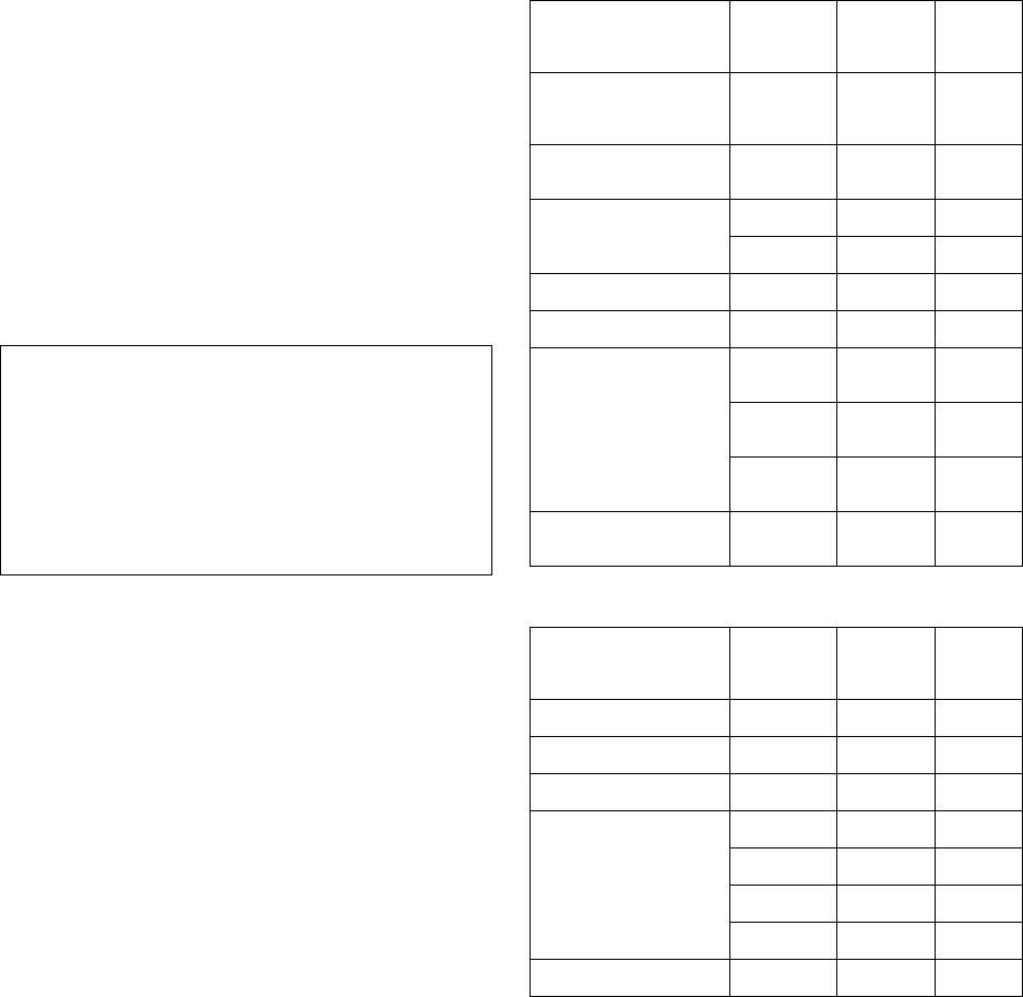
Typical Center Wavelength Maximum Output Power
830 nm - 860 nm -1.5 dBm
1270 nm - 1360 nm -3.0 dBm
1540 nm - 1570 nm 5.0 dBm
Electromagnetic Compatibility (EMC) Standards
This product complies with and conforms to the following international
EMC standards and all relevant national deviations:
Limits and Methods of Measurement of Radio Interference of Information
Technology Equipment, CISPR 22:1997 and EN55022:1998.
Information Technology Equipment - Immunity Characteristics - Limits
and Methods of Measurement, CISPR 24:1997 and EN55024:1998,
including:
• Electrostatic Discharge (ESD) IEC 61000-4-2
• Radiated Immunity IEC 61000-4-3
• Electrical Fast Transient IEC 61000-4-4
• Lightning Effects IEC 61000-4-5
• Conducted Immunity IEC 61000-4-6
• Mains Frequency Magnetic Field IEC 61000-4-8
• Voltage Dips and Variations IEC 61000-4-11
Power Line Emissions, IEC 61000-3-2: Electromagnetic compatibility
(EMC) - Part 3-2: Limits - Limits for harmonic current emissions.
Power Line Emissions, IEC 61000-3-3: Electromagnetic compatibility
(EMC) - Part 3-3: Limits - Limitation of voltage changes, voltage
fluctuations and flicker in public low-voltage supply systems.
Federal Communications Commission Statement
Part 15:
Part 68: Answer-Supervision Signaling
Allowing this equipment to be operated in a manner that does not provide
proper answer-supervision signaling is in violation of Part 68 rules. This
equipment returns answer-supervision signals to the public switched
network when:
• answered by the called station,
• answered by the attendant, or
• routed to a recorded announcement that can be administered
by the customer premises equipment (CPE) user.
This equipment returns answer-supervision signals on all direct inward
dialed (DID) calls forwarded back to the public switched telephone
network. Permissible exceptions are:
• A call is unanswered.
• A busy tone is received.
• A reorder tone is received.
Avaya attests that this registered equipment is capable of providing users
access to interstate providers of operator services through the use of
access codes. Modification of this equipment by call aggregators to block
access dialing codes is a violation of the Telephone Operator Consumers
Act of 1990.
REN Number
For MCC1, SCC1, CMC1, G600, and G650 Media Gateways:
This equipment complies with Part 68 of the FCC rules. On either the
rear or inside the front cover of this equipment is a label that contains,
among other information, the FCC registration number, and ringer
equivalence number (REN) for this equipment. If requested, this
information must be provided to the telephone company.
For G350 and G700 Media Gateways:
This equipment complies with Part 68 of the FCC rules and the
requirements adopted by the ACTA. On the rear of this equipment is a
label that contains, among other information, a product identifier in the
format US:AAAEQ##TXXXX. The digits represented by ## are the ringer
equivalence number (REN) without a decimal point (for example, 03 is a
REN of 0.3). If requested, this number must be provided to the telephone
company.
For all media gateways:
The REN is used to determine the quantity of devices that may be
connected to the telephone line. Excessive RENs on the telephone line
may result in devices not ringing in response to an incoming call. In most,
but not all areas, the sum of RENs should not exceed 5.0. To be certain
of the number of devices that may be connected to a line, as determined
by the total RENs, contact the local telephone company.
REN is not required for some types of analog or digital facilities.
Means of Connection
Connection of this equipment to the telephone network is shown in the
following tables.
For MCC1, SCC1, CMC1, G600, and G650 Media Gateways:
For G350 and G700 Media Gateways:
For all media gateways:
If the terminal equipment (for example, the media server or media
gateway) causes harm to the telephone network, the telephone company
will notify you in advance that temporary discontinuance of service may
be required. But if advance notice is not practical, the telephone
company will notify the customer as soon as possible. Also, you will be
advised of your right to file a complaint with the FCC if you believe it is
necessary.
The telephone company may make changes in its facilities, equipment,
operations or procedures that could affect the operation of the
equipment. If this happens, the telephone company will provide advance
notice in order for you to make necessary modifications to maintain
uninterrupted service.
If trouble is experienced with this equipment, for repair or warranty
information, please contact the Technical Service Center at
1-800-242- 2121 or contact your local Avaya representative. If the
equipment is causing harm to the telephone network, the telephone
company may request that you disconnect the equipment until the
problem is resolved.
Note: This equipment has been tested and found to comply with
the limits for a Class A digital device, pursuant to Part 15 of the
FCC Rules. These limits are designed to provide reasonable
protection against harmful interference when the equipment is
operated in a commercial environment. This equipment
generates, uses, and can radiate radio frequency energy and, if
not installed and used in accordance with the instruction
manual, may cause harmful interference to radio
communications. Operation of this equipment in a residential
area is likely to cause harmful interference in which case the
user will be required to correct the interference at his own
expense.
Manufacturer’s Port
Identifier FIC Code SOC/
REN/
A.S. Code
Network
Jacks
Off premises station OL13C 9.0F RJ2GX,
RJ21X,
RJ11C
DID trunk 02RV2-T 0.0B RJ2GX,
RJ21X
CO trunk 02GS2 0.3A RJ21X
02LS2 0.3A RJ21X
Tie trunk TL31M 9.0F RJ2GX
Basic Rate Interface 02IS5 6.0F, 6.0Y RJ49C
1.544 digital interface 04DU9-BN 6.0F RJ48C,
RJ48M
04DU9-IKN 6.0F RJ48C,
RJ48M
04DU9-ISN 6.0F RJ48C,
RJ48M
120A4 channel service
unit 04DU9-DN 6.0Y RJ48C
Manufacturer’s Port
Identifier FIC Code SOC/
REN/
A.S. Code
Network
Jacks
Ground Start CO trunk 02GS2 1.0A RJ11C
DID trunk 02RV2-T AS.0 RJ11C
Loop Start CO trunk 02LS2 0.5A RJ11C
1.544 digital interface 04DU9-BN 6.0Y RJ48C
04DU9-DN 6.0Y RJ48C
04DU9-IKN 6.0Y RJ48C
04DU9-ISN 6.0Y RJ48C
Basic Rate Interface 02IS5 6.0F RJ49C

A plug and jack used to connect this equipment to the premises wiring
and telephone network must comply with the applicable FCC Part 68
rules and requirements adopted by the ACTA. A compliant telephone
cord and modular plug is provided with this product. It is designed to be
connected to a compatible modular jack that is also compliant. It is
recommended that repairs be performed by Avaya certified technicians.
The equipment cannot be used on public coin phone service provided by
the telephone company. Connection to party line service is subject to
state tariffs. Contact the state public utility commission, public service
commission or corporation commission for information.
This equipment, if it uses a telephone receiver, is hearing aid compatible.
Canadian Department of Communications (DOC) Interference
Information
This Class A digital apparatus complies with Canadian ICES-003.
Cet appareil numérique de la classe A est conforme à la norme
NMB-003 du Canada.
This equipment meets the applicable Industry Canada Terminal
Equipment Technical Specifications. This is confirmed by the registration
number. The abbreviation, IC, before the registration number signifies
that registration was performed based on a Declaration of Conformity
indicating that Industry Canada technical specifications were met. It does
not imply that Industry Canada approved the equipment.
Installation and Repairs
Before installing this equipment, users should ensure that it is
permissible to be connected to the facilities of the local
telecommunications company. The equipment must also be installed
using an acceptable method of connection. The customer should be
aware that compliance with the above conditions may not prevent
degradation of service in some situations.
Repairs to certified equipment should be coordinated by a representative
designated by the supplier. Any repairs or alterations made by the user to
this equipment, or equipment malfunctions, may give the
telecommunications company cause to request the user to disconnect
the equipment.
Declarations of Conformity
United States FCC Part 68 Supplier’s Declaration of Conformity (SDoC)
Avaya Inc. in the United States of America hereby certifies that the
equipment described in this document and bearing a TIA TSB-168 label
identification number complies with the FCC’s Rules and Regulations 47
CFR Part 68, and the Administrative Council on Terminal Attachments
(ACTA) adopted technical criteria.
Avaya further asserts that Avaya handset-equipped terminal equipment
described in this document complies with Paragraph 68.316 of the FCC
Rules and Regulations defining Hearing Aid Compatibility and is deemed
compatible with hearing aids.
Copies of SDoCs signed by the Responsible Party in the U. S. can be
obtained by contacting your local sales representative and are available
on the following Web site: http://www.avaya.com/support.
All Avaya media servers and media gateways are compliant with FCC
Part 68, but many have been registered with the FCC before the SDoC
process was available. A list of all Avaya registered products may be
found at: http://www.part68.org by conducting a search using "Avaya" as
manufacturer.
European Union Declarations of Conformity
Avaya Inc. declares that the equipment specified in this document
bearing the "CE" (Conformité Europeénne) mark conforms to the
European Union Radio and Telecommunications Terminal Equipment
Directive (1999/5/EC), including the Electromagnetic Compatibility
Directive (89/336/EEC) and Low Voltage Directive (73/23/EEC).
Copies of these Declarations of Conformity (DoCs) can be obtained by
contacting your local sales representative and are available on the
following Web site: http://www.avaya.com/support.
Japan
This is a Class A product based on the standard of the Voluntary Control
Council for Interference by Information Technology Equipment (VCCI). If
this equipment is used in a domestic environment, radio disturbance may
occur, in which case, the user may be required to take corrective actions.
To order copies of this and other documents:
Call: Avaya Publications Center
Voice 1.800.457.1235 or 1.207.866.6701
FAX 1.800.457.1764 or 1.207.626.7269
Write: Globalware Solutions
200 Ward Hill Avenue
Haverhill, MA 01835 USA
Attention: Avaya Account Management
E-mail: totalware@gwsmail.com
For the most current versions of documentation, go to the Avaya support
Web site: http://www.avaya.com/support.

Issue 1 June 2005 5
About this book . . . . . . . . . . . . . . . . . . . . . . . . . . . . . . . . . . . . . . 13
Overview. . . . . . . . . . . . . . . . . . . . . . . . . . . . . . . . . . . . . . . . . . . . . . 13
Structure of book . . . . . . . . . . . . . . . . . . . . . . . . . . . . . . . . . . . . . . . . . 14
Audience. . . . . . . . . . . . . . . . . . . . . . . . . . . . . . . . . . . . . . . . . . . . . . 16
Downloading this book and updates from the Web . . . . . . . . . . . . . . . . . . . . . . . . 17
Safety labels and security alert labels . . . . . . . . . . . . . . . . . . . . . . . . . . . . . . . 18
Safety precautions. . . . . . . . . . . . . . . . . . . . . . . . . . . . . . . . . . . . . . . . . 18
Related resources . . . . . . . . . . . . . . . . . . . . . . . . . . . . . . . . . . . . . . . . . 19
Technical assistance. . . . . . . . . . . . . . . . . . . . . . . . . . . . . . . . . . . . . . . . 21
Trademarks . . . . . . . . . . . . . . . . . . . . . . . . . . . . . . . . . . . . . . . . . . . . 21
Sending us comments . . . . . . . . . . . . . . . . . . . . . . . . . . . . . . . . . . . . . . . 22
How to use this Document. . . . . . . . . . . . . . . . . . . . . . . . . . . . . . . . . . . . . 22
Organization . . . . . . . . . . . . . . . . . . . . . . . . . . . . . . . . . . . . . . . . . . . . 23
Conventions used in this document . . . . . . . . . . . . . . . . . . . . . . . . . . . . . . . .24
Useful terms . . . . . . . . . . . . . . . . . . . . . . . . . . . . . . . . . . . . . . . . . . . . 26
Chapter 1: Server Alarms . . . . . . . . . . . . . . . . . . . . . . . . . . . . . . . . . 27
Introduction . . . . . . . . . . . . . . . . . . . . . . . . . . . . . . . . . . . . . . . . . . . . 27
Background Terms. . . . . . . . . . . . . . . . . . . . . . . . . . . . . . . . . . . . . . . . . 29
Alarm-Related LEDs. . . . . . . . . . . . . . . . . . . . . . . . . . . . . . . . . . . . . . . . 30
Alarm Content . . . . . . . . . . . . . . . . . . . . . . . . . . . . . . . . . . . . . . . . . . . 30
QOS Alarms . . . . . . . . . . . . . . . . . . . . . . . . . . . . . . . . . . . . . . . . . . . . 31
Alarm Management . . . . . . . . . . . . . . . . . . . . . . . . . . . . . . . . . . . . . . . . 31
Alarms in Linux Media Servers . . . . . . . . . . . . . . . . . . . . . . . . . . . . . . . . . . 32
S8710 Alarms . . . . . . . . . . . . . . . . . . . . . . . . . . . . . . . . . . . . . . . . . . 121
Chapter 2: Denial Events . . . . . . . . . . . . . . . . . . . . . . . . . . . . . . . . 125
Event Type number ranges . . . . . . . . . . . . . . . . . . . . . . . . . . . . . . . . . . .126
Event Data . . . . . . . . . . . . . . . . . . . . . . . . . . . . . . . . . . . . . . . . . . . . 127
Denial Event Tables . . . . . . . . . . . . . . . . . . . . . . . . . . . . . . . . . . . . . . . . 177
Chapter 3: LEDs . . . . . . . . . . . . . . . . . . . . . . . . . . . . . . . . . . . . . . 255
Alarm levels . . . . . . . . . . . . . . . . . . . . . . . . . . . . . . . . . . . . . . . . . . . . 255
Terminal alarm notification. . . . . . . . . . . . . . . . . . . . . . . . . . . . . . . . . . . . . 256
Attendant console LEDs . . . . . . . . . . . . . . . . . . . . . . . . . . . . . . . . . . . . . . 257
Circuit pack LEDs . . . . . . . . . . . . . . . . . . . . . . . . . . . . . . . . . . . . . . . . . 257
Avaya Ethernet Switch LEDs . . . . . . . . . . . . . . . . . . . . . . . . . . . . . . . . . . . 268
Contents

Contents
6 Maintenance Procedures for Avaya Communication Manager 3.0, Media Gateways and Servers
UPS LEDs . . . . . . . . . . . . . . . . . . . . . . . . . . . . . . . . . . . . . . . . . . . . 269
IPSI LEDs . . . . . . . . . . . . . . . . . . . . . . . . . . . . . . . . . . . . . . . . . . . . . 270
650A Power supply LEDs . . . . . . . . . . . . . . . . . . . . . . . . . . . . . . . . . . . . . 273
655A Power Supply LEDs . . . . . . . . . . . . . . . . . . . . . . . . . . . . . . . . . . . . . 273
Duplication memory card LEDs . . . . . . . . . . . . . . . . . . . . . . . . . . . . . . . . . .274
S8710 Media Server LEDs . . . . . . . . . . . . . . . . . . . . . . . . . . . . . . . . . . . . 276
S8700 Media Server LEDs . . . . . . . . . . . . . . . . . . . . . . . . . . . . . . . . . . . . 279
S8500 Media Server LEDs . . . . . . . . . . . . . . . . . . . . . . . . . . . . . . . . . . . . 282
S8300 Media Server LEDs . . . . . . . . . . . . . . . . . . . . . . . . . . . . . . . . . . . . 283
G700 and Media Module LEDs . . . . . . . . . . . . . . . . . . . . . . . . . . . . . . . . . . 288
Chapter 4: G700 Media Gateway Traps. . . . . . . . . . . . . . . . . . . . . . . . . . 301
SNMP Alarming on the G700 . . . . . . . . . . . . . . . . . . . . . . . . . . . . . . . . . . .301
G700 Alarm Format . . . . . . . . . . . . . . . . . . . . . . . . . . . . . . . . . . . . . . . . 304
G700 Traps and Resolutions . . . . . . . . . . . . . . . . . . . . . . . . . . . . . . . . . . . 305
Chapter 5: Communication Manager Maintenance-Object Repair
Procedures . . . . . . . . . . . . . . . . . . . . . . . . . . . . . . . . . 325
Subsystems Maintained by Communication Manager . . . . . . . . . . . . . . . . . . . . . . 326
Viewing Communication Manager Alarms. . . . . . . . . . . . . . . . . . . . . . . . . . . . . 329
Command Syntax . . . . . . . . . . . . . . . . . . . . . . . . . . . . . . . . . . . . . . . . 329
Abort Code 1412 . . . . . . . . . . . . . . . . . . . . . . . . . . . . . . . . . . . . . . . . . 331
Escalation Procedure . . . . . . . . . . . . . . . . . . . . . . . . . . . . . . . . . . . . . . . 331
ABRI-PORT (ASAI ISDN-BRI Port) . . . . . . . . . . . . . . . . . . . . . . . . . . . . . . . . 332
AC-POWER . . . . . . . . . . . . . . . . . . . . . . . . . . . . . . . . . . . . . . . . . . . . 333
ADM-CONN (Administered Connection) . . . . . . . . . . . . . . . . . . . . . . . . . . . . . 341
ADX8D-BD (AUDIX Circuit Pack) . . . . . . . . . . . . . . . . . . . . . . . . . . . . . . . . . 344
ADX8D-PT (AUDIX Digital Port) . . . . . . . . . . . . . . . . . . . . . . . . . . . . . . . . . .345
ADX16D-B (16-Port AUDIX Circuit Pack) . . . . . . . . . . . . . . . . . . . . . . . . . . . . . 353
ADX16A-BD (AUDIX Circuit Pack) . . . . . . . . . . . . . . . . . . . . . . . . . . . . . . . . 354
ADX16D-P (16-Port AUDIX Digital Port) . . . . . . . . . . . . . . . . . . . . . . . . . . . . . 355
ADX16A-PT (AUDIX Analog Line/Control Link) . . . . . . . . . . . . . . . . . . . . . . . . . . 363
AESV-LNK (AE Services Link) . . . . . . . . . . . . . . . . . . . . . . . . . . . . . . . . . .371
AESV-SESS (AE Services Session). . . . . . . . . . . . . . . . . . . . . . . . . . . . . . . . 375
ALARM-PT (Alarm Port) . . . . . . . . . . . . . . . . . . . . . . . . . . . . . . . . . . . . . . 378
ANL-16-L (16-Port Analog Line) . . . . . . . . . . . . . . . . . . . . . . . . . . . . . . . . . . 384
ANL-BD (Analog Line Circuit Pack) . . . . . . . . . . . . . . . . . . . . . . . . . . . . . . . .403

Contents
Issue 1 June 2005 7
ANL-LINE (8-Port Analog Line) . . . . . . . . . . . . . . . . . . . . . . . . . . . . . . . . . . 404
ANL-NE-L (8-Port Analog Line) . . . . . . . . . . . . . . . . . . . . . . . . . . . . . . . . . . 425
AN-LN-PT (Analog Line Port) . . . . . . . . . . . . . . . . . . . . . . . . . . . . . . . . . . . 426
ANN-BD (Announcement circuit pack) . . . . . . . . . . . . . . . . . . . . . . . . . . . . . . 447
ANN-PT (announcement port). . . . . . . . . . . . . . . . . . . . . . . . . . . . . . . . . . .465
ANNOUNCE (announce) . . . . . . . . . . . . . . . . . . . . . . . . . . . . . . . . . . . . . 477
ASAI-ADJ (ASAI Adjunct) . . . . . . . . . . . . . . . . . . . . . . . . . . . . . . . . . . . . . 481
ASAI-BD (Multi-Application Platform Board) . . . . . . . . . . . . . . . . . . . . . . . . . . . 482
ASAI-EPT . . . . . . . . . . . . . . . . . . . . . . . . . . . . . . . . . . . . . . . . . . . . . 484
ASAI-PT . . . . . . . . . . . . . . . . . . . . . . . . . . . . . . . . . . . . . . . . . . . . . . 494
ASAI-RES (TN800 reserve slot) . . . . . . . . . . . . . . . . . . . . . . . . . . . . . . . . . .506
ATM-BCH (ATM B-Channel Trunk) . . . . . . . . . . . . . . . . . . . . . . . . . . . . . . . . 507
ATM-DCH (ATM D-Channel Port) . . . . . . . . . . . . . . . . . . . . . . . . . . . . . . . . . 522
ATM-EI (Expansion Interface Circuit Pack) . . . . . . . . . . . . . . . . . . . . . . . . . . . . 525
ATM-INTF (TN2305/6). . . . . . . . . . . . . . . . . . . . . . . . . . . . . . . . . . . . . . . 573
ATM-NTWK (ATM Network Error) . . . . . . . . . . . . . . . . . . . . . . . . . . . . . . . . . 576
ATM PNC-DUP (ATM PNC Duplication). . . . . . . . . . . . . . . . . . . . . . . . . . . . . . 587
ATM-SGRP (ATM Signaling Group) . . . . . . . . . . . . . . . . . . . . . . . . . . . . . . . . 598
ATM-SYNC (ATM Synchronization) . . . . . . . . . . . . . . . . . . . . . . . . . . . . . . . . 610
ATM-TRK (Circuit Emulation Service
Circuit Pack) . . . . . . . . . . . . . . . . . . . . . . . . . . . . . . . . . . . . . . . . . . . 617
ATM-WSP (ATM WAN Spare Processor) . . . . . . . . . . . . . . . . . . . . . . . . . . . . . 649
ATT-ADJ (AvayaAdjunct) . . . . . . . . . . . . . . . . . . . . . . . . . . . . . . . . . . . . . 654
ATTE-AJ (Ethernet Avaya Adjunct) . . . . . . . . . . . . . . . . . . . . . . . . . . . . . . . . 655
AUDIX-BD (AUDIX Circuit Pack) . . . . . . . . . . . . . . . . . . . . . . . . . . . . . . . . .656
AUDIX-PT (AUDIX Port) . . . . . . . . . . . . . . . . . . . . . . . . . . . . . . . . . . . . . . 657
AUX-BD (Auxiliary Trunk Circuit Pack) . . . . . . . . . . . . . . . . . . . . . . . . . . . . . . 658
AUX-TRK (Auxiliary Trunk) . . . . . . . . . . . . . . . . . . . . . . . . . . . . . . . . . . . . 659
AXA12-BD (AUDIX Circuit Packs). . . . . . . . . . . . . . . . . . . . . . . . . . . . . . . . . 670
ADX8D-BD (Audix Circuit Packs) . . . . . . . . . . . . . . . . . . . . . . . . . . . . . . . . .672
AXD12-BD (Audix Circuit Packs) . . . . . . . . . . . . . . . . . . . . . . . . . . . . . . . . .673
AXA12-RS (AUDIX Reserve Slots) . . . . . . . . . . . . . . . . . . . . . . . . . . . . . . . . 674
ADX8D-RS (AUDIX Reserve Slots) . . . . . . . . . . . . . . . . . . . . . . . . . . . . . . . . 675
AXD12-RS (AUDIX Reserve Slots) . . . . . . . . . . . . . . . . . . . . . . . . . . . . . . . . 676
BRI-BD (ISDN-BRI Line Circuit Pack) . . . . . . . . . . . . . . . . . . . . . . . . . . . . . . . 677
BRI-DAT (ISDN-BRI Data Module) . . . . . . . . . . . . . . . . . . . . . . . . . . . . . . . . 684

Contents
8 Maintenance Procedures for Avaya Communication Manager 3.0, Media Gateways and Servers
BRI-PORT (ISDN-BRI Port) . . . . . . . . . . . . . . . . . . . . . . . . . . . . . . . . . . . . 685
BRI-SET, Various Adjuncts . . . . . . . . . . . . . . . . . . . . . . . . . . . . . . . . . . . . 708
BRI-DAT . . . . . . . . . . . . . . . . . . . . . . . . . . . . . . . . . . . . . . . . . . . . . . 736
CAB-CALM (Customer alarm) . . . . . . . . . . . . . . . . . . . . . . . . . . . . . . . . . . .737
CAB-EXFR (emergency transfer) . . . . . . . . . . . . . . . . . . . . . . . . . . . . . . . . . 739
CAB-MTCE (Media Gateway Maintenance). . . . . . . . . . . . . . . . . . . . . . . . . . . . 744
CAB-PFL (Power Fan Lead). . . . . . . . . . . . . . . . . . . . . . . . . . . . . . . . . . . . 749
CAB-TEMP (Cabinet Temperature) . . . . . . . . . . . . . . . . . . . . . . . . . . . . . . . . 753
CABINET (Cabinet Sensors) . . . . . . . . . . . . . . . . . . . . . . . . . . . . . . . . . . . 758
CARR-POW (Carrier Power Supply) . . . . . . . . . . . . . . . . . . . . . . . . . . . . . . . 770
CDR-LNK (Call Detail Recording Link) . . . . . . . . . . . . . . . . . . . . . . . . . . . . . . 788
CLAN-BD (Control LAN Circuit Pack) . . . . . . . . . . . . . . . . . . . . . . . . . . . . . . . 789
CLSFY-BD (Call Classifier Circuit Pack). . . . . . . . . . . . . . . . . . . . . . . . . . . . . . 810
CLSFY-PT (Call Classifier Port) . . . . . . . . . . . . . . . . . . . . . . . . . . . . . . . . . . 811
CO-BD (Central Office Trunk Circuit Pack) . . . . . . . . . . . . . . . . . . . . . . . . . . . . 816
CO-DS1 (DS1 CO Trunk) . . . . . . . . . . . . . . . . . . . . . . . . . . . . . . . . . . . . . 817
CO-TRK (Analog CO Trunk). . . . . . . . . . . . . . . . . . . . . . . . . . . . . . . . . . . . 835
CONFIG (System Configuration) . . . . . . . . . . . . . . . . . . . . . . . . . . . . . . . . .862
CUST-ALM (Customer-Provided Alarming Device) . . . . . . . . . . . . . . . . . . . . . . . . 869
DAT-LINE (Data Line Port) . . . . . . . . . . . . . . . . . . . . . . . . . . . . . . . . . . . . 870
DC-POWER (Single-Carrier Cabinet Environment) . . . . . . . . . . . . . . . . . . . . . . . . 880
DETR-BD (Tone Detector Circuit) . . . . . . . . . . . . . . . . . . . . . . . . . . . . . . . . .884
DID-BD (Direct Inward Dial Trunk Circuit Pack) . . . . . . . . . . . . . . . . . . . . . . . . . . 885
DID-DS1 (Direct Inward Dial Trunk) . . . . . . . . . . . . . . . . . . . . . . . . . . . . . . . .886
DID-TRK (Direct Inward Dial Trunk) . . . . . . . . . . . . . . . . . . . . . . . . . . . . . . . .898
DIG-BD (Digital Line Circuit Pack). . . . . . . . . . . . . . . . . . . . . . . . . . . . . . . . . 915
DIG-IP-STN (Digital IP Station) . . . . . . . . . . . . . . . . . . . . . . . . . . . . . . . . . . 916
DIG-LINE (Digital Line) . . . . . . . . . . . . . . . . . . . . . . . . . . . . . . . . . . . . . . 924
DIOD-BD (DIOD Trunk Circuit Pack) . . . . . . . . . . . . . . . . . . . . . . . . . . . . . . . 951
DIOD-DS1 (DS1 DIOD Trunk) . . . . . . . . . . . . . . . . . . . . . . . . . . . . . . . . . . .952
DIOD-TRK (DIOD Trunk) . . . . . . . . . . . . . . . . . . . . . . . . . . . . . . . . . . . . . 964
DLY-MTCE (MO-DAILY) . . . . . . . . . . . . . . . . . . . . . . . . . . . . . . . . . . . . . . 975
DS1-BD (DS1 Interface Circuit Pack) . . . . . . . . . . . . . . . . . . . . . . . . . . . . . . . 978
DS1-FAC (DS1 Facility) . . . . . . . . . . . . . . . . . . . . . . . . . . . . . . . . . . . . . . 1053
DS1C-BD . . . . . . . . . . . . . . . . . . . . . . . . . . . . . . . . . . . . . . . . . . . . . 1077
DT-LN-BD (Data Line Circuit Pack) . . . . . . . . . . . . . . . . . . . . . . . . . . . . . . . .1114

Contents
Issue 1 June 2005 9
DTMR-PT (Dual-Tone Multifrequency Receiver Port) . . . . . . . . . . . . . . . . . . . . . . . 1115
E-DIG-BD (Multi Application Platform Board) . . . . . . . . . . . . . . . . . . . . . . . . . . 1121
E-DIG-RES (TN800 reserve slot) . . . . . . . . . . . . . . . . . . . . . . . . . . . . . . . . .1123
E-DIG-STA (Emulated Digital Line) . . . . . . . . . . . . . . . . . . . . . . . . . . . . . . . .1124
EMG-XFER (Emergency Transfer) . . . . . . . . . . . . . . . . . . . . . . . . . . . . . . . . 1134
EPN-SNTY (PN Sanity Audit) . . . . . . . . . . . . . . . . . . . . . . . . . . . . . . . . . . . 1143
ERR-LOG (Error Log) . . . . . . . . . . . . . . . . . . . . . . . . . . . . . . . . . . . . . . . 1145
ESS (Enterprise Survivable Server) . . . . . . . . . . . . . . . . . . . . . . . . . . . . . . . 1146
ETH-PT (Control LAN Ethernet) . . . . . . . . . . . . . . . . . . . . . . . . . . . . . . . . . .1153
ETR-PT (Enhanced Tone Receiver Port) . . . . . . . . . . . . . . . . . . . . . . . . . . . . . 1167
EXP-INTF (Expansion Interface Circuit Pack). . . . . . . . . . . . . . . . . . . . . . . . . . . 1176
EXP-PN (Expansion Port Network) . . . . . . . . . . . . . . . . . . . . . . . . . . . . . . . . 1235
EXT-DEV (External device alarm) . . . . . . . . . . . . . . . . . . . . . . . . . . . . . . . . .1240
EXT-DEV ADMIN? N (External Device Alarm) . . . . . . . . . . . . . . . . . . . . . . . . . . 1243
EXT-DEV ADMIN? Y (External Device Alarm) . . . . . . . . . . . . . . . . . . . . . . . . . . 1246
FIBER-LK (Fiber Link) . . . . . . . . . . . . . . . . . . . . . . . . . . . . . . . . . . . . . . . 1250
FW-DWNLD (Firmware Download) . . . . . . . . . . . . . . . . . . . . . . . . . . . . . . . . 1298
GPTD-PT (General-Purpose Tone Detector Port) . . . . . . . . . . . . . . . . . . . . . . . . . 1308
H323-BCH (H.323 B Channel) . . . . . . . . . . . . . . . . . . . . . . . . . . . . . . . . . .1313
H323-SGRP (H.323 Signaling Group). . . . . . . . . . . . . . . . . . . . . . . . . . . . . . . 1315
H323-STN (H.323 IP Station) . . . . . . . . . . . . . . . . . . . . . . . . . . . . . . . . . . . 1323
HYB-BD (Hybrid Line Circuit Pack) . . . . . . . . . . . . . . . . . . . . . . . . . . . . . . . .1328
HYB-LINE (Hybrid Line) . . . . . . . . . . . . . . . . . . . . . . . . . . . . . . . . . . . . . . 1329
INADS (INADS Link). . . . . . . . . . . . . . . . . . . . . . . . . . . . . . . . . . . . . . . . 1351
IPMEDPRO . . . . . . . . . . . . . . . . . . . . . . . . . . . . . . . . . . . . . . . . . . . . 1355
IPMEDPRO (TN2302 IP Media Processor) . . . . . . . . . . . . . . . . . . . . . . . . . . . . 1356
IPMEDPRO (TN2602AP IP Media Resource 320) . . . . . . . . . . . . . . . . . . . . . . . . 1380
IPSV-CTL (Ipserver Interface Control). . . . . . . . . . . . . . . . . . . . . . . . . . . . . . .1405
IP-SVR (IP Server Interface) . . . . . . . . . . . . . . . . . . . . . . . . . . . . . . . . . . . 1415
ISDN-PLK (ISDN-PRI Signaling Link Port) . . . . . . . . . . . . . . . . . . . . . . . . . . . . 1423
ISDN-SGR (ISDN-PRI Signaling Group) . . . . . . . . . . . . . . . . . . . . . . . . . . . . . 1429
ISDN-TRK (DS1 ISDN Trunk) . . . . . . . . . . . . . . . . . . . . . . . . . . . . . . . . . . .1446
JNL-PRNT (Journal Printer Link) . . . . . . . . . . . . . . . . . . . . . . . . . . . . . . . . . 1475
LGATE-AJ . . . . . . . . . . . . . . . . . . . . . . . . . . . . . . . . . . . . . . . . . . . . . 1476
LGATE-BD (ISDN-BRI Line Circuit Pack) . . . . . . . . . . . . . . . . . . . . . . . . . . . . . 1477
LGATE-PT . . . . . . . . . . . . . . . . . . . . . . . . . . . . . . . . . . . . . . . . . . . . . 1478

Contents
10 Maintenance Procedures for Avaya Communication Manager 3.0, Media Gateways and Servers
LIC-ERR (License-Error Mode) . . . . . . . . . . . . . . . . . . . . . . . . . . . . . . . . . .1479
LOG-SVN (Login Security Violation) . . . . . . . . . . . . . . . . . . . . . . . . . . . . . . . 1487
MAINT (PN’s Maintenance Circuit Pack) . . . . . . . . . . . . . . . . . . . . . . . . . . . . . 1490
MAPD-BD (MAPD Interface Circuit Pack TN802) . . . . . . . . . . . . . . . . . . . . . . . . . 1508
MEDPRO (Media Processor MAPD Circuit Pack). . . . . . . . . . . . . . . . . . . . . . . . . 1539
MEDPRO-C (Media-Processor Control). . . . . . . . . . . . . . . . . . . . . . . . . . . . . . 1551
MEDPROPT (TN802/TN2302/TN2602 MED PRO DSP PORT) . . . . . . . . . . . . . . . . . 1553
MET-BD (MET Line Circuit Pack) . . . . . . . . . . . . . . . . . . . . . . . . . . . . . . . . .1560
MET-LINE (MET Line) . . . . . . . . . . . . . . . . . . . . . . . . . . . . . . . . . . . . . . . 1561
MED-GTWY (MEDIA GATEWAY) . . . . . . . . . . . . . . . . . . . . . . . . . . . . . . . . . 1581
MG-ANA (ANALOG MM711) . . . . . . . . . . . . . . . . . . . . . . . . . . . . . . . . . . . 1583
MG-ANN (Voice Announcements). . . . . . . . . . . . . . . . . . . . . . . . . . . . . . . . . 1585
MG-BRI (BRI Trunk Media Module MM720). . . . . . . . . . . . . . . . . . . . . . . . . . . . 1586
MG-DCP (Digital Line Media Module) . . . . . . . . . . . . . . . . . . . . . . . . . . . . . . . 1593
MG-DS1 (DS1 Interface Media Module). . . . . . . . . . . . . . . . . . . . . . . . . . . . . . 1594
MG-IAMM (Integrated Analog Media Module). . . . . . . . . . . . . . . . . . . . . . . . . . . 1643
MG-ICC (Internal Call Controller) . . . . . . . . . . . . . . . . . . . . . . . . . . . . . . . . . 1650
MG-VOIP (MM760 MED PRO DSP PORT) . . . . . . . . . . . . . . . . . . . . . . . . . . . . 1651
MIS (Management Information System). . . . . . . . . . . . . . . . . . . . . . . . . . . . . . 1654
MMI-BD . . . . . . . . . . . . . . . . . . . . . . . . . . . . . . . . . . . . . . . . . . . . . . 1655
MMI-LEV (Multimedia Interface Resource Level) . . . . . . . . . . . . . . . . . . . . . . . . . 1666
MMI-PT . . . . . . . . . . . . . . . . . . . . . . . . . . . . . . . . . . . . . . . . . . . . . . 1669
MMI-SYNC . . . . . . . . . . . . . . . . . . . . . . . . . . . . . . . . . . . . . . . . . . . . 1675
MODEM-BD (Modem Pool Circuit Pack) . . . . . . . . . . . . . . . . . . . . . . . . . . . . . 1677
MODEM-PT (Modem Pool Port). . . . . . . . . . . . . . . . . . . . . . . . . . . . . . . . . . 1678
M/T-ANL (Maintenance/Test Analog Port) . . . . . . . . . . . . . . . . . . . . . . . . . . . . . 1696
M/T-BD (Maintenance/Test Circuit Pack) . . . . . . . . . . . . . . . . . . . . . . . . . . . . . 1705
M/T-DIG (Maintenance/Test Digital Port) . . . . . . . . . . . . . . . . . . . . . . . . . . . . . 1709
M/T-PKT (Maintenance/Test Packet Bus Port) . . . . . . . . . . . . . . . . . . . . . . . . . . 1722
NO-LIC (No License) . . . . . . . . . . . . . . . . . . . . . . . . . . . . . . . . . . . . . . . 1727
NR-CONN (Network-Region Connect) . . . . . . . . . . . . . . . . . . . . . . . . . . . . . . 1731
OPS-LINE (DS1 Off-Premises Station Line). . . . . . . . . . . . . . . . . . . . . . . . . . . . 1736
PDMODULE (Processor Data Module) . . . . . . . . . . . . . . . . . . . . . . . . . . . . . . 1751
PE-BCHL (PRI Endpoint Port). . . . . . . . . . . . . . . . . . . . . . . . . . . . . . . . . . . 1773
PKT-BUS (Packet Bus) . . . . . . . . . . . . . . . . . . . . . . . . . . . . . . . . . . . . . . 1790
PKT-INT (Packet Interface) . . . . . . . . . . . . . . . . . . . . . . . . . . . . . . . . . . . . 1799

Contents
Issue 1 June 2005 11
PLAT-ALM (Platform Alarms) . . . . . . . . . . . . . . . . . . . . . . . . . . . . . . . . . . . 1838
PMS-LINK (Property Management System Link) . . . . . . . . . . . . . . . . . . . . . . . . . 1839
PMS-PRNT/JNL-PRNT (PMS Printer Link) . . . . . . . . . . . . . . . . . . . . . . . . . . . . 1846
PNC-DUP (PNC Duplication) . . . . . . . . . . . . . . . . . . . . . . . . . . . . . . . . . . .1851
POWER . . . . . . . . . . . . . . . . . . . . . . . . . . . . . . . . . . . . . . . . . . . . . . 1869
POW-SUP (power supply). . . . . . . . . . . . . . . . . . . . . . . . . . . . . . . . . . . . . 1881
PPP-PT (Control LAN Packet/Port) . . . . . . . . . . . . . . . . . . . . . . . . . . . . . . . . 1893
PRI-CDR (Call Detail Recording Link). . . . . . . . . . . . . . . . . . . . . . . . . . . . . . . 1905
PROC-SAN (Process Sanity Audits) . . . . . . . . . . . . . . . . . . . . . . . . . . . . . . . 1911
PS-RGEN (Power supply ring generator) . . . . . . . . . . . . . . . . . . . . . . . . . . . . . 1912
RANL-STA (Remote Analog Line (Station) Port) . . . . . . . . . . . . . . . . . . . . . . . . . 1918
RDIG-STA (Remote Digital Station) . . . . . . . . . . . . . . . . . . . . . . . . . . . . . . . .1926
REM-OFF (Remote Office) . . . . . . . . . . . . . . . . . . . . . . . . . . . . . . . . . . . . 1940
RING-GEN (Analog Ring Generator) . . . . . . . . . . . . . . . . . . . . . . . . . . . . . . . 1942
RMB (Remote Maintenance Board) . . . . . . . . . . . . . . . . . . . . . . . . . . . . . . . 1949
RMB-REPORT (Remote Maintenance Board - Report) . . . . . . . . . . . . . . . . . . . . . 1950
RMC-ENV (Power/Fan Sensors) . . . . . . . . . . . . . . . . . . . . . . . . . . . . . . . . . 1951
SEC-CDR (Call Detail Recording Link) . . . . . . . . . . . . . . . . . . . . . . . . . . . . . . 1956
SER-BUS (Serial communication bus) . . . . . . . . . . . . . . . . . . . . . . . . . . . . . . 1957
SIP-BCH (SIP B Channel) . . . . . . . . . . . . . . . . . . . . . . . . . . . . . . . . . . . . . 1968
SIP-SGRP (SIP Signaling Group) . . . . . . . . . . . . . . . . . . . . . . . . . . . . . . . . . 1970
S-SYN-BD (Speech Synthesis Circuit Pack) . . . . . . . . . . . . . . . . . . . . . . . . . . . 1978
S-SYN-PT (Speech Synthesis Port) . . . . . . . . . . . . . . . . . . . . . . . . . . . . . . . . 1979
SN-CONF (Switch Node Configuration) . . . . . . . . . . . . . . . . . . . . . . . . . . . . . . 1992
SNC-BD (Switch Node Clock Circuit Pack) . . . . . . . . . . . . . . . . . . . . . . . . . . . . 2000
SNC-LINK (Switch Node Clock Link) . . . . . . . . . . . . . . . . . . . . . . . . . . . . . . . 2039
SNC-REF (Switch Node Clock Reference) . . . . . . . . . . . . . . . . . . . . . . . . . . . . 2043
SNI-BD (SNI Circuit Pack). . . . . . . . . . . . . . . . . . . . . . . . . . . . . . . . . . . . . 2046
SNI-PEER (SNI Peer Link) . . . . . . . . . . . . . . . . . . . . . . . . . . . . . . . . . . . . 2113
SRP-EPN . . . . . . . . . . . . . . . . . . . . . . . . . . . . . . . . . . . . . . . . . . . . . 2117
STA-FWDL . . . . . . . . . . . . . . . . . . . . . . . . . . . . . . . . . . . . . . . . . . . . 2118
STRAT-3 (Stratum-3 Clock) . . . . . . . . . . . . . . . . . . . . . . . . . . . . . . . . . . . . 2128
SVC-SLOT (Service Slot) . . . . . . . . . . . . . . . . . . . . . . . . . . . . . . . . . . . . . 2141
SYNC (Port-Network Synchronization) . . . . . . . . . . . . . . . . . . . . . . . . . . . . . . 2143
SYS-LINK (System Links) . . . . . . . . . . . . . . . . . . . . . . . . . . . . . . . . . . . . . 2175
SYS-PRNT (System Printer) . . . . . . . . . . . . . . . . . . . . . . . . . . . . . . . . . . . 2181

Contents
12 Maintenance Procedures for Avaya Communication Manager 3.0, Media Gateways and Servers
SYSTEM (System) . . . . . . . . . . . . . . . . . . . . . . . . . . . . . . . . . . . . . . . . 2186
TBRI-BD
(TN2185 ISDN Trunk-Side BRI) . . . . . . . . . . . . . . . . . . . . . . . . . . . . . . . . . 2192
TBRI-PT (ISDN Trunk-Side BRI Port) . . . . . . . . . . . . . . . . . . . . . . . . . . . . . . . 2200
TBRI-TRK (Trunk-Side ISDN BRI Channel) . . . . . . . . . . . . . . . . . . . . . . . . . . . . 2224
TDM-BUS (TDM Bus) . . . . . . . . . . . . . . . . . . . . . . . . . . . . . . . . . . . . . . . 2237
TDM-CLK (TDM Bus Clock) . . . . . . . . . . . . . . . . . . . . . . . . . . . . . . . . . . . .2252
TDMODULE (Trunk Data Module). . . . . . . . . . . . . . . . . . . . . . . . . . . . . . . . . 2268
TIE-BD (Tie Trunk Circuit Pack) . . . . . . . . . . . . . . . . . . . . . . . . . . . . . . . . . . 2269
TIE-DS1 (DS1 Tie Trunk) . . . . . . . . . . . . . . . . . . . . . . . . . . . . . . . . . . . . . 2270
TBRI-PT (ISDN Trunk-Side BRI Port) . . . . . . . . . . . . . . . . . . . . . . . . . . . . . . . 2291
TIE-TRK (Analog Tie Trunk) . . . . . . . . . . . . . . . . . . . . . . . . . . . . . . . . . . . . 2302
TIME-DAY (Time of Day) . . . . . . . . . . . . . . . . . . . . . . . . . . . . . . . . . . . . . 2326
TONE-BD (Tone-Clock Circuit) . . . . . . . . . . . . . . . . . . . . . . . . . . . . . . . . . . 2327
TONE-PT (Tone Generator) . . . . . . . . . . . . . . . . . . . . . . . . . . . . . . . . . . . . 2353
TR-LN-BD (Trunk Line Board) . . . . . . . . . . . . . . . . . . . . . . . . . . . . . . . . . . . 2363
TSC-ADM (Administered Temporary
Signaling Connections) . . . . . . . . . . . . . . . . . . . . . . . . . . . . . . . . . . . . . 2364
TTR-LEV (TTR Level) . . . . . . . . . . . . . . . . . . . . . . . . . . . . . . . . . . . . . . . 2370
UDS1-BD (UDS1 Interface Circuit Pack) . . . . . . . . . . . . . . . . . . . . . . . . . . . . . 2374
VAL-BD (Voice Announcements
over LAN Circuit Pack) . . . . . . . . . . . . . . . . . . . . . . . . . . . . . . . . . . . . . . 2477
VAL-PT (Voice Announcements over LAN Packet/Port). . . . . . . . . . . . . . . . . . . . . . 2503
VC-BD . . . . . . . . . . . . . . . . . . . . . . . . . . . . . . . . . . . . . . . . . . . . . . . 2509
VC-DSPPT . . . . . . . . . . . . . . . . . . . . . . . . . . . . . . . . . . . . . . . . . . . . 2513
VC-LEV (Voice Conditioner DSP Port Level) . . . . . . . . . . . . . . . . . . . . . . . . . . . 2522
VC-SUMPT . . . . . . . . . . . . . . . . . . . . . . . . . . . . . . . . . . . . . . . . . . . . 2525
WAE-PORT (Wideband Access Endpoint Port) . . . . . . . . . . . . . . . . . . . . . . . . . . 2531
XXX-BD (Common Port Circuit Pack/Media Module) . . . . . . . . . . . . . . . . . . . . . . . 2539
Index . . . . . . . . . . . . . . . . . . . . . . . . . . . . . . . . . . . . . . . . 2557

Issue 1 June 2005 13
About this book
Overview
This document provides procedures to monitor, test, and maintain an Avaya Media Server or
Gateway system. It covers many of the faults and troubles that can occur and provides simple
procedures to correct them. Simple, traditional troubleshooting methods are sometimes
sufficient to locate and clear faults. The traditional methods include substitution, visual
inspections, continuity checks, and clarification of operating procedures with end users.
Using this documentation, the Avaya technicians and the technicians of their business partners
and customers should be able to follow detailed procedures for:
●Monitoring, testing, and maintaining an Avaya Media Server, Media Gateway, and many
other system components.
●Using troubleshooting methods to clear faults.
●Required replacements, visual inspections, continuity checks, and clarifying operating
procedures with end users.
Document set
Although this maintenance book is published separately, it is part of a set:
●03-300190 Maintenance Alarms Reference (formerly 555-245-102)
●03-300191 Maintenance Commands Reference (formerly 555-245-101)
●03-300192 Maintenance Procedures Reference (formerly 555-245-103)
Equipment/platforms
This book contains information about the following equipment/platforms
●Avaya S8700/S8710 Media Servers
●Avaya S8500 Media Servers
●Avaya S8300 Media Servers
●Avaya G700/G650/G600/MCC/SCC Media Gateways

About this book
14 Maintenance Procedures for Avaya Communication Manager 3.0, Media Gateways and Servers
It does not contain information about
●DEFINITY G3R (see 555-233-117: Maintenance for DEFINITY R Servers or 555-233-142:
Maintenance for Avaya S8700 Media Servers with G600 Media Gateway)
●DEFINITY SI (see 555-233-119: Maintenance for DEFINITY SI Servers or 555-233-143:
Avaya S8700 Media Servers with MCC1/SCC1)
●Avaya S8100 Media Server (see 555-233-123: Maintenance for DEFINITY CSI Servers)
●IBM eServer BladeCenter HS20 Type 8832
●G150/G250/G350 Media Gateways
Structure of book
The following document contains combined Maintenance Alarms information for:
●S8300, S8500, and S8700 media servers
●MCC1, SCC1, and CMC1 media gateways
●G600, G650, and G700 media gateways
The document includes new information developed for Communication Manager Release 2.0,
and preexisting or modified information brought together from Release 1.3 maintenance
documentation.
This document is the first of three reference documents:
●Maintenance Alarms Reference (555-245-102)
●Maintenance Commands Reference (03-300191)
●Maintenance Procedures (03-300192)
The basis for these reference documents was the Release 1.3 S8700 media server with the
MCC1 and SCC1 media gateways maintenance document. To this document were added
Release 1.3 maintenance information for the S8300 media server, the G700, G600 and CMC1
media gateways, as well as new material developed for the S8500 media server and G650
media gateway.
In order to present maintenance information from all these sources side-by-side, when it was
not clear from a chapter or section title, marking conventions were adopted to delineate material
specific to a particular source. The markers act on three levels:
●Chapters or Maintenance Objects (MOs)
●Major and minor sections
●Paragraphs or in-line comments

Structure of book
Issue 1 June 2005 15
Chapters or Maintenance Objects (MOs)
At the Chapter or MO level, bold names of the server(s) or gateway(s) that are represented
within the sections to follow are inserted immediately after the Chapter title or MO title. For
example, the heading for the SER-BUS (Serial communication bus) MO looks like:
SER-BUS (Serial communication bus)
G650
The G650 after the title indicates that the material in this MO relates to the G650 media gateway.
Major and minor sections
At the Major and minor sections level, a similar bold name along with a ruled line delineates the
beginning of a section of material specific to the media server or gateway identified. At the
conclusion of the section, another ruled line marks the end of the specific material and a return
to common text. For example, a section of material specific to the S8700 or S8500 media server
looks like:
S8700 | 8710 / S8500
1. If only 1 analog circuit pack in the system has this problem, replace the circuit pack.
2. If only analog circuit packs on a particular carrier have this error, the ringing generator
may not be connected to this carrier.
3. If analog circuit packs on many carriers have this error, it is probably a problem with the
ringing generator.
Such sections can occasionally extend for several pages.

About this book
16 Maintenance Procedures for Avaya Communication Manager 3.0, Media Gateways and Servers
Paragraphs or in-line comments
At the paragraph level and for comments in-line, the specific media server or gateway is
indicated by its bold name, and the parenthetical information follows immediately afterward. For
example, a paragraph insert for the S8700 and S8500 media servers might looks like:
1. If the Tone-Clock circuit is a slave clock, then the EI to which it is listening is providing a bad
timing source. Follow the diagnostic procedures specified for TDM-CLK Error Code 2305.
2. S8700 | 8710 / S8500: If no problem can be found with the incoming synchronization signal,
replace the IPSI or Tone-Clock circuit pack. See Replacing the IPSI or Tone-Clock Circuit
Pack on page 2337.
In such cases, it is not necessary to delineate the beginning and end of the material.
An example of an in-line comment might look like:
3. Error Type 1: There is a serial number mismatch between the hardware serial number and
installed license file (S8700 | 8710 / S8500: there is a serial-number mismatch of the reference
IPSI and a subsequent License Error failure. S8300: there is a serial-number mismatch of the
G700 motherboard on which the serial number resides and a subsequent License Error
failure). This error is caused by the:
●S8700 | 8710 / S8500: Reference IPSI not responding
S8300: G700 motherboard not responding
●Expiration of the 10-day timer
The system enters No-License mode.
It is hoped that, by these techniques, material specific to several different sources can be
combined and viewed side-by-side without confusion.
Audience
The information in this book is intended for use by:
Avaya technicians, provisioning specialists, business partners, and customers, specifically:
●Trained Avaya technicians
●A maintenance technician dispatched to a customer site in response to a trouble alarm or
a user trouble report
●A maintenance technician located at a remote maintenance facility
●The customer’s assigned maintenance technician
The technician is expected to have a knowledge of telecommunications fundamentals and
of the particular Avaya Media Server and/or Media Gateway to the extent that the
procedures in this book can be performed, in most cases, without assistance.

Downloading this book and updates from the Web
Issue 1 June 2005 17
This book is not intended to solve all levels of troubles. It is limited to troubles that can be solved
using:
●The Alarm Log
●The Error Log
●Trouble-clearing procedures
●Maintenance tests
●Traditional troubleshooting methods
If the trouble still has not been resolved, it is the maintenance technician’s responsibility to
escalate the problem to a higher level of technical support. Escalation should conform to the
procedures in the Technical and Administration Escalation Plan.
Downloading this book and updates from the Web
You can download the latest version of this book from the Avaya Web site. You must have
access to the Internet, and a copy of Acrobat Reader must be installed on your personal
computer.
Avaya makes every effort to ensure that the information in this book is complete and accurate.
However, information can change after we publish this book. Therefore, the Avaya Web site
might also contain new product information and updates to the information in this book. You can
also download these updates from the Avaya Web site.
Downloading this book
To download the latest version of this book:
1. Access the Avaya web site at http://support.avaya.com.
2. At the top center of the page, click Product Documentation.
The system displays the Welcome to Product Documentation page.
3. In the upper-left corner type the 9-digit book number in the Search Support field, and then
click Go.
The system displays the Product Documentation Search Results page.
4. Scroll down to find the latest issue number, and then click the book title that is to the right of
the latest issue number.
5. On the next page, scroll down and click one of the following options:
●PDF Format to download the book in regular PDF format
●ZIP Format to download the book in zipped PDF format

About this book
18 Maintenance Procedures for Avaya Communication Manager 3.0, Media Gateways and Servers
Safety labels and security alert labels
Observe all caution, warning, and danger statements to help prevent loss of service, equipment
damage, personal injury, and security problems. This book uses the following safety labels and
security alert labels:
!CAUTION:
CAUTION: A caution statement calls attention to a situation that can result in harm to
software, loss of data, or an interruption in service.
!WARNING:
WARNING: A warning statement calls attention to a situation that can result in harm to
hardware or equipment.
!DANGER:
DANGER: A danger statement calls attention to a situation that can result in harm to
personnel.
!SECURITY ALERT:
SECURITY ALERT: A security alert calls attention to a situation that can increase the potential for
unauthorized use of a telecommunications system.
Safety precautions
When performing maintenance or translation procedures on the system, users must observe
certain precautions. Observe all caution, warning, and danger admonishments to prevent loss
of service, possible equipment damage, and possible personal injury. In addition, the following
precautions regarding electromagnetic interference (EMI) and static electricity must be
observed:
Electromagnetic interference
This equipment generates, uses, and can radiate radio frequency energy. Electromagnetic
fields radiating from the switch may cause noise in the customer’s equipment. If the equipment
is not installed and used in accordance with the instruction book, radio interference may result.
!WARNING:
WARNING: To maintain the EMI integrity of the system, maintenance personnel must ensure
that all cabinet panels, covers, and so forth, are firmly secured before leaving the
customer’s premises.

Related resources
Issue 1 June 2005 19
Related resources
Table 1: Additional document resources on page 19 lists additional documentation that is
available for you, and which has been referenced within this document.
Table 1: Additional document resources
Document Number
Avaya Enterprise Survivable Servers (ESS) User Guide, 03-300428 03-300428
Hardware Guide for Avaya Communication Manager, 555-245-207 555-245-207
Overview for Avaya Communication Manager, 03-300468 03-300468
Administrator Guide for Avaya Communication Manager, 03-300509 03-300509
Installation and Upgrades for the Avaya G700 Media Gateway Controlled by
an Avaya S8300 Media Server or an Avaya S8700 Media Server,
555-234-100
555-234-100
Maintenance Commands Reference (03-300191) 03-300431
Maintenance Procedures (03-300192) 03-300432
Maintenance for Avaya DEFINITY® Server R, 555-233-117 555-233-117
Avaya P333T User’s Guide N/A
Avaya S8300 and Avaya S8700 Media Server Library, 555-233-825 555-233-825
EMBEDDED AUDIX System Maintenance, 585-300-110 585-300-110
DEFINITY AUDIX System Release 3.2.4 Maintenance, 585-300-110 585-300-110
AT&T Network and Data Connectivity, 555-025-201 555-025-201
Digital PBX Standards, RS4648 RS4648
User Manual Z3A Asynchronous Data Unit, 555-401-701 555-401-701
DEFINITY® Communications System Generic 1, Generic 2 and Generic 3
V1 and 2 – Integrated Channel Service Unit (CSU) Module Installation and
Operation, 555-230-193
555-230-193
DEFINITY® Communications System Generic 2.2 and Generic 3 V2 DS1/
CEPT1/ISDN-PRI Reference, 555-025-107
555-025-107
DEFINITY® Communications System Generic 1 and Generic 3i Wiring,
555-204-111
555-204-111
1 of 3

About this book
20 Maintenance Procedures for Avaya Communication Manager 3.0, Media Gateways and Servers
Site Preparation, Installation, and Operator’s Manual, 167-405-035 167-405-035
Maintenance for the Avaya S8700 Media Server with an Avaya SCC1 Media
Gateway or an Avaya MCC1 Media Gateway, 555-233-143
555-233-143
Avaya MultiVantage Solutions Installation and Maintenance for Survivable
Remote EPN, 555-233-121
555-233-121
Installing the Avaya S8700 Media Server with the Avaya G600 Media
Gateway, the Avaya MCC1 Media Gateway, or the Avaya SCC1 Media
Gateway (Library CD)
Library CD
ATM Installation, Upgrades, and Administration using Avaya Communication
Manager, 555-233-124
555-233-124
Administration for Network Connectivity for Avaya Communication Manager,
555-233-504
555-233-504
Quick Start for Hardware Installation: Avaya S8700 Series Media Server,
555-245-703
555-245-703
Installing the Avaya S8700 Media Server with an Avaya G650 Media
Gateway, 555-245-109
555-245-109
Installing the S8500 Media Server with the G650 Media Gateway,
555-245-107
555-245-107
4606 IP Telephone User’s Guide, 555-233-775 555-233-775
4624 IP Telephone User’s Guide, 555-233-776 555-233-776
4612 IP Telephone User’s Guide, 555-233-777 555-233-777
Job Aid: Replacing the Avaya S8710 Media Server, 03-300146 03-300146
Job Aid: Replacing the Hard Drive in an Avaya S8710 Media Server,
03-300147
03-300147
Job Aids for Field Replacements for the Avaya S8700 Series Media Servers,
03-300530
03-300530
Job Aid: Replacing the Hard Drive in the S8700 Media Server (Pre-R2.0),
555-245-768
555-245-768
Job Aid: Replacing the Hard Drive in the S8700 Media Server (R2.x),
555-245-769
555-245-769
Job Aid: Replacing the S8500 Hard Drive, 555-245-761 555-245-761
Job Aid: Replacing the S8500 Remote Service Adapter, 555-245-759 555-245-759
Table 1: Additional document resources (continued)
Document Number
2 of 3

Technical assistance
Issue 1 June 2005 21
Technical assistance
Avaya provides the following resources for technical assistance.
Within the United States
For help with:
●Feature Administration and system applications, call Avaya Technical Consulting Support
at 1-800-225-7585
●Maintenance and repair, call the Avaya National Customer Care Support Line at
1-800-242-2121
●Toll fraud, call Avaya Toll Fraud Intervention at 1-800-643-2353
International
For all international resources, contact your local Avaya authorized dealer for additional help.
Trademarks
All trademarks identified by the ® or ™ are registered trademarks or trademarks, respectively,
of Avaya Inc. All other trademarks are the property of their respective owners.
Job Aid: Repacking the S8500 Dual Network Interface, 555-245-760 555-245-760
Job Aid: Replacing the G700 Media Gateway, 555-245-752 555-245-752
Table 1: Additional document resources (continued)
Document Number
3 of 3

About this book
22 Maintenance Procedures for Avaya Communication Manager 3.0, Media Gateways and Servers
Sending us comments
Avaya welcomes your comments about this book. To reach us by:
●Mail, send your comments to:
Avaya Inc.
Product Documentation Group
Room B3-H13
1300 W. 120th Avenue
Westminster, CO 80234 USA
●E-mail, send your comments to:
document@avaya.com
●Fax, send your comments to:
1-303-538-1741
Ensure that you mention the name and number of this book.
How to use this Document
Most maintenance sessions involve analyzing the Alarm and Error Logs to diagnose a trouble
source and replacing a component such as a circuit pack or media module. The information in
Chapter 5: Communication Manager Maintenance-Object Repair Procedures of this reference
will generally suffice to address these needs. Certain complex elements of the system require a
more comprehensive approach. Special procedures for these elements appear in Chapter
4: General troubleshooting of Maintenance Procedures (03-300192).
Note:
Note: This document is designed to be read online and in paper format. Because of the
large volume of information, additional cross-references have been added to
make it easier to locate information when using the manual online.

Organization
Issue 1 June 2005 23
Organization
Chapter 1: Server Alarms, contains information on alarms generated on various platforms,
including the S8300, S8500, and S8700 media server. These alarms cover such categories as
process watchdog, environmental, login, translation monitoring, and power supply alarms.
Alarm identifications, levels, and resolutions are given.
Chapter 2: Denial Events, contains information about denial events that are generated by Avaya
Communication Manager. Denial events are displayed via the Events Report (display
events screen) of Avaya Communication Manager.
Chapter 3: LEDs, contains information on the definition and interpretation of LED indicators to
be found on various system components, including servers, gateways, circuit packs, and media
modules.
Chapter 4: G700 Media Gateway Traps, contains information on traps that can occur on media
gateways. Trap identifications, alarm levels, trap descriptions, and recommended resolutions
are given.
Chapter 5: Communication Manager Maintenance-Object Repair Procedures, contains specific
troubleshooting and repair instructions for every component in the system. The maintenance
objects are listed alphabetically by name as they appear in the Alarm and Error Logs. Under
each maintenance object appears a description of the object’s function, tables for interpreting
alarm and error logs, and instructions on how to use tests, commands, and replacements to
resolve associated problems.

About this book
24 Maintenance Procedures for Avaya Communication Manager 3.0, Media Gateways and Servers
Conventions used in this document
Table 2: Typography used in this book on page 24 lists the typographic conventions in this
document.
Table 2: Typography used in this book
To represent . . . This typeface and syntax
are shown as . . .
For example, . . .
SAT commands ●Bold for literals
●Bold italic for variables
●Square brackets [ ]
around optional
parameters
●“|” between exclusive
choices
refresh ip-route [all | location]
SAT screen input
and output
●Bold for input
●Constant width for
output (screen
displays and
messages)
Set the Save Translation
field to daily.
The message Command
successfully completed
should appear.
Linux commands ●Constant-width bold for
literals
●Constant-width bold
italics for variables
●Square brackets []
around optional
arguments
●“Or” sign | between
exclusive choices
testmodem [-s] | [-t
arg]
Linux output Constant width Linux returns the message
almdisplay 4: Unable to
connect to MultiVantage.
1 of 2

Conventions used in this document
Issue 1 June 2005 25
Other conventions used in this book:
●Physical dimensions are in English [Foot Pound Second (FPS)] units, followed by metric
[Centimeter Gram Second) (CGS)] units in parentheses.
Wire-gauge measurements are in AWG, followed by the diameter in millimeters in
parentheses.
●Circuit-pack codes (such as TN790B or TN2182B) are shown with the minimum
acceptable alphabetic suffix (like the “B” in the code TN2182B).
Generally, an alphabetic suffix higher than that shown is also acceptable. However, not
every vintage of either the minimum suffix or a higher suffix code is necessarily acceptable.
Web interface ●Bold for menu
selections, tabs,
buttons, and field
names
●Right arrow > to
separate a sequence
of menu selections
Select Alarms and
Notification, the appropriate
alarm, and then click Clear.
Select Diagnostics > View
System Logs, then click
Watchdog Logs.
Keys Special font for keyboard
keys and SAT screen
clickable buttons
Press Tab.
Click Next Page.
Table 2: Typography used in this book (continued)
To represent . . . This typeface and syntax
are shown as . . .
For example, . . .
2 of 2

About this book
26 Maintenance Procedures for Avaya Communication Manager 3.0, Media Gateways and Servers
Useful terms
Table 3: Terminology summary on page 26 summarizes some of the terms used in this book
and relates them to former terminology.
Table 3: Terminology summary
Present Terminology Former Terminology
Communication Manager MultiVantage
Avaya Call Processing
S8300 Media Server ICC, Internal Call Controller
S8700 Media Server (or
non-co-resident S8300)
ECC, External Call Controller
MGP, Media Gateway Processor 860T Processor
Layer 2 Switching Processor P330 Stack Processor
Cajun Stack Processor
i960 Processor

Issue 1 June 2005 27
Chapter 1: Server Alarms
S8700 | 8710 / S8500 / S8300
This chapter provides background information on server alarming. For detailed information on
G700 Media Gateway Traps, refer to Chapter 4: G700 Media Gateway Traps.
Introduction
During normal operations, software or firmware may detect error conditions pertaining to
specific Maintenance Objects (MOs) or other subsystems. The system automatically attempts
either to fix or circumvent these problems. Errors are detected in two ways:
●Firmware on the component during ongoing operations
●A “periodic test” or a “scheduled test” started by software
The technician can run tests on demand that are generally more comprehensive (and
potentially disruptive) than are the "scheduled tests".
When an error is detected, the maintenance software puts the error in the Error Log and
increments the error counter for that error. When an error counter is “active” (greater than 0),
there is a maintenance record for the MO. If a hardware component incurs too many errors, an
alarm is raised.
Alarms on the Linux media servers can occur in several areas:
●Media Modules, Media Servers, the Media Gateway Processor, and the Layer 2 Switching
Processor are all capable of detecting internal failures and generating traps and alarms.
●Media gateways, such as the G700, detect faults and alert the Media Server; the Media
Server then raises an alarm, and sends the alarm to an appropriate network management
site.
●Communication Manager alarms reflect health status of network elements such as media
gateways, circuit packs, media modules, and their associated links, ports, and trunks.
●Messaging alarms provide health status of embedded or external messaging systems.
Alarms may be viewed using the following:
●Maintenance Web Interface
Provides alarms information related to Communication Manager, the media server, and
messaging.

Server Alarms
28 Maintenance Procedures for Avaya Communication Manager 3.0, Media Gateways and Servers
Note:
Note: For non-Communication Manager alarms, use the Web Page header "Alarms
and Notification" and "Diagnostics: View System Log". Choose the appropriate
heading and, if necessary, call Avaya support.
●Media Server bash shell
Provides alarms information related to Communication Manager, the media server, and
messaging.
●Media Server SAT CLI
Provides alarms information related to Communication Manager.
●MGP CLI (on the G700 Media Gateway)
Provides alarms and traps information related to the G700 platform and its subsystems.
●Layer 2 Switching Processor CLI (on the G700 Media gateway)
Provides information related to the media gateway stack.
Information related to Communication Manager, the media server, and messaging alarms can
be displayed using either the Maintenance Web Interface or the media server bash shell;
however, this document (Maintenance Alarms Reference (555-245-102)) provides maintenance
information only for Communication Manager (Chapter 5: Communication Manager
Maintenance-Object Repair Procedures)and media server alarms (Chapter 1: Server Alarms).
For messaging alarms and repair procedures, refer to the appropriate documentation for your
messaging system.
Alarm Classifications
Alarms are classified depending on their effect on system operation:
●MAJOR alarms identify failures that cause a critical degradation of service. These alarms
require immediate attention.
●MINOR alarms identify failures that cause some service degradation but that do not render
a crucial portion of the system inoperable. Minor alarms require attention. However,
typically a minor alarm affects only a few trunks, stations, or a single feature.
●WARNING alarms identify failures that cause no significant degradation of service or
equipment failures external to the switch. These failures are not reported to INADS or to
the attendant console.
●ON-BOARD problems originate in the circuitry on the alarmed Media Module.
●OFF-BOARD problems originate in a process or component that is external to the Media
Module.

Background Terms
Issue 1 June 2005 29
Background Terms
Table 4: Alarming Background Terms on page 29 gives a useful explanation of terms.
Table 4: Alarming Background Terms
Term Explanation
TRAP A trap is an event notification that is sent to the SNMP trap manager and
received from the Media Gateway Processor, Layer 2 Switching Processor,
or RTCP Monitor (Avaya VisAbility).
ALARM Some traps are determined to be an alarm. If determined to be an alarm they
are sent to an appropriate alarm management site, such as INADS.
INADS Initialization and Administration System, a software tool used by Avaya
services personnel to initialize, administer, and troubleshoot customer
communications systems remotely.
SNMP Simple Network Management Protocol, the industry standard protocol
governing network management and the monitoring of network devices and
their functions.
RTCP Real Time Control Protocol, contained in IETF RFC 1889.
ISM Intelligent Site Manager, a VPN gateway on the customer’s LAN that
provides a means for services personnel to access the customer’s LAN in a
secure manner via the Internet.
VPN Virtual Private Network, a private data network that makes use of the public
telecommunication infrastructure, maintaining privacy through the use of a
tunneling protocol and security procedures.

Server Alarms
30 Maintenance Procedures for Avaya Communication Manager 3.0, Media Gateways and Servers
Alarm-Related LEDs
Table 5: Alarm-Related LEDs on page 30 shows alarm-related LEDs on the faceplate of the
G700 or on an attendant console, and shows how certain LEDs reflect specific alarm situations.
Alarm Content
Alarms logged by Communication Manager are stored in an alarm log. All alarms include a date
and time stamp that reflects the date and time of the sending device. The alarm contains:
●Device type
●Component type
●Device name
●Current ip address
●Additional information necessary for identification of alarm origination
●Severity level to indicate the priority of the alarm
Alarms originating in a specific media server, such as an S8300, have a prefix denoting that of
an S8300.
Table 5: Alarm-Related LEDs
LED Location Alarm-Related Cause
ALARM LED Attendant Console The system alarm causes the attendant console ALARM
LED to light.
ACK LED Attendant Console The ACK LED on the attendant console reflects the state
of acknowledgement of the alarm report from INADS.
However, this is only possible for S8700-based Media
Servers.
RED ALM or
ALARM LED
LED Panel of G700
Media Gateway
The RED ALM or ALARM LED indicates the "health" of
the G700 by lighting when there are impaired functions
of the Media Gateway Processor, Layer 2 Switching
Processor, or VOIP engine. It lights, for example, when
the power supply voltage is out of bounds, if the G700
cannot locate a Media Servers, or when the unit is
overheating. It also indicates when the system is in
Power-up mode, or when a Media Module is resetting.

QOS Alarms
Issue 1 June 2005 31
QOS Alarms
An RTCP monitor using the local SNMP agent generates traps to a pre-administered trap
collector. The following QoS alarms are generated:
●The voip-callqos alarm is generated if a single session exceeds configured QOS levels. It
can generate a warning or an SNMP trap. Warnings are used for less severe problems.
They can be accumulated internally within Avaya VoIP Monitoring Manager for use by the
alarms defined below.
●The voip-systemqos alarm is generated if the number of voip-callqos warnings from all
terminals exceeds a configured count over a given period (e.g. 100 alarms over 24 hours).
The alarm causes a SNMP trap to be sent.
●The voip-terminalqos alarm is like the voip-systemqos alarm except it applies to a single
terminal. If any one terminal generates a number of voip-callqos warnings that exceed a
threshold then the alarm is generated.
Alarm Management
This section describes methods to determine the source of alarms that are generated when an
error occurs. The alarm log is viewable and follows that defined in Maintenance for Avaya
DEFINITY® Server R, 555-233-117. Technicians can view alarms via the Web Interface, CLI,
and SAT command-line interface.
SNMP management is a function of the Avaya MultiService Network Manager application. For
additional information, including information on event logs and trap logs, please refer to the
Avaya P333T User’s Guide.
Alarm management follows the S8700 Media Server Alarming Architecture Design; see
Maintenance for the Avaya S8700 Media Server with an Avaya SCC1 Media Gateway or an
Avaya MCC1 Media Gateway, 555-233-143.
Connection Strategies to a Services Organization
A services organization, such as INADS, receives alarms from the Media Server and connects
to the media server for troubleshooting. There are currently two product-connect strategies:
dialup modem access and Virtual Private Network (VPN) access over the Internet.
For dialup modem access:
1. Connect a USB modem, connected to a telephone line, to the USB port on the faceplate of
the media server.

Server Alarms
32 Maintenance Procedures for Avaya Communication Manager 3.0, Media Gateways and Servers
2. Enable the modem from the media server Web Interface. In addition, use the Setup Modem
Interface under the Configure Server pages.
3. With this modem, a client PC uses the Point-to-Point Protocol (PPP) to access the media
server and connect via telnet to a Linux shell.
4. Once logged into the media server, you can telnet out to media gateways, such as the
G700, and other devices on the network.
Note:
Note: Additionally, this modem can be used to allow the media server to call out to the
INADS or other alarm receiving system to report alarms. When performing
remote diagnostic tests, Services personnel should disable alarm call-outs to
INADS to avoid generating unnecessary alarms. Alarm suppression is released
after 30 minutes. If you are remotely logged in through the modem you prevent
alarms from being sent because you are using the modem, but you do not
prevent an alarm noting the absence of alarm reporting service being logged at
the alarm receiving site.
The VPN alternative is achieved by the use of the Intelligent Site Manager (ISM) application.
The ISM is a VPN gateway that resides on the customer’s LAN and provides a means for
services personnel to gain access to the customer’s LAN in a secure manner over the Internet.
Telnet is then used to access the media server and/or media gateways and other IP network
equipment.
Alarms in Linux Media Servers
S8700 | 8710 / S8500 / S8300
A Linux-based media server can be configured so that it serves as the trap collector and
provides external alarm notification.
A process called the Global Maintenance Manager (GMM) runs on the media server and
collects events that are logged to the Linux syslog_d process. These events consist primarily of
failure notification events logged by Communication Manager and INTUITY maintenance
subsystems, or of traps sent by media gateways (G700). For events that require external
notification, one option is to call the Avaya technical service center’s INADS (Initialization and
Administration System). However, other possible options include sending an e-mail to specified
destinations, or sending an SNMP trap to a specified network management address.
The media server has an SNMP trap manager that collects traps from:
●Uploads and downloads to media modules
●VoIP Media Modules
●VoIP engines on G700 motherboards
●G700-associated UPS systems

Alarms in Linux Media Servers
Issue 1 June 2005 33
Media server alarms perform a similar role to Communication Manager alarms in a traditional
telephony context. Media Server alarms:
●Comprise related sets of alarms, known as MOs
●Create an internal record of actual or potential problems
●Notify maintenance personnel of a problem
●Help isolate the problem’s source
●Point to and facilitate local and remote resolution of a problem
Note:
Note: If a user is logged into a server by an analog modem that is also the server’s only
alarm-reporting interface, enter almsuppress to suppress alarm reporting.
Otherwise, the other server logs an occurrence of SME Event ID #1 (see SME
Alarm in Media Server on page 78).
Clearing Media Server Alarms
A media server is an open standards-based CPU in the data- communications context. Unlike a
Communication Manager alarm, which cannot be cleared unless it is also resolved, a server
alarm:
●Can be manually cleared from its log, with the almclear Linux command
●Should not be considered resolved until it is actually repaired
Displaying Media Server Alarms
In following sections, each server alarm is described, and its resolution procedure is provided.
Like traditional Communication Manager MOs, the 3-column table for each server MO shows an
alarm’s:
1. Event ID
2. Severity
3. Definition, probable cause, and troubleshooting procedure
To help isolate a server problem, the 3rd column of these tables begins with quoted text for each
event (unlike traditional Communication Manager MOs). The text consists of the verbose (-v)
output of the almdisplay -v Linux command. For example, “interchange hand off failed” is
the quoted text for Arbiter’s Event ID #3.
If the almdisplay command returns a failure message, such as:
almdisplay: 4: Unable to connect to MultiVantage
enter the man almdisplay Linux command for command-related information.

Server Alarms
34 Maintenance Procedures for Avaya Communication Manager 3.0, Media Gateways and Servers
S8300
Alarming on the S8300 Functioning as a Local Survivable Processor
The S8300 functioning as a Local Survivable Processor (LSP) logs an alarm when it becomes
active. It also logs an alarm for every G700 Media Gateway that registers with it. It does NOT
log alarms when IP phones register with it; rather, it logs a warning.
Communication Manager Hardware Traps
Table 6: Communication Manager Hardware Traps on page 34 illustrates hardware traps that
apply to Communication Manager.
Note:
Note: The Avaya S8300 Media Server on a G700 Media Gateway platform has several
watchdog timers. If any one of them is not verified regularly, a trap of major
severity is sent. The timer associated with the S8300 is the S8300 Software
watchdog, which resets the S8300 processor if its connection is not verified
regularly.
Table 6: Communication Manager Hardware Traps
Trap Description
Media Server HW trap Hardware faults are analyzed by maintenance software and
correlate fault conditions to determine the appropriate action. If
appropriate action requires attention, a trap of critical severity is
sent.
Media Server HW clear
trap
Hardware faults that have created traps send a clear trap upon
clearing.
Media Server with
administered MG that’s
not registered
If a Media Server has an administered G700 but it has not
registered after an appropriate amount of time, send an alarm of
major severity indicating such.

Alarms in Linux Media Servers
Issue 1 June 2005 35
Backup and Restore Traps
The S8300 uses the LAN to backup a copy of its translation data. Table 7: Backup and Restore
Traps on page 35 illustrates the backup and restore traps.
Linux Media Server MOs and Alarms
Hardware MOs
The server’s hardware MOs are described in the following sections:
●DAJ1/DAL1 (Duplication Memory Board) on page 49
●RALM-SVC (Remote Alarm Service) on page 76
●USB1 (Modem Testing) Alarms on page 95
●UPS (Uninterruptible Power Supply) on page 89
●Remote Maintenance Board (RMB) Alarms on page 116
Table 7: Backup and Restore Traps
Trap Description
Successfully stored
backup
A trap of informational severity is sent when backup is successful.
(REPLY_ACK) The trap reads “Successful backup of S8300
translation data,” and names the backup location stored in the
string “BACKUP_LOCATION.”
This information also goes to the local maintenance screen, since
it is very possible that a backup is being requested as a result of an
on-site attempt to replace the S8300.
No backup data stored A trap of major severity is sent as soon as a REPLY_ERROR
message is returned. The trap states “Translation Data backup not
available,” and names the backup location stored in the string
“BACKUP_LOCATION.”

Server Alarms
36 Maintenance Procedures for Avaya Communication Manager 3.0, Media Gateways and Servers
Server-related alarms
Server-related alarms and their troubleshooting procedures are described in the following
tables:
●ARB (Arbiter) on page 37
●DAJ1/DAL1 Alarms in S8700 Media Server on page 54
●DUP (Duplication Manager) on page 56
●ENV (Environment) on page 60
●FSY (File Synchronization) on page 67
●HDD (Hard Disk Drive) on page 69
●KRN (Kernel) on page 73
●Login Alarms on page 74
●NIC (Network Interface Card) on page 75
●RALM-SVC (Remote Alarm Service) on page 76
●SME Alarm in S8700 Media Server on page 78
●SVC_MON (Service Monitor) on page 79
●_TM (Translation Manager) on page 88
●UPS Alarms to the Media Server on page 92
●USB1 (Modem Testing) Alarms on page 95
●_WD (Watchdog) Alarms on page 99
●Login Alarms - S8300 on page 115
●Virtual Alarms on page 116
●Remote Maintenance Board (RMB) Alarms on page 116
●S8500B Augmentix Server Availability Management Processor™ (A+SAMP) Alarms on
page 120
●S8710 environmental alarms on page 121
●S8710 server BIOS error messages on page 123

Alarms in Linux Media Servers
Issue 1 June 2005 37
ARB (Arbiter)
S8700 | 8710 only
The Arbiter process runs on S8700 Media Servers to:
●Decide which server is healthier and more able to be active
●Coordinate data shadowing between servers, under the Duplication Manager’s control
At the physical and data-link layers, an Ethernet-based duplication link provides an inter-arbiter
UDP communication path to:
●Enable this arbitration between the active and standby servers
●Provide the necessary status signaling for memory refreshes

Server Alarms
38 Maintenance Procedures for Avaya Communication Manager 3.0, Media Gateways and Servers
Table 8: ARB Alarms in Media Server on page 38 describes the Arbiter’s alarms and their
troubleshooting procedures. See DUP (Duplication Manager) on page 56 for more information.
Table 8: ARB Alarms in Media Server
Event
ID
Alarm
Level
Alarm Text, Cause/Description, Recommendation
3 MIN “Interchange hand off failed” — Standby server could not process active
server’s interchange request.
The interchange does not occur, and the active side remains active.
1. See if the standby side is RESET, either from the:
- Web interface’s Server section, by selecting View Summary
Status
- Linux command line, by entering server
2. Manually clear the alarm, either from the:
- Web interface, by selecting Alarms and Notification, the
appropriate alarm, and Clear
- Linux command line, by entering almclear -n #id
3. If the problem persists, troubleshoot the standby server.
a. See if the standby side is RESET, either from the:
- Web interface’s Server section, by selecting View Summary
Status
- Linux command line, by entering server
b. Check for application problems, either from the:
- Web interface, by selecting View Process Status
- Linux command line, by entering statapp,
and restore any applications with problems.
c. Check for problems with an Ethernet interface, either from the:
- Web interface, by selecting the Execute Pingall diagnostic
- Linux command line, by entering pingall -a
Check both sides of each failed link, and make any necessary
repairs.
4. If the applications and interfaces are okay but the problem persists,
escalate the problem.
1 of 12

Alarms in Linux Media Servers
Issue 1 June 2005 39
7 MAJ “Arbiter in invalid/unknown state” — Memory corruption or bad code/build
1. Verify that the server’s state is “Corrupt!”, either from the:
- Web interface’s Server section, by selecting View Summary
Status
- Linux command line, by entering server
2. Compare the suspected arbiter with the one in /root2 — using
the Linux commands:
/opt/ecs/sbin/acpfindvers /opt/ws/arbiter
(This command shows the arbiter’s version string.)
/sbin/cksum /opt/ws/arbiter
[This command runs a cyclical redundancy check (CRC) against
the arbiter, and then shows both the CRC’s output value and the
number of bytes in the arbiter file.]
3. If the two arbiter files differ:
a. Get a fresh copy of arbiter from the CD.
b. Manually clear the alarm, either from the:
- Web interface, by selecting Alarms and Notification, the
appropriate alarm, and Clear
- Linux command line, by entering almclear -n #id
4. If the arbiter file is OK or the problem persists, escalate the
problem.
Table 8: ARB Alarms in Media Server (continued)
Event
ID
Alarm
Level
Alarm Text, Cause/Description, Recommendation
2 of 12

Server Alarms
40 Maintenance Procedures for Avaya Communication Manager 3.0, Media Gateways and Servers
8 MIN “Both servers thought they were active”
1. To verify this condition, either from the:
- Web interface’s Server section, select View Summary Status
- Linux command line, enter server
2. To distinguish the cause, examine the trace logs for Interarbiter
messages with timestamps shortly before to shortly after the loss of
heartbeat, either from the:
- Web interface, by:
a. Selecting the View System Logs diagnostic and Logmanager
Debug trace
b. Specifying the Event Range for the appropriate time frame
c. Matching the Interarb pattern
- Linux command line, by entering logv -t ts
Depending on the cause, continue with either Step 3 or Step 4.
Table 8: ARB Alarms in Media Server (continued)
Event
ID
Alarm
Level
Alarm Text, Cause/Description, Recommendation
3 of 12

Alarms in Linux Media Servers
Issue 1 June 2005 41
8
(cont’d)
MIN 3. A high-priority process caused the active Arbiter to hang for at least
4.5 seconds (causing an interchange). Then, the hang lifted, and
each Arbiter realized that the other had assumed the active role.
An automatic resolution process should leave the newly active server
active, while the other server backs down to the standby role.
a. If so, manually clear the alarm, either from the:
- Web interface, by selecting Alarms and Notification, the
appropriate alarm, and Clear
- Linux command line, by entering almclear -n #id
b. If the problem recurs, escalate the problem.
4. Every Interarbiter link is down or mis-configured.
a. Check for problems with an Ethernet interface, either from the:
- Web interface, by selecting the Execute Pingall diagnostic
- Linux command line, by entering pingall -a
Check both sides of each failed link, and make any necessary
repairs.
b. If the links are OK but the problem persists, escalate the problem.
9 WRN <SOH (state-of-health) string> — Before an interchange, the standby
server is significantly healthier than the active server requesting the
interchange. (The active server is probably unable to sustain call
processing.)
Understanding ARB Event #9’s String Pairs
ARB Event #9 generates pairs of SOH strings, where in each string pair,
the:
●1st string represents the active
●2nd string represents the standby
server’s SOH just before an interchange. Since – (unless prevented by
external circumstances) – Event 9 triggers a server interchange, the 1st
string normally represents the less healthy server – which became the
standby. So, the 1st string’s data is usually more pertinent.
Table 8: ARB Alarms in Media Server (continued)
Event
ID
Alarm
Level
Alarm Text, Cause/Description, Recommendation
4 of 12

Server Alarms
42 Maintenance Procedures for Avaya Communication Manager 3.0, Media Gateways and Servers
9
(cont’d)
WRN The following is a sample string pair generated by ARB Event #9. Within
this sample, four pairs of digits in each string have special meaning, and
are labeled “aa” through “dd.”
aa bb cc dd
↓↓ ØØ ØØ ØØ
gmm 0700, pcd 00/00, dup 270, wd 81, actv 004
gmm 0700, pcd 06/06, dup 370, wd 01, actv 014
●For “aa,” any value other than “00” indicates a hardware problem.
(For example, the value “20” is common for a power failure.)
In the previous sample, neither server had hardware trouble.
●For “bb” and “cc,” different values within the same string indicate a
problem connecting to one or more IPSI connected PNs.
A PN reset can cause both server’s strings to reflect equally degraded
health, but that event (in itself) should not trigger a server interchange.
In the previous sample, both servers’ connectivity to IPSI connected
PNs is OK. (The 1st and 2nd strings have like “00” and “06” values,
respectively.)
●For “dd,” any value other than “01” indicates a failed software
process. (More precisely, a certain value indicates a problem with a
discrete portion of the platform’s process set, including:
- “21” for a Linux daemon (for example, “atd”, “httpd”, “inetd”, or
“xntpd”)
- “41” for a platform service (for example, “dbgserv”, “prune”, or
“syslog”)
- “81” for reloaded Communication Manager software, as in the
previous sample
Table 8: ARB Alarms in Media Server (continued)
Event
ID
Alarm
Level
Alarm Text, Cause/Description, Recommendation
5 of 12

Alarms in Linux Media Servers
Issue 1 June 2005 43
9
(cont’d)
WRN Troubleshooting ARB Event #9
1. compare the health of both servers, either from the:
- Web interface’s Server section, by selecting View Summary
Status
- Linux command line, by entering server
2. Using the output from Step 1, check the health of each server’s
individual processes.
3. Check the health of the active server’s individual processes, either
from the:
- Web interface, by selecting View Process Status
- Linux command line, by entering statapp
and restore any applications with problems.
4. See if the standby side is RESET, either from the:
- Web interface’s Server section, by selecting View Summary
Status
- Linux command line, by entering server
5. Check the health of the standby server’s individual processes, either
from the:
- Web interface, by selecting View Process Status
- Linux command line, by entering statapp,
and restore any applications with problems.
6. Check for problems with an Ethernet interface, either from the:
- Web interface, by selecting the Execute Pingall diagnostic
- Linux command line, by entering pingall -a
Check both sides of each failed link, and make any necessary repairs.
7. If the standby’s applications and interfaces are OK but the problem
persists, escalate the problem.
Table 8: ARB Alarms in Media Server (continued)
Event
ID
Alarm
Level
Alarm Text, Cause/Description, Recommendation
6 of 12

Server Alarms
44 Maintenance Procedures for Avaya Communication Manager 3.0, Media Gateways and Servers
After the interchange, the newly active server’s health should be
significantly better (lower SOH value) than the standby server’s. If so,
troubleshoot the standby server:
If not:
1. Manually clear the alarm, either from the:
- Web interface, by selecting Alarms and Notification, the
appropriate alarm, and Clear
- Linux command line, by entering almclear -n #id
2. If the problem recurs, escalate the problem.
11 WRN “Cannot create receive socket;” “cannot create transmit socket;” “cannot
bind receive socket;” “cannot bind send socket”
Since the Arbiter continuously attempts to create or bind the socket, the
problem may resolve itself. Once resolved, the Arbiter can send and
receive across every Interarbiter link (no subsequent error messages in
the trace log).
1. Examine the alarm log to distinguish between a:
Bind or create problem
Send or receive socket problem
by accessing either the:
- Web interface, by:
a. Selecting Alarms and Notification and the appropriate alarm
b. Selecting the View System Logs diagnostic
c. Selecting the Logmanager Debug trace
d. Specifying the Event Range for the appropriate time frame
e. Matching the “cannot create” pattern
- Linux command line, by entering almdisplay -v
Table 8: ARB Alarms in Media Server (continued)
Event
ID
Alarm
Level
Alarm Text, Cause/Description, Recommendation
7 of 12

Alarms in Linux Media Servers
Issue 1 June 2005 45
11
(cont’d)
WRN 2. Check for both the completeness and consistency of the servers’
hosts and servers.conf files (containing IP addresses of the
system’s configured components), either from the:
- Web interface, by selecting Configure Server
- Linux command line, by entering:
more /etc/hosts
more /etc/opt/ecs/servers.conf
3. If the files are OK, manually clear the alarm, either from the:
- Web interface, by selecting Alarms and Notification, the
appropriate alarm, and Clear
- Linux command line, by entering almclear -n #id
4. If this problem affects call processing or if the problem persists,
continue with Step 5 now.
If not, continue only at the customer’s convenience.
5. Escalate this problem for explicit guidance with Steps 5a through 6.
a. Enter server to verify that the suspected server is the standby.
b. If not, enter server -if to force a server interchange.
c. Busy out the standby server from the Linux command line, by
entering server -b.
d. Reboot the server (as the standby), either from the:
- Web interface, by selecting Shutdown This Server
- Linux command line, by entering /sbin/shutdown -r
now
6. If rebooting the standby does not help or if the problem recurs,
escalate the problem to the next higher tier.
Table 8: ARB Alarms in Media Server (continued)
Event
ID
Alarm
Level
Alarm Text, Cause/Description, Recommendation
8 of 12

Server Alarms
46 Maintenance Procedures for Avaya Communication Manager 3.0, Media Gateways and Servers
12 MIN “Interchange without doing prep” — Since the Arbiter could not create a
thread to request a file synchronization, some files did not get shadowed.
1. Examine the trace logs for the entry, Can't create
interchange-prep thread, either from the:
- Web interface by:
a. Selecting the View System Logs diagnostic and Logmanager
Debug trace
b. Specifying the Event Range for the appropriate time frame
c. Matching the “interchange-prep” pattern
- Linux command line, by entering logv -t ts
2. Resubmit any translation changes entered during the last 15-minute
file-synchronization interval.
3. Manually clear the alarm, either from the:
- Web interface, by selecting Alarms and Notification, the
appropriate alarm, and Clear
- Linux command line, by entering almclear -n #id
Table 8: ARB Alarms in Media Server (continued)
Event
ID
Alarm
Level
Alarm Text, Cause/Description, Recommendation
9 of 12

Alarms in Linux Media Servers
Issue 1 June 2005 47
13 MIN “Heartbeat timeout from ACTIVE” — When the timeout occurs, this alarm
is only logged on the standby side. After logging the alarm, the servers
should have interchanged, so that the:
●Alarm normally resides on the newly active (healthier) server
●Previously active server has backed down to the standby role
As potential causes, either the:
Alternate side is in normal shutdown (irregular, but possibly innocuous).
1. On the standby server, look for occurrences of the stop command,
either from the:
- Web interface, by:
a. Selecting View System Logs
b. Selecting Platform command history log
c. Specifying the Event Range for the appropriate time frame
d. Matching the “Stop” pattern
- Linux command line, by entering listhistory
Note: From the system’s perspective, this is normal behavior.
However, in terms of potential service outage due to human error, this
is quite irregular. Shutting down a server effectively downgrades a
duplex-, high-, or critical-reliability system to an unsupported
standard-reliability system.
Table 8: ARB Alarms in Media Server (continued)
Event
ID
Alarm
Level
Alarm Text, Cause/Description, Recommendation
10 of 12

Server Alarms
48 Maintenance Procedures for Avaya Communication Manager 3.0, Media Gateways and Servers
13
(cont’d)
MIN 2. From the Linux command line, enter start -a to restart the standby
server.
3. Prevent any future misuse of the stop command.
4. Manually clear the alarm on the active server, either from the:
- Web interface, by selecting Alarms and Notification, the
appropriate alarm, and Clear
- Linux command line, by entering almclear -n #id
Either the:
●The alternate side is hung (ARB Event 8 is not being generated)
●Two or more Interarbiter links are down (ARB Event 8 is also being
generated)
Therefore, if the servers interchanged (the previously active server
backed down to standby), use the following procedure:
5. Check for problems with an Ethernet interface, either from the:
- Web interface, by selecting the Execute Pingall diagnostic
- Linux command line, by entering pingall -a
Check both sides of each failed link, and make any necessary repairs.
a. If the Ethernet interfaces are OK, see if the standby server is
busied-out, either from the:
- Web interface, by selecting View Summary Status
- Linux command line, by entering server
b. If so, release the standby server, either from the:
- Web interface, by selecting Release Server
- Linux command line, by entering server -r
If not, check for related alarms to troubleshoot the standby.
6. Manually clear the alarm, either from the:
- Web interface, by selecting Alarms and Notification, the
appropriate alarm, and Clear
- Linux command line, by entering almclear -n #id
7. If the problem persists, escalate the problem.
Table 8: ARB Alarms in Media Server (continued)
Event
ID
Alarm
Level
Alarm Text, Cause/Description, Recommendation
11 of 12

Alarms in Linux Media Servers
Issue 1 June 2005 49
Back to: Hardware MOs Server-related alarms
DAJ1/DAL1 (Duplication Memory Board)
S8700 | 8710 only
This MO supports each S8700 media server’s Duplication Memory board (DAJ1) and the S8710
media server’s Duplication Memory board (DAL1). These Duplication Memory boards are a NIC
(network interface card) serving as the physical and data-link interface for an Ethernet-based
duplication link between the servers. This link provides a call-status data path for sending:
●TCP-based communication between each server’s Process Manager
●UDP-based communication between each server’s Arbiter to:
- Enable arbitration between the active and standby servers
- Provide status signaling for memory refreshes
Note:
Note: The Duplication Memory cards are not interchangeable between media servers.
The DAJ1 will only work in S8700 media servers and the DAL1 will only work in
S8710 media servers.
Note:
Note: This call-status data is separate from the translations and Linux files shadowed
between servers. (See FSY (File Synchronization) on page 67.)
13
(cont’d)
MIN If the servers did not interchange, use the following procedure:
8. See if the standby server is busied-out, either from the:
- Web interface, by selecting View Summary Status
- Linux command line, by entering server
9. If so, release the standby server, either from the:
- Web interface, by selecting Release Server
- Linux command line, by entering server -r
If not, escalate this problem for explicit guidance with general
troubleshooting of both servers.
Table 8: ARB Alarms in Media Server (continued)
Event
ID
Alarm
Level
Alarm Text, Cause/Description, Recommendation
12 of 12

Server Alarms
50 Maintenance Procedures for Avaya Communication Manager 3.0, Media Gateways and Servers
(Table 13: DAJ1/DAL1 Alarms in Media Server on page 54 describes the Duplication Memory
board’s alarms and their troubleshooting procedures.) [See also, ARB (Arbiter) on page 37,
DUP (Duplication Manager) on page 56, and NIC (Network Interface Card) on page 75.]
Both periodic and on-demand testing is provided for this MO. The periodic test runs the Read
Error Register test at 15-minute intervals. On-demand testing includes the Read Error Register
and Local Loop tests.
MO’s Name (in
Alarm Log)
Alarm
Level
Initial Linux Command to Run Full Name of MO
DAJ1 or DAL1 MAJ testdupboard1
1. See Table 9
Server Dup Mem board
DAJ1 or DAL1 MIN testdupboard Server Dup Mem board
DAJ1 or DAL1 WRN testdupboard Server Dup Mem board
Table 9: Testdupboard command syntax and arguments
Argument Description
Syntax: testdupboard [-s] | [-l] | [-t arg] | [-?]
no
argument
Performs “short” test.
-s Short test, performs read_err_reg test, this is also the default option.
-l Performs “short” tests, and localloop test
-t arg Specific test to perform. Possible values for arg are:
● read_err_reg
●localloop.
-? Usage (this).
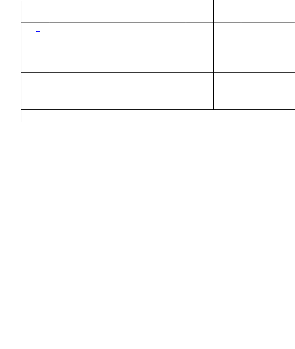
Alarms in Linux Media Servers
Issue 1 June 2005 51
Alarm Log Entries
Notes:
a. Event ID #2 Test failed — Error counter query for single-bit EDC (bad error register) on
the SDRAM is pegging. If the test detects 20 consecutive failures, the following Warning
alarm is logged:
#1,ACT,[DAJ1|DAL1],A,2,WRN,Single-bit EDC test (bad SB err count)
b. Event ID #3 SDRAM has multiple bit errors — The [DAJ1|DAL1] board can also
generate this event as an in-line error.
If this test detects a failure, the media server’s state of health is lowered to its most
critical level, and the following Major alarm is logged:
#1,ACT,[DAJ1|DAL1],A,3,MAJ, SDRAM multibit errors
c. Event ID #4 Looparound test failed — Either a mismatched address or a mismatched bit
pattern could have caused a failure.
If this test detects 3 failures, the following Minor alarm is logged:
#1,ACT,[DAJ1|DAL1],A,4,MIN,Local Looparound test failure
d. Event ID #5 Optical Line Receiver experiencing CRC errors — If this test detects 3
failures, the following Minor alarm is logged:
#1,ACT,[DAJ1|DAL1],A,5,MIN,Link Receiver CRC errors
e. Event ID #6 Inability to open a communications link with the Duplication Memory board.
The board is out of service if this failure occurs once, and a Major alarm is logged:
#1,ACT,[DAJ1|DAL1],A,6,MAJ,Failed to open [DAJ1|DAL1] card
Table 10: DAJ1/DAL1 Alarm Log Entries
EVENT
ID#
Associated Test Alarm
Level
On/Off
Board
Linux Test to
Clear Value
2 (a) Read Error Register test (EDC single-bit
errors)
WRN ON testdupboard
3 (b) Read Error Register test (SDRAM multibit
errors)
MAJ ON testdupboard
4 (c) DAJ1/DAL1 Local Looparound test MIN ON testdupboard
5 (d) Read Error Register test (Link Receiver CRC
errors)
MIN ON testdupboard
6 (e) Read Error Register test (Link Receiver CRC
errors)
MAJ ON testdupboard

Server Alarms
52 Maintenance Procedures for Avaya Communication Manager 3.0, Media Gateways and Servers
System Technician-Demanded Tests:
Descriptions and Error Codes
Investigate tests in the order shown in. By clearing error codes associated with the first test, you
may clear errors generated from other tests in the sequence.
Read Error Register Test
The Read Error Register test queries three registers including the:
●Optical line receiver’s CRC error register
CRC errors indicate problems with the optical interface between the active and standby
servers.
●SDRAM’s single-bit error register
Although the Duplication Memory board can “self heal” single-bit errors in the SDRAM’s
error register, chronic problems can indicate a more serious problem.
●SDRAM’s multiple-bit error register
An SDRAM multiple-bit error condition indicates a problem in the Duplication Memory
board’s memory, and cannot be recovered.
The following errors can be detected:
Order of Investigation Short Test
Sequence
Long Test
Sequence
D/ND1
1. D = Destructive; ND = Nondestructive
Read Error Register test X X D
[DAJ1|DAL1] Board Local Loop test X X D

Alarms in Linux Media Servers
Issue 1 June 2005 53
[DAJ1|DAL1] Local Loop Test
Note:
Note: This is an on-demand test that only runs on the standby media server when it is
busied out.
This test runs a local loop-around test on the standby media server’s [DAJ1|DAL1] board. A
32-bit data number is written to an address and verified for correct transmission. The test
reads the contents of the:
●Last data received registers
●Last address received register
and then compares the data. If the data matches, the test passes. If not, the test fails.
The following errors can be detected:
Table 11: TEST Read Error Register Test
Error Code Test
Result
Description / Recommendation
Open failed
to MDD
ABRT The Memory Duplication Driver (MDD) is the system driver that
communicates with the [DAJ1|DAL1] board. If this driver cannot be
opened, then the [DAJ1|DAL1] board’s registers cannot be read.
1. This is a system type error, try again.
System Error
–
MDD failed
to
return data
ABRT The test ran, but, for some reason the MDD could not return data.
1. This is a system type error, try again.
[DAJ1|DAL1]
err count
query,
code=?
?= 1 to 7
FAIL Test failed “[DAJ1|DAL1] err count query, code=?” — where “?”
indicates which of the [DAJ1|DAL1] board’s error counters had
positive data. The failure code can be 1–7 and is determined by the
bit vector, “0xxx”. (Every “x” bit could be set, indicating that every
error register had errors.) Specifically, if bit:
1 is set (0xx1) – Single-bit errors occurred.
2 is set (0x1x) – CRC errors occurred.
3 is set (01xx) – Multibit errors occurred.

Server Alarms
54 Maintenance Procedures for Avaya Communication Manager 3.0, Media Gateways and Servers
Back to: Hardware MOs Server-related alarms
DAJ1/DAL1 Alarms in S8700 Media Server
S8700 | 8710 only
Table 13: DAJ1/DAL1 Alarms in Media Server on page 54 describes the Duplication Memory
card MO’s alarms and their troubleshooting procedures.
Table 12: TEST DAJ1/DAL1 Local Loop Test
Error Code Test Result Description / Recommendation
Open failed
to MDD
ABRT The MDD is the system driver that communicates with the
Duplication Memory board. If this driver cannot be opened, the
board’s registers cannot be read.
This is a system type error, try again.
System Error
MDD failed
to return
data
ABRT The test ran, but for some reason the MDD could not return
data.
This is a system type error, try again.
Loop-around
test failed
FAIL The last address received does not match the address that was
written, or the last data received does not match the data that
was written.
Table 13: DAJ1/DAL1 Alarms in Media Server
Event
ID
Alarm
Level
Alarm Text, Cause/Description, Recommendation
2 WRN “Single-bit EDC test (bad SB err cnt)” — Single-bit SDRAM error occurred
20 times.
Software automatically clears the single-bit error register. This is a
log-only indication of the error’s occurrence.
1. Manually clear the alarm, either from the:
- Web interface, by selecting Alarms and Notification, the
appropriate alarm, and Clear
- Linux command line, by entering almclear -n #id
1 of 2

Alarms in Linux Media Servers
Issue 1 June 2005 55
Back to: Hardware MOs Server-related alarms
3 MAJ “Multibit EDC Test (bad err register)” — Catastrophic multibit SDRAM
error occurred. (Usually due to a hardware problem.)
1. Enter testdupboard on the Linux command line.
2. If the test fails, escalate this problem for explicit guidance with Steps
3 through 5.
3. Power-cycle the server.
4. Enter testdupboard again.
5. If the test still fails, replace the server.
4 MIN “Local-loop failure” — On-demand local-loop test failed 3 times. (Cannot
read from or write to DAJ1|DAL1 buffers.)
The Localloop test only runs on a busied-out standby server.
1. If the on-demand test is failing (but a running duplicated system has
no problems), do nothing.
If the running duplicated system has problems, continue with Step 2
2. Enter testdupboard on the Linux command line.
3. If the test fails, escalate this problem for explicit guidance with Steps
4 through 6.
4. Power-cycle the server.
5. Enter testdupboard again.
6. If the test still fails, replace the server.
5 MIN “Optical link received CRC errors” — Received multiple CRC errors
across the fiber link.
1. Run testdupboard on both servers.
2. If CRC errors are occurring on both servers, it may be a:
●Likely problem with the fiber link
●Far less likely problem with both Duplication Memory cards
If not, the other server’s Duplication Memory card may be faulty.
3. If the running system has duplication-related problems, escalate this
problem to replace the server.
If not, ignore the alarm.
Table 13: DAJ1/DAL1 Alarms in Media Server (continued)
Event
ID
Alarm
Level
Alarm Text, Cause/Description, Recommendation
2 of 2

Server Alarms
56 Maintenance Procedures for Avaya Communication Manager 3.0, Media Gateways and Servers
DUP (Duplication Manager)
S8700 | 8710 only
The Duplication Manager process, via coordination of the Arbiter process, runs on each S8700
Media Server to control data shadowing between them.
At the physical and data-link layers, an Ethernet-based duplication link provides a TCP
communication path between each server’s Duplication Manager to enable their control of data
shadowing.
Table 14: DUP Alarms in Media Server on page 57 describes the Duplication Manager’s
alarms and their troubleshooting procedures.
See ARB (Arbiter) on page 37 and DAJ1/DAL1 (Duplication Memory Board) on page 49 for
more information.

Alarms in Linux Media Servers
Issue 1 June 2005 57
Table 14: DUP Alarms in Media Server
Event
ID
Alarm
Level
Alarm Text, Cause/Description, Recommendation
1 MAJ “Duplication card error” — Duplication Manager determined that the
duplication card is not functioning, but it cannot distinguish between a bad
card, an unplugged card, or a bad fiber link.
1. Check the physical fiber connectivity at each server.
2. Verify the alarm, by accessing the trace log, either from the:
●Web interface, by:
a. Selecting the View System Logs diagnostic and Logmanager
Debug trace
b. Specifying the Event Range for the appropriate time frame
c. Matching the “dup” pattern
●Linux command line, by entering logv -t ts
3. Examine the trace-log query’s output for one of these messages:
“glbi: couldn't open Dup Card, errno=<#>. ndm exiting”
“glbi: mmap failed, errno=<#>. ndm exiting”
“Haven't heard from active dupmgr. Dup fiber link down.”
“san_check_rsp() FAILED: Dup Fiber link down.”
4. See if the dup link is both “up” and “refreshed”, either from the:
●Web interface’s Server section, by selecting View Summary
Status
●Linux command line, by entering the server command
5. If so, manually clear the alarm, either from the:
●Web interface, by selecting Alarms and Notification, the
appropriate alarm, and Clear
●Linux command line, by entering almclear -n #id
1 of 3

Server Alarms
58 Maintenance Procedures for Avaya Communication Manager 3.0, Media Gateways and Servers
1
(cont’d)
MAJ If not and at the customer’s convenience:
Since the following commands cause a brief service outage, they should
only be executed at the customer’s convenience.
a. Force a server interchange to make the suspected server standby,
either from the Linux command line, by entering server -if.
b. Busy out the standby server from the Linux command line, by
entering server -b.
c. Reboot the standby server, either from the:
- Web interface, by selecting Release Server
- Linux command line, by entering server -r
6. If the problem persists, you can try:
a. Replacing the fiber between the two servers
b. Rebooting the standby server
7. If the problem continues to persist, escalate for a probable server
replacement.
2 MAJ “Duplication link down” — One server’s Duplication Manager cannot
communicate with the other server’s Duplication Manager.
1. Access the trace log, either from the:
- Web interface, by:
a. Selecting the View System Logs diagnostic and Logmanager
Debug trace
b. Specifying the Event Range for the appropriate time frame
c. Matching the “dup” pattern
- Linux command line, by entering logv -t ts
2. Examine the trace-log query’s output for one of these messages:
“mainlp: get_addrs returned ***. Could not get IP address for other
server.
Verify name and address in servers.conf. ndm exiting.”
“san_check_msg() sync_msg failed: DUPLINK DOWN.”
Table 14: DUP Alarms in Media Server (continued)
Event
ID
Alarm
Level
Alarm Text, Cause/Description, Recommendation
2 of 3

Alarms in Linux Media Servers
Issue 1 June 2005 59
Back to: Hardware MOs Server-related alarms
2
(cont’d)
MAJ 3. See if the dup link is “up”, either from the:
- Web interface’s Server section, by selecting View Summary
Status
- Linux command line, by entering the server command
4. If so, manually clear the alarm, either from the:
- Web interface, by selecting Alarms and Notification, the
appropriate alarm, and Clear
- Linux command line, by entering almclear -n #id
If not, check the duplication interface’s Ethernet connectivity, either
from the:
- Web interface, by selecting the Execute Pingall diagnostic
- Linux command line, by entering pingall -d
5. If pingall passes, check the other server’s applications, either from
the:
- Web interface, by selecting View Process Status
- Linux command line, by entering statapp
Table 14: DUP Alarms in Media Server (continued)
Event
ID
Alarm
Level
Alarm Text, Cause/Description, Recommendation
3 of 3

Server Alarms
60 Maintenance Procedures for Avaya Communication Manager 3.0, Media Gateways and Servers
ENV (Environment)
S8700 | 8710 / S8300 / S8500B
The ENV MO monitors environmental variables within the server, including temperature,
voltages, and fans. Table 15: ENV Alarms in Media Server on page 60 describes the ENV
MO’s alarms and their troubleshooting procedures.
Table 15: ENV Alarms in Media Server
Event
ID
Alarm
Level
Alarm Text, Cause/Description, Recommendation
1 MAJ “Temperature reached critical low” — Motherboard's temperature reached
a critically low level.
1. See if the alarmed condition is still present, either from the:
- Web interface, by selecting the View Temperature/Voltage
diagnostic
- Linux command line, by entering environment
2. If not, manually clear the alarm, either from the:
- Web interface, by selecting Alarms and Notification, the
appropriate alarm, and Clear
- Linux command line, by entering almclear -n #id
2 MIN “Temperature reached warning low” — Motherboard's temperature
reached a warning low.
1. See if the alarmed condition is still present, either from the:
- Web interface, by selecting the View Temperature/Voltage
diagnostic
- Linux command line, by entering environment
2. If not, manually clear the alarm, either from the:
- Web interface, by selecting Alarms and Notification, the
appropriate alarm, and Clear
- Linux command line, by entering almclear -n #id
1 of 8

Alarms in Linux Media Servers
Issue 1 June 2005 61
3 MIN “Temperature reached warning high” — Motherboard's temperature
reached a warning high.
1. See if the alarmed condition is still present, either from the:
- Web interface, by selecting the View Temperature/Voltage
diagnostic
- Linux command line, by entering environment
2. If not, manually clear the alarm, either from the:
- Web interface, by selecting Alarms and Notification, the
appropriate alarm, and Clear
- Linux command line, by entering almclear -n #id
4
S8300
MAJ “Temperature reached critical high” — Motherboard's temperature
reached a critically high level.
1. Look for any obstructions blocking the server’s fans.
2. Check for any fan alarms, and clear those alarms.
3. Shut down and restart the system.
4. See if the alarmed condition is still present, either from the:
- Web interface, by selecting the View Temperature/Voltage
diagnostic
- Linux command line, by entering environment
5. If not, manually clear the alarm, either from the:
- Web interface, by selecting Alarms and Notification, the
appropriate alarm, and Clear.
- Linux command line, by entering almclear -n #id
Table 15: ENV Alarms in Media Server (continued)
Event
ID
Alarm
Level
Alarm Text, Cause/Description, Recommendation
2 of 8

Server Alarms
62 Maintenance Procedures for Avaya Communication Manager 3.0, Media Gateways and Servers
6 MAJ “+3.3 voltage reached critical low” — Motherboard's nominal +3.3 voltage
reached a critically low level.
1. See if the alarmed condition is still present, either from the:
- Web interface, by selecting the View Temperature/Voltage
diagnostic
- Linux command line, by entering environment
2. If not, manually clear the alarm, either from the:
- Web interface, by selecting Alarms and Notification, the
appropriate alarm, and Clear
- Linux command line, by entering almclear -n #id
8 MAJ “+3.3 voltage reached critical high” — Motherboard's nominal +3.3 voltage
reached a critically high level.
1. See if the alarmed condition is still present, either from the:
- Web interface, by selecting the View Temperature/Voltage
diagnostic
- Linux command line, by entering environment
2. If not, manually clear the alarm, either from the:
- Web interface, by selecting Alarms and Notification, the
appropriate alarm, and Clear
- Linux command line, by entering almclear -n #id
10 MAJ “+5 voltage reached critical low” — Motherboard's nominal +5 voltage
reached a critically low level.
1. See if the alarmed condition is still present, either from the:
- Web interface, by selecting the View Temperature/Voltage
diagnostic
- Linux command line, by entering environment
2. If not, manually clear the alarm, either from the:
- Web interface, by selecting Alarms and Notification, the
appropriate alarm, and Clear
- Linux command line, by entering almclear -n #id
Table 15: ENV Alarms in Media Server (continued)
Event
ID
Alarm
Level
Alarm Text, Cause/Description, Recommendation
3 of 8

Alarms in Linux Media Servers
Issue 1 June 2005 63
12 MAJ “+5 voltage reached critical high” — Motherboard's nominal +5 voltage
reached a critically high level.
1. See if the alarmed condition is still present, either from the:
- Web interface, by selecting the View Temperature/Voltage
diagnostic
- Linux command line, by entering environment
2. If not, manually clear the alarm, either from the:
- Web interface, by selecting Alarms and Notification, the
appropriate alarm, and Clear
- Linux command line, by entering almclear -n #id
14 MAJ “+12 voltage reached critical low” — Motherboard's nominal +12 voltage
reached a critically low level.
1. See if the alarmed condition is still present, either from the:
- Web interface, by selecting the View Temperature/Voltage
diagnostic
- Linux command line, by entering environment
2. If not, manually clear the alarm, either from the:
- Web interface, by selecting Alarms and Notification, the
appropriate alarm, and Clear
- Linux command line, by entering almclear -n #id
16 MAJ “+12 voltage reached critical high” — Motherboard's nominal +12 voltage
reached a critically high level.
1. See if the alarmed condition is still present, either from the:
- Web interface, by selecting the View Temperature/Voltage
diagnostic
- Linux command line, by entering environment
2. If not, manually clear the alarm, either from the:
- Web interface, by selecting Alarms and Notification, the
appropriate alarm, and Clear
- Linux command line, by entering almclear -n #id
Table 15: ENV Alarms in Media Server (continued)
Event
ID
Alarm
Level
Alarm Text, Cause/Description, Recommendation
4 of 8

Server Alarms
64 Maintenance Procedures for Avaya Communication Manager 3.0, Media Gateways and Servers
18 MAJ “-12 voltage reached critical low” — Motherboard's nominal -12 voltage
reached a critically low level.
1. See if the alarmed condition is still present, either from the:
- Web interface, by selecting the View Temperature/Voltage
diagnostic
- Linux command line, by entering environment
2. If not, manually clear the alarm, either from the:
- Web interface, by selecting Alarms and Notification, the
appropriate alarm, and Clear
- Linux command line, by entering almclear -n #id
20 MAJ “-12 voltage reached critical high” — Motherboard's nominal -12 voltage
reached a critically high level.
1. See if the alarmed condition is still present, either from the:
- Web interface, by selecting the View Temperature/Voltage
diagnostic
- Linux command line, by entering environment
2. If not, manually clear the alarm, either from the:
- Web interface, by selecting Alarms and Notification, the
appropriate alarm, and Clear
- Linux command line, by entering almclear -n #id
22 MAJ “CPU core voltage reached critical low” — Motherboard's CPU core
voltage reached a critically low level.
1. See if the alarmed condition is still present, either from the:
- Web interface, by selecting the View Temperature/Voltage
diagnostic
- Linux command line, by entering environment
2. If not, manually clear the alarm, either from the:
- Web interface, by selecting Alarms and Notification, the
appropriate alarm, and Clear
- Linux command line, by entering almclear -n #id
Table 15: ENV Alarms in Media Server (continued)
Event
ID
Alarm
Level
Alarm Text, Cause/Description, Recommendation
5 of 8

Alarms in Linux Media Servers
Issue 1 June 2005 65
24 MAJ “CPU core voltage reached critical high” — Motherboard's CPU core
voltage reached a critically high level.
1. See if the alarmed condition is still present, either from the:
- Web interface, by selecting the View Temperature/Voltage
diagnostic
- Linux command line, by entering environment
2. If not, manually clear the alarm, either from the:
- Web interface, by selecting Alarms and Notification, the
appropriate alarm, and Clear
- Linux command line, by entering almclear -n #id
26 MAJ “CPU I/O voltage reached critical low” — Motherboard's CPU I/O voltage
reached a critically low level.
1. See if the alarmed condition is still present, either from the:
- Web interface, by selecting the View Temperature/Voltage
diagnostic
- Linux command line, by entering environment
2. If not, manually clear the alarm, either from the:
- Web interface, by selecting Alarms and Notification, the
appropriate alarm, and Clear
- Linux command line, by entering almclear -n #id
28 MAJ “CPU I/O voltage reached critical high” — Motherboard's CPU I/O voltage
reached a critically high level.
1. See if the alarmed condition is still present, either from the:
- Web interface, by selecting the View Temperature/Voltage
diagnostic
- Linux command line, by entering environment
2. If not, manually clear the alarm, either from the:
- Web interface, by selecting Alarms and Notification, the
appropriate alarm, and Clear
- Linux command line, by entering almclear -n #id
Table 15: ENV Alarms in Media Server (continued)
Event
ID
Alarm
Level
Alarm Text, Cause/Description, Recommendation
6 of 8

Server Alarms
66 Maintenance Procedures for Avaya Communication Manager 3.0, Media Gateways and Servers
29 MAJ “All fan failure” — Every fan is running at a critically low speed.
1. See if the alarmed condition is still present, either from the:
- Web interface, by selecting the View Temperature/Voltage
diagnostic
- Linux command line, by entering environment
2. If not, manually clear the alarm, either from the:
- Web interface, by selecting Alarms and Notification, the
appropriate alarm, and Clear
- Linux command line, by entering almclear -n #id
31
S8500B
MAJ +1.5V under voltage. S8500B media server environment.
1. See if the alarmed condition is still present, either from the:
- Web interface, by selecting the View Temperature/Voltage
diagnostic
- Linux command line, by entering environment
2. If not, manually clear the alarm, either from the:
- Web interface, by selecting Alarms and Notification, the
appropriate alarm, and Clear
- Linux command line, by entering almclear -n #id
33
S8500B
MAJ +1.5V over voltage. S8500B media server environment.\
1. See if the alarmed condition is still present, either from the:
- Web interface, by selecting the View Temperature/Voltage
diagnostic
- Linux command line, by entering environment
2. If not, manually clear the alarm, either from the:
- Web interface, by selecting Alarms and Notification, the
appropriate alarm, and Clear
- Linux command line, by entering almclear -n #id
Table 15: ENV Alarms in Media Server (continued)
Event
ID
Alarm
Level
Alarm Text, Cause/Description, Recommendation
7 of 8

Alarms in Linux Media Servers
Issue 1 June 2005 67
Back to: Hardware MOs Server-related alarms
FSY (File Synchronization)
S8700 | 8710 / S8500
The File Synchronization (FSY) process uses TCP-based communication over 100Base-T
Ethernet links to provide synchronized duplication of critical data-shadowed files, including
translations and important Linux files.
Note:
Note: This set of files is separate from the data shadowed between each server’s
DAJ1/DAL1 (Duplication Memory Board) on page 49.
35
S8500B
MAJ +2.5V under voltage. S8500B media server environment.
1. See if the alarmed condition is still present, either from the:
- Web interface, by selecting the View Temperature/Voltage
diagnostic
- Linux command line, by entering environment
2. If not, manually clear the alarm, either from the:
- Web interface, by selecting Alarms and Notification, the
appropriate alarm, and Clear
- Linux command line, by entering almclear -n #id
37
S8500B
MAJ +2.5V over voltage. S8500B media server environment.
1. See if the alarmed condition is still present, either from the:
- Web interface, by selecting the View Temperature/Voltage
diagnostic
- Linux command line, by entering environment
2. If not, manually clear the alarm, either from the:
- Web interface, by selecting Alarms and Notification, the
appropriate alarm, and Clear
- Linux command line, by entering almclear -n #id
Table 15: ENV Alarms in Media Server (continued)
Event
ID
Alarm
Level
Alarm Text, Cause/Description, Recommendation
8 of 8

Server Alarms
68 Maintenance Procedures for Avaya Communication Manager 3.0, Media Gateways and Servers
Table 16: FSY Alarm in Media Server on page 68 describes the FSY MO’s alarms and their
troubleshooting procedures.
Back to: Hardware MOs Server-related alarms
Table 16: FSY Alarm in Media Server
Event
ID
Alarm
Level
Alarm Text, Cause/Description, Recommendation
1 MIN “File sync failed” — File synchronization operation failed.
1. See if the filesyncd (file sync daemon) process is up, either from the:
- Web interface, by selecting View Process Status
- Linux command line, by entering statapp
2. Check the trace log for more granular information. (The file sync
daemon can report failures of synchronizing one or more files.)
Access the trace log, either from the:
- Web interface, by:
a. Selecting the View System Logs diagnostic and Logmanager
Debug trace
b. Specifying the Event Range for the appropriate time frame
c. Matching the “file sync failed” pattern
- Linux command line, by entering logv -t ts
3. (Except S8500) Verify that the dup link is both “up” and “refreshed”,
either from the:
●Web interface’s Server section, by selecting View Summary Status
●Linux command line, by entering the server command
(Neither side should be “off-line” nor “down”.)
4. (Except S8500) Make sure that the Ethernet duplication link is up, either
from the:
- Web interface, by selecting the Execute Pingall diagnostic
- Linux command line, by entering pingall -a
If not, check each side of this failed link, and make any necessary
repairs.
5. (Except S8500) Check the physical fiber connectivity at each server to
verify that this alarm is not a consequence of other duplication-related
problems.
6. If the problem persists, escalate the problem.

Alarms in Linux Media Servers
Issue 1 June 2005 69
HDD (Hard Disk Drive)
The HDD MO monitors the hard drive via the Self Monitoring, Analysis, and Reporting
Technology (S.M.A.R.T) capability that is built into the hard disk drive unit. The integrated
controller for the hard disk drive works with sensors incorporated in the hard drive to monitor the
drive’s performance. The SMART technology makes status information concerning the disk
drive available to monitoring software.
The basic concept with SMART is that some hard disk drive problems do not occur suddenly.
They are the result of a gradual degradation of disk components. For example, if the value for
Reallocated Event Count (count of remap operations, both successful and non-successful) for
Event ID 21 is going up it may indicate an impending disk failure. At the very least it should be
monitored closely.
Table 17: HDD Alarm in Media Server on page 69 describes the HDD Event IDs and their
troubleshooting procedures.
Table 17: HDD Alarm in Media Server
Event
ID
Alarm
Level
Alarm Text, Cause/Description, Recommendation
19 WRN Device: device_name, Failed attribute: attr_number
This message indicates that the attribute value has exceeded its threshold
value.
1. If posted, user very likely has a drive problem and should definitely
consider replacing the drive.
20 WRN smartd: Device: device_name, Read Smartd Values Failed
smartd: Device: device_name, Read Smartd Threshold Failed
This message indicates the SMART utility was unable to read the current
SMART values or thresholds for the drive. This may result in SMART not
executing and the values that are reported may be stale (or outdated). See
also Event ID 22.
21 WRN smartd: Device: /dev/had, S.M.A.R.T. Attribute: attr_number Changed
chng_value.
The value for the specified attribute number (attr_number) has changed by
the specified value (chng_value). Posting of this alarm may/may not
indicate possible drive problems.
Definitions for the attributes are:
1 of 4

Server Alarms
70 Maintenance Procedures for Avaya Communication Manager 3.0, Media Gateways and Servers
21
(cont’d)
Num Name Description
1 Raw Read Error Indicates the rate of hardware read errors
that occur when reading data from the
disk surface. This error is critical. An
increasing error rate may indicate a
failing disk drive. (Samsung, Seagate,
IBM (Hitachi), Fujitsu, Maxtor, Western
Digital)
2 Throughput
Performance
Overall throughput performance of the
hard disk.
3 Spin Up Time Raw value average of time to spin up
drive spindle. (Samsung, Seagate, IBM
(Hitachi), Fujitsu, Maxtor, Western Digital)
4 Start Stop Count Count of hard disk spindle start/stop
cycles. (Samsung, Seagate, IBM
(Hitachi), Fujitsu, Maxtor, Western Digital)
5 Reallocated Sector
Count
Amount of remapped sectors.
6 Read Channel Margin No explanation of attribute available
7 Seek Error Rate Average rate of seek errors: if this value
continues to increase it indicates there
may be a problem with the disk surface or
a mechanical problem. (Samsung,
Seagate, IBM (Hitachi), Fujitsu, Maxtor,
Western Digital)
8 Seek Time Performance Disk seek system performance.
(Samsung, Seagate, IBM (Hitachi),
Fujitsu, Maxtor, Western Digital)
9 Power_On_Hours Number of hours of the power-on state of
the drive. This value indicates aging.
(Samsung, Seagate, IBM (Hitachi),
Fujitsu, Maxtor, Western Digital)
10 Spin_Retry_Count Count of retry of drive spindle spine start
up attempts. (Samsung, Seagate, IBM
(Hitachi), Fujitsu, Maxtor, Western Digital)
Table 17: HDD Alarm in Media Server (continued)
Event
ID
Alarm
Level
Alarm Text, Cause/Description, Recommendation
2 of 4

Alarms in Linux Media Servers
Issue 1 June 2005 71
21
(cont’d)
11 Recalibration Retries Number of times recalibration was
requested after initial request. (Samsung,
Seagate, IBM (Hitachi), Fujitsu, Maxtor,
Western Digital)
12 Device Power Cycle
Count
Count of full hard disk power on/off
cycles. (Samsung, Seagate, IBM
(Hitachi), Fujitsu, Maxtor, Western Digital)
13 Soft Read Error Rate Rate of program read errors when
reading data from disk. (Samsung,
Seagate, IBM (Hitachi), Fujitsu, Maxtor,
Western Digital)
193 Load/Unload Cycle Count of load/unload cycles into landing
zone position. (Samsung, Seagate, IBM
(Hitachi), Fujitsu, Maxtor, Western Digital)
194 Temperature Hard disk drive temperature. (Samsung,
Seagate, IBM (Hitachi), Fujitsu, Maxtor,
Western Digital - select models)
196 Reallocated Event
Count
Count of remap operations (transferring
of data from bad sector to reserved disk
area) successful and non-successful.
This error is critical. An increasing
count for this error may indicate a
failing disk drive. (Samsung, Seagate,
IBM (Hitachi), Fujitsu, Maxtor, Western
Digital - select models)
197 Current Pending Sector
Count
Current count of unstable sectors (waiting
for remap). This error is critical. An
increasing count for this error may
indicate a failing disk drive. (Samsung,
Seagate, IBM (Hitachi), Fujitsu, Maxtor,
Western Digital)
198 Uncorrectable Sector
Count
Count of uncorrectable errors when
reading/writing a sector. This error is
critical. An increasing count for this
error may indicate a failing disk drive.
(Samsung, Seagate, IBM (Hitachi),
Fujitsu, Maxtor, Western Digital)
Table 17: HDD Alarm in Media Server (continued)
Event
ID
Alarm
Level
Alarm Text, Cause/Description, Recommendation
3 of 4

Server Alarms
72 Maintenance Procedures for Avaya Communication Manager 3.0, Media Gateways and Servers
21
(cont’d)
199 UltraDMA CRC Error
Count
Count of Cyclic Redundancy Check
(CRC) errors during UltraDMA mode
(Samsung, Seagate, IBM (Hitachi),
Fujitsu - select models, Maxtor, Western
Digital - select models)
200 Write Error Rate (Multi
Zone Error Rate
Total number of errors found when writing
a sector. (Samsung, Seagate, IBM
(Hitachi), Fujitsu, Maxtor, Western Digital)
220 Disk Shift Indicates how much the disk has shifted
(unit of measure unknown). This error is
critical. An increasing value for this
error may indicate a failing disk drive.
(Seagate)
221 G-Sense Error Rate Rate of errors occurring as a result of
impact loads such as dropping the drive,
wrong installation, etc. (Seagate, Hitachi)
222 Loaded Hours Loading on magnetic heads actuator
caused by the general operating time.
223 Load/Unload Retry
Count
Loading on magnetic heads actuator
caused by numerous recurrences of
operations like: reading, recording,
positioning, etc.
224 Load Friction Loading of magnetic heads actuator
caused by friction in mechanical part of
the store.
226 Load-in Time Total time of loading on the magnetic
heads actuator.
227 Torque Amplification
Count
Count of efforts of the rotating moment of
a drive
228 Power-Off Retract
Count
Count of the number of times the drive
was powered off.
230 GMR Head Amplitude Amplitude of the heads trembling in
running mode.
22 WRN Failed to read smart values/thresholds
This indicates that the smart utility was not able to read the smart values/
thresholds from the drive. The smart utility is unable to function due to drive
access problems.
Table 17: HDD Alarm in Media Server (continued)
Event
ID
Alarm
Level
Alarm Text, Cause/Description, Recommendation
4 of 4

Alarms in Linux Media Servers
Issue 1 June 2005 73
KRN (Kernel)
S8700 | 8710
The KRN MO monitors the operating system Kernel. Table 18: KRN Alarm in Media Server on
page 73 describes the MO’s alarms and their troubleshooting procedures.
Back to: Hardware MOs Server-related alarms
Table 18: KRN Alarm in Media Server
Event
ID
Alarm
Level
Alarm Text, Cause/Description, Recommendation
10 MAJ Failure in a Synchronous Dynamic Random Access Memory (SDRAM)
Dual Inline Memory Module (DIMM). Error Correcting Code (ECC) memory
detected a multi-bit error (MBE) but cannot correct it.
1. The SDRAM DIMM within the media server is not field replaceable.
Replace the media server.

Server Alarms
74 Maintenance Procedures for Avaya Communication Manager 3.0, Media Gateways and Servers
Login Alarms
The Login MO monitors access to the server and alarms suspicious activity. Table 19: Login
Alarms in Media Server on page 74 describes the Login MO’s alarms and their troubleshooting
procedures.
Table 19: Login Alarms in Media Server
Event
ID
Alarm
Level
Alarm Text, Cause/Description, Recommendation
2 WRN “sat_Auth:Login for [inads] invalid password” — An SAT login to
Communication Manager failed.
1. Verify the alarm, either from the:
- Web interface, by selecting View Current Alarms
- Linux command line, by entering almdisplay -v
2. Since mis-typing a login sequence usually causes this alarm, enter
almclear -n #id to clear the alarm.
3. If this alarm is perceived as a security threat (often due to its
persistence or frequent recurrence), notify the customer.
4 WRN “Login for [inads] – failed – password check” — A login to a server’s Linux
command line failed.
1. Verify the alarm, either from the:
- Web interface, by selecting View Current Alarms
- Linux command line, by entering almdisplay -v
2. Since mis-typing a login sequence usually causes this alarm, enter
almclear -n #id to clear the alarm.
3. If this alarm is perceived as a security threat (often due to its
persistence or frequent recurrence), notify the customer.
5 MAJ “Probation interval for login [inads] ends – lockout interval begins” —
Multiple consecutive login failures.
1. If this alarm is perceived as a security threat, notify the customer.

Alarms in Linux Media Servers
Issue 1 June 2005 75
NIC (Network Interface Card)
S8700 | 8710 / S8500
This MO supports the NICs in each S8700 media server providing the physical and data-link
interfaces for Ethernet-based links.
Table 20: NIC Alarms in Media Server on page 75 describes NIC’s alarms and their
troubleshooting procedures. See DAJ1/DAL1 (Duplication Memory Board) on page 49 for more
information.
Table 20: NIC Alarms in Media Server
Event
ID
Alarm
Level
Alarm Text, Cause/Description, Recommendation
1 MIN “eth0 NIC Link is Down” — Ethernet link on native NIC 0 is down.
1. Verify Ethernet connectivity, either from the:
- Web interface, by selecting the Execute Pingall diagnostic
- Linux command line, by entering pingall -a
Check both sides of each failed link, and make any necessary repairs.
2. If the ping test fails, check the physical connections of NIC 0’s Ethernet
cable.
If not, manually clear the alarm, either from the:
- Web interface, by selecting Alarms and Notification, the
appropriate alarm, and Clear
- Linux command line, by entering almclear -n #id
1 of 2

Server Alarms
76 Maintenance Procedures for Avaya Communication Manager 3.0, Media Gateways and Servers
Back to: Hardware MOs Server-related alarms
RALM-SVC (Remote Alarm Service)
S8700 | 8710 only
For the RALM-SVC MO, maintenance software performed special periodic testing every 60
seconds.
2 MIN “eth1 NIC Link is Down” — Ethernet link on native NIC 1 is down.
1. Verify Ethernet connectivity, either from the:
- Web interface, by selecting the Execute Pingall diagnostic
- Linux command line, by entering pingall -a
Check both sides of each failed link, and make any necessary repairs.
2. If the ping test fails, check the physical connections of NIC 0’s Ethernet
cable.
If not, manually clear the alarm, either from the:
- Web interface, by selecting Alarms and Notification, the
appropriate alarm, and “Clear”
- Linux command line, by entering almclear -n #id
Table 20: NIC Alarms in Media Server (continued)
Event
ID
Alarm
Level
Alarm Text, Cause/Description, Recommendation
2 of 2
MOs Name Alarm Level Initial Command to Run Full Name of MO
RALM-SVC MAJOR None Remote Alarm Service
RALM-SVC MAJOR None Remote Alarm Service
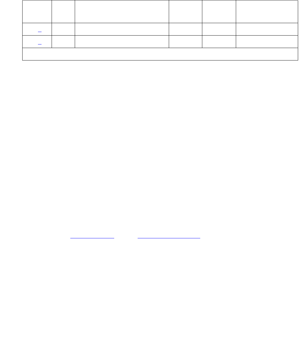
Alarms in Linux Media Servers
Issue 1 June 2005 77
Alarm Log Entries
These tests verify that the standby media server’s components are operating correctly.
Notes:
1. Event ID #1 SME_ARB test failed — This test determines the other server’s alarm-generation
capability by querying the local server’s Arbiter to report on the other server’s Remote
Alarm Service functionality. Both media servers must have their own alarm-generation
utilities. If the test fails 3 consecutive times, the following Major alarm is logged:
#1,ACT,SME,A,1,MAJ,Far-end alarm service is down
2. Event ID #2 Standby_PN_Check test failed — This periodic test:
1. Queries the standby media server about its PNs’ state of health
2. Compares the acquired information to an administered value
A failure indicates that a mismatch occurred and that the standby media server is out of
sync. If this test fails 2 consecutive times, the following Major alarm is logged:
#1,ACT,SME,A,2,MAJ,Standby Port-Network check failed
System Technician-Demanded Tests: Descriptions
and Error Codes
This MO provides no on-demand tests for system technicians.
Back to: Hardware MOs Server-related alarms
Table 21: RALM-SVC Alarm Log Entries
EVENT
ID#
Aux
Data
Associated Test Alarm
Level
On/Off
Board
Linux Test to
Clear Value
1 (1) SME_ARB test MAJOR ON testdupboard
2 (2) Standby_PN Check test MAJOR ON testdupboard

Server Alarms
78 Maintenance Procedures for Avaya Communication Manager 3.0, Media Gateways and Servers
SME Alarm in S8700 Media Server
Table 22: SME Alarm in Media Server on page 78 describes the SME alarm (for RALM-SVC
(Remote Alarm Service) and its troubleshooting procedures.
Back to: Hardware MOs Server-related alarms
Table 22: SME Alarm in Media Server
Event
ID
Alarm
Level
Alarm Text, Cause/Description, Recommendation
1 MAJ “Far-end alarm service is down” — No remote alarm service is available
since the other server is unable to report alarms — due to a failure of either
the GMM or administered reporting mechanisms (SNMP and/or modem).
1. Look for any GMM failures on the other server, either using the:
- Web interface, by selecting Diagnostics > View System Logs and
Watchdog Logs
- Linux command line, by entering logv -w or, directly, by examining
/var/log/ecs/wdlog.
2. If a GMM failure was found:
a. See if the GMM application is up, either from the:
- Web interface, by selecting View Process Status
- Linux command line, by entering statapp
b. If so, continue with Step 3.
If not, try to restart this application by entering start -s GMM on the
Linux command line.
c. If the GMM application successfully restarts, continue with Step 4.
If not, escalate the problem to the next higher tier.
3. If a GMM failure was not found, see if alarm reporting failed by looking in
the trace log for a string that includes “snd2Inads”, either from the:
- Web interface, by:
a. Selecting the View System Logs diagnostic and Logmanager
Debug trace
b. Specifying the “Event Range” for the appropriate time frame
c. Matching the “snd2Inads” pattern
- Linux command line, by entering logv -t ts
4. Test the administered reporting mechanisms, by entering testinads
on the Linux command line.
5. Once the alarm is resolved, manually clear the alarm, either from the:
- Web interface, by selecting Alarms and Notification, the appropriate
alarm, and Clear
- Linux command line, by entering almclear -n #id

Alarms in Linux Media Servers
Issue 1 June 2005 79
SVC_MON (Service Monitor)
S8700 | 8710 / S8500
SVC_MON is a media server process, started by Watchdog, to monitor Linux services and
daemons. It also starts up threads to communicate with a hardware-sanity device.
Table 23: SVC_MON Alarms in Media Server on page 80 describes the SVC_MON MO’s
alarms and their troubleshooting procedures.
For information about Watchdog, see _WD (Watchdog) Alarms on page 99.

Server Alarms
80 Maintenance Procedures for Avaya Communication Manager 3.0, Media Gateways and Servers
Table 23: SVC_MON Alarms in Media Server
Event
ID
Alarm
Level
Alarm Text, Cause/Description, Recommendation
1 MIN “service atd could not be restarted” — The Linux at daemon is down.
Scheduled services such as session cleanup or daily filesync will not work.
1. From the /sbin directory type service atd restart to restart the at
daemon.
2. If the daemon restarts, manually clear the alarm, either from the:
●Web interface, by selecting Alarms and Notification, the
appropriate alarm, and Clear
●Linux command line, by entering almclear -n #id
If not, escalate this problem for explicit guidance with steps 2a through 3
a. Enter grep svc_mon /var/log/messages to investigate why the
daemon failed.
!CAUTION:
CAUTION: Since the following commands cause a brief service outage,
they should only be executed at the customer’s convenience.
b. If the grep command’s output does not help:
●S8700 | 8710: enter server to verify that the suspected server is the
standby. If necessary and at the customer’s convenience, enter
server -if to force a server interchange.
●S8500: Proceed to Step d.
If necessary and at the customer’s convenience, enter server -if to
force a server interchange.
c. S8700 | 8710: Reboot the standby server, either from the:
●Web interface, by selecting Shutdown This Server
●Linux command line, entering /sbin/shutdown -r now
d. S8500: Reboot the server, either from the:
●Web interface, by selecting Shutdown This Server
●Linux command line, entering /sbin/shutdown -r now
3. If rebooting the standby does not help or if the problem recurs, escalate
the problem to the next higher tier.
1 of 8

Alarms in Linux Media Servers
Issue 1 June 2005 81
2 MIN “service crond could not be restarted” — The Linux cron daemon is down.
Periodic services such as session cleanup or daily filesync will not work.
1. Enter /sbin/service cron restart to restart the cron daemon.
2. If the daemon restarts, manually clear the alarm, either from the:
●Web interface, by selecting Alarms and Notification, the
appropriate alarm, and Clear
●Linux command line, by entering almclear -n #id
If not, escalate this problem for explicit guidance with steps 2a through 3
a. Enter grep svc_mon /var/log/messages to investigate why the
daemon failed.
Since the following commands cause a brief service outage, they should only
be executed at the customer’s convenience.
b. If the grep command’s output does not help:
●S8700 | 8710: enter server to verify that the suspected server is the
standby. If necessary and at the customer’s convenience, enter
server -if to force a server interchange.
●S8500: Proceed to Step d.
If necessary and at the customer’s convenience, enter server -if to
force a server interchange.
c. S8700 | 8710: Reboot the standby server, either from the:
●Web interface, by selecting Shutdown This Server
●Linux command line, entering /sbin/shutdown -r now
d. S8500: Reboot the server, either from the:
●Web interface, by selecting Shutdown This Server
●Linux command line, entering /sbin/shutdown -r now
3. If rebooting the standby does not help or if the problem recurs, escalate
the problem to the next higher tier.
Table 23: SVC_MON Alarms in Media Server (continued)
Event
ID
Alarm
Level
Alarm Text, Cause/Description, Recommendation
2 of 8

Server Alarms
82 Maintenance Procedures for Avaya Communication Manager 3.0, Media Gateways and Servers
3 MIN “service inet could not be restarted” — The Linux internet server daemon is
down. Networking services will not work.
1. Enter /sbin/service inet restart to restart the inet daemon.
2. If the daemon restarts, manually clear the alarm, either from the:
- Web interface, by selecting Alarms and Notification, the appropriate
alarm, and Clear
- Linux command line, by entering almclear -n #id
If not, escalate this problem for explicit guidance with steps 2a through
3.
a. Enter grep svc_mon /var/log/messages to investigate why the
daemon failed.
b. If this problem affects call processing, continue with the following
steps now.
If not, continue only at the customer’s convenience – since the
following commands cause a brief service outage.
The following commands cause a brief service outage.
c. If the grep command’s output does not help:
●S8700 | 8710: enter server to verify that the suspected server is the
standby. If necessary and at the customer’s convenience, enter
server -if to force a server interchange.
●S8500: Proceed to Step e.
If necessary and at the customer’s convenience, enter server -if to
force a server interchange.
d. S8700 | 8710: Reboot the standby server, either from the:
●Web interface, by selecting Shutdown This Server
●Linux command line, entering /sbin/shutdown -r now
e. S8500: Reboot the server, either from the:
●Web interface, by selecting Shutdown This Server
●Linux command line, entering /sbin/shutdown -r now
3. If rebooting the standby does not help or if the problem recurs, escalate
the problem to the next higher tier.
Table 23: SVC_MON Alarms in Media Server (continued)
Event
ID
Alarm
Level
Alarm Text, Cause/Description, Recommendation
3 of 8

Alarms in Linux Media Servers
Issue 1 June 2005 83
4 MIN “service syslog could not be restarted” — Linux “syslog” service is down.
Event logging to syslog and alarm generation will fail.
1. Enter /sbin/service syslog restart to restart the syslog service.
2. If the service restarts, manually clear the alarm, either from the:
●Web interface, by selecting Alarms and Notification, the
appropriate alarm, and Clear
●Linux command line, by entering almclear -n #id
If not, escalate this problem for explicit guidance with steps 2a through 3
a. Enter grep svc_mon /var/log/messages to investigate why the
daemon failed.
Since the following commands cause a brief service outage, they should only
be executed at the customer’s convenience.
b. If the grep command’s output does not help:
●S8700 | 8710: enter server to verify that the suspected server is the
standby. If necessary and at the customer’s convenience, enter
server -if to force a server interchange.
●S8500: Proceed to Step d.
If necessary and at the customer’s convenience, enter server -if to
force a server interchange.
c. S8700 | 8710: Reboot the standby server, either from the:
●Web interface, by selecting Shutdown This Server
●Linux command line, entering /sbin/shutdown -r now
d. S8500: Reboot the server, either from the:
●Web interface, by selecting Shutdown This Server
●Linux command line, entering /sbin/shutdown -r now
3. If rebooting the standby does not help or if the problem recurs, escalate
the problem to the next higher tier.
Table 23: SVC_MON Alarms in Media Server (continued)
Event
ID
Alarm
Level
Alarm Text, Cause/Description, Recommendation
4 of 8

Server Alarms
84 Maintenance Procedures for Avaya Communication Manager 3.0, Media Gateways and Servers
5 MIN “service xntpd could not be restarted” — The Linux network time protocol
daemon is down. The server’s clock and recently logged time stamps may
be inaccurate.
1. Enter /sbin/service xntpd restart to restart the xntpd daemon.
2. If the daemon restarts, manually clear the alarm, either from the:
●Web interface, by selecting Alarms and Notification, the
appropriate alarm, and Clear
●Linux command line, by entering almclear -n #id
If not, escalate this problem for explicit guidance with steps 2a through 3
a. Enter grep svc_mon /var/log/messages to investigate why the
daemon failed.
b. If this problem affects call processing, continue with the following
steps now.
If not, continue only at the customer’s convenience – since the
following commands cause a brief service outage.
The following commands cause a brief service outage.
c. If the grep command’s output does not help:
●S8700 | 8710: enter server to verify that the suspected server is the
standby. If necessary and at the customer’s convenience, enter
server -if to force a server interchange.
●S8500: Proceed to Step e.
If necessary and at the customer’s convenience, enter server -if to
force a server interchange.
d. S8700 | 8710: Reboot the standby server, either from the:
●Web interface, by selecting Shutdown This Server
●Linux command line, entering /sbin/shutdown -r now
e. S8500: Reboot the server, either from the:
●Web interface, by selecting Shutdown This Server
●Linux command line, entering /sbin/shutdown -r now
3. If rebooting the standby does not help or if the problem recurs, escalate
the problem to the next higher tier.
Table 23: SVC_MON Alarms in Media Server (continued)
Event
ID
Alarm
Level
Alarm Text, Cause/Description, Recommendation
5 of 8

Alarms in Linux Media Servers
Issue 1 June 2005 85
6 MIN “service dbgserv could not be restarted” — Debug server is down, and
Gemini debugger may not work. Although losing this service does not affect
operations, the debugging of a running system is prevented.
1. Enter /sbin/service dbgserv restart to restart the dbgserv
service.
2. If the service restarts, manually clear the alarm, either from the:
●Web interface, by selecting Alarms and Notification, the
appropriate alarm, and Clear
●Linux command line, by entering almclear -n #id
If not, escalate this problem for explicit guidance with steps 2a through 3
a. Enter grep svc_mon /var/log/messages to investigate why the
daemon failed.
Since the following commands cause a brief service outage, they should only
be executed at the customer’s convenience.
b. If the grep command’s output does not help:
●S8700 | 8710: enter server to verify that the suspected server is the
standby. If necessary and at the customer’s convenience, enter
server -if to force a server interchange.
●S8500: Proceed to Step d.
If necessary and at the customer’s convenience, enter server -if to
force a server interchange.
c. S8700 | 8710: Reboot the standby server, either from the:
●Web interface, by selecting Shutdown This Server
●Linux command line, entering /sbin/shutdown -r now
d. S8500: Reboot the server, either from the:
●Web interface, by selecting Shutdown This Server
●Linux command line, entering /sbin/shutdown -r now
3. If rebooting the standby does not help or if the problem recurs, escalate
the problem to the next higher tier.
Table 23: SVC_MON Alarms in Media Server (continued)
Event
ID
Alarm
Level
Alarm Text, Cause/Description, Recommendation
6 of 8

Server Alarms
86 Maintenance Procedures for Avaya Communication Manager 3.0, Media Gateways and Servers
7 MIN “service prune could not be restarted” — The prune service is not running.
The hard disk’s partition usage is not being monitored or cleaned.
1. Enter /sbin/service prune restart to restart the prune service.
2. If the service restarts, manually clear the alarm, either from the:
●Web interface, by selecting Alarms and Notification, the
appropriate alarm, and Clear
●Linux command line, by entering almclear -n #id
If not, escalate this problem for explicit guidance with steps 2a through 3
a. Enter grep svc_mon /var/log/messages to investigate why the
daemon failed.
b. If this problem affects call processing, continue with the following
steps now.
If not, continue only at the customer’s convenience – since the
following commands cause a brief service outage.
The following commands cause a brief service outage.
c. If the grep command’s output does not help:
●S8700 | 8710: enter server to verify that the suspected server is the
standby. If necessary and at the customer’s convenience, enter
server -if to force a server interchange.
●S8500: Proceed to Step e.
If necessary and at the customer’s convenience, enter server -if to
force a server interchange.
d. S8700 | 8710: Reboot the standby server, either from the:
●Web interface, by selecting Shutdown This Server
●Linux command line, entering /sbin/shutdown -r now
e. S8500: Reboot the server, either from the:
●Web interface, by selecting Shutdown This Server
●Linux command line, entering /sbin/shutdown -r now
3. If rebooting the standby does not help or if the problem recurs, escalate
the problem to the next higher tier.
Table 23: SVC_MON Alarms in Media Server (continued)
Event
ID
Alarm
Level
Alarm Text, Cause/Description, Recommendation
7 of 8

Alarms in Linux Media Servers
Issue 1 June 2005 87
Back to: Hardware MOs Server-related alarms
8 MIN “service httpd could not be restarted” — The hypertext transfer protocol
daemon is down. The Web interface will not work.
1. Enter /sbin/service httpd restart to restart the http daemon.
2. If the daemon restarts, manually clear the alarm, either from the:
●Web interface, by selecting Alarms and Notification, the
appropriate alarm, and Clear
●Linux command line, by entering almclear -n #id
If not, escalate this problem for explicit guidance with steps 2a through 3
a. Enter grep svc_mon /var/log/messages to investigate why the
daemon failed.
Since the following commands cause a brief service outage, they should only
be executed at the customer’s convenience.
b. If the grep command’s output does not help:
●S8700 | 8710: enter server to verify that the suspected server is the
standby. If necessary and at the customer’s convenience, enter
server -if to force a server interchange.
●S8500: Proceed to Step d.
If necessary and at the customer’s convenience, enter server -if to
force a server interchange.
c. S8700 | 8710: Reboot the standby server, either from the:
●Web interface, by selecting Shutdown This Server
●Linux command line, entering /sbin/shutdown -r now
d. S8500: Reboot the server, either from the:
●Web interface, by selecting Shutdown This Server
●Linux command line, entering /sbin/shutdown -r now
3. If rebooting the standby does not help or if the problem recurs, escalate
the problem to the next higher tier.
Table 23: SVC_MON Alarms in Media Server (continued)
Event
ID
Alarm
Level
Alarm Text, Cause/Description, Recommendation
8 of 8

Server Alarms
88 Maintenance Procedures for Avaya Communication Manager 3.0, Media Gateways and Servers
_TM (Translation Manager)
S8700 | 8710 / S8500 / S8300
The _TM MO is an S8700 Media Server that monitors the server’s ability to read
Communication Manager translations. Table 24: TM Alarm in Media Server on page 88
describes the _TM MO’s alarm and its troubleshooting procedures.
Back to: Hardware MOs Server-related alarms
Table 24: TM Alarm in Media Server
Event
ID
Alarm
Level
Alarm Text, Cause/Description, Recommendation
1 MAJ “Cannot read translations” — Server could not read translations. Usually,
indicates a failure loading translations, but can also infrequently occur on a
running system.
S8700 | 8710: The servers spontaneously interchange.
S8500: The server reboots.
1. Check the integrity of the translation files xln1 and xln2 in /etc/opt/defty,
and verify that they are of the same non-zero length.
2. From the /etc/opt/defty directory enter the Linux command cksum
xln1 xln2 to verify that the checksum of the files are identical.
3. S8700 | 8710: Copy the translation files from the backup or the other
server.
4. S8500: Copy the translation files from the backup.
5. If Steps 1 to 3 do not help, load the system with null translations.
6. If the system comes up, this is probably a translation problem.
If not, escalate the problem.
7. Once resolved, manually clear the alarm, either from the:
- Web interface, by selecting Alarms and Notification, the
appropriate alarm, and Clear
- Linux command line, by entering almclear -n #id

Alarms in Linux Media Servers
Issue 1 June 2005 89
UPS (Uninterruptible Power Supply)
S8700 | 8710 / S8500 / S8300
The UPS MO supports the UPS device for each media server. This MO’s maintenance software
reacts to UPS-generated in-line errors via SNMP traps.
Note:
Note: This MO provides no periodic or on-demand tests.
UPS Traps to Media Server
Table 25: Enterprise-Specific UPS Traps to Server on page 89 contains the various
UPS-generated SNMP traps to the media server.
Table 25: Enterprise-Specific UPS Traps to Server
SNMP Trap from UPS Event
ID
Definition of Trap
Trap (1) #6
(1–8)
Alarm string = #1, ACT, UPS, A, 6, MAJ, power failure:
Shutting down in 6 minutes.
If the Event ID is 6, the UPS battery’s power is in a
critically low condition, with an estimated 6 minutes of
remaining holdover.
●A warning is written to every logged-in user of the
server.
●When 6 minutes elapse, the server begins shutting
down.
(For troubleshooting procedures, see Events #1–8 on
page 92)
Trap (1) #7
(1–8)
Alarm string = #1, ACT, UPS, A, 7, MAJ, power failure:
Shutting down in 7 minutes.
The UPS battery’s power is in a critically low condition,
with an estimated 7 minutes of remaining holdover.
●A warning is written to every logged-in user of the
server.
●When 7 minutes elapse, the server begins shutting
down.
(For troubleshooting procedures, see Events #1–8 on
page 92)
1 of 4

Server Alarms
90 Maintenance Procedures for Avaya Communication Manager 3.0, Media Gateways and Servers
Trap (1) #8
(1–8)
Alarm string = #1, ACT, UPS, A, 8, MAJ, power failure:
Shutting down in 8 minutes.
The UPS battery’s power is in a critically low condition,
with an estimated 8 minutes of remaining holdover.
●A warning is written to every logged-in user of the
server.
●When 8 minutes elapse, the server begins shutting
down.
(For troubleshooting procedures, see Events #1–8 on
page 92)
Trap (3)
upsAlarmShutdownPend
ing
#12 Alarm string = #1, ACT, UPS, A, 12, WRN, Miscellaneous
trap, e.g., bad battery.
(For troubleshooting procedures, see Event #12 on
page 92)
Trap (3)1
upsAlarmShutdownImmi
nent
#13 Alarm string = #1,ACT, UPS, A, 13, MAJ, Miscellaneous
trap, e.g., bad battery.
(For troubleshooting procedures, see Event #13 on
page 92)
Trap (3)1
upsAlarmDepletedBatter
y
#14 Alarm string = #1,ACT,UPS,A,14,MAJ,Miscellaneous
trap, e.g., bad battery.
(For troubleshooting procedures, see Event #14 on
page 93)
Trap (3)1
upsAlarmBatteryBad
#15 Alarm string = #1,ACT,UPS,A,15,MIN,Miscellaneous
trap, e.g., bad battery
(For troubleshooting procedures, see Event #15 on
page 93)
Trap (3)
upsAlarmInputBad
#16 Alarm string = #1,ACT,UPS,A,16,MIN,Miscellaneous
trap, e.g., bad battery
(For troubleshooting procedures, see Event #16 on
page 93)
Trap (3)
upsAlarmTempBad
#17 Alarm string = #1,ACT,UPS,A,17,WRN,Miscellaneous
trap, e.g., bad battery
(For troubleshooting procedures, see Event #17 on
page 93)
Table 25: Enterprise-Specific UPS Traps to Server (continued)
SNMP Trap from UPS Event
ID
Definition of Trap
2 of 4

Alarms in Linux Media Servers
Issue 1 June 2005 91
Trap (3)
upsAlarmCommunicatio
nsLost
#18 Alarm string = #1,ACT,UPS,A,18,WRN,Miscellaneous
trap, e.g., bad battery
(For troubleshooting procedures, see Event #18 on
page 93)
Trap (3)
upsAlarmBypassBad
#19 Alarm string = #1,ACT,UPS,A,19,WRN,Miscellaneous
trap, e.g., bad battery
(For troubleshooting procedures, see Event #19 on
page 94)
Trap (3)
upsAlarmLowBattery
#20 Alarm string = #1,ACT,UPS,A,20,WRN,Miscellaneous
trap, e.g., bad battery
(For troubleshooting procedures, see Event #20 on
page 94)
Trap (3)
upsAlarmUpsOutputOff
#21 Alarm string = #1,ACT,UPS,A,21,WRN,Miscellaneous
trap, e.g., bad battery
(For troubleshooting procedures, see Event #21 on
page 94)
Trap (3)
upsAlarmOutputBad
#22 Alarm string = #1,ACT,UPS,A,22,WRN,Miscellaneous
trap, e.g., bad battery
(For troubleshooting procedures, see Event #22 on
page 94)
Trap (3)
upsAlarmOutputOverloa
d
#23 Alarm string = #1,ACT,UPS,A,23,WRN,Miscellaneous
trap, e.g., bad battery
(For troubleshooting procedures, see Event #23 on
page 94)
Trap (3)
upsAlarmChargerFailed
#24 Alarm string = #1,ACT,UPS,A,24,WRN,Miscellaneous
trap, e.g., bad battery
(For troubleshooting procedures, see Event #24 on
page 94)
Trap (3) –
upsAlarmFanFailure
#25 Alarm string = #1,ACT,UPS,A,25,WRN,Miscellaneous
trap, e.g., bad battery
(For troubleshooting procedures, see Event #25 on
page 94)
Trap (3) –
upsAlarmFuseFailure
#26 Alarm string = #1,ACT,UPS,A,26,WRN,Miscellaneous
trap, e.g., bad battery
(For troubleshooting procedures, see Event #26 on
page 95)
Table 25: Enterprise-Specific UPS Traps to Server (continued)
SNMP Trap from UPS Event
ID
Definition of Trap
3 of 4

Server Alarms
92 Maintenance Procedures for Avaya Communication Manager 3.0, Media Gateways and Servers
1. These events will degrade the server’s state of health.
System Technician-Demanded Tests:
Descriptions and Error Codes
This MO provides no on-demand tests for system technicians.
Back to: Hardware MOs Server-related alarms
UPS Alarms to the Media Server
S8700 | 8710 / S8500 / S8300
Table 26: UPS Alarms to the Media Server on page 92 describes the server’s UPS-related
alarms and their troubleshooting procedures.
Trap (3) –
upsAlarmGeneralFault
#27 #1,ACT,UPS,A,27,WRN,Miscellaneous trap, e.g., bad
battery
(For troubleshooting procedures, see Event #27 on
page 95)
Table 25: Enterprise-Specific UPS Traps to Server (continued)
SNMP Trap from UPS Event
ID
Definition of Trap
4 of 4
Table 26: UPS Alarms to the Media Server
Event
ID
Alarm
Level
Alarm Text, Cause/Description, Recommendation
1–8 MAJ “upsEstimatedMinutesRemaining” — UPS does not have an AC-power
source.
1. Restore AC power to the UPS.
12 MAJ “upsAlarmShutdownPending” — A shutdown-after-delay countdown is
underway (i.e., the UPS has been commanded off).
1. Stop countdown timer. (Can be done via SNMP messages.)
13 MAJ “upsAlarmShutdownImminent” — The UPS will turn off power to the load in
< 5 seconds.
1. Restore AC power to the UPS.
1 of 4

Alarms in Linux Media Servers
Issue 1 June 2005 93
14 MAJ “upsAlarmDepletedBattery” — If primary power is lost, the UPS could not
sustain the current load.
1. Charge or replace the batteries in the UPS, according to procedures in
its Site Preparation, Installation, and Operator’s Manual, 167-405-035.
15 MAJ “upsAlarmBatteryBad” — One or more batteries needs to be replaced.
1. Replace any defective batteries in the UPS, according to procedures in
its Site Preparation, Installation, and Operator’s Manual, 167-405-035.
16 MIN “upsAlarmInputBad” — An input condition is out of tolerance.
1. Provide appropriate AC power to the UPS.
17 MIN “upsAlarmTempBad” — The internal temperature of a UPS is out of
tolerance. (On the UPS, the “over temperature” alarm indicator flashes,
and the UPS changes to Bypass mode for cooling. Either:
1. Look for and remove any obstructions to the UPS’s fans.
2. Wait at least 5 minutes, and restart the UPS.
3. Check for and resolve any fan alarms (Event ID 25) against the UPS.
4. Either:
●Change (increase or decrease) the environment’s temperature.
●Change the alarming thresholds.
18 MIN “upsAlarmCommunicationsLost” — The SNMP agent and the UPS are
having communications problems. (A UPS diagnosis may be required.)
1. Behind the UPS in its upper left-hand corner, verify that an SNMP card
(with an RJ45 connector) resides in the UPS — instead of a serial card
with DB9 and DB25 connectors.
2. Verify that the server is physically connected to the UPS via the RJ45
connector.
3. Verify that the SNMP card is properly administered according to the
procedures in its users guide, provided by the vendor.
4. If necessary, replace the SNMP card in the UPS.
5. If the problem persists, replace the UPS, and diagnose it later.
Table 26: UPS Alarms to the Media Server (continued)
Event
ID
Alarm
Level
Alarm Text, Cause/Description, Recommendation
2 of 4

Server Alarms
94 Maintenance Procedures for Avaya Communication Manager 3.0, Media Gateways and Servers
19 WRN “upsAlarmBypassBad” — The “source” power to the UPS, which (during a
UPS overload or failure) also serves as “bypass” power to the load, is out of
tolerance — incorrect voltage by > ±12% or frequency > ±3%.
This on-line UPS normally regenerates its source power into clean AC
power for the load. However, the source power’s quality is currently
unacceptable as bypass power to the load).
1. Verify that the UPS expects the correct “nominal input voltage” from its
power source.
2. If so, restore acceptable AC power to the UPS.
If not, reconfigure the UPS to expect the correct voltage, according to
procedures in its Site Preparation, Installation, and Operator’s Manual,
167-405-035.
20 WRN “upsAlarmLowBattery” — The battery’s remaining run time ≤ specified
threshold.
1. Restore AC power to the UPS.
21 WRN “upsAlarmUpsOutputOff” — As requested, UPS has shut down output
power. The UPS is in Standby mode.
1. Turn on output power. (Can be done via SNMP messages.)
22 WRN “upsAlarmOutputBad” — A receptacle’s output is out of tolerance. (A UPS
diagnosis is required.)
1. Replace the UPS, and diagnose it later.
23 WRN “upsAlarmOutputOverload” — The load on the UPS exceeds its output
capacity. The UPS enters Bypass mode.
1. Reduce the load on the UPS.
2. Verify that the UPS returns to Normal mode.
24 WRN “upsAlarmChargerFailed” — The UPS battery charger has failed. (A UPS
diagnosis is required.)
1. Replace the UPS, and diagnose it later.
25 WRN “upsAlarmFanFailure” — One or more UPS fans have failed. Unless lightly
loaded, the UPS enters Bypass mode.
1. Replace the UPS, and diagnose it later.
Table 26: UPS Alarms to the Media Server (continued)
Event
ID
Alarm
Level
Alarm Text, Cause/Description, Recommendation
3 of 4
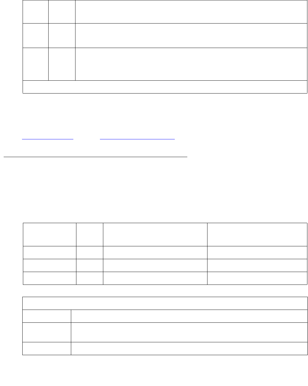
Alarms in Linux Media Servers
Issue 1 June 2005 95
This MO provides periodic and on-demand testing. The periodic test runs the “handshake” test
every 15 minutes. The on-demand tests include the “handshake”, “off-hook”, and “reset_usb”
tests.
Hardware MOs Server-related alarms
USB1 (Modem Testing) Alarms
S8700 | 8710 / S8500
This MO provides periodic and on-demand testing. The periodic test runs the “handshake” test
every 15 minutes. The on-demand tests include the “handshake”, “off-hook”, and “reset_usb”
tests.
26 WRN “upsAlarmFuseFailure” — One or more UPS fuses have failed.
1. Replace the UPS, and diagnose it later.
27 WRN “upsAlarmGeneralFault” — A general fault occurred in the UPS. (A UPS
diagnosis is required.)
1. Replace the UPS, and diagnose it later.
Table 26: UPS Alarms to the Media Server (continued)
Event
ID
Alarm
Level
Alarm Text, Cause/Description, Recommendation
4 of 4
MO’s Name
(in Alarm Log) Alarm
Level
Initial Linux Command to Run Full Name of MO
USB1 MAJ testmodem USB Port Modem Testing
USB1 MIN testmodem USB Port Modem Testing
USB1 WRN testmodem USB Port Modem Testing
Usage: testmodem [-s] | [-l] | [-t arg] | [-?]
no argument Performs “short” test.
-s Short test, performs handshake and off-hook tests this is also the default
option.
-l Performs “long” tests.
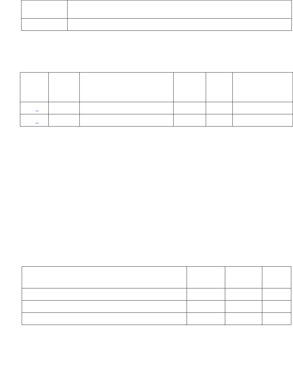
Server Alarms
96 Maintenance Procedures for Avaya Communication Manager 3.0, Media Gateways and Servers
Alarm Log Entries
Notes:
1. Event ID #1 Handshake Test failed — With 3 consecutive failures of either the periodic or
on-demand test, the following Minor alarm is logged:
#1,ACT,USB1,A,1,MIN,USB Modem handshake test failed
2. Event ID #2 Modem Off-Hook test failed — With 3 consecutive failures of this test, the
following Major alarm is logged:
#1,ACT,USB1,A,2,MAJ,USB Modem Off-Hook test failed
System Technician-Demanded Tests:
Descriptions and Error Codes
Always investigate tests in the order presented in the following table. For example, by clearing
error codes associated with the Handshake test, you may also clear errors generated by other
tests in the testing sequence.
-t arg Specific test to perform.
Possible values for arg are: reset_usb | handshake | off-hook |
-? Usage (this).
Table 27: USB1 Alarm Log Entries
EVENT
ID#
Aux
Data
Associated Test Alarm
Level
On/
Off
Board
Linux Test to
Clear Value
1 (1) Handshake test MIN ON testdupboard
2 (2) Modem Off-Hook test MAJ ON testdupboard
Order of Investigation Short Test
Sequence
Long Test
Sequence
D/ND1
1. D = Destructive; ND = Nondestructive
Handshake test X X D
Off-Hook test X X D
Reset USB test X X D

Alarms in Linux Media Servers
Issue 1 June 2005 97
Handshake Test
This test is destructive.
This test verifies that modem’s hardware is attached and that the modem can “handshake” with
the USB port. The test:
1. Tries to open the device
2. Sends a handshake string (ATZ) to the modem
The modem should return an “OK” string.
The following errors can be detected:
Off-Hook Test
This test is destructive.
Table 28: TEST Handshake Test
Error Code Test
Result
Description / Recommendation
Modem in
use, try again
later
ABRT Another application is currently using the modem. Try again later.
Could not
open USB
port
ABRT System error: An attempt to open the USB device failed.
1. Retry the test in about 5 minutes.
2. If the test still fails, escalate the problem.
Read error,
could not run
test
ABRT After the ATZ is sent, a read of the USB device is done. If the
read fails, a probable system error aborted the test.
1. Retry the test in about 5 minutes.
2. If the test still fails, escalate the problem.
Modem
Handshake
test failed
FAIL The modem did not return an “OK” string within a 15-second
interval.
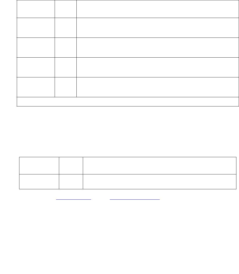
Server Alarms
98 Maintenance Procedures for Avaya Communication Manager 3.0, Media Gateways and Servers
This test runs an off-hook test for the modem attached to the USB port on the server. The test
sends an ATH1 string to check that a line is connected to the modem. The following errors can
be detected:
Reset USB Test
This test is destructive.
This test causes the modem to be reset, even if the modem is in use. Although no failures are
produced by this test, the following error can be detected:
Back to: Hardware MOs Server-related alarms
Table 29: TEST Off-Hook Test
Error Code Test
Result
Description / Recommendation
Modem in
use, try again
later
ABRT Some other application is currently using the modem. Try again
later.
Could not
open USB
port
ABRT System error: An attempt to open the USB device failed. Try again
later
Read error,
could not run
test
ABRT After the ATZ is sent, a read of the USB device is done. If the read
fails, a probable system error aborted the test. Try again.
Modem
Off-Hook test
failed
FAIL Modem Off-Hook test failed: The modem did not return an “OK”
string within a 15-second interval. This indicates that dial tone was
not detected in the allotted time.
Table 30: TEST Reset USB
Error
Code
Test
Result
Description / Recommendation
Could not
open USB port
ABRT System error: An attempt to open the USB device failed. Try
again later.

Alarms in Linux Media Servers
Issue 1 June 2005 99
_WD (Watchdog) Alarms
S8700 | 8710 / S8500 / S8300
The Watchdog MO is a media server process that:
●Creates other Communication Manager processes
●Monitors their sanity
●Can recover their failures
These applications come up and start heartbeats to the Watchdog. For more information about
Watchdog, see Table 31: _WD Alarms in Media Server on page 100 that describes the _WD
MO’s alarms and their troubleshooting procedures.
Watchdog also starts up a script to monitor Linux services and daemons, and threads to
communicate with a hardware-sanity device. For alarm-related information about these
services, daemons, and threads, see SVC_MON (Service Monitor) on page 79.

Server Alarms
100 Maintenance Procedures for Avaya Communication Manager 3.0, Media Gateways and Servers
Table 31: _WD Alarms in Media Server
Event
ID
Alarm
Level
Alarm Text, Cause/Description, Recommendation
4
S8300
MAJ “Application <name> (pid) TOTALLY FAILED” — An application is present,
but not launching. The application could not start the maximum allowed
number of times. (This alarm usually occurs with Event ID #20.)
1. To verify the alarm, look for the application’s name or process ID
(PID),” either using the:
- Web interface, by selecting Diagnostics > View System Logs and
Watchdog Logs
- Linux command line, by entering logv -w or, directly, by
examining /var/log/ecs/wdlog.
2. If the application is down, enter start -s application to start the
application.
3. If the application comes up, continue with Step 7.
If not, check the trace log to further investigate why the application
fails, either from the:
- Web interface by:
a. Selecting the View System Logs diagnostic and Logmanager
Debug trace
b. Specifying the Event Range for the appropriate time frame
c. Matching the application’s PID as the pattern
- Linux command line, by entering logv -t ts
Look for a related core-dump file in /var/crash, and escalate for an
analysis of this file.
4. Verify that the executable file named in the log exists and is
executable.
To locate the application’s executable file, enter the Linux command:
ls -l /opt/ecs/sbin/appl
If the executable is present, Linux returns a symbolic link to its
location.
1 of 15

Alarms in Linux Media Servers
Issue 1 June 2005 101
4
(cont’d)
MAJ 5. If so (less common):
a. Enter ls -l on the symbolic link’s address.
b. Verify that the executable has “execution” permissions.
c. If not, enter chmod +x to enable execution of the application.
If not — Linux has returned a “null link” (more common):
- Acquire the executable from the CD.
6. Enter start -s application to start the application.
7. Manually clear the alarm, either from the:
- Web interface, by selecting Alarms and Notification, the
appropriate alarm, and Clear
- Linux command line, by entering almclear -n #id
8. If the problem recurs, escalate the problem.
Table 31: _WD Alarms in Media Server (continued)
Event
ID
Alarm
Level
Alarm Text, Cause/Description, Recommendation
2 of 15

Server Alarms
102 Maintenance Procedures for Avaya Communication Manager 3.0, Media Gateways and Servers
5 MIN “WARNING: timeout waiting for reqsvr to initialize” — During each server’s
boot process, the server’s Watchd process waits up to 2 minutes for its
“reqsvr” (request server) thread to initialize. If the 2-minute waiting interval
elapses, this server logs this alarm, and its boot process hangs.
(Meanwhile, if the other server is already booted or subsequently boots, it
assumes the active role.)
In that (when this alarm occurs) a server hangs during its booting process,
this alarm’s external symptoms resemble those of two other _WD alarms,
#13 (Except S8500) and #14 (Except S8500). Therefore, carefully
discriminate between these three events.
1. To inspect the symptoms of this problem, verify that the:
a. Linux OS and the Web interface are up (including the commands:
telnet, statapp, server, logv, cat, grep, tail, vi, etc.)
b. Watchdog application is partially up, but no other Communication
Manager software is up
c. The almdisplay command displays no alarms. Instead, the
command returns the message:
“almdisplay: 4: Unable to connect to
MultiVantage”
Since the following commands cause a brief service outage, they should
only be executed at the customer’s convenience.
2. Escalate this problem for explicit guidance with the following steps.
3. Enter server to verify that the suspected server is the standby.
If necessary and at the customer’s convenience, enter server -if
to force a server interchange.
4. Reboot the standby server, either from the:
- Web interface, by selecting Shutdown This Server
- Linux command line, by entering /sbin/shutdown -r now
5. Once the standby server has booted, verify that Event ID #5 was
logged, either using the:
- Web interface, by selecting Diagnostics > View System Logs and
Watchdog Logs
- Linux command line, by entering logv -w or, directly, by
examining /var/log/ecs/wdlog.
Table 31: _WD Alarms in Media Server (continued)
Event
ID
Alarm
Level
Alarm Text, Cause/Description, Recommendation
3 of 15

Alarms in Linux Media Servers
Issue 1 June 2005 103
5
(cont’d)
MIN 6. If rebooting the server does not help or if the problem recurs, escalate
the problem to the next higher tier.
6
S8300
MAJ “Application <name> (pid) not started, config parm errors” — Watchdog
cannot read its configuration file, /etc/opt/ecs/watchd.conf.
1. To verify the alarm, look for the application’s name or process ID
(PID), either using the:
- Web interface, by selecting Diagnostics > View System Logs and
Watchdog Logs
- Linux command line, by entering logv -w or, directly, by
examining /var/log/ecs/wdlog.
2. Get a fresh copy of watchd.conf from the CD.
3. Verify that every executable file listed in watchd.conf exists and is
executable.
4. Enter start -s application to start the application.
5. Manually clear the alarm, either from the:
- Web interface, by selecting Alarms and Notification, the
appropriate alarm, and Clear
- Linux command line, by entering almclear -n #id
Table 31: _WD Alarms in Media Server (continued)
Event
ID
Alarm
Level
Alarm Text, Cause/Description, Recommendation
4 of 15

Server Alarms
104 Maintenance Procedures for Avaya Communication Manager 3.0, Media Gateways and Servers
7
S8300
MAJ “Application <name> not started, parm file errors” — Since an
application’s specified location in watchd.conf is incorrect, Watchdog
cannot start the application.
1. To verify the alarm, look for the application’s or process ID (PID),
either using the:
- Web interface, by selecting Diagnostics > View System Logs and
Watchdog Logs
- Linux command line, by entering logv -w or, directly, by
examining /var/log/ecs/wdlog.
2. Verify that the executable file named in the log exists and is
executable.
To locate the application’s executable file, enter the Linux command:
ls -l /opt/ecs/sbin/appl
If the executable is present, Linux returns a symbolic link to its
location.
3. If so (less common):
a. Enter ls -l on the symbolic link’s address.
b. Verify that the executable has “execution” permissions.
c. If not, enter chmod +x to enable execution of the application.
If not — Linux has returned a “null link” (more common):
- Acquire the executable from the CD.
4. Verify that the string in watchd.conf is correct.
5. Enter start -s application to start the application.
6. Manually clear the alarm, either from the:
- Web interface, by selecting Alarms and Notification, the
appropriate alarm, and Clear
- Linux command line, by entering almclear -n #id
Table 31: _WD Alarms in Media Server (continued)
Event
ID
Alarm
Level
Alarm Text, Cause/Description, Recommendation
5 of 15

Alarms in Linux Media Servers
Issue 1 June 2005 105
13
(Except
S8500)
MIN “ERROR: could not dup socket fd in reqsvr.c, heartbeat thread not created,
errno=<x>” — As either a:
●Booting application initiates
●Restarting application re-initiates heart beating with Watchdog (see
Event ID #5), the “reqsvr” (request server) thread tries to create a
duplicate socket for the hearbeating thread. This alarm indicates that
reqsvr could not create the socket. (Meanwhile, if the other server is
already started or subsequently starts, it assumes the active role.)
In that (when this alarm occurs) a server hangs, this alarm’s external
symptoms resemble those of two other _WD alarms, #5 and #14
(Except S8500). Therefore, carefully discriminate between these three
events.
1. To inspect the symptoms of this problem, verify that the:
a. Linux OS and the Web interface are up (including the commands:
telnet, statapp, server, logv, cat, grep, tail, vi, etc.)
b. Watchdog application is partially up, and some other
Communication Manager processes may be up, either using the:
- Web interface, by selecting View Process Status
- Linux command line, by entering statapp
c. If the GMM process is up, the almdisplay -v command shows
Event #13’s message string.
If not, the Watchdog log shows the message string, either using
the:
- Web interface, by selecting Diagnostics > View System Logs
and Watchdog Logs
- Linux command line, by entering logv -w or, directly, by
examining /var/log/ecs/wdlog.
Since the following commands cause a brief service outage, they should
only be executed at the customer’s convenience.
2. Escalate this problem for explicit guidance with the following steps.
3. Enter server to verify that the suspected server is the standby.
If necessary and at the customer’s convenience, enter server -if
to force a server interchange.
Table 31: _WD Alarms in Media Server (continued)
Event
ID
Alarm
Level
Alarm Text, Cause/Description, Recommendation
6 of 15

Server Alarms
106 Maintenance Procedures for Avaya Communication Manager 3.0, Media Gateways and Servers
13
(Except
S8500)
(cont’d)
MIN 4. Reboot the standby server, either from the:
- Web interface, by selecting Shutdown This Server
- Linux command line, by entering /sbin/shutdown -r now
5. If rebooting the server does not help or if the problem recurs, escalate
the problem to the next higher tier.
14
(Except
S8500)
MIN “ERROR in req2svr.p trying to create heartbeat thread, errno=<x>” — After
the “reqsvr” (request server) creates a duplicate socket (see Event ID #13
(Except S8500)), it tries to create a heart beating thread. This alarm
indicates that reqsvr could not create the thread. (Meanwhile, if the other
server is already started or subsequently starts, it assumes the active role.)
In that (when this alarm occurs) a server hangs, this alarm’s external
symptoms resemble those of two other _WD alarms, #5 and #13 (Except
S8500). Therefore, carefully discriminate between these three events.
1. To inspect the symptoms of this problem, verify that the:
a. Linux OS and the Web interface are up (including the commands:
telnet, statapp, server, logv, cat, grep, tail, vi, etc.)
b. Watchdog application is partially up, but all other Communication
Manager processes are up, either using the:
- Web interface, by selecting View Process Status
- Linux command line, by entering statapp
c. The almdisplay -v command shows Event #14’s message
string
Since the following commands cause a brief service outage, they should
only be executed at the customer’s convenience.
2. Escalate this problem for explicit guidance with the following steps.
3. Enter server to verify that the suspected server is the standby.
If necessary and at the customer’s convenience, enter server -if
to force a server interchange.
4. Reboot the standby server, either from the:
- Web interface, by selecting Shutdown This Server
5. If rebooting the server does not help or if the problem recurs, escalate
the problem to the next higher tier.
Table 31: _WD Alarms in Media Server (continued)
Event
ID
Alarm
Level
Alarm Text, Cause/Description, Recommendation
7 of 15

Alarms in Linux Media Servers
Issue 1 June 2005 107
15
S8300
MAJ “Detected a rolling reboot” — Watchdog has detected “x” number of Linux
reboots within “y” minutes (where x and y are configurable in /etc/opt/
ecs/watchd.conf). Rolling reboots have a wide variety of possible
causes.
1. To verify the alarm, look for the message, “WARNING: Rolling reboot
detected!!,“either using the:
- Web interface, by selecting Diagnostics > View System Logs and
Watchdog Logs
- Linux command line, by entering logv -w or, directly, by
examining /var/log/ecs/wdlog.
2. Escalate this problem for explicit guidance with the following steps.
3. Paying special attention to Communication Manager errors, continue
examining the Watchdog log (from Step 1), and try to determine which
application failed.
4. Verify that every executable file listed in watchd.conf exists and is
executable. Rolling reboots are often caused by executables in
unexpected locations.
5. If the files and their locations are OK, investigate the trace log to
isolate the cause, either from the:
- Web interface by:
a. Selecting the View System Logs diagnostic and Logmanager
Debug trace
b. Specifying the Event Range for the appropriate time frame
c. Matching the “rolling reboot” pattern
- Linux command line, by entering logv -t ts
Table 31: _WD Alarms in Media Server (continued)
Event
ID
Alarm
Level
Alarm Text, Cause/Description, Recommendation
8 of 15

Server Alarms
108 Maintenance Procedures for Avaya Communication Manager 3.0, Media Gateways and Servers
18
S8300
WRN “Application <name> restarted. Retry <retry count>, New Pid: <pid>” —
An application has failed, and Watchdog successfully restarted it.
1. To verify the alarm, look for the application’s name or process ID (pid),
either using the:
- Web interface, by selecting Diagnostics > View System Logs and
Watchdog Logs
- Linux command line, by entering logv -w or, directly, by
examining /var/log/ecs/wdlog.
2. No resolution. Manually clear the alarm, either from the:
- Web interface, by selecting Alarms and Notification, the
appropriate alarm, and Clear
- Linux command line, by entering almclear -n #id
Table 31: _WD Alarms in Media Server (continued)
Event
ID
Alarm
Level
Alarm Text, Cause/Description, Recommendation
9 of 15

Alarms in Linux Media Servers
Issue 1 June 2005 109
19
S8300
MIN “Application failed unintentionally” — Watchdog is bringing the system
down because an application failed to start correctly. The application may
have failed to start either because:
●The file did not exist (coincident with Event ID #7).
●Required application parameters were missing or invalid in
watchd.conf.
1. To verify the alarm, look for the message, “Application num <#>
(<application path>) not started. Watchdog exiting NOW,” either using
the:
- Web interface, by selecting Diagnostics > View System Logs and
Watchdog Logs
- Linux command line, by entering logv -w or, directly, by
examining /var/log/ecs/wdlog.
2. Verify that the file named in the log exists and is executable.
3. Verify that the string in watchd.conf is correct.
4. If Steps 2 and 3 are OK, investigate the trace log to see why the
application fails, either from the:
- Web interface by:
a. Selecting the View System Logs diagnostic and Logmanager
Debug trace
b. Specifying the Event Range for the appropriate time frame
c. Matching the application’s number as the pattern
- Linux command line, by entering logv -t ts
5. Once resolved, manually clear the alarm, either from the:
- Web interface, by selecting Alarms and Notification, the
appropriate alarm, and Clear
- Linux command line, by entering almclear -n #id
Table 31: _WD Alarms in Media Server (continued)
Event
ID
Alarm
Level
Alarm Text, Cause/Description, Recommendation
10 of 15

Server Alarms
110 Maintenance Procedures for Avaya Communication Manager 3.0, Media Gateways and Servers
20
S8300
MAJ “Application <name> (pid) TOTALLY FAILED” — Application failed the
maximum allowed number of times. (This alarm usually occurs with Event
ID #4.)
1. To verify the alarm, look for the application’s name or process ID
(PID), either using the:
- Web interface, by selecting Diagnostics > View System Logs and
Watchdog Logs
- Linux command line, by entering logv -w or, directly, by
examining /var/log/ecs/wdlog.
- See if the application is up, either from the:
- Web interface, by selecting View Process Status
- Linux command line, by entering statapp
2. If the application is down, enter start -s application to start the
application.
3. If the application comes up, continue with Step 7.
If not, check the trace log to further investigate why the application
fails, either from the:
- Web interface by:
a. Selecting the View System Logs diagnostic and Logmanager
Debug trace
b. Specifying the Event Range for the appropriate time frame
c. Matching the application’s PID as the pattern
- Linux command line, by entering logv -t ts
4. To locate the application’s executable file, enter the Linux command:
ls -l /opt/ecs/sbin/appl
If the executable is present, Linux returns a symbolic link to its
location.
Table 31: _WD Alarms in Media Server (continued)
Event
ID
Alarm
Level
Alarm Text, Cause/Description, Recommendation
11 of 15

Alarms in Linux Media Servers
Issue 1 June 2005 111
20
(cont’d)
MAJ 5. If so (less common):
a. Enter ls -l on the symbolic link’s address.
b. Verify that the executable has “execution” permissions.
c. If not, enter chmod +x to enable execution of the application.
If not — Linux has returned a “null link” (more common):
- Acquire the executable from the CD
6. Enter start -s application to start the application.
7. Manually clear the alarm, either from the:
- Web interface, by selecting Alarms and Notification, the
appropriate alarm, and Clear
- Linux command line, by entering almclear -n #id
8. If the problem recurs, escalate the problem.
Table 31: _WD Alarms in Media Server (continued)
Event
ID
Alarm
Level
Alarm Text, Cause/Description, Recommendation
12 of 15

Server Alarms
112 Maintenance Procedures for Avaya Communication Manager 3.0, Media Gateways and Servers
22
S8300
WRN “Application <name> (<pid>) terminated” — Watchdog successfully shut
down the named application, and (if appropriate) watchdog will try to
restart it.
1. To verify the alarm, look for the application’s name or process ID
(PID), either using the:
- Web interface, by selecting Diagnostics > View System Logs and
Watchdog Logs
- Linux command line, by entering logv -w
2. On the standby server, look for occurrences of the stop command,
either from the:
- Web interface, by:
a. Selecting View System Logs
b. Selecting Platform command history log
c. Specifying the Event Range for the appropriate time frame
d. Matching the “Stop” pattern
- Linux command line, by entering listhistory
3. If a stop command was inappropriately executed, prevent any future
misuse of the stop command.
Note: From the system’s perspective, this is normal behavior.
However, in terms of potential service outage due to human error, this
is quite irregular. (Shutting down a server effectively downgrades a
duplex-, high- or critical-reliability system to an unsupported
standard-reliability system.)
4. If listhistory shows no stop commands, then Watchdog
responded to abnormal internal processes by shutting down the
application.
Check the trace log for information about this application, either from
the:
- Web interface, by:
a. Selecting the View System Logs diagnostic and Logmanager
Debug trace
b. Specifying the Event Range for the appropriate time frame
c. Matching the application’s PID as the pattern
- Linux command line, by entering logv -t ts
Table 31: _WD Alarms in Media Server (continued)
Event
ID
Alarm
Level
Alarm Text, Cause/Description, Recommendation
13 of 15

Alarms in Linux Media Servers
Issue 1 June 2005 113
22
S8300
(cont’d)
WRN 5. Manually clear the alarm, either from the:
- Web interface, by selecting Alarms and Notification, the
appropriate alarm, and Clear
- Linux command line, by entering almclear -n #id
6. Watch to see if the alarm recurs. If so, escalate the problem.
23
S8300
MAJ “Watchd high-monitor thread is rebooting the system” — The:
1. Lo-monitor thread is missing heartbeats (can't get CPU time).
2. Hi-monitor thread has tried 3 times to recover the system by killing any
infinitely looping processes.
If after 3 CPU-occupancy profiles and recoveries, the lo-monitor thread is
still not heartbeating, then Watchd reboots the server.
3. To verify the alarm, look for messages:
Containing the CPU profiling results and attempted recoveries
Stating that Watchd is rebooting the server
using either the:
- Web interface, by selecting Diagnostics > View System Logs and
Watchdog Logs
- Linux command line, by entering logv -w or, directly, by
examining /var/log/ecs/wdlog.
A resolution is probably unnecessary. The server has usually rebooted
by the time a technician can analyze the system. (A reboot clears the
alarm and normally fixes problems with unresponsive software.)
4. Watch to see if the alarm recurs. If so, escalate the problem.
Table 31: _WD Alarms in Media Server (continued)
Event
ID
Alarm
Level
Alarm Text, Cause/Description, Recommendation
14 of 15

Server Alarms
114 Maintenance Procedures for Avaya Communication Manager 3.0, Media Gateways and Servers
Back to: Hardware MOs Server-related alarms
24
S8300
MAJ “Watchd’s high-monitor thread is stopping tickling of hw” — Event ID #23’s
call to reboot the server was unsuccessfully invoked. (A Linux kernel’s
semaphore is possibly stuck.) After this happens, Watchd stops tickling
the HW sanity timer so that the HW sanity watchdog executes a hard
reboot of the processor.
1. To verify that the alarm occurred, look for messages about:
Stopping the tickling of the HW sanity timer
CPU occupancy profiling
using either the:
- Web interface, by selecting Diagnostics > View System Logs
and Watchdog Logs
- Linux command line, by entering logv -w or, directly, by
examining /var/log/ecs/wdlog.
- If the HW sanity watchdog successfully executed a hard reboot,
the alarm was cleared. (This reboot normally fixes problems due
to unresponsive software.)
If not, power cycle the server to release it from this condition and to
clear the alarm.
2. Watch to see if the alarm recurs. If so, escalate the problem.
Table 31: _WD Alarms in Media Server (continued)
Event
ID
Alarm
Level
Alarm Text, Cause/Description, Recommendation
15 of 15

Alarms in Linux Media Servers
Issue 1 June 2005 115
Login Alarms - S8300
S8300
Table 32: Login Alarms in Media Server on page 115 describes media server login alarms and
their troubleshooting procedures.
Back to: Hardware MOs Server-related alarms
Table 32: Login Alarms in Media Server
Event
ID
Alarm
Level
Alarm Text, Cause/Description, Recommendation
1WRN
1. On the Web Interface, choose View Current Alarms.
2. Notify Customer.
2WRN
1. On the Web Interface, choose View Current Alarms.
2. Notify Customer.
3 MIN Security violation.
1. On the Web Interface, choose View Current Alarms.
2. Notify Customer.
4 MIN Security violation.
1. On the Web Interface, choose View Current Alarms.
2. Notify Customer.
5 MAJ Security violation.
1. On the Web Interface, choose View Current Alarms.
2. Notify Customer.

Server Alarms
116 Maintenance Procedures for Avaya Communication Manager 3.0, Media Gateways and Servers
Virtual Alarms
S8300 only
The Virtual Announcement Media Module faults are managed as server alarms. In the S8300
Media Server, the Virtual Analog Angel (VAA) represents a messaging board. The VAA is a
virtual board on the G700. When the G700 reboots, the VAA senses that it has lost connectivity
with the G700, and triggers its "removal and re-insertion". The removal of the VAA causes the
AUDIX ports to go out-of-service and to return back in service when the re-insertion is complete.
An alarm of MAJOR severity is generated, indicating loss of connectivity with the G700, which
must be cleared manually. Table 33: Virtual Alarm in S8300 Media Server on page 116
summarizes this server alarm.
Back to: Hardware MOs Server-related alarms
Remote Maintenance Board (RMB) Alarms
S8500
The Remote Supervisor Adapter (RSA) board is installed in PCI-X slot 1 of the S8500 Media
Server. It monitors and reports alarms on S8500 components and software and provides control
to power on and power off the server.
Table 33: Virtual Alarm in S8300 Media Server
Event
ID
Alarm
Level
Alarm Text, Cause/Description, Recommendation
1 MAJ Virtual Analog Angel (VAA) loss of connectivity with a G700, resulting in
temporary Out of Service (OOS) of AUDIX ports. A G700 reboot caused VAA
to "remove and re-insert" virtual board. Must be cleared manually.
1. Manually clear the alarm, either from the:
- Web interface, by selecting Alarms and Notification, the
appropriate alarm, and Clear
- Linux command line, by entering almclear -n #id
2. Execute list configuration all on SAT.
Verify that V8 MG MSG BOARD does not show no board against it.
(no board means AUDIX ports OOS.)

Alarms in Linux Media Servers
Issue 1 June 2005 117
Note:
Note: The S8500 has a set of alarms for the RSA card, which is also called the Remote
Maintenance Board (RMB). The MO name is RMB. Alarms reported, by the
S8500 media server, via the MO name RMB will include a Product ID beginning
with one (1) followed by nine digits.
The A+SAMP board in a S8500B media server may also report alarms via the
MO name RMB. See S8500B Augmentix Server Availability Management
Processor™ (A+SAMP) Alarms on page 120. When the A+SAMP board reports
alarms via the MO name RMB the Product ID begins with a five (5) followed by
nine digits.
Table 34: RMB Alarms in the S8500 Media Server
Event
ID
Alarm
Level
Alarm Text, Cause/Description, Recommendation
1 MIN "RMB driver missing - handshake Failed" - The driver for communicating
with the RSA card cannot be found. Several failures can generate this fault:
●the Linux bash command /sbin/lsmod is missing
●the results from running /sbin/lsmod could not be read
●/sbin/lsmod returned nothing
●the RSA device driver was not loaded
●the RSA device driver does not exist
The recommendations are:
1. Be sure /sbin/ibmod exists and is executable.
2. Be sure /tmp exists as a directory and can be written.
3. Be sure /lib/modules/ibmasm/ibmasm.o exists and has read
permission.
4. Run the bash command "service ibmasm start".
2 MIN "RMB cli is not loaded on the server." - The program that talks to the RSA
card could not be found. Several failures generate this fault:
●the Linux bash command /bin/ls is missing or not working properly
●the bash command /opt/ecs/rmb/rsa/rsacli is missing or is not
executable
The recommendations are:
1. Be sure all the above files and directories exist and have read and
execute permissions.
2. Reload any missing files from the distribution.
1 of 3

Server Alarms
118 Maintenance Procedures for Avaya Communication Manager 3.0, Media Gateways and Servers
3 MAJ "RMB reset command failed" - The RSA card did not respond to a reset
command. Several failures generate this fault:
●the bash command opt/IBMmpcli/bin/mpcli is missing or is not
executable
●the directory /usr/java/latest is missing or not symbolically linked to
the Java runtime environment (JRE)
●the file /opt/ecs/rmb/rsareset does not exist or cannot be read
●no response from the RSA card
●the RSA card did not execute the request
The recommendations are:
1. Be sure all the above files and directories exist and have read and
execute permissions.
2. Reload any missing files from the distribution.
3. Be sure the RSA card is installed by looking at the back and checking
that the green power LED on the RSA card is on, and that the amber
error LED is off.
4. Verify that the RSA card is working by dialing into it or logging on to it
over the service’s port of the RSA card.
5. Restart the RSA card from the RSA modem or service’s port and check
the LEDs on the back of the card.
6. Verify that the RSA card is plugged into the PCI-X slot of the server.
7. Verify that the flat ribbon cable from the RSA card to the server
motherboard has been installed and is firmly seated in the connectors
at both ends.
8. Replace the RSA card.
Table 34: RMB Alarms in the S8500 Media Server (continued)
Event
ID
Alarm
Level
Alarm Text, Cause/Description, Recommendation
2 of 3

Alarms in Linux Media Servers
Issue 1 June 2005 119
Back to: Hardware MOs Server-related alarms
4 MAJ "RMB failed handshake test" - The RSA card did not respond to commands
from the server. Several failures generate this fault:
●the bash command /opt/IBMmpcli/bin/mpcli is missing or is not
executable
●the directory /usr/java/latest is missing or not symbolically linked to
the Java runtime environment (JRE)
●the file /opt/ecs/rmb/rsagetip1 does not exist or cannot be read
●no response from the RSA card
●the RSA card did not execute the request
The recommendations are:
1. Be sure all the above files and directories exist and have read and
execute permissions.
2. Reload any missing files from the distribution.
3. Be sure the RSA card is installed by looking at the back and checking
that the green power LED on the RSA card is on, and that the amber
error LED is off.
4. Verify that the RSA card is working by dialing into it or logging on to it
over the service’s port of the RSA card.
5. Restart the RSA card from the RSA modem or service’s port and check
the LEDs on the back of the card.
6. Verify that the RSA card is plugged into the PCI-X slot of the server.
7. Verify that the flat ribbon cable from the RSA card to the server
motherboard has been installed and is firmly seated in the connectors
at both ends.
8. Replace the RSA card.
Table 34: RMB Alarms in the S8500 Media Server (continued)
Event
ID
Alarm
Level
Alarm Text, Cause/Description, Recommendation
3 of 3

Server Alarms
120 Maintenance Procedures for Avaya Communication Manager 3.0, Media Gateways and Servers
S8500B Augmentix Server Availability Management Processor™
(A+SAMP) Alarms
S8500B Only
The Augmentix Server Availability Management Processor (A+SAMP) board is installed in the
S8500B media server. It monitors and reports alarms on S8500B components and software and
provides control to power on and power off the server.
The A+SAMP will report alarms when it detects certain failure conditions. See A+SAMP Alarms
in the S8500B Media Server on page 120. These alarms will be reported under the
Maintenance Object (MO) name RMB. These alarms will be reported with a Product ID
beginning with a five (5) and followed by nine digits.
The S8500 media server may also report failure conditions via the MO name RMB but these
alarms will have a Product ID that begins with a one (1) followed by nine digits. See Remote
Maintenance Board (RMB) Alarms on page 116.
Table 35: A+SAMP Alarms in the S8500B Media Server
Event
ID
Alarm
Level
Alarm Text, Cause/Description, Recommendation
0MINTest Alarm. Hardware Platform Interface (HPI) User Event
1MINLoss of power to host. Hardware Platform Interface (HPI) Sensor Event.
2MAJ
Host boot timeout. Hardware Platform Interface (HPI) OEM Event
3MAJ
Host Alarm. Hardware Platform Interface (HPI) User Event
4MINLoss of External Power to SAMP. Hardware Platform Interface (HPI)
Sensor Event
5MAJ
Host failure timeout. Hardware Platform Interface (HPI) Watchdog Event
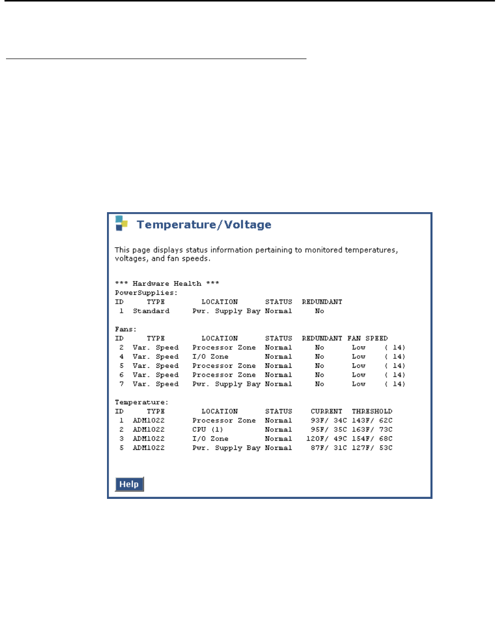
S8710 Alarms
Issue 1 June 2005 121
S8710 Alarms
S8710 environmental alarms
The Environmental maintenance object (ENV-MO) monitors environmental variables within the
server, including temperature and fans. However, you can check these variables from the
Maintenance Web Pages also.
To check the S8710 server temperature and voltage readings:
1. At the Maintenance Web Pages, select Diagnostics > Temperature/Voltage.
2. The Temperature/Voltage page displays.

Server Alarms
122 Maintenance Procedures for Avaya Communication Manager 3.0, Media Gateways and Servers
3. Use the descriptions in Table 36 to interpret the report.
Table 36: S8710 Temperature and voltage report
Field Description
ID An identification number automatically generated by the system.
Type Power supply:
●Intelligent—power regulating
●Standard—other
Fan: speeds include
●Var Speed—variable speed
●Basic Fan—fixed speed
●Auto. Speed—automatic speed fan
●Pwr Supply—power supply
●Unknown
Temperature: Basic Sensor—generic; ADM1022; Internal PS; Unknown
Type
Location The device location in the media server.
Status For power supplies and fans:
●Normal—operating normally
●Alarm—having a problem
Redundant For all types: Yes, No, or NA
Fan Speed Fans: percentage of full speed.
●Unknown
●Automatic—For Auto. Speed Fans, no speed state
●Low—< 30%
●Medium—30%–70%
●High—> 70%, reporting state: High state
●Normal—reporting state: Normal state
●Off
Current Temperature: current temperature of the device, in degrees Fahrenheit and
Celsius.
1 of 2

S8710 Alarms
Issue 1 June 2005 123
S8710 server BIOS error messages
The S8710 server BIOS error messages are listed and interpreted in Tab le 37.
Threshold Temperature: above for which an alarm is generated, in degrees Fahrenheit
and Celsius.
Table 36: S8710 Temperature and voltage report (continued)
Field Description
2 of 2
Table 37: S8710 BIOS error messages
Error
Code
Description Audible
Beeps
Possible Problem Possible Action
207 Memory configuration
warning; DIMM in DIMM
Socket X is not 4 bytes
wide (32 bits) and only
supports standard ECC.
None Installed DIMMs are
8 bytes wide (64
bits).
Escalate; replace
the media server
209 Online spare memory
configuration; spare bank
is invalid. Mixing of DIMMs
with 4 and 8 byte widths is
not allowed in this mode.
One
long and
one
short
Installed DIMMs for
online spare bank
are of a different
primary width than
the DIMMs in other
banks.
Escalate; replace
the media server
NA A mixture of 533-MHz and
400-MHz front side bus
speed processors
detected. All processors
must have the same front
side bus speed. System
halted.
One
long and
one
short
Wrong processors;
Processors have
different front side
bus speeds.
Escalate; replace
the media server
NA Media server only supports
400-MHz front side bus
speed processors. One or
more 533-MHz front side
bus speed processors
have been initialized at 400
MHz.
One
long and
one
short
Wrong processors;
Media server does
not support a front
side bus speed of
533 MHz.
Escalate; replace
the media server

Server Alarms
124 Maintenance Procedures for Avaya Communication Manager 3.0, Media Gateways and Servers

Issue 1 June 2005 125
Chapter 2: Denial Events
The tables in this chapter define and explain the information listed on the Events Report
(display events screen). The Event Type tables are grouped by denial event category,
denial event number, and Communication Manager release number. The Event Tables list:
●The number that identifies the Event Type. See Table 38: Denial Event types and
ranges on page 126. If the Event Type number defines different denial events in different
Communication Manager releases, that information is also listed.
●Event Description text, as it appears on the Events Report (display events type
denial).
●An explanation of why the event was generated.
●Type of data in Event Data 1 and Event Data 2 fields, for each applicable Event Type,
where this information is available. See Event Data on page 127.
To view denial events, use:
●display events type denial (to see historical denial event logs)
●list trace station
●list trace TAC
Use list trace to see any available Calling Party Number and Calling Party Name
associated with call setup.

Denial Events
126 Maintenance Procedures for Avaya Communication Manager 3.0, Media Gateways and Servers
Event Type number ranges
Event Type number ranges help define the type and source of the denial event, as listed in
Table 38: Denial Event types and ranges. Some numbers are placeholders and have no
assigned denial event.
Table 38: Denial Event types and ranges
Number range Type/source of denial event Reference
0 - 999 Vector process Avaya Communication Manager Call Center Software Call
Vectoring and Expert Agent Selection (EAS) Guide,
07-300186.
●500 - 999 Hunt/Trunk Group Vector
process
Avaya Communication Manager Call Center Software Call
Vectoring and Expert Agent Selection (EAS) Guide,
07-300186.
1000 - 2299 Call Process Table 48, Call Process denial events (1001 - 1172), on
page 177.
●1000 - 1299 Call Process, reorder Table 48, Call Process denial events (1001 - 1172), on
page 177 and Table 50, Call Process denial events (1225 -
1899), on page 193.
●1164, 1167,
1173 - 1224
Call Process, ISDN, IP, SIP Table 49, ISDN, IP, and SIP-generated denial events (1173
- 1224), on page 189.
●1300 - 1899 Call Process, intercept Table 50, Call Process denial events (1225 - 1899), on
page 193.
●1900 - 1906 User Manager process Table 51: User Manager denial events (1900 - 1906) on
page 226.
●1907 - 2079 IP Table 52: IP Denial Events (1907 - 2020) on page 226.
●2021-2299 Call Process Table 53, Call Process denial events (2021 - 2299), on page
238.
2300 - 2399 Connection Manager process Table 54: Connection Manager denial events (2300 -
2399) on page 247.
2400 - 2499 Dial Plan Manager process Table 55: Dial Plan Manager denial events (2400 - 2406) on
page 249.
3000 - 3100 Data Manager process Table 56: Data Manager generated Denial Events (3001 -
3003) on page 249.
3101 - 3200 Dial Access Plan process Table 57: Dial Access Plan denial events (3101 - 3200) on
page 250.
3201 - 3299 Meetme Conference
process
Table 58: Meet Me Conference denial events (3201 -
3299) on page 250.
3300 - 3399 LSP process Table 59: LSP denial events (3300 - 3399).
1 of 2

Event Data
Issue 1 June 2005 127
Event Data
Use Event Data information to isolate mis-translation and/or mis-matched provisioning.
Event Data might contain the information for:
●Internal User ID (UID) of a component involved in the call (station, IP User, gatekeeper)
●Product ID
●Object ID
●IP Address
●Extension
●IP Address involved in the call
●TTI State
●Numeric reason code explained in the tables in this chapter
●Numeric code showing the Cause Value, Cause Value Diagnostic, and Location Code for
the event. See Cause Values and their meanings/interpretations on page 128.
3400 - 3499 Data Error (corruption) process Table 60: Data Error denial events (3400 - 3499) on
page 252.
3500 - 3599 Contact Closure process Table 61: Contact Closure denial events (3500 - 3503) on
page 253.
3600 - 3604 ESS process Table 62: ESS denial events (3600 - 3604) on page 254.
Table 38: Denial Event types and ranges (continued)
Number range Type/source of denial event Reference
2 of 2

Denial Events
128 Maintenance Procedures for Avaya Communication Manager 3.0, Media Gateways and Servers
Cause Values and their meanings/interpretations
See Table 49: ISDN, IP, and SIP-generated denial events (1173 - 1224) on page 189 for the
Denial Events that show Cause Value information (Cause Value, Location Code, and Diagnostic
Code) in Event Data 2 fields.
Event Data 2 sometimes contains data that represents the Cause Value (CV) (required), Cause
Value Diagnostic (DIAG) (optional), Location Code (LC) (optional) from the denial event. This
information (DIAG/LOC/CV) is coded as a 32 bit hexadecimal number, divided into 8-bit fields.
●The least significant (right most) two digits are the Cause Value in hexadecimal.
●The next two digits to the left are the Location Code (optional) in hexadecimal. See
Table 42: Location Code definitions on page 130.
●The next two digits to the left are the Diagnostic Code (optional) in hexadecimal.
●The most significant (left most) two digits are not used.
See Table 39: Event Data 2 layout on page 128.
Interpreting Event Data 2 Cause Value information
In our example, we will use Denial Event 1178 with Event Data 1 and Event Data 2.
1. Note the information under the Event Data 2 column: 0x429.
●0x29 is the Cause Value.
●0x4 is the Location Code.
●0x00 is the Diagnostic Code (not provided for this denial event).
Table 39: Event Data 2 layout
8 bits 8 bits 8 bits 8 bits
NOT USED Diagnostic Code
(DIAG) (optional)
Zero + Location Code in lower 4 bits
(LOC) (optional)
Cause Value
(CV) (required)
display events denial Page 1 of 1
EVENTS REPORT
Event Event Event Event First Last Evnt
Type Description Data 1 Data 2 Occur Occur Cnt
1178 Normal Call Clearing 0x64 0x429 01/09/09:53 01/09/09:53 1

Event Data
Issue 1 June 2005 129
2. Convert the hexadecimal number provided in Event Data 2 to three binary numbers: put a
one in the appropriate binary number positions that add up to the value of the number.
Each binary number consists of eight bits. See Table 40: Event Data 2 conversion
example on page 129 for an example of the hexadecimal number 0x429, and
Table 41: Hexadecimal, decimal, and binary equivalents on page 130 for the binary
equivalents for individual digits.
3. Add up the decimal weights that have a one for each of the eight bit segments.
●Convert Cause Value 0x29 to decimal and find the sum.
Cause Value (Bits 1 - 8): 1 +8 + 32 = 41. This is Cause Value 41.
●Convert Location Code 0x4 to decimal and find the sum.
Location Code (Bits 9 - 16): 4 = 4. This is Location Code 4.
●Convert Diagnostic Value 0x00 (Bits 17 - 24): 0 = 0.
Diagnostic Code is 0, not provided for this example denial event.
4. Use the information in this chapter to find an explanation of the Data Event 2 information.
●Cause Value 41 = Temporary Failure. See Cause Values on page 134.
●Location Code 4 = Remote Network/Public Network Serving Remote User (the Local
Exchange Carrier at the far end of the call). See Table 42: Location Code definitions on
page 130.
Table 40: Event Data 2 conversion example
Diagnostic Code Location Code Cause Value
Event Data 2
000429
Binary number
00000000 00001000 0101001
Decimal weight of each digit position
8 42184218 42184218 4218421
Decimal weight of the binary positions for each eight-bit field
128643216842112864321684211286432168421
Bit position
24 23 22 21 20 19 18 17 16 15 14 13 12 11 10 9 8 7 6 5 4 3 2 1

Denial Events
130 Maintenance Procedures for Avaya Communication Manager 3.0, Media Gateways and Servers
.
Location Codes
See Table 49: ISDN, IP, and SIP-generated denial events (1173 - 1224) on page 189 for the
Denial Events that show Cause Value information (Cause Value, Location Code, and Diagnostic
Code) in Event Data 2 fields.
Use the location information of Event Data 2 to identify where in the network the called number
failed to be recognized, and from where the Cause Value originated. See Table 42: Location
Code definitions on page 130.
Table 41: Hexadecimal, decimal, and binary equivalents
HEX Decimal Binary Hex Decimal Binary
0 0 0000 8 8 1000
1 1 0001 9 9 1001
2 2 0010 A 10 1010
3 3 0011 B 11 1011
4 4 0100 C 12 1100
5 5 0101 D 13 1101
6 6 0110 E 14 1110
7 7 0111 F 15 1111
Table 42: Location Code definitions
Location
Code
Definition
0 User
1 Private Network Serving Local User.
The Local PBX or phone system on the Called Party premise
2 Public Network serving the Local User (the CO to which the PBX is directly
connected).
3 Transit network. For example, the long distance network to which the call was
passed by the LEC.
4 Public Network Serving Remote User [the Local Exchange Carrier (LEC) at the far
end of the call].
1 of 2

Event Data
Issue 1 June 2005 131
Transmission Protocols
See Table 49: ISDN, IP, and SIP-generated denial events (1173 - 1224) on page 189 for the
Denial Events that show Cause Value information (Cause Value, Location Code, and Diagnostic
Code) in Event Data 2 fields.
The meaning of the Denial Event Data information differs depending on the type of protocol
used for the call. The transmission protocol for your system is defined on the DS1 screen (add/
change/display ds1 location command) by:
●The numeric country code value in the Protocol field - sets the country protocol.
●The letter value for the protocol version in the Protocol Version field.
See Table 43, Country Codes and Transmission Protocols, on page 131.
5 Private Network Serving Remote User (the remote PBX or phone system on the
Called Party premises).
7 International.
A Network beyond inter-networking point.
Table 42: Location Code definitions (continued)
Location
Code
Definition
2 of 2
Table 43: Country Codes and Transmission Protocols
Country Code –
Protocol Version
Country Protocol Supported B-channel
Maint.
Message
Inter-working
Message
1-a US-Canada AT&T TR 41449 / 41459 SERVICE PROGRESS
1-b US Bellcore TR1268;
NIUF.302;
ANSI T1.607
RESTART PROGRESS
1-c US-Canada Nortel A211
AT&T TR 4449/41459
(with Layer 3 timers
adjusted)
SERVICE PROGRESS
1-d US Bellcore TR3268 SERVICE PROGRESS
2 Australia AUSTEL TS014.1;
Telcom Australia TPH 1856
RESTART PROGRESS
1 of 3

Denial Events
132 Maintenance Procedures for Avaya Communication Manager 3.0, Media Gateways and Servers
3 Japan NTT INS-NET RESTART ALERTING
4 Italy ETS 300 102 RESTART PROGRESS
5 Netherlands ETS 300 102 RESTART PROGRESS
6 Singapore ETS 300 102 RESTART PROGRESS
7 Mexico ETS 300 102 RESTART PROGRESS
8 Belgium ETS 300 102 RESTART ALERTING
9 Saudi Arabia ETS 300 102 RESTART PROGRESS
10-a UK ETS 300 102 (Connect to
DASS II/DPNSS through
external converter)
RESTART PROGRESS
10-b UK ETS 300 102 (Mercury)
British Telcom ISDN 30
NONE ALERTING
11 Spain Telefonica ISDN Spec RESTART PROGRESS
12-a France VN4 (French National PRI) NONE ALERTING
12-b France Modified ETS 300 102
according to P10-20
(Euronumeris)
NONE ALERTING
13-a Germany FTZ 1 TR 6
(German National PRI)
NONE ALERTING
13-b Germany ETS 300 102 RESTART ALERTING
14 Czech Republic
/ Slovakia
ETS 300 102 RESTART PROGRESS
15 RUSSIA (CIS) ETS 300 102 RESTART PROGRESS
16 Argentina ETS 300 102 RESTART PROGRESS
17 Greece ETS 300 102 RESTART PROGRESS
18 China ETS 300 102 RESTART PROGRESS
19 Hong Kong ETS 300 102 RESTART PROGRESS
20 Thailand ETS 300 102 RESTART PROGRESS
Table 43: Country Codes and Transmission Protocols (continued)
Country Code –
Protocol Version
Country Protocol Supported B-channel
Maint.
Message
Inter-working
Message
2 of 3
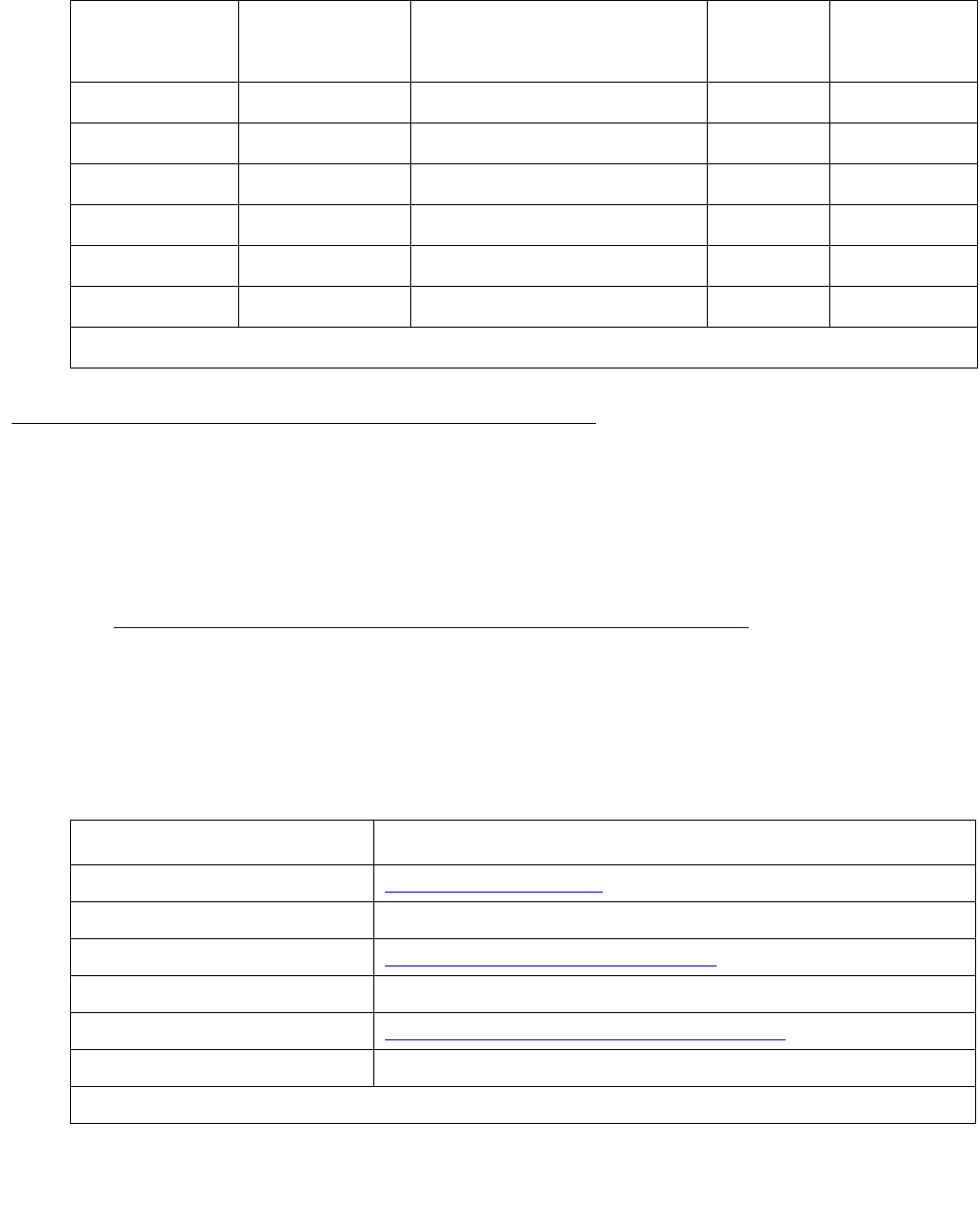
Event Data
Issue 1 June 2005 133
Cause Values
The Data Event 2 field on the display events screen sometimes contains Cause Value
information (DIAG/LOC/CV). Use this information to identify the Cause Value for each denial
event. The following information lists classes of Cause Values, their meaning and
interpretations, and associated translations.
See Table 49: ISDN, IP, and SIP-generated denial events (1173 - 1224) on page 189 for the
Denial Events that show Cause Value information (Cause Value, Location Code, and Diagnostic
Code) in Event Data 2 fields.
Cause Value Classes
21 Macedonia ETS 300 102 RESTART PROGRESS
22 Poland ETS 300 102 RESTART PROGRESS
23 Brazil ETS 300 102 RESTART PROGRESS
ETSI-a Europe, etc. ETS 300 102 RESTART PROGRESS
ETSI-b ETS 300 102 NONE PROGRESS
QSIG Private network ETS 300 102 RESTART PROGRESS
Table 43: Country Codes and Transmission Protocols (continued)
Country Code –
Protocol Version
Country Protocol Supported B-channel
Maint.
Message
Inter-working
Message
3 of 3
Table 44: Cause Value Classes and Ranges
Number range Cause Value Class
empty to 33 Normal Class Cause Values on page 134
●12, 14, 15, 24 unassigned
34 to 47 Resource Unavailable Class Cause Values on page 147
●36, 48 unassigned
49 to 63 Service or Option not Available Class Cause Values on page 151
●55, 60, 64 unassigned
1 of 2
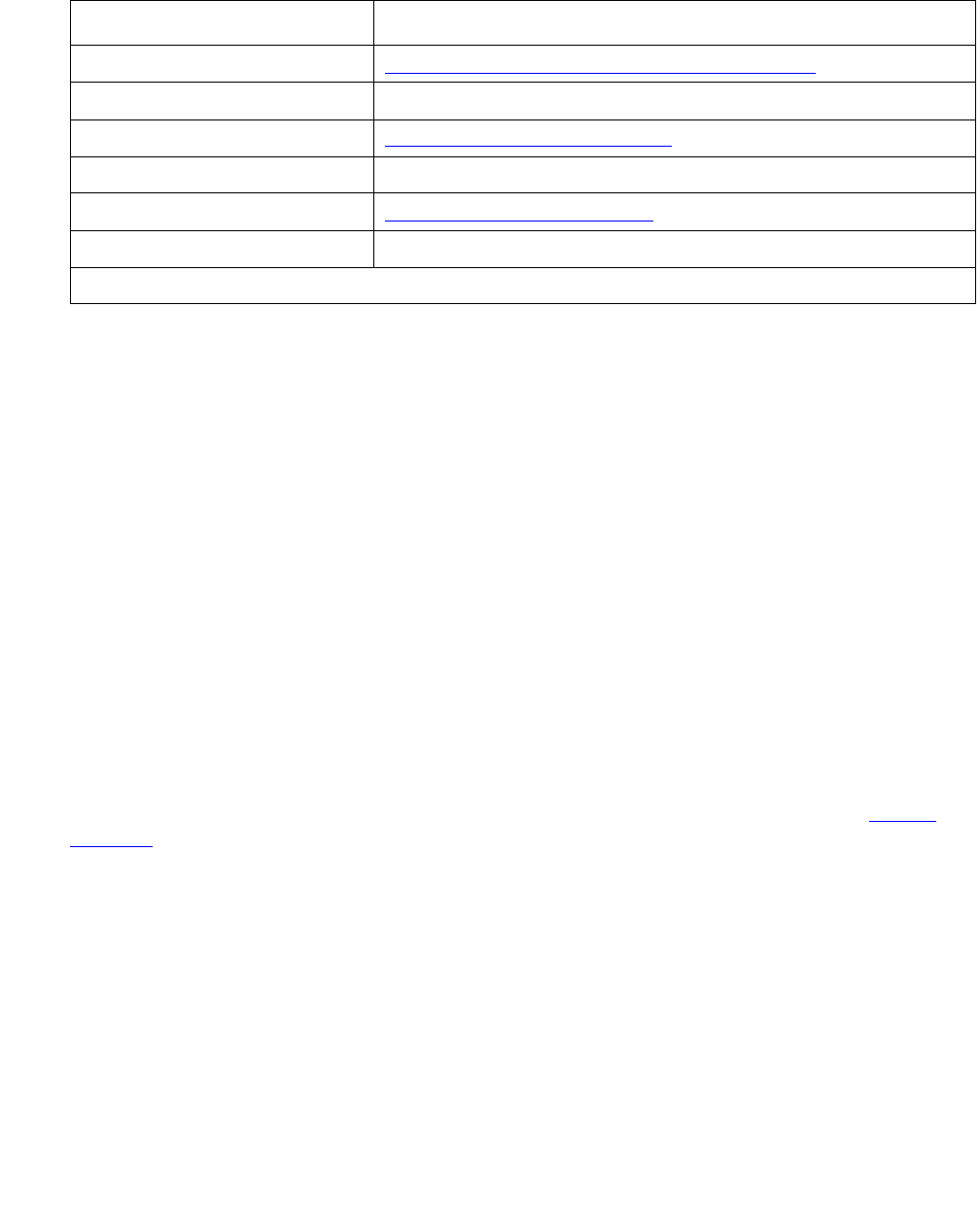
Denial Events
134 Maintenance Procedures for Avaya Communication Manager 3.0, Media Gateways and Servers
Cause Values
Normal Class Cause Values
Cause Value (empty)
[ ] -
Normal call clearing (1TR6: AT&T ISDN Protocol)
The call was disconnected normally by either end hanging up.
This Cause Value has end-to-end significance and should always be passed back through the
network to the user.
Cause Value 00
[0x0/0x80] -
Normal disconnect
The call was disconnected normally by either end hanging up. Most equipment uses Cause
Value 16 to report normal disconnect.
Cause Value 01
[0x1/0x81] -
Unassigned (Unallocated number)/
Invalid Call Reference Value (CRV) (1TR6: AT&T ISDN Protocol)
The call could not be completed because the number requested in the SETUP message is not
assigned/allocated by the ISDN network.
This Cause Value has end-to-end significance and should always be passed back through the
network to the user.
65 to 79 Service or Option not Implemented Class Cause Values on page 158
●67, 68, 71-78, 80 unassigned
81 to 95 Invalid Message Class Cause Values on page 161
● 92-94 unassigned
96 to127 Protocol Error Class Cause Values on page 165
●104-109, 116-126 unassigned
Table 44: Cause Value Classes and Ranges (continued)
Number range Cause Value Class
2 of 2

Event Data
Issue 1 June 2005 135
See also Cause Value 22 on page 143 and Cause Value 56 on page 154.
Troubleshooting
●Check the numbers sent to see if any prefixes or service values that were needed to
access the network were not sent.
●Check the Cause Value Information Element (LOC). See Location Codes on page 130.
●Check Communication Manager administration.
- Dial-plan/Location: The home NPA is administered incorrectly, causing incorrect code
conversion.
- IXC: The IXC matching pattern is administered incorrectly or not at all on the dial-plan,
causing incorrect IXC manipulation.
- AAR/ARS digit conversion: The wrong digit string substitution is being made. The call is
being routed into the wrong network and over the wrong route pattern. Further
conversion is needed, but the dial string is restricted from further conversion.
- AAR/ARS digit analysis: Call type is incorrect for the call being made specifying the
wrong type of number and/or number plan information, or it is preventing code
conversion from taking place. Call is being routed to the incorrect route pattern where the
incorrect digit manipulation and/or code conversion is taking place.
- ARS toll analysis: Toll/no toll classification is incorrect, causing incorrect code conversion
at the route pattern.
- Route pattern: Incorrect code conversion due to wrong entries in NPA, prefix mark, and
toll list/prefix mark fields. Deleting the wrong number of digits or inserting the wrong
digits. Failing to strip IXC or international code digits, stripping a user-dialed IXC code, or
IXC forcing the call to the wrong interexchange carrier.
- Trunk Group: The incorrect service or feature is specified for the call being made on a
CBC trunk group preference. The number format is being changed to a format incorrect
for the call type.
Cause Value 02
[0x2/0x82] -
No route to specified transit network/
Calling party off hold (5ESS: 5 Electronic Switching System)
The ISDN service provider’s equipment cannot route the call through the specified network. The
network either does not exist or is not compatible with the ISDN service provider’s equipment.
This Cause Value has local significance only. The ISDN network between the user and the
equipment generating the Cause Value might:
●Send no cause indication through the network.
●Send a more generic Cause Value through the network.
Because this Cause Value has only local significance, on tandem calls Communication
Manager might map it to Cause Value 31 instead of passing it back through the network.

Denial Events
136 Maintenance Procedures for Avaya Communication Manager 3.0, Media Gateways and Servers
Troubleshooting
●Check the diagnostic information (DIAG) for the transit network identity of the unreachable
network. See Cause Values and their meanings/interpretations on page 128.
●Check the numbers sent for any missing prefixes or service values that were needed to
access the network.
●Check that the call type (data, voice, fax) can be routed between the ISDN networks
serving both ends of the call.
●Check that the bearer capabilities of the call are acceptable to the ISDN network serving
both ends of the call.
●Check the Cause Value Information Element (LOC). See Location Codes on page 130.
●Check Communication Manager administration.
- AAR/ARS digit analysis: Call type is incorrect for the call being made specifying the
wrong type of number and/or number plan information, or it is preventing code
conversion from taking place. Call is being routed to the incorrect route pattern where the
incorrect digit manipulation and/or code conversion is taking place.
- Route pattern: Incorrect digits or IXC were inserted. Incorrect number of digits were
deleted. An incorrect ITC and/or BCIE were specified, affecting the SETUP message
bearer capability encoding. An incorrect service or feature was specified for the
preference. The number format specified is wrong for the call type.
- The ITC administered on the originating endpoint might be incorrect for this call.
- Incorrect data speed option is set in the BRI device, causing a call from a BRI endpoint
tandeming through Communication Manager to create a SETUP message with the
wrong bearer capability.
Cause Value 03
[0x3/0x83] -
No route to destination/
Calling party dropped while on hold (5ESS: 5 Electronic Switching System)/
Bearer service not implemented (1TR6: AT&T ISDN Protocol)
The ISDN service provider cannot route the call to the indicated destination. Communication
Manager does not originate Cause Value 03.
Troubleshooting
●Check the numbers sent for any missing prefixes or service values that were needed to
access the network.
●Check the Cause Value Information Element (LOC). See Location Codes on page 130.
●Check Communication Manager administration.
- Dial-plan/Location: The home NPA is administered incorrectly, causing incorrect code
conversion.

Event Data
Issue 1 June 2005 137
- IXC: The IXC matching pattern is administered incorrectly or not at all on the dial-plan,
causing incorrect IXC manipulation.
- AAR/ARS digit conversion: The wrong digit string substitution is being made. The call is
being routed into the wrong network and over the wrong route pattern. Further
conversion is needed but the dial string is restricted from further conversion.
- AAR/ARS digit analysis: Call type is incorrect for the call being made specifying the
wrong type of number and/or number plan information, or it is preventing code
conversion from taking place. Call is being routed to the incorrect route pattern where the
incorrect digit manipulation and/or code conversion is taking place.
- ARS toll analysis: Toll/no toll classification is incorrect, causing incorrect code conversion
at the route pattern.
- Route pattern: Incorrect code conversion due to wrong entries in NPA, prefix mark, and
toll list/prefix mark fields. Deleting the wrong number of digits or inserting the wrong
digits. Failing to strip IXC or international code digits, stripping a user-dialed IXC code, or
IXC forcing the call to the wrong interexchange carrier. Number format changed to a
format incorrect for the call type. The incorrect service or feature is specified for the call
being made on a CBC trunk group preference.
Cause Value 04
[0x4/0x84] -
Send special information tone/
Vacant Code (NI-2: National ISDN 2)
Cause Value 04 indicates the remote number that was dialed could not be reached.
Cause Value 04 (NI-2) indicates that the destination requested by the calling party cannot be
reached because the Numbering Plan Area (NPA) or Central Office (CO) code is vacant
(unassigned).
Troubleshooting
●Check the numbers sent for any missing prefixes or service values that were needed to
access the network.
●Check the Cause Value Information Element (LOC). See Location Codes on page 130.
●Check Communication Manager administration.
- Dial-plan/Location: The home NPA is administered incorrectly, causing incorrect code
conversion.
- IXC: The IXC matching pattern is administered incorrectly or not at all on the dial-plan,
causing incorrect IXC manipulation.
- AAR/ARS digit conversion: The wrong digit string substitution is being made. The call is
being routed into the wrong network and over the wrong route pattern. Further
conversion is needed but the dial string is restricted from further conversion.

Denial Events
138 Maintenance Procedures for Avaya Communication Manager 3.0, Media Gateways and Servers
- AAR/ARS digit analysis: Call type is incorrect for the call being made specifying the
wrong type of number and/or number plan information, or it is preventing code
conversion from taking place. Call is being routed to the incorrect route pattern where the
incorrect digit manipulation and/or code conversion is taking place. An incorrect service
or feature is specified for the call being made on a CBC trunk group preference.
Changing the Number format to a format incorrect for the call type.
- ARS toll analysis: Toll/no toll classification is incorrect, causing incorrect code conversion
at the route pattern.
- Route pattern: Incorrect code conversion due to wrong entries in NPA, prefix mark, and
toll list/prefix mark fields. Deleting the wrong number of digits or inserting the wrong
digits. Failing to strip IXC or international code digits, stripping a user-dialed IXC code, or
IXC forcing the call to the wrong interexchange carrier.
Cause Value 05
[0x5/0x85] -
Misdialed trunk prefix
The remote number that was dialed could not be reached.
Troubleshooting
●Check the numbers sent for any missing prefixes or service values that were needed to
access the network.
●Check the Cause Value Information Element (LOC). See Location Codes on page 130.
●Check Communication Manager administration.
- Dial-plan/Location: The home NPA is administered incorrectly, causing incorrect code
conversion.
- IXC: The IXC matching pattern is administered incorrectly or not at all on the dial-plan,
causing incorrect IXC manipulation.
- AAR/ARS digit conversion: The wrong digit string substitution is being made. The call is
being routed into the wrong network and over the wrong route pattern. Further
conversion is needed but the dial string is restricted from further conversion.
- AAR/ARS digit analysis: Call type is incorrect for the call being made specifying the
wrong type of number and/or number plan information, or it is preventing code
conversion from taking place. Call is being routed to the incorrect route pattern where the
incorrect digit manipulation and/or code conversion is taking place.
- ARS toll analysis: Toll/no toll classification is incorrect, causing incorrect code conversion
at the route pattern.
- Route pattern: Incorrect code conversion due to wrong entries in NPA, prefix mark, and
toll list/prefix mark fields. Deleting the wrong number of digits or inserting the wrong
digits. Failing to strip IXC or international code digits, stripping a user-dialed IXC code, or
IXC forcing the call to the wrong interexchange carrier.

Event Data
Issue 1 June 2005 139
- AAR/ARS digit analysis: Call type is incorrect for the call being made specifying the
wrong type of number and/or number plan information, or it is preventing code
conversion from taking place. An incorrect service or feature is specified for the call being
made on a CBC trunk group preference. Changing the Number format to a format
incorrect for the call type.
Cause Value 06
[0x6/0x86] -
Channel Unacceptable
The call attempt failed because the requested channel is not acceptable to the ISDN service
provider.
Troubleshooting
●Check Communication Manager administration.
- B-channels might be assigned off a T1/E1 into a trunk group that are not available for
service from the remote end. Contact the ISDN service provider to find out which
B-channels can be used.
Cause Value 07
[0x7/0x87] -
Call awarded and being delivered in an established channel/
Call identity does not exist (1TR6: AT&T ISDN Protocol)
Cause Value 07 indicates that a new incoming call is being established and is being connected
on a channel that has previously been connected to the same user for similar type calls (for
example, packet mode X.25 virtual channels being established on the d-channel).
Cause Value 07 (1TR6) indicates that a call resume has been attempted for a call with an
identity different from any currently suspended calls.
Not an option for ISDN D-channels.
Cause Value 08
[0x8/0x88] -
Preemption/
Prefix 0 dialed in error (NI-2: National ISDN 2)/
Call identity in use (1TR6: AT&T ISDN Protocol)/
Call is proceeding (NI-1: National ISDN 1)
Cause Value 08 For Autovon switching networks, the call attempt was blocked by a call with a
higher priority.
Cause Value 08 (NI-2) indicates that the network does not want to receive the prefix digit 0 as
part of the digit string in the CALLED PARTY NUMBER.
Cause Value 08 (1TR6) indicates that the call identity that sent in the call resume request is
already in use by the network.

Denial Events
140 Maintenance Procedures for Avaya Communication Manager 3.0, Media Gateways and Servers
Troubleshooting
Wait and try the call again later.
Cause Value 09
[0x9/0x89] -
Preemption, circuit reserved for reuse/
Prefix 1 dialed in error (NI-2: National ISDN 2)
Cause Value 09 For Autovon switching networks, the call attempt was blocked by a call with a
higher priority reserving the requested channel for reuse.
Cause Value 09 (NI-2) indicates that the network does not want to receive the prefix digit 1 as
part of the digit string in the CALLED PARTY NUMBER.
Troubleshooting
Wait and try the call again later.
Cause Value 10
[0xA/0x8A] -
Prefix 1 not dialed (NI-2: National ISDN 2)/
No channel available (1TR6: AT&T ISDN Protocol)
Cause Value 10 (N1-2) indicates that he user must send the prefix digit 1 as part of the
CALLED PARTY NUMBER.
Cause Value 10 (1TR6) indicates that the call cannot be completed because there is no
appropriate circuit/channel presently available to handle the call request, or that congestion
exists within the ISDN network.
This Cause Value has end-to-end significance and should always be passed back through the
network to the user.
Cause Value 11
[0xB/0x8B] -
Excessive digits received call proceeding (NI-2: National ISDN 2)
The equipment received more address digits in the CALLED PARTY NUMBER IE than
expected during call origination procedures, and the received address information has been
truncated.
Cause Value 13
[0xD/0x8D] -
Service Denied (NI-1: National ISDN 1)

Event Data
Issue 1 June 2005 141
Cause Value 16
[0x10/0x90] -
Normal call clearing/
Requested facility not implemented (1TR6: AT&T ISDN Protocol)
Cause Value 16 indicates that the call was disconnected normally by either end hanging up.
Cause Value 16 (1TR6) indicates that the call could not be completed because the equipment
sending this Cause Value does not support the requested service, feature, or supplementary
service in the SETUP message.
This Cause Value has end-to-end significance and should always be passed back through the
network to the user.
Troubleshooting
●Check the diagnostic information (DIAG) for the facility identifier of the not implemented
service. See Cause Values and their meanings/interpretations on page 128.
●If the remote device terminated the connection unexpectedly, contact the person
responsible for the remote end to determine if there is a problem with the remote endpoint.
●For data bearer capability calls, if the connection has failed to establish, but the CONNECT
and CONNECT_ACK messages were exchanged before the DISCONNECT was
received, the handshake between the devices involved in the call might have failed due to:
- Option settings with the endpoint devices
- Bandwidth constriction issues on the b-channel used by the two devices to make the call
Cause Value 17
[0x11/0x91] -
User busy/
Requested facility not subscribed (1TR6: AT&T ISDN Protocol)
Cause Value 17 indicates that the endpoint called is unable to accept another call.
Cause Value 17 (1TR6) indicates that the call could not be completed because the user has not
subscribed to the service, feature, or supplementary service requested in the SETUP message.
This Cause Value has end-to-end significance and should always be passed back through the
network to the user.
See also Cause Value 16 on page 141 and Cause Value 31 on page 146.
Troubleshooting
●Wait and try the call again later.
●If the user is supposed to have access to the service, feature, or supplementary service,
complete the ordering process with the ISDN service provider.

Denial Events
142 Maintenance Procedures for Avaya Communication Manager 3.0, Media Gateways and Servers
●Check the Cause Value Information Element (LOC).
- If the location information of the Cause Value is 4, “public network serving the remote
user”, the trunk group to the remote endpoint location might be experiencing an “all
trunks busy” condition or not enough channels allocated into a virtual group for the
particular NSF of the call.
- If the location information of the Cause Value is 0, “user”, the endpoint might be busy.
●If Communication Manager is generating this Cause Value, and the endpoint is not busy,
check the following Communication Manager administration.
- Trunk group screen: Usage Allocation is y on the CBC Service Type field. Not enough
incoming channels have been allocated for the NSF associated with this call.
- VDNs and Call vectoring: Analyze the vector processing and the call flow to determine
where the failure is occurring. VDN vector administration might incorrectly send the call
to a “busy” vector step. The call might go to a skill/Automatic Call Distribution (ACD)
group queue that is full and cannot accept any more calls. Look Ahead Interflow/Best
Service Routing (LAI/BSR) might receive an inappropriate ISDN response while
checking other sites for available agents and return busy feedback to the caller. The LAI/
BSR attempt might interact with the public network features Egress on busy – overflow to
POTS, Alternate Destination Routing (ADR), or Alternate Destination Call Redirection
(ADCR).
- Trunk and/or station Class of Restriction (COR) might prevent the call from terminating at
the endpoint.
- The endpoint might be call forwarded, and this is the second call within the 30-second
time limit on a station call-forwarding a call.
Cause Value 18
[0x12/0x92] -
No user responding/
No response from the remote device
The remote device/endpoint/PBX did not respond with an ALERTING/PROGRESS/CONNECT
indication within the time administered in the T303 or T310 timers Q.931 specification.
Cause Value 18 indicates high traffic conditions in the serving ISDN network or noisy conditions
on the T1/E1 span carrying the d-channel messaging. The noise is causing the loss of
messages being sent to the remote device. The remote device might also be unable to respond
to the incoming SETUP request.
This Cause Value has end-to-end significance and should always be passed back through the
network to the user.

Event Data
Issue 1 June 2005 143
Cause Value 19
[0x13/0x93] -
User alerting no answer
The remote device returned an alerting [ringing] indication but did not provide a connect
indication within the period of time prescribed by timer T301.
Communication Manager never originates this Cause Value.
Troubleshooting
Wait and retry the call later.
Cause Value 20
[0x14/0x94] -
Subscriber absent [wireless networks]
The mobile remote device/endpoint is not available.
Troubleshooting
Wait and try the call again later.
Cause Value 21
[0x15/0x95] -
Call rejected
The remote endpoint did not accept this call, even though the equipment is neither busy nor
incompatible and it could have accepted the call.
Check the diagnostic information (DIAG) for the user-supplied condition for why the call was
rejected. See Cause Values and their meanings/interpretations on page 128.
Cause Value 22
[0x16/0x96] -
Number changed
The called party number was changed to a new number.
Cause Value 01 appears if the ISDN network does not support Cause Value 22.
A BRI or Adjunct Switch Application Interface (ASAI) application might generate Cause Value
22. Communication Manager does not originate Cause Value 22 for PRI.
This Cause Value has end-to-end significance and should always be passed back through the
network to the user.
Check the diagnostic information (DIAG) for the new number. See Cause Values and their
meanings/interpretations on page 128.

Denial Events
144 Maintenance Procedures for Avaya Communication Manager 3.0, Media Gateways and Servers
Cause Value 23
[0x17/0x97] -
Redirection to new destination
The call has been redirected to a different endpoint.
Communication Manager does not originate Cause Value 23.
Cause Value 25
[0x19/0x99] -
Exchange routing error
The call cannot be routed to the remote party.
Cause Value 26
[0x1A/0x9A] -
Non-selected user clearing
The call was cleared before the called endpoint was awarded the incoming call.
Cause Value 27
[0x1B/0x9B] -
Destination out of order
The call cannot be delivered to the remote endpoint because the interface to the endpoint is not
functioning correctly. A signaling message could not be delivered to the remote device (for
example, there is a physical or data link layer failure at the remote device, or the remote device
is turned off).
Communication Manager does not originate Cause Value 27.
Cause Value 28
[0x1C/0x9C] -
Invalid number format (address incomplete)
Special intercept announcement (NI-1: National ISDN 1)
The called endpoint could not be reached because the CALLED PARTY NUMBER information
is not in a valid format or is not complete.
This Cause Value has end-to-end significance and should always be passed back through the
network to the user.

Event Data
Issue 1 June 2005 145
Troubleshooting
●Check the Cause Value Information Element (LOC). See Location Codes on page 130.
●Check Communication Manager administration (network generated the Cause Value).
- Dial-plan/Location: The home NPA is administered incorrectly, causing incorrect code
conversion.
- IXC: The IXC matching pattern is administered incorrectly or not at all on the dial-plan,
causing incorrect IXC manipulation.
- AAR/ARS digit conversion: The wrong digit string substitution is being made. The call is
being routed into the wrong network and over the wrong route pattern. Further
conversion is needed but the dial string is restricted from further conversion.
- AAR/ARS digit analysis: Call type is incorrect for the call being made specifying the
wrong type of number and/or number plan information, or it is preventing code
conversion from taking place. Call is being routed to the incorrect route pattern where the
incorrect digit manipulation and/or code conversion is taking place.
- ARS toll analysis: Toll/no toll classification is incorrect, causing incorrect code conversion
at the route pattern.
- Route pattern: Incorrect NPA is causing incorrect code conversion. If the Prefix mark
field has the wrong value, incorrect code conversion takes place. Toll list in combination
with prefix mark is causing incorrect code conversion to take place. The wrong number of
digits are deleted, or failed to strip IXC digits or international code digits. Inserted the
wrong digits IXC forcing the call to the wrong inter-exchange carrier, or stripped out a
user dialed IXC code. The incorrect service or feature is specified for the call being made
on a CBC trunk group preference. The Number format was changed to a format incorrect
for the call type.
●Check administration (Communication Manager generated the Cause Value).
- Trunk group: Incoming call handling table might cause Communication Manager to
delete or insert the wrong digits or number of digits to match the dial-plan.
Cause Value 29
[0x1D/0x9D] -
Facility rejected/
Special intercept announcement undefined code (NI-1: National ISDN 1)
The call could not be completed because the ISDN network does not support or is not
subscribed to the network service or feature requested for use by this call.
This Cause Value has end-to-end significance and should always be passed back through the
network to the user.

Denial Events
146 Maintenance Procedures for Avaya Communication Manager 3.0, Media Gateways and Servers
Troubleshooting
●Check the diagnostic information (DIAG) for the facility identifier of the service that was
rejected. See Cause Values and their meanings/interpretations on page 128.
●Check Communication Manager administration (network generated the Cause Value).
- Route pattern: The service or feature field contains an incorrect value for this route
preference. The ITC/BCIE fields might not indicate the correct information for a data call.
●Check administration (Communication Manager generated the Cause Value).
- Trunk group form: the Service type field might indicate a static service type when the
network is sending NSF information. Change the field to indicate CBC service.
Cause Value 30
[0x1E/0x9E] -
Response to STATUS_ENQUIRY
Special intercept announcement number unassigned (NI-1: National ISDN 1)
Cause Value 30 is included in a STATUS message when the STATUS message is generated
because a STATUS_ENQUIRY message was received. This is a normal event and does not
indicate a call-affecting problem. Communication Manager generates a call-state audit every
maintenance cycle that elicits this response from the remote end.
This Cause Value has local significance only. The ISDN network between the user and the
equipment generating the Cause Value might:
●Send no cause indication through the network
●Send a more generic Cause Value through the network
Cause Value 31
[0x1F/0x9F] -
Normal unspecified/
Special intercept announcement call blocked due to group restriction (NI-1: National
ISDN 1)
Cause Value 31 reports a normal event when no other cause in the normal class applies.
The ISDN network might substitute this Cause Value for other causes generated within the
network that do not have end-to-end significance.
For most Cause Values with only local significance on tandem calls, Communication Manager
maps Cause Values to Cause Value 31. See also Cause Value 02 on page 135.
Cause Value 31 can also be used as a return code on BSR polling attempts instead of Cause
Value 16 or Cause Value 17 depending on which Cause Value has less impact/interaction on
the intervening ISDN network.

Event Data
Issue 1 June 2005 147
Cause Value 32
[0x20/0xA0] -
Outgoing calls barred (1TR6: AT&T ISDN Protocol)
The call could not be completed because the calling user does not have permission to make an
outgoing call.
This Cause Value has local significance only. The ISDN network between the user and the
equipment generating the Cause Value might:
●Send no cause indication through the network
●Send a more generic Cause Value through the network
Cause Value 33
[0x21/0xA1] -
User access busy (1TR6: AT&T ISDN Protocol)
Resource Unavailable Class Cause Values
Cause Value 34
[0x22/0xA2] -
No circuit/channel available/
Negative closed user group comparison (1TR6: AT&T ISDN Protocol)
Cause Value 34 indicates that he call cannot be completed because there is no appropriate
circuit/channel available to handle the call request, or congestion exists within the ISDN
network.
Communication Manager generates this Cause Value when a call is tandeming through
Communication Manager and the trunk group to be used for the outgoing leg is:
●In “all trunks busy” condition
●Otherwise unavailable for service
●Unreachable from the incoming trunk group due to Class of Restriction (COR), FRL,
trunk-to-trunk transfer restrictions, or disconnect supervision restrictions
Cause Value 34 (1TR6) indicates that the packet mode call was rejected because the user is
not a member of the remote end’s Closed User Group (CUG), which is a feature associated with
packet mode calls similar to X.25 connection made over the ISDN D-channel.
Communication Manager does not support packet mode sessions on D-channels, therefore this
is not applicable to Communication Manager.
This Cause Value has end-to-end significance and should always be passed back through the
network to the user.

Denial Events
148 Maintenance Procedures for Avaya Communication Manager 3.0, Media Gateways and Servers
Troubleshooting
●Check Communication Manager administration (network generated the Cause Value).
- B-channels might be assigned off a T1/E1 into a trunk group that are not available for
service from the remote end. Contact the ISDN service provider to find out which
B-channels can be used.
●Check administration that might cause Communication Manager to generate this Cause
Value.
- If all of the B-channels in a span are busied out or otherwise tied up by switch
maintenance but the D-channel is still up, an incoming call is rejected with this Cause
Value because the call cannot be negotiated to another span.
Cause Value 35
[0x23/0xA3] -
Non-existent closed user group (1TR6: AT&T ISDN Protocol)
The packet mode call was rejected because the equipment sending the Cause Value does not
recognize the requested Closed User Group (CUG), which is a feature associated with packet
mode calls similar to X.25 connection made over the ISDN D-channel.
Communication Manager does not support packet mode sessions on D-channels, therefore this
is not applicable to Communication Manager.
Cause Value 37
[0x25/0xA5] -
Semi-permanent connection not permitted (1TR6: AT&T ISDN Protocol)
Cause Value 38
[0x26/0xA6] -
Network out of order
The call was not completed because the ISDN network is not functioning correctly, and the
condition is likely to last a relatively long period of time. Immediately reattempting the call will
probably be unsuccessful.
Cause Value 39
[0x27/0xA7] -
Permanent frame mode connection out of service
This appears to be a Q.933 frame relay Cause Value. Equipment failure might have caused
termination of a frame relay PVC.
Not applicable to a Communication Manager system.

Event Data
Issue 1 June 2005 149
Cause Value 40
[0x28/0xA8] -
Permanent frame mode connection is operational
This appears to be a Q.933 frame relay Cause Value. A frame relay PVC that was terminated
has been restored to service.
Not applicable to a Communication Manager system.
Cause Value 41
[0x29/0xA9] -
Temporary Failure
The call was not completed because the ISDN network is not functioning correctly. The
condition is not likely to last a long period of time. If the user attempts the call again it will
probably complete.
Cause Value 41 might also indicate:
●The failure of channel negotiation at the terminating interface.
●A data link layer malfunction has occurred locally or at the remote network interface.
●The call is being cleared as a result of one or more protocol errors at the remote network
interface.
See also Cause Value 63 on page 157 and Cause Value 79 on page 160.
Cause Value 42
[0x2A/0xAA] -
Switching equipment congestion
The call could not be completed because the switching equipment generating this Cause Value
is experiencing a period of high traffic.
This Cause Value has end-to-end significance and should always be passed back through the
network to the user.
Troubleshooting
Wait and try the call again later.
Cause Value 43
[0x2B/0xAB] -
Access information discarded
The network could not deliver access or user information (such as low-layer compatibility or
calling-name information) to the remote endpoint for any one of various reasons. For example,
the call interworked from ISDN to non-ISDN facilities, or the remote end does not support
delivery of such information.

Denial Events
150 Maintenance Procedures for Avaya Communication Manager 3.0, Media Gateways and Servers
This Cause Value is usually delivered in a STATUS message. Communication Manager
generates this Cause Value when:
●A tandem call inter-works from ISDN to non-ISDN trunking.
●Calling number and/or calling name information is sent in the SETUP message when it is
not needed.
●Connected number information is sent when the network does not support it.
This Cause Value has end-to-end significance and should always be passed back through the
network to the user.
Check the diagnostic information (DIAG) for the Information Element identifier of the discarded
information. See Cause Values and their meanings/interpretations on page 128.
Cause Value 44
[0x2C/0xAC] -
Requested circuit/channel not available
The call was not completed because the circuit/channel requested for use in the SETUP
message was not available, and the call could not be negotiated to another channel either
because no other channel was available, or negotiation is not supported or was not wanted for
this call.
This Cause Value is generated when a glare condition is occurring and B-channel negotiation is
not supported.
Communication Manager generates this Cause Value when:
●It is the NETWORK side of the interface and a glare condition is occurring on the
requested B-channel.
●The B-channel requested in the incoming SETUP message is not in the correct
maintenance state to handle a call (for example, it is busied out or undergoing testing).
Troubleshooting
●CO switch default settings turn off channel negotiation support. Make a specific request to
turn on channel negotiation support when ordering CO service.
●Check Communication Manager administration (network generated the Cause Value).
- Trunk group form: When the Channel Negotiation field is set to exclusive,
Communication Manager requests B-channels for calls without support for negotiation so
if at the remote end the requested B-channel is unavailable for whatever reason the call
cannot be negotiated to a more acceptable B-channel and the call will be rejected with
Cause Value 44. Set the Channel Negotiation field to preferred to support channel
negotiation.

Event Data
Issue 1 June 2005 151
Cause Value 45
[0x2D/0xAD] -
Pre-empted
The call could not be completed because the equipment sending this Cause Value does not
have the requested B-channel in a maintenance state that allows for call requests to be
processed.
Communication Manager does not support this Cause Value.
Cause Value 46
[0x2E/0xAE] -
Precedence call Blocked
For Autovon switching networks, the call could not complete because the remote endpoint is
busy with a call that has a higher priority.
Cause Value 47
[0x2F/0xAF] -
Resource unavailable, unspecified/
New destination (4ESS/5ESS: 4/5 Electronic Switching System)
Cause Value 47 indicates a resource unavailable event only when no other cause in the
resource unavailable class applies.
Cause Value 47 (4ESS/5ESS) If this Cause Value is returned in a RELEASE_COMPLETE or
DISCONNECT message and the customer is an Alternate Destination Call Redirection (ADCR)
subscriber, it invokes call redirection.
Communication Manager does not originate Cause Value 47.
Service or Option not Available Class Cause Values
Cause Value 49
[0x31/0xB1] -
Quality of service unavailable
The call could not be completed because the quality of service requested in the SETUP as
defined in ITU recommendation X.213 cannot be provided (for example, requested throughput
or transit delay cannot be supported).

Denial Events
152 Maintenance Procedures for Avaya Communication Manager 3.0, Media Gateways and Servers
Cause Value 50
[0x32/0xB2] -
Requested facility not subscribed
The call could not be completed because the user has not subscribed to the service, feature, or
supplementary service requested in the SETUP message. If the user is supposed to have
access to this service, feature, or supplementary service, then complete the required ordering
process with the ISDN service provider.
This Cause Value has end-to-end significance and should always be passed back through the
network to the user.
Communication Manager does not originate this Cause Value for PRI. A BRI or Adjunct Switch
Application Interface (ASAI) application might generate this Cause Value.
Communication Manager translations that can affect receiving this Cause Value from the
network are:
●Route Pattern: service or feature: An incorrect service or feature is specified for the call
being made on this CBC trunk group preference. An incorrect ITC and/or BCIE is
specified. These fields affect how the bearer capability is encoded in the SETUP message.
●The ITC administered on the originating endpoint might be incorrect for this call.
- Incorrect data speed option is set in the BRI device, causing a call from a BRI endpoint
tandeming through Communication Manager to create a SETUP message with the
wrong bearer capability.
●On tandem calls through Communication Manager from ISDN trunks to ISDN trunks, an
inappropriate NSF can be tandemed from one D-channel to the other D-channel.
●The problem is that the outgoing trunk group is CBC but no service or feature was
specified on the outgoing route pattern to overwrite the incoming NSF. Add the correct
service or feature to the route pattern or make the outgoing trunk group a static trunk
group (for example, public-network or tie) as appropriate.
●System Parameters Features: The US NI send Calling Name ID field is y. Communication
Manager sends the Bellcore calling name ID but the customer has not subscribed to that
service. Set the US NI send Calling Name ID field to n.
Cause Value 51
[0x33/0xB3] -
Bearer capability incompatible with service request (NI-1: National ISDN 1)
The requested action could not be completed. The requested action is incompatible with the
bearer capability of the call (for example, trying to place a data call on hold).

Event Data
Issue 1 June 2005 153
Cause Value 52
[0x34/0xB4] -
Outgoing calls barred
The call could not be completed because the network screened the call, and the calling user is
not permitted to make an outgoing call.
This Cause Value has local significance only. The ISDN network between the user and the
equipment generating the Cause Value might:
●Send no cause indication through the network
●Send a more generic Cause Value through the network
Cause Value 53
[0x35/0xB5] -
Service operation violated (NI-1: National ISDN 1)/
Destination not obtainable (1TR6: AT&T ISDN Protocol)
Cause Value 53 (NI-1) indicates that the user has violated the service operation.
Cause Value 53 (1TR6) indicates that the call cannot be delivered to the remote endpoint
because the interface to the endpoint in not functioning correctly. A signaling message could not
be delivered to the remote device (for example, there is a physical or data link layer failure at
the remote device, or the remote device is turned off).
Cause Value 54
[0x36/0xB6] -
Incoming calls barred
The call could not complete because the called user is not allowed to accept the call delivered in
the SETUP message.
This Cause Value has end-to-end significance and should always be passed back through the
network to the user.
Troubleshooting
●Check Communication Manager administration (network generated the Cause Value).
- Trunk group: Direction: The Communication Manager field might be set to two-way on a
trunk group that the ISDN network has configured as outgoing only, relative to the CO
switch, and a user on Communication Manager is attempting to make an outgoing call
over this trunk group, which is an incoming call to the CO.
- On tandem calls through Communication Manager from ISDN trunks to ISDN trunks, an
NSF for a one-way service (for example, Megacom 800) is being tandemed from one
D-channel to the other D-channel. The problem is that the outgoing trunk group is CBC
but no service or feature was specified on the outgoing route pattern to overwrite the
incoming NSF. Add the correct service or feature to the route pattern or make the
outgoing trunk group a static trunk group (for example, public-network or tie) as
appropriate.

Denial Events
154 Maintenance Procedures for Avaya Communication Manager 3.0, Media Gateways and Servers
Cause Value 56
[0x38/0xB8] -
Number changed (1TR6: AT&T ISDN Protocol)
The called party number indicated has been changed to a new number that might be sent in the
diagnostic information (DIAG) for this Cause Value. See Cause Values and their meanings/
interpretations on page 128. If this Cause Value is not supported by the ISDN network, Cause
Value 01 is used instead.
This Cause Value has end-to-end significance and should always be passed back through the
network to the user.
Communication Manager does not originate this Cause Value for PRI. A BRI or Adjunct Switch
Application Interface (ASAI) application might generate this Cause Value.
Cause Value 57
[0x39/0xB9] -
Bearer capability not authorized/
Out of order (1TR6: AT&T ISDN Protocol)
Cause Value 57 indicates that the call could not be completed because the user has requested
a bearer capability in the SETUP message which is implemented by the equipment generating
this Cause Value, but user has not subscribed to it or in other ways is not authorized to use.
Cause Value 57 (1TR6) indicates that the call cannot be delivered to the remote endpoint
because the interface to the endpoint is not functioning correctly. A signaling message could not
be delivered to the remote device (for example, due to a physical or data link layer failure at the
remote device, or the remote device is turned off).
Troubleshooting
●Check the diagnostic information (DIAG) for the unauthorized bearer capability attributes.
See Cause Values and their meanings/interpretations on page 128.
●Check Communication Manager administration (network generated the Cause Value).
- Route pattern: An incorrect ITC and/or BCIE specified, these fields affect how the bearer
capability is encoded in the SETUP message.
- The ITC administered on the originating endpoint might be incorrect for this call, and/or
the speed options in the device itself might be incorrect for calls over these ISDN
facilities.
- Incorrect data speed option is set in the BRI device, causing a call from a BRI endpoint
tandeming through Communication Manager to create a SETUP message with the
wrong bearer capability.
- A call tandeming through Communication Manager ISDN trunk group to ISDN trunk
group might have a bearer capability that is not supported by the outgoing ISDN facilities
or network.

Event Data
Issue 1 June 2005 155
- A call tandeming through Communication Manager on a non-ISDN trunk group
inter-working to an ISDN trunk group might have an incorrect bearer capability assigned
on the incoming trunk group. The BC and ITC fields on the incoming trunk group might
be set wrong.
Cause Value 58
[0x3A/0xBA] -
Bearer capability not presently available/
No user responding (1TR6: AT&T ISDN Protocol)
This Cause Value has end-to-end significance and should always be passed back through the
network to the user.
Cause Value 58 indicates that the call could not be completed because the user has requested
a bearer capability in the SETUP message which is implemented by the equipment generating
this Cause Value, but for which there are presently no resources available to be used to
complete the call.
Troubleshooting
Wait and try the call again later.
Cause Value 58 (1TR6) indicates that the remote device/endpoint/PBX did not respond with an
ALERTING/PROGRESS/CONNECT indication within the prescribed period of time allocated by
the expiry of the T303 or T310 timers in the Q.931 specification.
Troubleshooting
●Check the diagnostic information (DIAG) for the bearer capability attributes that are not
available. See Cause Values and their meanings/interpretations on page 128.
●Check Communication Manager administration (network generated the Cause Value).
- Route pattern: An incorrect ITC and/or BCIE specified, these fields affect how the bearer
capability is encoded in the SETUP message.
- The ITC administered on the originating endpoint might be incorrect for this call, and/or
the speed options in the device itself might be incorrect for calls over these ISDN
facilities.
- Incorrect data speed option is set in the BRI device, causing a call from a BRI endpoint
tandeming through Communication Manager to create a SETUP message with the
wrong bearer capability.
- A call tandeming through Communication Manager ISDN trunk group to ISDN trunk
group might have a bearer capability that is not supported by the outgoing ISDN facilities
or network.
- A call tandeming through Communication Manager on a non-ISDN trunk group
inter-working to an ISDN trunk group might have an incorrect bearer capability assigned
on the incoming trunk group. The BC and ITC fields on the incoming trunk group might
be set wrong.

Denial Events
156 Maintenance Procedures for Avaya Communication Manager 3.0, Media Gateways and Servers
Cause Value 59
[0x3B/0xBB] -
User busy (1TR6: AT&T ISDN Protocol)
The endpoint called has indicated an inability to accept another call.
This Cause Value has end-to-end significance and should always be passed back through the
network to the user.
Troubleshooting
●Wait and try the call again later.
●Check the Cause Value Information Element (LOC)
- If the Location Information of the Cause Value is 0 (User), the endpoint is probably busy.
- If the Location information of the Cause Value is 4 (Public Network Serving Remote
User), it is most likely that the trunk group to the remote endpoint location is experiencing
an “all trunks busy” condition or not enough channels allocated into a virtual group for the
particular NSF of the call.
●If Communication Manager is generating this Cause Value and the endpoint is not busy,
the following translations and features could be affecting the call:
- Trunk and/or station Class of Restriction (COR) might be preventing the call from
terminating at the called endpoint.
- The endpoint might be call-forwarded and this is the second call within the 30-second
time limit on a station call forwarding a call.
- Trunk group form: CBC service type: Usage Allocation is y. The usage allocation plan
might not have allocated enough incoming channels for the NSF associated with this call.
- VDNs and Call Vectoring: The vector associated with the VDN might be incorrectly
programmed and the call is inappropriately sent to a busy vector step. The skill/
Automatic Call Distribution (ACD) group that the call is trying to queue to might have a
full queue and cannot accept any more calls. Look Ahead Interflow/Best Service Routing
(LAI/BSR) might have received an inappropriate ISDN response while checking other
sites for available agents and has inadvertently returned busy feedback to the caller. The
LAI/BSR attempt might be interacting with the public network features Egress on busy –
overflow to POTS, Alternate Destination Routing (ADR), or Alternate Destination Call
Redirection (ADCR). Analyze the vector processing of the call and the call flow to
determine where the failure is occurring.
Cause Value 61
[0x3D/0xBD] -
Incoming calls barred (1TR6: AT&T ISDN Protocol)
The call could not complete because the called user is not allowed to accept the call delivered in
the SETUP message.

Event Data
Issue 1 June 2005 157
This Cause Value has end-to-end significance and should always be passed back through the
network to the user.
Troubleshooting
●Check Communication Manager administration (network generated the Cause Value).
- Trunk group: Direction: Communication Manager might be set to “two-way” on a trunk
group the ISDN network has configured as outgoing only, relative to the CO switch, and a
user on Communication Manager is attempting to make an outgoing call over this trunk
group, which is an incoming call to the CO.
- On tandem calls through Communication Manager from ISDN trunks to ISDN trunks, an
NSF for a one-way service (for example, Megacom 800) is being tandemed from one
D-channel to the other D-channel. The problem is that the outgoing trunk group is CBC
but no service or feature was specified on the outgoing route pattern to overwrite the
incoming NSF. Add the correct service or feature to the route pattern or make the
outgoing trunk group a static trunk group (for example, public-network or tie) as
appropriate.
Cause Value 62
[0x3E/0xBE] -
Service not authorized (VN4: French National PRI)/
Call rejected (1TR6: AT&T ISDN Protocol)
This Cause Value has end-to-end significance and should always be passed back through the
network to the user.
Cause Value 62 (VN4) indicates that the call could not be completed because the user has not
subscribed to the service, feature, or supplementary service requested in the SETUP message.
If the user is supposed to have access to this service, feature, or supplementary service, then
complete the required ordering process with the ISDN service provider.
Cause Value 62 (1TR6) indicates that the remote endpoint does not wish to accept this call,
although it could have accepted the call because the equipment is neither busy nor
incompatible.
The diagnostic information (DIAG) might be populated with the user-supplied condition for why
the call was rejected. See Cause Values and their meanings/interpretations on page 128.
Cause Value 63
[0x3F/0xBF] -
Service or option not available, unspecified
This Cause Value indicates that the requested service or option is unavailable when no other
cause in the Service or option not available class applies.
As an implementation option, this Cause Value shall either be passed to the user or mapped to
Cause Value 41 (Temporary Failure) when it is received at a CO as part of SS7 call handling.
Communication Manager does not originate Cause Value 63.

Denial Events
158 Maintenance Procedures for Avaya Communication Manager 3.0, Media Gateways and Servers
Service or Option not Implemented Class Cause Values
Cause Value 65
[0x41/0xC1] Bearer capability not implemented
The call could not be completed because the equipment sending this Cause Value does not
support the bearer capability requested in the SETUP message.
This Cause Value has end-to-end significance and should always be passed back through the
network to the user.
Troubleshooting
The diagnostic information (DIAG) of the Cause Value should contain if implemented the bearer
capability attributes that are not implemented. See Cause Values and their meanings/
interpretations on page 128.
Cause Value 66
[0x42/0xC2] Channel type not implemented
The call could not be completed because the equipment sending this Cause Value does not
support the channel type requested in the SETUP message.
This Cause Value has end-to-end significance and should always be passed back through the
network to the user.
Troubleshooting
●Check the diagnostic information (DIAG) for the unsupported channel type. See Cause
Values and their meanings/interpretations on page 128.
●Check Communication Manager administration (network generated Cause Value):
- Communication Manager is attempting to make a wideband call over an interface to an
ISDN network that does not support wideband calls. Check the trunk group and routing
translations to be sure the attempted call has not inadvertently been routed to this
interface or was mis-classified as a wideband call.
●Communication Manager administration that can affect sending of this Cause Value:
- The network is supporting wideband calling and Communication Manager does not have
wideband support enabled on the Wideband Switching field on the
system-parameters customer-options screen
- Communication Manager does not have wideband support enabled on the Wideband
Support field on the appropriate trunk group
- The trunk group does not have the correct type(s) of wideband channels enabled
- Communication Manager does not have the right size wideband endpoint programmed.

Event Data
Issue 1 June 2005 159
Cause Value 69
[0x45/0xC5] -
Requested facility not implemented
The call could not be completed because the equipment sending this Cause Value does not
support the requested service, feature, or supplementary service in the SETUP message.
This Cause Value has end-to-end significance and should always be passed back through the
network to the user.
Communication Manager does not originate this Cause Value for PRI. A BRI or Adjunct Switch
Application Interface (ASAI) application might generate this Cause Value.
Troubleshooting
●Check the diagnostic information (DIAG) for the facility identifier of the not-implemented
service. See Cause Values and their meanings/interpretations on page 128.
●Check Communication Manager administration (network generated the Cause Value).
- Route Pattern: service or feature: An incorrect service or feature is specified for the call
being made on this CBC trunk group preference. An incorrect ITC and/or BCIE specified,
these fields affect how the bearer capability is encoded in the SETUP message.
- The ITC administered on the originating endpoint might be incorrect for this call.
- Incorrect data speed option is set in the BRI device, causing a call from a BRI endpoint
tandeming through Communication Manager to create a SETUP message with the
wrong bearer capability.
- On tandem calls through Communication Manager from ISDN trunks to ISDN trunks, an
inappropriate NSF can be tandemed from one D-channel to the other D-channel. The
problem is that the outgoing trunk group is CBC but no service or feature was specified
on the outgoing route pattern to overwrite the incoming NSF. Add the correct service or
feature to the route pattern or make the outgoing trunk group a static trunk group (for
example, public-network or tie) as appropriate.
- System Parameters Features: US NI send Calling Name ID field is y. Communication
Manager sends the Bellcore calling name ID but the customer has not subscribed to that
service. Set the US NI send Calling Name ID field to n.
●Communication Manager is attempting to send User-to-User information in a message
through the public network when not subscribed to a UUS service, for example Look
Ahead Interflow/Best Service Routing (LAI/BSR) information, Adjunct Switch Application
Interface (ASAI) information, etc.

Denial Events
160 Maintenance Procedures for Avaya Communication Manager 3.0, Media Gateways and Servers
Cause Value 70
[0x46/0xC6] -
Only restricted digital information bearer capability is available
The call could not be completed because the equipment sending this Cause Value only
supports the restricted version of the requested bearer capability, and in the SETUP message
bearer capability was unrestricted.
Communication Manager does not originate Cause Value 70.
Troubleshooting
●Check Communication Manager administration (network generated the Cause Value).
- Route pattern: An incorrect ITC and/or BCIE specified, these fields affect how the bearer
capability is encoded in the SETUP message.
- The ITC administered on the originating endpoint might be incorrect for this call, and/or
the speed options in the device itself might be incorrect for calls over these ISDN
facilities.
- Incorrect data speed option is set in the BRI device, causing a call from a BRI endpoint
tandeming through Communication Manager to create a SETUP message with the
wrong bearer capability.
- A call tandeming through Communication Manager ISDN trunk group to ISDN trunk
group might have a bearer capability that is not supported by the outgoing ISDN facilities
or network.
- A call tandeming through Communication Manager on a non-ISDN trunk group
inter-working to an ISDN trunk group might have an incorrect bearer capability assigned
on the incoming trunk group. The BC and ITC fields on the incoming trunk group might
be set wrong.
Cause Value 79
[0x4F/0xCF] -
Service or option not implemented, unspecified
The call could not be completed because the equipment sending this Cause Value has not
implemented a service, feature, or supplementary service requested by the user, and none of
the other Cause Values in the Service or option not implemented class apply.
As an implementation option, this Cause Value might be mapped to Cause Value 41 (Temporary
Failure) when it is received at a CO as part of SS7 call handling.
Communication Manager does not originate Cause Value 79.

Event Data
Issue 1 June 2005 161
Invalid Message Class Cause Values
Cause Value 81
[0x51/0xD1] -
Invalid call reference value
The equipment sending this Cause Value received a message with a call reference value that is
not currently in use on this user-network (D-channel) interface. This could indicate a call state
mismatch for the attempted connection between the two sides of the interface.
This Cause Value is most often generated when a message in a call clearing sequence of
messages is lost in transmission due to problems experienced on the D-channel. One side of
the interface thinks that the call has been torn down but the other side sends messages to
complete clearing the call. The response to this new call clearing sequence becomes a
RELEASE_COMPLETE message with Cause Value 81.
This Cause Value has local significance only. The ISDN network between the user and the
equipment generating the Cause Value might:
●Send no cause indication through the network
●Send a more generic Cause Value through the network
Cause Value 82
[0x52/0xD2] -
Identified channel does not exist
The equipment sending this Cause Value received a SETUP request to use a channel that is
not activated on this interface for a call. For example, when a user has subscribed to those
channels on a primary rate interface numbered 1 to 12, and the user equipment or network
attempts to use one of the channels number 13 to 23, this Cause Value is generated.
This Cause Value has local significance only. The ISDN network between the user and the
equipment generating the Cause Value might:
●Send no cause indication through the network
●Send a more generic Cause Value through the network
Troubleshooting
●Check the diagnostic information (DIAG) for the channel number of the non-existent
channel. See Cause Values and their meanings/interpretations on page 128.
●Check Communication Manager administration (network generated the Cause Value).
- Communication Manager might have B-channels assigned off a T1/E1 into a trunk group
that are not available for service from the remote end. Contact the ISDN service provider
to find out which B-channels can be used.

Denial Events
162 Maintenance Procedures for Avaya Communication Manager 3.0, Media Gateways and Servers
●Communication Manager administration that can affect sending this Cause Value:
- Communication Manager might have missed assigning some B-channels into a trunk
group that the remote believes can be used for service and is attempting to request a call
on one. Check which channel is being requested and if possible assign it into the
appropriate trunk group. If the channel being requested is the 24th (T1) or 16th (E1)
channel, it might be incorrectly programmed as isdn-pri on the DS1 screen instead of
isdn-ext.
Cause Value 83
[0x53/0xD3] -
A suspended call exists, but this call identity does not
This Cause Value indicates that a call resume has been attempted for a call with an identity that
differs from any that are presently in a suspended state.
Cause Value 84
[0x54/0xD4] -
Call identity in use
This Cause Value indicates that the call identity sent in the call resume request is already in use
by the network.
Cause Value 85
[0x55/0xD5] -
No call suspended
This Cause Value indicates that a call resume has been attempted for a call, but the network
does not presently have any calls in a suspended state within the domain of interfaces over
which calls can be suspended.
Cause Value 86
[0x56/0xD6] -
Call having the requested call identity has been cleared
The equipment sending this cause received a resume request for a call identity indicating a
suspended call that had been cleared while still in the suspended state, either by a network
timeout or by the remote user.

Event Data
Issue 1 June 2005 163
Cause Value 87
[0x57/0xD7] -
User not a member of the Closed User Group [CUG]
The packet mode call was rejected because the user is not a member of the remote end’s
Closed User Group (CUG), which is a feature associated with packet mode calls similar to X.25
connection made over the ISDN D-channel.
Communication Manager does not support packet mode sessions on D-channels, therefore this
is not applicable to Communication Manager.
Cause Value 88
[0x58/0xD8] -
Incompatible destination
The call could not be completed because the call request in the SETUP message has low layer
compatibility, high layer compatibility, or other compatibility attributes (for example, data rate,
DN, or sub-address information) which the remote endpoint or network cannot accommodate.
This Cause Value has end-to-end significance and should always be passed back through the
network to the user.
Troubleshooting
●Check Communication Manager administration (network generated the Cause Value).
- Route pattern: An incorrect ITC and/or BCIE specified, these fields affect how the bearer
capability is encoded in the SETUP message.
- The ITC administered on the originating endpoint might be incorrect for this call, and/or
the speed options in the device itself might be incorrect for calls over these ISDN
facilities.
- Incorrect data speed option is set in the BRI device, causing a call from a BRI endpoint
tandeming through Communication Manager to create a SETUP message with the
wrong bearer capability.
- A call tandeming through Communication Manager ISDN trunk group to ISDN trunk
group might have a bearer capability that is not supported by the outgoing ISDN facilities
or network.
- A call tandeming through Communication Manager on a non-ISDN trunk group
inter-working to an ISDN trunk group might have an incorrect bearer capability assigned
on the incoming trunk group. The BC and ITC fields on the incoming trunk group might
be set wrong.
●Communication Manager administration that can affect sending this Cause Value:
- The extension number assigned in Communication Manager that was received in the
incoming SETUP message for this data call is assigned to an analog extension.
- The extension number assigned in Communication Manager that was received in the
incoming SETUP message for this voice call is assigned to a data extension.

Denial Events
164 Maintenance Procedures for Avaya Communication Manager 3.0, Media Gateways and Servers
- A data call attempt tandeming through Communication Manager ISDN trunk group to
ISDN trunk group the outgoing route pattern has the Bearer Capability Class (BCC)
required for making this call set to “NO” and/or the ITC and BCIE are not compatible with
the incoming bearer capability.
- A TSC setup attempt that is tandeming through Communication Manager, the outgoing
route pattern does not have the TSC bearer capability activated.
Cause Value 89
[0x59/0xD9] -
Network Congestion (1TR6: AT&T ISDN Protocol)
The call could not be completed because the switching equipment generating this Cause Value
is experiencing a period of high traffic.
This Cause Value has end-to-end significance and should always be passed back through the
network to the user.
Troubleshooting
Wait and try the call again later.
Cause Value 90
[0x5A/0xDA] -
Non-existent closed user group (CUG)/
Remote user initiated clearing (1TR6: AT&T ISDN Protocol)
The packet mode call was rejected because the equipment that sent the Cause Value did not
recognize the requested Closed User Group (CUG), which is a feature associated with packet
mode calls similar to X.25 connection made over the ISDN D-channel.
Communication Manager does not support packet mode sessions on D-channels, therefore this
is not applicable to Communication Manager.
Cause Value 91
[0x5B/0xDB] -
Invalid transit network selection
The call could not be completed because the equipment that sent this Cause Value received a
request to route a call to a transit network that it does not have a connection to, or the transit
network identification that was received is of an incorrect format as defined in Annex C of the
ITU Q.931 specification for either the TNS IE or the NSF IE.
Communication Manager does not originate Cause Value 91.

Event Data
Issue 1 June 2005 165
Troubleshooting
●Check Communication Manager administration (network generated the Cause Value).
- Communication Manager sent the transit network identification in the NSF IE when the
network expected it to be in the TNS IE. The protocol version on the DS1 form does not
match the near-end ISDN network that is terminating the D-channel. Contact the ISDN
network service provider and try to line up the protocols being used. NI-2 only supports
the TNS IE, while custom protocol supports use of the NSF IE for this purpose.
Cause Value 95
[0x5F/0xDF] -
Invalid message, unspecified
This Cause Value indicates an invalid message event only when no other cause in the invalid
message class applies.
Communication Manager does not originate this Cause Value for PRI. A BRI or Adjunct Switch
Application Interface (ASAI) application might generate this Cause Value.
Troubleshooting
The diagnostic information (DIAG) of the Cause Value should contain, if implemented, the
message type identifier of the invalid message. See Cause Values and their meanings/
interpretations on page 128.
Protocol Error Class Cause Values
Cause Value 96
[0x60/0xE0] -
Mandatory information element is missing
The equipment that sent this Cause Value Call Reference Value (CRV) received a message that
did not contain a required Information Element for the message to be parsed and processed.
Depending on which message in the call establishment sequence is missing information, a
message returned with this Cause Value might or might not indicate a problem establishing a
call.
When the public network is screening for Calling Party Number (CPN), the fact that CPN is
missing causes the network to return this Cause Value, but depending on optioning in the CO
the call might still go through.
This Cause Value has local significance only. The ISDN network between the user and the
equipment generating the Cause Value might:
●Send no cause indication through the network
●Send a more generic Cause Value through the network

Denial Events
166 Maintenance Procedures for Avaya Communication Manager 3.0, Media Gateways and Servers
Troubleshooting
●Check that the protocols at each end of the interface match (for example, both sides are
AT&T Custom or both sides are NI-2). If the ends of the interface are running different
protocols, they might be running with different Information Element encoding.
●Check the diagnostic information (DIAG) for the IE identifier of the missing information.
See Cause Values and their meanings/interpretations on page 128.
Communication Manager generates diagnostic information. See Table 45, Cause Value 96 &
100 Diagnostic Information, on page 166.
Table 45: Cause Value 96 & 100 Diagnostic Information
Missing IE Identifier Information Element
Code-set 0
0C/4C CONNECTED NUMBER
0D CONNECTED SUB-ADDRESS
01 CHANGE STATUS
1C FACILITY
1E PROGRESS INDICATOR
2C KEYPAD
04 BEARER CAPABILITY
6C CALLING PARTY NUMBER
6D CALLING PARTY SUB-ADDRESS
7C LOW LAYER COMPATIBILITY
7D HIGH LAYER COMPATIBILITY
7E USER-TO-USER INFORMATION
08 CAUSE
10 CALL IDENTITY
14 CALL STATE
18 CHANNEL IDENTIFICATION
1 of 2

Event Data
Issue 1 June 2005 167
Cause Value 97
[0x61/0xE1] -
Message type non-existent or not implemented
The equipment that sent this Cause Value received a message containing a message type it
does not recognize, either because the message type is not defined or it is defined but not
implemented by the equipment.
20 NETWORK SPECIFIC FACILITIES
27 NOTIFICATION INDICATOR
28 DISPLAY
34 SIGNAL
70 CALLED PARTY NUMBER
71 CALLED PARTY SUB-ADDRESS
74 REDIRECTING NUMBER
79 RESTART INDICATOR
78 TRANSIT NETWORK SELECTION
Code-set 6
7B LOOK AHEAD INTERFLOW
08 TRAVELING CLASS MARK
28 DISPLAY
55 Distributed Communication System
(DCS)
56 Distributed Communication System
(DCS) AUDIX
57 AUDIX
96 LOCK SHIFT TO CODE-SET6
Table 45: Cause Value 96 & 100 Diagnostic Information (continued)
Missing IE Identifier Information Element
2 of 2

Denial Events
168 Maintenance Procedures for Avaya Communication Manager 3.0, Media Gateways and Servers
This Cause Value has local significance only. The ISDN network between the user and the
equipment generating the Cause Value might:
●Send no cause indication through the network
●Send a more generic Cause Value through the network
Troubleshooting
●Check that the protocols at each end of the interface match (for example, both sides are
AT&T Custom or both sides are NI-2). If the ends of the interface are running different
protocols, they might be running with different Information Element encoding.
●Check the diagnostic information generated by Communication Manager for the message
type identifier of the unrecognized message.
Table 46: Cause Value 97, 98, 101 Diagnostic Information
Message Type Identifier Message
0D SETUP ACKNOWLEDGE
0F CONNECT ACKNOWLEDGE
01 ALERTING
02 CALL PROCEEDING
03 PROGRESS
05 SETUP
07 CONNECT
4D RELEASE
4E RESTART ACKNOWLEDGE
5A RELEASE COMPLETE
6A FACILITY ACKNOWLEDGE
6E NOTIFY
7B INFORMATION
7D STATUS
20 USER INFORMATION
45 DISCONNECT
46 RESTART
62 FACILITY
1 of 2

Event Data
Issue 1 June 2005 169
Cause Value 98
[0x62/0xE2] -
Message type, not compatible with call state, or non-existent, or not implemented
The equipment that sent this Cause Value received a message, and the procedures in the
protocol specification indicate that this is not a permissible message to receive while in this call
state. A STATUS message was received indicating an incompatible call state.
This Cause Value has local significance only. The ISDN network between the user and the
equipment generating the Cause Value might:
●Send no cause indication through the network
●Send a more generic Cause Value through the network
Troubleshooting
●Check that the protocols at each end of the interface match (for example, both sides are
AT&T Custom or both sides are NI-2). If the ends of the interface are running different
protocols, they might be running with different call state machines, or different message
type encoding.
●Check the diagnostic information generated by Communication Manager for the message
type identifier of the message that violates protocol. See Table 46: Cause Value 97, 98,
101 Diagnostic Information on page 168.
●Call state problems are reported with STATUS messages. The equipment sending the
Cause Value uses the CALL STATE IE of the STATUS message to indicate the call state.
To determine the call state of the other end of the interface, run the message sequence of
the call through the SDL flow charts of the appropriate side (user or network) and the
appropriate protocol (TR41449/41459, TR1268, A211 etc.). If the call state at the other end
of the interface does not agree with that reported in the STATUS message and both sides
are already running the same protocol, then a problem with the implementation of the state
machine exists on either side.
72 FACILITY REJECT
75 STATUS ENQUIRY
79 CONGESTION CONTROL
Maintenance Message
0F SERVICE
07 SERVICE ACKNOWLEDGE
Table 46: Cause Value 97, 98, 101 Diagnostic Information (continued)
Message Type Identifier Message
2 of 2

Denial Events
170 Maintenance Procedures for Avaya Communication Manager 3.0, Media Gateways and Servers
Problems have been revealed with the state machine implementations of some of the CO
switches for different protocols, and the state machine problems in the CO switches are
most likely not going to be corrected. Communication Manager has not shown any
problems with its state machine implementations for the different protocols.
Change Communication Manager administration to change the message sequence of the
call scenario causing the error, and help solve state machine implementation problems. For
example:
- change the inter-working message on the DS1 form from PROGRESS to ALERTING
- change the “wait” steps in vectors to be “i-silent” so that they do not generate extra
PROGRESS messages in the calling message sequence.
Cause Value 99
[0x63/0xE3] -
Information element non-existent or not implemented
The equipment that sent this Cause Value received a message that includes Information
Elements that are not recognized because the Information Element identifier is not defined, or it
is defined but has not been implemented by the equipment sending the Cause Value. However,
the Information Element is not mandatory in the message, and the equipment that sent the
Cause Value does not need to parse the Information Element in order to process the message.
This Cause Value has local significance only. The ISDN network between the user and the
equipment generating the Cause Value might:
●Send no cause indication through the network
●Send a more generic Cause Value through the network
Troubleshooting
●Check that the protocols at each end of the interface match (for example, both sides are
AT&T Custom or both sides are NI-2). If the ends of the interface are running different
protocols, they might be running with different Information Element encoding.
●Check Communication Manager administration (network generated the Cause Value).
- Sending connected number information with the domestic custom Information Element
identity encoding (0C), but international encoding (4C)is expected.
Cause Value 100
[0x64/0xE4] -
Invalid information element contents
The equipment that sent this Cause Value received a message that includes an Information
Element that it does recognize and implements, however one or more of the fields contained in
the Information Element are coded in such a way that it has not been implemented by the
equipment that sent this Cause Value.

Event Data
Issue 1 June 2005 171
This Cause Value has local significance only. The ISDN network between the user and the
equipment generating the Cause Value might:
●Send no cause indication through the network
●Send a more generic Cause Value through the network
Troubleshooting
●Check that the protocols at each end of the interface match (for example, both sides are
AT&T Custom or both sides are NI-2). If the ends of the interface are running different
protocols, they might be running with different Information Element encoding.
●Check Communication Manager diagnostics for the IE identifier of the Information Element
that contains the information that violates protocol.
The PROGRESS INDICATOR IE information that Communication Manager generates
should not affect call completion. There is no way to modify how Communication Manager
generates this information.
See Table 45, Cause Value 96 & 100 Diagnostic Information, on page 166.
Cause Value 101
[0x65/0xE5] -
Message not compatible with call state/
Protocol threshold exceeded (NI-2: National ISDN 2)
Cause Value 101 indicates that the equipment that sent this Cause Value received a message
that it does recognize, and procedures in the protocol specification indicate that it is not
permissible to receive the message while in this call state.
This Cause Value has local significance only. The ISDN network between the user and the
equipment generating the Cause Value might:
●Send no cause indication through the network
●Send a more generic Cause Value through the network
Cause Value 101 (NI-2) can also mean that an established call or an establishing call is being
cleared because the threshold for multiple signaling protocol errors occurring during an active
call has been exceeded.
Troubleshooting
●Check that the protocols at each end of the interface match (for example, both sides are
AT&T Custom or both sides are NI-2). If the ends of the interface are running different
protocols, they might be running different call state machines.
●Check the Communication Manager diagnostic information for the message type identifier
that is in violation of the protocol. Table 46: Cause Value 97, 98, 101 Diagnostic
Information on page 168

Denial Events
172 Maintenance Procedures for Avaya Communication Manager 3.0, Media Gateways and Servers
●Call state problems are reported with STATUS messages. The equipment sending the
Cause Value uses the CALL STATE IE of the STATUS message to indicate the call state.
To determine the call state of the other end of the interface, run the message sequence of
the call through the SDL flow charts of the appropriate side (user or network) and the
appropriate protocol (TR41449/41459, TR1268, A211 etc.). If the call state at the other end
of the interface does not agree with that reported in the STATUS message and both sides
are already running the same protocol, then a problem with the implementation of the state
machine exists on either side.
Problems have been revealed with the state machine implementations of some of the CO
switches for different protocols, and the state machine problems in the CO switches are
most likely not going to be corrected. Communication Manager has not shown any
problems with its state machine implementations for the different protocols.
Change Communication Manager administration to change the message sequence of the
call scenario causing the error, and help solve state machine implementation problems. For
example:
- change the inter-working message on the DS1 form from PROGRESS to ALERTING
- change the “wait” steps in vectors to be “i-silent” so that they do not generate extra
PROGRESS messages in the calling message sequence.
Cause Value 102
[0x66/0xE6] -
Recovery on timer Expiry
The equipment sending this Cause Value sent or received a Layer 3 Q.931 message. Sending
or receiving this message has initiated a Layer 3 timer that has expired. This Cause Value is
being generated in conjunction with Q.931 protocol error handling procedures.
This Cause Value has local significance only. The ISDN network between the user and the
equipment generating the Cause Value might:
●Send no cause indication through the network
●Send a more generic Cause Value through the network
Communication Manager logs timer expiry errors that it generates to the hardware error log
against the signaling group of the D-channel where the error occurred. The signaling group
(ISDN-SER) error is Error Type 1 and the Aux Data contains the identifier of the Layer 3 timer
that expired.
Communication Manager does not generate the diagnostic information for the Cause Value IE.

Event Data
Issue 1 June 2005 173
Troubleshooting
●Check the diagnostic information for the timer number that has expired. See Cause Values
and their meanings/interpretations on page 128.
●Check that the protocols at each end of the interface match (for example, both sides are
AT&T Custom or both sides are NI-2).
- If the ends of the interface are running different protocols, they might be running with
different values for their Layer 3 timers.
- If the protocols at each end of the interface match, the Communication Manager timer
might have expired because:
Table 47: Cause Value 102, Signaling Group Error Type 1, Aux Data information
Aux
Data
Value
Timer
Name
Timer
Value
Description
1 T302 4s SETUP_ACK messages (overlap receiving mode)
2 T303_1 4s SETUP message 1st timer expiration
3 T303_2 4s SETUP message 2nd timer expiration
4 T305 4/30s DISCONNECT message
5 T308_1 4s RELEASE message 1st expiration
6 T308_2 4s RELEASE message 2nd expiration
7 T310 10s CALL_PROCEEDING message
8 T313 4s CONNECT message
9 T313_2 4s “no longer used”
10 T316 120s RESTART message
11 TL3 30s Layer 3 timer expired (d-channel dropped)
12 T309 90s d-channel reestablishment expiration stable calls are
dropped
13 T_WRN h FACILITY message (waiting for ACK or REJ)
14 T321 120s SERVICE message (waiting for ACK)
15 TSM h retransmission of SERVICE on d-channel switchover
16 TM100 h ISDN-BRI maintenance (MIM timer)

Denial Events
174 Maintenance Procedures for Avaya Communication Manager 3.0, Media Gateways and Servers
●the far end never saw the message because the message was corrupted in
transmission by noise on the D-channel. Check for any type of T1/E1 facility errors.
●the far end is experiencing a high traffic condition and did not have the processing
time to parse the sent message before the timer expired.
●even though the message was seen to be generated in an internal Communication
Manager trace, the message was never transmitted out onto the D-channel. Perform
an external protocol capture on the D-channel to confirm the transmission of the
suspect message.
●To interpret the receipt of Cause Value 102 from the far end, look at a trace/protocol
capture of the messaging taking place, and find the last message received from the far end
before Cause Value 102 is received. The timer that expired is most likely the Layer 3 timer
associated with that last message. If Communication Manager generated a message in
between those 2 events that should have stopped the timer, the cause might be:
- the far end never saw the message because the message was corrupted in transmission
by noise on the D-channel. Check for any type of T1/E1 facility errors.
- the far end might be experiencing a high traffic condition and did not have the processing
time to parse the sent message before the timer expired.
- even though the message was seen to be generated in an internal Communication
Manager trace, the message was never actually transmitted out onto the D-channel.
Perform an external protocol capture on the D-channel to confirm the transmission of the
suspect message.
●If Communication Manager did not respond to the receipt of the last message from the far
end, then Communication Manager internal hardware and software becomes suspect, and
trouble shooting the problem must proceed from that point.
Communication Manager administration that can contribute to seeing timer expiry errors:
●Trunk group form: Incoming call handling table. If the Per call CPN/BN field is incorrectly
populated in comparison to how the CO is programmed to send CPN or BN, it causes
Communication Manager to send a FACILITY message to the CO requesting CPN/BN
information and the CO will never respond. Communication Manager will log many timer
expiry errors against the signaling group (Error Type 1, Aux Data 13).
●DS1 form: Protocol version: If Communication Manager is running custom protocol
(protocol version “A”) and is connected to a Nortel DMS central office running custom
protocol, Communication Manager will log timer expiry errors against signaling group for
DISCONNECT problems (Error Type 1, Aux Data 4) during high traffic conditions.
●The DMS CO custom protocol implementation uses the ANSI recommended timer values
for their Layer 3 timers while Communication Manager uses the ITU recommended timer
values. Thus the T305 timer in the Communication Manager is 4 seconds while the same
timer in the DMS is 30 seconds, this difference causes timer expiry problems in high traffic
conditions. Change Communication Manager’s protocol version to c to line up the timers.

Event Data
Issue 1 June 2005 175
Cause Value 103
[0x67/0xE7] -
Parameter not implemented
The equipment sending this Cause Value received a message that includes an Information
Element that it does recognize and implements, however one or more of the fields contained in
the Information Element are coded in such a way that it has not been implemented by the
equipment sending this Cause Value.
The diagnostic information of the Cause Value should contain, if implemented, the identifier of
the Information Element that contains the information that violates protocol. See Cause Values
and their meanings/interpretations on page 128.
This Cause Value has local significance only. The ISDN network between the user and the
equipment generating the Cause Value might:
●Send no cause indication through the network
●Send a more generic Cause Value through the network
Cause Value 110
[0x6E/0xEE] -
Message with unrecognized parameter
The equipment sending this Cause Value received a message that includes Information
Elements that are not recognized because the Information Element identifier is not defined, or it
is defined but has not been implemented by the equipment sending the Cause Value. However,
the Information Element is not mandatory in the message, and the equipment sending the
Cause Value does not need to parse the Information Element in order to process the message.
This Cause Value has local significance only. The ISDN network between the user and the
equipment generating the Cause Value might:
●Send no cause indication through the network
●Send a more generic Cause Value through the network
Cause Value 111
[0x6F/0xEF] -
Protocol error unspecified
Cause Value 111 indicates that he equipment sending this Cause Value experienced a protocol
error event for which no other Cause Value in the Protocol Error class applies.
This Cause Value has local significance only. The ISDN network between the user and the
equipment generating the Cause Value might:
●Send no cause indication through the network
●Send a more generic Cause Value through the network

Denial Events
176 Maintenance Procedures for Avaya Communication Manager 3.0, Media Gateways and Servers
Cause Value 111 (NI-2) is used in packet mode to be able to map the X.25 Cause Value 17
“remote procedure error”.
Communication Manager does not originate this Cause Value for PRI. A BRI or Adjunct Switch
Application Interface (ASAI) application might generate this Cause Value.
Cause Value 112
[0x70/0xF0] -
Local procedure error (1TR6: AT&T ISDN Protocol)
This is a packet mode Cause Value.
Cause Value 113
[0x71/0xF1] -
Remote procedure error (1TR6: AT&T ISDN Protocol)
This is a packet mode Cause Value.
Cause Value 114
[0x72/0xF2] -
Remote user suspended (1TR6: AT&T ISDN Protocol)
This Cause Value indicates to the remote user that the call has been put on hold.
Cause Value 115
[0x73/0xF3] -
Remote user resumed (1TR6: AT&T ISDN Protocol)
This Cause Value indicates to the remote user that the call has been taken off hold.
Inter-working Class Cause Values
Cause Value 127
[0x7F/0xFF] -
Inter-working, unspecified/
User info discarded locally (1TR6: AT&T ISDN Protocol)
This Cause Value indicates that in the equipment sending this Cause Value is the point in the
network where the call has inter-worked with a network that does not provide Cause Value
information for actions it takes. Thus when an event takes place this Cause Value is sent
because the precise cause for the event cannot be ascertained.
This Cause Value has end-to-end significance and should always be passed back through the
network to the user.

Denial Event Tables
Issue 1 June 2005 177
Communication Manager generates this Cause Value for events on tandem calls that have
inter-worked from ISDN trunk groups to non-ISDN trunk groups.
Troubleshooting
●Check the Cause Value Information Element (LOC). See Location Codes on page 130.
Denial Event Tables
Call processing Denial Events
Event Types 1000 - 2299 show denial events generated during call processing, as listed in
Table 48, Call Process denial events (1001 - 1172), on page 177, Table 50, Call Process denial
events (1225 - 1899), on page 193, and Table 53, Call Process denial events (2021 - 2299), on
page 238.
Use Event Types 1000 - 1899 to help isolate the cause of receiving reorder or intercept
treatment:
●Event Types 1000 -1299 might explain events where reorder treatments are initiated, or to
events that eventually lead to reorder treatments.
●Event Types 1300 - 1899 might explain events where intercept treatments are initiated, or
to events that eventually lead to intercept treatments.
Table 48: Call Process denial events (1001 - 1172)
Event
Type
Event Description, as it
appears on the event log
Explanation Event
Data 1
Event Data 2
1001 Resource not available grp_m process returned GM_FAIL in response to
GM_MTM_DIG_DONE message.
1002 Call parked on user A call might already be parked on user.
1003 Can't connect Tone Det Cannot connect or reconnect tone detector during
outgoing wait supervision. Automatic Number
Identification (ANI) request is expected.
1004 Can't reserve Tone Det Cannot reserve tone detector.
1005 Trunk sequence error Outgoing MFE call received answer before
addressing was complete.
1006 TTR_unavail GCOL_ERR usually means no Touch Tone
Receiver (TTR) available.
1 of 13

Denial Events
178 Maintenance Procedures for Avaya Communication Manager 3.0, Media Gateways and Servers
1007 CAS_remhold The Centralized Attendant Service (CAS) Remote
Hold feature was accessed. No CAS attendant
exists.
1008 CAS_remhold Centralized Attendant Service (CAS) Remote
Hold was accessed by a non-CAS attendant.
1009 CAS_remhold Centralized Attendant Service (CAS) Remote
Hold was accessed by non-CAS attendant.
Analog Answer-Hold/Unhold invalid.
1010 TEG denied origination Terminating Extension Group was denied an
origination.
1011 Dest_unavail Facilities were exhausted during rerouting. Bearer
capability is VOICE, VOICE BAND DATA.
Received unexpected TCM not yet used in
routing. Reroute attempt using received TCM
finds principal is NULL or attendant extended call
to ARS. Queueing is not allowed.
1012 Dest_unavail Facilities were exhausted during rerouting. Bearer
capability is VOICE, VOICE BAND DATA. No
outgoing trunk queuing, or no trunks, or DEXT, or
Adjunct origination, or Administered Connection,
or QSIG Call Completion Ringout attempt.
Queueing is not allowed.
1013 Dest_unavail Facilities were exhausted during rerouting. Bearer
capability is VOICE, VOICE BAND DATA. No
outgoing trunk queuing, or no trunks, or DEXT, or
Adjunct origination, or Administered Connection,
or QSIG Call Completion Ringout attempt.
Queueing is not allowed.
1014 Dest_unavail Inter-PBX attendant service termination attempt
failed. The trunk was busy.
1015 Dest_unavail Attendant seizing trunk for thru-dialing failed. The
trunk was busy or not available.
1016 Remote Cvg loop denial Outgoing remote coverage call, with digit
conversion to the principal's extension. Prevent
looping.
1017 ADX_unavail Termination to AUDIX coverage point failed,
unable to terminate at an AUDIX hunt group.
1018 MM_denial Multimedia call. Convert termination to a meetme
User ID instead of station User ID failed. Invalid
bearer cap received.
1019 MM_denial Multimedia call. Convert termination to a meetme
User ID instead of station User ID failed. user_m
failed to get & return meetme User ID.
1020 MM_denial Multimedia call. Convert termination to a meetme
User ID instead of station User ID failed. user_m
returned a meetme uid = 0.
1021 Call Term overflow Call termination overflow to DDD of an Electronic
Tandem Network Listed Directory Number. Call
should be blocked.
Table 48: Call Process denial events (1001 - 1172) (continued)
Event
Type
Event Description, as it
appears on the event log
Explanation Event
Data 1
Event Data 2
2 of 13

Denial Event Tables
Issue 1 June 2005 179
1022 CDR_resource Call Detail Recording (CDR) resource exhaustion.
Caller from tie trunk can receive reorder tone.
1023 CDR_resource Call Detail Recording (CDR) resource exhaustion.
Give Trunk/Personal Central Office Line (TK/
PCOL) caller termination to announcement. User
ID not found for announcement.
1024 CDR_resource Call Detail Recording (CDR) resource exhaustion.
Caller from non-Trunk/Personal Central Office
Line (TK/PCOL) (from line) can receive reorder
tone.
1025 Incompatable Bandwidth Terminated to an endpoint or trunk group that
cannot support the requested bandwidth.
1026 ADX_unavail Call from non-trunk. Unable to terminate at an
AUDIX hunt group.
1027 Attd control trk denial Switch Classified Calls might not go to a trunk
controlled by an attendant.
1028 Trk_unavail No trunks are available and there is no chance of
being queued.
1029 Mod_unavail Modem unavailable from pool.
1030 Mod_unavail Modem unavailable from pool.
1031 LWC failure Leave Word Calling. Async message response
from msg_sv: give user LW_REORDER.
1032 MM_fail Multimedia call. Creating a multimedia user. User
ID (UID) - failure. user_m returned a mtm_uid of
0.
1033 MM_fail Multimedia call. Cannot create a multimedia user.
1034 MM_fail Multimedia call. GM_MTM_DIGIT digit sending
message failed on second address of
multi-number call.
1035 MM_fail Multimedia call. Trying to send more than the
maximum of two addresses in a multi-number call.
1036 Station sec code len qry The query for the administered minimum
station-security-code length failed.
1037 Routing UID=0 The Routing User ID (UID) = 0 for a remote
Distributed Communication System (DCS) user
that has activated automatic callback toward a
station local to this switch.
1038 Acd_login Traditional Automatic Call Distribution (ACD)
agent login failed. The maximum number of logins
already exist.
1039 Acd_login GM/UM set up of the Automatic Call Distribution
(ACD) Logical Agent login info failed, before
password matching, if any.
Table 48: Call Process denial events (1001 - 1172) (continued)
Event
Type
Event Description, as it
appears on the event log
Explanation Event
Data 1
Event Data 2
3 of 13

Denial Events
180 Maintenance Procedures for Avaya Communication Manager 3.0, Media Gateways and Servers
1040 Acd_login GM/UM set up of the Automatic Call Distribution
(ACD) Logical Agent login info failed after
password matching succeeded.
1041 DS0 loop around failed Incoming ds0 test call failed to set up
non-inverting digital loop-around capability.
1042 TTR_unavail Facility Access Test. Touch Tone Receiver (TTR)
is missing, did not get attached, might be in use
by some other call.
1043 Specified TTR unavailable Facility Access Test. The specified Touch Tone
Receiver (TTR) needed to collect digits was in
use.
1044 reserve for FAT fat_compl Facility Access Test. Reserved for silent reorder
on the chance that recoding is required.
1045 FAT tone test failed Facility Access Test. The test to hear tone failed.
The Expansion Network Link might be down.
1046 Specified TSLOT busy Facility Access Test. Specified timeslot was busy.
1047 Music port connect fail Facility Access Test. Completing call to music port
failed. EPN Link might be down, or music port is
not administered.
1048 FAT trunk busy Facility Access Test - completing call to trunk.
Trunk is busy.
1049 ISDN trunk busy Facility Access Test - completing call to ISDN
trunk. Trunk is busy.
1050 Illegal Message Retrieval Remote access users are not allowed access to
messages via voice coverage message retrieval.
1051 Speech Port unavailable No voice synthesis speech port is available for
coverage message retrieval.
1052 Called announcement busy Call to announcement, but announcement is busy.
1053 Chime tone connection Connection of a chime tone to a service failed.
There might be an invalid service ID or software
error.
1054 TTR_unavail Collection of password digits needs a Touch Tone
Receiver (TTR). No in-service TTRs are available.
1055 No call to cancel Deactivate automatic callback (ACB) was denied
or outgoing trunk queueing (OTQ) was denied.
The Caller ID of the ACB/OTQ call to be cancelled
could not be found. There might be nothing to
deactivate.
1056 Adjct Rte calls can't Que Adjunct Switch Application Interface (ASAI)
adjunct originated switch classified calls and
adjunct-routed calls are not allowed to queue.
1057 COS - Auto Callback User's Class of Service does not permit activation
of automatic callback.
Table 48: Call Process denial events (1001 - 1172) (continued)
Event
Type
Event Description, as it
appears on the event log
Explanation Event
Data 1
Event Data 2
4 of 13

Denial Event Tables
Issue 1 June 2005 181
1058 Auto Callback User ID User activating automatic callback has software
partyblock member misrepresented.
1059 Auto Callback double qued User is activating automatic callback, but the call
has already been queued or has no principal
terminating User ID.
1060 Auto Callback terminator Activating automatic callback is not allowed when
the terminating extension is a group attendant,
terminating extension group, Vector Directory
Number, or if vector processing is active.
1061 Auto Callback terminator Activating automatic callback.
●For a non-Distributed Communication
System (DCS) terminator, if there is an
accompanying Call Detail Recording
(CDR) ineffective call attempt record, the
queue is full or zero-length.
●For a DCS terminator, termination did not
happen for one of several reasons
identified in rc from gm_term
re_termination attempt in onhk_que.c
1062 Auto Callback activation Activating automatic callback. Checks on queue
availability and/or Distributed Communication
System (DCS) termination pass OK, but activation
is denied.
1063 Auto Callback ineligible Activating Automatic Callback (ACB). Response
to callback type query is queue ineligible, might be
ACB is in use or call is on hold, or GQRY_ERR
(might be no call ID behind call back button).
1064 Double queueing denied Manual activation of queueing. Call has already
been queued (automatic).
1065 Manual queing terminator Manual activation of queueing. There is no
principal terminator on which to queue.
1066 Manual queing - full que Manual activation of queueing. The queue is full
or queue length is zero.
1067 Manaual queing denied Manual activation of queueing. Checks on queue
availability pass OK, but activation is denied.
1068 queued call went away Reactivation of automatic callback or outgoing
trunk queueing. The call disappeared from the
queue.
1069 PMS link/printer down Property Management System (PMS) cannot log
housekeeping status. PMS link is not operational
and the printer is down.
1070
(also in
Table 49)
TTR_unavail ISDN trunk initiation of in-band end-to-end digit
collection failed. Might be waiting for a Touch Tone
Receiver (TTR).
1071 Wireless - trunk failure General Central Office (GCO) Wireless
Subscriber System (WSS) call origination denied -
iap_cid_qry failure. Route to GCO subscriber
trunk failed.
Table 48: Call Process denial events (1001 - 1172) (continued)
Event
Type
Event Description, as it
appears on the event log
Explanation Event
Data 1
Event Data 2
5 of 13

Denial Events
182 Maintenance Procedures for Avaya Communication Manager 3.0, Media Gateways and Servers
1072 TTR_TDM_VC Time Division Multiplexed (TDM) Voice Condition
(VC) creation for Touch Tone Receiver (TTR)
failed while in Audio add-on password
supervision.
1073 TTR_TDM_VC Time Division Multiplexed (TDM) Voice Condition
(VC) creation for Touch Tone Receiver (TTR)
failed while in authorization code supervision,
waiting for digit analysis of the authorization code.
1074 TTR_TDM_VC Time Division Multiplexed (TDM) Voice Condition
(VC) creation for Touch Tone Receiver (TTR)
failed while in Code Call paging seizure
supervision.
1075 TTR_TDM_VC Time Division Multiplexed (TDM) Voice Condition
(VC) creation for Touch Tone Receiver (TTR)
failed while in feature supervision waiting to see
which feature is being invoked.
1076 TTR_TDM_VC Time Division Multiplexed (TDM) Voice Condition
(VC) creation for Touch Tone Receiver (TTR)
failed while in idle supervision.
1077 TTR_TDM_VC Time Division Multiplexed (TDM) Voice Condition
(VC) creation for Touch Tone Receiver (TTR)
failed while in normal answer supervision.
1078 TTR_TDM_VC Time Division Multiplexed (TDM) Voice Condition
(VC) creation for Touch Tone Receiver (TTR)
failed while in outgoing trunk outpulsing
supervision.
1079 TTR_TDM_VC Time Division Multiplexed (TDM) Voice Condition
(VC) creation for Touch Tone Receiver (TTR)
failed while in outgoing trunk seizure supervision.
1080 TTR_TDM_VC Time Division Multiplexed (TDM) Voice Condition
(VC) creation for Touch Tone Receiver (TTR)
failed while in the supervisor for telecommuting
access waiting for certain Feature Access Codes
after the telecommuting extension has been
accessed.
1081 Change SSC denied Change Station Security Code (SSC) -
REORDER. Possible causes:
●Too many admin users or save-trans in
progress
●Data already locked
●Translations being saved
●SAT user changing station data
●Station recently removed from translation
●System error
●Problem applying confirmation tone
●Terminal Translation Initiation (TTI)
feature not enabled
●TTI state not Voice (Data TTI enabled)
1082 Rmv skill - agent busy Doing “Remove Skill” on agent currently busy for
that skill (has DAC or is in ACW or on call).
Table 48: Call Process denial events (1001 - 1172) (continued)
Event
Type
Event Description, as it
appears on the event log
Explanation Event
Data 1
Event Data 2
6 of 13

Denial Event Tables
Issue 1 June 2005 183
1083 Add/Rmv skill denied Add/Remove Agent Skills. Possible causes:
●could not get station ID
●too many admin users or
save-translations in progress
●data already locked, maybe translations
are being saved or SAT user is changing
agent data
1084 DCS link down Remote user activation of call forward -
Distributed Communication System (DCS) link not
up.
1085 PMS response timeout Property Management System failed to respond
to maid status in the 4 seconds allowed.
1086 MFC no answer timeout MultiFrequency Compelled (MFC) call circuit
congestion. No answer timeout from MFC call.
1087 MFC no answer timeout MultiFrequency Compelled call circuit congestion.
No answer timeout. Might be bad trunk or no
Touch Tone Receiver (TTR) available at remote
end, for example.
1088 No answer timeout MultiFrequency Compelled call circuit congestion.
No answer timeout. Might be bad trunk or no
Touch Tone Receiver (TTR) available at remote
end, for example.
1089 MFC no answer timeout MultiFrequency Compelled call circuit congestion.
No answer timeout. Might be bad trunk or no
Touch Tone Receiver (TTR) available at remote
end, for example.
1090 T302 intercept timeout T302 interdigit timer timeout.
1091 Max Paste users Pasting The maximum allowable stations are currently
using PC Application Software Exchange
(PASTE). Wait and try again.
1092 Announcement unavailable Might be announcement is busy, or
announcement is not present on board.
1093 Announcement memory exh Announcement is dropped, announcement
memory is exhausted.
1094 Permanent Seizure Direct Inward Dialing trunk origination. Digit
timeout with no digits dialed. Permanent incoming
seizure treatment is to give reorder.
1095 QSIG Call Offer timeout QSIG Call Offer encountered timeout of 1 minute
path retention timer.
1096 Wakeup time unavailable Collecting digits for “room wakeup by tones”
feature. Cannot do a wakeup for the specified
time.
1097 MFC No Answer timeout MFC call circuit congestion. No answer timeout.
Might be bad trunk or no Touch Tone Receiver
(TTR) available at remote end, for example.
Table 48: Call Process denial events (1001 - 1172) (continued)
Event
Type
Event Description, as it
appears on the event log
Explanation Event
Data 1
Event Data 2
7 of 13

Denial Events
184 Maintenance Procedures for Avaya Communication Manager 3.0, Media Gateways and Servers
1098 TTI merge/unmerge failed Station server could not perform Terminal
Translation Initiation (TTI) merge/unmerge.
Certain resources are unavailable. The user can
try again and the resources might be available.
1099 LWC access code rejected Voice synthesis Leave Word Calling access code
rejected by msg_sv.
1100 TTI - station active In preparation for lock resources step for Terminal
Translation Initiation (TTI) merge/unmerge,
Personal Station Access (PSA) association/
disassociation finds that the station is active on a
call not to be interrupted.
1101 Modem unavailable There is a problem with allocating or finding a
modem for an incoming data call.
1102 MM - voice call failure Processing a Multimedia compatible vector, there
is failure doing conversion to voice call.
1103 Tone Detector conn fail Cannot connect tone detector for trunk terminated
call. Silent Reorder.
1104 Tone Detector conn fail Cannot connect tone detector for voice station or
DEXT. Silent Reorder.
1105 Ringback limit met The limit is met of 4 ringbacks in a row before far
end answers. Silent Reorder.
1106 Ringback limit met The limit is met of 36 ringbacks in a row before far
end answers. Silent Reorder.
1107 Reorder tone received Reorder tone received before far end answers.
Silent Reorder.
1108 LWC access code rejected The message server rejected the Leave Word
Calling Access code that was dialed.
1109 DCS link/msg buffer Remote busy verification encountered a
Distributed Communication System (DCS) link
down or an exhausted DCS message buffer.
1110 DCS link down Distributed Communication System (DCS) remote
trunk group selection. Remote Direct Trunk Group
Selection (DTGS) button push by attendant, but
DCS link is down.
1111 CFWD activate/cancel Send a callforward activation message to the
remote switch. Message buffers exhausted, call
not UDP & not Distributed Communication
System (DCS), DCS link is down.
1112 TTR_unavail Russian Automatic Number Identification (ANI)
3rd party feature button. Touch Tone Receiver
(TTR) not available.
1113 ANI error limit 3rd party feature activation. Automatic Number
Identification (ANI) error on 2 tries.
1114 DCS trunk required Remote busy verification. A Distributed
Communication System (DCS) trunk is required.
Table 48: Call Process denial events (1001 - 1172) (continued)
Event
Type
Event Description, as it
appears on the event log
Explanation Event
Data 1
Event Data 2
8 of 13

Denial Event Tables
Issue 1 June 2005 185
1115 LWC timeout Leave Word Calling timeout occurred in the dap
for a non-call associated attempt.
1116 DCS confirm msg timeout Remote busy verification. A Distributed
Communication System (DCS) confirmation
message was not back in 4 seconds.
1117 Outgoing trk seizure fail Outgoing trunk seizure failure, busy verify hit
glare, digit timeout via ogt_sz_sup().
1118 Analog station ringer Analog principal station has trouble ringing.
1119 Analog station ringer Analog covering station has trouble ringing and
principal was station not rung successfully.
1120 Bsy Vfy termination fail RP_M found busy verification terminator
available, but termination to it failed.
1121 Bsy Vfy termination fail RP_M found busy verification trunk terminator
available, but USER_M found it maintenance
busy or otherwise unavailable.
1122 Bsy Vfy termination fail GRP_M found busy verification terminator
available, but USER_M found it out-of-service.
1123 Bsy Vfy termination fail GRP_M found busy verify terminator available,
but USER_M denied termination to:
●TRUNK
- admin busy
- incoming seizure
● STATION
- query for virtual set’s station hunting
User ID fails
- virtual set’s physical station’s current
state is not idle or call busy
- admin busy
- maintenance busy
- no available call appearance
- currently dialing
- available call appearance not idle or
busy HUNTGRP - no available
member in free list, at least one not
made busy
1124 Bsy Vfy termination fail GRP_M found busy verify hunt group member
available, but USER_M found hunt group all busy
1125 Bsy Vfy call went away Bridging a busy verification party to a call that no
longer exists.
1126 Bsy Vfy merge failed Bridging a busy verification party to a call cannot
be merged. Merge checks include:
●not being busy verified by another user
●not a data call
●the call is in either talk or park state
- One exception to this is Converse calls
which are always in nrm_ans_sup()
●no tone connected or bv or conference
tone connected
●not exceed conference limit
●no aux trunk involved in the call
Table 48: Call Process denial events (1001 - 1172) (continued)
Event
Type
Event Description, as it
appears on the event log
Explanation Event
Data 1
Event Data 2
9 of 13

Denial Events
186 Maintenance Procedures for Avaya Communication Manager 3.0, Media Gateways and Servers
1127 Bsy Vfy warn tone conn Busy verification warning tone connection (callr)
failed.
1128 Bsy Vfy warn tone conn Busy verify warning tone connection to verified
call (callr2) failed.
1129 Bsy Vfy call went away Bridging a busy-verification call with a
busy-verification call that no longer exists.
1130 Bsy Vfy merge failed Bridging a busy verification party to a call cannot
be merged. Merge checks include:
●not being busy verified by another user
●not a data call
●the call is in either talk or park state
- One exception to this is Converse calls
which are always in nrm_ans_sup()
●no tone connected or bv or conference
tone connected
●not exceed conference limit
●no aux trunk involved in the call
1131 Bsy Vfy merge failed Bridging a busy verification party to a call, the
merge operation failed.
1132 Auto Callback failure ●Query for calling party’s callback type
failed
●Adding an automatic callback call to the
que of a trunk group failed or the queue
is full
●Calling party activation of automatic
callback failed
●No automatic callback button/feature
administered
●Automatic callback button already busy.
1133 Whisp Pg termination fail Whisper paging termination to station, idle call
appearance failed.
1134 Whisp Pg to OS station Whisper paging to Out of Service (OOS) station.
1135 Whisp Pg term denied Whisper page to station denied.
STATION - admin busy
●user has blocked whisper pages or has
service observe pending
●(BRI) maintenance busy and the call is
already queued
●whisper page not allowed towards
analog line
●whisper page termination requires at
least 2 idle call appearances
●the current call is in the CA_DIAL state
1136 Whisp Pg hunt grp busy Whisper paging - hunt group all made busy.
shouldn’t see this - hnt_qry does not respond to
qtype QWHISP_PG.
1137 Whisp Pg user blocked User has whisper page blocked.
1138 Whisp Pg Svc Obsvd call Whisper page - bridging to service-observed call.
Table 48: Call Process denial events (1001 - 1172) (continued)
Event
Type
Event Description, as it
appears on the event log
Explanation Event
Data 1
Event Data 2
10 of 13

Denial Event Tables
Issue 1 June 2005 187
1139 Whisp Pg Attd call Whisper page - bridging to call with an attendant
on it.
1140 Whisp Pg Man Exclsn call Whisper page - bridging to call with manual
exclusion activated.
1141 Whisp Pg merge denied Bridging a busy whisper paging party to a call
cannot be merged.
Merge checks include:
●not being busy verified by another user
●not a data call
●the call is in either talk or park state
- One exception to this is Converse calls
which are always in nrm_ans_sup()
●no tone connected or bv or conference
tone connected
●not exceed conference limit
●no aux trunk involved in the call
1142 Whisp Pg warn tone conn Whisper page warning tone connection to callr
failed.
1143 Whisp Pg warn tone conn Whisper page warning tone connection to callr2
failed.
1144 Whisp Pg merge failed Merge page call with paged call - query for
originator’s portid failed.
1145 Whisp Pg merge failed Merge page call with paged call - query for paged
party’s portid failed.
1146 Whisp Pg call went away Merge page call with paged call - paged party’s
call no longer exists
1147 Whisp Pg blocked Merge page call with paged call - paged party has
whisper page blocked.
1148 Whisp Pg Svc Obsvd call Merge page call with paged call - paged party is
being service observed.
1149 Whisp Pg merge Attd call Merge page call with paged call - paged party is
on a call with an attendant.
1150 Whisp Pg merge Man Exclsn Merge page call with paged call - paged party has
manual exclusion activated.
1151 Whisp Pg merge denied Bridging a busy whisper paging party to a call
cannot be merged.
Merge checks include:
●not being busy verified by another user
●not a data call
●the call is in either talk or park state
- One exception to this is Converse calls
which are always in nrm_ans_sup()
●no tone connected or bv or conference
tone connected
●not exceed conference limit
●no aux trunk involved in the call
1152 Whisp Pg merge failed Merge page call with paged call - merge operation
failed.
Table 48: Call Process denial events (1001 - 1172) (continued)
Event
Type
Event Description, as it
appears on the event log
Explanation Event
Data 1
Event Data 2
11 of 13

Denial Events
188 Maintenance Procedures for Avaya Communication Manager 3.0, Media Gateways and Servers
1153 ARS man activation queing Manual activation of queueing seen while in ARS
supervision - ARS DAC has been dialed.
1154 Outgoing trk seizure fail Seize failed. Indicates either:
●a problem with the selected trunk
●an incoming call was received on a trunk
selected for an outgoing call in busy
verification on non-Distributed
Communication System (DCS) call type
and not bridge-on case.
1155 Bsy Vfy digit timeout Digit timeout while in busy verification on
non-DCS call type and not bridge-on case.
1156 Connection resrce unavail Connection resource not available. this is an
administered connection.
1157 TTR_unavail Activate service observing feature. Initiated from a
vector step and only the Feature Access Code of
service observing is in the vector step. End-to-end
signaling digit collection of extension to be
observed could not get a Touch Tone Receiver
(TTR).
1158 Svc Obsv Ext table full Validation of service observed extension. No room
in software table to store service observing User
IDs.
1159 Cancel wakeup failed Collect digits for time used by the wakeup
features. Could not cancel wakeup.
1160 Activate wakeup failed Collect digits for time used by the wakeup
features. Could not activate wakeup time.
Possible causes:
●previous request exists and cancel flag
not set
●wakeup request time is too close
●15 min interval limit exceeded
●system limit on requests exceeded?
1161 Max# connected parties Whisper page - bridging to a call that has
maximum number of parties already connected.
1162 Max# connected parties Whisper page - bridging to call that has maximum
number of parties already connected.
1163 TTR_TDM_VC Time Division Multiplexed (TDM) Voice Condition
(VC) creation for Touch Tone Receiver (TTR)
failed while in whisper supervision.
1164
(also in
Table 49)
ISDN no cause value Outgoing ISDN trunk rejected/ dropped by far end DIAG/LOC/CV
1165 Attd ctrl of ARS pref (s) Attendant control of trunk group access ARS
preference(s).
1166
(also in
Table 49)
Unassigned number Unassigned number.
Table 48: Call Process denial events (1001 - 1172) (continued)
Event
Type
Event Description, as it
appears on the event log
Explanation Event
Data 1
Event Data 2
12 of 13
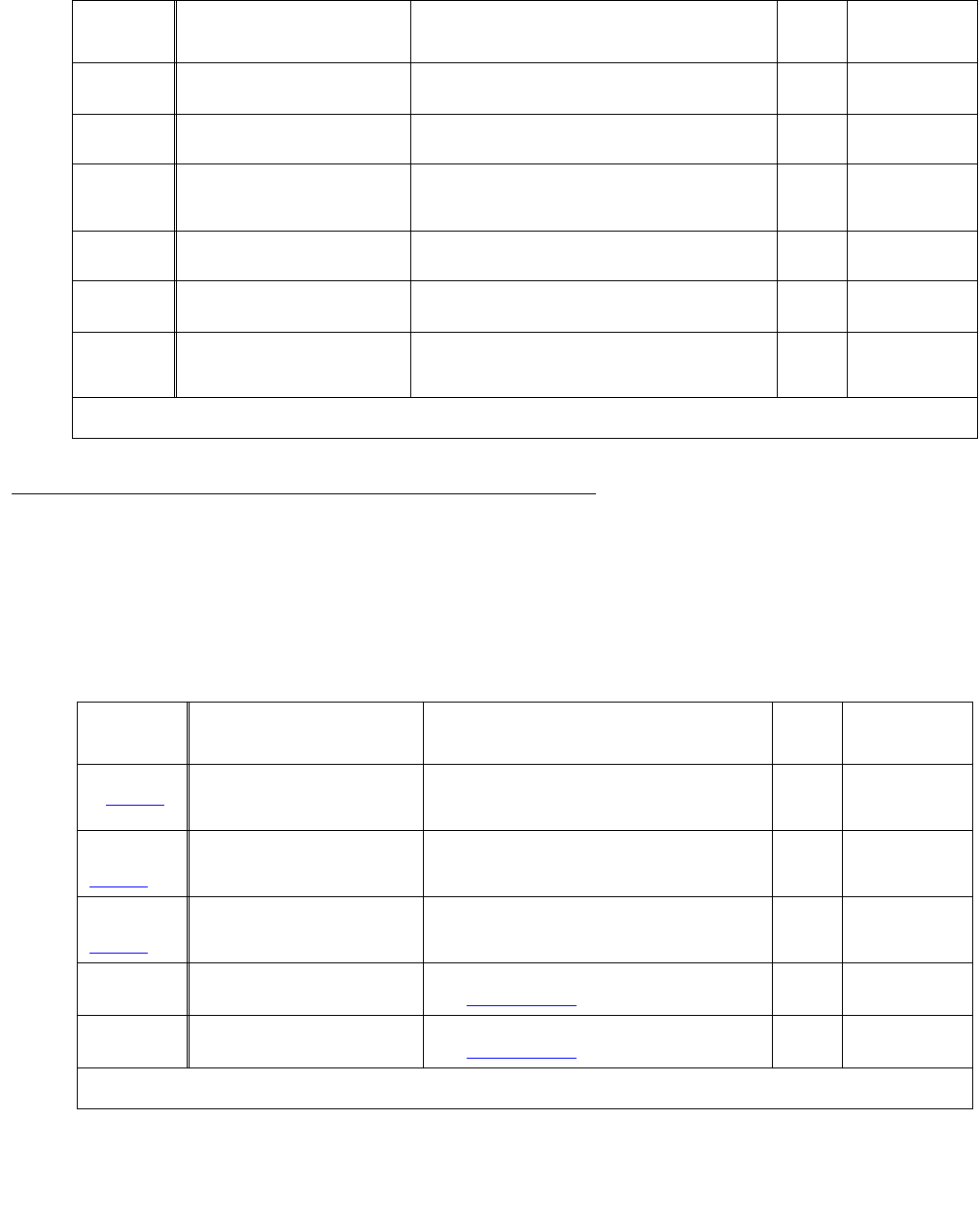
Denial Event Tables
Issue 1 June 2005 189
ISDN, IP, and SIP Denial Events
Some Event Type numbers in this section can be re-used for IP and SIP Denial Events. Please
check your log information carefully to determine what type of network experienced the event
that led to the denial, even if the explanation refers to ISDN.
1167 Can’t term emergency call No Attendants or redirection extension assigned
for termination of emergency call.
1168 Second call failed Russia MultiFrequency (MF) Packet Signaling -
Second call attempt failed.
1169 Retry option not enabled Russia MultiFrequency (MF) Packet Signaling.
Either T1 or T2 timer expired, or a B6 signal was
received, and the “Re-try?” option is no.
1170 Erroneous signal received Russia MultiFrequency (MF) Packet Signaling -
Erroneous signal received.
1171 ATM Blockage:TDMSVC fail TDM_SVC failed due to lack of resources, call
was dropped. The caller hears dead air.
1172 Path Rep ASAI to non-ASAI Path Replace merged from Adjunct Switch
Application Interface (ASAI) callr to non-ASAI
callr.
Table 48: Call Process denial events (1001 - 1172) (continued)
Event
Type
Event Description, as it
appears on the event log
Explanation Event
Data 1
Event Data 2
13 of 13
Table 49: ISDN, IP, and SIP-generated denial events (1173 - 1224)
Event
Type
Event Description, as it
appears on the event log
Explanation Event
Data 1
Event Data 2
1070 (also
in Table 48)TTR_unavail ISDN trunk initiation of in-band end-to-end digit
collection failed. Might be waiting for a Touch
Tone Receiver (TTR).
1164
(also in
Table 48)
ISDN no cause value Outgoing ISDN trunk rejected/ dropped by far
end.
DIAG/LOC/CV
1166
(also in
Table 48)
Unassigned number Unassigned number.
1173 No route to transit ntwk No route to specific transit network.
See Cause Value 02.
UID DIAG/LOC/CV
1174 No route to dest No route to destination.
See Cause Value 03 on page 136.
UID DIAG/LOC/CV
1 of 4

Denial Events
190 Maintenance Procedures for Avaya Communication Manager 3.0, Media Gateways and Servers
1175 ISDN channel unacceptable Channel unacceptable.
See Cause Value 06 on page 139.
UID DIAG/LOC/CV
1176 ISDN MLPP circ not resrvd MLPP preemption, circuit not reserved.
See Cause Value 08 on page 139.
UID DIAG/LOC/CV
1177 ISDN MLPP circ resv reuse MLPP preemption, circuit reserved for reuse.
See Cause Value 09 on page 140.
UID DIAG/LOC/CV
1178 Normal call clearing Normal call clearing.
See Cause Value 16 on page 141.
UID DIAG/LOC/CV
1179 User busy User busy.
See Cause Value 17 on page 141.
UID DIAG/LOC/CV
1180 No user responding No user responding.
See Cause Value 18 on page 142.
UID DIAG/LOC/CV
1181 User alerting, no answer User alerting, no answer.
See Cause Value 19 on page 143.
UID DIAG/LOC/CV
1182 Subscriber absent Subscriber absent.
See Cause Value 20 on page 143.
UID DIAG/LOC/CV
1183 Call rejected Call rejected.
See Cause Value 21 on page 143.
UID DIAG/LOC/CV
1184 Number changed Number changed.
See Cause Value 22 on page 143.
UID DIAG/LOC/CV
1185 Dest out of order Destination out of order.
See Cause Value 27 on page 144.
UID DIAG/LOC/CV
1186 Invalid number format Invalid number format.
See Cause Value 28 on page 144.
UID DIAG/LOC/CV
1187 Facility rejected Facility rejected.
See Cause Value 29 on page 145.
UID DIAG/LOC/CV
1188 Response status enquiry Response status enquiry.
See Cause Value 30 on page 146.
UID DIAG/LOC/CV
1189 Normal, unspecified Normal, unspecified.
See Cause Value 31 on page 146.
UID DIAG/LOC/CV
1190 No circ/chan avail No circuit or channel available.
See Cause Value 34 on page 147.
UID DIAG/LOC/CV
1191 Network failure Network failure.
See Cause Value 38 on page 148.
UID DIAG/LOC/CV
1192 Temporary failure Temporary failure.
See Cause Value 41 on page 149.
UID DIAG/LOC/CV
1193 Equipment congestion Switching equipment congestion.
See Cause Value 42 on page 149.
UID DIAG/LOC/CV
1194 ISDN user info discarded User info discarded.
See Cause Value 43 on page 149.
UID DIAG/LOC/CV
Table 49: ISDN, IP, and SIP-generated denial events (1173 - 1224) (continued)
Event
Type
Event Description, as it
appears on the event log
Explanation Event
Data 1
Event Data 2
2 of 4

Denial Event Tables
Issue 1 June 2005 191
1195 Circ/channel unavail Requested circuit / channel not available.
See Cause Value 44 on page 150.
UID DIAG/LOC/CV
1196 ISDN blocked precedence Locked precedence level.
See Cause Value 46 on page 151.
UID DIAG/LOC/CV
1197 Resources unavail/unspec Resources unavailable, unspecified.
See Cause Value 47 on page 151.
UID DIAG/LOC/CV
1198 ISDN req fac no subscribe Requested facility no subscribed.
See Cause Value 50 on page 152.
UID DIAG/LOC/CV
1199 ISDN outgoing call barred Outgoing calls barred.
See Cause Value 52 on page 153.
UID DIAG/LOC/CV
1200 ISDN incoming call barred Incoming calls barred.
See Cause Value 54 on page 153.
UID DIAG/LOC/CV
1201 Bearer cap not available Bearer capability not presently available.
See Cause Value 58 on page 155.
UID DIAG/LOC/CV
1202 Service unauth FranceVN4 Service not authorized / France VN4.
See Cause Value 62 on page 157.
UID DIAG/LOC/CV
1203 Serv/option unavailable Service/option not available, unspecified.
See Cause Value 63 on page 157.
UID DIAG/LOC/CV
1204 Bearer cap not implem Bearer capability not implemented.
See Cause Value 65 on page 158.
UID DIAG/LOC/CV
1205 ISDN chan type not implem Channel type not implemented.
See Cause Value 66 on page 158.
UID DIAG/LOC/CV
1206 Req facility not implem Requested facility not implemented.
See Cause Value 69 on page 159.
UID DIAG/LOC/CV
1207 Only restr digital BC av Only restricted digital BC available.
See Cause Value 70 on page 160.
UID DIAG/LOC/CV
1208 Srv/opt not imp/unsp Service/option not implemented, unspecified.
See Cause Value 79 on page 160.
UID DIAG/LOC/CV
1209 Invalid call reference Invalid call reference.
See Cause Value 81 on page 161.
UID DIAG/LOC/CV
1210 Channel doesn't exist Identified channel does not exist.
See Cause Value 82 on page 161.
UID DIAG/LOC/CV
1211 Incompatible dest Incompatible destination.
See Cause Value 88 on page 163.
UID DIAG/LOC/CV
1212 ISDN trans ntwk not exist Transit network does not exist.
See Cause Value 91 on page 164.
UID DIAG/LOC/CV
1213 Invalid message Invalid Message.
See Cause Value 95 on page 165.
UID DIAG/LOC/CV
1214 Mandatory IE missing Mandatory IE is missing.
See Cause Value 96 on page 165.
UID DIAG/LOC/CV
Table 49: ISDN, IP, and SIP-generated denial events (1173 - 1224) (continued)
Event
Type
Event Description, as it
appears on the event log
Explanation Event
Data 1
Event Data 2
3 of 4
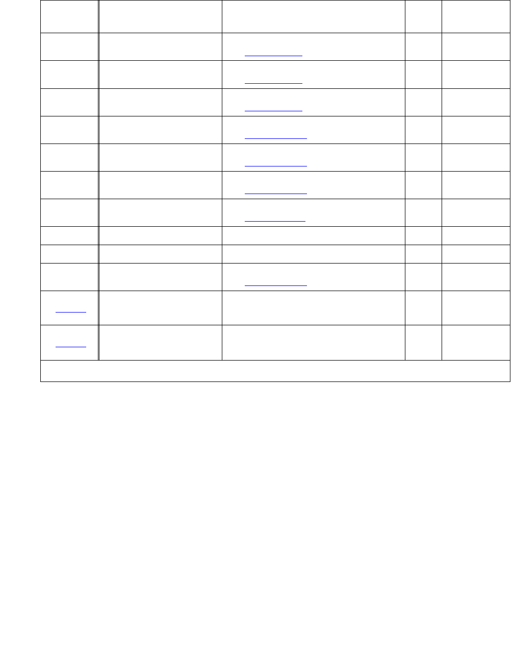
Denial Events
192 Maintenance Procedures for Avaya Communication Manager 3.0, Media Gateways and Servers
1215 ISDN msg typ nonexist/imp Message type nonexistent or not implemented.
See Cause Value 97 on page 167.
UID DIAG/LOC/CV
1216 Msg not compat state Message not compatible with call state.
See Cause Value 98 on page 169.
UID DIAG/LOC/CV
1217 ISDN nonexistant IE Nonexistent IE.
See Cause Value 99 on page 170.
UID DIAG/LOC/CV
1218 Invalid IE contents Invalid IE contents.
See Cause Value 100 on page 170.
UID DIAG/LOC/CV
1219 ISDN msg not compat state Message not compatible with call state.
See Cause Value 101 on page 171.
UID DIAG/LOC/CV
1220 Recovery on timer expiry Recovery on timer expiry.
See Cause Value 102 on page 172.
UID DIAG/LOC/CV
1221 Protocol err unspecified Protocol Error Unspecified.
See Cause Value 111 on page 175.
UID DIAG/LOC/CV
1222 ISDN intr ana ntwk Fr VN4 Inter-worked to analog network France VN4 UID DIAG/LOC/CV
1223 ISDN goto con mode Fr VN4 Go to conversation mode France VN4 UID DIAG/LOC/CV
1224 Interwork/cause unknown Inter-working or cause unknown.
See Cause Value 127 on page 176.
UID DIAG/LOC/CV
1570 (also
in Table 53)
TTR insertion failed Processing incoming digits for ISDN call.
Insertion of Touch Tone Receiver (TTR) to
collect in-band digits failed.
1573 (also
in Table 53)
Principal is not ISDN Get called digits, calling number and name,
etc., and send ISDN SETUP message to the far
end. The principal is not ISDN.
Table 49: ISDN, IP, and SIP-generated denial events (1173 - 1224) (continued)
Event
Type
Event Description, as it
appears on the event log
Explanation Event
Data 1
Event Data 2
4 of 4

Denial Event Tables
Issue 1 June 2005 193
Call processing Denial Events
Event Types 1000 - 1899 show denial events generated during call processing, as listed in Call
Process denial events (1001 - 1172) on page 177 and Call Process denial events (1225 -
1899) on page 193.
Table 50: Call Process denial events (1225 - 1899)
Event
Type
Event Description, as it
appears on the event log
Explanation Event
Data 1
Event Data 2
1225 All SBS extensions in use Separation of Bearer and Signaling (SBS)
Signaling call tried to allocate an SBS extension,
but all SBS extensions are in use.
1226 Cannot get SBS Sig CID Separation of Bearer and Signaling (SBS) Bearer
call tried to retrieve SBS Signaling call Caller ID.
1227 Can't send SBS ID to orig Separation of Bearer and Signaling (SBS)
Signaling call tried to send an INFO message
with unique ID, but the INFO could not be sent.
1228 Non-bearer trk to SBS ext A non-trunk call terminated to an allocated
Separation of Bearer and Signaling (SBS)
extension waiting for the Bearer SBS call to
come.
1229 Unable to get ARS fac Error occurred when getting the ARS Feature
Access Code in order to build the Separation of
Bearer and Signaling (SBS) complete callback
number.
1230 Unable to get contry code Error occurred when getting the local country
code in order to build the Separation of Bearer
and Signaling (SBS) complete callback number.
1231 Unable to get intl accode Error occurred when getting the international
access code in order to build the Separation of
Bearer and Signaling (SBS) complete callback
number.
1232 TTR err SBS ID dgt coll Error occurred when trying to allocate Touch
Tone Receiver (TTR) to collect the Unique ID
in-band at the terminating node.
1233 Invalid SBS ID dgts/tmo Invalid or partial Separation of Bearer and
Signaling (SBS) Unique ID collected, or interdigit
tmo while collecting Unique ID at SBS
terminating node.
1234 TTR err IGAR ID dgt coll Error occurred when trying to allocate Touch
Tone Receiver (TTR) to collect the Unique ID
in-band at the originating node.
1235 Invalid IGAR ID dgts/tmo Invalid or partial Inter-Gateway Alternate Routing
(IGAR) Index collected, or interdigit timeout while
collecting destination IGAR index at IGAR
originating node.
1236-1299 not assigned
begin intercept type source of denials
1 of 33

Denial Events
194 Maintenance Procedures for Avaya Communication Manager 3.0, Media Gateways and Servers
1300 Digits prevent call route MultiFrequency Compelled call not routed due to
invalid digit, not enough digits, etc.
1301 Need MFC or TT dial type Outgoing dial type is not MultiFrequency
Compelled or Touch Tone (TT).
1302 Dgts needed or caller typ Minimum digits not dialed before pressing feature
button, or calling party is not a station or
attendant.
1303 TTR queue type invalid Touch Tone Receiver (TTR) queueing problem.
Invalid “ttrq_typ” found.
1304 Dgt absorbtion/insertion Digit block requires preconditioning for digit
absorption or insertion. Error in treatment. A
Touch Tone Receiver (TTR) is available.
1305 Dgt collection software Software error. Invalid return code
ttrq_type == ORIG_TTRQ?
y - valid rc: GCOL_AUTO, GCOL_OK
ttrq_type == NO_TTRQ?
y - valid rc: GCOL_AUTO, GCOL_OK
GCOL_ERR, GCOL_ATTD, GCOL_ATTD_NS,
GCOL_NS, GCOL_TTRQ, GCOL_TERM
1306 Satlt dropped TGU B4 ansr Italian outgoing tie (TGU) call dropped by satellite
before answer.
1307 LoginID UID query failure Query for User ID of logged-in Logical Agent’s
LoginID failed.
1308 PNT or TIE restriction Enforce PNT-PNT Restrictions. PTT or TIE not
allowed to connect to this PTT trunk.
1309 Data/Voice BCC setup fail Trouble setting up voice to data/data to voice
(change Bearer Capability Class) and/or outgoing
Bearer Capability Class (BCC) for ISDN voice
call.
1310 Incompatible term endpnt Tried to terminate to incompatible endpoint.
1311 Routing software failure Invalid return code from dpm_rerte. Software
error.
1312 Route PTRN trunk unavail No available trunks in the routing pattern.
1313 Remote DTGS invalid digit Remote Direct Trunk Group Selection (DTGS)
that was processing digits (after tie Trunk Access
Code) from the preprocessing digit buffer to the
digit buffer found invalid digit (digit = 0 or > 0xa).
1314 Dgt collection setup fail Error during setup for end-to-end signaling digit
collection.
1315 Dgt collection setup fail Error during setup for end-to-end signaling digit
collection prevented setting an indication in
ttrq_typ that the call was queued during
termination waiting for a Touch Tone Receiver
(TTR) (CODEC_TTR).
Table 50: Call Process denial events (1225 - 1899) (continued)
Event
Type
Event Description, as it
appears on the event log
Explanation Event
Data 1
Event Data 2
2 of 33

Denial Event Tables
Issue 1 June 2005 195
1316 No unrstrictd term point No principal to terminate to, or it is termination
restricted, and there is no termination coverage
point.
1317 Coverage software failure Software error call_p termination to coverage
point received invalid gm_term return code.
1318 Split UID query failure Adjunct Switch Application Interface (ASAI)
Direct Agent Call termination fails in querying isg
for split User ID.
1319 Call record sftw failure Incoming QSIG call completion ringout call.
Failure retrieving suspended Temporary
Signaling Connection (TSC) call record from
service dispatcher.
1320 Call record sftw failure Incoming QSIG call completion ringout call. Call
completion ringout call record does not match
Temporary Signaling Connection (TSC) call
record retrieved from service dispatcher
suspension.
1321 Illegal term to rmt Audix Adjunct Switch Application Interface (ASAI)
switch classified call. Illegal attempt to terminate
off-switch to a remote AUDIX.
1322 Data to station w/o H.320 ATA call to station type endpoint, but the station
does not have the H.320 conversion flag set.
1323 Dgt collection setup fail Authorization code received, terminate to local
extension, origination from ISDN trunk or
endpoint, error during end-to-end signaling digit
collection setup.
1324 Data Ext code calling Code calling by a data extension.
1325 ASAI SCC to UDP nite svc ASAI Switch Classified Call (SCC) to hunt group
with UDP night service. This type of call is not
allowed to go off-switch.
1326 MM to Attd ctrld trunk Multimedia user is not allowed to call a trunk
under attendant control, Attendant Control of
Trunk Group Active (ACTGA).
1327 Obtaining Attd UID fails Call to trunk under attendant control (Attendant
Control of Trunk Group Active (ACTGA)). Failure
getting attendant User ID from dpm.
1328 Term to ACTGA Attd fails Call to trunk under attendant control (Attendant
Control of Trunk Group Active (ACTGA)). Failure
terminating caller to controlling attendant.
1329 Term to inappropriate pt Block termination to incoming-only type trunk or
user with voice bearer termination to a DEXT
group.
1330 Iterative term attd-retry Call termination failure rerouting to attendant.
Retry of termination to attendant was blocked to
prevent an endless retry.
1331 Italian misoperation Italian misoperation treatment.
Table 50: Call Process denial events (1225 - 1899) (continued)
Event
Type
Event Description, as it
appears on the event log
Explanation Event
Data 1
Event Data 2
3 of 33

Denial Events
196 Maintenance Procedures for Avaya Communication Manager 3.0, Media Gateways and Servers
1332 Data mod options qry fail Reserving a pooled modem. Query data module
for its options failed.
1333 Term to modem failure Seizing (terminating on) a pooled modem failed.
1334 Term to modem failure Analog endpoint termination to pooled modem
(after administrable time delay expires) failed.
1335 LWC blocked by msg_sv Leave Word Calling. Async message response
from msg_sv says give user LW_INTRCPT.
1336 Tone detection timeout Tone detector timeout without receiving a valid
tone.
1337 Intrcpt tone from far end Intercept tone received before far end answers.
1338 Wait for answer timeout Wait answer supervision was timedout on a call
from a station or tie trunk.
1339 Auth code required Digit analysis and routing problem. Authorization
code required.
1340 Rmt cfwd invald local ext The attendant activated call forwarding for a
remote extension to an invalid local extension.
1341 Non-voice call intercept Non-voice call was routed to attendant or
announcement for intercept treatment. Switch to
intercept tone treatment.
1342 Dest BCC incompatible The destination bearer capability code is
incompatible.
1343 Need higher FRL to route A higher Facility Restriction Level is needed to
route the call.
1344 Hop count restricted The outgoing call is hop count restricted.
1345 Multiparty caller paging Accessing paging equipment with more than 1
party on the call is not allowed.
1346 Svc Obsrv from wireless Service observing is not possible from wireless
stations because they don’t support “off-hook
idle” state.
1347 Svc Obsrv dpm query fail Query of dpm to see if Feature Access Code
service observing is optioned failed.
1348 No Fac Svc Observing Feature Access Code service observing is not
optioned.
1349 Term dial-up tst brdg app Feature Access Code entered to do terminal
dial-up test, not allowed on bridged appearances.
1350 Term dial-up tst term typ Terminal dial-up test is not allowed on attendant,
BRI, wt or analog type terminal, or the terminal
does not have a call appearance active on the
voice channel.
1351 More digits expected Appending number to end of digit buffer. All digits
have been processed for an Adjunct Switch
Application Interface (ASAI) originated call, but
more digits are expected to be collected.
Table 50: Call Process denial events (1225 - 1899) (continued)
Event
Type
Event Description, as it
appears on the event log
Explanation Event
Data 1
Event Data 2
4 of 33

Denial Event Tables
Issue 1 June 2005 197
1352 Port ntwk numbr too large Facility access test specified a port network
number greater than the maximum allowed
(MAX_PPNS).
1353 Cabinet number too large Malicious call trace specified a cabinet number
greater than the maximum allowed
(MAX_PPNS).
1354 SSC dialed ext's uid fail Station Security Code (SSC) digit processing.
The dialed extension’s User ID has lost its
association with the extension number.
1355 Auth code reqired. (ASAI) Call requires an authorization code. Call is an
Adjunct Switch Application Interface (ASAI)
phantom call. Not allowed.
1356 ASAI SCC VDN destination The first leg of an Adjunct Switch Application
Interface (ASAI) Switch Classified Call (SCC) has
Vector Directory Number as destination.
1357 LAGT COR/COR restriction There is a COR-to-COR (Class of Restriction)
between the originating logical agent and
terminating facility.
1358 ASAI SCC term loginID Adjunct Switch Application Interface (ASAI)
Switch Classified Call (SCC) first leg attempting
to terminate to logical agent loginID. Not allowed.
1359 LoginID extensn qry fail gm_query failure determining if the loginID
extension used for the Direct Agent call is
associated with a logged-in agent.
1360 ASAI SCC term loginID Adjunct Switch Application Interface (ASAI)
Switch Classified Call (SCC) first leg attempting
to terminate to logical agent loginID. Not allowed.
1361 Page data call preindictd Paging is denied if data call preindication was
activated.
1362 FAC follows priority FAC Priority feature activation code shouldn’t be
followed by other feature activation codes. (auth)
1363 FAC follows priority FAC Priority feature activation code shouldn’t be
followed by other feature activation codes. (route)
1364 FAC follows priority FAC Priority feature activation code shouldn’t be
followed by other feature activation codes. (other)
1365 More digits needed to rte Adjunct Switch Application Interface (ASAI) call.
DPM says it needs more digits to route on. There
are no digits left to use in the preprocessing
buffer, and no more digits are expected.
1366 BCC incompatibility Being called from auth_code(). DPM says digit
analysis is done and we have Bearer Capability
Class (BCC) incompatibility.
1367 BCC incompatibility Not being called from auth_code(). DPM says
digit analysis is done and we have Bearer
Capability Class (BCC) incompatibility.
Table 50: Call Process denial events (1225 - 1899) (continued)
Event
Type
Event Description, as it
appears on the event log
Explanation Event
Data 1
Event Data 2
5 of 33

Denial Events
198 Maintenance Procedures for Avaya Communication Manager 3.0, Media Gateways and Servers
1368 MFC out dialing timeout outgoing MultiFrequency Compelled call under
outpulse supervision. Interdigit or end-of-dialing
timeout without any expectation of user
completing dialing.
1369 Dgt tmout PCOL merge fail Unexpected digit timeout. Drop of principal finds
that it is a Personal Central Office Line (PCOL)
group User ID. Merge of PCOL member(s) into
the call (pcol_merge()) for disposition via
stndseq() fails.
1370 Digit timeout - drop fail Unexpected digit timeout. Drop of non-Personal
Central Office Line (PCOL)-type principal failure.
1371 Abbrv Dial DAC limit Abbreviated Dialing was already dial accessed.
There is a limit of 3 times that the DAC can be
dialed to get digits to route on. This would seem
to have a purpose of preventing looping via
entries in the abbreviated dial lists.
1372 Abbrv Dial list/entry inv Abbreviated Dialing. Invalid list and/or list entry.
1373 Abbrv Dial software fail Abbreviated Dialing. Software error while getting
the digits stored in user’s abbreviated dial list.
1374 Agent skills enabled qry Error while querying system parameters to see if
Expert Agent Selection (EAS) agent skills is
enabled.
1375 Dbl agent login to statn Agent is logging into a physical station that
already has an agent logged in.
1376 Agent login illegl source Trunk user or Remote Access user trying to do
Expert Agent Selection (EAS) agent login
operation. Not allowed.
1377 Last ACD call skill qry Query of UM for last Automatic Call Distribution
(ACD) call’s skill fails. Query of attendant, hunt,
DEXT, paging or Personal Central Office Line
(PCOL) group or Non Call Associated-Temporary
Signaling Connection (NCA-TSC) user
1378 No hunt grp for split idx Split group index from dialed digits is a
non-existent hunt group number.
1379 Agent logout fail (auto?) Agent logout failure. Might be spl_chk.c. logging
out while auto-available.
1380 Agent login failure Agent login failure getting number of digits in
logical agents password. Might be login-id User
ID was not found in dpm extension table Ext_e, or
an invalid logical agent login-id extension.
1381 Agent login failure Agent logging into MCH split already logged in
logging into adjunct controlled split?
1382 agent login invalid/error Login invalid or error condition.
Table 50: Call Process denial events (1225 - 1899) (continued)
Event
Type
Event Description, as it
appears on the event log
Explanation Event
Data 1
Event Data 2
6 of 33

Denial Event Tables
Issue 1 June 2005 199
1383 Agent login failure/error Logical Agent (LAGT) failure getting agent
login-id. Possible causes:
●error initializing agent-stat table
●login for a skill failed
●TRAD logging into split already logged
into
●already logged into maximum number of
splits.
1384 Agent logins maximum'd Maximum number of simultaneous logins
exceeded or ACPT_LOGIN failed.
1385 Agent passwd digits fail Failure getting logical agent password digits from
DPM.
1386 Agent passwd mismatch Agent entered password does not match
administered password.
1387 Agent login invalid/error Login invalid or error condition.
1388 Login acceptance fails Logical Agent login processing of ACPT_LOGIN
message to the la_spl_chk routine fails.
1389 Agent login max/error Maximum number of simultaneous logins
exceeded, or this agent failed the login digits
check (for example, this agent is using someone
else’s login-id).
1390 Work mode change failed Change of Agent Work Mode to after-call-work
failed.
1391 Work mode change failed Change of Logical Agent Work Mode to aux-work
failed.
1392 Work mode change failed Change of Agent Work Mode to man_in failed.
1393 Work mode change failed Change of Agent Work Mode to auto-in failed.
1394 Agent feat act FAC error Unrecognized Feature Access Code being
processed for Automatic Call Distribution (ACD)
agent feature activation.
1395 Agent sup assist rqst er Agent requesting supervisor assist. Possible
causes:
● split group invalid
● agent not logged in
● split group has no supervisor
● administered
1396 Split invalid/agent login Adjunct Switch Application Interface (ASAI)
requesting supervisor assist. Possible causes:
●split group invalid
● agent not logged in
1397 Direct agent call setup Supervisor assisted call to Expert Agent
Selection (EAS) login ID. Error encountered in
setting up Direct Agent Call.
1398 Direct agent calling COR Supervisor assisted call to Expert Agent
Selection (EAS) login ID. Direct agent calling
Class of Restriction (COR) check failure.
Table 50: Call Process denial events (1225 - 1899) (continued)
Event
Type
Event Description, as it
appears on the event log
Explanation Event
Data 1
Event Data 2
7 of 33

Denial Events
200 Maintenance Procedures for Avaya Communication Manager 3.0, Media Gateways and Servers
1399 EAS not enabled Activating Add/Remove Skill feature but Expert
Agent Selection (EAS) is not enabled.
1400 EAS not enabled Activating Add/Remove Skill feature but Expert
Agent Selection (EAS) is not enabled.
1401 COR_AR_SKL query failure Activating Add/Remove Skill feature
COR_AR_SKL dpm_query failed. User ID
structure not found.
1402 Skills COR restricted Activating Add/Remove Skill feature. User has no
Class of Restriction (COR) permission to Add/
Remove Agent Skills.
1403 Console prmsn, EAS agent Activating Add/Remove Skill feature. User has no
console permission and is not an Expert Agent
Selection (EAS) Agent. Activator is wrong type.
1404 LoginID prompt setup err Activating Add/Remove Skill feature. Error in
setting up the prompt for agent’s loginID.
1405 Skills prompt setup err Setting up prompting for skill number in the Add/
Remove Skills feature. Error in setting up prompt
for agent’s skills.
1406 LoginID tenant nbr fail Add agent. Skills translations failed to get the
Tenant Number for the agent’s loginID.
1407 Skills tenant nbr fail Add agent Skills translations. Failed to get the
Tenant Number for the agent’s skill.
1408 Tenant number mismatch Add agent Skills translations. Tenant Number of
the Expert Agent Selection (EAS) agent’s loginID
does not match the Tenant Number of the skill
being added.
1409 Skill level out of range Add agent Skills translations. Skill level out of
range.
1410 DAC skill nbr qry failed Remove agent Skills translations. dpm_query for
Logical Agent’s (LAGT) DAC skill number failed.
1411 DAC skill not removable Remove agent Skills translations. Logical agent’s
DAC skill is not removable.
1412 Skills ftr msg failure Add/Remove agent Skills translations. Add/
Remove Skills feature message sending to
station server failed. (SS_AR_SKL)
1413 DAC agent dest/split Adjunct Switch Application Interface (ASAI) third
party direct agent call. Process CP_DIR_AGENT
message from ISG. No DAC agent destination or
split specified in message.
1414 DAC agent dgts to uid Adjunct Switch Application Interface (ASAI) third
party direct agent call. Process CP_DIR_AGENT
message from ISG. DAC agent digits conversion
to User ID. failure.
Table 50: Call Process denial events (1225 - 1899) (continued)
Event
Type
Event Description, as it
appears on the event log
Explanation Event
Data 1
Event Data 2
8 of 33

Denial Event Tables
Issue 1 June 2005 201
1415 DAC msg err/agent login Adjunct Switch Application Interface (ASAI) third
party direct agent call. process CP_DIR_AGENT
message from ISG. Possible causes:
●adjunct agent not logged in
●adjunct gave the switch a wrong agent
extension
●adjunct gave the switch a wrong split
extension
1416 Auth code dgt coll fail Collecting authorization code digits as end-to-end
signaling failed.
1417 TTR queueing invalid Collecting authorization code digits. “TTR
queueing occurred in remote access” is indicated
in Touch Tone Receiver (TTR) of callr - not valid
in this routine.
1418 Bsy vfy trk member Error on query for busy status. Possible causes:
trunk member specified greater than maximum
trunks in group, or corrupted trunk index after a
tape read.
1419 COS restrctn Rus Intrsn User’s Class of Service does not allow access to
Russian Power Trunk Intrusion feature.
1420 Bsy vfy call merge fail Merging the busy-verifying call with the
busy-verified call. Failure to find an available
callr2 party slot.
1421 Bsy vfy termination fail Terminating the busy-verifying call to a trunk.
Failure to find an available caller party slot.
1422 Bsy vfy termination fail Terminating the busy-verifying call to a trunk.
Error getting the trunk’s index into the tmem_tbl
1423 Software invalid stim Remote user activation/deactivation of a type of
attendant call forwarding - stimulus other than
CP_ACFON, CP_ACFBDAON or CP_ACFOFF
received.
1424 Cfwd dest dgts storage Activation of call forwarding. Call forward
destination address digits did not all get stored.
1425 Cfwd actvt error/denial Activation of call forwarding. Error or denial of
activation.
1426 Off prem extension size Request remote switch to activate CF on one of
its local extensions. Answer Distributed
Communication System (DCS) off-premise
station extension size is defined by destination
digits dialed.
1427 FWDed party extension nbr Activating call forwarding. Feature button IDs
forwarded party extension number for which we
cannot find a user ID.
1428 Phys ext not cfwd avail Logged-in Expert Agent Selection (EAS) agent’s
physical extension is unavailable for any “simple”
(on switch?) call- forwarding.
Table 50: Call Process denial events (1225 - 1899) (continued)
Event
Type
Event Description, as it
appears on the event log
Explanation Event
Data 1
Event Data 2
9 of 33

Denial Events
202 Maintenance Procedures for Avaya Communication Manager 3.0, Media Gateways and Servers
1429 Rmte cfwd not allowed Disallow remote call-forwarding of an Expert
Agent Selection (EAS) loginID extension in all
cases (for example, whether the loginID is logged
into a terminal or not).
1430 COS deny cfwd activate User’s Class of Service does not allow this call
forwarding activation.
1431 Cfwd deact not allowed Expert Agent Selection (EAS) agents are not
permitted to deactivate call forwarding.
1432 Cfwd deact err/denial Deactivation of call forwarding. Error or denial of
deactivation.
1433 Held xfr call missing Converse Data Return requires that there be a
call held due to transfer while processing the
Converse Data return code (CONV_DAT_RET).
1434 Held call retrieval fail Converse Data Return processing failed to
retrieve the suspended call record from the SD
for the held call. The held call must be active on a
Converse vector step.
1435 Invalid vec step typ/pty Converse Data Return processing encountered
an invalid vector step type (not V_CONVERSE)
or the party is invalid.
1436 No COS for ctl rstrctn User Class of Service does not allow activation/
deactivation of controlled restrictions.
1437 Sys parm - dir call pkup Directed-call-pickup system parameter is not
enabled.
1438 Invalid usr dir call pkup Directed call pickup attempt from invalid user (for
example, not a station or attendant).
1439 Dir call pkup COR rsrtrct Directed call pickup attempt from user without
Class of Restriction (COR) permission.
1440 Dir call pkup non-station Directed call pickup attempt on a call to an
endpoint other than a station.
1441 Dir call pkup COR rsrtrct Directed call pickup attempt to a station that has
no Class of Restriction (COR) permission to
accept directed call pickup.
1442 Ring check query failure Directed call pickup attempt. Failure of UM query
to see if called station is still ringing before
completing the pickup to it.
1443 COS deny dat pvcy ftr act User’s Class of Service does not allow activation
of the data privacy feature.
1444 DS0 test call invalid DS0 test call is valid only for incoming data trunk
calls.
1445 Rmt emrg accs to attd dny Emergency access call to attendant is not
permitted from a remote user.
1446 Port ID/UID mapping fail Facilities Access Test call. Trunk or Touch Tone
Receiver (TTR) port_id->User ID mapping failed.
Table 50: Call Process denial events (1225 - 1899) (continued)
Event
Type
Event Description, as it
appears on the event log
Explanation Event
Data 1
Event Data 2
10 of 33

Denial Event Tables
Issue 1 June 2005 203
1447 TTR port type query fail Facilities Access Test call - Touch Tone Receiver
(TTR) test. CM query for TTR port type fails.
1448 Tested not trunk or TTR Facilities Access Test call - user type being tested
is neither a trunk or Touch Tone Receiver (TTR),
but logic that got us here thought it was.
1449 Vis Imprd Svc incompatibl Facilities Access Test call - this feature is not
compatible with Visually Impaired Service.
1450 FAT call error Facilities Access Test call. Possible causes:
●CM error connecting to tone or
maintenance timeslot
●necessary number of digits not dialed for
tone or timeslot call
●on trunk or Touch Tone Receiver (TTR),
call conversion of external ID to internal
ID failed, or portid to User ID mapping
failed.
1451 Connection to music error Facilities Access Test call to a music port. CM
error connecting to music.
1452 FAT non-ISDN COR rstrct Facilities Access Test (FAT) call to a trunk. User
is Class of Restriction (COR) restricted from
making a FAT test of the non-ISDN trunk.
1453 FAT test RLT/DID illegal Facilities Access Test (FAT) call to a trunk. FAT is
allowed for this trunk type, Release Link Trunk
(RLT) or Direct Inward Dialing (DID).
1454 Trk svc state change fail Facilities Access Test call to a trunk. Failure
moving trunk from out-of-service state to
in-service. Might be a bad User ID.
1455 FarEnd TstLn nbr qry fail Facilities Access Test call to a PRI trunk. GM
query for far end ISDN test line number failed
(QTC_NUM).
1456 FarEnd TstLn nbr invalid Facilities Access Test call to a PRI trunk. Invalid
digit in far end test line number.
1457 FarEnd TstLn nbr invalid Facilities Access Test call to a PRI trunk. Invalid
digit in far end test line number.
1458 Wrg Bch svc/usg/mnt state Facilities Access Test (FAT) call to a PRI trunk.
Wrong B-channel service, usage or maintenance
state to allow FAT test.
1459 Bad user Id Facilities Access Test call to a trunk. Might be a
bad User ID.
1460 Trk grp qry/get TAC Facilities Access Test call to a trunk. um_query
failure getting trunk’s group User ID
(QTRKGRPUID)? dpm_dgtget() failure getting
trunk group’s “real” dial access code.
1461 User Cverage path missing User activating Send All Calls does not have
coverage path allowing Send All Calls. If user is
an Expert Agent Selection (EAS) agent neither
the agent or station has a coverage path.
Table 50: Call Process denial events (1225 - 1899) (continued)
Event
Type
Event Description, as it
appears on the event log
Explanation Event
Data 1
Event Data 2
11 of 33

Denial Events
204 Maintenance Procedures for Avaya Communication Manager 3.0, Media Gateways and Servers
1462 Split group digits wrong User activating/deactivating Position Busy.
Wrong number of digits used to specify split
group.
1463 Agent denied in split group Agent deactivating Position Busy, not allowed in
split group.
1464 Agent not in aux work Agent not in AUX_WORK activating Position
Busy.
1465 SAC unavail to attd Send All Calls (SAC) or Position Busy feature
activation/deactivation denied (for example,
attendant is not allowed to activate/deactivate
SAC).
1466 No call to xfr to AUDIX Route transferred or call conferenced to AUDIX.
There is no held call that would be transferred/
conferenced in with AUDIX.
1467 No call to xfr to AUDIX Route transferred or call conferenced to AUDIX,
but the calling party was disconnected.
1468 Inelgbl invoker xfr AUDIX Route transferred or conferenced call to AUDIX.
Only the principal or covering user (or bridges of
them) are allowed to invoke this feature.
1469 Invld remote ADX mach-nbr Route remote transfer to AUDIX. Failure getting
the remote principal’s AUDIX Machine number.
1470 No ADX mach-nbr/
node-name
Route remote transfer to AUDIX. The remote
principals AUDIX Machine number does not
translate into an adjunct index. (QAX_ADJ_IDX)
1471 Invalid AUDIX mach-nbr Route remote transfer to AUDIX. The remote
principal’s AUDIX Machine number received is
“0”. dpm query for user’s serving AUDIX index
fails.
1472 Invalid AUDIX mach-nbr Route remote transfer to AUDIX. The remote
principal’s AUDIX Machine number received is
“0”. dpm query for user’s serving AUDIX index
received “0”. Query of grp_m for the first AUDIX
whose DCS link is up fails.
1473 No local AUDIX mach-nbr route local transfer to AUDIX. the local principals
AUDIX Machine number received is “0”. dpm
query for user’s serving AUDIX index fails.
1474 No primary AUDIX hnt grp Route transfer to AUDIX. Query for an AUDIX.
Adjunct’s Primary Transfer into AX Hunt Group
failed.
1475 No ADX hnt grp-cvg path Route local non-vector transfer to AUDIX. AUDIX
hunt group is not in the principal’s coverage path.
1476 Dat pvcy/rstrct ICOM call User with data privacy or data restriction is trying
to originate an ICOM call. This is not allowed.
1477 Invalid ICOM grp/dial cod ICOM call handling. Invalid ICOM group or ICOM
dial code of terminating station. (icm_route())
Table 50: Call Process denial events (1225 - 1899) (continued)
Event
Type
Event Description, as it
appears on the event log
Explanation Event
Data 1
Event Data 2
12 of 33

Denial Event Tables
Issue 1 June 2005 205
1478 Block iteratve Lst Nbr Dl Last Number Dialed was accessed through an
Abbreviated Dialing list. Do not allow it again.
1479 LND digits - DPM fail User’s Last Number Dialed (LND) digits were not
returned successfully by dial plan manager.
(DPM_LND)
1480 LND digits - DPM fail User’s Last Number Dialed (LND) digits were not
returned successfully by dial plan manager.
(software error)
1481 MASI setup not incmg ISDN Multimedia Application Server Interface (MASI)
path setup call - valid only for incoming ISDN
calls.
1482 MCT on DCS trk disallowed User activating Malicious Call Trace for a DCS
trunk not allowed.
1483 MCT target type invalid Malicious Call Trace target cannot be a group
User ID. Target PORT entered, must be a regular
TRUNK port or PRI.
1484 MCT target not in a call Malicious Call Trace target must actually be
involved in a call.
1485 MCT call serv_d rtrv fail Malicious Call Trace cannot retrieve callr from
serv-d for the call being traced.
1486 MCT trace resorce unavail Malicious Call Trace activation by button could
not get trace resources from GRP_M.
1487 MCT start invld ctlr alrt Malicious Call Trace start invalid controller
alerting return code from GRP_M (mct_start()).
1488 MCT deact dny by GRP_M/er Malicious Call Trace deactivation (not via
busyout) denied by GRP_M or error. (mct_end())
1489 MCT activator grp uid/uid Malicious Call Trace activation failure getting
individual User ID from activator group User ID.
1490 MCT activator COR rstrctd Malicious Call Trace (MCT) activation. Activator’s
Class of Restriction (COR) does not allow MCT
feature access.
1491 Trk ext/int ID cnvsn fail Malicious Call Trace request targeted to a trunk
port ID. Failure converting the external ID
(cabinet, carrier, slot, circuit) into an internal ID
(angel, circuit). (dig23dportid() - ATM,
dig2portid()).
1492 MCT act on trk pt ID fail Malicious Call Trace request targeted to a trunk
port ID. failure activating MCT for given trunk pt
ID.
1493 AD prg from non station Abbreviated dialing programming is messaging
the station server to enter a different mode and
prepare for digit collection. Only simple users
allowed. Wrong user type.
1494 Extension/passwd required Coverage message retrieval. Remote access not
allowed unless the user supplies the extension
and password.
Table 50: Call Process denial events (1225 - 1899) (continued)
Event
Type
Event Description, as it
appears on the event log
Explanation Event
Data 1
Event Data 2
13 of 33

Denial Events
206 Maintenance Procedures for Avaya Communication Manager 3.0, Media Gateways and Servers
1495 Local only/annc dest/uid Announcement record/playback session. Only
local calls to the announcement are allowed. Call
destination must be an announcement group.
Must have a User ID slot for the announcement
board.
1496 Annc ID needed/conn fail Begin integrated announcement session.
Integrated announcement not identified
(ann_sess()). cm_pt_conn failure or invalid Caller
ID root (au_sbegin()).
1497 Restricted by COS User’s Class of Service does not permit one of:
●Leave Word Calling-cancel
●AP Demand Print
●voice synthesis principal message
retrieval
●voice synthesis coverage message
retrieval
●integrated announcement session
1498 MM call software failure MultiMedia Call Handling multimedia call
activation from voice station. Notification of
USER_M failed.
1499 MM failure getting BCC MultiMedia Call Handling multimedia call
activation from voice station button. Failure
getting bearer capability from USER_M.
1500 Ext nbr or page typ invld Failure getting Code Call paging ID
corresponding to dialed extension. Invalid
extension number or page type.
1501 Page call park failure Drop paging equipment, start park timer, and park
call permanently. There is no record in callr of a
call having been parked during a page.
1502 Drop software failure Paging zone seizure denied. gm_drop() problem
returned other than GDRP_OK, GDRP_ANS, or
GDRP_OUT.
1503 Answer back merge failure Answer parked call, give confirmation tone to
parked party, merge 2 calls. Have no call record
of party originating answer back.
1504 Answer back merge failure Answer parked call, give confirmation tone to
parked party, merge 2 calls. No call parked on
this extension.
1505 Answer back merge failure Answer parked call, give confirmation tone to
parked party, merge 2 calls. Unknown return from
GRP_M retrieval of Caller ID of the parked call.
1506 Answer back merge failure Answer parked call, give confirmation tone to
parked party, merge 2 calls. Unknown return from
GRP_M unpark of call if the last party drops.
1507 Answer back merge failure Answer parked call, give confirmation tone to
parked party, merge 2 calls. Accessing the callr of
the parked call failed retrieval from serv-d.
Table 50: Call Process denial events (1225 - 1899) (continued)
Event
Type
Event Description, as it
appears on the event log
Explanation Event
Data 1
Event Data 2
14 of 33

Denial Event Tables
Issue 1 June 2005 207
1508 Unparking vec ctrld call Answer parked call, give confirmation tone to
parked party, merge 2 calls. Deny the unpark
(answer back) attempt if the parked call is under
vector control.
1509 Answr back station dialed Answer parked call, give confirmation tone to
parked party, merge 2 calls. User ID of station
dialed for answer back differs from park_uid in
call_r.
1510 COR/COR user restricted Answer parked call, give confirmation tone to
parked party, merge 2 calls. COR-to-COR (Class
of Restriction) between user where call is parked
and users in answer back callr.
fail code
(for example,
DPXFR_DENY
_9)
1511 Parked call already dropd Answer parked call, give confirmation tone to
parked party, merge 2 calls. The parked call was
already dropped by the originator but the chimes
haven’t finished yet.
1512 Too many parties to merge Answer parked call, give confirmation tone to
parked party, merge 2 calls. The merge is not
possible because cannot find an empty slot in
callr2.
1513 Park call on station only Trying to park a call on a non-station type user.
must park on a user with a SMPL group type.
1514 No call to park There is no conference pending. The caller to be
parked must have dropped or been dropped.
1515 Park ftr serv_d failure Failure encountered releasing the callr to serv_d.
1516 Park ftr serv_d failure Failure encountered retrieving the callr from
serv_d.
1517 Park ftr serv_d failure Failure encountered retrieving the callr from
serv_d.
1518 Too many park conferees Too many conferees in the call to allow parking.
1519 Vector active cant park Vectoring is active on the held call. Cannot allow
the held call to be parked.
1520 Park ftr serv_d failure Failure encountered releasing the callr to serv_d.
1521 Park ftr serv_d failure Failure encountered retrieving the callr from
serv_d.
1522 TAAS from guest room Pickup for Call Pickup or Trunk Answer Any
Station (TAAS). Attendant backup alerting is
active, maid status is dialed from guest room on
station doing pickup. Might be maid is invoking
TAAS from guest room.
1523 Not a pickup grp mbr Pickup for Call Pickup or Trunk Answer Any
Station (TAAS). Pickup initiator is not a member
of a pickup group.
1524 Picked up call ID error Pickup for Call Pickup or Trunk Answer Any
Station (TAAS). Error encountered getting call ID
of call to be picked up.
Table 50: Call Process denial events (1225 - 1899) (continued)
Event
Type
Event Description, as it
appears on the event log
Explanation Event
Data 1
Event Data 2
15 of 33

Denial Events
208 Maintenance Procedures for Avaya Communication Manager 3.0, Media Gateways and Servers
1525 Call pickup from adjnct Pickup for Call Pickup or Trunk Answer Any
Station (TAAS). Pickup of call originated by an
adjunct is not allowed.
1526 Pickup of call wait call Pickup for Call Pickup. Pickup of a call waiting
call is not allowed.
1527 Pickup of converse call Pickup for Call Pickup or Trunk Answer Any
Station (TAAS). Trying to pickup a converse call,
this is not allowed. Passing data efficiently to a
party that has already cut through on the call
cannot be handled.
1528 Pickup of self's call Stations A and B are in same pickup group.
Station A calls Station B, holds, and dials Feature
Access Code for pickup. Disallow pickup of
self-initiated call.
1529 Pickup COR/COR usr rstrct Pickup for Call Pickup or Trunk Answer Any
Station (TAAS). COR-to-COR (Class of
Restriction) restriction between the initiator of
pickup and user(s) of the call being picked up.
fail code
(for example,
DPXFR_DENY
_9)
1530 Priority call COS denied Caller’s Class of Service does not allow initiation
of priority calling treatment of call.
1531 Priority call COS denied Caller pushes the priority calling button after the
call has been dialed, but before it is answered.
Caller’s Class of Service does not allow initiation
of priority calling treatment of call.
1532 Passwd storage exhausted Dual Tone MultiFrequency (DTMF) password
collection for audio add-on party in VSP-MCU
passworded conference. No room in opls_dig to
store conference password - should never
happen.
1533 Invalid TTR queueing type Dual Tone MultiFrequency (DTMF) password
collection for audio add-on party in VSP-MCU
passworded conference. Touch Tone Receiver
(TTR) queing type in callr has invalid indication
whether or where TTR queing occurred.
1534 Software invalid stim Performing the callback of a party after the call
has been queued. Invalid Call Processing (CP)
message being processed and passed from a
call supervisor.
1535 ACB held call dropped Analog station flashooks and dials Automatic
Callback (ACB) activation Feature Access Code.
The call from which the user flashed is to be
removed from hold and used to activate ACB.
The call didn’t get held or it disappeared.
1536 GRP_M que service error GQSRV_ERR error returned from gm_qsrvc().
1537 Callback type sftw error Invalid callback type returned by gm_query().
1538 Auto callback COS denied User’s Class of Service does not allow activation
of Automatic Callback feature.
1539 Callback type qry failed gm_query() for callback type failed.
Table 50: Call Process denial events (1225 - 1899) (continued)
Event
Type
Event Description, as it
appears on the event log
Explanation Event
Data 1
Event Data 2
16 of 33

Denial Event Tables
Issue 1 June 2005 209
1540 Callback type qry failed Invalid callback type returned by gm_query().
1541 Invalid call ID/conn fail Switch has answered remote access call. Set up
end-to-end signaling digit collection. Invalid
Caller ID or Touch Tone Receiver (TTR)
connection failure. (tu_ecoll_dg(), bch_ecoll_dg()
-).
1542 TTR queueing error Switch answered a remote access call. Set up
end-to-end signaling digit collection. Touch Tone
Receiver (TTR) queueing erroneously occurred
in auth_feat().
1543 Telcmt accss ext qry fail Switch answered a remote access call and set up
end-to-end signaling digit collection. Failure
querying DPM for User ID of telecommuting
access extension.
1544 Barrier/auth cod qry fail Switch answered a remote access call and set up
end-to-end signaling digit collection. Invalid
response from DPM on query for whether barrier
code and authorization code are needed.
(dpm_remqry())
1545 Acct code length qry fail Query of DPM for SMDR account code length
failed.
1546 Held call serv_d failure Handle T120 requests for a video conference.
Accessing the callr of the held call failed retrieval
from serv-d.
1547 Video conf deact flag er T120 request for deactivation of video
conference, but the call has no indication that a
video conference exists. (mm_dataconf_on)
1548 Dat drop not frm dat orig T120 request for deactivation of video
conference. It is only valid to drop data from the
originator of data. The user who pressed the
button is not the originator.
1549 T120 drop CM failure CM failure on T120 drop request from valid user
with T120 on.
1550 T120 activate CM failure CM failure on Feature Access Code dialed
request for T120 activation.
1551 Invalid test tone specfd Terminating trunk transmission test call. Invalid
test tone specified for connection to the call.
1552 Whisp pg elgblity qry err Query of GRP_M for whisper page eligibility
encountered an error or the response was
invalid.
1553 Whisp pg too many parties Activate whisper page answer ftr. callr party block
has no slot available for the page originator.
1554 Whisp pg ansr merge fail Activate whisper page answer ftr. switch of the
Caller ID of the paging party from the original call
failed (um_wpswap())
1555 Whisp pg too many parties Merging the paging call with the paged call. callr2
party block has no slot available for the merged
call.
Table 50: Call Process denial events (1225 - 1899) (continued)
Event
Type
Event Description, as it
appears on the event log
Explanation Event
Data 1
Event Data 2
17 of 33

Denial Events
210 Maintenance Procedures for Avaya Communication Manager 3.0, Media Gateways and Servers
1556 Annc/music connect fail Wakeup announcement verification. Failure of
the CM to connect a wakeup announcement or
music to the call.
1557 Wakeup annc vfy COS deny Call originator does not have Class of Service
permission to verify wakeup announcements.
1558 Maid status PMS msg fail Sending the PMA_MDSTATUS message to the
PMS failed.
1559 Maid status ext COS deny Maid status Feature Access Code dialed from a
room station that does not have Class of Service
permission.
1560 Maid info digits qry fail Query of DPM for number of maid info digits
failed.
1561 Maid status PMS msg fail Send of a PMA_MDSTATUS message to the
PMS failed.
1562 Maid status ext COS deny Maid status Feature Access Code dialed from a
designated station that does not have Class of
Service permission.
1563 Maid status ftr ID invld Processes the dialed maid status code, but callr
feat_id is invalid for either maid status dialed from
a guest room or from a designated station.
1564 PMS rejects hskp status Property Management System rejects
housekeeping status v.
1565 PMS hskp response invalid Property Management System response to
housekeeping status is invalid. (CP_MDRES)
1566 Guest rm station COS deny Routing call to Property Management System to
log or obtain guest room status. The User ID of
the station entered by the user is not Class of
Service identified as a guest room station.
1567 Maid info digits qry fail Routing call to Property Management System to
log or obtain guest room status. Query of DPM for
number of maid information digits failed.
1568 Maid status PMS msg fail Routing call to Property Management System
(PMS) to log or obtain guest room status. Send of
a PMA_MDSTATUS message to the PMS failed.
1569 Voice msg type call_r flg Digit timeout waiting for entry of Do Not Disturb
turn-off time or entry of Automatic Wakeup time.
callr does not have this flagged as a Voice
message type call (vtype).
1570 (also
in Table 49)
TTR insertion failed Processing incoming digits for ISDN call.
Insertion of Touch Tone Receiver (TTR) to collect
in-band digits failed.
1571 WSS no callng pty nbr IE Processing incoming digits for ISDN call. A
General Central Office (GCO) Wireless
Subscriber System (WSS) call origination denied
- no calling party number IE was sent.
Table 50: Call Process denial events (1225 - 1899) (continued)
Event
Type
Event Description, as it
appears on the event log
Explanation Event
Data 1
Event Data 2
18 of 33

Denial Event Tables
Issue 1 June 2005 211
1572 Call hndlng/usg alloc err Processing incoming digits for ISDN call.Eerror
during Incoming Call Handling Treatment or
Usage allocation Check (GM_ISDNDIG).
1573 (also
in Table 49)
Principal is not ISDN Get called digits, calling number and name, etc.,
and send ISDN SETUP message to the far end.
The principal is not ISDN.
1574 SETUP msg IEs not created Get called digits, calling number and name, etc.,
and send ISDN SETUP message to the far end.
IEs necessary for SETUP not created and stored
in the IAP.
1575 SETUP msg send failed Get called digits, calling number and name, etc.,
and send ISDN SETUP message to the far end.
The “send” failed. (trk_setup(), um_setup())
1576 ISDN routing failure Get called digits, calling number and name, etc.,
and send ISDN SETUP message to the far end.
Routing failure. (gm_routepat())
1577 ISDN SETUP msg failure ISDN trunk group Trunk Access Code dialed or
simulated Q931_REC IEs set up and stored in
iap, and request send of SETUP msg. cp_setup()
returned a failure error.code. suser_m got a
failure indication from the gip in trying to send the
ISDN SETUP message?
1578 Inc tst call 2many partys Incoming test call for talk/listen on same timeslot.
Failure to find an available callr party slot.
1579 Inc tst call wrg usr type Incoming test call for talk/listen on same timeslot.
This type of test call is not permitted to access
the user type.
1580 Must be ISDN trunk group Check for usage allocation restrictions on
incoming overlap receiving calls. Possible
causes:
●not ISDN trunk group
●insane index into the call by call data
table
●get_tmem() failure from GRP_M
usage_chk()
●Unexpected error from inc_cuap_sf()
1581 Passwd digits err/timeout MCU audio add-on password supervision.
Possible causes:
●digit timeout before collecting all the
digits
●an invalid digit
●a set of digits that does not match the
conference password
1582 Spvsr state/feat_id wron Generating intercept via CP_REORDER with sup
= ACT_TTI_SUP (for Terminal Translation
Initiation digit collection) and feat_id !=
CHG_SEC (Change station security code).
Possible causes:
●wrong supervisory state
●wrong feat_id in callr
Table 50: Call Process denial events (1225 - 1899) (continued)
Event
Type
Event Description, as it
appears on the event log
Explanation Event
Data 1
Event Data 2
19 of 33

Denial Events
212 Maintenance Procedures for Avaya Communication Manager 3.0, Media Gateways and Servers
1583 Spvsr state/feat_id wrong Generating intercept via CP_CONFTONE with
sup = ACT_TTI_SUP (for Terminal Translation
Initiation digit collection) and feat_id !=
CHG_SEC (Change station security code).
Possible causes:
● wrong supervisory state
● wrong feat_id in callr
1584 Software invalid stim Software error. Invalid Call Processing (CP)
stimulus received while in supervision state that
handles Terminal Translation Initiation (TTI) digit
collection during dialing of the TTI security code
and extension.
1585 Abbrv Dial invalid digit Invalid digit detected while processing
abbreviated dialing.
1586 Abbrev dial prg rejected Rejection of abbreviated dialing programming
from station server.
1587 Agent extension invalid Add/Remove Agent Skills. Feature Access Code
was dialed by a user with console permissions,
but the agent-loginID extension entered is not a
valid Expert Agent Selection (EAS) AGENT
extension.
1588 Skill grp nbr illegal Add/Remove Agent Skills feature has been
invoked and the Skill number has been collected.
It does not represent a legal skill group number.
1589 Skill number invalid Add/Remove Agent Skills feature has been
invoked and the Skill number is not valid.
1590 System or software error Add/Remove Agent Skills feature has been
invoked. STN_SV encountered system or
software error.
1591 Digit collection error Add/Remove Agent Skills feature has been
invoked. Error in digit collection.
1592 Routing not to a station QSIG Call Completion ringout call from remote
originating party. Routing erroneously to a local
facility that is not an SMPL station.
1593 Digit tmo/invld rsn code Interdigit timeout or invalid reason code entered
during Expert Agent Selection (EAS) aux work
and logout reason code digit collection is in
progress.
1594 Software invalid stim Code Call paging seizure supervision received a
Call Processing (CP) stimulus from one of a big
list of incompatible feature CP stimulus.
1595 Cfwd tenant parttn rstrct Attendant-activation of call forwarding, and
extended administration of call forwarding. Error
or access denial resulted from TENANT_CHECK
where originator’s partition is restricted from
accessing partition of extension being
administered for call forwarding.
Table 50: Call Process denial events (1225 - 1899) (continued)
Event
Type
Event Description, as it
appears on the event log
Explanation Event
Data 1
Event Data 2
20 of 33

Denial Event Tables
Issue 1 June 2005 213
1596 Attd must enter station Attendant-activation of call forwarding, and
extended administration of call forwarding. The
extension being administered is not a simple
station user.
1597 Attd cant fwd attd calls Attendant-activation of call forwarding, and
extended administration of call forwarding.
Attendant is not allowed to forward its own calls.
1598 Feature ID invalid Attendant-activation of call forwarding, and
extended administration of call forwarding. The
feature ID in callr feat_id is wrong for the Call
Processing (CP) stimulus being processed by
this supervisor.
1599 Change cvg COR restricted Attendant-activation of call forwarding, and
extended administration of call forwarding.
Change coverage Feature Access Code was
dialed. Class of Restriction (COR) of dialed
extension does not permit change coverage.
1600 Software error Attendant-activation of call forwarding, and
extended administration of call forwarding.
CP_REJECT - partial perch write in station server
to administer the new active coverage option
failed.
1601 Software invalid stim Attendant-activation of call forwarding, and
extended administration of call forwarding. Invalid
Call Processing (CP) stimulus type sent to this
supervisor.
1602 Cfwd act to paging grp NA Call forwarding supervision. Activating call
forwarding to a paging group is not allowed.
1603 Cfwd offnet COS restrcted Call forwarding supervision. Activating call
forwarding off-net is not allowed for this user.
check the Class of Service permissions.
1604 Cfwd offnet COS restrcted Call forwarding supervision. Activating call
forwarding off-net via AAR/ARS is not allowed for
this user. Check the Class of Service
permissions.
1605 Cfwd to self denied Call forwarding supervision. Call forwarding to
self is prevented.
1606 Software error Call forwarding supervision. Invalid feedback
message type received with CP_FEEDBK type
stimulus to this supervisor from dap function.
1607 Software invalid stim Call forwarding supervision. invalid Call
Processing (CP) stimulus type sent to this
supervisor.
1608 Routing not to data user The “routed to” party is not a Data User.
1609 Local rtg must be to sta QSIG Call Completion ringout call from the
remote originating party. Routing locally, but not
to a station. This is not allowed.
1610 Party count not = 1 Prepare to collect deluxe paging & park
extension. The callr pty_cnt is not = 1.
Table 50: Call Process denial events (1225 - 1899) (continued)
Event
Type
Event Description, as it
appears on the event log
Explanation Event
Data 1
Event Data 2
21 of 33

Denial Events
214 Maintenance Procedures for Avaya Communication Manager 3.0, Media Gateways and Servers
1611 Not MM station/chnl busy Sending down the MultiMedia Call Handling
Basic mode activation message to the User
Manager fails. Possible causes:
●station not part of Multi-media
●data user busy on at least one channel.
1612 Svc link creation failure Sending down the MultiMedia Call Handling
Enhanced mode deactivation message to the
User Manager fails. Might be the creation of a
service link failed.
1613 BCC query failed MultiMedia Call Handling multinumber type call.
Query of USER_M for bearer capability failed.
1614 Ctrl rstrct/DND fail Controlled restriction activation/ deactivation, with
possible interaction with do-not-disturb. Failure
return from (dpm_crstrict() or awu_cancel()).
1615 Rstrct typ/featid/usr id Initial processing supervision for controlled
restriction. Possible causes:
●originator’s User ID not found in
DP_MGR User ID data tables
●restriction digit does not identify with
outward, total, termination or
station-to-station type restriction
● featid is not one of:
- activate user control restriction
- deactivate user control restriction
- activate group control restriction
- deactivate group control restriction
1616 Ctrl rstrct featid bad Initial processing supervision for controlled
restriction. Might be featid is not one of:
●activate user control restriction
●deactivate user control restriction
●activate group control restriction
●deactivate group control restriction
1617 Dialing tmo/invalid digit Supervisor for Logical Agents is logging in by
dialing LoginID digits, dialing timeout occurs or
an invalid digit is dialed.
1618 Paging timeout Loudspeaker paging seizure supervision. Might
be a paging timeout.
1619 LWC access cod dgt invld Supervision for Leave Word Calling access code.
Processing invalid digit dialed.
1620 LWC access code rejected Supervision for Leave Word Calling access code.
Processing msg_sv rejects code.
1621 Software invalid stim Invalid Call Processing (CP) message stimulus’d
to Malicious Call Trace supervisor.
1622 BCC selection digit invld Supervision for multimedia parameter selection.
Invalid digit dialed for selecting bearer capability
for call.
1623 MM parm select failure Supervision for multimedia parameter selection.
error returned from gm_ftr_act().
Table 50: Call Process denial events (1225 - 1899) (continued)
Event
Type
Event Description, as it
appears on the event log
Explanation Event
Data 1
Event Data 2
22 of 33

Denial Event Tables
Issue 1 June 2005 215
1624 Backward tone absent tmo Trunk outpulsing supervision. Outgoing backward
tone absent timeout on MultiFrequency
Compelled digit sending.
1625 7 min tmo - no tone rcvd Trunk outpulsing supervision. No tone has been
detected within 7 minutes after dialing Trunk
Access Code of a Cut Through Central Office
(CO) or Foreign Exchange (FX) trunk.
1626 MFC trk seize failure Trunk seizure supervision on outgoing trunks.
MultiFrequency Compelled trunk seizure failure.
1627 Out trk seize dgt invld Trunk seizure supervision on outgoing trunks.
1628 7 min tmo - no tone rcvd Trunk seizure supervision on outgoing trunks. No
tone has been detected within 7 minutes after
dialing Trunk Access Code of a Cut Through
Central Office (CO) or Foreign Exchange (FX)
trunk.
1629 7 min tmo - no tone rcvd Supervision when there is a tone detector on the
call, a wait timer has been set for a VOICE user,
or a data call over a trunk is waiting for a Stall
Answer feedback to DEXT. No tone has been
detected within 7 minutes after dialing the Trunk
Access Code of a Cut Through Central Office
(CO) or Foreign Exchange (FX) trunk.
1630 Onhk que spvsn invld dg Queued call or anticipated manually queued call
sees CP_INVDGT from somewhere.
1631 Rmt ACB ftr act timeout Queued call or anticipated manually queued call
sees timeout waiting for remote drop by activator
of Automatic Call Back feature.
1632 PASTE enbl/rstrct/usrtyp Possible causes:
●PC Application Software Exchange
(PASTE) not enabled
●attendant use of PASTE is not allowed.
station
●Class of Restriction (COR) does not
allow PASTE
●totally restricted station cannot use
PASTE
●station has no display
●bridge appearance cannot use PASTE
●agent not in AUX cannot use PASTE
●(su_ok4paste()) COR restricted for
PASTE
1633 Digit tmo/list nbr invld Inter-digit timeout or invalid list number entered
during PC Application Software Exchange
(PASTE) display list number collection.
1634 Software invalid stim Supervision after position busy (de)activation dial
access code has been recognized. Collecting
more digits. Invalid Call Processing (CP) stimulus
type sent to this supervisor.
1635 Extension type qry fail Refresh Terminal Parameters supervision. The
query to get the extension type failed.
Table 50: Call Process denial events (1225 - 1899) (continued)
Event
Type
Event Description, as it
appears on the event log
Explanation Event
Data 1
Event Data 2
23 of 33

Denial Events
216 Maintenance Procedures for Avaya Communication Manager 3.0, Media Gateways and Servers
1636 Not a downloadable set Refresh Terminal Parameters supervision. Port
type is not a valid downloadable station port type.
Only 8400/6400/4600/603 type stations and the
302 type attendant consoles are allowed.
1637 Wrt prot/maxd/annc bd Supervision for announcement record/playback
session processing. Integrated announcement
session instruction message sent to GRP_M.
Possible causes:
●announcement is write/delete protected
●invalid feat_type or not the same Caller
ID that is in the session
●CM port connection failure
●invalid Caller ID root (au_sbegin())
●CM port disconnect failure
●CM port listen failure
●no announcement board
●maximum number of announcements
already recorded
1638 Record playback reject Supervision for announcement record/playback
session processing. CP_REJECT stimulus
received from somewhere.
1639 Permanent seizure Standard action stimulus processing. Non-Direct
Inward Dialing trunk origination. Digit timeout with
no digits dialed. The permanent incoming seizure
treatment is to give intercept.
1640 Permanent seizure Standard action stimulus processing. Italian
external tie (TGU) call. Digit timeout with no digits
dialed. The permanent incoming seizure
treatment is to give intercept.
1641 Permanent seizure Standard action stimulus processing. Trunk group
type other than: DID, IN_TIE, EX_TIE, TAN_TIE,
ACCESS, IN_APLT,EX_APLT, ISDN_PRI, or
DIOD. Digit timeout with no digits dialed. The
permanent incoming seizure treatment is to give
intercept.
1642 Ofhk alrt tmo intvl admin Standard action stimulus processing. Station,
attendant or analog adjunct data extension
originator. Off-hook alert feature activation. No
off-hook alert timeout interval administered.
(OHK_ALERT)
1643 Off-hook dialing time out Standard action stimulus processing. originator
group type not trunk, DEXT, SMPL(station), or
attendant? DEXT, SMPL, attendant does not
Class of Service allow off-hook alert, processing
a CP_DG_TMO for Line Intercept Tone timer.
1644 Orig block/invalid digits Standard action stimulus processing. originator
group type not trunk, DEXT, SMPL(station), or
attendant? DEXT, SMPL, ATTD does not Class of
Service allow off-hook alert and NOT processing
a CP_DG_TMO for Line Intercept Tone timer.
1645 Talk state MFC trk fail MultiFrequency Compelled trunk failure after the
call is the talking state. (CP_MFCINTRCPT)
Table 50: Call Process denial events (1225 - 1899) (continued)
Event
Type
Event Description, as it
appears on the event log
Explanation Event
Data 1
Event Data 2
24 of 33

Denial Event Tables
Issue 1 June 2005 217
1646 No act call_ap/sftw err One-button transfer to data feature activation
failed. Possible causes:
●No active call appearance
●Call id passed from call_p to su_obt() is
not on the active call appearance
1647 Telcomtr diald illegl FAC Supervisor for telecommuting access.
Telecommuting extension was accessed, then a
Feature Access Code was dialed that is not
allowed to telecommute.
1648 Ctrl rstrct VDN extension Supervision for controlled restriction of user.
Control Restriction Activation/Deactivation for a
Vector Directory Number extension is not
allowed.
1649 Ctrl rstrct locl ext only Supervision for controlled restriction of user.
Control Restriction Activation/ Deactivation must
be on an extension that is local to the switch.
1650 Rstrct typ/featid/COR/sta Supervision for controlled restriction of user.
Possible causes:
●Originator’s User ID not found in
DP_MGR User ID data tables
●Restriction digit does not identify with
outward, total, termination or
station-to-station type restriction
●Featid is not one of:
- activate user control restriction
- deactivate user control restriction
- activate group control restriction
- deactivate group control restriction
●Class of Restriction (COR) restricted
●Controlled restriction not allowed on
trunk or attendant group type.
1651 TTI merge/unmerge fail Station server could not perform Terminal
Translation Initiation (TTI) merge/unmerge.
1652 LWC access cod dgt invld Voice synthesis Leave Word Calling access code
digit processing saw an invalid digit or msg_sv,
rejected the request.
1653 TTI - attd not allowed Terminal Translation Initiation (TTI) unmerge
operation is not allowed from attendants.
1654 TTI - attd not allowed Personal Station Access (PSA) associate
operation cannot be originated by attendant.
1655 TTI - BRI not allowed Personal Station Access (PSA) associate
operation cannot be originated by BRI station.
1656 Other calls active/COS Personal Station Access (PSA) associate
operation. If not on a Terminal Translation
Initiation (TTI) port, check the Class of Service.
Deny if possible. Also check for other calls active
on the station.
1657 TTI - attd not allowed Personal Station Access (PSA) disassociate
operation cannot be originated by attendant.
Table 50: Call Process denial events (1225 - 1899) (continued)
Event
Type
Event Description, as it
appears on the event log
Explanation Event
Data 1
Event Data 2
25 of 33

Denial Events
218 Maintenance Procedures for Avaya Communication Manager 3.0, Media Gateways and Servers
1658 TTI - BRI not allowed Cannot Personal Station Access (PSA)
disassociate a BRI station.
1659 TTI - COS restricted Class of Service does not allow Personal Station
Access (PSA) disassociate operation.
1660 TTI - BRI not allowed Cannot Personal Station Access (PSA) associate
a BRI station.
1
1661 TTI - COS restricted Class of Service of the extension to be
associated does not have Personal Station
Access (PSA) capability.
1662 Crossing tenant partition Personal Station Access (PSA) associate
operation cannot cross tenant partitions.
1663 Invalid user ID/sftw err Personal Station Access (PSA) associate
operation. There is no extension associated with
user ID. Invalid User ID or software error.
1664 Getting user ID failed Failure getting the User ID for the extension
dialed in an association/ dissociation step.
1665 Data mod usr id qry fail Data Terminal Translation Initiation (TTI) call. The
query for the real User ID of data module in dext
group failed.
1666 Originator ext not dialed Unmerge sequence initiated, and the extension
dialed must be the same as the originator’s.
1667 Non trunk intercept Proper intercept treatment for non DID/TIE/ISDN
trunk groups, or non-trunk originators.
1668 Trk needs disc supervisn Activate service observing feature. Service
observing cannot be activated by a trunk without
disconnect supervision.
1669 Svc obsrv from attd NA Activate service observing feature. Service
observing cannot be activated by an attendant.
1670 Svc obsrv from brdg NA Activate service observing feature.Service
observing cannot be activated from a bridged
appearance.
1671 Svc obsrvg svc obsrvd NA Activate service observing feature.Service
observing cannot be activated by a user that is
already a service observer or is being service
observed.
1672 Svc obsrvr/obsrvd COR dny Activate service observing feature. Activating
user’s Class of Restriction (COR) does not allow
it to be a service observer of intended observed.
1673 Svc obsrvr COR rstrct Activate service observing feature. Activator’s
Class of Restriction (COR) check failed.
1674 Svc obsrvr/obsrvd COR dny Activate service observing feature. Activating
user’s Class of Restriction (COR) does not allow
it to be a service observer of intended observed.
Table 50: Call Process denial events (1225 - 1899) (continued)
Event
Type
Event Description, as it
appears on the event log
Explanation Event
Data 1
Event Data 2
26 of 33

Denial Event Tables
Issue 1 June 2005 219
1675 Svc obsrvr vecstep/extdgt Activate service observing feature. Initiated from
a vector step and only the Feature Access Code
of service observing is in the vector step.
End-to-end signaling digit collection of extension
to be observed failed.
1676 Svc obsrv not on ext/VDN Validation of service observed extension. Service
observing is allowed only on a simple User ID or
a Vector Directory Number.
1677 Svc obsrv cust opt qry Validation of service observed extension. Query
for service observing customer-options failed.
1678 Need VDN obsrvg option Validation of service observed extension. Vector
Directory Number observing is not enabled.
1679 Svc obsrvee data rstrctd Validation of service observed extension.
Observee is data restricted.
1680 Svc obsrvg svc obsrvd Validation of service observed extension.
Non-Vector Directory Number observee is
already being observed, or is an observer.
1681 Svc obsrvee COR rstricted Validation of service observed extension. Class
of Restriction (COR) of observee does not allow
being observed.
1682 Svc obsrvd COR chk fail Validation of service observed extension. Class
of Restriction (COR) check failure.
1683 Svc obsrvr/obsrvd COR dny Validation of service observed extension.
Observer/observee Class of Restrictions do not
allow observer to observe observee.
1684 Svc obsrvg/obsrvg race Validation of service observed extension. The
observee is already in the process of activating
service observing for another party.
1685 Svc obsrv ftr act failure Validation of service observed extension. Feature
activation of selected “listen only” or “listen/talk”
service observing failed.
1686 Svc obsrv VDN SO wait flg Supervision after confirmation tone to a service
observer. DPM failure to set Vector Directory
Number (VDN) Service Observing wait flag in the
VDN’s VDN information block.
1687 Obsrvr conf_state unclear Supervision after confirmation tone to a service
observer. Confirmation tone is complete for an
observer. Make observer eligible to be taken off
the wait list for the Vector Directory Number.
Failure to clear the “conf_state” for the observer.
1688 Svc obsrvg/obsrvg race Supervision after confirmation tone to a service
observer. Bridging observer onto the agent
encountered race condition, observee is already
in the process of activating service observing for
another party.
1689 Svc obsrv ftr act fail Supervision after confirmation tone to a service
observer. Failure activating service observing for
observee.
Table 50: Call Process denial events (1225 - 1899) (continued)
Event
Type
Event Description, as it
appears on the event log
Explanation Event
Data 1
Event Data 2
27 of 33

Denial Events
220 Maintenance Procedures for Avaya Communication Manager 3.0, Media Gateways and Servers
1690 Software invalid stim Supervision after confirmation tone to a service
observer. Invalid Call Processing (CP) stimulus
received by this supervisor.
1691 Term restriction chk fail Processing incoming Call Forwarding. All
Distributed Communication System (DCS)
message. Other switch had problem processing
CF_ACT message. Termination restriction check
failed or could not convert designated extension
to a user ID.
1692 LWCpmsn/UDPext/dpst
admin
Leave Word Calling (LWC) operations generates
INT_DRP. Possible causes:
●attendant cannot leave DCS messages
because of eDIM, S85
●lw_nocall() activator of lwc store does
not have lwc permission
●activator is not a udp ext
●lwc_store() lw_rmstore()- DCS LWC - no
remote users involved
●lwc store operation remote to local-
Voice Mail Applications Support is
disabled
●called party not administered to receive
LWC messages
●no called party message header
●no LWC depository administered
●error in sending AUDIX STORE
message info (from remote user) to AAP
1693 Out trk DID orig/sftw err Italian Direct Inward Dial (DID) trunk group drop
treatment. Possible causes:
●DID origination on outgoing trunk
●Invalid return code from gm_orig()?
●Software error?
1694 Sta intrcpt tone fwd disc Station Intercept Tone Forward Disconnect.
1695 Bsy vfy sta/trk/hnt grp Cannot busy verify attendants.
1696 Bsy vfy trk grp no mbr Busy verify of trunk failure. Possible causes:
●No trunk in the group
●Trunk group member not found
1697 Bsy vfy access endpt trk Busy verification not supported for access
endpoint trunk type.
1698 Bsy vfy hnt grp no mbr Busy verify of hunt group failure. Might be there is
no member in the hunt group.
1699 LWC msg stor fail (conf) Leave Word Calling message cannot be stored
when there is a conference call.
1700 LWC msg - no destination No destination determined for Leave Word
Calling message store.
1701 Whisp pg not to station Whisper page allowed only to simple station
group type of user.
1702 Whisp pg query fail Whisper paging - shouldn’t see this - sim_quer/
su_query don’t develop GQRY_INVALID
response to qtype QWHISP_PG
Table 50: Call Process denial events (1225 - 1899) (continued)
Event
Type
Event Description, as it
appears on the event log
Explanation Event
Data 1
Event Data 2
28 of 33

Denial Event Tables
Issue 1 June 2005 221
1703 Whisp pg query fail Whisper paging - shouldn’t see this - sim_quer/
su_query don’t develop GQRY_AE response to
qtype QWHISP_PG
1704 Whisp pg usr not allowed Whisper paging. User is not allowed to make
whisper pages.
1705 Whisp pg query fail Whisper paging. QWHISP_PG type gm_query
failed.
1706 Wake up typ/voice actvat VIP and DAILY type wakeup cannot be modified
or deleted via voice-activated process.
1707 No attd to rcv wakeup Voice synthesizer is not available. Routing
automatic wakeup call to attendant, but no
attendant. (TN725).
1708 No attd to rcv wakeup Voice synthesizer not available. Routing
automatic wakeup call to attendant, but no
attendant. (TN725).
1709 Bsy vfy term is PCOL Busy verify is denied, the principal terminator is
Personal Central Office Line (PCOL).
1710 Bsy vfy is term rstrctd Busy verify is termination restricted.
1711 Bsy vfy dgt invalid/tmo While collecting digits for busy verification,
supervisor got an indication of invalid digit or digit
timeout.
1712 Ofhk alrt tmo intvl admin Standard action stimulus processing. Station,
attendant, or analog adjunct data extension
originated off-hook alert feature activation, but no
off-hook alert timeout interval is administered.
1713 Bsy vfy dgt invalid/tmo While collecting trunk member number digits for
busy verification, supervisor got an indication of
invalid digit or digit timeout.
1714 Whisp pg term is PCOL Whisper page feature activated, principal
terminator is Personal Central Office Line
(PCOL).
1715 Whisp pg is term rstrctd Whisper page feature activated, whisper page is
termination restricted.
1716 Software invalid stim Whisper page feature activated, whisper page
supervisor saw an invalid Call Processing (CP)
stimulus while collecting station digits.
1717 Self Sta Display denial Self Station Disp feature activated, either
activated from a bridged appearance or GRP_M
denial.
1718 Grp call pkup not enabled Group Call pickup is not enabled.
1719 Invalid dgts collected Invalid digits are collected in dgt_egpkup().
1720 QSIG VM-no simple uid Could not obtain simple user User ID for an SS-B
ISDN trunk.
Table 50: Call Process denial events (1225 - 1899) (continued)
Event
Type
Event Description, as it
appears on the event log
Explanation Event
Data 1
Event Data 2
29 of 33

Denial Events
222 Maintenance Procedures for Avaya Communication Manager 3.0, Media Gateways and Servers
1721 QSIG VM-no remote user id Received a Voicemail Number MSI but did not
receive an original diverting number.
1722 QSIG VM-prin not smpl uid The local principal User ID is not a simple user
User ID.
1723 QSIG VM-no voicemail nbr Do not know the number of the voicemail adjunct,
the call cannot transfer to the adjunct.
1724 Annc Record Session Fail Announcement record session was denied by the
board.
UID board’s reason
for denial.
1725 QSIG VM-hunt not in cvg p Principal does not have a QSIG MWI (Message
Waiting Indicator) hunt group in its coverage
path.
1726 Cant get Smpl Attd-uid Cannot get simple attendant User ID.
1727 cannot use PASTE Station restriction is total, cannot use PC
Application Software Exchange (PASTE).
1728 Deny PE originated calls PE already active on call.
1729 Direct Agent call failed Direct Agent Call failed.
1730 Trk-grp uid retrieve fail All failed to retrieve Release Link Trunk (RLT)
trunk group User ID for Centralized Attendant
Service (CAS).
1731 I/C call on O/G Trunk Incoming call on outgoing trunk.
1732 Caller COR Restricted Caller Class of Restriction (COR) restricted
access.
1733 Conference 2 Attendants Cannot conference 2 attendants.
1734 Max Pub Net Trks on conf Maximum number of Public Network Trunks on
conference.
1735 Max conf parties w/PNTrks Maximum number of conference parties with
Public Network Trunks.
1736 Max conf parties wo/PNTrk Maximum number of conference parties without
Public Network Trunks.
1737 Max conf/xfer parties Maximum number of conference or transfer
parties.
1738 Conf/xfer unstable calls Cannot conference or transfer unstable calls.
1739 Div Reroute/Path Replace Cannot transfer Diversion Rerouting or Path
Replacement call.
1740 No Disconnect Supervision Cannot transfer, no disconnect control party.
1741 Transfer trunk to trunk Cannot transfer trunk to trunk.
1742 Conf/xfer Whisper Page Cannot conference or transfer whisper page.
1743 cnf/xfr Emergency/Wakeup Cannot conference or transfer emergency or
wakeup call.
Table 50: Call Process denial events (1225 - 1899) (continued)
Event
Type
Event Description, as it
appears on the event log
Explanation Event
Data 1
Event Data 2
30 of 33

Denial Event Tables
Issue 1 June 2005 223
1744 Conf/xfer a tone Cannot conference or transfer tone.
1745 Conf/xfer Announcements Cannot conference or transfer with multiple
announcements.
1746 Conf/xfer a Vector call Cannot conference or transfer vector call.
1747 Cnf/xfr Service Observers Cannot conference or transfer two service
observers.
1748 Conf/xfer a Page call Cannot conference or transfer group or
loudspeaker page call.
1749 No Disconnect Supervision Cannot route call, no disconnect control party.
1750 FRL too low to route call Cannot route the call, Facility Restriction Level is
too low.
1751 No AAR/ARS route pat/pref No route pattern or preference translated.
1752 Conf with no ISDN connect Conference when ISDN connect message has
not been sent due to SA8434.
1753 Caller cvgpt COR restrict Remote/caller cannot terminate to coverage point
due to Class of Restriction (COR) setting.
1754 Caller cvgpt COR restrict Remote/caller cannot terminate to coverage point
due to Class of Restriction (COR) setting.
1755 Caller cvgpt COR restrict Remote caller cannot terminate to coverage point
due to Class of Restriction (COR) setting.
1756 Caller fwdto COR restrict Remote/caller cannot terminate forwarded to
party, Class of Restriction (COR) setting.
1757 Attd release COR restrict Attendant cannot release call, Class of
Restriction (COR) setting.
1758 Attd release link failure Attendant cannot release call, link restriction.
1759 Attd hold COR restrict Attendant cannot release call, Class of
Restriction (COR) setting.
1760 Conference COR restrict Controller cannot conference call, Class of
Restriction (COR) setting.
fail code
1761 Transfer COR restrict Controller cannot transfer call, Class of
Restriction (COR) setting.
1762 Transfer no pooled modem Controller cannot transfer call, no pooled modem.
1763 Cnf/xfr Intercept Anncmt Attempt to transfer/conference an intercept
announcement.
1764 Btn Ring Control timeout Button ring control activated via Feature Access
Code & time out has occurred. SA8428
1765 Invalid button pushed Invalid button pushed in button ring control mode.
SA8428
1766 Remote Logout Agent fail no info available
Table 50: Call Process denial events (1225 - 1899) (continued)
Event
Type
Event Description, as it
appears on the event log
Explanation Event
Data 1
Event Data 2
31 of 33

Denial Events
224 Maintenance Procedures for Avaya Communication Manager 3.0, Media Gateways and Servers
1767 Rmt Logout COR restricted no info available
1768 Rmt Logout COS restricted no info available
1769 Rmt Logout invalid input no info available
1770 Rmt Logout tenant number no info available
1771 Rmt Logout cant do self no info available
1772 PSA on Virt EXT disallow Personal Station Access (PSA) associate/
disassociate not allowed for virtual extension.
1773 Cnf/xfr Atd Intcpt Ann Attempt to transfer an intercept announcement at
the attendant.
1774 Stn Lock act/deact failed Station lock activation or deactivation failed.
1775 No adm for SBS extensions Separation of Bearer and Signaling (SBS) call
tried to allocate an SBS extension, but none was
administered.
1776 Can't send SBS # to orig Separation of Bearer and Signaling (SBS) call
tried to send back an INFO message with the
SBS complete public number, but the INFO could
not be sent. Check proper administration of
isdn-pub-unk form.
1777 Calling Pty COR chk fail Error occurred when retrieving Class of
Restriction (COR) of calling party.
1778 Orig COR/Auth COR dny Calling party Class of Restriction (COR) not
allowed to use mapped COR from authorization
code entry.
1779 FIPN RO when call on hold Fujitsu Intelligent Priva Network (FIPN -a Fujitsu
ISDN Protocol spec) route optimization denial.
There is call on hold. SA8506
1780 AAR/ARS fac not
administered
ARS/ARR Feature Access Code is not
administered.
1781 Note: Error codes 1781 through 1791 apply to Feature Access Code invocations that are designed to operate on
contact closure relays on a G350 Media Gateway. These error codes apply only to Linux-based servers.
17811CC: Improper COS ARS/ARR Feature Access Code is not
administered.
17821CC: Invalid digits Invalid digits (or a symbol for a digit, etc.) entered
for contact-closure related operation on a G350
Media Gateway.
17831CC: MG# out of range Media gateway number is out-of-range.
17841CC: software error Contact-closure related operation had internal
software error, should never happen. First byte of
the seconds data item gives info to ID where
error occurred out of many places that it can
happen.
17851CC: Invalid closure# Contact-closure related operation had bad
closure number.
Table 50: Call Process denial events (1225 - 1899) (continued)
Event
Type
Event Description, as it
appears on the event log
Explanation Event
Data 1
Event Data 2
32 of 33

Denial Event Tables
Issue 1 June 2005 225
17861CC: MG not administered Contact-closure related operation had
unadministered media gateway number.
17871CC: MG not registered An unregistered media gateway was selected for
a contact-relay related operation on a G350
Media Gateway.
17881CC: MG in link recovery The G350 Media Gateway selected for a
contact-relay related operation was in link
recovery mode.
17891CC: No CC on this MG type The media gateway selected for a contact-relay
related operation does not have a contact relay.
17891
Communication
Manager Re-
lease 2.2
CC: MG not a G350 gateway The media gateway selected for a contact-relay
related operation is not a G350.
17901CC: Invalid button push An invalid feature button was pushed after
invoking contact closure feature.
17911CC: Trunk usr not allowed Trunk access is not allowed for contact closure
feature.
1792 MI Chg Fail: Agt Burnout Deny change to manual-in mode because the
agent is in burnout state.
1793 AI Chg Fail: Agt Burnout Deny change to auto-in mode because the agent
is in burnout state.
1794 No STNHNT for Remote cvg. Deny station hunt after coverage if the last
coverage party is remote.
1795
Communication
Manager
Release
2.2
Caller FEAC restricted access.
1796-
1899
not assigned
1. Error codes 1781 through 1791 apply to Feature Access Code invocations that are designed to operate on
contact closure relays on a G350 Media Gateway. These error codes apply only to Linux-based servers.
Table 50: Call Process denial events (1225 - 1899) (continued)
Event
Type
Event Description, as it
appears on the event log
Explanation Event
Data 1
Event Data 2
33 of 33
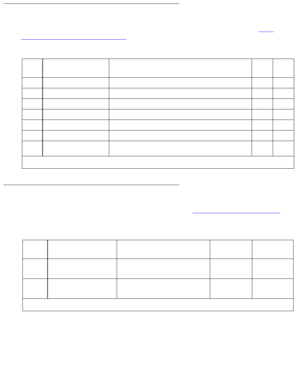
Denial Events
226 Maintenance Procedures for Avaya Communication Manager 3.0, Media Gateways and Servers
User Manager Events
Event Types 1900 - 1906 show User Manager-generated denial events, as listed in User
Manager denial events (1900 - 1906) on page 226.
IP Denial Events
Event Types 1907 - 2079 show IP denial events, as listed in IP Denial Events (1907 - 2020) on
page 226.
Table 51: User Manager denial events (1900 - 1906)
Event
Type
Event Description, as it
appears on the event log
Explanation Event
Data 1
Event
Data 2
1900 Invalid CFWD destination CF_DEST digits do not map to station User ID.
1901 Control Restrn Check fail Control Restriction.
1902 Enhanced Abbr List Failur Enhanced Abbreviated Dialing entry length failed.
1903 LWC Button xln Error Ignore Leave Word Calling button push due to bad translation.
1904 Override for the PGN disa User not allowed to activate override for this partition
1905 Auto selection of DID dis Automatic selection of Direct Inward Dialing numbers is disabled.
1906 SA8428 Btn Ring Ctl disab SA8428 Station User Button Ring Control has been disabled,
ignore button-ring button push.
Table 52: IP Denial Events (1907 - 2020)
Event
Type
Event Description, as it
appears on the event log
Explanation Event Data 1 Event Data 2
1907 IP RRJ-Invalid RAS addr IP Registration Rejected because the
RAS address in the registration request
(RRQ) is invalid.
0 IP address of
the endpoint
1908 IP RRJ-Invld call SigAddr IP Registration Rejection because the call
signaling address in the registration
request (RRQ) is invalid.
0 IP address of
the endpoint
1 of 13

Denial Event Tables
Issue 1 June 2005 227
1909 IP RRJ-RemoteOfc
misadmin
Registration rejected because:
●Remote Office is enabled on the
Signaling Group screen, but the
registration request (RRQ) is not
from a supported Remote Office
product (the Remote MAX
Product/Vendor ID is invalid).
●The RRQ is from a supported
Remote Office product, but
Remote Office is not enabled on
the Signaling Group screen.
●Remote Office is enabled on the
Signaling Group screen, but the
Terminal Type in the RRQ is not
valid (the Terminal Type is not a
gateway).
0 IP address of
the endpoint
1910 IP RRJ-H323 UserObj undef IP Registration rejected because there is
no H323 User Object.
0 IP address of
the endpoint
1911 IP RRJ-Exceed max endpts IP Registration rejected because the
capacity for either registered endpoints,
registered Remote Office endpoints, or
registered un-authenticating endpoints is
exceeded. Check maximum allowed in
the system on page 1 of the System
Parameters Customer Options screen.
0 Upper part:
number of
registered RO
endpoints.
Lower part:
number of
registered IP
endpoints.
1912 IP RRJ-Exceed ProdID/Ver IP Registration rejected because the
maximum number of registered endpoints
of a specific product ID and version is
exceeded. Check the limit on the
System-Parameters Customer-Options
screen.
Truncated
Product ID from
the System-
Parameters
Customer-
Options screen
Upper part:
registered limit.
Lower part:
actual count.
1913 IP RRJ-Invalid ProdID/Ver IP Registration rejected because of an
invalid Product ID / Version. Registering
Application's product ID is not
administered on the System-Parameters
Customer-Options screen or no Product
ID in registration request (RRQ)
message.
Truncated
Product ID of the
registering
application
Major version
number of the
endpoint sent in
the RRQ
1914 IP RRJ-ProdID search fail IP Registration rejected because the
search for the registering application's
Product ID failed.
Truncated
Product ID of the
registering
application
Major version
number of the
endpoint sent in
the RRQ
1915 IP RRJ-Invalid endpt/Ver Registration rejected because the
endpoint version is not compatible with
the gatekeeper version.
IP address of
endpoint
Endpoint’s
major version
number in 2nd
byte, minor
version number
in low byte
Table 52: IP Denial Events (1907 - 2020) (continued)
Event
Type
Event Description, as it
appears on the event log
Explanation Event Data 1 Event Data 2
2 of 13

Denial Events
228 Maintenance Procedures for Avaya Communication Manager 3.0, Media Gateways and Servers
1916 IP RRJ-No H323
NonStdData
Registration rejected because
Non-standard Data (NSD) is missing in
the registration request (RRQ) from the
endpoint.
0 IP address of
the endpoint
1917 IP RRJ-Invld H323 ObjID Registration rejected because the H323
Object ID in the registration request
(RRQ) is invalid.
Object ID in
RRQ
IP address of
the endpoint
1918 IP RRJ-Invld H225 NSData Registration rejected because cannot
decode H225 Non-standard Data (NSD)
message.
0 IP address of
the endpoint
1919 IP RRJ-Bad H225
NSDchoice
Registration rejected because an
unexpected Non-standard Data (NSD)
message was received from the
registering application.
NSD choice in
RRQ
IP address of
the endpoint
1920 IP GRJ-RRJ: new LM fail Registration rejected because of failure in
creating a new Login Manager. Possible
causes are:
●No available heap memory to
create LoginMgr
●Cannot start LoginMgr timer
●Clock not set
UID IP address of
the endpoint
1921 IP RRJ-IP-TTI port fail Registration rejected because of failure
when inserting the IP Terminal
Translation Initiation (TTI) port.
UID IP address of
the endpoint
1922
Communi-
cation
Manager
Release
2.1 and
earlier
IP RRJ-TTI inactive Registration rejected for an IP set with
Terminal Translation Initiation (TTI)
service. Possible causes:
●TTI is not enabled on the
System Parameters Customer
Options screen.
●Remote Office is not enabled on
the System Parameters Feature
Options screen.
0 IP address
1922
Communi-
cation
Manager
Release
2.2
IP RRJ-TTI or RO inactive Registration rejected for an IP set with
Terminal Translation Initiation (TTI)
service. Possible causes:
●TTI is not enabled on the
System-Parameters
Customer-Options screen.
●Remote Office is not enabled on
the Feature Related
System-Parameters screen.
0 IP address
1922
Communi-
cation
Manager
Release
3.0
IP RRJ-TTI or RO inactive Registration rejected for an IP set with
Terminal Translation Initiation (TTI)
service. Possible cause is TTI is not
enabled on the System-Parameters
Customer-Options screen.
IP address of the
endpoint
TTI state where:
0=TTI off
2=TTI on for
voice
3=TTI on for
data
Table 52: IP Denial Events (1907 - 2020) (continued)
Event
Type
Event Description, as it
appears on the event log
Explanation Event Data 1 Event Data 2
3 of 13

Denial Event Tables
Issue 1 June 2005 229
1923 IP RRJ-No E164 number Registration rejected because there is no
valid E.164 number in the RRQ or the
extension is not administered.
UID IP address of
the endpoint
1924 IP RRJ-No GRQ msg rcvd Registration rejected because no
Gatekeeper Request message was
received or RRQ was received more than
15 seconds after GRQ
UID IP address of
the endpoint
1925 IGAR trunk routing failed Registration rejected, denied while
routing an outgoing Inter-Gateway
Alternate Routing (IGAR) trunk call,
because of failure creating a new Login
Manager. Possible cause:
●No available heap memory to
create LoginMgr
●Cannot start LoginMgr timer
●Clock not set
UID IP address
1926 IP RRJ-Authenticatn fail Registration rejected because of
password authentication/ encryption
failure. The password that the user
entered and the administered password
on the station screen do not match or no
cryptoToken or keys sent in RRQ.
UID IP address of
the endpoint
1927
Communi-
cation
Manager
Release
2.2 and
earlier
IP RRJ-Invld station type Registration rejected because of:
●Invalid station type
●No Remote Office or IP
Softphone administration on the
station screen
●IP Softphone tried to register
shared-control to the wrong
telephone endpoint type.
UID station type or
IP address of
the endpoint
1927
Communi-
cation
Manager
Release
3.0
IP RRJ-Invld station type Registration rejected because of:
●Invalid station type for the
endpoint application
●R1 IP telephone
●R1 or R2 IP softphone in
roadWarrior or Telecommuter
mode
●IP console and not console
station type
●IP softphone and softphone not
set to yes on station screen
●IP telephone application and not
IP telephone station type
●Softphone that cannot operate
with a station type that does not
have a BIS or the speaker is
turned off
UID station type or
IP address of
the endpoint
Table 52: IP Denial Events (1907 - 2020) (continued)
Event
Type
Event Description, as it
appears on the event log
Explanation Event Data 1 Event Data 2
4 of 13

Denial Events
230 Maintenance Procedures for Avaya Communication Manager 3.0, Media Gateways and Servers
1928 IP RRJ-StnTyp/Protocl err Registration rejected because station
type and call-signaling protocol are
inconsistent. An IP Softphone should be
assigned as one of the following:
●DCP extension, with call control
set to IP Softphone
●H.323 extension, with call
control set to none
UID Endpoint type
(3rd and 2nd
nyble); call
signaling
protocol (low
nyble)
1929 IP RRJ-No idx for MMCmplx Registration rejected: user record for
dual-connected DCP set is missing the
index for the multimedia complex.
UID IP address of
the endpoint
1930
Communi-
cation
Manager
Release
2.2 and
earlier
IP RRJ-No voice path spec Registration rejected because the
endpoint (the virtual phone) has neither
an associated multimedia extension nor a
specified voice path, so no audio path
exists. Either:
●Add a Media Complex extension
on the station screen
or
●Add an extension on the
softphone (register as a
telecommuter)
UID IP address of
the endpoint
1930
Communi-
cation
Manager
Release
3.0
IP RRJ-No voice path spec Registration rejected because the
endpoint (the virtual phone) has neither a
specified voice path for telecommuter
mode or is itself audio capable, so no
audio path exists.
●Add an extension on the
softphone (register as a
telecommuter)
UID IP address of
the endpoint
1931 IP RRJ-H323 ext is
MMCmpx
Registration rejected because this H.323
extension is administered as a Media
Complex extension on a non-H.323 (for
example, a DCP) set.
UID IP address of
the endpoint
1932 IP RRJ-Ext has data modl Registration rejected because the
extension has a data module.
UID IP address of
the endpoint
1933 IP RRJ-IP addr mismatch Registration rejected because the H.323
application is not at the same IP address
as the authenticating application.
UID IP address of
registering
endpoint
1934 IP RRJ-Ext already reg Registration rejected because the
extension is already registered.
UID IP address of
the endpoint
1935 IP RRJ-Not Remote Ofc ext Registration rejected because Remote
Office is not administered on the station
screen for this extension.
UID IP address of
the endpoint
Table 52: IP Denial Events (1907 - 2020) (continued)
Event
Type
Event Description, as it
appears on the event log
Explanation Event Data 1 Event Data 2
5 of 13

Denial Event Tables
Issue 1 June 2005 231
1936
Communi-
cation
Manager
Release
2.2 and
earlier
IP RRJ-RO stn mismatch Registration rejected because of invalid
analog station type.
UID IP address of
the endpoint
1936
Communi-
cation
Manager
Release
3.0
IP RRJ-RO stn mismatch Registration of Remote Office endpoint
rejected because set type on Remote
Office differs from set type on station
screen.
UID IP address of
the endpoint
1937 IP RRJ-RemOfc not admin Registration rejected because the
Remote Office is not administered on the
remote-office form
UID IP address of
the endpoint
1938 IP RRJ-Immediate re-reg Immediate re-registration is rejected
when a registration or unregistration is in
progress for the extension.
UID IP address of
the endpoint
1939 IP RRJ-Failure moving ext Registration rejected because of failure
while trying to force the unregistration of
an extension in the process of moving it
to another port.
UID IP address of
the endpoint
1940 IP RRJ-Duplicate ext Registration rejected as a duplicate
extension.
UID IP address of
the endpoint
1941 IP KA-from invld endpt ID Keep Alive registration request rejected
because of invalid endpoint identifier in
RRQ.
UID IP address of
the endpoint
1942 IP KA-from unreg user Keep Alive registration request rejected
because it was received from an
unregistered extension.
UID IP address of
the endpoint
1943 IP-KA-from unreg SigGrp Keep Alive registration request rejected
because it was received from an
unregistered signaling group.
UID IP address of
the far-end
1944 IP RRJ-PSA merge failure Registration rejected because the
Personal Station Access (PSA) merge
failed (internal software error). Check for
corruption
UID IP address of
the endpoint
1945 IP RRJ-New IP user fail Registration rejected because of failure to
construct new H323 User object (internal
software error).
0 IP address of
the endpoint
1946 IP RRJ-PSA merge failure Registration rejected because the
LoginManager Personal Station Access
(PSA) merge operation failed (internal
software error). Check for corruption.
0 IP address of
the endpoint
1947 IP RRJ-PSA unmerge fail Registration rejected because the
LoginManager Personal Station Access
(PSA) unmerge operation failed (internal
software error). Check for corruption.
UID IP address of
the endpoint
Table 52: IP Denial Events (1907 - 2020) (continued)
Event
Type
Event Description, as it
appears on the event log
Explanation Event Data 1 Event Data 2
6 of 13

Denial Events
232 Maintenance Procedures for Avaya Communication Manager 3.0, Media Gateways and Servers
1948 IP RRJ-Complete pend reg Registration rejected because of failure to
obtain a station user record (internal
software error – corrupt translation).
UID IP address of
the endpoint
1949 IP RRJ-Build KARCF msg Registration rejected because of failure to
build a KeepAlive Registration Confirm
(KARCF) message (internal software
error).
0 IP address of
the endpoint
1950 IP RRJ-Build RCF msg Registration rejected because of failure to
build a Registration Confirm (RCF)
message (internal software error).
0 or UID IP address of
the endpoint
1951 IP GRJ-Invld IP addr/port Gatekeeper request rejected because of
invalid destination IP address and port in
the request (GRQ).
0 IP address
1952 IP GRJ-Invld gatekeeperID Gatekeeper request rejected because the
message is not for this gatekeeper.
Gatekeeper ID IP address
1953 IP GRJ-Invld auth capblty Gatekeeper request rejected because the
gatekeeper supports a capability that the
registering endpoint does not.
0 IP address of
the endpoint
1954 IP GRJ-Invld auth algrthm Gatekeeper request rejected because no
compatible authentication algorithm
exists between the endpoint and the
gatekeeper.
0 IP address of
the endpoint
1955
(not
used in
Communi-
cation
Manager
Release
3.0)
IP GRJ-Bld GCF:Gatewy/
MCU
Gatekeeper request rejected because of
failure to build a GateKeeper Confirm
(GCF) message for a GateWay/MCU
(internal software error).
0 IP address
1956
(not
used in
Communi-
cation
Manager
Release
3.0
IP GRJ-Bld GCF:TTI Gatekeeper request rejected because of
failure to build a GateKeeper Confirm
(GCF) message for an un-named
endpoint registration (internal software
error).
0 IP address
1957
Communi-
cation
Manager
Release
2.2 and
earlier
IP GRJ-GK will not host Gatekeeper request rejected because the
gatekeeper is unwilling to host endpoint
because:
●no alias address has been
provided
or
●Terminal Translation Initiation
(TTI) is in incorrect state (for
example, TTI is not enabled for
voice)
TTI state IP address of
the endpoint
Table 52: IP Denial Events (1907 - 2020) (continued)
Event
Type
Event Description, as it
appears on the event log
Explanation Event Data 1 Event Data 2
7 of 13

Denial Event Tables
Issue 1 June 2005 233
1957
Communi-
cation
Manager
Release
3.0
IP GRJ-GK will not host Gatekeeper request rejected because the
gatekeeper is unwilling to host endpoint
because no alias address has been
provided.
Endpoint type
sent in GRQ
IP address of
the endpoint
1958 IP GRJ-Invalid extension Gatekeeper request rejected because the
extension is not administered.
Either extension
number or 0
IP address of
the endpoint
1959 IP GRJ-No stn user record Gatekeeper request rejected because no
station user record exists for registering
this user (internal software error).
UID IP address of
the endpoint
1960 IP FURQ-Shared Ctrl Unreg Forced Unregistration Request: The
Gatekeeper is unregistering the IP
Softphone because it is in shared control
with IP Telephone, and the Telephone is
unregistering.
UID IP address of IP
Softphone
1961 IP GRJ-Build GCF msg Gatekeeper request rejected because of
failure to build a GateKeeper Confirm
(GCF) message (internal software error).
UID IP address of
the endpoint
1962 IP LRJ-No H323 sig group Location Request rejected because no
H.323 signaling group is administered to
handle the call.
UID IP address of
the far-end
1963 IP LRJ-Build LCF msg Location Request rejected because of
failure to build a Location Request
Confirm (LCF) message (internal
software error).
UID IP address
1964 IP DRJ-Null UserID Disengage Request rejected because the
endpoint ID could not be converted to a
User ID (UID).
UID IP address
1965 IP DRJ-Bld DCF:Gatewy/
MCU
Disengage Request rejected because of
failure to build Disengage Request
Confirm (DCF) message for a gateway or
MCU (internal software error).
UID IP address
1966 IP DRJ-Endpt not reg Disengage Request rejected because the
endpoint is not registered.
UID IP address
1967 IP DRJ-Build DCF msg Disengage Request rejected because of
failure to build a Disengage Request
Confirm (DCF) message for a
non-gateway or MCU user (internal
software error).
UID IP address
1968 IP BRJ-Null UserID Bandwidth Request rejected because an
invalid endpoint ID was received.
0 IP address
1969 IP BRJ-Bld BCF:Gatewy/
MCU
Bandwidth Request rejected because of
failure to build a Bandwidth Request
Confirm (BCF) message for a Gateway or
MCU (internal software error).
UID IP address
1970 IP BRJ-Endpt not reg Bandwidth Request rejected because the
endpoint is not registered.
UID IP address
Table 52: IP Denial Events (1907 - 2020) (continued)
Event
Type
Event Description, as it
appears on the event log
Explanation Event Data 1 Event Data 2
8 of 13

Denial Events
234 Maintenance Procedures for Avaya Communication Manager 3.0, Media Gateways and Servers
1971 IP BRJ-Build BCF msg Bandwidth Request rejected because of
failure to build a Bandwidth Request
Confirm (BCF) message for a
non-Gateway or MCU user (internal
software error).
UID IP address
1972 IP BRJ-No H323 user Bandwidth Request rejected because the
H.323 user object does not exist (internal
software error).
UID IP address
1973 IP BRJ-Call non-existent Bandwidth Request rejected because the
request is made for a non-existing call.
UID IP address
1974 IP BRJ-Bandwdth rqst fail Bandwidth Request rejected because of
unexpected return code from bandwidth
request.
UID IP address
1975 IP ARJ-Null UserID Admission Request rejected: received
invalid endpoint ID.
NIL UID IP address
1976 IP ARJ-Endpt not reg Admission Request rejected: the endpoint
is not registered.
UID IP address
1977 IP ARJ-No avail B-channel Admission Request rejected: no
B channel is available for the call.
UID IP address
1978 IP ARJ-Bld ACF:Gatewy/
MCU
Admission Request rejected: because of
failure to build an Admission Request
Confirm (ACF) message for a Gateway or
MCU (internal software error).
UID IP address
1979 IP ARJ-Not an H323 user Admission Request rejected: request was
received from a non-H.323 user.
UID IP address
1980 IP ARJ-Stn not in service Admission Request rejected: station is
not in service.
UID IP address
1981 IP ARJ-Build ACF msg Admission Request rejected: failure to
build an Admission Request Confirm
(ACF) message for a non-Gateway or
MCU user (internal software error).
UID IP address
1982 IP ARJ-No H323 user Admission Request rejected: H.323 user
object does not exist (internal software
error).
UID IP address
1983 IP ARJ-CRV already in use Admission Request rejected: Call
Reference Value (CRV) is already in use
by another call.
UID IP address
1984 IP ARJ-CRV does not exist Admission Request rejected: this call
reference value (CRV) does not exist.
UID IP address
1985 IP ARJ-CRV already in use Admission Request rejected: Call
Reference Value (CRV) is already in use
by another call. An ARQ has been
received while an earlier one is still
pending.
UID IP address
1986 IP ARJ-Insuff bandwidth Admission Request rejected: insufficient
bandwidth available to support this call.
UID IP address
Table 52: IP Denial Events (1907 - 2020) (continued)
Event
Type
Event Description, as it
appears on the event log
Explanation Event Data 1 Event Data 2
9 of 13

Denial Event Tables
Issue 1 June 2005 235
1987 IP ARJ-Admissn rqst fail Admission Request rejected: unexpected
return code from Admission Request
(internal software error).
UID IP address
1988 IP URJ-Null UserID Unregistration Request rejected: received
invalid endpoint ID.
0 IP address of
the endpoint
1989 IP URJ-Endpt not reg Unregistration Request rejected: endpoint
is not registered.
UID IP address of
the endpoint
1990 IP URJ-No endpoint ID Unregistration Request rejected: no
endpoint ID provided in URQ.
0 IP address of
the endpoint
1991 IP URJ-GW/MCU is not reg Unregistration Request rejected: URQ
received from a Gateway or MCU that is
not registered.
UID IP address of
the far-end
1992 IP URJ-No H323 sig group Unregistration Request rejected because
there is no H.323 user for the signaling
group (internal software error).
UID IP address of
the far-end
1993 IP URJ-No non-std data Unregistration Request rejected because
there is no non-standard data in the URQ.
UID IP address of
the endpoint
1994 IP URJ-NSD has invld OID Unregistration Request rejected because
the Non-standard Data (NSD) from the
registered application has an invalid
object ID in the URQ.
UID IP address of
the endpoint
1995 IP URJ-Can’t decode NSD Unregistration Request rejected because
of failure to decode Non-standard Data
(NSD) in the URQ.
UID IP address of
the endpoint
1996 IP URJ-Unexpected NSD
msg
Unregistration Request rejected because
of unexpected Non-standard Data (NSD)
in the URQ from the registered endpoint.
UID IP address of
the endpoint
1997 IP URJ-User is on a call Unregistration Request rejected because
the user is on a call.
UID IP address of
the endpoint
1998 IP URJ-PSA unmerge failed Unregistration Request rejected because
the Personal Station Access (PSA)
unmerge operation failed (internal
software error). Check for corruption.
UID IP address of
the endpoint
1999 IP URJ-PSA merge failed Unregistration Request rejected because
the Personal Station Access (PSA) merge
operation failed (internal software error).
Check for corruption
UID IP address of
the endpoint
2000 IP URJ-No stn user record Unregistration Request rejected because
no station user record exists for
unregistering user (internal software
error).
UID IP address of
the endpoint
2001 IP URJ-TTI op failed Unregistration Request rejected because
of an unexpected Terminal Translation
Initiation (TTI) return code.
UID IP address of
the endpoint
Table 52: IP Denial Events (1907 - 2020) (continued)
Event
Type
Event Description, as it
appears on the event log
Explanation Event Data 1 Event Data 2
10 of 13

Denial Events
236 Maintenance Procedures for Avaya Communication Manager 3.0, Media Gateways and Servers
2002 IP URJ-Build UCF msg Unregistration Request rejected because
of failure to build an unregistration
request confirm (UCF) message (internal
software error).
0 IP address of
the endpoint
2003 IP URJ-PSA unmerge failed Unregistration Request rejected because
the Personal Station Access (PSA)
unmerge operation failed (internal
software error). Check for corruption.
UID IP address of
the endpoint
2004 IP URJ-No stn user record Unregistration Request rejected because
the no station user record exists for the
unregistering user (internal software
error).
UID IP address of
the endpoint
2005 IP URJ-PSA unmerge failed Unregistration Request rejected because
the Personal Station Access (PSA)
unmerge operation failed (internal
software error).
UID IP address of
the endpoint
2006
(not
used in
Communi-
cation
Manager
Release
3.0)
IP FURQ-no H.323 ext reg Force Unregistration Request. Received
a KeepAlive request (RRQ) from a
dual-connect endpoint without a
registered H.323 extension (cannot make
calls). Re-register the endpoint.
UID IP address
2007 IP FURQ-User, no sig conn Force Unregistration Request. Unregister
user because there is no signaling
connection. RAS is alive, but the
signaling connection has gone down
(user cannot make calls). Re-register the
endpoint.
UID IP address of
the endpoint
2008 IP FURQ-H323, no sig conn Force Unregistration Request. Unregister
associated H.323 user because there is
no signaling connection. Re-register the
endpoint.
UID IP address of
the endpoint
2009 IP FURQ-Move user Force Unregistration Request. Extension
is already registered, but received a
forced login registration request (RRQ).
Send a URQ to the existing extension.
UID IP address of
the endpoint
2010 IP FURQ-Sig Conn closed Forced Unregistration Request. The
Gatekeeper is unregistering the endpoint
because its call signaling connection has
closed.
UID 0
2011 IP FURQ-NoQ931 msg rcvd Force Unregistration Request. After an
endpoint registers it should initiate the
TCP connection and send a SETUP
message. The SETUP message has not
been received from the endpoint, and no
Q931 Call object exists. The endpoint
cannot make calls, so unregister it.
H.323 UID IP address of
the endpoint
2012 IP FURQ-Aged Endpt-no KA Force Unregistration Request. Unregister
endpoint that has aged out. Endpoint's
time to live (TTL) expired without
receiving a keep-alive request (RRQ).
UID IP address of
the endpoint
Table 52: IP Denial Events (1907 - 2020) (continued)
Event
Type
Event Description, as it
appears on the event log
Explanation Event Data 1 Event Data 2
11 of 13

Denial Event Tables
Issue 1 June 2005 237
2013 IP FURQ-SigGrp removed Force Unregistration Request. An H.323
Gateway (administered as a signaling
group) is registered. Unregister the
Gateway before removing the
administered signaling group.
Gateway UID IP address of
the far-end
2014 IP FURQ-Siggrp changed Force Unregistration Request. Changes
have been made to a registered H.323
Gateway (administered as a signaling
group). Unregister the Gateway.
Signaling group IP address of
the near-end
2015 IP FURQ-Ext removed Forced Unregistration Request.
Unregister user because the extension
has been removed.
UID 0
2016
(not
used in
Communi-
cation
Manager
Release
3.0)
IP FURQ-IPusr is sftphone Forced Unregistration Request.
●A user has Personal Station
Accessed (PSA) an extension
that was registered as an IP
endpoint.
●An IP telephone extension in
shared-control was moved to
another IP port via registration.
Both shared-control IP
Telephone and IP softphone will
unregister if the rejected
registration attempt is forced.
IP User-UID 0
2017
Communi-
cation
Manager
Release
2.2 and
earlier
IP FURQ-Records
exhausted
Forced Unregistration Request.
Unregister the LAN port if there are no
station user-records remaining.
IP User-UID 0
2017
Communi-
cation
Manager
Release
3.0
IP FURQ-Records
exhausted
Forced Unregistration Request.
Unregister the endpoint if there are no
station user-records remaining.
IP User-UID 0
2018 IP FURQ-Mtc: H323/Vphone Forced Unregistration Request. The
release command was run on the
extension or port.
UID 0
2019 IP FURQ-Mtc: Remote Max Forced Unregistration Request. The
release command was run on the
Remote Office extension or port.
UID 0
Table 52: IP Denial Events (1907 - 2020) (continued)
Event
Type
Event Description, as it
appears on the event log
Explanation Event Data 1 Event Data 2
12 of 13

Denial Events
238 Maintenance Procedures for Avaya Communication Manager 3.0, Media Gateways and Servers
Call Process Denial Events
Event Types 2021 - 2299 show Call Process denial events, as listed in Call Process denial
events (2021 - 2299) on page 238.
2020
Communi-
cation
Manager
Release
2.2 and
earlier
IP FURQ-Mtc:RemOfc TTI Forced Unregistration Request. Terminal
Translation Initiation (TTI) background
maintenance task has requested the
removal of Remote Office LAN TTI ports.
UID 0
2020
Communi-
cation
Manager
Release
3.0
IP FURQ-Mtc:RemOfc TTI Forced Unregistration Request. Terminal
Translation Initiation (TTI) was turned off.
UID 0
Table 52: IP Denial Events (1907 - 2020) (continued)
Event
Type
Event Description, as it
appears on the event log
Explanation Event Data 1 Event Data 2
13 of 13
Table 53: Call Process denial events (2021 - 2299)
Event
Type
Event Description, as it
appears on the event log
Explanation Event Data 1 Event Data 2
2021 Cust Sel of DIDs inactive Custom Selection of VIP Direct
Inward Dialing numbers feature is
not active.
2022 Annc pres but not admin Announcement present but not
administered.
2023 Annc pres none on board Announcement present but no
announcements administered for
the board.
2024 Cannot create entry Registration rejected because
unable to create an entry in the
MTM complex table.
UID IP address of the endpoint
2025 Unadministered option Registration rejected because the
option chosen by the endpoint in
the RRQ for the emergency call
does not match the option
administered on the station form.
UID IP address of the endpoint
2026 Xmobile OOS: block orig Xmobile offhook request rejected
because Xmobile station has been
taken out of service.
1 of 9

Denial Event Tables
Issue 1 June 2005 239
2027 Annc not found on board User attempted to play
MO_VAL_BD announcement and
file was not found on board.
2028 Annc file has bad format User attempted to play
MO_VAL_BD announcement and
file had bad format.
2029 IP GRJ-NSD has invld
OID
Gatekeeper Request rejected
because the Non Standard Data
(NSD) from the registered
application has an invalid object ID.
UID IP address of the endpoint
2030 IP GRJ-Can't decode
NSD
Gatekeeper Request rejected
because of failure to decode Non
Standard Data (NSD) element.
UID IP address of the endpoint
2031 IP GRJ-Unexpected NSD
msg
Gatekeeper Request rejected
because of unexpected Non
Standard Data (NSD) message
from the registered application
endpoint.
UID IP address of the endpoint
2032 Force Unregistration Req Force Unregistration Request.
Instruct the RAS manager to
cleanup a User ID which had just
been registered prior to a system
restart. This event is not logged, but
only passed in the URQ.
2033
Communi-
cation
Manager
Release
2.2 and
earlier
IP FURQ-Demand
Unregister
Force Unregistration Request. The
command to force unregister
endpoints has been executed from
the SAT.
User ID IP address
2033
Communi-
cation
Manager
Release
3.0
IP FURQ-Demand
Unregister
Force Unregistration Request.
Reset ip-stations was executed
from the SAT to force unregister
endpoints.
NULL NULL
2034 Illegal TSC interaction A QSIG Non Call
Associated-Temporary Signaling
Connection (NCA-TSC) tried to
route out an AT&T TSC, or vice
versa, and this interaction is not
supported. This might occur when a
bsr_poll call over an IP trunk tries to
use a QSIG TSC but is tandemed
out an AT&T TSC.
2035 NCA-TSC not available Possible causes:
●The terminated
administered TSC
endpoint is disabled
●The incoming Non Call
Associated-Temporary
Signaling Connection
(NCA-TSC) call arrived at
the wrong signaling group
●The Maximum number of
NCA-TSC is set to 0
Table 53: Call Process denial events (2021 - 2299) (continued)
Event
Type
Event Description, as it
appears on the event log
Explanation Event Data 1 Event Data 2
2 of 9

Denial Events
240 Maintenance Procedures for Avaya Communication Manager 3.0, Media Gateways and Servers
2036 Incoming QSIG LWC
failed
Leave Word Calling on the
incoming side of a QSIG_LWC MSI
CS0FAC message failed.
2037 QSIG LWC fail find voice Getting the voice callr on the
outgoing side of a QSIG_LWC MSI
SETUP message failed.
2038 QSIG LWC fail get cling Getting the calling party number
from the incoming side of the call
failed.
2039 IP KA-No endpoint ID Keep Alive Registration Request.
Registration rejected because no
endpoint identifier was provided.
0 IP address
2040 IP GRJ-No CLAN
available
Gatekeeper Request rejected
because no resources available for
signaling connection.
UID IP address
2041 IP RRJ-No DSP Resource Registration Request rejected
because no Digital Signal
Processor (DSP) resources are
available.
UID IP address
2042-
2046
not assigned
2047 Reject-Unauthorized MG Registration rejected because it
was received from unauthorized
media gateway.
2048 Reject-MGC not ready Registration rejected because it is
not ready for a media gateway
re-registration.
2049 No VOIP Resource VOIP Resources unavailable.
2050 No MG Resource No gateway resource available.
2051 IP GRJ-RemOfc No Sig
Grp
Remote Office invalid request
(GRQ) No Sig Group available.
2052 IP RRJ-RemOfc No Sig
Grp
Remote Office invalid registration
request (RRQ) No Sig group
available.
2053 MG heartbeat missed MGKeepAlive: Wakeup() media
gateway heartbeat missed,
indicates lack of traffic from
specified gateway.
2054 Signaling CONN
Congestion
UMSocket: SockWrite() Congestion
on the Signaling Link due to PCD
buffer exhaustion.
2055 Reset MG - Pkt Send Err Reset the media gateway Signaling
Link due to error in Sending
packets.
Table 53: Call Process denial events (2021 - 2299) (continued)
Event
Type
Event Description, as it
appears on the event log
Explanation Event Data 1 Event Data 2
3 of 9

Denial Event Tables
Issue 1 June 2005 241
2056 No null caps SBS orig
end
IncomingMsg. Null caps not
received on originating end of
Separation of Bearer and Signaling
(SBS) trunk.
2057 No null caps SBS term
end
IncomingMsg. Null caps not
received on terminating end of
Separation of Bearer and Signaling
(SBS) trunk.
2058 Null caps on H323 trunk IncomingMsg. Null caps received
on terminating end of H323 trunk.
2059 SecCode change
disallowed
Change of security code through
Feature Access Code not
supported for IP.
2060 SA8508:Off Emergency access call to the
attendant using the 2nd access
code is not permitted because the
SA8508 is not optioned.
2061 Invalid Post msg dgt/tmo Post message digit timeout.
2062 Post msg too many msg
dgt
Post message too many digits.
2063 Post msg not stn user Post message not station user.
2064 IP RRJ-NSD encode
failed
Registration rejected because of
failure to encode Non-standard
Data (NSD) message.
UID IP address
2065 IP RRJ-Invalid vendor id Registration rejected because LSP
requesting registration has not sent
a valid vendor ID.
NULL IP address
2066 IP RRJ-LSP obj not init Registration rejected because the
LSP object has not been initialized.
NULL IP address
2067 IP RRJ-NSD improper
OID
Registration rejected because the
Non-standard Data (NSD) sent by
the LSP contains an invalid OID.
NULL IP address
2068 IP RRJ-Cannot decode
NSD
Registration rejected because of
failure to decode Non-standard
Data (NSD) message sent by the
LSP.
NULL IP address
2069 IP RRJ-Unxpctd NSD Registration rejected because of
receipt of an unexpected
Non-standard Data (NSD) message
from LSP.
NULL IP address
2070 MG must send full reg
msg
Media gateway attempted
registration with “warm start”
condition, but the controller needs
“cold start” data.
2071 Serial Number incorrect Media gateway attempted to
register with a different serial
number.
Table 53: Call Process denial events (2021 - 2299) (continued)
Event
Type
Event Description, as it
appears on the event log
Explanation Event Data 1 Event Data 2
4 of 9

Denial Events
242 Maintenance Procedures for Avaya Communication Manager 3.0, Media Gateways and Servers
2072 Conf/Transfer 2 Meet-me Conference or transfer 2 Meet-me
conference call.
2073 Permission denied (or)
Download permission
deny
User attempted to download
firmware to a station. User does not
have console permission.
2074 Rec fail: annc is playing Attempt to record a VAL
announcement while that
announcement is playing on a VAL
board.
2075 Var-in-Vec COS restricted User does not have console
permissions
2076 IP RRJ-Call Mismatch IP Registration Rejection (RRJ)
because of no call present on the
switch side. But there is a call
present on the ept.
UID IP address.
2077 IP FURQ-CallTimer
Expired
Force Unregistration Request.
Unregister endpoint whose call
preservation timer (H323 link loss
delay timer) expires.
UID IP address.
2078 Extend Call Button Denial OPTIM Extend Call via extend call
button press was denied.
station where
the button
was pushed
Reason the call was denied:
0 - denied because the call
already has 6 ports on it
1 - denied because the
station is at the OPTIM call
limit
2 - denied because the
application has no termination
mapping
3 - denied because call failed
to extend (check application
RTU)
2079 IP RRJ-Invld sta state Registration rejected because set in
wrong state (for example on call,
Out of Service (OOS), Administered
Without Hardware (AWOH),
Terminal Translation Initiation (TTI),
shared-control endpoints attempt to
register to different LSPs).
2080 IP FURQ-User dialed TSA IP Softphone in shared control
configuration with DCP is forced
unregistered because user dialed
TSA.
2081 IP FURQ-Invld sta state IP Softphone in shared control
configuration with DCP is forced
unregistered because softphone
switched to invalid state.
2082 Exceeded TLS conn limit A TLS socket was rejected because
of the constraint on the maximum
number of TLS peers.
2083 TLS: No cert returned A peer cert was rejected by
common name checking.
Table 53: Call Process denial events (2021 - 2299) (continued)
Event
Type
Event Description, as it
appears on the event log
Explanation Event Data 1 Event Data 2
5 of 9

Denial Event Tables
Issue 1 June 2005 243
2084 TLS: Handshake Failure Handshake failed, for example due
to no common cipher suite.
2085 TLS: Certificate expired An expired certificate was returned
and rejected.
2086 SBS bearer Auth not
supp
If authorization code is required on
outgoing Separation of Bearer and
Signaling (SBS) bearer call, this is
not supported. The call is dropped
with intercept treatment to the
originator.
2087 IP RRJ-Shrd Ctrl
OutofSrv
Used to inform softphone trying to
register in shared control with an
out-of-service DCP endpoint to try
registration with LSP.
UID IP address
2088 Bad Record Max. For example, an
attacker does not have the correct
private key, which can go
undetected until the MAC of the
exchange is checked.
2089 Bad Record Max. For example, an
attacker does not have the correct
private key, which can go
undetected until the MAC of the
exchange is checked.
2090 TLS shutdown received. Listen
socket could not be created.
2091 Conf/xfer Audix rec AUDIX one-step rec while conf.
2092 Post msg invalid SSC Post message invalid Station
Security Code (SSC).
2093 Can't start
announcement
Cannot start announcement.
2094 TCP/IP sig socket failure Establish a socket on an IP trunk.
The far end might be
mis-administered.
IP address of
the far end to
which the call
failed
Port number of the far end
2095 Rmt Div-fwding ext local QSIG Remote Diversion activation
for local extension not allowed.
2096 Rmt Div-SSC too long QSIG Remote Diversion Station
Security Code (SSC) contains too
many digits.
2097 Rmt Div-non QSIG trunk QSIG Remote Diversion is not
allowed over a non-QSIG trunk.
2098 Rmt Div-act ext not stn QSIG Remote Diversion activation
only allowed from station user.
2099 Rmt Div-act/deact failed QSIG Remote Diversion activation/
deactivation failed.
Table 53: Call Process denial events (2021 - 2299) (continued)
Event
Type
Event Description, as it
appears on the event log
Explanation Event Data 1 Event Data 2
6 of 9

Denial Events
244 Maintenance Procedures for Avaya Communication Manager 3.0, Media Gateways and Servers
2100 Rmt Div-QSIG VALU
disable
QSIG Remote Diversion is not
allowed over a QSIG trunk with
QSIG VALU disabled.
2101 Feat. requires only dgts A feature was activated via a
request URI. The part of the request
URI string that should contain all
digits contained characters other
than digits.
2102 SIP Estab Timer expiry SIP call establishment timer expired
prior to 200 OK (incoming or
outgoing call). Timer length is
administered on SIP sig-group
forms.
2103 Cannot ring add-in party Attempt to add a party to a call
failed at the termination stage.
UID of the
party that was
attempting to
terminate
Cause value/feedback
indicating the reason.
2104 Cannot add party to call Attempt to add a party to a call
failed at or after answer.
UID of the
party that was
being added
in
reason code:
1: internal failure (look for
proc_err around same time)
2: internal failure (look for
proc_err around same time)
3: conflict (ie adding
announcement to call with
tone or announcement)
4: already have six
connected/held parties on the
call
5: unable to combine voice
streams
6: internal failure (look for
proc_err around same time)
7: internal failure (look for
proc_err around same time)
2105 SCCAN handover denied Seamless Converged
Communications Across Networks
(SCCAN) attempt to handover
failed.
UID of the
station
involved in
handover
reason for failure:
0: No call found to handover
to
1: There is already a call in
the wireless domain
2: There are multiple
candidate calls to handover to
3: Handover from call not
found
4: Handover to call not found
5: Handover aborted
6: Call is at conference limit
Table 53: Call Process denial events (2021 - 2299) (continued)
Event
Type
Event Description, as it
appears on the event log
Explanation Event Data 1 Event Data 2
7 of 9

Denial Event Tables
Issue 1 June 2005 245
2106 SCCAN announcement
denied
Seamless Converged
Communications Across Networks
(SCCAN) attempt to handover
failed.
UID of the
station
involved in
handover
reason for failure:
0: Announcement not
administered on sys-param
sccan form
1+ - Feedback type
OPTIM SCCAN termination
was denied
1: WLAN call limit exceeded
2: No termination mapping
3: Cellular call limit exceeded
4: No termination mapping or
call NOT allowed or disabled
disabled is the most likely
cause (user controlled)
5: Call on bridged
appearance, and termination
disallowed
2107 SCCAN call out blocked OPTIM Seamless Converged
Communications Across Networks
(SCCAN) termination was denied
UID of the
station
involved
reason for denial:
1: WLAN call limit exceeded
2: No termination mapping
3: Cellular call limit exceeded
4: No termination mapping or
call NOT allowed or disabled.
Disabled is the most likely
cause (user controlled)
5: Call on bridged appearance
and termination disallowed.
2108 SCCAN retransmit
denied
There are problems with Seamless
Converged Communications
Across Networks (SCCAN) notify
retransmission response.
UID of the
station
involved
reason for denial:
1:Could not get Event header
from request
2: Could not get time to wait
for retransmission
3: Unknown event type
4: Internal failure (look for
proc_err around same time)
5: OPTIM application not
SCCAN
6: Station not administered
with OPTIM
2109 IP RRJ-Unknown
unnamed
Registration rejected because an
unnamed endpoint did not have the
terminal present bit set, or because
it did not supply Lucent vendor
information.
2110 Release btn push ignored Agent pushed IM_ACD_REL button
simultaneously with call
termination.
UID of agent
pushing
IM_ACD_RE
L button
NULL
2111 IP RRJ-TTI reg not in map Deny Terminal Translation Initiation
(TTI) registration, IP endpoint not in
ip-network-map.
IP address TTI state
2112 IP RRJ-TTI reg shared ctl Deny Terminal Translation Initiation
(TTI) registration, IP endpoint
requesting shared control.
IP address TTI state
Table 53: Call Process denial events (2021 - 2299) (continued)
Event
Type
Event Description, as it
appears on the event log
Explanation Event Data 1 Event Data 2
8 of 9

Denial Events
246 Maintenance Procedures for Avaya Communication Manager 3.0, Media Gateways and Servers
2113 IP RRJ-TTI incapable Deny Terminal Translation Initiation
(TTI) registration, IP endpoint not
TTI capable.
IP address TTI state
2114 IP RRJ-TTI reg eConsole Deny Terminal Translation Initiation
(TTI) registration, request from IP
eConsole.
NULL IP address.
2115 IP RRJ-RO addr no admin Deny Terminal Translation Initiation
(TTI) registration, Remote Office
address not administered.
IP address TTI state
2116 460.1 Neg failed in GRQ 460.1 feature not supported.
2117 Agent accept login error Non-EAS ACD split agent accept
login failed
Agent UID Caller ID
2118 ACD agent tot exceeds
max
Max number of ACD agents already
logged-in
UID Logged-in ACD agent count
2119 Memb per skill exceeds
mx
Max number of agents already
logged-in to skill
Agent UID Skill number
2120 Advocate agents exceed
mx
Max number of Business Advocate
agents already logged-in
Agent UID Logged-in Business Advocate
Agent count
2121 Oth agt using this logid Some other agent already using
this loginID
Agent UID Split number
2122 This agt using oth logid This agent already using some
other loginID
Agent UID Split number
2123 BCMS logid val failed BCMS (Basic Call Management
System) Login ID validation failed.
Agent UID Split number
2124 Agent tot exceeds sys
max
Agent total exceeds system limit Agent UID Agent total
2125 Over CMS agent login
cap
Maxed-out mis_ap CMS capacity Agent UID Skill number
2126 Over CMS agent login
cap
Maxed out mis_ap CMS capacity Agent UID Skill number
2127 Over BCMS agent login
cap
Maxed out mis_ap BCMS (Basic
Call Management System) capacity
Agent UID BCMS agent total
2128 Missing far-end IGAR LDN
(Inter-Gateway Alternate Routing)
2129 No idle trunks in either network
region (IGAR request)
2130 Deny TTI registration - IP endpoint
not in ip-network-map
IP address TTI state
2131 Deny TTI registration - IP endpoint
requesting shared control
IP address TTI state
2132-
2299
not assigned
Table 53: Call Process denial events (2021 - 2299) (continued)
Event
Type
Event Description, as it
appears on the event log
Explanation Event Data 1 Event Data 2
9 of 9

Denial Event Tables
Issue 1 June 2005 247
Connection Manager Denial Events
Event Types 2300 - 2399 show Connection Manager denial events, as listed in Connection
Manager denial events (2300 - 2399) on page 247.
Table 54: Connection Manager denial events (2300 - 2399)
Event
Type
Event Description, as it
appears on the event log
Explanation Event
Data 1
Event
Data 2
2300 Ept capabilities mismatch Endpoint connects to Time Division Multiplexed (TDM) bus or
it hairpinned capabilities mismatch.
2301 Tran/rec codec mismatch Transmitted or received codec mismatch.
2302 Ip_ept is in loopback Ip_ept is in loopback.
2303 Silence suppress mismatch Endpoint connects to Time Division Multiplexed (TDM) bus or
is hairpinned silence suppression mismatch.
2304 Tran/rec codec mismatch Transmitted or received codec mismatch.
2305 Silence suppress mismatch Ept1 directly connected to Ept2 silence suppression
mismatch.
2306 Reject outbound OLC Reject outbound OLC.
2307 TDM resource blockage Time Division Multiplexed (TDM) resource blockage.
2308 Selected codec mismatch Codec no longer supported.
2309 Drop call codec mismatch Drop call, codec mismatch.
2310 Invalid regions Invalid region.
2311 Invalid codec region Invalid codec region.
2312 No DSP resource No Digital Signal Processor (DSP) resource.
2313 No free list channels No channels on free list.
2314 No channel resources No channel resources.
2315 Not enough capacity
2316-
2328
not assigned
2329 No BW, prowler <--> IP ept No bandwidth channel resources between processor and IP
endpoint.
2330 No BW, prowler <--> prowler No bandwidth channel resources between processors.
2331 No VOIP channel, PN <--> PN No Voice Over IPchannel resources between port networks.
2332 No BW, prowler <--> MG No bandwidth channel resources between processor and
media gateway.
2333 No VOIP channel, PN <--> MG No Voice Over IPchannel resources between port network
and media gateway.
1 of 2

Denial Events
248 Maintenance Procedures for Avaya Communication Manager 3.0, Media Gateways and Servers
2334 No channel resources No channel resources.
2335 RejReqMode-no common
mode
Deny inbound RM, not compatible with modes received in
request.
2336 RejReqMode-no common
mode
Deny inbound RM, cannot arrive at common profile.
2337 RejReqMode-no modes rcvd Deny inbound RM, no data modes were received in request.
2338 RejReqMode-not 2 connectd Deny inbound RM, there are not two pt_conn parties on call.
2339 RejReqMode-no common
mode
Deny inbound RM dirip ept, no common profile.
2340 T38Fail-no voip resources Insufficient voip resources.
2341 T38Fail-far end timeout Far-end timeout.
2342 T38Fail-near end timeout Near-end timeout.
2343 ReqMode reject received Time Division Multiplexed (TDM)/HP connection.
2344 ReqMode reject received DIRIP connection.
2345 ReqMode release received Request release received, Time Division Multiplexed (TDM)/
HP connection.
2346 ReqMode release received Request release received, DIRIP connection.
2347 Rej inc T38OLC, not seq'd Not in sequence, dropping call.
2348 Rej inc T38OLC, no common Incompatible mode, Time Division Multiplexed (TDM)/HP
connection. Dropping call.
2349 Rej inc T38OLC, no common Incompatible mode, DIRIP connection. Dropping call.
2350 Rej inc T38OLC, idle state Deny inbound T38 OLC - IDLE state. Dropping call.
2351 Failed Xoip Attempt XOIP failed attempt, invalid call type.
2352 Failed Fax Relay Xoip Fax Relay XOIP failed attempt.
2353 Failed Modem Relay Xoip Modem Relay XOIP failed.
2354 T38Fail-no dsp resources Insufficient Digital Signal Processor (DSP) resources.
2355 IGAR trunk limit exceeded Attempt to exceed the number of trunks allowed for
Inter-Gateway Alternate Routing (IGAR) in this network
region.
2356 All IGAR managers in-use All Inter-Gateway Alternate Routing (IGAR) manager are in
use.
2357 Failed Fax Prowler Prowler reports chl could not go to FAX mode.
2358 Failed Fax Media Gateway Media Gateway reports chl could not go to FAX mode.
2359-
2399
not assigned
Table 54: Connection Manager denial events (2300 - 2399) (continued)
Event
Type
Event Description, as it
appears on the event log
Explanation Event
Data 1
Event
Data 2
2 of 2

Denial Event Tables
Issue 1 June 2005 249
Dial Plan Manager Denial Events
Event Types 2400 - 2406 show Dial Plan Manager denial events, as listed in Dial Plan Manager
denial events (2400 - 2406) on page 249.
Data Manager Denial Events
Event Types 3001 - 3003 show Data Manager denial events, as listed in Table 56: Data Manager
generated Denial Events (3001 - 3003) on page 249.
Table 55: Dial Plan Manager denial events (2400 - 2406)
Event
Type
Event Description, as it
appears on the event log
Explanation Event
Data 1
Event
Data 2
2400 UDP: too many conversions Digit conversion counter exceeded.
2401 UDP: node-rte pat blank Node number route pattern is blank.
2402 UDP: ENP code blank ENP numbering prefix is blank.
2403 Loc Digits Size incorrect Location Prefix digits size is not n, where the UDP form’s
matching row, Insert digits field is Ln.
2404 Var-in-Vec No adm for VAC Variable Access Code (VAC) in Variables in Vector Table not
administered.
2405 Var-in-Vec Invalid digit Invalid digit entered, or Feature Access Code corrupted from
call_p to dp_mgr.
2406 Unadministered annc ext Unadministered announcement extension for a location.
Table 56: Data Manager generated Denial Events (3001 - 3003)
Event Type Event Description, as it appears on the event log Explanation
3001 Bridge in use indicate PR_BRIDGE object is in use
3002 Button in use PR_BUTTON/PR_BTNTTI object is in use
3003 Station/Trunk in use one of the station/trunk PREC object is in use

Denial Events
250 Maintenance Procedures for Avaya Communication Manager 3.0, Media Gateways and Servers
Dial Access Plan Denial Events
Event Types 3101 - 3200 show Dial Access Plan denial events, as listed in Dial Access Plan
denial events (3101 - 3200) on page 250.
Meet Me Conference Denial Events
Event Types 3201 - 3299 show denial events generated by the Meet Me conference process, as
listed in Meet Me Conference denial events (3201 - 3299) on page 250.
Table 57: Dial Access Plan denial events (3101 - 3200)
Event
Type
Event Description, as it
appears on the event log
Explanation Event
Data 1
Event
Data 2
3101 DCS invalid PBX/Mach/Node Distributed Communication System (DCS) requires Trunk
Group pbx-id, Signal Group Mach-id, or AAR Analysis node
number.
3102 DCS no msg buffer avail No Distributed Communication System (DCS) message buffers
are available.
3103 DCS Station LWC mis-admin Distributed Communication System (DCS) station Leave Word
Calling is mis-administered.
3104 DCS Trunk Group mis-admin Distributed Communication System (DCS) trunk-group is
mis-administered.
3105 DCS invalid PBX/Mach/Node Distributed Communication System (DCS) requires Trunk
Group pbx-id, Signal Group Mach-id, or AAR Analysis node
number
3106-
3200
not assigned
Table 58: Meet Me Conference denial events (3201 - 3299)
Event
Type
Event Description, as it
appears on the event log
Explanation Event
Data 1
Event
Data 2
3201 Meet-Me Access chg TMO Meet-me security/access change time-out.
3202 Invld Num Digits MM Acc. Meet-me security/access change received too many digits.
3203 MM Extention not valid Meet-me security/access change not a valid extension.
3204 MM Access Chg Not a VDN Meet-me security/access change not a Vector Directory Number
extension.
3205 MM Invalid Access Entered Meet-me security/access change invalid security/access code.
1 of 2

Denial Event Tables
Issue 1 June 2005 251
3206 MM Access Obj/SAT Busy SAT window with Meet-me security/access code or obj is busy
and cannot make changes via AC.
3207 Merge Meet-me Conf call User tried to merge to a existing Meet-me conference call and
mmcon _val failed to validate the merge.
3208 Serv Observ Meet-me VDN User tried to service-observe a Meet-me conference call and
the service observing route failed.
3209 Meet-me Conf call full Meet-me conference total party number is over limit.
3210 Wrong MM Acc. code dialed Party failed to dial correct Meet-me conference access.
3211 Chg Station no Cons/Perm Meet-me security/access change the station extension does not
have console permissions.
3212 VDN not a meetme type Vector Directory Number (VDN) is not a meetme type.
3213 MM Invalid Conf Ctrlr Sta Station extension does not match controller extension.
3214 MM Inv Trk not Remote Acc Trunk User ID not allowed as a controller extension.
3215 MM Invalid Station Type Invalid station type of calling extension.
3216 Conf/Transfer 2 Meet-me Conference/or transfer 2 Meet-me conference call.
3217 MM Abbrev Dial Invalid Cannot use abbreviated dialing.
3218 Error in EMMC route dgt Error retrieving Enhanced MeetMe Conferencing (EMMC)
routing digits.
3219 Empty EMMC route digits Empty Enhanced MeetMe Conferencing (EMMC) routing digits.
3220 Exceed EMMC active conf Exceeded Enhanced MeetMe Conferencing (EMMC) active
conference.
3221 Exceed EMMC license ports Exceeded Enhanced MeetMe Conferencing (EMMC) license
ports.
3222 Exceed EMMC party limit Exceeded Enhanced MeetMe Conferencing (EMMC) party limit.
3223 Enhanced MeetMe Conferencing (EMMC)-no new vector proc
3224-
3299
not assigned
Table 58: Meet Me Conference denial events (3201 - 3299) (continued)
Event
Type
Event Description, as it
appears on the event log
Explanation Event
Data 1
Event
Data 2
2 of 2
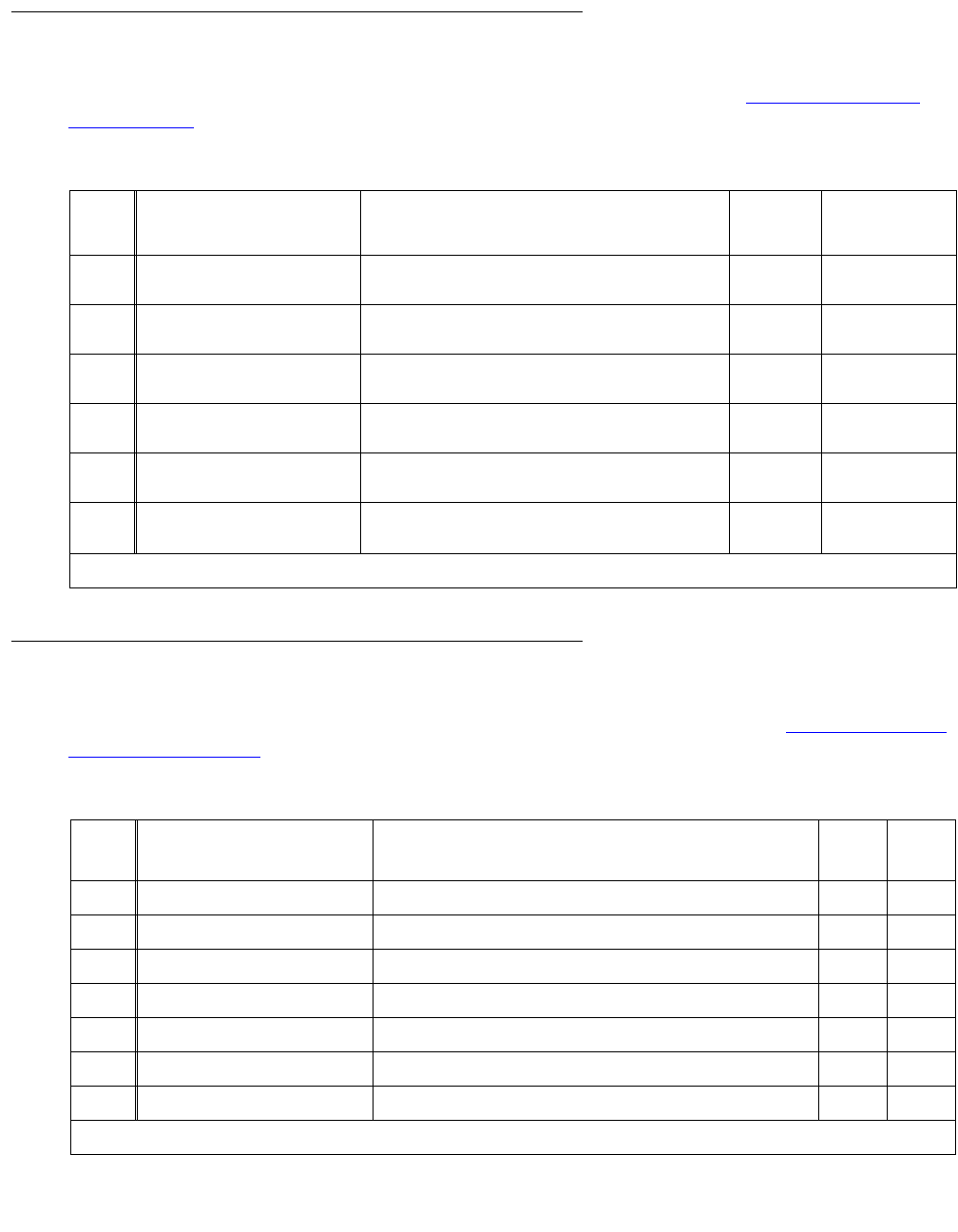
Denial Events
252 Maintenance Procedures for Avaya Communication Manager 3.0, Media Gateways and Servers
LSP Denial Events
Event Types 3300 - 3399 show LSP-generated denial events, as listed in LSP denial events
(3300 - 3399) on page 252.
Data Error Events
Event Types 3400 - 3499 show data error-generated denial events, as listed in Data Error denial
events (3400 - 3499) on page 252.
Table 59: LSP denial events (3300 - 3399)
Event
Type
Event Description
(keyword)
Explanation Event
Data 1
Event
Data 2
3300 IP RRJ-LSP not active Local Survivable Processor (LSP) is not yet active. NULL sending LSP’s
IP address
3301 IP RRJ-LSP not admin Local Survivable Processor (LSP) has not been
administered.
NULL sending LSP’s
IP address
3302 IP RRJ-Version mismatch Local Survivable Processor has not been
administered.
NULL sending LSP’s
IP address
3303 IP RRJ-GK reg with GK Local Survivable Processor (LSP)/ESS is
attempting to register with another LSP/ESS.
3304 IP RRJ-LSP's MG not admin Local Survivable Processor’s serial number does
not match any administered gateway.
NULL sending LSP’s
IP address
3305-
3399
not assigned
Table 60: Data Error denial events (3400 - 3499)
Event
Type
Event Description, as it
appears on the event log
Explanation Event
Data 1
Event
Data 2
3400 Error in vector data Bad step type.
3401 Invalid vector step type Bad step type.
3402 Companding mode mismatch Companding mode mismatch.
3403 Bad date in MCT record Bad Malicious Call Trace date.
3404 Bad date in MCT record Bad Malicious Call Trace date.
3405 Unicode cus file not read Unicode translation read error. Entire customer file not read.
3406 Error in Unicode cus file Unicode translation read error. Error found in customer file.
1 of 2
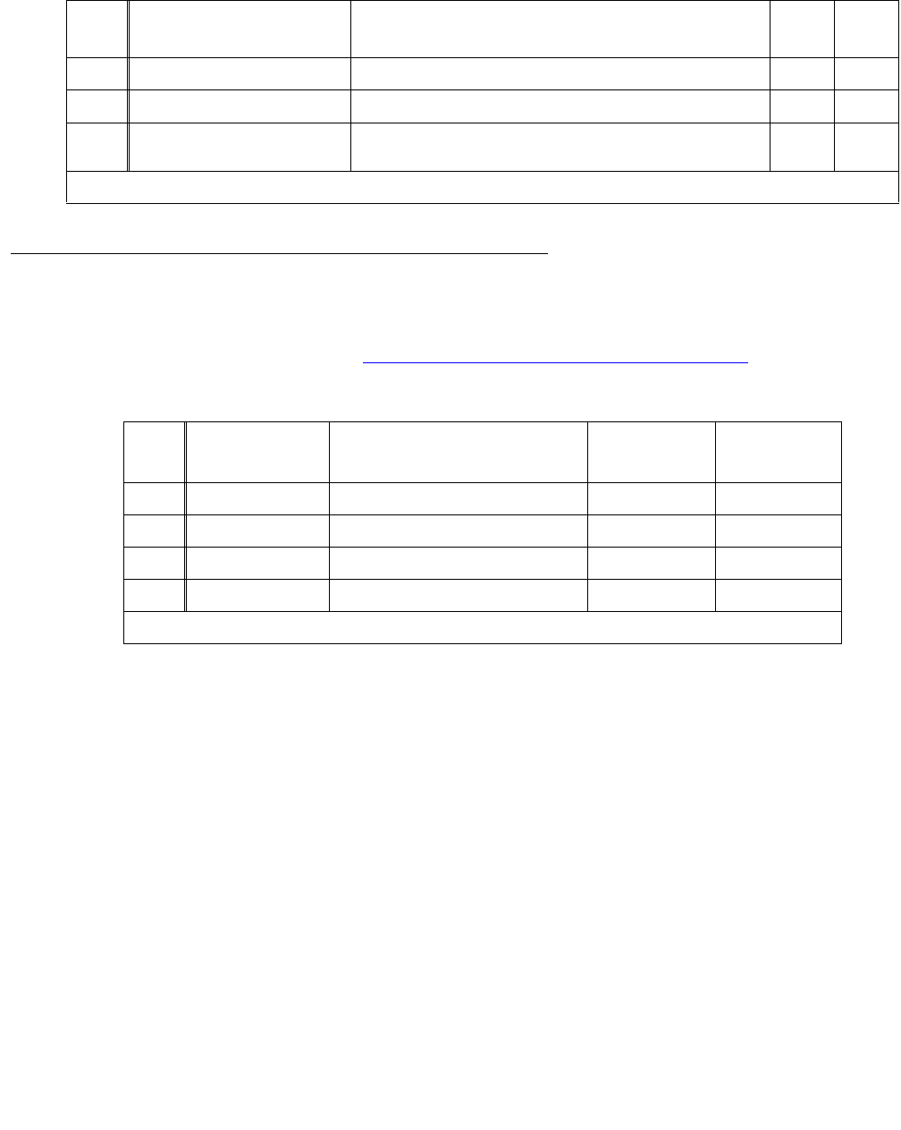
Denial Event Tables
Issue 1 June 2005 253
Contact Closure Denial Events
Contact Closure Denial Event Types 3501 - 3503 show successful feature activations and are
kept as historical data, as listed in Contact Closure denial events (3500 - 3503) on page 253.
3407 Unicode ava file not read Unicode translation read error. Entire Avaya file not read.
3408 Error in Unicode ava file Unicode translation read error. Error found in Avaya file.
3409-
3500
not assigned
Table 60: Data Error denial events (3400 - 3499) (continued)
Event
Type
Event Description, as it
appears on the event log
Explanation Event
Data 1
Event
Data 2
2 of 2
Table 61: Contact Closure denial events (3500 - 3503)
Event
Type
Event Description
(keyword)
Explanation Event
Data 1
Event
Data 2
3500 not assigned
3501 Relay OPEN Contact closure OPEN.
3502 Relay CLOSE Contact closure CLOSE.
3503 Relay PULSE Contact closure PULSE.
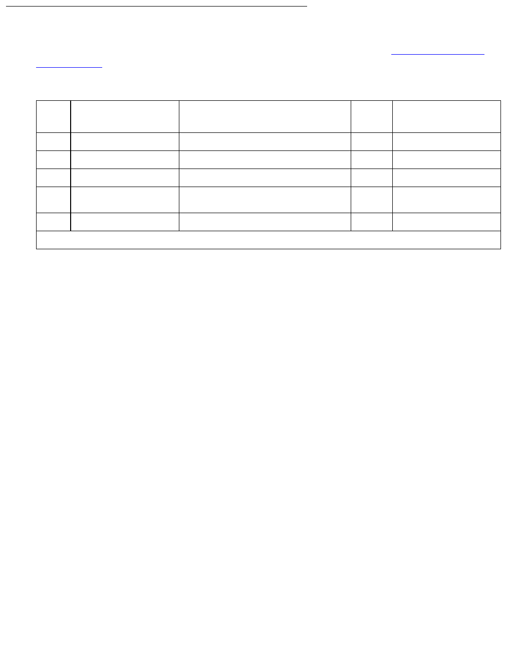
Denial Events
254 Maintenance Procedures for Avaya Communication Manager 3.0, Media Gateways and Servers
ESS Denial Events
Event Types 3600 - 3604 are ESS-generated denial events, and listed in ESS denial events
(3600 - 3604) on page 254.
Table 62: ESS denial events (3600 - 3604)
Event
Type
Event Description, as it
appears on the event log
Explanation Event
Data 1
Event Data 2
3600 IP RRJ-ESS not admin ESS has not been administered. NULL sending ESS’s IP address
3601 IP RRJ-ESS obj not init EssMgr_ptr has not been initialized. NULL sending ESS’s IP address
3602 IP RRJ-ESS bad SID sent ESS sent a bad System ID. SID sending ESS’s IP address
3603 ESS had a failure from ParseNsdLSPInfo
method.
NULL sending ESS’s IP address
3604- not assigned

Issue 1 June 2005 255
Chapter 3: LEDs
This chapter describes the meanings of the LEDs on system components and the alarm levels
they indicate. The chapter includes the following topics:
●Alarm levels on page 255
●Terminal alarm notification on page 256
●Attendant console LEDs on page 257
●Circuit pack LEDs on page 257
●Avaya Ethernet Switch LEDs on page 268
●UPS LEDs on page 269
●IPSI LEDs on page 270
●650A Power supply LEDs on page 273
●655A Power Supply LEDs on page 273
●S8710 Media Server LEDs on page 276
●S8700 Media Server LEDs on page 279
●S8500 Media Server LEDs on page 282
●S8300 Media Server LEDs on page 283
●G700 and Media Module LEDs on page 288
Alarm levels
If a maintenance object in the system begins to fail some of the periodic tests, the system
automatically generates an alarm that indicates the system needs to be restored to a normal
condition. The system identifies three levels of alarms:
●Major alarms — Failures that cause critical degradation of service and require immediate
attention.
●Minor alarms — Failures that cause some degradation of service, but do not render a
crucial portion of the system inoperable. This condition requires action, but its
consequences are not immediate. Problems might be impairing service to a few trunks or
stations or interfering with one feature across the entire system.
●Warning alarms — Failures that cause no significant degradation of service or failures in
equipment external to the system.

LEDs
256 Maintenance Procedures for Avaya Communication Manager 3.0, Media Gateways and Servers
Alarms are communicated to the system users and technicians by entries in the alarm log and
the lighting of LEDs located on the attendant console, on all circuit packs, on the server, on the
Cajun Ethernet switch if there is one, and, optionally, on customer-designated voice terminals.
Warning alarms are not reported to the attendant console.
Terminal alarm notification
Terminal alarm notification is an optional feature which displays several types of alarms on
voice terminals with administered feature buttons or the attendant console. A maximum of 10
digital and/or hybrid voice terminals may be used.
When an alarm occurs, the green status LED associated with the assigned button will be in a
steady state. The LED may be turned off by pressing the button associated with the lighted
alarm LED. If the LED is turned off and the alarm has not been resolved by the time
maintenance reschedules testing, the green status LED will resume its steady state.
The following alarms are displayed:
ac-alarm Administered Connection alarm: A locally administered connection
(ADM-CONN) has a major, minor, or warning alarm active.
pr-awu-alm Auto Wakeup Journal Printer alarm: The automatic wakeup journal printer has
a major, minor, or warning alarm active.
off-bd-alarm DS1 or ATM Facility alarm: An off-board major, minor, or warning alarm is
active on a DS1-BD, UDS1-BD, or ATM-TRK board.
trk-ac-alm Facility Access alarm: The facility access trunk test feature is activated.
major-alrm Major alarm: The system has logged a major alarm.
mj/mn-alrm Major/Minor alarm: The system has logged a major or minor alarm.
pr-pms-alm The Property Management System (PMS) printer has a major, minor, or
warning alarm active.
rs-alert Reset-Alert: reset system 2 or 3 has been performed.
cdr1-alrm Call Detail Recording alarm: The primary CDR link has a major, minor, or
warning alarm active.
cdr2-alrm Call Detail Recording alarm: The secondary link has a major, minor, or warning
alarm active.
pr-sys-alm System Printer alarm: The System Printer (SYS-PRNT) has a major, minor, or
warning alarm active.
pms-alarm The Property Management System has a major, minor or warning alarm active.

Attendant console LEDs
Issue 1 June 2005 257
Attendant console LEDs
The console has two red LEDs, labeled “ALM” and “ACK.” The ALM LED lights steadily when
there is a major or minor alarm at the switch cabinet. The ACK LED lights steadily if the alarm
has been successfully reported. If the system is unable to report the alarm, the LED flashes; this
signals the attendant to call the Avaya alarm receiving system and report the alarm.
Circuit pack LEDs
Typically each circuit pack has three LEDs on the front panel visible at the front of the carrier.
There are some exceptions to this (for example, DS1CONV or IPSI circuit pack) that are
covered later in this section. On most circuit packs, the LEDs indicate the following when lit
(Table 63: LED indicators on page 257). Exceptions to these indications are explained in
subsequent sections.
This section includes LED interpretation on the following circuit packs:
●LED alarms without Alarm Log entry or with Error Type 1 on page 258
●Expansion Interface circuit pack LEDs on page 259
●Maintenance circuit pack LEDs on page 260
●DS1C (TN574/TN1654) circuit pack LEDs on page 261
●Switch Node Interface LEDs on page 265
●Tone-Clock circuit pack LEDs on page 266
●IPSI LEDs on page 270
Table 63: LED indicators
LED
Color
State Interpretation
Red Alarm The system detected a fault in this circuit pack. The alarm log should contain
an on-board alarm for this circuit pack or one of the maintenance objects
associated with it. The red LED is also lit briefly when a circuit pack is
inserted or reset. If the circuit pack passes its initialization tests, the LED is
extinguished. If a fault is detected, it remains lit.
Green Testing The system is currently running tests on this circuit pack as part of
background maintenance or demand testing. This LED is also lit briefly
during initialization tests when a circuit pack is inserted or reset.
Yellow Busy The circuit pack is currently in use by the system.

LEDs
258 Maintenance Procedures for Avaya Communication Manager 3.0, Media Gateways and Servers
LED alarms without Alarm Log entry
or with Error Type 1
Whenever the system or a part of the system is reset, every affected circuit pack will briefly light
their red and green LEDs as they are initialized. Upon power up of a newly installed system,
several alarm indicators may remain lit until the circuit packs are administered. These alarms
should be ignored until administration is completed.
Boards with a “P” suffix have downloadable firmware. If such a board has both its green and
yellow LEDs lit simultaneously, a download may be in progress and the board will not appear to
be recognized. Use either the SAT command status firmware download or status
firmware download last to verify this condition.
G350: For G350 - WAN media modules, MM314, MM340, and MM342. If these media modules
are inserted in a slot administered for a voice media module the red LED will be lit.
After a circuit pack has been initialized, a red LED should be accompanied by an alarm in the
alarm log. A single fault can sometimes light alarm LEDs on several circuit packs, as in the
following examples.
●A TDM bus problem may cause several port circuit packs to display red LEDs.
●A Maintenance circuit pack can prevent an Expansion Interface (EI) circuit pack from
initializing.
●Extensive interactions in the Center Stage Switch (CSS) can cause multiple alarms from
single faults in DS1C, SNI and SNC circuit packs and fiber links.
●Tone-Clock problems may cause other circuit packs to report alarms.
●Mis-connected optical fiber cables may cause several circuit packs to alarm.
●Packet-bus faults can cause several port circuit packs to display red LEDs.
If a circuit pack has had at least five minutes to be initialized, and the red LED is lit without an
associated alarm in the alarm log, the circuit pack may not be in communication with the
system. This may also be the case when a circuit pack is properly administered and present in
its slot, but there is an error type 1 logged against it. To determine whether this is so, proceed as
follows:
1. Enter the list configuration board location command. If the system does not
detect the circuit pack, this command will return:
identifier not assigned or no board.
If the documentation for the associated maintenance object gives no special instructions for
this situation, go to the next step.
2. Check the hardware error log for TONE-BD or TDM-BUS errors. If the board has a “P” suffix
execute the reset board location command, otherwise execute the test tdm and
test tone-clock commands and use the appropriate maintenance procedures to
resolve any identified faults. If this does not resolve the problem, go to the next step.

Circuit pack LEDs
Issue 1 June 2005 259
3. Reseat the suspect circuit pack.
!CAUTION:
CAUTION: This procedure can cause a partial or total service outage. Consult thoroughly the
documentation for the associated maintenance object before proceeding.
Observe the precautions and procedures described above.
4. Inspect the backplane connectors for bent pins.
5. If the system seems to be functioning correctly, but the circuit pack in question will not
communicate with the system, replace the circuit pack.
Expansion Interface circuit pack LEDs
The Expansion Interface (EI) TN570 circuit pack has the standard red, green and yellow LEDs.
The red and green LEDs have the traditional meaning, where red indicates an alarm condition,
and green indicates testing in progress.
The yellow LED displays various flashing patterns to provide status information useful in
isolating faults in the fiber link and other components connected to the fiber link.
Table 64: Expansion Interface yellow LED flashing codes on page 259 illustrates the EI yellow
LED states.
Table 64: Expansion Interface yellow LED flashing codes
LED
on
LED
off
Condition
0.1 sec 0.1 sec Fiber Out-of-Frame. This state indicates a failure of test #989. This may
be caused by absence of the opposite end EI or Switch Node Interface
(SNI), a broken or missing fiber, or a missing lightwave transceiver on
either endpoint.
0.5 sec 0.5 sec In Frame — No Neighbor. This state corresponds to a failure of test #
237, usually due to a failure of this EI or of the EI or SNI at the other end
of the fiber.
2 sec 0.2 sec EI Active. This is the normal state of an active EI that is an archangel of
an EPN.
solid on EI Active. This is the normal state for an active EI that is not an EPN
archangel. These include EPN EIs connected to other EPN EIs in direct
connect configurations, and EIs located in the processor port network.
solid off EI Standby. This is the normal state for a standby EI in systems with a
duplication option.

LEDs
260 Maintenance Procedures for Avaya Communication Manager 3.0, Media Gateways and Servers
Maintenance circuit pack LEDs
TN775D PN maintenance circuit packs have seven LEDs on their front panels. The top three
LEDs are the standard group of red, green and yellow, and indicate the status of the circuit
pack. The green LED on TN775Ds blinks faintly once per second, indicating continual
self-testing.
The second group of three LEDs, labeled “ALARMS”, reflects maintenance conditions
throughout the system and indicates alarms reported against other components, as shown in
Table 65: Maintenance circuit pack LED interpretation on page 260.
These LEDS are illustrated Figure 1: TN775 circuit pack LEDs on faceplate on page 261.
Table 65: Maintenance circuit pack LED interpretation
LED
color
State Level/
Function
Interpretation
Red flashing MAJOR Major alarm against a component in the same cabinet.
solid MAJOR Major alarm against a component in another cabinet.
solid MINOR Minor alarm against a component in another cabinet.
flashing MINOR Minor alarm against a component in the same cabinet.
Yellow flashing WARNING Warning alarm against a component in the same
cabinet.
solid WARNING Warning alarm against a component in another
cabinet.
Green on ACK Acknowledged; alarm has been reported.
Red on EMERGENCY
TRANSFER
Emergency transfer has been invoked. This occurs
upon power-up as well as during disabling failures.
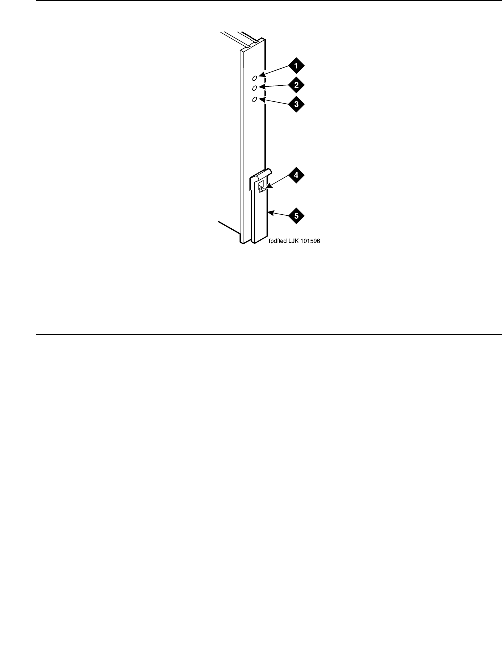
Circuit pack LEDs
Issue 1 June 2005 261
Figure 1: TN775 circuit pack LEDs on faceplate
DS1C (TN574/TN1654) circuit pack LEDs
The TN574 and the TN1654 LEDs provide an indication of the state of the DS1 converter and
facilities.
Note:
Note: DS1 converters are used exclusively with a CSS.
TN574 circuit pack LEDs
Seven LEDs provide an indication of the state of the DS1 converter (DS1C-BD) TN574 circuit
pack and the DS1 facilities. The top group has the standard red, green and yellow LEDs. The
red and green LEDs have the traditional meaning, where red indicates an alarm condition, and
green indicates testing in progress. The four green LEDs on the bottom indicate the status of
the DS1 facilities (see following section).
Figure notes:
1. Alarm LED (Red) 4. Latch pin
2. Test LED (Green) 5. Locking lever
3. Busy LED (Yellow)

LEDs
262 Maintenance Procedures for Avaya Communication Manager 3.0, Media Gateways and Servers
The yellow LED is used to indicate the state of the fiber interface, the fiber channel, and the
DS1 channel as listed in Table 66: DS1C yellow LED flashing states on page 262 in order of
priority.
DS1 Facility LEDs
Below the three standard LEDs on the DS1C circuit pack are four green LEDs that indicate
whether a receive signal is present for each of the four DS1 facilities. Figure 2: TN574 DS1
Converter circuit pack LEDs on page 263 shows which facility (A, B, C, or D) corresponds to
each LED. If a green LED is off, there is a Loss of Signal condition on the DS1 facility
associated with that LED. The presence of a signal does not guarantee that the signal is using
the correct framing format or line coding; an Alarm Indication Signal indicating that the opposite
end of the DS1C complex is out of service may be present.
Table 66: DS1C yellow LED flashing states
LED
on
LED
off
Condition
0.1 sec 0.1 sec Fiber Out-of-Frame or Fiber Loss of Signal
0.5 sec 0.5 sec In Frame, fiber channel down. The fiber channel communicating between
the DS1C and the other fiber endpoint (EI or SNI) is down.
1 sec 1 sec In Frame, DS1 channel down. The channel between the two DS1Cs in the
DS1C complex is down.
solid on DS1C active. This is the normal state for an active DS1C.
solid off DS1C standby. This is the normal state for a standby DS1C in
critical-reliability systems (duplicated PNC).
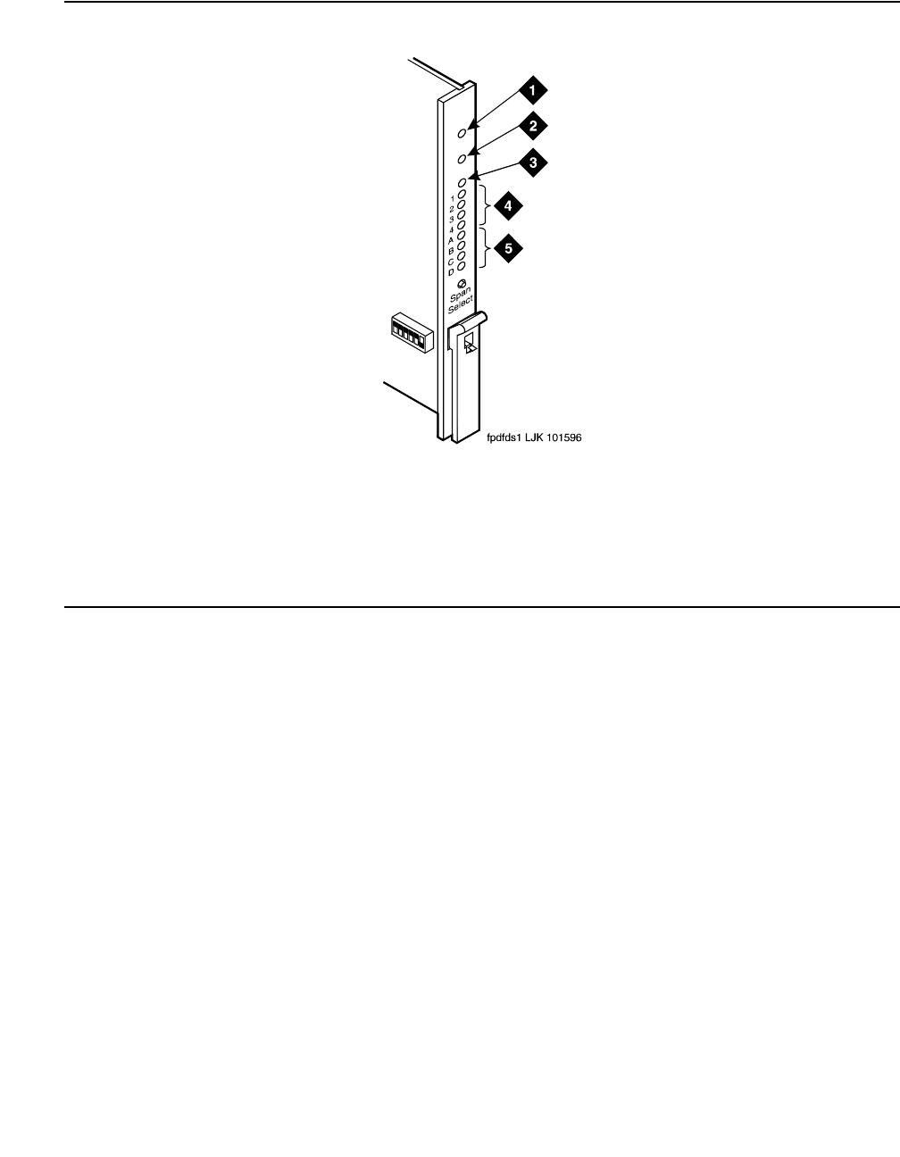
Circuit pack LEDs
Issue 1 June 2005 263
Figure 2: TN574 DS1 Converter circuit pack LEDs
TN1654 circuit pack LEDs
The TN1654 DS1C-BD board has 11 LEDs on its faceplate. The top three system standard
LEDs indicate the state of the DS1C-BD board. These LEDs are under firmware control until the
board has established a link to the S8700 Media Server via the EI or SNI. Once the link is
established, software controls the three LEDs. If the link breaks, the LEDs are again under
firmware control.
The red and green LEDs have the traditional meaning, where red indicates an alarm condition,
and green indicates testing in progress. The red and green LEDs are also turned on during
circuit pack initialization by firmware. When the control link to the circuit pack is lost, firmware
controls the red LED to indicate an alarm condition.
Figure notes:
1. Alarm LED (Red) 4. STATUS LEDs
2. Test LED (Green) 5. SPAN LEDs
3. Busy LED (Yellow)

LEDs
264 Maintenance Procedures for Avaya Communication Manager 3.0, Media Gateways and Servers
The yellow LED under firmware control is used to indicate the state of the physical fiber
interface, the Fiber Channel (link to EI or SNI), the DS1 Control Channel (link to opposite
DS1CONV board), and the S8700 Media Server communications link in the following manner
and order of priority. (The yellow LED remains on for longer periods of time as the DS1CONV
complex becomes closer to being fully operational.)
1. If the fiber is Out of Frame or if a Fiber Loss of Signal condition exists, the yellow LED will
flicker at a 5 Hz rate (on for 100 mS, off for 100 mS).
2. If the fiber channel is down (DS1 Converter circuit pack/fiber endpoint communications), the
yellow LED will flash at a 1 Hz rate (on for 500 ms, off for 500 ms).
3. If the DS1 control channel is down between the two DS1CONVs in the DS1CONV complex,
the yellow LED will pulse at a 0.5 Hz rate (on for 1 second, off for 1 second).
4. If the S8700 Media Server communications link is down, the yellow LED will wink off every 2
seconds for 200ms (2 sec on, 200 msec off).
5. If all is well with the fiber interface and every communications channel, the yellow LED will
remain on continuously in a standard- or high-reliability system configuration. In
critical-reliability systems (duplicated PNC), an active DS1CONV circuit pack will have its
yellow LED on continuously, and a standby DS1CONV circuit pack will have its yellow LED
off. The LED will then be under software control.
The bottom four green LEDs on the TN574 DS1CONV board are under hardware control. The
four green LEDs indicate, for each DS1CONV facility, whether a receive signal is present for the
DS1 facility
The next four LEDs on the TN1654 DS1CONV board are labeled STATUS LEDs and are for
future use. These LEDs will not be lit.
The bottom four LEDs on the TN1654 board are labeled SPAN LEDs. These LEDs are under
firmware control. If the facility is not administered, then the LED is not lit. The LED is lit amber if
the facility is running alarm free. If the facility is detecting either a red alarm (loss-of-signal or
loss-of-frame), a yellow alarm (remote frame alarm) or a blue alarm (AIS signal) then the LED is
lit red. The SPAN SELECT switch on the TN1654 faceplate is for future use. Pushing the switch
will have no effect on the board. See Figure 3: TN1654 DS1CONV circuit pack on page 265 for
a view of the faceplate on the TN1654 DS1CONV circuit pack.
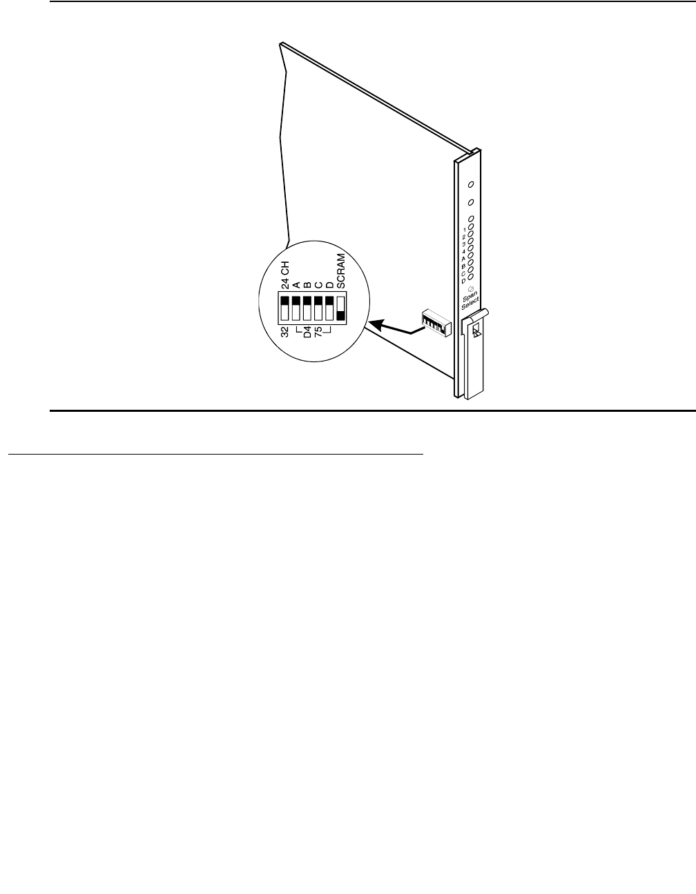
Circuit pack LEDs
Issue 1 June 2005 265
Figure 3: TN1654 DS1CONV circuit pack
.
Switch Node Interface LEDs
The Switch Node Interface (SNI) TN573 circuit pack has the standard red, green, and yellow
LEDs. The red and green LEDs have the traditional meaning, where red indicates an alarm
condition, and green indicates testing in progress.
The yellow LED displays various flashing patterns to provide status information useful in
isolating faults in the fiber link and other components connected to the fiber link.
INSET
0015_0 RBP 052396

LEDs
266 Maintenance Procedures for Avaya Communication Manager 3.0, Media Gateways and Servers
Table 67: Switch Node Interface (SNI) yellow LED flashing states on page 266 illustrates the
SNI yellow LED states.
Tone-Clock circuit pack LEDs
The Tone-Clock circuit packs found in non IPSI connected port networks have the standard red,
green and yellow LEDs. The red LED has the traditional meaning. The yellow and green LEDs
flash in specific patterns to indicate the status of the circuit pack. The standby status applies
only to systems with a duplication option.
Maintenance/Test circuit pack LEDs
The TN771D maintenance/test circuit pack has the standard red, green, and yellow LEDs. The
red and green LEDs have the traditional meaning, where red indicates an alarm condition, and
green indicates testing in progress.
The yellow LED can be off or on continuously or flashing, depending on the mode of operation
of the TN771D and whether or not it has detected errors. The yellow LED is on steady when the
TN771D’s analog test port or digital test ports are being used to test trunks or line circuits. The
yellow LED is also used to indicate packet-bus status. Table 68: TN771D Maintenance/Test
Yellow LED States on page 267 illustrates the maintenance/test yellow LED states as they
apply to packet-bus activity.
Table 67: Switch Node Interface (SNI) yellow LED flashing states
LED
on
LED
off
Condition
0.1 sec 0.1 sec Fiber Out-of-Frame. This state indicates a failure of test #238, which may
be caused by absence of the opposite end EI or Switch Node Interface, a
broken or missing fiber, or a missing lightwave transceiver on either
endpoint.
0.5 sec 0.5 sec In Frame — No Neighbor. This state corresponds to a failure of test #
237, usually due to a failure of this SNI, or the EI or SNI at the opposite of
the fiber. This condition may also be due to a faulty Switch Node Clock
(SNC).
solid
on
SNI Active. This is the normal state for an active SNI.
solid
off
SNI Standby. This is the normal state for a standby SNI in systems with a
duplication option.

Circuit pack LEDs
Issue 1 June 2005 267
Table 68: TN771D Maintenance/Test Yellow LED States
LED State1
1. It takes 5 to 10 seconds for the yellow LED to respond to a change in the state of the packet bus.
TN771D Mode Condition
Solid off Normal The Maintenance/Test circuit pack detects no packet-bus
faults.
Solid on2
2. Because the yellow LED on the Maintenance/Test circuit pack can also be on steady when the digital and
analog test ports on the circuit pack are in use, exact interpretation of the yellow LED may require that the
technician busy out the analog and digital test ports or examine the error and alarm logs for PKT-BUS
errors and alarms.
Normal The Maintenance/Test packet-bus port has successfully
reconfigured the packet bus around a fault.
Flashing (1 Hz) Normal The Maintenance/Test packet-bus port is unable to
reconfigure the packet bus around a fault.
Solid off Standalone3
3. “Standalone” refers to the TN771D’s capability to operate autonomously as a troubleshooting aid.
The Maintenance/Test detects no packet-bus faults.
Solid on Standalone This condition cannot normally occur. The LED is always
either off or blinking in standalone mode.
Flashing (1 Hz) Standalone The Maintenance/Test packet-bus port detects a
packet-bus fault.
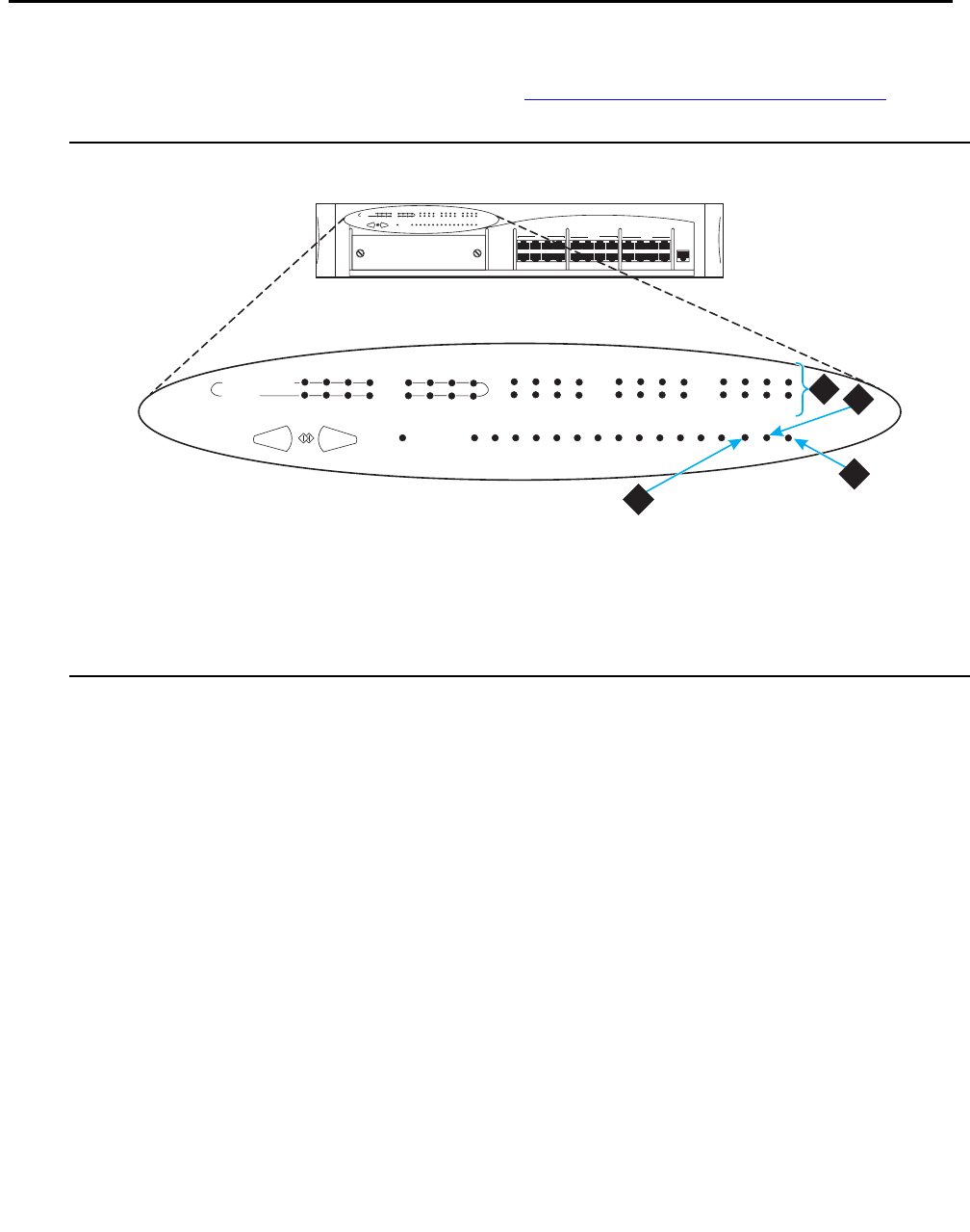
LEDs
268 Maintenance Procedures for Avaya Communication Manager 3.0, Media Gateways and Servers
Avaya Ethernet Switch LEDs
The Avaya Ethernet switch’s LEDs are shown in Figure 4: Avaya Ethernet switch LEDs on
page 268.
Figure 4: Avaya Ethernet switch LEDs
The following three LEDs are the primary indicators:
●SYS shows whether this module is the Cajun P330 stack master.
●OPR shows CPU boot status.
●PWR shows when power is on.
For all other LEDs, refer to the quick start guide and user guide that came with the Avaya
Ethernet switch.
Figure notes:
1. Ports in use 3. Power
2. CPU boot status 4. Lights if this module is the Cajun
P33x stack master
1
13
2
14
LAG 3
15
4
16
9
21
10
22
LAG 11
23
12
24
CONSOLE
5
17
6
18
LAG 7
19
8
20
51
EXPANSION
SLOT
59
FIV
55
63
LNK OPRSYS PWR
COL Tx Rx FC Hspd LAG
FDX
1
13
5
17
9
21
52
60
56
64
2
14
6
18
10
22
53
61
57
65
3
15
7
19
11
23
54
62
58
66
4
16
8
20
12
24
Cajun P333T Switch
51
EXPANSION
SLOT
59
FIV
55
63
LNK OPRSYS PWR
COL Tx Rx FC Hspd LAG
FDX
1
13
5
17
9
21
52
60
56
64
2
14
6
18
10
22
53
61
57
65
3
15
7
19
11
23
54
62
58
66
4
16
8
20
12
24
ledl333t KLC 030602
1
3
2
4
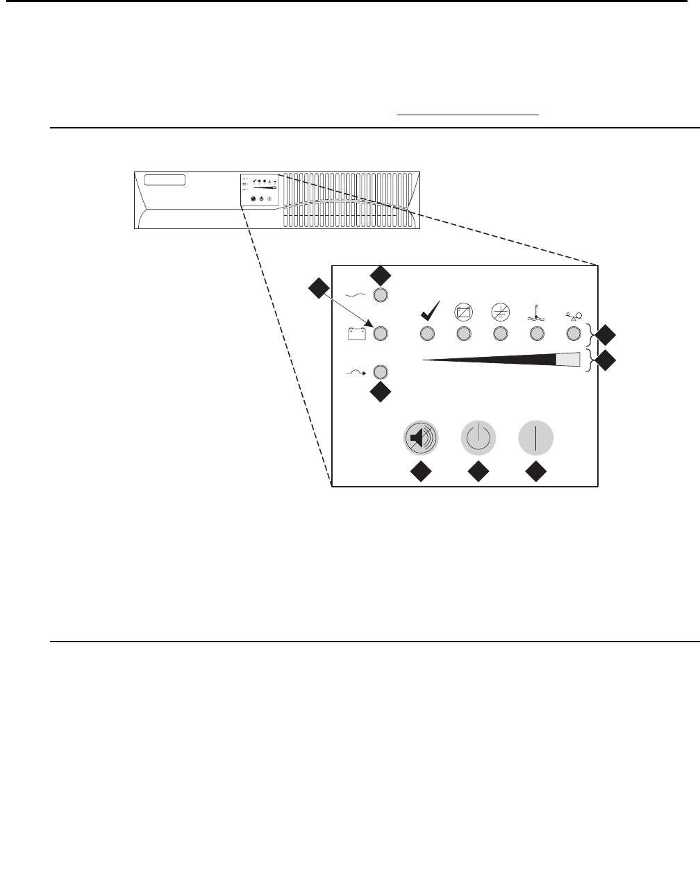
UPS LEDs
Issue 1 June 2005 269
UPS LEDs
All Ethernet hubs and UPSs have LEDs to indicate that they are powered on or off. LEDs “on”
imply the device is powered on. LED “off” implies the device is powered down.
The Powerware front panel has the LEDs shown in Figure 5: UPS LEDs on page 269.
Figure 5: UPS LEDs
When the Normal mode LED is steady green, it has power. If the LED is flashing, the UPS is in
standby mode.
For information on the other LEDs, refer to the UPS user’s guide that came with the Powerware
UPS unit.
Figure notes:
1. Normal mode indicator 5. Off button
2. Battery mode indicator 6. On button
3. Bypass mode indicator 7. Bar graph indicators
4. Test/Alarm reset button 8. Alarm indicators
1
2
3
4 5 6
7
8
ledlups KLC 030102
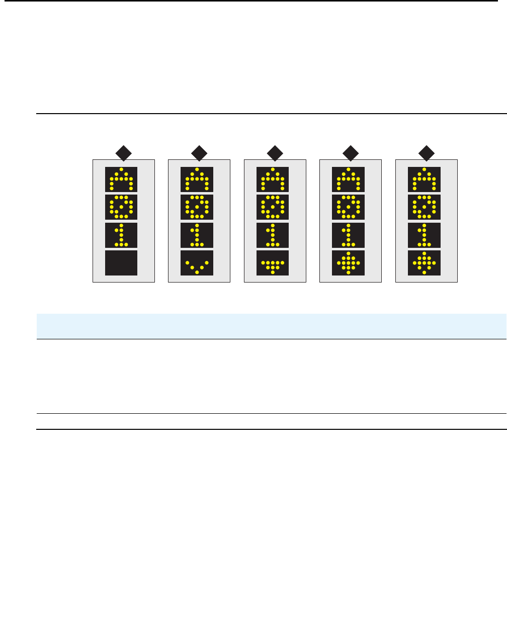
LEDs
270 Maintenance Procedures for Avaya Communication Manager 3.0, Media Gateways and Servers
IPSI LEDs
There are four LEDs on the TN2312AP IPSI faceplate, and five LEDs on the TN2312BP IPSI
faceplate. The top three LEDs are the standard ones found on most TN circuit packs. The fourth
LED imitates the TN2182B Tone-Clock’s amber LED. The archangel flashes the yellow LED
when active, 2 seconds on and 200 msec off. In addition, the TN2312BP has a fifth LED that
shows the emergency transfer control status.
Figure 6: IPSI display showing connectivity status
Table 69: IPSI connection status (figure notes)
Connectivity status 1 2 3 4 5
IPSI is connected to Avaya Ethernet switch no yes yes yes yes
IPSI has an IP address no no yes yes no
Laptop computer is connected to IPSI
services port
no no no yes yes
ledlipsi KLC 030502
1 2 43 5
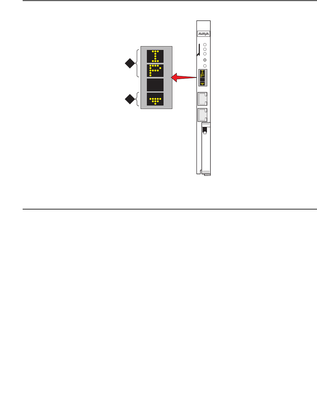
IPSI LEDs
Issue 1 June 2005 271
Figure 7: S8700 IP-Connect IPSI display
Figure notes:
1. IPSI using DHCP 2. IPSI has connectivity and an IP address
ledlip1 KLC 030502
1
2
CLK
S
E
R
V
I
C
E
N
E
T
W
O
R
K
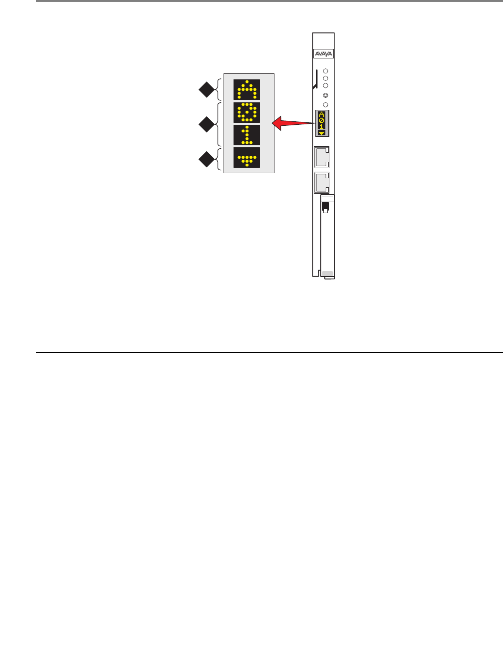
LEDs
272 Maintenance Procedures for Avaya Communication Manager 3.0, Media Gateways and Servers
Figure 8: S8700 Multi-Connect IPSI Board Display
Figure notes:
1. Switch identifier 3. IPSI has connectivity and an IP address
2. Cabinet
ledsa01 KLC 030502
1
2
3
CLK
S
E
R
V
I
C
E
N
E
T
W
O
R
K

650A Power supply LEDs
Issue 1 June 2005 273
650A Power supply LEDs
Table 70: LED and alarm conditions on page 273 shows the LED and alarm conditions for the
650A Power Supply. Ring voltage and neon bus output do not activate alarm status.
655A Power Supply LEDs
The G650 media gateway normally has two 655A power supplies. Each has a set of five LEDs,
the function of which is indicated in Table 71: 655A Power Supply LEDs on page 273.
Normally the ring voltage LED (#5) on the left power supply is ON and the ring voltage LED on
the right power supply is OFF. This changes momentarily when the ringer interchange test is
run. The ring voltage LED will only remain lit on the right power supply when there is a power
supply failure of the left hand supply or the left hand supply is removed.
Table 70: LED and alarm conditions
Condition LED
status
Alarm
state
Fan alarm
Normal Red off;
Yellow on
Open Normal
No input power Red off;
Yellow off
Closed No input power
DC output not present (except Neon) Red on;
Yellow off
Closed DC output not present
(except Neon)
Fan alarm Red on;
Yellow on
Closed Fan alarm
Table 71: 655A Power Supply LEDs
LED Color Function
1 Red Failure of power supply or fan
2 Yellow Status of power supply OK
3 Green AC input voltage applied
4 Green DC input voltage applied
5 Green Power supply providing ring voltage

LEDs
274 Maintenance Procedures for Avaya Communication Manager 3.0, Media Gateways and Servers
LED indicators of serial bus commands to the power supply
Operation of the 655A power supply LED indicators for visual indication of serial bus commands
to the power supply for power supply shutdown and ringing shutdown are described below.
Power supply shutdown
The 655A power supply can be commanded off for a period selectable from 1 to 255 seconds.
The intent is to allow a hard reset to the G650 chassis remotely. The yellow LED indicating
correct operation of the 655A power supply is on for normal power supply operation. When the
power supply is commanded off, the yellow LED blinks at a rate of 1 second on and 100ms off,
indicating that the power supply is operational but commanded off by the serial bus.
Ringing shutdown
The left hand power supply in the G650 cabinet is the master ringer. If the master ringer fails,
ringing is transferred to the redundant power supply, if present, and the red LED on the left hand
power supply turns on and the yellow LED turns off, indicating failure of the power supply.
The serial bus can command the ringer off for a period of 1 to 255 seconds. The purpose of this
command is to verify redundant ringer operation through the serial bus, remotely from the G650
chassis. The red LED blinks at a rate of 1 second on and 100ms off, indicating that the power
supply is operational but commanded off by the serial bus.
A second command relating to ringer operation is the to command the master ringer off, which
shuts down the master ringer and transfers control to the redundant power supply. This
command is used to permanently transfer ring voltage to the redundant power supply through
the serial bus, in order to resolve a problem with the master ringer. The red LED blinks at a rate
of 1 second on and 100ms off, indicating that the power supply is operational but commanded
off by the serial bus.
Duplication memory card LEDs
The Duplication memory card has LEDs that indicate active/standby, fiber link integrity/activity
states. The LED functions are:
●Link Active -- Green when light signal is sensed on the fiber.
●Link Sync -- Green when characters are received.
●Trans Mode -- Green when transmission is enabled.
●Receive Mode -- Green when reception is enabled.

Duplication memory card LEDs
Issue 1 June 2005 275
On the active server the Trans Mode LED will be green and the Receive Mode LED will be dark.
On the standby server the Receive Mode will be green and the Trans Mode LED will be dark.
Also see System shutdown LEDs on page 280.
Testing the Duplication Memory card LEDs
When you test the LEDs, the DAJ-1 or DAL-1 duplication memory card LED should blink
according to the following pattern:
1 second red, 1 second red off, 1 second green, 1 second green off
and so on for a total of one minute.
If the LED shows any of the following flashing patterns, an abnormal condition is indicated.
Table 72: Duplication memory card abnormal LED conditions on page 275 describes the
condition and suggests actions to take to resolve it.
!WARNING:
WARNING: The DAJ-1 and DAL-1 are not interchangeable. The DAJ-1 will not function in the
S8710 and the DAL-1 will not function in the S8700 media server.
Table 72: Duplication memory card abnormal LED conditions
LED
Color
Behavior Indication Resolution
Red Flashes on 1 second,
off 3 seconds
in a repeating pattern
The green element
is burned out
Replace the server.
Green Flashes on 1 second,
off 3 seconds,
in a repeating pattern
The red element is
burned out
Replace the server.
LED remains off
continuously
The DAJ-1 or
DAL-1 card is not
getting power, or
the server is hung
If the server is hung, it should
automatically reboot itself. If it does
not, power it down and reboot it.
Green or
Red
Flashed continuously The server is hung If the server is hung, it should
automatically reboot itself. If it does
not, power it down and reboot it.
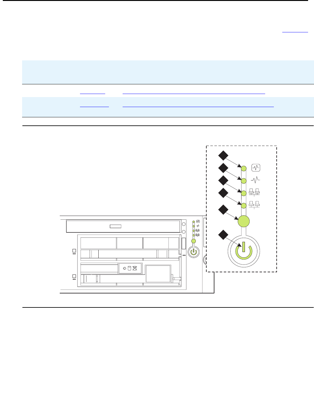
LEDs
276 Maintenance Procedures for Avaya Communication Manager 3.0, Media Gateways and Servers
S8710 Media Server LEDs
The S8710 Media Server has LEDs on both the front and back panels. Use the links in Table 73
for LED information and interpretation.
Figure 9: LEDs on front panel of S8710 Media Server
Table 73: S8710 LED information
S8710
location
Diagram LED interpretation
Front panel Figure 9 Table 74: S8710 front panel LED interpretation on page 277
Back panel Figure 10 Figure notes: S8710 rear panel LED interpretation on
page 278
Simplex Duplex ch ch 2
0
1
1
2
1
1
0
disc
COMPACT
msdsled1 KLC 041304
2
1
1
2
3
4
5
6
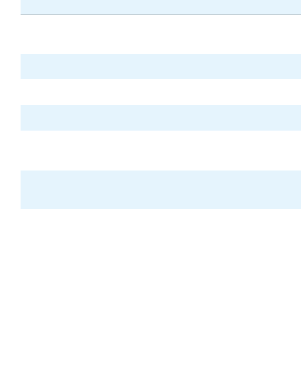
S8710 Media Server LEDs
Issue 1 June 2005 277
Table 74: S8710 front panel LED interpretation
Number Description Status
1 Internal health GREEN: normal
AMBER: system degraded. See system board
LEDs to identify component in degraded state.
RED: system critical. See system board LEDs to
identify component in critical state.
2Power supply GREEN: normal
AMBER: power redundancy failure
RED: Critical power supply failure
3 NIC 1 (Eth0) link/activity
(GREEN)
STEADY ON: network link
FLASHING: network link and activity
Off: No link to network
4NIC 2 (Eth1) link/activity
(GREEN)
STEADY ON: network link
FLASHING: network link and activity
OFF: No link to network
5 Active/Standby mode (BLUE) STEADY ON: in active mode
FLASHING: in standby mode
OFF: deactivated
NOTE: If pressed, the LED is deactivated; wait 10
seconds and the LED comes back on.
6Power on/
Standby button/
System power
GREEN: system on
AMBER: system shut down but power still applied
OFF: power supply failure
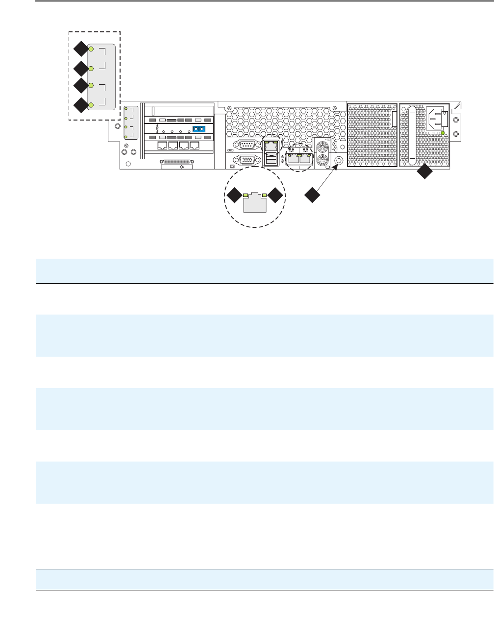
LEDs
278 Maintenance Procedures for Avaya Communication Manager 3.0, Media Gateways and Servers
Figure 10: LEDs on back panel of S8710 Media Server
Figure notes:S8710 rear panel LED interpretation
Number Description Status
1 Not used ON: expansion board failed.
OFF: normal
2Not used STEADY ON: slot has power
FLASHING: power is cycling
OFF: no power
3 Quad-NIC fault
(slot 2) (AMBER)
ON: expansion board failed.
OFF: normal
4Quad-NIC power
(slot 2) (GREEN)
STEADY ON: slot has power
FLASHING: power is cycling
OFF: no power
5 RJ45 link (GREEN) ON: linked to network
OFF: not linked to network
6RJ45 link (GREEN) STEADY ON: network activity
FLASHING: network activity
OFF: no network activity
7 Active/standby mode
(BLUE)
STEADY ON: in active mode
FLASHING: in standby mode
Off: deactivated
NOTE: If pressed, the LED is deactivated; wait 10 seconds
and the LED comes back on.
1 of 2
2
3
iLO
VDCI
1
2
3
133 MGz
100 MGz
100 MGz
UID
2 1
DAL1
DUP
MEMORY
RECEIVE
MODE
LINC
SYNC
TRANS
MODE
LINC
ACTIVE
msds871c KLC 040604
5 6
2
3
1
2
3
4
7
8

S8700 Media Server LEDs
Issue 1 June 2005 279
S8700 Media Server LEDs
The S8700 Media Server has an LED called Active/Standby that indicates whether the server is
the active server or the standby server. The Active/Standby LED in the “on” state implies active
and in the “flashing” state implies standby. It flashes at the rate of 400 ms “on” and 600 ms “off”
when in standby mode.
8Power supply
(GREEN)
ON: power is on and power supply is functioning properly
OFF: indicates one or more of the following conditions:
●AC power is unavailable
●Power supply failed
●Power supply in standby mode
●Power supply exceeded current limit
Figure notes:S8710 rear panel LED interpretation (continued)
Number Description Status
2 of 2

LEDs
280 Maintenance Procedures for Avaya Communication Manager 3.0, Media Gateways and Servers
Figure 11: S8700 Media Server LEDs—Front and Back
System shutdown LEDs
All server and Avaya duplication memory card LEDs are in the “off” state but still powered “on”
when the server is shut down.
Testing server LEDs
Using the media server Web interface, click Diagnostics > Test Server LEDs to make sure
that the Active/Standby LED on the server and the transmit LED on the DAJ-1 or DAL-1
duplication memory card are controllable and not burned out, and that the server is not hung.
During the test, the Active/Standby LED on the media server and the transmit LED on the
duplication memory card should blink slowly (1 second on, 1 second off) for 1 minute.
Figure notes:
1. Power 7. U2 (not used)
2. Configuration fault 8. 4 NIC ports (the numbers indicate their
assigned Ethernet ports)
3. Disk activity 9. LEDs for the NIC ports
4. Network activity (not used) 10. LEDs for fiber optic duplication connectivity
5. Service—configuration health (not used) 11. Status LED (not used)
6. Active or standby mode indicator
1
SERVICE
U2
STANDBY
ACTIVE
2
1
55443322
DAI - 1
DUP
MEMORY
LINE
RECEIVE
TRANS
LINK
STAT
AVAYA
1 2
3 44 5 67
9
10
11
8
scdlled KLC 030502

S8700 Media Server LEDs
Issue 1 June 2005 281
To test the server LEDs:
1. On the main menu, under Diagnostics, click Test Server LEDs.
2. On the Test Server LEDs screen, click Test LEDs.
3. Observe the Active/Standby LED on your server and the transmit LED on your duplication
card to ensure they are blinking.
Interpreting the test results
An abnormal condition is indicated if an LED shows any of the following flashing patterns.
Also see Testing the Duplication Memory card LEDs on page 275.
Resolving problems
If the server is hung, you do not need to do anything. It should automatically reboot and fix itself.
If the server does not reboot itself, power it down and then reboot it.
If an LED is clearly stuck or has a burned out element, ignore the indicators until you can
conveniently replace the server.
LED color / behavior Indication
Flashes red The green element is either burned out or not controlled.
Flashes green The red element is either burned out or not controlled.
Flashes between red
and amber
The green element is stuck on.
Flashes between green
and amber
The red element is stuck on.
Stays amber continuously Either the server is hung or the LED controller is stuck.
Stays off continuously The server is hung or powered off, the controller is stuck, or the
server is using a new or different LED controller.
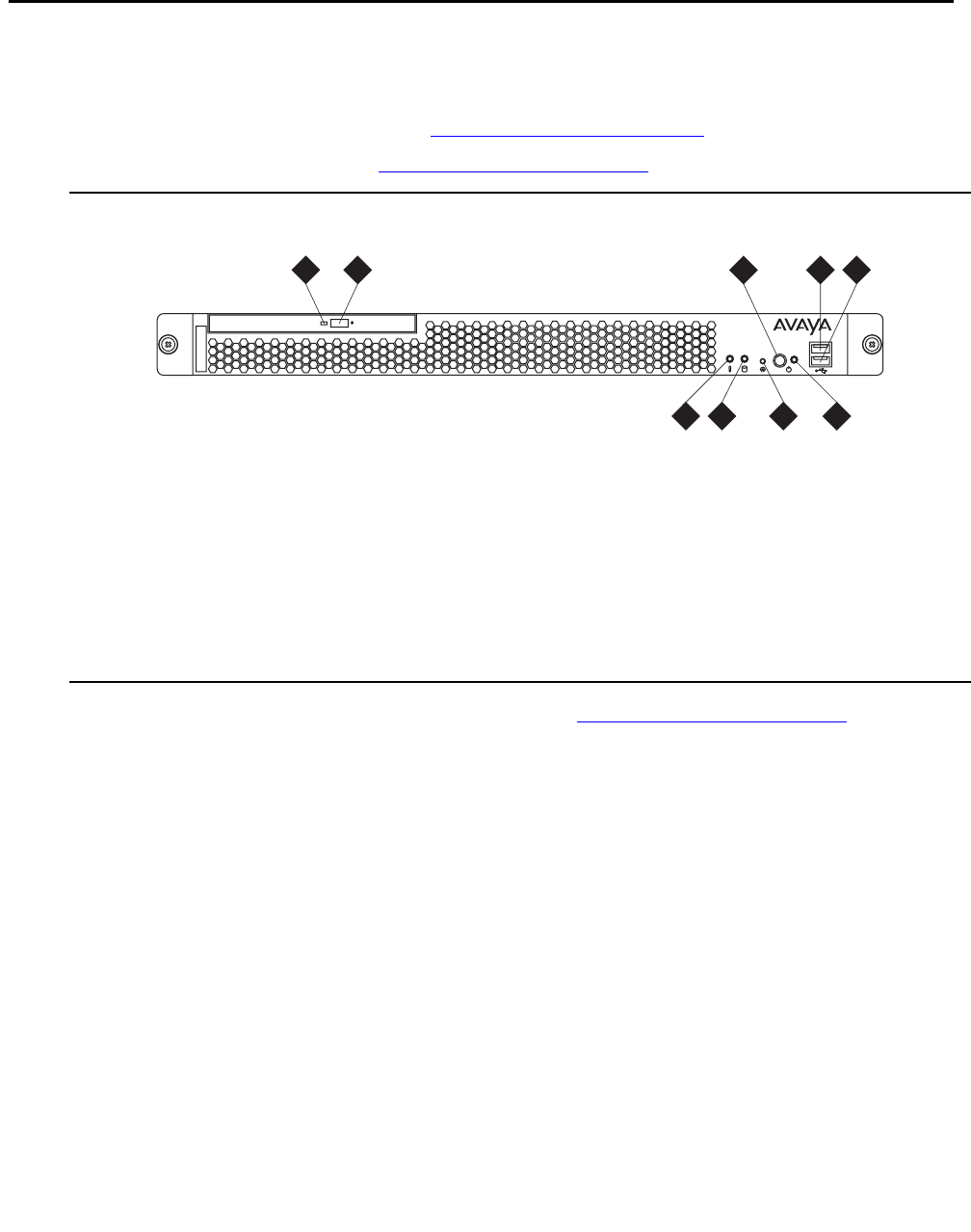
LEDs
282 Maintenance Procedures for Avaya Communication Manager 3.0, Media Gateways and Servers
S8500 Media Server LEDs
The S8500 Media Server has:
●Five (5) LEDs on the front panel (Figure 12: S8500 front panel on page 282)
●Four (4) LEDs on the back (Figure 13: S8500 rear panel on page 283)
Figure 12: S8500 front panel
The four LEDs on the S8500 back panel are shown in Figure 13: S8500 rear panel on
page 283.
Figure notes:
1. CD-ROM drive activity LED (green) 6. System-error LED (amber)
2. CD eject button 7. Hard disk drive activity LED (green)
3. Power-control button 8. Reset button
4. USB connector 1 9. Power-on LED (green)
5. USB connector 2
disc
7
2 4 5
68 9
h3msfrnt LAO 070103
1 3
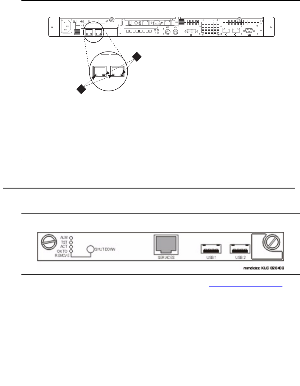
S8300 Media Server LEDs
Issue 1 June 2005 283
Figure 13: S8500 rear panel
S8300 Media Server LEDs
Figure 14: S8300 Media Server
The S8300 Media Server has a total of 6 LEDs on the faceplate (Figure 14: S8300 Media
Server on page 283). The three standard, red, green, and yellow LEDs. See S8300 LED
differences from Media Modules on page 284 for a detailed description of these LEDs.
The three additional LEDs:
●A fourth LED labeled “OK-to-Remove”, which indicates when the S8300’s disk is properly
shut down.
●Fifth and sixth LEDs, located on the lower left and right sides, respectively, of the
Services Port, which indicate whether or not data is being sent over the RJ45 jack, and
the data rate.
Figure notes:
1. Activity 2. Connection speed
●LED is off: there is a 10 BASE-T active link.
●LED is green: there is a 100 BASE-T active link.
●LED is orange: there is a 1000 BASE-T active link.
12
LINK TX/RX LINK TX/RX
PCI
1
PCI 2
100-127 -, 3,0A, 50/60 Hz
200-240 -, 1,5A, 50/60 Hz
133 MHz/64 Bit, 100 MHz/64 Bit
h3msble2 KLC 082503
100-127 -, 3,0A,
200-240 -, 1,5A, 5
1
2

LEDs
284 Maintenance Procedures for Avaya Communication Manager 3.0, Media Gateways and Servers
GREEN “OK-to-Remove” LED
The S8300 has a hard drive that must be shut down prior to removal of the S8300. Initiate a
shutdown process by first depressing the shutdown button located next to the fourth GREEN
“Ok-to-Remove” LED for 2-4 seconds (specific to the S8300). The GREEN LED will first blink;
then go steady. Once steady, the GREEN LED indicates that the disk drive has been shut down
properly and the S8300 is ready to be removed. Follow standard Media Module removal
procedures after the GREEN LED indicates that the disk drive has been properly parked.
There are three different ways that you can properly shut down the S8300 before it is removed:
●Press the shutdown button on the faceplate for 2-4 seconds.
●Initiate shutdown via the Web interface with a computer connected either:
●Remotely, on the customer’s LAN
●Locally, on the S8300 using the Services Port on the faceplate of the S8300
GREEN or YELLOW Services Port LEDs
One LED is located on the lower left side of the Services port. It indicates the data rate of the
connection:
●When GREEN, this LED indicates a 10MB connection.
●When YELLOW, this LED indicates a 100MB connection.
A second LED, located on the lower right side of the Services port, indicates whether or not data
is being sent over the RJ45 jack. This LED serves as a visual status of the Services' Ethernet
interface (TX/RX).
S8300 LED differences from Media Modules
Certain behaviors of the traditional S8300 LEDs differ from the Media Modules because the
S8300 is a Media Server running Communication Manager.
●Situations like “insanity” and IP concepts of “registered” through H.248 do not necessarily
apply to other Media Modules.
●The RED LED provides a major alarm indication. Software turns off the RED LED during
system startup. After startup, software turns on the RED LED whenever a major alarm is
present, and turns off the RED LED whenever a major alarm clears. Since the S8300
sees a major alarm whenever a G700 Media Gateway becomes unregistered, this
means the RED LED turns on. If the Media Gateway subsequently becomes registered,
the major alarm clears, and the RED LED turns off.
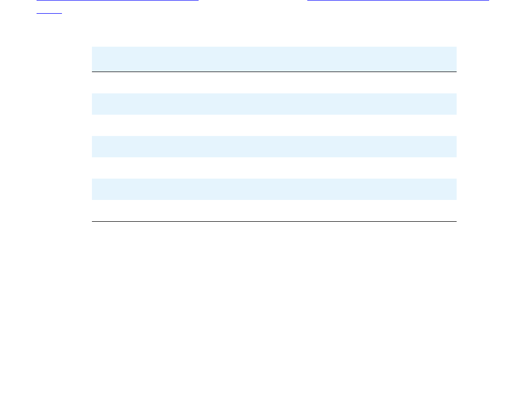
S8300 Media Server LEDs
Issue 1 June 2005 285
Note:
Note: For an S8300 configured as an LSP, the converse is true. If a G700 Media
Gateway registers with an LSP, a major alarm is generated, and the RED LED
turns on. When the Media Gateway unregisters, the RED LED turns off.
The RED LED can be turned on by software to report an application or other error. The
RED LED can also be turned on by a hardware watchdog that has not been cleared for at
least 10ms, when the processing complex has ceased to function.
●The GREEN LED provides self-testing and maintenance indication. For an S8300, the
software turns on the Green LED when the Avaya Communication Manager application
is running. This is important to know when the S8300 is used in the Local Survivable
Processor (LSP) configuration and no gateways or IP endpoints are registered with it.
●The YELLOW LED provides active “in use” indication. For an S8300, the software turns
on the YELLOW LED during system startup, and turns off the LED during shutdown.
During normal call processing operation, the YELLOW LED turns on whenever a G700
Media Gateway, an IP station, or an IP console is registered with the S8300. Likewise, it
turns off when none of the IP endpoints are registered.
Table 75: Major alarm (red LED) on page 285 through Table 79: ENET Link/Activity (green
LED) on page 287 illustrate the states of S8300 LEDs.
Table 75: Major alarm (red LED)
Major alarm Indicator
Power on Reset On
BIOS Boot On
OS and SW Boot On
System Up Off - SW
H.248 Registered Off - SW
Shutdown in Progress On
Shutdown Complete On

LEDs
286 Maintenance Procedures for Avaya Communication Manager 3.0, Media Gateways and Servers
Table 76: Test – Avaya Communication Manager status (green LED)
Test – To Be Defined
Power On Reset Off
BIOS Boot Off
OS and SW Boot On-SW
System Up Off - SW
Avaya Communication Manager Running On
H.248 Registered Off - SW
Shutdown in Progress Off - SW
Shutdown Complete Off
Table 77: Active – In Use (yellow LED)
Active – In Use
Power On Reset Off
BIOS Boot Off
OS and SW Boot Off
System Up SW
H.248 Registered On-SW
Shutdown in Progress Off-SW
Shutdown Complete Off
Table 78: OK to Remove (green LED)
OK to Remove
Power On Reset Off
BIOS Boot Off
OS and SW Boot Off
System Up Off
1 of 2

S8300 Media Server LEDs
Issue 1 June 2005 287
S8300 LED lighting sequence
In general, S8300 LEDs light in order from top to bottom, then from left to right on the S8300
faceplate.
The following order applies during restart or boot of the S8300:
1. ALM - RED: lights up first then turns off.
2. TST - GREEN: lights up second then turns off.
3. ACT - YELLOW: lights up third then turns off.
4. OK To REMOVE - GREEN: lights up fourth then turns off.
5. LEFT LED in SERVICES jack - GREEN (10 MB link speed): lights up fifth then turns off.
6. LEFT LED in SERVICES jack - YELLOW (100 MB link speed): lights up sixth then turns off.
7. RIGHT LED in SERVICES jack - GREEN: lights up seventh then turns off.
H.248 Registered Off
Shutdown in Progress 1 Hz flash
Shutdown Complete On
Table 79: ENET Link/Activity (green LED)
ENET Link/Activity
Power On Reset Off
BIOS Boot N/A
OS and SW Boot N/A
System Up Link Status
H.248 Registered Link Status
Shutdown in Progress Unknown
Shutdown Complete Off
Table 78: OK to Remove (green LED) (continued)
OK to Remove
2 of 2

LEDs
288 Maintenance Procedures for Avaya Communication Manager 3.0, Media Gateways and Servers
G700 and Media Module LEDs
LEDs are important status indicators for technicians during on-site installation, maintenance,
troubleshooting, and repair. They encompass three major areas: Alarms, Testing, and Usage
Activity. Some LEDs are specialized to support specific procedures (such as removing the
S8300 Media Server). When alarms or problems occur, LEDs are present to indicate that
attention by a technician is needed.
LEDs appear on the G700 LED panel, and each Media Module. The G700 LEDs are the same
as those on the Avaya Cajun P330, with the following exceptions:
●Slight modifications to two of the LEDs (OPR and SYS)
●Addition of the Alarm LED to the LED Panel to display prominently any error condition
See “Table 2-1: Avaya P333T LED Description, in the "Avaya P333T User’s Guide" for a
complete listing of LEDs.
Some Media Modules have additional LEDs, although each Media Module has the three
standard LED. Table 80: LED Interpretation on page 288 indicates the meanings associated
with standard DEFINITY server LEDs. Although in some cases these LEDs have been
augmented or modified for the S8300 Media Server and G700 Media Gateway, it is important to
be aware of their standard meanings when viewing the system.
Note:
Note: The four multi-color specialized status LEDs that have appeared on various
DEFINITY server TN boards like the T1/E1/DS1 board (TN464) do not appear on
the Media Modules.
Note:
Note: LEDs can also be viewed using the embedded Device Manager on the L2
Switching Processor; however, it displays LED position only, and does not
indicate status.
Table 80: LED Interpretation
Red Upon power-up or module insanity, this LED is turned on. Upon passing
diagnostics, this LED is turned off.
Green During power-up self testing and maintenance testing, this LED is turned on.
Yellow This LED indicates that the module is in service.
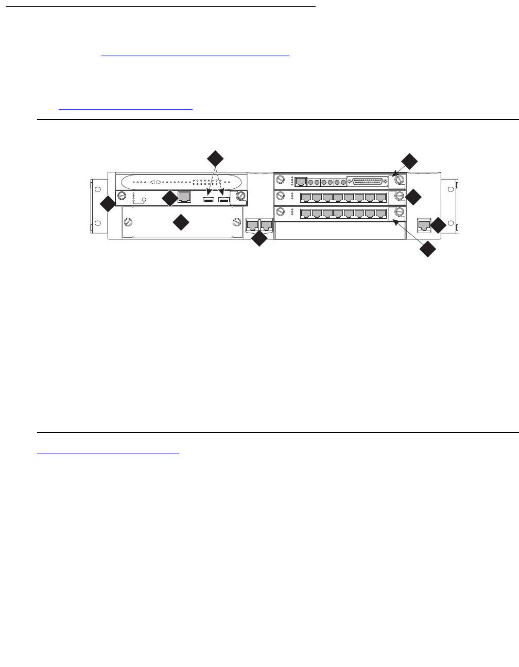
G700 and Media Module LEDs
Issue 1 June 2005 289
LED panel location on the G700
As shown in Figure 15: G700 LED Panel Location on page 289, the LED panel is located on
the top left corner of the G700. Directly below the LED panel is Media Module slot V1, which can
be occupied by any type of Media Module. However, the S8300 Media Server can reside only in
this particular slot because of height restrictions (for a specific discussion of the S8300 LEDs,
see S8300 Media Server LEDs on page 283.
Figure 15: G700 LED Panel Location
Figure 16: G700 LED Panel on page 290 shows an expanded view of the G700 LED panel.
Figure notes:
1. Media Module Slot #1 (V1) 5. 10/100 BaseT Ethernet Ports (Ext1,
Ext2)
2. S8300 Services Port (Used with
cross-over ethernet cable)
6. Media Module Slot #2 (V2)
3. S8300 USB Series Modem
connection
7. Media Module Slot #3 (V3)
4. Avaya Expansion Module Slot 8. Media Module Slot #4 (V4)
9. Console Interface (use with serial
cable)
ALM
TST
ACT
123456 87
ALM
TST
ACT
123456 87
REMOVE
ALM
TST
ACT
OK TO SHUT DOWN
SERVICES USB 1 USB 2
E1/T1 EIA 530A DCE
ALM
TST
ACT
SIG
EISO EMSM EOSI
msdcs830 KLC 031402
V1
V2
V3
V4
EXT 1 EXT 2 CONSOLE
1
4
5
6
7
8
9
ALM PWR CPU MSTR LNK COL Tx Rx FDX FC Hspd LAG EXT 1
51 52 53 54 55 56 57 58
59 60 61 62 63 64 65 66
EXT 2
2
3
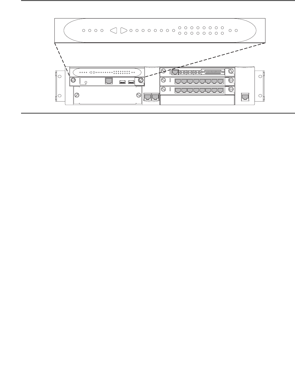
LEDs
290 Maintenance Procedures for Avaya Communication Manager 3.0, Media Gateways and Servers
Figure 16: G700 LED Panel
ALM
TST
ACT
123456 87
ALM
TST
ACT
123456 87
REMOVE
ALM
TST
ACT
OK TO SHUT DOWN
SERVICES USB 1 USB 2
E1/T1 EIA 530A DCE
ALM
TST
ACT
SIG
EISO EMSM EOSI
msdcled2 KLC 031402
V1
V2
V3
V4
EXT 1 EXT 2
ALM PWR CPU MSTR LNK COL Tx Rx FDX FC Hspd LAG EXT 1
51 52 53 54 55 56 57 58
59 60 61 62 63 64 65 66
EXT 2
ALM PWR CPU MSTR LNK COL Tx Rx FDX FC Hspd LAG EXT 1
51 52 53 54 55 56 57 58
59 60 61 62 63 64 65 66
EXT 2
CONSOLE
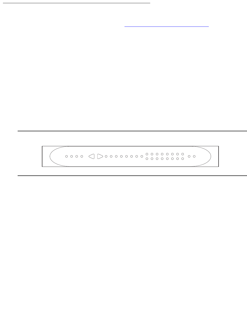
G700 and Media Module LEDs
Issue 1 June 2005 291
Front panel LEDs
The front panel includes the following LEDs (Figure 17: G700 Front Panel LEDs on page 291):
●4 LEDs in Voice/Data Module zone (ALM, PWR, CPU, MSTR)
Note:
Note: The LEDs labeled OPR and SYS on the P330 are labeled CPU and MSTR,
respectively, on the G700.
●16 LEDs representing the Data Ports associated with the Personality Module or Data
Expansion Ports
●8 LEDs in Data Function zone (LNK, COL, Tx, Rx, FDX, FC, Hspd, LAG)
●2 LEDs (EXT 1 and EXT 2) for two 10/100 Mb data ports on the chassis
Note:
Note: The four LEDs (ALM, PWR, CPU, MSTR) are positioned as closely as possible to
the top left corner of the LED Panel so that important motherboard-related
information can be quickly located by the service technician.
Figure 17: G700 Front Panel LEDs
A total of 30 LEDs appear on the LED Panel for the G700. The following three LEDs have been
added to the Avaya Cajun LEDs (see “Avaya P330 Manager User Guide”):
●RED ALM or Alarm LED
●EXT 1 LED
●EXT 2 LED
The G700 MSTR LED differs from the Avaya Cajun LED in that the bottom G700 in a stack of
10 G700s with the same version firmware is always elected master (therefore, its MSTR light is
lit). But, if the firmware versions are not the same, the G700 with the latest firmware version is
elected master and its MSTR light is lit. If there is only one G700 in a stack, its MSTR light is
always lit.
ledcled KLC 031402
ALM PWR CPU MSTR LNK COL Tx Rx FDX FC Hspd LAG EXT 1
51 52 53 54 55 56 57 58
59 60 61 62 63 64 65 66
EXT 2

LEDs
292 Maintenance Procedures for Avaya Communication Manager 3.0, Media Gateways and Servers
Navigating using the front panel LEDs
Navigation using the front panel LEDs on the G700 is that same as with the Avaya Cajun P330
series. “Table 2-2: Avaya P330 <--> Select buttons, in the "Avaya P333T User’s Guide". For
example, a technician can use the arrows to move left and right between the LEDs, and check
the following:
●LNK (link)
●Col (collision)
●Tx (send)
●Rx (receive)
In addition, a technician can query the status of the ports using 51-66 in the LED panel.
Use the push buttons (on the right and left of data mode LEDs) for selecting the function to be
reported simultaneously by all 16 of the Port data expansion LEDs. The function you are
selecting is indicated by a lightened LED in that Function zone. Each time you press on the right
(or on the left) push-button, the function currently lighted moves by one to the right (or to the left)
accordingly.
For example, if the COL LED is lit, all 16 Ports associated with the data expansion module LEDs
are reporting the Collision status of their respective port. If you want to select the LAG function,
press 6 times on the right push-button. Afterwards, if you want to select the Rx function, press 4
times on the left push-button.
For the G700, the LEDs display the information of ports 2 External 10/100Base-T Ethernet links
and data expansion ports 51-66. At power up the LEDs indicate the Link status of ports 51-66
and ext 1 & ext 2. Push the right button once to move the indication to Collision status of ports
51-66 and ext 1 & ext 2. Push the left button to move the indication backwards.
Note:
Note: Eight pushes in one direction complete a full cycle of display.
If you press the right and the left push buttons simultaneously for:
● 1.5sec, the module resets the Layer 2 Switching Processor but not the Media Gateway
Processor
●4 sec, the whole stack resets (performing slot renumbering)
●18sec, the module enters the debug mode – module disabled for data traffic
Note:
Note: Currently, there is no physical button or sequence of button presses defined to
reset the Media Gateway Processor or G700. Complete software resets by using
the Command Line Interface (CLI) for the Device Manager of the G700.

G700 and Media Module LEDs
Issue 1 June 2005 293
RED ALM or Alarm LED
The RED ALM or Alarm LED is on the top-left most corner of the LED Panel next to other
important system LEDs (PWR, CPU, MSTR), as specified in Figure 17: G700 Front Panel
LEDs on page 291. The presence of this RED ALM LED is primarily for on-site service
technicians or dispatches. It alerts technicians of major failures that require a physical
replacement or removal of equipment. Most major G700 components controlled or monitored by
the motherboard can be a cause of illumination. This includes the Avaya VoIP Media Module,
but not other Media Modules.
Note:
Note: The RED ALM LED lights for motherboard problems only. Check for a RED ALM
LED for problematic G700s and also check all of the Media Module LEDs for any
Media Module specific RED ALM LEDs.
Note:
Note: If the RED ALM LED is lit on a non-VoIP Media Module, check the G700 alarm
screens and the Avaya Communication Manager alarm screens to determine
where the fault lies.
The RED ALM LED indicates the health of the G700 by lighting under two distinct
circumstances:
●G700 hardware failure
●Impaired functions of the Layer 2 Switching Processor, Media Gateway Processor, or
VoIP engine
●Power supply voltage out of bounds
●Unit overheating
●The G700 cannot communicate to any server
The following are a few examples:
●The RED ALM LED is lighted when two or more fans have failed.
Various warnings, alarms, and a graceful shutdown are performed based on the fan and
thermal sensor conditions.
●The RED ALM LED is lit from the time power is applied until diagnostics end.
●The RED ALM LED turns “OFF” when:
●Physical conditions such as temperature are rectified and return to normal or acceptable
operating ranges.
●The alarm is cleared manually.

LEDs
294 Maintenance Procedures for Avaya Communication Manager 3.0, Media Gateways and Servers
EXT 1 LED
EXT 1 LED appears on the LED Panel (Figure 17: G700 Front Panel LEDs on page 291),
which reports the status of the first 10/100 MB/sec port (these LEDs report the 8 different
functional statuses dictated by the left and right arrow buttons).
EXT 2 LED
EXT 2 LED appears on the LED Panel (Figure 17: G700 Front Panel LEDs on page 291),
which reports the status of the second 10/100 MB/sec port (these LEDs report the 8 different
functional statuses dictated by the left and right arrow buttons).
G700 LED panel definitions
Table 81: LED Definitions on page 294 illustrates the LED definitions for the G700 LED Panel.
Table 81: LED Definitions
No. LED Name Description LED States
1 ALM Alarm Status
Color is RED
OFF - No alarms exist
ON (RED) - Alarm exists on the chassis itself
2PWR Alarm Status
Color is
GREEN
OFF - Power is down
ON - Power is up
Blinking - every 1.2 seconds (400ms on, 800ms off)
when 5 volts power is not available to the riser
board and the Media Modules
3 CPU CPU Operation
Color is
GREEN
OFF - CPU is in boot operation or is running BIST
ON - CPU boot operation and BIST completed
4MSTR Master/Slave
Status Color is
GREEN
OFF - Slave box of the stack
ON - Master of the stack and redundant cable is not
present or not active
1 Blink every 1.5 sec - Master of the stack and
active redundant cable
5 a LNK port
51-66, Ext
1-2
Port Status
Color is
GREEN
OFF - Port disabled or not existent. At phase 1, or
link fail of Giga ports.
ON - Port is enabled and link is OK.
1 Blink every 1.5 sec - Link test fail (of 10/100M
ports only at phase 1)
2 Blinks every 1.5 sec - Partition
b COL
Port 51-66,
Ext 1-2
Collision
(GREEN)
OFF - No collision or FDX port
ON - Collision occurred on line
1 of 2

G700 and Media Module LEDs
Issue 1 June 2005 295
cTx
Port 51-66,
Ext 1-2
Transmit to line
(GREEN)
OFF - No transmit activity
ON - Data transmitted on line
dRx
Port 55-66,
Ext 1-2
Receive from
line
(GREEN)
OFF - To receive activity
ON - Data received from the line
e FDX
Port 51-66,
Ext 1-2
Half/Full
Duplex
(GREEN)
OFF - Half Duplex mode of operation
ON - Full Duplex mode of operation, or for 10/
100Base-T ports when link test fail with
auto-negotiation enabled
fFC*
Port 51-66,
Ext 1-2
Symmetric
Flow Control
(GREEN)
OFF - Port is in an Asymmetric Flow control mode,
or in Flow Control mode disabled, or it is in half
duplex
ON - Port is in full duplex and in a symmetric Flow
Control mode
gHSpd
Port 51-66,
Ext 1-2
High Speed
(GREEN)
OFF - 10Base-T or for an expansion port that does
not exist
ON - 100Base-T, 100Base-F, 1000Base-X, and
OC-12, or for 10/100Base-T ports when link test fail
with auto-negotiation enabled
hLAG
Port 51-66,
Ext 1-2
Link
Aggregation
"Trunking"
(GREEN)
OFF - No LAG defined with this port
ON - Port belongs to a LAG
6 Data 16 data
expansion ports
51-66
(GREEN)
OFF - see notes on No. 5 a-h
ON - see notes on No. 5 a-h
7EXT 1 RJ 45 to
Non-Avaya
equipment
(GREEN)
OFF - see notes on No. 5 a-h
ON - see notes on No. 5 a-h
8 EXT 2 RJ 45 to
Non-Avaya
equipment
(GREEN)
OFF - see notes on No. 5 a-h
ON - see notes on No. 5 a-h
* For Giga ports, when auto-negotiation is enabled and the link is down, FC LED reflects the last mode
If the user resets the module/stack, then all of the module’s/stack’s LEDs light on (test lamp) for 150ms.
The COL, Tx, and Rx LED signals must be at least 150ms.
Table 81: LED Definitions (continued)
No. LED Name Description LED States
2 of 2
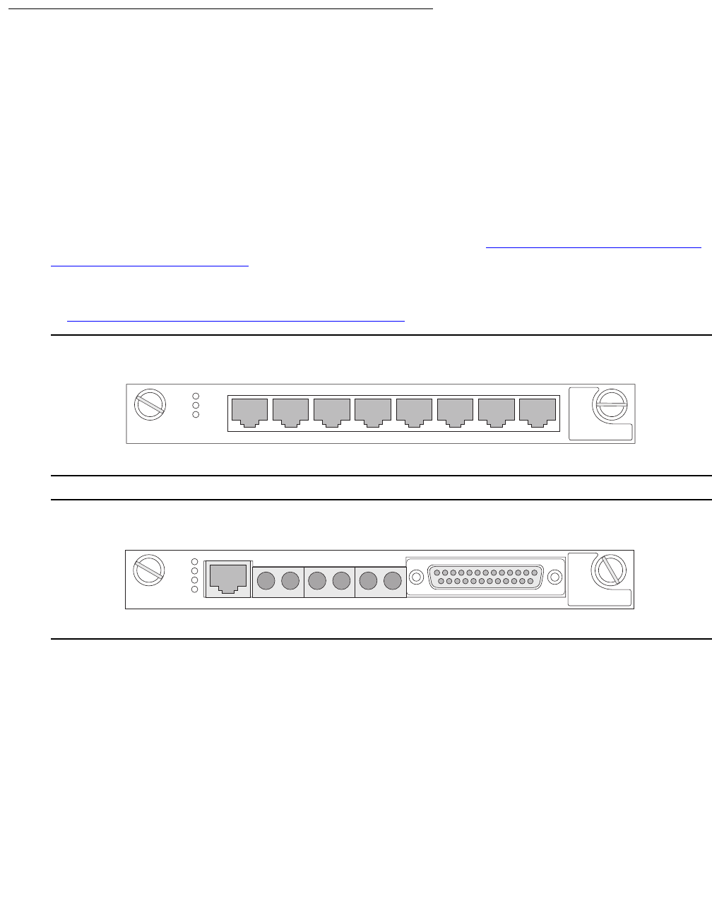
LEDs
296 Maintenance Procedures for Avaya Communication Manager 3.0, Media Gateways and Servers
Media Module LEDs
Media Gateway physical LEDs provide the technician with information regarding the ability to
troubleshoot the Media Module as a whole.
Note:
Note: The physical LEDs provide board level status information, while the SAT provides
port level status information.
LED Locations on the Media Modules
All Media Modules have three standard LEDs on the faceplate (Figure 18: Faceplate of Media
Modules with Standard LEDs on page 296). On the Avaya VoIP (MM760), Avaya BRI (MM720),
Avaya DCP (MM712), and Avaya Analog (MM711) Media Modules, these are the only LEDs
present. In addition, the Avaya T1/E1 Media Module (MM710) has an additional LED, as shown
in Figure 19: T1/E1 Media Module with Fourth LED on page 296.
Figure 18: Faceplate of Media Modules with Standard LEDs
Figure 19: T1/E1 Media Module with Fourth LED
mmdc712 KLC 022702
ALM
TST
ACT
123456 87
E1/T1 EIA 530A DCE
ALM
TST
ACT
SIG
EISO EMSM EOSI
mmdc710 KLC 020402
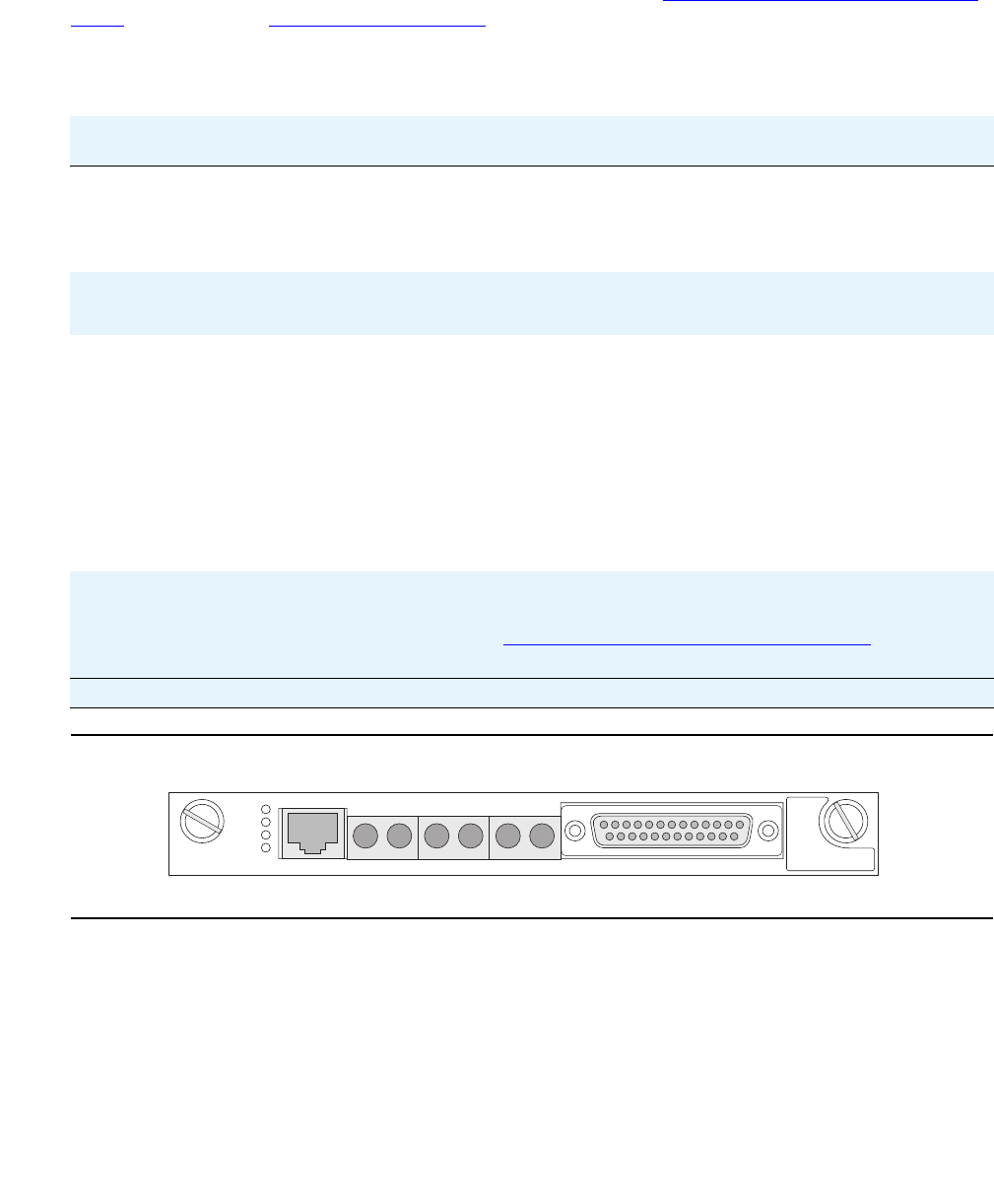
G700 and Media Module LEDs
Issue 1 June 2005 297
MM710 T1/E1 Media Module LEDs
The T1/E1 Media Module has four LEDs on its faceplate (see Figure 20: T1/E1 Media Module
LEDs on page 297). Table 82: T1/E1 LEDs on page 297 shows their color and functions. The
first three are the standard LEDs, which are under software control.
Figure 20: T1/E1 Media Module LEDs
Table 82: T1/E1 LEDs
Name Color Location Description
ALM RED Top Upon power-up, this LED is turned on. Upon passing
diagnostics this LED is turned off. During normal circuit pack
operation this LED is not turned on except for certain alarm
states.
TST GREEN Second During power-up self-testing and maintenance testing
requested by the SPE, this LED is turned on.
ACT YELLOW Third This LED indicates that the clock is synchronized with a
source (usually the Central Office). The LED is blinking 2700
ms ON and 300 ms OFF. This is the most common condition.
The opposite blinking of the YELLOW LED is 300 ms ON and
2700 ms OFF. This is an error condition, and indicates that
the MM710 T1/E1 Media Module is not synchronized with a
clock.
An infrequent occurrence is a steady YELLOW LED. This
indicates in-use activity, only when clock synchronization is
set to local.
SIG GREEN Bottom This LED indicates whether the link to the Central Office (CO)
is up (equivalent to the TN464 circuit pack Status 3 GREEN
LED). See Figure 20: T1/E1 Media Module LEDs on
page 297.
E1/T1 EIA 530A DCE
ALM
TST
ACT
SIG
EISO EMSM EOSI
mmdc710 KLC 020402

LEDs
298 Maintenance Procedures for Avaya Communication Manager 3.0, Media Gateways and Servers
The supported portion of the LED control message allows software to change the status of the
three standard LEDs on the T1/E1 Media Module faceplate. Power-up and alarm states are the
only conditions where hardware sets the state of the LEDs independent of ANGEL firmware
control.The exceptions to letting software turn off the LEDs are:
●The board is in reset (RED ALM LED remains on)
●A call is up (YELLOW ACT LED remains on while the E1 line is in-frame and at least one
voice/data call is up)
●During board reset initialization testing (GREEN TST LED remains on until initialization
testing is complete)
Note:
Note: For ISDN operation, the Yellow LED will be turned on if ANY port has an active
TDM connection (including the D-channel).
Synchronization
The YELLOW ACT LED on the front of the MM710 Media Module can tell you the status of that
module regarding synchronization.
●If the YELLOW ACT LED is solidly on or off, it has NOT been defined as a synchronization
source. If it is on, one or more channels is active. If it is an ISDN facility, the D-channel will
count as an active channel and will cause the YELLOW ACT LED to be on.
●When the MM710 is driving a clock sync source line to the G700 main clock, the YELLOW
ACT LED does not indicate port activity, but instead indicates that the MM710 is the sync
source by flashing with a regular 3-second period:
●It is on for 2.8 seconds and flashes off for 200 milliseconds if it has been specified as a
sync source and is receiving a signal that meets minimum requirements for the interface.
●If it has been specified as a sync source and is not receiving a signal, or is receiving a
signal that does not meet minimum requirements for the interface, then the YELLOW
ACT LED will be off for 2.8 seconds and flash on for 200 milliseconds.
T1/E1 Initialization
The T1/E1 Media Module LEDs behave in the following manner during initialization. The Angel
provides a visual indication of the Media Module’s status through the three faceplate LEDs:
●During initialization the YELLOW ACT LED is held off, while the RED and GREEN LEDs
are on during the entire initialization sequence.
●Upon power up or reset, if only the RED ALM LED comes on, the Angel processor is dead
or the board is being held permanently in reset.
●Upon completion of the diagnostics and initialization, the GREEN TST LED turns off.
●If the initialization tests fail, the RED ALM LED remains on.
●If the tests all pass, then all LEDs are extinguished until Communication Manager starts
using the Media Module.

G700 and Media Module LEDs
Issue 1 June 2005 299
Operational control
After successful initialization, the T1/E1 Media Module’s LEDs are controlled as follows:
●The Angel lights the YELLOW ACT LED when there is at least one non-idle trunk. If
Communication Manager sends a message to drive the clock sync signals, the YELLOW
ACT LED indicates this instead of the port busy/idle status.
●The Media Server may independently light and extinguish the three LEDs through
downlink LED Control messages, subject to the constraint that it may not turn off a
YELLOW ACT LED turned on by the Angel as a result of port activity.
●If the Media Module resets for any reason and is not released from reset, the RED ALM
LED lights and the YELLOW ACT and GREEN TST LEDs are held off.

LEDs
300 Maintenance Procedures for Avaya Communication Manager 3.0, Media Gateways and Servers

Issue 1 June 2005 301
Chapter 4: G700 Media Gateway Traps
This chapter applies to the G700 Media Gateway only.
SNMP Alarming on the G700
Setting up SNMP alarm reporting involves two main tasks:
●Configure the primary server to report alarms
●Configure the G700 to Send its Traps to the Primary Server
Configure the primary server to report alarms
The primary server may be either an S8300 Media Server or an S8700 Media Server. The
Media Server supports two methods for reporting alarms. Either method, both, or no
alarm-reporting method may be used at a given site.
●OSS Method. The server's software applications and hardware devices under its control
can generate Operations Support System (OSS) alarms. These alarms are recorded in the
server logs, and may be reported to Avaya's Initialization and Administration System
(INADS) or another services support agency over the server's modem interface.
To activate OSS alarm notification: The server requires a USB connection to a modem that
is connected to an analog line. The modem must be configured using the Web Interface, in
the Set Modem Interface screen, and enabled to send and receive calls using the Enable/
Disable Modem screen. Configuration of the OSS alarming method can only be done
using Linux shell commands.
● SNMP Method. SNMP traps may be sent in User Datagram Protocol (UDP) to a corporate
network management system (NMS) using the Configure Trap Destinations screen. The
OSS and SNMP alarm-notification methods operate independently of each other. Either or
both may be used. Currently, the following NMSs are supported:
●Avaya Communication Manager Fault and Performance Manager, as a standalone
application, or integrated within
●Avaya MultiService Network Manager
●HP Openview
To activate SNMP alarm notification: On the server Web Interface, use the Configure Trap
Destinations screen to set up SNMP destinations in the corporate NMS.

G700 Media Gateway Traps
302 Maintenance Procedures for Avaya Communication Manager 3.0, Media Gateways and Servers
Add INADS Phone Numbers and Enable Alarms to INADS
The following procedure using the primary server’s Linux shell commands administers the
dial-out modem to send alarms in the OSS method. In this example, the primary server is an
S8300, and the services support agency is Avaya’s Initialization and Administration System
(INADS).
Perform this task after all Communication Manager administration is complete.
To add INADS phone numbers and enable alarms to INADS
1. Connect your laptop to the Services port of the S8300 Media Server
Note:
Note: Do these steps only if the S8300 is the primary controller and the customer has a
maintenance contract with Avaya. Use the information acquired from the ART
tool (see “Run the ART Tool for the INADS IP Address” in Chapter 3 of
"Installation and Upgrades for the Avaya G700 Media Gateway Controlled by an
Avaya S8300 or S8700 Media Server, 555-234-100"). Also, a USB modem must
have already been installed. See "Universal Serial Bus (USB) Modems" in
Chapter 7 of the same source.
2. Click Start > Run to open the Run dialog box
3. Type telnet 192.11.13.6 and press Enter.
4. Log in as craft.
5. At the prompt, type almcall -f INADS phone number -s second-number and press
Enter.
6. At the prompt, type almenable -d b -s y and press Enter.
7. Type almenable and press Enter to verify that the alarms are enabled.
8. Log off.
Configure the G700 to Send its Traps to the Primary Server
Configuring the G700 Media Gateway to send SNMP traps to the primary server can be
accomplished by two commands:
●Layer 2 Switching Processor CLI command: set snmp community trap [community
string]
●Media Gateway Processor (MGP) CLI command: set snmp trap <IP address>
enable
Configure an SNMP community string for traps
SNMP requires community strings to be used for each SNMP "request". You can set only three
community strings on the G700 — one each for read requests, write requests, and traps. The
command for traps is set snmp community trap [community string].

SNMP Alarming on the G700
Issue 1 June 2005 303
To configure an SNMP community string for traps
1. Open the Run dialog box.
2. Type telnet <IP address of L2 Processor> and press Enter.
3. Log in as root.
4. At the L2 Processor CLI prompt, type set snmp community trap [community
string] and press Enter.
5. Type exit
Configure the destination for G700 SNMP traps
Events occurring on the G700 cause SNMP traps to be generated. The G700 MGP can be
configured to send SNMP traps to any network management system (NMS) in the network,
including the primary server (S8300/S8700). The MGP CLI set snmp trap command is the
way to configure the NMS network element that will receive those traps. The traps are sent in
User Datagram Protocol (UDP) on the customer’s IP network.
The command syntax is:
set SNMP trap <IP address> {enable|disable}
[{all|power|temp|app|module|config|voice|operations}]
where <IP address> is the IP address of the NMS trap receiver that will be receiving the
traps from the G700, and
[{all|power|temp|app|module|config|voice|operations}] indicates the groups
whose traps will be sent to the specified receiver. If no keywords follow the IP address entry,
then all traps will be enabled for the specified receiver.
If "enable" or "disable" is used without a trap designation keyword, then all traps is
assumed. Up to ten trap receivers can be configured.
To configure the destination for G700 SNMP traps
1. From the L2 Processor CLI, type session mgp
2. At the mg-xxx-n(super-user) prompt, type configure and press Enter.
3. At the mg-xxx-n(configure) prompt, type set snmp trap <IP address> enable and
press Enter.
4. Type exit

G700 Media Gateway Traps
304 Maintenance Procedures for Avaya Communication Manager 3.0, Media Gateways and Servers
G700 Alarm Format
G700 Media Gateways (serving either as standalone port networks, or as port networks within
an IP or a Multi-Connect system) report alarms to the primary server (either an S8300 or S8700
Media Server) using SNMP traps. Like the primary server’s own alarms, alarms from a G700
Media Gateway:
●Reside in the primary server’s alarm log
●Can be viewed using the SAT command display alarms
●Can be viewed using the Web Interface Display Alarms option
However, the format of these displayed alarms is slightly different. Using the G700 MO’s
Event ID #1 (the first entry in Table 83: G700 Alarms (SNMP Traps) to the Primary Media
Server on page 305) as an example, a displayed G700 alarm has the following format:
n CMG 1 WRN 07/17/2002:13:45 121.1.1.2:cmgMultipleFanFault
Within the previous alarm-display string, the value:
●“n” is a sequential alarm ID.
●“CMG” identifies a G700 Media Gateway as the MO.
●“1” is the event’s ID (1st column of Table 83: G700 Alarms (SNMP Traps) to the Primary
Media Server on page 305).
This table also contains each alarm’s corresponding SNMP trap # in the 2nd column of
Table 83: G700 Alarms (SNMP Traps) to the Primary Media Server on page 305. However,
many of the MIB-defined traps have been excluded, either because:
●A specific trap (such as, Trap #3) is the SNMP mechanism to clear an alarm logged by
another specific trap (in this case, Trap #2).
●The specific event indicated by a trap is not severe enough to justify an entry in the
primary server’s alarm log.
●A trap is defined, but not implemented.
●A trap # is reserved for future use.
●“WRN” is the event’s severity (3rd column of Table 83: G700 Alarms (SNMP Traps) to the
Primary Media Server on page 305).
●“07/17/2002:13:45“is the event’s date and time stamp.
●“121.1.1.2“is the IP address for Telnet access to the alarmed G700 Media Gateway
Processor (MGP).
●“cmgMultipleFanFault” is an alarm description (4th column of Table 83: G700 Alarms
(SNMP Traps) to the Primary Media Server on page 305).

G700 Traps and Resolutions
Issue 1 June 2005 305
G700 Traps and Resolutions
Although these alarms can be viewed from the primary server, they are normally resolved from
within the G700 Media Gateway. The G700 generates the following traps. Follow the error
resolution procedures in Table 83: G700 Alarms (SNMP Traps) to the Primary Media Server on
page 305 to resolve errors indicated by these traps.
Table 83: G700 Alarms (SNMP Traps) to the Primary Media Server
Event
ID
Trap
#
Alarm
Level
Description / Recommendation
1 2 WRN cmgMultipleFanFault — At least two G700 fans have been
operating at less than 90% of their nominal speed for >= 5 minutes.
(This may be an early warning of overheating.)
1. Verify there are faults in the system. Use the Avaya G700
Media Gateway Processor (MGP) Command Line Interface
(CLI) command show faults to display any faults on the
G700.
2. If there is a fan/temperature fault, check to see if the fans are
working, and/or if there is sufficient space around the G700 for
air circulation.
3. Maintenance software monitors voltages applied to the Media
Modules and other components of the G700, and compares
these to the general power supply unit (PSU) status bit. If none
of these voltages are out of tolerance, but the PSU status
indicates failure, this generates the fan fault, which will be
indicated in the show faults command output. Replace the
entire G700. Fans and the PSU are not field replaceable.
1 of 20

G700 Media Gateway Traps
306 Maintenance Procedures for Avaya Communication Manager 3.0, Media Gateways and Servers
2 4 MIN cmgPsuBriefFanFault — A G700’s PSU fan has been operating at
less than 90% of its nominal speed for between 5 and 15 minutes.
(This may be an early warning of overheating.)
1. Verify there are faults in the system. Use the Avaya G700
Media Gateway Processor (MGP) Command Line Interface
(CLI) command show faults to display any faults on the
G700.
2. If there is a fan/temperature fault, check to see if the fans are
working and/or if there is sufficient space around the G700 for
air circulation.
3. Maintenance software monitors voltages applied to the Media
Modules and other components of the G700, and compares
these to the general power supply unit (PSU) status bit. If none
of these voltages are out of tolerance, but the PSU status
indicates failure, this generates the fan fault, which will be
indicated in the show faults command output. Replace the
entire G700. Fans and the PSU are not field replaceable.
3 6 MIN cmgPsuProlongedFanFault — A G700’s fan has been operating at
less than 90% of its nominal speed for >= 15 minutes. (This may be
an early warning of overheating.)
1. Verify there are faults in the system. Use the Avaya G700
Media Gateway Processor (MGP) Command Line Interface
(CLI) command show faults to display any faults on the
G700.
2. If there is a fan/temperature fault, check to see if the fans are
working and/or if there is sufficient space around the G700 for
air circulation.
3. Maintenance software monitors voltages applied to the Media
Modules and other components of the G700, and compares
these to the general power supply unit (PSU) status bit. If none
of these voltages are out of tolerance, but the PSU status
indicates failure, this generates the fan fault, which will be
indicated in the show faults command output. Replace the
entire G700. Fans and the PSU are not field replaceable.
Table 83: G700 Alarms (SNMP Traps) to the Primary Media Server (continued)
Event
ID
Trap
#
Alarm
Level
Description / Recommendation
2 of 20

G700 Traps and Resolutions
Issue 1 June 2005 307
410 MIN cmgCpuTempWarningFault — A G700’s CPU temperature sensor
has exceeded its warning threshold.
1. Verify there are faults in the system. Use the Avaya G700
Media Gateway Processor (MGP) Command Line Interface
(CLI) command show faults to display any faults on the
G700.
2. If there is a temperature fault, turn off the G700 and allow it to
cool.
3. Reboot the G700. Check to see if the fans are working and/or if
there is sufficient space around the G700 for air circulation. Use
the MGP CLI show faults command to check for fan
problems.
4. Low voltage may be responsible for slower fans. Voltage may
be reduced by a short in one of the Media Modules or a bad
power supply. If there are no fan faults, use the MGP CLI
command show voltages to display voltages applied to
components on the motherboard and to the Media Modules.
5. If the Media Module voltage is out of tolerance, systematically,
remove each Media Module to determine if one of the Media
Modules is responsible for reducing the voltage level. If one is
found, replace the Media Module.
6. If no Media Module is found to be bad, the power supply is
suspect. Replace the G700.
Table 83: G700 Alarms (SNMP Traps) to the Primary Media Server (continued)
Event
ID
Trap
#
Alarm
Level
Description / Recommendation
3 of 20

G700 Media Gateway Traps
308 Maintenance Procedures for Avaya Communication Manager 3.0, Media Gateways and Servers
5 12 MIN cmgDspTempWarningFault — The temperature sensor in a G700’s
DSP complex has exceeded its warning threshold.
1. Verify there are faults in the system. Use the Avaya G700
Media Gateway Processor (MGP) Command Line Interface
(CLI) command show faults to display any faults on the
G700.
2. If there is a temperature fault, turn off the G700 and allow it to
cool.
3. Reboot the G700. Check to see if the fans are working and/or if
there is sufficient space around the G700 for air circulation.
4. Low voltage may be responsible for slower fans. Voltage may
be reduced by a short in one of the Media Modules or a bad
power supply. If there are no fan faults, use the MGP CLI
command show voltages to display voltages applied to
components on the motherboard and to the Media Modules.
5. If the Media Module voltage is out of tolerance, systematically,
remove each Media Module to determine if one of the Media
Modules is responsible for reducing the voltage level. If one is
found, replace the Media Module.
6. If no Media Module is found to be bad, the power supply is
suspect. Replace the G700.
Table 83: G700 Alarms (SNMP Traps) to the Primary Media Server (continued)
Event
ID
Trap
#
Alarm
Level
Description / Recommendation
4 of 20

G700 Traps and Resolutions
Issue 1 June 2005 309
614 MAJ cmgTempShutdownFault — The temperature sensor in a G700’s
CPU has exceeded its shutdown threshold. The system is about to
begin controlled shutdown.
1. Verify there are faults in the system. Use the Avaya G700
Media Gateway Processor (MGP) Command Line Interface
(CLI) command show faults to display any faults on the
G700.
2. If there is a temperature fault, turn off the G700 and allow it to
cool.
3. Reboot the G700. Check to see if the fans are working and/or if
there is sufficient space around the G700 for air circulation.
4. Enter the MGP CLI command show voltages to determine
voltages for Media Modules and other components of the
G700. While the +12V fan supply is not directly monitored, it is
included in the general power supply unit (PSU) status bit. Use
the show faults command to determine if there is a fan
problem. If none of the monitored voltages are out of tolerance,
but the PSU status indicates failure, this would generate a fan
fault. If fans are faulty, then replace the entire G700. Fans are
not field replaceable.
5. Voltage may also be reduced by a short in one of the Media
Modules. Systematically, remove each Media Module to
determine if one of the Media Modules is responsible for
reducing the voltage levels.
Table 83: G700 Alarms (SNMP Traps) to the Primary Media Server (continued)
Event
ID
Trap
#
Alarm
Level
Description / Recommendation
5 of 20

G700 Media Gateway Traps
310 Maintenance Procedures for Avaya Communication Manager 3.0, Media Gateways and Servers
7 16 MAJ cmgMgpPowerFault — The voltage reading at the server’s +5.1V
power source is out of tolerance.
1. Check voltages. Enter the MGP CLI command show
voltages to determine voltages for Media Modules and other
components of the G700. Voltage may be reduced by a short in
one of the Media Modules or a bad power supply.
2. Systematically, remove each Media Module to determine if one
of the Media Modules is responsible for reducing the voltage
levels. Replace faulty Media Module.
3. If the alarm clears in 10-20 seconds, it was a probable voltage
spike. Do not replace the G700. Use a power monitor to
monitor the power line.
4. If a brown-out condition is suspected, use a power monitor to
monitor the power line.
5. If the fault persists and the show voltages command
continues to show the level is out of tolerance, then replace the
G700.
818 MAJ cmgMediaModulePowerFault — The voltage reading at the Media
Modules’ -48V power source is out of tolerance.
1. Check voltages. Enter the MGP CLI command show
voltages to determine voltages for Media Modules and other
components of the G700. Voltage may be reduced by a short in
one of the Media Modules or a bad power supply.
2. Systematically, remove each Media Module to determine if one
of the Media Modules is responsible for reducing the voltage
levels. Replace faulty Media Module.
3. If the alarm clears in 10-20 seconds, it was a probable voltage
spike. Do not replace the G700. Use a power monitor to
monitor the power line.
4. If a brown-out condition is suspected, use a power monitor to
monitor the power line.
5. If the fault persists and the show voltages command
continues to show the level is out of tolerance, then replace the
G700.
Table 83: G700 Alarms (SNMP Traps) to the Primary Media Server (continued)
Event
ID
Trap
#
Alarm
Level
Description / Recommendation
6 of 20

G700 Traps and Resolutions
Issue 1 June 2005 311
9 20 MAJ cmgVoipPowerFault — The voltage reading at the VoIP complexes’
+3.4V power source is out of tolerance.
1. Check voltages. Enter the MGP CLI command show
voltages to determine voltages for Media Modules and other
components of the G700. Voltage may be reduced by a short in
one of the Media Modules or a bad power supply.
2. Systematically, remove each Media Module to determine if one
of the Media Modules is responsible for reducing the voltage
levels. Replace faulty Media Module.
3. If the alarm clears in 10-20 seconds, it was a probable voltage
spike. Do not replace the G700. Use a power monitor to
monitor the power line.
4. If a brown-out condition is suspected, use a power monitor to
monitor the power line.
5. If the fault persists and the show voltages command
continues to show the level is out of tolerance, then replace the
G700.
10 22 MAJ cmgDspPowerFault — The voltage reading at the DSP units’
+1.58V power source is out of tolerance.
1. Check voltages. Enter the MGP CLI command show
voltages to determine voltages for Media Modules and other
components of the G700. Voltage may be reduced by a short in
one of the Media Modules or a bad power supply.
2. Systematically, remove each Media Module to determine if one
of the Media Modules is responsible for reducing the voltage
levels. Replace faulty Media Module.
3. If the alarm clears in 10-20 seconds, it was a probable voltage
spike. Do not replace the G700. Use a power monitor to
monitor the power line.
4. If a brown-out condition is suspected, use a power monitor to
monitor the power line.
5. If the fault persists and the show voltages command
continues to show the level is out of tolerance, then replace the
G700.
Table 83: G700 Alarms (SNMP Traps) to the Primary Media Server (continued)
Event
ID
Trap
#
Alarm
Level
Description / Recommendation
7 of 20

G700 Media Gateway Traps
312 Maintenance Procedures for Avaya Communication Manager 3.0, Media Gateways and Servers
11 24 MAJ cmg8620PowerFault — The voltage reading at the VoIP
Processor’s +2.5V power source is out of tolerance.
1. Check voltages. Enter the MGP CLI command show
voltages to determine voltages for Media Modules and other
components of the G700. Voltage may be reduced by a short in
one of the Media Modules or a bad power supply.
2. Systematically, remove each Media Module to determine if one
of the Media Modules is responsible for reducing the voltage
levels. Replace faulty Media Module.
3. If the MM760 Media Module is not present, the VoIP engine on
the motherboard is possibly bad. Use the show faults
command to check for VoIP faults. Replace the G700.
4. If the alarm clears in 10-20 seconds, it was a probable voltage
spike. Do not replace the G700. Use a power monitor to
monitor the power line.
5. If a brown-out condition is suspected, use a power monitor to
monitor the power line.
6. If the fault persists and the show voltages command
continues to show the level is out of tolerance, then replace the
G700.
Table 83: G700 Alarms (SNMP Traps) to the Primary Media Server (continued)
Event
ID
Trap
#
Alarm
Level
Description / Recommendation
8 of 20

G700 Traps and Resolutions
Issue 1 June 2005 313
14 30 MAJ cmgSyncSignalFault — Synchronization signal lost.
1. Check that provisioned clock-sync source has a good signal by
issuing a Media Gateway Processor (MGP) Command Line
Interface (CLI) command show sync timing
Procedure for setting synchronization timing sources on T1/E1 MM
or MM710:
1. Be sure that the T1/E1 MM has been added properly on the
Avaya S8300 Media Server or Avaya S8700 Media Server,
otherwise go to System Access Terminal (SAT) and enter a
add DS1 command before going to the MGP CLI and entering
a set sync interface or set sync source command.
Otherwise the MGP CLI will not allow these commands to be
executed.
2. Go to the MGP’s CLI, and first specify the primary and
secondary clock sources for synchronizing the T1/E1 span,
using the set synch interface command.
Note: You don't specify the internal clock source from the CLI -
only the primary and secondary. The local clock is "built-in" and
not provisionable.
3. Enter a set sync source command to set to the specific
MM710 T1/E1 Media Module to be used as the active clock
reference.
4. Verify whether or not these commands were executed by
issuing a show sync timing command to ensure that the
source is provisioned and active, or visually inspect the Yellow
LED on the MM710 Media Module.
Note: When the Yellow LED is on 2.7 seconds and off 0.3
seconds, this means the tone-clock synchronizer is in “active”
mode, and an external synchronization source is being used as
a synchronization reference. Setting the sync timing was
successful.
When the Yellow LED is on 0.3 seconds and off 2.7 seconds,
this means the tone-clock synchronizer is in “active” mode and
the internal (on-board) clock is being used as a synchronization
reference. Setting the sync timing was not successful.
Table 83: G700 Alarms (SNMP Traps) to the Primary Media Server (continued)
Event
ID
Trap
#
Alarm
Level
Description / Recommendation
9 of 20

G700 Media Gateway Traps
314 Maintenance Procedures for Avaya Communication Manager 3.0, Media Gateways and Servers
14
(cont’d)
30 MAJ 5. Verify whether or not these commands were executed by
issuing a show sync timing command to ensure that the
source is provisioned and active, or visually inspect the Yellow
LED on the MM710 Media Module.
Note: When the Yellow LED is on 2.7 seconds and off 0.3
seconds, this means the tone-clock synchronizer is in “active”
mode, and an external synchronization source is being used as
a synchronization reference. Setting the sync timing was
successful.
When the Yellow LED is on 0.3 seconds and off 2.7 seconds,
this means the tone-clock synchronizer is in “active” mode and
the internal (on-board) clock is being used as a synchronization
reference. Setting the sync timing was not successful.
6. If there is more than one MM710 Media Module, and they have
been set up as primary and secondary, this behavior could be
on the second and not the timing of the bus.
For more details, please consult the maintenance documentation
under LEDs and T1/E1 Media Module, or see
http://support.avaya.com/elmodocs2/S8300/cd/index.htm
15 32 MAJ cmgVoipHardwareFault — A DSP complex serving the VoIP
engines has failed.
1. Check IP configuration.
2. Reset or replace Media Module.
50 cmgModuleRemove — A Media Module has been removed.
16 51 Reserved
52 cmgModuleInsertFault — The insertion sequence for a Media
Module has failed.
53 cmgModuleInsertSuccess — A Media Module has been inserted.
54 cmgMgBusyout — An administrator has busied-out a Media Module
or a port.
55 cmgMgRelease — An administrator has returned a busied-out
media module or port back into service.
56 –
69
Reserved
Table 83: G700 Alarms (SNMP Traps) to the Primary Media Server (continued)
Event
ID
Trap
#
Alarm
Level
Description / Recommendation
10 of 20
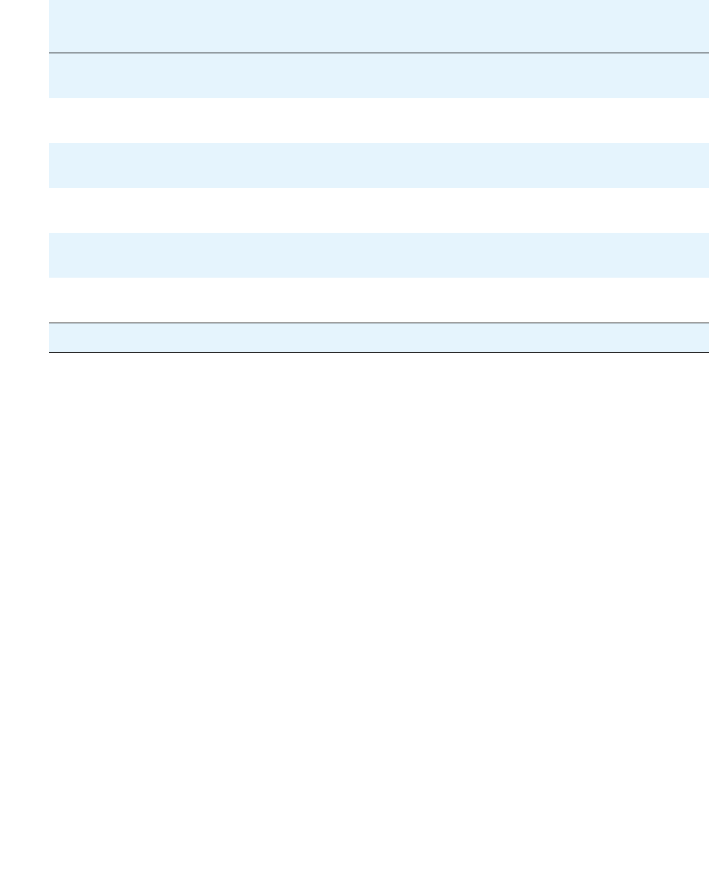
G700 Traps and Resolutions
Issue 1 June 2005 315
74 cmgFirmwareDownloadBegun — A Media Gateway began
downloading a software module.
75 cmgModuleManualReset — A Media Module is beginning a
user-requested reset operation.
76 cmgVoipManualReset — A VoIP engine is beginning a
user-requested reset operation.
77 cmgDsuManualReset — An E1 or T1’s DSU is beginning a
user-requested reset operation.
78 cmgConfigUploadBegun — A Media Gateway began uploading a
configuration file.
79 cmgConfigUploadSuccess — The Media Gateway successfully
uploaded the configuration file.
Table 83: G700 Alarms (SNMP Traps) to the Primary Media Server (continued)
Event
ID
Trap
#
Alarm
Level
Description / Recommendation
11 of 20

G700 Media Gateway Traps
316 Maintenance Procedures for Avaya Communication Manager 3.0, Media Gateways and Servers
17 90 MAJ cmgMemoryFault — The Media Gateway Processor has detected a
low processor memory condition. If an attempt by a software
module to allocate memory fails, or if available memory falls below
four million bytes, this trap is generated. If available memory later
rises above five million bytes, this trap is cleared. If available
memory falls below a half a million bytes, the Media Gateway
Processor is automatically reset.
1. Check the Media Gateway Processor and insure that it has the
latest version of firmware installed. If it does not, install the
latest version of firmware and continue to monitor.
2. If this trap occurs infrequently and is automatically cleared, the
trap may be due to an unusual transient condition. Monitor
future traps.
3. If this trap occurs frequently and is automatically cleared, it is
likely that the Media Gateway Processor software has the
wrong limits set for its memory monitoring. These limits are
hard coded in the software. Escalate.
4. If this trap occurs and does not clear, the Media Gateway may
be functionally impaired. Do not reset the Media Gateway.
Escalate and have Tier 3 personnel capture the trap
information and the event logs for analysis.
5. If this trap occurs and the Media Gateway Processor
automatically resets, then a severe processor memory
shortage occurred. Escalate and have Tier 3 personnel capture
the trap information and the event logs for analysis.
18 92 MAJ cmgDhcpRequestFault — The Media Gateway cannot contact its
DHCP server, or the DHCP server did not respond to a request.
1. Either correct the DHCP problem, or correct the Media
Module’s configuration file.
Table 83: G700 Alarms (SNMP Traps) to the Primary Media Server (continued)
Event
ID
Trap
#
Alarm
Level
Description / Recommendation
12 of 20

G700 Traps and Resolutions
Issue 1 June 2005 317
19 94 MAJ cmgFirmwareDownloadFault — An attempt to download a software
module has failed.
1. Check the event log to find the specific error.
2. Troubleshoot the specific error according to the information
found.
For example, if the string “File not found” appears in the log,
then verify that the image file:
a. Exists
b. Has the correct name
c. Resides in the correct directory
20 96 WRN cmgProcessRestart — a software module on the Media Gateway
Processor failed. The Media Gateway Processor will attempt to
restart the failing module. A successful restart of the module will
clear this trap
1. Check the Media Gateway Processor and insure that it has the
latest version of firmware installed. If it does not, install the
latest version of firmware and continue to monitor.
2. If this trap occurs infrequently and is automatically cleared, the
trap may be due to an unusual transient condition.Monitor
future traps.
3. If the trap occurs frequently and is automatically cleared, it may
indicate an issue with a particular software module. Reset the
Media Gateway at a time convenient with the customer.
Escalate and have Tier 3 personnel capture the trap
information and the event logs for analysis.
4. If the trap occurs and does not clear, the Media Gateway may
be functionally impaired. Reset the Media Gateway at a time
convenient with the customer and consistent with the
impairment. Escalate and have Tier 3 personnel capture the
trap information and the event logs for analysis.
Table 83: G700 Alarms (SNMP Traps) to the Primary Media Server (continued)
Event
ID
Trap
#
Alarm
Level
Description / Recommendation
13 of 20

G700 Media Gateway Traps
318 Maintenance Procedures for Avaya Communication Manager 3.0, Media Gateways and Servers
21 98 MAJ cmgIccMissingFault — An internal communications controller,
expected in Slot 1, is missing.
1. Check for presence of S8300.
2. If present, check the G700 administration.
3. If the administration is correct, suspect the S8300.
22 100 MAJ cmgIccAutoReset — The Media Gateway automatically reset the
internal communications controller.
1. If the problem persists, escalate.
23 102 MAJ cmgPrimaryControllerFault — The Media Gateway cannot contact
the first controller in its controller list.
1. Verify that the controller list is correct. From the MGP CLI, enter
the command show mgc list. The IP address should match
the S8700 Media Server CLAN or the S8300 Media Server IP
addresses.
2. If needed, correct this in 'configure' mode on the MGP's CLI by
clearing the mgc list first with the clear mgc list command,
and then issuing a set mgc list with the correct IP
addresses.
3. If so, verify that the primary controller is up.
4. If so, shut down every LSP.
24 104 MAJ cmgNoControllerFault — The Media Gateway does not have any
controllers in its controller list.
1. Verify that the controller list is empty. From the MGP CLI, enter
the command show mgc list to verify that there are no
controllers listed.
2. If none are listed, correct this by adding the correct IP address
of the S8700/S8300. In 'configure' mode on the MGP's CLI,
enter the set mgc list command with the correct IP
address.
Table 83: G700 Alarms (SNMP Traps) to the Primary Media Server (continued)
Event
ID
Trap
#
Alarm
Level
Description / Recommendation
14 of 20

G700 Traps and Resolutions
Issue 1 June 2005 319
25 106 MAJ cmgRegistrationFault — The Media Gateway cannot register with
any controllers in its controller list.
1. Verify that the controller list is correct. From the MGP CLI, enter
the command show mgc list. The IP address should match
the S8700 Media Server CLAN or the S8300 Media Server IP
addresses.
2. If needed, correct this in 'configure' mode on the MGP's CLI by
clearing the mgc list with the clear mgc list command, and
then issuing a set mgc list with the correct IP addresses.
3. If the IP address in the mgc list matches the S8700 Media
Server CLAN or the S8300 Media Server IP addresses, there
may be a network problem.
4. Verify that the primary controller is up.
26 108 MIN cmgH248LinkDown — An H.248 link between the Media Gateway
and its controller is down.
1. Check the S8300 or S8700.
2. If down, bring up.
3. If not, check the G700 administration.
Since the following command causes a brief service outage, it
should only be executed at the customer’s convenience.
4. If the administration is correct, reboot the G700.
5. If the problem persists, check network connectivity. Use ping
or traceroute to the S8300/S8700 to check connectivity.
6. If the problem persists, escalate.
Table 83: G700 Alarms (SNMP Traps) to the Primary Media Server (continued)
Event
ID
Trap
#
Alarm
Level
Description / Recommendation
15 of 20

G700 Media Gateway Traps
320 Maintenance Procedures for Avaya Communication Manager 3.0, Media Gateways and Servers
29 114 WRN cmgMgAutoReset — The Media Gateway Processor automatically
reset (rebooted). The processor automatically resets when a critical
error occurs from which it cannot recover. The error may be
software or hardware related. It may also automatically reset in
response to a maintenance test running on the call controller. (A
reset performed at the request of a SAT or CLI command entered
by craft or Tier technical support generates a different trap
indicating a manual reset.) Finally, it may automatically reset when
it reregisters with a call controller after being out of touch for too
long. This trap is generated as the Media Gateway Processor
comes back up after resetting. If the Media Gateway Processor
resets and fails to come back up, this trap will not be generated.
1. Check to see if a maintenance test that is supposed to reset the
processor was run.
2. Check that the reset was not due to the link with the call
controlling going down. If the reset is due to a link failure with
the call controller, follow call controller link failure
troubleshooting procedures.
3. Check the Media Gateway Processor and insure that it has the
latest version of firmware installed. If it does not, install the
latest version of firmware and continue to monitor.
4. If this trap occurs infrequently, the trap may be due to an
unusual transient condition. Monitor future traps.
5. If this trap occurs and the Media Gateway Processor is
frequently resetting, manually reset the media gateway.
Escalate and have Tier 3 personnel capture the trap
information and the event logs for analysis.
6. If this trap occurs frequently and the Media Gateway Processor
is not resetting, the Media Gateway may be functionally
impaired, and is not capable of resetting itself to restore
service. If service is impaired, reset the Media Gateway
manually. Escalate and have Tier 3 personnel capture the trap
information and the event logs for analysis.
Table 83: G700 Alarms (SNMP Traps) to the Primary Media Server (continued)
Event
ID
Trap
#
Alarm
Level
Description / Recommendation
16 of 20

G700 Traps and Resolutions
Issue 1 June 2005 321
30 116 WRN cmgModuleAutoReset — A Media Module in the Media Gateway
automatically reset (rebooted). A Media Module automatically
resets when it fails a sanity test performed by the Media Gateway
Processor. It may also automatically reset in response to a
maintenance test running on the call controller. (A reset performed
at the request of a SAT or CLI command entered by craft or Tier
technical support generates a different trap indicating a manual
reset.).
1. Check to see if a maintenance test that is supposed to reset the
Media Module was run.
2. Check the Media Module and insure that it has the latest
version of firmware installed. If it does not, install the latest
version of firmware and continue to monitor.
3. If this trap occurs infrequently, the trap may be due to an
unusual transient condition. Monitor future traps.
4. If this trap occurs and the Media Module does not return to
service, or if this trap occurs frequently, attempt to reset the
failing module from the SAT or CLI and see if this returns it to
stable service.
5. If manually resetting the Media Module does not return it to
service, and if a spare Media Module of the same time is
available, replace the failing Media Module with the spare and
see if the spare Media Module goes into service. If so, follow
procedures for dealing with the original, bad, Media Module.
6. If the spare Media Module fails to go into service, it is of course
possible that the spare Media Module is bad as well. But that
aside, try manually resetting the Media Gateway Processor at a
time convenient to the customer and see if this restores
service. If so, the both the original and the spare Media
Modules can probably be considered okay, and the problem is
probably with the Media Gateway Processor itself. Escalate
and have Tier 3 personnel capture the trap information and the
event logs for analysis.
Table 83: G700 Alarms (SNMP Traps) to the Primary Media Server (continued)
Event
ID
Trap
#
Alarm
Level
Description / Recommendation
17 of 20

G700 Media Gateway Traps
322 Maintenance Procedures for Avaya Communication Manager 3.0, Media Gateways and Servers
32 118 MIN cmgModulePostFault — A Media Module failed its power-on
start-up test.
1. Reset or replace the Media Module.
34 122 MAJ cmgConfigUploadFault — An attempt to upload a configuration file
failed.
1. Check the event log for an error message during the backup/
restore process.
2. Troubleshoot the specific error according to the information
found.
3. Retry the upload (backup) command; for example:
copy mgp-config tftp <filename> <ip address>
Since the following command causes a brief service outage, it
should only be executed at the customer’s convenience.
4. If the problem persists, reboot the G700.
Table 83: G700 Alarms (SNMP Traps) to the Primary Media Server (continued)
Event
ID
Trap
#
Alarm
Level
Description / Recommendation
18 of 20

G700 Traps and Resolutions
Issue 1 June 2005 323
37 128 WRN cmgVoipAutoReset — A VoIP (Voice Over IP) module in the Media
Gateway automatically reset (rebooted). A VoIP module
automatically resets when it fails a sanity test performed by the
Media Gateway Processor. It may also automatically reset in
response to a maintenance test running on the call controller. (A
reset performed at the request of a SAT or CLI command entered
by craft or Tier technical support generates a different trap
indicating a manual reset.) It automatically resets when its IP
address is administered. Finally, it automatically resets when it fails
a ping test performed by the Media Gateway Processor against the
VoIP module's IP address.
1. Check to see if a maintenance test that is supposed to reset the
VoIP module was run.
2. Check to see if the VoIP module had its IP address
re-administered.
3. Check to see if the IP address administered on the VoIP
module is correct.
4. Check to see if the IP address of the Media Gateway itself can
be pinged. Physical or logical connectivity issues (cabling or
routing problems) in the data network can cause ping failures.
5. Check the VoIP module and insure that it has the latest version
of firmware installed. If it does not, install the latest version of
firmware and continue to monitor.
6. If this trap occurs infrequently, the trap may be due to an
unusual transient condition. Monitor future traps.
7. If this trap occurs and the VoIP module does not return to
service, or if this trap occurs frequently, attempt to reset the
failing module from the SAT or CLI and see if this returns it to
stable service.
Table 83: G700 Alarms (SNMP Traps) to the Primary Media Server (continued)
Event
ID
Trap
#
Alarm
Level
Description / Recommendation
19 of 20

G700 Media Gateway Traps
324 Maintenance Procedures for Avaya Communication Manager 3.0, Media Gateways and Servers
37
(cont’d)
128 WRN 8. If manually resetting the VoIP module does not return it to
service, and if a spare VoIP module of the same type is
available, replace the failing VoIP module with the spare and
see if the spare VoIP module goes into service. If so, follow
procedures for dealing with the original, bad, VoIP module.
9. If the spare VoIP module fails to go into service, it is of course
possible that the spare VoIP module is bad, as well. There may
be a power issue, also.
10. Try manually resetting the Media Gateway Processor at a time
convenient to the customer and see if this restores service. If
so, both the original and the spare VoIP modules can probably
be considered okay, and the problem is probably with the
Media Gateway Processor itself. Capture the trap information.
If possible, capture the event logs, using the show
event-log CLI command, for analysis. Escalate.
If none of this works, capture the trap information. If possible,
capture the event logs, using the show event-log CLI
Table 83: G700 Alarms (SNMP Traps) to the Primary Media Server (continued)
Event
ID
Trap
#
Alarm
Level
Description / Recommendation
20 of 20

Issue 1 June 2005 325
Chapter 5: Communication Manager
Maintenance-Object Repair
Procedures
Note:
Note: This chapter does not contain MOs for the DEFINITY Wireless Business System
(DWBS), nor MOs for messaging systems. Refer to the maintenance
documentation that accompanies these products for this information
The Communication Manager maintenance subsystem is partitioned into separate entities
called Maintenance Objects (MOs). A maintenance object can be:
●An individual circuit pack or media module
●A hardware component that is part of a circuit pack or media module
●An entire subsystem
●A set of monitors
●A process (or set of processes)
●A combination of processes and hardware
“Maintenance names” are recorded in the Error and Alarm logs. Individual copies of an MO are
assigned an address that defines the MO physical location in the system when applicable.
These locations display as the port field in the Alarm and Error logs and as output of commands
such as test board (see Figure 21: Display of test board on page 326).
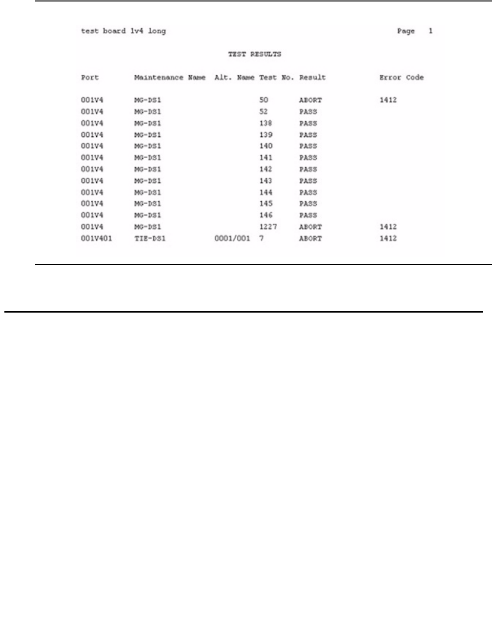
Communication Manager Maintenance-Object Repair Procedures
326 Maintenance Procedures for Avaya Communication Manager 3.0, Media Gateways and Servers
Figure 21: Display of test board
Subsystems Maintained by Communication Manager
Communication Manager subsystems are listable using list config and, in most cases,
have some maintenance activities involved.
Note:
Note: list config all on the Communication Manager SAT gives you information
that includes whether or not stations have been administered on a port. show mg
list_config on the G700 MGP gives you information for the installed
equipment in that G700.
G700

Subsystems Maintained by Communication Manager
Issue 1 June 2005 327
G700 Subsystems Maintained by Communication Manager
The G700 subsystems that are applicable to Communication Manager maintenance
considerations are identifiable by the presence of ‘angels’. Angels may be either physical or
virtual, and both types use the CCMS message. Table 84: G700 Subsystems Maintained by
Communication Manager on page 327 lists the applicable subsystems and how they are
maintained.
G700 Media Gateway MOs
The following list shows G700 specific maintenance objects. Other maintenance objects have
been modified slightly for the G700.
●MED-GTWY (MEDIA GATEWAY)
●MG-ANA (ANALOG MM711)
●MG-ANN (Voice Announcements)
●MG-BRI (BRI Trunk Media Module MM720)
●MG-DCP (Digital Line Media Module)
●MG-DS1 (DS1 Interface Media Module)
●MG-ICC (Internal Call Controller)
●MG-VOIP (MM760 MED PRO DSP PORT)
Table 84: G700 Subsystems Maintained by Communication Manager
Subsystem Angel Maintenance Type
Any Media Module Physical Angel
Messaging Daughter Board (part of the S8300) Virtual Angel
Announcement Circuitry (part of the MGP) Virtual Angel

Communication Manager Maintenance-Object Repair Procedures
328 Maintenance Procedures for Avaya Communication Manager 3.0, Media Gateways and Servers
MO Groupings by MM Type
Table 85: Media Module Tests on page 328 shows MO groupings by Avaya Media Module
type.
Table 85: Media Module Tests
Media Module Maintenance Object
T1/E1 Media Module (MM710) Board (MG-DS1)
DS1 CO Trunk (CO-DS1)
DS1 DID Trunk (DID-DS1)
DS1 Tie Trunk (TIE-DS1)
DS1 ISDN Trunk (ISDN-TRK)
ISDN-PRI Signaling Link Port (ISDN-LNK)
ISDN-PRI Signaling Group (ISDN-SGRP)
Wideband Access Endpoint Port (WAE-PORT)
Analog Media Module (MM711) Board (MG-ANA)
Analog Line (AN-LN-PT)
Analog Co Trunk (CO-TRK)
Analog DID Trunk (DID-TRK)
DIOD Trunk (DIOD-TRK)
Alarm Port (ALARM-PT)
BRI Trunk Media Module (MM720) Board (BRI-MM)
ISDN Trunk Side BRI Port (TBRI-PT)
ISDN Trunk Side Signaling (TBRI-TRK)
DCP Media Module (MM712) Board (MG-DCP)
Digital Line (DIG-LINE)
BRI Trunk Media Module (MM720) Board (MG-BRI)
ISDN Trunk Side BRI Port (TBRI-PT)
ISDN Trunk Side Signaling (TBRI-TRK)
1 of 2

Viewing Communication Manager Alarms
Issue 1 June 2005 329
Viewing Communication Manager Alarms
The technician views Communication Manager alarms and events through commands that are
available via the Web Interface or the SAT command-line interface. See Table 86: Commands
for Viewing Communication Manager Alarms on page 329.
Command Syntax
Maintenance commands use a different command syntax depending upon whether they refer to
port network circuit packs or media gateway Media Modules.
VOIP Media Module (MM760) Board (MG-VOIP)
Voice Announcements
(Communication Manager)
Board (MG-ANN)
Announcement Ports (VAL-PT)
Ethernet Port (ETH-PT)
Table 85: Media Module Tests (continued)
Media Module Maintenance Object
2 of 2
Table 86: Commands for Viewing Communication Manager Alarms
Command Interface Purpose Description
View Current Alarms Web Interface,
under Alarms and
Notification
View a list of outstanding
alarms against
Communication Manager
Displays a summary of alarms,
if present, followed by a
detailed table of explanation.
display alarms SAT CLI View logged Communication
Manager alarms
These are alarms that have not
yet been cleared, either
manually or via an Expert
System.

Communication Manager Maintenance-Object Repair Procedures
330 Maintenance Procedures for Avaya Communication Manager 3.0, Media Gateways and Servers
The command syntax for circuit packs is test port location.
The command syntax for media modules is test port GGGVSpp.
Full test commands can be either short or long, and can be repeated several times. For
example, in
test port location sh r 1
●she = short
●r = repeat
●1 = the number of times the test should be repeated.
Variable Definition Platform Range
UU Universal cabinet number ATM PNC 1-64
CSS PNC 1-44
G600 1-64
C Carrier designation ATM PNC A, B, C, D, or E
CSS PNC A, B, C, D, or E
G600 A, B, C, or D
SS Circuit pack slot ATM PNC 01-21
CSS PNC 01-21
G600 01-10
pp 2-digit port number All 01, 02,...
Variable Definition Platform Range
GGG Media gateway number G700 1-250
G350 1-250
VLiteral: designates media
gateway
All N/A
S Media module number G700 1-9
G350 1-7, 9
pp 2-digit port number All 01, 02,...

Abort Code 1412
Issue 1 June 2005 331
Abort Code 1412
Tests that do not run on the G700 abort with Abort Code 1412. Tests that abort are listed under
each MO, but are not described.
Escalation Procedure
This document is not intended to solve all levels of trouble. When the limits of these procedures
have been reached but a problem is not resolved, a technician should escalate the problem to a
higher level of technical support.
This escalation should conform to the procedures in the Technical and Administration Plan.
Frequently, a repair procedure recommends repeating a test several times after waiting short
time intervals, for example, at one minute intervals up to five times. If after these repetitions, no
response to the test has occurred, or if the same Abort or Failure continues to occur, escalate
the problem to a higher level of technical support.

Communication Manager Maintenance-Object Repair Procedures
332 Maintenance Procedures for Avaya Communication Manager 3.0, Media Gateways and Servers
ABRI-PORT (ASAI ISDN-BRI Port)
S8700 | 8710 / S8500
For repair procedures, see BRI-PORT (ISDN-BRI Port) on page 685.
MO Name in Alarm Log Alarm
Level
Initial Command to Run Full MO Name
ABRI-POR 1
1. Use set options to set the alarm level for ABRI ports. The alarm level can be set independently for on-
and off-board alarms to WARNING, MINOR, or MAJOR for every ABRI port in the system.
MAJ
MIN
WRN
test port location l ASAI ISDN-BRI port
AC-POWER
Issue 1 June 2005 333
AC-POWER
S8700 | 8710 / S8500
AC Power for AC-Powered Systems
S8700 MC
S8700 Multi-Connect systems support three different cabinet types as PNs: multicarrier
cabinets, single-carrier cabinets and the G650 rack mounted cabinets. All types may be
powered by either an AC or DC power source. Environmental maintenance differs according to
a cabinet’s type and its power supply.
!CAUTION:
CAUTION: Before powering down a cabinet or carrier that contains EMBEDDED AUDIX
circuit packs (TN566), first power down the AUDIX unit to avoid damaging its
software. Instructions for powering down this unit are in EMBEDDED AUDIX
System Maintenance, 585-300-110 for the circuit pack, and in Avaya S8300 and
Avaya S8700 Media Server Library, 555-233-825.
Power System for Single-Carrier Cabinet
Each single-carrier cabinet has one power supply that distributes DC power and AC ringing
voltage to the circuit pack slots in the cabinet.
AC Power Supply (WP-91153)
In an AC-powered cabinet, a single, plug-in, multi-output AC power supply is in the power
supply slot. A power cord, with a 3-prong plug on one end and an appliance connector on the
other end, connects the supply to a dedicated AC power source. The inputs to the power supply
can be (depending on list version):
●120 VAC, 60 Hz, 15 to 20 Amp; three wires in the power cord (one hot, one neutral, and
one ground wire)
●220 VAC or 240 VAC, 50 Hz, 10 Amp; three wires in the power cord (one hot, one neutral,
and one ground wire)
MO Name in Alarm Log Alarm
Level
Initial Command to Run Full Name of MO
AC-POWER WRN test environment UU1
1. UU is the universal cabinet number indicated in the PORT field of the alarm log.
AC Power

Communication Manager Maintenance-Object Repair Procedures
334 Maintenance Procedures for Avaya Communication Manager 3.0, Media Gateways and Servers
The AC power supply produces the following DC outputs: +5 VDC, -5 VDC, -48 VDC, +12 VDC,
and a battery-charging voltage. The DC outputs distribute power on the cabinet backplane to
the circuit pack slots.
The AC power supply also produces AC ringing voltage. The AC ringing voltage output value
and frequency depend on the country of use. The power supply has a circuit breaker and EMI
filtering.
Nominal Power Holdover
Multicarrier Cabinets
Two types of battery holdover are available:
●The small battery assembly provides short-term battery holdover. If AC power fails, 48
VDC batteries power the system for:
- 15 seconds in a PN cabinet
- 10 minutes in the expansion control carrier in the “A” position of a PN cabinet
●Some AC-powered multicarrier cabinets (MCCs) contain three 48-Volt batteries and a
battery charger (397C) to provide backup power in case power is interrupted. The
holdover times are identical to those above.
Single-Carrier Cabinets
A holdover circuit in the power supply allows a system to operate normally during AC power
interruptions. When AC input power fails, reserve batteries supply power to the memory and
processor circuit packs and fans for two minutes. Every port circuit pack is inactive during this
time. The power supply contains a battery charger to charge the holdover batteries.
Error Log Entries and Test to Clear Values
Table 87: AC Power Error Log Entries
Error
Type
Aux
Data
Associated Test Alarm
Level
On/Off
Board
Test to Clear Value
01
1. Run the short test sequence first. If every test passes, run the long test sequence. Refer to each
appropriate test’s description, and follow its recommended procedures.
0Any AnyAnytest environment UU sh r 1
513 Any AC Power Query test
(#78)
WRN OFF test environment UU sh r 1

AC-POWER
Issue 1 June 2005 335
System Technician-Demanded Tests:
Descriptions and Error Codes
Investigate tests in the order shown. By clearing error codes associated with the Battery and
Battery Charger Query test (#5), you may clear errors from other tests in the testing sequence.
Note:
Note: The following tests apply to J58890CE, J58890CF, and J58890CH.
AC Power Query Test (#78)
This test queries either the server’s watchdog (via an Ethernet or USB interface) or an MCC
PN’s Maintenance circuit pack for status of the cabinet’s AC power.
Order of Investigation Short Test
Sequence
Long Test
Sequence
D/ND1
1. D = Destructive; ND = Nondestructive
Battery & Battery Charger Query test (#5) X X ND
AC Power Query test (#78) X X ND
Power Unit Query test (carrier E) (#127) X X ND
Power Unit Query test (carrier D) (#127) X X ND
Power Unit Query test (carrier A) (#127) X X ND
Power Unit Query test (carrier B) (#127) X X ND
Power Unit Query test (carrier C) (#127) X X ND
Emergency Transfer Query test (#124) X X ND
Cabinet Temperature Query test (#122) X X ND
External Alarm Lead Query test (#120) X X ND
Analog Ring Generator Initialization test (#117) X X ND
Analog Ring Generator Query test (#118) X X ND

Communication Manager Maintenance-Object Repair Procedures
336 Maintenance Procedures for Avaya Communication Manager 3.0, Media Gateways and Servers
Table 88: Test #78 Power Query Test
Error
Code
Test
Result
Description / Recommendation
1000 ABRT System resources required to run test are not available.
1. Retry the command at 1-minute intervals up to 5 times.
100
2000
ABRT Response to the test request was not received within the allowable time
period.
1. Retry the command at 1-minute intervals up to 5 times.
2. If the test continues to ABORT with error code 2000, check for
system powering problems with the PN’s A carrier. Resolve every
AC-POWER and CARR-POW (S8700 IP: RMC-ENV) alarm. Repeat
the test.
3. S8700 MC: If the test still ABORTs with error code 2000, check for
and resolve every MAINT (Maintenance circuit pack) error in a PN.
Repeat the test.
4. If the test still ABORTs with error code 2000, escalate the problem.
2029
2319
2320
2500
ABRT Internal system error
1 FAIL The cabinet is currently without AC power.
Note:
Note: For a J58890CE, skip to Procedures for a J58890CE.
Procedures for a Global MCC (J58890CH)
1. For a nominal holdover system if there is no AC power at the wall
outlet, have a qualified electrician restore power to the outlet. Power
should range from 170 to 264 VAC.
2. If there is AC power at the wall outlet, then there could be a problem
with the RM0850 rectifiers, BU3200A BIU (battery interface unit), or
battery. Resolve every alarm logged against the POWER MO, and
rerun the test. If the test still fails, the BIU may be defective. Check
the BIU. If the BOD alarm LED is on, replace the BIU. For S8700 MC,
if the BOD LED is off and the BOK LED is on, then a PN’s
Maintenance circuit pack may be incorrectly reporting the problem.
Resolve every alarm against these MOs, and rerun the test.
1 of 2

AC-POWER
Issue 1 June 2005 337
1 (cont’d) FAIL Procedures for a J58890CE
1. Check for AC power at the wall outlet (99–127 or 200–250 VAC).
2. If AC power is absent, then the problem is not with the system itself.
Power must be restored to the wall outlet.
If present, there could be a problem with the battery or battery
chargers. Resolve every alarm logged against POWER (battery &
battery charger), and rerun the test.
3. If the test still fails, then fuse F5 may have opened. Replace this
fuse, and rerun the test.
!WARNING:
WARNING: Turn off the 397C Battery Charger before inserting or
removing Fuse F5.
4. If the test still fails, then the server’s watchdog or a PN’s
Maintenance circuit pack may be incorrectly reporting the problem.
Resolve every alarm against these MOs, and rerun the test. Some
watchdog and Maintenance circuit-pack errors may not be detected
by their respective maintenance routines, but can cause many
environment tests to fail.
5. If more than two environment tests are failing, replace the suspected
circuit pack (depending on the system configuration), and rerun the
test.
100 FAIL The cabinet is currently without AC power, and AC power maintenance
is in the middle of timing the NPH interval.
1. Follow the repair steps for error code 1.
PASS The server’s watchdog or the PN’s Maintenance circuit pack has reported
that the cabinet has AC power.
Table 88: Test #78 Power Query Test (continued)
Error
Code
Test
Result
Description / Recommendation
2 of 2

Communication Manager Maintenance-Object Repair Procedures
338 Maintenance Procedures for Avaya Communication Manager 3.0, Media Gateways and Servers
AC-POWER for DC-Powered Systems
Note:
Note: In a DC-powered multicarrier cabinet, the AC-POWER MO exists but serves no
functional purpose. Because the system cannot determine the type of power
used, the AC-POWER test should always pass or abort. See CARR-POW
(Carrier Power Supply) on page 770 for the maintenance strategy for power
components in DC cabinets.
S8700 MC supports three cabinet types for PNs: multicarrier cabinets (MCCs), single-carrier
cabinets (SCCs), and 19-inch rack mounted cabinets. Every type may be powered by either an
AC or DC power source. Environmental maintenance differs according to a cabinet’s type and
its power supply.
S8700 IP supports 19-inch rack mounted cabinets, powered by either an AC or DC power source.
Error Log Entries and Test to Clear Values
MO Name in Alarm Log Alarm
Level
Initial Command to Run Full Name of MO
AC-POWER WRN test environment location AC Power
Table 89: AC Power Error Log Entries
Error
Type
Aux
Data
Associated Test Alarm
Level
On/Off
Board
Test to Clear Value
01
1. Run the short test sequence first. If every test passes, run the long test sequence. Refer to each
appropriate test’s description, and follow its recommended procedures.
0 Any Any Any test environment UU sh r 1
513 Any AC Power Query test
(#78)
WRN OFF test environment UU sh r 1

AC-POWER
Issue 1 June 2005 339
System Technician-Demanded Tests:
Descriptions and Error Codes
Investigate tests in the order presented below. Clearing error codes associated with the one test
may also clear errors generated from other tests in the sequence.
Table 90: System Technician-demanded tests: AC-Power
Order of Investigation Short Test
Sequence
Long Test
Sequence
D/ND1
1. D = Destructive; ND = Nondestructive
Battery & Battery Charger Query test (#5) X X ND
AC Power Query test (#78) X X ND
Power Unit Query test (carrier E) (#127) X X ND
Power Unit Query test (carrier D) (#127) X X ND
Power Unit Query test (carrier A) (#127) X X ND
Power Unit Query test (carrier B) (#127) X X ND
Power Unit Query test (carrier C) (#127) X X ND
Emergency Transfer Query test (#124) X X ND
Cabinet Temperature Query test (#122) X X ND
External Alarm Lead Query test (#120) X X ND
Analog Ring Generator Initialization test (#117) X X ND
Analog Ring Generator Query test (#118) X X ND

Communication Manager Maintenance-Object Repair Procedures
340 Maintenance Procedures for Avaya Communication Manager 3.0, Media Gateways and Servers
AC Power Query Test (#78)
AC Power Query Test (#78) is not valid for DC-powered cabinets and should always abort or
pass. S8700 IP will always abort.
Table 91: Test #78 Power Query Test
Error
Code
Test
Result
Description / Recommendation
1000 ABRT System resources required to run test are not available.
100
2000
ABRT Response to the test request was not received within the allowable
time period.
1. Retry the command at 1-minute intervals up to 5 times.
2029
2319
2320
2500
ABRT Internal system error.
S8700 MC:
1. Retry the command at 1-minute intervals up to 5 times.
S8700 MC
Any
FAIL A PN’s Maintenance circuit pack is incorrectly reporting an AC power
problem. If this test fails, there is a problem with a Maintenance circuit
pack. Replace the suspected circuit pack, and run the test again.
S8700 MC PASS Since this test is invalid for DC-powered cabinets, this result simply
indicates that a PN’s Maintenance circuit pack is handling this test
properly.

ADM-CONN (Administered Connection)
Issue 1 June 2005 341
ADM-CONN (Administered Connection)
S8700 | 8710 / S8500
An administered connection provides an end-to-end connection between two access endpoints
or data modules residing in either the same switch or different switches. When administered,
the connection is automatically established and scheduled to be permanently active.
An error is logged whenever an administered connection fails or cannot be established. Failures
to establish a connection generate an error whether they occur on an initial try, a retry, a fast
retry, a re-dial or an auto-restoration. A failed connection generates an error whether or not the
connection is subsequently reestablished by fast retry, re-dial, or auto restoration.
An alarm is logged when an administered connection cannot be established either initially or
after a connection failure. Both the alarm level (none to major) and a failure threshold can be
administered for each administered connection. An alarm is raised when either of the following
occurs:
●The number of consecutive failed attempts to establish a connection reaches the
administered threshold.
●Software determines that failure to establish a connection is due to a mistake in
administration. See Table 92: Administered Connection Error Log Entries on page 341.
Error Log Entries and Test to Clear Values
MO Name
in Alarm
Log
Alarm
Level
Initial Command to Run Full Name of MO
ADM-CONN MAJ
MIN
WRN
status administered-connection n 1
1. n is an administered connection number indicated in the PORT field of the Alarm or Error Log.
Administered
Connection
Table 92: Administered Connection Error Log Entries
Error
Type
Aux
Data
Associated Test Alarm
Level
On/Off
Board
Test to Clear
Value
0, 29 Any None Any OFF None
1, 28 (a, b) Any None Any OFF None
2 (c) Any None Any OFF None
1 of 2
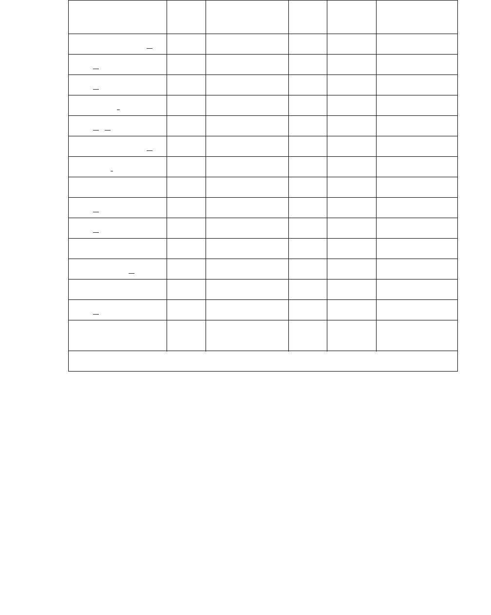
Communication Manager Maintenance-Object Repair Procedures
342 Maintenance Procedures for Avaya Communication Manager 3.0, Media Gateways and Servers
For ADM-CONN Errors
None of the Administered Connection Error Types have a specific associated test and, except
for errors 17 and 127, are valid only for administered connections established over ISDN-PRI
facilities. Error 127 is valid for administered connections established over non-ISDN facilities or
between two endpoints on the same switch.
Notes:
a. Error Types 1, 16, 22, 50, 52, 65, 66, 69, 88 are typically associated with administration
problems and are not expected to be temporary. The administered connection is not retried
and the failure is alarmed immediately. The alarm threshold specified by the customer is
ignored.
6, 21, 31, 127 (d) Any None Any OFF None
16 (a) Any None Any OFF None
17 (e) Any None Any OFF None
18, 102 (f) Any None Any OFF None
22 (a, g) Any None Any OFF None
34, 42, 44, 58 (h) Any None Any OFF None
38, 41 (i) Any None Any OFF None
43, 81 Any None Any OFF None
50 (a) Any None Any OFF None
52 (a) Any None Any OFF None
54 Any None Any OFF None
65, 66, 69 (a) Any None Any OFF None
82 Any None Any OFF None
88 (a) Any None Any OFF None
91, 95, 96, 97, 98,
99, 100, 111
Any None Any OFF None
Table 92: Administered Connection Error Log Entries (continued)
Error
Type
Aux
Data
Associated Test Alarm
Level
On/Off
Board
Test to Clear
Value
2 of 2

ADM-CONN (Administered Connection)
Issue 1 June 2005 343
b. Error Types 1, 28: the address of the destination endpoint is: an unassigned number (1),
has an invalid number format (28), or is restricted from terminating calls due to Class of
Restriction (“Access Denied”). Verify that the destination address is correct and that the
destination endpoint is administered. The destination endpoint is not administered on the
switch where this error is logged.
c. Error Type 2: a request has been made to use a transit network or common carrier that
cannot be accessed. Check the routing pattern used by this administered connection and
verify that the inter-exchange carrier specified is correct.
d. Error Types 6, 21, 31, 127: the exact failure cause is unknown or has been mapped to one
of these values. If this is a permanent condition, try reversing the direction of the
Administered Connection (originate the administered connection from the destination
switch). This may yield another failure cause.
e. Error Type 17: the destination endpoint is not available. Check the status of the destination
endpoint at the far-end switch. The status for the destination endpoint will not be available
on the switch where this error is logged. At the far end, use status access-endpoint or
status data-module to see whether the endpoint is busy, out-of-service or otherwise
unavailable.
f. Error Types 18, 102: this switch sent an ISDN message to another switch that either did not
respond (18) or did not respond within the allotted time (102). This could be due to link
failure, or congestion, or an outage at the other switch.
g. Error Type 22: the address of the destination endpoint has changed. Change the
administered connection accordingly. The destination endpoint will not be administered on
the switch where this error is logged.
h. Error Types 34, 42, 44, 58: a resource (for example, a circuit or bearer capability) required
by the administered connection is not currently available.
i. Error Types 38, 41: a network failure (38) or temporary failure (41) has occurred. Error Log
entries for other MOs (for example, DS1-BD) may indicate a local problem.

Communication Manager Maintenance-Object Repair Procedures
344 Maintenance Procedures for Avaya Communication Manager 3.0, Media Gateways and Servers
ADX8D-BD (AUDIX Circuit Pack)
S8700 | 8710 / S8500
The ADX8D-BD MO defines a TN566/TN2169 EMBEDDED AUDIX circuit pack (also called
DEFINITY AUDIX) operating in DP (digital-port) mode.
For port-level problems, see ADX8D-PT (AUDIX Digital Port) on page 345.
For circuit-pack-level problems, see XXX-BD (Common Port Circuit Pack/Media Module) on
page 2539.
EMBEDDED AUDIX consists of two circuit packs that occupy 5 slots on a port carrier. The tests
described in this manual apply only to switch-side maintenance which tests a circuit pack’s
components related to the TDM-bus interface. The AUDIX system has an extensive
maintenance strategy that is described in EMBEDDED AUDIX System Maintenance,
585-300-110.
MO Name in Alarm Log Alarm
Level
Initial Command to Run Full Name of MO
ADX8D-BD MIN
WRN test board location sh AUDIX circuit pack

ADX8D-PT (AUDIX Digital Port)
Issue 1 June 2005 345
ADX8D-PT (AUDIX Digital Port)
S8700 | 8710 / S8500
The ADX8D-PT MO represents a port on a TN566/TN2169 EMBEDDED AUDIX circuit pack
(also called DEFINITY AUDIX) operating in DP (digital-port) mode. The maintenance strategy
for ports on the TN566 operating in control-link mode is described in ADX16A-PT.
The tests described in this section apply only to switch-side maintenance that tests a circuit
pack’s components related to the TDM-bus interface. The AUDIX system has an extensive
maintenance strategy that is described in EMBEDDED AUDIX System Maintenance,
585-300-110.
AUDIX resides on a combined pair of circuit packs: the TN566 MFB (multifunction board) and
the TN2169 ALB (alarm board). Because of its size, this combination occupies 5 slots, but only
1 slot is functional as far as the switch is concerned. The other 4 slots are seen by the switch as
“AUDIX-reserved” slots (or ADXDP-RS/ADX8D-RS).
In DP mode the TN566 pack supports up to 8 voice ports, each with a primary and a secondary
information channel. Ports are administered in increments of two. When a call to a station with
an AUDIX login is not answered, AUDIX answers the call using one of the available voice ports.
Unlike other AUDIX systems, EMBEDDED AUDIX is not an adjunct.
!CAUTION:
CAUTION: Never do any of the following without first shutting down AUDIX. Follow
instructions on the TN566/TN2169 faceplate:
●Remove EMBEDDED AUDIX circuit packs
●Cycle power to a carrier containing EMBEDDED AUDIX circuit packs
●Remove power to a carrier containing EMBEDDED AUDIX circuit packs
MO Name in Alarm Log Alarm
Level
Initial Command to Run Full Name of MO
ADX8D-PT MIN test port location l AUDIX digital port
ADX8D-PT WRN test port location sh AUDIX digital port
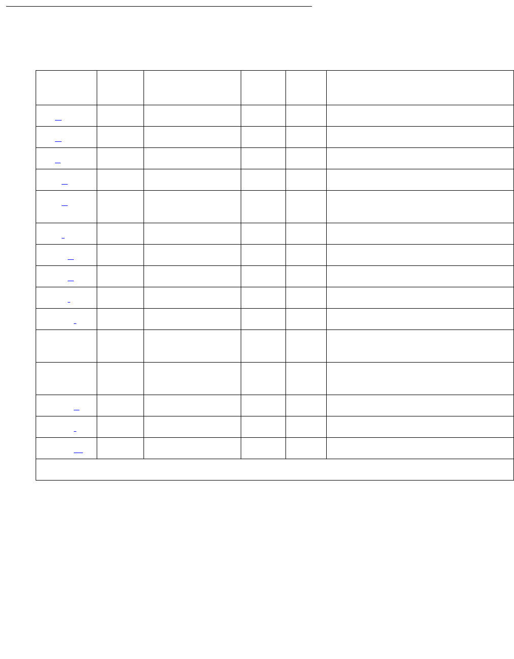
Communication Manager Maintenance-Object Repair Procedures
346 Maintenance Procedures for Avaya Communication Manager 3.0, Media Gateways and Servers
Error Log Entries and Test to Clear Values
Notes:
a. Error Type 0: run the short test sequence first. If every test passes, run the long test
sequence. Refer to each appropriate test’s description, and follow its recommended
procedures.
Table 93: EMBEDDED AUDIX Digital Port Error Log Entries
Error
Type
Aux
Data
Associated Test Alarm
Level
On/Off
Board
Test to Clear Value
0 (a) 0 Any Any Any test port location sh r 1
1 (b) 40987 None WRN OFF
1 (c) 1 to 20 None WRN OFF
15 (d) Any None
18 (e)0 busyout port
location
WRN OFF release port location
23 (f) 0 None WRN OFF
130 (g) None WRN ON test port location sh
257 (h) 40971 None
513 (i) Any None
1537 (j) 40968 None WRN OFF
1793 Voice & Ctrl.
Local Loop (#13)
MIN
WRN1
1. Minor alarms on this MO may be downgraded to Warning alarms based on the values used in set options.
ON test port location l r 3
2049 NPE Crosstalk
test (#9)
MIN
WRN1ON test port location l r 3
2305 (k) 40967 None
3840 (l) 40965 None
3840 (m) 41029 None

ADX8D-PT (AUDIX Digital Port)
Issue 1 June 2005 347
b. Error Type 1, Aux Data 40987: the user may experience a noisy port or link, due to an
off-board problem that is detected by the port circuit. If so, replace the circuit pack (see
caution at the beginning of this section). Once the problem is resolved, the alarm is retired
after a predetermined time.
c. Error Type 1, Aux Data 1 to 20: At least 15 off-board problems have been detected with
the link to the voice port. When an error with the link is detected, an on-board counter is
incremented. Also see Note (a).
d. Error Type 15: internal type error that occurs when an audit request fails.
e. Error Type 18: the port is busied-out by command. Use release port location to
release the port.
f. Error Type 23: the circuit pack is administered but not physically installed. The alarm will
clear when a circuit pack is inserted.
g. Error Type 130: the circuit pack was removed or has been insane for more than
21 minutes. To clear the error, reinsert or replace the AUDIX circuit pack (see Caution at the
beginning of this section).
h. Error Type 257: Something is interfering with transmission to the voice port. This is usually
an on-board problem and can be ignored if there are no user complaints.
i. Error Type 513: AUDIX is not available to the switch, possibly due to a busyout on the
AUDIX system. See EMBEDDED AUDIX System Maintenance, 585-300-110, if necessary.
j. Error Type 1537: An in-line maintenance error has generated an off-board warning due to
some problem with the link to the voice port. This can be ignored if there are no user
complaints. If the problem persists, replace the circuit pack (see Caution at the beginning of
this section). Once the problem is resolved, the alarm is retired after a certain period of time.
k. Error Type 2305: the link between the circuit pack and the voice port successfully reset. No
craft action is necessary.
l. Error Type 3840, Aux Data 40965: no voice ports are connected to the EMBEDDED
AUDIX circuit pack. No maintenance action is required.
m. Error Type 3840, Aux Data 41029: the message buffer in the circuit pack is full.

Communication Manager Maintenance-Object Repair Procedures
348 Maintenance Procedures for Avaya Communication Manager 3.0, Media Gateways and Servers
System Technician-Demanded Tests:
Descriptions and Error Codes
Investigate tests in the order presented when you are inspecting errors in the system.
NO-OP Tests
The maintenance strategy for EMBEDDED AUDIX emulates the one for DIG-LINE. NO-OP
Tests apply only to DIG-LINE and not to EMBEDDED AUDIX. NO-OP tests always return PASS.
●Electronic Power Feed test (#11)
●Station Lamp Updates test (#16)
●Station (Digital) Audits test (#17)
NPE Crosstalk Test (#9)
NPE Crosstalk Test (#9) verifies that this port’s NPE channel talks on the selected time slot and
that it never crosses over to time slots reserved for other connections. An NPE that is not
working correctly may cause 1-way and noisy connections. This test is part of a port’s long test
sequence, and it executes in about 20 to 30 seconds.
Order of Investigation Short Test
Sequence
Long Test
Sequence
D/ND1
1. D = Destructive; ND = Nondestructive
Voice and Control Channel Local Looparound test (#13) X ND
NPE Crosstalk test (#9) X ND

ADX8D-PT (AUDIX Digital Port)
Issue 1 June 2005 349
Crosstalk testing is performed on both the primary (for voice) and the secondary (for data)
information channel associated with each EMBEDDED AUDIX port. If NPE Crosstalk Test (#9)
fails on either channel, the voice port is taken out of service.
Table 94: Test #9 NPE Crosstalk Test
Error
Code
Test
Result
Description / Recommendation
1 ABRT During testing of the primary information channel, system resources may
not have been available. Also, the port may have been busy during the test.
1. Check the port status.
2. Use display port location to determine the voice port extension
of the port. Use status station to determine the service state of the
port. If the service state indicates that the port is active, wait until it is
idle.
3. Retry the command at 1-minute intervals up to 5 times.
2 ABRT System resources may not have been available, or the port may have been
busy during the test.
1. Retry the command at 1-minute intervals up to 5 times.
1000 ABRT System resources required to run this test are not available. The port may
be active.
1. Use display port location to determine the voice port extension
of the port. Use status station to determine the service state of the
port. If the service state indicates that the port is active, wait until it is
idle before retesting.
2. Retry the command at 1-minute intervals up to 5 times.
1001 ABRT System resources required to run this test are not available.
1. Retry the command at 1-minute intervals up to 5 times.
1002 ABRT The system could not allocate time slots for the test. The system may be
under heavy traffic conditions, or it may have time slots out-of-service due
to TDM-BUS errors.
1. If the system has no TDM-BUS errors and is not handling heavy traffic,
retry the command at 1-minute intervals up to 5 times.
1 of 2

Communication Manager Maintenance-Object Repair Procedures
350 Maintenance Procedures for Avaya Communication Manager 3.0, Media Gateways and Servers
Voice and Control Channel Local Loop Test (#13)
Voice and Control Channel Local Loop Test (#13) checks the information and control channels
between a server and the EMBEDDED AUDIX port circuit. First, the primary information (voice)
channel loop back test is run.
1003 ABRT The system could not allocate a tone receiver for the test. The system may
be oversized for the number of Tone Detectors present, or some Tone
Detectors may be out of service.
1. Resolve any TTR-LEV errors.
2. Resolve any TONE-PT errors.
3. Retry the command at 1-minute intervals up to 5 times.
1004 ABRT The port was put in use during the test. The test has been aborted.
1. Use display port location to determine the voice port extension
of the port. Use status station to determine the service state of the
port. If the port is active, wait until it is idle before testing.
1020 ABRT Test disabled by background testing.
1. Use status station to determine when the voice port is available
for testing.
2000 ABRT Response to the test request was not received within the allowable time
period.
1. Retry the command at 1-minute intervals up to 5 times.
1
2
FAIL The NPE of the tested port is transmitting in error. This causes noisy and
unreliable connections. Failure code 1 indicates that the Crosstalk test
failed on the primary channel. Failure code 2 indicates that the Crosstalk
test failed on the secondary channel.
1. Replace the circuit pack.
PASS The port is using its allocated time slots correctly.
1. To be sure that this is not an intermittent problem, repeat this test up to
10 times to make sure it continues to pass.
2. If complaints still exist, examine the connections.
Table 94: Test #9 NPE Crosstalk Test (continued)
Error
Code
Test
Result
Description / Recommendation
2 of 2

ADX8D-PT (AUDIX Digital Port)
Issue 1 June 2005 351
While the primary information channel is still looped around, the Control Channel Looparound
test is performed. The Looparound test for the secondary information (data) channel is then
performed. This is the same test as the primary information channel’s loop-around test.
Next, a Conference test is implemented for the primary information channel. This is the same
test as Conference test (#6).
Only one value (Pass, Fail, or Abort) is generated as a result of the four tests run. If any tests fail
or abort, the sequence stops.
Table 95: Test #13 Voice and Control Channel Local Loop Test
Error
Code
Test
Result
Description / Recommendation
ABRT Internal system error.
1. Retry the command at 1-minute intervals up to 5 times. Then try (b).
1000 ABRT System resources required to run this test are not available. The port may
be active.
1. Use display port location to determine the voice port extension
of the port. Use status station to determine the service state of the
port. If the service state indicates that the port is active, wait until it is
idle before retesting.
2. Retry the command at 1-minute intervals up to 5 times.
1001 ABRT System resources required for this test are not available.
1. Retry the command at 1-minute intervals up to 5 times.
1002 ABRT The system could not allocate time slots for the test. The system may be
under heavy traffic conditions, or may have time slots that are
out-of-service due to TDM-BUS errors.
1. If the system has no TDM-BUS errors and is not handling heavy traffic,
retry the command at 1-minute intervals up to 5 times.
1003 ABRT The system could not allocate a tone receiver for the test. The system may
be oversized for the number of Tone Detectors present, or some Tone
Detectors may be out of service.
1. Resolve any TTR-LEV errors.
2. Resolve any TONE-PT errors.
3. If neither condition exists, retry the command at 1-minute intervals up
to 5 times.
1 of 2

Communication Manager Maintenance-Object Repair Procedures
352 Maintenance Procedures for Avaya Communication Manager 3.0, Media Gateways and Servers
1004 ABRT The port was put in use during the test.
1. Use display port location to determine the voice port extension
of the port. Use status station to determine the service state of the
port. If the service state indicates that the port is active, wait until it is
idle before retesting.
2. Retry the command at 1-minute intervals up to 5 times.
2000 ABRT Response to the test request was not received within the allowable time
period.
1. Retry the command at 1-minute intervals up to 5 times.
2100 ABRT Could not allocate the necessary system resources to run this test.
1. Retry the command at 1-minute intervals up to 5 times.
7 FAIL Conference test failed on the primary channel. Some users may notice a
disruption in service. In extreme cases, the conferencing feature may not
work at all.
14 FAIL The primary voice channel is not transmitting properly. User impact may
range from no noticeable effect to loss of use of this port.
15 FAIL The control channel between the processor and the EMBEDDED AUDIX
circuit pack is not transmitting properly. User impact may range from no
noticeable effect to loss of use of this port.
16 FAIL The secondary voice channel is not transmitting properly. User impact may
range from no noticeable effect to loss of use of this port.
None FAIL The test failed for reasons external to the EMBEDDED AUDIX circuit pack.
1. Use test board location sh to run circuit tests to check the Tone
Generator circuit and the Tone Detector circuit.
2. Resolve any problems that are detected on the Tone Generator circuit
or Tone Detector circuit.
3. If both circuit packs are functioning properly and the test still fails,
replace the EMBEDDED AUDIX circuit pack (see caution at the
beginning of this section).
PASS Voice and Control Channel Local Loop test passed. Every channel is
transmitting properly.
1. To be sure that this is not an intermittent problem, repeat this test up to
10 times, and see whether it continues to pass.
2. If complaints still exist, examine the connections.
Table 95: Test #13 Voice and Control Channel Local Loop Test (continued)
Error
Code
Test
Result
Description / Recommendation
2 of 2

ADX16D-B (16-Port AUDIX Circuit Pack)
Issue 1 June 2005 353
ADX16D-B (16-Port AUDIX Circuit Pack)
S8700 | 8710 / S8500
The ADX16D-BD MO represents a TN566/TN2169 EMBEDDED AUDIX circuit pack
combination operating in 16-port mode digital (DP). For circuit-pack-level problems, see
XXX-BD (Common Port Circuit Pack/Media Module) on page 2539. Port-level maintenance is
covered by ADX16D-PT.
EMBEDDED AUDIX consists of two circuit packs that occupy 5 slots on a port carrier. The tests
described in this manual apply only to switch-side maintenance that tests a circuit pack’s
components related to the TDM-bus interface. The AUDIX system has an extensive
maintenance strategy of its own that is described in DEFINITY AUDIX System Release 3.2.4
Maintenance, 585-300-110.
MO Name in Alarm Log Alarm
Level
Initial Command to Run Full Name of MO
ADX16D-B MIN test board location sh AUDIX circuit pack
ADX16D-B WRN test board location sh AUDIX circuit pack

Communication Manager Maintenance-Object Repair Procedures
354 Maintenance Procedures for Avaya Communication Manager 3.0, Media Gateways and Servers
ADX16A-BD (AUDIX Circuit Pack)
S8700 | 8710 / S8500
The ADX16A-BD MO represents a TN566/TN2169 EMBEDDED AUDIX circuit pack
combination operating in control-link (CL) mode. For circuit-pack-level problems, see XXX-BD
(Common Port Circuit Pack/Media Module) on page 2539. Port-level maintenance is covered
by ADX16A-PT.
EMBEDDED AUDIX consists of two circuit packs that occupy 5 slots on a port carrier. The tests
described in this manual apply only to switch-side maintenance that tests a circuit pack’s
components related to the TDM-bus interface. The AUDIX system has an extensive
maintenance strategy that is described in EMBEDDED AUDIX System Maintenance,
585-300-110.
MO Name in Alarm Log Alarm
Level
Initial Command to Run Full Name of MO
ADXCL-BD
ADX16A-B
MIN
WRN test board location sh AUDIX circuit pack

ADX16D-P (16-Port AUDIX Digital Port)
Issue 1 June 2005 355
ADX16D-P (16-Port AUDIX Digital Port)
S8700 | 8710 / S8500
!CAUTION:
CAUTION: Never do any of the following without first shutting down AUDIX. Follow the
instructions on the TN566/TN2169 faceplate:
●Remove EMBEDDED AUDIX circuit packs
●Cycle power to a carrier containing EMBEDDED AUDIX circuit packs
●Remove power to a carrier or cabinet containing EMBEDDED AUDIX circuit pack
The ADX16D-P MO represents a port on a TN566/TN2169 EMBEDDED AUDIX circuit pack
operating in digital-port (DP) mode. The maintenance strategy for ports on the TN566 operating
in control-link mode is described in ADX16A-PT.
The tests described in this section apply only to switch-side maintenance that tests a circuit
pack’s components related to the TDM-bus interface. The AUDIX system has an extensive
maintenance strategy that is described in DEFINITY AUDIX System Release 3.2.4
Maintenance, 585-300-110.
AUDIX resides on a combined pair of circuit packs: the TN566 Multifunction board (MFB) and
the TN2169 Alarm board (ALB). Because of its size this combination occupies 5 slots, but the
system sees only 1 slot as functional. The other 4 slots are seen by the switch as
“AUDIX-reserved” slots (or ADX16-RES/ADX16D-RS).
In 16-port DP mode, the TN566 pack supports up to 16 voice ports, each with a primary and a
secondary information channel. Ports are administered in increments of two. When a call to a
station with an AUDIX login is not answered, AUDIX answers the call using one of the available
voice ports.
Unlike other AUDIX systems, EMBEDDED AUDIX is not an adjunct.
MO Name in Alarm Log Alarm
Level
Initial Command to Run Full Name of MO
ADX16D-P MIN
WRN test port location l AUDIX Digital port
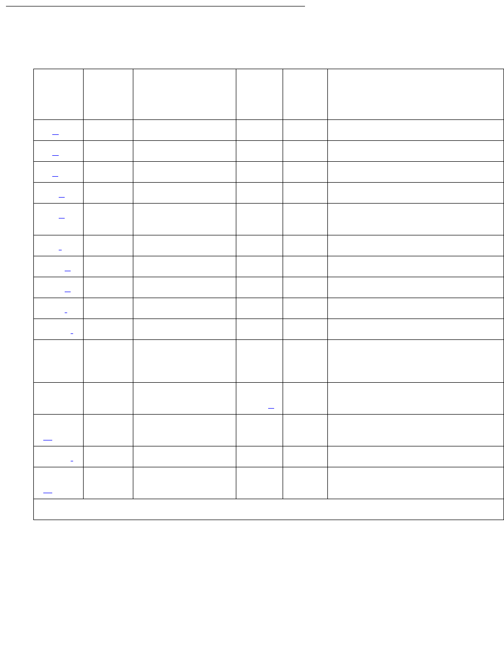
Communication Manager Maintenance-Object Repair Procedures
356 Maintenance Procedures for Avaya Communication Manager 3.0, Media Gateways and Servers
Error Log Entries and Test to Clear Values
Notes:
a. Error Type 0: run the short test sequence first. If every test passes, run the long test
sequence. Refer to each test’s description, and follow the recommended procedures
Table 96: EMBEDDED AUDIX Digital Port Error Log Entries
Error
Type
Aux
Data
Associated Test Alarm
Level
On/
Off
Board
Test to Clear Value
0 (a) 0 Any Any Any test port location sh r 1
1 (b) 40987 None WRN OFF
1 (c) 1 to 20 None WRN OFF
15 (d) Any None
18 (e)0 busyout port
location
WRN OFF release port location
23 (f) 0 None WRN OFF
130 (g) None WRN ON test port location sh
257 (h) 40971 None
513 (i) Any None
1537 (j) 40968 None WRN OFF
1793 Voice and Control
Local Loop Test
(#13)
MIN
WRN1
1. Minor alarms may be downgraded to Warning alarms based on the values used in set options.
ON test port location l r 3
2049 NPE Crosstalk
test (#9)
MIN
WRN1
ON test port location l r 3
2305
(k)
40967 None
3840 (l) 40965 None
3840
(m)
41029 None

ADX16D-P (16-Port AUDIX Digital Port)
Issue 1 June 2005 357
b. Error Type 1 with Aux Data 40987: The user may experience a noisy port or link, due to an
off-board problem that is detected by the port circuit. If so, replace the circuit pack (see
caution at the beginning of this section). Once the problem is resolved, the alarm is retired
after a predetermined time.
c. Error Type 1: At least 15 off-board problems have been detected with the link to the voice
port. When an error with the link is detected, an on-board counter is incremented. Also see
Note a above.
d. Error Type 15: An internal type error that occurs when an audit request fails.
e. Error Type 18: The port is busied-out by command. Release the port with release port
location.
f. Error Type 23: The circuit pack is administered but not physically installed. The alarm will
clear when a circuit pack is inserted.
g. Error Type 130: The circuit pack has been removed or has been insane for more than
21-minutes. To clear the error, reseat or replace the AUDIX circuit pack (see caution at the
beginning of this section).
h. Error Type 257: Something is interfering with transmission to the voice port. This is usually
an on-board problem and can be ignored if there are no user complaints.
i. Error Type 513: AUDIX is not available to the switch, possibly due to a busyout on the
AUDIX system. Refer to DEFINITY AUDIX System Release 3.2.4 Maintenance,
585-300-110.
j. Error Type 1537: An in-line maintenance error has generated an off-board warning due to
some problem with the link to the voice port. This can be ignored if there are no user
complaints. If the problem persists, replace the circuit pack (see caution at the beginning of
this section). Once the problem is resolved, the alarm is retired after a certain period of time.
k. Error Type 2305: The link between the circuit pack and the voice port is successfully reset.
No craft action is necessary.
l. Error Type 3840 with Aux Data 40965: No voice ports are connected to the EMBEDDED
AUDIX circuit pack. No maintenance action is required.
m. Error Type 3840 with Aux Data 41029: The message buffer in the circuit pack is full.
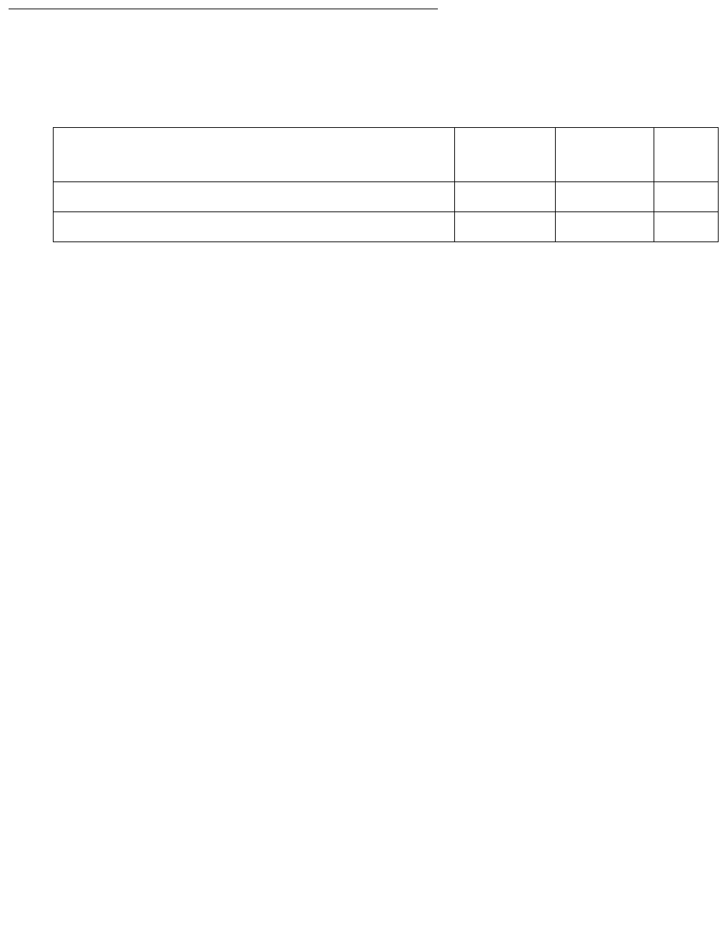
Communication Manager Maintenance-Object Repair Procedures
358 Maintenance Procedures for Avaya Communication Manager 3.0, Media Gateways and Servers
System Technician-Demanded Tests:
Descriptions and Error Codes
Investigate tests in the order presented.
NO-OP Tests
The maintenance strategy for EMBEDDED AUDIX emulates the one for DIG-LINE. The tests
listed below apply only to DIG-LINE and not to EMBEDDED AUDIX. These tests always return
PASS.
●Electronic Power Feed test (#11)
●Station Lamp Updates test (#16)
●Station (Digital) Audits test (#17)
●Digital Terminal Remote Looparound test (#1201)
NPE Crosstalk Test (#9)
NPE Crosstalk Test (#9) verifies that this port’s NPE channel talks on the selected time slot and
that it never crosses over to time slots reserved for other connections. If the NPE is not working
correctly, one-way and noisy connections may be observed. NPE Crosstalk Test (#9) is part of a
port’s long test sequence, and it executes in about 20 to 30 seconds.
Crosstalk testing is performed on both the primary (for voice) and the secondary (for data)
information channel associated with each EMBEDDED AUDIX port. If this test fails on either
channel, the voice port is taken out-of-service.
Order of Investigation Short Test
Sequence
Long Test
Sequence
D/ND1
1. D = Destructive; ND = Nondestructive
Voice and Control Channel Local Looparound test (#13) X ND
NPE Crosstalk test (#9) X ND

ADX16D-P (16-Port AUDIX Digital Port)
Issue 1 June 2005 359
Table 97: Test #9 NPE Crosstalk Test
Error
Code
Test
Result
Description / Recommendation
1 ABRT During testing of the primary information channel, system resources may
not have been available. Also, the port may have been busy during the test.
1. Check the port status.
2. Use display port location to determine the voice port extension
of the port. Use status station to determine the service state of the
port. If the port is active, it is unavailable for this test. Wait until the port
is idle.
3. Retry the command at 1-minute intervals up to 5 times.
2 ABRT System resources may not have been available, or the port may have been
busy during the test.
1. Verify that the port’s status is idle.
2. Retry the command at 1-minute intervals up to 5 times.
1000 ABRT System resources required to run this test are not available. The port may
be active.
1. Use display port location to determine the voice port extension
of the port. Use status station to determine the service state of the
port. If the port is active, it is unavailable for certain tests. Refer to
“Status” commands in Maintenance SAT Commands in Maintenance
Commands Reference (03-300191), for a full description of every
possible state. Wait until the port is idle before testing.
2. If the port’s status is idle, retry the command at 1-minute intervals up to
5 times.
1001 ABRT System resources required to run this test are not available.
1. Retry the command at 1-minute intervals up to 5 times.
1002 ABRT The system could not allocate time slots for the test. The system may be
under heavy traffic conditions, or it may have time slots out-of-service due
to TDM-BUS errors.
1. If the system has no TDM-BUS errors and is not handling heavy traffic,
retry the command at 1-minute intervals up to 5 times.
1 of 2

Communication Manager Maintenance-Object Repair Procedures
360 Maintenance Procedures for Avaya Communication Manager 3.0, Media Gateways and Servers
1003 ABRT The system could not allocate a tone receiver for the test. The system may
be oversized for the number of Tone Detectors present, or some Tone
Detectors may be out of service.
1. Resolve any TTR-LEV errors.
2. Resolve any TONE-PT errors.
1004 ABRT The port was put in use during the test. The test has been aborted.
1. Use display port location to determine the voice port extension
of the port. Use status station to determine the service state of the
port. If the port is active, it is unavailable for certain tests. Refer to
“Status” commands in Maintenance SAT Commands in Maintenance
Commands Reference (03-300191) for explanations of every possible
state. Wait until the port is idle before testing.
1020 ABRT Test disabled via background testing.
1. Use status station to determine when the voice port is available
for testing.
2000 ABRT Response to the test request was not received within the allowable time
period.
1. Retry the command at 1-minute intervals up to 5 times.
1, 2 FAIL The NPE of the tested port was found to be transmitting in error. This
causes noisy and unreliable connections. Failure code 1 indicates that the
Crosstalk test failed on the primary channel. Failure code 2 indicates that
the Crosstalk test failed on the secondary channel.
1. Replace the circuit pack (see caution at the beginning of this section).
PASS The port is using its allocated time slots correctly.
1. To verify that this is not an intermittent problem, repeat this test up to 10
times, and make sure it continues passing.
2. If complaints still exist, examine the connections.
Table 97: Test #9 NPE Crosstalk Test (continued)
Error
Code
Test
Result
Description / Recommendation
2 of 2

ADX16D-P (16-Port AUDIX Digital Port)
Issue 1 June 2005 361
Voice and Control Channel Local Loop Test (#13)
This test checks the information and control channels between the server the EMBEDDED
AUDIX port circuit. The server sends a message to loop around both the information and control
channels for the port. First, the primary information (voice) channel loop back test is run.
While the primary information channel is still looped around, the Control Channel Looparound
test is performed. The loop-around test for the secondary information (data) channel is then
performed. This test is the same as the primary information channel’s loop-around test.
Next, a Conference test is implemented for the primary information channel. This test is the
same as Conference Test #6.
Only one value (Pass, Fail, or Abort) is generated as a result of the four tests run. If any test
fails or aborts, the sequence is stopped.
Table 98: Test #13 Voice and Control Channel Local Loop Test
Error
Code
Test
Result
Description / Recommendation
ABRT Internal system error
1. Retry the command at 1-minute intervals up to 5 times.
1000 ABRT System resources required to run this test are not available. The port may
be active.
1. Use display port location to determine the voice port extension
of the port. Use status station to determine the service state of the
port. Wait until the port is idle before testing.
2. Retry the command at 1-minute intervals up to 5 times.
1001 ABRT System resources required to run this test are not available.
1. Retry the command at 1-minute intervals up to 5 times.
1002 ABRT The system could not allocate time slots for the test. The system may be
under heavy traffic conditions, or it may have time slots that are
out-of-service due to TDM-BUS errors.
1. If the system has no TDM-BUS errors and is not handling heavy traffic,
retry the command at 1-minute intervals up to 5 times.
1003 ABRT The system could not allocate a tone receiver for the test. The system may
be oversized for the number of Tone Detectors present, or some Tone
Detectors may be out of service.
1. Resolve any TTR-LEV errors.
2. Resolve any TONE-PT errors.
3. Retry the command at 1-minute intervals up to 5 times.
1 of 2

Communication Manager Maintenance-Object Repair Procedures
362 Maintenance Procedures for Avaya Communication Manager 3.0, Media Gateways and Servers
1004 ABRT The port was put in use during the test. The test has been aborted.
1. Use display port location to determine the voice port extension
of the port. Use status station to determine the service state of the
port. If the port is active, wait until it is idle before retesting.
2000 ABRT Response to the test request was not received within the allowable time
period.
1. Retry the command at 1-minute intervals up to 5 times.
2100 ABRT Could not allocate the necessary system resources for this test.
1. Retry the command at 1-minute intervals up to 5 times.
7 FAIL Conference test failed on the primary channel. In some cases, users may not
notice a disruption in service. In extreme cases, the conferencing feature may
not work at all.
14 FAIL The primary voice channel is not transmitting properly. User impact may
range from no noticeable effect to loss of use of this port.
15 FAIL The control channel between the processor and AUDIX is not transmitting
properly. User impact may range from no noticeable effect to loss of use of
this port. This failure could also be disruptive to other users.
16 FAIL The secondary voice channel is not transmitting properly. User impact may
range from no noticeable effect to loss of use of this port.
None FAIL The test failed for reasons external to the AUDIX.
1. Run circuit tests to check the Tone Generator circuit and the Tone
Detector circuit using test board location s.
2. Resolve any problems detected on the Tone Generator circuit or Tone
Detector circuit.
3. If both circuit packs are functioning properly and the test still fails,
replace the AUDIX (see caution at the beginning of this section).
PASS Voice and Control Channel Local Loop test passed. Every channel are
transmitting properly.
1. To be sure that this is not an intermittent problem, repeat this test up to
10 times, and see whether it continues to pass.
2. If complaints still exist, examine the connections.
Table 98: Test #13 Voice and Control Channel Local Loop Test (continued)
Error
Code
Test
Result
Description / Recommendation
2 of 2
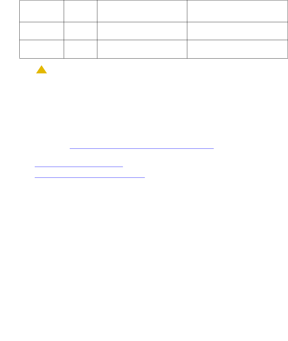
ADX16A-PT (AUDIX Analog Line/Control Link)
Issue 1 June 2005 363
ADX16A-PT (AUDIX Analog Line/Control Link)
S8700 | 8710 S8500
!CAUTION:
CAUTION: Never do any of the following without first shutting down AUDIX. Follow the
instructions on the TN566/TN2169 faceplate:
●Remove EMBEDDED AUDIX circuit packs
●Cycle power to a carrier containing EMBEDDED AUDIX circuit packs
●Remove power to a carrier containing EMBEDDED AUDIX circuit packs
The ADX16A-PT MO represents a port on a TN566/TN2169 EMBEDDED AUDIX circuit pack
that is operating in control-link (CL) mode. For circuit-pack-level problems (ADX16A-BD or
ANL-16-BD), see XXX-BD (Common Port Circuit Pack/Media Module) on page 2539. For
port-level problems with AUDIX operating in digital-port mode, see:
●ADX8D-PT (AUDIX Digital Port) on page 345
●ADX16D-P (16-Port AUDIX Digital Port) on page 355
The tests described in this section apply only to switch-side maintenance that tests a circuit
pack’s components related to the TDM-bus interface. The AUDIX system has an extensive
maintenance strategy that is described in DEFINITY AUDIX System Release 3.2.4
Maintenance, 585-300-110.
AUDIX resides on a combined pair of circuit packs: the TN566 Multifunction board (MFB) and
the TN2169 Alarm board (ALB). Because of its size this combination occupies 5 slots, but only 1
slot is functional as far as the switch is concerned. The other 4 slots are seen by the switch as
“AUDIX-reserved” slots.
In CL mode the TN566 pack supports up to 16 voice ports. When a call to a station with an
AUDIX login is not answered, AUDIX answers the call using one of the available voice ports.
Unlike other AUDIX systems, EMBEDDED AUDIX is not an adjunct.
MO Name in
Alarm Log
Alarm
Level
Initial Command to Run Full Name of MO
ADXCL-PT
or ADX16A-P
MIN test port location l AUDIX Analog Line/ Control Link
ADXCL-PT
or ADX16A-P
WRN test port location sh AUDIX Analog Line/ Control Link
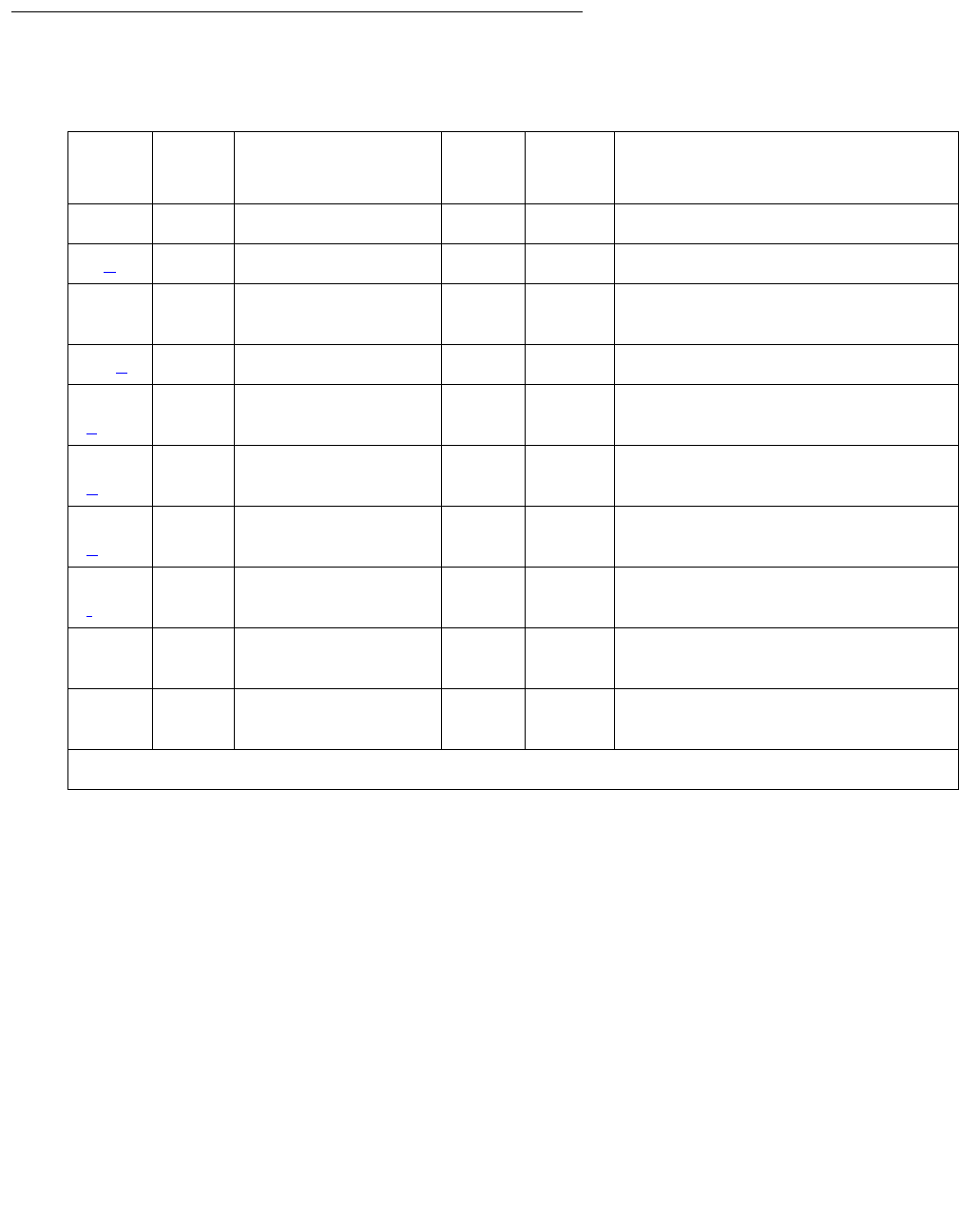
Communication Manager Maintenance-Object Repair Procedures
364 Maintenance Procedures for Avaya Communication Manager 3.0, Media Gateways and Servers
Error Log Entries and Test to Clear Values
Notes:
a. Error Type 1 is an in-line error that can only be resolved over time. No terminal equipment
was present when ringing was attempted. Execute test port location s.
b. Error Type 23: The circuit pack was logically administered but not physically installed. The
alarm will clear when the circuit pack is installed.
c. Error Type 130: The circuit pack was removed or has been insane for more than
11 minutes. To clear the error, reseat or replace the circuit pack.
Table 99: EMBEDDED AUDIX Analog Line/Control Link Error Log Entries
Error
Type
Aux
Data
Associated Test Alarm
Level
On/Off
Board
Test to Clear Value
01
1. Run the short test sequence first. If every test passes, run the long test sequence. Refer to each
appropriate test’s description, and follow its recommended procedures.
0Any AnyAnytest port location sh r 1
1 (a) 40977 None
18 0 busyout
station ext
WRN ON release station extension
23 (b)0 None WRN OFF
130
(c)
None WRN ON test port location sh
257
(d)
40973 None
513
(e)
Any None
1025
(f)
Looparound test
(#161)
MIN
WRN2
2. Minor alarms on this MO may be downgraded to Warning alarms based on the values used in set options.
ON test port location l r 2
1281 Conference test
(#7)
MIN
WRN2ON test port location l r 2
1537 NPE Crosstalk test
(#6)
MIN
WRN2ON test port location l r 2
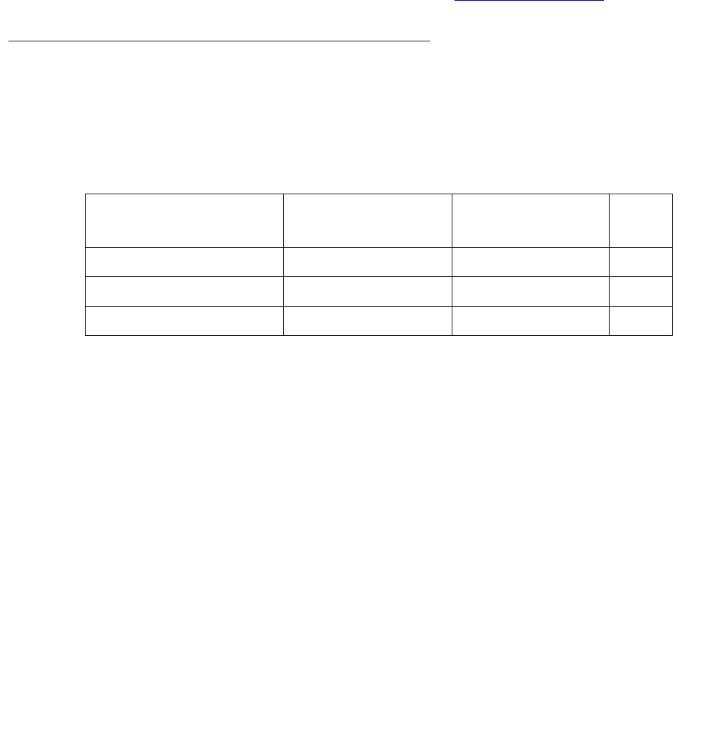
ADX16A-PT (AUDIX Analog Line/Control Link)
Issue 1 June 2005 365
d. Error Type 257 is an in-line error and can only be resolved over time. Ringing voltage is
absent. If only one analog circuit pack in the system has this problem, replace the circuit
pack. If only analog circuit packs on a particular carrier have this error, the ringing generator
may not be connected to this carrier. If analog circuit packs on many carriers have this error,
check the ringing generator.
e. Error Type 513: AUDIX is not available to the switch. Check the AUDIX system, referring to
DEFINITY AUDIX System Release 3.2.4 Maintenance, 585-300-110.
f. Error Type 1025: The TDM bus is out of service. See TDM-BUS (TDM Bus) on page 2237.
System Technician-Demanded Tests:
Descriptions and Error Codes
Investigate tests in the order presented. By clearing error codes associated with the
Looparound test (#161), you may also clear errors generated from other tests in the testing
sequence.
NO-OP Tests
The maintenance strategy for EMBEDDED AUDIX emulates the one for ANL-16-L. The tests
listed below apply only to ANL-16-L and not to EMBEDDED AUDIX. These tests always return
PASS.
●Battery Feed test (#35)
●Audits and Updates test (#36)
●Station Present test (#48)
Tests 36 and 48 ABORT when AUDIX is not running.
Order of Investigation Short Test
Sequence
Long Test
Sequence
D/ND1
1. D = Destructive; ND = Nondestructive
Looparound test (#161) X ND
Conference test (#7) X ND
NPE Crosstalk test (#6) X ND

Communication Manager Maintenance-Object Repair Procedures
366 Maintenance Procedures for Avaya Communication Manager 3.0, Media Gateways and Servers
NPE Crosstalk Test (#6)
This test verifies that this port’s NPE channel talks on the selected time slot and never crosses
over to time slots reserved for other connections. If the NPE is not working correctly, one-way
and noisy connections may be observed. This test is part of the long test sequence and
executes in about 25 seconds.
Table 100: Test #6 NPE Crosstalk Test
Error
Code
Test
Result
Description / Recommendation
ABRT Could not allocate the necessary system resources to run this test.
1. Retry the command at 1-minute intervals up to 5 times.
1000 ABRT System resources required to run this test are not available. The port may
be busy with a valid call.
1. Use display port location to determine the station extension.
Use status station to determine the service state of the port. If the
port is active, it is unavailable for certain tests. Wait until the port is idle
before testing.
2. Retry the command at 1-minute intervals up to 5 times.
1001 ABRT Could not allocate the necessary system resources to run this test.
1002 ABRT The system could not allocate time slots for the test. The system may be
under heavy traffic conditions or it may have time slots out-of-service due to
TDM-BUS errors.
1. If the system has no TDM-BUS errors and is not handling heavy traffic,
then retry the command at 1-minute intervals up to 5 times.
1003 ABRT The system could not allocate a tone receiver for the test. The system may
be oversized for the number of Tone Detectors present, or some Tone
Detectors may be out of service.
1. Resolve any TTR-LEV errors.
2. Resolve any TONE-PT errors.
3. Retry the command at 1-minute intervals up to 5 times.
1 of 2

ADX16A-PT (AUDIX Analog Line/Control Link)
Issue 1 June 2005 367
1004 ABRT The port was seized by a valid call during the test. The test has been
aborted.
1. Use display port location to determine the station extension.
Use status station to determine the service state of the port. If the
port is active, it is unavailable for certain tests. Wait until the port is idle
before testing.
2. Retry the command at 1-minute intervals up to 5 times.
1005 ABRT This condition indicates that the test is not applicable when the analog port is
used in a combined modem pool. This error can be ignored.
1018 ABRT Test disabled via administration.
1. To enable the test for the particular analog station being tested, enter
change station extension.
2. Enter y in the Test field.
2000 ABRT Response to the test request was not received within the allowable time
period.
1. Retry the command at 1-minute intervals up to 5 times.
2012 ABRT System could not respond to this request.
1. Retry the command at 1-minute intervals up to 5 times.
2100 ABRT Could not allocate the necessary system resources to run this test.
1. Retry the command at 1-minute intervals up to 5 times.
Any FAIL The NPE of the tested port was found to be transmitting in error. This
causes noisy and unreliable connections.
1. Replace the circuit pack.
PASS The port is correctly using its allocated time slots. User-reported troubles on
this port should be investigated by using other port tests, by examining
station wiring, or by examining the station.
Table 100: Test #6 NPE Crosstalk Test (continued)
Error
Code
Test
Result
Description / Recommendation
2 of 2

Communication Manager Maintenance-Object Repair Procedures
368 Maintenance Procedures for Avaya Communication Manager 3.0, Media Gateways and Servers
Conference Circuit Test (#7)
This test verifies that the NPE channel for the port being tested can correctly perform the
conferencing function.
Table 101: Test #7 Conference Circuit Test
Error
Code
Test
Result
Description / Recommendation
ABRT Could not allocate the necessary system resources to run this test.
1. Retry the command at 1-minute intervals up to 5 times.
1000 ABRT System resources required to run test are not available. The port may be
busy with a valid call.
1. Use display port location to determine the station extension.
Use status station to determine the service state of the port. If the
port is active, wait until it is idle before retesting.
2. Retry the command at 1-minute intervals up to 5 times.
1004 ABRT The port was seized by a valid call during the test. The test has been
aborted.
1. Use display port location to determine the station extension.
Use status station to determine the service state of the port. If the
port is active, wait until it is idle before testing.
2. Retry the command at 1-minute intervals up to 5 times.
1018 ABRT Test disabled by administration. This only applies to analog stations.
1. To enable the test for the analog station being tested, enter change
station extension and enter y in the Test field.
2000 ABRT Response to the test request was not received within the allowable time
period.
1. Retry the command at 1-minute intervals up to 5 times.
2100 ABRT Could not allocate the necessary system resources for this test.
1. Retry the command at 1-minute intervals up to 5 times.
Any FAIL The NPE of the tested port did not conference the tones correctly. This
causes noisy and unreliable connections.
1. Replace the circuit pack.
PASS The port can correctly conference multiple connections. User-reported
troubles on this port should be investigated by using other port tests and by
examining station, trunk, or external wiring.

ADX16A-PT (AUDIX Analog Line/Control Link)
Issue 1 June 2005 369
Loop-Around Test (#161)
This test is designed to check the on-board transmission capabilities of the NPE on the analog
port.
Table 102: Test #161 Loop-Around Test
Error
Code
Test
Result
Description / Recommendation
ABRT Could not allocate the necessary system resources for this test.
1. Retry the command at 1-minute intervals up to 5 times.
1000 ABRT System resources required to run this test are not available. The port may
be busy with a valid call.
1. Use display port location to determine the station extension.
Use status station to determine the service state of the port. If the
port is active, wait until it is idle before testing.
2. If the port status is idle, retry the command at 1-minute intervals up to 5
times.
1002 ABRT The system could not allocate time slots for the test. The system may be
under heavy traffic conditions or it may have time slots out-of-service due to
TDM-BUS errors.
1. If the system has no TDM-BUS errors and is not handling heavy traffic,
retry the command at 1-minute intervals up to 5 times.
1003 ABRT The system could not allocate a tone receiver for the test. The system may
be oversized for the number of Tone Detectors present, or some Tone
Detectors may be out of service.
1. Resolve any TTR-LEV errors.
2. Resolve any TONE-PT errors.
3. If neither condition exists, retry the command at 1-minute intervals up to
5 times.
1004 ABRT The port was seized by a valid call during the test. The test has been
aborted.
1. Use display port location to determine the station extension.
Use status station to determine the service state of the port. If the
port is active, wait until it is idle before testing.
2. Retry the command at 1-minute intervals up to 5 times.
1 of 2

Communication Manager Maintenance-Object Repair Procedures
370 Maintenance Procedures for Avaya Communication Manager 3.0, Media Gateways and Servers
1018 ABRT Test disabled by administration.
1. To enable the test for the particular analog station, enter change
station extension.
2. Enter y in the Test field.
2000 ABRT Response to the test was not received within the allowable time period.
1. Retry the command at 1-minute intervals up to 5 times.
2100 ABRT Could not allocate the necessary system resources to run this test.
1. Retry the command at 1-minute intervals up to 5 times.
FAIL The reflective loop-around test failed. This causes noisy or unreliable
connections or other users calling this port may hear an echo.
1. Replace the circuit pack.
PASS The port is able to provide an analog transmission path to the station
equipment. User-reported troubles on this port should be investigated by
using other port tests, by examining station wiring, or by examining the
station.
Table 102: Test #161 Loop-Around Test (continued)
Error
Code
Test
Result
Description / Recommendation
2 of 2

AESV-LNK (AE Services Link)
Issue 1 June 2005 371
AESV-LNK (AE Services Link)
S8700 | 8710 / S8500 / S8300
AESVCS Links provide a connection between Communication Manager and an AESVCS
Server in which data is exchanged. Communication Manager dynamically creates and deletes
AESVCS Links as socket connections to AESVCS Server are established and torn down.
AESVCS Links that are connected to the same AESVCS Server are grouped into an AESVCS
Session.
Error Log Entries and Test to Clear Values
Notes:
a. Error Type 513 is displayed when an AESVCS Link is hyperactive. The hyperactivity might
be caused by fluctuations in the engineered traffic load being generated by the AESVCS
Server. Both an AESVCS Session level and Link level alarm is generated to indicate that a
link is overloaded.
Once the problem has been resolved, it might take up to 45 minutes for the alarm to clear
due to the “leaky bucket” strategy. If the hyperactivity persists, escalate the problem.
MO Name in Alarm Log Alarm
Level
Initial Command to Run Full Name of MO
AESV-LNK MAJ
WRN
test aesvcs-server Application Enablement
Services (AESVCS)
Link
Table 103: AESV-LNK Error Log Entries
Error Type Aux
Data
Associated
Test
Alarm
Level
On/Off
Board
Test to Clear Value
513 (a) WRN Off none
769 (b) AESVCS
Link
Heartbeat
Test (#1324)
Log
only
1537 (c) Any Log
only
2561 (d) Log
only

Communication Manager Maintenance-Object Repair Procedures
372 Maintenance Procedures for Avaya Communication Manager 3.0, Media Gateways and Servers
b. Error type 769 is a log only error and is displayed when Communication Manager does not
receive a response from the AESVCS Server to a heartbeat message that was sent over
the AESVCS Link. Failure to receive a response to a heartbeat message results in the
deletion of the AESVCS Link by Communication Manager. Both an AESVCS Session Level
and Link level error is generated against this condition. Escalate if the error persists.
c. Error type 1537 is a log only error and displayed when an AESVCS Link is deleted from an
AESVCS Session for reasons other than a heartbeat failure. Both an AESVCS Session
Level and Link level error is generated against this condition. The Aux Data field contains
the reason code.
Aux Data Description
1 The far end closed the socket connection. Check the error logs on
the AEVCS Server for more information.
100 The reset aecvcs-link command was used to close the socket
connection
101 The AESVCS Interface on the IP Services form was disabled.
102 The AESVCS Interface was removed from the IP Services form.
103 The AE Services Server was disabled on the AE Services
Administration page of the IP Services form.
104 The AE Services Server was deleted on the AE Services
Administration page of the IP Services form.
200 The socket connection closed due to an internal error. Escalate if the
problem persists.
201 The socket connection was unexpectedly closed by Communication
Manager. Escalate if the problem persists.
202 Communication Manager detected and error and closed the socket
connection. Escalate if the problem persists.
203 Communication Manager detected an error reading from the socket
and closed the connection. Escalate if the problem persists.
204 Communication Manager failed to write a complete message and
closed the socket connection. Escalate if the problem persists.
205 AE Server established a new connection causing Communication
Manager to close the existing one. Escalate if the problem persists.
206 Communication Manager failed to send a heartbeat request and
closed the socket connection. Escalate if the problem persists.
207 Communication Manager detected a protocol violation and closed
the socket connection. Escalate if the problem persists.
1 of 2

AESV-LNK (AE Services Link)
Issue 1 June 2005 373
d. Error Type 2561 is a log only error and is displayed when an AESVCS message is
discarded due to a link buffer overflow. Both an AESVCS Session Level and Link level error
is generated against this condition. Escalate if the problem persists.
System Technician-Demanded Tests:
Descriptions and Error Codes
Investigate tests in the order shown. By clearing error codes associated with the AESVCS Link
Heartbeat Test (#1324), you might clear errors from other tests in the testing sequence.
AESVCS Link Heartbeat Test (#1324)
The AESVCS Link Heartbeat test sends a TCP tunnel connection heartbeat message to the far
end AESVCS Server. If the AESVCS Server fails to return a response to the heartbeat
message, the test fails. An AESVCS Link that fails a Heartbeat test is subsequently deleted
from the AESVCS Session.
208 Communication Manager detected processing the data from the
AESVCS Server and closed the socket connection. Escalate if the
problem persists.
209 Communication Manager could not read data from the socket and
closed the connection. Escalate if the problem persists.
Aux Data Description
2 of 2
Order of Investigation Short Test
Sequence
Long Test
Sequence
D/ND1
1. D = Destructive; ND = Nondestructive
AESVCS Link Heartbeat Test (#1324) X X ND
AESVCS Session Level Link Status Test
(#1323)
XXND
Table 104: AESVCS Link Heartbeat Test (#1324)
Error
Code
Test
Result
Description / Recommendation
FAIL The heartbeat test failed.
1. Check the network connectivity and check the AE Server.
1 of 2

Communication Manager Maintenance-Object Repair Procedures
374 Maintenance Procedures for Avaya Communication Manager 3.0, Media Gateways and Servers
AESVCS Session Level Link Status Test (#1323)
The AESVCS Session Level Link Status Test determines if any AESVCS Links are associated
with a given AESVCS Session.
PASS The heartbeat test passed.
Table 104: AESVCS Link Heartbeat Test (#1324) (continued)
Error
Code
Test
Result
Description / Recommendation
2 of 2
Table 105: AESVCS Session Level Link Status Test (#1323)
Error
Code
Test
Result
Description / Recommendation
1124 ABORT AE Services Server is disabled on the AE Services Administration page
of the IP Services form
FAIL No AESVCS links are associated with this session.
PASS At least one AESVCS link is assigned.

AESV-SESS (AE Services Session)
Issue 1 June 2005 375
AESV-SESS (AE Services Session)
S8700 | 8710 / S8500 / S8300
An AESVCS Session is a logical connection between Communication Manager and a single
AESVCS Server and encompasses all the AESVCS Links that are connected between them.
Error Log Entries and Test to Clear Values
Notes:
a. Error Type 513 occurs when one or more AESVCS Links within a given AESVCS Session
is hyperactive. The hyperactivity might be caused by fluctuations in the engineered traffic
load being generated by the AESVCS Server. Both an AESVCS Session Level and Link
level alarm is generated to indicate that a link is overloaded. The Aux Data field contains the
link ID of the last AESVCS Link to report hyperactivity.
Once the problem has been resolved, it might take up to 45 minutes for the alarm to clear
due to the “leaky bucket” strategy. Refer to AESV-LNK (AE Services Link) on page 371
section for more information.
MO Name in Alarm Log Alarm
Level
Initial Command to Run Full Name of MO
AESV-SESS MAJ
WRN
test aesvcs-server Application Enablement
Services (AESVCS
Session)
Table 106: AESV-SESS Error Log Entries
Error Type Aux
Data
Associated
Test
Alarm
Level
On/Off
Board
Test to Clear Value
513 (a) 1-16 WRN Off none
769 (b) 1-16 AESVCS
Link
Heartbeat
Test (#1324)
Log
only
1025 (c)1-16 MAJOfftest aesvcs-server
1537 (d) 1-16 Log
only
2561 (e) 1-16 Log
only

Communication Manager Maintenance-Object Repair Procedures
376 Maintenance Procedures for Avaya Communication Manager 3.0, Media Gateways and Servers
b. Error type 769 is a log only error and is displayed when Communication Manager detects a
heartbeat failure on one or more AESVCS Links within the AESVCS Session. The Aux Data
filed contains the link ID of the last AESVCS Link to report a heartbeat failure. An AESVCS
Link level error is also generated against this condition. Refer to AESV-LNK section for
more information.
c. Error Type 1025 is displayed when no AESVCS Links are left in an AESVCS Session. This
alarm is cleared when Communication Manager associates a new AESVCS Link to the
session. The Aux Data filed contains the link ID of the last AESVCS Link deleted from the
session.
d. Error type 1537 is a log only error and is displayed when one or more AESVCS Links,
within the AESVCS Session is deleted for reasons other than a heartbeat failure. The Aux
Data filed contains the link ID of the last AESVCS Link deleted from the session. An
AESVCS Link level error is also generated against this condition. Refer to AESV-LNK
section for more information.
e. Error Type 2561 is a log only error and is displayed when one or more AESVCS Links
within the AESVCS Session is discarding messages due to a link buffer overflow. This error
represents the sum of all the discarded messages in a given session. The Aux Data field
contains the link id of the last AESVCS Link, within the session, to discard a message. An
AESVCS Link level error is also generated against this condition. Refer to AESV-LNK
section for more information.
System Technician-Demanded Tests:
Descriptions and Error Codes
Investigate tests in the order shown. By clearing error codes associated with the AESVCS Link
Heartbeat Test (#1324), you might clear errors from other tests in the testing sequence.
Order of Investigation Short Test
Sequence
Long Test
Sequence
D/ND1
1. D = Destructive; ND = Nondestructive
AESVCS Link Heartbeat Test (#1324) X X ND
AESVCS Session Level Link Status Test (#1323) X X ND
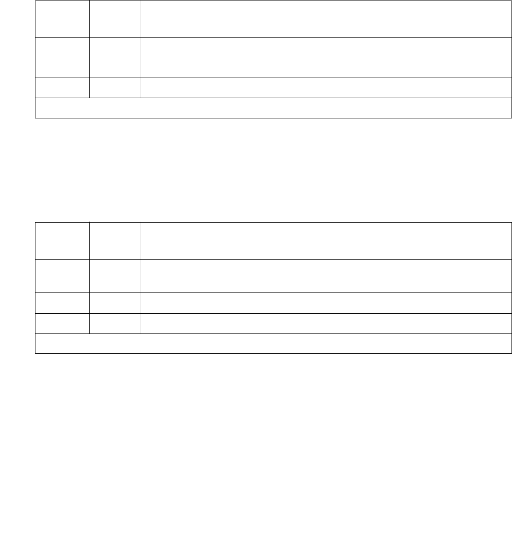
AESV-SESS (AE Services Session)
Issue 1 June 2005 377
AESVCS Link Heartbeat Test (#1324)
The AESVCS Link Heartbeat test sends a TCP tunnel connection heartbeat message to the far
end AESVCS Server. If the AESVCS Server fails to return a response to the heartbeat
message, the test fails. An AESVCS Link that fails a Heartbeat test is subsequently deleted
from the AESVCS Session.
AESVCS Session Level Link Status Test (#1323)
The AESVCS Session Level Link Status Test determines if any AESVCS Links are associated
with a given AESVCS Session.
Table 107: AESVCS Link Heartbeat Test (#1324)
Error
Code
Test
Result
Description / Recommendation
FAIL The heartbeat test failed.
1. Check the network connectivity and check the AE Server.
PASS The heartbeat test passed.
Table 108: AESVCS Session Level Link Status Test (#1323)
Error
Code
Test
Result
Description / Recommendation
1124 ABORT AE Services Server is disabled on the AE Services Administration page
of the IP Services form
FAIL No AESVCS links are associated with this session.
PASS At least one AESVCS link is assigned.

Communication Manager Maintenance-Object Repair Procedures
378 Maintenance Procedures for Avaya Communication Manager 3.0, Media Gateways and Servers
ALARM-PT (Alarm Port)
S8700 | 8710 / S8500 / S8300
The Alarm Port MO provides on-board maintenance for an analog line port that is administered
as an external device alarm port. Tests are provided to verify the analog line ports ability to
detect an external device alarm. The related MO, EXT-DEV ADMIN? Y (External Device
Alarm) on page 1246, is used for the off-board external device alarm.
Error Log Entries and Test to Clear Values
Notes:
a. Error Type 0: Run the short test sequence first. If every test passes, run the long test
sequence. Refer to each appropriate test’s description, and follow its recommended
procedures.
b. Error Type 15 is a software audit error that does not indicate any hardware malfunction.
Run the short test sequence, and investigate errors.
c. Error Type 130 indicates that the circuit pack or Media Module was removed or has been
insane for more than 11 minutes. To clear the error, reseat or replace the circuit pack or
Media Module
MO Name in Alarm Log Alarm
Level
Initial Command to Run Full Name of MO
ALARM-PT MIN test port location l Alarm-Port
ALARM-PT WRN test port location sh Alarm-Port
Table 109: ALARM-PT Error Log Entries
Error
Type
Aux
Data
Associated Test Alarm
Level
On/Off
Board
Test to Clear Value
0 (a) 0 Any Any Any test port location sh r 1
15 (b) Any Audits and Updates
(#36)
18 0 busyout station
extension
WRN OFF release station extension
130 (c) None WRN ON test port location sh

ALARM-PT (Alarm Port)
Issue 1 June 2005 379
System Technician-Demanded Tests:
Descriptions and Error Codes
Investigate tests in the order presented in the table below. For example, by clearing error codes
associated with the Battery Feed test (#35), you may also clear errors generated from other
tests in the testing sequence.
Battery Feed Test (or Port Diagnostic Test) (#35)
The battery feed chip provides power to the telephone equipment, signaling, rotary dial pulsing,
transmission, and balance. This test checks the signaling and switchhook capabilities of the
battery feed chip by terminating the port, applying battery, and trying to detect a current.
Order of Investigation Short Test
Sequence
Long Test
Sequence
D/
ND1
1. D = Destructive; ND = Nondestructive
Battery Feed test (#35) X X ND
Station Status and Translation Audits and Updates test
(#36)
XXND
Table 110: Test #35 Battery Feed Test
Error
Code
Test
Result
Description / Recommendation
ABRT Could not allocate the necessary system resources to run this test.
1. Retry the command at 1-minute intervals up to 5 times.
ABRT Internal system error.
1. Retry the command at 1-minute intervals a maximum of 5 times.
1000 ABRT System resources required to run this test are not available. The port may
be reporting an external device alarm.
1. Before retesting, enter test external-device-alarm port
location to determine whether the port is reporting an EXT-DEV
failure.
2. If the port has no EXT-DEV failures, retry the command at 1-minute
intervals up to 5 times.
1 of 3

Communication Manager Maintenance-Object Repair Procedures
380 Maintenance Procedures for Avaya Communication Manager 3.0, Media Gateways and Servers
1000 ABRT System resources required to run this test are not available. The port may
be busy with a valid call. Use display port location to determine the
station extension, attendant number, or trunk group/member number of the
port. Use status station, status attendant, or status trunk to
determine the service state of the port. If the service state indicates that the
port is in use, then the port is unavailable for certain tests. You must wait
until the port is idle before retesting. Attendants are always in use
(off-hook) if the handset is plugged in and the port is not busied out.
1. If the port status is idle, then retry the command at 1-minute intervals a
maximum of 5 times.
1004 ABRT The port received an EXT-DEV failure during the test. The test has been
aborted.
1. Before retesting, enter test external-device-alarm port
location to determine whether the port is reporting an EXT-DEV
failure.
2. If the port has no EXT-DEV failures, retry the command at 1-minute
intervals up to 5 times.
2000 ABRT Response to the test request was not received within the allowable time
period.
1. Retry the command at 1-minute intervals up to 5 times.
2100 ABRT Could not allocate the necessary system resources to run this test. This
could be due to a failure to seize the port.
1. Retry the command at 1-minute intervals up to 5 times.
FAIL The port’s battery feed chip is unable to supply sufficient power to sense
the external device alarm. This may occur when the test is performed at
the same time that the external device contact closure occurs.
1. Before retesting, enter test external-device-alarm port
location to determine whether the port is reporting an EXT-DEV
failure. Wait until the port has no EXT-DEV failures before retesting.
2. Retry the command at 1-minute intervals up to 5 times.
PASS The port’s battery feed chip is able to provide power to the external device
alarm to detect contact closure.
Table 110: Test #35 Battery Feed Test (continued)
Error
Code
Test
Result
Description / Recommendation
2 of 3

ALARM-PT (Alarm Port)
Issue 1 June 2005 381
Station Status and Translation Audits and Updates Test (#36)
Port Updates Test (#36)
For an analog line port that is administered as an external alarm, this test is limited to updating
the software with the switchhook state.
This test sends port level translation data from switch processor to the circuit pack to assure
that the translation is correct. The port audit operation verifies the consistency of the current
state of the port in the switch software.
0NO
BOARD The test could not relate the internal ID to the port (no board). This could
be due to incorrect translations, no board is inserted, an incorrect board is
inserted, or an insane board is inserted.
1. Check to ensure that the board translations are correct. enter list
config, and resolve any problems that are found.
2. If the board was found to be correctly inserted in step 1, enter
busyout board location
3. Enter reset board location
4. Enter release board location
5. Enter test board location long
This should re-establish the linkage between the internal ID and the port. If
this is not the case, check to ensure that there is a valid board inserted.
Table 110: Test #35 Battery Feed Test (continued)
Error
Code
Test
Result
Description / Recommendation
3 of 3
Table 111: Test #36 Station Status and Translation Audits and Updates
Error
Code
Test
Result
Description / Recommendation
ABRT Could not allocate the necessary system resources to run this test.
1. Retry the command at 1-minute intervals up to 5 times.
1 of 3

Communication Manager Maintenance-Object Repair Procedures
382 Maintenance Procedures for Avaya Communication Manager 3.0, Media Gateways and Servers
1000 ABRT The test was aborted because system resources required to run this test
were not available. The port may be busy with a valid call. Use display
port PCSSpp to determine the station extension of the port. Use status
station to determine the service state of the port. If the service state
indicates that the port is in use, then the port is unavailable for certain
tests. You must wait until the port is idle before retesting.
1. If the port is idle, retry the command at 1-minute intervals a maximum
of 5 times.
1004 ABRT The port received an EXT-DEV failure during the test. The test has been
aborted.
1. Before retesting, enter test external-device-alarm port
location to determine whether the port is reporting an EXT-DEV
failure.
2. If the port has no EXT-DEV failures, retry the command at 1-minute
intervals up to 5 times.
1006 ABRT This port has been busied out by command.
1. Check Error Log for Error Type 18 (port busied out). If present, use
release port location to release the port and run the test again.
2000 ABRT Response to the test request was not received within the allowable time
period.
1. Retry the command at 1-minute intervals up to 5 times.
2100 ABRT Could not allocate the necessary system resources to run this test.
1. Retry the command at 1-minute intervals up to 5 times.
1 FAIL This failure does not indicate a hardware problem. The switchhook audit
failed. This condition may occur when the audit is performed at the same
time that the terminal equipment goes off-hook.
1. Before retesting, enter test external-device-alarm port
location to determine whether the port is reporting an EXT-DEV
failure. Wait until the port has no EXT-DEV failures.
2. If the port has no EXT-DEV failures, retry the command at 1-minute
intervals up to 5 times.
7 FAIL The translation update failed. This does not indicate a hardware problem
but may be an internal software error.
Table 111: Test #36 Station Status and Translation Audits and Updates (continued)
Error
Code
Test
Result
Description / Recommendation
2 of 3

ALARM-PT (Alarm Port)
Issue 1 June 2005 383
PASS The software and the port processor have the same status.
0NO
BOARD The test could not relate the internal ID to the port (no board). This could
be due to incorrect translations, no board is inserted, an incorrect board is
inserted, or an insane board is inserted.
1. Check to ensure that the board translations are correct. Enter list
config, and resolve any problems that are found.
2. If the board was found to be correctly inserted in step 1, enter
busyout board location
3. Enter reset board location
4. Enter release board location
5. Enter test board location long. This should re-establish the
linkage between the internal ID and the port. If this is not the case,
dispatch to check to ensure that there is a valid board inserted.
Table 111: Test #36 Station Status and Translation Audits and Updates (continued)
Error
Code
Test
Result
Description / Recommendation
3 of 3

Communication Manager Maintenance-Object Repair Procedures
384 Maintenance Procedures for Avaya Communication Manager 3.0, Media Gateways and Servers
ANL-16-L (16-Port Analog Line)
S8700 | 8710 / S8500
The circuit packs listed below provide 16 analog line ports for single-line voice terminals. The
table below indicates which circuit packs are equipped with lightning protection (for
off-premises, out-of -building stations), and which ones support the neon message waiting lamp
feature.
S8700 | 8710 / S8500
These circuit packs provide 16 ports for analog voice terminals. The TN746, TN468, and TN749
support only single-line, on-premises/in-building, analog voice terminals, and not off-premises
stations, since these circuit packs are not equipped with lightning protection. The TN746B,
TN2144, TN2149, and TN468B support both on-premises and off-premises (that is,
out-of-building) analog voice terminals. The TN468, TN468B, TN479, TN2135, TN2144, and
TN2149 do NOT support the neon message waiting feature.
No maintenance of the terminal connected to the 16-Port Neon Analog Line circuit pack is
performed, except to determine whether or not the terminal is connected. Failures of the neon
message waiting lamp power and the common ringing application circuitry are reported as part
of common port circuit pack errors; see errors 1281 and 1793 in XXX-BD (Common Port Circuit
Pack/Media Module) on page 2539.
MO Name in Alarm Log Alarm
Level
Initial Command to Run Full Name of MO
ANL-16-L MIN test port location l 16-Port Analog Line
ANL-16-L WRN test port location sh 16-Port Analog Line
16-Port Analog Line Circuit Packs
Circuit Pack Off- Premises Neon
TN468B y
TN479
TN746 y
TN746B y y
TN2135 y
TN2144 y
TN2149 y
TN2180 y

ANL-16-L (16-Port Analog Line)
Issue 1 June 2005 385
Ringing Caused by Maintenance Testing
Test #48 may cause some terminal equipment to ring briefly during daily maintenance. If this
ringing is disturbing the customer or the terminal equipment, it should be disabled in the Tests
field of the change station extension screen. Be aware that this action will also disable
Tests #6, 7, 161, and 35.
Error Log Entries and Test to Clear Values
Table 112: 16-Port Analog Line Error Log Entries
Error
Type
Aux
Data
Associated Test Alarm
Level
On/
Off
Board
Test to Clear Value
0 (a) 0 Any Any Any test port location sh r 1
1(b) 40960
40975
40977
none
15(f) Any Audits and Updates
(#36)
18 0 busyout station
extension
WRN ON release station extension
130(g) None WRN ON test port location sh
257(h) 40973 none
513(i) Station Present (#48) WRN OFF test port location sh r 2
769 Battery Feed test
(#35)
MIN
WRN1
1. Minor alarms on this MO may be downgraded to Warning alarms based on the values used in set options.
ON test port location sh r 2
1025 Looparound (#161) MIN
WRN1
ON test port location l r 2
1281 Conference test (#7) MIN
WRN1
ON test port location l r 2
1537 NPE Crosstalk (#6) MIN
WRN1
ON test port location l r 2

Communication Manager Maintenance-Object Repair Procedures
386 Maintenance Procedures for Avaya Communication Manager 3.0, Media Gateways and Servers
Notes:
a. Error Type 0: Run the short test sequence first. If every test passes, run the long test
sequence. Refer to each appropriate test’s description, and follow its recommended
procedures.
b. Error Type 1: These are in-line errors and can only be resolved over time.
c. Aux Data 40960 indicates that too many simultaneous incoming ringing attempts were
made on this board. Only 4 ports on a board may ring simultaneously. A 5th incoming call
causes an inline error from the board.
d. Aux Data 40975 indicates that the terminal equipment was on-hook when ring-tip was
detected during ringing. This usually indicates a failure in the terminal equipment or the type
of terminal has a low ringer impedance. Call the terminal equipment and verify that the
terminal rings. If the terminal does not ring, then replace it. Otherwise, enter test port
location, and follow the procedure for Test #48.
e. Aux Data 40977 indicates that no terminal equipment was connected when ringing was
attempted. Run the short test via test port location, and follow the procedure for the
results of Test #48.
f. Error Type 15 is a software audit error that does not indicate any hardware malfunction.
Run short test sequence, and investigate associated errors.
g. Error Type 130: the circuit pack has been removed or has been insane for more than 11
minutes. To clear the error, reseat or replace the circuit pack.
h. Error Type 257: This is an in-line error and can only be resolved over time. This error
indicates that ringing voltage is absent. If only 1 analog circuit pack in the system has this
problem, then replace the circuit pack. If only analog circuit packs on a particular carrier
have this error, then the ringing generator may not be connected to this carrier. If analog
circuit packs on many carriers have this error, then it is probably a problem with the ringing
generator.
i. Error Type 513: Associated Test #48 may cause some terminal equipment to ring briefly
during daily maintenance. If this disturbs the customer or the terminal equipment, disable it
by setting the Tests field on the change station extension screen to n. On some
software releases, this will also disable Tests #6, 7, 161, and 35.
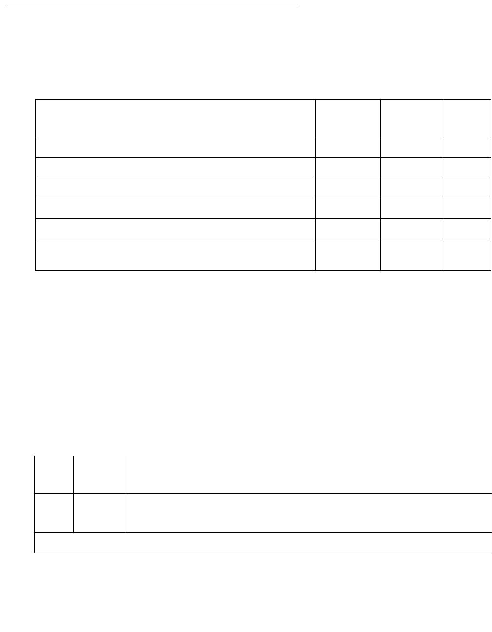
ANL-16-L (16-Port Analog Line)
Issue 1 June 2005 387
System Technician-Demanded Tests:
Descriptions and Error Codes
Investigate tests in the order presented. By clearing error codes associated with the Battery
Feed test (#35), you may also clear errors generated from other tests in the testing sequence.
NPE Crosstalk Test (#6)
One or more Network Processing Elements (NPEs) reside on each circuit pack with a TDM Bus
interface. The NPE controls port connectivity and gain, and provides conference functions on a
per-port basis.
This test verifies that this port’s NPE channel talks on the selected time slot and never crosses
over to time slots reserved for other connections. If the NPE is not working correctly, one-way
and noisy connections may be observed. This test is usually part of the long test sequence and
executes in about 20 to 30 seconds.
Order of Investigation Short Test
Sequence
Long Test
Sequence
D/ND1
1. D = Destructive; ND = Nondestructive
Battery Feed test (#35) X X ND
Station Present test (#48) X X ND
Looparound test (#161) X ND
Conference test (#7) X ND
NPE Crosstalk test (#6) X ND
Station Status and Translation Audits and Updates test
(#36)
XXND
Table 113: Test #6 NPE Crosstalk Test
Error
Code
Test
Result
Description / Recommendation
ABRT Could not allocate the necessary system resources to run this test.
1. Retry the command at 1-minute intervals up to 5 times.
1 of 4

Communication Manager Maintenance-Object Repair Procedures
388 Maintenance Procedures for Avaya Communication Manager 3.0, Media Gateways and Servers
1000 ABRT System resources required to run test are not available. The port may be
busy with a valid call. This result is also reported for the system’s
Music-On-Hold port when it is off-hook, which it usually is.
1. Enter display port location to determine the station’s
extension. Enter status station extension to determine the
service state of the port. If the port is active, wait until it is idle.
2. Retry the command at 1-minute intervals up to 5 times.
1001 ABRT System resources required to run test are not available. This could be due
to a failure to seize the port.
1. Retry the command at 1-minute intervals up to 5 times.
1002 ABRT The system could not allocate time slots for the test. The system may be
under heavy traffic conditions or have time slots out-of-service due to
TDM-BUS errors.
1. If the system has no TDM-BUS errors and is not handling heavy
traffic, retry the command at 1-minute intervals up to 5 times.
1003 ABRT The system could not allocate a tone receiver for the test. The system
may be oversized for the number of Tone Detectors present, or some
Tone Detectors may be out of service.
1. Resolve any TTR-LEV errors.
2. Resolve any TONE-PT errors.
3. If neither condition exists, retry the command at 1-minute intervals up
to 5 times.
1004 ABRT The port was seized by a valid call during the test. The test has been
aborted.
1. Use the display port location command to determine the
station extension. Use status station to determine the service
state of the port. If the port is active, wait until the it is idle before
testing.
2. Retry the command at 1-minute intervals up to 5 times.
1005 ABRT The test was aborted due to a configuration problem. This test may not be
applicable, or it may be disruptive to terminal equipment other than a voice
terminal (for example, the modem pool member or Music On Hold).
Table 113: Test #6 NPE Crosstalk Test (continued)
Error
Code
Test
Result
Description / Recommendation
2 of 4

ANL-16-L (16-Port Analog Line)
Issue 1 June 2005 389
1018 ABRT The test has been disabled by administration. The default for the Test field
on the station screen is y. Determine why this field has been set to “no” on
this station (this may be due to the ringing application Test #48, that can
be customer or terminal disturbing.
1. To enable the test for a particular station being tested, enter change
station extension and set the Test field on the station screen to
y.
2000 ABRT Response to the test request was not received within the allowable time
period.
1. Retry the command at 1-minute intervals up to 5 times.
2100 ABRT System resources required to run test are not available. This could be due
to a failure to seize the port.
1. Retry the command at 1-minute intervals up to 5 times.
Any FAIL This test can fail due to either on- or off-board problems. Off-board
problems include EXP-PN and EXP-INTF faults, (S8700 IP: RMC-ENV
faults), TDM-BUS faults, and faults associated with the Tone Detectors/
Tone Generators. Clear every off-board problem before replacing the
board. A TDM-BUS problem is usually the result of a faulty board
connected to the backplane, or bent pins on the backplane.
1. Resolve any EXP-PN and EXP-INTF errors.
S8700 IP: Resolve any RMC-ENV errors.
2. Resolve any TDM-BUS errors.
3. Resolve any TONE-BD or TONE-PT errors.
4. Test the board when the faults from steps 1, 2, and 3 are cleared.
Replace the board only if the test fails.
PASS The port is correctly using its allocated time slots. User-reported troubles on
this port should be investigated by using other port tests, by examining
station wiring, or by examining the station.
Table 113: Test #6 NPE Crosstalk Test (continued)
Error
Code
Test
Result
Description / Recommendation
3 of 4

Communication Manager Maintenance-Object Repair Procedures
390 Maintenance Procedures for Avaya Communication Manager 3.0, Media Gateways and Servers
Conference Circuit Test (#7)
This test verifies that the NPE channel for the port being tested can correctly perform the
conferencing function.
0NO
BOARD
The test could not relate the internal ID to the port (no board). This could
be due to incorrect translations, no board is inserted, an incorrect board is
inserted, or an insane board is inserted.
1. Verify that the board’s translations are correct. Enter list config,
and resolve any problems.
2. If the board was found to be correctly inserted in step 1, enter
busyout board location
3. Enter reset board location
4. Enter release board location
5. Enter test board location long
This should re-establish the linkage between the internal ID and the
port. If not, verify that a valid board is inserted.
Table 113: Test #6 NPE Crosstalk Test (continued)
Error
Code
Test
Result
Description / Recommendation
4 of 4
Table 114: Test #7 Conference Circuit Test
Error
Code
Test
Result
Description / Recommendation
ABRT Could not allocate the necessary system resources to run this test.
1. Retry the command at 1-minute intervals up to 5 times.
1000 ABRT System resources required to run this test are not available. The port may
be busy with a valid call. This result is also reported for the system’s
Music-On-Hold port when it is off-hook, which it usually is.
1. Enter display port location to determine the station’s extension.
Enter status station extension to determine the service state of
the port. If the port is active, wait until it is idle.
2. Retry the command at 1-minute intervals up to 5 times.
1 of 3

ANL-16-L (16-Port Analog Line)
Issue 1 June 2005 391
1004 ABRT The port was seized by a valid call during the test. The test has been
aborted.
1. Use display port location to determine the station extension.
Use status station to determine the service state of the port. If
the port is active, wait until it is idle.
2. Retry the command at 1-minute intervals up to 5 times.
1005 ABRT The test was aborted due to a configuration problem. This test may not be
applicable, or it may be disruptive to terminal equipment other than a voice
terminal (for example, the modem pool member or Music On Hold).
1018 ABRT The test has been disabled by administration. The default for the Test field
on the station screen is y. Determine why this field is n on this station. This
may be due to the ringing application Test #48, which can be customer or
terminal disturbing.
1. To enable the test for the particular analog station being tested, enter
change station extension and set the Test field on the station
to y.
2000 ABRT Response to the test request was not received within the allowable time
period.
1. Retry the command at 1-minute intervals up to 5 times.
2100 ABRT System resources required to run this test are not available.
1. Resolve any TONE-PT errors.
2. If there are no TONE-PT errors in the error log, retry the test at
1-minute intervals for a maximum of 5 times.
Any FAIL The NPE of the tested port did not conference the tones correctly. This
causes noisy and unreliable connections.
1. Enter display port and status station to determine whether
the station is idle. If the station is idle, enter test port for this port.
2. If the test continues to fail, enter busyout port and release port,
and retest.
3. If the test still fails, replace the board.
PASS The port can correctly conference multiple connections. User-reported
troubles on this port should be investigated by using other port tests and by
examining station, trunk, or external wiring.
Table 114: Test #7 Conference Circuit Test (continued)
Error
Code
Test
Result
Description / Recommendation
2 of 3

Communication Manager Maintenance-Object Repair Procedures
392 Maintenance Procedures for Avaya Communication Manager 3.0, Media Gateways and Servers
Battery Feed Test (or Port Diagnostic Test) (#35)
The battery feed chip provides power to the telephone equipment, signaling, rotary dial pulsing,
transmission, and balance. This test checks the signaling and switchhook capabilities of the
battery feed chip by terminating the port, applying battery and detecting the resulting current.
Note:
Note: For the TN746B, Test #35 does not actually run and instead always returns
PASS. Test #35 operates in the normal manner for TN746.
0NO
BOARD The test could not relate the internal ID to the port (no board). This could
be due to incorrect translations, no board is inserted, an incorrect board is
inserted, or an insane board is inserted.
1. Verify that the board’s translations are correct. Enter list config,
and resolve any problems.
2. If the board was found to be correctly inserted in step 1, enter
busyout board location
3. Enter reset board location
4. Enter release board location
5. Enter test board location long
This should re-establish the linkage between the internal ID and the
port. If not, verify that a valid board is inserted.
Table 114: Test #7 Conference Circuit Test (continued)
Error
Code
Test
Result
Description / Recommendation
3 of 3
Table 115: Test #35 Battery Feed Test
Error
Code
Test
Result
Description / Recommendation
ABRT Could not allocate the necessary system resources to run this test.
1. Retry the command at 1-minute intervals up to 5 times.
1 of 3

ANL-16-L (16-Port Analog Line)
Issue 1 June 2005 393
1000 ABRT System resources required to run this test are not available. The port may
be busy with a valid call. This result is also reported for the system’s
Music-On-Hold port when it is off-hook, which it usually is.
1. Enter display port location to determine the station’s extension.
Enter status station extension to determine the service state of
the port. If the port is active, wait until it is idle.
2. Retry the command at 1-minute intervals up to 5 times.
1004 ABRT The port was seized by a valid call during the test.
1. Use display port location to determine the station extension.
Use status station to determine the service state of the port. If the
port is active, wait until it is idle.
2. Retry the command at 1-minute intervals up to 5 times.
1005 ABRT The test was aborted due to a configuration problem. This test may not be
applicable, or it may be disruptive to terminal equipment other than a voice
terminal (for example, the modem pool member or Music On Hold).
1018 ABRT The test has been disabled by administration. The default for the Test field
on the station screen is y. Determine why this field was set to n on this
station. It may be due to the ringing application Test #48, which can be
customer or terminal disturbing.
1. To enable the test for the particular analog station being tested, enter
change station extension and set the Test field on the station to
y.
S8700
| 8710
S8500
S8300
1392
ABRT This port is currently a TTI port and the test will not execute on it.
1. Verify that the port is a TTI port using either display port, which
shows that the port is a TTI port) or list config, which shows a t for
the port.
2. If the port is not a TTI port, escalate the problem. If both commands
indicate that the port is a TTI port, the abort is correct for the test, and
no action is necessary.
Table 115: Test #35 Battery Feed Test (continued)
Error
Code
Test
Result
Description / Recommendation
2 of 3

Communication Manager Maintenance-Object Repair Procedures
394 Maintenance Procedures for Avaya Communication Manager 3.0, Media Gateways and Servers
2000 ABRT Response to the test request was not received within the allowable time
period.
1. Retry the command at 1-minute intervals up to 5 times.
2100 ABRT Could not allocate the necessary system resources to run this test.
1. Retry the command at 1-minute intervals up to 5 times.
FAIL The port's battery feed chip is unable to supply sufficient power to the
terminal equipment. This could be a marginal test, and the terminal
equipment may be operating satisfactorily.
1. Retry the command at 1-minute intervals up to 5 times.
2. If the test continues to fail, determine whether the customer is
experiencing problems on this line. Replace the circuit pack only if the
customer is experiencing problems.
PASS The port’s battery feed chip is able to provide power to the station equipment
to detect on-/off-hook, but may not be able to supply power for touch-tones.
If touch-tones are inoperative on this station, then replace the circuit pack
because this port is inoperative. User-reported troubles on this port should
be investigated by using other port tests, by examining station wiring, or by
examining the station.
0NO
BOARD The test could not relate the internal ID to the port (no board). This could
be due to incorrect translations, no board is inserted, an incorrect board is
inserted, or an insane board is inserted.
1. Verify that the board’s translations are correct. Enter list config,
and resolve any problems.
2. If the board was found to be correctly inserted in step 1, enter busyout
board
3. Enter reset board location
4. Enter release board location
5. Enter test board location long
This should re-establish the linkage between the internal ID and the port. If
not, verify that a valid board is inserted.
Table 115: Test #35 Battery Feed Test (continued)
Error
Code
Test
Result
Description / Recommendation
3 of 3

ANL-16-L (16-Port Analog Line)
Issue 1 June 2005 395
Station Status and Translation Audits and Updates Test (#36)
This test updates the analog port’s message lamp state (if it has one) and translations with
information in the software.
Table 116: Test #36 Station Status and Translation Audits and Updates
Error
Code
Test
Result
Description / Recommendation
ABRT Could not allocate the necessary system resources to run this test.
1. Retry the command at 1-minute intervals up to 5 times.
1004 ABRT The port was seized by a valid call during the test. The test has been
aborted.
1. Use display port location to determine the station extension.
Use status station to determine the service state of the port. If the
port is active, wait until it is idle.
2. Retry the command at 1-minute intervals up to 5 times.
3. If the test continues to abort and the port is not in use, escalate the
problem.
1005 ABRT The test was aborted due to a configuration problem. This test may not be
applicable, or it may be disruptive to terminal equipment other than a voice
terminal (for example, the modem pool member or Music On Hold).
1006 ABRT This port has been busied out by command, or taken out-of-service by the
failure of the NPE Crosstalk test.
1. Look in the error log for error type 18 (port busied out) for this port. If
this error is present, release the port with release station
extension, and run the test again.
2. Check the error log for error type 1025 (NPE crosstalk test failed) for
this port. If this error is present, investigate the errors associated with
the NPE Crosstalk test (#6).
3. Make sure that the terminal is connected and in service, and then
retest.
2000 ABRT Response to the test request was not received within the allowable time
period.
1. Retry the command at 1-minute intervals up to 5 times.
2100 ABRT Could not allocate the necessary system resources to run this test.
1. Retry the command at 1-minute intervals up to 5 times.
1 of 2

Communication Manager Maintenance-Object Repair Procedures
396 Maintenance Procedures for Avaya Communication Manager 3.0, Media Gateways and Servers
1 FAIL This does not indicate a hardware problem. The switchhook audit failed.
The other updates were not performed because of this failure. This may
occur when the audit is performed at the same time the terminal equipment
goes off-hook.
1. Use status station to determine when the port is available.
2. Retry the command at 1-minute intervals up to 5 times.
5 FAIL This may be an internal software error. The message waiting lamp update
failed. The translation and ringer updates were not performed because of
this failure.
7 FAIL The translation update failed. There may be an internal software error. The
ringer update was not performed because of this failure.
8 FAIL This does not indicate a hardware problem. There may be an internal
software error. The ringer update failed.
1. Retry the command at 1-minute intervals up to 5 times.
PASS The software and the port processor have the same status. User-reported
troubles on this port should be investigated by using other port tests, by
examining station wiring, or by examining the station.
0NO
BOARD The test could not relate the internal ID to the port (no board). This could be
due to incorrect translations, no board is inserted, an incorrect board is
inserted, or an insane board is inserted.
1. Verify that the board’s translations are correct. Enter list config
and resolve problems.
2. If the board was found to be correctly inserted in step 1, enter busyout
board
3. Enter reset board location
4. Enter release board location
5. Enter test board location long
This should re-establish the linkage between the internal ID and the port. If
not, verify that a valid board is inserted.
Table 116: Test #36 Station Status and Translation Audits and Updates (continued)
Error
Code
Test
Result
Description / Recommendation
2 of 2

ANL-16-L (16-Port Analog Line)
Issue 1 June 2005 397
Station Present Test (or Ringing Application Test) (#48)
This test applies momentary ringing voltage to the terminal equipment and monitors resulting
current flow to determine whether terminal equipment is connected to the port. This test may
cause some terminal equipment to ring briefly during daily maintenance. If this ringing disturbs
the customer or the terminal equipment, you can disable it via the Tests field on the change
station screen. However, on some software releases, Tests #6, 7, 161, and 35 are disabled.
Table 117: Test #48 Station Present Test
Error
Code
Test
Result
Description / Recommendation
ABRT Could not allocate the necessary system resources to run this test.
1. Retry the command at 1-minute intervals up to 5 times.
1000 ABRT System resources required to run this test are not available. The port may
be busy with a valid call.
1. If the port status is idle, then retry the command at 1-minute intervals a
maximum of 5 times.
1004 ABRT The port was seized by a valid call during the test. The test has been
aborted.
1. Use display port location to determine the station extension.
2. Use status station to determine the service state of the port. If
the service state indicates that the port is active, wait until it is idle.
3. Retry the command at 1-minute intervals up to 5 times.
1005 ABRT The test was aborted due to a configuration problem. This test may not be
applicable, or it may be disruptive to terminal equipment other than a voice
terminal (for example, the modem pool member or Music On Hold).
1008 ABRT Could not allocate a ringing circuit. Either every ringing circuit is active or
the ringing generator is either defective or incorrectly wired.
Retry the command at 1-minute intervals up to 5 times.
1. If the test continues to abort, look for RING-GEN errors in the Error
Log. If an ABORT 1008 occurs for this test on other circuit packs as
well, then the ringing generator may be defective or is incorrectly
wired. If it does not occur on other ports, then all four ring phases are
active.
1 of 3

Communication Manager Maintenance-Object Repair Procedures
398 Maintenance Procedures for Avaya Communication Manager 3.0, Media Gateways and Servers
1018 ABRT The test has been disabled by administration. The default for the Test field
on the station screen is y. Determine why this field was set to n on this
station. It may be due to the brief ringing disturbance that this test may
cause.
1. To enable the test for the particular analog station being tested, enter
change station extension and set the Test field on the station
to y.
2000 ABRT Response to the test request was not received within the allowable time
period.
1. Retry the command at 1-minute intervals up to 5 times.
2100 ABRT Could not allocate necessary system resources to run this test.
1. Retry the command at 1-minute intervals up to 5 times.
FAIL The terminal equipment is not connected to the circuit pack. Some
terminal equipment, such as modems, may fail even when connected
properly.
1. Remotely test the equipment.
2. If the test fails again, look for RING-GEN errors in the Error Log.
3. Check all of the wiring between the station equipment and the switch.
Then, run the test again.
4. If the test still fails, the set may be defective. Check the set, and
replace it, if necessary.
5. Some terminal equipment could fail even when it is connected
properly. If this is the case, disable the test using change station
extension (enter n into the Test field). Note that this action also
disables Tests 6, 7, 161, and 35 on this port.
PASS The station is connected properly to the switch. This test may also pass if
no terminal equipment is connected and the terminal is located very far
from the switch. Investigate user-reported troubles on this port by using
other port tests or by examining the station and its wiring.
Table 117: Test #48 Station Present Test (continued)
Error
Code
Test
Result
Description / Recommendation
2 of 3

ANL-16-L (16-Port Analog Line)
Issue 1 June 2005 399
Loop-Around Test (#161)
This test checks the on-board transmission capabilities of the NPE, the codec, and the battery
feed chip of the analog port. The test passes if the signal measured by the Tone Detector is
within acceptable limits.
0NO
BOARD The test could not relate the internal ID to the port (no board). This could
be due to incorrect translations, no board is inserted, an incorrect board is
inserted, or an insane board is inserted.
1. Verify that the board’s translations are correct. Enter list config,
and resolve any problems.
2. If the board was found to be correctly inserted in step 1, enter
busyout board location
3. Enter reset board location
4. Enter release board location
5. Enter test board location long
This should re-establish the linkage between the internal ID and the port. If
not, verify that a valid board is inserted.
Table 117: Test #48 Station Present Test (continued)
Error
Code
Test
Result
Description / Recommendation
3 of 3
Table 118: Test #161 Loop-Around Test
Error
Code
Test
Result
Description / Recommendation
ABRT Could not allocate the necessary system resources to run this test.
1. Retry the command at 1-minute intervals up to 5 times.
1000 ABRT System resources required to run this test are not available. The port
may be busy with a valid call.
1. Use display port location to determine the station extension.
2. Use status station to determine the service state of the port. If
the port is active, wait until it is idle.
3. Retry the command at 1-minute intervals up to 5 times.
1 of 4

Communication Manager Maintenance-Object Repair Procedures
400 Maintenance Procedures for Avaya Communication Manager 3.0, Media Gateways and Servers
1002 ABRT The system could not allocate time slots for the test. The system may be
under heavy traffic conditions or it may have time slots out-of-service due
to TDM-BUS errors.
1. If the system has no TDM-BUS errors and is not handling heavy
traffic, retry the command at 1-minute intervals up to 5 times.
1003 ABRT The system could not allocate a tone receiver for the test. The system
may be oversized for the number of Tone Detectors present, or some
Tone Detectors may be out of service.
1. Resolve any TTR-LEV errors.
2. Resolve any TONE-PT errors.
3. If neither condition exists, retry the command at 1-minute intervals up
to 5 times.
1004 ABRT The port was seized by a valid call during the test. The test has been
aborted.
1. Use display port location to determine the station extension.
Use status station to determine the service state of the port. If
the port is active, wait until it is idle.
2. Retry the command at 1-minute intervals up to 5 times.
1005 ABRT This test is not run on ports administered as External Alert, Announcement
or combined modem pool ports. This error can be ignored.
1018 ABRT The test has been disabled by administration. The default for the Test
field on the station screen is y. Determine why this field was set to n on
this station. It may be due to the ringing application Test #48, which can
be customer or terminal disturbing.
1. To enable the test for the particular analog station being tested, enter
change station extension.
2. Enter y in the Test field.
Table 118: Test #161 Loop-Around Test (continued)
Error
Code
Test
Result
Description / Recommendation
2 of 4

ANL-16-L (16-Port Analog Line)
Issue 1 June 2005 401
2000 ABRT Response to the test request was not received within the allowable time
period.
1. Retry the command at 1-minute intervals up to 5 times.
2100 ABRT Could not allocate the necessary system resources to run this test. This
could be due to a failure to seize the port.
1. Retry the command at 1-minute intervals up to 5 times.
FAIL The reflective loop around test failed. This could cause noisy or
unreliable connections, or users calling this port may hear an echo. The
problem can also be off-board.
1. Since the test may be affected by a line seizure, repeat the test at
1-minute intervals up to 5 times.
2. Run circuit pack tests to check the IPSI Tone Generator circuit or
Tone Generator circuit pack and the IPSI Tone Detector circuit or
Tone Detector circuit pack by using test board location
short.
3. Resolve any problems on the Tone Generator circuit or the Tone
Detector circuit.
4. If the Tone Generator and Tone Detector circuits are functioning
properly and the test still fails and a voice terminal is connected and
wired properly, replace the analog line circuit pack.
PASS The port is able to provide an analog transmission path to the station
equipment. User-reported troubles on this port should be investigated by
using other port tests, by examining station wiring, or by examining the
station.
Table 118: Test #161 Loop-Around Test (continued)
Error
Code
Test
Result
Description / Recommendation
3 of 4

Communication Manager Maintenance-Object Repair Procedures
402 Maintenance Procedures for Avaya Communication Manager 3.0, Media Gateways and Servers
0NO
BOARD The test could not relate the internal ID to the port (no board). This could
be due to incorrect translations, no board is inserted, an incorrect board
is inserted, or an insane board is inserted.
1. Verify that the board’s translations are correct. Enter list config,
and resolve any problems.
2. If the board was found to be correctly inserted in step 1, enter
busyout board location
3. Enter reset board location
4. Enter release board location
5. Enter test board location long
This should re-establish the linkage between the internal ID and the
port. If not, verify that a valid board is inserted.
Table 118: Test #161 Loop-Around Test (continued)
Error
Code
Test
Result
Description / Recommendation
4 of 4

ANL-BD (Analog Line Circuit Pack)
Issue 1 June 2005 403
ANL-BD (Analog Line Circuit Pack)
S8700 | 8710 / S8500
See XXX-BD (Common Port Circuit Pack/Media Module) on page 2539 for circuit pack-level
errors. See also ANL-16-L (16-Port Analog Line) on page 384 for related line information.
See also ANL-LINE (8-Port Analog Line) on page 404 for related line information.
MO Name in
Alarm Log
Alarm
Level
Initial Command to Run Full Name Of MO
ANL-BD MIN
WRN test board location sh 8-Port Analog Line circuit pack
ANL-BD MIN
WRN test board location sh 8-Port Neon Analog Line circuit pack
ANL-BD MIN
WRN test board location sh 16-Port Neon Analog Line circuit
pack
Communication Manager Maintenance-Object Repair Procedures
404 Maintenance Procedures for Avaya Communication Manager 3.0, Media Gateways and Servers
ANL-LINE (8-Port Analog Line)
Error log entries and tests also apply to ANL-NE-L (8-Port Analog Line).
S8700 | 8710 / S8500
The 8-port Analog Line circuit packs,
each provide eight ports for single-line, on or off-premises analog endpoints such as analog
voice terminals, queue warning level lamps, recorded announcements, dictation machines,
PAGEPAC paging equipment, external alerting devices, modems, fax machines, and AUDIX
voice ports. Only the TN769 supports a neon message waiting lamp.
Note:
Note: PAGEPAC™ is a registered trademark of Harris Corporation, Dracon Division.
Test #48 may cause some terminal equipment to ring briefly during daily maintenance, which
may disturb the customer or the terminal equipment. Test #47 may cause a false alarm when
the port is connected to certain off-premises equipment, non-voice terminal equipment, or loop
equipment. In either case, the tests can be disabled by entering n in the Tests field on the
change station extension screen. Be aware that this will disable Tests 6, 35, 47, and 48.
No maintenance of the terminal connected to the 8-Port Analog Line circuit pack or 8-Port Neon
Analog Line circuit pack is performed, except to determine whether or not the terminal is
connected. Failures of the common ringing application circuitry and the neon message waiting
lamp power (ANL-NE-L only) are reported as errors 1281and 1793 against XXX-BD (Common
Port Circuit Pack) in Table 907: Common Port Circuit Pack Maintenance Error Log Entries on
page 2544.
MO Name in Alarm
Log
Alarm
Level
Initial Command To Run Full Name of MO
ANL-LINE MIN test port location l8-Port Analog Line
ANL-LINE WRN test port location sh 8-Port Analog Line
ANL-NE-L MIN test port location l8-Port Neon Analog Line
ANL-NE-L WRN test port location sh 8-Port Neon Analog Line
TN712 TN411 [G3rV2] TN742
TN443 [G3r V2] TN769
TN443 [G3r V2] TN467 [G3r V2]

ANL-LINE (8-Port Analog Line)
Issue 1 June 2005 405
Hardware Error Log Entries and Test to Clear Values
Notes:
a. Error Type 0: Run the short test sequence first. If every test passes, run the long test
sequence. Refer to each appropriate test’s description, and follow its recommended
procedures.
Table 119: 8-Port Analog Line Error Log Entries
Error
Type
Aux
Data
Associated Test Alarm
Level
On/
Off
Board
Test to Clear Value
0 (a) 0 Any Any Any test port location sh r 1
1 (b) 40960
40975
40977
None
15 (c) Any Audits and Updates
(#36)
18 0 busyout station
extension
WRN OFF release station extension
130
(d)
None WRN ON test port location sh
257
(e)
Station Present test
(#48)
WRN OFF test port location sh r 3
513 Battery Feed test (#35) MIN
WRN
1
1. Minor alarms on this MO may be downgraded to Warning alarms based on the values used in set options.
ON test port location sh r 2
769 (f) Loop Around &
Conference (47) test port location l r 3
1025 NPE Crosstalk test (#6) MIN
WRN
1
ON test port location l r 3
1281
(g)
1793
(g)

Communication Manager Maintenance-Object Repair Procedures
406 Maintenance Procedures for Avaya Communication Manager 3.0, Media Gateways and Servers
b. Error Type 1: These are in-line errors that can only be resolved over time.
Aux Data 40960: too many simultaneous incoming ringing attempts were made on this
board. Only 4 ports on a board may ring simultaneously. A 5th incoming call will cause an
inline error from the board.
Aux Data 40975: the terminal equipment was on-hook when ring-tip was detected during
ringing. This usually indicates a failure in the terminal equipment or the type of terminal has
a low ringer impedance. Call the terminal equipment and verify that the terminal rings. If
the terminal doesn’t ring, then replace it. Otherwise, enter test port location, and
follow the procedure for Test #48.
Aux Data 40977: no terminal equipment was connected when ringing was attempted. Run
test port location sh, and follow the procedure for the results of Test #48.
c. Error Type 15: software audit error, does not indicate any hardware malfunction. Run short
test sequence, and investigate errors (if any).
d. Error Type 130: the circuit pack was removed or has been insane for more than 11 minutes.
To clear the error, reinsert or replace the circuit pack.
e. Error Type 257: Associated Test #48 may cause some terminal equipment to ring briefly
during daily maintenance. If this ringing is disturbing the customer or the terminal
equipment, it should be disabled via change station extension. However, on some
releases of the software, this will disable Tests #6, 47, and 35 as well as Test #48.
f. Error Type 769: Associated Test #47 may cause a false alarm when the port is connected
to off-premises equipment, some non-voice terminal equipment, and some loop equipment.
If this causes a false alarm, use change station, and change the Tests field to n to
disable the test.
g. Error Types 1281 and 1793: See XXX-BD (Common Port Circuit Pack/Media Module) on
page 2539.
System Technician-Demanded Tests:
Descriptions and Error Codes
Investigate tests in the order presented. By clearing error codes associated with the Battery
Feed test (#35), you may also clear errors generated from other tests in the testing sequence.
Order of Investigation Short Test
Sequence
Long Test
Sequence
D/ND1
Battery Feed test (#35) X X ND
Station Present test (#48) X X ND
NPE Crosstalk test (#6) X ND

ANL-LINE (8-Port Analog Line)
Issue 1 June 2005 407
NPE Crosstalk Test (#6)
One or more NPEs (Network Processing Elements) reside on each circuit pack with a TDM-bus
interface. The NPE controls port connectivity and gain, and provides conferencing functions on
a per-port basis. The NPE Crosstalk test verifies that this port’s NPE channel talks on the
selected time slot and never crosses over to time slots reserved for other connections. If the
NPE is not working correctly, 1-way and noisy connections may be observed. This test is
usually only part of a port’s long test sequence and executes in about 20 to 30 seconds.
Loop Around and Conference test (#47) X ND
Station Status and Translation Audits and Updates test (#36) X X ND
1. D = Destructive; ND = Nondestructive
Order of Investigation Short Test
Sequence
Long Test
Sequence
D/ND1
Table 120: Test #6 NPE Crosstalk Test
Error
Code
Test
Result
Description / Recommendation
1000 ABRT System resources required to run this test are not available. The port may
be busy with a valid call. This result is also reported for the system’s
Music-on-Hold port when it is off-hook, which it usually is.
1. Enter display port location to determine the station’s extension.
Enter status station extension to determine the service state of
the port. If the port is active, it will be unavailable for certain tests.
Wait until the port is idle before retesting.
2. When the port is idle, retry the command at 1-minute intervals up to 5
times.
1001 ABRT Could not allocate the necessary system resources to run this test.
1. Retry the command at 1-minute intervals up to 5 times.
1002 ABRT The system could not allocate time slots for the test. The system may be
under heavy traffic conditions or it may have time slots out-of-service due
to TDM-BUS errors.
1. If the system has no TDM-BUS errors and is not handling heavy traffic,
repeat test at 1-minute intervals up to 5 times.
2. If the test continues to abort, escalate the problem.
1 of 4

Communication Manager Maintenance-Object Repair Procedures
408 Maintenance Procedures for Avaya Communication Manager 3.0, Media Gateways and Servers
1003 ABRT The system could not allocate a tone receiver for the test. The system
may be oversized for the number of Tone Detectors present or some Tone
Detectors may be out-of-service.
1. Resolve TTR-LEV errors.
2. Resolve TONE-PT errors.
3. Retry the test at 1-minute intervals up to 5 times.
1004 ABRT The port was seized by a valid call during the test. The test has been
aborted.
1. Use display port location to determine the station extension.
Use status station to determine the service state of the port. If the
service state indicates that the port is active, then the port is
unavailable for certain tests. Wait until the port is idle before retesting.
2. Retry the command at 1-minute intervals up to 5 times.
3. If the test continues to abort and the port is idle, escalate the problem.
1005 ABRT The test was aborted due to a configuration problem. This code occurs
under either of the following conditions:
1. This test may not be applicable, or it may be disruptive to terminal
equipment other than a voice terminal (for example, a modem pool
member or music on hold).
2. The circuit pack is one of the following:
- TN742 vintage 13, 14, or 15
- TN769 vintage 3, 4, or 5
1018 ABRT Test disabled by administration. The default for the Test field on the station
screen is y; thus, you may want to determine why this field has been set to
n on this station (this may be due to the ringing application test 48, which
can be customer or terminal disturbing).
1. To enable the test for a particular station, enter change station
extension and set the Test field to y.
1020 ABRT The test did not run due to a previously existing error on the specific port or
a more general circuit pack error.
1. Examine Error Log for existing errors against this port or the circuit
pack and attempt to diagnose the previously existing error.
Table 120: Test #6 NPE Crosstalk Test (continued)
Error
Code
Test
Result
Description / Recommendation
2 of 4

ANL-LINE (8-Port Analog Line)
Issue 1 June 2005 409
2000 ABRT Response to the test request was not received within the allowable time
period.
1. Retry the command at 1-minute intervals up to 5 times.
2100 ABRT System resources required to run this test are not available. Either a
system allocation to get information about the port or to put the port into a
service state failed or the attempt to put the port in connection with a tone
source failed (this could be a Tone-Clock problem). The Tone-Clock and
Tone Detectors could be having a communication problem. For example,
the companding modes could be out of synchronization.
1. Retry the command at 1-minute intervals up to 5 times.
Table 120: Test #6 NPE Crosstalk Test (continued)
Error
Code
Test
Result
Description / Recommendation
3 of 4

Communication Manager Maintenance-Object Repair Procedures
410 Maintenance Procedures for Avaya Communication Manager 3.0, Media Gateways and Servers
Any FAIL This test can fail due to either on- or off-board problems. Off-board
problems of concern include EXP-PN, EXP-INTF, and RMC-ENV faults,
TDM-BUS faults, and faults associated with the Tone Detectors/Tone
Generators. Clear every off-board problem before replacing the board.
Keep in mind that a TDM-BUS problem is usually the result of a faulty
board connected to the backplane or bent pins on the backplane.
1. Resolve any EXP-PN, EXP-INTF, and RMC-ENV errors.
2. Resolve TDM-BUS errors.
3. Resolve TONE-BD or TONE-PT errors.
4. Test the board when the faults from steps 1, 2, and 3 are cleared.
Replace the board only if the test fails.
PASS The port is correctly using its allocated time slots. User-reported troubles on
this port should be investigated by using other port tests, by examining
station wiring, by examining the station, and by ensuring that the terminal is
correctly translated as off-premises or on-premises.
Note:
Note: This test always passes for circuit packs TN712 prior to
Vintage 14 and TN742 prior to Vintage 6.
0NO
BOARD The test could not relate the internal ID to the port (no board). This could
be due to incorrect translations, no board is inserted, an incorrect board is
inserted, or an insane board is inserted.
1. Verify that the board’s translations are correct. Enter list config,
and resolve any problems that are found.
2. If the board was found to be correctly inserted in step 1, enter
busyout board location
3. Enter reset board location
4. Enter release board location
5. Enter test board location long
This should re-establish the linkage between the internal ID and the port. If
not, dispatch to verify that a valid board is inserted.
Table 120: Test #6 NPE Crosstalk Test (continued)
Error
Code
Test
Result
Description / Recommendation
4 of 4

ANL-LINE (8-Port Analog Line)
Issue 1 June 2005 411
Battery Feed Test (or Port Diagnostic Test) (#35)
The battery feed chip provides power to the telephone equipment, signaling, rotary dial pulsing,
transmission, and balance. This test checks the signaling and switchhook capabilities of the
battery feed chip by terminating the port, applying battery, and trying to detect a current.
Table 121: Test #35 Battery Feed Test Results
Error
Code
Test
Result
Description / Recommendation
ABRT Could not allocate the necessary system resources to run this test.
1. Retry the command at 1-minute intervals up to 5 times.
1000 ABRT System resources required to run this test are not available. The port may
be busy with a valid call. This result is also reported for the system’s
Music-on-Hold port when it is off-hook, which it usually is.
1. Enter display port location to determine the station’s extension.
Enter status station extension to determine the service state of
the port. Refer to Maintenance SAT Commands in the Maintenance
Commands Reference (03-300191), for a full description of every
possible state. If the port is active, it will be unavailable for certain
tests. Wait until the port is idle before retesting.
2. When the port is idle, retry the command at 1-minute intervals up to 5
times.
1004 ABRT System resources required to run this test are not available. The port may
be busy with a valid call.
1. Use display port location to determine the station extension.
Use status station to determine the service state of the port. If the
service state indicates that the port is active, then the port is
unavailable for certain tests. Refer to Maintenance SAT Commands in
the Maintenance Commands Reference (03-300191), for a full
description of every possible state. Wait until the port is idle before
retesting.
2. Retry the command at 1-minute intervals up to 5 times.
3. If the test continues to abort and the port is idle, escalate the problem.
1 of 3

Communication Manager Maintenance-Object Repair Procedures
412 Maintenance Procedures for Avaya Communication Manager 3.0, Media Gateways and Servers
1005 ABRT The test was aborted due to a configuration problem. This error code
occurs under either of the following conditions:
1. This test may not be applicable, or it may be disruptive to terminal
equipment other than a voice terminal (for example, the modem pool
member or music on hold).
2. The circuit pack is one of the following:
- TN742 vintages 13,14, and 15
- TN769 vintages 3, 4, and 5
1018 ABRT Test disabled via administration. The default for the Test field on the is y.
Determine why this field was set to n on this station. It may be due to the
ringing application Test E48, which can be customer or terminal disturbing.
1. To enable the test for a particular station, enter change station
extension and set the Test field to y.
1392 ABRT This port is currently a TTI port and the test will not execute on it.
1. Verify that the port is a TTI port using either the display port
command (the display shows that the port is a TTI port) or list
config (the display shows a t for the port).
2. If either list config or display port indicate that the port is not
a TTI port, escalate the problem. If both commands indicate that the
port is a TTI port, the abort is correct for the test, and no action is
necessary.
2000 ABRT Response to the test request was not received within the allowable time
period.
1. Retry the command at 1-minute intervals up to 5 times.
2100 ABRT System resources required to run this test are not available. Either a
system allocation to get information about the port or to put the port into a
service state failed or the attempt to put the port in connection with a tone
source failed (this could be a Tone-Clock problem). The Tone-Clock and
Tone Detectors could be having a communication problem. For example,
the companding modes could be out of synchronization.
1. Retry the command at 1-minute intervals up to 5 times.
Table 121: Test #35 Battery Feed Test Results (continued)
Error
Code
Test
Result
Description / Recommendation
2 of 3

ANL-LINE (8-Port Analog Line)
Issue 1 June 2005 413
FAIL The port’s battery feed chip is unable to supply sufficient power to the
terminal equipment. This may occur when the test is performed at the
same time that the terminal equipment goes off-hook.
1. Use status station to determine when the port is available for
testing. When the port becomes available for testing, retry the
command at 1-minute intervals a minimum of five times.
2. If the test continues to fail, determine whether the customer is
experiencing problems on this line. Replace the circuit pack only if the
customer is experiencing problems.
PASS The port’s battery feed chip is able to provide power to the station
equipment to detect on-/off-hook. However, the battery feed chip may still
be unable to provide power for touch-tones. If tones are heard when
buttons are pressed, then the battery feed chip is functioning correctly;
otherwise, replace the circuit pack because this port is defective.
User-reported troubles on this port should be investigated by using other
port tests, by examining station wiring, by examining the station, and by
ensuring that the terminal is correctly translated as off-premises or
on-premises.
Note:
Note: This test always passes for circuit packs TN712 prior to
Vintage 14 and TN742 prior to Vintage 6.
0NO
BOARD The test could not relate the internal ID to the port (no board). This could
be due to incorrect translations, no board is inserted, an incorrect board is
inserted, or an insane board is inserted.
1. Verify that the board’s translations are correct. Enter list config,
and resolve any problems that are found.
2. If the board was found to be correctly inserted in step 1, enter
busyout board location
3. Enter reset board location
4. Enter release board location
5. Enter test board location long
This should re-establish the linkage between the internal ID and the port. If
not, dispatch to verify that a valid board is inserted.
Table 121: Test #35 Battery Feed Test Results (continued)
Error
Code
Test
Result
Description / Recommendation
3 of 3

Communication Manager Maintenance-Object Repair Procedures
414 Maintenance Procedures for Avaya Communication Manager 3.0, Media Gateways and Servers
Station Status and Translation Audits and Updates Test (#36)
This test updates the analog port’s message lamp state (if it has one) and translations (such as
station type, dial type, network connection) with information kept in the software. The software
is updated with the switchhook state reported by the port processor. When the ringer is in the
off state, this test also turns off the station’s ringer to prevent constant ringing caused by
defective hardware.
Table 122: Test #36 Station Status and Translation Audits and Updates Test
Error
Code
Test
Result
Description / Recommendation
ABRT Could not allocate the necessary system resources to run this test.
1004 ABRT System resources required to run this test are not available. The port may
be busy with a valid call.
1. Use display port location to determine the station extension.
Use status station to determine the service state of the port. If
the service state indicates that the port is active, then the port is
unavailable for certain tests. Wait until the port is idle before retesting.
2. Retry the command at 1-minute intervals up to 5 times.
3. If the test continues to abort and the port is idle, escalate the problem.
1005 ABRT The test was aborted due to a configuration problem. This error code
occurs under either of the following conditions:
1. This test may not be applicable, or it may be disruptive to terminal
equipment other than a voice terminal (for example, the modem pool
member or music on hold).
2. The circuit pack is one of the following:
- TN742 vintages 13,14, and 15
- TN769 vintages 3, 4, and 5
1 of 3

ANL-LINE (8-Port Analog Line)
Issue 1 June 2005 415
1006 ABRT This port has been busied out by command or taken out-of-service by the
failure of the NPE Crosstalk test.
1. Look in the Error Log for Error Type 18 (port busied out) for this port. If
this error is present, then release the port with release station
extension and run the test again.
2. Look in the Error Log for Error Type 1025 (NPE Crosstalk test failed)
for this port. If this error is present, then investigate the errors
associated with the NPE Crosstalk test (#6) first.
3. Make sure that the terminal is connected and in service, and then
retest.
2000 ABRT Response to the test request was not received within the allowable time
period.
1. Retry the command at 1-minute intervals up to 5 times.
2100 ABRT Could not allocate the necessary system resources to run this test.
1. Retry the command at 1-minute intervals up to 5 times.
1 FAIL This does not indicate a hardware problem. The switchhook audit failed,
and the other updates were not performed because of this failure. This
condition may occur when the audit is performed at the same time that the
terminal equipment goes off-hook. Use status station to determine
when the port is available for testing.
1. When the port becomes available for testing, retry the command at
1-minute intervals up to 5 times.
5 FAIL This does not indicate a hardware problem but may indicate an internal
software error. The message waiting lamp update failed. The translation
and ringer updates were not performed because of this failure.
7 FAIL The translation update failed. The ringer update was not performed
because of this failure. This does not indicate a hardware problem but may
be an internal software error.
8 FAIL This does not indicate a hardware problem but may be an internal software
error. The ringer update failed.
1. Retry the command at 1-minute intervals up to 5 times.
Table 122: Test #36 Station Status and Translation Audits and Updates Test (continued)
Error
Code
Test
Result
Description / Recommendation
2 of 3

Communication Manager Maintenance-Object Repair Procedures
416 Maintenance Procedures for Avaya Communication Manager 3.0, Media Gateways and Servers
Looparound and Conference Test (#47)
Each Analog port consists of:
●An NPE (Network Processing Element) for port connectivity and gain, and conferencing
functionality
●A codec that converts TDM Bus digital signals to analog
●A battery feed chip that provides power to the telephone set for signaling, dial pulsing,
transmission, and balance.
This test is designed to check the on-board transmission capabilities of the NPE, the codec, and
the battery feed chip of the Analog port. A Tone Detector and a Tone Generator talk and listen
on the same pair of time slots as the Analog port. The Analog port is then instructed to go into
loop around mode (see Figure 22: Analog Looparound and Conference Test on page 417). The
test passes if the signal measured by the Tone Detector is within acceptable limits.
PASS The software and the port processor have the same status. User-reported
troubles on this port should be investigated by using other port tests, by
examining station wiring, by examining the station, and by ensuring that the
terminal is correctly translated as off-premises or on-premises.
Note: This test always passes for circuit packs TN712 prior to vintage 14
and TN742 prior to vintage 6.
0NO
BOARD The test could not relate the internal ID to the port (no board). This could
be due to incorrect translations, no board is inserted, an incorrect board is
inserted, or an insane board is inserted.
1. Verify that the board’s translations are correct. Enter list config,
and resolve any problems that are found.
2. If the board was found to be correctly inserted in step 1, enter
busyout board location
3. Enter reset board location
4. Enter release board location
5. Enter test board location long
This should re-establish the linkage between the internal ID and the port. If
not, dispatch to verify that a valid board is inserted.
Table 122: Test #36 Station Status and Translation Audits and Updates Test (continued)
Error
Code
Test
Result
Description / Recommendation
3 of 3
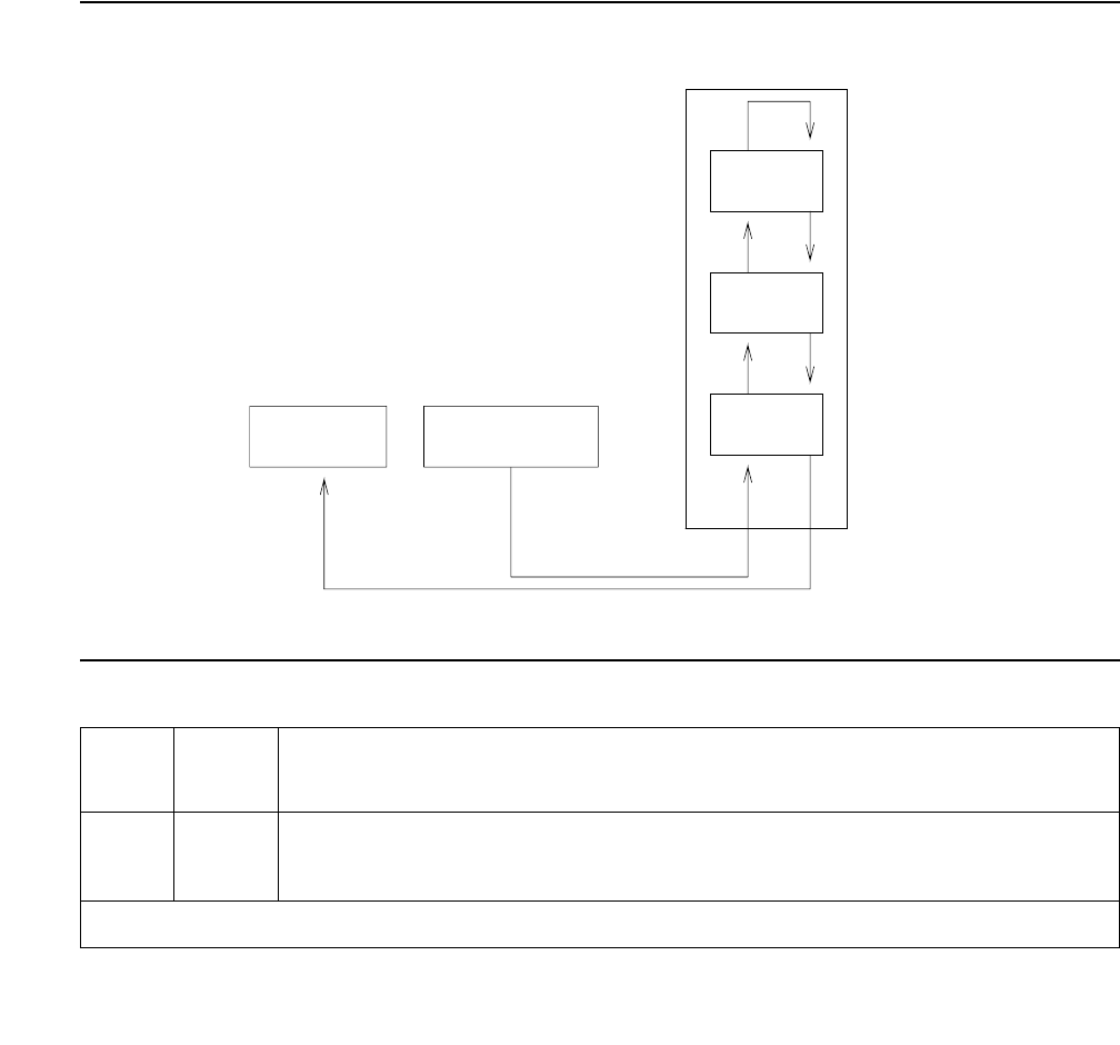
ANL-LINE (8-Port Analog Line)
Issue 1 June 2005 417
The Conference Circuit test verifies that the NPE channel for the port being tested can correctly
perform the conferencing function. Test #47 also tests the operation of the port conference
circuits in the NPE for three and four parties. In addition, a test is run to measure noise. The
NPE is instructed to listen to several different tones and conference the tones together. The
resulting signal is then measured by a Tone Detector port. If the level of the tone is within a
certain range, the test passes.
The noise test is performed by filtering out the tone, and then measuring inherent port noise.
Note:
Note: This looparound test is sensitive to the length of the loop, the equipment in the
loop, or the equipment terminating the loop, such as off-premises stations. If this
test is causing a false alarm, use change station for this station and change
the Tests field to n, to disable the test.
Figure 22: Analog Looparound and Conference Test
Table 123: Test #47 Loop Around and Conference Test
Error
Code
Test
Result
Description / Recommendation
ABRT Could not allocate the necessary system resources to run this test.
1. Retry the command at 1-minute intervals up to 5 times.
1 of 5
TDM BUS
BFC: Battery Feed Chip
NPE: Network Processing Element
Analog
Line
Port
BFC
CODEC
NPE Tone
Generator
Tone
Detector

Communication Manager Maintenance-Object Repair Procedures
418 Maintenance Procedures for Avaya Communication Manager 3.0, Media Gateways and Servers
7 ABRT The port was seized by a user for a valid call.
1. Enter display port location to determine the station’s
extension. Enter status station extension to determine the
service state of the port. If the port is active, it will be unavailable for
certain tests. Wait until the port is idle before retesting.
2. If the port is idle, retry the command at 1-minute intervals up to 5
times.
1000 ABRT System resources required to run this test were not available. The port
may be busy with a valid call. (This could be a Music-on-Hold port.)
1. Enter display port location to determine the station’s
extension. Enter status station extension to determine the
service state of the port. If the port is active, it will be unavailable for
certain tests. Wait until the port is idle before retesting.
2. If the port is idle, retry the command at 1-minute intervals up to 5
times.
1002 ABRT The system could not allocate time slots for the test. The system may be
under heavy traffic conditions or it may have time slots out-of-service due
to TDM-BUS errors.
1. If the system has no TDM-BUS errors and is not handling heavy traffic,
repeat test at 1-minute intervals up to 5 times.
1003 ABRT The system could not allocate a tone receiver for the test. The system
may be oversized for the number of Tone Detectors present or some Tone
Detectors may be out-of-service.
1. Resolve TTR-LEV errors.
2. Resolve TONE-PT errors.
3. If neither condition exists, retry the test at 1-minute intervals up to 5
times.
1004 ABRT The port has been seized for a valid call during the conference or noise
test.
1. If the circuit pack is a TN742 of Vintage 10 or less, this test is not valid.
Otherwise, proceed with step 2.
2. When the port is available for testing, retry the command at 1-minute
intervals up to 5 times.
Table 123: Test #47 Loop Around and Conference Test (continued)
Error
Code
Test
Result
Description / Recommendation
2 of 5

ANL-LINE (8-Port Analog Line)
Issue 1 June 2005 419
1005 ABRT The test was aborted due to a configuration problem. This error code
occurs under either of the following conditions:
●This test may not be applicable, or it may be disruptive to terminal
equipment other than a voice terminal (for example, a modem pool
member or music on hold).
●The circuit pack is one of the following:
- TN742 vintage 13, 14, or 15
- TN769 vintage 3, 4, or 5
1018 ABRT Test disabled by administration. The default for the Test field is y.
Determine why the field is n on this station. It may be due to the ringing
application test 48, which can be customer or terminal disturbing.
1. To enable the test for a particular station, enter change station
extension and set the Test field on the Station screen to y.
1392 ABRT This port is currently a TTI port and the test will not execute on it.
1. Verify that the port is a TTI port using either display port to show
that the port is a TTI port, or list config, where the display shows
a t for the port.
2. If either list config or display port indicate that the port is not
a TTI port, escalate the problem. If both commands indicate that the
port is a TTI port, the abort is correct for the test, and no action is
necessary.
2000 ABRT Response to the test request was not received within the allowable time
period.
1. Retry the command at 1-minute intervals up to 5 times.
2100 ABRT System resources required to run this test are not available. Either a
system allocation to get information about the port or to put the port into a
service state failed or the attempt to put the port in connection with a tone
source failed (this could be a Tone-Clock problem). The Tone-Clock and
Tone Detectors could be having a communication problem. For example,
the companding modes could be out of synchronization.
1. Retry the command at 1-minute intervals up to 5 times.
Table 123: Test #47 Loop Around and Conference Test (continued)
Error
Code
Test
Result
Description / Recommendation
3 of 5

Communication Manager Maintenance-Object Repair Procedures
420 Maintenance Procedures for Avaya Communication Manager 3.0, Media Gateways and Servers
7 FAIL The conference test or the noise test failed. This could cause noisy or
unreliable connections, or users calling this port may hear an echo. The
problem can also be off-board, as described below.
13 The reflective loop around with gain set to low and the 600-ohm balance
failed. This will cause noisy or unreliable connections.
14 The reflective loop around test (with the gain set to high, using RC balance)
failed. This could cause noisy or unreliable connections. The problem can
also be off-board, as described below.
15 The nonreflective loop-around test failed. This could cause noisy or
unreliable connections, or users calling this port may hear an echo. The
problem can also be off-board as described below.
1. Disconnect the terminal equipment from the circuit pack at the
cross-connect and run the test again.
2. If the test fails again, replace the circuit pack and reconnect the
terminal equipment. If the test passes the second time, then the test
results were affected by the terminal equipment connected to the port.
In this case, ignore the results of this test if every other test passes or
aborts and the station is operating properly. Failure of test 47 does not
cause an alarm. If there are failures of other tests, then investigate
those errors. User reported troubles with this port should be
investigated by using other port tests, by examining station wiring, and
by examining the station to ensure that it is correctly translated as
off-premises or on-premises.
If the Looparound and Conference circuit test fails for every port on a circuit
pack, a -5 Volt power problem is indicated. If a TN736 or TN752 power unit
circuit pack is present, either the 631DB AC power unit or the 676B DC
power unit may be defective. (The 631DB power unit is used in a medium
cabinet powered by an AC source. The 645B power unit is used in a
medium cabinet powered by a DC power source.) The system may contain
a TN736 or TN752 power unit circuit pack or a 631DB AC power unit, but
not both types of power units. To investigate problems with the power unit,
see the RMC-ENV MO (S8700 IP), or the CARR-POW MO (S8700 MC). If a
red LED is lit on TN736 or TN752 power unit circuit pack, replace the pack.
If the test fails on more than 1 port, check for errors on the TONE-BD or the
TONE-PT. If errors, take appropriate actions. When the tone errors are
cleared, rerun the test.
Table 123: Test #47 Loop Around and Conference Test (continued)
Error
Code
Test
Result
Description / Recommendation
4 of 5

ANL-LINE (8-Port Analog Line)
Issue 1 June 2005 421
Station Present Test (or Ringing Application Test) (#48)
This test provides a burst of ringing current to the terminal equipment and detects that current
flows. This test is to ascertain whether or not terminal equipment is connected to the port.
This test may cause some terminal equipment to ring briefly during daily maintenance. If this
ringing is disturbing the customer or the terminal equipment, it should be disabled using the
Tests field of the station administration screen. However, on some releases of the software, this
action disables Tests #6, 47, and 35, as well as Test #48.
PASS The port is able to provide an analog transmission path to the station
equipment. User-reported troubles on this port should be investigated by
using other port tests, by examining station wiring, by examining the station,
and by ensuring that the terminal is correctly translated as off-premises or
on-premises.
Note:
Note: This test always passes for circuit packs TN712 prior to
vintage 14 and TN742 prior to vintage 6.
0NO
BOARD The test could not relate the internal ID to the port (no board). This could
be due to incorrect translations, no board is inserted, an incorrect board is
inserted, or an insane board is inserted.
1. Verify that the board’s translations are correct. Enter list config,
and resolve any problems that are found.
2. If the board was found to be correctly inserted in step 1, enter
busyout board location
3. Enter reset board location
4. Enter release board location
5. Enter test board location long
This should re-establish the linkage between the internal ID and the
port. If not, dispatch to verify that a valid board is inserted.
Table 123: Test #47 Loop Around and Conference Test (continued)
Error
Code
Test
Result
Description / Recommendation
5 of 5

Communication Manager Maintenance-Object Repair Procedures
422 Maintenance Procedures for Avaya Communication Manager 3.0, Media Gateways and Servers
Table 124: Test #48 Station Present Test
Error
Code
Test
Result
Description / Recommendation
ABRT Could not allocate the necessary system resources to run this test.
1. Retry the command at 1-minute intervals up to 5 times.
1000 ABRT System resources required to run this test were not available. The port
may be busy with a valid call.
1. Use display port location to determine the station’s extension.
Use status station extension to determine the service state of
the port. If the port is active, it will be unavailable for certain tests.
Wait until the port is idle before retesting.
2. If the port is idle, retry the command at 1-minute intervals up to 5
times.
3. Check for phone left off-hook or for wiring problems.
1004 ABRT System resources required to run this test are not available. The port may
be busy with a valid call.
1. Use display port location to determine the station extension.
Use status station to determine the service state of the port. If
the service state indicates that the port is active, then the port is
unavailable for certain tests. Wait until the port is idle before retesting.
2. Retry the command at 1-minute intervals up to 5 times.
3. If the test continues to abort and the port is idle, escalate the problem.
1005 ABRT The test was aborted due to a configuration problem. This error code
occurs under either of the following conditions:
1. This test may not be applicable, or it may be disruptive to terminal
equipment other than a voice terminal (for example, the modem pool
member or music on hold).
2. The circuit pack is:
●TN742 vintages 13, 14, and 15
●TN769 vintages 3, 4, and 5
1 of 3

ANL-LINE (8-Port Analog Line)
Issue 1 June 2005 423
1008 ABRT Could not allocate a ringing circuit for one of the following reasons:
●Every ringing circuit is active.
●The ringing generator is defective.
●It is incorrectly wired.
1. Retry the command at 1-minute intervals up to 5 times.
2. If the test continues to abort, look for RING-GEN errors in the Error
Log. If an ABORT 1008 occurs for Test #48 on other circuit packs as
well, then the ringing generator may be defective or incorrectly wired.
If it does not occur on other ports, then that circuit pack is currently
using all four ringing phases.
1018 ABRT The test was disabled by administration. The default for the Test field is y;
thus, you may want to determine why this field has been set to “n” on this
station (this may be due to the ringing application Test #48, which can be
customer or terminal disturbing).
1. To enable the test for a particular station, enter change station
extension and set the Test field to y.
2000 ABRT Response to the test request was not received within the allowable time
period.
1. Retry the command at 1-minute intervals up to 5 times.
2100 ABRT System resources required to run this test are not available. Either a
system allocation to get information about the port or to put the port into a
service state failed or the attempt to put the port in connection with a tone
source failed (this could be a Tone-Clock problem). The Tone-Clock and
Tone Detectors could be having a communication problem. For example,
the companding modes could be out of synchronization.
1. Retry the command at 1-minute intervals up to 5 times.
2. If the test continues to abort, escalate the problem.
Table 124: Test #48 Station Present Test (continued)
Error
Code
Test
Result
Description / Recommendation
2 of 3

Communication Manager Maintenance-Object Repair Procedures
424 Maintenance Procedures for Avaya Communication Manager 3.0, Media Gateways and Servers
FAIL The terminal equipment is not connected to the circuit pack or the ringing
generator may have failed.
1. Remotely test the equipment.
2. If the test fails again, look for RING-GEN errors in the error log. If
present, see RING-GEN (Analog Ring Generator) on page 1942
(analog ring generator) maintenance.
3. Check all of the wiring between the station equipment and the switch.
Then, run the test again.
4. If the test still fails, the set may be defective. Check the set, and
replace it, if necessary.
5. Some terminal equipment (such as a modem) could fail even when it is
connected properly. If this is the case, disable the test using change
station extension (enter n into the Test field). Note that this
action also disables Tests 6, 7, 161, and 35 on this port.
PASS The station is connected properly to the switch. This test may also pass if
no terminal equipment is connected and the terminal is located very far from
the switch. Investigate user-reported troubles on this port by using other
port tests or by examining the station and its wiring.
0NO
BOARD The test could not relate the internal ID to the port (no board). This could
be due to incorrect translations, no board is inserted, an incorrect board is
inserted, or an insane board is inserted.
1. Verify that the board’s translations are correct. Enter list config
and resolve any problems.
2. If the board was found to be correctly inserted in step 1, enter
busyout board location
3. Enter reset board location
4. Enter release board location
5. Enter test board location long
This should re-establish the linkage between the internal ID and the port. If
not, dispatch to verify that a valid board is inserted.
Table 124: Test #48 Station Present Test (continued)
Error
Code
Test
Result
Description / Recommendation
3 of 3


Communication Manager Maintenance-Object Repair Procedures
426 Maintenance Procedures for Avaya Communication Manager 3.0, Media Gateways and Servers
AN-LN-PT (Analog Line Port)
S8700 | 8710 / S8500 / S8300 / G700
The TN793B/TN2793B Analog Line (w/ Caller ID) and the TN797 Analog Trunk and Line circuit
packs both support AN-LN-PT.
The TN793B/TN2793B Analog Line circuit pack (w/ Caller ID) provides 24 ports for voice
terminals and supports both on-premises and off-premises analog voice terminals.
Note:
Note: For DEFINITY G3i, si, and csi systems the TN793B/TN2793B analog line circuit
pack supports analog data modules. When assigned, analog data modules
provide access to the NetPkt (TN794 circuit pack) data ports. To activate an
analog data module you must assign the port location on the data screen and
connect a modem to the port. The analog data module can be used for
connection to a CDR output, or other adjuncts as needed. These ports are tested
like any other analog port on the circuit pack.
For S8500, S8700 products, CDR data is moved via LAN to a CDR adjunct.
The TN797 Analog Trunk and Line circuit pack provides 8 ports, each of which may be
administered in any of several ways, as described in MO TR-LN-BD.
S8300 / G700: The MM711 Analog Trunk and Line Media Module provides 8 ports, each of which
may be administered in any of several ways, as described in MO MG-ANA.
Note:
Note: Although the AN-LN-PT MO is provided for the G700 Media Gateways,
AN-LN-PT only partially supports the MM711 Analog Media Module.
Ringing caused by maintenance testing
Test #48 may cause some terminal equipment to ring briefly during daily maintenance. If this
ringing disturbs the customer or the terminal equipment, disable it in the Tests field of the
change station extension form. Be aware that this action also disables Tests #6, 7, 161,
and 35 on some software releases.
G700: Tests #6, 7, and 161 abort on the G700 with Error Code 1412.
MO Name in Alarm Log Alarm
Level
Initial Command to Run Full Name of MO
AN-LN-PT MIN test port location lAnalog Line port
AN-LN-PT WRN test port location sh Analog Line port

AN-LN-PT (Analog Line Port)
Issue 1 June 2005 427
Error log entries and test to clear values
Notes:
a. Error type 0: Run the short test sequence first. If every test passes, run the long test
sequence. Refer to each appropriate test’s description, and follow its recommended
procedures.
b. Error Type 1: these are inline errors and can only be resolved over time.
●Aux Data 40960 indicates that too many simultaneous incoming ringing attempts were
made on this board. Only 4 ports on a board may ring simultaneously. A 5th incoming
call causes an inline error from the board.
Table 125: Analog line port error log entries
Error
Type
Aux
Data
Associated Test Alarm
Level
On/
Off
Board
Test to Clear Value
0 (a) 0 Any Any Any test port location sh r 1
1 (b) 40960
40975
40977
none
15 (c) Any Audits and Updates test (#36)
18 0 busy station extension WRN ON release station extension
130 (d) None WRN ON test port location sh
257 (e) 40973 None
513 (f) Station Present test (#48) WRN OFF test port location sh r 2
769 Battery Feed test (#35) MIN
WRN1
1. Minor alarms on this MO may be downgraded to Warning alarms based on the values used in set
options.
ON test port location sh r 2
1025 Looparound test (#161) MIN
WRN2
ON test port location l r 2
1281 Conference test (#7) MIN
WRN2
ON test port location l r 2
1537 NPE Crosstalk test (#6) MIN
WRN2
ON test port location l r 2

Communication Manager Maintenance-Object Repair Procedures
428 Maintenance Procedures for Avaya Communication Manager 3.0, Media Gateways and Servers
●Aux Data 40975 indicates that the terminal equipment was on-hook when ring-tip was
detected during ringing. This usually indicates a failure in the terminal equipment or the
type of terminal has a low ringer impedance.
1. Call the terminal equipment and verify that the terminal rings.
2. If the terminal does not ring, replace it.
3. Otherwise, run test port location, and follow the procedure for Test #48.
●40977 indicates that no terminal equipment was connected when ringing was attempted.
Run test port location sh, and follow the procedure for the results of Test #48.
c. Error Type 15: this is a software audit error that does not indicate any hardware
malfunction. Run the short test sequence, and investigate any associated errors.
d. Error Type 130: this error type indicates that the circuit pack or media module has been
removed or has been insane for more than 11 minutes. To clear the error, reseat or replace
the circuit pack or media module.
e. Error Type 257: this is an in-line error and can only be resolved over time. This error
indicates that ringing voltage is absent.
S8700 | 8710 / S8500
●If only 1 analog circuit pack in the system has this problem, replace the circuit pack.
●If only analog circuit packs on a particular carrier have this error, the ringing generator
may not be connected to this carrier.
●If analog circuit packs on many carriers have this error, it is probably a problem with the
ringing generator.
S8300 / G700
●If not resolved over time, replace the media module.
f. Error Type 513:Test #48 can cause some terminal equipment to ring briefly during daily
maintenance.
1. If this disturbs the customer or the terminal equipment, disable it by setting the Tests
field on the change station extension form to n. On some software releases, this
also disables Tests #6, 7, 161, and 35.
S8300 / G700: In the G700, Tests #6, 7, and 161 abort with Error Code 1412.
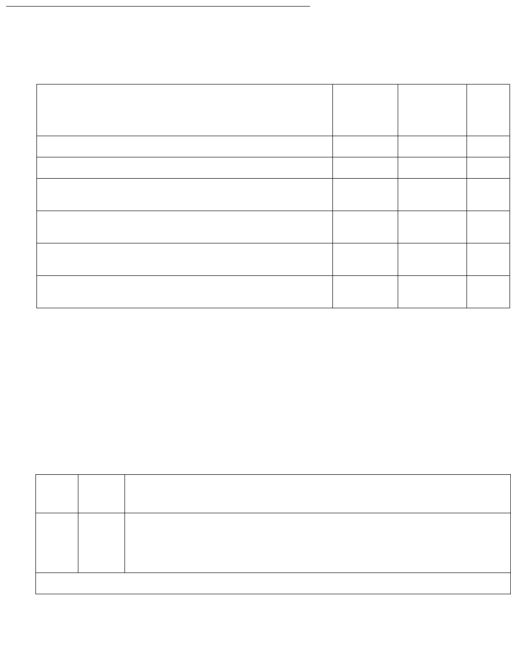
AN-LN-PT (Analog Line Port)
Issue 1 June 2005 429
System technician-demanded tests: descriptions and error codes
Investigate tests in the order presented. By clearing error codes associated with the Battery
Feed test (#35), you may clear errors generated from other tests in the sequence.
NPE Crosstalk Test (#6)
S8300 / G700: This test aborts with Error Code 1412.
This test verifies that the port’s NPE channel talks on the selected time slot and never crosses
over to time slots reserved for other connections. If the NPE is not working correctly, one-way
and noisy connections may be observed. This test is usually part of the long test sequence and
executes in about 20 to 30 seconds.
Order of Investigation Short
Test
Sequence
Long Test
Sequence
D/
ND1
1. D = Destructive; ND = Nondestructive
Battery Feed test (#35) X X ND
Station Present test (#48) X X ND
Analog Looparound test (#161)
S8300 / G700: This test aborts with Error Code 1412.
XND
Conference test (#7)
S8300 / G700: This test aborts with Error Code 1412.
XND
NPE Crosstalk test (#6)
S8300 / G700: This test aborts with Error Code 1412.
XND
Station Status and Translation Audit and Update test
(#36)
XXND
Table 126: Test #6 NPE Crosstalk Test
Error
Code
Test
Result
Description / Recommendation
ABRT Necessary system resources could not be allocated to run this test.
1. Retry the command at 1-minute intervals up to 5 times.
2. If the test continues to abort, escalate the problem.
1 of 4

Communication Manager Maintenance-Object Repair Procedures
430 Maintenance Procedures for Avaya Communication Manager 3.0, Media Gateways and Servers
1000 ABRT System resources are unavailable. The port may be busy with a valid call.
This result is also reported for the system’s Music-On-Hold port when it is
off-hook, which it usually is.
1. Enter display port location to determine the station’s extension.
2. Enter status station extension to determine the service state of
the port.
3. If the port is active, wait until it is idle. Retry the command at 1-minute
intervals up to 5 times.
4. If the test continues to abort, escalate the problem.
1001 ABRT System resources required to run test are not available. This could be due
to a failure to seize the port.
1. Retry the command at 1-minute intervals up to 5 times.
2. If the test continues to abort, escalate the problem.
1002 ABRT The system could not allocate time slots for the test. The system may be
under heavy traffic conditions or have time slots out-of-service due to
TDM-BUS errors.
1. Refer to TDM-BUS to diagnose any active TDM-BUS errors.
2. If the system has no TDM-BUS errors and is not handling heavy traffic,
retry the command at 1-minute intervals up to 5 times.
3. If the test continues to abort, escalate the problem.
1003 ABRT The system could not allocate a tone receiver for the test. The system may
be oversized for the number of Tone Detectors present or some Tone
Detectors may be out-of-service.
1. Resolve any TTR-LEV errors in the Error Log.
2. Resolve any TONE-PT errors in the Error Log.
3. If neither condition exists, retry the command at 1-minute intervals up
to 5 times.
4. If the test continues to abort, escalate the problem.
Table 126: Test #6 NPE Crosstalk Test (continued)
Error
Code
Test
Result
Description / Recommendation
2 of 4

AN-LN-PT (Analog Line Port)
Issue 1 June 2005 431
1004 ABRT A valid call seized the port during the test and aborted the test.
1. Use display port location to determine the station extension.
2. Use status station extension to determine the service state of
the port.
3. If the port is active, wait until it is idle before testing. Retry the
command at 1-minute intervals up to 5 times.
4. If the test continues to abort, escalate the problem.
1005 ABRT This test was aborted due to a configuration problem. The test is not
applicable for this type of analog port. This error can be ignored.
1018 ABRT Administration has disabled the test. The default for the Test field on the
station screen is y. Determine why this field has been set to n on this
station (this may be due to the ringing application Test #48, which can be
disturbing to customer or terminal equipment).
1. To enable the test for a particular station being tested, enter change
station extension.
2. Enter y in the Test field.
S8300
G700
1412
ABRT This test does not execute on a G700 Media Gateway.
2000 ABRT Response to the test request was not received within the allowable time
period.
1. Retry the command at 1-minute intervals up to 5 times.
2100 ABRT System resources required to run test are not available. This could be due
to a failure to seize the port.
1. Retry the command at 1-minute intervals up to 5 times.
2. If the test continues to abort, escalate the problem.
Table 126: Test #6 NPE Crosstalk Test (continued)
Error
Code
Test
Result
Description / Recommendation
3 of 4

Communication Manager Maintenance-Object Repair Procedures
432 Maintenance Procedures for Avaya Communication Manager 3.0, Media Gateways and Servers
Conference Circuit Test (#7)
S8300 / G700: This test aborts with Error Code 1412.
This test verifies that the NPE channel for the port being tested correctly performs the
conferencing function.
Any FAIL This test can fail due to either on- or off-board problems. Off-board
problems include TDM-BUS faults, EXP-PN, EXP-INTF, and RMC-ENV
faults, and faults associated with the Tone Detectors/Tone Generators.
Clear every off-board problem before replacing the board.
1. A TDM-BUS problem is usually the result of a faulty board connection
to the backplane, or bent pins on the backplane. Resolve any
TDM-BUS errors in the error log.
2. Resolve any any EXP-PN, EXP-INTF, and RMC-ENV errors in the
error log.
3. Resolve any TONE-BD and/or TONE-PT errors in the error log.
4. Test the board when the faults from steps 1, 2, and 3 are cleared.
Replace the board only if the test fails.
PASS The port is correctly using its allocated time slots. Investigate user-reported
troubles on this port by running other port tests, by examining station wiring,
or by inspecting the station.
0NO
BOARD The test could not relate the internal ID to the port (no board). This result
could be due to incorrect translations, no board is inserted, an incorrect
board is inserted, or an insane board is inserted.
1. Check to make sure that the board translations are correct. Enter
list configuration and resolve any problems.
2. If the board is correctly inserted, enter busy board location
3. Enter reset board location
4. Enter release board location
5. Enter test board location long
This should re-establish the link between the internal ID and the port. If not,
verify that a valid board is inserted.
Table 126: Test #6 NPE Crosstalk Test (continued)
Error
Code
Test
Result
Description / Recommendation
4 of 4

AN-LN-PT (Analog Line Port)
Issue 1 June 2005 433
Table 127: Test #7 Conference Circuit Test
Error
Code
Test
Result
Description / Recommendation
ABRT Necessary system resources could not be allocated to run this test.
1. Retry the command at 1-minute intervals up to 5 times.
2. If the test continues to abort, escalate the problem.
1000 ABRT System resources are unavailable. The port may be busy with a valid call.
This result is also reported for the system’s Music-On-Hold port when it is
off-hook, which it usually is.
1. Enter display port location to determine the station’s extension.
2. Enter status station extension to determine the service state of
the port.
3. If the port is active, wait until it is idle. Retry the command at 1-minute
intervals up to 5 times.
4. If the test continues to abort, escalate the problem.
1004 ABRT A valid call seized the port during the test and aborted the test.
1. Use display port location to determine the station extension.
2. Use status station extension to determine the service state of
the port.
3. If the port is active, wait until it is idle before testing. Retry the
command at 1-minute intervals up to 5 times.
4. If the test continues to abort, escalate the problem.
1005 ABRT This test was aborted due to a configuration problem. The test is not
applicable for this type of analog port. This error can be ignored.
1018 ABRT Administration has disabled the test. The default for the Test field on the
station screen is y. Determine why this field has been set to n on this
station (this may be due to the ringing application Test #48, which can be
disturbing to customer or terminal equipment).
1. To enable the test for a particular station being tested, enter change
station extension.
2. Enter y in the Test field.
S8300
G700
1412
ABRT This test does not execute on a G700 Media Gateway.
1 of 2

Communication Manager Maintenance-Object Repair Procedures
434 Maintenance Procedures for Avaya Communication Manager 3.0, Media Gateways and Servers
2000 ABRT Response to the test request was not received within the allowable time
period.
1. Retry the command at 1-minute intervals up to 5 times.
2100 ABRT System resources required to run this test are not available.
1. Resolve any TONE-PT errors in the error log.
2. If there are no TONE-PT errors, retry the command at 1-minute
intervals up to 5 times.
3. If the test continues to abort, escalate the problem.
Any FAIL The NPE of the tested port did not conference the tones correctly. This
causes noisy and unreliable connections.
1. Enter display port location and status station
extension to determine whether the station is idle.
2. If the station is idle, enter test port location for this port.
3. If the test continues to fail, enter busy port location and release
port location, and then retest.
4. If the test still fails, replace the board.
PASS The port can correctly conference multiple connections. Investigate
user-reported troubles on this port by running other port tests; by examining
station, trunk, or external wiring; or by inspecting the station.
0NO
BOARD The test could not relate the internal ID to the port (no board). This result
could be due to incorrect translations, no board is inserted, an incorrect
board is inserted, or an insane board is inserted.
1. Check to make sure that the board translations are correct. Enter list
configuration, and resolve any problems.
2. If the board is correctly inserted, enter busy board location
3. Enter reset board location
4. Enter release board location
5. Enter test board location long
This should re-establish the link between the internal ID and the port. If not,
verify that a valid board is inserted.
Table 127: Test #7 Conference Circuit Test (continued)
Error
Code
Test
Result
Description / Recommendation
2 of 2

AN-LN-PT (Analog Line Port)
Issue 1 June 2005 435
Battery Feed Test (or Port Diagnostic Test) (#35)
The battery feed chip provides power to the telephone equipment, signaling, rotary dial pulsing,
transmission, and balance. This test checks the signaling and switchhook capabilities of the
battery feed chip by terminating the port, applying battery power, and detecting the resulting
current.
Table 128: Test #35 Battery Feed Test
Error
Code
Test
Result
Description / Recommendation
ABRT Necessary system resources could not be allocated to run this test.
1. Retry the command at 1-minute intervals up to 5 times.
2. If the test continues to abort, escalate the problem.
1000 ABRT System resources are unavailable. The port may be busy with a valid call.
This result is also reported for the system’s Music-On-Hold port when it is
off-hook, which it usually is.
1. Enter display port location to determine the station’s
extension.
2. Enter status station extension to determine the service state of
the port.
3. If the port is active, wait until it is idle. Retry the command at 1-minute
intervals up to 5 times.
4. If the test continues to abort, escalate the problem.
1004 ABRT A valid call seized the port during the test and aborted the test.
1. Use display port location to determine the station extension.
2. Use status station extension to determine the service state of
the port.
3. If the port is active, wait until it is idle before testing. Retry the
command at 1-minute intervals up to 5 times.
4. If the test continues to abort, escalate the problem.
1005 ABRT This test was aborted due to a configuration problem. The test is not
applicable for this type of analog port. This error can be ignored.
1 of 3

Communication Manager Maintenance-Object Repair Procedures
436 Maintenance Procedures for Avaya Communication Manager 3.0, Media Gateways and Servers
1018 ABRT Administration has disabled the test. The default for the Test field on the
station form is y. Determine why this field has been set to n on this station
(this may be due to the ringing application Test #48, which can be
disturbing to customer or terminal equipment).
1. To enable the test for a particular station being tested, enter change
station extension.
2. Enter y in the Test field.
1392 ABRT This port is currently a TTI port and the test does not execute on it.
1. Verify that the port is a TTI port:
●Enter the display port location command (the display shows
that the port is a TTI port).
●Enter list configuration (the display shows a t for the port).
2. If both commands indicate that the port is a TTI port, the abort is
correct for the test, and no action is necessary.
3. If either command indicates that the port is not a TTI port, escalate the
problem.
2000 ABRT Response to the test request was not received within the allowable time
period.
1. Retry the command at 1-minute intervals up to 5 times.
2100 ABRT System resources required to run this test are not available.
1. Retry the command at 1-minute intervals up to 5 times.
2. If the test continues to abort, escalate the problem.
FAIL The port's battery feed chip is unable to supply sufficient power to the
terminal equipment. This test result might be marginal, and the terminal
equipment may be operating satisfactorily.
1. Retry the command at 1-minute intervals up to 5 times.
2. If the test continues to fail, determine whether the customer is
experiencing problems on this line. Replace the circuit pack or media
module only if the customer is experiencing problems.
Table 128: Test #35 Battery Feed Test (continued)
Error
Code
Test
Result
Description / Recommendation
2 of 3

AN-LN-PT (Analog Line Port)
Issue 1 June 2005 437
Station Status and Translation Audit and Update Test (#36)
This test updates the analog port’s message lamp state (if it has one) and translations with
information in the software.
PASS The port’s battery feed chip is able to provide sufficient power to the station
equipment to detect on-/off-hook, but may not be able to supply power for
touch-tones.
1. If touch-tones are inoperative on this station, replace the circuit pack or
media module, because this port is inoperative.
2. Investigate user-reported troubles on this port by running other port
tests, by examining station wiring, or by inspecting the station.
0NO
BOARD The test could not relate the internal ID to the port (no board). This result
could be due to incorrect translations, no board is inserted, an incorrect
board is inserted, or an insane board is inserted.
1. Check to make sure that the board translations are correct. Enter
list configuration, and resolve any problems.
2. If the board is correctly inserted, enter busy board location
3. Enter reset board location
4. Enter release board location
5. Enter test board location long
This should re-establish the link between the internal ID and the port. If not,
verify that a valid board is inserted.
Table 128: Test #35 Battery Feed Test (continued)
Error
Code
Test
Result
Description / Recommendation
3 of 3
Table 129: Test #36 Station Status and Translation Audit and Update
Error
Code
Test
Result
Description / Recommendation
ABRT Necessary system resources could not be allocated to run this test.
1. Retry the command at 1-minute intervals up to 5 times.
2. If the test continues to abort, escalate the problem.
1 of 3

Communication Manager Maintenance-Object Repair Procedures
438 Maintenance Procedures for Avaya Communication Manager 3.0, Media Gateways and Servers
1004 ABRT A valid call seized the port during the test and aborted the test.
1. Use display port location to determine the station extension.
2. Use status station extension to determine the service state of
the port.
3. If the port is active, wait until it is idle before testing. Retry the
command at 1-minute intervals up to 5 times.
4. If the test continues to abort, escalate the problem.
1005 ABRT This test was aborted due to a configuration problem. The test is not
applicable for this type of analog port. This error can be ignored.
1006 ABRT The port is out-of-service. The busy station extension has been
given to this port. If the port is on a circuit pack, it may have been taken
out-of-service by the failure of the NPE Crosstalk test.
1. Look for error type 18 (port busied out) for this port. If this error is
present, release the port with release station extension, and
run the test again.
2. If the port is on a circuit pack, check for error type 1537 (NPE
Crosstalk test failed) for this port. If this error is present, investigate
the errors associated with the NPE Crosstalk test (#6).
3. Make sure that the terminal is connected and in service, and then
retest.
2000 ABRT Response to the test request was not received within the allowable time
period.
1. Retry the command at 1-minute intervals up to 5 times.
2100 ABRT System resources required to run this test are not available.
1. Retry the command at 1-minute intervals up to 5 times.
2. If the test continues to abort, escalate the problem.
Table 129: Test #36 Station Status and Translation Audit and Update (continued)
Error
Code
Test
Result
Description / Recommendation
2 of 3

AN-LN-PT (Analog Line Port)
Issue 1 June 2005 439
1 FAIL The switchhook audit failed. This result does not indicate a hardware
problem. The other updates were not performed because of this failure.
This may occur if the audit is performed at the same time the terminal
equipment goes off-hook.
1. Use status station extension to determine when the port is
available.
2. Retry the command at 1-minute intervals up to 5 times.
3. If the test continues to fail, escalate the problem.
5 FAIL The message waiting lamp update failed. This may be an internal software
error. The translation and ringer updates were not performed because of
this failure.
7 FAIL The translation update failed. There may be an internal software error. The
ringer update was not performed because of this failure.
8 FAIL The ringer update failed. There may be an internal software error.
1. Retry the command at 1-minute intervals up to 5 times.
2. If the test continues to fail, escalate the problem.
PASS The software and the port processor have the same status. Investigate
user-reported troubles on this port by running other port tests, by examining
station wiring, or by inspecting the station.
0NO
BOARD The test could not relate the internal ID to the port (no board). This result
could be due to incorrect translations, no board is inserted, an incorrect
board is inserted, or an insane board is inserted.
1. Check to make sure that the board translations are correct. Enter
list configuration, and resolve any problems.
2. If the board is correctly inserted, enter busy board location
3. Enter reset board location
4. Enter release board location
5. Enter test board location long
This should re-establish the link between the internal ID and the port. If not,
verify that a valid board is inserted.
Table 129: Test #36 Station Status and Translation Audit and Update (continued)
Error
Code
Test
Result
Description / Recommendation
3 of 3

Communication Manager Maintenance-Object Repair Procedures
440 Maintenance Procedures for Avaya Communication Manager 3.0, Media Gateways and Servers
Station Present Test (or Ringing Application Test) (#48)
This test applies momentary ringing voltage to the terminal equipment and monitors resulting
current flow to determine whether terminal equipment is connected to the port. This test may
cause some terminal equipment to ring briefly during daily maintenance. If this ringing disturbs
the customer or the terminal equipment, you can disable it via the Tests field on the change
station extension screen. However, on some software releases, Tests #6, 7, 161, and 35
also are disabled.
S8300 / G700: In the G700, Tests #6, 7, and 161 abort with Error Code 1412.
Table 130: Test #48 Station Present Test
Error
Code
Test
Result
Description / Recommendation
ABRT Necessary system resources could not be allocated to run this test.
1. Retry the command at 1-minute intervals up to 5 times.
2. If the test continues to abort, escalate the problem.
1000 ABRT System resources are unavailable. The port may be busy with a valid call.
This result is also reported for the system’s Music-On-Hold port when it is
off-hook, which it usually is.
1. Enter display port location to determine the station’s
extension.
2. Enter status station extension to determine the service state of
the port.
3. If the port is active, wait until it is idle. Retry the command at 1-minute
intervals up to 5 times.
4. If the test continues to abort, escalate the problem.
1004 ABRT A valid call seized the port during the test and aborted the test.
1. Use display port location to determine the station extension.
2. Use status station extension to determine the service state of
the port.
3. If the port is active, wait until it is idle before testing. Retry the
command at 1-minute intervals up to 5 times.
4. If the test continues to abort, escalate the problem.
1005 ABRT This test was aborted due to a configuration problem. The test is not
applicable for this type of analog port. This error can be ignored.
1 of 3

AN-LN-PT (Analog Line Port)
Issue 1 June 2005 441
1008 ABRT A ringing circuit could not be allocated. Either every ringing circuit is
active, the ringing generator is defective, or it is incorrectly wired.
1. Retry the command at 1-minute intervals up to 5 times.
2. If the test continues to abort, look for RING-GEN errors in the Error
Log.
3. If ABORT 1008 occurs for this test on other circuit packs as well, the
ringing generator may be defective or is incorrectly wired (see
RING-GEN (Analog Ring Generator) on page 1942.
4. If an ABORT 1008 does not occur on other ports, then all four ring
phases are active.
1018 ABRT Administration has disabled the test. The default for the Test field on the
station screen is y. Determine why this field has been set to n on this
station (this may be due to the ringing application Test 48, which can be
disturbing to customer or terminal equipment).
1. To enable the test for a particular station being tested, enter change
station extension.
2. Enter y in the Test field.
2000 ABRT Response to the test request was not received within the allowable time
period.
1. Retry the command at 1-minute intervals up to 5 times.
2100 ABRT System resources required to run this test are not available.
1. Retry the command at 1-minute intervals up to 5 times.
2. If the test continues to abort, escalate the problem.
Table 130: Test #48 Station Present Test (continued)
Error
Code
Test
Result
Description / Recommendation
2 of 3

Communication Manager Maintenance-Object Repair Procedures
442 Maintenance Procedures for Avaya Communication Manager 3.0, Media Gateways and Servers
FAIL The terminal equipment is not connected to the circuit pack. Some
terminal equipment, such as modems, may fail even when connected
properly.
1. Remotely test the terminal equipment.
2. If the test fails again, resolve any RING-GEN errors in the error log, if
present.
3. Check all of the wiring between the station equipment and the switch.
Then, run the test again.
4. If the test still fails, the terminal equipment may be defective. Check
and replace it, if necessary.
5. Some terminal equipment might fail even when it is connected
properly. If this is the case, disable the test using change station
extension (enter n into the Test field). Note that this action also
disables Tests 6, 7, 35, and 161 on this port.
PASS The station is connected properly to the switch. Investigate user-reported
troubles on this port by running other port tests, by examining station wiring,
or by inspecting the station.
Note:
Note: This test may also pass if no terminal equipment is
connected and the terminal is located very far from the
switch.
0NO
BOARD The test could not relate the internal ID to the port (no board). This result
could be due to incorrect translations, no board is inserted, an incorrect
board is inserted, or an insane board is inserted.
1. Check to make sure that the board translations are correct. Enter
list configuration, and resolve any problems.
2. If the board is correctly inserted, enter busy board location
3. Enter reset board location
4. Enter release board location
5. Enter test board location long
This should re-establish the link between the internal ID and the port. If not,
verify that a valid board is inserted.
Table 130: Test #48 Station Present Test (continued)
Error
Code
Test
Result
Description / Recommendation
3 of 3

AN-LN-PT (Analog Line Port)
Issue 1 June 2005 443
Analog Looparound Test (#161)
S8300 / G700: This test aborts with Error Code 1412.
This test checks the on-board transmission capabilities of the NPE, the codec, and the battery
feed chip of the analog port. The test passes if the signal measured by the Tone Detector is
within acceptable limits.
Table 131: Test #161 Analog Looparound Test
Error
Code
Test
Result
Description / Recommendation
ABRT Necessary system resources could not be allocated to run this test.
1. Retry the command at 1-minute intervals up to 5 times.
2. If the test continues to abort, escalate the problem.
1000 ABRT System resources are unavailable. The port may be busy with a valid call.
This result is also reported for the system’s Music-On-Hold port when it is
off-hook, which it usually is.
1. Enter display port location to determine the station’s extension.
2. Enter status station extension to determine the service state of
the port.
3. If the port is active, wait until it is idle. Retry the command at 1-minute
intervals up to 5 times.
4. If the test continues to abort, escalate the problem.
1002 ABRT The system could not allocate time slots for the test. The system may be
under heavy traffic conditions or have time slots out-of-service due to
TDM-BUS errors.
1. Refer to “TDM-BUS” to diagnose any active TDM-BUS errors.
2. If the system has no TDM-BUS errors and is not handling heavy traffic,
retry the command at 1-minute intervals up to 5 times.
3. If the test continues to abort, escalate the problem.
1 of 4

Communication Manager Maintenance-Object Repair Procedures
444 Maintenance Procedures for Avaya Communication Manager 3.0, Media Gateways and Servers
1003 ABRT The system could not allocate a tone receiver for the test. The system may
be oversized for the number of Tone Detectors present or some Tone
Detectors may be out-of-service.
1. Resolve any TTR-LEV errors in the Error Log.
2. Resolve any TONE-PT errors in the Error Log.
3. If neither condition exists, retry the command at 1-minute intervals up to
5 times.
4. If the test continues to abort, escalate the problem.
1004 ABRT A valid call seized the port during the test and aborted the test.
1. Use display port location to determine the station extension.
2. Use status station extension to determine the service state of
the port.
3. If the port is active, wait until it is idle before testing. Retry the
command at 1-minute intervals up to 5 times.
4. If the test continues to abort, escalate the problem.
1005 ABRT This test was aborted due to a configuration problem. The test is not
applicable for this type of analog port. This error can be ignored.
1018 ABRT Administration has disabled the test. The default for the Test field on the
station screen is y. Determine why this field has been set to n on this
station (this may be due to the ringing application Test 48, which can be
disturbing to customer or terminal equipment).
1. To enable the test for a particular station being tested, enter change
station extension.
2. Enter y in the Test field.
S8300
G700
1412
ABRT This test does not execute on a G700 Media Gateway.
Table 131: Test #161 Analog Looparound Test (continued)
Error
Code
Test
Result
Description / Recommendation
2 of 4

AN-LN-PT (Analog Line Port)
Issue 1 June 2005 445
2000 ABRT Response to the test request was not received within the allowable time
period.
1. Retry the command at 1-minute intervals up to 5 times.
2100 ABRT System resources required to run this test are not available.
1. Retry the command at 1-minute intervals up to 5 times.
2. If the test continues to abort, escalate the problem.
FAIL The reflective loop-around test failed. This could cause noisy or unreliable
connections, or users calling this port may hear an echo. The problem can
also be off-board.
1. Since a line seizure may affect the test, repeat the test at 1-minute
intervals up to 5 times.
2. Use test board location short to run circuit pack tests to check
the Tone Generator and the Tone Detector circuits on the IPSIs or the
Tone Generator/Tone Detector circuit packs.
3. Resolve any problems on the Tone Generator or the Tone Detector
circuit.
4. If the Tone Generator and Tone Detector circuits are functioning
properly, determine whether a voice terminal is connected and wired
properly. Resolve any problems found.
5. If the test still fails, replace the analog line circuit pack.
PASS The port provides an analog transmission path to the station equipment.
Investigate user-reported troubles on this port by running other port tests, by
examining station wiring, or by inspecting the station.
Table 131: Test #161 Analog Looparound Test (continued)
Error
Code
Test
Result
Description / Recommendation
3 of 4

Communication Manager Maintenance-Object Repair Procedures
446 Maintenance Procedures for Avaya Communication Manager 3.0, Media Gateways and Servers
0NO
BOARD The test could not relate the internal ID to the port (no board). This result
could be due to incorrect translations, no board is inserted, an incorrect
board is inserted, or an insane board is inserted.
1. Check to make sure that the board translations are correct. Enter list
configuration, and resolve any problems.
2. If the board is correctly inserted, enter busy board location
3. Enter reset board location
4. Enter release board location
5. Enter test board location long
This should re-establish the link between the internal ID and the port. If
not, verify that a valid board is inserted.
Table 131: Test #161 Analog Looparound Test (continued)
Error
Code
Test
Result
Description / Recommendation
4 of 4

ANN-BD (Announcement circuit pack)
Issue 1 June 2005 447
ANN-BD (Announcement circuit pack)
Note:
Note: The information contained in ANN-BD refers only to the TN750-series of circuit
packs. Expressions such as "announcement circuit pack" and "announcement
board" are to be interpreted to mean the TN750-series only.
The TN750 Announcement circuit pack is a service circuit which provides an integrated means
for recording announcements that can be played back on demand by call processing as part of
a calling feature (for example, announcements on hunt group calls). There are 16
Announcement Ports on the Announcement circuit pack. Each port can play any integrated
announcement, independently of the other ports. In addition to the 16 Announcement Ports, the
Announcement circuit pack also has one Data Line Circuit Port (port 17). The Data Line Circuit
Port is used for uploading/downloading the announcement memory to/from the memory card. If
there are any errors associated with port 17, refer to DAT-LINE (Data Line Port) on page 870. If
there are any errors associated with any other port, refer to ANN-PT (announcement port) on
page 465.
Note:
Note: TN750C is required if your system has multiple TN750x announcement boards
(up to ten are allowed). Only one TN750A/B may be present in the system with
up to nine additional TN750C boards. All ten boards may be TN750C. The
announcements from a TN750A/B can be saved and restored to a TN750C, but
once the announcements are recorded onto a TN750C they are not backward
compatible with the TN750A/B.
The Announcement circuit pack has two processors on it. The first processor, or Angel, controls
the circuit pack and communicates with the switch via the control channel on the TDM Bus. The
second processor, or Speech Processor (SP), controls the speech memory and
announcements. Digital speech is converted from its TDM Bus form to an internal storage form
(for recording) and vice versa (for playbacks) by the 140AY device on the circuit pack, which
has 16 channels (one for each Announcement Port).
MO Name in Alarm
Log
Alarm
level
Initial command to run Full name of MO
ANN-BD MIN test board location lAnnouncement Circuit Pack
ANN-BD WRN test board location lAnnouncement Circuit Pack

Communication Manager Maintenance-Object Repair Procedures
448 Maintenance Procedures for Avaya Communication Manager 3.0, Media Gateways and Servers
General notes
Here are a few important general notes that apply to any problem on the Announcement circuit
pack. The user should read this before attempting to work on the TN750 Announcement circuit
pack or Announcement Ports, especially if the circuit pack needs to be replaced.
1. The TN750 Announcement circuit pack retains all integrated announcements as long as the
circuit pack has power. For this reason, whenever there is a problem with either the
Announcement circuit pack or an Announcement Port that may require the circuit pack to be
reset, it is always best to try to reset the circuit pack via reset board PCSS first. If that
does not work, replace the circuit pack. Announcements are preserved through a software
reset, but they are lost when the circuit pack is reseated.
2. If a customer has announcements on the Announcement circuit pack, then announcements
must be saved on the memory card to ensure that they are not lost. This should be done as
soon as the announcements are recorded on the circuit pack (or whenever they are
changed), assuming that the circuit pack is in proper working order (see Note).
Note:
Note: Unlike translations, announcements are NEVER automatically saved to the
memory card.
3. Save announcements replaces the TN750x announcement file on the memory card.
Care must be taken not to mistakenly enter this command and, as a result, destroy a valid
file on the memory card.
4. Restore announcements replaces the TN750x Announcement circuit pack speech
memory with the announcement file on the memory card. Care must be taken not to
mistakenly enter this command, destroying valid speech memory, especially if the memory
card does not have a valid announcement file on it.
5. Whenever the TN750x Announcement circuit pack is replaced, announcements must
always be rerecorded or downloaded to the new circuit pack. Otherwise, call processing is
not able to use the pack.
6. If announcement speech memory is corrupted, announcements should not be saved [that
is, if the Announcement Checksum Test (#209) fails, or if the speech sounds corrupted on
playback]. This can ruin a good announcement file on the memory card and potentially
cause errors/alarms on any circuit pack to which the new file is downloaded. However, if the
customer does not have a valid announcement file on the memory card, announcements
can be saved in an effort to try to retain some of them (all of the announcements recorded
may not be corrupted).
7. Due to a hardware fault in the TN750 announcement board, the following sequence of
events may cause the announcement file to become corrupted and unusable:
a. Fill the board with recorded announcements.
b. Delete the last few announcements recorded.
c. Re-record the announcements deleted.

ANN-BD (Announcement circuit pack)
Issue 1 June 2005 449
If the announcement file becomes corrupted, the only solution is to re-record all
announcements. To do this, follow these steps:
d. Remove the announcement board.
e. Remove the tape cartridge from the tape drive. Do this so that announcements are not
automatically restored from tape.
f. Re-insert the announcement board.
g. Re-record all announcements.
h. Insert the tape cartridge in the tape drive.
i. Enter save announcements to save all the announcements on the tape.
This hardware fault is fixed in the TN750B announcement board. However, the TN750B
board will not automatically correct an announcement file which has previously been
corrupted by a TN750 board. The only way to correct an announcement file corrupted by
the TN750 board is to follow the steps above.
Announcement administration
A brief description of the integrated announcement administration is given here to aid in
troubleshooting the Announcement circuit pack and its ports. In many cases, it is necessary to
record, play back, and/or delete announcements to resolve an alarm. It may also be necessary
to save and restore announcements as part of the maintenance procedures. For a complete
description of integrated announcement administration, please refer to Administrator Guide for
Avaya Communication Manager, 03-300509.
Announcement session
Announcements can be recorded, played back, and deleted from an announcement session. A
station’s COS needs to include console permissions in order for that station to be able to enter
an announcement session. To enter an announcement session, go off-hook on a station that
has console permissions and enter the appropriate Feature Access Code (FAC), administered
as Announcement access code on the FACs form. Dial tone should be returned at this point.
Enter the extension of the announcement that needs to be recorded, deleted, or played back.
Again, dial tone should be heard. To record an announcement, press station keypad digit 1,
record after the tone, and hang up when done. To play back an announcement, press 2. To
delete an announcement, press 3 (confirmation tone is given if the delete worked).
Announcements can also be played back by simply calling the announcement extension
associated with them.

Communication Manager Maintenance-Object Repair Procedures
450 Maintenance Procedures for Avaya Communication Manager 3.0, Media Gateways and Servers
Uploading/Downloading announcements
Integrated announcements on the TN750 Announcement circuit pack can be uploaded to the
memory card with save announcements. Likewise, integrated announcements can be
downloaded to the Announcement circuit pack with restore announcements. Both of these
commands require a free data module of NETCON type to be administered, a data module of
announcement type (on the Announcement circuit pack) to be administered, and a memory
card. These commands are useful in maintaining the customer’s recorded announcements.
Depending on system traffic, announcement uploads and/or downloads take between 30 and
45 minutes.
The system automatically tries to download the Announcement circuit pack five minutes after it
is inserted. This automatic download procedure is aborted if:
●An announcement is recorded within 10 minutes of circuit pack insertion.
●An announcement download is invoked sooner with the restore announcements.
●No announcement and/or NETCON data module is administered.
●Either the announcement data module is busy or all the administered NETCON data
modules are busy.
●No memory card is in the system.
●The memory card in the system does not have a valid announcement file saved on it.
Hardware error log entries and test to clear values
Table 132: Announcement circuit pack error log entries
Error
type
Aux
data
Associated test Alarm
level
(See
WRN
message)
On/
Off
board
Test to clear value
0 (a)0 Any Any Any test board PCSS sh r 1
1 (b)0 Circuit pack removed or SAKI Test (#53) MIN ON
2 (c)None
14 (d)1 to 64 Announcement Checksum (209)
18 0 busyout board PCSS WRN OFF release board PCSS
23 (e)0None WRN OFF
1 of 2
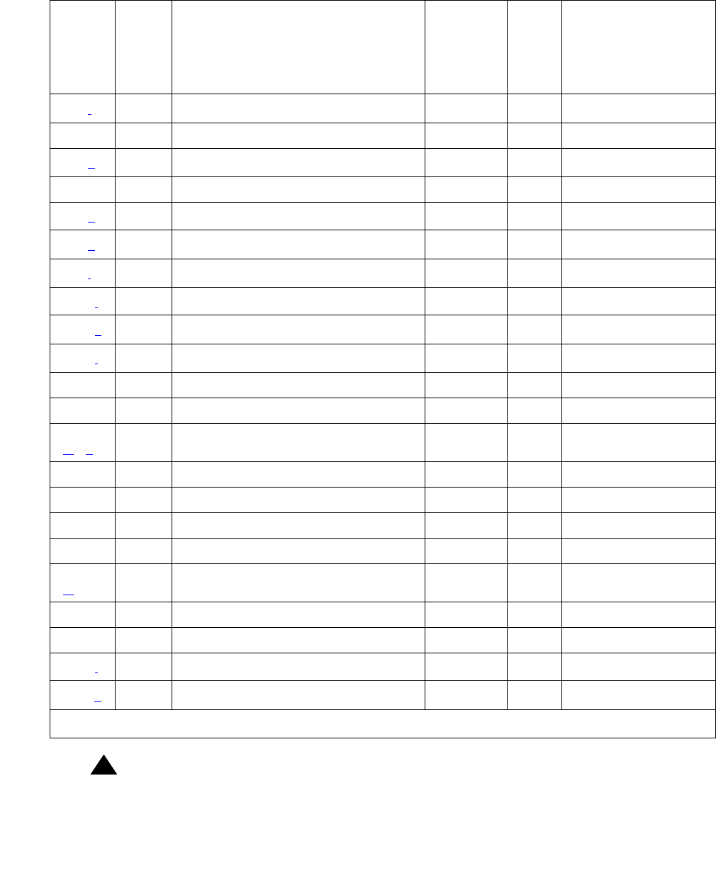
ANN-BD (Announcement circuit pack)
Issue 1 June 2005 451
!WARNING:
WARNING: All alarms are upgraded to MAJOR when the BASE Tone Generator is set to 12
(France).
125 (f)None MIN ON
170 0 None MIN ON
217 (g)0None WRN OFF
257 65535 Control Channel Test (#52) MIN ON test board PCSS l r 20
257 (h)Any None
267 (g)0None WRN OFF
513 (i)Any None
1025 (j)4363 NPE Audit Test (#50) test board PCSS l
1281 (k)17699 None
1538 (l)Any None MIN ON
1793 Angel-SP Handshake (#208) MIN ON test board PCSS l r 3
17680 In-line Error
2049
(m) (n)
Clock Match Inquiry (#212) MIN ON test board PCSS sh r 3
17674 In-line Error
2305 140AY Loop Around (#210) MIN ON test board PCSS sh r 3
2561 Super Frame Match Inquiry (211) MIN ON test board PCSS sh r 3
17676 In-line Error
2817
(m)
Announcement Checksum (#209) MIN ON test board PCSS sh r 3
17682 In-line Error
17699 In-line Error
3840 (j)Any None
3999 (o)Any None
Table 132: Announcement circuit pack error log entries (continued)
Error
type
Aux
data
Associated test Alarm
level
(See
WRN
message)
On/
Off
board
Test to clear value
2 of 2

Communication Manager Maintenance-Object Repair Procedures
452 Maintenance Procedures for Avaya Communication Manager 3.0, Media Gateways and Servers
Notes:
a. Error Type 0: Run the Short Test Sequence first. If all tests pass, run the Long Test
Sequence. Refer to the appropriate test description and follow the recommended
procedures.
b. Error Type 1: the circuit pack totally stopped functioning or it was physically removed from
the system.
Note:
Note: The alarm is logged about 11 minutes after the circuit pack has been removed
and/or SAKI Test (#53) fails.
If the circuit pack is not in the system, insert a circuit pack (in the same slot as the error
indicates) to resolve this error. Or, if the circuit pack is in the system and the red LED is on,
follow the instructions for "Red (alarm)" in RIGHT LED in SERVICES jack - GREEN: lights
up seventh then turns off. on page 287.
Note:
Note: The alarm is logged about 11 minutes after the circuit pack has been removed
and/or SAKI Test (#53) fails.
!WARNING:
WARNING: Reseating and/or replacing the circuit pack results in loss of integrated
announcements (TN750/B only). See General notes on page 465 near the
beginning of this Maintenance procedure.
c. Error Type 2: Check the Class of Restriction (COR) administered for the Data Line
extension assigned to the TN750 for uploading and downloading announcements. The
extension can be found by using list data-module.
d. Error Type 14: logged when the Announcement Checksum Test (#209) fails. The Aux Data
indicates the number of the first defective announcement found. This number corresponds
to the announcement numbers on the announcement form. The extension relating to the
announcement can be determined by display announcement. This error only appears
in the Error Log in conjunction with Error Type 2817. Follow the procedures for Error Type
2817 to troubleshoot Error Type 14.
e. Error Type 23: the circuit pack has been logically administered but not physically installed.
The alarm is cleared when the circuit pack is installed.
f. Error Type 125: the wrong circuit pack is inserted in the slot where this circuit pack is
logically administered. To resolve this problem, either remove the wrong circuit pack and
insert the logically administered circuit pack OR use change circuit-pack to
readminister this slot to match the circuit pack inserted.
g. Error Type 217 and 267: there is more than one TN750 Announcement circuit pack
inserted in the system. Remove the alarmed circuit pack.
h. Error Type 257: transient communication problems with this circuit pack. This error is not
service-affecting and no action is required.

ANN-BD (Announcement circuit pack)
Issue 1 June 2005 453
i. Error Type 513: when reported with Aux Data in the range of 4352 to 4358, the circuit pack
has reported a hardware failure on the circuit pack. The circuit pack should be replaced.
Replacing the circuit pack results in loss of integrated announcements (TN750/B only). See
General notes on page 465 near the beginning of this Maintenance procedure.
j. Error Types 1025 and 3840: not service-affecting, no action is required.
k. Error Type 1281: the speech processor (SP) found a fault in the speech main memory
(SMM) (that is, it found one or more faulty memory locations). Whenever this error is
logged, error 2817 is also logged [see Note (m)], which causes the maintenance system to
run the Announcement Checksum Test (#209) to determine if the bad memory location was
being used by an announcement.
l. Error Type 1538: the hyperactive circuit pack is out-of-service and may exhibit one or more
of the following symptoms:
1. The tests run on the ports of this circuit pack are returning with a NO-BOARD.
2. A busyout/release of the circuit pack has no effect on test results.
3. A list configuration command shows that the circuit pack and ports are properly
installed.
The system tries to restore the circuit pack within 15 minutes. If the error recurs after 15
minutes, replace the circuit pack. (Refer to Reseating and replacing circuit packs in
Maintenance Procedures (03-300192).)
m. Error Types 2049 and 2817: logged in conjunction with Error Type 1281, Aux Data 17699.
Because Error Type 1281 means that a defective speech memory location was found, [see
Note (k)] the announcement checksum error is also logged. This causes the Announcement
Checksum Test (#209) to run, which determines if the defective memory location has
corrupted any recorded announcements. If the Checksum Test passes, the faulty memory
location is currently not being used, and the SP marks the location as faulty to ensure that
future announcements do not attempt to use it.
Note:
Note: As memory locations are marked faulty, the amount of available memory
decreases, which decreases the total amount of announcement time available on
the circuit pack.
n. Error Type 2049: transient error that does not cause an alarm can occasionally occur
during a SPE, TDM BUS, or Tone Clock interchange. It is possible for a marginal
Tone-Clock circuit pack to cause this error against the ANN-BD without alarming the
TONE-BD. If this error occurs again, replacing the Tone-Clock circuit pack may clear up this
error. See the FAIL case in the Clock Match Inquiry Test (#212).
o. Error type 3999: the circuit pack sent a large number of control channel messages to the
switch within a short period of time. If error type 1538 is also present, then the circuit pack
was taken out-of-service due to hyperactivity. If error type 1538 is not present, then the
circuit pack has not been taken out-of-service, but it has generated 50% of the messages
necessary to be considered hyperactive. This may be completely normal during heavy
traffic periods. However, if this error type is logged when the circuit pack is being lightly
used, it may indicate a problem with the circuit pack or the equipment attached to it.
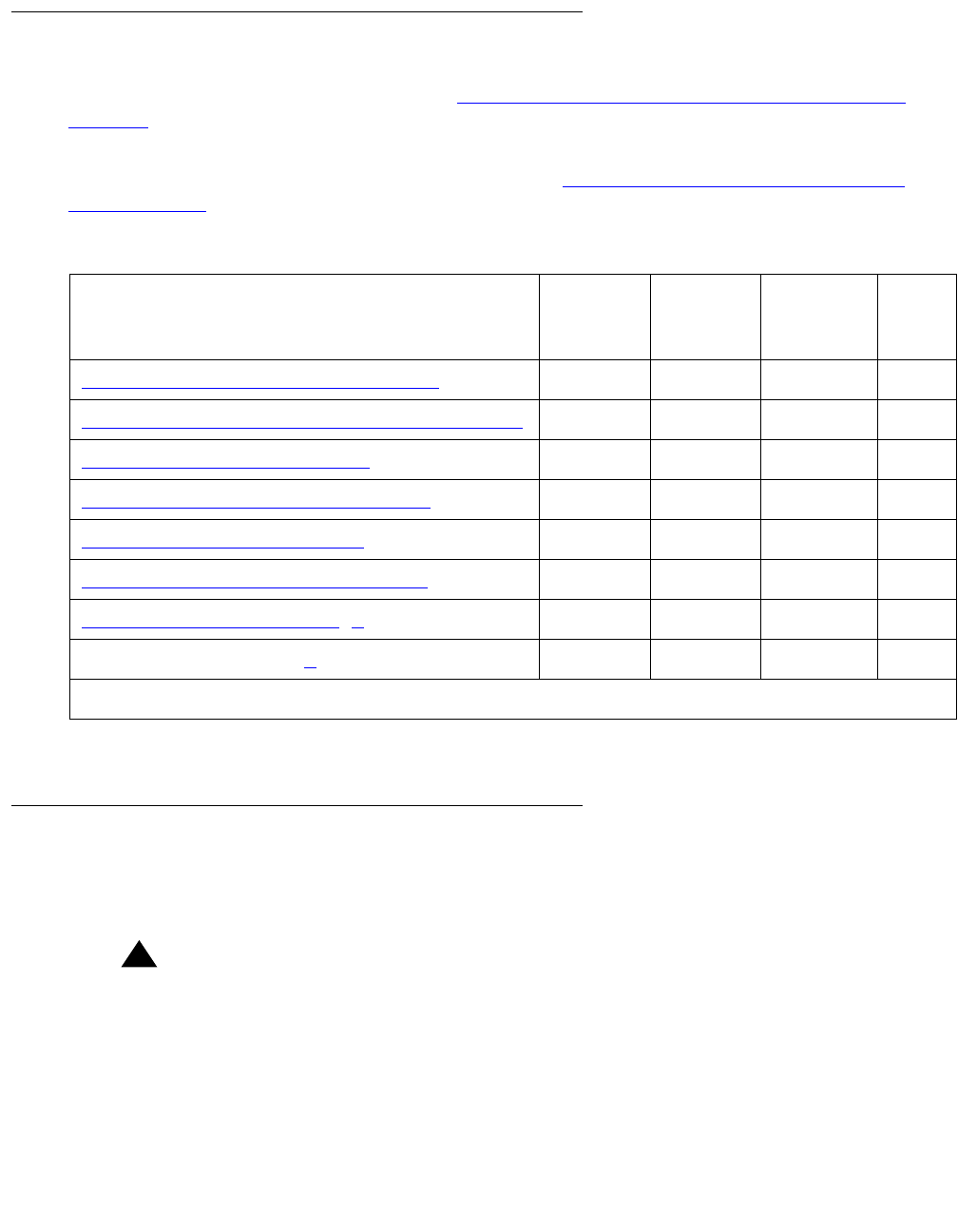
Communication Manager Maintenance-Object Repair Procedures
454 Maintenance Procedures for Avaya Communication Manager 3.0, Media Gateways and Servers
System technician-demanded tests: descriptions and error codes
Investigate tests in the order presented in Table 133: System Technician-demanded tests:
ANN-BD on page 454. By clearing error codes associated with the first test, you may clear other
errors in the sequence.
For a complete description of these tests, refer to the XXX-BD (Common Port Circuit Pack/
Media Module) on page 2539.
Angel-speech processor (sp) handshake test (#208)
This test checks the integrity of the communication link between the two processors on the
Announcement circuit pack.
!WARNING:
WARNING: Failure of this test indicates that the Speech Processor is insane and results in
the loss of all integrated announcements on the circuit pack.
Table 133: System Technician-demanded tests: ANN-BD
Order of investigation Short test
sequence
Long test
sequence
Reset
board
sequence
D/ND1
1. D = Destructive, ND = Nondestructive
Control channel loop-around test (#52) XND
Angel-speech processor (sp) handshake (#208) XND
Clock match inquiry test (#212) XX ND
Super frame match inquiry test (#211) XX ND
140AY loop around test (#210) XX ND
Announcement checksum test (#209) XX ND
Connection Audit Test (#50) (a)XND
SAKI Sanity Test (#53) (a)X D
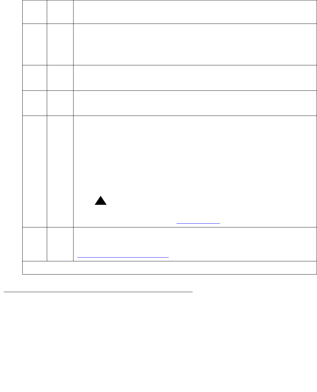
ANN-BD (Announcement circuit pack)
Issue 1 June 2005 455
Announcement checksum test (#209)
Associated with every recorded announcement is a checksum. In this test, the SP checks a
stored global checksum covering all recorded announcements against a calculated one and
returns the results to the maintenance system. If the global checksum failed, maintenance
requests the SP to check each individual announcement’s checksum.
Table 134: TEST #208 angel-speech processor (SP) handshake test
Error
code
Test
result
Description/ Recommendation
2000 ABRT Response to the test request was not received within the allowable time
period. If Error Type 1538 is present in the Error Log, follow the maintenance
strategy recommended for this Error Type.
1. Retry the command at 1-minute intervals up to 5 times.
2100 ABRT Could not allocate the necessary system resources to run this test.
1. Retry the command at 1-minute intervals up to 5 times.
ABRT Internal system error.
1. Retry the command at 1-minute intervals a maximum of 5 times.
FAIL Test failed. Circuit pack cannot be used. Announcement speech memory is
cleared when this test fails. Therefore, when the problem has been resolved,
announcements must be rerecorded or downloaded to the circuit pack.
1. Reset the circuit pack via reset board PCSS and then run this test
again. If the test continues to fail, replace the circuit pack and then run
this test again.
2. If there are recurring alarms on this circuit pack caused by this test
failing, replace the circuit pack even if Step 1 works.
!WARNING:
WARNING: Replacing the circuit pack results in loss of integrated
announcements. See General notes on page 465.
PASS The communications link between the two processors on the Announcement
circuit pack is functioning properly. User-reported troubles on this circuit pack
should be investigated using other circuit pack and port tests. Refer to
ANN-PT (announcement port) on page 465 for a description of the port tests.

Communication Manager Maintenance-Object Repair Procedures
456 Maintenance Procedures for Avaya Communication Manager 3.0, Media Gateways and Servers
If the test fails, then it returns the total number of defective announcements found. In addition,
associated with each failure is an error in the Error Log (Error Type 14). The Aux Data indicates
the number of the first defective announcement found. This number corresponds to the
announcement numbers on the announcement form. The extension relating to the
announcement can be determined by display announcement.
Table 135: TEST #209 announcement checksum test
Error
code
Test
result
Description/ Recommendation
0 ABRT An error code of 0 indicates that the announcement file has been corrupted
due to a hardware fault in the TN750 board. Follow step #7 under General
notes on page 465 at the beginning of this section.
1023 ABRT There are no announcements currently recorded on the circuit pack.
1024 ABRT This abort code is given for the following reasons:
1. An announcement upload or download is in progress.
2. An announcement upload or download is requested when this test is
running.
3. A record is in progress.
4. A record request comes in when this test is running.
If an announcement upload or download is in progress, status
data-module <announcement data extension> should show that the
announcement data port is connected to a NETCON data channel, and the
"card-in-use" LED for the memory card is on (to determine the extension of
the announcement data module, use list data-module).
See Note (a) at end of table for more information.
1. Wait until the blocking event is finished, and then run this test again. An
upload or download could take up to 45 minutes to complete, and a
recording session is finished as soon as the station that was making the
recording is placed on-hook.
2. If the test continues to abort, and a record or upload/download is not in
progress, escalate the problem.
2000 ABRT Response to the test request was not received within the allowable time
period. If Error Type 1538 is present in the Error Log, follow the
maintenance strategy recommended for this Error Type.
1. Retry the command at 1-minute intervals up to 5 times.
2100 ABRT Could not allocate the necessary system resources to run this test.
1. Retry the command at 1-minute intervals up to 5 times.
1 of 3

ANN-BD (Announcement circuit pack)
Issue 1 June 2005 457
ABRT Internal system error.
1. Retry the command at 1-minute intervals a maximum of 5 times.
0-256 FAIL Test failed. The error code indicates the total number of defective
announcements that were found.
When TEST #209 fails with error code 0, the Global Checksum failed on the
board, but no individual Checksum failed.
Note:
Note: Since the announcements are recorded digitally, it is possible
for the Announcement Checksum Test to fail but still have all
the announcements sound uncorrupted. When an individual
announcement fails the Checksum Test, always listen to the
announcement first before taking any action (an
announcement can be played back by dialing the
announcement extension associated with the announcement
number). If the announcement sounds corrupted, then
rerecord it or delete it.
1. Look in the Error Log to determine the number of the first defective
announcement. Play back the announcement. If the announcement
sounds defective, rerecord it or delete it. If the error code was greater
than one (indicating that there is more than one defective
announcement), run this test again and repeat this step.
2. If after deleting and rerecording all defective announcements, the
checksum test still fails, reset the circuit pack using reset board
PCSS and run this test again.
3. If the test still continues to fail, reseat the circuit pack and restore all
announcements with an appropriate time estimate (for example, 40
minutes.) Then rerecord the lost announcements (that is, those
recorded since the last save operation) and run this test again.
4. If the test still continues to fail, replace the circuit pack, and run this test
again.
!WARNING:
WARNING: Replacing the circuit pack results in loss of integrated
announcements. See General notes on page 465 near the
beginning of this Maintenance procedure.
Table 135: TEST #209 announcement checksum test (continued)
Error
code
Test
result
Description/ Recommendation
2 of 3

Communication Manager Maintenance-Object Repair Procedures
458 Maintenance Procedures for Avaya Communication Manager 3.0, Media Gateways and Servers
Notes:
a. The Announcement circuit pack can exhibit a condition that does not allow recording.
If the circuit pack gets locked into this state (this is an extremely rare condition), two of the
Announcement Ports on the circuit pack will be unusable by software, one of which is the
record port. Also, save/restore announcements will not work, since the record port
looks busy to the circuit pack. Note that software does not have any way of knowing this,
and attempts to use the ports.
If the circuit pack is locked into this state, the following symptoms are observed:
1. When attempting to record an announcement, users hear the proper record tone, but the
announcement do not record (they do not know it until the announcement is played
back).
2. Performing a test board long when the circuit pack is in this state yield the following
abort codes:
●Ports 1 AND 9 abort Test #206 with code 1024
●Ports 1 AND 9 abort Test #205 with code 2000
●Board level Tests #209 and #210 abort with code 1024
3. Save/restore announcements times out with:
Error encountered, can’t complete request
The Announcement circuit pack lock-up can be cleared remotely by performing a soft reset
to the circuit pack:
●busyout board PCSS (this command drops all calls in progress on the Announcement
circuit pack)
●Reset circuit pack using reset board PCSS
●Release circuit pack using release board PCSS
PASS All recorded announcements checksum correctly, indicating that the speech
main memory is functioning properly. User-reported troubles on this circuit
pack should be investigated using other circuit pack and port tests. Refer to
ANN-PT (announcement port) on page 465 Maintenance documentation for
a description of the port tests.
Table 135: TEST #209 announcement checksum test (continued)
Error
code
Test
result
Description/ Recommendation
3 of 3

ANN-BD (Announcement circuit pack)
Issue 1 June 2005 459
140AY loop around test (#210)
This test checks the integrity of the record channel on the Announcement circuit pack
(Announcement Port 1). The main function of the 140AY device is to accept Pulse Code
Modulation (PCM)/Adaptive Differential Pulse Code Modulation (ADPCM) samples and
compress/expand the samples using ADPCM. This test connects a Tone Generator to one port
(Announcement Port 1, the recording port), and a Tone Detector to another port (Announcement
Port 9). A tone is generated by the Tone Generator on the first port and looped through the
140AY device to the second port. The Tone Detector then responds with a tone present/absent
message. The 140AY Loop Around Test is repeated at three different speech compression
rates.
Since this test involves sending a tone through two different ports, the Playback Speech
Memory Array (PSMA) Test (#206) is run on the two ports first to make sure that they are
working properly. See ANN-PT (announcement port) on page 465 for a description of this test.
Table 136: TEST #210 140AY loop around test
Error
code
Test
result
Description/ Recommendation
1-3 ABRT Response to the test request was not received within the allowable time
period. The error code indicates at which speech compression rate the test
aborted (one being the first rate tested, three being the last).
1. Retry the command at 1-minute intervals a maximum of 5 times.
10 ABRT The PSMA Test (#206) failed on Announcement Port 1.
1. Refer to ANN-PT (announcement port) on page 465 Maintenance
documentation, Test #206.
90 ABRT The PSMA Test (#206) failed on Announcement Port 9.
1. Refer to ANN-PT (announcement port) on page 465 Maintenance
documentation, Test #206.
1000 ABRT System resources required to run this test are not available. This test needs
Announcement Ports 1 and 9 to run. One of the ports may be in use on a
valid call.
1. Retry the command at 1-minute intervals a maximum of 5 times.
2. If the test continues to abort and Ports 1 and 9 are not in use, escalate
the problem.
1 of 3

Communication Manager Maintenance-Object Repair Procedures
460 Maintenance Procedures for Avaya Communication Manager 3.0, Media Gateways and Servers
1002 ABRT The system could not allocate time slots for the test. The system may be
under heavy traffic conditions or it may have time slots out-of-service due to
TDM-BUS errors. Refer to TDM-BUS (TDM Bus) on page 2237 Maintenance
documentation to diagnose any active TDM-BUS errors.
1. If system has no TDM-BUS errors and is not handling heavy traffic,
repeat test at 1-minute intervals a maximum of 5 times.
1003 ABRT The system could not allocate a tone receiver for the test. The system may
be oversized for the number of Tone Detectors present or some Tone
Detectors may be out-of-service.
1. Look for TTR-LEV errors in the Error Log. If present, refer to the
TTR-LEV (TTR Level) on page 2370.
2. Look for TONE-PT errors in the Error Log. If present, refer to the
TONE-PT (Tone Generator) on page 2353.
3. If neither condition exists, retry the test at 1-minute intervals a maximum
of 5 times.
1007 ABRT The Announcement circuit pack thinks that Port 1 or Port 9 is busy.
1. Retry the command at 1-minute intervals a maximum of 5 times.
2. If the test continues to abort, follow the Announcement Port
maintenance procedures for Ports 1 and 9.
1024 ABRT Announcement circuit pack blocked the test because an announcement
download is in progress. If an announcement download is in progress,
status data-module <announcement data extension> should
show that the announcement data port is connected to a NETCON data
channel, and the "card-in-use" LED for the memory card should be on (to
determine the extension of the announcement data module, use list
data-module). See Note (a) at end of table for more information.
1. Wait until download is finished (can take up to 45 minutes), and then run
the test again.
2. If the test continues to abort and there is no download in progress,
escalate the problem.
2000 ABRT Response to the test request was not received within the allowable time
period. If Error Type 1538 is present in the Error Log, follow the maintenance
strategy recommended for this error type.
1. Retry the command at 1-minute intervals a maximum of 5 times.
Table 136: TEST #210 140AY loop around test (continued)
Error
code
Test
result
Description/ Recommendation
2 of 3
ANN-BD (Announcement circuit pack)
Issue 1 June 2005 461
Notes:
a. The Announcement circuit pack can exhibit a condition that does not allow recording.
If the circuit pack gets locked into this state (this is an extremely rare condition), two of the
Announcement Ports on the circuit pack will be unusable by software, one of which is the
record port. Also, save/restore announcements will not work since the record port
looks busy to the circuit pack. Note that software does not have any way of knowing this,
and attempts to use the ports.
If the circuit pack is locked into this state, the following symptoms are observed:
2007 ABRT The Announcement circuit pack thinks that Port 1 or Port 9 is busy.
1. Retry the command at 1-minute intervals a maximum of 5 times.
2. If the test continues to abort, follow the Announcement Port
maintenance procedures for Ports 1 and 9.
2100 ABRT Could not allocate the necessary system resources to run this test.
1. Retry the command at 1-minute intervals a maximum of 5 times.
ABRT Internal system error.
1. Retry the command at 1-minute intervals a maximum of 5 times.
1-3 FAIL Test failed. The error code indicates at which speech compression rate the
test actually failed (one being the first rate tested, three being the last).
1. Reset the circuit pack via reset board PCSS and then run this test
again. If the test still fails, replace the circuit pack (see Warning) and run
this test again.
2. If there are recurring alarms on this circuit pack caused by this test
failing, replace the circuit pack even if Step 1 works (see Warning).
!WARNING:
WARNING: Replacing the circuit pack results in loss of integrated
announcements. See General notes on page 465.
PASS The record channel on the Announcement circuit pack is functioning properly.
User-reported troubles on this circuit pack should be investigated using other
circuit pack and port tests. Refer to ANN-PT (announcement port) on
page 465 for a description of the port tests.
Table 136: TEST #210 140AY loop around test (continued)
Error
code
Test
result
Description/ Recommendation
3 of 3

Communication Manager Maintenance-Object Repair Procedures
462 Maintenance Procedures for Avaya Communication Manager 3.0, Media Gateways and Servers
1. When attempting to record an announcement, users hear the proper record tone, but the
announcement does not record (they do not know it until the announcement is played
back).
2. Performing a test board long when the circuit pack is in this state yields the
following abort codes:
●Ports 1 AND 9 abort Test #206 with code 1024
●Ports 1 AND 9 abort Test #205 with code 2000
●Board level Tests #209 and #210 abort with code 1024
3. Save/restore announcements times out with Error encountered, can’t complete
request
The Announcement circuit pack lock-up can be cleared remotely by performing a soft reset
to the circuit pack:
●busyout board PCSS (this command drops all calls in progress on the Announcement
circuit pack)
●Reset circuit pack using reset board PCSS
●Release circuit pack using release board PCSS
Super frame match inquiry test (#211)
The super frame is a means by which the SP synchronizes with the 140AY device on the
Announcement circuit pack. If the super frame is not synchronized, the SP is not able to
properly process record/playback requests. Both the SP and the hardware generate a super
frame pulse. When these two pulses are out of synch, the SP sets a flag to indicate the
mismatch. When this test is run, the state of this flag is returned.
Table 137: TEST #211 super frame match inquiry
Error
code
Test
result
Description/ Recommendation
2000 ABRT Response to the test request was not received within the allowable time
period. If Error Type 1538 is present in the Error Log, follow the maintenance
strategy recommended for this Error Type.
1. Retry the command at 1-minute intervals up to 5 times.
1 of 2
ANN-BD (Announcement circuit pack)
Issue 1 June 2005 463
Clock match inquiry test (#212)
This test is supported to determine the state of the clock generation circuitry on the
Announcement circuit pack. This circuitry is used for controlling various pieces of the hardware,
like the 140AY device. It is also used to synchronize the Announcement circuit pack with the
clock that is on the backplane.
2100 ABRT Could not allocate the necessary system resources to run this test.
1. Retry the command at 1-minute intervals up to 5 times.
ABRT Internal system error.
1. Retry the command at 1-minute intervals a maximum of 5 times.
FAIL Test failed. Announcement playbacks should sound corrupted.
1. Reset the circuit pack via reset board PCSS and then run this test
again. If the test continues to fail, replace the circuit pack (see Warning).
2. If there are recurring alarms on this circuit pack caused by this test
failing, replace the circuit pack even if Step 1 works (see Warning).
!WARNING:
WARNING: Replacing the circuit pack results in loss of integrated
announcements. See General notes on page 465 near the
beginning of this Maintenance procedure.
PASS The SP can properly process record/playback requests. User-reported
troubles on this circuit pack should be investigated using other circuit pack
and port tests. Refer to ANN-PT (announcement port) on page 465 for a
description of the port tests.
Table 137: TEST #211 super frame match inquiry (continued)
Error
code
Test
result
Description/ Recommendation
2 of 2
Table 138: TEST #212 clock match inquiry test
Error
code
Test
result
Description/ Recommendation
2000 ABRT Response to the test request was not received within the allowable time
period. If Error Type 1538 is present in the Error Log, follow the maintenance
strategy recommended for this Error Type.
1 of 2
Communication Manager Maintenance-Object Repair Procedures
464 Maintenance Procedures for Avaya Communication Manager 3.0, Media Gateways and Servers
2100 ABRT Could not allocate the necessary system resources to run this test.
ABRT Internal system error.
1. Retry the command at 1-minute intervals a maximum of 5 times.
FAIL Test failed. Announcements recorded or played back while the clock circuitry
is not functioning properly sound distorted. The ANN-BD may be defective or
the Active Tone-Clock circuit pack (TONE-BD) may be marginal and is
causing this test to fail.
1. Reset the circuit pack via reset board PCSS and then run this test
again. If the test continues to fail, proceed to Step 2 or 3 as applicable.
!WARNING:
WARNING: Replacing the circuit pack results in loss of integrated
announcements. See General notes on page 465 near the
beginning of this Maintenance procedure.
FAIL 2. Replace the ANN-BD. Rerun the test. If the test continues to fail, replace
the Tone-Clock circuit pack.
!WARNING:
WARNING: Replacing the TONE-BD causes a COLD 2 reset. See
Replacing the IPSI or Tone-Clock Circuit Pack on page 2337.
Replacing the ANN-BD results in loss of integrated
announcements. See General notes on page 465 near the
beginning of this Maintenance procedure.
3. If there are recurring alarms on this circuit pack caused by this test
failing, replace the ANN-BD even if the previous steps were successful.
PASS Announcement record/playbacks should have clear sound quality.
User-reported troubles on this circuit pack should be investigated using other
circuit packs and port tests. Refer to ANN-PT (announcement port) on
page 465 for a description of the port tests.
Table 138: TEST #212 clock match inquiry test (continued)
Error
code
Test
result
Description/ Recommendation
2 of 2

ANN-PT (announcement port)
Issue 1 June 2005 465
ANN-PT (announcement port)
The TN750 Announcement circuit pack is a service circuit pack that provides an integrated
means for recording announcements that can be played back on demand by call processing as
part of a calling feature (that is, announcements on hunt group calls). There are 16
Announcement Ports on the Announcement circuit pack. Each port can play any integrated
announcement, independently of the other ports. If there are any errors associated with the
circuit pack, refer to ANN-BD (Announcement circuit pack) on page 447.
The Announcement circuit pack has two processors on it. The first processor, or Angel, controls
the circuit pack, and communicates with the switch via the control channel on the TDM Bus. The
second processor, or SP, controls the speech memory and announcements. Digital speech is
converted from its TDM Bus form to an internal storage form (for recording) and vice versa (for
playbacks) by the 140AY device on the circuit pack, which has 16 channels (one for each
Announcement Port).
General notes
Here are a few very important general notes that apply to any problem on the TN750
Announcement circuit pack. The user should read this before attempting to work on the TN750
Announcement circuit pack or Announcement Ports, especially if the circuit pack needs to be
replaced.
1. The TN750/B Announcement circuit pack retains all integrated announcements as long as
the circuit pack has power. For this reason, whenever there is a problem with either the
Announcement circuit pack or an Announcement Port that may require the circuit pack to be
reset, it is always better to try to reset the circuit pack via reset board PCSS first and, if
that does not work, then try to reseat it. Announcements are preserved through a software
reset, but they are lost when the circuit pack is reseated.
2. If a customer has announcements on the Announcement circuit pack, then announcements
must be saved on the system tape to ensure that they are not lost. This should be done as
soon as the announcements are recorded on the circuit pack (or whenever they are
changed), assuming that the pack is in proper working order (see Note).
Note:
Note: Unlike translations, announcements are NEVER automatically saved to the
memory card.
MO Name in
Alarm Log
Alarm
level
Initial command to run Full name of MO
ANN-PT MIN test port location lAnnouncement Port
ANN-PT WRN test port location lAnnouncement Port

Communication Manager Maintenance-Object Repair Procedures
466 Maintenance Procedures for Avaya Communication Manager 3.0, Media Gateways and Servers
3. Save announcements replaces the announcement file on the card with the
Announcement circuit pack speech memory. Care must be taken not to mistakenly enter
this command, thereby destroying a valid file on tape.
4. Restore announcements replaces the Announcement circuit pack speech memory with
the announcement file on the card. Care must be taken not to mistakenly enter this
command, thereby destroying valid speech memory (especially if the card does not have a
valid announcement file on it).
5. Whenever the Announcement circuit pack is replaced, announcements must always be
re-recorded or downloaded to the new circuit pack. Otherwise, call processing is not able to
use the circuit pack.
6. If announcement speech memory is corrupted, announcements should not be saved, that
is, if the Announcement Checksum Test (#209) fails or if the speech sounds corrupted on
playback. This can ruin a good announcement file and potentially cause errors/alarms on
any circuit pack to which the new file is downloaded. However, if the customer does not
have a valid announcement file, then announcements can be saved in an effort to try to
retain some of them (all of the announcements recorded may not be corrupted).
7. Although Announcement Port 5 and Data Line Circuit Port 17 on the Announcement circuit
pack are logically two separate ports, they are physically the same port. Therefore, if one of
the ports is in use, the other one will be busy. Also, if Announcement Port 5 is out-of-service,
the Data Line Circuit Port is taken out-of-service. However, if the Data Line Circuit Port is
out-of-service, the Announcement Port remains in-service.
Announcement administration
A brief description of the integrated announcement administration is given here to aid in the
troubleshooting of the Announcement circuit pack and its ports. In many cases, it is necessary
to record, play back, and/or delete announcements to resolve an alarm. It may also be
necessary to save and restore announcements as part of the maintenance procedures. For a
complete description of integrated announcement administration, please refer to Administrator
Guide for Avaya Communication Manager, 03-300509.

ANN-PT (announcement port)
Issue 1 June 2005 467
Announcement session
Announcements can be recorded, played back, and deleted from an announcement session. A
station’s COS needs to include console permissions in order for that station to be able to enter
an announcement session. To enter an announcement session, go off-hook on a station that
has console permissions and enter the appropriate FAC (administered as Announcement
access code on the FACs form). Dial tone should be returned at this point. Enter the extension
of the announcement that needs to be recorded, deleted or played back. Again, dial tone should
be heard. To record an announcement, press station keypad digit 1, record after the tone, and
hang up when done. To play back an announcement, press station keypad digit 2. To delete an
announcement, press station keypad digit 3 (confirmation tone is given if the delete worked).
Announcements can also be played back by simply calling the announcement extension
associated with them.
Uploading/Downloading announcements
Integrated announcements on the TN750 Announcement circuit pack can be uploaded to the
memory card with save announcements. Similarly, integrated announcements can be
downloaded to the Announcement circuit pack with restore announcements. Both of these
commands require a free data module of NETCON type to be administered, a data module of
announcement type (on the Announcement circuit pack) to be administered, and a memory
card. These commands are useful in maintaining the customer’s recorded announcements.
Depending on system traffic, announcement uploads/downloads take between 30 and 45
minutes.
The system automatically tries to download the Announcement circuit pack five minutes after it
is inserted. This automatic download procedure is aborted if:
●An announcement is recorded within 10 minutes of circuit pack insertion.
●An announcement download is invoked sooner with the administration terminal restore
announcements command.
●There is no announcement and/or NETCON data module administered.
●Either the announcement data module is busy or all the administered NETCON data
modules are busy.
●There is no memory card in the system.
●The memory card in the system does not have a valid announcement file saved on it.
Note:
Note: Unlike translations, there is no provision in the system for automatically saving
announcements to the memory card.

Communication Manager Maintenance-Object Repair Procedures
468 Maintenance Procedures for Avaya Communication Manager 3.0, Media Gateways and Servers
Announcement Board Locked Condition
The Announcement circuit pack can exhibit a condition that does not allow recording.
If the circuit pack gets locked into this state (this is an extremely rare condition), two of the
announcement ports on the circuit pack (one of which is the record port) will be unusable by
software. Also, save/restore announcements will not work since the record port looks
busy to the circuit pack. Note that software does not have any way of knowing this and will
attempt to use the ports.
If the circuit pack is locked into this state, the following symptoms will be observed:
1. When attempting to record an announcement, users will hear the proper record tone, but
the announcement will not record (they will not know it until the announcement is played
back).
2. Performing a test board long when the circuit pack is in this state will yield the
following abort codes:
●Ports 1 AND 9 abort Test 206 with code 1024.
●Ports 1 AND 9 abort Test 205 with code 2000.
●Board-level Tests 209 and 210 abort with code 1024.
3. The save/restore announcements times out with:
Error encountered, can’t complete request
The Announcement circuit pack lock-up can be cleared remotely by performing a soft reset to
the circuit pack:
●busyout board location (this command drops every call in progress on the
Announcement circuit pack).
●Reset circuit pack using reset board location.
●Release board using release board location.

ANN-PT (announcement port)
Issue 1 June 2005 469
Hardware error log entries and test to clear values
Notes:
a. Error Type 0: Run the Short Test Sequence first. If all tests pass, run the Long Test
Sequence. Refer to the appropriate test description and follow the recommended
procedures.
b. Error Type 130: the circuit pack has been removed or has been insane for more than 11
minutes. To clear the error, reinsert or replace the circuit pack.
c. Error Type 769 is logged and the port is alarmed when an alarm is raised on the
Announcement circuit pack because of a faulty condition with a common circuit pack
resource. Any one of the following alarmed errors on the Announcement circuit pack causes
this error to be logged against the Announcement Port: 1793, 2049, 2305, 2561. Follow the
ANN-BD (Announcement circuit pack) maintenance documentation to resolve these alarms.
When the corresponding circuit pack alarm is cleared, this alarm clears.
Table 139: Announcement port error log entries
Error
Type
Aux
data
Associated test Alarm
level
On/
Off
board
Test to clear value
0 (a) 0 Any Any Any test port PCSSpp sh r 1
1 Playback Speech
Memory Array
(PSMA) Test (#206)
MIN ON test port PCSSpp sh r 3
18 0 The port was busied
out
WRN OFF release port PCSSpp
130 (b) None WRN ON test port PCSSpp sh
257 Channel
Administration
Memory Array
(CAMA) Test (#205)
MINOR ON test port PCSSpp l r 3
17667 In-line error
513 140AY Channel
Sanity Inquiry Test
(#222)
MINOR ON test port PCSSpp sh r 3
17684 In-line error
769 (c) None

Communication Manager Maintenance-Object Repair Procedures
470 Maintenance Procedures for Avaya Communication Manager 3.0, Media Gateways and Servers
System technician-demanded tests: descriptions and error codes
Investigate tests in the order presented. By clearing error codes associated with the Channel
Administration Memory Array (CAMA) Test, you may also clear other errors.
Channel administration memory array (CAMA) test (#205)
This test is a memory device that stores information used to control the 140AY device. The
Angel asynchronously feeds the CAMA with the control information. During the CAMA test, the
Angel writes patterns into the CAMA, reads them back, and verifies that they match. If the
patterns do not match, the test fails. This test is run periodically by the switch maintenance and
by the Announcement circuit pack in the background.
Table 140: Announcement port system technician-demanded tests
Order of investigation Short test
sequence
Long test
sequence
D/ND1
1. D = Destructive; ND = Nondestructive
Channel administration memory array (cama) test (#205) X ND
Playback speech memory array (PSMA) test (#206) X X ND
140AY channel sanity inquiry test (#222) X X ND
Table 141: TEST #205 channel administration memory array (CAMA) test
Error
code
Test
result
Description/ Recommendation
1000 ABRT System resources required to run this test are not available. The port may
be in use on a valid call.
1. Retry the command at 1-minute intervals a maximum of 5 times.
2000 ABRT Response to the test request was not received within the allowable time
period. See Note (a) at end of table for more information.
2100 ABRT Could not allocate the necessary system resources to run this test.
ABRT Internal system error.
1. Retry the command at 1-minute intervals a maximum of 5 times.
1 of 2
ANN-PT (announcement port)
Issue 1 June 2005 471
Notes:
a. The Announcement circuit pack can exhibit a condition that does not allow recording.
If the circuit pack gets locked into this state (this is an extremely rare condition), two of the
Announcement Ports on the circuit pack (one of which is the record port) is unusable by
software. Also, save/restore announcements do not work because the record port looks
busy to the circuit pack. Note that software does not have any way of knowing this and attempts
to use the ports.
If the circuit pack is locked into this state, the following symptoms are observed:
●When attempting to record an announcement, users hear the proper record tone, but the
announcement does not record (they do not know it until the announcement is played
back).
●Performing a test board location long when the circuit pack is in this state yields
the following abort codes:
●Ports 1 AND 9 abort Test #206 with code 1024
●Ports 1 AND 9 abort Test #205 with code 2000
●Board level Tests #209 and #210 abort with code 1024
●Save/restore announcements times out with Error encountered, can’t complete
request
FAIL Test failed. Announcements played back on this port may sound corrupted.
1. Reset the circuit pack via reset board PCSS and then run this test
again. If the test continues to fail, replace the circuit pack (see Warning).
2. If there are recurring alarms on this port caused by this test failing,
replace the circuit pack even if Step 1 works (see Warning).
!WARNING:
WARNING: Replacing the circuit pack results in loss of integrated
announcements. Refer to General notes on page 465.
PASS This test verifies that the Angel processor can properly set up this port for
playbacks. User-reported troubles on this circuit pack should be investigated
using other port and circuit pack tests. (Refer to ANN-BD (Announcement
circuit pack) on page 447 for a description of the circuit pack tests.)
Table 141: TEST #205 channel administration memory array (CAMA) test (continued)
Error
code
Test
result
Description/ Recommendation
2 of 2

Communication Manager Maintenance-Object Repair Procedures
472 Maintenance Procedures for Avaya Communication Manager 3.0, Media Gateways and Servers
Clear the Announcement circuit pack lock-up remotely by performing a soft reset to the circuit
pack:
1. busyout board location (this command drops all calls in progress on the
Announcement circuit pack)
2. Reset circuit pack using reset board location
3. Release circuit pack using release board location
Playback speech memory array (PSMA) test (#206)
The PSMA test checks the integrity of a playback channel’s interface to the speech memory and
the TDM Bus. The SP has an internal buffer that contains a specific 256-byte sequence. During
this test, the byte sequence is "played" through the 140AY device onto the TDM Bus. A General
Purpose Tone Detector is used to confirm that the proper sequence was played. This test is
very important. It is the only test that actually checks an Announcement Port’s ability to play
back an announcement on the TDM Bus. If the test fails, the Tone Detector returns the number
of bytes that did not match the expected sequence. The larger the number, the more severe the
problem with that port. If this test fails, announcements played over this port should sound
corrupted.
It is the only test that actually checks an Announcement Port’s ability to play back an
announcement on the TDM Bus. If the test fails, the Tone Detector returns the number of bytes
that did not match the expected sequence. The larger the number, the more severe the problem
with that port. If this test fails, announcements played over this port should sound corrupted.
Table 142: TEST #206 playback speech memory array (PSMA) test
Error
code
Test
result
Description/ Recommendation
1000 ABRT System resources required to run this test are not available. The port may be
in use on a valid call.
1. Retry the command at 1-minute intervals a maximum of 5 times.
1002 ABRT The system could not allocate time slots for the test. The system may be
under heavy traffic conditions or it may have time slots out-of-service due to
TDM-BUS errors. Refer to TDM-BUS (TDM Bus) on page 2237 to diagnose
any active TDM-BUS errors.
1. If system has no TDM-BUS errors and is not handling heavy traffic,
repeat the test at 1-minute intervals a maximum of 5 times.
1 of 3

ANN-PT (announcement port)
Issue 1 June 2005 473
1003 ABRT The system could not allocate a tone receiver for the test. The system may
be oversized for the number of Tone Detectors present or some Tone
Detectors may be out-of-service.
1. Look for TTR-LEV errors in the Error Log. If present, refer to TTR-LEV
(TTR Level) on page 2370.
2. Look for TONE-PT errors in the Error Log. If present, refer to TONE-PT
(Tone Generator) on page 2353.
3. If neither condition exists, retry the test at 1-minute intervals a maximum
of 5 times.
1024 ABRT Announcement circuit pack blocked the test because an announcement
download is in progress. If an announcement download is in progress,
status data-module <announcement data extension> should
show that the announcement data port is connected to a NETCON data
channel, and the memory card should be active. (To determine the extension
of the announcement data module, use list data-module.)
See Note (a) at end of table for more information.
1. Wait until download is finished (could take a maximum of 45 minutes),
and then run the test again.
2. If the test continues to abort and there is no download in progress,
escalate the problem.
2000 ABRT Response to the test request was not received within the allowable time
period.
1. Retry the command at 1-minute intervals a maximum of 5 times.
2100 ABRT Could not allocate the necessary system resources to run this test.
1. Retry the command at 1-minute intervals a maximum of 5 times.
ABRT Internal system error.
1. Retry the command at 1-minute intervals a maximum of 5 times.
Table 142: TEST #206 playback speech memory array (PSMA) test (continued)
Error
code
Test
result
Description/ Recommendation
2 of 3
Communication Manager Maintenance-Object Repair Procedures
474 Maintenance Procedures for Avaya Communication Manager 3.0, Media Gateways and Servers
Notes:
The Announcement circuit pack can exhibit a condition that does not allow recording.
If the circuit pack gets locked into this state (this is an extremely rare condition), two of the
Announcement Ports on the circuit pack (one of which is the record port) will be unusable by
software. Also, save/restore announcements will not work, since the record port looks
busy to the circuit pack. Note that software does not have any way of knowing this and attempts
to use the ports.
1
to
254
FAIL Test failed. The error code indicates the number of byte count errors found
by the Tone Detector.
1. Reset the circuit pack via reset board PCSS and then run this test
again. If the test continues to fail, replace the circuit pack (see Warning).
2. If there are recurring alarms on this port caused by this test failing,
replace the circuit pack even if Step 1 works (see Warning).
!WARNING:
WARNING: Replacing the circuit pack results in loss of integrated
announcements. Refer to General notes on page 465.
255 FAIL Test failed. The Announcement Port and the Tone Detector never
synchronized. Check for active GPTD-PT errors, and refer to GPTD-PT
(General-Purpose Tone Detector Port) on page 1308 to diagnose them first.
1. If there are no active GPTD-PT errors, reset the circuit pack via reset
board PCSS and then run this test again. If the test continues to fail,
replace the circuit pack (see Warning).
2. If there are recurring alarms on this port caused by this test failing,
replace the circuit pack even if Step 1 works (see Warning).
!WARNING:
WARNING: Replacing the circuit pack results in loss of integrated
announcements. Refer to General notes on page 465.
PASS This port can cleanly play announcements. User-reported troubles on this
pack should be investigated using other port and circuit pack tests. Refer to
ANN-BD (Announcement circuit pack) on page 447 for a description of the
circuit pack tests.
Table 142: TEST #206 playback speech memory array (PSMA) test (continued)
Error
code
Test
result
Description/ Recommendation
3 of 3

ANN-PT (announcement port)
Issue 1 June 2005 475
If the circuit pack is locked into this state, the following symptoms are observed:
●When attempting to record an announcement, users hear the proper record tone, but the
announcement does not record (they do not know it until the announcement is played
back).
●Performing a test board location long when the circuit pack is in this state yields
the following abort codes:
●Ports 1 and 9 abort Test #206 with code 1024
●Ports 1 and 9 abort Test #205 with code 2000
●Board level Tests #209 and #210 abort with code 1024
●The restore announcements command times out with Error encountered, can’t
complete request
The Announcement circuit pack lock-up can be cleared remotely by performing a soft reset to
the circuit pack:
1. busyout board location (this command drops all calls in progress on the
Announcement circuit pack)
2. Reset circuit pack using reset board location
3. Release circuit pack using release board location
140AY channel sanity inquiry test (#222)
The Angel keeps a sanity status bit for each of the 16 channels on the 140AY device. This test
queries the Angel to determine the status for a particular channel. If a channel is insane, that
implies that announcements cannot be played back on that channel.
Table 143: TEST #222 140AY channel sanity inquiry test
Error
code
Test
result
Description/ Recommendation
2000 ABRT Response to the test request was not received within the allowable time
period.
1. Retry the command at 1-minute intervals a maximum of 5 times.
2100 ABRT Could not allocate the necessary system resources to run this test.
1. Retry the command at 1-minute intervals a maximum of 5 times.
ABRT Internal system error.
1. Retry the command at 1-minute intervals a maximum of 5 times.
1 of 2
Communication Manager Maintenance-Object Repair Procedures
476 Maintenance Procedures for Avaya Communication Manager 3.0, Media Gateways and Servers
FAIL Test failed. Announcements cannot be played back over this port.
1. Reset the circuit pack via reset board PCSS and then run this test
again. If the test continues to fail, replace the circuit pack (see Warning).
2. If there are recurring alarms on this port caused by this test failing,
replace the circuit pack even if Step 1 works (see Warning).
!WARNING:
WARNING: Replacing the circuit pack results in loss of integrated
announcements. Refer to General notes on page 465.
PASS Announcements can be played back over this port. User-reported troubles on
this pack should be investigated using other port and circuit pack tests. Refer
to the ANN-BD (Announcement circuit pack) on page 447 for a description of
the circuit pack tests.
Table 143: TEST #222 140AY channel sanity inquiry test (continued)
Error
code
Test
result
Description/ Recommendation
2 of 2
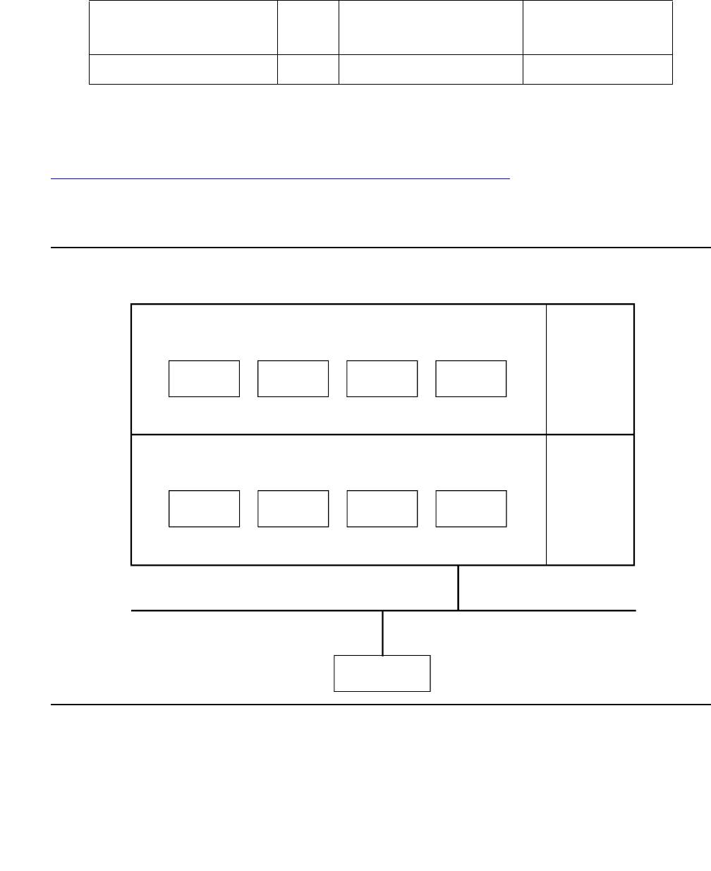
ANNOUNCE (announce)
Issue 1 June 2005 477
ANNOUNCE (announce)
●The ANNOUNCE MO logs an error in the hardware error log if save announcements or
restore announcements does not complete successfully, or the system fails to restore
announcements from the memory card at boot time.
Figure 23: Connection of announcement circuit pack to the system on page 477 shows the
connection of the Announcement Circuit Pack to the system. To save or restore
announcements, an ANNOUNCEMENT Data Extension must be administered, and at least one
DATA-CHL (Network Control Data Channel) must be in the in-service/idle state.
Figure 23: Connection of announcement circuit pack to the system
MO Name in Alarm Log Alarm
level
Initial command to run Full name of MO
ANNOUNCE none none ANNOUNCEMENT
Switch Software Applications
Network Control
DATA
CHL1
DATA
CHL4
DATA
CHL3
Announcement
Circuit Pack
DATA
CHL2
Data-CHL
Software
Data-CHL
Software
Data-CHL
Software
Data-CHL
Software
PR-MAINT
CARD-MEM
TN798 Processor
TDM bus
cydmacps RPY 062397
Communication Manager Maintenance-Object Repair Procedures
478 Maintenance Procedures for Avaya Communication Manager 3.0, Media Gateways and Servers
Hardware error log entries
Notes:
a. Error Type 1: occurred while saving announcements. See Table 145: Aux data error codes
and recommended repair procedures on page 478.
b. Error Type 513: User pressed cancel while announcements were being saved.
c. Error Type 1025: Error occurred while restoring announcements. See Table 145: Aux data
error codes and recommended repair procedures on page 478.
d. Error Types 1, 257, 513, 769, 1025: The port field for this error contained the active PE
complex when the error occurred.
Aux data error codes and recommended repair procedures
Table 144: ANNOUNCE error log entries
Error
type
Aux
data
Associated test Alarm
level
On/Off
board
Test to clear value
1 (a) (d) any None
257 (d) any None
513 (b) (d) 0 None
769 (d) 0 None
1025 (c) (d) any None
Table 145: Aux data error codes and recommended repair procedures
Aux data Description/ Recommendation
9000
through
9031
CARD-MEM errors
Check and resolve CARD-MEM errors and alarms.
1 of 3

ANNOUNCE (announce)
Issue 1 June 2005 479
32001 Internal system error.
1. Check other ANNOUNCE errors and take corrective action. If there are no
other ANNOUNCE errors, do the following:
2. Retry the command at 2-minute intervals a maximum of 3 times.
3. If restore announcements fails, escalate the problem.
32002 Announcement circuit pack is in use.
1. Retry the command at 2-minute intervals a maximum of three times.
2. If restore announcements fails, escalate the problem.
32003 Announcement port is in use.
1. Wait for all Announcement ports to become available.
2. Enter save/restore announcements.
32004 There are no announcements recorded on the Announcement Circuit Pack. Save
announcements does not prevent the destroying of the announcement file on
tape [286 systems] or on the memory card [386 systems].
32005 Integrated announcement circuit pack is not present. The Announcement Circuit
Pack is not inserted, or it is defective.
1. Enter list config to check for the presence of the circuit pack in the
system.
2. If the Announcement Circuit Pack is present, use test board PCSS to
check the status of the Announcement Circuit Pack.
32006 Announcement Data Module not available.
1. Use status to check the status of the Announcement Data Module.
32007 Announcement Data Module out of service.
1. Use status to check the status of the Announcement Data Module.
32008 Announcement data is being saved or loaded.
1. Retry the command at 2-minute intervals a maximum of three times.
2. If save/restore announcements fails, escalate the problem.
Table 145: Aux data error codes and recommended repair procedures (continued)
Aux data Description/ Recommendation
2 of 3

Communication Manager Maintenance-Object Repair Procedures
480 Maintenance Procedures for Avaya Communication Manager 3.0, Media Gateways and Servers
32009 Required DATA-CHL is not administered or out of service. (A DATA-CHL is
required to save or restore announcements.)
1. Add a DATA-CHL if none is administered.
2. If a DATA-CHL is administered, use status to check the status of all
DATA-CHLs. At least one DATA-CHL should be in the in-service/idle state.
32010
32013
DATA-CHL is not administered, or it is unavailable. (A DATA-CHL is required to
save or restore announcements.)
1. Add a DATA-CHL if none is administered.
2. If a DATA-CHL is administered, use status to check the status of all
DATA-CHLs. At least one DATA-CHL should be in the in-service/idle state.
32012 Required Announcement Data Module is not administered.
1. Add an Announcement Data Module and repeat the command.
32015 Time of day not set.
1. Set the time of day, and reenter save/restore announcements.
32016 Internal system errors.
Check for any other ANNOUNCE errors and take corrective action.If there are no
other announcements errors, do the following:
1. Retry the command at 2-minute intervals a maximum of three times.
2. If save/restore announcements fails, escalate the problem.
Table 145: Aux data error codes and recommended repair procedures (continued)
Aux data Description/ Recommendation
3 of 3


Communication Manager Maintenance-Object Repair Procedures
482 Maintenance Procedures for Avaya Communication Manager 3.0, Media Gateways and Servers
ASAI-BD (Multi-Application Platform Board)
S8700 | 8710 / S8500
Maintenance testing of the common circuit pack is handled by on-board firmware and
server-controlled tests. Maintenance software queries the firmware for error and alarm
information, status, and test results. Firmware automatically reports error conditions that result
in server-controlled testing.
For MAPD board insertion, the switch makes an additional board query if any of the following
circuit packs are inserted:
For any of the previous initial board uplinks, the switch queries the board for administration data
as well as reporting the switch software release and the system type.
For the native mode, the response to the board query downlink messages consists of several
CCMS uplink messages that identify the true board code, vintage, suffix, emulation type, and
number of reserved slots needed.
Note:
Note: Refer to LAN-BD Maintenance documentation for circuit pack level errors. See
also ASAI-PT on page 494 and ASAI-EPT on page 484 for related line
information. See the following exceptions listed below:
●Hyperactivity: Currently, the common circuit pack is considered “hyperactive” if the
Service Dispatcher receives 200 uplink messages from the circuit pack in a 10-second
period. Since MAPD has 32 ports, the hyperactivity limit increases to 500 uplink
messages per 10 seconds. The switch issues an alarm when the limit reaches 400;
when it reaches 500 up-link messages in 10 seconds, the board is taken out of service.
MO Name in
Alarm Log
Alarm
Level
Initial Command to Run Full Name of MO
ASAI-BD MIN test board location ASAI-BD
ASAI-BD WRN test board location ASAI-BD
Circuit Pack Vintage
TN754 49
TN556 49,
80 or
greater
TN800 any

ASAI-BD (Multi-Application Platform Board)
Issue 1 June 2005 483
●LED use: The LED Control message 038x requests the Angel to drive the red, amber,
and green LEDs on the face plate of a typical port board on or off. Only the MAPD’s red
LED is controlled by this message. Yellow and green change requests the MAPD
receives from the switch drive LCD behavior rather than LED behavior. The system
continues to send the same LED control messages to the MAPD that the system
currently sends to every other port board. The MAPD handles proper interpretation of
these messages. You should note that the PC on the MAPD and the switch itself control
the LEDs and the LCD on the MAPD.
●Port Administration: In Administration Without Hardware (AWOH), the switch allows
administration of up to 8 ports in any of the first 12 ports. If the port type later reported by
the board does not match the existing type, the switch assumes it to be a MAPD board
with a different configuration and rejects the board.
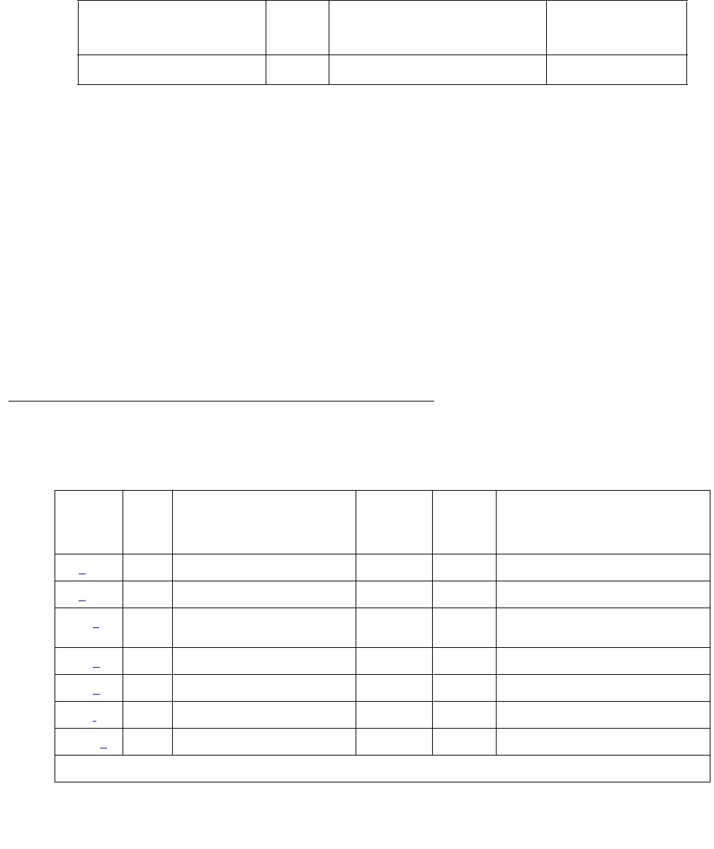
Communication Manager Maintenance-Object Repair Procedures
484 Maintenance Procedures for Avaya Communication Manager 3.0, Media Gateways and Servers
ASAI-EPT
S8700 | 8710 / S8500
The maintenance strategy for this endpoint MO is built on maintenance facilities offered in the
Avaya ISDN-BRI protocol and in the ASAI adjuncts. Currently there are no facilities in the
protocol that provide for maintenance of set data features.
The TN800 is a PC-based platform that allows interaction of multiple applications with
Communication Manager at any time. Communication Manager (native mode) supports
emulation of three types of port MOs on this board. The type of ports to be emulated is defined
by the applications running on the TN800.
Note:
Note: If the TN800 is emulating BRI, the software/firmware supports up to 12 ports, but
only 8 of the 12 ports can be administered at any one time.
Error Log Entries and Test to Clear Values
MO Name in Alarm Log Alarm
Level
Initial Command to Run Full Name of MO
ASAI-EPT MAJ1
1. The alarm level for ASAI adjuncts is adminisered using set options. The alarm level can be set
independently for on- and off-board alarms toWARNING, MINOR, or MAJOR for every ASAI
adjunct in the system.
test station extension ASAI-Adjunct
Table 146: ASAI-EPT Error Log Entries
Error
Type
Aux
Data
Associated
Test
Alarm
Level
ASAI-EPT
On/ Off
Board
Test to Clear Value
0 (a) 0 Any Any Any test ASAI-ADJ
2 (b)2-102None
257 (c) Any BRI Layer 3 query MAJ
WRN1OFF test station ext r 2
test data-module ext r 2
351 (d) 0 none WRN OFF busyout and release station
513 (e)0 None
769 (f)0 None MAJ OFF
2561 (g)0 None
1 of 2
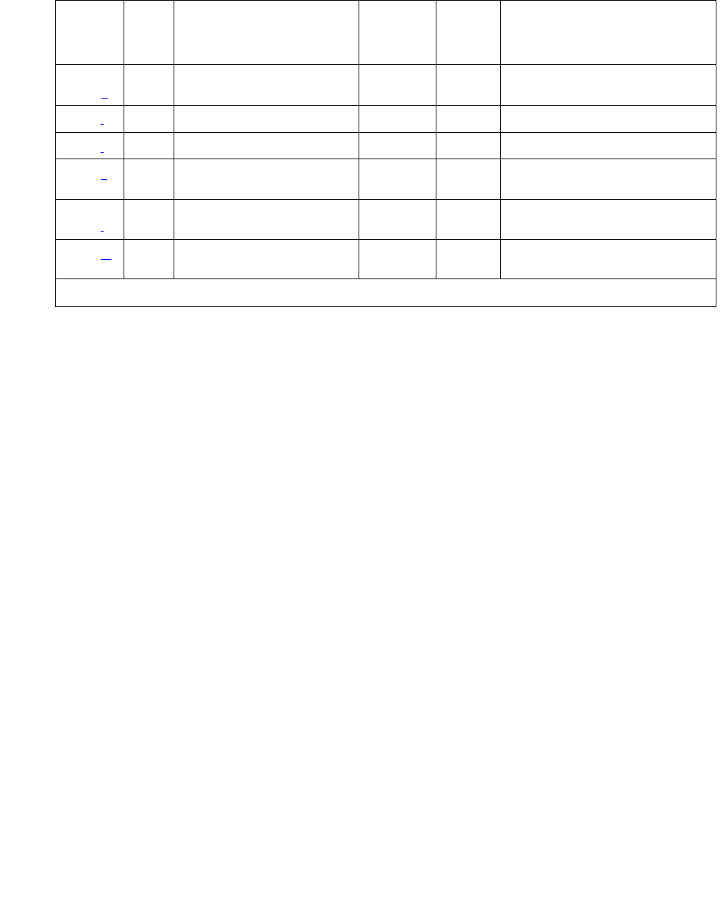
ASAI-EPT
Issue 1 June 2005 485
Notes:
a. Error Type 0: Run the short test sequence first. If every test passes, run the long test
sequence. Refer to each appropriate test’s description, and follow its recommended
procedures.
2562-
2566 (h)
0None
2567 (i)0 None
2568 (j)0 None
3329 (k) Any Signaling Link status (#626) MAJ
WRN†
OFF
3584-
3839 (l)
Any None
3841 (m)
4095
Any None
1. Major alarms on this MO may be downgraded to Warning alarms based on the value used in set options.
Table 146: ASAI-EPT Error Log Entries (continued)
Error
Type
Aux
Data
Associated
Test
Alarm
Level
ASAI-EPT
On/ Off
Board
Test to Clear Value
2 of 2

Communication Manager Maintenance-Object Repair Procedures
486 Maintenance Procedures for Avaya Communication Manager 3.0, Media Gateways and Servers
b. Error Type 2: ISDN-BRI signaling protocol violation. Timers associated with layer-3
messages expired before a required response was received. In the following table, the aux
data column indicates which timer has just expired.
The switch sent a message to an endpoint that did not respond in the allotted time. This
may be due to failure of the point-to-point signaling link or because of a problem in the ASAI
adjunct. To repair:
●Execute test station extension and perform the associated repair procedures for
those tests.
c. Error Type 257: An endpoint is not responding to the service state query message sent to
the adjunct or to the endpoint. This error causes an alarm to be raised. The alarm is retired
when the switch receives a response to the service state query to the endpoint or to the
adjunct.
When this error occurs for an ASAI adjunct, the Aux Data field indicates the state of the
ASAI link and whether an invalid response or no response was received to the query from
the switch, as shown in the following table:
Aux Data Timer Type
2 First T303 (SETUP timer)
3 Second T303 (SETUP timer)
4 T305 (DISConnect timer)
5 First T308 (RELease timer)
6 Second T308 (RELease timer)
10 T316 (RESTart timer)
12 T309 (Layer-2 Failure timer)
16 TM100 (Management Information message
Timer 1)
17 TM200 (Management Information message
Timer 2)
102 TASAI (ASAI Routing Timer)
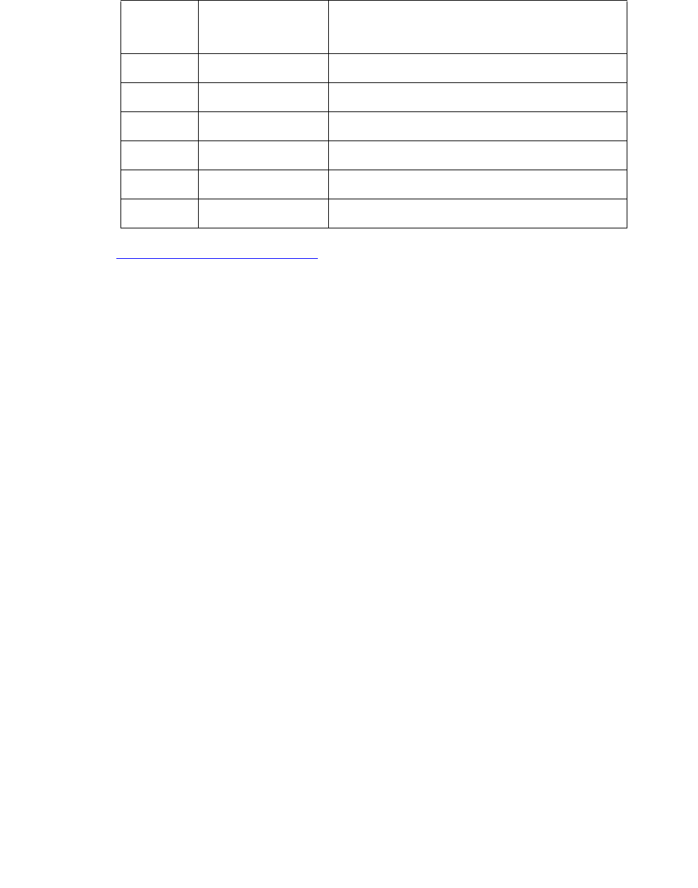
ASAI-EPT
Issue 1 June 2005 487
See Maintenance SAT Commands in Maintenance Commands Reference (03-300191) for
an explanation of the ASAI link states.
For ASAI or Avaya adjuncts, the switch queries the adjunct every two minutes. The Layer 3
Query test is not executed for ASAI or Avaya adjuncts through a command entered from the
management terminal. While alarmed for this error, the switch takes the associated port
out-of-service for five seconds every 15 minutes. This action attempts to stimulate recovery
actions to be taken by the adjunct.
When this error occurs for an ASAI or Avaya adjunct, the service technician should:
1. Execute test station extension and perform the associated repair procedures.
2. Check the health of the adjunct by following the recommended repair procedures of the
manufacturer of the adjunct if the preceding step does not resolve the problem.
d. Error Type 351: logged against an ASAI endpoint when the adjunct asks the switch to
suspend maintenance on the ASAI endpoint. Clear with busyout and release of the ASAI
station.
e. Error Type 513: the endpoint sent more messages than the switch could handle. The
switch suspends the reception of messages from the endpoint for a short period of time.
There is no repair procedure for this error. If the condition persists, replace the endpoint.
f. Error Type 769: an ASAI endpoint’s associated signaling link has too much traffic related to
link establishment. This occurs when the signaling link is alternating between assigned and
established states. If this problem persists, replace the endpoint.
g. Error Type 2561: the ASAI-EPT message was not transmitted because the PKT-CTRL
(Packet Control circuit pack) transmit buffers are exhausted. Frequent or persistent
occurrence of these events may indicate a hardware problem or traffic overload on the
PKT-CTRL, the signaling link, or the ASAI adjunct. Follow the repair procedures for the
PKT-CTRL. If these attempts fail, re-engineering the traffic on the PKT-CTRL, signaling
link, or adjunct may be necessary.
Aux
Data
ASAI Link State Error
102 13-restarting No response to RESTART message
104 13-restarting Invalid response to RESTART message
152 13-restarted No response to layer-3 query
154 13-restarted Invalid response to layer-3 query
202 13-established No response to layer-3 query
204 13-established Invalid response to layer-3 query

Communication Manager Maintenance-Object Repair Procedures
488 Maintenance Procedures for Avaya Communication Manager 3.0, Media Gateways and Servers
h. Error Type 2562 - 2566: the ASAI message is not transmitted because the transmit buffer
for the ASAI link is full, causing the link to be flow-controlled. Frequent or persistent
occurrence of these events may indicate a hardware problem or traffic overload on the
PKT-CTRL, the signaling link, or the ASAI adjunct. Follow the repair procedures issued by
the manufacturer of the adjunct. If these attempts fail, re-engineering of the traffic on the
PKT-CTRL, signaling link, or adjunct may be necessary.
i. Error Type 2567: This version of ASAI is not supported. Check the software version that is
running on the ASAI adjunct.
j. Error Type 2568: The adjunct identification is invalid. Check the vendor ID or software
running on the ASAI adjunct.
k. Error Type 3329: the point-to-point signaling link to the endpoint went down, except when
the link goes down because either a system technician has busied out the PKT-CTRL or the
PKT-BUS, or they have failed. This error raises an alarm against the endpoint or adjunct.
Execute test station extension short and note the results of the Signaling Link
Status Test (#626). If this test fails, follow the repair procedure for Test #626. The alarm is
retired when the signaling link is re-established to the endpoint or adjunct.
l. Error Type 3584 - 3839: The switch software logs certain ASAI cause values. The cause
value is determined from the following formulas:
- If the error type is greater than 3712, then the ASAI cause value is equal to the error type
minus 3712. The switch sent this value to the adjunct.
- If the error type is less than 3712, then the ASAI cause value is equal to the error type
minus 3584. The adjunct sent this value to the switch.
Table 147: ASAI cause values on page 489 contains a description of the various ASAI
cause values and recommended system technician actions associated with the cause
value.
m. Error Type 3841 - 4095: The switch software logs certain ASAI cause values. The cause
value is determined from the following formula:
- If the error type is greater than 3968, then the ASAI cause value is equal to the error type
minus 3968. The switch sent this value to the endpoint.
- If the error type is less than 3968, then the ASAI cause code is equal to the error type
minus 3840. The endpoint sent this value to the switch.

ASAI-EPT
Issue 1 June 2005 489
Table 147: ASAI cause values
Code Explanation Recommendation
0 Unrecognized
ASAI Protocol
Operation.
Requested ASAI protocol is not implemented by switch or adjunct.
Aux Data field of error log entry contains protocol identifier for
unrecognized operation.
1. Consult switch and adjunct documentation to determine which
set of operations is supported by switch and the adjunct.
Turning off adjunct operations not implemented by the switch
may resolve the problem.
34 No circuit or
channel
available
A resource on the switch is unavailable for a call. For BRI
endpoints, this cause value is not logged. For ASAI, this condition
means that there are no available trunks for an outgoing call
request.
1. Verify that the adjunct is administered to support the trunk
capabilities of the switch.
2. Investigate trunk-group status by issuing status trunk from
the SAT or by requesting trunk-group queries from the adjunct.
3. Perform trunk diagnostic procedures outlined in this manual.
40 Resources
not available.
No available internal resources to service switch or adjunct request.
Exceeds system transaction capacity for adjunct or switch.
1. May require re-engineering of adjunct services.
1 of 3

Communication Manager Maintenance-Object Repair Procedures
490 Maintenance Procedures for Avaya Communication Manager 3.0, Media Gateways and Servers
50 Requested
facility not
subscribed
Requested facility is implemented, but not administered. Potential
administration problem with endpoint or adjunct.
For BRI endpoints:
1. Verify the switch administration of endpoint using display
station or display data-module.
2. If step 1 does not resolve the problem, refer to the endpoint’s
service manual and verify administration on the endpoint.
For ASAI adjuncts:
1. Display the Customer Optional Features screen (administration
screen) on the switch to determine which ASAI capabilities are
turned on in the switch.
2. Verify that the adjunct is administered to support the identical
capabilities as the switch. If there is a mismatch in the
administered capabilities, then re-administer the switch and/or
the adjunct to establish a consistent set of desired capabilities
on both the switch and the adjunct.
58 Bearer
capability not
currently
available
Requested bearer capability is implemented, but not administered.
No B channel is administered. See code 50 above.
63 Service or
option not
available
Requested ASAI capability or resource is not available on the switch
or adjunct. More than one adjunct may be contending for the same
switch resource. Potential administration mismatch between the
resource domains administered on the switch and those
administered on the adjunct.
1. Verify that no overlapping administration of switch resources (for
example, requesting notifications on a single domain by multiple
adjuncts attempting to control a single call) exists across any
adjunct connected to the switch. If an overlap exists, then
re-administer the adjuncts to ensure that each adjunct is
associated with a unique set of switch resources.
65 Bearer
service not
implemented
Requested service not implemented in switch or endpoint.
Table 147: ASAI cause values (continued)
Code Explanation Recommendation
2 of 3

ASAI-EPT
Issue 1 June 2005 491
System Technician-Demanded Tests:
Descriptions and Error Codes
Investigate errors associated with the circuit pack and port first. Clearing these error codes may
also clear errors against the endpoint. When every circuit pack and port error has been cleared,
but errors still exist against the endpoint, investigate errors in the table below.
BRI Layer 3 Query Test (#629)
This test is not used by the ASAI-ADJ MO. For information about this test, see BRI-SET,
Various Adjuncts on page 708.
69 Requested
facility not
implemented
Requested service not supported in switch or endpoint.
1. Consult switch and endpoint documentation to determine
service support.
79 Service or
option not
implemented
Requested service or option (or combination of selected options) is
not supported (implemented) in switch or the adjunct.
1. Consult switch and adjunct documentation to determine ASAI
service and options supported by both switch and adjunct.
Re-administration of the switch-administered capabilities (see
Customer Optional Feature screen) or those of the adjunct may
be necessary to correct the problem.
81 Invalid CRV An invalid CRV was sent by the adjunct.
1. This may indicate a CRV inconsistency between the switch and
the adjunct. See the CallVisor protocol reference manual.
87 Internal switch
audit
There is an inconsistency in switch data records.
1. There is no action needed, since the switch has corrected the
data inconsistency.
Table 147: ASAI cause values (continued)
Code Explanation Recommendation
3 of 3
Order of Investigation Short Test
Sequence
Long Test
Sequence
D/ND
Signaling Link Status test (#626) X X Nondestructive

Communication Manager Maintenance-Object Repair Procedures
492 Maintenance Procedures for Avaya Communication Manager 3.0, Media Gateways and Servers
Signaling Link Status Test (#626)
This test determines the current status of the signaling link. This test passes if the link is
“bound” to an endpoint and fails if the link is “not bound.”
The definition of the term “bound” for a link depends upon the type of endpoint and may depend
on the successful completion of procedures at both Layers 2 and 3 of the protocol. The
definition of “bound” for ASAI type of endpoint is:
●ASAI adjuncts and BRI endpoints not administered for MIM initialization (point-to-point):
For endpoints of this type, the signaling link is “bound” when the link is connected at Layer 2
(L2 established).
Table 148: Test #626 Signaling Link Status Test
Error
Code
Test
Result
Description / Recommendation
1139 ABRT The PN’s packet bus is out-of-service.
1. Follow the repair procedures for the packet bus.
2. After completing step 1, execute test port location long and
review the results of the BRI Port Local LAN Looparound test (#618) to
verify the repair.
1141 ABRT The PKT-CTRL is out-of-service.
1. Refer to PKT-CTRL maintenance documentation.
S8700
| 8710
S8500:
1187
ABRT The circuit pack, port, or station may have been busied out.
1. Look in the Error Log for Error Type 18 (busied out) for ASAI-BD,
ASAI-PT, or ASAI-EPT.
2. If this Error Type is present for ASAI-EPT only, use release
station and run the test again.
3. If this Error Type is present for ASAI-PT and ASAI-EPT, use release
port and run the test again.
4. If this Error Type is present for ASAI-BD, ASAI-PT, and ASAI-EPT, use
release board and run the test again.
2012 ABRT Internal system error
2100 ABRT Could not allocate the necessary system resources to run this test.
1. Retry the command at 1-minute intervals up to 5 times.
1 of 2

ASAI-EPT
Issue 1 June 2005 493
1113 FAIL The signaling link is not “bound” to the adjunct. For ASAI adjuncts this
error indicates that the link is disconnected at Layer 2. Since the signaling
link associated with the endpoint has been identified by administration, the
link is only “unbound” from the endpoint when it is disconnected.
1. Execute status bri-port location and see BRI-PORT
(ISDN-BRI Port) on page 685.
PASS The signaling link is connected at Layer 2 and “bound” to the ASAI adjunct.
Table 148: Test #626 Signaling Link Status Test (continued)
Error
Code
Test
Result
Description / Recommendation
2 of 2

Communication Manager Maintenance-Object Repair Procedures
494 Maintenance Procedures for Avaya Communication Manager 3.0, Media Gateways and Servers
ASAI-PT
S8700 | 8710 / S8500
Unless otherwise stated, every maintenance action contained in this section applies to ASAI-PT
and ISDN-BRI ports connected to ASAI adjuncts. This port type is administered as an ASAI-BD
on the TN800 circuit pack.
The TN800 circuit pack is a PC-based platform that allows interaction of multiple applications
with Avaya™ Communication Manager. Communication Manager software (native mode)
supports emulation of three types of port MOs on this board. The type of ports to be emulated
are defined by the applications running on the TN800. The TN800 can support up to 32 ports
(time slots) at a time.
The TN800 connects to the switch through a single slot in the backplane, however its width is
not limited to one slot. The number of slots occupied by the TN800 is supplied by the board
during its insertion. The TN800 (Release 5 and higher) is three slots wide. The blank (reserve)
slots are to the left of the functional slot.
In non-native mode the TN800 is recognized as TN556, TN2181, TN754, or TN746 based on
the switch software and the application running on the TN800. In non-native mode only one
type of port MO runs at any time, and the port type depends on the application running on the
TN800. If the TN800 fails diagnostics in non-native mode, the system’s alarm and error logs
would show a failure for the board type the TN800 is emulating.
MO Name in Alarm Log Alarm
Level
Initial Command to Run Full Name of MO
ASAI-PT MAJ1,2
1. The alarm level for ASAI adjunct ports may be administered using set options. The alarm level
can be set independently for on- and off-board alarms toWARNING, MINOR, or MAJOR for every
ASAI adjunct port in the system.
2. All alarming for an ASAI adjunct and off-board alarming for an ASAI port is disabled if the ASAI
adjunct asks the switch to suspend maintenance. When this occurs, an error and a WARNING
alarm is logged against the ASAI adjunct. Check the Hardware Error and Alarm Logs to see if the
adjunct has disabled alarming.
test port location l ASAI ISDN BRI port
ASAI-PT WRN test port location l ASAI ISDN BRI port
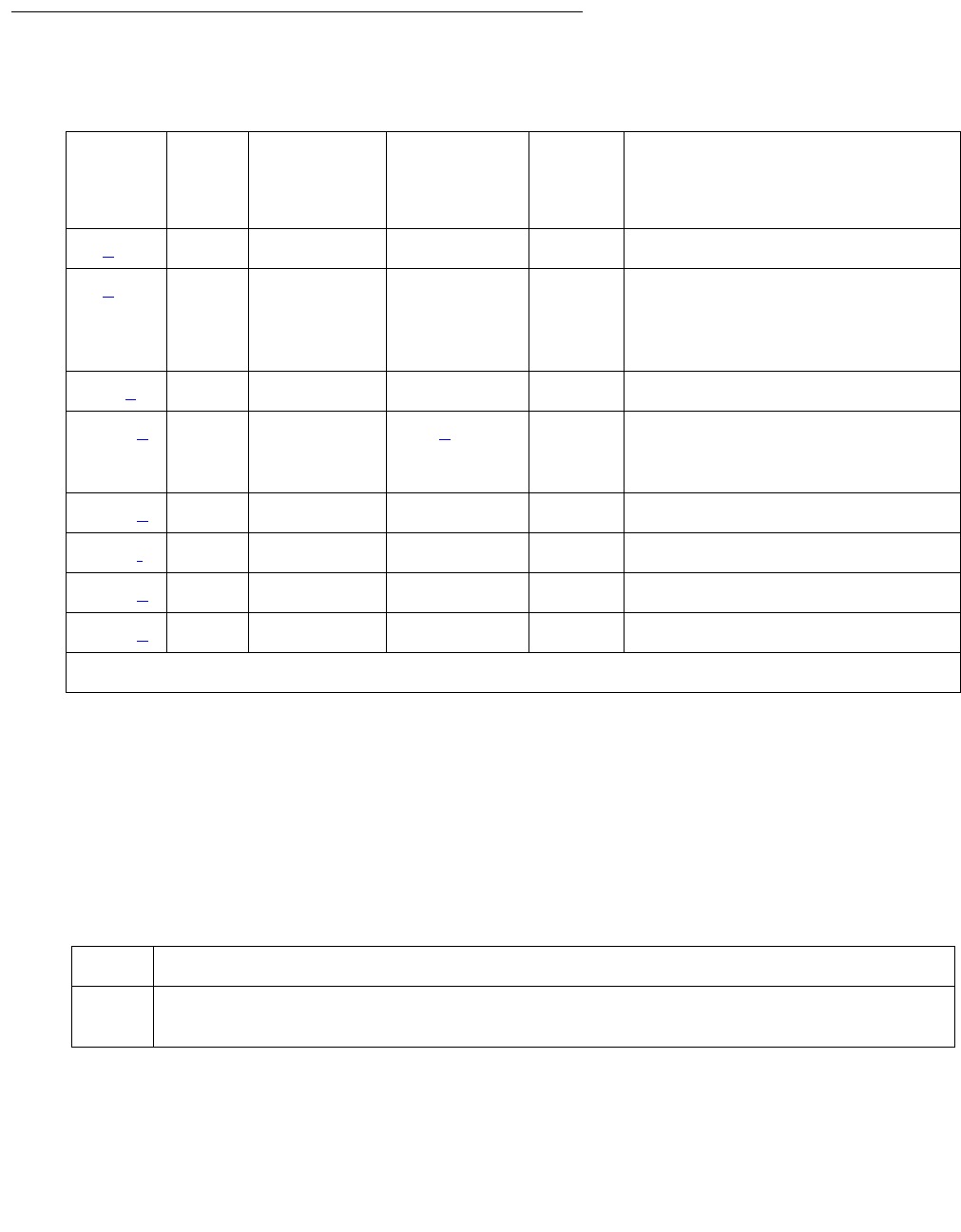
ASAI-PT
Issue 1 June 2005 495
Error Log Entries and Test to Clear Values
Notes:
a. Error Type 0: Run the short test sequence first. If every test passes, run the long test
sequence. Refer to each appropriate test’s description, and follow its recommended
procedures.
b. Error Type 1: Level 1 Status inquiry fails or when the BRI circuit pack detects that Level 1
has been deactivated on the port. The Aux Data field contains one of the following values:
Refer to the repair procedures for Test #621.
Table 149: ASAI-PT Error Log Entries
Error
Type
Aux
Data
Associated
Test
Alarm Level
ASAI-
PORT
On/Off
Board
Test to Clear Value
0 (a)0 Any Any Anytest port location sh r 1
1 (b) (a) Level 1
Status
inquiry
(#621)
MAJ1
1. Major and Minor alarms may be downgraded to warning alarms based on the value used in set options.
OFF test port location sh r 2
513 (c) 0 none (b) ON
1537 (d) 46210 CRC Error
counter
(#623)
MAJ1OFF
3841 (e) 46208 None
3844 (f) 46223 None
3845 (g) 46211 None
3846 (h) TEI None
Blank This indicates that the Level 1 Status inquiry failed.
32773 This is a message from the ASAI-Line circuit pack indicating Level 1 has been
deactivated.

Communication Manager Maintenance-Object Repair Procedures
496 Maintenance Procedures for Avaya Communication Manager 3.0, Media Gateways and Servers
c. Error Type 513: The circuit pack is having problems transmitting data to the packet bus,
thus affecting the conveyance of signaling information over the D channel. This error
occurs when the packet bus transmit FIFO buffer overflows. This condition probably
indicates a hardware problem as well. The ASAI-PORT alarm level is MAJOR with aux data
0. Use troubleshooting procedures for both on-board hardware problems and potential
off-board packet-bus problems.
d. Error Type 1537: The port received an invalid frame over the D channel. When the cyclical
redundancy check (CRC) errors exceed 5 within 15 minutes, the port is taken out of service
for 5 seconds. If 5 more CRC errors are received within 15 minutes of the first set of 5
errors, the port is taken out of service for one minute. If 5 more CRC errors are received
within 15 minutes of the last 5, the port is taken out of service for 15 minutes.
This error is most likely due to a problem with the wiring to the set or adjunct, interference
on the wiring due to a noise source, or no termination (an open circuit). It usually does not
indicate a problem with the circuit pack.
●Check the wiring to the endpoints or the adjunct.
●If the problem persists, replace the endpoints or adjuncts.
e. Error Type 3841: a Layer 1 Transmission error is detected for the port. Run the long test
sequence, and note the results of the Layer 1 Transmission Error Counter test (#624).
f. Error Type 3844: the circuit pack detects an overflow of its receive buffers. Run the long
test sequence, and note the results of the Receive FIFO Overflow Counter test (#625).
g. Error Type 3845: the BRI Port Local LAN Looparound test (#618) fails. Run the long test
sequence, and note the results of Test #618.
h. Error Type 3846: the TEI (Terminal Endpoint Identifier) administered for the ASAI endpoint
most likely does not match the TEI administered in the ASAI adjunct. Check the switch
administration of the TEI against that of the adjunct, and make sure that both are using the
same TEI.

ASAI-PT
Issue 1 June 2005 497
System Technician-Demanded Tests:
Descriptions and Error Codes
Investigate tests in the order presented. By clearing error codes associated with the ASAI Port
Local LAN Looparound test (#618), you may also clear errors generated from other tests in the
testing sequence.
BRI Port Local LAN Loop-Around Test (#618)
This test is destructive.
This test verifies the connectivity of a BRI port across the LAN Bus and executes only if the port
is out-of-service. The test aborts if calls associated with the port are in-progress. Failures of
this test indicate either on-board faults associated with the ASAI-PT hardware on the circuit
pack or problems with the LAN Bus, which is used to form connectivity between the switch and
the ASAI-PT.
The dotted lines in Figure 24: BRI Port Local LAN Loop-Around Path on page 498 show how a
loop-around test is performed across the packet bus for the D channel.
Table 150: System Technician-Demanded Tests: ASAI-PT
Order of Investigation Short Test
Sequence
Long Test
Sequence
D/ND1
1. D = Destructive, ND = Nondestructive
ASAI Port Local LAN Looparound test (#618) X D
Level 1 Status Inquiry test (#621) X X ND
CRC Error Counter test (#623) X ND
Layer 1 Transmission Error Counter test (#624) X ND
Receive FIFO Overflow Error Counter test (#625) X ND
Clear Error Counters (#270) X X ND
Communication Manager Maintenance-Object Repair Procedures
498 Maintenance Procedures for Avaya Communication Manager 3.0, Media Gateways and Servers
Figure 24: BRI Port Local LAN Loop-Around Path
Table 151: Test #618 BRI Port Local LAN Looparound
Error
Code
Test
Result
Description / Recommendation
1015 ABRT The port is not in the out-of-service state.
1. Display the Port Status screen using status bri-port location
to determine which stations or adjuncts are on this port.
2. Use the extension shown on this screen in status station to
determine whether the station or adjunct is active.
3. If the port is active, wait until it is idle, and use busyout port
location to place it in the out-of-service state and repeat this test.
!WARNING:
WARNING: Since the busyout command is destructive, using this
command prior to the port being idle causes every
transaction associated with the ASAI on the port to be torn
down. Note that 3rd-party calls established by an ASAI
adjunct remain connected even though the port is taken
out-of-service.
1 of 2
BRI LINE
CIRCUIT
PACK
PACKET
INTERFACE
PACKET BUS
.
.
.
.
. . . . . . . . . . . . . . . . . . . . . . .
.
.
.
.
.
.
. . . . . . . . . . . . . . . . . . . . . .
.
.
.
.
.
. . . .

ASAI-PT
Issue 1 June 2005 499
Level 1 Status Inquiry Test (#621)
This test determines the state of the transmission facility of a BRI port at the Level 1 (L1) or
physical layer. L1 can be in one of two possible states: Activated or Deactivated.
The Activated state is the correct state for an ISDN-BRI port. In this state the Level 1 interface
can communicate with the BRI endpoint or ASAI adjunct administered on this port. This test
passes if the state of L1 is activated. This test also passes if software has taken this port out of
service.
1139 ABRT The PN’s packet bus is out-of-service.
1. Follow the repair procedures for the packet bus.
2. After completing step 1, execute test port long location and
review the results of the BRI Port Local LAN Looparound test to verify
the repair.
1141 ABRT The PKT-CTRL is out-of-service.
1. Follow the repair procedures for the PKT-CTRL.
2. Enter test port long location and review the results of the BRI
Port Local LAN Looparound test to verify the repair.
2012 ABRT Internal system error
1. Retry the command at 1-minute intervals up to 5 times.
2100 ABRT Could not allocate the necessary system resources to run this test.
1. Retry the command at 1-minute intervals up to 5 times.
FAIL The loop-around test has failed.
1. If the test fails repeatedly, attempt to reset the circuit pack if the other
ports on the board are idle. Reset the circuit pack by issuing the
busyout board location and reset board locations.
2. If the test fails again, execute test pkt P on the management
terminal. If this fails, follow the failure procedures the in PKT-BUS
section.
3. If the tests executed in step 2 pass, the problem is local to the BRI
board. Replace the circuit pack.
PASS The BRI Port Local LAN Looparound test has passed.
Table 151: Test #618 BRI Port Local LAN Looparound (continued)
Error
Code
Test
Result
Description / Recommendation
2 of 2

Communication Manager Maintenance-Object Repair Procedures
500 Maintenance Procedures for Avaya Communication Manager 3.0, Media Gateways and Servers
The Deactivated state indicates a problem with the ASAI circuit pack. When in this state, the
Level 1 interface is idle and is not trying to communicate with the BRI endpoints or adjunct.
When an ASAI port is placed in the out-of-service state, Level 1 is also put into the deactivated
state. This could be due either to the system detecting a fault with the port or in response to a
busyout port location request.
Table 152: Test #621 Level 1 Status Inquiry
Error
Code
Test
Result
Description / Recommendation
1187 ABRT The board, port, or station may have been busied-out by a technician.
1. Look in the Error Log for Error Type 18 (port busied out) for this port
and ASAI-BD (board busied out). If this error type is present for
ASAI-PT only, then release the port using release port
location and run the test again. If the error is present for both
ASAI-BD and ASAI-PT, then release the board with release port
location and run the test again.
Note:
Note: When you release a port, you release every port
associated with it. If certain ports still need to be busied out,
use busyout port location to busy them out.
2. Make sure the terminal is connected.
3. Retry the command at 1-minute intervals up to 5 times.
2000 ABRT Response was not received from the circuit pack within the allowable time
period.
1. If the test aborts repeatedly up to 5 times, reset the circuit pack using
busyout board location and reset board location.
2. If the test aborts again, replace the circuit pack.
2012 ABRT Internal system error
2100 ABRT Could not allocate the necessary system resources to run this test.
1. Retry the command at 1-minute intervals up to 5 times.
1 of 2

ASAI-PT
Issue 1 June 2005 501
CRC Error Counter Test (#623)
This test reads and clears the BRI port’s CRC error counter maintained on the BRI-LINE circuit
pack. This counter is incremented by the circuit pack when it receives a frame from the
endpoint or adjunct with a bad CRC over the D channel. The test passes if the value of the
counter is 0 (the error is cleared). If the counter is not 0, the test fails and the value of the
counter is displayed in the Error Code field. A CRC error is most likely due to a problem with
the wiring to the set or adjunct, interference on the wiring due to a noise source (for example,
electrical motors or generators), or no termination (open circuit). It usually does not indicate a
problem with the BRI circuit pack. This test is used for verifying the repair of the problem.
3 FAIL Received a status of Level 1 Deactivated; the port is out of service.
1. Enter status bri-port location to verify that the service state
of the port is out-of-service. If the port is not out of service, escalate
the problem, or else proceed to step 2.
2. If the port has been placed out-of-service using busyout port
location, use release port location. Then enter test
port long location and review the results of Level 1 Status
Inquiry test. If this test still fails, proceed to step 3.
3. After executing test port long location review the results of
every test. Follow the repair procedures for any tests that fail. Verify
repair of the problem by executing test port location and by
determining that the Level 1 Status test passes.
4. If the test continues to fail for this reason, escalate the problem.
PASS This test indicates that Level 1 is activated, or that software has taken the
port out of service.
Table 152: Test #621 Level 1 Status Inquiry (continued)
Error
Code
Test
Result
Description / Recommendation
2 of 2

Communication Manager Maintenance-Object Repair Procedures
502 Maintenance Procedures for Avaya Communication Manager 3.0, Media Gateways and Servers
Layer 1 Transmission Error Counter Test (#624)
This test reads and clears the BRI port’s Layer 1 Transmission error counter maintained on the
ASAI circuit pack. This counter is incremented by the circuit pack when it detects a Layer 1
transmission problem. The test passes if the value of the counter is 0 (that is, the error is
cleared). If the counter is not zero, the test fails, and the value of the counter is displayed in the
Error Code field.
This error is most likely due to a problem with the wiring or adjunct (verify that the wiring meets
the configuration rules defined in DEFINITY® Communications System Generic 1 and Generic
3i Wiring, 555-204-111. It does not indicate a problem with the TN800 circuit pack. This test is
useful for verifying the repair of the problem.
Table 153: Test #623 CRC Error Counter Test
Error
Code
Test
Result
Description / Recommendation
2000 ABRT Response was not received from the circuit pack within the allowable time
period.
1. If the test aborts repeatedly up to 5 times, reset the circuit pack using
busyout board location and reset board location.
2. If the test aborts again, replace the circuit pack.
!CAUTION:
CAUTION: Do not leave the circuit pack busied out.
2012 ABRT Internal system error
1. Retry the command at 1-minute intervals up to 5 times.
Any FAIL The BRI circuit pack is still detecting CRC errors. The Error Code field
contains the value of the counter.
1. Retry the command at 1-minute intervals up to 5 times.
2. If the test continues to fail, review the results of other tests in the long
test sequence. Pay particular attention to the results of the Level 1
Status Inquiry test. Follow the repair procedures for any of the
executed tests if they fail; otherwise, proceed to step 3.
3. If the tests for the endpoints or adjunct pass and the CRC error counter
test continues to fail, check the wiring to the endpoints or adjunct. If
the wiring appears to be OK, escalate the problem.

ASAI-PT
Issue 1 June 2005 503
Receive FIFO Error Counter Test (#625)
This test reads and clears the BRI port’s Receive FIFO error counter maintained on the TN800
circuit pack. This counter is incremented by the circuit pack when it detects an overflow of its
receive buffers. The test passes if the value of the counter is 0 (that is, the error is cleared). If
the counter is not zero, the test fails, and the value of the counter is displayed in the Error Code
field.
This error can occur if signaling frames are being received from a packet bus at a rate sufficient
to overflow the receive buffers on the circuit pack for a port or if hardware fault is causing the
receive buffers not to be emptied properly. This test is useful for verifying the repair of the
problem.
Table 154: Test #624 Layer 1 Transmission Error Counter Test
Error
Code
Test
Result
Description / Recommendation
2000 ABRT Response was not received from the circuit pack within the allowable time
period.
1. If the test aborts repeatedly up to 5 times, reset the circuit pack using
busyout board location and reset board location.
2. If the test aborts again, replace the circuit pack.
2012 ABRT Internal system error
2100 ABRT Could not allocate necessary system resources to run test.
1. Retry the command at 1-minute intervals up to 5 times.
Any FAIL The TN800 circuit pack is still detecting errors of this type. The Error Code
field contains the value of this counter.
1. Retry the command at 1-minute intervals up to 5 times.
2. If the test continues to fail, review the results of other tests in the long
test sequence. Note the results of the Level 1 Status Inquiry test.
Follow the repair procedures for any of the executed tests if they fail.
Otherwise, go to the next step.
3. Replace the circuit pack.
PASS The Layer 1 Transmission error counter was read correctly and has a value
of 0.

Communication Manager Maintenance-Object Repair Procedures
504 Maintenance Procedures for Avaya Communication Manager 3.0, Media Gateways and Servers
Table 155: Test #625 Receive FIFO Error Counter Test
Error
Code
Test
Result
Description / Recommendation
2000 ABRT Response was not received from the circuit pack within the allowable time
period.
1. If the test aborts repeatedly up to 5 times, reset the circuit pack using
busyout board location and reset board location.
2. If the test aborts again, replace the circuit pack.
2012 ABRT Internal system error
2100 ABRT Could not allocate necessary system resources to run test.
1. Retry the command at 1-minute intervals up to 5 times.
Any FAIL The TN800 circuit pack is still detecting errors of this type. The Error Code
field contains the value of this counter.
1. Retry the command at 1-minute intervals up to 5 times.
2. If the test continues to fail, review the results of other tests in the long
test sequence. Note the results of the Level 1 Status Inquiry test.
Follow repair procedures for any of the tests that fail. Otherwise, go to
the next step.
3. If the tests for the endpoints or adjunct pass and the Layer 1
Transmission Error Counter test continues to fail, check the wiring to
the endpoints or adjunct.
PASS The Layer 1 Transmission error counter was read correctly and has a value
of 0.

ASAI-PT
Issue 1 June 2005 505
Clear Error Counters Test (#270)
There are various error counters associated with each ASAI-PT. This test clears those counters
and triggers the auditing of layer-3 reinitialization. This test is used only to send messages to
the ASAI-PT and should not abort nor fail. ASAI uses a fixed TEI value of 1.
Table 156: Test #270 Clear Error Counters
Error
Code
Test
Result
Description / Recommendation
Any ABRT This test should never abort.
Any FAIL This test should never fail.
1. Retry the command at 1-minute intervals up to 5 times.
PASS The message to clear the error counters of the ASAI-PT has been sent.

Communication Manager Maintenance-Object Repair Procedures
506 Maintenance Procedures for Avaya Communication Manager 3.0, Media Gateways and Servers
ASAI-RES (TN800 reserve slot)
Error log entries and tests also apply to E-DIG-RES.
S8700 | 8710 / S8500
There are no tests associated with these MOs. Both the test board and busyout board
commands abort when either is attempted on a reserved slot. An error message indicates the
slot is associated with the circuit pack that the TN800 is emulating, but the requested operation
is not valid.
The TN800 MAPD (Multi-Application Platform) circuit pack connects to the switch through a
single slot in the backplane. The number of slots occupied by the MAPD pack is supplied by the
board when inserted. The TN800 in R5EM is three slots wide. The TN800 requires 2 reserve
slots to its left. The reserve (blank) slots are to left of the functional slot and are place holders
on the switch, and do not have any interaction with the switch.
Each instance of these MOs represents a reserve slot associated with respective circuit pack
mode in which the MAPD is working.
MO Name in
Alarm Log
Alarm
Level
Initial Command to Run Full Name of MO
ASAI-RES NONE NONE TN800 ASAI reserve slot
E-DIG-RE NONE NONE TN800 DIG reserve slot

ATM-BCH (ATM B-Channel Trunk)
Issue 1 June 2005 507
ATM-BCH (ATM B-Channel Trunk)
S8700 | 8710 / S8500
ATM-BCH explains how to test and repair TN230x ATM Interface circuit packs (TN2305 and
TN2306) that have ATM B-channel trunks administered for ATM Circuit Emulation Service
(CES).
For additional repair information, see also ATM-DCH (ATM D-Channel Port) on page 522,
ATM-SGRP (ATM Signaling Group) on page 598 and PKT-BUS (Packet Bus) on page 1790.
For maintenance instructions for TN230x circuit packs that are administered as Expansion
Interfaces for ATM network connectivity, see ATM-INTF (TN2305/6) on page 573.
ATM Circuit Emulation Service
Under ATM Circuit Emulation Service, you simulate ISDN-PRI circuits by assigning ATM ports
to signaling groups. Each signaling group represents a PRI circuit, and the ports in the group
represent the D channel and B channels of that circuit. B channels must also be assigned to
ISDN-PRI trunk groups. TN230x circuit packs support up to 248 ports per circuit pack.
Signaling Group Components
B (bearer) channels (ATM-BCH) transmit digitized voice or data, while a separate D channel
(ATM-DCH) handles call-control signaling. One D channel handles signaling for a group of B
channels that combine to form a signaling group (ATM-SGRP).
MO Name in
Alarm Log
Alarm
Level
Initial Command to Run Full Name of MO
ATM-BCH MAJ1
1. A MAJOR alarm on a trunk means that alarms on these trunks are not downgraded by
set options, and at least 75% of the trunks in this trunk group are alarmed.
test port location lATM B-Channel Trunk
ATM-BCH MIN test port location lATM B-Channel Trunk
ATM-BCH WRN test port location sh ATM B-Channel Trunk

Communication Manager Maintenance-Object Repair Procedures
508 Maintenance Procedures for Avaya Communication Manager 3.0, Media Gateways and Servers
B-Channel Service States
The ISDN specification defines two service state categories for B channels as listed in
Table 157: ATM ISDN service states on page 508.
Table 157: ATM ISDN service states
Category Description
Service states
In-Service (INS) B channel is in normal
operating state
Active A call is connected over
the B channel.
Idle There is no call on the
B channel.
Out-of-Service/
Far-End (OOS/FE)
The switch has not successfully negotiated B-channel connection as
of yet. Calls cannot be placed or received.
When you first administer a B channel, the switch initializes the
B channel to this state while it tries to negotiate a connection to the far
end. If the request times out with no response from the far end, the
switch leaves the B channel in the OOS/FE state.
Out-of-Service/
Near-End (OOS/NE)
The NPE Crosstalk test has failed, or the trunk is busied out. Calls
cannot be placed or received.
Maintenance/
Far-End (MTC/FE)
A request has timed out with no response from the far end after
signaling is in place and B channels are in service. Calls can be
received but not placed, and stable calls are unaffected.
Maintenance/
Near-End (MTC/NE)
The signaling channel (ISDN-LNK) has been busied out, possibly after
test trunk grp#/mem# long. Calls cannot be placed or received,
but stable calls are unaffected.
Pending states The switch is waiting for a reply from the far end. Pending service
states remain in effect until the near end receives a response or times
out.
Pending-in-Service The near end is waiting for a response to a transition-to-service
request.
Pending-
Maintenance
The near end is waiting for a transition-to-maintenance-service
request (US and other country-protocol-1 systems).
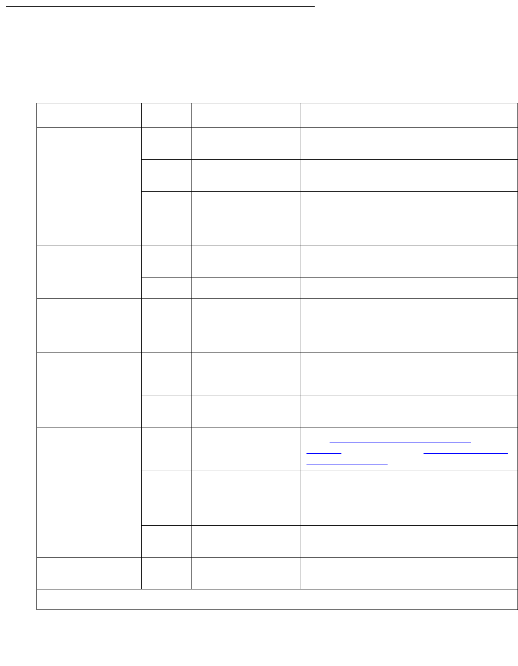
ATM-BCH (ATM B-Channel Trunk)
Issue 1 June 2005 509
B-Channel Alarms
The Maintenance/Far-End and Out-Of-Service/Far-End states generate warning alarms
displayed with status trunk grp#/mem#.
Table 158: ATM-BCH alarms by service state
Service state Alarm1
1. ATM-BCH alarms; alarms against other MOs may also be present.
Possible cause Possible solution
Out-of-Service/NE WRN Trunk busied out Release the port (release trunk
grp#/mem#).
MIN NPE Crosstalk test
(#6) failed
Replace ATM circuit pack.
None ATM circuit pack
lost signal or there
is a circuit pack
problem.
Install circuit pack or cable. Check circuit
pack using procedures in ATM-BCH.
Check far-end switch status.
Out-of-Service/FE WRN Unadministered far
end
Administer the corresponding trunk on
the far-end switch.
WRN Far-end busied out Check the status of the far-end switch.
Pending/
In-Service
Pending/Maint
None Maintenance
message timed out
waiting for reply
Wait 2 minutes after the pending state
clears, and check the service state.
Maint/NE None ISDN test call in
progress (test
trunk long)
Wait for the test to finish and recheck.
None System link busied
out
Check link status. Run release link
link#.
Maint/FE WRN Signaling channel
down for over 90
sec.
See ATM-SGRP (ATM Signaling
Group) on page 598 or ATM-DCH (ATM
D-Channel Port) on page 522.
WRN Repeated lack of
response to
messages sent to
the far end
Wait. Maintenance software resends
messages periodically. Or run test
trunk grp#/mem# or test
signaling-grp grp#.
WRN The far-end trunk
is being tested.
Check status of the far-end switch. Wait
for testing to finish.
In-Service None Normal operating
state
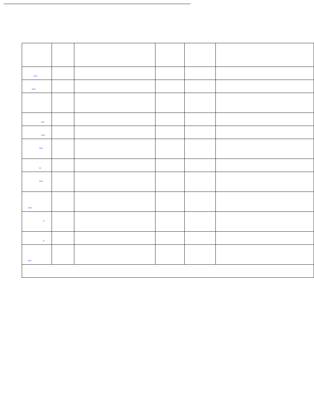
Communication Manager Maintenance-Object Repair Procedures
510 Maintenance Procedures for Avaya Communication Manager 3.0, Media Gateways and Servers
Error Log Entries and Test to Clear Values
Notes:
a. Error Type 0: Run the short test sequence first. If every test passes, run the long test
sequence. Refer to each appropriate test’s description, and follow its recommended
procedures.
b. Error Type 1: the two ends of the ATM trunk do not agree on the ISDN call state. Possible
causes:
●Received a DISConnect or RELease COMplete message with cause value 52 (outgoing
calls barred)
●Received a DISConnect or RELease COMplete message with cause value 54 (incoming
calls barred)
Table 159: ATM-BCH Error Log entries
Error
Type
Aux
Data
Associated Test Alarm
Level
On/Off
Board
Test to Clear Value
0 (a) 0 Any Any Any test port location
1(b) Any None test port location
18 0 busyout trunk grp/
mbr release trunk grp/mbr
129 (c) None WRN OFF test port location
130 (d)test port location
257(e) Any Service State Audit test
(#256) test port location
513(f) Any None WRN OFF test port location
769(g) Any Service State Audit test
(#256) test port location
1793
(h)
Any None test port location
3073(i) Any Service State Audit test
(#256) test port location
3585(j) Any None none
3841
(k)
Any None WRN OFF none

ATM-BCH (ATM B-Channel Trunk)
Issue 1 June 2005 511
●Outgoing call renegotiated by the far end to another B channel in the absence of SETUP
message glare
●Near end attempted a call on a B channel that the far end has marked OOS
When running the short test sequence, pay close attention to the results of the Call State
Audit test (#257).
c. Error Type 129: the far-end switch changed its ISDN service state to either out-of-service
or maintenance. This may be a temporary condition because the far end is testing that
trunk or a hardware problem with the trunk. Outgoing calls may not be allowed over that
trunk.
1. Investigate the trunk’s status (status trunk grp#/mem#).
d. Error Type 130: the circuit pack has been removed or has been insane for more than 11
minutes.
1. Reinsert or replace the circuit pack to clear the error.
e. Error Type 257: SETUP received for a B channel that is in an invalid service state. Service
states may be incompatible at the two ends of the trunk. A normal call was received while
the B channel was MTC/FE, MTC/NE, OOS/FE, or OOS/NE or a test call was received
while the B channel was OOS/FE or OOS/NE.
f. Error Type 513: RELease COMplete message received with cause value 82 (nonexistent
channel). The B channel may not be administered at the far end. The trunk has been
placed in the OOS/FE state.
g. Error Type 769: inconsistent SERVice or SERVice ACKnowledge message. Possible
causes:
●SERVice or SERVice ACKnowledge message received containing a change status that
is more available than the previously-transmitted SERVice message.
●Unsolicited SERVice ACKnowledge message received containing a change status that
does not match the current B-channel state.
ISDN-PRI service-state negotiation rules have been violated and may indicate that a
pending service-state audit is failing. The system:
●cancels the maintenance timer
●increments the Service State Audit counter
●attempts a Service State Audit
When running the short test sequence, pay close attention to the results of the Service State
Audit test (#256).
h. Error Type 1793: TN230x circuit pack failed. The maintenance system
●places the trunk in the OOS/NE state
●sends a SERvice message to the far end (if possible) containing a change status of OOS
for the B channel
●returns the trunk to service when the ATM trunk circuit pack reports the failure cleared

Communication Manager Maintenance-Object Repair Procedures
512 Maintenance Procedures for Avaya Communication Manager 3.0, Media Gateways and Servers
i. Error Type 3073: Service State Audit attempt failed. See Service State Audit Test (#256) on
page 514. Calls can be received but not placed until the test passes and the trunk state
returns to In-Service.
1. Check the trunk’s status (status trunk grp#/mem#).
j. Error Type 3585: ISDN RESTART message received. Active calls have been dropped.
The following Aux Data values (Error Type 3585 only) below represent the trunk’s ISDN call
state at the time Error 3585 occurred. This information can be useful if users report
dropped calls on the ISDN-PRI trunks.
k. Error Type 3841: the far end rejected an ATM CES trunk selected by the near end 10 times.
The ATM CES trunk may not be administered on the far end.
1. Get the physical name of the ATM trunk by noting the decimal number in the Aux Data
field.
2. Check administration for the named trunk on the far end.
3. If problems persist, then busyout the ATM trunk to take it out of the hunt group.
The WARNING alarm retires automatically whenever a called endpoint answers an
outgoing or incoming call that uses the alarmed trunk.
Aux Data Description
0 An idle trunk received a restart.
10 An ISDN RESTART from the far end has unexpectedly cleared a call in the
ACTIVE state (call stable, parties talking).
4
7
8
260 263
An ISDN RESTART from the far end has unexpectedly cleared a RINGING call.
1
3
6
9
265
An ISDN RESTART from the far end has unexpectedly cleared a call before the
call entered the RINGING state.
11
12
19
531 267
268
An ISDN RESTART from the far end has unexpectedly cleared a call that was
already in the process of clearing.
If this condition occurs frequently, the far end may be trying to clear trunks that
appear to be in the “hung” state.

ATM-BCH (ATM B-Channel Trunk)
Issue 1 June 2005 513
System Technician-Demanded Tests:
Descriptions and Error Codes
Investigate tests in the order presented. When you clear one of the error codes associated with
a given test, you clear errors generated by other tests in the testing sequence.
Signaling Link State Audit Test (#255)
This nondestructive test checks the status of the TN230x ATM-CES Interface circuit pack and
the ATM D-channel (ATM-DCH) trunk, which are both important elements to the health of the
ATM-BCH trunk.
Table 160: System Technician-Demanded Tests: ATM-BCH
Order of Investigation Short
Test
Sequence
Long Test
Sequence
D/ND1
1. D = Destructive, ND = Nondestructive
Signaling Link State Check test (#255) X X ND
Service State Audit test (#256) X X ND
Call State Audit test (#257) X X ND
ISDN Test Call test (#258) X ND
Table 161: Test #255 Signaling Link State Audit Test
Error
Code
Test
Result
Description / Recommendation
None ABRT Internal system error
0 ABRT 1. Retry the command up to 5 times at 1-minute intervals.
1114 ABRT Signaling link in transitional state
1. Retry the command up to 5 times at 1-minute intervals.
1018 ABRT Maintenance disabled
1. Enable maintenance. Enter y in the Maintenance Tests field on the
change trunk-group screen.
1 of 2
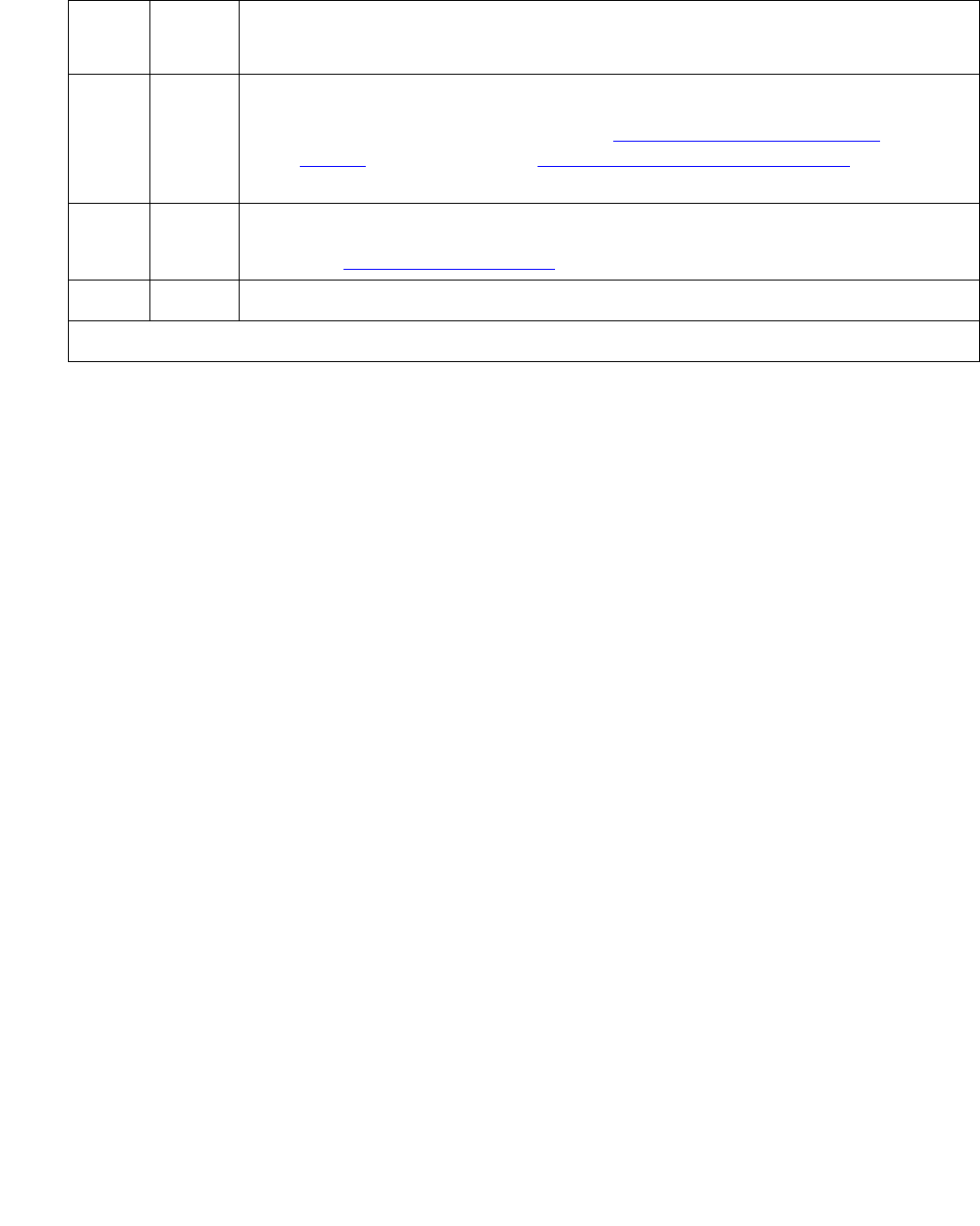
Communication Manager Maintenance-Object Repair Procedures
514 Maintenance Procedures for Avaya Communication Manager 3.0, Media Gateways and Servers
Service State Audit Test (#256)
This test checks the service state of the trunk.
Country protocol 1
If the interface uses country protocol 1 (includes USA), the service-state audit executes in every
trunk service state. It queries the service state on the far end and waits 2 minutes for a reply. If
the first request times out, the service-state audit asks again. If the request times out again, it
logs error 3073 and resends the request every 15 minutes. It places in-service trunks in the
MAINTENANCE/FAR-END state (outgoing calls blocked, incoming calls accepted). Incoming
calls trigger an immediate service-state audit without waiting for the end of a 15-minute cycle.
Any other country protocol
If the interface uses some other country protocol, the service-state audit executes only on
trunks that are in the OUT-OF-SERVICE/FAR-END state. It asks the far-end switch to bring the
trunk back into the IN-SERVICE state and waits 2 minutes for a reply. If the first request times
out, the service-state audit asks again. If the request times out again, it leaves the trunk in the
OUT-OF-SERVICE/FAR-END state and tries again in 1 hour.
Note:
Note: PASS for this test only means that a message to the far end was successfully
sent.
To check the service state of the ATM-BCH trunk, run status trunk grp#/mem#.
4 FAIL Signaling channel problem
1. Look for errors or alarms against ATM-SGRP (ATM Signaling
Group) on page 598 and ATM-DCH (ATM D-Channel Port) on
page 522.
8 FAIL TN230x circuit pack failed
1. See ATM-INTF (TN2305/6) on page 573.
PASS Signaling link OK.
Table 161: Test #255 Signaling Link State Audit Test (continued)
Error
Code
Test
Result
Description / Recommendation
2 of 2

ATM-BCH (ATM B-Channel Trunk)
Issue 1 June 2005 515
Table 162: Test #256 Service State Audit Test
Error
Code
Test
Result
Description / Recommendation
1000 ABRT Needed resources not available, port on a call or initializing
1. Run status trunk grp#/mem#.
2. Check the results of Test #255.
1018 ABRT Maintenance disabled
1. Enable maintenance by entering y in the Maintenance Tests field on
the change trunk-group screen.
1113 ABRT Signaling link failed
1. Run status trunk grp#/mem#.
2. Check the results of Test #255.
3. See ATM-SGRP (ATM Signaling Group) on page 598.
1114 ABRT Signaling link in transitional state
1. Retry the command up to 5 times at 1-minute intervals.
1116 ABRT Trunk not in Out-of-Service/Far-end state and country protocol other than 1
1117 ABRT Service-state audit message outstanding
1. Wait 2 minutes, then try again.
2100 ABRT Could not allocate needed resources
1. Retry the command up to 5 times at 1-minute intervals.
1113 FAIL Signaling link failed
1. See ATM-SGRP (ATM Signaling Group) on page 598 and ISDN-PLK
(ISDN-PRI Signaling Link Port) on page 1423.
FAIL Internal system error
1. Retry the command up to 5 times at 1-minute intervals.
PASS PASS
1. Wait 4 minutes, then check the Error Log for any new Error Type 3073.
●If there are none, both sides of the ISDN connection agree on the
service state. The negotiation succeeded.
●If there is a new 3073 error, then the negotiation failed (the request
timed out).

Communication Manager Maintenance-Object Repair Procedures
516 Maintenance Procedures for Avaya Communication Manager 3.0, Media Gateways and Servers
Call State Audit Test (#257)
This test audits the internal call state by asking the far-end switch for the ISDN call state. The
test is particularly useful when you are trying to clear a hung call. If the internal call state on the
near end differs from that on the far end, the call is torn down.
The ISDN specification allows up to 2 minutes for a reply. If a reply is not received within the 2
minute window, the test logs a protocol time-out violation against the associated signaling
channel (ATM-DCH, Error Type 1).
Note:
Note: PASS simply means that an appropriate message was composed and sent to the
far-end switch.
Table 163: Test #257 Call State Audit Test
Error
Code
Test
Result
Description / Recommendation
1018 ABRT Maintenance disabled
1. Enable maintenance by entering y in the Maintenance Tests field on
the change trunk-group screen.
1019 ABRT Audit already in progress
1. Wait 2 minutes, and try again.
1113 ABRT Signaling link failed
1. Check the results of Test #255 (Signaling Link State check).
1114 ABRT Signaling link in transitional state
1. Retry the command up to 5 times at 1-minute intervals.
1116 ABRT Trunk out-of-service
1. Check the trunk service state (status trunk grp#/mem#).
2100 ABRT Could not allocate needed resources
1. Retry the command up to 5 times at 1-minute intervals.
FAIL Internal system error
1. Retry the command up to 5 times at 1-minute intervals.
PASS PASS
1. Wait 4 minutes, then check the Error Log for call-state mismatches. If
a call state mismatch is found, the call is torn down.

ATM-BCH (ATM B-Channel Trunk)
Issue 1 June 2005 517
ISDN Test Call Test (#258)
This nondestructive test performs a far-end loop-around test over an ATM-BCH trunk if:
●The trunk is IN-SERVICE, MAINTENANCE/NEAR-END, or OUT-OF-SERVICE/
NEAR-END.
●No calls are active on the trunk.
●The system uses country protocol 1 (including US), or the far end has loop-around
capability.
The test sets up a call to a far-end switch over the ATM-BCH trunk. Then the digital port on a
TN711D Maintenance/Test circuit pack sends a bit pattern to the far end and back. If the
received pattern matches that sent, the test passes. If there are differences, it fails.
Synchronous Test Calls
You can initiate a synchronous outgoing test call (including a test call for ISDN-PRI trunks) with
these commands:
●test trunk grp#/mem# long (repeat#)
●test board location long (repeat#)
●test port location long (repeat#)
Table 164: Test #258 ISDN Test Call
Error
Code
Test
Result
Description / Recommendation
4 ABRT Signaling channel problem
1. Look for errors or alarms against ATM-SGRP (ATM Signaling
Group) on page 598 and ATM-DCH (ATM D-Channel Port) on
page 522.
8 ABRT TN230x circuit-pack problem
1. See ATM-INTF (TN2305/6) on page 573.
1004 ABRT B channel is active.
1. See if a call is active. Run status trunk grp#/mem#.
2. If the service state is In-Service/Idle, retry the test.
1005 ABRT Bad configuration (for example, no Maintenance/Test circuit pack)
1. Make sure that the Maintenance/Test circuit pack is inserted.
2. Repeat the test.
1 of 5

Communication Manager Maintenance-Object Repair Procedures
518 Maintenance Procedures for Avaya Communication Manager 3.0, Media Gateways and Servers
1018 ABRT Test call disabled
1. Set the Maintenance field on the Trunk Group screen to y.
1020 ABRT TN230x circuit-pack problem
1. See ATM-INTF (TN2305/6) on page 573.
1024 ABRT Maintenance/Test digital port active
1. Wait until amber and green LEDs on the Maintenance/Test circuit pack
are OFF.
2. Rerun the test.
3. If the problem persists, see M/T-DIG (Maintenance/Test Digital Port) on
page 1709.
1113 ABRT Signaling link failed
1. Check the results of Test #255 (Signaling Link State Check test).
1116 ABRT Switch could not change the service state
1. See if calls are active. Run status trunk grp#/mem#.
2. If a call is active, proceed as for Error Code 1119.
If not, check the Error and Alarm Logs and see ATM-TRK (Circuit
Emulation Service Circuit Pack) on page 617.
1117 ABRT ISDN service message outstanding
1. Wait 2 minutes. Then try again.
1118 ABRT Far-end not administered
1. Check the administration of the far end of the ATM trunk. Run status
trunk grp#/mem#.
2. Try the test again.
1119 ABRT Test call aborted, normal call attempted
1. Wait for the call to finish normally, or drop it by running busyout
trunk grp#/mem#.
2. When the trunk is idle, retry the test.
Table 164: Test #258 ISDN Test Call (continued)
Error
Code
Test
Result
Description / Recommendation
2 of 5

ATM-BCH (ATM B-Channel Trunk)
Issue 1 June 2005 519
1120 ABRT Trunk OUT-OF-SERVICE/FAR-END
3. Try to change the service state via Test #256 (Service State Audit test).
4. Try the test again.
1122 ABRT No test-line number for the far-end switch
1. Check the Trunk Group screen.
1123 ABRT No Feature Access Code administration for this Facility test
1. Check the Dial Plan and Feature Administration forms.
2000
2012
None
ABRT Internal system error
1. Retry the command up to 5 times at 1-minute intervals.
2035 ABRT Call timed out
1. Wait 1 minute, and try again.
2036
–
2037
ABRT Internal system error
1. Retry the command up to 5 times at 1-minute intervals.
2038
–
2039
ABRT Problem reading test data
1. Wait 1 minute, and then try again.
2. If the test aborts again, there is a serious internal problem.
2040 ABRT Internal system error
1. Retry the command up to 5 times at 1-minute intervals.
2041 ABRT Call timed out
1. Wait 1 minute, and try again.
2066 ABRT Could not establish test call
1. Retry the command up to 5 times at 1-minute intervals.
2067 ABRT Call timed out
1. Wait 1 minute, and try again.
Table 164: Test #258 ISDN Test Call (continued)
Error
Code
Test
Result
Description / Recommendation
3 of 5

Communication Manager Maintenance-Object Repair Procedures
520 Maintenance Procedures for Avaya Communication Manager 3.0, Media Gateways and Servers
2074 ABRT Bit and Block Error query failed
1. Retry the command up to 5 times at 1-minute intervals.
2. If the test continues to abort, there may be a serious internal problem in
the Maintenance/Test Digital port. See M/T-DIG (Maintenance/Test
Digital Port) on page 1709.
2075 ABRT Internal system error
1. Retry the command up to 5 times at 1-minute intervals.
2100 ABRT Could not allocate the necessary system resources to run this test.
1. Retry the command at 1-minute intervals up to 5 times.
2201
–
2205
ABRT Internal system error
1. Retry the command up to 5 times at 1-minute intervals.
2206 ABRT Could not allocate needed resources
1. Retry the command at 1-minute intervals up to 5 times.
2208 ABRT Internal system error
1. Retry the command at 1-minute intervals up to 5 times.
2209
–
2210
ABRT Could not allocate needed resources
1. Follow recommendations for ABORT code 2100.
2211 ABRT Internal system error.
1. Retry the command at 1-minute intervals up to 5 times.
2212 ABRT Call terminated by unexpected disconnect
1. Wait 1 minute and then try again.
2213 ABRT Call timed out
1. Wait 1 minute, and try again.
2214 ABRT Call terminated by unexpected disconnect
1. Wait 1 minute and then try again.
2215
–
2219
ABRT Internal system error
1. Retry the command at 1-minute intervals up to 5 times.
Table 164: Test #258 ISDN Test Call (continued)
Error
Code
Test
Result
Description / Recommendation
4 of 5

ATM-BCH (ATM B-Channel Trunk)
Issue 1 June 2005 521
2220 ABRT Call terminated prematurely
1. Wait 1 minute, and try again.
2221
–
2226
ABRT Internal system error
1. Retry the command at 1-minute intervals up to 5 times.
2227 ABRT Could not allocate needed resources
1. Retry the command at 1-minute intervals up to 5 times.
2042 FAIL Test data corrupt
PASS Test pattern intact. If the synchronous test call was performed (long test
sequence), the communications path is operating properly.
Table 164: Test #258 ISDN Test Call (continued)
Error
Code
Test
Result
Description / Recommendation
5 of 5

Communication Manager Maintenance-Object Repair Procedures
522 Maintenance Procedures for Avaya Communication Manager 3.0, Media Gateways and Servers
ATM-DCH (ATM D-Channel Port)
S8700 | 8710 / S8500
Note:
Note: TN230x circuit packs are not interchangeable. Always replace an ATM circuit
pack with the same type.
ATM-DCH uses the existing ISDN-PLK or D-channel maintenance strategy with modifications.
The ATM circuit pack can be administered for up to 8 Circuit Emulation Service (CES) or
signaling groups, each with its own D channel, as opposed to one D channel for an entire DS1
circuit pack.
Note:
Note: Due to the dual personalities and the number of D channels that the ATM board
can possess, the in-line errors and signaling port LAN loopback test has been
moved to the MO ATM-TRK (Circuit Emulation Service Circuit Pack) on
page 617. When an in-line error is sent due to packet-bus errors, the ATM circuit
pack MO receives the error, not ATM-DCH.
The D-channel ISDN-PRI interface is emulated for ATM-CES and uses out-of-band signaling to
transmit control messages between two endpoints. User information or bearer channels (B
channels) carry digitized voice and digital data and are assigned to DS1 ISDN trunks or PRI
endpoints. Call-control signaling for the B channels is combined and carried over the separate
ISDN-PRI Signaling Link port D channel.
Problems with ATM-DCH affects every associated B channel, since call-control signaling cannot
reach the far-end switch or terminal adapter. Stable calls can remain operational, but no new
calls can be made. In turn, ATM-DCH depends on the:
●TN230X ATM Trunk circuit pack where it resides
●Packet bus that provides the link to the processor
When working ATM-DCH alarms or errors, also investigate
●ATM-TRK (Circuit Emulation Service Circuit Pack) on page 617
●PKT-BUS (Packet Bus) on page 1790
MO Name in
Alarm Log
Alarm
Level
Initial Command to Run Full Name of MO
ATM-DCH MIN test port location lATM D-Channel
ATM-DCH WRN test port location sh ATM D-Channel
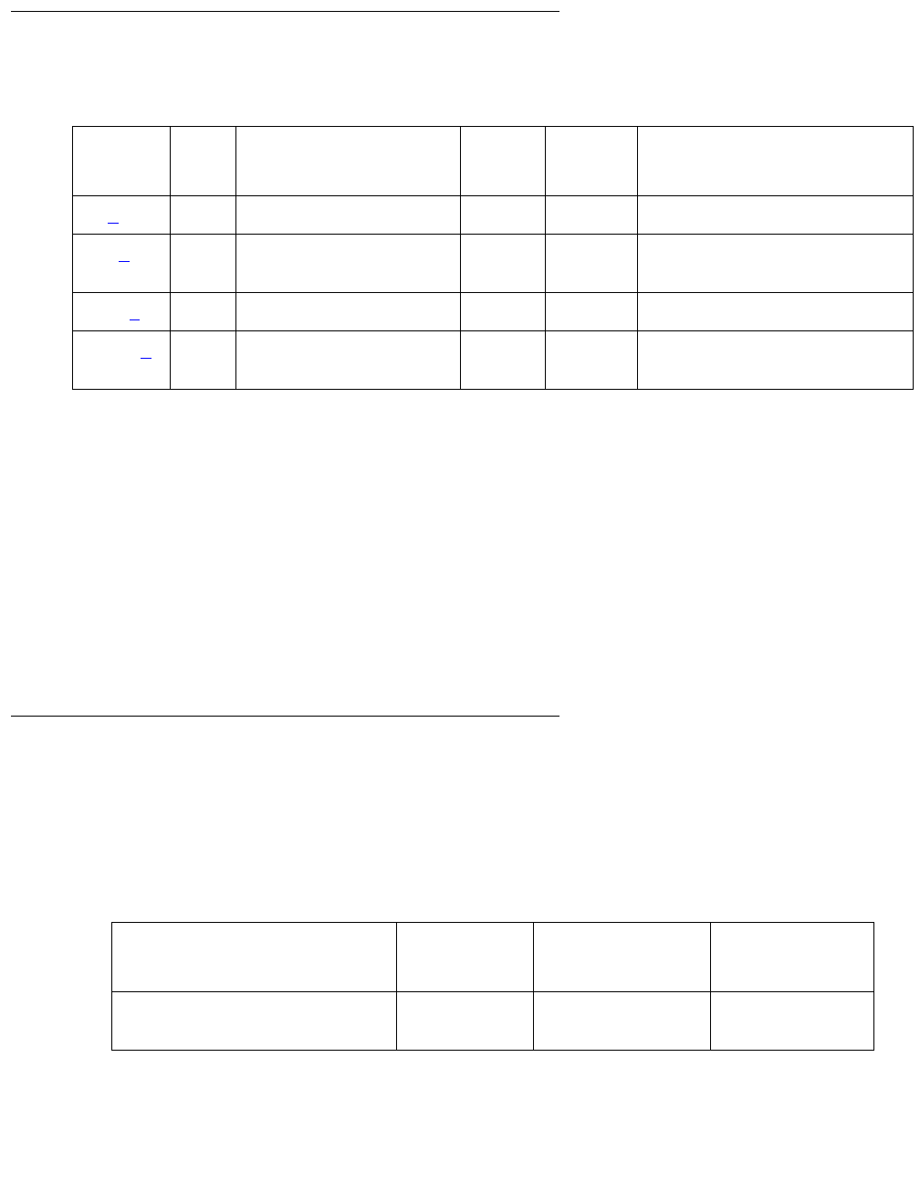
ATM-DCH (ATM D-Channel Port)
Issue 1 June 2005 523
Hardware Error Log Entries and Test to Clear Values
Notes:
a. Error Type 0: Run the short test sequence first. If every test passes, run the long test
sequence. Refer to each appropriate test’s description, and follow its recommended
procedures.
b. Error Type 18: D channel busied out; no calls possible over this D channel.
c. Error Type 130: circuit pack removed or has been insane for more than 11 minutes. To
clear the error, reinsert or replace the circuit pack.
d. Error Type 1793: ATM Trunk circuit pack failed the Signaling Link Board check (#643).
Resolve any ATM-TRK errors in the Error Log.
System Technician-Demanded Tests:
Descriptions and Error Codes
The command to test the ATM-DCH MO is test port location, where location is for
ports 9-32.
Table 165: ATM D-channel Error Log entries
Error
Type
Aux
Data
Associated Test Alarm
Level
On/Off
Board
Test to Clear Value
0 (a)0Any AnyAnytest port location
18 (b)0 busyout port
location
WRN OFF release port location
130 (c) None WRN ON test port location
1793 (d) Signaling Link Board
check (#643) test board location l
Table 166: System Technician-Demanded Tests: ATM-DCH
Order of Investigation Short Test
Sequence
Long Test
Sequence
D/ND
Signaling Link Board check
(#643)
X X Nondestructive
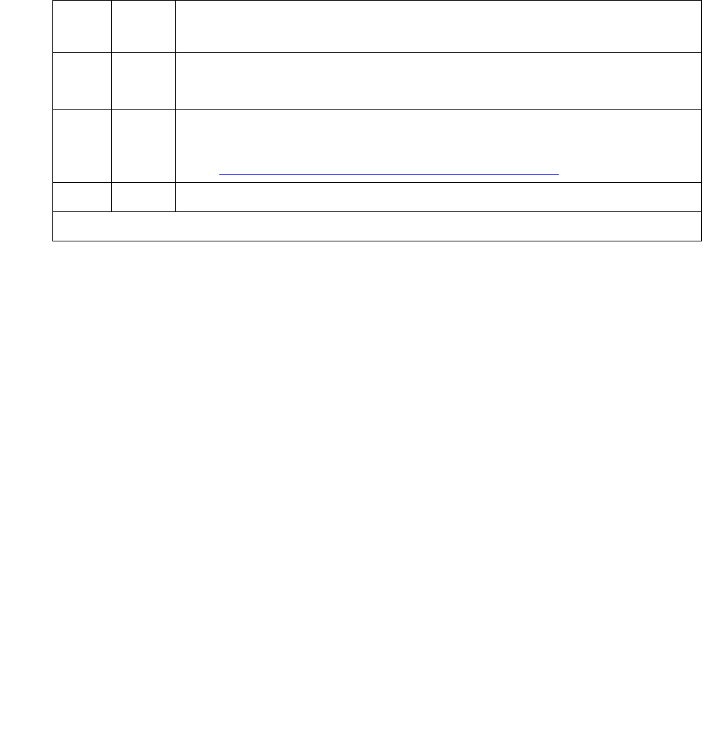
Communication Manager Maintenance-Object Repair Procedures
524 Maintenance Procedures for Avaya Communication Manager 3.0, Media Gateways and Servers
Signaling Link Board Check (#643)
This nondestructive test checks the health of the ATM TN230X trunk circuit pack’s hardware.
The test runs on a periodic or scheduled basis, during initialization testing, and upon demand.
Note:
Note: The board-level maintenance is handled independently of the ATM-CES
signaling link maintenance, raising the possibility of inconsistent states.
Error
Code
Test
Result
Description / Recommendation
ABRT Internal system error
1. Retry the command at 1-minute intervals up to 5 times.
8 FAIL The TN230X circuit pack is not in-service.
1. Check the Error Log for ATM-TRK errors and resolve any using
ATM-TRK (Circuit Emulation Service Circuit Pack) on page 617.
PASS The ATM TN230X circuit pack is in-service.
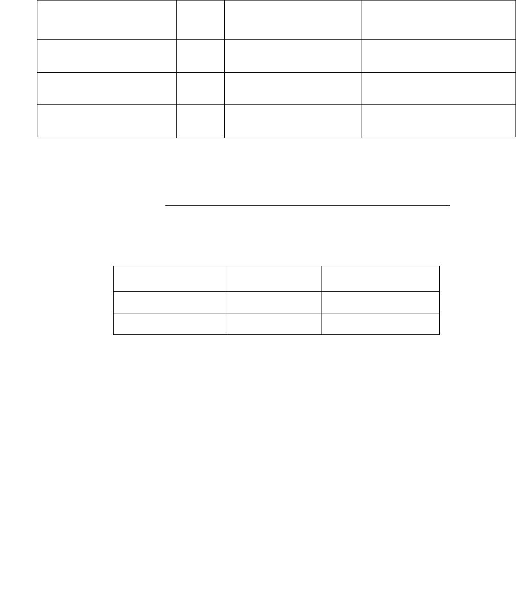
ATM-EI (Expansion Interface Circuit Pack)
Issue 1 June 2005 525
ATM-EI (Expansion Interface Circuit Pack)
S8700 MC
ATM-EI covers the ATM circuit pack administered as an Expansion Interface (ATM-EI) for ATM
Port-Network Connectivity (ATM PNC). The ATM-EI provides PNC between a S8700
Multi-Connect server and every PN through the ATM switch.
The circuit packs listed in Table 167: ATM-EI circuit packs for S8700 Multi-Connect on
page 525 are ATM-EI boards if they are administered to support ATM Port Network Connectivity
(ATM PNC) for S8700 MC.
Note:
Note: TN230x circuit packs are not interchangeable. Always replace an ATM circuit
pack with the same type.
Note:
Note: ATM switch maintenance is not covered in this section. When S8700
Multi-Connect system maintenance software suspects the ATM switch
connections, it raises appropriate Communication Manager alarms.
To clear any ATM switch faults, refer to the particular ATM switch’s
documentation.
MO Name in Alarm Log Alarm
Level
Initial Command to
Run
Full Name of MO
ATM-EI MAJ test board location ATM Expansion Interface
circuit pack
ATM-EI MIN test board location ATM Expansion Interface
circuit pack
ATM-EI WRN test board location ATM Expansion Interface
circuit pack
Table 167: ATM-EI circuit packs for S8700 Multi-Connect
Circuit pack Fiber Echo cancellation
TN2305 Multimode Y
TN2306 Single mode Y

Communication Manager Maintenance-Object Repair Procedures
526 Maintenance Procedures for Avaya Communication Manager 3.0, Media Gateways and Servers
LEDs
The ATM Interface circuit pack has three LEDs:
●Red indicates some alarm condition.
●Green indicates maintenance testing in progress.
●Amber provides useful visual information regarding the operating mode of the ATM-EI and
possible error conditions.
The possible LED states are in Table 168.
Table 168: ATM Interface LED codes
LED LED Status Condition
Red Steady on Board is not healthy
Never on Normal conditions
Red
and
Green
Red LED solid on
Green LED 200 msec on; 200 msec off
Board is in the processes of booting
Green Steady on1
1. The green LED flashes between tests.
Maintenance is running tests on the
board
100 msec on - 100 msec off No links to the board
Amber 100 msec on -100 msec off Fiber Loss of Signal (LOS), LOF,
MS_RDI, MS_AIS, LCD, HP_RDI,
HP_AIS, LOP, PSC
Amber 500 msec on; 500 msec off Signal to the ATM switch is down
Amber 2 sec on; 0.2 sec off ATM-EI is Expansion Archangel (EAA)
Amber Steady on ATM-EI active (Center Stage Switch PN)
Amber Never on ATM-EI standby

ATM-EI (Expansion Interface Circuit Pack)
Issue 1 June 2005 527
ATM-EI-Related Commands
The following commands can be helpful in resolving ATM-EI problems:
Replacing an ATM-EI Circuit Pack
Standard Reliability
1. Enter busyout atm pn# (this is service-affecting) at the SAT.
2. Replace the ATM PNC circuit pack, and reconnect the fiber.
3. Enter release atm pnc.
4. Wait 2½ minutes for board insertion.
5. Enter list sys-link to verify that the links are up.
6. Enter test board location, and verify that every test passes.
Duplex or High Reliability
There is 1 ATM-EI circuit pack in each PN.
1. Enter busyout atm pnc # at the SAT.
Note:
Note: If the ATM-EI is in a PN, this is service-affecting.
2. Replace the circuit pack.
3. Enter release atm pnc.
4. Wait 2½ minutes for board insertion.
5. Enter list sys-link to verify that the links are up.
6. Enter test board location, and verify that every test passes.
add atm pnc list measurements atm
busyout/release atm pnc remove atm pnc
busyout/release board reset board
change atm pnc (pnc duplication) status atm pnc
display atm pnc status cabinet
list atm oam-statistics status port-network
list atm pnc test board

Communication Manager Maintenance-Object Repair Procedures
528 Maintenance Procedures for Avaya Communication Manager 3.0, Media Gateways and Servers
Critical Reliability
There are 2 ATM-EI circuit packs in each PN.
1. Enter status pnc at the SAT. If the board is on the active side, enter reset pnc
interchange to switch the active ATM-EI board to the standby side.
2. Enter busyout pnc-standby.
3. Enter busyout atm pnc # a-pnc or b-pnc.
4. Replace the circuit pack.
5. Enter release atm pnc #.
6. Enter release pnc-standby.
7. Wait 2½ minutes for board insertion.
8. Enter test board location, and verify that every test passes.
Basic ATM PNC Administration
Note:
Note: This section contains basic administration information only. Refer to ATM
Installation, Upgrades, and Administration using Avaya Communication Manager,
555-233-124, for more detailed information.
ATM PNC connections involve administering
●1 ATM-EI board in each PN (standard, duplex, or high reliability)
●2 ATM-EI boards in each PN (critical reliability)
Adding ATM PNC Connections
Standard, Duplex or High Reliability
1. If the ATM-EI circuit pack is absent or if the circuit pack is present but in a PN, use the
change circuit-pack command to add circuit pack translations.
2. Enter add atm pnc n (connection number), and administer the circuit pack’s location and
its ATM address.
Critical Reliability
1. Enter change system-parameters duplication, and change the Enable Operation
of PNC Duplication field to n.
2. If the ATM-EI circuit pack is absent or is present but in a PN that does not yet have PNC
connectivity to it, use the change circuit-pack command to add circuit pack translation
for the missing circuit pack.

ATM-EI (Expansion Interface Circuit Pack)
Issue 1 June 2005 529
3. Enter add atm pnc n (connection number), and administer the circuit pack location and
ATM address.
4. Enter change system-parameters duplication, and change the Enable Operation
of PNC Duplication field to y.
Removing ATM PNC Connections
Standard, Duplex or High Reliability
Note:
Note: These systems are not equipped with PNC duplication.
1. Enter busyout atm pnc n (connection number).
2. Enter remove atm pnc n (connection number).
Critical Reliability
1. Enter status pnc, and ensure that the A-PNC is active.
If not, request a PNC interchange using the reset pnc interchange command.
2. Enter busyout pnc-standby.
3. Enter change system-parameters duplication, and change the Enable Operation
of PNC Duplication field to n.
4. Enter busyout atm pnc n (PN’s number).
5. Enter remove atm pnc n (PN’s number) to remove both ATM-EI boards, or enter change
atm pnc to remove the B-side ATM-EI board.
6. Enter change system-parameters duplication, and change the Enable Operation
of PNC Duplication field to y.
Changing Circuit Pack Location or ATM Address
Standard, Duplex or High Reliability
Note:
Note: These systems are not equipped with PNC duplication.
1. Remove the ATM PNC connection (see Removing ATM PNC Connections on page 529).
2. Add an ATM PNC connection (see Adding ATM PNC Connections on page 528).
A-side ATM-EI—Critical Reliability
1. Remove the ATM PNC connection (see Removing ATM PNC Connections on page 529).
2. Add an ATM PNC connection (see Adding ATM PNC Connections on page 528).

Communication Manager Maintenance-Object Repair Procedures
530 Maintenance Procedures for Avaya Communication Manager 3.0, Media Gateways and Servers
B-side ATM-EI—Critical Reliability
1. Enter status pnc, and ensure that the A-PNC is active.
If not, request a pnc interchange using reset pnc interchange.
2. Enter busyout pnc-standby.
3. Enter list config carrier, and verify that an ATM circuit pack is assigned for the new
location. If not, add the ATM circuit pack’s translations.
4. Enter busyout atm pnc n (connection number) b-pnc.
5. Enter change atm pnc n (connection number) and change circuit pack location for the B
side.
6. Enter release pnc-standby.
Changing ATM Address of Standby
ATM PNC EI, Critical Reliability
1. Enter busy pnc-standby.
2. Enter change atm pnc n (connection number), and change the ATM address for the
standby side.
3. Enter release pnc-standby.
Error Log Entries and Test to Clear Values
Table 169: ATM-EI Error Log Entries
Error
Type
Aux
Data
Associated Test Alarm
Level
On/Off
Board
Test to Clear Value
0 (a) 0 Any Any Any test board location
2 (b) None MIN ON
18 (c)0 busyout board
location
WRN OFF release board location
23 (d) 0 None WRN OFF
125 (e) None MIN ON
131 (f) None MIN ON
257-259
(g)
Any Expansion Interface
Control Channel test
(#316)
MAJ ON test board location r 2
1 of 3

ATM-EI (Expansion Interface Circuit Pack)
Issue 1 June 2005 531
513 (h) Any ATM Crosstalk test
(#1298)
MIN ON test board long
location
769 (i) 34
35
ATM Board Error
Query (1259)
WRN OFF test board location
770 (i) 31 ATM Board Error
Query (#1259)
WRN OFF test board location
771 (i) 26 ATM Board Error
Query (#1259)
WRN OFF test board location
1024–
1151 (j)
Any None WRN
MIN
ON test board location
1153 (k) None WRN ON test board location
1281 (l) ATM Board Error
Query (1259)
MAJ OFF test board location r 1
1537
(m)
12 None MIN ON
1538 (n) 0 None MIN ON
1793 (o) 13 None MIN ON
2049 (p) 15 None MIN OFF test board location r 4
2050 (p) Expansion Interface
Lock Query (#304)
MIN OFF test board location r 4
2305 (q) None MIN ON
2309 (q) Packet interface test
(#598)
MIN ON test board location r 2
2561 (r) Expansion Interface
2-way Transmission
test (#241)
MAJ OFF test board location r 3
2817 (s) Any ATM Board DSP test
(#1293)
MIN ON test board location
2818 (s) Any None MIN ON test board location
3329 (t) 3 LANHO critical error MAJ OFF
Table 169: ATM-EI Error Log Entries (continued)
Error
Type
Aux
Data
Associated Test Alarm
Level
On/Off
Board
Test to Clear Value
2 of 3
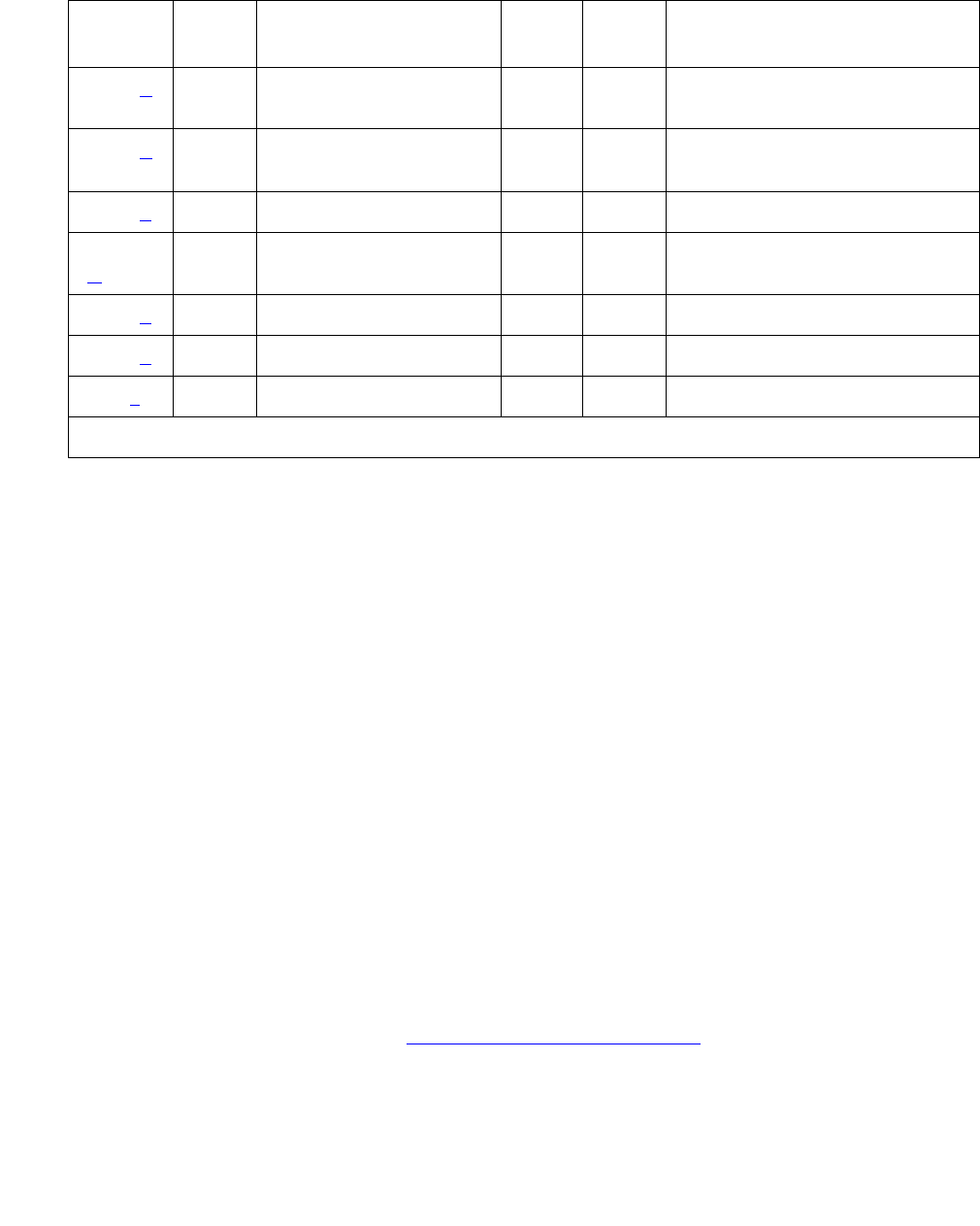
Communication Manager Maintenance-Object Repair Procedures
532 Maintenance Procedures for Avaya Communication Manager 3.0, Media Gateways and Servers
Notes:
a. Error Type 0: Run the short test sequence first. If every test passes, run the long test
sequence. Refer to each appropriate test’s description, and follow its recommended
procedures.
b. Error Type 2: The on-board DUART chip failed. This results in communication failure
between the PN’s Maintenance board and the ATM-EI board. The Maintenance board
should have a red LED lit, because the link to the ATM-EI is down in this PN.
1. Reset the board with reset board location.
2. If the board does not recover, replace the board.
c. Error Type 18: The ATM-EI circuit pack has been busied out.
1. Release the circuit pack (release board location).
d. Error Type 23: An ATM-EI circuit pack has been administered with the add atm pnc n
command, but the circuit pack has not been inserted into the system.
1. Insert an ATM-EI circuit pack at this location.
e. Error Type 125: A wrong circuit pack is located in the slot where the ATM-EI circuit pack is
logically administered.
1. Either remove the wrong circuit pack and insert the ATM-EI circuit pack or remove the
ATM-EI administration (see Basic ATM PNC Administration on page 528).
2. Remove the ATM-INTF administration and re-administer the slot (change circuit-pack) to
match the circuit-pack that is physically present in this slot.
3585 (u) ATM Framer
Looparound (#1260)
MAJ ON test board location l
3586 (u) ATM Framer
Looparound (#1260)
MAJ ON test board location l
3841 (v)
3842
(w)
3843 (x) None
3999 (y) Any None
Any (z) 32767 None
Table 169: ATM-EI Error Log Entries (continued)
Error
Type
Aux
Data
Associated Test Alarm
Level
On/Off
Board
Test to Clear Value
3 of 3

ATM-EI (Expansion Interface Circuit Pack)
Issue 1 June 2005 533
f. Error Type 131: An ATM-EI circuit pack has been removed from the slot for 5 minutes.
1. Insert the ATM-EI circuit pack into its administered slot.
2. Another way to resolve or prevent this alarm is to remove the ATM-EI administration (see
Basic ATM PNC Administration on page 528), then remove the ATM-INTF administration
(change circuit-pack).
It is possible that the ATM-EI could be held in reset by the PN’s Maintenance board and is
not inserted in the system.
3. Try issuing test maint P long on the maintenance board in the same PN.
g. Error Type 257: Expansion Interface Control Channel test (#316) failed (board cannot
communicate on the TDM bus control channel). Follow the suggested test procedures.
Error Type 258: The archangel is out of sequence (Aux Data indicates angel number).
Error type 259: The expansion archangel link (EAL) to the active ATM-EI board is down.
See SYS-LINK (System Links) on page 2175.
h. Error Type 513: The ATM Crosstalk test failed. The board is either writing to or reading
from a TDM time slot that is not allocated to the board.
1. Test the board (test board location), and follow the test procedures suggested for
this test. In random tests of a single DSP during low or high traffic, the same DSP can be
tested more than once.
i. Error Types 769 and 770: are board-degraded alarm errors that result when the ATM
switch is sending corrupted cells or excessive AAL/LAPD retransmissions (off-board ATM
cell corruption errors). These errors indicate the detection of a problem in handling ATM
cells that are received from the fiber interface.
Aux Data for these Error Types:
The problem is most likely not on the ATM-EI circuit pack reporting the errors, but it could be
due to one or more of the following reasons:
●The fiber is not snugly connected to either the board or the ATM switch.
●The PN’s packet bus is corrupting the cells. See PKT-BUS (Packet Bus) on page 1790
(Aux Data 35 only).
●The fiber between the ATM switch and the ATM-EI is too long (greater than 2 km for
multimode fiber). Use loopback to see if the fiber is corrupting the cells.
Error Type Aux Data Description
769 34 Excessive AAL-5 retransmission requests
769 35 Excessive LAPD retransmission requests
770 25 Uncorrectable ATM cell headers – threshold
771 26 VPI, VCI pair unknown

Communication Manager Maintenance-Object Repair Procedures
534 Maintenance Procedures for Avaya Communication Manager 3.0, Media Gateways and Servers
●Some other ATM-EI board is not receiving the cells properly.
●The intervening ATM switch is dropping the ATM cells due to a shortage of bandwidth, or
S8700 MC is using more than the subscribed bandwidth.
Error Type 771: The ATM switch is sending cells with unknown VPI and VCI address
(wrong connection).
1. Ensure that the ATM-EI board address on the ATM switch matches the ATM-EI (ATM)
address on the S8700 Multi-Connect side.
j. Error Types 1024-1151: These errors represent problems detected by the ATM-EI board in
response to SETUP and ADDPARTY requests from software.
●The Error Types and descriptions are in Table 170: ATM Error Types 1024 - 1151 on
page 534.
●Aux Data values represent PN and angel numbers and are in Table 171: Error Type
1024-1151 Aux Data values (XXYYY) converted to slot number on page 536.
Table 170: ATM Error Types 1024 - 1151
Error
Type
Description General problem
1024 Next node unreachable ATM protocol stack on
ATM-EI3 circuit pack
1056 DTL Transit not my node ID
1 of 3

ATM-EI (Expansion Interface Circuit Pack)
Issue 1 June 2005 535
1088
1104
ATM-EI circuit pack received a request with an
invalid connection identifier.
Firmware-detected problems
on the ATM-EI circuit pack.
Note: Error Types 1088–1103
are reported by the board that
is originating the connection.
Error Types 1104–1119 are
reported by the board that is
terminating the connection. In
most cases, when the
terminating board reports one
of these errors, the originating
board also reports an
ATM-NTWK error for the same
event (usually with Error Type
21).
1089
1105
ATM-EI circuit pack received a request with a
reference to an unknown VC token.
1090
1106
ATM-EI circuit pack did not have enough
resources (memory) for the requested operation.
1091
1107
Internal failure in the local protocol stack. This can
occur when the connection to the ATM switch
failed, perhaps because the:
●ATM switch rebooted
●fiber between the ATM switch and the
ATM-EI circuit pack disconnected
1092
1108
ATM-EI circuit pack received a request for which
the referenced VC was in the wrong call state.
1093
1109
ATM-EI circuit pack received a request for which
the VPI/VCI pair was invalid or out of range.
1094
1110
ATM-EI circuit pack received a request to add a
party to an existing VC. The add party request
failed, and a retry was not possible.
1095
1111
ATM-EI circuit pack in link recovery after the lower
ATM layer (Q.SAAL portion of the protocol stack)
failed. This can occur when the connection to the
ATM switch failed, perhaps because the:
●ATM switch rebooted
●fiber between the ATM switch and the
ATM-EI circuit pack disconnected
1096
1112
ATM-EI circuit pack received an error from the
local protocol stack for which no more detailed
cause was specified.
1102 ATM-EI circuit pack asked to create more
connections that it was capable of creating.
1103 ATM-EI circuit pack detected an illegal message
from software.
Check the Error Log for CONN-M proc errors for
more information.
Table 170: ATM Error Types 1024 - 1151 (continued)
Error
Type
Description General problem
2 of 3

Communication Manager Maintenance-Object Repair Procedures
536 Maintenance Procedures for Avaya Communication Manager 3.0, Media Gateways and Servers
1. Test the ATM-EI circuit pack (test board location) and investigate further based on
each test’s results. If every test passes, the error was a transient problem.
Aux Data values: For Setup and Add Party connection request failure type, the port-network
and the angel number of the destination ATM-EI circuit pack are logged Aux Data values in
the form XXYYY, where
●port-network number = XX
●angel number = YYY
Aux Data values for WSP Setup (XX = WSP number, YYY = location code).
Since you need to know the slot number also, Table 171: Error Type 1024-1151 Aux Data
values (XXYYY) converted to slot number on page 536 converts the Aux Data to slot
numbers.
1113 Problems detected by the
board terminating the
connection
Table 170: ATM Error Types 1024 - 1151 (continued)
Error
Type
Description General problem
3 of 3
Table 171: Error Type 1024-1151 Aux Data values (XXYYY) converted to slot number
Slot Carrier
ABCDE
Failure type Failure type Failure type Failure type Failure type
Slot
#
Set
up
Add
Party
WSP
Set
up
Set
up
Add
Party
WSP
Set
up
Set
up
Add
Party
WSP
Set
up
Set
up
Add
Party
WSP
Set
up
Set
up
Add
Party
WSP
Set
up
1 28 528 828 66 566 866 98 598 898 34 534 834 02 502 802
2 29 529 829 67 567 867 99 599 899 35 535 835 03 503 803
3 30 530 830 68 568 868 100 600 900 36 536 836 04 504 804
4 31 531 831 69 569 869 101 601 901 37 537 837 05 505 805
5 56 556 856 70 570 870 102 602 902 38 538 838 06 506 606
6 57 557 857 71 571 871 103 603 903 39 539 839 07 507 607
7 58 558 858 72 572 872 104 604 904 40 540 840 08 508 808
1 of 2

ATM-EI (Expansion Interface Circuit Pack)
Issue 1 June 2005 537
k. Error type 1153: The ATM connection audit found some discrepancy in the firmware’s VC
token numbers and live VCs. The problem is rectified in firmware and no action is needed.
8 59 559 859 73 573 873 105 605 905 41 541 841 09 509 809
9 60 560 860 74 574 874 106 606 906 42 542 842 10 510 810
10 61 561 861 75 575 875 107 607 907 43 543 843 11 511 811
11 62 562 862 76 576 876 108 608 908 44 544 844 12 512 812
12 63 563 863 77 577 877 109 609 909 45 545 845 13 513 813
13 88 588 888 78 578 878 110 610 910 46 546 846 14 514 814
14 89 589 889 79 579 879 111 611 911 47 547 847 15 515 815
15 90 590 890 80 580 880 112 612 912 48 548 848 16 516 816
16 91 591 891 81 581 881 113 613 913 49 549 849 17 517 817
17 92 592 892 82 582 882 114 614 914 50 550 850 18 518 818
18 93 593 893 83 583 883 115 615 915 51 551 851 19 519 819
19 94 594 894 84 584 884 116 616 916 52 552 852 20 520 820
20 95 595 895 85 585 885 117 617 917 53 553 853 21 521 821
21 NA NA NA 86 586 886 118 618 918 54 554 854 22 522 822
22 NA NA NA 87 587 887 119 619 919 55 555 855 23 523 823
Table 171: Error Type 1024-1151 Aux Data values (XXYYY) converted to slot number
Slot Carrier
ABCDE
Failure type Failure type Failure type Failure type Failure type
Slot
#
Set
up
Add
Party
WSP
Set
up
Set
up
Add
Party
WSP
Set
up
Set
up
Add
Party
WSP
Set
up
Set
up
Add
Party
WSP
Set
up
Set
up
Add
Party
WSP
Set
up
2 of 2

Communication Manager Maintenance-Object Repair Procedures
538 Maintenance Procedures for Avaya Communication Manager 3.0, Media Gateways and Servers
l. Error Type 1281: The loss of high-level signal indicating operational problems of equipment
located outside of the circuit pack and the fiber connected to the board. Aux Data values
are listed in Table 172: Error type 1281 Aux Data and repair procedures on page 538.
Table 172: Error type 1281 Aux Data and repair procedures
Aux
Data
Alarm
Description
Repair procedure
15 SYSCLOCK
failed
The board is not locked to the TDM backplane clock signal. This is
probably due to a Tone-Clock problem.
1. Check for TDM-BUS or TONE-BD errors in the Error Log.
2. If no other problems are present, reset the circuit pack (reset
board location)
16 Loss of Signal:
LOS
The fiber is not connected properly to the ATM-EI board or ATM
switch (or to the multiplexer section [MUX] if present).It is possible
that the board transceivers are not functioning properly.
1. Run test board location.
2. If Test #1259 fails, connect a fiber back-to-back in a looped
mode (one strand of fiber connecting the transmit transceiver to
the receive transceiver of the board) and see if the amber LED
flash goes away. If it does the problem is off-board.
3. If the amber LED continues to flash, replace the circuit pack.
17 Loss of Frame:
LOF
The fiber signal cannot obtain or maintain STM-1/OC-3 framing.
1. Try to move the fiber on the ATM switch side to a different port.
This could require administration on the ATM switch.
2. If the problem persists, reset the circuit pack (reset board
location).
18 Multiplexer
Section Alarm
Indication
Signal:
MS_AIS
There is a major problem on the far end (between multiplexer
section [MUX] and the switch) that prohibits the circuit pack from
sending a valid signal.
1. See if the ports at the MUX and/or the ATM switch are
connected snugly.
2. Run test board location.
3. If Test #1259 fails with Error Code 18, connect a fiber
back-to-back in a looped mode (one strand of fiber connecting
the transmit transceiver to the receive transceiver of the board)
and see if the amber LED flash goes away.
4. If it does, the problem is off-board.
5. If the amber LED continues to flash, replace the circuit pack; if
the error persists, escalate the problem.
1 of 3

ATM-EI (Expansion Interface Circuit Pack)
Issue 1 June 2005 539
19 Multiplexer
Section
Remote Defect
Indicator:
MS_RDI
The far end is detecting a major problem with the signal that this
board is transmitting.
1. Make sure the ATM switch port (or a MUX port, if present
between ATM switch and the ATM-EI board) is the same as the
ATM-EI circuit pack’s cable interface.
2. Run test board location.
3. If Test #1259 fails with Error Code 19, connect a fiber
back-to-back in a looped mode (one strand of fiber connecting
the transmit transceiver to the receive transceiver of the board)
and see if the amber LED flash goes away.
4. If it does the problem is off-board.
5. If the amber LED continues to flash, replace the circuit pack; if
the error persists, escalate the problem.
20 Loss of pointer:
LOP
ATM framer chip is unable to access the payload part of the signal.
1. Reset the board (reset board location).
2. If the error persists replace the board.
21 Path Signal
Error (PSL)
(STM1/
SONET)
The incoming signal payload is not set up for transmission of ATM
data.
1. Make sure the ATM switch port (or a MUX port, if present
between ATM switch and the ATM-EI board) is the same as the
ATM-EI circuit pack’s cable interface.
22 High-level Path
Alarm
Indication
Signal:
HP_AIS
The payload is invalid.
1. Make sure the ATM switch port (or a MUX port, if present
between ATM switch and the ATM-EI board) is the same as the
ATM-EI circuit pack’s cable interface.
2. Run test board location.
3. If Test #1259 fails with Error Code 22, connect a fiber
back-to-back in a looped mode (one strand of fiber connecting
the transmit transceiver to the receive transceiver of the board)
and see if the amber LED flash goes away.
4. If it does the problem is off-board.
5. If the amber LED continues to flash, replace the circuit pack.
Table 172: Error type 1281 Aux Data and repair procedures (continued)
Aux
Data
Alarm
Description
Repair procedure
2 of 3

Communication Manager Maintenance-Object Repair Procedures
540 Maintenance Procedures for Avaya Communication Manager 3.0, Media Gateways and Servers
m. Error Type 1537: LAN bus time out. The circuit pack is transmitting a packet larger than
1,024 bytes. Replace the circuit pack.
n. Error Type 1538: A hyperactive ATM-EI circuit pack is generating an abnormal amount of
control messages to the processor. When this error is generated, the system automatically
resets the ATM-EI.
1. Enter reset board location for this ATM-EI circuit pack.
2. If the same error persists, replace the ATM-EI circuit pack.
23 High-level path
Remote defect
Indicator:
HP_RDI
The far end is detecting a major problem with the signal that this
board is transmitting. The transmitted payload is invalid.
1. Make sure the ATM switch port (or a MUX port, if present
between ATM switch and the ATM-EI board) is the same as the
ATM-EI circuit pack’s cable interface.
2. Run test board location. If the Test #1259 fails with Error
Code 23, connect a fiber back-to-back in a looped mode (one
strand of fiber connecting the transmit transceiver to the
receive transceiver of the board) and see if the amber LED
flash goes away.
3. If it does the problem is off-board.
4. If the amber LED continues to flash, replace the circuit pack.
24 Loss of cell
delineation
(LCD)
On board ATM framer chip is not able to frame cells based on the
cell header.
1. Reset the board (reset board location).
2. If the error persists, replace the board.
27 SIGCON_DO
WN ATM
switch high
level signal.
The board cannot communicate with the ATM switch.
1. Busyout the board (busyout board location).
2. Test the board (test board long location).
3. If Test #1260 fails, replace the board.
4. If Test #1260 passes, make sure the ATM address on both the
S8700 Multi-Connect and the ATM switch sides are the same
for this board.
5. If the address is the same, change the port on the ATM switch
side. This could require administration on the ATM switch.
6. If the error is resolved, the problem is on the ATM switch port.
Duplicated PNC? Then:
Yes service to the PN is disrupted
No the system switches to the standby PNC
Table 172: Error type 1281 Aux Data and repair procedures (continued)
Aux
Data
Alarm
Description
Repair procedure
3 of 3

ATM-EI (Expansion Interface Circuit Pack)
Issue 1 June 2005 541
o. Error Type 1793: LANHO transmit FIFO overflow error (the transmit FIFO RAM buffers on
the circuit pack overflowed). This most likely indicates a hardware problem on the circuit
pack, because the speed of the LAN/packet bus is much higher than the speed of the link
connected to the port.
1. Test this ATM-EI circuit pack (test board location).
2. If Test #598 fails again, replace the ATM-EI circuit pack.
p. Error Types 2049 and 2050: The ATM-EI is out of lock with the backplane system clock.
1. Test this ATM-EI circuit pack (test board location).
2. If Test #304 fails, follow the repair procedures suggested for this test.
q. Error Type 2305: Too many parity errors on data received from the LAN/packet bus (could
be due to packet-bus problems).
1. Test the ATM-EI circuit pack (test board location).
2. If Test #598 fails, follow the repair procedures suggested for this test.
3. If the test passes, look for and resolve any PKT-BUS (packet bus) alarms/errors.
4. If there are no PKT-BUS errors and the problem persists, escalate the problem.
Error Type 2309: The packet-interface chip (LANHO) is malfunctioning.
5. Test the ATM-EI circuit pack (test board location).
6. If Test #598 fails, follow the repair procedures suggested for this test.
r. Error Type 2561: ATM-EI 2-way transmission failure (circuit pack is having problems
creating connections to other PNs in the system).
1. Test the ATM-EI circuit pack (test board location).
2. Follow the repair procedures suggested for Test #241.
s. Error Types 2817 and 2818: A DSP test failure detected along the circuit path of the
ATM-EI circuit pack.
1. Test the ATM-EI circuit pack (test board location).
2. Follow the repair procedures suggested for Test #1258.
Error Type Description Aux Data indicates
2817 DSP test failure The Aux Data field contains the following
information about the failed DSPs:
X is the number of talker DSPs
Y is the number of listener DSPs
Z is the number of echo-cancelling DSPs
2818 One or more DSPs failed DSP number that has failed
Communication Manager Maintenance-Object Repair Procedures
542 Maintenance Procedures for Avaya Communication Manager 3.0, Media Gateways and Servers
t. Error Type 3329: The on-board LANHO chip is insane, possibly due to a problem in
packet-bus arbitration, the transmission line frame, or the circuit pack itself. The circuit pack
cannot talk to the packet bus.
If the packet bus is alarmed:
1. Resolve any PKT-BUS errors. The probability of this error being related to a packet-bus
problem increases with the number of other circuit packs using the bus that are also
showing this error.
If the packet bus is not alarmed:
2. Reset the circuit pack (reset board location).
3. If the problem persists, replace the ATM-EI circuit pack.
If the system has a duplicated PNC, and the in-line error received is from an active ATM-EI,
the system switches to the standby PNC.
!CAUTION:
CAUTION: If the system does not have duplicated PNC, services to the PN could be
disrupted.
u. Error Types 3585 and 3586: (Major board alarm) A failure of critical components involved
in the operation of the circuit pack, and the switch can no longer recognize the circuit pack.
If the system has a duplicated PNC and the in-line error received is from an active ATM-EI,
the system switches to standby PNC.
!CAUTION:
CAUTION: If the system does not have duplicated PNC, services to the PN could be
disrupted.
Error Type 3585
Aux Data (Error Type 3585 only):
Aux
Data
Description
1 ATM framer failure
2 NCE failed (only from ATM-EIs in PN)
4 TDM_PLD_FAILED
5 DSP_ALL FAILED
6 Receive Network Processor (RNP) failure
7 Transmit Network Processor (TNP) failure
8 MEMORY read/write failure
ATM-EI (Expansion Interface Circuit Pack)
Issue 1 June 2005 543
1. If the system has duplicated PNC:
a. Test the ATM-EI (test board location l).
b. If Error 3585 is detected again, or if the board is not recognized anymore, replace the
ATM-EI circuit pack.
2. If the system does not have duplicated PNC and the circuit pack is in a PN:
a. Replace the ATM-EI circuit pack.
Error Type 3586: Framer Looparound test (#1260) failed.
Aux Data (Error Code 3586 only):
3. If Error Type 3586 is detected again, replace the circuit pack.
v. Error Type 3841: The board received a message from the switch that it does not recognize,
and the board responded with an inconsistent down link error message. This error does not
affect service, and no action is required.
w. Error Type 3842: The circuit pack received data from the packet bus faster than it could
distribute the data to its endpoint. This circuit pack should be able to recover by itself, and
no action is necessary.
x. Error Type 3843: The firmware on the circuit pack is reporting a resource that is low. This
error does not affect service and no action is required.
y. Error Type 3999: The circuit pack sent a large number of control channel messages to the
switch within a short period of time.
Aux Data Description
2 Packet path failed
3 Circuit path failed
4 TDM loop cannot be created
5 Packet loop cannot be created
If Then
Error Type 1538 is also
present
Circuit pack is taken out of service
Error Type 1538 is absent Circuit pack is not taken out of service, but has generated
50% of the messages necessary to be considered
hyperactive.
This can be normal during heavy traffic.
If the error is logged during light traffic, it can indicate a
problem with the circuit pack or the equipment attached to it.

Communication Manager Maintenance-Object Repair Procedures
544 Maintenance Procedures for Avaya Communication Manager 3.0, Media Gateways and Servers
z. Aux Data 32767 for any error log entry indicates that an alarmed ATM-EI was busied out
and then released. When this occurs, existing service-affecting alarms must be preserved.
Typically, every alarm is resolved when the ATM-EI is released. Therefore, the Alarm and
Error Logs must be repopulated with the alarms present at time of busyout. This Aux Data
indicates that existing Error Type and Error Log time stamps are no longer valid because
they were lost when the circuit pack was released.
System Technician-Demanded Tests:
Descriptions and Error Codes
Investigate tests in the order presented. By clearing error codes associated with the Expansion
Interface 2-Way Transmission test (#241), you can also clear errors generated from other tests
in the sequence.
Note:
Note: To get a better indication of a problem’s location, test both ATM-EI circuit packs
on the associated fiber link, whether the circuit packs are both ATM-EI circuit
packs or not.
Table 173: System Technician-Demanded Tests: ATM-EI
Order of Investigation Short Test
Sequence
Long Test
Sequence
Reset
Board
Sequence
D/
ND1
1. D = Destructive, ND = Nondestructive
Expansion Interface 2-Way Transmission
test (#241)
XX ND
ATM Board Framer Looparound test (#1260) X D
Expansion Interface Lock Query test (#304) X X ND
ATM Board Error Query test (#1259) X X ND
ATM Expansion Interface Reset (#1256) X D
ATM board DSP test(#1293) for TN2305 and
TN2306 circuit packs.
XX ND
ATM Cross Talk test(#1298) for TN2305 and
TN2306 circuit packs
XND
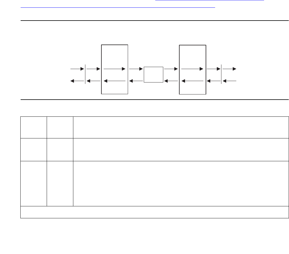
ATM-EI (Expansion Interface Circuit Pack)
Issue 1 June 2005 545
Expansion Interface 2-Way Transmission Test (#241)
This test is nondestructive and applies to every ATM-EI, both active and standby. It is run as
part of craft short and long testing, periodic, scheduled, initialization, and error analysis testing.
The test sets up a connection between a Tone-Clock in one cabinet and a Tone Detector in a
separate cabinet and transmits a digital test count between the PNs. The ATM-EIs used to set
up this connection are chosen by maintenance, not call processing. After the connection is
checked for dial-tone, the connection is torn down and re-established in the opposite direction.
For this test, the second ATM-EI can reside in any PN outside the tested ATM-EI’s PN.
Therefore, if the test should fail in either direction, the test is repeated with a different PN, if
available. This aids the fault isolation procedure.
The test results indicate if the test failed in one or both directions. The test aborts if the ATM-EIs
do not exist on both ends (for example, the EIs are not administered correctly). If the test
passes, the TDM and ATM framer interfaces of both ATM-EIs are functioning properly. If the
test fails, a series of tests are run on the board. Figure 25: Expansion Interface 2-Way
Transmit Test #241 PN X and PN Y represent any of 44 possible PNs. on page 545 shows a
schematic of this test.
Figure 25: Expansion Interface 2-Way Transmit Test #241
PN X and PN Y represent any of 44 possible PNs.
Table 174: Expansion Interface 2-Way Transmission Test (#241)
Error
Code
Test
Result
Description / Recommendation
ABRT Could not allocate the necessary system resources to run this test.
1. Retry the command at 1-minute intervals up to 5 times.
1002 ABRT The system could not allocate time slots for the test. The system could be
under heavy traffic conditions or it can have time slots out of service due
to TDM-BUS errors.
1. If the system has no TDM-BUS errors and is not handling heavy
traffic, retry the command at 1-minute intervals up to 3 times.
1 of 8
Tone
clock
Tone
clock
Tone
detector
Tone
detector
PNC modePNC mode iodf2way AWF 040699
ATM
switch
TDM bus
(PN X)
TDM bus
(PN Y)
ATM
circuit
pack
ATM
circuit
pack

Communication Manager Maintenance-Object Repair Procedures
546 Maintenance Procedures for Avaya Communication Manager 3.0, Media Gateways and Servers
1003 ABRT The system could not allocate a tone receiver for the test. The system
may be oversized for the number of Tone Detectors present, or some
Tone Detectors may be out of service.
1. Resolve any TTR-LEV errors.
2. Verify that at least one Tone Detector resides in this PN. (Even
without a TTR-LEV error, the tested circuit pack’s PN could be missing
a Tone Detector.)
If missing, the test always aborts for this circuit pack, without harming
the system.
Note:
Note: A TN2182 Tone-Clock circuit pack in a PN must be of
vintage B or newer. If an earlier vintage resides in a PN,
this test always aborts with this abort code.
3. Resolve any TONE-PT errors.
4. If neither condition exists, retry the command at 1-minute intervals up
to 3 times.
Table 174: Expansion Interface 2-Way Transmission Test (#241) (continued)
Error
Code
Test
Result
Description / Recommendation
2 of 8

ATM-EI (Expansion Interface Circuit Pack)
Issue 1 June 2005 547
1033 ABRT The test cannot run because either the ATM-EI board is not administered,
or there were no other PNs administered that had its ATM-EI board
in-service.
1. Ensure that the board is administered as ATM PNC Expansion
Interface circuit pack.
2. If the board is administered as ATM-EI circuit pack, then there has
been some change in the ability of the ATM-EI circuit pack in the other
PNs to communicate with the ATM-EI on the other end of its
connection.
3. Using status port x (the port-network number where the board is
administered), see if both ACL and EAL are up to this board. If not,
see the service procedure for SYS-LINK.
4. Check the Error Log for Error Type 1281 with Aux Data 27 (board
cannot talk to the ATM switch). See Table 172: Error type 1281 Aux
Data and repair procedures on page 538 for repair procedures.
5. If present, check both the ATM switch and the Communication
Manager translations for consistent ATM addresses. Reset the board,
and see if the problem resolves.
6. Repeat Test #241. If it continues to abort with this abort code, replace
the board.
1394 ABRT ABORT
1. See Table 172: Error type 1281 Aux Data and repair procedures on
page 538 (Error Type 1281) with Aux Data 27 (board cannot talk to the
ATM switch), and if present, check both the ATM switch and the
Communication Manager translations for consistent ATM addresses.
2. Reset the board and see if the problem resolves.
3. Repeat the test.
Table 174: Expansion Interface 2-Way Transmission Test (#241) (continued)
Error
Code
Test
Result
Description / Recommendation
3 of 8

Communication Manager Maintenance-Object Repair Procedures
548 Maintenance Procedures for Avaya Communication Manager 3.0, Media Gateways and Servers
1395 ABRT This test cannot run on an ATM-EI circuit pack if it is part of the B-side
PNC and Duplicated PNC is not enabled.
1. If this test needs to run on this ATM-EI circuit pack, enable PNC with
the change system-parameters duplication command.
2. Prevent the system from doing a PNC interchange by executing the
set PNC lock command.
3. Repeat this test.
1413 ABRT This test requires the use of a Tone-Clock circuit in each of the PNs used
in this test. This abort code indicates that a Tone-Clock circuit is absent
from one of the PNs.
1. Verify that an IPSI or Tone-Clock circuit pack resides in the same PN
as the ATM PNC Expansion Interface circuit pack under test.
2. In ATM PNC configurations, make sure that there is at least one other
PN besides the PN where the ATM-EI circuit pack under test resides
that contains a Tone-Clock circuit.
1414 ABRT The active Tone-Clock circuit in one of the PNs being used for the test has
a MAJOR or MINOR alarm logged against it.
1. Enter display alarms and resolve any TONE-BD and TONE-PT
alarms.
1956 ABRT ACL to the board is not up. See ACL status with list sys-link and
follow the repair procedures for SYS-LINK.
2000 ABRT Response to the test request was not received within the allowable time
period.
2100 ABRT System resources required to run this test are not available.
2500 ABRT Internal system error
1. Retry the command at 1-minute intervals up to 3 times.
FAIL The test tone was not detected correctly in either direction.
1. Test the active Tone-Clocks in the PNs for which the ATM-EI circuit
pack under test provides a link. This determines if the dial tone is
supplied.
Table 174: Expansion Interface 2-Way Transmission Test (#241) (continued)
Error
Code
Test
Result
Description / Recommendation
4 of 8

ATM-EI (Expansion Interface Circuit Pack)
Issue 1 June 2005 549
10MM FAIL The failure codes only apply to a system equipped with an ATM Switch.
The letters “MM” refer to the distant or far-end PN, and “NN” to the
near-end ATM-EI under test.
The test tone was detected correctly in forward direction (data sent from
the PN where the circuit pack under test resides and detected correctly in
port network MM), but not the opposite direction.
1. Test the active Tone-Clocks on the “MM” PN and the PN where the
ATM-EI under test resides (test tone-clock location). This
determines if a dial tone is supplied.
2. Ensure that the ATM address of the ATM-EI circuit pack under test
matches the ATM address on the ATM switch for the port to which this
circuit pack is connected. Refer to ATM Installation, Upgrades, and
Administration using Avaya Communication Manager, 555-233-124,
for the procedure to check the ATM port address on the ATM switch.
3. Run Test #241 on the active ATM-EI in port network MM. If this test
fails with Error Code 10NN or 30NN, go back to step 2.
4. If the address was the same, replace the active ATM-EI circuit pack on
port network MM.
5. If this test fails with Error Code 20NN or 40NN, replace ATM-EI circuit
pack that had the initial problem.
Table 174: Expansion Interface 2-Way Transmission Test (#241) (continued)
Error
Code
Test
Result
Description / Recommendation
5 of 8

Communication Manager Maintenance-Object Repair Procedures
550 Maintenance Procedures for Avaya Communication Manager 3.0, Media Gateways and Servers
20MM FAIL The failure codes only apply to a system equipped with an ATM Switch.
The letters “MM” refer to the distant or far-end PN, and “NN” to the near-end
ATM-EI under test.
6. The test tone was detected correctly in reverse direction (data sent
from port network MM was detected correctly in the PN where the
circuit pack under test resides, but not the opposite direction).
7. Test the active Tone-Clock on the “MM” PN and the PN where the
ATM-EI under test resides (test tone-clock location). This
determines if dial tone is supplied.
8. Ensure that the ATM address of the active ATM-EI circuit pack under
test matches the ATM address on the ATM switch for the port to which
this circuit pack is connected. Refer to ATM Installation, Upgrades,
and Administration using Avaya Communication Manager,
555-233-124, for the procedure to check the ATM port address on the
ATM switch.
9. Run Test #241 on the active ATM-EI in port network MM. If this test
fails with Error Code 20NN or 40NN, go back to step 2.
If the address was the same, replace the active ATM-EI circuit pack on
port network MM.
If this test fails with Error Code 10NN or 30NN, replace ATM-EI circuit
pack with the initial problem.
Table 174: Expansion Interface 2-Way Transmission Test (#241) (continued)
Error
Code
Test
Result
Description / Recommendation
6 of 8

ATM-EI (Expansion Interface Circuit Pack)
Issue 1 June 2005 551
30MM FAIL The failure codes only apply to a system equipped with an ATM Switch.
The letters “MM” refer to the distant or far-end PN, and “NN” to the near-end
ATM-EI under test.
The test failed for the first connection from the ATM-EI board under test to
another PN, and the test tone was detected correctly in the forward
direction (data sent from the PN where the circuit pack under test resides
was detected correctly in port network MM, but not the opposite direction).
1. Test the active Tone-Clock on the “MM” PN and the PN where the
ATM-EI under test resides (test tone-clock location). This
determines if dial tone is supplied.
2. Ensure that the ATM address of the ATM-EI circuit pack under test
matches the ATM address on the ATM switch for the port to which this
circuit pack is connected. Refer to for the procedure to check the ATM
port address on the ATM switch.
3. Run Test #241 on the active ATM-EI in port network MM. If this test
fails with Error Code 10NN or 30NN, go back to step 2.
If the address was the same, replace the active ATM-EI circuit pack on
port network MM.
If this test fails with Error Code 20NN or 40NN, replace ATM-EI circuit
pack with the initial problem.
Table 174: Expansion Interface 2-Way Transmission Test (#241) (continued)
Error
Code
Test
Result
Description / Recommendation
7 of 8

Communication Manager Maintenance-Object Repair Procedures
552 Maintenance Procedures for Avaya Communication Manager 3.0, Media Gateways and Servers
40MM FAIL Failure code only applies to a system equipped with an ATM Switch. The
letters “MM” refer to the distant or far-end PN, and “NN” to the near-end
ATM-EI under test.
The test failed for the first connection from the ATM-EI board under test to
another PN, and the test tone was detected correctly in the reverse
direction (data sent from port network MM was detected correctly in the PN
where the circuit pack under test resides), but not the opposite direction.
1. Test for the Active Tone-Clocks on port network MM and the PN where
the ATM-EI under test resides. This determines if dial tone is
supplied.
2. Ensure that the ATM address of the active ATM-EI circuit pack in port
network MM matches the ATM address on the ATM switch for the port
to which this circuit pack is connected. Refer to ATM Installation,
Upgrades, and Administration using Avaya Communication Manager,
555-233-124, for the procedure to check the ATM port address on the
ATM switch.
3. Run Test #241 on the active ATM-EI in port network MM. If this test
fails with Error Code 20NN or 40NN, go back to step 2.
If the address was the same, replace the active ATM-EI circuit pack on
port network MM.
If this test fails with Error Code 10NN or 30NN, replace ATM-EI circuit
pack with the initial problem.
PASS Tone successfully transmitted in both directions. Both ATM-EI boards and
their lightwave transceivers are functioning properly.
0NO
BOARD No board was detected by the test.
1. Resolve either wrong board (Error 125) or no board (Error 131)
issues.
2. Check that the board is properly translated and inserted. If so, check
for hyperactivity (Error 1538). If hyperactive, use reset board
location.
3. Run the test again. If it fails, the ID chip on board could be bad.
Replace the board and retest.
Table 174: Expansion Interface 2-Way Transmission Test (#241) (continued)
Error
Code
Test
Result
Description / Recommendation
8 of 8

ATM-EI (Expansion Interface Circuit Pack)
Issue 1 June 2005 553
Expansion Interface Lock Query Test (#304)
This test is nondestructive and is used to query the ATM and EI circuit packs (both active and
standby) for its status concerning lock to the backplane system clock. It is run as part of
periodic, scheduled, initialization, and error analysis testing. When an in-line, “out-of-lock”
report comes in, this test is run to check the circuit pack’s status. The ATM-EI responds with “in
lock” or “out of lock.” If the response is “in lock,” the test passes; if the response is “out of lock,”
the test fails.
Table 175: Test #304 Expansion Interface Lock Query Test (#304)
Error
Code
Test
Result
Description / Recommendation
2000 ABRT Response to the test request was not received within the allowable time
period.
2100 ABRT Could not allocate the necessary system resources to run this test.
2500 ABRT Internal system error
1. Retry the command at 1-minute intervals up to 3 times.
FAIL A PN’s unduplicated ATM-EI circuit pack responded incorrectly, or a PN’s
active ATM-EI circuit pack could not communicate with the PN’s circuit
packs.
1. If the PN’s active ATM-EI circuit pack is failing and duplicated PNC is
enabled:
a. Enter reset PNC interchange to switch to the standby PNC.
b. Repeat the short test sequence.
c. If test continues to fail, enter reset board location to reset the
ATM-EI circuit pack.
2. If the PN’s unduplicated ATM-EI circuit pack is failing:
a. Enter display errors and display alarms, and follow the
associated repair procedures for TDM-CLK, TONE-BD, or SYNC
alarms/errors.
b. Repeat the short test sequence.
c. If test continues to fail, replace the circuit pack or transceiver.
PASS Communication from software to the ATM-EI circuit pack is functioning
correctly.
1 of 2

Communication Manager Maintenance-Object Repair Procedures
554 Maintenance Procedures for Avaya Communication Manager 3.0, Media Gateways and Servers
Expansion Interface Control Channel Test (#316)
This test is nondestructive. If an ATM-EI circuit pack is an active ATM-EI in the PN (amber LED
on long/off short), the Expansion Interface Control Channel test checks to see if the ATM-EI
circuit pack can communicate with other circuit packs in the PN using the PN’s TDM bus.
If the circuit pack is a standby ATM-EI (amber LED off), this test queries the ATM PNC
Expansion Interface circuit pack for information about its type and vintage.
0NO
BOARD No board was detected by the test.
1. Check the error log for wrong board (error 125) or no board (error 131).
Resolve either of these issues.
2. Check that the board is properly translated and inserted. If so, check
for hyperactivity (error 1538). If hyperactive, use reset board
location.
3. Run the test again. If it fails, the NCE chip on board could be bad.
Replace the board and retest.
Table 175: Test #304 Expansion Interface Lock Query Test (#304) (continued)
Error
Code
Test
Result
Description / Recommendation
2 of 2
Table 176: Expansion Interface Control Channel Test #316
Error
Code
Test
Result
Description / Recommendation
2000 ABRT Response to the test request was not received within the allowable time
period.
2100 ABRT Could not allocate the necessary system resources to run this test.
1. Retry the command at 1-minute intervals up to 3 times.
2500 ABRT Internal system error
1. Retry the command at 1-minute intervals up to 3 times.
1 of 2

ATM-EI (Expansion Interface Circuit Pack)
Issue 1 June 2005 555
Packet Interface Test (#598)
This test is nondestructive and attempts to send a data packet from the TN1655 Packet
Interface circuit pack through any ATM PNC Expansion Interface circuit packs. The path the
data packet takes depends on the location of the ATM PNC Expansion Interface circuit pack
being tested and whether the system has duplicated port-network connectivity.
FAIL A PN’s unduplicated ATM-EI circuit pack responded incorrectly, or a PN’s
active ATM-EI circuit pack could not communicate with the PN’s circuit
packs.
1. If the PN’s active ATM-EI circuit pack is failing and duplicated PNC is
enabled:
a. Enter reset PNC interchange to switch to the standby PNC.
b. Repeat the short test sequence.
c. If test continues to fail, enter reset board location to reset the
ATM-EI circuit pack.
2. If the PN’s unduplicated ATM-EI circuit pack is failing:
a. Enter display errors and display alarms, and follow the
associated repair procedures for TDM-CLK, TONE-BD, or SYNC
alarms/errors.
b. Repeat the short test sequence.
c. If test continues to fail, replace the circuit pack or transceiver.
PASS The ATM-EI circuit pack did respond correctly to test. Communication from
software to the ATM-EI circuit pack is functioning.
1. Refer to other ATM-EI circuit pack tests if the link is not functioning
correctly.
0NO
BOARD No board was detected by the test.
1. Resolve any wrong board (Error 125) or no board (Error 131) issues.
2. Check that the board is properly translated and inserted. If so, check
for hyperactivity (Error 1538). If hyperactive, use reset board
location.
3. Run the test again. If it fails, the NCE chip on board could be bad.
Replace the board and retest.
Table 176: Expansion Interface Control Channel Test #316 (continued)
Error
Code
Test
Result
Description / Recommendation
2 of 2
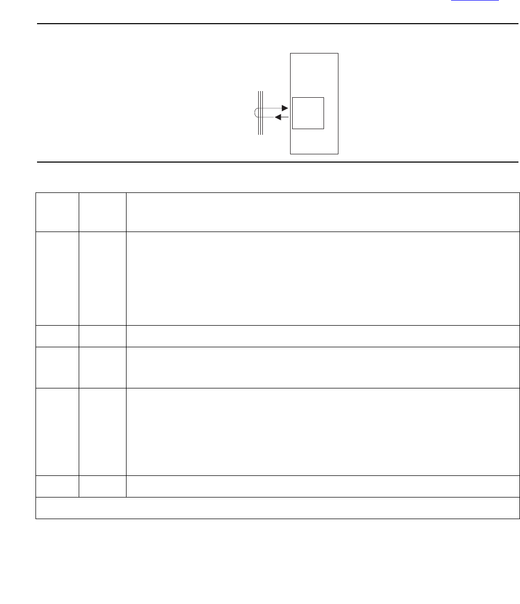
Communication Manager Maintenance-Object Repair Procedures
556 Maintenance Procedures for Avaya Communication Manager 3.0, Media Gateways and Servers
The Packet Interface Looparound test checks the packet-bus interface circuitry on this board.
The on-board LANHO chip sends a data stream to the bus, retrieves it back, and checks for its
consistency. If the data is consistent, the test passes; otherwise, it fails. The test aborts if the
specified PN’s packet bus has an active minor alarm or is out of service. This test runs as a part
of initialization, periodic or scheduled error analysis, and demand-test sequences. Figure 26
shows a schematic of the test.
Figure 26: Packet Interface Test (#598)
Table 177: Packet Interface Test (#598)
Error
Code
Test
Result
Description / Recommendation
2000 ABRT Response to the test request was not received within the allowable time
period.
1. Retry the command at 1-minute intervals up to 3 retries.
2. If the test fails repeatedly, attempt to reset the circuit pack.
3. If the test continues to fail, replace the circuit pack.
2012 ABRT Internal system error
2100 ABRT Could not allocate the necessary system resources to run this test.
1. Retry the command at 1-minute intervals up to 5 times.
ANY FAIL The transmitted data packet was not received correctly by the Packet
Interface circuit pack. The failure can be in the ATM-EI under test, the
DS1C-BD circuit packs, or the intervening Center Stage components.
1. Retry the command at 1-minute intervals up to five times.
2. If the test continues to fail, replace the circuit pack.
PASS The Packet Interface test passed.
PNC mode
iodfchip AWF 040699
LANHO
chip
LAN bus
(PN X)
ATM
circuit
pack

ATM-EI (Expansion Interface Circuit Pack)
Issue 1 June 2005 557
ATM Board Error Query Test (#1259)
This test is nondestructive. The ATM circuit pack firmware maintains counters for some of the
on- and off-board errors. The maintenance software queries the board for its health information
to do error analysis. These alarms have assigned priority: if a higher priority alarm occurs, the
remaining alarms are not reported to the software (through the inline errors), avoiding
unnecessary up-link, in-line error message traffic. This is run as a part of a craft demand test
sequence periodic testing, initialization, and error analysis.
Table 178: ATM Board Error Query Test (#1259)
Error
Code
Test
Result
Description / Recommendation
2000 ABRT Response to the test was not received within the allowable time period.
2100 ABRT System resources required to run this test are not available.
1. Retry the command at 1-minute intervals up to 3 times.
2500 ABRT Internal system error
1. Retry the command at 1-minute intervals up to 3 times.
XXYY FAIL On-board hardware or off-board signaling errors on the board. XX
indicates the on-board hardware error, and YY indicates the off-board
errors on the as shown in Table 179: XX Error Codes, Test #1259 (ATM
Board Error Query Test) on page 558 or Table 180: YY Error Codes, Test
#1259 (ATM Board Error Query Test) on page 559.
1. Resolve any errors in error logs.
PASS No service effecting errors or alarms were detected on the circuit pack.
0NO
BOARD No board was detected by the test.
1. Check the Error Log for wrong board (Error Type 125) or no board
(Error Type 131). Resolve either of these issues, if applicable.
2. Check that the board is properly translated and inserted. If so, check
for hyperactivity (Error Type 1538). If hyperactive, use reset board
location.
3. Run the test again. If it fails, the NCE chip on board could be bad.
Replace the board and retest.

Communication Manager Maintenance-Object Repair Procedures
558 Maintenance Procedures for Avaya Communication Manager 3.0, Media Gateways and Servers
Table 179: XX Error Codes, Test #1259 (ATM Board Error Query Test)
XX Aux Data Description
1 ATM framer chip failed
2 NCE chip failed
3 LANHO critical error
4 TDM Prog. logic device failed
5 Every on-board DSP failed
6 Receive network processor failed
7 Transmit network processor failed
8 Memory read failed
9 Dual UART chip failed
10 LANHO receive parity error
11 LANHO FIFO overflow error
12 LAN Bus timeout
13 LANHO Xmit FIFO overflow
14 One or more on-board DSPs failed

ATM-EI (Expansion Interface Circuit Pack)
Issue 1 June 2005 559
Table 180: YY Error Codes, Test #1259 (ATM Board Error Query Test)
YY Aux Data Description
15 Backplane clock failed
16 Loss of signal
17 Loss of frame
18 Multiplexer Section Alarm indication signal error
19 Multiplexer Section remote defect indicator error
20 Loss of pointer
21 Path signal level mismatch
22 High level path alarm indication signal
23 High level path remote defect indicator
24 Loss of cell delineation
25 Uncorrectable headers sent by the ATM switch
26 Too many cells with invalid Virtual Path Indicator (VPI)/Virtual
Circuit Indicator (VCI) combination
27 The signaling link between the board and the ATM switch is
down.
28 Board to the ATM switch connection is down
34 Excessive AAL-5 (ATM signaling protocol) retransmission
requests
35 Excessive LAPD retransmission requests
37 ATM CLP (cell loss priority) bit. See ATM-NTWK (ATM
Network Error) on page 576.
38 ATM congestion indicator. See ATM-NTWK (ATM Network
Error) on page 576.
39 ATM cell underrun. See ATM-NTWK (ATM Network Error) on
page 576.
40 ATM cell overrun. See ATM-NTWK (ATM Network Error) on
page 576.
41 Lost ATM cell. See ATM-NTWK (ATM Network Error) on
page 576.
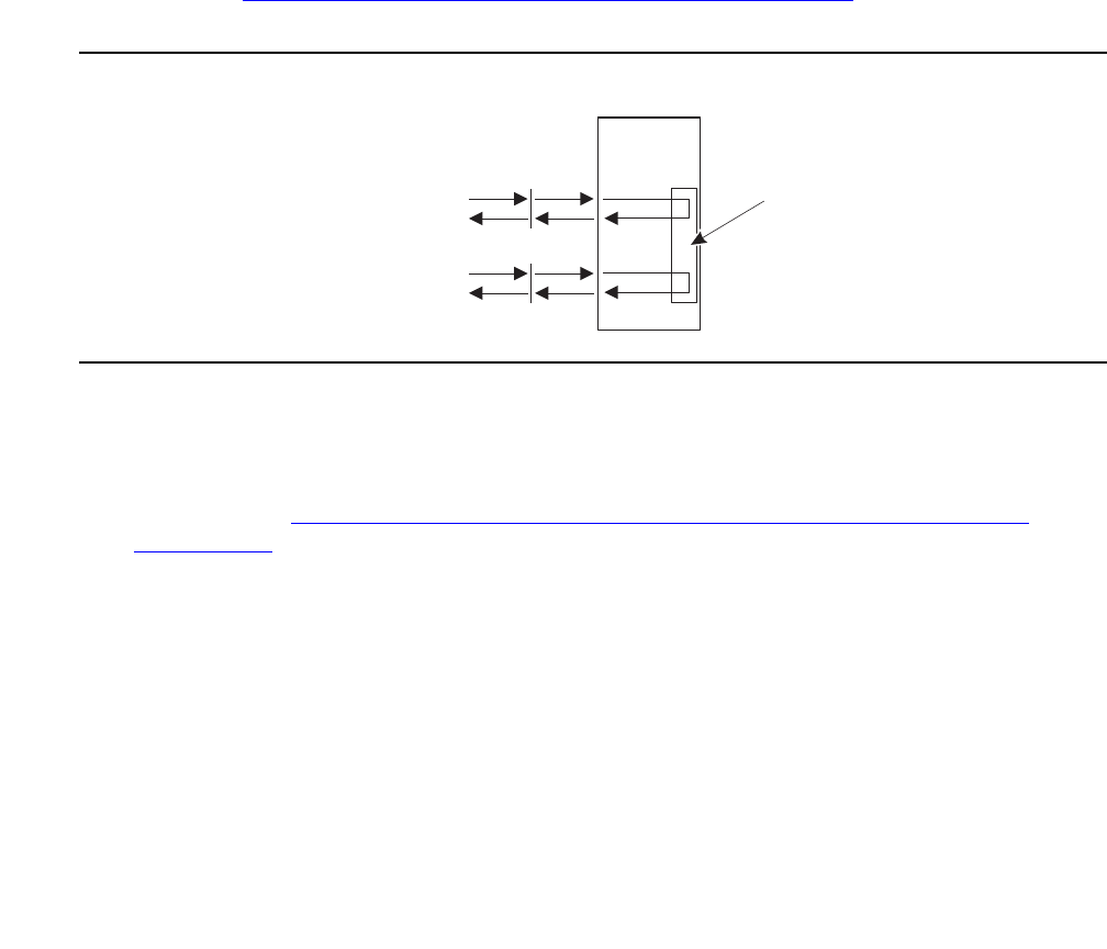
Communication Manager Maintenance-Object Repair Procedures
560 Maintenance Procedures for Avaya Communication Manager 3.0, Media Gateways and Servers
ATM Board Framer Loop-Around Test (#1260)
This test is destructive.
Note:
Note: This test can be run on the standby PNC only if the board is busied out.
This test places the ATM circuit pack in ATM framer loop-around mode. Once the board
receives this message, it creates a dummy virtual circuit that originates and ends on the same
board, without leaving the board. This test verifies both the TDM path and the Packet Path. If
the TDM test path passes, then the packet path is tested. Definitions of each test path are:
●The circuit (TDM) path: one of the Tone Generators sends a bit pattern through a TDM
bus time slot to the ATM framer. The pattern is converted into ATM cells and looped back
to the ATM-EI board, which converts the cell back into the bit pattern and puts it on a
pre-determined time slot. A Tone Detector tests for the bit pattern and reports the test
result. This test verifies that a large portion of the ATM-EIs circuit paths are functioning
correctly. Figure 27: ATM Board Framer Loop-Around Test (#1260) on page 560 shows a
diagram of the test.
Figure 27: ATM Board Framer Loop-Around Test (#1260)
●Packet path: the Packet Interface circuit pack sends packet data to the ATM framer
interface, where it is mapped into ATM cells and then looped around internally. The cells
are converted back to packet data after it has been looped. This portion of the test verifies
correct operation of the ATM-EI’s packet-bus interface and a large portion of the ATM-EI's
packet paths. Figure 28: ATM Board Framer Loop-Around Test (#1260) (non-EAA,
Packet Path) on page 561 shows the packet switched signal path for the ATM circuit pack.
●This test verifies the operation of a large portion of the ATM-EI circuit and packet paths, but
does not verify the optical portion of the lightwave transceiver. If this test passes, the
ATM-EI circuit pack is functioning correctly, but faults can exist in the lightwave transceiver.
If the test fails, the fault can be on the board. After the test results are reported, the ATM
framer is taken out of loopback.
Note:
Note: This test can be run on active or standby ATM-EIs, but it is not allowed if an
ATM-EI is the Expansion Archangel.
Tone clock
Tone detector
Packet
Interface
PNC mode
ATM
framer
looped
iodftone AWF 040699
TDM bus
(PPN)
Packet bus
(PPN)
ATM
circuit
pack
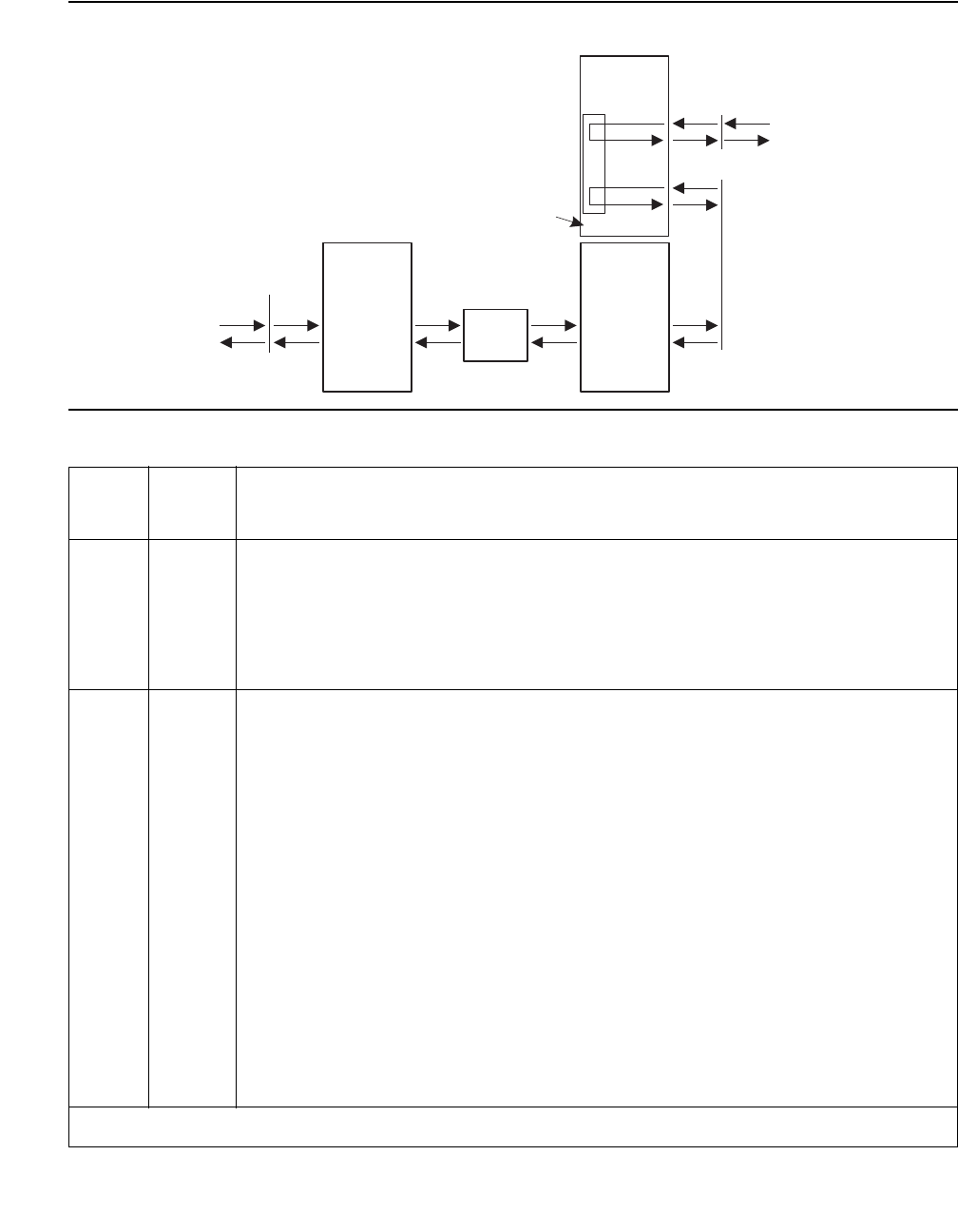
ATM-EI (Expansion Interface Circuit Pack)
Issue 1 June 2005 561
Figure 28: ATM Board Framer Loop-Around Test (#1260) (non-EAA, Packet Path)
Table 181: ATM Board Framer Loop-Around Test (#1260)
Error
Code
Test
Result
Description / Recommendation
1002 ABRT The system could not allocate timeslots for the test. The system could be
under heavy traffic conditions or it could have timeslots out of service due
to TDM-BUS errors.
1. If the system has no TDM-BUS errors and is not handling heavy traffic,
retry the command at 1-minute intervals up to 3 times.
1003 ABRT The system could not allocate a tone receiver for the test. The system
may be oversized for the number of Tone Detectors present, or some Tone
Detectors may be out of service.
1. Verify that at least one Tone Detector resides in this PN. (Even without
a TTR-LEV error, the tested circuit pack’s PN could be missing a Tone
Detector.)
If missing, the test always aborts for this circuit pack, without harming
the system.
Note: A TN2182 Tone-Clock circuit pack must be of vintage B or
newer. If an earlier vintage circuit pack resides in a PN, this test
always aborts with this abort code.
2. Resolve any TONE-PT errors.
3. If neither condition exists, retry the command at 1-minute intervals up
to 3 times.
1 of 5
Tone clock
Tone detector
PNC mode
PNC modePNC mode
ATM
framer
looped
iodfpak AWF 040699
ATM
switch
Packet bus
(PPN)
TDM bus
(EPN X)
Packet bus
(EPN X)
Packet
interface
ATM
circuit
pack
ATM
circuit
pack
ATM
circuit
pack
ATM
expansion
archangel

Communication Manager Maintenance-Object Repair Procedures
562 Maintenance Procedures for Avaya Communication Manager 3.0, Media Gateways and Servers
1015 ABRT The ATM-EI circuit pack has not been busied out.
1. Busyout the ATM-Expansion Interface circuit pack, then repeat test
board location long .
1031 ABRT If the ATM Expansion Interface circuit pack is in a PN and is on the active
PNC, this test cannot be executed.
1. If PNC Duplication is enabled, attempt to make the standby PNC active
using reset pnc interchange.
2. If the PNC Interchange is successful, rerun the test.
1033 ABRT The ATM-EI circuit pack is absent.
1. Use list atm pnc to verify that switch recognizes the circuit pack.
2. Retry the command.
1139 ABRT The packet bus in the PN where this ATM-EI board resides has a major
alarm against it. This test needs to use the alarmed PN’s packet bus.
1. Resolve any PKT-BUS problems.
2. Retry the command.
1141 ABRT The Packet Interface circuit pack is out of service.
1. Resolve any PKT-INTF problems.
1394 ABRT The ATM-EI board is out of service and the test cannot be run. This
condition is due to a change in the ATM-EI board’s ability to communicate
with the ATM switch.
1. Run Test #241. If it does not pass, see repair procedures for
Expansion Interface 2-Way Transmission Test (#241).
1395 ABRT This test cannot be run on an ATM-EI circuit pack if it is part of the B-side
PNC and duplicated PNC is not enabled.
1. If this test needs to run on this ATM-EI circuit pack, enable PNC
duplication with the change system-parameters duplication
command.
2. Prevent the system from doing a PNC interchange by executing the
set PNC lock command.
3. Repeat this test.
Table 181: ATM Board Framer Loop-Around Test (#1260) (continued)
Error
Code
Test
Result
Description / Recommendation
2 of 5

ATM-EI (Expansion Interface Circuit Pack)
Issue 1 June 2005 563
1407 ABRT This test cannot be run on an ATM-EI board that is on the active PNC
because it cannot be busied out. This error code indicates that PNC
duplication is enabled.
1. Attempt to perform a PNC interchange with the reset pnc
interchange command.
2. If the PNC interchange is successful, busyout the original
ATM-Expansion Interface circuit pack with the busyout board
location (address of the original ATM-EI board) command.
3. Retry the command.
2000 ABRT Response to the test was not received in the allowable time period.
1. Retry the command at 1-minute intervals up to 3 times.
2060 ABRT The link on the packet bus being used to perform the test has failed.
1. Retry the command at 1-minute intervals up to 3 times.
2. If the test continues to abort, resolve any PKT-INTF errors.
2100 ABRT Could not allocate the necessary system resources to run this test.
1. Retry the command at 1-minute intervals up to 3 times.
2500 ABRT Internal system error.
1. Retry the command at 1-minute intervals up to 3 times.
1 FAIL The test did not detect the test tone through the loop-around connection.
Note:
Note: The packet portion of this test was not run since the circuit
portion failed.
1. Test the active Tone-Clock (test tone-clock location) in the PN
that contains the defective ATM-EI circuit pack to verify that dial tone is
being supplied.
2. If the Tone-Clock is healthy, test the ATM-EI circuit pack (test board
location long).
3. If this test continues to fail, replace the ATM-EI circuit pack or
transceiver.
4. Test the new ATM-EI circuit pack (test board location long).
Table 181: ATM Board Framer Loop-Around Test (#1260) (continued)
Error
Code
Test
Result
Description / Recommendation
3 of 5

Communication Manager Maintenance-Object Repair Procedures
564 Maintenance Procedures for Avaya Communication Manager 3.0, Media Gateways and Servers
2 FAIL The test tone was transmitted and detected correctly, but the correct data
packet was not detected by the Packet Interface circuit pack.
1. Test the Packet Interface circuit pack to verify that it is functioning
properly. If any tests fail, investigate those tests and repair the Packet
Interface circuit pack.
2. If the Packet Interface circuit pack is OK, resolve any DS1C-BD alarms
or errors (if so equipped).
3. Test the ATM-EI circuit pack (test board location long).
4. If this test continues to fail, replace the ATM-EI board.
5. Test the new ATM-EI circuit pack (test board location long).
3 FAIL The test tone was transmitted correctly, but the returned tone was
distorted.
1. If the Tone-Clock is healthy, test the ATM-EI circuit pack (test board
location long).
2. If this test continues to fail, replace the ATM-EI circuit pack.
3. Test the new ATM-EI circuit pack (test board location long).
4 FAIL Unable to create loop for TDM path for this test.
1. Retry the command at 1-minute intervals up to 3 times.
2. If this test continues to fail, replace the ATM-EI circuit pack.
3. Test the new ATM-EI circuit pack (test board location long).
5 FAIL Unable to create loop for packet path for this test.
1. Retry the command at 1-minute intervals up to 3 times.
2. If this test continues to fail, replace the ATM-EI circuit pack.
3. Test the new ATM-EI circuit pack (test board location long).
6 FAIL A previously-established loop around was not released.
1. Enter reset board location.
2. Retry the command at 1-minute intervals up to 3 times.
3. If this test continues to fail, replace the ATM-EI circuit pack.
4. Test the new ATM-EI circuit pack (test board location long).
Table 181: ATM Board Framer Loop-Around Test (#1260) (continued)
Error
Code
Test
Result
Description / Recommendation
4 of 5

ATM-EI (Expansion Interface Circuit Pack)
Issue 1 June 2005 565
ATM Board Time Of Day Update (#1261)
This test is nondestructive. The ATM circuit pack requires a reference time to do SDH/SONET
performance monitoring. This test updates the system time to the board and synchronizes the
board with the S8700 Multi-Connect system’s clock during initialization, scheduled
maintenance, and craft long test.
PASS The ATM-EI board is functioning properly, however this test does not verify
that the optical portion of the lightwave transceiver is functioning.
0NO
BOARD No board was detected by the test.
1. Resolve either wrong board (Error 125) or no board (Error 131) issues,
if applicable.
2. Check that the board is properly translated and inserted. If so, check
for hyperactivity (Error 1538). If hyperactive, use reset board
location.
3. Run the test again. If it fails, the NCE chip on board could be bad.
Replace the board and retest.
Table 181: ATM Board Framer Loop-Around Test (#1260) (continued)
Error
Code
Test
Result
Description / Recommendation
5 of 5
Table 182: ATM Board Time Of Day Update (#1261)
Error
Code
Test
Result
Description / Recommendation
2031 FAIL The attempt to send the message to the ATM-EI circuit pack was not
successful.
2500 FAIL Did not send the time-of-day information to the board.
1. Retry the command at 1-minute intervals up to 3 times.
PASS The ATM-EI circuit pack is successfully updated with system time.
1. If status port-network still indicates that this link is down, it is
possible that one or both of the ATM-EI circuit packs have been busied
out.
2. If the link still does not come up, reset one or both ATM-EI circuit
packs on the link.
1 of 2

Communication Manager Maintenance-Object Repair Procedures
566 Maintenance Procedures for Avaya Communication Manager 3.0, Media Gateways and Servers
ATM Board Reset (#1256)
This test is destructive.
If the ATM-EI board is a standby in a PN, the reset is done through the SAKI reset interface. If
the ATM-EI is an Expansion Archangel (active ATM-EI board in the PN) and if the EAL is
present, a special message is sent to the board over the EAL.
0NO
BOARD No board detected.
1. Resolve either wrong board (Error 125) or no board (Error 131) issues,
if applicable.
2. Check that the board is properly translated and inserted. If so, check
for hyperactivity (Error 1538). If hyperactive, use reset board
location.
3. Run the test again. If it fails, the circuit pack’s NCE chip could be bad.
Replace the pack and retest.
Table 182: ATM Board Time Of Day Update (#1261) (continued)
Error
Code
Test
Result
Description / Recommendation
2 of 2
Table 183: ATM Board Reset (#1256)
Error
Code
Test
Result
Description / Recommendation
1386 ABRT No Active EAL to the board. This error applies only if the board under test is
in a PN. Check the error logs for SYS-LINK (System Links) errors against
the PN where the ATM-EI resides, and take appropriate diagnostic action for
the SYS-LINK.
1015 ABRT This test cannot be run because the ATM-EI circuit pack has not been
busied out.
1. Busyout the ATM circuit pack, then repeat test board location
long.
1407 ABRT ABORT
1. Perform a PNC Interchange
2. Try to reset the board again.
1 of 2

ATM-EI (Expansion Interface Circuit Pack)
Issue 1 June 2005 567
None ABRT Could not allocate the necessary system resources to run this test.
1. Retry the command at 1-minute intervals up to 5 times.
2. If the test continues to abort escalate the problem.
2000 ABRT Did not receive the SANITY response in the given time.
1. Wait for 5 minutes and see if board is visible to the system by using
list config all.
2. If the board is visible, run the test again. If same abort code results,
escalate the problem.
3. If the board is not visible to the system with list configuration
all, reseat the board.
4. If the board is still not recognized by the system, replace the board.
2100 ABRT Could not allocate the necessary system resources to run this test.
1. Retry the command at 1-minute intervals up to 5 times.
2500 ABRT Internal system error
1. Try to reset the board again.
1 FAIL The circuit pack failed to reset.
2 FAIL The circuit pack failed to restart.
1. Execute command again.
2. If the problem persists, replace the circuit pack.
PASS The ATM-EI circuit pack is successfully reset.
1. If status port-network still indicates that this link is down, it is
possible that one or both of the ATM-EI circuit packs are busied out.
2. If the links do not come up after reset, review the error logs and take
appropriate diagnostic action.
Table 183: ATM Board Reset (#1256) (continued)
Error
Code
Test
Result
Description / Recommendation
2 of 2
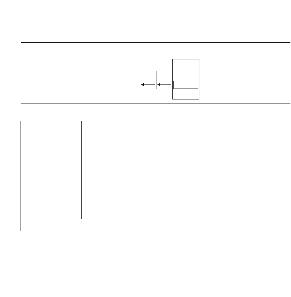
Communication Manager Maintenance-Object Repair Procedures
568 Maintenance Procedures for Avaya Communication Manager 3.0, Media Gateways and Servers
ATM Cross Talk Test (#1298)
This test is nondestructive. The ATM board Cross Talk test verifies that the selected TDM bus
time slot never crosses over to time slots reserved for other connections. The test also checks
for cross connections, where the board talks to time slots other than those specified. Since this
test uses many system resources (TDM time slots, Tone Generator, Tone Detector, and others),
it runs as a part of demand test only.
This test fails if either the TDM programmable logic and/or the interface to the DSP is not
operating properly. Failure of these components can result in 1-way or noisy connections.
Refer to Figure 29: ATM Cross Talk Test #1298 schematic on page 568 for a schematic of this
test.
Note:
Note: This test takes approximately 12 minutes and applies only to TN2305 and
TN2306 circuit packs.
Figure 29: ATM Cross Talk Test #1298 schematic
Table 184: ATM Crosstalk Test (#1298)
Error
Code
Test
Result
Description / Recommendation
ABRT Could not allocate the necessary system resources to run this test.
1. Retry the command at 1-minute intervals up to 5 times.
1002 ABRT The system could not allocate time slots for the test. The system could
be under heavy traffic conditions or it could have time slots
out-of-service due to TDM-Bus errors. Refer to TDM-BUS to diagnose
these errors.
1. If the system has no TDM-Bus errors and is not handling heavy
traffic, repeat test at 1-minute intervals up to 5 times.
1 of 2
ATM
circuit
pack
PNC mode
iodfatcr AWF 040699
DSP Talker
TDM bus
(PN X)
Tone detector

ATM-EI (Expansion Interface Circuit Pack)
Issue 1 June 2005 569
1003 ABRT The system could not allocate a tone receiver for the test. The system
may be oversized for the number of Tone Detectors present or some
Tone Detectors may be out-of-service.
1. Resolve any TTR-LEV errors in the Error Log.
2. Resolve any TONE-PT errors in the Error Log.
3. If neither condition exists, retry the test at 1-minute intervals up to 5
times.
2000 ABRT Response to the test was not received within the allowable time period.
1. Retry the command at 1-minute intervals up to 5 times.
2100 ABRT Could not allocate the necessary system resources to run this test.
1. Retry the command at 1-minute intervals up to 5 times.
1962 ABRT Every TALKER DSP is busy (an unlikely event).
1. Retry the command at 1-minute intervals up to 3 times.
2302 ABRT Inconsistent uplink message from the ATM-EI board. This is a very
unlikely event.
1. Retry the command at 1-minute intervals up to 3 times.
2752 ABRT The circuit pack in this location is not a TN230X.
1–8 None FAIL The board is writing to unauthorized TDM time slots. The error code
indicates the number of faulted TALKER DSPs.
1. Retry the command up to 3 times.
2. If the failure persists, replace the circuit pack.
1–8 PASS The board is not talking to unauthorized time slots on the TDM Bus. The
error code indicates the number of TALKER DSPs that were tested.
Table 184: ATM Crosstalk Test (#1298) (continued)
Error
Code
Test
Result
Description / Recommendation
2 of 2
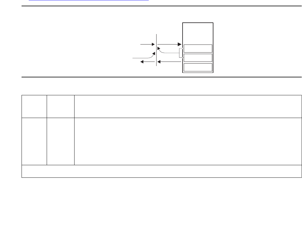
Communication Manager Maintenance-Object Repair Procedures
570 Maintenance Procedures for Avaya Communication Manager 3.0, Media Gateways and Servers
ATM Board DSP Test (#1293)
This test is nondestructive and is designed to test the board’s interface to the TDM bus and the
functions of all 24 on-board DSPs (Digital Signal Processors). There are three functional types
of DSPs:
●talkers – put data on the TDM bus
●listeners – take data off the TDM bus
●echo cancelers – as implied
Listener and echo cancelers are tightly coupled because firmware allocates sets of DSPs.
Since there are a total of 24 DSPs on the board, there can be up to 8 triplets allocated.
If the test fails for every DSP, a MAJOR alarm is raised against the board. If the test fails for one
or more DSPs, a MINOR alarm is raised. If a DSP is busy, the test for that particular DSP is
considered passed. The test aborts if the system resources (for example, the TDM time slots,
Tone Generator, and others) are not available.
This test applies to TN2305 and TN2306 ATM-EIs, both active and standby, and is run as part of
craft short and long testing, periodic, scheduled, initialization, and error analysis testing. Refer
to Figure 30: ATM Board DSP Test (#1293) on page 570 for a diagram of this loop-around test.
Figure 30: ATM Board DSP Test (#1293)
Table 185: ATM Board DSP Test (#1293)
Error
Code
Test
Result
Description / Recommendation
1002 ABRT The system could not allocate time slots for the test. The system could be
under heavy traffic conditions or it could have time slots out of service due
to TDM-BUS errors.
1. If the system has no TDM-BUS errors and is not handling heavy traffic,
retry the command at 1-minute intervals up to 3 times.
1 of 3
ATM
circuit
pack
iodfatmd AWF 040699
DSP echo
DSP listener
CCMS
CCMS
DSP talker
Tone detector
TDM bus
(PN X)
Tone clock
Tone detector

ATM-EI (Expansion Interface Circuit Pack)
Issue 1 June 2005 571
1003 ABRT The system could not allocate a tone receiver for the test. The system may
be oversized for the number of Tone Detectors present, or some Tone
Detectors may be out of service.
1. Verify that at least one Tone Detector resides in this PN. (Even without
a TTR-LEV error, the tested circuit pack’s PN could be missing a Tone
Detector.)
If missing, the test always aborts for this circuit pack, without harming
the system.
2. Resolve any TONE-PT errors.
3. If neither condition exists, retry the command at 1-minute intervals up
to 3 times.
1962 ABRT Every DSPs is busy (an unlikely event).
1. Retry the command at 1-minute intervals up to 3 times.
2000 ABRT Response to the test was not received within the allowable time period for
some of the DSPs.
1. If the board is in standby, reset the board and run the test again.
2. Look into the Error Log for Error Type 1218 (bad DSP). If Error Type
1218 is not logged against this board, run the DSP test again and see if
the error persists.
2100 ABRT Could not allocate the necessary system resources to run this test.
2302 ABRT Inconsistent uplink message from the ATM-EI board (an unlikely event).
1. Retry the command at 1-minute intervals up to 3 times.
2500 ABRT Internal system error
2752 ABRT The circuit pack in this location is not a TN230X.
Table 185: ATM Board DSP Test (#1293) (continued)
Error
Code
Test
Result
Description / Recommendation
2 of 3

Communication Manager Maintenance-Object Repair Procedures
572 Maintenance Procedures for Avaya Communication Manager 3.0, Media Gateways and Servers
XYZ FAIL A device on the circuit pack is failing. There is at least one bad DSP on the
board. Values are as follows:
●The X value indicates the number of talker DSPs
●Y indicates the number of listener DSPs
●Z indicates the number of Echo Canceler DSPs that have failed the
test.
1. Run the tests for the active Tone-Clock in the PN that contains the
indicted ATM-EI circuit pack to verify that dial-tone is supplied.
2. If the Tone-Clock is healthy, repeat the short test on the ATM-EI board.
3. If this test continues to fail, replace the ATM-EI circuit pack.
XYZ PASS The test passed for some or all DSPs depending on XYZ values. XYZ
indicates the number of talker, listener and echo-canceler DSPs for which
the test passed, respectively. In the DSPs that passed the test, the test tone
was correctly detected by the DSP Listener and by tone-detector for the
DSP Talkers on both buses, and the Echo Canceler DSPs are working
properly.
0NO
BOARD No board was detected by the test.
1. Check the Error Log for wrong board (Error Type 125) or no board
(Error Type 131). Resolve either of these issues, if applicable.
2. Check that the board is properly translated and inserted. If so, check
for hyperactivity (Error Type 1538). If hyperactive, use reset board
location.
3. Run the test again. If it fails, the circuit pack could be bad. Replace
the circuit pack and retest.
Table 185: ATM Board DSP Test (#1293) (continued)
Error
Code
Test
Result
Description / Recommendation
3 of 3

ATM-INTF (TN2305/6)
Issue 1 June 2005 573
ATM-INTF (TN2305/6)
S8700 MC
The system recognizes a TN2305/6 as an ATM interface board (ATM-INTF) unless it has an
assigned personality (add atm pnc or add atm trunk). ATM-INTF does not have an
associated maintenance strategy, although the:
●list config and change circuit-pack reveal the board
●test board runs an on-demand Control Channel test
●reset board resets the board
Table 186 lists circuit packs that are ATM-EI boards if they are administered to provide ATM
port-network connectivity (ATM PNC).
Note:
Note: Always replace an ATM-EI circuit pack with the same type.
Error Log Entries and Test-to-Clear Values
MO Name in Alarm Log Alarm
Level
Initial Command to Run Full Name of MO
ATM-INTF WRN test board location ATM interface board
Table 186: ATM-EI circuit packs for ATM PNC
Circuit Pack Fiber Echo
Cancellation
TN2305 Multimode Yes
TN2306 Single-mode Yes
Table 187: ATM-INTF Error Log Entries
Error
Type
Aux
Data
Associated Test Alarm
Level
On/Off
Board
Test-to-Clear Value
23 (a) 0 None WRN Off
125 (b) None MINOR On
217 (c) 0 None WRN Off

Communication Manager Maintenance-Object Repair Procedures
574 Maintenance Procedures for Avaya Communication Manager 3.0, Media Gateways and Servers
Notes:
a. Error Type 23: The ATM expansion interface circuit pack is administered through a change
circuit-pack command, but has not been inserted into the system. Insert the circuit
pack.
b. Error Type 125: A wrong circuit pack is located in the slot where this circuit pack is logically
administered. To resolve this problem either remove the wrong circuit pack or insert the
logically-administered circuit pack.
c. Error Type 217: The ATM circuit pack is physically present but has not been given a
personality. Remove the circuit pack or administer it using add atm pnc or add atm
trunk.
System Technical Demanded Tests: Descriptions and Error Codes
Test failure is not logged in the error log.
Control Channel Loop-Around Test
This test queries the circuit pack for its circuit-pack code and vintage, and verifies its records.
Order of Investigation Short Test
Sequence
Long Test
Sequence
D/ND
Control Channel Loop Around test (#52) X X Nondestructive
Table 188: Test #52: Control Channel Loop-Around
Error
Code
Test
Result
Description / Recommendation
2000 ABRT The response to the test request was not received within the allowable time
period.
2100 ABRT The system resources required to this test are not available.
1. Retry the command at 1-minute intervals up to 5 times.
2500 ABRT Internal system error.
1. Retry the command at 1-minute intervals up to 5 times.
1 of 2

ATM-INTF (TN2305/6)
Issue 1 June 2005 575
FAIL The circuit pack failed to return the circuit pack code or vintage.
1. Retry the command up to 5 times.
2. If the problem continues, reset the circuit pack.
3. Retry the command up to 5 times.
PASS Communication with this circuit pack is successful.
Any NO
BOARD This is normal if the test is being executed when:
1. The board is not physically in the system.
2. The system is booting.
Otherwise, there is some inconsistency in the date stored in the system.
1. Verify that the board is physically in the system.
2. Verify that the system is not in the process of booting.
3. Retry the command at 1-minute intervals up to 5 times.
Table 188: Test #52: Control Channel Loop-Around (continued)
Error
Code
Test
Result
Description / Recommendation
2 of 2

Communication Manager Maintenance-Object Repair Procedures
576 Maintenance Procedures for Avaya Communication Manager 3.0, Media Gateways and Servers
ATM-NTWK (ATM Network Error)
S8700 MC
In an ATM PNC configuration, a proprietary Center Stage Switch (CSS) is replaced by an ATM
network. Because CSS nodes are replaced by the ATM network in the ATM PNC configuration,
SNI boards are no longer needed. In place of the SNI boards, ATM Expansion Interface (EI) or
ATM Circuit Emulation Service (CES) boards are connected to an ATM switch port over a
fiber-optic cable. The ports on the ATM switch are under control of its maintenance software.
Refer to ATM Installation, Upgrades, and Administration using Avaya Communication Manager,
555-233-124, for more information.
An error against ATM-NTWK indicates a problem in the ATM network (including the ATM
switch) that is affecting service quality. These error events are either:
●Reported by the ATM network to an ATM EI or ATM CES board
●Detected by either the ATM EI or ATM CES board itself
Since these errors are not related to the ATM EI or ATM CES board, they are not reported
against the ATM-EI or ATM-TRK MO. However, some of these errors invoke alarms that require
action by the system’s maintenance software, while other log-only errors require no action.
Error Codes and Aux Data values
The Cause Code/Error Type information is shown in Table 189. These are the possible errors
that can be logged against the ATM-NTWK MO.
MO Name in Alarm Log Physical Name in
Error Log1
1. AT indicates it is an ATM switch-related address, UU is the connection number. The connection
number can be converted into a board location with display atm pnc UU, which shows the
translations for the board that reported the ATM network error. P indicates if the ATM-EI board
(reporting the ATM network error) is on the PNC’s A side or the B side. If the system is simplex, only A
is valid.
Alarm
Level
Full Name of MO
ATM-NTWK ATUUP WRN ATM Network Error
ATM-NTWK location WRN ATM Network Error
ATM-NTWK (ATM Network Error)
Issue 1 June 2005 577
If the ATM-NTWK MO receives more than 6 errors, the most recent are discarded.
Table 189: Error codes and Aux Data values ATM-NTWK
Cause
Code/
Error
Type
Aux
Data
Cause Codes Description
NORMAL EVENTS
0(a) Network unreachable
1(a) Unallocated (unassigned) number. This cause indicates that the called
party cannot be reached because, although the number is in a valid format,
it is not currently assigned (allocated).
2(a) No route to specified transit network. This cause indicates that the
equipment sending this cause has received a request to route the call
through a particular network that it does not recognize, either because the
transit network does not exist or because that particular transit network
does not serve the equipment that is sending this cause. This cause is
supported on a network-dependent basis.
3(a) No route to destination. This cause indicates that the called party cannot
be reached because the network through which the call has been routed
does not serve the destination desired. This cause is supported on a
network-dependent basis.
10 (a) VPCI/VCI unacceptable. This cause indicates that the virtual channel most
recently identified is not acceptable to the sending entity for use in this call.
16 (a) Normal call clearing. This cause indicates that the call is being cleared
because one of the users involved in the call has requested that the call be
cleared. Under normal situations, the source of this cause is not the
network.
17 (a) User busy. This cause indicates that the called party is unable to accept
another call because the user busy condition has been encountered. This
cause value can be generated by the called user or by the network.
18 (a) No user responding. This cause is used when a called party does not
respond to a call establishment message with a connect indication within
the prescribed period of time allocated.
1 of 6

Communication Manager Maintenance-Object Repair Procedures
578 Maintenance Procedures for Avaya Communication Manager 3.0, Media Gateways and Servers
21 (a) Call rejected. This cause indicates that the equipment sending this cause
does not wish to accept this call, although it could have accepted the call
because the equipment sending this cause is neither busy nor
incompatible.
Note: If the call was rejected by the far-end ATM-EI or ATM-CES board,
there could also be additional information about this rejection in an ATM-EI
error log entry. Look for an ATM-EI or error with an Error Type between
1104 and 1119 inclusive, with approximately the same time stamp as this
error.
22 (a) Number changed. This cause is returned to a calling party when the called
party’s number indicated by the calling user is no longer assigned. The new
called party’s number can optionally be included in the diagnostic field. If a
network does not support this capability, cause number 1 “unassigned
(unallocated) number” is used.
23 (a) User rejects every call with CLIR (calling line identification restriction). This
cause is returned by the called party when the call is offered without calling
party’s number information and the called party requires this information.
27 (a) Destination out of order. This cause indicates that a user-indicated
destination cannot be reached because a signaling message could not be
delivered to the remote user over the destination’s interface (for example, a
physical-layer or SAAL failure at the remote user, or remote user’s
equipment is off line).
28 (a) Invalid number format (address incomplete). This cause indicates that the
called user cannot be reached because the called party’s number is not in a
valid format or has insufficient digits.
30 (a) Response to STATUS ENQUIRY. This cause is included in the STATUS
message when the reason for generating the STATUS message was the
prior receipt of a STATUS ENQUIRY message.
31 (a) Normal, unspecified. When no more specific cause values apply, this
cause reports a normal event.
32 (a) DTL transit not-my-node ID
RESOURCE UNAVAILABLE
35 (a) Requested VPCI/VCI not available. This cause indicates that the requested
VPCI/VCI is not available. This can be caused by mismatched VCI ranges
on different ATM switches.
36 (a) VPCI/VCI assignment failure
Table 189: Error codes and Aux Data values ATM-NTWK (continued)
Cause
Code/
Error
Type
Aux
Data
Cause Codes Description
2 of 6
ATM-NTWK (ATM Network Error)
Issue 1 June 2005 579
37 (a) User Cell Rate not available
38 (a) Network out of order. This cause indicates that the network is not
functioning correctly and that the condition is likely to last a relatively long
time. (Immediately retrying the call is unlikely to succeed.)
41 (a) Temporary failure. This cause indicates that the network is not functioning
correctly, but the condition is unlikely to last long. (Immediately retrying the
call is likely to succeed.)
43 (a) Access information discarded. This cause indicates that the network could
not deliver access information to the remote user as requested (that is, ATM
adaptation-layer parameters, Broadband low-layer information, Broadband
high-layer information, or sub-address as indicated in the diagnostic).
45 (a) No VPCI/VCI available. This cause indicates that no appropriate VPCI/VCI
is currently available to handle the call.
47 (a) Resource unavailable, unspecified. When no more specific cause values
apply, this cause reports a resource-unavailable event.
SERVICE OR OPTION UNAVAILABLE
49 (a) Quality of Service unavailable. This cause reports that the requested
Quality of Service cannot be provided.
51 (a) User cell rate not available. This cause reports that the requested ATM
Traffic Descriptor is unobtainable.
57 (a) Bearer capability not authorized. This cause indicates that a
user-requested bearer capability is implemented by the cause-sending
equipment, but the user is not authorized to use the capability.
58 (a) Bearer capability not currently available. This cause indicates that the
user-requested bearer capability is implemented by the cause-sending
equipment, but the capability is currently unavailable.
63 (a) Service or option not available, unspecified. When no more specific cause
values apply, this cause reports an unavailable service or option event.
65 (a) Bearer capability not implemented. This cause indicates that its sending
equipment does not support the bearer capability requested.
73 (a) Unsupported combination of traffic parameters. This cause indicates that
the combination of traffic parameters contained in the ATM traffic descriptor
information element (IE) is not supported.
Table 189: Error codes and Aux Data values ATM-NTWK (continued)
Cause
Code/
Error
Type
Aux
Data
Cause Codes Description
3 of 6
Communication Manager Maintenance-Object Repair Procedures
580 Maintenance Procedures for Avaya Communication Manager 3.0, Media Gateways and Servers
78 (a) AAL parameters cannot be supported.
INVALID MESSAGES
81 (a) Invalid call reference value. This cause indicates that its sending
equipment received a message with a call reference that is currently
inactive on the user-network interface.
82 (a) Identified channel does not exist. This cause indicates that its sending
equipment received a request to use a channel not activated for the call’s
interface.
88 (a) Incompatible destination. This cause indicates that its sending equipment
received a request to establish a call with either Broadband low-layer
information, Broadband high-layer information, or other compatibility
attributes that cannot be accommodated.
89 (a) Invalid endpoint reference value. This cause indicates that its sending
equipment has received a message with an endpoint reference that is
currently idle on the user-network interface.
91 (a) Invalid transit network selection. This cause indicates that a transit network
identification was received in an incorrect format.
92 (a) Too many pending add-party requests. This cause indicates a temporary
condition when the calling party sends an add-party message, but the
network rejects the message due to full queues.
93 (a) AAL parameters cannot be supported. This cause indicates that its sending
equipment received a request to establish a call with ATM adaptation-layer
parameters that cannot be accommodated.
PROTOCOL ERROR
96 (a) Mandatory information element (IE) is missing. This cause indicates its
sending equipment has received a message with a missing IE.
97 (a) Message type either non-existent or not implemented. This cause indicates
that its sending equipment received a message with an unrecognized type,
either because the type is undefined, or defined but not implemented by the
cause-sending equipment.
Table 189: Error codes and Aux Data values ATM-NTWK (continued)
Cause
Code/
Error
Type
Aux
Data
Cause Codes Description
4 of 6
ATM-NTWK (ATM Network Error)
Issue 1 June 2005 581
99 (a) Information element (IE) either non-existent or not implemented. This
cause indicates that its sending equipment received a message with an
unrecognized IE, either because the IE’s identifier(s) are undefined, or
defined but not implemented by the cause-sending equipment.
This cause indicates that its sending equipment discarded the IE. However,
the equipment could still process the message since this IE was not
required.
100 (a) Invalid contents in information element (IE). This cause indicates that its
sending equipment received and implemented an IE. However, one or
more of the IE’s fields are coded in a way that the cause-sending
equipment has not implemented.
101 (a) Message not compatible with call state. This cause indicates receipt of a
message that is incompatible with the call state.
102 (a) Recovery on timer expiration. This cause indicates that a timer’s expiration
initiated an error-handling procedure.
104 (a) Incorrect message length
111 (a) Protocol error, unspecified. When no more specific cause values apply, this
cause reports a protocol-error event.
Table 189: Error codes and Aux Data values ATM-NTWK (continued)
Cause
Code/
Error
Type
Aux
Data
Cause Codes Description
5 of 6

Communication Manager Maintenance-Object Repair Procedures
582 Maintenance Procedures for Avaya Communication Manager 3.0, Media Gateways and Servers
257
to
300 (b)
(b) ATM Impaired Paths
1. Examine the error log (display errors), atm setup-events log
(list measurements atm svc-setup), and atm pnc-latency
(list measurements atm latency) screens to help diagnose the
problem, although the switch could be operating normally. In this
case, you should consider raising the Activation threshold and/or
increasing the Timeout value on the ATM-RELATED System
Parameters screen. (change system atm).
Use list measurements atm svc-setup to see information
about errors associated with connection numbers.
2. After entering the above command, note the time stamps shown in the
list measurements atm setup-events screen. Execute the
above command periodically and note the time stamps. If the time
stamps have changed for a particular From Conn-To Conn pair, this
indicates there are still setup failures/delays for that connection.
3. After verifying that every associated ATM endpoint is operating
correctly, and if errors are still occurring, contact your local service
provider.
301 (c) ANY System wide ATM Impaired Paths.
See the suggestions listed above to trouble shoot these errors.
769 (d) ATM CLP (Cell Loss Priority) Bit Errors
1025 (e) ATM Congestion Bit Errors
1281 (f) ATM Cell Underrun Errors
1537 (g) ATM Cell Overrun Errors
1793 (h) ATM Lost Cells
Table 189: Error codes and Aux Data values ATM-NTWK (continued)
Cause
Code/
Error
Type
Aux
Data
Cause Codes Description
6 of 6

ATM-NTWK (ATM Network Error)
Issue 1 June 2005 583
Notes:
a. Aux Data values for Setup and Add Party (XX = port network, YYY = location code). Aux
Data values for WSP Setup (XX = WSP number, YYY = location code). Table 190: Location
codes from Aux Data values on page 583 is a list of UNI 3.1 location codes:
b. Error Types 257 to 300: used to determine the destination PNC connection number of an
ATM Network connection that is experiencing an impaired path. The connection number is
obtained by subtracting 256 from the number that is shown in the Error Type field. See the
following example:
If the Error Type field = 263, subtract 256, which equals 7, the PNC destination
connection number.
The Aux Data field contains the originating and destination PN number (XXYY). Where XX
= the originating PN #, and YY = the destination PN # for example:
1. Aux Data = 302
3 = orig
2 = dest
2. Example Aux Data = 1510
15 = orig
10 = dest
c. Error Type 301 indicates that there is a system wide impaired path network problem.
Note:
Note: Under certain circumstances network errors can be against the ATM EI board.
Table 190: Location codes from Aux Data values
Setup
(Location
Code)
Add Party
(Location
Code)
WSP Setup
(location
Code)
Location Code Meaning
0 500 800 User
1 501 801 Private network serving the local user
2 502 802 Public network serving the local user
3 503 803 Transit network
4 504 804 Public network serving the remote user
5 505 805 Private network serving the remote user
7 507 807 International network
10 510 810 Network beyond interworking point

Communication Manager Maintenance-Object Repair Procedures
584 Maintenance Procedures for Avaya Communication Manager 3.0, Media Gateways and Servers
d. Error Type 769: ATM CLP (Cell Loss Priority) Bit Errors
The ATM cell header has a bit called the cell loss priority (CLP) bit. The bit indicates one of
two states: the cell is eligible for discarding, or it is not. In an ATM configuration, every cell
is transmitted into the ATM network with the CLP bit set to 0 indicating that these cells are
NOT eligible for discarding. Should the system ever receive a cell from the ATM network
with the CLP bit set to 1 (discard eligible), an entity in the ATM network modified the bit
during transit. Generally, an ATM network switch sets the CLP bit to 1 (discard eligible) only
if the cell fails to conform to the cell rate specified in the traffic contract for the VC.
However, Communication Manager cell emissions conform with the VC traffic contract.
Therefore, the presence of a non-conforming cell implies that something else in the ATM
network switch is setting the CLP bit in some cells, the ATM switch can also be policing out
(discarding) cells which do not conform to the traffic contract. This error can occur together
with other errors such as:
“Excessive AAL-5 CRC errors” or
“Excessive LAP-D retransmissions”
These errors affect SVCs with Variable Bit Rate (VBRnt) traffic contracts. VBR SVCs
transport system links such as EAL, PACL, and PRI links. Again, this indicates problems
with cell transmissions in the ATM network.
If cell discard is happening generically in the ATM network, other symptoms can affect the
Constant Bit Rate (CBR) SVCs including audible artifacts in talk paths, failure of modems
over voice lines, and “Cell Underruns” - see note (f).
e. Error Type 1025: ATM Congestion Bit Errors
The ATM cell header has a bit called the congestion bit. In Communication Manager ATM,
every cell is transmitted into the ATM network with the congestion bit set to 0 (congestion
not experienced). Should the system ever receive a cell from the ATM network with the
congestion bit set to 1 (congestion experienced), an entity in the ATM network modified the
bit during transit. It simply indicates that the ATM network is experiencing heavy traffic.
During periods of congestion, the ATM network can choose to discard cells even though
those cells conform to their traffic contracts. Should the ATM network discard cells, errors
such as the following can occur:
“Excessive AAL-5 CRC errors”
“Excessive LAP-D retransmissions”.
These errors affect SVCs with Variable Bit Rate (VBRnt) traffic contracts. VBR SVCs
transport system links such as EAL, PACL, and PRI links. Symptoms that can affect the
Constant Bit Rate (CBR) SVCs include audible artifacts in talk paths, failure of modems
over voice lines, and “cell Underruns” – see note (f).
f. Error Type 1281: ATM Cell Underruns
Communication Manager ATM monitors for cell underrun conditions on SVCs with Constant
Bit Rate (CBR) traffic contracts or on ATM CES trunks. In either case, cells are expected to
arrive at a fixed rate. If cells arrive below that rate, an underrun condition exists. The most
likely cause of cell underruns is a problem with cell transmission through the ATM network.

ATM-NTWK (ATM Network Error)
Issue 1 June 2005 585
Possible symptoms include audible artifacts in talk paths and failure of modems over voice
lines. If cell loss is happening generically in the ATM network, other symptoms like
“excessive AAL-5 CRC errors” or “excessive LAP-D retransmissions” are possible on SVCs
with Variable Bit Rate (VBRnt) traffic contracts. The VBR SVCs transport system links such
as EAL, PACL, and PRI links.
Another ATM board within the system originally generated the arriving cells at the specified
traffic contract rate. In order to have arrived at a lower rate, these cells were either slowed
during transmission or possibly discarded by the ATM network. This indicates problems
with cell transmission in the ATM network. Consult the ATM network vendor. Ask about cell
delay variation, cell discard, and traffic policing.
Cell underruns often happen in conjunction with cell overruns. If both occur, it further indicts
the ATM network.
g. Error Type 1537: ATM Cell Overruns
Communication Manager ATM monitors for cell overrun conditions on SVCs with Constant
Bit Rate (CBR) traffic contracts or on ATM CES trunks. In either case, cells are expected to
arrive at a fixed rate. If cells arrive above that rate, an overrun condition exists. The most
likely cause of cell overruns is a problem with cell transmission through the ATM network.
Both cell underruns and overruns are typical symptoms of cell transmission problems like
cell jitter or delay. The ATM board attempts to compensate somewhat by buffering cells.
However, if the ATM network transmission delays are high, the board could conclude that it
has seen a cell overrun because it has exhausted all of its buffer space.
If cell underruns or both cell underruns and overruns occur, indict the ATM network. Consult
the ATM vendor. Ask about cell delay variation, cell discard, and traffic policing.
Another much less likely cause of cell overruns is that an ATM board is generating cells
above the traffic contract rate. Suppose, a board somehow generates cells too quickly. The
ATM network likely reacts by at least setting the CLP bit in the cells that exceed the traffic
contract (see note (d) for ATM CLP errors). The ATM network can also discard the excess
cells.
If only cell overruns occur, locate the ATM board generating those cells. Execute test
board long. If the board passes, then the ATM network remains the likely cause of
transmission problems. Consult the ATM network vendor. Ask about cell delay variation,
cell discard, and traffic policing.
h. Error Type 1793: ATM lost cells:
The ATM board receiving the CBR cell stream is detecting out-of-sequence AAL1 sequence
numbers, above the defined threshold. This normally indicates that the ATM network has
lost the missing cells. In this case, “lost” could mean that the cells were, for example,
policed out, lost to congestion, or misdirected to another endpoint.
The likely user-visible symptoms of lost cells are missing talk paths or poor voice quality.

Communication Manager Maintenance-Object Repair Procedures
586 Maintenance Procedures for Avaya Communication Manager 3.0, Media Gateways and Servers
The “lost cells” error can help you diagnose cell underrun problems. When cell underruns
are accompanied by lost cells errors, the lost cells could have caused the underruns. But if
you have cell under runs without lost cells, it could indicate that the underruns were due to
network jitter instead. It is also possible that network jitter can cause both cell underruns
and lost cells, if the jitter is so severe it causes the cells to violate their traffic contract.
When accompanied by congestion or CLP errors, the congestion or CLP can be causing the
lost cells.
When accompanied by cell overrun errors, the cell overruns can be causing the TN2305 to
discard cells, which in turn can show up as lost cells.
Lost cells without other errors can indicate that cells are being corrupted, especially the
AAL1 sequence number.
In any case, consult your ATM network vendor about possible causes. Look for jitter (cell
delay variation), cell discard, and traffic policing.

ATM PNC-DUP (ATM PNC Duplication)
Issue 1 June 2005 587
ATM PNC-DUP (ATM PNC Duplication)
S8700 MC
The PNC-DUP MO tracks the health of the active and standby PNCs, controls planned and
spontaneous interchanges, and manages related functions such as double call refresh and
unrefresh, antithrashing, and so on. The main responsibility of PNC-DUP is to recover the
system to full service in the event of a fault. In the event of multiple faults, PNC-DUP does its
best to maximize service continuity.
Note:
Note: ATM PNC-DUP behaves differently when the system is running the ATM PNC
feature. While not a separate MO, this discussion explains the unique behavior
of PNC-DUP under the ATM PNC feature.
In critical-reliability systems, the following components comprising the port-network connectivity
(PNC), are duplicated:
●ATM-Expansion Interface (ATM-EI) circuit packs in port networks (PNs)
●Fiber-optic cables connecting the above circuit packs to the ATM Switch Interface Modules
●ATM Switch
Although not part of the PNC, Tone-Clock circuit packs are also duplicated in each PN. ATM
PNC systems can have up to 64 PNs.
PNC duplication architecture utilizes an active/standby duplication scheme in which one
complete set of PNC components supports call processing, while the duplicate PNC is held in
reserve. All calls on the active PNC are simultaneously set up, or shadowed, on the standby
PNC in order for it to be capable of instantly assuming active status when necessary, allowing
for interchanges without service disruption (in the case of single faults).
PNC duplication does not introduce any additional types of hardware or hardware faults, and
there are no tests associated with the PNC-DUP MO. Instead, its error log entries contain
useful information about the occurrence and causes of interchanges in order to facilitate
diagnosis of problems, which can then be addressed by using the documentation for the
individual MO involved.
MO Name in Alarm Log Alarm
Level
Initial Command to Run Full Name of MO
PNC-DUP NA status pnc PNC duplication

Communication Manager Maintenance-Object Repair Procedures
588 Maintenance Procedures for Avaya Communication Manager 3.0, Media Gateways and Servers
PNC-DUP Related Commands
Table 191: PNC-DUP Commands on page 588 lists the PNC-DUP related commands and their
output forms are fully described in Maintenance SAT Commands in Maintenance Commands
Reference (03-300191).
Busyouts and PNC-DUP
Busyout pnc puts the standby PNC in the busyout state. In this condition:
●Double call set up is turned off.
●The standby PNC is unrefreshed; existing duplicate call connections are removed.
●PNC interchanges are prevented.
Upon release, interchanges are re-enabled and a global refresh of double call setup on the
standby is performed.
When PNC duplication is in effect:
●An active PNC component cannot be busied-out.
●A standby PNC component can only be busied-out when the standby PNC is first
busied-out.
●The standby PNC cannot be released unless all standby PNC components are released.
Table 191: PNC-DUP Commands
Command Description
status pnc Shows information about both PNCs’ operational status,
including state of health, alarms, busyouts and locks.
reset pnc interchange Initiates a demand PNC interchange. If the standby is healthy
(all-zero state-of-health indexes), there is no effect on service.
Otherwise, calls may be dropped.
set pnc Locks or unlocks the active PNC, preventing interchanges.
Does not interfere with double call setup.
busyout pnc Removes the standby PNC from service. See also the
section on busyout of PNC components.

ATM PNC-DUP (ATM PNC Duplication)
Issue 1 June 2005 589
Enabling and Removing PNC Duplication
To Enable PNC Duplication
To enable PNC duplication, perform the following sequence of steps:
1. Enable administration of PNC-DUP on the change system-parameters
customer-options screen.
2. Fully administer duplicate ATM PNC connectivity. Verify by list atm pnc. Or for IP
duplication, go to step three.
3. Fully administer IPSI duplication (ipserver-interface duplication). Verify by using
list ipserver-interface.
4. Activate PNC-DUP through the change system-parameters duplication screen.
This is not allowed if any component of either PNC (A or B) is busied out.
5. The system must insert all connectivity-related components for both standby and active
PNC, a process that takes up to 5 minutes, depending upon circuit pack insertion. The
process finishes when the first terminal login prompt appears.
6. The PNC-DUP initialization anti-thrashing timer must expire (this occurs 5 minutes after
completion of board insertion, PNC interchange, or system reset of level 2 or higher).
To Disable PNC Duplication
To disable PNC duplication perform the following sequence of steps:
1. Verify that the A-PNC is active. A forced interchange may be required. See reset pnc.
2. Busyout the standby PNC (B-PNC).
3. Turn off the system parameter for PNC-DUP through change system-parameters
duplication.
4. Remove the B-PNC connectivity by removing the Board Locations on the change fiber
screen for ATM PNC.
5. Remove the B-PNC circuit packs (ATM-EI boards). Use change circuit-pack
location.
6. Disable administration of PNC duplication on the change system-parameters
customer-options screen by changing the PNC Duplication field to n.
Notes:
●Alterations to PNC that involve only the addition of connectivity can be done with
PNC-DUP operational.
●Alterations requiring the removal of connectivity must be done with PNC-DUP removed.
●PNC-DUP must be removed and translations should be saved before making any
hardware changes.

Communication Manager Maintenance-Object Repair Procedures
590 Maintenance Procedures for Avaya Communication Manager 3.0, Media Gateways and Servers
Steady State LEDs
The LEDs of PNC components in a stable duplicated system should appear as follows:
●For an active ATM EI (functioning as Archangel) in a PN without IPSIs, its amber LED’s
flash pattern is 2 seconds on/200 ms off.
●For a standby ATM EI in a PN without IPSIs, it’s amber LED is off.
●For an active ATM EI in a PN with IPSIs, its amber LED is on steady.
●For an standby ATM EI in a PN with IPSIs, its amber LED is off.
PNC State of Health
PNC-DUP software monitors the health of the two PNCs as determined by their state-of-health
(SOH) vectors, and initiates an interchange when the health of the active falls below that of the
standby (unless prevented from doing so by a PNC lock, busyout, or antithrashing mechanism).
Potentially service-disrupting faults that occur in a PNC’s components are reported to
PNC-DUP and incorporated in the affected PNC’s state of health. The SOHs of both PNCs are
displayed on the status pnc screen, as shown in Figure 31: Status PNC screen with standby
PNC fully In-Service on page 590.
Figure 31: Status PNC screen with standby PNC fully In-Service
status pnc page 1 of 1
PORT-NETWORK CONNECTIVITY
Duplicated? yes
Software Locked? no
Standby Busied? no
Standby Refreshed? yes
Interchange Disabled? no
A-PNC B-PNC
Mode: active Mode: standby
State of Health: functional State of Health: functional
Inter PN Index: 00.00.00.00 Inter PN Index: 00.00.00.00
Major Alarms: 0 Major Alarms: 0
Minor Alarms: 0 Minor Alarms: 0
Warning Alarms: 0 Warning Alarms: 0

ATM PNC-DUP (ATM PNC Duplication)
Issue 1 June 2005 591
PNC State-of-Health Indexes
The Inter-PN Index screen the state-of-health vector is used to track and compare the states of
health of both PNCs. The fields making up the indexes are 2-digit numbers separated by
periods (.), with each field representing a different class of faults. The fault class fields are
arranged in order of decreasing importance from left to right. In other words, each field in the
index supersedes the following fields in determining which PNC is healthiest. A fault class
drives an interchange only when all of the higher priority fault classes are equal. A zero entry
indicates no faults present for that class. Increasing numbers indicate increasingly higher
numbers of faults present in that class.
The Inter-PN Index contains four fields (XX.XX.XX.XX). The Inter-PN Index reports faults in
connectivity between PNs.
●The meaning of each fault class field is given in Table 192: PNC State-of-Health Fault
Classes on page 591.
●A zero entry indicates that there are no faults reported.
●Higher numbers indicate increasing number of faults.
●All zeros indicate a perfect state of health.
●Unless the PNCs are locked, the active PNC’s state of health should always be equal to or
better than the standby’s. Otherwise, the system performs a spontaneous interchange.
After a PNC-related alarm is cleared, the system performs a partial refresh of the standby PNC.
The corresponding fault class field is not updated to reflect the improved state of health until the
refresh is done. The state-of-health indexes do not agree with the current alarm status during
this period.
Table 192: PNC State-of-Health Fault Classes
Fault
Class
Priority Description MOs
FC_EAL 1 Number of PNs with EALs down EXP-PN
FC_PACL 2 Number of PNs with LINL, RINL, or EI-SNI neighbor link
faults
EXP-PN
FC_BFD 3 Number of PNs with BFDL (Bearer Fault Detection Link)
faults
SYS-LINK
FC_HW 4 Number of PNs affected by hardware faults in a link having
an EI as an endpoint. Use list atm pnc to see endpoint
designations.
ATM-EI

Communication Manager Maintenance-Object Repair Procedures
592 Maintenance Procedures for Avaya Communication Manager 3.0, Media Gateways and Servers
Resolving Poor State of Health
When both PNCs do not have an all-zero SOH (perfect health), use the following steps to
identify and repair the problem.
1. Look for PNC component alarms (major or minor) for the PNC side without an all-zero SOH.
The standby PNC should be repaired first.
2. Busy-out the standby PNC.
3. Follow the appropriate diagnostic and repair procedures for the alarmed PNC components
just as with a simplex PNC. Both the alarm and error logs should be examined to isolate the
fault.
4. Verify that the related PNC’s SOH is restored to all zeros.
5. Release the standby PNC.
Refresh and Unrefresh of the Standby PNC
In a fully-functional PNC with healthy standby and active sides, the standby PNC has a
complete set of call connections corresponding to those in the active PNC. If, however, the
standby PNC’s state of health degrades, a selective unrefresh of those connections that utilize
the faulted component(s) is performed. If the standby PNC’s health improves, a selective
refresh of connections on the affected route is performed so that call setup is consistent
between the active PNC and the healthy parts of the standby PNC.
The Standby Refreshed? field on the status pnc screen does not refer to the selective type
of refresh. It refers only to a global refresh that is performed when:
●The system is initialized and PNC duplication is enabled.
●There has been a spontaneous PNC interchange.
●The standby PNC has been released from busy-out.
●A system reset of level 2 or higher has taken place.
The Refreshed field may display yes when in fact the standby is partially unrefreshed. An
interchange into an incompletely refreshed standby results in dropped calls. This can happen
when a more severe fault occurs on the active PNC or when reset pnc interchange is
used with the override option.

ATM PNC-DUP (ATM PNC Duplication)
Issue 1 June 2005 593
PNC Interchanges
PNC spontaneous interchanges occur when PNC duplication software determines that the
standby PNC’s state of health (SOH) surpasses the active PNC’s.
●PNC-DUP executes a spontaneous interchange in response to a message from a PNC
component MO indicating that either a fault has occurred on the active PNC or a fault has
been resolved on the standby PNC.
●The PNC SOH is compared to the standby PNC, and an interchange occurs if the standby
PNC’s state of health surpasses the active PNC’s.
●A corresponding Major or Minor alarm is logged by the reporting MO, stimulating an alarm
report.
When the resolution of a fault on the standby renders it more healthy than a
simultaneously-faulted active PNC, the error message indicates the type and location of the
improved component.
Once the interchange completes, the failed component is on the standby PNC. A demand
interchange can be requested in the presence or absence of standby PNC faults. The following
sequence of actions can be observed during a fault-free interchange:
1. The ATM-Expansion Interfaces currently acting as archangels in the PNs are deactivated as
indicated by the amber LEDs going from flashing to on solid.
2. The ATM-EIs in IPSI connected PNs are interchanged, indicated by the new standby
ATM-EI amber LED off and the new active ATM-EI amber LED on steady.
3. One by one, the ATM-EIs in non IPSI connected PNs are interchanged as indicated by new
standby ATM-EI amber LED turning off and the new active ATM-EI amber LED flashing (2
seconds on / 200 milliseconds off). At this point, the interchange is functionally complete.
Certain conditions may interfere with the normal execution of the interchange:
1. In a faulted spontaneous interchange, it is possible the PN(s) directly affected by the fault
will be the last to interchange.
2. A user directly affected by the single fault instigating a PNC interchange can experience a
momentary voice path outage during the switch.
3. If faults exist on both the standby and active PNC, it is possible to have some PNs go out of
service while others are returned to service.
In any multifault situation, rely on status pnc to determine which is the active PNC.
PNC duplication informs Timing Synchronization maintenance when a PNC interchange has
been completed and indicates which PNC is active. This causes Synchronization to audit and
ensure that the primary source for synchronization of Tone-Clocks in each PN is supplied by a
path associated with the active PNC.

Communication Manager Maintenance-Object Repair Procedures
594 Maintenance Procedures for Avaya Communication Manager 3.0, Media Gateways and Servers
Antithrashing and PNC Interchanges
Following a spontaneous PNC interchange, subsequent PNC interchanges are prevented for 5
minutes. This condition is indicated by y in the Interchange Disabled? field of the status
pnc screen. After 5 minutes, the antithrashing timer expires, interchange decisions are
re-enabled, and the field displays n.
Note:
Note: Should a catastrophic failure occur on the active PNC during the period when the
Interchange Disabled? field is set to “yes,” there will be no spontaneous
PNC interchange.
Demand PNC interchanges also invoke anti-thrashing, but only for a period of 30 seconds.
During antithrashing mode, demand interchanges are also prevented unless the override option
is specified.
!CAUTION:
CAUTION: Use of this option may cause a service disruption.
Repairs on the Standby PNC Components
!CAUTION:
CAUTION: If there is a TDM-CLK alarm, system timing may be routed through part of the
standby PNC, and circuit switched data may be affected by the following repair
procedures. This can happen, for example, when a slave tone/clock circuit pack
experiences a loss of signal and switches to receive timing from the standby
ATM-EI. In this case TDM-CLK 2305 error is logged, and the clock problem
should be addressed first, if possible.
To repair PNC components in a duplicated PNC proceed as follows:
1. Most repairs involve fixing a single fault on the standby PNC. Use set pnc lock or
busy-out pnc to prevent an interchange into the PNC being repaired.
2. If a faulty component exists on the active PNC, this also means that the standby PNC is
more severely faulted. Normally, the standby PNC is repaired first, since it is the most
severely impaired.
To repair the active PNC (standby is already repaired), enter set pnc unlock, which
generates a spontaneous interchange. In a PNC demand interchange with reset pnc
interchange use the override-and-lock qualifier for the active PNC. The
override-and-lock option ensures that no subsequent interchange can occur during
the repair of the standby PNC. A demand interchange may not be necessary if the following
conditions drive a spontaneous interchange:
●The anti-thrashing period from the last interchange has expired.

ATM PNC-DUP (ATM PNC Duplication)
Issue 1 June 2005 595
●The global refresh from releasing the standby PNC has completed.
●The standby PNC’s state of health surpasses the active PNC’s.
At this point, the faulty component is on the standby PNC, and the PNCs are locked in their
current active/standby state.
3. Busyout the PNC with busyout pnc.
4. Use fault isolation and component testing procedures for the individual PNC components,
just as for a simplex PNC. Replacement of components does disrupt operation of the active
PNC.
5. Once the failed component is replaced, use status pnc to check the health standby PNC
component.
6. When confident that the problem has been resolved, as indicated by an all-zero state of
health, unlock (set pnc unlock) and release (release pnc) the PNC. Note that no
further PNC interchange is required since you can test the standby PNC as thoroughly as
the active.
Interactions: Server Resets and PNC Interchanges
●A system reset of level 1 (warm), 2 (cold2) or 4 (reboot) does not change which PNC is
active. If a PNC interchange was in progress when the reset took place, the PNC
interchange continued until completion.
●If a reset system 1 (warm) takes place during a PNC interchange, the reset is
escalated to level 2 (cold2).
Fault Isolation Using Duplicated PNC
In some cases, PNC duplication can aid in the fault isolation procedure. PNC interchanges can
be used to help isolate the faulty hardware. Two examples demonstrating this technique follow:
1. There is a fault that can occur in either an IPSI connected PN’s ATM-EI or the PKT-INT
which cannot be readily attributed to one board or the other. If the packet bus transceivers
on either the PKT-INT or ATM-EI fail, the two boards cannot communicate, but it will not be
clear which board is at fault. In this case, a planned interchange of the PNC can be used to
indicate which of the two boards. If the interchange:
- Cures the problem, the ATM-EI was at fault
- Does not cure the problem, the PKT-INT is suspect (provided there are no PKT-BUS
faults)
2. A similar relationship exists for the PN Archangel (EAA - the active ATM-EI) and certain
TDM-bus problems. If the EAA is unable to communicate with a port board over the TDM
bus, either the EAA has a fault, the port board has a fault, or there is a problem with the

Communication Manager Maintenance-Object Repair Procedures
596 Maintenance Procedures for Avaya Communication Manager 3.0, Media Gateways and Servers
TDM bus itself. If TDM bus maintenance tests find no problems with the bus, then it is
either the port board or the EAA. It may be simpler to replace the port board than to request
a PNC interchange. However, if it is not clear which port board may be at fault or
maintenance is being performed remotely, verify that the EAA is not at fault by executing a
PNC interchange. If the interchange solves the problem, then the EAA is faulty. If the
problem persists after the interchange, but TDM bus maintenance finds no problem, then
the port board is faulty.
Error Log Entries
Whenever a PNC interchange takes place, an error is logged against PNC-DUP with a code
that conveys information about the cause of the interchange and which PNC became active.
There are no alarms associated with PNC-DUP errors, but there should be an alarm against the
PNC component that caused the interchange. There are no PNC-DUP test sequences, but
status pnc provides information regarding the status of the PNCs. The information in
Table 193: Error Code descriptions and Aux Data correlations on page 596 and
Table 194: Error Log Encode Field Decoding on page 597 can help to identify which areas of
the Alarm Log to investigate to find the source of the problem.
Table 193: Error Code descriptions and Aux Data correlations
Error
Code
Description Aux Data1
1. The Aux Data indicates which PNC became active after the PNC interchange: “0” denotes PNC-A; “1”
denotes PNC-B.
00000 Error in generating error code None
1cxpp Spontaneous Interchange in response to a constraint for A-PNC Active PNC
2cxpp Spontaneous Interchange in response to a constraint for B-PNC Active PNC
51000 Spontaneous Interchange at expiration of SOH validation timer Active PNC
52000 Spontaneous Interchange upon PNC UNLOCK Active PNC
53000 Spontaneous Interchange at completion of Global Refresh Active PNC
60801 PNC Demand Interchange Active PNC
60800 PNC Demand Interchange with override Active PNC

ATM PNC-DUP (ATM PNC Duplication)
Issue 1 June 2005 597
Error Log Entries and Test to Clear Values
Note:
Note: The list config port-network command shows the cabinet number
associated with a PN.
Table 194: Error Log Encode Field Decoding
Field Variable Name Values Description
cAlarm Type 0
1
Alarm retired
MAJOR or MINOR alarm on any PNC component
x Fault class; see
description for
contributing
MOs
0 EAL (Expansion Archangel Link - EXP-PN) carries CCMS
messages
1 PACL (ATM-EI) carries ATM signaling commands from Call
Processing to the remote ATM-EI circuit packs
2 PNC hardware (providing connectivity of PN-to-PN or
-ATM-EI)
5 BFDL (bearer fault detection link) solely for the purpose of
detecting bearer faults
pp Port-network
number
0–63 0–2 for constraint class (this is an internal number; add 1 for
external port number)
Error
Type
Aux
Data
Associated Test Alarm
Level
On/Off
Board
Test to Clear Value
18 None busy PNC-DUP WRN ON release pnc-dup

Communication Manager Maintenance-Object Repair Procedures
598 Maintenance Procedures for Avaya Communication Manager 3.0, Media Gateways and Servers
ATM-SGRP (ATM Signaling Group)
S8700 | 8710 / S8500
ATM-SGRP applies when ATM signaling groups have been administered on an ATM circuit
pack as ATM trunks.
Table 195: R7 ATM-SGR circuit packs on page 598 outlines the differences between ATM
interface circuit packs:
The TN2305 and TN2306 ATM Interface circuit boards are referred to as TN230X for the
remainder of ATM-SGRP.
An ATM Signaling Group is a collection of B channels for which a given ISDN-PRI
signaling-channel port (ATM D channel) carries signaling information. ATM B channels
(ATM-BCH) carry voice or data and are assigned to ISDN trunks. For more information see
ATM-TRK (Circuit Emulation Service Circuit Pack) on page 617.
The operation of the entire ATM signaling group depends on several other entities:
●ATM-DCH signaling-channel port
●TN230X Interface circuit pack where a D channel resides
●System link to the processor via the packet bus
When there are problems with ATM-SGRP (ATM signaling group), also investigate:
●ATM-DCH (ATM D-Channel Port)
●ATM-BCH (ATM B-Channel Trunk)
●SYS-LINK (System Links)
●PKT-BUS (Packet Bus)
MO Name in
Alarm Log
Alarm
Level
Initial Command to Run1
1. grp# is the signaling group number (1–166); the test sequence can be either short or long.
Full Name of MO
ATM-SGRP MIN test sig-group grp# ATM-CES Signaling Group
ATM-SGRP WRN test sig-group grp# ATM-CES Signaling Group
Table 195: R7 ATM-SGR circuit packs
Circuit
pack
Channel
types
Interface Fiber Echo
cancellation
TN2305 B and D
channels
24- or
32-channel
Multimode Y
TN2306 B and D
channels
24- or
32-channel
Single-mode Y
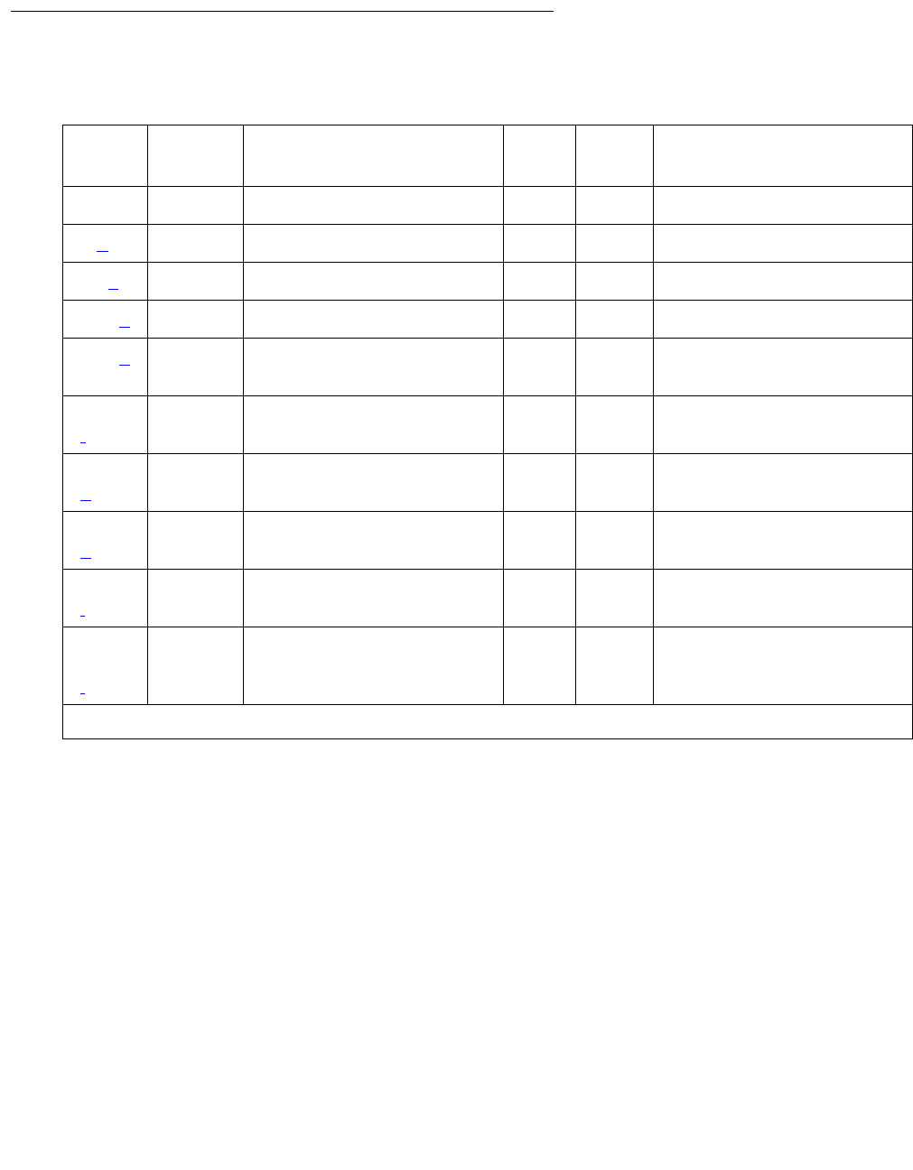
ATM-SGRP (ATM Signaling Group)
Issue 1 June 2005 599
Error Log Entries and Test to Clear Values
Notes:
a. Error Type 1: switch sent a message to the far-end switch or terminal adapter, and the far
end did not respond in the allotted time. Possible causes include link failure and congestion
or outage at the far end. The Aux Data field contains layer-3 protocol information used by
internal counters.
If no other symptoms are present, no action is required. If layer-3 communication is down:
a. Check for alarms and errors against link components
2. Check out other errors against ATM-SGRP, ATM-TRK, and other hardware components on
the link.
There is no test to clear these errors. The error counter is decremented by 1 every 15
minutes.
Table 196: ATM-SGRP Signaling Group Error Log Entries
Error
Type
Aux
Data
Associated Test Alarm
Level
On/Off
Board
Test to Clear Value
00 Any Any test sig-group grp#
1 (a) Any None
18 (c) MO busied out
257 (d) Any None test sig-group grp#
769 (e) Any Primary Signaling Link
Hardware check (#636) test sig-group grp#
1281
(f)
Any Secondary Signaling Link
Hardware check (#639) test sig-group grp#
1793
(g)
Any Layer 2 Status test (#647) WRN OFF test sig-group grp#
2305
(h)
Any Remote Layer 3 Query test
(#637)
MIN OFF test sig-group grp#
3585
(i)
Port
number
None
3840 -
3928
(j)
Port
number
None

Communication Manager Maintenance-Object Repair Procedures
600 Maintenance Procedures for Avaya Communication Manager 3.0, Media Gateways and Servers
c. Error Type 18: the ATM circuit pack has been busied out (either busyout atm sig-grp
or busyout board location).
1. Release the ATM signaling group (release atm sig-grp) or the circuit pack
(release board location).
d. Error Type 257: the primary signaling channel connection has been lost for more than 90
seconds.
●The associated B channels are placed in the ISDN Maintenance/Far-End state.
●The B channels are not usable for outgoing calls, although incoming calls can be
accepted.
●The switch automatically attempts to recover the signaling link.
1. Pay particular attention to the results of Test #636 (Primary Signaling Link Hardware
Check) in the test sequence.
●When the link does recover, the B channels are negotiated back to the In-Service state
and their alarms are retired.
2. When this error occurs, the state of the Signaling Group is changed to out-of-service
(verify using the status sig-group command).
e. Error Type 769: signaling link hardware error.
Service-affecting failures of the hardware used to transport the D channel are reported to
the ATM CES Signaling Group MO. Maintenance logs this error, places the D channel into
the OOS state, and raises a board-level alarm. The D channel is returned to service, and
the alarm is retired once the hardware failure condition clears.
f. Error Type 1281: Degraded PVC alarms indicate that a particular Permanent Virtual Circuit,
or signaling group, has encountered sufficient errors to exceed firmware thresholds.
Operations can continue but at a lower level of reliability or performance. Firmware filters
these alarms so that only one is reported active at a given time. The following in-line error is
considered a Degraded PVC alarm:
●Excessive AAL – The AAL layer is experiencing an excessive number of errors in trying
to reconstruct Service Data Units (SDUs). Possible causes:
- Problem with the ATM switch
- Noisy communication paths on opposite side of ATM switch
- Unhealthy sending node
- Congestion at the ATM switch
g. Error Type 1793: Layer 2 Query test for the primary signaling channel failed.
●Excessive AAL – The AAL layer is experiencing an excessive number of errors in trying
to reconstruct Service Data Unit (SDUs). Possible causes:
- Problem with the ATM switch
- Noisy communication paths on opposite side of ATM switch
- Unhealthy sending node
- Congestion at the ATM switch

ATM-SGRP (ATM Signaling Group)
Issue 1 June 2005 601
h. Error Type 2305: The Remote Layer 3 Query test (#637) failed. A specific message was
sent to the far-end switch, and it did not respond within the allotted time.
1. Investigate elements of the ATM D channel(s) (ATM-DCH) for both this switch and the
far-end switch.
If Test #637 fails twice in a row, the B channels are alarmed and made unavailable for
outgoing calls (although incoming calls are still accepted). When Test #637 succeeds and
the far-end switch starts responding properly, the ATM trunk (B channels) are placed back
into normal operation and their alarms retired.
i. Error Type 3585: A SERV or SERV ACK ISDN D-channel message has been received by
a non-US-type interface (country option other than 1 on the DS1 administration screen).
However, these messages are used only for duplex NFAS signaling, which is supported by
country protocol 1.
Thus, there may be a mismatch in administration between the local and far-end switches.
1. Consult with the customer’s network provider to determine whether the D channel is set
up correctly on the far-end switch.
j. Error Type 3840-3928: These error types are used to report certain error messages
received by the ATM-SGRP Signaling Group for one of its associated B channels. The Aux
Data field is the port number of the B channel from which the message was received.
The error code generated equals 3840+x, where x is a Cause Value defined by the ISDN
PRI Specification. Note that there is no Test to Clear Value for these error types; selected
ISDN cause values are placed in the log when they are received, but no direct action or
alarming is performed solely in response to receiving them. They provide added data that
may prove useful when tracking down obscure networking and routing problems. See
Table 197: Descriptions and repair recommendations (Error Types 3840-3928) on
page 601 for more information.
Table 197: Descriptions and repair recommendations (Error Types 3840-3928)
Error
Code
Description Recommendation
3842 A request has been
made to use a transit
network or common
carrier that cannot be
accessed.
From the circuit pack and port number (in the Aux Data
field), determine the trunk group against which the error
was reported.
1. Check every routing pattern containing this trunk group
for validity of interexchange carriers requested (IXC
field).
1 of 5

Communication Manager Maintenance-Object Repair Procedures
602 Maintenance Procedures for Avaya Communication Manager 3.0, Media Gateways and Servers
3846 The far-end switch has
indicated that the
B channel (trunk) is
not acceptable for use
in the call for which it
was requested.
This could indicate
●an administration problem (for example, the local
switch and the far-end switch have different B
channels administered)
●a normal race condition (for example, the local switch
has requested use of a B channel that the far-end
switch had just reserved for use on another call).
1. From the circuit pack and port number (in the Aux Data
field), determine the trunk group against which the
error was reported.
2. Enter status trunk for the indicated trunk.
3. Refer to Table 157: ATM ISDN service states on
page 508 for recovery suggestions.
3858 Similar to Error Type
1. The switch sent an
ISDN message to the
far-end switch or
terminal adapter that
did not respond in the
allotted time.
1. Check for alarms and errors against link components
2. Check out other errors against ATM-SGRP (ATM
Signaling Group), ATM-TRK (Circuit Emulation Service
Circuit Pack), and other hardware components on the
link.
3878 The far-end switch has
indicated that the
network is not
functioning correctly
and that the condition
may last a relatively
long period of time (for
example, immediately
re-attempting the call
may not be
successful).
1. From the circuit pack and port number (in the Aux Data
field, determine the trunk group against which the error
was reported.
2. Consult with the network provider to determine the
nature and expected duration of the out of service
condition.
3. Consider modifying every routing pattern containing
this trunk group, to route calls around the network that
is out of service.
Table 197: Descriptions and repair recommendations (Error Types 3840-3928) (continued)
Error
Code
Description Recommendation
2 of 5

ATM-SGRP (ATM Signaling Group)
Issue 1 June 2005 603
3890 A request to use a
network service (for
example, SDN) has
been denied.
Administration
somewhere in the
network has indicated
that the requested
service has not been
subscribed to or
purchased for this
trunk.
This could indicate
●a local administration problem
●a mismatch between the local administration and that
of the network provider.
1. From the circuit pack and port number (in the Aux Data
field), determine the trunk group against which the
error was reported.
2. Display the trunk group screen.
If the trunk group is Call-by-Call (the Service Type
field is cbc), check every routing pattern screen
containing this trunk group to see if the Service/
Feature fields contain the correct network services
purchased for this trunk.
If the trunk group is not Call-by-Call, check that the
Service Type field contains the single network service
purchased for this trunk.
3. If local administration appears correct, consult with the
customer and/or the network provider to determine the
services that the customer has subscribed to for this
trunk group.
3892 Protocol detail; may
offer a clue if customer
is having ISDN calls
denied with an
unexpected intercept
tone.
1. If customer is complaining of unexpected intercept
tones when accessing ISDN trunks or PRI endpoints
and no other cause can be found, escalate the
problem and provide the next tier with this Error Log
information.
Table 197: Descriptions and repair recommendations (Error Types 3840-3928) (continued)
Error
Code
Description Recommendation
3 of 5

Communication Manager Maintenance-Object Repair Procedures
604 Maintenance Procedures for Avaya Communication Manager 3.0, Media Gateways and Servers
3894 Protocol detail; may
offer a clue if customer
is having ISDN calls
denied with an
unexpected intercept
tone.
1. Eliminate any transitory state mismatch problems
(test port location for the trunk port shown in
the Aux Data field). Test #256 (Service State Audit) is
the important test in the sequence.
2. If Test #256 passes yet the customer continues to
complain of unexpected intercept tones when
accessing ISDN trunks or PRI endpoints and no other
cause can be found, escalate the problem and provide
the next tier with this Error Log information.
3905 Protocol detail; may
offer a clue if customer
is having ISDN calls
denied with an
unexpected intercept
tone.
1. If customer is complaining of unexpected intercept
tones when accessing ISDN trunks or PRI endpoints
and no other cause can be found, escalate the
problem and provide the next tier with this Error Log
information.
3906 Protocol detail; may
offer a clue if customer
is having ISDN calls
denied with an
unexpected intercept
tone.
1. If customer is complaining of unexpected intercept
tones when accessing ISDN trunks or PRI endpoints
and no other cause can be found, escalate to the
problem and provide the next tier with this Error Log
information.
3909 A request to use a
network service has
been made, but the
network has rejected
the request because
the requested service
is not implemented.
1. Follow the recommendations listed above for Error
Type 3890.
Table 197: Descriptions and repair recommendations (Error Types 3840-3928) (continued)
Error
Code
Description Recommendation
4 of 5

ATM-SGRP (ATM Signaling Group)
Issue 1 June 2005 605
System Technician-Demanded Tests: Descriptions and Error
Codes
Investigate tests in the order presented. By clearing error codes associated with the Primary
Signaling Link Hardware check (#636), you may also clear errors generated from other tests in
the sequence.
3928 A call was denied
because of a basic
incompatibility
between the type of
call and either the
facilities selected by
the routing pattern or
the called user itself.
This error might be helpful as a clue if the customer
complains of receiving unexpected intercept tone after
accessing ISDN trunks or PRI endpoints.
1. Determine the trunk group from the circuit pack and
port number (in the aux data field)
2. check the BCC fields of the pertinent routing patterns.
3. Also, investigate whether or not the calling and called
endpoints are compatible (for example, some ISDN
switches may not allow a voice station to call a data
extension).
Table 197: Descriptions and repair recommendations (Error Types 3840-3928) (continued)
Error
Code
Description Recommendation
5 of 5
Table 198: System Technician-Demanded Tests: ATM-SGRP
Order of Investigation Short Test
Sequence
Long Test
Sequence
D/
ND1
1. D = Destructive, ND = Nondestructive
Primary Signaling Link Hardware check (#636) X X ND
Layer 2 Status test (#647) X X ND
Remote Layer 3 Query test (#1291) X X ND

Communication Manager Maintenance-Object Repair Procedures
606 Maintenance Procedures for Avaya Communication Manager 3.0, Media Gateways and Servers
Primary Signaling Link Hardware Check (#636)
The ATM-SGRP Signaling Group D-channel port depends on the health of the TN230X
interface circuit pack on which it resides. This test fails if there are problems with either the
ATM-DCH (D-channel port) MO or the TN230X circuit pack. Investigate the ATM TN230X
circuit pack (ATM-TRK) anytime there are problems with the ATM D-channel port (ATM-DCH).
Layer 2 Status Test (#647)
The Layer 2 Status test checks the layer-2 status of the ATM-SRG signaling channel (D
channel). This test fails when:
●there is a hardware failure
●there is a facility problem
●the D channels are not administered correctly
The Signaling Link Hardware Check (Test #637) and the Remote Layer 3 Query test (#1291)
detects most problems caused by hardware failures or incorrect administration.
Table 199: Primary Signaling Link Hardware Check (#636)
Error
Code
Test
Result
Description / Recommendation
ABRT Internal system error
1. Retry the command at 1-minute intervals up to 5 times.
8 FAIL There is a problem with the ATM TN230X circuit pack or the ATM signaling
channel (D channel), preventing any ISDN trunk calls until the problem is
resolved.
1. Consult the procedures for the TN230X circuit pack (ATM-TRK) and
the ATM D channel (ATM-DCH).
PASS The basic physical connectivity of the D channel is intact and functional.
1. Try this test repeatedly to ensure the link is up and to uncover any
transitory problems.

ATM-SGRP (ATM Signaling Group)
Issue 1 June 2005 607
Table 200: Test #647 Layer 2 Status Query Test
Error
Code
Test
Result
Description / Recommendation
1132 ABRT Internal system error. The port location for the D channel is not known.
This condition should not be possible since an administered ATM circuit
pack must be specified when a Signaling Group is administered:
1. Retry the command at 1-minute intervals up to five times.
1134 ABRT Internal system error. The associated ATM circuit pack is not administered.
This condition should not be possible, since an administered ATM circuit
pack must be specified when administering a Signaling Group.
1. Retry the command at 1-minute intervals up to three times.
2500 ABRT Internal system error
1. Retry the command at 1-minute intervals up to five times.
1 FAIL Layer 2 of the signaling channel is down.
1. Examine the results of the Signaling test (#636), and follow
recommendations provided there.
2. If Test #636 (Primary Signaling Link Hardware Check) passes, the
Layer 2 Query test may still fail if the signaling channel at the far end
has not been administered correctly or if the signaling channel has
been busied out.
3. Verify that the far-end signaling channel (D channel) has been
administered correctly.
4. Verify that the ATM-DCH port used for the D channel has not been
busied out at the far end.
3 FAIL The D channel is down.
1. Examine the results of the Primary Signaling Link Hardware Check
(#636) and follow recommendations provided there.
2. If Test #636 (Primary Signaling Link Hardware Check) passes, the
Layer 2 Query test may still fail if the signaling channel at the far end
has not been administered correctly or if the signaling channel has
been busied out.
3. Verify that the far-end signaling channel (D channel) has been
administered correctly.
4. Verify that the far-end ATM-DCH ports used for the Primary and
Secondary D channels have not been busied out.
PASS The Primary signaling channel is up.

Communication Manager Maintenance-Object Repair Procedures
608 Maintenance Procedures for Avaya Communication Manager 3.0, Media Gateways and Servers
Remote Layer 3 Query (#1291)
This test queries the far-end switch or terminal adapter to determine whether the signaling
connection is functioning properly at Layer 3. It selects a B channel in the in-service or
maintenance service state and sends an ISDN layer-3 SERVice message, which requires a
response from the far end (similar to performing Test #256 on an ISDN trunk). The test is not
performed if there are no B channels in an appropriate ISDN service state (for example, when
none are administered or they are all out of service).
Note:
Note: The service state can be displayed by using the status trunk grp#/mem# or
status pri-endpoint command.
As is the case with Test #256 for an ISDN trunk, a PASS only indicates that a message was
composed and sent to the far-end switch or terminal adapter. The ISDN PRI Specification
allows up to 2 minutes for a response. Check the Error Log for ATM-SGRP errors of type 2305
for evidence of a Remote Layer 3 Query failure.
Test #636 checks the health of the D channels and ATM Interface circuit packs. This test goes
one step further by checking the communication path from the processor, through the TDM/
packet bus and ATM Interface circuit pack, and on to the far-end switch or terminal adapter. A
special ISDN message is sent to the far-end switch or terminal adapter that must respond within
a specified amount of time. This test is designed to ensure that the communication path
between the switch and the far end is up and operational, and that the two endpoints can
properly exchange ISDN control messages.
Table 201: Test #1291 Remote Layer 3 Query
Error
Code
Test
Result
Description / Recommendation
1006 ABRT There are no associated B channels in an ISDN “in-service” or
“maintenance” service state. This is a NORMAL ABORT.
1. Administer or release an ISDN trunk or PRI endpoint before retrying
the test. For an ATM trunk, use status trunk grp#/mem# to verify
the ISDN trunk state.
2. Retry this test when at least one B channel is in the “in-service” or
“maintenance” states.
1113 ABRT The signaling channel is down. Therefore, no messages can be sent to the
far-end switch or terminal adapter.
1. Examine the results of Test #636, and follow recommendations
provided there.
1 of 2

ATM-SGRP (ATM Signaling Group)
Issue 1 June 2005 609
2100 ABRT Could not allocate the necessary system resources to run this test.
1. Retry the command at 1-minute intervals up to 5 times.
2500,
none
ABRT Internal system error or administration problem
1. Determine whether any B channels are administered.
2. If there are none, then this is a normal ABORT, since this test cannot
run unless at least one B channel is administered.
3. If at least one B channel is administered, there is an internal system
error. Retry the command at 1-minute intervals up to 5 times.
FAIL Internal system error
1. See description of ABORT with Error Code 2500.
PASS A message was sent to the far-end switch or terminal adapter. The ISDN
PRI specification allows up to 2 minutes for a reply.
1. Check the Error Log for ATM-SGRP errors of type 2305 for evidence of
a Remote Layer 3 Query failure.
2. If no new errors were logged since this test was run, then this switch
and the far-end switch can exchange call control messages.
3. If there is still a problem with a particular ATM trunk, busyout the trunk
and run the long test sequence, paying particular attention to the
results of Test #258 (ISDN test call).
Table 201: Test #1291 Remote Layer 3 Query (continued)
Error
Code
Test
Result
Description / Recommendation
2 of 2

Communication Manager Maintenance-Object Repair Procedures
610 Maintenance Procedures for Avaya Communication Manager 3.0, Media Gateways and Servers
ATM-SYNC (ATM Synchronization)
S8700 MC
This section discusses intra-switch synchronization maintenance and the hardware and
software components that provide a common reference frequency for reliable digital
communications among the G3r system, the ATM switch, and other PBXs, Central Offices
(COs) or customer-premises equipment (CPE). Circuit packs involved in synchronization
include:
Note:
Note: TN768 or TN780 Tone-Clock circuit packs are not compatible with ATM EIs.
●TN2312 IPSI circuit pack’s Tone-Clock circuit
●TN2182 Tone-Clock
●TN722, TN464, and TN767 DS1 Interfaces (all suffixes)
●TN2305/6 ATM Expansion Interface (multimode fiber)
Synchronization is achieved between the S8700 Media Server Multi-Connect IPSI and the port
networks (PNs) through the ATM port-network connectivity (ATM PNC) between the networks.
Depending on the network’s synchronization plan and the status of synchronization sources, the
system timing reference may be:
●The clock circuit pack on the ATM switch
●A DS1 or UDS1 interface circuit pack-tapped T1 input signal connected to the ATM switch
clock circuit
●An OC-3 interface circuit pack on the ATM switch
Stratum 4 synchronization extracts timing information directly from
●A DS1 or UDS1 reference
●An OC3 reference
●The ATM switch clock
For further information about synchronization including network synchronization, refer to AT&T
Network and Data Connectivity, 555-025-201.
MO Name in
Alarm Log
Alarm
Level
Initial Command to Run Full Name of MO
ATM-SYNC MIN display errors ATM Synchronization
ATM-SYNC WRN test
synchronization
ATM Synchronization

ATM-SYNC (ATM Synchronization)
Issue 1 June 2005 611
Stratum 4 Synchronization
Systems may have primary and secondary synchronization references (DS1/UDS1 interface
circuit packs or ATM-Switch) when using Stratum 4 synchronization.
If the primary synchronization reference in Figure 32: Stratum-4 Synchronization with
Unduplicated ATM PNC on page 612 is providing a valid timing signal, then the flow of system
synchronization would travel from the DS1 interface circuit pack in the PN to the ATM switch.
The primary DS1 interface circuit pack provides a timing signal for the ATM switch clock
circuitry. This synchronization source is then distributed to all of its OC3 Interface Modules.
Each ATM Expansion Interface circuit pack uses the received data stream from the ATM switch
to generate a timing signal. The Tone-Clock circuits in the PNs use this signal to generate
timing for every circuit pack in their respective PNs. All PNs, in the above mentioned scenario
are designated the slave PNs. The ATM switch is the master that contains the system
synchronization source. If the primary synchronization reference does not provide a valid timing
signal, ATM synchronization maintenance infers a switch to the secondary reference.
If the primary synchronization reference is not providing a valid timing signal, the system
automatically switches to the secondary synchronization reference. If the primary
synchronization reference is invalid, and if the secondary reference does not provide a valid
timing signal or is not administered as a synchronization reference, the switch infers that the
local oscillator of the ATM switch provides the system timing source. If the system is using the
local oscillator of the ATM switch as the system timing source because the primary and
secondary references are providing invalid timing signals, when either the primary or secondary
reference becomes valid again, the system switches back to the primary or secondary source.
When both the primary and secondary source become valid, the system switches to the primary
source, since the primary source is always preferred over the secondary source when both
sources are equally healthy.
Figure 32 depicts a simplex ATM PNC with T1/OC3 synchronization reference into the ATM
switch.
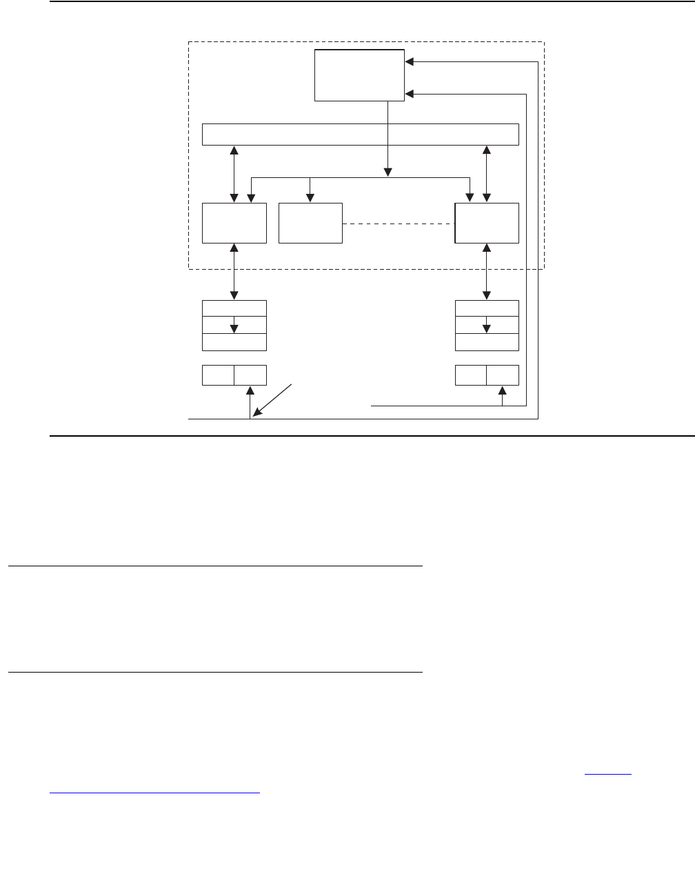
Communication Manager Maintenance-Object Repair Procedures
612 Maintenance Procedures for Avaya Communication Manager 3.0, Media Gateways and Servers
Figure 32: Stratum-4 Synchronization with Unduplicated ATM PNC
Note:
Note: The TN722 DS1 Interface circuit pack does not provide a synchronization
reference as reliably as the TN767 or TN464 circuit packs. Therefore, administer
the TN767 or TN464 circuit packs as the primary or secondary sources.
Stratum-3 Synchronization
Stratum-3 synchronization is not supported in S8700 Multi-Connect with ATM PNC.
Troubleshooting ATM synchronization
A significant part of the Synchronization Recovery Strategy for a S8700 Multi-Connect with ATM
PNC resides in the ATM switch’s clock hardware, firmware, and software. S8700 Multi-Connect
monitors synchronization performance and alarms any faulty components. See SYNC
(Port-Network Synchronization) on page 2143.
Clock
ExternalT1/E1
ExternalT1/E1
secondary
primary
ATM switch fabric
ATM timing distribution
Interface
module
Interface
module
Interface
module
ATMPNC
DEFINITY
PPN
DEFINITY
EPN
OC3OC3
ATM-EI ATM-EI
Tone clockTone clock
DS1DS1DS1DS1
T1-splitter
T1-primary
T1-secondary
iodfst4LJK 011998
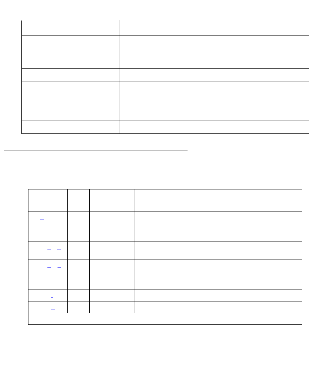
ATM-SYNC (ATM Synchronization)
Issue 1 June 2005 613
ATM-SYNC Commands
Use the commands in Table 202 to help troubleshoot ATM-SYNC problems:
Error Log Entries and Test to Clear Values
Table 202: ATM-SYNC commands
Command Description
change synchronization Allows primary and secondary references to be administered
for the Stratum 4 option, or ATM-Switch, indicating that the
synchronization references are input directly to the ATM
switch
status synchronization Shows the current inferred synchronization reference
status synchronization Shows the administered primary and secondary
synchronization references
disable/enable
synchronization-switch
Prevents or allows switching to another synchronization
source
test synchronization Tests the administered synchronization source
Table 203: Synchronization Error Log Entries
Error
Type
Aux
Data
Associated
Test
Alarm
Level
On/Off
Board
Test to Clear Value
0 (a)0Any Any Anytest synchronization
1 (b) (h) None WRN
MINOR
OFF None
257 (c) (h) None WRN
MINOR
OFF None
513 (d) (h) None WRN/
MAJOR
OFF None
1537 (e) None WRN OFF None
1793 (f) 0-50 None NONE OFF None
2049 (g) 0 None WRN OFF None

Communication Manager Maintenance-Object Repair Procedures
614 Maintenance Procedures for Avaya Communication Manager 3.0, Media Gateways and Servers
Notes:
a. Error Type 0: Run the short test sequence first. If every test passes, run the long test
sequence. Refer to each appropriate test’s description, and follow its recommended
procedures.
b. Error Type 1: problem with the primary DS1 reference. It is cleared when the primary
reference is restored. The following steps should give an indication of the source of the
problem:
1. Check if the primary DS1 interface circuit pack is inserted in the carrier with list
configuration board location.
2. Verify that the administered primary reference matches the DS1 reference from the
network synchronization plan.
3. Test the primary DS1 interface circuit pack with test board location long. Check
the Error Log for DS1-BD or UDS1-BD errors and see DS1-BD (DS1 Interface Circuit
Pack) on page 978 or UDS1-BD (UDS1 Interface Circuit Pack) on page 2374 to resolve
any errors associated with the primary DS1 (DS1 or UDS1) interface circuit pack. If the
only errors against DS1-BD or UDS1-BD are slip errors, then follow the procedures
described in the troubleshooting section above. If no errors are listed in the Error Log for
the primary DS1 interface circuit pack, continue with the following steps.
4. Test the active Tone-Clock circuit in the master PN with test tone-clock location long.
Check the Error Log for TDM-CLK errors and verify that TDM Bus Clock Test #148 (TDM
Bus Clock Circuit Status Inquiry test) passes successfully. If Test #148 fails with an Error
Code 2 through 32, see TDM-CLK (TDM Bus Clock) on page 2252 to resolve the
problem.
c. Error Type 257: problem with the secondary DS1 reference. It is cleared when the
secondary reference is restored. Refer to note (a) to resolve this error substituting
secondary for primary in the preceding resolution steps.
d. Error Type 513: the ATM switch clock is inferred to be providing the timing source for the
system. The primary and secondary (if administered) are not providing a valid timing signal.
Investigate errors 1 and 257 to resolve this error.
e. Error Type 1537: over half of the DS1s that are administered with slip detection enabled
through the Slip Detection field set to y are experiencing slips. It may take up to 1 hour for
these alarms to clear via the “leaky bucket” strategy.
f. Error Type 1793: inferred excessive switching of system synchronization references has
occurred. When this error occurs, it is inferred that the ATM switch clock has become the
synchronization reference for the system. It may take up to 1 hour for these alarms to clear
via the “leaky bucket” strategy.
1. Check for timing loops and resolve any loops that exist.

ATM-SYNC (ATM Synchronization)
Issue 1 June 2005 615
2. Test the active Tone-Clock circuit in the master PN with test tone-clock location
long.
Check the Error Log for TDM-CLK errors, and verify that TDM Bus Clock Circuit Status
Inquiry test (#148) passes successfully.
If Test #148 fails with an Error Code 2–32, see TDM-CLK (TDM Bus Clock) on
page 2252 to resolve the problem. If not, continue with the following steps.
3. For Duplicated Tone-Clock circuit packs in the master PN: Switch Tone-Clock circuit
packs on the master PN with set tone-clock location.
For Simplex Tone-Clock circuit packs in the master PN: replace the primary and
secondary (if administered) DS1 Interface circuit packs.
4. Investigate any other SYNC errors.
g. Error Type 2049: the ATM Expansion Interface circuit packs have errors that affect
synchronization. Test the ATM Expansion Interface circuit pack with test board
location.
This error is cleared by a “leaky bucket” strategy and takes up to one hour to clear (leak
away) the error counter once it is cleared.
h. Error Types 1, 257, and 513: noise on the DS1 line can cause transient alarms on
synchronization. Therefore, when a synchronization problem occurs on Error Types 1, 257,
or 513, a WARNING alarm is first raised for 15 to 20 minutes before the alarm is upgraded
to a MINOR or MAJOR alarm.
System Technician-Demanded Tests: Descriptions and Error
Codes
Order of Investigation Short Test
Sequence
Long Test
Sequence
D/ND1
1. D = Destructive, ND = Non-destructive
Test Synchronization test (#417) X X ND

Communication Manager Maintenance-Object Repair Procedures
616 Maintenance Procedures for Avaya Communication Manager 3.0, Media Gateways and Servers
Test Synchronization Test (#417)
This test updates all the Synchronization Maintenance component circuit packs with the correct
information regarding their role in providing synchronization for the system. All the Tone-Clock,
ATM Expansion Interface, DS1 Interface, and UDS1 Interface circuit packs in the system are
updated through this test. This test either passes or aborts.
Table 204: Test #417 Test Synchronization Test
Error
Code
Test
Result
Description / Recommendation
1000 ABRT System resources required to run this test are not available.
1. Retry the command at 1-minute intervals up to 3 times.
1115 ABRT Could not allocate the necessary system resources to run this test.
1. Retry the command at 1-minute intervals up to 3 times.
2500 ABRT Internal system error
PASS The synchronization maintenance component circuit pack parameters
have been successfully updated. The system should be synchronized
after successful execution of this test.
1. If synchronization problems still exist, refer to the Error Log to obtain
information regarding the source of the problem.

ATM-TRK (Circuit Emulation Service Circuit Pack)
Issue 1 June 2005 617
ATM-TRK (Circuit Emulation Service
Circuit Pack)
S8700 | 8710 / S8500
ATM-TRK explains how you test and repair TN230x ATM Interface circuit packs (TN2305 and
TN2306) that have been administered as virtual ISDN-PRI trunks for ATM Circuit Emulation
Service (CES). The maintenance instructions for TN230x circuit packs that have been
administered as Expansion Interfaces for WAN connectivity are in the ATM-INTF (TN2305/6)
MO.
Description
The TN2305 and TN2306 (Table 205: R7 ATM-TRK circuit packs on page 617) are
dual-purpose ATM circuit packs that can be administered as either:
●ATM Circuit Emulation Service or virtual ISDN-PRI signaling trunks
●Expansion Interfaces (ATM-EIs) for port-network connectivity (ATM PNC) between the
PNs
Either circuit pack “personality” requires SONET OC-3 or SDH STM-1 fiber cable connections
between the circuit pack and the ATM switch. As a trunk board, it supports direct connection
between ATM CES circuit packs without an intervening ATM switch.
MO Name in
Alarm Log
Alarm
Level
Initial Command to Run Full Name of MO
ATM-TRK MAJ test board location ATM TRUNK (ATM Circuit
Emulation Service)
ATM-TRK MIN test board location ATM TRUNK (ATM Circuit
Emulation Service)
ATM-TRK WRN test board location ATM TRUNK (ATM Circuit
Emulation Service)
Table 205: R7 ATM-TRK circuit packs
Circuit
pack
Channel types Interface Fiber Echo
cancellation
TN2305 B and D
channels
24 or 32
channel
Multimode Y
TN2306 B and D
channels
24 or 32
channel
Single-mode Y

Communication Manager Maintenance-Object Repair Procedures
618 Maintenance Procedures for Avaya Communication Manager 3.0, Media Gateways and Servers
Note:
Note: TN230x circuit packs are not interchangeable.
ATM Circuit Emulation Service
Under ATM Circuit Emulation Service (CES), simulate ISDN-PRI circuits by assigning ports to
signaling groups. Each signaling group represents a PRI circuit, and the ports in the group
represent the D channel and B channels of that circuit.
Virtual D channels
Non-facility associated signaling is not supported under ATM-CES, so you must reserve one
port in each signaling group for use as a D channel. Use channel 24 when emulating a T-1
ISDN facility, and channel 16 when emulating an E-1 facility. The D channel can be any
physical port from 9 to 32.
Virtual circuits
The TN230x can support a varied number of virtual circuits, depending on the switch and the
administration of the circuit pack.
Virtual trunk groups
You cannot bundle physical DS1 ISDN-PRI circuits and virtual ATM-CES circuits into the same
trunk groups. Virtual circuits can only be assigned to all-virtual, all-ATM trunk groups.
LEDs
The ATM circuit pack LEDs give you a visual indication of the condition of the TN230x circuit
pack (Table 206: ATM-TRK LED interpretation on page 618).
Table 206: ATM-TRK LED interpretation
LEDs Condition LED status
Red Error (alarm logged) On
Red &
Green
Booting (LEDs being tested) Blinking (on 200 ms, off 200 ms)
Green Test/maintenance in progress On
Amber Fiber Loss of Signal (LOS), LOF,
MS_RDI, MS_AIS, LCD, HP_RDI,
HP_AIS, LOP, PSC
Blinking fast (100 ms on, 100 ms off)
Amber Signal to ATM switch down Blinking slowly (500 ms on, 500 ms off)
1 of 2

ATM-TRK (Circuit Emulation Service Circuit Pack)
Issue 1 June 2005 619
ATM-TRK-related commands
Table 207: ATM CES troubleshooting commands on page 619 lists some commands that can
be useful in troubleshooting ATM errors and alarms.
Amber One or more CES signaling groups
administered
On
Amber CES signaling group not administered or
not reporting to firmware
Off
Table 206: ATM-TRK LED interpretation (continued)
LEDs Condition LED status
2 of 2
Table 207: ATM CES troubleshooting commands
Command Description
display circuit-packs cabinet Shows the circuit packs in the cabinet,
identifying ATM trunk as well as ATM-EI
boards. “ATM Interface” boards have not been
administered as CES or PNC.
display atm ports location Shows the 256 ports on the ATM board with
the corresponding signaling and trunk group.
list configuration atm Lists the ATM boards, identifying equipment
location, board code, type, and vintage.
list configuration trunks Lists boards identifying assigned ports. While
the ATM board is listed, the 256 ports are not.
busyout/release atm
signaling-group
Busyout or release of an ATM signaling group
within a trunk group.
status atm signaling-group Show current status of an ATM signaling
group.
status trunk-group Shows status of the trunk group (ATM
signaling groups are part of trunk groups).
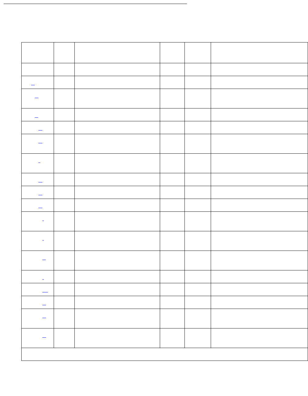
Communication Manager Maintenance-Object Repair Procedures
620 Maintenance Procedures for Avaya Communication Manager 3.0, Media Gateways and Servers
Error Log Entries and Test to Clear Values
Table 208: ATM-TRK Error Log entries
Error
Type
Aux
Data
Associated Test Alarm
Level
On/Off
Board
Test to Clear Value
00Any Any test board location
1(a) None MIN ON
18(b)0busyout board
location
MIN ON release board location
23(c) 0 None MIN ON
125(d) None MIN ON
257(e) Any Control Channel Loop
(#52)
MIN ON test board location r
2
513(f) Any ATM Cross Talk (#1298) MIN ON test board location l
r 1
769(g) 35 ATM Error Query (#1259) WRN OFF test board location
770(g) 25 ATM Error Query (#1259) WRN OFF test board location
771(h) 26 ATM Error Query (#1259) WRN OFF test board location
1281(i) ATM Board Error Query
(#1259)
WRN
/ MIN
OFF test board location r
1
1537(j) 12 None WRN
/ MIN
ON
1538(k) 0 None WRN
/ MIN
ON reset board location
1794(l) 13 None MIN ON
2049(m) 15 None WRN OFF test board location
2306(n) None
2561(o) Packet interface test
(#598)
MIN ON test board location r
2
2817(p) 1-24 ATM Board DSP (#1293) WRN
/ MIN
ON test board location
1 of 2
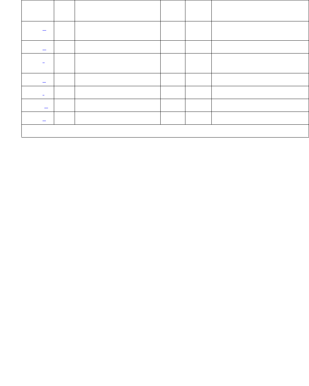
ATM-TRK (Circuit Emulation Service Circuit Pack)
Issue 1 June 2005 621
Notes:
a. Error Type 1: the ATM-TRK circuit pack does not appear to be in its assigned slot.
1. Make sure that the ATM-TRK circuit pack is installed correctly seated in the slot
administered for the ATM trunk.
b. Error Type 18: the ATM circuit pack is busied out.
1. Run release board location.
c. Error Type 23: an ATM trunk is administered, but the corresponding ATM-TRK circuit pack
does not appear to be physically installed.
1. Make sure the ATM-TRK circuit pack is installed and correctly seated in the slot.
d. Error Type 125: an ATM trunk is administered but a non-ATM-TRK circuit pack is installed
in the corresponding slot. You have two options:
●Replace the incorrect circuit pack with an ATM-TRK circuit pack.
●Or re-administer the slot for the circuit pack that is physically present, locate the slot
where the ATM-TRK circuit pack is actually installed, and re-administer the ATM trunk.
e. Error Type 257: Control Channel Loop test (#52) failed. The circuit pack is not properly
connected with the control channel on the TDM bus.
1. Take the corrective action specified by Test #52.
f. Error Type 513: ATM Crosstalk test (#1298) failed. The board is writing to or reading from
a TDM time slot that is not allocated to the board, or the Digital Signal Processor (DSP)
selected for this test has malfunctioned.
1. Run test board location.
2. Take the corrective action specified for Test #1298.
2818(p)1-24 WRN
/ MIN
ON test board location
3330(q)3 MIN OFF
3585(r) ATM Board Error Query
(#1259)
WRN
/ MIN
ON test board location l
3841(s) Any None
3842(t) 11 None
3843 (u) None
3999(v) Any None
Table 208: ATM-TRK Error Log entries (continued)
Error
Type
Aux
Data
Associated Test Alarm
Level
On/Off
Board
Test to Clear Value
2 of 2

Communication Manager Maintenance-Object Repair Procedures
622 Maintenance Procedures for Avaya Communication Manager 3.0, Media Gateways and Servers
g. Error Type 769, 770: the ATM switch is requesting too many LAPD retransmissions
(off-board ATM cell corruption errors).
1. Check the connections between the fiber cable, the ATM-TRK circuit pack, and the ATM
switch.
2. See PKT-BUS (Packet Bus) on page 1790 for test and corrective procedures.
3. Determine what type of fiber is installed between the ATM-TRK circuit pack and the ATM
switch.
4. Perform ATM loopback tests on the near-end ATM-TRK circuit pack and on the far-end
circuit pack or ATM switch.
5. Check capacity and peak bandwidth consumption for the ATM span.
Error
Type
Aux
Data
Description
769 35 Excessive LAPD retransmission requests
770 25 Uncorrectable ATM cell headers – threshold
If Then
There is multimode fiber Check the length of the fiber. If the cable is
longer than 2 km, it may be causing errors.
There is single-mode fiber or the length of
the multimode fiber is less than 2 km
The source of the errors can lie in the ATM
facility, the ATM-TRK circuit pack, or the far-end
circuit pack.
If Then
The ATM-TRK circuit pack fails the
loopback test.
The problem is in the ATM-TRK circuit pack.
Replace the circuit pack.
The far-end circuit pack or ATM switch
fails the loopback test.
The problem is in the far-end circuit pack or ATM
switch. Consult the circuit-pack or ATM switch
documentation for advice.
The equipment at each end of the ATM
span passes the loopback test
The problem is somewhere in the ATM span. Lack
of bandwidth can be forcing an intermediate ATM
switch to drop cells.
If Then
The capacity of the span is inadequate, or
bandwidth consumption is too high.
Reduce traffic on the system to ensure that it is
using no more that its subscribed bandwidth.

ATM-TRK (Circuit Emulation Service Circuit Pack)
Issue 1 June 2005 623
h. Error Type 771: the ATM switch is sending cells with unknown Virtual Path-Identifier (VPI)
and Virtual Channel-Identifier (VCI) addresses.
1. Make sure that the ATM-TRK circuit-pack address is administered identically on the ATM
switch and the S8700 Multi-Connect system.
i. Error Type 1281: Board major signals error (loss of high-level signal). The far end has
detected a major problem in transmissions originating from the ATM-TRK circuit pack. The
possible Aux Data values for this software counter are listed in Table 209: Error type 1281
Aux Data and repair procedures on page 623.
Table 209: Error type 1281 Aux Data and repair procedures
Aux
Data
Alarm
Description
Repair procedure
15 SYSCLOCK
failed
The board is not locked to the TDM backplane clock signal. This is
probably due to a Tone-Clock problem.
1. Check for TDM-BUS or TONE-BD errors in the Error Log.
2. If no other problems are present, reset the circuit pack with
reset board location
16 Loss of Signal:
LOS
The fiber is not connected properly to the ATM-TRK board or ATM
switch (or to the multiplexer section [MUX] if present).It is possible
that the board transceivers are not functioning properly.
1. Run test board location.
2. If Test #1259 fails with Error Code 16, connect a fiber
back-to-back in a looped mode (one strand of fiber connecting
the transmit transceiver to the receive transceiver of the board)
and see if the amber LED flash goes away. If it does the
problem is off-board.
3. If the amber LED continues to flash, replace the circuit pack.
17 Loss of Frame:
LOF
The fiber signal cannot obtain or maintain STM-1/OC-3 framing.
1. Try to more the fiber on the ATM switch side to a different port.
2. If the problem persists, reset the circuit pack with reset
board location.
1 of 3

Communication Manager Maintenance-Object Repair Procedures
624 Maintenance Procedures for Avaya Communication Manager 3.0, Media Gateways and Servers
18 Multiplexer
Section Alarm
Indication
Signal:
MS_AIS
There is a major problem on the far end (between multiplexer
section [MUX] and the switch) that prohibits the circuit pack from
sending a valid signal.
1. See if the ports at the MUX and/or the ATM switch are
connected snugly.
2. Run test board location.
3. If Test #1259 fails with Error Code 18, connect a fiber
back-to-back in a looped mode (one strand of fiber connecting
the transmit transceiver to the receive transceiver of the board)
and see if the amber LED flash goes away.
4. If it does the problem is off-board.
5. If the amber LED continues to flash, replace the circuit pack; if
the error persists, escalate the problem.
19 Multiplexer
Section
Remote Defect
Indicator:
MS_RDI
The far end is detecting a major problem with the signal that this
board is transmitting.
1. Make sure the ATM switch port (or a MUX port, if present
between ATM switch and the ATM-TRK board) is the same as
the ATM-TRK circuit pack’s cable interface
2. Run test board location.
3. If Test #1259 fails with Error Code 19, connect a fiber
back-to-back in a looped mode (one strand of fiber connecting
the transmit transceiver to the receive transceiver of the board)
and see if the amber LED flash goes away.
4. If it does the problem is off-board.
5. If the amber LED continues to flash, replace the circuit pack; if
the error persists, escalate the problem.
20 Loss of pointer:
LOP
ATM framer chip is unable to access the payload part of the signal.
1. Reset the board with reset board location.
2. If the error persists replace the board.
21 Path Signal
Error (PSL)
(STM1/
SONET)
The incoming signal payload is not set up for transmission of ATM
data.
1. Make sure the ATM switch port (or a MUX port, if present
between ATM switch and the ATM-TRK board) is the same as
the ATM-TRK circuit pack’s cable interface.
Table 209: Error type 1281 Aux Data and repair procedures (continued)
Aux
Data
Alarm
Description
Repair procedure
2 of 3

ATM-TRK (Circuit Emulation Service Circuit Pack)
Issue 1 June 2005 625
22 High-level Path
Alarm
Indication
Signal:
HP_AIS
The payload is invalid.
1. Make sure the ATM switch port (or a MUX port, if present
between ATM switch and the ATM-TRK board) is the same as
the ATM-TRK circuit pack’s cable interface.
2. Run test board location.
3. If Test #1259 fails with Error Code 22, connect a fiber
back-to-back in a looped mode (one strand of fiber connecting
the transmit transceiver to the receive transceiver of the board)
and see if the amber LED flash goes away.
4. If it does the problem is off-board.
5. If the amber LED continues to flash, replace the circuit pack.
23 High-level path
Remote defect
Indicator:
HP_RDI
The far end is detecting a major problem with the signal that this
board is transmitting. The transmitted payload is invalid.
1. Make sure the ATM switch port (or a MUX port, if present
between ATM switch and the ATM-TRK board) is the same as
the ATM-TRK circuit pack’s cable interface.
2. Run test board location.
If Test #1259 fails with Error Code 23, connect a fiber
back-to-back in a looped mode (one strand of fiber connecting
the transmit transceiver to the receive transceiver of the board)
and see if the amber LED flash goes away.
●If it does the problem is off-board.
●If the amber LED continues to flash, replace the circuit pack.
24 Loss of cell
delineation
(LCD)
On board ATM framer chip is not able to frame cells based on the
cell header.
1. Reset the board with reset board location.
2. If the error persists, replace the board.
27 SIGCON_DO
WN ATM
switch high
level signal.
The board cannot communicate with the ATM switch.
1. Busyout the board (busyout board location).
2. Test the board (test board long location).
3. If Test #1260 fails, replace the board.
4. If Test #1260 passes, make sure the ATM address on both the
S8700 Multi-Connect and the ATM switch sides are the same
for this board.
5. If the address is the same, change the port on the ATM switch
side.
6. If the error is resolved, the problem is on the ATM switch port.
Table 209: Error type 1281 Aux Data and repair procedures (continued)
Aux
Data
Alarm
Description
Repair procedure
3 of 3

Communication Manager Maintenance-Object Repair Procedures
626 Maintenance Procedures for Avaya Communication Manager 3.0, Media Gateways and Servers
j. Error Type 1537: LANHO bus timeout. The circuit pack is transmitting too many bytes on
the LAN bus for a single frame. This can be due to:
●an on-board fault.
●a faulty data received on one of the circuit pack’s external ports.
If the error occurs three times in 10 minutes, the board is isolated from the packet bus, and
the board is alarmed. To clear the alarm:
1. Restore this circuit pack to the packet bus with this command sequence:
a. busyout board location
b. reset board location
c. test board location long
d. release board location
2. If the problem persists and there are no PKT-BUS or port alarms, replace the circuit pack.
k. Error Type 1538: The ATM-TRK circuit pack is hyperactive (sending an abnormal number
of control messages to the processor). Use the following command sequence for this
ATM-TRK circuit pack:
1.busyout board location
2.reset board location
3.test board location long
4.release board location
5. If this error persists, replace the circuit pack.
l. Error Type 1794: LANHO transmit FIFO overflow. The circuit pack’s transmit buffers have
overflowed.
1. Run test board location r 5
m. Error Type 2049: ACL Link Failure (link is down). The ATM Control Link (ACL) has failed,
communication has been interrupted between the server and the ATM-TRK circuit packs on
the system, and signaling-group parameters are not communicated across the packet bus.
1. Check the PKT-BUS (Packet Bus) on page 1790 and SYS-LINK (System Links) on
page 2175 MOs, and follow the repair procedures indicated.
If Then
Test #598 fails Replace the circuit pack.
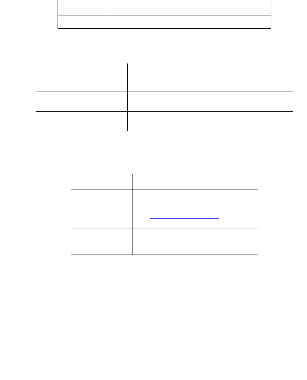
ATM-TRK (Circuit Emulation Service Circuit Pack)
Issue 1 June 2005 627
2. Run test board location against the ATM-TRK circuit pack.
n. Error Type 2306: too many parity errors in data received from the LAN/packet bus.
1. Run test board location
o. Error Type 2561: Packet Interface Loop Around test (#598) failure. The ATM-TRK circuit
pack has failed, the packet bus has a minor alarm active, or the packet bus is out of service.
1. Run test board location
p. Error Type 2817, 2818: DSP failure detected along the circuit path.
1. Run test board location.
If Then
Test 598 fails. Follow the repair procedures suggested for that test.
If Then
Test 598 fails. Follow the repair procedures suggested for that test.
Test 598 passes See PKT-BUS (Packet Bus) and perform the
specified repair.
There are no errors against
the packet bus MO
This can be a transient condition. Do nothing now,
but escalate if the error occurs repeatedly.
If Then
Test 598 fails Follow the repair procedures suggested
for that test.
Test 598 passes See PKT-BUS (Packet Bus) and
perform the specified repair.
There are no
errors against the
packet bus MO
This can be a transient condition. Do
nothing now, but escalate if the error
occurs repeatedly.

Communication Manager Maintenance-Object Repair Procedures
628 Maintenance Procedures for Avaya Communication Manager 3.0, Media Gateways and Servers
2. Follow the repair procedures suggested for Test #1293.
q. Error Type 3330: LANHO critical error. The circuit pack reports that the on-board LANHO
chip is insane (possibly due to a problem in packet-bus arbitration, in the transmission line
frame, or in the circuit pack itself). The circuit pack cannot talk to the packet bus.
1. Check for PKT-BUS alarms.
Error
Type
Description
2818 One or more DSPs failed. The Aux Data field contains the ID number
of DSP that failed
2817 DSP test failure. The Aux Data field contains the following
information about the failed DSPs:
X is the number of talker DSPs
Y is the number of listener DSPs
Z is the number of echo-cancelling DSPs
If Then
There is a packet-bus alarm There is probably a packet-bus problem,
particularly if other circuit packs on the packet
bus report the same error. See PKT-BUS
(Packet Bus) and Isolating and repairing
packet-bus faults in Maintenance Procedures
(03-300192) for repair procedures.
There are no packet-bus
alarms
Run the following command sequence:
1. busyout board location
2. reset board location
3. test board location long
4. release board location
The problem persists Replace the ATM-TRK circuit pack.

ATM-TRK (Circuit Emulation Service Circuit Pack)
Issue 1 June 2005 629
r. Error Type 3585: Major board alarm; failure of critical components involved in the operation
of the circuit pack. The circuit pack has failed, and the switch can no longer recognize it.
1. Run test board location long.
s. Error Type 3841: the ATM-TRK circuit pack received an unrecognized message from the
switch and responded with an inconsistent down-link error message.
1. Do nothing. This error does not affect service.
t. Error Type 3842: LANHO Receive FIFO Overflow error; the packet bus is delivering data to
the ATM-TRK circuit pack faster than the circuit pack can distribute it to the endpoint.
1. Do nothing. The circuit pack can recover by itself.
u. Error Type 3843: The firmware on the circuit pack is reporting a resource that is to low.
This error does not affect the service and no action is required.
Aux
Data
Description
1 ATM framer chip failure
2 NCE failed
4 TDM PLD failed
5 Every DSP on the circuit pack has failed.
6 RNP (Receive Network Processor) failed
7 TNP (Transmit Network Processor)
failed
8 MEMORY read/write failure
9 DUART failure
If Then
Test #1259 fails with Error Code XXYY
and XX is an AUX value in the
preceding table
Replace the ATM-TRK circuit pack.
The system does not recognize the
circuit pack
Replace the ATM-TRK circuit pack.
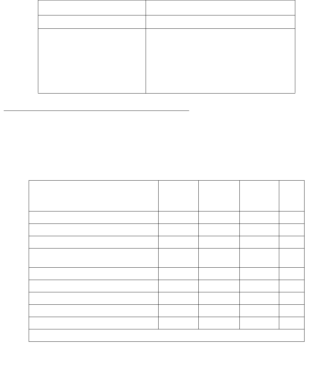
Communication Manager Maintenance-Object Repair Procedures
630 Maintenance Procedures for Avaya Communication Manager 3.0, Media Gateways and Servers
v. Error Type 3999: circuit pack sent a large number of control channel messages to the
switch within a short period of time.
System Technician-Demanded Tests:
Descriptions and error codes
Investigate problems in the order presented. When you clear one of the error codes associated
with a given test, you may clear errors generated by other tests in the testing sequence.
If Then
Error Type 1538 is also present Circuit pack is taken out of service.
Error Type 1538 is absent Circuit pack is not taken out of service, but has
generated 50% of the messages necessary to
be considered hyperactive.
●This can be normal during heavy traffic.
●If the error is logged during light traffic, it
can indicate a problem with the circuit
pack or the equipment attached to it.
Table 210: System Technician-Demanded Tests: ATM-TRK
Order of Investigation Short
Test
Sequence
Long Test
Sequence
Reset
Board
Sequence
D/
ND1
1. D = Destructive, ND = Nondestructive
ATM Board Time Of Day Update (#1261) X ND
Connection Audit test (#50) X ND
Control Channel Loop test (#52) X ND
Packet Interface Loop Around test
(#598)
XX ND
ATM DSP test (#1293) X X ND
ATM Board Framer Looparound (#1260) X D
ATM Board Error Query test (#1259) X X ND
ATM Cross Talk test (#1298) X ND
ATM Board Reset (#1256) X D

ATM-TRK (Circuit Emulation Service Circuit Pack)
Issue 1 June 2005 631
Connection Audit Test (#50)
Nondestructive (in a sane switch environment).
The Connection Audit test updates TDM time slots. It sends network-update Control Channel
Message Set (CCMS) messages that tell the ATM-TRK circuit pack to listen to, talk to, or
disconnect particular time slots.
The test passes if software successfully sends the downlink network-update messages. It
aborts otherwise.
!CAUTION:
CAUTION: Though normally nondestructive, this test could unintentionally tear down an
active call if the connection-manager software’s tables are corrupt.
Table 211: Test #50 Connection Audit Test
Error
Code
Test
Result
Description / Recommendation
None,
2100
ABRT System resources required for this test are not available.
1. Retry the command up to 5 times at 1-minute intervals.
1019 ABRT The test aborted because a test was already running on the port.
1. Retry the command up to 5 times at 1-minute intervals.
FAIL Internal system error
1. Retry the command up to 5 times at 1-minute intervals.
1 of 2

Communication Manager Maintenance-Object Repair Procedures
632 Maintenance Procedures for Avaya Communication Manager 3.0, Media Gateways and Servers
Control Channel Loop Test (#52)
The nondestructive Control Channel Loop test is part of the maintenance subsystem’s Common
Port Board Testing feature. The Common Port Board test sends board vintage queries to a port
circuit pack and checks the responses. CCMS downlink notifications tell the circuit pack which
TDM Bus (A or B) carries the control channel and which carries the touch tones.
PASS The circuit pack has been updated with its translation.
0NO
BOARD The test could not relate the internal ID to the port (no board). This could
be due to incorrect translations, no board is inserted, an incorrect board is
inserted, or an insane board is inserted.
1. Check the board translations.
2. If the ATM-TRK circuit pack is not administered, run add atm trunk
location.
3. If the ATM-TRK circuit pack is administered correctly, check the error
log.
4. If ATM-TRK circuit pack is hyperactive, shut down, and reseat the
circuit pack to force re-initialization.
5. If the ATM-TRK circuit pack is correctly inserted, run busyout board
location
6. Run reset board location
7. Run release board location
8. Run test board location long to re-establish the linkage
between the internal ID and the port.
Table 211: Test #50 Connection Audit Test (continued)
Error
Code
Test
Result
Description / Recommendation
2 of 2

ATM-TRK (Circuit Emulation Service Circuit Pack)
Issue 1 June 2005 633
The test passes if the port circuit pack responds. The test aborts if the circuit pack does not
respond. The test fails otherwise.
Table 212: Control Channel Test #52
Error
Code
Test
Result
Description / Recommendation
2000 ABRT Test request timed out.
2100 ABRT Could not allocate needed system resources.
1. Retry the command at 1-minute intervals up to 3 times.
2500 ABRT Internal system error
1. Retry the command up to 3 times at 1-minute intervals.
FAIL The ATM circuit pack responded incorrectly.
1. Retry the command up to 3 times at 1-minute intervals.
2. If the test continues to fail, reset the ATM-TRK circuit pack with reset
board location.
3. If test continues to fail, replace the circuit pack or transceiver.
PASS The ATM-TRK circuit pack is communicating correctly with the software.
0NO
BOARD Circuit pack not detected.
1. Check the error log for Error 125 (wrong board) or Error 131 (no
board), and correct any errors found.
2. Make sure that the ATM-TRK circuit pack is properly translated and
inserted.
3. Check for Error 1538 (hyperactivity). If hyperactive, run reset board
location.
4. Run the test again. If it fails, replace the ATM-TRK circuit pack, and
retest.

Communication Manager Maintenance-Object Repair Procedures
634 Maintenance Procedures for Avaya Communication Manager 3.0, Media Gateways and Servers
Packet Interface Loop Around Test (#598)
This nondestructive test checks the ATM-TRK circuit pack’s packet-bus interface. The LANHO
chip sends data through the bus and back to itself. If the data received is consistent with the
data sent, the test passes. The test does not run if the specified PN’s packet bus has a minor
alarm or is out of service.
ATM Board Reset (#1256)
This test is destructive.
This test checks the sanity of the angel processor using the Sanity and Control Interface (SAKI)
test (Common Port Board test, #53). It resets the circuit pack if the SAKI test fails and runs the
test again.The ATM Board Reset test passes if SAKI can successfully reset and retest the
board.
Before running the SAKI test, you must:
●Move synchronization off the ATM-TRK circuit pack
●Busyout the ATM-TRK circuit pack
Table 213: Packet Interface Loop Around Test (#598)
Error
Code
Test
Result
Description / Recommendation
2000 ABRT Test request timed out.
1. Retry the command up to 3 times at 1-minute intervals.
2. If the test fails repeatedly, run reset board location.
3. If the test continues to fail, replace the ATM-TRK circuit pack.
2012 ABRT Internal system error.
1. Retry the command at 1-minute intervals up to 5 times.
2100 ABRT Could not allocate needed system resources.
1. Retry the command up to 5 times at 1-minute intervals.
ANY FAIL Data packet not received correctly by the ATM Interface circuit pack.
1. Retry the command up to 5 times at 1-minute intervals.
2. If the test continues to fail, replace the ATM-TRK circuit pack.
PASS The Packet Interface test passed.

ATM-TRK (Circuit Emulation Service Circuit Pack)
Issue 1 June 2005 635
The test aborts if the ATM-TRK circuit pack is supplying synchronization.
Table 214: ATM Board Reset (#1256)
Error
Code
Test
Result
Description / Recommendation
1005 ABRT Wrong circuit pack configuration to run this test. The ATM CES
Trunk Interface circuit pack provides timing for the system and
cannot be reset without major system disruptions.
1. Set synchronization to another ATM CES trunk circuit pack
or to the Tone-Clock circuit pack and test again.
1015 ABRT Test cannot be run because the ATM-TRK circuit pack has not
been busied out.
1. Busyout out the circuit pack (busyout board location).
2. Repeat the test (test board location long).
None ABRT Could not allocate the required system resources
1. Retry the command up to 5 times at 1-minute intervals.
2. If the test continues to abort escalate the problem.
2000 ABRT Sanity test timed out.
1. Wait 5 minutes. Then see if ATM-TRK circuit pack is visible
to the system by running list configuration all.
2. If the ATM-TRK circuit pack is visible (list
configuration all), run the test again, and escalate if
the problem recurs.
3. If the ATM-TRK circuit pack is not visible to the system (list
configuration all), re-seat the ATM-TRK circuit pack,
and retest.
4. If the ATM-TRK circuit pack is still not recognized by the
system, replace the board.
2100 ABRT Could not allocate required system resources
1. Retry the command up to 5 times at 1-minute intervals.
2500 ABRT Internal system error
1. Try to reset the circuit pack with reset board location.
1 of 2

Communication Manager Maintenance-Object Repair Procedures
636 Maintenance Procedures for Avaya Communication Manager 3.0, Media Gateways and Servers
1 FAIL The circuit pack failed to reset
2 FAIL The circuit pack failed to restart.
1. Retry command.
2. If the problem persists, replace the ATM-TRK circuit pack.
PASS The ATM-TRK circuit pack is successfully reset.
0NO
BOARD No board detected.
1. Check the error log for Error 125 (wrong board) or Error 131
(no board), and perform the appropriate repair, if needed.
2. Ensure that the board is properly translated and inserted.
3. Check for Error 1538 (hyperactivity). If hyperactive, run
reset board location.
4. Run the test again. If it fails, replace the ATM-TRK circuit
pack, and retest.
Table 214: ATM Board Reset (#1256) (continued)
Error
Code
Test
Result
Description / Recommendation
2 of 2

ATM-TRK (Circuit Emulation Service Circuit Pack)
Issue 1 June 2005 637
ATM Board Error Query Test (#1259)
This nondestructive ATM Error Query test retrieves the most severe, active, on- and off-board
problem from the ATM-TRK circuit pack’s firmware and increments error counts in the Error Log.
The test passes if there are no errors and fails otherwise. A passing test clears the software
counters; a failure increments the counter associated with the problem that caused the failure
and clears the others.
Table 215: ATM Board Error Query Test (#1259)
Error
Code
Test
Result
Description / Recommendation
2000 ABRT Test request timed out.
2031 ABRT SCD failure. Unable to send down-link message.
1. Retry the command at 1-minute intervals up to 3 times.
2100 ABRT Could not allocate needed system resources.
1. Retry the command at 1-minute intervals up to 5 times.
2500 ABRT Internal system error
1. Retry the command up to 3 times at 1-minute intervals.
XXYY FAIL On-board error XX (Table 216: Aux Data XXfor ATM Board Error Query
Test (#1259) on page 638) and/or off-board error YY (Table 217: Aux Data
YY for ATM Board Error Query Test (#1259) on page 638).
1. Examine the error logs and repair any errors found.
PASS The ATM circuit pack has passed this test. No service effecting errors/
alarms have been detected on board.
0NO
BOARD ATM-TRK circuit pack not found
1. Check the error log, and correct Error 125 (wrong board) or Error 131
(no board), if found.
2. Make sure that the board is properly translated and inserted.
3. Check for hyperactivity (Error 1538). Run reset board location if
hyperactive.
4. Run the test again. If it fails, replace the board, and retest.

Communication Manager Maintenance-Object Repair Procedures
638 Maintenance Procedures for Avaya Communication Manager 3.0, Media Gateways and Servers
Aux Data XX
Aux Data YY
Table 216: Aux Data XXfor ATM Board Error Query Test (#1259)
If
XX=
Then
1 ATM framer chip failed
2 NCE chip failed
3 LANHO critical error
4 TDM Programmable Logic Device failed
5 Every on-board DSP failed
6 Receive Network Processor failed
7 Transmit Network Processor failed
8 Memory read failed
9 Dual UART chip failed
10 LANHO receive parity error
11 LANHO FIFO overflow error
12 LAN bus time out
13 LANHO Xmit FIFO overflow error
14 One or more on-board DSPs failed
Table 217: Aux Data YY for ATM Board Error Query Test (#1259)
If
YY=
Then
15 Back plane clock failed
16 Loss of signal
17 Loss of frame
18 MS alarm indication signal error
1 of 2

ATM-TRK (Circuit Emulation Service Circuit Pack)
Issue 1 June 2005 639
19 MS remote defect indicator error
20 Loss of pointer
21 Path signal level mismatch
22 High-level path alarm indication signal
23 High-level path remote defect indicator
24 Loss of cell delineation
25 Uncorrectable headers sent by the ATM switch
26 Too many cells with invalid VPI/VCI combination
27 The signaling link between the board and the ATM switch is down.
34 Excessive AAL-5 retransmission requests - per VC
35 Excessive LAPD retransmission requests - per VC
37 ATM CLP (cell loss priority) bit – see MO ATM-NTWK (ATM Network
Error)
38 ATM congestion indicator – see MO ATM-NTWK (ATM Network
Error)
39 ATM cell underrun – see MO ATM-NTWK (ATM Network Error)
40 ATM cell overrun – see MO ATM-NTWK (ATM Network Error)
41 Lost ATM cells – see MO ATM-NTWK (ATM Network Error)
Table 217: Aux Data YY for ATM Board Error Query Test (#1259) (continued)
If
YY=
Then
2 of 2

Communication Manager Maintenance-Object Repair Procedures
640 Maintenance Procedures for Avaya Communication Manager 3.0, Media Gateways and Servers
ATM Board Framer Loop-Around Test (#1260)
This test is destructive.
This test verifies the board's circuit (Time Division Multiplexing) and packet paths using an
on-board, dummy virtual circuit. Before running the test, you must:
●busyout the ATM-TRK circuit pack (busyout board location) and
●switch synchronization (change synchronization) from the ATM-TRK circuit pack
If the ATM-TRK circuit pack is supplying synchronization, the test aborts.
The test sends a digital counter from one of the Tone Generators via one of the TDM bus time
slots. The ATM framer interface converts this digital counter to ATM cells and loops them back
internally. The ATM-TRK circuit pack converts the cells back to a digital counter and sends it to
the tone receiver for verification. If the circuit pack passes the circuit check, the software
checks the packet path by sending a packet from the packet-interface circuit pack to the
ATM-TRK circuit pack via the ATM protocol stack.
Table 218: ATM Board Framer Loop-Around Test (#1260)
Error
Code
Test
Result
Description / Recommendation
1002 ABRT Time slots could not be allocated. Traffic could be heavy or time slots could
be out-of-service.
1. Run display errors, and perform repairs associated with
TDM-BUS errors.
2. Retry the command up to 3 times at 1-minute intervals.
1003 ABRT Tone receiver could not be allocated.
1. Run display errors, and perform the repairs associated with
TTR-LEV and TONE-PT errors.
The test cannot run unless there is at least one Tone Detector available
in the PN that holds the ATM-TRK circuit pack.
2. Retry the command up to 3 times at 1-minute intervals.
1015 ABRT ATM-TRK circuit pack not busied out
1. Busyout the ATM circuit pack.
2. Rerun the command.
1 of 4

ATM-TRK (Circuit Emulation Service Circuit Pack)
Issue 1 June 2005 641
1033 ABRT ATM-TRK circuit pack not found
1. See if the switch can see the circuit pack. Run status
trunk-group.
2. Retry the command.
1139 ABRT Major alarm on the PN’s packet bus
1. Run display alarms, and perform the repairs associated with
PKT-BUS errors.
2. Run display errors, and perform the repairs associated with
PKT-BUS errors.
3. Retry the command.
1141 ABRT Packet-interface circuit pack out of service
1. See PKT-INT (Packet Interface).
1394 ABRT ATM-TRK circuit pack out of service
1. Run ATM Board Reset Test #1256.
2000 ABRT Request timed out.
1. Retry the command up to 3 times at 1-minute intervals.
2060 ABRT Packet-bus link has failed.
1. Retry the command up to 3 times at 1-minute intervals.
2. If the test continues to abort, run display errors, and perform the
repairs associated with PKT-INT errors.
2100 ABRT Could not allocate the necessary system resources to run this test.
1. Retry the command at 1-minute intervals up to 5 times.
2500 ABRT Internal system error
1. Retry the command up to 3 times at 1-minute intervals.
Table 218: ATM Board Framer Loop-Around Test (#1260) (continued)
Error
Code
Test
Result
Description / Recommendation
2 of 4

Communication Manager Maintenance-Object Repair Procedures
642 Maintenance Procedures for Avaya Communication Manager 3.0, Media Gateways and Servers
1 FAIL Test tone not detected over the loop around; packet-path test aborted.
1. Test the active Tone-Clock in the PN, and verify that a tone is reaching
the ATM-TRK circuit pack. If not, correct the condition.
2. Run test board location long.
3. If the test continues to fail, replace the ATM-TRK circuit pack or
transceiver.
4. Rerun test board location long.
2 FAIL TN1655 Packet Interface circuit pack could not detect the correct data
packet.
1. Test the TN1655 Packet Interface circuit pack to verify that it is
functioning properly. If not, correct the condition.
2. Run display errors, and perform the repairs associated with
DS1C-BD errors, if applicable.
3. Run display alarms, and perform the repairs associated with
DS1C-BD alarms, if applicable.
4. Run test board location long.
5. If this test continues to fail, replace the ATM-TRK circuit pack.
6. Run test board location long.
3 FAIL Distorted tone returned
1. Test the active Tone-Clock in the PN, and verify that a tone is reaching
the ATM-TRK circuit pack. If not, correct the condition.
2. Run test board location long.
3. If the test continues to fail, replace the ATM-TRK circuit pack.
4. Run test board location long.
4 FAIL Unable to create TDM-path loop.
1. Retry the command up to 3 times at 1-minute intervals.
2. If this test continues to fail, replace the ATM-TRK circuit pack.
3. Run test board location long.
Table 218: ATM Board Framer Loop-Around Test (#1260) (continued)
Error
Code
Test
Result
Description / Recommendation
3 of 4

ATM-TRK (Circuit Emulation Service Circuit Pack)
Issue 1 June 2005 643
5 FAIL Unable to create packet-path loop.
1. Retry the command up to 3 times at 1-minute intervals.
2. If this test continues to fail, replace the ATM-TRK circuit pack.
3. Rerun test board location long.
6 FAIL A previously established loop around was not released.
1. Run reset board location.
2. Retry the command up to 3 times at 1-minute intervals.
3. If this test continues to fail, replace the ATM-TRK circuit pack.
4. Rerun test board location long.
PASS The non-optical parts of the ATM-TRK circuit pack are functioning properly.
0NO
BOARD ATM-TRK circuit pack not found
1. Check the error log for Error 125 (wrong board) or Error 131 (no board),
and correct as necessary.
2. Check that the board is properly translated and inserted.
3. Check for Error 1538 (hyperactivity), and run reset board
location if necessary.
4. Rerun test board location long.
5. If the test fails, replace the board, and rerun test board location
long.
Table 218: ATM Board Framer Loop-Around Test (#1260) (continued)
Error
Code
Test
Result
Description / Recommendation
4 of 4

Communication Manager Maintenance-Object Repair Procedures
644 Maintenance Procedures for Avaya Communication Manager 3.0, Media Gateways and Servers
ATM Board Time Of Day Update (#1261)
The nondestructive ATM-TOD-UPD test updates the system time used by the ATM-TRK circuit
pack for SDH/SONET performance monitoring and synchronizes the ATM-TRK circuit pack with
the S8700 Multi-Connect system’s clock. This test is run during initialization, scheduled
maintenance, and craft long test.
Table 219: ATM Board Time Of Day Update (#1261)
Error
Code
Test
Result
Description / Recommendation
2031 FAIL The attempt to send the message to the ATM-TRK circuit pack was not
successful.
2500 FAIL Internal system error. Did not send the time-of-day information to the
board.
1. Retry the command up to 3 times at 1-minute intervals.
2. If the test aborts with the same error code, escalate the problem.
PASS The ATM-TRK circuit pack is successfully updated with system time.
1. If status port-network still indicates that this link is down, one or
both of the ATM-TRK circuit packs may have been busied out.
2. If the link still does not come up, reset one or both ATM-TRK circuit
packs on the link.
0NO
BOARD No board detected.
1. Check the error log for wrong board (Error 125) or no board (Error
131). Resolve either of these issues, if applicable.
2. Check that the board is properly translated and inserted. If so, check
for hyperactivity (Error 1538). If hyperactive, use reset board
location.
3. Run the test again. If it fails, the board could be bad. Replace the
board and retest.

ATM-TRK (Circuit Emulation Service Circuit Pack)
Issue 1 June 2005 645
ATM Board DSP Test (#1293)
This test is nondestructive.
There are three kinds of digital signal processors (DSPs): talkers, listeners, and echo
cancelers.Talkers put data on the TDM bus, listeners take data off the TDM bus, and echo
cancelers filter out echoes of the main transmission. Firmware allocates DSPs in sets of three
(one of each type), up to a maximum of 8 sets. This has three parts, one for each type of DSP.
If the test fails for every DSP, a MAJOR alarm is raised. If the test fails for one or more DSPs, a
MINOR alarm is raised. If a DSP is busy, the test passes for that DSP. The test aborts if system
resources are not available. Each part of the test returns the number of DSPs that passed or
failed. This test run during initialization, error analysis testing, periodic, scheduled, and craft
short and long testing.
Table 220: ATM Board DSP Test (#1293)
Error
Code
Test
Result
Description / Recommendation
1002 ABRT Could not allocate time slots. Traffic could be heavy or time slots could be
out-of-service.
1. Run display errors, and follow associated repair procedures for
TDM-BUS.
2. Retry the command up to 3 times at 1-minute intervals.
1003 ABRT Could not allocate a Tone Detector. Too few Tone Detectors present or
Tone Detectors out-of-service.
1. Run display errors, and follow the repair procedures associated
with any TTR-LEV (TTR Level) errors that appear.
2. Verify that there is at least one Tone Detector in the PN that holds the
ATM-TRK circuit pack.
3. Resolve any TONE-PT (Tone Generator) errors listed in the Error Log.
4. Retry the command up to 3 times at 1-minute intervals.
1962 ABRT Every DSPs is busy. This is a very unlikely event.
1. Retry the command up to 3 times at 1-minute intervals.
1 of 3

Communication Manager Maintenance-Object Repair Procedures
646 Maintenance Procedures for Avaya Communication Manager 3.0, Media Gateways and Servers
2000 ABRT Test timed out.
1. If the ATM-TRK circuit pack is in standby, reset the board and run the
test again after the ATM-TRK circuit pack is inserted.
2. Examine the Error Log for Error 1218 (bad DSP).
3. Run the test again.
2100 ABRT Could not allocate required system resources.
1. Retry the command at 1-minute intervals up to 5 times.
2302 ABRT Inconsistent uplink message from the ATM-TRK circuit pack.
2500 ABRT Internal system error
1. Retry the command up to 5 times at 1-minute intervals.
2752 ABRT Circuit pack not a TN2305A/2306A.
XYZ FAIL There is at least one bad DSP on the board. The X value indicates the
number of bad talker DSPs, Y indicates the number of bad listener DSPs
and Z indicates the number of bad echo canceler DSPs.
1. Test the Active Tone-Clock in the PN that contains the ATM-TRK circuit
pack for dial-tone. Repair as needed.
2. Repeat the short test on the ATM-TRK circuit pack.
3. If the test continues to fail, check for service-affecting MINOR alarms.
If a MINOR alarm is raised for Error Type 2817 or 1818, replace the
circuit pack.
4. If a WARNING alarm is raised, this is a non-service-affecting error, and
the circuit pack can still process calls.
XYZ PASS The test passed for some or all DSPs. XYZ indicates the number of talker,
listener, and echo-canceler DSPs for which the test passed (the rest of the
DSPs were skipped). The X value indicates the number of good talker
DSPs, Y indicates the number of good listener DSPs, and Z indicates the
number of good echo canceler DSPs.
Table 220: ATM Board DSP Test (#1293) (continued)
Error
Code
Test
Result
Description / Recommendation
2 of 3

ATM-TRK (Circuit Emulation Service Circuit Pack)
Issue 1 June 2005 647
ATM Cross Talk Test (#1298)
This nondestructive ATM Cross Talk test makes sure that TDM time slots are correctly allocated
to connections. It is useful for diagnosing one-way or noisy connections. The test fails if the
TDM programmable logic and/or the interface to the DSP is not operating properly. The test
can take more than 10 minutes.
0NO
BOARD No board detected.
1. Check the Error Log for wrong board Error 125 (wrong board) or Error
131 (no board). Replace or insert the circuit pack if necessary.
2. Check that the board is properly translated and inserted.
3. If Error 1538 (hyperactivity) is listed in the Error Log, and run reset
board location.
4. Run the test again, and, if it fails, replace the ATM-TRK circuit pack.
5. Retest.
Table 220: ATM Board DSP Test (#1293) (continued)
Error
Code
Test
Result
Description / Recommendation
3 of 3
Table 221: ATM Crosstalk Test (#1298)
Error
Code
Test
Result
Description / Recommendation
ABRT Could not allocate required system resources.
1. Retry the command up to 5 times at 1-minute intervals.
1002 ABRT Could not allocate time slots. Traffic could be heavy or time slots could be
out-of-service.
1. Identify and correct TDM-bus errors (if any) using the procedures in
the TDM-BUS (TDM Bus) MO.
2. Repeat the test up to 5 times at 1-minute intervals.
1 of 2

Communication Manager Maintenance-Object Repair Procedures
648 Maintenance Procedures for Avaya Communication Manager 3.0, Media Gateways and Servers
1003 ABRT Could not allocate a tone receiver. Too few Tone Detectors installed or
Tone Detectors out-of-service.
1. Identify and correct any TTR-LEV (TTR Level) errors listed in the Error
Log.
2. Resolve any TONE-PT (Tone Generator) errors listed in the Error Log.
3. Retry the test up to 5 times at 1-minute intervals a maximum.
1962 ABRT Every TALKER DSP is busy.
2000 ABRT Test timed out.
1. Retry the command at 1-minute intervals up to 5 times.
2100 ABRT Could not allocate required system resources
1. Retry the command 5 times at 1-minute intervals.
2302 ABRT Inconsistent uplink message from the ATM-TRK circuit pack.
1. Retry the command up to 3 times at 1-minute intervals.
2752 ABRT The circuit pack in this location is not a TN2305A/2306A.
1–8,
None
FAIL ATM-TRK circuit pack writing on unauthorized TDM time slots. The error
code indicates the number of TALKER DSPs that are at fault. These
DSPs cannot be used again until this test of the ATM DSP test (#1293)
tells the circuit pack to use them again.
1. Retry the command up to 3 times at 1-minute intervals.
2. If the failure persists, replace the circuit pack.
1-8 PASS ATM-TRK circuit pack not talking to un-authorized time slots on the TDM
bus. The error code indicates the number of TALKER DSPs tested.
Table 221: ATM Crosstalk Test (#1298) (continued)
Error
Code
Test
Result
Description / Recommendation
2 of 2

ATM-WSP (ATM WAN Spare Processor)
Issue 1 June 2005 649
ATM-WSP (ATM WAN Spare Processor)
S8700 MC
S8700 Multi-Connect systems with multiple PNs connected via ATM PNC have the option of
installing up to 15 ATM WAN Spare Processor (WSP) units. Each WSP has the ability to function as
the S8700 Multi-Connect server, if the main server is not functional or is not connected to one or
more of the other PNs.
ATM WSP is available in S8700 Multi-Connect standard loads. A WSP is capable of running an
entire S8700 Multi-Connect system (just as the main server can), or whatever PNs with which it
can establish links while the ATM network is impaired. WSPs continually monitor a path to the
main server to determine whether it is on-line. In the event of a main server failure, an
automatic switch-over to WSP control is neither instantaneous nor call-preserving. Likewise,
restoring the system to normal operation (under control of the main server) requires manual
intervention, and is neither instantaneous nor call preserving.
Each WSP attempts to establish connections (links) to every other WSP and to the main server.
These links are re-established once a minute. If a link cannot be re-established, its status is
flagged as “down.”
A WSP or main server is considered “down” if:
1. For standard reliability, links cannot be established on the A-PNC.
2. For a duplex- or high-reliability system and for standard reliability on the other WSPs, links
cannot be established:
- to both A-PNCs of the main server
- on the A-PNC between other WSPs
3. For a critical-reliability system, links cannot be established on both the A- and B-PNCs.
A WSP becomes active (initiates a fail-over) when every link to a higher-priority WSP and the
main server has been in a “down” state for an administered amount of time (as specified in the
WSP Activation Timer field of the System-Parameters Maintenance screen).
When a WSP becomes active, a major alarm is raised against ATM-WSP. If it is later
determined that the WSP should not be active, or the system is rebooted at a COLD-2 or more
severe level, the WSP is returned to a standby state and the alarm retired. This alarm is never
activated for the main server.
MO Name in
Alarm Log
Alarm
Level
Initial Command to Run Full Name of MO
ATM-WSP MAJ status atm wsp wsp# ATM WAN Spare Processor
ATM-WSP MIN status atm wsp wsp# ATM WAN Spare Processor
ATM-WSP WRN display atm wsp wsp# ATM WAN Spare Processor

Communication Manager Maintenance-Object Repair Procedures
650 Maintenance Procedures for Avaya Communication Manager 3.0, Media Gateways and Servers
Operations of the ATM WAN Spare Processors
The WSP has the following operational features:
●The WSP feature is activated/deactivated via license file. You can verify that ATM WSP is
enabled by checking the value of the ATM WAN Spare Processor field on the
system-parameters customer-options screen.
●Fail-over occurs when the connections with the main server and every higher-priority WSP
is lost (for an administrable period of time between 5 and 99 minutes; default = 5 minutes).
When the administered threshold is exceeded, the highest-priority standby WSP becomes
active. Once the standby WSP becomes active, it takes over control of one or more PNs.
Restoration to the normal configuration must be manual.
●A WSP in the standby mode is not intended to be a DCS node. Although DCS could
potentially play a role in an effective back-up or re-route strategy, no provision has been
made to support DCS connections between parts of a failed switch. A WSP in the active
mode can have the DCS functionality of the server.
●The main server makes no attempt to do maintenance on the WSPs.
●A WSP can perform maintenance on itself, and monitor WAN connectivity.
●A WSP is not recognized by the system’s hardware or software as a PN when not active,
and functions in place of the main server when active. Up to seven WSPs can reside in an
ATM PNC configuration. The number of PNs in an S8700 Multi-Connect configuration is
not limited by the number of WSPs used (i.e., the number of WSPs used is not subtracted
from the total number of PNs to determine the number of PNs that can the system can
support).
●Every WSP could potentially take over the entire S8700 Multi-Connect system.
●Links are established between the main server and each WSP, and from every WSP to
every other WSP. These links are monitored by the WSPs, as well as by the main server,
so that each processor is able to observe and report status.
●Each WSP is assigned a unique priority. WSPs become active if they cannot establish
communications both with the main server and with a higher-priority WSP.
●An active WSP attempts to establish EAL connectivity to the PNs.
●Contention for support of PNs is addressed by prioritization, and also by the fact that the
PNs accept an EAL connection to only the main server or one WSP at a time.
Note:
Note: Each WSP reports its alarms to INADS as an individual system processor. The
INADS database correlates WSPs together as part of a larger network.
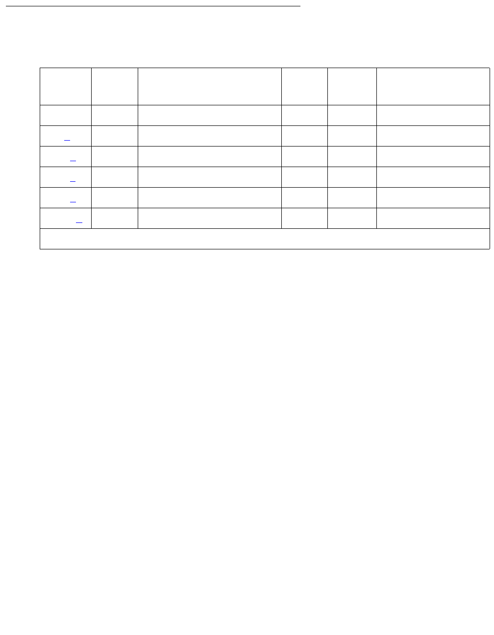
ATM-WSP (ATM WAN Spare Processor)
Issue 1 June 2005 651
Error Log Entries and Test to Clear Values
Notes:
a. Error Type 18: the ATM WSP has been busied out with busyout atm wsp. Check for
other errors that require that the WSP be made maintenance busy. Clear every related
alarm. After every related alarm is clear, or if there are no other alarms, release the ATM
circuit pack using release atm wsp.
b. Error Type 257: the WSP has become active. When a WSP takes over, the error becomes
active and causes an alarm condition. This error is not applicable for the main server. To
return the system to normal operation:
1. Run status atm wsp on the active WSP to verify that the main server or a
higher-priority WSP that you want to be in control is “up.”
2. If the main server or the higher-priority WSP is “up,” then run reset system 2. The
active WSP should relinquish control.
3. Wait a few minutes, and run list sys-link on the main server or higher-priority WSP
to verify that the EAL and ACL system links are “up.”
c. Error Type 513: there is a down ATM WSP link status from this WSP to the main server or
a higher-priority WSP. If any of the links are considered down, this alarm is logged. When
every link probed by this WSP is “up,” the alarm should be cleared.
Remember that more than one link can be down. To get a system-wide view of the status of
the network run status atm wsp.
Aux Data Values are in the form of XYY where
●X is the PNC: 0 = A-PNC, 1 = B-PNC
●YY is the WSP number
Table 222: ATM-WSP Error Log Entries
Error
Type
Aux
Data
Associated Test Alarm
Level
On/Off
Board
Test to Clear Value
00Any Any
18 (a) MO busied out release atm wsp
257 (b) Active WSP (#1401) MAJ OFF reset system 2
513 (c) WSP Link Status (#1400) MIN OFF
769 (d) WSP # WSP Priority Error MIN OFF
1025 (e) WSP Error WRN OFF

Communication Manager Maintenance-Object Repair Procedures
652 Maintenance Procedures for Avaya Communication Manager 3.0, Media Gateways and Servers
Examples:
●Aux Data 15: the B-PNC link to WSP 5 is down.
●Aux Data 3: the A-PNC link to WSP 3 is down.
d. Error Type 769: there are inconsistent translations with regard to WSP’s priority. Each
WSP keeps a list of every other WSP’s priority levels. Inconsistent priorities can exist that
result in a WSP receiving an unexpected probe. This causes an alarm to be raised.
Follow the procedures listed below to correct any inconsistency in WSP priorities:
1. Obtain a list of WSP priorities from the system administrator.
2. Use display error to find the WSP number with the incorrect priority (the Aux Data of
the error).
3. Use status atm wsp to determine if any administered priorities are incorrect,
especially WSP X and the local WSP.
4. If any are incorrect, use change atm wsp n to administer the correct priority, where n
is the appropriate WSP number. If the priorities for WSP X and the local WSP are both
correct, then there is an error in priority administered on WSP X.
5. On WSP X, use status atm wsp to determine whether the priority of WSP X, the local
WSP, and the priority of the WSP with the alarm are correct. At least one should be
incorrect.
6. Use change atm wsp n to administer the correct WSP priority, where n is the
appropriate WSP number.
e. Error Type 1025: there is a WSP error. The Aux Data determine the WSP number and
error code.
Aux Data Values are in the form of XXYY where
●XX is the WSP number that probed this WSP
●YY is the error code 1: The probing WSP (XX value in Aux Data) contains an ATM
address in its message that does not match the translation for that ATM address on this
WSP.
Example: This is WSP 1. Aux Data 201 indicates that WSP 2 probed this WSP, and it has
a different address in the probe message than WSP 1 has for WSP 2.
1. On WSP X, use display atm wsp X to determine its address.
2. On this WSP, use change atm wsp X to change the address of WSP X, if they do not
match.
3. If the addresses do match, then the ATM switch has a different address administered for
WSP X, even though each WSP is consistent.

ATM-WSP (ATM WAN Spare Processor)
Issue 1 June 2005 653
System Technician-Demanded Tests:
Descriptions and Error Codes
There are no system technician-demanded tests associated with ATM-WSP, only tests run by
system software.


Communication Manager Maintenance-Object Repair Procedures
656 Maintenance Procedures for Avaya Communication Manager 3.0, Media Gateways and Servers
AUDIX-BD (AUDIX Circuit Pack)
S8700 | 8710 / S8500
The AUDIX-BD MO represents a TN566/TN2169 EMBEDDED AUDIX circuit pack combination.
For circuit-pack-level problems, see XXX-BD (Common Port Circuit Pack/Media Module) on
page 2539.
EMBEDDED AUDIX consists of a combination of two circuit packs that occupy five slots on a
port carrier. The tests described in this manual apply only to switch-side maintenance that tests
a circuit pack’s components related to the TDM-bus interface. The AUDIX system has an
extensive maintenance strategy that is described in DEFINITY AUDIX System Release 3.2.4
Maintenance, 585-300-110
MO Name in Alarm Log Alarm
Level
Initial Command to Run Full Name of MO
AUDIX-BD MIN test board location sh AUDIX circuit pack
AUDIX-BD WRN test board location sh AUDIX circuit pack

AUDIX-PT (AUDIX Port)
Issue 1 June 2005 657
AUDIX-PT (AUDIX Port)
S8700 | 8710 / S8500
The AUDIX-PT MO represents a port on a TN566/TN2169 EMBEDDED AUDIX circuit pack
operating in digital-port (DP) mode. For circuit-pack-level problems (AUDIX-BD), see XXX-BD
(Common Port Circuit Pack/Media Module) on page 2539.
The maintenance strategy for ports on the TN566 operating in control-link mode is described in
ADX16A-PT.
MO Name in
Alarm Log
Alarm
Level
Initial Command to Run Full Name of MO
AUDIX-PT MIN test port location lAUDIX port
AUDIX-PT WRN test port location sh AUDIX port

Communication Manager Maintenance-Object Repair Procedures
658 Maintenance Procedures for Avaya Communication Manager 3.0, Media Gateways and Servers
AUX-BD (Auxiliary Trunk Circuit Pack)
S8700 | 8710 / S8500
See XXX-BD (Common Port Circuit Pack/Media Module) on page 2539 maintenance
information for circuit pack-level errors. See also AUX-TRK (Auxiliary Trunk) on page 659 for
related trunk information.
MO Name in
Alarm Log
Alarm
Level
Initial Command to Run Full Name of MO
AUX-BD MIN test board location sh Auxiliary Trunk circuit
pack
AUX-BD WRN test board location sh Auxiliary Trunk circuit
pack
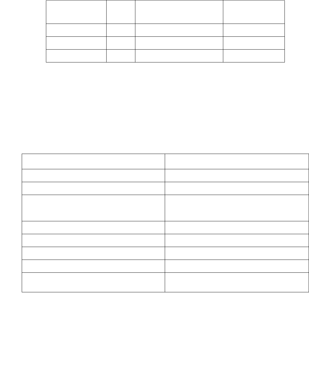
AUX-TRK (Auxiliary Trunk)
Issue 1 June 2005 659
AUX-TRK (Auxiliary Trunk)
S8700 | 8710 / S8500
The TN763B/C/D and TN417 Auxiliary Trunk circuit packs may be used to provide ports for the
following features: Music-On-Hold, loudspeaker paging (voice and coded chimes), dictation,
automated wake-up with AUDICHRON. Recorder/Announcer, and recorded announcements.
TN763C circuit packs support Mu-law companding. TN417 circuit packs support A-law
companding. TN763D can support either companding mode and defaults to mu-law on
initialization. Companding modes are administered on the location-parameters screen.
Use the following commands to administer the features:
Music-On-Hold provides audible feedback to a held, parked, or otherwise split-away party
indicating that the call is still connected. The feedback can be customer-provided music, a
recorded message, or other audible indication. Since the Music-On-Hold port is always busy,
some of its port tests always abort.
MO Name in
Alarm Log
Alarm
Level
Initial Command to Run Full Name of MO
AUX-TRK MAJ1
1. A Major alarm on a trunk indicates that alarms on these trunks are not downgraded by
set options and that at least 75% of the trunks in this trunk group are alarmed.
test port location lAuxiliary Trunk
AUX-TRK MIN test port location lAuxiliary Trunk
AUX-TRK WRN test port location sh Auxiliary Trunk
Command Administration
change system-parameters features Music-On-Hold
change paging loudspeaker loudspeaker paging
add trunk-group grp#
[Customer-Provided Equipment
(CPE) Type]
loudspeaker paging
change paging loudspeaker system-provided paging
add trunk-group grp# access to otherwise-provided (CPE) paging
change paging code-calling-ids translation for code chiming
add trunk-group grp# (CPE Type) Recorded announcement and dictation
change system-parameters
hospitality
Automatic wake-up (uses all four ports on a
TN763B Auxiliary Trunk circuit pack)
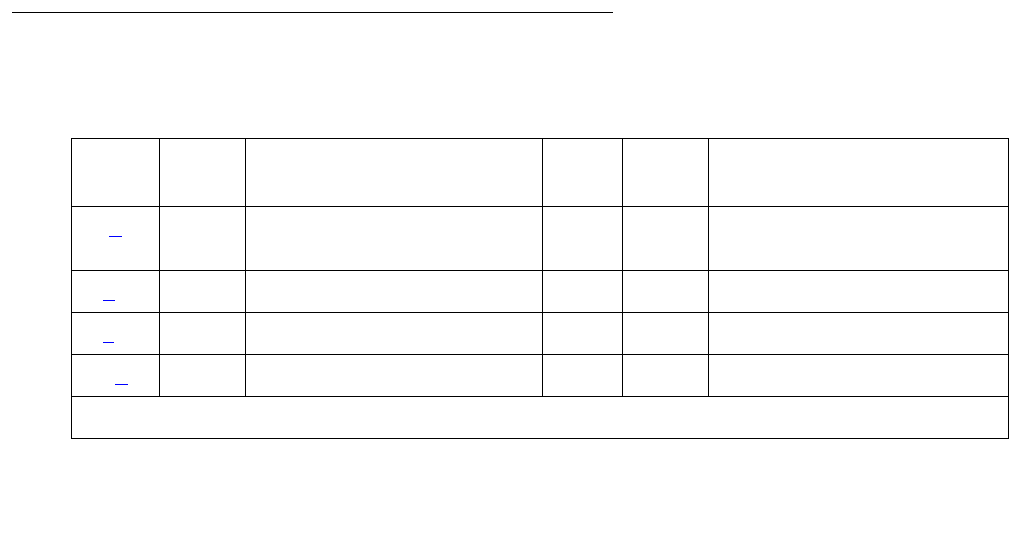
Communication Manager Maintenance-Object Repair Procedures
660 Maintenance Procedures for Avaya Communication Manager 3.0, Media Gateways and Servers
The Loudspeaker Paging feature provides voice and/or code calling chime paging. If multiple
paging zones are provided at a customer’s premises, the Loudspeaker Paging feature gives a
user the option of paging to a particular zone or to every zone. If a zone is active for one page,
it cannot be used at the same time for another.
An Auxiliary Trunk circuit pack contains four ports and uses DTMF signaling. A different
hardware interface between the switch and the auxiliary equipment is used for the four types of
signaling that the auxiliary trunk circuit pack supports.
The interface used for the Communication Manager loudspeaker paging consists of the
following three pairs:
●The Tip-Ring (T-R) pair used for voice transmission.
●The S (S-S1) pair that carries answer supervision and/or make busy information.
●The SZ (SZ-SZ1) pair that provides the external equipment with a seizure indication.
The interface used for recorded announcement, dictation, and other loudspeaker paging
consists of the following two pairs:
●The Tip-Ring (T-R) pair used for voice transmission.
●The S (S-S1) pair that carries answer supervision and/or make busy information.
The interface used for Music-On-Hold consists of one pair:
●The Tip-Ring (T-R) pair used for voice transmission.
The interface, used for automatic wake-up using an Audichron recorder/announcer unit,
consists of the following two pairs:
●The Tip-Ring (T-R) pair used for voice transmission.
●The S (S-S1) pair that carries the synchronization signal.
Error Log Entries and Test to Clear Values
Table 223: Auxiliary Trunk Error Log Entries
Error
Type
Aux
Data
Associated Test Alarm
Level
On/Off
Board
Test to Clear Value
0 (a) 0 Any Any Any test port location sh
r 1
1(b) 57481 None
1(c) 57482
15(d) Any Audit Update test (#36)
1 of 2

AUX-TRK (Auxiliary Trunk)
Issue 1 June 2005 661
Notes:
a. Error Type 0: Run the short test sequence first. If every test passes, run the long test
sequence. Refer to each appropriate test’s description, and follow its recommended
procedures.
b. *Error Type 1 with Aux Data 57481 indicates a port fault. Use an empty port if one is
available until the circuit pack can be replaced.
c. Error Type 1 or 769 with Aux Data 57482 indicates a fault on signaling lead, which is an
off-board error. This error should only occur with loudspeaker paging. If the trunk is being
used for another application, check that the administration is correct. Otherwise, check the
wiring to the external equipment connected to the Auxiliary Trunk and check the external
equipment.
d. Error Type 15: software audit error that does not indicate any hardware malfunction. Run
short test sequence, and investigate associated errors.
e. Error Type 130: the circuit pack has been removed or has been insane for more than 11
minutes. To clear the error, reseat or replace the circuit pack.
18 0 busyout port
location
WRN OFF release port location
130(eNone WRN ON test trunk grp#/mem#
sh
769(c) 57482 None
257 Hybrid/Conference MIN
WRN
1
ON test port location l
r 3
Circuit test (#33)
513 NPE Crosstalk test (#6) MIN
WRN
2
ON test port location l
r 3
1025 Diagnostic: Auxiliary Trunk
(#114)
WRN ON test port location sh
r 3
1. Major or Minor alarms may be downgraded to Warning alarms based on the values used in set options.
Table 223: Auxiliary Trunk Error Log Entries (continued)
Error
Type
Aux
Data
Associated Test Alarm
Level
On/Off
Board
Test to Clear Value
2 of 2

Communication Manager Maintenance-Object Repair Procedures
662 Maintenance Procedures for Avaya Communication Manager 3.0, Media Gateways and Servers
System Technician-Demanded Tests:
Descriptions and Error Codes
Investigate tests in the order presented. By clearing error codes associated with the
Looparound and Conference test (#33), you may also clear errors generated from other tests in
the testing sequence.
NPE Crosstalk Test (#6)
The NPE Crosstalk test verifies that this port’s NPE channel talks on the selected time slot and
never crosses over to time slots reserved for other connections. If the NPE is not working
correctly, 1-way and noisy connections may be observed. This test is part of a port’s long test
sequence and executes in about 20 to 30 seconds.
Order of Investigation Short Test
Sequence
Long Test
Sequence
D/ND1
1. D = Destructive; ND = Nondestructive
Looparound and Conference test (#33) X ND
NPE Crosstalk test (#6) X ND
Diagnostic test (#114) X X ND
Audit Update test (#36) X X ND
Table 224: Test #6 NPE Crosstalk Test
Error
Code
Test
Result
Description / Recommendation
ABRT Could not allocate the necessary system resources to run this test.
1. Retry the command at 1-minute intervals up to 5 times
1000 ABRT System resources required to run test are not available. The port may be
busy with a valid call.
1. Use display port location to determine the trunk group/member
number of the port. Use status trunk to determine the service state
of the port. If the port is active, wait until it is idle.
2. Retry the command at 1-minute intervals up to 5 times.
1 of 3

AUX-TRK (Auxiliary Trunk)
Issue 1 June 2005 663
1001 ABRT Could not allocate the necessary system resources to run this test.
1. Retry the command at 1-minute intervals up to 5 times.
1002 ABRT The system could not allocate time slots for the test. The system may be
under heavy traffic conditions or it may have time slots out-of-service due to
TDM-BUS errors.
1. If the system has no TDM-BUS errors and is not handling heavy traffic,
retry the command at 1-minute intervals up to 5 times.
1003 ABRT The system could not allocate a tone receiver for the test. The system may
be oversized for the number of Tone Detectors present or some Tone
Detectors may be out-of-service.
1. Resolve TTR-LEV errors.
2. Resolve TONE-PT errors.
3. If neither condition exists, retry the command at 1-minute intervals up to
5 times.
1004 ABRT The port was seized by a valid call during the test. The test has been
aborted.
1. Use display port location to determine the trunk group/member
number of the port. Use status trunk to determine the service state
of the port. If the port is active, wait until it is idle.
2. Retry the command at 1-minute intervals up to 5 times.
2000 ABRT Response to the test request was not received within the allowable time
period.
1. Retry the command at 1-minute intervals up to 5 times.
2020 ABRT The test did not run due to a previously existing error on the specific port or
a more general circuit pack error.
1. Examine Error Log for existing errors against this port or the circuit
pack and attempt to diagnose the previously existing error.
2100 ABRT Could not allocate the necessary system resources to run this test.
1. Retry the command at 1-minute intervals up to 5 times.
Table 224: Test #6 NPE Crosstalk Test (continued)
Error
Code
Test
Result
Description / Recommendation
2 of 3

Communication Manager Maintenance-Object Repair Procedures
664 Maintenance Procedures for Avaya Communication Manager 3.0, Media Gateways and Servers
Looparound and Conference Test (#33)
This test checks the reflective loop around and conference capabilities of an auxiliary trunk port
circuit. The test uses 404-Hz, 1004-Hz, and 2804-Hz tones. Each tone is separately
transmitted through the loop and checked. All of these tests are performed on-board.
Any FAIL The Network Processing Element (NPE) of the tested port was found to be
transmitting in error. This will cause noisy and unreliable connections. This
problem may be caused by defective Tone Detectors.
1. Test every Tone-Clock circuit pack, and resolve any errors on these
circuit packs before any action is taken on the auxiliary trunk circuit
pack. Then, repeat the test.
2. If the test fails again, replace the auxiliary trunk circuit pack.
PASS The port is correctly using its allocated time slots. User-reported troubles on
this port should be investigated using other port tests and examining station,
trunk, or external wiring.
Table 224: Test #6 NPE Crosstalk Test (continued)
Error
Code
Test
Result
Description / Recommendation
3 of 3
Table 225: Test #33 Looparound and Conference
Error
Code
Test
Result
Description / Recommendation
ABRT Could not allocate the necessary system resources to run this test.
1. Retry the command at 1-minute intervals up to 5 times.
1000 ABRT System resources required to run this test are not available. The port may
be busy with a valid call.
1. Use display port location to determine the trunk group/member
number of the port. Use status trunk to determine the service
state of the port. If the port is active, wait until it is idle.
2. Retry the command at 1-minute intervals up to 5 times.
1 of 4

AUX-TRK (Auxiliary Trunk)
Issue 1 June 2005 665
1004 ABRT The port was seized by a valid call during the test. The test has been
aborted.
1. Use display port location to determine the trunk group/member
number of the port. Use status trunk to determine the service
state of the port. If the port is active, wait until it is idle.
2. Retry the command at 1-minute intervals up to 5 times.
2100 ABRT Could not allocate the necessary system resources to run this test.
1. Retry the command at 1-minute intervals up to 5 times.
7 FAIL The conference capabilities of the port failed.
1. If no service problems exist on the port, continue to use the port until
the circuit pack can be replaced.
129 FAIL The reflective 404-Hz tone test failed, no transmission was detected to or
from the port. The problem may be off-board.
1. To make sure the problem is on-board, disconnect the port from the
auxiliary equipment and retry test.
2. If the test fails, replace the circuit pack. Otherwise, if the test passed
after disconnecting the port from the auxiliary equipment, the problem
is off-board. Check the wiring and connections to the auxiliary
equipment and retry the test after reconnecting the port to the auxiliary
equipment. If the test fails, check the auxiliary equipment. See the
preceding procedure for a failure with Error Code 7.
Note:
Note: If the Looparound and Conference test fails for every port on a
circuit pack, a -5 Volt power problem is indicated. If a TN736 or
TN752 power unit circuit pack is present, the 631DB AC power
unit or the 676B power unit may be defective. The system may
contain either a TN736 or a TN752 power unit circuit pack OR a
631DB power unit, but not both types of power units. To
investigate power problems, see CARR-POW (Carrier Power
Supply) on page 770
Table 225: Test #33 Looparound and Conference (continued)
Error
Code
Test
Result
Description / Recommendation
2 of 4

Communication Manager Maintenance-Object Repair Procedures
666 Maintenance Procedures for Avaya Communication Manager 3.0, Media Gateways and Servers
131 FAIL The reflective 1004-Hz tone test failed. No transmission was detected to or
from the port. The problem may be off-board.
1. To make sure the problem is on-board, disconnect the port from the
auxiliary equipment and retry test.
2. If the test fails, replace the circuit pack. Otherwise, if the test passed
after disconnecting the port from the auxiliary equipment, the problem
is off-board. Check the wiring and connections to the auxiliary
equipment and retry the test after reconnecting the port to the auxiliary
equipment. If the test fails, check the auxiliary equipment. See the
preceding procedure for a failure with Error Code 7.
Note:
Note: If the Looparound and Conference test fails for every port on a
circuit pack, a -5 Volt power problem is indicated. If a TN736 or
TN752 power unit circuit pack is present, the 631DB AC power
unit or the 676B power unit may be defective. The system may
contain either a TN736 or a TN752 power unit circuit pack OR a
631DB power unit, but not both types of power units. To
investigate power problems, see CARR-POW (Carrier Power
Supply) on page 770
Table 225: Test #33 Looparound and Conference (continued)
Error
Code
Test
Result
Description / Recommendation
3 of 4

AUX-TRK (Auxiliary Trunk)
Issue 1 June 2005 667
133 FAIL The reflective 2804-Hz tone test failed. No transmission was detected to or
from the port. The problem may be off-board.
1. To make sure the problem is on-board, disconnect the port from the
auxiliary equipment and retry test.
2. If the test fails, replace the circuit pack. Otherwise, if the test passed
after disconnecting the port from the auxiliary equipment, the problem
is off-board. Check the wiring and connections to the auxiliary
equipment and retry the test after reconnecting the port to the auxiliary
equipment. If the test fails, check the auxiliary equipment. See the
preceding procedure for a failure with Error Code 7.
Note:
Note: If the Looparound and Conference test fails for every port on a
circuit pack, a -5 Volt power problem is indicated. If a TN736 or
TN752 power unit circuit pack is present, the 631DB AC power
unit or the 676B power unit may be defective. The system may
contain either a TN736 or a TN752 power unit circuit pack OR a
631DB power unit, but not both types of power units. To
investigate power problems, see CARR-POW (Carrier Power
Supply) on page 770.
PASS Looparound and Conference test is successful. This port is functioning
properly.
Table 225: Test #33 Looparound and Conference (continued)
Error
Code
Test
Result
Description / Recommendation
4 of 4

Communication Manager Maintenance-Object Repair Procedures
668 Maintenance Procedures for Avaya Communication Manager 3.0, Media Gateways and Servers
Audit Update Test (#36)
This test sends updates of the auxiliary trunk port translation for every port on the Auxiliary
Trunk circuit pack that has been translated. The update is non-disruptive and guards against
possible corruption of translation data contained on the circuit pack. No response message is
expected from the circuit pack once it receives translation updates. The port translation data
includes:
●Trunk type
●DTMF time slot
●Termination R/RC
●Gain, high/low
●End-to-end signaling, tone, and pause duration
●Trunk state, idle/active/unavailable
●Companding mode (A-law or mu-law)
Table 226: Test #36 Audit Update Test
Error
Code
Test
Result
Description / Recommendation
ABRT Could not allocate the necessary system resources to run this test.
1. Retry the command at 1-minute intervals up to 5 times.
1006 ABRT Port is in out-of-service state as a result of being busied out. This audit
cannot be run.
1. Retry the command once the port is in service (release port
location has been run).
2100 ABRT Could not allocate the necessary system resources to run this test.
1. Retry the command at 1-minute intervals up to 5 times.
FAIL Internal system error.
1. Retry the command at 1-minute intervals up to 5 times.
PASS This test passed. Translation information was successfully updated on the
circuit pack.

AUX-TRK (Auxiliary Trunk)
Issue 1 June 2005 669
Diagnostic Test—Auxiliary Trunk Test (#114)
The system software sends a message to the on-board microprocessor to operate a relay in the
port circuit. If ground is detected, the test passes.
Table 227: Test #114 Diagnostic Test—Auxiliary Trunk Test
Error
Code
Test
Result
Description / Recommendation
ABRT Could not allocate the necessary system resources to run this test.
1. Retry the command at 1-minute intervals up to 5 times.
1000 ABRT System resources required to run this test are not available. The port may
be busy with a valid call.
1. Use display port location to determine the trunk group/
member number of the port. Use status trunk to determine the
service state of the port. If the port is active, wait until it is idle.
2. Retry the command at 1-minute intervals up to 5 times.
1004 ABRT The port was seized by a valid call during the test. The test has been
aborted.
1. Use display port location to determine the trunk group/
member number of the port. Use status trunk to determine the
service state of the port. If the port is active, wait until it is idle.
2. Retry the command at 1-minute intervals up to 5 times.
2100 ABRT Could not allocate the necessary system resources to run this test.
1. Retry the command at 1-minute intervals up to 5 times.
FAIL This test failed to detect ground.
1. Try the test once more.
2. If the test fails again, replace the circuit pack.
PASS This test passed. Ground was detected.

Communication Manager Maintenance-Object Repair Procedures
670 Maintenance Procedures for Avaya Communication Manager 3.0, Media Gateways and Servers
AXA12-BD (AUDIX Circuit Packs)
Error log entries and tests also apply to ADX8D-BD and AXD12-BD.
S8700 MC
The TN568 is an EMBEDDED AUDIX circuit pack that occupies 2 slots in a port carrier. The
tests below apply only to switch-side maintenance, which tests a circuit pack’s components
related to the TDM-bus interface. The AUDIX system has an extensive maintenance strategy of
its own that is described in EMBEDDED AUDIX System Maintenance, 585-300-110.
AXA12-BD
TN568 EMBEDDED AUDIX circuit packs operating in control-link mode appear to the system as
TN746 Analog Line circuit packs with vintage greater than 50. For circuit-pack-level problems,
see XXX-BD (Common Port Circuit Pack/Media Module) on page 2539. The maintenance
strategy for ports on the TN568 operating in control-link mode is described in ADXCL-PT.
ADX8D-BD
TN568 EMBEDDED AUDIX circuit packs operating in 8-port digital mode appear to the system
as TN754 Digital Line circuit packs with vintage greater than 50. For circuit-pack-level
problems, see XXX-BD (Common Port Circuit Pack/Media Module) on page 2539. The
maintenance strategy for ports on the TN568 operating in 8-port digital mode is described in
ADXDP-PT.
MO Name in
Alarm Log
Alarm
Level
Initial Command to Run Full Name of MO
AXA12-BD MIN test board location sh AUDIX circuit pack
AXA12-BD WRN test board location sh AUDIX circuit pack
ADX8D-BD MIN test board location sh AUDIX circuit pack
ADX8D-BD WRN test board location sh AUDIX circuit pack
AXD12-BD MIN test board location sh AUDIX circuit pack
AXD12-BD WRN test board location sh AUDIX circuit pack

AXA12-BD (AUDIX Circuit Packs)
Issue 1 June 2005 671
ADX12-BD
The ADX12-BD MO represents a TN568 EMBEDDED AUDIX circuit pack operating in 12-port
digital (DP) mode. TN568 EMBEDDED AUDIX circuit packs operating in 12-port digital mode
appear to the system as TN2181 Digital Line circuit packs with vintage greater than 50. For
circuit-pack-level problems, see XXX-BD (Common Port Circuit Pack/Media Module) on
page 2539. Port-level problems are covered by ADX12D-PT.


Communication Manager Maintenance-Object Repair Procedures
674 Maintenance Procedures for Avaya Communication Manager 3.0, Media Gateways and Servers
AXA12-RS (AUDIX Reserve Slots)
Error log entries and tests also apply to ADX8D-RD and AXD12-RS.
S8700 MC
There are no tests associated with these MOs. Both test board and busyout board abort
when either is attempted on a reserved slot. An error message indicates that the slot is
associated with the circuit pack that the TN568 is emulating, but the requested operation is not
valid. If there are errors logged against these MOs, see XXX-BD (Common Port Circuit Pack/
Media Module) on page 2539.
The TN568 circuit pack connects to the switch through a single slot in the backplane; however,
the number of slots physically occupied by the circuit pack is supplied by the board when
inserted. The TN568 is 2 slots wide: the functional slot and a reserve slot. The reserve (blank)
slot to the left of the functional slot is a place holder on the switch and has no interaction with
the switch.
These MOs are place holders for the extra slot needed for the EMBEDDED AUDIX board.
Each instance of these MOs represents a reserve slot associated with the respective circuit
pack mode in which the TN568 (EMBEDDED AUDIX) is working. They are used for
EMBEDDED AUDIX and emulation of respective port types.
MO Name in
Alarm Log
Alarm
Level
Initial Command to Run Full Name of MO
AXA12-RS NONE NONE TN568 12-port analog
reserve slot
ADX8D-RS NONE NONE TN568 8-port digital reserve
slot
AXD12-RS NONE NONE TN568 12-port digital
reserve slot


BRI-BD (ISDN-BRI Line Circuit Pack)
Issue 1 June 2005 677
BRI-BD (ISDN-BRI Line Circuit Pack)
Error log entries and tests also apply to LGATE-BD.
S8700 | 8710 / S8500
!CAUTION:
CAUTION: A detailed flowchart for isolating and resolving Packet Bus faults is included in
Isolating and repairing packet-bus faults in Maintenance Procedures
(03-300192). This flowchart, along with the other information presented in the
chapter, can help in resolving problems that involve more than a single station or
circuit pack. Whenever the repair procedures for this Maintenance Object refer to
Packet Bus and/or Packet Control maintenance, be sure to see Isolating and
repairing packet-bus faults. See also PKT-BUS (Packet Bus) on page 1790 for
repair procedures.
This section relates to the TN556 ISDN BRI, TN2198 ISDN BRIU, TN2208 Ethernet,
(LGATE)-Ethernet Multifunction (MFB) circuit packs.
The TN2208 LGATE MFB provides the system with the interface to Adjunct-Switch Application
Interface (ASAI) and Avaya adjuncts (for example, CONVERSANT® Voice System). This circuit
pack contains 12 ports for line circuit interface (although only 8 are usable by the switch), each
of which operates with two B channels and 1 D channel. In this context, the term “ISDN-BRI
port” is used to refer to ports on the TN2208 MFB circuit pack that are connected to ASAI or
Avaya adjuncts. The TN2208 LGATE MFB is handled by the switch software as if it is an
ISDN-BRI compatible board, and every maintenance action referring to ASAI and Avaya adjunct
links in this section applies.
The TN556, TN2198, and TN2208 ISDN-BRI Lines are packet port circuit packs that provides
access to ISDN-BRI endpoints. The ISDN-BRI Line circuit packs supports 12 ports, each of
which provides access to ISDN stations. Voice and circuit-switched data from the ISDN stations
are carried on the Time Division Multiplex (TDM) Bus. Signaling is carried over the packet bus.
MO Name in
Alarm Log
Alarm
Level
Initial Command to Run Full Name of MO
BRI-BD MAJ test board location lISDN-BRI Line circuit pack
BRI-BD MIN test board location lISDN-BRI Line circuit pack
BRI-BD WRN test board location sh ISDN-BRI Line circuit pack
LGATE-BD MAJ test board location lDEFINITY LAN Gateway
LGATE-BD MIN test board location lDEFINITY LAN Gateway
LGATE-BD WRN
(See Caution) test board location sh DEFINITY LAN Gateway

Communication Manager Maintenance-Object Repair Procedures
678 Maintenance Procedures for Avaya Communication Manager 3.0, Media Gateways and Servers
LEDS
The ISDN-BRI Line circuit pack performs extensive initialization tests and lights both the red
and green LEDS during the initialization testing. See Chapter 3: LEDs, for more details on
circuit pack status LEDs.
Hardware Error Log Entries and Test to Clear Values
Table 228: BRI-BD Error Log Entries
Error
Type
Aux
Data
Associated Test Alarm
Level
On/Off
Board
Test to Clear Value
0 (a) 0 Any Any Any test board location sh r 1
1(b) Any None MIN ON
18(c)0 busyout board
location
WRN OFF release board location
23(d) 0 None WRN OFF
257(e) 65535 Control Channel
Loop (#52)
MIN ON test board location r 20
513(f) 4352 to
4357
769(g)4358
1025(h) 4363 NPE Audit test
(#50)
1293
1294 (i)
46088
to
46096
SAKI Sanity test
(#534)
MIN ON See Note (h)
1537
1538 (j)
46082 MIN ON
1793 (k) 46080 MIN ON
1794 (k) 46094 MIN ON
1795 (k) 46085 MIN ON
1 of 2
BRI-BD (ISDN-BRI Line Circuit Pack)
Issue 1 June 2005 679
Notes:
a. Error Type 0: Run the short test sequence first. If every test passes, run the long test
sequence. Refer to each appropriate test’s description, and follow its recommended
procedures.
b. Error Type 1: the circuit pack totally stopped functioning or it was physically removed from
the system. The alarm is logged approximately 11 minutes after the circuit pack has been
removed and/or SAKI Sanity test (#53) fails.
If the circuit pack is not in the system, insert a circuit pack (in the same slot as the error
indicates) to resolve this error. Or, if the circuit pack is in the system and the red LED is on,
follow the instructions for “Red (alarm)” in Circuit pack LEDs on page 257.
c. Error Type 18: This circuit pack has been busied out via busyout board location.
d. Error Type 23: Port(s) has (have) been administered on this circuit pack but the circuit pack
is not physically present.
e. Error Type 257: transient communication problems between the switch and this circuit
pack. Execute test board location and see Control Channel Loop-Around Test
(#52) on page 2400 for the repair procedures.
f. Error Type 513: An on-board hardware failure has been detected by the circuit pack.
Aux Data 4352: External RAM error
Aux Data 4353: Internal RAM error
Aux Data 4355: ROM Checksum error
Aux Data 4357: Instruction set error
Reset the circuit pack by executing busyout board location and reset board
location. When it is reset, the circuit pack executes a set of tests to detect the presence
of any of the above faults. The detection of one of these errors during initialization causes
the circuit pack to lock-up and appear insane to the system. See the repair procedure in
footnote (a) for error type 1.
2306 (k) LANBIC Receive
Parity Error
Counter test
(#595)
3330 (l) 46083 MIN OFF
3840
(m)
4096 to
4101
3843 (n) 46097
3999 (o) Any None
Table 228: BRI-BD Error Log Entries (continued)
Error
Type
Aux
Data
Associated Test Alarm
Level
On/Off
Board
Test to Clear Value
2 of 2

Communication Manager Maintenance-Object Repair Procedures
680 Maintenance Procedures for Avaya Communication Manager 3.0, Media Gateways and Servers
g. Error Type 769: reported by the circuit pack when it detects a program logic error. No
action is required, but this error may lead to errors of other types being reported against this
circuit pack.
h. Error Type 1025: reported by the circuit pack when it cannot update NPE memory and read
it back. No action is required, but this error may lead to errors of other types being reported
against the circuit pack.
i. Error Type 1293, 1294: a critical hardware failure has been detected on the circuit pack.
Error Type 1293: On-board auxiliary processor insane.
Error Type 1294: Internal memory access error.
Reset the circuit pack via busyout board location and reset board location. If
the Circuit Pack Restart test (#594) passes, then the on-board circuitry is healthy. Retire
the alarm via test board location long clear. If the Circuit Pack Restart test
(#594) fails, replace the circuit pack.
j. Error Type 1537: Frame overrun at packet-bus interface. This condition may be caused by
an on-board fault or by faulty data received on one of the circuit pack’s external ports. If any
of the ports on this circuit pack are alarmed, refer to the repair procedures for those MOs.
Error Type 1538: Circuit packet is hyperactive; that is, it is flooding the switch with
messages sent over the control channel. The circuit pack is taken out-of-service when a
threshold number of these errors is reported to the switch. Clear the alarm with busyout
board location, reset board location, test board location long clear,
release board location. If the error recurs within 10 minutes, then replace the circuit
pack.
k. Error Type 1793, 1794, 1795, 2306: the circuit pack is having problems transmitting data to
the packet bus.
Error Type 1793: Parity errors are detected when transmitting data to the packet bus.
Error Type 1794: Overflow of packet-bus transmit buffers has occurred.
Error Type 1795: Circuit pack cannot find end of frame when transmitting to packet bus.
Clear the alarm via the following commands: busyout board location, reset board
location, test board location long clear, release board location. If the
error recurs within 10 minutes, then replace the circuit pack.
Error Type 2306: This error occurs when the circuit pack detects an error in a received
frame from the packet bus. These errors are most likely caused by a packet-bus problem,
but may be due to a circuit pack fault. An invalid Link Access Procedure Data (LAPD) frame
error occurs if the frame contains a bad cyclical redundancy check (CRC), is greater than
the maximum length, or violates the link level protocol. When bus parity errors are reported,
the LANBIC Receive Parity Error Counter test (#595) should be performed to determine
whether the condition had cleared. See Isolating and repairing packet-bus faults in
Maintenance Procedures (03-300192) to determine whether the problem is isolated to this
circuit pack or is caused by packet-bus faults.

BRI-BD (ISDN-BRI Line Circuit Pack)
Issue 1 June 2005 681
l. Error Type 3330: A critical failure has been detected in the packet-bus interface of the
circuit pack. This failure may be due to either a packet-bus or to an on-board fault. If the
packet bus is alarmed, see XXX-BD (Common Port Circuit Pack/Media Module) on
page 2539 and Isolating and repairing packet-bus faults in Maintenance Procedures
(03-300192) for recommended repair procedures. The probability of this error being related
to packet-bus problems increases with the number of ISDN-BRI circuit packs displaying this
error.
If the packet bus is not alarmed, reset the circuit pack with busyout board location
and reset board location. If the Circuit Pack Restart test (#594) passes, then the
on-board circuitry is healthy. Retire the alarm with test board location long clear.
If the Circuit Pack Restart test (#594) fails, replace the circuit pack. If the problem persists
after complying with the above instructions, then follow normal escalation procedures.
m. Error Types 4096, 4097, 4098, 4099, 4100, 4101: reported by the circuit pack when it
receives a bad control channel message from the switch. Not service-affecting, no action is
required. The auxiliary data identifies the error events.
Error Type 4096: Bad major heading
Error Type 4097: Bad port number
Error Type 4098: Bad data
Error Type 4099: Bad sub-qualifier
Error Type 4100: State inconsistency
Error Type 4101: Inconsistent downlink message
n. Error Type 3843: bad translation RAM detected, but call continues by using another
translation location.This error is not service-affecting. No action is required.
o. Error Type 3999: the circuit pack sent a large number of control channel messages to the
switch in a short period of time.
If Error Type 1538 is also present, the circuit pack was taken out-of-service due to
hyperactivity.
If Error Type 1538 absent, the circuit pack was not taken out-of-service, but has generated
50% of the messages necessary to be considered hyperactive. This may be normal during
heavy traffic periods. If traffic is light, it may indicate a problem with the circuit pack or the
equipment attached to it.

Communication Manager Maintenance-Object Repair Procedures
682 Maintenance Procedures for Avaya Communication Manager 3.0, Media Gateways and Servers
System Technician-Demanded Tests:
Descriptions and Error Codes
Investigate tests in the order presented. By clearing error codes associated with one test, you
may also clear errors generated from other tests in the sequence.
NPE Audit Test (#50)
See the repair procedure described in XXX-BD (Common Port Circuit Pack) as NPE Audit Test
(#50) on page 2548.
Control Channel Loop Around Test (#52)
See the repair procedure described in XXX-BD (Common Port Circuit Pack) as Control Channel
Loop-Around Test (#52) on page 2551.
SAKI Sanity Test (#53)
Refer to the repair procedure described in XXX-BD (Common Port Circuit Pack) as SAKI Sanity
Test (#53) on page 2552.
LANBIC Receive Parity Error Counter Test (#595)
This test is destructive.
The test reads and clears the LANBIC Receive Parity Error Counter on the circuit pack. This
counter is incremented by the circuit pack when it detects a parity error in data received from the
packet bus.
Order of Investigation Short Test
Sequence
Long Test
Sequence
D/ND1
1. D = Destructive; ND = Nondestructive
Control Channel Loop-Around test (#52) X X ND
NPE Audit test (#50) X ND
LANBIC Receive Parity Error Counter test (#595) X ND

BRI-BD (ISDN-BRI Line Circuit Pack)
Issue 1 June 2005 683
These errors may indicate a circuit-pack problem, packet-bus problem, or a problem with
another circuit pack on the bus. This test is useful for verifying the repair of the problem.
Table 229: Test #595 LANBIC Receive Parity Error Counter Test
Error
Code
Test
Result
Description / Recommendation
2000 ABRT Response to the test was not received from the circuit pack within the
allowable time period.
1. If the test aborts repeatedly up to five times, reset the circuit pack via
busyout board location and reset board location.
2. If the test aborts again, replace the circuit pack.
2100 ABRT Could not allocate the necessary system resources to run this test.
1. Retry the command at 1-minute intervals up to 5 times.
2. If the test continues to fail, escalate the problem.
2012 ABRT Internal system error.
1. Retry the command at 1-minute intervals up to 5 times.
2. If the test continues to fail, escalate the problem.
1–10 FAIL The circuit pack is still detecting errors of this type. The error code
indicates the value of the on-board error counter.
1. Retry the command at 1-minute intervals up to 5 times.
2. If the test continues to fail, verify the validity of the packet bus. Run the
Packet Bus Maintenance test, test pkt P long. If any packet-bus
tests fail, see PKT-BUS (Packet Bus) on page 1790 for recommended
repair procedures.
3. If the Packet Bus test passes, check the validity of the circuit pack.
Execute a test that involves data transmission onto the packet bus.
For example, the BRI may use the connectivity tests of the port-level
MO (BRI-PORT) by executing test port location. Refer to the
repair procedures for the executed test if it fails. Otherwise, proceed to
the next step.
4. Other circuit packs on the packet bus can cause of the parity error.
Use display errors to check the Error Log for other circuit packs
that are alarmed. If any alarms are present for the other circuit packs,
retire those alarms also. Then, rerun the LANBIC Receive Parity Error
Counter test (#595) on this circuit pack.
PASS No errors detected by circuit pack.

Communication Manager Maintenance-Object Repair Procedures
684 Maintenance Procedures for Avaya Communication Manager 3.0, Media Gateways and Servers
BRI-DAT (ISDN-BRI Data Module)
S8700 | 8710 / S8500
Refer to BRI-SET, Various Adjuncts on page 708.
MO Name in
Alarm Log
Alarm
Level
Initial Command to Run Full Name of MO
BRI-DAT WRN1
1. The alarm level for ASAI or Avaya adjuncts may be administered using set options. The alarm level can
be set independently for on- and off-board alarms to WARNING, MINOR, or MAJOR for every ASAI adjunct
in the system.
test data-module extension ISDN-BRI Stand-alone Data
Module
BRI-PORT (ISDN-BRI Port)
Issue 1 June 2005 685
BRI-PORT (ISDN-BRI Port)
Error log entries and tests also apply to ABRI-POR, ATT-PORT, LGATE-PT, and ATTE-PT.
S8700 | 8710 / S8500
Note:
Note: Some of the information in this section is reserved for future use.
!CAUTION:
CAUTION: The section, Isolating and repairing packet-bus faults in Maintenance Procedures
(03-300192), along with the other information presented in the chapter, can help
resolve problems involving more than one station or circuit pack.
!WARNING:
WARNING: If a significant packet-bus failure occurs, errors and alarms may not be logged as
expected for BRI-PORT/ABRI-POR/ATT-PORT/ LGATE-PT/ ATTE-PT.
Conditions under which this occurs are detailed in Isolating and repairing
packet-bus faults in Maintenance Procedures (03-300192).
MO Name in
Alarm Log
Alarm
Level
Initial Command to Run Full Name of MO
BRI-PORT MIN test port location lISDN-BRI port
BRI-PORT WRN test port location sh ISDN-BRI port
ABRI-POR MAJ1
1. The alarm level for ASAI and Avaya adjunct ports may be administered using set options. The alarm level
can be set independently for on- and off-board alarms to WARNING, MINOR, or MAJOR for every ASAI
and Avaya adjunct port in the system.
All alarming for an ASAI and Avaya adjunct and OFF-BOARD alarming for an ASAI or Avaya port is
disabled if the ASAI or Avaya adjunct asks the switch to suspend maintenance. When this occurs, an error
and a WARNING alarm is logged against the ASAI or Avaya adjunct. The Hardware Error and Alarm Logs
should be checked to see if the adjunct has disabled alarming.
test port location lASAI ISDN-BRI port
ABRI-POR WRN1test port location lASAI ISDN-BRI port
ATT-PORT MAJ 1test port location lAvaya Adjunct ISDN-BRI port
ATT-PORT WRN 1test port location lAvaya Adjunct ISDN-BRI port
LGATE-PT MAJ 1test port location lEthernet ASAI port
LGATE-PT WRN 1test port location lEthernet ASAI port
ATTE-PT MAJ 1test port location lEthernet Avaya Adjunct port
ATTE-PT WRN 1test port location lEthernet Avaya Adjunct port

Communication Manager Maintenance-Object Repair Procedures
686 Maintenance Procedures for Avaya Communication Manager 3.0, Media Gateways and Servers
The TN2208 LGATE MFB provides Communication Manager with the interface to
Adjunct-Switch Application Interface (ASAI) and Avaya adjuncts (for example, CONVERSANT®
Voice System). The circuit pack contains 12 ports of line circuit interface (although only 8 are
usable by the switch), each of which operates with two B channels (referred to as B1 and B2
throughout this section) and one D channel. In this context, the term “ISDN-BRI port” is used to
refer collectively to ports on the TN2208 circuit pack that are connected to ASAI or Avaya
adjuncts.
The TN556 and TN2198 ISDN-BRI Line circuit packs provide the system with the interface to
ISDN-BRI endpoints, Adjunct-Switch Application Interface (ASAI) and Avaya adjuncts (for
example, CONVERSANT® Voice System). The circuit packs contain 12 ports of line circuit
interface, each of which operates with two B channels (referred to as B1 and B2 throughout this
section) and one D channel. In this context, the term “ISDN-BRI port” is used to refer
collectively to ports on the TN556 an TN2198 circuit packs that are connected to either BRI
endpoints, ASAI or Avaya adjuncts.
For BRI endpoints, each B channel may support voice or circuit-switched data and may be
circuit-switched simultaneously. The B channels are not used on ports connected to ASAI or
Avaya adjuncts. The D channel is used for conveying signaling between the switch and a BRI
endpoint(s), ASAI or Avaya adjunct. Each ISDN-BRI D channel is connected to the switch
processor and the ISDN-BRI port through the packet bus.
ISDN-BRI endpoints are available in various configurations. Every endpoint requires the D
channel to convey signaling information to the switch. Only one B channel is required for a
voice-only set or a stand-alone data module (BRI-DAT). A voice and data-capable set requires
both B channels (one for voice and one for data). Therefore, each TN556 or TN2198 port can
support either two voice-only sets, two stand-alone data modules (BRI-DAT), or one voice and
data-capable set. Only a single ASAI or Avaya adjunct may be connected to an ISDN-BRI port.
Multiple adjuncts per line are not supported.
Figure 33: ISDN-BRI Port Interactions on page 687 illustrates the physical connection (solid
line) between an ISDN-BRI port and its associated ISDN-BRI set(s). Each physical connection
allows for two B channels and one D channel. Each ISDN-BRI circuit pack can support up to 12
of these physical connections to different voice and voice/data sets or ASAI or Avaya adjuncts.
On a TN2198 each ISDN-BRI circuit pack can support up to 12 physical connections to a NT1
which in turn connects to 2 terminals.
This section covers the maintenance documentation for ISDN-BRI ports. Some of the results of
maintenance testing of ISDN-BRI ports may be affected by the health of the ISDN-BRI Line
circuit pack (BRI-BD), BRI endpoint (BRI-SET), or ASAI adjunct (ASAI-ADJ/LGATE-AJ/
LGATE-AJ) or Avaya adjunct (ATT-ADJ/ATTE-AJ). These interactions should be kept in mind
when investigating the cause of ISDN-BRI port problems. For more information about the
circuit pack, see:
●BRI-BD (ISDN-BRI Line Circuit Pack) on page 677
●BRI-SET, Various Adjuncts on page 708
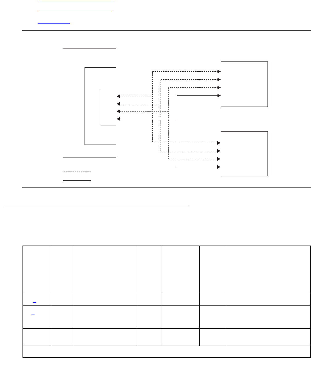
BRI-PORT (ISDN-BRI Port)
Issue 1 June 2005 687
and for more information about its endpoints, see:
●ASAI-ADJ (ASAI Adjunct) on page 481
●ATT-ADJ (AvayaAdjunct) on page 654
●LGATE-AJ on page 1476
Figure 33: ISDN-BRI Port Interactions
Hardware Error Log Entries and Test to Clear Values
D-channel
B-channel
B-channel
Logical connection
Physical connection
Voice or
data terminal
Voice or
data terminal
bripor1 LJK 072501
Switch
BRI line
circuit pack
Port
Table 230: ISDN-BRI Port Error Log Entries
Error
Type
Aux
Data
Associated
Test
Alarm
Level
BRI-
PORT
Alarm
Level
ABRI-PORT
ATT-PORT
LGATE-PT
ATTE-PT
On/Off
Board
Test to Clear Value
0 (a) 0 Any Any Any Any test port PCSSpp sh r 1
1(b) Level 1 Status Inquiry
(#621)
WRN MAJ
MIN
WRN1
OFF test port PCSSpp sh r 2
18 busyout port
PCSSpp
WRN OFF release port PCSSpp
1 of 2
Communication Manager Maintenance-Object Repair Procedures
688 Maintenance Procedures for Avaya Communication Manager 3.0, Media Gateways and Servers
Notes:
a. Error Type 0: Run the short test sequence first. If every test passes, run the long test
sequence. Refer to each appropriate test’s description, and follow its recommended
procedures.
b. Error Type 1: the Level 1 Status Inquiry fails or when the BRI circuit pack detects that Level
1 has been deactivated on the port. Refer to the repair procedures for Test #621.
Aux Data blank: the Level 1 Status Inquiry failed.
Aux Data 32773: message from the BRI-LINE circuit pack indicating Level 1 has been
deactivated.
130(c)WRNONtest port PCSS sh
257(dEPF Inquiry (#622) WRN MAJ
MIN
WRN2
OFF test port PCSSpp sh r 1
513(e) 46222 none (d) (d) ON
769(f) 0 none WRN MAJ OFF
1281(g) NPE Crosstalk (#617) MIN
WRN2
ON test port PCSSpp l r 2
1537(h) 46210 CRC Error Counter
(#623)
WRN MAJ
MIN
WRN2
OFF
1793(i) BRI Port Local TDM
Loop Around (#619)
MIN
WRN2
ON test port PCSSpp l r 2
3841(j46208 None
3842(k)0 None
3843(l)0 None
3844(m) 46223 None
3845(n)None
3846(o)TEI None
3847(p)0 None
1. Major and Minor alarms on this MO may be downgraded to Warning alarms based on the value used in set
options.
Table 230: ISDN-BRI Port Error Log Entries (continued)
Error
Type
Aux
Data
Associated
Test
Alarm
Level
BRI-
PORT
Alarm
Level
ABRI-PORT
ATT-PORT
LGATE-PT
ATTE-PT
On/Off
Board
Test to Clear Value
2 of 2

BRI-PORT (ISDN-BRI Port)
Issue 1 June 2005 689
c. Error Type 130: the circuit pack has been removed or has been insane for more than 11
minutes. To clear the error, replace or reinsert the circuit pack.
d. Error Type 257: the EPF Status Inquiry fails due to an overcurrent condition or when the
BRI-LINE circuit pack detects that the EPF is in an over current condition. The aux data
field contains one of the following values:
●blank – This indicates that the EPF Status Inquiry failed due to an overcurrent condition.
●40988 – This indicates that the BRI-LINE circuit pack has detected an overcurrent
condition and has turned the EPF off.
Execute the short test sequence, and see the repair procedures for Test #622.
e. Error Type 513: the circuit pack is having problems transmitting data to the packet bus,
thus affecting the conveyance of signaling information over the D channel. With Aux Data
46222, this error occurs when the packet-bus transmit buffers overflow. This condition
probably indicates a hardware problem. The BRI-PORT Alarm Level for the error with Aux
Data 46222 is “MINOR/WARNING,” and the ABRI-PORT/ATT-PORT/LGATE-PT/ATTE-PT
Alarm Level is “MAJOR/MINOR/WARNING.” With Aux Data 0, this error occurs whenever
the packet-bus transmit FIFO buffers overflow. This condition can be caused by an
on-board hardware problem as well as by problems on the packet bus that disrupt the BRI
circuit pack’s ability to transmit data onto the packet bus. Use troubleshooting procedures
for both on-board hardware problems and potential off-board packet-bus problems. See
PKT-BUS (Packet Bus) on page 1790 as well as Isolating and repairing packet-bus faults in
Maintenance Procedures (03-300192) for more information about troubleshooting the
packet bus. The BRI-PORT Alarm Level for the error with Aux Data 0 is “MINOR,” and the
ABRI-PORT/ATT-PORT/LGATE-PT/ATTE-PT Alarm Level is “MAJOR.”
f. Error Type 769: the NPE Crosstalk test (#617) fails. Run the long test sequence, and pay
particular attention to the results of Test #617.
g. Error Type 1281: a port’s associated broadcast-signaling links have too much traffic related
to link establishment. This could occur if an endpoint on this port is sending link
establishment traffic on a port level broadcast link or if there are Level 1 problems on the
port. Check the error logs for Level 1 errors. If Level 1 problems exist, follow the repair
procedures listed for Test #621. Software will suspend activity to this port for 75 minutes
when the port is alarmed due to this error (note that service suspension does not occur if
the port is an ABRI-PORT/LGATE-PT/ATTE-PT/ATT-PORT). If this problem persists,
replace the endpoint or endpoints associated with this port. If replacing the endpoints does
not fix the problem, follow normal escalation procedures.
h. Error Type 1537: the port receives an invalid frame over the D channel. When CRC errors
exceed five within 15 minutes, the port is taken out of service for five seconds. If five more
CRC errors are received within 15 minutes of the first set of five errors, the port is taken out
of service for one minute. If five more CRC errors are received within 15 minutes of the last
five, the port is taken out of service for 15 minutes.

Communication Manager Maintenance-Object Repair Procedures
690 Maintenance Procedures for Avaya Communication Manager 3.0, Media Gateways and Servers
This error is most likely due to a problem with the wiring to the set or adjunct, interference
on the wiring due to a noise source, or no termination (an open circuit). It usually does not
indicate a problem with the circuit pack.
●Check the wiring to the endpoints or the adjunct.
●If the problem persists, replace the endpoints or adjuncts, or escalate the problem.
i. Error Type 1793: the BRI Port Local TDM Loop Around test (#619) fails. Run the long test
sequence, and pay particular attention to the results of Test #619.
There are no Test to Clear Values for the following error types. The error types are simply
provided as additional data that may prove useful while troubleshooting.
j. Error Type 3841: a Layer 1 Transmission error is detected for the port. Run the long test
sequence, and pay particular attention to the results of the Layer 1 Transmission Error
Counter test (#624).
k. Error Type 3842: A BRI port supports up to three Terminal Endpoint Identifiers (TEIs). This
error occurs when the switch receives a request for a fourth TEI on a port. Check the
number of endpoints administered for this port.
l. Error Type 3843: a SPID initialization request is made from an endpoint and the switch
determines that the SPID value is invalid or is a duplicate of another SPID that is already
initialized at Layer 3 on the port. Check the administration of the endpoints.
m. Error Type 3844: the circuit pack detects an overflow of its receive buffers. Run the long
test sequence, and pay particular attention to the results of the Receive FIFO (First In First
Out) Overflow Error Counter test (#625).
n. Error Type 3845: the BRI Port Local LAN Loop Around test (#618) fails. Run the long test
sequence, and pay particular attention to the results of Test #618.
o. Error Type 3846: most likely occurs when the Terminal Endpoint Identifier (TEI)
administered for the ASAI or Avaya endpoint does not match the TEI administered in the
ASAI or Avaya adjunct. Check the switch administration of the TEI against that of the
adjunct and make sure that both are using the same TEI.
p. Error Type 384: sets on the port do not support layer-3 initialization. Consult the Service
Set documentation.

BRI-PORT (ISDN-BRI Port)
Issue 1 June 2005 691
System Technician-Demanded Tests:
Descriptions and Error Codes
Investigate tests in the order presented. By clearing error codes associated with the NPE
Crosstalk test (#617), you may clear errors generated from other tests in the sequence.
Note:
Note: The NPE Crosstalk test and the BRI Port Local TDM Loop Around test are not
executed for ABRI-PORT/ATT-PORT/LGATE-PT/ATTE-PT.
NPE Crosstalk Test (#617)
This test is destructive.
One or more NPEs reside on each circuit pack with a TDM-bus interface. The NPE controls
port connectivity and gain, and provides conferencing functions on a per-port basis. The NPE
Crosstalk test verifies that this port’s NPE channel talks on the selected time slot and never
crosses over to time slots reserved for other connections. If the NPE is not working correctly,
one-way and noisy connections may be observed. This test is part of a port’s long test
sequence and executes in approximately 20 to 30 seconds. Crosstalk testing is performed on
both B channels (B1 and B2) associated with a BRI port. If this test fails on either channel, any
endpoint connected to the port is taken out-of-service.
Order of Investigation Short Test
Sequence
Long Test
Sequence
D/ND1
1. D = Destructive; ND = Nondestructive
NPE Crosstalk test (#617) X D
BRI Port Local LAN Loop Around test (#618) X D
BRI Port Local TDM Loop Around test (#619) X D
Electronic Power Feed Restoral test (#620) X X ND
Level 1 Status Inquiry test (#621) X X ND
Electronic Power Feed Inquiry test (#622) X X ND
CRC Error Counter test (#623) X ND
Layer 1 Transmission Error Counter test (#624) X ND
Receive FIFO Overflow Error Counter (#625) X ND
Clear Error Counters (#270) X X ND

Communication Manager Maintenance-Object Repair Procedures
692 Maintenance Procedures for Avaya Communication Manager 3.0, Media Gateways and Servers
This test is not executed for ABRI-PORT/ATT-PORT/LGATE-PT/ATTE-PT because the B
channels associated with the port are not used by ASAI or Avaya adjuncts.
Table 231: Test #617 NPE Crosstalk Test
Error
Code
Test
Result
Description / Recommendation
1000 ABRT System resources required to run this test are not available. The port may
be busy with a valid call.
1. Use display port location to determine the station extension or
trunk group/member number of the port. Use status bri-port
location to determine the service state of the port. If the service
state indicates that the port is active, then the port is unavailable for
certain tests. (Refer to Maintenance SAT Commands in Maintenance
Commands Reference (03-300191) for a full description of every
possible state.) Wait until the port is idle before retesting.
2. If the port status is idle, then retry the command at 1-minute intervals up
to 5 times.
3. If the test continues to abort, escalate the problem.
1004 ABRT The port has been seized by a user for a valid call.
1. Use status station for the station associated with this port and
determine when the port is available for testing.
2. Retry the command at 1-minute intervals up to 5 times.
3. If the test continues to abort and the port is idle, escalate the problem.
1005 ABRT This test is not valid for this type of translation. Ports administered as “ASAI”
or “ADJK” cannot run this test, because the B channels associated with the
port are not used by ASAI or Avaya Adjunct Links. This is a normal
condition.
2012 ABRT Internal system error.
2100 ABRT Could not allocate the necessary resources to run this test.
1. Retry the command at 1-minute intervals up to 5 times.
1, 2 FAIL The NPE of the tested port was found to be transmitting in error. This
causes noisy and unreliable connections. Error code 1 indicates that the
NPE Crosstalk test failed on Channel B1. Error code 2 indicates that the
NPE Crosstalk test failed on Channel B1.
1. Replace the circuit pack.
1 of 2
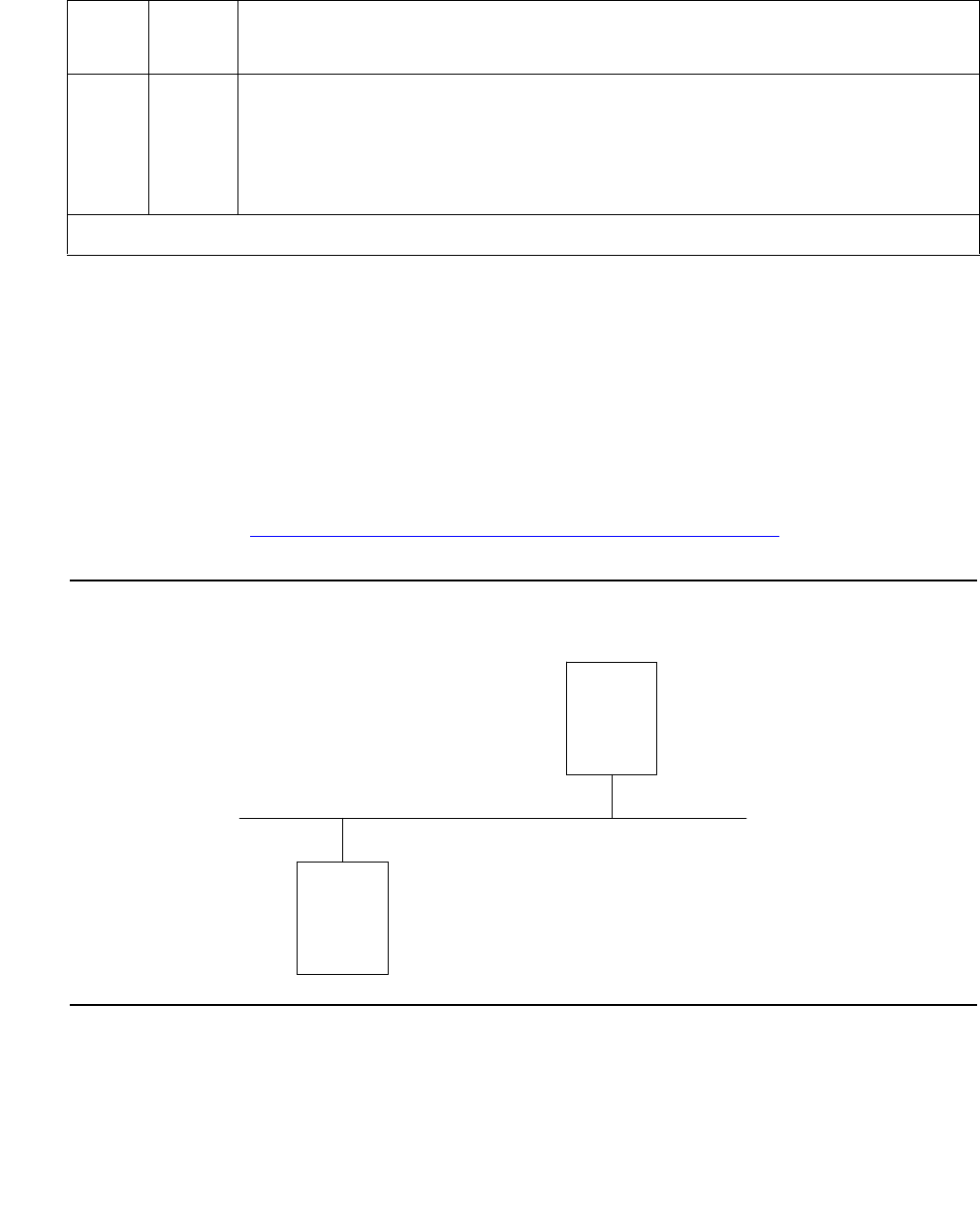
BRI-PORT (ISDN-BRI Port)
Issue 1 June 2005 693
BRI Port Local LAN Loop Around Test (#618)
This test is destructive.
This test verifies the connectivity of a BRI port across the LAN Bus and executes only if the port
is out-of-service. The test aborts if calls associated with the port are in-progress. Failures of
this test indicate either on-board faults associated with the BRI-PORT hardware on the circuit
pack, or problems with the LAN Bus, which is used to form connectivity between the switch and
the BRI-PORT.
The dotted lines in Figure 34: Path of the BRI Port Local LAN Loop Around on page 693 show
how a Loop Around test is performed across the packet bus for the D channel.
Figure 34: Path of the BRI Port Local LAN Loop Around
PASS The port is correctly using its allocated time slots.
1. To verify that this is not an intermittent problem, repeat this test up to 10
times to make sure it continues passing.
2. If complaints still exist, examine the station, connections, and wiring.
Table 231: Test #617 NPE Crosstalk Test (continued)
Error
Code
Test
Result
Description / Recommendation
2 of 2
BRI LINE
CIRCUIT
PACK
PACKET
INTERFACE
PACKET BUS
.
.
.
.
. . . . . . . . . . . . . . . . . . . . . . .
.
.
.
.
.
.
. . . . . . . . . . . . . . . . . . . . . .
.
.
.
.
.
. . . .

Communication Manager Maintenance-Object Repair Procedures
694 Maintenance Procedures for Avaya Communication Manager 3.0, Media Gateways and Servers
Table 232: Test #618 BRI Port Local LAN Loop Around
Error
Code
Test
Result
Description / Recommendation
1015 ABRT The port is not in the out-of-service state.
1. Display the BRI Port Status screen via status bri-port location
to determine what stations or adjuncts are on this port.
2. Use the extension shown on this screen in status station to
determine whether the station or adjunct is active.
3. If so, wait until it is idle, and then busyout the port with busyout port
location to place it in the out-of-service state and repeat this test.
!WARNING:
WARNING: Since the “busyout” command is destructive, execution of
this command prior to the port being idle causes every call
associated with BRI endpoints and every transaction
associated with ASAI or Avaya adjuncts on the port to be
torn down. Note that 3rd-party calls established by an ASAI
or Avaya adjunct remain connected even though the port is
taken out-of-service.
1139 ABRT The PN’s packet bus is out-of-service.
1. Follow the repair procedures for the packet bus.
2. After completing step 1, execute test port long location, and
review the results of the BRI Port Local LAN Loop Around test to verify
the repair.
1141 ABRT The PKT-CTRL is out-of-service.
1. Follow the repair procedures for the PKT-CTRL.
2. After completing step 1, execute test port long location, and
review the results of the BRI Port Local LAN Loop Around test to verify
the repair.
1144 ABRT The Port Network (PN) Packet Bus is out-of-service.
1. Follow the repair procedures for the Packet Bus.
2. After completing Step 1, execute test port long location, and
review the results of the BRI Port Local LAN Loop Around Test to verify
the repair.
1 of 2

BRI-PORT (ISDN-BRI Port)
Issue 1 June 2005 695
BRI Port Local TDM Loop Around Test (#619)
This test is destructive.
This test verifies the connectivity of a BRI port across the TDM Bus. It aborts if calls associated
with the port are in progress. Failure of this test indicates an on-board fault associated with the
port hardware on the circuit pack.
This Loop Around test runs a series of individual tests on the two B channels (B1 and B2)
associated with the port. It is a collection of the following:
●Loop Around test across the TDM Bus for B1.
●Conference Circuit test for B1.
●Loop Around test across the TDM Bus for B2.
●Conference Circuit test for B2.
The tests are run in the above order. If one fails, the remaining tests in the sequence are not
executed. An error code is returned at that point.
This test is not executed for ABRI-PORT/ATT-PORT/LGATE-PT/ATTE-PT because the B
channels associated with the port are not used by ASAI or Avaya adjuncts.
2012 ABRT Internal system error.
2100 ABRT Could not allocate the necessary system resources to run this test.
1. Retry the command at 1-minute intervals up to 5 times.
2. If the test continues to abort, escalate the problem.
FAIL The Loop Around test has failed.
1. If the test fails repeatedly, attempt to reset the circuit pack if the other
ports on the board are idle. Reset the circuit pack by issuing the
busyout board location and reset board location.
2. If the test fails again, execute test port-network pn#. If this fails,
follow failure procedures in PKT-BUS (Packet Bus) on page 1790.
3. If tests executed in step 2 pass, the problem is local to the BRI board.
Replace the circuit pack.
PASS The BRI Port Local LAN Loop Around test has passed.
Table 232: Test #618 BRI Port Local LAN Loop Around (continued)
Error
Code
Test
Result
Description / Recommendation
2 of 2
Communication Manager Maintenance-Object Repair Procedures
696 Maintenance Procedures for Avaya Communication Manager 3.0, Media Gateways and Servers
The dotted lines in Figure 35: Path of the BRI Port Local TDM Loop Around on page 696 show
how a Loop Around test is performed for the B channels. The figure shows a terminal
connected to a BRI line board using a TN556. If a TN2198 is used the terminal would be
connected to a NT1, and the NT1 to the BRI board.
Figure 35: Path of the BRI Port Local TDM Loop Around
Tone
Generator
Tone
Detector
BRI Line
Board
TDM Bus

BRI-PORT (ISDN-BRI Port)
Issue 1 June 2005 697
Table 233: Test #619 BRI Port Local TDM Loop Around
Error
Code
Test
Result
Description / Recommendation
1000 ABRT The system resources required to run this test are not available. The port
may be busy with a valid call.
1. Use display port location to determine the station extension or
trunk group/member number of the port. Use status bri-port
location to determine the service state of the port. If the service
state indicates that the port is active, then the port is unavailable for
certain tests. (Refer to Maintenance SAT Commands in Maintenance
Commands Reference (03-300191) for a full description of every
possible state.) Wait until the port is idle before retesting.
2. If the port is idle, then retry the command at 1-minute intervals up to 5
times.
3. If the test continues to abort, escalate the problem.
1002 ABRT The system could not allocate time slots for the test. The system may be
under heavy traffic conditions or it may have time slots out-of-service due
to TDM-BUS errors.
1. If the system has no TDM-BUS errors and is not handling heavy traffic,
repeat test at 1-minute intervals up to 5 times.
2. If the test continues to abort, escalate the problem.
1003 ABRT The system could not allocate a tone receiver for the test. The system may
be oversized for the number of Tone Detectors present, or some Tone
Detectors may be out of service.
1. Resolve any TTR-LEV errors.
2. Resolve any TONE-PT errors.
3. If neither condition exists, retry the test at 1-minute intervals up to 5
times.
4. If the test continues to abort, escalate the problem.
1004 ABRT The port has been seized by a user for a valid call. Use status station
for the station associated with this port and determine when the port is
available for testing.
1. Retry the command at 1-minute intervals up to 5 times.
2. If the test continues to abort and the port is idle, escalate the problem.
1 of 2

Communication Manager Maintenance-Object Repair Procedures
698 Maintenance Procedures for Avaya Communication Manager 3.0, Media Gateways and Servers
1005 ABRT This test is not valid for this type of translation. Ports administered as “ASAI”
or “ADJK” cannot run this test, because the B channels associated with the
port are not used by ASAI or Avaya Adjunct Links. This is a normal
condition.
2000 ABRT Response to the test was not received from the BRI-LINE circuit pack
within the allowable time period.
1. If this result occurs repeatedly, attempt to reset the circuit pack if the
other ports are idle. Reset the circuit pack by issuing the busyout
board location and reset board location.
2. If this result occurs again, replace the circuit pack.
2012 ABRT Internal system error.
1. Retry the command at 1-minute intervals up to 5 times.
2. If the test continues to abort, escalate the problem.
2100 ABRT Could not allocate the necessary resources to run this test.
1. Retry the command at 1-minute intervals up to 5 times.
2. If the test continues to abort, escalate the problem.
2103 ABRT The system could not make the conference connection for the test.
1. Retry the command at 1-minute intervals up to 5 times.
2. If the test continues to abort, escalate the problem.
1, 2 FAIL As stated previously, this test runs a TDM Loop Around test on each
B channel. This indicates that the loop around failed on one of the channels.
Error Code 1 indicates that the TDM Loop Around test failed on B1. Error
Code 2 indicates that the TDM Loop Around test failed on B2.
7, 8 FAIL As stated previously, this test runs a Conference Circuit test on each
B channel. A failure here indicates that one of these conference tests
failed; Error Code 7 means that the test failed on B1; Error Code 8 means
that the test failed on B2.
1. If the test fails repeatedly, attempt to reset the circuit pack if the other
ports on the circuit pack are idle. Reset the circuit pack by issuing the
busyout board location and reset board location.
2. If the test fails again, replace the circuit pack.
PASS The BRI Port Local TDM Loop Around test has passed.
Table 233: Test #619 BRI Port Local TDM Loop Around (continued)
Error
Code
Test
Result
Description / Recommendation
2 of 2

BRI-PORT (ISDN-BRI Port)
Issue 1 June 2005 699
Electronic Power Feed Restoral Test (#620)
This test attempts to restore the Electronic Power Feed (EPF) on an ISDN-BRI port twice. In
this test, the processor requests that the EPF be turned on for a given port. An attempt is made
to turn on the power unit to the station or adjunct. If no current is being drawn by a station, this
probably indicates that the station is not connected. No current being drawn by an adjunct is
the normal condition. If an overcurrent condition is sensed (that is, too much current is being
drawn), this condition may indicate a short in the wiring to the endpoint or adjunct. Depending
on what condition is sensed, a message is returned stating that either the EPF was turned on
successfully with no problems or that an overcurrent condition is sensed. This response is
reported by the Electronic Power Feed Inquiry (#622), which follows in the testing sequence.
EPF Restoral is attempted again by this test five seconds later. This test always passes for the
TN2198 because it has no EPF. This test will always abort when run on the TN2208.
Level 1 Status Inquiry Test (#621)
This test determines the state of the transmission facility of a BRI port at the physical layer (that
is, Level 1). Level 1 can be in one of three possible states: Activated, Pending Activation, or
Deactivated.
Table 234: Test #620 Electronic Power Feed Restoral
Error
Code
Test
Result
Description / Recommendation
1005 ABRT This test is not valid for this port type. The TN2208 does not have an
electronic power feed, and the test will abort.
2012 ABRT Internal system error.
1. Retry the command at 1-minute intervals up to 5 times.
2. If the test continues to abort, escalate the problem.
PASS The EPF test passed. The message to turn on the power feed to the
station or the adjunct was successfully sent to the port.
1. Although this test should not return a fail result, after running this test,
the Error Log should be checked for any entries with error type 257 to
examine the real results of this test.
2. An error type of 257 in the Error Log indicates some problem with the
power to the station or the adjunct. Check for a short in the wiring, a
damaged jack, a defective voice terminal or adjunct, or an incorrect
type of terminal.

Communication Manager Maintenance-Object Repair Procedures
700 Maintenance Procedures for Avaya Communication Manager 3.0, Media Gateways and Servers
The Activated state is the correct state for an ISDN-BRI port. In this state the Level 1 interface
can communicate with the BRI endpoint or ASAI or Avaya adjunct administered on this port.
This test passes if the state of Level 1 (L1) is Activated. This test also passes if software has
taken this port out of service. See the description of the Level 1 “Deactivated State” below for
more details.
The Pending Activation state indicates a problem with the endpoints or adjunct, the wiring to the
sets or adjunct, or the BRI-LINE circuit pack. When in this state, the Level 1 interface is either
not receiving any L1 framing from the endpoint or adjunct (Endpoint Idle), or it is communicating
with the endpoint or adjunct but cannot transition to the Activated state (Endpoint Active).
The Deactivated state indicates a problem with the BRI-LINE circuit pack. When in this state,
the Level 1 interface is idle and is not trying to communicate with the BRI endpoints or adjunct.
When an ISDN-BRI port is placed in the out-of-service state, Level 1 is also put into the
Deactivated state. This could be due either to the system detecting a fault with the port or to a
busyout port location request.
Table 235: Test #621 Level 1 Status Inquiry
Error
Code
Test
Result
Description / Recommendation
1187 ABRT The board, port or station may have been busied out by a technician.
1. Look in the Error Log for Error Type 18 (port busied out) for this port
and BRI-BD (board busied out). If this error type is present for
BRI-PORT only, release the port via release port pp and run the
test again. If the error is present for both BRI-BD and BRI-PORT, then
release the board via release port location and run the test
again.
Note:
Note: When you release a port, you release every port associated
with it. If certain ports still need to be busied out, use port
location to busy them out.
2. Make sure the terminal is connected.
3. Retry the command at 1-minute intervals up to 5 times.
4. If the test continues to abort, escalate the problem.
2000 ABRT Response to the test was not received from the circuit pack within the
allowable time period.
1. If the test aborts repeatedly up to five times, reset the circuit pack via
the busyout board location and reset board location.
2. If the test aborts again, replace the circuit pack.
1 of 4

BRI-PORT (ISDN-BRI Port)
Issue 1 June 2005 701
2012 ABRT Internal system error.
2100 ABRT Could not allocate the necessary system resources to run this test.
1. Retry the command at 1-minute intervals up to 5 times.
2. If the test continues to fail, escalate the problem.
1 FAIL Received a status of Level 1 Pending Activation-Endpoint Idle which
indicates a problem with the BRI endpoint or ASAI or Avaya adjunct, the
wiring to the endpoint or adjunct, or the ISDN-BRI port.
The TN2198, received a status of Level 1 Pending Activation. interface
down, which indicates a problem with a connection between the switch and
the NT1.
Note:
Note: An NT1 is a 2- to 4-wire converter that is used to connect
4-wire Avaya terminals to a 2-wire TN2198 circuit pack. The
NT1 also has status lamps to determine the health of the
unit.
1. For the TN556, verify that an endpoint is connected to the port. If an
endpoint is connected to the port then proceed to step 2. For the
TN2198 verify that the connections are good between the switch and
the NT1. Verify that the NT1 has power.
2. As necessary, check and repair the wiring between the circuit pack and
the endpoint or adjunct. If a TN2198 is used the set must have been
plugged in for at least 15 seconds before it will stabilize. Execute test
port PCSSpp, and review the results of the Level 1 Status Inquiry test
to verify the repair. If this test is still failing, proceed to step 3.
3. For BRI endpoints, replace the BRI endpoint(s) connected to the port
or the NT1 if a TN2198 is used. For ASAI or Avaya adjuncts, follow the
recommended repair procedures of the manufacturer for link
communication problems. For the NT1, follow the manufacturers
repair procedures. Then execute test port PCSSpp and review the
results of the Level 1 Status Inquiry test to verify repair. If this test is
still failing, proceed to step 4.
4. Escalate the problem to the next tier.
Table 235: Test #621 Level 1 Status Inquiry (continued)
Error
Code
Test
Result
Description / Recommendation
2 of 4

Communication Manager Maintenance-Object Repair Procedures
702 Maintenance Procedures for Avaya Communication Manager 3.0, Media Gateways and Servers
2 FAIL For the TN556 or TN2208, received a status of Level 1 Pending
Activation-Endpoint Active which indicates a problem with the BRI endpoint
or ASAI or Avaya adjunct, the wiring to the endpoint or adjunct, or the
ISDN-BRI port.
For the TN2198, received a status of Level 1 Pending Activation. U
interface up S/T interface down, which indicates a problem with the NT1 or
the wiring between the NT1 and the BRI endpoint (S/T interface).
1. As necessary, check and repair the wiring between the circuit pack and
the endpoint or adjunct. Execute test port location, and review
the results of the Level 1 Status Inquiry test to verify the repair. If this
test is still failing, proceed to step 2.
2. For BRI endpoints, try replacing the BRI endpoint(s) connected to the
port. For ASAI or Avaya adjuncts, follow the recommended repair
procedures of the manufacturer for link communication problems. For
the NT1, follow the recommended repair procedures of the
manufacturer. Then execute test port location, and review the
results of the Level 1 Status Inquiry test to verify repair. If this test is
still failing, proceed to step 3.
3. Escalate the problem to the next tier.
3 FAIL Received a status of Level 1 Deactivated; the port is out-of-service.
1. Enter status bri-port location to verify that the service state of
the port is out-of-service. If the service state of the port is not
out-of-service, escalate the problem to the next tier. Otherwise,
proceed to step 2.
2. If the port has been placed out-of-service via busyout port
location, try releasing the port by executing the release port
location. Then enter test port long location, and review the
results of Level 1 Status Inquiry test. If this test is still failing, proceed
to step 3.
3. After executing test port long location, review the results of
every test. Follow the repair procedures for any tests that fail. Verify
repair of the problem by executing test port location and by
determining that the Level 1 Status test passes. If the test continues to
fail for this reason, proceed to step 4.
4. Escalate the problem to the next tier.
Table 235: Test #621 Level 1 Status Inquiry (continued)
Error
Code
Test
Result
Description / Recommendation
3 of 4

BRI-PORT (ISDN-BRI Port)
Issue 1 June 2005 703
Electronic Power Feed Inquiry (#622)
This test queries the BRI-LINE circuit pack for the status of the Electronic Power Feed (EPF)
supplied to a BRI endpoint or an ASAI or Avaya adjunct. If the EPF is on and no overcurrent
condition exists, this test passes. All other states are not normal and indicate a problem with
the endpoint or adjunct, the wiring to the endpoint or adjunct, or the BRI-LINE circuit pack. This
test is not run on the TN2208 circuit pack or the TN2198 and will always return a pass for the
TN2198. The TN2208 has no power feeds.
4 FAIL For the TN2198 only:
Received a status of Level 1 Pending Activation, the NT1 has a loss of
power indicating a problem with the NT1.
1. For the NT1 follow the manufacturers recommended repair
procedures.
2. Execute test port location, and review the results of the Level 1
Status Inquiry test to verify the repair. If the test is still failing proceed
to step 3.
3. Escalate the problem to the next tier.
PASS This test indicates that Level 1 is activated, or that software has taken the
port out of service.
Table 235: Test #621 Level 1 Status Inquiry (continued)
Error
Code
Test
Result
Description / Recommendation
4 of 4
Table 236: Test #622 Electronic Power Feed Inquiry
Error
Code
Test
Result
Description / Recommendation
1005 ABRT This test is not valid for this port type. Ports on the TN2208 cannot run this
test because this board does not have an electronic power feed.
2000 ABRT Response to the test was not received from the circuit pack within the
allowable time period.
1. If the test aborts repeatedly up to five times, reset the circuit pack via
busyout board location and reset board location.
2. If the test aborts again, replace the circuit pack.
1 of 2

Communication Manager Maintenance-Object Repair Procedures
704 Maintenance Procedures for Avaya Communication Manager 3.0, Media Gateways and Servers
Layer 1 Transmission Error Counter Test (#624)
This test reads and clears the BRI port’s Layer 1 Transmission error counter maintained on the
BRI-LINE circuit pack. This counter is incremented by the circuit pack when it detects a Layer 1
transmission problem. The test passes if the value of the counter is 0 (that is, the error is
cleared). If the counter is not zero, the test fails, and the value of the counter is displayed in the
Error Code field.
This error is most likely due to a problem with the wiring or the endpoint or adjunct (verify that
the wiring meets the configuration rules defined in DEFINITY® Communications System
Generic 1 and Generic 3i Wiring, 555-204-111. It does not indicate a problem with the
ISDN-BRI circuit pack. This test is useful for verifying the repair of the problem.
2012 ABRT Internal system error.
2100 ABRT Could not allocate the necessary system resources to run this test.
1. Retry the command at 1-minute intervals up to 5 times.
2. If the test continues to abort, escalate the problem.
1 FAIL The BRI-LINE circuit pack reports that it has detected an overcurrent
condition and has turned off the EPF.
1. As necessary, check and repair the wiring between the circuit pack and
the endpoint or adjunct. Check the endpoints and replace one or both
sets if the sets are drawing too much current. Execute test port
location and review the results of the EPF Inquiry test to verify the
repair. If this test is still failing, proceed to step 2.
2. Execute test port location, and review the results of the Level 1
Status Inquiry test. If this test is also failing, then follow the repair
procedure for the Level 1 Status Inquiry test. Otherwise, escalate this
problem to the next tier.
PASS The Electronic Power Feed Inquiry test reports that the EPF is on.
Table 236: Test #622 Electronic Power Feed Inquiry (continued)
Error
Code
Test
Result
Description / Recommendation
2 of 2

BRI-PORT (ISDN-BRI Port)
Issue 1 June 2005 705
Table 237: Test #624 Layer 1 Transmission Error Counter Test
Error
Code
Test
Result
Description / Recommendation
2000 ABRT Response to the test was not received from the circuit pack within the
allowable time period.
1. If the test aborts repeatedly up to five times, reset the circuit pack via
busyout board location and reset board location.
2. If the test aborts again, replace the circuit pack.
2012 ABRT Internal system error.
2100 ABRT Could not allocate necessary system resources to run test.
1. Retry the command at 1-minute intervals up to 5 times.
2. If the test continues to fail, escalate the problem.
value FAIL The BRI-LINE circuit pack is still detecting errors of this type. The Error
Code field contains the value of this counter.
1. Retry the command at 1-minute intervals up to 5 times.
2. If the test continues to fail, review the results of other tests in the long
test sequence. Pay particular attention to the results of the Level 1
Status Inquiry test. Follow repair procedures for any of the executed
tests if they fail. Otherwise, go to the next step.
3. If the tests for the endpoints or adjunct pass and the Layer 1
Transmission Error Counter test continues to fail, check the wiring to
the endpoints or adjunct. If the wiring appears to be fine, escalate the
problem.
PASS The Layer 1 Transmission error counter was read correctly and has a value
of 0.

Communication Manager Maintenance-Object Repair Procedures
706 Maintenance Procedures for Avaya Communication Manager 3.0, Media Gateways and Servers
Receive FIFO Overflow Error Counter Test (#625)
This test reads and clears the BRI port’s Receive FIFO Overflow error counter maintained on
the BRI-LINE circuit pack. This counter is incremented by the circuit pack when it detects an
overflow of its receive buffers. The test passes if the value of the counter is 0 (that is, the error
is cleared). If the counter is non-zero, the test fails, and the value of the counter is displayed in
the Error Code field.
This error can occur if signaling frames are being received from the packet bus at a rate
sufficient to overflow the receive buffers on the circuit pack for a port OR if a hardware fault is
causing the receive buffers not to be emptied properly by the circuit pack. This test is useful for
verifying the repair of the problem.
Table 238: Test #625 Receive FIFO Overflow Error Counter Test
Error
Code
Test
Result
Description / Recommendation
2000 ABRT Response to the test was not received from the circuit pack within the
allowable time period.
1. If the test aborts repeatedly up to five times, reset the circuit pack via
busyout board location and reset board location.
2. If the test aborts again, replace the circuit pack.
2012 ABRT Internal system error.
2100 ABRT Could not allocate the necessary system resources to run this test.
1. Retry the command at 1-minute intervals up to 5 times.
2. If the test continues to fail, escalate the problem.
value FAIL The BRI-LINE circuit pack is still detecting errors of this type. The Error
Code field contains the value of this counter.
1. Retry the command at 1-minute intervals up to 5 times.
2. If the test continues to fail, run the long test sequence, and pay
particular attention to the Loop Around tests (#618 and #619). See the
repair procedures for the executed test if it fails. Otherwise, go to the
next step.
3. Replace the circuit pack.
PASS The Receive FIFO Overflow error counter was read correctly and has a
value of 0.

BRI-PORT (ISDN-BRI Port)
Issue 1 June 2005 707
Clear Error Counters Test (#270)
This test is not an actual test in the strict sense of the word. There are various error counters
associated with each BRI-PORT/ABRI-PORT/ATT-PORT/LGATE-PT/ATTE-PT. This test clears
those counters and triggers the auditing of Terminal Endpoint Identifier (TEI) values and layer-3
reinitialization. This test is used only to send messages to the BRI-PORT/ABRI-PORT/
ATT-PORT/LGATE-PT/ATTE-PT and, therefore, should neither abort nor fail.
Table 239: Test #270 Clear Error Counters
Error
Code
Test
Result
Description / Recommendation
Any ABRT This test should never abort.
Any FAIL This test should never fail.
1. Retry the command at 1-minute intervals up to 5 times.
2. If the test continues to fail, escalate the problem.
PASS The message to clear the error counters of the BRI-Port/ABRI-Port/
ATT-PORT/LGATE-PT/ATTE-PT has been sent.

Communication Manager Maintenance-Object Repair Procedures
708 Maintenance Procedures for Avaya Communication Manager 3.0, Media Gateways and Servers
BRI-SET, Various Adjuncts
Error log entries and tests also apply to ATT-ADJ, ATTE-AJ, ASAI-ADJ, BRI-DAT, and
LGATE-AJ.
S8700 | 8710 / S8500
!WARNING:
WARNING: Information for isolating and resolving packet-bus faults is included in Isolating
and repairing packet-bus faults in Maintenance Procedures (03-300192). The
Troubleshooting Packet Bus Problems flowchart, along with the other information
presented in the chapter, can help resolve problems that involve more than a
single station or circuit pack.
!WARNING:
WARNING: If a significant packet-bus failure occurs, errors and alarms may not be logged as
expected for BRI-PORT/ABRI-POR/ATT-PORT/ LGATE-PT/ ATTE-PT.
Conditions under which this occurs are detailed in the Isolating and repairing
packet-bus faults in Maintenance Procedures (03-300192).
MO Name in
Alarm Log
Alarm
Level
Initial Command to Run Full Name of MO
BRI-SET WRN1
1. **The alarm level for ASAI and Avaya adjuncts may be administered using set options. The alarm level
can be set independently for on- and off-board alarms to WARNING, MINOR, or MAJOR for every ASAI
and Avaya adjunct in the system.
test station extension lISDN-BRI Set
BRI-DAT WRN1test data-module extension l ISDN-BRI Data Module
ASAI-ADJ MAJ1test station extension
test data-module extension
ASAI-Adjunct
ASAI-ADJ WRN2
2. Alarming for an ASAI and Avaya adjuncts is disabled if the adjunct asks the switch to suspend
maintenance. When this occurs, an error and a WARNING alarm are logged against the endpoint. Busying
out and releasing the ASAI station or ADJLK station will clear the alarm.
test data-module extension ASAI-Adjunct
ATT-ADJ MAJ1test station extension Avaya-Adjunct
ATT-ADJ WRN2test station extension Avaya-Adjunct
LGATE-AJ MAJ1test station extension Ethernet ASAI-Adjunct
LGATE-AJ WRN2test station extension Ethernet ASAI-Adjunct
ATTE-AJ MAJ1test station extension Ethernet Avaya-Adjunct
ATTE-AJ WRN2test station extension Ethernet Avaya-Adjunct

BRI-SET, Various Adjuncts
Issue 1 June 2005 709
The TN2208 ESAI MFB provides the system with an Ethernet interface to Adjunct-Switch
Application Interface (ASAI) and Avaya adjuncts (for example, CONVERSANT® Voice System).
This circuit pack contains 8 ports of line circuit interface, each of which operates with two B
channels (referred to as B1 and B2 throughout this section) and one D channel. In this context,
the term ``ISDN-BRI port'' is used to refer collectively to ports on the TN2208 MFB circuit pack
that is connected to ASAI or Avaya adjuncts. The TN2208 ESAI MFB is handled by switch
software as it is an ISDN BRI compatible board and every maintenance action referring to ASAI
and Avaya Adjunct Links in this section applies.
In G3iV1.1-286 and G3iV2-386, two types of ISDN-BRI endpoints may be connected to
ISDN-BRI (ISDN Basic Rate Interface Line) TN556 and TN2198 circuit packs: ISDN-BRI station
endpoints, ASAI (Adjunct-Switch Application Interface) and Avaya adjuncts (for example
CONVERSANT® Voice System). These circuit packs contain 12 ports of line circuit interfaces,
each of which operates at 192 kilobits per second (kbps) with two B channels and one D
channel. For BRI endpoints, each B channel may support voice or circuit-switched data and
may be circuit-switched simultaneously. The B channels are not used by ASAI or Avaya
adjuncts. The D channel is used for conveying signaling between the switch and a BRI
endpoint(s) or ASAI or Avaya adjuncts. Each ISDN-BRI D channel is connected to the switch
processor and the ISDN-BRI port through the PKT-BUS (packet bus).
ISDN-BRI endpoints come in a number of configurations. Every endpoint requires the D
channel to convey signaling information to the switch. A voice-only set requires only one B
channel. A voice and data-capable set requires both B channels (one for voice and one for
data). Therefore, each TN556 port can support either two voice-only sets or one voice and
data-capable set. Only a single ASAI or Avaya adjunct may be connected to an ISDN-BRI port.
Multiple adjuncts per line are not supported.
Figure 36: ISDN-BRI Set Interactions on page 710 illustrates the physical connection (solid
line) between an ISDN-BRI circuit pack and a voice or voice/data set. Each physical connection
allows for two B channels, as stated above, plus one D channel. Each ISDN-BRI circuit pack
can support up to 12 of these PHYSICAL connections to different voice and voice/data sets or
ASAI and Avaya adjuncts.
Communication Manager Maintenance-Object Repair Procedures
710 Maintenance Procedures for Avaya Communication Manager 3.0, Media Gateways and Servers
Figure 36: ISDN-BRI Set Interactions
This section contains the ISDN-BRI Set, ASAI Adjunct and Avaya Adjunct Maintenance
documentation. Some of the results of maintenance testing of the ISDN-BRI Set or the ASAI
and Avaya Adjunct may be affected by the health of the ISDN-BRI circuit pack and port. These
interactions should be kept in mind when investigating the cause of ISDN-BRI Set problems.
Hardware Error Log Entries and Test to Clear Values
BRI Line
Circuit Pack
P
O
R
T
D-Channel
B-Channel
B-Channel
PHYSICAL CONNECTION
VOICE
or DATA
SET
Logical Connection
VOICE
or DATA
SET
PBX
Physical Connection
Table 240: BRI-SET/ASAI-ADJ Error Log Entries
Error
Type
Aux
Data
Associated
Test
Alarm
Level
BRI-SET
BRI-DAT
Alarm
Level
ASAI-ADJ
ATT-ADJ
ATTE-AJ
LGATE-AJ
On/ Off
Board
Test to Clear Value
0 (a) 0 Any Any Any Any test station ext r 2
test data-module ext r 2
2 (b)2-102None
18 0 busyout
station ext
WRN MAJ
WRN1OFF release station ext
130 (c)WRNONtest port PCSS sh
1 of 2
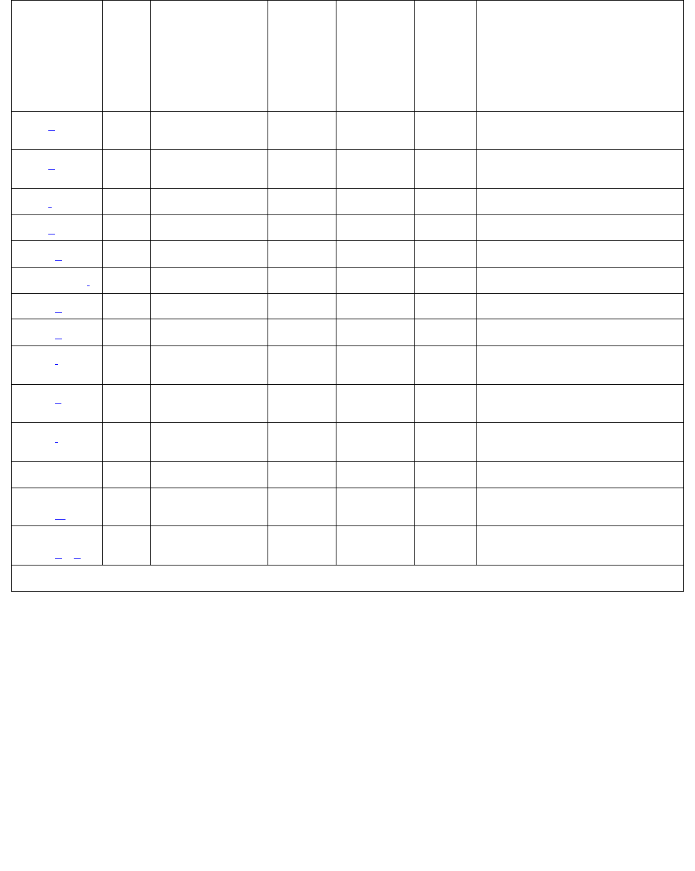
BRI-SET, Various Adjuncts
Issue 1 June 2005 711
Notes:
a. Error Type 0: Run the short test sequence first. If every test passes, run the long test
sequence. Refer to each appropriate test’s description, and follow its recommended
procedures.
257 (d) Any BRI Layer 3
Query (#629)
WRN MAJ
WRN2
OFF test station ext r 2
test data-module ext r 2
351 (e) 0 None WRN OFF busyout station
and release station
513 (f)0None
769 (g)0None WRNMAJ OFF
2561 (h)0None
2562-2566 (i)0 None
2567 (p)0None
2568 (q)0None
2817 (j) 0 XID test (#628) WRN MAJ
WRN2
OFF test station ext r 2
test data-module ext r 2
3073 (k) 0 BRI Remote Loop
Back (#627)
WRN OFF test station ext l r 2
test data-module ext l r 2
3329 (l) Any Signaling Link
Status (#626)
WRN MAJ
WRN2
OFF
3584 0,1 None
3585-
3839 (m)
0None
3840-
4095 (n) (o)
0None
1. Major and Minor alarms on this MO may be downgraded to Warning alarms based on the value used in set
options.
Table 240: BRI-SET/ASAI-ADJ Error Log Entries (continued)
Error
Type
Aux
Data
Associated
Test
Alarm
Level
BRI-SET
BRI-DAT
Alarm
Level
ASAI-ADJ
ATT-ADJ
ATTE-AJ
LGATE-AJ
On/ Off
Board
Test to Clear Value
2 of 2

Communication Manager Maintenance-Object Repair Procedures
712 Maintenance Procedures for Avaya Communication Manager 3.0, Media Gateways and Servers
b. Error Type 2: violations of the ISDN-BRI signaling protocol; timers associated with certain
layer-3 messages have expired before a required response was received. In the following
table, the aux data field indicates what timer has just expired.
The switch sent a message to the endpoint that did not respond in the allotted time. This
can happen occasionally due to failure of the point-to-point signaling link or because of a
problem in the BRI endpoint or ASAI adjunct or Avaya adjunct. Execute test station
extension sh and pay particular attention to the results of the BRI Layer 3 Query test
(#629). If this test fails, follow the repair procedure for Test #629.
c. Error Type 130: the circuit pack has been removed or has been insane for more than 11
minutes. To clear the error, replace or reinsert the circuit pack.
d. Error Type 257: the endpoint does not respond to the service state query message sent to
the adjunct or the endpoint. This error causes an alarm to be raised. The alarm is retired
when the switch receives a response to the service state query to the endpoint or the
adjunct.
For BRI endpoints, the Aux Data field for this error contains “0.” When it occurs, execute
test station extension sh and pay particular attention to the results of the BRI
Layer 3 Query test (#629). If this test fails, follow the repair procedure for Test #629.
Aux
Data
Timer Type
2 First T303 (SETUP timer)
3 Second T303 (SETUP timer)
4 T305 (DISConnect timer)
5 First T308 (RELease timer)
6 Second T308 (RELease timer)
10 T316 (RESTart timer)
12 T309 (Layer-2 Failure timer)
16 TM100 (Management Information message
Timer 1)
17 TM200 (Management Information message
Timer 2)
102 TASAI (ASAI Routing timer)
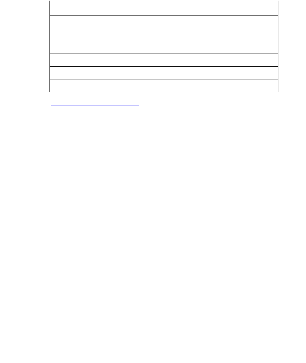
BRI-SET, Various Adjuncts
Issue 1 June 2005 713
When this error occurs for an ASAI or Avaya adjunct, the Aux Data field indicates the state
of the ASAI link or Avaya link and whether an invalid response or no response was received
to the query from the switch, as shown in the following table:
See Maintenance SAT Commands in Maintenance Commands Reference (03-300191) for
an explanation of the ASAI link states.
For ASAI or Avaya adjuncts, the switch automatically queries the adjunct every two minutes
(and therefore the Layer 3 Query test is not executed for ASAI or Avaya adjuncts via a
command entered from the G3MT terminal). While alarmed for this error, the switch
momentarily (for five seconds) takes the associated port out-of-service every 15 minutes.
This action is taken in an attempt to stimulate recovery actions to be taken by the adjunct.
When this error occurs for an ASAI or Avaya adjunct:
1. Execute test station extension and pay particular attention to tests that fail.
Perform the associated repair procedures for those tests.
2. Check the health of the adjunct by following the recommended repair procedures of the
manufacturer of the adjunct if the preceding step does not resolve the problem.
3. If the above steps do not resolve the problem and the alarm persists, follow normal
escalation procedures.
e. Error Type 351 and associated WARNING alarm are logged against an ASAI or Avaya
endpoint when the adjunct has asked the switch to suspend Maintenance on the ASAI or
Avaya endpoint. Busy out and release the ASAI station or ADJLK station to clear the alarm.
f. Error Type 513: the endpoint sends more messages than the switch can handle. The
switch suspends the reception of messages from the endpoint for a short period of time.
There is no repair procedure for this error. If the condition persists, replace the endpoint.
g. Error Type 769: a BRI endpoint’s signaling-associated link has too much traffic related to
link establishment. This could occur if the signaling link is bouncing between assigned and
established states. Software suspends activity to this endpoint for 75 minutes when the
endpoint is alarmed due to this problem. Note that service suspension does not occur if the
endpoint is an ASAI or Avaya adjunct. If this problem persists, replace the endpoint. If
replacing the endpoint does not fix the problem, follow normal escalation procedures.
Aux Data ASAI Link State Error
102 13-restarting No response to RESTART message
104 13-restarting Invalid response to RESTART message
152 13-restarted No response to layer-3 query
154 13-restarted Invalid response to layer-3 query
202 13-established No response to layer-3 query
204 13-established Invalid response to layer-3 query

Communication Manager Maintenance-Object Repair Procedures
714 Maintenance Procedures for Avaya Communication Manager 3.0, Media Gateways and Servers
h. Error Type 2561: the ASAI-ADJ or ATT-ADJ or LGATE-AJ or ATTE-AJ message is not
transmitted because the PKT-CTRL (Packet Control circuit pack) transmit buffers are
exhausted. Frequent or persistent occurrence of these events may indicate a hardware
problem or traffic overload on the PKT-CTRL, the signaling link, or the ASAI or Avaya
adjunct. Attempt to resolve the problem by following the repair procedures for the
PKT-CTRL. If these attempts fail, the problem should be escalated because re-engineering
of the traffic on the PKT-CTRL, signaling link, or adjunct may be necessary.
i. Error Type 2562-2566: the ASAI message is not transmitted because the transmit buffer for
the ASAI link is full, causing the link to be flow controlled. Frequent or persistent occurrence
of these events may indicate a hardware problem or traffic overload on the PKT-CTRL, the
signaling link, or the ASAI or Avaya adjunct. Attempt to resolve the problem by following the
repair procedures issued by the manufacturer of the adjunct. If these attempts fail, the
problem should be escalated because re-engineering of the traffic on the PKT-CTRL,
signaling link, or adjunct may be necessary.
j. Error Type 2817: there is a layer-2 problem over the D channel between the switch and the
endpoint. When this error occurs, an alarm is raised against the station or adjunct. Execute
test station extension short and pay particular attention to the results of the BRI
XID test (#628). If this test fails, follow the repair procedure for Test #628.
k. Error Type 3073: there is a problem with the B-channel connection between the switch and
the endpoint. When this error occurs, a warning alarm is raised against the endpoint.
Execute test station extension long and pay particular attention to the results of
the BRI Remote Loop Back test (#627). If this test fails, follow the repair procedure for Test
#627.
l. Error Type 3329: occurs whenever the point-to-point signaling link to the endpoint goes
down (except when it goes down because either the PKT-CTRL or the PKT-BUS has failed
or has been busied out by system technician). When this error occurs, an alarm is raised
against the endpoint or adjunct. Execute test station extension short and pay
particular attention to the results of the Signaling Link Status test (#626). If this test fails,
follow the repair procedure for Test #626. The alarm is retired when the signaling link is
reestablished to the endpoint or adjunct.
m. Error Type 3585-3839: Certain ASAI protocol-specific cause codes are logged by switch
software. The cause code can be determined from the following formula:
If the error type is greater than 3712, then the ASAI cause code is equal to the error type
minus 3712. This code was sent to the adjunct by the switch.
If the error type is less than 3712, then the ASAI cause code is equal to the error type minus
3584. This code was sent to the switch by the adjunct.
A description of the various ASAI cause values is contained in the Table 241: ASAI CAUSE
VALUES; (BRI-SET/ASAI-ADJ Error Log Entries Notes) on page 715. This table also
contains recommended system technician actions associated with the cause value. In
addition, the Aux Data field of the Error Log entry contains additional diagnostic information
additional diagnostic.

BRI-SET, Various Adjuncts
Issue 1 June 2005 715
Table 241: ASAI CAUSE VALUES; (BRI-SET/ASAI-ADJ Error Log Entries Notes)
Error
Code
Test Result Description / Recommendation
0 Unrecognized
ASAI Protocol
Operation
Requested ASAI protocol operation is not implemented by the
switch or adjunct. Aux Data field of Error Log entry contains
protocol identifier for unrecognized operation.
1. Consult switch and adjunct documentation to determine which
set of operations is supported by the switch and the adjunct.
Adjunct administration turning off operations not implemented
by the switch may resolve the problem.
2. If step 1 does not resolve the problem, escalate to the next
tier.
40 Resources not
available
No available internal resources to service switch or adjunct
request. System transaction capacity for adjunct or switch is
exceeded.
1. Re-engineering of adjunct services my be required. If
problem persists, escalate problem to the next tier.
63 SERVICE OR
OPTION NOT
AVAILABLE
Requested ASAI capability or resource is not available on the
switch or adjunct. More than one adjunct may be contending for
the same switch resources. Potential administration mismatch
between the resource domains administered on the switch and
those administered on the adjunct.
1. Verify that no overlapping administration of switch resources
(e.g., requesting notifications on a single domain by multiple
adjuncts or multiple adjuncts attempting to control a single
call) exists across any adjunct connected to the switch. If an
overlap exists, then re-administer the adjuncts to guarantee
that each adjunct is associated with a unique set of switch
resources.
2. If step 1 does not resolve the problem, escalate to the next
tier.
79 SERVICE OR
OPTION NOT
IMPLEMENTED
Requested service or option (or combination of selected options) is
not supported (implemented) in switch or the adjunct.
1. Consult switch and adjunct documentation to determine ASAI
service and options supported by both switch and adjunct.
Re-administration of the switch-administered capabilities (see
Customer Optional Feature screen) or those of the adjunct
may be necessary to correct the problem.
2. If step 1 does not provide the set of desired services due to
deficient implementation, escalate the problem to the next
tier.
1 of 2

Communication Manager Maintenance-Object Repair Procedures
716 Maintenance Procedures for Avaya Communication Manager 3.0, Media Gateways and Servers
n. Error Type 3840-4095: Certain ISDN-BRI cause codes are logged by switch software. The
cause code can be determined from the following formula:
If the error type is greater than 3968, then the ISDN-BRI cause code is equal to the error
type minus 3968. This code was sent to the endpoint by the switch.
If the error type is less than 3968, then the ISDN-BRI cause code is equal to the error type
minus 3840. This code was sent to the switch by the endpoint.
A description of the various ISDN-BRI cause values is contained in Table 242: ISDN-BRI
CAUSE VALUES; (BRI-SET/ASAI-ADJ Error Log Notes) on page 716. This table also
contains recommended system technician actions associated with the cause value. In
addition, the Aux Data field of the Error Log entry contains additional diagnostic information.
o. Error 3847: sets on the port do not support level 3 initialization. Consult the Set Service
documentation.
p. Error 2567: the version of ASAI is not supported, check version of the software running on
the ASAI or Avaya adjunct.
87 Internal switch
audit
There is an inconsistency in switch data records.
1. There is no action needed since the switch has corrected the
data inconsistency.
2. If a number of these errors continue to occur, then escalate to
next tier.
Table 242: ISDN-BRI CAUSE VALUES; (BRI-SET/ASAI-ADJ Error Log Notes)
Error
Code
Test
Result
Description / Recommendation
1 Channel in
use
Another station is using requested channel on the BRI-PORT. (Not
applicable for ASAI or Avaya adjuncts.)
For BRI endpoints:
1. Try to originate a call to or from this port.
2. If the error persists, busyout and release the port.
3. If the problem still persists, replace stations on the port.
4. If the problem still persists, escalate to the next tier.
1 of 3
Table 241: ASAI CAUSE VALUES; (BRI-SET/ASAI-ADJ Error Log Entries Notes)
Error
Code
Test Result Description / Recommendation
2 of 2

BRI-SET, Various Adjuncts
Issue 1 June 2005 717
34 No circuit or
channel
available
A resource on the switch is unavailable for a call. For BRI
endpoints: This cause value is not logged. For ASAI or Avaya
Adjuncts: This condition means that there are no available trunks for
an outgoing call request.
1. Verify that the adjunct is administered to support the trunk
capabilities of the switch.
2. Investigate trunk group status by issuing status trunk
commands from the SAT or by requesting a trunk group query
or queries from the adjunct.
3. Perform trunk diagnostic procedures outlined in this manual.
4. If step 3 does not resolve the problem, escalate to the next tier.
42 Switch
Equipment
Congestion
Switch takes control to limit received traffic. For BRI endpoints: This
cause value is not logged. For ASAI or Avaya Adjuncts:
1. Refer to the CallVisor protocol reference manual.
2. If step 1 does not resolve the problem, escalate to the next tier.
50 Requested
Facility Not
Subscribed
Requested facility is implemented, but not administered. Potential
administration problem with endpoint or adjunct. For BRI endpoints:
1. Verify the switch administration of endpoint using display
station or display data-module.
2. If step 1 does not resolve the problem, refer to the endpoint’s
service manual and verify administration on the endpoint.
3. If step 2 does not resolve the problem, escalate to the next tier.
For ASAI adjuncts:
1. Display the Customer Optional Features screen (administration
screen) on the switch to determine which ASAI capabilities are
turned on in the switch.
2. Verify that the adjunct is administered to support the identical
capabilities as the switch. If there is a mismatch in the
administered capabilities, then re-administer the switch and/or
the adjunct to establish a consistent set of desired capabilities
on both the switch and the adjunct.
3. If step 2 does not resolve the problem, escalate to the next tier.
For Avaya adjuncts:
1. Display the Customer Optional Features screen (administration
screen) on the switch to determine whether the Avaya adjunct
is set enabled on in the switch.
2. If error type 2567 or 2568, verify the Avaya adjunct version,
and re-administer if needed.
3. If step 2 does not fix the problem, escalate to the next tier of
support
Table 242: ISDN-BRI CAUSE VALUES; (BRI-SET/ASAI-ADJ Error Log Notes) (continued)
Error
Code
Test
Result
Description / Recommendation
2 of 3

Communication Manager Maintenance-Object Repair Procedures
718 Maintenance Procedures for Avaya Communication Manager 3.0, Media Gateways and Servers
q. Error 2568: the adjunct ID is invalid, check the vender ID or software running on the Avaya
adjunct.
System Technician-Demanded Tests:
Descriptions and Error Codes
Investigate errors associated with the circuit pack and port first. Clearing these error codes first
may also clear errors generated against the endpoint. When every circuit pack and port error
has been cleared, and errors still exist against the endpoint, investigate errors in the order they
are presented in the table below. By clearing error codes associated with the Signaling Link
Status test (#626), you may also clear errors generated from other tests in the sequence.
58 Bearer
Capability Not
Currently
Available
Requested bearer capability is implemented, but not administered.
No B channel is administered. See recommendation for Error Code
50 above.
65 Bearer
Service Not
Implemented
Requested service not implemented in switch or endpoint.
69 Requested
Facility Not
Implemented
Requested service not supported in switch or endpoint.
1. Consult switch and endpoint documentation to determine
service support.
2. If step 1 does not resolve the problem, escalate to the next tier.
81 Invalid CRV An invalid CRV was sent by the adjunct.
1. This may indicate a CRV inconsistency between the switch and
the adjunct. Refer to the CallVisor protocol reference manual.
2. If step 1 does not resolve the problem, escalate to the next tier.
Table 242: ISDN-BRI CAUSE VALUES; (BRI-SET/ASAI-ADJ Error Log Notes) (continued)
Error
Code
Test
Result
Description / Recommendation
3 of 3
Order of Investigation Short Test
Sequence
Long Test
Sequence
D/ND1
Signaling Link Status test (#626) X X ND
BRI XID test (#628) X X ND
BRI Layer 3 Query (#629) X(a) X(a) ND
1 of 2

BRI-SET, Various Adjuncts
Issue 1 June 2005 719
Note:
Note: (a) Execute test port long location, and review the results of the BRI
Port Local LAN Loop Around test (#618) to verify the repair.
Signaling Link Status Test (#626)
This test determines the current status of the signaling link. This test passes if the link is
“bound” to an endpoint and fails if the link is “not bound.”
The definition of the term “bound” for a link depends upon the type of endpoint and may depend
on the successful completion of procedures at both Layers 2 and 3 of the protocol. The
definition of “bound” for each type of endpoint is as follows:
●BRI endpoints administered for MIM (management information messages) initialization
(multipoint):
Note:
Note: An MIM is a level 3 message that conveys management and maintenance
information between a communications system and a BRI terminal.
For endpoints of this type, the signaling link is “bound” when the link is connected at Layer 2
and the link has been associated with an endpoint, [that is, the endpoint has completed
SPID initialization (L3 established)].
●ASAI adjuncts and BRI endpoints not administered for MIM initialization (point-to-point):
For endpoints of this type, the signaling link is “bound” when the link is connected at Layer 2
(L2 established).
For every endpoint type, a signaling link becomes “unbound” when it is disconnected at Layer 2.
For BRI endpoints supporting MIM initialization, a signaling link may also become “unbound” if a
subsequent attempt to perform SPID initialization on a “bound” link fails (that is, wrong SPID is
entered into the endpoint by the user).
BRI Remote Loop Back (#627) X(a) ND
BRI Set Audits (#630) X(a) X(a) ND
BRI Vendor ID test (#631) X(a) ND
BRI Model/Vintage ID test (#632) X(a) ND
1. D = Destructive; ND = Nondestructive
Order of Investigation Short Test
Sequence
Long Test
Sequence
D/ND1
2 of 2

Communication Manager Maintenance-Object Repair Procedures
720 Maintenance Procedures for Avaya Communication Manager 3.0, Media Gateways and Servers
Table 243: Test #626 Signaling Link Status Test
Error
Code
Test
Result
Description / Recommendation
1139 ABRT The PN’s packet bus is out-of-service.
1. Follow the repair procedures for the packet bus.
2. After completing step 1, use test port long location, and
review the results of the BRI Port Local LAN Loop Around test (#618) to
verify the repair.
1141 ABRT The PKT-CTRL is out-of-service.
1. Refer to PKT-CTRL (Packet Control Circuit Pack) Maintenance
documentation.
2. If step 1 does not resolve the problem, escalate to the next tier.
1187 ABRT The circuit pack, port or station may have been busied out by a technician.
1. Look in the Error Log for Error Type 18 (busied out) for BRI-BD,
BRI-PORT, or BRI-SET.
a. If this error type is present for BRI-SET only, then release the station
via release station.
b. If this error type is present for BRI-PORT and BRI-SET, then release
the port via release port location and run the test again.
c. If the error is present for BRI-BD, BRI-PORT, and BRI-SET, then
release the circuit pack via release port location and run the
test again. If the error is present for BRI-SET only, then release the
circuit pack via release port location and run the test again.
If the error is present for both BRI-BD and BRI-PORT, then release
the circuit pack via release board location and run the test
again.
Note:
Note: When you release the circuit pack, you release every port
associated with it. If certain ports still need to be busied out,
use busyout port location to busy them out.
2. Make sure the terminal is connected.
3. Retry the command at 1-minute intervals up to 5 times.
4. If the test continues to abort, escalate the problem.
1 of 2

BRI-SET, Various Adjuncts
Issue 1 June 2005 721
BRI Remote Loop Back Test (#627)
This test checks the integrity of a circuit-switched B-channel connection between the switch and
the endpoint.
In this test, the endpoint is put in the “maintenance busy” state to prevent the switch from
issuing calls to the endpoint during the test. An application message containing a loop back
activate request for the appropriate B channel is sent to the endpoint. The endpoint responds
with a loop back activated response. Maintenance then sends data to the endpoint over the B
channel under test. Since the B channel is looped back at the endpoint, maintenance should
receive the data that it sent. If no data is detected, the test fails. An application message
containing a loop-back deactivate request is then sent to the endpoint to discontinue the remote
loop-back test. The endpoint responds with an MIM message containing a loop-back deactivate
response. Maintenance then releases the endpoint so that it is available to terminate calls.
2012 ABRT Internal system error.
2100 ABRT Could not allocate the necessary system resources to run this test.
1. Retry the command at 1-minute intervals up to 5 times.
2. If the test continues to abort, escalate the problem.
1113 FAIL The signaling link is not “bound” to the adjunct or endpoint. For BRI
endpoints supporting MIM initialization, this error indicates that the
endpoint has not been bound to a signaling link (that is, SPID initialization
has not been completed). Since the signaling link associated with the
endpoint is not identified until SPID initialization completes, this error does
not imply that the signaling link is connected or disconnected at Layer 2 nor
does it provide the status of TEI assignment for the endpoint. For ASAI
adjuncts and BRI endpoints not supporting MIM initialization, this error
indicates that the link is disconnected at Layer 2. Since the signaling link
associated with the endpoint has been identified via administration, the link
is only “unbound” from the endpoint when it is disconnected.
1. Execute status bri-port location and see the associated
procedures in BRI-PORT (ISDN-BRI Port) on page 685.
PASS The signaling link is connected at Layer 2 and “bound” to the BRI endpoint
or ASAI adjunct.
Table 243: Test #626 Signaling Link Status Test (continued)
Error
Code
Test
Result
Description / Recommendation
2 of 2

Communication Manager Maintenance-Object Repair Procedures
722 Maintenance Procedures for Avaya Communication Manager 3.0, Media Gateways and Servers
This test is not executed for ASAI adjuncts because adjuncts do not support MIMs upon which
this test is based.
Table 244: Test #627 BRI Remote Loop Back
Error
Code
Test
Result
Description / Recommendation
1000 ABRT Could not seize the endpoint or B channels for test.
1. Retry the command at 1-minute intervals up to 5 times.
2. If the test continues to abort, escalate the problem.
1005 ABRT The endpoint’s MIMs Supported field is administered to “no.”
1. Use change station extension to change parameter only if the
endpoint documentation reflects support for ISDN-BRI Management
and Maintenance Procedures.
1113 ABRT The signaling link between the switch and the endpoint is down.
1. Use test port location long to clear any errors that prevent
establishment of the signaling link.
2. Examine the results of the Signaling Link Status test (#626) that is run
as part of this command. If this test aborts or fails, follow the repair
procedure for Test #626.
3. If the XID test (#628) continues to abort, escalate the problem.
1139 ABRT The PN’s packet bus is out-of-service.
1. Follow the repair procedures for the packet bus.
2. After completing step 1, execute test port long location, and
review the results of the BRI Port Local LAN Loop Around test (#618)
to verify the repair.
1141 ABRT The PKT-CTRL is out-of-service.
1. Refer to PKT-CTRL (Packet Control Circuit Pack) Maintenance
documentation.
2. If step 1 does not resolve the problem, escalate to the next tier.
1 of 3

BRI-SET, Various Adjuncts
Issue 1 June 2005 723
1187 ABRT The circuit pack, port or station may have been busied out by a technician.
1. Look in the Error Log for Error Type 18 (busied out) for BRI-BD,
BRI-PORT, or BRI-SET.
a. If this error type is present for BRI-SET only, then release the station
via the release station
b. If this error type is present for BRI-PORT and BRI-SET, then release
the port via release port location and run the test again.
c. If the error is present for BRI-BD, BRI-PORT, and BRI-SET, then
release the circuit pack via the release port location and run
the test again. If the error is present for both BRI-BD and
BRI-PORT, then release the circuit pack via release board
location and run the test again. If the error is present for
BRI-SET only, then release the circuit pack via release port
location and run the test again.
Note:
Note: When you release the circuit pack, you release every port
associated with it. If certain ports still need to be busied out,
use busyout port location to busy them out.
2. Make sure the terminal is connected.
3. Retry the command at 1-minute intervals up to 5 times.
2012 ABRT Internal system error.
1. Retry the command at 1-minute intervals up to 5 times.
2. If the test continues to abort, escalate the problem.
2068 ABRT The endpoint has rejected the switch sent application message. This
indicates that the endpoint does not support the ISDN-BRI Management
and Maintenance Procedure for Loop Back testing.
1. Use change station extension and set the MIMs Supported
field to n.
Table 244: Test #627 BRI Remote Loop Back (continued)
Error
Code
Test
Result
Description / Recommendation
2 of 3

Communication Manager Maintenance-Object Repair Procedures
724 Maintenance Procedures for Avaya Communication Manager 3.0, Media Gateways and Servers
2069 ABRT The endpoint has returned an error response to the application message
sent by the switch.
2100 ABRT Could not allocate the necessary system resources to run this test.
1. Retry the command at 1-minute intervals up to 5 times.
2. If the test continues to abort, escalate the problem.
2000 FAIL No loop back activation or deactivation response is received from the
endpoint.
1. Consult the endpoint documentation to determine if ISDN-BRI
Management and Maintenance Procedures are supported. If not
supported, use change station extension to set the MIMs
Supported field to n. Use busyout station extension and
release station extension to busyout and release the endpoint
to resolve any endpoint alarms resulting from failure of this test.
2. If the endpoint supports these procedures and the test continues to fail,
assume the endpoint is defective and replace it.
2071 FAIL No data is detected on Channel B1 during loop back.
2072 FAIL No data is detected on Channel B2 during loop back.
1. Replace the endpoint and repeat test.
2. If test continues to fail, check the wiring between the endpoint and the
switch and repeat the test.
PASS The endpoint has responded to the switch activate and deactivate loop back
application messages. Data has been detected on the looped back
channels.
Table 244: Test #627 BRI Remote Loop Back (continued)
Error
Code
Test
Result
Description / Recommendation
3 of 3

BRI-SET, Various Adjuncts
Issue 1 June 2005 725
BRI XID Test (#628)
This test checks the D-channel connection between the server and an endpoint or adjunct.
In this test, a D-channel XID frame is sent to the endpoint or adjunct over the point-to-point
signaling link. The test passes if the endpoint or adjunct responds with a layer-2
XID-RESPONSE frame
This test must be administered to not run in the Station Administration screen for ports on a
TN2208.
Table 245: Test #628 BRI XID
Error
Code
Test
Result
Description / Recommendation
1000 ABRT The BRI-SET, ASAI-ADJ, ATT-ADJ, LGATE-AJ, ATTE-AJ is busy. The test
cannot be executed at this time:
1. Pause momentarily (30 seconds) and re-execute at this time.
2. If this problem persists, escalate this problem.
Note: A BRI-PORT can also be busy. When using this for BRI-PORT/
ABRI-PORT tests, the words “BRI-SET, ASAI-ADJ, ATT-ADJ,” can be
changed to “BRI-PORT, ABRI-PORT, ATT-ADJ.”
1005 ABRT The endpoint is not administered to support XID testing.
1. If the endpoint documentation reflects support XID testing, use change
station extension and change the XID Testing field on the screen
to y.
1113 ABRT The signaling link between the switch and the endpoint is down.
1. Use test port location long to clear any errors that prevent
establishment of the signaling link.
2. Examine the results of the Signaling Link Status test (#626) that is run
as part of this command. If this test aborts or fails, follow the repair
procedure for Test #626.
3. If the XID test (#628) continues to abort, escalate the problem.
1139 ABRT The PN’s packet bus is out-of-service.
1. Follow the repair procedures for the packet bus.
2. After completing step 1, execute test port location long and
review the results of the BRI Port Local LAN Loop Around test (#618)
to verify the repair.
1 of 3

Communication Manager Maintenance-Object Repair Procedures
726 Maintenance Procedures for Avaya Communication Manager 3.0, Media Gateways and Servers
1141 ABRT The PKT-CTRL is out-of-service.
1. Refer to PKT-CTRL (Packet Control Circuit Pack) Maintenance
documentation.
2. If step 1 does not resolve the problem, escalate to the next tier.
1187 ABRT The circuit pack, port or station may have been busied out by a technician.
1. Look in the Error Log for Error Type 18 (busied out) for BRI-BD,
BRI-PORT, or BRI-SET.
a. If this error type is present for BRI-SET only, use release
station to release the station.
b. If this error type is present for BRI-PORT and BRI-SET, use
release port location and run the test again.
c. If the error is present for BRI-BD, BRI-PORT, and BRI-SET, use
release port location to release the circuit pack, and run the
test again.
If the error is present for BRI-SET only, use release port
location to release the circuit pack, and run the test again.
If the error is present for both BRI-BD and BRI-PORT, use release
board location to release the circuit pack, and run the test
again.
Note:
Note: When you release the circuit pack, you release every port
associated with it. If ports still need to be busied out, use
busyout port location.
2. Make sure the terminal is connected.
3. Retry the command at 1-minute intervals up to 5 times.
4. If the test continues to abort, escalate the problem.
2012 ABRT Internal system error.
2100 ABRT Could not allocate the necessary system resources to run this test.
1. Retry the command at 1-minute intervals up to 5 times.
2. If the test continues to abort, escalate the problem.
Table 245: Test #628 BRI XID (continued)
Error
Code
Test
Result
Description / Recommendation
2 of 3

BRI-SET, Various Adjuncts
Issue 1 June 2005 727
BRI Layer 3 Query Test (#629)
This test is used to check the application layer communications between the switch and the
endpoint or adjunct.
For BRI endpoints, an application message containing the appropriate endpoint service state is
sent by the switch to the endpoint. The endpoint responds with an acknowledgment to the
application message.
For ASAI and Avaya adjuncts, this test is not executed from the administration terminal. Rather,
a query message is automatically sent by the switch every two minutes. Failure of the switch to
receive a response to a query from the adjunct is logged in the Hardware Error Log.
2000 FAIL The XID-RESPONSE message was not received from the endpoint.
1. Consult the endpoint’s documentation to determine whether layer-2
XID and XID-RESPONSE messages are supported. If the
documentation reflects no support for these messages, use change
station extension and change the XID Testing field to n.
2. If the endpoint supports these layer-2 messages and the test continues
to fail, assume the endpoint is defective and replace it.
3. If the test continues to fail, escalate the problem.
PASS The switch can successfully pass messages over the D channel to the BRI
endpoint.
Table 245: Test #628 BRI XID (continued)
Error
Code
Test
Result
Description / Recommendation
3 of 3
Table 246: Test #629 BRI Layer 3 Query
Error
Code
Test
Result
Description / Recommendation
1005 ABRT The endpoint’s MIMs Supported? field is administered to “no.”
1. Use change station extension to change the parameter only if
the endpoint documentation reflects support for ISDN-BRI
Management and Maintenance Procedures.
1 of 4

Communication Manager Maintenance-Object Repair Procedures
728 Maintenance Procedures for Avaya Communication Manager 3.0, Media Gateways and Servers
1113 ABRT The signaling link between the switch and the endpoint or adjunct is down.
1. Use test port location long to clear any errors that prevent
establishment of the signaling link.
2. Examine the results of Test #626 that are executed with the command.
If this test aborts or fails, follow the repair procedure for the Signaling
Link Status test.
3. Escalate problem if BRI Layer 3 Query test continues to abort.
1139 ABRT The PN’s packet bus is out-of-service.
1. Follow the repair procedures for the packet bus.
2. After completing step 1, execute test port location long, and
review the results of the BRI Port Local LAN Loop Around test (#618)
to verify the repair.
1141 ABRT The PKT-CTRL is out-of-service.
1. Consult the repair procedure for PKT-CTRL (Packet Control Circuit
Pack) Maintenance documentation.
2. If step 1 does not resolve the problem, escalate to the next tier.
Table 246: Test #629 BRI Layer 3 Query (continued)
Error
Code
Test
Result
Description / Recommendation
2 of 4

BRI-SET, Various Adjuncts
Issue 1 June 2005 729
1187 ABRT The circuit pack, port or station may have been busied out by a technician.
1. Look in the Error Log for Error Type 18 (busied out) for BRI-BD,
BRI-PORT, or BRI-SET.
a. If this error type is present for BRI-SET only, then release the station
via release station.
b. If this error type is present for BRI-PORT and BRI-SET, then release
the port via release port location and run the test again.
c. If the error is present for BRI-BD, BRI-PORT, and BRI-SET, then
release the circuit pack via release port location and run the
test again. If the error is present for BRI-SET only, then release the
circuit pack via release port location and run the test again.
If the error is present for both BRI-BD and BRI-PORT, then release
the circuit pack via release board location and run the test
again.
Note:
Note: When you release the circuit pack, you release every port
associated with it. If certain ports still need to be busied out,
use busyout port location to busy them out.
2. Make sure the terminal is connected.
3. Retry the command at 1-minute intervals up to 5 times.
4. If the test continues to abort, escalate the problem.
2012 ABRT Internal system error.
2100 ABRT Could not allocate the necessary system resources to run this test.
1. Retry the command at 1-minute intervals up to 5 times.
2. If the test continues to abort, escalate the problem.
2068 ABRT The endpoint has rejected the switch sent application message. This
indicates that the endpoint does not support the ISDN-BRI Management
and Maintenance Procedure for Endpoint Service messages.
1. Use change station extension and change the MIMs Supported
field to n.
Table 246: Test #629 BRI Layer 3 Query (continued)
Error
Code
Test
Result
Description / Recommendation
3 of 4

Communication Manager Maintenance-Object Repair Procedures
730 Maintenance Procedures for Avaya Communication Manager 3.0, Media Gateways and Servers
2069 ABRT The endpoint has returned an error response to the switch sent application
message.
1. Retry the command at 1-minute intervals up to 5 times.
2. If the test continues to abort, escalate the problem.
2000 FAIL No response is received from the endpoint or the adjunct. For BRI
endpoints:
1. Consult the endpoint’s documentation to determine whether ISDN-BRI
Management and Maintenance Procedures are supported. If not
supported, use change station extension to change the MIMs
Supported field to n. Use busyout station extension and
release station extension to busyout and release the endpoint
to resolve any endpoint alarms resulting from failure of this test.
2. If the endpoint supports these procedures and the test continues to fail,
assume the endpoint is defective and replace it.
PASS The endpoint has successfully responded to the switch’s application
message.
Table 246: Test #629 BRI Layer 3 Query (continued)
Error
Code
Test
Result
Description / Recommendation
4 of 4

BRI-SET, Various Adjuncts
Issue 1 June 2005 731
BRI Set Audits Test (#630)
This is a series of two tests that are classified as audits. The switch sends messages to the BRI
endpoint to perform the following tests:
●Ringer Audit – This audit insures that both the switch and the endpoint agree as to the
current state of the endpoint’s ringer.
●Lamps Audit – This audit insures that both the switch and the endpoint agree as to the
current state of the endpoint’s lamps.
●Call Activity Audit – This audit insures that the state of calls is consistent between the
switch and the endpoint.
This test is not executed for ASAI or Avaya adjunct because adjuncts do not employ ringers or
lamps, or establish calls on the B channels associated with the BRI interface.
Table 247: Test #630 BRI Set Audits
Error
Code
Test
Result
Description / Recommendation
1113 ABRT The signaling link between the switch and the endpoint is down.
1. Use test port location long to clear any errors that prevent
establishment of the signaling link.
2. Examine the results of the Signaling Link Status test (#626) that is run
as part of this command. If this test aborts or fails, follow the repair
procedure for Test #626.
3. If the BRI Set Audits test continues to abort, escalate the problem.
1139 ABRT The PN’s packet bus is out-of-service.
1. Follow the repair procedures for the packet bus.
2. After completing step 1, execute test port location long and
review the results of the BRI Port Local LAN Loop Around test (#618)
to verify the repair.
1141 ABRT The PKT-CTRL is out-of-service.
1. Refer to PKT-CTRL (Packet Control Circuit Pack) Maintenance
documentation.
2. If step 1 does not resolve the problem, escalate to the next tier.
1 of 2

Communication Manager Maintenance-Object Repair Procedures
732 Maintenance Procedures for Avaya Communication Manager 3.0, Media Gateways and Servers
1187 ABRT The circuit pack, port or station may have been busied out by a technician.
1. Look in the Error Log for Error Type 18 (busied out) for BRI-BD,
BRI-PORT, or BRI-SET.
a. If this error type is present for BRI-SET only, then release the station
via release station.
b. If this error type is present for BRI-PORT and BRI-SET, then release
the port via release port location and run the test again.
c. If the error is present for BRI-BD, BRI-PORT, and BRI-SET, use
release port location to release the circuit pack, and run the
test again. If the error is present for both BRI-BD and BRI-PORT,
use release board location to release the circuit pack, and
run the test again.
Note:
Note: When you release the circuit pack, you release every port
associated with it. Use busyout port location if ports
still need to be busied out.
2. Make sure the terminal is connected.
3. Retry the command at 1-minute intervals up to 5 times.
4. If the test continues to abort, escalate the problem.
2012 ABRT Internal system error.
2100 ABRT Could not allocate the necessary system resources to run this test.
1. Retry the command at 1-minute intervals up to 5 times.
2. If the test continues to abort, escalate the problem.
PASS The switch has successfully executed the BRI station audits.
Table 247: Test #630 BRI Set Audits (continued)
Error
Code
Test
Result
Description / Recommendation
2 of 2

BRI-SET, Various Adjuncts
Issue 1 June 2005 733
SPID Facility Test
This test is used to verify the wiring and operation of the signaling link between the switch and a
endpoint or adjunct on a BRI interface. This test is not executed from the administration
terminal, but rather is executed by using a BRI test set equipped with a display. The test set
may replace the BRI set, ASAI or Avaya adjunct under test by plugging it into the same jack or
by bridging it onto the wiring at some point between the switch and the endpoint (or adjunct),
thereby creating a pseudo-BRI multipoint configuration.
When plugged into the port in this manner, the test set establishes a signaling link connection
with the switch and attempts to complete Service Profile IDentifier (SPID) initialization by using
the Service SPID administered for the system (see the System Maintenance Administration
screen). If the test set displays the correct administered port address for the endpoint or
adjunct under test, the test passes (see Table 249: Service SPID Display on page 734). If after
one minute nothing is displayed on the test set, the test fails.
Table 248: SPID Facility Test
Test
Result
Description / Recommendation
FAIL No response is received from the endpoint.
1. Check the physical wiring between the switch and the endpoint or adjunct.
2. If test continues to fail, escalate to the next tier.
FAIL Display does not match administered port address for the endpoint or adjunct.
1. Change station administration for endpoint or adjunct to match displayed port
address.
2. If test continues to fail, escalate the problem.
1 of 2

Communication Manager Maintenance-Object Repair Procedures
734 Maintenance Procedures for Avaya Communication Manager 3.0, Media Gateways and Servers
The abbreviations used in Service SPID Display have the following meanings:
PASS Display matches administered port address for the endpoint or adjunct.
For BRI endpoints:
1. Verify that the SPID values administered in the switch and the endpoint are
consistent.
2. If the SPID values are correct, replace the endpoint.
3. If test continues to fail, escalate the problem.
For ASAI adjuncts:
1. Verify that the TEI values administered in the switch and the adjunct are
consistent.
2. If the TEI values are correct, consult the recommended repair procedures of the
manufacturer for the adjunct.
3. If test continues to fail, escalate the problem.
UU Universal cabinet number (1 – 44 for PNs)
C Carrier (A,B,C,...)
SS Slot (01, 02,...)
pp port (01 – 12)
ext extension one and two (1 – 99999)
SPID service profile identifier
Table 249: Service SPID Display
Restricted Service starting
display column
814 2531
port location - ext1 - SPID111111 - ext2 - SPID222222
starting display column 8 14 25 31
port location * ext1 * SPID111111 - ext2 - SPID222222
1 of 2
Table 248: SPID Facility Test (continued)
Test
Result
Description / Recommendation
2 of 2

BRI-SET, Various Adjuncts
Issue 1 June 2005 735
Bound to Second Endpoint
Translation starting display
column
814 2531
port location - ext1 - SPID111111 * ext2 * SPID222222
Table 249: Service SPID Display (continued)
Restricted Service starting
display column
814 2531
2 of 2


CAB-CALM (Customer alarm)
Issue 1 June 2005 737
CAB-CALM (Customer alarm)
G650
CAB-CALM provides control of a relay contact between a pair of leads from the TN2312BP IPSI
that can be wired to an external alarming device that is provided by the customer (CPAD). A
contact closure is provided between the leads when the alarm exceeds the level specified in the
CPE Alarm Activation Level field on the change system-parameters maintenance screen.
CAB-CALM is not associated with any background or demand tests that are used to clear
alarms. CAB-CALM becomes active when any other MO reaches a predetermined level (none,
warning, minor, or major) and generates an alarm. Clear the MO that is generating the alarm to
retire the contact closure across the CPAD relay contact.
If you think that there is a problem with the CPAD, you can test it by executing the test
customer-alarm command that activates the device closing the relay on the TN2312BP IPSI
for one minute. You can specify the repeat parameter to close the relay contact for a longer
time. The number of repeats that you specify is the number of minutes the external device is
activated.
System technician-demanded test:
Descriptions and error codes
The test customer-alarm location (short|long) r# command causes the TN2312BP
IPSI to:
●Close the CPAD relay contact for one minute
●Return to the state determined by the active alarm level specified by the CPE Alarm
Activation Level field on the change system-parameters maintenance screen
Customer Provided Alarming Device Test (#115)
The CPAD test closes the relay that activates the CPAD for one minute. If more than one minute
is necessary to verify the CPAD activation, you can change the repeat number on test
customer-alarm location to close the relay for up to 99 minutes. For example, specifying
r99 repeats for 99 minutes.
MO name in alarm
log
Alarm
level
Initial SAT command to run Full name of MO
CAB-CALM test customer-alarm location Customer Alarm
Order of investigation Short test
sequence
Long test
sequence
D/ND
Customer Provided Alarming Device Test (#115) X X Nondestructive

Communication Manager Maintenance-Object Repair Procedures
738 Maintenance Procedures for Avaya Communication Manager 3.0, Media Gateways and Servers
Table 250: Test 115 Customer provided alarming device
Error
Code
Test
Result
Description / Recommendations
1000 ABRT This is an internal system error.
1. Repeat the command at one-minute intervals 1 to 3 times.
2000 ABRT The response to a query was not received in the time allowed.
1. Repeat the command at one-minute intervals 1 to 3 times.
PASS (When the command returns a PASS result, the relay contact remains closed
for one minute after the command is executed. )
The software successfully sent the request to the TN2312BP IPSI circuit
pack to turn on the CPAD. You must inspect the CPAD to verify that it is
operating.
1. If the CPAD is operating, but a customer complains that the CPAD did
not indicate an actual system alarm:
a. Enter display system-parameters maintenance to check
the administered alarm-activation level
b. Compare administered alarm level with the customer’s
specifications. If the administered alarm level does not match the
customer’s specifications, change the alarm level using the change
system-parameters maintenance screen.
2. If Test 115 passes, but the CPAD is not being activated, check the
CPAD connection to the TN2312BP IPSI circuit pack.
3. If the CPAD can be activated but not deactivated, enter status
cabinet or status health to verify that emergency transfer is not
activated in the affected media gateway. Note that you can force
emergency transfer to manual OFF using set
emergency-transfer cabinet.
4. If Emergency Transfer is OFF and the CPAD still cannot be
deactivated:
a. Enter display system-parameters maintenance to check
the administered CPAD alarm levels.
b. Enter display alarms to compare CPAD levels against those
currently in the system.

CAB-EXFR (emergency transfer)
Issue 1 June 2005 739
CAB-EXFR (emergency transfer)
G650
The emergency transfer feature connects some central office trunks directly through to analog
user stations when the system has a serious problem or experiences a total power failure.
Emergency transfer is activated by the TN2312BP IPSI when:
●The system is booting.
●The cabinet containing the TN2312BP IPSI board is in power failure.
●The TN2312BP IPSI has detected a loss of control connectivity for more than 70 seconds.
●The server has detected a serious problem in the cabinet.
●A request is made from a SAT command to set the state of emergency transfer.
Refer to Figure 115: G650 Cabinet Environmental Hardware Components on page 1959 for
further information.
On, off, and auto in emergency transfer
This is introduced to set the state of emergency transfer (set emergency-xfr on | off |
auto location), because a physical switch is not provided on the faceplate of the TN2312BP
IPSI circuit pack to control the state of emergency transfer.
The TN2312BP IPSI supplies -48V DC voltage to an emergency transfer panel. This -48V
supply keeps relays within the emergency transfer panel operating which, in turn, keep analog
stations and CO trunks wired to ports (station and trunk respectively) on the system. When the
TN2312BP IPSI is supplying -48V, the state of emergency transfer is off. When a problem is
detected and the TN2312BP IPSI stops supplying -48V the state of emergency transfer is on.
When the TN2312BP IPSI is in the auto state, it is usually supplying -48V to the emergency
transfer panel, but automatically switches to the on state and stops supplying -48V if it detects a
problem.
MOs name in
alarm log
Alarm
level
Initial SAT command to run Full name of MO
CAB-EXFR MIN test environment location sh Emergnncy Transfer
CAB-EXFR MAJ test environment location l Emergency Transfer

Communication Manager Maintenance-Object Repair Procedures
740 Maintenance Procedures for Avaya Communication Manager 3.0, Media Gateways and Servers
Error log entries and test-to-clear values
Table 251: CAB-EXFR Error Log Entries
Notes:
a. Error Type 1 – Manual on. Run test environment location and follow the repair
steps for Test #1532.
For information on specifying a location, see Command Syntax on page 329.
b. Error Type 2 – Firmware has activated emergency transfer. This error is not expected. Run
test environment location and follow the repair steps for Test #1532.
c. Error Type 257 – Manual off. Run test environment location and follow the repair
steps for Test #1532.
System technician-demanded test:
Descriptions and error codes
Error
type
Aux
data
Associated test Alarm
level
On/Off
board
Test-to-clear value
1 (a) — Emergency transfer
query test (#1532)
MAJ On test environment
location
2 (b) — Emergency transfer
query test (#1532)
MAJ On test environment
location
257 (c) — Emergency transfer
query tesst (#1532)
WRN On test environment
location
Order of investigation Short test
sequence
Long test
sequence
D/ND
Emergency transfer query test (#1532) X X Nondestructive

CAB-EXFR (emergency transfer)
Issue 1 June 2005 741
Emergency Transfer Query test (#1532)
There is only one test associated with the MO CAB-EXFR. The emergency transfer query test
queries the maintenance module on the TN2312BP IPSI to determine if the emergency transfer
is set in MANUAL-ON or MANUAL-OFF mode. If emergency transfer is set to MANUAL-ON, a
major alarm is generated. If emergency transfer is set to MANUAL-OFF, a warning alarm is
generated.
Table 252: Test 1532 Emergency transfer query
Error
code
Test
result
Description and recommendation
1000 ABRT This is an internal system error.
1. Repeat the command at one-minute intervals 1 to 3 times.
2000 ABRT The response to a query was not received in the time allowed.
1. Repeat the command at one-minute intervals 1 to 3 times.
1 FAIL The emergency transfer is set to Manual-Off.
1. Use the status cabinet cab or status health cab command
to display the status of the emergency transfer select switch:
●“on” means that emergency transfer was manually activated by the
set emergency-transfer on command.
●“off” means that emergency transfer was manually deactivated by the
set emergency-transfer off command.
●“auto+” means that the system has a serious alarm that causes
Communication Manager to activate emergency transfer.
●“auto-” means that emergency transfer is not active and is not being
controlled by the set emergency transfer command.
2. If "off", enter set emergency auto cab command to return control
of emergency transfer to Communication Manager.
1 of 3

Communication Manager Maintenance-Object Repair Procedures
742 Maintenance Procedures for Avaya Communication Manager 3.0, Media Gateways and Servers
2 FAIL The emergency transfer is set to Manual-On.
1. Use the status cabine cab or status health cab command to
display the status of the emergency transfer select switch:
●“on” means that emergency transfer was manually activated by the
set emergency-transfer on command.
●“off” means that emergency transfer was manually deactivated by the
set emergency-transfer on command.
●“auto+” means that the system has a serious alarm that causes
Communication Manager to activate emergency transfer.
●“auto-” means that emergency transfer is not active and is not being
controlled by the set emergency transfer command.
2. If "on", enter the set emergency transfer auto cab command to
return control of emergency transfer to Communication Manager.
16 FAIL Embedded software (firmware) has activated emergency transfer. This is an
internal error, since Communication Manager should have set the state to
"Manual-on", "Manual-off", or "auto" at the time the TN2312BP was initiated.
1. Run test maintenance cab to see if communications with the
TN2312BP are up.
2. Reset the TN2312BP circuit pack with the reset ipserver
command.
Table 252: Test 1532 Emergency transfer query (continued)
Error
code
Test
result
Description and recommendation
2 of 3

CAB-EXFR (emergency transfer)
Issue 1 June 2005 743
PASS System software has control of Emergency Transfer within this cabinet. If
Emergency Transfer is currently invoked (the emergency transfer LED is
on), the cause could be a major alarm.
1. The following shows the error types that can cause Emergency
Transfer. If any of these errors appear in the log, then see TONE-BD
(Tone-Clock Circuit) on page 2327, and resolve these error types first:
●Error Type 3848, Aux Data 0
●Error Type 2305, Aux Data 0
These errors indicate the loss of one or more clock signals from the
reported TN2312BP circuit pack.
a. Examine the Hardware Error Log for errors reported against circuit
packs in the same port network, especially TDM-CLK, TONE-BD,
and EXP-INTF. Follow the repair or replacement procedures
indicated for any such errors found.
b. If the error is not corrected by resolving errors found in step 1, the
TN2312BP circuit pack should be replaced. See Replacing the IPSI
or Tone-Clock Circuit Pack on page 2337.
2. If none of the previous errors appear in the log, then check the
Emergency Transfer hardware.
Table 252: Test 1532 Emergency transfer query (continued)
Error
code
Test
result
Description and recommendation
3 of 3

Communication Manager Maintenance-Object Repair Procedures
744 Maintenance Procedures for Avaya Communication Manager 3.0, Media Gateways and Servers
CAB-MTCE (Media Gateway Maintenance)
G650
Avaya Communication Manager 2.0 introduces the G650 media gateway. The G650 media
gateway does not support the traditional maintenance board (TN775D), therefore
environmental maintenance is performed by the TN2312BP IPSI circuit pack. The CAB-MTCE
MO is used to allow the alarming and logging of environmental maintenance errors for the
TN2312BP IPSI in a G650 media gateway. Since the TN2312BP IPSI supports environmental
maintenance in the G650 media gateway, trouble with the TN2312BP IPSI may cause
environmental maintenance to falsely detect problems. The following environmental MOs may
be affected:
●CAB-EXFR (emergency transfer) on page 739
●CAB-CALM (Customer alarm) on page 737
●CAB-PFL (Power Fan Lead) on page 749
●SER-BUS (Serial communication bus) on page 1957
●EXT-DEV (External device alarm) on page 1240
When the TN2312BP is used in the SCC1 and MCC1 media gateways the collocated TN775D
Maintenance circuit pack performs environmental maintenance.
When the TN2312BP IPSI is used in a G600 or CMC1 media gateway it monitors environment
maintenance (power supply and fans) using the AuxSig lead.
Initialization
Initialization Test (#1548) is executed when an IPSI is inserted and the board and media
gateway type is determined. When a TN2312AP is inserted in a CMC1, G600, or G650 the
Power Fan Lead (AuxSig) environmental maintenance is enabled.
When a TN2312BP IPSI is inserted in either a CMC1 or G600, Communication Manager sends
the following messages to the embedded software (firmware) on the board:
●Enable environmental maintenance (Power Fan lead)
●A query to verify that environmental maintenance is enabled
MO name in
alarm log
Alarm
level
Initial SAT command to run Full name of MO
CAB-MTCE MIN test maintenance location sh Media Gateway
Maintenance
CAB-MTCE MAJ test maintenance location l Media Gateway
Maintenance
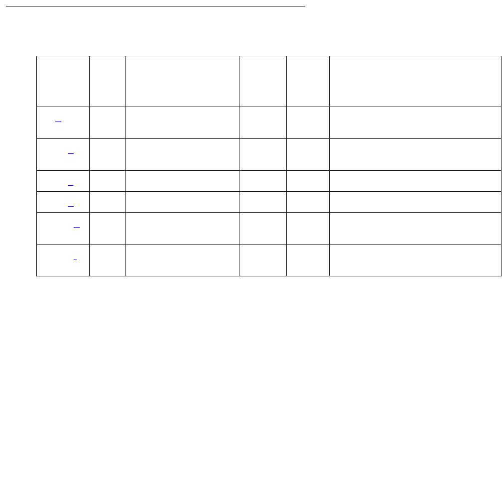
CAB-MTCE (Media Gateway Maintenance)
Issue 1 June 2005 745
When a TN2312BP IPSI is inserted in a G650, Communication Manager sends the following
messages to embedded software (firmware) on the board:
●Enable environmental maintenance
●Enable power supply insertion
●Enable power supply audits
●A query to verify that environmental maintenance is enabled
●A query to verify that power supply insertion is enabled
●A query to verify that power supply audits are enabled
Error log entries and test-to-clear values
Table 253: CAB-MTCE Error Log Entries
Notes:
a. Error Type 1—When a TN2312AP IPSI is inserted into a CMC1 or G650 Media Gateway a
minor alarm is raised. Full environmental maintenance is NOT available. Replace the
TN2312AP IPSI with a TN2312BP IPSI. NOTE: A TN2312AP inserted in a G600 media
gateway DOES not raise any alarm or error.
b. Error Type 257—This error indicates the inability to communicate with the TN2312BP IPSI
board. NOTE: The board must be a TN2312BP IPSI for this test to run.
c. Error Type 513—This error indicates that the op-code for messages received from the
TN2312BP was not equal to any known op-code. The unknown op-code is recorded under
Aux data.
Error
Type
Aux
data
Associated test Alarm
level
On/
Off
board
Test-to-clear value
1 (a) — Correct board test
(#1546)
MIN ON test maintenance
location
257 (b) — Sanity test (#1547) MIN ON test maintenance
location
513 (c)AnyAll NONE— —
769 (d)AnyAll NONE— —
1025 (e) — Reset test (#1545) MIN ON test maintenance
location
1281 (f) — Initialization test
(#1548)
MIN ON reset maintenance
location
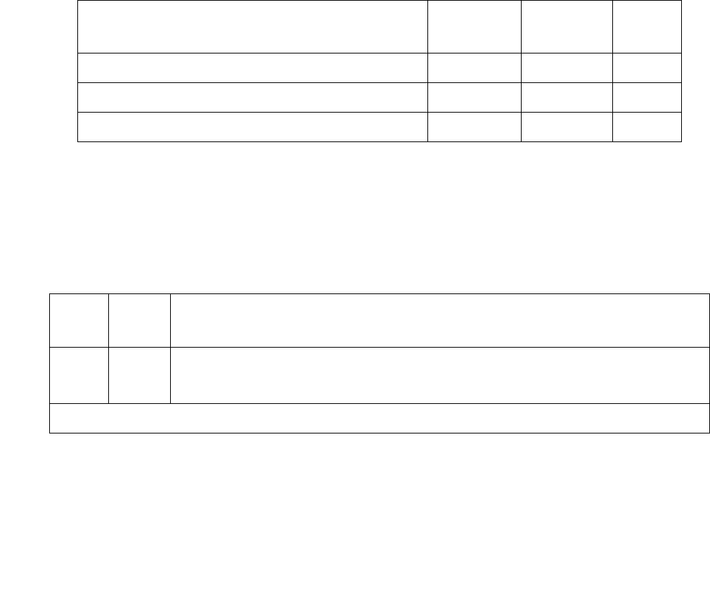
Communication Manager Maintenance-Object Repair Procedures
746 Maintenance Procedures for Avaya Communication Manager 3.0, Media Gateways and Servers
d. Error Type 769—This error indicates that a message with a valid op-code was received but
some other part of the message was indecipherable. The op-code with the error is recorded
under Aux data.
e. Error Type 1025—This error indicates that an unsuccessful attempt was made to reset
environmental maintenance.
f. Error Type 1281—This error indicates that environmental initialization failed. Run the Reset
Environmental Maintenance Test (#1545), which calls the Initialization Test (#1548).
System technician-demanded tests:
Descriptions and error codes
Investigate tests in the order presented. When you clear error codes associated with the
Correct Board Test (1546), you might also clear errors generated from other tests in the testing
sequence.
Reset Environmental Maintenance test (#1545)
This test resets the environmental maintenance on the TN2312BP IPSI board.
Order of investigation Short test
sequence
Long test
sequence
D/ND1
1. D = Destructive, ND = Nondestructive
Correct Board Test (#1546) X X ND
Sanity Test (#1547) X X ND
Reset Environmental Maintenance Test (#1545) — X D
Table 254: Test #1545 Reset test
Error
code
Test
result
Description and recommendation
1000 ABRT There is an internal software problem.
1. Repeat the command at one-minute intervals 1 to 3 times.
1 of 2

CAB-MTCE (Media Gateway Maintenance)
Issue 1 June 2005 747
1982 ABRT The board being tested is NOT a TN2312BP IPSI or later.
1. Insert a TN2312BP IPSI circuit pack.
1986 ABRT The TN2312BP IPSI failed to set emergency transfer to AUTO at
initialization.
1. Enter reset maintenance
2. If the reset maintenance command aborts again enter set emergency
command to see if emergency transfer can be activated or deactivated.
3. If the reset maintenance command continues to abort escalate the
problem.
2000 ABRT The response to a query was not received in the time allowed.
1. Run reset maintenance
2. Escalate the problem if the test continues to abort.
2500 ABRT An internal operation failed (Possible unknown cabinet type).
1. Repeat the command at one-minute intervals 1 to 3 times.
2. Escalate the problem if the test continues to abort.
1 FAIL The TN2312BP IPSI environmental maintenance initialization failed.
1. Repeat the command at one-minute intervals 1 to 3 times.
2 FAIL The TN2312BP IPSI failed a sanity test.
1. Run reset maint command.
2. If the problem persists, replace the circuit pack.
PASS Environmental maintenance has been enabled and passes a sanity test.
Table 254: Test #1545 Reset test (continued)
Error
code
Test
result
Description and recommendation
2 of 2

Communication Manager Maintenance-Object Repair Procedures
748 Maintenance Procedures for Avaya Communication Manager 3.0, Media Gateways and Servers
Correct Board test (#1546)
The TN2312BP IPSI board is required for the environmental functions to work in the G650
media gateway. This test verifies that the proper IPSI is inserted in the G650.
Sanity test (#1547)
The TN2312BP is queried to determine whether or not it can sustain basic sanity.
.
Table 255: Test #1546 Correct board test
Error
code
Test
result
Description and recommendation
2500 ABRT An internal operation failed.
1. Repeat the command at one-minute intervals 1 to 3 times.
1 FAIL For G650 or CMC1 media gateways: A TN2312AP IPSI has been inserted.
PASS For G600 media gateways: Either a TN2312AP or TN2312BP IPSI is present.
PASS For CMC1, G600, and G650 media gateways: A TN2312BP IPSI is present.
Table 256: Test #1547 Sanity test
Error
code
Test
result
Description and recommendation
1000 ABRT There is an internal system error.
1. Repeat the command at one-minute intervals 1 to 3 times.
1981 ABRT The TN2312BP IPSI is busied out.
1. Enter the release ipserver-interface command.
1982 ABRT The board being tested is NOT a TN2312BP IPSI or later.
1. Insert a TN2312BP IPSI circuit pack.
2033 ABRT There is an internal system error.
2500 ABRT An internal operation failed (Possible unknown cabinet type).
1. Repeat the command at one-minute intervals 1 to 3 times.
FAIL The TN2312BP in carrier A is missing. If an incorrect or no response from
firmware is received back when the board is queried, this test will also fail.
PASS The correct board is present and a valid response was received for a sanity
query.

CAB-PFL (Power Fan Lead)
Issue 1 June 2005 749
CAB-PFL (Power Fan Lead)
G650
The CAB-PFL represents the state of a combined power/fan lead. This lead is known as the
AuxSig lead. On a G650, the AuxSig output signal is a ground referenced relay contact closure
indicating a failure of the 655A power supply outputs, hot spot thermal warning, hot spot thermal
shutdown, or failure of the fan assembly in a G650.
Use the AuxSig lead to determine the alarm state of the power supplies and fans if the serial
bus or the interface to the serial bus of the TN2312BP IPSI in a G650 fails. If there is a
CAB-PFL alarm in a G650 carrier, there should also be a SER-BUS, POW-SUP, CAB-TEMP, or
PS-RGEN alarm indicating the source of the failure.
Refer to Figure 115: G650 Cabinet Environmental Hardware Components on page 1959 for
further information.
When the TN2312BP IPSI is used in a CMC1 or a G600 carrier, use the CAB-PFL MO to
determine the status of the power supply and fans, but the repair procedure should be the same
as that for RMC-ENV (Power/Fan Sensors) on page 1951.
Note:
Note: Fan/filter replacement procedures for the CMC1 and G600 media gateways are
to be found under Variable-speed fans in Maintenance Procedures (03-300192).
Error log entries and test-to-clear values
Note:
a. Error Type 1—The AuxSig lead is active. Run test environment location and follow
the repair steps for Test #1533.
MOs name (in
alarm log)
Alarm
level
Initial SAT command to run Full name of MO
CAB-PFL MIN test environment location Power Fan Lead
CAB-PFL MAJ test environment location Power Fan Lead
Table 257: CAB-PFL Error Log Entries
Error
Type
Aux
data
Associated test Alarm
level1
1. The alarm level of CAB-PFL is adjusted to be the same as the highest active alarm level for SER-BUS,
POW-SUP, CAB-TEMP, or PS-RGEN, or it will be a MAJOR alarm if no G650 alarms in that category are
found.
On/Off
board
Test-to-clear value
1 (a) Power/Fan lead query
test (#1533)
MAJ
MIN
OFF test environment
location

Communication Manager Maintenance-Object Repair Procedures
750 Maintenance Procedures for Avaya Communication Manager 3.0, Media Gateways and Servers
System technician-demanded tests:
Descriptions and error codes
S8700 | 8710
Power/Fan lead query test #(1533)
The Power/Fan Query test sends a request for the state of the power/fan lead (AuxSig) to the
TN2312BP IPSI board in the G650 with an A carrier address. If the lead is on, the test fails. If
the lead is off, the test passes.
Order of Investigation Short test
sequence
Long test
sequence
D/ND
Power/Fan lead query test (1533) X X Nondestructive
Table 258: Test 1533 Power/Fan lead query
Error
code
Test
result
Description and recommendation
1000 ABRT This is an internal system error.
1. Repeat the command at one-minute intervals 1 to 3 times.
2000 ABRT The response to a query was not received in the time allowed.
1. Repeat the command at one-minute intervals 1 to 3 times.
1FAIL
G650: In a G650 carrier, this indicates a failure in any of the following MOs:
●SER-BUS
●POW-SUP
●CAB-TEMP
●PS-RGEN
Use the diagnostic procedures for those MOs to clear the problem.
1 of 3

CAB-PFL (Power Fan Lead)
Issue 1 June 2005 751
1FAIL
(Cont)
G600 / CMC1
In a G600 or CMC1, this error code indicates a failure in either:
●Power supply
●Fan Assembly
There is a fan, temperature, power, or voltage problem in one or more of the
cabinets. The power supply’s LEDs may indicate the problem’s source.
1. If none of the fans are running, then:
a. Verify 8- to 14-Volt DC power is available to the fan units by checking
the wiring connector. If there is 8- to 14-Volt DC power at the
connector, there should be power to the fans. If the fans still do not
run, replace the fan assembly.
b. If not, then the power unit’s fan output is defective or thermally shut
down. Let the power unit cool, and recycle AC input power. If no fan
output, replace the power unit. If the fans still do not run, escalate
the problem.
2. If only 1 of the fans is not running, replace the fan.
3. If every fan can be started, wait 5 minutes and rerun the test. If the test
fails again, proceed to Step 4 or 5 as applicable.
4. If the fans are not at high speed, measure the cabinet’s temperature at
the air intake and the air exhaust at the top of the cabinet.
a. If the 5- to 600-C criteria is met, there is a problem with the fans that
is preventing the fans from operating at high speed. Replace the
fans. If the fans run at high speed, wait 5 minutes to give the cabinet
time to cool down and, rerun the test. If the problem persists, go to
step 5.
b. If not, the Processor circuit pack is incorrectly reporting this
condition. Look for and resolve every error on these MOs first, then
rerun the test.
Table 258: Test 1533 Power/Fan lead query (continued)
Error
code
Test
result
Description and recommendation
2 of 3

Communication Manager Maintenance-Object Repair Procedures
752 Maintenance Procedures for Avaya Communication Manager 3.0, Media Gateways and Servers
5. If the fans are running at high speed, check the items on following list.
Any one of these could be restricting or redirecting the cabinet’s air flow.
Check filter. If the filter is dirty or clogged it should be cleaned or
replaced. The filter can either be washed with soap and water or
vacuumed.
a. Verify that nothing other than circuit packs in the carrier slots that
could be restricting air flow.
b. Verify that no circuit-pack blanks or carrier faceplates are missing.
Install and/or replace them as necessary.
c. Be sure the cabinet’s doors are properly closed. The doors must be
closed to enable the fans to properly cool the cabinet. Wait 5
minutes to allow the fans to cool the cabinet. Rerun the test. If the
test still fails, proceed to 6.
6. At this point, there should be nothing impeding the air flow, and the fans
should be running at high speed. Check the temperatures for the 5- to
600-C criteria.
a. If the 5- to 600-C criteria exists, a temperature problem exists, and
the fans (at high speed) should cool down the switch. Wait 5
minutes, and rerun the test. If the test still fails, the ambient room
temperature is probably too high, and the room should be cooled.
b. If not, the fans are defective. Replace the fan assembly, and rerun
the test. Failures can occur on the Processor circuit pack that is not
detected by the respective MO, but that cause many, if not every,
environment test to fail. If many environment tests are failing, the
suspected circuit pack (depending on the system configuration)
should be replaced and the test rerun.
7. There is a problem with the environment of the power system:
8. The power unit for the cabinet may be defective.
a. Verify and, if necessary, replace the power unit.
b. Rerun the test. If the test still fails, escalate.
PASS This indicates that the power/fan lead is off and there are no failures in the
G650 or G650 stack.
Table 258: Test 1533 Power/Fan lead query (continued)
Error
code
Test
result
Description and recommendation
3 of 3

CAB-TEMP (Cabinet Temperature)
Issue 1 June 2005 753
CAB-TEMP (Cabinet Temperature)
G650
The MO CAB-TEMP monitors the G650 and the 655A for the following:
●The power supply
- Inlet temperature
- Hot spot temperature status
- Fan speed
- Fan alarm lead
●The G650 carrier exhaust temperature
The serial bus is used by the TN2312BP IPSI to obtain this information from each power supply
in a G650 media gateway. There is only one outlet temperature sensor and fan assembly in a
G650, so information obtained from dual power supplies (slot 0 and 15) is redundant.
Refer to Figure 115: G650 Cabinet Environmental Hardware Components on page 1959 for
further information.
Note:
Note: Fan/filter replacement procedures for the CMC1 and G600 media gateways are
to be found under Variable-speed fans in Maintenance Procedures (03-300192).
Error log entries and test-to-clear values
MO name (in
alarm log)
Alarm
level
Initial SAT command to
run
Full name of MO
CAB-TEMP MIN test board location Cabinet Temperature
CAB-TEMP MAJ test board location Cabinet Temperature
Table 259: CAB-TEMP Error Log Entries
Error
Type
Aux
data
Associated test Alarm
level
On/Off
board
Test-to-clear value
1 (a) Power supply
temperature test (#1537)
MIN OFF test enviroment location
test board location
257 (b) Power supply
temperature test (#1537)
MIN ON test enviroment location
test board location

Communication Manager Maintenance-Object Repair Procedures
754 Maintenance Procedures for Avaya Communication Manager 3.0, Media Gateways and Servers
Notes
a. Error Type 1: the inlet temperature is over the threshold—120o Fahrenheit (49o Celsius).
Run test board and check results of Test #1537.
b. Error Type 257: the exhaust temperature is over the threshold—120o Fahrenheit (49o
Celsius). Run test board and check results of Test #1537.
c. Error Type 513: the hot spot temperature is over the threshold. Run test board and
check results of Test #1537.
d. Error Type 769: the fan alarm is active. Run test board and check results of Test #1537.
System technician-demanded tests:
Descriptions and error codes
Investigate tests in the order presented
Power supply temperature test (#1537)
The power supply temperature test provides the status of the following temperatures:
●Inlet to the power supply (120F/49C)
●Carrier exhaust (120F/49C)
●Power supply hot spot status
513 (c) Power supply
temperature test (#1537)
MIN/
MAJ 1ON test enviroment location
test board location
769 (d) Power supply fan test
(#1538)
MIN ON test enviroment location
test board location
1. This is a minor alarm if there is a redundant power supply, and a major alarm if there is only one power
supply.
Table 259: CAB-TEMP Error Log Entries
Error
Type
Aux
data
Associated test Alarm
level
On/Off
board
Test-to-clear value
Order of investigation Short test
sequence
Long test
sequence
D/ND
Power supply temperature test (#1537) X X Nondestructive
Power supply fan test (#1538) X X Nondestructive

CAB-TEMP (Cabinet Temperature)
Issue 1 June 2005 755
Table 260: Test #1537 Power Supply Temperature
Error
code
Test
result
Description and recommendation
1000 ABRT There is an internal software error.
1. Repeat the command at one-minute intervals 1 to 3 times.
1035 ABRT The port network is not available.
1. Use status port-network to verify that the network is not up.
2. Look for alarms against EXP-PN, EXP-INT, PK-INT, etc.
3. Use diagnostic procedures for those MOs to clear the problem.
2028 ABRT There is a problem communicating with the environmental maintenance
firmware.
2100 ABRT The system could not allocate resources.
1. Repeat the command at one-minute intervals 1 to 3 times.
2319 ABRT The EPN is out of range.
2500 ABRT An internal operation failed.
1. Repeat the command at one-minute intervals 1 to 3 times.
1 FAIL The inlet temperature is over threshold.
1. Use test board location to check the temperature.
2. If redundant power supplies are present, there may be a problem with
the backplane. Verify that each power supply can detect the problem by
using recycle carrier, specifying the slot number of the power
supply to be shut down. Refer to the notes and cautions for this
command in Maintenance Commands Reference (03-300191) before
executing recycle carrier.
3. Replace the power supply.
4. If the problem persists, check the backplane for shorts.
1 of 2

Communication Manager Maintenance-Object Repair Procedures
756 Maintenance Procedures for Avaya Communication Manager 3.0, Media Gateways and Servers
2 FAIL The exhaust temperature is over threshold.
1. Use the test board location command to check the temperature.
2. If redundant power supplies are present, there may be a problem with
the backplane. Verify that each power supply can detect the problem by
using recycle carrier, specifying the slot number of the power
supply to be shut down. Refer to the notes and cautions for this
command in Maintenance Commands Reference (03-300191) before
executing recycle carrier.
3. Replace the power supply.
4. If the problem persists, check the backplane for shorts.
3 FAIL Both the inlet and the exhaust temperatures are over threshold.
1. Use the test board location command to check the temperature.
2. If redundant power supplies are present, there may be a problem with
the backplane. Verify that each power supply can detect the problem by
using recycle carrier, specifying the slot number of the power
supply to be shut down. Refer to the notes and cautions for this
command in Maintenance Commands Reference (03-300191) before
executing recycle carrier.
3. Replace the power supply.
If the problem persists, check the backplane for shorts.
4 FAIL There is a hot spot temperature warning.
8 FAIL There is a hot spot temperature shutdown.
PASS The inlet, exhaust, and hot spot temperatures are within limits.
NO
BOARD The power supply is administered but not detected.
1. Verify that the power supply is plugged in.
2. Replace the power supply.
Table 260: Test #1537 Power Supply Temperature (continued)
Error
code
Test
result
Description and recommendation
2 of 2

CAB-TEMP (Cabinet Temperature)
Issue 1 June 2005 757
Power supply fan test (#1538)
The power supply fan test verifies that the fan alarm lead from the fan assembly is not active.
Table 261: Test #1538 power supply fan
Error
code
Test
result
Description and recommendation
1000 ABRT This is an internal software error.
1035 ABRT The port network is not available.
2028 ABRT There is a problem communicating with the environmental maintenance
firmware.
2100 ABRT The system could not allocate resources.
1. Repeat the command at one-minute intervals 1 to 3 times.
2319 ABRT The EPN is out of range.
2500 ABRT An internal operation failed. Retry the command.
FAIL The fan alarm lead from the fan assembly is active.
1. Verify proper operation of the fan assembly.
2. Replace the fan assembly. See G650 fan removal/replacement in
Maintenance Procedures (03-300192).
PASS The fan alarm lead from the fan assembly is not active.
NO
BOARD The power supply is administered but not detected.
1. Verify that the power supply is plugged in.
2. Replace the power supply.

Communication Manager Maintenance-Object Repair Procedures
758 Maintenance Procedures for Avaya Communication Manager 3.0, Media Gateways and Servers
CABINET (Cabinet Sensors)
S8700 | 8710 / S8500
This maintenance object covers environmental maintenance for S8700, and S8500 media
servers equipped with multicarrier cabinets (MCCs), and for media servers equipped with
CMC1 or G600 carriers.
S8700 | 8710 / S8500
Note:
Note: The CABINET MO for S8700 and S8500 media servers is valid only for
multicarrier cabinets (MCCs). For information about environmental maintenance
on single-carrier cabinets (SCCs), see DC-POWER (Single-Carrier Cabinet
Environment) on page 880.
The cabinet sensors monitor cabinet temperature and fan rotation. Variable-speed fans are
used extensively in S8700 systems.
The Maintenance circuit pack in an MCC PN monitors a temperature sensor (S1) at the top of
the cabinet and generates a major alarm if the exit air temperature exceeds 65 degrees Celsius
(149 degrees Fahrenheit). Another temperature sensor in the top of the cabinet (S2) also
monitors exit air temperature. If it exceeds 70 degrees Celsius (158 degrees Fahrenheit), the
power-distribution unit turns off all cabinet power and invokes emergency transfer. Other
sensors monitor fan performance.
The repair procedures that follow rely on your ability to distinguish between high and low fan
speeds by the sound of the fans. Experience will allow you to distinguish between the high and
low pitches generated by high and low speeds. A thermometer is also required for some of the
procedures that follow.
In making replacements, observe the following rules:
●New fan assemblies accept only variable-speed fans.
●Old fan assemblies accept either variable- or constant-speed fans.
●Replace a fan assembly (carrier) only with a fan assembly of the same type (new for new,
old for old).
MO Name in Alarm Log Alarm
Level
Initial Command to Run Full Name of MO
CABINET MAJ test environment location Cabinet Sensors
CABINET MIN test environment location Cabinet Sensors

CABINET (Cabinet Sensors)
Issue 1 June 2005 759
Variable-Speed Fans
A variable-speed fan is identified by the following features:
●A fan and air filter assembly with product code ED-67077-30, Group 4 or greater, labeled
on the front of the carrier
●A 5-pin white connector mounted next to each fan on the fan assembly cover plate for
speed control and alarm circuitry
●A 2-pin black -48 V power connector to each fan
●A power filter (ED-1E554-30, G1 or G2) located in a metal box mounted behind the fans on
the right-hand cable trough as you face the rear of the cabinet
●The AHD1 circuit pack and the two S4 sensors used with older fan assemblies are absent.
Alarm leads from each fan are tied together into a single lead that registers a minor alarm
against CABINET whenever a fan’s speed drops below a preset limit or fails altogether.
Note:
Note: The front fans may run at a different speed than the rear fans since they are
controlled by different sensors.
Note:
Note: Fan/filter replacement procedures for the CMC1 and G600 media gateways are
to be found under Variable-speed fans Maintenance Procedures (03-300192).
Error Log Entries and Test to Clear Values
S8700 | 8710 / S8500
Table 262: S8700 | 8710 / S8500: Cabinet Sensors Error Log Entries
Error
Type
Aux
Data
Associated Test Alarm
Level
On/Off
Board
Test to Clear Value
0 0 Any Any Any test environment UU
1 0 or 1 Cabinet Temperature Query
(#122)
MIN ON test environment UU s r 3
257 0 or 1 Cabinet Temperature Query
(#122)
MAJ ON test environment UU s r 3
Communication Manager Maintenance-Object Repair Procedures
760 Maintenance Procedures for Avaya Communication Manager 3.0, Media Gateways and Servers
CMC1
Notes:
a. Error Type 0: Run the Short Test Sequence first. If all tests pass, run the Long Test
Sequence. Refer to the appropriate test description and follow the recommended
procedures.
b. Error Type 1: the Power/Fan Status lead indicates that the power supply of one or more
CMC1 cabinets has detected an alarm condition. The condition can be caused by the failure
of any fan or the failure of any power supply output. If more than one CMC1 cabinet exists,
all of the Power/Fan Status leads are tied together (the fan and power lead is an O-ring of all
cabinets’ status leads). Since an error condition on a fan or power supply output could be
the result of a temporary overload (e.g. during board insertion) or caused by the location of
the equipment (e.g. fan blockage), a single event may be an anomaly that eventually clears.
However, a repeating condition will cause a major alarm.
c. Error Type 257: temperature Sensor 1: Since temperature alarms can be transient, a single
event may be an anomaly that eventually clears. However, a repeating condition will cause
a major alarm and may indicate a need to replace one or more components (e.g. a Cabinet
Fan may be bad, or check to see if the equipment room air conditioning supply/unit is
functional).
d. Error Type 513: temperature Sensor 2: Since temperature alarms can be transient a single
event may be an anomaly that eventually clears. However, a repeating condition will cause
a major alarm and may indicate a need to replace one or more components (e.g. a Cabinet
Fan may be bad, or check to see if the equipment room air conditioning supply/unit is
functional).
Table 263: CMC1: Cabinet sensors error log entries
Error
Type
Aux
Data
Associated Test Alarm
Level
On/Off
Board
Test to Clear Value
0 (a)0Any AnyAnytest environment
1(b)
257 (c)
513 (d)
769 (e)
1025 (f)
1281 (g)
1537 (h)
1793 (i)
Any Cabinet
Temperature or
Voltage Query
Test (#122)
MAJ ON test environment

CABINET (Cabinet Sensors)
Issue 1 June 2005 761
Note:
Note: An out-of-tolerance voltage condition may be caused by transient conditions (e.g.
board insertion or electrical noise). Voltage problems can cause serious damage
to the TN2314 or highly unpredictable failure modes. Therefore, a repeating
condition will cause a major alarm. The following Error Types 769 through 1793
represents the various system voltages and are listed below:
e. Error Type 769: Out-Of-Tolerance voltage condition for -48 VDC.
f. Error Type: 1025: Out-Of-Tolerance voltage condition for -5 VDC.
g. Error Type: 1281: Out-Of-Tolerance voltage condition for +5 VDC.
h. Error Type: 1537: Out-Of-Tolerance voltage condition for +12 VDC.
i. Error Type: 1793: Out-Of-Tolerance voltage condition for +3.3 VDC.

Communication Manager Maintenance-Object Repair Procedures
762 Maintenance Procedures for Avaya Communication Manager 3.0, Media Gateways and Servers
System Technician-Demanded Tests:
Descriptions and Error Codes
S8700 | 8710 / S8500
Investigate tests in the order presented. By clearing error codes associated with one test, you
may clear errors generated from later tests in the sequence.
Order of Investigation Short Test
Sequence
Long Test
Sequence
D/ND1
1. D = Destructive; ND = Nondestructive
Battery & Battery Charger Query test (#5) X X ND
AC Power Query test (#78) See AC-POWER on
page 333
XXND
OLS Query test (carrier E) (#127)
See CARR-POW (Carrier Power Supply) on page 770
XXND
OLS Query test (carrier D) (#127)
See CARR-POW (Carrier Power Supply) on page 770
XXND
OLS Query test (carrier A) (#127)
See CARR-POW (Carrier Power Supply) on page 770
XXND
OLS Query test (carrier B) (#127)
See CARR-POW (Carrier Power Supply) on page 770
XXND
OLS Query test (carrier C) (#127)
See CARR-POW (Carrier Power Supply) on page 770
XXND
Emergency Transfer Query test (#124)
See EMG-XFER (Emergency Transfer) on page 1134
XXND
Cabinet Temperature Query test (#122)
See CABINET (Cabinet Sensors) on page 758
XXND
External Alarm Lead Query test (#120)
See EXT-DEV ADMIN? Y (External Device Alarm) on
page 1246
XXND
Analog Ring Generator Initial test (#117)
See RING-GEN (Analog Ring Generator) on page 1942
XXND
Analog Ring Generator Query test (#118)
See RING-GEN (Analog Ring Generator) on page 1942
XXND
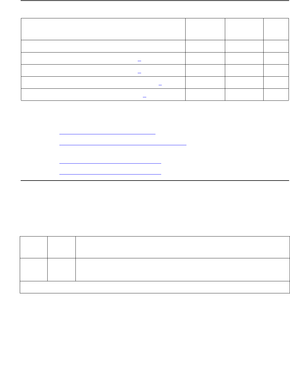
CABINET (Cabinet Sensors)
Issue 1 June 2005 763
CMC1
Notes:
a. Refer to EMG-XFER (Emergency Transfer) on page 1134 for a description of this test.
b. Refer to EXT-DEV ADMIN? N (External Device Alarm) on page 1243 for a description of
this test.
c. Refer to RING-GEN (Analog Ring Generator) on page 1942 for a description of this test.
d. Refer to RING-GEN (Analog Ring Generator) on page 1942 for a description of this test.
Cabinet Temperature Query Test (#122)
This test queries for the status of the temperature and fan sensors in the cabinet.
Order of Investigation Short Test
Sequence
Long Test
Sequence
D/ND1
1. D = Destructive; ND = Nondestructive
Cabinet Test (#122) X X ND
Emergency Transfer Query Test (#124) (a)XXND
External Alarm Lead Query Test (#120) (b)XXND
Analog Ring Generator Initialization Test (#117)(c)XXND
Analog Ring Generator Query Test (#118)(d)XXND
Table 264: Test #122 Cabinet Temperature Query Test
Error
Code
Test
Result
Description / Recommendation
1000 ABRT System resources required to run test are not available.
1. Retry the command at 1-minute intervals up to 5 times.
1 of 7

Communication Manager Maintenance-Object Repair Procedures
764 Maintenance Procedures for Avaya Communication Manager 3.0, Media Gateways and Servers
2000 ABRT Response to the test request was not received within the allowable time
period.
1. Retry the command at 1-minute intervals up to 5 times.
2. S8700 | 8710: If the test continues to abort with error code 2000, check
for power problems with the PN’s A carrier.
S8700 MC: Look for and resolve every AC-POWER and CARR-POW
alarm in a multicarrier cabinet or DC-POWER alarm in a single-carrier
cabinet.
S8700 IP:Look for and resolve every RMC-ENV alarm. Repeat the test.
3. S8700 MC: If the test continues to abort with error code 2000, check for
and resolve every MAINT error in a PN. Repeat the test.
2029
S8700 |
8710
S8500:23
19,
2500
ABRT Internal system error
1. Retry the command at 1-minute intervals up to 5 times.
Table 264: Test #122 Cabinet Temperature Query Test (continued)
Error
Code
Test
Result
Description / Recommendation
2 of 7

CABINET (Cabinet Sensors)
Issue 1 June 2005 765
S8700 |
8710
S8500:1
FAIL VARIABLE-SPEED FAN ASSEMBLIES: One or more fans have stopped.
If none of the fans are running:
1. Resolve every alarm against CARR-POW (Carrier Power Supply) on
page 770.
S8700 IP Resolve every alarm against RMC-ENV.
2. Verify that 48 VDC is available to the fan power filter at the J2F local
cable connector. The voltage range is -42.5 V to -52.5 V. There should
be 48 VDC between the following pin pairs: 2/3, 8/9, 10/11. If -48 VDC
is absent, replace the CFY1B current limiter card.
3. If there are 48 VDC at the power filter’s input, follow this procedure to
verify that there are also 48 VDC at the power filter’s output to avoid
damage to the fan alarm circuit. (Note that the J2F/P2F connectors on
the power filter must be disconnected whenever connecting or
disconnecting the J2/P2 connectors on the fan assembly.
a. Disconnect connector J2F from P2F on the top of the filter.
b. Disconnect J2 from P2 on the fan assembly.
c. Reconnect J2F to P2F on the filter. (There should be 48 VDC
between the following pin pairs on the J2 connector: 2/3, 8/9, 10/11.)
d. If 48 VDC is present, the fans should have power. Make sure every
power connector is sound and making good contact. (Be sure to
disconnect the J2F/P2F connector again before reconnecting the
J2/P2.)
e. If not, replace the fan power filter using the previous procedure
described. (Be sure to disconnect the J2F/P2F connector again
before reconnecting the J2/P2.)
Table 264: Test #122 Cabinet Temperature Query Test (continued)
Error
Code
Test
Result
Description / Recommendation
3 of 7

Communication Manager Maintenance-Object Repair Procedures
766 Maintenance Procedures for Avaya Communication Manager 3.0, Media Gateways and Servers
S8700 |
8710
S8500:1
(cont’d)
FAIL
(cont’d)
If some of the fans are running and some are not:
1. Replace the defective fans. If every fan can then be started, wait 5
minutes and rerun the test. If the test fails again, proceed to the next
step.
2. Remove all six white 5-pin connectors on the front and back of the fan
assembly. This will cause every fan to run at high speed and the alarm
to be cleared.
S8700 MC: If the alarm does not clear, a PN’s Maintenance circuit pack
is incorrectly reporting the problem. Check for and resolve every error
against MAINT, and then rerun the test.
3. One at a time, replace the 5-pin connectors and check to see if the
alarm recurs. Replace each fan whose reconnection causes a
recurrence of the alarm.
Table 264: Test #122 Cabinet Temperature Query Test (continued)
Error
Code
Test
Result
Description / Recommendation
4 of 7

CABINET (Cabinet Sensors)
Issue 1 June 2005 767
S8700 |
8710
S8500:1
(cont’d)
FAIL
(cont’d)
NONVARIABLE-SPEEDFAN ASSEMBLIES (older or upgraded cabinets):
The AHD1 circuit pack has reported an air-flow problem. The temperature
difference between the air intake and the air exhaust is at least 150C
(590F)) and the absolute temperature at the top of the cabinet is at least
500C (1220F). The fans should be running at high speed. If none of the
fans are running then:
1. Look for an resolve every alarm against CARR-POW.
S8700 IP Look for an resolve every alarm against RMC-ENV.
2. Verify that 48 VDC is available to the fan wiring harness connector
between pin pairs 2/3, 8/9, and 10/11. The tolerable range for this
measurement is -42.5 V to -52.5 V.
If 48 VDC is present and the fans are not running, replace the AHD1
circuit pack.
3. If the fans still do not run, escalate the problem.
4. If 48 VDC is absent, replace the CFY1B current limiter card.
If the fans still do not run, escalate the problem.
If some fans are running and some not, replace the defective fans.
5. If every fan can then be started, wait 5 minutes, and rerun the test. If
the test fails again, proceed to the next step.
6. If every fan is running but not at high speed, measure the cabinet
temperature at the air intake and the air exhaust at the top of the
cabinet.
a. If the 150-/500-C criteria is met, there is a problem with the AHD1
circuit pack or the fans. Replace the AHD1 circuit pack and/or fans.
If the fans run at high speed, wait 5 minutes for the cabinet to cool,
then retest. If the test fails, escalate the problem.
b. If the 150-/500-C criteria is not met, then environmental maintenance
is incorrectly reporting this condition. Resolve every error (S8700
MC: MAINT) and retest. If the test fails, escalate the problem.
Table 264: Test #122 Cabinet Temperature Query Test (continued)
Error
Code
Test
Result
Description / Recommendation
5 of 7

Communication Manager Maintenance-Object Repair Procedures
768 Maintenance Procedures for Avaya Communication Manager 3.0, Media Gateways and Servers
S8700 |
8710
S8500:1
(cont’d)
FAIL
(cont’d)
NONVARIABLE-SPEEDFAN ASSEMBLIES (cont’d): If the fans are
running at high speed, check the following items, any of which can restrict
or redirect airflow within the cabinet.
1. Check both filters. If a filter is dirty or clogged, clean with soapy water
or a vacuum.
2. Ensure that there is nothing other than circuit packs in the carrier slots
that could be restricting the airflow.
3. Ensure that there are no missing circuit-pack faceplates or blanks.
4. The cabinet door must be closed for proper cooling.
5. Wait 5 minutes for the cabinet to cool and rerun the test.
6. If the test fails, check temperatures for the 150-/500-C criteria. If the
150-/500-C criteria is present, then the fans should be running at high
speed.
7. Wait 5 minutes, and rerun the test.
8. If the test still fails, then the ambient room temperature is probably too
high. Cool the room.
9. If the 150-/500-C criteria does not exist, one of the following
components if defective:
●AHD1 circuit pack
●fans
●S3 sensors
●S4 sensors
Replace these items one at a time in the order listed, running the test
after each replacement.
S8700 MC: If many environmental tests are failing, it can be a problem
that is undetected by maintenance on a PN’s Maintenance circuit pack.
Replace the circuit pack.
Escalate if the problem persists.
Table 264: Test #122 Cabinet Temperature Query Test (continued)
Error
Code
Test
Result
Description / Recommendation
6 of 7

CABINET (Cabinet Sensors)
Issue 1 June 2005 769
S8700 |
8710
S8500:2
FAIL A temperature problem due to the S1 sensor detecting a temperature of at
least 650 C (1490 F) has been reported. The entire cabinet is in danger of
power-down if the temperature reaches 700 C (1580 F).
1. If any of the fans are not running, there should be a FAIL with Error
Code 1 present. Follow the procedures for that Error Code, noting the
differences for variable- and constant-speed fan assemblies.
2. If the fans are running, check the temperature at the top of the cabinet.
a. If the temperature is at least 650 C (1490 F), the ambient room
temperature is too high and the fans cannot cool the system.
Unless the room temperature is reduced, the system will shut down
soon.
3. If the temperature at the top of the cabinet is less than 650 C (1490F),
the S1 sensor, or a PN’s Maintenance circuit pack is incorrectly
reporting the problem.
a. Resolve any errors against the S1 sensor or against MAINT), then
rerun the test.
b. If there are still errors, replace the S1 sensor and retest. If the test
fails, escalate.
S8700 |
8710
S8500:3
FAIL Fan failures and temperature alarms have been reported.
1. Resolve the fan failure (Error Code 1). This should also resolve the
temperature alarm. (With constant-speed fan assemblies, fan failures
correspond to air-flow problems.)
PASS Temperature measurements and fan performance are satisfactory.
Table 264: Test #122 Cabinet Temperature Query Test (continued)
Error
Code
Test
Result
Description / Recommendation
7 of 7

Communication Manager Maintenance-Object Repair Procedures
770 Maintenance Procedures for Avaya Communication Manager 3.0, Media Gateways and Servers
CARR-POW (Carrier Power Supply)
S8700 MC
S8700 Multi-Connect systems support two different cabinet types for PNs. Both cabinet types
may be powered by either AC or DC external power source. Environmental maintenance differs
according to cabinet type and external power supply.
!CAUTION:
CAUTION: Before powering down a cabinet or carrier that contains EMBEDDED AUDIX
circuit packs (TN566), first power down the AUDIX unit to avoid damaging the
AUDIX software. Instructions for powering down this unit are in the Removing
and restoring EMBEDDED AUDIX power in Chapter 4: General troubleshooting
in Maintenance Procedures (03-300192) on the circuit pack, and in DEFINITY
AUDIX System Release 3.2.4 Maintenance, 585-300-110.
The CARR-POW MO represents the pair of power supplies that supply +5V, -48V and -5 VDC
power to each carrier in a multicarrier cabinet. In AC-powered cabinets, these are called Off
Line Switches (OLS); in DC-powered cabinets, they are DC/DC converters.
MO Name in
Alarm Log
Alarm
Level
Initial Command to Run Full Name of MO
CARR-POW MAJ recycle carrier location Carrier Port Power Supply

CARR-POW (Carrier Power Supply)
Issue 1 June 2005 771
Cycling Power Supplies
When a port carrier power supply problem is reported by hardware, the system can cycle the
power supplies in that carrier. When a carrier is cycled, the power supplies are turned off for 2
seconds and then turned back on. The system cannot cycle the power supplies on any of the
following types carriers even if they are duplicated:
●Expansion control carrier
●Switch node carrier
●Single-carrier cabinet
!WARNING:
WARNING: When port carrier power is cycled, all service dependent upon circuit packs in
that carrier is disrupted.
Table 265: Carrier Port Power Supplies for Multicarrier Cabinets
Code System
Power
Output (VDC) Location
631DA AC +5 Left side
631DB AC -48/-5 Right side
644A DC +5 Left side
645B DC -48/-5 Right Side
TN755B 165 Slots 17 and 18
631WA/AR AC +5 Left side
631WB/BR AC -48 Right side
TN736 AC -5 Used with 631
TN752 AC 165/-5 WA/WB or AR/AB
649A AC -48 at 10 Amps
+5 VDC and -5 VDC at 6 Amps
Right side on control and port
carriers. Left and right side on
switch node carriers.
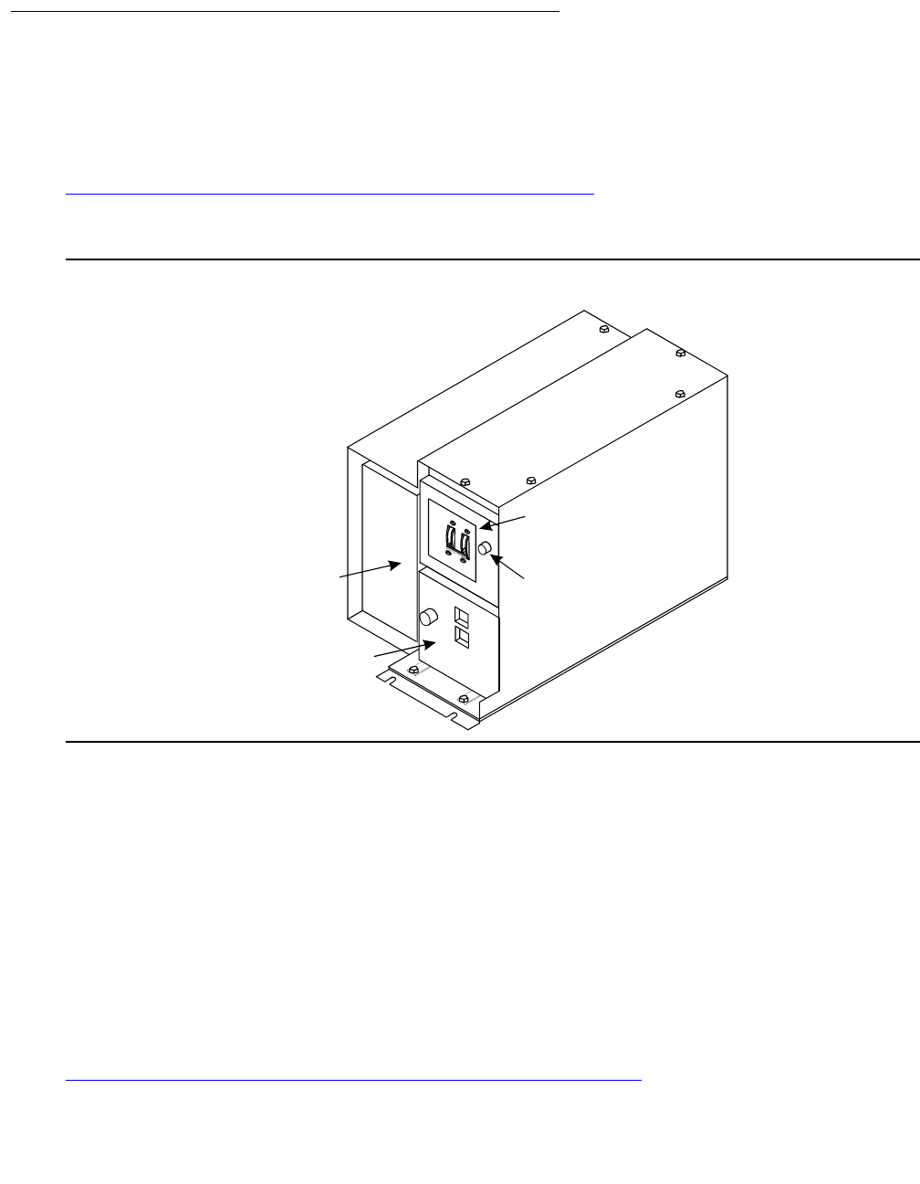
Communication Manager Maintenance-Object Repair Procedures
772 Maintenance Procedures for Avaya Communication Manager 3.0, Media Gateways and Servers
AC-Powered Cabinets
AC Power-Distribution Unit and Battery
Charger (J58890CE-2)
Figure 37: AC Power-Distribution Unit (J58890CE-2): Front on page 772 shows an AC
power-distribution unit (List 9 or List 10). This unit sits at the bottom of some multicarrier
cabinets.
Figure 37: AC Power-Distribution Unit (J58890CE-2): Front
The AC power-distribution unit contains the following components:
●Circuit breaker
●Electromagnetic Interference (EMI) filter
●Ring generator
●AC input fuse
●20-Amp fuses
●Signal connector
●-48 VDC fan power
The optional battery charger (List 11) sits at the bottom of some multicarrier cabinets. See
Figure 38: Battery Charger (Optional Part of J58890CE-2): Front on page 773.
j58890ce RBP 031996
Circuit
Breakers
Ring
Generator
631DB
Power Unit
Ring Generator
Fuse
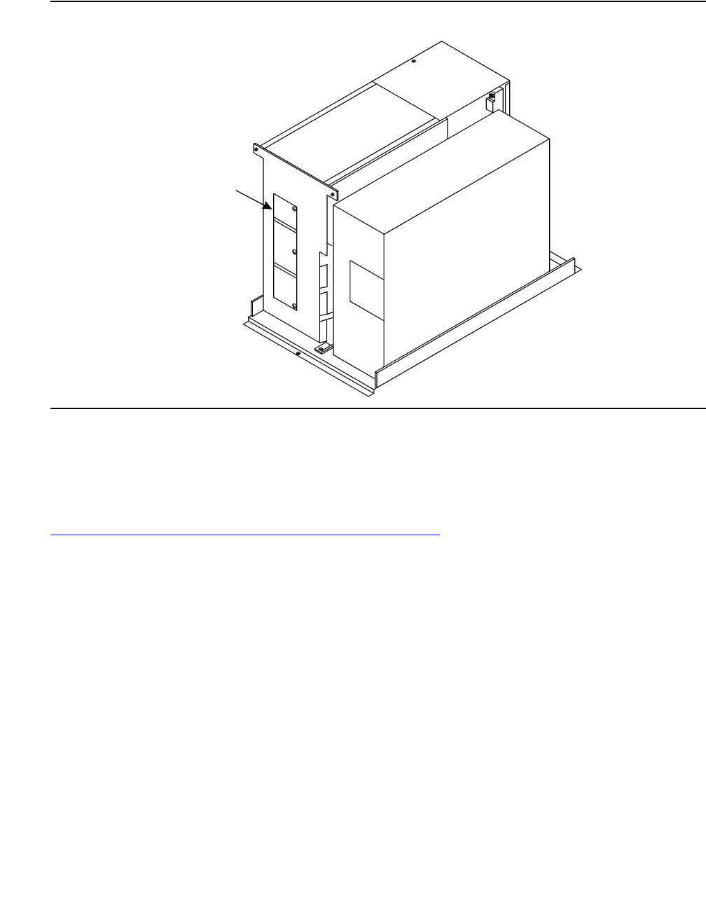
CARR-POW (Carrier Power Supply)
Issue 1 June 2005 773
Figure 38: Battery Charger (Optional Part of J58890CE-2): Front
The charger is used only without an uninterruptible power supply (UPS). The charger contains:
●Three 48 VDC batteries for backup power to the cabinet
●A DC power relay to automatically switch the batteries into the power circuit if a main
power failure is detected
Figure 39: AC Power Distribution in Multicarrier Cabinets on page 774 shows AC power
distribution in some multicarrier cabinets. The DC power-distribution cables are on both sides
of the cabinet. These cables supply power to each of the carriers. The optional battery
charger is at the right side of the power-distribution unit.
Batteries
Battery
Charger
battchar RBP 031996
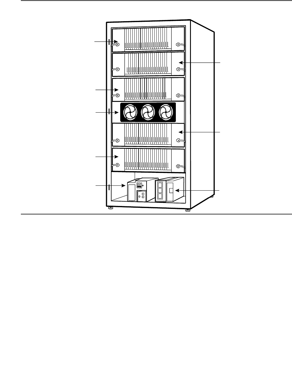
Communication Manager Maintenance-Object Repair Procedures
774 Maintenance Procedures for Avaya Communication Manager 3.0, Media Gateways and Servers
Figure 39: AC Power Distribution in Multicarrier Cabinets
Power Backup
If AC power fails, three 48-V DC batteries power the system for:
●15 seconds in a PN cabinet
●10 minutes in the expansion control carrier in the “A” position of a PN cabinet
Uninterruptible Power Supply
An external UPS provides a longer backup time than holdover batteries and can replace the
batteries and battery charger. The unit connects from the AC power source to a cabinet’s AC
power cord. If AC power fails, the unit supplies its own AC power to the cabinet.
3
2
"C" Position
Carrier
"B" Position
Carrier
"A" Position
Carrier
"D" Position
Carrier
Battery
Charger
(Optional)
"E" Position
Carrier
"F" Position
Fan Unit
Power
Distribution
Unit
mcc4_g3 RBP 041696
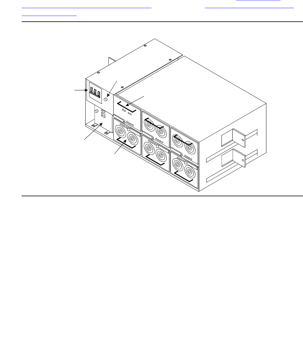
CARR-POW (Carrier Power Supply)
Issue 1 June 2005 775
J58890CH-1
In AC-powered cabinets, the power-distribution unit (J58890CH-1), distributes 170 to 264 VAC
from a wall outlet to a set of BU3200A Battery Interface Units (BIU). See Figure 40: AC
Power-Distribution Unit (J58890CH-1): Front on page 775 and Figure 41: Power-Distribution
Unit (J58890CH-1) on page 776.
Figure 40: AC Power-Distribution Unit (J58890CH-1): Front
Circuit
Breakers
Rectifier
Modules
Ring
Generator
Ring Generator
Fuse
Battery
Interface
Unit
j58890ch RBP 071596
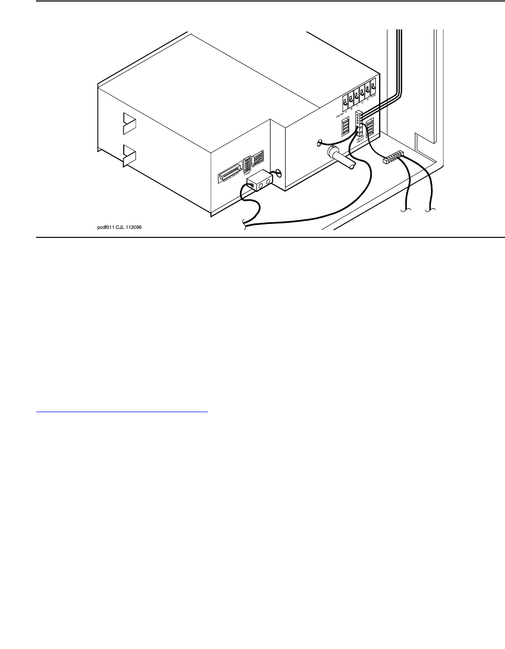
Communication Manager Maintenance-Object Repair Procedures
776 Maintenance Procedures for Avaya Communication Manager 3.0, Media Gateways and Servers
Figure 41: Power-Distribution Unit (J58890CH-1)
Power Backup
The small battery is at the center rear of the multicarrier cabinet. This 8-AH (Amp Hour) battery
is fused for short circuit protection and is charged by the J58890CH-1. The batteries also
contain a thermal sensor that changes the charging voltage depending on battery temperature.
The small batteries provide short-term battery holdover. If AC power fails, 48-V DC batteries
power the system for:
●15 seconds in a PN cabinet
●10 minutes in the expansion control carrier in the “A” position of a PN cabinet
Figure 42: Small Battery Assembly on page 777 shows the small battery assembly.
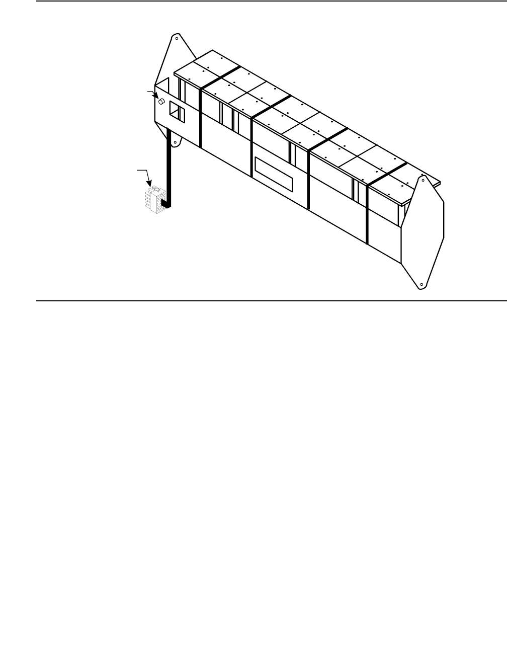
CARR-POW (Carrier Power Supply)
Issue 1 June 2005 777
Figure 42: Small Battery Assembly
0064
_
0 RBP 071596
Fuse
Battery
Connector
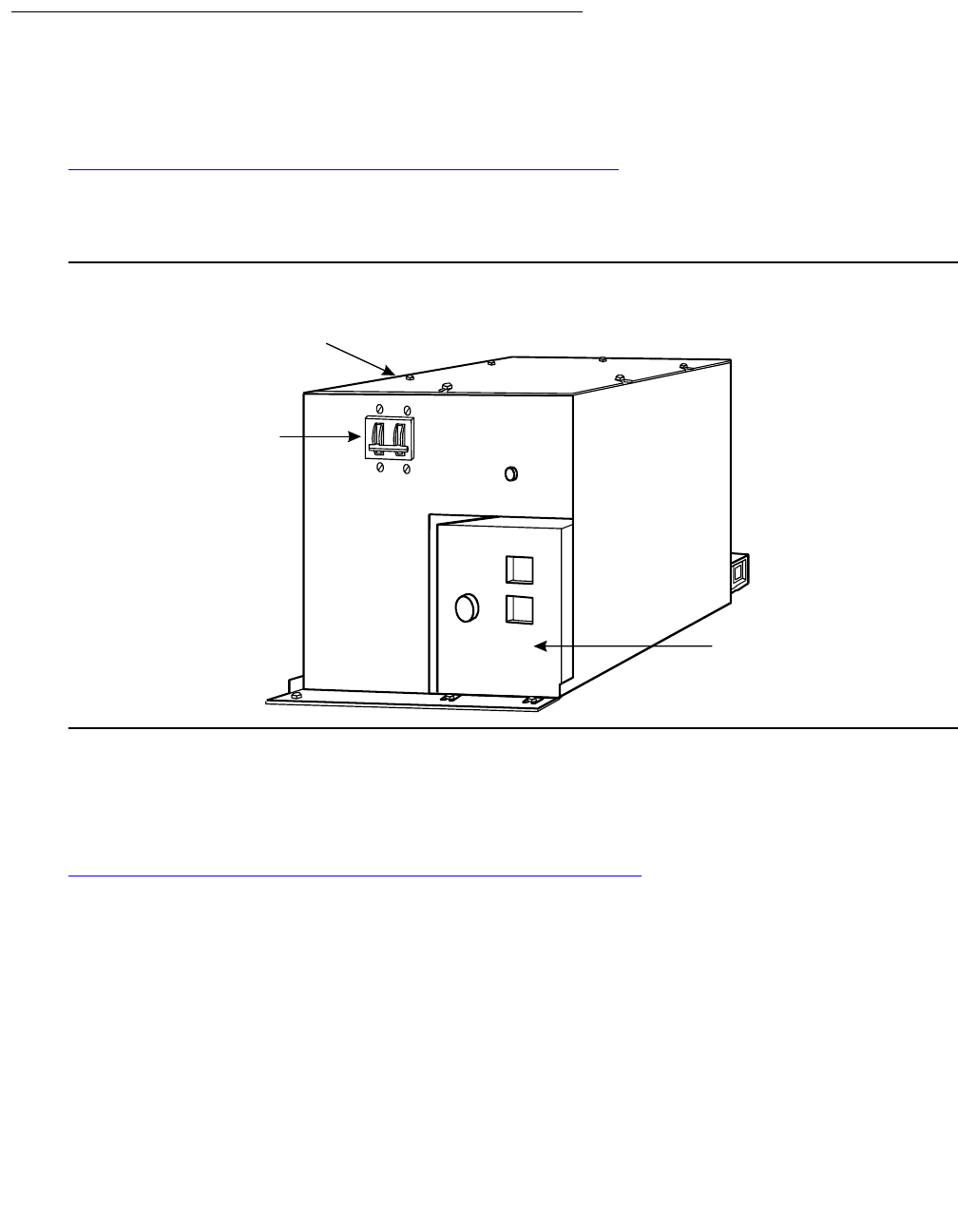
Communication Manager Maintenance-Object Repair Procedures
778 Maintenance Procedures for Avaya Communication Manager 3.0, Media Gateways and Servers
DC-Powered Cabinets
DC Power-Distribution Unit (J58890CF-2)
Figure 43: DC Power-Distribution Unit (J58890CF-2): Front on page 778 shows a
power-distribution unit in some DC-powered multicarrier cabinets. The unit sits at the bottom of
the cabinet and contains the ring generator, 20-Amp circuit breakers, terminal blocks, and
system fan power.
Figure 43: DC Power-Distribution Unit (J58890CF-2): Front
Some carriers may contain two power supplies, the 644A and the 645B, that together supply the
required voltages to the carrier. Other carriers may contain one 649A power supply located on
the right side of the carrier. In these systems, an additional 649A is located on the right of the
optional switch node carriers.
Figure 44: Typical Multicarrier Cabinet with 649A Power Units on page 779 shows a typical
AC-powered multicarrier cabinet.
4
2
Circuit
Breakers
D
C
Power
Distribution
Unit
Ring
Generator
Termina
l
Block
mcc_dc_1 PDH 062696
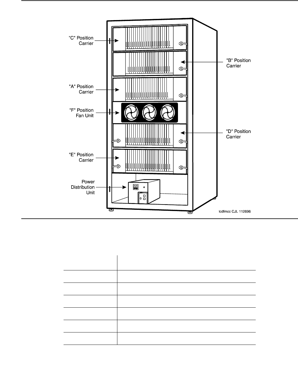
CARR-POW (Carrier Power Supply)
Issue 1 June 2005 779
Figure 44: Typical Multicarrier Cabinet with 649A Power Units
The table below shows what carriers are protected by each circuit breaker on the J58890CF-1.
The ring generator is protected by a fuse located next to the main circuit breaker on the front of
the unit.
Circuit Breaker Associated Carriers
CB1 Carrier A, both sides
CB2 Carrier B, both sides
CB3 Carrier C, both sides
CB4 Carrier D, both sides
CB5 Carrier E, both sides
CB6 Level F (Fans) and Level G (Ring Generator)

Communication Manager Maintenance-Object Repair Procedures
780 Maintenance Procedures for Avaya Communication Manager 3.0, Media Gateways and Servers
The table below shows what carriers are protected by each circuit breaker on the J58890CH-1.
The ring generator is protected by a fuse located next to the main circuit breaker on the front of
the unit.
Neon Lamp Power
The system can also support neon message waiting lamps on analog telephones. Any carrier
containing a TN769 Neon Analog Line circuit packs must also be supplied with 150 Volts from a
TN755B power supply circuit pack. See the table above for other supported neon power circuit
packs.
Error Log Entries and Test to Clear Values
!WARNING:
WARNING: The OLS Recycle test (#126) is destructive. For more information, see OLS
Recycle Test (#126) on page 782.
Circuit Breaker Associated Carriers
CB1 Carrier A, both sides
CB2 Carrier B, both sides
CB3 Carrier C, both sides
CB4 Carrier D, both sides
CB5 Carrier E, both sides
CB6 Level F (Fans) and Level G (Ring Generator)
Table 266: Carrier Port Power Supply Error Log Entries
Error
Type
Aux
Data
Associated Test Alarm
Level
On/Off
Board
Test to Clear Value
11
1. Run the OLS Query test (#127) using test environment UU r 2. If a carrier must be recycled to clear the
CARR-POW alarm, use recycle carrier UUC to run the OLS Recycle test (#126). The OLS Recycle test
(#126) is not included in either the long or short test sequences.
0 or 1 OLS Query test (#127) MAJ ON test environment UU r 2
recycle carrier UUC

CARR-POW (Carrier Power Supply)
Issue 1 June 2005 781
System Technician-Demanded Tests:
Descriptions and Error Codes
Investigate tests in the order presented. By clearing error codes associated with the Battery &
Battery Charger Query test (#5), you may also clear errors generated from other tests in the
sequence.
Notes:
a. Refer to POWER section for a description of this test.
b. Refer to AC-POWER section for a description of this test.
c. Refer to EMG-XFER (Emergency Transfer) section for a description of this test.
d. Refer to CABINET (Cabinet Sensors) section for a description of this test.
e. Refer to EXT-DEV (External device alarm) section for a description of this test.
f. Refer to RING-GEN (Analog Ring Generator) section for a description of this test.
Order of Investigation Short Test
Sequence
Long Test
Sequence
D/ND1
1. D = Destructive; ND = Nondestructive
Battery & Battery Charger Query test (#5) (a)XXND
AC Power Query test (#78) (b)XXND
OLS Query test (carrier E) (#127) X X ND
OLS Query test (carrier D) (#127) X X ND
OLS Query test (carrier A) (#127) X X ND
OLS Query test (carrier B) (#127) X X ND
OLS Query test (carrier C) (#127) X X ND
OLS Recycle Carrier test (#126) D
Emergency Transfer Query test (#124) (c)XXND
Cabinet Temperature Query test (#122) (d)XXND
External Alarm Lead Query test (#120) (e)XXND
Analog Ring Generator Initialization test (#117) (f)XXND
Analog Ring Generator Query test (#118) (f)XXND

Communication Manager Maintenance-Object Repair Procedures
782 Maintenance Procedures for Avaya Communication Manager 3.0, Media Gateways and Servers
OLS Recycle Test (#126)
This test is destructive.
This test removes power from the specified carrier and causes every circuit pack in the recycled
carrier to be removed and inserted. These actions cause every call originating from or
terminating to circuit packs in this carrier to be dropped. The pair of OLSs in the specified
carrier is recycled. Both OLSs in the carrier are turned off for 2 seconds and then back on
again. After the OLSs have been turned back on, the test queries a PN’s Maintenance circuit
pack for the status of the pair of OLSs in the specified carrier. If both OLSs are on and
functioning, then the test passes. If both OLSs are not on and functioning, the test fails, and
BOTH OLSs are turned off.
Table 267: Test #126 OLS Recycle Test
Error
Code
Test
Result
Description / Recommendation
1000 ABRT System resources required for this test are not available.
1. Retry the command at 1-minute intervals up to 5 times.
1366 ABRT Indicates that the active Tone-Clock for the PN is in requested carrier.
1. If duplicated Tone-Clock boards or IPSIs exist, useset tone-clock
to switch Tone-Clocks, otherwise the power cannot be cycled.
2. If the switch succeeds, rerun the test.
1367 ABRT Indicates that the active Expansion Interface link for the PN is in requested
carrier.
1. If duplicated EIs exist, use reset pnc interchange to switch EIs,
otherwise the power cannot be cycled.
2. If the switch succeeds, rerun the test.
2000 ABRT Response to the test request was not received within the allowable time
period.
1. Retry the command at 1-minute intervals up to 5 times.
2029,
2319,
2320,
2500
ABRT Internal system error
1. Retry the command at 1-minute intervals up to 5 times.
1 of 2

CARR-POW (Carrier Power Supply)
Issue 1 June 2005 783
Off-Line Switcher (OLS) Query Test (#127)
This test queries the the PN’s Maintenance for the status of the pair of OLSs in the specified
carrier. If both OLSs are on and functioning, then the test passes. If both are not on and
functioning, it fails.
FAIL There is a problem with one or both OLSs on the cycled carrier.
1. Since the OLS Recycle test failed, both OLSs in the cycled carrier
should have been powered off by the system software. Both OLSs
should be showing a red status LED, instead of an amber one. Since
the OLS Query test is a subset of the OLS Recycle test, the OLS
Query test (#127) should also fail. Run the OLS Query test by using
test environment UU where UU is the appropriate cabinet number.
2. If Test #127 fails, follow the repair procedures described for Test #127.
PASS Both OLSs in the recycled carrier were found to be healthy by a PN’s
Maintenance circuit pack after the OLSs were powered down and back up.
If the status LEDs on both OLSs are not showing amber, then the MAINT
(Maintenance) circuit pack may have incorrectly reported the state of the
OLSs. Resolve any alarms on these MOs.
Table 267: Test #126 OLS Recycle Test (continued)
Error
Code
Test
Result
Description / Recommendation
2 of 2
Table 268: Test #127 OLS Query Test
Error
Code
Test
Result
Description / Recommendation
1000 ABRT System resources required for this test are not available.
1. Retry the command at 1-minute intervals up to 5 times.
1 of 5

Communication Manager Maintenance-Object Repair Procedures
784 Maintenance Procedures for Avaya Communication Manager 3.0, Media Gateways and Servers
2000 ABRT Response to the test request was not received within the allowable time
period.
1. Retry the command at 1-minute intervals up to 5 times.
2. If the test continues to ABORT with error code 2000, check for system
powering problems with the PN’s A carrier. Resolve every
AC-POWER and CARR-POW alarm in a multicarrier-cabinet system or
DC-POWER alarm in a single-carrier cabinet system. Then, repeat the
test.
3. If the test continues to ABORT with a 2000 error code, resolve any
errors against the PN’s MAINT (Maintenance circuit pack). Then,
repeat the test.
2029,
2500
ABRT Internal system error
1. Retry the command at 1-minute intervals up to 5 times.
FAIL AC-POWERED SYSTEMS
There is a problem with one or both OLSs on the tested carrier.
1. For each OLS that has every status LED OFF, check the AC input to
the OLS at the OLS outlet. If there is no AC, then check the
appropriate fuses for the affected OLS. Replace open fuses. If the
fuses open again or AC does not show up at the OLS outlet, then there
is probably a power wiring problem in the cabinet.
2. At this point, AC should be present at the OLS outlet. Use recycle
carrier UUC (where UUC is the appropriate cabinet and carrier) in
an attempt to bring back the OLSs for this carrier. If the test passes,
the trouble is cleared. If the test does not pass, one OLS or both, in
the tested carrier is defective. If only one OLS is defective, then the
status LEDs on the healthy OLS will light green for a moment. When
the recycle test determines that both OLSs are defective, the software
will turn off power to both the good and defective OLSs. This will
cause the status LED(s) on the good OLS to light red.
3. Unplug both OLSs, and wait approximately 1-minute to allow the OLSs
to cool down. Plug in the OLSs. If either OLS is operating properly
(the status LEDs show green), then replace the defective OLS(s). See
OLS Replacement Procedures in this section.
Table 268: Test #127 OLS Query Test (continued)
Error
Code
Test
Result
Description / Recommendation
2 of 5

CARR-POW (Carrier Power Supply)
Issue 1 June 2005 785
FAIL
(cont’d)
4. If the replaced OLS(s) still do not operate properly, then a circuit pack
or a defective telephone connected to a circuit pack in the affected
carrier could be causing an electrical load that is preventing the OLS
from operating properly. Unseat every circuit pack in the carrier, and
enter recycle carrier.
a. If the recycle passes, then the OLSs are healthy, and the problem is
with one of the circuit packs. Reinsert the circuit packs one at a
time. If the status LED shows red after reinserting a circuit pack,
then replace the defective circuit pack. If the status LED still shows
red, then remove the amphenol connector on the back of the slot
containing this circuit pack and enter recycle carrier. If the
status LED shows green, then the problem is with one of the
telephones or the wiring to one of the telephones on this slot.
b. If either OLS still shows a red status LED, then check for bent pins
and cable placement in the affected carrier. There are failures that
can occur on the PN’s Maintenance circuit pack that will not be
detected by their respective maintenance, but that will cause many,
if not every, environment test to fail. If many environment tests are
failing, the suspect circuit pack, depending on the system
configuration, should be replaced and the test rerun.
Table 268: Test #127 OLS Query Test (continued)
Error
Code
Test
Result
Description / Recommendation
3 of 5

Communication Manager Maintenance-Object Repair Procedures
786 Maintenance Procedures for Avaya Communication Manager 3.0, Media Gateways and Servers
FAIL DC-POWERED SYSTEMS
There is a problem with one or both port carrier power supplies on the
tested carrier.
1. For each port carrier power supply that has every status LED OFF,
check the DC input to the port carrier power supply at the port carrier
power supply outlet. If there is no DC, then check the appropriate
circuit breakers for the affected port carrier power supply. If the circuit
breaker has tripped, reset the circuit breaker. If the circuit breaker trips
again or if DC is absent at the port carrier’s power supply outlet, then
there is probably a power wiring problem in the cabinet.
2. At this point, DC should be present at the port carrier power supply
outlet. Use recycle carrier UUC where UUC is the appropriate
cabinet and carrier, to attempt to bring back the port carrier power
supplies for this carrier. If the test passes, the trouble is cleared. If the
test does not pass, one port carrier power supply, or both, in the tested
carrier is defective. If only one port carrier power supply is defective,
then the status LEDs on the healthy port carrier power supply will light
green for a moment. When the recycle test determines that both port
carrier power supplies are defective, the software will turn off power to
both the good and defective port carrier power supplies. This will
cause the status LED(s) on the good port carrier power supply to light
red.
3. Unplug both port carrier power supplies, and wait approximately
1-minute to allow the power supplies to cool down. Plug in the power
supplies. If either power supply is operating properly (the status LEDs
show green), then replace the defective power supplies).
4. If the replaced port carrier power supply(s) still do not operate properly,
then a circuit pack or a defective telephone connected to a circuit pack
in the affected carrier could be causing an electrical load that is
preventing the power supply from operating properly. Unseat every
circuit pack in the carrier, and enter recycle carrier.
Table 268: Test #127 OLS Query Test (continued)
Error
Code
Test
Result
Description / Recommendation
4 of 5

CARR-POW (Carrier Power Supply)
Issue 1 June 2005 787
FAIL
(cont’d)
a. If the recycle passes, then the port carrier power supplies are
healthy, and the problem is with one of the circuit packs.
Reinsert the circuit packs one at a time. If the status LED shows
red after reinserting a circuit pack, then replace the defective
circuit pack. If the status LED still shows red, then remove the
amphenol connector on the back of the slot containing this circuit
pack and enter recycle carrier. If the status LED shows
green, then the problem is with one of the telephones or the
wiring to one of the telephones on this slot.
b. If either port carrier power supply still shows a red status LED,
then check for bent pins and cable placement in the affected
carrier. There are failures that can occur on the PN’s
Maintenance circuit pack that will not be detected by their
respective maintenance, but that will cause many, if not every,
environment test to fail. If many environment tests are failing,
the suspect circuit pack, depending on the system configuration,
should be replaced and the test rerun.
PASS AC-POWERED SYSTEMS
Both OLSs in the tested carrier were found to be healthy by the PN’s
Maintenance circuit pack. If the status LEDs on both OLSs are not showing
green, then the PN’s MAINT circuit pack may have incorrectly reported the
state of the OLSs. Resolve any alarms on these MOs.
DC-POWERED SYSTEMS
Both power supplies in the tested port carrier were found to be healthy by
the PN’s Maintenance circuit pack. If the status LEDs on both power
supplies are not showing green, then the MAINT circuit pack may have
incorrectly reported the state of the power supplies. Resolve any alarms on
these MOs.
Table 268: Test #127 OLS Query Test (continued)
Error
Code
Test
Result
Description / Recommendation
5 of 5

Communication Manager Maintenance-Object Repair Procedures
788 Maintenance Procedures for Avaya Communication Manager 3.0, Media Gateways and Servers
CDR-LNK (Call Detail Recording Link)
Refer to PRI-CDR (Call Detail Recording Link) on page 1905 for Call Detail Recording Link
problems.
MO Name in
Alarm Log
Alarm
Level
Initial Command to Run Full Name of MO
CDR-LINK MIN test cdr [primary | secondary] l CDR Link
CDR-LINK WRN test cdr [primary | secondary]CDR Link

CLAN-BD (Control LAN Circuit Pack)
Issue 1 June 2005 789
CLAN-BD (Control LAN Circuit Pack)
S8700 | 8710 / S8500
Control LAN circuit pack
The TN799 Control LAN (C-LAN) packet port circuit pack provides TCP/IP connection to
adjunct applications such as CMS, INTUITY, and DCS Networking. The C-LAN circuit pack has
one 10baseT Ethernet connection and up to 16 DS0 physical interfaces for PPP connections.
C-LAN also extends ISDN capabilities to csi models by providing packet-bus access.
An RSCL (remote socket control link) links the C-LAN and the server to pass call- control and
other management information. Because one link serves every port on the circuit pack,
maintenance of the RSCL is part of the C-LAN circuit-pack maintenance.
The TN799 C-LAN circuit pack combines the functions of the PGATE and PI circuit packs into
one circuit pack. Use a PGATE or PI with a C-LAN to create an X.25-to-TCP/IP bridge for
adjunct and DCS connectivity.
C-LAN socket load balancing
Prior to Communication Manager Release 2.0, IP endpoints registered to C-LANs (TN799x) on
a round-robin algorithm, where an IP endpoint registers to the next available C-LAN within a list
of available C-LANs. In a system with two or more C-LANs, this distribution method can result in
one C-LAN controlling the majority of IP endpoints. This skewed distribution of endpoints among
available C-LANs results in a vulnerability to a higher loss of telephony resources in the event of
a C-LAN failure than if the IP endpoints were more uniformly distributed across the available
C-LANs.
With Communication Manager Release 2.0, a new feature provides for a more uniform
balancing of the load across the available C-LANs. With this feature, an IP endpoint registers to
the C-LAN with the least number of used sockets (regardless of the number of available
sockets). This will apply to the following IP endpoints:
●H.245, H.248, and H.323 signaling groups
●H.323 stations
●SIP endpoints
MO Name in
Alarm Log
Alarm
Level
Initial Command to Run Full Name of MO
CLAN-BD MIN test board location long Control LAN circuit pack
CLAN-BD WRN test board location short Control LAN circuit pack

Communication Manager Maintenance-Object Repair Procedures
790 Maintenance Procedures for Avaya Communication Manager 3.0, Media Gateways and Servers
Socket counts will include H.245 and H.248 endpoints but the load-balancing algorithm will not
be used for registering these endpoints. Sockets used by adjuncts will not be included in the
socket count.
Note:
Note: This allocation is performed for the C-LANs assigned within each network region,
independently of the C-LANs assigned to other network regions.
A new field, Number of CLAN Sockets Before Warning, has been added to the ip-interfaces
form. The system logs a warning to the hardware error log when a TN799x circuit pack has
reached the socket usage specified in this field. The warning can be viewed using display
errors.
Note:
Note: IP endpoints can still register to this circuit pack after the warning has been
issued.
The presence of the warning in the error log indicates that the customer needs to look at the
network configuration. The status clan-usage command displays socket usage for C-LAN
circuit packs in a system. This allows the customer to verify that IP endpoint registration has
been evenly distributed, or to determine whether additional TN799x circuit packs are needed.
Also, even though all CLANs may be available, all endpoints are configured to be in a few
specific network regions, and may possibly be overloading the CLANs in those network regions.
This would indicate that additional capacity is required in the affected network regions, or that
network configuration and administration needs to be altered to make it more balanced.
Additional C-LANs can be administered, or existing administration of C-LANs can be changed
using the add/change ip-interfaces commands (see Maintenance Commands
Reference (03-300191) for details).
Note:
Note: When a TN799x is replaced or added, re-balancing does not occur. That is, the
system does not un-register an IP endpoint for the purpose of load balancing.
Replaced or added TN799x circuit packs will be detected as the least-used
C-LANs, and IP endpoints will register with them until the socket load is evenly
balanced.

CLAN-BD (Control LAN Circuit Pack)
Issue 1 June 2005 791
C-LAN congestion controls
The switch activates congestion controls on a C-LAN when it detects a buffer exceeding the
threshold. The switch releases the congestion controls when the C-LAN reports that its buffers
have returned to normal levels.
Error Log Entries and Test to Clear Values
If congestion: Then the switch:
Persists for a 14-minute interval, Raises MINOR alarm.
Exhausts buffers, Raises MINOR alarm.
Ceases for 12 minutes, Retires MINOR alarm.
Table 269: CLAN-BD Error Log Entries
Error
Type
Aux
Data
Associated Test Alarm
Level
On/Off
Board
Test to Clear Value
1 (a)0 MINON
18 (b)0 WRNOFFrelease board location
217 (c) 0 None WRN ON
257 65535 Control Channel
Loop test (#52)
MIN ON test board location l r
20
257 (d)
513 (e) 4352-
4357
MIN ON
769 (f) 4358
1293 to
1297 (g)
Any MIN ON reset board location
1537 (h)Any MIN ON
1794 (i)MINON
1796 (j) 46211
Any
MIN ON
1 of 3

Communication Manager Maintenance-Object Repair Procedures
792 Maintenance Procedures for Avaya Communication Manager 3.0, Media Gateways and Servers
1797 (k)
1798 (l)
2049 (m) Packet Interface
test (#598)
MIN ON test board location l r 3
2305
2306 (n)
2561 to
2668 (o)
Any
2817
2819 (p)
Congestion
Query test
(#600)
MIN ON test board location s r 3
2820 (af)WRNOFF
3073 (q) Link Status test
(#601)
MIN ON test board location s
3330 (r)MINONreset board location
3586 (s)
3999 (s) Any None
3840 (t) 4096-
4102
3841
3843 (u)
3842 (v)
3844 (w)Any
3845 (x)Any
3846 (y)Any
3848 (z)Any
3849 (aa)Any
3850-
3861 (ab)
Any
Table 269: CLAN-BD Error Log Entries (continued)
Error
Type
Aux
Data
Associated Test Alarm
Level
On/Off
Board
Test to Clear Value
2 of 3

CLAN-BD (Control LAN Circuit Pack)
Issue 1 June 2005 793
Notes:
a. Error Type 1: Circuit pack stopped functioning or is not physically present.
1. Verify that the circuit pack is present. If circuit pack is present, reset the circuit pack with
reset board location.
●If the error persists, replace the circuit pack.
b. Error Type 18: The C-LAN circuit pack busied out.
c. Error Type 217: applies to 10 circuit packs:
1. Remove the circuit pack(s) against which the error is logged.
d. Error Type 257: Transient communication problem between switch and circuit pack; does
not affect service and can be ignored.
1. Ignore this error, unless the Control Channel Loop Test (#52) fails.
2. If Test #52 fails, replace the circuit pack.
Repetitive failures of the Control Channel Loop test indicate circuit pack hardware failure.
e. Error Type 513: Circuit pack detected and reported hardware failure.
1. Reset the circuit pack with reset board location.
Aux Data:
f. Error Type 769: Logic error. By itself this error may be ignored, but it may result in other
error types being reported.
3862 (ac)Any
3865 (ad)Any
3866 (ae)Any
4352 External RAM error
4353 Internal RAM error
4355 ROM Checksum error
4356 Angel Message Corruption error
4357 Instruction set error
Table 269: CLAN-BD Error Log Entries (continued)
Error
Type
Aux
Data
Associated Test Alarm
Level
On/Off
Board
Test to Clear Value
3 of 3

Communication Manager Maintenance-Object Repair Procedures
794 Maintenance Procedures for Avaya Communication Manager 3.0, Media Gateways and Servers
g. Error Type 1293-1297: Critical hardware or firmware error.
Error Type descriptions are as follows:
1. Attempt to clear the alarm with reset board location.
2. If alarm persists, replace circuit pack.
h. Error Type 1537: Switch removed hyperactive circuit pack that reported threshold number
of errors.
1. Attempt to clear the alarm with reset board location.
2. If the error recurs within 15 minutes, replace the circuit pack.
i. Error Type 1794: Packet-bus transmit buffers have overflowed.
1. Attempt to clear the alarm with reset board location.
2. If the error recurs within 15 minutes, replace the circuit pack.
j. Error Type 1796, Aux Data 42611: DLCI out of range. The switch activates congestion
controls on CLAN when it detects buffers exceeding the threshold. The switch releases the
congestion controls when the CLAN reports that its buffer level has returned to normal. A
minor alarm is raised if congestion persists for 14 minutes or if buffers are exhausted
because of congestion. The alarm is retired when the alarm condition ceases for 12
minutes.
1. Attempt to clear the alarm with reset board location.
2. If the alarm recurs within 15 minutes, replace the circuit pack.
Aux Data Any: Bad DLCI.
If the switch detects: Then the switch:
1 error, Resets circuit pack.
3 errors in 15 minutes, Raises MINOR alarm.
1293 Insane onboard processor
1294 Onboard translation RAM error
1295 (Aux 3) RSCL link down
Software requested a reset of the CLAN because it failed to get a keep-alive
response from the CLAN for over a minute.
(Aux 0) RSCL keep alive failure
1296 Software requested a reset of the CLAN.
1297 Software requested a reset of the CLAN

CLAN-BD (Control LAN Circuit Pack)
Issue 1 June 2005 795
3. Reset circuit pack with the busyout board location, reset board location,
and release board location commands.
4. Clear alarms using the test board long clear command.
5. If the error returns within 15 minutes, replace the circuit pack.
k. Error Type 1797: Invalid layer 2 frame received.
l. Error Type 1798: Unable to write translation RAM.
1. Attempt to clear alarm with reset board location.
2. If alarm recurs within 15 minutes, replace the circuit pack.
m. Error Type 2049: Packet Interface test (#598) failed.
1. Attempt to clear the alarm (test board location l r 3).
2. If alarm does not clear, reset the circuit pack with reset board location.
3. If circuit pack resets, execute Packet Interface test (#598) several times.
4. If Packet Interface test (#598) continues to fail, replace the circuit pack.
n. Error Type 2305-2306: Error in received frame from packet bus.
This may be due to a packet-bus problem or circuit-pack fault.
Invalid LAPD frame errors occur when the frame:
●contains a bad Cyclic Redundancy Check (CRC)
●is greater than the maximum length
●violates the link level protocol
1. Retry test board location and see if the condition clears.
2. If condition persists, execute PPE/LANBIC Receive Parity Error Counter test (#597), and
determine whether the condition clears.
3. If condition persists, execute Packet Interface test (#598) to verify circuit pack integrity.
4. If Packet Interface test (#598) fails, consult repair procedure for the packet bus.
o. Error Type 2561-2668: System software received an indication that the socket was closed
due to an error. Errors are reported as log only. Errors logged here are for the sockets that
had no processor channels associated with them, for example, sockets to read SNMP data.
The counter base is offset by the application type of the application associated with this
socket that is down. The Aux Data field of the log entry contains this application’s number,
for example, a SNMP application would have its application number in the Aux Data field.
Error Type Description
2305 Received invalid LAPD frame.
2306 Detected parity error on received frame.

Communication Manager Maintenance-Object Repair Procedures
796 Maintenance Procedures for Avaya Communication Manager 3.0, Media Gateways and Servers
Note:
Note: 2561 - 2668 is a range of reserved numbers for future applications. 2570
currently represents an SNMP socket failure.
p. Error Type 2817-2819: Congestion Query test (#600) failed.
The Error Types correspond to the descriptions:
1. Refer to Congestion Query test (#600) for Abort and Fail codes 3601.
q. Error Type 3073: RSCL (Remote Socket Control Link) or Link Status test (#601) failed.
This failure may be due to:
●This circuit pack
●The packet bus
●The Packet Interface circuit pack.
r. Error Type 3330: Critical failure in packet-bus interface.
Below, Error Types correspond to descriptions.
1. Attempt to clear the alarm with reset board location.
2. If alarm persists, replace circuit pack.
2817 All buffers exhausted.
2819 Utilized buffers exceed threshold.
If: Then:
Active buffers exceed threshold C-LAN enters congested state.
If: Then:
RSCL disconnects at link level Link fails
Link cannot be reconnected quickly Switch raises MINOR alarm
If the switch detects: Then it:
1 error, Resets circuit pack.
2 errors in 15 minutes, Raises MINOR alarm.

CLAN-BD (Control LAN Circuit Pack)
Issue 1 June 2005 797
s. Error Type 3586 and 3999: Switch removed hyperactive circuit pack that reported
threshold number of errors. One or more of the following symptoms may be present:
●Circuit pack port tests return NO BOARD.
●List configuration command shows circuit pack and ports are installed properly
1. Busyout (busyout board location) and release (release board location)
circuit pack
2. Allow 30 minutes for condition to clear itself.
3. To re-establish circuit pack into service manually, busyout (busyout board
location), reset with reset board location, and release (release board
location) the circuit pack.
4. If error recurs within 15 minutes, replace the circuit pack.
5. If the same error occurs on a different circuit pack, follow normal escalation procedures.
t. Error Type 3840: Circuit pack received bad control channel message from switch.
Aux Data:
If Error Type
3999:
And
traffic
volume
is:
Then:
Does not
accompany Error
Type 3586,
Heavy Circuit pack is in service, but sent at least half hyperactive
threshold. With heavy traffic, this is normal.
Does not
accompany Error
Type 3586,
Light Circuit pack is in service, but sent at least half hyperactive
threshold. With light traffic, this error indicates a problem
with the circuit pack, its links, or the equipment attached to
the links.
Accompanies
Error Type 3586,
Light or
Heavy
Switch removed hyperactive circuit pack.
4096 Bad major heading
4097 Bad port number
4098 Bad data
4099 Bad sub-qualifier
4100 State inconsistency
4101 Bad logical link
4102 Bad application identifier

Communication Manager Maintenance-Object Repair Procedures
798 Maintenance Procedures for Avaya Communication Manager 3.0, Media Gateways and Servers
u. Error Type 3841-3843: errors do not affect service.
Below, Error Types correspond to descriptions.
These errors do not affect service, however, they may cause reports of other errors that do
affect service.
If Error Type 3843 begins to affect service, it escalates to Error Type 1294.
v. Error Type 3842: Packet interface receive buffers overflowed.
If this error occurs frequently, the overflow may be congesting the circuit pack.
1. Refer to Receive FIFO Overflow Error Counter test (#596).
w. Error Type 3844: LAPD frame contains LAPD protocol error.
By themselves, these errors do not affect service.
x. Error Type 3845: Angel interprocessor error.
By themselves, these errors do not affect service.
y. Error Type 3846: High CPU occupancy.
By themselves, these errors do not affect service.
z. Error Type 3848: Interprocessor LAPD protocol error.
By themselves, these errors do not affect service.
aa. Error Type 3849: Interprocessor LAPD frame error.
By themselves, these errors do not affect service.
ab. Error Type 3850 - 3861: IBL error.
By themselves, these errors do not affect service. These errors can occur only on a G3csi
machine that has an Interboard Link (IBL).
ac. Error Type 3862: Memory allocation failure.
By themselves, these errors do not affect service.
ad. Error Type 3865: S8700 | 8710 / S8500: CLAN DLCI audit action has removed CIP only DLCIs.
By themselves, these errors do not affect service.
ae. Error Type 3866: S8700 | 8710 / S8500: CLAN DLCI audit action has removed CLAN only
DLCIs. By themselves, these errors do not affect service.
af. Error Type 2820: A threshold number of sockets in use for IP endpoint registration per
C-LAN can be administered by the customer. When the threshold is reached, a warning
message is logged, but IP endpoints can still register with that C-LAN if it has additional
sockets available. The warning can be viewed using display errors.
3841 Internal firmware error.
3843 Bad translation RAM. Call uses another translation location.

CLAN-BD (Control LAN Circuit Pack)
Issue 1 June 2005 799
System Technician-Demanded Tests:
Descriptions and Error Codes
Investigate errors in the order they appear in the table below.
Order of Investigation Short Test
Sequence
Long Test
Sequence
D/ND1
1. D = Destructive; ND = Nondestructive
Control Channel Loop-Around test (#52) X X ND
Circuit Pack Restart test (#252) D
Invalid LAPD Frame Error Counter test (#597) X ND
PPE/LANBIC Receive Parity Error Counter test (#595) X ND
Receive FIFO Overflow Error Counter test (#596) X ND
Packet Interface test (#598) X X ND
Congestion Query test (#600) X X ND
Link Status test (#601) X X ND

Communication Manager Maintenance-Object Repair Procedures
800 Maintenance Procedures for Avaya Communication Manager 3.0, Media Gateways and Servers
Control Channel Loop-Around Test (#52)
This nondestructive test fails if the circuit pack does not return to a sane state after being reset.
This test queries the circuit pack for its code and vintage, and verifies its records.
Table 270: Test #52 Control Channel Loop-Around Test
Error
Code
Test
Result
Description / Recommendation
None,
2100
ABRT Could not allocate the necessary system resources to run test.
1. Retry the command at 1-minute intervals up to 5 times.
2. If the problem persists, escalate the problem.
FAIL The circuit pack failed to return the code or vintage.
1. Retry command at 1-minute intervals up to 5 times.
2. Reset the board with reset board location.
3. If reset aborts with error code 1115, busyout (busyout board
location), reset with reset board location, and release board
(release board location).
4. If test continues to fail, replace the circuit pack.
5. Escalate the problem if failures continue.
PASS Test successful.

CLAN-BD (Control LAN Circuit Pack)
Issue 1 June 2005 801
Circuit Pack Restart Test (#252)
This test is destructive.
Execute this test (not part of either short or long demand test sequence) to reset the circuit pack
only if there are PPCPU errors. This test fails if the circuit pack does not return to a sane state
after being reset. The circuit pack resets through the SAKI Sanity test (#53).
Table 271: Test #252 Circuit Pack Restart Test
Error
Code
Test
Result
Description / Recommendation
None ABRT Could not allocate the necessary system resources to run test.
1. Retry the command at 1-minute intervals up to 5 times.
2. If the problem persists, escalate the problem.
1015 ABRT Port is not out-of-service.
1. Busyout the circuit pack (busyout board location).
2. Retry the command at 1-minute intervals up to 5 times.
3. If the problem persists, escalate the problem.
2100 ABRT Could not allocate the necessary system resources to run test.
1. Retry the command at 1-minute intervals up to 5 times.
2. If the problem persists, escalate the problem.
1, 2 FAIL The circuit pack failed to reset.
1. Retry command at 1-minute intervals up to 5 times.
2. If the problem persists, pull out and reseat the circuit pack.
3. If the problem persists, replace the circuit pack.
PASS The circuit pack initialized correctly.

Communication Manager Maintenance-Object Repair Procedures
802 Maintenance Procedures for Avaya Communication Manager 3.0, Media Gateways and Servers
PPE/LANBIC Receive Parity Error Counter
Test (#595)
This test is nondestructive. When the C-LAN circuit pack detects a parity error with a received
frame, it increments the PPE/LANBIC Receive Parity error counter. This test reads and clears
the counter, and may verify repair of problem.
Errors may indicate a problem with:
●This circuit pack
●A packet bus
●Another circuit pack on the bus
Table 272: Test #595 PPE/LANBIC Receive Parity Error Counter Test
Error
Code
Test
Result
Description / Recommendation
2000 ABRT Did not receive circuit pack test response within the allowable time period.
1. Retry command at 1-minute intervals up to 5 times.
2. If the problem persists, reset the circuit pack with reset board
location.
3. If the problem persists, replace the circuit pack.
2100 ABRT Could not allocate the necessary system resources to run test.
1. Retry the command at 1-minute intervals up to 5 times.
2500 ABRT Internal system error.
1. Retry the command at 1-minute intervals up to 5 times.
2. If the problem persists, escalate the problem.
1–10 FAIL Circuit pack detects parity errors. The Error Code indicates the value of the
on-board error counter.
1. Retry the command at 1-minute intervals up to 5 times.
2. If the test continues to fail, execute Packet Interface test (#598) (test
board location).
3. If Packet Interface test (#598) fails, see packet-bus repair procedures.
PASS Circuit pack detects no errors.

CLAN-BD (Control LAN Circuit Pack)
Issue 1 June 2005 803
Receive FIFO Overflow Error Counter
Test (#596)
This test is nondestructive. When the C-LAN circuit pack detects packet-bus buffer overflow, it
increments the error on the FIFO Overflow error counter. This test reads and clears the
counter.
If errors are: Then they may be due to:
Occasional Statistical buffer sizing
Persistent Circuit pack congestion that requires redistribution of traffic load
Table 273: Test #596 Receive FIFO Overflow Error Counter Test
Error
Code
Test
Result
Description / Recommendation
2000 ABRT Did not receive circuit pack test response within the allowable time period.
1. Retry command at 1-minute intervals up to 5 times.
2. If the problem persists, reset the circuit pack with reset board
location.
3. If the problem persists, replace the circuit pack.
2100 ABRT Could not allocate the necessary system resources to run test.
1. Retry the command at 1-minute intervals up to 5 times.
2500 ABRT Internal system error.
1. Retry the command at 1-minute intervals up to 5 times.
2. If the problem persists, escalate the problem.
1–10 FAIL Circuit pack detects overflow errors. The error code indicates the value of
the on-board error counter.
1. Retry the command at 1-minute intervals up to 5 times.
2. If the test continues to fail, execute Packet Interface Test #598 (test
board location).
3. If Packet Interface Test #598 fails, see PKT-BUS (Packet Bus) on
page 1790 for repair procedures.
PASS Circuit pack detects no errors.

Communication Manager Maintenance-Object Repair Procedures
804 Maintenance Procedures for Avaya Communication Manager 3.0, Media Gateways and Servers
Invalid LAPD Frame Error Counter Test (#597)
This test is nondestructive.
A C-LAN detects an invalid frame when it receives:
●a frame with a CRC error
●an unrecognizable frame
●a recognizable frame in an unexpected state
When the C-LAN circuit pack detects an invalid LAPD frame, it increments the Invalid LAPD
Frame error counter. This test reads and clears the counter, and verifies the repair of the
problem.
Errors may indicate a:
●circuit-pack problem
●packet-bus problem
●problem with another circuit pack on the bus
Table 274: Test #597 Invalid LAPD Frame Error Counter Test
Error
Code
Test
Result
Description / Recommendation
2000 ABRT Did not receive circuit pack test response within the allowable time period.
1. Retry command at 1-minute intervals up to 5 times.
2. If the problem persists, reset the circuit pack with reset board
location.
3. If the problem persists, replace the circuit pack.
2100 ABRT Could not allocate the necessary system resources to run this test.
1. Retry the command at 1-minute intervals up to 5 times.
2500 ABRT Internal system error.
1. Retry the command at 1-minute intervals up to 5 times.
2. If the problem persists, escalate the problem.
1 of 2

CLAN-BD (Control LAN Circuit Pack)
Issue 1 June 2005 805
Packet Interface Test (#598)
This nondestructive test checks the packet-bus interface circuitry on the C-LAN circuit pack.
Test failure indicates faulty circuit pack.
1–10 FAIL The circuit pack detects LAPD frame errors. The error code indicates the
value of the on-board error counter.
1. Retry the command at 1-minute intervals up to 5 times.
2. If the test continues to fail, execute the Packet Interface test (#598)
(test board location long).
3. If the Packet Interface test (#598) fails, see PKT-BUS (Packet Bus) on
page 1790 for repair procedures.
PASS Circuit pack detects no errors.
Table 274: Test #597 Invalid LAPD Frame Error Counter Test (continued)
Error
Code
Test
Result
Description / Recommendation
2 of 2
Table 275: Test #598 Packet Interface Test
Error
Code
Test
Result
Description / Recommendation
2000 ABRT Did not receive circuit pack test response within the allowable time period.
1. Retry command at 1-minute intervals up to 5 times.
2. If the problem persists, reset the circuit pack with reset board
location.
3. If the problem persists, replace the circuit pack.
2012 ABRT Could not allocate the necessary system resources to run test.
1. Retry the command at 1-minute intervals up to 5 times.
2100 ABRT Internal system error.
1. Retry the command at 1-minute intervals up to 5 times.
2. If the problem persists, escalate the problem.
1 of 2

Communication Manager Maintenance-Object Repair Procedures
806 Maintenance Procedures for Avaya Communication Manager 3.0, Media Gateways and Servers
Congestion Query Test (#600)
This nondestructive test queries the number of used buffers to determine whether the C-LAN
circuit pack is congested.
Normal call handling resumes when the C-LAN circuit pack has recovered from congestion.
FAIL Circuit pack has detected a failure of Packet Interface Test #598.
1. Retry command at 1-minute intervals up to 5 times.
2. If the problem persists, reset the circuit pack with reset board
location.
3. If the test continues to fail, replace the circuit pack.
PASS Packet Interface Test #598 passed.
Table 275: Test #598 Packet Interface Test (continued)
Error
Code
Test
Result
Description / Recommendation
2 of 2
If: Then:
Used buffers are, or are nearly, exhausted The test fails
The test fails The switch redirects outgoing calls to another
available C-LAN, and denies new incoming calls
Table 276: Test #600 Congestion Query Test
Error
Code
Test
Result
Description / Recommendation
2000 ABRT Did not receive circuit pack test response within the allowable time period.
1. Retry command at 1-minute intervals up to 5 times.
2. If the problem persists, reset the circuit pack with reset board
location.
3. If the problem persists, replace the circuit pack.
1 of 2

CLAN-BD (Control LAN Circuit Pack)
Issue 1 June 2005 807
2012 ABRT Could not allocate the necessary system resources to run test.
1. Retry the command at 1-minute intervals up to 5 times.
2100 ABRT Internal system error.
1. Retry the command at 1-minute intervals up to 5 times.
2. If the problem persists, escalate the problem.
1,
2
FAIL
FAIL
The buffer level is nearly exhausted.
The C-LAN is congested, and no buffers are available.
1. Retry command at 1-minute intervals up to 5 times.
2. If command continues to fail, examine the C-LAN port measurements
to determine what ports are heavily utilized and the processor
occupancy of the circuit pack.
Low processor occupancy when C-LAN congested indicates circuit pack
failure.
1. If the problem persists, reset the circuit pack with reset board
location.
2. If congestion recurs, replace the circuit pack.
High processor occupancy indicates the C-LAN is congested due to traffic
load.
1. To relieve congestion in the short term, selectively busyout ports
(busyout port location) on the Control LAN circuit pack.
2. To achieve a more permanent resolution, it may be necessary to move
ports on this circuit pack to other Control LAN circuit packs.
3. Consider replacing affected C-LAN ports with new ports.
3 FAIL The C-LAN circuit pack is not operating normally and is congested.
PASS Hardware setting and attached cable type match C-LAN circuit pack
administration. The circuit pack detects no errors.
Table 276: Test #600 Congestion Query Test (continued)
Error
Code
Test
Result
Description / Recommendation
2 of 2

Communication Manager Maintenance-Object Repair Procedures
808 Maintenance Procedures for Avaya Communication Manager 3.0, Media Gateways and Servers
Link Status Test (#601)
This nondestructive test determines the state of the call-control signaling link for Control LANs.
If the signaling link is physically connected, the test sends a test frame over the link and checks
for a response. The test passes only if both the signaling link is connected and the test frame is
successfully transmitted.
A failure may indicate a problem with:
●this circuit pack
●the packet bus
●the Packet Interface circuit pack
Table 277: Test #601 Link Status Test
Error
Code
Test
Result
Description / Recommendation
1125 ABRT RSCL link or C-LAN board not in service.
1. Release the board.
2. Repeat the test.
3. Escalate if the problem persists.
2012 ABRT Could not allocate the necessary system resources to run this test.
1. Retry the command at 1-minute intervals up to 5 times.
2100 ABRT Internal system error.
1. Retry command at 1-minute intervals up to 5 times.
2. If the problem persists, escalate the problem.
2 FAIL The RSCL control link disconnected.
1. Retry command at 1-minute intervals up to 5 times.
2. If the test continues to fail, execute Packet Interface test (#598) (test
board location) to determine if the problem is due to the circuit
pack.
3. If Packet Interface test (#598) fails, see PKT-BUS (Packet Bus) on
page 1790 for repair procedures.
4. If Packet Interface test (#598) passes, refer to Packet Control circuit
pack and packet-bus repair procedures.
1 of 2

CLAN-BD (Control LAN Circuit Pack)
Issue 1 June 2005 809
3 FAIL Received no response to RSCL control link test frame.
1. Retry command at 1-minute intervals up to 5 times.
2. If the problem persists, reset the circuit pack with reset board
location.
3. If test continues to fail, replace the circuit pack.
PASS RSCL control link connected.
Table 277: Test #601 Link Status Test (continued)
Error
Code
Test
Result
Description / Recommendation
2 of 2

Communication Manager Maintenance-Object Repair Procedures
810 Maintenance Procedures for Avaya Communication Manager 3.0, Media Gateways and Servers
CLSFY-BD (Call Classifier Circuit Pack)
S8700 | 8710 / S8500
See XXX-BD (Common Port Circuit Pack/Media Module) on page 2539 for circuit pack-level
errors. See also CLSFY-PT (Call Classifier Port) on page 811 for related port information.
MO Name in
Alarm Log
Alarm
Level
Initial Command to Run Full Name of MO
CLSFY-BD MIN test board location sh Call Classifier circuit pack
CLSFY-BD WRN test board location sh Call Classifier circuit pack
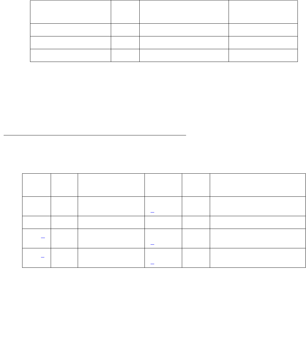
CLSFY-PT (Call Classifier Port)
Issue 1 June 2005 811
CLSFY-PT (Call Classifier Port)
S8700 | 8710 / S8500
The TN744 Call Classifier is a service circuit pack that provides specialized tone detection
capabilities to support the Outbound Call Management (OCM) and Inbound Call Management
(ICM) features. The TN744 supports both A-law and Mu-law companding.
The TN744 has eight ports (CLSFY-PTs), each capable of supporting call classification,
touch-tone reception and MFC-tone generation and detection. The CLSFY-PT MO implements
a set of tests designed to ensure proper operation of the Call Classifier.
Error Log Entries and Test to Clear Values
Notes:
a. A major alarm is raised if the total number of call classifier ports currently in-service is less
than or equal to 1/2 of the administered threshold number. For major or minor alarm, run
the short test sequence on the alarmed port and follow the error code procedures for the
individual tests.
The in-service threshold number for alarming call classifier ports is administered using the
change system-parameters maintenance.
MO Name in Alarm Log Alarm
Level
Initial Command to Run Full Name of MO
CLSFY-PT MAJ test port location sh Call Classifier Port
CLSFY-PT MIN test port location sh Call Classifier Port
CLSFY-PT WRN test port location sh Call Classifier Port
Table 278: Call Classifier Port (CLSFY-PT) Error Log Entries
Error
Type
Aux
Data
Associated Test Alarm
Level
On/Off
Board
Test to Clear Value
1 any Tone Detector Audit/
Update test (#43)
MAJ / MIN
(a)
ON test port location r 2
18 busyout port WRN OFF release port location
257 (b) 17666 Tone Detection Audit
Update test (#43)
MAJ / MIN
(a)
ON test port location r 3
513 (c) any Tone Detection
Verification test (#42)
MAJ / MIN
(a)
ON test port location r 3
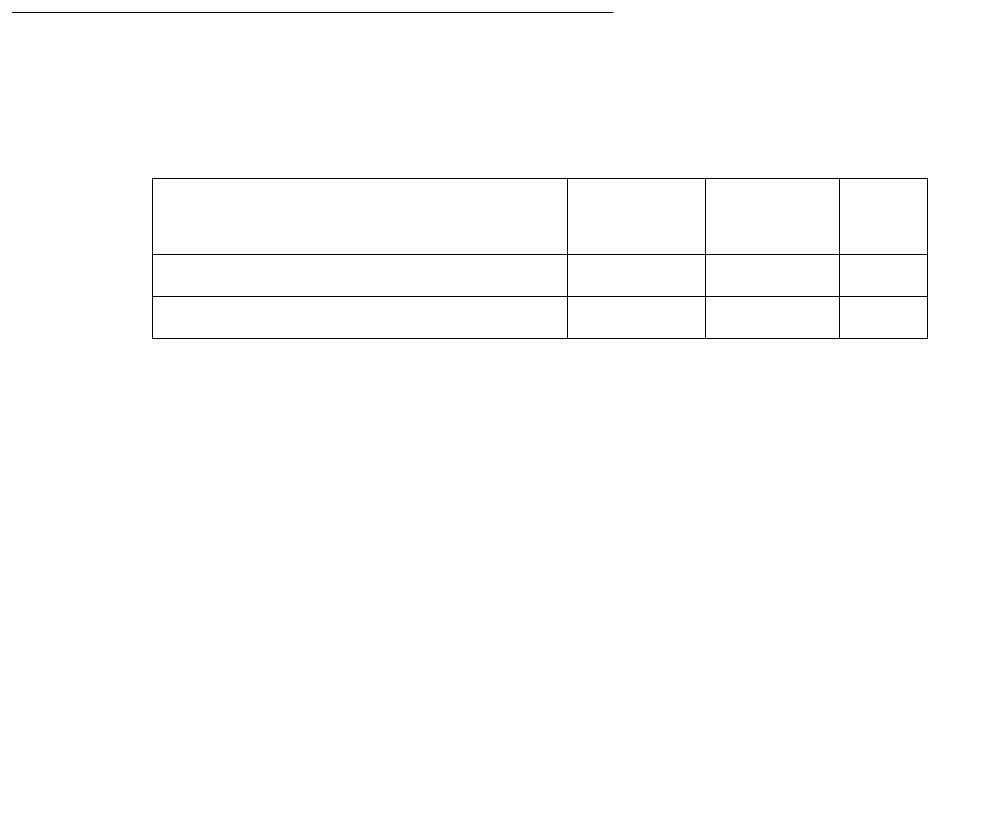
Communication Manager Maintenance-Object Repair Procedures
812 Maintenance Procedures for Avaya Communication Manager 3.0, Media Gateways and Servers
1. Enter these commands in order: busyout board, reset board, release board.
The board reset is required to reload on-board RAM associated with the TN744’s DSPs.
This takes all 8 Tone Detector ports out of service for a few seconds. Only 4 of the 8
would be out of service due to the alarm. (There are five Tone Detectors on each of the
two DSPs.) Other than the unlikely potential of running out of Tone Detector resources in
the switch, there is no other effect when the board is reset.
2. Test the board with test board location long.
3. If the test still fails, replace the board.
b. Error 257: The CLSFY-PT lost its translation. Testing the CLSFY-PT is sufficient to reload
its translation. If testing the call classifier port does not clear the error, then the call
classifier circuit pack containing the defective call classifier port should be replaced.
c. Error 513: This error indicates the call classifier port is having problems detecting call
classification tones or detecting and generating R2-MFC tones This is usually accompanied
by failures of some incoming or outgoing calls. If this error type is persistently logged, then
replace the call classifier circuit pack containing the defective CLSFY-PT.
System Technician-Demanded Tests:
Descriptions and Error Codes
Investigate tests in the order presented.
Tone Detection Verification Test (#42)
This test checks the operation of the TN744 in touch-tone receiver, call classifier and R2-MFC
modes. It verifies the circuit pack’s ability to detect DTMF, ring back, busy reorder and modem
answer tones and to generate and detect forward and backward MFC tones.
Order of Investigation Short Test
Sequence
Long Test
Sequence
D/ND1
1. D = Destructive; ND = Nondestructive
Tone Detection Verification test (#42) X X ND
Tone Detection Audit/Update test (#43) X X ND

CLSFY-PT (Call Classifier Port)
Issue 1 June 2005 813
Table 279: Test #42 Tone Detection Verification Test
Error
Code
Test
Result
Description / Recommendation
none ABRT The system was not able to allocate every resource needed for this test,
OR there was an internal system error.
1 ABRT The system could not allocate every resource needed to test the tones.
1. Retry the command at 1-minute intervals up to 5 times.
1001 ABRT The system was unable to put the call classifier port in the appropriate
mode to test it.
1. Retry the command at 1-minute intervals up to 5 times.
1002 ABRT The system could not allocate time slots for the test connection. This
situation could occur when the system is heavily loaded. If the system is
not heavily loaded, use test tdm to test the TDM-BUS.
1. Retry the command at 1-minute intervals up to 5 times.
1003 ABRT The system could not allocate a Tone-Clock for the test connection. This
may be caused by a heavy load on the system or by a faulted Tone-Clock.
1. Check to see if there are any alarms against the Tone-Clock in the PN
where the test aborted. If so, see TONE-BD (Tone-Clock Circuit) on
page 2327 and TONE-PT (Tone Generator) on page 2353 for
recommended procedures.
2. If a new Tone-Clock has been inserted, allow about 1-minute for
maintenance to run on the newly inserted circuit pack.
3. Retry the command at 1-minute intervals up to 5 times.
2000 ABRT Call classifier circuit pack’s response to the test request was not received
within the allowable time period.
1. Retry the command at 1-minute intervals up to 5 times.
1 of 2

Communication Manager Maintenance-Object Repair Procedures
814 Maintenance Procedures for Avaya Communication Manager 3.0, Media Gateways and Servers
2006 ABRT Indicates that the active Tone-Clock circuit pack or a Tone Detector circuit
pack may not be functioning properly.
If there is more than one Tone Detector circuit pack in the system, then
the problem can be either with the Tone-Clock circuit pack or the Tone
Detector circuit pack. This could also be caused by the mode
administered for the system not matching that of the Tone Detector circuit
pack.
1. Test the active Tone-Clock circuit pack in the PN with test
tone-clock UUC. See TONE-BD (Tone-Clock Circuit) on
page 2327 for failures.
2. Retry the command at 1-minute intervals up to 5 times.
2100 ABRT Could not allocate the necessary system resources to run this test.
1. Retry the command at 1-minute intervals up to 5 times.
1-3 FAIL DTMF digits were not detected correctly. This may or may not impact
reception of R2-MFC calls.
1. Run the short test sequence via test port location sh r 1.
2. If the problem persists, the system is still operating properly but
capacity will be reduced. To restore performance to normal, replace
the call classifier circuit pack containing the defective CLSFY-PT (Call
Classifier Port).
S8700 |
8710
S8500
102
FAIL 2225-Hz Modem Answer tone was not detected correctly. This will impact
call-classification operation.
1. Run the short test sequence with test port location sh r 1.
2. If the problem persists, the system can still operate properly but
capacity will be reduced. In order to restore performance to normal,
replace the call classifier circuit pack containing the defective port.
101-
122
130
FAIL Forward or backward R2-MFC signals were not correctly generated or
detected. This will impact R2-MFC calls.
1. Run the short test sequence with test port location sh r 1.
2. If the problem persists, the system can still operate properly but
capacity will be reduced. In order to restore performance to normal,
replace the call classifier circuit pack containing the defective port.
PASS Tone detection verification is successful. The call classifier port is able to
detect and generate every necessary tone.
Table 279: Test #42 Tone Detection Verification Test (continued)
Error
Code
Test
Result
Description / Recommendation
2 of 2

CLSFY-PT (Call Classifier Port)
Issue 1 June 2005 815
Tone Detector Audit/Update Test (#43)
This test performs a sanity audit on the CLSFY-PT (Call Classifier Port).
Table 280: Test #43 Tone Detector Audit/Update Test
Error
Code
Test
Result
Description / Recommendation
none ABRT The system was not able to allocate the resources for this test.
1. Retry the command at 1-minute intervals up to 5 times.
2000 ABRT Response to the test request was not received within the allowable time
period.
1. Retry the command at 1-minute intervals up to 5 times.
2100 ABRT Could not allocate the necessary system resources to run this test.
1. Retry the command at 1-minute intervals up to 5 times.
FAIL Hardware audit failed.
1. Enter these commands in order: busyout board, reset board,
release board. The board reset is required to reload on-board RAM
associated with the TN744’s DSPs. This takes all 8 Tone Detector
ports out of service for a few seconds. Only 4 of the 8 would be out of
service due to the alarm. (There are five Tone Detectors on each of the
two DSPs.) Other than the unlikely potential of running out of Tone
Detector resources in the switch, there is no other effect when the
board is reset.
2. Test the board with test board location long.
3. If the test still fails, replace the board.
PASS The call classifier port has passed the sanity inquiry.

Communication Manager Maintenance-Object Repair Procedures
816 Maintenance Procedures for Avaya Communication Manager 3.0, Media Gateways and Servers
CO-BD (Central Office Trunk Circuit Pack)
S8700 | 8710 / S8500
See XXX-BD (Common Port Circuit Pack/Media Module) on page 2539 for circuit pack-level
errors. See also CO-TRK (Analog CO Trunk) on page 835 for related trunk information.
MO Name in
Alarm Log
Alarm
Level
Initial Command to Run Full Name of MO
CO-BD MIN test board location sh Central Office Trunk circuit pack
CO-BD WRN test board location sh Central Office Trunk circuit pack
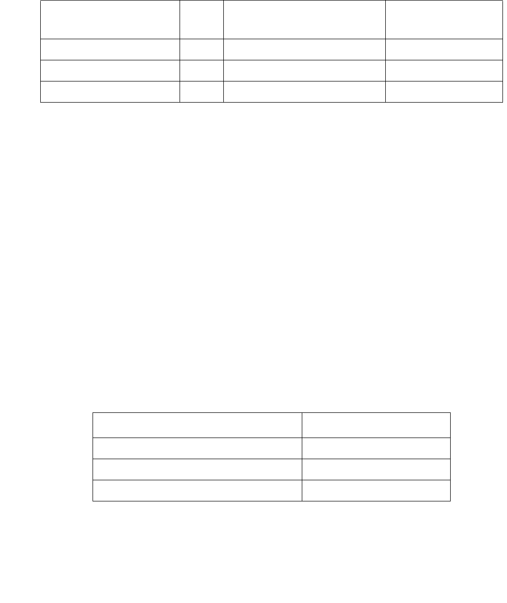
CO-DS1 (DS1 CO Trunk)
Issue 1 June 2005 817
CO-DS1 (DS1 CO Trunk)
S8700 | 8710 / S8500 / S8300
Many trunk problems are caused by incorrect settings of parameters on the trunk group
administration screen. Settings must be compatible with the local environment and with
parameter settings on the far end. Refer to “Chapter 12, Managing Trunks", in the Administrator
Guide for Avaya Communication Manager, 03-300509 for information on how to administer
trunks. The Application Notes section of that book shows the correct settings for administrable
timers and other parameters on a country-by-country basis.
A DS1 CO (central office) trunk provides a link for digitized voice or data communications
between the system and a central office switch. There are two types of DS1 interfaces:
●24 DS0 channels on a 1.544-Mbps link
●31 DS0 channels + 1 framing channel on a 2.048-Mbps link
32-channel mode is supported on the TN464C or higher suffix, TN2207, and TN2464
circuit packs (S8300/G700: and on MM710 Media Modules).
The DS1-CO MO monitors and maintains a CO trunk port on a TN767 DS1 Interface circuit
pack, a TN464 UDS1 Interface circuit pack, or on S8300 / G700: MM710 Media Module.
Throughout this discussion, the term DS1 applies to all. For more information, see one of the
following maintenance objects:
The DS1 circuit pack or media module supports low level CO trunk signaling interfaces for both
ground-start and loop-start trunks. This maintenance strategy covers the in-line errors log,
initialization tests, periodic tests, scheduled tests, demand tests, and alarm resolution.
MO Name in Alarm Log Alarm
Level
Initial Command to Run Full Name of MO
CO-DS1 MAJ1
1. A Major alarm on a trunk indicates that alarms on these trunks are not downgraded by set options
and that at least 75 percent of the trunks in this trunk group are alarmed. For more information about
set options, see Maintenance Commands Reference (03-300191).
test trunk grp#/mem# l DS1 CO Trunk
CO-DS1 MIN test trunk grp#/mem# l DS1 CO Trunk
CO-DS1 WRN test trunk grp#/mem# DS1 CO Trunk
Circuit Pack/Media Module Maintenance Object
TN767 DS1 Interface Circuit Pack DS1-BD
TN464 UDS1 Interface Circuit Pack UDS1-BD
S8300 / G700: MM710 DS1 Media Module MG-DS1
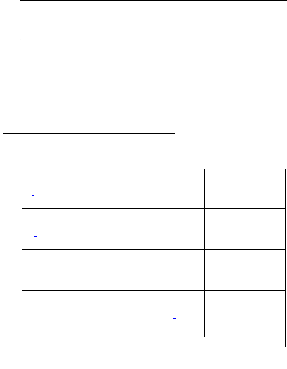
Communication Manager Maintenance-Object Repair Procedures
818 Maintenance Procedures for Avaya Communication Manager 3.0, Media Gateways and Servers
S8300 / G700
The MM710 supports T1/E1, and delivers the same functionality as the TN464 circuit pack.
Although CO-DS1 is provided for G700/G350 Media Gateways, CO-DS1 only partially supports
the MM710 DS1 Media Module.
Three trunk service states are specified by DS1 CO trunk maintenance:
Error Log Entries and Test to Clear Values
out-of-service The trunk is in a deactivated state and cannot be used for either
incoming or outgoing calls.
in-service The trunk is in an activated state and can be used for both
incoming and outgoing calls.
disconnect
(ready-for-service)
The trunk is in an activated state but can only be used for an
incoming call.
Table 281: DS1 CO Trunk Error Log Entries
Error
Type
Aux
Data
Associated Test Alarm
Level
On/Off
Board
Test to Clear Value
0 (a) 0 Any Any Any test trunk grp/mbr
1 (b) 57408
1 (b) 57487
15 (c) Any Port Audit and Update (#36)
18 (d)0 busyout trunk grp/mbr WRN OFF release trunk grp/mbr
130 (e) None WRN ON test trunk grp/mbr
257 (f) 57392 DS1 CO Dial Tone Seizure (#314)
G700 aborts with Error Type 1412
MIN
WRN
OFF
513 (g) 57393 DS1 CO Dial Tone Seizure (#314)
G700 aborts with Error Code 1412
MIN
WRN
OFF
769 (h) 57484
1025 DS1 CO Dial Tone Seizure (#314)
G700 aborts with Error Code 1412
MIN
WRN1OFF test trunk grp/mbr r 2
1281 Conference Circuit (#7)
G700 aborts with Error Code 1412
MIN
WRN1
ON test trunk grp/mbr l r 4
1537 NPE Crosstalk (#6)
G700 aborts with Error Code 1412
MIN
WRN1
ON test trunk grp/mbr l r 3
1 of 2

CO-DS1 (DS1 CO Trunk)
Issue 1 June 2005 819
Notes:
a. Error Type 0: Run the short test sequence first. If every test passes, run the long test
sequence. Refer to each appropriate test’s description, and follow its recommended
procedures.
b. Error Type 1:
Aux Data 57408: No tip ground is detected on an outgoing call.
Aux Data 57487: PBX could not get “loop close” signal.
If the error occurred on a port of a TN767 DS1 or TN464 UDS1 Interface circuit pack, the
circuit pack detected a hardware fault. These errors will cause Dial Tone Test #314 to run
and are only considered a problem if the Dial Tone test fails (in which case Error Type 1025
will also show up). In this case, the trunk may be put in the ready-for-service state (shown
as “disconnected” by status), which allows only incoming calls. Run Dial Tone Test #314,
and follow the procedures.
S8300 / G700: If the error occurred on a port of an MM710 DS1 Media Module, Test #314 will
abort with Error Code 1412. Escalate the problem.
c. Error Type 15: software audit error that does not indicate any hardware malfunction. Run
short test sequence, and investigate associated errors (if any).
d. Error Type 18: the trunk was busied-out to the out-of-service state. No calls can be made
on this trunk except Facility Access Test Calls.
e. Error Type 130: the circuit pack has been removed or has been insane for more than 11
minutes. To clear the error, reinsert or replace the circuit pack or media module.
f. Error Type 257: the DS1 Interface circuit pack detects a hardware fault. Aux Data 57392
indicates no external release on PBX disconnect. This alarm will only be raised when the
System-Parameter Country screen has the Base Tone Generator field set to 4 (Italy). This alarm will be a
MINOR alarm unless 75% or more trunks in this trunk group are out of service, then the alarm will be upgraded
to a MAJOR alarm.
S8300 / G700: On an MM710 DS1 Media Module, Associated Test #314 will abort with Error
Code 1412. Escalate the problem.
1793 (i)test board location l
2562 (j) 16665
2817 (k) 52992
3840 (l) Port Audit and Update (#36)
1. Major alarms MO may be downgraded to Warning alarms based on the value used in set options.
Table 281: DS1 CO Trunk Error Log Entries (continued)
Error
Type
Aux
Data
Associated Test Alarm
Level
On/Off
Board
Test to Clear Value
2 of 2

Communication Manager Maintenance-Object Repair Procedures
820 Maintenance Procedures for Avaya Communication Manager 3.0, Media Gateways and Servers
g. Error Type 513: The DS1 Interface circuit pack detects a hardware fault. Aux Data 57393
indicates belated external release on PBX disconnect. This alarm will only be raised when the
System-Parameter Country screen has the Base Tone Generator field set to 4 (Italy). This alarm will be a
MINOR alarm unless 75% or more trunks in this trunk group are out of service, then the alarm will be upgraded
to a MAJOR alarm.
S8300 / G700: On an MM710 DS1 Media Module, Associated Test #314 will abort with Error
Code 1412. Escalate the problem.
h. Error Type 769: The DS1 Interface circuit pack or media module detects a hardware fault.
The Aux Data contains the following error type:—57484, fault is detected on tip/ring.
i. Error Type 1793: DS1 Interface circuit pack or media module is out-of-service. Look in the
Hardware Error Log:
j. Error Type 2562: Retry Failure error. This error is logged only. It is not a hardware failure
and hence does not start any testing or generate any alarms. This error comes from call
processing and is generated when a second attempt (retry) to seize an outgoing trunk fails.
k. Error Type 2817: Glare error. This error is logged only. It is not a hardware failure and
hence does not start any testing or generate any alarms. This error is the result of a
simultaneous seizure of a 2-way trunk from both the near and far ends. Attempt to place
the call again. If the error persists, execute the Dial Tone Seizure test (#314), and follow
those procedures.
S8300 / G700: If the error occurred on a port of an MM710 DS1 Media Module, Test #314 will
abort with Error Code 1412. Escalate the problem.
l. Error Type 3840: Port Audit and Update test (#36) failed due to an internal system error.
Enter status trunk to verify the status of the trunk. If the trunk is out-of-service, then
enter release trunk to put it back into in-service. Retry the test command.
If port is on Look in
TN767 DS1 Board DS1-BD
TN464 UDS1 Board UDS1-BD
S8300 / G700: MM710 DS1 Media Module MG-DS1

CO-DS1 (DS1 CO Trunk)
Issue 1 June 2005 821
System Technician-Demanded Tests: Descriptions and Error
Codes
Investigate tests in the order they are presented. By clearing error codes associated with the
NPE Crosstalk test (#6), you may also clear errors generated from other tests in the testing
sequence.
NPE Crosstalk Test (#6)
Note:
Note: S8300 / G700: This test aborts with Error Code 1412.
The NPE Crosstalk test verifies that this port’s NPE channel talks on the selected time slot and
never crosses over to time slots reserved for other connections. If the NPE is not working
correctly, one-way and noisy connections may be observed. This test is usually only part of a
port’s long test sequence and executes in about 20 to 30 seconds.
Order of Investigation Short Test
Sequence
Long Test
Sequence
D/ND1
1. D = Destructive; ND = Nondestructive
NPE Crosstalk test (#6)
S8300 / G700 aborts with Error Code 1412
XND
Conference Circuit test (#7)
S8300 / G700 aborts with Error Code 1412
XND
DS1 CO Trunk Seizure test (#314)
S8300 / G700 aborts with Error Code 1412
XXND
Port Audit and Update test (#36) X X ND
Table 282: Test #6 NPE Crosstalk Test
Error
Code
Test
Result
Description / Recommendation
ABRT System resources required for this test are not available.
1. Retry the command at 1-minute intervals up to 5 times.
1 of 4

Communication Manager Maintenance-Object Repair Procedures
822 Maintenance Procedures for Avaya Communication Manager 3.0, Media Gateways and Servers
1000 ABRT System resources required to run this test were not available. The port
may be busy with a valid call.
1. Use display port location to determine the trunk group/member
number of the port. Use status trunk to determine the service state
of the port. If the port is active, wait until it is idle before testing.
2. If the port status is active but the port is idle (no calls), check the error
log for error type 1025 (see the error log table for a description of this
error and required actions). The port may be locked up.
3. If the port status is idle, retry the command at 1-minute intervals up to 5
times.
1001 ABRT System resources required for this test are not available.
1. Retry the command at 1-minute intervals up to 5 times.
1002 ABRT The system could not allocate time slots for the test. The system may be
under heavy traffic conditions or it may have time slots out-of-service due
to TDM-BUS errors. Use status health to determine whether the
system is experiencing heavy traffic.
1. If the system has no TDM-BUS errors and is not handling heavy traffic,
retry the command at 1-minute intervals up to 5 times.
1003 ABRT The system could not allocate a tone receiver for the test. The system may
be oversized for the number of Tone Detectors present, or some Tone
Detectors may be out of service.
1. Enter list measurements tone-receiver to see information
about the system’s tone receivers.
2. Resolve any TTR-LEV errors.
3. Resolve any TONE-PT errors.
4. If neither condition exists, retry the command at 1-minute intervals up
to 5 times.
1004 ABRT The port was seized by a user for a valid call.
1. Use display port location to determine the trunk group/member
number of the port. Use status trunk to determine the service state
of the port. If the port is active, wait until it is idle before testing.
2. If the port status is idle, retry the command at 1-minute intervals up to 5
times.
Table 282: Test #6 NPE Crosstalk Test (continued)
Error
Code
Test
Result
Description / Recommendation
2 of 4

CO-DS1 (DS1 CO Trunk)
Issue 1 June 2005 823
1020 ABRT The test did not run due to a previously existing error on the specific port or
a more general circuit pack error.
1. Examine Error Log for existing errors against this port or the circuit
pack and attempt to diagnose the already existing error.
S8300
G700
1412
ABRT This test does not execute on a G700 Media Gateway.
2000 ABRT Response to the test request was not received within the allowable time
period.
1. Retry the command at 1-minute intervals up to 5 times.
2100 ABRT System resources required for this test are not available.
1. Retry the command at 1-minute intervals up to 5 times.
2053 ABRT At least one of the following errors was found on the DS1 circuit pack: Loss
of signal (1281), Blue alarm (1793), Red alarm (2049), Yellow alarm (2305),
or Hyperactivity (1537).
1. Look for the previous error types in the Hardware Error Log, and follow
the procedures given in the appropriate DS1-BD or UDS1-BD
maintenance documentation for the listed error types.
FAIL The NPE of the tested port was found to be transmitting in error. This will
cause noisy and unreliable connections.
1. Replace the circuit pack.
PASS The port is correctly using its allocated time slots. User-reported troubles on
this port should be investigated using other port tests and examining station,
trunk, or external wiring.
Table 282: Test #6 NPE Crosstalk Test (continued)
Error
Code
Test
Result
Description / Recommendation
3 of 4

Communication Manager Maintenance-Object Repair Procedures
824 Maintenance Procedures for Avaya Communication Manager 3.0, Media Gateways and Servers
Conference Circuit Test (#7)
Note:
Note: S8300 / G700: This test aborts with Error Code 1412.
The Conference Circuit test verifies that the NPE channel for the port being tested can correctly
perform the conferencing function. The NPE is instructed to listen to several different tones and
conference the tones together. The resulting signal is then measured by a Tone Detector port.
If the level of the tone is within a certain range, the test passes.
0NO
BOARD The test could not relate the internal ID to the port (no board). This could
be due to incorrect translations, no board is inserted, an incorrect board is
inserted, an insane board is inserted, or the board is hyperactive.
1. Verify that the board’s translations are correct. Enter list config,
and resolve any problems that are found.
2. If the board was found to be correctly inserted in step 1, enter busyout
board location
3. Enter reset board location
4. Enter release board location
5. Enter test board location long
This should re-establish the linkage between the internal ID and the port. If
not, dispatch to verify that a valid board is inserted.
Note:
Note: Hyperactivity causes some special problems with the
sequence suggested above. If the ports are translated after
entering list config but the Vintage field reports that
there is no board (when there really is a board), then
busyout board and release board do not work, but
reset board location works. The software puts the
hyperactive board back in service after the hyperactivity
clears.
Table 282: Test #6 NPE Crosstalk Test (continued)
Error
Code
Test
Result
Description / Recommendation
4 of 4

CO-DS1 (DS1 CO Trunk)
Issue 1 June 2005 825
Table 283: Test #7 Conference Circuit Test
Error
Code
Test
Result
Description / Recommendation
ABRT System resources required for this test are not available.
1. Retry the command at 1-minute intervals up to 5 times.
1000 ABRT The test was aborted. System resources required to run this test were not
available. The port may be busy with a valid call.
1. Use display port location to determine the trunk group/member
number of the port. Use status trunk to determine the service state
of the port. If the port is active, wait until it is idle before testing.
2. If the port status is active but the port is idle (no calls), check the error
log for error type 1025 (see the error log table for a description of this
error and required actions). The port may be locked up.
3. If the port status is idle, retry the command at 1-minute intervals up to 5
times.
1002 ABRT The system could not allocate time slots for the test. The system may be
under heavy traffic conditions, or it may have time slots out of service due
to TDM-BUS errors.
1. If the system has no TDM-BUS errors and is not handling heavy traffic
and the port status is idle, retry the command at 1-minute intervals up
to 5 times.
1003 ABRT The system could not allocate a tone receiver for the test. The system may
be oversized for the number of Tone Detectors present, or some of the
Tone Detectors may be out of service.
1. Use list measurements tone-receiver to see basic information
about the system's tone receivers.
2. Resolve any TTR-LEV errors.
3. Resolve any TONE-PT errors.
4. If neither condition exists, retry the command at 1-minute intervals up
to 5 times.
1004 ABRT The port has been seized by a user for a valid call.
1. Use status station or status trunk to determine when the port
is available for testing.
2. Retry the command at 1-minute intervals up to 5 times.
1 of 4

Communication Manager Maintenance-Object Repair Procedures
826 Maintenance Procedures for Avaya Communication Manager 3.0, Media Gateways and Servers
1018 ABRT The test was disabled via translation. You may want to determine why the
test has been disabled before you enable it.
1. Verify that the Maintenance Test field on the Trunk Administration
form is set to n. To enable the test, change the trunk administration and
enter y into the Maintenance Test field.
2. Repeat the test.
1020 ABRT The test did not run due to a previously existing error on the specific port or
a more general circuit pack error.
1. Examine Error Log for existing errors against this port or the circuit
pack and attempt to diagnose the previously existing error.
1412 ABRT This test does not execute on a G700/G350 Media Gateway.
2000 ABRT Response to the test request was not received within the allowable time
period.
1. Retry the command at 1-minute intervals up to 5 times.
2100 ABRT System resources required for this test are not available.
1. Retry the command at 1-minute intervals up to 5 times.
2053 ABRT At least one of the following errors was found on the DS1 circuit pack: Loss
of signal (1281), Blue alarm (1793), Red alarm (2049), Yellow alarm (2305),
or Hyperactivity (1537).
Look for the previous error types in the Hardware Error Log, and follow the
procedures given in the appropriate DS1-BD or UDS1-BD maintenance
documentation for the listed error types.
Table 283: Test #7 Conference Circuit Test (continued)
Error
Code
Test
Result
Description / Recommendation
2 of 4

CO-DS1 (DS1 CO Trunk)
Issue 1 June 2005 827
Any FAIL The NPE of the tested port did not conference the tones correctly. This will
cause noisy and unreliable connections.
1. Enter list configuration board location. If the circuit pack
is a TN767B vintage 8 or 9, replace the circuit pack with a TN767C V3
or later. The error log may have error type 1281 entries.
2. Test every administered trunk on the board. If one fails, this could be
an off-board problem (such as an incoming seizure or an off-hook port
seizure during the test). Retest the board.
3. If every port fails, check CARR-POW MO or RMC-ENV MO.
4. If several ports fail, check the error log for TONE-BD or TONE-PT
errors. If there are such errors, take the appropriate action. When the
TONE errors have cleared, rerun the test.
5. If the retry passes and troubles have been reported, coordinate
isolation with the CO. Make sure that the switch, the CO, and any
NTCE equipment (the CSI’s) have the correct administration.
6. Replace the circuit pack.
Note:
Note: If the conference circuit test fails for every port on a circuit
pack, a -5 Volt power problem is indicated. To investigate
problems with a power unit, see CARR-POW (Carrier Power
Supply) MO or RMC-ENV MO. If a red LED is lit on a TN736
or TN752 power unit circuit pack, replace the pack.
PASS The port can correctly conference multiple connections. User-reported
troubles on this port should be investigated by using other port tests and by
examining station, trunk, or external wiring.
Table 283: Test #7 Conference Circuit Test (continued)
Error
Code
Test
Result
Description / Recommendation
3 of 4

Communication Manager Maintenance-Object Repair Procedures
828 Maintenance Procedures for Avaya Communication Manager 3.0, Media Gateways and Servers
0NO
BOARD The test could not relate the internal ID to the port (no board).
This result could be due to incorrect translations, no board is inserted, an
incorrect board is inserted, an insane board is inserted, or the board is
hyperactive.
1. Verify that the board’s translations are correct. Enter list config,
and resolve any problems that are found.
2. If the board was found to be correctly inserted in step 1, enter busyout
board location
3. Enter reset board location
4. Enter release board location
5. Enter test board location long
This should re-establish the linkage between the internal ID and the port. If
not, dispatch to verify that a valid board is inserted.
Note:
Note: Hyperactivity causes some special problems with the
sequence suggested above.If the ports are translated after
issuing list config but the Vintage field reports that
there is no board (when there really is a board), then
busyout board and release boards will not work (even
though reset board location will work). The software
will put the hyperactive board back in service after the
hyperactivity clears.
Table 283: Test #7 Conference Circuit Test (continued)
Error
Code
Test
Result
Description / Recommendation
4 of 4

CO-DS1 (DS1 CO Trunk)
Issue 1 June 2005 829
Port Audit and Update Test (#36)
This test sends port level translation data from switch processor to the DS1 Interface circuit
pack or media module to assure that the trunk’s translation is correct. Translation updates
include the following data: trunk type (in/out), dial type, timing parameters, and signaling bits
enabled. The port audit operation verifies the consistency of the current state of trunk.
Table 284: Test #36 Port Audit and Update Test
Error
Code
Test
Resul
t
Description / Recommendation
ABRT Internal system error
1. Retry the command at 1-minute intervals up to 5 times.
1000 ABRT System resources required to run this test were not available. The port
may be busy with a valid call.
1. Enter display port location to determine the trunk group/
member number of the port. Use status trunk to determine the
service state of the port. If the port is active, wait until it is idle before
testing.
2. If the port status is active but the port is idle (no calls), check the error
log for error type 1025. The port may be locked up.
3. If the port status is idle, retry the command at 1-minute intervals up to 5
times.
1006 ABRT The DS1 CO trunk is out of service.
1. Use status trunk to verify that the trunk is out of service.
2. If the trunk is out of service, determine why.
3. If it is OK to put the trunk back in service, enter release trunk to put
the trunk back in service, and then retry the test.
2000 ABRT Response to the test was not received within the allowable time period.
1. Retry the command at 1-minute intervals up to 5 times.
2100 ABRT Could not allocate the necessary system resources to run this test.
1. Retry the command at 1-minute intervals up to 5 times.
FAIL Test failed due to internal system error.
1. Retry the command at 1-minute intervals up to 5 times.
1 of 2

Communication Manager Maintenance-Object Repair Procedures
830 Maintenance Procedures for Avaya Communication Manager 3.0, Media Gateways and Servers
PASS Trunk translation has been updated successfully. The current trunk states
kept in the DS1 Interface circuit pack or media module and switch software
are consistent. If the trunk is busied out, the test will not run but will return
PASS. To verify that the trunk is in-service:
1. Enter status trunk to verify that the trunk is in-service. If the trunk
is in-service, no further action is necessary. If the trunk is
out-of-service.
2. Enter release trunk to put the trunk back into in-service.
3. Retry the test command.
0NO
BOARD The test could not relate the internal ID to the port. This result could be due
to incorrect translations, no board inserted, an incorrect board inserted, an
insane board inserted, or the board is hyperactive.
1. Verify that the board’s translations are correct. Enter list config,
and resolve any problems that are found.
2. Enter busyout board location
3. Enter reset board location
4. Enter release board location
5. Enter test board location long
This should re-establish the linkage between the internal ID and the port. If
not, dispatch to verify that a valid board is inserted.
Hyperactivity causes some special problems with the sequence suggested
above. If the ports are translated after issuing list config but the
Vintage field reports that there is no board (when there really is a board),
then busyout board and release board do not work, even though
reset board does work. The software puts the hyperactive board back in
service after the hyperactivity clears.
Table 284: Test #36 Port Audit and Update Test (continued)
Error
Code
Test
Resul
t
Description / Recommendation
2 of 2

CO-DS1 (DS1 CO Trunk)
Issue 1 June 2005 831
DS1 CO Dial Tone Seizure Test (#314)
Note:
Note: S8300 / G700: This test aborts with Error Code 1412.
The DS1 CO Dial Tone Seizure test checks the trunk’s signaling capability provided by the DS1
Interface circuit pack. The maintenance software initiates the test by sending a “seizure”
message to the DS1 Interface circuit pack and expects an “active” reply from the DS1 interface
circuit pack. If the “active” message is received, then the test passes. If no message is
received and the timer expires, the test is aborted. If the DS1 Interface circuit pack sends a
“reorder” message back to maintenance software, then the test fails.
This test cannot be run on a trunk in any of the following conditions:
1. The trunk direction is administered as an incoming only trunk.
2. The trunk has been seized by a normal trunk call.
3. The trunk is administered with maintenance test disabled.
4. S8300 / G700: The trunk is on a port of an MM710 DS1 Media Module.
Table 285: Test #314 DS1 CO Dial Tone Seizure Test
Error
Code
Test
Result
Description / Recommendation
ABRT Internal system error
1. Retry the command at 1-minute intervals up to 5 times.
1000 ABRT The test was aborted because system resources required to run this test
were not available. The port may be busy with a valid call.
1. Use display port location to determine the trunk group/
member number of the port. Use status trunk to determine the
service state of the port. If the port is active, wait until it is idle before
testing.
2. If the port status is active but the port is idle (no calls), check the error
log for error type 1025. The port may be locked up.
3. If the port status is idle, retry the command at 1-minute intervals up to
5 times.
1 of 4

Communication Manager Maintenance-Object Repair Procedures
832 Maintenance Procedures for Avaya Communication Manager 3.0, Media Gateways and Servers
1004 ABRT The test was aborted because the port was seized by a user for a valid
call.
1. Use display port location to determine the trunk group/
member number of the port. Use status trunk to determine the
service state of the port. If the port is active, wait until it is idle before
testing.
2. If the port status is idle, retry the command at 1-minute intervals up to
5 times.
1005 ABRT Test failed due to incompatible configuration administered in trunk group
screen.
1. Look at the trunk group administration form and see whether the trunk
is incoming only, port 24 on a DS1 Interface with common control
channel signaling, or an automatic CO type such as FX. Under any of
these conditions this is a normal abort.
1018 ABRT Test is disabled via translation. You may want to determine why the test
has been disabled before you enable it.
1. Verify that the Maintenance Test field on the Trunk Group
screen is n. To enable the test, enter change trunk-group <x>
(<x> is the number of the trunk group to be tested). Change the
Maintenance Test field on the screen to y.
2. Repeat the test.
1020 ABRT The DS1 Interface circuit pack is out-of-service.
1. Look for DS1-BD/UDS1-BD errors in the Hardware Error Log. If
present, see the appropriate DS1-BD/UDS1-BD (DS1/UDS1 Trunk
circuit pack).
2. Retry the command.
1040 ABRT The test was aborted because this port may be an access endpoint.
1. Verify that this port is an access endpoint by issuing display port
location
2. If the port has been administered as an access endpoint, then this is a
normal abort.
Table 285: Test #314 DS1 CO Dial Tone Seizure Test (continued)
Error
Code
Test
Result
Description / Recommendation
2 of 4

CO-DS1 (DS1 CO Trunk)
Issue 1 June 2005 833
S8300 /
G700
1412
ABRT This test does not execute on a G700 Media Gateway.
2000 ABRT Response to the test request was not received within the allowable time
period.
1. Retry the command at 1-minute intervals up to 5 times.
2012 ABRT The test was aborted due to an internal system error.
1. Retry the command at 1-minute intervals up to 5 times.
2100 ABRT Could not allocate the necessary system resources for this test.
1. Retry the command at 1-minute intervals up to 5 times.
2000 FAIL Response to the seizure message was not received within the allowable
time period.
1. Enter list configuration board location. If the circuit pack
is a TN767B vintage 8 or 9, a failure of test 314 causes a subsequent
failure of test 7 due to a firmware bug. Eventually, the board and all of
its ports will be taken out of service and extraneous on-board alarms
will be generated. Replace the circuit pack with a TN767C V3 or later.
2. Verify that the Trunk Type field on the Trunk Administration form
matches the trunk type administered on far-end switch.
3. Look for DS1-BD or UDS1-BD errors in the hardware error log. If
present, see DS1-BD (DS1 Interface Circuit Pack) on page 978 or
UDS1-BD (UDS1 Interface Circuit Pack) on page 2374.
4. Retry the command at 1-minute intervals up to 5 times.
2053 FAIL At least one of the following errors was found on the DS1 circuit pack:
Loss of signal (1281), Blue alarm (1793), Red alarm (2049), Yellow alarm
(2305), or Hyperactivity (1537).
1. Look for these error types in the hardware error log, and then follow
the procedures given in the maintenance documentation that is
appropriate for the error type that was found.
Table 285: Test #314 DS1 CO Dial Tone Seizure Test (continued)
Error
Code
Test
Result
Description / Recommendation
3 of 4

Communication Manager Maintenance-Object Repair Procedures
834 Maintenance Procedures for Avaya Communication Manager 3.0, Media Gateways and Servers
FAIL The trunk cannot be seized for an outgoing call. This could cause in-line
failures to be reported against the trunk (no answer would report error
type 257 with auxiliary data 57487 in the error log).
1. Verify the Trunk Type field on the trunk administration screen
screen matches the trunk type administered on far-end switch.
2. Look for DS1-BD/UDS1-BD errors in Error Log. If present, see
DS1-BD (DS1 Interface Circuit Pack) on page 978.
3. Retry the command at 1-minute intervals up to 5 times.
PASS The trunk can be seized for an outgoing call.
0NO
BOARD The test could not relate the internal ID to the port (no board).
This could be due to incorrect translations, no board is inserted, an
incorrect board is inserted, an insane board is inserted, or the board is
hyperactive.
1. Verify that the board’s translations are correct. Enter list config,
and resolve any problems that are found.
2. Enter busyout board location
3. Enter reset board location
4. Enter release board location
5. Enter test board location long
This should re-establish the linkage between the internal ID and the port. If
not, dispatch to verify that a valid board is inserted.
Note:
Note: Hyperactivity causes some special problems with the
sequence suggested above. If the ports are translated
after issuing list config but the Vintage field shows
that there is no board (when there really is a board),
busyout board and release board do not work, even
though reset board does work. The software puts the
hyperactive board back in service after the hyperactivity
clears.
Table 285: Test #314 DS1 CO Dial Tone Seizure Test (continued)
Error
Code
Test
Result
Description / Recommendation
4 of 4

CO-TRK (Analog CO Trunk)
Issue 1 June 2005 835
CO-TRK (Analog CO Trunk)
S8700 | 8710 / S8500 / S8300
S8700 | 8710 / S8500
For systems supporting circuit packs:
If ATMS testing is enabled, check the error log for ATMS errors 3840 and 3841. If the error log
indicates that measurements exceeded acceptable thresholds, and no other trouble is found
with test trunk, run the ATMS test call with test analog-testcall port location
full.
Note:
Note: Many trunk problems are caused by incorrect settings of parameters on the trunk
group administration screen. Settings must be compatible with the local
environment and with parameter settings on the far end.
Analog CO trunks are 2-wire analog lines to the CO that support both incoming and outgoing
calls. CO trunk circuit packs have eight ports, each of which provides an interface between the
2-wire CO line and the 4-wire TDM bus. The system supports the following CO trunk circuit
packs:
MO Name in Alarm Log Alarm
Level
Initial Command to Run Full Name of MO
CO-TRK MAJ1
1. A MAJOR alarm on a trunk indicates that alarms on these trunks are not downgraded by set
options and that at least 75% of the trunks in this trunk group are alarmed.
test port location Analog CO Trunk
CO-TRK MIN test port location Analog CO Trunk
CO-TRK WRN test port location Analog CO Trunk
TN438 TN2138
TN447 TN2147
TN465 TN2148
TN747

Communication Manager Maintenance-Object Repair Procedures
836 Maintenance Procedures for Avaya Communication Manager 3.0, Media Gateways and Servers
S8300 / G700
For systems supporting Media Modules:
Analog CO trunks are 2-wire analog lines to the CO which support both incoming and outgoing
calls. CO trunk MM711 Analog Media Modules have eight ports.
Note:
Note: Although the CO-TRK MO is provided for G700 and G350 media gateways, this
MO only partially supports the MM711 Analog Media Module.
The following sequences show the interactions between the switch and the CO during call setup
for both loop-start and ground-start trunks.
Loop Start Operation
Idle State: Tip = ground, Ring = CO Battery
Outgoing Call:
1. PBX Off-Hook (Seize message): Closes the Tip-Ring Loop
CO response: DC loop current + Dial tone
2. PBX On-Hook (Drop message): Open Tip-Ring loop, no loop current
CO response: CO goes to idle state (see Note)
Incoming Call:
1. CO Applies Ringing Voltage
PBX response: Detect ringing current
2. PBX Off-Hook (Answer message): Close loop
CO response: Trip ringing, provide loop current
3. PBX On-Hook (Drop message): Open Tip-Ring loop, no loop current
CO response: CO goes to idle state
Note:
Note: CO does not normally provide an On-Hook (Disconnect) signal. Exceptions to
this rule include Netherlands loop start and UK loop-calling guarded-clearing.

CO-TRK (Analog CO Trunk)
Issue 1 June 2005 837
Ground Start Operation
Idle state: Tip = open, Ring = CO Battery
Outgoing Call:
1. PBX Off-Hook (Seize message): Places ground on Ring
CO response: Places ground on Tip
PBX response: Close the loop
CO response: Provide loop current
PBX response: Dial out digits
2. PBX On-Hook first (Drop message): Open the Tip-Ring Loop, no loop current
CO response: Open circuit on Tip
3. CO On-Hook first (Disconnect): Open circuit on Tip, no loop current
PBX response: Open Tip-Ring loop
Incoming Call:
1. CO Off-Hook (Seizure): CO applies ground on Tip and applies ringing voltage to the Ring
lead.
PBX response: Make trunk busy for outgoing calls
2. CO Ringing: CO applies ringing voltage to the Ring lead.
PBX response: Detect ringing, ring destination (Attendant, hunt group, etc.)
3. PBX Off-Hook (Answer message): Close loop
CO response: Trip ringing, provide loop current
4. PBX On-Hook first (Drop message): Open the Tip-Ring Loop, no loop current
CO response: Open circuit on Tip
5. CO On-Hook first (Disconnect): Open circuit on Tip, no loop current

Communication Manager Maintenance-Object Repair Procedures
838 Maintenance Procedures for Avaya Communication Manager 3.0, Media Gateways and Servers
Error Log Entries and Test to Clear Values
Table 286: CO Trunk Error Log Entries
Error
Type
Aux
Data
Associated Test Alarm
Level
On/Off
Board
Test to Clear Value
0 (a)0 Any AnyAnytest port location sh r 1
1 (b) 57347 None
15 (c) any Port Audit Update (#36)
18 0 busyout trunk WRN OFF release trunk grp#/mem#
130 (d) None WRN ON test port location sh r 2
257 (b) 50176 None
513 (b) 57364 None MAJ
MIN
WRN1
ON
769 (b) 57392 None MAJ
MIN
WRN1
OFF
1025 (f) Any Demand Diagnostic (#3) MAJ
MIN
WRN1
OFF test port location sh r 2
1281 (f) Any Demand Diagnostic (#3) MAJ
MIN
WRN1
ON test port location sh r 3
1537 Dial Tone Test (#0) MAJ
MIN
WRN1
OFF test port location l r 2
The next two tests abort on the G700/G350 with Error Code 1412.
1793 Looparound and Conference Test
(#33)
MAJ
MIN
WRN1
ON test port location l r 3
2049 NPE Cross Talk Test (#6) MAJ
MIN
WRN1
ON test port location l r 3
2561 (e) 57345 None
2817 (b) 57360 None
2817 (b) 57393 None
2817 (b) 57484 Dial Tone Test (#0) MAJ
MIN
WRN
OFF test port location l r 1
1 of 2
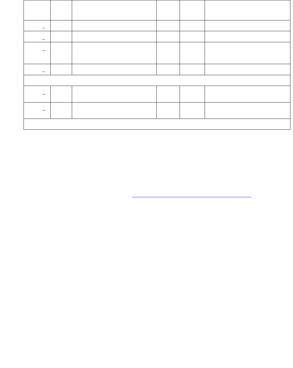
CO-TRK (Analog CO Trunk)
Issue 1 June 2005 839
Notes:
a. Error Type 0: Run the short test sequence first. If every test passes, run the long test
sequence. Refer to each appropriate test’s description, and follow its recommended
procedures.
b. These are in-line errors that have no specific test associated with them. Numerous Error
Types have these errors. Refer to Table 287: CO Trunk Errors with No Tests on page 840
for an explanation and appropriate action.
c. Error Type 15: software audit error that does not indicate any hardware malfunction. Run
short test sequence, and investigate associated errors.
d. Error Type 130: the circuit pack has been removed or has been insane for at least 11
minutes. To clear the error, reinsert or replace the circuit pack.
e. Numerous Error Types have these errors.
●Aux data 57345: Single polarity ringing current
●Aux data 57376: No loop current on incoming call
●Aux data 57408: No tip ground detected on outgoing call
●Aux data 57424: No loop current on outgoing call
●Aux data 57484: No dial tone on outgoing call
These errors will cause Dial Tone Test #0 to run and are only considered a problem if the
Dial Tone test fails (in which case Error Type 1537 will also show up). In this case, the trunk
may be put in “Ready-for-Service” state (shown as “disconnected” by status command), that
allows only incoming calls. Run Dial Tone Test #0, and follow its outlined procedures.
3073 (e) 57376 None
3329 (e) 57408 None
3329 (e) 57484 Dial Tone Test (#0) MAJ
MIN
WRN
OFF test port location l r 1
3585 (e) 57424 None
The ATMS Transmission Tests are not supported on the G700/G350, and abort with Error Code 1412.
3840 (g) 8000 Transmission Tests (ATMS)
(#844-848)
OFF test analog-testcall
3841 (g) Transmission Tests (ATMS)
(#844-848)
MIN OFF test analog-testcall
1. Major alarms may be downgraded to Warning alarms based on the value used in set options.
Table 286: CO Trunk Error Log Entries (continued)
Error
Type
Aux
Data
Associated Test Alarm
Level
On/Off
Board
Test to Clear Value
2 of 2

Communication Manager Maintenance-Object Repair Procedures
840 Maintenance Procedures for Avaya Communication Manager 3.0, Media Gateways and Servers
If error count associated with this error type is very high (i.e., 255) and if Alarm Status on the
Hardware Error Report is “n” (not alarmed), then the existence of this error type indicates
that, despite the fact that many in-line error messages have been received, every Call
Seizure test has passed. Problems at the CO may cause this condition rather than
problems with the PBX.
f. Error Types 1025/1281: logged for every version of the CO-TRK/CO-BD. However, no
MINOR alarms will be generated for Central Office Trunks [TN747B] with vintages V8 or
greater. Any failures received by this test will still be logged as Error type 1025/1281.
Check for the use of MFT/Range extenders. If there are extenders present, and there are
no other complaints or maintenance errors against this trunk, then there is a good chance
that Test #3 failed due to excessive loop current and may be ignored.
g. Error Type 3840: test calls made by the Automatic Transmission Measurement System
(ATMS) returned measurements in the unacceptable range.
Error Type 3841: measurements were in the marginal range. Use list testcall
detail to examine the specific transmission parameters that are out of spec, and
investigate the trunk for that kind of noise. If the noise is acceptable, then the AMTS
thresholds administered on the trunk group screen should be changed.
S8300 / G700: The associated tests for these error types do not run on a G700 Media
Gateway, and abort with Error Code 1412.
Table 287: CO Trunk Errors with No Tests
Error
Type
Aux
Data
Error Description and Repair Action
1 57347 Port error. Ringing without ground. This error is detected on an incoming
call on a ground-start CO trunk. The CO trunk circuit pack has not detected
a Tip ground before ringing current is detected. This may indicate that the
ground detector is not working. However, the call will be accepted. Busyout
the affected port, and run a long test. Observe the test results. If any tests
fail, refer to the description of the tests and the associated error codes.
Release the port. If users continue to report troubles, check for other errors
and make test calls to determine whether the problem should be referred to
the CO.
257 50176 Battery reversal detected. This is usually caused by the CO (often seen with
step-by-step and cross-bar offices in connection with outgoing calls). This is
detected if the direction of the loop current changes from normal to reverse
for at least 40 msec. Could occur if the trunk was just installed and for some
reason the Tip and Ring wires were reversed at the PBX. If battery reversals
occur during dialing, wrong numbers may result. Refer problem to CO. Ask
them to remove the battery reversal option.
1 of 3

CO-TRK (Analog CO Trunk)
Issue 1 June 2005 841
513 57364 Ground detector stuck active. After several occurrences, an on-board minor
alarm is generated. Run the short test sequence. If test aborts with Error
Code 1000, disconnect Tip and Ring and repeat short test. If test still aborts,
replace circuit pack. If test passes, refer problem to CO. If any other error
code is received, pursue that problem.
769 57392 CO not releasing after call is dropped from PBX end, or the loop is not open
after a disconnect. After several occurrences, an off-board or on-board
warning alarm is generated. Refer problem to CO.
2561 57345 Single polarity ringing current. This error results from abnormal ringing
current, but does not prevent the incoming call from being accepted. One
cause could be that the reverse current detector associated with the port is
failing. (Will not be detected by any tests.) Another cause could be that
normal current is not detected. In this case, neither incoming nor outgoing
calls can be completed, and the dial tone test will also fail. The last cause
could be that certain types of noise are present on the CO line during the
silent period of ringing. First check for other errors. If the count for this error
is very high (255), and every test passes, then either the reverse current
detector is defective or the CO line is noisy. If the CO line is suspect, make
Tip and Ring observations. If the line is determined to be noisy, refer the
problem to the CO. If the reverse current detector is defective, ignore this
error.
2817 57360 Ground but no ringing. This error occurs on an incoming call on a
ground-start trunk. If ringing is not detected within 5 seconds of the Tip being
grounded, the call is still accepted. If the CO is of the No. 5ESS. switch
type, ringing delays of more than 5 seconds during heavy traffic are fairly
common. Check for other errors.
2817 57393 The loop is opening too slowly after a disconnect. This error indicates an
on-board problem, although the trunk may be functional. Check for other
errors.
3073 57376 No loop current on incoming call. The incoming destination has already
answered and no loop current has been detected. If this is a hard fault, the
dial tone test and every outgoing call should also fail. Check for other errors.
Table 287: CO Trunk Errors with No Tests (continued)
Error
Type
Aux
Data
Error Description and Repair Action
2 of 3

Communication Manager Maintenance-Object Repair Procedures
842 Maintenance Procedures for Avaya Communication Manager 3.0, Media Gateways and Servers
System Technician-Demanded Tests: Descriptions and Error
Codes
Investigate tests in the order presented. By clearing error codes associated with NPE Crosstalk
test (#6), you may clear errors generated from other tests in the testing sequence.
3329 57408 Trunk error. No Tip ground detected on outgoing call. This error occurs
when an attempt is made to seize a ground-start CO trunk for an outgoing
call and Tip ground is not detected or the caller hangs up before Tip ground
is detected.
1. Busyout the affected port, and run a long test. Observe the test results.
If any tests fail, refer to the description of the tests and the associated
error codes. Release the port.
2. If users continue to report troubles, check for other errors and make test
calls to determine whether the problem should be referred to the CO.
Busyout the affected port, and run a long test. If Dial Tone Test #0
passes, ignore this error. Release the port.
3585 57424 No loop current on outgoing call. This error occurs on attempt to seize a loop
or ground-start trunk for an outgoing call. An error occurs if loop current is
not detected or the caller hangs up before it is detected. Busyout the
affected port, and run a long test. If CO Demand Diagnostic Test #3 passes
and this error keeps occurring, refer problems to CO. Release the port.
Table 287: CO Trunk Errors with No Tests (continued)
Error
Type
Aux
Data
Error Description and Repair Action
3 of 3
Order of Investigation Short Test
Sequence
Long Test
Sequence
D/ND1
NPE Crosstalk test (#6)
S8300 / G700 aborts with Error Code 1412
XND
Dial Tone test (#0) X ND
CO Demand Diagnostic test (#3) X X ND
Looparound and Conference test (#33)
S8300 / G700 aborts with Error Code 1412
XND
1 of 2

CO-TRK (Analog CO Trunk)
Issue 1 June 2005 843
Note:
Note: A Demand Diagnostic test (#3) will always return a PASS indication for CO-TRK/
CO-BD [TN747B] version 8 or greater. However, any errors produced as a result
of this test will be logged and produce no alarms.
If errors logged by Test #3 are the only complaints against this trunk, then the
system technician should check if MFT/Range Extenders are being used. If
extenders are present, then there is a good chance that there is excessive loop
current, which will cause Test #3 to log errors.
However, all else being normal, these errors should not affect the customer.
Note:
Note: The ATMS tests are not part of either test sequence. They are run either on
demand with test analog-testcall or by the ATMS schedule.
Dial Tone Test (#0)
This test attempts to seize a port and checks for the return of a dial tone.
Audit Update test (#36) X X ND
Transmission test - ATMS (#844-848)
S8300 / G700 aborts with Error Code 1412
ND
1. D = Destructive; ND = Nondestructive
Order of Investigation Short Test
Sequence
Long Test
Sequence
D/ND1
2 of 2
Table 288: Test #0 Dial Tone Test
Error
Code
Test
Result
Description / Recommendation
ABRT Could not allocate system resources to run this test.
1. Retry the command at 1-minute intervals up to 5 times.
1 of 4

Communication Manager Maintenance-Object Repair Procedures
844 Maintenance Procedures for Avaya Communication Manager 3.0, Media Gateways and Servers
1000 ABRT System resources required to run this test are not available. The port may
be busy with a valid call.
1. Use display port location to determine the trunk group/
member number of the port. Use status trunk to determine the
service state of the port. If the service state indicates that the port is
active, then it is unavailable for certain tests. Wait until the port is idle
before retesting.
2. Retry the command at 1-minute intervals up to 5 times.
1001 ABRT System resources required to run this test were not available. This could
be due to a failure to seize the port.
1. Retry the command at 1-minute intervals up to 5 times.
1002 ABRT The system could not allocate time slots for the test. The system may be
under heavy traffic conditions or it may have time slots out-of-service due
to TDM-BUS errors.
1. If the system has no TDM-BUS errors and is not handling heavy traffic,
retry the command at 1-minute intervals up to 5 times.
1004 ABRT The port was seized by a user for a valid call.
1. Use display port location to determine the trunk group/member
number of the port. Use status trunk to determine the service state
of the port. If the service state indicates that the port is active, then it is
unavailable for certain tests. Wait until the port is idle before retesting.
2. If the port status is idle, retry the command at 1-minute intervals up to 5
times.
1005 ABRT Trunk has been administered as incoming-only; dial tone can only be
obtained on outgoing trunks. This is a normal condition.
1018 ABRT Test has been disabled by administration.
1. Verify that the Maintenance Tests field on the Trunk Group form is
set to n. To enable the test, use change trunk-group x where <x>
equals the number of the trunk group to be tested. Enter y in the
Maintenance Tests field.
2000 ABRT Response to the test was not received within the allowable time period.
1. Retry the command at 1-minute intervals up to 5 times.
Table 288: Test #0 Dial Tone Test (continued)
Error
Code
Test
Result
Description / Recommendation
2 of 4

CO-TRK (Analog CO Trunk)
Issue 1 June 2005 845
FAIL Trunk was seized, but dial tone could not be detected.
1. Test every administered outgoing port on the board. Failure of 1 port
indicates a problem toward the CO.
2. If every port fails, see note below.
3. Check for errors on the TONE-BD or TONE-PT. Clear any errors
found, and repeat the test.
4. If the error has still not cleared, refer the problem to the CO.
5. If no service problems exist on the port, continue to use the port until
the circuit pack or media module can be replaced (as a last resort).
Perform a trunk test call to see if the trunk is operable.
Note:
Note: If the dial tone test fails for every port on a circuit pack or
media module, a -5 Volt power problem is indicated. To
investigate problems with a power unit, seeCARR-POW
(Carrier Power Supply) on page 770 or RMC-ENV (Power/
Fan Sensors) on page 1951.
2002 FAIL Seizure portion of test failed due to hardware problem. Fault is usually
caused by a disconnected trunk.
1. If the CO Demand Diagnostic test (#3) also failed, display the
Hardware Error Log. If the CO Demand Diagnostic test failed because
it could not detect ground (indicated by Error Type 1281 in the
Hardware Error Log) AND Error Type 3329 or 3585 appears in the
Hardware Error Log (with the same last occurred time as Error Type
1281 and 1537), replace the circuit pack or media module.
2. Check trunk wiring to ensure good connection; repeat test if wiring
correction made.
3. Locate another identical CO trunk and swap its wiring with the one
under test. Repeat test on both trunks, and determine whether
problem follows trunk or remains at original port. If problem follows
trunk, refer problem to CO. If problem remains at the port, replace the
circuit pack or media module and repeat the test.
1009 PASS Detected tone was not pure dial tone. No action required.
Table 288: Test #0 Dial Tone Test (continued)
Error
Code
Test
Result
Description / Recommendation
3 of 4

Communication Manager Maintenance-Object Repair Procedures
846 Maintenance Procedures for Avaya Communication Manager 3.0, Media Gateways and Servers
CO Demand Diagnostic Test (#3)
For ground start trunks, circuit pack or media module port relays are operated and checks are
made to see if the port can detect and apply ground on the Tip lead. This test also verifies that
there is no external ground on the Ring lead. In the absence of other failures, the circuit pack or
media module should be replaced only if this test fails with the CO line disconnected.
This test also checks the on-board programmable transmission circuits that allow the circuit
pack or media module to support transmission characteristics of several different countries.
PASS Trunk was seized, and dial tone was detected. User-reported troubles on
this port should be investigated by using other port tests and by examining
trunk or external wiring.
0NO
BOARD The test could not relate the internal ID to the port.
1. Verify that the board’s translations are correct. Translate the board, if
necessary.
2. Enter busyout board location
3. Enter reset board location
4. Enter release board location
5. Enter test board location
This should re-establish the linkage between the internal ID and the port.
Table 288: Test #0 Dial Tone Test (continued)
Error
Code
Test
Result
Description / Recommendation
4 of 4
Table 289: Test #3 CO Demand Diagnostic Test
Error
Code
Test
Result
Description / Recommendation
ABRT Could not allocate system resources to run this test.
1. Retry the command at 1-minute intervals up to 5 times.
1 of 4

CO-TRK (Analog CO Trunk)
Issue 1 June 2005 847
1000 ABRT System resources required to run this test are not available. The port may
be busy with a valid call.
1. Use display port location to determine the trunk group/member
number of the port. Use status trunk to determine the service state
of the port. If the service state indicates that the port is active, then it is
unavailable for certain tests. Wait until the port is idle before retesting.
2. If the port status is idle, retry the command at 1-minute intervals up to 5
times.
1004 ABRT The port was seized by a user for a valid call.
1. Use display port location to determine the trunk group/member
number of the port. Use status trunk to determine the service state
of the port. If the service state indicates that the port is active, then it is
unavailable for certain tests. Wait until the port is idle before retesting.
2. If the port status is idle, retry the command at 1-minute intervals up to 5
times.
1005 ABRT Test inapplicable to present configuration. This is a normal condition.
1018 ABRT Test has been disabled by administration.
1. For this test to run, the Maintenance Tests field on the Trunk Group
form must be n. Use change trunk-group <grp> to check the
field.
2000 ABRT Response to the test was not received within the allowable time period.
1. Retry the command at 1-minute intervals up to 5 times.
Table 289: Test #3 CO Demand Diagnostic Test (continued)
Error
Code
Test
Result
Description / Recommendation
2 of 4

Communication Manager Maintenance-Object Repair Procedures
848 Maintenance Procedures for Avaya Communication Manager 3.0, Media Gateways and Servers
FAIL Failure to detect ground or faulty ground detected on Ring lead. Display the
hardware errors for this trunk, to determine whether the fault was on- or
off-board. Look for Error Type 1025 or 1281 (if both appear in the Hardware
Error Log, pick the most recent error). Error Type 1025 indicates a faulty
ground detected on Ring lead (an off-board fault) and Error Type 1281
indicates failure to detect (internally generated) ground (an on-board fault).
Faulty ground detected on Ring lead (Error Type 1025):
Note:
Note: On TN747B vintage 8 and greater circuit packs, an incoming
seizure during this test may cause it to fail with an off-board
fault.
1. Repeat test. If test passes, ignore the original failure. If test aborts,
follow the recommended procedures.
2. Repeat test with CO line removed.
3. If test fails, replace the circuit pack or media module.
4. If test passes, refer problem to CO.
Failure to detect ground (Error Type 1281):
1. Run the long test sequence. If the CO Demand Diagnostic test fails,
the Dial Tone test (#0) fails with Error Code 2002, AND Error Type 3329
or 3585 appears in the Hardware Error Log (with the same last
occurred time as Error Type 1281 and 1537), replace the circuit pack or
media module.
2. Repeat test with CO line removed.
3. If test fails, replace the circuit pack or media module.
4. If test passes, the CO may be drawing too much current. Refer
problem to CO.
PASS This test verifies that the port is able to apply ground for outgoing calls and
detect ground for incoming calls; however, it does not provide information
about whether a CO line is actually connected. User-reported troubles on
this port should be investigated by using other port tests and by examining
trunk or external wiring.
Table 289: Test #3 CO Demand Diagnostic Test (continued)
Error
Code
Test
Result
Description / Recommendation
3 of 4

CO-TRK (Analog CO Trunk)
Issue 1 June 2005 849
NPE Crosstalk Test (#6)
Note:
Note: S8300 / G700: This test aborts with Error Code 1412.
The NPE Crosstalk test verifies that this port’s NPE channel talks on the selected time slot and
never crosses over to time slots reserved for other connections. If the NPE is not working
correctly, one way and noisy connections may be observed. This test is usually only part of a
port’s long test sequence and executes in approximately 20 to 30 seconds.
0NO
BOARD The test could not relate the internal ID to the port (no board).
1. Verify that the board’s translations are correct. Translate the board, if
necessary.
2. Enter busyout board location
3. Enter reset board location
4. Enter release board location
5. Enter test board location
This should re-establish the linkage between the internal ID and the port.
Table 289: Test #3 CO Demand Diagnostic Test (continued)
Error
Code
Test
Result
Description / Recommendation
4 of 4
Table 290: Test #6 NPE Crosstalk Test
Error
Code
Test
Result
Description / Recommendation
ABRT Could not allocate the necessary system resources to run this test.
1. Retry the command at 1-minute intervals up to 5 times.
1 of 3

Communication Manager Maintenance-Object Repair Procedures
850 Maintenance Procedures for Avaya Communication Manager 3.0, Media Gateways and Servers
1000 ABRT The port was seized by a user for a valid call.
1. Use display port location to determine the trunk group/member
number of the port. Use status trunk to determine the service state
of the port. If the port is active, wait until it is idle before testing.
2. If the port status is active but the port is idle (no calls), check the error
log for error type 1025 (see the error log table for a description of this
error and required actions). The port may be locked up. Check the CO
wiring, check for excessive loop current, and check the trunk
translations. (If the trunk is translated incorrectly, this test will abort.)
3. If the port status is idle, busyout and release the trunk, and retry the
command at 1-minute intervals up to 5 times.
4. If the test still aborts, replace the circuit pack.
1001 ABRT Could not allocate the necessary system resources to run this test.
1. Retry the command at 1-minute intervals up to 5 times.
1002 ABRT The system could not allocate time slots for the test. The system may be
under heavy traffic conditions or it may have time slots out-of-service due to
TDM-BUS errors.
1. If the system has no TDM-BUS errors and is not handling heavy traffic,
retry the command at 1-minute intervals up to 5 times.
1003 ABRT The system could not allocate a tone receiver for the test. The system may
be oversized for the number of Tone Detectors present, or some Tone
Detectors may be out of service.
1. Resolve any TTR-LEV errors.
2. Resolve any TONE-PT errors.
3. If neither condition exists, retry the command at 1-minute intervals up to
5 times.
1004 ABRT The port was seized by a valid call during the test. The test has been
aborted.
1. Use display port location to determine the trunk group/member
number of the port. Use status trunk to determine the service state
of the port. If the port is active, wait until it is idle before testing.
Table 290: Test #6 NPE Crosstalk Test (continued)
Error
Code
Test
Result
Description / Recommendation
2 of 3

CO-TRK (Analog CO Trunk)
Issue 1 June 2005 851
S8300 /
G700
1412
ABRT This test does not execute on a G700 media gateway.
2000 ABRT Response to the test request was not received within the allowable time
period.
1. Retry the command at 1-minute intervals up to 5 times.
2100 ABRT Could not allocate the necessary system resources to run this test.
1. Retry the command at 1-minute intervals up to 5 times.
Any FAIL The NPE of the tested port was found to be transmitting in error. This will
cause noisy and unreliable connections.
1. Replace the circuit pack.
PASS The port is correctly using its allocated time slots. User-reported troubles on
this port should be investigated by using other port tests and by examining
trunk or external wiring.
0NO
BOARD The test could not relate the internal ID to the port (no board).
1. Verify that the board’s translations are correct. Translate the board, if
necessary.
2. Enter busyout board location
3. Enter reset board location
4. Enter release board location
5. Enter test board location
This should re-establish the linkage between the internal ID and the port.
Table 290: Test #6 NPE Crosstalk Test (continued)
Error
Code
Test
Result
Description / Recommendation
3 of 3

Communication Manager Maintenance-Object Repair Procedures
852 Maintenance Procedures for Avaya Communication Manager 3.0, Media Gateways and Servers
Looparound and Conference Circuit Test (#33)
Note:
Note: S8300 / G700: This test aborts with Error Code 1412.
This test checks the reflective loop-around and conference capabilities of a CO port circuit. The
test uses 404-Hz, 1004-Hz, and 2804-Hz tones. Each tone is transmitted separately through
the loop and checked.
Table 291: Test #33 Looparound and Conference Circuit Test
Error
Code
Test
Result
Description / Recommendation
ABRT Could not allocate the necessary system resources to run this test.
1. Retry the command at 1-minute intervals up to 5 times.
7 ABRT Conference Circuit test aborted.
1. Retry the command at 1-minute intervals up to 5 times.
129 ABRT The 404-Hz reflective loop-around test aborted. Response to the test
request was not received within the allowable time period.
1. Retry the command at 1-minute intervals up to 5 times.
131 The 1004-Hz reflective loop-around test aborted. Response to the test
request was not received within the allowable time period.
1. Retry the command at 1-minute intervals up to 5 times.
133 The 2804-Hz reflective loop-around test aborted. Response to the test
request was not received within the allowable time period.
1. Retry the command at 1-minute intervals up to 5 times.
1000 ABRT System resources required to run this test are not available. The port may
be busy with a valid call.
1. Use display port location to determine the trunk group/
member number of the port. Use status trunk to determine the
service state of the port. If the port is active, wait until it is idle before
testing.
2. If the port status is active but the port is idle (no calls), check the error
log for error type 769 (see the error log table for a description of this
error and required actions). The port may be locked up.
3. If the port status is idle, retry the command at 1-minute intervals up to
5 times.
1 of 4

CO-TRK (Analog CO Trunk)
Issue 1 June 2005 853
1002 ABRT The system could not allocate time slots for the test. The system may be
under heavy traffic conditions or it may have time slots out-of-service due
to TDM-BUS errors.
1. If the system has no TDM-BUS errors and is not handling heavy
traffic, retry the command at 1-minute intervals up to 5 times.
1003 ABRT The system could not allocate a tone receiver for the test. The system
may be oversized for the number of Tone Detectors present, or some
Tone Detectors may be out of service.
1. Resolve any TTR-LEV errors.
2. Resolve any TONE-PT errors.
3. If neither condition exists, retry the command at 1-minute intervals up
to 5 times.
1004 ABRT System resources required to run this test are not available. The port may
be busy with a valid call.
1. Use display port location to determine the trunk group/
member number of the port. Use status trunk to determine the
service state of the port. If the port is active, wait until it is idle before
testing.
2. If the port status is idle, retry the command at 1-minute intervals up to
5 times.
1018 ABRT The test was disabled by administration. Verify that the Maintenance
Test field on the Trunk Group screen is set to n. To enable the test, use
change trunk-group <x>, where <x> equals the number of the trunk
group to be tested. Change the Maintenance Test field on the screen to
y.
1. Retry the command at 1-minute intervals up to 5 times.
S8300 /
G700
1412
ABRT This test does not execute on a G700 media gateway.
2000 ABRT Response to the test was not received within the allowable time period.
1. Retry the command at 1-minute intervals up to 5 times.
2100 ABRT Could not allocate the necessary system resources to run this test.
1. Retry the command at 1-minute intervals up to 5 times.
Table 291: Test #33 Looparound and Conference Circuit Test (continued)
Error
Code
Test
Result
Description / Recommendation
2 of 4

Communication Manager Maintenance-Object Repair Procedures
854 Maintenance Procedures for Avaya Communication Manager 3.0, Media Gateways and Servers
7 FAIL The conference capabilities of the port failed (Error Code 7).
129 The reflective 404-Hz Tone test failed. No transmission was detected to or
from the port (Error Code 129).
FAULT ISOLATION: Proceed as follows unless power or tone problems are
suspected (see Description/Recommendation for Error Code 7 below).
2. To make sure the problem is on-board, disconnect the port from the
CO and retry the test. Coordinate this with the CO, or do it after busy
hours; otherwise, the CO may put the connection out of service.
3. If the retry fails, replace the circuit pack.
4. If the retry passes and no troubles have been reported, disable the
test. If the retry passes and troubles have been reported, refer the
problem to the CO.
131 The reflective 1004-Hz Tone test failed. No transmission was detected to
or from the port (Error Code 131).
FAULT ISOLATION: Proceed as follows unless power or tone problems are
suspected (see Description/Recommendation for Error Code 7 below).
5. To make sure the problem is on-board, disconnect the port from the
CO and retry the test. Coordinate this with the CO, or do it after busy
hours; otherwise, the CO may put the connection out of service.
6. If the retry fails, replace the circuit pack.
7. If the retry passes and no troubles have been reported, disable the
test. If the retry passes and troubles have been reported, refer the
problem to the CO.
133 The reflective 2804-Hz Tone test failed. No transmission was detected to
or from the port (Error Code 133).
FAULT ISOLATION: Proceed as follows unless power or tone problems are
suspected (see Description/Recommendation for Error Code 7 below).
8. To make sure the problem is on-board, disconnect the port from the
CO and retry the test. Coordinate this with the CO, or do it after busy
hours; otherwise, the CO may put the connection out of service.
9. If the retry fails, replace the circuit pack.
10. If the retry passes and no troubles have been reported, disable the
test. If the retry passes and troubles have been reported, refer the
problem to the CO.
Table 291: Test #33 Looparound and Conference Circuit Test (continued)
Error
Code
Test
Result
Description / Recommendation
3 of 4

CO-TRK (Analog CO Trunk)
Issue 1 June 2005 855
7
129
131
133
FAIL If the Looparound and Conference Circuit test (#33) fails for every port on a
circuit pack, a -5 Volt power problem is indicated. To investigate problems
with a power unit, see CARR-POW (Carrier Power Supply) on page 770 or
RMC-ENV (Power/Fan Sensors) on page 1951.
If a red LED is lit on the power unit circuit pack, replace the pack.
If the test fails on more than 1 port, check for errors on the TONE-BD or the
TONE-PT. If errors, take appropriate actions. When the tone errors are
cleared, rerun the test.
S8700 MC: if the test fails again, see Fault Isolation Using Duplicated
PNC on page 1862.
PASS CO Trunk Looparound and Conference test is successful. User-reported
troubles on this port should be investigated by using other port tests and by
examining trunk or external wiring.
0NO
BOARD The test could not relate the internal ID to the port (no board).
1. Verify that the board’s translations are correct. Translate the board, if
necessary.
2. Enter busyout board location
3. Enter reset board location
4. Enter release board location
5. Enter test board location
This should re-establish the linkage between the internal ID and the port.
Table 291: Test #33 Looparound and Conference Circuit Test (continued)
Error
Code
Test
Result
Description / Recommendation
4 of 4

Communication Manager Maintenance-Object Repair Procedures
856 Maintenance Procedures for Avaya Communication Manager 3.0, Media Gateways and Servers
Port Audit Update Test (#36)
This test will send updates of the CO port translation for every port on the circuit pack or media
module that has been translated. The update is non-disruptive and guards against possible
corruption of translation data contained on the circuit pack or media module. No response
message is expected from the circuit pack or media module once it receives translation
updates. The port translation data includes: ground or loop start trunk, tone or rotary dialing
trunk, rotary dialing inter-digit timing, network balance R/RC, and disconnect timing.
Table 292: Test #36 Port Audit Update Test
Error
Code
Test
Result
Description / Recommendation
ABRT Could not allocate the necessary system resources to run this test.
1. Retry the command at 1-minute intervals up to 5 times.
1006 ABRT The port has been placed out of service, perhaps by craft busyout.
1. Use display port location to determine the trunk group/
member number of the port. Use status trunk to determine
the service state of the port. If the service state indicates that the
port is active, wait until it is idle before testing.
2. If the port status is idle, retry the command at 1-minute intervals
up to 5 times.
2100 ABRT System resources required to run this test were not available.
1. If the port status is idle, retry the command at 1-minute intervals
up to 5 times.
FAIL Internal system error
1. Retry the command at 1-minute intervals up to 5 times.
PASS This test passed. Translation information was successfully updated
on the circuit pack or media module. User-reported troubles on this
port should be investigated by using other port tests and by examining
trunk or external wiring. If the trunk is busied out, the test will not run,
but will return PASS. To verify that the trunk is in-service:
1. Enter status trunk to verify that the trunk is in-service. If the
trunk is in-service, no further action is necessary. If the trunk is
out-of-service, continue to step 2.
2. Enter release trunk to put trunk back into in-service.
3. Retry the test command.
1 of 2

CO-TRK (Analog CO Trunk)
Issue 1 June 2005 857
Transmission Test (#844-848)
This test is nondestructive.
Note:
Note: S8300 / G700 The G700 Media Gateway does not support the Automatic
Transmission Measurement System. These tests abort with Error Code 1412.
Note:
Note: Tests #844 – 848 are not supported on an International switch.
These tests are run by the ATMS (Automatic Transmission Measurement System). They are
not part of the long or short trunk test sequences. Instead, they are run on demand with test
analog-testcall or as part of ATMS scheduled testing. For more information, see
Automatic Transmission Measurement System in Maintenance Procedures (03-300192).
The test call is run from an analog port on a TN771 Maintenance/Test circuit pack. It attempts to
seize a port and make a call to a TTL (terminating test line) on the trunk’s far end. Transmission
performance measurements are made and compared to administered thresholds. Errors are
generated when results fall outside of “marginal” or “unacceptable” thresholds. Detail and
summary measurement reports are obtainable via list testcalls.
0NO
BOARD The test could not relate the internal ID to the port (no board).
1. Verify that the board’s translations are correct. Translate the
board, if necessary.
2. Enter busyout board location
3. Enter reset board location
4. Enter release board location
5. Enter test board location
This should re-establish the linkage between the internal ID and the
port.
Table 292: Test #36 Port Audit Update Test (continued)
Error
Code
Test
Result
Description / Recommendation
2 of 2

Communication Manager Maintenance-Object Repair Procedures
858 Maintenance Procedures for Avaya Communication Manager 3.0, Media Gateways and Servers
Table 293: Test #844-848 Transmission Test
Error
Code
Test
Result
Description / Recommendation
1000 ABRT System resources required to run this test are not available. The port may
be busy with a valid call.
1. Use display port location to determine the trunk group/member
number of the port. Use status trunk to determine the service
state of the port. If the port is active, wait until it is idle before testing.
2. If the port status is idle, then retry the command at 1-minute intervals
up to 5 times.
1001 ABRT Could not allocate the necessary system resources to run this test.
1. Retry the command at 1-minute intervals up to 5 times.
1002 ABRT The system could not allocate timeslots for the test. The system may be
under heavy traffic conditions or it may have timeslots out of service due to
TDM bus errors.
1. If the system has no TDM bus errors and is not handling heavy traffic,
retry the command at 1-minute intervals up to 5 times.
1004 ABRT The port has been seized by a user for a valid call. Use status trunk to
determine when the port is available for testing.
1. Retry the command at 1-minute intervals up to 5 times.
1005 ABRT Trunk has been administered as incoming-only; transmission tests can only
be run on outgoing trunks.
1115 ABRT The near-end test line on the TN771 circuit pack could not be allocated.
1. Verify that the TN771 circuit pack is in service and that port 1 is
administered and in service with status port.
2. Retry the command at 1-minute intervals up to 5 times.
1900 ABRT The test completion message was not received from the TN771 circuit
pack.
1. Test the TN771 circuit packs.
1901 ABRT This error occurs when the TN771 circuit pack uplinks a message that is
not the proper response for this test. The anticipated uplink messages are
seize, ring or answer.
1. Verify that the trunk is administered properly.
1 of 4

CO-TRK (Analog CO Trunk)
Issue 1 June 2005 859
1905 ABRT Intercept tone detected from far end.
1. Get the test line data from and verify it with the far end.
2. Dial the test number manually to see if the TTL is reached.
If not, then either the number is wrong or the far end is administered
incorrectly.
1906 ABRT Reorder tone detected from far end.
1. See actions for error code 1905.
1907 ABRT Other unexpected tone detected from far end.
1. See actions for error code 1905.
1913 ABRT Audible Ring detected from far end.
1. See actions for error code 1905.
1914 ABRT Unidentified interrupted tone detected from far end.
1. See actions for error code 1905
1915 ABRT Busy tone detected from far end.
1. Since the test line at the far end was busy, try the test again.
2. If the test continues to abort, the problem is with the far-end system.
1918 ABRT Test progress tone not removed from far end (type 105 test line only).
1. The problem is with the far-end system; a technician at the far end
should test the test line TN771 or ADFTC).
1919 ABRT Unexpected far-end release
1. The problem is with the far-end system; a technician at the far end
should test the test line (TN771 or ADFTC).
1920 ABRT No response from far end.
1. The problem is with the far-end system; a technician at the far end
should test the test line: TN771 or ADFTC.
1921 ABRT No data returned from far end.
1. The problem is with the far-end system; a technician at the far end
should test the test line: TN771 or ADFTC.
Table 293: Test #844-848 Transmission Test (continued)
Error
Code
Test
Result
Description / Recommendation
2 of 4

Communication Manager Maintenance-Object Repair Procedures
860 Maintenance Procedures for Avaya Communication Manager 3.0, Media Gateways and Servers
1922 ABRT Steady, unidentifiable tone from far end
1. See actions for error code 1905.
1923 ABRT Broadband energy detected from far end (such as voice or
announcement).
1. See actions for error code 1905.
1924 ABRT No test tone from far end
1. See actions for error code 1905.
1938 ABRT Near-end self test failed.
1. Test the TN771 circuit packs.
1939 ABRT Loss self check at 0dBm at 1004 Hz failed.
1. Test the TN771 circuit packs.
1940 ABRT Far-end noise self check failed.
1. The problem is with the far end system; a technician at the far end
should test the test line: TN771 or ADFTC.
1941 ABRT High-frequency singing return loss self check failed.
1. Test the TN771 circuit packs.
1942 ABRT Echo return loss self check failed.
1. Test the TN771 circuit packs.
1943 ABRT Singing return loss self check failed.
1. Test the TN771 circuit packs.
1944 ABRT Loss self check at -16 dBm at 1004 Hz failed.
1. Test the TN771 circuit packs.
1945 ABRT Loss self check at -16 dBm at 404 Hz failed.
1. Test the TN771 circuit packs.
1946 ABRT Loss self check at -16 dBm at 2804 Hz failed.
1. Test the TN771 circuit packs or.
Table 293: Test #844-848 Transmission Test (continued)
Error
Code
Test
Result
Description / Recommendation
3 of 4

CO-TRK (Analog CO Trunk)
Issue 1 June 2005 861
1947 ABRT Noise with tone self check failed.
1. Test the TN771 circuit packs or.
2000 ABRT The test timed out while waiting for a response from the TN771 circuit
pack.
Retry the command at 1-minute intervals up to 5 times.
2012 ABRT An internal software error occurred.
1. Retry the command at 1-minute intervals up to 5 times.
2053 ABRT The test call could not be established, but an explanation is unavailable.
1. Retry the command at 1-minute intervals up to 5 times.
2056 ABRT An error occurred while trying to obtain results from the TN771 circuit pack.
Test the TN771 circuit packs.
FAIL Measured transmission performance was in the unacceptable range as
administered on the trunk group screen. Retrieve a measurement report via
list testcalls. Make sure that ATMS thresholds are set properly on
page 4 of the trunk group screen. Besides the facility, test failures can be
caused by faulty test lines or switch paths. If the measurements point to a
facility problem, report the results to the trunk vendor.
8000 FAIL Measured transmission performance was in the marginal range as
administered on the trunk group screen. This generally means that the
trunk is usable but has an undesirable amount of noise or loss. If the user
does not report unacceptable effects, it may not be necessary to take any
action. Retrieve a measurement report via list testcalls. Make sure
that ATMS thresholds are set properly on page 4 of the trunk group screen.
Table 293: Test #844-848 Transmission Test (continued)
Error
Code
Test
Result
Description / Recommendation
4 of 4
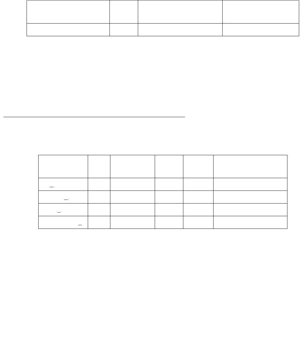
Communication Manager Maintenance-Object Repair Procedures
862 Maintenance Procedures for Avaya Communication Manager 3.0, Media Gateways and Servers
CONFIG (System Configuration)
S8700 | 8710 / S8500
The System Configuration MO oversees logical insertion and removal of circuit packs in the
system. When Switch Control detects that a circuit pack is present in a port slot, it informs
System Configuration and System Configuration queries the circuit pack to determine the type
and vintage of the circuit pack. Similarly, when Switch Control detects that a circuit pack has
been removed from a port slot, it informs System Configuration.
There are no alarms or tests for System Configuration, but three types of errors are logged to
the Hardware Error Log.
Error Log Entries and Test to Clear Values
Notes:
a. This error should not occur. It indicates that an attempt was made by software to raise an
alarm against CONFIG without first logging a CONFIG error.
b. Error Types 1-119: a port circuit pack in the system did not respond to a circuit pack type
inquiry. Follow the procedures outlined in (c) to determine whether there is an error.
c. Error Type 257: less than 25% of trunk group is available.
MO Name in Alarm Log Alarm
Level
Initial Command to Run Full Name of MO
CONFIG none none System Configuration
Table 294: System Configuration Error Log Entries
Error Type Aux
Data
Associated
Test
Alarm
Level
On/Off
Board
Test to Clear Value
0 (a) 0 none none N/A none
1–119 (b) 0–21 none
257 (c) none MAJ
1001–1119 (d) 0–21 none

CONFIG (System Configuration)
Issue 1 June 2005 863
d. Error Types 1001 - 1119: a port circuit pack in the system did not respond to a vintage
inquiry.
As a result of any of these errors, a port circuit pack may be physically inserted in a port
slot, but the system may not recognize its existence. The Aux Data field specifies the
circuit pack’s port-network number as indicated in the following table.
The Error Type field specifies the carrier and slot location of the circuit pack that caused the
error as indicated in Table 295: Converting Error Types To Carrier Locations on page 864.
Converting Aux Data to Port-Network Number
Aux Data Port-Network Number
01
12
23
34
45
56
67
78
89
910
10 11
11 12
12 13
13 14
14 15
15 16
16 17
17 18
18 19
19 20
20 21
21 22

Communication Manager Maintenance-Object Repair Procedures
864 Maintenance Procedures for Avaya Communication Manager 3.0, Media Gateways and Servers
If the Error Type is greater than 1000, subtract 1000 from the Error Type field before
consulting the table.
S8700 MC:Before proceeding, if multiple CONFIG errors are simultaneously logged with an
Aux Data of 1, investigate any EXP-INTF (Expansion Interface) errors.
Once the port’s circuit-pack location has been determined from Table 295: Converting Error
Types To Carrier Locations on page 864, use list configuration all to determine
whether the circuit pack is inserted. If the circuit pack has already been inserted but the
error persists, replace the circuit pack. If not, insert the pack.
Table 295: Converting Error Types To Carrier Locations
Error Type Carrier Location
1(a)
2E01
3E02
4E03
5E04
6E05
7E06
8E07
9E08
10 E09
11 E10
12 E11
13 E12
14 E13
15 E14
16 E15
17 E16
18 E17
19 E18
20 E19
21 E20
1 of 5

CONFIG (System Configuration)
Issue 1 June 2005 865
22 E00 (d)
23 (a)
24 (a)
25 (a)
26 (a)
27 A00 (e)
28 A01 (b)
29 A02
30 A03
31 A04
32 (a)
33 (a)
34 D01
35 D02
36 D03
37 D04
38 D05
39 D06
40 D07
41 D08
42 D09
43 D10
44 D11
45 D12
46 D13
47 D14
48 D15
Table 295: Converting Error Types To Carrier Locations (continued)
Error Type Carrier Location
2 of 5

Communication Manager Maintenance-Object Repair Procedures
866 Maintenance Procedures for Avaya Communication Manager 3.0, Media Gateways and Servers
49 D16
50 D17
51 D18
52 D19
53 D20
54 D00 (d)
55 (a)
56 A05
57 A06
58 A07
59 A08
60 A09
61 A10 (c)
62 A11
63 A12
64 (a)
65 (a)
66 B01
67 B02
68 B03
69 B04
70 B05
71 B06
72 B07
73 B08
74 B09
75 B10
Table 295: Converting Error Types To Carrier Locations (continued)
Error Type Carrier Location
3 of 5

CONFIG (System Configuration)
Issue 1 June 2005 867
76 B11
77 B12
78 B13
79 B14
80 B15
81 B16
82 B17
83 B18
84 B19
85 B20
86 B00 (d)
87 (a)
88 A13
89 A14
90 A15
91 A16
92 A17
93 A18
94 A19
95 A20
96 (a)
97 (a)
98 C01
99 C02
100 C03
101 C04
102 C05
Table 295: Converting Error Types To Carrier Locations (continued)
Error Type Carrier Location
4 of 5

Communication Manager Maintenance-Object Repair Procedures
868 Maintenance Procedures for Avaya Communication Manager 3.0, Media Gateways and Servers
Notes:
a. Error Types 1, 23, 25, 25, 26, 32, 33, 55, 64, 65, 87, 96, 97, 119 do not represent physical
port circuit pack slots and are not logged against CONFIG..
b. If Error Type 28 occurs in a PN, it refers to the circuit pack in slot A01.
c. If Error Type 61 occurs in a PN, it refers to the circuit pack in slot A10.
d. Error Type 22, 54, 86, 118: Slots B00, C00, D00, and E00 refer to the Service Slots in the
B, C, D, and E carriers.
e. Error Type 27: In a PN’s A carrier, slot A00 is the Tone Generator’s slot.
103 C06
104 C07
105 C08
106 C09
107 C10
108 C11
109 C12
110 C13
111 C14
112 C15
113 C16
114 C17
115 C18
116 C19
117 C20
118 C00 (d)
119 (a)
Table 295: Converting Error Types To Carrier Locations (continued)
Error Type Carrier Location
5 of 5


Communication Manager Maintenance-Object Repair Procedures
870 Maintenance Procedures for Avaya Communication Manager 3.0, Media Gateways and Servers
DAT-LINE (Data Line Port)
S8700 | 8710 / S8500
The TN726 Data Line circuit pack has eight ports, each of which supports an RS-232 interface
to asynchronous CPE (customer-premises equipment). Each of these ports and the equipment
connected to it constitute a data line. For DT-LN-BD (Data Line circuit pack) errors, see XXX-BD
(Common Port Circuit Pack/Media Module) on page 2539. Check circuit pack-level errors first
since the usability of the ports depend on the health of the circuit pack.
Use add data-module to administer data line ports at the terminal. The data module type is
data-line. The list data-module command shows every administered data module in the
system.
The TN750 Announcement circuit pack has one data line-type port on it. This data line port is
used for saving and restoring announcements. This data line port is not supported on the S8500
and S8700 media server products. For a description of and repair instructions for the TN750,
see ANL-BD (Analog Line Circuit Pack) on page 403.
Note:
Note: If the tests for the data line port in question pass, and user-reported complaints
persist, there is probably an external problem. Test the ADU (asynchronous data
unit), using the procedures in User Manual Z3A Asynchronous Data Unit,
555-401-701. If the ADU appears to be working properly, check the external
wiring, then check the equipment.
Error Log Entries and Test to Clear Values
MO Name in
Alarm Log
Alarm
Level
Initial SAT Command to Run Full Name of MO
DAT-LINE MIN test port location lData Line port
DAT-LINE WRN test port location lData Line port
Table 296: Data Line Port Error Log Entries
Error
Type
Aux
Data
Associated Test Alarm
Level
On/Off
Board
Test to Clear Value
0 (a) 0 Any Any Any test port location sh r 1
1Digital
Looparound test
(#171)
MIN ON test port location s r 2
1 of 2
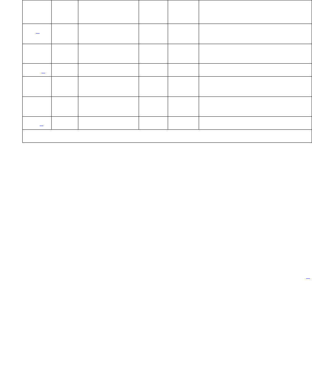
DAT-LINE (Data Line Port)
Issue 1 June 2005 871
Notes:
a. Error Type 0: Run the short test sequence first. If every test passes, run the long test
sequence. Refer to each test’s description, and follow its recommended procedures.
b. Error Type 15: This is a software audit error that does not indicate any hardware
malfunction. Run the short test sequence, and investigate errors.
c. Error Type 130: the circuit pack has been removed or has been insane for more than
11-minutes. To clear the error, reseat or replace the circuit pack.
d. Error Type 769: the data line circuit pack found an error in the transmit/receive circuitry of
an administered data line when the circuit pack was inserted. Perform the following:
1. Enter busyout board location for the circuit pack on which the port resides.
2. Enter reset board location. Check the Error Log to determine whether Error Type
#769 is logged again for DAT-LINE. Verify that the Active Alarms Only field is n.
If Error Type #769 reappears, replace the data line circuit pack. If not, proceed to Step 3.
3. Enter release board location.
15(b) Any Audit Update test
(#36)
18 0 busyout port
location
WRN OFF rel port location
130 (c) None WRN ON test port location sh
257 Conference
Circuit test (#7)
MIN ON test port location l r 2
513 NPE Crosstalk
test (#6)
MIN ON test port location l r 2
769(d) 40983 None
Table 296: Data Line Port Error Log Entries (continued)
Error
Type
Aux
Data
Associated Test Alarm
Level
On/Off
Board
Test to Clear Value
2 of 2

Communication Manager Maintenance-Object Repair Procedures
872 Maintenance Procedures for Avaya Communication Manager 3.0, Media Gateways and Servers
System Technician-Demanded Tests:
Descriptions and Error Codes
Investigate tests in the order presented. By clearing error codes associated with the Digital
Looparound test, you may also clear errors generated from other tests in the testing sequence.
NPE Crosstalk Test (#6)
The NPE Crosstalk test verifies that this port’s NPE channel talks on the selected time slot and
never crosses over to time slots reserved for other connections. If the NPE is not working
correctly, 1-way and noisy connections may be observed. This test is usually part of a port’s
long test sequence and executes in about 20 to 30 seconds.
Order of Investigation Short Test
Sequence
Long Test
Sequence
D/ND1
1. D = Destructive; ND = Nondestructive
Digital Looparound test
(#171)
XXND
NPE Crosstalk test (#6) X ND
Conference Circuit test (#7) X ND
Audit Update test (#36) X X ND
Table 297: Test #6 NPE Crosstalk Test
Error
Code
Test
Result
Description / Recommendation
ABRT Could not allocate the necessary system resources to run this test.
1. Retry the command at 1-minute intervals up to 5 times.
1000 ABRT System resources required to run test are not available. The port may be
in use on a valid call. Use status data-module to determine when the
port is available for testing.
1. Retry the command at 1-minute intervals up to 5 times.
1001 ABRT Could not allocate the necessary system resources to run this test.
1. Retry the command at 1-minute intervals up to 5 times.
1 of 2

DAT-LINE (Data Line Port)
Issue 1 June 2005 873
1002 ABRT The system could not allocate time slots for the test. The system may be
under heavy traffic conditions or it may have time slots out-of-service due
to TDM-BUS errors.
1. Resolve any TDM-BUS errors.
2. If the system is not handling heavy traffic, retry the command at
1-minute intervals up to 5 times.
1003 ABRT The system could not allocate a tone receiver for the test. The system
may be oversized for the number of tone detectors present, or some tone
detectors may be out-of-service.
1. Resolve any TTR-LEV and TONE-PT errors.
2. If neither condition exists, retry the command at 1-minute intervals up
to 5 times.
1004 ABRT The port was in use on a valid call.
1. Determine whether the port is available for testing (status
data-module).
2. When available, retry the command at 1-minute intervals up to 5
times.
1020 ABRT An existing Error Type 769 on this port prevented the test from running.
1. Follow the procedures for Error Type 769.
2000 ABRT Response to the test command was not received within the allowable time
period.
1. Rerun the test at 1-minute intervals up to 5 times.
2100 ABRT Could not allocate the necessary system resources to run this test.
1. Retry the command at 1-minute intervals up to 5 times.
Any FAIL The NPE of the tested port was transmitting in error, which can cause
noisy and unreliable connections.
1. Replace the circuit pack.
PASS The port is correctly using its allocated time slots.
1. Investigate user-reported troubles on this port using other port tests
and examining the ADU, external wiring, and customer equipment.
Table 297: Test #6 NPE Crosstalk Test (continued)
Error
Code
Test
Result
Description / Recommendation
2 of 2

Communication Manager Maintenance-Object Repair Procedures
874 Maintenance Procedures for Avaya Communication Manager 3.0, Media Gateways and Servers
Conference Circuit Test (#7)
The Conference Circuit test verifies that the NPE channel for the port being tested can correctly
perform the conferencing function. The NPE is instructed to listen to several different tones and
conference the tones together. The resulting signal is then measured by a tone detector port. If
the level of the tone is within a certain range, the test passes.
Table 298: Test #7 Conference Circuit Test
Error
Code
Test
Result
Description / Recommendation
ABRT Could not allocate the necessary system resources to run this test.
1. Retry the command at 1-minute intervals up to 5 times.
1000 ABRT System resources required to run this test are not available. The port may
be in use on a valid call. Use status data-module to determine when
the port is available for testing.
1004 ABRT The port has been seized by a user for a valid call. Use status
data-module to determine when the port is available for testing.
1. Retry the command at 1-minute intervals up to 5 times.
1020 ABRT An existing Error Type #769 on this port prevented the test from running.
1. Follow the procedure following the Error Log Table for Error Type
#769.
2000 ABRT Response to the test request was not received within the allowable time
period.
1. Rerun the test at 1-minute intervals up to 5 times.
2100 ABRT Could not allocate the necessary system resources to run this test.
1. Retry the command at 1-minute intervals up to 5 times.
Any FAIL The conference circuit test failed (possible off-board problem).
1. Busyout and release the port (data line), and then retest.
2. Replace the circuit pack if the test continues to fail.
PASS The port can correctly conference multiple connections. Investigate
user-reported troubles on this port using other port tests and examining the
ADU, external wiring, and customer equipment.

DAT-LINE (Data Line Port)
Issue 1 June 2005 875
Audit Update Test (#36)
This audit verifies that the hardware state of the data line is consistent with the system
translations. The audit queries the port for the switchhook state, the software state is updated
according to the returned value. Also, the audit data line options down to the port.
Table 299: Test #36 Audit Update Test
Error
Code
Test
Result
Description / Recommendation
1000 ABRT System resources required to run this test are not available.
1. Retry the command at 1-minute intervals up to 5 times.
2. Escalate the problem if the test continues to abort.
1006 ABRT An existing Error Type #769 on this port prevented the test from running.
1. Follow the procedure following the Error Log Table for Error Type
#769.
2000 ABRT Response to the test request was not received within the allowable time
period.
1. Rerun the test at 1-minute intervals up to 5 times.
2100 ABRT Could not allocate the necessary system resources to run this test.
1. Retry the command at 1-minute intervals up to 5 times.
ABRT Internal system error
1. Try the command again at 1-minute intervals up to 5 times.
7 FAIL Internal system error
1. Try the command again at 1-minute intervals up to 5 times.
PASS The hardware port state is consistent with the software state. Investigate
user-reported troubles on this port using other port tests and examining the
ADU, external wiring, and customer equipment.

Communication Manager Maintenance-Object Repair Procedures
876 Maintenance Procedures for Avaya Communication Manager 3.0, Media Gateways and Servers
Digital Loop-Around Test (#171)
The Digital Looparound test checks the data line port’s ability to transmit and receive data on
the TDM Bus. Data is sent through an available Maintenance/Test digital port over the TDM
Bus, internally looped through the data line port back onto the TDM Bus, and received again by
the same Maintenance/Test digital port.
Only one of the two digital ports on a Maintenance/Test circuit pack is used for this test, and that
port must be the first such port; such as port 02. If port 02 is in use, out-of-service, or not
present, the test aborts. This test may fail if the Maintenance/Test digital port used by the test is
not functioning properly. If there are any M/T-DIG errors in the Error Log, see M/T-BD
(Maintenance/Test Circuit Pack) on page 1705 to clear them first.
This test will pass regardless of any customer equipment that may be connected to the port, as
long as the equipment is not using the port.
Table 300: Test #171 Digital Loop-Around Test
Error
Code
Test
Result
Description / Recommendation
ABRT Internal system error
1. Retry the command at 1-minute intervals up to 5 times.
1000 ABRT System resources required to run test are not available. The port may be in
use on a valid call. Use status data-module to determine when the port
is available for testing.
1. Retry the command at 1-minute intervals up to 5 times.
1005
1007
ABRT Data Channel 3 is not administered. This port is required to run this test.
1. Verify that data channel 3 is not administered with list
data-module. Administer data channel 3 with add data-module,
and run this test again.
1016 ABRT Data Channel 3 is busy. The port may be in use on a valid call. Use status
data-module to determine when the port is available for testing.
1. Retry the command at 1-minute intervals a maximum of 5 times.
1020 ABRT An existing Error Type #769 on this port prevented the test from running.
1. Follow the procedure following the Error Log Table for Error Type #769.
1 of 4

DAT-LINE (Data Line Port)
Issue 1 June 2005 877
1042 ABRT Port under test is a TTI port and has only default translations with no
assigned extension. The executed test requires an assigned extension
associated with the port being tested. Therefore, this test cannot
successfully execute.
1. If there is a need to execute the test on this particular port, then the
tester must ensure that the port is fully translated such that the port has
an assigned extension.
1180 ABRT There is no Maintenance/Test circuit pack digital port available to carry out
the test.
1. Check to see if the Maintenance/Test digital ports are present. (Enter
list config; ports 02 and 03 should show).
2. If the digital ports (02 and 03) on the Maintenance/ Test circuit pack are
not present, see M/T-BD (Maintenance/Test Circuit Pack) on
page 1705.
3. If the digital ports are present, retry the command at 1-minute intervals
up to 5 times.
1181 ABRT No time-slots available to connect digital ports for the test.
1182 ABRT Internal system error. Failed to connect the digital ports with time-slots.
1. Retry the command at 1-minute intervals up to 5 times.
1340 ABRT No Maintenance/Test digital port is currently available to perform this test.
1. Use list config to determine whether any Maintenance/Test digital
ports (ports 02 and 03 on the Maintenance/Test circuit pack) are
present in the system. At least one Maintenance/Test circuit pack must
be present in PN 1 of the system. There should be at least two such
ports present. If the ports are present, proceed to step 2. Otherwise,
determine why no ports appear in the list config display. Refer to
“M/T-DIG” and “M/T-BD”.
2. Look for M/T-DIG errors in the Error Log. If present, see M/T-DIG
(Maintenance/Test Digital Port) on page 1709.
3. If the ports are present and no errors are logged against them, retry the
command at 1-minute intervals up to 5 times.
4. If the test continues to abort, replace the Maintenance/Test circuit pack.
Table 300: Test #171 Digital Loop-Around Test (continued)
Error
Code
Test
Result
Description / Recommendation
2 of 4

Communication Manager Maintenance-Object Repair Procedures
878 Maintenance Procedures for Avaya Communication Manager 3.0, Media Gateways and Servers
1392 ABRT This port is currently a TTI port and the test will not execute on it.
1. Verify that the port is a TTI port using either display port (the
display shows that the port is a TTI port) or list config (the display
shows a “t” for the port).
2. If either list config or display port indicates that the port is not
a TTI port, escalate the problem. If both commands indicate that the
port is a TTI port, the abort is correct for the test, and no action is
necessary.
2000 ABRT Response to the test request was not received within the allowable time
period.
1. Retry the command at 1-minute intervals up to 5 times.
2. Escalate the problem if the test continues to abort.
2003 ABRT Failed to receive an off-hook from the Data Line.
1. Retry the command at 1-minute intervals a maximum of 5 times.
2004 ABRT Off hook was not received from the data line device.
1. Busyout the digital port being tested on the data line circuit pack. Retry
the command at 1-minute intervals up to 5 times.
2. If the test still aborts, replace the circuit pack.
2005 ABRT The handshake between the Maintenance/Test circuit pack digital port and
the data line port failed.
1. Resolve any M/T-DIG errors.
2. Retry the command at 1-minute intervals up to 5 times.
3. If the test still aborts, replace the data line circuit pack.
2100 ABRT Could not allocate the necessary system resources to run this test.
1. Retry the command at 1-minute intervals a maximum of 5 times.
2312 ABRT Test did not finish, did not receive loop back data.
1. Resolve any M/T-DIG errors.
2. Retry the test, if still aborts, replace the Data Line circuit pack.
Table 300: Test #171 Digital Loop-Around Test (continued)
Error
Code
Test
Result
Description / Recommendation
3 of 4

DAT-LINE (Data Line Port)
Issue 1 June 2005 879
2313 ABRT Failed to receive a response from the Maintenance/Test digital port.
1. Resolve any M/T-DIG errors.
2. Retry the command at 1-minute intervals up to 5 times.
3. If the test continues to abort, replace the Maintenance/Test circuit pack.
2314 ABRT Data line port did not respond to downlinked message.
1. Busyout the digital port being tested on the data line circuit pack. Retry
the command at 1-minute intervals up to 5 times.
2. If the test still aborts, replace the circuit pack.
2500 ABRT Internal system error.
1. Retry the command at 1-minute intervals up to 5 times.
2000 FAIL The test failed waiting for the transmitted data to be looped back.
1. Look for DATA-CHL errors in the Error Log. If present, refer to
DATA-BD (Data Channel Processor circuit pack) Maintenance
documentation.
2. Repeat this test.
3. If the test fails again, replace the Data Line circuit pack.
FAIL The test failed because the data received did not match the data sent. This
would indicate that there is a fault somewhere in the transmit/receive path
to the TDM Bus, which will probably result in data corruption over this port.
This test may fail if the Maintenance/Test digital port used by the test is not
functioning properly.
1. Resolve any M/T-DIG errors.
2. Repeat Test #171.
3. If the test fails again, replace the data line circuit pack.
PASS The port can correctly transmit/receive data. Investigate user-reported
troubles on this port using other port tests and examining the ADU, external
wiring, and customer equipment.
Table 300: Test #171 Digital Loop-Around Test (continued)
Error
Code
Test
Result
Description / Recommendation
4 of 4

Communication Manager Maintenance-Object Repair Procedures
880 Maintenance Procedures for Avaya Communication Manager 3.0, Media Gateways and Servers
DC-POWER (Single-Carrier Cabinet Environment)
S8700 MC only
The S8700 Sever in a Multi-Connect configuration supports two different cabinet types:
multicarrier and single-carrier. Single-carrier cabinets are used only for PNs. Both cabinet types
may be powered by either AC or DC external power source. Environmental maintenance differs
according to cabinet type and external power supply. Refer to the following table to determine
which MO documentation to use for environmental maintenance.
The DC-POWER MO represents all environmental maintenance for single-carrier cabinets,
whether the external power supply is AC or DC. This includes the external power supply and
every Carrier Port Power Supply in an PN composed of a single-carrier cabinet stack. A Carrier
Port Power Supply provides +5, -5, and/or -48 Volts DC to the circuit packs on the carrier. The
following power supplies are used:
Each power unit has one amber LED. A lit LED signifies normal operation. An unlit LED signifies
a loss of external power to the cabinet, or a fault in the power unit. When hardware detects a
problem with any of these components, it reports the information to the system software through
a single lead. System software does not differentiate between different environmental failures.
Since several environmental elements of single-carrier cabinets are logged against the
DC-POWER MO, it is possible to have a DC-POWER alarm while there is still power to the
system.
MO Name in
Alarm Log
Alarm
Level
Initial SAT Command to Run Full Name of MO
DC-POWER MAJ test environment UU
(UU is the universal cabinet number in
the PORT field of the alarm log)
Single-Carrier Cabinet
Environment
Cabinet Type Power
Source
Environmental Maintenance Objects
Single-carrier
(PN)
AC or DC DC-POWER (all environmental maintenance)
Multicarrier AC AC-POWER for AC-powered systems (external power source)
POWER for AC-powered systems (battery backup)
CARR-POW (carrier port power supply)
CABINET (temperature and fan sensors)
Multicarrier DC CARR-POW (carrier port power supply)
CABINET (temperature and fan sensors)
WP-91153 Accepts AC power input
676B Accepts DC power input
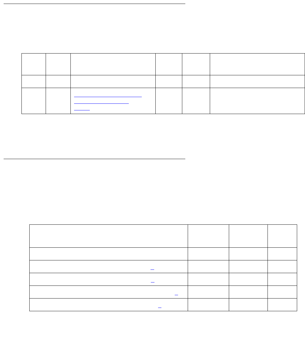
DC-POWER (Single-Carrier Cabinet Environment)
Issue 1 June 2005 881
If a Carrier Port Power Supply is physically removed from a carrier in a single-carrier cabinet,
there will not be a DC-POWER alarm. DC-POWER maintenance cannot distinguish between
removal of the power supply and the physical absence of the cabinet.
There is a nominal power holdover of.25 second in an PN single-carrier cabinet.
Hardware Error Log Entries and Test to Clear
Values
System Technician-Demanded Tests:
Descriptions and Error Codes
Investigate tests in the order presented. By clearing error codes associated with the
Single-Carrier Cabinet Power Query test, you may also clear errors generated from other tests
in the sequence.
Table 301: Single-Carrier Cabinet Power Error Log Entries
Error
Type
Aux
Data
Associated Test Alarm
Level
On/Off
Board
Test to Clear Value1
1. UU is the universal cabinet number indicated in the PORT field of the Alarm Log.
02
2. Run the short test sequence first. If every test passes, run the long test sequence. Refer to each test’s
description and recommended procedures.
0Any AnyAnytest environment UU
513 0 or 1 Single-Carrier Cabinet
Power Query Test
(#79) on page 882
MAJ ON test environment UU r 2
Order of Investigation Short Test
Sequence
Long Test
Sequence
D/ND1
1. D = Destructive; ND = Nondestructive
Single-Carrier Cabinet Power Query test (#79) X X ND
Emergency Transfer Query test (#124) (a)XXND
External Alarm Lead Query test (#120) (b)XXND
Analog Ring Generator Initialization test (#117) (c)X X ND
Analog Ring Generator Query test (#118) (c)XXND

Communication Manager Maintenance-Object Repair Procedures
882 Maintenance Procedures for Avaya Communication Manager 3.0, Media Gateways and Servers
Notes:
a. See EMG-XFER (Emergency Transfer) on page 1134 for a description.
b. See EXT-DEV ADMIN? Y (External Device Alarm) on page 1246 for a description.
c. See RING-GEN (Analog Ring Generator) on page 1942 for a description.
Single-Carrier Cabinet Power Query Test (#79)
This test queries an PN’s Maintenance circuit pack about the power’s status in a single-carrier
cabinet PN. This test can only detect power problems in the carriers of the PN where the Carrier
Port Power Supply physically resides.
Table 302: Test #79 Single-Carrier Cabinet Power Query Test
Error
Code
Test
Result
Description / Recommendation
1000 ABRT System resources required to run this test are not available.
1. Retry the command at 1-minute intervals up to 5 times.
2000 ABRT Response to the test request was not received within the allowable time
period.
1. Retry the command at 1-minute intervals up to 5 times.
2. If the test continues to ABORT with a 2000 error code, check for and
resolve every MAINT (Maintenance circuit pack) error. Repeat the test.
3. If the test still aborts with this error code, escalate the problem.
2029
2319
2320
2500
ABRT Internal system error
1. Retry the command at 1-minute intervals up to 5 times.
1 of 2

DC-POWER (Single-Carrier Cabinet Environment)
Issue 1 June 2005 883
1 FAIL There is currently a problem with the environment of the power system.
1. The power supply to any one of the carriers may have been lost.
a. Verify, and if necessary restore, AC power at the wall outlet for each
carrier.
b. Rerun the test. If the test still fails, proceed to step 2.
2. One of the WP-91153 or 676-B power units for one of the carriers could
be defective.
a. If the yellow status LED on a WP-91153 or 676-B power unit is off,
replace the power unit. See Chapter 10: Component replacement in
Maintenance Procedures (03-300192).
b. Rerun the test. If the test still fails, proceed with Step 3.
3. The PN’s MAINT (Maintenance circuit pack) could be incorrectly
reporting this error. Resolve every alarm on these MOs, and rerun the
test. There are failures that can occur on the PN’s Maintenance circuit
pack that will not be detected by their respective maintenance, but that
will cause many, if not all, environment tests to fail. If more than two
environment tests are failing, the suspect circuit pack, depending on
the system configuration, should be replaced and the test rerun. If the
test still fails, follow normal escalation procedures.
PASS The PN’s MAINT (Maintenance circuit pack) has reported no problem with
the power.
Table 302: Test #79 Single-Carrier Cabinet Power Query Test (continued)
Error
Code
Test
Result
Description / Recommendation
2 of 2

Communication Manager Maintenance-Object Repair Procedures
884 Maintenance Procedures for Avaya Communication Manager 3.0, Media Gateways and Servers
DETR-BD (Tone Detector Circuit)
S8700 | 8710 / S8500
For proper tone detection, the companding mode administered for the system must match that
of the DETR-BD circuit. The companding mode is administered on the
location-parameters screen.
See XXX-BD (Common Port Circuit Pack/Media Module) on page 2539 for DETR-BD (Tone
Detector circuit) errors.
MO Name in
Alarm Log
Alarm
Level
Initial SAT Command to Run Full Name of MO
DETR-BD MIN test board location Tone Detector circuit
DETR-BD WRN test board location Tone Detector circuit

DID-BD (Direct Inward Dial Trunk Circuit Pack)
Issue 1 June 2005 885
DID-BD (Direct Inward Dial Trunk Circuit Pack)
S8700 | 8710 / S8500
See XXX-BD (Common Port Circuit Pack/Media Module) on page 2539 for circuit pack-level
errors. See DID-TRK (Direct Inward Dial Trunk) on page 898 for related trunk information.
MO Name in
Alarm Log
Alarm
Level
Initial SAT Command to Run Full Name of MO
DID-BD MIN test board location sh Direct Inward Dial Trunk circuit pack
DID-BD WRN test board location sh Direct Inward Dial Trunk circuit pack
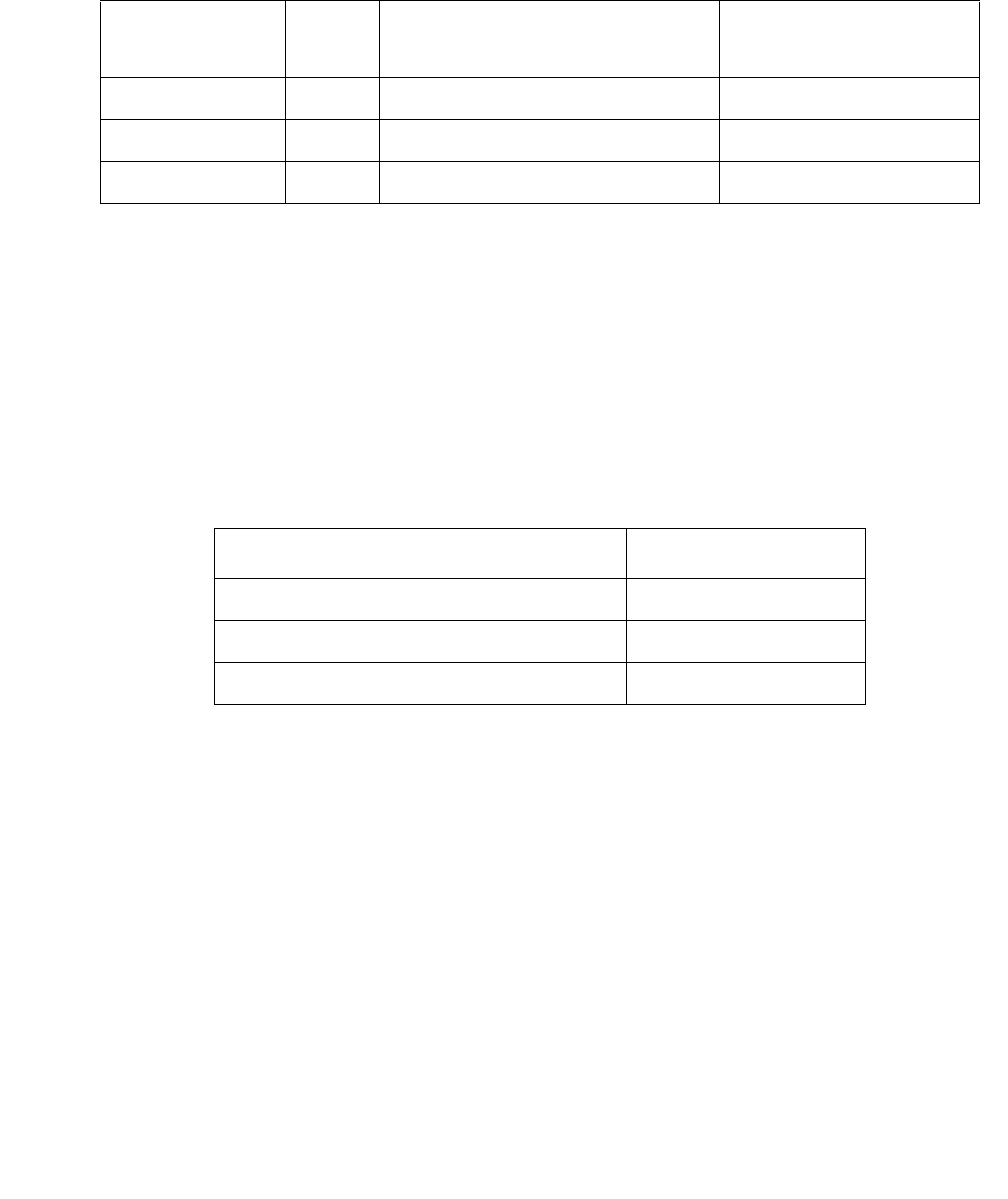
Communication Manager Maintenance-Object Repair Procedures
886 Maintenance Procedures for Avaya Communication Manager 3.0, Media Gateways and Servers
DID-DS1 (Direct Inward Dial Trunk)
S8700 | 8710 / S8500 / S8300
The DID-DS1 trunk provides a digital Direct Inward Dial (DID) trunk from a CO switch to the
system through a DS1 link. A 24-channel DS1 link can support up to 24 DID-DS1 trunk calls
simultaneously. A 32-channel link can support up to 30.
A DID-DS1 trunk can be used for digitized voice and data communications with DS1 signaling
mode (for example, common-channel signaling). The TN767 and TN464 series circuit packs,
and the MM710 Media Module, support wink-start and immediate-start trunks and Avaya™
Communication Manager signaling. Throughout this section, the term DS1 applies to all. For
more information, see one of the following maintenance objects:
S8300 / G700 Although the DID-DS1 MO is provided for a G700 Media Gateway, the DID-DS1
only partially supports the MM710 DS1 Media Module.
Information included in this section covers the in-line errors log, initialization tests, periodic
tests, scheduled tests, system technician demand tests, and alarms escalation and elimination.
Two trunk service states are specified in the DID-DS1 trunk maintenance:
If a DS1 is out-of-service, then every trunk on the circuit pack or media module is put into the
out-of-service state, and a Warning alarm is raised.
MO Name in
Alarm Log
Alarm
Level
Initial SAT Command to Run Full Name of MO
DID-DS1 MAJ1
1. A Major alarm on a trunk indicates that alarms on these trunks are not downgraded by set
options and that at least 75 percent of the trunks in this trunk group are alarmed.
test trunk grp#/mem# long Direct Inward Dial Trunk
DID-DS1 MIN test trunk grp#/mem# long Direct Inward Dial Trunk
DID-DS1 WRN test trunk grp#/mem# Direct Inward Dial Trunk
Circuit Pack/Media Module Maintenance Object
TN767 DS1 Interface Circuit Pack DS1-BD
TN464 UDS1 Interface Circuit Pack UDS1-BD
S8300 / G700 MM710 DS1 Media Module MG-DS1
out-of-service The trunk is in a deactivated state and cannot be used for
incoming calls.
in-service The trunk is in an activated state and can be used for
incoming calls.
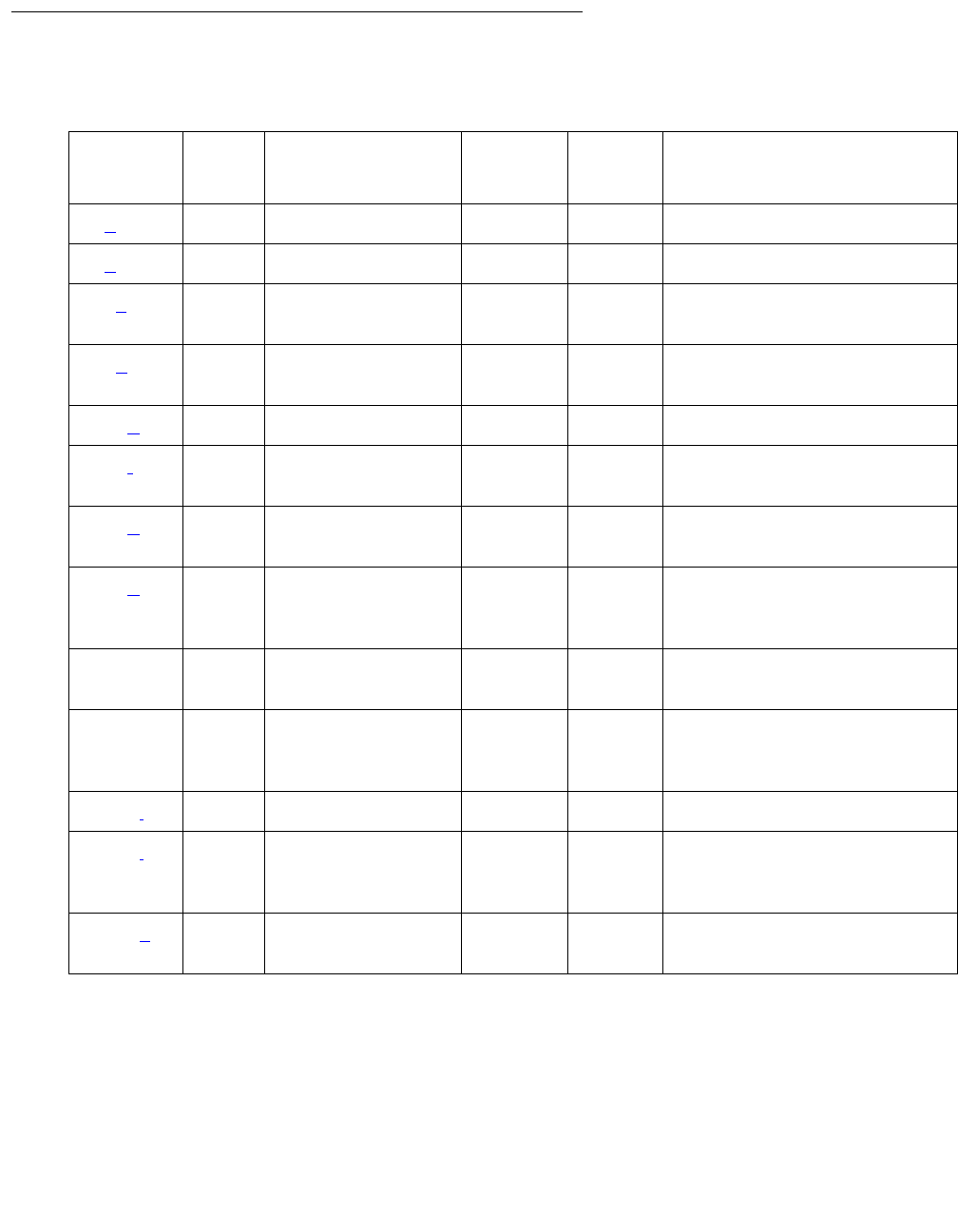
DID-DS1 (Direct Inward Dial Trunk)
Issue 1 June 2005 887
Error Log Entries and Test to Clear Values
Table 303: DID-DS1 Trunk Error Log Entries
Error
Type
Aux
Data
Associated Test Alarm
Level
On/Off
Board
Test to Clear Value
0 (a) 0 Any Any Any test trunk grp#/mem#
1 (b)Any
15 (c) Any Port Audit and
Update test (#36)
18 (d)WRNOFFrelease trunk grp#/
mem#
130 (e) None WRN ON test trunk grp#/mem#
257 (f) 57474
57473
513 (g) 57392 MAJ
MIN1
1. This alarm is raised only when the Base Tone Generator field is 4 (Italy) on the System-Parameter
Country screen. This alarm is a MINOR alarm unless 75% or more trunks in this trunk group are out of
service, when the alarm is upgraded to a MAJOR alarm.
769 (h) 57393 MAJ
MIN
1
1281 Conference Circuit
test (#7)
MIN
WRN2
2. Major alarms may be downgraded to Warning alarms based on the value used in set options.
ON test trunk grp#/mem#
l r 4
1537 NPE Crosstalk test
(#6)
MIN
WRN
2
ON test trunk grp#/mem#
l r 3
1793 (i)test board location l
2305 (j) 50944 None MAJ
MIN
1
OFF
3840 (k) Port Audit and
Update test (#36)

Communication Manager Maintenance-Object Repair Procedures
888 Maintenance Procedures for Avaya Communication Manager 3.0, Media Gateways and Servers
Notes:
a. Error Type 0: Run the short test sequence first. If every test passes, run the long test
sequence. Refer to each test’s description, and follow its recommended procedures.
b. Error Type 1: DS1 Interface circuit pack or media module detects a hardware error on the
DS1 DID trunk. The Aux Data field indicates the following:
Maintenance does not start any testing or generate any alarms in response to these errors.
c. Error Type 15 is a software audit error that does not indicate hardware malfunction. Run
short test sequence, and investigate any errors.
d. Error Type 18: The trunk has been taken out of service by a demand busyout. No calls can
be made on this trunk.
e. Error Type 130 indicates that the circuit pack or media module has been removed or has
been insane for more than 11 minutes. To clear the error, reinsert or replace the circuit pack
or media module.
f. Error Type 257: DS1 Interface circuit pack or media module detects a hardware error on
the DS1 DID trunk. The Aux Data field indicate the source of the error:
g. Error Type 513: DS1 Interface circuit pack or media module detects a hardware error on
the DS1 DID trunk. Aux Data 57392 indicates no external release on PBX disconnect.
h. Error Type 769: DS1 Interface circuit pack or media module detects a hardware error on
the DS1 DID trunk. Aux Data 57393 indicates belated external release on PBX disconnect.
i. Error Type 1793: DS1 Interface circuit pack or media module is out-of-service. Look in the
Hardware Error Log:
57476 On-hook before wink
57477 On-hook before ready to receive digits
57485 Wink too short for valid signal
57474 Rotary dial rate above 12 pulses per
second
57473 Rotary dial rate below 8 pulses per
second
If port is on Look in
TN767 DS1 Board DS1-BD
TN464 UDS1 Board UDS1-BD
S8300 / G700: MM710 DS1 Media Module MG-DS1

DID-DS1 (Direct Inward Dial Trunk)
Issue 1 June 2005 889
j. Error Type 2305 indicates that a signaling change was detected by the PBX trunk circuit
pack or media module which is inconsistent with the present state of the trunk.
k. Error Type 3840: Port Audit and Update test (#36) failed due to an internal system error.
Enter status trunk to verify the status of the trunk. If the trunk is out-of-service, enter
release trunk to put it back to in-service. Retry the test command.
System Technician-Demanded Tests:
Descriptions and Error Codes
Investigate tests in the order they are presented. By clearing error codes associated with NPE
Crosstalk, you may also clear errors generated from other tests in the sequence.
NPE Crosstalk Test (#6)
Note:
Note: S8300 / G700: This test aborts with Error Code 1412.
The NPE Crosstalk test verifies that this port’s NPE channel talks on the selected time slot and
never crosses over to time slots reserved for other connections. If the NPE is not working
correctly, 1-way and noisy connections may be observed. This test is usually only part of a
port’s long test sequence and executes in about 20 to 30 seconds.
Order of Investigation Short Test
Sequence
Long Test
Sequence
D/ND1
1. D = Destructive; ND = Nondestructive
NPE Crosstalk test (#6)
S8300 / G700 Test aborts with Error Code 1412.
XND
Conference Circuit test (#7)
S8300 / G700: Test aborts with Error Code 1412.
XND
Port Audit and Update test (#36) X X ND
Table 304: Test #6 NPE Crosstalk Test
Error
Code
Test
Result
Description / Recommendation
ABRT System resources required for this test are not available.
1. Retry the command at 1-minute intervals up to 5 times.
1 of 4

Communication Manager Maintenance-Object Repair Procedures
890 Maintenance Procedures for Avaya Communication Manager 3.0, Media Gateways and Servers
1000 ABRT System resources required for this test are not available.
The port may be busy with a valid call.
1. Use display port location to determine the trunk group/
member number of the port. Use status trunk to determine the
service state of the port. If the port is in use, wait until it is idle before
testing.
2. If the port status is active but the port is idle (no calls), check the error
log for Error Type #1025. The port may be locked up.
3. If the port status is idle, retry the command at 1-minute intervals up to
5 times.
1001 ABRT System resources required for this test are not available.
1. Retry the command at 1-minute intervals up to 5 times.
1002 ABRT The system could not allocate time slots for the test. The system may be
under heavy traffic conditions or it may have time slots out-of- service due
to TDM BUS error. Use status health to determine whether the
system is experiencing heavy traffic.
1. If the system has no TDM-BUS errors and is not handling heavy traffic,
retry the command at 1-minute intervals up to 5 times.
1003 ABRT The system could not allocate a tone receiver for the test. The system may
be oversized for the number of Tone Detectors present, or some Tone
Detectors may be out of service.
1. Enter list measurements tone-receiver to display information
about the tone receivers.
2. Resolve any TTR-LEV errors.
3. Resolve any TONE-PT errors.
4. If neither condition exists, retry the command at 1-minute intervals up
to 5 times.
Table 304: Test #6 NPE Crosstalk Test (continued)
Error
Code
Test
Result
Description / Recommendation
2 of 4

DID-DS1 (Direct Inward Dial Trunk)
Issue 1 June 2005 891
1004 ABRT The port was seized by a user for a valid call.
1. Use display port location to determine the trunk group/
member number of the port. Use status trunk to determine the
service state of the port. If the port is in use, wait until it is idle before
testing.
2. If the port status is idle, retry the command at 1-minute intervals up to
5 times.
1020 ABRT The test did not run due to a previously existing error on the specific port
or a more general circuit pack error.
1. Examine Error Log for existing errors against this port or circuit pack
and attempt to diagnose the previously existing error.
S8300 /
G700
1412
ABRT This test does not execute on a G700 Media Gateway.
2000 ABRT Response to the test was not received within the allowable time period.
1. Rerun the test at 1-minute intervals up to 5 times.
2100 ABRT System resources required for this test are not available.
1. Retry the command at 1-minute intervals up to 5 times.
2053 ABRT At least one of the following errors is found on the DS1 circuit pack
(DS1-BD or UDS1-BD): 1281 – Loss of signal, 1793 – Blue Alarm, 2049 –
Red Alarm, 2305 – Yellow Alarm, or 1537 – Hyperactivity
1. Resolve any of the previous error types.
ANY FAIL This can be due to off-board problems, including EXP-PN and EXP-INTF
faults, RMC-ENV faults (S8700 IP), TDM-BUS faults, and Tone Detectors/
Tone Generators. Clear every off-board problem before replacing the
board. A TDM-BUS problem is usually a faulty board or bent pins on the
backplane.
1. Resolve any EXP-PN, EXP-INTF, RMC-ENV (S8700 IP), TDM-BUS,
TONE-BD, and TONE-PT errors in the error log.
2. Retest when errors are cleared. Replace the board if the test fails.
PASS The port is correctly using its allocated time slots. Investigate user-reported
troubles on this port using other port tests and by examining station, trunk,
or external wiring.
Table 304: Test #6 NPE Crosstalk Test (continued)
Error
Code
Test
Result
Description / Recommendation
3 of 4

Communication Manager Maintenance-Object Repair Procedures
892 Maintenance Procedures for Avaya Communication Manager 3.0, Media Gateways and Servers
Conference Circuit Test (#7)
Note:
Note: S8300 / G700 This test aborts with Error Code 1412.
The Conference Circuit test verifies that the NPE channel for the port being tested can correctly
perform the conferencing function. The NPE is instructed to listen to several different tones and
conference the tones together.
0NO
BOARD The test could not relate the internal ID to the port. This could be due to
incorrect translations, no board is inserted, an incorrect board is inserted,
or an insane board is inserted.
1. Verify that the board translations are correct. Enter list config,
and resolve any problems that are found.
2. Enter busyout board location
Enter reset board location
Enter release board location
3. Enter test board location long
This should re-establish the link between the internal ID and the port. If
not, check to see that there is a valid board inserted.
Table 304: Test #6 NPE Crosstalk Test (continued)
Error
Code
Test
Result
Description / Recommendation
4 of 4
Table 305: Test #7 Conference Circuit Test
Error
Code
Test
Result
Description / Recommendation
ABRT Could not allocate the necessary system resources for this test.
1. Retry the command at 1-minute intervals up to 5 times.
1 of 4

DID-DS1 (Direct Inward Dial Trunk)
Issue 1 June 2005 893
1000 ABRT System resources required for this test were not available. The port may
be busy with a valid call.
1. Use display port location to determine the trunk group/
member number of the port. Use status trunk to determine the
service state of the port. If the port is in use, wait until it is idle before
testing.
2. If the port status is active but the port is idle (no calls), check the error
log for Error Type #1025. The port may be locked up.
3. If the port status is idle, retry the command at 1-minute intervals up to
5 times.
1002 ABRT The system could not allocate time slots for the test. The system may be
under heavy traffic conditions, or it may have time slots out of service due
to TDM-BUS errors.
1. If the system has no TDM-BUS errors and is not handling heavy traffic
and the port status is idle, retry the command at 1-minute intervals up
to 5 times.
1003 ABRT The system could not allocate a tone receiver for the test. The system
may be oversized for the number of Tone Detectors present, or some Tone
Detectors may be out of service.
1. Enter list measurements tone-receiver to display information
about the tone receivers.
2. Resolve any TTR-LEV errors.
3. Resolve any TONE-PT errors.
4. If neither condition exists, retry the command at 1-minute intervals up
to 5 times.
1004 ABRT The port was seized by a user for a valid call.
1. Use display port location to determine the trunk group/
member number of the port. Use status trunk to determine the
service state of the port. If the port is in use, wait until it is idle before
testing.
2. If the port status is idle, retry the command at 1-minute intervals up to
5 times.
Table 305: Test #7 Conference Circuit Test (continued)
Error
Code
Test
Result
Description / Recommendation
2 of 4

Communication Manager Maintenance-Object Repair Procedures
894 Maintenance Procedures for Avaya Communication Manager 3.0, Media Gateways and Servers
1018 ABRT The test was disabled via translation. Determine why the test has been
disabled before you enable it.
1. Verify that the Maintenance Test field on the Trunk Administration
form is n. Enter y to enable the test.
2. Repeat the test.
1020 ABRT The test did not run due to a previously existing error on the specific port
or a more general circuit pack error.
1. Examine Error Log for existing errors against this port or the circuit
pack and attempt to diagnose the previously existing error.
S8300 /
G700
1412
ABRT This test does not execute on a G700 media gateway.
2000 ABRT Response to the test was not received within the allowable time period.
1. Rerun the test at 1-minute intervals up to 5 times.
2100 ABRT Could not allocate the necessary system resources to run this test.
1. Retry the command at 1-minute intervals up to 5 times.
2053 ABRT At least one of the following errors is found on the DS1 circuit pack
(DS1-BD or UDS1-BD):
1281 – Loss of signal, 1793 – Blue Alarm, 2049 – Red Alarm, 2305 –
Yellow Alarm, 1537 – Hyperactivity
1. Resolve any of the previous error types.
Table 305: Test #7 Conference Circuit Test (continued)
Error
Code
Test
Result
Description / Recommendation
3 of 4

DID-DS1 (Direct Inward Dial Trunk)
Issue 1 June 2005 895
Any FAIL The NPE of the tested port did not conference the tones correctly. This
can cause noisy and unreliable connections.
1. Enter list configuration board location. The circuit pack
must be a TN767C V3 or later. The error log may have Error Type
#1281.
2. Test every administered trunk on the board. If one fails, this could be
an off-board problem (such as an incoming seizure or an off-hook port
seizure during the test). Retest the board.
3. If every port fails, a -5V power problem is indicated. Check
CARR-POW (Carrier Power Supply) on page 770.
4. If several ports fail, resolve any TONE-BD (Tone-Clock Circuit) on
page 2327 or TONE-PT (Tone Generator) on page 2353 errors and
rerun the test.
5. If the retry passes and troubles are reported, coordinate isolation with
the CO. Make sure that the switch, the CO, and any NTCE equipment
(the CSUs) have the correct administration.
6. Replace the circuit pack.
PASS The port can correctly conference multiple connections. Investigate
user-reported troubles on this port using other port tests and by examining
station, trunk, or external wiring.
This test always passes for TN742 Analog circuit packs prior to Vintage 4.
0NO
BOARD The test could not relate the internal ID to the port. This could be due to
incorrect translations, no board is inserted, an incorrect board is inserted,
or an insane board is inserted.
1. Verify that the board’s translations are correct. Use lIst config,
and resolve any problems that are found.
2. If the board was found to be correctly inserted in step 1, enter
busyout board location
3. Enter reset board location
4. Enter release board location
5. Enter test board location long
This should re-establish the link between the internal ID and the port.
If not, check to see that there is a valid board inserted.
Table 305: Test #7 Conference Circuit Test (continued)
Error
Code
Test
Result
Description / Recommendation
4 of 4

Communication Manager Maintenance-Object Repair Procedures
896 Maintenance Procedures for Avaya Communication Manager 3.0, Media Gateways and Servers
Port Audit and Update Test (#36)
This test sends port-level translation data from the switch processor to the DS1 Interface circuit
pack or media module to assure that a trunk’s translations are correct. The port audit operation
verifies the consistency of the current state of the trunk as kept in the DS1 Interface circuit pack
or media module and in switch software.
Table 306: Test #36 Port Audit and Update Test
Error
Code
Test
Result
Description / Recommendation
ABRT Internal system error
1. Retry the command at 1-minute intervals up to 5 times.
1000 ABRT The port may be busy with a valid call.
1. Enter display port location to determine the trunk group/
member number of the port. Use status trunk to determine the
service state of the port. If the port is in use, wait until it is idle before
testing.
2. If the port status is active but the port is idle (no calls), check the error
log for Error Type #1025. The port may be locked up.
3. If the port status is idle, retry the command at 1-minute intervals up to 5
times.
1006 ABRT The test was aborted because the trunk is out of service.
1. Use status trunk to verify that the trunk is out of service.
2. If the trunk is out of service, determine why.
3. To put the trunk back in service, enter release trunk. Retry the test.
2000 ABRT Response to the test was not received in the allowable time period.
1. Rerun the test at 1-minute intervals up to 5 times.
2100 ABRT Could not allocate resources to run this test.
1. Retry the command at 1-minute intervals up to 5 times.
FAIL Test failed due to internal system error.
1. Retry the command at 1-minute intervals up to 5 times.
1 of 2

DID-DS1 (Direct Inward Dial Trunk)
Issue 1 June 2005 897
PASS Trunk translation has been updated successfully. The current trunk states
kept in the DS1 Interface circuit pack media module and switch software
are consistent. If the trunk is busied out, the test will not run but will return
PASS. To verify that the trunk is in-service:
1. Enter status trunk to verify that the trunk is in-service. If the trunk
is in-service, no further action is necessary. If the trunk is
out-of-service.
2. Enter release trunk to put the trunk back into in-service.
3. Retry the test command.
0NO
BOARD The test could not relate the internal ID to the port (no board). This could
be due to incorrect translations, no board is inserted, an incorrect board is
inserted, or an insane board is inserted.
1. Verify that the board’s translations are correct. Use the list config
command, and resolve any problems that are found.
2. If the board was found to be correctly inserted in step 1, enter
busyout board location
3. Enter reset board location
4. Enter release board location
5. Enter test board location long
This should re-establish the linkage between the internal ID and the
port. If this is not the case, check to see that there is a valid board
inserted.
Table 306: Test #36 Port Audit and Update Test (continued)
Error
Code
Test
Result
Description / Recommendation
2 of 2
Communication Manager Maintenance-Object Repair Procedures
898 Maintenance Procedures for Avaya Communication Manager 3.0, Media Gateways and Servers
DID-TRK (Direct Inward Dial Trunk)
S8700 | 8710 / S8500 / S8300
Note:
Note: Many trunk problems are caused by incorrect settings of parameters on the trunk
group administration screen. Settings must be compatible with the local
environment and with parameter settings on the far end. Refer to Administrator
Guide for Avaya Communication Manager, 03-300509, for information about how
to administer trunks. The Application Notes section of that book shows the
correct settings for administrable timers and other parameters on a
country-by-country basis.
Direct Inward Dial (DID) trunks coming from the Central Office (CO) allow outside parties to call
directly to an extension in the system. DID Trunk circuit packs include:
DID trunk circuit packs and the MM711 Media Module support eight incoming-only ports. Each
port provides an interface between the 2-wire analog CO line and the 4-wire TDM bus on the
switch.
S8300 / G700 Although the DID-TRK MO is provided for a G700/G350 Media Gateway, this MO
only partially supports the MM711 Analog Media Module.
MO Name in
Alarm Log
Alarm
Level
Initial SAT Command to Run Full Name of MO
DID-TRK MAJ1
1. A MAJOR alarm on a trunk indicates that alarms on these trunks are not downgraded by
set options and that at least 75 percent of the trunks in this trunk group are alarmed.
test port location lDID Trunk
DID-TRK MIN test port location l DID Trunk
DID-TRK WRN None DID Trunk
TN753 United States
TN2146 Belgium and the
Netherlands
TN2139 Italy
TN 436 Australia
TN459 United Kingdom

DID-TRK (Direct Inward Dial Trunk)
Issue 1 June 2005 899
DID Trunk Operation
The DID port receives three to seven digits from the CO that are used to directly connect an
outside caller to the called station without assistance from an attendant. For each call, the CO
switch signals the system by opening and closing individual DID loops (one of the eight ports),
causing the starting or stopping of loop current.
DID Trunk Testing
The system uses technician-invoked tests of on-board circuitry to diagnose the health of the
trunk. These are described in the following sections. Additionally, in-line testing which can
generate errors, is performed while a call is in progress. See the Error Log table for a
description of these errors. These errors may be reproduced by placing a call on the trunk and
checking the Hardware Error Log.
Problems detected during signaling may be caused by off-board faults in the CO switch or
connections for which a Warning alarm is raised.
Before a maintenance test can be run on a port, the port must be idle. If an incoming call seizes
a port that is being tested, the test will abort and the incoming call will proceed.
For transmission and signaling standard specification, refer to Digital PBX Standards, RS4648.
Ports Out-of-Service without Errors or Alarms
A common trouble on DID trunks that produces no errors or alarms occurs when the CO busies
out (disconnects) the port. This situation occurs when the CO thinks there are problems with the
DID port. In this case, no incoming calls will be possible through this port. This may result in
complaints from outside callers trying unsuccessfully to call in. This problem can be diagnosed
by listing measurements on lightly used trunks. If a particular port is detected as idle, a call to
the CO will be necessary to get the connection back in service.
Error Log Entries and Test to Clear Values
Table 307: DID Trunk Error Log Entries
Error
Type
Aux
Data
Associated
Test
Alarm
Level
On/Off
Board
Test to Clear Value
0 (a) 0 Any Any Any test port location sh r
1
1 of 2

Communication Manager Maintenance-Object Repair Procedures
900 Maintenance Procedures for Avaya Communication Manager 3.0, Media Gateways and Servers
1 (b) Any None WRN OFF
1 (c) 57476 None WRN OFF
1 (d) 57477 None WRN OFF
1 (e) 57483 None WRN OFF
15 (f) Any Port Audit
Update (#36)
18 0 busyout
trunk grp#/
mem#
WRN OFF release trunk grp#/mem#
130 (g) None WRN ON test trunk grp#/mem#
257 (h) 57472 None WRN OFF
257 (i) 57473 None WRN OFF
257 (j) 57474 None WRN OFF
257 (k) 57475 None WRN OFF
513 (l) 57392 None MIN
WRN1OFF
513 (m) 57393 None
769 Any Port Diagnostic
(#35)
MIN
WRN1ON test port location r 3
1025 Looparound
and
Conference
(#33)
MIN
WRN1ON test port location l r 3
1281 NPE Crosstalk
(#6)
MIN
WRN1ON test port location l r 3
1537 Any Port Diagnostic
(#35)
MAJ
MIN
WRN1
OFF test port location r 3
1793 (n) 57489 None None
1. Major alarms may be downgraded to Warning alarms based on the value used in set options.
Table 307: DID Trunk Error Log Entries (continued)
Error
Type
Aux
Data
Associated
Test
Alarm
Level
On/Off
Board
Test to Clear Value
2 of 2

DID-TRK (Direct Inward Dial Trunk)
Issue 1 June 2005 901
Notes:
a. Error Type 0: Run the short test sequence first. If every test passes, run the long test
sequence.
b. Error Type 1; Aux Data - Any occurs when the tone detector times out waiting for digits.
Change wink/immediate-start parameter to wink/immediate-start and rotary/tone-dial
parameters.
1. Verify trunk administered wink/immediate-start parameter.
2. Test trunk using BUTT set.
3. Refer problem to CO.
c. Error Type 1; Aux Data - 57476: Rotary dial before wink occurs when the CO starts dialing
before the PBX sends wink on a wink-start trunk.
1. Verify trunk administered wink/immediate-start parameter.
2. Refer problem to CO.
d. Error Type 1; Aux Data - 57477: Rotary dial too early occurs when the CO starts dialing too
soon after seizure on an immediate-start trunk.
1. Verify trunk administered wink/immediate-start parameter.
2. Refer problem to CO.
e. Error Type 1; Aux Data - 57483: Rotary dial pulse during wink occurs when the CO sends
rotary dial digits too soon after seizure on a wink-start trunk.
1. Verify trunk administered wink/immediate-start parameter.
2. Refer problem to CO.
f. Error Type 15 is a software audit error that does not indicate a hardware malfunction. Run
short test sequence, and investigate any associated errors.
g. Error Type 130 indicates that the circuit pack or media module has been removed or has
been insane for more than 11 minutes. To clear the error, reinsert or replace the circuit pack
or media module.
h. Error Type 257; Aux Data - 57472: Rotary dial pulse on-hook longer than 105 msec, the
break between rotary pulses is too long.
1. Test trunk by performing an incoming test call.
2. Refer problem to CO.
i. Error Type 257; Aux Data - 57473: Rotary dial rate below 8 pulses/sec, more than 135
msec between two successive breaks.
1. Verify trunk administered interdigit-timing parameters.
2. Refer problem to CO.
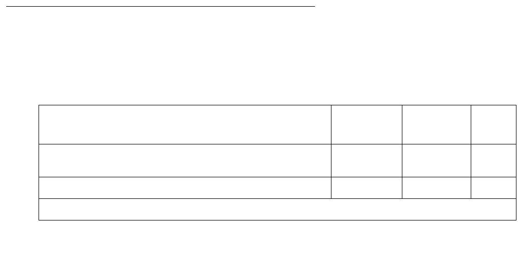
Communication Manager Maintenance-Object Repair Procedures
902 Maintenance Procedures for Avaya Communication Manager 3.0, Media Gateways and Servers
j. Error Type 257; Aux Data - 57474: Rotary dial rate above 12 pulses/sec, less than 75
msec between two successive breaks.
1. Verify trunk administered interdigit-timing parameters.
2. Refer problem to CO.
k. Error Type 257; Aux Data - 57475: Digit detection, CO is starting new rotary dial digit
within 150 msec of previous digit.
1. Verify trunk administered interdigit timing parameters.
2. Refer problem to CO.
l. Error Type 513; Aux Data - 57392: Loop current active, CO is not releasing trunk after PBX
disconnect. Occurs when the PBX end drops first and the CO does not release the trunk
within 4 minutes.
1. Verify the interface to the network with a hand telephone set. If calls are placed correctly,
then refer problem to the CO.
2. If unable to place calls or this equipment is not available, check the status on port using
status trunk. If active but not connected, disconnect bridging clips at the network
interface. Check status on the trunk. If trunk went idle, then replace clips. If trunk is still
active but unable to place calls, refer problem to the CO.
m. Error Type 513; Aux Data - 57393: Late CO trunk release occurs only after the occurrence
of Error Type 513. The CO released the trunk 4 minutes after the PBX dropped the call. This
event decrements the severity (error count) of Error Type 513, or may mean the problem
related to Error Type 513 has been fixed.
Verify that Error Type 513 does not occur again. Refer to Error 513.
n. Error Type 1793: Incomplete Dial timer expired, applies only to TN459 and indicates a
problem with incoming dialing stream. Refer the problem to the CO.
System Technician-Demanded Tests:
Descriptions and Error Codes
Investigate tests in the order presented. By clearing error codes associated with the NPE
Crosstalk, you may also clear errors generated from subsequent tests in the sequence.
Order of Investigation Short Test
Sequence
Long Test
Sequence
D/ND1
NPE Crosstalk test (#6)
S8300 / G700: This test aborts with Error Code 1412.
XND
Port Diagnostic test (#35) X X ND
1 of 2

DID-TRK (Direct Inward Dial Trunk)
Issue 1 June 2005 903
NPE Crosstalk Test (#6)
Note:
Note: S8300 / G700: This test aborts with Error Code 1412.
The NPE Crosstalk test verifies that this port’s NPE channel talks on the selected time slot on
the TDM bus and never crosses over to time slots reserved for other connections. If the NPE is
not working correctly, 1-way and noisy connections may be observed. This test is usually only
part of a port’s long test sequence and executes in about 20 to 30 seconds.
Looparound and Conference Circuit test (#33)
S8300 / G700: This test aborts with Error Code 1412.
XND
Port Audit Update test (#36) X X ND
1. D = Destructive; ND = Nondestructive
Order of Investigation Short Test
Sequence
Long Test
Sequence
D/ND1
2 of 2
Table 308: Test #6 NPE Crosstalk Test
Error
Code
Test
Result
Description / Recommendation
ABRT Could not allocate the necessary system resources for this test. This could
be due to a failure to seize the port.
1. Retry the command at 1-minute intervals up to 5 times.
1000 ABRT System resources required to run this test are not available. The port may
be busy with a valid call.
1. Enter display port location to determine the station extension,
attendant number, or trunk group/member number of the port. Enter
status station, status attendant, or status trunk to
determine the service state of the port. If the port is in use, wait until it
is idle before testing. Attendants are always in use (off-hook) if the
handset is plugged in and the port is not busied out.
2. If the port status is active but the port is idle (no calls), check the Error
Log for Error Type 513. The port may be locked up.
3. If the port status is idle, retry the command at 1-minute intervals up to 5
times.
1 of 3

Communication Manager Maintenance-Object Repair Procedures
904 Maintenance Procedures for Avaya Communication Manager 3.0, Media Gateways and Servers
1001 ABRT Could not allocate the necessary system resources to run this test.
1. Retry the command at 1-minute intervals up to 5 times.
1002 ABRT The system could not allocate time slots for the test. The system may be
under heavy traffic conditions or it may have time slots out-of- service due
to TDM-BUS errors.
1. If the system has no TDM-BUS errors and is not handling heavy traffic,
retry the command at 1-minute intervals up to 5 times.
1003 ABRT The system could not allocate a tone receiver for the test. The system may
be oversized for the number of Tone Detectors present, or some Tone
Detectors may be out of service.
1. Resolve any TTR-LEV errors.
2. Resolve any TONE-PT errors.
3. If neither condition exists, retry the command at 1-minute intervals up
to 5 times.
1004 ABRT The port was seized by a valid call during the test.
1. Enter display port location to determine the station extension,
attendant number, or trunk group/member number of the port. Enter
status station, status attendant, or status trunk to
determine the service state of the port. If the port is in use, wait until it
is idle before testing. Attendants are always in use (off-hook) if the
handset is plugged in and the port is not busied out.
2. Retry the command at 1-minute intervals up to 5 times.
S8300
G700
1412
ABRT This test does not execute on a G700 media gateway.
2000 ABRT Response to the test was not received within the allowable time period.
1. Rerun the test at 1-minute intervals up to 5 times.
2100 ABRT Could not allocate the necessary system resources for this test. This could
be due to a failure to seize the port.
1. Retry the command at 1-minute intervals up to 5 times.
Table 308: Test #6 NPE Crosstalk Test (continued)
Error
Code
Test
Result
Description / Recommendation
2 of 3

DID-TRK (Direct Inward Dial Trunk)
Issue 1 June 2005 905
Looparound and Conference Circuit Test (#33)
Note:
Note: S8300 / G700: This test aborts with Error Code 1412.
This test checks the reflective and non-reflective loop-around and conference capabilities of a
DID port circuit. The test that uses 404-, 1004-, and 2804-Hz tones is an on-board test only.
Each tone is separately transmitted to and from the port (loop around within the port) and
verified.
This test may fail due to noise induced by adjacent electric power lines. Resolve this problem
with the local power company. To temporarily alleviate the alarm caused by the failure of this
test, disable the test from the trunk administration Test field. This also disables the port
diagnostic test.
Any FAIL This test can fail due to off-board problems, including EXP-PN and
EXP-INTF faults RMC-ENV faults (S8700 IP), TDM-BUS faults, and Tone
Detectors/Tone Generators. Clear every off-board problem before
replacing the board. A TDM-BUS problem is usually a faulty board or bent
pins on the backplane.
1. Resolve any EXP-PN and EXP-INTF, RMC-ENV (S8700 IP), TDM-BUS,
TONE-BD, and TONE-PT errors in the error log.
2. Retest the board. Replace the board if the test fails.
PASS The port is correctly using its allocated time slots. User-reported troubles on
this port should be investigated using other port tests and by examining
station, trunk, or external wiring.
0NO
BOARD The test could not relate the internal ID to the port (no board).
1. Verify that the board’s translations are correct. Translate the board if
necessary.
2. Enter busyout board location.
3. Enter reset board location.
4. Enter release board location.
5. Enter test board location.
This should re-establish the linkage between the internal ID and the
port.
Table 308: Test #6 NPE Crosstalk Test (continued)
Error
Code
Test
Result
Description / Recommendation
3 of 3

Communication Manager Maintenance-Object Repair Procedures
906 Maintenance Procedures for Avaya Communication Manager 3.0, Media Gateways and Servers
Table 309: Test #33 Loop-Around and Conference Circuit Test
Error
Code
Test
Result
Description / Recommendation
ABRT Could not allocate the necessary system resources to run this test. This
could be due to a failure to seize the port.
1. Retry the command at 1-minute intervals up to 5 times.
3 ABRT System resources required to run this test are not available. The seized
tone detector did not respond. This abort code is usually associated with
tone-clock (TONE-BD, TONE-PT, and TDM-CLK) resources.
1. Clear any tone errors in the error log.
2. Retry the command a 1-minute intervals up to 5 times.
3. If the test continues to abort, escalate the problem.
1000 ABRT System resources required to run this test are not available. The port may
be busy with a valid call.
1. Enter display port location to determine the station extension,
attendant number, or trunk group/member number of the port. Use
status station, status attendant, or status trunk to
determine the service state of the port. If the port is in use, wait until it
is idle before testing. Attendants are always in use (off-hook) if the
handset is plugged in and the port is not busied out.
2. If the port status is active but the port is idle (no calls), check the Error
Log for Error Type 513. The port may be locked up.
3. If the port status is idle, retry the command at 1-minute intervals up to
5 times.
1004 ABRT The port was seized by a valid call during the test.
1. Enter display port location to determine the station extension,
attendant number, or trunk group/member number of the port. Use
status station, status attendant, or status trunk to
determine the service state of the port. If the port is in use, wait until it
is idle before testing. Attendants are always in use (off-hook), if the
handset is plugged in and the port is not busied out.
2. Retry the command at 1-minute intervals up to 5 times.
1 of 5

DID-TRK (Direct Inward Dial Trunk)
Issue 1 June 2005 907
1018 ABRT Test disabled by administration. Verify that the Maintenance Tests? field
on the Trunk Group form is set to n. To enable the test, enter change
trunk-group x (x is the trunk group number). Enter y in the
Maintenance Tests field.
S8300 /
G700
1412
ABRT This test does not execute on a G700 Media Gateway.
2000 ABRT Response to the test was not received within the allowable time period.
1. Retry the command at 1-minute intervals up to 5 times.
2100 ABRT System resources required to run this test are not available. This may be
due to the port being seized.
1. This abort code is usually associated with tone-clock (TONE-BD,
TONE-PT, and TDM-CLK) resources. Clear any tone errors in the
error log.
2. Retry the command at 1-minute intervals up to 5 times.
3 FAIL The nonreflective 1004-Hz tone test of the port failed. An echo was
detected from the port. Poor-quality transmission was detected to or from
the port. The problem may be off-board. See additional information for this
error code below.
!CAUTION:
CAUTION: The port may still be operational, or the fault may be
off-board (connections or CO). Off-board problems include
incoming seizures or off-hook port seizures during the test
and, perhaps, noise induced by adjacent electric power
lines. The test may be disabled from the trunk
administration 'Test' field. This turns off all testing for that
trunk group except for tests 6 and 36.
Table 309: Test #33 Loop-Around and Conference Circuit Test (continued)
Error
Code
Test
Result
Description / Recommendation
2 of 5

Communication Manager Maintenance-Object Repair Procedures
908 Maintenance Procedures for Avaya Communication Manager 3.0, Media Gateways and Servers
7 The conference capabilities of the port failed. Poor-quality transmission
was detected to or from the port. The problem may be off-board. See
additional information for this error code below.
!CAUTION:
CAUTION: The port may still be operational, or the fault may be
off-board (connections or CO). Off-board problems include
incoming seizures or off-hook port seizures during the test
and, perhaps, noise induced by adjacent electric power
lines. The test may be disabled from the trunk
administration 'Test' field. This turns off all testing for that
trunk group except for tests 6 and 36.
129 The reflective 404-Hz tone test failed. Poor-quality transmission was
detected to or from the port. The problem may be off-board. See additional
information for this error code below.
!CAUTION:
CAUTION: The port may still be operational, or the fault may be
off-board (connections or CO). Off-board problems include
incoming seizures or off-hook port seizures during the test
and, perhaps, noise induced by adjacent electric power
lines. The test may be disabled from the trunk
administration 'Test' field. This turns off all testing for that
trunk group except for tests 6 and 36.
Table 309: Test #33 Loop-Around and Conference Circuit Test (continued)
Error
Code
Test
Result
Description / Recommendation
3 of 5
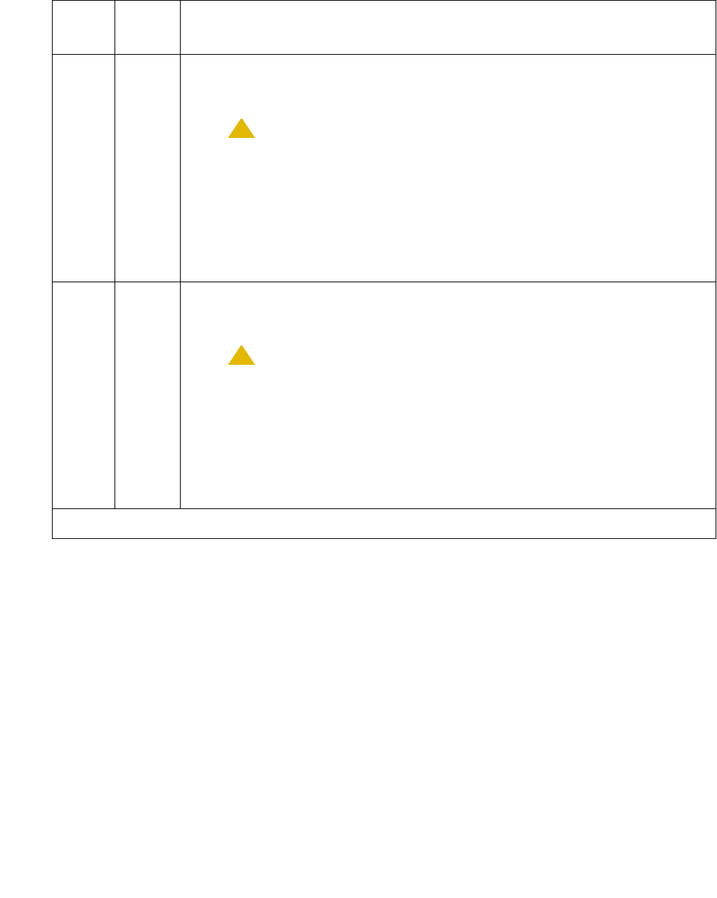
DID-TRK (Direct Inward Dial Trunk)
Issue 1 June 2005 909
131 The reflective 1004-Hz tone test failed. Poor-quality transmission was
detected to or from the port. The problem may be off-board. See additional
information for this error code below.
!CAUTION:
CAUTION: The port may still be operational, or the fault may be
off-board (connections or CO). Off-board problems include
incoming seizures or off-hook port seizures during the test
and, perhaps, noise induced by adjacent electric power
lines. The test may be disabled from the trunk
administration 'Test' field. This turns off all testing for that
trunk group except for tests 6 and 36.
133 The reflective 2804-Hz tone test failed. Poor-quality transmission was
detected to or from the port. The problem may be off-board. See additional
information for this error code below.
!CAUTION:
CAUTION: The port may still be operational, or the fault may be
off-board (connections or CO). Off-board problems include
incoming seizures or off-hook port seizures during the test
and, perhaps, noise induced by adjacent electric power
lines. The test may be disabled from the trunk
administration 'Test' field. This turns off all testing for that
trunk group except for tests 6 and 36.
Table 309: Test #33 Loop-Around and Conference Circuit Test (continued)
Error
Code
Test
Result
Description / Recommendation
4 of 5

Communication Manager Maintenance-Object Repair Procedures
910 Maintenance Procedures for Avaya Communication Manager 3.0, Media Gateways and Servers
3
7
129
131
133
(cont’d)
FAIL
(cont’d)
Proceed as follows unless power or tone problems are suspected (see
following note).
1. To see if the problem is on-board, disconnect the port from the far end,
and retry the test. Coordinate this with the CO, or do it after busy
hours.
2. If the retry fails, replace the circuit pack.
3. If the retry passes and no troubles have been reported, disable the
test in the trunk group administration. If the retry passes and troubles
are reported, coordinate isolation with the CO.
Note:
Note: If the loop-around and conference circuit test fails for every
port on a circuit pack, a -5V power problem is indicated. A
power unit may be defective (CARR-POW (Carrier Power
Supply) on page 770). If the test fails on more than 1 port,
check for errors on the TONE-BD (Tone-Clock Circuit) on
page 2327 or the TONE-PT (Tone Generator) on
page 2353 MOs.
4. Rerun the test.
PASS DID Trunk Looparound and Conference test is successful. This port is
functioning properly.
1. If users are reporting troubles, examine loop connections to the port
and refer problem to the CO.
0NO
BOARD The test could not relate the internal ID to the port (no board).
1. Verify that the board’s translations are correct.
2. Enter busyout board location
3. Enter reset board location
4. Enter release board location
5. Enter test board location
This should establish the link between the internal ID and the port.
Table 309: Test #33 Loop-Around and Conference Circuit Test (continued)
Error
Code
Test
Result
Description / Recommendation
5 of 5

DID-TRK (Direct Inward Dial Trunk)
Issue 1 June 2005 911
Port Diagnostic Test (#35)
This test checks a port’s battery feed circuitry for on-/off-hook detection, battery shutdown, and
battery reversal (wink) capabilities.
Table 310: Test #35 Port Diagnostic Test
Error
Code
Test
Result
Description / Recommendation
ABRT System resources required to run this test were not available.
1. Retry the command at 1-minute intervals up to 5 times.
1000 ABRT System resources required to run this test were not available. The port
may be busy with a valid call.
1. Enter display port location to determine the trunk group/
member number of the port. Use status trunk to determine the
service state of the port. If the port is in use, wait until it is idle before
testing.
2. If the port status is active but the port is idle (no calls), check the error
log for Error Type 513. The port may be locked up.
3. If the port status is idle, busyout and release the trunk, and retry the
command at 1-minute intervals up to 5 times.
4. If the test continues to abort, check for wiring errors toward the CO
which may cause the trunk to lock up.
5. If the wiring is good and the test continues to abort, replace the circuit
pack or media module.
1004 ABRT The port was seized by a valid call during the test.
1. Enter display port location to determine the station extension,
attendant number, or trunk group/member number of the port. Use
status station, status attendant, or status trunk to
determine the service state of the port. If the port is in use, wait until it
is idle before testing. Attendants are always in use (off-hook) if the
handset is plugged in and the port is not busied out.
2. Retry the command at 1-minute intervals up to 5 times.
1018 ABRT Test disabled via administration. Verify that the Maintenance Tests field on
the Trunk Group form is set to n. To enable the test, enter change
trunk-group x, where x is the trunk group number. Change the entry in
the Maintenance Tests field to y.
1 of 3

Communication Manager Maintenance-Object Repair Procedures
912 Maintenance Procedures for Avaya Communication Manager 3.0, Media Gateways and Servers
2000 ABRT Response to the test was not received within the allowable time period.
1. Rerun the test at 1-minute intervals up to 5 times.
2100 ABRT Could not allocate the necessary system resources to run this test.
1. Retry the command at 1-minute intervals up to 5 times.
61446 FAIL Battery feed test failed. A loop current fault was detected. This is most
probably an incoming CO-line problem. This failure code is only reported
by the TN2139 Italian DID circuit pack.
1. Check the incoming CO-line for loop current. If none is detected refer
the problem to the CO.
2. If the CO-line checks out OK, the failure must be on the DID port.
Replace the circuit pack.
61456 FAIL Battery feed test failed. An on-board problem was detected. This port is
out-of-service.
1. Replace the circuit pack or media module.
61472 FAIL Battery feed test failed. A problem with the incoming CO-line was
detected.
1. Check the incoming CO-line for proper operation. If warranted, refer
the problem to the CO.
2. If the CO-line is not at fault, the failure must be on the DID port.
Replace the circuit pack or media module.
PASS Current flow was detected for this port.
1. User-reported troubles on this port should be investigated using other
port tests and by examining connections.
2. Refer problem to the CO.
Table 310: Test #35 Port Diagnostic Test (continued)
Error
Code
Test
Result
Description / Recommendation
2 of 3

DID-TRK (Direct Inward Dial Trunk)
Issue 1 June 2005 913
Port Audit Update Test (#36)
This test sends updates of the DID port translation for every port on the circuit pack or media
module that has been translated. The update is non-disruptive and guards against possible
corruption of translation data contained on the circuit pack or media module. No response
message is expected from the circuit pack or media module once it receives translation
updates. The port translation data includes:
●Wink or immediate start trunk
●Dial tone or rotary dialing trunk
●Rotary dialing inter-digit timing
●Network balance R/RC
●Disconnect timing
0NO
BOARD The test could not relate the internal ID to the port (no board).
1. Verify that the board’s translations are correct. Translate the board if
necessary.
2. Enter busyout board location
3. Enter reset board location
4. Enter release board location
5. Enter test board location
This should re-establish the linkage between the internal ID and the
port.
Table 310: Test #35 Port Diagnostic Test (continued)
Error
Code
Test
Result
Description / Recommendation
3 of 3
Table 311: Test #36 Port Audit Update Test
Error
Code
Test
Result
Description / Recommendation
ABRT Could not allocate the necessary system resources to run this test.
1. Retry the command at 1-minute intervals up to 5 times.
1 of 2

Communication Manager Maintenance-Object Repair Procedures
914 Maintenance Procedures for Avaya Communication Manager 3.0, Media Gateways and Servers
1006 ABRT The port is out of service, perhaps busied out.
1. Use display port location to determine the trunk group/member
number of the port. Use status trunk to determine the service state
of the port. If the port is out of service, wait until the port is in service
and idle before testing.
2. If the port status is in service and idle, then retry the command at
1-minute intervals up to 5 times.
2100 ABRT Could not allocate the necessary system resources to run the test.
1. Retry the command at 1-minute intervals up to 5 times.
FAIL Internal system error
1. Retry the command at 1-minute intervals up to 5 times.
PASS This test passed. Translation information was successfully updated on the
circuit pack or media module.
1. If signaling troubles are reported (Error Types 1, 257, or 513), verify
translation for this port.
2. Refer problem to the CO.
If the trunk is busied out, the test does not run, but returns PASS. To verify
that the trunk is in-service:
1. Enter status-command to verify that the trunk is in-service. If the
trunk is in-service, no further action is necessary. If the trunk is
out-of-service, continue to Step 2.
2. Enter release-trunk to put trunk back into in-service.
3. Retry the test command.
0NO
BOARD The test could not relate the internal ID to the port.
1. Verify that the board’s translations are correct. Translate the board if
necessary.
2. Enter busyout board location
3. Enter reset board location
4. Enter release board location
5. Enter test board location
This should re-establish the linkage between the internal ID and the
port.
Table 311: Test #36 Port Audit Update Test (continued)
Error
Code
Test
Result
Description / Recommendation
2 of 2

DIG-BD (Digital Line Circuit Pack)
Issue 1 June 2005 915
DIG-BD (Digital Line Circuit Pack)
S8700 | 8710 / S8500 / S8300
See XXX-BD (Common Port Circuit Pack/Media Module) on page 2539 for circuit pack-level
errors. See also DIG-LINE (Digital Line) on page 924 in this chapter for related line information.
Note:
Note: The separate, but equivalent, MG-DCP MO can reside in slots 1–4 of a G700. See
MG-DCP (Digital Line Media Module) on page 1593 for information about G700
MOs.
MO Name in
Alarm Log
Alarm
Level
Initial SAT Command to Run Full Name of MO
DIG-BD MIN test board location sh Digital Line circuit pack
DIG-BD WRN test board location sh Digital Line circuit pack

Communication Manager Maintenance-Object Repair Procedures
916 Maintenance Procedures for Avaya Communication Manager 3.0, Media Gateways and Servers
DIG-IP-STN (Digital IP Station)
S8700 | 8710 / S8500
The DIG-IP-STN MO represents Softphone and Avaya 46XX phones. Softphone has some
DCP maintenance capability in the form of audits, updates, error log entries, and test to clear
values. Avaya 46XX IP phones communicate to the switch via an IP LAN and emulate DCP
signaling carried over TCP.
The IP phone is not attached to a port board. Insertion of the phone is driven by successful
registration of the endpoint, not by board insertion. It is maintained via a set of explicit TCP/IP
ping requests and errors reported by the User Manager software, which terminates the H.323
signaling portion of each endpoint. The MO follows standard maintenance methodology and
supports test, busyout, release and status commands.
A registered extension has a port number or ID in the form of SNNNNN, where N is a digit from
0–9. This ID indicates that the extension is a virtual port and a station.
Note:
Note: A port number or ID of SNNNNN does not necessarily indicate that the extension
is registered. A registered extension retains the SNNNNN port number or ID,
even if the extension later unregisters.
Maintenance for Softphone includes Error Log Entries and Test to Clear Values.
MO Name in
Alarm Log
Alarm
Level
Initial SAT Command to Run Full Name of MO
DIG-IP-S WRN test station extension Digital IP Station
Table 312: DIG-IP-STN Digital IP Station Error Log Entries
Error
Type
Aux
Data
Associated Test Alarm
Level
On/Off
Board
Test to Clear Value
00Any Any test station extension
1 (a) Registration Status
Inquiry (#1372)
WRN OFF
18 (b)0 busyout port |
station
WRN OFF release port |station
257 (c) Signaling Path PING test
(#1373)
WRN OFF
(d) Digital Terminal Lamp
Update (#16)
WRN OFF
1 of 2
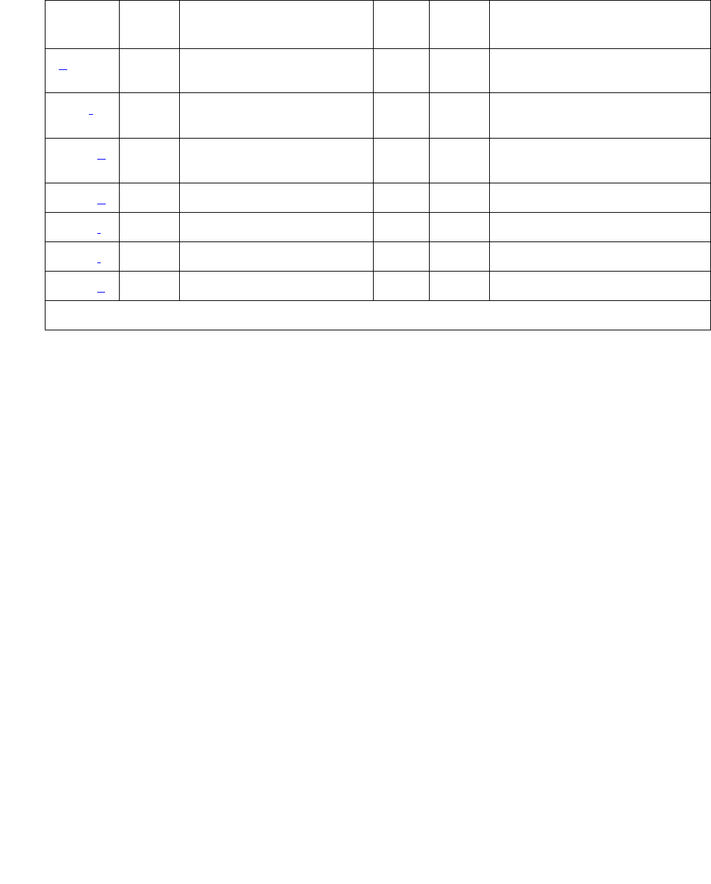
DIG-IP-STN (Digital IP Station)
Issue 1 June 2005 917
Notes:
a. Error Type 1 reports the registration status of the endpoint. If Communication Manager
software claims the endpoint is registered and receives keep-alive handshakes from the
endpoint, the test passes. If keep-alive handshaking has failed, the test fails. If the user has
intentionally un-registered from the S8700 media server, the station is now basically an
AWOH station and is no longer being maintained; no tests run for this station.
b. Error Type 18 is logged when the port/station is busied out by maintenance personnel.
Make sure the port/station is released from busy via release port | station (IP
terminal only).
c. Error Type 257 tracks failures of the signaling path PING test. The test attempts to send a
PING packet to the endpoint IP address, as reported during registration. The PING packet
originates with the C-LAN board through which the endpoint is registered. If the PING
response packet is received, the test passes. If the PING response packet times out, the
test fails.
d. This refreshes the lamp state of every lamp on a virtual DCP station. If successful, the
update always passes. It can abort, but it never fails. This update (test number 16) is the
same one used for existing DCP stations.
e. This refreshes the ringer state on a virtual DCP station and queries the virtual station’s
switch-hook state. If successful, the update always passes. It can abort, but it never fails.
This runs a subset of the entire audit update that runs for standard DCP sets.
f. Error Type 513 indicates that the terminal failed to respond to the ID Query request. This
implies that there is something wrong with the terminal or the communication path. (IP
terminal only).
(e) Digital Terminal Audit
Update (#17)
WRN OFF
513 (f) Any Station Digital AUDIT test
(#17)
WRN OFF test port | station
1281 (g) Any Station Digital AUDIT test
(#17)
WRN OFF test port | station
1537 (h) 40968 WRN OFF test port | station
1793 (i)None WRNOFF
2305 (j) Any None
2817 (k) Station Hyperactivity
Table 312: DIG-IP-STN Digital IP Station Error Log Entries (continued)
Error
Type
Aux
Data
Associated Test Alarm
Level
On/Off
Board
Test to Clear Value
2 of 2

Communication Manager Maintenance-Object Repair Procedures
918 Maintenance Procedures for Avaya Communication Manager 3.0, Media Gateways and Servers
g. Error Type 1281 indicates that the terminal is reporting a bad state of health (IP terminal
only).
h. Error Type 1537 indicates that the link has gone down between the terminal and its
gateway to the switch. This likely means that the terminal has unregistered (IP terminal
only).
i. Error Type 1793: indicates the IP station has registered with a Local Survivable Processor
(LSP). Follow standard practices to repair the primary server, or network failure.
j. Error Type 2305 indicates that there was an unsolicited Link Reset even though switch
software believed the terminal to be functional and in service. This error can be ignored if no
user complaints are received (IP terminal only).
k. Error Type 2817 tracks failures of the port hyperactivity counter. If a port generates more
than 50 uplink CCMS messages within 10 seconds, the port is taken out-of-service for 30
seconds. Even though the Softphone actually signals over a TCP/IP link, DCP CCMS
messages received over the TCP link are counted as regular CCMS uplinks and can cause
the station to be marked as hyperactive.
System Technician-Demanded Tests:
Descriptions and Error Codes
Investigate tests in the order presented. By clearing error codes associated with one test, you
can also clear errors generated from other tests in the sequence.
Order of Investigation Short Test
Sequence
Long Test
Sequence
D/ND1
1. D = Destructive; ND = Nondestructive
Registration Status Inquiry (#1372) X X ND
Signaling Path PING Test (#1373) X X ND
Digital Terminal Lamp Update Test (#16) X X ND
Digital Terminal Audits Test (#17) X ND

DIG-IP-STN (Digital IP Station)
Issue 1 June 2005 919
Registration Status Inquiry (#1372)
The Registration status inquiry reports the H.323 registration status of the endpoint. An endpoint
must be registered and authenticated in order to receive service from the system.
Registration is initiated when the endpoint user attempts to login using the Avaya registration
software application running on the endpoint PC. The user must provide a valid extension and
security code. The registration messages are sent to the IP address of a C-LAN’s Ethernet port.
An extension that is registered, or has been registered in the past, has a port number or ID that
appears as SNNNNN, where N is a digit from 0–9 and is an indication that the port is virtual and
a station.
Signaling Path PING Test (#1373)
This test is nondestructive.
The test determines the local C-LAN through which the signaling originates and the endpoint’s
IP address. It then requests the local C-LAN to execute a PING on the endpoint’s address. If the
PING is successful, the test passes, if the PING is not successful, the test fails.
Table 313: Test #1372 Registration Status Inquiry
Error
Code
Test
Result
Description / Recommendation
1
2
3
FAIL The endpoint is not successfully registered.
1. Verify that the user is entering the:
●Correct extension and security code
●C-LAN’s IP address
2. Verify that the extension has been enabled for IP softphone operation.
3. If many endpoints cannot register, investigate any errors of the
C-LAN’s Ethernet port.
4. Examine the Ethernet cabling from the endpoint PC to the Ethernet
hub.
PASS The endpoint is successfully registered and continues to respond to
registration handshaking.

Communication Manager Maintenance-Object Repair Procedures
920 Maintenance Procedures for Avaya Communication Manager 3.0, Media Gateways and Servers
Note:
Note: Multiple failures of this test can take the Digital IP Station out of service.
This test checks the circuitry involved in the data path of a peer-to-peer IP layer
connection.
Note:
Note: This nondestructive test runs due to in-line errors, during periodic and schedule
maintenance, and on demand.
Table 314: Test #1373 Signaling Path PING Test
Error
Code
Test
Result
Description / Recommendation
2100 ABRT Could not locate the necessary system resources to run this test.
1. Retry the command at 1-minute intervals up to 5 times.
2. Escalate if the problem persists.
2500 ABRT Internal system error
1. Retry the command at 1-minute intervals up to 3 times.
2. Escalate if the problem persists.
1003 FAIL Ping to the destination failed.
1. Retry the command at 1-minute intervals up to 3 times.
2. Investigate any errors of the C-LAN’s Ethernet port.
1007 FAIL The system could not PING the registered endpoint via the CLAN.
1. Verify that at least one destination is reachable through this port. PING
this destination (ping ip-address xxx.xxx.xxx.xxx).
2. If a PING to any destination is successful through this port, the link is
up.
3. If a PING to every destination fails, test the CLAN port (test port
location short), and follow repair procedures for Session Status
test (#1286) failures.
4. If only this station cannot be pinged:
●Make sure the PC is up.
●Make sure the PC has a network connection (Ethernet or dial-up).
●Check the Ethernet cabling.
PASS The system can successfully send IP packets to the registered endpoint
from the C-LAN.

DIG-IP-STN (Digital IP Station)
Issue 1 June 2005 921
Digital Terminal Lamp Update (#16)
This test updates internal lamp states that can or cannot be shown on the actual PC graphical
user interface. The lamp updates run only if the station is in-service. The status of the station is
checked and the lamp updates are blocked from taking place if the station is not in the
in-service state. This test does not affect the status of the Message Waiting lamp.
Table 315: Test #16 DIG-LINE Station Lamp Updates Test
Error
Code
Test
Result
Description / Recommendation
ABRT Internal system error
1. Retry the command at 1-minute intervals up to 5 times.
1 ABRT This port could have been busied out by system technician.
1. Look in the Error Log for Error Type 18 (port busied out) for this port. If
this error type is present, then release the port via release station
extension and run the test again.
2. Make sure that the terminal is connected.
3. Retry the command at 1-minute intervals up to 5 times.
3 ABRT Station could be in ready-for-service or out-of-service state.
1. Use status station to verify state of station.
2. Make sure the terminal is connected.
3. Retry the command at 1-minute intervals up to 5 times.
1000 ABRT System resources required to run this test are not available. The port could
be busy with a valid call.
1. Use display port location to determine the station extension of
the port. Use status station to determine the service state of the
port. If the port is in use, wait until it is idle before testing.
2. If the port status is idle, then retry the command at 1-minute intervals
up to 5 times.
FAIL Internal system error
1. Retry the command at 1-minute intervals up to 5 times.
PASS The message to light every station lamp was successfully sent to the port.

Communication Manager Maintenance-Object Repair Procedures
922 Maintenance Procedures for Avaya Communication Manager 3.0, Media Gateways and Servers
Digital Terminal Audits Test (#17)
This is a series of tests that are classified as audits. The media server sends messages to the
softphone application or IP phone to perform the following tests. These audits run only if the
station is in-service.
●Switchhook Inquiry test updates the media server’s records according to the softphone
switch-hook state.
●Ringer Update test updates the softphone’s ringer state according to the media server’s
records.
●ID Request queries the station for its status. The terminal returns its configuration
information and health information. The information is checked, and a PASS/ABORT result
is provided. If the result is ABORT, an error is logged in the hardware error log (IP terminal
only).
Table 316: Test #17 Station (Digital) Audits Test
Error
Code
Test
Result
Description / Recommendation
1 ABRT Switchhook audit timed out.
2 ABRT ID request fails, health bit returned from voice terminal is bad (IP Terminal
only).
1. Make sure voice terminal is connected, and repeat test.
2. If test fails, replace the voice terminal, and repeat test.
4 ABRT Internal system error
1. Resolve any outstanding circuit pack maintenance problems.
2. Retry the command at 1-minute intervals up to 5 times.
5 ABRT Ringer update aborted due to station being in ready-for-service or
out-of-service state.
6 ABRT This port could have been busied out by system technician.
1. Look in the Error Log for Error Type 18 (port busied out) for this port. If
this error is present, then release the port via release station
extension.
2. Make sure that the terminal is connected.
3. Retry the command at 1-minute intervals up to 5 times.
1000 ABRT System resources required for this test are not available.
1 of 2

DIG-IP-STN (Digital IP Station)
Issue 1 June 2005 923
2000 ABRT Response to the test was not received in the allowable time period.
1. Retry the command at 1-minute intervals up to 5 times.
PASS Station Audits passed.
1. If complaints persist, investigate by using other port tests, and by
examining the station, wiring, and connections.
Table 316: Test #17 Station (Digital) Audits Test (continued)
Error
Code
Test
Result
Description / Recommendation
2 of 2

Communication Manager Maintenance-Object Repair Procedures
924 Maintenance Procedures for Avaya Communication Manager 3.0, Media Gateways and Servers
DIG-LINE (Digital Line)
S8700 | 8710 / S8500 / S8300
DIG-LINE monitors and tests ports on digital line circuit packs or digital line media modules and
on hardware administered as a digital station on those ports. These include stations with only a
digital phone and stations with a digital phone linked to a data module.
S8700 | 8710 / S8500
Standalone data modules, and data adaptors in standalone mode, are covered by PDMODULE
(Processor Data Module) on page 1751. Circuit pack-level maintenance is covered by DIG-BD
(Digital Line Circuit Pack) on page 915, the strategy for which is described in XXX-BD
(Common Port Circuit Pack/Media Module) on page 2539.
The following circuit packs support digital lines:
MO Name in
Alarm Log
Alarm
Level
Initial SAT Command to Run Full Name of MO
DIG-LINE MIN test port location lDigital Line
DIG-LINE WRN test port location sh Digital Line
Table 317: Digital Line Circuit Packs
Code Port
s
Type Compandin
g
Endpoints
TN754
TN754B
TN2181
TN2224B/
CP
8
8
16
24
4-wire
DCP
4-wire
DCP
2-wire
IDCP
2-wire
IDCP
mu-law
A-law/
mu-law
A-law/
mu-law
A-law/
mu-law
7400 series digital voice
terminals, attendant consoles,
510D personal terminals,
MT515 BCTs, DCP data
modules
TN2136
TN2181
TN2224B/
CP
8
16
24
2-Wire
IDCP
2-wire
IDCP
2-wire
IDCP
A-law/
mu-law
A-law/
mu-law
A-law/
mu-law
Data Adaptors (DA), Italtel
Digital Telephone Models 1 and
2 (IDT1/2).
DIG-LINE (Digital Line)
Issue 1 June 2005 925
Each digital line port supports two 64 kbps information channels (primary and secondary) and
one 8kbps signaling channel. Digital voice terminals always use the primary information
channel, and only one voice terminal can be connected to each port. The secondary information
channel can be used to connect a data terminal via a Digital Terminal Data Module (DTDM) or a
Data Adaptor (DA). All other devices currently supported by Digital Line circuit packs
communicate on the primary information channel. Figure 45: Digital Line Connectivity on
page 925 shows examples of digital line connectivity.
Use only the TN754B or TN2136 circuit packs in out-of-building applications.
The TN2181 and TN2224B/CP support both modes as shown in Figure 45: Digital Line
Connectivity on page 925 and Figure 46: Digital Line Connections on page 926.
Figure 45: Digital Line Connectivity
.
.
.
.
.
.
.
TN413, TN754/B
Digital Line
Circuit Pack
Port
Port
Port
Port Secondary Information Channel (Data)
DTDM
Digital
Voice
Terminal
Control Channel (Signaling)
Primary Information Channel (Voice)
Physical Connection
. . . . . . . . . . . . . . .
.
.
.
.
.
.
.
.
.
.
.
.
.
.
.................... . . . . . . . . . . . . . . . . . . . . . . . . . . . . . . . . . . . . . . . . . . . . . . . . . . . . . . . . . . . . . . . . . . . . . . . . . . . . . . . . . . . . . . . . . . . . . . . . . . . . . . . . . . . . .
.
.
.
.
.
.
.
.
.
.
.
.
.
.
.
.
.
.
.
.
.
.
.
.
.
.
.
.
.
.
.
.
.
.
.
.
.
.
.
.
.
.
.
.
. . . . . . . . . . . . . . . . . . . . . . . . . . . . . . . . . . . . . . . . . . . . . . . . . . . .
. . . . . . . . . . . . . . . . . . . . . . . . . . . . . . . . . . . . . . . . . . . . . . . . . . . . . . . . . . . . .
.
.
.
.
.
.
.
.
.
.
.
.
.
.
.
.
Digital Line
. . . . . . . . . . . . . . Data
Terminal
.
.
.
.
.
.
.
.
.
Communication Manager Maintenance-Object Repair Procedures
926 Maintenance Procedures for Avaya Communication Manager 3.0, Media Gateways and Servers
Figure 46: Digital Line Connections
Only 2-wire Italtel Digital Telephone Models 1 and 2 (IDT1/2) or DAs can directly connect to a
TN2136 circuit pack. Avaya DCP (4-wire) digital voice terminals and data modules can connect
to these circuit packs via Italtel’s 2/4-wire adapter. DAs operate in either of 2 modes, and are
covered by different MOs:
S8300 / G700
For Media Gateway-level maintenance, see MG-DCP (Digital Line Media Module) on
page 1593, the strategy for which is described in XXX-BD (Common Port Circuit Pack/Media
Module) on page 2539.
Note:
Note: DIG-LINE MO is provided for G700, but this MO only partially supports the G700’s
MM712 DCP media module.
DA Mode Administered as: Endpoint MO
Standalone PDM Data endpoint only PDMODULE
Linked DTDM IDT1/2 and optional data terminal DIG-LINE
TN2136
Digital Line
Circuit Pack
Secondary Information Channel (Data)
Italtel
Digital
Telephone
Model 1/2
Data
Terminal
IDCP
CCITT
V24-V28
Physical Connection
Primary Information Channel (Voice)
Control Channel (Signaling)
Data
Adaptor
(Linked
Mode)
.
.
.
.
. . . . . . . . . . . . . .
Digital Line
.
.
.
.
.
.
.
.
.
.
.
.
.
.
Port
. . . . . . . . . . . . . . . . . . . . . . . . . . . . . . . . . . . . . . . . . . . . . . . . . . . . . . . . . . . . . . . . . . . . . . . . . . . . . . . . . . . . . . . . . . . . . . . . . . . . . . . . . .
.
.
.
.
.
.
.
.
.
.
.
.
.
.
.
.
.
.
.
.
.
.
.
.
.
.
.
.
. . . . . . . . . . . . . . . . . . . . . . . . . . . . . . . . . . . . . . . . . . . . . . . . . . . . . . . . . . . . . . . . . . . . . . . . . . . . . . . . . . . . . . . . . . . . . . . . . . . . . . . . . .
.
.
.
.
.
.
.
.
.
.
.
.
.
.
.
.
.
.
.
.
.
.
.
.
.
.
.
.
.
.
.
.
.
.
.
.
Italtel
Digital
Telephone
Model 1/2
Digital Line
Physical Connection
Primary Information Channel (Voice)
Control Channel (Signaling)
(Secondary Information Channel Unused)
Data Adaptors operating in stand-alone mode are treated as
PDMODULE Maintenance Objects.
.
. . . . . . . . . . . . . . . . . . . . . . . . . . . . . . . . . . . . . . . . . . . . . . . . . . . . . . . . . . . . . . . . . . . . . . . . . . . . . . . . . . . . . . . . . . . . . . . . . . . . . . . . . . . . . .
.
.
.
.
.
.
.
.
.
.
.
.
.
.
.
.
.
.
.
.
.
.
.
.
.
.
.
.
.
.
.
.
.
.
.
.
.
.
.
.
.
.
.
. . . . . . . . . . . . . . . . . . . . . . . . . . . . . . . . . . . . . . . . . . . . . . . . . . . . . . . . . . . . . . . . . . . . . . . . . . . . . . . . . . . . . . . . . . . . . . . . . . . . . . . . . . .
.
....................
.
.
.
.
.
.
.
.
.
.
.
.
.
.
.
. . . . . . . . . . . . . .
Port
Port
Port
Port

DIG-LINE (Digital Line)
Issue 1 June 2005 927
Service States
Digital line maintenance interacts with digital line circuit pack (DIG-BD), or with digital line media
module (MG-DCP) maintenance. The health of the digital-line circuit pack or media module can
affect the results of DIG-LINE testing. Keep this in mind when investigating digital-line
problems.
It is sometimes important to know the service state of a station. These service states apply to
digital-line stations:
Downloading Terminal Parameters
This section explains how maintenance software interacts with terminal parameter
downloading.
For Systems Supporting Circuit Packs
Terminal Types:
Software can interact with the following terminal types:
●84xx multi button digital voice terminals (8403D01A, 8410B, 8410D02A, 8434D01A) with
optional expansion module.
●603A1 and 603D1 Callmaster terminals for telemarketing applications.
●302B1 and 302C1 attendant console.
Out-of-Service state The port, and thus the station, have been removed from service.
Busyout puts the port in the out-of-service state.
Ready-for-Service state The port on the circuit pack or media module has been put into
service, but the voice terminal has not yet established signaling
communications with the port.
In-Service state The voice terminal has established signaling communications with
the port, and the system is ready to process calls to and from that
station. A terminal in the ready-for-service state will progress to the
in-service state if it is functioning normally. It can also be forced
into the in-service state by going off-hook.
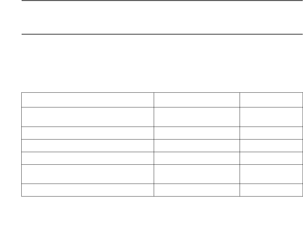
Communication Manager Maintenance-Object Repair Procedures
928 Maintenance Procedures for Avaya Communication Manager 3.0, Media Gateways and Servers
Circuit Packs:
●8400x, 302B1 Terminals
●TN754 (4-wire, mu-law)
Note:
Note: Minimum usable vintage for 8410D and 8434D terminals - V11
●TN413 (4-wire, A-law)
●TN754B (4-wire, A-law/mu-law selectable)
●TN2177 (2-wire, 16-port, A-law/mu-law selectable)
●TN2181 (2-wire, 16-port, A-law/mu-law selectable)
●TN2224 (2-wire, 24-port, A-law/mu-law selectable)
●603A1/D1 Terminals
●TN754 (4-wire, mu-law),
●TN413 (4-wire, A-law)
●TN754B (4-wire, A-law/mu-law selectable)
S8300 / G700
The MM712 Media Module supports 8410D and 8434D terminals (2-wire, 8-port, A-law/mu-law
selectable).
Programmable Terminals
The following parameters are downloaded to programmable terminals.
Table 318: Parameters Downloadable to Programmable Terminals
Parameter Scope Terminal
International Flags (A-law/mu-law,
Display Mode, DLI Voltage level)
System level 84xx, 603x, 302B1
Primary Levels (Transmission & Sidetone) System level 84xx, 603x, 302B1
Adjunct Levels (Transmission & Sidetone) System level 84xx
Handset Expander Option System level 84xx
Administrable Options
(Speakerphone & Mute Button)
Per-terminal 84xx
Administrable Softkeys Per-terminal, System level 8410D, 8434D

DIG-LINE (Digital Line)
Issue 1 June 2005 929
Nonvolatile Memory
Nonvolatile memory stores downloadable parameters in programmable terminals. Once the
terminal is downloaded, it is not be necessary to download it again, even if power is removed
from the terminal. If nonvolatile memory fails with power still present, the terminal reverts to its
default factory settings except for its A-law/mu-law companding settings which are stored in
RAM. If power is removed after the nonvolatile memory fails, the terminal reverts to its factory
default settings.
Note:
Note: The mu-law companding mode is assigned as a default setting at the factory. For
the United States, a programmable terminal can place calls even though it has
not been downloaded from the system.
Download Actions
There are several different scenarios that cause a terminal to be downloaded. These can occur
as part of background maintenance activity or on demand from the system access terminal or
from a station.
For the following background actions, the terminal downloads automatically if a download retry
flag for the terminal is set in software. This flag is set:
●At boot time when translation is loaded
●When translation that affects the parameters of a terminal is changed as part of system
administration action
●When a port is inserted in software as a result of board insertion or translation change
Automatic Download Actions
This section describes download actions that occur automatically.
System Reboot/Restart
A global download action is started when periodic maintenance tests start after a system
reboot/restart regardless of whether the parameters have been downloaded previously.
Periodic Tests
If the download flag is still set when periodic tests are run on a terminal, a download action
will occur. This operation is required in case a terminal could not be downloaded previously
either:
●Because it was off-hook at the time the system first booted
●Because the terminal was off-hook at the time translation associated with downloadable
parameters was changed

Communication Manager Maintenance-Object Repair Procedures
930 Maintenance Procedures for Avaya Communication Manager 3.0, Media Gateways and Servers
Note:
Note: It may take more than 1 hour for periodic tests to reach the terminal that needs to
be downloaded.
Terminal Administration
A downloadable terminal is automatically downloaded when translation changes associated
with downloadable parameters are made as part of system administration. As shown in
Table 318: Parameters Downloadable to Programmable Terminals on page 928, these
changes can be for a specified terminal or may be system-wide. If the change is for
system-level parameter, a background global update request is made to download all
programmable terminals.
This global update may take more than an hour for a system with several thousand
programmable terminals.
Port Insertion
Whenever maintenance software initiates a request to place a port into service, a terminal
download action is started on that terminal if that terminal is programmable. This port
insertion action occurs under the following circumstances:
●A digital line circuit pack or media module that is physically inserted into the system has
ports currently administered for programmable terminals.
If more than 20 port insertion requests are received within a few seconds, a global
download request is started up as a background task. This action updates all
programmable terminals instead of just those being inserted. This is done to avoid
system overload for situations where there is massive board insertion. This could occur
when connectivity to an PN is re-established after that PN was down.
●A station port is added to the system by add station or change station.
●A TTI port is activated.
Audits
As part of periodic maintenance, the hardware status audit test queries programmable
terminals to determine what levels and/or options are being used. If the reported values are
not equal to the administered values, the system will initiate a terminal download action.
This audit does NOT check the parameters used for softkeys.
Activation of TTI
A terminal is downloaded automatically when it is activated using the Terminal Translation
Initialization feature. Therefore, no special user actions are required for TTI.
Note:
Note: Plugging the station cord into a terminal does not automatically cause the
terminal to be downloaded. If this terminal has factory defaults or if the terminal
has been previously downloaded with parameters different from those desired,
use one of the following demand download actions to download the terminal.

DIG-LINE (Digital Line)
Issue 1 June 2005 931
Demand Download Actions
Busyout/Release Command
A maintenance demand busyout/release request for a station causes the terminal to be
downloaded regardless of its previous download status.
Feature Access Code
A Refresh Terminal Parameters Feature Access Code can be used to request a terminal
download action. When this code is followed by a pound sign (#), the programmable
parameters for the current terminal are downloaded when the terminal goes on hook. When
this code is followed by an extension, the programmable parameters for the specified
station are downloaded.
Assign the Refresh Terminal Parameters Feature Access Code on the Feature Access
Codes form.
A confirmation is returned if the download request is accepted. A busy tone is returned if the
request is made from a different station when the target station is off-hook.
Note:
Note: For systems supporting circuit packs, the first three green call appearance LEDs
on the 84xx 603x terminal will be turned on for three seconds if the station was
successfully downloaded as a result of an entry of a Refresh Terminal
Parameters Facility Access Code. This is not true for the 302B1 terminal.
There is no visible display on a station for the other background or demand download
actions. Use status station and status attendant forms to check the download
status of a specified terminal.
Status of Parameter Downloads
The status station and status attendant forms show the current download status of
individual 84xx terminals (S8300 / G700: MM712 Media Module), and 84xx, 603, and 301B1
terminals (S8700 | 8710 / S8500) in the Download Status field. Possible download states are:
Status Explanation
Complete Terminal successfully downloaded sometime in the past.
Pending System waiting to download the terminal. This may require the
execution of a background periodic test which could take more than
an hour. A demand download as previously described may also be
used to initiate an immediate download.
Not Applicable Not a programmable terminal.
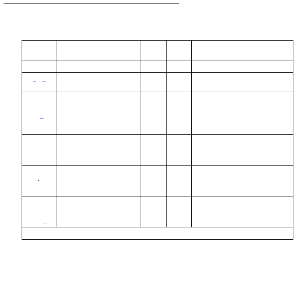
Communication Manager Maintenance-Object Repair Procedures
932 Maintenance Procedures for Avaya Communication Manager 3.0, Media Gateways and Servers
Possible reasons for a terminal not being downloaded include:
●Terminal is off-hook.
●Terminal detected a bad checksum.
●Terminal detected a bad or missing EEPROM (refer to hardware error log).
●Terminal is busy programming data from a previous PROGRAM message.
●Terminal is in the Programming Disabled state.
●Terminal is in the Local Program Options mode.
●Terminal is disconnected or out of service (use status station).
Error Log Entries and Test to Clear Values
Table 319: Digital Line Error Log Entries
Error
Type
Aux
Data
Associated Test Alarm
Level
On/Off
Board
Test to Clear Value
0 (a) 0 Any Any Any test port location sh r 1
1 (b) (c) 40987
1 – 20
None WRN OFF
18 (d)0 busyout port
location
WRN OFF release port location
130 (e)None WRNONtest port location sh
257 (f) 40971 None
513 0 Station (Digital)
Audits (#17)
WRN OFF test port location sh r 6
767 (g) 40964 None WRN OFF
769 (h)
(i)
40963
40988
None WRN OFF
1026 (j) NONE WRN OFF
1281 Any Station (Digital)
Audits (#17)
WRN OFF test port location sh r 4
1537 (k) 40968 None WRN OFF
1 of 2
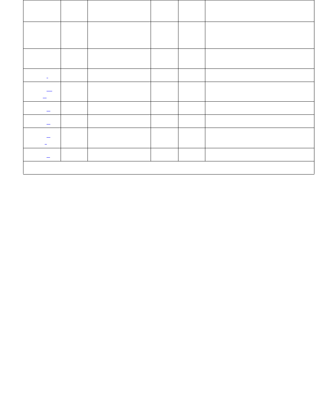
DIG-LINE (Digital Line)
Issue 1 June 2005 933
Notes:
a. Error Type 0: Run the short test sequence first. If every test passes, run the long test
sequence.
b. Error Type 1; Aux Data - 40987 could indicate a noisy port or link. This is an off-board
problem detected by the port circuit. Check for defective wiring, a defective voice terminal,
or move voice terminal closer to the switch (in terms of feet of wire from the jack to the
switch). If the problem still exists, replace the circuit pack. Once the problem is resolved, the
alarm is retired after a predetermined amount of time.
c. Error Type 1; Aux Data - 1 to 20 occurs when at least 15 off-board problems with the link
to the terminal have been detected. When an error with the link is detected, an on-board
counter is incremented.
The user could experience a noisy port or link. This is an off-board problem detected by the
port circuit. Check for defective wiring, a defective voice terminal, or move voice terminal
closer to the switch (in terms of feet of wire from the jack to the switch). If the problem still
exists, replace the circuit pack. Once the problem is resolved, the alarm is retired after a
predetermined amount of time.
d. Error Type 18 is logged when the port in question is busied out by maintenance personnel.
Use release port location to release the port from busyout.
1793 Voice and Ctrl.
Local Loop test
(#13)
MIN
WRN1ON test port location l r 3
2049 NPE Crosstalk
test (#9)
MIN
WRN2ON test port location l r 3
2304 (l)None
2305 (m)
(n)
32770
40969
None
2817 (o)Any None OFF
3585 (p)
3840 (q)
(r)
40965
40989
None
3841 (s) 41029 None
1. Major alarms may be downgraded to Warning alarms based on the value used in set options.
Table 319: Digital Line Error Log Entries (continued)
Error
Type
Aux
Data
Associated Test Alarm
Level
On/Off
Board
Test to Clear Value
2 of 2

Communication Manager Maintenance-Object Repair Procedures
934 Maintenance Procedures for Avaya Communication Manager 3.0, Media Gateways and Servers
e. Error Type 130 indicates that the circuit pack or media module has been removed or has
been insane for more than 21 minutes. To clear the error, reinsert or replace the circuit pack
or media module.
f. Error Type 257 indicates problems transmitting to the voice terminal. This can be caused
by defective wiring, which can cause varying degrees of problems on different types of sets.
Sets such as the 7410 appear to be more susceptible to wiring problems than other sets.
This is usually an on-board problem and can be ignored if no user complaints are received.
g. Error Type 767 is an in-line event that produces this error type when a favorable response
is received from running the Digital Line Electronic Power Feed test (#11). No craft action is
necessary. This alarm is resolved with the passing of time.
h. Error Type 769 with Aux Data 40963 is a result of an unfavorable response to the
Electronic Power Feed/ Positive Temperature Coefficient test (#11).
i. Error Type 769 with Aux Data 40988 indicates that the EPF/PTC circuit has been turned off
due to an overcurrent condition.
S8700 | 8710 / S8500
For TN754 vintage 13 or earlier and TN413, the EPF circuit senses an overcurrent condition
at the voice terminal. Check for a short in the wiring, a damaged jack, an incorrect type of
voice terminal, or a defective voice terminal.
For TN754 vintage 14 or later, TN754B and TN2136, the PTC will open if there is a short on
the power line for 1/2 second or longer. The voice terminal is probably not operating
properly. Unplug the voice terminal for 30 seconds and then plug it back in. If the voice
terminal still does not operate, then check for a short in the wiring, a damaged jack, an
incorrect type of voice terminal, or a defective voice terminal.
Once the problem has been resolved, it may take up to 1 hour for the alarm to clear. If the
problem cannot be resolved by one of the previous steps, then replace the circuit pack or
media module.
j. Error Type 1026: There is a problem with the voice terminal EEPROM. When the voice
terminal is repaired the alarm will be resolved with the passing of time.
k. Error Type 1537: An in-line maintenance error has generated an off-board warning due to
some problem with the link to the voice terminal. This can be ignored if no user complaints
are received. Otherwise, make sure the voice terminal is connected, check for defective
wiring, check for a defective voice terminal, and move voice terminal to a jack that is closer
to the switch (in terms of feet of wiring between the jack and the switch). If the problem still
exists, replace the circuit pack or media module. Once the problem has been resolved, the
alarm will be retired after a predetermined amount of time.
l. Error Type 2304: Internal system error. No action is necessary.

DIG-LINE (Digital Line)
Issue 1 June 2005 935
m. Error Type 2305; Aux Data - 32770: This indicates that the station went off-hook while it
was in the ready-for-service state. Use status station to determine the state of the
station. The off-hook should have moved the station to ready-for-service. No craft action is
necessary.
n. Error Type 2305; Aux Data - 40967: An in-line maintenance error has generated an
off-board warning due to some problem with the link to the voice terminal. This can be
ignored if no user complaints are received. Otherwise, make sure the voice terminal is
connected, check for defective wiring, check for a defective voice terminal, and move voice
terminal to a jack that is closer to the switch (in terms of feet of wiring between the jack and
the switch). If the problem still exists, replace the circuit pack or media module. Once the
problem has been resolved, the alarm will be retired after a predetermined amount of time.
o. Error Type 2817: Port Level Hyperactivity. Fifty or more CCMS uplink messages were
received from the port within ten seconds. The user is taken out of service for a short
interval of time (default 30 seconds).
p. Error Type 3585: This error type indicates that an attempt to execute a firmware download
of a DCP terminal has failed. The DCP terminal must be replaced before the firmware
download can be executed successfully. Replace the DCP terminal and re-execute the
firmware download.
q. Error Type 3840; Aux Data - 40965: No terminal is connected to the Digital Line board. No
maintenance action is required.
r. Error Type 3840; Aux Data - 40989: An uplink message has been logged indicating that
the Electric Power Feed (EPF) is on with no load on it. No action is necessary.
s. Error Type 3841: The circuit pack’s or media module’s message buffer is full. This may be
caused by having many display phones with heavy traffic connected to the circuit pack or
media module. No action is necessary.

Communication Manager Maintenance-Object Repair Procedures
936 Maintenance Procedures for Avaya Communication Manager 3.0, Media Gateways and Servers
System Technician-Demanded Tests:
Descriptions and Error Codes
Investigate tests in the order presented. By clearing error codes associated with the Voice and
Control Channel Local Loop-Around test, you may also clear errors generated from other tests
in the sequence.
Digital Terminal Remote Loop-around Test (#1201)
Note:
Note: On the G700/ G350, this test aborts with Error Code 1412.
This test checks the connection between the media server and the digital terminal and the
ability of the terminal and the associated port to send and receive data. This test is based on
procedure 622 to isolate digital terminal problems.
A request is presented to the terminal to go into loop-back mode. Data is sent to the terminal
and when received back, checked for consistency. This test is run as a part of the test long
procedure. It is not included in any error recovery strategy and generates no error log entries or
alarms. To begin the test, Maintenance will ask Communication Manager to make the
associated endpoint and port Maintenance Busy. This test succeeds if the endpoint is “idle”. If
the reserve request fails then the test aborts. If the request succeeds then the media server
sends a message to loop around both information channels for the digital terminal.
1. First the primary information (voice information channel 1 or l1) channel loop-back test is
run. The test is performed by sending a digital count from the Tone-Clock circuit on the
primary information channel time slot and receiving the same digital count with a general
purpose tone detector.
Order of Investigation Short Test
Sequence
Long Test
Sequence
D/ND1
1. D = Destructive; ND = Nondestructive
Digital Terminal Remote Loop-around Test (#1201)
S8300 / G700: This test aborts with Error Code 1412.
XD
Voice and Control Channel Local Loop-Around Test (#13)
S8300 / G700: This test aborts with Error Code 1412.
XND
Digital Line NPE Crosstalk Test (#9)
S8300 / G700: This test aborts with Error Code 1412.
XND
Digital Line Electronic Power Feed Test (#11) X ND
DIG-LINE Station Lamp Updates Test (#16) X X ND
Station (Digital) Audits Test (#17) X X ND

DIG-LINE (Digital Line)
Issue 1 June 2005 937
2. If the primary information channel test is successful, the loop-around test for the secondary
information (data, Information Channel 2 or I2) channel is then performed. This is the same
test as the primary information channel’s loop around test and is performed only if a DTDM
is administered. This is also the case for a linked DA.
Only one value (Pass, Fail, or Abort) is generated as a result of the two tests run. If any test fails
aborts, the sequence is stopped. Upon completion of this test, the associated endpoint and port
are moved back into the previous service state.
Table 320: Test #1201 Digital Terminal Remote Loop-around Test
Error
Code
Test
Result
Description / Recommendation
ABRT Internal system error
1. Retry the command at 1-minute intervals up to 5 times.
1000 ABRT System resources required to run this test are not available. The port may
be busy with a valid call.
1. Use display port location to determine the station extension or
attendant number of the port. Use status station or status
attendant to determine the service state of the port. If the port is in
use, wait until it is idle before testing. Attendants are always in use
(off-hook) if the handset is plugged in and the port is not busied out.
2. If the port status is idle, then retry the command at 1-minute intervals
up to 5 times.
1001 ABRT System resources required to run this test are not available.
1. If the port status is idle, then retry the command at 1-minute intervals
up to 5 times.
1002 ABRT The system could not allocate time slots for the test. The system may be
under heavy traffic conditions, or it may have time slots out of service due
to TDM-BUS errors.
1. If the system has no TDM-BUS errors and is not handling heavy
traffic, retry the command at 1-minute intervals up to 5 times.
1003 ABRT The system could not allocate a tone receiver for the test. The system
may be oversized for the number of Tone Detectors present, or some
Tone Detectors may be out of service.
1. Resolve any TTR-LEV errors.
2. Resolve any TONE-PT errors.
3. If neither condition exists, retry the command at 1-minute intervals up
to 5 times.
1 of 3

Communication Manager Maintenance-Object Repair Procedures
938 Maintenance Procedures for Avaya Communication Manager 3.0, Media Gateways and Servers
1004 ABRT The port was seized by a valid call during the test.
1. Enter display port location to determine the station extension
or attendant number of the port. Use status station or status
attendant to determine the service state of the port. If the port is in
use, wait until it is idle before resetting. Attendants are always in use
(off-hook) if the handset is plugged in and the port is not busied out.
2. Retry the command at 1-minute intervals up to 5 times.
1005 ABRT The installed circuit pack does not support this operation.
S8300 /
G700
1412
ABRT This test does not execute on a G700 media gateway.
2000 ABRT Response to the test was not received within the allowable time period.
1. Retry the command at 1-minute intervals up to 5 times.
2100 ABRT System resources required to run this test are not available.
1. Make sure terminal is connected and repeat test.
2. If test fails replace terminal and repeat test.
3. Retry the command at 1-minute intervals up to 5 times.
14 FAIL The primary channel is not operating properly. User impact may range
from noticing nothing to not being able to use the port.
1. Check the results of “Voice and Control Channel Local Loop test
(#13).
2. If that test fails, suspect the Digital Line circuit pack. If that test passes
then replace the terminal.
3. If both tests fail, and component replacement does not change the
results, then:
a. Run circuit pack tests to check the tone generator circuit and the
Tone Detector circuit using test board location.
b. Resolve any problems that are detected on the Tone Generator
circuit or Tone Detector circuit.
1015 ABRT The station is not busied out (busyout station).
Table 320: Test #1201 Digital Terminal Remote Loop-around Test (continued)
Error
Code
Test
Result
Description / Recommendation
2 of 3

DIG-LINE (Digital Line)
Issue 1 June 2005 939
Digital Line NPE Crosstalk Test (#9)
Note:
Note: S8300 / G700: This test aborts with Error Code 1412.
The NPE Crosstalk test verifies that this port’s NPE channel talks on the selected time slot and
never crosses over to time slots reserved for other connections. If the NPE is not working
correctly, one-way and noisy connections may be observed. This test is part of a port’s Long
Test Sequence and takes about 20 to 30 seconds to complete.
16 FAIL The secondary channel is not operating properly. User impact may range
from noticing nothing to not being able to use this terminal.
1. Check the results of Voice and Control Channel Local Loop test (#13).
2. If that test fails, suspect the Digital Line circuit pack. If that test passes
then replace the terminal.
3. If both test fail, and component replacement does not change the
results, then:
a. Run circuit pack tests to check the tone generator circuit and the
Tone Detector circuit pack using test board location.
b. Resolve any problems that are detected on the Tone Generator
circuit or Tone Detector circuit.
PASS Voice and Control Channel Local Loop test passed. All channels are
transmitting properly.
1. To verify that this is not an intermittent problem, repeat this test up to
ten times.
2. If complaints persist (noisy connections for voice. corrupted data
transfer for data), examine the station, connections, and wiring.
Table 320: Test #1201 Digital Terminal Remote Loop-around Test (continued)
Error
Code
Test
Result
Description / Recommendation
3 of 3

Communication Manager Maintenance-Object Repair Procedures
940 Maintenance Procedures for Avaya Communication Manager 3.0, Media Gateways and Servers
Crosstalk testing is performed on both the primary information channel (voice) and the
secondary information channel (data) associated with each digital station port. If this test fails on
either channel, the station and the DTDM are taken out-of-service.
Table 321: Test #9 Digital Line NPE Crosstalk Test
Error
Code
Test
Result
Description / Recommendation
1 ABRT During testing of the primary information channel, system resources were
not available. Also, the port may have been busy during the test.
1. Enter display port location to determine the station extension
of the port. Use status station to determine the service state of
the port. If the port is in use, wait until it is idle before testing.
2. If the port status is idle, retry the command at 1-minute intervals up to
5 times.
2 ABRT During testing of DTDM, system resources may not have been available.
Also, the port may have been busy during the test.
1. Check if port is being used. If possible, disconnect by toggling
disconnect button on DTDM. Retry command after 1 minute.
!WARNING:
WARN ING: This action will drop the call in progress.
1000 ABRT System resources required to run this test are not available. The port may
be busy with a valid call.
1. Enter display port location to determine the station extension
or attendant number of the port. Use status station or status
attendant to determine the service state of the port. If the port is in
use, wait until it is idle before testing. Attendants are always in use
(off-hook) if the handset is plugged in and the port is not busied out.
2. If the port status is idle, retry the command at 1-minute intervals up to
5 times.
1001 ABRT System resources required to run this test are not available.
1. Retry the command at 1-minute intervals up to 5 times.
1002 ABRT The system could not allocate time slots for the test. The system may be
under heavy traffic conditions or it may have time slots out of service due
to TDM-BUS errors.
1. If system has no TDM-BUS errors and is not handling heavy traffic.
Retry the command at 1-minute intervals up to 5 times.
1 of 2

DIG-LINE (Digital Line)
Issue 1 June 2005 941
1003 ABRT The system could not allocate a tone receiver for the test. The system may
be oversized for the number of Tone Detectors present, or some Tone
Detectors may be out of service.
1. Resolve any TTR-LEV errors.
2. Resolve any TONE-PT errors.
3. If neither condition exists, retry the command at 1-minute intervals up
to 5 times.
1004 ABRT The port was seized by a valid call during the test. The test has been
aborted.
1. Enter display port location to determine the station extension
or attendant number of the port. Use status station or status
attendant to determine the service state of the port. If the port is in
use, wait until it is idle before testing. Attendants are always in use
(off-hook) if the handset is plugged in and the port is not busied out.
1020 ABRT Test disabled by background testing. Use status station to determine
when station is available for testing.
S8300 /
G700
1412
ABRT This test does not execute on a G700 media gateway.
2000 ABRT Response to the test request was not received within the allowable time
period.
1. Retry the command at 1-minute intervals up to 5 times.
1
2
FAIL The Network Processing Element (NPE) of the tested port was transmitting
in error.
Error code 1 = Crosstalk test failed on the primary channel.
Error code 2 = Crosstalk test failed on the secondary channel.
1. Replace circuit pack.
PASS The port is correctly using its allocated time slots.
1. To verify that this is not an intermittent problem, repeat this test up to
10 times.
2. If complaints persist, examine the station, connections, and wiring.
Table 321: Test #9 Digital Line NPE Crosstalk Test (continued)
Error
Code
Test
Result
Description / Recommendation
2 of 2

Communication Manager Maintenance-Object Repair Procedures
942 Maintenance Procedures for Avaya Communication Manager 3.0, Media Gateways and Servers
Digital Line Electronic Power Feed/Positive
Temperature Coefficient/PPF Test (#11)
S8700 | 8710 / S8500
For TN413, and TN754 vintage 13 or earlier, this is an Electronic Power Feed (EPF) restoral
test. In this test, the processor requests that the EPF be turned on for a given port, and an
attempt is made to turn on the power supply to the station. If no current is drawn, the station is
probably not connected. If an overcurrent condition is sensed, there may be a short in the loop.
A message is returned reporting that either the EPF was successfully turned on, or that an
overcurrent condition was sensed. This test is repeated again 5 seconds later.
For TN754 vintage 14 or later, TN754B and TN2136 this is a Positive Temperature Coefficient
(PTC) restoral test. In this test, the processor requests that the PTC be turned on for a given
port, and an attempt is made to turn on the power supply to the station. If an overcurrent
condition is sensed, there is probably a short on the power line that causing the PTC to open
and disconnect the voice terminal. Since the PTC does not have self-restoral capability, the
voice terminal must be manually unplugged for 30 seconds and then plugged back in to restore
the PTC. A message is returned reporting that either the PTC was successfully turned on
successfully with no problem or an overcurrent condition was sensed. This test is repeated
again 5 seconds later.
TN2181 and TN2224 boards carry a Protected Power Feed (PPF) relays, one for each port.
Therefore this will be a Protected Power Feed restoral test. The test procedure and its response
is same as that of EPF. One of differences between EFP and PPF is that, if the port goes into a
overcurrent state, PPF does not report this change of state because it is a transient state which
will not last more than 50ms. If the over current persists the power will be shut off automatically
and an EPF_off_overcurrent message is sent uplink.
S8300 / G700
MM711 Media Modules provide power to the terminals. Therefore this will be an EPF restore
test. The test procedure and its response is same as that of EPF. If the over current persists the
power will be shut off automatically and an EPF_off_overcurrent message is sent uplink.
Table 322: Test #11 Digital Line Electronic Power Feed Test
Error
Code
Test
Result
Description / Recommendation
ABRT Internal system error
1. Retry the command at 1-minute intervals up to 5 times.
1 of 2

DIG-LINE (Digital Line)
Issue 1 June 2005 943
1000 ABRT System resources required to run this test are not available. The port may
be busy with a valid call.
1. Enter display port location to determine the station extension
or attendant number of the port. Use status station or status
attendant to determine the service state of the port. If the port is in
use, wait until it is idle before testing. Attendants are always in use
(off-hook) if the handset is plugged in and the port is not busied out.
2. If the port status is idle, then retry the command at 1-minute intervals
up to 5 times.
FAIL Internal system error
1. Retry the command at 1-minute intervals up to 5 times.
PASS Electronic Power Feed test passed. The message to turn on the power to
the station was successfully sent to the port.
1. Although, except for the previous Internal system error, this test never
actually returns a FAIL result, it will log an error indicating the real
results of the test. Check the Error Log for any entries with Error Types
767 or 769 after the test completes.
2. If Error Type 767 appears in the Error Log, this indicates that the test
sensed no problems with the power to the station. To verify that the
station is powered up correctly, run a self-test on the station and check
that every feature button is operating.
3. If Error Type 769 appears in the Error Log, this indicates some
problem with the power to the station. Check for a short in the wiring, a
damaged jack, a defective voice terminal, or an incorrect type of
terminal.
Table 322: Test #11 Digital Line Electronic Power Feed Test (continued)
Error
Code
Test
Result
Description / Recommendation
2 of 2

Communication Manager Maintenance-Object Repair Procedures
944 Maintenance Procedures for Avaya Communication Manager 3.0, Media Gateways and Servers
Voice and Control Channel Local Loop Test (#13)
Note:
Note: S8300 / G700: This test aborts with Error Code 1412.
These tests check the information and control channels between the media server and the
Digital Line port circuit. The media server sends a message to loop around both the port’s
information and control channels.
1. First, the primary information (voice) channel’s loop-back test is run.
The test is performed by sending a digital count from the Tone-Clock circuit on the primary
information channel’s time slot and receiving the same digital count with a General-Purpose
Tone Detector.
2. While the primary information channel is still looped around, the Control Channel
Loop-Around test is run.
This test consists of sending four different transparent patterns to the on-board
microprocessor, receiving them back, and comparing them.
3. Then, the secondary information (data) channel’s loop-around test is run.
This is the same test as the primary information channel’s loop-around test and is
performed only if a DTDM is administered.
4. Next, a Conference test is run for the primary information channel.
This is the same test as Conference test (#6).
This 4-test sequence only generates one value (Pass, Fail, or Abort). If any test fails or aborts,
the sequence stops.
Table 323: Test #13 Voice and Control Channel Local Loop Test
Error
Code
Test
Result
Description / Recommendation
ABRT Internal system error
1. Retry the command at 1-minute intervals up to 5 times.
1000 ABRT System resources required to run this test are not available. The port may
be busy with a valid call.
1. Use display port location to determine the station extension or
attendant number of the port. Use status station or status
attendant to determine the service state of the port. If the port is in
use, wait until it is idle before testing. Attendants are always in use
(off-hook) if the handset is plugged in and the port is not busied out.
2. If the port status is idle, retry the command at 1-minute intervals up to 5
times.
1 of 3

DIG-LINE (Digital Line)
Issue 1 June 2005 945
1001 ABRT System resources required for this test are not available.
1. Retry the command at 1-minute intervals up to 5 times.
1002 ABRT The system could not allocate time slots for the test. The system may be
under heavy traffic conditions or it may have time slots out of service due to
TDM-BUS errors.
1. If system has no TDM-BUS errors and is not handling heavy traffic,
repeat test at 1-minute intervals up to 5 times.
1003 ABRT The system could not allocate a tone receiver for the test. The system may
be oversized for the number of Tone Detectors present, or some Tone
Detectors may be out of service.
1. Resolve any TTR-LEV errors.
2. Resolve any TONE-PT errors.
3. If neither condition exists, retry the command at 1-minute intervals up
to 5 times.
1004 ABRT The port was seized by a valid call during the test. The test has been
aborted.
1. Use display port location to determine the station extension or
attendant number of the port. Use status station or status
attendant to determine the service state of the port. If the port is in
use, wait until it is idle before testing. Attendants are always in use
(off-hook) if the handset is plugged in and the port is not busied out.
2. Retry the command at 1-minute intervals up to 5 times.
S8300 /
G700
1412
ABRT This test does not execute on a G700 Media Gateway.
2000 ABRT Response to the test was not received within the allowable time period.
1. Retry the command at 1-minute intervals up to 5 times.
2100 ABRT Could not allocate the necessary system resources to run this test.
1. Rerun the test at 1-minute intervals up to 5 times.
7 FAIL Conference test failed on primary channel. In some cases, users may not
notice disruption in service. In extreme cases, conferencing feature may not
work at all.
Table 323: Test #13 Voice and Control Channel Local Loop Test (continued)
Error
Code
Test
Result
Description / Recommendation
2 of 3

Communication Manager Maintenance-Object Repair Procedures
946 Maintenance Procedures for Avaya Communication Manager 3.0, Media Gateways and Servers
DIG-LINE Station Lamp Updates Test (#16)
This test lights all lamps on the terminal as specified. The lamp updates will run only if the
station is in-service. The status of the station is checked and the lamp updates are blocked from
taking place if the station is not in the in-service state. This test does not affect the status of the
Message Waiting lamp.
14 FAIL The primary voice channel is not transmitting properly. User impact may
range from noticing nothing to not being able to use this port.
15 FAIL The control channel between the processor and digital circuit pack is not
transmitting properly. User impact may range from noticing nothing to not
being able to use the port. Could also be disruptive to other users.
16 FAIL The secondary voice channel is not transmitting properly. User impact may
range from noticing nothing to not being able to use this port.
1. Run circuit pack tests to check the Tone Generator circuit and the Tone
Detector circuit using test board location.
2. Resolve any problems that are detected on the Tone Generator circuit
or Tone Detector circuit.
3. If the Tone Generator and Tone Detector circuit are functioning
properly, and the test still fails, replace the Digital Line circuit pack.
PASS Voice and Control Channel Local Loop test passed. All channels are
transmitting properly.
1. To be sure that this is not an intermittent problem, repeat this test up to
10 times.
2. If complaints persist (noisy connections for voice, corrupted data for
data transfer), examine the station, connections, and wiring.
Table 323: Test #13 Voice and Control Channel Local Loop Test (continued)
Error
Code
Test
Result
Description / Recommendation
3 of 3
Table 324: Test #16 DIG-LINE Station Lamp Updates Test
Error
Code
Test
Result
Description / Recommendation
ABRT Internal system error
1. Retry the command at 1-minute intervals up to 5 times.
1 of 3

DIG-LINE (Digital Line)
Issue 1 June 2005 947
1 ABRT This port may have been busied out by system technician.
1. Look in the Error Log for Error Type 18 (port busied out) for this port. If
this error type is present, then release the port via release station
extension and run the test again.
2. Make sure that the terminal is connected.
3. Retry the command at 1-minute intervals up to 5 times.
3 ABRT Station may be in ready-for-service or out-of-service state.
1. Use status station to verify state of station.
2. Make sure the terminal is connected.
3. Retry the command at 1-minute intervals up to 5 times.
1000 ABRT System resources required to run this test are not available. The port may
be busy with a valid call.
1. Use display port location to determine the station extension or
attendant number of the port. Use status station or status
attendant to determine the service state of the port. If the port is in
use, wait until it is idle before testing. Attendants are always in use
(off-hook) if the handset is plugged in and the port is not busied out.
2. If the port status is idle, then retry the command at 1-minute intervals
up to 5 times.
1392 ABRT This port is currently a TTI port and the test will not execute on it.
1. Verify that the port is a TTI port using either display port (the port
is a TTI port) or list config (a “t” shows for the port).
2. If either list config or display port indicates that the port is not
a TTI port, escalate the problem. If both commands indicate that the
port is a TTI port, the abort is correct, and no action is necessary.
FAIL Internal system error
1. Retry the command at 1-minute intervals up to 5 times.
Table 324: Test #16 DIG-LINE Station Lamp Updates Test (continued)
Error
Code
Test
Result
Description / Recommendation
2 of 3
Communication Manager Maintenance-Object Repair Procedures
948 Maintenance Procedures for Avaya Communication Manager 3.0, Media Gateways and Servers
Digital Station Audits Test (#17)
This is a series of six tests that are classified as audits. The media server sends messages to
the on-board microprocessor to perform the following tests. These audits run only if the station
is in-service.
●Switchhook Inquiry test — This is an update of the media server’s records according to the
circuit pack’s or media module’s records. This inquiry is sent all the way to the voice
terminal.
●Bad Scan Inquiry test — An up-link message is sent containing a count generated by
certain events relating to the link’s conditions. This can be an indication of communications
problems between the media server and Digital Port circuit pack or media module.
●ID Request test — A request is made to the station for its status. The station sends its
configuration information and health information back. This information is checked and a
pass/fail result is provided.
●Ringer Update test — This updates the digital telephone ringer state according to the
processor records.
●DTMF Administration Update test — This is a message to the digital station to refresh the
default value that causes the station to send touch- tones only in the primary information
channel. This value is set initially when the station is put in-service and every time the
station’s state changes from other states to in-service state.
S8700 | 8710 / S8500
●EPF/PTC Inquiry test — For a TN413 or a TN754 (vintage 13 or earlier), an up-link status
message of the Electronic Power Feed (EPF) is sent. Possible conditions are: EPF-on-ok,
EPF-off, and EPF-no-load.
For TN754 (vintage 14 or later), TN754B, TN2136, TN2181, or TN2224, an up-link status of
the PTC is sent. Possible conditions are: PTC-on-ok, PTC-off, and PTC-no- load.
PASS The message to light every station lamp was sent successfully to the port.
1. Observe the station lamps being lit when running the test. If all lamps
do not light, the other Digital Line test results may indicate related
problems that do not allow the lamps to light.
2. Investigate by using other Digital Line port tests, and by examining the
station, wiring, and connections.
Table 324: Test #16 DIG-LINE Station Lamp Updates Test (continued)
Error
Code
Test
Result
Description / Recommendation
3 of 3

DIG-LINE (Digital Line)
Issue 1 June 2005 949
S8300 / G700
●For the MM712 Media Module, the status of the EPF is sent uplink. Possible conditions are
EPF-on-ok, EPF-off, and EPF-no-load.
Table 325: Test #17 Station (Digital) Audits Test
Error
Code
Test
Result
Description / Recommendation
1 ABRT Switchhook audit timed out.
2 ABRT ID request fails, health bit returned from voice terminal is bad.
1. Make sure voice terminal is connected, and repeat the test.
2. If test fails, replace voice terminal and repeat test.
3ABRT
S8700 | 8710 / S8500: The EPF/PTC has detected an overcurrent condition.
1. For a TN754 vintage 13 or earlier Digital Line circuit pack, use test
location long.
●If Test #11 passes, then the EPF/PTC condition was cleared. Rerun
the Short Test Sequence.
●If Test #11 does not pass, follow the repair procedures described for
Test #11.
S8700 | 8710 / S8500 / S8300:
2. Look for Error Type 769 logged against DIG-LINE and follow the
procedures in the additional information. If any additional problems are
found, rerun the test.
4 ABRT Internal system error
1. Resolve any outstanding circuit pack or media module maintenance
problems.
2. Retry the command at 1-minute intervals up to 5 times.
5 ABRT Ringer update aborted due to station being in ready-for-service or
out-of-service state.
1 of 2

Communication Manager Maintenance-Object Repair Procedures
950 Maintenance Procedures for Avaya Communication Manager 3.0, Media Gateways and Servers
6 ABRT This port may have been busied out by system technician.
1. Look in the Error Log for Error Type 18 (port busied out) for this port. If
this error is present, the release the port via release station
extension.
2. Make sure that the terminal is connected.
3. Retry the command at 1-minute intervals up to 5 times.
1000 ABRT System resources required for this test are not available.
1392 ABRT This port is currently a TTI port and the test will not execute on it.
1. Verify that the port is a TTI port using either display port (the
display shows that the port is a TTI port) or list config (the display
shows a “t” for the port).
2. If either list config or display port indicate that the port is not
a TTI port, escalate the problem. If both commands indicate that the
port is a TTI port, the abort is correct, and no action is necessary.
2000 ABRT Response to the test was not received in the allowable time period.
FAIL Internal system error
1. Retry the command at 1-minute intervals up to 5 times.
PASS Station Audits passed. This Digital Port circuit pack or media module is
functioning properly.
1. If complaints persist, investigate by using other port tests, and by
examining the station, wiring, and connections.
Table 325: Test #17 Station (Digital) Audits Test (continued)
Error
Code
Test
Result
Description / Recommendation
2 of 2


Communication Manager Maintenance-Object Repair Procedures
952 Maintenance Procedures for Avaya Communication Manager 3.0, Media Gateways and Servers
DIOD-DS1 (DS1 DIOD Trunk)
S8700 | 8710 / S8500
Note:
Note: Many trunk problems are caused by incorrect settings of parameters on the trunk
group administration screen. Settings must be compatible with the local
environment and with parameter settings on the far end. Refer to Administrator
Guide for Avaya Communication Manager, 03-300509 for information on how to
administer trunks. The Application Notes section of that book shows the correct
settings for administrable timers and other parameters on a country-by-country
basis.
A DS1 Direct Inward Outward Dialing (DIOD) trunk provides a link for digitized voice or data
communications between the system and a central office switch. There are two types of DS1
interfaces:
●24 DS0 channels on a 1.544-Mbps link
●31 DS0 channels + 1 framing channel on a 2.048-Mbps link
Note:
Note: 32-channel mode is supported only on TN464C and higher suffix circuit packs
and beginning with G3r V2 systems.
The DS1-DIOD MO monitors and maintains a DIOD trunk port on a TN464 UDS1 Interface
circuit pack. See UDS1-BD (UDS1 Interface Circuit Pack) on page 2374 for more information
about this circuit pack. The DS1 circuit pack supports low-level CO trunk signaling interfaces for
both ground-start and loop-start trunks. This maintenance strategy covers the in-line errors log,
initialization tests, periodic tests, scheduled tests, demand tests, and alarm resolution and
escalation.
MO Name in
Alarm Log
Alarm
Level
Initial SAT Command to Run Full Name of MO
DIOD-DS1 MAJ1
1. A Major alarm on a trunk indicates that alarms on these trunks are not downgraded by set
options and that at least 75 percent of the trunks in this trunk group are alarmed.
test trunk grp#/mem# l DS1 DIOD Trunk
DIOD-DS1 MIN test trunk grp#/mem# l DS1 DIOD Trunk
DIOD-DS1 WRN test trunk grp#/mem# DS1 DIOD Trunk

DIOD-DS1 (DS1 DIOD Trunk)
Issue 1 June 2005 953
Three trunk service states are specified by DS1 DIOD trunk maintenance:
Error Log Entries and Test to Clear Values
out-of-service The trunk is in a deactivated state and cannot be used for either
incoming or outgoing calls.
in-service The trunk is in an activated state and can be used for both incoming
and outgoing calls.
disconnect
(ready-for-service)
The trunk is in an activated state but can only be used for an
incoming call.
Table 326: DS1 DIOD Trunk Error Log Entries
Error
Type
Aux
Data
Associated Test Alarm
Level
On/Off
Board
Test to Clear Value
0 (a) 0 Any Any Any test trunk grp#/mem#
1(b) 57408
1(b) 57487
57476
57477
57485
15 (c) Any Port Audit and
Update (#36)
18 (d)0 busyout
trunk grp#/
mem#
WRN OFF release trunk grp#/mem#
130 (e) None WRN ON test trunk grp#/mem#
257 (f) 57392 DS1 CO Dial
Tone Seizure
(#314)
MAJ
MIN1OFF
513 (g) 57393 DS1 CO Dial
Tone Seizure
(#314)
MAJ
MIN1OFF
769 (h) 57484
1025 (i) 51200
1 of 2

Communication Manager Maintenance-Object Repair Procedures
954 Maintenance Procedures for Avaya Communication Manager 3.0, Media Gateways and Servers
Notes:
a. Error Type 0: Run the short test sequence first. If every test passes, run the long test
sequence. Refer to each test’s description, and follow its recommended procedures.
b. Error Type 1
Aux Data 57408: No tip ground is detected on an outgoing call.
Aux Data 57476: Rotary Dial before Wink.
Aux Data 57477: Rotary Dial pulse too early.
Aux Data 57485: Wink too short for a valid signal.
Aux Data 57487: PBX could not get “loop close” signal.
The DS1 Interface circuit pack detected a hardware fault. These errors will cause the Dial
Tone test (#314) to run and are only considered a problem if the Dial Tone test fails (in which
case Error Type 1025 will also show up). In this case, the trunk may be put in the
ready-for-service state (shown as “disconnected” by the status command), which allows
only incoming calls. Run the Dial Tone test (#314) and follow the procedures.
1025 DS1 CO Dial
Tone Seizure
(#314)
MIN
WRN2OFF test trunk grp#/mem# r 2
1281 Conference
Circuit test (#7)
MIN
WRN2ON test trunk grp#/mem# l r 4
1537 NPE Crosstalk
test (#6)
MIN
WRN2ON test trunk grp#/mem# l r 3
1793 (j)test board location l
2049 (k) 57473
57474
57475
2305 (l) 50944
2562 (m) 16665
2817 (n) 52992
3840 (o) Port Audit and
Update (#36)
1. This alarm is raised when the Base Tone Generator field is 4 (Italy) on the System-Parameter
Country screen. This alarm is MINOR unless 75% or more trunks in this trunk group are out of service, then
the alarm is upgraded to a MAJOR alarm.
2. Major alarms may be downgraded to Warning alarms based on the value used in set options.
Table 326: DS1 DIOD Trunk Error Log Entries (continued)
Error
Type
Aux
Data
Associated Test Alarm
Level
On/Off
Board
Test to Clear Value
2 of 2

DIOD-DS1 (DS1 DIOD Trunk)
Issue 1 June 2005 955
c. Error Type 15 is a software audit error that does not indicate any hardware malfunction.
Run short test sequence, and investigate any errors.
d. Error Type 18: System Technician has busied out the trunk to the out-of-service state. No
calls can be made on this trunk except Facility Access Test Calls. For details, see Facility
test calls in Maintenance Procedures (03-300192).
e. Error Type 130 indicates that the circuit pack has been removed or has been insane for
more than 11 minutes. To clear the error, reinsert or replace the circuit pack.
f. Error Type 257: The DS1 Interface circuit pack detects a hardware fault. Aux Data 57392
indicates no external release on PBX disconnect.
g. Error Type 513: The DS1 Interface circuit pack detects a hardware fault. Aux Data 57393
indicates belated external release on PBX disconnect.
h. Error Type 769: The DS1 Interface circuit pack detects a hardware fault. Aux Data
57484indicates fault is detected on tip/ring.
i. Error Type 1025: The DS1Interface circuit pack detects a hardware fault, and Aux Data
contains 51200, port is unavailable. Run the Dial Tone test (#314).
j. Error Type 1793: DS1 Interface circuit pack is out-of-service. Look for UDS1-BD errors in
the Hardware Error Log if the port is on a TN464 UDS1 board. See UDS1-BD (UDS1
Interface Circuit Pack) on page 2374 for details.
k. Error Type 2049:
Aux Data 57473 – Rotary dial rate below 8 pulses per second.
Aux Data 57474 – Rotary dial rate above 12 pulses per second.
Aux Data 57475 – Rotary Dial interdigit time is too short.
The DS1 interface circuit pack detects a hardware error on the DS1 DIOD trunk. The trunk
cannot communicate with the far end because it is unable to interpret digits sent from the
far-end switch. Check with the far-end switch or Operating Company for proper trunk
connection.
l. Error Type 2305: Recorder message, trunk could not be seized (Aux Data 50944). Run
Test #314, and follow the outlined procedures.
m. Error Type 2562: Retry Failure error. This error is logged only. It is not a hardware failure
and hence does not start any testing or generate any alarms. This error comes from
Communication Manager and is generated when a second attempt (retry) to seize an
outgoing trunk fails.
n. Error Type 2817: Glare error. This error is logged only. It is not a hardware failure and
hence does not start any testing or generate any alarms. This error is the result of a
simultaneous seizure of a 2-way trunk from both the near and far ends. Attempt to place the
call again. If the error persists, execute the Dial Tone Seizure test (#314), and follow those
procedures.
o. Error Type 3840: Port Audit and Update test (#36) failed due to an internal system error.
Enter status trunk to verify the status of the trunk. If the trunk is out-of-service, then
enter release trunk to put it back into in-service. Retry the test command.

Communication Manager Maintenance-Object Repair Procedures
956 Maintenance Procedures for Avaya Communication Manager 3.0, Media Gateways and Servers
System Technician-Demanded Tests:
Descriptions and Error Codes
Investigate tests in the order they are presented. By clearing error codes associated with the
NPE Crosstalk test, for example, you may also clear errors generated from other tests in the
sequence.
NPE Crosstalk Test (#6)
The NPE Crosstalk test verifies that this port’s NPE channel talks on the selected time slot and
never crosses over to time slots reserved for other connections. If the NPE is not working
correctly, 1-way and noisy connections may be observed. This test is usually only part of a
port’s long test sequence and executes in about 20 to 30 seconds.
Table 327: System Technician-Demanded Tests: DS1-BD
Order of Investigation Short Test
Sequence
Long Test
Sequence
D/ND1
1. D = Destructive, ND = Nondestructive
NPE Crosstalk test (#6) X ND
Conference Circuit test (#7) X ND
DS1 Dial Tone test (#314) X X ND
Port Audit and Update test (#36) X X ND
Table 328: Test #6 NPE Crosstalk Test
Error
Code
Test
Result
Description / Recommendation
ABRT System resources required for this test are not available.
1. Retry the command at 1-minute intervals up to 5 times.
1000 ABRT System resources required to run this test are not available. The port may
be in use on a valid call.
1. Use status station or status trunk to determine when the port
is available for testing.
2. Retry the command at 1-minute intervals up to 5 times.
1 of 3

DIOD-DS1 (DS1 DIOD Trunk)
Issue 1 June 2005 957
1001 ABRT System resources required for this test are not available.
1. Retry the command at 1-minute intervals up to 5 times.
1002 ABRT The system could not allocate time slots for the test. The system may be
under heavy traffic conditions or it may have time slots out-of-service due
to TDM-BUS errors. Use status health to determine if the system is
experiencing heavy traffic.
1. If the system has no TDM-BUS errors and is not handling heavy traffic,
repeat test at 1-minute intervals up to 5 times.
1003 ABRT The system could not allocate a tone receiver for the test. The system may
be oversized for the number of Tone Detectors present, or some Tone
Detectors may be out of service.
1. Enter list measurements tone-receiver to see information
about the system’s tone receivers.
2. Resolve any TTR-LEV errors.
3. Resolve any TONE-PT errors.
4. If neither condition exists, retry the test at 1-minute intervals up to 5
times.
1004 ABRT The port has been seized by a user for a valid call. Use status trunk to
determine when the port is available for testing.
1. Retry the command at 1-minute intervals up to 5 times.
1020 ABRT The test did not run due to a previously existing error on the specific port or
a more general circuit pack error.
1. Examine Error Log for existing errors against this port or the circuit
pack and attempt to diagnose the already existing error.
2000 ABRT Response to the test request was not received within the allowable time
period.
1. Rerun the test at 1-minute intervals up to 5 times.
2100 ABRT System resources required for this test are not available.
1. Retry the command at 1-minute intervals up to 5 times.
Table 328: Test #6 NPE Crosstalk Test (continued)
Error
Code
Test
Result
Description / Recommendation
2 of 3

Communication Manager Maintenance-Object Repair Procedures
958 Maintenance Procedures for Avaya Communication Manager 3.0, Media Gateways and Servers
Conference Circuit Test (#7)
The Conference Circuit test verifies that the NPE channel for the port being tested can correctly
perform the conferencing function. The NPE is instructed to listen to several different tones and
conference the tones together. The resulting signal is then measured by a tone detector port. If
the level of the tone is within a certain range, the test passes.
2053 ABRT At least one of the following errors is found on the DS1 circuit pack:
●1281 – Loss of signal
●1793 – Blue alarm
●2049 – Red alarm
●2305 – Yellow alarm
●1537 – Hyperactivity
Look for the previous error types in the Hardware Error Log, and follow the
procedures given in the DS1-BD (DS1 Interface Circuit Pack) on page 978
or UDS1-BD (UDS1 Interface Circuit Pack) on page 2374 maintenance
documentation for the listed error types.
FAIL The NPE of the tested port was found to be transmitting in error. This will
cause noisy and unreliable connections.
1. Replace the circuit pack.
PASS The port is correctly using its allocated time slots. User-reported troubles on
this port should be investigated using other port tests and examining station,
trunk, or external wiring.
Table 328: Test #6 NPE Crosstalk Test (continued)
Error
Code
Test
Result
Description / Recommendation
3 of 3
Table 329: Test #7 Conference Circuit Test
Error
Code
Test
Result
Description / Recommendation
ABRT System resources required for this test are not available.
1. Retry the command at 1-minute intervals up to 5 times.
1 of 3

DIOD-DS1 (DS1 DIOD Trunk)
Issue 1 June 2005 959
1000 ABRT System resources required to run this test are not available. The port may
be in use on a valid call.
1. Use status station or status trunk to determine when the port
is available for testing.
1004 ABRT The port has been seized by a user for a valid call.
1. Use status station or status trunk to determine when the port
is available for testing.
2. Retry the command at 1-minute intervals up to 5 times.
1018 ABRT Test disabled by administration. This only applies to analog stations.
1. To enable test, use change station extension and set the Test
field to y. Run the test.
1020 ABRT The test did not run due to a previously existing error on the specific port or
a more general circuit pack error.
1. Examine Error Log for existing errors against this port or the circuit
pack and attempt to diagnose the previously existing error.
2000 ABRT Response to the test request was not received within the allowable time
period.
1. Rerun the test at 1-minute intervals up to 5 times.
2100 ABRT System resources required for this test are not available.
1. Retry the command at 1-minute intervals up to 5 times.
2053 ABRT At least one of the following errors is found on the DS1 circuit pack:
●1281 – Loss of signal
●1793 – Blue alarm
●2049 – Red alarm
●2305 – Yellow alarm
●1537 – Hyperactivity
Look for the previous error types in the Hardware Error Log, and follow the
procedures given in the DS1-BD (DS1 Interface Circuit Pack) on page 978
or UDS1-BD (UDS1 Interface Circuit Pack) on page 2374 maintenance
documentation for the listed error types.
Table 329: Test #7 Conference Circuit Test (continued)
Error
Code
Test
Result
Description / Recommendation
2 of 3
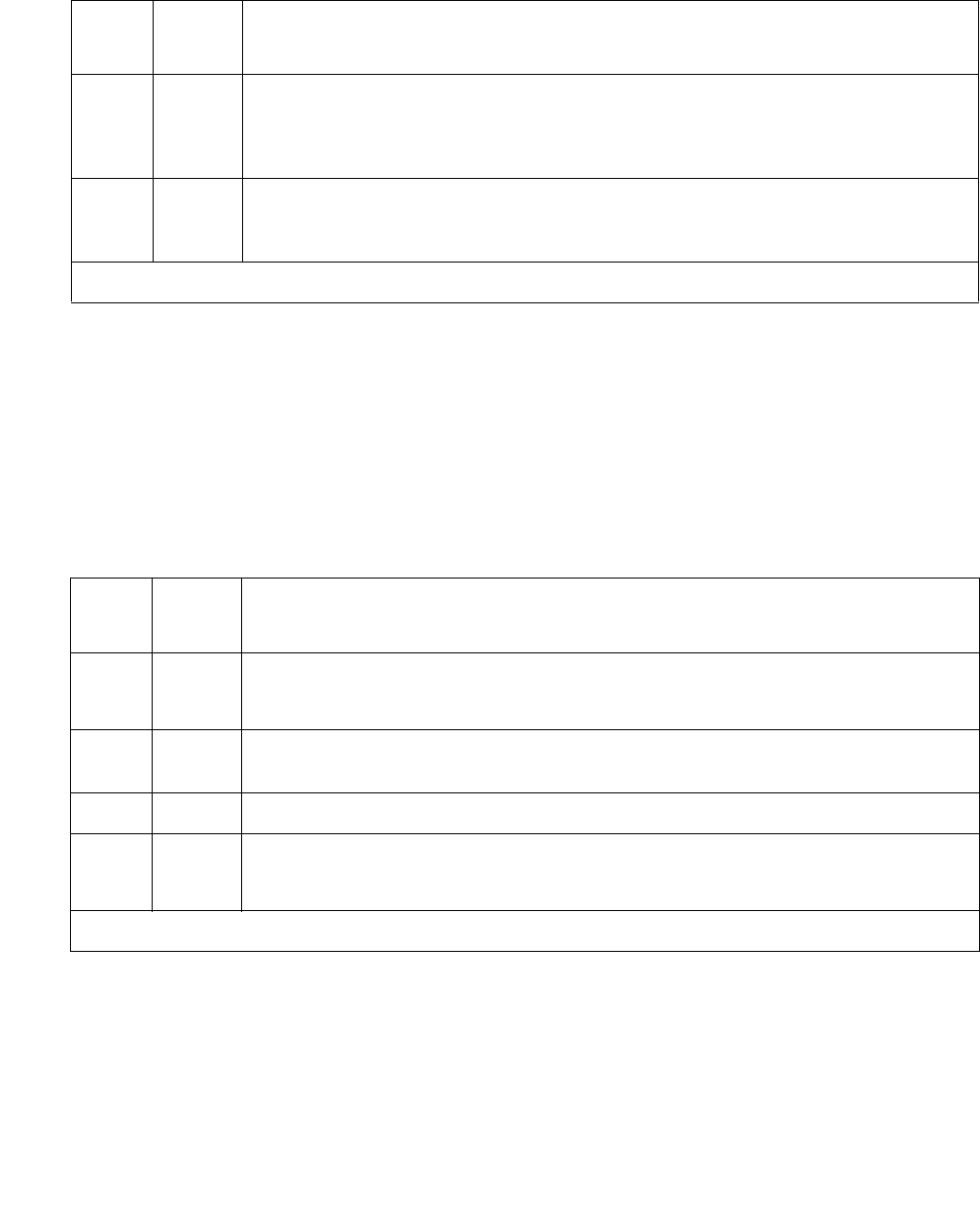
Communication Manager Maintenance-Object Repair Procedures
960 Maintenance Procedures for Avaya Communication Manager 3.0, Media Gateways and Servers
Port Audit and Update Test (#36)
This test sends port-level translation data from switch processor to the DS1 Interface circuit
pack to assure that a trunk’s translations are correct. Translation updates include the following
data: trunk type (in/out), dial type, timing parameters, and signaling bits enabled. The port audit
operation verifies the consistency of the current state of trunk kept in the DS1 Interface circuit
pack and in switch software.
FAIL The NPE of the tested port did not conference the tones correctly. This will
cause noisy and unreliable connections.
1. Replace the circuit pack.
PASS The port can correctly conference multiple connections. User-reported
troubles on this port should be investigated by using other port tests and by
examining station, trunk, or external wiring.
Table 329: Test #7 Conference Circuit Test (continued)
Error
Code
Test
Result
Description / Recommendation
3 of 3
Table 330: Test #36 Port Audit and Update Test
Error
Code
Test
Result
Description / Recommendation
ABRT Internal system error
1. Retry the command at 1-minute intervals up to 5 times.
2000 ABRT Response to the test request was not received within the allowable time
period.
2100 ABRT Could not allocate the necessary system resources to run this test.
FAIL Test failed due to internal system error.
1. Retry the command at 1-minute intervals up to 5 times.
1 of 2

DIOD-DS1 (DS1 DIOD Trunk)
Issue 1 June 2005 961
DS1 CO Dial Tone Seizure Test (#314)
DS1 CO Dial Tone Seizure test checks the trunk’s signaling capability provided by the DS1
Interface circuit pack. The maintenance software initiates the test by sending a “seizure”
message to the DS1 Interface circuit pack and expects an “active” reply from the DS1 interface
circuit pack. If the “active” message is received, then the test passes. If no message is received
and the timer expires, the test is aborted. If the DS1 Interface circuit pack sends a “reorder”
message back to maintenance software, then the test fails.
This test cannot be run on a trunk in any of the following conditions:
●The trunk direction is administered as an incoming only trunk.
●The trunk has been seized by a normal trunk call.
●The trunk is administered with maintenance test disabled.
PASS Trunk translation has been updated successfully. The current trunk states
kept in the DS1 Interface circuit pack and switch software are consistent. If
the trunk is busied out, the test will not run but will return PASS. To verify
that the trunk is in-service:
1. Enter status trunk to verify that the trunk is in-service. If the trunk
is in-service, no further action is necessary. If the trunk is
out-of-service, continue to step 2.
2. Enter release trunk to put the trunk back into in-service.
3. Retry the test command.
Table 330: Test #36 Port Audit and Update Test (continued)
Error
Code
Test
Result
Description / Recommendation
2 of 2
Table 331: Test #314 DS1 CO Dial Tone Seizure Test
Error
Code
Test
Result
Description / Recommendation
ABRT Internal system error
1. Retry the command at 1-minute intervals up to 5 times.
1000 ABRT System resources required to run this test are not available. The port may
be in use on a valid call. Use status trunk to determine when the port is
available for testing.
1 of 3

Communication Manager Maintenance-Object Repair Procedures
962 Maintenance Procedures for Avaya Communication Manager 3.0, Media Gateways and Servers
1004 ABRT The port has been seized by a user for a valid call. Use status trunk to
determine when the port is available for testing.
1. Retry the command at 1-minute intervals up to 5 times.
1005 ABRT Test failed due to incompatible configuration administered in trunk group
screen.
1. Look at the Trunk Group administration screen and see if the trunk is
incoming only, port 24 on a DS1 Interface with common
control-channel signaling, or an automatic CO type such as FX. Under
any of these conditions this is a normal abort.
1018 ABRT Test has been disabled via administration.
1. Verify that the Maintenance Tests field on the Trunk Group screen is
set to n. To enable the test, enter change trunk-group x where
“x” equals the number of the trunk group to be tested, and change the
Maintenance Tests field on the screen to y.
2. Repeat the test.
1020 ABRT The DS1 Interface circuit pack is out-of-service.
1. Look for UDS1-BD errors in the Hardware Error Log. If present, see
UDS1-BD (UDS1 Interface Circuit Pack) on page 2374.
2. Retry the command.
2000 ABRT Response to the test request was not received within the allowable time
period.
1. Rerun the test at 1-minute intervals up to 5 times.
2100 ABRT Could not allocate the necessary system resources to run this test.
1. Retry the command at 1-minute intervals up to 5 times.
Table 331: Test #314 DS1 CO Dial Tone Seizure Test (continued)
Error
Code
Test
Result
Description / Recommendation
2 of 3

DIOD-DS1 (DS1 DIOD Trunk)
Issue 1 June 2005 963
2053 ABRT At least one of the following errors is found on the DS1 circuit pack:
●1281 – Loss of signal
●1793 – Blue alarm
●2049 – Red alarm
●2305 – Yellow alarm
●1537 – Hyperactivity
Look for the previous error types in the Hardware Error Log, and follow the
procedures given in the DS1-BD (DS1 Interface Circuit Pack) on page 978
or UDS1-BD (UDS1 Interface Circuit Pack) on page 2374 maintenance
documentation for the listed error types.
FAIL The trunk cannot be seized for an outgoing call.
1. Verify that the Trunk Type field on the trunk administration screen
screen matches the trunk type administered on far-end switch.
2. Look for UDS1-BD errors in Hardware Error Log. If present, see
UDS1-BD (UDS1 Interface Circuit Pack) on page 2374.
3. Retry the test at 1-minute intervals up to 5 times.
PASS The trunk can be seized for an outgoing call.
Table 331: Test #314 DS1 CO Dial Tone Seizure Test (continued)
Error
Code
Test
Result
Description / Recommendation
3 of 3

Communication Manager Maintenance-Object Repair Procedures
964 Maintenance Procedures for Avaya Communication Manager 3.0, Media Gateways and Servers
DIOD-TRK (DIOD Trunk)
S8700 | 8710 / S8500 / S8300
Note:
Note: Many trunk problems are caused by incorrect settings of parameters on the trunk
group administration screen. Settings must be compatible with the local
environment and with parameter settings on the far end. Refer to Administrator
Guide for Avaya Communication Manager, 03-300509, for information about how
to administer trunks. The Application Notes section of that book shows the
correct settings for administrable timers and other parameters on a
country-by-country basis.
Direct inward and outward dial (DIOD) trunks are 2-wire analog lines to the CO which support
the following services:
●Both incoming and outgoing CO calls
●DID trunk
●DID trunk and 1-way outgoing DIOD
TN429 DIOD trunk circuit packs and MM711 Analog Media Modules provide eight ports for
loop-start CO trunks and serve as an interface between the 2-wire analog CO line and the
4-wire TDM bus on the switch.
Note:
Note: S8300 / G700 Although DIOD-TRK is provided for a G700 Media Gateway,
DIOD-TRK only partially supports the MM711 Analog Media Module.
Loop Start Operation
Idle State: Tip = ground, Ring = CO Battery
MO Name in
Alarm Log
Alarm
Level
Initial SAT Command to Run Full Name of MO
DIOD-TRK MAJ1
1. A MAJOR alarm on a trunk indicates that alarms on these trunks are not downgraded by
set options and that at least 75 percent of the trunks in this trunk group are alarmed.
test port location DIOD Trunk
DIOD-TRK MIN test port location DIOD Trunk
DIOD-TRK WRN test port location DIOD Trunk
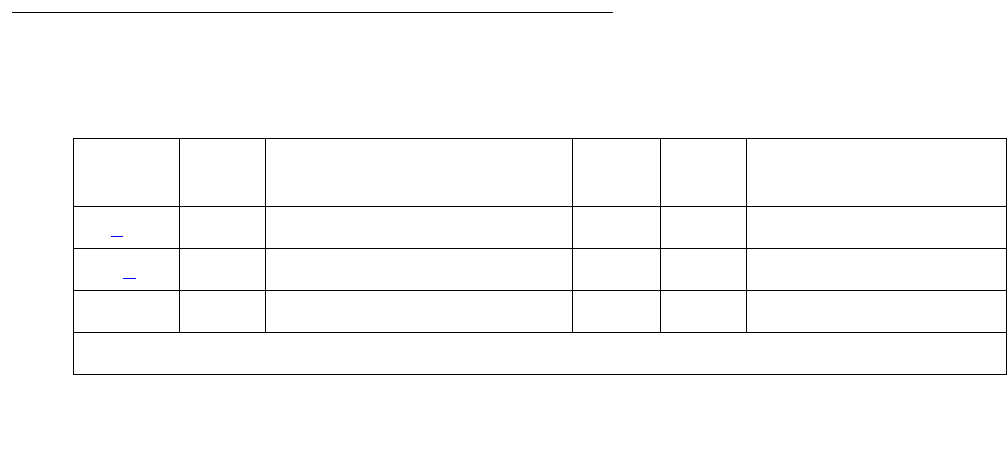
DIOD-TRK (DIOD Trunk)
Issue 1 June 2005 965
Outgoing Call
1. PBX Off-Hook (Seize Message): Closes the Tip-Ring Loop CO Response: DC loop current
+ Dial tone
2. PBX On-Hook (Drop Message): Open Tip-Ring loop, no loop current CO Response: CO
goes to idle state (see Note)
Incoming Call
1. CO Applies Ringing Voltage PBX Response: Detect ringing current
2. PBX Off-Hook (Answer Message): Close loop CO Response: Trip ringing, provide loop
current
3. PBX On-Hook (Drop Message): Open Tip-Ring loop, no loop current CO Response: CO
goes to idle state (see Note)
Direct Inward Dialing (DID) (Loop Start)
1. CO Applies Ringing Voltage
PBX Response: Detect ringing current and close loop
CO Response: Send DTMF digits
PBX Response: Acknowledge of Number dialed and open loop
2. PBX Off-Hook (Answer Message): Close loop CO Response: Trip ringing, provide loop
current
3. PBX On-Hook (Drop Message): Open Tip-Ring loop, no loop current CO Response: CO
goes to idle state (see Note)
Note:
Note: CO does not normally provide an On-Hook (Disconnect) signal.
Error Log Entries and Test to Clear Values
Table 332: DIOD Trunk Error Log Entries
Error
Type
Aux
Data
Associated Test Alarm
Level
On/Off
Board
Test to Clear Value
0 (a) 0 Any Any Any test port sh
15 (b) any Port Audit Update test (#36)
18 0 busyout trunk grp/mbr WRN release trunk
1 of 2

Communication Manager Maintenance-Object Repair Procedures
966 Maintenance Procedures for Avaya Communication Manager 3.0, Media Gateways and Servers
Additional Information:
a. Error Type 0: Run the short test sequence first. If every test passes, run the long test
sequence. Refer to each test’s description, and follow its recommended procedures.
b. Error Type 15 is a software audit error and does not indicate any hardware malfunction.
Run the short test sequence, and investigate associated errors.
c. Error Type 769 Aux Data 57392 are in-line errors that have no specific test associated with
them. The CO is not releasing after the call is dropped from the PBX end. After several occurrences, an
off-board warning alarm is generated. Refer the problem to the CO.
d. Error Type 2561 Aux Data 57345: Single polarity ringing current. This is an in-line error
that has no specific test associated with it. This error results from abnormal ringing current,
but does not prevent the incoming call from being accepted. This error code is logged for
information purposes only and does not cause additional testing to occur. One cause could
be that the reverse current detector associated with the port is failing. (Will not be detected
by any tests.) The other cause could be that normal current is not detected. In this case,
neither incoming nor outgoing calls can be completed, and the Dial Tone test (#0) also fails.
Check for other errors.
769 (c) 57392 None MAJ
MIN
WRN1
ON
1537 Dial Tone test (#0) MAJ
MIN
WRN1
ON test port long r 2
1793 Looparound and Conference
(#33)
MAJ
MIN
WRN1
ON test port long r 3
2049 NPE Cross Talk test (#6) MAJ
MIN
WRN1
ON test port long r 3
2561 (d) 57345 None
2817 (e) 57393 None
3073 (f) 57376 None
3585 (g) 57424 None
1. Major alarms on this MO may be downgraded to Warning alarms based on the value in set options. If
the Minor alarm is not downgraded by set options values, the Minor alarm is upgraded to a Major alarm
if 75 percent of the trunks in this trunk group are alarmed.
Table 332: DIOD Trunk Error Log Entries (continued)
Error
Type
Aux
Data
Associated Test Alarm
Level
On/Off
Board
Test to Clear Value
2 of 2

DIOD-TRK (DIOD Trunk)
Issue 1 June 2005 967
e. Error Type 2817 Aux Data 57393 is an in-line error that has no specific test associated with
it. CO released the trunk at least four minutes after the PBX dropped the call. This error
code is log only and causes no other testing to occur. No alarm is generated. Check for
other errors.
f. Error Type 3073 Aux Data 57376 is an in-line error that has no specific test associated with
it. No loop current on incoming call. The incoming destination has already answered and no
loop current has been detected. If this is a hard fault, the Dial Tone test (#0) and every
outgoing call should also fail. Check for other errors.
g. Error Type 3585 Aux Data 57424 is an in-line error that has no specific test associated with
it. No loop current on outgoing call. This error occurs on an attempt to seize a loop or
ground-start trunk for an outgoing call. An error occurs if loop current is not detected or the
caller hangs up before it is detected. Busyout the affected port, and run a Long test. If the
Dial Tone test (#0) passes, ignore this error. Release the port.
System Technician-Demanded Tests:
Descriptions and Error Codes
Investigate tests in the order they are presented. By clearing error codes associated with NPE
Crosstalk test, you may also clear errors generated from other tests in the sequence.
Order of Investigation Short Test
Sequence
Long Test
Sequence
D/ND1
1. D = Destructive; ND = Nondestructive
NPE Crosstalk test (#6)
S8300 / G700 This test aborts with Error Code 1412.
XND
Dial Tone test (#0)
S8300 / G700 This test aborts with Error Code 1412.
XND
Looparound and Conference test (#33)
S8300 / G700 This test aborts with Error Code 1412.
XND
Audit Update test (#36) X X ND

Communication Manager Maintenance-Object Repair Procedures
968 Maintenance Procedures for Avaya Communication Manager 3.0, Media Gateways and Servers
Dial Tone Test (#0)
Note:
Note: S8300 / G700: This test aborts with Error Code 1412.
This test attempts to seize a port and checks for the return of a dial tone.
Table 333: Test #0 Dial Tone Test
Error
Code
Test
Result
Description / Recommendation
ABRT Could not allocate system resources to run this test.
1. Retry the command at 1-minute intervals up to 5 times.
1000 ABRT System resources required to run this test are not available. The port may
be busy with a valid call.
1. Use display port location to determine the trunk group/member
number of the port. Use status trunk to determine the service state
of the port. If the service state indicates that the port is in use, then the
port is unavailable for certain tests. Wait until the port is idle before
retesting.
2. If the port status is idle, then retry the command at 1-minute intervals up
to 5 times.
1001 ABRT Could not allocate the necessary system resources to run this test.
1. Retry the command at 1-minute intervals up to 5 times.
1002 ABRT The system could not allocate time slots for the test. The system may be
under heavy traffic conditions or it may have time slots out-of-service due to
TDM-BUS errors.
1. If the system has no TDM-BUS errors and is not handling heavy traffic,
repeat test at 1-minute intervals up to 5 times.
1004 ABRT The port has been seized by a user for a valid call. Use status trunk to
determine when the port is available for testing.
1. Retry the command at 1-minute intervals up to 5 times.
1018 ABRT Test has been disabled via administration.
1. The Maintenance Tests field must be y on the Trunk Group form for
this test to run. Use change trunk-group grp# to access the form.
Then change the entry in the Maintenance Tests? field on the form to
y.
1 of 2

DIOD-TRK (DIOD Trunk)
Issue 1 June 2005 969
1005 ABRT Trunk has been administered as incoming-only; or DID trunk group type; dial
tone can only be obtained on outgoing trunks. This is a normal condition.
S8300
/
G700
1412
ABRT This test does not execute on a G700 Media Gateway.
2000 ABRT Response to the test was not received within the allowable time period.
1. Retry the command at 1-minute intervals up to 5 times.
FAIL Trunk was seized, but dial tone could not be detected.
1. Check for errors on TONE-BD or TONE-PT. Clear any errors and
repeat test.
2. If error has still not cleared, refer problem to CO.
2002 FAIL Seizure portion of test failed due to hardware problem. Fault is usually
caused by a disconnected trunk.
1. Check trunk wiring to ensure good connection; repeat test if wiring
correction made.
2. Locate another identical CO trunk and swap its wiring with one under
test. Repeat test on both trunks and determine whether problem follows
trunk or remains at original port. If problem follows trunk, refer problem
to CO. If problem remains at port, replace the circuit pack and repeat
test.
1009 PASS Detected tone was not pure dial tone. No action required.
PASS Trunk was seized, and dial tone was detected. User-reported troubles on this
port should be investigated by using other port tests and by examining trunk
or external wiring.
Table 333: Test #0 Dial Tone Test (continued)
Error
Code
Test
Result
Description / Recommendation
2 of 2

Communication Manager Maintenance-Object Repair Procedures
970 Maintenance Procedures for Avaya Communication Manager 3.0, Media Gateways and Servers
NPE Crosstalk Test (#6)
Note:
Note: S8300 / G700: This test aborts with Error Code 1412.
The NPE Crosstalk test verifies that this port’s NPE channel talks on the selected time slot and
never crosses over to time slots reserved for other connections. If the NPE is not working
correctly, 1-way and noisy connections may be observed. This test is usually only part of a
port’s long test sequence and executes in about 20 to 30 seconds.
Table 334: Test #6 NPE Crosstalk Test
Error
Code
Test
Result
Description / Recommendation
ABRT Could not allocate the necessary system resources to run this test.
1. Retry the command at 1-minute intervals up to 5 times.
1000 ABRT System resources required to run this test are not available. The port may
be busy with a valid call.
1. Enter display port location to determine the trunk group/
member number of the port. Use status trunk to determine the
service state of the port. If the port is in use, wait until it is idle before
testing.
2. If the port status is idle, then retry the command at 1-minute intervals
up to 5 times.
1001 ABRT Could not allocate the necessary system resources to run this test.
1. Retry the command at 1-minute intervals up to 5 times.
1002 ABRT The system could not allocate time slots for the test. The system may be
under heavy traffic conditions or it may have time slots out-of-service due
to TDM-BUS errors.
1. If the system has no TDM-BUS errors and is not handling heavy traffic,
repeat test at 1-minute intervals up to 5 times.
1003 ABRT The system could not allocate a tone receiver for the test. The system may
be oversized for the number of Tone Detectors present, or some Tone
Detectors may be out of service.
1. Resolve any TTR-LEV errors.
2. Resolve any TONE-PT errors.
3. If neither condition exists, retry the test at 1-minute intervals up to 5
times.
1 of 2

DIOD-TRK (DIOD Trunk)
Issue 1 June 2005 971
1004 ABRT The port was seized by a valid call during the test. The test has been
aborted.
1. Enter display port location to determine the trunk group/
member number of the port. Use status trunk to determine the
service state of the port. If the port is in use, wait until it is idle before
retesting.
S8300
G700
1412
ABRT This test does not execute on a G700 Media Gateway.
2000 ABRT Response to the test was not received within the allowable time period.
1. Rerun the test at 1-minute intervals up to 5 times.
2100 ABRT Could not allocate the necessary system resources to run this test.
1. Retry the command at 1-minute intervals up to 5 times.
Any FAIL The NPE of the tested port was found to be transmitting in error. This
causes noisy and unreliable connections.
1. Replace the circuit pack.
PASS The port is correctly using its allocated time slots. User-reported troubles on
this port should be investigated by using other port tests and by examining
trunk or external wiring.
Table 334: Test #6 NPE Crosstalk Test (continued)
Error
Code
Test
Result
Description / Recommendation
2 of 2

Communication Manager Maintenance-Object Repair Procedures
972 Maintenance Procedures for Avaya Communication Manager 3.0, Media Gateways and Servers
Looparound and Conference Circuit Test (#33)
Note:
Note: S8300 / G700: This test aborts with Error Code 1412.
This test checks the reflective loop and conference abilities of a CO port circuit. The test uses
404-, 1004-, and 2804-Hz tones. Each tone is transmitted separately through the loop and
checked.
Table 335: Test #33 Looparound and Conference Circuit Test
Error
Code
Test
Result
Description / Recommendation
ABRT Could not allocate system resources to run this test.
7 ABRT Conference Circuit test aborted.
1000 ABRT System resources required to run this test are not available. The port may
be busy with a valid call.
1. Enter display port location to determine the trunk group/
member number of the port. Use status trunk to determine the
service state of the port. If the port is unavailable, wait until it is idle
before testing.
2. If the port status is idle, retry the command at 1-minute intervals up to 5
times.
1004 ABRT The port has been seized by a user for a valid call. Use status trunk to
determine when the port is available for testing.
1. Retry the command at 1-minute intervals up to 5 times.
S8300
G700
1412
ABRT This test does not execute on a G700 Media Gateway.
2100 ABRT Could not allocate the necessary system resources to run this test.
1. Retry the command at 1-minute intervals up to 5 times.
1 of 2

DIOD-TRK (DIOD Trunk)
Issue 1 June 2005 973
7 FAIL Fail
1. Check for errors on TONE-BD or TONE-PT.
2. If the Reflective Looparound test fails for every port on a circuit pack, a
-5V power problem is indicated.
S8700 | 8710 / S8500: If a TN736 or TN752 power unit circuit pack is
present, check the circuit pack for a red LED. If the red LED is on, then
replace the power unit circuit pack. If neither the TN736 nor the TN752
Power Unit circuit pack is present, then the OLS631DB AC power unit
may be defective. The system may contain a TN736 or TN752 power
unit circuit pack or an OLS631DB AC power unit, but not both. See
RMC-ENV (S8700 IP), or CARR-POW (S8700 MC).
3. Rerun the test.
4. If the test fails again, replace the circuit pack.
PASS CO Trunk Looparound and Conference test is successful. User-reported
troubles on this port should be investigated by using other port tests and by
examining trunk or external wiring.
Table 335: Test #33 Looparound and Conference Circuit Test (continued)
Error
Code
Test
Result
Description / Recommendation
2 of 2

Communication Manager Maintenance-Object Repair Procedures
974 Maintenance Procedures for Avaya Communication Manager 3.0, Media Gateways and Servers
Port Audit Update Test (#36)
This test sends updates of the CO port translation for every translated port on the circuit pack or
media module. The update is non-disruptive and guards against possible corruption of
translation data contained on the circuit pack or media module. No response message is
expected from the circuit pack or media module once it receives translation updates. The port
translation data includes: ground or loop start trunk, tone or rotary dialing trunk, rotary dialing
inter-digit timing, network balance R/RC, and disconnect timing.
Table 336: Test #36 Port Audit Update Test
Error
Code
Test
Result
Description / Recommendation
ABRT Could not allocate the necessary system resources to run this test.
1. Retry the command at 1-minute intervals up to 5 times.
2100 ABRT Could not allocate the necessary system resources to run the test.
FAIL Internal system error.
1. Retry the command at 1-minute intervals up to 5 times.
PASS This test passed. Translation information was successfully updated on the
circuit pack or media module. User-reported troubles on this port should be
investigated by using other port tests and by examining trunk or external
wiring. If the trunk is busied out, the test does not run, but returns PASS. To
verify that the trunk is in-service:
1. Enter status trunk to verify that the trunk is in-service. If the trunk is
in-service, no further action is necessary. If the trunk is out-of-service,
continue to step 2.
2. Enter release trunk to put trunk back into in-service.
3. Retry the test command.

DLY-MTCE (MO-DAILY)
Issue 1 June 2005 975
DLY-MTCE (MO-DAILY)
S8700 | 8710 / S8500
The DLY-MTCE MO monitors daily translation saves. If a translation save times out or fails to
run, an error is logged against this MO.
Daily Maintenance Interference
Table 337: Communication Manager SAT Command Actions on page 975 lists Communication
Manager SAT administration command actions that, when active, interfere with daily
maintenance. Customer administrators frequently use these commands for routine
administration of the system.
MO Name in Alarm Log Alarm Level Initial Command to Run Full Name of MO
DLY-MTCE MINOR NONE DLY-MTCE
DLY-MTCE MAJOR NONE DLY-MTCE
If Save Fails Then System Raises
Three times in a row MINOR Alarm
Seven times in a row MAJOR Alarm
Table 337: Communication Manager SAT Command Actions
Likely to Disrupt Less Likely to Disrupt
add backup ping
change busyout recycle
duplicate clear release
remove display reset
set enable restore
format resume
get save
list status
mark test
monitor upgrade
netstat

Communication Manager Maintenance-Object Repair Procedures
976 Maintenance Procedures for Avaya Communication Manager 3.0, Media Gateways and Servers
Other command actions can also interfere with daily maintenance when certain qualifiers are
used in the commands, or under certain circumstances. For example, certain test commands,
when used with the modifier continuously, could interfere with daily maintenance. However,
such command actions are not typically used by customer administrators doing routine
administration, and are less likely to disrupt daily maintenance routines than are the add,
change, duplicate, remove, and set command actions.
Incomplete Command Time-Out
A time-out feature exists on the Maintenance-Related System Parameters screen. Use change
system parameters maintenance to access the screen. The time-out feature improves the
operation of daily maintenance by allowing maintenance routines to run that might otherwise not
run. It also helps to prevent the loss of translations that were not saved with a save
translation, and were also not saved because daily maintenance was prevented from
running prior to the system reset. Highlights of the feature include:
●Options for blank, 1, 2, 3, 4, 5, or 6 hours (the default is 2 hours)
●The blank option indicates that the feature is not active
●Only commands that block the running of daily maintenance (add, change, duplicate,
remove, and set) are affected
●All logins will time-out if any of these commands are active for the prescribed time (except
for the “blank” option)
●The feature applies to all logins, regardless of type (init, dadmin, craft, inads) or
permissions granted to the specific login ID of an administration or maintenance user
●The corresponding “time-out” entry is appended to the list history log
The Command Time-out field can be viewed by customer administrators. A craft, init, dadmin,
or inads login is required to change the option for the field. Figure 47: Maintenance-Related
System Parameters (change system-parameters maintenance) on page 977 shows the
Maintenance-related System Parameters screen for Communication Manager.
Figure 48: Command Time-out Entry on list history on page 977 shows an example of the LIST
HISTORY screen with the “time-out” entry. The final line indicates that change
system-parameters maintenance was being executed when the time-out period of 2
hours expired.

DLY-MTCE (MO-DAILY)
Issue 1 June 2005 977
Figure 47: Maintenance-Related System Parameters
(change system-parameters maintenance)
change system-parameters maintenance Page 1 of 3
MAINTENANCE-RELATED SYSTEM PARAMETERS
SCHEDULED MAINTENANCE
Start Time: 01 : 00
Stop Time: 06 : 00
Save Translation: daily
Figure 48: Command Time-out Entry on list history
list history
HISTORY
Date of Loaded Translation: no translation loaded
Date Time Port Login Actn Object
Qualifier
9/18 16:13 MGR1 init logn

Communication Manager Maintenance-Object Repair Procedures
978 Maintenance Procedures for Avaya Communication Manager 3.0, Media Gateways and Servers
DS1-BD (DS1 Interface Circuit Pack)
S8700 | 8710 / S8500
The DS1 Interface circuit pack provides an interface to an external DS1 facility and supports 24
DS0 channels carried on a 1.544-Mbps DS1 link. These DS0 channels can be administered as
either trunks to other switches or lines to off-premises stations. The TN464C (or later-suffixed)
Universal DS1 Interface also supports a 32-channel interface on a 2.048-Mbps link. The
functions and maintenance strategy for the TN464 circuit packs are covered under a separate
MO, UDS1-BD (UDS1 Interface Circuit Pack) on page 2374.
DS1-BD maintenance logs in-line errors reported by the DS1 Interface circuit pack, runs tests
for error diagnosis and recovery, and raises and clears alarms. The following table shows the
capabilities of each DS1 circuit pack. The TN722 and TN722B are not supported on G3r V1 or
later systems.
ISDN-PRI Trunk signaling (for example, Q.921, Q.931) requires a TN464D or higher suffix,
TN2464, or TN2242 (tie trunk signaling only) and is handled by system software. The TN464,
TN2464, and TN2242 are covered in UDS1-BD (UDS1 Interface Circuit Pack) on page 2374.
Each trunk and line have their own maintenance strategies. However, they all depend on the
health of the DS1 Interface circuit pack. See the following sections for details: TIE-DS1 (DS1 Tie
Trunk) on page 2270, CO-DS1 (DS1 CO Trunk) on page 817, DID-DS1 (Direct Inward Dial
Trunk) on page 886, OPS-LINE (DS1 Off-Premises Station Line) on page 1736, ISDN-TRK
(DS1 ISDN Trunk) on page 1446, and ISDN-PLK (ISDN-PRI Signaling Link Port) on page 1423.
Signaling over the DS1 link must be synchronized between the transmitting and receiving ends
to ensure error-free communication. See SYNC (Port-Network Synchronization) on page 2143
for details.
MO Name in
Alarm Log
Alarm
Level
Initial SAT Command to Run Full Name of MO
DS1-BD MAJ test board location sh DS1 Interface circuit pack
DS1-BD MIN test board location lDS1 Interface circuit pack
DS1-BD WRN test board location sh DS1 Interface circuit pack
Circuit
Pack Code
24-
Channel
32-
Channel
Tie Trunk
Signaling
CO Trunk
Signaling
DID
Trunk
Signaling
OPS Line Signaling
TN722/B X X
TN767/B/C/D/E X X X X X
TN464C/D/E/F/GP X X X X X X (24-chl only)
TN2313 X X X X X X

DS1-BD (DS1 Interface Circuit Pack)
Issue 1 June 2005 979
Combined with a TN767E circuit pack, Avaya’s 120A1 Integrated CSU module becomes an
enhanced CSU. The 120A1 CSU, combined with new switch software and the functionality
provided by a TN767E’s hardware and firmware, provides functionality equivalent to an external
stand-alone Avaya ESF T1 CSU. The 120A1 CSU connects to the TN767E circuit pack on the I/
O connector panel on the back of the port carrier, and thus becomes an integrated part of the
system. Throughout this document, the term 120A1 means a 120A1 (or later-suffixed) CSU.
The 120A1 CSU and the TN767E are for use in the United States of America with 1.544-Mbps
DS1 service. For more information about the 120A1 CSU module see DEFINITY®
Communications System Generic 1, Generic 2 and Generic 3 V1 and 2 – Integrated Channel
Service Unit (CSU) Module Installation and Operation, 555-230-193.
A TN767E and a 120A1 integrated CSU support on-demand loop-back tests assisting fault
detection between the:
●TN767E circuit pack and the integrated CSU
●Integrated CSU and an optional customer-premises loop-back jack
●Integrated CSU and a remote CSU.
These loop-back tests are explained in detail later in this DS1-BD section, but
Figure 49: High-Level Overview Of Loop-Back Points on page 980 gives a high-level overview
of the loop-back points.
The following list of acronym definitions are for Figure 49: High-Level Overview Of Loop-Back
Points on page 980:
●PLB = Payload Loopback
●BLB = Board Loopback
●ELB = Equipment Loopback
●LLB = Line Loopback
●RLB = Repeater Loopback
●CLJ = Loop-Back Jack Loopback
●R-LLB = Remote Line Loopback
●SMRT = Smart Jack
●LPBK = Loopback
For more information about DS1 interfaces, refer to the DEFINITY® Communications System
Generic 2.2 and Generic 3 V2 DS1/CEPT1/ISDN-PRI Reference, 555-025-107.

Communication Manager Maintenance-Object Repair Procedures
980 Maintenance Procedures for Avaya Communication Manager 3.0, Media Gateways and Servers
Figure 49: High-Level Overview Of Loop-Back Points
Error Log Entries and Test to Clear Values
CPE
LPBK
JACK
NET
SMRT
JACK
CSU
MOD
NET
SMRT
JACK
CPE
LPBK
JACK
DS1
BRD
CSU
MOD
DS1
BRD
NET-
WORK
CSU module to CSU module
Remote end
NETWORK ENVIRONMENT
Local end
NETWORK
SMRT
JACK
BLB
R-LLB
CPE
LPBK
JACK
DS1
BOARD
Remote end loop backs (* CSU or External CSU)
NETWORK
SMRT
JACK
CSU*
MOD
CSU
MOD
CLJ-LB LLB RLB ELB
PLB
CPE
LPBK
JACK
DS1
BOARD
Local end loop backs
Table 338: DS1 Interface Circuit Pack Maintenance Error Log Entries
Error
Type
Aux
Data
Associated Test Alarm
Level
On/Off
Board
Test to Clear Value
0 (a) 0 Any Any Any test board location
1 (b)0Circuit pack
removed or SAKI
(#53)
MIN
WRN
‡
ON
18 (c)0 busyout board
location
WRN OFF release board location
23 (d)0 WRNOFFadd ds1 location
125 (e)None MINON
1 of 4

DS1-BD (DS1 Interface Circuit Pack)
Issue 1 June 2005 981
257 65535 Control Channel
Loop test (#52)
MIN ON test board location l r
20
257 (f) Any None
513 (g)Any MINON
769 (h)4358
1025 (i) 4363 NPE Audit test
(#50)
1281 Any Loss of Signal
Alarm Inquiry
(#138)
MIN
WRN
†
OFF test board location
1300 (i) Any Loss of Signal
Alarm Inquiry
(#138)
WRN OFF test board location
1301 (j) Any Loss of Signal
Alarm Inquiry
(#138)
WRN OFF test board location
1302 (k) Any Loss of Signal
Alarm Inquiry
(#138)
MIN
WRN
†
OFF test board location
1303 (l) Any Loss of Signal
Alarm Inquiry
(#138)
MIN
WRN
†
ON test board location
1310 (m) Any Board Loopback
test (#1209)
MIN ON test ds1-loop location
ds1/csu-loopback-tests
1311 (n) Any Equipment
Loopback test
(#1210)
MIN
WRN
†
OFF test ds1-loop location
ds1/csu-loopback-test
1312 (o) Any Repeater
Loopback test
(#1211)
MIN
WRN
†
OFF test ds1-loop location
ds1/csu-loopback-tests
1313 (p) Any CPE Loopback
Jack test (#1212)
MIN
WRN
†
OFF test ds1-loop location
end-loopback/span-test
Table 338: DS1 Interface Circuit Pack Maintenance Error Log Entries (continued)
Error
Type
Aux
Data
Associated Test Alarm
Level
On/Off
Board
Test to Clear Value
2 of 4

Communication Manager Maintenance-Object Repair Procedures
982 Maintenance Procedures for Avaya Communication Manager 3.0, Media Gateways and Servers
1314 (q) Any Far CSU
Loopback test
(#1213)
MIN
WRN
†
OFF test ds1-loop location
end-loopback/span-test
1320 Any Loss of Signal
Alarm Inquiry
(#138)
MIN
WRN
†
OFF test board location
1321 Any Loss of Signal
Alarm Inquiry
(#138)
MIN
WRN
†
OFF test board location
1322 Any Loss of Signal
Alarm Inquiry
(#138)
MIN ON test board location
1323 Any Loss of Signal
Alarm Inquiry
(#138)
MIN
WRN
†
OFF test board location
1324 Any Loss of Signal
Alarm Inquiry
(#138)
WRN OFF test board location
1538 (r)Any MIN ON
1793 Any Blue Alarm
Inquiry test (#139)
MAJ
MIN
WRN*
*
OFF test board location
1794 Any Blue Alarm
Inquiry test (#139)
MAJ
MIN
WRN*
*
OFF test board location
1795 Any Blue Alarm
Inquiry test (#139)
MAJ
MIN
WRN*
*
OFF test board location
2049 Any Red Alarm Inquiry
test (#140)
MIN
WRN
†
OFF test board location
2305 Any Yellow Alarm
Inquiry test (#141)
MIN OFF test board location
Table 338: DS1 Interface Circuit Pack Maintenance Error Log Entries (continued)
Error
Type
Aux
Data
Associated Test Alarm
Level
On/Off
Board
Test to Clear Value
3 of 4

DS1-BD (DS1 Interface Circuit Pack)
Issue 1 June 2005 983
Notes:
a. Error Type 0: Run the short test sequence first. If every test passes, run the long test
sequence. Refer to the test’s description and follow the recommended procedures.
b. Error Type 1: the circuit pack stopped functioning or is not completely administered. The
alarm is logged approximately 15 minutes after the circuit pack has been removed or 11
minutes after the SAKI test (#53) fails.
To be completely administered, a DS1 circuit pack must:
●Have an entry in the circuit plan field in change circuit-packs
●Be administered using add ds1 location
●Be physically inserted in the correct slot
2306 Any Yellow Alarm
Inquiry test (#141)
MIN OFF test board location
2561 Any Major Alarm
Inquiry test (#142)
MIN
WRN
†
OFF test board location
2817 Minor Alarm
Inquiry test (#143)
MIN
WRN
†
OFF test board location
3073 to
3160 (s)
Any Slip Alarm Inquiry
test (#144)
MIN
WRN
†
OFF test board location r 6
3329 to
3345 (t)
Any Misframe Alarm
Inquiry test (#145)
MIN
WRN
†
OFF test board location r 6
3840 (u) Any None
3900 (v) Any CPE Loopback
Jack test (#1212)
3901(w) Any Far CSU
Loopback test
(#1213)
3902 (x) Any One-Way Span
test (#1214)
3999 (y) Any None
Table 338: DS1 Interface Circuit Pack Maintenance Error Log Entries (continued)
Error
Type
Aux
Data
Associated Test Alarm
Level
On/Off
Board
Test to Clear Value
4 of 4

Communication Manager Maintenance-Object Repair Procedures
984 Maintenance Procedures for Avaya Communication Manager 3.0, Media Gateways and Servers
If the circuit pack has an entry in the circuit plan and either of the other two conditions are
not met, a MINOR alarm is logged. To resolve the error, either:
●Make sure all conditions for administration are met and that a functioning DS1 circuit
pack is inserted in the correct slot, or
●Completely remove the DS1-BD from the system:
1. Remove any administered DS1 trunks or access endpoints associated with the circuit
pack from their trunk groups.
2. Execute remove ds1 location and change circuit-packs UU.
If all the administration conditions are met for this circuit pack and the red LED is still on,
follow the instructions in LED alarms without Alarm Log entry or with Error Type 1 on
page 258.
c. Error Type 18: the DS1 Interface circuit pack has been busied out by busyout board
location.
d. Error Type 23: the DS1-BD circuit pack is not completely administered. Ensure that the
DS1-BD circuit pack has an entry in the circuit plan via change circuit-packs, is
administered via add ds1 location, and is inserted into the correct port slot.
e. Error Type 125: the circuit pack in the slot does not match the type administered to that
position. Either replace the circuit pack with one of the type administered, or use change
circuit-packs to re-administer the slot. This error may also indicate that the 24/
32-channel selection on the DS1 administration screen does not match the configuration of
the circuit pack.
f. Error Type 257 is associated with the Common Port circuit pack maintenance test. See
XXX-BD (Common Port Circuit Pack/Media Module) on page 2539 for details.
g. Error Type 513: The DS1 Interface circuit pack has detected a transient hardware problem
(for example, external RAM failure, internal RAM failure, internal ROM failure, or instruction
set failure). This error disappears when no faults are detected for 30 minutes. The value in
the Aux Data field indicates the type of hardware problem. However, when this error is
reported with Aux Data of 4352 to 4358, the circuit pack has reported a hardware failure.
Escalate the problem.
h. Error Type 769: The DS1 Interface circuit pack detected a transient hardware logic error
(for example, program logic inconsistency). This error disappears when no faults are
detected for 100 minutes. The value in Aux Data field indicates the type of hardware
problem.
i. Error Type 1025: CSU module or T1 sync splitter missing. The Near-End CSU Type field
on the add ds1 screen has been administered as integrated, but the 120A1 CSU or T1
sync splitter is not physically connected (or is improperly connected) to the TN767E board
on the back of the port carrier.
If using the 120A1 CSU or T1 sync splitter, plug (or replug) the CSU or T1 sync splitter into
the TN767E circuit pack’s connector on the I/O connector panel on back of the carrier.

DS1-BD (DS1 Interface Circuit Pack)
Issue 1 June 2005 985
Otherwise, change the Near-End CSU Type field using the change ds1 screen to
other.
If this error remains after plugging the 120A1 CSU or T1 sync splitter into the board’s
connector, there could be a problem with the I/O connector panel.
j. Error Type 1301: CSU module/T1 sync splitter not expected. The 120A1 CSU or T1 sync
splitter is physically connected to the TN767E board on the back of the port carrier, but the
Near-End CSU Type field on the add ds1 screen has not been administered as
integrated.
If the 120A1 CSU or T1 sync splitter is to be used, use change ds1 to change the
Near-End CSU Type field to integrated. Otherwise, physically remove the 120A1 CSU
or T1 sync splitter from the back of the port carrier.
k. Error Type 1302: DS1 configuration error. Attempting to use a 120A1 CSU with a TN767E
circuit pack that is configured for 32-channel (2.048-Mbps) operation. This CSU only works
with a DS1 board configured for 24-channel (1.544-Mbps) operation in the United States of
America.
l. Error Type 1303: DS1 circuit pack suffix incorrect for CSU or T1 sync splitter. The
Near-End CSU Type field on the add ds1 screen has been administered as
integrated but the DS1 circuit pack is not a TN767E (or higher-suffixed) DS1 board.
If the 120A1 CSU or T1 sync splitter is to be used, remove the circuit pack and replace it
with a TN767E (or higher-suffixed) board. Otherwise, use change ds1 to change the
Near-End CSU Type field to other.
m. Error Type 1310: BLB failure. This error occurs when the DS1 Board Loopback (BLB)
demand test fails. Repeat the test using busyout board location, test ds1-loop
location ds1/csu-loop-back jack-tests, release board location. If the
BLB test continues to fail, then the TN767E circuit pack needs to be replaced.
n. Error Type 1311: ELB failure. This error occurs when the Integrated CSU (I-CSU) Module
Equipment Loopback (ELB) test fails. This test is executed during I-CSU/T1 sync splitter
power-up/reset (i.e., the TN767E board is physically inserted and the CSU module/T1 sync
splitter is already installed) or when the CSU module/T1 sync splitter is plugged on to an
already initialized DS1 board. The ELB test is also executed as part of test ds1-loop
location ds1/csu-loopback-tests.
Attempt to clear the alarm with busyout board location, test ds1-loop location
ds1/csu-loopback-tests, and release board location. If the ELB test continues
to fail, then either the TN767E board, the CSU module, the T1 sync splitter, or the I/O cable
between the backplane and the CSU module/T1 sync splitter (or any combination thereof)
has failed. Escalate this problem.
o. Error Type 1312: RLB failure. This error occurs when the Integrated CSU (I-CSU) Module
Repeater Loopback (RLB) test fails. This test is executed during I-CSU/T1 sync splitter
power-up/reset (i.e., the TN767E board is physically inserted and the CSU module/T1 sync
splitter is already installed) or when the CSU module/T1 sync splitter is plugged on to an
already initialized DS1 board. The RLB test is also executed as part of the command test
ds1-loop location ds1/csu-loopback-tests.

Communication Manager Maintenance-Object Repair Procedures
986 Maintenance Procedures for Avaya Communication Manager 3.0, Media Gateways and Servers
Attempt to clear the alarm with busyout board location, test ds1-loop
location ds1/csu-loopback-tests, and release board location. If the RLB
test continues to fail, then the CSU module/T1 sync splitter needs to be replaced.
p. Error Type 1313: CPE loop-back jack deactivation error. This error occurs when the
TN767E circuit pack could not deactivate a CPE loop-back jack loop-back.
Attempt to clear the alarm with busyout board location, test ds1-loop location
end-loopback/span-test, and release board location. If the attempt to
deactivate the CPE loop-back jack loop back continues to fail, other steps must be taken to
deactivate the loop back.
q. Error Type 1314: Far CSU Loopback deactivation error. This error occurs when the
TN767E circuit pack could not deactivate a far-end CSU loop back on power-up/reset or
upon software request.
Attempt to clear the alarm with busyout board location, test ds1-loop
location end-loop back/span-test, release board location. If the attempt to
deactivate the Far CSU loop back continues to fail, then escalate the problem.
r. Error Type 1538: The hyperactive circuit pack is out-of-service and may exhibit one or
more of the following symptoms:
●The common circuit pack-level tests, such as Test #51 and Test #220, are aborting with
error code 2000.
●The tests run on the ports of this circuit pack are returning NO BOARD.
●A busyout/release of the circuit pack has no affect on test results.
●List configuration shows that the circuit pack and ports are properly installed.
The circuit pack is isolated from the system and all trunks of this circuit pack are placed into
the out-of-service state. The system will try to restore the circuit pack within 15 minutes.
When no faults are detected for 15 minutes, the DS1 Interface circuit pack is restored to
normal operation. All trunks of the DS1 Interface circuit pack are then returned to the
in-service state. If the error recurs after 15 minutes, then escalate this problem.
s. Error Type 3160: For later releases of G3V4 and beyond, only error 3073 shows that this
board is receiving Slips, and the AUX data shows the last Slip count that was reported.
t. Error Type 3329 - 3345: For later releases of G3V4 and beyond, only error 3329 shows
that this board is receiving misframes and the AUX data shows the last misframe count that
was reported.
u. Error Type 3840: ignore, is not service-affecting.
v. Error Type 3900: used to give status information about a CPE Loopback Jack test. The
value in the Aux Data field indicates the status of the loop-back test:
Aux Data 1: Test is currently running.
Aux Data 2: Test failed because loop back could not be activated.
Aux Data 3: Test failed because test pattern could not be detected.
Aux Data 4: Test has been deactivated.
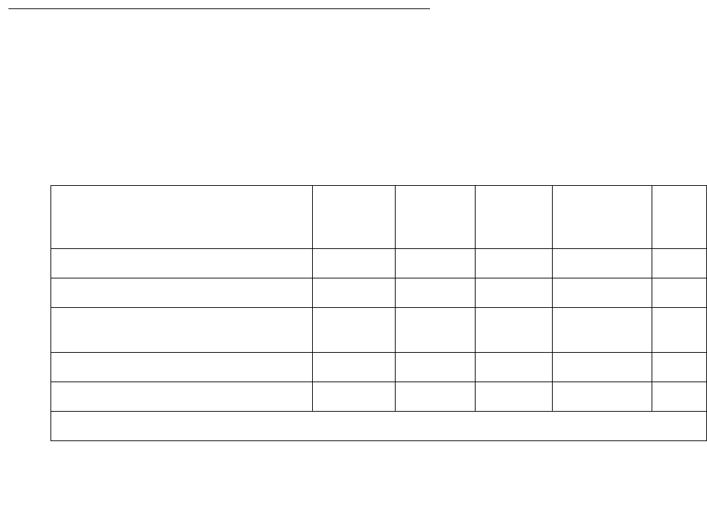
DS1-BD (DS1 Interface Circuit Pack)
Issue 1 June 2005 987
w. Error Type 3901: gives status information about a Far CSU Loopback test. The value in the
Aux Data field indicates the status of the loop-back test.
Aux Data 1: Test is currently running.
Aux Data 2: Test failed because loop back could not be activated.
Aux Data 3: Test failed because test pattern could not be detected.
Aux Data 4: Test has been deactivated.
x. Error 3902: gives status information about a One-Way Span test. The value in the Aux
Data field indicates the status of the span test:
Aux Data 1: Test is currently running.
Aux Data 2: Test failed because loop back could not be activated.
Aux Data 3: Test pattern was not received from the far end.
Aux Data 4: Test has been deactivated.
y. Error Type 3999: the circuit pack sent a large number of control-channel messages to the
switch within a short period of time. If Error Type #1538 is also present, then the circuit pack
was taken out-of-service due to hyperactivity. If Error Type #1538 is absent, then the circuit
pack has not been taken out-of-service, but it has generated 50% of the messages
necessary to be considered hyperactive. This may be completely normal during heavy
traffic periods. However, if this error type is logged when the circuit pack is being lightly
used, it may indicate a problem with the circuit pack or the equipment attached to it.
System Technician-Demanded Tests:
Descriptions and Error Codes
Investigate tests in the order they are presented. By clearing error codes associated with the
NPE Connection Audit test, for example, you may clear errors generated from other tests in the
sequence.
Table 339: System Technician-Demanded Tests: DS1-BD
Order of Investigation Short Test
Sequence
Long Test
Sequence
Reset
Board
Sequence
test ds1-loop
Command
D/ND1
NPE Connection Audit test (#50) X ND
Control Channel Loop test (#52) X ND
Loss of Signal Alarm Inquiry test
(#138)
XX ND
Blue Alarm Inquiry test (#139) X X ND
Red Alarm Inquiry test (#140) X X ND
1 of 2

Communication Manager Maintenance-Object Repair Procedures
988 Maintenance Procedures for Avaya Communication Manager 3.0, Media Gateways and Servers
Yellow Alarm Inquiry test (#141) X X ND
Major Alarm Inquiry test (#142) X X ND
Minor Alarm Inquiry test (#143) X X ND
Slip Alarm Inquiry test (#144) X X ND
Misframe Alarm Inquiry test (#145) X X ND
Translation Update test (#146) X X ND
ICSU Status LEDs test (#1227) X X ND
SAKI Sanity test (#53) X D
Internal Looparound test (#135) X D
DS1/CSU Loopback tests X D
DS1 Board Loopback test (#1209) X D
CSU Equipment Loopback test
(#1210)
XD
CSU Repeater Loopback test
(#1211)
XD
CPE Loop-Back Jack test (#1212) X D
Far CSU Loopback test (#1213) X D
One-Way Span test (#1214) X D
Inject Single Bit Error (#1215) X D
End Loopback/Span test (#1216) X D
1. D = Destructive, ND = Non-destructive
Table 339: System Technician-Demanded Tests: DS1-BD (continued)
Order of Investigation Short Test
Sequence
Long Test
Sequence
Reset
Board
Sequence
test ds1-loop
Command
D/ND1
2 of 2

DS1-BD (DS1 Interface Circuit Pack)
Issue 1 June 2005 989
NPE Connection Audit Test (#50):
The system sends a message to the on-board microprocessor to update the network
connectivity translation for all the Network Processing Elements (NPEs) on the circuit pack.
Table 340: Test #50 NPE Connection Audit Test
Error
Code
Test
Result
Description / Recommendation
None,
2100
ABRT System resources required for this test are not available.
1. Retry the command at 1-minute intervals up to 5 times.
1019 ABRT Test already in progress.
FAIL Internal system error
1. Retry the command at 1-minute intervals up to 5 times.
PASS The circuit pack’s NPEs have been updated with their translation.
0NO
BOARD The test could not relate the internal ID to the port (no board).
This could be due to incorrect translations, no board is inserted, an
incorrect board is inserted, or an insane board is inserted.
1. Verify that the board’s translations are correct. Use add ds1
location to administer the DS1 interface if it is not already
administered.
2. If board was already administered correctly, check the error log to
determine whether the board is hyperactive. If so, the board was shut
down. Reseating the board will re-initialize it.
3. Enter busyout board
4. Enter reset board
5. Enter release board
6. Enter test board long
This should re-establish the linkage between the internal ID and the
port.

Communication Manager Maintenance-Object Repair Procedures
990 Maintenance Procedures for Avaya Communication Manager 3.0, Media Gateways and Servers
Control Channel Loop-around Test (#52)
This test queries the circuit pack for its circuit pack code and vintage and verifies its records.
Table 341: Test #52 Control Channel Loop-around Test
Error
Code
Test
Result
Description / Recommendation
None
2100
ABRT System resources required for this test are not available.
1. Retry the command at 1-minute intervals up to 5 times.
FAIL The test failed because the circuit pack did not return the circuit pack code
or vintage.
Note: Error type 1538 in the error log indicates hyperactivity. The
hyperactive circuit pack is out of service and one or more of the following
symptoms may be exhibited.
●The DS1-BD tests (such as Tests 138 and 139) are aborting with error
code 2000.
●The tests run on the ports of this circuit pack are returning a no board
result.
●A busyout or a release command has no affect on the test result.
●A list config command shows that the circuit pack and the ports
are properly installed.
When hyperactivity occurs, the circuit pack is isolated from the system,
and all of its trunks are placed into the out-of-service state. The system will
try to restore the circuit pack within 15 minutes. When no faults are
detected for 15 minutes, the DS1 interface circuit pack is restored to
normal operation. Every DS1 interface trunk is then returned to the
in-service state. Hyperactivity is often caused by the associated facility. In
such a case, faults (such as slips, misframes, or blue alarms) would be
entered in the error log. In addition, many hardware errors would be logged
against the associated trunk circuits. If the facility is OK and the error
occurs again after 15 minutes, escalate this problem.
1. Retry the command up to 5 times.
2. If the problem continues, check for hyperactivity. Resolve the problem,
as appropriate.
3. If there is no longer hyperactivity, retry the command up to 5 times.
4. If the test continues to fail, escalate this problem.
PASS Communication with this circuit pack is successful.
1 of 2

DS1-BD (DS1 Interface Circuit Pack)
Issue 1 June 2005 991
0NO
BOARD The test could not relate the internal ID to the port (no board).
This could be due to incorrect translations, no board is inserted, an
incorrect board is inserted, or an insane board is inserted.
1. Verify that the board’s translations are correct. Use add ds1
location to administer the DS1 interface if it is not already
administered.
2. If board was already administered correctly, check the error log to
determine whether the board is hyperactive. If so, the board was shut
down. Reseating the board will re-initialize it.
3. If the board was found to be correctly inserted in step 1, enter
busyout board.
4. Enter reset board
5. Enter release board
6. Enter test board long
This should re-establish the linkage between the internal ID and the
port.
Table 341: Test #52 Control Channel Loop-around Test (continued)
Error
Code
Test
Result
Description / Recommendation
2 of 2

Communication Manager Maintenance-Object Repair Procedures
992 Maintenance Procedures for Avaya Communication Manager 3.0, Media Gateways and Servers
SAKI Sanity Test (#53)
This test is destructive. This test resets the circuit pack.
Table 342: Test #53 SAKI Sanity Test
Error
Code
Test
Result
Description / Recommendation
None ABRT System resources required for this test are not available.
1. Retry the command at 1-minute intervals up to 5 times.
1005 ABRT Wrong circuit pack configuration to run this test. This error applies only to
DS1 Interface circuit packs. It means the DS1 Interface circuit pack is
providing timing for the system and, therefore, it cannot be reset without
major system disruptions.
1. If the circuit pack needs to be reset, then set synchronization to
another DS1 Interface circuit pack or to the Tone-Clock circuit and try
again. Refer to “SYNC (Synchronization)”.
1015 ABRT Port is not out-of-service.
1. Busyout the circuit pack.
2. Execute the command again.
2100 ABRT System resources required for this test are not available.
1. Retry the command at 1-minute intervals up to 5 times.
1 FAIL The circuit pack failed to reset.
2 FAIL The circuit pack failed to restart.
1. Execute the command again.
2. If the problem persists, escalate this problem.
PASS The circuit pack initializes correctly.
1. Run the short test sequence.
1 of 2

DS1-BD (DS1 Interface Circuit Pack)
Issue 1 June 2005 993
Internal Loop-Around Test (#135)
This test is destructive.
The Internal Looparound test is run by looping the transmitted DS1 bit stream back into the
DS1’s board receiver. The loop occurs just before the DS1 facility interface. The test is highly
destructive and can only be initiated by a technician-demanded reset board location.
All trunks on the DS1 Interface circuit pack must be busied out via the system technician
busyout board command before running the Internal Looparound test. When the Internal
Looparound test is initiated, maintenance software sends messages to the DS1 Interface circuit
pack to start the test. The test uses the Tone Generator and Tone Detector to exercise a bit
pattern consistency test for all ports. If the transmitted and received bit patterns on a trunk are
different, the test fails.
When the test is complete, the maintenance software sends a stop loop around message to the
DS1 Interface circuit pack to put the circuit pack back into the normal operation mode. All trunks
of the DS1 Interface circuit pack are restored to the in-service state after release board is
entered.
0NO
BOARD The test could not relate the internal ID to the port (no board).
This could be due to incorrect translations, no board is inserted, an
incorrect board is inserted, or an insane board is inserted.
1. Verify that the board’s translations are correct. Use add ds1
location to administer the DS1 interface if it is not already
administered.
2. If board was already administered correctly, check the error log to
determine whether the board is hyperactive. If so, the board was shut
down. Reseating the board will re-initialize it.
3. If the board was found to be correctly inserted in step 1, enter
busyout board
4. Enter reset board
5. Enter release board
6. Enter test board long
This should re-establish the linkage between the internal ID and the
port.
Table 342: Test #53 SAKI Sanity Test (continued)
Error
Code
Test
Result
Description / Recommendation
2 of 2

Communication Manager Maintenance-Object Repair Procedures
994 Maintenance Procedures for Avaya Communication Manager 3.0, Media Gateways and Servers
Table 343: Test #135 Internal Loop-Around Test
Error
Code
Test
Result
Description / Recommendation
2012 ABRT Internal system error
1. Retry the command at 1-minute intervals up to 5 times.
1002 ABRT The system could not allocate time slots for the test. The system may be
under heavy traffic conditions or it may have time slots out-of-service due
to TDM-BUS errors.
1. If system has no TDM-BUS errors and is not handling heavy traffic,
repeat test at 1-minute intervals up to 5 times.
1003 ABRT The system could not allocate a tone receiver for the test. The system may
be oversized for the number of Tone Detectors present, or some Tone
Detectors may be out of service.
1. Resolve any TTR-LEV errors.
2. Resolve any TONE-PT errors.
3. If neither condition exists, retry the test at 1-minute intervals up to 5
times.
1004 ABRT Received an incoming call on a port of the DS1 circuit pack during the test.
1. Enter busyout board location to put every trunk on the DS1
circuit pack into the out-of-service state.
2. Retry the command at 1-minute intervals up to 5 times.
1015 ABRT Ports on DS1 Interface circuit pack have not been busied out.
1. Enter busyout board location to put every trunk on the
DS1circuit pack into the out-of-service state.
2. Retry the command.
1039 ABRT The DS1 Interface circuit pack is providing timing for the system.
Therefore, it cannot be reset without major system disruption.
1. If the DS1 Interface circuit pack needs to be tested, set the
synchronization reference to another DS1 Interface circuit pack or to
the Tone-Clock circuit using the following command sequence:
a. Enter disable synchronization-switch
b. Enter set synchronization location
c. Enter enable synchronization-switch
1 of 3

DS1-BD (DS1 Interface Circuit Pack)
Issue 1 June 2005 995
2000 ABRT The test was aborted. Response to the test was not received within the
allowable time period. This may be due to hyperactivity. Error type 1538 in
the error log indicates hyperactivity. The hyperactive circuit pack is out of
service and one or more of the following symptoms may be exhibited.
●The DS1-BD tests (such as Tests 139 and 140) are aborting with
error code 2000.
●The tests run on the ports of this circuit pack are returning a no board
result.
●A busyout or a release command has no affect on the test results.
●A list config command shows that the circuit pack and the ports
are properly installed.
When hyperactivity occurs, the circuit pack is isolated from the system, and
all of its trunks are placed into the out-of-service state. The system will try to
restore the circuit pack within 15 minutes. When no faults are detected for
15 minutes, the DS1 interface circuit pack is restored to normal operation.
Every DS1 interface trunk is then returned to the in-service state.
Hyperactivity is often caused by the associated facility. In such a case, faults
(such as slips, misframes, or blue alarms) would be entered in the error log.
In addition, many hardware errors would be logged against the associated
trunk circuits. If the facility is OK and the error recurs after 15 minutes,
escalate this problem.
2100 ABRT Could not allocate the necessary system resources to run this test.
1. Retry the command at 1-minute intervals up to 5 times.
FAIL DS1 Interface circuit pack failed the Internal Looparound test.
1. Retry the command at 1-minute intervals up to 5 times.
2. If the DS1 Interface circuit pack is a TN767, enter list
measurement ds1-log location to read the error seconds
measurement. Otherwise, skip this step.
3. Verify that both of the DS1 link’s endpoints are assigned with the same
signaling mode, framing mode, and line coding.
4. Check the physical connectivity of DS1 Interface circuit packs and
cable.
5. Contact T1 Network Service to diagnose remote DS1 endpoint.
6. If 2 to 5 are OK and the problem recurs, escalate the problem.
Table 343: Test #135 Internal Loop-Around Test (continued)
Error
Code
Test
Result
Description / Recommendation
2 of 3

Communication Manager Maintenance-Object Repair Procedures
996 Maintenance Procedures for Avaya Communication Manager 3.0, Media Gateways and Servers
Loss of Signal Alarm Inquiry Test (#138)
This test verifies the synchronization status and continuity of the DS1 link. The Loss of Signal
alarm indicates that the DS1 Interface circuit pack is unable to derive the synchronization clock
from the DS1 facility. When the DS1 Interface circuit pack detects a Loss of Signal alarm, it
stops providing the synchronization clock for the system if it is administered as a timing source
and transmits a Yellow alarm to the remote DS1 endpoint.
When the Loss of Signal alarm is confirmed, the maintenance software places all trunks or ports
of the DS1 Interface circuit pack into the out-of-service state. The inquiry test will run every 10
minutes until the loss of signal has been restored. The DS1 Interface circuit pack raises a Loss
of Signal alarm after the signal has been lost for about 1second. It will not retire the alarm until
the signal has returned for about 10 seconds.
PASS Every administered trunk of DS1 Interface circuit pack passed the Internal
Looparound test. The bit pattern consistency test executed successfully
over the path that covers a DS1 port, cable, and the external NCTE device.
0NO
BOARD The test could not relate the internal ID to the port (no board).
This could be due to incorrect translations, no board is inserted, an
incorrect board is inserted, or an insane board is inserted.
1. Verify that the board’s translations are correct. Use add ds1
location to administer the DS1 interface if it is not already
administered.
2. If board was already administered correctly, check the error log to
determine whether the board is hyperactive. If so, the board was shut
down. Reseating the board will re-initialize it.
3. If the board was found to be correctly inserted in step 1, enter
busyout board
4. Enter reset board
5. Enter release board
6. Enter test board long
This should re-establish the linkage between the internal ID and the
port.
Table 343: Test #135 Internal Loop-Around Test (continued)
Error
Code
Test
Result
Description / Recommendation
3 of 3

DS1-BD (DS1 Interface Circuit Pack)
Issue 1 June 2005 997
S8700 MC
This test is also used to maintain the 120A CSU module and the 401A T1 sync splitter. The
CSU module, when combined with the functionality provided by the TN767E circuit pack,
provides functionality equivalent to an external standalone ESF T1 CSU The 401A T1 sync
splitter, when combined with the functionality provided by the TN767E circuit pack, allows an
ATM switch to derive its timing off a T1 facility connected to the S8700 Multi-Connect’s
DS1circuit pack.
If a TN767E circuit pack detects certain I-CSU/T1 sync splitter hardware errors, it will notify the
maintenance subsystem. When the subsystem receives notification of the error, it executes this
Loss of Signal Inquiry test. The test, in addition to querying for a Loss of Signal alarm condition,
will also query the TN767E board to confirm the error. A Minor or Warning alarm will be raised
depending on the severity of the error. The trunks on the board may be taken out of service if
the error is deemed serious.
If a Loss of Signal alarm and an I-CSU/T1 sync splitter error co-exist, the Loss of Signal alarm
condition takes priority, and the board and all of its trunks are put in the out-of-service state.
However both errors will be logged.
When the maintenance subsystem receives notification that the ICSU/T1 sync splitter hardware
error condition no longer exists, maintenance will restore the board and all trunks to their
previous service state if the alarm can be cleared (no other errors or Loss of Signal alarm exist).
Table 344: Test #138 Loss of Signal Alarm Inquiry Test
Error
Code
Test
Result
Description / Recommendation
ABRT Internal system error
2100 ABRT Could not allocate the necessary system resources to run this test.
1. Retry the command at 1-minute intervals up to 5 times.
1 of 7

Communication Manager Maintenance-Object Repair Procedures
998 Maintenance Procedures for Avaya Communication Manager 3.0, Media Gateways and Servers
2000 ABRT Response to the test was not received within the allowable time period. This
may be due to hyperactivity. Error type 1538 in the error log indicates
hyperactivity. The hyperactive circuit pack is out of service and one or more
of the following symptoms may be exhibited.
●The DS1-BD tests (such as test 138 and test 139) are aborting with
error code 2000.
●The tests run on the ports of this circuit pack are returning a no board
result.
●A busyout or a release command has no affect on the test results.
●A list config command shows that the circuit pack and the ports
are properly installed.
When hyperactivity occurs, the circuit pack is isolated from the system, and
all of its trunks are placed into the out-of-service state. The system will try to
restore the circuit pack within 15 minutes. When no faults are detected for
15 minutes, the DS1 interface circuit pack is restored to normal operation.
Every DS1 interface trunk is then returned to the in-service state.
Hyperactivity is often caused by the associated facility. In such a case, faults
(such as slips, misframes, or blue alarms) would be entered in the error log.
In addition, many hardware errors would be logged against the associated
trunk circuits. If the facility is OK and the error occurs again after 15
minutes, escalate this problem.
FAIL DS1 Interface circuit pack detects a Loss of Signal alarm. The physical link
is broken or the remote DS1 endpoint is down. All trunks or ports of this
DS1 interface circuit pack are out-of-service. If the DS1 Interface circuit
pack is designated as the supplier of the system synchronization source,
then the system synchronization maintenance will adopt a source
elsewhere. Refer to “SYNC (Synchronization)” section for details.
1. If the DS1 Interface circuit pack connects to a T1 facility, call the
vendor of the T1 carrier to diagnose the remote DS1 endpoint. If the
DS1 Interface circuit pack connects directly to a switch, call the system
technician of the remote switch to diagnose the DS1 endpoint.
2. Check the physical connection of the DS1 Interface circuit pack and
the cable. If a 120A1 CSU module/T1 sync splitter is physically
connected to a TN767E board on the back of the port carrier, check
the physical connection of the CSU module/T1 sync splitter, and make
sure the Network Interface cable is plugged into the CSU module’s/T1
sync splitter’s NETWORK jack.
Table 344: Test #138 Loss of Signal Alarm Inquiry Test (continued)
Error
Code
Test
Result
Description / Recommendation
2 of 7

DS1-BD (DS1 Interface Circuit Pack)
Issue 1 June 2005 999
1300 FAIL The CSU module or the T1 sync splitter is missing. The Near-End CSU
Type field on the add ds1 screen has been administered as integrated,
but the 120A1 CSU module/T1 sync splitter is not physically connected to
the TN767E board on the back of the port carrier.
1. If using the 120A1 CSU module/T1 sync splitter, plug the CSU module/
T1 sync splitter into the TN767E circuit pack’s connector on the I/O
connector panel on back of the carrier. Otherwise, set the Near-End
CSU Type field using the change ds1 screen to other.
2. Run the test again.
1301 FAIL The 120A1 CSU module or the T1 sync splitter is physically connected to
the TN767E board on the back of the port carrier, but the Near-End CSU
Type field on the add ds1 screen is not administered as integrated.
1. If the 120A1 CSU module/T1 sync splitter is to be used, use change
ds1 to change the Near-End CSU Type field to integrated.
Otherwise, physically remove the 120A1 CSU module/T1 sync splitter
from the back of the port carrier.
2. Run the test again.
1302 FAIL Attempting to use a 120A1 CSU module with a TN767E circuit pack that is
configured for 32-channel (2.048-Mbps) operation. This CSU only works
with a DS1 board configured for 24-channel (1.544-Mbps) operation in the
United States of America.
1. If the 120A1 CSU is to be used, physically remove the TN767E circuit
pack, and reconfigure it for 24-channel (1.544-Mbps) operation.
2. Reinsert the circuit pack, and run the test again.
1303 FAIL The DS1 circuit pack’s suffix is incorrect for CSU module/T1 sync splitter
administration. The Near-End CSU Type field on the add ds1 screen has
been administered as integrated, but the DS1 circuit pack is not a TN767E
(or higher-suffixed) DS1 board.
1. If the CSU module or the T1 sync splitter is to be used, and the
Near-End CSU Type field is set to integrated to allow for CSU
module/T1 sync splitter administration, remove the circuit pack and
replace it with a TN767E (or higher-suffixed) board. Otherwise, use
change ds1 to set the Near-End CSU Type field to other.
Table 344: Test #138 Loss of Signal Alarm Inquiry Test (continued)
Error
Code
Test
Result
Description / Recommendation
3 of 7

Communication Manager Maintenance-Object Repair Procedures
1000 Maintenance Procedures for Avaya Communication Manager 3.0, Media Gateways and Servers
1310 FAIL The DS1 Board Loopback (BLB) demand test (#1209) failed.
1. Repeat the test using test ds1-loop location ds1/
csu-loopback-tests.
2. If the BLB test continues to fail, then replace the TN767E circuit pack.
3. Run this test again.
1311 FAIL The Integrated CSU (I-CSU) Module Equipment Loopback (ELB) test
(#1210) failed. This test is executed during ICSU/T1 sync splitter
power-up/reset (the TN767E board is physically inserted and the CSU
module/T1 sync splitter is already installed) or when the 120A CSU
module/T1 sync splitter is plugged on to an already initialized DS1 board.
The ELB test is also executed as part of test ds1-loop location
ds1/csu-loopback-tests.
1. Execute test ds1-loop location ds1/csu-loopback-tests.
If the ELB test continues to fail, then either the TN767E board, the
CSU module/T1 sync splitter, or the I/O cable between the backplane
and the CSU module/T1 sync splitter (or any combination thereof) has
failed. Attempt to isolate the problem to one of these areas.
2. Replace the CSU module/T1 sync splitter and run test ds1-loop
location ds1/csu-loopback-tests.
3. If the ELB test continues to fail, then replace the TN767E board and
run test ds1-loop location ds1/csu-loopback-tests
again.
4. If the ELB test continues to fail, the problem could be in the I/O cable
between the backplane and the CSU module/T1 sync splitter.
Table 344: Test #138 Loss of Signal Alarm Inquiry Test (continued)
Error
Code
Test
Result
Description / Recommendation
4 of 7

DS1-BD (DS1 Interface Circuit Pack)
Issue 1 June 2005 1001
1312 FAIL The Integrated CSU (I-CSU) Module Repeater Loopback (RLB) test
(#1211) failed. This test is executed during ICSU/T1 sync splitter
power-up/reset (the TN767E board is physically inserted and the CSU
module/T1 sync splitter is already installed), or when the 120A1 CSU
module/T1 sync splitter is plugged on to an already initialized DS1 board.
The RLB test is also executed as part of the command test ds1-loop
location ds1/csu-loopback-tests.
1. Execute test ds1-loop location ds1/csu-loopback-tests.
2. If the RLB test continues to fail, replace the CSU module/T1 sync
splitter.
3. Run this test again.
1313 FAIL The TN767E circuit pack could not deactivate a CPE loop-back jack loop
back.
1. Execute test ds1-loop location end-loopback/
span-test.
2. If the attempt to deactivate the CPE loop-back jack is not successful,
check the cabling and investigate the problem at the CPE loop-back
jack.
3. Run the test again.
1314 FAIL The TN767E circuit pack could not deactivate a far-end CSU loop-back.
1. Execute test ds1-loop location end-loopback/
span-test.
1320 FAIL A CSU module/T1 sync splitter hardware failure or an ICSU/T1 sync
splitter serial interface audit failure was detected by the TN767E DS1
circuit pack.
1. Replace the CSU module/T1 sync splitter, and then run the test again.
2. If the test continues to fail with this error code, replace the TN767E
and run the test again.
3. If the test continues to fail with this error code, the problem could be in
the I/O cable between the backplane and the CSU module/T1 sync
splitter.
Table 344: Test #138 Loss of Signal Alarm Inquiry Test (continued)
Error
Code
Test
Result
Description / Recommendation
5 of 7

Communication Manager Maintenance-Object Repair Procedures
1002 Maintenance Procedures for Avaya Communication Manager 3.0, Media Gateways and Servers
1321 FAIL DTE LOS (loss of signal) was detected between the TN767E DS1 board
and the 120A1 CSU module or the T1 sync splitter. Either the TN767E
board, the 120A1 CSU module/T1 sync splitter, or the I/O cable between
the backplane and the 120A1 CSU module or the 401A T1 sync splitter (or
any combination thereof) has failed. Attempt to isolate the problem to one
of these areas.
1. Replace the CSU module/T1 sync splitter, and run the test again.
2. If the test continues to fail with this error code, then replace the
TN767E board, and run the test again.
3. If the test continues to fail with this error code, the problem could be in
the I/O cable between the backplane and the 120A1 CSU module or
the 401A T1 sync splitter.
1322 FAIL No 5-Volt power detected from the TN767E circuit pack to the 120A1 CSU
module/T1 sync splitter. Problem is probably due to an open fuse on the
DS1 board or a faulty ICSU/T1 sync splitter.
NOTE Do not swap DS1 boards as this may open the fuse on the new
board.
1. Remove the TN767E from the system and reinsert.
2. Run the test again once the board has finished its reset.
3. If the test continues to fail with this error code, then replace the CSU
module/T1 sync splitter, and run the test again.
4. If the test continues to fail with this error code, the problem could be in
the I/O cable between the backplane and the 120A1 CSU module or
the 401A T1 sync splitter.
5. If the test continues to fail with this error code, escalate this problem.
1323 FAIL A service-affecting CSU module/T1 sync splitter audit failure was detected
by the TN767E DS1 circuit pack. All administered ports on the DS1 circuit
pack are affected and maintenance software will place the ports into the
out-of-service state.
1. Replace the 120A1 CSU module/T1 sync splitter.
1324 FAIL A non-service-affecting CSU module/T1 sync splitter audit failure was
detected by the TN767E DS1 circuit pack. No ports should be affected. No
immediate action is required. These errors indicate that the CSU module/T1
sync splitter hardware may have a problem, and that it should be replaced
when practical to avoid further deterioration.
Table 344: Test #138 Loss of Signal Alarm Inquiry Test (continued)
Error
Code
Test
Result
Description / Recommendation
6 of 7

DS1-BD (DS1 Interface Circuit Pack)
Issue 1 June 2005 1003
Blue Alarm Inquiry Test (#139)
A remote DS1 endpoint sends a blue-alarm signal across the DS1 link when it is out-of-service.
When a local DS1 Interface circuit pack detects a blue alarm from the remote DS1 endpoint, the
circuit pack sends both:
●Periodic yellow alarms to the remote DS1 endpoint
●A BLUE ALARM message to the maintenance software
The Blue Alarm Inquiry test checks the remote DS1 endpoint’s blue-alarm status. After the blue
alarm is confirmed, maintenance software
●Takes every DS1 trunk on the circuit pack out of service
●Runs this test every 10 minutes until the blue alarm is cleared
PASS DS1 signal is present and the physical link is healthy. In addition, no
Integrated CSU errors are detected.
0NO
BOARD The test could not relate the internal ID to the port (no board).
This could be due to incorrect translations, no board is inserted, an
incorrect board is inserted, or an insane board is inserted.
1. Verify that the board’s translations are correct. Use the add ds1
location command to administer the DS1 interface if it is not already
administered.
2. If board was already administered correctly, check the error log to
determine whether the board is hyperactive. If so, the board was shut
down. Reseating the board will re-initialize it.
3. If the board was found to be correctly inserted in step 1, enter
busyout board
4. Enter reset board
5. Enter release board
6. Enter test board long
This should re-establish the link between the internal ID and the port.
Table 344: Test #138 Loss of Signal Alarm Inquiry Test (continued)
Error
Code
Test
Result
Description / Recommendation
7 of 7

Communication Manager Maintenance-Object Repair Procedures
1004 Maintenance Procedures for Avaya Communication Manager 3.0, Media Gateways and Servers
For blue alarms, a DS1 Interface circuit pack takes much longer to recognize and report its
resolution (~ 16 seconds) than its occurrence (~ 2 seconds). So, when a blue alarm is cleared,
the local DS1 Interface circuit pack avoids false blue alarms by quickly:
●Restoring the DS1 trunks to service
●Discontinuing yellow alarms to the remote endpoint
before the remote endpoint can recognize and report another blue alarm.
Line Loopback Alarm
The Line Loopback (LLB) is used by the remote DS1 endpoint to put the ICSU or DS1 into a
loop-back mode. When the ICSU or DS1 Board is in the LLB mode, the arriving bit pattern is
regenerated and sent back. Line Loopback (LLB) Alarm is activated when the in-band activate
LLB bit pattern has been arriving continuously for 5 seconds on the DS1 line. LLB is deactivated
when the in-band deactivate LLB bit pattern has been arriving continuously for 5 seconds on the
DS1 line.
Since LLB is a maintenance condition rendering all DS0 channels unavailable for signaling or
bearer traffic, maintenance software treats this the same as a Blue Alarm.
Payload Loopback Alarm
The Payload Loopback (PLB) is used by the remote DS1 endpoint to put the switch DS1 into a
loop-back mode. PLB Alarm is activated when a network protocol activate bit pattern arrives
over the 4-kbps ESF data link on the DS1 line. PLB is deactivated when a network protocol
deactivate bit pattern arrives over the 4-kbps ESF data link on the DS1 line.
Since PLB is a maintenance condition rendering all DS0 channels unavailable for signaling or
bearer traffic, maintenance software treats this the same as a Blue Alarm.
Table 345: Test #139 Blue Alarm Inquiry Test
Error
Code
Test
Result
Description / Recommendation
ABRT Internal system error
2100 ABRT Could not allocate the necessary system resources to run this test.
1. Retry the command at 1-minute intervals up to 5 times.
1 of 3

DS1-BD (DS1 Interface Circuit Pack)
Issue 1 June 2005 1005
2000 ABRT Response to the test was not received within the allowable time period. This
may be due to hyperactivity. Error type 1538 in the error log indicates
hyperactivity. The hyperactive circuit pack is out of service and one or more
of the following symptoms may be exhibited.
●The DS1-BD tests (such as test 138 and test 139) are aborting with
error code 2000.
●The tests run on the ports of this circuit pack are returning a no board
result.
●A busyout or a release has no affect on the test results.
●A list config shows that the circuit pack and the ports are
properly installed.
When hyperactivity occurs, the circuit pack is isolated from the system, and
all of its trunks are placed into the out-of-service state. The system will try to
restore the circuit pack within 15 minutes. When no faults are detected for
15 minutes, the DS1 interface circuit pack is restored to normal operation.
Every DS1 interface trunk is then returned to the in-service state.
Hyperactivity is often caused by the associated facility. In such a case, faults
(such as slips, misframes, or blue alarms) would be entered in the error log.
In addition, many hardware errors would be logged against the associated
trunk circuits. If the facility is OK and the error occurs again after 15
minutes, escalate this problem.
FAIL The remote DS1 endpoint is out-of-service.
1. If the DS1 interface circuit pack connects to a T1 facility, call the
vendor of the T1 carrier to diagnose the remote endpoint.
2. If the DS1 interface circuit pack connects directly to a switch, call the
system technician of the remote switch to diagnose the DS1 endpoint.
1794 FAIL The DS1 Interface circuit pack detects a Line Loopback Alarm (LLB).
1. If the DS1 interface circuit pack connects to a T1 facility, call the
vendor of the T1 carrier to diagnose the remote DS1 endpoint.
2. If the DS1 interface circuit pack connects directly to a switch, call the
system technician of the remote switch to diagnose the DS1 endpoint.
3. If the DS1 interface circuit pack connects directly to a line-side
terminating device (for example, a PRI terminal adapter), call the
vendor of the terminating device to diagnose the equipment.
Table 345: Test #139 Blue Alarm Inquiry Test (continued)
Error
Code
Test
Result
Description / Recommendation
2 of 3

Communication Manager Maintenance-Object Repair Procedures
1006 Maintenance Procedures for Avaya Communication Manager 3.0, Media Gateways and Servers
Red Alarm Inquiry Test (#140)
DS1 Interface circuit pack raises a Red alarm when the framing pattern of the incoming DS1 bit
stream has been lost. The Red Alarm Inquiry test checks the framing status of a DS1 Interface
circuit pack. DS1 Interface circuit pack takes 3 seconds to recognize and report a Red alarm
and 10 seconds to recognize and report the resolution of a Red alarm.
When the DS1 Interface circuit pack detects a Red alarm, the circuit pack will transmit a Yellow
alarm to the remote DS1 endpoint and send a RED ALARM message to the maintenance
software. After the Red alarm is confirmed, the maintenance software places all trunks of the
circuit pack into the out-of-service state. The inquiry test will be run every 10 minutes until the
Red alarm is cleared.
1795 FAIL The DS1 Interface circuit pack detects a Payload Loopback Alarm (PLB). If
the DS1 Interface circuit pack connects to a leased T1 facility, call the
vendor of the T1 carrier to diagnose the remote DS1 endpoint. If the DS1
Interface circuit pack connects directly to another DS1 board, call the
system technician of the remote switch to diagnose the DS1 endpoint.
PASS Remote DS1 endpoint is in-service. Neither a Blue alarm nor a Line
Loopback alarm nor a Payload Loopback alarm is detected in the DS1
Interface circuit pack.
0NO
BOARD The test could not relate the internal ID to the port (no board).
This could be due to incorrect translations, no board is inserted, an
incorrect board is inserted, or an insane board is inserted.
1. Verify that the board’s translations are correct. Use add ds1
location to administer the DS1 interface if it is not already
administered.
2. If board was already administered correctly, check the error log to
determine whether the board is hyperactive. If so, the board was shut
down. Reseating the board will re-initialize it.
3. If the board was found to be correctly inserted in step 1, enter
busyout board.
4. Enter reset board
5. Enter release board
6. Enter test board long
This should re-establish the link between the internal ID and the port.
Table 345: Test #139 Blue Alarm Inquiry Test (continued)
Error
Code
Test
Result
Description / Recommendation
3 of 3

DS1-BD (DS1 Interface Circuit Pack)
Issue 1 June 2005 1007
When the Red alarm is cleared, the DS1 Interface circuit pack will stop transmitting the Yellow
alarm to the remote DS1 endpoint. The maintenance software restores all trunks of the DS1
Interface circuit pack to the service state before the Red alarm occurs.
Loss of Multiframe Alarm: If the DS1 Interface circuit pack is administered using DMI-BOS
signaling, the DS1 Interface circuit pack raises a Loss of Multiframe Alarm (LMA) when it cannot
interpret the incoming signaling bits to synchronize to the multiframe pattern received in the 24th
channel. Once DS1 Interface circuit pack detects an LMA, the circuit pack will transmit a
Remote Multiframe Alarm (RMA) to the remote DS1 endpoint. Maintenance software handles
both Red alarm and LMA alarm(s) using the same mechanism.
Table 346: Test #140 Red Alarm Inquiry Test
Error
Code
Test
Result
Description / Recommendation
ABRT Internal system error
2100 ABRT Could not allocate the necessary system resources to run this test.
1. Retry the command at 1-minute intervals up to 5 times.
2000 ABRT Response to the test was not received within the allowable time period. This
may be due to hyperactivity. Error type 1538 in the error log indicates
hyperactivity. The hyperactive circuit pack is out of service and one or more
of the following symptoms may be exhibited.
●The DS1-BD tests (such as test 138 and test 139) are aborting with
error code 2000.
●The tests run on the ports of this circuit pack are returning a no board
result.
●A busyout or a release has no affect on the test results.
●A list config shows that the circuit pack and the ports are
properly installed.
When hyperactivity occurs, the circuit pack is isolated from the system, and
all of its trunks are placed into the out-of-service state. The system will try to
restore the circuit pack within 15 minutes. When no faults are detected for
15 minutes, the DS1 interface circuit pack is restored to normal operation.
Every DS1 interface trunk is then returned to the in-service state.
Hyperactivity is often caused by the associated facility. In such a case, faults
(such as slips, misframes, or blue alarms) would be entered in the error log.
In addition, many hardware errors would be logged against the associated
trunk circuits. If the facility is OK and the error occurs again after 15 minutes,
escalate this problem.
1 of 3

Communication Manager Maintenance-Object Repair Procedures
1008 Maintenance Procedures for Avaya Communication Manager 3.0, Media Gateways and Servers
FAIL The DS1 Interface circuit pack detects a Red alarm. An out-of-frame
condition occurs on the DS1 Interface circuit pack. DS1 Interface circuit
pack will transmit a Yellow alarm to the remote DS1 endpoint until the Red
alarm is retired.
1. Verify that both endpoints of the DS1 link are administered using the
same signaling mode, framing mode, and line coding. Likewise, verify
that any intermediate CSUs are administered correctly.
2. If the DS1 interface circuit pack connects to a T1 facility, call the vendor
of the T1 carrier to diagnose the remote DS1 endpoint. If the DS1
interface circuit pack connects directly to a switch, call the system
technician of the remote switch to diagnose the DS1 endpoint.
3. Check the physical connectivity of the DS1 pack and of the cable.
4. If this continues to fail, escalate this problem.
1 FAIL The DS1 interface circuit pack detected a loss of multiframe alarm (LMA).
An out of frame condition occurred on the DS1 interface circuit pack. The
DS1 interface circuit pack will transmit a remote multiframe alarm (RMA) to
the remote DS1 endpoint until the LMA is retired.
1. Verify that both endpoints of the DS1 link are administered using the
same signaling mode, framing mode, and line coding. Likewise, verify
that any intermediate CSUs are administered correctly.
2. If the DS1 interface circuit pack connects to a T1 facility, call the vendor
of the T1 carrier to diagnose the remote DS1 endpoint. If the DS1
interface circuit pack connects directly to a switch, call the system
technician of the remote switch to diagnose the DS1 endpoint.
3. Check the physical connectivity of the DS1 pack and of the cable.
4. If this continues to fail, escalate this problem.
PASS No Red alarm is detected on DS1 Interface circuit pack.
Table 346: Test #140 Red Alarm Inquiry Test (continued)
Error
Code
Test
Result
Description / Recommendation
2 of 3

DS1-BD (DS1 Interface Circuit Pack)
Issue 1 June 2005 1009
Yellow Alarm Inquiry Test (#141)
Receiving a Yellow alarm from remote DS1 endpoint indicates that the remote DS1 endpoint
has an out-of-frame condition. The Yellow Alarm Inquiry test is used to determine whether the
remote DS1 endpoint is transmitting a Yellow alarm. The DS1 Interface circuit pack takes
½ second to recognize and report either a:
●Yellow alarm condition
●Cleared Yellow alarm condition
When the DS1 Interface circuit pack detects a Yellow alarm from the remote DS1 endpoint, it
will send a YELLOW-ALARM uplink message to the maintenance software. After the
maintenance software receives the YELLOW-ALARM message, the Yellow Alarm Inquiry test is
run to confirm the Yellow alarm. Once the Yellow alarm is confirmed, the maintenance software
places all trunks on the circuit pack into the out-of-service state. The Inquiry test will be run
every 10 minutes until the Yellow alarm is cleared.
When the Yellow alarm is cleared, the maintenance software restores all trunks on the DS1
Interface circuit pack back to their previous service state before the Yellow alarm is raised.
0NO
BOARD The test could not relate the internal ID to the port (no board).
This could be due to incorrect translations, no board is inserted, an
incorrect board is inserted, or an insane board is inserted.
1. Verify that the board’s translations are correct. Use add ds1
location to administer the DS1 interface if it is not already
administered.
2. If board was already administered correctly, check the error log to
determine whether the board is hyperactive. If so, the board was shut
down. Reseating the board will re-initialize it.
3. If the board was found to be correctly inserted in step 1, enter
busyout board
4. Enter reset board
5. Enter release board
6. Enter test board long
This should re-establish the linkage between the internal ID and the
port.
Table 346: Test #140 Red Alarm Inquiry Test (continued)
Error
Code
Test
Result
Description / Recommendation
3 of 3

Communication Manager Maintenance-Object Repair Procedures
1010 Maintenance Procedures for Avaya Communication Manager 3.0, Media Gateways and Servers
This Yellow Alarm corresponds to the yellow F2 state documented in CCITT recommendation
I.431.
Remote Multiframe Alarm: Remote Multiframe Alarm (RMA) indicates that the remote DS1
endpoint is in a Loss of Multiframe Alarm condition while the DS1 Interface circuit pack is
administered using the DMI-BOS common-channel signaling. The RMA is handled as a Yellow
alarm.
Yellow F5 State Alarm: For 32-channel E1 operation with CRC4 on, the F5 fault state is defined
as a fault in the user-network interface, specifically in the direction from the user (PBX) to the
network. Refer to CCITT recommendation I.431
Table 347: Test #141 Yellow Alarm Inquiry Test
Error
Code
Test
Result
Description / Recommendation
ABRT Internal system error
2100 ABRT Could not allocate the necessary system resources to run this test.
1. Retry the command at 1-minute intervals up to 5 times.
2000 ABRT Response to the test was not received within the allowable time period. This
may be due to hyperactivity. Error type 1538 in the error log indicates
hyperactivity. The hyperactive circuit pack is out of service and one or more
of the following symptoms may appear.
●The DS1-BD tests (such as test 138 and test 139) are aborting with
error code 2000.
●The tests run on the ports of this circuit pack are returning a no board
result.
●A busyout or a release has no affect on the test results.
●A list config shows that the circuit pack and the ports are
properly installed.
When hyperactivity occurs, the circuit pack is isolated from the system, and
all of its trunks are placed into the out-of-service state. The system will try to
restore the circuit pack within 15 minutes. When no faults are detected for
15 minutes, the DS1 interface circuit pack is restored to normal operation.
Every DS1 interface trunk is then returned to the in-service state.
Hyperactivity is often caused by the associated facility. In such a case, faults
(such as slips, misframes, or blue alarms) would be entered in the error log.
In addition, many hardware errors would be logged against the associated
trunk circuits. If the facility is OK and the error occurs again after 15 minutes,
escalate this problem.
1 of 3

DS1-BD (DS1 Interface Circuit Pack)
Issue 1 June 2005 1011
FAIL The DS1 interface circuit pack detected a yellow alarm sent by the remote
DS1 endpoint. An out of frame condition occurred at the DS1 endpoint.
1 FAIL The DS1 Interface circuit pack detects a Remote Multiframe Alarm sent by
the remote DS1 endpoint. An out-of-frame condition occurs on the remote
DS1 endpoint.
2 FAIL The DS1 Interface circuit pack is reporting a yellow F5 State alarm. There
is a fault in the user-network interface from the user (PBX) to the network.
1. Verify that both endpoints of the DS1 link are administered using the
same signaling mode, framing mode, and line coding. Likewise, verify
that any intermediate CSUs are administered correctly.
2. If the DS1 interface circuit pack connects to a T1 facility, call the vendor
of the T1 carrier to diagnose the remote DS1 endpoint. If the DS1
interface circuit pack connects directly to a switch, call the system
technician of the remote switch to diagnose the DS1 endpoint.
3. Check the physical connectivity of the DS1 pack and of the cable.
4. If this continues to fail, escalate this problem.
PASS No Yellow alarm nor Remote Multiframe Alarm nor F5 State Alarm is
received from the remote DS1 endpoint.
Table 347: Test #141 Yellow Alarm Inquiry Test (continued)
Error
Code
Test
Result
Description / Recommendation
2 of 3

Communication Manager Maintenance-Object Repair Procedures
1012 Maintenance Procedures for Avaya Communication Manager 3.0, Media Gateways and Servers
Major Alarm Inquiry Test (#142)
The Major alarm raised by a DS1 Interface circuit pack indicates that the average bit error rate
on the DS1 facility is greater than 1/1000. The Major Alarm Inquiry test is used to determine that
the received DS1 bit error rate is greater than 1/1000. When D4 framing mode is selected, the
DS1 Interface circuit pack takes 16 seconds to recognize and report a Major alarm and 16
seconds to recognize and report that a Major alarm condition is cleared. If ESF framing mode is
selected, the DS1 Interface circuit pack takes 10 seconds to recognize and report a Major alarm
and 10 seconds to recognize and report that a Major alarm condition is cleared.
When the DS1 Interface circuit pack detects a Major alarm, it will send a MAJOR-ALARM
message to the maintenance software. After the maintenance software receives a
MAJOR-ALARM message, the Major Alarm Inquiry test is initiated to confirm the Major alarm on
the DS1 Interface circuit pack. The Inquiry test will be run every 10 minutes until the Major alarm
is cleared. The maintenance software places all trunks on the circuit pack in the out-of-service
state if the Major alarm persists for more than 20 minutes.
0NO
BOARD The test could not relate the internal ID to the port (no board).
This could be due to incorrect translations, no board is inserted, an
incorrect board is inserted, or an insane board is inserted.
1. Verify that the board’s translations are correct. Use add ds1
location to administer the DS1 interface if it is not already
administered.
2. If board was already administered correctly, check the error log to
determine whether the board is hyperactive. If so, the board was shut
down. Reseating the board will re-initialize it.
3. If the board was found to be correctly inserted in step 1, enter
busyout board
4. Enter reset board
5. Enter release board
6. Enter test board long
This should re-establish the linkage between the internal ID and the
port.
Table 347: Test #141 Yellow Alarm Inquiry Test (continued)
Error
Code
Test
Result
Description / Recommendation
3 of 3

DS1-BD (DS1 Interface Circuit Pack)
Issue 1 June 2005 1013
When the Major alarm is cleared, the maintenance software restores all trunks on the circuit
pack to their previous service state before a Major alarm occurs.
Table 348: Test #142 Major Alarm Inquiry Test
Error
Code
Test
Result
Description / Recommendation
ABRT Internal system error
2100 ABRT Could not allocate the necessary system resources to run this test.
1. Retry the command at 1-minute intervals up to 5 times.
2000 ABRT Response to the test was not received within the allowable time period. This
may be due to hyperactivity. Error type 1538 in the error log indicates
hyperactivity. The hyperactive circuit pack is out of service and one or more
of the following symptoms may be exhibited.
●The DS1-BD tests (such as test 138 and test 139) are aborting with
error code 2000.
●The tests run on the ports of this circuit pack are returning a no board
result.
●A busyout or a release has no affect on the test results.
●A list config shows that the circuit pack and the ports are
properly installed.
When hyperactivity occurs, the circuit pack is isolated from the system, and
all of its trunks are placed into the out-of-service state. The system will try to
restore the circuit pack within 15 minutes. When no faults are detected for 15
minutes, the DS1 interface circuit pack is restored to normal operation. Every
DS1 interface trunk is then returned to the in-service state. Hyperactivity is
often caused by the associated facility. In such a case, faults (such as slips,
misframes, or blue alarms) would be entered in the error log. In addition,
many hardware errors would be logged against the associated trunk circuits.
If the facility is OK and the error occurs again after 15 minutes, escalate this
problem.
1 of 2

Communication Manager Maintenance-Object Repair Procedures
1014 Maintenance Procedures for Avaya Communication Manager 3.0, Media Gateways and Servers
FAIL The DS1 Interface circuit pack detects a Major alarm. The DS1 bit error rate
is greater than 1/1000.
1. The performance of DS1 link between DS1 Interface circuit pack and
remote DS1 endpoint is very poor. If the DS1 Interface circuit pack is
TN767, enter list measurement ds1-log location to read the
error seconds measurement.
2. Verify that both endpoints of the DS1 link are administered using the
same signaling mode, framing mode, and line coding.
3. If the DS1 interface circuit pack connects to a T1 facility, call the vendor
of the T1 carrier to diagnose the remote DS1 endpoint. If the DS1
interface circuit pack connects directly to a switch, call the system
technician of the remote switch to diagnose the DS1 endpoint.
4. Check the physical connectivity of the DS1 pack and of the cable.
5. Replace the local DS1 interface circuit pack, and repeat the test.
PASS No Major alarm is detected in DS1 Interface circuit pack.
0NO
BOARD The test could not relate the internal ID to the port (no board).
This could be due to incorrect translations, no board is inserted, an
incorrect board is inserted, or an insane board is inserted.
1. Verify that the board’s translations are correct. Use add ds1
location to administer the DS1 interface if it is not already
administered.
2. If board was already administered correctly, check the error log to
determine whether the board is hyperactive. If so, the board was shut
down. Reseating the board will re-initialize it.
3. If the board was found to be correctly inserted in step 1, enter busyout
board
4. Enter reset board
5. Enter release board
6. Enter test board long
This should re-establish the link between the internal ID and the port.
Table 348: Test #142 Major Alarm Inquiry Test (continued)
Error
Code
Test
Result
Description / Recommendation
2 of 2
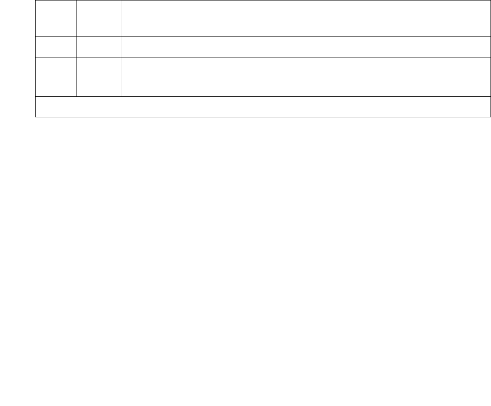
DS1-BD (DS1 Interface Circuit Pack)
Issue 1 June 2005 1015
Minor Alarm Inquiry Test (#143)
The Minor alarm raised by a DS1 Interface circuit pack indicates that the average bit error rate
on the DS1 facility is greater than 1/1,000,000, but less than 1/1000. The Minor Alarm Inquiry
test is used to determine that the received DS1 bit error rate is greater than 1/1,000,000 and
less than 1/1000. When D4 framing mode is selected, the DS1 Interface circuit pack takes 41
minutes to recognize and report a Minor alarm and 41 minutes to recognize and report that a
Minor alarm condition is cleared. If ESF framing mode is selected, the DS1 Interface circuit pack
takes 10 minutes to recognize and report a Minor alarm and 10 minutes to recognize and report
that a Minor alarm condition is cleared.
When the DS1 Interface circuit pack detects a Minor alarm condition, it will send a
MINOR-ALARM message to the maintenance software. After the maintenance software
receives a MINOR-ALARM message, the Minor Alarm Inquiry test is initiated to confirm the
Minor alarm. All trunks on the circuit pack are kept in the in-service state after the Minor alarm is
confirmed. The Minor Alarm Inquiry test is run every 10 minutes until the Minor alarm is cleared.
Table 349: Test #143 Minor Alarm Inquiry Tests
Error
Code
Test
Result
Description / Recommendation
ABRT Internal system error
2100 ABRT Could not allocate the necessary system resources to run this test.
1. Retry the command at 1-minute intervals up to 5 times.
1 of 3

Communication Manager Maintenance-Object Repair Procedures
1016 Maintenance Procedures for Avaya Communication Manager 3.0, Media Gateways and Servers
2000 ABRT Response to the test was not received within the allowable time period. This
may be due to hyperactivity. Error type 1538 in the error log indicates
hyperactivity. The hyperactive circuit pack is out of service and one or more
of the following symptoms may be exhibited.
●The DS1-BD tests (such as test 138 and test 139) are aborting with
error code 2000.
●The tests run on the ports of this circuit pack are returning a no board
result.
●A busyout or a release has no affect on the test results.
●A list config shows that the circuit pack and the ports are
properly installed.
When hyperactivity occurs, the circuit pack is isolated from the system, and
all of its trunks are placed into the out-of-service state. The system will try to
restore the circuit pack within 15 minutes. When no faults are detected for
15 minutes, the DS1 interface circuit pack is restored to normal operation.
Every DS1 interface trunk is then returned to the in-service state.
Hyperactivity is often caused by the associated facility. In such a case, faults
(such as slips, misframes, or blue alarms) would be entered in the error log.
In addition, many hardware errors would be logged against the associated
trunk circuits. If the facility is OK and the error occurs again after 15 minutes,
escalate this problem.
FAIL The DS1 Interface circuit pack detects a Minor alarm. The DS1 bit error
rate is greater than 1/1,000,000 and less than 1/1000.
1. The performance of DS1 link between DS1 Interface circuit pack and
remote DS1 endpoint is poor. If DS1 Interface circuit pack is TN767,
enter list measurement ds1-log location to read the error
seconds measurement.
2. Verify that both endpoints of the DS1 link are administered using the
same signaling mode, framing mode, and line coding.
3. If the DS1 interface circuit pack connects to a T1 facility, call the
vendor of the T1 carrier to diagnose the remote DS1 endpoint. If the
DS1interface circuit pack connects directly to a switch, call the system
technician of the remote switch to diagnose the DS1 endpoint.
4. Check the physical connection of the DS1 pack and of the cable.
5. If this continues to fail, escalate this problem.
PASS No Minor alarm is detected in DS1 Interface circuit pack.
Table 349: Test #143 Minor Alarm Inquiry Tests (continued)
Error
Code
Test
Result
Description / Recommendation
2 of 3

DS1-BD (DS1 Interface Circuit Pack)
Issue 1 June 2005 1017
Slip Alarm Inquiry Test (144)
Slips occur when transmitter and receiver are not running at precisely the same clock rate. The
DS1 Interface circuit pack can detect both positive and negative slips on the DS1 facility. The
Slip Alarm Inquiry test is used to acquire the total number of slips occurred on a DS1 link.
When the DS1 Interface circuit pack detects a slip condition, the circuit pack will increase the
on-board slip counter by 1. A SLIP-COUNT message is spontaneously sent to the system
software after the counter reaches a threshold (for example, 88). When the maintenance
software receives the SLIP-COUNT message, the Slip Alarm Inquiry test is initiated to query the
slip counters on DS1 Interface circuit pack and total the slip counts in the maintenance software.
If the count of slips is over the threshold, a Minor alarm is raised against the DS1 Interface
circuit pack. All trunks of the DS1 Interface circuit pack are still in the in-service state. If the DS1
Interface circuit pack is used to supply the system synchronization source, the MINOR alarm
will initiate a synchronization source switch. See TDM-BUS (TDM Bus) on page 2237 and
SYNC (Port-Network Synchronization) on page 2143 for details.
0NO
BOARD The test could not relate the internal ID to the port (no board).
This could be due to incorrect translations, no board is inserted, an
incorrect board is inserted, or an insane board is inserted.
1. Verify that the board’s translations are correct. Use add ds1
location to administer the DS1 interface if it is not already
administered.
2. If board was already administered correctly, check the error log to
determine whether the board is hyperactive. If so, the board was shut
down. Reseating the board will re-initialize it.
3. If the board was found to be correctly inserted in step 1, enter
busyout board
4. Enter reset board
5. Enter release board
6. Enter test board long
This should re-establish the link between the internal ID and the port.
Table 349: Test #143 Minor Alarm Inquiry Tests (continued)
Error
Code
Test
Result
Description / Recommendation
3 of 3

Communication Manager Maintenance-Object Repair Procedures
1018 Maintenance Procedures for Avaya Communication Manager 3.0, Media Gateways and Servers
Table 350: Test #144 Slip Alarm Inquiry Test
Error
Code
Test
Result
Description / Recommendation
ABRT Internal system error
2100 ABRT Could not allocate the necessary system resources to run this test.
1. Retry the command at 1-minute intervals up to 5 times.
2000 ABRT Response to the test was not received within the allowable time period.
This may be due to hyperactivity. Error type 1538 in the error log indicates
hyperactivity. The hyperactive circuit pack is out of service and one or more
of the following symptoms may be exhibited.
●The DS1-BD tests (such as test 138 and test 139) are aborting with
error code 2000.
●The tests run on the ports of this circuit pack are returning a no board
result.
●A busyout or a release has no affect on the test results.
●A list config shows that the circuit pack and the ports are
properly installed.
When hyperactivity occurs, the circuit pack is isolated from the system, and
all of its trunks are placed into the out-of-service state. The system will try
to restore the circuit pack within 15 minutes. When no faults are detected
for 15 minutes, the DS1 interface circuit pack is restored to normal
operation. Every DS1 interface trunk is then returned to the in-service
state. Hyperactivity is often caused by the associated facility. In such a
case, faults (such as slips, misframes, or blue alarms) would be entered in
the error log. In addition, many hardware errors would be logged against
the associated trunk circuits. If the facility is OK and the error occurs again
after 15 minutes, escalate this problem.
1 of 3

DS1-BD (DS1 Interface Circuit Pack)
Issue 1 June 2005 1019
1 to 88 FAIL The DS1 interface circuit pack detected a slip alarm. The error code
equals the number of slips detected by the DS1 interface circuit pack
since the last slip alarm inquiry test.
1. Retry the command at 1-minute intervals up to 5 times.
2. If the DS1 interface circuit pack is a TN767, enter list
measurement ds1-log location to read the error seconds
measurement.
3. Verify that both endpoints and all intermediate equipment of the DS1
link are administered using the same signaling mode, framing mode,
and line coding.
4. If the DS1 interface circuit pack connects to a T1 facility, call the
vendor of the T1 carrier to diagnose the remote DS1 endpoint. If the
DS1 interface circuit pack connects directly to a switch, call the
system technician of the remote switch to diagnose the DS1 endpoint.
5. Check the active alarm and error logs for recent alarms and errors
against the synchronization (SYNC). Follow the suggested repair
procedure for these errors.
6. Check the physical connectivity of the DS1 pack and of the cable.
7. If this continues to fail, escalate this problem.
PASS No Slip alarm is detected on the DS1 Interface circuit pack.
Table 350: Test #144 Slip Alarm Inquiry Test (continued)
Error
Code
Test
Result
Description / Recommendation
2 of 3

Communication Manager Maintenance-Object Repair Procedures
1020 Maintenance Procedures for Avaya Communication Manager 3.0, Media Gateways and Servers
Misframe Alarm Inquiry Test (#145)
Misframe Alarm indicates that framing bits observed on a DS1 Interface circuit pack are in error.
Misframe Alarm Inquiry test queries the total number of misframes that occurred on a DS1
Interface circuit pack since the last inquiry.
When the DS1 Interface circuit pack detects a misframe error, it will increase its misframe
counter by 1. If the counter reaches the threshold, a MISFRAME-COUNT message is
automatically sent to the switch maintenance software. After the maintenance software receives
the MISFRAME-COUNT message, the Misframe Alarm Inquiry test is initiated to collect the
misframe counts from the DS1 Interface circuit pack.
When the threshold of misframes is reached, if the DS1 Interface circuit pack is supplying the
system synchronization source, then a switching synchronization source message is sent to the
TDM Bus Clock. See TDM-BUS (TDM Bus) Maintenance documentation for details. A Minor
alarm against the DS1 Interface circuit pack is raised, but all trunks of the DS1 Interface circuit
pack are still in the in-service state.
0NO
BOARD The test could not relate the internal ID to the port (no board).
This could be due to incorrect translations, no board is inserted, an
incorrect board is inserted, or an insane board is inserted.
1. Verify that the board’s translations are correct. Use add ds1
location to administer the DS1 interface if it is not already
administered.
2. If board was already administered correctly, check the error log to
determine whether the board is hyperactive. If so, the board was shut
down. Reseating the board will re-initialize it.
3. If the board was found to be correctly inserted in step 1, enter
busyout board
4. Enter reset board
5. Enter release board
6. Enter test board long
This should re-establish the link between the internal ID and the port.
Table 350: Test #144 Slip Alarm Inquiry Test (continued)
Error
Code
Test
Result
Description / Recommendation
3 of 3

DS1-BD (DS1 Interface Circuit Pack)
Issue 1 June 2005 1021
Table 351: Test #145 Misframe Alarm Inquiry Test
Error
Code
Test
Result
Description / Recommendation
ABRT Internal system error
2100 ABRT Could not allocate the necessary system resources to run this test.
1. Retry the command at 1-minute intervals up to 5 times.
2000 ABRT Response to the test was not received within the allowable time period. This
may be due to hyperactivity. Error type 1538 in the error log indicates
hyperactivity. The hyperactive circuit pack is out of service and one or more
of the following symptoms may appear.
●The DS1-BD tests (such as test 138 and test 139) are aborting with
error code 2000.
●The tests run on the ports of this circuit pack are returning a no board
result.
●A busyout or a release has no affect on the test results.
●A list config shows that the circuit pack and the ports are
properly installed.
When hyperactivity occurs, the circuit pack is isolated from the system, and
all of its trunks are placed into the out-of-service state. The system will try to
restore the circuit pack within 15 minutes. When no faults are detected for 15
minutes, the DS1 interface circuit pack is restored to normal operation.
Every DS1 interface trunk is then returned to the in-service state.
Hyperactivity is often caused by the associated facility. In such a case, faults
(such as slips, misframes, or blue alarms) would be entered in the error log.
In addition, many hardware errors would be logged against the associated
trunk circuits. If the facility is OK and the error occurs again after 15 minutes,
escalate this problem.
1 of 3

Communication Manager Maintenance-Object Repair Procedures
1022 Maintenance Procedures for Avaya Communication Manager 3.0, Media Gateways and Servers
ANY FAIL The test failed because the DS1 interface circuit pack detected errors in the
received framing bits pattern. The error code equals the number of
misframes detected by the DS1 interface circuit pack since the last
misframe alarm inquiry test. Major bit and minor bit error rate (error types
2561 and 2817) error logs often accompany misframe alarms. Clearing the
cause of these error logs may clear the misframes that are occurring.
1. Retry the command at 1-minute intervals up to 5 times.
2. If the DS1 interface circuit pack is a TN767, enter list measurement
ds1-log location to read the error seconds measurement.
3. Verify that both endpoints and all intermediate equipment of the DS1
link are administered using the same signaling mode, framing mode,
and line coding.
4. If the DS1 interface circuit pack connects to a T1 facility, call the vendor
of the T1 carrier to diagnose the remote DS1 endpoint. If the DS1
interface circuit pack connects directly to a switch, call the system
technician of the remote switch to diagnose the DS1 endpoint.
5. Check the active alarm and error logs for recent alarms and errors
against the synchronization (SYNC). Follow the suggested repair
procedure for these errors.
6. Check the physical connection of the DS1 pack and of the cable.
7. If this continues to fail, escalate this problem.
PASS No Misframe alarm is detected on the DS1 Interface circuit pack.
Table 351: Test #145 Misframe Alarm Inquiry Test (continued)
Error
Code
Test
Result
Description / Recommendation
2 of 3

DS1-BD (DS1 Interface Circuit Pack)
Issue 1 June 2005 1023
Translation Update Test (#146)
The Translation Update test sends the circuit pack-level information specified by System
Administration to the DS1 Interface circuit pack. Translation includes the following data
administered for a DS1 Interface circuit pack (see output of display ds1 location): DS1
Link Length between two DS1 endpoints, Synchronization Source Control, All Zero
Suppression, Framing Mode, Signaling Mode, time-slot number of 697-Hz tone, time-slot
number of 700-Hz tone, etc.
If a TN767E or later DS1 circuit pack is combined with a 120A CSU module or a T1 sync splitter
to screen an integrated CSU module, this test will also send the administration for this
Integrated CSU to the circuit pack to assure the board’s translations are correct. The
administration of the CSU module is done using the DS1 circuit pack administration screen.
Translation for the CSU module includes the following data: Transmit LBO, Receive ALBO,
Supply CPE loop-back jack Power, and so forth.
0NO
BOARD The test could not relate the internal ID to the port (no board).
This could be due to incorrect translations, no board is inserted, an
incorrect board is inserted, or an insane board is inserted.
1. Verify that the board’s translations are correct. Use add ds1
location to administer the DS1 interface if it is not already
administered.
2. If board was already administered correctly, check the error log to
determine whether the board is hyperactive. If so, the board was shut
down. Reseating the board will re-initialize it.
3. If the board was found to be correctly inserted in step 1, enter busyout
board
4. Enter reset board
5. Enter release board
6. Enter test board long
This should re-establish the link between the internal ID and the port.
Table 351: Test #145 Misframe Alarm Inquiry Test (continued)
Error
Code
Test
Result
Description / Recommendation
3 of 3

Communication Manager Maintenance-Object Repair Procedures
1024 Maintenance Procedures for Avaya Communication Manager 3.0, Media Gateways and Servers
DS1 Board Loop-Back Test (#1209)
This test is destructive.
The DS1 BLB (Board Loopback) test causes a loop back at the TN767E DS1 board edge, and
tests DS1 board internal circuitry.
The test is destructive and is initiated by a technician-demanded test ds1-loop location
ds1/csu-loopback-test.
All trunks or ports on the DS1 Interface circuit pack must be busied out using busyout board
before running the BLB test.
Table 352: Test #146 Translation Update Test
Error
Code
Test
Result
Description / Recommendation
ABRT Internal system error
1. Retry the command at 1-minute intervals up to 5 times.
FAIL Internal system software error.
1. Enter display ds1 location to verify the DS1 Interface circuit
pack translation.
PASS Translation data has been downloaded to the DS1 Interface circuit pack
successfully.
0NO
BOARD The test could not relate the internal ID to the port (no board).
This could be due to incorrect translations, no board is inserted, an
incorrect board is inserted, or an insane board is inserted.
1. Verify that the board’s translations are correct. Use add ds1
location to administer the DS1 interface if it is not already
administered.
2. If board was already administered correctly, check the error log to
determine whether the board is hyperactive. If so, the board was shut
down. Reseating the board will re-initialize it.
3. If the board was found to be correctly inserted in step 1, enter
busyout board
4. Enter reset board
5. Enter release board
6. Enter test board long
This should re-establish the link between the internal ID and the port.

DS1-BD (DS1 Interface Circuit Pack)
Issue 1 June 2005 1025
When the BLB test is initiated, maintenance software sends a message to the TN767E DS1
Interface circuit pack to start the test. The board sets up the BLB loop back, transmits a test
pattern, and verifies that the pattern is received unaltered through the loop back. If the
transmitted and received pattern is different, the test fails.
When the test is complete, enter release board to restore all trunks or ports on the TN767E
DS1 Interface circuit pack to the in-service state.
Table 353: Test #1209 DS1 Board Loop-Back Test
Error
Code
Test
Result
Description / Recommendation
ABRT Internal system error
1. Retry test ds1-loop location ds1/csu-loopback-tests at
1-minute intervals up to 5 times.
1005 ABRT DS1 Board Loopback test cannot be executed in the current configuration.
To run this test, the TN767E (or higher-suffixed) DS1 must be administered
for 24-channel operation. The Bit Rate field on the DS1 circuit pack
administration screen must be set to “1.544” for 24-channel operation.
1015 ABRT Ports on the DS1 Interface circuit pack have not been busied out to
out-of-service.
1. Enter busyout board location to put all trunks or ports of the DS1
Interface circuit pack into the out-of-service state.
2. Retry the command.
1039 ABRT The DS1 Interface circuit pack is providing timing for the system. Executing
this test could cause major system disruption.
If the DS1 Interface circuit pack needs to be tested, set the synchronization
reference to another DS1 Interface circuit pack or to the Tone-Clock circuit
via the following command sequence:
1. Enter disable synchronization-switch
2. Enter set synchronization location
3. Enter enable synchronization-switch
1950 ABRT Another loop-back/span test is already executing on the DS1 board or the
board is in a network requested loop-back mode (Line loop back or Payload
loop back). The hardware error log will indicate whether a Customer
loop-back jack test, Far CSU Loopback test, or the One-Way Span test is
executing or if the board is in line loop-back or payload loop-back mode.
Only one long-duration loop-back/span test can be active at a given time.
Thus, if a loop-back/span test is already active, that test must be
deactivated via test ds1-loop location end-loopback/
span-test in order to execute this test.
1 of 3

Communication Manager Maintenance-Object Repair Procedures
1026 Maintenance Procedures for Avaya Communication Manager 3.0, Media Gateways and Servers
ABRT Internal system error
2100 ABRT Could not allocate the necessary system resources to run this test.
1. Retry the command at 1-minute intervals up to 5 times.
2000 ABRT Response to the test was not received within the allowable time period. This
may be due to hyperactivity. Error type 1538 in the error log indicates
hyperactivity. The hyperactive circuit pack is out of service and one or more
of the following symptoms may be exhibited.
●The DS1-BD tests (such as test 138 and test 139) are aborting with
error code 2000.
●The tests run on the ports of this circuit pack are returning a no board
result.
●A busyout or a release has no affect on the test results.
●A list config shows that the circuit pack and the ports are
properly installed.
When hyperactivity occurs, the circuit pack is isolated from the system, and
all of its trunks are placed into the out-of-service state. The system will try to
restore the circuit pack within 15 minutes. When no faults are detected for
15 minutes, the DS1 interface circuit pack is restored to normal operation.
Every DS1 interface trunk is then returned to the in-service state.
Hyperactivity is often caused by the associated facility. In such a case, faults
(such as slips, misframes, or blue alarms) would be entered in the error log.
In addition, many hardware errors would be logged against the associated
trunk circuits. If the facility is OK and the error occurs again after 15 minutes,
escalate this problem.
FAIL DS1 Interface circuit pack failed the DS1 Board Loopback test.
1. Retry test ds1-loop location ds1/csu-loopback-tests.
2. If the BLB test continues to fail, then replace the DS1 circuit pack.
PASS The BLB test executed successfully. The test pattern was transmitted and
received successfully up to the TN767E DS1 board edge.
Table 353: Test #1209 DS1 Board Loop-Back Test (continued)
Error
Code
Test
Result
Description / Recommendation
2 of 3

DS1-BD (DS1 Interface Circuit Pack)
Issue 1 June 2005 1027
CSU Equipment Loop-Back Test (#1210)
This test is destructive.
The CSU ELB (Equipment Loopback) test causes a loop back at the near-edge of the local
120A CSU module or T1 sync splitter, and tests the connection from the TN767E DS1 board to
the CSU module/T1 sync splitter (DS1 board edge interconnecting cable, and CSU module/T1
sync splitter edge). This test will only be performed if the 120A CSU module/T1 sync splitter is
present, administered, and connected to a 1.544-Mbps TN767E DS1 circuit pack on the back of
the port carrier.
The test is destructive and can only be initiated by a technician-demanded test ds1-loop
location ds1/csu-loopback-tests.
Use busyout board to busy out all trunks or ports on the DS1 Interface circuit pack before
running the ELB test.
When the ELB test is initiated, maintenance software sends a message to the TN767E DS1
Interface circuit pack to start the test. The board sets up the ELB loop back, transmits a test
pattern, and verifies that the pattern is received unaltered through the loop back. If the
transmitted and received pattern is different, the test fails.
0NO
BOARD The test could not relate the internal ID to the port (no board).
This could be due to incorrect translations, no board is inserted, an
incorrect board is inserted, or an insane board is inserted.
1. Verify that the board’s translations are correct. Use add ds1
location to administer the DS1 interface if it is not already
administered.
2. If board was already administered correctly, check the error log to
determine whether the board is hyperactive. If so, the board was shut
down. Reseating the board will re-initialize it.
3. If the board was found to be correctly inserted in step 1, enter
busyout board
4. Enter reset board
5. Enter release board
6. Enter test board long
This should re-establish the link between the internal ID and the port.
Table 353: Test #1209 DS1 Board Loop-Back Test (continued)
Error
Code
Test
Result
Description / Recommendation
3 of 3

Communication Manager Maintenance-Object Repair Procedures
1028 Maintenance Procedures for Avaya Communication Manager 3.0, Media Gateways and Servers
The DS1 circuit pack hardware applies a DC current while the test is running in order to detect
any broken wires that may not be detected by the loop-back pattern.
When the test is complete, use release board to restore all trunks or ports on the TN767E
DS1 Interface circuit pack to the in-service state.
Table 354: Test #1210 CSU Equipment Loop-Back Test
Error
Code
Test
Result
Description / Recommendation
ABRT Internal system error
1. Retry test ds1-loop location ds1/csu-loopback-tests at
1-minute intervals up to 5 times.
1005 ABRT CSU Equipment Loopback test cannot be executed in the current
configuration. To run this test, the Near-End CSU Type field on the DS1
circuit pack administration screen must be set to integrated and the Bit
Rate field must be set to “1.544” (for 24-channel operation).
1. Use change ds1 location and set the Near-End CSU Type field
on the DS1 circuit pack administration screen to integrated, and/or set
the Bit Rate field to 1.544 if the board is to be used in a 24-channel
configuration.
2. Retry test ds1-loop location ds1/csu-loopback-tests.
1015 ABRT Ports on the DS1 Interface circuit pack have not been busied out to
out-of-service.
1. Enter busyout board location to put all trunks or ports of the
DS1 Interface circuit pack into the out-of-service state.
2. Retry the command.
1039 ABRT The DS1 Interface circuit pack is providing timing for the system. Executing
this test could cause major system disruption.
If the DS1 Interface circuit pack needs to be tested, set the synchronization
reference to another DS1 Interface circuit pack or to the Tone-Clock circuit
via the following command sequence:
1. Enter disable synchronization-switch.
2. Enter enable synchronization-switch set
synchronization location.
3. Enter enable synchronization-switch.
1 of 3

DS1-BD (DS1 Interface Circuit Pack)
Issue 1 June 2005 1029
1950 ABRT Another loop-back/span test is already executing on the DS1 board or the
board is in a network requested loop-back mode (Line loop back or Payload
loop back). The hardware error log will indicate whether a Customer
loop-back jack test, Far CSU Loopback test, or the One-Way Span test is
executing or if the board is in line loop-back or payload loop-back mode.
Only one long-duration loop-back/span test can be active at a given time.
Thus, if a loop-back/span test is already active, that test must be
deactivated via test ds1-loop location end-loopback/
span-test in order to execute this test.
1951 ABRT The CSU Equipment Loopback test could not be executed because the
120A CSU module/T1 sync splitter was not physically installed. Physically
connect the 120A CSU module/T1 sync splitter to the TN767E board on the
back of the port carrier.
ABRT Internal system error
2100 ABRT Could not allocate the necessary system resources to run this test.
1. Retry the command at 1-minute intervals up to 5 times.
2000 ABRT Response to the test was not received within the allowable time period. This
may be due to hyperactivity. Error type 1538 in the error log indicates
hyperactivity. The hyperactive circuit pack is out of service and one or more
of the following symptoms may be exhibited.
●The DS1-BD tests (such as test 138 and test 139) are aborting with
error code 2000.
●The tests run on the ports of this circuit pack are returning a no board
result.
●A busyout or a release command has no affect on the test results.
●A list config command shows that the circuit pack and the ports
are properly installed.
When hyperactivity occurs, the circuit pack is isolated from the system, and
all of its trunks are placed into the out-of-service state. The system will try to
restore the circuit pack within 15 minutes. When no faults are detected for
15 minutes, the DS1 interface circuit pack is restored to normal operation.
Every DS1 interface trunk is then returned to the in-service state.
Hyperactivity is often caused by the associated facility. In such a case, faults
(such as slips, misframes, or blue alarms) would be entered in the error log.
In addition, many hardware errors would be logged against the associated
trunk circuits. If the facility is OK and the error occurs again after 15 minutes,
escalate this problem.
Table 354: Test #1210 CSU Equipment Loop-Back Test (continued)
Error
Code
Test
Result
Description / Recommendation
2 of 3

Communication Manager Maintenance-Object Repair Procedures
1030 Maintenance Procedures for Avaya Communication Manager 3.0, Media Gateways and Servers
FAIL DS1 Interface circuit pack failed the CSU Equipment Loopback test.
1. Retry test ds1-loop location ds1/csu-loopback-tests.
2. If the ELB test continues to fail, then either the TN767E board, the
CSU module/T1 sync splitter, or the I/O cable between the backplane
and the 120A1 CSU module or the 401A T1 sync splitter (or any
combination thereof) has failed. Attempt to isolate the problem to one
of these areas. Replace the CSU module/T1 sync splitter, and run
test ds1-loop location ds1/csu-loopback-tests again.
3. If the ELB test continues to fail, then replace the TN767E board and
run test ds1-loop location ds1/csu-loopback-tests
again.
4. If the ELB test continues to fail, the problem could be in the I/O cable
between the backplane and the 120A1 CSU module or the 401A T1
sync splitter.
PASS The ELB test executed successfully. The test pattern was transmitted and
received successfully over the connection from the TN767E DS1 board to
the near-edge of the 120A1 CSU module/T1 sync splitter.
0NO
BOARD The test could not relate the internal ID to the port (no board).
This could be due to incorrect translations, no board is inserted, an
incorrect board is inserted, or an insane board is inserted.
1. Verify that the board’s translations are correct. Use add ds1
location to administer the DS1 interface if it is not already
administered.
2. If board was already administered correctly, check the error log to
determine whether the board is hyperactive. If so, the board was shut
down. Reseating the board will re-initialize it.
3. If the board was found to be correctly inserted in step 1, enter
busyout board
4. Enter reset board
5. Enter release board
6. Enter test board long
This should re-establish the link between the internal ID and the port.
Table 354: Test #1210 CSU Equipment Loop-Back Test (continued)
Error
Code
Test
Result
Description / Recommendation
3 of 3

DS1-BD (DS1 Interface Circuit Pack)
Issue 1 June 2005 1031
CSU Repeater Loop-Back Test (#1211)
This test is destructive.
The CSU RLB (Repeater Loopback) test causes a loop back at the far-edge of the local 120A
CSU module or T1 sync splitter, and tests the connection from the TN767E DS1 board to and
including the CSU module/T1 sync splitter circuitry. The test runs only if the 120A CSU module/
T1 sync splitter is present, administered, and connected to a 1.544-Mbps TN767E DS1 circuit
pack on the back of the port carrier.
The test is destructive and can only be initiated by test ds1-loop location ds1/
csu-loopback-test.
Use busyout board to busy out all trunks or ports on the DS1 Interface circuit pack before
running the RLB test.
When the RLB test is initiated, maintenance software sends a message to the TN767E DS1
Interface circuit pack to start the test. The board sets up the RLB loop back, transmits a test
pattern, and verifies that the pattern is received unaltered through the loop back. If the
transmitted and received pattern is different, the test fails.
The DS1 circuit pack hardware applies a DC current while the test is running in order to detect
any broken wires that may not be detected by the loop-back pattern.
When the test is complete, use release board to restore all trunks or ports on the TN767E
DS1 Interface circuit pack to the in-service state.
Table 355: Test #1211 CSU Repeater Loop-Back Test
Error
Code
Test
Result
Description / Recommendation
ABRT Internal system error
1. Retry test ds1-loop location ds1/csu-loopback-tests at
1-minute intervals up to 5 times.
1005 ABRT CSU Repeater Loopback test cannot be executed in the current
configuration.
1. Use change ds1 location and set the Near-End CSU Type field
on the DS1 circuit pack administration screen to integrated, and/or set
the Bit Rate field to 1.544 if the board is to be used in a 24-channel
configuration.
2. Retry test ds1-loop location ds1/csu-loopback-tests.
1 of 4

Communication Manager Maintenance-Object Repair Procedures
1032 Maintenance Procedures for Avaya Communication Manager 3.0, Media Gateways and Servers
1015 ABRT Ports on the DS1 Interface circuit pack have not been busied out to
out-of-service.
1. Enter busyout board location to put all trunks or ports of the DS1
Interface circuit pack into the out-of-service state.
2. Retry the command.
1039 ABRT The DS1 Interface circuit pack is providing timing for the system. Executing
this test could cause major system disruption.
If the DS1 Interface circuit pack needs to be tested, set the synchronization
reference to another DS1 Interface circuit pack or to the Tone-Clock circuit
via the following command sequence:
1. Enter disable synchronization-switch
2. Enter enable synchronization-switch set
synchronization location
3. Enter enable synchronization-switch
1950 ABRT Another loop-back/span test is already executing on the DS1 board or the
board is in a network requested loop-back mode (Line loop back or Payload
loop back). The hardware error log indicates whether a Customer Loopback
Jack test, Far CSU Loopback test, or the One-Way Span test is executing or
if the board is in line loop-back or payload loop-back mode. Only one
long-duration loop-back/span test can be active at a given time. Thus, if a
loop-back/span test is already active, that test must be deactivated via test
ds1-loop location end-loopback/span-test in order to execute
this test.
1951 ABRT The CSU Repeater Loopback test could not be executed because the 120A
CSU module/T1 sync splitter was not physically installed. Physically connect
the 120A1 CSU module/T1 sync splitter to the TN767E board on the back of
the port carrier.
Table 355: Test #1211 CSU Repeater Loop-Back Test (continued)
Error
Code
Test
Result
Description / Recommendation
2 of 4

DS1-BD (DS1 Interface Circuit Pack)
Issue 1 June 2005 1033
ABRT Internal system error
2100 ABRT Could not allocate the necessary system resources to run this test.
1. Retry the command at 1-minute intervals up to 5 times.
2000 ABRT Response to the test was not received within the allowable time period. This
may be due to hyperactivity. Error type 1538 in the error log indicates
hyperactivity. The hyperactive circuit pack is out of service and one or more
of the following symptoms may be exhibited.
●The DS1-BD tests (such as test 138 and test 139) are aborting with
error code 2000.
●The tests run on the ports of this circuit pack are returning a no board
result.
●A busyout or a release has no affect on the test results.
●A list config shows that the circuit pack and the ports are
properly installed.
When hyperactivity occurs, the circuit pack is isolated from the system, and
all of its trunks are placed into the out-of-service state. The system will try to
restore the circuit pack within 15 minutes. When no faults are detected for 15
minutes, the DS1 interface circuit pack is restored to normal operation.
Every DS1 interface trunk is then returned to the in-service state.
Hyperactivity is often caused by the associated facility. In such a case, faults
(such as slips, misframes, or blue alarms) would be entered in the error log.
In addition, many hardware errors would be logged against the associated
trunk circuits. If the facility is OK and the error occurs again after 15 minutes,
escalate this problem.
FAIL DS1 Interface circuit pack failed the CSU Repeater Loopback test.
1. Retry test ds1-loop location ds1/csu-loopback-tests.
2. If the RLB test continues to fail, and the CSU Equipment Loopback test
(#1210) passed, then replace the CSU module/T1 sync splitter.
PASS The RLB test executed successfully. The test pattern was transmitted and
received successfully over the connection from the TN767E DS1 board to
the far-edge of the 120A1 CSU module/T1 sync splitter.
Table 355: Test #1211 CSU Repeater Loop-Back Test (continued)
Error
Code
Test
Result
Description / Recommendation
3 of 4

Communication Manager Maintenance-Object Repair Procedures
1034 Maintenance Procedures for Avaya Communication Manager 3.0, Media Gateways and Servers
CPE Loopback Jack Test (#1212)
This test is destructive.
The CPE Loopback Jack (CLJ-LB) test causes a loop back at the CPE loop-back jack and tests
the building wiring connection between the TN767E DS1 board and the CPE loop-back jack.
The test is highly destructive and can only be initiated by a technician-demanded test
ds1-loop location cpe-loopback-jack-test-begin [number-of-bits
bit-pattern]. The system technician can either enter a loop-back activation code on the
command line or use the default code (0x47F).
Use busyout board to busy out all trunks or ports on the DS1 Interface circuit pack before
running the CPE Loopback Jack test.
The CPE Loopback Jack test has the TN767E DS1 Interface circuit pack transmit a loop-back
activation code to the CPE loop-back jack, waits up to 10 seconds for return of the code to verify
the loop back has been established, transmits a framed 3-in-24 test pattern, begins counting bit
errors in the received test pattern, and returns a PASS result to indicate that the pattern was
successfully sent. If the loop back is not established within the 10 seconds, the test returns
FAIL.
0NO
BOARD The test could not relate the internal ID to the port (no board).
This could be due to incorrect translations, no board is inserted, an
incorrect board is inserted, or an insane board is inserted.
1. Verify that the board’s translations are correct. Use add ds1
location to administer the DS1 interface if it is not already
administered.
2. If board was already administered correctly, check the error log to
determine whether the board is hyperactive. If so, the board was shut
down. Reseating the board will re-initialize it.
3. If the board was found to be correctly inserted in step 1, enter busyout
board
4. Enter reset board
5. Enter release board
6. Enter test board long
This should re-establish the link between the internal ID and the port.
Table 355: Test #1211 CSU Repeater Loop-Back Test (continued)
Error
Code
Test
Result
Description / Recommendation
4 of 4

DS1-BD (DS1 Interface Circuit Pack)
Issue 1 June 2005 1035
The status of the CPE Loopback Jack test appears in the hardware error log via Error Type
#3900. Several distinct aux values give information on the status of the test.
Use list measurements ds1 summary to show the length of time the test has been
running (Test Duration field) and number of bit errors detected (Loopback/Span Test
Bit-Error Count field). If the test pattern is passed through the loop back cleanly, the
number of bit errors should be very low. The command also shows the type of loop-back/span
test executing (Test field), the type of pattern generated for the loop-back/span test (Pattern
field), and whether the pattern (3-in-24 Pattern) is synchronized (Synchronized field).
Use test ds1-loop location end-loopback/span-test to end the test.
Table 356: Test #1212 CPE Loopback Jack Test
Error
Code
Test
Result
Description / Recommendation
ABRT Internal system error
1. Retry test ds1-loop location
cpe-loopback-jack-test-begin at 1-minute intervals up to 5
times.
1005 ABRT CPE Loopback Jack test cannot be executed in the current configuration. To
run this test, the TN767E (or higher-suffixed) DS1 must be administered for
24-channel operation. The Bit Rate field on the DS1 circuit pack
administration screen must be set to “1.544” for 24-channel operation.
1015 ABRT Ports on the DS1 Interface circuit pack have not been busied out to
out-of-service.
1. Enter busyout board location to put all trunks or ports of the DS1
Interface circuit pack into the out-of-service state.
2. Retry the command.
1039 ABRT The DS1 Interface circuit pack is providing timing for the system. Executing
this test could cause major system disruption.
If the DS1 Interface circuit pack needs to be tested, set the synchronization
reference to another DS1 Interface circuit pack or to the Tone-Clock circuit
via the following command sequence:
1. Enter disable synchronization-switch.
2. Enter enable synchronization-switch set
synchronization location.
3. Enter enable synchronization-switch.
1 of 4

Communication Manager Maintenance-Object Repair Procedures
1036 Maintenance Procedures for Avaya Communication Manager 3.0, Media Gateways and Servers
1950 ABRT Another loop-back/span test is already executing on the DS1 board or the
board is in a network requested loop-back mode (Line loop back or Payload
loop back). The hardware error log will indicate whether a Customer
loop-back jack test, Far CSU Loopback test, or the One-Way Span test is
executing or if the board is in line loop-back or payload loop-back mode.
Only one long-duration loop-back/span test can be active at a given time.
Thus, if a loop-back/span test is already active, that test must be deactivated
via test ds1-loop location end-loopback/span-test in order to
execute this test.
ABRT Internal system error
2100 ABRT Could not allocate the necessary system resources to run this test.
1. Retry the command at 1-minute intervals up to 5 times.
2000 ABRT Response to the test was not received within the allowable time period. This
may be due to hyperactivity. Error type 1538 in the error log indicates
hyperactivity. The hyperactive circuit pack is out of service and one or more
of the following symptoms may be exhibited.
●The DS1-BD tests (such as test 138 and test 139) are aborting with
error code 2000.
●The tests run on the ports of this circuit pack are returning a no board
result.
●A busyout or a release has no affect on the test results.
●A list config shows that the circuit pack and the ports are
properly installed.
When hyperactivity occurs, the circuit pack is isolated from the system, and
all of its trunks are placed into the out-of-service state. The system will try to
restore the circuit pack within 15 minutes. When no faults are detected for 15
minutes, the DS1 interface circuit pack is restored to normal operation.
Every DS1 interface trunk is then returned to the in-service state.
Hyperactivity is often caused by the associated facility. In such a case, faults
(such as slips, misframes, or blue alarms) would be entered in the error log.
In addition, many hardware errors would be logged against the associated
trunk circuits. If the facility is OK and the error occurs again after 15 minutes,
escalate this problem.
Table 356: Test #1212 CPE Loopback Jack Test (continued)
Error
Code
Test
Result
Description / Recommendation
2 of 4

DS1-BD (DS1 Interface Circuit Pack)
Issue 1 June 2005 1037
2 FAIL The CLJ-LB test failed because it was not set up properly. The DS1
interface pack could not successfully put the CPE loop-back jack into
loop-back mode.
1. Rerun test ds1-loop location
cpe-loopback-jack-test-begin.
2. If the test continues to fail, the problem could be with the TN767E
board, the CPE loop-back jack equipment, or somewhere between.
Run test ds1-loop location ds1/csu-loopback-tests to
determine if the loop-back tests that are closer to the TN767E board
are successful. If any of the tests fail, follow the maintenance strategy
that is associated with the failing test.
3 FAIL The CPE Loopback Jack test was not set up properly. The framed 3-in-24
test pattern, generated by the DS1 Interface circuit pack and looped back
through the CPE loop-back jack, could not be detected properly by the DS1
circuit pack.
1. Retry test ds1-loop location
cpe-loopback-jack-test-begin.
2. If the CPE Loopback test continues to fail, the problem could be with
the TN767E board, the CPE loop-back jack equipment, or somewhere
in between. Run test ds1-loop location ds1/
csu-loopback-tests to see if the loop-back tests closer to the
TN767E board are successful. If any of those loop-back tests fail,
follow the maintenance strategy associated with those.
PASS The CPE Loopback Jack test has successfully began executing. The test
runs until the system technician enters the test ds1-loop location
end-loopback/span-test or release board location.
Table 356: Test #1212 CPE Loopback Jack Test (continued)
Error
Code
Test
Result
Description / Recommendation
3 of 4

Communication Manager Maintenance-Object Repair Procedures
1038 Maintenance Procedures for Avaya Communication Manager 3.0, Media Gateways and Servers
Far CSU Loop-Back Test (#1213)
This test is destructive.
The Far CSU Loopback (R-LLB) test causes a loop back at the far-end CSU, and tests all
circuitry and facilities from the local TN767E DS1 board to the far-end CSU.
The test is destructive and can only be initiated by a technician-demanded test ds1-loop
location far-csu-loopback-test-begin.
Use busyout board to busy out all trunks or ports on the DS1 Interface circuit pack before
running the Far CSU Loopback test.
If the far-end CSU is not a 120A CSU module or a 401A T1 sync splitter, and the DS1 is
administered for ami-zcs line coding, disable density protection on the CSU during the test, due
to the large number of zero’s in the 3-in-24 test pattern.
The Far CSU Loopback test has the TN767E DS1 Interface circuit pack transmit a loop-back
activation code to the remote CSU, waits up to 15 seconds for return of the code to verify the
loop back has been established, transmits a framed 3-in-24 test pattern, begins counting bit
errors in the received test pattern, and returns a PASS result. If the loop back is not established
within the 15 seconds, the test fails.
0NO
BOARD The test could not relate the internal ID to the port (no board).
This could be due to incorrect translations, no board is inserted, an
incorrect board is inserted, or an insane board is inserted.
1. Verify that the board’s translations are correct. Use add ds1
location to administer the DS1 interface if it is not already
administered.
2. If board was already administered correctly, check the error log to
determine whether the board is hyperactive. If so, the board was shut
down. Reseating the board will re-initialize it.
3. If the board was found to be correctly inserted in step 1, enter busyout
board
4. Enter reset board
5. Enter release board
6. Enter test board long
This should re-establish the link between the internal ID and the port.
Table 356: Test #1212 CPE Loopback Jack Test (continued)
Error
Code
Test
Result
Description / Recommendation
4 of 4

DS1-BD (DS1 Interface Circuit Pack)
Issue 1 June 2005 1039
The status of the Far CSU Loopback test appears in the hardware error log via Error Type
#3901. Several aux values give information on the status of the test.
Use list measurements ds1 summary to show the length of time the test has been running
(Test Duration field) and number of bit errors detected (Loopback/Span Test
Bit-Error Count field). If the test pattern is passed through the loop back cleanly, the
number of bit errors should be very low. The command also shows the type of loop-back/span
test executing (Test field), the type of pattern generated for the loop-back/span test (Pattern
field), and whether the pattern (i.e., 3-in-24 Pattern) is synchronized (Synchronized field).
Use test ds1-loop location end-loopback/span-test or release board to end
the test. Use release board to restore all trunks or ports on the TN767E DS1 Interface
circuit pack to the in-service state.
Table 357: Test #1213 Far CSU Loop-Back Test
Error
Code
Test
Result
Description / Recommendation
ABRT Internal system error
1. Retry test ds1-loop location
far-csu-loopback-test-begin at 1-minute intervals up to 5
times.
1005 ABRT Far CSU Loopback test cannot be executed in the current configuration. To
run this, the TN767E (or higher-suffixed) DS1 must be administered for
24-channel operation. The Bit Rate field on the DS1 circuit pack
administration screen must be set to “1.544” for 24-channel operation.
1015 ABRT Ports on the DS1 Interface circuit pack have not been busied out to
out-of-service.
1. Enter busyout board location to put all trunks or ports of the DS1
Interface circuit pack into the out-of-service state.
2. Retry the command.
1039 ABRT The DS1 Interface circuit pack is providing timing for the system. Executing
this test could cause major system disruption.
If the DS1 Interface circuit pack needs to be tested, set the synchronization
reference to another DS1 Interface circuit pack or to the Tone-Clock circuit
via the following command sequence:
1. Enter disable synchronization-switch.
2. Enter enable synchronization-switch set
synchronization location.
3. Enter enable synchronization-switch.
1 of 3

Communication Manager Maintenance-Object Repair Procedures
1040 Maintenance Procedures for Avaya Communication Manager 3.0, Media Gateways and Servers
1950 ABRT Another loop-back/span test is already executing on the DS1 board or the
board is in a network requested loop-back mode (Line loop back or Payload
loop back). The hardware error log will indicate whether a Customer
Loopback Jack test, Far CSU Loopback test, or the One-Way Span test is
executing or if the board is in line loop-back or payload loop-back mode.
Only one long-duration loop-back/span test can be active at a given time.
Thus, if a loop-back/span test is already active, that test must be deactivated
via test ds1-loop location end-loopback/span-test in order to
execute this test.
ABRT Internal system error
2100 ABRT Could not allocate the necessary system resources to run this test.
1. Retry the command at 1-minute intervals up to 5 times.
2000 ABRT Response to the test was not received within the allowable time period. This
may be due to hyperactivity. Error type 1538 in the error log indicates
hyperactivity. The hyperactive circuit pack is out of service and one or more
of the following symptoms may be exhibited.
●The DS1-BD tests (such as test 138 and test 139) are aborting with
error code 2000.
●The tests run on the ports of this circuit pack are returning a no board
result.
●A busyout or a release command has no affect on the test results.
●A list config command shows that the circuit pack and the ports
are properly installed.
When hyperactivity occurs, the circuit pack is isolated from the system, and
all of its trunks are placed into the out-of-service state. The system will try to
restore the circuit pack within 15 minutes. When no faults are detected for 15
minutes, the DS1 interface circuit pack is restored to normal operation. Every
DS1 interface trunk is then returned to the in-service state. Hyperactivity is
often caused by the associated facility. In such a case, faults (such as slips,
misframes, or blue alarms) would be entered in the error log. In addition,
many hardware errors would be logged against the associated trunk circuits.
If the facility is OK and the error occurs again after 15 minutes, escalate this
problem.
2 FAIL The far CSU Loopback test was not set up properly. The DS1 Interface
circuit pack could not put the far-end CSU into loop-back mode.
Table 357: Test #1213 Far CSU Loop-Back Test (continued)
Error
Code
Test
Result
Description / Recommendation
2 of 3

DS1-BD (DS1 Interface Circuit Pack)
Issue 1 June 2005 1041
3 FAIL The far CSU Loopback test was not set up properly. The framed 3-in-24
test pattern, generated by the DS1 Interface circuit pack and looped back
through the far-end CSU, could not be detected by the DS1 circuit pack.
1. Retry test ds1-loop location
far-csu-loopback-test-begin.
2. If the Far CSU Loopback test continues to fail with this error code, the
problem could be with the TN767E board, the far-end CSU equipment,
or somewhere in between. Run test ds1-loop location
cpe-loopback-jack-test-begin to see if the CPE Loopback Jack
test that is closer to the TN767E board is successful.
If a CPE loop-back jack device is not being used, run test ds1-loop
location ds1/csu-loopback-tests to see if the closer loop-back
tests succeed. If the closer loop-back test fails, follow the maintenance
strategy associated with that loop back
PASS The Far CSU Loopback test has successfully began executing. The test runs
until the system technician enters test ds1-loop location
end-loopback/span-test or the release board location.
0NO
BOARD The test could not relate the internal ID to the port (no board).
This could be due to incorrect translations, no board is inserted, an
incorrect board is inserted, or an insane board is inserted.
1. Verify that the board’s translations are correct. Use add ds1
location to administer the DS1 interface if it is not already
administered.
2. If board was already administered correctly, check the error log to
determine whether the board is hyperactive. If so, the board was shut
down. Reseating the board will re-initialize it.
3. If the board was found to be correctly inserted in step 1, enter busyout
board
4. Enter reset board
5. Enter release board
6. Enter test board long
This should re-establish the link between the internal ID and the port.
Table 357: Test #1213 Far CSU Loop-Back Test (continued)
Error
Code
Test
Result
Description / Recommendation
3 of 3

Communication Manager Maintenance-Object Repair Procedures
1042 Maintenance Procedures for Avaya Communication Manager 3.0, Media Gateways and Servers
One-Way Span Test (#1214)
This test is destructive.
The One-Way Span test allows 1-way span testing to and from remote test equipment or
another Communication Manager solution. This tests all circuitry and facilities from the local
TN767E DS1 board to the remote test equipment or other Communication Manager solution.
The test is destructive and can only be initiated by a technician-demanded test ds1-loop
location one-way-span-test-begin.
Use busyout board to busy out all trunks or ports on the DS1 Interface circuit pack before
running the One-Way Span test.
The One-Way Span test has the TN767E DS1 Interface circuit pack transmit a framed 3-in-24
test pattern and attempts to receive and verify the pattern. If the TN767E board receives a
framed 3-in-24 test pattern sent from another Communication Manager system or test
equipment at the far end of the DS1, it begins counting bit errors within the received pattern.
Note:
Note: G700: When a TN464 and an MM710 are connected, the One-Way Span test
does not frame-align to the 3-in-24 repetitive pattern, and the test fails.
The status of the One-Way Span test appears in the hardware error log via Error Type #3902.
Several aux values give information on the status of the test.
Use list measurements ds1 summary to see the length of time the test has been running
(Test Duration field) and number of bit errors detected (Loopback/Span Test
Bit-Error Count field). If the test pattern is sent cleanly over the span from the far end, the
number of bit errors should be very low. The Test Duration field is 0 until the test pattern is
received from the far end. Upon receiving the test pattern, the board begins calculating the test
duration and number of bit errors. The command also shows the type of loop-back/span test
executing (Test field), the type of pattern generated for the loop-back/span test (Pattern
field), and whether the pattern (i.e., 3-in-24 Pattern) is synchronized (Synchronized field).
Use test ds1-loop location end-loopback/span-test or release board to end
the test. Use release board to restore all trunks or ports on the TN767E DS1 Interface circuit
pack to the in-service state.
Table 358: Test #1214 One-Way Span Test
Error
Code
Test
Result
Description / Recommendation
ABRT Internal system error
1. Retry test ds1-loop location one-way-span-test-begin at
1-minute intervals up to 5 times.
1 of 4

DS1-BD (DS1 Interface Circuit Pack)
Issue 1 June 2005 1043
1005 ABRT One-Way Span test cannot be executed in the current configuration. To run
this, the TN767E (or higher-suffixed) DS1 must be administered for
24-channel operation. The Bit Rate field on the DS1 circuit pack
administration screen must be set to “1.544” for 24-channel operation.
1015 ABRT Ports on the DS1 Interface circuit pack have not been busied out to
out-of-service.
1. Enter busyout board location to put all trunks or ports of the DS1
Interface circuit pack into the out-of-service state.
2. Retry the command.
1039 ABRT The DS1 Interface circuit pack is providing timing for the system. Executing
this test could cause major system disruption.
If the DS1 Interface circuit pack needs to be tested, set the synchronization
reference to another DS1 Interface circuit pack or to the Tone-Clock circuit
via the following command sequence:
1. Enter disable synchronization-switch
2. Enter enable synchronization-switch set
synchronization location
3. Enter enable synchronization-switch
1950 ABRT Another loop-back/span test is already executing on the DS1 board or the
board is in a network requested loop-back mode (Line loop back or Payload
loop back). The hardware error log will indicate whether a Customer
Loop-Back Jack test, Far CSU Loopback test, or the One-Way Span test is
executing or if the board is in line loop-back or payload loop-back mode.
Only one long-duration loop-back/span test can be active at a given time.
Thus, if a loop-back/span test is already active, that test must be deactivated
via test ds1-loop location end-loopback/span-test in order to
execute this test.
ABRT Internal system error
2100 ABRT Could not allocate the necessary system resources to run this test.
1. Retry the command at 1-minute intervals up to 5 times.
Table 358: Test #1214 One-Way Span Test (continued)
Error
Code
Test
Result
Description / Recommendation
2 of 4

Communication Manager Maintenance-Object Repair Procedures
1044 Maintenance Procedures for Avaya Communication Manager 3.0, Media Gateways and Servers
2000 ABRT Response to the test was not received within the allowable time period. This
may be due to hyperactivity. Error type 1538 in the error log indicates
hyperactivity. The hyperactive circuit pack is out of service and one or more
of the following symptoms may be exhibited.
●The DS1-BD tests (such as test 138 and test 139) are aborting with
error code 2000.
●The tests run on the ports of this circuit pack are returning a no board
result.
●A busyout or a release command has no affect on the test results.
●A list config command shows that the circuit pack and the ports
are properly installed.
When hyperactivity occurs, the circuit pack is isolated from the system, and
all of its trunks are placed into the out-of-service state. The system will try to
restore the circuit pack within 15 minutes. When no faults are detected for 15
minutes, the DS1 interface circuit pack is restored to normal operation. Every
DS1 interface trunk is then returned to the in-service state. Hyperactivity is
often caused by the associated facility. In such a case, faults (such as slips,
misframes, or blue alarms) would be entered in the error log. In addition,
many hardware errors would be logged against the associated trunk circuits.
If the facility is OK and the error occurs again after 15 minutes, escalate this
problem.
G700: FAIL Test was run between a TN464 and an MM710, which generate incompatible
patterns.
PASS The One-Way Span test has successfully began transmitting a framed
3-in-24 test pattern. The test will continue to run until the system technician
enters test ds1-loop location end-loopback/span-test or
release board location.
Table 358: Test #1214 One-Way Span Test (continued)
Error
Code
Test
Result
Description / Recommendation
3 of 4

DS1-BD (DS1 Interface Circuit Pack)
Issue 1 June 2005 1045
Inject Single Bit Error Test (#1215)
This test is destructive.
The Inject Single Bit Error test causes a single bit error to be sent within an active framed
3-in-24 test pattern.
The test is highly destructive and can only be initiated by a technician-demanded test
ds1-loop location inject-single-bit-error. An attempt to use this command is
rejected if none of the three long-duration DS1 loop-back/span tests (CPE Loopback Jack test,
Far CSU Loopback test, One-Way Span test) are active on a TN767E circuit pack.
Use busyout board to busy out all trunks or ports on the DS1 Interface circuit pack before
running the Inject Single Bit Error test.
Use list measurements ds1 summary to show the number of bit errors detected
(Loopback/Span Test Bit-Error Count field). Injecting this single bit error should
increment the bit error count of the loop-back/span test by one.
0NO
BOARD The test could not relate the internal ID to the port (no board).
This could be due to incorrect translations, no board is inserted, an
incorrect board is inserted, or an insane board is inserted.
1. Verify that the board’s translations are correct. Use add ds1
location to administer the DS1 interface if it is not already
administered.
2. If board was already administered correctly, check the error log to
determine whether the board is hyperactive. If so, the board was shut
down. Reseating the board will re-initialize it.
3. If the board was found to be correctly inserted in step 1, enter busyout
board
4. Enter reset board
5. Enter release board
6. Enter test board long
This should re-establish the link between the internal ID and the port.
Table 358: Test #1214 One-Way Span Test (continued)
Error
Code
Test
Result
Description / Recommendation
4 of 4

Communication Manager Maintenance-Object Repair Procedures
1046 Maintenance Procedures for Avaya Communication Manager 3.0, Media Gateways and Servers
Use release board to restore the trunks or ports on the TN767E DS1 Interface circuit pact to
the inservice state.
Table 359: Test #1215 Inject Single Bit Error Test
Error
Code
Test
Result
Description / Recommendation
ABRT Internal system error
1. Retry test ds1-loop location inject-single-bit-error at
1-minute intervals up to 5 times.
1015 ABRT Ports on the DS1 Interface circuit pack have not been busied out to
out-of-service.
1. Enter busyout board location to put all trunks or ports of the DS1
Interface circuit pack into the out-of-service state.
2. Retry the command.
ABRT Internal system error
2100 ABRT Could not allocate the necessary system resources to run this test.
1. Retry the command at 1-minute intervals up to 5 times.
2000 ABRT Response to the test was not received within the allowable time period. This
may be due to hyperactivity. Error type 1538 in the error log indicates
hyperactivity. The hyperactive circuit pack is out of service and one or more
of the following symptoms may be exhibited.
●The DS1-BD tests (such as test 138 and test 139) are aborting with
error code 2000.
●The tests run on the ports of this circuit pack are returning a no board
result.
●A busyout or a release command has no affect on the test results.
●A list config command shows that the circuit pack and the ports
are properly installed.
When hyperactivity occurs, the circuit pack is isolated from the system, and
all of its trunks are placed into the out-of-service state. The system will try to
restore the circuit pack within 15 minutes. When no faults are detected for
15 minutes, the DS1 interface circuit pack is restored to normal operation.
Every DS1 interface trunk is then returned to the in-service state.
Hyperactivity is often caused by the associated facility. In such a case, faults
(such as slips, misframes, or blue alarms) would be entered in the error log.
In addition, many hardware errors would be logged against the associated
trunk circuits. If the facility is OK and the error occurs again after 15 minutes,
escalate this problem.
1 of 2

DS1-BD (DS1 Interface Circuit Pack)
Issue 1 June 2005 1047
End Loopback/Span Test (#1216)
This test is destructive.
The End Loopback/Span test deactivates an active loop-back or span test on a TN767E DS1
circuit pack. Bit error counting against the received test pattern stream halts, and sending of the
framed 3-in-24 test pattern ceases. If either the CPE loop-back jack or the far-end CSU is
looped, the loop-back deactivate code is sent. If the loop back could not be deactivated, the test
will FAIL and a MINOR alarm is noted in the alarm log until the loop back is cleared.
The test is highly destructive and can only be initiated by a technician-demanded test
ds1-loop location end-loopback/span-test. Since only one of these three different
long-duration loop-back/span tests can be active at a time, the TN767E circuit pack knows
which loop-back/span test to halt.
Use busyout board to busy out all trunks or ports on the DS1 Interface circuit pack before
running this End Loopback/Span test.
PASS A single bit error has been successfully injected into an active framed
3-in-24 test pattern.
0NO
BOARD The test could not relate the internal ID to the port (no board).
This could be due to incorrect translations, no board is inserted, an
incorrect board is inserted, or an insane board is inserted.
1. Verify that the board’s translations are correct. Use add ds1
location to administer the DS1 interface if it is not already
administered.
2. If board was already administered correctly, check the error log to
determine whether the board is hyperactive. If so, the board was shut
down. Reseating the board will re-initialize it.
3. If the board was found to be correctly inserted in step 1, enter
busyout board
4. Enter reset board
5. Enter release board
6. Enter test board long
This should re-establish the link between the internal ID and the port.
Table 359: Test #1215 Inject Single Bit Error Test (continued)
Error
Code
Test
Result
Description / Recommendation
2 of 2

Communication Manager Maintenance-Object Repair Procedures
1048 Maintenance Procedures for Avaya Communication Manager 3.0, Media Gateways and Servers
Use list measurements ds1 summary to show the length of time the test ran (Test
Duration field) and number of bit errors detected (Loopback/Span Test Bit-Error
Count field).
Use release board to restore the trunks or ports on the TN767E DS1 Interface circuit pack to
the in-service state.
Table 360: Test #1216 End Loopback/Span Test
Error
Code
Test
Result
Description / Recommendation
ABRT Internal system error
1. Retry test ds1-loop location end-loopback/span-test
at 1-minute intervals up to 5 times.
1005 ABRT End Loopback/Span test cannot be executed in the current configuration.
To run this, the TN767E (or higher-suffixed) DS1 must be administered
for 24-channel operation. The Bit Rate field on the DS1 circuit pack
administration screen must be set to “1.544” for 24-channel operation.
1015 ABRT Ports on the DS1 Interface circuit pack have not been busied out to
out-of-service.
1. Enter busyout board location to put all trunks or ports of the
DS1 Interface circuit pack into the out-of-service state.
2. Retry the command.
ABRT Internal system error
2100 ABRT Could not allocate the necessary system resources to run this test.
1. Retry the command at 1-minute intervals up to 5 times.
1 of 3

DS1-BD (DS1 Interface Circuit Pack)
Issue 1 June 2005 1049
2000 ABRT Response to the test was not received within the allowable time period.
This may be due to hyperactivity. Error type 1538 in the error log
indicates hyperactivity. The hyperactive circuit pack is out of service and
one or more of the following symptoms may be exhibited.
●The DS1-BD tests (such as test 138 and test 139) are aborting
with error code 2000.
●The tests run on the ports of this circuit pack are returning a no
board result.
●A busyout or a release command has no affect on the test
results.
●A list config command shows that the circuit pack and the
ports are properly installed.
When hyperactivity occurs, the circuit pack is isolated from the system,
and all of its trunks are placed into the out-of-service state. The system
will try to restore the circuit pack within 15 minutes. When no faults are
detected for 15 minutes, the DS1 interface circuit pack is restored to
normal operation. Every DS1 interface trunk is then returned to the
in-service state. Hyperactivity is often caused by the associated facility. In
such a case, faults (such as slips, misframes, or blue alarms) would be
entered in the error log. In addition, many hardware errors would be
logged against the associated trunk circuits. If the facility is OK and the
error occurs again after 15 minutes, escalate this problem.
1313 FAIL The TN767E DS1 circuit pack could not deactivate the loop back
through the Customer loop-back jack.
1. Retry test ds1-loop location end-loopback/span-test
at 1-minute intervals up to 5 times.
1314 FAIL The TN767E DS1 circuit pack could not deactivate the loop back
through the far-end CSU.
1. Make sure that the far-end DS1 is installed if the far-end CSU is a
120A CSU module/T1 sync splitter.
2. Retry test ds1-loop location end-loopback/span-test
at 1-minute intervals up to 5 times.
PASS The active long-duration loop-back or span test on the TN767E circuit
pack was successfully deactivated.
Table 360: Test #1216 End Loopback/Span Test (continued)
Error
Code
Test
Result
Description / Recommendation
2 of 3

Communication Manager Maintenance-Object Repair Procedures
1050 Maintenance Procedures for Avaya Communication Manager 3.0, Media Gateways and Servers
ICSU Status LEDs Test (#1227)
The TN767E DS1 circuit pack has four status LEDs on the faceplate in addition to the three
standard faceplate LEDs. These four status LEDs are associated with the 120A1 Channel
Service Unit (CSU) Module that can be connected to the TN767E board via the I/O connector
panel on the back of the port carrier.
This test is a visual test. It lights the four status LEDs red for 5 seconds, green for 5 seconds,
and yellow for 5 seconds. It then turns the LEDs off and returns control of the status LEDs to the
circuit pack.
This test runs only on TN767E (or higher-suffixed) DS1 circuit packs administered for 24-channel
operation (1.544 Mbps).
If the 1201 CSU module/T1 sync splitter is not installed, the status LEDs are always off and this
test aborts.
0NO BOARD The test could not relate the internal ID to the port (no board).
This could be due to incorrect translations, no board is inserted, an
incorrect board is inserted, or an insane board is inserted.
1. Verify that the board’s translations are correct. Use add ds1
location to administer the DS1 interface if it is not already
administered.
2. If board was already administered correctly, check the error log to
determine whether the board is hyperactive. If so, the board was
shut down. Reseating the board will re-initialize it.
3. If the board was found to be correctly inserted in step 1, enter
busyout board.
4. Enter reset board
5. Enter release board
6. Enter test board long
This should re-establish the link between the internal ID and the
port.
Table 360: Test #1216 End Loopback/Span Test (continued)
Error
Code
Test
Result
Description / Recommendation
3 of 3

DS1-BD (DS1 Interface Circuit Pack)
Issue 1 June 2005 1051
Table 361: Test #1227 ICSU Status LEDs Test
Error
Code
Test
Result
Description / Recommendation
ABRT Internal system error
1. Retry the command at 1-minute intervals up to 5 times.
1005 ABRT The ICSU Status LEDs test cannot be executed for the current configuration.
The test applies only to TN767E or later DS1 circuit packs administered for
24-channel (1.544-Mbps) operation.
2. If the circuit pack is a TN767E (or higher-suffixed) DS1 circuit pack,
then retry the command.
1951 ABRT The ICSU Status LEDs test cannot be executed because a 120A1 (or
higher-suffixed) CSU module or a 401A (or higher-suffixed) T1 sync splitter
is not physically installed. If using a 120A1 CSU module/T1 sync splitter,
physically connect it to the TN767E board on the back of the port carrier.
Otherwise, ignore this abort.
2100 ABRT Could not allocate the necessary system resources to run this test.
1. Retry the command at 1-minute intervals up to 5 times.
2500 ABRT Internal system error.
1. Retry the command.
PASS The ICSU Status LEDs test executed successfully. A PASS result, however,
does not necessarily mean that the status LEDs behaved properly. It only
means that the software successfully attempted to light the status LEDs.
This is a visual test. The service technician must visually exam the behavior
of the LEDs while the test is running. The LEDs are functioning properly if
the four status LEDs are lit red for 5 seconds, then lit green for 5 seconds,
then lit yellow for 5 seconds. If the LEDs behave differently, escalate this
problem.
1 of 2

Communication Manager Maintenance-Object Repair Procedures
1052 Maintenance Procedures for Avaya Communication Manager 3.0, Media Gateways and Servers
0NO
BOARD The test could not relate the internal ID to the port (no board).
This could be due to incorrect translations, no board is inserted, an
incorrect board is inserted, or an insane board is inserted.
1. Verify that the board’s translations are correct. Use add ds1
location to administer the DS1 interface if it is not already
administered.
2. If board was already administered correctly, check the error log to
determine whether the board is hyperactive. If so, the board was shut
down. Reseating the board will re-initialize it.
3. If the board was found to be correctly inserted in step 1, enter
busyout board.
4. Enter reset board
5. Enter release board
6. Enter test board long
This should re-establish the linkage between the internal ID and the
port.
Table 361: Test #1227 ICSU Status LEDs Test (continued)
Error
Code
Test
Result
Description / Recommendation
2 of 2

DS1-FAC (DS1 Facility)
Issue 1 June 2005 1053
DS1-FAC (DS1 Facility)
S8700 MC
The DS1-FAC is a part of the DS1 Converter (DS1C-BD) complex. The DS1C-BD complex
consists of two TN574 DS1C-BD circuit packs or two TN1654 DS1C-BD circuit packs
connected by one to four DS1 facilities. The MO name for the DS1 converter circuit pack is
DS1C-BD, and the MO name for the connected DS1 facilities is DS1-FAC.
The TN1654 DS1 Converter circuit pack is a redesign of the TN574 DS1 Converter board. The
TN1654 provides functionality equivalent to the TN574, and adds a 32-channel E1 interface for
international support as well as circuit-switched wideband connections (NxDS0).
The TN1654 DS1 converter circuit pack is not compatible with the TN574 DS1 converter board
or the Y-cable used to interface to the TN574 DS1 converter. A TN573B (or higher-suffixed) SNI
board must be used when connecting to the TN1654 DS1 converter board. See DS1C-BD for
information about both DS1 converter circuit packs.
The DS1 converter complex is a part of the port-network connectivity (PNC). The DS1 converter
complex is used to extend the range of the 32-Mbps fiber links that connect PNs to the Center
Stage Switch, allowing PNs to be located at remote sites.
The DS1 converter circuit pack contains on-board firmware that detects DS1 facility alarms and
errors, communicates status to maintenance software, and runs either background or
on-demand tests from maintenance software. The overall maintenance software strategy
includes demand tests, recovery strategies, error and alarm logging, and periodic audits.
Every error condition reported by the firmware is associated with the background tests that the
firmware runs autonomously. Demand tests that are executed by the maintenance software do
not have any functionality that would effect any additional error manipulation by the firmware.
However, the Failure Audit test (#949) affects auditing of the software error log by forcing the
firmware to report the pending errors again.
DS1 converter circuit packs are connected to the Expansion Interface (EI) circuit packs (TN570)
and the Switch Node Interface (SNI) circuit packs (TN573) as shown in Figure 50: DS1
Converter Complex and the DS1 Facilities on page 1054.
MO Name in
Alarm Log
Alarm
Level
Initial SAT Command to Run Full Name of MO
DS1-FAC MAJ test board location sh r 1 DS1 Facility
DS1-FAC MIN test board location sh r 1 DS1 Facility
DS1-FAC WRN test board location sh r 1 DS1 Facility

Communication Manager Maintenance-Object Repair Procedures
1054 Maintenance Procedures for Avaya Communication Manager 3.0, Media Gateways and Servers
Figure 50: DS1 Converter Complex and the DS1 Facilities
The DS1 converter complex can replace fiber links between two EIs and fiber links between an
PN’s EI and an SNI. Fiber links between two SNIs and fiber links between the and the Center
Stage Switch (CSS) cannot be replaced by a DS1 converter complex.
On the TN574 DS1 converter circuit pack, one of the four DS1 facilities is used as the primary
facility (or packet facility), and it is the only facility that can carry packet traffic besides providing
circuit connections. The primary facility has 22 channels available for circuit and packet
connections. Other facilities each have 24 channels available for circuit connections. On the
TN574 primary facility, channels 1and 24 are not available for packet or for circuit connections.
Channel 1 is used for excess packets traffic to prevent packet overflow that might result from
zero code substitutions. Channel 24 is the DS1 control channel that carries control link data
between the two DS1 converter circuit packs.
The primary facility on the TN1654 DS1 converter circuit pack is restricted to facility A or facility
B. The TN1654 provides fixed packet bandwidth of 192 kbps while the TN574 provides packet
bandwidth of up to 1408 kbps with a dynamic allocation mechanism that could change packet/
circuit use of individual channels. The first three 64-kbps channels on the primary facility of the
TN1654 are reserved as the packet channels. The DS1 control channel will be Channel 24 in T1
mode and Channel 31 in E1 mode. In T1 format the TN1654 provides 24 circuit channels for
use on non-primary facilities and 20 circuit channels on the primary facility. E1 format provides
31 circuit channels for use on non-primary facilities and 27 circuit channels on the primary
facility.
When there are alarms on the packet facility, DS1 converter circuit pack firmware changes the
mapping of the DS1 channels to move the packet traffic to another facility. On TN574 DS1
converter boards, the packet traffic will be moved to another “Digital Data Compatible” facility
(as indicated on the fiber link administration screen). On TN1654 DS1 converter boards, the
packet traffic will be moved to either facility A or B if available. This mapping is done to keep the
packet service operational at all times as the system control links are carried on these packet
connections. When packet traffic is moved to another facility, circuit connections on the new
facility are torn down and circuit connections on the old (faulty) facility are re-mapped to the new
packet facility.
After firmware initialization, facility A, the first facility, is chosen as the default primary facility for
both DS1 converter boards.
Metallic or Fiber Connection
DS1CONV
DS1 Facilities
Network
EI or
SNI
EI
DS1CONV
Metallic or Fiber Connection

DS1-FAC (DS1 Facility)
Issue 1 June 2005 1055
The TN574 DS1 converter has seven LEDs that provide an indication of the state of the DS1
converter circuit pack and the DS1 facilities. There is a yellow, a green, and a red LED under
software and/or firmware control. There are four Green LEDs under hardware control that
indicate, for each DS1 facility, whether a receive signal is present for the DS1 facility. From top
to bottom these green LEDs correspond to DS1 facilities A, B, C, and D respectively. If one of
the four green LED is on, it indicates a signal is present, but it does not imply that the signal is
using the correct framing format (ESF or D4) or line coding (ZCS or B8ZS). See section
DS1C-BD for the description of the red, the green, and the amber LEDs on the DS1 converter
circuit pack.
The TN1654 DS1 converter board has eleven LEDs on its faceplate. The top three system
standard LEDs (yellow, green and red) are used to provide an indication of the state of the DS1
converter board. The bottom four LEDs on the TN1654 board are labeled SPAN LEDs. These
LEDs are under firmware control. If the facility is not administered, then the LED is not lit. The
LED is lit amber if the facility is running alarm free. If the facility is detecting either a red alarm
(loss-of-signal or loss-of-frame), a yellow alarm (remote frame alarm) or a blue alarm (AIS
signal) then the LED is lit red. See section DS1C-BD for a complete description off all the LEDs.
The TN1654 DS1 converter circuit pack supports the Wideband Switching feature. The TN574
DS1 converter does not.
DS1 Facility Busyout
Busy out the MO to gracefully disconnect service. Busyout puts the object out-of-service until
the repair procedures are completed.
Use busyout ds1-facility to busy out DS1 facilities. When an attempt is made to busyout
the packet facility (or primary facility), the system prints a warning message indicating that the
override option must be used to busyout the packet facility. Busying out the packet facility
moves the packet traffic to another facility, and disconnects circuit connections on that new
facility.
The system does not allow the last packet DS1 facility to be busied out. In this case, busy out
the DS1 converter circuit pack instead.
When the busyout ds1-facility command is executed, software communicates with both
DS1 converter circuit packs in the DS1 converter complex. If the board at which the facility is
being busied out is not accessible, the abort code 2100 is returned. If the board at the other end
of the DS1 converter complex is not accessible, the abort code 105 is returned.
DS1 Facility Administration
DS1 facility administration is a part of the fiber link administration. DS1 options are set on the
Fiber Link Administration screen. For critical-reliability systems, the Fiber Link Administration
screen contains the DS1 facility options for the B side of the PNC.

Communication Manager Maintenance-Object Repair Procedures
1056 Maintenance Procedures for Avaya Communication Manager 3.0, Media Gateways and Servers
DS1 facility administration is explained in the following sections. These descriptions do not
provide complete coverage of fiber link administration.
Replacing a DS1 Facility
Disconnecting a DS1 facility is service disrupting except on critical-reliability systems since they
have PNC duplication.
For a standard-, duplex-, or high-reliability system (no PNC duplication):
This procedure is destructive.
1. Use busyout ds1-facility to busy out the DS1 facility.
2. Replace the DS1 facility.
3. Use release ds1-facility to release the DS1 facility.
For a critical-reliability system (PNC duplication):
This procedure is nondestructive.
1. If the DS1 facility to be replaced is on the active PNC (its amber LED is on solid), use
reset pnc interchange to do a PNC demand interchange. Use status pnc to
determine the active PNC.
2. When the DS1 facility to be replaced is on the standby PNC (if the DS1 facility was originally
on the standby PNC or after the PNC interchange has finished), use busyout
ds1-facility to busyout the DS1 facility.
3. Replace the DS1 facility.
4. Use release ds1-facility to release the DS1 facility.
Installing a DS1 Facility
To install a DS1 facility:
1. Connect the facility.
2. Use list fiber-link to check the fiber link number.
3. Use change fiber-link to administer the DS1 facility via the command. Set the
Facility Installed field to y for the facility that is being installed.
4. Use busyout board to busyout the DS1 converter circuit pack.
5. Use test board location long to run the DS1 Facilities Connectivity test (#790), to
ensure that the facilities are connected correctly.
6. Use release board to release the DS1 converter circuit pack.

DS1-FAC (DS1 Facility)
Issue 1 June 2005 1057
Removing a DS1 Facility
Removing a DS1 facility is service disrupting in any system configuration, because the DS1
facility administration is similar on both sides of the PNC on critical-reliability systems.
This procedure is destructive.
1. Use busyout ds1-facility to busyout the DS1 facility.
2. Use list fiber-link to check the fiber link number.
3. Use change fiber-link to administer the DS1 facility. Set the Facility Installed
field to n for the facility that is being removed.
4. Disconnect the DS1 facility (or facilities in a critical-reliability system configuration).
DS1 Interface Options
Use fiber link administration to set the following DS1 Interface options. Use list fiber-link
to check the number of the fiber link. Execute change fiber-link and set the following
fields:
Table 362: DS1 Interface Options administration
Field Description
Facility
Installed
y when the facility is installed.
For TN574 DS1 converter boards, facility A must be installed first. Install
Facilities B, C and D in any order on any of the four facilities.
For TN1654 DS1 converter boards, facility A must be installed first, then B,
then C or D. This is required because the primary facility can only reside on
facilities A or B.
Passes
Far-End Clock
y when the DS1 facility is used as a clock reference for the receive fiber
signal.
Appears on the Fiber-Link screen for TN574 DS1 converter circuit packs.
On the TN1654 DS1 converter board, none of the facilities can be used as a
clock reference for the receive fiber signal, and administration of this field is
not applicable.
DS1 facilities cannot be used as system synchronization sources.
Digital Data
Compatible
y when the DS1 facility is digital data compatible and suitable for carrying
packet traffic.
Appears on the Fiber-link screen for TN574 DS1 converter circuit packs. The
TN574 circuit pack allows any of the four facilities to be used as the primary
facility that carries the packet traffic.
The TN1654 DS1 converter board allows packet traffic only on facilities A
and B, and administration of this field is not applicable.
1 of 3

Communication Manager Maintenance-Object Repair Procedures
1058 Maintenance Procedures for Avaya Communication Manager 3.0, Media Gateways and Servers
Bit Rate Select domestic T1 operation or international E1 operation for all facilities in
the TN1654 DS1 converter complex:
●1.544 Mbps for T1 operation
●2.048 Mbps for E1 operation
Appears on the fiber-link screen only for TN1654 DS1 converter circuit
packs.
The TN1654 DS1 converter circuit pack is also field configurable for T1 or E1
operation. All four DS1 facilities are configured to either T1 or E1 as a group
via an option switch located on the component side of the circuit pack. An
error is logged and an alarm is raised if there is a T1/E1 inconsistency
between the administered bit rate and the board option switch setting.
Idle Code Set the idle code for all facilities on the TN1654 DS1 converter board. This
field can accept any combination of ones (1) and zeros (0) with the
exception that the second left-most digit must be set to one (1) at all times.
Appears on the fiber-link screen for TN1654 DS1 converter circuit packs
CRC This field determines if CRC is enabled for every facility on a TN1654 circuit
pack. The field is y if a cyclic redundancy check (CRC) is to be performed
on transmissions that the board receives.
CRC only applies to E1 operation and appears on the Fiber-link screen only
for TN1654 DS1 converter circuit packs with a bit rate of 2.048 Mbps.
DS1
Converter-1
and
DS1
Converter-2
Line
Compensation
The DS1 facility line signal is pre-equalized at the transmitter on the DS1
converter circuit pack so that DS1 line pulses have correct amplitude and
shape when they reach the Network Interface (see Figure 51: DS1 Facility
Connections on page 1068). The amount of equalization necessary is
determined by the distance to the Network Interface, and also by the type of
wiring used to connect to the Network Interface. If the equalization is not set
to the correct value, potentially high error rates (errored seconds) will be
observed on the DS1 facility. Table 363: DS1 Facility Line Signal
Equalization Values on page 1060 explains how equalization values are
determined.
Line compensation is applicable only to T1 operation, thus these fields will
not appear on the fiber-link screen if the TN1654 DS1 converter is
administered for a bit rate of 2.048 Mbps.
Table 362: DS1 Interface Options administration (continued)
Field Description
2 of 3

DS1-FAC (DS1 Facility)
Issue 1 June 2005 1059
Line Coding Administer the line coding for the DS1 facility. For the TN574 board and the
TN1654 board in T1 mode, the field may be set to ami-zcs or b8zs. If the
TN1654 board is set for E1 operation, the line coding may be set to either
ami-basic or hdb3. The line coding must be the same at each end of the
DS1 converter complex.
Framing Mode esf or d4 for the DS1 facility. The same framing mode must be used at
each end of the DS1 converter complex.
For TN574 DS1 converter boards, this is administrable.
For TN1654 DS1 converter boards, this field is display only. The TN1654
has option switches located on the component side of the circuit pack. If T1
operation is selected via the first switch, four additional switches are used to
select the framing mode for each facility. Each facility can be set to either
D4 or ESF framing. The Framing Mode field will display what the switch is
set to for the DS1 facility.
Framing Mode is applicable only to T1 operation. This field does not appear
on the fiber-link screen if the TN1654 DS1 converter is administered for a
bit rate of 2.048 Mbps.
Line
Termination Display only, shows the line termination for the DS1 facility on the TN1654
DS1 Converter circuit pack.
The TN1654 has option switches located on the component side of the
circuit pack. If E1 operation is selected via the first switch, four additional
switches are used to select the line termination for each facility. Each facility
can be set to either CEPT 75 ohm coaxial or 120 ohm CEPT twisted pair.
This line termination field will display what the switch is set to for the DS1
facility.
Line Termination is applicable only to E1 operation. This field does not
appear on the fiber-link screen if the TN1654 DS1 converter is administered
for a bit rate of 1.544 Mbps
Facility Circuit
ID Specify a unique alpha-numeric name for each DS1 facility. This field
appears for each facility when Facility Installed is y.
Table 362: DS1 Interface Options administration (continued)
Field Description
3 of 3
Communication Manager Maintenance-Object Repair Procedures
1060 Maintenance Procedures for Avaya Communication Manager 3.0, Media Gateways and Servers
DS1 Converter Performance Measurements Report
The DS1 Converter Performance Measurements provide link performance measurements for
the DS1 facilities.
When no facility alarms exist on the DS1 facility, events that indicate a degradation in the
performance of the DS1 facility are monitored and recorded. These events will generate alarms
when performance of the DS1 facility has degraded below acceptable levels. These
measurements include errored seconds, bursty seconds, severely errored seconds, and failed
seconds.
There are two DS1 Converter Performance Measurements Sub-reports:
●The DS1 Converter Performance Measurements Summary Report provides information
about the worst 15-minute interval of data, the total for 24 hours of data and the current
15-minute counter for each of the previously mentioned counters.
●The DS1 Converter Performance Measurements Detailed Report displays a detailed log
for the last 96 15-minute intervals for each of the previously mentioned counters.
Access the DS1 Converter Performance Measurements Summary Report with list
measurements ds1-facility summary location [print | schedule]. Access a
more detailed version of the report with list measurements ds1-facility log
location f [print | schedule].
You can reset every hardware- and software-measurement counter for a given facility with
clear measurements ds1-facility location f. The Counted Since time is also
reset and the Number of Valid Intervals count is set to zero.
The reports are printed on the screen or, by using the print option, on a printer attached to the
terminal.
Table 363: DS1 Facility Line Signal Equalization Values
DS1 Converter-1 and
DS1 Converter-2 Line
Compensation
(cont’d)
Equalizer
Setting
Distance to Network Interface (feet)
Cable type 22 AWG ABAM &
24 AWG PDS
Cable type 26
AWG PDS
1 1 to 133 0 to 90
2 133 to 266 90 to 180
3 266 to 399 180 to 270
4 399 to 533 270 to 360
5 533 to 655 360 to 450

DS1-FAC (DS1 Facility)
Issue 1 June 2005 1061
Clearing Firmware Errors
DS1 converter error reports are generated by firmware autonomously. DS1 converter error
reports are not associated with technician-demanded tests. The test board clear
command does not affect the error status known by the DS1 converter firmware. To clear every
on-board firmware-detected error unconditionally, use clear firmware-counters.
Error Log Entries and Test to Clear Values
Table 364: DS1 Facility Error Log Entries
Error
Type
Aux
Data
Associated Test Alarm
Level
On/Off
Board
SAT Test to Clear Value
0 (a)0Any AnyAnytest ds1-facility location sh r 1
1 (b) Failure Audit #949 MAJ ON test board location sh r 1
18 (c)0 busyout
ds1-facility
location
WRN OFF release ds1-facility location
257 (d) Failure Audit #949 MIN ON test board location sh r 1
513 (e) 1 Failure Audit #949 MIN OFF test board location sh r 1
513 (e) 2 Failure Audit #949 MIN OFF test board location sh r 1
856 (f) DS1 Facility Query for
Slips/Misframes #972
MIN OFF none
1025 (g) Failure Audit #949 MAJ1
1. These failures are logged as a WRN alarm when the error is first reported. The alarm severity is raised to a
MAJOR in 15 minutes if the problem persists.
OFF test board location sh r 1
1281 (h) None Failure Audit #949 MAJ1OFF test board location sh r 1
1281 (h) 1 Failure Audit #949 MAJ1OFF test board location sh r 1
1281 (h) 2 Failure Audit #949 MAJ1OFF test board location sh r 1
1537 (i) Failure Audit #949 MAJ1OFF test board location sh r 1
1793 (j) Failure Audit #949 MAJ1OFF test board location sh r 1
2065 (k) DS1 Facility Query for
Slips/Misframes #972
MIN OFF none
2305 (l) Failure Audit #949 MAJ OFF test board location sh r 1
2561 (m) Failure Audit #949 MIN1OFF test board location sh r 1

Communication Manager Maintenance-Object Repair Procedures
1062 Maintenance Procedures for Avaya Communication Manager 3.0, Media Gateways and Servers
Notes:
When problems persist, use reset board to reset the DS1 converter circuit pack. This may
temporarily resolve the error condition and restore service until further assistance is provided.
a. Error Type 0: Run the short test sequence first. If every test passes, run the long test
sequence. Refer to each test’s description, and follow its recommended procedures.
b. Error Type 1: A major failure occurred on the DS1 interface hardware on the DS1
converter circuit pack associated with this DS1 facility. Replace the DS1 converter circuit
pack.
c. Error Type 18 indicates that the DS1 facility has been busied out via the busyout
ds1-facility command. To resolve this error, release the DS1 facility via release
ds1-facility.
d. Error Type 257: A minor failure occurred on the DS1 interface hardware on the DS1
converter circuit pack associated with this DS1 facility. Replace the DS1 converter circuit
pack.
e. Error Type 513: DS1 converter circuit packs in this DS1 converter complex do not match in
their framing formats or line coding formats.
Aux Data 1 indicates that the framing formats (ESF or D4) do not match. For TN574 DS1
converter boards, the framing mode is administered on the fiber-link screen. The TN1654
DS1 converter has option switches located on the component side of the circuit pack. If T1
operation is selected via the first switch, four additional switches are used to select the
framing mode for each facility. The Framing Mode field on the fiber-link screen is
display-only for the TN1654 boards. It displays what the switch is set to for the DS1 facility.
It cannot be administered.
Aux Data 2 indicates that the line coding formats do not match. Line Coding is an
administrable value on the fiber-link screen. The line coding options are ami-zcs or b8zs for
TN574 boards and TN1654 boards in T1 mode. For TN1654 boards in E1 mode, the line
coding options are ami-basic or hdb3.
This error should clear in 15 minutes.
1. Verify that DS1 facility and the network is using the same line coding (ami-zcs, b8zs,
ami-basic, hdb3) and framing mode (ESF, D4). Use list fiber-link and display
fiber-link to check the values for this DS1 facility. Contact T1 Network Service to
check the modes used by the network.
If the framing mode format differs on boards in a TN1654 DS1 converter complex, the
DS1 converter board that has its option switch set incorrectly will have to be physically
removed from the system in order to set the facility framing mode switch properly.
2. If the problem persists, reset both DS1 converter circuit packs via the reset board.
3. If the problem still persists, replace this DS1 converter circuit pack.
4. If the problem still persists, replace the DS1 converter circuit pack at the other end of the
DS1 converter complex.

DS1-FAC (DS1 Facility)
Issue 1 June 2005 1063
f. Error Type 856: More than 88 negative and/or positive slip errors occurred. This error
clears when there are no slips for 1 hour.
1. Enter display errors and follow the associated repair procedures for any SYNC,
TDM-CLK, and SNC-BD errors.
2. Verify that the DS1 facility and the network are using the same Line Coding. For TN574
boards and TN1654 boards in T1 mode, also verify that the Framing Mode used is the
same. Use list fiber-link and display fiber-link to check the values for this
DS1 facility. Contact T1 Network Service to check the modes used by the network. See
the previous sections, “Line Coding” and “Framing Mode” for details on how these
options apply to the TN574 and TN1654 DS1 converter boards.
3. For TN574 boards and TN1654 boards in T1 mode, check line equalization settings as
described in the previous section, “DS1 converter-1 and DS1 converter-2 Line
Compensation.”
4. Enter display errors and follow the associated repair procedures for any EXP-INTF,
and SNI-BD errors for the Fiber Endpoints. Enter display errors and follow the
associated repair procedures for any FIBER-LK errors for this fiber link.
5. If the problem still persists, replace this DS1 converter circuit pack.
6. If the problem still persists, replace the DS1 converter circuit pack at the other end of the
DS1 converter complex.
g. Error Type 1025: Loss of Frame Alignment (LFA) Alarm, the RED alarm. This alarm
indicates that the DS1 interface associated with the DS1 facility cannot frame up on the
received data.
For the following repair procedure, see to Figure 51: DS1 Facility Connections on
page 1068 and the diagrams in the related test descriptions.
1. If the network is used instead of private T1 lines, check that the DS1 facility and the
network are using the same line coding. For TN574 boards and TN1654 boards in T1
mode, also verify that the Framing Mode used is the same. For TN1654 boards, verify
that the two boards in the DS1 converter complex are using the same bit rate. Use list
fiber-link and display fiber-link to check the values for this DS1 facility.
Contact T1 Network Service to verify the modes set for the network. See the previous
sections, Line Coding on page 1059, Framing Mode on page 1059, and Bit Rate on
page 1058 for details on how these options apply to the TN574 and TN1654 DS1
converter boards.
2. Run the Near-End External Loopback test (#799) via test ds1-facility location
external-loopback by setting up a loop back at CPE side of CSU towards DS1
converter circuit pack shown as loop back point LB 1 in the test description diagram. If
the test fails, replace connectors and the cables between CSU and the DS1 converter
circuit pack.
3. If the test passes, run the Near-End External Loopback test (#799) via test
ds1-facility location external-loopback by setting up a loop back at DS1
facility side of CSU towards the DS1 converter circuit pack shown as loop-back point LB
2 in the test description diagram. If the test fails, replace the CSU.

Communication Manager Maintenance-Object Repair Procedures
1064 Maintenance Procedures for Avaya Communication Manager 3.0, Media Gateways and Servers
4. If Test #799 passes, run the Far-End Internal Loopback test (#797) via test
ds1-facility location long. If Test #797 passes, go to step 6. If the test fails,
then run the Near-End External Loopback test (#799) via test ds1-facility
location external-loopback at the other end of the DS1 converter complex, and
repeat steps 2 and 3 for the other endpoint.
If this is not a critical-reliability system and if there is only one DS1 facility, then Test #799
can only be executed at the end that is closer to the media server relative to the DS1
converter circuit pack at the end of the DS1 converter complex. If the test cannot be
executed for this reason, then replace the cables, connectors and the CSU at the other
end of the DS1 converter complex.
5. If the problem could not be isolated by the near-end external loop-back tests, then the
fault should be between CSU A and CSU B. Contact T1 Network Service to resolve the
problem(*).
6. If the problem still persists, check for excessive slips and synchronization problems.
Enter display errors and follow the associated repair procedures for any SYNC,
TDM-CLK, or SNC-BD errors. For TN574 boards and TN1654 boards in T1 mode, check
line equalization settings as described in the previous section, DS1 Converter-1 and DS1
Converter-2 Line Compensation on page 1058.
7. Enter display errors and follow the associated repair procedures for any EXP-INTF,
and SNI-BD errors for the Fiber Endpoints. Enter display errors and follow the
associated repair procedures for any FIBER-LK errors for this fiber link.
8. If the problem still persists, replace this DS1 converter circuit pack.
9. If the problem still persists, replace the DS1 converter circuit pack at the other end of the
DS1 converter complex.
If D4 framing mode is used, an in-band alarm signal (RFA) will be transmitted that will
corrupt the transmit data on this facility.
h. Error Type 1281:
Aux Data None: This entry in the DS1 Facility Error Log occurs only prior to Release V5.
The DS1 converter circuit pack's neighbor (the DS1 converter circuit pack at the other end
of the DS1 converter complex) is unable to frame up on the signal being sent to it by this
DS1 converter circuit pack on this DS1 facility. The far-end facility will be in LFA state. To
isolate faults for this case, follow the repair procedure for Error Type #1025 for the other end
of the DS1 facility. Note that references to the near and far ends are reversed, for example,
the neighbor is now the near end. If D4 framing is used, received data will be corrupted as
well as transmitted data.
Aux Data 1: indicates that the facility is detecting a Remote Frame Alarm (RFA), also
known as the YELLOW alarm, being sent by the remote DS1 endpoint. This Yellow alarm
corresponds to the yellow F2 state documented in CCITT Recommendation I.431. If D4
framing is used, received data will be corrupted in addition to transmitted data.

DS1-FAC (DS1 Facility)
Issue 1 June 2005 1065
Aux Data 2: indicates that the facility is detecting a yellow F5 state alarm. This error only
applies to TN1654 DS1 converter boards in 32-channel E1 operation with CRC enabled via
the fiber-link screen. The F5 fault state is defined as a fault in the user-network interface,
specifically in the direction from the user (PBX) to the network. Refer to CCITT
recommendation I.431.
The far-end facility will be in LFA state. To isolate faults for this case, follow the same repair
procedure as in Error Type #1025 (loss of frame alignment) for the other end of the DS1
facility.
i. Error Type 1537: Alarm Indication Signal (AIS), the BLUE alarm. This alarm indicates that
the far end of the facility is out of service. This means that the other end of the DS1 facility is
undergoing maintenance testing or has a LOS condition and the CSU is providing a Keep
Alive signal. If the Keep Alive signal is not supplied by the CSU, a LOS condition will exist
on the facility instead of the AIS. If a LOS condition exists on the facility, the green LED on
the TN574 DS1 converter circuit pack that is associated with the facility will be off; if an AIS
condition exists on the facility, the green LED that is associated with the facility that has the
AIS will be on. For TN1654 DS1 converter boards, the LED associated with the facility will
be lit red if either the LOS or AIS conditions exist.
To isolate faults for this case, follow the same repair procedure as in Error Type #1793 (loss
of signal) for the other end of this DS1 facility.
An RFA alarm indication (YELLOW alarm) is transmitted in response to this BLUE alarm. If
D4 framing is used, transmitted data is corrupted.
j. Error Type 1793: Loss of Signal (LOS) alarm. This alarm indicates that no signal is present
at the DS1 interface associated with the facility. On TN574 DS1 converter boards, the green
LED that is associated with the facility will be off. For TN1654 DS1 converter boards, the
LED that is associated with the facility will be lit red. If the LED behavior differs, replace the
DS1 converter circuit pack.
Fault isolation for this problem may be different depending on the capabilities of the CSU
device that is being used. Typically, CSUs provides an LED that is useful for fault isolation
(see Figure 52: Typical CSU Maintenance Capabilities on page 1068). This is the “16
Zeros” LED. This LED is momentarily lit when a string of 16 consecutive zeros is detected in
the DS1 signal from the DS1 converter. Zeros on a DS1 link are represented by an absence
of a pulse. Thus, an active 16 Zeros LED indicates a LOS alarm from the DS1 converter.
For the following repair procedure, see Figure 51: DS1 Facility Connections on page 1068
and the diagrams in the related test descriptions.
1. If the DS1 facility side LOS indication on CSU A is off (inactive), check for a problem
between the DS1 converter A circuit pack and the CPE side of CSU A. Connectors,
cables, and the CSU may need to be replaced.
2. If the DS1 facility side LOS indication on CSU A is on (active), check for a problem
between the CSU A and the CSU B. Contact T1 Network Service to resolve the problem.
DS1 facility may be a private line or it may be connected to the Network. Network
Interface (NI) point is where the customer’s maintenance responsibility ends and the DS1
facility vendor’s maintenance responsibility begins. This point ideally is the T, R, T1, and
R1 terminals on the rear of the CSU to which the wires of the DS1 facility vendor’s DS1

Communication Manager Maintenance-Object Repair Procedures
1066 Maintenance Procedures for Avaya Communication Manager 3.0, Media Gateways and Servers
facility is attached. If the NI does not occur at this point, then any cabling between the
CSU terminals and the NI is also considered to be part of the CPE. This cable typically
runs between the DS1 facility terminals of the CSU and a cross-connect field where the
DS1 facility vendor has terminated the DS1 facility. Maintenance responsibility for this
portion of the DS1 facility resides with the customer unless other arrangements are
made.
3. If the CPE side LOS indication on CSU B is on (active), check for a problem between the
CPE side of CSU B and the DS1 converter B circuit pack. Connectors, cables, and the
CSU B may need to be replaced.
4. If the CSU A and the CSU B do not provide visual CPE side and DS1 facility side LOS
indications, follow the repair procedure that is given for Error Type1025 (loss of frame
alignment). Apply the procedure first to the DS1 converter B side instead of the DS1
converter A where the error is reported (external loop-back test is not expected to pass if
we execute it at this end as long as we have the LOS indication).
Repair procedure for Error Type #1025 (loss of frame alignment) includes execution of
the Near-End External Loopback test (#799). If this is not a critical-reliability system and
if there is only one DS1 facility, then Test #799 can only be executed at the end that is
closer to the media server relative to the DS1 converter circuit pack at the end of the DS1
converter complex. If the test cannot be executed for that reason, then still make the
external loop back as if the test was going to be executed, but instead of executing the
test, check the green LED at the face plate of the DS1 converter B that is associated with
this DS1 facility. If the green LED is off, then replace the connectors, cables, and the
CSU B.
5. If the problem still persists, replace the DS1 converter circuit pack at the other end of the
DS1 converter complex.
6. If the problem still persists, replace this DS1 converter circuit pack.
If D4 framing is used, an in-band alarm signal (RFA) is transmitted that corrupts transmit
data in response to this alarm.
k. Error Type 2065: More than 17 misframe errors occurred. This error will clear when there
are no misframes for 1 hour.
1. Enter display errors and follow the associated repair procedures for any SYNC,
TDM-CLK, or SNC-BD errors.
2. Verify that the DS1 facility and the network are using the same Line Coding. For TN574
boards and TN1654 boards in T1 mode, also verify that the Framing Mode used is the
same. Use list fiber-link and display fiber-link to check the values for this
DS1 facility. Contact T1 Network Service to check the modes used by the network. See
the previous sections, “Line Coding on page 1059 and Framing Mode on page 1059 for
details on how these options apply to the TN574 and TN1654 DS1 converter boards.
3. For TN574 boards and TN1654 boards in T1 mode, check line equalization settings as
described in the previous section DS1 Converter-1 and DS1 Converter-2 Line
Compensation on page 1058.

DS1-FAC (DS1 Facility)
Issue 1 June 2005 1067
4. Enter display errors and follow the associated repair procedures for any EXP-INTF,
and SNI-BD errors for the Fiber Endpoints. Enter display errors and follow the
associated repair procedures for any FIBER-LK errors for this fiber link.
5. If the problem still persists, replace this DS1 converter circuit pack.
6. If the problem still persists, replace the DS1 converter circuit pack at the other end of the
DS1 converter complex.
l. Error Type 2305: Facility Packet Channel Loopback Error. This error indicates that the DS1
converter primary facility that carries the packet time slots and DS1 control channel is
looped to itself. This error applies only to facilities A and B on TN1654 DS1 converter
boards. If both facilities A and B are being used and firmware detects a loop-back condition
an attempt will be made to switch the primary facility to the other facility. If the other facility is
looped, down or not being used, the PN will be down until this loop back is removed.
1. Check the loop-back LEDs on both CSU A and CSU B as shown in Figure 51: DS1
Facility Connections on page 1068 to see if a CSU is in a loop-back mode. Also check to
see if the CSUs have been manually hard-wired into a loop-back mode. Remove
detected loop backs.
2. If the CSUs are not in loop-back mode, reset both DS1 converter boards via reset
board.
m. Error Type 2561: Facility Jitter Alarm. This alarm indicates excessive receive jitter on the
DS1 facility. This error only applies to TN1654 DS1 converter boards. The problem is
external to the DS1 converter board. It could be caused by bad wiring, a bad device (CSU
or repeater) or a bad signal coming in at the Network Interface.
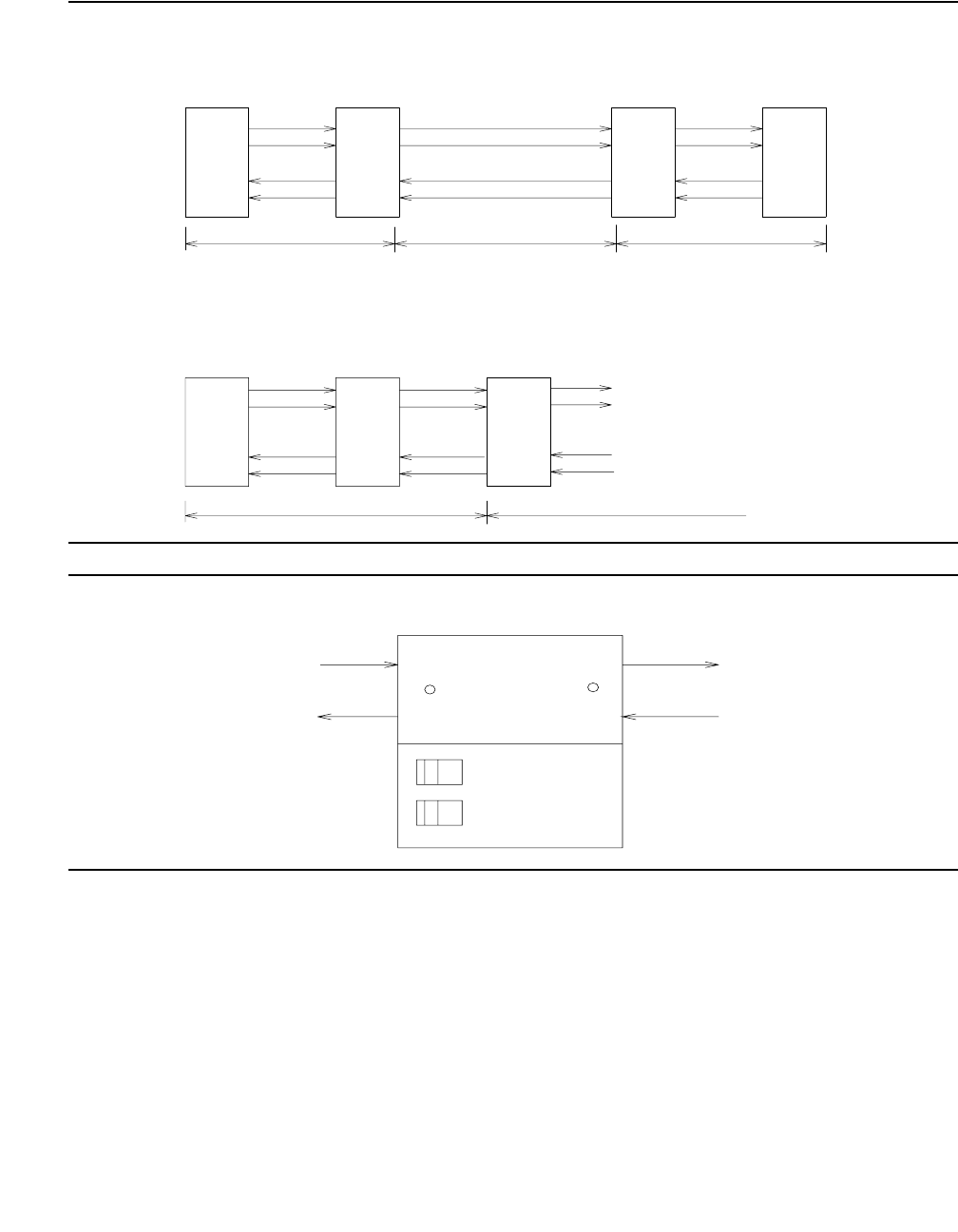
Communication Manager Maintenance-Object Repair Procedures
1068 Maintenance Procedures for Avaya Communication Manager 3.0, Media Gateways and Servers
Figure 51: DS1 Facility Connections
Figure 52: Typical CSU Maintenance Capabilities
DS1CONV
B
CPE CPE
CSU
ACSU
BA
D
S1CONV
Network/DS1 Facility
Network Interface at CSU
Network Interface at Cross Connect Field
T
R
T1
R1
T
R
T1
R1
CPE Network/DS1 Facility
Cross
Connect
Field
D
S1CONV
R1
T1
R
T
CSU
CPE Loopback
Switch
Self Test
Switch
Signal In
Signal In
DS1 Facility Side
CSU
CPE Side
LOS LED
DS1 Facility
Side LOS
LED
Signal Out
Signal Ou
t
CPE Side

DS1-FAC (DS1 Facility)
Issue 1 June 2005 1069
System Technician-Demanded Tests:
Descriptions And Error Codes
Investigate tests in the order presented. By clearing error codes associated with the Failure
Audit, you may clear errors generated from other tests in the sequence. Use test board to
run Failure Audit.
.
Far-End Internal Loop-Back Test (#797)
This test is destructive.
This test starts at the DS1 converter circuit pack whose equipment location was entered and
traverses over the specified facility and loops at the internal facility interface on the other DS1
converter circuit pack in the DS1 converter complex. See the following diagram.
Every part of this test is executed under firmware control and the result is sent back to the
maintenance software. The test is executed by sending digital data through every DS1 channel
on this facility. For TN574 DS1 Converter facilities, test patterns are sent through every DS1
channel. For TN1654 DS1 Converter facilities, test patterns are sent through one DS1 channel.
If there is only one DS1 facility available, the system will not allow that last facility to be busied
out. In that case, the DS1 converter circuit pack must be busied out before executing this test.
For a standard-, duplex-, or high-reliability system (no PNC duplication), if there is only one DS1
facility available, then this test can only be executed at the endpoint that is closer to the media
server relative to the neighbor DS1 converter circuit pack because of its impacts on the system
control links. For TN574 DS1 converter boards, the completion of the test will be delayed in this
configuration to wait for the recovery of the system control links. For a critical-reliability system
(PNC duplication) or for a system with multiple DS1 facilities, the test can be executed at any
DS1 converter circuit pack.
If the test passes on a TN1654 DS1 facility, the round trip delay time appears in milliseconds in
the Error Code field. The round trip delay time is the length of time in milliseconds it takes for
the firmware to receive the test pattern after it has been sent.
Order of Investigation Short Test
Sequence
Long Test
Sequence
External
Loopback
Reset
Sequence
D/ND1
1. D = Destructive; ND = Nondestructive
Failure Audit (#949) ND
DS1 Interface Options Audit
(#798)
XX ND
Far-End Internal Loopback
(#797)
XD
Near-End External
Loopback test (#799)
XD
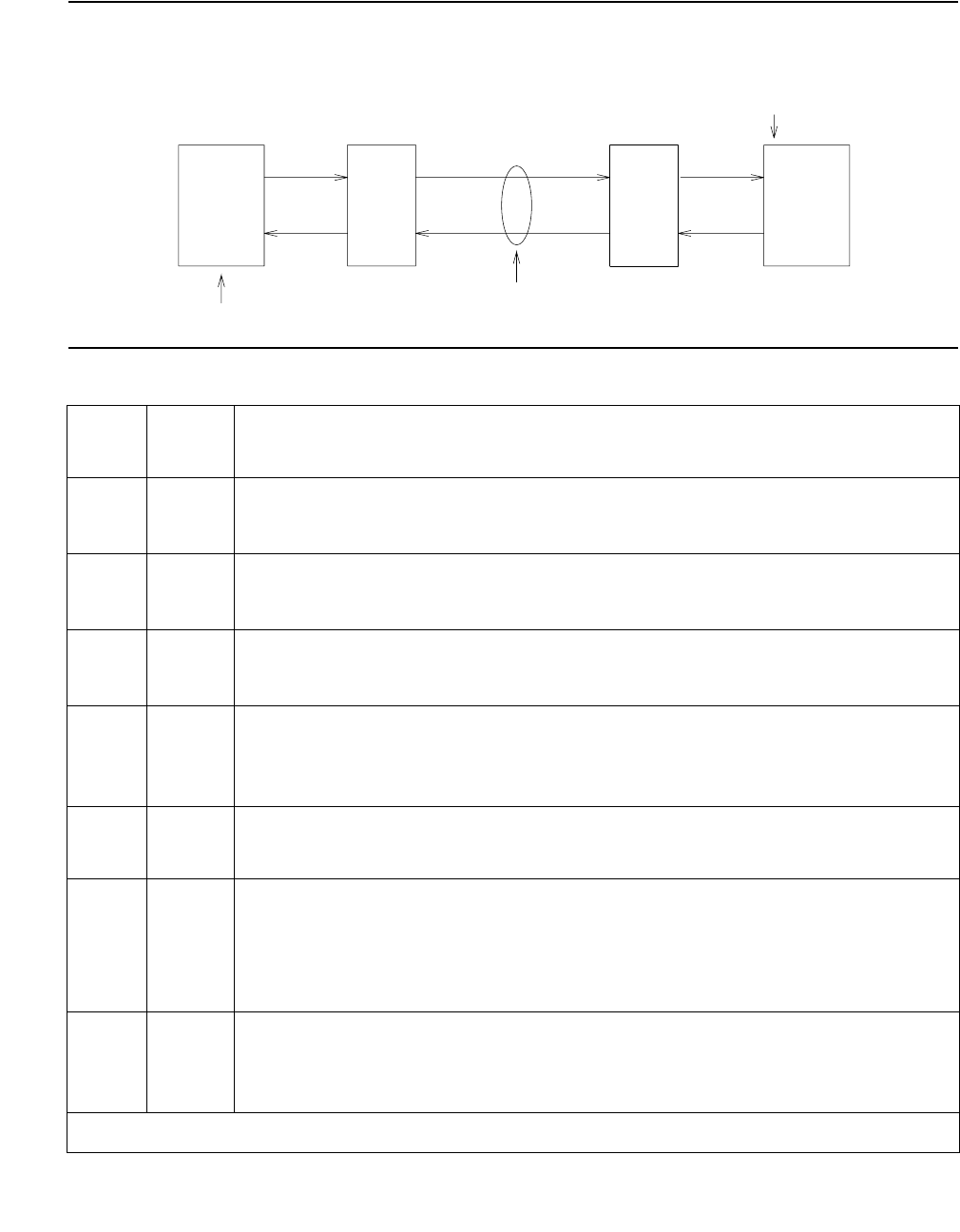
Communication Manager Maintenance-Object Repair Procedures
1070 Maintenance Procedures for Avaya Communication Manager 3.0, Media Gateways and Servers
Figure 53: Far-End Internal Loop-Back Test (#797)
Table 365: Test #797 Far-End Internal Loop-Back Test
Error
Code
Test
Result
Description / Recommendation
2000 ABRT Timed out while waiting for a response from the circuit pack.
1. Retry the command at 1-minute intervals up to 3 times.
2100 ABRT Could not allocate the necessary system resources to run this test.
1. Retry the command at 1-minute intervals up to 3 times.
2300 ABRT The downlink message necessary to run this test could not be sent.
1. Retry the command at 1-minute intervals up to 3 times.
2301 ABRT The timer could not be set before sending the downlink message
necessary to run this test.
1. Retry the command at 1-minute intervals up to 3 times.
2316 ABRT Fiber link is not administered.
●Use add fiber-link to administer the DS1 converter.
2321 ABRT DS1 facility is not busied out.
●Use busyout ds1-facility to busyout the DS1 facility.
●If there is only one DS1 facility, use busyout board to busyout the
DS1 converter circuit pack.
2332 ABRT For this system configuration, test is not allowed to execute at the far end
when there is only one DS1 facility available.
1. Execute the test at the other end of the DS1 converter complex.
1 of 2
DS1 Facility
DS1CONV
A
. . .
.
.
.
.
.
.
.
.
.
.
.
. . .
Loop at internal interfac
e
for the DS1 facility
DS1CONV
B
CSU
B
Test starts here
CSU
A

DS1-FAC (DS1 Facility)
Issue 1 June 2005 1071
2500 ABRT Internal system error
1. Retry the command at 1-minute intervals up to 3 times.
FAIL Far-End Internal loop back failed. A problem exists between DS1 converter
A and DS1 converter B’s internal interface for the DS1 facility (see previous
diagram).
1. If the test is executed as a part of an error analysis, then return back to
the related section.
2. Enter display errors and follow the associated repair procedures
for any on-board DS1C-BD errors on this DS1 converter circuit pack
and the DS1 converter circuit pack at the other end of the DS1
converter complex.
3. If the network is used instead of private T1 lines, verify that the DS1
facility and the network are using the same Line Coding. For TN574
boards and TN1654 boards in T1 mode, also verify that the Framing
Mode used is the same. Use list fiber-link and display
fiber-link to check the values for this DS1 facility. Contact T1
Network Service to check the modes used by the network. See the
previous sections, “Line Coding” and “Framing Mode” for details on
how these options apply to the TN574 and TN1654 DS1 converter
boards.
4. Isolate the problem by running the Near-End External Loopback test
(#799) via test ds1-facility location external-loopback,
first at this end and then at the other end of the DS1 converter complex.
Setup loop backs at different points as shown in the description
diagram for Test #799, and follow repair procedures described for Test
#799.
5. If the problem could not be found by near-end external loop-back tests,
then the fault should be between the CSU A and the CSU B. Contact
T1 Network Service to resolve the problem, also see the repair
procedures for Error Type #1025 (loss of frame alignment).
Any PASS Transmission through the path of the loop back is successful. TN1654 DS1
facilities will display the round trip delay time in milliseconds in the Error
Code field. The round trip delay time is defined as the length of time in
milliseconds it takes for the firmware to receive the test pattern after it has
been sent.
Table 365: Test #797 Far-End Internal Loop-Back Test (continued)
Error
Code
Test
Result
Description / Recommendation
2 of 2

Communication Manager Maintenance-Object Repair Procedures
1072 Maintenance Procedures for Avaya Communication Manager 3.0, Media Gateways and Servers
DS1 Interface Options Audit Test (#798)
This test is nondestructive.
This test sends the administered DS1 Interface options to the DS1 converter circuit pack.
Options are sent to both DS1 converter circuit packs at the same time to prevent any
transitional mismatch of options.
The following DS1 facility options are sent to the TN574 DS1 converter circuit pack: Framing
Mode, Line Coding and DS1 converter-1 and DS1 converter-2 Line Compensation.
The following DS1 facility options are sent to the TN1654 DS1 converter circuit pack: Line
Coding and DS1 converter-1 and DS1 converter-2 Line Compensation (T1 only). These option
fields appear on the Fiber-link Administration screen.
Table 366: Test #798 DS1 Interface Options Audit
Error
Code
Test
Result
Description / Recommendation
105 ABRT The neighbor DS1 converter circuit pack at the other end of the DS1
converter complex is not accessible.
1. Retry the command at 1-minute intervals up to 3 times.
2100 ABRT Could not allocate the necessary system resources to run this test.
1. Retry the command at 1-minute intervals up to 3 times.
2000 ABRT Timed out while waiting for a response from the circuit pack.
1. Retry the command at 1-minute intervals up to 3 times.
2300 ABRT The downlink message necessary to run this test could not be sent.
1. Retry the command at 1-minute intervals up to 3 times.
2301 ABRT The timer could not be set before sending the downlink message
necessary to run this test.
1. Retry the command at 1-minute intervals up to 3 times.
2316 ABRT Fiber link is not administered. Use add fiber-link to administer the
DS1 converter fiber link.
2500 ABRT Internal system error
1. Retry the command at 1-minute intervals up to 3 times.
PASS The DS1 Interface options are sent to the circuit pack.

DS1-FAC (DS1 Facility)
Issue 1 June 2005 1073
Near-End External Loop-Back Test (#799)
This test is destructive.
This test starts at the DS1 converter circuit pack whose equipment location was entered and
traverses over the specified facility and loops back at the manually hard-wired external
loop-back device. Depending on the type of physical connectivity of the DS1 facility, special
tools, cables or connectors may be required to make the hard-wired loop backs.
To isolate a problem, set the loop back first at the loop-back point LB 1, and then at the
loop-back point LB 2, see Figure 54: Loopback Points for Test #799 on page 1074 and
Figure 51: DS1 Facility Connections on page 1068. Place the loop backs at as many points as
your CSU capabilities will allow. Hard-wired loop backs at the far end are not desirable, because
the equalization-level adjustments may cause problems.
Every part of this test is executed under firmware control and the result is sent back to the
maintenance software. The test is executed by sending digital data through every DS1 channel
on this DS1 facility.
This test is executed via test ds1-facility location external-loopback. It is not
part of the long test sequence because it requires modifications to the physical connectivity of
the DS1 facility.
If there is only one DS1 facility available, system will not allow the last facility to be busied out.
In that case, the DS1 converter circuit pack must be busied out before executing this test.
For a standard-, duplex-, or high-reliability system (no PNC duplication), if there is only one DS1
facility available, then this test can only be executed at the endpoint that is closer to the media
server relative to the neighbor DS1 converter circuit pack because of its impacts on the system
control links. For a critical-reliability system (PNC duplication) or for a system with multiple DS1
facilities, the test can be executed at any DS1 converter circuit pack.
If the test passes on a TN1654 DS1 facility, the round trip delay time will be displayed in
milliseconds in the Error Code field. The round trip delay time is defined as the length of time
in milliseconds it takes for the firmware to receive the test pattern after it has been sent. This
measurement is taken on the last DS1 channel tested.
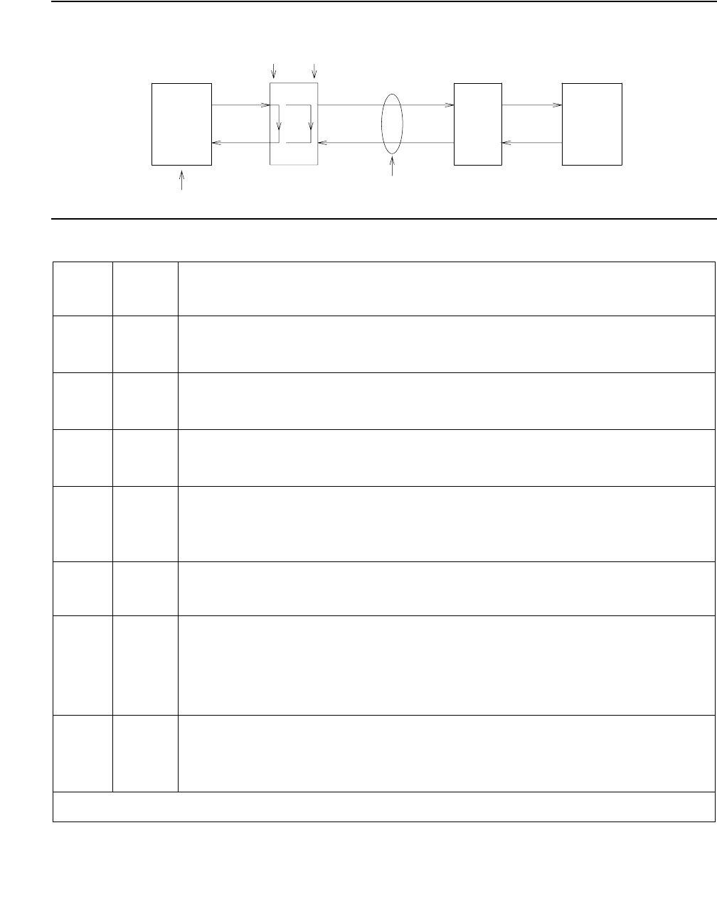
Communication Manager Maintenance-Object Repair Procedures
1074 Maintenance Procedures for Avaya Communication Manager 3.0, Media Gateways and Servers
Figure 54: Loopback Points for Test #799
Table 367: Test #799 Near-End External Loop-Back Test
Error
Code
Test
Result
Description / Recommendation
2100 ABRT Could not allocate the necessary system resources to run this test.
1. Retry the command at 1-minute intervals up to 3 times.
2000 ABRT Timed out while waiting for a response from the circuit pack.
1. Retry the command at 1-minute intervals up to 3 times.
2300 ABRT The downlink message necessary to run this test could not be sent.
1. Retry the command at 1-minute intervals up to 3 times.
2301 ABRT The timer could not be set before sending the downlink message
necessary to run this test.
1. Retry the command at 1-minute intervals up to 3 times.
2316 ABRT Fiber link is not administered.
●Use add fiber-link to administer the DS1 converter fiber link.
2321 ABRT DS1 facility is not busied out.
●Busyout the DS1 facility via busyout ds1-facility.
●If there is only one DS1 facility, busyout the DS1 converter circuit
pack via busyout board.
2332 ABRT With this system configuration, test is not allowed to execute at the far end
when there is only one DS1 facility available. Check the green LED at the
face plate of the DS1 converter circuit pack. The green LED should be on if
the loop is complete.
1 of 2
LB 2
LB 1
DS1 Facility
DS1CONV
A
CSU A
Test starts here
CSU B
DS1CONV
B

DS1-FAC (DS1 Facility)
Issue 1 June 2005 1075
2500 ABRT Internal system error
1. Retry the command at 1-minute intervals up to 3 times.
FAIL Near-end external loop back failed. A problem exists in the path of the loop
back.
1. If the test is executed as a part of an error analysis, then return back to
the related section.
2. Enter display errors and follow the associated repair procedures
for any on-board DS1C-BD errors.
3. If the loop-back point is LB 1, replace connectors and cables between
the DS1 converter A and the CSU A. If the loop-back point is LB 2,
replace CSU A. Also see the repair procedure for Error Type #1025
(loss of frame alignment).
4. If the test still fails, replace DS1 converter A circuit pack.
Any PASS Transmission through the path of the loop back is successful. TN1654 DS1
facilities will display the round trip delay time in milliseconds in the Error
Code field. The round trip delay time is defined as the length of time in
milliseconds it takes for the firmware to receive the test pattern after it has
been sent. This measurement is taken on the last DS1 channel tested.
Table 367: Test #799 Near-End External Loop-Back Test (continued)
Error
Code
Test
Result
Description / Recommendation
2 of 2

Communication Manager Maintenance-Object Repair Procedures
1076 Maintenance Procedures for Avaya Communication Manager 3.0, Media Gateways and Servers
Failure Audit (#949)
This test is nondestructive.
This test queries the DS1 converter circuit pack for any existing circuit pack or facility failures
and any unacknowledged cleared failure messages. Upon receiving the query request, DS1
converter firmware sends failure reports to the maintenance software for every error in its failure
database.
This test operates on both MOs DS1C-BD and DS1-FAC. Error counts of both MOs (DS1C-BD
and DS1-FAC) that are displayed in the error log will be incremented when this test is executed.
This test is executed via test board. The test is also executed internally by the maintenance
software when an alarm is resolved
Table 368: Test #949 Failure Audit
Error
Code
Test
Result
Description / Recommendation
2100 ABRT Could not allocate the necessary system resources to run this test.
1. Retry the command at 1-minute intervals up to 3 times.
2000 ABRT Timed out while waiting for a response from the circuit pack.
1. Retry the command at 1-minute intervals up to 3 times.
2300 ABRT The downlink message necessary to run this test could not be sent.
1. Retry the command at 1-minute intervals up to 3 times.
2301 ABRT The timer could not be set before sending the downlink message
necessary to run this test.
1. Retry the command at 1-minute intervals up to 3 times.
2316 ABRT Fiber link is not administered.
●Use add fiber-link to administer the DS1 converter fiber link.
2500 ABRT Internal system error
1. Retry the command at 1-minute intervals up to 3 times.
FAIL The DS1 converter circuit pack reported failures or retransmitted a cleared
failure message.
1. Enter display errors and follow the associated repair procedures
for any DS1C-BD and DS1-FAC errors.
PASS The DS1 converter circuit pack has no failures.
DS1C-BD
Issue 1 June 2005 1077
DS1C-BD
S8700 MC only
Also called DS1 Converter
The DS1 converter complex is part of the port-network connectivity (PNC) consisting of two
TN574 DS1 Converter or two TN1654 DS1 Converter circuit packs connected by one to four
DS1 facilities. It is used to extend the range of the 32-Mbps fiber links that connect PNs to the
Center Stage Switch, allowing PNs to be located at remote sites.
The TN1654 DS1 Converter Circuit pack is a redesign of the TN574 DS1 Converter board. The
TN1654 provides functionality equivalent to the TN574 but also adds a 32-channel E1 interface
for international support as well as circuit-switched wideband connections (NxDS0). The
TN1654 is supported beginning with DEFINITY Release 5r.
Every error condition reported by the firmware is associated with background tests that the
firmware runs autonomously. Demand tests that are executed by the maintenance software do
not cause any new error generation by the firmware. However, Failure Audit test (#949) affects
auditing of the software error log by forcing the firmware to report the pending errors again.
Maintenance of the DS1 facilities themselves is covered under the “DS1-FAC” MO.
The DS1 converter complex can extend a fiber link between two EIs or between a PN EI and an
SNI. Fiber links between two SNIs or between a PN and the Center Stage Switch (CSS) cannot
be extended.
The TN1654 board is not compatible with the TN574 board. A DS1 converter complex may
consist of two TN574 boards or two TN1654 boards, but a TN574 cannot be combined with a
TN1654 in the same complex. A system with multiple DS1 converter-remoted PNs may contain
DS1 converter complexes of both types, TN1654 board-pairs and TN574 board-pairs.
Critical-reliability configurations with a pair of DS1 converter complexes serving an PN require
identical board pairs and facilities. For example, a TN574 complex and a TN1654 complex may
not be used together to serve the same PN in a critical-reliability configuration.
DS1 converter circuit packs connect to TN570 Expansion Interface (EI) circuit packs and TN573
Switch Node Interface (SNI) circuit packs via metallic cables as shown in Figure 55: DS1
converter connection to EIs and SNIs on page 1078. A fiber link cable can be used instead of
the metallic cable if it is necessary to locate the DS1 converter far from the connected EI or SNI
circuit pack, for example, in an adjacent cabinet.
MO Name in
Alarm Log
Alarm
Level
Initial SAT Command to Run Full Name of MO
DS1C-BD MAJ test board location sh r 1 DS1 converter circuit pack
DS1C-BD MIN test board location sh r 1 DS1 converter circuit pack
DS1C-BD WRN test board location sh r 1 DS1 converter circuit pack
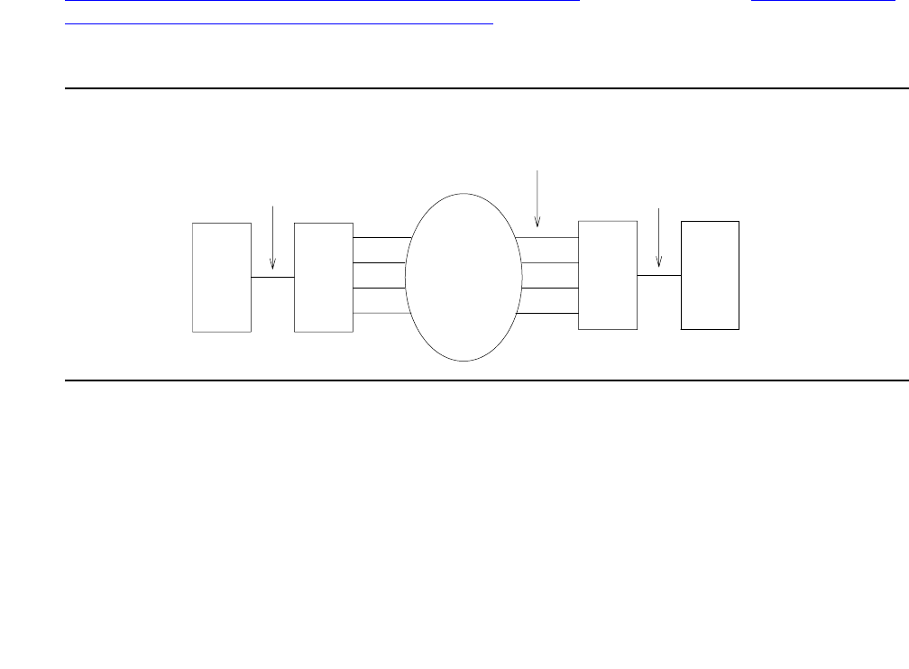
Communication Manager Maintenance-Object Repair Procedures
1078 Maintenance Procedures for Avaya Communication Manager 3.0, Media Gateways and Servers
The DS1 converter circuit pack can be placed in any regular slot in a PN carrier. However, the
DS1 converter circuit pack can only be placed in slots 1 and 21 in a Switch Node (SN) carrier.
The DS1 converter circuit pack is not connected to the TDM bus or the SN backplane.
Communication to the circuit pack is done through the connected EI or the SNI circuit packs.
Therefore, there is considerable interaction between the DS1 converters and the connected EIs
and the SNIs. A special “Y” cable connects the DS1 converter circuit pack to the Fiber Endpoint
and to the facilities.
Note:
Note: The two DS1 converter boards, TN1654 and TN574, use unique “Y” cables that
are incompatible with each other.
The TN573 SNI circuit pack is incompatible with the TN1654 board. A TN573B (or
higher-suffixed) SNI board must be used when connecting to a TN1654 board. The TN573B
SNI board is fully backward compatible with the TN573 board and can be connected to either
TN1654 or TN574 boards.
Note:
Note: A TN573B (or higher-suffixed) board must be used when connecting a SNI board
to a TN1654 board. Error 125 will be logged and an on-board minor alarm will be
generated against the SNI board if it is incompatible with the TN1654 circuit pack.
Figure 56: DS1 converter Complex in Direct Connect PNC on page 1079 and Figure 57: DS1
Converter Complex in Duplicated PNC with 1 SN on page 1080 show DS1 converter
connections in a direct-connect PNC configuration and between the CSS and an PN in a
critical-reliability system configuration (duplicated PNC).
Figure 55: DS1 converter connection to EIs and SNIs
Metallic or Fiber Connection
DS1CONV
DS1 Facilities
Network
EI
or
SNI
EI
DS1CONV
Metallic or Fiber Connection
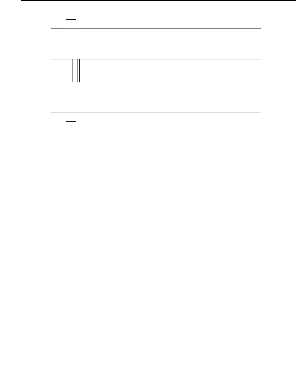
DS1C-BD
Issue 1 June 2005 1079
Figure 56: DS1 converter Complex in Direct Connect PNC
DS1 Facilities
I
E
D
S
1
C
O
N
V
D
S
1
C
O
N
V
I
E
Metallic or Fiber Connection
Remote EPN
PPN
Metallic or Fiber Connection
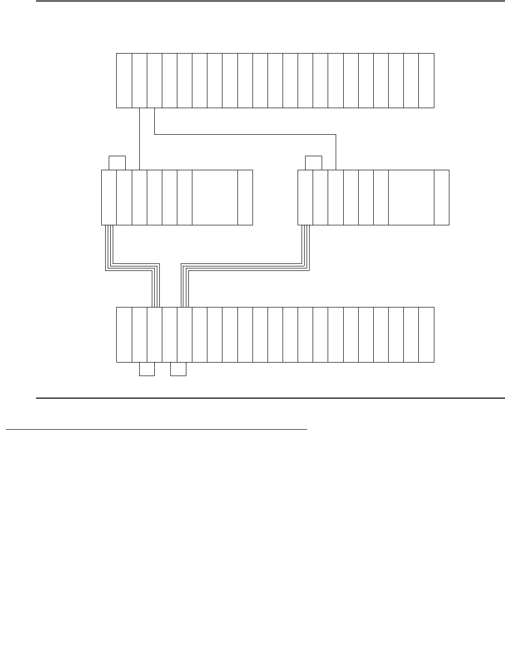
Communication Manager Maintenance-Object Repair Procedures
1080 Maintenance Procedures for Avaya Communication Manager 3.0, Media Gateways and Servers
Figure 57: DS1 Converter Complex in Duplicated PNC with 1 SN
DS1 Converter Administration and Board Insertion
Board insertion is the detection of a circuit pack by the system. The DS1 converter circuit pack
will not be inserted unless the circuit pack type, TN574 or TN1654, is entered into the
associated field in circuit pack administration screen. The Fiber Endpoint (the EI or the SNI)
must also be inserted and be operational for the DS1 converter circuit pack to function.
Fiber link administration must be completed before the DS1 converter maintenance can be
operational. Fiber links are administered via add fiber-link. Fiber Endpoints, DS1
converter circuit pack locations and DS1 facility options are entered as a part of the fiber link
administration.
Metallic
or Fiber
Connection
Fiber Link
E
I
E
I
PPN
. . .
I
N
S
D
S
1
C
O
N
V
. . .
I
S
N
I
S
N
I
S
N
D
S
1
C
O
N
V
E
I
Metallic or Fiber Connection
EPN
DS1 Facilities
DS1 Facilities
SN B-PNC
SN A-PNC
D
S
1
C
O
N
V
E
I
D
S
1
C
O
N
V
Metallic
or Fiber
Connection
Fiber Link

DS1C-BD
Issue 1 June 2005 1081
To administer a standard-, duplex-, or high-reliability system (no PNC duplication):
1. Administer carriers via add/change cabinet.
2. Administer circuit packs via change circuit-pack.
3. Administer connectivity and the facility options of the DS1 converter complex via add/
change fiber-link.
To administer a critical-reliability system (PNC duplication):
1. Enable PNC duplication feature using the change system-parameter
customer-option.
2. Administer carriers via add/change cabinet.
3. Administer circuit packs via change circuit-pack.
4. Administer connectivity and the DS1 facility options of each DS1 converter complex via
add/change fiber-link.
5. Turn on PNC duplication via change system-parameter duplication.
TN1654 Board Configuration Switch Settings
The TN1654 DS1 converter circuit pack is field configurable for T1 or E1 operation so that a
single board serves worldwide application. All four DS1 facilities are configured to either T1 or
E1 as a group via an option switch located on the component side of the circuit pack. If T1
operation is selected, four additional switches are used to select the framing mode for each
facility. Each facility can be set to either D4 or ESF framing. If E1 operation is selected, the
same four switches are used to select the E1 facility line termination impedance. The E1 line
termination impedance for each facility can be set to either 120Ω for twisted-pair or 75Ω for
coaxial wiring.
T1 or E1 operation must also be administered for the TN1654 DS1 converter board on the
fiber-link screen via the Bit Rate field. An error will be logged and an alarm will be raised if
there is a T1/E1 inconsistency between the administered bit rate and the board option switch
setting.
The T1 facility framing mode and the E1 facility line termination impedance are defined by the
option switch settings only. Administration of these values is not allowed. The fiber-link screen
will display the selected option switch settings for each facility.
DS1 Converter LEDs
The TN574 board has seven LEDs on its faceplate. The TN1654 board has eleven LEDs on its
faceplate. The top three system standard LEDs are used to provide an indication of the state of
the DS1 converter board. These LEDs are under firmware control until the board has
established a link to the media server via the EI or SNI. Once the link is established, software
controls the three LEDs. If the link breaks, the LEDs are again under firmware control.

Communication Manager Maintenance-Object Repair Procedures
1082 Maintenance Procedures for Avaya Communication Manager 3.0, Media Gateways and Servers
The red and green LEDs have the traditional use where red means an alarm condition and
green indicates that maintenance testing is in progress. The red and green LED is also turned
on during circuit pack initialization by firmware. When the control link to the circuit pack is lost,
firmware controls the red LED to indicate an alarm condition.
The amber LED under firmware control is used to indicate the state of the:
●Physical fiber interface
●Fiber channel (link to EI or SNI)
●DS1 control channel (link to opposite DS1 converter board)
●Server communications link
in the following manner and descending order of priority. (The amber LED stays lit longer as the
DS1 converter complex approaches full operation.)
1. If the fiber is out of frame or is in a loss-of-signal condition, the amber LED will flicker at a
5-Hz rate (on for 0.1 second, off for 0.1 second).
2. If the fiber channel is down (DS1 Converter circuit pack/fiber endpoint communications), the
amber LED will flash at a 1-Hz rate (on for ½ second, off for ½ second).
3. If the DS1 control channel is down between the two DS1 converters in the DS1 converter
complex, the amber LED will pulse at a 1/2-Hz rate (on for 1 second, off for 1 second).
4. If the media server communications link is down, the amber LED will wink off every 2
seconds for 200 msec (2 seconds on, 0.2 second off).
5. If all is well with the Fiber Interface and every communications channel, the amber LED will
remain on continuously in a standard-, duplex-, or high-reliability system. In a
critical-reliability system (duplicated PNC):
- An active DS1 converter circuit pack’s amber LED remains on continuously.
- A standby DS1 converter circuit pack’s amber LED remains off.
The LED will then be under software control.
The bottom four green LEDs on the TN574 DS1 converter board are under hardware control.
The four green LEDs indicate, for each DS1 converter facility, whether a receive signal is
present for the DS1 facility.
The next four LEDs on the TN1654 DS1 converter board are labeled STATUS LEDs and are for
future use. These LEDs will not be lit.
The bottom four LEDs on the TN1654 board are labeled SPAN LEDs. These LEDs are under
firmware control. If the facility is not administered, then the LED is not lit. The LED is lit amber if
the facility is running alarm free. If the facility is detecting either a red alarm (loss-of-signal or
loss-of-frame), a yellow alarm (remote frame alarm) or a blue alarm (AIS signal) then the LED is
lit red. The SPAN SELECT Switch on the TN1654 faceplate is for future use. Pushing the switch
will have no affect on the board.

DS1C-BD
Issue 1 June 2005 1083
Clear Firmware-Counters Command
DS1 converter firmware generates error reports autonomously. This takes place independently
of technician-demanded tests. The test board location clear command will not affect
the error status reported by firmware. The clear firmware-counters command clears
every on-board firmware-detected error unconditionally.
The clear firmware-counters location command sends a downlink message to the
DS1 converter circuit packs, causing them to clear out their firmware error counters and failure
databases. Once the firmware failure database is cleared, the failure audit test (#949) will pass.
If problems still exist, the firmware will increment its error counters and the failure audit test will
begin failing again.
This command should not be used as a replacement for the repair procedures associated with
the hardware error log entries. This command may be useful if a problem has been fixed and
off-board alarms associated with the problem are still active.
Downtime Required when Upgrading to
TN1654 DS1 Converter Circuit Packs
!WARNING:
WARNING: Upgrading from TN574 DS1 converter circuit packs to TN1654 DS1 converter
circuit packs will require down time for the affected PN.
The TN1654 DS1 Converter circuit pack is not compatible with the TN573 SNI circuit pack, the
TN574 DS1 converter board, the Y-cable used to connect to the TN574 DS1 converter board or
pre-G3V5 software. All DS1 converter boards and Y-cables must be upgraded. If the PN is
remoted via a Center-Stage Switch, the connected SNI must also be upgraded. A TN573B (or
higher-suffixed) SNI board must be used when connecting to a TN1654 DS1 converter board.
Use remove fiber-link to remove the fiber-link administration for the TN574 DS1
converter complex. Use change circuit-pack show that TN1654 boards are now being
used. Then use add fiber-link to administer the TN1654 DS1 converter complex.

Communication Manager Maintenance-Object Repair Procedures
1084 Maintenance Procedures for Avaya Communication Manager 3.0, Media Gateways and Servers
Replacing a DS1 Converter Circuit Pack with
the Same Type DS1 Converter Circuit Pack —
Unduplicated PNC
!WARNING:
WARNING: Do not power down a Switch Node carrier to replace a circuit pack.
!WARNING:
WARNING: Replacing a Switch Node Interface, Switch Node Clock, Expansion Interface or
DS1 Converter circuit pack on an unduplicated system disrupts service. The
service effect can range from outage of a single PN to outage of the entire
system.
!WARNING:
WARNING: A DS1 Converter complex must consist of two TN574 boards or two TN1654
boards. A TN574 cannot be combined with a TN1654 in the same DS1 converter
complex.
Steps Comments
Enter busyout board location. location represents the cabinet-carrier-slot address of
the circuit pack to be replaced.
Replace the circuit pack with the same
DS1 converter board type.
Wait for the circuit pack to reset. Red and green LEDs will light and then go out.
Enter release board location CAUTION: Do not busyout any Expansion Interface
circuit packs after this point.
Enter test alarms long clear
for category exp-intf.
Wait 5 minutes for SNI-BD, FIBER-LK,
and DS1C-BD alarms to clear, or
enter clear firmware-counters
a-pnc.

DS1C-BD
Issue 1 June 2005 1085
Replacing a DS1 Converter Circuit Pack with
the Same Type DS1 Converter Circuit Pack—Duplicated
PNC
!WARNING:
WARNING: On a system with duplicated PNC, synchronization may be provided over a
combination of active and standby components. This condition is indicated by an
OFF-BOARD WRN alarm against TDM-CLK with Error Type #2305. Repairs to
standby PNC in this state may disrupt service. Otherwise, if the active PNC is
functional, replacement of a standby component will not disrupt service.
!WARNING:
WARNING: Do not power down a Switch Node carrier to replace a circuit pack.
Steps Comments
Enter status pnc. Verify that the component to be replaced is on the
standby PNC.
Enter busyout pnc.
Enter busyout board location. location represents the cabinet-carrier-slot address
of the circuit pack to be replaced.
Replace the circuit pack with the same
DS1 converter board type.
Enter release board location.CAUTION: Do not busyout any Expansion
Interface circuit pack after this point.
Enter test alarms long clear for
category exp-intf.
Wait 5 minutes for SNI-BD, SNI-PEER,
FIBER-LK, and DS1C-BD alarms to
clear, or enter clear
firmware-counters <a-pnc or
b-pnc>.
Use the letter designation of the pnc that holds the
replaced component (the standby pnc).
Enter status pnc. If either PNC’s state of health is not “functional”,
consult the PNC-DUP section of the Maintenance
Manual.
Enter release pnc.

Communication Manager Maintenance-Object Repair Procedures
1086 Maintenance Procedures for Avaya Communication Manager 3.0, Media Gateways and Servers
!WARNING:
WARNING: Replacing a Switch Node Interface, Switch Node Clock, Expansion Interface or
DS1 Converter circuit pack on an unduplicated system disrupts service. The
service effect can range from outage of a single PN to outage of the entire
system.
!WARNING:
WARNING: A DS1 Converter complex must consist of two TN574 boards or two TN1654
boards. A TN574 cannot be combined with a TN1654 in the same DS1 converter
complex.
!WARNING:
WARNING: The two DS1 converter boards, TN1654 and TN574, use unique “Y” cables that
are incompatible with each other.
!WARNING:
WARNING: A TN573B (or higher-suffixed) board must be used when connecting a SNI board
to a TN1654 DS1 Converter board.
Steps Comments
Enter list fiber-link Determine the fiber-link number associated with the
two TN574 circuit packs to be upgraded.
Enter busyout fiber-link
fiber#
Fiber# represents the fiber-link number associated
with the TN574 DS1 converter complex that is being
upgraded to a TN1654 DS1 converter complex.
Enter remove fiber-link fiber#
Remove the TN574 DS1 converter
circuit packs from the system.
Replace the TN574 Y-cables with
TN1654 Y-cables.
Replace the removed TN574 DS1
converter circuit packs with TN1654
DS1 converter circuit packs. Prior to
installing the TN1654 boards, review
the prior section, TN1654 Board
Configuration Switch Settings.
If a TN1654 DS1 converter board is
connected to an SNI board, upgrade
the SNI to a TN573B or greater.
Wait for the circuit packs to reset Red and green LEDs will light and then go out.
1 of 2

DS1C-BD
Issue 1 June 2005 1087
Upgrading TN574 DS1 Converter Circuit Packs
in a Fiber-Link to TN1654s — Duplicated PNC
!WARNING:
WARNING: Do not power down a Switch Node carrier to replace a circuit pack.
!WARNING:
WARNING: In duplicated PNC configurations, one DS1 converter complex in the fiber-link
serves as the active and the second DS1 converter complex serves as the
standby. Each DS1 Converter complex consists of two TN574 boards or two
TN1654 boards. A TN574 cannot be combined with a TN1654 in the same DS1
converter complex. It is also required that all four DS1 converter boards and
interconnecting facilities that serve an PN be of the same type. Note, however,
that TN574 and TN1654 boards can coexist within the same system, they just
cannot be in the same fiber-link.
!WARNING:
WARNING: The two DS1 converter boards, TN1654 and TN574, use unique “Y” cables that
are incompatible with each other.
!WARNING:
WARNING: A TN573B (or higher-suffixed) board must be used when connecting a SNI board
to a TN1654 DS1 Converter board.
Enter change circuit-packs
cabinet #. Update the screen to
show that TN1654 boards are now
being used instead of TN574 boards.
Also update the connected SNI, if
applicable, to suffix B.
Cabinet # represents the cabinet associated with a
DS1 converter board. The change circuit-packs
screen needs to be updated for both DS1 converter
boards. Also, if needed, re-add translations for
connected EI boards.
Enter add fiber-link fiber# to
re-add the fiber-link using TN1654 DS1
converter circuit packs.
Fiber# represents the fiber-link number associated
with the TN574 DS1 converter complex that is being
upgraded to a TN1654 DS1 converter complex
Enter test alarms long clear
for category exp-intf.
Wait 5 minutes for SNI-BD, FIBER-LK
AND DS1C-BD alarms to clear, or
enter clear firmware-counters
a-pnc
Steps Comments
2 of 2

Communication Manager Maintenance-Object Repair Procedures
1088 Maintenance Procedures for Avaya Communication Manager 3.0, Media Gateways and Servers
Table 369: Upgrading TN574 DS1 Converter Circuit Packs in a fiber-link to TN1654s —
Duplicated PNC
Steps Comments
Enter status pnc. Verify that the A-PNC is active. If the B-PNC is
active, enter the reset pnc interchange command to
cause the A-PNC to go active.
Enter busyout pnc-standby. Fiber link cannot be removed if PNC duplication is
operational. Must busyout the standby PNC first.
Enter change system-parameters
duplication. Change the Enable
Operation of PNC Duplication
field to n.
Disable PNC duplication.
Enter list fiber-link. Determine the fiber-link number that the four
TN574 circuit packs to be upgraded are associated
with.
Enter busyout fiber-link
fiber#.
fiber# represents the fiber-link number
associated with the TN574 DS1 converter
complexes that are being upgraded to TN1654
DS1 converter complexes.
Enter remove fiber-link fiber#.
Remove the four TN574 DS1 converter
circuit packs from the system.
Replace the TN574 Y-cables with
TN1654 Y-cables.
Replace the removed TN574 DS1
converter circuit packs with TN1654
DS1 converter circuit packs. Prior to
installing the TN1654 boards, review the
prior section, TN1654 Board
Configuration Switch Settings.
If a TN1654 DS1 converter board is
connected to an SNI board, upgrade the
SNI to a TN573B or greater.
Wait for the circuit packs to reset. Red and green LEDs will light and then go out.
Enter change circuit-packs
cabinet#. Update the screen to show
that TN1654 boards are now being used
instead of TN574 boards. Also update
the connected SNI, if applicable, to
suffix B.
cabinet# represents the cabinet associated with
a DS1 converter board. The change circuit-packs
screen needs to be updated for all four DS1
converter boards. Also, if needed, re-add
translations for connected EI boards.
1 of 2

DS1C-BD
Issue 1 June 2005 1089
Enter change system-parameters
duplication. Enter y in Enable
Operation of PNC Duplication
field.
Enable PNC duplication.
Enter add fiber-link fiber# to
re-add the fiber-link using TN1654 DS1
converter circuit packs.
fiber# represents the fiber-link number
associated with the TN574 DS1 converter
complexes that are being upgraded to TN1654
DS1 converter complexes.
Enter test alarms long clear for
category exp-intf.
Wait 5 minutes for SNI-BD, SNI-PEER,
FIBER-LK and DS1C-BD alarms to
clear, or enter clear
firmware-counters a-pnc |
b-pnc.
Enter status pnc. If either PNC’s state of health is not “functional”,
consult the PNC-DUP section of the Maintenance
Manual.
Table 369: Upgrading TN574 DS1 Converter Circuit Packs in a fiber-link to TN1654s —
Duplicated PNC (continued)
Steps Comments
2 of 2

Communication Manager Maintenance-Object Repair Procedures
1090 Maintenance Procedures for Avaya Communication Manager 3.0, Media Gateways and Servers
Converting DS1-CONV Complex to Direct-
Connect Fiber (duplicated PNC)
Note:
Note: The following procedure is generic in its scope. Check the customer’s switch
configuration for EI/SNI structures.
!WARNING:
WARNING: Do not power down a Switch Node carrier to replace a circuit pack.
!WARNING:
WARNING: In duplicated PNC configurations, one DS1-CONV complex in the fiber-link
serves as the active and the second DS1-CONV complex serves as the standby.
Each DS1 Converter complex consists of two TN574 or TN1654 circuit packs.
Table 370: Convert from DS1-CONV to direct-connect fiber in a duplicated PNC
Step Command/Step Description
1.
status pnc Verify that the A-side is active.
●If the B-PNC is active, enter reset
pnc-interchange and press Enter.
●Then verify that the A-side is active
(status pnc).
2. busyout pnc-standby Busyout the duplicated switch side.
3. change system-parameters
duplication
Disable PNC duplication by changing the
Enable Operation of PNC Duplication
field to n.
4. list fiber-link Lists administered fiber connections by number.
Select the link number associated with the
DS1-CONV complex that you are removing.
5. busyout fiber link n Busyout the fiber link of interest. The fiber link
number (step 6) is n for this command.
6. remove fiber link nRemove the link administration for this link.
7. change circuit-pack
cabinet
Remove the DS1-CONV administration for the
four designated circuit packs (cabinet is the
cabinet number where these DS1-CONV
complexes reside).
Press Enter.
1 of 2

DS1C-BD
Issue 1 June 2005 1091
8. Remove the DS1- CONV
hardware.
Remove the 4 TN574 or TN1654 DS1-CONV
circuit packs and Y-cables.
The TN1654 and TN574 DS1-CONV boards use
unique “Y” cables that are incompatible with
each other. Reuse these cables only with the
proper circuit pack.
9. Install fiber-optic cable. Add the lightwave transceivers (multimode
9823A or single-mode 300A) to match the
lightguide fiber. Add these to the EIs and SNIs
formerly connected to the DS1 converter circuit
packs. Connect the lightwave transceivers with
lightguide fiber.
10. Check fiber-optic cable
connections.
Ensure that the fiber-optic cables are securely
connected to the lightwave transceivers that are
attached to the designated circuit packs through
the connections on the back of the cabinet.
11. add fiber-link nAdminister the new EI/SNI fiber connection.
12. change system-parameters
duplication
Enable PNC duplication by changing the
Enable Operation of PNC Duplication
field to y.
13. Enter test alarms long
clear for category exp-intf.
14. Wait 5 minutes. SNI-BD, SNI-PEER, FIBER-LK and EXP-INTF
MOs need time to clear (or enter clear
firmware-counters a-pnc or b-pnc)
15. Enter status pnc. If either PNC’s state of health is not
functional, consult the PNC-DUP MO.
Table 370: Convert from DS1-CONV to direct-connect fiber in a duplicated PNC
Step Command/Step Description
2 of 2

Communication Manager Maintenance-Object Repair Procedures
1092 Maintenance Procedures for Avaya Communication Manager 3.0, Media Gateways and Servers
Removing Fiber Connectivity to an PN
This procedure covers removing the connectivity to an PN or between SNs. Removing an PN
and its associated carrier and circuit packs can be handled on a board-type basis.
If this system is duplicated, start with step 1; otherwise, start with step 6.
Note:
Note: The following procedure is generic in its scope. Check the customer’s switch
configuration for EI/SNI structures.
!WARNING:
WARNING: Do not power down a Switch Node carrier to replace a circuit pack.
!WARNING:
WARNING: In duplicated PNC configurations, one DS1-CONV complex in the fiber-link
serves as the active and the second DS1-CONV complex serves as the standby.
Each DS1Converter complex consists of two TN574 or TN1654 circuit packs.
Table 371: Removing Fiber Connectivity from a PN
Step Command/Step Description
1. status pnc Verify that the A-side is active.
1. If the B-PNC is active, enter reset
pnc-interchange and press Enter.
2. Verify that the A-side is active (status
pnc).
3. busyout pnc standby Busyout the duplicated switch side.
4. change system-parameters
duplication
Disable PNC duplication by setting the
Enable Operation of PNC
Duplication field to n.
5. list fiber-link List administered fiber connections by
number. Record the endpoints (EIs, SNIs,
and DS1Cs), and fiber link numbers that you
are removing.
6. busyout fiber-link nBusyout the fiber link of interest. The fiber link
number (step 4) is n for this command.
7. remove fiber- link nRemove the link administration for this link.
1 of 2

DS1C-BD
Issue 1 June 2005 1093
Downgrading from Critical to High Reliability
The strategy this downgrade follows is to change from critical to high reliability. High reliability is
actually duplication of the media server, control network, and IPSIs without duplicate paths from
IPSIs to CSS.
8. change system-parameters
duplication
Enable PNC duplication by changing the
Enable Operation of PNC
Duplication field to y.
9. Physically remove the a-pnc and
b-pnc fiber endpoint circuit packs
Physically remove EI, SNI, and DS1C circuit
packs associated with the b-pnc.
10. change circuit-pack Un-administer the PNC circuit packs.
11. clear firmware Clear any alarms or errors against those
circuit packs.
12. status pnc Use status pnc to ensure that the PNC is
in good health.
Table 371: Removing Fiber Connectivity from a PN (continued)
Step Command/Step Description
2 of 2
Table 372: Downgrading from Critical to High Reliability
Step # Command/Step Description
1.
status pnc Check to see if A-side is active. If not:
1. Resolve any alarms against a-pnc.
2. reset pnc-interchange to activate
a-pnc.
3. busyout pnc-standby Busyout the standby PNC.
4. change system-parameters
duplication
Disable PNC duplication by setting the
Enable Operation of PNC
Duplication field to n.
5. list fiber-link Lists administered fiber connections by
number.
1 of 2

Communication Manager Maintenance-Object Repair Procedures
1094 Maintenance Procedures for Avaya Communication Manager 3.0, Media Gateways and Servers
!CAUTION:
CAUTION: The removal of hardware and fiber cable will interrupt service.
Note:
Note: At this point in the downgrade procedure, the system is in unduplicated mode and
is operational. The physical removal of the SN carriers may be done at a time that
is convenient for the customer. The next step in the downgrade is to follow the
normal upgrade procedures from standard to high reliability.
6. change fiber-link nChange fiber removes the b-pnc endpoints
(EI, DS1Cs, if equipped). n is the number of
the fiber from step 4. Repeat this step for
every fiber from step 4.
7. Physically remove the b-pnc
endpoint circuit packs
Start with the switch carrier most distant from
the media server. Physically remove EI, SNI,
and SNC circuit packs associated with the
b-pnc.
Remove fiber cable not used for b-pnc
carriers. See the following CAUTION.
8. change circuit-packs Update the translations for the removed circuit
packs using change circuit-packs for
the:
●Cabinet with b-pnc SN carrier
-SNIs
- SNCs
- EIs and DS1Cs, if any
●Cabinet with b-pnc SN carrier
- DS1Cs from port carrier
●Cabinet with b-pnc EIs in every PN
(also DS1Cs, if equipped)
9. change cabinet UU Remove the b-pnc SN carrier.
10. Disable duplication. Obtain a license file to disable PNC
duplication.
Table 372: Downgrading from Critical to High Reliability (continued)
Step # Command/Step Description
2 of 2

DS1C-BD
Issue 1 June 2005 1095
Error Log Entries and Test to Clear Values
Table 373: DS1 Converter Board Error Log Entries
Error
Type
Aux
Data
Associated Test Alarm
Level
On/Off
Board
SAT Test to Clear Value
0 (a) 0 Any Any Any test board location sh r 1
1 (b) Failure Audit test
(#949)
MAJ ON/
OFF test board location sh r 1
18 (c)0busyout board
UCSS
WRN OFF release board UCSS
125 (d) 3 None MIN ON
218 (e) any None MAJ ON
257 (f) Failure Audit test
(#949)
MIN ON test board location sh r 1
513 (g) 1 Failure Audit test
(#949)
MAJ ON test board location sh r 1
513 (h) 2 Failure Audit test
(#949)
MAJ ON test board location sh r 1
513 (i) 3 Failure Audit test
(#949)
MAJ ON test board location sh r 1
513 (j) 4 Failure Audit test
(#949)
MAJ ON test board location sh r 1
513 (k) 5 Failure Audit test
(#949)
MAJ ON test board location sh r 1
769 (l) 1 Failure Audit test
(#949)
MIN ON/OFF test board location sh r 1
769 (m) 2 Failure Audit test
(#949)
MIN ON/OFF test board location sh r 1
769 (n) 3 Failure Audit test
(#949)
MIN ON/OFF test board location sh r 1
769 (o) 5 Failure Audit test
(#949)
MIN ON/OFF test board location sh r 1
769 (p) 6 Failure Audit test
(#949)
MIN ON test board location sh r 1
1 of 2

Communication Manager Maintenance-Object Repair Procedures
1096 Maintenance Procedures for Avaya Communication Manager 3.0, Media Gateways and Servers
Notes:
When problems persist, resetting the DS1 converter circuit pack via reset board may
temporarily resolve the error condition and restore service until further assistance is provided.
a. Error Type 0: Run the short test sequence first. If every test passes, run the long test
sequence. Refer to each test’s description, and follow its recommended procedures.
b. Error Type 1: If the alarm is on board, then a major hardware error has occurred in a
common part of the circuit pack, not circuit or packet specific. Replace the DS1 converter
circuit pack.
If the alarm is off board, then either a major hardware error has occurred in a common part
of the circuit pack, or a good clock signal cannot be recovered from the synchronization
source. The synchronization source can be the fiber link or any one of the DS1 facilities.
1. Enter display errors and follow the associated repair procedures for any SYNC,
TDM-CLK, and SNC-BD errors.
2. Enter display errors and follow the associated repair procedures for any FIBER-LK
and DS1-FAC errors.
3. If the problem persists, replace the DS1 converter circuit pack.
c. Error Type 18: indicates that the DS1 converter circuit pack has been busied out via
busyout board. To resolve this error, release the DS1 converter circuit pack via the
release board.
769 (q) 7 Failure Audit test
(#949)
MIN ON test board location sh r 1
1281(r) Failure Audit test
(#949)
MIN OFF test board location sh r 1
1537 (s) Failure Audit test
(#949)
MAJ OFF test board location sh r 1
1793 (t) Failure Audit test
(#949)
MAJ OFF test board location sh r 1
2049 (u) Failure Audit test
(#949)
MAJ OFF test board location sh r 1
3329 (v) Failure Audit test
(#949)
WRN OFF test board location sh r 1
Table 373: DS1 Converter Board Error Log Entries (continued)
Error
Type
Aux
Data
Associated Test Alarm
Level
On/Off
Board
SAT Test to Clear Value
2 of 2

DS1C-BD
Issue 1 June 2005 1097
d. Error Type 25: The 24/32-channel option switch setting on the TN1654 circuit pack does
not match the administered Bit Rate on the fiber-link screen. If the on-board switch setting is
wrong, the circuit pack must be physically removed to change the setting of the board
option switch. If the administered bit rate is wrong, use change fiber-link to correct it.
e. Error Type 218: The DS1 converter board is physically installed in a slot different than its
administered slot. Remove the DS1 converter board and install it in its administered slot or
execute remove fiber-link followed by add fiber-link to re-add the fiber-link
setting the DS1 converter board’s administered location to the physically installed slot.
f. Error Type 257: A minor hardware error has occurred in a common part of the circuit pack,
not circuit or packet specific. Replace the DS1 converter circuit pack.
g. Error Type 513, Aux Data 1: A major hardware problem has occurred that affects only
circuit data being received from the DS1 converter circuit pack. Replace the DS1 converter
circuit pack.
h. Error Type 513, Aux Data 2: A major hardware problem has occurred that affects only
circuit data being transmitted from the DS1 converter circuit pack. Replace the DS1
converter circuit pack.
i. Error Type 513, Aux Data 3: A major hardware problem has occurred that affects only
packet data being received from the DS1 converter circuit pack. Replace the DS1 converter
circuit pack.
j. Error Type 513, Aux Data 4: A major hardware problem has occurred that affects only
packet data being transmitted from the DS1 converter circuit pack. Replace the DS1
converter circuit pack.
k. Error Type 513, Aux Data 5: A major lightwave transceiver transmit error occurred that
affects data transmitted from the fiber link to the DS1 facility. Replace the DS1 converter
circuit pack.
l. Error Type 769, Aux Data 1: This error only applies to TN574 DS1 converter circuit packs.
If the alarm is on board, then a minor hardware problem has occurred that affects only
circuit data being received from the DS1 converter circuit pack. Replace the DS1 converter
circuit pack.
If the alarm is off board, then either a minor hardware problem has occurred that affects only
circuit data being received into the DS1 converter circuit pack or a good clock signal cannot
be recovered from one of the DS1 facilities.
1. Enter display errors and follow the associated repair procedures for any SYNC,
TDM-CLK, and SNC-BD errors.
2. Enter display errors and follow the associated repair procedures for any DS1-FAC
errors.
3. If the problem persists, replace the DS1 converter circuit pack.

Communication Manager Maintenance-Object Repair Procedures
1098 Maintenance Procedures for Avaya Communication Manager 3.0, Media Gateways and Servers
m. Error Type 769, Aux Data 2: This error only applies to TN574 DS1 converter circuit packs.
If the alarm is on board, then a minor hardware problem has occurred that affects only
circuit data being transmitted from the DS1 converter circuit pack. Replace the DS1
converter circuit pack.
If the alarm is off board, then either a minor hardware problem has occurred that affects only
circuit data being transmitted from the DS1 converter circuit pack or a good clock signal
cannot be recovered from the fiber channel.
1. Enter display errors and follow the associated repair procedures for any SYNC,
TDM-CLK, and SNC-BD errors.
2. Enter display errors and follow the associated repair procedures for any EXP-INTF,
SNI-BD, and FIBER-LK errors.
3. If the problem persists, replace the DS1 converter circuit pack.
n. Error Type 769, Aux Data 3: This error only applies to TN574 DS1 converter circuit packs.
If the alarm is on board, then a minor hardware problem has occurred that affects only
packet data being received from the DS1 converter circuit pack. Replace the DS1 converter
circuit pack.
If the alarm is off board, then either a minor hardware problem has occurred that affects only
packet data being received from the DS1 converter circuit pack or corrupted packets are
being received from the packet facility.
1. Enter display errors and follow the associated repair procedures for any EXP-INTF,
SNI-BD, and DS1-FAC errors.
2. If the problem persists enter display errors and follow the associated repair
procedures for any SYNC, TDM-CLK, and SNC-BD errors.
3. If the problem still persists, replace the DS1 converter circuit pack.
o. Error Type 769, Aux Data 5: If the alarm is on board, then a minor FOI transmit error
occurred that affects data transmitted from the fiber link to the DS1 facility. Replace the DS1
converter circuit pack.
If the alarm is off board, then either a minor FOI transmit error occurred that affects data
transmitted from the fiber link to the DS1 facility. or corrupted packets are being received
from the packet facility.
1. Enter display errors and follow the associated repair procedures for any EXP-INTF,
SNI-BD, and DS1-FAC errors.
2. If the problem persists enter display errors and follow the associated repair
procedures for any SYNC, TDM-CLK, and SNC-BD errors.
3. If the problem still persists, replace the DS1 converter circuit pack.
p. Error Type 769, Aux Data 6: A minor FOI receive error occurred that affects data received
from the DS1 facility and transmitted to the fiber link. Replace the DS1 converter circuit
pack.

DS1C-BD
Issue 1 June 2005 1099
q. Error Type 769, Aux Data 7: A minor on-board hardware failure exists on the processor/
control hardware on the DS1 converter circuit pack. Replace the DS1 converter circuit pack.
r. Error Type 1281: For TN574 DS1 converter boards, this error indicates that the facility
masks or the clock reference masks do not match between the two DS1 converter circuit
packs in the DS1 converter complex.
For TN1654 DS1 converter boards, this error indicates that the facility masks do not match
between the two DS1 converter circuit packs in the DS1 converter complex.
Alarm should clear in 15 minutes.
1. If the problem persists, reset both DS1 converter circuit packs in the DS1 converter
complex via reset board.
2. If the problem persists, replace this DS1 converter circuit pack.
3. If the problem persists, replace the DS1 converter circuit pack at the other end of the DS1
converter complex.
s. Error Type 1537: The two TN574 DS1 converter circuit packs in the DS1 converter
complex do not have the same firmware vintage. The TN574 DS1 converter with the older
vintage should be replaced. This error does not apply to TN1654 boards.
t. Error Type 1793: Fiber Loss of Frame Alignment (LFA) alarm occurred at the other end of
the DS1 converter complex. The DS1 converter circuit pack at the other end of the DS1
converter complex cannot frame up on the signal coming into the circuit pack from the fiber.
(The neighbor DS1 converter circuit pack detected the LFA and relayed this information to
this DS1 converter circuit pack via the DS1 control channel.) The amber LED will flicker at a
5-Hz rate (on for 0.1 second, off for 0.1 second).
1. Execute list fiber-link to determine the Fiber Endpoint that is connected to the
DS1 converter circuit pack. Enter display errors and follow the associated repair
procedures for any EXP-INTF, and SNI-BD errors for the Fiber Endpoints. Enter
display errors and follow the associated repair procedures for any FIBER-LK errors
for this fiber link.
2. If the problem still persists, check for excessive slips and synchronization problems.
Enter display errors and follow the associated repair procedures for any SYNC,
TDM-CLK, and SNC-BD errors.
3. If the problem still persists, run the Far-End DS1 converter Circuit Pack Loopback test
(#788) on this DS1 converter circuit pack via test board location long. This test
indicates if the neighbor DS1 converter circuit pack hardware is functioning. If the test
fails, replace the DS1 converter circuit pack at the other end of the DS1 converter
complex.
4. If the problem still persists, run the Far-End Fiber Optic Terminator (lightwave
transceiver) Loopback test (#789) on this DS1 converter circuit pack via test board
location long. If this test fails, replace the lightwave transceiver that is connected to
the neighbor DS1 converter circuit pack at the other end of the DS1 converter complex. If
the neighbor board is connected to the Fiber Endpoint via metallic cable, this test aborts.

Communication Manager Maintenance-Object Repair Procedures
1100 Maintenance Procedures for Avaya Communication Manager 3.0, Media Gateways and Servers
5. If the problem still persists, replace connectors and the cable between the neighbor DS1
converter circuit pack and the Fiber Endpoint at the other end of the DS1 converter
complex. The cable may be a fiber or a metallic cable.
u. Error Type 2049: Fiber Loss of Signal (LOS) alarm occurred at the other end of the DS1
converter complex. The DS1 converter circuit pack at the other end of the DS1 converter
complex does not detect a signal coming into the circuit pack from the fiber. (The neighbor
DS1 converter circuit pack detected the LOS and relayed this information to this DS1
converter circuit pack via the DS1 channel.) The amber LED will flicker at a 5-Hz rate (on for
0.1 second, off for 0.1 second).
1. Execute list fiber-link to determine the Fiber Endpoints that are connected to
both ends of this DS1 converter complex. Enter display errors and follow the
associated repair procedures for any EXP-INTF, and SNI-BD errors for the Fiber
Endpoints that are administered on this fiber link, and Enter display errors and
follow the associated repair procedures for any FIBER-LK errors for this fiber link.
2. If the problem still persists, run the Far-End DS1 converter circuit pack loop-back test
(#788) on this DS1 converter circuit pack via test board location long. This test
shows if the neighbor DS1 converter circuit pack hardware is functioning. If this test fails,
replace the DS1 converter circuit pack at the other end of the DS1 converter complex.
3. If the problem still persists, run the Far-End Fiber Optic Terminator (lightwave
transceiver) Loopback test (#789) on this DS1 converter circuit pack via test board
location long. If this test fails, replace the lightwave transceiver that is connected to
the neighbor DS1 converter circuit pack. If the neighbor board is connected to the Fiber
Endpoint via metallic cable, then this test will abort.
4. If the problem persists, replace connectors and the cable between the neighbor DS1
converter circuit pack and the Fiber Endpoint at the other end of the DS1 converter
complex. The cable may be fiber or metallic.
v. Error Type 3329: This error indicates that excessive slips have occurred on the fiber link
between the DS1 converter board and the Fiber Endpoint. See MO SYNC for diagnosing
slip problems.

DS1C-BD
Issue 1 June 2005 1101
System Technician-Demanded Tests:
Descriptions And Error Codes
Investigate tests in the order presented. By clearing error codes associated with the Failure
Audit, you may also clear errors generated from other tests in the sequence. Tests 788 and 789
are executed by the TN574 DS1 Converter circuit pack only.
Note:
Note: Test #984 is not an actual demand maintenance test. This test number is used to
report results of clear firmware-counters. Refer to the table for Test #949
to interpret ABORT codes for Test #984.
Reset Test (#787)
This test is destructive.
DS1 converter circuit pack is reset via reset board. When the circuit pack is reset, firmware
executes a series of diagnostic tests on the circuit pack. The results of these tests are queried
from the board when the board is inserted after completion of the reset sequence. If any of the
diagnostic tests fail, the error log will have an entry of Error Type #1 for this circuit pack’s
location, and the alarm log will have an entry of ON-BOARD MAJOR alarm.
Order of Investigation Short Test
Sequence
Long Test
Sequence
Reset
Board
Sequence
D/ND1
1. D = Destructive; ND = Nondestructive
Failure Audit (#949) X X ND
DS1 Facilities Connectivity test (#790) X D
Far-End DS1 converter circuit pack loop back
(#788) (Executed by TN574 only)
XD
Far-End Lightwave Transceiver Loopback test
(#789) (Executed by TN574 only)
XD
Board Options Audit (#795) X X ND
Reset test (#787) X D

Communication Manager Maintenance-Object Repair Procedures
1102 Maintenance Procedures for Avaya Communication Manager 3.0, Media Gateways and Servers
The reset sequence will take about one minute to complete.
Table 374: Test #787 Reset Board
Error
Code
Test
Result
Description / Recommendation
2100 ABRT Could not allocate the necessary system resources to run this test.
1. Retry the command at 1-minute intervals up to 3 times.
2300 ABRT The downlink message necessary to run this test could not be sent.
1. Retry the command at 1-minute intervals up to 3 times.
2301 ABRT The timer could not be set before sending the downlink message
necessary to run this test.
1. Retry the command at 1-minute intervals up to 3 times.
2316 ABRT Fiber link is not administered.
●Use add fiber-link to administer the DS1 converter fiber link.
2321 ABRT DS1 converter circuit pack is not busied out.
●Use busyout board to busyout the DS1 converter circuit pack.
2500 ABRT Internal system error
1. Retry the command at 1-minute intervals up to 3 times.
PASS Reset sequence was executed successfully. (However, this test result does
not indicate whether the firmware diagnostic tests passed.)
1. Enter display errors to check the error log for any failed diagnostic
firmware tests. (This is indicated by an entry of Error Type #1 for this
circuit pack’s location.)
2. Enter display alarms to check the alarm log for any ON-BOARD
MAJOR alarms.
0NO
BOARD The system software found no board.
1. Reset the board.
2. Remotely retry the command.
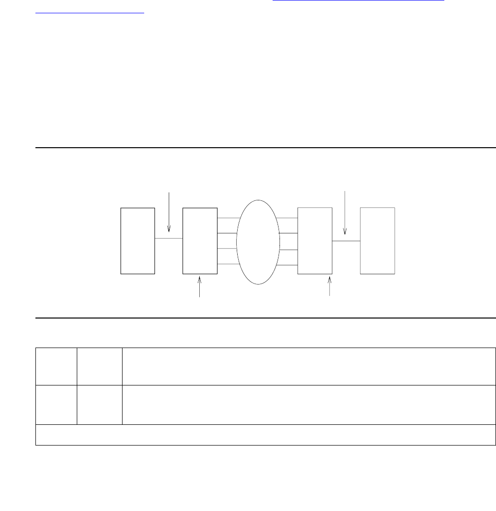
DS1C-BD
Issue 1 June 2005 1103
Far-End DS1 Converter Circuit Pack
Loopback Test (#788)
This test is destructive.
This test is executed by the TN574 DS1 Converter circuit pack only. See Test #790 for testing
for the TN1654 DS1 Converter.
This test starts at the DS1 converter circuit pack whose equipment location was entered, and
loops all fiber time slots at the far edge Fiber Optic Interface of the DS1 converter circuit pack at
the other end of the DS1 converter complex. See Figure 58: Far-End DS1 Converter
Loop-Back Test (#788) on page 1103.
This test is executed under firmware control, and the result is sent back to the maintenance
software. The test is executed by sending digital data through every administered DS1 facility
channel. Two different test patterns are used: hexadecimal values 55 and AA.
For a standard-, duplex-, or high-reliability system (no PNC duplication), this test can only be
executed at the endpoint that is closer to the media server relative to the neighbor DS1
converter circuit pack, because of its impacts on the system control links, The completion of the
test is delayed in this configuration to wait for the recovery of the system control links. For a
critical-reliability system (PNC duplication), test can be executed at any DS1 converter circuit
pack.
Figure 58: Far-End DS1 Converter Loop-Back Test (#788)
Table 375: Test #788 Far-End DS1 Converter Board Loop-Back Test
Error
Code
Test
Result
Description / Recommendation
2000 ABRT Timed out while waiting for a response from the circuit pack.
1. Retry the command at 1-minute intervals up to 3 times.
1 of 3
Metallic or Fiber Connection
Metallic or Fiber Connection
Loops here
DS1CONVDS1CONV
B
Network
A
Test starts here
or
SNI
EI or
SNI
EI

Communication Manager Maintenance-Object Repair Procedures
1104 Maintenance Procedures for Avaya Communication Manager 3.0, Media Gateways and Servers
2100 ABRT Could not allocate the necessary system resources to run this test.
1. Retry the command at 1-minute intervals up to 3 times.
2300 ABRT The downlink message necessary to run this test could not be sent to the
selected DS1C board.
1. Retry the command at 1-minute intervals up to 3 times.
2301 ABRT The timer could not be set before sending the downlink message
necessary to run this test.
1. Retry the command at 1-minute intervals up to 3 times.
2316 ABRT Fiber link is not administered. Administer the DS1 converter fiber link via
add fiber-link.
2321 ABRT DS1 converter circuit pack is not busied out.
1. Busyout the DS1 converter circuit pack via busyout board.
2332 ABRT With this system configuration (unduplicated PNC), the test was aborted
because it cannot be run at the far end when there is only one DS1-FAC
available. (The link would be lost, and no test results would be seen at the
media server). Run the test at the other end of the DS1C complex.
2500 ABRT Internal system error
1. Retry the command at 1-minute intervals up to 3 times.
Table 375: Test #788 Far-End DS1 Converter Board Loop-Back Test (continued)
Error
Code
Test
Result
Description / Recommendation
2 of 3

DS1C-BD
Issue 1 June 2005 1105
Far-End Lightwave Transceiver Loopback
Test (#789)
This test is destructive.
This test is executed by the TN574 DS1 Converter circuit pack only. Test #790 covers this
testing for the TN1654 DS1 Converter.
This test starts at the DS1 converter circuit pack whose equipment location was entered and
loops at the Fiber Optic Terminator (lightwave transceiver) that is connected to the DS1
converter circuit pack at the other end of the DS1 converter complex. See the following
diagram.
FAIL Far-end DS1 converter loop back failed. A problem exists between the
DS1 converter A and the DS1 converter B (see previous diagram).
1. If there are facilities that are not digital-data compatible, busyout the
facilities via busyout ds1-facility.
2. If the test is executed as a part of an error analysis, then return back to
the related section.
3. Enter display errors and follow the associated repair procedures
for any on-board DS1C-BD errors on this DS1 converter circuit pack
and the DS1 converter circuit pack at the other end of the DS1
converter complex. Enter display errors and follow the associated
repair procedures for any DS1-FAC errors on the DS1 facilities.
4. Check the DS1 Converter Measurements Report to see if there are
facilities with excessive errors. Use list measurements
ds1-facility summary. If there are facilities with excessive errors,
execute the Far-End Internal Loopback test (#797) on those facilities,
and follow repair procedures described for the test.
5. If the test still fails, replace the DS1 converter circuit pack at the other
end of the DS1 converter complex.
6. If the test still fails, replace this DS1 converter circuit pack.
PASS Transmission through the path of the loop back is successful.
0NO
BOARD The system software found no board.
1. Reset the board.
2. Remotely retry the command.
Table 375: Test #788 Far-End DS1 Converter Board Loop-Back Test (continued)
Error
Code
Test
Result
Description / Recommendation
3 of 3
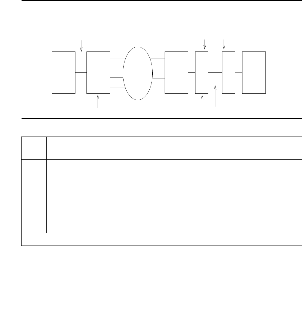
Communication Manager Maintenance-Object Repair Procedures
1106 Maintenance Procedures for Avaya Communication Manager 3.0, Media Gateways and Servers
Every part of this test is executed under firmware control and the result is sent back to the
maintenance software. The test is executed by sending digital data through every DS1 facility
channel. Two different test patterns are used, these are hexadecimal values 55 and AA.
For a standard-, duplex-, or high-reliability system (no PNC duplication), this test can only be
executed at the endpoint that is closer to the media server relative to the neighbor DS1
converter circuit pack because of its impacts on the system control links, also the completion of
the test will be delayed in this configuration to wait for the recovery of the system control links.
For a critical-reliability system (PNC duplication), the test can be executed at any DS1 converter
circuit pack.
Figure 59: Far-End Lightwave Transceiver Loop-Back Test
Table 376: Test #789 Far-End FOT (Lightwave Transceiver) Loop-Back Test
Error
Code
Test
Result
Description / Recommendation
1410 ABRT The test aborted because no lightwave transceiver is present. The neighbor
DS1 converter circuit pack and the fiber endpoint are connected via metallic
cable. This abort may be ignored.
2000 ABRT Timed out while waiting for a response from the circuit pack.
1. Retry the command at 1-minute intervals up to 3 times.
2100 ABRT Could not allocate the necessary system resources to run this test.
1. Retry the command at 1-minute intervals up to 3 times.
1 of 3
lightwave
transceiver
SNI
B
DS1CONVDS1CONV
Test starts here
A
EI Network
Loops here
Metallic or Fiber Connection
Fiber Connection

DS1C-BD
Issue 1 June 2005 1107
2300 ABRT The downlink message necessary to run this test could not be sent.
1. Retry the command at 1-minute intervals up to 3 times.
2301 ABRT The timer could not be set before sending the downlink message
necessary to run this test.
1. Retry the command at 1-minute intervals up to 3 times.
2316 ABRT Fiber link is not administered. Administer the DS1 converter fiber link via
add fiber-link.
2321 ABRT DS1 converter circuit pack is not busied out. Busyout the DS1 converter
circuit pack via busyout board.
2332 ABRT With this system configuration (unduplicated PNC), the test was aborted
because it cannot be run at the far end when there is only one DS1-FAC
available. (The link would be lost, and no test results would be seen at the
media server). Run the test at the other end of the DS1C complex.
2500 ABRT Internal system error
1. Retry the command at 1-minute intervals up to 3 times.
Table 376: Test #789 Far-End FOT (Lightwave Transceiver) Loop-Back Test (continued)
Error
Code
Test
Result
Description / Recommendation
2 of 3

Communication Manager Maintenance-Object Repair Procedures
1108 Maintenance Procedures for Avaya Communication Manager 3.0, Media Gateways and Servers
FAIL Far-end lightwave transceiver loop back failed. A problem exists between
the DS1 converter A and the lightwave transceiver connected to the DS1
converter B (see previous diagram).
1. If there are facilities that are not digital-data compatible, busyout the
facilities via busyout ds1-facility.
2. If the test is executed as a part of an error analysis, then return back to
the related section.
3. Enter display errors and follow the associated repair procedures
for any on-board DS1C-BD errors on this DS1 converter circuit pack
and the DS1 converter circuit pack at the other end of the DS1
converter complex. Enter display errors and follow the associated
repair procedures for any DS1-FAC errors on the DS1 facilities.
4. Check the DS1 Converter Measurements Report to see if there are
facilities with excessive errors. Use list measurements
ds1-facility summary. If there are facilities with excessive errors,
execute the Far-End Internal Loopback test (#797) on those facilities,
and follow repair procedures described for the test.
5. If the test still fails, replace the lightwave transceiver device that is
connected to the DS1 converter circuit pack at the other end of the DS1
converter complex.
6. If the test still fails, replace the DS1 converter circuit pack at the other
end of the DS1 converter complex.
7. If the test still fails, replace this DS1 converter circuit pack.
PASS Transmission through the path of the loop back is successful.
0NO
BOARD The system software found no board.
1. Reset the board.
2. Remotely retry the command.
Table 376: Test #789 Far-End FOT (Lightwave Transceiver) Loop-Back Test (continued)
Error
Code
Test
Result
Description / Recommendation
3 of 3

DS1C-BD
Issue 1 June 2005 1109
DS1 Facilities Connectivity Test (#790)
This test is destructive.
The DS1 facilities connectivity test will check the correct connectivity of the DS1 facilities at
opposite ends of the DS1 converter complex. Every part of this test is executed under firmware
control and the result is sent back to the maintenance software.
For TN574 DS1 Converter circuit packs, this test is executed by sending digital data through
each time slot of every DS1 facility channel. Two different test patterns are used, these are
hexadecimal values 55 and AA.
For TN1654 DS1 Converter circuit packs, this test has been enhanced to provide error codes
that point to the exact fault. Rather than simply reporting a failure of the connectivity test, the
TN1654 test specifically identifies the two DS1 facilities that are cross-connected at the near
and far ends of the DS1 converter complex. In addition, a fault code will indicate the condition of
not being able to loop-up the far end, as required to run the test, due to the packet DS1 facility
being down.
The TN1654 connectivity test sends digital data through only one time slot. Instead of looping
back the facility to itself, the TN1654 version of the test loops-up the other three facilities. If the
test pattern comes back, the firmware fails the test due to an incorrect connection between DS1
facilities. It should be noted that this test will pass and give no indication of problems if the
non-packet facilities are down.
For a standard-, duplex-, or high-reliability system (no PNC duplication), this test can only be
executed at the endpoint that is closer to the media server relative to the neighbor DS1
converter circuit pack because of its impacts on the system control links. In addition, for TN574
DS1 converter boards, the completion of the test will be delayed in this configuration to wait for
the recovery of the system control links. For a critical-reliability system (PNC duplication), test
can be executed at any DS1 converter circuit pack.
Table 377: Test #790 DS1 Facilities Connectivity Loop-Back Test
Error
Code
Test
Result
Description / Recommendation
2000 ABRT Timed out while waiting for a response from the circuit pack.
1. Retry the command at 1-minute intervals up to 3 times.
2100 ABRT Could not allocate the necessary system resources to run this test.
1. Retry the command at 1-minute intervals up to 3 times.
2300 ABRT The downlink message necessary to run this test could not be sent.
1. Retry the command at 1-minute intervals up to 3 times.
1 of 3

Communication Manager Maintenance-Object Repair Procedures
1110 Maintenance Procedures for Avaya Communication Manager 3.0, Media Gateways and Servers
2301 ABRT The timer could not be set before sending the downlink message
necessary to run this test.
1. Retry the command at 1-minute intervals up to 3 times.
2316 ABRT Fiber link is not administered. Use add fiber-link to administer the DS1
converter fiber link.
2321 ABRT DS1 converter circuit pack is not busied out.
●Use busyout board to busyout the DS1 converter circuit pack.
2332 ABRT With this system configuration (unduplicated PNC), the test was aborted
because it cannot be run at the far end when there is only one DS1-FAC
available. (The link would be lost, and no test results would be seen at the
media server.) Run the test at the other end of the DS1C complex.
2500 ABRT Internal system error
1. Retry the command at 1-minute intervals up to 3 times.
FAIL TN574 DS1 facilities connectivity loop-back test failed.
1 FAIL TN1654 near-end DS1 facility A is connected to far-end DS1 facility B.
2 FAIL TN1654 near-end DS1 facility A is connected to far-end DS1 facility C.
3 FAIL TN1654 near-end DS1 facility A is connected to far-end DS1 facility D.
10 FAIL TN1654 near-end DS1 facility B is connected to far-end DS1 facility A.
12 FAIL TN1654 near-end DS1 facility B is connected to far-end DS1 facility C.
13 FAIL TN1654 near-end DS1 facility B is connected to far-end DS1 facility D.
20 FAIL TN1654 near-end DS1 facility C is connected to far-end DS1 facility A.
21 FAIL TN1654 near-end DS1 facility C is connected to far-end DS1 facility B.
23 FAIL TN1654 near-end DS1 facility C is connected to far-end DS1 facility D.
30 FAIL TN1654 near-end DS1 facility D is connected to far-end DS1 facility A.
31 FAIL TN1654 near-end DS1 facility D is connected to far-end DS1 facility B.
32 FAIL TN1654 near-end DS1 facility D is connected to far-end DS1 facility C.
Table 377: Test #790 DS1 Facilities Connectivity Loop-Back Test (continued)
Error
Code
Test
Result
Description / Recommendation
2 of 3

DS1C-BD
Issue 1 June 2005 1111
55 FAIL TN1654 DS1 converter packet facility is down and can’t send loop-up
message to the far end.
1. Enter display errors and follow the associated repair procedures
for any DS1-FAC errors on the DS1 facilities at both ends of the DS1
converter complex. If an alarm exists on a DS1 facility, then this test will
fail.
2. Check the DS1 connections, both circuit packs should have their DS1
facilities connected identically.
3. Check the DS1 Converter Measurements Report to see if there are
facilities with excessive errors. Use list measurements
ds1-facility summary. If there are facilities with excessive errors,
execute the Far-End Internal Loopback test (#797) via test
ds1-facility location long on those facilities, and follow repair
procedures described for the test.
4. Both circuit packs may not have the same translation information. Run
the Board Options Audit test (#795) via test board location
short for both circuit packs in the DS1 converter complex to send the
options. Check the results of this audit test. This test does not pass until
the audit test problems are resolved.
PASS DS1 facility connections are correct.
0NO
BOARD The system software found no board.
1. Reset the board.
2. Remotely retry the command.
Table 377: Test #790 DS1 Facilities Connectivity Loop-Back Test (continued)
Error
Code
Test
Result
Description / Recommendation
3 of 3

Communication Manager Maintenance-Object Repair Procedures
1112 Maintenance Procedures for Avaya Communication Manager 3.0, Media Gateways and Servers
Board Options Audit (#795)
This test is nondestructive.
This test sends the administered circuit pack options to the DS1 converter circuit pack. Options
are sent to both DS1 converter circuit packs at the same time to prevent any transitional
mismatch of options.
The following data is sent to the TN574 DS1 converter circuit pack:
●system-reliability configuration
●master and slave endpoints for framing (determined by the relative position of the circuit
pack to the media server)
●facility mask (whether each facility is installed)
●clock reference mask (whether:
- each facility can be used as a clock-reference source
- the board is being used as a network-timing source)
●packet compatible mask (whether each facility is packet compatible)
●facility information for line coding, framing mode, and line compensation
The following data is sent to the TN1654 DS1 converter circuit pack:
●system-reliability configuration
●master and slave endpoints for framing (determined by the relative position of the circuit
pack to the media server)
●facility mask (whether each facility is installed)
●idle code
●CRC-enabled/-disabled flag (sent in E1 mode only)
●facility information for line coding and line compensation (sent in T1 mode only).
Failure Audit (#949)
This test is nondestructive.
This test queries the DS1 converter circuit pack for any existing circuit pack or facility failures
and any unacknowledged cleared failure messages for auditing purposes. Upon receiving the
query request, DS1 converter firmware sends failure reports to the maintenance software for
every error in its failure database.

DS1C-BD
Issue 1 June 2005 1113
This test operates on both MOs DS1C-BD and DS1-FAC. Error counts of both MOs (DS1C-BD
and DS1-FAC) that are displayed in the error log will be incremented when this test is executed.
This test is also executed internally by the maintenance software when an alarm is resolved
Table 378: Test #949 Failure Audit
Error
Code
Test
Result
Description / Recommendation
2000 ABRT Timed out while waiting for a response from the circuit pack.
1. Retry the command at 1-minute intervals up to 3 times.
2100 ABRT Could not allocate the necessary system resources to run this test.
1. Retry the command at 1-minute intervals up to 3 times.
2300 ABRT The downlink message necessary to run this test could not be sent.
1. Retry the command at 1-minute intervals up to 3 times.
2301 ABRT The timer could not be set before sending the downlink message
necessary to run this test.
1. Retry the command at 1-minute intervals up to 3 times.
2316 ABRT Fiber link is not administered. Administer the DS1 converter fiber link via
add fiber-link.
2500 ABRT Internal system error
1. Retry the command at 1-minute intervals up to 3 times.
FAIL The DS1 converter circuit pack reported failures or retransmitted a cleared
failure message.
1. Enter display errors and follow the associated repair procedures
for any DS1C-BD and DS1-FAC errors.
PASS The DS1 converter circuit pack has no failures.
0NO
BOARD The system software found no board.
1. Reset the board.
2. Remotely retry the command.

Communication Manager Maintenance-Object Repair Procedures
1114 Maintenance Procedures for Avaya Communication Manager 3.0, Media Gateways and Servers
DT-LN-BD (Data Line Circuit Pack)
S8700 | 8710 / S8500
See XXX-BD (Common Port Circuit Pack/Media Module) on page 2539 for circuit pack-level
errors. See also DAT-LINE (Data Line Port) on page 870 for related line information.
MO Name in
Alarm Log
Alarm
Level
Initial SAT Command to Run Full Name of MO
DT-LN-BD MIN test board location sh Data Line circuit pack
DT-LN-BD WRN test board location sh Data Line circuit pack

DTMR-PT (Dual-Tone Multifrequency Receiver Port)
Issue 1 June 2005 1115
DTMR-PT (Dual-Tone Multifrequency Receiver Port)
S8700 | 8710 / S8500
Dual-Tone Multifrequency Receiver ports (DTMR), also known as Touch-Tone Receivers
(TTRs), reside on the following circuit packs:
●TN748
●TN420
●TN756
●TN744B and TN744C
●TN2182
●TN2312AP
●TN2312BP
There are four Dual-Tone Multifrequency Receiver (DTMR-PT) ports and two General Purpose
Tone Detector (GPTD-PT) ports on the TN748, TN420 and TN756 Tone Detector packs. There
are eight GPTD-PT ports on each TN744, TN2182 and TN2312AP circuit packs. The GPTD
ports can be used for TTR, call progress tone detection, call prompting, MF signaling, dial tone
detection, CO answer detection and OCM call classification. The DTMR port is used to detect
touch-tone digits that are placed on the Time Division Multiplex (TDM) bus. Examples of
touch-tone digits are digits 0 through 9, digit #, and digit *. The ability of the DTMR port to detect
touch-tone digits is essential for maintenance of other circuit packs (for example, IPSI circuit
pack) and in placing a station-to-station call. Calls originating from a hybrid station do not
require a DTMR port.
The DTMR-PT MO implements a set of tests to ensure that detection of touch-tone digits by the
DTMR port is functioning properly. For any Tone Detector circuit-level error (DETR-BD), see
XXX-BD (Common Port Circuit Pack/Media Module) on page 2539.
MO Name in
Alarm Log
Alarm
Level
Initial SAT Command to Run Full Name of MO
DTMR-PT MAJ test port location sh Dual-Tone Multifrequency
Receiver port (TTR)
DTMR-PT MIN test port location sh Dual-Tone Multifrequency
Receiver port (TTR)
DTMR-PT WRN release port location Dual-Tone Multifrequency
Receiver port (TTR)

Communication Manager Maintenance-Object Repair Procedures
1116 Maintenance Procedures for Avaya Communication Manager 3.0, Media Gateways and Servers
Error Log Entries and Test to Clear Values
Notes:
a. Error Type 0: Run the short test sequence first. If every test passes, run the long test
sequence. Refer to each test’s description, and follow its recommended procedures.
b. There are two possible alarm levels for this error: Major alarm and Minor alarm. A Major
alarm is raised if the total number of DTMR ports currently in service is less than or equal to
1/2 of the administered threshold number. Otherwise, a Minor alarm is raised. In either
case, run the short test sequence against the DTMR port and follow the error code
procedures for the individual tests.
The threshold number of DTMR ports for service is administered using change
system-parameters maintenance.
c. Error Type 257 The DTMR port lost its translation. Testing the DTMR port is sufficient to
reload its translation. If testing the DTMR port does not clear the error, then the IPSI or Tone
Detector circuit pack containing the defective DTMR port should be replaced.
d. Error Type 513: This error indicates the DTMR port is having problems detecting
touch-tone digits. If this error is being constantly logged, then the IPSI or Tone Detector
circuit pack containing the defective DTMR port should be replaced.
e. Error Type 130: This error type indicates that the circuit pack has been removed or has
been insane for at least 11 minutes. To clear the error, reinsert or replace the circuit pack.
Table 379: Dual-Tone Multifrequency Receiver Port (TTR) Error Log Entries
Error
Type
Aux
Data
Associated Test Alarm
Level
On/Off
Board
Test to Clear Value
0 (a)0 Any Any Any test port location sh r 1
1 (d) 17664 Tone Detector
Audit/ Update test
(#43)
MAJ
MIN
(b)
ON test port location r 2
18 0 busyout port
location
WRN ON release port location
130 (e) None WRN ON test port location sh r 2
257 (c) 17666 Tone Detector
Audit/ Update test
(#43)
MAJ
MIN
(b)
ON test port location r 3
513 (d) Any Tone Detection
Verification test
(#42)
MAJ
MIN
(b)
ON test port location r 3

DTMR-PT (Dual-Tone Multifrequency Receiver Port)
Issue 1 June 2005 1117
System Technician-Demanded Tests:
Descriptions and Error Codes
Investigate tests in the order presented.
Tone Detection Verification Test (#42)
This test checks the touch-tone digits detection capability of the DTMR port.
Order of Investigation Short Test
Sequence
Long Test
Sequence
D/ND1
1. D = Destructive; ND = Nondestructive
Tone Detection Verification test (#42) X X ND
Tone Detector Audit/Update test (#43) X X ND
Table 380: Test #42 Tone Detection Verification Test
Error
Code
Test
Result
Description / Recommendation
ABRT The system could not allocate enough resources for this test, or there was
an Internal system error.
1. Retry the command at 1-minute intervals up to 5 times.
1 ABRT The system could not allocate enough resources to test the DTMR port.
1. Retry the command at 1-minute intervals up to 5 times.
1001 ABRT The system was unable to put the DTMR port in the mode to test it.
1. Retry the command at 1-minute intervals up to 5 times.
1002 ABRT The system could not allocate time slots for the test connection. This could
happen when the system is heavily loaded. If the system is not heavily
loaded, then test the TDM Bus via the test tdm [a|b].
1. Retry the command at 1-minute intervals up to 5 times.
1 of 2

Communication Manager Maintenance-Object Repair Procedures
1118 Maintenance Procedures for Avaya Communication Manager 3.0, Media Gateways and Servers
1003 ABRT The system could not allocate a Tone Generator for the test connection.
This may be caused by a heavy load on the system or by a faulted
Tone-Clock.
1. Check to see if there are any alarms against the Tone-Clock in the PN
where the test aborted. If so, see the recommended procedures for
TONE-BD (Tone-Clock Circuit) on page 2327 or TONE-PT (Tone
Generator) on page 2353.
2. If a new Tone-Clock has been inserted, allow about 1 minute for
maintenance to run on the newly inserted circuit pack.
3. Retry the command at 1-minute intervals up to 5 times.
2000 ABRT Response to the test was not received within the allowable time period.
1. Retry the command at 1-minute intervals up to 5 times.
2100 ABRT Could not allocate the necessary system resources to run this test
1. Retry the command at 1-minute intervals up to 5 times.
2006 ABRT DTMF detection failed. Make sure that the companding mode administered
for the system matches that of the Tone Detector: mu-law for TN748, A-law
for TN420.
1-3 FAIL DTMF digits were not correctly detected.
1. Run the short test sequence: test port location sh r 1.
2. If the problem persists, the system is still operating properly but
system capacity will be reduced. In order to restore the system
performance to normal, replace the Tone Detector or IPSI circuit pack
containing the defective DTMR port.
PASS The DTMR port is able to detect every touch-tone digit.
Table 380: Test #42 Tone Detection Verification Test (continued)
Error
Code
Test
Result
Description / Recommendation
2 of 2

DTMR-PT (Dual-Tone Multifrequency Receiver Port)
Issue 1 June 2005 1119
Tone Detector Audit/Update Test (#43)
The DTMR port is refreshed with all time-slot information, and sanity audit is performed on the
DTMR port.
Table 381: Test #43 Tone Detector Audit/Update Test
Error
Code
Test
Result
Description / Recommendation
None ABRT The system was not able to allocate all the resources needed for this test.
1. Wait 1 minute and try again.
2000 ABRT Response to the test request was not received within the allowable time
period.
1. Retry the command at 1-minute intervals up to 5 times.
2100 ABRT Could not allocate the necessary system resources to run this test.
1. Retry the command at 1-minute intervals up to 5 times.
FAIL Hardware audit failed.
1. Run the short test sequence: test port location sh r 1.
2. If the problem persists, the system is still operating properly but system
capacity will be reduced. In order to restore the system performance to
normal, replace the Tone Detector or IPSI circuit pack containing the
defective DTMR port.
PASS The DTMR port has been successfully refreshed with its translation.

Communication Manager Maintenance-Object Repair Procedures
1120 Maintenance Procedures for Avaya Communication Manager 3.0, Media Gateways and Servers

E-DIG-BD (Multi Application Platform Board)
Issue 1 June 2005 1121
E-DIG-BD (Multi Application Platform Board)
S8700 | 8710 / S8500
The maintenance strategy for DIG800-BD is the same as the one described for MO-XXX-BD
[XXX-BD (Common Port Circuit Pack/Media Module) on page 2539]. Maintenance testing of the
common circuit pack is handled by on-board firmware and server-controlled tests. Maintenance
software queries the firmware for error and alarm information, status, and test results. The
firmware automatically reports error conditions that will result in server-controlled testing.
Board Insertion
The switch makes an additional board query if any of the following circuit packs are inserted:
For any of the previous initial board up-links, the switch sends queries requesting additional
data from the board for administration purposes, while also telling the board the switch software
release and the system type.
For the native mode, the response to the board query downlink messages consists of several
CCMS uplink messages that identify the true board code, vintage, suffix, emulation type, and
the number of reserved slots it needs.
Hyperactivity
The common circuit pack is considered “hyperactive” if the service dispatcher receives 200
up-link messages from the circuit pack in a 10-second period. Since MAPD has 32 ports, the
hyperactivity limit is increased to 500 up-link messages per 10 seconds. An alarm is issued, and
the board is taken out of service when the limit reaches 400 or when it hits 500 up-link
messages in 10 seconds.
MO Name in
Alarm Log
Alarm
Level
Initial SAT Command to Run Full Name of MO
DIG800-B MIN test board location sh MO800DIG-BD
DIG800-B WRN test board location sh MO800DIG-BD
Circuit Pack Vintage
TN754 49
TN556 49
80 or greater
TN800 any

Communication Manager Maintenance-Object Repair Procedures
1122 Maintenance Procedures for Avaya Communication Manager 3.0, Media Gateways and Servers
LED Use
The LED Control message 038x requests the Angel to drive the red, yellow, and green LEDs on
the face plate of typical port board on or off. On the MAPD, only the red LED is controlled by this
message. Yellow and green change requests received from the switch by the MAPD drive LCD
behavior rather than LED behavior. The switch continues to send the same LED control
messages to the MAPD that it currently sends to every other port board. The MAPD handles
proper interpretation of these messages. The PC on the MAPD, as well as the switch itself, can
control the LEDs and the LCD on the MAPD.
Port Administration
In administration without hardware, the switch allows administration of up to 32 MAPD ports of
any port type. If the port type later reported by the board does not match the existing type, the
switch assumes the board is a MAPD board with a different configuration and rejects the board.
MAPD_DCP_STA and MAPD_ASAI_STA are the only two types of terminals are allowed on a
MAPD board. Therefore, while administering ports on MAPD with add station, it will allow
only the previously mentioned terminals.
Note:
Note: See XXX-BD (Common Port Circuit Pack/Media Module) on page 2539 for circuit
pack-level errors. See DIG-LINE (Digital Line) on page 924 for related line
information.

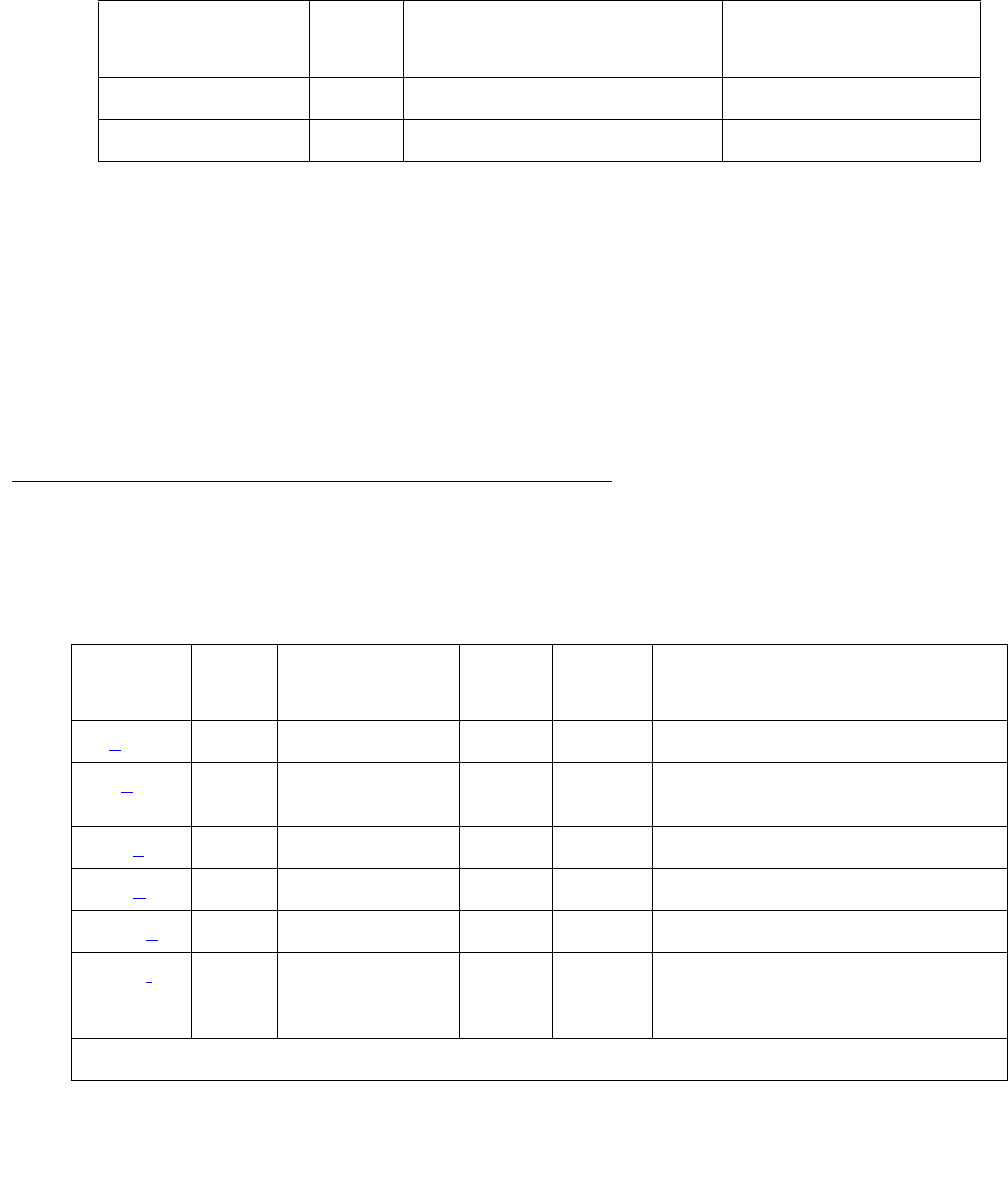
Communication Manager Maintenance-Object Repair Procedures
1124 Maintenance Procedures for Avaya Communication Manager 3.0, Media Gateways and Servers
E-DIG-STA (Emulated Digital Line)
S8700 | 8710 / S8500
There are 4 tests in the Emulated Digital Line station maintenance test sequence and only one
test path in the test sequence. Once the test sequence begins, every test in the test sequence is
executed.
E-DIG-ST maintenance monitors and tests ports on the TN800 MAPD circuit pack and the
hardware connected to those ports for lines administered as a digital station. These include
stations with an emulated digital voice terminal and stations with an emulated digital voice
terminal and a linked data module. Stand-alone data modules and data adaptors in stand-alone
mode are not supported by the TN800 circuit pack. Circuit pack maintenance is covered by
E-DIG-BD.
Hardware Error Log Entries and
Test to Clear Values
MO Name in
Alarm Log
Alarm
Level
Initial SAT Command to Run Full Name of MO
E-DIG-ST MIN test port location l Emulated Digital Station
E-DIG-ST WRN test port location sh Emulated Digital Station
Table 382: Digital Line Error Log Entries – E-DIG-STA
Error
Type
Aux
Data
Associated
Test
Alarm
Level
On/Off
Board
Test to Clear Value
0 (a)0Any AnyAnytest port location sh r 1
18 (b)0 busyout port
location
WRN OFF rel port location
130 (c)NoneWRNONtest port location sh
257 (d) 40971 None
1537 (e) 40968 None WRN OFF
1793 (f) Voice and
Control Local
Loop test (#13)
MIN
WRN1ON test port location l r 3
1 of 2
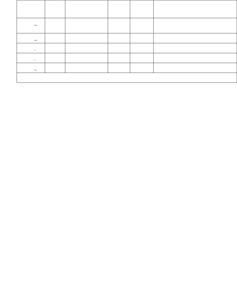
E-DIG-STA (Emulated Digital Line)
Issue 1 June 2005 1125
Notes:
a. Error Type 0: Run the short test sequence first. If every test passes, run the long test
sequence. Refer to each appropriate test’s description, and follow its recommended
procedures.
b. Error Type 18: Maintenance personnel have busied out the port in question. Make sure that
the port is released from busyout by using release port location.
c. Error Type 130: The circuit pack has been removed or has been insane for more than
21 minutes. To clear the error, reinsert or replace the circuit pack.
d. Error Type 257: Problems transmitting to the voice terminal. This problem can be caused
by defective wiring that can cause varying degrees of problems on different types of sets.
Sets such as the 7410 appear to be more susceptible to wiring problems than others.
e. Error Type 1537: An in-link maintenance error has generated an off-board warning due to
some problem with the link to the voice terminal. This can be ignored if no user complaints
are received. Otherwise, make sure the voice terminal is connected, check for defective
wiring, check for a defective voice terminal, and move voice terminal to a jack that is closer
to the switch (number of feet of wiring between the jack and the switch). If the problem still
exists, replace the circuit pack. Once the problem has been resolved, the alarm is retired
after a predetermined amount of time.
f. Error Type 1793: The local loop test failed. Each failure increments the counter by 1 when
the local loop test fails. The counter is decremented when the loop test passes. When the
counter reaches a threshold of 3, an on-board MINOR alarm is raised.
g. Error Type 2049: The NPE Crosstalk test failed. The counter increments by 1 when the
NPE Crosstalk test fails. The counter is decremented by 1 when the NPE Crosstalk test
passes. When the counter reaches a threshold of 3, an on-board MINOR alarm is raised
and the board is taken out of service.
2049 (g) NPE Crosstalk
test (#9)
MIN
WRN1ON test port location l r 3
2305 (h) 32770 None
3840 (i) 40965 None
3841 (j) 41029 None
2304 (k)None
1. Major alarms may be downgraded to Warning alarms based on the value used in set options.
Table 382: Digital Line Error Log Entries – E-DIG-STA (continued)
Error
Type
Aux
Data
Associated
Test
Alarm
Level
On/Off
Board
Test to Clear Value
2 of 2
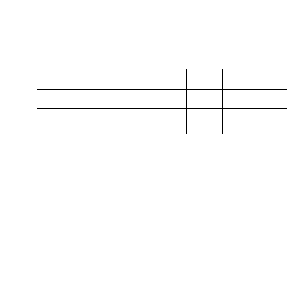
Communication Manager Maintenance-Object Repair Procedures
1126 Maintenance Procedures for Avaya Communication Manager 3.0, Media Gateways and Servers
h. Error Type 2305: The station went off-hook while it was in the ready-for-service state. Use
status station to determine the state of the station. The off-hook should have moved
the station to ready-for-service. No technician action is necessary.
i. Error Type 3840: No terminal is connected to the Digital Line board. No maintenance
action is required.
j. Error Type 3841: The circuit pack’s message buffer is full. This may be caused by having
many display phones with heavy traffic connected to the circuit pack. No action is
necessary.
k. Error Type 2304: Internal system error; no action is necessary. The error counters 1, 2, 3,
4, 5, 6, 10, 11, 12, 13, 14, 15, and 16 do not have any significance for this MO.
System Technician-Demanded Tests:
Descriptions and Error Codes
Always investigate tests in the order presented in the following table when inspecting errors in
the system. By clearing error codes associated with the Voice and Control Channel Local Loop
Around test (#13), you may also clear errors generated from other tests in the testing sequence.
Digital Line NPE Crosstalk Test (#9)
One or more Network Processing Elements (NPEs) reside on each circuit pack with a TDM-bus
interface. The NPE controls port connectivity and gain and provides conferencing functions on a
per-port basis. The NPE Crosstalk test verifies that this port’s NPE channel talks on the
selected time slot and never crosses over to time slots reserved for other connections. If the
NPE is not working correctly, 1-way and noisy connections may be observed. This test is part of
a port’s long test sequence and takes about 20 to 30 seconds to complete. Crosstalk testing
occurs on both the primary information channel (voice) and the secondary information channel
(data) associated with each digital station port. If this test fails on either channel, the station and
the DTDM are taken out of service.
Order of Investigation Short Test
Sequence
Long Test
Sequence
D/ND1
1. D = Destructive; ND = Nondestructive
Voice and Control Channel Local Loop Around
test (#13)
XD
NPE Crosstalk test (#9) X ND
Station Lamp Updates test (#16) X ND

E-DIG-STA (Emulated Digital Line)
Issue 1 June 2005 1127
Table 383: Test #9 Digital Line NPE Crosstalk Test
Error
Code
Test
Result
Description / Recommendation
1 ABRT During testing of the primary information channel, system resources may
not have been available or the port was busy during the test.
1. Check the port status.
2. Use display port location to determine the station extension of
the port. Use status station to determine the service state of the
port. If the port is in use, wait until it is idle before retesting.
3. If the port status is idle, then retry the command at 1-minute intervals
up to 5 times.
2 ABRT During testing of DTDM, system resources may not have been available or
he port was busy during the test.
1. Check if port is being used. If possible, disconnect by toggling the
disconnect button on DTDM. Retry the command after 1 minute.
!CAUTION:
CAUTION: This action drops the call in progress.
1000 ABRT System resources required to run this test are not available. The port may
be busy with a valid call.
1. Use display port location to determine the station extension or
attendant number of the port. Use status station or status
attendant to determine the service state of the port. If the port is in
use, wait until it is idle before retesting. Attendants are always in use
(off-hook) if the handset is plugged in and the port is not busied out.
2. If the port status is idle, then retry the command at 1-minute intervals
up to 5 times.
1001 ABRT System resources required to run this test are not available.
1. Retry the command at 1-minute intervals up to 5 times.
1002 ABRT The system could not allocate time slots for the test. The system is under
heavy traffic conditions or has time slots out of service due to TDM-BUS
errors.
1. If the system has no TDM-BUS errors and is not handling heavy traffic,
repeat test at 1-minute intervals up to 5 times.
1 of 2

Communication Manager Maintenance-Object Repair Procedures
1128 Maintenance Procedures for Avaya Communication Manager 3.0, Media Gateways and Servers
1003 ABRT The system could not allocate a tone receiver for the test. The system may
be oversized for the number of Tone Detectors present, or some Tone
Detectors may be out of service.
1. Resolve any TTR-LEV errors.
2. Resolve any TONE-PT errors.
3. If neither condition exists, retry the command at 1-minute intervals up to
5 times.
1004 ABRT The port was seized by a valid call during the test.
1. Use display port location to determine the station extension or
attendant number of the port.
2. Use status station or status attendant to determine the
service state of the port.
3. If the service state indicates that the port is in use, then the port is
unavailable for certain tests. Wait until the port is idle before retesting.
Attendants are always in use (off-hook) if the handset is plugged in and
the port is not busied out.
1020 ABRT Test disabled by background testing. Use status station to determine
when the station is available for testing.
2000 ABRT Response to the test request was not received within the allowable time
period.
1. Retry the command at 1-minute intervals up to 5 times.
1
2
FAIL The Network Processing Element (NPE) of the tested port is transmitting in
error. This causes noisy and unreliable connections.
Error code 1 = Crosstalk test failed on the primary channel.
Error code 2 = Crosstalk test failed on the secondary channel.
1. Replace the circuit pack.
PASS The port is correctly using its allocated time slots.
1. To ensure that this is not an intermittent problem, repeat this test up to
10 times.
2. If complaints persist, examine the station, connections, and wiring.
Table 383: Test #9 Digital Line NPE Crosstalk Test (continued)
Error
Code
Test
Result
Description / Recommendation
2 of 2

E-DIG-STA (Emulated Digital Line)
Issue 1 June 2005 1129
Voice and Control Channel Local Loop Test (#13)
These tests check the information and control channels between the media server and the
Digital Line port circuit. The media server sends a message to loop around both the information
and control channels for the port. First, the primary information (voice) channel loop-back test
sends a digital count from the Tone-Clock circuit pack on the primary information channel time
slot and receives the same digital count with a General-Purpose Tone Detector.
While the primary information channel is still looped around, the Control Channel Loop-around
test sends four different transparent patterns to the on-board microprocessor, receives them
back, and compares them.
The Loop Around test for the secondary information (data) channel is the same as the primary
information channel loop around test and is performed only if a DTDM is administered.
A Conference test checks the primary information channel. This is the same test as Conference
test (#6).
The four tests generate only one result: Pass, Fail, or Abort. If any test fails or aborts, the test
sequence stops.
Table 384: Test #13 Voice and Control Channel Local Loop Test
Error
Code
Test
Result
Description / Recommendation
ABRT Internal system error
1. Retry the command at 1-minute intervals up to 5 times.
1000 ABRT System resources required to run this test are not available. The port may
be busy with a valid call.
1. Use display port location to determine the station extension or
attendant number of the port. Use status station or status
attendant to determine the service state of the port. If the port is in
use, wait until it is idle before retesting. Attendants are always in use
(off-hook) if the handset is plugged in and the port is not busied out.
2. If the port status is idle, then retry the command at 1-minute intervals
up to 5 times.
1001 ABRT System resources required to run this test are not available.
1. Retry the command at 1-minute intervals up to 5 times.
1 of 3

Communication Manager Maintenance-Object Repair Procedures
1130 Maintenance Procedures for Avaya Communication Manager 3.0, Media Gateways and Servers
1002 ABRT The system could not allocate time slots for the test. The system is under
heavy traffic conditions or it has time slots out of service due to TDM-BUS
errors.
1. If the system has no TDM-BUS errors and is not handling heavy
traffic, repeat test at 1-minute intervals up to 5 times.
1003 ABRT The system could not allocate a tone receiver for the test. The system
may be oversized for the number of Tone Detectors present, or some
Tone Detectors may be out of service.
1. Resolve any TTR-LEV errors.
2. Resolve any TONE-PT errors.
3. If neither condition exists, retry the command at 1-minute intervals up
to 5 times.
1004 ABRT The port was seized by a valid call during the test.
1. Use display port location to determine the station extension or
attendant number of the port.
2. Use status station or status attendant to determine the
service state of the port. If the port is in use, wait until it is idle before
retesting. Attendants are always in use (off-hook) if the handset is
plugged in and the port is not busied out.
3. Retry the command at 1-minute intervals up to 5 times.
2000 ABRT Response to the test request was not received within the allowable time
period.
1. Rerun the test at 1-minute intervals up to 5 times.
2100 ABRT Could not allocate the necessary system resources to run this test.
1. Rerun the test at 1-minute intervals up to 5 times.
Table 384: Test #13 Voice and Control Channel Local Loop Test (continued)
Error
Code
Test
Result
Description / Recommendation
2 of 3

E-DIG-STA (Emulated Digital Line)
Issue 1 June 2005 1131
7 FAIL Conference test failed on primary channel. In some cases, users may not
notice disruption in service. In extreme cases, conferencing feature may
not work at all.
14 FAIL The primary voice channel is not transmitting properly. User impact may
range from noticing nothing to not being able to use this port.
15 FAIL The control channel between the Processor and Digital circuit pack is not
transmitting properly. User impact may range from noticing nothing to not
being able to use the port. This could disrupt other users.
16 FAIL The secondary voice channel is not transmitting properly. User impact
may range from noticing nothing to not being able to use this port.
1. Run circuit pack tests to check the Tone Generator circuit pack and
the Tone Detector circuit pack using test board location.
2. Resolve any problems that are detected on the Tone Generator circuit
pack or Tone Detector circuit pack.
3. If the test still fails, replace the Digital Line circuit pack.
PASS The test passed, and every channel is transmitting properly.
1. To ensure that this is not an intermittent problem, repeat this test up to
10 times.
2. If noisy connections for voice or corrupted data for data transfer
persist, examine the station, connections, and wiring.
Table 384: Test #13 Voice and Control Channel Local Loop Test (continued)
Error
Code
Test
Result
Description / Recommendation
3 of 3

Communication Manager Maintenance-Object Repair Procedures
1132 Maintenance Procedures for Avaya Communication Manager 3.0, Media Gateways and Servers
Station Lamp Updates Test (#16)
This test lights every lamp on the terminal as specified. The lamp updates will run only if the
station is in service. The status of the station is checked and the lamp updates are blocked from
taking place if the station is not in the in-service state. This test does not affect the status of the
Message Waiting lamp.
Table 385: Test #16 DIG-LINE Station Lamp Updates Test
Error
Code
Test
Result
Description / Recommendation
ABRT Internal system error
1. Retry the command at 1-minute intervals up to 5 times.
1 ABRT System technician may have busied out the port.
1. Look for Error Type 18 (port busied out) for this port. If this error type
is present, then release the port (release station extension)
and run the test again.
2. Make sure that the terminal is connected.
3. Retry the command at 1-minute intervals up to 5 times.
3 ABRT Station may be in ready-for-service or out-of-service state.
1. Use status station to verify state of station.
2. Make sure the terminal is connected.
3. Retry the command at 1-minute intervals up to 5 times.
1000 ABRT System resources required to run this test are not available. The port is
busy with a valid call.
1. Use display port location to determine the station extension or
attendant number of the port.
2. Use status station or status attendant to determine the
service state of the port. If the port is in use, wait until it is idle before
retesting. Attendants are always in use (off-hook) if the handset is
plugged in and the port is not busied out.
3. Retry the command at 1-minute intervals up to 5 times.
1 of 2

E-DIG-STA (Emulated Digital Line)
Issue 1 June 2005 1133
1392 ABRT This is currently a TTI port, and the test cannot execute on it.
1. Verify that the port is a TTI port using either display port (the
display shows that the port is a TTI port) or list config (the
display shows a t for the port).
2. If either list config or display port indicates that the port is
not a TTI port, escalate the problem. If both commands indicate that
the port is a TTI port, the abort is correct, and no action is necessary.
FAIL Internal system error.
1. Retry the command at 1-minute intervals up to 5 times.
PASS The message to light every station lamp was successfully sent to the port.
1. Observe the station lamps being lit when running the test. If every
lamps does not light, the other Digital Line test results may indicate
related problems that are causing the unlit lamps.
2. Investigate by using other Digital Line port tests and by examining the
station, wiring, and connections.
Table 385: Test #16 DIG-LINE Station Lamp Updates Test (continued)
Error
Code
Test
Result
Description / Recommendation
2 of 2

Communication Manager Maintenance-Object Repair Procedures
1134 Maintenance Procedures for Avaya Communication Manager 3.0, Media Gateways and Servers
EMG-XFER (Emergency Transfer)
S8700 | 8710 / S8500
S8700 | 8710 / S8500
Emergency Transfer (SCC Cabinets)
The system provides the ability to cut designated analog phones through to CO trunks if the
switch cannot provide even minimal phone service. This ability is known as Emergency
Transfer. The EMG-XFER MO tracks the control of Emergency Transfer. There is one
EMG-XFER MO for the port network. Emergency Transfer can be controlled by the system or
can be manually controlled via the Emergency Transfer switch located on the Maintenance
(TN775) circuit pack. A manual ON position (up) generates a Major alarm. A manual OFF
position (down) generates a Warning alarm. Unless a technician is currently working on the
system, the switch should be left in the auto position.
Error Log Entries and Test to Clear Values
MO Name in
Alarm Log
Alarm
Level
Initial SAT Command to Run1
1. UU is the universal cabinet number listed in the PORT field of the Alarm or Error Log.
Full Name of MO
EMG-XFER MAJ test environment UU Emergency Transfer
EMG-XFER WRN test environment UU Emergency Transfer
Table 386: Emergency Transfer Error Log Entries
Error
Type
Aux
Data
Associated Test Alarm
Level
On/Off
Board
Test to Clear Value
0 0 Any Any Any test environment sh r
1
1 (a) 0 Emergency Transfer Query
(#124)
MAJ ON test environment r 3
257 (b) 0 Emergency Transfer Query
(#124)
WRN ON test environment r 3

EMG-XFER (Emergency Transfer)
Issue 1 June 2005 1135
Notes:
a. Error Type 1 indicates that the Emergency Transfer switch located on the Processor circuit
pack is set to the manual ON position (up). When the Emergency Transfer switch is in this
position it generates a Major alarm.
b. Error Type 257 indicates that the Emergency Transfer switch located on the Processor
circuit pack is set to the manual OFF position (down). When the Emergency Transfer switch
is in this position it generates a Warning alarm.
System Technician-Demanded Tests: Descriptions and Error
Codes
Investigate tests in the order presented. By clearing error codes associated with the Cabinet
Query Test, you may also clear errors generated from other tests in the testing sequence.
Single Carrier System
Notes:
a. See CABINET (Cabinet Sensors) on page 758 for a description of this test.
b. See EXT-DEV ADMIN? Y (External Device Alarm) on page 1246 for a description of this
test.
c. See RING-GEN (Analog Ring Generator) on page 1942 for a description of this test.
Table 387: Emergency Transfer System Technician-Demanded Tests
Order of Investigation Short Test
Sequence
Long Test
Sequence
D/ND1
1. D = Destructive; ND = Nondestructive
Cabinet Query Test (#122) (a)XXND
Emergency Transfer Query Test (#124) X X ND
External Alarm Lead Query Test (#120) (b)X XND
Analog Ring Generator Initialization Test
(#117) (c)
XXND
Analog Ring Generator Query Test (#118) (c)X X ND

Communication Manager Maintenance-Object Repair Procedures
1136 Maintenance Procedures for Avaya Communication Manager 3.0, Media Gateways and Servers
Emergency Transfer Query Test (#124)
This test queries the hardware for the state of the Emergency Transfer switch and reports the
result. If the switch is in a position where the system software can control Emergency Transfer,
then the test passes. If the switch is in a position where the system software cannot control
Emergency Transfer, then the test fails. The Processor controls Emergency Transfer. The
system software does not have control of Emergency Transfer within a cabinet if the switch is in
the manual ON or manual OFF state.
Table 388: TEST #124 Emergency Transfer Query Test
Error
Code
Test
Result
Description/Recommendation
1000 ABRT System resources required to run this test are not available.
1. Retry the command at 1-minute intervals a maximum of 5 times.
2000 ABRT Response to the test request was not received within the allowable time
period.
1. Retry the command at 1-minute intervals a maximum of 5 times.
2. If the test continues to ABRT with error code 2000, check for system
powering problems with the A carrier. Resolve all CABINET alarms.
Then, repeat the test.
2029 ABRT Internal system error
1. Retry the command at 1-minute intervals a maximum of 5 times.
1 FAIL Emergency Transfer is manually turned OFF via the Emergency Transfer
switch.
1. Place the switch in the AUTO position.
2 FAIL Emergency Transfer is manually turned ON via the Emergency Transfer
switch.
1. Place the switch in the AUTO position.
PASS The system software has control of Emergency Transfer. If Emergency
Transfer is invoked, then there can be a Major alarm in the system that is
invoking Emergency Transfer. Table 389: Test #124 Error Log Entries That
Cause Emergency Transfer on page 1137 lists the error types and MOs that
may cause Emergency Transfer. If any or all of these errors appear in the
log, then refer to the appropriate Maintenance documentation and resolve
those problems first.
If none of these errors appear in the log, then check the Emergency
Transfer hardware.

EMG-XFER (Emergency Transfer)
Issue 1 June 2005 1137
S8700 | 8710 / S8500
The Emergency Transfer MO monitors the position of the Emergency Transfer switch(es) on the
EPNs’ Maintenance circuit packs. It does not monitor whether the system is actually in
Emergency Transfer.
Emergency Transfer (ET) provides the ability to connect designated analog phones to CO
trunks when the switch cannot provide minimal phone service. Each EPN’s cabinet has its own
ET capability, and there is one EMG-XFER MO for each cabinet or stack of single-carrier
cabinets.
ET is controlled either automatically by the system, or manually, depending on the setting of the
ET switches as described in the following section.
Emergency Transfer Status
The status cabinet UU command shows the location of the ET switches and the current
status of ET in the designated cabinet as follows:
Table 389: Test #124 Error Log Entries That Cause Emergency Transfer
MO Name Error Type Aux Data
SW-CTL 1
SW-CTL 2
TONE-BD 1 0
TONE-BD 2305 0
auto+ ET is invoked and under system control.
auto- ET is not in effect and is under system control (normal operating state).
unavailable The switch setting(s) is not available.
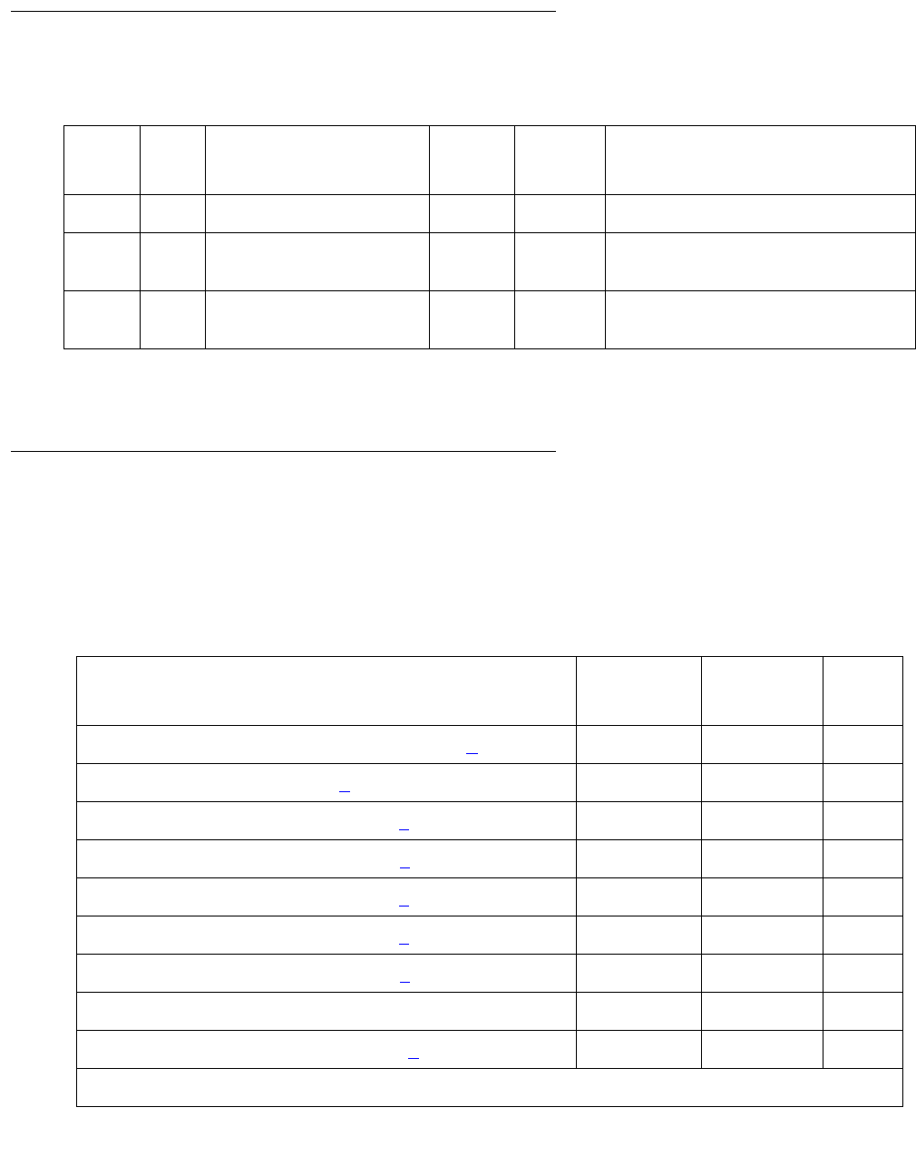
Communication Manager Maintenance-Object Repair Procedures
1138 Maintenance Procedures for Avaya Communication Manager 3.0, Media Gateways and Servers
Error Log Entries and Test to Clear Values
System Technician-Demanded Tests:
Descriptions and Error Codes (Multicarrier)
Always investigate tests in the order presented in the following table. By clearing error codes
associated with one test, you may clear errors generated from other tests in the sequence.
Table 390: EMG-XFER Error Log Entries
Error
Type
Aux
Data
Associated Test Alarm
Level
On/Off
Board
Test to Clear Value
01
1. Run the short test sequence first. If every test passes, run the long test sequence. Refer to each
appropriate test’s description, and follow its recommended procedures.
0Any AnyAnytest environment UU
1 0 Emergency Transfer
query (#124)
MAJ ON test environment UU r 3
257 0 Emergency Transfer
query (#124)
WRN ON test environment UU r 3
Table 391: System Technician-Demanded Tests: EMG-XFER (Multicarrier Cabinets)
Order of Investigation Short Test
Sequence
Long Test
Sequence
D/ND1
Battery & Battery Charger Query test (#5) (a)XXND
AC Power Query test (#78) (b)XXND
OLS Query test (Carrier E) (#127) (c)XXND
OLS Query test (Carrier D) (#127) (c)XXND
OLS Query test (Carrier A) (#127) (c)XXND
OLS Query test (Carrier B) (#127) (c)XXND
OLS Query test (Carrier C) (#127) (c)XXND
Emergency Transfer Query test (#124) X X ND
Cabinet Sensors Query test (#122) (d)XXND
1 of 2

EMG-XFER (Emergency Transfer)
Issue 1 June 2005 1139
Notes:
a. See POWER on page 1869 for a description of this test.
b. See AC-POWER on page 333 for a description of this test.
c. See CARR-POW (Carrier Power Supply) on page 770 for a description of this test.
d. See CABINET (Cabinet Sensors) on page 758 for a description of this test.
e. See EXT-DEV ADMIN? Y (External Device Alarm) on page 1246 section for a description of
this test.
f. See RING-GEN (Analog Ring Generator) on page 1942 section for a description of this test.
These tests show up in the test sequence only if there is a TN768 or TN780 Tone-Clock
circuit pack in the EPN being tested.
External Alarm Lead Query test (#120) (e)XXND
Analog Ring Generator Initialization test
Analog Ring Generator Initialization test (#117) (f)X XND
Analog Ring Generator Query test (#118) (f)XXND
1. D = Destructive, ND = Nondestructive
Table 391: System Technician-Demanded Tests: EMG-XFER (Multicarrier Cabinets)
Order of Investigation Short Test
Sequence
Long Test
Sequence
D/ND1
2 of 2
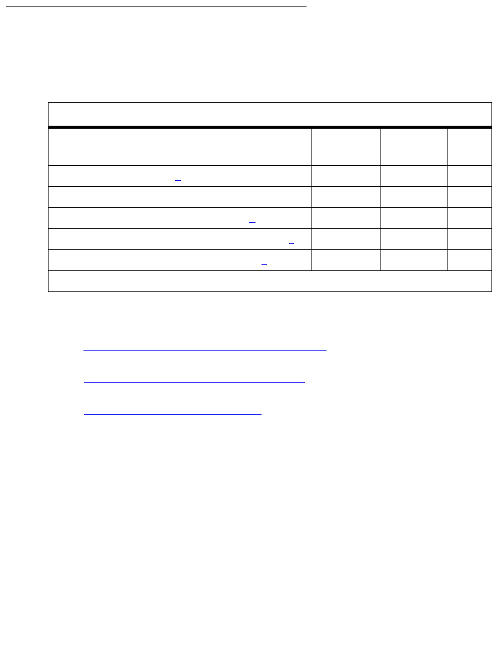
Communication Manager Maintenance-Object Repair Procedures
1140 Maintenance Procedures for Avaya Communication Manager 3.0, Media Gateways and Servers
System Technician-Demanded Tests:
Descriptions and Error Codes (Single-Carrier)
Investigate tests in the order presented. By clearing error codes associated with the Power
Query test (#79), you may also clear errors generated from other tests in the sequence.
Notes:
a. See DC-POWER (Single-Carrier Cabinet Environment) on page 880 for a description of this
test.
b. See EXT-DEV ADMIN? Y (External Device Alarm) on page 1246 for a description of this
test.
c. See RING-GEN (Analog Ring Generator) on page 1942 for a description of this test.
Note:
Note: These tests only show up in the test sequence if there is a TN768 Tone-Clock
Board in the EPN being tested.
Single-Carrier System
Order of Investigation Short Test
Sequence
Long Test
Sequence
D/ND1
1. D = Destructive; ND = Nondestructive
Power Query test (#79) (a)XXND
Emergency Transfer Query test (#124) X X ND
External Alarm Lead Query test (#120) (b)XXND
Analog Ring Generator Initialization test (#117) (c)X XND
Analog Ring Generator Query test (#118) (c)XXND

EMG-XFER (Emergency Transfer)
Issue 1 June 2005 1141
Emergency Transfer Query Test (#124)
The Emergency Transfer Query test queries the hardware for the state of the Emergency
Transfer switch and reports the result. If the position of the switch in a PN cabinet is such that
the system software can control Emergency Transfer (auto), then the test passes. If the position
of the switch or switches is such that the system software cannot control Emergency Transfer
(manual “on” or manual “off”), then the test fails. Maintenance Tone-Clock controls Emergency
Transfer.
Table 392: Test #124 Emergency Transfer Query Test
Error
Code
Test
Result
Description / Recommendation
1000 ABRT System resources required to run this test are not available.
1. Retry the command at 1-minute intervals up to 5 times.
2000 ABRT Response to the test was not received within the allowable time period.
1. Retry the command at 1-minute intervals up to 5 times.
2. If the test continues to ABORT with Error Code 2000, check for
system powering problems with the PN’s A carrier. Resolve every
AC-POWER and CARR-POW alarm in a multicarrier cabinet system
or DC-POWER alarm in a single-carrier cabinet system. Then,
repeat the test.
3. If the test continues to ABORT with a 2000 Error Code, resolve every
or MAINT (Maintenance circuit pack) error in a PN. Then, repeat the
test.
2029
2319
2320
2500
ABRT Internal system error
1. Retry the command at 1-minute intervals up to 5 times.
17
18
20
33
65
289
FAIL Emergency Transfer is manually turned OFF (Emergency Transfer
switch off).
1. Place the switch in the AUTO position.

Communication Manager Maintenance-Object Repair Procedures
1142 Maintenance Procedures for Avaya Communication Manager 3.0, Media Gateways and Servers
34, 290 FAIL Emergency Transfer is manually turned ON (Emergency Transfer switch
on).
1. Place the switch in the AUTO position.
PASS System software has control of Emergency Transfer within this cabinet. If
Emergency Transfer is currently invoked (the emergency transfer LED is
on), the cause could be a major alarm.
1. The following list shows the error types that can cause Emergency
Transfer. If any of these errors appear in the log, then see TONE-BD
(Tone-Clock Circuit) on page 2327, and resolve these error types
first:
●Error Type 3585, Aux Data 121
●Error Type 2305, Aux Data 40800
2. If none of the previous errors appear in the log, then check the
Emergency Transfer hardware.
3. On an EPN, if Emergency Transfer is invoked while call processing
is permitted, verify that the current limiter card (982LS) is in the
correct slot on the backplane. If the current limiter card is not in the
correct slot, move it to the correct location, and rerun Test #124.
Table 392: Test #124 Emergency Transfer Query Test (continued)
Error
Code
Test
Result
Description / Recommendation

EPN-SNTY (PN Sanity Audit)
Issue 1 June 2005 1143
EPN-SNTY (PN Sanity Audit)
S8700 | 8710 / S8500
The EPN Sanity Audit feature enhances the system’s ability to recover from failure conditions
that disable an entire PN. In such situations, not only is the affected PN unable to provide
service to the system, but the system itself has not detected the condition. The EPN Sanity
Audit feature recognizes a PN as unable to provide service when the software cannot receive
control messages from PN circuit packs. When such a failure is detected by the EPN Sanity
Audit, a sequence of recovery actions is triggered to restore the PN to service.
For a standard-reliability system (unduplicated server), the recovery sequence is:
1. TDM bus switch
2. EPN WARM reset
3. EPN COLD reset
The recovery sequence is:
1. TDM bus switch
2. Tone-Clock switch within the PN
3. PNC interchange
4. PN WARM reset
5. PN COLD reset
The EPN Sanity Audit feature activates only when every existing maintenance operation has
failed to detect the PN problem. The EPN Sanity Audit serves as a safety net for the PN.
Note:
Note: It is not clear why certain types of PN problems activate this feature. Thus, error
log entries related to these problems do not specify which hardware to replace.
The error log entries only indicate that some drastic recovery action occurred due
to an unknown problem. However, clues as to the root cause of the PN outage
may be present in the Error Logs and the Alarm Logs of the following MOs:
TDM-BUS (TDM Bus) on page 2237, EXP-INTF (Expansion Interface Circuit
Pack) on page 1176, and TDM-CLK (TDM Bus Clock) on page 2252, EXP-PN
(Expansion Port Network) on page 1235, and PNC-DUP (PNC Duplication) on
page 1851. You should refer to these maintenance sections during
troubleshooting operations.
MO Name in
Alarm Log
Alarm
Level
Initial Command to Run Full Name of MO
EPN-SNTY None None EPN Sanity Audit
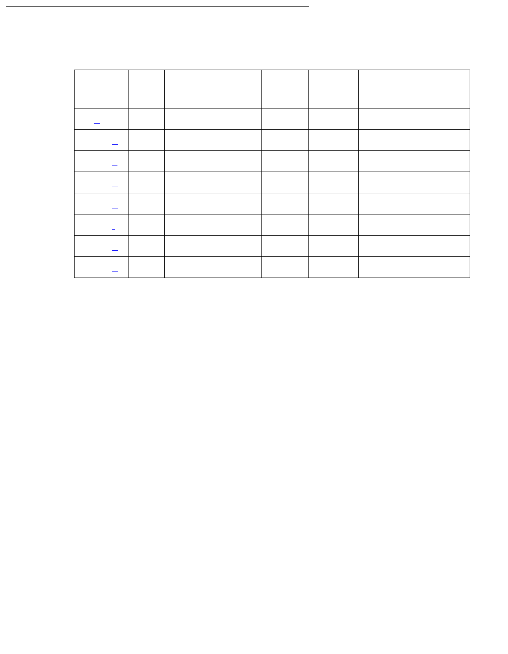
Communication Manager Maintenance-Object Repair Procedures
1144 Maintenance Procedures for Avaya Communication Manager 3.0, Media Gateways and Servers
Error Log Entries and Test to Clear Values
Notes:
a. Error Type 0: Run the short test sequence first. If every test passes, run the long test
sequence. Refer to each appropriate test’s description, and follow its recommended
procedures.
b. Error 8801: the PN is unable to send up-link control messages, and the control channel of
the PN’s TDM bus is swapped as part of the recovery procedure.
c. Error 8803: the PN is unable to send up-link control messages and the PN’s Tone-Clock is
swapped as part of the recovery procedure.
d. Error 9901: the PN is unable to send up-link control messages, but recovers after the
control channels of the PN’s TDM bus are swapped.
e. Error 9902: the PN is unable to send up-link control messages, but recovers after the PN’s
active Tone-Clock is swapped.
f. Error 9903: the PN is unable to send up-link control messages, but recovers after a PNC
interchange has taken place.
g. Error 9904: the PN is unable to send up-link control messages, but recovers after a PN
WARM reset.
h. Error 9905: the PN is unable to send up-link control messages, but recovers after a PN
COLD reset.
Table 393: EPN-SNTY Error Log Entries
Error
Type
Aux
Data
Associated Test Alarm
Level
On/Off
Board
Test to Clear Value
0 (a)0Any None
8801 (b) Any None
8803 (c) Any None
9901 (d) Any None
9902 (e) Any None
9903 (f) Any None
9904 (g) Any None
9905 (h) Any None

ERR-LOG (Error Log)
Issue 1 June 2005 1145
ERR-LOG (Error Log)
S8700 | 8710 / S8500
The ERR-LOG MO is responsible for the sanity of the Alarm Log, the Hardware Error Log, and
the Software Error Log. If an inconsistency is detected in any one of these logs, every log will be
re-initialized and a hardware error will be logged against ERR-LOG indicating the time of
inconsistency. There are no tests and no alarms for the Error Log MO. This MO exists solely for
the purpose of allowing errors to be logged against it.
Hardware Error Log Entries
Notes:
a. Error Type 510: An inconsistency was detected in either the Alarm Log, the Hardware Error
Log, or the Software Error Log. The system attempts to recover the logs but, depending on
the extent of the corruption, some or all entries in the logs may be lost. Any alarms that were
active at the time of this error have been cleared. There is no associated test for this error.
The Aux Data value indicates when the inconsistency was found:
MO Name in Alarm Log Alarm Level Initial Command to Run Full Name of MO
ERR-LOG none none Error Log
Error
Type
Aux
Data
Associated Test Alarm
Level
On/Off
Board
Test to Clear Value
510 (a) See Note none none none none
0 During a periodic audit of the Error Log
1 After an extended reboot
2 After a reboot
3 After a Reset System 3 (Cold_1)
4 After a Level-3 System Reset (Cold_1)
4 After a Reset System 2 (Cold_2)
8 After a Level-2 System Reset (Cold_2)
16 After a Level-1 System Reset (Warm Start)
100 After an internal software audit
2500 After a single-process (MDM) restart

Communication Manager Maintenance-Object Repair Procedures
1146 Maintenance Procedures for Avaya Communication Manager 3.0, Media Gateways and Servers
ESS (Enterprise Survivable Server)
S8700 | 8710 / S8500
The Enterprise Survivable Server (ESS) maintenance object (MO) monitors the status of the
ESS feature.
On the Main server the MO will:
●Monitor the registration status for all administered ESS. See display
system-parameters ess for a list of administered ESS. The registration status of all
ESS servers is initially checked approximately ten minutes after the Main boots up.
Subsequent to this, the registration status for all ESS servers is monitored each time an
ESS server registration status change is received at the Main.
On an ESS server the MO will:
●Monitor the registration status of the active server within an ESS. Only the active server, of
an ESS server pair (S8700 | 8710), will register with the active Main server. The ESS MO at
an ESS server does not track the registration status of other ESS servers.
●Monitor the IP Server Interface (IPSI) socket connections for all administered IPSI circuit
packs. Each ESS server will establish a socket connection to all administered IPSI circuit
packs. These connections are used to advertise the ESS server administered values to all
IPSIs. If needed, the IPSI will use this socket connection to request service from the ESS.
Error Log Entries and Test to Clear Values
MO Name Alarm Level Initial SAT Command to Run Full Name of MO
ESS MAJ None Enterprise Survivable Server
ESS MIN None Enterprise Survivable Server
Table 394: ESS Error Log Entries
Error
Type
Aux
Data
Associated Test Alarm
Level
On/Off
Board
Test to Clear Value
1 (a)None MAJ OFF ESS controlling Port
Network(s).
Resolve any server and/or
network problems. Schedule or
initiate an on-demand switch
back of Port Networks to the
Main server.
1 of 2

ESS (Enterprise Survivable Server)
Issue 1 June 2005 1147
Notes:
a. Error Type 1: This error only applies to an ESS.
When an ESS server becomes the master of an IPSI Port Network this error is generated
and logged.
The following steps may be followed to investigate and attempt to retire the alarm:
1. Avaya Fault and Performance Management can be used to obtain a network view of the
Enterprise Survivable Server configuration. Note any network fragmentation or media
server outages (Main or ESS).
2. Use the SAT command status ess port-network to identify which ESS Cluster IDs
each Port Network (IPSI) is connected to. This command may be executed at either a
Main or ESS. With a fragmented network it may be necessary to execute this command
at each media server in the system configuration to acquire a complete view of IPSI
connectivity.
3. Using either Avaya Fault and Performance Management or SAT sessions to each media
server determine the extent of any server or network outages.
4. Resolve media server outages. If possible bring the Main media server(s) back online
first.
Note:
Note: Bringing a Main media server back online will not cause Port Networks to
immediately switch back to it. Restoring Port Network control to a Main server in
a stable network requires proactive interaction. See step 7 below.
5. Resolve network fragmentation and outage issues per local practice.
6. Use either Avaya Fault and Performance Management or the System Access Terminal
(SAT) commands status ess port-network and status ess clusters to verify
that all media servers and network resources are operational.
257 (b)None MIN OFF ESS is not registered.
Resolve any server and/or
network problems.
513 (c)None MIN OFF Connection not established
between ESS server and IPSI.
Resolve any ESS server and/or
network problems. Use the PING
command to verify connectivity
to IPSI circuit packs.
Table 394: ESS Error Log Entries
Error
Type
Aux
Data
Associated Test Alarm
Level
On/Off
Board
Test to Clear Value
2 of 2

Communication Manager Maintenance-Object Repair Procedures
1148 Maintenance Procedures for Avaya Communication Manager 3.0, Media Gateways and Servers
!CAUTION:
CAUTION: Issuing the commands below will cause a service interruption. When Port
Networks switch to either a Main server or ESS server a level 2 restart is initiated
on the Port Network. Service will be interrupted to the entire Port Network. Note
that shuffled IP to IP calls will not be dropped but during the restart they will not
have any access to features (Hold, Transfer, Conference, etc.).
7. When the Main media server(s) and network are operational and stable, schedule or
initiate an on demand switch back of Port Networks to the Main. At the Main use these
commands:
Note:
Note: ATM PNC
When a Port Network, that is providing control for other sub-tending Port
Networks via an ATM Expansion Interface (ATM-EI) circuit pack switches to a
media server, the other sub-tending Port Networks may or may not end up being
controlled by the same media server. All IPSI controlled Port Network(s) in the
configuration will vie for control of the sub-tending Port Networks. The only way to
guarantee that ATM-EI controlled Port Networks will be controlled by the same
media server is if all IPSI controlled Port Networks are controlled by that same
media server.
●Schedule a switchback to the Main with the change system-parmeters ess
command. See Avaya Enterprise Survivable Servers (ESS) User Guide,
03-300428 on page 19 for more information.
The Auto Return field may be set to scheduled or no. If no is used the only way to
initiate a switch back is via an on demand command (See below). The
system-parameters ess administration screen may be displayed at all ESS
servers but may only be changed at the Main server.
●Initiate an on demand switch back by using the get forced-takeover
ipserver-interface port-network N command. Note that this command may
be issued with a qualifier for all Port Networks or a single individual port-network
N.
b. Error Type 257: This error applies to a Main or ESS media server.
This error is generated when an ESS server is translated on the Main but is NOT registered
with the Main.
For detailed information on maintenance commands see Maintenance Commands
Reference (03-300191) on page 19.
For detailed information on administration commands see the Avaya Enterprise Survivable
Servers (ESS) User Guide, 03-300428 on page 19.
Follow these steps to investigate and attempt to retire the alarm:

ESS (Enterprise Survivable Server)
Issue 1 June 2005 1149
At the Main:
1. Use display system-parameters ess to verify that the ESS server is properly
administered. A ESS server must be administered on the Main before it can register with
the Main. Record these values for use when troubleshooting the ESS server.
2. Use the SAT ping ip-address board <location> nnn.nnn.nnn.nnn command
to verify connectivity between the Main server and the ESS. Where board is the location
of the CLAN board the ESS server is trying to register with and nnn.nnn.nnn.nnn is
the IP address of the ESS server.
3. Use the display events command with a category of denial to display denial events
related to ESS. The ESS registration denial events are in the 36xx range. See ESS
Denial Events on page 254 for descriptions of individual ESS denial events.
4. Use the list trace ras ip-address command to monitor registration requests
from the ESS. This command will display registration requests from the ESS server and
the associated response from the Main server. Note that under normal operation a
Keep-Alive (KA) message is periodically sent from the ESS server to the Main server.
This should not be confused with a registration failure.
5. Firewalls or other security measures may preclude the Main server and ESS server from
communicating. Verify that these ports are open through the network between the Main
and the ESS:
●1719 Registration between the ESS server and the Main.
●21874 Filesync (rsync) between the Main server and ESS.
At the ESS server that is not registered:
!CAUTION:
CAUTION: In the next steps be careful to use the Close Window button to cancel out of the
Configure Server page to avoid a reboot of the ESS. Do not Update the
system.
6. Use the bash ping nnn.nnn.nnn.nnn command to verify connectivity between the
ESS server and Main servers. Where nnn.nnn.nnn.nnn is IP address of the CLAN in
the Main that the ESS server is trying to register with. To determine which IP address the
ESS server is attempting to register with use the Configure Server command from
the Maintenance Web Interface on the ESS server to display the configure ESS
screen.
7. Firewalls or other security measures may preclude the Main server and ESS server from
communicating. Verify that these ports are open through the network between the Main
and the ESS:
●1719 Registration between the ESS server and the Main.
●21874 Filesync (rsync) between the Main server and ESS.

Communication Manager Maintenance-Object Repair Procedures
1150 Maintenance Procedures for Avaya Communication Manager 3.0, Media Gateways and Servers
8. On the Maintenance WEB Interface Configure Server pages:
●Verify on the Set Identities page that the correct Server ID (SVID) is entered.
This should be a unique value for each server. The SVID must be between 1 and 99.
Gaps in the SVIDs for a configuration are allowed (10, 20, 30,...) but the servers may
be consecutively numbered if desired. Each server in the system, duplex or simplex,
Main or ESS, requires a unique SVID.
●Verify on the Configure ESS page that the correct platform type (8700/8710 or
8500) is selected and the correct CLAN and Main IP addresses are entered. The ESS
server will use these addresses to establish a connection with the Main and register.
See step 1 above.
●On the Status Summary page verify that the Cluster ID is correct. Verify that the
individual server IDs are correct.
Note:
Note: Note: The individual server IDs should be the same as entered on the Set
Identities page of the Configure Server procedure.
9. On the SAT execute the display system-parameters customer-options
command.
●Verify that the ESS Administration field is set to y.
●Verify that the Enterprise Survivable Server field is set to y.
Tip:
Tip: Customer options may only be set with the Avaya license file. If the fields above
are incorrect obtain a new license file with corrected data.
10. From the Maintenance Web Interface:
●Click on the License File command. Verify that the license mode is normal.
11. Use the SAT command status ess clusters to verify that a translation file has been
sent to this ESS. The translation file is only sent after a successful registration. If a
translation file has never been sent it is an indication of either serious network
connectivity issues or Avaya Communication Manager administration and/or
configuration errors. See above.
Note:
Note: It may take several minutes for the ESS server to register with the Main.
c. Error Type 513: This error only applies to an ESS.
When a socket connection can not be established between the ESS server and an IPSI, this
error is generated and logged.
Follow these steps to investigate and attempt to retire the alarm:
1. On the Maintenance Web Interface use the ipsiversion command to verify that all
IPSIs have the current hardware and firmware. See the Minimum Firmware/Hardware
Vintages document found at: http://support.avaya.com .

ESS (Enterprise Survivable Server)
Issue 1 June 2005 1151
2. From the Maintenance Web Interface pages of the ESS server that is not connecting,
initiate a PING to the administered IPSIs to verify connectivity between the ESS server
and IPSIs.
3. Firewalls or other security measures may preclude the server and IPSI from
communicating. Verify that these ports are open through the network between the server
and the IPSI:
●5010 IPSI / Server control channel
●5011 IPSI / Server IPSI version channel
●5012 IPSI / Server serial number channel
4. Use the SAT command status ess port-network to identify which ESS Cluster IDs
a Port Network (IPSI) is connected to. This command may be executed at either a Main
or ESS. With a fragmented network it may be necessary to execute this command at
each media server in the system configuration to acquire a complete view of IPSI
connectivity.
Figure 60 shows an example of an IPSI (the standby IPSI in PN 2) that does not have a
connection established with the media server.
Figure 60: status ess port-networks example
status ess port-networks
Cluster ID 1 ESS PORT NETWORK INFORMATION
Port IPSI Pri/ Pri/ Cntl Connected
Com Intf Intf Ntwk Gtway Sec Sec Clus Clus(ter)
PN Num Loc Type Ste Loc Loc State ID IDs
1 1 1B01 IPSI up 1B01 1AXX standby 1 1 44 64 13 9 200 100 500
1B01 actv-aa 1 1 44 64 13 9 200 100 500
2 1 2AXX IPSI up 2AXX 2AXX actv-aa 1 1 44 64 13 9 200 100 500
2B01 standby * * 44 64 13 9 200 100 500
3 2 3AXX IPSI up 3AXX 3AXX actv-aa 1 1 44 64 13 100 500 850 9
3B01 standby 1 1 44 64 13 100 500 850 9
4 2 4A01 IPSI up 4A01 4A01 actv-aa 1 1 44 64 13 100 500 850 9
4B01 standby 1 1 44 64 13 100 500 850 9
5 1 5A01 EI up 3AXX
Command successfully completed
Command:

Communication Manager Maintenance-Object Repair Procedures
1152 Maintenance Procedures for Avaya Communication Manager 3.0, Media Gateways and Servers
5. Resolve network fragmentation and outage issues per local practice.
6. Use the SAT command status ess port-network to verify that all Port Networks
(IPSIs) are communicating with media servers.
System Technician-Demanded Tests:
Descriptions and Error Codes
There are no system technician demanded tests for the ESS maintenance object.
Order of Investigation Short Test
Sequence
Long Test
Sequence
Reset
Board
Sequence
D/ND1
1. D = Destructive; ND = Nondestructive
None
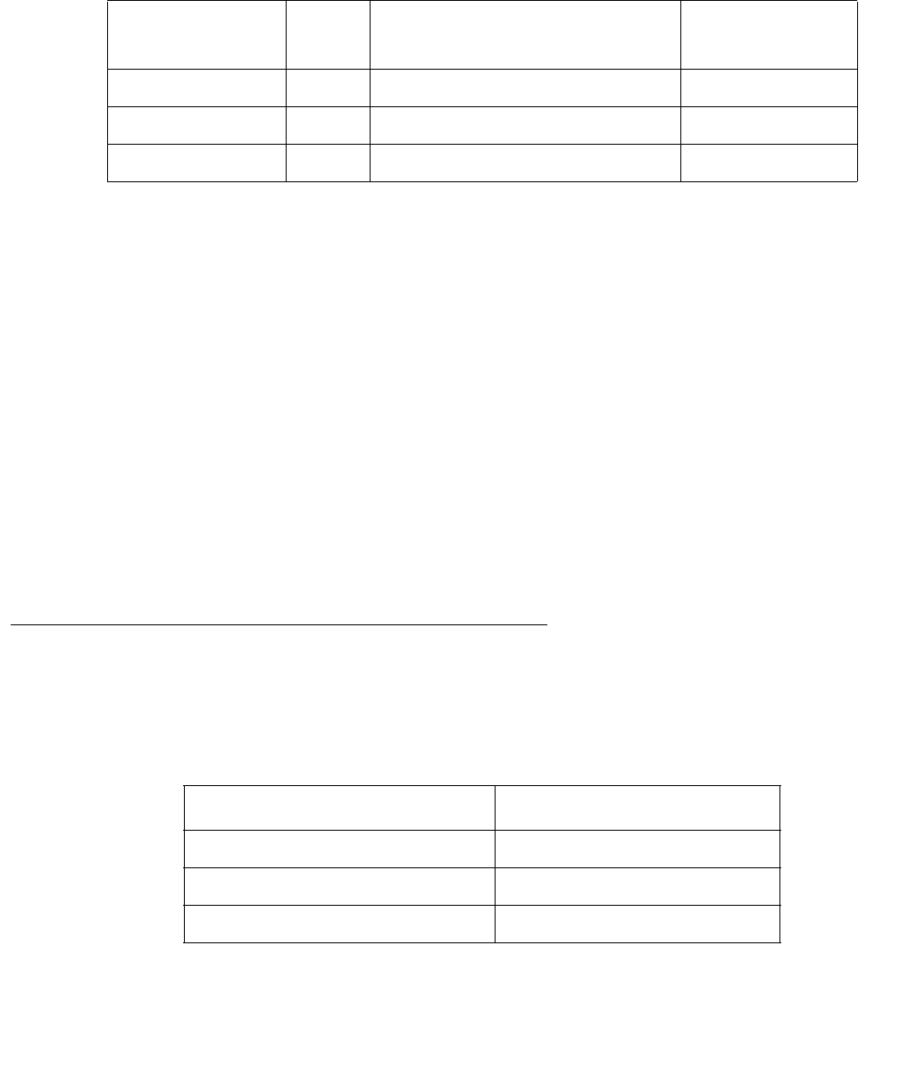
ETH-PT (Control LAN Ethernet)
Issue 1 June 2005 1153
ETH-PT (Control LAN Ethernet)
S8700 | 8710 / S8500 / S8300
The TN799DP Control LAN (C-LAN) packet port circuit pack provides TCP/IP connection to
adjuncts applications such as CMS, INTUITY, and DCS Networking. The C-LAN circuit pack has
one 10baseT Ethernet connection and up to 16 DS0 physical interfaces for PPP connections.
Multiple C-LAN circuit packs in a system provide additional TCP/IP capacity.
Note:
Note: S8300 / G700: Although the ETH-PT MO is provided for a G700 media gateway,
this MO only partially supports the G700’s MG-ANN virtual media module.
An RSCL (remote socket control link) links the C-LAN and the media server to pass call-control
and other management information. Since one link serves every port on the circuit pack,
maintenance of the RSCL is part of the C-LAN circuit pack’s maintenance.
Note:
Note: The TN799DP C-LAN circuit pack replaces the PGATE and PI circuit packs in the
G3r and G3si/G3vs systems, respectively. The PGATE or PI can be used with the
C-LAN to create an X.25-to-TCP/IP bridge for adjunct and DCS connections.
Control LAN Congestion Controls
The switch activates congestion controls on C-LAN when it detects buffers exceeding the
threshold. The switch releases the congestion controls when the C-LAN reports that its buffers
have returned to normal levels.
MO Name in
Alarm Log
Alarm
Level
Initial SAT Command to Run Full Name of MO
ETH-PT MAJ test port location long MO_ETH_PT
ETH-PT MIN test port location long MO_ETH_PT
ETH-PT WRN test port location short MO_ETH_PT
If congestion: Then the switch:
Persists for a 14-minute interval Raises a MINOR alarm.
Exhausts buffers Raises a MINOR alarm.
Ceases for 12 minutes Retires a MINOR alarm.
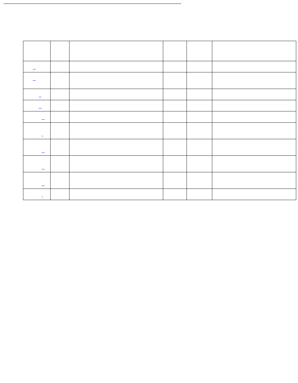
Communication Manager Maintenance-Object Repair Procedures
1154 Maintenance Procedures for Avaya Communication Manager 3.0, Media Gateways and Servers
Error Log Entries and Test to Clear Value
Notes:
a. Error Type 0: Run the short test sequence first. If every test passes, run the long test
sequence. Refer to each appropriate test’s description, and follow its recommended
procedures.
b. Error Type 1: Ethernet Local Looparound test (#1278) failed.
1. Test the port (test port location long).
2. Refer to repair procedures for Test #1278.
c. Error Type 513: Link Integrity Inquiry test (#1282) failed, or C-LAN port detected loss of
Ethernet link integrity.
Possible causes:
●Cables
●Ethernet transceiver
1. Test the port (test port location long).
2. If the Link Integrity Inquiry test (#1282) fails, refer to its repair procedure.
Table 395: ETH-PT Error Log Entries
Error
Type
Aux
Data
Associated Test Alarm
Level
On/Off
Board
Test to Clear Value
0 (a)0Any AnyAnytest port location s
1 (b) 0 Ethernet Local Looparound test
(#1278)
MIN ON test port location l r 3
513 (c) 0 Link Integrity Inquiry (#1282) MIN OFF test port location r 2
769 (d)0 WRN OFF
1281 (e)0
1537,
1538 (f)
Session Status test (#1286) MIN OFF
1793–
1920 (g)
2305–
2560 (h)
2561–
2816 (h)
3329 (i) TCP/IP Ping test (#1281) WRN OFF
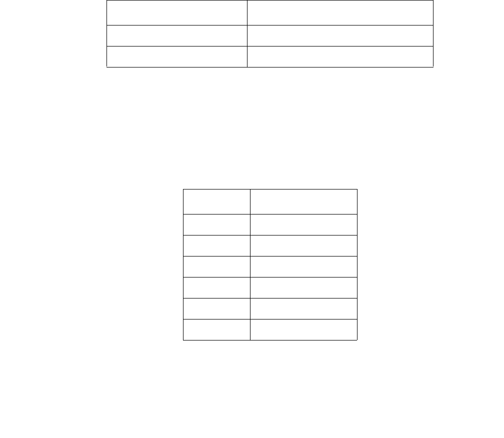
ETH-PT (Control LAN Ethernet)
Issue 1 June 2005 1155
d. Error Type 769: Port received invalid frame.
Invalid Ethernet frame errors occur when the frame:
●Contains a bad cyclic redundancy check (CRC)
●Is misaligned
1. Isolate the problem with the Ethernet Local Looparound test (#1278).
2. Test the port (test port location long).
3. Verify the repair with the Ethernet Local Looparound test (#1278).
4. Clear the alarm (test port location long clear).
e. Error Type 1281: System software received an indication that the far end has requested a
disconnect of a session on this link. This is a log-only error.
f. Error Type 1537–1538: Some or all sessions on a port are down
.
1. Test the port (test port location short).
2. Refer to Session Status test (#1286) repair procedure to verify repair.
g. Error Type 1793–1920: System software received an indication that a socket was closed
due to an error.
The error type indicates the application associated with this socket. (Whereas, the Aux Data
indicates the internal application number.)
If: Then the switch raises:
Some sessions are down WARNING alarm on circuit pack
Every session is down MINOR alarm on circuit pack
Error Type Application
1793 Unused
1794 DCS
1795 AUDIX
1796 CMS
1797 ISDN Gateway
1798–1920 Reserved for future

Communication Manager Maintenance-Object Repair Procedures
1156 Maintenance Procedures for Avaya Communication Manager 3.0, Media Gateways and Servers
h. Error Type 2305–2816: System software detected a session is down. Aux Data indicates
the session number. These are log-only errors. Error types 2305–2560 are for session
numbers 1–256. Error types 2561–2816 are for session numbers 257–512.
i. Error Type 3329: TCP/IP Ping test failed.
1. Test port (test port location short).
2. Refer to TCP/IP Ping test (#1281) repair procedures.
System Technician-Demanded Tests:
Descriptions and Error Codes
Investigate errors in the order they appear in the following table.
Ethernet Local Loop-around Test (#1278)
This test is destructive.
Use this test to check circuitry in the data path for an Ethernet call (from the on-board processor
to the Ethernet Transceiver). This test fails if the data it receives does not match the data it
transmits.
Table 396: System Technician-Demanded Tests: ETH-PT
Order of Investigation Short Test
Sequence
Long Test
Sequence
D/ND1
1. D = Destructive, ND = Nondestructive
Ethernet Local Loop-Around test (#1278) X D
TCP/IP Ping test (#1281) X X ND
Session Status test (#1286) X X ND
Link Integrity Inquiry test (#1282) X X ND
Verify NIC options (#1511) X X ND

ETH-PT (Control LAN Ethernet)
Issue 1 June 2005 1157
Table 397: Test #1278 Ethernet Local Loop-Around Test
Error
Code
Test
Result
Description / Recommendation
1000 ABRT The port is in use.
1. Determine status of port (status clan-port location).
2. Retry the command when the port is idle. You can force the port to the
idle state by executing busyout port location.
!CAUTION:
CAUTION: The busyout port command is destructive, causing
every call and link associated with the port to be torn down.
2000 ABRT Did not receive circuit pack test response within the allowable time period.
1. If the problem persists, reset the circuit pack (busyout board
location, reset board location, and release board
location).
2. If the problem persists, replace the circuit pack.
2012 ABRT Internal system error.
1. Retry the command at 1-minute intervals, up to 3 times.
2. If the problem persists, escalate the problem.
2100 ABRT Could not allocate the necessary resources to run test.
1. Retry the command at 1-minute intervals, up to 5 times.
2. If the problem persists, escalate the problem.
1 FAIL Circuit pack detected failure in the Ethernet Local Looparound test
(#1278).
1. If the problem persists, reset the circuit pack (busyout board
location, reset board location, and release board
location).
2. If the problem persists, replace the circuit pack.
PASS The circuitry tests properly.

Communication Manager Maintenance-Object Repair Procedures
1158 Maintenance Procedures for Avaya Communication Manager 3.0, Media Gateways and Servers
TCP/IP Ping Test (#1281)
This nondestructive test fails if every endpoint fails to respond. Use this test to check the
circuitry in the data path for a peer-to-peer IP layer connection.
Table 398: Test #1281 TCP/IP Ping Test
Error
Code
Test
Result
Description / Recommendation
1
2
11
ABRT Internal error
1. Retry the command at 1-minute intervals up to 3 times.
2. If the problem persists, escalate the problem.
7 ABRT Destination unreachable.
1. Verify that there is a destination to ping in the routing table (list ip-route
and look for destinations reachable through this Ethernet port).
2. If there are no reachable destinations from this port (i.e., no routes
administered on Ethernet), administer a route and retry.
3. Escalate if the problem persists.
1005 ABRT Incorrect test configuration.
1. Verify Ethernet link is in service (status port location or
status link n).
2. Verify that Ethernet link is enabled (status port location,
status link n, or display data-module).
3. Verify routing table has reachable destinations.
4. Repeat the test.
5. If problem persists while the Ethernet link is in service and enabled,
escalate the problem.
1124 ABRT Ethernet link is not enabled.
1. Verify that the Ethernet link is enabled (status port location,
status link n, or display data-module).
2. If the link is not enabled, enable the link (change data-module).
3. Repeat the test.
4. Escalate if the problem persists.
1 of 3

ETH-PT (Control LAN Ethernet)
Issue 1 June 2005 1159
1125 ABRT Ethernet link not in service.
1. Verify Ethernet link is in service (status port location or
status link n).
2. If the link is not in service, release the link using (release link n or
release port location).
3. Repeat the test.
4. Escalate if the problem persists.
2000 ABRT Did not receive circuit pack test response within the allowable time period.
1. Reset the circuit pack (busyout board location, reset board
location, and release board location).
2. If the test fails again, replace the circuit pack.
2012 ABRT Internal system error.
1. Retry the command at 1-minute intervals, up to 3 times.
2. Escalate if the problem persists.
2100 ABRT Could not locate the necessary system resources to run this test.
1. Retry the command at 1-minute intervals, up to 5 times.
2. Escalate if the problem persists.
2500 ABRT Internal system error.
1. Retry the command at 1-minute intervals, up to 3 times.
2. Escalate if the problem persists.
1003 FAIL Ping to the destination failed due to on-board problem.
1. Retry the command at 1-minute intervals, up to 3 times.
2. If the problem persists, reset the circuit pack (busyout board
location, reset board location, and release board
location).
3. If the problem persists, re-administer the Ethernet connection through
a different Ethernet port, if available.
4. If the problem still persists, or if there are no other available Ethernet
ports, replace the circuit pack.
Table 398: Test #1281 TCP/IP Ping Test (continued)
Error
Code
Test
Result
Description / Recommendation
2 of 3

Communication Manager Maintenance-Object Repair Procedures
1160 Maintenance Procedures for Avaya Communication Manager 3.0, Media Gateways and Servers
Link Integrity Inquiry Test (#1282)
This nondestructive test queries the C-LAN Ethernet port’s physical connections.
1007 FAIL Ping to the destination failed due to the destination down.
1. Verify that at least one destination reachable through this port is up.
Ping this destination (ping ip-address xxx.xxx.xxx.xxx).
2. If the ping to any destination is successful through this port, the link is
up, although some destinations are unreachable. Ignore the failure.
3. If ping to every destination fails, test this port (test port location
short), and follow the repair procedures for Session Status test
(#1286) failures.
PASS TCP/IP Ping test (#1281) is successful.
Table 398: Test #1281 TCP/IP Ping Test (continued)
Error
Code
Test
Result
Description / Recommendation
3 of 3
If . . . Then the test . . .
C-LAN connection is present Passes
C-LAN connection is absent Fails
There is no response Aborts
Table 399: Test #1282 Link Integrity Inquiry Test
Error
Code
Test
Result
Description / Recommendation
1124 ABRT Ethernet link is not enabled.
1. Verify that the Ethernet link is enabled (status port location,
status link n, or display data-module).
2. If the link is not enabled, enable the link (change data-module).
3. Repeat the test.
4. Escalate if the problem persists.
1 of 2

ETH-PT (Control LAN Ethernet)
Issue 1 June 2005 1161
1125 ABRT Ethernet link not in service.
1. Verify whether Ethernet link is in service (status port location
or status link n).
2. If the Ethernet link is not in service, release the link (release link
n or release port location).
3. Repeat the test.
4. Escalate if the problem persists.
1959 ABRT Downlink message error.
1. Retry the command at 1-minute intervals, up to 3 times.
2. Escalate if the problem persists.
2012 ABRT Internal system error.
1. Retry the command at 1-minute intervals, up to 3 times.
2. Escalate if the problem persists.
2100 ABRT Could not locate the necessary system resources to run this test.
1. Retry the command at 1-minute intervals, up to 5 times.
2. Escalate if the problem persists.
2500 ABRT Internal system error.
1. Retry the command at 1-minute intervals, up to 3 times.
2. Escalate if the problem persists.
FAIL Link integrity lost due to problem with attachment of Ethernet cable to the
port.
1. Repeat the test.
2. If the test fails, verify that the cable properly is secured to Ethernet port
and to the bus.
3. Verify the C-LAN circuit pack’s link integrity LED is glowing.
4. Retry the test.
5. If problem persists, see Ethernet Local Loop-around test (#1278)
repair procedures.
PASS The Ethernet Link Integrity test (#1282) detects good connections.
Table 399: Test #1282 Link Integrity Inquiry Test (continued)
Error
Code
Test
Result
Description / Recommendation
2 of 2

Communication Manager Maintenance-Object Repair Procedures
1162 Maintenance Procedures for Avaya Communication Manager 3.0, Media Gateways and Servers
Session Status Test (#1286)
This nondestructive test determines the status of every Ethernet port session. This test queries
the system software on port session status.
If the system software indicates that. . . Then the switch . . .
Every port session is up (ALL UP) Raises no alarm, or retires alarm
Some port sessions are up (SOME UP) Raises WARNING alarm
Every port session is down (ALL DOWN) Raises MINOR alarm
Table 400: Test #1286 Session Status Test
Error
Code
Test
Result
Description / Recommendation
1124 ABRT Ethernet link is not enabled.
1. Verify that the Ethernet link is enabled (status port location,
status link n, or display data-module).
2. If the link is not enabled, enable the link (change data-module).
3. Repeat the test.
4. Escalate if the problem persists.
1125 ABRT Ethernet link not in service.
1. Verify whether Ethernet link is in service (status port location
or status link n).
2. If the Ethernet link is not in service, release the link (release link
n or release port location).
3. Repeat the test.
4. Escalate if the problem persists.
2000 ABRT Did not receive circuit pack test response within the allowable time period.
1. If the problem persists, reset the circuit pack (busyout board
location, reset board location, and release board
location).
2. If the problem persists, replace the circuit pack.
1 of 2

ETH-PT (Control LAN Ethernet)
Issue 1 June 2005 1163
2100 ABRT Could not locate the necessary system resources to run this test.
1. Retry the command at 1-minute intervals, up to 5 times.
2. Escalate if the problem persists.
2500 ABRT Internal system error.
1. Retry the command at 1-minute intervals, up to 3 times.
2. Escalate if the problem persists.
1 FAIL System software indicates at least one Ethernet link session is down
(SOME UP).
1. Isolate downed sessions (status port location or status
link n).
2. Follow actions based on session information.
2 FAIL System software indicates every Ethernet session is down (ALL DOWN).
1. Test the port (test port location) to verify the Ethernet Local
Looparound test (#1278) result.
2. If test passes, wait for system software to indicate ALL UP.
If not, check the destination and other components in the path.
3. If the destination and other components in the path are in service,
take action based on session information.
PASS Every session is up.
Table 400: Test #1286 Session Status Test (continued)
Error
Code
Test
Result
Description / Recommendation
2 of 2

Communication Manager Maintenance-Object Repair Procedures
1164 Maintenance Procedures for Avaya Communication Manager 3.0, Media Gateways and Servers
Verify NIC Options Test (#1511)
This test is non-destructive.
This test verifies if the NIC interface parameters, speed, and duplex (full/half) match with
administration.
The test passes if the NIC parameters match administration. The test fails if the NIC parameters
do not match administration.
Table 401: Verify NIC Options Test (#1511)
Error
Code
Test
Result
Description / Recommendation
1014 ABRT Board is not inserted. Insert and administer a TN2302 board.
1022 ABRT Invalid board. The board is not capable of changing its ethernet options.
The board suffix must be D or greater.
1115 ABRT Unable to allocate system resources (in-use) to run this test.
1. Retry the test at one minute intervals a maximum of 3 times.
2000 ABRT Response to the test was not received within the allowable time. Retry the
command at 1 minute intervals a maximum of 3 times.
1. If this result occurs repeatedly, attempt to reset the circuit pack with
busyout board location and reset board location.
2. If this result occurs again, after resetting the board, replace the circuit
pack.
2012 ABRT Internal system error.
1. Retry the command at 1-minute intervals up to 3 times.
2100 ABRT System resources required for this test are not available.
1. Retry the command at 1-minute intervals up to 5 times.
2801 ABRT Could not find the IP address for this board. Use the change
ip-interfaces location to administer an IP address for this board.
Retest.
2807 ABRT The board is administered but not enabled on the ip-interfaces form. Use
the change ip-interfaces location to enable the board. Retest.
1 of 3

ETH-PT (Control LAN Ethernet)
Issue 1 June 2005 1165
3585 FAIL Aux Data = 1. The board is reporting that it is running half duplex with
auto-negotiate (y). Communication Manager is trying to negotiate the
settings on the circuit pack to match the administered settings and, under
the above condition, it is logging a fault. It could be argued that this is a
false alarm, especially if the link is operating correctly with no observable
degradation of service. This capability (Test 1511) started with release
R011i.03 1.531.0.
Note:
Note: Do not immediately replace the board for this fault. There is
a mismatch between what is programmed in the board and
administration on Communication Manager.
CAT-3 wiring does not support 100Mbps data rates. Wiring
between the backplane and router must be CAT-5
Follow these steps to attempt to resolve the problem.
1. Change the ethernet options. Set the speed to 100Mbps with full
duplex. Set Auto (negotiate) to n. This should match the settings of the
connected router. If the router does not have the same capabilities,
you may have to adjust accordingly. The important thing is to make the
media processor (TN2302) and the connected router match.
Command steps to accomplish changes to Communication Manager
administration.
a) Enter get ethernet-options location to determine current
settings, both administered and actual.
b) Enter change ip-interface location (Enable Ethernet Port
field to n) to turn off the interface. Submit the command to disable the
interface.
c) Enter change ip-interface location change the Ethernet
Options fields as required. Submit the form.
d) Enter change ip-interface location (Enable Ethernet
Port field to y) to turn on the interface. Submit the command. to
enable the interface.
e) Enter get ethernet-options location to verify that Ethernet
options are the same in administration and on the board.
2. If service is normal and the alarm is causing concern, disable the test
and escalate the problem.
Table 401: Verify NIC Options Test (#1511) (continued)
Error
Code
Test
Result
Description / Recommendation
2 of 3

Communication Manager Maintenance-Object Repair Procedures
1166 Maintenance Procedures for Avaya Communication Manager 3.0, Media Gateways and Servers
3585 FAIL Aux Data = 2. The board is reporting different options than what is
administered. Software tried to correct the options but the board did not
take the option update. It could be argued that this is a false alarm,
especially if the link is operating correctly with no observable degradation of
service. This capability (Test 1511) started with release R011i.03 1.531.0.
Note:
Note: Do not immediately replace the board for this fault. There is
a mismatch between what is programmed in the board and
administration on Communication Manager.
Follow these steps to attempt to resolve the problem.
1. Use the command steps listed below to administer the ethernet
options to their desired values.
a) Enter get ethernet-options location to determine current
settings, both administered and actual.
b) Enter change ip-interface location (Enable Ethernet Port
field to n) to turn off the interface. Submit the command to disable the
interface.
c) Enter change ip-interface location change the Ethernet
Options fields as required. Submit the form.
d) Enter change ip-interface location (Enable Ethernet
Port field to y) to turn on the interface. Submit the command. to
enable the interface.
e) Enter get ethernet-options location to verify that Ethernet
options are the same in administration and on the board.
2. If the board values and administration values still do not match repeat
the actions from step 1 above one time.
3. Set the administration values to the actual values that the board is
reporting. Test the board using the test board location
command. If the test still fails replace the board.
4. If service is normal and the alarm is causing concern, disable the test
and escalate the problem.
Table 401: Verify NIC Options Test (#1511) (continued)
Error
Code
Test
Result
Description / Recommendation
3 of 3

ETR-PT (Enhanced Tone Receiver Port)
Issue 1 June 2005 1167
ETR-PT (Enhanced Tone Receiver Port)
S8700 | 8710 / S8500
Note:
Note: Replacing the Tone-Clock circuit pack requires a special procedure which is
described in TONE-BD (Tone-Clock Circuit) on page 2327. That section also
describes the LED display for this board.
The ETR-PT MO is supported by TN2182, TN2312AP and TN2312BP circuit packs.
TN2312AP IPSI Circuit Pack’s Tone-Clock
For a PN with a TN2312 IPSI, the TONE-BD MO is a module located on the IPSI circuit pack. It
provides tone generation, tone detection, call classification, and clock generation and
synchronization. The TN2312 replaces the TN2182B Tone-Clock board and is inserted into
each PN’s Tone-Clock slot. For a non IPSI PN, the TN2182B Tone-Clock circuit packs provide
the previous functions.
The TN2312 IPSI circuit pack (for PNs equipped with IPSIs) or the Tone-Clock circuit packs (for
non IPSI PNs) both house two independent components:
●Tone Generator that provides every tone needed by the system
●Clock that generates clocks for both the system’s Time Division Multiplex (TDM) bus and
the LAN bus. It also aids in monitoring and selecting internal synchronization references.
When resolving errors/alarms on an IPSI or Tone-Clock circuit pack, the following sections
should also be consulted:
●For a non IPSI PN, use set tone-clock UC to establish the tone and synchronization
resources for the system.
●For an IPSI PN, use set ipserver-interface UC to establish the tone and
synchronization resources for the system.
●TONE-PT (Tone Generator)
●TDM-CLK (TDM Bus Clock)
●SYNC (Synchronization)
●TONE-BD
●PKT-INT (IPSI only)
MO Name in
Alarm Log
Alarm
Level
Initial SAT Command to Run Full Name of MO
ETR-PT MAJ test port location sh Enhanced Tone Receiver Port
ETR-PT MIN test port location sh Enhanced Tone Receiver Port
ETR-PT WRN test port location sh Enhanced Tone Receiver Port
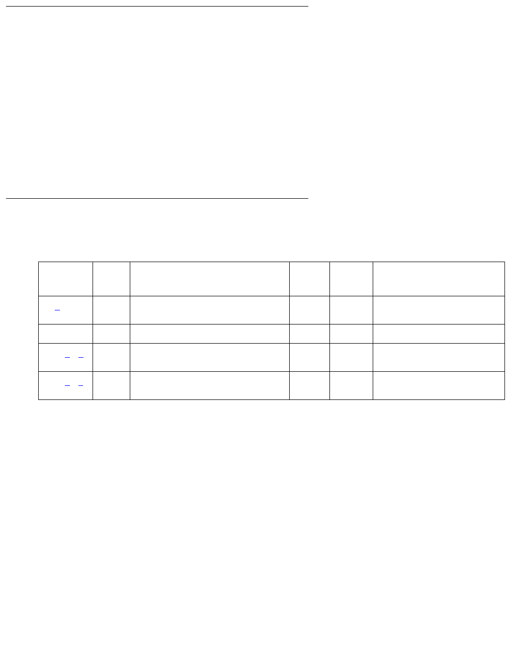
Communication Manager Maintenance-Object Repair Procedures
1168 Maintenance Procedures for Avaya Communication Manager 3.0, Media Gateways and Servers
TN2182 Tone-Clock Circuit Pack (for Non IPSI Connected PNs)
A TN2182 is a combined Tone Generator/Tone Detector board. It provides eight Enhanced Tone
receiver (ETR) ports. Each of these ports provides the functions previously found individually on
DTMR-PTs, GPTD-PTs and CLAS-PTs ports. Each port on the TN2182 may be used for any
tone-detection function that was previously done by TN748, TN420, or TN744 Tone Detection
boards.
The TN2182 provides Mu-law or A-law tone-detection capability.
Since the TN2182 also provides Tone-Clock function, only one TN2182 circuit pack may reside
in a PN (or two if your system is duplicated). If more tone-detection resources are needed, the
additional resources must be provided by TN748, TN420, or TN744 circuit packs.
Error Log Entries and Test to Clear Values
Notes:
a. Error Type 1, 257, 513: There are two possible alarm levels for this error type: major alarm
and minor alarm. These alarm levels are dependent on the administered thresholds for
TTR, CPTR, and CCTR. Each ETR port is capable of operating an any of these.
A major alarm is raised if the total number of ports capable of TTR, CPTR or CCTR
detection currently in service is less than or equal to one-half of the administered TTR,
CPTR, or CCTR threshold number. Otherwise, a minor alarm is raised. In either case, run
the short test sequence against the port (ETR-PT) and follow the error code procedures for
the individual tests.
The threshold number of ports for service is administered using change
system-parameters maintenance.
If a major or minor alarm occurs, follow this repair procedure.
Table 402: ETR-PT Error Log Entries
Error
Type
Aux
Data
Associated Test Alarm
Level
On/Off
Board
Test to Clear Value
1 (a) any Test #43 Tone Detector Audit/Update
Tes t
MAJ
MIN
ON test port location r 2
18 busyout port WRN OFF release port location
257 (a) (b) 17666 Test #43 Tone Detector Audit/Update
Tes t
MAJ
MIN
ON test port location r 3
513 (a) (c) any Test #43 Tone Detector Audit/Update
Tes t
MAJ
MIN
ON test port location r 3

ETR-PT (Enhanced Tone Receiver Port)
Issue 1 June 2005 1169
1. Use list configuration carrier to get the board type and location. If the board is
TN744, then do steps 2–4; if it is TN2182 or TN2312, do steps 5–12.
2. Execute three commands: busyout board location, reset board location,
and release board location. Reset is required to reload RAM associated with the
TN744’s DSPs. This will take all eight tone detector ports out of service for a few
seconds. Only four of the eight would be out of service due to the alarm. (There are four
tone detectors on each of the two DSPs.) Other than the unlikely potential of running out
of tone detector resources in the switch, there is no other effect when the board is reset.
3. Test the board (test board location long).
4. If the test passes, terminate the repair process. If the test fails, replace the board.
5. Check to see if the board is duplicated (list cabinet and status port-network
on the affected PN).
6. If the board is not duplicated, use test tone location long to resolve the error.
The long test resets the board and is required to reload on-board RAM associated with
the DSPs. The effect is that tone detectors are taken out of service momentarily and
tones are removed from the TDM bus for about 10 seconds. This means no dial pulses or
touch tones during this interval, which probably will not affect calls in progress but could
cause a call origination to abort or cause a user to not get dial tone when going off hook.
7. If every test passes and the alarm does not resolve, retest (test tone location
long clear).
8. If the test passes, terminate the repair process. If it fails, replace the circuit pack at the
customer’s convenience.
9. If the board is duplicated, switch to the standby side (set tone/set
ipserver-interface).
10. Test the alarmed board (test tone location long). This resets the board and is
required to reload on-board RAM associated with the circuit pack’s DSPs.
11. If every test passes and the alarm does not resolve, retest with test tone location
long clear.
12. If the test passes, terminate the repair process. If it fails, replace the board.
b. Error Type 257: The ETR-PT lost its translation. Testing the ETR-PT is sufficient to reload
its translation. If testing the ETR port does not clear the error, then the circuit pack
containing the defective ETR port should be replaced at a time when it is convenient to
remove a clock board from the system. Follow the procedures described in TONE-BD
(Tone-Clock Circuit) on page 2327 for replacing a Tone-Clock circuit pack.
c. Error Type 513: This error indicates the (ETR-PT) Enhanced Tone Receiver is having
problems detecting touch tones, call-progress tones, or MFC tones. If this error type is
persistently logged, then the circuit pack containing the defective ETR-PT should be
replaced at a time it is convenient to remove a clock board from the board from the system.
Follow the procedures described in the TONE-BD (Tone-Clock Circuit) on page 2327
section for replacing a Tone-Clock circuit pack.

Communication Manager Maintenance-Object Repair Procedures
1170 Maintenance Procedures for Avaya Communication Manager 3.0, Media Gateways and Servers
System Technician-Demanded Tests:
Descriptions and Error Codes
Investigate tests in the order presented.
Tone Detection Verification Test (#42)
This test checks out a single ETR port’s touch-tone receiver mode, MFC tone-detection/
generation mode, and general-purpose tone-detection mode. During the test sequence, these
modes are tested in the following order:
1. Touch-tone receivers
2. General-purpose, call-progress, and maintenance tones
3. MFC tones
Order of Investigation Short Test
Sequence
Long Test
Sequence
D/ND1
1. D = Destructive; ND = Nondestructive
Tone Detection Verification test (#42) X X ND
Tone Detection Audit/Update test (#43) X X ND
Table 403: Test #42 Tone Detection Verification Test
Error
Code
Test
Result
Description / Recommendation
none ABRT The system was not able to allocate every resource needed for this
test, or there was an internal system error.
1. Retry the command at 1-minute intervals up to 5 times.
1 ABRT The system could not allocate every resource needed to test the tones.
1. Retry the command at 1-minute intervals up to 5 times.
1001 ABRT The system was unable to put the ETR-PT in the appropriate mode to
test it.
1. Retry the command at 1-minute intervals up to 5 times.
1 of 3

ETR-PT (Enhanced Tone Receiver Port)
Issue 1 June 2005 1171
1002 ABRT The system could not allocate time slots for the test connection. This
situation could occur when the system is heavily loaded. If the system
is not heavily loaded, test the TDM-BUS with test tdm.
1. Retry the command at 1-minute intervals up to 5 times.
1003 ABRT The system could not allocate a Tone-Clock for the test connection.
This may be caused by a heavy load on the system or by a faulted
Tone-Clock.
1. Check to see if there are any alarms against the TONE-BD or
TONE-PT in the PN where the test aborted.
2. If a new Tone-Clock has been inserted, allow about 1 minute for
maintenance to run on the newly inserted circuit pack.
3. Retry the command at 1-minute intervals up to 5 times.
2000 ABRT Circuit pack’s response to the test request was not received within the
allowable time period.
1. Retry the command at 1-minute intervals up to 5 times.
2006 ABRT This abort code indicates that the active Tone-Clock circuit pack or a
Tone Detector circuit pack may not be functioning properly.
1. Test the active Tone-Clock circuit pack in the PN with test
tone-clock UUC.
2. Retry the command at 1-minute intervals up to 5 times.
2100 ABRT Could not allocate the necessary system resources to run this test.
1. Retry the command at 1-minute intervals up to 5 times.
1–122 FAIL DTMF digits were not detected correctly.
1. Run the short test sequence with test port location sh r
1.
2. If the problem persists, the system is still operating properly but
capacity is reduced. To restore performance to normal, replace the
circuit pack with the defective ETR-PT.
Table 403: Test #42 Tone Detection Verification Test (continued)
Error
Code
Test
Result
Description / Recommendation
2 of 3

Communication Manager Maintenance-Object Repair Procedures
1172 Maintenance Procedures for Avaya Communication Manager 3.0, Media Gateways and Servers
102 FAIL 2225-Hz Modem Answer Tone was not detected correctly. This
impacts call-classification operation.
1. Run the short test sequence via test port location sh r
1.
2. If the problem persists, the system can still operate properly but
capacity is reduced. In order to restore performance to normal,
replace the circuit pack containing the defective port. Follow the
procedures described in TONE-BD (Tone-Clock Circuit) on
page 2327 for replacing a Tone-Clock circuit pack.
130 FAIL Forward or Backward MFC signals were not correctly generated or
detected. This will impact MFC calls.
1. Run the short test sequence via test port location sh r
1.
2. If the problem persists, the system can still operate properly but
capacity will be reduced. In order to restore performance to
normal, replace the TN2182/TN2312AP circuit pack containing the
defective ETR-PT. Follow the procedures described in TONE-BD
(Tone-Clock Circuit) on page 2327 for replacing a Tone-Clock
circuit pack.
PASS Tone detection verification is successful. The ETR port is able to detect/
generate every necessary tone.
Table 403: Test #42 Tone Detection Verification Test (continued)
Error
Code
Test
Result
Description / Recommendation
3 of 3

ETR-PT (Enhanced Tone Receiver Port)
Issue 1 June 2005 1173
Tone Detector Audit/Update Test (#43)
A Digital Signal processor sanity audit is performed on the ETR-PT.
Table 404: Test #43 Tone Detector Audit/Update Test
Error
Code
Test
Result
Description / Recommendation
none ABRT The system could not allocate every resource needed for this test.
1. Rerun the test at 1-minute intervals up to 5 times.
2000 ABRT Response to the test request was not received within the allowable time
period.
1. Rerun the test at 1-minute intervals up to 5 times.
2100 ABRT Could not allocate the necessary system resources to run this test.
1. Retry the command at 1-minute intervals up to 5 times.
1 of 3

Communication Manager Maintenance-Object Repair Procedures
1174 Maintenance Procedures for Avaya Communication Manager 3.0, Media Gateways and Servers
FAIL Hardware audit failed.
1. Use list configuration carrier to get the board type and
location. If the board is TN744, then do steps 2–4; if it is TN2182/
TN2312AP, do steps 5–12.
2. Execute three commands: busyout board location, reset
board location, and release board location. Reset is
required to reload RAM associated with the TN744’s DSPs. This will
take all eight tone detector ports out of service for a few seconds.
Only four of the eight would be out of service due to the alarm. (There
are four tone detectors on each of the two DSPs.) Other than the
unlikely potential of running out of tone detector resources in the
switch, there is no other effect when the board is reset.
3. Test the board (test board location long).
4. If the test passes, terminate the repair process. If the test fails,
replace the board. Follow the procedures in TONE-BD.
5. Check to see if the board is duplicated (list cabinet and status
port-network on the affected PN.)
6. If the board is not duplicated, use test tone location long to
resolve the error. The long test resets the board and is required to
reload on-board RAM associated with the TN2182’s/TN2312AP’s
DSPs. The effect is that tone detectors are taken out of service
momentarily and tones are removed from the TDM bus for about 10
seconds. This means no dial pulses or touch tones during this
interval, which probably will not affect calls in progress, but could
cause a call origination to abort or cause a user to not get dial tone
when going off hook.
7. If every test passes and the alarm does not resolve, retest (test
tone location long clear).
8. If the test passes, terminate the repair process. If it fails, replace the
circuit pack at the customer’s convenience. Follow the procedures in
TONE-BD.
9. If the board is duplicated, switch to the standby side (set tone/set
ipserver-interface).
Table 404: Test #43 Tone Detector Audit/Update Test (continued)
Error
Code
Test
Result
Description / Recommendation
2 of 3

ETR-PT (Enhanced Tone Receiver Port)
Issue 1 June 2005 1175
FAIL
(cont’d)
10. Test the alarmed board (test tone location long). This resets
the board and is required to reload on-board RAM associated with the
TN2182’s/TN2312AP’s DSPs.
11. If every test passes and the alarm does not resolve, retest with test
tone location long clear.
12. If the test passes, terminate the repair process. If it fails, replace the
board. Follow the procedures in TONE-BD.
PASS The ETR port has passed the sanity inquiry.
Table 404: Test #43 Tone Detector Audit/Update Test (continued)
Error
Code
Test
Result
Description / Recommendation
3 of 3
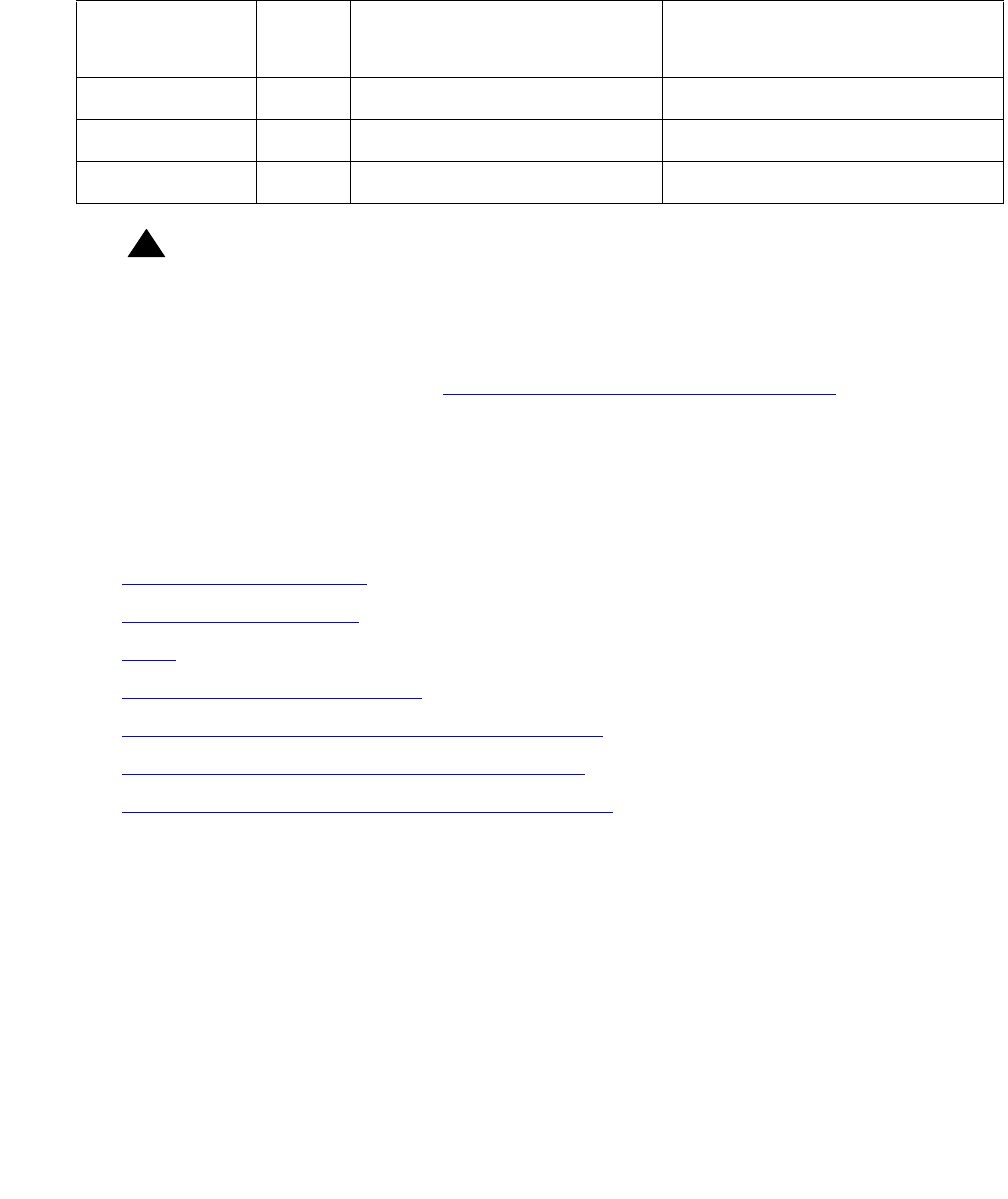
Communication Manager Maintenance-Object Repair Procedures
1176 Maintenance Procedures for Avaya Communication Manager 3.0, Media Gateways and Servers
EXP-INTF (Expansion Interface Circuit Pack)
S8700 | 8710 / S8500
!WARNING:
WARNING: If the Expansion Interface (EI) circuit pack you are troubleshooting is associated
with a Survivable Remote EPN (SREPN), before the SREPN can be returned to
normal service, every LAPD EI link problem must be cleared, and the SREPN
slide switch on the TN2301 (located in the SREPN carrier) must be manually set
to the normal position. See Restoring Normal Service to the SREPN on
page 1183 in this section.
Refer also to Avaya MultiVantage Solutions Installation and Maintenance for Survivable Remote
EPN, 555-233-121.
Following this introductory description of the Expansion Interface (EI) circuit pack are sections
on the following topics:
●EI In-Service Mechanism on page 1181
●Survivable Remote EPN on page 1182
●LEDs on page 1183
●EI and Tone-Clock Interactions on page 1186
●Replacing an EI Circuit Pack—Unduplicated PNC on page 1189
●Replacing an EI Circuit Pack— Duplicated PNC on page 1190
●Expansion Interface Manual Loop-Back Procedure on page 1191
The TN570 or the TN776 Expansion Interface (EI) circuit pack provides a TDM- and packet
bus-to-fiber interface for the communication of signaling information, circuit-switched
connections, and packet-switched connections between endpoints residing in separate PNs. EI
circuit packs are connected via optical fiber links. An EI can be connected to:
●Another EI, in a direct-connect configuration
●A DS1 converter in a DS1 converter complex, used to remote a PN
●A Switch Node Interface (SNI), in a center stage switch (CSS) configuration
●A survivable remote EPN (SREPN)
MO Name in
Alarm Log
Alarm
Level
Initial SAT Command to
Run
Full Name of MO
EXP-INTF MAJ test board location s Expansion Interface circuit pack
EXP-INTF MIN test board location s Expansion Interface circuit pack
EXP-INTF WRN test board location s Expansion Interface circuit pack
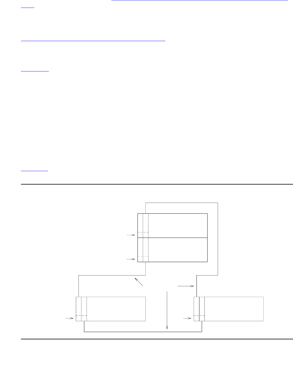
EXP-INTF (Expansion Interface Circuit Pack)
Issue 1 June 2005 1177
In a CSS configuration with duplicated Port Network Connectivity (PNC), EI circuit packs reside
in the Switch Node Carrier (see Figure 64: Center Stage Switch Configuration with Duplicated
PNC on page 1180). In this case, the EI and SNI circuit packs may be connected via a metallic
cable instead of an optical fiber link. Metallic cable should be tested and replaced in the same
manner as optical fiber.
A PN-to-PN connection can be extended through a DS1 converter complex. (See
Figure 65: Fiber Link with DS1 Converter Complex on page 1181). When discussing problems
that may be related to fiber links, the DS1 converter is considered part of the fiber link. If
diagnosis of the problem points to fiber connectivity and a DS1 converter circuit pack is part of
the connectivity, problems with the DS1 converter circuit pack should be investigated (see
DS1C-BD on page 1077). The DS1 converter circuit pack enters into diagnostics for the EI
circuit pack via such tests as the Neighbor Query test (#237), the Fiber Out-of-Frame test
(#238), the Two-Way Transmission test (#241), and the Packet Transmission test (#589).
In a critical-reliability system, the fiber link’s are duplicated as part of PNC duplication. In a
high-reliability system with a CSS (Center Stage Switch) and unduplicated PNC, a single point
of failure between the media server and the CSS is eliminated by duplicating each link,
consisting of:
●SNI in the CSS to which the PN’s EI connects
●Physical fiber paths between them
These dual connections normally share the call-processing load. Should one of these links fail,
the entire load can be shifted to the operational link.
Figure 61 shows the location of the EI circuit packs in a typical unduplicated PNC, direct
connect configuration.
Figure 61: Direct Connect Configuration with Unduplicated PNC
Slot #
Slot #
Slot # Slot #
2
2
2 1 2 1
CABINET 2 CABINET 3
CARRIER A CARRIER A
CABINET 1
CABINET 1
EPN
EPN
E
E
E E E E
I
FIBER LINKS
I
I I I I
PORT CARRIER
PORT CARRIER
PPN
PPN
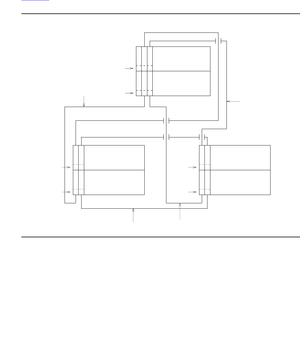
Communication Manager Maintenance-Object Repair Procedures
1178 Maintenance Procedures for Avaya Communication Manager 3.0, Media Gateways and Servers
Each PN in a direct-connect configuration must be connected to the other PNs through a fiber
link. Each PN has one EI that functions as an Archangel. This EI must be connected with fiber
to an EI. If an EI is functioning as an Archangel (bus master), its amber LED will be flashing at a
rate of 2 seconds on and 200 ms off.
Figure 62 shows the location of EI circuit packs in a typical duplicated PNC, direct-connect
configuration.
Figure 62: Direct Connect Configuration with Duplicated PNC
In a duplicated PNC there is an A-side and a B-side PNC. Every EI in this diagram is labeled
with an A or a B designating to which PNC it belongs. Note that a PNC’s designation (A or B)
does not relate directly to the carrier where its EIS reside. Again, only one of a PN’s EIs can
function as the Archangel (TDM-bus master). A PN’s EI that is:
●On the active PNC
●Logically connected to the media server
is the only one that can function in this mode. In normal operation, its amber LED should be
blinking at a rate of 2 seconds on and 200 ms off.
PPN
CAB 1
CARRIER D
CARRIER C
EPN
CAB 2
CARRIER B
CARRIER A
EPN
CAB 3
CARRIER B
CARRIER A
FIBER 1 (A)
FIBER 1 (B)
FIBER 2 (A)
FIBER 2 (B)
FIBER 3 (B)
FIBER 3 (A)
E E
E E
E E
E E
E E
E E
I I
I I
3 2
3 2
Slot #
Slot #
Slot #
2 1
2 1
2 1
2 1
Slot #
Slot #
Slot #
I I
I I
I I
I I
(A) (A)
(A) (A) (A) (A)
(B) (B) (B) (B)
(B) (B)
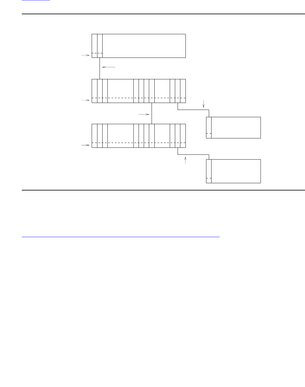
EXP-INTF (Expansion Interface Circuit Pack)
Issue 1 June 2005 1179
Figure 63 shows the location of EIs in a typical center stage switch configuration with
unduplicated PNC.
Figure 63: Center Stage Switch Configuration with Unduplicated PNC
For an unduplicated center stage switch configuration, only one EI is needed in each PN. Notice
that there is no direct connection between the PNs, rather every inter-PN connection is made
through the center stage switch. Each SNI in the switch node carriers can be connected to a PN
through an EI circuit pack.
Figure 64: Center Stage Switch Configuration with Duplicated PNC on page 1180 shows the
location of EIs in a typical two Switch Node Center Stage Switch configuration with duplicated
PNC.
METALLIC
FIBER
Slot #
Slot #
Slot #
C
20 19 13 12 10 3 2
C C
CN N N N N N
N N N N N N N
NS S S S S S
S S S S S S S
S
CAB 3
I
1
1
I
E
E
CARRIER A
CARRIER A
CAB 2
EPN
EPN
I I I I
I I I I I
I
20 19 13 12 10 3
CARRIER C
CABINET 1
PPN
2
CAB 2
SN #2
CARRIER E
CARRIER E
CAB 1
SN #1
2 1
FIBER
FIBER
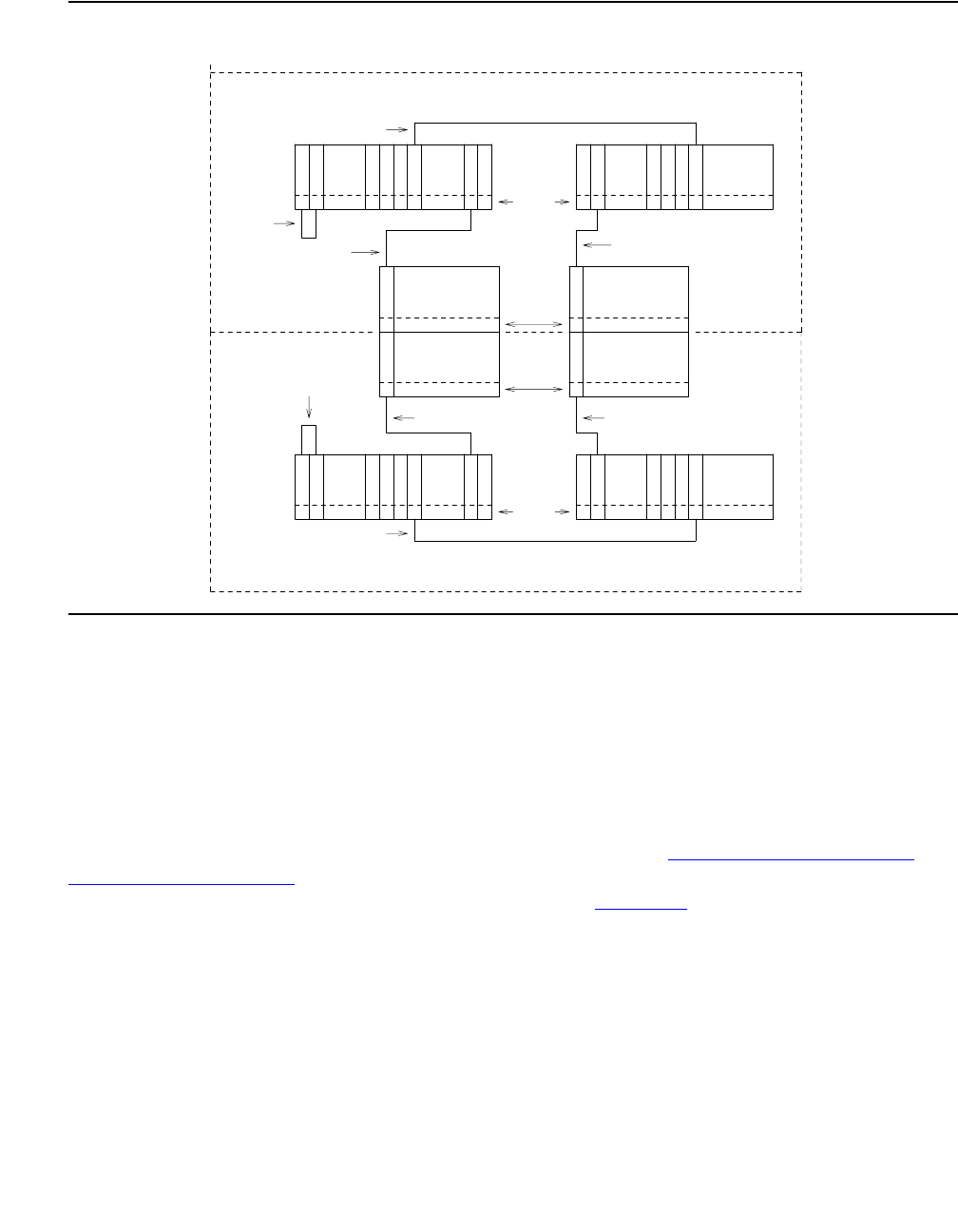
Communication Manager Maintenance-Object Repair Procedures
1180 Maintenance Procedures for Avaya Communication Manager 3.0, Media Gateways and Servers
Figure 64: Center Stage Switch Configuration with Duplicated PNC
In a duplicated center stage switch configuration, two EIs are needed in each PN. One resides
in the PNC’s A side and one in the B side. Note that a PNC designation (A or B) does not
directly designate the carrier where an EI resides. The active PNC’s EI is the one acting as the
PN’s Archangel (TDM bus master). This EI’s amber LED should be blinking at a rate of
2 seconds on and 200 ms off. Whereas, the amber LED on standby PNC’s EI should be off.
A PN (and thus, the EIs contained within it) can be remoted via a DS1 Converter complex. This
requires that a fiber link (providing connectivity to the remoted PN) be administered with an
associated DS1 Converter complex. This complex consists of two TN574 DS1 Converter
(DS1C-BD) circuit packs connected by from 1 to 4 DS1 facilities. Figure 65: Fiber Link with
DS1 Converter Complex on page 1181 shows where the DS1 converter complex fits into an
EI-to-SNI or EI-to-EI fiber link. For more information, see DS1C-BD on page 1077.
FIBER
FIBER
A-PNC
FIBER
FIBER FIBER
21
21
10
1 1
1 2 10 13
13 1 2 10 12
N N N
N N N N
I I I I I
II
II I
C C
C C
CARRIER D
SN #1
SN #1
CAB 1
CAB 1
CARRIER D
Slot #
Slot #
EPN EPN
CAB 2
CAB 2
CARRIER B CARRIER B
CARRIER A CARRIER A
CAB 3
CAB 3
Slot #
Slot #
SN #2
SN #2
CAB 2
CAB 2
CARRIER E CARRIER E
E
E
E
E
E
E
I
I I
I I
I
S S S S S S S
S S S
S S S S
N N N N N N N
1
2
2
2 10 13
13 2 1
20
20
B-PNC
METALLIC
METALLIC
CABLE
CABLE
FIBER

EXP-INTF (Expansion Interface Circuit Pack)
Issue 1 June 2005 1181
Figure 65: Fiber Link with DS1 Converter Complex
EI In-Service Mechanism
In order for calls to be routed through a given PN, the EI that is part of the connectivity to that
PN must be put into service. In order for an EI to be put into service, the following criteria must
be met:
1. The EI must be recognized by software (inserted). Use list config carrier to verify
that the board is recognized by software.
2. The EI must have a fiber link administered to it. Use list fiber-link to verify that this
EI circuit pack has a fiber administered to it.
3. The EI must have established a LAPD link to its neighbor (the circuit pack on the “other end”
of the fiber link). This neighbor can be another EI or an SNI.
!CAUTION:
CAUTION: If previous requirements 1 and 2 have been met, and the amber LEDs are
flashing in a manner that appears to confirm that the EI circuit pack has
established a LAPD link to its neighbor, the circuit pack still may not be “in
service”. The requirement is that it must have the CORRECT neighbor on the
other end of the fiber. Care must be taken when connecting the fibers to the back
of the carriers so that fibers are connected to the correct circuit packs. In a Center
Stage Switch configuration, run the “configuration audit” test against the SNI
circuit pack that is the neighbor of the EI circuit pack in question (see SNI-BD
(SNI Circuit Pack) on page 2046 for more details).
Once an EI has been put into service, if any of the previously listed in-service criteria become
untrue, the EI is taken out of service, and service to that PN is not available.
In a system that is configured with PNC duplication active, taking an EI out of service that is on
the active PNC will, if all other things on the active and standby PNC are equal (i.e., both PNCs
are equally healthy, the standby PNC is not busied out, the PNC is not locked by software),
result in a PNC interchange.
METALLIC CABLE or METALLIC CABLE or
EI EI (TN570)
(TN570)
or
SNI
(TN573)
DS1C DS1C
(TN574) (TN574)
OPTICAL FIBER OPTICAL FIBER 1 to 4 DS1 FACILITIES

Communication Manager Maintenance-Object Repair Procedures
1182 Maintenance Procedures for Avaya Communication Manager 3.0, Media Gateways and Servers
Survivable Remote EPN
The Survivable Remote EPN (SREPN) feature allows a S8700 Multi-Connect EPN (either MCC
or SCC) to provide service to the customer when:
●Its fiber (or T1/E1 EI link to the S8700 Multi-Connect processor) fails or is severed
●The S8700 Multi-Connect processor or center stage fails.
Note:
Note: This feature is viewed as a “disaster recovery operation” capability rather than as
an additional reliability option.
The SREPN allows a remote EPN cabinet to provide processor capabilities to the EPN in the
event of a failure. A logic switch circuit pack (TN2301) located in the SRPPN detects when the
link to the S8700 Multi-Connect is down and switches to a link from the local SRPPN
(TN790B-based processor). When the links to the S8700 Multi-Connect are restored and
verified to be stable, the logic switch is manually reset, and the EPN is reconnected to the links
from the S8700 Multi-Connect.
Note:
Note: The SREPN feature is not available when an ATM-PNC/EI circuit pack is used to
replace the TN570 EI circuit pack in a direct-connect configuration, or an ATM
Switch is providing the Center Stage (PNC) connectivity.
Note:
Note: If you suspect a problem with the TN790B-based R6si SRPPN use the R6si
maintenance documentation supplied with the SREPN feature to resolve any
alarms/errors associated with the SRPPN carrier.
SREPN Feature Active
!WARNING:
WARNING: Every call within the SREPN is terminated when the SREPN feature is activated,
and the R6si SRPPN takes control of the SREPN.
The SREPN feature is activated when the Maintenance circuit pack (TN775C or later and
located in the SREPN) detects a problem with the SREPN’s EI (TN570B) LAPD link to its
counterpart in a S8700 Multi-Connect EPN. The TN775C Maintenance circuit pack notifies the
co-located SRPPN of the problem, and the TN2301 SRSwitch circuit pack in the SRPPN carrier
switches the EI LAPD link connection from the S8700 Multi-Connect Port Network to its
counterpart in the S8300 Media Server with G700 Media Gateway SRPPN. The SREPN is now
in the Survivable Remote mode and has the capabilities of an S8300 Media Server with G700
Media Gateway EPN that has been pre-translated with a Disaster Recovery configuration.
Note:
Note: When SREPN feature is active, the EI circuit pack that is assigned to the SREPN
and located in the S8700 Multi-Connect PN is put in loop-back mode.

EXP-INTF (Expansion Interface Circuit Pack)
Issue 1 June 2005 1183
Restoring Normal Service to the SREPN
!WARNING:
WARNING: Every call within the SREPN is terminated when the SREPN feature is returned
to normal service.
To restore normal connections to the SREPN EI circuit pack in the S8700 Multi-Connect PN,
you must:
1. Clear every error logged against the S8700 Multi-Connect SREPN EI circuit pack by using
the suggested repair procedures outlined in this MO.
2. At the SRP flip the 3-position switch on the TN2301 to the RSTR (restore) or top position for
at least 1 second and return the switch to the AUTO, or middle position.
3. After the SREPN slide switch has been restored to the normal position, test the connectivity
to S8700 Multi-Connect EI LAPD link, by using the suggested procedures outlined in this
MO.
4. After normal service is returned to the S8300 Media Server with G700 Media Gateway
SREPN, the SRPPN will be in an alarmed state. This is normal for an SRPPN and indicates
that the:
●SRSwitch (TN2301) has disconnected it from its neighbor (EI in the SREPN)
●SRPPN is no longer in control.
Connectivity has been reestablished between the EI in the SREPN and its counterpart EI circuit
pack in the S8700 Multi-Connect PN. The system is now in a normal S8700 Multi-Connect EI
configuration.
LEDs
SREPN Expansion Interface
The EI circuit pack has red, green, and amber LEDs. The red and green LEDs show the
standard conditions:
●Red indicates an alarm condition.
●Green indicates maintenance testing in progress.
The amber LED is used to provide useful visual status information:
●Active EI circuit packs:
- Have their amber LED on solid (for an inter-EPN EI in a direct connect system)
- Blink a pattern of 2 seconds on and 200 ms off.
●The standby PNC EI circuit packs should have their amber LEDs off.
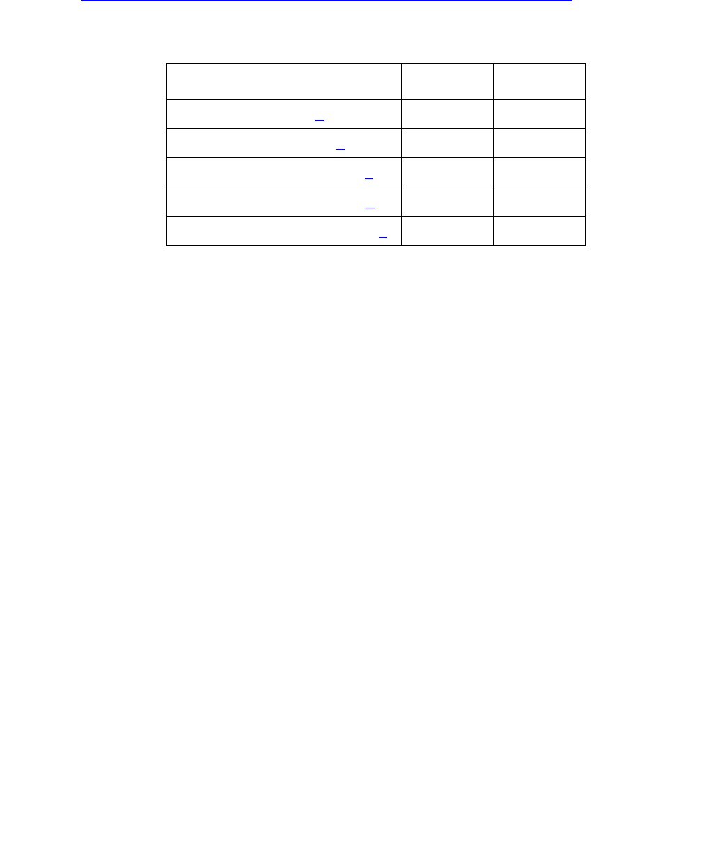
Communication Manager Maintenance-Object Repair Procedures
1184 Maintenance Procedures for Avaya Communication Manager 3.0, Media Gateways and Servers
Another way to determine which PNC (and therefore, which EIs in an EPN) is active and which
is standby, use status port-network and status PNC.
See Table 405: Expansion Interface Circuit Pack Amber LED Flashing States on page 1184 for
the possible EI amber LED states.
Notes:
a. This flashing state corresponds to error codes 769 and 770 from the Hardware Error Log
and indicates a failure of Test #238. These error codes are usually accompanied by error
code 1281 (no EI or SNI detected on opposite end of fiber). This condition may be caused
by the absence of the neighbor EI or SNI circuit pack, a broken or missing fiber, or a missing
lightwave transceiver on either endpoint (EI or SNI circuit packs).
b. This corresponds to error code 1281 from the Hardware Error Log and indicates a failure of
Test #237. This condition is usually due to the failure of this EI circuit pack or a failed EIEI or
SNI circuit pack counterpart.
c. This is the normal state for an active PN EI circuit pack that is also the bus master
(Expansion Archangel) in the EPN.
d. This is the normal state for an active EI circuit pack that is not the bus master (Expansion
Archangel) for a PN. This applies only in the direct-connect configuration where the EI
circuit pack in a PN is connected via a fiber link to an EI circuit pack in the other PN.
e. This is the normal state for a standby EI circuit pack in a PN.
Note:
Note: In a PN, its TN775C Maintenance (MAINT) circuit pack monitors the sanity of the
EI circuit pack. If the EI circuit pack should cycle between sane and insane
several times, the Maintenance circuit pack will hold the EI circuit pack reset. If a
new EI circuit pack is installed in the PN, and the red LED remains lit, the PN’s
Maintenance circuit pack should be removed because it may be holding the new
EI circuit pack reset. This condition could present itself if there is a link problem to
the PN, and the PN experiences several PN restarts. The Maintenance circuit
pack may be reinstalled after the EI circuit pack has been physically inserted and
the EI circuit pack’s red LED has gone off.
Table 405: Expansion Interface Circuit Pack Amber LED Flashing States
Condition LED On LED Off
Fiber Out-of-Frame (a) 0.1 second 0.1 second
In Frame-No Neighbor (b) 0.5 second 0.5 second
Expansion Interface Active (c) 2 second 0.2 second
Expansion Interface Active (d) solid on never off
Expansion Interface Standby (e) never on solid off
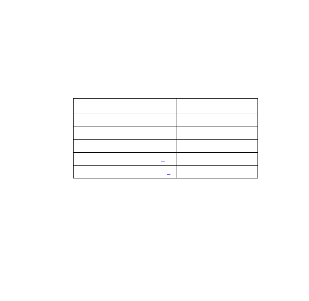
EXP-INTF (Expansion Interface Circuit Pack)
Issue 1 June 2005 1185
The link between two active EI circuit packs or between an active EI circuit pack and an active
SNI circuit pack is involved in synchronization. The EI circuit pack reports slip errors if
synchronization is not operating properly. When diagnosing synchronization problems, the EI
circuit packs should be examined as a possible cause.
Expansion Interface LEDs
The EI circuit pack has the standard red, green, and amber LEDs. The red and green LEDs
have the traditional uses: red means some alarm condition and green indicates maintenance
testing in progress. The amber LED is used to provide useful visual status information. The
state of the amber LED is very important when executing the Expansion Interface Manual
Loop-Back Procedure. The possible amber LED states are shown in Table 406: Expansion
Interface Circuit Pack Amber LED Flashing States on page 1185.
Upon power-up, the red and green LEDs turn on and off. The amber LED goes to its appropriate
state.
To determine which PNC (and which EIs in a PN) is active and which is standby, use status
port-network and status pnc. Alternately, visual inspection will show that the active EI
circuit packs will have their amber LED on solid (for an inter-PN EI in a direct connect system)
or blink a pattern of 2 seconds on and 200 ms off. The standby PNC EI circuit packs will have
their amber LEDs off. See Table 406: Expansion Interface Circuit Pack Amber LED Flashing
States on page 1185 for the possible EI amber LED states.
Notes:
a. Fiber Out-of-Frame - This flashing state corresponds to error codes 769 and 770 from the
Hardware Error Log and indicates a failure of Test #238. These error codes will usually be
accompanied by error code 1281 (no Expansion Interface or SNI detected on opposite end
of fiber). This condition may be caused by the absence of the neighbor EI or SNI circuit
pack, a broken or missing fiber, or a missing lightwave transceiver on either endpoint (EI or
SNI circuit pack).
b. In frame-No Neighbor - This flashing state corresponds to error code 1281 from the
Hardware Error Log and indicates a failure of Test #237. This condition is usually due to the
failure of this EI circuit pack or a failed EI or SNI circuit pack neighbor.
Table 406: Expansion Interface Circuit Pack Amber LED Flashing States
Condition LED On LED Off
Fiber Out-of-Frame (a) 0.1 second 0.1 second
In frame-No Neighbor (b) 0.5 second 0.5 second
Expansion Interface Active (c) 2 second 0.2 second
Expansion Interface Active (d) solid on never off
Expansion Interface Standby (e) never on solid off

Communication Manager Maintenance-Object Repair Procedures
1186 Maintenance Procedures for Avaya Communication Manager 3.0, Media Gateways and Servers
c. This is the normal state for an active PN EI circuit pack that is also the bus master
(Expansion Archangel) in the PN.
d. This is the normal state for an active EI circuit pack that is not the bus master (Expansion
Archangel) for a PN. This applies only in the Direct Connect configuration where the EI
circuit pack in a PN is connected via a fiber link to an EI circuit pack in the other PN.
e. This is the normal state for a standby EI circuit pack in a PN.
Note:
Note: In a PN, its TN775C Maintenance (MAINT) circuit pack monitors the sanity of the
EI circuit pack. If the EI circuit pack should cycle between sane and insane
several times, the Maintenance circuit pack will hold the EI circuit pack reset. If a
new EI circuit pack is installed in the PN, and the red LED remains lit, the PN’s
Maintenance circuit pack should be removed because it may be holding the new
EI circuit pack reset. This condition could present itself if there is a link problem to
the PN, and the PN experiences several PN restarts. The Maintenance circuit
pack may be reinstalled after the EI circuit pack has been physically inserted and
the EI circuit pack’s red LED has gone off.
The link between two active EI circuit packs or between an active EI circuit pack and an active
SNI circuit pack is involved in synchronization. The EI circuit pack will report slip errors if
synchronization is not operating properly. When diagnosing synchronization problems, the EI
circuit packs should be examined as a possible cause.
EI and Tone-Clock Interactions
The viability of the EI fiber link depends upon the system clock that is provided by the active
Tone-Clock circuit pack on each network (see TDM-CLK (TDM Bus Clock) on page 2252 and
TONE-BD (Tone-Clock Circuit) on page 2327). Each EI circuit pack transmits over the fiber at a
rate derived from the system clock on its network. If the active Tone-Clock is defective in such a
way that the frequency of system clock it produces is out of the specified range (“out of spec”),
an EI fiber link might go down. This affects an Expansion Archangel Link (EAL), a Remote
Neighbor Link (RNL), and/or a Local Neighbor Link (LNL), even though the EI circuit packs are
healthy. When the PNC is duplicated, both fiber links could go down if there is a defective active
Tone-Clock.
Whether or not a fiber link goes down, depends on certain characteristics of the EI circuit packs.
An EI circuit pack should not be replaced if the fiber link on which it resides goes down because
of a defective active Tone-Clock circuit pack. The defective Tone-Clock circuit pack should be
replaced instead. The EI circuit packs are more sensitive to a defective system clock than the
rest of the components of the system. Therefore, testing of the Tone-Clock circuit pack might
not reveal a problem.

EXP-INTF (Expansion Interface Circuit Pack)
Issue 1 June 2005 1187
The symptoms of the problem in which an invalid system clock causes an Expansion Link to go
down are as follows:
●If the Tone-Clock in the PN provides the current on-line synchronization reference (see
status synchronization), is providing an invalid system clock:
Any EI or SNI circuit pack has a Fiber Out-of-Frame condition or a No Neighbor condition.
An EI circuit pack amber LED blinks quickly when a Fiber Out-of-Frame condition exists (0.1
seconds on, 0.1 seconds off) and Test #238 fails on the EI circuit pack that is out-of-frame.
An SNI circuit pack with a Fiber Out-of-Frame condition blinks its amber LED quickly (0.1
seconds on, 0.1 seconds off) and Test #989 fails on the SNI circuit pack that is out-of-frame.
An EI circuit pack amber LED blinks slowly when a No Neighbor condition exists (0.5
seconds on, 0.5 seconds off) and Test #237 fails on this EI circuit pack, but Test #238
passes.
An SNI circuit pack with a no neighbor condition blinks its amber LED slowly (0.5 seconds
on, 0.5 seconds off) and Test #759 fails on this SNI circuit pack, but Test #989 passes.
●If a Tone-Clock in a PN that does not provide the current on-line synchronization reference
(see status synchronization) is providing an invalid system clock:
In a direct connect configuration, the PN EI circuit pack amber LED will blink quickly (Fiber
Out-of-Frame condition – 0.1 seconds on, 0.1 seconds off).
Test #238 fails on this EI circuit pack.
In a CSS configuration, the SNI connected to the PN EI circuit pack blinks its amber LED
quickly (Fiber Out-of-Frame condition – 0.1 seconds on, 0.1 seconds off).
The PN EI circuit pack amber LED blinks slowly (In-frame, No Neighbor condition – 0.5
seconds on, 0.5 seconds off).
If the PN is in service, Test #237 fails on this EI circuit pack, but Test #238 passes.
These symptoms can also be the result of other problems (for example, one half of the fiber
being unable to transmit data). If the system exhibits these symptoms, execute the following
procedure:
1. Verify that the PN stays down for at least 1 minute.
If the EAL comes back in service after a short time, without switching the active Tone-Clock,
the problem was probably that the on-line synchronization source became invalid (See
SYNC Maintenance documentation for more information).
However, if the EAL(s) have not come back into service after a minute, the synchronization
source is not the cause of the problem. Proceed to step 2.
2. Check for errors via display errors with the Category field set to tone and the Active
Alarms field set to n. Some of the alarms on PN objects might have been resolved if the PN
went down. Refer to the appropriate MO Maintenance documentation for descriptions of
any of the errors occurring at about the same time as the EXP-PN errors, SYS-LINK errors
against EAL s, RNLs, or LNLs, or FIBER-LK (769, 1025, or 1281) errors. Resolve any active
alarms. Also, if Error Type 18 was logged against the SYNC MO when the PN went down,

Communication Manager Maintenance-Object Repair Procedures
1188 Maintenance Procedures for Avaya Communication Manager 3.0, Media Gateways and Servers
the problem was probably that the synchronization on-line reference became invalid. Since
reference switching was disabled, the Tone-Clock did not switch from the invalid reference.
Therefore, the Tone-Clock circuit pack put out a system clock that was “out of spec.” Enter
enable synchronization-switch. If the PN is down, reseat the Tone-Clock circuit
packs on the PN. This action should restore the PN to service.
Execute Steps 3 and 4 in the order most convenient to you and least destructive to the
customer.
3. Check to see if the fiber-optic cable is transmitting properly via the following procedure on
one of the out-of-service links, or use the Fiber link fault isolation in Maintenance
Procedures (03-300192).
a. Carefully record the symptoms (amber LED pattern and test failing) that were occurring
on the PN EI circuit pack and the PN EI circuit pack or the connected CI circuit pack in
the case of a Center Stage system. Clearly indicate what symptoms are occurring on
which EI/SNI circuit pack.
!CAUTION:
CAUTION: Before proceeding, note which is the current transmit fiber and which is the
current receive fiber for proper re-connection.
b. Disconnect the transmit and receive fiber pair from the lightwave transceiver on the back
of one of the EI circuit pack slots that is exhibiting symptoms.
c. Connect what was formerly the transmit fiber to the receive jack.
d. Connect what was formerly the receive fiber to the transmit jack.
e. Perform steps b, c, and d on the opposite end of the fiber and the lightwave transceiver
on the back of the connected EI or SNI circuit pack slot.
f. If the symptoms that were formerly occurring on the EI circuit pack that was exhibiting
these symptoms are now occurring on the connected EI or SNI circuit pack and vice
versa, the fiber is defective and should be replaced.
4. Determine whether the problem is due to a defective active Tone-Clock circuit pack. Refer
to the preceding list of symptoms to decide which network contains the suspect active
Tone-Clock.
!CAUTION:
CAUTION: If you remove the PN EI circuit pack that is active or that was active when the PN
was last in service, the Tone-Clock lead will revert to the default value which will
cause the Tone-Clock circuit pack located in the A carrier to become the active
Tone-Clock. This characteristic can be deceiving. Replacing or reseating the
active PN EI circuit pack might restore the link(s) temporarily. However, if the
Tone-Clock circuit pack located in the B carrier was really the source of the
problem and not the EI circuit pack, then the link(s) will go down again the next
time a Tone-Clock switch to the Tone-Clock in the B carrier is attempted (probably
when the scheduled Tone-Clock switch occurs).

EXP-INTF (Expansion Interface Circuit Pack)
Issue 1 June 2005 1189
!CAUTION:
CAUTION: If, after every link is restored, you suspect the problem might have been due to a
defective Tone-Clock circuit pack, switch to this Tone-Clock at an appropriate
time. If the Tone-Clock circuit pack was the cause of the problem and the same EI
circuit packs are in place, the same link(s) will go down again.
a. When the suspect Tone-Clock circuit pack resides in an in-service pot network (PN) with
duplicated Tone-Clock circuit packs:
Switch to the standby Tone-Clock in this PN. If the suspect Tone-Clock is defective, the
link(s) should be restored at this point. (Switching back to the defective Tone-Clock
should take the same link(s) out of service.) This Tone-Clock is defective and should be
replaced as soon as possible. If switching Tone-Clocks does not bring up the PN, then
this Tone-Clock is not the source of the problem. Be sure to switch back to the original
Tone-Clock.
!CAUTION:
CAUTION: If a defective Tone-Clock circuit pack is left as the standby Tone-Clock, then a
scheduled Tone-Clock switch will cause the same link(s) go out of service again.
b. When the suspect Tone-Clock resides in an out-of-service PN:
Replace the active Tone-Clock circuit pack in this PN. In a PN with duplicated Tone-Clock
circuit packs, the active Tone-Clock’s amber LED is flashing. If both amber LEDs are
flashing, the active Tone-Clock’s LED is blinking slower.
!CAUTION:
CAUTION: If a defective Tone-Clock circuit pack is left as the standby Tone-Clock, then a
scheduled Tone-Clock switch will cause the same PN to go out of service again.
If replacing this circuit pack restores the link(s), then the circuit pack should be replaced
as soon as possible. If not, then it was not the source of the problem.
Replacing an EI Circuit Pack—Unduplicated PNC
!WARNING:
WARNING: Do not power down a Switch Node carrier to replace a circuit pack.
!WARNING:
WARNING: Replacing a Switch Node Interface, Switch Node Clock, Expansion Interface, or
DS1 Converter circuit pack in a standard-, duplex-, or high-reliability system
disrupts service. This service effect can range from an outage of a single PN to
an outage of the entire system.
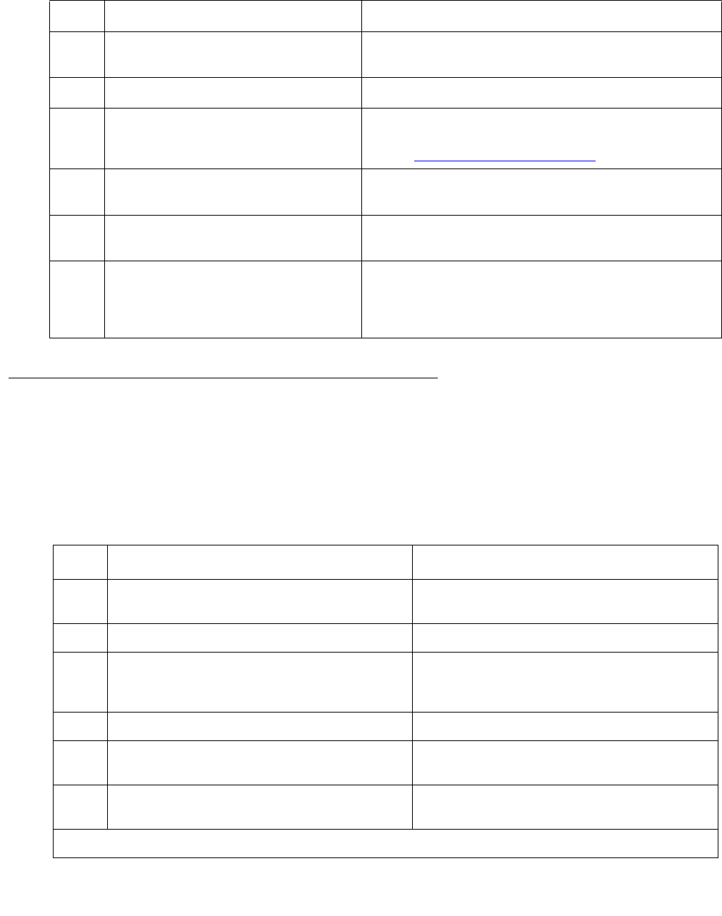
Communication Manager Maintenance-Object Repair Procedures
1190 Maintenance Procedures for Avaya Communication Manager 3.0, Media Gateways and Servers
Replacing an EI Circuit Pack— Duplicated PNC
On a system with duplicated PNC, synchronization may be provided over a combination of
active and standby components. This condition is indicated by an OFF-BOARD WARNING
alarm against TDM-CLK with Error Type 2305. Repairs to standby PNC in this state may disrupt
service. Otherwise, if the active PNC is functional, replacement of a standby component will not
disrupt service.
Step Action Explanation / Caution
1. Enter busyout board
location.
location = cabinet-carrier-slot location of the
circuit pack to be replaced.
2. Replace the circuit pack.
3. Wait for the circuit pack to reset. Red and green LEDs light and then go out.
If the red LED remains lit, see the previous note
under Expansion Interface LEDs on page 1185.
4. Enter release board
location.
CAUTION: Do not busyout any EI circuit packs
after this point.
5. Enter test alarms long
clear for category exp-intf.
6. Wait 5 minutes for SNI-BD,
FIBER-LK, and DS1C-BD alarms
to clear, or enter clear
firmware-counters a-pnc.
Step Action Explanation / Caution
1. Enter status pnc. Verify that the component to be replaced
is on the standby PNC.
2. Enter busyout pnc.
3. Enter busyout board location. location represents the
cabinet-carrier-slot location of the circuit
pack to be replaced.
4. Replace the circuit pack.
5. Enter release board location. CAUTION: Do not busyout any EI circuit
packs after this point.
6. Enter test alarms long clear for
category exp-intf.
1 of 2

EXP-INTF (Expansion Interface Circuit Pack)
Issue 1 June 2005 1191
If the red LED remains lit, see the previous note under Expansion Interface LEDs on page 1185.
Expansion Interface Manual Loop-Back Procedure
This procedure is to be used when an EI circuit pack cannot be tested by software. This occurs
when the EI circuit pack resides in an out-of-service PN. A short length of optical fiber is
required for this procedure.
If this procedure is run on both endpoints of a fiber link (EI circuit packs or SNI circuit packs),
and both check out fine, then the failure is most likely in the fiber itself, assuming neither
endpoint circuit pack is busied out and the link remains inactive.
1. Busyout the circuit pack (EI or SNI) with the busyout board location.
2. Disconnect the transmit and receive fiber pair from the lightwave transceiver on the back of
the circuit pack (EI or SNI) slot.
Note:
Note: The fiber connected to the transmit side of the lightwave transceiver on one EI
circuit pack should be connected to the receive side of the lightwave transceiver
on the circuit pack on the opposite end of the fiber.
3. Using a fiber jumper cable, interconnect the transmit and receive jacks of the lightwave
transceiver as shown in Figure 66: Interconnection of Lightwave Transceiver Transmit/
Receive Jacks on page 1192.
Note:
Note: Make sure that the total length of the fiber jumper cable does not exceed the
maximum length recommended for the fiber link connections between cabinets.
Using cable lengths not within connectivity guidelines can adversely affect test
results.
7. Wait 5 minutes for SNI-BD, SNI-PEER,
FIBER-LK, and DS1C-BD alarms to clear,
or enter clear firmware-counters
a-pnc or b-pnc.
Use the letter designation of the PNC that
holds the replaced component (the
standby PNC).
8. Enter status pnc. If either PNC’s state of health (SOH) is
not “functional,” consult PNC-DUP (PNC
Duplication) on page 1851.
9. Enter release pnc.
Step Action Explanation / Caution
2 of 2
Communication Manager Maintenance-Object Repair Procedures
1192 Maintenance Procedures for Avaya Communication Manager 3.0, Media Gateways and Servers
4. Go to the front of the cabinet and inspect the amber LED.
●If the amber LED flashes on at a rate of once per second, the (EI or SNI) circuit pack or
transceiver should be replaced.
●If the amber LED flashes on at a rate of five times per second, the circuit pack (EI or SNI)
or the lightwave transceiver may need replacement. This condition may also be due to a
faulty system clock on the network containing this EI circuit pack.
●If the amber LED is not blinking, this circuit pack (EI or SNI) and the lightwave transceiver
are functioning properly.
5. Replace faulty components and reconnect the original fiber. Be sure to reconnect the fibers
properly as noted in step 3. If there is a problem with the PN after re-connecting the fiber,
and the PN is connected to a Center Stage Switch, run the Configuration Audit via test
board on the SNI circuit pack to which the intervening fiber is connected. See the SNI-BD
section for instructions on interpreting results.
6. Release EI circuit pack or SNI circuit pack with release board location.
Figure 66: Interconnection of Lightwave Transceiver Transmit/Receive Jacks
Tx Rx
Transceiver
Lightwave
Back Skin of Cabinet

EXP-INTF (Expansion Interface Circuit Pack)
Issue 1 June 2005 1193
Error Log Entries and Test to Clear Values
Table 407: EXP-INTF Error Log Entries
Error
Type
Aux
Data1
Associated
Test
Alarm
Level
On/Off
Board
Test to Clear Value
020Any AnyAnytest board location
1 Any EI Local TDM
Looparound (#240)
MAJ ON test board location r 2
2 EI Local TDM
Looparound (#240)
MAJ ON test board location r 2
18 (a)0busyout board
location
WRN OFF release board location
23 (b) 0 None WRN OFF
125 (c) None MIN ON
131 (d) None MIN ON
257 (e) Any None MIN OFF
513 (f) 5–7 None MAJ ON
769 (g) 113 EI FOOF Query test
(#238)
WRN OFF test board location r 1
770 EI FOOF Query test
(#238)
WRN OFF test board location r 1
1025 Any EI Control Channel
test (#316)
MAJ ON test board location r 1
1281 (h) EI Neighbor Query
test (#237)
MIN OFF test board location r 1
1537 EI 2-way
Transmission test
(#241)
MAJ OFF test board location r 4
1538 (i) None MIN ON
1793 EI Lightwave
Transceiver
Looparound test
(#242)
MAJ ON test board location l r
3
1 of 2

Communication Manager Maintenance-Object Repair Procedures
1194 Maintenance Procedures for Avaya Communication Manager 3.0, Media Gateways and Servers
Notes:
a. Error Type 18: indicates that the EI circuit pack has been busied out via busyout board
location. To resolve this error, release the EI circuit pack via release board
location.
2049 (j) 117 None WRN OFF
2305 (k) 118 None WRN OFF
2306 (l) 3 None WRN OFF
112
2561 (m) Any None MIN ON
2817 (n) Any None MIN ON
3073 (o) Any EI Packet Interface
test (#589)
MAJ OFF test board location r 3
3074 (p) 2 EI Packet Interface
test (#589)
MAJ OFF test board location r 3
3075 (p) 1 EI Packet Interface
test (#589)
MAJ OFF test board location r 3
3076 EI Packet Interface
test (#589)
MAJ OFF test board location r 3
3330 (q) Any None WRN ON
3585 (r) 0 None WRN OFF
3841(s,u) Any None MIN OFF (s)
3842(t,u) Any None MIN OFF (s)
10001 (v) 0 None
1. Aux Data 32767 for any error log entry indicates that an alarmed EI was busied out and then released.
When this occurs, existing service affecting alarms must be preserved. As is typical, when the EI is released
every alarm is resolved. Therefore the alarm and error logs must be repopulated with the alarms present at
time of busyout. This error code is an indication that existing aux data and error log time stamps are no
longer valid because they were lost when the alarms were resolved upon release of the circuit pack.
2. Run the short test sequence first. If every test passes, run the long test sequence. Refer to each appropriate
test’s description, and follow its recommended procedures.
Table 407: EXP-INTF Error Log Entries (continued)
Error
Type
Aux
Data1
Associated
Test
Alarm
Level
On/Off
Board
Test to Clear Value
2 of 2

EXP-INTF (Expansion Interface Circuit Pack)
Issue 1 June 2005 1195
b. Error Type 23: EI circuit pack has been administered on the Circuit Pack screen, but has
not been physically inserted into the system. Insert the circuit pack.
c. Error Type 125: A different circuit pack occupies the slot where this circuit pack is logically
administered. To resolve this problem, either:
1. Replace the incorrect circuit pack with the logically assigned circuit pack.
2. Use change circuit-pack to reassign the slot to match the existing circuit pack. (If a
fiber is assigned for the existing circuit pack, remove the fiber from translations before
changing the circuit pack’s translations.)
d. Error Type 131: is raised after an EI circuit pack has been removed from a slot for 5
minutes. The alarm will be resolved when the EI circuit pack is physically inserted into this
slot and becomes recognized by software.
Another way to resolve or prevent this alarm is to use change circuit pack to remove
the EI circuit pack administrative entry for this slot after the EI circuit pack has been
removed from the slot.
It is also possible that the EI could be held in reset by the PN’s Maintenance board (MAINT)
and is not inserted in the system. Enter test maint P long on the Maintenance board in
the same PN.
e. Error Type 257 indicates that this EI circuit pack is detecting incorrect data on the incoming
fiber bit stream. The data is originating at the connected circuit pack (DS1 converter circuit
pack, EI circuit pack, or SNI circuit pack).
1. Enter display errors and save a copy of the error log for use in later steps.
Intervening repair procedures are likely to alter the contents of the error log and this
information may be needed in later steps.
2. Perform the Fiber link fault isolation in Maintenance Procedures (03-300192).
3. If errors are still present or if this error occurs intermittently, replace the EI circuit packs,
SNI circuit packs, DS1 converter circuit packs, or the transceivers on this link.
4. These errors could result from a bad timing reference on the network or switch node that
contains the DS1 converter circuit pack, the EI circuit pack or SNI circuit pack on the
opposite end of the fiber. Refer to the error log that was saved in step 1 and follow the
associated repair procedure for EXP-INTF error 2305 to resolve this error. If there are
any TONE-BD, TDM-CLK, or SYNC errors, resolve these errors as well.
f. Error Type 513 with Aux Data 5–7— Indicates an ON BOARD hardware failure of the circuit
packs RAM or ROM.
1. Replace the EI circuit pack.
g. Error Type 769: Besides running the test sequence and following procedures outlined for
Test #238, perform the Fiber link fault isolation in Maintenance Procedures (03-300192).
h. Error type 1281: The link to the neighbor circuit pack is broken or that the fibers have been
connected incorrectly. Enter test board location and follow repair procedures for the
tests.
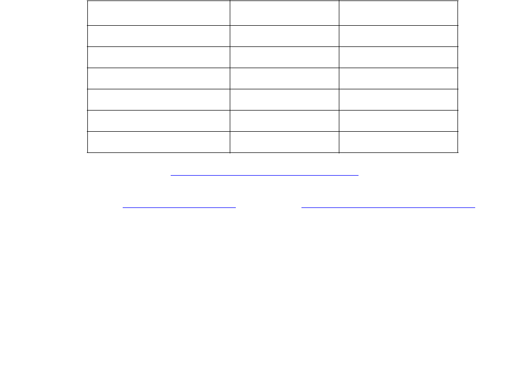
Communication Manager Maintenance-Object Repair Procedures
1196 Maintenance Procedures for Avaya Communication Manager 3.0, Media Gateways and Servers
i. Error Type 1538 indicates a hyperactive EI circuit pack that is generating an abnormal
amount of control messages to the Processor. When this error was generated, the EI was
automatically reset by the system. If this system does not have duplicated Port Network
Connectivity, service to the PN will have been disrupted. If this system does have duplicated
Port Network Connectivity, the system should have switched to the standby Port Network
Connectivity.
1. Enter reset board location for this EI circuit pack.
2. If error 1538 is detected again, replace the EI circuit pack.
j. Error Type 2049 with Aux Data 117 indicates that there is a problem with the fiber optic
interface (FOI), that is generating bit errors. Sometimes these bit errors may be constant.
This error could be caused by a crimped fiber, a fiber that is not seated correctly in the
transceiver, or a defective transceiver.
k. Error Type 2305 with Aux Data 118 indicates that the EI circuit pack has detected slips on
the incoming fiber data stream. That is, a PN in a Direct Connect configuration, or a PN and
a Switch Node in a Center Stage Switch configuration, are not synchronized.
1. Enter display errors and follow the repair procedures for non-slip errors against any
SYNC, TDM-CLK, TONE-BD, DS1C-BD, EXP-INTF, SNC-BD, and SNI-BD. Non-slip
errors are those not listed below:
2. For slip errors, see SYNC (Port-Network Synchronization) on page 2143.
l. Error Type 2306 indicates on-board failures related to system timing and synchronization.
Perform the Fiber link fault isolation described in Chapter 4: General troubleshooting of
Maintenance Procedures (03-300192).
m. Error Type 2561 indicates an on-board failure of EI circuitry related to handling packet data
from the fiber interface and from the packet-bus interface.
1. If this error has generated a minor alarm, the EI circuit pack should be replaced.
n. Error Type 2817 indicates an on-board failure of EI circuitry related to transmission of data
to the fiber interface.
1. If this error has generated a minor alarm, the EI circuit pack or transceiver should be
replaced.
Circuit Pack’s Name Name in Error Log Log Entry (for Slips)
DS1 Interface DS1-BD 3073 to 3160
Expansion Interface EXP-INTF 2305
SNI SNI-BD 1537
Tone-Clock TDM-CLK 1025
UDS1 Interface UDS1-BD 3073 to 3160
DS1 converter circuit pack DS1C-BD 3329

EXP-INTF (Expansion Interface Circuit Pack)
Issue 1 June 2005 1197
o. Error Type 3073: Perform the following steps for Error Type 3073:
1. Execute display errors and resolve any errors on the following: PKT-BUS, PKT-INT,
PDATA-BD, PGATE-BD, BRI-BD, BRI-PT, BRI-SET/ASAI, UDS1-BD.
2. Enter test board location r3 for this circuit pack. If this error continues to appear,
replace the EI circuit pack.
p. Error Types 3074 and 3075: failures of the EI circuit pack Packet Path test. This packet
path test exercises circuitry on the EI circuit pack, the neighbor EI or SNI circuit pack, and
any intervening DS1 converter circuit packs (if the PN is remoted).
1. Certain packet-bus faults can cause these errors without the EI being defective. Check to
see if PKT-BUS errors are also present. If they are, use the PKT-INT (Packet
Interface) on page 1799 section of this chapter and Isolating and repairing packet-bus
faults in Maintenance Procedures (03-300192) to diagnose the problem.
2. If Error Type 3075 is present without Error Type 3074, replace the EI circuit pack.
3. If Error Type 3074 exists with or without 3075, run test board location on the EI,
and follow the repair procedures for any test that does not pass.
4. If PKT-BUS errors are absent and replacing the EI does not resolve the problem, there is
still the possibility of a packet-bus fault. See Isolating and repairing packet-bus faults in
Maintenance Procedures (03-300192).
q. Error Type 3330 indicates a failure of a diagnostic component on the EI circuit pack. The
failed component will not impair service, but it may leave the EI circuit pack in a state where
the EI circuit pack cannot detect errors.
1. Replace the EI circuit pack at a time when it is most convenient for the customer (this
may cause service outages).
r. Error Type 3585 indicates that the EI circuit pack experienced a series of very short
out-of-frame conditions within several minutes. This may indicate transmission difficulties
over the fiber link. If this condition ceases, the warning alarm should be resolved within 15
minutes.
1. Enter display errors and resolve any SNC-BD, TDM-BUS, TDM-CLK or SYNC
errors.
2. Perform the “Fiber Fault Isolation Procedure” described in Chapter 5.
3. If the alarm is not resolved within the next 15 minutes, replace the lightwave transceiver
on the EI circuit pack reporting the problem and on the connected EI circuit pack, SNI
circuit pack, or DS1 converter circuit pack.
4. If the alarm is not resolved within the next 15 minutes, replace the EI circuit pack
reporting the alarm.
5. If the alarm is not resolved within the next 15 minutes, replace the connected EI circuit
pack, SNI circuit pack or DS1 converter circuit pack.
s. Error Type 3841 indicates the EI has reported a loss of lock with the backplane system
clock.

Communication Manager Maintenance-Object Repair Procedures
1198 Maintenance Procedures for Avaya Communication Manager 3.0, Media Gateways and Servers
t. Error Type 3842 indicates that the test that queries the EI for the state of the lock to the
system clock has failed. This means that a loss of lock condition is present.
u. The counter associated with Error Types 3841 and 3842 is cleared when the query for the
state of the clock-to-system-clock passes. Once the alarm is raised, this test is run every
five minutes. However, the test is not part of any sequence that can be run on demand. See
previous Note “p” for repair procedure.
v. Error Type 10001 is a report that the EI circuit pack dropped one control message to the
PN. This condition may have been observed as a call that did not complete correctly. No
system technician action is required.
System Technician-Demanded Tests:
Descriptions and Error Codes
Always investigate tests in the order presented in Table 408. For example, by clearing error
codes associated with the Expansion Interface Reset test (#336), you may also clear errors
generated from other tests in the testing sequence.
When testing EI circuit packs to investigate problems, tests should always be run on both circuit
packs on the associated fiber link, whether the circuit packs are both EI circuit packs, or one is a
SNI circuit pack. This will provide a better indication of where a problem is located.
Table 408: System Technician-Demanded Tests: EXP-INTF
Order of Investigation Short
Test
Sequence
Long
Test
Sequence
Reset
Board
Sequence
D/ND1
1. D = Destructive, ND = Nondestructive
Expansion Interface Reset test (#336) X D
Expansion Interface Fiber Out-of-Frame Query
(#238)
XX ND
Expansion Interface Lightwave Transceiver
Looparound (#242)
XD
Expansion Interface Control Channel (#316) X X ND
Expansion Interface Neighbor Query (#237) X X ND
Expansion Interface Local Looparound (#240) X X ND
Expansion Interface 2-way Transmission (#241) X X ND
Expansion Interface Packet Interface (#589) X X ND

EXP-INTF (Expansion Interface Circuit Pack)
Issue 1 June 2005 1199
When testing of the EI is not possible, (for example, when the PN is down), see the previous EI
Manual Loop-Back procedure.
Expansion Interface Neighbor Query Test (#237)
This test is nondestructive.
The Expansion Interface Neighbor Query test is a request to an EI circuit pack to determine
whether it has established communication with its neighbor EI or SNI circuit pack.
Table 409: Test #237 Expansion Interface Neighbor Query Test
Error
Code
Test
Result
Description / Recommendation
1033 ABRT The EI circuit pack does not have a fiber link administered to it. There is
not sufficient data to run test.
1. Enter list fiber-link to verify that there is no fiber link
administered to this circuit pack.
2. If there is no fiber administered to this circuit pack, but there should be
add the correct fiber using add fiber-link.
3. Retry the command.
2000 ABRT Response to the test was not received within the allowable time period.
1. Retry the command at 1-minute intervals up to 3 times.
2031 ABRT The attempt to send the message to the EI circuit pack, asking it who it’s
neighbor is, was not successful.
1. Retry the command at 1-minute intervals up to 3 times.
2100 ABRT System resources required to run this test are not available. Someone
may be doing something on this Port Network Interface.
1. Retry the command at 1-minute intervals up to 3 times.
2500 ABRT Internal system error
1. Retry the command at 1-minute intervals up to 3 times.
1 of 2

Communication Manager Maintenance-Object Repair Procedures
1200 Maintenance Procedures for Avaya Communication Manager 3.0, Media Gateways and Servers
1033 FAIL The EI circuit pack under test cannot make contact with its neighbor EI or
SNI circuit pack.
Perform the Fiber link fault isolation in Chapter 4: General troubleshooting
in Maintenance Procedures (03-300192).
2027 FAIL The EI circuit pack has contact with the neighboring EI or SNI circuit pack,
but it is the incorrect EI or SNI circuit pack.
1. Enter list fiber-link and verify that every fiber link cable is
installed as it is administered.
2. Repeat the command.
PASS The EI circuit pack has successfully established a link with the neighbor EI
or SNI circuit pack.
If status port-network still indicates that this link is down, one or both
of the EI and/or SNI circuit packs may have been busied out.
1. If the link still does not come up, reset one or both EI and/or SNI circuit
packs on the link.
0NO
BOARD No board was detected by the test.
1. Check the error log for wrong board (Error 125) or no board (error
131). Resolve either of these issues, if applicable.
2. Check that the board is properly translated and inserted. If so, check
for hyperactivity (Error 1538). If hyperactive, use reset board
location.
3. Run the test again. If it fails, the ID chip on board may be bad. Replace
the board and retest.
Table 409: Test #237 Expansion Interface Neighbor Query Test (continued)
Error
Code
Test
Result
Description / Recommendation
2 of 2

EXP-INTF (Expansion Interface Circuit Pack)
Issue 1 June 2005 1201
Expansion Interface Fiber Out-of-Frame
(FOOF) Query Test (#238)
This test is nondestructive. This test is a request to an EI circuit pack to determine whether it is
currently detecting the framing sequence on the incoming fiber data stream. If it cannot detect
this framing signal, the EI circuit pack will not be able to establish a link with the neighbor EI or
SNI circuit pack.
Table 410: Test #238 Expansion Interface Fiber Out-of-Frame Query Test
Error
Code
Test
Result
Description / Recommendation
1033 ABRT The EI circuit pack does not have a fiber link administered to it. There is
not sufficient data to run test.
1. Enter list fiber-link to verify that there is no fiber link
administered to this circuit pack.
2. If there is no fiber administered to this circuit pack, but there should be
add the correct fiber using add fiber-link.
3. Retry the command.
2000 ABRT Response to the test was not received within the allowable time period.
1. Retry the command at 1-minute intervals up to 3 times.
2100 ABRT System resources required to run this test are not available.
1. Retry the command at 1-minute intervals up to 3 times.
2500 ABRT Internal system error
1. Retry the command at 1-minute intervals up to 3 times.
FAIL EI circuit pack could not detect framing sequence.
1. If the EI circuit pack that is failing Test #238 is in the PN, and the red
LEDs are ON on a large number of circuit packs, then reseat any
Tone-Clock circuit packs in the PN.
2. Perform the Fiber link fault isolation in Maintenance Procedures
(03-300192).
3. Enter display errors and resolve any SNC-BD, TDM-BUS,
TDM-CLK, or SYNC errors.
PASS The EI circuit pack has detected the valid framing signal on the fiber.
1. Refer to errors from other EI circuit pack, SNI tests, or DS1 converter
tests (if present) if the link is still not functioning.
1 of 2

Communication Manager Maintenance-Object Repair Procedures
1202 Maintenance Procedures for Avaya Communication Manager 3.0, Media Gateways and Servers
Expansion Interface Local Looparound (#240)
This test is nondestructive. The EI local loop around is similar to the Lightwave Transceiver
Looparound test (#242). A test tone is received by the EI being tested, but is not transmitted out
to the fiber interface before being looped back. The loop back is internal to the circuit pack.
Thus, this test does not interfere with the normal fiber data stream.
0NO
BOARD No board was detected by the test.
1. Check the error log for wrong board (error 125) or no board (error
131). Resolve either of these issues, if applicable.
2. Check that the board is properly translated and inserted. If so, check
for hyperactivity (error 1538). If hyperactive, use reset board
location.
3. Run the test again. If it fails, the ID chip on board may be bad.
Replace the board and retest.
Table 410: Test #238 Expansion Interface Fiber Out-of-Frame Query Test (continued)
Error
Code
Test
Result
Description / Recommendation
2 of 2
Table 411: Test #240 Expansion Interface Local Looparound
Error
Code
Test
Result
Description / Recommendation
1 ABRT Could not allocate time slot on TDM Bus A. Loop back passed on TDM
Bus B.
1. If there is no reason to doubt that the EI circuit pack can transfer data
to or from a TDM Bus, then since the test passed on one bus, assume
that the test passes on the other bus.
2. If this test continues to abort with the same error, rerun test at
1-minute intervals up to 3 times.
3. If the test still does not pass on the other TDM Bus, follow the
procedure for ABORT Error Code 3.
1 of 4

EXP-INTF (Expansion Interface Circuit Pack)
Issue 1 June 2005 1203
2 ABRT Could not allocate time slot on TDM Bus B. Loop back passed on TDM
Bus A.
1. If there is no reason to doubt that the EI circuit pack can transfer data
to or from a TDM Bus, then since the test passed on one bus, assume
that the test passes on the other bus.
2. If this test continues to abort with the same error, rerun test at
1-minute intervals up to 3 times.
3. If the test still does not pass on the other TDM Bus, follow the
procedure for ABORT Error Code 3.
3 ABRT The system could not allocate time slots for the test on either TDM Bus.
The system may be under heavy traffic conditions or it may have time
slots out of service due to TDM-BUS errors.
1. If the system has no TDM-BUS errors and is not handling heavy
traffic, retry the command at 1-minute intervals up to 3 times.
1003 ABRT The system could not allocate a tone receiver for the test. The system may
be oversized for the number of tone detectors present or some tone
detectors may be out of service.
1. Enter display errors and follow associated repair procedures for
TTR-LEV errors in the error log. Even if there are not TTR-LEV errors,
there may not be a tone detector available on the network that
contains the circuit pack being tested. Verify that there is at least one
tone detector on the network. If not, this test always aborts for this EI
circuit pack. This does not harm the system.
2. Resolve any TONE-PT errors.
3. If neither condition exists, retry the command at 1-minute intervals up
to 3 times.
1031 ABRT A query of the EI circuit pack aborted. The purpose of this query was to
see if the EI circuit pack could detect the framing signal.
1. If Test #238 aborted, follow the procedure associated with this abort
code.
2. If Test #238 did not abort, rerun Test #240 at 1-minute intervals up to 3
times.
Table 411: Test #240 Expansion Interface Local Looparound (continued)
Error
Code
Test
Result
Description / Recommendation
2 of 4

Communication Manager Maintenance-Object Repair Procedures
1204 Maintenance Procedures for Avaya Communication Manager 3.0, Media Gateways and Servers
1032 ABRT The EI cannot detect the framing signal and cannot run the test.
1. Refer to the errors for Test #238 to determine why the EI circuit pack is
out of frame.
1033 ABRT The EI circuit pack does not have a fiber link administered to it. There is
not sufficient data to run test.
1. Use list fiber-link to verify that there is no fiber link
administered to this circuit pack.
2. If there is no fiber administered to this circuit pack, but there should
be, use add fiber-link to add the correct fiber.
3. Retry the command.
1394 ABRT The EI circuit pack is out of service and the test cannot be run. This
condition is due to a change in the EI circuit pack’s ability to communicate
with the EI or SNI circuit pack on the other end of the fiber.
1. Run Test #237, and check the Error Log for EXP-INTF error type
1281. If error type 1281 is present or if Test #237 does not pass, see
repair procedures for Test #237, in Table 409: Test #237 Expansion
Interface Neighbor Query Test on page 1199.
1395 ABRT This test cannot be run on an EI circuit pack if it is part of the B-side PNC
and duplicated PNC is not enabled.
1. If this test needs to run on this EI circuit pack, use change
system-parameters duplication to enable PNC.
2. Use set pnc lock to prevent the system from doing a PNC
interchange.
3. Repeat this test.
2000 ABRT Response to the test was not received within the allowable time period.
1. Retry the command at 1-minute intervals up to 3 times.
2100 ABRT Could not allocate the necessary system resources to run this test.
1. Retry the command at 1-minute intervals up to 3 times.
2500 ABRT Internal system error
1. Retry the command at 1-minute intervals up to 3 times.
Table 411: Test #240 Expansion Interface Local Looparound (continued)
Error
Code
Test
Result
Description / Recommendation
3 of 4

EXP-INTF (Expansion Interface Circuit Pack)
Issue 1 June 2005 1205
1 FAIL Loop back on TDM Bus A failed. Loop back on TDM Bus B passed.
2 FAIL Loop back on TDM Bus B failed. Loop back on TDM Bus A passed.
3 FAIL Loop back on both TDM Buses failed.
12 FAIL Loop back on TDM Bus B failed. Loop back on TDM Bus A aborted
because the system could not allocate time slots.
21 FAIL Loop back on TDM Bus A failed. Loop back on TDM Bus B aborted
because the system could not allocate time slots.
None FAIL The test tone was not detected correctly after being looped through the EI
circuit pack.
1. If Error Type 2305 has been logged against the EI circuit pack in the
last 5 minutes, this test could have failed due to the associated slips. If
so, first resolve the 2305 error, and then repeat the test.
2. Run the tests for the active Tone-Clock on the PN that contains the
indicted EI circuit pack to verify that dial-tone is supplied.
3. If the tone-clock is healthy, repeat the short test on the EI board.
4. If this test continues to fail, replace the EI circuit pack.
PASS Test tone was correctly detected after internal EI loop back on both TDM
buses.
1. Refer to other EI circuit pack tests if the links between this EI circuit
pack and the EI or SNI circuit pack on the other end of the fiber is not
functioning correctly.
0NO
BOARD No board was detected by the test.
1. Check the error log for wrong board (error 125) or no board (error
131). Resolve either of these issues, if applicable.
2. Check that the board is properly translated and inserted. If so, check
for hyperactivity (error 1538). If hyperactive, use reset board
location.
3. Run the test again. If it fails, the ID chip on board may be bad.
Replace the board and retest.
Table 411: Test #240 Expansion Interface Local Looparound (continued)
Error
Code
Test
Result
Description / Recommendation
4 of 4
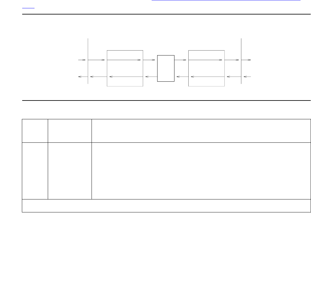
Communication Manager Maintenance-Object Repair Procedures
1206 Maintenance Procedures for Avaya Communication Manager 3.0, Media Gateways and Servers
Expansion Interface 2-Way Transmission
Test (#241)
This test is nondestructive. The EI 2-way transmission test is a basic connectivity test between
two PNs. The test first sends dial tone from the cabinet of the EI circuit pack under test through
the Center Stage Switch, through the DS1 converter circuit packs, and through another EI
circuit pack to a tone detector in the other cabinet. The connections are then reversed and the
tone is passed in the opposite direction. If the system is equipped with a Center Stage Switch,
and this test either fails or aborts with the above connection, a second PN is chosen (if one is
available and the EI circuit pack is In-Service) and the same test is run on this new connection.
This helps in the isolation of the fault. Since two EI circuit packs are involved in the connection,
either one of them could be at fault and this repeated test can help determine which one is
actually at fault.
The path used in this test is represented in Figure 67: Two-Way Circuit Switch Transmission
Test .
Figure 67: Two-Way Circuit Switch Transmission Test
Table 412: Test #241 Expansion Interface 2-Way Transmission Test
Error
Code
Test
Result
Description / Recommendation
1002 ABRT The system could not allocate time slots for the test. The system may
be under heavy traffic conditions or it may have time slots out of
service due to TDM-BUS errors. Enter display errors and follow
the repair procedures for TDM-BUS errors.
1. If the system has no TDM-BUS errors and is not handling heavy
traffic, retry the command at 1-minute intervals up to 3 times.
1 of 5
Clock
Clock
Tone
Tone
Tone
Tone
TDM BUS (PN Y) TDM BUS (PN X)
CSS
(Optional)
EXP-INTF EXP-INTF
Detector
Detector

EXP-INTF (Expansion Interface Circuit Pack)
Issue 1 June 2005 1207
1003 ABRT The system could not allocate a tone receiver for the test. The system
may be oversized for the number of tone detectors present or some
tone detectors may be out of service.
1. Enter display errors and follow the repair procedures for
TTR-LEV errors in the error log. Even if there are not TTR-LEV
errors, there may not be a tone detector available on the network
that contains the circuit pack being tested. Verify that there is at
least one tone detector on this network. If not, this test will always
abort for this EI circuit pack. This will not harm the system in any
way.
S8700 MC: Tone Detector circuit packs (TN768) must be of vintage
“B” or newer. If older Tone Detector circuit packs are installed in
the system, this test will always abort with this code.
2. Enter display errors and follow the repair procedures for
TONE-PT errors.
3. If neither condition exists, retry the command at 1-minute intervals
up to 3 times.
1033 ABRT The test cannot run because either the EI board does not have a fiber
link administered to it and there is not sufficient data to run the test, or
there were no other PNs administered that had its EI board
In-Service.
1. Check fiber administration to insure that there is a fiber link
administered to this EI circuit pack.
2. If there is a fiber administered to this EI circuit pack, then some
change in the status of the ability of the EI circuit pack in the other
PNs to communicate with the EI or SNI circuit pack on the other
end of its fiber has occurred.
3. Test #237 and check for EXP-INTF circuit pack Error Type 1281 in
the Error Log for the EI circuit packs in these other PNs. If Error
Type 1281 is present and/or Test #237 does not pass, see repair
procedures for Test #237, in Table 409: Test #237 Expansion
Interface Neighbor Query Test on page 1199.
4. If Test #237 passes, reseat the EI circuit pack. This is not
destructive since the circuit pack cannot be serving as the
Expansion Archangel if it is not in service.
Table 412: Test #241 Expansion Interface 2-Way Transmission Test (continued)
Error
Code
Test
Result
Description / Recommendation
2 of 5

Communication Manager Maintenance-Object Repair Procedures
1208 Maintenance Procedures for Avaya Communication Manager 3.0, Media Gateways and Servers
1394 ABRT The EI circuit pack is out of service and the test cannot be run. This
condition is due to a change in the EI circuit pack’s ability to
communicate with the EI or SNI circuit pack on the other end of the
fiber.
1. Run Test #237, and check the Error Log for EXP-INTF Error Type
1281. If Error Type 1281 is present or if Test #237 fails, see repair
procedures for Test #237, in Table 409: Test #237 Expansion
Interface Neighbor Query Test on page 1199.
1395 ABRT This test cannot be run on an EI circuit pack if it is part of the B-side
PNC and duplicated PNC is not enabled.
1. If this test needs to run on this EI circuit pack, use change
system-parameters duplication to enable PNC.
2. Use set pnc lock to prevent the system from doing a PNC
interchange.
3. Repeat this test.
1413 ABRT This test requires the use of a Tone-Clock circuit pack in each of the
PNs used in this test. This abort code indicates that there are none of
these circuit packs located in one of the PNs.
1. Verify that there is a Tone-Clock circuit pack in the PN where the
EI circuit pack under test resides.
2. In a Direct Connect configuration, verify that there is a Tone-Clock
circuit pack in the PN where the neighbor EIEI circuit pack circuit
pack resides.
3. In a Center Stage Switch configuration, verify that there is at least
one other PN, besides the PN where the EI circuit pack under test
resides, with a Tone-Clock circuit pack.
1414 ABRT This test requires the use of an active Tone-Clock circuit pack in each
of the PNs used in this test that does not have a MAJOR or MINOR
alarm logged against it. This abort code indicates that the active
Tone-Clock circuit pack in one of the PNs being used for the test has a
MAJOR or MINOR alarm logged against it.
1. Enter display alarms and resolve every TONE-BD and
TONE-PT alarm.
Table 412: Test #241 Expansion Interface 2-Way Transmission Test (continued)
Error
Code
Test
Result
Description / Recommendation
3 of 5

EXP-INTF (Expansion Interface Circuit Pack)
Issue 1 June 2005 1209
2000 ABRT Response to the test request was not received within the allowable
time period.
1. Retry the command at 1-minute intervals up to 3 times.
2100 ABRT System resources required to run this test are not available.
1. Retry the command at 1-minute intervals up to 3 times.
2500 ABRT Internal system error
1. Retry the command at 1-minute intervals up to 3 times.
FAIL The test tone was not detected correctly in either direction.
1. Run the test for the active Tone-Clocks on the PNs for which the
EI circuit pack under test provides a link. This will determine
whether dial tone is being supplied.
2. Perform the Fiber link fault isolation in Chapter 4: General
troubleshooting in Maintenance Procedures (03-300192).
1 or 2 FAIL The test tone was detected correctly in one direction, but not the
opposite direction.
1. Test for the active Tone-Clocks on the PNs for which the defective
EI board provides a link. This determines if the dial tone is
supplied.
2. Perform the Fiber link fault isolation in Chapter 4: General
troubleshooting in Maintenance Procedures (03-300192).
Center Stage: These failure codes are possible on a Center Stage
Switch configuration only when there is just one other PN available for
looping back the test tone.
1. Perform the Fiber link fault isolation in Chapter 4: General
troubleshooting in Maintenance Procedures (03-300192).
Table 412: Test #241 Expansion Interface 2-Way Transmission Test (continued)
Error
Code
Test
Result
Description / Recommendation
4 of 5

Communication Manager Maintenance-Object Repair Procedures
1210 Maintenance Procedures for Avaya Communication Manager 3.0, Media Gateways and Servers
Expansion Interface Lightwave Transceiver Loop-Around Test (#242)
This test is destructive.
This test requires that the EI circuit pack first be busied out. If the system has a duplicated Port
Network Connectivity, this test cannot be run on an EI circuit pack that resides on the current
active PNC due to restrictions that prohibit the busying-out of certain components that are part
of the active PNC. If this test is run on an EI circuit pack that is part of the standby PNC, this test
is not destructive and no service outages will take place.
In a system without duplicated Port Network Connectivity, where this EI circuit supports an IPSI
to PN link, this test will disrupt service to one or more PN’s. If the EI circuit pack is part of a
PN-to-PN link in a Direct Connect system, service between the two PNs will be disrupted.
3 or 4 FAIL The failure codes only apply to a system equipped with a Center
Stage Switch. They indicate that the test aborted or failed for the first
connection from the EI board under test to another PN, and that the
test tone was detected correctly in one direction, but not the opposite
direction when the connection was between the EI board under test
and a different PN than was used in the first connection.
1. Run the test for the active Tone-Clocks on the PNs for which the
defective EI board provides a link. This determines if the dial tone
is being supplied.
2. Perform the Fiber link fault isolation in Chapter 4: General
troubleshooting in Maintenance Procedures (03-300192).
PASS The tone was successfully transmitted in both directions. Both EI
boards, SNI boards, DS1 converter circuit packs, and their lightwave
transceivers are functioning properly.
0NO
BOARD No board was detected by the test.
1. Check the error log for wrong board (error 125) or no board (error
131). Resolve either of these issues, if applicable.
2. Check that the board is properly translated and inserted. If so,
check for hyperactivity (error 1538). If hyperactive, use reset
board location.
3. Run the test again. If it fails, the ID chip on board may be bad.
Replace the board and retest.
Table 412: Test #241 Expansion Interface 2-Way Transmission Test (continued)
Error
Code
Test
Result
Description / Recommendation
5 of 5
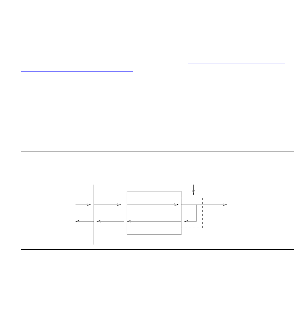
EXP-INTF (Expansion Interface Circuit Pack)
Issue 1 June 2005 1211
This is a 2-part connectivity test. In the first part of the test, a digital count is transmitted from the
cabinet of the EI circuit pack under test, through the EI circuit pack under test, out to its
lightwave transceiver. The connection then loops back into the lightwave transceiver, through
the same EI circuit pack again, and into the originating cabinet. If the test tone is detected by a
tone detector, the first part of the test passes. The path used for this part of the test is
represented in Figure 68: TDM BUS Lightwave Transceiver Looparound on page 1211.
In the second part of the test, a data packet is sent from the TN1655 Packet Interface circuit
pack to the EI circuit pack under test, the packet is looped back through the lightwave
transceiver and is sent back to the Packet Interface circuit pack. If the Packet Interface circuit
pack receives the same packet it transmitted, the second part of the test passes. If the entire
test has passed, the EI circuit pack, its backplane wiring, and the electrical portion of the
lightwave transceiver are healthy. The path used for this test is represented in
Figure 69: Packet Bus Lightwave Transceiver Looparound—PN only on page 1212. The path
used for this test if the EI resides in a PN is represented in Figure 70: Packet Bus Lightwave
Transceiver Looparound—CSS and PN on page 1212.
When the EI circuit pack under test is in a PN, the data packet must also pass through the active
EI circuit packs and the active DS1 converter circuit packs (and the active SNI circuit pack(s) in
a Center Stage Switch system) of the active PNC link connecting the PN.
This test requires the EI circuit pack to ignore incoming data from its neighbor EI circuit pack or
SNI circuit pack. Thus this test will:
●Disturb any inter-PN connections that currently exist over the link provided by the EI under
test and its neighbor
●Disrupt signaling between the two circuit packs
Figure 68: TDM BUS Lightwave Transceiver Looparound
lightwave
To CSS or
Neighbor EI
TDMBUS (PN X)
Tone
Tone
Clock
Detector
EXP_INTF
transceiver
Communication Manager Maintenance-Object Repair Procedures
1212 Maintenance Procedures for Avaya Communication Manager 3.0, Media Gateways and Servers
Figure 69: Packet Bus Lightwave Transceiver Looparound—PN only
Figure 70: Packet Bus Lightwave Transceiver Looparound—CSS and PN
Table 413: Test #242 Expansion Interface Lightwave Transceiver Looparound
Error
Code
Test
Result
Description / Recommendation
1002 ABRT The system could not allocate timeslots for the test. The system may be
under heavy traffic conditions, or it may have timeslots out of service due to
TDM-BUS errors. Enter display errors and resolve any TDM-BUS
errors.
1. If the system has no TDM-BUS errors and is not handling heavy traffic,
retry the command at 1-minute intervals up to 3 times.
1 of 6
lightwave
To CSS or
Neighbor EI
Packet
Interface
TDMBUS (PN X)
EXP_INTF
transceiver
Interface
Packet
EXP_INTF
Neighbor EI
To CSS or
lightwave
transceiver
(Optional)
CSS
EXP_INTF EXP_INTF

EXP-INTF (Expansion Interface Circuit Pack)
Issue 1 June 2005 1213
1003 ABRT The system could not allocate a tone receiver for the test. The system may
be oversized for the number of Tone Detectors present or some Tone
Detectors may be out of service.
1. Enter display errors and follow associated repair procedures for
TTR-LEV. Even if there are no TTR-LEV errors, there may not be a
Tone Detector available on the network that contains the circuit pack
being tested. Verify that there is at least one Tone Detector on this
network. If there is not at least one Tone Detector, this test always
aborts for this EI board. This will not harm the system.
2. Enter display errors and follow associated repair procedures for
TONE-PT.
3. If neither condition exists, retry the command at 1-minute intervals up
to 3 times.
1015 ABRT The system will not allow this test to be run because the EI circuit pack has
not been busied out.
1. Busyout the EI circuit pack. Repeat test board location long.
1031 ABRT If the EI circuit pack is in a PN and is on the active PNC, and is not part of a
PN-to-PN link, this test cannot be executed. If the lightwave transceiver
looparound is activated, it is impossible to deactivate it.
1. If PNC Duplication is enabled, attempt to make the standby PNC active
through reset pnc interchange.
2. If the PNC Interchange is successful, the Lightwave Transceiver
Looparound test may now be executed on the original EI circuit pack.
1033 ABRT The test cannot run because the EI circuit pack does not have a fiber link
administered to it and there is not sufficient data to run the test.
1. Enter list fiber-link to verify that there is no fiber link
administered to this circuit pack.
2. If there is no fiber administered to this circuit pack (but should be), add
the correct fiber using add fiber-link.
3. Retry the command.
Table 413: Test #242 Expansion Interface Lightwave Transceiver Looparound (continued)
Error
Code
Test
Result
Description / Recommendation
2 of 6

Communication Manager Maintenance-Object Repair Procedures
1214 Maintenance Procedures for Avaya Communication Manager 3.0, Media Gateways and Servers
1139 ABRT The packet bus in the PN where this EI board resides has a major alarm
against it. This test needs to use the alarmed PN’s packet bus.
1. Enter display alarms and display errors and resolve any
PKT-BUS alarms.
2. Retry the command.
1141 ABRT The Packet Interface circuit pack is out of service.
1. See PKT-INT (Packet Interface) on page 1799.
1144 ABRT The PN’s packet bus has a major alarm against it. This test needs to use
the alarmed PN’s packet bus.
1. Enter display alarms and display errors and resolve any
PKT-BUS alarms.
2. Retry the command.
1394 ABRT The EI board is out of service and the test cannot be run. This condition is
due to a change in the EI board’s ability to communicate with the EI or SNI
circuit pack on the other end of the fiber.
1. Run Test #237 and check the Error Log for EXP-INTF Error Type 1281.
If Error Type 1281 is present or if Test #237 fails, see repair procedures
for Test #237, in Table 409: Test #237 Expansion Interface Neighbor
Query Test on page 1199.
1395 ABRT This test cannot be run on an EI circuit pack if it is part of the B-side PNC
and duplicated PNC is not enabled.
1. If this test needs to run on this EI circuit pack, enable PNC with change
system-parameters duplication.
2. Use set pnc lock to prevent the system from doing a PNC
interchange.
3. Repeat this test.
Table 413: Test #242 Expansion Interface Lightwave Transceiver Looparound (continued)
Error
Code
Test
Result
Description / Recommendation
3 of 6

EXP-INTF (Expansion Interface Circuit Pack)
Issue 1 June 2005 1215
1407 ABRT This test cannot be run on an EI board that is on the active PNC because it
cannot be busied out. This error code indicates that PNC duplication is
enabled.
1. Attempt to perform a PNC interchange via reset pnc
interchange.
2. If the PNC interchange is successful, busyout the original EI circuit
pack via busyout board location (location of the original EI
board).
3. Retry the command.
2000 ABRT Response to the test was not received in the allowable time period.
1. Retry the command at 1-minute intervals up to 3 times.
2060 ABRT The link on the packet bus being used to perform the test has failed.
1. Retry the command at 1-minute intervals up to 3 times.
2. If the test continue to abort, enter display errors and resolve any
PKT-INT errors.
2100 ABRT Could not allocate the necessary system resources to run this test.
1. Retry the command at 1-minute intervals up to 3 times.
2500 ABRT Internal system error
1. Retry the command at 1-minute intervals up to 3 times.
1 FAIL The test did not detect the test tone through the loop-around connection.
The packet portion of this test was not run since the circuit portion failed.
1. Test the active Tone-Clock on the PN that contains the defective EI
circuit pack to verify that dial tone is being supplied.
2. If the Tone-Clock is healthy, enter test board location long on
the EI circuit pack.
3. If this test continues to fail, replace the EI circuit pack or transceiver.
Then execute test board location long on the new EI circuit
pack.
Table 413: Test #242 Expansion Interface Lightwave Transceiver Looparound (continued)
Error
Code
Test
Result
Description / Recommendation
4 of 6

Communication Manager Maintenance-Object Repair Procedures
1216 Maintenance Procedures for Avaya Communication Manager 3.0, Media Gateways and Servers
2 FAIL The test tone was transmitted and detected correctly, but the correct data
packet was not detected by the TN1655 Packet Interface circuit pack.
1. Test the TN1655 Packet Interface circuit pack to verify that it is
functioning properly. If any tests fail, investigate those tests and repair
the Packet Interface circuit pack.
2. If the Packet Interface circuit pack checks out OK, enter display
errors and display alarms and resolve any SNI-BD and
FIBER-LK alarms or errors (Center Stage Switch only) and DS1C-BD
alarms or errors (if present).
3. Enter test board location long on the EI board.
4. If Test #242 continues to fail, replace the EI board. Then enter test
board location long for the new EI board.
5. If Test #242 continues to fail, replace the lightwave transceiver, reset
the circuit pack and enter test board location long on the EI
circuit pack.
PASS When this test (#242) and the EI Local Looparound test (#240) pass, this
indicates that the EI board is functioning properly, but it does not verify that
the optical portion of the lightwave transceiver is functioning.
1. Enter test board location on the EI board on both ends of fiber. If
this test passes from both sides, but other tests fail, such as #241, this
condition indicates either a faulty lightwave transceiver or the fiber itself
has failed. To determine whether a lightwave transceiver or the fiber
itself has failed, execute the EI Manual Loop-Back procedure described
in a previous section.
Test #242 can only be run from both EIs if they are the standby pair and
the active pair is working properly.
2. If this EI board is failing other tests, execute the EI Manual Loop-Back
Tes t.
3. If problems still exist after the EI Manual Loop-Back Procedure
indicates both EI boards and both lightwave transceivers are healthy,
manually check out the building fiber. Verify that each optical fiber
connects to a transmitter at one end and a receiver at the other.
Table 413: Test #242 Expansion Interface Lightwave Transceiver Looparound (continued)
Error
Code
Test
Result
Description / Recommendation
5 of 6

EXP-INTF (Expansion Interface Circuit Pack)
Issue 1 June 2005 1217
Expansion Interface Control Channel Test (#316)
This test is nondestructive. If an EI circuit pack is a standby EI circuit pack (amber LED off) or if
the EI is active in the PN (amber LED on), this test queries the EI circuit pack for its circuit pack
type and vintage information. If the EI circuit pack is an active EI circuit pack in the PN (amber
LED on long off short) the Expansion Interface Control Channel test checks to see if the EI
circuit pack can communicate with other circuit packs in the PN using the PN TDM bus.
0NO
BOARD No board was detected by the test.
1. Check the error log for wrong board (Error 125) or no board (Error 131).
Resolve either of these issues, if applicable.
2. Check that the board is properly translated and inserted. If so, check
for hyperactivity (Error 1538). If hyperactive, use reset board
location.
3. Run the test again. If it fails, the ID chip on board may be bad. Replace
the board and retest.
Table 413: Test #242 Expansion Interface Lightwave Transceiver Looparound (continued)
Error
Code
Test
Result
Description / Recommendation
6 of 6
Table 414: Test #316 Expansion Interface Control Channel Test
Error
Code
Test
Result
Description / Recommendation
2000 ABRT Response to the test request was not received within the allowable time
period.
1. Retry the command at 1-minute intervals up to 3 times.
2100 ABRT Could not allocate the necessary system resources to run this test.
1. Retry the command at 1-minute intervals up to 3 times.
2500 ABRT Internal system error
1. Retry the command at 1-minute intervals up to 3 times.
1 of 2

Communication Manager Maintenance-Object Repair Procedures
1218 Maintenance Procedures for Avaya Communication Manager 3.0, Media Gateways and Servers
Any FAIL The EI circuit pack responded incorrectly or if it is the PN active EI circuit
pack, it could not talk to PN circuit packs.
1. If the active EI circuit pack in the PN is failing and duplicated PNC is
enabled, attempt to switch to the standby PNC using reset PNC
interchange.
2. Repeat the short test sequence.
3. If test continues to fail, reset the EI circuit pack via reset board
location.
4. If the EI circuit pack in the PN is failing, enter display errors and
display alarms, and resolve any TDM-CLK, TONE-BD, or SYNC
alarms or errors.
5. Repeat the short test sequence.
6. If test continues to fail, replace the circuit pack or transceiver.
PASS The EI circuit pack did respond correctly to test. Communication from
software to the EI circuit pack is functioning.
1. Refer to other EI circuit pack tests if the link is not functioning
correctly.
0NO
BOARD No board was detected by the test.
1. Resolve either wrong board (Error 125) or no board (Error 131)
issues.
2. Check that the board is properly translated and inserted. If so, check
for hyperactivity (Error 1538). If hyperactive, use reset board
location.
3. Run the test again. If it fails, the ID chip on board may be bad.
Replace the board and retest.
Table 414: Test #316 Expansion Interface Control Channel Test (continued)
Error
Code
Test
Result
Description / Recommendation
2 of 2

EXP-INTF (Expansion Interface Circuit Pack)
Issue 1 June 2005 1219
Expansion Interface Reset Test (#336)
This test is destructive.
This test is potentially very destructive and requires the EI circuit pack to be busied out prior to
execution of this test.
The Expansion Interface Reset test, which is not part of either the Short or the Long test
sequences test, is executed via reset board location where location is the location of the
EI circuit pack to be reset.
If the system does not have duplicated PNC, and is a Direct Connect system, and one of the EI
circuit packs must be reset, the action of busying out the desired EI circuit pack will deny calls to
the PN until the EI circuit pack is released from the busyout state. If the EI circuit pack is part of
a PN-to-PN link, new connections to the PN will be denied. If the EI circuit pack is part of a
PN-to-PN link, calls between the two PNs will be denied.
In a non-duplicated PNC system with a Center Stage Switch, if the EI circuit pack in the PN is
busied out, new service to that PN only will be denied. However, if the EI circuit pack resides in
the PN, new service to every PN will be denied until the EI circuit pack is released from the
busyout state.
If the system does not have duplicated PNC, the reset of any EI is allowed, but it will result in
the resetting of every PN board and loss of service to the PN(s) for a few minutes.
If the system does have duplicated PNC, and the EI circuit pack to be reset is part of the active
PNC, the system will not allow the busyout and the system technician will be required to
interchange the PNCs via reset pnc interchange. After executing the PNC interchange, it
will be possible to busyout and then reset the original EI circuit pack.
If the PN’s Maintenance (MAINT) circuit pack determines that the EI (EXP-INTF) circuit pack is
cycling between sane and insane several times within several minutes, MAINT may inhibit
operation of the EXP-INTF by holding the EI circuit pack in a reset state. This condition may
result in an unsuccessful reset of the EI circuit pack.
If the reset command returns “PN is unavailable,” execute the following steps:
1. Use change circuit-pack P (PN’s number).
2. For the EI circuit pack you wish to reset, add an entry to the Circuit Pack screen for the
TN570 EI circuit pack. Be sure to enter the appropriate carrier and slot.
3. Enter the screen.
4. Enter busyout board location.
5. Repeat reset board.

Communication Manager Maintenance-Object Repair Procedures
1220 Maintenance Procedures for Avaya Communication Manager 3.0, Media Gateways and Servers
Table 415: Test #336 Expansion Interface Reset Test
Error
Code
Test
Result
Description / Recommendation
4 ABRT Could not reset the PN EI circuit pack over the optical fiber since the
neighbor EI circuit pack or SNI circuit pack is not recognized by software
(inserted).
1. Insert neighbor EI circuit pack or SNI circuit pack and perform reset
again.
1015 ABRT The system will not allow this test to be run because the EI circuit pack
has not been busied out.
1. Busyout the EI circuit pack. Enter reset board location.
2. Retry the command.
2000 ABRT Response to the test request was not received within the allowable time
period.
2100 ABRT Could not allocate the necessary system resources to run this test.
2500 ABRT Internal system error
1. Retry the command at 1-minute intervals up to 3 times.
1 FAIL The EI did not successfully reset.
1. If the EI circuit pack is in the PN, the PN’s Maintenance board may be
holding the EI circuit pack reset. Attempt to rectify this condition by
executing test maint P long on the Maintenance board in the
same PN.
2. If step 1 was not successful in releasing the EI circuit pack,
temporarily remove the PN’s Maintenance circuit pack.
3. Repeat reset board location.
4. If reset continues to fail, replace circuit pack.
5. Insert PN’s Maintenance circuit pack if it was removed.
2 FAIL The EI circuit pack was successfully reset, but it did not begin running
after the reset.
1. If the EI circuit pack is in the PN, temporarily remove the PN’s
Maintenance circuit pack.
2. Use reset board location.
3. Reinsert the PN’s Maintenance circuit pack if it was removed.
1 of 3

EXP-INTF (Expansion Interface Circuit Pack)
Issue 1 June 2005 1221
3 FAIL The reset over the optical fiber failed.
1. Execute test board location on the PN neighbor EI circuit pack
located on the opposite end of the fiber from this EI circuit pack. If Test
#238 fails, follow the maintenance procedure associated with this test
result. Then perform the reset again.
2. If the EI circuit pack is in the PN, temporarily remove the PN’s
Maintenance circuit pack.
3. Repeat reset board location.
4. Reinsert PN’s Maintenance circuit pack if it was removed.
5. If the symptoms match those described in the EI and Tone-Clock
Interactions on page 1186 section, follow those guidelines.
6. Check the Error Log for the PN Tone-Clock errors that were resolved
when the PN went down. These errors may have been resolved
BECAUSE the PN went down. When there is no Tone-Clock
generating the system clock on a PN, then an EI circuit pack can only
be reset once. Every subsequent reset attempt fails. It is also possible
that the system itself may have already tried to reset the EI circuit
pack. Refer to TONE-BD (Tone-Clock Circuit) on page 2327 for
Tone-Clock problems.
7. If the reset still fails, execute the Manual Loop Back Procedure on the
opposite PN EI circuit pack. This procedure is described in the section
preceding the Error Log Entries and Test to Clear Values table for this
MO. If the EI circuit pack and the lightwave transceiver are healthy,
the problem is the EI circuit pack and its lightwave transceiver on the
PN end of the fiber or the fiber itself. Test the PN EI circuit pack with
the manual loop back procedure and investigate the test results.
PASS The EI was successfully reset. Remove the EI circuit pack from the
busyout state by using release board location.
1. Execute test board location short. Refer to errors for each
test.
Table 415: Test #336 Expansion Interface Reset Test (continued)
Error
Code
Test
Result
Description / Recommendation
2 of 3
Communication Manager Maintenance-Object Repair Procedures
1222 Maintenance Procedures for Avaya Communication Manager 3.0, Media Gateways and Servers
Expansion Interface Packet Interface Test (#589)
This test is nondestructive. This test attempts to send a data packet from the TN1655 Packet
Interface circuit pack through any intervening EI circuit packs and/or SNI circuit packs and
through the EI circuit pack to be tested. The path the data packet takes is dependent on the
location of the EI circuit pack to be tested and whether the system has duplicated PNC. The
following diagrams and short discussion of each describe the different paths the test uses.
Figure 71: Expansion Interface Packet Interface Test—Packet Endpoint Loop
The path shown in Figure 71: Expansion Interface Packet Interface Test—Packet Endpoint
Loop on page 1222 is used when testing a PN EI that is on the active PNC.
0NO
BOARD No board was detected by the test.
1. Resolve either wrong board (error 125) or no board (error 131) issues.
2. Check that the board is properly translated and inserted. If so, check
for hyperactivity (error 1538). If hyperactive, use reset board
location.
3. Run the test again. If it fails, the ID chip on board may be bad.
Replace the board and retest.
Table 415: Test #336 Expansion Interface Reset Test (continued)
Error
Code
Test
Result
Description / Recommendation
3 of 3
(Optional)
CSS
EXP-INTF EXP-INTF
Packet Bus (PPN) Packet Bus (PN X)
PKT-
INT
LAPD
ENDPT
EXP-INTF (Expansion Interface Circuit Pack)
Issue 1 June 2005 1223
Figure 72: Expansion Interface Packet Interface Test, PN-to-PN loop
In a Center Stage configuration the path shown in Figure 72: Expansion Interface Packet
Interface Test, PN-to-PN loop on page 1223 is used when testing a PN EI that is on the standby
PNC. In a Direct Connect configuration, this path is used on any PN EI or on a PN EI that is on
the standby PNC.
Figure 73: Expansion Interface Packet Interface Test—PN to CSS Loop
The path shown in Figure 73: Expansion Interface Packet Interface Test—PN to CSS Loop on
page 1223 is used when running the test on a PN EI in a Center Stage configuration.
(optional)
PKT-
INT
EXP-INTF EXP-INTF
Packet Bus (PPN) Packet Bus (PN X)
CSS
INTERFACE
SWITCH NODE
EXP-INTF
Packet Bus (PPN)
PKT-
INT
Communication Manager Maintenance-Object Repair Procedures
1224 Maintenance Procedures for Avaya Communication Manager 3.0, Media Gateways and Servers
Figure 74: Expansion Interface Packet Interface Test, PN-to-PN link
The path shown in Figure 74 is used when the EI under test is one that provides connectivity
between the two PNs in a Direct Connect configuration.
INT
PKT
EXP-INTF
EXP-INTF EXP-INTF
EXP-INTF
EXP-INTF
EXP-INTF
Packet Bus ( PPN ) Packet Bus ( PN X )
Packet Bus ( PN Y )

EXP-INTF (Expansion Interface Circuit Pack)
Issue 1 June 2005 1225
Table 416: Test #589 Expansion Interface Packet Interface Test
Error
Code
Test
Result
Description / Recommendation
1033 ABRT The test cannot run because the EI circuit pack does not have a fiber link
administered to it and there is not sufficient data to run the test or because
EI circuit packs on other port networks needed for this test are out of
service.
1. Execute list fiber-link and determine whether the EI circuit pack
under test is an endpoint of one of the administered fiber links. If so,
then proceed to step 2. If not, then this is considered to be a spare
board, and the test should not be attempted on this EI circuit pack.
2. Follow procedures for applicable configuration:
Direct Connect:
1. Use list config for the cabinet and carrier where the neighbor EI
circuit pack resides. If the results reveal that the board is not
recognized by software, the board is out of service because of this
condition. Perform the following steps:
a. If this test is being executed on an EI circuit pack located in the PN,
enter display errors and resolve any EXP-PN errors for the port
network where the neighbor EI circuit pack resides. Re-execute this
test.
b. If this test continues to abort with this abort code reset the DS1
converter circuit pack (if so equipped) or the neighbor EI circuit pack.
This will not be destructive since the circuit pack cannot be serving
as the Expansion Archangel if it is not in service.
2. Run Test #237 and check for EXP-INTF circuit pack Error Type 1281 in
the Error Log. If Error Type 1281 is present and/or Test #237 does not
pass, see repair procedures for Test #237, in Table 409: Test #237
Expansion Interface Neighbor Query Test on page 1199.
3. If Test #237 passes, reseat the EI circuit pack. This will not be
destructive since the circuit pack cannot be serving as the Expansion
Archangel if it is not in service.
4. Repeat Test #237.
1 of 5

Communication Manager Maintenance-Object Repair Procedures
1226 Maintenance Procedures for Avaya Communication Manager 3.0, Media Gateways and Servers
1033
(cont’d)
ABRT
(cont’d)
Center Stage:
If the EI circuit pack under test resides in the PN:
None of the EI circuit packs located in the PNs (on the same PNC side) are
in service (for PN EIs see the next case).
5. Enter list fiber-linklist fiber-link to determine whether
any of the PN’s EI circuit packs are administered as endpoints of a fiber
link. If not, then ignore the results of this test.
6. Enter list conf for the cabinets and carriers where the EI circuit
packs reside in every other PN. If the results returned indicated that the
circuit packs are not recognized by software, they are out of service for
this reason.
7. Enter display errors, and resolve any EXP-PN errors. Re-execute
this test.
8. If the test continues to abort with this error code, reseat the EI circuit
packs (or DS1 converter circuit pack if so equipped) on the PNs. This
will not be destructive since the circuit pack cannot be serving as the
Expansion Archangel if it is not in service.
9. Run Test #237 on each of the PN EI circuit packs, and check for
EXP-INTF circuit pack Error Type 1281 in the error log. If Error Type is
present and/or Test #237 does not pass, see repair procedures for
Test #237, in Table 409: Test #237 Expansion Interface Neighbor
Query Test on page 1199.
10. Repeat this test.
If the EI circuit pack under test resides in the PN:
The EI circuit located in the PN is out of service.
1. Run Test #237 on each of the PN EI circuit packs and check for
EXP-INTF circuit pack Error Type 1281 in the error log. If Error Type is
present and/or Test #237 does not pass, see repair procedures for
Test #237 in Table 409: Test #237 Expansion Interface Neighbor
Query Test on page 1199.
2. Repeat this test.
Table 416: Test #589 Expansion Interface Packet Interface Test (continued)
Error
Code
Test
Result
Description / Recommendation
2 of 5

EXP-INTF (Expansion Interface Circuit Pack)
Issue 1 June 2005 1227
1139 ABRT The packet bus in the PN where this EI circuit pack resides has a major
alarm against it. This test needs to use the alarmed port network’s packet
bus.
1. Enter display alarms and resolve any PKT-BUS alarms.
2. Retry the command.
1141 ABRT The Packet Interface circuit pack is out of service.
1. See PKT-INT (Packet Interface) on page 1799 for the recommended
repair procedure.
1144 ABRT The PN’s packet bus has a major alarm against it. This test needs to use
the alarmed PN’s packet bus.
1. Enter display alarms and resolve any PKT-BUS alarms.
2. Retry the command.
1394 ABRT The EI circuit pack is out of service and the test cannot be run. This
condition is due to a change in the EI circuit pack’s ability to communicate
with the EI or SNI circuit pack on the other end of the fiber.
1. Run Test #237 and check the Error Log for EXP-INTF Error Type 1281.
If Error Type 1281 is present or if Test #237 does not pass, see the
repair procedures for Test #237, in Table 409: Test #237 Expansion
Interface Neighbor Query Test on page 1199.
2. If Test #237 passes, rest the EI pack. Note that this will not be
destructive to the port network where EI circuit pack resides because it
will not be serving as the expansion Archangel if it is not in service.
3. Repeat this test.
1395 ABRT This test cannot be run on an EI circuit pack if it is part of the B-side PNC
and duplicated PNC is not enabled.
1. If this test needs to run on this EI circuit pack, use change
system-parameters duplication to enable PNC.
2. Use set pnc lock to prevent the system from doing a PNC
interchange.
3. Repeat this test.
Table 416: Test #589 Expansion Interface Packet Interface Test (continued)
Error
Code
Test
Result
Description / Recommendation
3 of 5

Communication Manager Maintenance-Object Repair Procedures
1228 Maintenance Procedures for Avaya Communication Manager 3.0, Media Gateways and Servers
1421 ABRT This abort code appears only when the EI circuit pack addressed in the test
command is one that terminates a fiber link between two PNs in a direct
connect system. It indicates that the test failed, but that this test was run on
the PN EI board that is: a) in the same PN as the board under test b) on the
active PNC (if duplicated) c) terminates the fiber from the PN The EI tested
is probably not at fault.
1. Enter display alarms and follow the EXP-INTF repair procedures
for any alarms against the PN EI that is:
a. In the same PN as the board just tested
b. On the active PNC
c. Terminates the fiber link from the PN
2. If there are no alarms logged against that EI, run Test #589 on it and
follow procedures for this test.
3. Try this command again.
1422 ABRT This abort code is valid and will only appear when the EI circuit pack under
test resides in a PN of a system with a Center Stage Switch configuration. It
means that the test failed, but that this test was then run on the PN EI on
the same PNC as the EI under test and that test failed. This means that the
EI originally tested is probably not at fault.
1. Resolve any alarms that are logged against the PN EI that is on the
same PNC as the EI under test.
2. If there are no alarms logged against the PN EI, run Test #589 against
the PN EI and follow procedures for this test.
3. Try this command again.
2000 ABRT Response to the test request was not received within the allowable time
period.
1. Retry the command at 1-minute intervals up to 3 times.
2060 ABRT The link on the packet bus being used to perform the test has failed.
2. Retry the command at 1-minute intervals up to 3 times.
3. If the test continues to abort, enter display errors and resolve any
PKT-INT errors.
Table 416: Test #589 Expansion Interface Packet Interface Test (continued)
Error
Code
Test
Result
Description / Recommendation
4 of 5

EXP-INTF (Expansion Interface Circuit Pack)
Issue 1 June 2005 1229
2100 ABRT Could not allocate the necessary system resources to run this test.
2500 ABRT Internal system error
1. Retry the command at 1-minute intervals up to 3 times.
ANY FAIL The transmitted data packet was not received correctly by the Packet
Interface circuit pack. The failure may be in the EI under test, the DS1
converter circuit packs, or the intervening Center Stage components.
1. Test the Packet Interface circuit with test packet-interface CS
where “C” is the IPSI’s carrier in a high- or critical-reliability system, and
“S” is the slot number where the IPSI’s Packet Interface resides. If the
Packet Interface circuit fails any tests, see PKT-INT (Packet
Interface) on page 1799.
2. If the EI under test resides in a high-reliability system’s PN,
(2 PN-to-CSS fibers in an unduplicated PNC), run the short test
sequence on both of the PN’s EI boards, and follow procedures for
Test #589.
3. Enter display errors and resolve any PKT-BUS errors.
4. Perform the Fiber link fault isolation in Chapter 4: General
troubleshooting in Maintenance Procedures (03-300192).
PASS Although this test has passed, there may be related problems on other EIs
used in connectivity to and from this EI. Software may have conducted
tests on these other components and determined that this board was
functioning properly and any problems were probably due to a problem with
some other connectivity component. Check the error and alarm logs for
problems with other EI circuit packs and resolve these errors.
1. Refer to other EI board tests if the link is not functioning correctly.
0NO
BOARD No board was detected by the test.
1. Resolve either wrong board (Error 125) or no board (Error 131) issues.
2. Check that the board is properly translated and inserted. If so, check for
hyperactivity (Error 1538). If hyperactive, use reset board
location.
3. Run the test again. If it fails, the ID chip on board may be bad. Replace
the board and retest.
Table 416: Test #589 Expansion Interface Packet Interface Test (continued)
Error
Code
Test
Result
Description / Recommendation
5 of 5

Communication Manager Maintenance-Object Repair Procedures
1230 Maintenance Procedures for Avaya Communication Manager 3.0, Media Gateways and Servers
Expansion Interface Test (#244)
This test is potentially very destructive and requires the EI circuit pack to be busied out prior to
execution of this test.
The Expansion Interface test, which is not a part of either the short or long test sequences, is
executed via reset board PCSS where PCSS is the location of the EI circuit pack to be reset.
If the system only has one working EI link between a pair of port networks and one of the EI
circuit packs must be reset, the action of busying out the desired EI circuit pack WILL DISRUPT
SERVICE TO THE PN until the circuit pack is released from the busyout state. If the circuit pack
is part of a PN-to-PN link, the PN WILL BE WITHOUT SERVICE. If the circuit pack is part of a
PN-to-PN link CALLS BETWEEN THE TWO PNs WILL BE DENIED.
If the system has working duplicate EI links, and the EI circuit pack to be reset is part of the
active EI link, the system does not allow the busyout and instructs system technician to switch
EI links via set expansion-link location where location is the location of either standby
EI circuit pack on the standby link. After executing the EI link switch, it is possible to busyout
and then reset the original EI circuit pack.
However, if the PN’s Maintenance (MAINT) circuit pack determines that the EI (EXP-INTF)
circuit pack is cycling between sane and insane several times within several minutes, MAINT
may inhibit operation of the EXP-INTF by holding the EI circuit pack in a reset state. This
condition may result in an unsuccessful reset of the EI circuit pack.
If the reset command returns with PN is unavailable, execute the following:
1. Use change circuit-pack P (PN’s number).
2. For the EI circuit pack you wish to reset, add an entry to the Circuit Pack screen for the
TN776 EI circuit pack. Be sure to enter the appropriate carrier and slot (that is, A01 or B02).
3. Repeat reset board.
Table 417: Test #224 Expansion Interface Test
Error
Code
Test
Result
Description / Recommendation
ABRT Internal system error.
1. Retry the command at 1-minute intervals up to 3 times.
4 ABRT Could not reset PN EI circuit pack over optical fiber since PN EI circuit pack
on opposite end of fiber is not inserted.
1. Insert opposite EI circuit pack and perform reset again.
1015 ABRT The system does not allow this test to be run because the EI circuit pack
has not been busied out.
1. Busyout the EI circuit pack. Enter reset board PCSS.
1 of 5

EXP-INTF (Expansion Interface Circuit Pack)
Issue 1 June 2005 1231
2000 ABRT Response to the test request was not received within the allowable time
period.
1. Rerun the test at 1-minute intervals up to 3 times.
2100 ABRT System resources required to run this test are not available.
1. Retry the command at 1-minute intervals up to 3 times.
9999 ABRT EI circuit pack reset successfully. Could not perform initialization test
results query because link to PN is not up.
1. Execute release board PCSS. Wait one minute. Enter display
error. If you see Error Type 2049 logged against this EI circuit pack,
then the EI Test has failed with an error code equal to the aux data of
this entry. Otherwise, the initialization tests have passed.
12000 ABRT EI circuit pack reset successfully. Response to the initialization test results
query was not received within the allowable time period.
12100 ABRT EI circuit pack reset successfully. System resources required to run
initialization test are not available.
1. Retry the command at 1-minute intervals up to 3 times.
12026 ABRT EI circuit pack reset successfully. It responded with an unknown reply to
the query for the results of its initialization tests.
1. Retry the command at 1-minute intervals up to 3 times.
2. If the test continues to abort, replace the circuit pack or transceiver.
1 FAIL The EI did not successfully reset.
1. If the EI circuit pack is in the PN, the PN’s Maintenance board may be
holding the EI circuit pack reset. Attempt to rectify this condition by
executing test maint P long on the Maintenance board in the
same PN.
2. If step 1 was not successful in releasing the EI circuit pack, temporarily
remove the PN’s Maintenance circuit pack.
3. Enter reset board PCSS.
4. If reset continues to fail, replace circuit pack.
5. Insert PN’s Maintenance circuit pack if it was removed.
Table 417: Test #224 Expansion Interface Test (continued)
Error
Code
Test
Result
Description / Recommendation
2 of 5

Communication Manager Maintenance-Object Repair Procedures
1232 Maintenance Procedures for Avaya Communication Manager 3.0, Media Gateways and Servers
2 FAIL The EI circuit pack was successfully reset, but it did not begin running after
the reset.
1. If the EI circuit pack is in the PN, temporarily remove the PN’s
Maintenance circuit pack.
2. Repeat reset board PCSS.
3. Re-insert the PN’s Maintenance circuit pack if it was removed.
3 FAIL The reset over the optical fiber failed.
1. Execute test board PCSS on the PN neighbor EI circuit pack
located on the opposite end of the fiber from this EI circuit pack. If Test
#238 does not pass, follow the maintenance procedure associated with
this test result. Then perform the reset again.
2. If the EI circuit pack is in the PN, temporarily remove the PN’s
Maintenance circuit pack.
3. Repeat reset board PCSS.
4. Reinsert PN’s Maintenance circuit pack if it was removed.
5. Follow the procedure described in the “Relationship Between
Expansion Interface and Tone-Clock Circuit Packs” section if the
symptoms match those described there.
6. Check the Error Log for the PN Tone-Clock errors that were resolved
about the same time when the PN went down. These PN Tone-Clock
errors may have been resolved because the PN went down. When
there is no Tone-Clock generating the system clock on a PN, then an
EI circuit pack can only be reset once. Every subsequent reset attempt
fails. It is also possible that the system itself may have already tried to
reset the EI circuit pack. See TONE-BD (Tone-Clock Circuit) on
page 2327 for recommended maintenance strategy for Tone-Clock
problems.
3FAIL
(cont’d)
7. If the reset still fails, execute the Manual Loop Back Procedure on the
opposite PN EI circuit pack. This procedure is described in the section
preceding the Hardware Error Log Entries and Test to Clear Values
table for this MO. If the EI circuit pack and the lightwave transceiver are
healthy, the problem must lie with the EI circuit pack and its lightwave
transceiver on the PN end of the fiber or with the fiber itself. Test the
PN EI circuit pack with the manual loop back procedure and investigate
the test results.
Table 417: Test #224 Expansion Interface Test (continued)
Error
Code
Test
Result
Description / Recommendation
3 of 5

EXP-INTF (Expansion Interface Circuit Pack)
Issue 1 June 2005 1233
5001 FAIL Initialization failure: the EI circuit pack reset successfully and restarted
execution, but the EI circuit pack could not synchronize itself during
hardware initialization.
1. Enter reset board PCSS. If the circuit pack is in the active link, this
procedure can be very destructive. If a test board PCSS shows
every test passing, and there is no standby link to which you can
switch, perform this reset at a time when service is least disrupted by
losing use of the PN.
2. If the reset fails with the same error code, execute test tone-clock
PC where P is the network that contains this EI circuit pack and C is the
carrier that contains the active Tone-Clock on network P. Also look for
SYNC and TONE-BD errors. Resolve any SYNC and TONE-BD errors
by following the Maintenance documentation for these MOs. Then
execute reset board PCSS.
3. If the EI circuit pack still fails to reset with the same error code, replace
the EI circuit pack.
5002 FAIL Initialization failure: EI circuit pack reset successfully and restarted
execution. But the EI circuit pack has determined that a lightwave
transceiver was not attached to the backplane connector when the EI
circuit pack was last reset. If this system does not have duplicate EI links,
every user in the PN will be without service until this problem is resolved. If
this system does have duplicate links, the backup EI link is unavailable
until this problem is resolved.
1. Attach lightwave transceiver to 25-pair backplane connector in slot
belonging to EI circuit pack.
2. Reset the circuit pack again.
3. If the reset fails with an Error Code other than 5002, refer to the
appropriate maintenance section.
4. If the reset fails again with Error Code 5002, replace the lightwave
transceiver, reset the circuit pack, and execute test board PCSS
again.
5. If the reset fails again with Error Code 5002, the new lightwave
transceiver may be defective, or the EI circuit pack may need to be
replaced.
Table 417: Test #224 Expansion Interface Test (continued)
Error
Code
Test
Result
Description / Recommendation
4 of 5

Communication Manager Maintenance-Object Repair Procedures
1234 Maintenance Procedures for Avaya Communication Manager 3.0, Media Gateways and Servers
5016
5017
5018
5019
5032
5033
5048
5064
5080
5096
5112
FAIL Initialization failure: the EI circuit pack reset successfully and restarted
execution, but the EI circuit pack detected communication errors during
hardware initialization. The nature of the failure may prevent the EI circuit
pack from communicating with its neighbor EI circuit pack on the opposite
end of the fiber. The fault itself may be either on the EI circuit pack or on
the lightwave transceiver.
1. If every other test on this EI circuit pack is passing and no other errors
have been logged against this circuit pack, replacement of the
lightwave transceiver or the circuit pack is recommended, but not
critical.
2. If some tests on this EI circuit pack are failing or other errors have been
logged against this circuit pack, replace the lightwave transceiver and/
or the EI circuit pack.
PASS The EI was successfully reset, and it restarted execution. It also passed all
of its initialization tests and detected a lightwave transceiver. Remove the
EI circuit pack from the busyout state by using release board PCSS.
1. Execute test board PCSS short. Refer to errors for each test.
0NO
BOARD No board was detected by the test.
1. Resolve either wrong board (Error 125) or no board (Error 131) issues.
2. Check that the board is properly translated and inserted. If so, check
for hyperactivity (Error 1538). If hyperactive, use reset board
location.
3. Run the test again. If it fails, the ID chip on board may be bad. Replace
the board and retest.
Table 417: Test #224 Expansion Interface Test (continued)
Error
Code
Test
Result
Description / Recommendation
5 of 5

EXP-PN (Expansion Port Network)
Issue 1 June 2005 1235
EXP-PN (Expansion Port Network)
S8700 MC
The EXP-PN MO is responsible for overall maintenance of an Expansion Port Network (EPN)
and monitors cross-cabinet administration for compatible companding across the
circuit-switched connection. The focus of EPN maintenance is on the EI, the ATM’s EI, or the IP
Server Interface (IPSI) circuit pack that is acting as the Expansion Archangel link in an EPN.
EXP-INTF or ATM-EI or IP-SVR covers maintenance of the EI, ATM EI, or IPSI circuit pack,
while EXP-PN covers a much broader area of activities and problems on an EPN. The alarming
strategy for EXP-PN is fairly simple and does not make use of any failure analysis routine for
spawning maintenance actions. EXP-PN alarming is based on the availability of an EPN for
service and the EPN’s response to various recovery actions.
When investigating alarms logged against an EPN, problems involving the EI, an ATM EI, or an
IPSI circuit pack acting as the Expansion Archangel; problems that may involve loss of
communication between the EPN and the media server should be investigated. This could
ultimately include fiber links (FIBER-LK), DS1 converter circuit packs (DS1C-BD), SNI circuit
packs (SNI-BD) and Switch Node Configurations (SN-CONF) for CSS. For ATM, this could
include the PN ATM EI (ATM-EI) circuit pack, the ATM switch (ATM-NTWK), and EPN ATM EI
(ATM-EI) circuit pack. For TN2312 IPSI circuit packs this could include IP-SVR or IPSV-CTL
maintenance objects.
PN Restarts
While not an exhaustive discussion of PN recovery actions, this section describes at a high level
the causes and effects of PN restarts so that these Error Log events can be understood.
PN Warm Restarts
PN Warm Restart (PN Reset Level 1) is generally performed on a PN when the recovery of that
PN can be accomplished in less than 30 seconds. When possible, Warm Restart minimizes the
work required to reinitialize a PN and reduces the impact of a PN failure by avoiding the longer
and highly-destructive PN Cold Restart. The primary cause of PN restarts is failure of the link
from the media server to the PN due to a hardware fault in the link’s path. For most hardware
failures this link (and thus the PN) cannot be recovered until the failed hardware is replaced.
However, several failure modes provide hardware redundancy, allowing the link to be recovered
quickly. For instance in duplicated systems, the failure of a Packet Interface circuit pack causes
an IPSI interchange that allows the link to be recovered quickly over the newly-active Packet
Interface. Or on a Center Stage Switch with multiple fibers interconnecting the switch nodes, a
link carried on one fiber can be rerouted over another fiber.
MO Name in
Alarm Log
Alarm
Level
Initial SAT Command to Run1
1. Investigate errors against EXP-PN and EXP-INTF.
Full Name of MO
EXP-PN MAJ display errors1Expansion Port Network

Communication Manager Maintenance-Object Repair Procedures
1236 Maintenance Procedures for Avaya Communication Manager 3.0, Media Gateways and Servers
If the Expansion Archangel Link (EAL) is recovered quickly, the PN Warm Restart returns the
PN to service with minimal effects on user service. If the EAL cannot be recovered quickly, the
PN is taken out of service and a PN Reset Level 2 (PN Cold Restart) is required to return it to
service.
PN Cold Restarts
If the media server-to-PN link has failed and has not been recovered within 30 seconds, the PN
is taken out of service and can be brought back into service only with a PN Reset Level 2 (PN
Cold Restart). Effects of a PN Cold Restart include a reset of every circuit pack in the PN and
the disconnection of every call to or from the PN. Calls with both endpoints within the PN are
dropped upon recovery.
PN Restart Escalation
PN restarts follow an escalation strategy controlled by maintenance software. Whenever a
request for a PN Reset Level 1 (PN Warm Restart) is made, software checks to see if the restart
should be escalated to a PN Reset Level 2 (PN Cold Restart). If any of the following are true,
the restart is escalated:
●At least two level 1 restarts have occurred and less than 30 minutes has elapsed since the
last occurrence.
●Current PN conditions do not allow a level 1 restart, such as when the PN is out of service.
●Less than 3 minutes has elapsed since the last PN Cold Restart, indicating that the PN is
unstable.
If two PN Cold Restarts have been executed in less than an hour and the link is functional, but
the PN has not recovered to an in-service state, a MAJOR alarm is raised against EXP-PN, and
the PN is put into Emergency Transfer by system software. (Software can invoke PN
Emergency Transfer only when the link to the PN is up. If the link is down, the hardware
automatically invokes Emergency Transfer 1 minute after it detects a link failure).
Connectivity Alarming
When a PN is out of service, a MAJOR EXP-PN alarm is raised against that PN. A PN can only
be alarmed if it is out of service and the fiber between the media server and the PN is up.
G3R only: If the fiber from the Processor Port Network (PPN) to the Center Stage Switch is
down (by removing it from administration, for example), every Expansion Port Network (EPN) is
lost but not alarmed, since they are not the cause of the problem. However, if Center Stage
connectivity is restored and the EPN fails to recover, the EPN is alarmed.
For ATM, a Port Network can only be alarmed if it is out of service and the connections to the
Media Server, the ATM switch, and the EPN are up. If the connection from the Media Server to
the ATM switch is down (by removing it from administration, for example), every Port Network is
lost but not alarmed, since they are not the cause of the problem.
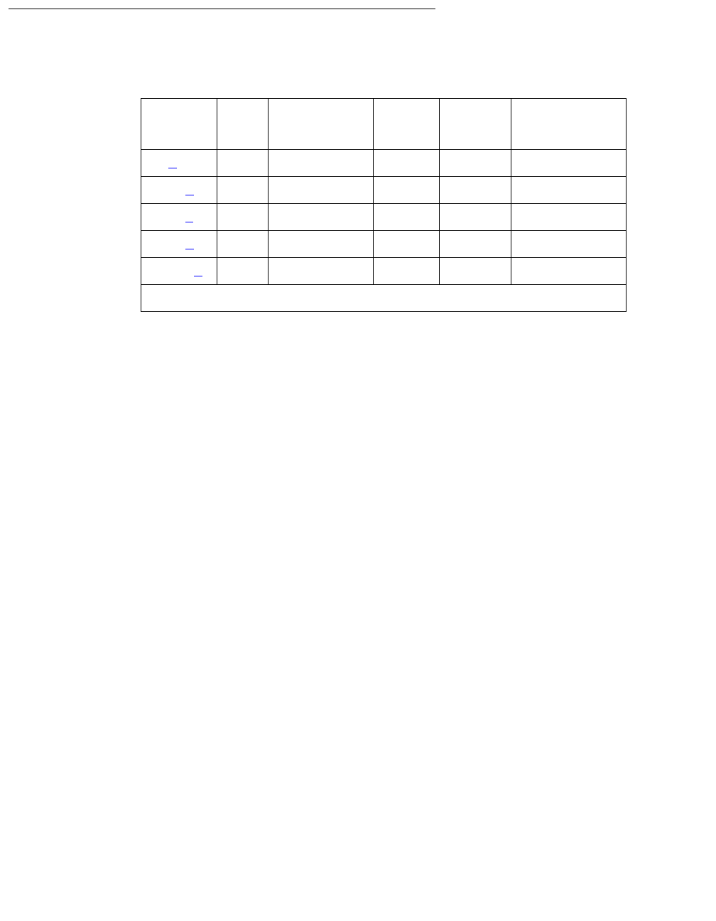
EXP-PN (Expansion Port Network)
Issue 1 June 2005 1237
Error Log Entries and Test to Clear Values
Notes:
a. Error Type 1: informational entry only, indicating that a PN Reset Level 1 (PN Warm
Restart) has been executed on this PN.
b. Error Type 257: informational entry only, indicating that a PN Reset Level 2 (PN Cold
Restart) has been executed on this PN. This does not include restarts done at system
initialization time.
c. Error Type 513: indicates that a PN is not in service when it is expected to be. The value
specified in the port field of the error log, is the PN number of the affected PN. When this
condition occurs, examine every system link error and EXP-INTF or ATM-PNC error to aid
in resolving the alarm (examples of system link errors are errors logged against PKT-INTF,
EXP-INTF, SNI-BD, FIBER-LK, and PKT-BUS and for ATM, PKT-BUS, ATM-EI,
ATM-NTWK). Also check that all fiber connectivity matches that have been administered for
the system. This alarm and error is resolved and removed from the logs only when the PN
comes back into service.
d. Error Type 769: This alarm is raised when PN maintenance has attempted to execute a
Cold Restart recovery action two times, and both restarts failed. This will cause the PN to be
placed in Emergency Transfer. Examine every EXP-INTF or ATM-EI error that, when
cleared, may aid in resolving this alarm. Also check for any SNI-BD, SNI-PEER, FIBR-LK,
SN-CONF, or DS1C-BD errors or for ATM, ATM-EI or ATM-NTWK errors that may indicate a
communication problem between the processor and the PN. Make sure that the physical
fiber connectivity matches that of system administration.
e. Error Type 1025: If two cabinets are DS1-C connected and their companding modes differ,
the system raises a major alarm only if the Multinational Locations field is y on the
Customer Options form. See Administrator Guide for Avaya Communication Manager,
03-300509 for more information about administering multiple locations, particularly the
Locations form in Screen Reference section.
Table 418: Expansion Port Network (EXP-PN) Error Log Entries
Error
Type
Aux
Data
Associated
Test
Alarm
Level
On/Off
Board
Test to Clear
Value
1 (a) 0 None None
257 (b) 0 None None
513 (c)0 None MAJ OFF
769 (d)0 None MAJ OFF
1025 (e) Any None MAJ OFF

Communication Manager Maintenance-Object Repair Procedures
1238 Maintenance Procedures for Avaya Communication Manager 3.0, Media Gateways and Servers
System Technician-Demanded Tests:
Descriptions And Error Codes
EXP-PN does not support demand testing. A demand reset can be executed to perform a
demand reset on a PN by using reset port-network P level 1 or 2 (P is the port
network’s number, and 1 or 2 specifies the reset level).
PN Cold Restart (#955)
PN Cold Restart, or PN Reset Level 2, reset port-network P level 2 is used as a
recovery mechanism for a PN that has been taken out of service. It is executed as a result of PN
recovery escalation when a Warm Restart is not possible, or as a result of a system technician
demanded PN restart. Once a PN has gone out of service, a PN Cold Restart is required to
bring it back into service.
This is the most severe of the PN restarts, and users will experience a service outage. For the
first 30 seconds after the occurrence of an event that requires a restart, every stable call is
preserved (although new calls will be denied). All calls terminating in the PN are then dropped,
and PN users are not able to place new phone calls during the restart. All PN hardware will also
be re-initialized during this restart. The restart takes no longer than 2 minutes with service being
restored much quicker in a typical restart situation.
Table 419: Test #955 PN Cold Restart
Error
Code
Test
Result
Description / Recommendation
1386 ABRT The system link to this PN is unavailable and cannot be used. This reset
cannot be executed without the link being operational.
1. Refer to SYS-LINK and resolve the link problem.
2100 ABRT Could not allocate the necessary system resources to execute this reset.
2000 ABRT Response to a request made in the internal portion of this reset procedure
was not received within the allowable time period.
2500 ABRT Internal system error
1. Retry the command at 1-minute intervals up to 3 times.
FAIL Internal system error
1. Retry the command at 1-minute intervals up to 3 times.
PASS The PN Cold Restart procedure completed successfully.

EXP-PN (Expansion Port Network)
Issue 1 June 2005 1239
PN Warm Restart (#956)
The PN Warm Restart, or PN Reset Level 1, reset port-network P level 1 is used to
restart a PN that has not been taken out of service. It is the least severe of the PN restart levels
and is used in an attempt to preserve the state of the system as much as possible, thereby
reducing user impact. This restart is attempted on a PN if it is still in service, or as a result of a
system technician-demanded PN Warm Restart.
During a PN Warm Restart all calls are preserved including voice, data, and packet calls. Once
an event has occurred that requires a warm restart, service is fully restored within 35 seconds.
Table 420: Test #956 PN Warm Restart
Error
Code
Test
Result
Description / Recommendation
2100 ABRT Could not allocate the necessary system resources to execute this reset.
1. Retry the command at 1-minute intervals up to 3 times.
1386 ABRT The system link to this PN is unavailable and cannot be used. This reset
cannot be executed without the link being operational.
1. See SYS-LINK and resolve the link problem.
1387 ABRT This PN is not in a state where it is possible to perform a Warm Restart on
the PN. It is necessary to perform a PN Cold Restart (PN Reset Level 2)
because of one of the following reasons:
●The PN is in an out-of-service state.
●Insufficient time has elapsed since the last PN Cold Restart was
performed on this PN.
2000 ABRT Response to a request made in the internal portion of this reset procedure
was not received within the allowable time period.
2500 ABRT Internal system error
1. Retry the command at 1-minute intervals up to 3 times.
FAIL Internal system error
1. Retry the reset command at 1-minute intervals up to 3 times.
PASS The PN Warm Restart procedure completed successfully.
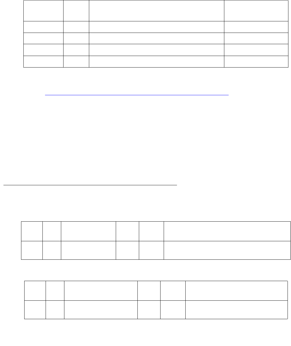
Communication Manager Maintenance-Object Repair Procedures
1240 Maintenance Procedures for Avaya Communication Manager 3.0, Media Gateways and Servers
EXT-DEV (External device alarm)
G650
A TN2312BP IPSI, in a G650 with a carrier address set to A, has two alarm ports that connect to
external devices. An example of an external device is an uninterruptible power supply (UPS).
Refer to Figure 115: G650 Cabinet Environmental Hardware Components on page 1959 for
further information.
Conditions can occur on the external device that close the contacts on the alarm leads. This
notifies the switch to originate an EXT-DEV alarm. One set of leads generates a major alarm,
the other set generates a minor alarm.
In this case, the designation of major or minor refers to the port, not to the severity of the alarm
associated with the connection. For example, the major port can be administered as a major,
minor, or warning alarm, and the minor port can be administered as a major, minor, or warning
alarm. Analog line ports can also be administered as external device alarms in the same
manner.
Error log entries and test-to-clear values
-
MO name in
alarm Log
Alarm
level
Initial SAT command to run Full name of MO
EXT-DEV MIN test environment location External Device Alarm
EXT-DEV MAJ test environment location External Device Alarm
EXT-DEV MIN test eda-external-device-alm location External Device Alarm
EXT-DEV MAJ test eda-external-device-alm location External Device Alarm
Table 421: Test to clear with external device alarm administration enabled
Error
Type
Aux
data
Associated test Alarm
level
On/Off
board
Test-to-clear value
1 Alarm query test
(#120)
MAJ
MIN
OFF test eda-external-device-alm
location
Table 422: Test-to-clear without external device alarm administration enabled
Error
type
Aux
data
Associated test Alarm
level
On/Off
board
Test-to-clear value
1 Alarm query test (#120) MAJ
MIN
OFF test environment location

EXT-DEV (External device alarm)
Issue 1 June 2005 1241
System technician-demanded test:
Descriptions and error codes
Alarm query test (#120)
The external device alarm test requests the status of the external device alarm from a
maintenance circuit pack and reports the results. The test has no affect on the external device
itself. The test environment command will report an error against Test #120 if there is a
short on one or both of the pairs of leads connecting the external device.
!CAUTION:
CAUTION: Alarms can be generated on adjunct equipment, sent to the Avaya system, and
recorded and reported as "external alarms". The adjunct equipment must provide
an isolated contact closure across the alarm leads provided by the Avaya system.
The contact must be rated at a minimum of 60 V DC, with a current carrying
capacity of 5 mA minimum.
Order of investigation Short test
sequence
Long test
sequence
D/ND
Alarm query test (#120) X X Nondestructive
Table 423: Test #120 Alarm query
Error
code
Test
result
Description and Recommendation
1000 ABRT This is an internal system error.
1. Repeat the command at one-minute intervals 1 to 3 times.
1035 ABRT The port network is not available.
1. Use status port-network to verify that the network is not up.
2. Look for alarms against EXP-PN, EXP-INT, PK-INT, etc.
3. Use diagnostic procedures for those MOs to clear the problem.
2000 ABRT A response to the test request was not received within the time allowed.
1. Repeat the command at one-minute intervals 1 to 3 times.
1 of 2

Communication Manager Maintenance-Object Repair Procedures
1242 Maintenance Procedures for Avaya Communication Manager 3.0, Media Gateways and Servers
ANY FAIL The external device alarm has been activated by the external device.
1. Clear the major alarm on the external device and repeat the test.
2. If the test fails, disconnect the external device alarm leads from the
TN2312BP IPSI circuit pack and repeat the test.
3. If the test fails, there is a problem with the analog external device alarm
port, the TN775 Maintenance circuit pack, or TN2312BP IPSI circuit
pack that reports the alarm. There are failures that can occur on the
TN775 and TN2312BP IPSI circuit pack that are not detected by their
respective maintenance, but cause many environment tests to fail. If
many environment tests fail, replace the circuit pack and repeat the test.
PASS If there is a problem with the external device, but none of the following
report an alarm, the external device might not be reporting the problem
correctly or the external device might not be properly connected to the
external device alarm leads:
●The administered analog line external device alarm
●TN775D or later circuit pack
●TN2312BP IPSI circuit pack
Table 423: Test #120 Alarm query (continued)
Error
code
Test
result
Description and Recommendation
2 of 2

EXT-DEV ADMIN? N (External Device Alarm)
Issue 1 June 2005 1243
EXT-DEV ADMIN? N (External Device Alarm)
S8700 | 8710 / S8500
Note:
Note: Use this Maintenance Object when the External Device Alarm Admin field on
the change system-parameters customer-options form is n.
S8700 | 8710 / S8500: The IPSI monitors the EXT-DEV alarm leads.
The system only recognizes pairs connected to the 1M and 1m (ALARM MONITOR) leads.
Refer to the DEFINITY® Communications System Generic 1 and Generic 3i Wiring
(555-204-111) for more details.
Hardware Error Log Entries and Test to Clear Values
MO Name in
Alarm Log
Alarm
Level
Initial Command to Run1
1. Where UU is the cabinet number in the PORT field from the Alarm or Error Log.
Full Name of MO
EXT-DEV MAJ test environment UU External Device Alarm
EXT-DEV MIN test environment UU External Device Alarm
Table 424: EXT-DEV ADMIN?N Error Log Entries
Error
Type
Aux
Data
Associated Test Alarm
Level
On/Off
Board
Test to Clear Value
01
1. Run the Short Test Sequence first. If all tests pass, run the Long Test Sequence. Refer to the appropriate
test description and follow the recommended procedures.
0Any AnyAnytest environment UU r 2 or 6
1 or 5 Any External Device Alarm
(#120)
MAJ
MIN2
2. One port generates a MAJOR alarm; the other port generates a MINOR alarm.
OFF test environment UU r 2 or 6

Communication Manager Maintenance-Object Repair Procedures
1244 Maintenance Procedures for Avaya Communication Manager 3.0, Media Gateways and Servers
System Technician-Demanded Tests: Descriptions and Error
Codes
Always investigate tests in the order presented in the table below when inspecting errors in the
system. By clearing error codes associated with the Cabinet Query Test, you may also clear
errors generated from other tests in the testing sequence.
Notes:
a. Refer to EMG-XFER (Emergency Transfer) on page 1134 for a description of this test.
b. Refer to RING-GEN (Analog Ring Generator) on page 1942 for a description of this test.
Table 425: EXT-DEV ADMIN?N System Technician-Demanded Tests
Order of Investigation Short Test
Sequence
Long Test
Sequence
D/ND1
1. D = Destructive; ND = Nondestructive
Cabinet Query Test (#79) X X ND
Emergency Transfer Query Test (#124) (a)XXND
External Device Alarm Test (MAJOR port) (#120) X X ND
External Device Alarm Test (MINOR port) (#120) X X ND
Analog Ring Generator Initialization Test (#117) (b)X X ND
Analog Ring Generator Query Test (#118) (b)X X ND

EXT-DEV ADMIN? N (External Device Alarm)
Issue 1 June 2005 1245
External Device Alarm Test (#120)
The External Device Alarm Test requests the state of the External Device Alarm from the
Maintenance circuit pack and reports the results. The test has no effect on the external device
itself.
Table 426: TEST #120 External Device Alarm Test
Error
Code
Test
Result
Description/ Recommendation
1000 ABRT System resources required to run this test are not available.
1. Retry the command at 1-minute intervals a maximum of 5 times.
2000 ABRT Response to the test request was not received within the allowable time
period.
1. Retry the command at 1-minute intervals a maximum of 5 times.
2. If the test continues to ABORT with error code 2000, check for system
powering problems with the A carrier. Look for and resolve all
AC-POWER alarms. Then, repeat the test.
3. If the test continues to ABORT with a 2000 error code, check for and
resolve all SYSAM errors. Then, repeat the test.
2029
2319
2320
2500
ABRT Internal system error
1. Retry the command at 1-minute intervals a maximum of 5 times.
ANY FAIL The External Device Alarm has been activated by the external device.
1. Clear the major alarm on the external device, and rerun the test.
2. If the test still fails, then disconnect the External Device Alarms from
the Maintenance circuit pack and rerun the test.
3. If the test still fails, then there is a problem with the Maintenance circuit
pack that is reporting the alarm. This circuit pack should be replaced.
There are failures that can occur on Maintenance circuit pack’s that will
not be detected by their respective maintenance, but which will cause
many environment tests to fail. If many environment tests are failing,
the suspect circuit pack should be replaced and the test rerun.
PASS If there is a problem with the external device, but the Maintenance circuit
pack connected to the device reports no alarm, then the External Device
may not be properly reporting the problems or the External Device may not
be properly connected to the External Device.

Communication Manager Maintenance-Object Repair Procedures
1246 Maintenance Procedures for Avaya Communication Manager 3.0, Media Gateways and Servers
EXT-DEV ADMIN? Y (External Device Alarm)
S8700 | 8710 / S8500
Note:
Note: Use this MO when the External Device Alarm Admin field on the change
system-parameters customer-options screen is y. You must have INADS
or INIT login permissions to administer EXT-DEV Alarm.
S8700 | 8710 / S8500
Each PN’s Maintenance circuit pack has two alarm ports that connect to such external devices
as uninterruptible power supplies (UPSs) or adjuncts (e.g., AUDIX).
Certain conditions on the external device close the contacts on the alarm leads to notify the
switch that in turn originates an EXT-DEV alarm. One set of leads generates a major alarm; the
other set generates a minor alarm.
The special locations UUmajor and UUminor are used to designate the major or minor
Maintenance board’s alarm connection for cabinet UU. The major/minor designation specifies
the port, not the alarm level associated with the connection; for example, the “major” port can be
administered as a major, minor, or warning alarm, and the “minor” port can be administered as a
major, minor, or warning alarm. In addition Analog line ports can also be administered as
external device alarms.
Note:
Note: An un-administered Maintenance board’s external device alarm port, that is
sensing a contact closure will have an entry in the Error Log and in the Alarm
Log. The alarm receiver will not receive warning alarms.
MO Name in
Alarm Log
Alarm
Level
Initial SAT Command to Run 1
1. UU is a cabinet number determined in the Port field of the Alarm or Error Log.
Full Name of MO
EXT-DEV MAJ test eda-external-device-alrm UU External Device Alarm
EXT-DEV MIN test eda-external-device-alrm UU External Device Alarm
EXT-DEV WRN test eda-external-device-alrm UU External Device Alarm

EXT-DEV ADMIN? Y (External Device Alarm)
Issue 1 June 2005 1247
Error Log Entries and Test to Clear Values
Note:
Note: The loss of -48 volt power prevents detection of an external device alarm.
AC-POWER, CARR-POW, and DC-POWER alarms could indicate the loss of the
external device alarm -48 volt power source. ALARM-PT alarms may also
indicate a loss of power. When analog line ports are administered as analog line
external device alarms loss of -48 volts prevents detection of an external device
alarm.
System Technician-Demanded Tests:
Descriptions and Error Codes
Always investigate tests in the order presented in the table below when inspecting errors in the
system. For example, by clearing error codes associated with the Battery & External Device
Alarm test (#120), you may also clear errors generated from other tests in the testing sequence.
Error
Type
Aux
Data
Associated Test Alarm
Level
On/Off
Board
Test to Clear Value
0 0 Any Any Any test eda-external-device-alrm
physical-location r 2 | 6
1 or 5 Any External Device
Alarm test (#120)
Any OFF test eda-external-device-alrm
physical-location r 2 | 6
Order of Investigation Short Test
Sequence
Long Test
Sequence
D/ND1
1. D = Destructive; ND = Nondestructive
External Device Alarm test (MAJOR port) (#120) X X ND
External Device Alarm test (MINOR port) (#120) X X ND
External Device Alarm test (WARNING port) (#120) X X ND

Communication Manager Maintenance-Object Repair Procedures
1248 Maintenance Procedures for Avaya Communication Manager 3.0, Media Gateways and Servers
External Device Alarm Test (#120)
The External Device Alarm Test requests the state of the External Device Alarm from a
Maintenance circuit pack and reports the results. The test has no effect on the external device
itself.
Table 427: Test #120 External Device Alarm Test
Error
Code
Test
Result
Description / Recommendation
1000 ABRT System resources required to run this test are not available.
1. Retry the command at 1-minute intervals up to 5 times.
1035 ABRT The PN containing this equipment is not available.
Resolve every PN problem with this cabinet.
2000 ABRT Response to the test request was not received within the allowable time
period.
1. Retry the command at 1-minute intervals up to 5 times.
2. (Maintenance Board) If the test continues to ABORT with Error Code
2000, check for system powering problems with the A carrier. Resolve
every AC-POWER and CARR-POW alarm in a multi-carrier cabinet or
DC-POWER alarms in a single-carrier cabinet. Then, repeat the test.
3. (Maintenance Board) If the test continues to ABORT with a 2000 Error
Code, resolve every maintenance circuit pack error. Then, repeat the
test.
2029
2100
2319
2320
2500
ABRT Internal system error
1. Retry the command at 1-minute intervals up to 5 times.
1 of 2

EXT-DEV ADMIN? Y (External Device Alarm)
Issue 1 June 2005 1249
Any FAIL The External Device Alarm has been activated by the external device.
1. Clear the major alarm on the external device, and rerun the test.
2. If the test still fails, then disconnect the External Device Alarm Leads
from the Maintenance circuit pack and rerun the test.
3. If the test still fails, then there is a problem with the analog external
device alarm port or the Maintenance circuit pack that is reporting the
alarm. This circuit pack should be replaced. There are failures that can
occur on the Maintenance circuit pack that will not be detected by their
respective maintenance, but that will cause many environment tests to
fail. If many environment tests are failing, the suspect circuit pack
should be replaced and the test rerun.
PASS If there is a problem with the external device, but the administered analog
line external device alarm, or the administered Maintenance circuit pack
connected to the device reports no alarm, then the External Device may not
be properly reporting the problems or the External Device may not be
properly connected to the External Device Alarm Leads.
Table 427: Test #120 External Device Alarm Test (continued)
Error
Code
Test
Result
Description / Recommendation
2 of 2

Communication Manager Maintenance-Object Repair Procedures
1250 Maintenance Procedures for Avaya Communication Manager 3.0, Media Gateways and Servers
FIBER-LK (Fiber Link)
A fiber link consists of the endpoint boards that are connected via the optical fiber, the lightwave
transceivers or metallic connections on the endpoint boards, and, if administered, the DS1
Converter (DS1 converter) complex that exists between the two fiber endpoints. The fiber
endpoints are EI circuit packs and/or SNI (SNI) circuit packs.
Three types of fiber links exist in G3r systems:
Fiber link errors and alarms are generated only on fibers that have at least one SNI endpoint.
Fiber errors for fibers that have EIs as both endpoints are detected by the EI circuit pack, thus
generating off-board EXP-INTF errors and alarms. Fiber errors and alarms on EI-SNI fiber links
generate FIBER-LK and/or off-board EXP-INTF errors and alarms.
Fiber links are administered via add fiber-link F or add fiber-link next, where F is
the fiber link’s number. The 2 endpoints of the fiber are administered (EI and EI, EI and SNI, or
SNI and SNI). In a duplicated PNC configuration, both the A- and B-PNC’s fiber links are
assigned with the same fiber link’s number. The fiber links are designated by F P, where F is the
fiber link’s number and P is the PNC, A-PNC or B-PNC. In addition, a DS1 converter complex
may be assigned to the fiber link. In a duplicated PNC configuration, both the A- and B-PNC’s
DS1 converter complexes are administered with the same fiber link’s number. DS1 facilities and
parameters can be modified via change fiber-link F P.
Use display fiber-link F to see an individual fiber link. Use list fiber-link to see
every fiber link.
MO Name in
Alarm Log
Alarm
Level
Initial Command to Run1
1. F is the fiber link number; pnc is either “a-pnc” or “b-pnc” (always “a-pnc” for a standard-,
high-, or critical-reliability system).
Full Name of MO
FIBER-LK MAJ test fiber-link F pnc s Fiber Link
FIBER-LK MIN test fiber-link F pnc s Fiber Link
FIBER-LK WRN test fiber-link F pnc s Fiber Link
EI-to-EI fiber This type of fiber is an EI-to-EI connection and is only used in direct connect
PNC.
EI-SNI fiber This type of fiber is an EI-to-SNI connection and is only used in Center Stage
Switch (CSS) PNC.
SNI-SNI fiber This type of fiber is an SNI-to-SNI connection and is only used in CSS PNC
when two switch node carriers are connected in a 2- or 3-switch node
configuration.

FIBER-LK (Fiber Link)
Issue 1 June 2005 1251
The following terms are used in the error descriptions:
LEDs for Circuit Packs on a Fiber Link
The amber LEDs on the three types of boards, SNI (TN573), EI (TN570), and DS1 Converter
(TN574 or TN1654), that may be a part of the fiber link can help in diagnosing problems with the
fiber link. The amber LED states are as follows. The flashing LED patterns take precedence
over the active or standby LED patterns.
If both endpoints of a fiber link (EI and/or SNI) are flashing with a fiber out of frame pattern, a
fast amber LED pattern (0.1 second on and 0.1 second off), check the lightwave transceivers (if
present). Both lightwave transceivers on the fiber link must be of the same type. The 9823a
shortwave transceiver and the 9823b longwave transceiver must never be combined on the
same fiber link because a fiber out-of-frame condition will exist. The 9823a lightwave
transceiver should be used for distances up to 4900 feet and the 9823b lightwave transceiver
should be used for distances up to 25,000 feet.
Control Path The path between the two fiber endpoints that is necessary for the two
endpoint circuit packs to communicate.
Circuit Path The path between the two fiber endpoints that is necessary for circuit switched
phone calls to work.
Neighbor The circuit pack on the other end of the fiber.
Out of Frame A circuit pack reports fiber out of frame if it cannot detect valid data coming
from the fiber.
Packet Path The path between the two fiber endpoints that is necessary for
packet-switched messages to be sent between the two fiber endpoints.
Table 428: SNI Amber LED Flashing Codes
Condition LED on LED off
Fiber out of Frame 0.1 second 0.1 second
In Frame, No Neighbor1
1. The fiber is in frame, but no communication exists to
the neighbor
0.5 second 0.5 second
SNI active Solid on Never off
SNI standby Never on Solid off
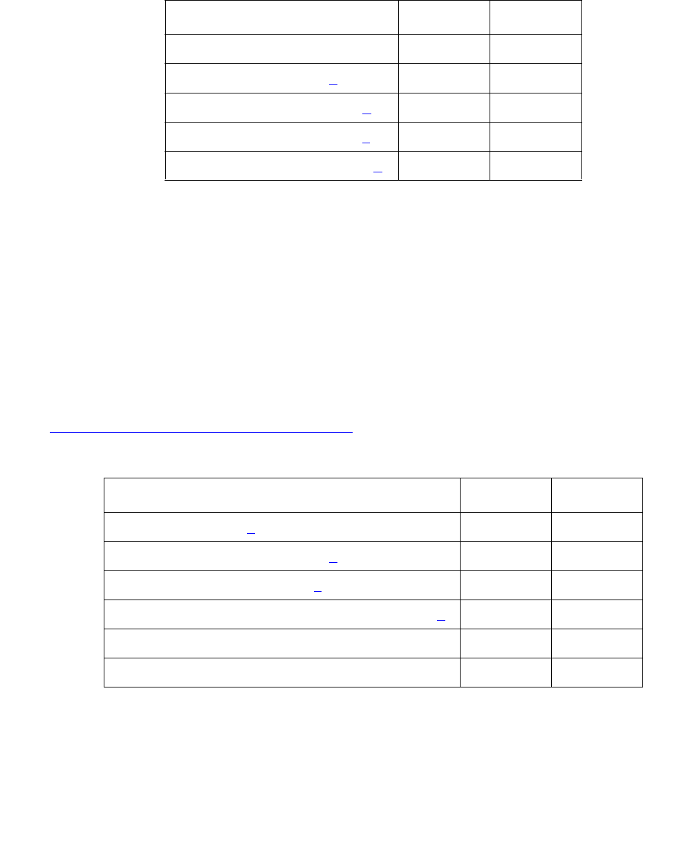
Communication Manager Maintenance-Object Repair Procedures
1252 Maintenance Procedures for Avaya Communication Manager 3.0, Media Gateways and Servers
Notes:
a. The fiber is in frame, but no communication exists to the neighbor.
b. This is the normal state for an active PN EI circuit pack that is also the bus master
(expansion Archangel) in the PN.
c. This is the normal state for an active EI circuit pack that is not the bus master (expansion
Archangel) for a PN. This applies only in the direct connect configuration where the EI
circuit pack in a PN connects via a fiber link to an EI circuit pack in the other PN. This state
also applies for an active EI circuit pack located in the PN.
d. This is the normal state for a standby expansion Interface circuit pack in the PN.
For more details about how the EI circuit pack error codes relate to the LED states, see
EXP-INTF (Expansion Interface Circuit Pack) on page 1176.
Notes:
a. A Fiber is out of frame or a fiber loss-of-signal condition exists.
b. DS1 converter/fiber endpoint communication is down.
c. The DS1 channel is down between the two DS1 converters in the DS1 converter complex.
Table 429: Expansion Interface Circuit Pack Amber LED Flashing Codes
Condition LED on LED off
Fiber Out-of-Frame 0.1 second 0.1 second
In frame-No Neighbor (a) 0.5 second 0.5 second
Expansion Interface Active (b) 2 second 0.2 second
Expansion Interface Active (c) Solid on Never off
Expansion Interface Standby (d) Never on Solid off
Table 430: DS1 Converter Amber LED Flashing Codes
Condition LED on LED off
Fiber out of Frame (a) 0.1 second 0.1 second
In frame, fiber channel is down (b) 0.5 second 0.5 second
In frame, DS1 channel down (c) 1 second 1 second
DS1 converter, no response from media server (d) 2 second 0.2 second
DS1 converter active Solid on Never off
DS1 converter standby Never on Solid off

FIBER-LK (Fiber Link)
Issue 1 June 2005 1253
d. The media server is not acknowledging messages from the DS1 converter circuit pack or
the DS1 converter circuit pack does not have a processor route. This pattern indicates a
probable software problem.
In addition to the traditional red, green, and amber LEDs, the DS1 converter circuit pack has
four green LEDs that indicate whether a receive signal is present for each DS1 facility.
Error Log Entries and Test to Clear Values
Notes:
a. The failure audit test (#777) should be run to confirm whether the error still exists.
b. Error Type 1: indicates problem with the control path to the neighbor. See Repair
procedures.
Table 431: Fiber Link Error Log Entries
Error
Type
Aux
Data
Associated Test Alarm
Level
On/Off
Board
Test to Clear Value
01
1. Run the short test sequence first. If every test passes, run the long test sequence. Refer to each
appropriate test’s description, and follow its recommended procedures.
0 Any Any Any test fiber-link F P r 1
1 (b) any Failure audit (#777) (a)MAJ
MIN
WRN
OFF test fiber-link F P r 1
18 (c)0busyout fiber F P WRN OFF release fiber F P
257 (d) any Failure audit (#777) (a)MAJ
MIN
WRN
OFF test fiber-link F P r 1
513 (e) any Failure audit (#777) (a)MAJ
MIN
WRN
OFF test fiber-link F P r 1
769 (f) any Failure audit (#777) (a)MAJ
MIN
WRN
OFF test fiber-link F P r 1
1025 (g) any Failure audit (#777) (a)MAJ
MIN
WRN
OFF test fiber-link F P r 1
1281 (h) any Failure audit (#777) (a)MAJ
MIN
WRN
OFF test fiber-link F P r 1

Communication Manager Maintenance-Object Repair Procedures
1254 Maintenance Procedures for Avaya Communication Manager 3.0, Media Gateways and Servers
c. Error Type 18: indicates that the fiber link has been busied out via busyout fiber-link
F P. To resolve this error, use release fiber-link F P to release the fiber link.
d. Error Type 257: indicates problem with the circuit path to the neighbor. See Repair
procedures.
e. Error Type 513: indicates problem with the packet path to the neighbor. See Repair
procedures.
f. Error Type 769: indicates problem with the control path from the neighbor. See Repair
procedures.
g. Error Type 1025: indicates problem with the circuit path from the neighbor. See Repair
procedures.
h. Error Type 1281: indicates problem with the packet path from the neighbor. See Repair
procedures.
Repair procedures
For Note b and Notes d through h, perform the following steps:
1. Perform the Fiber link fault isolation in Chapter 4: General troubleshooting in Maintenance
Procedures (03-300192).
2. Enter display errors and if any of the listed slip errors exist, follow the associated repair
procedures in the SYNC section for slip errors.
Table 432: Error Log Entries for Slip Errors
Circuit Pack’s Name Error Log Name Error Log Entry (for Slips)
DS1 Interface DS1-BD 3073 to 3160
Expansion Interface EXP-INTF 2305
SNI SNI-BD 1537
Tone-Clock TDM-CLK 1025
UDS1 Interface UDS1-BD 3073 to 3160
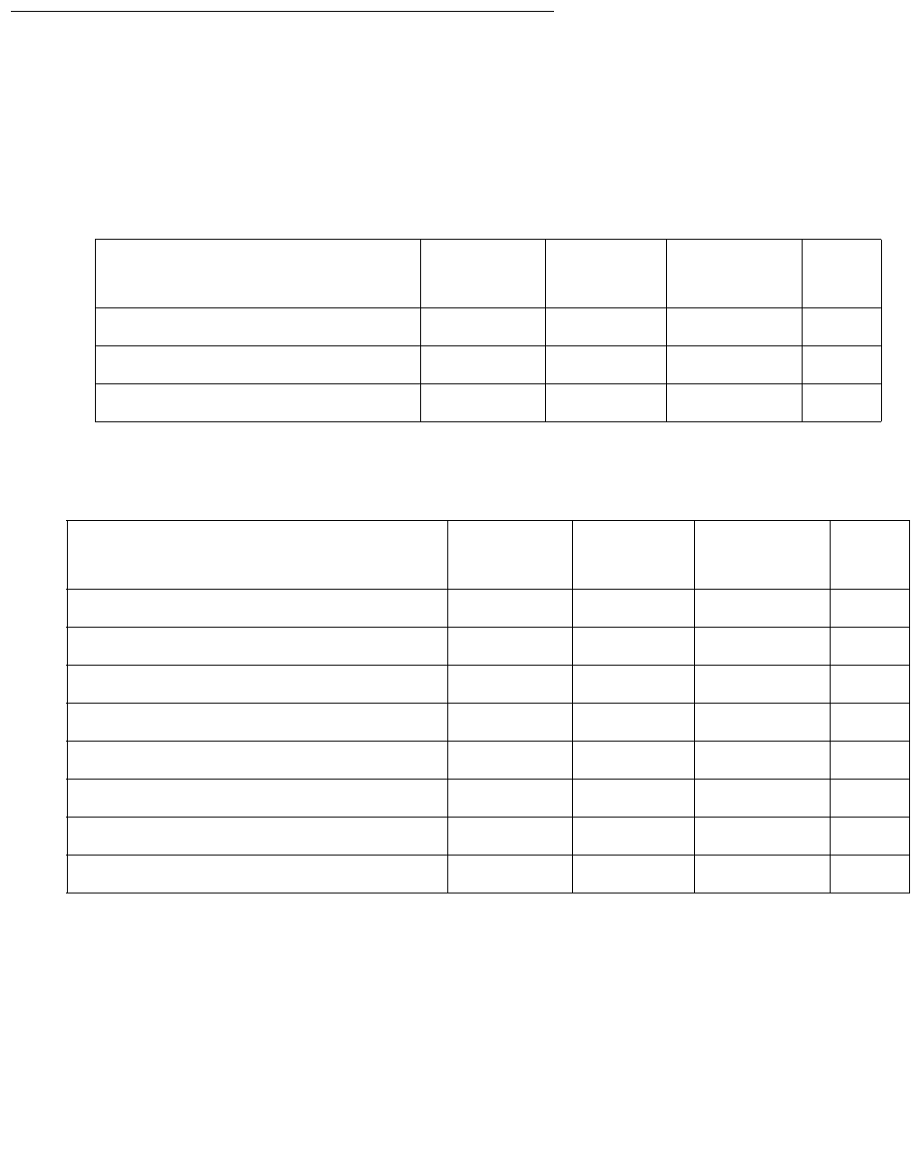
FIBER-LK (Fiber Link)
Issue 1 June 2005 1255
System Technician-Demanded Tests:
Descriptions and Error Codes
Always investigate tests in the following order when inspecting errors in the system. For
example, by clearing error codes associated with the EI Out-of-Frame Query test (#238), you
may also clear errors generated by other tests later in the sequence.
Table 433: Tests Run for an EI-to-EI Fiber Link
Order of Investigation Short Test
Sequence
Long Test
Sequence
Reset Fiber
Sequence
D/ND1
1. D = Destructive; ND = Nondestructive
EI Out-of-Frame Query test (#238) X X ND
EI Neighbor Query test (#237) X X ND
Fiber Link Reset test (#768) X D
Table 434: Tests Run for an EI-to-SNI Fiber Link
Order of Investigation Short Test
Sequence
Long Test
Sequence
Reset Fiber
Sequence
D/ND1
1. D = Destructive, ND = Nondestructive
EI Out-of-Frame Query test (#238) X X ND
EI Neighbor Query test (#237) X X ND
Configuration audit (#759) X X ND
Failure audit (#777) X X ND
Fiber Out of Frame query (#989) X X ND
Destructive Facility test (#757) X D
Off-Board Destructive Facility test (#756) X D
Fiber Link Reset test (#768) X D

Communication Manager Maintenance-Object Repair Procedures
1256 Maintenance Procedures for Avaya Communication Manager 3.0, Media Gateways and Servers
Expansion Interface Neighbor Query Test (#237)
This test is nondestructive. The Expansion Interface Neighbor Query test is a request to an EI
circuit pack to determine whether it has established communication with the EI or SNI circuit
pack at the opposite end of the fiber.
For EI-to-EI fiber links, this test is run on both EI circuit pack endpoints of the fiber link.
Table 435: Tests Run for an SNI-to-SNI Fiber Link
Order of Investigation Short Test
Sequence
Long Test
Sequence
Reset Fiber
Sequence
D/ND1
1. D = Destructive; ND = Nondestructive
Configuration audit (#759) X X ND
Failure audit (#777) X X ND
Fiber Out of Frame query (#989) X X ND
Destructive Facility test (#757) X D
Off-Board Destructive Facility test (#756) X D
Fiber Link Reset test (#768) X D
Table 436: Test #237 Expansion Interface Neighbor Query Test
Error
Code
Test
Result
Description / Recommendation
1033 ABRT The EI circuit pack does not have a fiber link administered to it. There is not
sufficient data to run test. Because test fiber-link was run, the
expansion interface should be administered on a fiber link, and this must be
a software problem.
2000 ABRT Response to the test request was not received within the allowable time
period.
1. Run test board location separately for each EI endpoint on this
fiber link, and follow the procedures for this test in EXP-INTF
(Expansion Interface Circuit Pack) on page 1176.
1 of 2
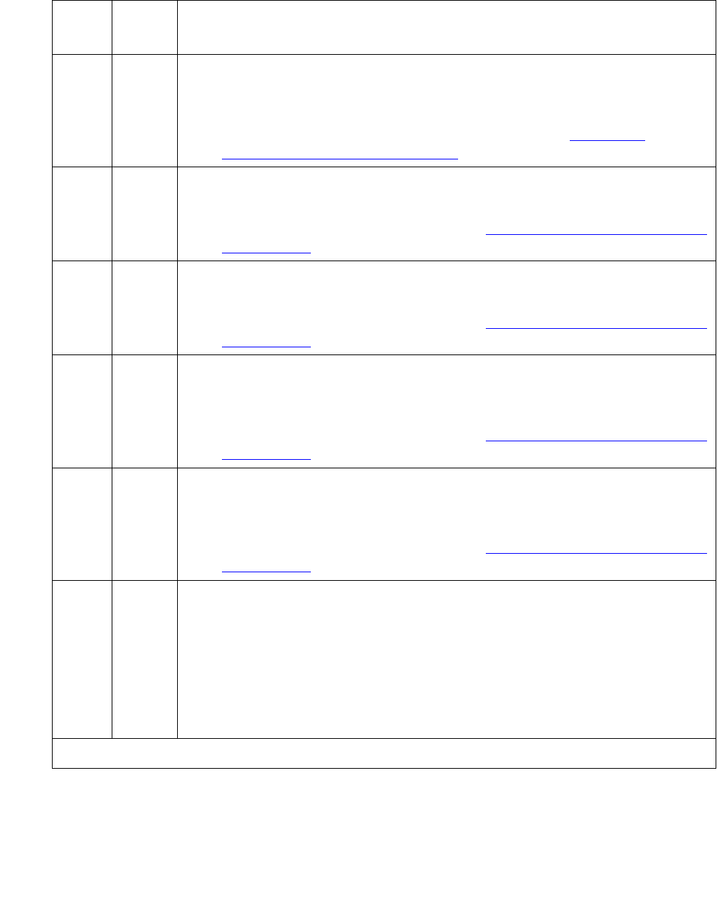
FIBER-LK (Fiber Link)
Issue 1 June 2005 1257
2031 ABRT The attempt to send the message to the EI circuit pack, asking it who it’s
neighbor is, was not successful.
1. Run test board location separately for each EI endpoint on this
fiber link, and follow the procedures for this test in EXP-INTF
(Expansion Interface Circuit Pack) on page 1176.
2100 ABRT System resources required to run this test are not available.
1. Run test board location separately for each EI endpoint on this
fiber link, and follow the procedures in EXP-INTF (Expansion Interface
Circuit Pack) on page 1176.
2500 ABRT Internal system error
1. Run test board location separately for each EI endpoint on this
fiber link, and follow the procedures in EXP-INTF (Expansion Interface
Circuit Pack) on page 1176.
1033 FAIL The EI circuit pack under test cannot make contact with opposite end EI or
SNI circuit pack.
1. Run test board location separately for each EI endpoint on this
fiber link, and follow the procedures in EXP-INTF (Expansion Interface
Circuit Pack) on page 1176.
2027 FAIL The EI circuit pack has contact with the opposite EI or SNI circuit pack, but
it is the incorrect EI or SNI circuit pack.
1. Run test board location separately for each EI endpoint on this
fiber link, and follow the procedures in EXP-INTF (Expansion Interface
Circuit Pack) on page 1176.
PASS The EI circuit pack(s) have successfully established a link with the
opposite EI or SNI circuit pack.
1. If status port-network still indicates that this link is down, it is
possible that one or both of the EI and/or SNI circuit packs have been
busied out.
2. If the link still does not come up, reset one or both EI and/or SNI circuit
packs on the link.
Table 436: Test #237 Expansion Interface Neighbor Query Test (continued)
Error
Code
Test
Result
Description / Recommendation
2 of 2

Communication Manager Maintenance-Object Repair Procedures
1258 Maintenance Procedures for Avaya Communication Manager 3.0, Media Gateways and Servers
Expansion Interface Fiber Out-of-Frame (FOOF) Query Test (#238)
This test is nondestructive.
This test is a request to an EI circuit pack to determine whether it is currently detecting the
framing sequence on the incoming fiber’s data stream. If it cannot detect this framing signal, the
EI circuit pack will not be able to establish a link with the opposite EI or SNI circuit pack.
For EI-to-EI fiber links, this test is run on both EI circuit pack endpoints of the fiber link.
Table 437: Test #238 Expansion Interface Fiber Out-of-Frame Query Test
Error
Code
Test
Result
Description / Recommendation
ABRT Internal system error (software).
1. Run test board location separately for each EI endpoint on this
fiber link and follow the procedures for this test in the EXP-INTF
(Expansion Interface Circuit Pack) on page 1176 section of the
maintenance manual.
2. If the test continues to abort or fail, escalate the problem.
1033 ABRT The EI circuit pack does not have a fiber link administered to it. There is not
sufficient data to run test. Because test fiber-link was run, the
expansion interface should be administered on a fiber link, therefore this
must be a software problem.
2000 ABRT Response to the test request was not received within the allowable time
period.
1. Run test board location separately for each EI endpoint on this
fiber link and follow the procedures in EXP-INTF (Expansion Interface
Circuit Pack) on page 1176.
2100 ABRT System resources required to run this test are not available.
1. Run test board location separately for each EI endpoint on this
fiber link and follow the procedures in EXP-INTF (Expansion Interface
Circuit Pack) on page 1176.
2500 ABRT Internal system error
1. Run test board location separately for each EI endpoint on this
fiber link and follow the procedures in EXP-INTF (Expansion Interface
Circuit Pack) on page 1176.
1 of 2

FIBER-LK (Fiber Link)
Issue 1 June 2005 1259
SNI Off-Board Destructive Facility Test (#756)
This test is destructive.
The SNI runs a destructive loop around of the on- and off-board looparounds. This test returns
the result of the off-board loop around, while Test 757 returns the result of the on-board loop
around. For SNI-to-SNI fiber links, this test is run on both SNI circuit pack endpoints of the fiber
link.
FAIL EI circuit pack can’t frame up to incoming signal. Several fail codes may be
returned depending on which endpoint can’t frame up. Error codes 2326,
2327, and 2328 denote Endpoint 1, Endpoint 2, and both endpoints,
respectively.
1. Clear any SYNC and TDM-CLK errors listed in the error log.
2. Run test board location for each EI board on this fiber link and
follow the appropriate repair sequence for any failing tests.
3. If the EI circuit pack fails Test #238 and is in the PN, and the red LEDs
are ON for a large number of circuit packs, then reseat any Tone-Clock
circuit packs in the PN. See the “How to replace Tone-Clock circuit
packs” section of TDM-CLK (TDM Bus Clock) on page 2252
Maintenance documentation.
4. Enter display errors and follow the associated repair procedures
for any SNC-BD (if applicable to this fiber link configuration) or
TDM-BUS errors.
5. Perform the Fiber link fault isolation in Chapter 4: General
troubleshooting in Maintenance Procedures (03-300192)”, described in
Chapter 5.
6. If the test continues to abort, follow normal escalation procedures.
PASS The EI circuit pack(s) have detected the valid framing signal on the fiber.
1. Refer to errors from other EI circuit packs, SNI (SNI) tests, or DS1
Converter tests (if present) if the link is still not functioning.
Table 437: Test #238 Expansion Interface Fiber Out-of-Frame Query Test (continued)
Error
Code
Test
Result
Description / Recommendation
2 of 2

Communication Manager Maintenance-Object Repair Procedures
1260 Maintenance Procedures for Avaya Communication Manager 3.0, Media Gateways and Servers
Table 438: Test #756 SNI Off-Board Destructive Facility Test
Error
Code
Test
Result
Description / Recommendation
1015 ABRT The system will not allow this test to be run because the fiber link has not
been busied out. Busyout the fiber link with busyout fiber-link F P.
Run test fiber-link F P long.
1415 ABRT The lightwave transceiver is absent from Endpoint 1 of the fiber link. Use
list fiber-link to display fiber link endpoints.
1. If a lightwave transceiver should not be present, do nothing. For
example, an SNI connected to a DS1 converter circuit pack or an SNI
with a metallic connection does not have a lightwave transceiver. This
test can only be run when a lightwave transceiver exists.
2. Otherwise, continue with the following steps.
3. Check the lightwave transceiver connections.
4. Replace the lightwave transceiver. If a fiber out-of-frame condition
exists and lightwave transceivers are used, check that the lightwave
transceivers are of the same type (both are 9823a or both are 9823b).
If they are not the same type, replace one of the lightwave
transceivers.
5. Replace the SNI circuit pack.
1416 ABRT The lightwave transceiver is absent from Endpoint 2 of the fiber link. Use
list fiber-link to display fiber link endpoints.
1. If a lightwave transceiver should not be present, do nothing. For
example, an SNI connected to a DS1 converter circuit pack or an SNI
with a metallic connection does not have a lightwave transceiver. This
test can only be run when a lightwave transceiver exists.
2. Check the lightwave transceiver connections.
3. Replace the lightwave transceiver. If a fiber out-of-frame condition
exists and lightwave transceivers are used, check that the lightwave
transceivers are of the same type (both are 9823a or both are 9823b).
If they are not the same type, replace one of the lightwave
transceivers.
4. Replace the SNI circuit pack.
1 of 3

FIBER-LK (Fiber Link)
Issue 1 June 2005 1261
2100 ABRT Could not allocate the necessary system resources to run this test.
1. Retry the command at 1-minute intervals up to 3 times.
2300 ABRT The downlink message necessary to run this test could not be sent.
1. Retry the command at 1-minute intervals up to 3 times.
2301 ABRT The software timer could not be set before sending the downlink message
necessary to run this test.
1. Retry the command at 1-minute intervals up to 3 times.
2304 ABRT SNI circuit pack responded that it is not able to run the test requested by
software.
1. Retry the command at 1-minute intervals up to 3 times.
2306 ABRT A fiber link’s SNI circuit pack is not responding to test requests sent by
software.
1. Run test led switch-node for the switch node where the SNI
board(s) reside to verify whether their LEDs light. If not, continue with
the following steps.
2. If LEDs light on other boards in the same carrier (but not on this board),
enter test board location l (#760) for the active SNC in this
carrier. Wait 5 minutes, and try step 1 again. If the board’s LEDs still do
not light, replace the board. (Replacing an SNI may be service
interrupting. Refer to the SNI-BD section for the procedure to replace
an SNI.)
3. If no LEDs light on any board in the same carrier, fix any connectivity
problems between this carrier and the media server. Use list
fiber-link to determine the fiber connections to this carrier. Check
the LEDs on every SNI and EI, and fix any fiber problems. Enter
display errors, and resolve any SYNC, SNI-BD, SNC-BD,
FIBER-LK, or SNI-PEER error entries.
Table 438: Test #756 SNI Off-Board Destructive Facility Test (continued)
Error
Code
Test
Result
Description / Recommendation
2 of 3

Communication Manager Maintenance-Object Repair Procedures
1262 Maintenance Procedures for Avaya Communication Manager 3.0, Media Gateways and Servers
SNI Destructive Facility Test (#757)
This test is destructive.
The SNI runs a destructive loop around of the on- and off-board looparounds. This test returns
the result of the on-board loop around, while Test 756 returns the result of the off-board loop
around.
For SNI-to-SNI fiber links, this test is run on both SNI circuit pack endpoints of the fiber link.
127 FAIL The data is not correctly looped around on Endpoint 1 of the fiber link. Use
list fiber-link to display fiber link endpoints.
1. Check the lightwave transceiver.
2. Replace the lightwave transceiver. If a fiber out-of-frame condition
exists and lightwave transceivers are used, check that the lightwave
transceivers are of the same type (both are 9823a or both are 9823b).
If they are not the same type, replace one of the lightwave
transceivers.
3. Replace the SNI circuit pack.
227 FAIL The data is not correctly looped around on Endpoint 2 of the fiber link Use
list fiber-link to display fiber link endpoints.
1. Check the lightwave transceiver.
2. Replace the lightwave transceiver. If a fiber out-of-frame condition
exists and lightwave transceivers are used, check that the lightwave
transceivers are of the same type (both are 9823a or both are 9823b).
If they are not the same type, replace one of the lightwave
transceivers.
3. Replace the SNI circuit pack.
PASS No problems associated with this test are detected on the SNI(s).
Table 438: Test #756 SNI Off-Board Destructive Facility Test (continued)
Error
Code
Test
Result
Description / Recommendation
3 of 3

FIBER-LK (Fiber Link)
Issue 1 June 2005 1263
Table 439: Test #757 SNI Destructive Facility Test
Error
Code
Test
Result
Description / Recommendation
1015 ABRT The system will not allow this test to be run because the fiber link has not
been busied out.
1. Busyout the fiber link with busyout fiber-link F P.
2. Enter test fiber-link F P long.
2100 ABRT Could not allocate the necessary system resources to run this test.
1. Retry the command at 1-minute intervals up to 3 times.
2300 ABRT The downlink message necessary to run this test could not be sent.
1. Retry the command at 1-minute intervals up to 3 times.
2301 ABRT The software timer could not be set before sending the downlink message
necessary to run this test.
1. Retry the command at 1-minute intervals up to 3 times.
2304 ABRT SNI circuit pack responded that it is not able to run the test requested by
software.
1. Retry the command at 1-minute intervals up to 3 times.
2306 ABRT A fiber link’s SNI circuit pack is not responding to test requests sent by
software.
1. Run test led switch-node for the switch node where the SNI
board(s) reside to verify whether their LEDs light. If not, continue with
the following steps.
2. If LEDs light on other boards in the same carrier (but not on this
board), enter test board location l (#760) for the active SNC in
this carrier. Wait 5 minutes, and try step 1 again. If the board’s LEDs
still do not light, replace the board. (Replacing an SNI may be service
interrupting. Refer to the SNI-BD section for the procedure to replace
an SNI.)
3. If no LEDs light on any board in the same carrier, fix any connectivity
problems between this carrier and the media server. Use list
fiber-link to determine the fiber connections to this carrier. Check
the LEDs on every SNI and EI, and fix any fiber problems. Enter
display errors, and resolve any SYNC, SNI-BD, SNC-BD,
FIBER-LK, or SNI-PEER error entries.
1 of 2
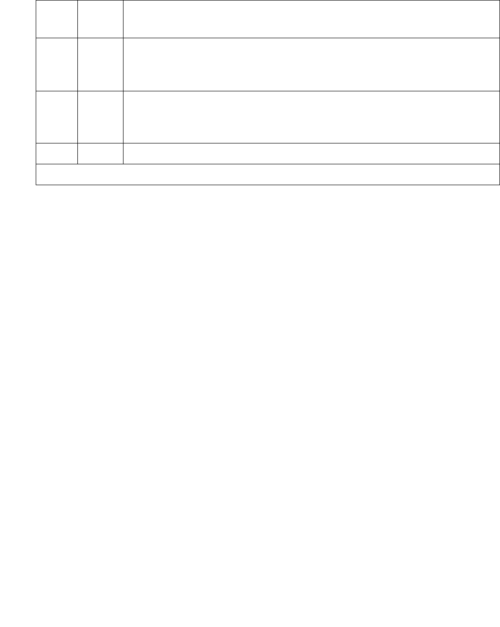
Communication Manager Maintenance-Object Repair Procedures
1264 Maintenance Procedures for Avaya Communication Manager 3.0, Media Gateways and Servers
Configuration Audit (#759)
This test is nondestructive.
This test is run via test board short or test board long for SNI circuit packs or via
test fiber-link for fiber links with SNI endpoint(s).
This test queries the SNI for SNCs in the same switch node carrier, SNI peers, DS1 converter s,
and EI or SNI neighbors that the SNI can communicate with and compares this data to the
administered data.
Failures of this test cause entries in the error and alarm logs against Switch Node Configuration
(SN-CONF) with the board location of the SNI.
This test is unable to detect the case where an SNI is connected to the same type of board (EI
or SNI) as administered but located in a different cabinet but the same carrier and same slot as
the administered fiber endpoint. Use list fiber-link to see the administered fiber
endpoint. This test can only detect if the fiber endpoint connected to the SNI is in a different
carrier, slot location than the administered fiber endpoint.
If the SNI is connected to the same type of fiber endpoint as the administered fiber endpoint, but
the location is the same as administered except for the cabinet, no phone calls will work
correctly; some phone calls will not go through and some phone calls will ring the wrong phone.
The test led command can be used in this case to check connectivity.
1. Run test led port-network for each administered PN, and verify that the LEDs on the
correct PN are lit.
If not, check that the fiber connections to the PN are consistent with the administered fibers
(list fiber-link) that do not light the LEDs as expected.
127 FAIL The data is not correctly looped around on Endpoint 1 of the fiber link. Use
list fiber-link to display fiber link endpoints.
1. Replace the SNI circuit pack.
227 FAIL The data is not correctly looped around on Endpoint 2 of the fiber link. Use
list fiber-link to display fiber link endpoints.
1. Replace the SNI circuit pack.
PASS No problems associated with this test are detected on the SNI(s).
Table 439: Test #757 SNI Destructive Facility Test (continued)
Error
Code
Test
Result
Description / Recommendation
2 of 2

FIBER-LK (Fiber Link)
Issue 1 June 2005 1265
2. Run test led switch-node for each administered switch node carrier (SNC), and verify
that the LEDs on the correct SNC are lit.
If not, check the connectivity to the SNC that does not light the LEDs as expected.
Table 440: Test #759 Configuration Audit
Error
Code
Test
Result
Description / Recommendation
2100 ABRT Could not allocate the necessary system resources to run this test for
endpoint 1 of the fiber link.
1. Use list fiber-link to display a fiber link’s endpoints.
2. If this fiber link has two SNI endpoints, run test board location
separately for each SNI and follow the repair procedures in section
SNI-BD.
2300 ABRT The downlink message necessary to run this test could not be sent.
1. Use list fiber-link to display fiber link endpoints.
2. If this fiber link has two SNI endpoints, run test board location
separately for each SNI and follow the repair procedures in section
SNI-BD.
2301 ABRT The software timer could not be set before sending the downlink message
necessary to run this test.
1. Use list fiber-link to display fiber link endpoints.
2. If this fiber link has two SNI endpoints, run test board location
separately for each SNI and follow the repair procedures in section
SNI-BD.
1 of 22

Communication Manager Maintenance-Object Repair Procedures
1266 Maintenance Procedures for Avaya Communication Manager 3.0, Media Gateways and Servers
2306 ABRT An SNI circuit pack on the fiber link is not responding to test requests sent
by software.
1. Run the test led switch-node for the switch node(s) where the
SNI(s) reside to verify whether the LEDs on the board(s) light. Follow
the steps below for the SNI(s) that had no LEDs light.
2. If the LEDs on the other boards in the carrier light, but the LEDs on this
board do not light, run Test #760 via test board location l for
the active SNC in this carrier. Wait 5 minutes and then try step 1 one
more time. If the LEDs on this board still do not light, replace the
board. (Replacing an SNI may be service interrupting. Refer to the
SNI-BD section for the procedure to replace an SNI.)
3. If none of the LEDs light for the boards in the same carrier as this
board, fix any problems associated with the connectivity of this carrier
to the media server. Use list fiber-link to determine the fiber
connections to this carrier. Check the LEDs on every SNI and EI, and
fix any fiber problems. Enter display errors and resolve any
EXP-INTF error entries associated with the PN. Also, resolve any
SYNC, SNI-BD, SNC-BD, FIBER-LK, or SNI-PEER error entries.
2500 ABRT Internal system error If this fiber link has two SNI endpoints, run test
board location separately for each SNI and follow the repair
procedures in section SNI-BD. Use list fiber-link to see a fiber
link’s endpoints. Otherwise:
1. Retry the command at 1-minute intervals up to 3 times.
102 FAIL The SNI circuit pack (Endpoint 1) cannot communicate with the equipped
SNI in slot 2. Use list fiber-link to see a fiber link’s endpoints.
1. Perform the Fiber link fault isolation in Chapter 4: General
troubleshooting in Maintenance Procedures (03-300192). This should
resolve multiple SNI-PEER errors.
2. If the SNI being tested has SNI-PEER Error Type 1, replace the SNI
being tested. (Replacing an SNI may be service interrupting. Refer to
the SNI-BD section for the procedure to replace an SNI.) To view
SNI-PEER errors, use display errors with category PNC-PEER.
Retry the command.
3. If the SNI being tested still has SNI-PEER Error Type 1, replace the
SNI in slot 2.
Table 440: Test #759 Configuration Audit (continued)
Error
Code
Test
Result
Description / Recommendation
2 of 22

FIBER-LK (Fiber Link)
Issue 1 June 2005 1267
103 FAIL The SNI circuit pack (Endpoint 1) cannot communicate with the equipped
SNI in slot 3. Use list fiber-link to see a fiber link’s endpoints.
1. Perform the Fiber link fault isolation in Chapter 4: General
troubleshooting in Maintenance Procedures (03-300192). This should
resolve multiple SNI-PEER errors.
2. If the SNI being tested has SNI-PEER Error Type 257, replace the SNI
being tested. (Replacing an SNI may be service interrupting. Refer to
the SNI-BD section for the procedure to replace an SNI.) To view
SNI-PEER errors, use display errors with category PNC-PEER.
Retry the command.
3. If the SNI being tested still has SNI-PEER Error Type 257, replace the
SNI in slot 3.
104 FAIL The SNI circuit pack (Endpoint 1) cannot communicate with the equipped
SNI in slot 4. Use list fiber-link to see a fiber link’s endpoints.
1. Perform the Fiber link fault isolation in Chapter 4: General
troubleshooting in Maintenance Procedures (03-300192). This should
resolve multiple SNI-PEER errors.
2. If the SNI being tested has SNI-PEER Error Type 513, replace the SNI
being tested. (Replacing an SNI may be service interrupting. Refer to
the SNI-BD section for the procedure to replace an SNI.) To view
SNI-PEER errors, use display errors with category PNC-PEER.
Retry the command.
3. If the SNI being tested has SNI-PEER Error Type 513, replace the SNI
in slot 4.
Table 440: Test #759 Configuration Audit (continued)
Error
Code
Test
Result
Description / Recommendation
3 of 22

Communication Manager Maintenance-Object Repair Procedures
1268 Maintenance Procedures for Avaya Communication Manager 3.0, Media Gateways and Servers
105 FAIL The SNI circuit pack (Endpoint 1) cannot communicate with the equipped
SNI in slot 5. Use list fiber-link to see a fiber link’s endpoints.
1. Perform the Fiber link fault isolation in Chapter 4: General
troubleshooting in Maintenance Procedures (03-300192). This should
resolve multiple SNI-PEER errors.
2. If the SNI being tested has SNI-PEER Error Type 769, replace the SNI
being tested. (Replacing an SNI may be service interrupting. Refer to
the SNI-BD section for the procedure to replace an SNI.) To view
SNI-PEER errors, use display errors with category PNC-PEER.
Retry the command.
3. If the SNI being tested has SNI-PEER Error Type 769, replace the SNI
in slot 5.
106 FAIL The SNI circuit pack (Endpoint 1) cannot communicate with the equipped
SNI in slot 6. Use list fiber-link to see a fiber link’s endpoints.
1. Perform the Fiber link fault isolation in Chapter 4: General
troubleshooting in Maintenance Procedures (03-300192). This should
resolve multiple SNI-PEER errors.
2. If the SNI being tested has SNI-PEER Error Type 1025, replace the
SNI being tested. (Replacing an SNI may be service interrupting.
Refer to the SNI-BD section for the procedure to replace an SNI.) To
view SNI-PEER errors, use display errors with category
PNC-PEER. Retry the command.
3. If the SNI being tested still has SNI-PEER Error Type 1025, replace
the SNI in slot 6.
Table 440: Test #759 Configuration Audit (continued)
Error
Code
Test
Result
Description / Recommendation
4 of 22

FIBER-LK (Fiber Link)
Issue 1 June 2005 1269
107 FAIL The SNI circuit pack (Endpoint 1) cannot communicate with the equipped
SNI in slot 7. Use list fiber-link to see a fiber link’s endpoints.
1. Perform the Fiber link fault isolation in Chapter 4: General
troubleshooting in Maintenance Procedures (03-300192). This should
resolve multiple SNI-PEER errors.
2. If the SNI being tested has SNI-PEER Error Type 1281, replace the
SNI being tested. (Replacing an SNI may be service interrupting.
Refer to the SNI-BD section for the procedure to replace an SNI.) To
view SNI-PEER errors, use display errors with category
PNC-PEER. Retry the command.
3. If the SNI being tested still has SNI-PEER Error Type 1281, replace
the SNI in slot 7.
108 FAIL The SNI circuit pack (Endpoint 1) cannot communicate with the equipped
SNI in slot 8. Use list fiber-link to see a fiber link’s endpoints.
1. Perform the Fiber link fault isolation in Chapter 4: General
troubleshooting in Maintenance Procedures (03-300192). This should
resolve multiple SNI-PEER errors.
2. If the SNI being tested has SNI-PEER Error Type 1537, replace the
SNI being tested. (Replacing an SNI may be service interrupting.
Refer to the SNI-BD section for the procedure to replace an SNI.) To
view SNI-PEER errors, use display errors with category
PNC-PEER. Retry the command.
3. If the SNI being tested still has SNI-PEER Error Type 1537, replace
the SNI in slot 8.
Table 440: Test #759 Configuration Audit (continued)
Error
Code
Test
Result
Description / Recommendation
5 of 22

Communication Manager Maintenance-Object Repair Procedures
1270 Maintenance Procedures for Avaya Communication Manager 3.0, Media Gateways and Servers
109 FAIL The SNI circuit pack (Endpoint 1) cannot communicate with the equipped
SNI in slot 9. Use list fiber-link to see a fiber link’s endpoints.
1. Perform the Fiber link fault isolation in Chapter 4: General
troubleshooting in Maintenance Procedures (03-300192). This should
resolve multiple SNI-PEER errors.
2. If the SNI being tested has SNI-PEER Error Type 1793, replace the
SNI being tested. (Replacing an SNI may be service interrupting.
Refer to the SNI-BD section for the procedure to replace an SNI.) To
view SNI-PEER errors, use display errors with category
PNC-PEER. Retry the command.
3. If the SNI being tested still has SNI-PEER Error Type 1793, replace
the SNI in slot 9.
112 FAIL The SNI circuit pack (Endpoint 1) cannot communicate with the active
SNC. Use list fiber-link to see a fiber link’s endpoints.
1. Check the error log for other SNI circuit packs in the same carrier with
a 257 SNI-BD error. Use display errors with category PNC to
view SNI-BD errors. If other SNI circuit packs in the same switch node
carrier have Error 257, then replace the active SNC in this switch node
carrier. Replacing an SNC may be service interrupting. Refer to the
SNC-BD section for the procedure for replacing an SNC.
2. Replace this SNI.
3. Replace the active SNC in the same switch node carrier.
113 FAIL The SNI circuit pack (Endpoint 1) cannot communicate with the equipped
SNI in slot 13. Use list fiber-link to see a fiber link’s endpoints.
1. Perform the Fiber link fault isolation in Chapter 4: General
troubleshooting in Maintenance Procedures (03-300192). This should
resolve multiple SNI-PEER errors.
2. If the SNI being tested has SNI-PEER Error Type 2049, replace the
SNI being tested. (Replacing an SNI may be service interrupting.
Refer to the SNI-BD section for the procedure to replace an SNI.) To
view SNI-PEER errors, use display errors with category
PNC-PEER. Retry the command.
3. If the SNI being tested still has SNI-PEER Error Type 2049, replace
the SNI in slot 13.
Table 440: Test #759 Configuration Audit (continued)
Error
Code
Test
Result
Description / Recommendation
6 of 22

FIBER-LK (Fiber Link)
Issue 1 June 2005 1271
114 FAIL The SNI circuit pack (Endpoint 1) cannot communicate with the equipped
SNI in slot 14. Use list fiber-link to see a fiber link’s endpoints.
1. Perform the Fiber link fault isolation in Chapter 4: General
troubleshooting in Maintenance Procedures (03-300192). This should
resolve multiple SNI-PEER errors.
2. If the SNI being tested has SNI-PEER Error Type 2305, replace the
SNI being tested. (Replacing an SNI may be service interrupting.
Refer to the SNI-BD section for the procedure to replace an SNI.) To
view SNI-PEER errors, use display errors with category
PNC-PEER. Retry the command.
3. If the SNI being tested still has SNI-PEER Error Type 2305, replace
the SNI in slot 14.
115 FAIL The SNI circuit pack (Endpoint 1) cannot communicate with the equipped
SNI in slot 15. Use list fiber-link to see a fiber link’s endpoints.
1. Perform the Fiber link fault isolation in Chapter 4: General
troubleshooting in Maintenance Procedures (03-300192). This should
resolve multiple SNI-PEER errors.
2. If the SNI being tested has SNI-PEER Error Type 2561, replace the
SNI being tested. (Replacing an SNI may be service interrupting.
Refer to the SNI-BD section for the procedure to replace an SNI.) To
view SNI-PEER errors, use display errors with category
PNC-PEER. Retry the command.
3. If the SNI being tested still has SNI-PEER Error Type 2561, replace
the SNI in slot 15.
Table 440: Test #759 Configuration Audit (continued)
Error
Code
Test
Result
Description / Recommendation
7 of 22

Communication Manager Maintenance-Object Repair Procedures
1272 Maintenance Procedures for Avaya Communication Manager 3.0, Media Gateways and Servers
116 FAIL The SNI circuit pack (Endpoint 1) cannot communicate with the equipped
SNI in slot 16. Use list fiber-link to see a fiber link’s endpoints.
1. Perform the Fiber link fault isolation in Chapter 4: General
troubleshooting in Maintenance Procedures (03-300192). This should
resolve multiple SNI-PEER errors.
2. If the SNI being tested has SNI-PEER Error Type 2817, replace the
SNI being tested. (Replacing an SNI may be service interrupting.
Refer to the SNI-BD section for the procedure to replace an SNI.) To
view SNI-PEER errors, use display errors with category
PNC-PEER. Retry the command.
3. If the SNI being tested still has SNI-PEER Error Type 2817, replace
the SNI in slot 16.
117 FAIL The SNI circuit pack (Endpoint 1) cannot communicate with the equipped
SNI in slot 17. Use list fiber-link to see a fiber link’s endpoints.
1. Perform the Fiber link fault isolation in Chapter 4: General
troubleshooting in Maintenance Procedures (03-300192). This should
resolve multiple SNI-PEER errors.
2. If the SNI being tested has SNI-PEER Error Type 3073, replace the
SNI being tested. (Replacing an SNI may be service interrupting.
Refer to the SNI-BD section for the procedure to replace an SNI.) To
view SNI-PEER errors, use display errors with category
PNC-PEER. Retry the command.
3. If the SNI being tested still has SNI-PEER Error Type 3073, replace
the SNI in slot 17.
Table 440: Test #759 Configuration Audit (continued)
Error
Code
Test
Result
Description / Recommendation
8 of 22

FIBER-LK (Fiber Link)
Issue 1 June 2005 1273
118 FAIL The SNI circuit pack (Endpoint 1) cannot communicate with the equipped
SNI in slot 18. Use list fiber-link to see a fiber link’s endpoints.
1. Perform the Fiber link fault isolation in Chapter 4: General
troubleshooting in Maintenance Procedures (03-300192). This should
resolve multiple SNI-PEER errors.
2. If the SNI being tested has SNI-PEER Error Type 3329, replace the
SNI being tested. (Replacing an SNI may be service interrupting.
Refer to the SNI-BD section for the procedure to replace an SNI.) To
view SNI-PEER errors, use display errors with category
PNC-PEER. Retry the command.
3. If the SNI being tested still has SNI-PEER Error Type 3329, replace
the SNI in slot 18.
119 FAIL The SNI circuit pack (Endpoint 1) cannot communicate with the equipped
SNI in slot 19. Use list fiber-link to see a fiber link’s endpoints.
1. Perform the Fiber link fault isolation in Chapter 4: General
troubleshooting in Maintenance Procedures (03-300192). This should
resolve multiple SNI-PEER errors.
2. If the SNI being tested has SNI-PEER Error Type 3585, replace the
SNI being tested. (Replacing an SNI may be service interrupting.
Refer to the SNI-BD section for the procedure to replace an SNI.) To
view SNI-PEER errors, use display errors with category
PNC-PEER. Retry the command.
3. If the SNI being tested still has SNI-PEER Error Type 3585, replace
the SNI in slot 19.
Table 440: Test #759 Configuration Audit (continued)
Error
Code
Test
Result
Description / Recommendation
9 of 22

Communication Manager Maintenance-Object Repair Procedures
1274 Maintenance Procedures for Avaya Communication Manager 3.0, Media Gateways and Servers
120 FAIL The SNI circuit pack (Endpoint 1) cannot communicate with the equipped
SNI in slot 20. Use list fiber-link to see a fiber link’s endpoints.
1. Perform the Fiber link fault isolation in Chapter 4: General
troubleshooting in Maintenance Procedures (03-300192). This should
resolve multiple SNI-PEER errors.
2. If the SNI being tested has SNI-PEER Error Type 3841, replace the
SNI being tested. (Replacing an SNI may be service interrupting.
Refer to the SNI-BD section for the procedure to replace an SNI.) To
view SNI-PEER errors, use display errors with category
PNC-PEER. Retry the command.
3. If the SNI being tested still has SNI-PEER Error Type 3841, replace
the SNI in slot 20.
133 FAIL No neighbor link is assigned, but the SNI (Endpoint 1) has an EI neighbor.
Use list fiber-link to see a fiber link’s endpoints.
1. Administer the SNI on a fiber link to the EI neighbor it is connected to
via add fiber-link next. Or remove both fiber endpoints (i.e., this
SNI and its EI neighbor) and remove the fiber endpoints from circuit
pack administration via change circuit-pack.
134 FAIL No neighbor link is assigned, but the SNI (Endpoint 1) has an SNI
neighbor. Use list fiber-link to see a fiber link’s endpoints.
1. Administer the SNI on a fiber link to the SNI neighbor it is connected to
via add fiber-link next. Or remove both fiber endpoints (i.e., this
SNI and its SNI neighbor) and remove the fiber endpoints from circuit
pack administration via change circuit-pack.
135 FAIL The SNI circuit pack (Endpoint 1) cannot communicate with its assigned
neighbor. Use list fiber-link to see a fiber link’s endpoints.
1. Check if the administered neighbor is inserted. If not, insert the
neighbor circuit pack.
2. Perform the Fiber link fault isolation in Chapter 4: General
troubleshooting in Maintenance Procedures (03-300192).
136 FAIL The Endpoint 1 SNI’s administered neighbor does not match the physical
neighbor connected. Use list fiber-link to see a fiber link’s
endpoints. The SNI’s assigned neighbor is another SNI, but the SNI is
physically connected to an EI. Enter list fiber-link and verify that the
fiber-optic and metallic cables are installed as administered.
Table 440: Test #759 Configuration Audit (continued)
Error
Code
Test
Result
Description / Recommendation
10 of 22

FIBER-LK (Fiber Link)
Issue 1 June 2005 1275
137 FAIL The Endpoint 1 SNI’s administered neighbor does not match the physical
neighbor connected. Use list fiber-link to see a fiber link’s
endpoints. The SNI’s assigned neighbor is an EI, but the SNI is physically
connected to another SNI. Enter list fiber-link and verify that the
fiber-optic and metallic cables are installed as administered.
138 FAIL The physical location of SNI Endpoint 1’s neighbor does not match its
administered location. Use list fiber-link to see a fiber link’s
endpoints. One location (carrier and slot) is assigned for the endpoint’s
neighbor, but it physically resides in another location.
1. Enter list fiber-link and verify that the fiber-optic and metallic
cables are installed as administered.
2. If the problem does not seem to be caused by either a
physical-connection or an administration problem, replace the
neighbor circuit pack. The neighbor circuit pack may have a hardware
problem causing it to report a wrong angel address (physical carrier/
slot address) to software.
139 FAIL The Endpoint 1 SNI is administered to be connected to a DS1 converter, but
is not physically connected to one. Use list fiber-link to see a fiber
link’s endpoints.
If a DS1 converter should be connected to this SNI, enter list
fiber-link and verify that the fiber-optic and/or metallic cables are
installed as assigned.
If not, change administration to remove the DS1 converter complex from
the SNI’s fiber link:
1. Enter list fiber-link to locate the fiber with this SNI as an
endpoint
2. Enter remove fiber-link to remove the fiber
3. Enter add fiber-link to add the fiber back, without assigning the
DS1 converter complex
Table 440: Test #759 Configuration Audit (continued)
Error
Code
Test
Result
Description / Recommendation
11 of 22

Communication Manager Maintenance-Object Repair Procedures
1276 Maintenance Procedures for Avaya Communication Manager 3.0, Media Gateways and Servers
140 FAIL The Endpoint 1 SNI is physically connected to a DS1 converter but is not
administered to be connected to a DS1 converter. Use list
fiber-link to see a fiber link’s endpoints. Either add the DS1 converter
complex to the fiber that this SNI is associated with:
1. Check for the fiber that this SNI is an endpoint of by checking list
fiber-link.
2. Remove fiber-link for the fiber that this SNI is an endpoint of.
3. Add the fiber back via add fiber-link and administer the DS1
converter complex also. Or, remove the DS1 converter connection and
connect the SNI directly to its administered fiber endpoint by entering
list fiber-link and verifying that the fiber-optic and metallic
cable connections are installed as administered.
202 FAIL The SNI circuit pack (Endpoint 2) cannot communicate with the equipped
SNI in slot 2. Use list fiber-link to see a fiber link’s endpoints.
1. Perform the Fiber link fault isolation in Chapter 4: General
troubleshooting in Maintenance Procedures (03-300192). This should
resolve multiple SNI-PEER errors.
2. If the SNI being tested has SNI-PEER Error Type 1, replace the SNI
being tested. (Replacing an SNI may be service interrupting. Refer to
the SNI-BD section for the procedure to replace an SNI.) To view
SNI-PEER errors, use display errors with category PNC-PEER.
Retry the command.
3. If the SNI being tested still has SNI-PEER Error Type 1, replace the
SNI in slot 2.
Table 440: Test #759 Configuration Audit (continued)
Error
Code
Test
Result
Description / Recommendation
12 of 22

FIBER-LK (Fiber Link)
Issue 1 June 2005 1277
203 FAIL The SNI circuit pack (Endpoint 2) cannot communicate with the equipped
SNI in slot 3. Use list fiber-link to see a fiber link’s endpoints.
1. Perform the Fiber link fault isolation in Chapter 4: General
troubleshooting in Maintenance Procedures (03-300192). This should
resolve multiple SNI-PEER errors.
2. If the SNI being tested has SNI-PEER Error Type 257, replace the SNI
being tested. (Replacing an SNI may be service interrupting. Refer to
the SNI-BD section for the procedure to replace an SNI.) To view
SNI-PEER errors, use display errors with category PNC-PEER.
Retry the command.
3. If the SNI being tested still has SNI-PEER Error Type 257, replace the
SNI in slot 3.
204 FAIL The SNI circuit pack (Endpoint 2) cannot communicate with the equipped
SNI in slot 4. Use list fiber-link to see a fiber link’s endpoints.
1. Perform the Fiber link fault isolation in Chapter 4: General
troubleshooting in Maintenance Procedures (03-300192). This should
resolve multiple SNI-PEER errors.
2. If the SNI being tested has SNI-PEER Error Type 513, replace the SNI
being tested. (Replacing an SNI may be service interrupting. Refer to
the SNI-BD section for the procedure to replace an SNI.) To view
SNI-PEER errors, use display errors with category PNC-PEER.
Retry the command.
3. If the SNI being tested still has SNI-PEER Error Type 513, replace the
SNI in slot 4.
Table 440: Test #759 Configuration Audit (continued)
Error
Code
Test
Result
Description / Recommendation
13 of 22

Communication Manager Maintenance-Object Repair Procedures
1278 Maintenance Procedures for Avaya Communication Manager 3.0, Media Gateways and Servers
205 FAIL The SNI circuit pack (Endpoint 2) cannot communicate with the equipped
SNI in slot 5. Use list fiber-link to see a fiber link’s endpoints.
1. Perform the Fiber link fault isolation in Chapter 4: General
troubleshooting in Maintenance Procedures (03-300192). This should
resolve multiple SNI-PEER errors.
2. If the SNI being tested has SNI-PEER Error Type 769, replace the SNI
being tested. (Replacing an SNI may be service interrupting. Refer to
the SNI-BD section for the procedure to replace an SNI.) To view
SNI-PEER errors, use display errors with category PNC-PEER.
Retry the command.
3. If the SNI being tested still has SNI-PEER Error Type 769, replace the
SNI in slot 5.
206 FAIL The SNI circuit pack (Endpoint 2) cannot communicate with the equipped
SNI in slot 6. Use list fiber-link to see a fiber link’s endpoints.
1. Perform the Fiber link fault isolation in Chapter 4: General
troubleshooting in Maintenance Procedures (03-300192). This should
resolve multiple SNI-PEER errors.
2. If the SNI being tested has SNI-PEER Error Type 1025, replace the
SNI being tested. (Replacing an SNI may be service interrupting.
Refer to the SNI-BD section for the procedure to replace an SNI.) To
view SNI-PEER errors, use display errors with category
PNC-PEER. Retry the command.
3. If the SNI being tested still has SNI-PEER Error Type 1025, replace
the SNI in slot 6.
Table 440: Test #759 Configuration Audit (continued)
Error
Code
Test
Result
Description / Recommendation
14 of 22

FIBER-LK (Fiber Link)
Issue 1 June 2005 1279
207 FAIL The SNI circuit pack (Endpoint 2) cannot communicate with the equipped
SNI in slot 7. Use list fiber-link to see a fiber link’s endpoints.
1. Perform the Fiber link fault isolation in Chapter 4: General
troubleshooting in Maintenance Procedures (03-300192). This should
resolve multiple SNI-PEER errors.
2. If the SNI being tested has SNI-PEER Error Type 1281, replace the
SNI being tested. (Replacing an SNI may be service interrupting.
Refer to the SNI-BD section for the procedure to replace an SNI.) To
view SNI-PEER errors, use display errors with category
PNC-PEER. Retry the command.
3. If the SNI being tested still has SNI-PEER Error Type 1281, replace
the SNI in slot 7.
208 FAIL The SNI circuit pack (Endpoint 2) cannot communicate with the equipped
SNI in slot 8. Use list fiber-link to see a fiber link’s endpoints.
1. Perform the Fiber link fault isolation in Chapter 4: General
troubleshooting in Maintenance Procedures (03-300192). This should
resolve multiple SNI-PEER errors.
2. If the SNI being tested has SNI-PEER Error Type 1537, replace the
SNI being tested. (Replacing an SNI may be service interrupting.
Refer to the SNI-BD section for the procedure to replace an SNI.) To
view SNI-PEER errors, use display errors with category
PNC-PEER. Retry the command.
3. If the SNI being tested still has SNI-PEER Error Type 1537, replace
the SNI in slot 8.
Table 440: Test #759 Configuration Audit (continued)
Error
Code
Test
Result
Description / Recommendation
15 of 22

Communication Manager Maintenance-Object Repair Procedures
1280 Maintenance Procedures for Avaya Communication Manager 3.0, Media Gateways and Servers
209 FAIL The SNI circuit pack (Endpoint 2) cannot communicate with the equipped
SNI in slot 9. Use list fiber-link to see a fiber link’s endpoints.
1. Perform the Fiber link fault isolation in Chapter 4: General
troubleshooting in Maintenance Procedures (03-300192). This should
resolve multiple SNI-PEER errors.
2. If the SNI being tested has SNI-PEER Error Type 1793, replace the
SNI being tested. (Replacing an SNI may be service interrupting.
Refer to the SNI-BD section for the procedure to replace an SNI.) To
view SNI-PEER errors, use display errors with category
PNC-PEER. Retry the command.
3. If the SNI being tested still has SNI-PEER Error Type 1793, replace
the SNI in slot 9.
212 FAIL The SNI circuit pack (Endpoint 2) cannot communicate with the active
SNC. Use list fiber-link to see a fiber link’s endpoints.
1. Check the error log for other SNI circuit packs in the same carrier with
a 257 SNI-BD error. Use display errors with category PNC to
view SNI-BD errors. If other SNI circuit packs in the same switch node
carrier have error 257, then replace the active SNC in this switch node
carrier. Replacing an SNC may be service interrupting. Refer to the
SNC-BD section for the procedure for replacing an SNC.
2. Replace this SNI.
3. Replace the active SNC in the same switch node carrier.
213 FAIL The SNI circuit pack (Endpoint 2) cannot communicate with the equipped
SNI in slot 13. Use list fiber-link to see a fiber link’s endpoints.
1. Perform the Fiber link fault isolation in Chapter 4: General
troubleshooting in Maintenance Procedures (03-300192). This should
resolve multiple SNI-PEER errors.
2. If the SNI being tested has SNI-PEER Error Type 2049, replace the
SNI being tested. (Replacing an SNI may be service interrupting.
Refer to the SNI-BD section for the procedure to replace an SNI.) To
view SNI-PEER errors, use display errors with category
PNC-PEER. Retry the command.
3. If the SNI being tested still has SNI-PEER Error Type 2049, replace
the SNI in slot 13.
Table 440: Test #759 Configuration Audit (continued)
Error
Code
Test
Result
Description / Recommendation
16 of 22

FIBER-LK (Fiber Link)
Issue 1 June 2005 1281
214 FAIL The SNI circuit pack (Endpoint 2) cannot communicate with the equipped
SNI in slot 14. Use list fiber-link to see a fiber link’s endpoints.
1. Perform the Fiber link fault isolation in Chapter 4: General
troubleshooting in Maintenance Procedures (03-300192). This should
resolve multiple SNI-PEER errors.
2. If the SNI being tested has SNI-PEER Error Type 2305, replace the
SNI being tested. (Replacing an SNI may be service interrupting.
Refer to the SNI-BD section for the procedure to replace an SNI.) To
view SNI-PEER errors, use display errors with category
PNC-PEER. Retry the command.
3. If the SNI being tested still has SNI-PEER Error Type 2305, replace
the SNI in slot 14.
215 FAIL The SNI circuit pack (Endpoint 2) cannot communicate with the equipped
SNI in slot 15. Use list fiber-link to see a fiber link’s endpoints.
1. Perform the Fiber link fault isolation in Chapter 4: General
troubleshooting in Maintenance Procedures (03-300192). This should
resolve multiple SNI-PEER errors.
2. If the SNI being tested has SNI-PEER Error Type 2561, replace the
SNI being tested. (Replacing an SNI may be service interrupting.
Refer to the SNI-BD section for the procedure to replace an SNI.) To
view SNI-PEER errors, use display errors with category
PNC-PEER. Retry the command.
3. If the SNI being tested still has SNI-PEER Error Type 2561, replace
the SNI in slot 15.
Table 440: Test #759 Configuration Audit (continued)
Error
Code
Test
Result
Description / Recommendation
17 of 22

Communication Manager Maintenance-Object Repair Procedures
1282 Maintenance Procedures for Avaya Communication Manager 3.0, Media Gateways and Servers
216 FAIL The SNI circuit pack (Endpoint 2) cannot communicate with the equipped
SNI in slot 16. Use list fiber-link to see a fiber link’s endpoints.
1. Perform the Fiber link fault isolation in Chapter 4: General
troubleshooting in Maintenance Procedures (03-300192). This should
resolve multiple SNI-PEER errors.
2. If the SNI being tested has SNI-PEER Error Type 2817, replace the
SNI being tested. (Replacing an SNI may be service interrupting.
Refer to the SNI-BD section for the procedure to replace an SNI.) To
view SNI-PEER errors, use display errors with category
PNC-PEER. Retry the command.
3. If the SNI being tested still has SNI-PEER Error Type 2817, replace
the SNI in slot 16.
217 FAIL The SNI circuit pack (Endpoint 2) cannot communicate with the equipped
SNI in slot 17. Use list fiber-link to see a fiber link’s endpoints.
1. Perform the Fiber link fault isolation in Chapter 4: General
troubleshooting in Maintenance Procedures (03-300192). This should
resolve multiple SNI-PEER errors.
2. If the SNI being tested has SNI-PEER Error Type 3073, replace the
SNI being tested. (Replacing an SNI may be service interrupting.
Refer to the SNI-BD section for the procedure to replace an SNI.) To
view SNI-PEER errors, use display errors with category
PNC-PEER. Retry the command.
3. If the SNI being tested still has SNI-PEER Error Type 3073, replace
the SNI in slot 17.
Table 440: Test #759 Configuration Audit (continued)
Error
Code
Test
Result
Description / Recommendation
18 of 22

FIBER-LK (Fiber Link)
Issue 1 June 2005 1283
218 FAIL The SNI circuit pack (Endpoint 2) cannot communicate with the equipped
SNI in slot 18. Use list fiber-link to see a fiber link’s endpoints.
1. Perform the Fiber link fault isolation in Chapter 4: General
troubleshooting in Maintenance Procedures (03-300192). This should
resolve multiple SNI-PEER errors.
2. If the SNI being tested has SNI-PEER Error Type 3329, replace the
SNI being tested. (Replacing an SNI may be service interrupting.
Refer to the SNI-BD section for the procedure to replace an SNI.) To
view SNI-PEER errors, use display errors with category
PNC-PEER. Retry the command.
3. If the SNI being tested still has SNI-PEER Error Type 3329, replace
the SNI in slot 18.
219 FAIL The SNI circuit pack (Endpoint 2) cannot communicate with the equipped
SNI in slot 19. Use list fiber-link to see a fiber link’s endpoints.
1. Perform the Fiber link fault isolation in Chapter 4: General
troubleshooting in Maintenance Procedures (03-300192). This should
resolve multiple SNI-PEER errors.
2. If the SNI being tested has SNI-PEER Error Type 3585, replace the
SNI being tested. (Replacing an SNI may be service interrupting.
Refer to the SNI-BD section for the procedure to replace an SNI.) To
view SNI-PEER errors, use display errors with category
PNC-PEER. Retry the command.
3. If the SNI being tested still has SNI-PEER Error Type 3585, replace
the SNI in slot 19.
Table 440: Test #759 Configuration Audit (continued)
Error
Code
Test
Result
Description / Recommendation
19 of 22

Communication Manager Maintenance-Object Repair Procedures
1284 Maintenance Procedures for Avaya Communication Manager 3.0, Media Gateways and Servers
220 FAIL The SNI circuit pack (Endpoint 2) cannot communicate with the equipped
SNI in slot 20. Use list fiber-link to see a fiber link’s endpoints.
1. Perform the Fiber link fault isolation in Chapter 4: General
troubleshooting in Maintenance Procedures (03-300192). This should
resolve multiple SNI-PEER errors.
2. If the SNI being tested has SNI-PEER Error Type 3841, replace the
SNI being tested. (Replacing an SNI may be service interrupting.
Refer to the SNI-BD section for the procedure to replace an SNI.) To
view SNI-PEER errors, use display errors with category
PNC-PEER. Retry the command.
3. If the SNI being tested still has SNI-PEER Error Type 3841, replace
the SNI in slot 20.
233 FAIL No neighbor link is assigned, but the SNI (Endpoint 2) has an EI neighbor.
Use list fiber-link to display a fiber link’s endpoints.
If the SNI should have an EI neighbor:
1. Enter add fiber-link next to assign the fiber link’s SNI to its
physically connected EI neighbor.
If not:
2. Remove both fiber endpoints (i.e., this SNI and its EI neighbor).
3. Use change circuit-pack to remove the fiber endpoints from
circuit-pack administration.
234 FAIL No neighbor link is administered, but the SNI (Endpoint 2) has an SNI
neighbor Use list fiber-link to display a fiber link’s endpoints.
1. Administer the SNI on a fiber link to the SNI neighbor it is connected to
via add fiber-link next. Or remove both fiber endpoints (i.e., this
SNI and its SNI neighbor) and remove the fiber endpoints from circuit
pack administration via change circuit-pack.
235 FAIL The SNI circuit pack (Endpoint 2) cannot communicate with its neighbor.
Use list fiber-link to display fiber link endpoints. The SNI has an
administered neighbor, but cannot communicate with its neighbor.
1. Check if the administered neighbor is inserted. If not, insert the
neighbor circuit pack.
2. Perform the Fiber link fault isolation in Chapter 4: General
troubleshooting in Maintenance Procedures (03-300192).
Table 440: Test #759 Configuration Audit (continued)
Error
Code
Test
Result
Description / Recommendation
20 of 22

FIBER-LK (Fiber Link)
Issue 1 June 2005 1285
236 FAIL The Endpoint 2 SNI’s administered neighbor does not match the physical
neighbor connected. Use list fiber-link to see a fiber link’s
endpoints. The SNI’s assigned neighbor is another SNI, but the SNI is
physically connected to an EI. Enter list fiber-link and verify that the
fiber-optic and metallic cables are installed as administered.
237 FAIL The Endpoint 2 SNI’s administered neighbor does not match the physical
neighbor connected. Use list fiber-link to see fiber link endpoints.
The SNI’s assigned neighbor is an EI, but the SNI is physically connected to
another SNI. Enter list fiber-link and verify that the fiber-optic and
metallic cables are installed as administered.
238 FAIL The physical location of SNI Endpoint 2’s neighbor does not match its
administered location. Use list fiber-link to see a fiber link’s
endpoints. One location (carrier and slot) is assigned for the endpoint’s
neighbor, but it physically resides in another location.
1. Enter list fiber-link and verify that the fiber-optic and metallic
cables are installed as administered.
2. If the problem does not seem to be caused by either a
physical-connection or an administration problem, replace the
neighbor circuit pack. The neighbor circuit pack may have a hardware
problem causing it to report a wrong angel address (physical carrier/
slot address) to software.
239 FAIL The SNI Endpoint 2 is assigned to be connected to a DS1 converter, but is
not physically connected to one. Use list fiber-link to see a fiber
link’s endpoints.
If this SNI endpoint should be connected to a DS1 converter:
1. Enter list fiber-link to verify that the fiber-optic cable and/or
metallic cable connections are installed as assigned.
If not, change administration to remove the DS1 converter complex from
the SNI’s fiber link:
1. Enter list fiber-link to locate this SNI endpoint’s fiber
2. Enter remove fiber-link for this SNI endpoint’s fiber
3. Enter add fiber-link to replace the fiber without assigning the
DS1 converter complex.
Table 440: Test #759 Configuration Audit (continued)
Error
Code
Test
Result
Description / Recommendation
21 of 22

Communication Manager Maintenance-Object Repair Procedures
1286 Maintenance Procedures for Avaya Communication Manager 3.0, Media Gateways and Servers
Fiber Link Reset Test (#768)
This test is destructive.
This test resets both endpoints of the fiber link and is executed via reset fiber-link F P.
Any DS1 converter circuit packs on the fiber link are not reset. The reset fiber-link
command should almost never be used. It may be necessary to use it when the endpoint circuit
packs enter a mode in which they cannot communicate with software. When necessary, always
reset fiber endpoints with the command instead of reseating the endpoint circuit packs.
For EI-to-EI fibers that connect an IPSI PN, the EI on the PN is reset first followed by the EI on
the IPSI PN. For EI-to-EI fiber links that connect two PNs, one EI is reset first followed by the
other.
For an EI-SNI fiber link in which the EI is on the PN, the SNI is reset first followed by the EI.
For an EI-SNI fiber link in which the EI is on a PN, the SNI is reset first followed by the EI.
For an SNI-to-SNI fiber link, the SNI farthest from the PN is reset first followed by the SNI
nearest to the PN.
240 FAIL The SNI Endpoint 2 is physically connected to a DS1 converter, but is not
assigned to be connected to one. Use list fiber-link to display a fiber
link’s endpoints.
Either replace the DS1 converter with fiber:
1. Enter list fiber-link to verify that the fiber-optic and metallic
cable connections are installed as assigned
2. Disconnect the SNI endpoint from the DS1 converter
3. Enter add fiber-link to reconnect the SNI to its assigned fiber
or
Add a DS1 converter complex to the SNI’s fiber:
1. Enter list fiber-link to locate this SNI endpoint’s fiber
2. Enter remove fiber-link for this SNI endpoint’s fiber
3. Enter add fiber-link to replace the fiber and to assign the DS1
Converter complex
PASS The administered data and the circuit packs the SNI(s) can communicate
with match.
Table 440: Test #759 Configuration Audit (continued)
Error
Code
Test
Result
Description / Recommendation
22 of 22

FIBER-LK (Fiber Link)
Issue 1 June 2005 1287
When an EI endpoint is reset, the Expansion Interface Reset test (#336) is executed. When an
SNI endpoint is reset, the SNI Reset test (#761) is executed. These tests are described in the
EXP-INTF and SNI-BD sections.
This test starts the other reset test mentioned above and returns PASS without waiting for the
results of the other reset test. For a better indication of how the other reset tests are running,
use reset board location on each individual fiber link endpoint.
Failure Audit (#777)
This test is nondestructive.
This test queries the SNI(s) on the fiber link for any existing failures and any unacknowledged
cleared failure messages. Each failure generates an error and alarm entry against SNI-BD,
SNI-PEER, or FIBER-LK. An unacknowledged cleared failure message is a message the SNI
circuit pack sent to software indicating a previous failure is now gone and the SNI circuit pack
did not receive a message from software indicating that the failure message was received by
software.
If no failures are detected by the SNI circuit pack, this test will pass.
If this test reports failures, the results screen for test fiber-link shows FAIL with no FAIL
code. The error log must then be displayed via display errors with category PNC to view
SNI-BD and FIBER-LK errors and display errors with category PNC-PEER to view
SNI-PEER errors.
Table 441: Test #768 Fiber Link Reset Test
Error
Code
Test
Result
Description / Recommendation
1703 ABRT Both fiber endpoints are in the hardware path for INLs to their respective
switch node carriers and, thus, cannot get a response from this test
because the INLs response should come on will go down as a result of the
reset.
1. Reset the individual fiber-link endpoints via reset board.
2500 ABRT Internal system error
1. Retry the command at 1-minute intervals up to 3 times.
PASS The reset of both fiber endpoints successfully completed.

Communication Manager Maintenance-Object Repair Procedures
1288 Maintenance Procedures for Avaya Communication Manager 3.0, Media Gateways and Servers
For EI-to-EI fiber links, this test is not run. For EI-to-SNI fiber links, this test is run on the SNI
circuit pack endpoint of the fiber link. For SNI-to-SNI fiber links, this test is run on both SNI
circuit pack endpoints of the fiber link.
Table 442: Test #777 Failure Audit
Error
Code
Test
Result
Description / Recommendation
2100 ABRT Could not allocate the necessary system resources to run this test.
2300 ABRT The downlink message necessary to run this test could not be sent.
2301 ABRT The software timer could not be set before sending the downlink message
necessary to run this test.
2302 ABRT The SNI circuit pack claims that it received a bad message from software.
2303 ABRT The SNI circuit pack claims that the test requested by software is invalid.
2304 ABRT SNI firmware is not able to run the test.
1. Retry the command at 1-minute intervals up to 3 times.
2306 ABRT An SNI circuit pack on the fiber link is not responding to test requests sent
by software.
1. Run the test led switch-node for the switch node(s) where the
SNI(s) reside to verify whether the LEDs on the board(s) light. Follow
the steps below for the SNI(s) from step 1 that had no LEDs light.
2. If the LEDs on the other boards in the carrier light, but the LEDs on this
board do not light, run test 760 via test board location l for the
active SNC in this carrier. Wait 5 minutes and then try step 1 one more
time. If the LEDs on this board still do not light, replace this board.
(Replacing an SNI may be service interrupting. Refer to the SNI-BD
section for the procedure to replace an SNI.)
3. If none of the LEDs light for the boards in the same carrier as this board,
fix any problems associated with the connectivity of this carrier to the
media server. Use list fiber-link to determine the fiber
connections to this carrier. Check the LEDs on every SNI and EI, and fix
any fiber problems. Enter display errors and resolve any
EXP-INTF error entries associated with the Port Network. Also, resolve
any SYNC, SNI-BD, SNC-BD, FIBER-LK, or SNI-PEER error entries.
1 of 2

FIBER-LK (Fiber Link)
Issue 1 June 2005 1289
SNI Fiber Out of Frame Query (#989)
This test is nondestructive.
The SNI circuit pack reports whether a fiber out-of-frame condition exists, whether a
loss-of-signal condition exists, and whether the lightwave transceiver is present.
FAIL The SNI circuit pack reported failures or retransmitted a cleared failure
message.
1. If this is the first time this test was run, run the test again. If there were
any previous failure messages that software did not acknowledge, this
test will FAIL even if the failure messages indicate a FAIL to PASS
transition, i.e., a problem has gone away. If this test is run twice and
FAILs both times, then at least one problem still exists.
2. Resolve any errors or alarms (display errors and display
alarms) for SNI-BD, SNI-PEER, and FIBER-LK entries.
3. If no SNI-BD, SNI-PEER, or FIBER-LK entries exist in the error and
alarm logs, retry the command.
PASS No problems are detected on the board.
Table 442: Test #777 Failure Audit (continued)
Error
Code
Test
Result
Description / Recommendation
2 of 2
Table 443: Test #989 SNI Fiber Out of Frame Query
Error
Code
Test
Result
Description / Recommendation
1415 ABRT The lightwave transceiver is absent from Endpoint 1 of the fiber link. Use
list fiber-link to display fiber link endpoints.
1. If a lightwave transceiver should not be present (for example, an SNI
connected to a DS1 converter circuit pack), do nothing.
2. Otherwise, continue with the following steps.
3. Check the lightwave transceiver connections.
4. Replace the lightwave transceiver.
5. Replace the SNI circuit pack.
1 of 9

Communication Manager Maintenance-Object Repair Procedures
1290 Maintenance Procedures for Avaya Communication Manager 3.0, Media Gateways and Servers
1416 ABRT The lightwave transceiver is absent from Endpoint 2 of the fiber link. Use
list fiber-link to display fiber link endpoints.
1. If a lightwave transceiver should not be present (for example, an SNI
connected to a DS1 converter circuit pack), do nothing.
2. Otherwise, continue with the following steps.
3. Check the lightwave transceiver connections.
4. Replace the lightwave transceiver.
5. Replace the SNI circuit pack.
2100 ABRT Could not allocate the necessary system resources to run this test.
1. Retry the command at 1-minute intervals up to 3 times.
2300 ABRT The downlink message necessary to run this test could not be sent.
1. Retry the command at 1-minute intervals up to 3 times.
2301 ABRT The software timer could not be set before sending the downlink message
necessary to run this test.
1. Retry the command at 1-minute intervals up to 3 times.
2304 ABRT The SNI circuit pack responded that it is not able to run the test requested
by software.
1. Retry the command at 1-minute intervals up to 3 times.
Table 443: Test #989 SNI Fiber Out of Frame Query (continued)
Error
Code
Test
Result
Description / Recommendation
2 of 9

FIBER-LK (Fiber Link)
Issue 1 June 2005 1291
2306 ABRT A fiber link’s SNI circuit pack is not responding to test requests sent by
software.
1. Run the test led switch-node for the switch node where the SNI
board(s) reside to verify whether their LEDs light. If not, continue with
the following steps.
2. If LEDs light on other boards in the same carrier (but not on this
board), enter test board location long (#760) for the active
SNC in this carrier. Wait 5 minutes, and try step 1 again. If the board’s
LEDs still do not light, replace the board. (Replacing an SNI may be
service interrupting. Refer to the SNI-BD section for the procedure to
replace an SNI.)
3. If no LEDs light on any board in the same carrier, fix any connectivity
problems between this carrier and the media server. Use list
fiber-link to list the fiber connections to this carrier. Check the
LEDs on every SNI and EI, and fix any fiber problems. Enter display
errors, and resolve any SYNC, SNI-BD, SNC-BD, FIBER-LK, or
SNI-PEER error entries.
2500 ABRT Internal system error
1. Retry the command at 1-minute intervals up to 3 times.
141 FAIL The SNI circuit pack (Endpoint 1 of the fiber link) has a fiber out-of-frame
condition, but no loss-of-signal condition. Also, a lightwave transceiver is
connected to the SNI circuit pack.
1. Check that the connected circuit pack is physically installed. The
connected circuit pack is the other endpoint of the fiber link if no DS1
converter complex is administered (check via list fiber-link).
Otherwise, if a DS1 converter complex is administered, the connected
circuit pack is the DS1 converter circuit pack connected to the SNI
circuit pack.
2. Perform the Fiber link fault isolation in Chapter 4: General
troubleshooting in Maintenance Procedures (03-300192) in Chapter 5.
3. Replace this SNI circuit pack.
4. Replace the connected circuit pack.
Table 443: Test #989 SNI Fiber Out of Frame Query (continued)
Error
Code
Test
Result
Description / Recommendation
3 of 9

Communication Manager Maintenance-Object Repair Procedures
1292 Maintenance Procedures for Avaya Communication Manager 3.0, Media Gateways and Servers
142 FAIL The SNI circuit pack (Endpoint 1 of the fiber link) has a fiber out-of-frame
condition, but no loss-of-signal condition. Also, no lightwave transceiver is
connected to the SNI circuit pack.
1. Check that the connected circuit pack is physically installed. The
connected circuit pack is the other endpoint of the fiber link if no DS1
converter complex is administered (check via list fiber-link).
Otherwise, if a DS1 converter complex is administered, the connected
circuit pack is the DS1 converter circuit pack connected to the SNI
circuit pack.
2. Perform the Fiber link fault isolation in Chapter 4: General
troubleshooting in Maintenance Procedures (03-300192) in Chapter 5.
3. Replace this SNI circuit pack.
4. Replace the connected circuit pack.
143 FAIL The SNI circuit pack (Endpoint 1 of the fiber link) has a loss-of-signal
condition, but no fiber out-of-frame condition. Also, a lightwave transceiver
is connected to the SNI circuit pack.
1. Check that the connected circuit pack is physically installed. The
connected circuit pack is the other endpoint of the fiber link if no DS1
converter complex is administered (check via list fiber-link).
Otherwise, if a DS1 converter complex is administered, the connected
circuit pack is the DS1 converter circuit pack connected to the SNI
circuit pack.
2. Perform the Fiber link fault isolation in Chapter 4: General
troubleshooting in Maintenance Procedures (03-300192) in Chapter 5.
3. Replace this SNI circuit pack.
4. Replace the connected circuit pack.
Table 443: Test #989 SNI Fiber Out of Frame Query (continued)
Error
Code
Test
Result
Description / Recommendation
4 of 9

FIBER-LK (Fiber Link)
Issue 1 June 2005 1293
144 FAIL The SNI circuit pack (Endpoint 1 of the fiber link) has a loss-of-signal
condition, but no fiber out-of-frame condition. Also, no lightwave
transceiver is connected to the SNI circuit pack.
1. Check that the connected circuit pack is physically installed. The
connected circuit pack is the other endpoint of the fiber link if no DS1
converter complex is administered (check via list fiber-link).
Otherwise, if a DS1 converter complex is administered, the connected
circuit pack is the DS1 converter circuit pack connected to the SNI
circuit pack.
2. Perform the Fiber link fault isolation in Chapter 4: General
troubleshooting in Maintenance Procedures (03-300192) in Chapter 5.
3. Replace this SNI circuit pack.
4. Replace the connected circuit pack.
145 FAIL The SNI circuit pack (Endpoint 1 of the fiber link) has a fiber out-of-frame
condition and a loss-of-signal condition. Also, a lightwave transceiver is
connected to the SNI circuit pack.
1. Check that the connected circuit pack is physically installed. The
connected circuit pack is the other endpoint of the fiber-link if no DS1
converter complex is administered (check via list fiber-link).
Otherwise, if a DS1 converter complex is administered, the connected
circuit pack is the DS1 converter circuit pack connected to the SNI
circuit pack.
2. Perform the Fiber link fault isolation in Chapter 4: General
troubleshooting in Maintenance Procedures (03-300192) in Chapter 5.
3. Replace this SNI circuit pack.
4. Replace the connected circuit pack.
Table 443: Test #989 SNI Fiber Out of Frame Query (continued)
Error
Code
Test
Result
Description / Recommendation
5 of 9

Communication Manager Maintenance-Object Repair Procedures
1294 Maintenance Procedures for Avaya Communication Manager 3.0, Media Gateways and Servers
146 FAIL The SNI circuit pack (Endpoint 1 of the fiber link) has a fiber out-of-frame
condition, and a loss-of-signal condition. Also, no lightwave transceiver is
connected to the SNI circuit pack.
1. Check that the connected circuit pack is physically installed. The
connected circuit pack is the other endpoint of the fiber link if no DS1
converter complex is administered (check via list fiber-link).
Otherwise, if a DS1 converter complex is administered, the connected
circuit pack is the DS1 converter circuit pack connected to the SNI
circuit pack.
2. Perform the Fiber link fault isolation in Chapter 4: General
troubleshooting in Maintenance Procedures (03-300192) in Chapter 5.
3. Replace this SNI circuit pack.
4. Replace the connected circuit pack.
241 FAIL The SNI circuit pack (Endpoint 2 of the fiber link) has a fiber out-of-frame
condition, but no loss-of-signal condition. Also, a lightwave transceiver is
connected to the SNI circuit pack.
1. Check that the connected circuit pack is physically installed. The
connected circuit pack is the other endpoint of the fiber link if no DS1
converter complex is administered (check via list fiber-link).
Otherwise, if a DS1 converter complex is administered, the connected
circuit pack is the DS1 converter circuit pack connected to the SNI
circuit pack.
2. Perform the Fiber link fault isolation in Chapter 4: General
troubleshooting in Maintenance Procedures (03-300192) in Chapter 5.
3. Replace this SNI circuit pack.
4. Replace the connected circuit pack.
Table 443: Test #989 SNI Fiber Out of Frame Query (continued)
Error
Code
Test
Result
Description / Recommendation
6 of 9

FIBER-LK (Fiber Link)
Issue 1 June 2005 1295
242 FAIL The SNI circuit pack (Endpoint 2 of the fiber link) has a fiber out-of-frame
condition, but no loss-of-signal condition. Also, no lightwave transceiver is
connected to the SNI circuit pack.
1. Check that the connected circuit pack is physically installed. The
connected circuit pack is the other endpoint of the fiber link if no DS1
converter complex is administered (check via list fiber-link).
Otherwise, if a DS1 converter complex is administered, the connected
circuit pack is the DS1 converter circuit pack connected to the SNI
circuit pack.
2. Perform the Fiber link fault isolation in Chapter 4: General
troubleshooting in Maintenance Procedures (03-300192) in Chapter 5.
3. Replace this SNI circuit pack.
4. Replace the connected circuit pack.
243 FAIL The SNI circuit pack (Endpoint 2 of the fiber link) has a loss-of-signal
condition, but no fiber out-of-frame condition. Also, a lightwave transceiver
is connected to the SNI circuit pack.
1. Check that the connected circuit pack is physically installed. The
connected circuit pack is the other endpoint of the fiber-link if no DS1
converter complex is administered (check via list fiber-link).
Otherwise, if a DS1 converter complex is administered, the connected
circuit pack is the DS1 converter circuit pack connected to the SNI
circuit pack.
2. Perform the Fiber link fault isolation in Chapter 4: General
troubleshooting in Maintenance Procedures (03-300192) in Chapter 5.
3. Replace this SNI circuit pack.
4. Replace the connected circuit pack.
Table 443: Test #989 SNI Fiber Out of Frame Query (continued)
Error
Code
Test
Result
Description / Recommendation
7 of 9

Communication Manager Maintenance-Object Repair Procedures
1296 Maintenance Procedures for Avaya Communication Manager 3.0, Media Gateways and Servers
244 FAIL The SNI circuit pack (Endpoint 2 of the fiber link) has a loss-of-signal
condition, but no fiber out-of-frame condition. Also, no lightwave
transceiver is connected to the SNI circuit pack.
1. Check that the connected circuit pack is physically installed. The
connected circuit pack is the other endpoint of the fiber link if no DS1
converter complex is administered (check via list fiber-link).
Otherwise, if a DS1 converter complex is administered, the connected
circuit pack is the DS1 converter circuit pack connected to the SNI
circuit pack.
2. Perform the Fiber link fault isolation in Chapter 4: General
troubleshooting in Maintenance Procedures (03-300192) in Chapter 5.
3. Replace this SNI circuit pack.
4. Replace the connected circuit pack.
245 FAIL The SNI circuit pack (Endpoint 2 of the fiber link) has a fiber out-of-frame
condition and a loss-of-signal condition. Also, a lightwave transceiver is
connected to the SNI circuit pack.
1. Check that the connected circuit pack is physically installed. The
connected circuit pack is the other endpoint of the fiber link if no DS1
converter complex is administered (check via list fiber-link).
Otherwise, if a DS1 converter complex is administered, the connected
circuit pack is the DS1 converter circuit pack connected to the SNI
circuit pack.
2. Perform the Fiber link fault isolation in Chapter 4: General
troubleshooting in Maintenance Procedures (03-300192) in Chapter 5.
3. Replace this SNI circuit pack.
4. Replace the connected circuit pack.
Table 443: Test #989 SNI Fiber Out of Frame Query (continued)
Error
Code
Test
Result
Description / Recommendation
8 of 9

FIBER-LK (Fiber Link)
Issue 1 June 2005 1297
246 FAIL The SNI circuit pack (Endpoint 2 of the fiber link) has a fiber out-of-frame
condition, and a loss-of-signal condition. Also, no lightwave transceiver is
connected to the SNI circuit pack.
1. Check that the connected circuit pack is physically installed. The
connected circuit pack is the other endpoint of the fiber link if no DS1
converter complex is administered (check via list fiber-link).
Otherwise, if a DS1 converter complex is administered, the connected
circuit pack is the DS1 converter circuit pack connected to the SNI
circuit pack.
2. Perform the Fiber link fault isolation in Chapter 4: General
troubleshooting in Maintenance Procedures (03-300192) in Chapter 5.
3. Replace this SNI circuit pack.
4. Replace the connected circuit pack.
PASS No problems associated with this test are detected on the SNI.
Table 443: Test #989 SNI Fiber Out of Frame Query (continued)
Error
Code
Test
Result
Description / Recommendation
9 of 9

Communication Manager Maintenance-Object Repair Procedures
1298 Maintenance Procedures for Avaya Communication Manager 3.0, Media Gateways and Servers
FW-DWNLD (Firmware Download)
S8700 | 8710 / S8500
Firmware Download provides the capability to download new firmware to one or more
programmable circuit packs of the same type residing within the same system. Programmable
circuit packs have a “P” in their suffix. For example TN799DP is programmable, but TN799C is
not. This programmable capability reduces the need to physically remove circuit packs and
return them to Avaya for firmware updates
Error Log Entries and Test to Clear Values
Table 444: FW-DWNLD Maintenance Error Log Entries on page 1298 shows the error log
entries and tests apply to self- and C-LAN distributed downloads, not to IPSI downloads.
MO Name in Alarm Log Alarm Level Full Name of MO
FW-DWNLD MINOR1
1. MINOR alarms can be down-graded to a WARNING level per local
instructions by using the set options command.
Firmware Download
Table 444: FW-DWNLD Maintenance Error Log Entries
Error
Type
Aux Data Cause of
Error
Alarm
Level
On/Off
Board
Test to Clear Value
257 (a) See
associated
note
Download
failure
MIN OFF test firmware download
location
258 (b) See
associated
note
Download
failure
MIN OFF test firmware download
location
259 (c) See
associated
note
Download
failure
MIN OFF test firmware download
location
513 (a) See
associated
note
Download
failure
MIN OFF test firmware download
location
769 (2) See
associated
note
Firmware
download
request
MIN OFF test firmware download
location

FW-DWNLD (Firmware Download)
Issue 1 June 2005 1299
Notes:
a. Error Type 257 — A log-only error indicating that a certain software resource was not
available. Such an error very seldom occurs and usually produces a proc_err. However, in
the firmware download feature, the file cannot be downloaded and/or the schedule can also
abort/fail. To resolve the error, use the test firmware download command. The Aux
Data specifies the unavailable resource that caused the error. See Table 445 for more
details.
Table 445: Aux Data for Error Type 257
Aux
Data
Description of Failure
1 Source board query failed.
1. Check for system-wide problems.
2. Clear every error, and retry the download.
2 Target board query failed.
1. Check for system-wide problems.
2. Clear every error, and retry the download.
3 Allocating resources failed.
1. Check for system-wide problems.
2. Clear every error, and retry the download.
4 Firmware Download Information table query failed.
1. Check for system-wide problems.
2. Clear every error, and retry the download.
5 Header message failed.
1. Check for system-wide problems.
2. Clear every error, and retry the download.
6 Download Map timer expired.
1. Check for system-wide problems.
2. Clear every error, and retry the download.

Communication Manager Maintenance-Object Repair Procedures
1300 Maintenance Procedures for Avaya Communication Manager 3.0, Media Gateways and Servers
b. Error Type 258 — A log-only error indicating that a source board-related error occurred.
The download schedule can also abort/fail. To resolve the error, use the command test
firmware download. The Aux Data specifies the error. See Table 446 for more details.
Table 446: Aux Data for Error Type 258
Aux
Data
Description of Failure
1 Download image file specified on the change firmware download screen
not present on the source board.
1. Use the list directory board location command to verify file
system’s contents.
2 The image on the source board has an invalid header.
1. Retry the test.
2. If error recurs, then escalate.
3 Bad CRC on image file on source board.
1. Retry the test.
2. If error recurs, then escalate.
4 File name too long.
1. Rename the file, and try again.
5 Invalid TN code on the change firmware download screen does not
match TN code of image on the source board.
1. Verify screen, and make sure the correct image is being used.
6 Invalid suffix on the change firmware download screen does not match
suffix of image on the source board.
1. Verify screen, and make sure the correct image is being used.
7 Source board is not present.
1. Compare board’s entered location on the change firmware download
screen with its actual location.
8 Incorrect source board
1. Verify that the source board has a valid TN code and suffix (for example,
AP).
9 PPP ports not available
1. Use another source board, or reschedule the download for off hours.
10 DL Setup message to source failed.
1. Retry the download.
2. If error recurs, then escalate.

FW-DWNLD (Firmware Download)
Issue 1 June 2005 1301
c. Error Type 259 — A log-only error indicating that the target board failed to download. To
resolve the error, use the command test firmware download. The Aux Data specifies
the error. See Table 447 for more details.
Table 447: Aux Data for Error Type 259
Aux Data Description of Failure
1 Target board is not present / responding.
1. Check board’s location and translations, and retry download.
2 Incorrect target board for download schedule.
1. Verify board’s location and download schedule.
3 Target failed to go into DL Mode.
1. Retry the download.
4 Target received bad file header.
1. Get a new image, and retry download.
5 Bad checksum on source board’s image.
1. Get a new image, and retry download.
6 TFTP protocol error – One reason for this type of failure may be that the
target board is located in a DS1-C remote PN using ami-zcs line coding
to communicate with the Media Server. To have a successful firmware
download you must have a clear channel between the source and target
board, or the source and target must reside in the remote PN. Some
examples of the correct type of line coding for this feature are: b8zs and
hdb3.
7 File transfer timer expired.
1. Check the board’s location and translations, and retry download.
8 Target failed to reset after transfer.
1. Check the board’s location and translations, and retry download.
10 Download of target failed.
1. Check the board’s location and translations, and retry download.
13 The target board rejected the download image.
1. Check the board’s translations.
2. Verify the image file.
3. Retry the download, and escalate if it still fails.
20 Could not open the requested file – Internal firmware error on target
board.
1. Retry the download, and escalate if it still fails.
1 of 2

Communication Manager Maintenance-Object Repair Procedures
1302 Maintenance Procedures for Avaya Communication Manager 3.0, Media Gateways and Servers
a. Error Type 513 — Indicates that the schedule has failed. A schedule failure can result from:
●Any of the previously mentioned log-only errors (257 – 259)
●An expiration of the schedule timer
●An execution of disable firmware download command
To resolve the error and clear the alarm, use the test firmware download command.
The Aux Data specifies the reason why the schedule failed. See Table 448 for more details.
21 Problem reading the requested file – Internal firmware error on target
board.
1. Retry the download, and escalate if it still fails.
22 The download file has a bad CRC – Internal firmware error on target
board.
1. Retry the download, and escalate if it still fails.
24 A download is already in progress – Internal firmware error on target
board.
1. Retry the download, and escalate if it still fails.
30 A start download sequence error – Internal firmware error on target
board.
4. Retry the download, and escalate if it still fails.
32 The file name is too long – Internal firmware error on target board.
1. Retry the download, and escalate if it still fails.
40 FLASH programming failed on firmware – Internal firmware error on
target board.
1. Retry the download, and escalate if it still fails.
All other
Aux Data
values
TFTP protocol error
1. Retry the download and escalate if it still fails.
Table 448: Error Type 513 Aux Data
Aux
Data
Description of Failure
1 Software resources not available; see Error Type 257 (a).
1 of 2
Table 447: Aux Data for Error Type 259 (continued)
Aux Data Description of Failure
2 of 2
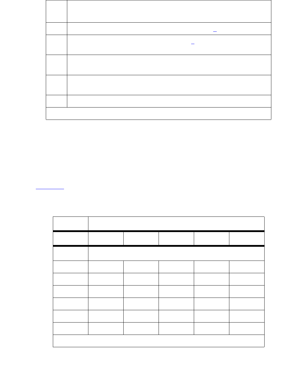
FW-DWNLD (Firmware Download)
Issue 1 June 2005 1303
2. Error Type: 769 — Indicates that a downloadable board image is bad and that a good
image needs to be downloaded. This error may be a result of a failed download attempt or a
board that is in an unstable condition. The Aux Data indicates the location of the circuit pack
requesting the firmware download and is in the form UUAAA, where UU is the port network
number (cabinet) and AAA is the angel number.
The angel number can be converted into the carrier and slot number by using the following
table. Continuing with the example of Aux Data 1080, you look for angel number 80 in
Table 449. You can find it in the column of carrier B and in the row of slot 15, so the target
board is located in 1B15.
2 Source board-related failure; see Error Type 258 (b).
3 A target board failed; see Error Type 259 (c).
1. Check image, translations and retry.
4 Two consecutive target boards failed, download schedule aborted.
1. Verify download image, translations, and retry.
5 Schedule timer expired
1. Schedule unfinished target boards, and retry.
6disable firmware download command executed.
Table 449: Converting an angel number into carrier and slot
Carrier
ABCDE
Slot # Angel Number
1 2866983402
2 2967993503
3 30 68 100 36 04
4 31 69 101 37 05
5 56 70 102 38 06
6 57 71 103 39 07
1 of 2
Table 448: Error Type 513 Aux Data (continued)
Aux
Data
Description of Failure
2 of 2

Communication Manager Maintenance-Object Repair Procedures
1304 Maintenance Procedures for Avaya Communication Manager 3.0, Media Gateways and Servers
System Technician-Demanded Tests:
Descriptions and Error Codes
Like the FW-DWNLD (Firmware Download) MO, its associated test, Test Firmware Download
(#1413) on page 1305, is non-traditional. Maintenance software automatically executes this test
as part of scheduling, verifying, and running a firmware-download schedule.
This MO provides no on-demand tests for system technicians.
7 58 72 104 40 08
8 59 73 105 41 09
9 60 74 106 42 10
10 61 75 107 43 11
11 62 76 108 44 12
12 63 77 109 45 13
13 88 78 110 46 14
14 89 79 111 47 15
15 90 80 112 48 16
16 91 81 113 49 17
17 92 82 114 50 18
18 93 83 115 51 19
19 94 84 116 52 20
20 95 85 117 53 21
21 NA 86 118 54 22
22 NA 87 119 55 23
Table 449: Converting an angel number into carrier and slot (continued)
Carrier
ABCDE
Slot # Angel Number
2 of 2

FW-DWNLD (Firmware Download)
Issue 1 June 2005 1305
Test Firmware Download (#1413)
This test is destructive.
This test has two functions and can only be executed if there is a download schedule to verify or
there are FW-DWNLD errors to resolve and alarms to clear.
1. This test verifies that the information on the FIRMWARE DOWNLOAD screen is correct. It
also verifies that the source board is of the correct type, that the file to be downloaded is
present on that source board, and that the file is error free. In addition it verifies that the
target board code and suffix are correct. It also retrieves the new firmware vintage for the
target board and populates the appropriate field in the firmware download table.
2. If this test is executed after a FIRMWARE DOWNLOAD schedule has run, and there are
FW-DWNLD alarms/errors, it resolves the errors, clears the alarms, copies the current
download status table to the last table, and clears out the current table.
Table 450: TEST #1413 Firmware Download Test
Error
Code
Test
Result
Description / Recommendation
ABRT Internal system error
1. Retry the command at 1-minute intervals up to 5 times.
2100 ABRT System resources required for this test are not available.
1. Retry the command at 1-minute intervals up to 5 times.
1 FAIL The firmware image file entered on the change firmware download
screen is not present on the source board specified in the screen.
1. Execute the list directory board location command, and
verify that:
●A file system is enabled on the board
●The file is present
2. If the file system is not enabled:
a. Execute the enable filesystem command.
b. FTP the correct firmware image to the source board.
If the correct image file is present, then the name entered on the
screen is incorrect.
3. Execute the change firmware download command, and enter the
correct file name.
1 of 3

Communication Manager Maintenance-Object Repair Procedures
1306 Maintenance Procedures for Avaya Communication Manager 3.0, Media Gateways and Servers
2 FAIL The image file header on the source board is invalid.
1. FTP a good firmware image file to the source board.
3 FAIL Firmware image file on the source board has a bad CRC.
1. FTP a good firmware image file to the source board.
4 FAIL Firmware image file name is too long.
1. Rename the image file to a file name of the correct size.
2. FTP the new image file to the source board.
3. Execute the change firmware download command, and enter the
new file name on the screen.
5 FAIL The TN code of the firmware image file on the source board does not
match the TN code entered on the screen. The firmware file is incorrect for
the board type entered on the screen.
1. Execute the list directory board location command, and
verify that a file system is enabled on the board and the file is present.
2. If the file system is not enabled, execute the enable filesystem
command, and FTP the correct firmware image to the source board.
3. Execute the change firmware download command, and enter the
new file name on the screen.
6 FAIL The suffix of the firmware image file on the source board does not match
the suffix entered on the screen. The firmware image file is incorrect for the
board types entered on the screen.
1. Execute the list directory board location command, and
verify that a file system is enabled on the board and the file is present.
2. If the correct firmware image is not present, FTP the correct firmware
image to the source board.
3. Execute the change firmware download command, and enter the
new file name on the screen.
Table 450: TEST #1413 Firmware Download Test (continued)
Error
Code
Test
Result
Description / Recommendation
2 of 3

FW-DWNLD (Firmware Download)
Issue 1 June 2005 1307
7 FAIL The source board entered on the screen is not present.
1. Execute the display firmware download command, and verify
the source board’s location.
2. Verify the source board’s translations.
3. If the location is incorrect, execute the change firmware download
command, and enter the correct location on the screen.
8 FAIL The source boards entered on the screen are incorrect. The board could
have been changed after the schedule was entered.
1. Execute the list configuration command. Verify the source
board’s location.
2. Execute the change firmware download command, and enter the
correct location on the screen.
PASS Firmware download to this circuit pack is successful.
0NO
BOARD The test could not relate the internal ID to the port (no board). This could
be due to incorrect translations, no board is inserted, an incorrect board is
inserted, or an insane board is inserted.
1. Ensure that the board’s translations are correct.
2. If the board was already administered correctly, check the error log to
determine whether the board is hyperactive.
If so, the board was shut down. Reseat the board to reinitialize it.
3. If the board was found to be correctly inserted in step 1, then:
a. Enter the busyout board location command.
b. Enter the reset board location command.
c. Enter the release board location command.
d. Enter the test board location long command.
This should re-establish the linkage between the internal ID and the
port.
Table 450: TEST #1413 Firmware Download Test (continued)
Error
Code
Test
Result
Description / Recommendation
3 of 3

Communication Manager Maintenance-Object Repair Procedures
1308 Maintenance Procedures for Avaya Communication Manager 3.0, Media Gateways and Servers
GPTD-PT (General-Purpose Tone Detector Port)
S8700 | 8710 / S8500
The GPTD (General-Purpose Tone Detector) ports, also known as CPTRs (Call-Progress Tone
Receivers), reside on the following circuit packs:
●TN748, any suffix (mu-law companding)
The GPTD port performs level measurements of test tones and to detect call-progress tones.
Examples of call-progress tones are dial tone, ring back, busy, alert, confirmation, and recall
dial. The abilities of the GPTD port to perform level measurements of test tones and to detect
call-progress tones are essential for maintenance of other circuit packs (for example,
Tone-Clock).
The GPTD MO defines a set of tests to ensure that the GPTD port’s general-purpose tone
detection is functioning properly. For every Tone Detector circuit pack-level error (DETR-BD),
see XXX-BD (Common Port Circuit Pack/Media Module) on page 2539.
Error Log Entries and Test to Clear Values
MO Name in
Alarm Log
Alarm
Level
Initial SAT Command to
Run
Full Name of MO
GPTD-PT MAJ test port location sh General-Purpose Tone Detector
Port
GPTD-PT MIN test port location sh General-Purpose Tone Detector
Port
GPTD-PT WRN release port location General-Purpose Tone Detector
Port
Table 451: General-Purpose Tone Detector Port (CPTR) Error Log Entries
Error
Type
Aux
Data
Associated Test Alarm
Level
On/Off
Board
Test to Clear Value
0 (b)0 Any AnyAnytest port location sh
r 1
1 17664 Tone Detector Audit/
Update (#43)
MAJ
MIN
(a)
ON test port location r
2
18 0 busyout port
location
WRN ON release port location
1 of 2
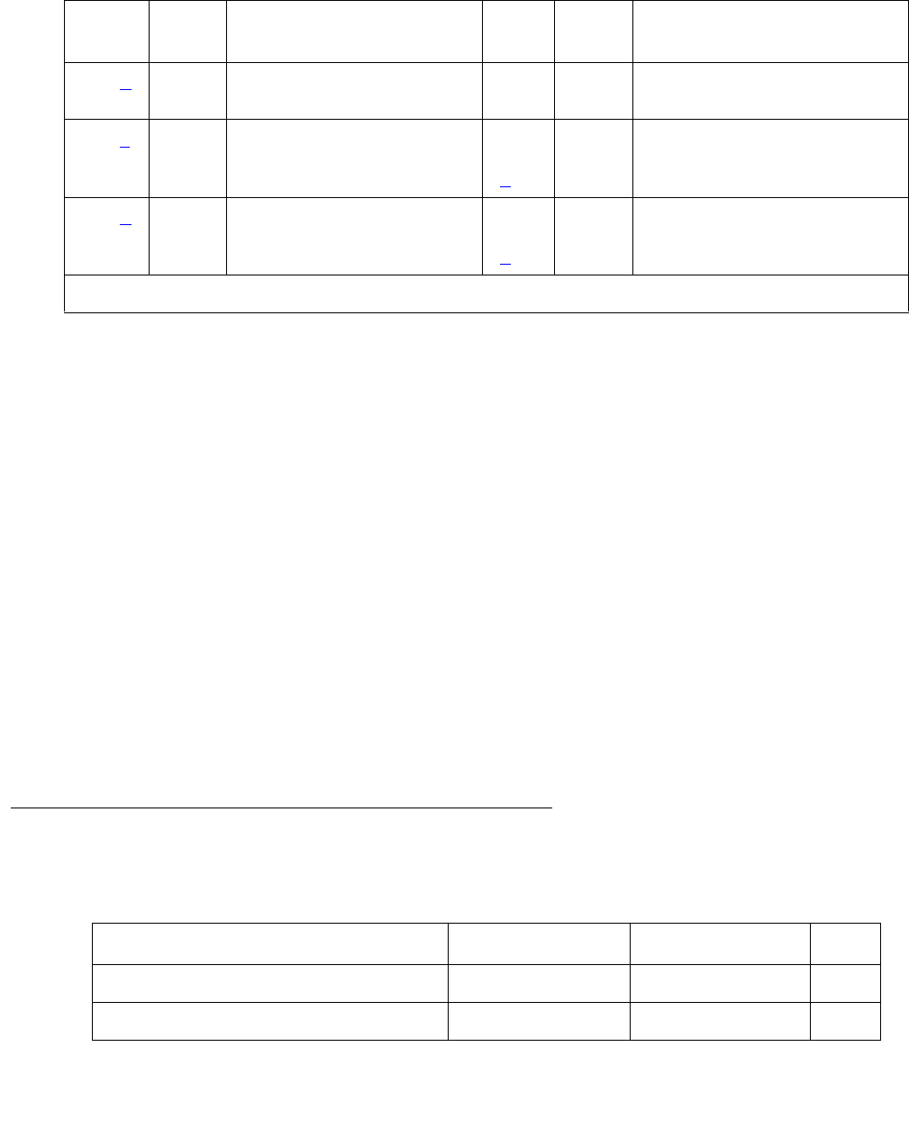
GPTD-PT (General-Purpose Tone Detector Port)
Issue 1 June 2005 1309
Notes:
a. A Major or a Minor alarm may be logged with this error. A Major alarm is raised when the
total number of GPTD ports currently in service is less than or equal to 1/2 of the threshold
number administered via change system-parameters maintenance. Otherwise, a
Minor alarm is raised. In either case, run the short test sequence on the alarmed GPTD port
and follow procedures for the individual test results.
b. Error Type 0: run the short test sequence first. If every test passes, run the long test sequence.
Refer to each appropriate test’s description, and follow its recommended procedures
c. Error Type 257: the GPTD port lost its translation. Testing the GPTD port is sufficient to
reload its translation. If testing the GPTD port does not clear the error, then replace the Tone
Detector circuit pack containing the defective GPTD port.
d. Error Type 513: the GPTD port is having problems detecting call-progress tones. If this
error is logged constantly, replace the Tone Detector circuit pack containing the defective
GPTD port.
e. Error Type 130: the circuit pack has been removed or has been insane for at least 11
minutes. To clear the error, reinsert or replace the circuit pack.
Technician-Demand Tests: Descriptions and Error Codes
Investigate tests in the order presented.
130 (e)None WRNONtest port location sh
r 2
257 (c) 17666 Tone Detector Audit/
Update (#43)
MAJ
MIN
(a)
ON test port location r
3
513 (d) Any Tone Detection Verification
(#42)
MAJ
MIN
(a)
ON test port location r
3
Table 451: General-Purpose Tone Detector Port (CPTR) Error Log Entries (continued)
Error
Type
Aux
Data
Associated Test Alarm
Level
On/Off
Board
Test to Clear Value
2 of 2
Order of Investigation Short Test Sequence Long Test Sequence D/ND1
1. D = Destructive; ND = Nondestructive
Tone Detection Verification test (#42) X X ND
Tone Detector Audit/Update test (#43) X X ND

Communication Manager Maintenance-Object Repair Procedures
1310 Maintenance Procedures for Avaya Communication Manager 3.0, Media Gateways and Servers
Tone Detection Verification Test (#42)
This test verifies that the call-progress tone-detection and the tone-level measurement
capabilities of the GPTD port are functioning properly.
Table 452: Test #42 Tone Detection Verification Test
Error
Code
Test
Result
Description / Recommendation
ABRT The system was not able to allocate every resource needed for this test, or
there was an Internal system error.
1 ABRT The system could not allocate every resource needed to test the
call-progress tones.
1001 ABRT The system was unable to put the GPTD port in the appropriate mode to
test it.
1002 ABRT The system could not allocate time slots for the test connection. This can
happen when the system is heavily loaded. If the system is not heavily
loaded, then test the TDM-BUS via test tdm 1 or test tdm 2.
1. Retry the command at 1-minute intervals up to 5 times.
1003 ABRT The system could not allocate a Tone-Clock for the test connection. This
may be caused by a heavy load on the system or by a faulted Tone-Clock.
1. Check to see if there are any alarms against the Tone-Clock in the port
network where the test ABORTed. If so see the recommended
procedures for TONE-BD (Tone-Clock Circuit) on page 2327 or
TONE-PT (Tone Generator) on page 2353.
2. If a new Tone-Clock has been inserted, allow about 1 minute for
maintenance to run on the newly-inserted circuit pack.
3. Retry the command at 1-minute intervals up to 5 times.
2000 ABRT Response to the test request was not received within the allowable time
period.
1. Retry the command at 1-minute intervals up to 5 times.
2006 ABRT The active Tone-Clock circuit pack or a Tone Detector circuit pack may not
be functioning properly.
1. Test the active Tone-Clock circuit pack in the port network with test
tone-clock location, and see TONE-BD (Tone-Clock Circuit) on
page 2327 for failures.
2. Retry the command at 1-minute intervals up to 5 times.
1 of 2

GPTD-PT (General-Purpose Tone Detector Port)
Issue 1 June 2005 1311
2100 ABRT Could not allocate the necessary system resources to run this test.
1. Retry the command at 1-minute intervals up to 5 times.
101–
122
FAIL FAIL
1. Run the short test sequence: test port location sh r 1.
2. If the problem persists, the system is still operating properly but system
capacity will be reduced. In order to restore the system performance to
normal, replace the tone detector circuit pack containing the defective
GPTD port.
1022 FAIL Tone detection for the system is administered as part of a wideband
configuration, and the tone detector is not a TN420C (the only circuit pack
with this capability). GPTD ports on other types of tone detector circuit
packs are taken out of service since they cannot provide the administered
function.
1. Change the tone-detection mode administered on the
system-parameters country-options screen, or remove every circuit
pack except TN420C tone detectors from the system.
PASS Tone Detection Verification is successful. The GPTD port is able to detect
every call-progress tone and perform level measurements of test tones.
Table 452: Test #42 Tone Detection Verification Test (continued)
Error
Code
Test
Result
Description / Recommendation
2 of 2

Communication Manager Maintenance-Object Repair Procedures
1312 Maintenance Procedures for Avaya Communication Manager 3.0, Media Gateways and Servers
Tone Detector Audit/Update Test (#43)
The GPTD port is refreshed with all time-slot information, and a sanity audit is performed on the
GPTD port.
Table 453: Test #43 Tone Detector Audit/Update Test
Error
Code
Test
Result
Description / Recommendation
ABRT The system was not able to allocate the resources needed for this test.
1. Wait 1 minute and try again.
2000 ABRT Response to the test request was not received within the allowable time
period.
1. Retry the command at 1-minute intervals up to 5 times.
2100 ABRT Could not allocate the necessary system resources to run this test.
1. Retry the command at 1-minute intervals up to 5 times.
FAIL Hardware audit failed.
1. Run the short test sequence: test port location short
repeat 1.
2. If the problem persists, the system is still operating properly but system
capacity will be reduced. To restore the system performance to normal,
replace the Tone Detector circuit pack containing the defective GPTD
port.
PASS The GPTD port has been successfully refreshed with its translation.
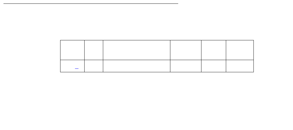
H323-BCH (H.323 B Channel)
Issue 1 June 2005 1313
H323-BCH (H.323 B Channel)
S8700 | 8710 / S8500 / S8300
No maintenance diagnostic tests exist for this object.
H.323 signaling is similar to ISDN Q.931 signaling. In order to take advantage of existing ISDN
Avaya™ Communication Manager, H.323 trunk AvayaCommunication Manager software
includes H.323 signaling groups, H.323 D channels and H.323 B channels. H.323 signaling
groups are similar in concept to ISDN PRI signaling groups. H.323 D-channels are an artificial
fabrication created only to allow maximum re-use of system ISDN code. H.323 B channels are
also an artificial fabrication.
No physical hardware components make up the H.323 B-channel object discussed here. Along
with the D channel, these objects allow existing ISDN Communication Manager software to be
re-used for H.323 trunking. The H.323 signaling group is not a collection of physical D-channels
that exist on one or more DS1 facilities. The H.323 signaling group can be considered to be one
D channel that physically rides on a C-LAN port (IP_PROCR port in an S8300 system) and the
IP network. Unlike ISDN D-channels, the H.323 D channel may come up and down on a
call-by-call basis. So, the H.323 D channel is actually a TCP/IP signaling channel. Layer 1 and 2
of this signaling channel may be monitored by IP PING testing.
Performance in terms of voice latency for a signaling group is monitored by background
measurements collected by the Media Processor board.
H.323 B channels use Media Processor ports to carry the actual bearer. The Media Processor
port is a service circuit. On a call-by-call basis, any port of a media processor may be serving an
H.323 station or an H.323 B channel. Status information may exist for a specific H.323 B
channel, and an H.323 B channel may be busied out and released, but no maintenance
diagnostic tests will exist for the object.
Errors are logged for craft busyout conditions. The system receives service state updates for
craft-driven busyout/release. Under normal conditions the system automatically places H.323 B
channels into or out of service when it receives an H.323 signaling-group service state update.
Craft busyout drops active calls.
Error Log Entries and Test to Clear Values
Note:
a. *Error Type 18: Indicates that this specific H.323 trunk group member has been craft
busied-out.
Table 454: H323-BCH B-Channel Error Log Entries
Error
Type
Aux
Data
Associated Test Alarm
Level
On/Off
Board
Service
State
18 (a) Any B-channel busied out Warning off OOS

Communication Manager Maintenance-Object Repair Procedures
1314 Maintenance Procedures for Avaya Communication Manager 3.0, Media Gateways and Servers
System Technician Commands
The following commands are available to the system technician:
●busyout port location: on a specific H.323 B channel, drops any active call on that
B channel and reduces the trunk group’s capacity by one. No physical piece of hardware
is removed from service.
●release port location: on a specific H.323 B channel, increases the trunk group’s
capacity by one. No physical piece of hardware is actually added to service.
●status trunk grp#/mem#: used to find the current status of the specific B channel.
Additional status for an H.323 B channel shows near- and far-end IP signaling addresses,
near- and far-end H.245 addresses, tunneling status, call-reference value for an active
call, and the H.323 conference ID.
●test port location: results in the message No tests applicable to this
object.
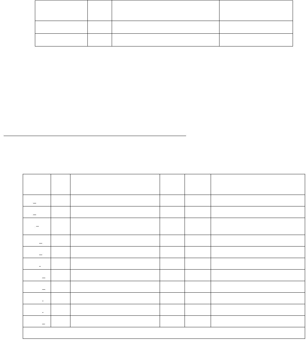
H323-SGRP (H.323 Signaling Group)
Issue 1 June 2005 1315
H323-SGRP (H.323 Signaling Group)
S8700 | 8710 / S8500
The H.323 Signaling Group (H323-SGRP) MO supports a signaling channel (D channel) for
H.323 Trunk connections. The MedPro TN802 circuit pack provides audio connectivity, working
in concert with a C-LAN (TN799DP) circuit pack that provides control signaling to support an
H.323 connection.
The H.323 signaling group (H323-SGRP) is a Signaling channel that physically resides on a
C-LAN port (socket) and the IP network. Unlike ISDN D-channels, the H.323 channel may
actually come up and down on a call by call basis. The H.323 channel is actually a TCP/IP
signaling channel. Layers 1 and 2 of this signaling channel are monitored by IP PING testing.
Error Log Entries and Test to Clear Values
MO Name in
Alarm Log
Alarm
level
Initial SAT Command to Run Full Name of MO
H323-SGR MIN test signaling-group grp# H323 Signaling Group
H323-SGR WRN test signaling-group grp# H323 Signaling Group
Table 455: H323-SGRP Signaling Group Error Log Entries
Error
Type
Aux
Data
Associated Test Alarm
Level
On/Off
Board
Test to Clear Value
0 (a)0Any Any test signaling-group grp#
1 (b) Any Ethernet Port Status test (#1386) MIN OFF test signaling-group grp#
18 (c)0 busyout signaling-group
grp #
WRN OFF release signaling-group grp#
257 (d) Any H.323 SGRP PING (#1387) MIN OFF test signaling-group grp#
513 (e) Any H.323 SGRP PING (#1387) WRN OFF test signaling-group grp#
770 (f)Any WRNOFF
1025 (g) Any MEDPRO Status test (#1392) MIN OFF test signaling-group grp#
1281 (h) Any MEDPRO Status test (#1392) MIN OFF
1537 (i)Any NONE
1794 (j) MEDPRO Status test (#1392) MIN OFF test signaling-group grp#
2049 (k) Keep Alive Failure MIN OFF
1 of 2

Communication Manager Maintenance-Object Repair Procedures
1316 Maintenance Procedures for Avaya Communication Manager 3.0, Media Gateways and Servers
Notes:
a. Error Type 0: Run the short test sequence first. If every test passes, run the long test sequence. Refer to
each appropriate test’s description, and follow its recommended procedures.
b. Error Type 1: Represents a failure of the C-LAN hardware (IP-PROCR in S8300 systems)
carrying the signaling group channel. To determine which C-LAN had been administered for
this signaling group, find the near-end node name on the signaling group form; then
find the C-LAN or IP_PROCR with the same node name on the ip-interfaces form.
Check for errors against the CLAN-BD MO.
c. Error Type 18: Logged when the signaling group in question is busied out by craft. Make
sure, if appropriate, that the signaling group is released from craft busy using the release
signaling-group grp# command.
d. Error Type 257: Tracks failures of the H.323 signaling-group PING test. H.323
signaling-group PING test failures are documented later in this MO.
e. Error Type 513: Tracks excessive round-trip delay of the H.323 signaling-group PING test,
if the round-trip delay exceeds 4 seconds.
f. Error Type: 770: Tracks excessive latency and packet-loss from background IP
measurements collected by the Media Processor Board. Indicates that test packets sent
from a media processor circuit pack to the far-end ip address specified on the signaling
group form have exceeded the IP latency and loss thresholds, as administered on the
system-parameters ip-options form. Exceeding these thresholds indicates that the IP
network may not be providing sufficient quality of service for adequate transmission of
voice. If the signaling group has been administered to enable BYPASS, then error type
1025 also occurs.
g. Error Type 1025: Indicates that the signaling group has been placed into a BYPASS
condition because of IP network congestion. The signaling group accepts incoming calls,
but every outgoing call is denied. The system routes these calls over a secondary route, if
one has been administered.
h. Error Type 1281: Implies that no media processor resources are in service to provide VoIP
connections for the trunk members of the signaling group.
Check for errors against the MEDPRO and MEDPROPT maintenance objects. This error
causes all H323 B Channels to be in an out-of-service near-end state.
2305 (l) Gateway Unregistered Inline Error MIN OFF
2561(m) Any Registered to LSP Inline Error MIN OFF
Table 455: H323-SGRP Signaling Group Error Log Entries (continued)
Error
Type
Aux
Data
Associated Test Alarm
Level
On/Off
Board
Test to Clear Value
2 of 2

H323-SGRP (H.323 Signaling Group)
Issue 1 June 2005 1317
i. Error Type 1537: Indicates that the far end of the signaling group is not ready to handle
audio bearer. If the other end of this signaling group is also a Communication Manager
server, this error means the server on the other end does not have MEDPRO in-service for
its signaling group.
This error places the H323 B Channels into an out-of-service far-end state.
j. Error Type 1794: The Signaling Group reported that the far end has detected excessive
packet latency or loss. This error places the H323 B channels into an out-of-service far-end
state.
k. Error Type 2049: A Keep-Alive timer is set for every registered endpoint on the Remote
Office, and the switch expects Keep-Alive update within that timer’s time period. If the
update does not occur, a message is generated that causes an error to be logged against
MO REM-OFF, as well as MO H323-SGRP. Because the signaling group is still known, the
error against MO H323-SGRP generates a Minor alarm. This error is only valid if the
change signaling-group screen has the RRQ field set to y. This error counter is only
set if a failure has been detected by Communication Manager and it notifies maintenance
software. The Keep-Alive Error Type 2049 clears only after a registration occurs and Error
Type 2305 clears.
l. Error Type 2305: Indicates that the Gateway (signaling group on the Remote Office) is
unregistered. Because the signaling group is still known, the error against MO H323-SGRP
generates a Minor alarm when this failure occurs. This error is only applicable if the change
signaling-group screen has the RRQ field set to y.
m. Error Type 2561: This error indicates that the signaling group is registered to an LSP.
System Technician-Demanded Tests:
Descriptions and Error Codes
Always investigate tests in the order presented in the table below when inspecting errors in the
system. For example, by clearing error codes associated with the CLAN Ethernet Status test
(#1386), you may also clear errors generated from other tests in the testing sequence.
Order of Investigation Short Test
Sequence
Long Test
Sequence
D/ND1
1. D = Destructive; ND = Nondestructive
CLAN Ethernet Status test (#1386) X X ND
MedPro Status test (#1392) X X ND
H.323 Signaling Group Ping test (#1387) X X ND

Communication Manager Maintenance-Object Repair Procedures
1318 Maintenance Procedures for Avaya Communication Manager 3.0, Media Gateways and Servers
CLAN Ethernet Status Test (#1386)
This test is nondestructive.
This test checks the status of the C-LAN Ethernet port that is the near end gatekeeper this
signaling group. If the C-LAN Ethernet port is in service, the test passes; if it is OOS (out of
service), the test fails.
Note:
Note: Failure of this test will put the SIG-GRP in the OOS state.
Table 456: Test #1386 CLAN Ethernet Status Test
Error
Code
Test
Result
Description / Recommendation
1125 ABRT Ethernet Link is not in service.
1. Check if the Ethernet link is in service or not. If the link is not in service,
release the link using release link n or release port
location, and repeat the test. This is a normal abort.
2. If the test continues to abort after following the repair procedures,
escalate the problem.
2000 ABRT Response to the test was not received from the TN799DP C-LAN circuit
pack within the allowable time period.
1. If this result occurs repeatedly, attempt to reset the circuit pack if the
other ports on the board are idle (amber LED is off). Reset the circuit
pack by issuing busyout board location, reset board
location, and release board location.
2. If this result occurs again, replace the circuit pack.
2100 ABRT The necessary system resources to execute the test could not be
allocated.
1. Retry the command at 1-minute intervals up to 5 times.
2500 ABRT Internal system error.
1. Retry the command at 1-minute intervals up to 3 times.
FAIL The C-LAN Ethernet port corresponding to the near-end address of the
SIG-GRP that is OOS has failed. Every session is down.
1. Execute test port location long and verify the result of the
H.323 Signaling Group Ping test (#1387). If the test continues to fail,
escalate the problem. If the test passes wait for the sessions to come
up.
1 of 2

H323-SGRP (H.323 Signaling Group)
Issue 1 June 2005 1319
H.323 Signaling Group Ping Test (#1387)
This test is nondestructive.
This test is only run for those signaling groups that have an administered far-end IP address. If
the H.323 signaling group does not have an administered far-end IP address, the test will abort.
The test determines the local C-LAN through which the signaling originates, and the far-end
terminating IP address. It then requests the local C-LAN to execute a PING on the far-end
address. If the PING is successful, the test passes; if the ping is not successful, the test fails.
Note:
Note: Multiple failures of this test will cause this signaling group’s associated H.323 B
channels to be taken out of service (OOSFE). This will allow incoming calls to be
made when the far-end comes up before the near end has detected it. The
Signaling group will be left in service, but in the far end bypass state.
If the PING is successful, this test looks at the PING round-trip delay. If a round-trip delay of
greater than 4 seconds is reported, a separate error is logged. Excessive round-trip delays
within the signaling group will not take the signaling group out of service, however.
Services can execute the standard PING command using the C-LAN board’s address and
far-end IP address from the signaling group screen to see the actual round-trip delay.
This test checks the circuitry involved in the data path of a peer-to-peer IP layer connection.
This test is a nondestructive test. It runs because of in-line errors, during periodic and
scheduled maintenance, and on-demand.
PASS The C-LAN Ethernet port corresponding to the near-end address of the
SIG-GRP that is in service has passed this test. Every session on the
Ethernet link is up.
Table 456: Test #1386 CLAN Ethernet Status Test (continued)
Error
Code
Test
Result
Description / Recommendation
2 of 2
Table 457: Test #1387 H.323 Signaling Group Ping Test
Error
Code
Test
Result
Description / Recommendation
1, 2 ABRT Internal Error.
1. Retry the command at 1-minute intervals up to 3 times.
1 of 3

Communication Manager Maintenance-Object Repair Procedures
1320 Maintenance Procedures for Avaya Communication Manager 3.0, Media Gateways and Servers
7ABRT Destination unreachable.
1. Verify that the C-LAN has been administered with an IP-Route that
enables the C-LAN to reach the far-end IP address.
2. Once verified, use test sig-group grp# to verify that the H.323
Signaling Group Ping test (#1387) passes.
1005 ABRT Configuration for this test is incorrect.
1. Verity that the link is in service with the status port or status
link. Verify that the routing table has destinations that are reachable
through this port.
2. Repeat the test.
3. If the test aborts with Error Code 7, while step 1 verified, escalate the
problem.
1125 ABRT Link is not in service.
1. Check if the link is in service or not. If the link is not in service, release
the link using release link or release port, and repeat the test.
This is a normal abort.
2. If the test continues to abort after following the repair procedures,
escalate the problem.
2000 ABRT Response to the test was not received from the C-LAN circuit pack within
the allowable time period.
1. If this result occurs repeatedly, attempt to reset the circuit pack if the
other ports on the board are idle (amber LED is off). Reset the circuit
pack by issuing busyout board location, reset board
location, and release board location.
2. If this result occurs again, replace the circuit pack.
2012 ABRT Internal system error.
1. Retry the command at 1-minute intervals up to 3 times.
2100 ABRT The necessary system resources to execute the test could not be
allocated.
1. Retry the command at 1-minute intervals up to 5 times.
Table 457: Test #1387 H.323 Signaling Group Ping Test (continued)
Error
Code
Test
Result
Description / Recommendation
2 of 3

H323-SGRP (H.323 Signaling Group)
Issue 1 June 2005 1321
2500 ABRT Internal system error.
1. Retry the command at 1-minute intervals up to 3times.
2800 ABRT No C-LAN in the same region.
1. Verify translations and retest.
2801 ABRT No IP address defined.
1. Verify translations and retest.
2802 ABRT Different IP address pinged than software had allocated for the test.
1. Retry the command at 1-minute intervals up to 3 times.
7
89
1007
FAIL PING to the destination failed through this port because the destination was
down.
1. Verify that at least one destination reachable through this port is “up”.
Once verified, execute test signaling-group grp# to verify that
the H.323 Signaling Group Ping test (#1387) passes.
ANY ABRT Refer to the CLAN Port PING test in TCP/IP Ping Test (#1281) on page 1900
for a more detailed description of the reasons for the abort.
ANY FAIL The far-end of the signaling group could not be reached.
1. Refer to the C-LAN port PING test in TCP/IP Ping Test (#1281) on
page 1900 for a more detailed description of the reasons for the failure.
PASS PING through this port was successful.
Table 457: Test #1387 H.323 Signaling Group Ping Test (continued)
Error
Code
Test
Result
Description / Recommendation
3 of 3

Communication Manager Maintenance-Object Repair Procedures
1322 Maintenance Procedures for Avaya Communication Manager 3.0, Media Gateways and Servers
MedPro Status Test (#1392)
This test is nondestructive.
This test determines if at least one media processor port exists that is in service, and that
serves the same region as the C-LAN that the signaling group uses. If at least one exists and is
in service, the test passes; otherwise, the test fails.
Table 458: Test #1392 MedPro Status Test
Error
Code
Test
Result
Description / Recommendation
2100 ABRT The necessary system resources to execute the test could not be
allocated.
1. Retry the command at 1-minute intervals up to 5 times.
2500
Any
ABRT Internal system Error.
1. Retry the command at 1-minute intervals up to 3 times
FAIL No MEDPRO ports in this region are in service. Every session is down.
1. Check the system for errors against MEDPRO and MEDPROPT
maintenance objects.
2. Execute test signaling-group grp# and verify the result of the
H.323 Signaling Group Ping test (#1387). If the test continues to fail,
escalate the problem. If the test passes, wait for the sessions to come
up.
PASS Every session on the Ethernet link is up.

H323-STN (H.323 IP Station)
Issue 1 June 2005 1323
H323-STN (H.323 IP Station)
S8700 | 8710 / S8500
H323-STN covers implementation of the maintenance for native mode H.323 endpoints. Native
mode H.323 applications such as Netmeeting or Proshare provide only what is needed to
support the H.323 standard. Communication Manager can invoke very little in the maintenance
area. Communication Manager reports errors as they are detected via the RAS registration and
keep-alive mechanism. Communication Manager PINGs the endpoint via the signaling path, for
example via C-LAN, and via the media path, for example, via Medpro.
The H.323 station type is not attached to a port board. Insertion of the station is not driven by
board insertion, it is driven by successful registration of the endpoint. The H.323 station is
maintained via a set of explicit TCP/IP ping requests and errors reported by the switch software,
which terminates the H.323 signaling portion of each endpoint. H323-STN follows standard
maintenance methodology and supports test, busyout, release and status commands.
Error Log Entries and Test to Clear Values
Notes:
a. Error Type 1 reports the registration status of the endpoint. If Communication Manager
claims the endpoint is registered and receives keep-alive handshakes from the endpoint,
the test passes. If keep-alive handshaking fails, the test fails. If the user has intentionally
un-registered the station from the Media Server, the station is basically an AWOH station
and is no longer being maintained; no tests will run for this station.
MO Name in
Alarm Log
Alarm
Level
Initial SAT Command to Run Full Name of MO
H323-STN WRN test station extension H.323 IP Station
Table 459: H323-STN IP Station Error Log Entries
Error
Type
Aux
Data
Associated Test Alarm
Level
On/Off
Board
Test to Clear Value
00Any Any test station extension
1 (a) Registration Status
Inquiry test (#1372)
WRN OFF
257 (b) Signaling Path PING
test (#1373)
WRN OFF
513 (c) Media Path PING test
(#1374)
WRN OFF
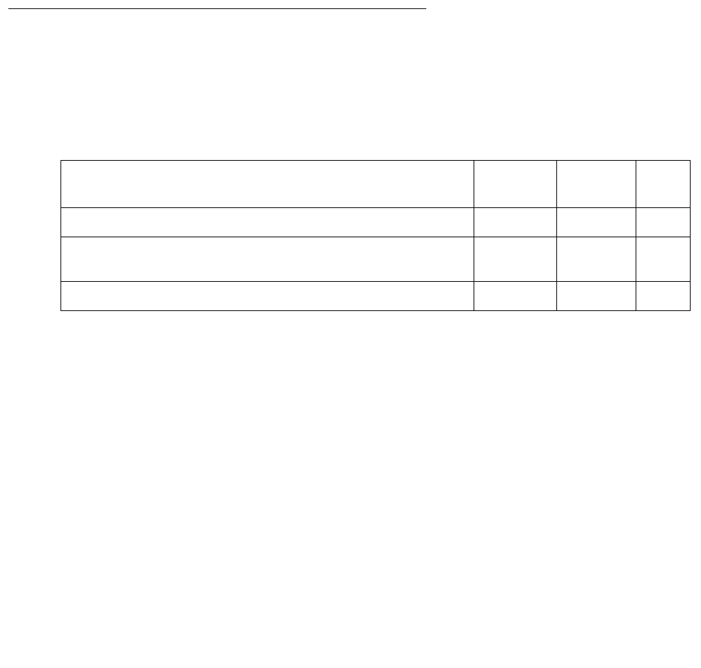
Communication Manager Maintenance-Object Repair Procedures
1324 Maintenance Procedures for Avaya Communication Manager 3.0, Media Gateways and Servers
b. Error Type 257 tracks failures of the signaling path PING test. The test attempts to send a
PING packet to the endpoint IP address, as reported during registration. The PING packet
originates with the C-LAN board through which the endpoint is registered. If the PING
response packet is received, the test passes. If the ping response packet times out, the
test fails.
c. Error Type 513 tracks failures with the media path ping test. The test attempts to send a
ping packet to the endpoint IP address, as reported during registration. The ping packet
originates with a Media Processor board. Any Media Processor board may be used as long
as it is administered to be in the same network region as the C-LAN board through which
the endpoint is registered. If the ping response is received, the test passes. If the ping
response packet times out, the test fails.
System Technician-Demanded Tests:
Descriptions and Error Codes
Investigate tests in the order presented. By clearing error codes associated with the Signaling
Path PING test (#1373), for example, you may clear errors generated from other tests in the
sequence.
Registration Status Inquiry Test (#1372)
The Registration status inquiry reports the H.323 registration status of the endpoint. An endpoint
must be registered and authenticated in order to receive service from the system.
Registration is initiated when the endpoint user attempts to login using the Avaya registration
software application running on the endpoint PC. The user must provide a valid extension and
security code. The registration messages are sent to the IP address of a C-LAN Ethernet port.
Order of Investigation Short Test
Sequence
Long Test
Sequence
D/ND1
1. D = Destructive; ND = Nondestructive
Registration Status Inquiry test (#1372) X X ND
Signaling Path PING test (#1373)
S8300 / G700: aborts on G700 with Error Code 1412.
XXND
Media Path PING test (#1374) X X ND

H323-STN (H.323 IP Station)
Issue 1 June 2005 1325
A registered extension has a port type SNNNNN, where N is a digit from 0–9. A non-registered
extension has an X port.
Signaling Path PING Test (#1373)
This test is nondestructive.
Signaling Path PING test determines the local C-LAN through which the signaling originates
and the endpoint’s IP address. It then requests the local C-LAN to execute a PING on the
endpoint’s address. If the PING is successful, the test passes, if the PING is not successful, the
test fails.
Note:
Note: Multiple failures of this test can take the H.323 IP Station out of service.
Note:
Note: S8300 / G700: This test does not execute on a G700 Media Gateway.
This test checks the circuitry involved in the data path of a peer-to-peer IP layer connection.
Table 460: Test #1372 Registration Status Inquiry
Error
Code
Test
Result
Description / Recommendation
1,
2,
3
FAIL The endpoint is not successfully registered.
1. Verify that the user is entering the:
●correct extension and security code
●C-LAN IP address
2. Verify that the extension has been enabled for IP Softphones
operation.
3. If many endpoints cannot register, investigate any errors of the C-LAN
Ethernet port.
4. Examine the Ethernet cabling from the endpoint PC to the Ethernet
hub.
PASS The endpoint is successfully registered and continues to respond to
registration handshaking.

Communication Manager Maintenance-Object Repair Procedures
1326 Maintenance Procedures for Avaya Communication Manager 3.0, Media Gateways and Servers
This nondestructive test runs due to in-line errors, during periodic and schedule maintenance,
and on demand.
Table 461: Test #1373 Signaling Path PING Test
Error
Code
Test
Result
Description / Recommendation
S8300
G700
1412
ABRT This test does not execute on a G700 media gateway.
2100 ABRT Could not locate the necessary system resources to run this test.
1. Retry the command at 1-minute intervals, up to 5 times.
2. Escalate if the problem persists.
2500 ABRT Internal system error.
1. Retry the command at 1-minute intervals, up to 3 times.
2. Escalate if the problem persists.
1003 FAIL Ping to the destination failed.
1. Retry the command at 1-minute intervals, up to 3 times.
2. Investigate any C-LAN Ethernet port errors.
1007 FAIL The system could not PING the registered endpoint via the C-LAN.
1. Verify that at least one destination reachable through this port. PING this
destination (ping ip-address xxx.xxx.xxx.xxx).
2. If the PING to any destination is successful through this port, the link is
up.
3. If PING to every destination fails, test the C-LAN port (test port
location short), and follow repair procedures for Session Status test
(#1286) failures.
4. If only this station cannot be pinged:
●Make sure the PC is up.
●Make sure the PC has a network connection (Ethernet or dial-up).
●Check the Ethernet cabling.
PASS The system can successfully send IP packets to the registered endpoint from
the C-LAN.

H323-STN (H.323 IP Station)
Issue 1 June 2005 1327
Media Path PING Test (#1374)
This test is nondestructive.
The test selects a Media Processor board. It then requests the local Media Processor to
execute a PING on the endpoint address. If the PING is successful, the test passes. If the PING
is not successful, the test fails.
Services can execute the standard ping command using the Media Processor board address
and endpoint IP address to see the actual round-trip delay.
This test checks the IP network connectivity needed for audio packets to be sent to the
endpoint.
This nondestructive test runs due to in-line errors, during periodic and schedule maintenance,
and on demand.
Table 462: Test #1374 Media Path PING Test
Error
Code
Test
Result
Description / Recommendation
2100 ABRT Could not locate the necessary system resources to run this test.
1. Retry the command at 1-minute intervals, up to 5 times.
2. Escalate if the problem persists.
2500 ABRT Internal system error.
1. Retry the command at 1-minute intervals, up to 3 times.
2. Escalate if the problem persists.
2806 ABRT No Media Processor board found to use for this test.
ANY FAIL The system could not PING the registered endpoint from a Media
Processor board. This may result in calls with no talk path.
1. If the Registration Status Inquiry test (#1372) fails, follow those
procedures.
2. Refer to MEDPRO, Test #1378, for a detailed description of the error
codes.
PASS PING through this Media Processor is successful.

Communication Manager Maintenance-Object Repair Procedures
1328 Maintenance Procedures for Avaya Communication Manager 3.0, Media Gateways and Servers
HYB-BD (Hybrid Line Circuit Pack)
S8700 | 8710 / S8500
See XXX-BD (Common Port Circuit Pack/Media Module) on page 2539 for circuit pack-level
errors. See also HYB-LINE (Hybrid Line) on page 1329 for related line information.
MO Name in
Alarm Log
Alarm
Level
Initial SAT Command to Run Full Name of MO
HYB-BD MIN test board location sh Hybrid Line circuit pack
HYB-BD WRN test board location sh Hybrid Line circuit pack

HYB-LINE (Hybrid Line)
Issue 1 June 2005 1329
HYB-LINE (Hybrid Line)
S8700 | 8710 / S8500
Hybrid Line is another term for the MFAT (Multi-Function Analog Telephone). The Hybrid Line
set is also known as an SCS (Small Communications System).
The TN762B Hybrid Line circuit pack supports eight of these multifunction analog telephone
sets. The Hybrid Line sets use three pairs of wires: an analog voice pair, a transmit/receive pair,
and a power pair.
This section describes HYB-LINE (Hybrid Line) maintenance. HYB-LINE maintenance is closely
related to, and sometimes interacts with, HYB-BD (Hybrid Line circuit pack) maintenance. This
interaction should be kept in mind when troubleshooting Hybrid Line problems.
This section occasionally refers to a station’s service state. These service states are defined as
follows:
Use status station to determine terminal service state. Status is reported as either out of
service, in service, or disconnect. The latter is equivalent to the ready-for-service state.
MO Name in
Alarm Log
Alarm
Level
Initial SAT Command to Run Full Name of MO
HYB-LINE MIN test port location lHybrid Line
HYB-LINE WRN test port location lHybrid Line
Out-of-Service The port, and thus the station, have been removed from service. A
busyout of a port will cause it to be out of service.
Ready-for-Service The port on the circuit pack has been put into service, but the voice
terminal has not yet established signaling communications with the
port.
In-Service The voice terminal has established signaling communications with the
port, and the system is ready to process calls to and from that station.
A terminal in the ready-for-service state will progress to the in-service
state if it is functioning normally, but it can also be forced into the
in-service state if it goes off-hook.
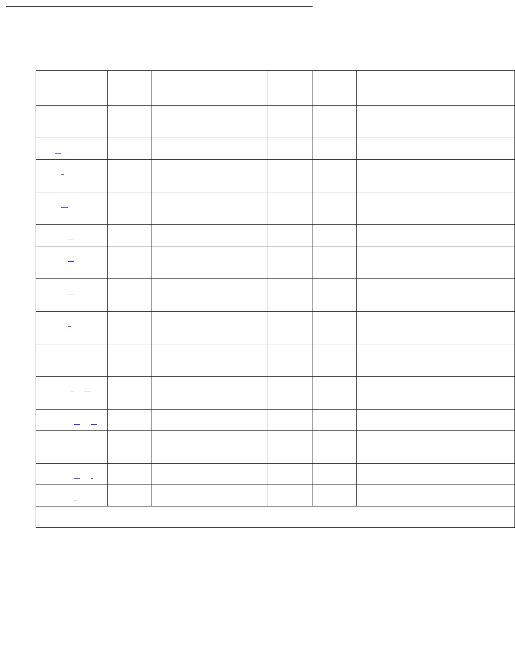
Communication Manager Maintenance-Object Repair Procedures
1330 Maintenance Procedures for Avaya Communication Manager 3.0, Media Gateways and Servers
Error Log Entries and Test to Clear Values
Table 463: Hybrid Line Error Log Entries
Error
Type
Aux
Data
Associated Test Alarm
Level
On/Off
Board
Test to Clear Value
01
1. Run the short test sequence first. If every test passes, run the long test sequence. Refer to each
appropriate test’s description, and follow its recommended procedures.
0Any AnyAnytest port location sh
r 1
1 (a) 40987 None WRN OFF
15 (j) Any Hybrid Line Audits
test (#161)
18 (b)0busyout port
location
WRN OFF release port location
130 (c) None WRN ON test port location sh
257 (d) 40988 None MIN
WRN
OFF
513 (e) 40965 Hybrid Line Audits
test (#61)
WRN OFF test port location sh
r 4
769 (f) Remote Dig
Looparound (#59)
WRN OFF test port location sh
r 3
1025 Hybrid & Comfy.
Circuits (#57)
MIN
WRN
ON test port location l r
3
1281(f) (g) Local Digital
Looparound (#58)
WRN ON test port location l r
3
1537 (g) (h) 40968 None WRN OFF
1793 TDM NPE Crosstalk
(#6)
MIN
WRN2
2. Major or minor alarms may be downgraded to Warning alarms based on the value used in the set options
command.
ON test port location l r
2049 (h) (i) 32770 None
2049 (i) 40967 None

HYB-LINE (Hybrid Line)
Issue 1 June 2005 1331
Notes:
a. Error Type 1: The data link between the port and the terminal is not operational. (An
off-board problem was detected by port circuit). Verify that the Hybrid set is connected and
that the Electronic Power Feed (EPF) test passes. If data transmission problems are
experienced, check for defective wiring or a defective voice terminal, or move terminal
closer to the switch (reduce the length of the wiring between the terminal and the switch). If
the problem persists, replace the circuit pack. Once the problem has been resolved, the
alarm will be retired after a predetermined delay.
b. Error Type 18: the port is busied out. The port is released with release port
location.
c. Error Type 130: the circuit pack has been removed or has been insane for more than
11 minutes. To clear the error, reinsert or replace the circuit pack.
d. Error Type 257: the EPF has been turned off due to an overcurrent condition at the voice
terminal. Check for defective wiring or a damaged jack, and make sure the voice terminal is
a Hybrid set. Once the problem has been resolved, the alarm will be retired after a
predetermined delay.
e. Error Type 513: the voice terminal has been disconnected or there is a problem in the
wiring to the terminal. Make sure that the voice terminal is connected or check for defective
wiring to the voice terminal.
f. Error Type 769 and Error Type 1281: by themselves create Warning alarms. If both are
present, a Minor alarm is logged.
g. Error Type 1281 or 1537: the port has reported a problem with the data link to the voice
terminal. Ignore this error if there are no complaints about the voice terminal. Otherwise,
make sure the voice terminal is connected, check for defective wiring, check for a defective
voice terminal, and decrease the length of the wiring between the voice terminal and the
switch. If the problem persists, replace the circuit pack.
h. The voice terminal went off-hook while in the disconnect state. Use status station to
determine the state of the terminal. The off-hook should have moved the terminal to in
service. No repair action is necessary.
i. Error Type 2049: the link between the circuit pack and the voice terminal has been
successfully reset. No repair action is necessary.
j. Error Type 15: a software audit error that does not indicate any hardware malfunction. Run
the short test sequence and investigate any errors.
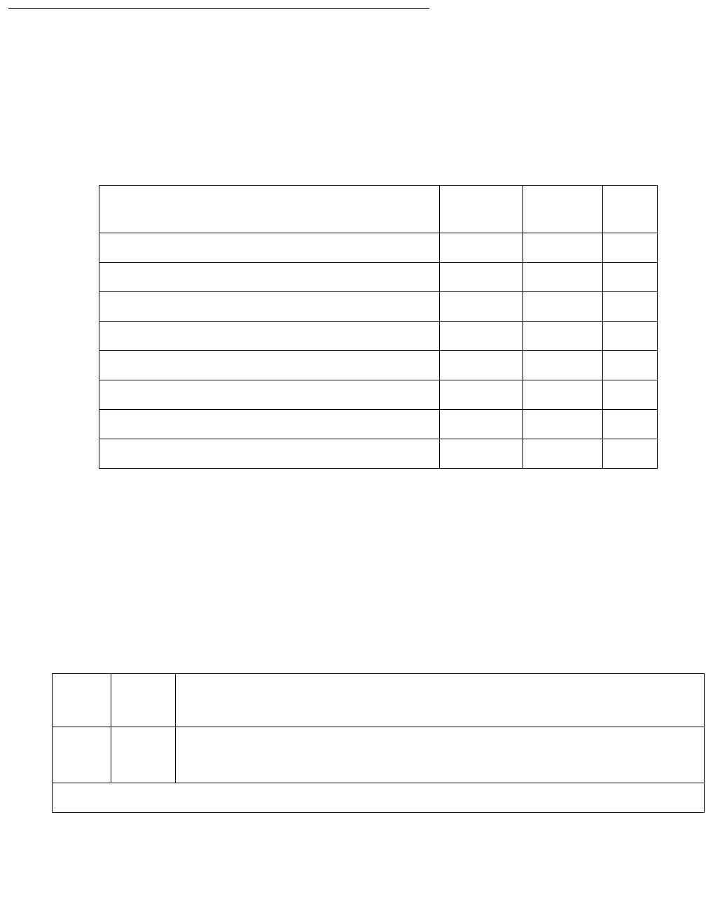
Communication Manager Maintenance-Object Repair Procedures
1332 Maintenance Procedures for Avaya Communication Manager 3.0, Media Gateways and Servers
System Technician-Demanded Tests:
Descriptions and Error Codes
Investigate tests in the order presented. By clearing error codes associated with the Local
Digital Looparound test (#58), you may also clear errors generated from other tests in the
sequence.
NPE Crosstalk Test (#6)
The NPE Crosstalk Test verifies that this port’s NPE channel talks on the selected time slot and
never crosses over to time slots reserved for other connections. If the NPE is not working
correctly, 1-way and noisy connections may be observed. This test is part of a port’s long test
sequence and takes about 20 to 30 seconds to complete.
Table 464: System Technician-Demanded Tests: DS1-BD
Order of Investigation Short Test
Sequence
Long Test
Sequence
D/ND1
1. D = Destructive, ND = Nondestructive
NPE Crosstalk test (#6) X ND
Hybrid Electronic Power Feed test (#56) X ND
Hybrid Circuit and Conference Circuit test (#57) X ND
Local Digital Looparound test (#58) X ND
Remote Digital Looparound test (#59) X X ND
Station Lamp Update test (#60) X X ND
Station Audits test (#61) X X ND
Ringer Update test (#62) X X ND
Table 465: Test #6 NPE Crosstalk Test
Error
Code
Test
Result
Description / Recommendation
ABRT Could not allocate the necessary system resources to run this test.
1. Retry the command at 1-minute intervals up to 5 times.
1 of 4

HYB-LINE (Hybrid Line)
Issue 1 June 2005 1333
1000 ABRT System resources required to run this test are not available. The port may
be busy with a valid call.
1. Use display port location to determine the station extension
number of the port. Use status station to determine the service
state of the port. If the port is in use, wait until it is idle before testing.
2. If the port status is idle, then retry the command at 1-minute intervals
up to 5 times.
1001 ABRT Could not allocate the necessary system resources to run this test. This
could be a failure to seize the port.
1. Retry the command at 1-minute intervals up to 5 times.
1002 ABRT The system could not allocate time slots for the test. The system may be
under heavy traffic conditions or it may have time slots out of service due
to TDM-BUS errors.
1. If the system has no TDM-BUS errors and is not handling heavy traffic,
repeat test at 1-minute intervals up to 5 times.
1003 ABRT The system could not allocate a tone receiver for the test. The system may
be oversized for the number of Tone Detectors present, or some Tone
Detectors may be out of service.
1. Resolve any TTR-LEV errors.
2. Resolve any TONE-PT errors.
3. If neither condition exists, retry the test at 1-minute intervals up to 5
times.
1004 ABRT The port was seized by a valid call during the test. The test has been
aborted.
1. Use display port location to determine the station extension
number of the port. Use status station to determine the service
state of the port. If the port is in use, wait until it is idle before testing.
2. Retry the command at 1-minute intervals up to 5 times.
Table 465: Test #6 NPE Crosstalk Test (continued)
Error
Code
Test
Result
Description / Recommendation
2 of 4

Communication Manager Maintenance-Object Repair Procedures
1334 Maintenance Procedures for Avaya Communication Manager 3.0, Media Gateways and Servers
1018 ABRT Test disabled by administration. This only applies to analog stations.
The default for this field is ‘y,’ so you may want to determine why it has been
turned off for this station.
1. To enable test, set the Test field on the station administration screen
for the particular analog station being tested to y. Use change
station extension.
2000 ABRT Response to the test request was not received within the allowable time
period.
1. Retry the command at 1-minute intervals up to 5 times.
2020 ABRT The test did not run due to an already existing error on the specific port or
a more general circuit pack error.
1. Examine Error Log for existing errors against this port or the circuit
pack and attempt to diagnose the already existing error.
2100 ABRT Could not allocate the necessary system resources to run this test. This
could be due to a failure to seize the port.
1. Retry the command at 1-minute intervals up to 5 times.
Any FAIL This test can fail due to on-board or off-board problems. Off-board
problems of concern include EXP-PN, EXP-INTF, RMC-ENV faults,
TDM-BUS faults, and faults associated with the tone detectors/tone
generators. Clear every off-board problem before replacing the board.
Keep in mind that a TDM-BUS problem is usually the result of a faulty
board connected to the backplane or bent pins on the backplane.
1. Resolve any “EXP-PN, RMC-ENV,” or “EXP-INTF” errors in the error
log.
2. Resolve any “TDM-BUS” errors in the error log.
3. Retest the board when the faults from steps 1 and 2 are cleared.
PASS The port is correctly using its allocated time slots. User-reported troubles on
this port should be investigated using other port tests and by examining
station, trunk, or external wiring.
Table 465: Test #6 NPE Crosstalk Test (continued)
Error
Code
Test
Result
Description / Recommendation
3 of 4

HYB-LINE (Hybrid Line)
Issue 1 June 2005 1335
Hybrid Electronic Power Feed Test (#56)
In this test, the software requests that the EPF be turned on for a given port. Then hardware
attempts to turn on the power unit from the station. If no current is drawn, the station is probably
not connected. If an overturned condition is sensed (that is, too much current is being drawn),
this may indicate a short in the loop or a defective voice terminal. A message is returned stating
that either the EPF was turned on successfully, or that an overcurrent condition exists. This test
is repeated once more 5 seconds later. If either test is not successful, the test will abort (see first
ABORT entry in Table 466: Test #56 Hybrid Electronic Power Feed Test on page 1335).
0NO
BOARD The test could not relate the internal ID to the port (no board). This could
be due to incorrect translations, no board is inserted, an incorrect board is
inserted, or an insane board is inserted.
1. Check to ensure that the board translations are correct. Use list
config, and resolve any problems that are found.
2. If the board was found to be correctly inserted in step 1, enter
busyout board location
3. Enter reset board location
4. Enter release board location
5. Enter test board location long This should re-establish the
linkage between the internal ID and the port. If this is not the case,
dispatch to check to ensure that there is a valid board inserted.
Table 465: Test #6 NPE Crosstalk Test (continued)
Error
Code
Test
Result
Description / Recommendation
4 of 4
Table 466: Test #56 Hybrid Electronic Power Feed Test
Error
Code
Test
Result
Description / Recommendation
ABRT Internal system error
1. Retry the command at 1-minute intervals up to 5 times.
1 of 3

Communication Manager Maintenance-Object Repair Procedures
1336 Maintenance Procedures for Avaya Communication Manager 3.0, Media Gateways and Servers
1000 ABRT System resources required to run this test are not available. The port may
be busy with a valid call.
1. Use display port location to determine the station extension
number of the port. Use status station to determine the service
state of the port. If the port is in use, wait until it is idle before testing.
2. If the port status is idle, then retry the command at 1-minute intervals
up to 5 times.
FAIL Internal system error
1. Retry the command at 1-minute intervals up to 5 times.
PASS Electronic Power Feed test passed. The message to turn on the power to
the station was successfully sent to the port.
1. Although this test never actually returns a FAIL result, except for the
previous Internal system error, it logs an error if the overcurrent case is
detected by the hardware. Check the Error Log for any entries with
Error Type 257 when the test has completed.
2. If Error Type 257 does not appear in the Error Log within 10 seconds
after completion of this test, it is safe to assume that the test sensed no
problems with the power to the station. To verify that the station is
powered up correctly, run a self-test on the station, if available, and
check that every feature button is operating.
3. If Error Type 257 appears in the Error Log, this indicates some problem
with the power to the station. Check for a short in the wiring, a
damaged jack, a defective voice terminal, or an incorrect type of
terminal.
Table 466: Test #56 Hybrid Electronic Power Feed Test (continued)
Error
Code
Test
Result
Description / Recommendation
2 of 3

HYB-LINE (Hybrid Line)
Issue 1 June 2005 1337
Hybrid Circuit and Conference Circuit Test (#57)
This test checks two different port circuit functions. The Hybrid Circuit test performs an analog
reflective looparound measurement on the port’s hybrid circuitry. The conference circuit test
performs a conference test on the port’s NPE.
For the Hybrid Circuit Test results to be valid, a voice terminal must be connected to the port
being tested. The test instructs the on-board microprocessor to put the port in analog reflective
looparound mode.
The Conference Test is performed only if the Hybrid Test passes. The Conference Circuit Test
verifies that the Network Processing Element (NPE) is able to correctly conference several test
tones together.
0NO
BOARD The test could not relate the internal ID to the port (no board). This could be
due to incorrect translations, no board is inserted, an incorrect board is
inserted, or an insane board is inserted.
1. Check to ensure that the board translations are correct. Enter
list config, and resolve any problems that are found.
2. If the board was found to be correctly inserted in step 1, enter busyout
board location
3. Enter reset board location
4. Enter release board location
5. Enter test board location long
This should re-establish the linkage between the internal ID and the port. If
this is not the case, dispatch to check to ensure that there is a valid board
inserted.
Table 466: Test #56 Hybrid Electronic Power Feed Test (continued)
Error
Code
Test
Result
Description / Recommendation
3 of 3
Table 467: Test #57 Hybrid Circuit and Conference Circuit Test
Error
Code
Test
Result
Description / Recommendation
ABRT Could not allocate the necessary system resources to run this test.
1. Retry the command at 1-minute intervals up to 5 times.
1 of 4

Communication Manager Maintenance-Object Repair Procedures
1338 Maintenance Procedures for Avaya Communication Manager 3.0, Media Gateways and Servers
1000 ABRT System resources required to run this test are not available. The port may be
busy with a valid call.
1. Use display port location to determine the station extension
number of the port. Use status station to determine the service
state of the port. If the port is in use, wait until it is idle before testing.
2. If the port status is idle, then retry the command at 1-minute intervals up
to 5 times.
1001 ABRT Could not allocate the necessary system resources to run this test. This
could be a failure to seize the port.
1. Retry the command at 1-minute intervals up to 5 times.
1002 ABRT The system could not allocate time slots for the test. The system may be
under heavy traffic conditions or it may have time slots out of service due to
TDM-BUS errors.
1. If the system has no TDM-BUS errors and is not handling heavy traffic,
repeat test at 1-minute intervals up to 5 times.
1003 ABRT The system could not allocate a tone receiver for the test. The system may
be oversized for the number of Tone Detectors present, or some Tone
Detectors may be out of service.
1. Resolve any TTR-LEV errors.
2. Resolve any TONE-PT errors.
3. If neither condition exists, retry the test at 1-minute intervals up to 5
times.
1004 ABRT The port was seized by a valid call during the test. The test has been
aborted.
1. Use display port location to determine the station extension
number of the port. Use status station to determine the service
state of the port. If the port is in use, wait until it is idle before testing.
2. Retry the command at 1-minute intervals up to 5 times.
Table 467: Test #57 Hybrid Circuit and Conference Circuit Test (continued)
Error
Code
Test
Result
Description / Recommendation
2 of 4

HYB-LINE (Hybrid Line)
Issue 1 June 2005 1339
1392 ABRT This port is currently a TTI port and the test will not execute on it.
1. Verify that the port is a TTI port using either display port (the port is
a TTI port) or list config (the display shows a t for the port).
2. If list config or display port indicate that the port is not a TTI
port, escalate the problem. If both commands indicate that the port is a
TTI port, the abort is correct, and no action is necessary.
2000 ABRT Response to the test request was not received within the allowable time
period.
1. Retry the command at 1-minute intervals up to 5 times.
2012 ABRT Internal system error.
1. Retry the command at 1-minute intervals up to 5 times.
2100 ABRT The system could not allocate a tone generator for the test.
1. Resolve any TONE-PT errors.
2. If no TONE-PT errors appear in the Error Log, retry the test at 1-minute
intervals up to 5 times.
2103 ABRT The system could not make the conference connection for the test.
1. Retry the command at 1-minute intervals up to 5 times.
7 FAIL Conference test failed. User may be able to use conference circuit without
difficulty in some cases. In other extreme cases, conference calling will be
totally restricted.
The failure may be due to off-board circumstances, the most common of
which is an off-hook occurring during the test. Also, check the error logs
against the GPTD-BD, the TONE-BD, and the TONE-PT.
1. This error can be caused by a disconnected terminal. First, ensure that
the terminal is connected and the wiring is OK.
2. Then, enter display port and status station to determine
whether the station is idle. If so, enter test port for this port.
3. If test continues to fail, enter busyout port and release port, and
then retest the port.
4. It is possible that the port may still be functional from a user's point of
view.
Table 467: Test #57 Hybrid Circuit and Conference Circuit Test (continued)
Error
Code
Test
Result
Description / Recommendation
3 of 4

Communication Manager Maintenance-Object Repair Procedures
1340 Maintenance Procedures for Avaya Communication Manager 3.0, Media Gateways and Servers
57 FAIL Hybrid Circuit test failed. This could result in noisy or bad connections.
1. This error can be caused by a disconnected terminal. First, ensure that
the terminal is connected and the wiring is OK.
2. Run circuit pack tests to check the Tone Generator circuit pack and the
Tone Detector circuit pack using test board location short.
3. Resolve any problems that are detected on the Tone Generator circuit
pack or Tone Detector circuit pack.
4. If the Tone Generator and Tone Detector circuit packs are functioning
properly, and the test still fails, replace the Hybrid Line circuit pack.
If the Hybrid Circuit and Conference Circuit test fails for every port on a circuit
pack, a -5 volt power problem is indicated. The AC power unit may be
defective. The system may contain a TN752 power unit circuit pack or a
631DB AC power unit, but not both types of power units. To investigate
problems with a power unit, see RMC-ENV (Power/Fan Sensors) on
page 1951 or CARR-POW (Carrier Power Supply) on page 770.
PASS Hybrid Circuit and Conference Circuit test passed. The hybrid circuitry is
transmitting properly.
1. If complaints still exist, investigate by using other port tests, and by
examining the station, wiring, and connections.
0NO
BOARD The test could not relate the internal ID to the port (no board). This could be
due to incorrect translations, no board inserted, an incorrect board inserted,
or an insane board inserted.
1. Check to ensure that the board translations are correct. Enter
list config, and resolve any problems that are found.
2. If the board was found to be correctly inserted in step 1, enter busyout
board location.
3. Enter reset board location.
4. Enter release board location.
5. Enter test board location long.
This should re-establish the linkage between the internal ID and the port. If
this is not the case, dispatch to check to ensure that there is a valid board
inserted.
Table 467: Test #57 Hybrid Circuit and Conference Circuit Test (continued)
Error
Code
Test
Result
Description / Recommendation
4 of 4

HYB-LINE (Hybrid Line)
Issue 1 June 2005 1341
Hybrid Line Local Digital Loop-Around Test (#58)
This test checks the control channel between the media server and the port’s digital circuitry.
The media server sends transparent data to the on-board microprocessor and compares the
data echoed back. This test is repeated three times.
Table 468: Test #58 Hybrid Line Local Digital Loop-Around Test
Error
Code
Test
Result
Description / Recommendation
ABRT Internal system error.
1. Retry the command at 1-minute intervals up to 5 times.
1000 ABRT System resources required to run this test are not available. The port may
be busy with a valid call.
1. Use display port location to determine the station extension
number of the port. Use status station to determine the service
state of the port. If the port is in use, wait until it is idle before testing.
2. If the port status is idle, then retry the command at 1-minute intervals up
to 5 times.
1004 ABRT The port was seized by a valid call during the test. The test has been
aborted.
1. Use display port location to determine the station extension
number of the port. Use status station to determine the service
state of the port. If the port is in use, wait until it is idle before testing.
2. Retry the command at 1-minute intervals up to 5 times.
2000 ABRT Response to the test was not received within the allowable time period.
1. Retry the command at 1-minute intervals up to 5 times.
1 of 2

Communication Manager Maintenance-Object Repair Procedures
1342 Maintenance Procedures for Avaya Communication Manager 3.0, Media Gateways and Servers
1, 2, 3 FAIL The control channel between the processor and the port is not transmitting
properly. This port is not operable.
1. Retry the test.
2. If the failure still occurs, enter busyout location and release
location, and then retest.
3. If the failure is occurring on more than one port on the board, suspect
the board.
4. If the failure is occurring on several boards in the same carrier, escalate
the problem.
5. If the failure appears to be isolated to one port, check all wiring to the
set and all set connections.
6. Replace the circuit pack as a last resort.
PASS Hybrid Line Local Digital Looparound test passed. The control channel is
transmitting properly.
1. If complaints still exist, investigate by using other circuit pack tests, and
by examining the station, wiring, and connections.
0NO
BOARD The test could not relate the internal ID to the port (no board). This could be
due to incorrect translations, no board is inserted, an incorrect board is
inserted, or an insane board is inserted.
1. Check to ensure that the board translations are correct. Enter
list config, and resolve any problems that are found.
2. If the board was found to be correctly inserted in step 1, enter busyout
board location.
3. Enter reset board location.
4. Enter release board location.
5. Enter test board location long.
This should re-establish the linkage between the internal ID and the port. If
this is not the case, dispatch to check to ensure that there is a valid board
inserted.
Table 468: Test #58 Hybrid Line Local Digital Loop-Around Test (continued)
Error
Code
Test
Result
Description / Recommendation
2 of 2

HYB-LINE (Hybrid Line)
Issue 1 June 2005 1343
Hybrid Line Remote Digital Looparound
Test (#59)
This test checks the digital control pair from the port circuit to the terminal. The on-board
microprocessor sends a message to the terminal and checks for a proper return message. This
test is repeated three times, with two out of the three attempts passing being sufficient for this
test to pass. This test will run if the station is in service or out of service.
Table 469: Test #59 Hybrid Line Remote Digital Loop-Around Test
Error
Code
Test
Result
Description / Recommendation
ABRT Internal system error
1. Retry the command at 1-minute intervals up to 5 times.
1 ABRT A request for a remote station audit aborted even though every internal
resource was correctly allocated.
1. Look in the error log for Error Type 18 (port busied out) for this port. If
this Error Type is present, release the port via release port
location or release station extension, and then run the test
again.
2. Make sure that the terminal is connected.
3. Retry the command at 1-minute intervals up to 5 times.
1000 ABRT System resources required to run this test are not available. The port may
be busy with a valid call.
1. Use display port location to determine the station extension
number of the port. Use status station to determine the service
state of the port. If the port is in use, wait until it is idle before testing.
2. If the port status is idle, then retry the command at 1-minute intervals
up to 5 times.
2000 ABRT Response to the test request was not received within the allowable time
period.
1. Retry the command at 1-minute intervals up to 5 times.
1 of 2

Communication Manager Maintenance-Object Repair Procedures
1344 Maintenance Procedures for Avaya Communication Manager 3.0, Media Gateways and Servers
1, 2, 3 FAIL No response was received within the allowable time period on one of the
transmissions to the terminal. This indicates a problem with the data link to
the voice terminal. This could be a sleeping set problem or it may be due to
wiring or an unplugged or defective set.
1. Check for errors in the error log, for example, error 1537.
2. Remotely enter busyout location and release location, and
run the short test sequence on the port to check for other errors
associated with the port or terminal.
3. Check the wiring to the set if it appears that the terminal is not
responding to any tests; otherwise, replace the terminal and rerun the
test.
4. If the test still fails, replace the circuit pack and reconnect the original
terminal.
PASS Hybrid Line Remote Digital Looparound test passed. The hybrid circuit pack
is sending and receiving proper messages to and from the voice terminal.
1. If problems still exist, investigate using other circuit pack tests and by
examining the station, wiring, and connections.
0NO
BOARD The test could not relate the internal ID to the port (no board). This could be
due to incorrect translations, no board is inserted, an incorrect board is
inserted, or an insane board is inserted.
1. Check to ensure that the board translations are correct. Enter
list config, and resolve any problems that are found.
2. If the board was found to be correctly inserted in step 1, enter busyout
board location
3. Enter reset board location
4. Enter release board location
5. Enter test board location long
This should re-establish the linkage between the internal ID and the port. If
this is not the case, dispatch to check to ensure that there is a valid board
inserted.
Table 469: Test #59 Hybrid Line Remote Digital Loop-Around Test (continued)
Error
Code
Test
Result
Description / Recommendation
2 of 2

HYB-LINE (Hybrid Line)
Issue 1 June 2005 1345
Hybrid Line Lamp Updates Test (#60)
For this test, the software lights the lamps on the terminal based on the status record contained
in the processor. The lamp updates will run only if the station is in service.
Table 470: Test #60 Hybrid Line Lamp Updates Test
Error
Code
Test
Result
Description / Recommendation
1 ABRT A request for a remote station lamp update aborted even though every
internal resource was correctly allocated.
1. Look in the error log for Error Type 18 (port busied out) for this port. If this
Error Type is present, release the port via release port location or
release station extension, and then run the test again.
2. Make sure that the terminal is connected.
3. Retry the command at 1-minute intervals up to 5 times.
2 ABRT Internal system error
1. Retry the command at 1-minute intervals up to 5 times.
3 ABRT The station is in a ready for service or an out of service state. This may be
due to wiring or an unplugged or defective set.
1. Make sure terminal is connected and the wiring is correct.
2. Retry the command at 1-minute intervals up to 5 times.
1000 ABRT System resources required to run this test are not available. The port may be
busy with a valid call.
1. Use display port location to determine the station extension
number of the port. Use status station to determine the service
state of the port. If the port is in use, wait until it is idle before testing.
2. If the port status is idle, then retry the command at 1-minute intervals up
to 5 times.
1392 ABRT This port is currently a TTI port and the test will not execute on it.
1. Verify that the port is a TTI port using either display port (the port is
a TTI port) or list config (shows a t for the port).
2. If list config or display port indicate that the port is not a TTI
port, escalate the problem. If both commands indicate that the port is a
TTI port, the abort is correct, and no action is necessary.
1 of 2

Communication Manager Maintenance-Object Repair Procedures
1346 Maintenance Procedures for Avaya Communication Manager 3.0, Media Gateways and Servers
Hybrid Line Audits Test (#61)
This is a series of three tests that are classified as audits. These audits will abort if attempted on
an out-of-service station. The tests are as follows:
●Switchhook Audit: This updates the media server’s records according to the circuit packs’
records.
●Bad Scan Inquiry: An up-link message is sent containing a count generated due to certain
events relating to the data link’s conditions. This indicates data-transmission problems
between the Hybrid circuit pack and the voice terminal.
●EPF Inquiry: An up-link status message of the Electronic Power Feed is sent. Possible
conditions are: EPF-on-ok, EPF-off, EPF-no-load, and EPF-on-overcurrent.
FAIL Internal system error
1. Retry the command at 1-minute intervals up to 5 times.
PASS Hybrid Line Lamp Updates completed successfully
1. If complaints still exist, investigate by using other circuit pack tests, and
by examining the station, wiring, and connections.
0NO
BOARD The test could not relate the internal ID to the port (no board). This could be
due to incorrect translations, no board is inserted, an incorrect board is
inserted, or an insane board is inserted.
1. Check to ensure that the board translations are correct. Enter
list config, and resolve any problems that are found.
2. If the board was found to be correctly inserted in step 1, enter busyout
board location.
3. Enter reset board location.
4. Enter release board location.
5. Enter test board location long.
This should re-establish the linkage between the internal ID and the port. If
this is not the case, dispatch to check to ensure that there is a valid board
inserted.
Table 470: Test #60 Hybrid Line Lamp Updates Test (continued)
Error
Code
Test
Result
Description / Recommendation
2 of 2

HYB-LINE (Hybrid Line)
Issue 1 June 2005 1347
Table 471: Test #61 Hybrid Line Audits Test
Error
Code
Test
Result
Description / Recommendation
ABRT Internal system error
1 ABRT The test was aborted due to an internal system error during the switchhook
audit.
2 ABRT Internal system error occurred during bad scan inquiry audit.
1. Make sure that the station is not in an out of service state.
2. Retry the command at 1-minute intervals up to 5 times.
3 ABRT This port may have been busied out by system technician.
1. Look in the Error Log for Error Type 18 (port busied out) for this port. If
this Error Type is present, release the port via release station
extension, and run the test again.
2. Make sure that the terminal is connected.
3. Retry the command at 1-minute intervals up to 5 times.
1000 ABRT System resources required to run this test are not available. The port may
be busy with a valid call.
1. Use display port location to determine the station extension
number of the port. Use status station to determine the service
state of the port. If the port is in use, wait until it is idle before testing.
2. If the port status is idle, then retry the command at 1-minute intervals up
to 5 times.
1004 ABRT The port was seized by a valid call during the test. The test has been
aborted.
1. Use display port location to determine the station extension
number of the port. Use status station to determine the service
state of the port. If the port is in use, wait until it is idle before testing.
2. Retry the command at 1-minute intervals up to 5 times.
1392 ABRT This port is currently a TTI port and the test will not execute on it.
1. Verify that the port is a TTI port using either display port (the port is
a TTI port) or list config (shows a t for the port).
2. If either list config or display port indicate that the port is not a
TTI port, escalate the problem. If both commands indicate that the port
is a TTI port, the abort is correct, and no action is necessary.
1 of 2

Communication Manager Maintenance-Object Repair Procedures
1348 Maintenance Procedures for Avaya Communication Manager 3.0, Media Gateways and Servers
2000 ABRT Response to the test request was not received within the allowable time
period.
1. Retry the command at 1-minute intervals up to 5 times.
FAIL Internal system error
1. Retry the command at 1-minute intervals up to 5 times.
PASS Hybrid Line Audits test passed.
1. Although this test never actually returns a FAIL result (except for the
previous Internal system error), it can enter Error Types 257 and 513
into the Error Log. To check for problems that don’t show up in the test
result, look for these error types in the Error Log.
2. If these errors appear in the Error Log, or if user complaints still exist,
investigate by using other circuit pack tests, and by examining the
station, wiring, and connections.
0NO
BOARD The test could not relate the internal ID to the port (no board). This could be
due to incorrect translations, no board is inserted, an incorrect board is
inserted, or an insane board is inserted.
1. Check to ensure that the board translations are correct. Enter
list config, and resolve any problems that are found.
2. If the board was found to be correctly inserted in step 1, enter busyout
board location.
3. Enter reset board location.
4. Enter release board location.
5. Enter test board location long.
This should re-establish the linkage between the internal ID and the port. If
this is not the case, dispatch to check to ensure that there is a valid board
inserted.
Table 471: Test #61 Hybrid Line Audits Test (continued)
Error
Code
Test
Result
Description / Recommendation
2 of 2

HYB-LINE (Hybrid Line)
Issue 1 June 2005 1349
Hybrid Line Ringer Update Test (#62)
In this update, a ‘‘ringer on’’ or a ‘‘ringer off’’ message is sent to the firmware to start and stop
the ringer on the set.
Table 472: Test #62 Hybrid Line Ringer Update Test
Error
Code
Test
Result
Description / Recommendation
3 ABRT This port may have been busied out by system technician.
1. Look in the Error Log for Error Type 18 (port busied out) for this port. If
this Error Type is present, release the port with the release station
extension command, and run the test again.
2. Make sure that the terminal is connected.
3. Retry the command at 1-minute intervals up to 5 times.
1000 ABRT System resources required to run this test are not available. The port may be
busy with a valid call.
1. Use display port location to determine the station extension
number of the port. Use status station to determine the service
state of the port. If the port is in use, wait until it is idle before testing.
2. If the port status is idle, then retry the command at 1-minute intervals up
to 5 times.
1392 ABRT This port is currently a TTI port and the test will not execute on it.
1. Verify that the port is a TTI port using either display port, (the port is
a TTI port) or list config, which shows a t for the port.
2. If either list config or display port indicate that the port is not a
TTI port, escalate the problem. If both commands indicate that the port is
a TTI port, the abort is correct, and no action is necessary.
FAIL Internal system error
1. Retry the command at 1-minute intervals up to 5 times.
PASS Hybrid Station Ringer Update passed
1. If complaints still exist, investigate using other circuit pack tests on this
circuit pack, and by examining the terminal, wiring, and connections.
1 of 2

Communication Manager Maintenance-Object Repair Procedures
1350 Maintenance Procedures for Avaya Communication Manager 3.0, Media Gateways and Servers
0NO
BOARD The test could not relate the internal ID to the port (no board). This could be
due to incorrect translations, no board is inserted, an incorrect board is
inserted, or an insane board is inserted.
1. Check to ensure that the board translations are correct. Enter
list config, and resolve any problems that are found.
2. If the board was found to be correctly inserted in step 1, enter busyout
board location.
3. Enter reset board location.
4. Enter release board location.
5. Enter test board location long.
This should re-establish the linkage between the internal ID and the port. If
this is not the case, dispatch to check to ensure that there is a valid board
inserted.
Table 472: Test #62 Hybrid Line Ringer Update Test (continued)
Error
Code
Test
Result
Description / Recommendation
2 of 2

INADS (INADS Link)
Issue 1 June 2005 1351
INADS (INADS Link)
S8700 | 8710 / S8500 / S8300
The INADS Link MO represents the software and communications link used by the switch to call
an alarm receiver. The purpose of the INADS Link MO is to:
●Check the communications link between the system and the alarm receiver
●Verify that the alarm notification process works correctly
To verify that alarms will be reported to the alarm receiver, either a centralized technician can
remotely test the process, or an on-site technician can test the connection either during an
installation or a subsequent service call.
Although the INADS Link MO never alarms, its errors are logged, and these errors are only
logged by issuing test inads-link.
Error Log Entries and Test to Clear Values
The Hardware Error Log entries are described as part of the following INADS Link test
description.
System Technician-Demanded Tests:
Descriptions and Error Codes
The test inads-link command is different from other test commands:
●There is no long or short option.
●Resulting test does not have an associated test number.
When a user enters test inads-link, the system immediately returns either the Command
successfully completed or Command failed message.
INADS Link Test (No Test Number)
The INADS Link test attempts to call an alarm receiver (in the background) to verify the
communications link with the alarm receiver. When a user enters test inads-link, the
system immediately returns either a Command successfully completed or Command
failed message.
MO Name in Alarm Log Alarm
Level
Initial SAT Command to Run Full Name of MO
INADS none test inads-link INADS Link

Communication Manager Maintenance-Object Repair Procedures
1352 Maintenance Procedures for Avaya Communication Manager 3.0, Media Gateways and Servers
The “Command successfully completed” message means the switch will attempt to call the
alarm receiver in 2 minutes. (This test runs even if Alarm Origination is disabled.) The 2-minute
delay provides enough time for a remote technician to hang up the call and thus free up the
alarm receiver’s line so that the customer’s switch can call the alarm receiver back. The
“Command failed” message appears when either:
●A previously entered test inads-link is in progress
●The system is attempting to report active alarms to the alarm receiver
As any error conditions are encountered during the test, they are logged against the INADS Link
MO.
●If the initial test result was Command successfully completed, any logged error
codes would range from 1–9.
●If the initial test result was Command failed, any logged error codes would be 10 or 11.
An error is logged at the alarm receiver even if the call to the alarm receiver finally succeeds.
The the alarm receiver’s software (Release 3.2 or later):
1. Recognizes this special “test inads” alarm type
2. Automatically opens and closes a trouble ticket
Within the trouble ticket, a field containing the description TESTING INADS LINK indicates
that the ticket was initiated by test inads-link.
After entering the command, up to 9 minutes can elapse before the switch places the call and
the alarm receiver responds. Therefore, to determine whether the call was successful, the Error
Log should be examined (using the inads category) 10 minutes after successfully issuing the
command. Table 473 explains the error codes.
Table 473: INADS Link Test Error Log Entries
Error
Code
Test
Result
Description / Recommendation
1 0 A test call was successfully placed to the alarm receiver. No trouble found.
2 0 Informative error indicating that alarm origination was disabled at the time of
the test. The test runs even though alarm origination is disabled.
1. If desired, enable Alarm Origination via the Maintenance-Related System
Parameters screen.
2. Repeat the test.
3 0 The alarm receiver’s connection is currently in use.
1. Wait 10 minutes, and retry this command.
1 of 3

INADS (INADS Link)
Issue 1 June 2005 1353
4 0 The alarm receiver did not answer the test call.
1. Verify that the alarm receiver is up and running.
2. Verify the accuracy of the alarm receiver’s phone number and the
system’s product ID using the Maintenance-Related System
Parameters screen.
3. Enable alarm origination using the Maintenance-Related System
Parameters screen.
4. Test the SYSAM (System Access Maintenance) by issuing test
maintenance a | b.
5. Retry the command.
5 0 The alarm receiver’s phone number is not assigned.
1. Assign the alarm receiver’s phone number via the Maintenance-Related
System Parameters screen.
2. Retry the command.
6 0 The alarm receiver did not return an acknowledgment for the “test inads
alarm” message.
1. Verify the accuracy of the alarm receiver’s phone number and the
system’s product ID via the Maintenance-Related System Parameters
screen.
2. Verify that the alarm receiver is up and running.
3. Retry the command.
7 0 The alarm receiver returned a negative acknowledgment for the TESTING
INADS LINK message.
1. Verify that the product IDs match in the customer’s switch and the alarm
receiver’s database. Use the Maintenance-Related System
Parameters screen to identify the product ID of the switch.
2. Rerun the test.
8 0 Internal system error. System received an invalid return code.
9 0 Internal system error
1. Retry the command at 1-minute intervals up to 5 times.
Table 473: INADS Link Test Error Log Entries (continued)
Error
Code
Test
Result
Description / Recommendation
2 of 3

Communication Manager Maintenance-Object Repair Procedures
1354 Maintenance Procedures for Avaya Communication Manager 3.0, Media Gateways and Servers
10 0 A test inads-link is already in progress.
1. Wait 10 minutes for the current command to finish.
2. Review the current command’s results by viewing the Error Log and
selecting the category inads-link.
11 0 The switch is trying to report alarms to the alarm receiver. The test cannot be
run at this time.
1. Wait 10 minutes, and retry the command.
Table 473: INADS Link Test Error Log Entries (continued)
Error
Code
Test
Result
Description / Recommendation
3 of 3

IPMEDPRO
Issue 1 June 2005 1355
IPMEDPRO
The IPMEDPRO Maintenance Object applies to the TN2302 IP Media Processor and the
TN2602AP IP Media Resource 320.
To identify which type of circuit pack is alarmed use the list configuration command for
the location recorded in the error log. Then use the appropriate link below to diagnose the
problem.
See:
IPMEDPRO (TN2302 IP Media Processor) on page 1356
IPMEDPRO (TN2602AP IP Media Resource 320) on page 1380

Communication Manager Maintenance-Object Repair Procedures
1356 Maintenance Procedures for Avaya Communication Manager 3.0, Media Gateways and Servers
IPMEDPRO (TN2302 IP Media Processor)
S8700 | 8710 / S8500
The IPMEDPRO Maintenance Object applies to the TN2302 IP Media Processor and the
TN2602AP IP Media Resource 320.
To identify which type of circuit pack is alarmed use the list configuration command for
the location recorded in the error log. If the circuit pack type displayed from the list
configuration command is a TN2302 use this MO. If the circuit pack displayed is a
TN2602AP use IPMEDPRO (TN2602AP IP Media Resource 320) on page 1380.
The TN2302 (IP Media Processor) circuit pack is the next generation VOIP platform. The
TN2302 includes a 10/100 BaseT Ethernet interface to support IP audio for IP trunks and H.323
endpoints. The TN2302 can perform echo cancellation, silence suppression, DTMF detection,
and conferencing. It supports the following codecs, fax detection for them, and conversion
between them:
●G.711 (mu-law or a-law, 64 kbps)
●G.723.1 (6.3-kbps or 5.3-kbps audio)
●G.729A (8-kbps audio)
The TN2302 circuit board is used to provide voice over IP connectivity. The TN2302 acts as a
service circuit to terminate generic RTP streams used to carry packetized audio over an IP
network. As part of the overall H.323 implementation, the TN2302 circuit pack handles the audio
streams while the TN799DP C-LAN handles the TCP/IP signaling channels.
Error Log Entries and Test to Clear Values
MO Name in Alarm
Log
Alarm
Level
Initial SAT Command to Run Full Name of MO
IPMEDPRO MAJ test board location sh IP Media Processor
IPMEDPRO MIN test board location l IP Media Processor
IPMEDPRO WRN test board location sh IP Media Processor
Table 474: TN2302 IPMEDPRO Circuit Pack Maintenance Error Log Entries
Error
Type
Aux
Data
Associated Test Alarm
Level
On/Off
Board
Test to Clear Value
1 of 3

IPMEDPRO (TN2302 IP Media Processor)
Issue 1 June 2005 1357
010Any AnyAnytest board location
1 (a)0Circuit pack
removed or SAKI
test (#53) failed
MIN ON
18 (b)0 busyout board
location
WRN OFF release board location
23 (c) 0 Board
administered but
not inserted
WRN OFF insert the board into the
system
125 (d) none Wrong board MIN ON
257 (e) 65535 Control Channel
Loop test (#52)
MIN ON test board location l r 20
513 (f) 4352,
4353,
4355,
4356,
4358
TN2302 on-board
hardware errors
MIN ON
769 (g)IP 2-Way
Transmission
tests (#1505 &
1506)
MIN OFF
1025 (h) Any FPGA Query test
(#1406)
MIN ON
1281 (i) Any TSI Health Query
test (#1406)
MIN ON
1538 (j) Any Circuit pack is
hyperactive
MIN ON
1793 (k) Any NIC Loss of
Signal
MIN
WRN2OFF test board location l r 2
2049 (l) Any PPC Sanity
Query test
(#1406)
MIN ON
2305 (m) Any IP Address
Update (#1371)
MIN ON
Table 474: TN2302 IPMEDPRO Circuit Pack Maintenance Error Log Entries (continued)
Error
Type
Aux
Data
Associated Test Alarm
Level
On/Off
Board
Test to Clear Value
2 of 3

Communication Manager Maintenance-Object Repair Procedures
1358 Maintenance Procedures for Avaya Communication Manager 3.0, Media Gateways and Servers
Notes:
a. Error Type 1: the circuit pack has been removed from the system or is not fully
administered. The alarm is logged about 15 minutes after the circuit pack has been
removed, or 11 minutes after the SAKI test (#53) fails.
To be fully administered, an IPMEDPRO circuit pack must meet four conditions:
●Have an entry in the circuit pack screen (change circuit-pack)
●Have the MedPro IP address administered (change node-names ip)
●Be enabled (change ip-interface)
●Be physically inserted into the correct slot
If the circuit pack has an entry on the circuit pack screen and any of the other conditions are
NOT met, a MINOR alarm is logged. To resolve the error:
2561 (n) Ping error
(#1379)
MIN OFF
2817 (o) Any Ethernet
Hardware Query
test (#1405)
MIN ON
3073 (p) Any Circuit pack reset
test (#53)
MIN ON
3329 (q) Any Duplicate
network IP
Address detected
MIN OFF
3585 (r) 1 or 2 Verify NIC option
test (#1511)
MIN OFF
3841(s) None Inconsistent
downlink
3841(t) 4283 RTCP Monitor
Server error
3999 (u) Any None
1. Run the short test sequence first. If every test passes, run the long test sequence. Refer to each
appropriate test’s description, and follow its recommended procedures.
2. Minor alarms on this MO may be downgraded to warning alarms based on values set in set options.
Table 474: TN2302 IPMEDPRO Circuit Pack Maintenance Error Log Entries (continued)
Error
Type
Aux
Data
Associated Test Alarm
Level
On/Off
Board
Test to Clear Value
3 of 3

IPMEDPRO (TN2302 IP Media Processor)
Issue 1 June 2005 1359
●Make sure every condition for administration is met, and that a functioning MedPro circuit
pack is inserted in the correct slot.
●Completely remove the IPMEDPRO from the system:
a. Remove the administered IP-Interface associated with the circuit pack.
b. Physically remove the circuit pack from the slot.
b. Error Type 18: The IPMEDPRO interface circuit pack has been busied out by a busyout
board location.
1. Release the circuit pack (release board location).
c. Error Type 23: The IPMEDPRO circuit pack is not completely administered. To be fully
administered, an IPMEDPRO circuit pack must meet all of these four conditions:
●Have an entry in the circuit plan (change circuit-pack)
●Have the IPMEDPRO IP address administered (change node-names ip)
●Be enabled (change ip-interface)
●Be physically inserted into the correct slot.
A TN2302 differs from most circuit packs in that inserting the circuit pack into the switch is
not enough to make the board usable. It must also be administered.
d. Error Type 125: the wrong circuit pack is inserted in the slot where this circuit pack is
logically administered. Do one of the following:
●Remove the wrong circuit pack and insert the logically administered circuit pack.
●Re-administer this slot to match the circuit pack inserted (change circuit-pack).
e. Error Type 257: failure of the Control Channel test (#52). See Control Channel
Loop-around Test (#52) on page 1362 for details.
f. Error Type 513: transient hardware device problems on the board. They include an
external RAM failure, internal RAM failure, ROM checksum failure, message corruption,
and program logic inconsistency. If the board detects only one of these hardware problems
it may be alarmed. The error will disappear when none of these faults are detected for 10
minutes. There are no associated tests for these inline errors; if they continue to happen,
the circuit pack should be replaced.
g. Error Type 769: failed attempts to verify IP network connectivity between a specified IP
Media Processor and other IP Media Processor/s in the system. See Test #1505 for Short
IP 2-way transmission test failures and Test #1506 IP long 2-way transmission test failures.
h. Error Type 1025: Field Programmable Gate Array (FPGA) failure, associated with a
problem on the FPGA device located on the TN2302. Avaya Communication Manager will
take the resources associated with every DSP out of service, and then attempt to reset the
FPGA. For the repair procedure, see associated Test #1406.
i. Error Type 1281: TSI failures. There are potentially 2 different TSI failures that can occur:
one is a TSI DSP failure, and the other is a TSI FPGA failure. The switch will take the

Communication Manager Maintenance-Object Repair Procedures
1360 Maintenance Procedures for Avaya Communication Manager 3.0, Media Gateways and Servers
resources associated with every DSP out of service, and then attempt to reset the TSI. For
the repair procedure, see associated Test #1406.
j. Error Type 1538: this error indicates hyperactivity on the board. Hyperactivity means the
circuit pack is sending too many uplink messages to switch software. The circuit pack will be
taken out of service. See Error Type 3999.
k. Error Type 1793: this error indicates a loss of the Network Interface Connectivity. Either the
Ethernet cable is unplugged, there is a problem with a connection, or there is a problem with
the network.
l. Error Type 2049: the processor, specifically the Power PC, 860T hardware is failing. The
PPC provides the Angle functionality as well as the UDP/IP interface; an attempt is made to
reset the board automatically. For the repair procedure, see associated Test #1406. If the
reset fails, the board is probably bad and should be replaced.
m. Error Type 2305: IP address inconsistency between switch software and the IPMEDPRO
board. If this error occurs, an attempt will be made to download the IP address again. If the
board still refuses the IP address, the board will be reset. See associated test #1371.
n. Error Type 2561: the ping test has failed. For the repair procedure, see the associated test
#1379.
o. Error Type 2817: indicates an Ethernet hardware failure on the TN2302 circuit pack. The
switch will take resources associated with every DSP out of service and then attempt to
reset the Ethernet hardware. There are several error conditions that can be sent up in the
error message for this problem; they will be treated as the same failure by switch software.
For the repair procedure, see associated Test #1405.
p. Error Type 3073: circuit board reset failed. The switch will take resources associated with
every DSP out of service and then attempt to reset the board, as the failure of a Scotch is
severe enough to warrant a board reset. After the reset a query is made again for the health
of the Scotch devices to verify whether they are working properly or not. If they are working
properly, the alarm and error counters are cleared; if they are not working properly the alarm
will continue, every DSP will be left out of service, and maintenance diagnostics will stop. If
the board continues to fail with this error type, replace the TN2302.
q. Error Type 3329: an IP address update (Test #1371) was sent to the circuit pack, which
detected that this IP address is a duplicate of an existing network IP address. Duplicate IP
addresses can cause problems with terminations on the IPMEDPRO circuit pack. There is
no way to place indications of where the other duplicate address is located. See the repair
procedure for test #1371.
r. Error Type 3585:
Aux Data = 1: The NIC parameters on the board do not match those in administration.
Software is trying to negotiate the settings on the circuit pack to match the administered
settings. See the repair procedures for test #1511.
Aux Data = 2: The board is reporting different options than what is administered. Software
tried to correct the options, but the board did not take the option update. See the repair
procedures for test #1511.
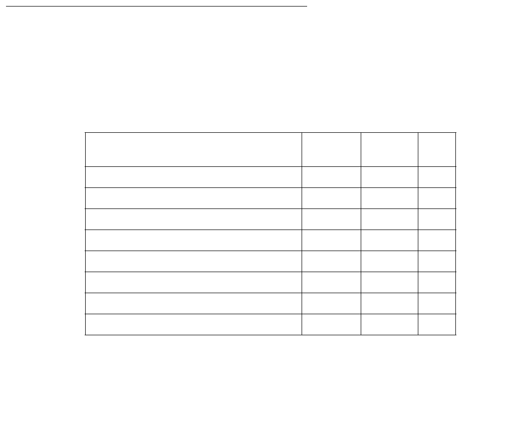
IPMEDPRO (TN2302 IP Media Processor)
Issue 1 June 2005 1361
s. Error Type 3841: Aux Data = None: Inconsistent downlink message. The board was sent a
message it did not understand. These errors are not service affecting. No action is required.
t. Error Type 3841: Aux Data = 4283: The RTCP monitor server is not connected.
There is a network problem between the monitor server and the media server or the RTCP
monitor server is mis-administered. Use the Avaya Communication Manager administration
command change system-parameters ip-options to verify administration of RTCP
monitor server parameters.
u. Error Type 3999: the circuit pack sent a large number of control channel messages to the
switch within a short period of time. If Error Type 1538 is also present, then the circuit pack
was taken out of service due to hyperactivity. If Error Type 1538 is not present, then the
circuit pack has not been taken out of service, but it has generated 50 percent of the
messages necessary to be considered hyperactive. This may be completely normal during
heavy traffic periods. However, if this error type is logged when the circuit pack is being
lightly used, it may indicate a problem with the circuit pack or the equipment attached to it.
System Technician-Demanded Tests:
Descriptions and Error Codes
Investigate tests in the order they are presented. By clearing error codes associated with the
Control Channel Loop test, you may also clear errors generated from other tests in the
sequence.
Table 475: System Technician-Demanded Tests
Order of Investigation Short Test
Sequence
Long Test
Sequence
D/ND1
1. D = Destructive; ND = Nondestructive
Control Channel Loop test (#52) X X ND
IP Address Update Test (#1371) X X D
NIC Query test (#1383) X X ND
Local Ping test (#1379) X X ND
Short IP 2-Way Transmission test (#1505) X ND
Long IP 2-Way Transmission test (#1506) X ND
Verify NIC options (#1511) X X ND
MP Diagnostic Test (#1406) X ND

Communication Manager Maintenance-Object Repair Procedures
1362 Maintenance Procedures for Avaya Communication Manager 3.0, Media Gateways and Servers
Control Channel Loop-around Test (#52)
This test queries the circuit pack for its circuit pack code and vintage and verifies its records.
SAKI Sanity Test (#53)
This test is destructive.
This test is only run as a part of a reset board procedure. For the Media Processor, use the
change ip-interface screen to disable the media processor’s IP interface before
performing this procedure.
Table 476: Test #52 Control Channel Loop-around Test
Error
Code
Test
Result
Description / Recommendation
None,
2100
ABRT System resources required for this test are not available.
1. Retry the command at 1-minute intervals up to 5 times.
FAIL The circuit pack failed to return the circuit pack code or vintage.
1. Retry the command up to 5 times.
2. If the problem continues, replace the circuit pack.
3. Retry the command up to 5 times.
PASS Communication with this circuit pack is successful.
0NO
BOARD The test could not relate the internal ID to the port (no board). This could
be due to incorrect translations, no board is inserted, an incorrect board is
inserted, or an insane board is inserted.
1. Ensure that the board translations are correct. Administer the MedPro
interface if it is not already administered.
2. If the board was already administered correctly, check the error log to
determine whether the board is hyperactive. If this is the case, the
board is shut down. Reseat the board to reinitialize it.
3. If the board was found to be correctly inserted in step 1, enter
busyout board location.
4. Enter reset board location.
5. Enter release board location.
6. Enter test board location long.
This should re-establish the linkage between the internal ID and the port.

IPMEDPRO (TN2302 IP Media Processor)
Issue 1 June 2005 1363
A reset of this circuit pack takes about 3½ minutes.
Table 477: Test #53 SAKI Sanity Test
Error
Code
Test
Result
Description / Recommendation
None ABRT System resources required for this test are not available.
1. Retry the command at 1-minute intervals up to 5 times.
1015 ABRT Port is not out of service.
1. Busy out the circuit pack.
2. Execute command again.
2100 ABRT System resources required for this test are not available.
1. Retry the command at 1-minute intervals up to 5 times.
2803 ABRT Need to disable the IP interface.
1. Use the change ip-interfaces screen to disable the media
processor’s IP interface.
2. Execute the command again.
1 FAIL The circuit pack failed to reset.
1. Execute command again.
2. If the problem persists, replace the circuit pack.
2 FAIL The circuit pack failed to restart.
1. Execute command again.
2. If the problem persists, replace the circuit pack.
PASS The circuit pack initializes correctly.
1. Run the short test sequence.
Any NO
BOARD This is normal if the test is being done when (a) the board is not physically
in the system or (b) the system is booting up. Otherwise, there is some
inconsistency between the physical configuration and the data kept in the
system.
1. Verify that the board is physically in the system.
2. Verify that the system is not in a stage of booting up.
3. Retry the command at 1-minute intervals for up to 5 times.

Communication Manager Maintenance-Object Repair Procedures
1364 Maintenance Procedures for Avaya Communication Manager 3.0, Media Gateways and Servers
IP Address Update Test #1371
This test is destructive.
This test queries the media processor for its IP address, subnet mask, and gateway translation
(IP parameters). If the parameters do not match software translation, maintenance software
reboots the board. The board goes through a logical board removal and insertion.
or:
This test sends the IP Media Resource the IP address, subnet mask, and gateway translation
(IP parameters). If the parameters do not match software translation, the system reboots the
board. The board goes through a logical board removal and insertion.
When this test fails, it is an indication that an illegal change was made and the customer should
be notified.
Table 478: Test #1371 IP Address Query Test
Error
Code
Test
Result
Description / Recommendation
ABRT Internal system error
1. Retry the command at 1-minute intervals up to 5 times.
2100 ABRT Insufficient system resources to run this test.
1. Retry the command at 1-minute intervals up to 5 times.
2801 ABRT Unable to find IP address data for this location.
1. Verify that the board is administered.
2807 ABRT The board is administered, but not enabled on the change
ip-interfaces form.
FAIL The IP address, subnet mask, and gateway translation parameters do not
match Communication Manager translations. The board has been reset.
1. If the problem persists, replace the circuit pack.
PASS Translation data matches.

IPMEDPRO (TN2302 IP Media Processor)
Issue 1 June 2005 1365
Network Connectivity Query Test (#1383)
This test is nondestructive.
This test passes if the Ethernet port is connected. It fails, with no error code or aux data, if no
electrical signal is detected.
Table 479: Test #1383 Network Connectivity Query Test
Error
Code
Test
Result
Description / Recommendation
None ABRT System resources required for this test are not available.
1. Retry the command at 1-minute intervals up to 5 times.
1015 ABRT Port is not out of service.
1. Enter busyout board location to busyout the circuit pack.
2. Execute the command again.
2100 ABRT System resources required for this test are not available.
1. Retry the command at 1-minute intervals up to 5 times.
FAIL The Ethernet cable is not connected.
PASS The Ethernet cable is connected.
0NO
BOARD The test could not relate the internal ID to the port (no board). This could
be due to incorrect translations, no board is inserted, an incorrect board is
inserted, or an insane board is inserted.
1. Ensure that the board’s translations are correct.
2. If the board is not correctly administered, administer the MedPro
interface.
If correctly administered, check the error log to determine whether the
board is hyperactive. If so, the board was shut down. Reseat the board
to reinitialize it.
3. If the board is correctly inserted and administered, enter busyout
board location.
4. Enter reset board location.
5. Enter release board location.
6. Enter test board location long.
This should re-establish the linkage between the internal ID and the port.

Communication Manager Maintenance-Object Repair Procedures
1366 Maintenance Procedures for Avaya Communication Manager 3.0, Media Gateways and Servers
Ping Test (#1379)
This test is nondestructive.
This test verifies that the MedPro circuit pack can communicate with other nodes on the LAN.
This test pings the gateway IP address as defined on the IP Interface screen. If the PING is
successful, this test looks at the PING round-trip delay. If a round-trip delay of greater than 4
seconds is reported, a separate error is logged. Excessive round-trip delays do not take the
MedPro out of service.
Services can execute the standard PING command using the C-LAN board address and
MedPro IP address to see the actual round-trip delay. (See ping commands.)
Table 480: Test #1379 Ping Test
Error
Code
Test
Result
Description / Recommendation
1,
2
ABRT Internal Error.
1. Retry the command at 1-minute intervals up to 3 times.
7 ABRT Destination unreachable.
1. Verify that at least one destination reachable through this port is up.
2. Repeat the test.
3. If the test still aborts, escalate the problem.
1005 ABRT Configuration for this test is incorrect.
1. Verify that the Ethernet link is in-service with the status port or
status link command. Verify that the routing table has destinations
that are reachable through this port.
2. Repeat this test.
3. If the test aborts with error code 7 while step 1 verified, escalate the
problem.
2000 ABRT Response to the test was not received from the Media Processor circuit
pack within the allowable time period.
1. If this result occurs repeatedly, attempt to reset the circuit pack. Reset
the circuit pack by entering busyout board location and reset
board location.
2. If this result occurs again, replace the circuit pack.
2012 ABRT Internal system error.
1. Retry the command at 1-minute intervals up to 3 times.
1 of 2

IPMEDPRO (TN2302 IP Media Processor)
Issue 1 June 2005 1367
MP Diagnostic Test (#1406)
This test is destructive.
The MP Diagnostic test (#1406) runs the following diagnostic tests in the following order, but
only if each successive test passes:
1. DSP FPGA Query
2. ETHERNET Query
3. SCOTCH Sanity
2100 ABRT The necessary system resources to execute the test could not be
allocated.
1. Retry the command at 1-minute intervals up to 5 times.
2500 ABRT Internal system error.
1. Retry the command at 1-minute intervals up to 3 times.
2801 ABRT No IP address defined. Verify IP interfaces translations and retest.
2802 ABRT Different IP address pinged than software had allocated for the test.
1. Retry the command at 1-minute intervals up to 3 times.
2805 FAIL The number of pings received did not match the number sent (normally
one ping sent). This means that no ping responses were received from the
gateway defined on the ip-interface form for the media processor.
1. Retry the command at 1-minute intervals up to 3 times.
2807 ABRT The board is administered but not enabled on the change
ip-interfaces form.
7
89
1007
FAIL A ping to the destination failed through this port. This failure is because the
destination is down.
1. Verify that at least one destination is reachable through this port.
2. Once verified, execute test port location to verify that the H.323
Signaling Group Ping test (#1387) passes.
PASS Ping through this port is successful.
Table 480: Test #1379 Ping Test (continued)
Error
Code
Test
Result
Description / Recommendation
2 of 2

Communication Manager Maintenance-Object Repair Procedures
1368 Maintenance Procedures for Avaya Communication Manager 3.0, Media Gateways and Servers
FPGA Query
This test verifies the status of the FPGA device on the TN2302 circuit pack. If the device is bad,
software posts an error and alarm, and takes every DSP out of service (every DSP that is
controlled by the one FPGA). Software then attempts to reset the FPGA. If the reset passes or
the original test passes, the DSPs are placed back into service.
Ethernet Query
This test passes if the TN2302 hardware tests ok and the Ethernet port is connected.
Otherwise, it fails.
SCOTCH Sanity
The Scotch device on a board communicates with switch software via the TDM bus for
conferencing and gain adjustment. This is done by setting up connections on TDM bus time
slots.
There are three different errors that can be generated due to the problems with Scotch devices
on the board: NPE SCOTCH 0, NPE SCOTCH 1, and NCE SCOTCH. If any of these errors are
reported from the board, the DSPs are taken from service and a circuit pack reset is executed
by running the SAKI test.
Table 481: Test #1406 MP Diagnostic Test
Error
Code
Test
Result
Description / Recommendation
2012 ABRT System error:
1. Retry the command at 1-minute intervals up to 5 times.
2100 ABRT System resources required for this test are not available.
1. Retry the command at 1-minute intervals up to 5 times.
FAIL The MP Diagnostic test has failed for this TN2302 and the board is in the
out-of-service state.
1. Enter busyout board location.
2. Enter reset board location.
3. Enter release board location.
4. Enter test board location long.
If the board continues to fail, replace the board.
1 of 3

IPMEDPRO (TN2302 IP Media Processor)
Issue 1 June 2005 1369
8192–
8328
FAIL The FPGA DSP test failed:
1. Enter busyout board location.
2. Enter reset board location.
3. Enter release board location.
4. Enter test board location long.
If the board continues to fail, replace the board.
16384–
16900
FAIL A SCOTCH device failed:
1. Enter busyout board location.
2. Enter reset board location.
3. Enter release board location.
4. Enter test board location long.
If the board continues to fail, replace the board.
24576–
24580
FAIL An ETHERNET device failed:
1. Enter busyout board location.
2. Enter reset board location.
3. Enter release board location.
4. Enter test board location long.
If the board continues to fail, replace the board.
PASS The FPGA device on this TN2302 is operating correctly.
Table 481: Test #1406 MP Diagnostic Test (continued)
Error
Code
Test
Result
Description / Recommendation
2 of 3

Communication Manager Maintenance-Object Repair Procedures
1370 Maintenance Procedures for Avaya Communication Manager 3.0, Media Gateways and Servers
Short IP 2-Way Transmission Test (#1505)
This test is nondestructive.
This test attempts to verify IP network connectivity between one pair of IP Media Processors
that are connected to a customer’s LAN/WAN IP network.
This test creates a G.711 audio path between the source IP Media Processor board specified in
the command line and a destination IP Media Processor board. The destination media
processor board is chosen by the system. The destination media processor is chosen from a
port network other than the port network containing the source media processor. In addition, the
destination media processor board is chosen from the same IP network region as the source
media processor board or is chosen from an IP network region that is administered to be
connected to the IP network region of the source media processor board.
0NO
BOARD The test could not relate the internal ID to the port (no board). This could
be due to incorrect translations, no board is inserted, an incorrect board
is inserted, or an insane board is inserted.
1. Ensure that the board translations are correct. Administer the
IPMEDPRO interface if it is not already administered.
2. If the board was already administered correctly, check the error log to
determine whether the board is hyperactive. If this is the case, the
board is shut down. Reseat the board to reinitialize it.
3. If the board was found to be correctly inserted in step 1, then enter
busyout board location.
4. Enter reset board location.
5. Enter release board location.
6. Enter test board location long.
This should re-establish the linkage between the internal ID and the port.
Table 481: Test #1406 MP Diagnostic Test (continued)
Error
Code
Test
Result
Description / Recommendation
3 of 3

IPMEDPRO (TN2302 IP Media Processor)
Issue 1 June 2005 1371
An audio channel using G.711 is setup between both boards. A 1004-Hz test tone is transmitted
from the source PN to the destination PN over the G.711 audio channel. The test tone is then
transmitted from the destination PN to the source PN.
Table 482: Short IP 2-Way Transmission Test (#1505)
Error
Code
Test
Result
Description / Recommendation
1002 ABRT The system could not allocate timeslots for the test. The system may be
under heavy traffic conditions or it may have timeslots out of service due
to TDM-BUS errors.
1. If system has no TDM-BUS errors and is not handling heavy traffic,
retry the command at 1-minute intervals up to 3 times.
2. If system has TDM-BUS errors, clear any errors, and retry the
command at 1-minute intervals up to 3 times.
3. If the command continues to abort, escalate the problem.
1003 ABRT The system could not allocate a tone receiver for the test. The system
may be oversized for the number of Tone Detectors present, or some
Tone Detectors may be out of service.
1. Resolve any TTR-LEV errors. Even without TTR-LEV errors, a Tone
Detector could be unavailable in the PN containing the circuit pack
being tested. Verify that at least one Tone Detector resides in this
PN. If not, this test always aborts, but does not harm the system.
2. Resolve any TONE-PT errors.
3. If neither condition exists, retry the command at 1-minute intervals
up to 3 times.
1014 ABRT Board not inserted.
2000 ABRT Response to the test was not received in the allowable time period.
1. Retry the command at 1-minute intervals up to 3 times.
2012 ABRT Generic system call failed. Internal system error.
1. Retry the command at 1-minute intervals up to 3 times.
2100 ABRT Could not allocate the necessary system resources to run this test.
1. Retry the command at 1-minute intervals up to 3 times.
2500 ABRT Internal system error.
1. Retry the command at 1-minute intervals up to 3 times.
1 of 3

Communication Manager Maintenance-Object Repair Procedures
1372 Maintenance Procedures for Avaya Communication Manager 3.0, Media Gateways and Servers
2801 ABRT The IP Media Processor board has not been administered on the
ip-interface form.
2806 ABRT The system could not find any in-service IP Media Processor boards to
use as a destination for this test.
2807 ABRT The specified IP Media Processor board has been disabled on the
ip-interfaces form.
10XX
XX = PN # FAIL The test tone was not successfully sent from the IP Media Processor
specified in the test command and not successfully received by an IP
Media Processor in the PN specified in the error code (XX). XX = PN
number.
The source to destination direction failed. The destination to source
direction was not tested.
1. Resolve all other board alarms for the specified source IP Media
Processor.
2. Resolve all other board alarms for the IP Media Processor boards in
the destination PN.
3. Use ping and traceroute to localize the problem to the
customer’s LAN/WAN IP network.
20XX
XX = PN # FAIL The test tone was successfully sent from the IP Media Processor
specified in the test command and received by an IP Media Processor in
the PN specified in the error code (XX). XX = PN number.
The test tone was not successfully sent in the reverse direction. The
destination to source direction failed. The source to destination direction
passed.
1. Resolve all other board alarms for the specified source IP Media
Processor.
2. Resolve all other board alarms for the IP Media Processor boards in
the destination PN.
3. Use ping and traceroute to localize the problem to the
customer’s LAN/WAN IP network.
Table 482: Short IP 2-Way Transmission Test (#1505) (continued)
Error
Code
Test
Result
Description / Recommendation
2 of 3

IPMEDPRO (TN2302 IP Media Processor)
Issue 1 June 2005 1373
Long IP 2-Way Transmission Test (#1506)
This test is nondestructive.
In Test #1505 IP voice connectivity is verified in both directions, between the specified IP Media
Processor (A) and a system chosen destination IP Media Processor (B).
Test 1506 is used to verify IP network connectivity between a specified IP Media Processor and
every other IP Media Processor in the system. It is an extended version of Test #1505.
In Test #1506 we verify IP voice connectivity in both directions, between the specified IP media
Processor (A) and all other IP Media Processor/s (B, C, D, E, ....) that have administered IP
network region connectivity to the IP network region of the source IP Media Processor.
The test passes if the source IP Media Processor (A) has 2-way voice connectivity to all other IP
Media Processors. The test fails and stops immediately when the source IP Media Processor
(A) cannot verify 2-way talk path to any destination IP Media Processor. The failure code
indicates the port network that contains the destination media processor that could not be
reached.
This test creates a G.711 audio path between the source IP Media Processor board specified in
the command line and a destination IP Media Processor board. All destination media processor
boards are chosen from the same IP network region as the source IP Media Processor and
connected IP network regions. An audio channel using G.711 is setup between a pair of boards.
XX
XX = PN # PASS The board is functioning properly. The test tone was transmitted and
received successfully between:
●The IP Media Processor specified in the test command
●An IP Media Processor in the PN specified in the error code (XX).
(The test tone was sent and received in both directions). XX = PN
number.
0NO
BOARD No board was detected by the test.
1. Resolve either wrong board (Error 125) or no board (Error 131)
issues, if applicable.
2. Check that the board is properly translated and inserted. If so, check
for hyperactivity (Error 1538). If hyperactive, use reset board
location.
3. Run the test again. If it fails, the NCE chip on board may be bad.
Replace the board and retest.
Table 482: Short IP 2-Way Transmission Test (#1505) (continued)
Error
Code
Test
Result
Description / Recommendation
3 of 3

Communication Manager Maintenance-Object Repair Procedures
1374 Maintenance Procedures for Avaya Communication Manager 3.0, Media Gateways and Servers
A 1004-Hz test tone is transmitted from the source PN to the destination PN over the G.711
audio channel. The test tone is then transmitted from the destination PN to the source PN.
Table 483: Long IP 2-Way Transmission Test (#1506)
Error
Code
Test
Result
Description / Recommendation
1002 ABRT The system could not allocate timeslots for the test. The system may be
under heavy traffic conditions or it may have timeslots out of service due
to TDM-BUS errors.
1. If system has no TDM-BUS errors and is not handling heavy traffic,
retry the command at 1-minute intervals up to 3 times.
2. If system has TDM-BUS errors, clear any errors, and retry the
command at 1-minute intervals up to 3 times.
3. If the command continues to abort, escalate the problem.
1003 ABRT The system could not allocate a tone receiver for the test. The system
may be oversized for the number of Tone Detectors present, or some
Tone Detectors may be out of service.
1. Resolve any TTR-LEV errors. Even without TTR-LEV errors, a Tone
Detector could be unavailable in the PN containing the circuit pack
being tested. Verify that at least one Tone Detector resides in this PN.
If not, the test always aborts for this circuit pack, but does not harm
the system.
2. Resolve any TONE-PT errors.
3. If neither condition exists, retry the command at 1-minute intervals up
to 3 times.
1014 ABRT Board not inserted.
2000 ABRT Response to the test was not received in the allowable time period.
1. Retry the command at 1-minute intervals up to 3 times.
2012 ABRT Generic system call failed. Internal system error.
1. Retry the command at 1-minute intervals up to 3 times.
2100 ABRT Could not allocate the necessary system resources to run this test.
1. Retry the command at 1-minute intervals up to 3 times.
2500 ABRT Internal system error.
1. Retry the command at 1-minute intervals up to 3 times.
1 of 3

IPMEDPRO (TN2302 IP Media Processor)
Issue 1 June 2005 1375
2801 ABRT The IP Media Processor board has not been administered on the
ip-interfaces form.
2806 ABRT The system could not find any in-service IP Media Processor boards to use
as a destination for this test.
2807 ABRT The specified IP Media Processor board has been disabled on the
ip-interfaces screen.
10XX
XX = PN # FAIL The test tone was not successfully sent from the IP Media Processor
specified in the test command, and not successfully received by an IP
Media Processor in the PN specified in the error code (XX). Source to
destination direction failed. Destination to source direction not tested.
XX = PN number.
1. Resolve all other board alarms for the specified source IP Media
Processor.
2. Resolve all other board alarms for the IP Media Processor boards in
the destination PN.
3. Use ping and traceroute to localize the problem to the customer’s
LAN/WAN IP network.
20XX FAIL The test tone was successfully sent from the IP Media Processor specified
in the test command and received by an IP Media Processor in the PN
specified in the error code (XX).
The test tone was not successfully sent in the reverse direction.
Destination to source direction failed. Source to destination direction
passed.
1. Resolve all other board alarms for the specified source IP Media
Processor.
2. Resolve all other board alarms for the IP Media Processor boards in
the destination PN.
3. Use ping and traceroute to localize the problem to the
customer’s LAN/WAN IP network.
PASS The customer network is functioning properly. The test tone was
transmitted and received successfully between:
●The IP Media Processor specified in the test command
●Every other IP Media Processor in the set of connected IP network
regions.
Table 483: Long IP 2-Way Transmission Test (#1506) (continued)
Error
Code
Test
Result
Description / Recommendation
2 of 3

Communication Manager Maintenance-Object Repair Procedures
1376 Maintenance Procedures for Avaya Communication Manager 3.0, Media Gateways and Servers
0NO
BOARD No board was detected by the test.
1. Resolve either wrong board (Error 125) or no board (Error 131)
issues, if applicable.
2. Check that the board is properly translated and inserted.
a. If so, check for hyperactivity (Error 1538).
b. If hyperactive, use reset board location.
3. Run the test again. If it fails, the NCE chip on board may be bad.
Replace the board and retest.
Table 483: Long IP 2-Way Transmission Test (#1506) (continued)
Error
Code
Test
Result
Description / Recommendation
3 of 3

IPMEDPRO (TN2302 IP Media Processor)
Issue 1 June 2005 1377
Verify NIC Options Test (#1511)
This test is nondestructive.
This test verifies if the NIC interface parameters, speed, and duplex (full/half) match with
administration.
The test passes if the NIC parameters match administration. The test fails if the NIC parameters
do not match administration.
Table 484: Verify NIC Options Test (#1511)
Error
Code
Test
Result
Description / Recommendation
1014 ABRT Board is not inserted. Insert and administer a TN2302 board.
1022 ABRT Invalid board. The board is not capable of changing its ethernet options.
The board suffix must be D or greater.
1115 ABRT Unable to allocate system resources (in-use) to run this test. Retry the test
at one minute intervals a maximum of 3 times.
2000 ABRT Response to the test was not received within the allowable time. Retry the
command at 1 minute intervals a maximum of 3 times.
1. If this result occurs repeatedly, attempt to reset the circuit pack with
busyout board location and reset board location.
2. If this result occurs again, after resetting the board, replace the circuit
pack.
2012 ABRT Internal system error.
1. Retry the command at 1-minute intervals up to 3 times.
2100 ABRT System resources required for this test are not available.
1. Retry the command at 1-minute intervals up to 5 times.
2500 ABRT Internal system error.
Retry the command at 1-minute intervals up to 3 times.
2801 ABRT Could not find the IP address for this board.
1. Use the change ip-interfaces location to administer an IP
address for this board. Retest.
1 of 3

Communication Manager Maintenance-Object Repair Procedures
1378 Maintenance Procedures for Avaya Communication Manager 3.0, Media Gateways and Servers
2807 ABRT The board is administered but not enabled on the ip-interfaces form.
1. Use the change ip-interfaces location to enable the board.
2. Retest the board.
1FAIL
The board is reporting that it is running half duplex with auto-negotiate (y).
Communication Manager is trying to negotiate the settings on the circuit
pack to match the administered settings and, under the above condition, it
is logging a fault. It could be argued that this is a false alarm, especially if
the link is operating correctly with no observable degradation of service.
Note: Do not immediately replace the board for this fault. There is a
mismatch between what is programmed in the board and administration on
Communication Manager.
CAT-3 wiring does not support 100Mbps data rates. Wiring between the
backplane and router must be CAT-5
Follow these steps to attempt to resolve the problem.
1. Change the ethernet options. Set the speed to 100Mbps with full
duplex. Set Auto (negotiate) to n. This should match the settings of the
connected router. If the router does not have the same capabilities, you
may have to adjust accordingly. The important thing is to make the
media processor (TN2302) and the connected router match.
Command steps to accomplish changes to Communication Manager
administration.
a) Enter get ethernet-options location to determine current
settings, both administered and actual.
b) Enter change ip-interface location (Enable Ethernet Port
field to n) to turn off the interface. Submit the command to disable the
interface.
c) Enter change ip-interface location change the Ethernet
Options fields as required. Submit the form.
d) Enter change ip-interface location (Enable Ethernet
Port field to y) to turn on the interface. Submit the command. to enable
the interface.
e) Enter get ethernet-options location to verify that Ethernet
options are the same in administration and on the board.
2. If service is normal and the alarm is causing concern, disable the test
and escalate the problem.
Table 484: Verify NIC Options Test (#1511) (continued)
Error
Code
Test
Result
Description / Recommendation
2 of 3

IPMEDPRO (TN2302 IP Media Processor)
Issue 1 June 2005 1379
2 FAIL The board is reporting different options than what is administered. Software
tried to correct the options but the board did not take the option update. It
could be argued that this is a false alarm, especially if the link is operating
correctly with no observable degradation of service.
Note: Do not immediately replace the board for this fault. There is a
mismatch between what is programmed in the board and administration on
Communication Manager.
Follow these steps to attempt to resolve the problem.
1. Use the command steps listed below to administer the ethernet options
to their desired values.
a) Enter get ethernet-options location to determine current
settings, both administered and actual.
b) Enter change ip-interface location (Enable Ethernet Port
field to n) to turn off the interface. Submit the command to disable the
interface.
c) Enter change ip-interface location change the Ethernet
Options fields as required. Submit the form.
d) Enter change ip-interface location (Enable Ethernet
Port field to y) to turn on the interface. Submit the command. to enable
the interface.
e) Enter get ethernet-options location to verify that Ethernet
options are the same in administration and on the board.
2. If the board values and administration values still do not match repeat
the actions from step 1 above one time.
3. Set the administration values to the actual values that the board is
reporting. Test the board using the test board location
command. If the test still fails replace the board.
4. If service is normal and the alarm is causing concern, disable the test
and escalate the problem.
Table 484: Verify NIC Options Test (#1511) (continued)
Error
Code
Test
Result
Description / Recommendation
3 of 3
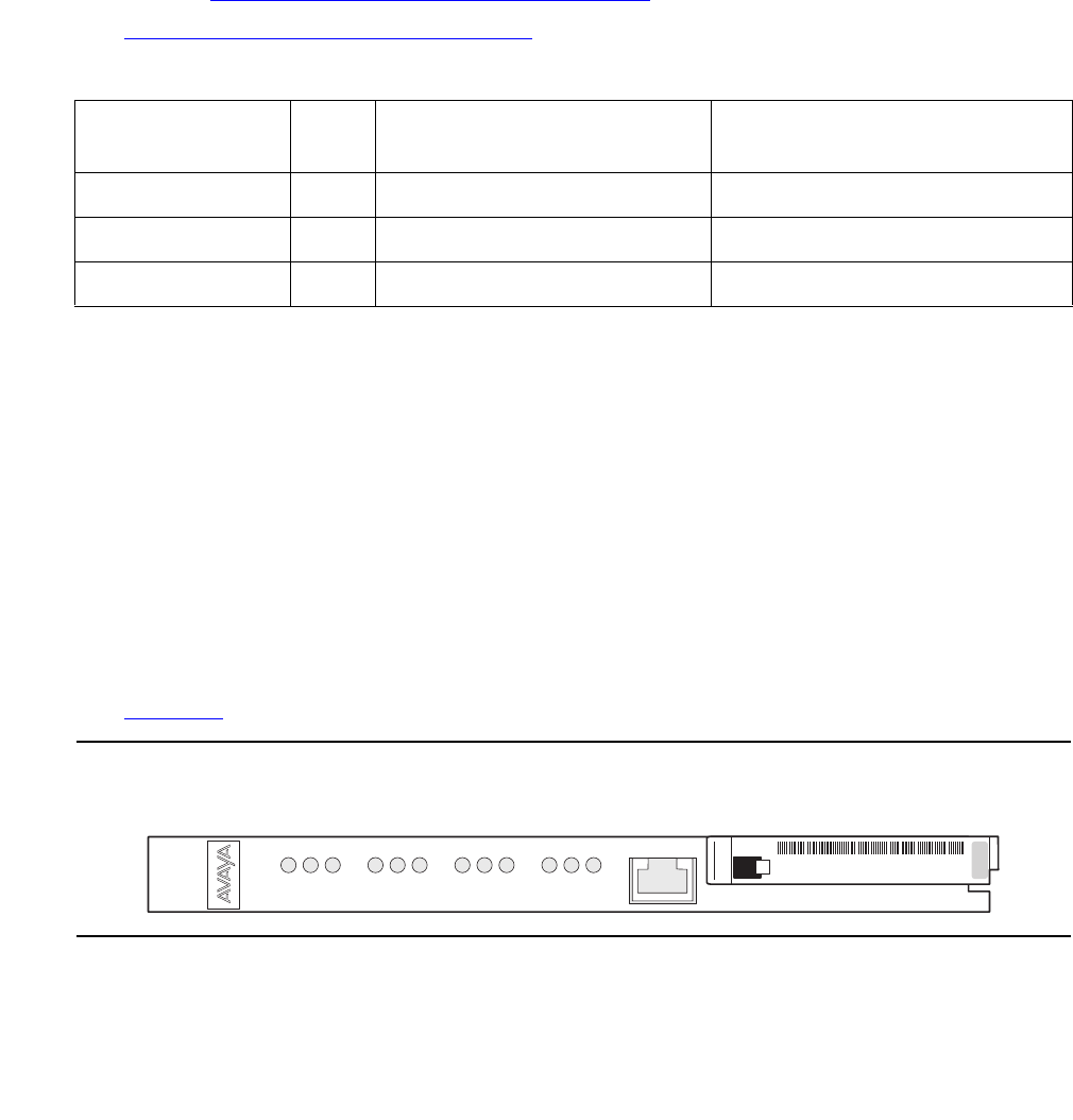
Communication Manager Maintenance-Object Repair Procedures
1380 Maintenance Procedures for Avaya Communication Manager 3.0, Media Gateways and Servers
IPMEDPRO (TN2602AP IP Media Resource 320)
S8700 | 8710 / S8500
The IPMEDPRO Maintenance Object applies to the TN2302 IP Media Processor and the
TN2602AP IP Media Resource 320.
To identify which type of circuit pack is alarmed use the list configuration command for
the location recorded in the error log. If the circuit pack type displayed from the list
configuration command is a TN2602AP use this MO. If the circuit pack displayed is a
TN2302 use IPMEDPRO (TN2302 IP Media Processor) on page 1356
See MEDPRO-C (Media-Processor Control) on page 1551 for additional information on the
TN2602AP IP Media Resource 320.
The TN2602AP IP Media Resource 320 enables IP port network connectivity. The TN2602AP
allows bearer traffic to be moved from the traditional Center Stage Switch (CSS) or ATM
network to the IP network. Together with the TN2312BP IPSI-2 circuit pack, the TN2602AP is
intended to be a traditional CSS replacement for port network connectivity.
The TN2602AP includes a 10/100 BaseT Ethernet interface to support IP audio for IP trunks
and H.323 endpoints.
The TN2602AP IP Media Resource 320 provides high-capacity voice over Internet protocol
(VoIP) audio access to the switch for local stations and outside trunks. The IP Media Resource
320 provides audio processing for the following types of calls:
●TDM-to-IP and IP-to-TDM
●IP-to-IP
See Figure 75 for an example of the IP Media Resource 320 faceplate
Figure 75: IP Media Resource 320 faceplate
The TN2602AP IP Media Resource 320 circuit pack has two capacity options, both of which are
determined by the license file installed on Communication Manager:
MO Name in Alarm
Log
Alarm
Level
Initial SAT Command to Run Full Name of MO
IPMEDPRO MAJ test board location sh IP Media Resource 320
IPMEDPRO MIN test board location l IP Media Resource 320
IPMEDPRO WRN test board location sh IP Media Resource 320
ckdf2602 KLC 020305
S
E
R
V
I
C
E
700261928
AVAYA
04J219701400 HV1
TN2602AP Media Resource 320
FDX
ACT
LNK
SRVC
FDX
ACT
LNK
PORT 1
FDX
ACT
LNK
PORT 2

IPMEDPRO (TN2602AP IP Media Resource 320)
Issue 1 June 2005 1381
●320 voice channels, considered the standard IP Media Resource 320
●80 voice channels, considered the low-density IP Media Resource 320
Up to two TN2602AP circuit packs may be installed in a single port network for load balancing.
The TN2602AP circuit pack is also compatible with and can share load balancing with the
TN2302 circuit pack. Actual capacity may be affected by a variety of factors, including the codec
and fax support.
Actual capacity may be affected by a variety of factors, including the codec used for a call and
encryption usage and the echo cancellation tail length and fax support.
TN2602AP features
The IP Media Resource 320 supports hairpin connections and the shuffling of calls between
TDM connections and IP-to-IP direct connections. The IP Media Resource 320 can also
perform the following functions:
●Echo cancellation
●Silence suppression
●Dual-tone multifrequency (DTMF) detection
●AEA Version 2 and AES media encryption
●Conferencing
●802.1p and 802.Q layer 2 QoS mechanisms
●RSVP protocol
The TN2602AP IP Media Resource 32 circuit pack supports the following codecs for voice,
conversion between codecs, and fax detection:
●G.711, A-law or Mu-law, 64 kbps
●G.726A, 32 kbps
●G.729 A/AB, 8 kbps audio
IPMEDPRO 320 Error Log Entries and Test to Clear Values
Table 485: TN2602AP IP Media Resource Maintenance Error Log Entries
Error
Type
Aux
Data
Associated Test Alarm
Level
On/Off
Board
Test to Clear Value
010Any AnyAnytest board location
1 of 3

Communication Manager Maintenance-Object Repair Procedures
1382 Maintenance Procedures for Avaya Communication Manager 3.0, Media Gateways and Servers
1 (a)0Circuit pack
removed or
sanity failure
MIN ON
18 (b)0 busyout board
location
WRN OFF release board location
23 (c) 0 Board
administered but
not inserted
WRN OFF add ds1 location
125 (d) Wrong board MIN ON
257 (e) 65535 Control Channel
Loop test (#52)
MIN ON test board location l r 20
513 (f) 4352,
4353,
4355,
4356,
4358
TN2602 on-board
hardware errors
MIN ON
769 (g)IP 2-Way
Transmission
tests (#1505 &
1506)
MIN OFF
1281 (h) 20481
to
20493
Board Status Test
(#1402)
MIN ON
1538 (i)
(t)
Any Circuit pack is
hyperactive
MIN ON
1793 (j) Any NIC Loss of
Signal (#1383)
MIN
WRN2OFF test board location l r 2
2049 (k) Any Packet Count
Query (#1630)
MIN ON
2305 (l) Any IP Address
Update (#1371)
MIN ON
2561 (m) Ping error(#1379) MIN OFF
2817 (n) Any Ethernet
Hardware Query
test (#1405)
MIN ON
Table 485: TN2602AP IP Media Resource Maintenance Error Log Entries (continued)
Error
Type
Aux
Data
Associated Test Alarm
Level
On/Off
Board
Test to Clear Value
2 of 3

IPMEDPRO (TN2602AP IP Media Resource 320)
Issue 1 June 2005 1383
Notes:
a. Error Type 1: the circuit pack has been removed from the system or is not fully
administered. The alarm is logged about 15 minutes after the circuit pack has been
removed, or 11 minutes after the SAKI test (#53) fails.
To be fully administered, an IP Media Resource must:
●Have an entry on the circuit pack screen (change circuit-pack)
●Have the Media Resource IP address administered (change node-names)
●Be enabled (change ip-interface)
●Be physically inserted into the correct slot
If the circuit pack has an entry on the circuit pack screen and any of the other conditions are
not met, a MINOR alarm is logged. To resolve the error:
●Make sure every condition for administration is met, and that a functioning Media
Resource is inserted in the correct slot.
●Completely remove the IP Media Resource from the system:
a. Remove the administered IP-Interface associated with the circuit pack.
3073 (o) Any Aggregator
Hardware Query
(#1629)
MIN ON
3329 (p) Any Duplicate
network IP
address detected
(#1371)
MIN OFF
3585 (q) 1 or 2 Verify NIC option
test (#1511)
MIN OFF
3841(r) None Inconsistent
downlink or
board error
3841(s) 4283 RTCP Monitor
Server error
3999 (t) Any None
1. Run the short test sequence first. If every test passes, run the long test sequence. Refer to each
appropriate test’s description, and follow its recommended procedures.
2. Minor alarms on this MO may be downgraded to warning alarms based on values set in set options.
Table 485: TN2602AP IP Media Resource Maintenance Error Log Entries (continued)
Error
Type
Aux
Data
Associated Test Alarm
Level
On/Off
Board
Test to Clear Value
3 of 3

Communication Manager Maintenance-Object Repair Procedures
1384 Maintenance Procedures for Avaya Communication Manager 3.0, Media Gateways and Servers
b. Physically remove the circuit pack from the slot.
b. Error Type 18: The IP Media Resource was busied out by a busyout board location.
1. Release the circuit pack (release board location).
c. Error Type 23: The IP Media Resource is not completely administered. To be fully
administered, an IP Media Resource must:
●Have an entry in the circuit plan (change circuit-pack)
●Have an administered IP address (change node-names ip)
●Be enabled (change ip-interface)
●Be physically inserted into the correct slot.
An IP Media Resource differs from most circuit packs in that inserting the circuit pack into
the switch is not enough to make the board usable. It must also be administered.
d. Error Type 125: The wrong circuit pack is inserted in the slot where this circuit pack is
logically administered. Do one of the following:
●Remove the wrong circuit pack and insert the logically administered circuit pack.
●Re-administer this slot to match the circuit pack inserted (change circuit-pack).
e. Error Type 257: failure of the Control Channel test (#52). See Control Channel
Loop-around Test (#52) on page 1362 for details.
f. Error Type 513: transient hardware device problems on the board. They include an
external RAM failure, internal RAM failure, ROM checksum failure, message corruption,
and program logic inconsistency. There are no associated tests for these inline errors; if
they continue to happen, an alarm will occur.
g. Error Type 769: failed attempts to verify IP network connectivity between a specified IP
Media Resource and other IP Media Resources in the system. See Test #1505 for Short IP
2-way transmission test failures and Test #1506 IP long 2-way transmission test failures.
h. Error Type 1281: certain firmware modules or components on the board failed to initialize
properly. This test is only run at board insertion. When the board is first inserted this test is
run to verify that the embedded software (firmware) applications on the board are working
properly. If the test fails, it is immediately run a second time. If the test fails a second time an
alarm is raised. See Board StatusTest (#1402) on page 1392 for more information.
i. Error Type 1538: hyperactivity on the board. The circuit pack is sending too many
messages to switch software. The circuit pack will be taken out of service. See Error Type
3999.
j. Error Type 1793: no electrical signal is detected on the Ethernet cable. The Ethernet cable
is unplugged or there is a problem with a connection to the network interface.
k. Error Type 2049: Packet Count Query, indicates a problem with the packet bus.
l. Error Type 2305: IP address inconsistency between switch software and the IP Media
Resource. If this error occurs, an attempt will be made to download the IP address again. If
the board still refuses the IP address, the board will be reset. See associated test #1371.

IPMEDPRO (TN2602AP IP Media Resource 320)
Issue 1 June 2005 1385
m. Error Type 2561: the ping test has failed. The diagnostics that are run by this failure start
up analysis testing and rerun the test. Testing will continue until the problem is cleared.
n. Error Type 2817: Ethernet hardware failure on the TN2602AP IP Media Resource. The
switch takes resources associated with every DSP out of service and attempts to reset the
Ethernet hardware. There are several error conditions that can be sent up in the error
message for this problem. They will all be treated as the same failure by switch software.
For the repair procedure, see associated Test #1405.
o. Error Type 3073: there is a problem with the Aggregator Hardware on the TN2602.
p. Error Type 3329: duplicate IP address detected. Administration of the TN2602AP contains
an IP address that is a duplicate of an existing network IP address. The board accepted the
address, but there might be problems in the network that could cause problems with calls
on the TN2602.
q. Error Type 3585: The administered NIC interface options (auto-negotiate, speed, and
duplex) do not match the TN2602AP administration. On the change ip-interface form,
if auto is y, set speed to 100 and duplex to full. Submit the form.
r. Error Type 3841: Aux Data = None: Inconsistent downlink message. The board was sent a
message it did not understand. These errors are not service affecting. No action is required.
s. Error Type 3841: Aux Data = 4283: The RTCP monitor server is not connected. There is a
network problem between the monitor server and the media server or the RTCP monitor
server is mis-administered. Use the Avaya Communication Manager administration
command change system-parameters ip-options to verify administration of RTCP
monitor server parameters.
t. Error Type 3999: the circuit pack sent a large number of control channel messages to the
switch within a short period of time.
●If Error Type 1538 is also present, then the circuit pack was taken out of service due to
hyperactivity.
●If Error Type 1538 is not present, then the circuit pack has not been taken out of service,
but it has generated 50 percent of the messages necessary to be considered
hyperactive. This may be completely normal during heavy traffic periods. However, if this
error type is logged when the circuit pack is being lightly used, it may indicate a problem
with the circuit pack or the equipment attached to it.

Communication Manager Maintenance-Object Repair Procedures
1386 Maintenance Procedures for Avaya Communication Manager 3.0, Media Gateways and Servers
System Technician-Demanded Tests:
Descriptions and Error Codes
Investigate tests in the order they are presented. By clearing error codes associated with the
Control Channel Loop test, you may also clear errors generated from other tests in the
sequence.
Control Channel Loop-around Test (#52)
This test queries the circuit pack for its circuit pack code and vintage and verifies its records.
Table 486: System Technician-Demanded Tests
Order of Investigation Short Test
Sequence
Long Test
Sequence
D/ND1
1. D = Destructive; ND = Nondestructive; CD = Conditionally destructive
Ethernet Query (#1405) X X ND
Control Channel Loop test (#52) X X ND
IP Update (#1371) X X CD
Verify NIC options (#1511) X X CD
Network Connectivity (#1383) X X ND
Ping test (#1379) X X ND
Short IP 2-Way Transmission test (#1505) X ND
Long IP 2-Way Transmission test (#1506) X ND
Aggregator Hardware Query (#1629) X x ND
Packet Count Query (#1630) X X ND
Table 487: Test #52 Control Channel Loop-around Test
Error
Code
Test
Result
Description / Recommendation
None,
2100
ABRT System resources required for this test are not available.
1. Retry the command at 1-minute intervals up to 5 times.
1 of 2

IPMEDPRO (TN2602AP IP Media Resource 320)
Issue 1 June 2005 1387
SAKI Sanity Test (#53)
This test is destructive.
This test is only run as a part of a reset board procedure. For the Media Resource, use the
change ip-interface screen to disable the Media Resource’s IP interface before
performing this procedure.
A reset of this circuit pack takes about 3½ minutes.
FAIL The circuit pack failed to return the circuit pack code or vintage.
1. Retry the command up to 5 times.
2. If the problem continues, replace the circuit pack.
3. Retry the command up to 5 times.
PASS Communication with this circuit pack is successful.
0NO
BOARD The test could not relate the internal ID to the port (no board). This could
be due to incorrect translations, no board is inserted, an incorrect board is
inserted, or an insane board is inserted.
1. Ensure that the board translations are correct. Administer the IP Media
Resource interface if it is not already administered.
2. If the board was already administered correctly, check the error log to
determine whether the board is hyperactive. If this is the case, the
board is shut down. Reseat the board to reinitialize it.
3. If the board was found to be correctly inserted in step 1, enter
busyout board location.
4. Enter reset board location.
5. Enter release board location.
6. Enter test board location long.
This should re-establish the linkage between the internal ID and the port.
Table 487: Test #52 Control Channel Loop-around Test (continued)
Error
Code
Test
Result
Description / Recommendation
2 of 2

Communication Manager Maintenance-Object Repair Procedures
1388 Maintenance Procedures for Avaya Communication Manager 3.0, Media Gateways and Servers
Table 488: Test #53 SAKI Sanity Test
Error
Code
Test
Result
Description / Recommendation
None ABRT System resources required for this test are not available.
1. Retry the command at 1-minute intervals up to 5 times.
1015 ABRT Port is not out of service.
1. Busy out the circuit pack.
2. Execute command again.
2100 ABRT System resources required for this test are not available.
1. Retry the command at 1-minute intervals up to 5 times.
2803 ABRT Need to disable the IP interface.
1. Use the change ip-interfaces screen to disable the Media
Resource’s IP interface.
2. Execute the command again.
1 FAIL The circuit pack failed to reset.
1. Execute command again.
2. If the problem persists, replace the circuit pack.
2 FAIL The circuit pack failed to restart.
1. Execute command again.
2. If the problem persists, replace the circuit pack.
PASS The circuit pack initializes correctly.
1. Run the short test sequence.
Any NO
BOARD This is normal if the test is being done when (a) the board is not physically
in the system or (b) the system is booting up. Otherwise, there is some
inconsistency between the physical configuration and the data kept in the
system.
1. Verify that the board is physically in the system.
2. Verify that the system is not in a stage of booting up.
3. Retry the command at 1-minute intervals for up to 5 times.

IPMEDPRO (TN2602AP IP Media Resource 320)
Issue 1 June 2005 1389
IP Address Update Test #1371
This test is conditionally destructive.
This test queries the Media Resource for its IP address, subnet mask, and gateway translation
(IP parameters). If the parameters do not match software translation, maintenance software
reboots the board.
or:
This test sends the IP Media Resource the IP address, subnet mask, and gateway translation
(IP parameters). If the parameters do not match software translation, the system reboots the
board. The board goes through a logical board removal and insertion.
When this test fails, it is an indication that an illegal change was made and the customer should
be notified.
Table 489: Test #1371 IP Address Update Test
Error
Code
Test
Result
Description / Recommendation
ABRT Internal system error
1. Retry the command at 1-minute intervals up to 5 times.
2100 ABRT Insufficient system resources to run this test.
1. Retry the command at 1-minute intervals up to 5 times.
2801 ABRT Unable to find IP address data for this location.
1. Verify that the board is administered.
2807 ABRT The board is administered, but not enabled on the change
ip-interfaces form.
FAIL The IP address, subnet mask, and gateway translation parameters do not
match Communication Manager translations. The board has been reset.
1. If the problem persists, replace the circuit pack.
PASS Translation data matches.

Communication Manager Maintenance-Object Repair Procedures
1390 Maintenance Procedures for Avaya Communication Manager 3.0, Media Gateways and Servers
Network Connectivity (#1383)
This test is nondestructive.
This test passes if the Ethernet port is connected. It fails, with no error code or aux data, if no
electrical signal is detected.
Table 490: Test #1383 Network Connectivity
Error
Code
Test
Result
Description / Recommendation
None ABRT System resources required for this test are not available.
1. Retry the command at 1-minute intervals up to 5 times.
1015 ABRT Port is not out of service.
1. Enter busyout board location to busyout the circuit pack.
2. Execute the command again.
2100 ABRT System resources required for this test are not available.
1. Retry the command at 1-minute intervals up to 5 times.
FAIL The Ethernet cable is not connected.
PASS The Ethernet cable is connected.
0NO
BOARD The test could not relate the internal ID to the port (no board). This could
be due to incorrect translations, no board is inserted, an incorrect board is
inserted, or an insane board is inserted.
1. Ensure that the board’s translations are correct.
2. If the board is not correctly administered, administer the IP Media
Resource interface.
If correctly administered, check the error log to determine whether the
board is hyperactive. If so, the board was shut down. Reseat the board
to reinitialize it.
3. If the board is correctly inserted and administered, enter busyout
board location.
4. Enter reset board location.
5. Enter release board location.
6. Enter test board location long.
This should re-establish the linkage between the internal ID and the port.

IPMEDPRO (TN2602AP IP Media Resource 320)
Issue 1 June 2005 1391
Ping Test (#1379)
This test is nondestructive.
This test verifies that the IP Media Resource can communicate with other nodes on the LAN.
This test pings the gateway IP address as defined on the IP Interface screen. If the PING is
successful, this test looks at the PING round-trip delay. If a round-trip delay of greater than 4
seconds is reported, a separate error is logged. Excessive round-trip delays do not take the IP
Media Resource out of service.
Services can execute the standard PING command using the C-LAN board address and IP
Media Resource IP address to see the actual round-trip delay. (See ping commands.)
Table 491: Test #1379 Ping Test
Error
Code
Test
Result
Description / Recommendation
1,
2
ABRT Internal Error.
1. Retry the command at 1-minute intervals up to 3 times.
7 ABRT Destination unreachable.
1. Verify that at least one destination reachable through this port is up.
2. Repeat the test.
3. If the test still aborts, escalate the problem.
1005 ABRT Configuration for this test is incorrect.
1. Verify that the Ethernet link is in-service with the status port or
status link command. Verify that the routing table has destinations
that are reachable through this port.
2. Repeat this test.
3. If the test aborts with error code 7 while step 1 verified, escalate the
problem.
2000 FAIL Response to the test was not received from the IP Media Resource within
the allowable time period.
1. If this result occurs repeatedly, attempt to reset the circuit pack. Reset
the circuit pack by entering busyout board location and reset
board location.
2. If this result occurs again, replace the circuit pack.
2012 ABRT Internal system error.
1. Retry the command at 1-minute intervals up to 3 times.
1 of 2

Communication Manager Maintenance-Object Repair Procedures
1392 Maintenance Procedures for Avaya Communication Manager 3.0, Media Gateways and Servers
Board StatusTest (#1402)
This test is nondestructive.
This test is run at board insertion. The test queries the embedded software (firmware)
applications to determine if they are running properly. If the test fails once, an immediate retest
is automatically done. If the test fails a second time, depending on the specific failure type, a
minor, alarm is logged and the board will not be placed in service.
2100 ABRT The necessary system resources to execute the test could not be
allocated.
1. Retry the command at 1-minute intervals up to 5 times.
2500 ABRT Internal system error.
1. Retry the command at 1-minute intervals up to 3 times.
2801 ABRT No IP address defined. Verify IP interfaces translations and retest.
2802 ABRT Different IP address pinged than software had allocated for the test.
1. Retry the command at 1-minute intervals up to 3 times.
2805 FAIL The number of pings received did not match the number sent (normally
one ping sent). This means that no ping responses were received from the
gateway defined on the ip-interface form for the IP Media Resource.
1. Retry the command at 1-minute intervals up to 3 times.
2807 ABRT The board is administered but not enabled on the change
ip-interfaces form.
7
89
1007
FAIL A ping to the destination failed through this port. This failure is because the
destination is down.
1. Verify that at least one destination is reachable through this port.
2. Once verified, execute test port location to verify that the H.323
Signaling Group Ping test (#1387) passes.
PASS Ping through this port is successful.
Table 491: Test #1379 Ping Test (continued)
Error
Code
Test
Result
Description / Recommendation
2 of 2

IPMEDPRO (TN2602AP IP Media Resource 320)
Issue 1 June 2005 1393
For logged failures reseat the board to run the test again. If the board still fails, replace the
board.
Short IP 2-Way Transmission Test (#1505)
This test is nondestructive.
This test attempts to verify IP network connectivity between one pair of IP Media Resources that
are connected to a customer’s LAN/WAN IP network.
This test creates a G.711 audio path between the source IP Media Resource specified in the
command line and a destination IP Media Resource. The destination Media Resource is chosen
by the system. The destination Media Resource is chosen from a port network other than the
port network containing the source Media Resource. In addition, the destination Media
Resource is chosen from the same IP network region as the source Media Resource or is
chosen from an IP network region that is administered to be connected to the IP network region
of the source Media Resource.
Table 492: Test #1402 Aux Data values
Aux Data Description Board in
service?
20481 Field Programmable Gate Array (FPGA) not functioning
properly.
No
20482 Super NPE failed FIFO test No
20483 Unable to start VoIP engine No
20484 Digital Signal Processors (DSP) not functioning properly No
20485 Bad initialization on network interface No
20486 Bad services port - log error only, no alarm Yes
20487 Packet bus driver interface not functioning properly No
20488 Network interface 1 not working No
20489 Network interface 2 not working - log error only, no alarm Yes
20490 Virtual Network interface not functioning properly No
20491 Angel interface not functioning properly No
20492 Spitfire driver not functioning properly No
20493 Packet bus hardware interface not functioning properly No

Communication Manager Maintenance-Object Repair Procedures
1394 Maintenance Procedures for Avaya Communication Manager 3.0, Media Gateways and Servers
An audio channel using G.711 is setup between both boards. A 1004-Hz test tone is transmitted
from the source PN to the destination PN over the G.711 audio channel. The test tone is then
transmitted from the destination PN to the source PN.
Table 493: Short IP 2-Way Transmission Test (#1505)
Error
Code
Test
Result
Description / Recommendation
1002 ABRT The system could not allocate timeslots for the test. The system may be
under heavy traffic conditions or it may have timeslots out of service due
to TDM-BUS errors.
1. If system has no TDM-BUS errors and is not handling heavy traffic,
retry the command at 1-minute intervals up to 3 times.
2. If system has TDM-BUS errors, clear any errors, and retry the
command at 1-minute intervals up to 3 times.
3. If the command continues to abort, escalate the problem.
1003 ABRT The system could not allocate a tone receiver for the test. The system
may be oversized for the number of Tone Detectors present, or some
Tone Detectors may be out of service.
1. Resolve any TTR-LEV errors. Even without TTR-LEV errors, a Tone
Detector could be unavailable in the PN containing the circuit pack
being tested. Verify that at least one Tone Detector resides in this
PN. If not, this test always aborts, but does not harm the system.
2. Resolve any TONE-PT errors.
3. If neither condition exists, retry the command at 1-minute intervals
up to 3 times.
1014 ABRT Board not inserted.
2000 ABRT Response to the test was not received in the allowable time period.
1. Retry the command at 1-minute intervals up to 3 times.
2012 ABRT Generic system call failed. Internal system error.
1. Retry the command at 1-minute intervals up to 3 times.
2100 ABRT Could not allocate the necessary system resources to run this test.
1. Retry the command at 1-minute intervals up to 3 times.
2500 ABRT Internal system error.
1. Retry the command at 1-minute intervals up to 3 times.
1 of 3

IPMEDPRO (TN2602AP IP Media Resource 320)
Issue 1 June 2005 1395
2801 ABRT The IP Media Resource has not been administered on the change
ip-interface form.
2806 ABRT The system could not find any in-service IP Media Resources to use as a
destination for this test.
2807 ABRT The specified IP Media Processor has been disabled on the change
ip-interfaces form.
10XX
XX = PN # FAIL The test tone was not successfully sent from the IP Media Resource
specified in the test command and not successfully received by an IP
Media Resource in the PN specified in the error code (XX). XX = PN
number.
The source to destination direction failed. The destination to source
direction was not tested.
1. Resolve all other board alarms for the specified source IP Media
Resource.
2. Resolve all other board alarms for the IP Media Resources in the
destination PN.
3. Use ping and traceroute to localize the problem to the
customer’s LAN/WAN IP network.
20XX
XX = PN # FAIL The test tone was successfully sent from the IP Media Resource
specified in the test command and received by an IP Media Resource in
the PN specified in the error code (XX). XX = PN number.
The test tone was not successfully sent in the reverse direction. The
destination to source direction failed. The source to destination direction
passed.
1. Resolve all other board alarms for the specified source IP Media
Resource.
2. Resolve all other board alarms for the IP Media Resources in the
destination PN.
3. Use ping and traceroute to localize the problem to the
customer’s LAN/WAN IP network.
Table 493: Short IP 2-Way Transmission Test (#1505) (continued)
Error
Code
Test
Result
Description / Recommendation
2 of 3

Communication Manager Maintenance-Object Repair Procedures
1396 Maintenance Procedures for Avaya Communication Manager 3.0, Media Gateways and Servers
Long IP 2-Way Transmission Test (#1506)
This test is nondestructive.
This test is used to verify IP network connectivity between a specified IP Media Resource and
every other IP Media Resource in the system. It is an extended version of Test #1505.
Test #1505 verifies IP voice connectivity in both directions, between the specified IP Media
Resource (A) and a system chosen destination IP Media Resource (B).
Test #1506 verifies IP voice connectivity in both directions, between the specified IP Media
Resource (A) and all other IP Media Resource/s (B, C, D, E, ....) that has administered IP
network region connectivity to the IP network region of the source IP Media Resource.
The test passes if the source IP Media Resource (A) has 2-way voice connectivity to all other IP
Media Resources. The test fails and stops immediately when the source IP Media Resource (A)
cannot verify 2-way talk path to any destination IP Media Resource. The failure code indicates
the port network that contains the destination Media Resource that could not be reached.
This test creates a G.711 audio path between the source IP Media Resource specified in the
command line and a destination IP Media Resource. All destination Media Resources are
chosen from the same IP network region as the source IP Media Resource and connected IP
network regions. An audio channel using G.711 is setup between a pair of boards. A 1004-Hz
XX
XX = PN # PASS The board is functioning properly. The test tone was transmitted and
received successfully between:
●The IP Media Resource specified in the test command
●An IP Media Resource in the PN specified in the error code (XX).
(The test tone was sent and received in both directions). XX = PN
number.
0NO
BOARD No board was detected by the test.
1. Resolve either wrong board (Error 125) or no board (Error 131)
issues, if applicable.
2. Check that the board is properly translated and inserted. If so, check
for hyperactivity (Error 1538). If hyperactive, use reset board
location.
3. Run the test again. If it fails, the NCE chip on board may be bad.
Replace the board and retest.
Table 493: Short IP 2-Way Transmission Test (#1505) (continued)
Error
Code
Test
Result
Description / Recommendation
3 of 3

IPMEDPRO (TN2602AP IP Media Resource 320)
Issue 1 June 2005 1397
test tone is transmitted from the source PN to the destination PN over the G.711 audio channel.
The test tone is then transmitted from the destination PN to the source PN.
Table 494: Long IP 2-Way Transmission Test (#1506)
Error
Code
Test
Result
Description / Recommendation
1002 ABRT The system could not allocate timeslots for the test. The system may be
under heavy traffic conditions or it may have timeslots out of service due
to TDM-BUS errors.
1. If system has no TDM-BUS errors and is not handling heavy traffic,
retry the command at 1-minute intervals up to 3 times.
2. If system has TDM-BUS errors, clear any errors, and retry the
command at 1-minute intervals up to 3 times.
3. If the command continues to abort, escalate the problem.
1003 ABRT The system could not allocate a tone receiver for the test. The system
may be oversized for the number of Tone Detectors present, or some
Tone Detectors may be out of service.
1. Resolve any TTR-LEV errors. Even without TTR-LEV errors, a Tone
Detector could be unavailable in the PN containing the circuit pack
being tested. Verify that at least one Tone Detector resides in this PN.
If not, the test always aborts for this circuit pack, but does not harm
the system.
2. Resolve any TONE-PT errors.
3. If neither condition exists, retry the command at 1-minute intervals up
to 3 times.
1014 ABRT Board not inserted.
2000 ABRT Response to the test was not received in the allowable time period.
1. Retry the command at 1-minute intervals up to 3 times.
2012 ABRT Generic system call failed. Internal system error.
1. Retry the command at 1-minute intervals up to 3 times.
2100 ABRT Could not allocate the necessary system resources to run this test.
1. Retry the command at 1-minute intervals up to 3 times.
2500 ABRT Internal system error.
1. Retry the command at 1-minute intervals up to 3 times.
1 of 3

Communication Manager Maintenance-Object Repair Procedures
1398 Maintenance Procedures for Avaya Communication Manager 3.0, Media Gateways and Servers
2801 ABRT The IP Media Resource has not been administered on the
ip-interfaces form.
2806 ABRT The system could not find any in-service IP Media Resources to use as a
destination for this test.
2807 ABRT The specified IP Media Resource has been disabled on the ip-interfaces
screen.
10XX
XX = PN # FAIL The test tone was not successfully sent from the IP Media Resource
specified in the test command, and not successfully received by an IP
Media Resource in the PN specified in the error code (XX). Source to
destination direction failed. Destination to source direction not tested.
XX = PN number.
1. Resolve all other board alarms for the specified source IP Media
Resource.
2. Resolve all other board alarms for the IP Media Resources in the
destination PN.
3. Use ping and traceroute to localize the problem to the customer’s
LAN/WAN IP network.
20XX FAIL The test tone was successfully sent from the IP Media Resource specified
in the test command and received by an IP Media Resource in the PN
specified in the error code (XX).
The test tone was not successfully sent in the reverse direction.
Destination to source direction failed. Source to destination direction
passed.
1. Resolve all other board alarms for the specified source IP Media
Resource.
2. Resolve all other board alarms for the IP Media Resources in the
destination PN.
3. Use ping and traceroute to localize the problem to the
customer’s LAN/WAN IP network.
PASS The customer network is functioning properly. The test tone was
transmitted and received successfully between:
●The IP Media Resource specified in the test command
●Every other IP Media Resource in the set of connected IP network
regions.
Table 494: Long IP 2-Way Transmission Test (#1506) (continued)
Error
Code
Test
Result
Description / Recommendation
2 of 3

IPMEDPRO (TN2602AP IP Media Resource 320)
Issue 1 June 2005 1399
Verify NIC Options #1511
This test is conditionally destructive.
This test queries the Media Resource for current network interface parameters of
auto-negotiate, speed, and duplex.
●If the network interface parameters and the administered parameters do not match, the
test updates the board with the administered parameters.
●If the network interface parameters and the administered parameters match, nothing
happens.
0NO
BOARD No board was detected by the test.
1. Resolve either wrong board (Error 125) or no board (Error 131)
issues, if applicable.
2. Check that the board is properly translated and inserted.
a. If so, check for hyperactivity (Error 1538).
b. If hyperactive, use reset board location.
3. Run the test again. If it fails, the NCE chip on board may be bad.
Replace the board and retest.
Table 494: Long IP 2-Way Transmission Test (#1506) (continued)
Error
Code
Test
Result
Description / Recommendation
3 of 3
Table 495: Test #1511 Verify NIC Options
Error
Code
Test
Result
Description / Recommendation
1014 ABRT Board is not inserted. Insert and administer a TN2302 board.
1022 ABRT Invalid board. The board is not capable of changing its ethernet options.
The board suffix must be D or greater.
1115 ABRT Unable to allocate system resources (in-use) to run this test. Retry the test
at one minute intervals a maximum of 3 times.
1 of 4

Communication Manager Maintenance-Object Repair Procedures
1400 Maintenance Procedures for Avaya Communication Manager 3.0, Media Gateways and Servers
2000 ABRT Response to the test was not received within the allowable time. Retry the
command at 1 minute intervals a maximum of 3 times.
1. If this result occurs repeatedly, attempt to reset the circuit pack with
busyout board location and reset board location.
2. If this result occurs again, after resetting the board, replace the circuit
pack.
2012 ABRT Internal system error.
1. Retry the command at 1-minute intervals up to 3 times.
2100 ABRT System resources required for this test are not available.
1. Retry the command at 1-minute intervals up to 5 times.
2500 ABRT Internal system error.
Retry the command at 1-minute intervals up to 3 times.
2801 ABRT Could not find the IP address for this board.
1. Use the change ip-interfaces location to administer an IP
address for this board. Retest.
2807 ABRT The board is administered but not enabled on the ip-interfaces form.
1. Use the change ip-interfaces location to enable the board.
2. Retest the board.
Table 495: Test #1511 Verify NIC Options (continued)
Error
Code
Test
Result
Description / Recommendation
2 of 4

IPMEDPRO (TN2602AP IP Media Resource 320)
Issue 1 June 2005 1401
1FAIL
The board is reporting that it is running half duplex with auto-negotiate (y).
Communication Manager is trying to negotiate the settings on the circuit
pack to match the administered settings and, under the above condition, it
is logging a fault. It could be argued that this is a false alarm, especially if
the link is operating correctly with no observable degradation of service.
Note: Do not immediately replace the board for this fault. There is a
mismatch between what is programmed in the board and administration on
Communication Manager.
CAT-3 wiring does not support 100Mbps data rates. Wiring between the
backplane and router must be CAT-5
Follow these steps to attempt to resolve the problem.
1. Change the ethernet options. Set the speed to 100Mbps with full
duplex. Set Auto (negotiate) to n. This should match the settings of the
connected router. If the router does not have the same capabilities, you
may have to adjust accordingly. The important thing is to make the
media processor (TN2302) and the connected router match.
Command steps to accomplish changes to Communication Manager
administration.
a) Enter get ethernet-options location to determine current
settings, both administered and actual.
b) Enter change ip-interface location (Enable Ethernet Port
field to n) to turn off the interface. Submit the command to disable the
interface.
c) Enter change ip-interface location change the Ethernet
Options fields as required. Submit the form.
d) Enter change ip-interface location (Enable Ethernet
Port field to y) to turn on the interface. Submit the command. to enable
the interface.
e) Enter get ethernet-options location to verify that Ethernet
options are the same in administration and on the board.
1. If service is normal and the alarm is causing concern, disable the test
and escalate the problem.
Table 495: Test #1511 Verify NIC Options (continued)
Error
Code
Test
Result
Description / Recommendation
3 of 4

Communication Manager Maintenance-Object Repair Procedures
1402 Maintenance Procedures for Avaya Communication Manager 3.0, Media Gateways and Servers
Aggregator Hardware Query #1629
This test is nondestructive.
This test queries the status of the Aggregator hardware on the IP Media Resource. The host
processor and aggregator hardware work in tandem to implement an IP network interface
supporting VoIP connectivity.
2 FAIL The board is reporting different options than what is administered. Software
tried to correct the options but the board did not take the option update. It
could be argued that this is a false alarm, especially if the link is operating
correctly with no observable degradation of service.
Note: Do not immediately replace the board for this fault. There is a
mismatch between what is programmed in the board and administration on
Communication Manager.
Follow these steps to attempt to resolve the problem.
1. Use the command steps listed below to administer the ethernet options
to their desired values.
a) Enter get ethernet-options location to determine current
settings, both administered and actual.
b) Enter change ip-interface location (Enable Ethernet Port
field to n) to turn off the interface. Submit the command to disable the
interface.
c) Enter change ip-interface location change the Ethernet
Options fields as required. Submit the form.
d) Enter change ip-interface location (Enable Ethernet
Port field to y) to turn on the interface. Submit the command. to enable
the interface.
e) Enter get ethernet-options location to verify that Ethernet
options are the same in administration and on the board.
2. If the board values and administration values still do not match repeat
the actions from step 1 above one time.
3. Set the administration values to the actual values that the board is
reporting. Test the board using the test board location
command. If the test still fails replace the board.
4. If service is normal and the alarm is causing concern, disable the test
and escalate the problem.
Table 495: Test #1511 Verify NIC Options (continued)
Error
Code
Test
Result
Description / Recommendation
4 of 4
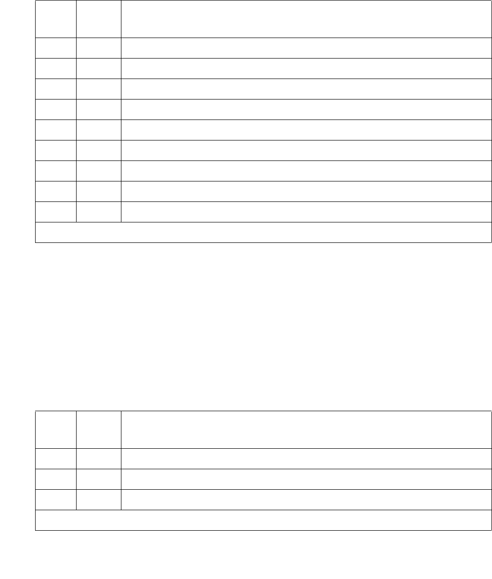
IPMEDPRO (TN2602AP IP Media Resource 320)
Issue 1 June 2005 1403
If the status is bad, the DSPs are taken out-of-service. A reset of the Aggregator hardware is
attempted, and if this is successful the DSPs are placed pack into service.
Packet Count Query #1630
This test is nondestructive.
This test sends a request for a count of packets received by the firmware from the LAN bus on
the TN2602AP IP Media Resource. This test is based on the Medpro DSP looparound test. The
Packet Count Query requests the packet count value from the IP Media Resource, runs the
looparound test on an available port, then requests a second packet count value from the IP
Media Resource. If the second value is greater than the first, then the packet bus is working. If
the second value is not greater than the first, then there is a problem with the packet bus.
Table 496: Test #1629 Aggregator Hardware Query
Error
Code
Test
Result
Description / Recommendation
2000 ABRT Response was not received within the allowable time
2012 ABRT System call failed
2100 ABRT Could not allocate the necessary system resources to run this test
2500 ABRT Internal system error
1 FAIL Reset- not initialized
2 FAIL Heartbeat failure
5 FAIL Aggregator stuck in reset
6 FAIL Aggregator disabled
255 FAIL Internal error
Table 497: Test #1630 Packet Count Query
Error
Code
Test
Result
Description / Recommendation
1000 ABRT Could not seize port for maintenance
1001 ABRT Connection manager could not seize the port
1002 ABRT No time slots available
1 of 2

Communication Manager Maintenance-Object Repair Procedures
1404 Maintenance Procedures for Avaya Communication Manager 3.0, Media Gateways and Servers
1003 ABRT No tone receivers available
1007 ABRT Port not translated
1014 ABRT Board not translated
1115 ABRT No in-service port available for testing
1139 ABRT Packet Bus in Port Network is out-of-service
1144 ABRT PPN Packet Bus is out-of-service
2000 ABRT Response was not received within the allowable time
2012 ABRT System call failed
2100 ABRT Could not allocate the necessary system resources to run this test
2500 ABRT Internal system error.
2801 ABRT The TN2602 has not been administered correctly (no IP address found)
2807 ABRT IP interface disabled on IP-INTERFACE form
6 FAIL System link down and not available for use
2060 FAIL Packet Bus link is down
Any FAIL The test did not detect the test tone
0No
Board
No board was detected by the test
Table 497: Test #1630 Packet Count Query (continued)
Error
Code
Test
Result
Description / Recommendation
2 of 2

IPSV-CTL (Ipserver Interface Control)
Issue 1 June 2005 1405
IPSV-CTL (Ipserver Interface Control)
S8700 | 8710 / S8500
The TN2312AP IPSI and TN2312BP circuit packs are duplicated in a high- or critical-reliability
system. As part of duplicated IPSIs, PKT-INTs, Archangels, and Tone-Clocks are also
duplicated. However, to simplify recovery algorithms, only one IPSI can be “active” in a given
PN. The one exception to this rule is the IPSI’s tone-detection module. Both IPSIs may have
active tone detectors.
Note:
Note: The TN2312BP IPSI is a replacement for the TN2312AP IPSI and can be used
anywhere a TN2312AP is used. The TN2312AP is not compatible with CMC1and
G650 media gateways.
During an IPSI interchange, the IPSI’s PKT-INTs, Archangels, and Tone-Clocks are temporarily
distributed between the two IPSIs. During stable operation, the active PKT-INT, Archangel, and
Tone-Clock must all reside on the same IPSI.
S8700 IP: In an S8700 IP-connect configuration, IPSI capabilities are provided by a single IPSI,
not shared by two IPSIs. All IPSI capabilities that are functioning are provided by a single IPSI in
an IP-connect configuration. This differs from multi-connect configurations in which the EAL can
be in an expansion interface (EI) circuit pack during a recovery operation. (S8700 IP-connect
configurations do not contain EI circuit packs.)
Each IPSI’s state of health (SOH) is based on the following elements in descending order of
priority:
Note:
Note: A low priority fault indicates a better state-of-health than a high priority fault. For
example, a clock fault on an IPSI is more severe that a PKTINT fault on an IPSI.
MO Name in
Alarm Log
Alarm
Level
Initial SAT Command to Run Full Name of MO
IPSV-CTL NA set ipserver-interface Ipserver Interface Control
Table 498: Fault classes and IPSI interchanges
Fault Class Circuit pack function that is monitored Priority
Clock Clocking signal for the TDM bus 1 (highest)
PKTINT Sending and receiving packet control messages 2
EAL Noting the state of the expansion archangel link (up or down) 3
Generation Generating tones 4 (lowest)

Communication Manager Maintenance-Object Repair Procedures
1406 Maintenance Procedures for Avaya Communication Manager 3.0, Media Gateways and Servers
The active media server’s maintenance software is responsible for maintaining the SOH of both
the active and standby IPSI in each PN. If an active IPSI’s SOH is lower than the standby’s, IPSI
interchange is initiated. The following list contains failures and actions that cause an
interchange:
Active IPSI has a faulty Tone-Clock.
1. IPSI’s hardware detects loss of clock, and its firmware initiates clock interchange.
2. IPSI’s firmware notifies software of loss of clock.
3. Software interchanges Archangel.
4. Software interchanges PKT-INT.
5. The port-network is COLD started.
Active IPSI has a faulty PKT-INT.
1. Software detects faulty PKT-INT.
2. Software interchanges PKT-INT.
3. Software interchanges Archangel.
4. Software interchanges Tone-Clock.
Active IPSI has a faulty Archangel.
1. PKT-INT detects dead EAL and reports it to software.
2. Software interchanges Tone-Clock.
3. Software interchanges Archangel.
4. Software interchanges PKT-INT.
Both IPSIs are healthy (planned interchange sequence).
1. Software interchanges Tone-Clock.
2. Software interchanges Archangel.
3. Software interchanges PKT-INT.
If both of a PN’s IPSIs have faulty Tone-Clock, then the PN is out of service.
If both of a PN’s IPSIs have faulty EAL and/or PKT-INT, then the PN “falls back” to EI-EAL mode
of operation, where:
●The PN’s Expansion Interface circuit pack (EI) provides Archangel functionality
●Another PN’s IPSI provides PKT-INT functionality
For details, see EXP-INTF (Expansion Interface Circuit Pack) on page 1176.
Table 499: IPSI A is Active on page 1407, Table 500: IPSI B is Active on page 1407,
Table 501: IPSI A Provides Tone-Clock; Fall-Back to EI-EAL on page 1407, and
Table 502: IPSI B Provides Tone-Clock; Fall-Back to EI-EAL on page 1407 show the valid
combinations of IPSIs and EIs providing Tone-Clock, PKT-INT, and Archangel functions.

IPSV-CTL (Ipserver Interface Control)
Issue 1 June 2005 1407
Table 499: IPSI A is Active
Function IPSI A IPSI B EI IPSI in Another PN
Tone-Clock X
PKT-INT X
Archangel X
Table 500: IPSI B is Active
Function IPSI A IPSI B EI IPSI in Another PN
Tone-Clock X
PKT-INT X
Archangel X
Table 501: IPSI A Provides Tone-Clock; Fall-Back to EI-EAL
Function IPSI A IPSI B EI IPSI in another PN
Tone-Clock X
PKT-INT X
Archangel X
Table 502: IPSI B Provides Tone-Clock; Fall-Back to EI-EAL
Function IPSI A IPSI B EI IPSI in Another PN
Tone-Clock X
PKT-INT X
Archangel X

Communication Manager Maintenance-Object Repair Procedures
1408 Maintenance Procedures for Avaya Communication Manager 3.0, Media Gateways and Servers
System Configurations with Duplicated IPSIs
Figure 76 shows a critical-reliability system with duplicated IPSIs and directly connected PNCs.
Figure 77: Duplicated IPSI Duplicated PNC with Center Stage Switch Connectivity on
page 1409 shows a critical-reliability system with duplicated IPSIs and CSS-connected PNCs.
Table 503: Cabinets that support IPSI and IPSI duplication on page 1409 shows a complete list
of cabinets.
Figure 76: Duplicated IPSI Duplicated Direct Connect PNC Connectivity
PKT-INT
AAT/C
IPSI A
PN 1
EI
EI
EI
EI
EI EI EI EI
EI EI EI EI
MAINT/
Test
PORT CARRIER
PORT CARRIER
PN 2 PN 3
T/C AA PKT-INT
IPSI B
LAN
TDM
TDM
LAN

IPSV-CTL (Ipserver Interface Control)
Issue 1 June 2005 1409
Figure 77: Duplicated IPSI Duplicated PNC with Center Stage Switch Connectivity
Table 503: Cabinets that support IPSI and IPSI duplication
Cabinet type Supported IPSI Duplication
TN2312AP TN2312BP Primary slot Secondary slot
SCC1 EPN Stack Y Y A00 B01
1 of 2
CSS A
CSS B
PN
IPSI A
IPSI B
Switch Node Switch Node
Switch Node Switch Node
T/C AA PKT-INT
Maint/
Test
TDM
LAN
EI
EI EI
EI EI
EI EI
EI EI
EI
S
N
I
S
N
I
S
N
I
S
N
I
S
N
I
S
N
I
S
N
I
S
N
I
S
N
I
S
N
I
S
N
I
S
N
I
S
N
I
S
N
I
PN 1 PN n PN n+m PN 64
T/C AA PKT-INT
...
LAN
TDM
...

Communication Manager Maintenance-Object Repair Procedures
1410 Maintenance Procedures for Avaya Communication Manager 3.0, Media Gateways and Servers
MCC1 EPN - 1 PN Y Y A00 B01
MCC1 EPN - 2 PNs Y Y A00 B01
E02 D01
MCC1 EPN - 3PNs Y Y A00 N/A
B02 N/A
D02 N/A
MCC1 EPN - 4 PNs Y Y A00 N/A
B02 N/A
C02 N/A
D02 N/A
MCC1 EPN - 5 PNs Y Y A00 N/A
B02 N/A
C02 N/A
D02 N/A
E02 N/A
G600 Y Y A02 N/A
CMC1 PN N Y A02 N/A
G650 Stack N Y A01 B01
Table 503: Cabinets that support IPSI and IPSI duplication (continued)
Cabinet type Supported IPSI Duplication
TN2312AP TN2312BP Primary slot Secondary slot
2 of 2
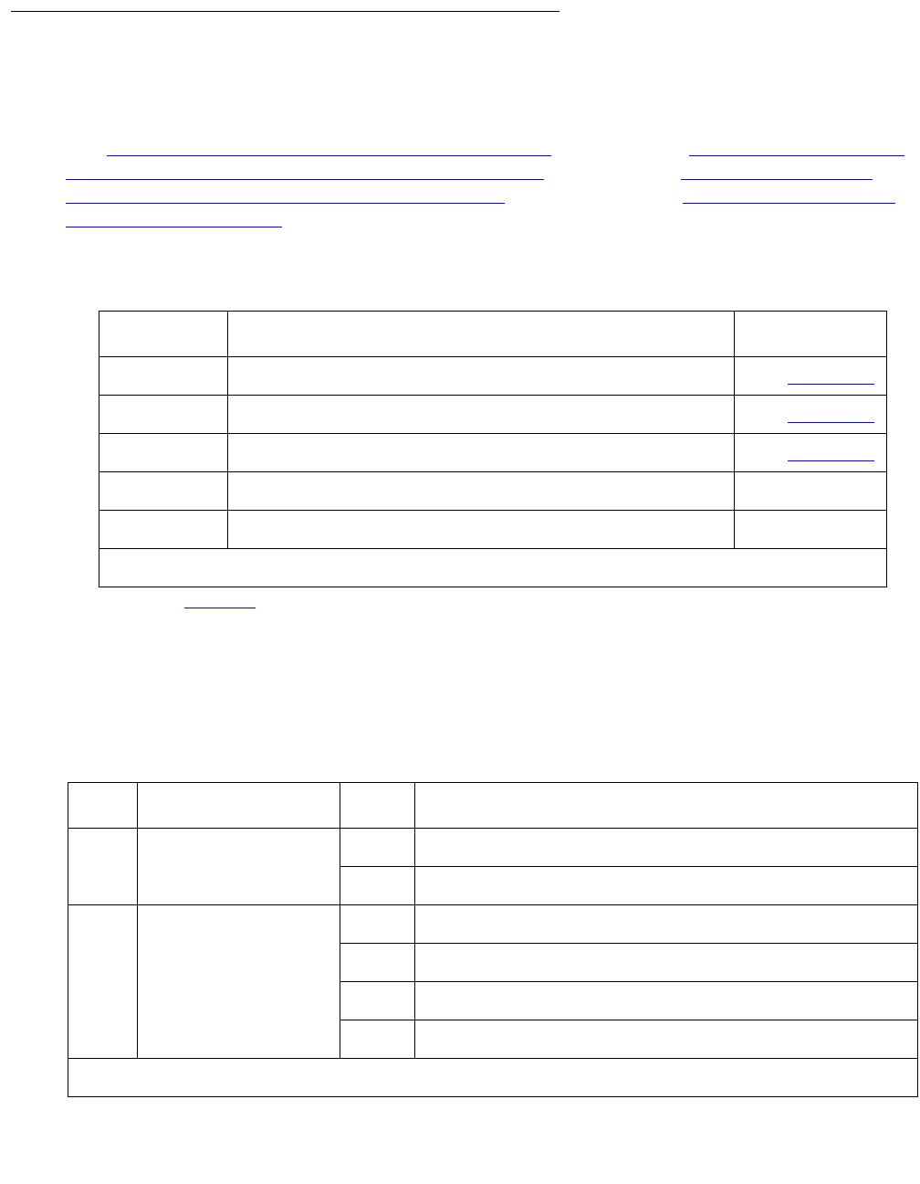
IPSV-CTL (Ipserver Interface Control)
Issue 1 June 2005 1411
Error Log Entries
Whenever an IPSI interchange takes place, an error is logged against IPSV-CTL with a code
that conveys information about the cause of the interchange and which IPSI became active.
Use Table 504: Error Code Descriptions and Aux Data on page 1411, Table 505: Encoding of
Error Codes for Software Requested IPSI interchange on page 1411, Table 506: Aux Data
Descriptions for Software-Requested Interchange on page 1412, and Table 507: Error codes
for set ipserver-interface on page 1413 to help identify areas of the Alarm Log to investigate to
find the source of the problem.
Error Codes for Software-Requested Interchanges
Table 504: Error Code Descriptions and Aux Data
Error Code Description Aux Data
3wxyz1
1. See Table 505 for encoding of the wxyz digits of the error code.
Software requested IPSI interchange / control change2
2. Control change is moving the Archangel’s functionality to or from the IPSI.
See Table 506
50000 Craft demand interchange of IPSI to A side See Table 506
51000 Craft demand interchange of IPSI to B side See Table 506
60000 Daily interchange of IPSI to standby failed 0
61000 Daily interchange of IPSI back to previous active failed 0
Table 505: Encoding of Error Codes for Software Requested IPSI interchange
Field Variable Name Value Description
w Active IPSI post
action
0 The A-side IPSI is active after the interchange.
1 The B-side IPSI is active after the interchange.
x Control (Archangel)
pre and post action
0 Control on IPSI before and after the interchange.
1 Not in IPSI control before and after the interchange.
2 Control leaves IPSI.
3 Control moves to IPSI.
1 of 2
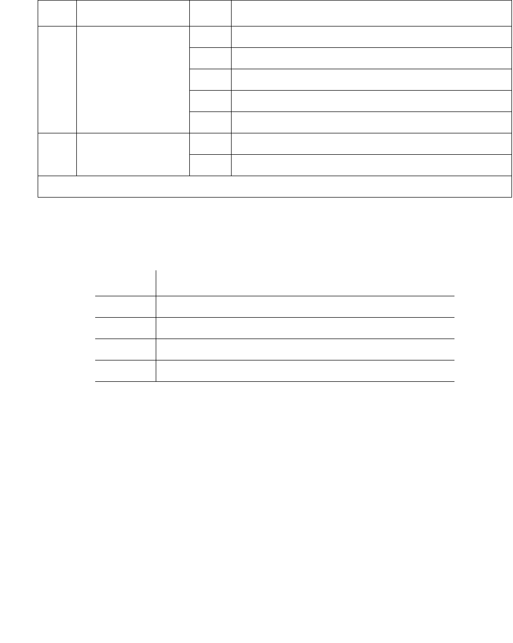
Communication Manager Maintenance-Object Repair Procedures
1412 Maintenance Procedures for Avaya Communication Manager 3.0, Media Gateways and Servers
AUX Data Descriptions
Examples:
Error Code of 30320 with Aux Data 2 software requested the archangel move to the A-side IPSI
as a result of a PKT-INT fault class improvement.
Error Code of 31041 with Aux Data 1 indicates a software requested interchange from the
A-side IPSI to the B-side IPSI leaving the archangel on the IPSI due to a loss of TDM clock.
y Fault class/stimulus
causing software
action
1 EAL fault class
2 PKT-INT fault class
3 TONE-BD fault class (not TDM-CLK)
4 TDM-CLK fault class (loss of clock)
7 Preference migration to A-side IPSI
z Fault or
improvement
0 This is an improvement in the previous fault class (y).
1 This is a degradation of the previous fault class (y).
Table 505: Encoding of Error Codes for Software Requested IPSI interchange (continued)
Field Variable Name Value Description
2 of 2
Table 506: Aux Data Descriptions for Software-Requested Interchange
Aux Data Description
0 No specific extra information is available
1 An IPSI interchange only took place
2 A control change only took place
3 Both an IPSI interchange and a control change took place

IPSV-CTL (Ipserver Interface Control)
Issue 1 June 2005 1413
IPSI Interchange (Duplicated IPSIs)
Software will take action upon any fault that affects the IPSI and attempt to interchange to the
healthier IPSI. In addition, when neither IPSI is completely healthy to provide clock, packet
interface and archangel, one IPSI will be chosen to be the clock, and the archangel will move to
the EI. Moving the archangel’s functionality to the EI requires another port network to have a
healthy IPSI, and this port network to have an EI. The exact order of action taken will vary
depending on the fault being processed, as well as the existing state of health (SOH) of the
IPSIs in the PN. An IPSI interchange (if necessary) will always happen before a control change
(moving of the archangel to/from IPSI/EI). If both IPSIs are equally healthy, software
preferentially migrates to the A-side IPSI. However, this preferential migration is not done if craft
has set to a B-side IPSI.
Craft can also demand an interchange of IPSIs in one or every PN from the SAT. The command
set ipserver-interface Uc is used to interchange a specific IPSI. In addition, set
ipserver-interface a-all | b-all can be used to interchange every IPSI in the
system to the A-side or B-side respectively. This is particularly useful if preparing for a
control-network outage. For a planned interchange of IPSIs, the following steps occur. The:
1. Going active IPSI is marked as active, the going standby is marked as standby.
2. Tone-Clock is migrated. This includes tone generation as well as TDM clock.
3. Archangel is migrated to the newly active IPSI.
4. PKT-INT on the newly active IPSI is made active. Every link is migrated between IPSIs.
See Table 507: Error codes for set ipserver-interface on page 1413 for ABORT/FAIL codes
associated with set ipserver-interface:
Table 507: Error codes for set ipserver-interface
Error
Code
Command
Result
Description
2343 ABRT Interchange not permitted. The anti-thrashing timer has not yet
expired.
1. Retry command in 30 seconds.
2338 FAIL The SOH of the set-to IPSI is bad. Use list ipserver-interface
to display the current IPSI’s SOH.
2341 FAIL An error occurred during the interchange.
2342 FAIL The set-to IPSI has been busied out.
1. Run release ipserver-interface Uc.
PASS The interchange was successful, or the set to IPSI was already active.
If set to a B-side IPSI, it will be marked as “craft set” and will not
preference switch back to the A-side by software.

Communication Manager Maintenance-Object Repair Procedures
1414 Maintenance Procedures for Avaya Communication Manager 3.0, Media Gateways and Servers
An example of the output of the list ipserver-interface command is:
The State of Health information contains the fault class information in the far right columns as
follows:
●C = Clock
●P = Packet Interface
●E = Expansion Archangel Link
●G = Tone Generation
list ipserver-interface
IP SERVER INTERFACE INFORMATION
Port Pri/ Primary/ Primary/ Primary/ State Of
Ntwk Sec Secondary Secondary Secondary Serv Control Health
Num Bd Loc IP Address Host Name DHCP ID State State C P E G
---- ------ --------------- ---------------- --------- ----- ------- -------
2 2A01 172.18.18.181 172.18.18.181 ipsi-A02a IN actv-aa 0.0.0.0
3 3A02 172.18.18.182 172.18.18.182 ipsi-A03a IN actv-aa 0.0.0.0
8 8A02 192.168.18.40 192.168.18.40 ipsi-A08a IN actv-aa 0.0.0.0
15 15A02 172.18.18.34 172.18.18.34 ipsi-A15a IN actv-aa 0.0.0.0
45 45A02 172.17.17.60 172.17.17.60 ipsi-A45a IN actv-aa 0.0.0.0
51 51A02 172.18.18.81 172.18.18.81 ipsi-A51a IN actv-aa 0.0.0.0

IP-SVR (IP Server Interface)
Issue 1 June 2005 1415
IP-SVR (IP Server Interface)
S8700 | 8710 / S8500
TN2312 IP Server Interface Circuit Pack
Note:
Note: The only error type reported against this MO is error Type 18. All other error types
will be reported against MOs supporting the IPSI circuit pack functional modules,
PKT-INT, IPSV-CTL, ETR-PT, TDM-CLK, TONE-PT, TONE-BD, SER-BUS,
CAB-EXFR, EXT-DEV, CAB-PFL, POW-SUP, CAB-TEMP, PS-RGEN,
CAB-CALM, and CAB-MTCE.
The TN2312 IPSI circuit pack is used by S8700 systems to connect the port networks to the
media servers via an IP network and provide port-network control functions.
The TN2312 IPSI is inserted into the PN’s Tone-Clock slots and provides interface back to the
media servers via Ethernet. See the following list of IPSI circuit-pack functions:
●PKT-INT packet-bus interface
●Archangel TDM-bus interface
●Tone-Clock functionality (equivalent to TN2182C Tone-Clock circuit pack)
●Ethernet interface for connectivity to the media servers
●Ethernet interface for connectivity to Services’ laptop PCs
●Maintenance-board interface for communication with the PN’s TN775 Maintenance board
(TN2312AP)
●Environmental maintenance (TN2312BP)
For S8700 systems, the processors, and the PKT-INTs reside in different cabinets, connected to
each other via the control networks. All communication between the media servers and the
IPSIs are done over TCP/IP Socket connections. Other than the Ethernet that connects the
media servers to the IPSIs, there are no other leads for signaling and resets. All communication
between the media servers and the IPSIs must be done via messages over the socket
connections.
Each IPSI’s state of health (SOH) is kept with the following elements in descending order of
priority:
MO Name in
Alarm Log
Alarm
Level
Initial SAT Command to Run Full Name of MO
IP-SVR WRN busyout/release ipserver-interface IP Server Interface
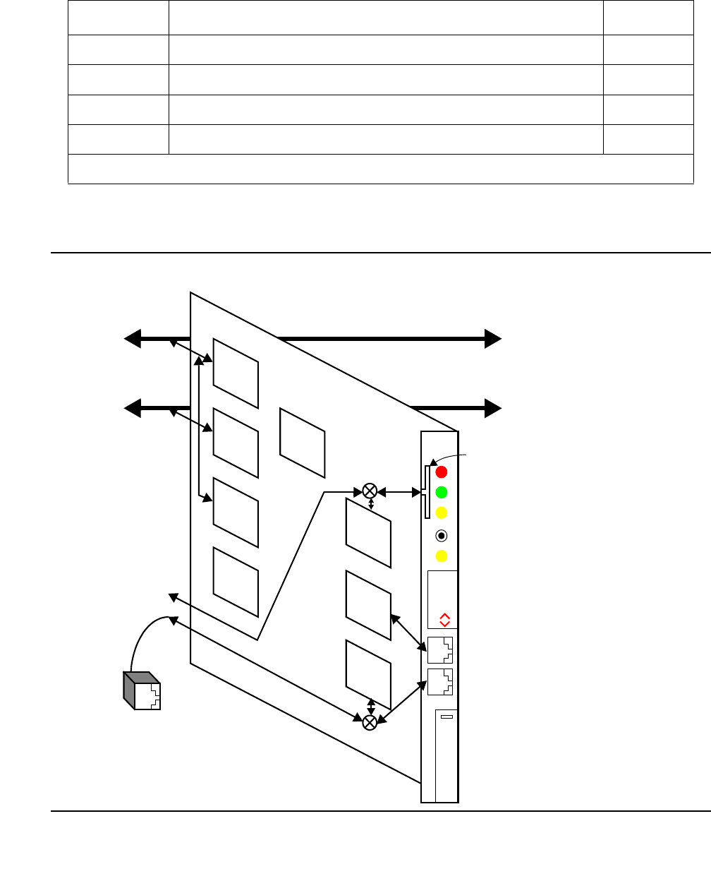
Communication Manager Maintenance-Object Repair Procedures
1416 Maintenance Procedures for Avaya Communication Manager 3.0, Media Gateways and Servers
TN2312AP IP Server Interface (IPSI)
Figure 78: TN2312AP IPSI
Table 508: IPSI state-of-health components
Fault Class Circuit pack function that is monitored Priority
Clock Clocking signal for the TDM bus 1 (highest)
PKTINT Sending and receiving packet control messages 2
EAL Noting the state of the expansion archangel link (up or down) 3
Generation Generating tones 4 (lowest)
Spitfire2
TDM Bus
Packet Bus
TN2312AP
Clock Status LED (Amber)
Push Button Switch
Circuit Pack Alarm LED (Red)
In Use LED (Amber)
Test In Progress LED (Green)
A
0
1
Switch ID (One character)
Cabinet Number (Two digits)
Ethernet Link Status
Services Interface (RJ45)
Control Network Interface (RJ45)
IP Server Intfc
(Top bar for Services Interface,
LANIS
NCEs
DSP
MPC8260
Ethernet
Ethernet
RS232 +
Control Network Interface (RJ45)
Maintenance
Board
Maintenance Board Interface
Interface
Clocks
Bottom bar for Control Network)

IP-SVR (IP Server Interface)
Issue 1 June 2005 1417
Control Network Interface
This is a 10/100 BaseT Ethernet interface used to connect to the Control network. This interface
is available through the backplane I/O as well as through the faceplate. When the IPSI I/O
adapter is plugged onto the Amphenol connector, located on the rear of the carrier, the
backplane connections will be selected, otherwise, connectivity to the faceplate will be selected.
For the PN control carriers, the backplane connections are available only when the new PN
control carriers are used.
Services Interface
This is a 10/100 BaseT Ethernet interface accessible from the faceplate for services personnel
to configure the IPSI firmware (IP address settings), access the SAT, and to debug the control
network connectivity (ping, traceroute, etc.).
PN’s Maintenance Board Interface (TN2312AP)
This interface consists of RS232 transmit and receive leads and reset leads that connect to the
PN’s TN775D Maintenance board via the faceplate or the backplane. Communication Manager
talks to the Maintenance board via the IPSI’s archangel through this interface for cabinet
maintenance (cabinet temperature, voltage, emergency transfer and etc.). This interface also
allows the Maintenance board to reset the IPSI board when it detects insanity of the IPSI’s
archangel. When the ribbon cables are connected between the IPSIs and the PN’s TN775D
Maintenance board, the faceplate connections are selected, otherwise the backplane
connections are used. The backplane connections are available only when the new backplane
is used. This connection will not support the RS-232 SAT connection via the PN’s Maintenance
board.
Environmental maintenance (TN2312BP)
The TN2312BP IP Server Interface (IPSI) provides environmental maintenance and is the only
IP server interface that is supported in the G650. A TN2312BP can only be placed in a G650
with a carrier address set to A or B. Only a TN2312BP in a G650 with a carrier address set to A
provides environmental maintenance. The TN2312BP is backward compatible with the
TN2312AP, but provides environmental maintenance only when used in a G650. The
TN2312BP always provides tone detection, call classification, tone generation, and clock
functions.
When the TN2312BP is used in an MCC1or SCC1, a TN775D provides the environmental
maintenance.
The TN2312BP provides environmental maintenance for the G650. This includes:
●External device alarm detection
●Emergency transfer control
●Customer-provided alarm device control

Communication Manager Maintenance-Object Repair Procedures
1418 Maintenance Procedures for Avaya Communication Manager 3.0, Media Gateways and Servers
The TN2312BP and the 655A power supply provide the following information to the G650:
●Environment maintenance
- Inlet temperature - Inlet temperature of the G650 (sensor is in the 655A power supply)
- Exhaust temperature - G650 carrier exhaust air sensor
- Hot Spot temperature status- 655A power supply sensor
-Voltage
-+5VDC
--5VDC
--48VDC
- Fan Control - The speed at which the fans are operating:
- Undr indicates that the fan voltage is under 12VDC.
- Mid (normal) indicates that the fan voltage is +12VDC.
- High indicates that the fan voltage is +14VDC.
- Over indicates that the fan voltage is above 14 to 15VDC.
- Fan Alarm - Detection of a blocked or failed fan
- Ring Status - OK, overload, shorted, or failed
- Ring Control - Active, standby, disabled, off (shorted or failed)
- Ringer Setting - 20Hz, 25Hz, or other
- Ring Detection - Reports if the power supply detects ring on the backplane ring leads
- Input Power - Indicates the type of power present and in use, AC or DC
●External device alarm detection
The external device alarm detection uses two external leads. External devices such as an
uninterruptible power supply (UPS) or voice messaging system can use these leads to
generate alarms using the Avaya Communication Manager alarm reporting capability.
Ground potential on either of these leads results in an alarm being generated. You can
administer the alarm level (major, minor, or warning), product ID, alternate name, and alarm
description for each lead.
●Emergency transfer control
Emergency transfer control provides -48VDC to operate an external emergency transfer
panel. The Communication Manager controls the state of the emergency transfer. (Note
that, in the past, hardware boards or alarm panels provided a three-position physical switch
to control emergency transfer.) An emergency transfer status red LED shows when
emergency transfer is active.

IP-SVR (IP Server Interface)
Issue 1 June 2005 1419
You can use the following Communication Manager SAT commands for emergency
transfer:
-set emergency-transfer on|off|auto - Use this to set emergency transfer to on
(not in emergency transfer), off (in emergency transfer), or auto (emergency transfer is
controlled by Communication Manager).
-status cabinet nn - Use this to verify the current setting of emergency transfer.
When the emergency transfer is set to other than auto an alarm is generated.
●Customer provided alarm device (CPAD) control
CPAD provides a contact closure across a pair of external leads that can be used to control
a customer-provided alarm device or an alarm indicator. The level of alarm (major, minor,
warning, or none) that causes a contact closure can be administered system wide. When
the alarm level matches the alarm level that was administered, the TN2312BP closes this
contact. When the TN2312BP is in emergency transfer, this contact is closed to activate the
CPAD.
●Tone Detection / Call Classification
The TN2312BP provides eight ports of tone detection and call classification. The
TN2312AP provides the same functionality.
●Tone/Clock functions
The TN2312BP generates tones and provides clock functions for the port network in which
it is placed. (The TN2312AP provides the same functionality.) This functionality is equivalent
to the TN2182B Tone/Clock circuit pack.
TDM-Bus Interface
The TDM bus is used by four different functions on the IPSI board:
1. When the Archangel module is activated, it uses the Spitfire2 device to be the bus master of
the TDM bus. The Archangel uses this interface to talk to the other port boards’ angels on
the TDM bus.
2. In angel mode, the Tone-Clock angel uses the Spitfire2 device to talk to an off-board
Archangel.
3. The Tone Generator uses the Spitfire2 device to put tones on the TDM bus.
4. The Tone Detector uses the NCE device to receive TDM bus time slots for tone detection.
Packet Bus Interface
When the PKT-INT module is activated, it uses the LANIS device to talk and listen on the packet
bus.
System Clock Interface
The Clock module uses the Spitfire2 device to generate clock pulses for the backplane.

Communication Manager Maintenance-Object Repair Procedures
1420 Maintenance Procedures for Avaya Communication Manager 3.0, Media Gateways and Servers
IPSI Circuit Pack Faceplate
The faceplate view of the TN2312AP IPSI is shown in Figure 78: TN2312AP IPSI on
page 1416 and described in the following sections.
IPSI LEDs
There are four LEDs on the TN2312AP IPSI faceplate, and five LEDs on the TN2312BP IPSI
faceplate. The top three LEDs are the standard ones found on most TN circuit packs. The fourth
LED imitates the TN2182B Tone-Clock’s amber LED. In addition, the TN2312BP has a fifth LED
that shows the emergency transfer control status. The following table describes the IPSI’s LED
operation.
Table 509: IPSI LEDs
Function LED State Description
Standard
circuit pack
status
Red On/Off TN2312AP circuit pack alarm (controlled by
both the PKT-INT and the Tone-Clock Angel;
combined by a logical “or”)
Green On/Off TN2312AP test in progress (controlled by both
the PKT-INT and the Tone-Clock Angel;
combined by a logical “or”)
Amber Off Archangel inactive
Flashing
2 sec on
0.2 sec off
Archangel active
1 of 2

IP-SVR (IP Server Interface)
Issue 1 June 2005 1421
Push-Button Switch
The push-button switch is used to administer the switch ID and the cabinet number of the IPSI.
This button can also be used to erase the manually programmed IP address. Inserting the IPSI
board with the button pressed or just resetting it while the button is pressed will keep the IPSI in
boot mode.
Clock status
TN2312BP,
(same as
TN2182B)
Amber Flashing
2.7 sec on
0.3 sec off
Active: Master clock, using offboard
synchronization source.
Winking
0.3 sec on
2.7 sec off
Active: Master clock, using its local reference
source.
Steady on Active: Board has been reset and is providing
clocks but has not been told which
synchronization source to use.
Steady off Standby: Applying no tones to the network.
“Jingle Bells”
Green and Amber
0.1 sec on, 0.2
sec off,
0.1 sec on, 0.4
sec off,
0.4 sec on, 0.4
sec off
Standby: Tone generator is being used.
Double blink
Amber
0.3 sec on, 0.3
sec off,
0.3 sec on, 2.4
sec off
Active: Lost all external references and is in
holdover mode.
Random Standby: This LED may come on and off
intermittently as ETR-PTs on the board are
used for tone-detection services.
Emergency
transfer
(TN2312BP)
Red On Emergency transfer is active.
Off Emergency transfer is inactive.
Table 509: IPSI LEDs (continued)
Function LED State Description
2 of 2

Communication Manager Maintenance-Object Repair Procedures
1422 Maintenance Procedures for Avaya Communication Manager 3.0, Media Gateways and Servers
4-Character LED
The 4-character LED is used to display the circuit pack status related to the Ethernet interfaces.
If automatic IP address assignment via DHCP is enabled, the top character displays the Switch
ID and the next two characters display the Cabinet Number. The last character is used to
display the link status of the two Ethernet interfaces.
Services Interface
The top RJ45 jack is the services interface. This is a 10/100 BaseT Ethernet interface.
Control Network Interface
The bottom RJ45 jack is the control network interface. This is a 10/100 BaseT Ethernet
interface. This interface is active only when the IPSI I/O adapter is not plugged onto the
Amphenol connector, located on the rear of the carrier.
PN’s Maintenance Board Interface
The PN’s Maintenance board interface is a header on the IPSI circuit pack with a slit on the
faceplate of the IPSI for the ribbon cable to connect to the PN’s TN775D Maintenance board.
Error Log Entries and Test to Clear Values
System Technician-Demanded Tests:
Descriptions and Error Codes
There is no system technician demand test for this MO.
Table 510: LIC-ERR Error Log Entries
Error Type Aux
Data
Associated Test Alarm
Level
On/Off
Board
Test to Clear Value
18
The IPSI circuit pack
is busied out by
maintenance
personnel.
0busyout
ipserver-in
terface
location
WRN OFF release
ipserver-interface
location

ISDN-PLK (ISDN-PRI Signaling Link Port)
Issue 1 June 2005 1423
ISDN-PLK (ISDN-PRI Signaling Link Port)
S8700 | 8710 / S8500 / S8300
This MO was formerly known as “ISDN-LNK (ISDN-PRI Signaling Link Port)”. For related
information, see UDS1-BD (UDS1 Interface Circuit Pack) on page 2374.
Note:
Note: See the figures in the ISDN-SGR (ISDN-PRI Signaling Group) on page 1429
section of this chapter for an illustration of the principles described below.
The ISDN-PRI interface uses out-of-band signaling (as opposed to robbed-bit, in-band
signaling) to transmit control messages between two endpoints. User information channels
carry digitized voice and digital data and are known as bearer channels (B channels). B
channels are assigned to DS1 ISDN trunks or PRI endpoints. Call-control signaling for the B
channels is combined and carried over the separate ISDN-PRI Signaling Link Port D channel.
The ISDN-PRI Signaling Link Port (ISDN-LNK) is a port on a TN464C or higher suffix UDS1
Interface circuit pack that has a direct interface to the packet bus that carries D-channel
messages to the processor. The associated B channels can use ports on the same circuit pack
or ports on other TN464C or higher suffix or TN767 DS1 Interface circuit packs. (The TN722
cannot be used for this application). The B channels are connected to the TDM Bus.
Note:
Note: S8300 / G700: Although the ISDN-PLK MO is provided for a G700 media gateway,
this MO only partially supports the G700’s MM710 DS1 media module.
Two types of DS1 interfaces exist:
●24 DS0 channels on a 1.544-Mbps link
●31 DS0 channels + 1 framing channel on a 2.048-Mbps link
In a 32-channel system, the DS1 ISDN Trunk or PRI endpoint port (B-channels) may use any of
the ports 1-15 or 17-31, but the ISDN-PRI Signaling Link Port must be the 16th port on the
TN464F/GP circuit pack. In certain configurations (NFAS), the 16th port may be used as a
B-channel. Refer to ISDN-SGR (ISDN-PRI Signaling Group) on page 1429 for further details.
The TN767 DS1 interface is used for 24 channel 1.544 Mbps systems. The TN464F/GP can be
used for either 24 or 32 channel systems. The 32-channel (31 DS0 channels + 1 framing
channel on a 2.048 Mbps link) are only supported on TN464 series circuit packs. A description
of these circuit packs appears in DS1-BD or UDS1-BD maintenance documentation.
MO Name in Alarm
Log
Alarm
Level
Initial Command to Run1
1. For this MO, location is 24 for 24-channel interfaces and 16 for 32-channel interfaces.
Full Name of MO
ISDN-LNK MIN test port location lISDN-PRI Signaling Link port
ISDN-LNK WRN test port location sh ISDN-PRI Signaling Link port
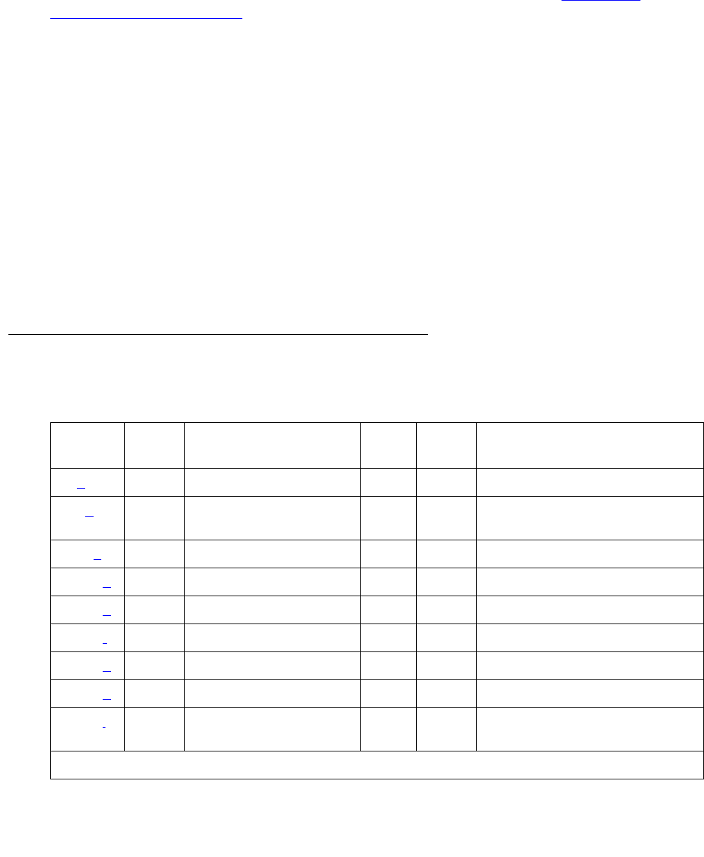
Communication Manager Maintenance-Object Repair Procedures
1424 Maintenance Procedures for Avaya Communication Manager 3.0, Media Gateways and Servers
In a 24-channel system, the DS1 ISDN Trunk or PRI endpoint port (B-channels) may use any of
the first 23 ports. The ISDN-PRI Signaling Link Port must be the 24th port. In certain
configurations (NFAS), the 24th port may be used as a B-channel. Refer to ISDN-SGR
(ISDN-PRI Signaling Group) on page 1429 for further details.
A problem with an ISDN-LNK will affect every associated B channel since, without it, no
call-control information can be conveyed to the far-end switch or to a terminal adapter. Stable
calls may remain operational, but no new calls can be placed. In turn, the ISDN-LNK depends:
●S8700 | 8710 / S8500: For systems supporting circuit packs:
●On the TN464C or higher suffix UDS1 Interface circuit pack where it resides
●On the packet bus that provides the link to the processor
●S8700 | 8710 / S8500 / S8300: For systems supporting media modules:
●On the MM710 Media Module that provides the link to the processor
If there are problems with the ISDN-LNK, also investigate the TN464C or higher suffix UDS1
Interface circuit pack (UDS1-BD) and the packet bus (PKT-BUS) for systems supporting circuit
packs (S8700 | 8710 / S8500), or investigate MG-DS1 (MM710 DS1 Interface Media Module) for
systems supporting media gateways (S8700 | 8710 / S8500 / S8300).
Error Log Entries and Test to Clear Values
Table 511: ISDN-PRI Signaling Link Port Error Log Entries
Error
Type
Aux
Data
Associated Test Alarm
Level
On/Off
Board
Test to Clear Value
0 (a) 0 Any Any Any test port location1
1. location is 24 for 24-channel interfaces and 16 for 32-channel interfaces.
18 (b)0 busyout port
location1WRN OFF release port location1
130 (c) None WRN ON test port location1
1537 (d) 46210 WRN OFF
1793 (e)test board location l
3585 (f) 46222 MIN ON
3841 (g) 46211
3842 (h) 46223
3843 (i) Signaling Port LAN
Loop-Back (#939) test port location1 l

ISDN-PLK (ISDN-PRI Signaling Link Port)
Issue 1 June 2005 1425
Notes:
a. Error Type 0: run the short test sequence first. If every test passes, run the long test
sequence. Refer to each appropriate test’s description, and follow its recommended
procedures.
b. Error Type 18: The D channel is demand busied out. No calls can be made over this
D channel.
c. Error Type 130: the circuit pack or media module has been removed or has been insane for
more than 11 minutes. To clear the error, reinsert or replace the circuit pack or media
module.
d. Error Type 1537: Link error. This error occurs when the port receives an invalid frame over
the D channel. This error normally indicates an off-board problem usually related to
transmission errors on the DS1 facility. Execute list measurements ds1-log for the
UDS1 TN464 circuit pack or MM710 Media Module where the D channel resides. If the
UDS1 or MG-DS1 is reporting some errors, then the DS1 facility has experienced
transmission problems that could have caused the ISDN-LNK to report a Link Error.
If the UDS1 or MG-DS1 is not reporting errors, execute the long test sequence for the D
channel. Investigate any errors. If there are none, execute a long test sequence for the
UDS1 circuit pack (UDS1-BD) or MM710 Media Module (MG-DS1). Investigate any errors.
If no errors could be found by testing, the Link Error is probably not affecting service.
However, if this Link Error continues to be logged, follow normal escalation procedures.
e. Error Type 1793: UDS1 Interface circuit pack or MM710 DS1 Interface Media Module is out
of service. Look for and resolve UDS1-BD or MG-DS1 errors in the Hardware Error Log.
f. Error Type 3585: transmit FIFO Overflow error. The circuit pack is having problems
transmitting data to the packet bus, thus affecting the conveyance of signaling information
over the D channel. Specifically, this error occurs when the packet-bus transmit buffers
overflow. This condition probably indicates a hardware problem.
The actual alarming level will depend on the options chosen via set options on the
G3-MT terminal. ISDN-PRI Signaling Link port alarms are treated as Station alarms, and
their default alarming option is to downgrade every alarm to Warning. The value shown in
the preceding table indicates the normal, unfiltered case (option “y” on the set options
screen).
G700: This error type does not occur on the G700.
g. Error Type 3841: Bad DLCI error. This error occurs when a LAPD frame is received across
the DS1 facility that contains a DLCI that does not have a valid entry in the on-board
translation memory. This error normally indicates an off-board problem usually related to a
broken endpoint or a state mismatch between a remote endpoint and the local
call-processing software. Maintenance will not start any testing or generate any alarms in
response to this error.

Communication Manager Maintenance-Object Repair Procedures
1426 Maintenance Procedures for Avaya Communication Manager 3.0, Media Gateways and Servers
h. Error Type 3842: Receive FIFO Overflow error. This error occurs when the circuit pack or
media module detects an overflow of its receive buffers. If it occurs frequently, it may
indicate a LAPD parameter mismatch between the two endpoints of a packet-switched
connection. LAPD should be able to recover from this problem, but it may degrade the
performance of the LAN bus. Maintenance will not start any testing or generate any alarms
in response to this error.
i. Error Type 3843: This error occurs when the Signaling Port LAN Loop-Back test (#939)
fails. Run the long test sequence and pay particular attention to the results of Test #939.
G700: For this error type, the associated test aborts with Error Code 1412 on the G700.
System Technician-Demanded Tests:
Descriptions and Error Codes
The command to test the ISDN-LNK MO is test port location where location is 24 for
24-channel interfaces and 16 for 32-channel interfaces.
Signaling Link Board Check (#643)
This test checks the health of the TN464C/D, TN464F/GP UDS1 Interface or MM710 DS1
Interface Media Module transporting the ISDN-PRI Signaling Link port.
Order of Investigation Short Test
Sequence
Long Test
Sequence
D/ND1
1. D = Destructive; ND = Nondestructive
Signaling Port LAN Loop-Back test (#939)
S8300 / G700: On G700, aborts with Error Code 1412.
XD
Signaling Link Board check (#643) X X ND
Table 512: Test #643 Signaling Link Board Check
Error
Code
Test
Result
Description / Recommendation
ABRT Internal system error
1. Retry the command at 1-minute intervals up to 5 times.
1 of 2

ISDN-PLK (ISDN-PRI Signaling Link Port)
Issue 1 June 2005 1427
Signaling Port LAN Loop-Back Test (#939)
This test is destructive.
Note:
Note: This test aborts with Error Code 1412 on the G700 Media Gateway.
This test verifies the connectivity of an ISDN-PRI signaling port (D channel) across the packet
bus, also known as the LAN bus. It will execute only if the port is out of service. Failure of this
test indicates a fault associated with the port hardware on the circuit pack.
1700 ABRT Rollabout video abort. The PRI terminal adapter associated with this
D-channel port is detached from the circuit pack. This is normal when the
rollabout video feature is enabled. To complete a test on this port:
1. Re-attach the disconnected PRI terminal adapter.
2. Enter change ds1 location to disable rollabout video on the
board, and set the “Alarm when PRI Endpoint Detached” field to y.
8 FAIL The UDS1 TN464C/D, TN464F/GP circuit pack is not in service.
1. Check the Hardware Error Log for entries logged against UDS1-BD,
and consult “UDS1-BD” for repair procedures.
PASS The UDS1 Interface circuit pack transporting the ISDN-PRI Signaling Link
Port is in service.
Any NO
BOARD The test could not relate the internal ID to the port (no board). This could be
due to incorrect translations, no board is inserted, an incorrect board is
inserted, or an insane board is inserted.
Ensure that the board translations are correct. Execute add ds1
location to administer the MM710 interface if it is not already
administered.
If the board was already administered correctly, check the error log to
determine whether the board is hyperactive. If this is the case, the board is
shut down. Reseating the board will re-initialize the board.
If the board was found to be correctly inserted in step 1, then enter
busyout board location.
Enter reset board location.
Enter release board location.
Enter test board location long.
This should re-establish the linkage between the internal ID and the port.
Table 512: Test #643 Signaling Link Board Check (continued)
Error
Code
Test
Result
Description / Recommendation
2 of 2

Communication Manager Maintenance-Object Repair Procedures
1428 Maintenance Procedures for Avaya Communication Manager 3.0, Media Gateways and Servers
Table 513: Test #939 Signaling Port LAN Loop back
Error
Code
Test
Result
Description / Recommendation
1015 ABRT The port is not in the out-of-service state. Use busyout port location
to place it in the out-of-service state and repeat this test.
!CAUTION:
CAUTION: The busyout prevents new call originations on every B
channel in the signaling group until the port is released.
1139 ABRT This port network’s packet bus is out of service.
1. Follow repair procedures for the packet bus.
2. Enter test port location long, and check results of this test
(#939).
1141 ABRT The Packet Interface circuit pack is out of service.
3. Follow repair procedures for PKT-INT.
4. Enter test port location long, and check results of this test
(#939).
S8300 /
G700:
1412
ABRT This test does not execute on a G700 media gateway.
2012 ABRT Internal system error.
1. Retry the command at 1-minute intervals up to 5 times.
2100 ABRT Could not allocate the necessary system resources to run this test.
1. Retry the command at 1-minute intervals up to 5 times.
FAIL The Loop-Back Test has failed.
1. If the test fails repeatedly, attempt to reset the circuit pack when the
other ports on the board are idle. Reset the circuit pack by entering
busyout board location and reset board location.
2. Repeat the test and, if it continues to fail, replace the circuit pack.
PASS Connectivity of the D channel over the packet bus is operational.

ISDN-SGR (ISDN-PRI Signaling Group)
Issue 1 June 2005 1429
ISDN-SGR (ISDN-PRI Signaling Group)
S8700 | 8710 / S8500 / S8300
An ISDN-PRI Signaling Group is a collection of B channels for which a given ISDN-PRI
Signaling Channel Port (D channel) carries signaling information. B channels carry voice or
data and can be assigned to DS1 ISDN trunks (ISDN-TRK) or PRI endpoint ports (PE-BCHL).
Note:
Note: Throughout this discussion, the term “B channel” refers to an ISDN-TRK or
PE-BCHL, depending on the application under investigation.
The following circuit packs/media modules are supported in the implementation of ISDN-PRI.
The TN464C/D UDS1 Interface circuit pack and MM710 DS1 Interface Media Module, which
have a direct interface to the packet bus, are required for D-channel signaling. There are two
types of DS1 interfaces:
●24 DS0 channels on a 1.544-Mbps link
●31 DS0 channels + 1 framing channel on a 2.048-Mbps link
The following discussion describes 24-channel interface signaling groups. The 32-channel
interface works the same way, except that only port number 16 is used for signaling instead of
port number 24. Ports 1 through 15 and 17 through 31 are used for B channels. The 32nd
channel (port 0) is always used for framing.
MO Name in
Alarm Log
Alarm
Level
Initial SAT Command to Run1
1. grp# is the signaling group number (1–166); the test sequence can be either short or long.
Full Name of MO
ISDN-SGR MIN test signaling-group grp# ISDN-PRI Signaling Group
ISDN-SGR WRN test signaling-group grp# ISDN-PRI Signaling Group
Circuit Pack/
Media Module
Channel Types Interface
MM710 B and D Channels 24 or 32 channel
TN464C/D B and D channels 24 or 32 channel
TN767 B channels 24 channel
TN464B B channels 32 channel
(G3r V2 only)
TN767B or later B channel with ISDN-PRI D-channel over PI-BD 24-channel
TN464F/GP B channel with ISDN-PRI D-channel over PI-BD 24- or 32-channel

Communication Manager Maintenance-Object Repair Procedures
1430 Maintenance Procedures for Avaya Communication Manager 3.0, Media Gateways and Servers
ISDN-PRI D-channel signaling can be combined with a group of B channels in three basic ways:
●FAS (facility-associated signaling)
●NFAS (non-facility-associated signaling)
●Backup NFAS signaling
In a FAS signaling group, the 24th port of the TN464 UDS1 Interface circuit pack or MM710 DS1
Interface Media Module carries D-channel signaling for up to 23 B-channel ports on the same
circuit pack or media module.
In an NFAS signaling group, the 24th port of one TN464C or higher suffix UDS1 Interface or
MM710 DS1 Interface Media Module can carry D-channel signaling for B channels on several
other DS1 circuit packs or DS1 Media Modules, as well, including TN767s and TN464Bs. The
24th port on the other circuit packs or media modules can be used as a B channel. A D channel
in an NFAS group can signal for B channels on a total of 20 DS1 circuit packs or media
modules.
D-channel backup provides increased reliability, which is highly desirable since NFAS permits a
D channel to signal for many more B channels. NFAS allows the administration of a backup D
channel that remains in a standby state until the active D channel goes down. If so, the backup
D Channel takes over and provides signaling for every B channel in the signaling group.
The operation of the entire ISDN-PRI signaling group depends on several other entities:
●S8700 | 8710 / S8500 / S8300: The ISDN-PRI signaling channel ports, the TN464 UDS1
Interface circuit pack or MM710 DS1 Interface Media Module, on which the D channels
reside, and the system link that is carried over the packet bus to the processor.
When there are problems with the ISDN-PRI signaling group, also investigate ISDN-PLK
(ISDN-PRI Signaling Link Port) on page 1423, UDS1-BD (UDS1 Interface Circuit Pack) on
page 2374, MG-DS1 (DS1 Interface Media Module) on page 1594, SYS-LINK (System
Links) on page 2175, and PKT-INT (Packet Interface) on page 1799, as appropriate.
Error Log Entries and Test to Clear Values
Table 514: ISDN-PRI Signaling Group Error Log Entries
Error
Type
Aux
Data
Associated Test Alarm
Level
On/Off
Board
Test to Clear Value
0 (a)0 Any Any test signaling-group grp#
1 (b) Any None
257 (c) Any None test signaling-group grp#
513 (d) Any None test signaling-group grp#
1 of 2

ISDN-SGR (ISDN-PRI Signaling Group)
Issue 1 June 2005 1431
Notes:
a. Error Type 0: Run the short test sequence first. If every test passes, run the long test
sequence. Refer to each appropriate test’s description, and follow its recommended
procedures.
b. Error Type 1: this switch sent a message to the far-end switch or terminal adapter, and the
far end did not respond in the allotted time. Possible causes include link failure and
congestion or outage at the far end. The Aux Data field contains layer-3 protocol information
used by internal counters.
If no other symptoms are present, no action is required. If layer-3 communication is down,
there should be indications in the screen of alarms and errors for link components. Check
for other errors against ISDN-SGR, ISDN-TRK, and other hardware components on the link.
There is no test to clear these errors. The error counter is decremented by 1 every 15
minutes.
c. Error Type 257: the primary signaling channel connection has been lost for more than 90
seconds. If a secondary signaling channel does not exist or is not in service, the associated
B channels will be placed in the ISDN Maintenance/Far-End state. The B channels will not
be usable for outgoing calls, although incoming calls will still be accepted. The switch will
automatically attempt to recover the signaling link. Pay particular attention to the results of
Test #636 (Primary Signaling Link Hardware Check) in the test sequence. When the link
769 Any Primary Signaling
Link Hardware
Check (#636)
test signaling-group grp#
1025 Any Secondary
Signaling Link
Hardware Check
(#639)
test signaling-group grp#
1793 (e) Any Layer 2 Status
Test (#647)
WRN OFF test signaling-group grp#
2049 (f) Any Layer 2 Status
Test (#647)
WRN OFF test signaling-group grp#
2305 (g) Any Remote Layer 3
Query (#637)
MIN OFF test signaling-group grp#
3585 (h)Port
number None
3842 –
3942 (i)
Port
number None
Table 514: ISDN-PRI Signaling Group Error Log Entries (continued)
Error
Type
Aux
Data
Associated Test Alarm
Level
On/Off
Board
Test to Clear Value
2 of 2

Communication Manager Maintenance-Object Repair Procedures
1432 Maintenance Procedures for Avaya Communication Manager 3.0, Media Gateways and Servers
does recover, the B channels will be negotiated back to the In-Service state and their
alarms will be retired.
When this error occurs, the state of the Signaling Group is changed to out of service (verify
using status signaling-group grp#).
d. Error Type 513: the secondary signaling channel connection has been lost for more than
90 seconds. If the primary signaling channel is not in service, B channels will be placed in
the ISDN Maintenance/Far-End state. The B channels will not be usable for outgoing calls,
although incoming calls will still be accepted. The switch will automatically attempt to
recover the signaling link. Pay particular attention to the results of Test #639 (Secondary
Signaling Link Hardware Check) in the test sequence. When the link does recover, the B
channels will be negotiated back to the In-Service state and their alarms will be retired.
When this error occurs, the state of the Signaling Group is changed to out of service (verify
using status signaling-group grp#).
e. Error Type 1793: This error indicates a failure of the Layer 2 Query Test for the primary
signaling channel.
f. Error Type 2049: This error indicates a failure of the Layer 2 Query Test for the secondary
signaling channel.
g. Error Type 2305: This error indicates a failure of the Remote Layer 3 Query test (#637). A
specific message was sent to the far-end switch, and it did not respond within the allotted
time. Investigate elements of the ISDN PRI D channel(s) (ISDN-LNK) for both this switch
and the far-end switch. If Test #637 fails twice in a row, the B channels will be alarmed and
made unavailable for outgoing calls (although incoming calls will still be accepted). When
Test #637 succeeds and the far-end switch starts responding properly, the DS1 ISDN Trunk
(B channels) will be placed back into normal operation, and their alarms will be retired.
h. Error Type 3585: A SERV or SERV ACK ISDN D-channel message has been received by a
non-US-type interface (country option other than 1 on the DS1 Administration screen).
However, these messages are used only for NFAS D-channel backup signaling that is
supported only by country protocol 1.
Thus, there may be a mismatch in administration between the local and far-end switches.
Consult with the customer’s network provider to determine whether the D channel is set up
correctly at the far-end switch.
i. Error Types 3842 - 3942: These Error Types are used to report certain error messages
received by the ISDN-PRI Signaling Group for one of its associated B channels. The aux
data field shows for which B channel (port number) the message was received.
The error code generated equals 3840+x, where “x” is a cause value defined by the
ISDN-PRI Specification. Note that there is no Test to Clear Value for these Error Types;
selected ISDN cause values are placed in the log when they are received, but no direct
action or alarming is performed solely in response to receiving them. They provide added
data that may prove useful when tracking down obscure networking and routing problems.
Table 515 provides more information:

ISDN-SGR (ISDN-PRI Signaling Group)
Issue 1 June 2005 1433
Table 515: Descriptions and Recommendations for Error Types 3842-3942
Error
Code
Description Recommendation
3842 A request has been
made to use a transit
network or common
carrier that cannot be
accessed.
1. From the circuit pack or media module and port
number (in the Aux Data field), determine the trunk
group against which the error was reported.
2. Check every routing pattern containing this trunk group
for validity of interexchange carriers requested (IXC
field).
3843 No route to destination.
Request received to
route call through a
transit network that is
recognized but not
allowed to carry the call
or not able to serve the
destination.
3846 The far-end switch has
indicated that the B
channel (trunk) is not
acceptable for use in
the call for which it was
requested.
This could indicate an administration problem (for example,
the local switch and the far-end switch have different
B channels administered), or could reflect the occurrence
of a normal race condition (for example, the local switch
has requested use of a B channel that the far-end switch
had just reserved for use on another call).
1. From the circuit pack or media module and port
number (in the Aux Data field), determine the trunk
group against which the error was reported.
2. Enter status trunk for the indicated trunk. Refer to
the “DS1 ISDN Trunk Service States” and “ISDN-PRI
Trunk Service States” sections of ISDN-TRK for
recovery suggestions.
3858 Similar to Error Type 1.
The switch sent an
ISDN message to the
far-end switch or
terminal adapter that
did not respond in the
allotted time.
Follow same recommendations as for Error Type 1.
1 of 4

Communication Manager Maintenance-Object Repair Procedures
1434 Maintenance Procedures for Avaya Communication Manager 3.0, Media Gateways and Servers
3878 The far-end switch has
indicated that the
network is not
functioning correctly
and that the condition
may last a relatively
long period of time (for
example, immediately
re-attempting the call
may not be successful).
1. From the circuit pack or media module and port
number (in the Aux Data field, determine the trunk
group against which the error was reported.
2. Consult with the network provider to determine the
nature and expected duration of the out of service
condition.
3. Consider modifying every routing pattern containing
this trunk group to route calls around the network that
is out of service.
3890 A request to use a
network service (e.g.,
SDN) has been denied.
Administration
somewhere on the
network has indicated
that the requested
service has not been
subscribed to or
purchased for this
trunk.
This could be a local administration problem only, or a
mismatch between the local administration and that of the
network provider.
1. From the circuit pack or media module and port
number (in the Aux Data field), determine the trunk
group against which the error was reported.
2. Display the trunk group form: If the trunk group is
Call-by-Call (Service Type is “cbc”), check every
routing pattern form containing this trunk group to see if
the Service/Feature fields contain the correct network
services purchased for this trunk. If the trunk group is
not Call-by-Call, check that the Service Type field
contains the single network service purchased for this
trunk.
3. If local administration appears correct, consult with the
customer and/or the network provider to determine the
services that the customer has subscribed to for this
trunk group.
3892 Protocol detail; may
offer a clue if customer
is having ISDN calls
denied with an
unexpected intercept
tone.
If customer is complaining of unexpected intercept tones
when accessing ISDN trunks or PRI endpoints and no other
cause can be found, escalate the problem and provide the
next tier with this Error Log information.
Table 515: Descriptions and Recommendations for Error Types 3842-3942 (continued)
Error
Code
Description Recommendation
2 of 4

ISDN-SGR (ISDN-PRI Signaling Group)
Issue 1 June 2005 1435
3894 Protocol detail; may
offer a clue if customer
is having ISDN calls
denied with an
unexpected intercept
tone.
First, eliminate any transitory state mismatch problems by
issuing test port location for the trunk port shown in
the Aux Data field. Test #256 (Service State Audit) is the
important test in the sequence. If this passes satisfactorily,
yet the customer continues to complain of unexpected
intercept tones when accessing ISDN trunks or PRI
endpoints and no other cause can be found, escalate the
problem and provide the next tier with this Error Log
information.
Note: For details on command addresses, see Command
Syntax on page 329.
3902 FRANCE ONLY:
Service not authorized.
3903 Service or option not
available, unspecified.
This cause is used to
report a “service or
option not available”
event only when no
other cause in the
“service or option not
available” class
applies.
3905 Protocol detail; may
offer a clue if customer
is having ISDN calls
denied with an
unexpected intercept
tone.
If customer is complaining of unexpected intercept tones
when accessing ISDN trunks or PRI endpoints and no other
cause can be found, escalate the problem and provide the
next tier with this Error Log information.
3906 Protocol detail; may
offer a clue if customer
is having ISDN calls
denied with an
unexpected intercept
tone.
If customer is complaining of unexpected intercept tones
when accessing ISDN trunks or PRI endpoints and no other
cause can be found, escalate to the problem and provide the
next tier with this Error Log information.
3909 A request to use a
network service has
been made, but the
network has rejected
the request because
the requested service
is not implemented.
Follow the previous recommendation for Error Type 3890.
Table 515: Descriptions and Recommendations for Error Types 3842-3942 (continued)
Error
Code
Description Recommendation
3 of 4

Communication Manager Maintenance-Object Repair Procedures
1436 Maintenance Procedures for Avaya Communication Manager 3.0, Media Gateways and Servers
System Technician-Demanded Tests:
Descriptions and Error Codes
Investigate tests in the order presented. By clearing error codes associated with the Primary
Signaling Link Hardware check (#636), you may also clear errors generated from other tests in
the sequence.
3910 Only restricted digital
BC available.
3919 Service or option not
implemented,
unspecified. Used
when no other cause in
this class applies.
3928 A call was denied
because of a basic
incompatibility existed
between the type of call
and either the facilities
selected by the routing
pattern or the called
user.
This error might be helpful as a clue if the customer
complains of receiving unexpected intercept tone after
accessing ISDN trunks or PRI endpoints. Determine the
trunk group from the circuit pack or media module and port
number (in the Aux Data field) and then check the BCC
fields of the pertinent routing patterns. Also, investigate
whether or not the calling and called endpoints are
compatible (for example, some ISDN switches may not
allow a voice station to call a data extension).
3942 Timer expiry: T310
time-out, no answer to
CALL PROCEEDING.
Table 515: Descriptions and Recommendations for Error Types 3842-3942 (continued)
Error
Code
Description Recommendation
4 of 4
Order of Investigation Short Test
Sequence
Long Test
Sequence
D/ND1
1. D = Destructive; ND = Nondestructive
Primary Signaling Link Hardware check (#636) X X ND
Secondary Signaling Link Hardware check (#639) X X ND
Layer 2 Status test (#647) X X ND
Remote Layer 3 Query test (#637) X X ND

ISDN-SGR (ISDN-PRI Signaling Group)
Issue 1 June 2005 1437
Primary Signaling Link Hardware Check (#636)
The ISDN-PRI Signaling Group D-channel port depends on the health of the TN464C or higher
suffix UDS1 Interface circuit pack or MM710 DS1 Interface Media Module on which it resides.
This test will fail if there are problems with either the ISDN-PRI Primary D-channel port or the
UDS1 circuit pack or MM710 DS1 Media Module. If there are problems with the ISDN-PRI
Primary Signaling Channel port (ISDN-LNK), also investigate the UDS1 circuit pack
(UDS1-BD), or MM710 Media Module (MG-DS1).
Table 516: Test #636 Primary Signaling Link Hardware Check
Error
Code
Test
Result
Description / Recommendation
ABRT Internal system error
1. Retry the command at 1-minute intervals up to 5 times.
1700 ABRT Rollabout video abort. The PRI terminal adapter associated with the
primary D-channel port is detached from the circuit pack or media module.
This is a normal abort when the rollabout video feature is enabled. To
complete test on this port, either:
1. Re-attach the disconnected PRI terminal adapter, or
2. Enter change ds1 location to disable rollabout video on the
board, and set the Alarm when PRI Endpoint Detached field to y.
8 FAIL There is a problem with the UDS1 TN464C or higher suffix circuit pack or
the MM710 DS1 Interface Media Module, or the ISDN-PRI Signaling
Channel (D channel). No ISDN trunk or PRI endpoint calls can be made
until the problem is resolved.
1. Consult the procedures for the UDS1 TN464C or higher suffix circuit
pack (UDS1-BD), or the MM710 DS1 Interface Media Module
(MG-DS1), and the ISDN-PRI Signaling Channel (ISDN-LNK).
PASS The basic physical connectivity of the primary D channel is intact and
functional. One might try this test repeatedly to ensure the link is up and to
uncover any transitory problems.
1 of 2

Communication Manager Maintenance-Object Repair Procedures
1438 Maintenance Procedures for Avaya Communication Manager 3.0, Media Gateways and Servers
Remote Layer 3 Query (#637)
This test will query the far-end switch or terminal adapter to determine whether the signaling
connection is functioning properly at Layer 3. It will select a B channel in the in-service or
maintenance service state and send an ISDN layer-3 SERVice message, which requires a
response from the far end (similar to performing Test #256 on an ISDN trunk. The test will not
be performed if there are no B channels in an appropriate ISDN service state (as when none are
administered or they are all out of service).
Note:
Note: Use status trunk grp#/mem# or status pri-endpoint to see the
service state.
As is the case with Test #256 for an ISDN trunk, a PASS indicates only that a message was
composed and sent to the far-end switch or terminal adapter. The ISDN PRI Specification
allows up to 2 minutes for a response. Check the Error Log for ISDN-SGR (ISDN-PRI Signaling
Group) on page 1429 errors of type 2305 for evidence of a Remote Layer 3 Query failure.
Tests #639 and #636 check the health of the D channels and DS1/UDS1 Interface circuit packs
or MM710 DS1 Interface Media Module. As shown in Figure 79, this test goes one step further
by checking the communication path from the processor, through the TDM/packet bus and DS1/
UDS1 Interface circuit pack, or through the MM710 Media Module, and on to the far-end switch
or terminal adapter. A special ISDN message is sent to the far-end switch or terminal adapter,
which must respond within a specified amount of time. This test is designed to ensure that the
communication path between the switch and the far end is up and operational, and that the two
endpoints can properly exchange ISDN control messages.
Any NO
BOARD The test could not relate the internal ID to the port (no board). This could be
due to incorrect translations, no board is inserted, an incorrect board is
inserted, or an insane board is inserted.
Ensure that the board translations are correct. Execute add ds1
location to administer the circuit pack or media module interface if it is not
already administered.
If the board was already administered correctly, check the error log to
determine whether the board is hyperactive. If this is the case, the board is
shut down. Reseating the board will re-initialize the board.
If the board was found to be correctly inserted in step 1, then enter
busyout board location.
Enter reset board location.
Enter release location board.
Enter test board location long.
This should re-establish the linkage between the internal ID and the port.
Table 516: Test #636 Primary Signaling Link Hardware Check (continued)
Error
Code
Test
Result
Description / Recommendation
2 of 2

ISDN-SGR (ISDN-PRI Signaling Group)
Issue 1 June 2005 1439
Figure 79: Remote Layer 3 Query Test (#637)
For systems supporting circuit packs (S8700, S8500) Figure 79 illustrates a UDS1 Interface
circuit pack located in the PN. When the UDS1 board resides in a PN, there is additional PNC
hardware connecting the packet buses of the IPSI PN and PN. Examples of such hardware are
the Center Stage Switch and fiber-optic cables.
Table 517: Test #637 Remote Layer 3 Query
Error
Code
Test
Result
Description / Recommendation
(blank) ABRT Internal system error.
1. Retry the command a 1-minute intervals up to 5 times.
1006 ABRT There are no associated B channels in an ISDN in-service or maintenance
service state.
For country protocol 1 interfaces (including the USA), either there are no
B-channels administered in this signaling group, or all B-channels in this
signaling group are either out-of-service or are in a “pending” state (PINS or
PMTC, indicating that a B-channel maintenance message for that B-channel
has been sent and not yet acknowledged).
This is a NORMAL ABORT.
1. Administer or release an ISDN trunk or PRI endpoint before retrying the
test. For an ISDN trunk, use status trunk grp#/mem# to verify the
ISDN trunk state. For a PRI endpoint use status pri-endpoint
extension. Then, retry this test when at least one B channel is in the
in-service or maintenance states.
For systems not using country protocol 1 interfaces, there are no B-channels
administered in this signaling group.
1019 ABRT There is already a Remote Layer 3 Query in progress. This is a normal
ABORT.
1. Wait two minutes, then follow the procedures for when this test passes.
1 of 3
PKTINT
PACKET
BUS
UDS1
TN464C/D
TO FAR-END
(TN1655)
PROCESSOR
CIRCUIT
PACK CIRCUIT
PACK
PROCESSOR
(UN331)
INTERFACE

Communication Manager Maintenance-Object Repair Procedures
1440 Maintenance Procedures for Avaya Communication Manager 3.0, Media Gateways and Servers
1113 ABRT The signaling channel is down. Therefore, no messages can be sent to the
far-end switch or terminal adapter.
1. Examine the results of Tests #636 and #639 and follow
recommendations provided there.
2100 ABRT Could not allocate the necessary system resources to run this test.
1. Retry the command at 1-minute intervals up to 5 times.
2500
or
none
ABRT Internal system error or administration problem
1. Determine whether any B channels are administered. If not, then this is
a normal ABORT, since this test cannot run unless at least one B
channel is administered. If at least one B channel is administered, there
is an internal system error. Retry the command at 1-minute intervals up
to 5 times.
FAIL Internal system error. See description of ABORT with error code 2500.
PASS A message was composed and sent to the far-end switch or terminal
adapter. The ISDN PRI specification allows up to 2 minutes for a reply.
1. Check the Error Log for ISDN-SGR (ISDN-PRI Signaling Group) on
page 1429 for errors of type 2305 for evidence of a Remote Layer 3
Query failure. If no new errors were logged since this test was run, then
this switch and the far-end switch or terminal adapter can exchange call
control messages.
2. If there is still a problem with a particular ISDN trunk or PRI endpoint,
busyout the trunk and run the long test sequence, paying particular
attention to the results of Test #258 (ISDN Test Call).
Table 517: Test #637 Remote Layer 3 Query (continued)
Error
Code
Test
Result
Description / Recommendation
2 of 3

ISDN-SGR (ISDN-PRI Signaling Group)
Issue 1 June 2005 1441
Secondary Signaling Link Hardware
Check (#639)
The ISDN-PRI Signaling Group D-channel port depends on the health of the TN464C or higher
suffix UDS1 Interface circuit pack or MM710 DS1 Interface Media Module on which it resides.
This test will fail if there are problems with the ISDN-PRI Secondary D-channel port, or the
UDS1 circuit pack, or the MM710 DS1 Media Module. This test will abort if a Secondary D
channel is not administered for the signaling group. If there are problems with the ISDN-PRI
Secondary Signaling Channel port (ISDN-LNK), also investigate the UDS1 circuit pack
(UDS1-BD), (DS1-BD), or MM710 DS1 Media Module (MG-DS1).
Any NO
BOARD The test could not relate the internal ID to the port (no board). This could be
due to incorrect translations, no board is inserted, an incorrect board is
inserted, or an insane board is inserted.
Ensure that the board translations are correct. Execute add ds1 location
to administer the circuit pack or media module interface if it is not already
administered.
If the board was already administered correctly, check the error log to
determine whether the board is hyperactive. If this is the case, the board is
shut down. Reseating the board will re-initialize the board.
If the board was found to be correctly inserted in step 1, then enter busyout
board location.
Enter reset board location.
Enter release location board.
Enter test board location long.
This should re-establish the linkage between the internal ID and the port.
Table 517: Test #637 Remote Layer 3 Query (continued)
Error
Code
Test
Result
Description / Recommendation
3 of 3
Table 518: Test #639 Secondary Signaling Link Hardware Check
Error
Code
Test
Result
Description / Recommendation
ABRT Internal system error
1. Retry the command at 1-minute intervals up to 5 times.
1132 ABRT The Secondary D channel is not administered for this Signaling Group. This is
a NORMAL ABORT. Only a Primary D channel must be administered for a
Signaling Group.
1 of 2

Communication Manager Maintenance-Object Repair Procedures
1442 Maintenance Procedures for Avaya Communication Manager 3.0, Media Gateways and Servers
4 FAIL There is a problem with the Processor Interface Link. No DS1 ISDN Trunk
(B-channel) or Wideband PRI Endpoint calls can be made until the problem
is resolved.
1. Display the Communication-Interface Links Form via display
communication-interface to determine which link is down (find the
one that matches the DS1 Interface circuit pack on which this ISDN-PRI
Signaling Link Port resides) and then refer to PKT-INT (Packet
Interface) on page 1799.
8 FAIL There is a problem with the TN464C or higher suffix UDS1 Interface circuit
pack or the MM710 DS1 Interface Media Module, or the ISDN-PRI
Secondary Signaling Channel (D channel). No ISDN trunk or PRI endpoint
calls can be made until the problem is resolved.
1. Consult the procedures for the UDS1 TN464C or higher suffix circuit
pack (UDS1-BD), (DS1-BD), or the MM710 DS1 Interface Media Module
(MG-DS1), and the ISDN-PRI Signaling Channel (ISDN-LNK).
PASS The basic physical connectivity of the Signaling Group’s Secondary D channel
is intact and functional. Try this test repeatedly to ensure the link is up and to
uncover any transitory problems.
Any NO
BOARD The test could not relate the internal ID to the port (no board). This could be
due to incorrect translations, no board is inserted, an incorrect board is
inserted, or an insane board is inserted.
Ensure that the board translations are correct. Execute add ds1 location
to administer the circuit pack or media module interface if it is not already
administered.
If the board was already administered correctly, check the error log to
determine whether the board is hyperactive. If this is the case, the board is
shut down. Reseating the board will re-initialize the board.
If the board was found to be correctly inserted in step 1, then enter busyout
board location.
Enter reset board location.
Enter release location board.
Enter test board location long.
This should re-establish the linkage between the internal ID and the port.
Table 518: Test #639 Secondary Signaling Link Hardware Check (continued)
Error
Code
Test
Result
Description / Recommendation
2 of 2

ISDN-SGR (ISDN-PRI Signaling Group)
Issue 1 June 2005 1443
Layer 2 Status Test (#647)
The Layer 2 Status Test checks the layer-2 status of the ISDN-PRI Signaling Channel (D
channel). This test will fail if there is a hardware failure or a facility problem, or if the primary and
secondary ISDN-PRI D channels are not administered correctly.
The Primary and Secondary Signaling Link Hardware tests (test 637 and 639) and the Remote
Layer 3 Query test (#637) will detect most problems caused by hardware failures or incorrect
administration. However, this layer-3 test cannot detect end-to-end transmission problems with
the standby D channel since layer-3 messages are not sent on the standby channel.
For systems supporting circuit packs, the SYS-LINK MO reports layer-2 ISDN-PRI D-channel
problems and the PI-LINK MO reports layer-2 ISDN-PRI D-channel problems (if the D channel
is connected to the Processor Interface circuit pack). However, for some systems, the PI-LINK
MO does not monitor the layer-2 status of the ISDN-PRI D channel, when it is connected to the
Packet Control circuit pack for the ISDN-PRI over PACCON feature.
The Layer 2 Query test is provided to detect Layer-2 D-Channel failures and generate an
associated Warning alarm independent of the hardware configuration used for the D channels.
Table 519: Test #647 Layer 2 Status Query Test
Error
Code
Test
Result
Description / Recommendation
1132 ABRT Internal system error:
The port location for the primary ISDN-PRI D channel is not known. This
condition should not be possible since an administered DS1 circuit pack or
media module must be specified when a Signaling Group is administered:
1. Retry the command at 1-minute intervals up to 5 times.
1134 ABRT Internal system error:
The associated DS1 circuit pack or media module is not administered. This
condition should not be possible since an administered DS1 circuit pack or
media module must be specified when a Signaling Group is administered.
1. Retry the command at 1-minute intervals up to 3 times.
2500 ABRT Internal system error:
1. Retry the command at 1-minute intervals up to 5 times.
1 of 3

Communication Manager Maintenance-Object Repair Procedures
1444 Maintenance Procedures for Avaya Communication Manager 3.0, Media Gateways and Servers
1 FAIL Layer 2 of the primary signaling channel is down:
1. Examine the results of the Primary Signaling test (#636), and follow
recommendations provided there.
2. If Test #636 passes, the Layer 2 Query test may still fail if the Signaling
Channel at the far end has not been administered correctly or if the
Signaling Channel has been busied out. Verify that the Primary
Signaling Channel (D channel) at the far end has been administered
correctly. Verify that the DS1 port used for the Primary D channel has
not been busied out at the far end.
2 FAIL Layer 2 of the secondary signaling channel is down.
1. Examine the results of Secondary Signaling Link Hardware test (#639),
and follow recommendations provided there.
2. If tests #639 passes, the Layer 2 Query test may still fail if the Signaling
Channel at the far end has not been administered correctly or if the
Signaling Channel has been busied out. Verify that the Secondary
Signaling Channel (D channel) at the far end has been administered
correctly. Verify that the DS1 port used for the Secondary D channel has
not been busied out at the far end.
3 FAIL Both the primary and secondary are down.
1. Examine the results of the Primary and Secondary Signaling Link
Hardware Tests (#636 and #639) and follow recommendations provided
there.
2. If tests #636 and #639 pass, the Layer 2 Query test may still fail if the
Signaling Channel at the far end has not been administered correctly or
if the Signaling Channel has been busied out. Verify that the Primary
and Secondary Signaling Channel (D channel) at the far end has been
administered correctly. Verify that the DS1 port used for the Primary and
Secondary D-channels has not been busied out at the far end.
PASS The Primary Signaling Channel is up and, if administered the Secondary
Channel is up.
Table 519: Test #647 Layer 2 Status Query Test (continued)
Error
Code
Test
Result
Description / Recommendation
2 of 3

ISDN-SGR (ISDN-PRI Signaling Group)
Issue 1 June 2005 1445
Any NO
BOARD The test could not relate the internal ID to the port (no board). This could be
due to incorrect translations, no board is inserted, an incorrect board is
inserted, or an insane board is inserted.
Ensure that the board translations are correct. Execute add ds1 location
to administer the circuit pack or media module interface if it is not already
administered.
If the board was already administered correctly, check the error log to
determine whether the board is hyperactive. If this is the case, the board is
shut down. Reseating the board will re-initialize the board.
If the board was found to be correctly inserted in step 1, then enter busyout
board location.
Enter reset board location.
Enter release location board.
Enter test board location long.
This should re-establish the linkage between the internal ID and the port.
Table 519: Test #647 Layer 2 Status Query Test (continued)
Error
Code
Test
Result
Description / Recommendation
3 of 3

Communication Manager Maintenance-Object Repair Procedures
1446 Maintenance Procedures for Avaya Communication Manager 3.0, Media Gateways and Servers
ISDN-TRK (DS1 ISDN Trunk)
S8700 | 8710 / S8500 / S8300
Note:
Note: Many trunk problems are caused by incorrect settings of parameters on the trunk
group administration screen. Settings must be compatible with the local
environment and with parameter settings on the far end. See Administrator Guide
for Avaya Communication Manager, 03-300509. The Application Notes section of
that book shows the correct settings for administrable timers and other
parameters on a country-by-country basis.
Note:
Note: See the figures in the ISDN-SGR (ISDN-PRI Signaling Group) on page 1429
maintenance object for an illustration of the principles described below.
Throughout this section, the general term DS1 circuit pack refers to TN464 and
TN767 series circuit packs for systems supporting circuit packs (S8700, S8500),
and to MM710 DS1 Media Modules for systems supporting media modules
(S8300, G700, G350).
For additional repair information, see also DS1-BD (DS1 Interface Circuit Pack) on page 978 for
TN767 ports, UDS1-BD (UDS1 Interface Circuit Pack) on page 2374 for TN464C or higher
suffix ports, and MG-DS1 (DS1 Interface Media Module) on page 1594 for MM710 Media
Module ports.
A DS1 ISDN trunk is a 64-kbps bearer channel used to transmit digitized voice or data traffic.
These trunks, or B channels, use a separate channel, the D channel for call-control signaling.
This mode of operation is known as out-of-band signaling, as opposed to in-band robbed-bit
signaling, in which signaling is carried in the same channel as the voice or data traffic. One D
channel, or ISDN signaling link (ISDN-LNK), carries signaling messages for several B channels,
forming an ISDN signaling group (ISDN-SGR).
A B channel may be a port on a TN464 series UDS1 circuit pack, a TN767 series DS1 Interface
circuit pack, or an MM710 DS1 Interface Media Module.
MO Name in
Alarm Log
Alarm
Level
Initial SAT Command to
Run
Full Name of
MO
ISDN-TRK MAJ1
1. A MAJOR alarm on a trunk indicates that alarms on these trunks are not
downgraded by the set options.
test port location l DS1 ISDN Trunk
ISDN-TRK MIN test port location l DS1 ISDN Trunk
ISDN-TRK WRN test port location s DS1 ISDN Trunk

ISDN-TRK (DS1 ISDN Trunk)
Issue 1 June 2005 1447
Two types of DS1 interfaces exist:
●24 DS0 channels on a 1.544-Mbps link
●31 DS0 channels + 1 framing channel on a 2.048-Mbps link
On 24-channel interfaces, any of the first 23 ports on the DS1 circuit packs or media modules
can be a B channel. On the TN464C or higher suffix UDS1 circuit pack or MM710 Media
Module, the 24th port may be used as a B channel or as a D channel depending on the type of
ISDN-PRI signaling group (FAS or NFAS) implemented on the circuit pack or media module.
For more details, see ISDN-SGR (ISDN-PRI Signaling Group) on page 1429. On the TN767
DS1 circuit pack, all 24 ports are used as B channels since D-channel signaling is not supported
on the TN767 circuit pack. The signaling for these B channels is done over a D channel located
on a UDS1 TN464C or higher suffix board.
On 32-channel interfaces, any of ports 1 – 15 and 17 – 31 on the DS1 interface circuit pack or
media module can be a B channel. The 16th port may be used as a B channel or as a D channel
depending on the type of ISDN-PRI signaling group (FAS or NFAS) to which it belongs. For
more details, see ISDN-SGR (ISDN-PRI Signaling Group) on page 1429 and DS1-BD (DS1
Interface Circuit Pack) on page 978 or MG-DS1 (DS1 Interface Media Module) on page 1594.
For interfaces using country protocol 1 on the DS1 circuit pack or media module administration
form (including US), the signaling protocol used for the maintenance of the B channel is defined
by the Avaya ISDN-PRI specification. For interfaces using country protocols other than 1, the
signaling protocol used for the maintenance of the B channel is defined by the CCITT ISDN-PRI
Specification.
There are five possible service states for a B channel. The service state is negotiated with the
far-end switch, changes over time, and may have far-end and near-end components. The
service state is initialized to Out-of-Service/Far-End, and an attempt is made to negotiate it to
In-Service.
Note:
Note: A system technician can display the service state of a particular DS1 ISDN Trunk
B channel by issuing status trunk grp#/mem#.
When a call is present, the specification defines the permissible call states, as well. There are
tests in the short and long test sequences for DS1 ISDN Trunk designed to audit these states
and ensure agreement between both ends of the PRI connection.

Communication Manager Maintenance-Object Repair Procedures
1448 Maintenance Procedures for Avaya Communication Manager 3.0, Media Gateways and Servers
Alarming Based on Service States
A warning alarm is logged against a DS1 ISDN B-channel trunk when it is placed in the
Maintenance/Far-End or Out-Of-Service/Far-End states, during which the trunk is unusable for
outgoing calls. When a warning alarm is present, use the status trunk grp#/mem#
command to determine the exact state. Other alarms can be diagnosed by using the short and/
or long test sequences.
An ISDN B-channel trunk can be placed in a Far-End service state by either action taken by the
far-end switch or by failure of the far-end switch to respond. For example, if the far end does not
respond to a Remote Layer 3 Query test (#637) for ISDN-SGR, the associated DS1 ISDN trunk
B channels will be placed in the Maintenance/Far-End service state.
As a port on a DS1 circuit pack (DS1-BD or UDS1-BD), or a DS1 Media Module (MG-DS1), and
as part of a signaling group dependent on a D channel (ISDN-LNK) for signaling, operation of
the ISDN-TRK is dependent on the health of these other MOs. In turn, the ISDN D channel
depends on the packet bus (PKT-BUS) for transmission through the system. Keep this
hierarchy of dependencies in mind when diagnosing problems.
DS1 ISDN Trunk Service States
The status trunk command shows the following possible service states for ISDN trunks.
Table 520: Service States on page 1451 gives recommended procedures for each state.
●In-Service (INS)
The B channel is in its normal operating state.
●Out-of-Service/Far-End (OOS/FE)
A B channel is initialized to this state when administered. The switch sends messages to
the far end to negotiate the B channel into service. If the far end does not respond to the
messages within a certain time period, then the service state remains out of service and
maintenance will periodically resend the messages. The trunk is unusable for incoming and
outgoing calls.
On US interfaces, the trunk is unusable for incoming calls, but on non-US interfaces,
incoming calls will be accepted.
●Out-of-Service/Near-End (OOS/NE)
This is the state of the trunk when the NPE Crosstalk Test fails or when the trunk is busied
out by the system technician. In this state, the trunk is unusable for incoming or outgoing
calls. No messages are sent to the far end until the signaling link comes back into service or
the trunk is released by the system technician.

ISDN-TRK (DS1 ISDN Trunk)
Issue 1 June 2005 1449
●Maintenance/Far-End (MTC/FE)
This state is reached when the far end does not respond after a certain amount of time to
messages sent over the signaling link for a particular trunk. This state is different from OOS/
FE since the signaling link must have initially been up and the B channels in service. The
switch will periodically send messages to the far end to try to negotiate the trunk (B channel)
into service. The trunk is unusable for outgoing calls but will service incoming call requests
from the far end. Note that transitions into MTC/FE do not drop stable calls. Therefore, if the
service state changes from in service to MTC/FE, then stable calls are unaffected.
●Maintenance/Near-End (MTC/NE)
The trunk (B channel) is in this state if the signaling channel (ISDN-LNK) is busied out by
the system technician. The trunk (B channel) is also temporarily in this state if the system
technician enters test trunk grp#/mem# long. This command executes the ISDN-PRI
test call. This test changes the state of the trunk member to MTC/NE for the duration of the
test unless a call request comes in from the far end. In that case, the test would abort. Note
that transitions into MTC/NE do not drop stable calls. In this state, the B channel is not
usable for new incoming or outgoing calls.
●Pending States
In addition to one of the previous components, the service state may have a pending
component, indicating that the switch is waiting for a reply from the far end. These service
states remain in effect until either a response is received or the allotted waiting time expires.
- Pending-in-Service
The near end is awaiting a far-end response to a B-channel maintenance message
requesting that a B channel be transitioned to in service.
The far-end has a certain amount of time to respond to the message. The service state
will be PINS until either a response is received or the timer expires.
- Pending-Maintenance
This state is supported only by systems using country protocol 1 (including US). The near
end is awaiting a far-end response to a maintenance message requesting that a B
channel be transitioned to the maintenance service state. The far-end has a certain
amount of time to respond to the message. The service state will be PMTC until either a
response is received or the timer expires.
●Call Activity States
The in-service state also has a call activity component.
-Active
A call is connected over the B channel (for example, in service active).
-Idle
There is no call currently on the B channel (for example, in serviced).
The following diagram of the DS1 ISDN Trunk service states shows the common progression
from one service state to another and the event that caused the change of state.
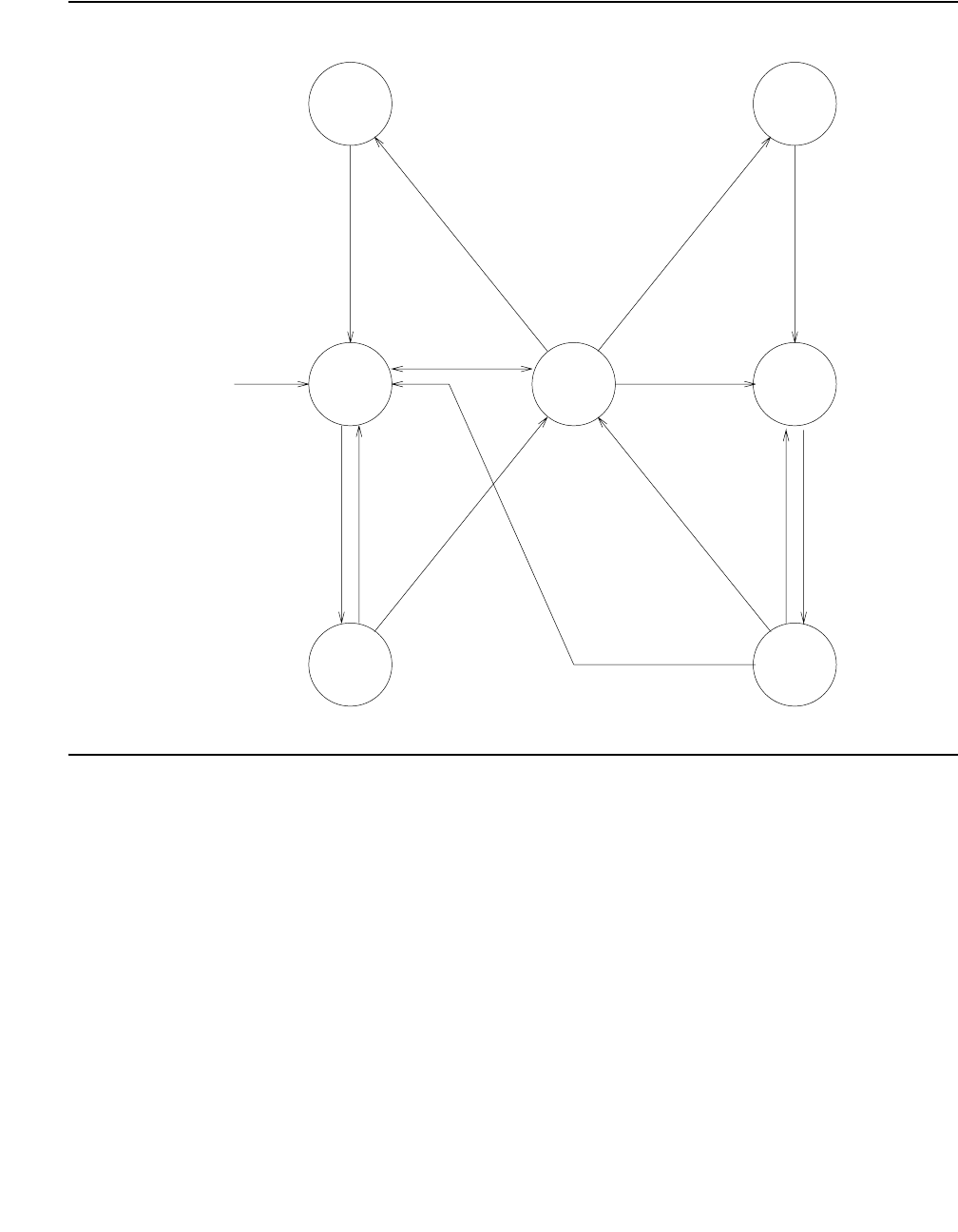
Communication Manager Maintenance-Object Repair Procedures
1450 Maintenance Procedures for Avaya Communication Manager 3.0, Media Gateways and Servers
Figure 80: Common Progressions in Service States
Craft busyout of B-channel
(TRK-GRP/MBR), or problem
with near en d PI-LINK, DS1-BD,
PI-BD, or port.
long test of the trunk.
Craft busyout of signaling link
busyout link LINK-NO or
transient state for demand
link, or craft
demanded test
completed.
of signaling
Craft release
If D-channel
controlling the
B-channel is
up, send a
message
requesting
transition to
In-Service.
least 90 seconds,
or Remote Level 3
Query failed.
been down for at
D-channel has
Maintenance
Near End
Maintenance
Far End
Pending
In-Service
Maintenance
Far End
Craft release of
B-channel or
clearing of near-end
problem with
DS1-BD, PI-BD,
PI-LINK or port.
Out-of-
Service
Far End
Out-of-
Service
Far End
Pending
In-Service
Out-of-
Service
Near End
Administer
B-channel
as member
of a trunk
group.
If D-channel control-
ling the B-channel is
up, send a message
requesting transition
to In-Service.
Failed to receive
reply from far
end. MTCE will
periodically try
to resend the
message.
Received
acknowledgement
or other
indication from the
far end that
B-channel is in service.
or other indication
from the far end,
that B-channel is
inservice.
acknowledgement
Received
message. [Country
protocol 1]
try to resend the
MTCE will periodically
reply from far end.
Failed to receive
in service.
B-channel in/not
from far end that
Received indication
message. [country
protocol other than 1]
try to resend the
MTCE will periodically
reply from far end.
Failed to receive
In-Service

ISDN-TRK (DS1 ISDN Trunk)
Issue 1 June 2005 1451
ISDN-PRI Trunk Service States
Use status trunk grp#/mem# to see DS1 ISDN Trunk service states, as shown in
Table 520: Service States on page 1451.
Note:
Note: Refer to Troubleshooting ISDN-PRI in Maintenance Procedures (03-300192) for
a layered approach to processing ISDN-PRI problems.
Table 520: Service States
Service State Alarm1Possible Cause Possible Solution
out-of-service/NE WRN Trunk is demand busied
out.
Enter release trunk grp#/
mem#.
MIN NPE Crosstalk test (#6)
failed.
Replace DS1/UDS1 circuit pack.
None DS1 or UDS1 circuit
pack or MM710 Media
Module lost its signal.
Is the DS1/UDS1 circuit pack, or
MM710 Media Module, or cable
removed? Is the far-end switch
restarting? Check circuit pack or
media module using procedures in
DS1-BD, UDS1-BD, or MG-DS1.
out-of-service/FE WRN Unadministered far end Administer corresponding trunk on
far-end switch.
WRN The far-end trunk is
busied out.
Check the status of the far-end
switch.
pending-in-service,
pending-maint
None Maintenance message
was sent and the switch
is waiting up to 2 min.
for a reply from the far
end.
Wait 2 minutes and check service
state after the pending state has
cleared.
maint/NE None ISDN test call in
progress (test trunk
long and test
isdn-testcall)
Wait several minutes for test to
finish and check status again.
None System link has been
busied out by command.
Check link status. Release link with
release link lnk#.
1 of 2
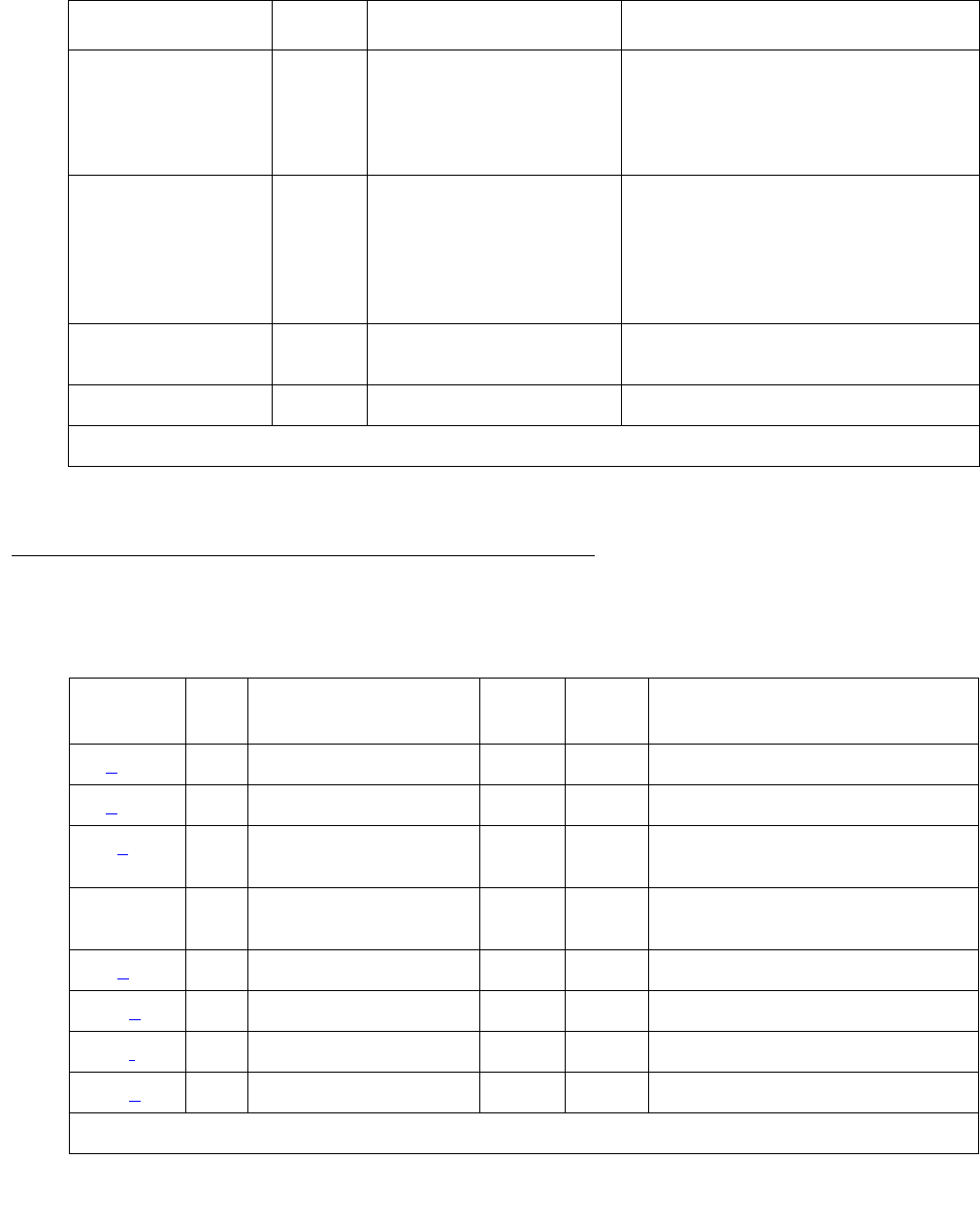
Communication Manager Maintenance-Object Repair Procedures
1452 Maintenance Procedures for Avaya Communication Manager 3.0, Media Gateways and Servers
Error Log Entries and Test to Clear Values
maint/FE WRN Signaling channel has
been down for over 90
sec.
Consult ISDN-SGRP and/or
ISDN-LNK. Far-end signaling
channel may be busied out, or the
far-end switch may currently be
restarting.
WRN Repeated failure of far
end to respond to
messages.
Maintenance software will
periodically try to resend
messages. You can speed the
process with test trunk grp#/
mem# and/or test
signaling-group sig-grp#.
WRN The far-end trunk is
being tested.
Check status of the far-end switch.
Wait for testing to finish.
in-service None Normal operating state
1. ISDN-TRK alarms; alarms against other objects may also be present.
Table 520: Service States (continued)
Service State Alarm1Possible Cause Possible Solution
2 of 2
Table 521: DS1 ISDN Trunk Error Log Entries
Error
Type
Aux
Data
Associated Test Alarm
Level
On/Off
Board
Test to Clear Value
0 (a) 0 Any Any Any test port location
1 (b)AnyNone test port location
15 (c) Any Audit and Update Test
(#36)
18 0 busyout trunk
grp#/mem# release trunk grp#/mem#
19 (d)0None
129 (e)None WRNOFFtest port location
130 (f)None WRNONtest port location
257 (g)AnyNone test port location
1 of 2

ISDN-TRK (DS1 ISDN Trunk)
Issue 1 June 2005 1453
Notes:
a. Error Type 0: Run the short test sequence first. If every test passes, run the long test
sequence. Refer to each appropriate test’s description, and follow its recommended
procedures.
b. Error Type 1: Disagreement between this switch and the switch at the other end of the
trunk connection with regard to the ISDN call state of the DS1 ISDN Trunk. This switch will
automatically try to recover by clearing the call, (that is, call will be torn down). You can use
status trunk grp#/mem# to determine the state of the trunk.
When running the short test sequence, pay close attention to the results of the Call State
Audit test (#257).
c. Error Type 15: Software audit error and does not indicate a hardware malfunction. Run the
short test sequence, and investigate associated errors.
d. Error Type 19: Possible protocol mismatch or far end may be out of service.
e. Error Type 129: The far-end switch changed its ISDN service state to either out of service
or maintenance. This may be either a temporary condition due to far-end testing of that
trunk or a hardware problem with the trunk. Outgoing calls will not be allowed over the trunk.
To investigate the status of the trunk, enter status trunk grp#/mem#.
513 (h) Any None WRN OFF test port location
769 (g)AnyNone test port location
1025 (i)0 None
1281 Any Conference Circuit
Test (#7)
MAJ
MIN
WRN1
ON test port location l r 4
1537 Any NPE Crosstalk Test
(#6)
MAJ
MIN
WRN
ON test port location l r 3
1793 (j)AnyNone test port location
3073 (k) Any Service State Audit
(#256) test port location
3585 (l)AnyNone
3841 (m) Any None WRN OFF
1. Major or minor alarms may be downgraded to Warning alarms based on the value used in the set
options command.
Table 521: DS1 ISDN Trunk Error Log Entries (continued)
Error
Type
Aux
Data
Associated Test Alarm
Level
On/Off
Board
Test to Clear Value
2 of 2

Communication Manager Maintenance-Object Repair Procedures
1454 Maintenance Procedures for Avaya Communication Manager 3.0, Media Gateways and Servers
f. Error Type 130: The circuit pack or media module has been removed or has been insane
for more than 11 minutes. To clear the error, reinsert or replace the circuit pack or media
module.
g. Error Types 257 and 796: Disagreement between this switch and the switch at the other
end of the trunk connection with regard to the ISDN service state of the DS1 ISDN Trunk.
This switch will automatically try to recover by performing a service state audit. You can use
status trunk grp#/mem# to determine the state of the trunk.
When running the short test sequence, pay close attention to the results of the Service State
Audit test (#256).
h. Error Type 513: This trunk is not recognized by the far-end switch. Investigate the trunk
administration for both switches and make changes as necessary.
i. Error Type 1025: An unexpected SERVICE or SERVICE ACK was received. Possibilities
include:
●Translations conflict
●Protocol differences
●ESS may be using NI3 protocol, not currently implemented in Communication Manager.
●B-channel negotiation problem (glare)
j. Error Type 1793: failure of the DS1/UDS1 Interface circuit pack. When running the short
test sequence, the results of the Signaling Link State Check Test (#255) are important.
k. Error Type 3073: service State Audit attempt failed (see Test #256). The trunks will not be
usable for any outgoing calls (although incoming calls will be accepted) until the test passes
and the trunk state is changed to in service (use status trunk grp#/mem# to investigate
trunk status).
l. Error Type 3585: the switch receives an ISDN RESTART message for an ISDN trunk. Calls
are cleared with the RESTART message. Therefore, this error type may be associated with
a dropped call report from a user.
The following Aux Data values for Error Type 3585 represent the trunk’s ISDN call state at
the time the unexpected request to restart the channel was received from the remote
switch. This information can be useful if dropped calls (cutoffs) are reported by users of the
ISDN-PRI trunks.

ISDN-TRK (DS1 ISDN Trunk)
Issue 1 June 2005 1455
The meanings of Aux Data values are shown below; ignore any others.
m. Error Type 3841: An ISDN trunk selected by the near end has been rejected 10 times by
the far end without a successful call. This may indicate a service-state mismatch between
the near and far ends for this trunk that is affecting the end user (that is, customer receives
unexpected intercept tones when accessing ISDN trunks). This may indicate that the ISDN
trunk is not administered at the far end.
The Aux field contains the physical name of the ISDN trunk in decimal. Using this decimal
name, verify that the far end has this trunk administered.
The Warning alarm will be retired automatically whenever an outgoing or incoming call that
uses this trunk is answered by the called endpoint. If problems persist, then busyout the
ISDN trunk to take it out of the hunt group.
Table 522: ISDN Trunk - Error 3585 Aux Data Values
Aux
Data
Cause
0 A idle trunk received a restart.
10 A call in a stable, talking state was cleared unexpectedly by the far end with
an ISDN RESTART message. This state is called the “active” state.
4,
7,
8,
260,
263
A call that has not reached the active state, but has at least reached a
ringing state, was cleared unexpectedly by the far end with an ISDN
RESTART message.
1,
3,
6,
9,
265
A call that has not yet reached a ringing state was cleared unexpectedly by
the far end with an ISDN RESTART message.
11,
12,
19,
531,
267,
268
A call that was in the process of clearing anyway has been cleared by the far
end with an ISDN RESTART message. If this condition occurs frequently, it
may mean that the far end is attempting to clear trunks that it thinks are in a
“hung” state. The RESTART message brings the trunk to an idle condition.

Communication Manager Maintenance-Object Repair Procedures
1456 Maintenance Procedures for Avaya Communication Manager 3.0, Media Gateways and Servers
System Technician-Demanded Tests:
Descriptions and Error Codes
Investigate tests in the order presented. By clearing error codes associated with the NPE
Crosstalk test (#6), you may also clear errors generated from other tests in the sequence.
NPE Crosstalk Test (#6)
The NPE Crosstalk Test verifies that this port’s NPE channel talks on the selected time slot and
never crosses over to time slots reserved for other connections. If the NPE is not working
correctly, 1-way and noisy connections may be observed. This test is usually only part of a
port’s long test sequence and takes about 20 to 30 seconds to complete.
Note:
Note: S8300 / G700: On the G700/G350, this test aborts with Error Code 1412.
Note:
Note: The TN464C or higher suffix UDS1 circuit pack has one SCOTCH-NPE chip
instead of several NPE chips.
Table 523: System Technician-Demanded Tests: DS1-BD
Order of Investigation Short Test
Sequence
Long Test
Sequence
D/ND1
1. D = Destructive, ND = Nondestructive
NPE Crosstalk test (#6)
S8300 / G700 On the G700/G350, aborts with Error Code 1412.
XND
Conference Circuit test (#7)
S8300 / G700 On the G700/G350, aborts with Error Code 1412.
XND
Audit and Update test (#36) X X ND
Signaling Link State Check test (#255) X X ND
Service State Audit test (#256) X X ND
Call State Audit test (#257) X X ND
ISDN Test Call test (#258)
S8300 / G700: On the G700/G350, aborts with Error Code 1412.
XND

ISDN-TRK (DS1 ISDN Trunk)
Issue 1 June 2005 1457
Table 524: Test #6 NPE Crosstalk Test
Error
Code
Test
Result
Description / Recommendation
ABRT Could not allocate the necessary system resources to run this test.
1. Retry the command at 1-minute intervals up to 5 times.
1000 ABRT System resources required to run this test are not available. The port may
be in use on a valid call.
1. Use status station or status trunk to determine when the port
is available for testing.
2. Retry the command at 1-minute intervals up to 5 times.
1001 ABRT Could not allocate the necessary system resources to run this test.
1. Retry the command at 1-minute intervals up to 5 times.
1002 ABRT The system could not allocate time slots for the test. The system may be
under heavy traffic conditions or it may have time slots out of service due
to TDM-Bus errors.
1. If the system has no TDM-Bus errors and is not handling heavy traffic,
repeat test at 1-minute intervals up to 5 times.
1003 ABRT The system could not allocate a tone receiver for the test. The system may
be oversized for the number of Tone Detectors present, or some Tone
Detectors may be out of service.
1. Resolve any TTR-LEV errors.
2. Resolve any TONE-PT errors.
3. If neither condition exists, retry the test at 1-minute intervals up to 5
times.
1004 ABRT The port has been seized by a user for a valid call. Use status station
or status trunk to determine when the port is available for testing.
1. Retry the command at 1-minute intervals up to 5 times.
1018 ABRT Maintenance is disabled on this trunk.
1. Enable maintenance by entering y in the Maintenance Tests field on
the change trunk-group form.
1117 ABRT A service state audit message is outstanding.
1. Wait 2 minutes and then try again.
1 of 2

Communication Manager Maintenance-Object Repair Procedures
1458 Maintenance Procedures for Avaya Communication Manager 3.0, Media Gateways and Servers
Conference Circuit Test (#7)
The Conference Circuit test verifies that the NPE channel for the port being tested can correctly
perform the conferencing function. The NPE is instructed to listen to several different tones and
conference the tones together. The resulting signal is then measured by a tone detector port. If
the level of the tone is within a certain range, the test passes.
Note:
Note: S8300 / G700: On the G700/G350, this test aborts with Error Code 1412.
Note:
Note: The TN464C or higher suffix UDS1 circuit pack has one SCOTCH-NPE chip
instead of several NPE chips.
S8300 /
G700:
1412
ABRT This test does not execute on a G700 Media Gateway.
2000 ABRT Response to the test was not received within the allowable time period.
1. Retry the command at 1-minute intervals up to 5 times.
2020 ABRT The test did not run due to an already existing error on the specific port or
a more general circuit pack error.
1. Examine Error Log for existing errors against this port or the circuit
pack and attempt to diagnose the already existing error.
2100 ABRT Could not allocate the necessary system resources to run this test.
1. Retry the command at 1-minute intervals up to 5 times.
Any FAIL The NPE of the tested port was found to be transmitting in error. This will
cause noisy and unreliable connections. The ISDN-TRK is moved to
out-of-service/near-end state.
1. Replace the circuit pack.
PASS The port is able to communicate over the TDM Bus.
Table 524: Test #6 NPE Crosstalk Test (continued)
Error
Code
Test
Result
Description / Recommendation
2 of 2

ISDN-TRK (DS1 ISDN Trunk)
Issue 1 June 2005 1459
Table 525: Test #7 Conference Circuit Test
Error
Code
Test
Result
Description / Recommendation
ABRT Could not allocate the necessary system resources to run this test.
1. Retry the command at 1-minute intervals up to 5 times.
1000 ABRT System resources required to run this test are not available. The port may
be in use on a valid call. Use status station or status trunk to
determine when the port is available for testing.
1004 ABRT The port has been seized by a user for a valid call. Use status station
or status trunk to determine when the port is available for testing.
1. Retry the command at 1-minute intervals up to 5 times.
1018 ABRT Maintenance is disabled on this trunk.
1. Enable maintenance by entering y in the Maintenance Tests field
on of the change trunk-group form.
1020 ABRT The test did not run due to an already existing error on the specific port or
a more general circuit pack error.
1. Examine Error Log for existing errors against this port or the circuit
pack and attempt to diagnose the already existing error.
S8300 /
G700
1412
ABRT This test does not execute on a G700/G350 Media Gateway.
2000 ABRT Response to the test request was not received within the allowable time
period.
1. Retry the command at 1-minute intervals up to 5 times.
2100 ABRT Could not allocate the necessary system resources to run this test.
1. Retry the command at 1-minute intervals up to 5 times.
Any FAIL The NPE of the tested port did not conference the tones correctly. This will
cause noisy and unreliable connections.
1. Replace the circuit pack.
PASS The port can correctly conference multiple connections. User-reported
troubles on this port should be investigated using other port tests and
examining station, trunk, or external wiring.

Communication Manager Maintenance-Object Repair Procedures
1460 Maintenance Procedures for Avaya Communication Manager 3.0, Media Gateways and Servers
Audit and Update Test (#36)
This test sends port level translation data from the switch processor to the DS1 interface circuit
pack or media module to assure that the trunk’s translation is correct. The port audit operation
verifies the consistency of the current state of trunk kept in the DS1 interface circuit pack or
media module and in the switch software.
Table 526: Test #36 Audit and Update Test
Error
Code
Test
Result
Description / Recommendation
ABRT Internal system error
1018 ABRT Maintenance is disabled on this trunk.
1. Enable maintenance by entering y in the Maintenance Tests field
on the change trunk-group form.
2000 ABRT Response to the test request was not received within the allowable time
period.
1. Retry the command at 1-minute intervals up to 5 times.
2100 ABRT Could not allocate the necessary system resources to run this test.
1. Retry the command at 1-minute intervals up to 5 times.
FAIL Test failed due to internal system error.
1. Retry the command at 1-minute intervals up to 5 times.
PASS Trunk translation has been updated successfully. The current trunk states
kept in the DS1 interface circuit pack or media module and switch software
are consistent.
If the trunk is busied out, the test will not run, but will return PASS. To verify
that the trunk is in-service:
1. Enter status-command to verify that the trunk is in-service. If the
trunk is in-service, no further action is necessary. If the trunk is
out-of-service, continue to Step 2.
2. Enter release-trunk to put trunk back into in-service.
3. Retry the test command.
1 of 2

ISDN-TRK (DS1 ISDN Trunk)
Issue 1 June 2005 1461
Signaling Link State Check Test (#255)
The DS1 ISDN Trunk depends on the health of the appropriate TN464C or later UDS1 Interface
circuit pack, TN767 DS1 interface circuit pack, or MM710 DS1 Interface Media Module for
proper operation. It also depends on the ISDN-PRI D channel (ISDN-LNK) trunk. This test
checks the status of those critical elements.
Any NO
BOARD The test could not relate the internal ID to the port (no board). This could be
due to incorrect translations, no board is inserted, an incorrect board is
inserted, or an insane board is inserted.
Ensure that the board translations are correct. Execute add ds1
location command to administer the MM710 interface if it is not already
administered.
If the board was already administered correctly, check the error log to
determine whether the board is hyperactive. If this is the case, the board is
shut down. Reseating the board will re-initialize the board.
If the board was found to be correctly inserted in step 1, then enter
busyout board location.
Enter reset board location.
Enter release board location.
Enter test board location long.
This should re-establish the linkage between the internal ID and the port.
Table 526: Test #36 Audit and Update Test (continued)
Error
Code
Test
Result
Description / Recommendation
2 of 2
Table 527: Test #255 Signaling Link State Check Test
Error
Code
Test
Result
Description / Recommendation
ABRT Internal system error
1. Retry the command at 1-minute intervals up to 5 times.
0 ABRT
1018 ABRT Maintenance is disabled on this trunk.
1. Enable maintenance by entering y in the Maintenance Tests field on
the change trunk-group form.
1114 ABRT The signaling link is in a transitional state.
1. Retry the command at 1-minute intervals up to 5 times.
1 of 2

Communication Manager Maintenance-Object Repair Procedures
1462 Maintenance Procedures for Avaya Communication Manager 3.0, Media Gateways and Servers
Service State Audit (#256)
As noted in the general description for DS1 ISDN Trunk, these trunks may be in one of several
service states. This test performs a Service State Audit with the far-end switch.
For interfaces using country protocol 1 (including the US) the Service State Audit executes in
every trunk service state. A message is sent to the far-end switch to ensure that both sides
agree on the service state. A PASS for this test simply means that the message has been
successfully sent. Two minutes are allowed for a reply. If no reply is received within that
2-minute window, the message is sent out again. If that attempt fails, an Error Type 3073 will be
logged and the switch will attempt another Service State Audit every 15 minutes. If the trunk
4 FAIL There is a problem with the signaling channel.
1. If the Packet Control circuit pack is used, consult the procedures for
the ISDN-PRI Signaling Group (ISDN-SGRP). Further information may
also be obtained by consulting the procedures for the ISDN-PRI
Signaling Channel (ISDN-LNK).
2. If the Packet Interface is used, consult the procedures for PKT-INT
8 FAIL There is a problem with the DS1 interface circuit pack or media module.
1. Consult the procedures for the appropriate DS1 interface circuit pack
(DS1-BD or UDS1-BD), or MM710 DS1 Interface Media Module
(MG-DS1).
PASS The signaling link hardware is OK.
Any NO
BOARD The test could not relate the internal ID to the port (no board). This could be
due to incorrect translations, no board is inserted, an incorrect board is
inserted, or an insane board is inserted.
Ensure that the board translations are correct. Execute add ds1
location to administer the MM710 interface if it is not already
administered.
If the board was already administered correctly, check the error log to
determine whether the board is hyperactive. If this is the case, the board is
shut down. Reseating the board will re-initialize the board.
If the board was found to be correctly inserted in step 1, enter busyout
board location.
Enter reset board location.
Enter release board location.
Enter test board location long.
This should re-establish the linkage between the internal ID and the port.
Table 527: Test #255 Signaling Link State Check Test (continued)
Error
Code
Test
Result
Description / Recommendation
2 of 2

ISDN-TRK (DS1 ISDN Trunk)
Issue 1 June 2005 1463
was initially in service, it is placed in the maintenance/far-end state. No outgoing calls will be
placed over this trunk, but incoming calls will be accepted. If an incoming call is presented with
the trunk in such a state, a Service State Audit is immediately attempted (the switch does not
wait for the 15-minute cycle, but tries to recover immediately).
For interfaces not using country protocol 1, the Service State Audit executes only if the trunk is
in the out-of-service/far-end state. A message is sent to the far-end switch to attempt to bring
the trunk back into the in-service state. A PASS for this test simply means that the message has
been successfully sent. Two minutes are allowed for a reply. If no reply is received within that
2-minute window, the message is sent out again. If again no response is received within two
minutes, the trunk remains in the out-of-service/far-end state. The switch will attempt another
Service State Audit after an hour has passed.
To investigate the service state of the DS1 ISDN Trunk, enter the status trunk grp#/mem#
command.
Table 528: Test #256 Service State Audit Test
Error
Code
Test
Result
Description / Recommendation
1000 ABRT Resources required to run this test were not available. The port may be on a
valid call or initializing. Use status station or status trunk to
determine when the trunk is available for testing. Check the results of Test
#255.
1018 ABRT Maintenance is disabled on this trunk.
1. Enable maintenance by entering y in the Maintenance Tests field
on the change trunk-group form.
1113 ABRT The signaling link has failed, so the system cannot send any messages on
behalf of this trunk.
1. Check the results of Test #255 and consult procedures for ISDN-SGR
(ISDN-PRI Signaling Group) on page 1429.
1114 ABRT The signaling link is in a transitional state.
1. Retry the command at 1-minute intervals up to 5 times.
1116 ABRT The trunk is not in the out-of-service/far-end state that is required to run this
test on systems using a country protocol other than 1.
1117 ABRT A service state audit message is outstanding.
1. Wait 2 minutes and then try again.
2100 ABRT Could not allocate the necessary system resources to run this test.
1. Retry the command at 1-minute intervals up to 5 times.
1 of 2

Communication Manager Maintenance-Object Repair Procedures
1464 Maintenance Procedures for Avaya Communication Manager 3.0, Media Gateways and Servers
1113 FAIL The signaling link has failed; the system cannot send any messages on
behalf of this trunk.
1. Consult procedures for ISDN-SGR (ISDN-PRI Signaling Group) and
ISDN-LNK (ISDN Signaling Link Port).
FAIL Internal system error
1. Retry the command at 1-minute intervals up to 5 times.
PASS Wait 4 minutes and then check the Error Log for any new errors of type
3073. If there are none, then both sides of the ISDN connection agree on
the service state; the negotiation succeeded. If there is a new 3073 error,
then the negotiation failed (the far-end switch twice failed to respond within
2 minutes). The switch will automatically retry every 15 minutes. If the trunk
was initially in service, it is now placed in the maintenance/far-end state.
Incoming calls will be accepted, but no outgoing calls can be originated. If
an incoming call is presented, another Service State Audit will be
immediately performed in an attempt to put the DS1 ISDN Trunk in the
proper state.
Any NO
BOARD The test could not relate the internal ID to the port (no board). This could be
due to incorrect translations, no board is inserted, an incorrect board is
inserted, or an insane board is inserted.
Ensure that the board translations are correct. Execute add ds1
location to administer the MM710 interface if it is not already
administered.
If the board was already administered correctly, check the error log to
determine whether the board is hyperactive. If this is the case, the board is
shut down. Reseating the board will re-initialize the board.
If the board was found to be correctly inserted in step 1, then enter
busyout board location.
Enter reset board location.
Enter release board location.
Enter test board location long.
This should re-establish the linkage between the internal ID and the port.
Table 528: Test #256 Service State Audit Test (continued)
Error
Code
Test
Result
Description / Recommendation
2 of 2

ISDN-TRK (DS1 ISDN Trunk)
Issue 1 June 2005 1465
Call State Audit Test (#257)
If a call is active on the trunk, the switches on both sides of the connection should agree on the
ISDN state of the call, as defined in the ISDN Protocol Specification. This test audits internal call
state data by querying the far-end switch as to the ISDN state of the call. It can be helpful when
trying to clear a hung call. If the internal call state data on the near-end switch is different than
that of the far-end switch, then the call will be torn down.
As with Test #256 (Service State Audit), a PASS simply means that an appropriate message
was composed and sent to the far-end switch. The ISDN Specification allows up to 2 minutes
for a reply. If a reply is not received within the 2-minute window, a protocol time-out violation will
be recorded in the error log against the associated signaling channel (ISDN-LNK, Error Type 1).
Table 529: Test #257 Call State Audit Test
Error
Code
Test
Result
Description / Recommendation
1018 ABRT Maintenance is disabled on this trunk.
1. Enable maintenance by entering y in the Maintenance Tests field
on the change trunk-group form.
1019 ABRT An audit is already in progress.
1. Wait 2 minutes and try again.
1113 ABRT The signaling link has failed, so the system cannot send any messages on
behalf of this trunk.
1. Check the results of Test #255 (Signaling Link State Check).
1114 ABRT The signaling link is in a transitional state.
1. Retry the command at 1-minute intervals up to 5 times.
1116 ABRT The trunk is in an out-of-service ISDN service state.
1. A call cannot be present if the trunk is in an ISDN out-of-service state,
so a call state audit would be inappropriate. No action necessary. Use
status trunk grp#/mem# to investigate the ISDN state of the
trunk.
2100 ABRT Could not allocate the necessary system resources to run this test.
1. Retry the command at 1-minute intervals up to 5 times.
FAIL Internal system error
1. Retry the command at 1-minute intervals up to 5 times.
1 of 2

Communication Manager Maintenance-Object Repair Procedures
1466 Maintenance Procedures for Avaya Communication Manager 3.0, Media Gateways and Servers
ISDN Test Call Test (#258)
Note:
Note: S8300 / G700: On the G700, this test aborts with Error Code 1412.
This test performs a far-end loop around to a far-end switch over an ISDN trunk. The trunk’s
service state must be in service, maint-NE, or out-of-service/NE, and no call can be active on
the trunk. The test call can be initiated as part of a long test sequence, or as an individual test,
as described below. This test is valid only for systems using country protocol 1 (including US),
or when the far end has loop-around capability.
A test call connection is established to a far-end switch over the ISDN trunk to be tested. The
digital port on a TN711D Maintenance/Test circuit pack generates a test-pattern bit stream that
is sent to the far-end switch and echoed back. The received pattern is then compared to the
sent pattern and checked for errors that indicate a loss of integrity on the communications path.
If a test call is running when scheduled maintenance starts, the green LED is turned off. To
determine whether a test call is still running:
●Enter list isdn-testcall and status isdn-testcall.
●Check for a lit amber LED on the Maintenance/Test circuit pack.
PASS This switch sent a call state auditing message to the far-end switch to verify
the state of the call active on this trunk. If a call state mismatch is found,
then the call will be torn down within two minutes. If no call was active, then
no message was sent.
Any NO
BOARD The test could not relate the internal ID to the port (no board). This could be
due to incorrect translations, no board is inserted, an incorrect board is
inserted, or an insane board is inserted.
Ensure that the board translations are correct. Execute the add ds1
location to administer the MM710 interface if it is not already
administered.
If the board was already administered correctly, check the error log to
determine whether the board is hyperactive. If this is the case, the board is
shut down. Reseating the board will re-initialize the board.
If the board was found to be correctly inserted in step 1, then enter the
busyout board location.
Enter reset board location.
Enter release board location.
Enter test board location long.
This should re-establish the linkage between the internal ID and the port.
Table 529: Test #257 Call State Audit Test (continued)
Error
Code
Test
Result
Description / Recommendation
2 of 2
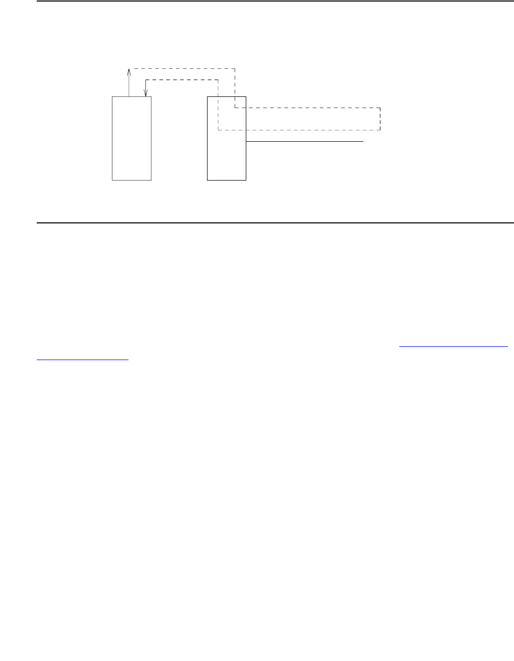
ISDN-TRK (DS1 ISDN Trunk)
Issue 1 June 2005 1467
Figure 81: Outgoing ISDN-PRI Test Call
There are two methods available to place an outgoing ISDN-PRI test call.
In the first method, the test call connection is established over the TDM Bus of the transmit and
receive sides of the ISDN-PRI trunk to a data channel. This method is selected when no
Maintenance/Test circuit pack resides in the system.
In the second method, the test call connection is established over the TDM Bus of the transmit
and receive sides of the ISDN-PRI trunk to a digital trunk testing port on the Maintenance/Test
circuit pack. The Maintenance/Test Digital Port generates a pseudo bit stream. A pictorial
description of the outgoing ISDN-PRI test call connectivity is contained in Figure 82: ISDN-PRI
Outgoing Test Call on page 1468.
DS1 Facility
ISDN Trunk
(B-Channel)
UDS1
TN464
. . . . . . . . . . . . . . . . . . . . . . . . . . . . . . . . . . . . . . . . . . . . . . . . . . . . . . . .
.
.
.
.
.
.
.
.
.
.
.
.
.
.
.
.
.
.
.
.
.
.
.
.
.
.
.
.
.
.
.
.
.
.
.
.
.
.
.
.
.
.
.
.
. . . . . . . . . . . . . . . . . . . . . . . . . . . . . . . . . . . . . . . . . . . . . . . . . . . . . . . . .
.
.
.
.
.
.
.
.
.
.
.
.
.
.
.
.
.
.
.
.
.
.
.
.
.
.
.
.
.
.
.
.
.
.
.
.
.
.
.
.
.
.
.
.
.
M/T
TN771
G3r Switch originating test call
TDM Bus
Far-End Switch
with test call
terminating capability
. . . . . . . . . . . . . . . . . . . . . . . . . . . .
.
.
.
.
.
.
.
.
.
.
.
.
.
.
.
.
. . . . . . . . . . . . . . . . . . . . . . . . . . . .
.
.
.
.
.
.
.
.
.
.
.
.
.
.
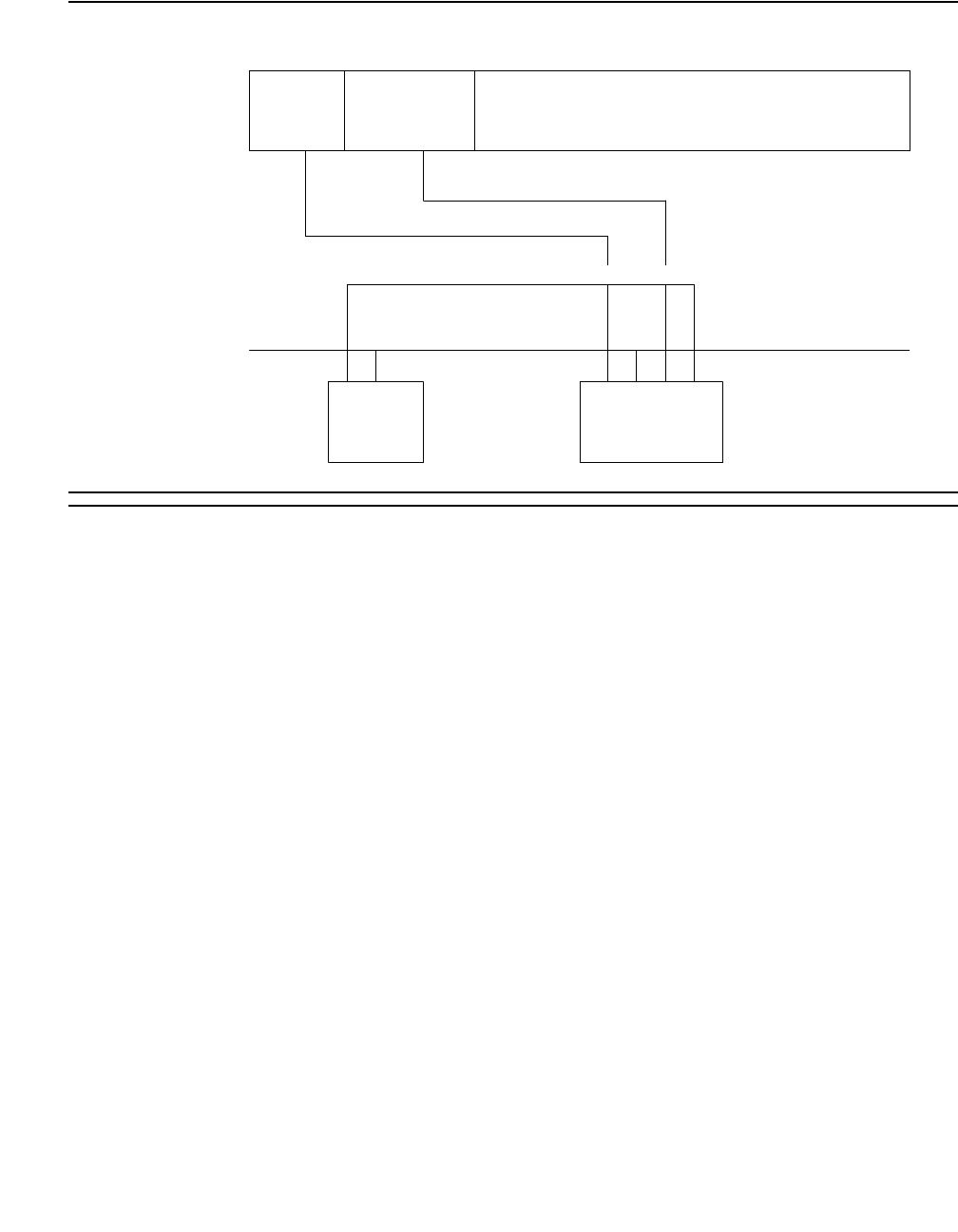
Communication Manager Maintenance-Object Repair Procedures
1468 Maintenance Procedures for Avaya Communication Manager 3.0, Media Gateways and Servers
Figure 82: ISDN-PRI Outgoing Test Call
Synchronous Test Calls
Use one of the following commands to initiate a synchronous outgoing test:
●test trunk grp#/mem# long [repeat #]
●test board address long [repeat #]
●test port address long [repeat #]
The previous test sequences include a test call for ISDN-PRI trunks. The duration of the test call
is 8.6 seconds for unrestricted (B8ZS) B channels and 9.4 seconds for restricted (ZCS) B
channels. The test fails if the bit error rate retrieved from the Maintenance/Test digital port is
greater than 0. When this occurs, you will need to perform further diagnostics, such as test
isdn-testcall described below.
Asynchronous Test Calls
You can start, query, and stop an outgoing test call by using the following maintenance
commands:
●test isdn-testcall grp#/mem# [minutes #]
This command initiates an outgoing ISDN-PRI test call up to 120 minutes. Default times are
as above. Only one trunk per PN can be tested at one time.
●status isdn-testcall grp#/mem#
This command displays the progress of the outgoing test call by reporting bit and block error
rates of the tested B channel.
PI (TN765)
or
PACCON
(TN778)
NETCON SPE
D-channel Setup
B-channel
B-channel
TDM BUS
M/T
TN7771B
DS1/UDS1

ISDN-TRK (DS1 ISDN Trunk)
Issue 1 June 2005 1469
●clear isdn-testcall grp#/mem#
This command terminates an outgoing test call already in progress. Measurements already
collected are not cleared until the next test call begins.
A PASS of the asynchronous test indicates only that the test call was successfully established.
Use status and list to get the results of the test.
Note:
Note: Before attempting to make an ISDN-PRI test call to the public network (that is,
the network of the far end), make sure that test call service is provisioned by the
network. The user must subscribe to Test Type 108 service and have the correct
far-end test call number administered on the trunk group form for the call to be
allowed.
Table 530: Test #258 ISDN Test Call
Error
Code
Test
Result
Description / Recommendation
4 ABRT There is a problem with the Signaling Channel.
1. Consult the procedures for the ISDN-PRI Signaling Group
(ISDN-SGRP). Further information may also be obtained by consulting
the procedures for the ISDN-PRI Signaling Channel (ISDN-LNK).
8 ABRT There is a problem with the DS1 interface circuit pack.
1. Consult the procedures for the appropriate DS1 interface circuit pack
(DS1-BD or UDS1-BD).
1004 ABRT B channel in use.
1. Enter status trunk grp#/mem# to determine whether a call is
active on this DS1 ISDN trunk.
2. When the service state indicates in service/idle, retry the test.
1005 ABRT Bad Configuration (such as no Maintenance/Test circuit pack)
1. Make sure the Maintenance/Test circuit pack is inserted.
2. Repeat the test.
1018 ABRT Test call is disabled.
1. Enable Maintenance on the Trunk Group form.
1 of 6

Communication Manager Maintenance-Object Repair Procedures
1470 Maintenance Procedures for Avaya Communication Manager 3.0, Media Gateways and Servers
1019 ABRT Another Test call is in progress.
1. Enter list isdn-testcall to locate the test call.
2. Enter status isdn-testcall to find out the duration and start time
of the test call.
3. Enter clear isdn-testcall to stop the test call from running.
4. If time and duration indicate that the test call should have stopped, and
clear isdn-testcall does not work, seeM/T-DIG (Maintenance/
Test D igi ta l Po r t) on page 1709 for recommended maintenance
strategy.
1020 ABRT There is a problem with the DS1 Interface circuit pack.
1. See DS1-BD (DS1 Interface Circuit Pack) on page 978 or UDS1-BD
(UDS1 Interface Circuit Pack) on page 2374.
1024 ABRT (M/T-DIG) Maintenance/Test Digital Port in use.
1. Wait until yellow and green LEDs are turned off on the M/T-BD
(Maintenance/Test circuit pack).M/T-DIG (Maintenance/Test Digital
Port) on page 1709
2. Retry test. If problem persists, seeM/T-DIG (Maintenance/Test Digital
Port) on page 1709.
1113 ABRT The signaling link has failed. Therefore, the system cannot send any
messages on behalf of this trunk.
1. Check the results of the Signaling Link State Check test (#255).
1116 ABRT The switch could not appropriately change the ISDN service state.
1. Enter status trunk grp#/mem# to determine whether a call is
active on this DS1 ISDN trunk. If so, proceed as for Error Code 1119.
2. If not, check the Error and Alarm Logs for problems with this
ISDN-TRK (DS1 ISDN Trunk) MO.
1117 ABRT ISDN Service message is already outstanding.
1. Wait 2 minutes. Then try again.
Table 530: Test #258 ISDN Test Call (continued)
Error
Code
Test
Result
Description / Recommendation
2 of 6

ISDN-TRK (DS1 ISDN Trunk)
Issue 1 June 2005 1471
1118 ABRT Far end of ISDN trunk is not administered.
1. Check the administration of the far-end ISDN trunk.
2. Enter status trunk grp#/mem#.
3. Try the test again.
1119 ABRT The test call was aborted due to a normal call attempt on this trunk.
The test call will only be performed if the trunk is idle.
1. Either wait for the normal call to finish normally, or force it to be
dropped by using busyout trunk grp#/mem# to busyout the DS1
ISDN Trunk. When the trunk is idle, retry the test.
1120 ABRT The DS1 ISDN Trunk is in the ISDN out-of-service/far-end state.
1. Try to change the service state via Test #256 (Service State Audit Test)
and then try this test again. Keep in mind that the trunk may be in the
out-of-service/far-end state due to problems at the far-end switch. If
that is the case, no remedial action can be taken at this end.
1122 ABRT There is no test line number for the far-end switch.
1. Check the Trunk Group administration form.
1123 ABRT There is no Feature Access Code administration for this Facility Test.
1. Check the Dial Plan and Feature administration forms.
S8300 /
G700:
1412
ABRT This test does not execute on a G700 Media Gateway.
2000,
2012,
None
ABRT Internal system error.
1. Retry the command at 1-minute intervals up to 5 times.
2035 ABRT The call has timed out, perhaps because of a lack of system resources.
1. Wait 1 minute and try again.
2036,
2037
ABRT Internal system error.
1. Follow recommendation for ABORT code 2012.
2038,
2039
ABRT A problem occurred while trying to read the test data.
1. Wait 1 minute and then try again. If the test aborts again in the same
manner, there is a serious internal problem.
Table 530: Test #258 ISDN Test Call (continued)
Error
Code
Test
Result
Description / Recommendation
3 of 6

Communication Manager Maintenance-Object Repair Procedures
1472 Maintenance Procedures for Avaya Communication Manager 3.0, Media Gateways and Servers
2040 ABRT Internal system error.
1. Follow recommendations for ABORT code 2012.
2041 ABRT The call has timed out, perhaps because of a lack of system resources.
Follow recommendations for ABORT code 2035.
2066 ABRT Could not establish test call.
1. Retry the command at 1-minute intervals up to 5 times.
2067 ABRT The call has timed out, perhaps because of a lack of system resources.
1. Follow recommendations for ABORT code 2035.
2074 ABRT Bit and Block Error query failed.
1. Retry the command at 1-minute intervals up to 5 times.
2. If the test continues to abort, there may be a serious internal problem
with M/T-DIG (Maintenance/Test Digital Port). If this is the case, seeM/
T-DIG (Maintenance/Test Digital Port) on page 1709.
2075 ABRT Internal system error. Follow recommendations for ABORT code 2012.
2100 ABRT Could not allocate the necessary system resources to run this test.
1. Retry the command at 1-minute intervals up to 5 times.
2104 ABRT Call dropped or could not be originated.
1. Make sure service is provisioned by the network.
2. Check the administration of the far-end test line extension on the
Trunk Group Administration form.
3. Check the administration of the Testcall BCC (Bearer Capability Class)
on the Trunk Group Administration form.
4. Check the reason for termination with status isdn-testcall.
5. For further instructions see Troubleshooting ISDN-PRI test calls in
Maintenance Procedures (03-300192).
6. Try the test again.
2201,
2202,
2203,
2204,
2205
ABRT Internal system error. Follow recommendations for ABORT code 2012.
Table 530: Test #258 ISDN Test Call (continued)
Error
Code
Test
Result
Description / Recommendation
4 of 6

ISDN-TRK (DS1 ISDN Trunk)
Issue 1 June 2005 1473
2206 ABRT Could not allocate the necessary system resources to run this test.
1. Follow recommendations for ABORT code 2100.
2208 ABRT Internal system error.
1. Follow recommendations for ABORT code 2012.
2209,
2210
ABRT Could not allocate the necessary system resources to run this test.
1. Follow recommendations for ABORT code 2100.
2211 ABRT Internal system error.
1. Follow recommendations for ABORT code 2012.
2212 ABRT Call ended by unexpected disconnect.
1. Wait 1 minute, and then try again.
2213 ABRT The call has timed-out, perhaps because of a lack of system resources.
1. Follow recommendations for ABORT code 2035.
2214 ABRT Call ended by unexpected disconnect.
1. Wait 1 minute, and then try again.
2215,
2216,
2217,
2218,
2219
ABRT Internal system error.
1. Follow recommendations for ABORT code 2012.
2220 ABRT Call ended prematurely.
1. Wait 1 minute, and then try again.
2221,
2222,
2223,
2224,
2225,
2226
ABRT Internal system error.
1. Follow recommendations for ABORT code 2012.
2227 ABRT Could not allocate the necessary system resources to run this test.
1. Follow recommendations for ABORT code 2100.
Table 530: Test #258 ISDN Test Call (continued)
Error
Code
Test
Result
Description / Recommendation
5 of 6

Communication Manager Maintenance-Object Repair Procedures
1474 Maintenance Procedures for Avaya Communication Manager 3.0, Media Gateways and Servers
2042 FAIL Comparison of data sent to data received indicates a loss of integrity on the
communications path.
1. Take the trunk out of service and check the quality of the DS1
connection, including the transmission facility and any external
equipment such as DACs, CSUs, etc. Use test isdn-testcall
and status isdn-testcall to get the bit and block error rates.
PASS The test pattern was sent and received properly. If the synchronous test call
was performed (long test sequence), this indicates that the communications
path is operating properly. If test isdn-testcall was used, PASS
indicates only that the test call was established. Use status
isdn-testcall to get the bit and block error rates detected by the test. If
the bit and block error rates are not acceptable, perform a complete analysis
of the DS1 facility including the transmission facility and any external
equipment such as DACs, CSUs, etc.
Table 530: Test #258 ISDN Test Call (continued)
Error
Code
Test
Result
Description / Recommendation
6 of 6

JNL-PRNT (Journal Printer Link)
Issue 1 June 2005 1475
JNL-PRNT (Journal Printer Link)
S8700 | 8710 / S8500
The maintenance strategies for JNL-PRNT (Journal Printer Link) and PMS-PRNT (PMS Printer
Link) are the same. Refer to the “PMS-PRNT/JNL-PRNT (PMS Printer Link)” section of this
chapter.
MO Name in Alarm Log Alarm
Level
Initial SAT Command to Run Full Name of MO
JNL-PRNT MIN test journal wakeup-log Journal Printer Link
JNL-PRNT WRN test journal wakeup-log Journal Printer Link


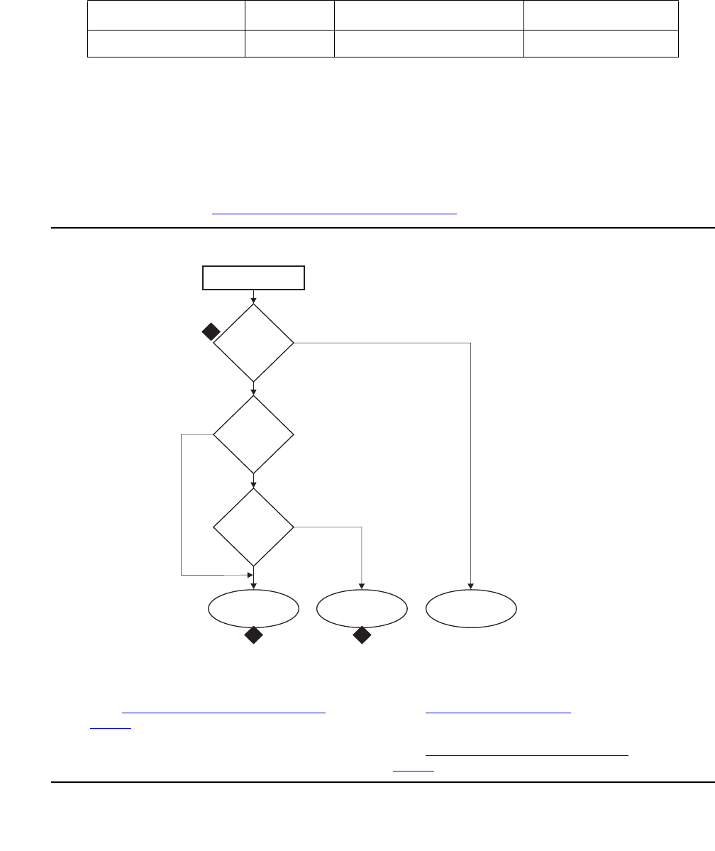
LIC-ERR (License-Error Mode)
Issue 1 June 2005 1479
LIC-ERR (License-Error Mode)
S8700 | 8710 / S8500 / S8300
The LIC-ERR MO works with the NO-LIC MO to look for any errors and violations associated
with a License File. Once a License File error occurs, LIC-ERR MO logs the error, raises an
alarm, and generates the following SAT login message:
“System Administration Will Be Blocked in Approximately XXX hours.
Contact Your Service Representative.”
Entry into License Error mode starts a timer that, when expired, causes the system to enter
No-License mode (see Figure 83: License mode algorithm on page 1479).
Figure 83: License mode algorithm
MO Name in Alarm Log Alarm Level Initial SAT Command to Run Full Name of MO
LIC-ERR MAJ test license License-Error Mode
Figure notes:
1. See Troubleshooting License File
errors on page 1482.
2. See NO-LIC (No License) on page 1727.
3. See Troubleshooting License File
errors on page 1482
System initialization
License-Error
present?
Timer
value
readable?
Timer expired?
fldfmode KLC 052504
License-Error
mode
No-License
mode
License-Normal
mode
Ye s
Ye s
Ye s
No
No
No
1
23
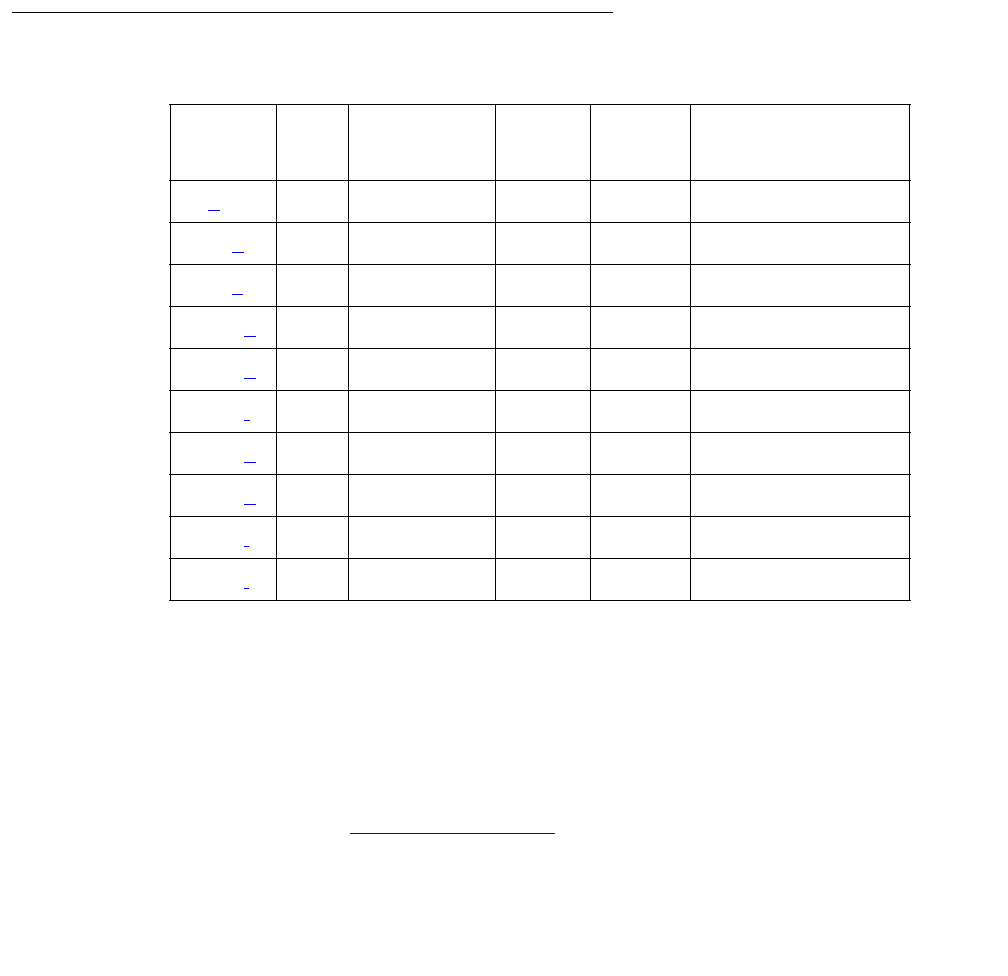
Communication Manager Maintenance-Object Repair Procedures
1480 Maintenance Procedures for Avaya Communication Manager 3.0, Media Gateways and Servers
The License File is loaded onto a server during initialization of Communication Manager
software, restoration of translations, and periodically during normal operation. After initialization,
a query is made to WebLM, a license server plug-in that
●Reads the serial number in a License file.
●Compares this file’s serial number to a serial number in hardware.
●Compares the file’s serial number with a running software version.
If a match occurs, the Web License Generator (WebLM) that resides on a designated server in
the enterprise delivers a new feature mask, an information set that controls which features are
enabled or not on the Customer Options and Special Applications screens.
Error Log Entries and Test to Clear Values
Notes:
a. Error Type 1: S8700 | 8710 / S8500: the reference IPSI is not responding. S8300: the G700
motherboard on which the serial number resides is not responding.
Either the reference is not responding or its serial number does not match the one in the
Licence file, and the 30-day timer begins. When the 30-day timer expires, the system enters
No-License mode (see NO-LIC (No License) on page 1727, Error Type 1).
Error
Type
Aux
Data
Associated
Test
Alarm
Level
On/Off
Board
Test to Clear Value
1 (a) MAJ OFF See footnote1
1. These error types can be cleared by installing the correct License File.
513 (b) None MAJ OFF See footnote1
769 (c) None MAJ OFF See footnote1
1281 (d) None MAJ OFF See footnote1
1537 (e) None MAJ OFF See footnote1
1793 (f) None MAJ OFF See footnote1
2305 (g) None MAJ OFF See footnote1
2561 (h) None MAJ OFF See footnote1
3073 (i) None MAJ OFF
3074 (j) None MAJ OFF

LIC-ERR (License-Error Mode)
Issue 1 June 2005 1481
b. Error Type 513: the license has expired, and the 30-day timer has started. When the
10-day timer expires, the system enters No-License mode (see NO-LIC (No License) on
page 1727, Error Type 513).
c. Error Type 769: feature use has exceeded limits, if the license has expired and the 30-day
timer begins. When the timer expires, the system enters No-License mode.
d. Error Type 1281: a new license was not installed after an upgrade. A countdown timer is
starts; see NO-LIC (No License) on page 1727, Error Type 1281.
e. Error Type 1537: the License file is missing or corrupt. A countdown timer for a license
error starts only if the previous state was License-Normal.
f. Error Type 1793: the current software version does not match the software version in the
License File, and the countdown timer has started. When the timer expires, the system
enters No License mode.
g. Error Type 1852: the Offer Category in translation does not match the Offer Category in the
License File, and the countdown timer has started. When the timer expires, the system
enters No-License mode (see NO-LIC (No License) on page 1727).
h. Error Type 2561: during the last attempted License File audit, the license server did not
respond in time.
i. Error Type 3073: this LSP (the one reporting the LIC-ERR) has gone active because one or
more media gateways have registered with it. Follow standard practices to repair the
primary media server(s) or control network.
j. Error Type 3074: this Enterprise Survivable Server (ESS) is controlling one or more port
networks. Follow standard practices to repair the Main media server(s) or control network.
System Technician-Demanded Tests:
Descriptions and Error Codes
Use test license to initiate a License File test.
Table 531: Test #1484 and Test #19 License File Test
Error
Code
Test
Result
Description / Recommendation
1 FAIL The system is in License-Error mode. For details, see Troubleshooting
License File errors on page 1482.
2 FAIL The system is in No-License mode. For details, see NO-LIC (No License) on
page 1727.
1 of 2

Communication Manager Maintenance-Object Repair Procedures
1482 Maintenance Procedures for Avaya Communication Manager 3.0, Media Gateways and Servers
Troubleshooting License File errors
The License file enables the switch’s software category, release, features, and capacities.
License Files are created using SAP order information and/or current customer configuration
information.
Without a valid license installed or a mismatched license the system:
1. Generates a major alarm.
2. Starts a 30-day countdown timer (call processing continues)
The License file requires a serial number from:
●S8700 | 8710 / S8500: the reference IPSI circuit pack
●S8300: the G700 motherboard
The License file includes a license serial identification number that is matched against the
hardware in the system as well as information about the Communication Manager software
version and Call Center features, Offer Category, and capacities. Once installed or initialized,
every hour the system compares these parameters to determine the system status:
●License-Normal mode
- License file was installed successfully
- Feature use is within prescribed limits
- License file’s serial number matches the serial number of the reference IPSI
●License-Error mode
- The License file’s serial number reference source is not responding, or its serial number
does not match the hardware
- Communication Manager software versions do not match
1014 ABRT Within the first 30 minutes after a system restart, the system cannot test the
License file.
1. Enter display initcauses to find out when the system last
restarted.
2. Wait for the remaining time plus 2 minutes, and retry the test.
PASS The system is in License-Normal mode.
Table 531: Test #1484 and Test #19 License File Test (continued)
Error
Code
Test
Result
Description / Recommendation
2 of 2

LIC-ERR (License-Error Mode)
Issue 1 June 2005 1483
- Feature use exceeded prescribed limits
- License expired
- After a system had a valid license, the License file is missing or corrupt.
Note:
Note: System resets do not reset the 30-day timer. If a system in License-Error mode is
reset and the license error remains, the timer picks up the countdown where it left
off.
To clear LIC-ERR alarms, the License file must match the switch hardware and administered
parameters.
●No-License mode
- System software versions do not match.
- License file is missing or could not be installed.
- Offer categories do not match.
- A condition that caused the system to enter License-Error mode has not been corrected
or resolved, and the countdown timer has expired.
- The switch returns to License-Normal mode when every license error is cleared.
Login Warning Messages
Anyone logging onto the SAT (System Administration Terminal) when the system is in
License-Error or No-License mode, receives a warning message stating the system’s Licence
mode, depending on the conditions. Table 532: Error messages and repair procedures on
page 1483 shows the 3 license modes, the warning message, describes the error conditions,
and lists the recommended repair procedures.
Table 532: Error messages and repair procedures
License
Mode
Description Explanation and repair procedure
License-Normal No mismatches
between license
and hardware
Stable running condition
1 of 2

Communication Manager Maintenance-Object Repair Procedures
1484 Maintenance Procedures for Avaya Communication Manager 3.0, Media Gateways and Servers
Initialization and Periodic Checking
Within the License file is the feature mask, an information set that controls which features are
enabled or not on the Customer Options and Special Applications screens. Each of the
approximately 150 feature mask entries is one of three types (examples in parentheses):
●Type I: features with a simple on/off state (DCS Call Coverage)
●Type II: features with an alphanumeric setting values associated with them (Logged-in
ACD Agents)
License-Error Warning mode;
Communication
Manager
supported, 30-day
countdown timer
begins.
If you log in to the server through the SAT, a message
reads: “System Administration Will Be Blocked in
Approximately XXX hours. Contact Your Service
Representative.” Communication Manager functions
normally for 'XXX' hours, at which time the system
goes into No-License mode.
One of the following conditions is present:
●Serial number reference source not
responding.
●The License file expired.
●Feature use does not match the License file.
No-License Warning period has
expired.
If you log in to the server through the SAT, a message
reads: “System Administration Is Blocked. Contact
Your Service Representative Immediately.”
One of the following conditions is present:
●No License file is installed in the system.
●The License-Error timer expired.
Table 532: Error messages and repair procedures (continued)
License
Mode
Description Explanation and repair procedure
2 of 2

LIC-ERR (License-Error Mode)
Issue 1 June 2005 1485
●Type III: includes the product ID (license serial identification number), release number, and
capacities.
Type III features cannot be changed by any login under any circumstances (applies to IP
Telephones, IP Softphones, and IP Agents).
Table 533: License error messages
If the system
goes into
this mode...
And reports this
error message...
It means that...
No-License License File is
Missing or Corrupted
License could not be decrypted.
Checksum did not match, data possibly lost.
Mismatched settings:
●Offer Category
●Version
●Call Center Release
●Model
Min. and Max. values of “* and # in vector collect step”
do not match the License file.
IP product defined in translations but not defined in the
License file.
No-License The License has
Expired
The License has expired.
No-License Software Version
Mismatch
The current software version does not match the
software version in the License file.
No-License Offer Category
Mismatch
The Offer Category in translation does not match the
Offer Category in the License file.
License-Error S8700 | 8710 / S8500:
Golden IPSI Not
Responding
S8300: G700
Motherboard Not
Responding
The reference source’s serial number does not match
the serial number in the License file, or the reference
source is not responding.
1 of 2

Communication Manager Maintenance-Object Repair Procedures
1486 Maintenance Procedures for Avaya Communication Manager 3.0, Media Gateways and Servers
License-Error Feature Usage
Exceeds Limits
The value of the Used field for any TYPE II or TYPE III
field on the Customer Options forms (pages 1, 5, 6,
and 9) is greater than the value of the field.
To more quickly identify which of these TYPE II and
TYPE III features is causing the error, compare the
Used field with the value of the field itself (the License
file value).
Before usage is checked, if the value of the field is not
between the upper and lower values in the License
file, the value of the field is changed in translation to
the lower value in the License file.
License-Error Software Upgrade
Requires New
License
The system reports this message immediately after an
upgrade. You have 10 days in which to install the
License file.
Table 533: License error messages (continued)
If the system
goes into
this mode...
And reports this
error message...
It means that...
2 of 2

LOG-SVN (Login Security Violation)
Issue 1 June 2005 1487
LOG-SVN (Login Security Violation)
S8700 | 8710 / S8500
The Security Violation Notification (SVN) feature provides notification when the number of failed
attempts to access the system administration/maintenance interface meets or exceeds
customer administered threshold parameters.
A major alarm is logged whenever a security violation is detected involving an Avaya services
login ID and that login ID has been disabled as a result of detection of the security violation. The
capability to disable a login ID following detection of a security violation involving that login ID is
administrable on a per login ID basis.
Refer to the Administrator Guide for Avaya Communication Manager, 03-300509, for
information about administration required for the Security Violation Notification feature, and the
option to disable a login ID following detection of a security violation involving the affected
login ID.
Error Log Entries and Test to Clear Values
General Information about log-svn error log entries:
1. The number (1–15), that appears in the error type field, corresponds to the location of the
login in the internal login data structure.
2. The Alt Name field on the alarm report indicates the login ID associated with the security
violation and major alarm.
3. These errors/alarms are associated with a number of failed attempts to access the system
management/maintenance interface using an Avaya services login ID that meet or exceed
the customer administered threshold parameters. The associated alarm is immediately
raised as a major alarm.
MO Name in
Alarm Log
Alarm
Level
Initial SAT Command to Run Full Name of MO
LOG-SVN MAJ enable login loginID1
1. Where loginID is the Avaya services login ID for which the security violation was detected. The
Alt Name field indicates the login ID associated with the security violation and the major alarm.
Login Security Violation
Table 534: Security Violation Notification Error Log Entries
Error
Type
Aux
Data
Associated
Test
Alarm
Level
On/Off
Board
Test to Clear Value
1–15 None None Major OFF enable login loginID

Communication Manager Maintenance-Object Repair Procedures
1488 Maintenance Procedures for Avaya Communication Manager 3.0, Media Gateways and Servers
4. The affected login ID will be disabled as a result of detection of the security violation, unless
it is the system’s last enabled INADS-type login. The provision to disable a login ID following
detection of a security violation involving that login ID is administrable on a login ID basis.
5. Use enable login to enable a login that has been disabled, and to retire any login
security violation alarms associated with the login ID.
6. To use enable login to enable a login and/or retire alarms, use a login ID with greater
service level hierarchy permissions.
7. Access to enable login is controlled through the Administer Permissions field on the
Command Permission Categories screen. Set the Administer Permissions field to y to
access enable login.
8. The Port alarm report field identifies the port where the final invalid login attempt, involving
the alarmed login ID, was detected. Valid port values for G3i products include:
- MGR1: Dedicated Manager 1 or G3 MT (management terminal) connection
- NET-n: Network controller’s dial-up port
- INADS: Alarm receiver’s port
- PN: PN’s maintenance EIA port
- EIA: Other EIA port
Valid port values for G3r products include:
- SYSAM _LOC: Local administration port
- SYSAM _RMT: Remote administration port
- SYS_PORT: System port
- MAINT: Maintenance port
9. The Svc State alarm report field will be set to OUT if the login ID is in the disabled state as
a result of detection of a security violation involving the login ID. Once the login ID has been
enabled, the field will be set to IN.
10. The source or reason of the failed login attempts should be identified and the cause
corrected prior to re-enabling a login ID and/or retiring any alarms associated with the login
ID. The cause may be something as innocuous as the failure of Avaya services automatic
login software, to something as insidious as a hacker attempting to gain access to the
switch system management interface.
Prior to retiring an SVN alarm and enabling the associated login ID, use monitor
security-violations login to access information about the invalid login attempts that
caused the security violation. This information can be useful in determining the source of the
invalid attempts and analyzing why they occurred.
Use list logins to see status information about logins on the system. If a login has been
disabled as a result of a security violation, the status is svn-disabled.

LOG-SVN (Login Security Violation)
Issue 1 June 2005 1489
Procedure to Retire SVN Alarm
To retire a SVN alarm:
1. Enter the enable login loginID.
The login ID associated with that alarm is displayed in the Alt Name field of the alarm report
and the alarm is retired.

Communication Manager Maintenance-Object Repair Procedures
1490 Maintenance Procedures for Avaya Communication Manager 3.0, Media Gateways and Servers
MAINT (PN’s Maintenance Circuit Pack)
S8700 MC
The PN’s TN775D Maintenance circuit pack monitors and supports environmental maintenance
for PN multicarrier or single-carrier cabinets. The PN’s Maintenance circuit pack provides switch
software with a mechanism to activate or deactivate Emergency Transfer in the PN. Control by
the system of Emergency Transfer can be overridden by the Emergency Transfer switch on the
faceplate of the circuit pack. The PN’s Maintenance circuit pack invokes Emergency Transfer
when the PN loses contact with the media server or when the PN’s Maintenance circuit pack
loses contact with every Expansion Interface circuit pack. The PN’s Maintenance circuit pack
handles loss of AC power in the PN multicarrier cabinet by supplying battery power for 15
seconds to the PN cabinet and then an additional 10 minutes of power to just the control carrier
in the PN. When power fails in a single-carrier PN cabinet, no such power holdover is available.
In the event that an Expansion Interface circuit pack goes insane and is reset six times within 15
minutes, the PN’s Maintenance circuit pack will hold the Expansion Links reset preventing the
Expansion Interface circuit pack from running.
The PN’s Maintenance circuit pack has alarm LEDs which indicate the presence of Major,
Minor, and Warning alarms. A flashing LED indicates the presence of an alarm within the
cabinet. A continuously lit LED indicates the presence of an alarm elsewhere in the system.
See CAB-MTCE (Media Gateway Maintenance) on page 744 for an explanation of emergency
transfer operation in a G650 Media Gateway port network.
Customer-provided alarming device (CPAD)
The system provides customers a way to connect their own alarm indication device to a switch.
The CUST-ALM MO represents this customer-provided alarming device (CPAD).
The customer administers the level of alarm for which the CPAD will be activated using the
change system-parameter maintenance screen (CPE Alarm Activation Level field). The
customer sets this field to: none, warning, minor, or major depending on the level of alarm at
which the CPAD should be activated. When an alarm occurs of at least the level to which the
CPAD is administered, the CPAD in the PN will be activated. The CPAD will also be activated
within a cabinet whenever Emergency Transfer is invoked within that cabinet.
The CPAD is connected to the PN’s Maintenance circuit pack. The CUST-ALM MO is not
maintained by the system, and will not generate any alarms. If a problem is suspected with the
CPAD, it may be tested using test customer-alarm, which will activate the device by
MO Name in
Alarm Log
Alarm
Level
Initial SAT Command to Run Full Name of MO
MAINT MIN test maintenance sh PN’s Maintenance circuit pack
MAINT MAJ test maintenance l PN’s Maintenance circuit pack

MAINT (PN’s Maintenance Circuit Pack)
Issue 1 June 2005 1491
closing the relay on either the PN’s Maintenance circuit pack (whichever is specified) for 1
minute. The repeat parameter may be used to close the relay for a longer length of time where
the number of the repeat is the number of minutes for which the device will be activated (5
minutes is the suggested repeat value).
Note:
Note: S8700 and S8500 media servers equipped with G650 carriers will differ from this
MO, in that the IPSI board provides the CPAD leads. The intent for the feature is
in other ways the same.
The test customer-alarm location command is provided to allow a technician to check
that the customer-provided alarming device is correctly installed and functional (See
Customer-Provided Alarming Device Test (#115) on page 1506). It is recommended that this
test be run at least once after both the switch and the customer alarm have been installed.
Connectivity paths
The media server communicates with a PN’s Maintenance circuit pack via the following path.
(Up-link messages back from this Maintenance circuit pack to the media server take the reverse
path.) Messages flow from the media server’s processor to an IPSI connected PN’s TN2312AP
IPSI circuit pack’s Packet Interface circuit, over this PN’s LAN bus to its Expansion Interface
circuit pack, across the fiber link to the active PN’s Expansion Interface circuit pack, and over a
serial link to the PN’s Maintenance circuit pack.
The PN’s Maintenance circuit pack must be physically inserted into the dedicated slot marked
Maintenance in the A carrier of the PN. The serial links from the PN’s Maintenance circuit pack
to the Expansion Interface circuit packs are physically connected from this dedicated slot to
slots 2A01 and 2B02 (2B02 is used only if there is duplicated Port Network Connectivity). The
serial link from slot 2A01 to the maintenance slot is hard-wired into the backplane of carrier A,
whereas the serial link from slot 2B02 to the maintenance slot is a ribbon cable connecting the
two slots. The serial link from the PN’s Maintenance circuit pack to the terminal is also a ribbon
cable which plugs into a connector labeled TERM on the back of carrier A.
The maintenance strategy for the PN’s Maintenance circuit pack consists of checking the
integrity of the communications path to/from the PN’s Maintenance circuit pack, testing
individual hardware components on the PN’s Maintenance circuit pack, and keeping the alarm
LEDs up-to-date. The individual hardware components include the serial interfaces which
handle the serial links connected to the PN’s Maintenance circuit pack. There are three serial
interfaces, one for each possible Expansion Interface circuit pack and one for the terminal.
Since the PN’s Maintenance circuit pack supports environmental maintenance in the PN,
trouble with the PN’s Maintenance circuit pack can cause environmental maintenance to falsely
detect problems. In a multicarrier cabinet PN, these environmental MOs include: POWER
(Battery and Battery Charger), CARR-POW (Carrier Port Power Unit), AC-POWER (AC Power),
CABINET (Cabinet Sensors), EMG-XFER (Emergency Transfer), EXT-DEV (External Device
Alarm), and CUST-ALM (Customer-Provided Alarming Device). In a single carrier cabinet PN,
these environmental MOs include DC-POWER (Single Carrier Cabinet Power), EMG-XFER
(Emergency Transfer), EXT-DEV (External Device Alarm), and CUST-ALM (Customer-Provided
Alarming Device).

Communication Manager Maintenance-Object Repair Procedures
1492 Maintenance Procedures for Avaya Communication Manager 3.0, Media Gateways and Servers
TN775D Maintenance Circuit Pack
Used with a TN2312AP IPSI Circuit Pack
Connectivity when installed in an Existing System
There is no backplane connectivity from the TN775D Maintenance circuit pack to the
TN2312AP IPSI circuit pack in existing pre-R11carrier backplanes. To achieve connectivity for
pre-R11 carriers, a faceplate cable must be used. The faceplate cable runs between the
TN775D and the TN2312AP IPSI circuit packs faceplates.
Note:
Note: The TN775D maintenance circuit pack is located in slot one of Control Carrier A.
The associated TN2312AP IPSI circuit pack is located in slot two of Control
Carrier A.
Backplane Connectivity when Installed in a New System
New systems PN Control Carriers have backplane connectivity between the TN775D
Maintenance circuit pack located in slot one of the new PN Control Carrier and the TN2312AP
IPSI circuit pack located in slot two. No face plate cable is needed.
Error Log Entries and Test to Clear Values
Table 535: PN’s Maintenance Circuit Pack Error Log Entries
Error
Type
Aux
Data
Associated Test Alarm
Level
On/Off
Board
Test to Clear Value
0 (a)0Any AnyAnytest maintenance sh r 1
1 (b)0
1
PN Maintenance
Circuit Pack Reset
(#306)
MIN ON test maintenance l
513 (b)0
1
MGR I Channel Loop
test (#228)
MIN ON test maintenance sh r 3
769 (c) Any Sanity Handshake test
(#106)
1537 (d)0
1
Sanity Maze test
(#303)
MIN ON test maintenance sh r 3
2049 (d) Any Battery Holdover
Vintage Verification
Test (#311)
WRN ON test maintenance sh r 1
1 of 2
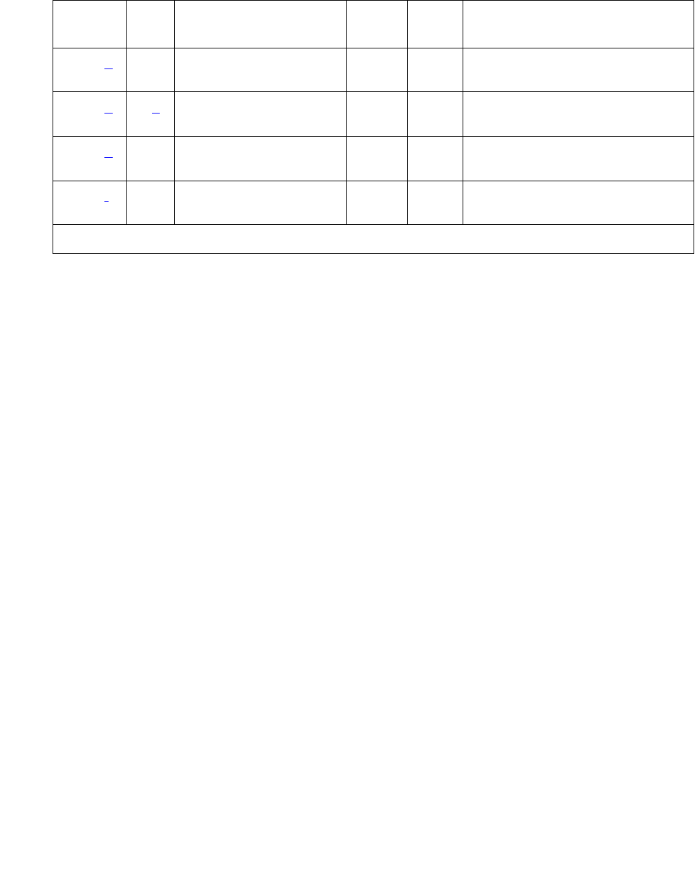
MAINT (PN’s Maintenance Circuit Pack)
Issue 1 June 2005 1493
Notes:
a. Error Type 0: run the short test sequence first. If every test passes, run the long test
sequence. Refer to each test’s description, and follow its procedures.
b. Error Type 1, 513, 2561, 2817: a value of 0 indicates that PNC-A (and therefore, the
Expansion Interface circuit pack located on PNC-A) was active when this error occurred. A
value of 1 indicates that PNC-B (and therefore, the Expansion Interface circuit pack located
on PNC-B) was active when this error occurred. To clear this problem, make sure the active
PNC is the same as that indicated by the Aux Value.
c. Error Type 769: multiple values can appear in the Aux Data field. There will be other
errors in the log if there is a real problem. Use these other errors to troubleshoot the
problem.
d. Error Type 1537, 2049: the PN’s Maintenance circuit pack hardware vintage does not
support battery holdover for all carriers. This failure indicates that the cabinet administration
is set for battery holdover for all carriers.
e. Error Type 3329, Aux Data 0: the serial link between the Expansion Interface circuit pack in
the A carrier and the PN’s Maintenance circuit pack is defective. Aux data of 10 indicates
that the serial link between the IPSI circuit pack in the A carrier and the PN’s Maintenance
circuit pack is defective.
f. Error Type 3585, Aux Data 1: indicates that the serial link between the Expansion Interface
circuit pack in the B carrier and the PN’s Maintenance circuit pack is defective. Aux data of
11 indicates that the serial link between the IPSI circuit pack in the B carrier and the PN’s
Maintenance circuit pack is defective.
2561 (b)0
1
Sanity Handshake test
(#106)
MIN ON test maintenance sh r 3
2817 (b)0 (c)
1
Serial Channel Loop
test (#229)
MIN ON test maintenance sh r 3
3329 (e) Any Serial Link Test (#337) MIN
WRN1OFF test maintenance sh r 3
3585 (f) Any Serial Link Test (#337) MIN
WRN2OFF test maintenance sh r 3
1. Major and Minor alarms may be downgraded to Warning alarms based on the value used in set options.
Table 535: PN’s Maintenance Circuit Pack Error Log Entries (continued)
Error
Type
Aux
Data
Associated Test Alarm
Level
On/Off
Board
Test to Clear Value
2 of 2
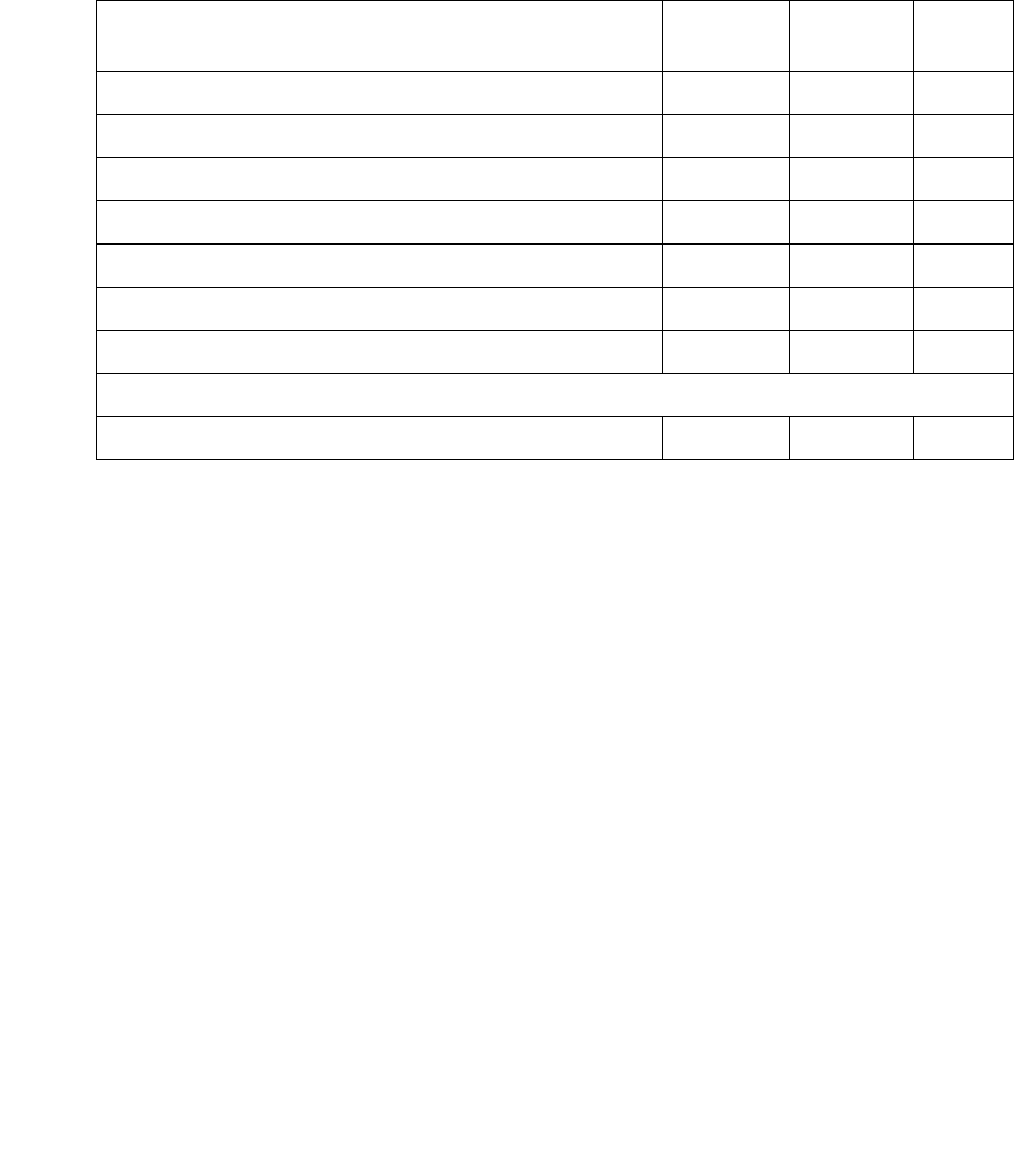
Communication Manager Maintenance-Object Repair Procedures
1494 Maintenance Procedures for Avaya Communication Manager 3.0, Media Gateways and Servers
System Technician-Demanded Tests:
Descriptions and Error Codes
Investigate tests in the order presented below. Clearing Error Codes associated with the one
test may also clear errors generated from other tests in the sequence.
Sanity Handshake Test (#106)
This test checks the ability of a PN’s Maintenance circuit pack’s to respond to queries. A
message is sent to the PN’s Maintenance circuit pack which then sends a message back. If the
response message is received, then the Maintenance circuit pack is queried for the PN cabinet
type (valid PN cabinet types are single carrier and multicarrier cabinets). The Maintenance
circuit pack reads pins on the backplane of carrier A that identify the type of cabinet and report
this information. If a valid cabinet type is returned, then the test passes.
Order of Investigation Short Test
Sequence
Long Test
Sequence
D/ND1
1. D = Destructive, ND = Nondestructive
Sanity Handshake test (#106) X X ND
PN Maintenance Circuit Pack Reset test (#306) X D
Serial Channel Local Loop-around test (#229) X X ND
MGR I Channel Local Loop-around test (#228) X D
PN Maintenance Circuit Pack Sanity Maze test (#303) X X ND
PN Maintenance Circuit Pack Serial Link test (#337) X X ND
Battery Holdover Vintage Verification test (#311) X X ND
The following test is not part of the above test sequences:
Customer-Provided Alarming Device Test (#115) ND

MAINT (PN’s Maintenance Circuit Pack)
Issue 1 June 2005 1495
Table 536: Test #106 Sanity Handshake Test
Error
Code
Test
Result
Description / Recommendation
ABRT Internal system error.
1. Retry the command at 1-minute intervals up to 5 times.
1000 ABRT System resources required for this test are not available.
1. Retry the command at 1-minute intervals up to 5 times.
2000 ABRT Response to cabinet query was not received in the allowable time
period.
1. Retry the command at 1-minute intervals up to 5 times.
2033 ABRT Internal system error.
1. Retry the command at 1-minute intervals up to 5 times.
2046 ABRT The PN’s Maintenance circuit pack reported an invalid cabinet type. Not
knowing the cabinet type of the PN will prevent all PN environment
maintenance from running.
1. Retry the command.
2. If the test continues to abort with 2046, then either the PN’s
Maintenance circuit pack is defective, or the PN cabinet’s wiring is
defective. First, replace the Maintenance circuit pack.
3. If the test continues to abort with 2046, then the PN cabinet’s wiring
is defective in the A carrier, and the PN’s Maintenance circuit pack
cannot read the backplane pins to determine the cabinet type.
10601 ABRT Test disabled via software patch.
1 of 2

Communication Manager Maintenance-Object Repair Procedures
1496 Maintenance Procedures for Avaya Communication Manager 3.0, Media Gateways and Servers
FAIL PN’s Maintenance circuit pack did not respond to Sanity Handshake and
the test timed out.
1. Verify that the carrier A power units are good. If the -5 Volt unit is
defective in the A carrier, then communication with the PN’s
Maintenance circuit pack will not be possible.
2. If the -5 Volt unit is good and this test continuously fails, background
maintenance will automatically escalate to a PN’s Maintenance
circuit pack Reset test (#306). Otherwise, manually reset a PN’s
Maintenance circuit pack by issuing test maintenance long
and evaluating any generated Error Codes from Test #306. If Test
#306 passes, this test should also PASS. Use the following steps to
determine whether the PN’s Maintenance circuit pack or its serial
link, is defective:
Duplicated Port Network Connectivity (PNC):
1. Switch PNC by entering reset pnc interchange.
2. Run the short test sequence against the PN’s Maintenance circuit
pack. If Test #106 still fails, replace the Maintenance circuit pack and
retest. Otherwise, follow the error routines for any errors that are
logged by this short test.
Unduplicated PNC:
1. Replace the PN’s Maintenance circuit pack, and invoke the short
test sequence against it.
2. If error persists, replace the PN Expansion Interface circuit pack, at
a time when the PN can go down with minimal inconvenience.
3. If the error still persists, the problem is with the actual serial link in A
carrier backplane and not with the PN’s Maintenance circuit pack.
PASS The communications path to and from the PN’s Maintenance circuit pack
is sane, and the Maintenance circuit pack can read and report the correct
PN cabinet type. The Maintenance circuit pack may still have problems
related to Tests #228, #229, #303, or #306.
Table 536: Test #106 Sanity Handshake Test (continued)
Error
Code
Test
Result
Description / Recommendation
2 of 2

MAINT (PN’s Maintenance Circuit Pack)
Issue 1 June 2005 1497
Management Terminal Channel Local
Loop-Around Test (#228)
This test is destructive.
This test checks TN775D on-board circuitry associated with the serial link for the management
terminal connection. This test will not cause the local terminal login to drop, but any data
displayed on the terminal while the test is running will be lost.
The PN’s Maintenance circuit pack has three separate serial interfaces, one to each of the
following:
●Management terminal which is tested by Test #228
●Active EI circuit pack which is tested by Test #229
●Standby EI circuit pack which is tested by Test #229
Table 537: Test #228 Management Terminal Channel Local Loop-Around Test
Error
Code
Test
Result
Description / Recommendation
1000 ABRT System resources required for this test are not available.
1. Retry the command at 1-minute intervals up to 5 times.
2000 ABRT Response to the test was not received within the allowable time period.
1. Retry the command at 1-minute intervals up to 5 times.
2033 ABRT Internal system error.
1. Retry the command at 1-minute intervals up to 5 times.
2034 ABRT Background maintenance on the PN’s Maintenance circuit pack is running
the MGR I Channel Local Loop-around test.
1. Wait 30 seconds and retry the test up to 5 times.
22801 ABRT Test disabled by means of software patch.
FAIL Test failed which means the PN terminal is not usable.
1. Run the test three more times.
2. If the test continues to fail, replace the PN’s Maintenance circuit pack.
1 of 2

Communication Manager Maintenance-Object Repair Procedures
1498 Maintenance Procedures for Avaya Communication Manager 3.0, Media Gateways and Servers
Serial Channel Local Loop-Around Test (#229)
This test checks TN775D on-board circuitry associated with the serial links to the Expansion
Interface circuit packs. A request is sent to the PN’s Maintenance circuit pack over the active
link via the active Expansion Interface circuit pack serial interface circuitry to test the serial
interface circuitry of the standby Expansion Interface circuit pack link. If a response is received,
then by definition the serial interface circuitry associated with the active link is good.
The PN’s Maintenance circuit pack has 3 separate serial interfaces, one to each of the
following:
●Management terminal which is tested by Test #228
●Active EI circuit pack which is tested by Test #229
●Standby EI circuit pack which is tested by Test #229
PASS The serial interface circuitry on the PN’s Maintenance circuit pack which
controls the PN-connected terminal is functioning properly. If there are still
troubles with the PN G3-MT terminal, the problem may be one of the
following:
1. The PN-connected terminal is not configured properly. The
connection between the terminal and the PN’s Maintenance circuit
pack must be set up at 9600 bps.
2. The serial link from the back of carrier A to the PN terminal may be
defective. The serial link consists of the connector on the back of
carrier A labeled TERM and the ribbon cable running to the terminal.
3. The terminal may be defective. Try another terminal.
4. Since this test is not 100 percent accurate, there may still be problems
with the PN’s Maintenance circuit pack.
Table 537: Test #228 Management Terminal Channel Local Loop-Around Test (continued)
Error
Code
Test
Result
Description / Recommendation
2 of 2
Table 538: Test #229 Serial Channel Local Loop-Around Test
Error
Code
Test
Result
Description / Recommendation
1000 ABRT System resources required to run this test are not available.
1. Retry the command at 1-minute intervals up to 5 times.
1 of 3

MAINT (PN’s Maintenance Circuit Pack)
Issue 1 June 2005 1499
2000 ABRT Response to the test request was not received within the allowable time
period.
1. Retry the command at 1-minute intervals up to 5 times.
2033 ABRT Internal system error.
1. Retry the command at 1-minute intervals up to 5 times.
2034 ABRT Background maintenance on the PN’s Maintenance circuit pack is
running the Serial Channel Local Loop-around test.
1. Wait 30 seconds, and retry the test up to 5 times.
22901 ABRT Test disabled via software patch.
FAIL The on-board circuitry associated with the standby serial link is defective.
Since the PN’s Maintenance circuit pack reported this failure, the
on-board circuitry associated with the active serial link is functional.
1. This test checks the circuitry on the PN’s Maintenance circuit pack
associated with the standby Expansion Interface link.
a. In a switch without duplicated Port Network Connectivity (PNC),
current service will not be affected because the circuitry failing is
not being used. Nevertheless, a Minor alarm will remain in the
Alarm Log against MAINT. Therefore, the PN’s Maintenance
circuit pack must be replaced.
b. In a switch with duplicated PNC, service is not affected as long as
you do not interchange the PNCs. Otherwise, the connection to
the PN’s Maintenance circuit pack will be lost. Losing this
connection would mean losing connectivity to the terminal and PN
Environment maintenance. The PN’s Maintenance circuit pack
must be replaced to correct this problem.
Table 538: Test #229 Serial Channel Local Loop-Around Test (continued)
Error
Code
Test
Result
Description / Recommendation
2 of 3

Communication Manager Maintenance-Object Repair Procedures
1500 Maintenance Procedures for Avaya Communication Manager 3.0, Media Gateways and Servers
PN Maintenance Circuit Pack Sanity Maze
Test (#303)
The processor on the PN’s Maintenance circuit pack has direct access to special registers in the
Maintenance circuit pack. These registers are tied to such things as the Expansion Interface
circuit pack reset leads and Carrier Port Power Unit reset leads (which enable the PN’s
Maintenance circuit pack to recycle carriers). To prevent an insane Maintenance circuit pack
from inadvertently controlling these external devices, a special interface called the Sanity Maze
is provided that must first be navigated by the Maintenance circuit pack processor prior to any
register access. There are two parts to the test. Part 1 involves navigating the Sanity Maze to
toggle an unused lead. Part 2 attempts to toggle an unused lead without first navigating the
Sanity Maze. The Sanity Maze test passes if Part 1 is successful and Part 2 fails.
PASS The on-board circuitry associated with both Expansion Interface circuit
pack serial links is good. If there is still a problem communicating with the
PN’s Maintenance circuit pack, check the following:
1. The cable comprising the serial link (B carrier Expansion Interface
circuit pack to PN’s Maintenance circuit pack only) may be defective.
2. The PN’s Maintenance circuit pack may actually be defective.
This test may not be 100 percent accurate.
3. The Expansion Interface circuit pack on the standby link may be
defective.
Table 538: Test #229 Serial Channel Local Loop-Around Test (continued)
Error
Code
Test
Result
Description / Recommendation
3 of 3
Table 539: Test #303 PN’s Maintenance Circuit Pack Sanity Maze Test
Error
Code
Test
Result
Description / Recommendation
1000 ABRT System resources required to run this test are not available.
1. Retry the command at 1-minute intervals up to 5 times.
2000 ABRT Response to the test was not received within the allowable time period.
1. Retry the command at 1-minute intervals up to 5 times.
1 of 2

MAINT (PN’s Maintenance Circuit Pack)
Issue 1 June 2005 1501
PN Maintenance Circuit Pack Reset Test (#306)
This test is destructive.
The terminal connection will be dropped and, if the Emergency Transfer switch is in the AUTO
position, Emergency Transfer will be disabled for the duration of the test.
The PN’s Maintenance circuit pack is reset by the active Expansion Interface circuit pack. After
the Expansion Interface circuit pack reports that the PN’s Maintenance circuit pack has reset, a
handshake message is sent to the Maintenance circuit pack. If the Maintenance circuit pack
responds to the handshake, the test passes. If not, it fails. If the test passes, the PN-connected
terminal is brought back up, and Emergency Transfer is restored to its previous state.
2033 ABRT Response to the test was not received within the allowable time period.
1. Retry the command at 1-minute intervals up to 5 times.
FAIL The Sanity Maze of the PN’s Maintenance circuit pack is defective.
1. Replace the PN’s Maintenance circuit pack.
PASS The Sanity Maze is working properly, and the PN’s Maintenance circuit
pack can access the unused register. If recycle carrier (for PN
carriers) does not work, the following problems may still exist:
1. The Carrier Port Power Unit or wiring to the Carrier Port Power Unit
may be defective. See CARR-POW (Carrier Power Supply) on
page 770.
2. Since this test only tests the PN, there is a very small probability
that the PN’s Maintenance circuit pack cannot access those
registers that deal with PN devices. The Maintenance circuit pack
may need to be replaced.
Table 539: Test #303 PN’s Maintenance Circuit Pack Sanity Maze Test (continued)
Error
Code
Test
Result
Description / Recommendation
2 of 2
Table 540: Test #306 PN Maintenance Circuit Pack Reset Test
Error
Code
Test
Result
Description / Recommendation
1000 ABRT System resources required to run this test are not available.
1. Retry the command at 1-minute intervals up to 5 times.
1 of 4

Communication Manager Maintenance-Object Repair Procedures
1502 Maintenance Procedures for Avaya Communication Manager 3.0, Media Gateways and Servers
1018 ABRT Test disabled via software patch.
2029 ABRT Internal system error.
1. Retry the command at 1-minute intervals up to 5 times.
2500 ABRT Internal system error.
1. Retry the command at 1-minute intervals up to 5 times.
1204 FAIL
1205 EI circuit pack could not reset the PN’s Maintenance circuit pack.
For duplicated Port Network Connectivity:
1. The standby EI circuit pack may be defective, preventing the active
EI circuit pack from resetting the PN’s Maintenance circuit pack.
Unplug the standby EI circuit pack, and try to reset the Maintenance
circuit pack using test maint long. If Test #306 passes, replace
the standby EI circuit pack, and attempt the reset test again. If Test
#306 fails, then replace the standby PN EI circuit pack.
2. The active EI circuit pack may be defective and unable to reset the
PN’s Maintenance circuit pack. Interchange the PNC using reset
pnc interchange. Reset the Maintenance circuit pack again
using test maintenance long. If the test passes, the problem is
with the known standby EI circuit pack. Repeat Step 2 to determine
whether the standby EI circuit pack should be replaced.
Table 540: Test #306 PN Maintenance Circuit Pack Reset Test (continued)
Error
Code
Test
Result
Description / Recommendation
2 of 4

MAINT (PN’s Maintenance Circuit Pack)
Issue 1 June 2005 1503
1205
(cont’d)
3. Replace the PN’s Maintenance circuit pack, and run the test again. If
the test passes, the problem is with the Maintenance circuit pack.
Interchange the PNC by entering reset pnc interchange, and
run the test again. The test should pass with both EI circuit packs
being active.
4. If the B carrier EI circuit pack is active, the ribbon cable connecting
the Expansion Interface circuit pack and the PN’s Maintenance
circuit pack may be defective. Check the ribbon cable to make sure it
is connected properly and is not damaged.
For unduplicated Port Network Connectivity:
1. Replace the PN’s Maintenance circuit pack, and run the test again. If
it passes, the problem is with the Maintenance circuit pack.
2. If the test fails, replace the EI circuit pack. If the tests passes, the
problem is with the EI circuit pack.
3. If the test still fails, the problem is with the serial link wired into the
backplane of carrier A.
2005 FAIL PN Maintenance Circuit Pack reset passed, but the PN’s Maintenance
circuit pack did not respond to subsequent handshake message. Retry
this command three more times. If it continues to fail, the Maintenance
circuit pack, the active EI circuit pack, or the serial link is defective. To
determine which is defective:
For Duplicated Port Network Connectivity:
1. Interchange PNCs by entering reset pnc interchange.
2. Run the short test sequence against the PN’s Maintenance circuit
pack. If Test #306 still fails, replace the Maintenance circuit pack and
retest. Otherwise, follow the error routines for any errors that are
logged by this short test sequence.
For Unduplicated Port Network Connectivity:
1. Replace the PN’s Maintenance circuit pack, and invoke the short
test sequence against it.
2. If the error persists, replace the EI circuit pack, at a time when the
PN can go down with minimal inconvenience.
3. If the error still persists, the problem is with the actual serial link in A
carrier backplane and not with the PN’s Maintenance circuit pack.
Table 540: Test #306 PN Maintenance Circuit Pack Reset Test (continued)
Error
Code
Test
Result
Description / Recommendation
3 of 4

Communication Manager Maintenance-Object Repair Procedures
1504 Maintenance Procedures for Avaya Communication Manager 3.0, Media Gateways and Servers
Battery Holdover Hardware
Verification Test (#311)
The hardware/firmware vintage of the PN’s TN775D Maintenance boards does not support
battery holdover for all carriers. This test checks to see if PN cabinet battery holdover for all
carriers has been administered in error. If battery holdover is administered for all carriers, the
test will fail and a t alarm will be raised against this MO.
PASS The active EI circuit pack can reset the PN’s Maintenance circuit pack.
This implies the Maintenance circuit pack, the active EI circuit pack, and
active serial link are sane. There could still be a problem with the standby
EI circuit pack and standby serial link in a Duplication Option system.
Table 540: Test #306 PN Maintenance Circuit Pack Reset Test (continued)
Error
Code
Test
Result
Description / Recommendation
4 of 4
Table 541: TEST #303 PN Maintenance Circuit Pack Sanity Maze Test
Error
Code
Test
Result
Description/ Recommendation
1000 ABRT System resources required to run this test are not available.
1. Retry the command at 1-minute intervals up to 5 times.
2000 ABRT Response to the test was not received within the allowable time period.
1. Retry the command at 1-minute intervals up to 5 times.
2029 ABRT Internal system error.
1. Retry the command at 1-minute intervals up to 5 times.
2500 ABRT Internal system error.
1. Retry the command at 1-minute intervals up to 5 times.
1 of 2

MAINT (PN’s Maintenance Circuit Pack)
Issue 1 June 2005 1505
PN Maintenance Circuit Pack Serial Link
Test (#337)
This test is destructive.
This test checks the serial link from the standby EI or standby IPSI circuit pack to the PN’s
Maintenance circuit pack. If there is no standby link, or the standby link is down at the time of
the test, this test aborts.
Note:
Note: The status of the link changes to “down” when the standby EI or standby IPSI
circuit pack begins initialization tests (for example, after being reset). The link
status updates at the conclusion of these tests.
FAIL The hardware vintage of the PN’s Maintenance circuit pack does not
support battery holdover for all carriers.
This failure indicates that the cabinet administration is set for battery
holdover for all carriers.
1. Verify cabinet administration, make sure that the battery holdover
feature is administered correctly (That cabinet administration is not
set for battery holdover for all carriers.).
2. Retry the command at 1-minute intervals up to 5 times.
PASS The cabinet administration shows battery holdover for A carrier only. Also,
the hardware vintage of the PN’s TN775D Maintenance board is correct.
Table 541: TEST #303 PN Maintenance Circuit Pack Sanity Maze Test (continued)
Error
Code
Test
Result
Description/ Recommendation
2 of 2
Table 542: Test #337 PN Maintenance Circuit Pack Serial Link Test
Error
Code
Test
Result
Description / Recommendation
1000 ABRT System resources required for this test are not available.
1. Retry the command at 1-minute intervals up to 5 times.
2029 ABRT Internal system error.
1. Retry the command at 1-minute intervals up to 5 times.
1 of 2

Communication Manager Maintenance-Object Repair Procedures
1506 Maintenance Procedures for Avaya Communication Manager 3.0, Media Gateways and Servers
Customer-Provided Alarming Device Test (#115)
Within a specified PN, the Customer-Provided Alarming Device (CPAD) test closes the relay
that activates the CPAD for 1 minute. If more than 1 minute is necessary to verify the CPAD’s
activation, the Repeat field on test customer-alarm location can be used to close the
relay for up to 99 minutes.
2500 Internal system error.
1. Retry the command at 1-minute intervals up to 5 times.
FAIL The serial link between the currently standby EI or standby IPSI circuit
pack and the PN’s Maintenance circuit pack is defective. If the standby
EXP-INTF or IPSI is on Carrier A, then error type 3329 is logged. If the
standby EXP-INTF or IPSI is on Carrier B, then error type 3585 is logged.
1. If error type 3585 was logged:
●See if the ICCA/ICCB cables between carriers A and B are present
and properly connected (ICCA to ICCA, and ICCB to ICCB).
●See if the ICCC/ICCD cables between carriers A and B are present
and properly connected (ICCC to ICCC, and ICCD to ICCD).
●If the IPSI has faceplate ICC cables See if the faceplate cables
between the IPSIs and Maintenance circuit pack are properly
connected.
2. Install or reconnect the cables if necessary, and rerun the test.
3. Replace the PN’s Maintenance circuit pack.
4. Rerun the test. If the test continues to fail, replace the standby PN
Expansion Interface circuit pack.
5. Rerun the test. If the test continues to fail and the standby link is on B
side, replace the ICC cable or IPSI faceplate cable that carries the
serial link from Expansion Interface or IPSI circuit pack B to the PN’s
Maintenance circuit pack.
PASS The serial link from the standby Expansion Interface or IPSI to the PN’s
Maintenance circuit pack is working.
Table 542: Test #337 PN Maintenance Circuit Pack Serial Link Test (continued)
Error
Code
Test
Result
Description / Recommendation
2 of 2

MAINT (PN’s Maintenance Circuit Pack)
Issue 1 June 2005 1507
However, when the repeat option is used, the results for Test #115 come back immediately and,
for each test that passed, the CPAD is kept on for one minute. The CPAD does not go off after
the PASS result and then come back on for a repeat. Instead, the CPAD is kept on continuously
for the entire time. If the CPAD is being activated and deactivated in a flickering fashion, there is
a problem with either the CPAD or a PN’s Maintenance circuit pack.
Table 543: Test #115 Customer-Provided Alarming Device Test
Error
Code
Test
Result
Description / Recommendation
Any
1000
2029
ABRT Internal system error
1. Retry the command at 1-minute intervals up to 5 times.
PASS The switch software successfully sent the request to the PN’s
Maintenance circuit pack to turn on the CPAD. The CPAD must be
physically inspected to verify that it is working.
1. If the CPAD is working but a customer complains that the CPAD did
not indicate an actual system alarm:
a. Enter display system-parameter maintenance to check
the administered alarm-activation level.
b. Compare this level with the customer’s specifications. If the level
does not match the customer’s specifications, change it using the
change system-parameter maintenance screen.
2. If Test #115 passes but the CPAD is not being activated, check the
CPAD’s connection to the PN’s Maintenance circuit pack, or to the
IPSI circuit pack in an IPSI connected system.
3. If the CPAD can be activated but not deactivated, enter status
port-network to verify that Emergency Transfer is not activated in
the affected PN. G650: Enter status cabinet to verify that
Emergency Transfer is not activated in the affected cabinet.
Emergency Transfer can be forced to manual OFF via the
Emergency Transfer switch on the PN’s Maintenance circuit pack, or
by issuing the command set emergency-transfer for the
TN2312BP circuit pack.
4. If Emergency Transfer is OFF and the CPAD still cannot be
deactivated:
a. Enter display system-parameter maintenance to check
the administered CPAD alarm levels.
b. Enter display alarms to compare the CPAD levels against
those currently present in the system.

Communication Manager Maintenance-Object Repair Procedures
1508 Maintenance Procedures for Avaya Communication Manager 3.0, Media Gateways and Servers
MAPD-BD (MAPD Interface Circuit Pack TN802)
S8700 | 8710 / S8500
The TN802 Multiple Application Platform (MAP-D) circuit pack allows sending voice and fax
from a Communication Manager media server through the Internet to another Communication
Manager media server also having this feature or to other PBXs that are equipped with the
Internet Telephony server (ITS-E).
Throughout this section, the term TN802 means the MAP-D IP trunk circuit pack.
Be sure to observe these special considerations for the TN802:
●Port alarms on this circuit pack display as “TIE-DS1” in the Alarm and Error logs.
●The reset board command reboots the MAPD PC CPU, but busyout board only
busies out every emulated port on the board.
●Switch resets that take the switch out of service for more than 20 seconds also cause the
MAPD's PC to reboot, which takes several minutes to complete.
Switch-Demanded Tests
Switch-demanded diagnostic tests on the TN802 do not run unless the Internet trunking
application is running on Windows NT, located on the circuit pack.
Feature Limitations
The Internet trunking application relies on the single call scenario, or a direct, point-to-point call
that does not terminate at multiple S8700 Media Server nodes through call processing.
MO Name in
Alarm Log
Alarm
Level
Initial SAT Command to Run Full Name of MO
MAPD-BD MAJ test board location sh MAPD Interface circuit pack
MAPD-BD MIN test board location lMAPD Interface circuit pack
MAPD-BD WRN test board location sh MAPD Interface circuit pack

MAPD-BD (MAPD Interface Circuit Pack TN802)
Issue 1 June 2005 1509
Table 544: IP trunk feature/performance limitations on page 1509 describes the feature
limitations for S8700 Media Server.
Table 544: IP trunk feature/performance limitations
Feature/
Performance
Description Recommendation
Abbreviated
Dialing
Abbreviated Dial strings with
embedded pauses lose digits
after the pause
Most calls work. Do not create Abbreviated
dial strings with embedded pauses.
Compression
limitations
Every IP trunk call goes
through A/D conversion,
which uses compression to
reduce bandwidth. Each
compression degrades the
voice signal and creates call
processing delay.
No more than 3 compression/
decompression cycles for any call.
The compression/decompression that most
voice mail systems use must be counted
as 1 cycle.
Call Classifier IP trunk’s compression/
decompression cycle makes
ringback, busy and voice
detection
Do not administer these features:
●Call Coverage Redirected Off-Net
(CCRON)
●Certain wireless phone coverage
Call Coverage
Call
Forwarding
Call Transfer
Calls extended across
multiple DCS nodes or across
multiple facilities require
multiple call paths. Significant
voice quality degradation is
likely.
Multiple call paths not recommended
Conferencing Voice quality and delay
problems if the party
controlling the conference is
on the IP trunk (voice paths
from external callers come in
on the IP trunk, are
conferenced, then sent out to
other external parties across
an IP trunk)
Avoid conference calls where at least two
other parties are on the other side of the IP
trunk.
The following conferences work OK:
●Conferences of parties on the local
media server
●Conferences controlled by the local
media server, involving local parties
and only 1 party on the other side of
an IP trunk
DCS Know limitations:
●Auto Callback
Coordinate specific administration and
between the IP trunk and Communication
Manager for any DCS functionality. Some
limitations on routing flexibility may apply.
1 of 2

Communication Manager Maintenance-Object Repair Procedures
1510 Maintenance Procedures for Avaya Communication Manager 3.0, Media Gateways and Servers
Backing Up to the PCMCIA Disk
Table 545: Backing up TN802 administration data on page 1510 details how to back up
administration data for the IP trunk application to and restored from the local PCMCIA disk and
the Ethernet port. Before backing up, be sure to shut down the application running on the circuit
pack, following the procedures in Shutting Down NT on the TN802 on page 1529.
ISDN IP trunking has no signalling
capability.
ISDN not supported. This includes:
●10-digit number display
●QSIG
●Path replacement
Voice mail Calls that have terminated at
one location and then cover
to a second site for voice mail
coverage can have voice
quality degradation.
Centralized voice mail through an IP
network is not recommended.
Table 544: IP trunk feature/performance limitations (continued)
Feature/
Performance
Description Recommendation
2 of 2
Table 545: Backing up TN802 administration data
Step Description Comments
1. Busyout circuit pack At the S8700 Media Server terminal, type busyout board
location (the address of the TN802 circuit pack), and press
Enter.
2. Backup
administration TN802
to disk
At the Windows 2000 desktop, double-click on the IP Trunk
Backup Restore icon.
The IP Trunk Backup/Restore Utility screen appears.
3. Select utility In the IP Trunk Backup/Restore Utility dialog screen, click on
Files > Backup.
The IP Trunk Backup screen appears.
4. Select backup In the IP Trunk Backup screen, click on the Backup button.
1 of 2

MAPD-BD (MAPD Interface Circuit Pack TN802)
Issue 1 June 2005 1511
Note:
Note: Local restore of a complete system from the PCMCIA disk should not require
more than 20 minutes assuming that a replacement MAPD pack is available and
pre-loaded with the IP trunk application software.
Restoring Data from the PCMCIA Disk
Before You Start
1. Shut down the application running on the circuit pack. See Shutting Down NT on the
TN802 on page 1529.
2. Remove the defective IP Trunk circuit pack from the switch (if applicable).
3. Install the replacement IP Trunk circuit pack in the switch (if applicable).
4. Insert the backup diskette into the IP Trunk circuit pack.
5. Wait Backup can take as much as 20 minutes to complete.
6. Release circuit pack At the S8700 Media Server terminal, type release board
location (the address of the TN802 circuit pack), and press
Enter.
Table 545: Backing up TN802 administration data (continued)
Step Description Comments
2 of 2
Table 546: Restore TN802 administration data
Step Description Comments
1. Restore IP
Trunk
administration
At the Windows 2000 desktop, double-click on the IP Trunk
Backup/ Restore icon.
The IP Trunk Backup/Restore Utility screen appears.
2. Select utility In the IP Trunk Backup/Restore Utility dialog screen, click Files>
Restore.
The IP Trunk Backup screen appears.
3. Select restore In the IP Trunk Backup screen, click on the Restore button.
4. Wait Wait until the amber Disk-In-Use LED (Note 5 in Figure 84: TN802
faceplate on page 1513) light is out.

Communication Manager Maintenance-Object Repair Procedures
1512 Maintenance Procedures for Avaya Communication Manager 3.0, Media Gateways and Servers
PSTN Fallback
Public Switched Telephone Network (PSTN) fallback is available on the Internet trunk
application software, which periodically pings the remote destinations that the software calls.
When the far end returns a poor response time to the ping, ARS or AAR network routing
patterns bypass those ports and direct the call to another port, typically on a PSTN trunk.
When the remote destinations show acceptable response times to subsequent pings, the
corresponding ports are returned to “idle,” where they are available for service.
Cabinet Configuration
Because of overheating, the TN802 circuit pack should not be placed directly above or below
another MAPD circuit pack.
UPS Protection
An uninterruptable power supply (UPS) protection is strongly recommended for a PN containing
a TN802 circuit pack.
Faceplate
Figure 84: TN802 faceplate on page 1513 shows the TN802 faceplate.
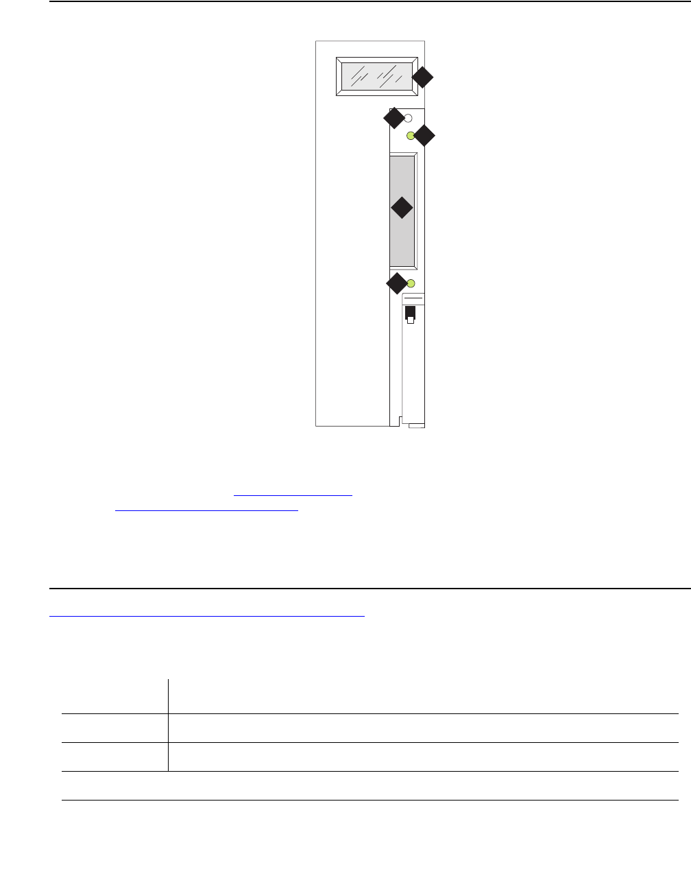
MAPD-BD (MAPD Interface Circuit Pack TN802)
Issue 1 June 2005 1513
Figure 84: TN802 faceplate
Table 547: TN802 LCD messages for IP trunks on page 1513 lists the TN802 LCD messages
that you might see if installing or servicing an IP Trunk.
Figure notes:
1. LCD display (see Table 547: TN802
LCD messages for IP trunks on
page 1513)
4. PCMCIA card slot
2. Reset button (recessed) 5. Amber PCMCIA disk-in-use LED
3. Red board-status LED
Table 547: TN802 LCD messages for IP trunks
Display Explanation
PC BOOT The TN802 MAPD PC is booting up.
IP TRK # IP Trunk application is running (# character blinks).
1 of 2
1
2
3
4
5
fpdfmapd KLC 030899

Communication Manager Maintenance-Object Repair Procedures
1514 Maintenance Procedures for Avaya Communication Manager 3.0, Media Gateways and Servers
Support for Laptop PCs
S8700 | 8710 / S8500
Field technicians can access the TN802 circuit pack through:
●pcAnywhere client software
●A directly-connected keyboard, monitor, and mouse
pcANYWHERE Client Software
1. Attach a male-to-male serial cable and a NULL modem connector (if not built into the
cable you use) to the COM2 connector (Note 8 in Figure 85: TN802 external cable
assembly on page 1515). Attach the other end to the serial port of your laptop.
2. Launch the pcANYWHERE application.
3. Click on Add Remote Control Item.
4. In the Properties window, choose the communication port to which you connected the
cable in Step 1.
IML DWN # Internal error on the IP Trunk. System shuts down and sends an error
message to the board.
MSHUT #,
where both
MSHUT and
# are blinking
The system is in the process of shutting down due to a front panel button
press. Do not attempt to remove board.
MSHUT #,
where # is
blinking
The system has shut down gracefully.
Table 547: TN802 LCD messages for IP trunks (continued)
Display Explanation
2 of 2
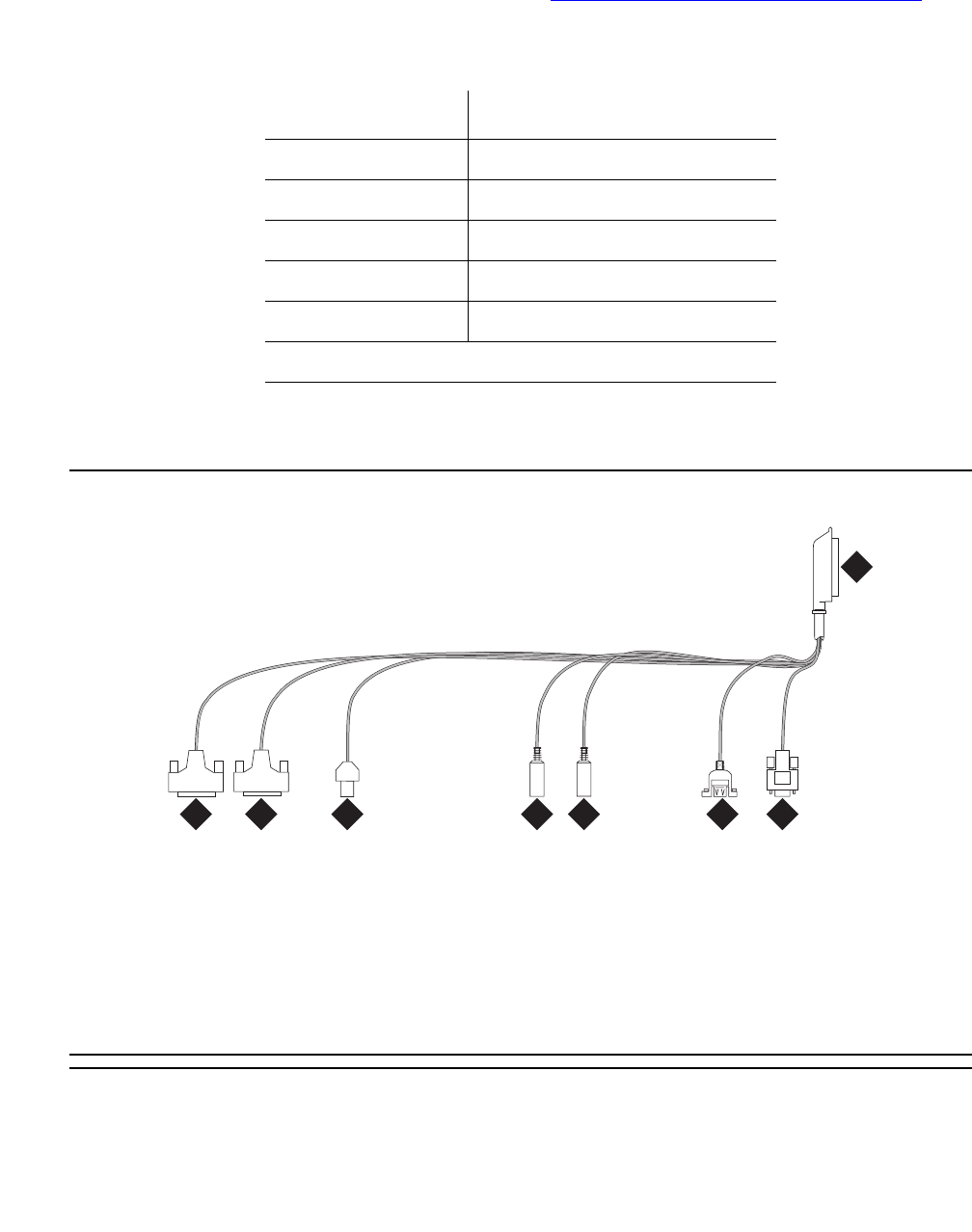
MAPD-BD (MAPD Interface Circuit Pack TN802)
Issue 1 June 2005 1515
5. Click on Details and configure the settings (Table 548: Remote connection settings on
page 1515):
6. Click on the new item icon, and the laptop connects to the host pcANYWHERE
application on the TN802 circuit pack.
Figure 85: TN802 external cable assembly
Table 548: Remote connection settings
Field Value
Speed 38,400
Parity None (default)
Flow Control RTS/CTS
Started by Carrier detect (DCD)
Ended by Carrier detect (DCD)
Figure notes:
1. To TN802 cabinet backplane 5. Mouse
2. VGA monitor 6. Ethernet
3. USB (Universal Serial Bus) 7. 25-pin modem connection
4. Keyboard 8. 25-pin COM2 connection
cbdfocto AWF 122398
2
1
3
45
6
78

Communication Manager Maintenance-Object Repair Procedures
1516 Maintenance Procedures for Avaya Communication Manager 3.0, Media Gateways and Servers
S8700 | 8710 / S8500
Directly-Connected Keyboard, Monitor, Mouse
You need 2 power sources for the monitor and the modem in order to complete this procedure.
The TN802 circuit pack must be booted with a local mouse and keyboard connected to it for
these devices to work.
1. Connect the VGA monitor to the VGA connector of the TN802 external cable.
2. Plug the monitor into an AC power receptacle, and turn it on.
3. Attach the keyboard to the keyboard connector of the TN802 external cable assembly.
4. Attach the mouse to the mouse connector of the TN802 external cable assembly.
5. Insert the circuit pack to cause it to boot.
Troubleshooting LAN Connections
This section contains information for troubleshooting
●External Connections to the LAN on page 1516
●Internal Connections to the LAN on page 1517
External Connections to the LAN
Test the external connections to the LAN by pinging the local host, the external IP trunk server,
and another device connected to the network.
1. Click Start in Windows (lower left-hand corner), then select Programs, then Command
Prompt.
This starts a DOS command-line session.
2. At the command prompt, type ping 127.0.0.1 (the local host’s default address), and
press Enter.
If configured correctly, the system displays:
Reply from nnn.nn.nn.nn: bytes=32 time<##ms TTL=###
If there is no reply, escalate the problem or replace the circuit pack. The problem is not with
the external network but within the circuit pack.

MAPD-BD (MAPD Interface Circuit Pack TN802)
Issue 1 June 2005 1517
3. At the command prompt, type ping nnn.nn.nn.nn (the external IP trunk server’s
address), and press Enter.
If configured correctly, the system displays:
Reply from nnn.nn.nn.nn: bytes=32 time<##ms TTL=###
If there is no reply, verify the IP address and check the physical connections to and from the
TN802 circuit pack.
4. At the command prompt, type ping nnn.nn.nn.nn (the IP address of another computer
on the network), and press Enter.
If configured correctly, the system displays:
Reply from nnn.nn.nn.nn: bytes=32 time<##ms TTL=###
If there is no reply:
a. Verify the IP address.
b. Check the physical connections to and from the TN802 circuit pack.
c. Check the internal cables on the TN802 circuit pack (Notes 4 and 6 in Figure 87: TN802
board assembly and cables (side view) on page 1520).
d. Try pinging another device in the same subnet.
e. Try pinging the gateway to the rest of the network from the subnet.
f. Try pinging a device outside the local subnet but inside the network or another subnet.
5. When finished, type exit at the command prompt, and press Enter.
Internal Connections to the LAN
Test the internal connections to the LAN by pinging the local host, an internal IP trunk server,
and another device connected to the network.
1. Click Start in Windows (lower left-hand corner), then select Programs, then Command
Prompt.
This starts a DOS command-line session.
2. At the command prompt, type ping 127.0.0.1 (the local host’s default address), and
press Enter.
If configured correctly, the system displays:
Reply from nnn.nn.nn.nn: bytes=32 time <##ms TTL=###
If there is no reply:
a. Check that the internal cables on the TN802 circuit pack (Notes 4 and 6 in
Figure 87: TN802 board assembly and cables (side view) on page 1520 have not
worked loose.
b. Otherwise, replace the circuit pack.

Communication Manager Maintenance-Object Repair Procedures
1518 Maintenance Procedures for Avaya Communication Manager 3.0, Media Gateways and Servers
3. At the command prompt, type ping 10.32.64.97 (the internal IP trunk server’s address),
and press Enter.
If configured correctly, the system displays:
Reply from nnn.nn.nn.nn: bytes=32 time <##ms TTL=###
If there is no reply:
a. Check that the internal cables on the TN802 circuit pack (Notes 4 and 6 in
Figure 87: TN802 board assembly and cables (side view) on page 1520) have not
worked loose.
b. Otherwise, replace the circuit pack.
4. At the command prompt, type ping 10.32.64.96 (the IP address of the internal Motorola
MPC860 processor), and press Enter.
If configured correctly, the system displays:
Reply from nnn.nn.nn.nn: bytes=32 time <##ms TTL=###
If there is no reply:
a. Check that the internal cables on the TN802 circuit pack (Notes 4 and 6 in
Figure 87: TN802 board assembly and cables (side view) on page 1520) have not
worked loose.
b. Otherwise, replace the circuit pack.
5. Ping the gateway: at the command prompt, type ping XX.XXX.XXX.XXX (the IP address
of the gateway), and press Enter.
6. When finished, type exit at the command prompt, and press Enter.
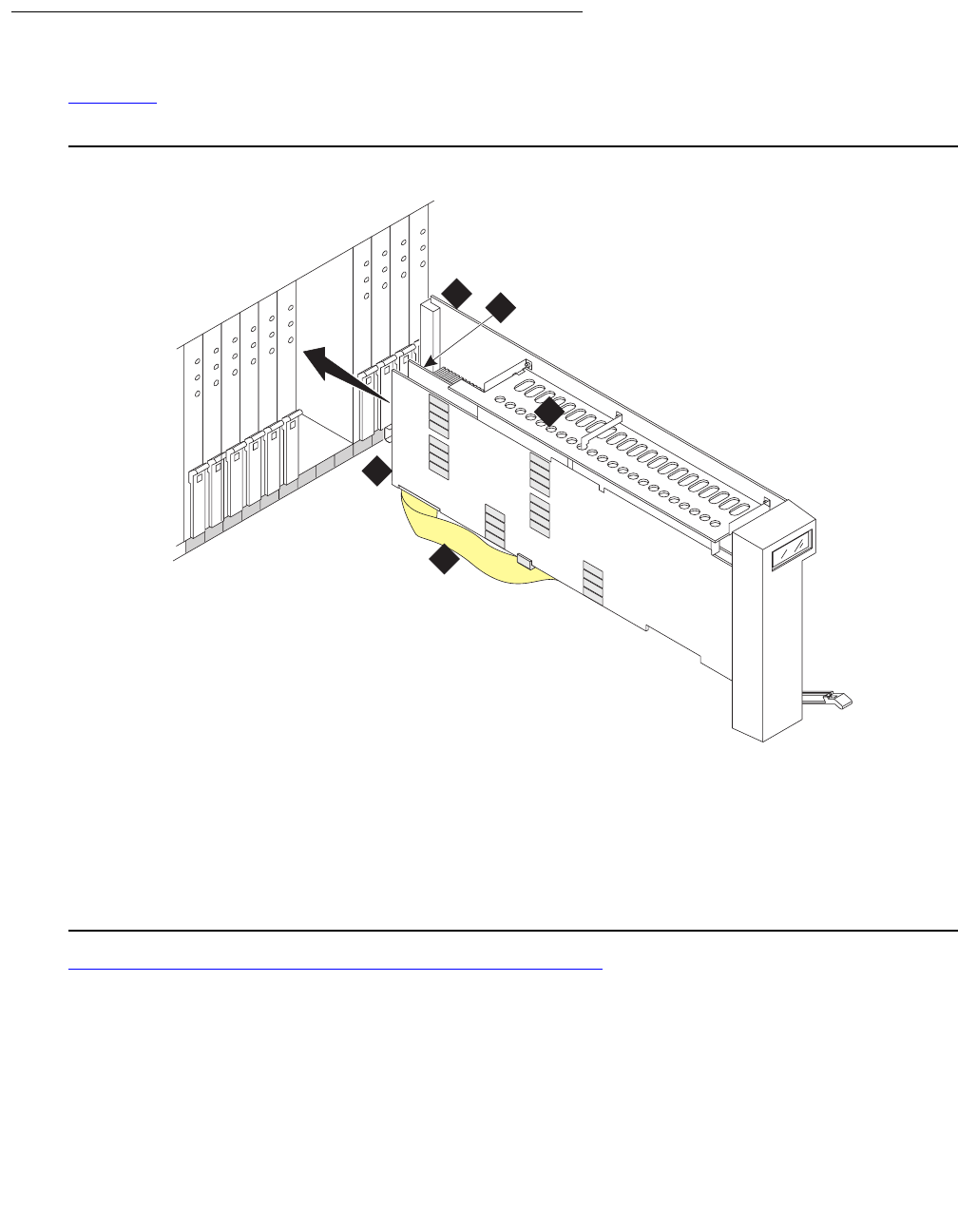
MAPD-BD (MAPD Interface Circuit Pack TN802)
Issue 1 June 2005 1519
Board Assembly and Cables
Figure 86 shows the circuit pack with the two additional boards connected through the side
plane.
Figure 86: TN802 board assembly
Figure 87: TN802 board assembly and cables (side view) on page 1520 shows a side view of
the three boards and interconnecting cables that make up the TN802.
Figure notes:
1. Main TN802 board 4. Side plane
2. Texas Microsystems Inc. (TMI) board 5. SCSA (Signal Computing System
Architecture) ribbon cable
3. Analogic board
45678910 11 12 13 14 15 16
indfmap2 KLC 031699
1
3
4
5
2
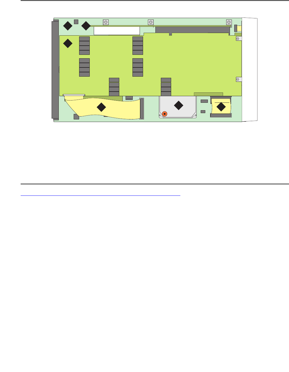
Communication Manager Maintenance-Object Repair Procedures
1520 Maintenance Procedures for Avaya Communication Manager 3.0, Media Gateways and Servers
Figure 87: TN802 board assembly and cables (side view)
Figure 88: TN802 board assembly and cables (end view) on page 1521 shows the end view of
the three boards and interconnecting cables on the TN802.
Figure notes:
1. Main TN802 board 4. SCSA (Signal Computing System Architecture) ribbon
cable
2. Side plane 5. Hard drive
3. Analogic board 6. Processor I/O ribbon cable
cddfmap2 KLC 040699
1 2
3
456
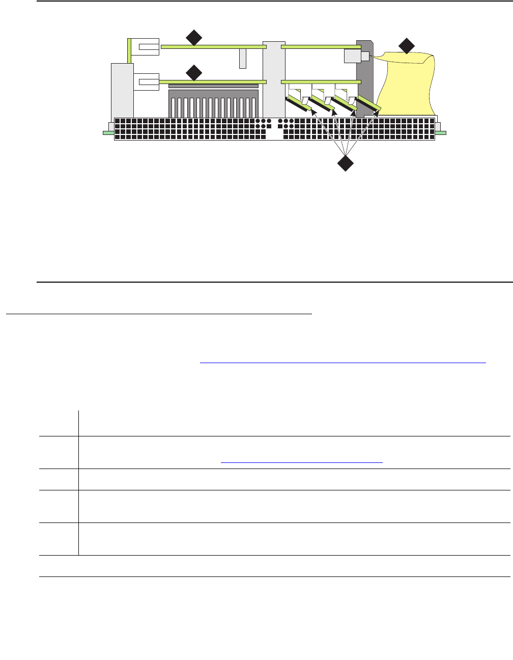
MAPD-BD (MAPD Interface Circuit Pack TN802)
Issue 1 June 2005 1521
Figure 88: TN802 board assembly and cables (end view)
Replacing the Hard Disk
The TN802 hard drive (Note 5 in Figure 87: TN802 board assembly and cables (side view) on
page 1520) can be replaced in the field.
Figure notes:
1. Analogic board 3. SIMMs (memory)1
1. If the board is seated and you hear fast beeping, it means that one of the small boards containing the
memory chips is dislodged. Secure the memory board firmly in the receptacle and reseat the circuit pack.
2. TMI (Texas Microsystems Inc.)
board
4. SCSA (Signal Computing System
Architecture) ribbon cable
ckdfmap3 KLC 040699
1
2
4
3
Table 549: Replacing the TN802 hard drive
Step Description Comments
1. Shut down Windows
2000.
Shut down Windows 2000 by either method described in
Shutting Down NT on the TN802 on page 1529.
2. Remove the circuit pack. Unlatch the circuit pack, and remove it from the carrier.
3. Remove the hard drive. Remove the 2 screws, and lift the hard drive out of its
mounting bracket.
4. Replace the hard drive. Position the new hard drive in the mounting bracket, and
replace the 2 screws (Step 3).
1 of 2
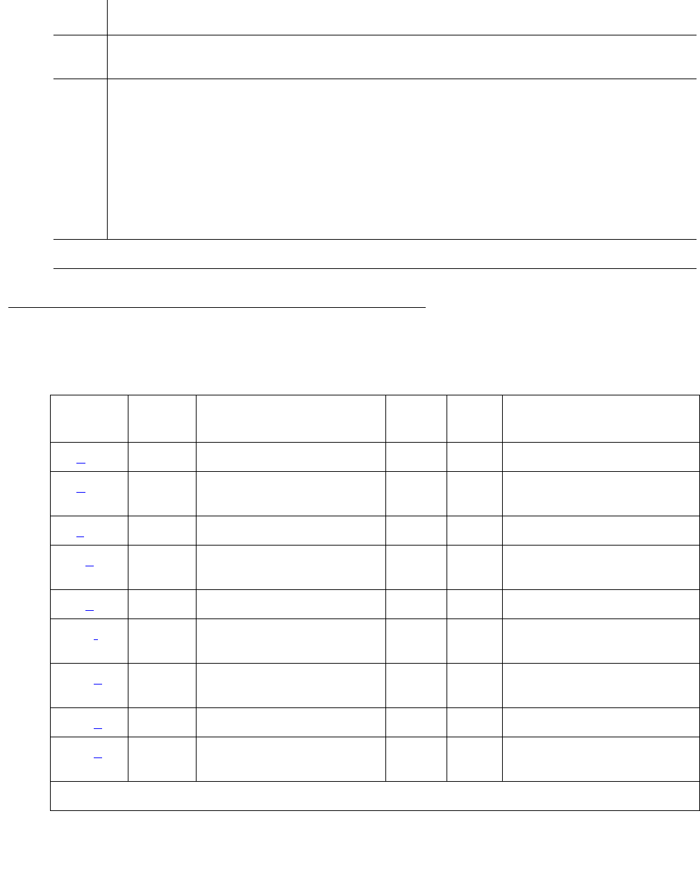
Communication Manager Maintenance-Object Repair Procedures
1522 Maintenance Procedures for Avaya Communication Manager 3.0, Media Gateways and Servers
Error Log Entries and Test to Clear Values
5. Replace the circuit pack. Slide the circuit pack into the slot, and lock the latching
lever.
6. Wait for initialization. Wait for:
●the circuit pack to reseat (faceplate LEDs light go
out).
●Windows 2000 boots (PC BOOT appears on the
faceplate LCD).
●IP Trunk application to run (IP TRK # appears on
the faceplate LCD).
Table 549: Replacing the TN802 hard drive (continued)
Step Description Comments
2 of 2
Table 550: MAPD (TN802) Error Log entries
Error
Type
Aux
Data
Associated Test Alarm
Level
On/Off
Board
Test to Clear Value
0 (a) 0 Any Any Any test board location
1 (b) 0 Circuit pack removed or
SAKI (#53)
MIN
WRN1ON
2 (c)
18 (d)0 busyout board
location
WRN OFF release board
location
23 (e)0 WRNOFFadd ds1 location
125 (f) none 3 None MIN
WRN2ON
257 (g) 65535 Control Channel Loop
(#52)
MIN ON test board location
l r 20
257 (g) Any None
513 (h)Any MIN
WRN3ON
1 of 3

MAPD-BD (MAPD Interface Circuit Pack TN802)
Issue 1 June 2005 1523
514 (i) 46086 MIN
WRN3ON
769 (j) 46085 MIN
WRN3ON
770 (k) 46096 MIN
WRN3ON
1025 (e) 4363 NPE Audit test (#50)
1281 Any Loss of Signal Alarm
Inquiry (#138)
MIN
WRN3OFF test board location
1537 (l) 46082 MIN
WRN3ON
1538 (m)Any MIN
WRN3ON
1793 Any Blue Alarm Inquiry test
(#139)
MAJ
MIN
WRN3
OFF test board location
2049 Any Red Alarm Inquiry test
(#140)
MIN
WRN3OFF test board location
2305 Any Yellow Alarm Inquiry test
(#141)
MIN
WRN3OFF test board location
2306 Any Yellow Alarm Inquiry test
(#141)
MIN
WRN3OFF test board location
2561 Any Major Alarm Inquiry test
(#142)
MIN
WRN3OFF test board location
2817 Minor Alarm Inquiry test
(#143)
MIN
WRN3OFF test board location
3073 to
3160 (n)
Any Slip Alarm Inquiry test
(#144)
MIN
WRN3OFF test board location
r 6
3330 (o) 46083 MIN
WRN3ON
3585 to
3601 (p)
Any Misframe Alarm Inquiry
test (#145)
MIN
WRN3OFF test board location
r 6
3840 (q) Any None
Table 550: MAPD (TN802) Error Log entries (continued)
Error
Type
Aux
Data
Associated Test Alarm
Level
On/Off
Board
Test to Clear Value
2 of 3

Communication Manager Maintenance-Object Repair Procedures
1524 Maintenance Procedures for Avaya Communication Manager 3.0, Media Gateways and Servers
Notes:
a. Error Type 0: Run the short test sequence first. If every test passes, run the long test
sequence. Refer to each test’s description and follow its procedures.
b. Error Type 1: the circuit pack has totally stopped functioning or is not fully administered.
The alarm is logged about 15 minutes after the circuit pack has been removed or 11
minutes after the SAKI test (#53) fails.
To be fully administered, a MAPD circuit pack must:
●Have an entry in the circuit plan (change circuit-pack)
●Be administered (add ds1 location)
●Be physically inserted into the correct slot
If the circuit pack has an entry in the circuit plan and the other two conditions are not met, a
MINOR alarm is logged. To resolve the error:
●Make sure the circuit pack is properly administered and that a functioning MAPD circuit
pack is inserted in the correct slot
or
●Completely remove the MAPD-BD from the system:
1. Shut down Windows 2000. See Shutting Down NT on the TN802 on page 1529.
2. Remove any administered DS1 trunks, access endpoints, or PRI endpoints associated
with the circuit pack from their respective trunk groups.
3. Remove the DS1 (remove ds1 location) and circuit pack (change
circuit-pack location) administration.
3841 (r) 4358
3842 (s) 46097
3843 (t) 46081
3999 (u) Any None
1. If ports are assigned to the circuit pack, then a minor alarm is raised. If no ports are assigned to the circuit
pack, then a warning alarm is raised. The alarm is raised after the circuit pack has been missing for a
period of 15 minutes. Warning alarms are also raised against any ports administered on the circuit pack.
2. Minor alarms on this MO may be downgraded to warning alarms based on values set in set options.
3. Major alarms on this MO may be downgraded to minor or warning based on values set in set options.
Table 550: MAPD (TN802) Error Log entries (continued)
Error
Type
Aux
Data
Associated Test Alarm
Level
On/Off
Board
Test to Clear Value
3 of 3

MAPD-BD (MAPD Interface Circuit Pack TN802)
Issue 1 June 2005 1525
If the circuit pack is properly administered and the red LED is still on, follow the instructions
for LED alarms without Alarm Log entry or with Error Type 1 on page 258.
c. Error Type 2: Windows 2000 is down and the system attempts to reset the board. If the
reset fails, the board may be bad.
1. Replace the circuit pack.
d. Error Type 18: The circuit pack has been busied out.
1. Release the board (release board location).
e. Error Type 23 and 1025: The MAPD-BD circuit pack is not completely administered.
To be fully administered, a MAPD circuit pack must:
●Have an entry in the circuit plan (change circuit-pack)
●Be administered (add ds1 location)
●Be physically inserted into the correct slot
The MAPD circuit pack differs from others in that inserting it into the switch backplane is not
enough to make the board usable.
f. Error Type 125, no Aux Data: A wrong circuit pack is inserted in the slot where this circuit
pack is logically administered. To resolve this problem:
●Remove the wrong circuit pack and insert the logically administered circuit pack
or
●Re-administer the slot (change circuit-pack) to match the circuit pack inserted.
g. Error Type 257 is associated with the Common Port circuit pack maintenance test. See
XXX-BD (Common Port Circuit Pack/Media Module) on page 2539 for details.
h. Error Type 513: Transient hardware problem, where Aux Data:
1. If the same Error Type/Aux Data value occurs more than once in a 24-hour period, the
circuit pack should be replaced. See Shutting Down NT on the TN802 on page 1529
before removing the circuit pack.
If the MAPD board detects only one of these hardware problems, then the error is resolved
when none of these faults are detected for 10 minutes.
i. Error Type 514: LAN External RAM Error; hardware fault in the PPE external RAM, used for
message buffering to and from the packet bus. This error should not occur regularly.
1. If this error occurs 10 times within 30 minutes, replace the circuit pack. See Shutting
Down NT on the TN802 on page 1529 before removing the circuit pack.
4352 External RAM failure
4353 Internal RAM failure
4355 Internal ROM failure

Communication Manager Maintenance-Object Repair Procedures
1526 Maintenance Procedures for Avaya Communication Manager 3.0, Media Gateways and Servers
j. Error Type 769: Transmit FIFO Underflow (threshold is 3 errors within 10 minutes); the
circuit pack cannot find the “end of frame” bit when transmitting a frame to the packet bus.
1. Clear the alarm with:
a. busyout board location
b. reset board location
c. test board location long clear
d. release board location
2. If the error recurs within 10 minutes, replace the circuit pack. See Shutting Down NT on
the TN802 on page 1529 before removing the circuit pack.
k. Error Type 770: Unable to Write LAN Translation RAM (threshold is 2 errors within 10
minutes); a call is aborted because there are no available translation RAM locations for the
call connection attempt.
1. Clear the alarm with:
a. busyout board location
b. reset board location
c. test board location long clear
d. release board location
2. If the error recurs within 10 minutes, replace the circuit pack. See Shutting Down NT on
the TN802 on page 1529 before removing the circuit pack.
l. Error Type 1537: There was a LAN Bus Timeout because the circuit pack transmitted too
many bytes on the LAN bus for a single frame. This condition may be caused by:
●an on-board fault
●faulty data received on one of the circuit pack’s external ports. If any of the ports on this
circuit pack are alarmed, refer to the repair procedures for those MOs.
If the error occurs 3 times within 10 minutes, the system raises the board alarm and isolates
it from the packet bus.
1. Clear the alarm and restore the board to the packet bus:
a. busyout board location
b. reset board location
c. test board location long clear
d. release board location
2. If the problem persists, and there are no PKT-BUS alarms or port alarms, replace the
circuit pack. See Shutting Down NT on the TN802 on page 1529 before removing the
circuit pack.

MAPD-BD (MAPD Interface Circuit Pack TN802)
Issue 1 June 2005 1527
m. Error Type 1538: Hyperactive circuit pack is out-of-service and may exhibit one or more of
the following symptoms:
●The common circuit pack tests (for example, Test #50 and/or Test #52) abort with Error
Code 2000.
●Port tests on this circuit pack return NO-BOARD.
●A busyout/release of the circuit pack has no effect on test results.
●A list configuration shows that the circuit pack and ports are properly installed.
The circuit pack is isolated from the system, and every trunk or port on this circuit pack is
placed into the out-of-service state. The system attempts to restore the circuit pack within
20 – 30 minutes. When no faults are detected for 20 – 30 minutes, the MAPD Interface
circuit pack is restored to normal operation, and every trunk or port on the MAPD Interface
circuit pack returns to the in-service state.
1. If the board is not restored to normal operation or the error recurs after the board is
restored to normal operation, escalate the problem.
n. Error Types 3073 – 3160: Board is reporting slip errors. Aux Data shows the last reported
slip count.
o. Error Type 3330: LAN Critical error; critical failure in the packet-bus interface to the circuit
pack. This failure may be due to an on-board or a packet-bus fault.
1. If the packet bus is alarmed, see PKT-BUS (Packet Bus) on page 1790 or PKT-INT
(Packet Interface) on page 1799 for repair procedures.
If the packet bus is not alarmed, clear this alarm and restore the board to the packet bus
using:
a. busyout board location
b. reset board location
c. test board location long clear
d. release board location
2. If the problem persists, and there are no PKT-BUS alarms, replace the circuit pack. See
Shutting Down NT on the TN802 on page 1529 before removing the circuit pack.
p. Error Types 3585–3601: The board received misframe errors. Aux Data shows the last
reported misframe count.
q. Error Type 3840: The circuit pack received a bad control channel message from the switch.
This error is not service-affecting, and requires no action. The Aux Data describes the
following error events:
4096 Bad major heading
4097 Bad port number
1 of 2

Communication Manager Maintenance-Object Repair Procedures
1528 Maintenance Procedures for Avaya Communication Manager 3.0, Media Gateways and Servers
r. Error Type 3841: The circuit pack detected a transient hardware logic error (for example,
program logic inconsistency). This error resolves when no faults are detected for 100
minutes. The value in Aux Data field (4358) indicates the type of hardware problem.
s. Error Type 3842: Bad Translation RAM Location Found error. The call continues by using
another translation location. This error is not service-affecting and requires no action.
t. Error Type 3843: LAN Receive Parity error. The circuit pack detected an error in a received
frame from the packet bus. These errors are most likely caused by a packet-bus problem,
but may be due to a circuit-pack fault.
1. Determine whether the problem is isolated to this circuit pack or the problem is caused by
packet-bus faults (see PKT-BUS (Packet Bus) on page 1790).
u. Error Type 3999: The circuit pack sent a large number of control-channel messages to the
switch within a short period of time.
4098 Bad data
4099 Bad sub-qualifier
4100 State inconsistency
4101 Bad logical link
Error Type 1538
(hyperactivity)
also present?
Then the system:
Y Takes the circuit pack out-of-service due to hyperactivity.
N Does not take the circuit pack out-of-service, but the circuit pack
has generated 50% of the messages necessary to be considered
hyperactive. This may be normal during heavy traffic periods.
2 of 2

MAPD-BD (MAPD Interface Circuit Pack TN802)
Issue 1 June 2005 1529
Shutting Down NT on the TN802
Before removing the TN802 circuit pack from the carrier, shut Windows NT down first by
following either procedure described in Table 551: Windows NT shutdown procedures on
page 1529:
System Technician-Demanded Tests:
Descriptions and Error Codes
Investigate tests in the order presented below. Clearing Error Codes associated with the one
test may also clear errors generated from other tests in the sequence.
Table 551: Windows NT shutdown procedures
Step Faceplate button PC interface
1. Push the recessed button on the front
faceplate and hold it in.
Click on the Start button in the lower left
corner.
2. “M shut” flashes on the LCD display Click on Shut Down.
3. When shutdown is complete, “MSHUT
#” displays (“#” is blinking).
Select the Shut down the computer?
radio button.
4. Remove the circuit pack. Click on OK.
5. Wait for the message indicating that
shutdown is complete.
6. Remove the circuit pack.
Order of Investigation Apply to
TN802?1
Short Test
Sequence
Long Test
Sequence
Reset
Board
Sequence
D/ND2
NPE Connection Audit test (#50) Y X ND
Control Channel Loop test (#52) Y X ND
Loss of Signal Alarm Inquiry test (#138) N X X ND
Blue Alarm Inquiry test (#139) N X X ND
1 of 2
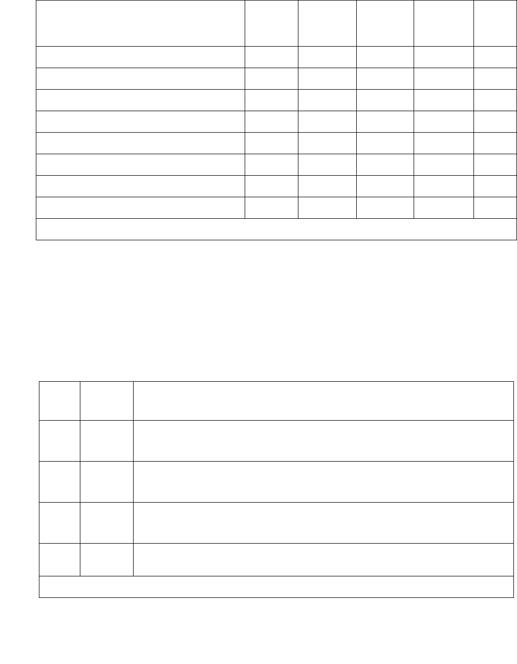
Communication Manager Maintenance-Object Repair Procedures
1530 Maintenance Procedures for Avaya Communication Manager 3.0, Media Gateways and Servers
NPE Connection Audit Test (#50)
The system sends the circuit pack’s on-board microprocessor a message to update the
network-connectivity translation for its SCOTCH-NPE chip.
Red Alarm Inquiry test (#140) N X X ND
Yellow Alarm Inquiry test (#141) N X X ND
Major Alarm Inquiry test (#142) N X X ND
Minor Alarm Inquiry test (#143) N X X ND
Slip Alarm Inquiry test (#144) N X X ND
Misframe Alarm Inquiry test (#145) N X X ND
Translation Update test (#146) N X X ND
SAKI Sanity test (#53) Y X D
1. N = No; this test either passes or ABORTS with Error Code 2000 (problem with NT)
2. D = Destructive; ND = Nondestructive
Order of Investigation Apply to
TN802?1
Short Test
Sequence
Long Test
Sequence
Reset
Board
Sequence
D/ND2
2 of 2
Table 552: Test #50 NPE Connection Audit Test
Error
Code
Test
Result
Description / Recommendation
None
2100
ABRT System resources required for this test are not available.
1. Retry the command at 1-minute intervals up to 5 times.
1019 ABRT The test aborted because a test was already running on the port.
1. Retry the command at 1-minute intervals up to 5 times.
FAIL Internal system error
1. Retry the command at 1-minute intervals up to 5 times.
PASS The circuit pack’s SCOTCH-NPE chip has been updated with its
translation.
1 of 2

MAPD-BD (MAPD Interface Circuit Pack TN802)
Issue 1 June 2005 1531
0NO
BOARD
The test could not relate the internal ID to the port (no board). This could
be due to incorrect translations, no board is inserted, an incorrect board
is inserted, or an insane board is inserted.
1. Ensure that the board translations are correct. Execute add ds1
location to administer the MAPD interface if it is not already
administered.
2. If the board was already administered correctly, check the error log to
determine whether the board is hyperactive. If so, the board was shut
down. Reseating the board re-initializes it.
3. If the board was found to be correctly inserted in Step 1, then enter
busyout board.
4. Enter the reset board command.
5. Enter the release board command.
6. Enter the test board long command.
This should re-establish the linkage between the internal ID and the port.
Table 552: Test #50 NPE Connection Audit Test (continued)
Error
Code
Test
Result
Description / Recommendation
2 of 2

Communication Manager Maintenance-Object Repair Procedures
1532 Maintenance Procedures for Avaya Communication Manager 3.0, Media Gateways and Servers
Control Channel Loop-Around Test (#52)
This test queries the circuit pack for its circuit pack code and vintage and verifies its records.
Table 553: Test #52 Control Channel Loop-Around Test
Error
Code
Test
Result
Description / Recommendation
None
2100
ABRT System resources required for this test are not available.
1. Retry the command at 1-minute intervals up to 5 times.
FAIL The circuit pack failed to return the circuit pack code or vintage.
1. Retry the command up to 5 times.
2. If the problem continues, and if the circuit pack is one of the Port
circuit packs, replace the circuit pack.
3. Otherwise, if the circuit pack is part of the SPE, use the procedure
described in Reseating and replacing circuit packs in Maintenance
Procedures (03-300192).
PASS Communication with this circuit pack is successful.
0NO
BOARD
The test could not relate the internal ID to the port (no board). This could
be due to incorrect translations, no board is inserted, an incorrect board is
inserted, or an insane board is inserted.
1. Ensure that the board translations are correct. Execute add ds1
location to administer the MAPD interface if it is not already
administered.
2. If the board was already administered correctly, check the error log to
determine whether the board is hyperactive. If so, the board was shut
down. Reseating the board re-initializes it.
3. If the board was found to be inserted correctly, enter busyout
board.
4. Enter the reset board command.
5. Enter the release board command.
6. Enter the test board long command.
This should re-establish the linkage between the internal ID and the port.

MAPD-BD (MAPD Interface Circuit Pack TN802)
Issue 1 June 2005 1533
SAKI Sanity Test (#53)
This test is destructive.
This test resets the circuit pack. The test is highly destructive and can only be initiated by a
system technician-demanded reset board location.
Table 554: Test #53 SAKI Sanity Test
Error
Code
Test
Result
Description / Recommendation
None ABRT System resources required for this test are not available.
1. Retry reset board at 1-minute intervals up to 5 times.
1015 ABRT Port is not out-of-service.
1. Busyout the circuit pack (busyout board location).
2. Execute reset board.
2100 ABRT System resources required for this test are not available.
1. Retry reset board at 1-minute intervals up to 5 times.
1 FAIL The circuit pack failed to reset.
2 FAIL The circuit pack failed to restart.
1. Execute reset board.
2. If the problem persists, replace the circuit pack.
PASS The circuit pack initializes correctly.
1. Run the short test sequence.
0NO
BOARD
The test could not relate the internal ID to the port (no board). This could
be due to incorrect translations, no board is inserted, an incorrect board
is inserted, or an insane board is inserted.
1. Ensure that the board translations are correct. Use add ds1
location to administer the MAPD interface if it is not already
administered.
2. If the board was already administered correctly, check the error log
to determine whether the board is hyperactive. If so, the board was
shut down. Reseating the board re-initializes it.
3. If the board was inserted correctly, enter busyout board.
4. Enter the reset board command.
5. Enter the release board command.
6. Enter the test board long command.
This should re-establish the linkage between the internal ID and the port.

Communication Manager Maintenance-Object Repair Procedures
1534 Maintenance Procedures for Avaya Communication Manager 3.0, Media Gateways and Servers
Loss of Signal Alarm Inquiry Test (#138)
This test is meaningless for the TN802 MAPD circuit pack.
Blue Alarm Inquiry Test (#139)
This test is meaningless for the TN802 MAPD circuit pack.
Table 555: Loss of Signal Inquiry Test (#138) results
Windows 2000
up on the
TN802?
Then Cause
Y Test passes
Y Test aborts with ABORT 2000 Error
Code.
Windows 2000 is not
communicating with the angel
firmware.
N Test aborts with ABORT 2000 Error
Code.
Windows 2000 down.
Table 556: Blue Alarm Inquiry Test (#139) results
Windows 2000
up on the
TN802?
Then Cause
Y Test passes
Y Test aborts with ABORT 2000 Error
Code.
Windows 2000 is not communicating
with the angel firmware.
N Test aborts with ABORT 2000 Error
Code.
Windows 2000 down.

MAPD-BD (MAPD Interface Circuit Pack TN802)
Issue 1 June 2005 1535
Red Alarm Inquiry Test (#140)
This test is meaningless for the TN802 MAPD circuit pack.
Yellow Alarm Inquiry Test (#141)
This test is meaningless for the TN802 MAPD circuit pack.
Major Alarm Inquiry Test (#142)
This test is meaningless for the TN802 MAPD circuit pack.
Table 557: Red Alarm Inquiry Test (#140) results
If Windows 2000 is up
on the TN802
When the switch confirms Red alarm:
YTest passes
N Test aborts with ABORT 2000 Error Code.
Table 558: Yellow Alarm Inquiry Test (#141) results
If Windows 2000
is up on the
TN802
When the switch confirms Yellow alarm:
Y Test passes
N Test aborts with ABORT 2000 Error Code.
Table 559: Major Alarm Inquiry Test (#142) results
If Windows 2000
is up on the
TN802
When the switch confirms Major alarm:
Y Test passes
N Test aborts with ABORT 2000 Error Code.

Communication Manager Maintenance-Object Repair Procedures
1536 Maintenance Procedures for Avaya Communication Manager 3.0, Media Gateways and Servers
Minor Alarm Inquiry Test (#143)
This test is meaningless for the TN802 MAPD circuit pack.
Slip Alarm Inquiry Test (#144)
This test is meaningless for the TN802 MAPD circuit pack.
Note:
Note: The query for slips always returns a 0 count.
Misframe Alarm Inquiry Test (#145)
This test is meaningless for the TN802 MAPD circuit pack.
Note:
Note: The query for misframes always returns a 0 count.
Table 560: Minor Alarm Inquiry Test (#142) results
If Windows 2000
is up on the
TN802
When the switch confirms Minor alarm:
Y Test passes
N Test aborts with ABORT 2000 Error Code.
Table 561: Slip Alarm Inquiry Test (#144) results
If Windows 2000
is up on the
TN802
When the switch confirms Slip alarm:
Y Test passes
N Test aborts with ABORT 2000 Error Code.
Table 562: Misframe Alarm Inquiry Test (#145) results
If Windows 2000
is up on the
TN802
When the switch confirms Misframe alarm:
Y Test passes
N Test aborts with ABORT 2000 Error Code.

MAPD-BD (MAPD Interface Circuit Pack TN802)
Issue 1 June 2005 1537
Translation Update Test (#146)
The Translation Update test sends the circuit pack-level information to the MAPD Interface
circuit pack. Translation includes the following data administered for a MAPD Interface circuit
pack (report from display ds1 location):
●DS1 Link Length between two DS1 endpoints
●Synchronization Source Control
●All Zero Suppression
●Framing Mode
●Signaling Mode
●Time Slot Number of the 697-Hz tone
●Time Slot Number of the 700-Hz tone
Table 563: Test #146 Translation Update Test
Error
Code
Test
Result
Description / Recommendation
ABRT Internal system error
1. Retry the command at 1-minute intervals up to 5 times.
FAIL Internal system software error.
1. Verify the MAPD Interface circuit pack translation (display ds1
location).
PASS Translation data has been downloaded to the MAPD Interface circuit
pack successfully.
1 of 2

Communication Manager Maintenance-Object Repair Procedures
1538 Maintenance Procedures for Avaya Communication Manager 3.0, Media Gateways and Servers
0NO
BOARD
The test could not relate the internal ID to the port (no board). This could
be due to incorrect translations, no board is inserted, an incorrect board
is inserted, or an insane board is inserted.
1. Ensure that the board translations are correct. Use add ds1
location to administer the MAPD interface if it is not already
administered.
2. If the board was already administered correctly, check the error log
to determine whether the board is hyperactive. If so, the board was
shut down. Reseating the board re-initializes it.
3. If the board was found to be inserted correctly, enter busyout
board.
4. Enter the reset board command.
5. Enter the release board command.
6. Enter the test board long command.
This should re-establish the linkage between the internal ID and the port.
Table 563: Test #146 Translation Update Test (continued)
Error
Code
Test
Result
Description / Recommendation
2 of 2

MEDPRO (Media Processor MAPD Circuit Pack)
Issue 1 June 2005 1539
MEDPRO (Media Processor MAPD Circuit Pack)
S8700 | 8710 / S8500
The TN802B MedPro circuit board provides voice over IP connectivity. The TN802B can run
either the:
●IP Trunk application allows the TN802B to emulate a DS1 circuit pack. In this mode, the
circuit pack is maintained as a standard DS1 board with its associated Tie trunk ports. The
TN802B operates as an integrated Internet Telephony server (ITS). It communicates with
other ITS boxes or IP trunk boards.
●Media Processor (MedPro) application allows the TN802B to act as a service circuit to
terminate generic RTP streams used to carry packetized audio over an IP network. As part
of the overall H.323 implementation, the TN802B or later circuit pack handles the audio
streams while the TN799DP C-LAN handles the TCP/IP signaling channels. This
maintenance plan applies only to a TN802B MedPro running the Media Processor
application.
The MedPro hardware combines an angel complex, a Windows 2000 PC and a TAP802 DSP
card in a 3-slot package. When operating as an IP trunk circuit pack, the MedPro emulates a
DS1 Tie Trunk circuit pack and blindly responds to DS1 trunk maintenance requests. Actual
maintenance is accomplished via the Windows 2000 interface and the ITS software diagnostics.
The Media Processor application is built upon the existing ITS software, and as such is not
administered in Communication Manager as a DS1 trunk, and does not emulate a DS1 for
maintenance purposes. Use the following Maintenance procedures for this application.
MO Name in
Alarm Log
Alarm
Level
Initial SAT Command to Run Full Name of MO
MEDPRO MAJ test board location sh Media Processor MAPD circuit pack
MEDPRO MIN test board location l Media Processor MAPD circuit pack
MEDPRO WRN test board location sh Media Processor MAPD circuit pack
Communication Manager Maintenance-Object Repair Procedures
1540 Maintenance Procedures for Avaya Communication Manager 3.0, Media Gateways and Servers
Error Log Entries and Test to Clear Values
Table 564: Media Processor MAPD Circuit Pack Maintenance Error Log Entries
Error
Type
Aux
Data
Associated Test Alarm
Level
On/Off
Board
Test to Clear Value
0 (a) 0 Any Any Any test board location
1 (b)0Circuit pack
removed or
SAKI (#53)
MIN
WRN1
1. If ports are assigned to the circuit pack, then a minor alarm is raised. If no ports are assigned to the circuit
pack, then a warning alarm is raised. The alarm is raised after the circuit pack has been missing for a
period of 15 minutes. Warning alarms are also raised against any ports administered on the circuit pack.
ON
18 (c)0 busyout
board
location
WRN OFF release board location
23 (d)0 WRNOFFadd ip-interface board
location
125 (e) None None MIN
WRN2
2. Minor alarms on this MO may be downgraded to warning based on values in set options.
ON
257 (f) 65535 Control
Channel Loop
test (#52)
MIN ON test board location l r 2
1538 (g) Any Hyperactivity MIN
WRN2ON
1793 Any NIC Loss Of
Signal
MIN
WRN2test board location l r 2
2049 (h) Any NT PC Failure MIN
WRN2reset board location
2305 Any IP Address
Inconsistency test board location l r 2
2561 Any Ping Error MIN
WRN2test board location l r 5
3841 (i) 4358 Log Only
3999 (j) Any None

MEDPRO (Media Processor MAPD Circuit Pack)
Issue 1 June 2005 1541
Notes:
a. Error Type 0: run the short test sequence first. If every test passes, run the long test
sequence. Refer to each test’s description, and follow its procedures.
b. Error Type 1: the circuit pack stopped functioning or is not fully administered. The alarm is
logged approximately 15 minutes after the circuit pack has been removed or 11-minutes
after the SAKI test (#53) fails.
To be fully administered, a MedPro circuit pack must:
●Be physically inserted into the correct slot
●Have an entry in the circuit pack screen (change circuit-pack)
●Have the MedPro IP address administered (change node-names)
●Be enabled (change ipserver-interface)
If the circuit pack has an entry in the circuit pack screen and the other conditions are not
met, a MINOR alarm is logged. To resolve the error:
●Make sure every condition for administration is met and that a functioning MedPro circuit
pack is inserted in the correct slot.
or
●Completely remove the MedPro from the system using the following steps:
1. Remove the administered IP-Interface associated with the circuit pack.
2. Physically remove the circuit pack from the slot.
3. Execute remove medpro location and change circuit-pack location.
c. Error Type 18: The MedPro Interface circuit pack has been busied out by busyout board
location.
1. Release the circuit pack (release board location).
d. Error Type 23: The MedPro circuit pack is not completely administered.
To be fully administered, a MedPro circuit pack must:
●Be physically inserted into the correct slot
●Have an entry in the circuit pack screen (change circuit-pack)
●Have the MedPro IP address administered (change node-names)
●Be enabled (change ipserver-interface)
A MEDPRO (and DS1, MAPD, UDS1-BD and DS1-BD) differs from most circuit packs in
that inserting the circuit pack into the switch is not enough to make the board usable. It must
also be administered.

Communication Manager Maintenance-Object Repair Procedures
1542 Maintenance Procedures for Avaya Communication Manager 3.0, Media Gateways and Servers
e. Error Type 125: No Aux Data: The wrong circuit pack is inserted in the slot where this
circuit pack is logically administered.
●Remove the wrong circuit pack and insert the logically administered circuit pack
or
●Re-administer this slot to match the circuit pack inserted (change circuit-pack).
f. Error Type 257: Associated with the Common Port circuit pack maintenance test. See
XXX-BD (Common Port Circuit Pack/Media Module) on page 2539 for details.
g. Error Type 1538: hyperactivity on a circuit pack. Hyperactivity occurs when the angel is
sending too many CCMS messages uplink, 400 per ten seconds for the TN802B, to switch
software. The circuit pack will be taken out of service. See error Type 3999.
h. Error Type 2049: the operating system is down. An attempt is made to reset the board
automatically. If the reset fails, the board is probably bad and should be replaced.
i. Error Type 3841: Inconsistent downlink message. This error is not service-affecting. No
action is required.
j. Error Type 3999: the circuit pack sent a large number of control channel messages to the
switch within a short period of time.
If Error Type 1538 is also present, the circuit pack was taken out-of-service due to
hyperactivity.
If Error Type 1538 is absent, the circuit pack has generated 50% of the messages
necessary to be considered hyperactive but was not taken out-of-service. This may be
completely normal during heavy traffic periods.
If this error type is logged when the circuit pack is being lightly used, it may indicate a
problem with the circuit pack or the equipment attached to it.
System Technician-Demanded Tests:
Descriptions and Error Codes
Investigate tests in the order they are presented. By clearing Error Codes associated with the
Control Channel Loop test (#52), you may also clear errors generated from other tests in the
sequence.
Order of Investigation Short Test
Sequence
Long Test
Sequence
Reset Board
Sequence
D/ND1
Control Channel Loop test (#52) X ND
SAKI Sanity test (#53) X D
1 of 2

MEDPRO (Media Processor MAPD Circuit Pack)
Issue 1 June 2005 1543
Control Channel Loop-Around Test (#52)
This test queries the circuit pack for its circuit pack code and vintage, and verifies its records.
IP Address Query (#1371) X X D
NIC Query test (#1383) X X ND
PING test (#1379) X X ND
Windows 2000 Reset (#1381) X D
1. D = Destructive; ND = Nondestructive
Order of Investigation Short Test
Sequence
Long Test
Sequence
Reset Board
Sequence
D/ND1
2 of 2
Table 565: Test #52 Control Channel Loop-Around Test
Error
Code
Test
Result
Description / Recommendation
None
2100
ABRT System resources required for this test are not available.
1. Retry the command at 1-minute intervals up to 5 times.
FAIL The circuit pack failed to return the circuit pack code or vintage.
1. Retry the command up to 5 times.
2. If the problem continues, and if the circuit pack is one of the Port
circuit packs, replace the circuit pack.
PASS Communication with this circuit pack is successful.
1 of 2

Communication Manager Maintenance-Object Repair Procedures
1544 Maintenance Procedures for Avaya Communication Manager 3.0, Media Gateways and Servers
SAKI Sanity Test (#53)
This test is destructive.
This test is only run as a part of a reset board procedure. For the Media Processor, use change
ipserver-interface to disable the Media Processor IP interface before performing this
reset board procedure. Use reset board location to reset other common circuit packs,
and to also execute this test.
A reset of this circuit pack will take about 3½ minutes.
0NO
BOARD
The test could not relate the internal ID to the port (no board). This
could be due to incorrect translations, no board is inserted, an incorrect
board is inserted, or an insane board is inserted.
1. Ensure that the board translations are correct. Administer the
MedPro interface if it is not already administered.
2. If the board was already administered correctly, check the error log
to determine whether the board is hyperactive. If so, the board was
shut down. Reseating the board re-initializes it.
3. If the board was found to be inserted correctly, enter busyout
board location.
4. Enter reset board location.
5. Enter release board location.
6. Enter test board location long.
This should re-establish the linkage between the internal ID and the port.
Table 565: Test #52 Control Channel Loop-Around Test (continued)
Error
Code
Test
Result
Description / Recommendation
2 of 2

MEDPRO (Media Processor MAPD Circuit Pack)
Issue 1 June 2005 1545
Table 566: Test #53 SAKI Sanity Test
Error
Code
Test
Result
Description / Recommendation
None ABRT System resources required for this test are not available.
1. Retry the command at 1-minute intervals up to 5 times.
1015 ABRT Port is not out-of-service.
1. Busyout the circuit pack.
2. Execute command again.
2100 ABRT System resources required for this test are not available.
1. Retry the command at 1-minute intervals up to 5 times.
2803 ABRT It is necessary to reset the board.
1. Use change ipserver-interfaces to disable the Media
Processor IP interface.
2. Execute the command again.
1 FAIL The circuit pack failed to reset.
2 FAIL The circuit pack failed to restart.
1. Execute command again.
2. If the problem persists, replace the circuit pack.
PASS The circuit pack initializes correctly.
1. Run the short test sequence.
Any NO
BOARD
This is normal if the test is being done when the board is not physically
in the system or when the system is booting up. Otherwise, there is
some inconsistency between the physical configuration and the data
kept in the system.
1. Verify that the board is physically in the system.
2. Verify that the system is not in a stage of booting up.
3. Retry the command at 1-minute intervals up to 5 times.

Communication Manager Maintenance-Object Repair Procedures
1546 Maintenance Procedures for Avaya Communication Manager 3.0, Media Gateways and Servers
IP Address Query Test #1371
This test is destructive.
A Media Processor has two administration interfaces:
●SAT interface using CCMS messages
●Windows 2000 PC interface
However, the Windows 2000 PC interface allows changes that cause the Media Processor
board to be inconsistent with Communication Manager translations (including the IP address,
subnet mask, and gateway translation).
This test causes the Communication Manager software to send its IP address, subnet mask,
and gateway translation (IP parameters) to the Media Processor. If these parameters do not
match MedPro’s values in its Windows registry, the parameter values are written into the
registry, and the Windows 2000 PC on the board asks the maintenance sub-system to reboot
the board. The board goes through a logical board removal and insertion.
When this test fails, it is an indication that an illegal change was made and the customer should
be notified. Also, writing the IP address parameters to the registry requires Windows 2000 on
the board to reboot.
If the IP addresses match, there is no need to update the registry or reboot Windows 2000.
Table 567: Test #1371 IP Address Query Test
Error
Code
Test
Result
Description / Recommendation
ABRT Internal system error
1. Retry the command at 1-minute intervals up to 5 times.
2100 ABRT Insufficient system resources to run this test.
1. Retry the command at 1-minute intervals up to 5 times.
2801 ABRT Unable to find IP address data for this location. Verify that the board is
administered.
2807 ABRT The board is administered, but not enabled in change
ipserver-interface.
FAIL The IP address, subnet mask, and gateway translation parameters in
the Communication Manager software and on the MedPro board do not
match. After the new values are written into the board’s Windows
registry, the Windows 2000 PC on the board must go through a reboot.
The board goes through a logical board removal and insertion.
1. If the problem persists, replace the circuit pack.
PASS Communication Manager translation data matches MedPro’s Windows
registry.

MEDPRO (Media Processor MAPD Circuit Pack)
Issue 1 June 2005 1547
Ping Test (#1379)
This test is a nondestructive test. It runs because of in-line errors, during periodic and
scheduled maintenance, and on demand.
This test verifies that the MedPro circuit pack can communicate to other nodes on the LAN by
pinging the gateway IP address as defined on the IP Interfaces screen (display
ip-interface location).
If the PING is successful, this test looks at the PING round trip delay. If a round trip delay of
greater than 4 seconds is reported, a separate error is logged. Excessive round trip delays do
not take the MedPro out of service.
Services can execute the standard ping command using the C-LAN board address and
MedPro IP address to see the actual round-trip delay.
Table 568: Test #1379 Ping Test
Error
Code
Test
Result
Description / Recommendation
1
2
ABRT Internal Error.
1. Retry the command at 1-minute intervals up to 3 times.
7ABRT Destination unreachable.
1. Verify that at least one destination reachable through this port is up.
2. Repeat the test.
3. If the test still aborts, escalate the problem.
2000 ABRT Response to the test was not received from the Media Processor circuit
pack within the allowable time period.
1. If this result occurs repeatedly, attempt to reset the circuit pack.
Reset the circuit pack by issuing busyout board location and
reset board location.
2. If this result occurs again, replace the circuit pack.
2012 ABRT Internal system error.
1. Retry the command at 1-minute intervals up to 3 times.
2100 ABRT The necessary system resources to execute the test could not be
allocated.
1. Retry the command at 1-minute intervals up to 5 times.
2500 ABRT Internal system error.
1. Retry the command at 1-minute intervals up to 3 times.
1 of 2

Communication Manager Maintenance-Object Repair Procedures
1548 Maintenance Procedures for Avaya Communication Manager 3.0, Media Gateways and Servers
Windows 2000 Reset Test (#1381)
This test resets the circuit pack. The test is highly destructive and can be initiated only by a
system technician-demanded reset board location.
2801 ABRT No IP address defined.
1. Verify IP Interfaces translations and retest.
2802 ABRT Different IP address pinged than software had allocated for the test.
1. Retry the command at 1-minute intervals up to 3 times.
2805 FAIL The number of pings received did not match the number sent (normally
one ping sent). This means that no ping responses were received from
the gateway defined on the ip-interfaces screen for the Media
Processor.
1. Retry the command at 1-minute intervals up to 3 times.
2807 ABRT The board is administered, but not enabled in change
ipserver-interface.
7
89
1007
FAIL Ping to the destination failed through this port due to the destination
down.
1. Verify that at least one destination reachable through this port is up.
2. Once verified, use test port location to verify that the H.323
Signaling Group Ping test (#1387) passes.
PASS Ping through this port successful.
Table 568: Test #1379 Ping Test (continued)
Error
Code
Test
Result
Description / Recommendation
2 of 2
Table 569: Test #1381 NT Reset Test
Error
Code
Test
Result
Description / Recommendation
None ABRT System resources required for this test are not available.
1. Retry reset board location at 1-minute intervals up to 5 times.
1 of 2

MEDPRO (Media Processor MAPD Circuit Pack)
Issue 1 June 2005 1549
1015 ABRT Port is not out-of-service.
1. Busyout the circuit pack (busyout board location).
2. Execute reset board location.
2100 ABRT System resources required for this test are not available.
1. Retry reset board location at 1-minute intervals up to 5 times.
1 FAIL The circuit pack failed to reset.
2 FAIL The circuit pack failed to restart.
1. Execute reset board location.
2. If the problem persists, replace the circuit pack.
PASS The circuit pack initializes correctly.
1. Run the short test sequence.
0NO
BOARD
The test could not relate the internal ID to the port (no board). This could
be due to incorrect translations, no board is inserted, an incorrect board
is inserted, or an insane board is inserted.
1. Ensure that the board translations are correct. Administer the
MEDPRO interface if it is not already administered.
2. If the board was already administered correctly, check the error log to
determine whether the board is hyperactive. If so, the board was shut
down. Reseating the board re-initializes it.
3. If the board was found to be inserted correctly, enter busyout
board location.
4. Enter reset board location.
5. Enter release board location.
6. Enter test board location long.
This should re-establish the linkage between the internal ID and the port.
Table 569: Test #1381 NT Reset Test (continued)
Error
Code
Test
Result
Description / Recommendation
2 of 2

Communication Manager Maintenance-Object Repair Procedures
1550 Maintenance Procedures for Avaya Communication Manager 3.0, Media Gateways and Servers
NIC Query Test (#1383)
This test is nondestructive.
The test passes if the Ethernet port is connected, and you can talk on the network. Otherwise, it
fails with no fail code or AUX data.
Table 570: Test #1383 NIC Query Test
Error
Code
Test
Result
Description / Recommendation
None ABRT System resources required for this test are not available.
1. Retry the command at 1-minute intervals up to 5 times.
1015 ABRT Port is not out-of-service.
1. Busyout the circuit pack (busyout board location).
2. Execute the command again.
2100 ABRT System resources required for this test are not available.
1. Retry the command at 1-minute intervals up to 5 times.
FAIL The Ethernet port is not connected, and you cannot talk on the network.
PASS The Ethernet port is connected, and you can talk on the network.
0NO
BOARD
The test could not relate the internal ID to the port (no board). This could
be due to incorrect translations, no board is inserted, an incorrect board
is inserted, or an insane board is inserted.
1. Ensure that the board translations are correct. Administer the
MedPro interface if it is not already administered.
2. If the board was already administered correctly, check the error log
to determine whether the board is hyperactive. If so, the board was
shut down. Reseating the board re-initializes it.
3. If the board was found to be inserted correctly, enter busyout
board location.
4. Enter reset board location.
5. Enter release board location.
6. Enter test board location long.
This should re-establish the linkage between the internal ID and the port.
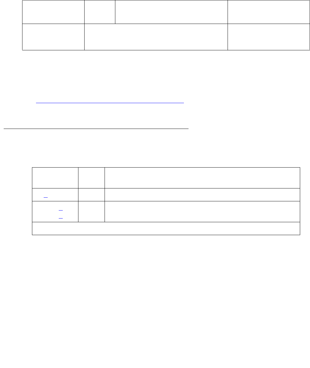
MEDPRO-C (Media-Processor Control)
Issue 1 June 2005 1551
MEDPRO-C (Media-Processor Control)
S8700 | 8710 / S8500
The TN2602AP IP Media Resource 320 provides high-capacity voice over Internet protocol
(VoIP) audio access to the switch for local stations and outside trunks. A MEDPRO-C MO is
logged in the Event Log when:
●the TN2602AP becomes active
See IPMEDPRO (TN2602AP IP Media Resource 320) on page 1380 for more information on
the TN2602AP.o, for CM3.0, the only entry weíll see is when the one board goes active.
MEDPRO-C Error Log Entries
Notes:
a. Error Type 1: the circuit pack has been removed from the system or is not fully
administered. The alarm is logged about 15 minutes after the circuit pack has been
removed, or 11 minutes after the SAKI test (#53) fails.
To be fully administered, an IP Media Resource must:
●Have an entry on the circuit pack screen (change circuit-pack)
●Have the Media Resource IP address administered (change node-names)
●Be enabled (change ip-interface)
MO Name in
Alarm Log
Alarm
Level
Initial SAT Command to Run Full Name of MO
MEDPRO-C This MO is not hardware-based, there will be
no alarms, commands to run, or tests to clear.
Events appear in display event logs.
Media-Processor Control
Table 571: Media Processor Control Circuit Pack Maintenance Error Log Entries
Error
Type
Aux
Data
Description
1 (a) The board was taken out of service.
10002 (b)
10012 (b)
Board transition to the active state

Communication Manager Maintenance-Object Repair Procedures
1552 Maintenance Procedures for Avaya Communication Manager 3.0, Media Gateways and Servers
●Be physically inserted into the correct slot
If the circuit pack has an entry on the circuit pack screen and any of the other conditions are
not met, a MINOR alarm is logged. To resolve the error:
●Make sure every condition for administration is met, and that a functioning Media
Resource is inserted in the correct slot.
●Completely remove the IP Media Resource from the system:
a. Remove the administered IP-Interface associated with the circuit pack.
b. Physically remove the circuit pack from the slot.
b. Error Type 1000210012: Simplex mode downlink. The reason for the state interchange to
active was a Simplex mode downlink to the circuit pack. When the board is inserted and
before it is used for any bearer traffic, the server configures the board to operate either in
Simplex or Duplex mode via a downlink message. That operation may trigger the
interchange.

MEDPROPT (TN802/TN2302/TN2602 MED PRO DSP PORT)
Issue 1 June 2005 1553
MEDPROPT (TN802/TN2302/TN2602 MED PRO DSP PORT)
S8700 | 8710 / S8500
The Media Processor Port (MEDPROPT) MO monitors the health of the Media Processor
(MEDPRO) digital signal processors (DSPs).
The TN802B MAP-D (Multi-Application Platform for DEFINITY) Media Processor circuit pack,
the TN2302, and TN2602 Media Processor circuit packs provide the audio bearer channels for
H.323 voice over IP calls.
●One TN802B circuit pack has one MEDPROPT media processing resource; that one
TN802B MEDPROPT can handle 31 channels, for a total of 31 channels per TN802B.
Note that the TN802B has 11 physical DSP devices but they are treated as one logical
MEDPROPT by Communication Manager software.
If the list ip-codec-set screen specifies only G.711 mu-law or G.711 a-law as the
audio codecs, the TN802B MEDPROPT can service 31 channels. If any other codec type
(G.723-5.3K, G.723-6.3K, or G.729) is administered, the TN802B MEDPROPT can service
22 channels.
●One TN2302AP has 8 MEDPROPTs; each TN2302 MEDPROPT has the processing
capacity to handle 8 G.711 coded channels, for a total of 64 channels per TN2302. Note
that early TN2302AP boards have eight physical DSP devices. Vintage 11 and later
TN2302AP boards have two physical DSP devices. Both board configurations provide
eight MEDPROPTs and a total of 64 channels.
When only G.711 codecs are in use the TN2302AP has the processing capacity to handle
64 channels. If only G.723/G.729 codecs are in use the TN2302AP has the processing
capacity to support 32 channels. If a combination of G.711 and G.723/G.729 codecs are in
use the number of channels supported will fall somewhere between 32 and 64. Use the
list ip-codec-set command to display the administered codecs.
●The capacity provided by the TN2602 is controlled by the Avaya Communication Manager
license file and may be set at either 80 G.711 channels or 320 G.711 channels. Depending
on the codecs used by individual calls the number of simultaneous calls supported will
vary. The TN2602 supports G.711, G.729A, G.729AB, and G.726 codecs.
If individual DSPs on the TN802B or TN2302AP or TN2602 fail, the board remains in-service at
lower capacity.
The MEDPROPT is a shared service circuit. It is shared between H.323 trunk channels and
H.323 stations. An idle channel is allocated to an H.323 trunk/station on a call-by-call basis.
MO Name in
Alarm Log
Alarm
Level
Initial SAT Command to Run Full Name of MO
MEDPROPT MIN
WRN test port location [short/
long] [repeat#] | [clear]
TN802/TN2302/TN2602
MEDPRO DSP PORT

Communication Manager Maintenance-Object Repair Procedures
1554 Maintenance Procedures for Avaya Communication Manager 3.0, Media Gateways and Servers
Error Log Entries and Test to Clear Values
Notes:
a. Error Type 0: Run the short test sequence first. If every test passes, run the long test
sequence. Refer to each test’s description and follow its procedures.
b. Error Type 1: For the TN802B only, less than three DSPs are OOS (out of service), and no
alarm is raised. The Aux Data field contains the number of DSPs that are OOS.
c. Error Type 18: the MEDPRO has been busied out by busyout port location.
1. Release the port (release port location).
d. Error Type 258: For the TN802B only, more than three, but less than 9 DSPs are OOS (out
of service), and a WARNING alarm is raised. The Aux Data field contains the number of
DSPs that are OOS.
e. Error Type 513: For the TN2302 and TN2602 only, the port is OOS (out of service) because
an associated DSP is bad.
Table 572: MEDPROPT Error Log Entries
Error
Type
Aux
Data
Associated Test Alarm
Level
On/Off
Board
Test to Clear Value
0 (a)0Any AnyAnytest board location
1 (b) Any DSP Capacity test
(#1382)
ON test board location l r
5
18 (c)0 busyout port
location
WRN OFF release port location
258 (d) Any DSP Capacity test
(#1382)
WRN ON test board location l r
5
513 (e) DSP Capacity test
(#1382)
MIN ON test port location
515 (f) Any DSP Capacity Query
test (#1382)
MIN ON test board location l r
5
769 Any TDM NIC
Loop-Around test
(#1380)
MIN ON test port location l r
10
1025 (g)Any

MEDPROPT (TN802/TN2302/TN2602 MED PRO DSP PORT)
Issue 1 June 2005 1555
f. Error Type 515: For the TN802B only, this error type indicates that every DSP is OOS (out
of service), and a MINOR alarm is raised. The Aux Data field contains the number of DSPs
that are OOS.
g. Error Type 1025: The port is OOS (out of service) because of a board-level failure. Check
for errors/alarms against the board, in particular ping problems, IP address inconsistency, or
board sanity problems.
1. Verify correct administration.
2. Check cabling and customer network before replacing circuit pack.
System Technician-Demanded Tests:
Descriptions and Error Codes
Investigate tests in the order presented below. Clearing Error Codes associated with the one
test may also clear errors generated from other tests in the sequence.
DSP Query Test (#1382)
This test is nondestructive.
For the TN802B
When using theTN802B, this test polls the circuit pack for the number of failed DSPs. If every
DSP is functional, the test passes and the board is operating at maximum capacity. If any DSPs
have failed, the test fails and reports the number of failed DSPs.
A failure of 3 or fewer DSPs does not result in an alarm. A failure of more than 3 and up to 8
DSPs results in a warning alarm. A failure of more than 8 DSPs results in a minor alarm. In all
cases, except when every DSP fails, the MEDPROPT continues to provide reduced capacity.
Order of Investigation Short Test
Sequence
Long Test
Sequence
D/ND1
1. D = Destructive; ND = Nondestructive
DSP Query test (#1382) X X ND
TDM NIC Loop-Around test (#1380) X X ND
Port Status test (#1407) X X ND

Communication Manager Maintenance-Object Repair Procedures
1556 Maintenance Procedures for Avaya Communication Manager 3.0, Media Gateways and Servers
For the TN2302 and TN2602
When using the TN2302 or TN2602, this test polls the circuit pack for the state of health of a
specific DSP. If the DSP is bad, an error will be logged and the board will be polled again. If the
circuit pack is still failing, the DSP will be taken out of service and a MINOR alarm will be raised.
Table 573: DSP Query Test (#1382)
Error
Code
Test
Result
Description / Recommendation
1014 ABRT Board not inserted.
1022 ABRT Board not valid for test.
2000 ABRT Response to the test was not received within the allowable time period.
1. Retry the command at 1-minute intervals up to 3 times.
2100 ABRT Could not allocate the necessary system resources to run this test.
1. Retry the command at 1-minute intervals up to 3 times.
2500 ABRT Internal system error
1. Retry the command at 1-minute intervals up to 3 times.
1–11 FAIL Some DSPs on the circuit pack have failed. The FAIL code is the number of
bad DSPs reported (TN802B only).
FAIL For the TN2302 and TN2602 only, the DSP failed. If it continues to fail, it
will be taken out of service.
PASS All 11 DSPs are functioning and in-service.
0NO
BOARD
No board was detected by the test.
1. Check the Error Log for wrong board (Error Type 125) or no board
(Error Type 131). Resolve either of these issues, if applicable.
2. Check that the board is properly translated and inserted. If so, check
for hyperactivity. If hyperactive, use reset board location.
3. Run the test again. If it fails, the circuit pack may be bad. Replace the
circuit pack and retest.

MEDPROPT (TN802/TN2302/TN2602 MED PRO DSP PORT)
Issue 1 June 2005 1557
DSP Port TDM Loop-Around Test (#1380)
This test is nondestructive.
This test sets up a loop-back path from the TDM bus out to the NIC edge of the Media
Processor and back to the TDM bus. The loop back is established by setting up the outbound IP
connection to send IP packets to the MedPro’s own IP address. The tone generator places a
test tone (440Hz) onto a timeslot. The timeslot is listened to by the Media Processor board. The
tone is routed through the board’s DSP farm, where it may undergo transcoding to G.723, etc.
The tone is looped back at the Network interface and back through the board where it is
converted back into standard PCM. The tone is placed onto a TDM timeslot and detected by a
tone detector port. The test passes if 440Hz is reported by the tone detector.
Table 574: DSP PORT TDM Loop-Around Test (#1380)
Error
Code
Test
Result
Description / Recommendation
1002 ABRT The system could not allocate timeslots for the test. The system may be
under heavy traffic conditions, or it may have timeslots out of service due
to TDM-BUS errors.
1. If the system has no TDM-BUS errors and is not handling heavy
traffic, retry the command at 1-minute intervals up to 3 times.
2. If the system has TDM-BUS errors, clear any errors, and retry the
command at 1-minute intervals up to 3 times.
3. If the command continues to abort, escalate the problem.
1003 ABRT The system could not allocate a tone receiver for the test. The system
may be oversized for the number of Tone Detectors present, or some
Tone Detectors may be out of service.
1. Resolve any TTR-LEV errors. Even if there are no TTR-LEV errors,
there may not be a Tone Detector available on the network that
contains the circuit pack being tested. Verify that there is at least one
Tone Detector on this network. This does not harm the system.
2. Resolve any TONE-PT errors.
3. If neither condition exists, retry the command at 1-minute intervals up
to 3 times.
1014 ABRT Board not inserted.
2000 ABRT Response to the test was not received in the allowable time period.
1. Retry the command at 1-minute intervals up to 3 times.
1 of 2

Communication Manager Maintenance-Object Repair Procedures
1558 Maintenance Procedures for Avaya Communication Manager 3.0, Media Gateways and Servers
2100 ABRT Could not allocate the necessary system resources to run this test.
1. Retry the command at 1-minute intervals up to 3 times.
2500 ABRT Internal system error.
1. Retry the command at 1-minute intervals up to 3 times.
2801 ABRT The TN802B/TN2302 Media Processor board has not been administered
on the ip-interfaces screen.
ANY FAIL The test did not detect the test tone through the looparound connection.
1. Test the tone-clock in the port network that contains the media
processor under test.
2. If the tone-clock is healthy, test the media processor board again.
3. If the test continues to fail, replace the media processor board.
PASS The board is functioning properly.
0NO
BOARD
No board was detected by the test.
1. Resolve either wrong board (Error 125) or no board (Error 131)
issues, if applicable.
2. Check that the board is properly translated and inserted. If so, check
for hyperactivity (Error 1538). If hyperactive, use reset board
location.
3. Run the test again. If it fails, the NCE chip on board may be bad.
Replace the board and retest.
Table 574: DSP PORT TDM Loop-Around Test (#1380) (continued)
Error
Code
Test
Result
Description / Recommendation
2 of 2

MEDPROPT (TN802/TN2302/TN2602 MED PRO DSP PORT)
Issue 1 June 2005 1559
DSP Port Status Query Test (#1407)
This test is nondestructive.
This test queries the state of the DSP port.
Table 575: DSP Port Status Query Test (#1407)
Error
Code
Test
Result
Description / Recommendation
1 ABRT This port is Out of service (OOS) due to:
●A board-level problem, for example no IP address has been
translated for this location.
●A DSP hardware problem (see DSP Port TDM Loop-Around Test
(#1380) on page 1557 and DSP Query Test (#1382) on
page 1555).
2 ABRT This port has been made maintenance busy.
1002 ABRT The system could not allocate timeslots for the test. The system may be
under heavy traffic conditions, or it may have timeslots out of service
due to TDM-BUS errors.
1. If the system has no TDM-BUS errors and is not handling heavy
traffic, retry the command at 1-minute intervals up to 3 times.
2. If the system has TDM-BUS errors, clear any errors, and retry the
command at 1-minute intervals up to 3 times.
3. If the command continues to abort, escalate the problem.
2000 ABRT Response to the test was not received in the allowable time period.
1. Retry the command at 1-minute intervals up to 3 times.
2100 ABRT Could not allocate the necessary system resources to run this test.
1. Retry the command at 1-minute intervals up to 3 times.
2500 ABRT Internal system error.
1. Retry the command at 1-minute intervals up to 3 times.
FAIL Unable to get status for this port. Verify that this board has been
administered correctly, and that there are no alarms against this board.
PASS The board is functioning properly and the port is in-service and available.
0NO
BOARD
No board was detected by the test.
1. Resolve either wrong board (Error 125) or no board (Error 131)
issues, if applicable.
2. Check that the board is properly translated and inserted. If so, check
for hyperactivity (Error 1538). If hyperactive, use reset board
location.
3. Run the test again. If it fails, replace the board and retest.

Communication Manager Maintenance-Object Repair Procedures
1560 Maintenance Procedures for Avaya Communication Manager 3.0, Media Gateways and Servers
MET-BD (MET Line Circuit Pack)
S8700 | 8710 / S8500
See XXX-BD (Common Port Circuit Pack/Media Module) on page 2539 for circuit pack-level
errors. See also MET-LINE (MET Line) Maintenance documentation for related line information.
MO Name in
Alarm Log
Alarm
Level
Initial SAT Command to Run Full Name of MO
MET-BD MIN test board location sh MET Line circuit pack
MET-BD WRN test board location sh MET Line circuit pack

MET-LINE (MET Line)
Issue 1 June 2005 1561
MET-LINE (MET Line)
S8700 | 8710 / S8500
The TN735 MET Line circuit pack supports four Multibutton Electronic Telephone (MET) station
sets. Each MET set uses three pairs of wires: an analog voice pair, a transmit pair, and a
receive pair. Power is sent over the transmit and receive pairs. The MET Line circuit pack
supports every 10-, 20-, and 30-button set.
This section describes MET-LINE (MET Line) maintenance. MET-LINE maintenance is closely
related to, and interacts with, MET-BD (MET Line circuit pack) maintenance. This interaction
should be kept in mind when troubleshooting MET Line problems.
This section occasionally refers to a station’s service states. The service states are defined as
follows:
Use status station to determine terminal service state. Status is reported as out-of-service,
in-service, or disconnect, which means the station is in the ready-for-service state.
MO Name in
Alarm Log
Alarm
Level
Initial SAT Command to Run Full Name of MO
MET-LINE MIN test port location l MET Line
MET-LINE WRN test port location sh MET Line
Out-of-Service The port, and thus the station, have been removed from service.
A busyout of a port will cause it to be out-of-service.
Ready-for-Service The port on the circuit pack has been put into service, but the
voice terminal has not yet established signaling
communications with the port.
In-Service The voice terminal has established signaling communications
with the port, and the system is ready to process calls to and
from that station. A terminal in the ready-for-service state will
progress to the in-service state if it is functioning normally, but it
can also be forced into the in-service state if it goes off-hook.

Communication Manager Maintenance-Object Repair Procedures
1562 Maintenance Procedures for Avaya Communication Manager 3.0, Media Gateways and Servers
Error Log Entries and Test to Clear Values
Notes:
a. Error Type 0: run the short test sequence first. If every test passes, run the long test sequence. Refer to
each test’s description and follow its procedures.
Table 576: MET Line Error Log Entries
Error
Type
Aux
Data
Associated Test Alarm
Level
On/Off
Board
Test to Clear Value
0 (a) 0 Any Any Any test port location sh r 1
1 (b) 40987 None
18 (c)0 busyout port
location
WRN OFF release port location
130 (d) None WRN ON test port location sh
257 (e) 40988 None MIN
WRN1
1. Major or Minor alarms MO can be downgraded to Warning based on the values in set options.
OFF
513 (f) 40965 Hybrid Line
Station Audits
(#61)
WRN OFF test port location sh r 4
769 Port Diagnostic
test (#35)
MIN
WRN1ON test port location l r 3
1025 Hybrid and Conf.
Circuits (#57)
MIN
WRN1ON test port location l r 3
1537 (g) 40968 None MIN
WRN1OFF
1793 TDM NPE
Crosstalk test
(#6)
MIN
WRN1ON test port location l r 3
2049 (h) 32770
2049 (h) 40967
3840 (i) 40989

MET-LINE (MET Line)
Issue 1 June 2005 1563
b. Error Type 1: the data link between the port and the terminal is not operational (that is, the
port circuitry has detected an off-board problem). Verify that the MET set is connected and
that the EPF (Electronic Power Feed) test passes. If data transmission problems are
experienced, check for defective wiring or a defective voice terminal, or move terminal
electrically closer to the switch (that is, reduce the length of the wiring between the terminal
and the switch). If the problem persists, replace the circuit pack. Once the problem is
resolved, the system retires the alarm after a predetermined time delay.
c. Error Type 18: is logged when maintenance personnel busyout the port. The port is
released from busyout using release port location.
d. Error Type 130: the circuit pack has been removed or has been insane for more than 11
minutes. To clear the error, reinsert or replace the circuit pack.
e. Error Type 257: the EPF has been turned off due to an overcurrent condition at the voice
terminal. Check for defective wiring or a damaged jack, and verify that the voice terminal is
an MET set. Once the problem is resolved, the system retires the alarm after a
predetermined time delay.
f. Error Type 513: the EPF inquiry audit has returned “epf-no-load” messages. This usually
indicates that the voice terminal has been disconnected or that there is a defect in the wiring
to the terminal. Check out both possibilities.
When the EPF inquiry audit subsequently receives an “epf-on-ok” or an “epf-off-ok”
message, the system will take action to retire the alarm.
g. Error Type 1537: the port has reported a problem with the data link to the voice terminal.
Ignore this error if there are no complaints about the voice terminal. Otherwise, make sure
the voice terminal is connected, check for defective wiring, check for a defective voice
terminal, and decrease the length of the wiring between the voice terminal and the switch. If
the problem persists, replace the circuit pack.
h. Error Type 2049, Aux Data 32770: the voice terminal went off-hook while it was in the
ready-for-service state. Use status station to determine the state of the voice terminal.
The off-hook should have moved the station to in-service. No repair action is necessary.
Error Type 2049, Aux Data 40967: this code is generated when the link between the circuit
pack and the voice terminal is successfully reset. No repair action is necessary.
i. Error Type 3840: the hardware sent an uplink message indicating that the Electric Power
Feed (EPF) is not loaded, that is, it is not currently supplying power to a voice terminal. No
repair action is necessary.

Communication Manager Maintenance-Object Repair Procedures
1564 Maintenance Procedures for Avaya Communication Manager 3.0, Media Gateways and Servers
System Technician-Demanded Tests:
Descriptions and Error Codes
Investigate tests in the order presented below. Clearing Error Codes associated with the one
test may also clear errors generated from other tests in the sequence.
NPE Crosstalk Test (#6)
The NPE Crosstalk test verifies that this port’s NPE channel talks on the selected time slot and
never crosses over to time slots reserved for other connections. If the NPE is not working
correctly, one-way and noisy connections may be observed. This test is part of a port’s long test
sequence and takes about 20 to 30 seconds to complete.
Table 577: System Technician-Demanded Tests: MET-LINE
Order of Investigation Short Test
Sequence
Long Test
Sequence
D/ND1
1. D = Destructive, ND = Nondestructive
NPE Crosstalk test (#6) X ND
Port Diagnostic test (#35) X ND
MFAT Electronic Power Feed test (#56) X ND
Hybrid Circuit and Conference Circuit test (#57) X ND
Station Lamp Update test (#60) X X ND
Station Audits test (#61) X X ND
Ringer Update test (#62) X X ND
Table 578: Test #6 NPE Crosstalk Test
Error
Code
Test
Result
Description / Recommendation
ABRT Could not allocate the necessary system resources to run this test.
1. Retry the command at 1-minute intervals up to 5 times.
1 of 4

MET-LINE (MET Line)
Issue 1 June 2005 1565
1000 ABRT System resources required to run this test are not available. The port may
be busy with a valid call.
1. Use display port location to determine the station extension of
the port. Use status station to determine the service state of the
port. If the port is in use, wait until the port is idle before testing.
2. If the port status is idle, then retry the command at 1-minute intervals
up to 5 times.
1001 ABRT System resources required to run this test are not available. This could be
due to a failure to seize the port.
1. Retry the command at 1-minute intervals up to 5 times.
1002 ABRT The system could not allocate time slots for the test. The system may be
under heavy traffic conditions or it may have time slots out-of-service due
to TDM-BUS errors.
1. If the system has no TDM-BUS errors and is not handling heavy
traffic, repeat test at 1-minute intervals up to 5 times.
1003 ABRT The system could not allocate a tone receiver for the test. The system
may be oversized for the number of Tone Detectors present or some Tone
Detectors may be out-of-service.
1. Resolve any TTR-LEV errors.
2. Resolve any TONE-PT errors.
3. If neither condition exists, retry the test at 1-minute intervals up to 5
times.
1004 ABRT The port was seized by a valid call during the test. The test has been
aborted.
1. Use display port location to determine the station extension of
the port. Use status station to determine the service state of the
port. If the port is in use, wait until the port is idle before testing.
2. Retry the command at 1-minute intervals up to 5 times.
Table 578: Test #6 NPE Crosstalk Test (continued)
Error
Code
Test
Result
Description / Recommendation
2 of 4

Communication Manager Maintenance-Object Repair Procedures
1566 Maintenance Procedures for Avaya Communication Manager 3.0, Media Gateways and Servers
1018 ABRT Test disabled by administration. This only applies to analog stations. The
default for this field is y, so you may want to determine why it was turned
off on this station.
1. To enable the test for the particular analog station being tested, enter
change station extension and set the Test field on the Station
screen to y.
2000 ABRT Response to the test request was not received within the allowable time
period.
1. Retry the command at 1-minute intervals up to 5 times.
2020 ABRT The test did not run due to an already existing error on the specific port or
a more general circuit pack error.
1. Examine Error Log for existing errors against this port or the circuit
pack and attempt to diagnose the already existing error.
2100 ABRT System resources required to run this test are not available. This could be
due to a failure to seize the port.
1. Retry the command at 1-minute intervals up to 5 times.
Any FAIL This test can fail due to on-board or off-board problems. Off-board
problems of concern include EXP-PN, EXP-INTF, or RMC-ENV faults,
TDM-BUS faults, and faults associated with the tone detectors/tone
generators. Clear every off-board problem before replacing the board.
Keep in mind that a TDM-BUS problem is usually the result of a faulty
board connected to the backplane or bent pins on the backplane.
1. Resolve any EXP-PN, EXP-INTF, or RMC-ENV errors.
2. Resolve any TDM-BUS errors.
3. Resolve any TONE-BD and/or TONE-PT errors.
4. Test the board when the faults from steps 1, 2, and 3 are cleared.
Replace the board only if the test fails.
PASS The port uses its allocated time slots correctly. Investigate user-reported
troubles on this port using other port tests and by examining station, trunk,
or external wiring.
Table 578: Test #6 NPE Crosstalk Test (continued)
Error
Code
Test
Result
Description / Recommendation
3 of 4

MET-LINE (MET Line)
Issue 1 June 2005 1567
Port Diagnostic Test (#35)
This test checks a port's battery feed circuitry. The battery feed circuitry is tested for proper
battery voltage by testing the switchhook state. In response to the test message, the on-board
firmware terminates the line and checks for switch-hook presence. The termination is then
removed, and a check is made for no switch-hook presence. The MET set must be on-hook for
the test to execute.
0NO
BOARD
The test could not relate the internal ID to the port (no board). This could
be due to incorrect translations, no board is inserted, an incorrect board is
inserted, or an insane board is inserted.
1. Check to ensure that the board translations are correct. Use list
config and resolve any problems that are found.
2. If the board was found to be inserted correctly, enter busyout board
location.
3. Enter the reset board location command.
4. Enter the release board location command.
5. Enter test board location long. This should re-establish the
linkage between the internal ID and the port. If this is not the case,
check to ensure that there is a valid board inserted.
Table 578: Test #6 NPE Crosstalk Test (continued)
Error
Code
Test
Result
Description / Recommendation
4 of 4
Table 579: Test #35 Port Diagnostic Test
Error
Code
Test
Result
Description / Recommendation
ABRT Internal system error.
1. Retry the command at 1-minute intervals up to 5 times.
1 of 3

Communication Manager Maintenance-Object Repair Procedures
1568 Maintenance Procedures for Avaya Communication Manager 3.0, Media Gateways and Servers
1000 ABRT System resources required to run this test are not available. The port
may be busy with a valid call.
1. Use display port location to determine the station extension
of the port. Use status station to determine the service state of
the port. If the port is in use, wait until the port is idle before testing.
2. If the port status is idle, then retry the command at 1-minute intervals
up to 5 times.
1004 ABRT The port was seized by a valid call during the test. The test has been
aborted.
1. Use display port location to determine the station extension
of the port. Use status station to determine the service state of
the port. If the port is in use, wait until the port is idle before testing.
The battery feed circuitry is tested for proper battery voltage by testing
the switchhook state. In response to the test message, the on-board
firmware terminates the line and checks for switch-hook presence. The
termination is then removed, and a check is made for no switch-hook
presence. The MET set must be on-hook for the test to execute.
1. If the port status is idle, then retry the command at 1-minute intervals
up to 5 times.
1018 ABRT Test disabled by software patch.
2000 ABRT This port may have been busied out.
1. Look in the Error Log for Error Type 18 (port busied out) for this port.
If this error type is present, then release the port using release
station extension and run the test again.
2. Make sure that the terminal is connected.
3. Retry the command at 1-minute intervals up to 5 times.
2100 ABRT Could not allocate the necessary system resources to run this test. This
could be due to a failure to seize the port.
1. Retry the command at 1-minute intervals up to 5 times.
Table 579: Test #35 Port Diagnostic Test (continued)
Error
Code
Test
Result
Description / Recommendation
2 of 3

MET-LINE (MET Line)
Issue 1 June 2005 1569
MFAT Electronic Power Feed (#56)
The software requests that the EPF be turned on for a given port. The hardware then attempts
to turn on that port’s station power unit. If no current is drawn, the station is probably not
connected. If an overcurrent condition is sensed (too much current is drawn), a short may exist
in the loop, or the voice terminal may be defective. The test results in a message indicating that
either the EPF was turned on successfully with no problems, or an overcurrent condition exists.
This test is repeated after a 5 second delay. If either test is not successful, the test aborts.
Although this test will never actually return a fail result (except for the internal system error), an
error type 257 entry will be made in the error log when the test has completed if the overcurrent
case is detected by the hardware.
FAIL Battery Feed test failed. This port is out-of-service.
1. Other ports on this circuit pack are not affected. Place user on a
different port, if available, until a replacement circuit pack can be
obtained.
2. Replace circuit pack when available.
PASS Battery Feed test passed. Current flow is properly detected for this port.
1. If users are reporting problems, examine connections to the port.
0NO
BOARD
The test could not relate the internal ID to the port (no board). This could
be due to incorrect translations, no board is inserted, an incorrect board
is inserted, or an insane board is inserted.
1. Check to ensure that the board translations are correct. Use list
config, and resolve any problems that are found.
2. If the board was found to be inserted correctly, enter busyout
board location.
3. Enter the reset board location command.
4. Enter the release board location command.
5. Enter test board location long. This should re-establish the
linkage between the internal ID and the port. If this is not the case,
check to ensure that there is a valid board inserted.
Table 579: Test #35 Port Diagnostic Test (continued)
Error
Code
Test
Result
Description / Recommendation
3 of 3

Communication Manager Maintenance-Object Repair Procedures
1570 Maintenance Procedures for Avaya Communication Manager 3.0, Media Gateways and Servers
Table 580: Test #56 MFAT Electronic Power Feed Test
Error
Code
Test
Result
Description / Recommendation
ABRT The test was aborted due to an internal system error on a software
request to the board.
1. Retry the command at 1-minute intervals up to 5 times.
1000 ABRT System resources required to run this test are not available. The port may
be busy with a valid call.
1. Use display port location to determine the station extension
of the port. Use status station to determine the service state of
the port. If the port is in use, wait until the port is idle before testing.
2. If the port status is idle, then retry the command at 1-minute intervals
up to 5 times.
FAIL The test failed with an internal error while it was attempting to turn on the
EPF.
1. Retry the command at 1-minute intervals up to 5 times.
PASS Electronic Power Feed test passed. The message to turn on the power to
the station was successfully sent to the port.
1. Although this test will never actually return a FAIL result except for the
internal system error described above, it will log an error if the
overcurrent case is detected by the hardware. Check the Error Log for
any entries with Error Type 257 when the test has completed.
2. If Error Type 257 does not appear in the Error Log within 10 seconds
after completion of this test, it is safe to assume that the test sensed
no problems with the power to the station. You can verify that the
station is powered up correctly by executing a self-test on the station,
and checking that every feature button is operating.
3. The appearance of Error Type 257 in the Error Log indicates a station
power problem. Check for a wiring short, a damaged jack, a defective
voice terminal, or an incorrect type of terminal.
1 of 2

MET-LINE (MET Line)
Issue 1 June 2005 1571
MET Circuit and Conference Circuit Test (#57)
This test checks two different port circuit functions. The Hybrid Circuit test performs an analog
reflective loop-around measurement on the port’s hybrid circuitry. The Conference Circuit test
performs a conference test on the port’s NPE.
For Hybrid Circuit test results to be valid, a voice terminal must be connected to the port being
tested. The test instructs the on-board microprocessor to put the port in analog reflective
loop-around mode. The Tone-Clock circuit pack supplies a 1004-Hz tone to the port’s listen time
slot and a GPTD (General-Purpose Tone Detector) measures the level of the reflected signal
appearing on port’s talk time slot.
The Conference test is performed only if the Hybrid Circuit test passes. The Conference Circuit
test verifies that the Network Processing Element (NPE) can correctly conference several test
tones together. The test is executed in two parts. The first half of the test verifies operation of
the NPE’s first three conference channels, and the second half verifies the NPE’s remaining
four conference channels. The test puts the NPE in loop-around mode and instructs it to talk on
a specified time slot while listening to a 1004-Hz tone using the Conference Channels. A GPTD
then measures the signal and noise levels of the conferenced output and reports whether or not
these fall within a specified acceptable range.
0NO
BOARD
The test could not relate the internal ID to the port (no board). This could
be due to incorrect translations, no board is inserted, an incorrect board is
inserted, or an insane board is inserted.
1. Check to ensure that the board translations are correct. Use list
config and resolve any problems that are found.
2. If the board was found to be inserted correctly, enter busyout
board location.
3. Enter the reset board location command.
4. Enter the release board location command.
5. Enter test board location long.
This should re-establish the linkage between the internal ID and the port.
If this is not the case, check to ensure that there is a valid board inserted.
Table 580: Test #56 MFAT Electronic Power Feed Test (continued)
Error
Code
Test
Result
Description / Recommendation
2 of 2

Communication Manager Maintenance-Object Repair Procedures
1572 Maintenance Procedures for Avaya Communication Manager 3.0, Media Gateways and Servers
Table 581: Test #57 Hybrid Circuit and Conference Circuit Test
Error
Code
Test
Result
Description / Recommendation
ABRT Could not allocate the necessary system resources to run this test.
1. Retry the command at 1-minute intervals up to 5 times.
1000 ABRT System resources required to run this test are not available. The port
may be busy with a valid call.
1. Use display port location to determine the station extension
of the port. Use status station to determine the service state of
the port. If the port is in use, wait until the port is idle before retesting.
2. If the port status is idle, then retry the command at 1-minute intervals
up to 5 times.
1001 ABRT System resources required to run this test were not available. This could
be due to a failure to seize the port.
1. Retry the command at 1-minute intervals up to 5 times.
1002 ABRT The system could not allocate time slots for the test. The system may be
under heavy traffic conditions or it may have time slots out-of-service due
to TDM-BUS errors.
1. If the system has no TDM-BUS errors and is not handling heavy
traffic, repeat test at 1-minute intervals up to 5 times.
1003 ABRT The system could not allocate a tone receiver for the test. The system
may be oversized for the number of Tone Detectors present or some
Tone Detectors may be out-of-service.
1. Resolve any TTR-LEV errors.
2. Resolve any TONE-PT errors.
3. If neither condition exists, retry the test at 1-minute intervals up to 5
times.
1004 ABRT The port was seized by a valid call during the test. The test has been
aborted.
1. Use display port location to determine the station extension
of the port. Use status station to determine the service state of
the port. If the port is in use, wait until the port is idle before testing.
2. Retry the command at 1-minute intervals up to 5 times.
1 of 3

MET-LINE (MET Line)
Issue 1 June 2005 1573
2000 ABRT Response to the test request was not received within the allowable time
period.
1. Retry the command at 1-minute intervals up to 5 times.
2012 ABRT Internal system error.
2103 ABRT The system could not make the conference connection for the test.
1. Retry the command at 1-minute intervals up to 5 times.
7 FAIL The conference circuit test failed. The conference circuit test is
performed only if the hybrid test passes. The conference circuit test
verifies that the network processing element (NPE) can correctly
conference several test tones together. The test is executed in two parts.
The first half of the test verifies the operation of the NPE's first three
conference channels, while the second half verifies the NPE's remaining
four conference channels. The test puts the NPE in loop around mode
and instructs it to talk on a specified time slot while listening to a 1004-Hz
tone, using the conference channels. A GPTD then measures the signal
and noise levels of the conferenced output and reports whether or not
these are within an acceptable range. The failure may be due to
off-board circumstances, the most common of which is an off-hook
occurring during the test. It is possible that the port may still be functional
from a user's point of view. Also, check the error logs against the
GPTD-BD, the TONE-BD, and the TONE-PT.
1. This error can be caused by a disconnected terminal. First, ensure
that the terminal is connected and the wiring is OK.
2. Then, enter display port and status station to determine
whether the station is idle. If so, enter test port for this port.
3. If test continues to fail, enter busyout port and release port,
and retest the port.
Table 581: Test #57 Hybrid Circuit and Conference Circuit Test (continued)
Error
Code
Test
Result
Description / Recommendation
2 of 3

Communication Manager Maintenance-Object Repair Procedures
1574 Maintenance Procedures for Avaya Communication Manager 3.0, Media Gateways and Servers
57 FAIL Hybrid Circuit test failed. This can result in noisy or bad connections.
1. Run circuit pack tests to check the Tone Generator circuit pack and
the Tone Detector circuit pack, using test board location
short.
2. Resolve any problems that are detected on the Tone Generator
circuit pack or Tone Detector circuit pack.
3. If the Tone Generator and Tone Detector circuit packs are functioning
properly, and the test still fails, replace the MET Line circuit pack.
If the Hybrid Circuit and Conference Circuit test fails for every port on a
circuit pack, a -5 Volt power problem is indicated. To investigate problems
with a power unit, see RMC-ENV (Power/Fan Sensors) on page 1951, or
CARR-POW (Carrier Power Supply) on page 770.
PASS Hybrid Circuit and Conference Circuit test passed. The hybrid circuitry is
transmitting properly.
1. If complaints persist, investigate by using other port tests, and by
examining the station, wiring, and connections.
0NO
BOARD
The test could not relate the internal ID to the port (no board). This could
be due to incorrect translations, no board is inserted, an incorrect board
is inserted, or an insane board is inserted.
1. Check to ensure that the board translations are correct. Use list
config and resolve any problems that are found.
2. If the board was found to be inserted correctly, enter busyout
board location.
3. Enter the reset board location command.
4. Enter the release board location command.
5. Enter test board location long.
6. This should re-establish the linkage between the internal ID and the
port. If this is not the case, check to ensure that there is a valid board
inserted.
Table 581: Test #57 Hybrid Circuit and Conference Circuit Test (continued)
Error
Code
Test
Result
Description / Recommendation
3 of 3

MET-LINE (MET Line)
Issue 1 June 2005 1575
MET Line Station Lamp Updates Test (#60)
For this test, the software lights the lamps on the terminal based on the status record contained
in the processor. The lamp updates run only if the station is in-service.
Table 582: Test #60 MET Line Station Lamp Updates Test
Error
Code
Test
Result
Description / Recommendation
1 ABRT This port may have been busied out.
1. Look in the Error Log for Error Type 18 (port busied out) for this port. If
this error type is present, then release the port using release
station extension and run the test again.
2. Make sure that the terminal is connected.
3. Retry the command at 1-minute intervals up to 5 times.
2 ABRT Internal system error
1. Retry the command at 1-minute intervals up to 5 times.
3 ABRT Station is in ready-for-service or out-of-service state. This may be due to
wiring or an unplugged or defective set.
1. Make sure terminal is connected and the wiring is correct.
2. Retry the command at 1-minute intervals up to 5 times.
1000 ABRT System resources required to run this test are not available. The port may
be busy with a valid call.
1. Use display port location to determine the station extension of
the port. Use status station to determine the service state of the
port. If the port is in use, wait until the port is idle before testing.
2. If the port status is idle, then retry the command at 1-minute intervals
up to 5 times.
FAIL Internal system error.
1. Retry the command at 1-minute intervals up to 5 times.
PASS MET Line Station Lamp Updates completed successfully.
1. If complaints persist, investigate by using other circuit pack tests, and
by examining the station, wiring, and connections.
1 of 2

Communication Manager Maintenance-Object Repair Procedures
1576 Maintenance Procedures for Avaya Communication Manager 3.0, Media Gateways and Servers
MET Line Station Audits Test (#61)
This is a series of three tests that are classified as audits. These audits abort if attempted on an
out-of-service station. Although this test never actually returns a fail result (except for the
internal system error), it is possible that it will enter error types 257 (over current) or 513 (open
circuit) into the error log. To determine whether there are any problems that do not show up in
the test result, look for these error types in the error log. If these errors appear in the error log or
if user complaints still exist, investigate by using other circuit pack tests and by examining the
station, the wiring, and the connections. The tests are as follows:
0NO
BOARD
The test could not relate the internal ID to the port (no board). This could
be due to incorrect translations, no board is inserted, an incorrect board is
inserted, or an insane board is inserted.
1. Check to ensure that the board translations are correct. Use list
config and resolve any problems that are found.
2. If the board was found to be inserted correctly, enter busyout board
location.
3. Enter the reset board location command.
4. Enter the release board location command.
5. Enter test board location long.
This should re-establish the linkage between the internal ID and the port.
If this is not the case, check to ensure that there is a valid board inserted.
Table 582: Test #60 MET Line Station Lamp Updates Test (continued)
Error
Code
Test
Result
Description / Recommendation
2 of 2
Switchhook
Audit
This is an update of the Communication Manager records according
to the circuit packs’ records.
Bad Scan Inquiry A message is sent uplink that contains a count that is generated due
to certain events relating to the link conditions. This is an indication
of data transmission problems between the MET Line circuit pack
and the voice terminal.
EPF Inquiry The status of the Electronic Power Feed is sent uplink. Possible
conditions are: EPF-on-ok, EPF-off, EPF-no-load, and
EPF-on-overcurrent.

MET-LINE (MET Line)
Issue 1 June 2005 1577
Table 583: Test #61 MET Line Station Audits Test
Error
Code
Test
Result
Description / Recommendation
ABRT Internal system error
1 ABRT The test was aborted due to an internal system error during the
switchhook audit.
2 The test was aborted due to an internal system error during the bad scan
inquiry.
3 The test was aborted due to an internal system error during the EPF
audit inquiry.
1. Make sure that the station is not in an out-of-service state.
2. Retry the command at 1-minute intervals up to 5 times.
1000 ABRT System resources required to run this test are not available. The port
may be busy with a valid call.
1. Use display port location to determine the station extension
of the port. Use status station to determine the service state of
the port. If the port is in use, wait until the port is idle before testing.
2. If the port status is idle, then retry the command at 1-minute intervals
up to 5 times.
1004 ABRT The port was seized by a valid call during the test. The test has been
aborted.
1. Use display port location to determine the station extension
of the port. Use status station to determine the service state of
the port. If the port is in use, wait until the port is idle before testing.
2. Retry the command at 1-minute intervals up to 5 times.
2000 ABRT Response to the test request was not received within the allowable time
period.
1. Retry the command at 1-minute intervals up to 5 times.
FAIL The test failed due to an internal system error.
1. Retry the command at 1-minute intervals up to 5 times.
1 of 2

Communication Manager Maintenance-Object Repair Procedures
1578 Maintenance Procedures for Avaya Communication Manager 3.0, Media Gateways and Servers
PASS Hybrid Line Station audits passed.
1. Although this test will never actually return a FAIL result except for
the Internal system error described above, it is possible that it will
enter Error Type 257 or 513 into the Error Log. To determine whether
there are any problems that don’t show up in the test result, look for
these error types in the Error Log.
2. If these errors appear in the Error Log, or if user complaints persist,
investigate by using other circuit pack tests, and by examining the
station, wiring, and connections.
0NO
BOARD
The test could not relate the internal ID to the port (no board). This could
be due to incorrect translations, no board is inserted, an incorrect board
is inserted, or an insane board is inserted.
1. Check to ensure that the board translations are correct. Use list
config and resolve any problems that are found.
2. If the board was found to be inserted correctly, enter busyout
board location.
3. Enter the reset board location command.
4. Enter the release board location command.
5. Enter test board location long.
This should re-establish the linkage between the internal ID and the port.
If this is not the case, check to ensure that there is a valid board inserted.
Table 583: Test #61 MET Line Station Audits Test (continued)
Error
Code
Test
Result
Description / Recommendation
2 of 2

MET-LINE (MET Line)
Issue 1 June 2005 1579
MET Line Ringer Update Test (#62)
In this update, a “ringer on” or a “ringer off” message is sent to the firmware to start and stop the
ringer on the set.
Table 584: Test #62 MET Line Ringer Update Test
Error
Code
Test
Result
Description / Recommendation
3 ABRT This port may have been busied out.
1. Look in the Error Log for Error Type 18 (port busied out) for this port. If
present, release the port using release station extension and
run the test again.
2. Make sure that the terminal is connected.
3. Retry the command at 1-minute intervals up to 5 times.
1000 ABRT System resources required to run this test are not available. The port may
be busy with a valid call.
1. Use display port location to determine the station extension of
the port. Use status station to determine the service state of the
port. If the port is in use, wait until the port is idle before testing.
2. If the port status is idle, retry the command at 1-minute intervals up to
5 times.
FAIL Internal system error
1. Retry the command at 1-minute intervals up to 5 times.
PASS Hybrid Station Ringer Update passed.
1. If complaints persist, investigate using other circuit pack tests, and by
examining the terminal, wiring, and connections.
1 of 2

Communication Manager Maintenance-Object Repair Procedures
1580 Maintenance Procedures for Avaya Communication Manager 3.0, Media Gateways and Servers
0NO
BOARD
The test could not relate the internal ID to the port. This could be due to
incorrect translations, no board is inserted, an incorrect board is inserted,
or an insane board is inserted.
1. Check to ensure that the board translations are correct. Use list
config and resolve any problems that are found.
2. If the board was found to be inserted correctly, enter busyout board
location.
3. Enter the reset board location command.
4. Enter the release board location command.
5. Enter test board location long.
This should re-establish the linkage between the internal ID and the port. If
this is not the case, check to ensure that there is a valid board inserted.
Table 584: Test #62 MET Line Ringer Update Test (continued)
Error
Code
Test
Result
Description / Recommendation
2 of 2

MED-GTWY (MEDIA GATEWAY)
Issue 1 June 2005 1581
MED-GTWY (MEDIA GATEWAY)
S8700 | 8710 / S8500 / S8300 / G700
The MEDIA GATEWAY maintenance object monitors the H.248 link to the Avaya G700 Media
Gateway. It logs errors when the Keep Alive messages that are exchanged between the server
and G700 fail. These messages indicate the status of the H.248 link between the two. If the
Keep Alive messages are active all is well, if not an error is logged.
Error log entries and test to clear values
Notes:
a. Error Type 1: failure of the H.248 link keep alive messages between the server and the
G700. This is an indication that the LAN or the platform is down.
b. Error Type 257: If the server is an LSP, at least one Media Gateway is registered with the
LSP.
c. Error Type 513: there is a problem on the G700. Log on to the G700 and check the error
log for problems using the MGP CLI.
d. Error Type 769 is a transient error, indicating that the link has unregistered with the G700. If
the G700 re-registers, the alarm is resolved. If the link loss delay timer on the primary server
expires, Error Type 1 is logged.
MO Name in
Alarm Log
Alarm
Level
Initial Command to Run Full Name of MO
MED-GTWY MAJ test board location MEDIA GATEWAY
Table 585: MED-GTWY error log entries
Error
Type
Aux
Data
Associated Test Alarm
Level
On/Off
Board
Test to Clear Value
1 (a)None MAJOFF
257 (b)None MAJOFF
513 (c)None MAJON
769 (d)None MINOFF

Communication Manager Maintenance-Object Repair Procedures
1582 Maintenance Procedures for Avaya Communication Manager 3.0, Media Gateways and Servers
System Technician-Demanded Tests: Descriptions and Error
Codes
test media-gateway nn
Test #1527 - Link Audit. This test verifies the Media Gateway H.248 link state and alarm state. If
the user knows the MG is up, but there is still an alarm indicating the link is down, this test
should be run. This test always passes.
Test #1586 - Board Audit. This test runs a board audit against the Media Gateway and verifies
that all boards in the Media Gateway are present in Avaya Communication Manager translation.
This test runs three minutes after a media gateway registers and when the
test media-gateway nn command is executed.
Order of Investigation Short Test
Sequence
Long Test
Sequence
D/ND1
1. D = Destructive; ND = Nondestructive
link audit (#1527) X X ND
board audit (#1586) X X ND

MG-ANA (ANALOG MM711)
Issue 1 June 2005 1583
MG-ANA (ANALOG MM711)
S8700 | 8710 / S8500 / S8300 / G700
Note:
Note: For more information, refer to XXX-BD (Common Port Circuit Pack/Media
Module) on page 2539 of this document. In addition, refer to AN-LN-PT (Analog
Line Port) on page 426 and to CO-TRK (Analog CO Trunk) on page 835.
The Avaya MM711 Analog Trunk and Line Media Module provides 8 ports, any of which can be
administered as one of the following:
The MM 711 Analog Media Module supports eight analog interfaces allowing the connectivity of
Loop Start, Ground Start, Analog DID trunks, and 2-wire analog Outgoing CAMA E911 trunks.
As well, the MM711 Analog Media Module allows connectivity of analog, tip/ring devices such
as single line telephones, modems, or group 3 fax machines. Each port may be configured as
either a trunk interface or a station interface. Also included is support for caller ID signaling, ring
voltage generation for a variety of international frequencies and cadences and administrable
line termination styles.
MO Name in Alarm Log For Location Full Name of MO
MG-ANA GGGVSPP ANALOG MEDIA MODULE
Consult local records for the location and designation of the equipment rack where the
G700 is mounted.
Table 586: MM711 Analog Trunk and Line Media Module – port administration
Function Group Type Trunk Type LED MWI
Central Office trunk (CO) co
fx
wats
loop start
ground start
CAMA/E911 trunk cama loop start
Direct Inward Dialing (DID) trunk did wink start
immed start
Analog Line, on-or-off premises n/a n/a With / without MWI
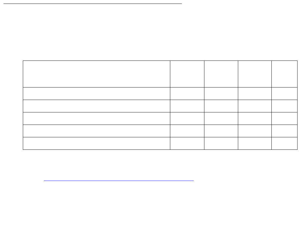
Communication Manager Maintenance-Object Repair Procedures
1584 Maintenance Procedures for Avaya Communication Manager 3.0, Media Gateways and Servers
Analog modems are supported on the G700 only in limited configurations, in which the modem
call stays within a single Media Gateway. If the modem is connected to an MM711 Analog
Media Module, and the call goes to either
●Another modem on an MM711 within the same Media Gateway.
or
●The PSTN through an analog, T1/E1, or BRI trunk on the same Media Gateway, the call
will succeed.
If the modem is connected to an MM711, and the call goes to a modem or trunk on a different
Media Gateway or port network or to an IP trunk, the call will most likely fail. Modem calls are
not supported even between Media Gateways in a stacked configuration.
The MM711 Analog Trunk and Line Media Module does not support Neon Lamp Message
Waiting Indication (MWI). No maintenance of the terminal connected to the Neon Analog Line
Media Module is performed.
Note:
Note: Too many MM711 Analog Media Modules might trip the G700 electronic breaker
and cause the power supply for the entire G700 to shut down.
System Technician-Demanded Tests: Descriptions and Error
Codes
Investigate tests in the order presented below. Clearing Error Codes associated with the one
test may also clear errors generated from other tests in the sequence.
For hardware error log entries and for more information on the tests listed in the table above
refer to XXX-BD (Common Port Circuit Pack/Media Module) on page 2539.
Order of Investigation Short Test
Sequence
Long Test
Sequence
Reset
Board
Sequence
D/ND1
1. D = Destructive, ND = Nondestructive
NPE Audit Test (#50), aborts with code 1412 X ND
Ringing Application (#51), aborts with code 1412
Control Channel Looparound Test (#52) X X ND
SAKI Sanity Test (#53) X D
NEON Test (#220), aborts with code 1412

MG-ANN (Voice Announcements)
Issue 1 June 2005 1585
MG-ANN (Voice Announcements)
S8700 | 8710 / S8500 / S8300 / G700
Voice Announcements over the LAN
The MG-ANN (Voice Announcements) maintenance object provides per board announcement
storage time of up to 20 minutes (15 playback ports and 1 recording port that can also be used
as a playback port), and allows for announcement file portability via LAN connectivity. MG-ANN
also allows for LAN backup and restore of announcement files and the use of customer
provided waveform (.WAV) files. The S8700 Media Server supports 10 integrated
announcement boards (TN750C, TN2501), plus an additional 250 G700 announcement
sources (total of 260). The S8300 Media Server supports 50 G700 announcement sources.
Each G700 supports up to 20 minutes of recording time of up to 256 individual announcements.
Note:
Note: The S8300 does not support standard port networks and TN type boards.
The MG-ANN hardware is located on the G700 mother board. Communication Manager
maintenance supports the MG-ANN by using a virtual board concept to allow for board insertion
and maintenance testing. The virtual slot location is V9.
System Technician-Demanded Tests: Descriptions and Error
Codes
There are no System Technician-Demanded Tests for this MO.

Communication Manager Maintenance-Object Repair Procedures
1586 Maintenance Procedures for Avaya Communication Manager 3.0, Media Gateways and Servers
MG-BRI (BRI Trunk Media Module MM720)
S8700 | 8710 / S8500 / S8300 / G350 / G700
The MM720 BRI Media Module contains eight ports that can be administered either as BRI
trunk connections or BRI endpoint (telephone and data module) connections.
Note:
Note: The MM720 BRI Media Module cannot be administered to support both BRI
trunks and BRI endpoints at the same time. Also, the MM720 BRI Media Module
does not support combining both B-channels together to form a 128-kbps
channel. Finally, if the MM720 BRI Media Module is administered to support BRI
endpoints, it cannot be used as a clock synchronization source.
For BRI trunking, the MM720 BRI Media Module supports up to eight BRI interfaces, or up to 16
trunk ports, to the central office at the ISDN S/T reference point.
For BRI endpoints, each of the 8 ports on the MM720 BRI Media Module can support one
integrated voice/data endpoint or up to 2 BRI stations and/or data modules. Supported
endpoints must conform to AT&T BRI, World Class BRI, or National ISDN NI1/NI2 BRI
standards. The MM720 BRI Media Module provides -40 volt phantom power to the BRI
endpoints.
Information is communicated in two ways:
●Over two 64-kbps channels, called B1 and B2, that can be circuit-switched simultaneously
●Over a 16-kbps channel, called the D-channel, that is used for signaling
The circuit-switched connections have an A- or Mu-law option for voice operation. The circuit-
switched connections operate as 64-kbps clear channels when in the data mode.
LEDs
The three LEDs on the Media Module faceplate indicate board status. When illuminated, the red
LED indicates a board failure or a major or minor on-board alarm, the green LED indicates that
testing is in progress, and the amber LED indicates that the board is in use.
MO Name in
Alarm Log
Alarm
Level
Initial Command to Run Full Name of MO
MG-BRI MIN test board location MO_MG_BRI

MG-BRI (BRI Trunk Media Module MM720)
Issue 1 June 2005 1587
ISDN Interface Reference Points
Figure 89: Integrated Trunk-Side BRI, ISDN Interface Reference Points on page 1588 shows,
for a generic integrated trunk-side BRI, the ISDN Interface Reference Points. Table 587: ISDN
Interface Reference Point definitions on page 1588 gives definitions for the generic ISDN
Interface Reference Points.
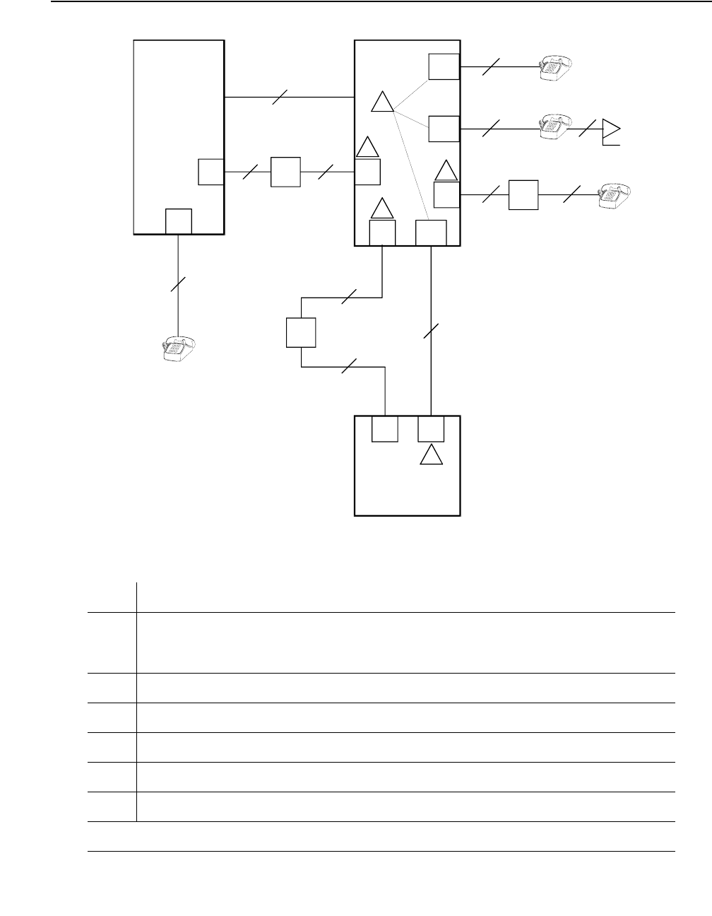
Communication Manager Maintenance-Object Repair Procedures
1588 Maintenance Procedures for Avaya Communication Manager 3.0, Media Gateways and Servers
Figure 89: Integrated Trunk-Side BRI, ISDN Interface Reference Points
Table 587: ISDN Interface Reference Point definitions
LT Logical Terminal
V Primary Rate user/network (asymmetrical) trunk interface. The ECS is
capable of acting as the user or as the network side of this 1.544 - or
2.048-Mbps interface.
R Interface between Terminal Equipment and Network Termination
S Basic Rate network-side 4-wire line interface
S/T 4-wire Basic Rate connection to a Network Termination1.
T 4-wire Basic Rate interface to a Network Termination.2
TE Terminal Equipment
1 of 2
CO
NT
2-Wire
NT
2-Wire
NT
2-Wire
NT
4-Wire
4-Wire
4-Wire
NT
2-Wire
NT
4-Wire
PBX
PBX
LT TE
TE TE
cydfisdn RPY 072397
NT2
LT
LT
NT2
NT2
Term in al
Adapter
NT2
S/T
TE
TE
NT1
VPRI
U
U
T
S/T
T
S
S
UT
R
NT1
NT1
ISDN Interface Reference Points
1
2
3
4
5

MG-BRI (BRI Trunk Media Module MM720)
Issue 1 June 2005 1589
Error Log Entries and Test to Clear Values
U Basic Rate network-side 2-wire line interface.
1 TN556B ISDN-BRI 4-Wire S/T-NT Line (A-law)
2 TN 2185 ISDN-BRI 4-Wire S Interface (Trunk Side)
3 TN2198 ISDN-BRI 2-Wire U Interface
4 TN2198 ISDN-BRI 2-Wire U Interface
5 TN 2185 ISDN-BRI 4-Wire S Interface (Trunk Side)
1. Network Termination 2 (NT2), that terminates Layer 1 and higher layers. PBXs, LANs, and
terminal controllers typically provide NT2 functionality including protocol handling and
multiplexing for Layers 2 and 3.
2. Network Termination 1 (NT1), that terminates Layer 1 and monitors maintenance,
performance, timing, power transfer, multiplexing, and multi-drop termination with contention
resolution.
Table 587: ISDN Interface Reference Point definitions (continued)
2 of 2
Table 588: MG-BRI Error Log Entries and Test to Clear Values
Error
Type
Aux
Data
Associated Test Alarm
Level
On/Off
Board
Test to Clear Value
0 (a) 0 Any Any Any test board location sh r 1
1 (b) Any None MIN ON
257 (c) 65535 Control
Channel Loop
(#52)
MIN ON test board location r 20
513 (d) 4352 to
4357
None ON
769 (e) 4358
1025 (f) NPE/NCE
Audit (#50)
None ON
1 of 2
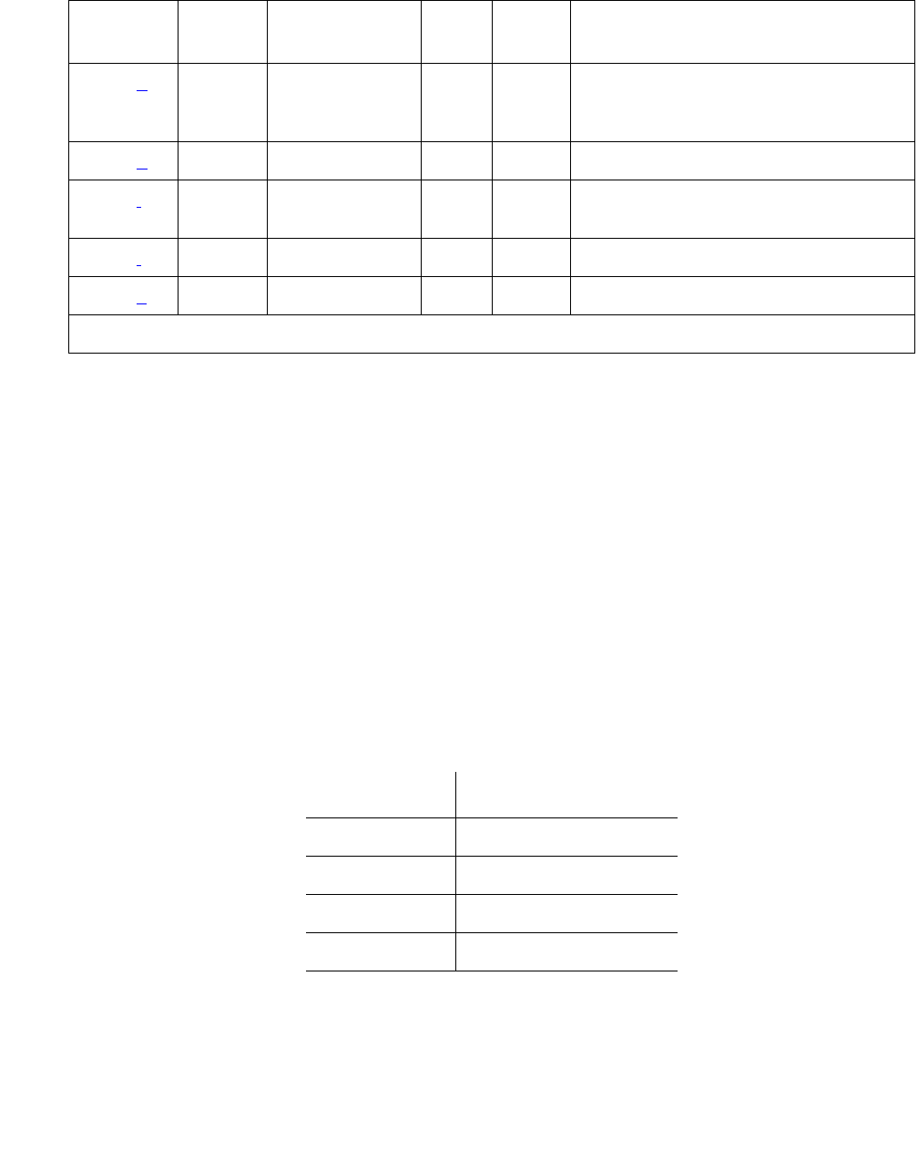
Communication Manager Maintenance-Object Repair Procedures
1590 Maintenance Procedures for Avaya Communication Manager 3.0, Media Gateways and Servers
Notes:
a. Error Type 0: run the short test sequence first. If every test passes, run the long test
sequence. Refer to each test’s description, and follow its procedures.
b. Error Type 1: the circuit pack stopped functioning or is physically removed from the system.
This alarm logs approximately 11 minutes after removing the circuit pack and/or the SAKI
Sanity Test (#53) fails.
If the circuit pack is not in the system, insert a circuit pack in the same slot as the error
indicates. See note (g).
c. Error Type 257: transient communication problems between the switch and this circuit
pack. Execute the test board location command and refer to the repair procedures
for the Control Channel Loop Around Test (#52).
d. Error Type 513: on-board hardware failure. Aux data values correspond to the following
detected errors:
Reset the circuit pack with the busyout board location and reset board
location commands. When reset, the circuit pack executes a set of tests to detect the
presence of any of the faults listed above. Detection of one of these errors during
initialization causes the circuit pack to lock-up and appear insane to the system.
1291 (g) 4359 Clear Error
Counters
(#270)
MIN ON
3586 (h)MINOFF
3840 (i) 4096 to
4101
3842 (j) 46095
3843 (k) 46097
Aux Value Detected Error
4352 External RAM error
4353 Internal RAM error
4355 ROM checksum error
4357 Instruction set error
Table 588: MG-BRI Error Log Entries and Test to Clear Values (continued)
Error
Type
Aux
Data
Associated Test Alarm
Level
On/Off
Board
Test to Clear Value
2 of 2

MG-BRI (BRI Trunk Media Module MM720)
Issue 1 June 2005 1591
e. Error Type 769: the circuit pack detects a program logic error. While no action is required,
this error can lead to other errors against this circuit pack.
f. Error Type 1025: the circuit pack cannot update and read back NPE/NCE memory. This
error can be ignored, but may lead to other errors against this circuit pack.
g. Error Type 1291: the MM720 BRI Media Module notifies maintenance software that it has
detected a parity error while accessing its dynamic RAM (that stores the board’s translation
information and downloadable application firmware). Maintenance software resets the
circuit pack.
h. Error Type 3586: the SPE software detects an excessive number of up-link messages from
the TN2185 board within a certain time period. To prevent the faulty board from flooding the
switch with data, the switch software takes the board out of service and alarms it. The
switch software also tells the Archangel to ignore up-link messages from the board.
When the board is alarmed due to this error, the switch software periodically puts the board
back in service and tells the Archangel to process up-link messages from the board. If the
problem still exists, the software takes the circuit pack out of service again. If the circuit pack
does not exhibit the problem for a certain time period, then maintenance software resolves
the alarm and the circuit pack is left in service.
i. Error Type 3840: the circuit pack received an inconsistent down-link message (a bad
header, port number, data, sub-qualifier, or logical link) over the Control Channel.
j. Error Type 3842: the board is receiving data from the bus faster than it can distribute the
data to its endpoints, causing the FIFO RAM buffer to overflow. This error can occur
occasionally due to the statistical sizing of the buffers. If it occurs frequently, it may indicate
a LAPD parameter mismatch. LAPD should recover from this problem, but it may degrade
the performance of the LAN bus.
When this error is reported, maintenance reads and clears the board counter and logs the
problem in the maintenance error log.
k. Error Type 3843: bad translation RAM detected, but the call continues by using another
translation location. The circuit pack reports this error when it cannot update NPE/NCE
memory and read it back. This error is not service-affecting and can be ignored, but can
lead to other types of errors against this circuit pack.

Communication Manager Maintenance-Object Repair Procedures
1592 Maintenance Procedures for Avaya Communication Manager 3.0, Media Gateways and Servers
System Technician-Demanded Tests: Descriptions and Error
Codes
Investigate tests in the order presented below. Clearing Error Codes associated with the one
test may also clear errors generated from other tests in the sequence.
Control Channel Loop Around Test (#52)
Refer to the repair procedure described in XXX-BD (Common Port Circuit Pack/Media
Module) on page 2539.
NPE /NCE Audit Test (#50)
This test will abort with ABRT code 1412. This test is an audit that sends network update
messages to various ports on a board. Since the Media Server does not handle network
connections for the Media Gateway, this test is not intended to be run.
SAKI Sanity Test (#53)
!CAUTION:
CAUTION: This test is destructive.
Refer to the repair procedure described in XXX-BD (Common Port Circuit Pack/Media
Module) on page 2539. This test is only run as a part of a reset board procedure.
LAN Receive Parity Error Counter Test (#595)
The test reads and clears a circuit pack’s LAN Receive Parity Error Counter.
Order of Investigation Short Test
Sequence
Long Test
Sequence
D/ND1
1. D = Destructive; ND = Nondestructive
Control Channel Loop-Around (#52) X X ND
NPE/NCE Audit Test (#50). Aborts with Error Code 1412 X ND
LAN Receive Parity Error Counter (#595) X ND
SAKI Sanity Test (#53) X D

MG-DCP (Digital Line Media Module)
Issue 1 June 2005 1593
MG-DCP (Digital Line Media Module)
S8700 | 8710 / S8500 / S8300 / G700
DIG-LINE maintenance monitors and tests ports on digital line Media Modules and the
hardware connected to those ports for lines administered as a digital station. Media
Gateway-level maintenance is covered by MG-DCP (Digital Line Media Module) on page 1593,
whose strategy is described in XXX-BD (Common Port Circuit Pack/Media Module) on
page 2539.
Note:
Note: Refer to XXX-BD (Common Port Circuit Pack/Media Module) on page 2539 for
Media Module level errors. See also “DIG-LINE (Digital Line) on page 924 for
related line information.
MO Name in
Alarm Log
Alarm
Level
Initial Command to Run Full Name of MO
MG-DCP MIN test board location sh Digital Line Media Module
MG-DCP WRN test board location sh Digital Line Media Module

Communication Manager Maintenance-Object Repair Procedures
1594 Maintenance Procedures for Avaya Communication Manager 3.0, Media Gateways and Servers
MG-DS1 (DS1 Interface Media Module)
S8700 | 8710 / S8500 / S8300 / G700
MM710 DS1 Media Module
The MM710 Universal DS1 Interface Media Module provide an interface to the DS1 facility, and
are designed to support 24 DS0 channels on a 1.544 Mbps DS1 link, or 32 DS0 channels on a
2.048 Mbps link. The DS0 channels can be administered as trunks to other switches, lines to
off-premises stations, ports to line-side PRI terminating devices, or ports to other line-side
non-PRI terminating devices. (DS0 channels on the MM710 can only be administered as trunks
to other switches.) For more information on how MM710 ports can be used, see these
maintenance objects: ISDN-SGR, ISDN-TRK, ISDN-LNK, TIE-DS1, CO-DS1, DID-DS1, and
WAE-PT.
Note:
Note: The MM710 provides Echo Cancellation, and in addition, the MM710 firmware
can be updated using the firmware download feature.
The MG-DS1 maintenance strategy includes logging in-line errors reported by the MM710
Media Module, running tests for error diagnosis and recovery, and raising or clearing
maintenance alarms.
MM710 Media Modules support the following:
●Digital Tie, CO, and DID trunks
●DS1 off-premises (OPS) lines
●Narrowband and wideband access endpoint ports
●ISDN-PRI trunks and accompanying signaling channel
●PRI endpoint ports (PE-BCHL) and accompanying signaling channel
Each trunk, line, or endpoint has its own maintenance strategy, but all depend on the health of
the MM710 Interface Media Module. Refer to the following MOs for details: TIE-DS1, CO-DS1,
DID-DS1, OPS-LINE, ISDN-TRK, ISDN-LNK, ISDN-SGR, WAE-PT and PE-BCHL.
MO Name in
Alarm Log
Alarm
Level
Initial Command to Run Full Name of MO
MG-DS1 MAJ test board location sh DS1 Interface Media Module
MG-DS1 MIN test board location l DS1 Interface Media Module
MG-DS1 WRN test board location sh DS1 Interface Media Module

MG-DS1 (DS1 Interface Media Module)
Issue 1 June 2005 1595
Echo Cancellation
The MM710 Media Module features an integrated echo canceller. Echo cancellation supports
channels carrying voice and is not intended for channels that support data. The MM710 has the
capability to detect modem tone and turn off echo cancellation accordingly for the duration of a
data call. Echo cancellation on the MM710 will be administrable per channel. The echo
cancellation circuitry on a given MM710 is driven by administrable parameters.
The MM710 Media Modules are intended for use with ATM, IP, wideband, or other complex
services which are likely to have problems with echo.
The echo cancellation circuitry on a given MM710 is a right-to-use feature activated on the
System-Parameters Customer-Options form. Also on this form is a field Maximum Number
of DS1 Boards with Echo Cancellation that indicates the number of DS1 boards on which
echo cancellation is activated for a specific customer.
The DS1 Media Module form for the MM710 Media Module has fields to support echo
cancellation: Echo Cancellation?, EC Direction, and EC Configuration. The Echo
Cancellation? field displays only if the Echo Cancellation feature has been activated on the
system-parameters customer-options form by entering a y in the DS1 Echo
Cancellation field. The EC Direction and EC Configuration fields do not display unless the
user has entered y in the DS1 Echo Cancellation field.
●EC Direction determines the direction from which echo will be eliminated, ether inward or
outward.
●EC Configuration is the set of parameters that will be used when cancelling echo. This
information is stored in firmware on the MM710 Media Module.
Echo cancellation is turned on or off on a trunk group basis using the change trunk-group
command. If the Trunk Group field, DS1 Echo Cancellation? is set to y, echo cancellation will
be applied to every MM710 trunk member in that trunk group. The echo cancellation
parameters used for a given trunk member are determined by the Echo Cancellation
Configuration Number administered on the DS1 Media Module form for that specific trunk’s
board.
Note:
Note: It is not necessary to busyout a port or trunk group to change the DS1 Echo
Cancellation field on the change trunk-group form. However, the modified
setting will not take effect until one of the following occurs:
●Port is busied-out/released
●Trunk group is busied-out/released
●Test trunk group is executed
●Periodic maintenance runs
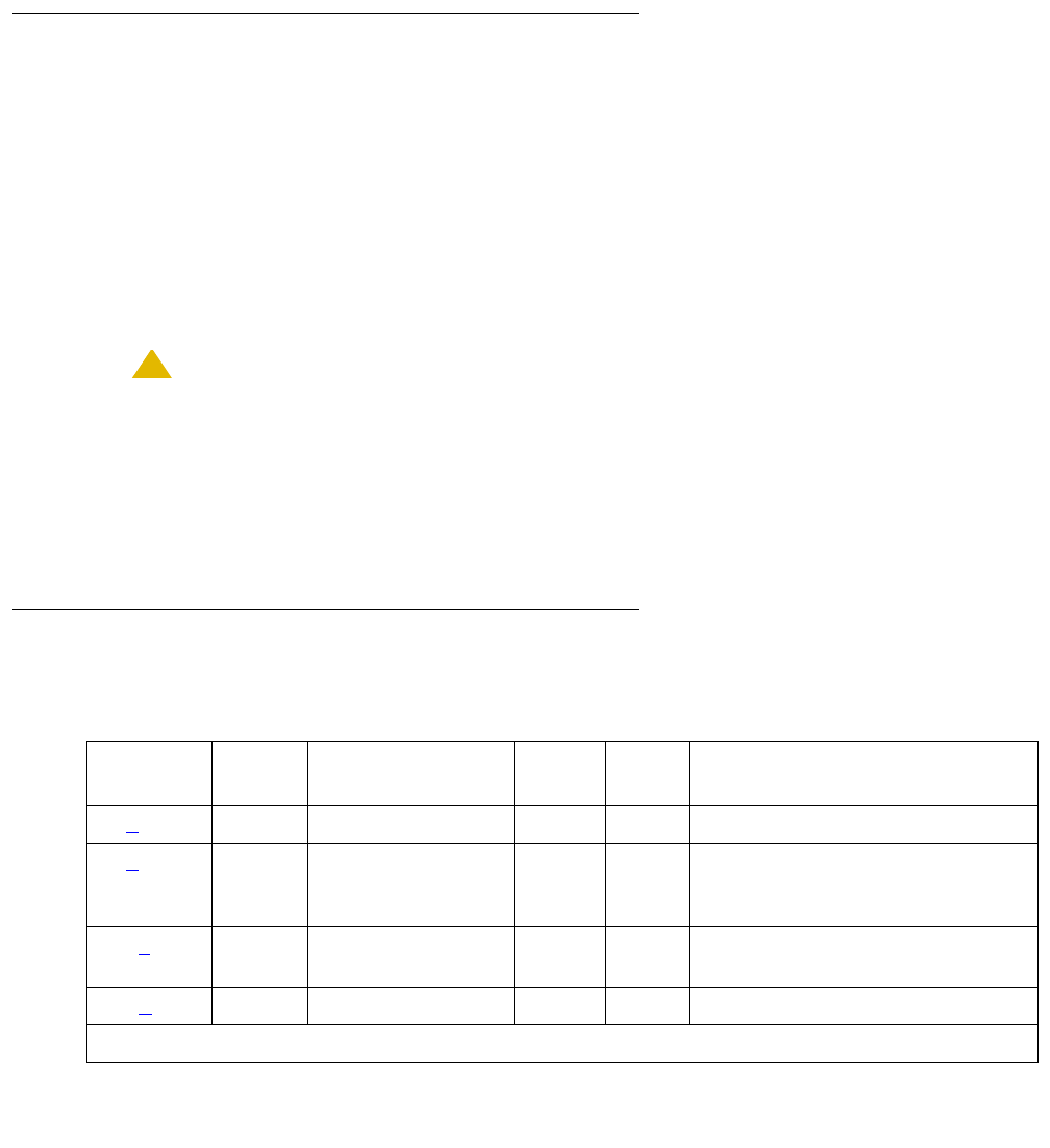
Communication Manager Maintenance-Object Repair Procedures
1596 Maintenance Procedures for Avaya Communication Manager 3.0, Media Gateways and Servers
Echo cancellation on the MM710 is selectable per channel, even though it is administrable on a
trunk group basis. For example, if all but two ports on a MM710 need to have echo cancellation
applied, those two ports must be put in a trunk group where the DS1 Echo Cancellation field is
set to n. The remaining ports will be in a trunk group(s) where the DS1 Echo Cancellation field
is set to y. A user will have the ability to cancel echo coming from the network (far-end echo) or
coming from the switch (near-end echo).
Media Module Administration and Options
The DS1 configuration for each Media Module is administered on the DS1 Media Module form.
Bit Rate is set to 1.544 Mbps for 24-channel systems, and 2.048 Mbps for 32-channel systems.
Country Protocol is used to drive layer 3 protocol decisions based on PRI specifications
specific to a given country (not those related to specific features). This Country Protocol is
independent of the parameters administered on the system-parameters
country-options form. Different MM710 Media Modules may be administered with different
Country Protocols, allowing the switch to act as a gateway between two incompatible ISDN-PRI
implementations (for example, between two different countries). US systems use country
protocol 1.
!CAUTION:
CAUTION: Echo cancellation is administered in part by administering an echo cancellation
plan. The DS1 Echo Cancellation Plan 1 uses a 96ms echo tail and introduces
6db of loss for additional cancellation. Because no digital facilities have ever
introduced loss, this is an unexpected side effect of the Plan 1 echo cancellation
feature. Since services personnel might not expect to find it there, services might
try to change the loss plan to compensate, which can lead to other problems.
Error Log Entries and Test to Clear Values
Table 589: DS1 Interface Media Module Maintenance Error Log Entries
Error
Type
Aux
Data
Associated Test Alarm
Level
On/Off
Board
Test to Clear Value
0 (a) 0 Any Any Any test board location
1 (b)0 Media Gateway
removed or SAKI
Test (#53)
MIN
WRN1ON
18 (c)0 busyout board
location
WRN OFF release board location
23 (d)0 WRNOFFadd ds1 location
1 of 3

MG-DS1 (DS1 Interface Media Module)
Issue 1 June 2005 1597
125 (e) none 3 None MIN
WRN1ON
257 65535 Control Channel
Loop (#52)
MIN ON test board location l r
20
257 (f) Any None
513 (g)Any MIN
WRN1ON
514 (h) 46086 MIN
WRN1ON
769 (i) 46085 MIN
WRN1ON
770 (j) 46096 MIN
WRN1ON
1281 Any Loss of Signal
Alarm Inquiry
Test (#138)
MIN
WRN1OFF test board location
1320 Any Loss of Signal
Alarm Inquiry
Test (#138)
MIN
WRN1OFF test board location
1321 Any Loss of Signal
Alarm Inquiry
Test (#138)
MIN
WRN1OFF test board location
1322 Any Loss of Signal
Alarm Inquiry
Test (#138)
MIN ON test board location
1323 Any Loss of Signal
Alarm Inquiry
(#138)
MIN
WRN1OFF test board location
1324 Any Loss of Signal
Alarm Inquiry
(#138)
WRN OFF test board location
1400
1401
(k)
Any Loss of Signal
Alarm Inquiry
(#138) and Echo
Cancellation
(#1420)
MIN ON test board location
1537 (l) 46082 MIN
WRN1ON
Table 589: DS1 Interface Media Module Maintenance Error Log Entries (continued)
Error
Type
Aux
Data
Associated Test Alarm
Level
On/Off
Board
Test to Clear Value
2 of 3
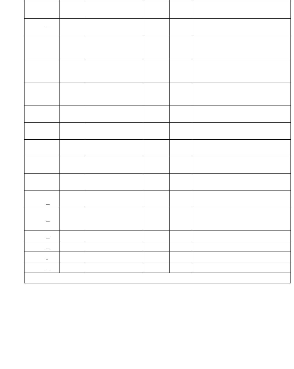
Communication Manager Maintenance-Object Repair Procedures
1598 Maintenance Procedures for Avaya Communication Manager 3.0, Media Gateways and Servers
1538 (m)Any MMIN
WRN1ON
1793 Any Blue Alarm
Inquiry (#139)
MAJ
MIN
WRN2
OFF test board location
1794 Any Blue Alarm
Inquiry (#139)
MAJ
MIN
WRN2
OFF test board location
1795 Any Blue Alarm
Inquiry (#139)
MAJ
MIN
WNG2
OFF test board location
2049 Any Red Alarm
Inquiry (#140)
MIN
WRN1OFF test board location
2305 Any Yellow Alarm
Inquiry (#141)
MIN
WRN1OFF test board location
2306 Any Yellow Alarm
Inquiry (#141)
MIN
WRN1OFF test board location
2561 Any Major Alarm
Inquiry (#142)
MIN
WRN1OFF test board location
2817 Minor Alarm
Inquiry (#143)
MIN
WRN1OFF test board location
3073 to
3160 (n)
Any Slip Alarm Inquiry
(#144)
MIN
WRN1OFF test board location r 6
3585 to
3601 (o)
Any Misframe Alarm
Inquiry Test
(#145)
MIN
WRN1OFF test board location r 6
3840 (p) Any None
3841 (q) 4358
3842 (r) 46097
3999 (s) Any None
1. If ports are assigned to the Media Module, then a minor alarm is raised. If no ports are assigned to the
Media Module, then a warning alarm is raised. The alarm is raised after the Media Module has been
missing for a period of 15 minutes. Warning alarms are also raised against any ports administered on
the Media Module.
2. Major alarms on this MO may be downgraded to minor or warning alarms, and minor alarms
on this MO may be downgraded to warning alarms based on values set in set options.
Table 589: DS1 Interface Media Module Maintenance Error Log Entries (continued)
Error
Type
Aux
Data
Associated Test Alarm
Level
On/Off
Board
Test to Clear Value
3 of 3

MG-DS1 (DS1 Interface Media Module)
Issue 1 June 2005 1599
Notes:
a. Error Type 0: run the Short Test Sequence first. If all tests pass, run the Long Test
Sequence. Refer to the appropriate test description and follow the recommended
procedures.
b. Error Type 1: the Media Module has totally stopped functioning or is not fully administered.
The alarm is logged about 15 minutes after the Media Module has been removed or
11-minutes after the SAKI Test (#53) fails.To be fully administered, a MM710 must meet all
three of the following conditions:
●Have an entry in the circuit plan using the change media module command
●Be administered using the add ds1 location command
●Be physically inserted into the correct slot
If the Media Module has an entry in the circuit plan and either of the other two conditions are
not met, a MINOR alarm is logged.
1. To resolve the error do either of the following:
●Make sure that all conditions for administration are met and that a functioning MM710
is inserted in the correct slot.
●Completely remove the MM710 from the system using the following steps.
2. Remove any administered DS1 trunks, access endpoints or PRI endpoints associated
with the Media Module from their trunk groups.
3. Execute remove ds1 location and change media module location.
c. Error Type 18: the MM710 Interface Media Module has been busied out by a busyout
board location command.
d. Error Type 23: the MM710 Media Module is not completely administered. To be fully
administered, the MM710 Media Module must:
●Have an entry in the circuit plan using the change media module command
●Be administered using the add ds1 location command
●Be physically inserted into the correct slot
A DS1 (MG-DS1, DS1-BD) differs from most Media Modules in that inserting the Media
Module into the media gateway is not enough to make the board usable. It must also be
administered with the add ds1 command.
e. Error Type 125, no Aux Data: An incorrect Media Module is inserted in the slot where the
MM710 Media Module is logically administered.
To resolve this problem, either:
●Remove the incorrect Media Module and insert the logically administered Media Module.
●Use the change circuit-pack command to re-administer this slot to match the Media
Module inserted.

Communication Manager Maintenance-Object Repair Procedures
1600 Maintenance Procedures for Avaya Communication Manager 3.0, Media Gateways and Servers
f. Error Type 257: associated with the Common Port Media Module Maintenance Test.
Refer to XXX-BD (Common Port Circuit Pack/Media Module) on page 2539 Maintenance
documentation for details.
g. Error Type 513: the MG-DS1 (MM710) has detected a transient hardware problem.
The value in the Aux Data field indicates the type of hardware problem:
If the board detects only one of these hardware problems, then the error will disappear
when none of these faults are detected for 10 minutes. If the same Aux Data value is logged
more than once in a 24 hour period, the Media Module should be replaced.
h. Error Type 514: is a LAN External RAM Error.
This error occurs when there is a hardware fault in the PPE external RAM. The RAM is used
for message buffering to and from the Packet Bus. This error should not occur frequently. If
it does (10 times within 30 minutes), the Media Module should be replaced.
i. Error Type 769: is a transmit FIFO Underflow Error.
This error occurs when the Media Module cannot find the end of frame bit when transmitting
a frame to the Packet Bus. An alarm is raised if this error occurs three times within 10
minutes. Clear the alarm using the following commands: busyout board location,
reset board location, test board location long, release board
location. If the error recurs within 10 minutes, replace the Media Module.
j. Error Type 770: is an Unable to Write LAN Translation RAM Error.
This error occurs when a call is aborted because there are no available translation RAM
locations for the call connection attempt. An alarm is raised if this error occurs two times
within 10 minutes. Clear the alarm using the following commands: busyout board
location, reset board location, test board location long, release board
location. If the error recurs within 10 minutes, replace the Media Module.
k. Error Types 1400, 1401: is an Echo Cancellation error.
Echo Cancellation errors are logged when:
●Error 1400 - Echo canceller function failed. The Echo Canceller Function Test, which is
executed by firmware, failed.
●Error 1401 - Echo canceller memory failed. The Echo Canceller Memory Test, which is
executed by firmware, failed.
Aux Data Problem
4352 External RAM failure
4353 Internal RAM failure
4355 Internal ROM failure

MG-DS1 (DS1 Interface Media Module)
Issue 1 June 2005 1601
Echo Cancellation is no longer being supplied by the board. Clear the alarm using the
following commands: busyout board location, test board location long,
release board location. If Test #1420 (Echo Canceler Test) fails, replace the Media
Module.
l. Error Type 1537: is a LAN Bus Timeout Error.
This error occurs when the Media Module transmits too many bytes on the LAN bus for a
single frame. This condition may be caused by an on-board fault or by faulty data received
on one of the Media Module’s external ports. If any of the ports on this Media Module are
alarmed, refer to the repair procedures for those maintenance objects.
If the error occurs three times within 10 minutes, the board is isolated from the Packet Bus
and the board alarmed. To clear the alarm and restore the board to the Packet Bus, use the
commands busyout board location, reset board location, test board
location long, release board location.
If the problem persists, and there are no PKT-BUS alarms or port alarms, then replace the
Media Module.
m. Error Type 1538: The hyperactive Media Module is out-of-service and may exhibit one or
more of the following symptoms:
●The common Media Module level tests such as Test #50 abort with Error Code 2000.
●The tests run on the ports of this Media Module return a NO-BOARD result.
●A busyout/release of the Media Module has no affect on test results.
●A list configuration command shows that the Media Module and ports are
properly installed.
The Media Module is isolated from the system and all trunks or ports on this Media Module
are placed into the out-of-service state. The system will try to restore the Media Module
within 20-30 minutes. When no faults are detected for 20-30 minutes, the MM710 is
restored to normal operation. All trunks or ports of the MM710 are then returned to the
in-service state.
If the board is not restored to normal operation, or the error recurs after the board was
restored to normal operation, escalate the problem.
n. Error Types 3073 to 3160: Error Type 3073 shows that this board is receiving slips and the
AUX Data “minus 3072” shows the last slip count reported.
o. Error Types 3585 to 3601: Error Type 3585 shows that this board is receiving misframes,
and the AUX Data “minus 3584” shows the last misframe count reported.

Communication Manager Maintenance-Object Repair Procedures
1602 Maintenance Procedures for Avaya Communication Manager 3.0, Media Gateways and Servers
p. Error Type 3840: is not service-affecting. No action is required.
These errors are reported by the Media Module when it receives a bad control channel
message from the switch. The Aux Data identifies the following error events:
q. Error Type 3841: The MG-DS1 (MM710) has detected a transient hardware logic error (for
example, program logic inconsistency).
This error will disappear when no faults are detected for 100 minutes.
r. Error Type 3842 is a Bad Translation RAM Location Found Error.
This error is not service-affecting. No action is required. A Bad Translation RAM is detected,
but the call continues by using another translation location.
s. Error Type 3999: the Media Module sent a large number of control channel messages to
the switch within a short period of time.
If Error Type 1538 is also present, then the Media Module was taken out-of-service due to
hyperactivity. If Error Type 1538 is not present, then the Media Module has not been taken
out-of-service, but it has generated 50% of the messages necessary to be considered
hyperactive. This may be completely normal during heavy traffic periods. However, if this
error type is logged when the Media Module is being lightly used, it may indicate a problem
with the Media Module or the equipment attached to it.
Aux Data Event
4096 Bad major heading
4097 Bad port number
4098 Bad data
4099 Bad sub-qualifier
4100 State inconsistency
4101 Bad logical link

MG-DS1 (DS1 Interface Media Module)
Issue 1 June 2005 1603
System Technician-Demanded Tests: Descriptions and Error
Codes
Investigate tests in the order they are presented. By clearing Error Codes associated with the
Echo Cancellation Tes t you may also clear errors generated from other tests in the sequence.
Order of Investigation Short Test
Sequence
Long Test
Sequence
Reset
Board
Sequence
test
ds1-loop
D/ND1
1. D = Destructive; ND = Nondestructive
Echo Cancellation Test (#1420) X D
Control Channel Loop Test (#52) X ND
NPE Connection Audit Test (#50)
Aborts with Error Code 1412
Loss of Signal Alarm Inquiry (#138) X X ND
Blue Alarm Inquiry Test (#139) X X ND
Red Alarm Inquiry Test (#140) X X ND
Yellow Alarm Inquiry Test (#141) X X ND
Major Alarm Inquiry Test (#142) X X ND
Minor Alarm Inquiry Test (#143) X X ND
Slip Alarm Inquiry Test (#144) X X ND
Misframe Alarm Inquiry Test (#145) X X ND
Translation Update Test (#146) X X ND
SAKI Sanity Test (#53) X D
Internal Looparound Test (#135)
Aborts with Error Code 1412
XD

Communication Manager Maintenance-Object Repair Procedures
1604 Maintenance Procedures for Avaya Communication Manager 3.0, Media Gateways and Servers
Control Channel Looparound Test (#52)
This test queries the Media Module for its Media Module vintage to verify angel communication.
Table 590: Test #52 Control Channel Looparound Test
Error
Code
Test
Result
Description/ Recommendation
None
2100
ABRT System resources required for this test are not available.
1. Retry the command at 1-minute intervals a maximum of 5 times.
FAIL The Media Module failed to return the Media Module code or vintage.
1. Retry the command a maximum of 5 times.
2. If the problem continues, replace the Media Module.
PASS Communication with this Media Module is successful.
Any NO
BOARD
The test could not relate the internal ID to the port (no board). This
could be due to incorrect translations, no board is inserted, an incorrect
board is inserted, or an insane board is inserted.
1. Check to ensure that the board translations are correct. Use list
config and resolve any problems that are found.
2. If the board was found to be inserted correctly, enter busyout
board location.
3. Enter the reset board location command.
4. Enter the release board location command.
5. Enter test board location long.
This should re-establish the linkage between the internal ID and the port.
If this is not the case, check to ensure that there is a valid board
inserted.

MG-DS1 (DS1 Interface Media Module)
Issue 1 June 2005 1605
SAKI Sanity Test (#53)
!CAUTION:
CAUTION: This test resets the Media Module. The test is highly destructive and can only be
initiated by a system technician-demanded reset board location
command.
Table 591: Test #53 SAKI Sanity Test
Error
Code
Test
Result
Description/ Recommendation
None ABRT System resources required for this test are not available.
1. Retry the reset board command at 1-minute intervals a maximum
of 5 times.
1005 ABRT Wrong Media Module configuration to run this test. This error applies
only to DS1 Interface Media Modules. It means the DS1 Interface Media
Module is providing timing for the system, and therefore, it cannot be
reset without major system disruptions.
1. If the Media Module needs to be reset, then set synchronization to
another DS1 Interface Media Module or to the Tone-Clock Media
Module and try again.
1015 ABRT Port is not out-of-service.
1. Busyout the Media Module.
2. Execute the reset board command again.
2100 ABRT System resources required for this test are not available.
1. Retry the reset board command at 1-minute intervals a maximum
of 5 times.
1 FAIL The Media Module failed to reset.
1. Execute the reset board command again.
2. If the problem persists, replace the Media Module.
2 FAIL The Media Module failed to restart.
1. Execute the reset board command again.
2. If the problem persists, replace the Media Module.
1 of 2

Communication Manager Maintenance-Object Repair Procedures
1606 Maintenance Procedures for Avaya Communication Manager 3.0, Media Gateways and Servers
Loss of Signal Alarm Inquiry Test (#138)
This test verifies the synchronization status, echo cancellation, and continuity of the DS1 link.
The Loss of Signal alarm indicates that the MM710 Interface Media Module is unable to derive
the synchronization clock from the DS1 facility. When the MM710 Interface Media Module
detects a Loss of Signal alarm, it stops providing the synchronization clock for the system, if it is
administered as a timing source, and transmits a Yellow alarm to the remote DS1 endpoint.
Note:
Note: Synchronization is not administered from the SAT. It is administered through a
CLI session with the G700 Media Gateway Processor.
When the Loss of Signal alarm is confirmed, maintenance software places all trunks or ports of
the MM710 Interface Media Module into the out-of-service state. The inquiry test will run every
10 minutes until the loss of signal has been restored.
The MM710 Interface Media Module raises a Loss of Signal alarm after the signal has been lost
for about 1 second. It will not retire the alarm until the signal has returned for about 10 seconds.
PASS The Media Module initializes correctly.
1. Run the Short Test Sequence.
Any NO
BOARD
The test could not relate the internal ID to the port (no board). This could
be due to incorrect translations, no board is inserted, an incorrect board
is inserted, or an insane board is inserted.
1. Ensure that the board translations are correct. Execute the add ds1
location command to administer the MM710 interface if it is not
already administered.
2. If the board was already administered correctly, check the error log to
determine whether the board is hyperactive. If this is the case, the
board is shut down. Reseating the board will re-initialize the board.
3. If the board was found to be correctly inserted in step 1, then enter
the busyout board location command.
4. Enter the reset board location command.
5. Enter the release board location command.
6. Enter the test board location long command.
This should re-establish the linkage between the internal ID and the port.
Table 591: Test #53 SAKI Sanity Test (continued)
Error
Code
Test
Result
Description/ Recommendation
2 of 2

MG-DS1 (DS1 Interface Media Module)
Issue 1 June 2005 1607
Echo Cancellation
If the MM710 firmware detects a serious echo canceller hardware error, it notifies maintenance
software. When the maintenance subsystem receives notification of the echo cancellation error,
it executes this Loss Of Signal Alarm Inquiry test.
This test, in addition to querying for a loss of signal condition and CSU errors, also queries
MM710 to confirm the echo canceller error. A minor alarm is raised if the error is confirmed. The
trunks of the board remain in-service since the board is still functional except for the echo
cancellation capability.
If a loss of signal condition coexists with CSU and/or echo canceller errors, the loss of signal
condition takes priority, and the board and all trunks on the board are put in the out-of-service
state. Errors are logged, however, for each error type.
When the maintenance subsystem receives notification that the echo canceller hardware error
condition no longer exists, the maintenance subsystem restores the board and all trunks to their
previous service state, if the alarm can be cleared (no other CSU errors or loss of signal
conditions exist).
Note:
Note: The DSU functionality is not available in this release of Communication Manager.
Table 592: TEST #138 Loss of Signal Alarm Inquiry Test
Error
Code
Test
Result
Description/ Recommendation
ABRT Internal system error
1. Retry the command at 1-minute intervals for a maximum of 5 times.
1 of 4

Communication Manager Maintenance-Object Repair Procedures
1608 Maintenance Procedures for Avaya Communication Manager 3.0, Media Gateways and Servers
2000 ABRT Response to the test was not received within the allowable time period.
This may be due to hyperactivity. Error Type 1538 in the error log
indicates hyperactivity. The hyperactive Media Module is out of service
and one or more of the following symptoms may be exhibited:
●The MG-DS1 tests (such as Test #138 and Test #139) are aborting
with Error Code 2000.
●The tests run on the ports of this Media Module are returning a no
board result.
●A busyout or a release command has no affect on the test
results.
●A list config command shows that the Media Module and the
ports are properly installed.
When hyperactivity occurs, the Media Module is isolated from the
system, and all of the trunks for this Media Module are placed into the
out of service state. The system will try to restore the Media Module
within 15 minutes. When no faults are detected for 15 minutes, the
MM710 interface Media Module is restored to normal operation. All of
the trunks for the Media Module are then returned to the in service state.
Hyperactivity is often caused by the associated facility. In such a case,
faults (such as slips, misframes, or blue alarms) would be entered in the
error log. In addition, many hardware errors would be logged against the
associated trunk circuits.
1. If the facility is OK and the error occurs again after 15 minutes,
replace the Media Module.
2100 ABRT Could not allocate the necessary system resources to run this test.
1. Retry the command at 1-minute intervals for a maximum of 5 times.
Table 592: TEST #138 Loss of Signal Alarm Inquiry Test (continued)
Error
Code
Test
Result
Description/ Recommendation
2 of 4

MG-DS1 (DS1 Interface Media Module)
Issue 1 June 2005 1609
FAIL MM710 detects a Loss of Signal alarm. The physical link is broken or
the remote DS1 endpoint is down. All trunks or ports of this MM710 are
out-of-service.
1. Check the physical connection of the MM710 Interface Media
Module and the cable.
2. Check the physical connection of the MM710 Interface Media
Module to the terminating device.
3. Check premise distribution system (or intra-premise wiring) for
physical connection failures.
4. If the MM710 connects to a T1 network facility, call the vendor of the
T1 carrier to diagnose the remote DS1 endpoint.
5. If the MM710 Interface Media Module connects directly to a switch,
call the system technician of the remote switch to diagnose the DS1
endpoint.
6. If the MM710 connects to a line-side terminating device such as a
PRI terminal adapter, contact the vendor of the line-side terminating
device to diagnose the equipment.
1400 FAIL Echo Canceller Function failed, this could be a hardware problem on the
MM710:
1. Enter the busyout board command.
2. Enter the test board long command.
3. Enter the release board command.
4. If Test 138 still fails with EC 1400, replace the board.
1401 FAIL Echo Canceller Function failed, this could be a hardware problem on the
MM710:
1. Enter the busyout board command.
2. Enter the reset board command.
3. Enter the test board long command.
4. Enter the release board command.
5. If the test still fails replace the board.
PASS DS1 signal is present and the physical link is healthy.
Table 592: TEST #138 Loss of Signal Alarm Inquiry Test (continued)
Error
Code
Test
Result
Description/ Recommendation
3 of 4

Communication Manager Maintenance-Object Repair Procedures
1610 Maintenance Procedures for Avaya Communication Manager 3.0, Media Gateways and Servers
Blue Alarm Inquiry Test (#139)
The Blue Alarm is a signal sent by the remote DS1 endpoint when it is out-of-service. The Blue
Alarm Inquiry Test checks the blue alarm status of the remote DS1 endpoint.
When the MM710 Interface Media Module detects a Blue Alarm signal from the remote DS1
endpoint, the Media Module transmits a Yellow alarm to the remote DS1 endpoint and sends a
BLUE ALARM message to the maintenance software. When the Blue alarm is confirmed, the
maintenance software places all trunks or ports of the MM710 Interface Media Module into the
out-of-service state. The inquiry test runs every 10 minutes until the Blue alarm is cleared.
The MM710 Interface Media Module takes one second to recognize and report a Blue alarm
and 16 seconds to recognize and report the resolution of a Blue alarm. When the Blue alarm is
cleared, the MM710 Interface Media Module stops transmitting the Yellow alarm and places the
trunks or ports back into the service state they were in before the Blue alarm occurred.
Any NO
BOARD
The test could not relate the internal ID to the port (no board). This could
be due to incorrect translations, no board is inserted, an incorrect board
is inserted, or an insane board is inserted.
1. Ensure that the board translations are correct. Execute the add
ds1 location command to administer the MM710 interface if it is
not already administered.
2. If the board was already administered correctly, check the error log
to determine whether the board is hyperactive. If this is the case, the
board is shut down. Reseating the board will re-initialize the board.
3. If the board was found to be correctly inserted in step 1, then enter
the busyout board location command.
4. Enter the reset board location command.
5. Enter the release board location command.
6. Enter the test board location long command.
This should re-establish the linkage between the internal ID and the port.
Table 592: TEST #138 Loss of Signal Alarm Inquiry Test (continued)
Error
Code
Test
Result
Description/ Recommendation
4 of 4
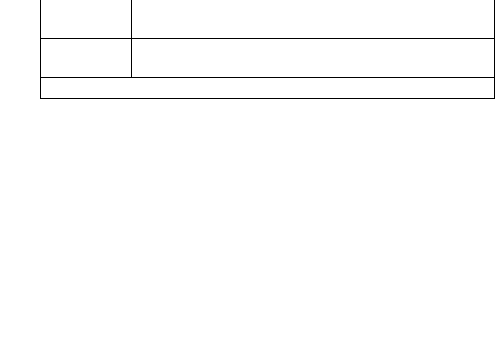
MG-DS1 (DS1 Interface Media Module)
Issue 1 June 2005 1611
Line Loopback Alarm
The Line Loopback (LLB) is used by the remote DS1 endpoint to put the DS1 board into a
loopback mode. When the DS1 board is in the LLB mode, the arriving bit pattern is regenerated
and sent back. The Line Loopback (LLB) Alarm activates when the in-band activate LLB bit
pattern arrives continuously for 5 seconds on the DS1 line. The LLB deactivates when the
in-band deactivate LLB bit pattern arrives continuously for 5 seconds on the DS1 line.
Since LLB is a maintenance condition rendering all DS0 channels unavailable for signaling or
bearer traffic, maintenance software treats this the same as a Blue Alarm.
Payload Loopback Alarm
The Payload Loopback (PLB) is used by the remote DS1 endpoint to put the switch DS1 into a
loopback mode. The PLB Alarm activates when a network protocol activate bit pattern arrives
over the 4Kbps ESF data link on the DS1 line. The PLB deactivates when a network protocol
deactivate bit pattern arrives over the 4Kbps ESF data link on the DS1 line.
Since PLB is a maintenance condition rendering all DS0 channels unavailable for signaling or
bearer traffic, maintenance software treats this the same as a Blue Alarm
Table 593: TEST #139 Blue Alarm Inquiry Test
Error
Code
Test
Result
Description/ Recommendation
ABRT Internal system error
1. Retry the command at 1-minute intervals for a maximum of 5 times.
1 of 4

Communication Manager Maintenance-Object Repair Procedures
1612 Maintenance Procedures for Avaya Communication Manager 3.0, Media Gateways and Servers
2000 ABRT Response to the test was not received within the allowable time period.
This may be due to hyperactivity. Error Type 1538 in the error log
indicates hyperactivity. The hyperactive Media Module is out of service
and one or more of the following symptoms may be exhibited:
●The MG-DS1 tests (such as Test #138 and Test #139) are aborting
with Error Code 2000.
●The tests run on the ports of this Media Module are returning a no
board result.
●A busyout or a release command has no affect on the test
results.
●A list config command shows that the Media Module and the
ports are properly installed.
When hyperactivity occurs, the Media Module is isolated from the
system, and all of the trunks for this Media Module are placed into the
out of service state. The system will try to restore the Media Module
within 15 minutes. When no faults are detected for 15 minutes, the
MM710 interface Media Module is restored to normal operation. All of
the trunks for the MM710 interface Media Module are then returned to
the in service state. Hyperactivity is often caused by the associated
facility. In such a case, faults (such as slips, misframes, or blue alarms)
would be entered in the error log. In addition, many hardware errors
would be logged against the associated trunk circuits.
1. If the facility is OK and the error occurs again after 15 minutes,
replace the Media Module.
2100 ABRT Could not allocate the necessary system resources to run this test.
1. Retry the command at 1-minute intervals for a maximum of 5 times.
Table 593: TEST #139 Blue Alarm Inquiry Test (continued)
Error
Code
Test
Result
Description/ Recommendation
2 of 4

MG-DS1 (DS1 Interface Media Module)
Issue 1 June 2005 1613
FAIL The remote DS1 endpoint is out-of-service.
1
1794
FAIL The MM710 Interface Media Module detects a Line Loopback Alarm
(LLB).
1. If the DS1-M interface Media Module connects to a T1 facility, call
the vendor of the T1 carrier to diagnose the remote DS1 endpoint.
2. If the MM710 interface Media Module connects directly to a switch,
call the system technician of the remote switch to diagnose the DS1
endpoint.
3. If the MM710 interface Media Module connects directly to a line-side
terminating device (for example, a PRI terminal adapter), call the
vendor of the terminating device to diagnose the equipment.
1795 FAIL The MM710 Interface Media Module detects a Payload Loopback Alarm
(PLB).
1. If the MM710 Interface Media Module connects to a leased T1
facility, call the vendor of the T1 carrier to diagnose the remote DS1
endpoint.
2. If the MM710 Interface Media Module connects directly to another
DS1 board, call the system technician of the remote switch to
diagnose the DS1 endpoint.
3. If the MM710 Interface Media Module connects directly to a line-side
terminating device such as a PRI terminal adapter contact the
vendor of the terminating device to diagnose the equipment.
PASS Remote DS1 endpoint is in-service. Neither a Blue alarm nor a Line
Loopback alarm nor a Payload Loopback Alarm is detected by the
MM710 Interface Media Module.
Table 593: TEST #139 Blue Alarm Inquiry Test (continued)
Error
Code
Test
Result
Description/ Recommendation
3 of 4

Communication Manager Maintenance-Object Repair Procedures
1614 Maintenance Procedures for Avaya Communication Manager 3.0, Media Gateways and Servers
Red Alarm Inquiry Test (#140)
An MM710 Interface Media Module raises a Red alarm when the framing pattern of the
incoming DS1 bit stream has been lost. The Red Alarm Inquiry Test checks the framing status
of an MM710 Interface Media Module. An MM710 Interface Media Module takes 3 seconds to
recognize and report a Red alarm and 10 seconds to recognize and report the resolution of a
Red alarm.
When the MM710 Interface Media Module detects a Red alarm, the Media Module transmits a
Yellow alarm to the remote DS1 endpoint and sends a RED ALARM message to the
maintenance software. After the Red alarm is confirmed, the maintenance software places all
trunks or ports of the Media Module into the out-of-service state. The inquiry test runs every 10
minutes until the Red alarm is cleared.
When the Red alarm is cleared, the MM710 Interface Media Module stops transmitting the
Yellow alarm to the remote DS1 endpoint. The maintenance software restores all trunks or ports
of the MM710 Interface Media Module to the service state it was in before the Red alarm
occurred.
Any NO
BOARD
The test could not relate the internal ID to the port (no board). This could
be due to incorrect translations, no board is inserted, an incorrect board
is inserted, or an insane board is inserted.
1. Ensure that the board translations are correct. Execute the add
ds1 location command to administer the MM710 interface if it is
not already administered.
2. If the board was already administered correctly, check the error log
to determine whether the board is hyperactive. If this is the case, the
board is shut down. Reseating the board will re-initialize the board.
3. If the board was found to be correctly inserted in step 1, then enter
the busyout board location command.
4. Enter the reset board location command.
5. Enter the release board location command.
6. Enter the test board location long command.
This should re-establish the linkage between the internal ID and the port.
Table 593: TEST #139 Blue Alarm Inquiry Test (continued)
Error
Code
Test
Result
Description/ Recommendation
4 of 4

MG-DS1 (DS1 Interface Media Module)
Issue 1 June 2005 1615
Loss of Multiframe Alarm
If the MM710 Interface Media Module is administered using DMI-BOS signaling, the MM710
Interface Media Module raises a Loss of Multiframe Alarm (LMA) when it cannot interpret the
incoming signaling bits to synchronize to the multiframe pattern received in the 24th channel.
Once the MM710 Interface Media Module detects an LMA, the Media Module transmits a
Remote Multiframe Alarm (RMA) to the remote DS1 endpoint. Maintenance software handles
both Red alarm and LMA alarm(s) using the same mechanism.
Table 594: TEST #140 Red Alarm Inquiry Test
Error
Code
Test
Result
Description/ Recommendation
ABRT Internal system error
1. Retry the command at 1-minute intervals a maximum of 5 times.
2000 ABRT Response to the test was not received within the allowable time period.
This may be due to hyperactivity. Error Type 1538 in the error log
indicates hyperactivity. The hyperactive Media Module is out of service
and one or more of the following symptoms may be exhibited:
●The MG-DS1 tests (such as Test #138 and Test #139) are aborting
with Error Code 2000.
●The tests run on the ports of this Media Module are returning a no
board result.
●A busyout or a release command has no affect on the test
results.
●A list config command shows that the Media Module and the
ports are properly installed.
When hyperactivity occurs, the Media Module is isolated from the
system, and all of the trunks for this Media Module are placed into the
out of service state. The system will try to restore the Media Module
within 15 minutes. When no faults are detected for 15 minutes, the
MM710 interface Media Module is restored to normal operation. All of
the trunks for the MM710 interface Media Module are then returned to
the in service state. Hyperactivity is often caused by the associated
facility. In such a case, faults (such as slips, misframes, or blue alarms)
would be entered in the error log. In addition, many hardware errors
would be logged against the associated trunk circuits.
1. If the facility is OK and the error occurs again after 15 minutes,
replace the Media Module.
1 of 4

Communication Manager Maintenance-Object Repair Procedures
1616 Maintenance Procedures for Avaya Communication Manager 3.0, Media Gateways and Servers
FAIL The MM710 interface Media Module detected a red alarm. An out of
frame condition occurred on the MM710 interface Media Module. The
MM710 interface Media Module will transmit a yellow alarm to the remote
MM710 endpoint until the red alarm is retired.
If the MM710 connects to a T1 network facility or to another switch, do
the following:
1. Check the physical connectivity of the MM710 packs and of the
cable.
2. Replace the local MM710 interface Media Module, and repeat the
test.
3. Verify that both endpoints of the DS1 link are administered using the
same signaling mode, framing mode, and line coding.
4. Contact T1 Network Service or a technician at the far-end switch to
diagnose the remote DS1 endpoint.
If the MM710 connects to a line-side terminating device (for example, a
PRI terminal adapter), do the following:
1. Check the physical connection of the MM710 interface Media
Module to the terminating device, and check the premise distribution
system (or the intra-premise wiring) for physical connection failures.
2. Replace the local MM710 interface Media Module and repeat the
test.
3. Verify that the switch DS1 and the line-side terminating device are
administered using the same signaling mode, framing mode, and
line coding.
4. Investigate the maintenance status of the line-side terminating
device. Refer to the 'Line-Side Terminating Device Operating
Manual' for information.
5. Contact the vendor of the line-side terminating device to diagnose
the equipment.
Table 594: TEST #140 Red Alarm Inquiry Test (continued)
Error
Code
Test
Result
Description/ Recommendation
2 of 4

MG-DS1 (DS1 Interface Media Module)
Issue 1 June 2005 1617
1 FAIL The test failed. The MM710 interface Media Module detected a loss of
multiframe alarm (LMA). An out of frame condition occurred on the
MM710 interface Media Module. The MM710 interface Media Module will
transmit a remote multiframe alarm (RMA) to the remote MM710 endpoint
until the LMA is retired.
If the MM710 connects to a T1 network facility or to another switch, do
the following:
1. Verify that both endpoints of the DS1 link are administered using the
same signaling mode, framing mode, and line coding.
2. Check the physical connectivity of the MM710 packs and of the
cable.
3. Replace the local MM710 interface Media Module, and repeat the
test.
4. Contact T1 Network Service or a technician at the far-end switch to
diagnose the remote DS1 endpoint.
If the MM710 connects to a line-side terminating device (for example, a
PRI terminal adapter), do the following:
1. Verify that the switch DS1 and the line-side terminating device are
administered using the same signaling mode, framing mode, and
line coding.
2. Investigate the maintenance status of the line-side terminating
device. Refer to the 'Line-Side Terminating Device Operating
Manual' for information.
3. Check the physical connection of the MM710 interface Media
Module to the terminating device, and check the premise distribution
system (or the intra-premise wiring) for physical connection failures.
4. Replace the local MM710 interface Media Module and repeat the
test.
5. Contact the vendor of the line-side terminating device to diagnose
the equipment.
Table 594: TEST #140 Red Alarm Inquiry Test (continued)
Error
Code
Test
Result
Description/ Recommendation
3 of 4

Communication Manager Maintenance-Object Repair Procedures
1618 Maintenance Procedures for Avaya Communication Manager 3.0, Media Gateways and Servers
Yellow Alarm Inquiry Test (#141)
Receiving a Yellow alarm from a remote DS1 endpoint indicates that the remote DS1 endpoint
has an out-of-frame condition. The Yellow Alarm Inquiry Test is used to determine whether the
remote DS1 endpoint is transmitting a Yellow alarm. The MM710 Interface Media Module takes
500 msec to recognize and report a Yellow alarm and 500 msec to recognize and report that a
Yellow alarm condition is cleared.
When the MM710 Interface Media Module detects a Yellow alarm from the remote DS1
endpoint, it sends a YELLOW-ALARM uplink message to the maintenance software. After the
maintenance software receives the YELLOW-ALARM message, the Yellow Alarm Inquiry Test is
run to confirm the Yellow alarm. Once the Yellow alarm is confirmed, the maintenance software
places all trunks or ports on the Media Module into the out-of-service state. The Inquiry Test
runs every 10 minutes until the Yellow alarm is cleared.
PASS No Red alarm is detected on the MM710 Interface Media Module.
Any NO
BOARD
The test could not relate the internal ID to the port (no board). This could
be due to incorrect translations, no board is inserted, an incorrect board
is inserted, or an insane board is inserted.
1. Ensure that the board translations are correct. Execute the add
ds1 location command to administer the MM710 interface if it is
not already administered.
2. If the board was already administered correctly, check the error log
to determine whether the board is hyperactive. If this is the case, the
board is shut down. Reseating the board will re-initialize the board.
3. If the board was found to be correctly inserted in step 1, then enter
the busyout board location command.
4. Enter the reset board location command.
5. Enter the release board location command.
6. Enter the test board location long command.
This should re-establish the linkage between the internal ID and the port.
Table 594: TEST #140 Red Alarm Inquiry Test (continued)
Error
Code
Test
Result
Description/ Recommendation
4 of 4

MG-DS1 (DS1 Interface Media Module)
Issue 1 June 2005 1619
When the Yellow alarm is cleared, the maintenance software restores all trunks or ports on the
MM710 Interface Media Module back to their previous service state before the Yellow alarm
was raised.
This Yellow alarm corresponds to the yellow F2 state documented in CCITT Recommendation
I.431.
Remote Multiframe Alarm
Remote Multiframe Alarm (RMA) indicates that the remote DS1 endpoint is in a Loss of
Multiframe Alarm condition while the MM710 Interface Media Module is administered using the
DMI-BOS common channel signaling. The RMA is handled as a Yellow alarm.
Yellow F5 Fault Alarm
For 32-channel E1 operation with CRC4 on, the F5 fault state is defined as a fault in the
user-network interface, specifically in the direction from the user (PBX) to the network. Refer to
CCITT recommendation I.431.
Table 595: TEST #141 Yellow Alarm Inquiry Test
Error
Code
Test
Result
Description/ Recommendation
ABRT Internal system error
Retry the command at 1-minute intervals a maximum of 5 times.
1 of 6

Communication Manager Maintenance-Object Repair Procedures
1620 Maintenance Procedures for Avaya Communication Manager 3.0, Media Gateways and Servers
2000 ABRT Response to the test was not received within the allowable time period.
This may be due to hyperactivity. Error Type 1538 in the error log indicates
hyperactivity. The hyperactive Media Module is out of service and one or
more of the following symptoms may be exhibited:
●The MG-DS1 tests (such as Test #138 and Test #139) are aborting
with Error Code 2000.
●The tests run on the ports of this Media Module are returning a no
board result.
●A busyout or a release command has no affect on the test
results.
●A list config command shows that the Media Module and the
ports are properly installed.
When hyperactivity occurs, the Media Module is isolated from the
system, and all of the trunks for this Media Module are placed into the out
of service state. The system will try to restore the Media Module within 15
minutes. When no faults are detected for 15 minutes, the MM710
interface Media Module is restored to normal operation. All of the trunks
for the MM710 interface Media Module are then returned to the in service
state. Hyperactivity is often caused by the associated facility. In such a
case, faults (such as slips, misframes, or blue alarms) would be entered
in the error log. In addition, many hardware errors would be logged
against the associated trunk circuits.
1. If the facility is OK and the error occurs again after 15 minutes,
replace the Media Module.
Table 595: TEST #141 Yellow Alarm Inquiry Test (continued)
Error
Code
Test
Result
Description/ Recommendation
2 of 6

MG-DS1 (DS1 Interface Media Module)
Issue 1 June 2005 1621
FAIL The MM710 interface Media Module detected a yellow alarm sent by the
remote DS1 endpoint. An out of frame condition occurred at the DS1
endpoint.
If the MM710 connects to a T1 network facility or to another switch, do
the following:
1. Verify that both endpoints of the DS1 link are administered using the
same signaling mode, framing mode, and line coding.
2. Check the physical connectivity of the MM710 packs and of the
cable.
3. Replace the local MM710 interface Media Module, and repeat the
test.
4. Contact T1 Network Service or a technician at the far-end switch to
diagnose the remote DS1 endpoint.
If the MM710 connects to a line-side terminating device (for example, a
PRI terminal adapter), do the following:
1. Verify that the switch DS1 and the line-side terminating device are
administered using the same signaling mode, framing mode, and line
coding.
2. Investigate the maintenance status of the line-side terminating
device. Refer to the 'Line-Side Terminating Device Operating Manual'
for information.
3. Check the physical connection of the MM710 interface Media Module
to the terminating device, and check the premise distribution system
(or the intra-premise wiring) for physical connection failures.
4. Replace the local MM710 interface Media Module and repeat the
test.
5. Contact the vendor of the line-side terminating device to diagnose the
equipment.
Table 595: TEST #141 Yellow Alarm Inquiry Test (continued)
Error
Code
Test
Result
Description/ Recommendation
3 of 6

Communication Manager Maintenance-Object Repair Procedures
1622 Maintenance Procedures for Avaya Communication Manager 3.0, Media Gateways and Servers
1 FAIL The MM710 interface Media Module detected a remote multiframe alarm
(RMA) sent by the remote DS1 endpoint. An out of frame condition
occurred at the DS1 endpoint.
If the MM710 connects to a T1 network facility or to another switch, do
the following:
1. Verify that both endpoints of the DS1 link are administered using the
same signaling mode, framing mode, and line coding.
2. Check the physical connectivity of the MM710 packs and of the
cable.
3. Replace the local MM710 interface Media Module, and repeat the
test.
4. Contact T1 Network Service or a technician at the far-end switch to
diagnose the remote DS1 endpoint.
If the MM710 connects to a line-side terminating device (for example, a
PRI terminal adapter), do the following:
1. Verify that the switch DS1 and the line-side terminating device are
administered using the same signaling mode, framing mode, and line
coding.
2. Investigate the maintenance status of the line-side terminating
device. Refer to the 'Line-Side Terminating Device Operating Manual'
for information.
3. Check the physical connection of the MM710 interface Media Module
to the terminating device, and check the premise distribution system
(or the intra-premise wiring) for physical connection failures.
4. Replace the local MM710 interface Media Module and repeat the
test.
5. Contact the vendor of the line-side terminating device to diagnose the
equipment.
Table 595: TEST #141 Yellow Alarm Inquiry Test (continued)
Error
Code
Test
Result
Description/ Recommendation
4 of 6

MG-DS1 (DS1 Interface Media Module)
Issue 1 June 2005 1623
2 FAIL The MM710 interface Media Module is reporting a Yellow F5 fault alarm.
There is a fault in the User-Network interface from the user (PBX) to the
network. An out-of-frame condition occurs on the remote DS1 endpoint.
If the MM710 connects to a T1 network facility:
1. Verify that both endpoints of the DS1 link are administered using the
same signaling mode, framing mode, and line coding.
2. Check the physical connectivity of the DS1 Interface Media Modules
and cable.
3. Replace the local MM710 Interface Media Module and repeat the
test.
4. Contact T1 Network Service to diagnose the remote DS1 endpoint.
If the MM710 connects to a line-side terminating device such as a PRI
terminal adapter:
1. Verify that the switch DS1 and the line-side terminating device are
administered using the same signaling mode, framing mode, and line
coding.
2. Investigate the maintenance status of the line-side terminating
device. Refer to the 'Line-Side Terminating Device Operating Manual'
for information.
3. Check the physical connection of the MM710 Interface Media Module
to the terminating device. Check premise distribution system (or
intra-premise wiring) for physical connection failures.
4. Replace the local MM710 Interface Media Module and repeat the
test.
5. Contact the vendor of the line-side terminating device to diagnose the
equipment.
PASS Neither a Yellow alarm nor a Remote Multiframe Alarm nor a F5 state
alarm is being received from the remote DS1 endpoint.
Table 595: TEST #141 Yellow Alarm Inquiry Test (continued)
Error
Code
Test
Result
Description/ Recommendation
5 of 6

Communication Manager Maintenance-Object Repair Procedures
1624 Maintenance Procedures for Avaya Communication Manager 3.0, Media Gateways and Servers
Major Alarm Inquiry Test (#142)
The Major alarm raised by an MM710 Interface Media Module indicates that the average bit
error rate on the DS1 facility is greater than 1/1000. The Major Alarm Inquiry Test is used to
determine that the received DS1 bit error rate is greater than 1/1000. The MM710 Interface
Media Module takes 10 seconds to recognize and report a Major alarm and 10 seconds to
recognize and report that a Major alarm condition is cleared.
When the MM710 Interface Media Module detects a Major alarm, it sends a MAJOR-ALARM
message to the maintenance software. (32-channel interfaces send a YELLOW alarm to the far
end). After the maintenance software receives a MAJOR-ALARM message, the Major Alarm
Inquiry Test is initiated to confirm the Major alarm on the MM710 Interface Media Module. The
Inquiry Test runs every 10 minutes until the Major alarm is cleared. The maintenance software
places all trunks or ports on the Media Module in the out-of-service state if the Major alarm
persists for more than 20 minutes.
Any NO
BOARD
The test could not relate the internal ID to the port (no board). This could
be due to incorrect translations, no board is inserted, an incorrect board
is inserted, or an insane board is inserted.
1. Ensure that the board translations are correct. Execute the add ds1
location command to administer the MM710 interface if it is not
already administered.
2. If the board was already administered correctly, check the error log to
determine whether the board is hyperactive. If this is the case, the
board is shut down. Reseating the board will re-initialize the board.
3. If the board was found to be correctly inserted in step 1, then enter
the busyout board location command.
4. Enter the reset board location command.
5. Enter the release board location command.
6. Enter the test board location long command.
This should re-establish the linkage between the internal ID and the port.
Table 595: TEST #141 Yellow Alarm Inquiry Test (continued)
Error
Code
Test
Result
Description/ Recommendation
6 of 6

MG-DS1 (DS1 Interface Media Module)
Issue 1 June 2005 1625
When the Major alarm is cleared, the maintenance software restores all trunks or ports on the
Media Module to their previous service state before a Major alarm occurs.
Table 596: TEST #142 Major Alarm Inquiry Test
Error
Code
Test
Result
Description/ Recommendation
ABRT Internal system error
1. Retry the command at 1-minute intervals a maximum of 5 times.
2000 ABRT Response to the test was not received within the allowable time period.
This may be due to hyperactivity. Error Type 1538 in the error log indicates
hyperactivity. The hyperactive Media Module is out of service and one or
more of the following symptoms may be exhibited:
●The MG-DS1 tests (such as Test #138 and Test #139) are aborting
with Error Code 2000.
●The tests run on the ports of this Media Module are returning a no
board result.
●A busyout or a release command has no affect on the test
results.
●A list config command shows that the Media Module and the
ports are properly installed.
When hyperactivity occurs, the Media Module is isolated from the
system, and all of the trunks for this Media Module are placed into the
out of service state. The system will try to restore the Media Module
within 15 minutes. When no faults are detected for 15 minutes, the
MM710 interface Media Module is restored to normal operation. All of the
trunks for the MM710 interface Media Module are then returned to the in
service state. Hyperactivity is often caused by the associated facility. In
such a case, faults (such as slips, misframes, or blue alarms) would be
entered in the error log. In addition, many hardware errors would be
logged against the associated trunk circuits.
1. If the facility is OK and the error occurs again after 15 minutes,
replace the Media Module.
2100 ABRT Could not allocate the necessary system resources to run this test.
1. Retry the command at 1-minute intervals for a maximum of 5 times.
1 of 3

Communication Manager Maintenance-Object Repair Procedures
1626 Maintenance Procedures for Avaya Communication Manager 3.0, Media Gateways and Servers
FAIL The performance of the DS1 link between the MM710 interface Media
Module and the remote DS1 endpoint is very poor. Enter the list
measurement ds1-log location command to read the error
seconds measurement.
If the MM710 connects to a T1 network facility or to another switch, do
the following:
1. Verify that both endpoints of the DS1 link are administered using the
same signaling mode, framing mode, and line coding.
2. Check the physical connectivity of the MM710 interface Media
Modules and the cable.
3. Replace the local MM710 interface Media Module, and repeat the
test.
4. Contact T1 Network Service or the technician at the remote switch to
diagnose the equipment.
FAIL
(cont’d)
If the MM710 connects to a line-side terminating device (for example, a
PRI terminal adapter), do the following:
1. Verify that the switch DS1 and the line-side terminating device are
administered using the same signaling mode, framing mode, and line
coding.
2. Investigate the maintenance status of the line-side terminating
device. Refer to the 'Line-Side Terminating Device Operating
Manual' for information.
3. Check the physical connection of the MM7101 interface Media
Module to the terminating device, and check the premise distribution
system (or the intra-premise wiring) for physical connection failures.
4. Replace the local MM710 interface Media Module and repeat the
test.
5. Contact the vendor of the line-side terminating device to diagnose
the equipment.
PASS No Major alarm is detected in the MM710 Interface Media Module.
Table 596: TEST #142 Major Alarm Inquiry Test (continued)
Error
Code
Test
Result
Description/ Recommendation
2 of 3

MG-DS1 (DS1 Interface Media Module)
Issue 1 June 2005 1627
Minor Alarm Inquiry Test (#143)
The Minor alarm raised by an MM710 Interface Media Module indicates that the average bit
error rate on the DS1 facility is greater than 1/1,000,000, but less than 1/1000. The Minor Alarm
Inquiry Test is used to determine that the received DS1 bit error rate is greater than 1/1,000,000
and less than 1/1000. When D4 framing mode is selected, the MM710 Interface Media Module
takes 41-minutes to recognize and report a Minor alarm and 41-minutes to recognize and report
that a Minor alarm condition has cleared. If ESF framing mode is selected, the MM710 Interface
Media Module takes 10 minutes to recognize and report a Minor alarm and 10 minutes to
recognize and report that a Minor alarm condition has cleared.
When the MM710 Interface Media Module detects a Minor alarm condition, it sends a
MINOR-ALARM message to the maintenance software. After the maintenance software
receives a MINOR-ALARM message, the Minor Alarm Inquiry Test is initiated to confirm the
Minor alarm. All trunks or ports on the Media Module are kept in the in-service state after the
Minor alarm is confirmed. The Minor Alarm Inquiry Test runs every 10 minutes until the Minor
alarm is cleared.
Any NO
BOARD
The test could not relate the internal ID to the port (no board). This could
be due to incorrect translations, no board is inserted, an incorrect board
is inserted, or an insane board is inserted.
1. Ensure that the board translations are correct. Execute the add ds1
location command to administer the MM710 interface if it is not
already administered.
2. If the board was already administered correctly, check the error log to
determine whether the board is hyperactive. If this is the case, the
board is shut down. Reseating the board will re-initialize the board.
3. If the board was found to be correctly inserted in step 1, then enter
the busyout board location command.
4. Enter the reset board location command.
5. Enter the release board location command.
6. Enter the test board location long command.
This should re-establish the linkage between the internal ID and the port.
Table 596: TEST #142 Major Alarm Inquiry Test (continued)
Error
Code
Test
Result
Description/ Recommendation
3 of 3

Communication Manager Maintenance-Object Repair Procedures
1628 Maintenance Procedures for Avaya Communication Manager 3.0, Media Gateways and Servers
Table 597: TEST #143 Minor Alarm Inquiry Test
Error
Code
Test
Result
Description/ Recommendation
ABRT Internal system error
1. Retry the command at 1-minute intervals a maximum of 5 times.
2000 ABRT Response to the test was not received within the allowable time period.
This may be due to hyperactivity. Error Type 1538 in the error log
indicates hyperactivity. The hyperactive Media Module is out of service
and one or more of the following symptoms may be exhibited:
●The MG-DS1 tests (such as Test #138 and Test #139) are aborting
with Error Code 2000.
●The tests run on the ports of this Media Module are returning a no
board result.
●A busyout or a release command has no affect on the test
results.
●A list config command shows that the Media Module and the
ports are properly installed.
When hyperactivity occurs, the Media Module is isolated from the
system, and all of the trunks for this Media Module are placed into the
out of service state. The system will try to restore the Media Module
within 15 minutes. When no faults are detected for 15 minutes, the
MM710 interface Media Module is restored to normal operation. All of
the trunks for the MM710 interface Media Module are then returned to
the in service state. Hyperactivity is often caused by the associated
facility. In such a case, faults (such as slips, misframes, or blue alarms)
would be entered in the error log. In addition, many hardware errors
would be logged against the associated trunk circuits.
1. If the facility is OK and the error occurs again after 15 minutes,
replace the Media Module.
2100 ABRT Could not allocate the necessary system resources to run this test.
1. Retry the command at 1-minute intervals for a maximum of 5 times.
1 of 3

MG-DS1 (DS1 Interface Media Module)
Issue 1 June 2005 1629
FAIL Minor alarms are often accompanied by slip and misframe alarms against
the board. Trunk alarms and hardware error logs may occur on the
associated trunks.
The performance of the DS1 link between the MM710 interface Media
Module and the remote DS1 endpoint is poor. Enter the list
measurement ds1-log location command to read the error
seconds measurement.
If the MM710 connects to a T1 network facility or to another switch, do
the following:
1. Verify that both endpoints of the DS1 link are administered using the
same signaling mode, framing mode, and line coding.
2. Check the physical connectivity of the MM710 interface Media
Modules and the cable.
3. Replace the local MM710 interface Media Module, and repeat the
test.
4. Contact T1 Network Service or the technician at the remote switch to
diagnose the equipment.
FAIL
(cont’d)
If the MM710 connects to a line-side terminating device (for example, a
PRI terminal adapter), do the following:
1. Verify that the switch DS1 and the line-side terminating device are
administered using the same signaling mode, framing mode, and
line coding.
2. Investigate the maintenance status of the line-side terminating
device. Obtain the error seconds measurement on the terminating
device (if possible). Refer to the 'Line-Side Terminating Device
Operating Manual' for information.
3. Check the physical connection of the MM710 interface Media
Module to the terminating device, and check the premise distribution
system (or the intra-premise wiring) for physical connection failures.
4. Replace the local MM710 interface Media Module and repeat the
test.
5. Contact the vendor of the line-side terminating device to diagnose
the equipment.
PASS No Minor alarm is detected in the MM710 Interface Media Module.
Table 597: TEST #143 Minor Alarm Inquiry Test (continued)
Error
Code
Test
Result
Description/ Recommendation
2 of 3

Communication Manager Maintenance-Object Repair Procedures
1630 Maintenance Procedures for Avaya Communication Manager 3.0, Media Gateways and Servers
Slip Alarm Inquiry Test (#144)
Slips occur when transmitter and receiver are not running at precisely the same clock rate. The
MM710 Interface Media Module can detect both positive and negative slips on the DS1 facility.
The Slip Alarm Inquiry Test is used to acquire the total number of slips that have occurred on a
DS1 link.
When the MM710 Interface Media Module detects a slip condition, the Media Module
increments the on-board slip counter by one. A SLIP-COUNT message is spontaneously sent to
the system software after the counter reaches a threshold (for example, 88). When the
maintenance software receives the SLIP-COUNT message, the Slip Alarm Inquiry Test is
initiated to query the slip counters on an MM710 Interface Media Module and total the slip
counts in the maintenance software.
Any NO
BOARD
The test could not relate the internal ID to the port (no board). This could
be due to incorrect translations, no board is inserted, an incorrect board
is inserted, or an insane board is inserted.
1. Ensure that the board translations are correct. Execute the add ds1
location command to administer the MM710 interface if it is not
already administered.
2. If the board was already administered correctly, check the error log
to determine whether the board is hyperactive. If this is the case, the
board is shut down. Reseating the board will re-initialize the board.
3. If the board was found to be correctly inserted in step 1, then enter
the busyout board location command.
4. Enter the reset board location command.
5. Enter the release board location command.
6. Enter the test board location long command.
This should re-establish the linkage between the internal ID and the port.
Table 597: TEST #143 Minor Alarm Inquiry Test (continued)
Error
Code
Test
Result
Description/ Recommendation
3 of 3

MG-DS1 (DS1 Interface Media Module)
Issue 1 June 2005 1631
If the count of slips is over the threshold, a Minor alarm is raised against the MM710 Interface
Media Module. All trunks or ports of the MM710 Interface Media Module remain in the in-service
state.
Table 598: TEST #144 Slip Alarm Inquiry Test
Error
Code
Test
Result
Description/ Recommendation
ABRT Internal system error
1. Retry the command at 1-minute intervals a maximum of 5 times.
2000 ABRT Response to the test was not received within the allowable time period.
This may be due to hyperactivity. Error Type 1538 in the error log
indicates hyperactivity. The hyperactive Media Module is out of service
and one or more of the following symptoms may be exhibited:
●The MG-DS1 tests (such as Test #138 and Test #139) are
aborting with Error Code 2000.
●The tests run on the ports of this Media Module are returning a no
board result.
●A busyout or a release command has no affect on the test
results.
●A list config command shows that the Media Module and the
ports are properly installed.
When hyperactivity occurs, the Media Module is isolated from the
system, and all of the trunks for this Media Module are placed into the
out of service state. The system will try to restore the Media Module
within 15 minutes. When no faults are detected for 15 minutes, the
MM710 interface Media Module is restored to normal operation. All of
the trunks for the MM710 interface Media Module are then returned to
the in service state. Hyperactivity is often caused by the associated
facility. In such a case, faults (such as slips, misframes, or blue alarms)
would be entered in the error log. In addition, many hardware errors
would be logged against the associated trunk circuits.
1. If the facility is OK and the error occurs again after 15 minutes,
replace the Media Module.
2100 ABRT Could not allocate the necessary system resources to run this test.
1. Retry the command at 1-minute intervals for a maximum of 5
times.
1 of 4

Communication Manager Maintenance-Object Repair Procedures
1632 Maintenance Procedures for Avaya Communication Manager 3.0, Media Gateways and Servers
1 to 88 FAIL The test failed because the MM710 interface Media Module and the
remote DS1 endpoint are not synchronized to the same clock rate. The
MM710 interface Media Module detected a slip alarm. The Error Code
equals the number of slips detected by the MM710 interface Media
Module since the last slip alarm inquiry test.
If the MM710 connects to a T1 network facility or to another switch, do
the following:
1. Retry the command at 1-minute intervals for a maximum of 5
times.
2. For a DS1 interface Media Module, enter the list measurement
ds1-log location command to read the error seconds
measurement.
3. Verify that both endpoints of the DS1 link are administered using
the same signaling mode, framing mode, and line coding.
4. Check the physical connectivity of the MM710 interface Media
Modules and the cable.
5. Replace the local MM710 interface Media Module, and repeat the
test.
6. Contact T1 Network Service or the technician at the remote switch
to diagnose the remote DS1 endpoint.
Table 598: TEST #144 Slip Alarm Inquiry Test (continued)
Error
Code
Test
Result
Description/ Recommendation
2 of 4

MG-DS1 (DS1 Interface Media Module)
Issue 1 June 2005 1633
1 to 88
(cont’d)
FAIL
(cont’d)
If the MM710 connects to a line-side terminating device (for example, a
PRI terminal adapter), do the following:
1. Retry the command at 1-minute intervals for a maximum of 5
times.
2. Enter the list measurement ds1-log location command
to read the error seconds measurement.
3. Verify that the switch DS1 and the line-side terminating device are
administered using the same signaling mode, framing mode, and
line coding.
4. Investigate the maintenance status of the line-side terminating
device. Refer to the 'Line-Side Terminating Device Operating
Manual' for information.
5. Check the physical connection of the MM710 interface Media
Module to the terminating device, and check the premise
distribution system (or the intra-premise wiring) for physical
connection failures.
6. Replace the local MM710 interface Media Module and repeat the
test.
7. Contact the vendor of the line-side terminating device to diagnose
the equipment.
PASS No Slip alarm is detected on the MM710 Interface Media Module.
Table 598: TEST #144 Slip Alarm Inquiry Test (continued)
Error
Code
Test
Result
Description/ Recommendation
3 of 4

Communication Manager Maintenance-Object Repair Procedures
1634 Maintenance Procedures for Avaya Communication Manager 3.0, Media Gateways and Servers
Misframe Alarm Inquiry Test (#145)
Misframe Alarm indicates that framing bits observed on an MM710 Interface Media Module are
in error. The Misframe Alarm Inquiry Test queries the total number of misframes that have
occurred on a DS1 Interface Media Module since the last inquiry.
When the DS1 Interface Media Module detects a misframe error, it increments its misframe
counter by one. If the counter reaches a specified threshold (i.e., 17), a MISFRAME-COUNT
message is automatically sent to the switch maintenance software. After the maintenance
software receives the MISFRAME-COUNT message, the Misframe Alarm Inquiry Test is
initiated to collect the misframe counts from the MM710 Interface Media Module.
Any NO
BOARD
The test could not relate the internal ID to the port (no board). This
could be due to incorrect translations, no board is inserted, an incorrect
board is inserted, or an insane board is inserted.
1. Ensure that the board translations are correct. Execute the add
ds1 location command to administer the MM710 interface if it
is not already administered.
2. If the board was already administered correctly, check the error log
to determine whether the board is hyperactive. If this is the case,
the board is shut down. Reseating the board will re-initialize the
board.
3. If the board was found to be correctly inserted in step 1, then enter
the busyout board location command.
4. Enter the reset board location command.
5. Enter the release board location command.
6. Enter the test board location long command.
This should re-establish the linkage between the internal ID and the
port.
Table 598: TEST #144 Slip Alarm Inquiry Test (continued)
Error
Code
Test
Result
Description/ Recommendation
4 of 4

MG-DS1 (DS1 Interface Media Module)
Issue 1 June 2005 1635
A Minor alarm against the MM710 Interface Media Module is raised, but all trunks or ports of the
MM710 Interface Media Module remain in the in-service state.
Table 599: TEST #145 Misframe Alarm Inquiry Test
Error
Code
Test
Result
Description/ Recommendation
ABRT Internal system error
1. Retry the command at 1-minute intervals a maximum of 5 times.
2000 ABRT Response to the test was not received within the allowable time period.
This may be due to hyperactivity. Error Type 1538 in the error log
indicates hyperactivity. The hyperactive Media Module is out of service
and one or more of the following symptoms may be exhibited:
●The MG-DS1 tests (such as Test #138 and Test #139) are aborting
with Error Code 2000.
●The tests run on the ports of this Media Module are returning a no
board result.
●A busyout or a release command has no affect on the test
results.
●A list config command shows that the Media Module and the
ports are properly installed.
When hyperactivity occurs, the Media Module is isolated from the
system, and all of the trunks for this Media Module are placed into the
out of service state. The system will try to restore the Media Module
within 15 minutes. When no faults are detected for 15 minutes, the
MM710 interface Media Module is restored to normal operation. All of
the trunks for the MM710 interface Media Module are then returned to
the in service state. Hyperactivity is often caused by the associated
facility. In such a case, faults (such as slips, misframes, or blue alarms)
would be entered in the error log. In addition, many hardware errors
would be logged against the associated trunk circuits.
1. If the facility is OK and the error occurs again after 15 minutes,
replace the Media Module.
2100 ABRT Could not allocate the necessary system resources to run this test.
1. Retry the command at 1-minute intervals for a maximum of 5 times.
1 of 4

Communication Manager Maintenance-Object Repair Procedures
1636 Maintenance Procedures for Avaya Communication Manager 3.0, Media Gateways and Servers
1 to 17 FAIL The test failed because the MM710 interface Media Module detected
errors in the received framing bits pattern. The Error Code equals the
number of misframes detected by the MM710 interface Media Module
since the last misframe alarm inquiry test. Major bit and minor bit error
rate (error types 2561 and 2817) error logs often accompany misframe
alarms. Clearing the cause of these error logs may clear the misframes
which are occurring.
If the MM710 connects to a T1 network facility or to another switch, do
the following:
1. Retry the command at 1-minute intervals for a maximum of 5 times.
2. Enter list measurement ds1-log GGGVS to read the error
seconds measurement.
3. Verify that both endpoints of the DS1 link are administered using
the same signaling mode, framing mode, and line coding.
4. Check the physical connectivity of the MM710 interface Media
Modules and the cable.
5. Replace the local MM710 interface Media Module, and repeat the
test.
6. Contact T1 Network Service or the technician at the remote switch
to diagnose the remote DS1 endpoint.
Table 599: TEST #145 Misframe Alarm Inquiry Test (continued)
Error
Code
Test
Result
Description/ Recommendation
2 of 4

MG-DS1 (DS1 Interface Media Module)
Issue 1 June 2005 1637
1 to 17
(cont’d)
FAIL If the MM710 connects to a line-side terminating device such as a PRI
terminal adapter:
1. Retry the command at 1-minute intervals for a maximum of 5 times.
2. Enter list measurement ds1-log GGGVS to read the error
seconds measurement.
3. Verify that the switch DS1 and the line-side terminating device are
administered using the same signaling mode, framing mode, and
line coding.
4. Investigate the maintenance status of the line-side terminating
device. Refer to the 'Line-Side Terminating Device Operating
Manual' for information.
5. Check the physical connection of the MM710 interface Media
Module to the terminating device, and check the premise
distribution system (or the intra-premise wiring) for physical
connection failures.
6. Replace the local MM710 interface Media Module and repeat the
test.
7. Contact the vendor of the line-side terminating device to diagnose
the equipment.
PASS No Misframe alarm is detected on the MM710 Interface Media Module.
Table 599: TEST #145 Misframe Alarm Inquiry Test (continued)
Error
Code
Test
Result
Description/ Recommendation
3 of 4

Communication Manager Maintenance-Object Repair Procedures
1638 Maintenance Procedures for Avaya Communication Manager 3.0, Media Gateways and Servers
Any NO
BOARD
The test could not relate the internal ID to the port (no board). This
could be due to incorrect translations, no board is inserted, an incorrect
board is inserted, or an insane board is inserted.
1. Ensure that the board translations are correct. Execute the add
ds1 location command to administer the MM710 interface if it is
not already administered.
2. If the board was already administered correctly, check the error log
to determine whether the board is hyperactive. If this is the case,
the board is shut down. Reseating the board will re-initialize the
board.
3. If the board was found to be correctly inserted in step 1, then enter
the busyout board location command.
4. Enter the reset board location command.
5. Enter the release board location command.
6. Enter the test board location long command.
This should re-establish the linkage between the internal ID and the port.
Table 599: TEST #145 Misframe Alarm Inquiry Test (continued)
Error
Code
Test
Result
Description/ Recommendation
4 of 4

MG-DS1 (DS1 Interface Media Module)
Issue 1 June 2005 1639
Translation Update Test (#146)
The Translation Update Test sends the circuit-pack-level information specified by System
Administration to the MM710 Interface Media Module. Translation includes the following data
administered for a MM710 Interface Media Module (see output of display ds1 location
command): DS1 Link Length between two DS1 endpoints, Synchronization Source Control, All
Zero Suppression, Framing Mode, Signaling Mode, Time Slot Number of 697-Hz Tone, Time
Slot Number of 700-Hz Tone, etc.
Table 600: TEST #146 Translation Update Test
Error
Code
Test
Result
Description/ Recommendation
ABRT Internal system error
1. Retry the command at 1-minute interval s a maximum of 5 times.
FAIL Internal system software error.
1. Enter the display ds1 location command to verify the MM710
Interface Media Module translation.
PASS Translation data has been downloaded to the MM710 Interface Media
Module successfully.
Any NO
BOARD
The test could not relate the internal ID to the port (no board). This could
be due to incorrect translations, no board is inserted, an incorrect board
is inserted, or an insane board is inserted.
1. Ensure that the board translations are correct. Execute the add ds1
location command to administer the MM710 interface if it is not
already administered.
2. If the board was already administered correctly, check the error log to
determine whether the board is hyperactive. If this is the case, the
board is shut down. Reseating the board will re-initialize the board.
3. If the board was found to be correctly inserted in step 1, then enter
the busyout board location command.
4. Enter the reset board location command.
5. Enter the release board location command.
6. Enter the test board location long command.
This should re-establish the linkage between the internal ID and the port.
Communication Manager Maintenance-Object Repair Procedures
1640 Maintenance Procedures for Avaya Communication Manager 3.0, Media Gateways and Servers
Echo Canceller Test (#1420)
!CAUTION:
CAUTION: This test is executed only for MM710 Media Modules that have been
administered on the DS1 Media Module form to provide echo cancellation. The
MM710 must be busied out before this demand test is run.
This test is for the MM710 Media Module. The test originates from a manually
initiated test board long demand test of a MM710 Media Module. The test
instructs firmware to test the echo cancellation circuity. The MM710 firmware
tests echo cancellation on a subset of channels. If any channel fails twice, or if
any two channels fail once, the test fails, and echo cancellation is bypassed on all
channels of the board. Otherwise, the test passes, and echo cancellation is
configured to the administered parameters.
Table 601: Test #1420 Echo Canceller Test
Error
Code
Test
Result
Description/ Recommendation
1015 ABRT The board is not busied out. This test will abort if the MM710 Media
Module under test is in service.
1 of 3

MG-DS1 (DS1 Interface Media Module)
Issue 1 June 2005 1641
2000 ABRT Response to the test was not received within the allowable time period.
This may be due to hyperactivity. Error Type 1538 in the error log indicates
hyperactivity. The hyperactive Media Module is out of service and one or
more of the following symptoms may be exhibited:
●The MG-DS1 tests (such as Test #138 and Test #139) are aborting
with Error Code 2000.
●The tests run on the ports of this Media Module are returning a no
board result.
●A busyout or a release command has no affect on the test
results.
●A list config command shows that the Media Module and the
ports are properly installed.
When hyperactivity occurs, the Media Module is isolated from the
system, and all of the trunks for this Media Module are placed into the
out of service state. The system will try to restore the Media Module
within 15 minutes. When no faults are detected for 15 minutes, the
MM710 interface Media Module is restored to normal operation. All of the
trunks for the MM710 interface Media Module are then returned to the in
service state. Hyperactivity is often caused by the associated facility. In
such a case, faults (such as slips, misframes, or blue alarms) would be
entered in the error log. In addition, many hardware errors would be
logged against the associated trunk circuits.
1. If the facility is OK and the error occurs again after 15 minutes,
replace the Media Module.
2012 ABRT Internal system error.
1. Retry the command at 1-minute intervals for a maximum of 5 times.
2100 ABRT Could not allocate the necessary system resources to run this test.
1. Retry the command at 1-minute intervals for a maximum of 5 times.
2500 ABRT Internal system error.
1. Retry the command at 1-minute intervals for a maximum of 5 times.
Table 601: Test #1420 Echo Canceller Test (continued)
Error
Code
Test
Result
Description/ Recommendation
2 of 3

Communication Manager Maintenance-Object Repair Procedures
1642 Maintenance Procedures for Avaya Communication Manager 3.0, Media Gateways and Servers
1400,
1401
FAIL The Echo Cancellation Test has failed:
●Error 1400 - Echo canceller function failed. The Echo Canceller
Function Test, which is executed by firmware, failed.
●Error 1401 - Echo canceller memory failed. The Echo Canceller
Memory Test, which is executed by firmware, failed.
Echo Cancellation is no longer being supplied by the board. Clear the
alarm using the following commands: busyout board location, test
board location long, release board location. If the test still
fails, replace the Media Module.
When this test fails, echo cancellation will be bypassed on all channels on
the board. The Media Module can still be used for a T1/E1 line interface
without echo cancellation. This capability provides limited service for the
customer until the Media Module can be replaced.
PASS The Echo Cancellation feature is functioning properly.
Any NO
BOARD
The test could not relate the internal ID to the port (no board). This could
be due to incorrect translations, no board is inserted, an incorrect board
is inserted, or an insane board is inserted.
1. Ensure that the board translations are correct. Execute the add ds1
location command to administer the MM710 interface if it is not
already administered.
2. If the board was already administered correctly, check the error log to
determine whether the board is hyperactive. If this is the case, the
board is shut down. Reseating the board will re-initialize the board.
3. If the board was found to be correctly inserted in step 1, then enter
the busyout board location command.
4. Enter the reset board location command.
5. Enter the release board location command.
6. Enter the test board location long command.
This should re-establish the linkage between the internal ID and the port.
Table 601: Test #1420 Echo Canceller Test (continued)
Error
Code
Test
Result
Description/ Recommendation
3 of 3

MG-IAMM (Integrated Analog Media Module)
Issue 1 June 2005 1643
MG-IAMM (Integrated Analog Media Module)
S8700 | 8710 / S8500 / S8300 - G250 G250-BRI G350
The MG-IAMM Maintenance Object represents the Integrated Analog Media Module (IAMM)
located on the main board of the G250, G250-BRI and G350 media gateway.
The Integrated Analog Media Module is a non field replaceable module.
G250
On the G250 the Integrated Analog Media Module consists of six (6) fixed configuration analog
ports.
●Ports one through four are fixed as analog trunk ports.
●Ports five and six are fixed as analog line ports.
●Ports four and five are used by the media gateway processor for emergency transfer relay
(ETR) purposes.
The Integrated Analog Media Module is a non field replaceable module. Slot #3 is virtual and
designated as the integrated media module slot. Slot #3 supports the IAMM exclusively.
Administration will only allow ports one through four to be administered as loop start CO trunks.
Ports five and six may only be administered as analog stations, DID trunks, or external alarm
ports. Ports four and five are used by the emergency transfer relay (ETR).
G250-BRI, G350
For the G250-BRI and G350 the Integrated Analog Media Module consists of three (3) fixed
configuration analog ports
●Port one is fixed as an analog trunk port.
●Ports two and three are fixed as analog line ports.
●Ports one and two are used by the media gateway processor for emergency transfer relay
(ETR) purposes.
On a G250-BRI, slot #3 is virtual and designated as the integrated media module slot. On a G350,
slot #7 is virtual and designated as the integrated media module slot.
Administration will only allow port one to be administered as a loop start CO trunk. Ports two
and three may only be administered as analog stations, DID trunks, or external alarm ports.
Ports one and two are used by the emergency transfer relay (ETR).
MO Name Alarm Level Initial SAT Command to Run Full Name of MO
MG-IAMM MIN test board location l 6-Port Integrated
Analog Media
Module
MG-IAMM WRN test board location sh 6-Port Integrated
Analog Media
Module

Communication Manager Maintenance-Object Repair Procedures
1644 Maintenance Procedures for Avaya Communication Manager 3.0, Media Gateways and Servers
G250, G250-BRI, G350
See XXX-BD (Common Port Circuit Pack/Media Module) on page 2539 for media module level
errors.
For individual port problems see the relevant MO:
●If the port is administered as a CO trunk, see CO-TRK (Analog CO Trunk) on page 835.
●If the port is administered as a DID trunk, see DID-TRK (Direct Inward Dial Trunk) on
page 898.
●If the port is administered as a CAMA/E911 trunk, see DIOD-TRK (DIOD Trunk) on
page 964.
●If the port is administered as an analog line port (station), see AN-LN-PT (Analog Line
Port) on page 426.
●If the port is administered as an external device alarm, see ALARM-PT (Alarm Port) on
page 378.
●If the port is administered as an analog endpoint, see ANL-LINE (8-Port Analog Line) on
page 404.
Error Log Entries and Test to Clear Values
Notes:
a. Error Type 1: the Integrated Analog Media Module (IAMM) has stopped functioning or is
physically removed from the system. This alarm is logged 11 minutes after removing the
Table 602: MG-IAMM Error Log Entries
Error
Type
Aux
Data
Associated Test Alarm
Level
On/Off
Board
Test to Clear Value
1 (a)0 Sanity Failure MIN ON
18 (b)0 busyout location OFF release location
23 (c)WRN
OFF
257 (d) 65535
or Any
Control Channel Looparound
Tes t
MIN ON test board location
513 (e)Any None MIN ON
769 (f)4358 None - -

MG-IAMM (Integrated Analog Media Module)
Issue 1 June 2005 1645
media module or the SAKI Sanity Test fails. NOTE: The IAMM is not removable, this error
indicates that there may be a firmware or hardware problem with the media gateway.
1. Reset the Integrated Analog Media Module with the SAT command reset board
<location>.
Retest the board using the SAT command test board location.
2. If this error persists, replace the media gateway.
b. Error Type 18: the indicated Integrated Analog Media Module (IAMM) circuit has been
made unavailable using busyout location. To resolve this error, execute release
location for the alarmed media module.
c. Error Type 23: the media module has been administered but is not inserted. Because this
is an integrated media module this means that there may be a hardware or firmware
problem with the media gateway main board.
1. Reset the Integrated Analog Media Module with the SAT command reset board
<location>. Use the SAT command list configuration media-gateway location to
verify whether or not the IAMM is inserted.
- For the G250 the code field for slot three should indicate 4T2LIM
- For the G250-BRI the code field for slot three should indicate 1T2LIM
- For the G350 the code for slot seven should indicate 1T2LIM
2. Verify that the latest version of firmware is present on the media gateway main board.
Use the CLI command show mg list_config. Upgrade the firmware if necessary.
3. If the problem persists, replace the media gateway.
d. Error Type 257: test #52 failed. This error will clear when the test passes.
e. Error Type 513: this error occurs when the IAMM circuitry detects a memory error during its
background self-test diagnostics (External RAM failure, Internal RAM failure, ROM
checksum failure, Message corruption). This error indicates the IAMM is running corrupted
code.
1. Download and install firmware on the media gateway.
2. If the problem persists, replace the media gateway.
f. Error Type 769: this error occurs when the integrated media module detects an internal
consistency error that cannot be attributed to outside stimuli. This error can be ignored.

Communication Manager Maintenance-Object Repair Procedures
1646 Maintenance Procedures for Avaya Communication Manager 3.0, Media Gateways and Servers
System Technician-Demanded Tests:
Descriptions and Error Codes
Investigate tests in the order presented below. Clearing error codes associated with one test
may also clear errors generated from other tests in the sequence.
NPE /NCE Audit Test (#50)
This test is not applicable to media modules and will always abort.
Order of Investigation Short Test
Sequence
Long Test
Sequence
Reset
Board
Sequence
D/ND1
1. D = Destructive; ND = Nondestructive
NPE Audit Test (#50)
G250 G250-BRI G350: Aborts with Error Code
1412 on G700/G350/G250
XND
Ringing Application Test (#51)
G250 G250-BRI G350: Aborts with Error Code
1412 on G700/G350/G250
XX ND
Control Channel Loop Test (#52) X X
Flow Control Update (#1)
G250 G250-BRI G350: Always passes on G700/
G350/G250
XX ND
Neon Test (#220)
G250 G250-BRI G350: Aborts with Error Code
1412 on G700/G350/G250
XX ND
Table 603: Test #50 NPE Audit
Error
Code
Test
Result
Description / Recommendation
1412 ABRT 1. This test is not run on media modules and will always abort.

MG-IAMM (Integrated Analog Media Module)
Issue 1 June 2005 1647
Ringing Application Test (#51)
This test is not applicable to media modules and will always abort.
Control Channel Loop Test (#52)
This test has two parts. Part one of the test, which is not run on media modules, sends Control
Channel Message Set (CCMS) downlink messages to notify the Media Module which TDM bus
the Control Channel is on and which TDM bus the touch tones are on.
The second part of this test sends board vintage and type inquiries to the media module and
checks the associated responses.
Table 604: Test #51 Ringing Application Test
Error
Code
Test
Result
Description / Recommendation
1412 ABRT 1. This test is not run on media modules and will always abort.
Table 605: Test #52 Control Channel Loop Test
Error
Code
Test
Result
Description / Recommendation
None
2100
ABRT System resources required for this test are not available.
1. Retry the command at 1-minute intervals up to 5 times.
FAIL The test failed because the media module failed to return the code or
vintage.
1. Retry the command up to 5 times.
2. If the test still fails, enter:
●busyout board location
●reset board location
●release board location
and then retest.
3. If the problem continues, replace the media gateway.
4. Run the test again.
PASS Communication with this circuit pack or media module is successful.

Communication Manager Maintenance-Object Repair Procedures
1648 Maintenance Procedures for Avaya Communication Manager 3.0, Media Gateways and Servers
SAKI Sanity Test (#53)
This test is destructive.
This test resets the circuit pack or media module. This test is executed as part of the reset
board location command.
Table 606: Test #53 SAKI Sanity Test
Error
Code
Test
Result
Description / Recommendation
None ABRT System resources required for this test are not available.
1. Retry the command at 1-minute intervals up to 5 times.
1015 ABRT Port is not out-of-service.
1. Busy out the circuit pack or media module.
2. Execute command again.
2100 ABRT System resources required for this test are not available.
1. Retry the command at 1-minute intervals up to 5 times.
1 FAIL The media module failed to reset.
2 FAIL The media module failed to restart.
1. Execute command again.
2. If the problem persists, replace the media gateway.
PASS The circuit pack or media module initializes correctly.
1. Run the short test sequence.
Any NO
BOARD
This is normal if the test is being done when the system is booting up.
Otherwise, there is some inconsistency between the physical
configuration and the data kept in the system.
1. Verify that the system is not in a stage of booting up.
2. Retry the command at 1-minute intervals up to 5 times.

MG-IAMM (Integrated Analog Media Module)
Issue 1 June 2005 1649
Flow Control Update Test (#1)
This test is not applicable to media modules and will always PASS.
Neon Test (#220)
This test is not applicable to media modules and will always abort.
Table 607: Test #51 Ringing Application Test
Error
Code
Test
Result
Description / Recommendation
PASS 1. This test is not run on media modules and will always PASS.
Table 608: Test #51 Ringing Application Test
Error
Code
Test
Result
Description / Recommendation
1412 ABRT 1. This test is not run on media modules and will always abort.

Communication Manager Maintenance-Object Repair Procedures
1650 Maintenance Procedures for Avaya Communication Manager 3.0, Media Gateways and Servers
MG-ICC (Internal Call Controller)
S8700 | 8710 / S8500 / S8300 / G700
This maintenance object monitors the H.323 link between the S8300 Media Server running as
an LSP or as the primary call controller. It logs errors when the Keep Alive messages that are
exchanged between the servers fail. These messages indicate the status of the H.323 link
between the two. If the Keep Alive messages are active all is well; if not, an error is logged on
the LSP only.
Error log entry and test to clear value
System Technician-Demanded Tests: Descriptions and Error
Codes
There are no System Technician-Demanded Tests associated with this MO.
MO Name in
Alarm Log
Alarm
Level
Initial Command to Run Full Name of MO
MG-ICC MAJ None INTERNAL CALL CONTROLLER
Table 609: MG-ICC error log entries
Error
Type
Aux
Data
Associated Test Alarm
Level
On/Off
Board
Test to Clear Value
1 None MAJ OFF
Error Type 1 indicates a failure of the H.323 link keep alive messages between the LSP
and primary call controller. This is an indication that the LAN or the primary call controller is
down.

MG-VOIP (MM760 MED PRO DSP PORT)
Issue 1 June 2005 1651
MG-VOIP (MM760 MED PRO DSP PORT)
S8700 | 8710 / S8500 / S8300 / G700
The MM760 Media Module provides the audio bearer channels for voice over IP calls, and is
under control of the G700. One MM760 Media Module has one VOIP-MM media processing
resource. Based on system administration of audio codecs, a VOIP-MM can handle either 64 or
32 simultaneous channels of H.323 audio processing. If the IP Parameters form specifies only
G.711 mu-law or G.711 a-law as the audio codecs, the VOIP-MM can service 64 channels. If any
other codec type (G.723-5.3K, G.723-6.3K, or G.729) is administered, the VOIP-MM can only
service 32 channels.
Error Log Entries and Test to Clear Values
Notes:
a. Error Type 0: run the short test sequence first. If every test passes, run the long test
sequence. Refer to each test’s description, and follow its procedures.
b. Error Type 257: refer to the appropriate test description and follow the recommended
procedures.
MO Name in
Alarm Log
Alarm
Level
Initial Command to Run Full Name of MO
MG-VOIP MIN
WRN test port location [short/long]
[repeat#] | [clear]
Voice Over IP
Table 610: VOIP-MM Error Log Entries
Error
Type
Aux
Data
Associated Test Alarm
Level
On/Off
Board
Test to Clear Value
0 (a)0 Any AnyAnytest board location
257 (b) 65535 Control Channel
Loop Test (#52)
MIN ON test board location l r 2

Communication Manager Maintenance-Object Repair Procedures
1652 Maintenance Procedures for Avaya Communication Manager 3.0, Media Gateways and Servers
System Technician-Demanded Tests: Descriptions and Error
Codes
Control Channel Looparound Test (#52)
This test queries the Media Module for its type and vintage to verify angel communication.
Order of Investigation Short Test
Sequence
Long Test
Sequence
D/ND
Control Channel Loop Test (#52) X X Nondestructive
Table 611: TEST #52 Control Channel Looparound Test
Error
Code
Test
Result
Description/ Recommendation
None
2100
ABRT System resources required for this test are not available.
1. Retry the command at 1-minute intervals a maximum of 5 times.
FAIL The Media Module failed to return the Media Module code or vintage.
1. Retry the command a maximum of 5 times.
2. If the problem continues, replace the Media Module.
3. Retry the command.
PASS Communication with this Media Module is successful.
1 of 2

MG-VOIP (MM760 MED PRO DSP PORT)
Issue 1 June 2005 1653
0NO
BOARD
The test could not relate the internal ID to the port (no board). This could
be due to incorrect translations, no board is inserted, an incorrect board is
inserted, or an insane board is inserted.
1. Ensure that the board translations are correct. Execute the add ds1
location command to administer the MM710 interface if it is not
already administered.
2. If the board was already administered correctly, check the error log to
determine whether the board is hyperactive. If this is the case, the
board is shut down. Reseating the board will re-initialize the board.
3. If the board was found to be correctly inserted in step 1, then enter
the busyout board location command.
4. Enter the reset board location command.
5. Enter the release board location command.
6. Enter the test board location long command.
This should re-establish the linkage between the internal ID and the port.
Table 611: TEST #52 Control Channel Looparound Test (continued)
Error
Code
Test
Result
Description/ Recommendation
2 of 2

Communication Manager Maintenance-Object Repair Procedures
1654 Maintenance Procedures for Avaya Communication Manager 3.0, Media Gateways and Servers
MIS (Management Information System)
S8700 | 8710 / S8500
Use the Management Information System (MIS)/Call Management System (CMS) to monitor
MIS busyouts during administration of MIS translations. There are no hardware failures
associated with this MO.
The MIS/CMS is an adjunct processor that collects Automatic Call Distribution (ACD) data sent
from the switch. In order to change MIS translations, enter busyout mis at the G3-MT. When
the MIS is busied out, the switch stops sending ACD data to the MIS, and a Warning alarm is
raised.
When the busyout mis is complete, enter release mis at the terminal. This clears the
Warning alarm and allows the switch to send ACD data to the MIS.
Error Log Entries and Test to Clear Values
Notes:
a. Error Type 0: run the short test sequence first. If every test passes, run the long test
sequence. Refer to each test’s description, and follow its procedures.
b. Error Type 18: with busyout mis, no data is sent to the MIS/CMS regardless of the link
state. To allow data to be sent to MIS/CMS, use release mis at the terminal.
MO Name in
Alarm Log
Alarm
Level
Initial SAT Command to Run Full Name of MO
MIS WRN release mis Management Information System
Table 612: Management Information System Error Log Entries
Error
Type
Aux
Data
Associated
Test
Alarm
Level
On/Off
Board
Test to Clear Value
0 (a) 0 Any Any Any release mis
18 (b)0 busyout mis WRN ON release mis
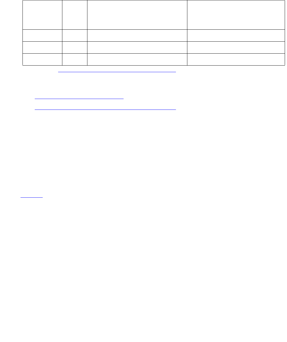
MMI-BD
Issue 1 June 2005 1655
MMI-BD
S8700 | 8710 / S8500
Two circuit packs can be used for multimedia connections:
●TN787D (or later) on page 1655
●TN2207/Expansion Services Module on page 1656
TN787D (or later)
The Multimedia Interface circuit pack (TN787D or later, also called the MMCH circuit pack)
provides a number of H.221 protocol terminations for bit streams received from the TDM bus.
The Multimedia Interface de multiplexes the H.221 bit stream (audio, video, data, control, and
indication signals) and transmits the bit streams onto the TDM bus so that the appropriate circuit
packs can process them.
The Multimedia Interface circuit pack is commonly referred to as the MMI pack for H.221
protocol termination. There are 32 ports (also called resources) on the circuit pack. See
MMI-PT on page 1669 for maintenance of these resources.
The MMI circuit pack contains 4 digital signal processors that manage the 32 resources.
MO Name
in Alarm
Log
Alarm
Level
Initial SAT Command to Run Full Name of MO
MMI-BD MAJ test board location l r# Multimedia Interface circuit pack
MMI-BD MIN test board location l r# Multimedia Interface circuit pack
MMI-BD1
1. Refer to XXX-BD (Common Port Circuit Pack/Media Module) on page 2539.
WRN test board location s r# Multimedia Interface circuit pack
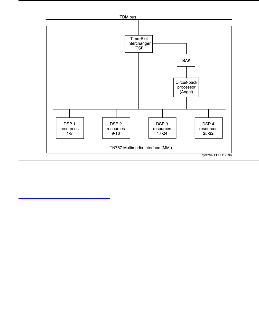
Communication Manager Maintenance-Object Repair Procedures
1656 Maintenance Procedures for Avaya Communication Manager 3.0, Media Gateways and Servers
Figure 90: TN787 Multimedia Interface (MMI) Circuit Pack
TN2207/Expansion Services Module
The TN2207 circuit pack permits connecting an ESM (Expansion Services Module). See
Figure 91: Typical ESM connections on page 1657 for connectivity.
●The TN2207 circuit pack provides T.120 data-sharing capability on a MMCH multipoint
H.320 video conference
●Each conference participant must have endpoints administered and a personal computer
with the H.320 video application installed.
●The S8700 Media Server configuration must have an expansion service module installed.
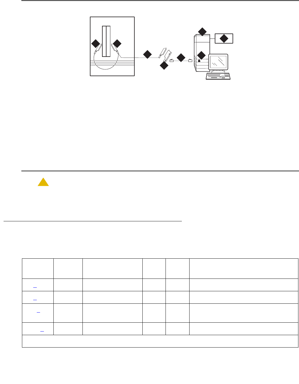
MMI-BD
Issue 1 June 2005 1657
Figure 91: Typical ESM connections
!CAUTION:
CAUTION: The TN2207 circuit pack is the only pack that allows connection of an ESM to
S8700 Media Server configurations.
Error Log Entries and Test to Clear Values
Figure notes:
1. Port B Y-cable connector to a TN787
MMI (Multimedia Interface) circuit
pack
5. D8W cord connected to 356A
adapter port 1
2. Port A Y-cable connector to a
TN2207 PRI circuit pack
6. Expansion Service Module (ESM)
3. 25-pair Y-cable 7. Port B on compatible PRI (primary
rate interface) card
4. 356A adapter
cydf012 KLC 092801
4
5
3
6
7
8
1 2
Table 613: MMI-BD Error Log Entries
Error
Type
Aux
Data
Associated Test Alarm
Level
On/Off
Board
Test to Clear Value
0 (a) 0 Any Any Any test board location sh r 1
1 (b) Any None MIN ON
18 (c)0 busyout board
location
WRN OFF release board location
217 (d) 0 None WRN ON
1 of 2

Communication Manager Maintenance-Object Repair Procedures
1658 Maintenance Procedures for Avaya Communication Manager 3.0, Media Gateways and Servers
Notes:
a. Error Type 0: run the short test sequence first. If every test passes, run the long test
sequence. Refer to each test’s description, and follow its procedures.
b. Error Type 1: the circuit pack stopped functioning or it was physically removed from the
system. The alarm logs approximately 11 minutes after the circuit pack has been removed
and/or the SAKI Sanity test (#53) fails.
If the circuit pack is in the system and the red LED is on, follow the instructions for a red
alarm in Circuit pack LEDs on page 257.
c. Error Type 18: the circuit pack was busied out using busyout board location.
d. Error Type 217: there are more than four MMI circuit packs in the system. Remove the
circuit pack that generated the error in the error log by locating the slot indicated by the
error.
e. Error Type 257: there are transient communication problems between the switch and this
circuit pack. Execute test board location and see the repair procedures for the
Control Channel Loop-around test (#52) in XXX-BD (Common Port Circuit Pack/Media
Module) on page 2539.
257 (e) 65535 Control Channel
Loop test (#52)
MIN ON test board location r 3
513 (f) 4352
to 4357
Uplink error from
circuit pack
769 (g)Any MMI
Synchronization
Status (#1123)
1281 (h) Any Circuit Pack
Restart test
(#594)
MAJ ON
1538 (i) Any Software detected
error
MIN ON
1793 (j) Any TSI XTalk (#6) MIN ON test board location l r 3
2049 (k) Any TSI Loop (#1108) MAJ ON test board location l r 3
Table 613: MMI-BD Error Log Entries (continued)
Error
Type
Aux
Data
Associated Test Alarm
Level
On/Off
Board
Test to Clear Value
2 of 2

MMI-BD
Issue 1 June 2005 1659
f. Error Type 513: the circuit pack detected an Angel on-board hardware failure. The reported
Aux Data values correspond to the following detected errors:
4352 — External RAM error
4253 — Internal RAM error
4355 — ROM Checksum error
4357 — Instruction set error
Use busyout board location, reset board location, and release board
location. When reset, the circuit pack executes a set of tests to detect the presence of
any of the above faults. The detection of one these errors during initialization causes the
circuit pack to lock up and appear insane to the system. See the repair procedures in Note
(b) for Error Type 1.
g. Error Type 769: this MMI circuit pack reported a loss of MMI synchronization. Refer to
Test #1123 for repair procedures.
h. Error Type 1281: a failure of the time slot interchanger was detected. Reset the circuit pack
using busyout board location, reset board location, and release board
location. If the reset passes, then the on-board circuitry is healthy. Retire the alarm using
test board location long clear followed by release board location.
i. Error Type 1538: the circuit pack is hyperactive and it is flooding the switch with messages
sent over the control channel. The circuit pack is taken out-of-service when a threshold
number of these errors is reported to the switch. Clear the alarm using busyout board
location, reset board location, test board location long clear, and
release board location. If the error recurs within 10 minutes, replace the circuit pack.
j. Error Type 1793: the TSI Cross Talk test (#6) failed. See the description of this test, and
follow its repair procedures.
k. Error Type 2049: the TSI Loop-around test (#1108) failed. See the description of this test,
and follow its repair procedures.

Communication Manager Maintenance-Object Repair Procedures
1660 Maintenance Procedures for Avaya Communication Manager 3.0, Media Gateways and Servers
System Technician-Demanded Tests:
Descriptions and Error Code
Investigate tests in the order presented when inspecting errors in the system. By clearing Error
Codes associated with the first test, you may also clear errors generated from other tests in the
sequence.
TSI Crosstalk Test (#6)
This test is nondestructive.
The Time Slot Interchanger (TSI) chip controls connectivity to the TDM bus. The TSI Cross Talk
test verifies that this TSI talks on the selected TDM bus time slot and never crosses over to time
slots reserved for other connections. If the TSI is not working correctly, one-way and noisy
connections may occur. If the test passes, then the TSI can communicate over the TDM bus.
This test is part of the circuit pack’s demand and scheduled long test sequence, and takes
approximately 20 to 30 seconds to complete.
Order of Investigation Short Test
Sequence
Long Test
Sequence
Reset Board
Sequence
D/ND1
1. D = Destructive, ND = Nondestructive
TSI Crosstalk test (#6) X ND
TSI Loop-around test (#1108) X ND
MMI SYNC Status test (#1123) X ND
MMI SYNC Status test (#1122) X ND
Control Channel Loop-around test (#52)2
2. Refer to the repair procedure described in XXX-BD (Common Port Circuit Pack/Media
Module) on page 2539 for a description of this test.
XX ND
SAKI Sanity test (#53)2XD

MMI-BD
Issue 1 June 2005 1661
Table 614: Test #6 TSI Crosstalk Test
Error
Code
Test
Result
Description / Recommendation
ABRT Internal system error. This is an abnormal abort.
1. Retry the command at 1-minute intervals up to 5 times.
1002 ABRT The system could not allocate time slots for the test, the traffic load on the
system is very high, or the time slots are out-of-service due to TDM-BUS
errors.
1. If the system has no TDM-BUS errors and is not handling heavy traffic,
repeat the test at 1-minute intervals up to 5 times.
1003 ABRT The system could not allocate a tone detector for the test. The system is
oversized for the number of tone detectors present, or some tone detectors
are out-of-service.
1. Resolve any TTR-LEV errors.
2. Resolve any TONE-PT errors.
3. If neither condition exists, retry the test at 1-minute intervals up to 5
times.
2000 ABRT Response to the test was not received from the MMI-BD circuit pack within
the allowable time period.
1. If this result occurs repeatedly, attempt to reset the circuit pack if the
other ports are idle. Reset the circuit pack by issuing busyout board
location, reset board location, and release board
location.
2. If this result occurs again, replace the circuit pack.
2012 ABRT Internal system error. This is an abnormal abort.
1. Retry the command at 1-minute intervals up to 5 times.
2100 ABRT Could not allocate the necessary resources to run this test. This is an
abnormal abort.
1. Retry the command at 1-minute intervals up to 5 times.
FAIL The TSI was found to be transmitting in error. This causes noisy and
unreliable connections.
1. Replace the circuit pack.
PASS The TSI is correctly using its allocated time slots.

Communication Manager Maintenance-Object Repair Procedures
1662 Maintenance Procedures for Avaya Communication Manager 3.0, Media Gateways and Servers
TSI Loop-Around Test (#1108)
This test is nondestructive.
During this test, the MMI’s Time Slot Interchanger (TSI) is listens to a TDM timeslot. A digital
count tone loops back in the TSI and onto another TDM timeslot without passing through any
resource hardware. A tone detector port verifies the looped data. If the digital count is correct,
then the test passes. The test is done for both TDM buses. Failures indicate that the TSI is
unreliable.
Table 615: Test #1108 TSI Loop-Around Test
Error
Code
Test
Result
Description / Recommendation
ABRT Internal system error. This is an abnormal abort.
1. Retry the command at 1-minute intervals up to 5 times.
1002 ABRT The system could not allocate time slots for the test. Either the traffic load
on the system is very high or time slots are out-of-service due to TDM-BUS
errors.
1. If the system has no TDM-BUS errors and is not handling heavy traffic,
repeat the test at 1-minute intervals up to 5 times.
1003 ABRT The system could not allocate a tone detector for the test. The system may
be oversized for the number of Tone Detectors present, or some Tone
Detectors may be out-of-service.
1. Resolve any TTR-LEV errors.
2. Resolve any TONE-PT errors.
3. If neither condition exists, retry the test at 1-minute intervals up to 5
times.
2000 ABRT Response to the test was not received from the Tone Detector circuit pack
within the allowable time period.
1. If this result occurs repeatedly, attempt to reset the circuit pack (if the
other ports are idle). Reset the circuit pack by issuing busyout board
location, reset board location, and release board
location.
2. If this result occurs again, replace the circuit pack.
2012 ABRT Internal system error. This is an abnormal abort.
1. Retry the command at 1-minute intervals up to 5 times.
1 of 2
MMI-BD
Issue 1 June 2005 1663
MMI Synchronization Status Test
(#1122 and 1123)
This test is nondestructive.
To support applications involving multiple MMI circuit packs, the appropriate MMI circuit packs
must be synchronized with one another. One such circuit pack is designated as the master sync
source, which provides the synchronization signal onto the TDM bus. The other MMI circuit
packs in the system listen to this signal.
This test monitors this synchronization state. The test fails if the MMI circuit pack is not in sync.
The test passes with auxiliary code 1100 if the MMI circuit pack is in sync and is providing the
synchronization signal for the system. The test also passes with an auxiliary code of 1101 if the
MMI circuit pack is in sync and listening to the sync signal. MMI circuit packs do not lose the
synchronization signal unless an MMI circuit pack is either pulled out of the system or reset by
using a technician command.
Test #1122 runs when the long option of test board is entered, initiating the recovery of
synchronization. Test #1123 runs when the short option of test board is entered, giving the
status of the synchronization. The long option is not required, because synchronization signal
recovery should take place within software running in the background. Use the long option only
if synchronization is not established within 5 minutes of investigating the problem.
2100 ABRT Could not allocate the necessary resources to run this test. This is an
abnormal abort.
1. Retry the command at 1-minute intervals up to 5 times.
FAIL The TSI was found to be transmitting in error, causing noisy and unreliable
connections.
1. Replace the circuit pack.
PASS The TSI is correctly using its allocated time slots.
Table 615: Test #1108 TSI Loop-Around Test (continued)
Error
Code
Test
Result
Description / Recommendation
2 of 2

Communication Manager Maintenance-Object Repair Procedures
1664 Maintenance Procedures for Avaya Communication Manager 3.0, Media Gateways and Servers
Table 616: Test #1122/1123 MMI Synchronization Status Test
Error
Code
Test
Result
Description / Recommendation
ABRT Internal system error. This is an abnormal abort.
1. Retry the command at 1-minute intervals up to 5 times.
2000 ABRT A response to the test was not received from the MMI circuit pack within
the allowable time period.
1. If this result occurs repeatedly and the MMI circuit pack is idle, reset
the circuit pack using busyout board location, reset board
location, and release board location.
2. Rerun the test; if the same result occurs again, replace the MMI circuit
pack.
2012 ABRT Internal system error
1. Retry the command at 1-minute intervals up to 5 times.
2100 ABRT Could not allocate the necessary resources to run this test. This is an
abnormal abort.
1. Retry the command at 1-minute intervals up to 5 times.
FAIL The MMI circuit pack is out of MMI synchronization. Run the long option
of the test board command.
1. Wait up to 5 minutes, and then reset the circuit pack with busyout
board location, reset board location, and release
board location.
2. Rerun the test; if the same result occurs again, replace the circuit
pack.
1100 PASS The MMI circuit pack is providing the synchronization correctly. This MMI
circuit pack is designated as the Master Sync source.
1101 PASS The MMI circuit pack is listening to the synchronization signal correctly.

MMI-BD
Issue 1 June 2005 1665
Control Channel Loop-Around Test (#52)
Refer to the repair procedure described in XXX-BD (Common Port Circuit Pack) as Control
Channel Loop-Around Test (#52) on page 2551.
SAKI Sanity Test (#53)
Refer to the SAKI Sanity Test (#53) on page 2552 repair procedure in the XXX-BD (Common
Port Circuit Pack/Media Module) on page 2539.

Communication Manager Maintenance-Object Repair Procedures
1666 Maintenance Procedures for Avaya Communication Manager 3.0, Media Gateways and Servers
MMI-LEV (Multimedia Interface Resource Level)
S8700 | 8710 / S8500
The Multimedia Interface Resource Level MO monitors MMI efficiency by tracking the number
of MMI ports that are in-service, and then comparing that number with the value entered in the
MMIs field on the System-Parameters Maintenance screen. This MMIs field is located under the
Minimum Maintenance Threshold section. The MMIs field contains the minimum number of
MMI ports needed for the Multimedia Call Handling (MMCH) feature to run efficiently and is an
administrable field. This field must contain a minimum threshold number for MMI port capacity
of between 0-128. The MMCH feature must be enabled on the System-Parameters
Customer-Options screen before the MMIs field can be changed to a number greater than zero.
The algorithm for determining that a low level of MMI resources exists uses the value entered in
the MMIs field, and the number of MMI ports that are in-service in the system.
Each MMI circuit pack contains up to 32 ports. If the number of in-service MMI ports falls below
the minimum port capacity (value entered on the System Parameters Maintenance screen
under the Minimum Maintenance Threshold section and in the MMIs field), a MMI-LEV error is
logged. If this outage continues for 15 minutes, a MAJOR alarm is raised.
Resolving MMI-LEV Errors/Alarms
MMI ports are a key part of the MMCH feature, and any loss in the number of ports available for
use degrades the MMCH customer-defined service level.
If a MMI circuit pack or port is busied out using busyout board or busyout port, these
out-of-service ports are not included in the MMI level calculation, thus allowing a technician to
busyout a MMI circuit pack for maintenance reasons without causing a MAJOR alarm to be
raised. However, if every port on the MMI circuit pack is not made busy and the circuit pack is
removed, an alarm is raised.
Note:
Note: When diagnosing a MMI-LEV problem, begin by resolving any alarms raised
against MMI-BD or MMI-PT MOs. Clearing MMI-BD or MMI-PT alarms may clear
the MMI-LEV alarm.
The MMI circuit pack is maintained by the software like the Tone Detector circuit pack, which
can be removed and reinserted in any port board slot without administration. Similarly, if a MMI
circuit pack is removed from service logically by failing the Archangel sanity scan test or is
removed from service physically by removing the circuit pack from the carrier, no error/alarm is
raised against either the MMI-BD or the MMI-PT MOs. Therefore, if a MMI-LEV error/alarm
MO Name in
Alarm Log
Alarm
Level
Initial Command to Run Full Name of MO
MMI-LEV MAJ See Resolving MMI-LEV Errors/Alarms.MMI-LEV
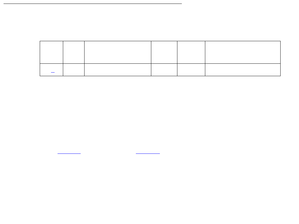
MMI-LEV (Multimedia Interface Resource Level)
Issue 1 June 2005 1667
exists, yet no alarms have been raised against MMI-BD or MMI-PT MOs, a MMI circuit pack
may have been removed from service causing the MMI-LEV error/alarm. To resolve a MMI-LEV
MAJOR alarm, restore the number of MMI ports available for service to be equal to or greater
than the calculated port capacity.
To determine how many MMI circuit packs are needed for the MMCH feature:
1. Using display system-parameters maintenance, locate the number listed in the
Minimum Maintenance Thresholds (MMIs) field and record this number.
2. Use list configuration to verify the number of MMI ports.
3. Compare this number with the value listed in the MMIs field on the System-Parameters
Maintenance screen (number listed in step 1: minimum thresholds number for MMI ports of
between 0-128). Each MMI circuit pack contains up to 32 ports. If this number in the MMIs
field is less than or equal to 32, one MMI circuit pack is needed. If this number is 64, then
two MMI circuit pack are needed.
4. Use list configuration to verify that the number of MMI circuit packs listed agrees
with the required minimum port capacity (from step 1). If the number of MMI circuit packs
listed in the step 2 differs from the calculated number, restore the number of MMI circuit
packs to the correct value, in order to resolve the MMI-LEV alarm.
Error Log Entries and Test to Clear Values
Notes:
a. Error Type 1: The number of MMI resources in the system that are in service has fallen
below the calculated minimum value. If the number of in-service MMI ports falls below the
MMCH port capacity (value entered in the Minimum Maintenance Thresholds for MMIs
field) on the System-Parameters Maintenance screen, a MMI-LEV error is logged. If this
outage continues for 15 minutes, a MAJOR alarm is raised.
To resolve this alarm, correct the out-of-service problem:
1. See MMI-PT on page 1669 and MMI-BD on page 1655 and resolve any associated
alarms.
2. If a MMI-LEV error/alarm exist and none has been raised against MMI-BD or MMI-PT
MOs, an MMI circuit pack may have been removed from service causing the MMI-LEV
error/alarm. To resolve a MMI-LEV MAJOR alarm, restore the number of MMI ports
Table 617: MMI-LEV Error Log Entries
Error
Type
Aux
Data
Associated Test Alarm
Level
On/Off
Board
Test to Clear Value
1 (a) Any None MAJ OFF

Communication Manager Maintenance-Object Repair Procedures
1668 Maintenance Procedures for Avaya Communication Manager 3.0, Media Gateways and Servers
available for service to be equal to or more than the calculated port capacity. See the
Resolving MMI-LEV Errors/Alarms on page 1666 section for details.
3. If this error continues, escalate the problem.
System Technician-Demanded Tests:
Descriptions and Error Code
There are no System Technician-Demanded tests for MMI-LEV.

MMI-PT
Issue 1 June 2005 1669
MMI-PT
S8700 | 8710 / S8500
Note:
Note: Refer to Chapter 4: General troubleshooting in Maintenance Procedures
(03-300192) for MMCH troubleshooting information.
The Multimedia Interface circuit pack provides a number of H.221 protocol terminations for bit
streams received from the TDM bus. The Multimedia Interface demultiplexes the H.221 bit
stream (audio, video, data, control, and indication signals) and transmits the bit streams onto
the TDM bus to be processed by the appropriate circuit packs.
Each Multimedia Interface circuit pack contains 32 separately maintained “ports,” more
commonly referred to as “resources.” MMI-PT represents one of these 32 resources. At system
boot or when the circuit pack is inserted, 32 resources are inserted into the system.
The MMI circuit pack contains 4 Digital Signal Processors (DSPs) which manage the 32
resources. These resources are directly mapped to DSPs:
All 8 resources that the circuit pack controls may be placed out of service by the failure of one of
these DSPs.
MO Name in
Alarm Log
Alarm
Level
Initial SAT Command to Run Full Name of MO
MMI-PT MAJ test port location l r# Multimedia Interface Port
MMI-PT MIN test port location l r# Multimedia Interface Port
MMI-PT WRN test port location l r# Multimedia Interface Port
Resource Direct Map
1–8 DSP1
9–16 DSP2
17–24 DSP3
25–32 DSP4
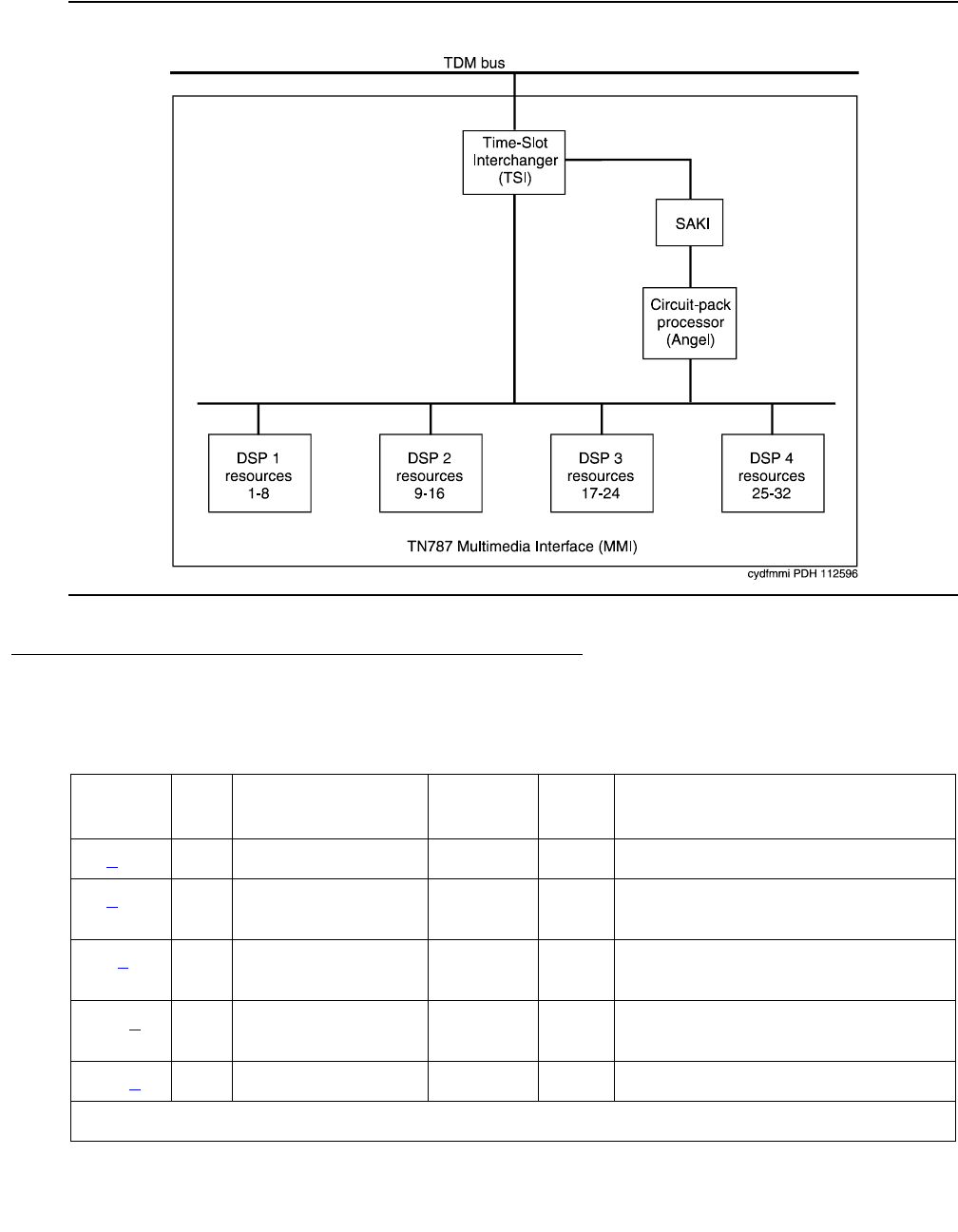
Communication Manager Maintenance-Object Repair Procedures
1670 Maintenance Procedures for Avaya Communication Manager 3.0, Media Gateways and Servers
Figure 92: TN787 MMI (MULTIMEDIA INTERFACE) CIRCUIT PACK
Error Log Entries and Test to Clear Values
Table 618: MMI-PT Error Log Entries
Error
Type
Aux
Data
Associated Test Alarm
Level
On/Off
Board
Test to Clear Value
0 (a)0Any Any Anytest port location sh r 1
1 (b) Any Uplink error from
pack
18 (c)0busyout port
location
WRN OFF release port location
130 (d)AnySoftware
generated
WRN ON
257 (e) Any None MAJ MIN ON
1 of 2

MMI-PT
Issue 1 June 2005 1671
Notes:
a. Error Type 0: run the short test sequence first. If every test passes, run the long test
sequence. Refer to each test’s description and follow its procedures.
b. Error Type 1: the customer endpoint connected on a conference sent too many messages
to the VSP-MCU in a specified amount of time. Check status conference to correlate
which customer had the problem. This is a customer endpoint problem, not a VSP-MCU
problem.
c. Error Type 18: this port was busied out by busyout port location.
d. Error Type 130: the circuit pack was removed or has been insane for more than 11 minutes.
To clear the error, replace or reseat the circuit pack.
e. Error Type 257: the MMI circuit pack detects a DSP Error. Maintenance software resets the
DSP when this error is received. This error is logged for all 8 resources connected to this
particular DSP. If this DSP continues to fail sanity, a Minor alarm is raised. Replace the
circuit pack.
f. Error Type 513: the Resource Loop-around test (#1111) fails. Run the long test sequence,
and note the results of Test #1111.
g. Error Type 1025: either the MMI or Voice Conditioner (VC) circuit packs reports a loss of
framing on the service channel between these two circuit packs. When a customer endpoint
establishes a call to the VSP-MCU, a channel is established between the MMI resource and
the VC port. If this channel is detected to go down by either circuit pack, an uplink message
is sent. This error is then forwarded to maintenance for both circuit packs. Run the long test
sequence for this MMI resource, and if any of the tests fail, follow the repair procedures for
that test. If every test passes, the cause of the problem might be with the VC pack. See the
VC-DSPPT on page 2513 repair procedures.
513 (f) Any Resource
Loop-Back test
(#1111)
MIN ON test port location sh r 3
1025 (g) Any Uplink error from
pack
3841 to
3844 (h)
Any Uplink error from
pack
Table 618: MMI-PT Error Log Entries (continued)
Error
Type
Aux
Data
Associated Test Alarm
Level
On/Off
Board
Test to Clear Value
2 of 2

Communication Manager Maintenance-Object Repair Procedures
1672 Maintenance Procedures for Avaya Communication Manager 3.0, Media Gateways and Servers
h. Error Types 3841 - 3844: are not related to VSP-MCU. They could be caused by network
problems or from the customer endpoints. They are presented here for logging purposes
only.
System Technician-Demanded Tests:
Descriptions and Error Codes
Resource Loop-Around Test (#1111)
This test is destructive.
This test checks the connectivity of the resource within MMI circuit pack and out to the TDM
bus. The object is to test the circuitry that an H.221 bit stream comes in contact with when that
stream is demultiplexed, pre-processed, written to the TDM bus and then reread (looped in the
TSI), post-processed, multiplexed, and then written back to the TDM bus for verification. The
video, audio, and data components of the bit stream are tested separately. If any one of these
tests fails, the resource is taken out of service.
Code Description
3841 CRC4 Error (Frame checksum error)
3842 Correctable BAS (Control msg bit error – 1- or 2-bit error, correctable)
3843 Uncorrectable BAS (Control msg bit error – 3-bit error or more, not
correctable)
3844 Protocol Error (H.221 Protocol error from endpoint detected)
Order of Investigation Short Test
Sequence
Long Test
Sequence
D/ND
Resource Looparound test (#1111) X X Destructive

MMI-PT
Issue 1 June 2005 1673
Table 619: Test #1111 Resource Loop-Around Test
Error
Code
Test
Result
Description / Recommendation
1000 ABRT System resources required to run this test are not available. The port may
be busy with a valid call.
1. Retry the command at 1-minute intervals up to 5 times.
2. Use status conference to determine if there is an active
conference. If a call is active, the test cannot run until the conference
call finishes.
1002 ABRT The system could not allocate time slots for the test. The traffic load on the
system may be very high, or time slots may be out-of-service due to
TDM-Bus errors.
1. If the system has no TDM-BUS errors and is not handling heavy traffic,
repeat the test at 1-minute intervals up to 5 times.
1003 ABRT The system could not allocate a tone detector for the test. The system is
oversized for the number of tone detectors present or some tone detectors
are out-of-service.
1. Resolve any TTR-LEV errors.
2. Resolve any TONE-PT errors.
3. If neither condition exists, retry the test at 1-minute intervals up to 5
times.
1004 ABRT The resource has been seized by a user for a valid call. Use status
conference to verify that there is an active conference call.
1. If there are no conference calls, retry the command at 1-minute
intervals up to 5 times.
2000 ABRT Response to the test was not received from the Tone Detector circuit pack
within the allowable time period.
1. If this result occurs repeatedly, reset the circuit pack, if the other ports
are idle. Reset the circuit pack by issuing busyout board
location and reset board location, followed by release
board location.
2. If this result occurs again, replace the circuit pack.
2012 ABRT Internal system error
1. Retry the command at 1-minute intervals up to 5 times.
1 of 2

Communication Manager Maintenance-Object Repair Procedures
1674 Maintenance Procedures for Avaya Communication Manager 3.0, Media Gateways and Servers
2100 ABRT Could not allocate the necessary resources to run this test. Abnormal
abort.
1. Retry the command at 1-minute intervals up to 5 times.
0, 1, 2 FAIL This resource cannot guarantee data integrity and is out-of-service. The
following Error Codes indicate failure of a particular media loop:
0 = video
1 = audio
2 = low-speed data
1. Replace the circuit pack.
PASS The resource is functioning normally.
Table 619: Test #1111 Resource Loop-Around Test (continued)
Error
Code
Test
Result
Description / Recommendation
2 of 2

MMI-SYNC
Issue 1 June 2005 1675
MMI-SYNC
S8700 | 8710 / S8500
Note:
Note: Refer to Chapter 4: General troubleshooting in Maintenance Procedures
(03-300192) for MMCH troubleshooting information.
Each Port Network (PN) must have a TN787D or later MMI circuit pack assigned as the
Multimedia Interface (MMI) master synchronization source for that PN. If one or more MMI
circuit pack is administered in a PN, one MMI circuit pack is designated as the master
synchronization source for every MMI circuit pack within that PN.
The MMI circuit pack generates a synchronization signal and puts that signal on the TDM bus.
Other MMI packs or any other circuit pack within a PN can listen to this signal and “synchronize
up” to it. The first MMI circuit pack inserted in a PN is normally designated as the master. As
subsequent MMI packs are inserted, they are instructed to listen and synchronize to the
time-slot of the master MMI. In the unlikely case of an MMI losing this reference, an uplink
message is sent from the MMI circuit pack that lost the signal to maintenance, which also clears
the “event” counter on this MMI with a downlink message. This forces the MMI circuit pack to
return the current state of the synchronization signal. If the signal is still lost, then the recovery
algorithm is entered. Note that during this time, the MMI circuit pack synchronizes to its internal
clock, and there should be no service disruption. A loss of synchronization is usually the result
of a circuit pack failure. The maintenance strategy is to switch the master source away from the
bad pack to another healthy MMI circuit pack within the PN.
A synchronization switch takes place if half or more of the MMI circuit packs in a PN report a
loss of synchronization. For example, a PN with two MMIs reporting a loss of sync source
switches immediately, three and four MMIs switch if two report the loss, and so forth. A healthy
MMI circuit pack becomes the master synchronization source providing the signal on a new
timeslot. The other MMI circuit packs within the PN are instructed to listen to this new signal,
and the old master stops providing the signal and now listens to the new master MMI. If an MMI
is physically removed from the system, then the remaining MMIs report the loss of
synchronization. The first MMI with no alarms present becomes the new master of that PN.
Once a synchronization switch has occurred, another switch is not allowed for 15 minutes to
avoid hyperactive switching. If every MMI has an alarm, then no switch is made.
If the MMI circuit pack that provides synchronization is craft busied out, it will not affect the PN
synchronization. The signal is still provided by the busied-out pack. There is no effect on
synchronization if the technician enters a release of the busied-out MMI. Synchronization is not
affected by a warm start of the system (reset system 1). For every other restart (reboot through
cold 2), MMI synchronization recovers during board insertion.
MO Name in
Alarm Log
Alarm
Level
Initial SAT Command to Run Full Name of MO
MMI-SYNC MIN test board location l r# Multimedia Interface circuit pack
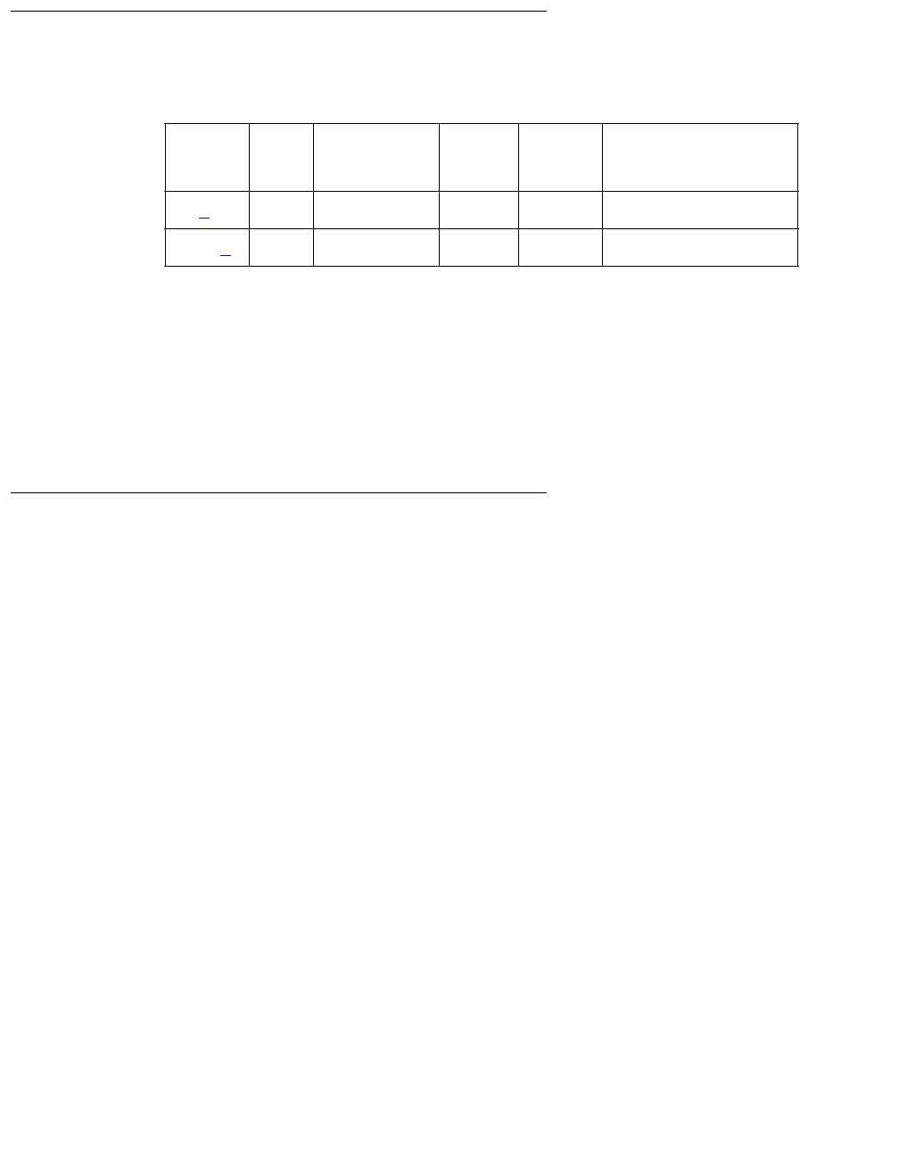
Communication Manager Maintenance-Object Repair Procedures
1676 Maintenance Procedures for Avaya Communication Manager 3.0, Media Gateways and Servers
Error Log Entries and Test to Clear Values
Notes:
a. Error Type 1: an MMI synchronization switch was successful.
1. Refer to MMI-BD errors for the reason for the switch.
b. Error Type 257: the requested MMI synchronization switch failed.
1. Resolve every MMI-BD alarm.
System Technician-Demanded Tests:
Descriptions and Error Codes
There are no system technician-demanded tests for MMI-SYNC.
Table 620: MMI-SYNC Error Log Entries
Error
Type
Aux
Data
Associated
Test
Alarm
Level
On/Off
Board
Test to Clear Value
1 (a) Any None
257 (b) Any None MIN OFF

MODEM-BD (Modem Pool Circuit Pack)
Issue 1 June 2005 1677
MODEM-BD (Modem Pool Circuit Pack)
S8700 | 8710 / S8500
Refer to XXX-BD (Common Port Circuit Pack/Media Module) on page 2539 for circuit pack-level
errors. See also MODEM-PT (Modem Pool Port) on page 1678 for related port information.
MO Name Alarm
Level
Initial SAT Command to Run Full Name of MO
MODEM-BD MIN test board location sh Modem Pool circuit pack
MODEM-BD WRN test board location sh Modem Pool circuit pack

Communication Manager Maintenance-Object Repair Procedures
1678 Maintenance Procedures for Avaya Communication Manager 3.0, Media Gateways and Servers
MODEM-PT (Modem Pool Port)
S8700 | 8710 / S8500
The Modem Pool Port provides an interface for digital and analog data communication devices
or ports connected to the PBX. It may be thought of as a PBX data communications “conversion
resource” because it converts analog modem signals typically used in the telephone network
into digital signals that are compatible with the internal PBX network and vice versa.
There may be a number of these conversion resources available in the PBX, each assigned to
an available Modem Pool Group. Only one conversion resource is used per data connection.
The PBX software usually adds the conversion resource into a data connection if it determines
that it is necessary for the call. Typical connections that include Modem Pool conversion
resources include data calls from Analog Line or Central Office Trunk ports to any digital port or
Digital Line or Trunk ports to any analog port. An example of a Data Module to Central Office
Trunk connection using a Modem Pool conversion resource is shown in Figure 93: Typical
Modem Pool Switched Connection with Integrated Pooled Modem on page 1679. In the case
where a local data call originates from an analog port normally used for voice service only and
terminates on a digital port, a Data Origination access code must be dialed before the extension
number for the Modem Pool conversion resource to be included in the connection.
Each Modem Pool conversion resource contains two ports. One of these, an analog port, is
connected (via the PBX network) to the analog line or trunk port that is the source of the modem
signal. The second port is referred to as the digital port and is connected (again through the
PBX network) to the digital line or trunk port associated with the Data Module in the connection.
The analog modem signals enter the analog port of the conversion resource in standard Pulse
Code Modulation (PCM) format, but are converted into Data Communications Protocol (DCP)
format before going to the digital line or trunk in the connection.
Integrated Modem Pools
There are two primary types of Modem Pool conversion resources available: an Integrated
Pooled Modem and a Combined Modem Pool. The integrated TN758 Pooled Modem circuit
pack contains two independent 300- or 1200-bps conversion resources. Each conversion
resource contains two interfaces to the PBX digital network: an analog port and a digital port.
The analog port is connected through the PBX network to the analog line or trunk port
containing the analog modem signals. The digital port connects through the PBX network to the
digital line or trunk port in the call. Figure 93: Typical Modem Pool Switched Connection with
Integrated Pooled Modem on page 1679 shows a typical end-to-end connection using a
conversion resource on the integrated Pooled Modem circuit pack.
MO Name Alarm
Level
Initial SAT Command to Run Full Name of MO
MODEM-PT MIN test port location sModem Pool Port
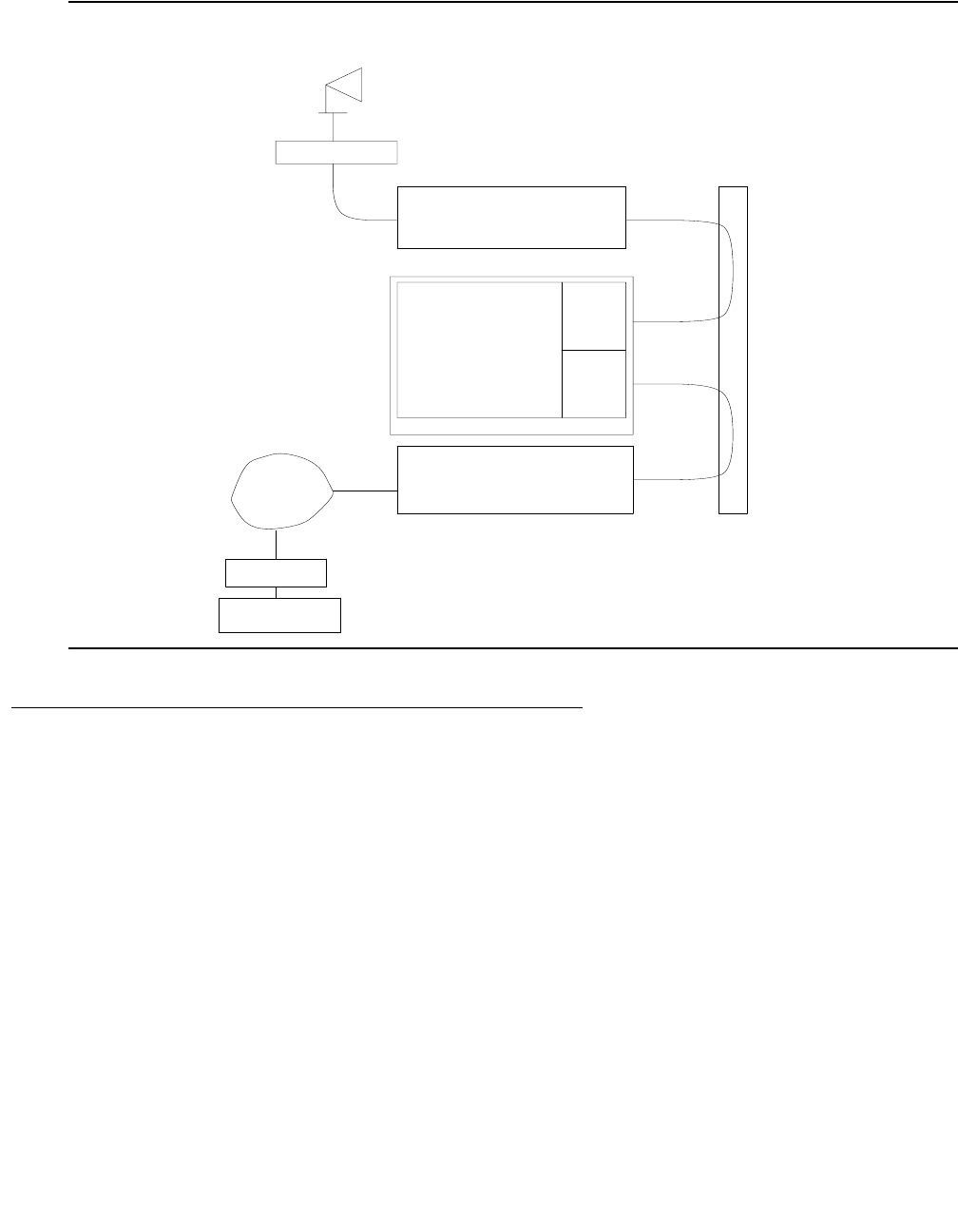
MODEM-PT (Modem Pool Port)
Issue 1 June 2005 1679
Figure 93: Typical Modem Pool Switched Connection with Integrated Pooled Modem
Combined Modem Pools
The Combined Modem Pool conversion resource is the second type available. The function
served by the Combined Modem Pool is similar to that of the integrated Pooled Modem circuit
pack, but the physical implementation is much different. It has the advantage of supporting any
speed the external modem can support. The integrated Pooled Modem circuit pack can only
support 300- or 1200-bps transmission rates. The Combined Modem Pool conversion resource
consists of a port on an Analog Line circuit pack, an external modem, a Data Module, and a port
on a TN754 Digital Line circuit pack. The tip and ring interface of the Analog Line is connected
to the modem, the RS-232C interface of the modem connects to the Data Module, and the DCP
interface on the Data Module is connected to the Digital Line port.
The analog modem signals pass through the Analog Line port to the modem. The modem
converts these to RS-232C signals which are passed on to the Data Module. The Data Module
further converts the signals to the DCP protocol for the Digital Line port which passes the
signals on to the PBX network.
ANALOG
ANALOG
DCP
DCP
DCP
TIP/RING
PORT
DIGITAL
PORT
(TN758)
ANALOG
CONVERSION
POOLED MODEM
DATA MODULE
COMPUTER
HOST
MODEM
NETWORK
TELEPHONE
NETWORK
DIGITAL
PBX
(TN754)
LINE
DIGITAL
(TN747B)
TRUNK
CENTRAL OFFICE
RESOURCE
TERMINAL
PCM
PCM
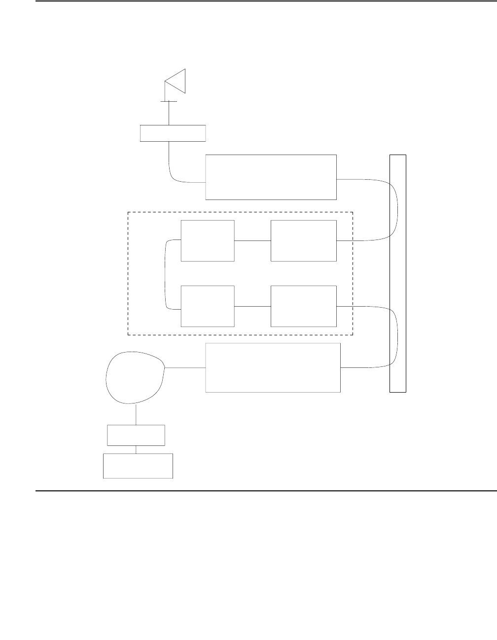
Communication Manager Maintenance-Object Repair Procedures
1680 Maintenance Procedures for Avaya Communication Manager 3.0, Media Gateways and Servers
Figure 94: Typical Modem Pool Switched Connection with Combined Modem Pool
HOST
COMPUTER
DATA MODULE
TERMINAL
CENTRAL OFFICE
TRUNK
(TN747B)
DIGITAL
DIGITAL
LINE
DATA
MODULE
MODEM
ANALOG
LINE
RS-232
DCP
DCP
PCM
PCM
DCP
ANALOG
ANALOG
DCP
COMBINED MODEM POOL
DCP
Tip/Ring
(TN754)
LINE
(TN754)
PBX
DIGITAL
NETWORK
TELEPHONE
NETWORK
MODEM

MODEM-PT (Modem Pool Port)
Issue 1 June 2005 1681
Troubleshooting Modem-Pool Symptoms
Certain customer-reported troubles may provide important information for troubleshooting
Modem Pool problems. For example, if the customer tries to make a data call requiring a
Modem Pool conversion resource, and the Modem Pool and Data Module speeds or other
options do not match, they may receive a CHECK OPTIONS error message on the terminal. In
this case, check the Modem Pool administration and Data Module option settings. If the Modem
Pool is a Combined type, check also the option settings on the external Modem and Data
Module, and cabling and connections between the Digital Line port, Data Module, Analog Line
port, and Modem.
Testing Modem Pools
There are three types of commands that can be used to test Modem Pool circuits: test port,
test modem-pool #, and test board. The test port command is generally the first test
to run after the Error Log is evaluated and an entry is found for a Modem Pool port. The test
modem-pool # command runs the same tests as test port short performed on a Modem
Pool port. However, test modem-pool # can automatically test every port in the Modem Pool
group number specified in #. The test board command performs the same tests as test
port and test modem-pool # plus additional tests for circuits common to the entire circuit
pack. See XXX-BD (Common Port Circuit Pack/Media Module) on page 2539 for information
about additional tests performed with test board (#50, #52, and #53).
If the Modem Pool port or group being tested with test modem-pool # contains Combined
Modem Pools, the ports on the associated Analog Line circuit pack and the TN754 Digital Line
circuit pack are tested as a group. Note, however, that Combined Modem Pools are not tested
with the tests described in this section and the repair information related to Tests #96, 97, 98,
and 99 is not applicable. The Analog port of the Combined Modem port is tested with Analog
port tests, and the Digital port of the Combined Modem port is tested with TDMODULE/
PDMODULE tests. Therefore, use the repair procedures outlined in the ANL-LINE, ANL-16-L,
ANL-NE-L, and TDMODULE/PDMODULE Maintenance documentation when interpreting the
results of the execution of test modem-pool # on Combined Modem Pools.
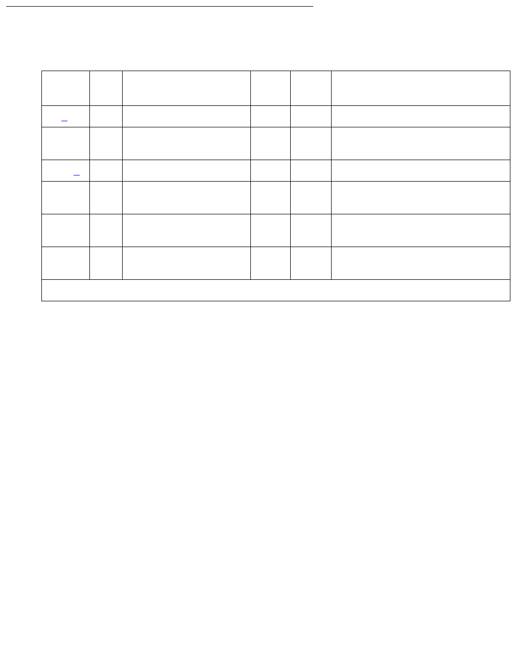
Communication Manager Maintenance-Object Repair Procedures
1682 Maintenance Procedures for Avaya Communication Manager 3.0, Media Gateways and Servers
Error Log Entries and Test to Clear Values
Notes:
a. Error Type 0: run the short test sequence first. If every test passes, run the long test
sequence. Refer to each test’s description, and follow its procedures.
b. Error Type 130: the circuit pack has been removed or has been insane for more than 21
minutes. To clear the error, reinsert or replace the circuit pack.
Table 621: Modem Pool Port Error Log Entries
Error
Type
Aux
Data
Associated Test Alarm
Level
On/Off
Board
Test to Clear Value
0 (a)0 Any AnyAnytest port location sh r 1
18 0 busyout port
location
WRN OFF release port location
130 (b) None WRN ON test port location sh
257 Conversion Resource
Loop (#98)
MIN ON test port location s r 3
513 Modem Conference
(#97)
MIN ON test port location l r 3
769 Modem NPE Crosstalk
(#96)
MIN ON test port location l r 3
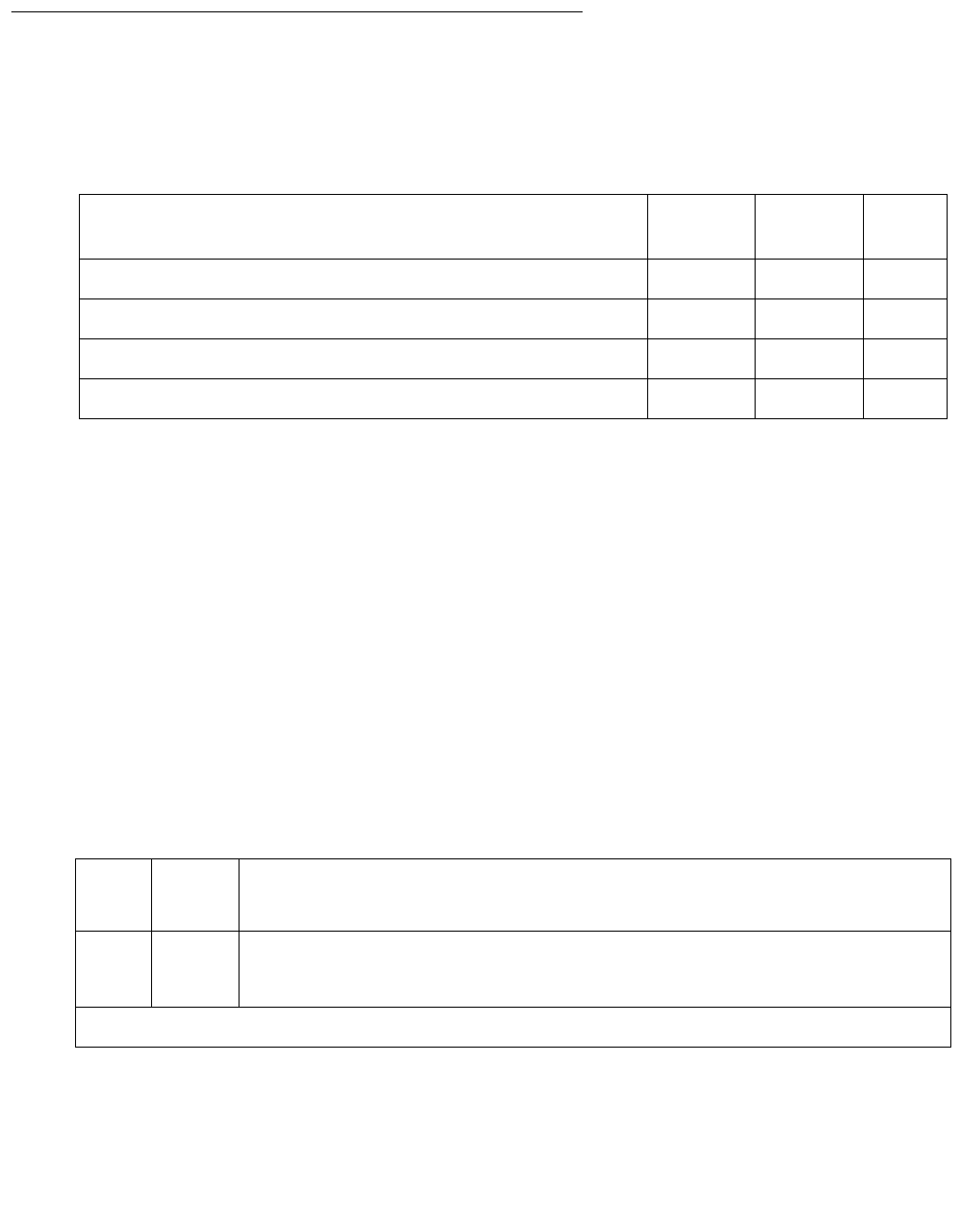
MODEM-PT (Modem Pool Port)
Issue 1 June 2005 1683
System Technician-Demanded Tests:
Descriptions and Error Codes
Investigate tests in the order presented below. Clearing Error Codes associated with the one
test may also clear errors generated from other tests in the sequence.
Note:
Note: The tests in this section do not apply to Combined Modem Pool conversion
resources. The standard Digital Line and/or Analog Line port tests are run on the
ports associated with the Combined Modem Pool. Consult the test descriptions
for those MOs when repairing Combined Modem Pool arrangements.
Modem Pool NPE Crosstalk Test (#96)
This test is destructive.
The Modem Pool Crosstalk test verifies that the NPE is connected only to the desired time slot
and is not crosstalking on other time slots. This test operates exactly like Test #6 for other types
of port circuits but is performed twice in order to test both NPEs in the Modem Pool Port.
Order of Investigation Short Test
Sequence
Long Test
Sequence
D/ND1
1. D = Destructive, ND = Nondestructive
Modem Pool NPE Crosstalk test (#96) X D
Modem Pool Conference test (#97) X D
Modem Pool Conversion Resource Loop-Around test (#98) X X ND
Modem Pool Audits test (#99) X X ND
Table 622: Test #96 Modem Pool NPE Crosstalk Test
Error
Code
Test
Result
Description / Recommendation
ABRT System resources required for this test are not available.
1. Retry the command at 1-minute intervals up to 5 times.
1 of 3

Communication Manager Maintenance-Object Repair Procedures
1684 Maintenance Procedures for Avaya Communication Manager 3.0, Media Gateways and Servers
1000 ABRT Note:
Note: System resources required for this test are not available.
The port may be in use on a valid call. Determine whether
the port is available for testing.
2. Retry the command at 1-minute intervals up to 5 times.
1001 ABRT System resources required to run this test are not available.
1. Retry the command at 1-minute intervals up to 5 times.
1002 ABRT The system could not allocate time slots for the test. The system may be
under heavy traffic conditions, or it may have time slots out-of-service due
to TDM-BUS errors.
1. If the system has no TDM-BUS errors and is not handling heavy
traffic, repeat the test at 1-minute intervals up to 5 times.
1003 ABRT The system could not allocate a tone receiver for the test. The system
may be oversized for the number of Tone Detectors present or some Tone
Detectors may be out-of-service.
1. Resolve any TTR-LEV errors.
2. Resolve any TONE-PT errors.
3. If neither condition exists, retry the test at 1-minute intervals up to 5
times.
1004 ABRT The port has been seized by a user for a valid call. Determine whether the
port is available for testing.
1. Retry the command at 1-minute intervals up to 5 times.
1020 ABRT The test did not run due to a previously existing error on the specific port
or because of a more general circuit pack error.
1. Examine the Error Log for existing errors against this port or the
circuit pack, and attempt to diagnose the previously existing errors.
2000 ABRT A response to the test was not received within the allowable time period.
1. Retry the command at 1-minute intervals up to 5 times.
2100 ABRT System resources required for this test are not available.
1. Retry the command at 1-minute intervals up to 5 times.
Table 622: Test #96 Modem Pool NPE Crosstalk Test (continued)
Error
Code
Test
Result
Description / Recommendation
2 of 3

MODEM-PT (Modem Pool Port)
Issue 1 June 2005 1685
6000 ABRT System resources needed to complete the test could not be allocated for
the digital section of the Modem Pool conversion resource. Ordinarily, this
means the conversion resource or other hardware used during the test
was in use.
1. Wait 1 minute and attempt the test again.
2. If the same error occurs, use status port to determine whether the
Modem Pool conversion resource is in use.
3. If the conversion resource is in use, and it is absolutely necessary to
test it, the call must be dropped by issuing busyout port
location against the conversion resource. Run the test again.
4. If the same error occurs while the conversion resource is idle, busyout
both Modem Pool conversion resources on the TN758 Pooled Modem
circuit pack containing the conversion resource under test.
5. If the test continues to fail or abort, replace the Pooled Modem circuit
pack and retest.
6001 ABRT System resources needed to complete the test could not be allocated for
the analog section of the Modem Pool conversion resource. Follow the test
procedures for the previous Error Code.
None FAIL The test failed. This error is internal to the Pooled Modem circuit pack and
does not involve external equipment or interfaces.
1. Busyout both of the TN758 Pooled Modem conversion resources on
the circuit pack containing the failing conversion resource.
2. If the test continues to fail, replace the Pooled Modem circuit pack
and retest.
ANY FAIL The NPE of the tested port was found to be transmitting in error. This
condition will cause noisy and unreliable connections.
1. If the remaining ports are currently idle (amber LED is off), reset the
circuit pack and repeat the test.
2. If the test fails again, replace the circuit pack.
PASS The port is correctly using its allocated time slots. Investigate user-reported
troubles on this port using other port tests and by examining station, trunk,
or external wiring.
Table 622: Test #96 Modem Pool NPE Crosstalk Test (continued)
Error
Code
Test
Result
Description / Recommendation
3 of 3

Communication Manager Maintenance-Object Repair Procedures
1686 Maintenance Procedures for Avaya Communication Manager 3.0, Media Gateways and Servers
Modem Pool Conference Test (#97)
This test is destructive.
The Modem Pool Conference test checks most of the switching and gain control functions
provided by the NPE circuit in the analog section of the conversion resource. This test
conferences a 1004-Hz tone through the NPE, looping it back so that it can be verified with a
Tone Detector circuit
Table 623: Test #97 Modem Pool Conference Test
Error
Code
Test
Result
Description / Recommendation
ABRT System resources required for this test are not available.
1000 ABRT System resources required to run this test are not available. The port
may be in use on a valid call.
1. Determine whether the port is available for testing.
1002 ABRT The system could not allocate time slots for the test. The system may be
under heavy traffic conditions, or it may have time slots out-of-service
due to TDM-BUS errors.
1. If the system has no TDM-BUS errors and is not handling heavy
traffic, repeat test at 1-minute intervals up to 5 times.
1003 ABRT The system could not allocate a tone receiver for the test. The system
may be oversized for the number of Tone Detectors present, or some
Tone Detectors may be out-of-service.
1. Resolve any TTR-LEV errors.
2. Resolve any TONE-PT errors.
3. If neither condition exists, retry the test at 1-minute intervals up to 5
times.
1004 ABRT The port has been seized by a user for a valid call. Determine whether
the port is available for testing.
1. Retry the command at 1-minute intervals up to 5 times.
1020 ABRT The test did not run due to a previously existing error on the specific port
or because of a more general circuit pack error.
1. Examine the Error Log for existing errors against this port or the
circuit pack, and attempt to diagnose previously existing errors.
1 of 3

MODEM-PT (Modem Pool Port)
Issue 1 June 2005 1687
2000 ABRT The response to the test was not received in the allowable time period.
1. Retry the command at 1-minute intervals up to 5 times.
2012 ABRT Internal system error
1. Retry the command at 1-minute intervals up to 5 times.
2100 ABRT System resources required for this test are not available.
1. Retry the command at 1-minute intervals up to 5 times.
2103 ABRT The system could not make the conference connection for the test.
1. Retry the command at 1-minute intervals up to 5 times.
4000 ABRT System resources needed to complete the test could not be allocated.
Ordinarily, this means the conversion resource or other hardware used
during the test was in use.
1. Wait 1 minute and attempt the test again.
2. If the same error occurs, use status port to determine whether
the Modem Pool conversion resource is in use.
3. If the conversion resource is in use, and it is absolutely necessary to
test it, the call must be dropped by issuing busyout port
location against the conversion resource. Run the test again.
4. If the same error occurs while the conversion resource is idle,
busyout both Modem Pool conversion resources on the TN758
Pooled Modem circuit pack containing the conversion resource
under test. Run the test again.
5. If the test continues to abort, replace the Pooled Modem circuit pack
and retest.
65515 ABRT System resources required for this test are not available.
1. Retry the command at 1-minute intervals up to 5 times.
2. Enter test port long on the port on which the test aborted. If any
test aborted or failed, follow recommended maintenance strategy for
the appropriate port type (for example, ANL-LINE (8-Port Analog
Line) on page 404, DIG-LINE (Digital Line) on page 924).
Table 623: Test #97 Modem Pool Conference Test (continued)
Error
Code
Test
Result
Description / Recommendation
2 of 3
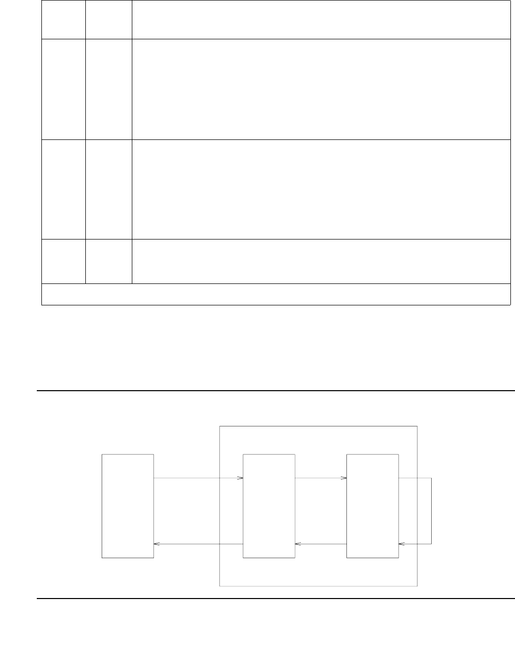
Communication Manager Maintenance-Object Repair Procedures
1688 Maintenance Procedures for Avaya Communication Manager 3.0, Media Gateways and Servers
Modem Pool Conversion Resource Loop-
Around Test (#98)
The Modem Pool Conversion Resource Loop-Around test is set up as follows:
Figure 95: Modem Pool Conversion Resource Loop-Around
None FAIL The test failed. This error is internal to the Pooled Modem circuit pack
and does not involve external equipment or interfaces.
1. Busyout both of the TN758 Pooled Modem conversion resources on
the circuit pack containing the failing conversion resource.
2. If the test continues to fail, replace the Pooled Modem circuit pack
and retest.
Any FAIL The Network Processing Element (NPE) of the tested port did not
conference the tones correctly. This will cause noisy and unreliable
connections.
1. If the remaining ports are currently idle (amber LED is off), reset the
circuit pack and repeat the test.
2. If the test fails again, replace the circuit pack.
PASS The port can correctly conference multiple connections. User-reported
troubles on this port should be investigated using other port tests and by
examining station, trunk, or external wiring.
Table 623: Test #97 Modem Pool Conference Test (continued)
Error
Code
Test
Result
Description / Recommendation
3 of 3
TS-A
TS-C
ANALOG
PORTION
DIGITAL
PORTION
MAINTENANCE/
TEST BOARD
(TN771B)
DIGITAL
PORT
MODEM POOL CONVERSION RESOURCE
TN758 POOLED MODEM CIRCUIT PACK
TS-B

MODEM-PT (Modem Pool Port)
Issue 1 June 2005 1689
Test data patterns are transmitted from a Maintenance/Test board’s digital port over network
time slot A through the digital port on the conversion resource, looped around through the
analog port via time slot C back to the Maintenance/Test board’s digital port circuit via time slot
B where the patterns are checked for accuracy. Finally, the test forces a disconnect by breaking
the connection between the Maintenance/Test board’s digital port and the Modem Pool port
(time slot A) and verifying that the Maintenance/Test board’s digital port and Modem Pool port
go on-hook within the proper time. This test attempts to allocate a Maintenance/Test board’s
digital port, Modem Pool port, and other internal resources. If any of these allocation attempts
fail, the test cannot be completed, and a specific abort error is reported.
Table 624: Test #98 Modem Pool Conversion Resource Loop-Around Test
Error
Code
Test
Result
Description / Recommendation
S8700 | 8710 / S8500
1000 ABRT System resources needed to complete the test could not be allocated for
the digital section of the Modem Pool conversion resource. Ordinarily, this
means the conversion resource or other hardware used during the test
was in use.
1. Wait 1 minute and attempt the test again.
2. If the conversion resource is in use, and it is absolutely necessary to
test it, the call will have to be dropped by issuing busyout port
location against the conversion resource. Run the test again. If the
test passes, release the port.
3. If the same error occurs while the conversion resource is idle,
busyout both Modem Pool conversion resources on the TN758
Pooled Modem circuit pack containing the conversion resource under
test. Rerun the test.
4. If the test continues to abort, replace the Pooled Modem circuit pack
and retest.
1 of 6

Communication Manager Maintenance-Object Repair Procedures
1690 Maintenance Procedures for Avaya Communication Manager 3.0, Media Gateways and Servers
1180 ABRT A Maintenance/Test board’s digital port could not be allocated for this test.
Since this error more closely relates to the digital ports on the specific
Maintenance/Test board used than to the TN758 Pooled Modem circuit
pack itself, any hardware testing or replacement activities will focus on
the Maintenance/Test board.
1. Use list config to verify the presence of both digital ports (ports
02 and 03) on the Maintenance/Test board. The display should show
entries for both.
2. If the ports are absent, see M/T-BD (Maintenance/Test Circuit
Pack) on page 1705.
3. If the ports are present, retry the command at 1-minute intervals up to
5 times.
1181 ABRT No time-slots available to connect digital ports for the test.
1. Retry the command at 1-minute intervals up to 5 times.
1182 ABRT Internal system error. Failed to connect the digital ports with time-slots.
1. Retry the command at 1-minute intervals up to 5 times.
1340 ABRT No Maintenance/Test digital port is currently available to perform this test.
1. Use list config to determine whether any Maintenance/Test
digital ports (ports 02 and 03 on the Maintenance/Test circuit pack)
are present in the system. Because at least one Maintenance/Test
circuit pack must always be present in the a PN of any Multi-Connect
configuration, there should be at least two such ports present. If the
ports are present, proceed to step 2. Otherwise, determine why no
ports appear in the list config display.
2. If the ports are present and no errors are logged against them, retry
the command at 1-minute intervals up to 5 times.
3. If the test continues to abort, replace the Maintenance/Test circuit
pack.
2004 ABRT Off-Hook was not received from the Pooled Modem.
1. Busyout the digital port being tested on the Pooled Modem circuit
pack. Retry the command at 1-minute intervals up to 5 times.
2. If the test still aborts, replace the circuit pack.
Table 624: Test #98 Modem Pool Conversion Resource Loop-Around Test (continued)
Error
Code
Test
Result
Description / Recommendation
2 of 6

MODEM-PT (Modem Pool Port)
Issue 1 June 2005 1691
2005 ABRT The Maintenance/Test and the Pooled Modem boards’ digital ports failed
to handshake.
1. Retry the command at 1-minute intervals up to 5 times.
2. If the test still aborts, replace the Pooled Modem circuit pack.
2312 ABRT The Loop-around test did not complete, failed to receive loop-back data.
1. Retry the test, if still aborts, replace the Pooled Modem board.
2313 ABRT The Maintenance/Test board’s digital port allocated for this test did not
respond to down-linked message.
1. Retry the command at 1-minute intervals up to 5 times.
2. If the test continues to abort, replace the MTB.
2314 ABRT The Modem Pool digital port did not respond to downlinked message.
This error is internal to the Modem Pool circuit pack and does not involve
external equipment or interfaces.
1. Busyout the TN758 Pooled Modem conversion resources on the
circuit pack.
2. If the test continues to abort, replace the Pooled Modem circuit pack
and retest.
2500 ABRT Internal system error.
1. Retry the command at 1-minute intervals up to 5 times.
2323 ABRT The Maintenance Test circuit pack digital port allocated for this test did not
disconnect properly. This error is more closely related to the Maintenance
Test circuit pack digital port used for this test than the TN758 Pooled
Modem circuit pack itself. Therefore, any hardware testing or replacement
activities will focus on the Maintenance Test circuit pack.
1. Wait 1 minute and attempt the test again up to 5 times.
2324 ABRT The digital portion of the tested Modem Pool port did not disconnect
properly.
1. Wait 1 minute and attempt the test again.
2. If the test continues to abort, replace the Pooled Modem circuit pack
and retest.
Table 624: Test #98 Modem Pool Conversion Resource Loop-Around Test (continued)
Error
Code
Test
Result
Description / Recommendation
3 of 6

Communication Manager Maintenance-Object Repair Procedures
1692 Maintenance Procedures for Avaya Communication Manager 3.0, Media Gateways and Servers
2325 FAIL The Modem Pool port did not respond with an on-hook message when
the connection to the TN711 Maintenance/Test digital port was broken,
indicating a likely problem with the TN758 Pooled Modem circuit pack.
1. Busyout both of the TN758 Pooled Modem conversion resources on
the circuit pack containing the failing conversion resource.
2. If the test continues to fail, replace the Pooled Modem circuit pack
and retest.
FAIL The Loop-around test failed, the loop-back data did not match the original
data.
1. Repeat Test #98.
2. If the test fails again, replace the Pooled Modem circuit pack.
5001 ABRT A Network Control Channel could not be allocated for this test. This error
is more closely related to the Data Channels (1 or 3 only) on the
DATA-CHL circuit pack used for this test than the TN758 Pooled Modem
circuit pack itself. Therefore, any hardware testing or replacement
activities focus on the DATA-CHL circuit pack. However, the Data
Channels on the DATA-CHL circuit pack normally should not be busied
out, tested with the ‘‘test data-module’’ command, or reseated in the
carrier to clear this error, since this may drop other data calls that may be
active at the time. The administration of Data Channels 1 and 3 should be
checked if this error occurs.
1. Wait one minute and attempt the test again.
2. If the same error persists after five attempts at one-minute intervals,
escalate the problem.
5002 ABRT The Network Control Channel allocated for this test could not be set to
"maintenance busy" status.
1. Follow the repair procedures for Error Code 5001.
5003 ABRT The test was not able to establish a connection for the digital portion of
the Modem Pool Port.
1. Follow the repair procedures for Error Code 5000.
Table 624: Test #98 Modem Pool Conversion Resource Loop-Around Test (continued)
Error
Code
Test
Result
Description / Recommendation
4 of 6

MODEM-PT (Modem Pool Port)
Issue 1 June 2005 1693
5004 ABRT The test was not able to allocate the analog portion of the Modem Pool
Port.
1. Follow the repair procedures for Error Code 5000.
5005 ABRT The test was not able to establish a connection for the analog portion of
the Modem Pool Port.
1. Follow the repair procedures for Error Code 5000.
5006 FIL The Modem Pool Port did not respond to the "maintenance activate"
message. This error is internal to the Modem Pool circuit pack and does
not involve external equipment or interfaces. The test failed. This error is
internal to the Pooled Modem circuit pack and does not involve external
equipment or interfaces.
1. Busyout both of the TN758 Pooled Modem conversion resources on
the circuit pack containing the failing conversion resource.
2. If the test continues to fail, replace the Pooled Modem circuit pack
and retest.
3. If the circuit pack fails after replacement, escalate the problem.
5007 ABRT The Network Control Channel allocated for this test did not respond to the
incoming call indication.
1. Follow the repair procedures for Error Code 5001.
5009 ABRT The Network Control Channel allocated for this test did not handshake
correctly.
1. Attempt the test again.
2. If the same error occurs, test the DATA-CHL circuit pack using the
test data-module command (refer to the DATA-CHL maintenance
strategy).
3. If the DATA-CHL circuit pack tests pass, escalate the trouble report.
5010 FAIL The Data Loop Around Test failed, indicating a probable problem with the
TN758 Pooled Modem circuit pack.
1. Follow the repair procedure for Error Code 5006.
Table 624: Test #98 Modem Pool Conversion Resource Loop-Around Test (continued)
Error
Code
Test
Result
Description / Recommendation
5 of 6
Communication Manager Maintenance-Object Repair Procedures
1694 Maintenance Procedures for Avaya Communication Manager 3.0, Media Gateways and Servers
5011 ABRT The Network Control Channel allocated for this test did not disconnect
properly.
1. Follow the repair procedures for Error Code 5001.
5012 ABRT The digital portion of the tested Modem Pool Port did not disconnect
properly.
1. Follow the repair procedures for Error Code 5000.
5013 FAIL The Modem Pool Port did not respond with an on-hook message when
the connection to the Data Channel was broken, indicating a likely
problem with the TN758 Pooled Modem circuit pack.
1. Follow the repair procedure for Error Code 5006.
5014 ABRT The Network Control Channel allocated for this test did not respond
correctly to the setup message sent to it after the connection was
established.
1. Attempt the test again.
2. If the same error occurs, test the DATA-CHL circuit pack using the
test data-module command (refer to the DATA-CHL maintenance
strategy).
3. If the DATA-CHL circuit pack tests pass, escalate the problem.
5015 ABRT Data Channels 1 and/or 3 have not been administered.
1. Administer the Data Channels and retest.
PASS The port can correctly transmit/receive data.
Table 624: Test #98 Modem Pool Conversion Resource Loop-Around Test (continued)
Error
Code
Test
Result
Description / Recommendation
6 of 6

MODEM-PT (Modem Pool Port)
Issue 1 June 2005 1695
Modem Pool Audit Test (#99)
This audit updates the Modem Pool conversion resource status contained in the TN758 Pooled
Modem circuit pack’s microprocessor. It does not test the Pooled Modem circuit pack, so there
are no FAIL codes. The audit can only be performed on idle conversion resources. If the
conversion resource is in use, the audit aborts.
Table 625: Test #99 Modem Pool Audit Test
Error
Code
Test
Result
Description / Recommendation
None ABRT The system was not able to allocate every necessary resource to execute
this test. An ABORT simply indicates that the conversion resource was in
use when the audit was performed. No repair action is necessary unless
the conversion resource was known to be idle during the test (amber
in-use LED was off) or was busied out before the test was run. In that
case, a TN758 failure condition may exist and the following procedure
should be used:
1. Busyout both of the TN758 Pooled Modem conversion resources on
the circuit pack containing the failing conversion resource.
2. If the test continues to abort, replace the Pooled Modem circuit pack
and retest.
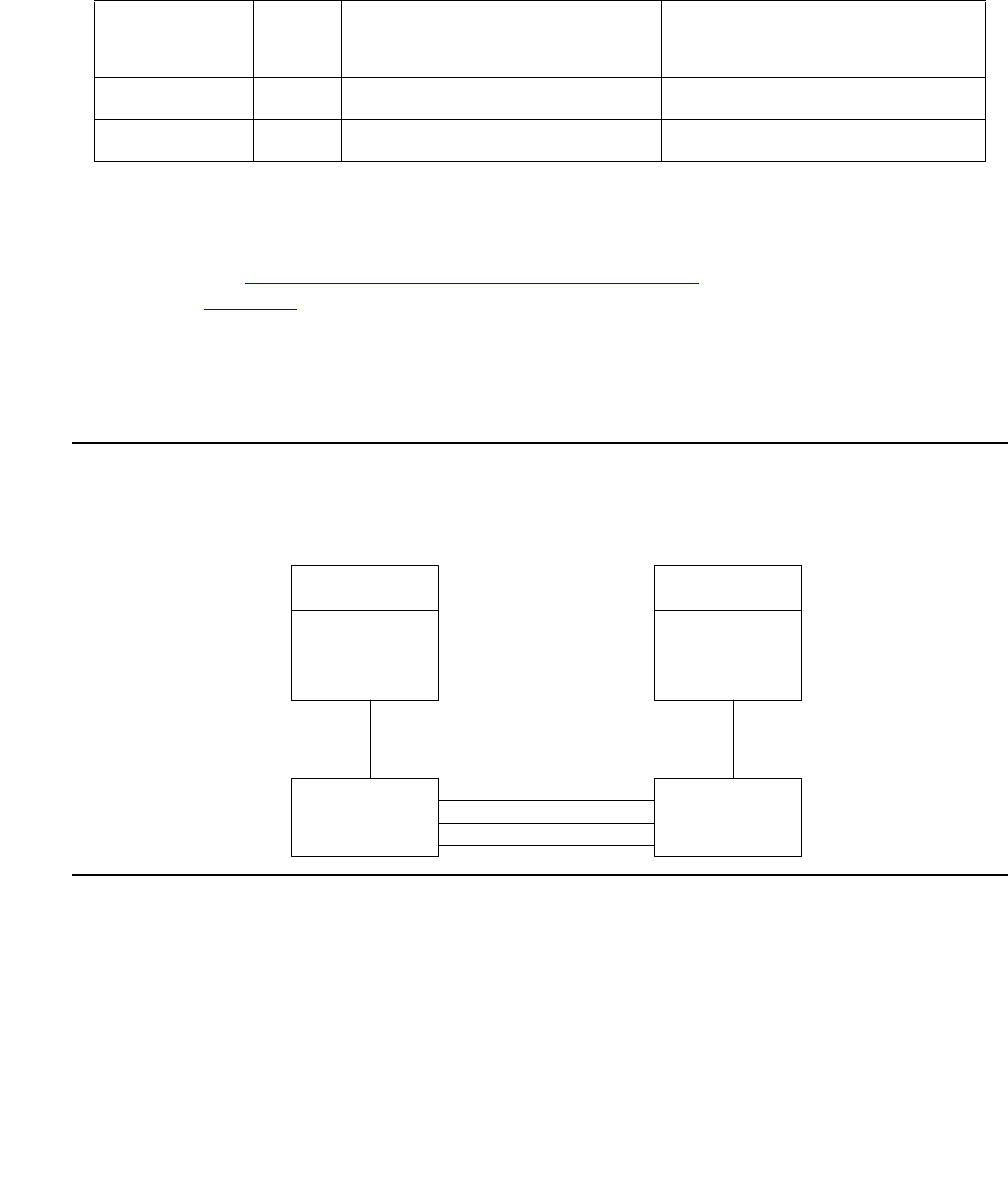
Communication Manager Maintenance-Object Repair Procedures
1696 Maintenance Procedures for Avaya Communication Manager 3.0, Media Gateways and Servers
M/T-ANL (Maintenance/Test Analog Port)
S8700 | 8710 / S8500
The Maintenance/Test analog port is port number 1 on the TN771D Maintenance/ Test circuit
pack. This port is used by the Automatic Transmission Measurement System (ATMS) as an
Originating Test Line (OTL) or Terminating Test Line (TTL) for test calls over analog trunks. For
more details, see Automatic Transmission Measurement System in Maintenance Procedures
(03-300192). Figure 96 shows a typical ATMS configuration.
M/T-ANL maintenance ensures that the analog trunk’s testing function is operating correctly.
Although an M/T-ANL alarm can reduce service, it will not block service. To accurately measure
the performance and health of analog trunks, replace an alarmed TN771D when a new circuit
pack is available.
Figure 96: ATMS Tie Trunk Test Call
MO Name in
Alarm Log
Alarm
Level
Initial SAT Command to Run Full Name of MO
M/T-ANL MIN test port location lMaintenance/Test analog port
M/T-ANL WRN release port location Maintenance/Test analog port
Tie
Trunk
Facilities
Originating
Test Line
(OTL)
TN771
TDM Bus
Terminating
Test Line
(TTL)
TN771
TDM Bu
s
PBX originating
the test call
PBX terminating
the test call
Tie Trunk
Circuit Pack
Tie Trunk
Circuit Pack
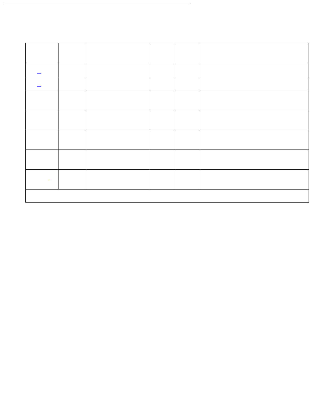
M/T-ANL (Maintenance/Test Analog Port)
Issue 1 June 2005 1697
Error Log Entries and Test to Clear Values
Notes:
a. Error Type 0: run the short test sequence first. If every test passes, run the long test
sequence. Refer to each test’s description, and follow its procedures. This Error Code
appears in the Error Log only if the MTB circuit pack has been removed since the Error Log
was last cleared. Verify that the circuit pack has been reinserted.
b. Error Type 1: a hardware failure on the Analog Port circuitry. Replace the Maintenance/Test
circuit pack if the command does not resolve the alarm.
c. Error Type 3840: call processing records did not agree with on-board records for the hook
state (on-/off-hook) of the Maintenance/Test analog port. This error is not service-affecting
and no action is required.
Table 626: M/T-ANL Error Log Entries
Error
Type
Aux
Data
Associated Test Alarm
Level
On/Off
Board
Test to Clear Value
0 (a)0 Any AnyAnytest port location
1 (b) 41018 none MIN ON test port location l r 3
18 0 busyout port
location
WRN OFF release port location
257 Any NPE Crosstalk test
(#9)
MIN ON test port location l r 3
513 Any Analog Port Sanity
test (#963)
MIN ON test port location r 2
769 Any Analog Port Digital
Loop-around (#13)
MIN ON test port location r 3
3840 (c) Any Hook State Inquiry
test (#566)

Communication Manager Maintenance-Object Repair Procedures
1698 Maintenance Procedures for Avaya Communication Manager 3.0, Media Gateways and Servers
System Technician-Demanded Tests:
Descriptions and Error Codes
Investigate tests in the order presented. By clearing Error Codes associated with the Analog
Port Sanity test (#963), you may also clear errors generated from other tests in the sequence.
NPE Crosstalk Test (#9)
The NPE Crosstalk test verifies that this port’s NPE channel talks on the selected time slot and
never crosses over to time slots reserved for other connections.
One or more Network Processing Elements (NPE) reside on each circuit pack with a TDM-bus
interface. The NPE controls port connectivity, gain, and provides conferencing functions on a
per-port basis. If the NPE is not working correctly, one-way and/or noisy connections may be
observed. This test is part of a port’s long test sequence and takes approximately 10 to 20
seconds to complete.
Order of Investigation Short Test
Sequence
Long Test
Sequence
D/ND1
1. D = Destructive, ND = Nondestructive
Analog Port Sanity test (#963) X X ND
Digital Loop-around test (#13) X X ND
NPE Crosstalk test (#9) X ND
Hook State Inquiry (#566) X X ND
Clear Error Counters (#270) X ND
Table 627: Test #9 NPE Crosstalk Test
Error
Code
Test
Result
Description / Recommendation
1000 ABRT System resources required to run this test are not available. The port may
be in use on a valid ATMS trunk test call.
1. Retry the command at 1-minute intervals up to 3 times.
1001 ABRT System resources required to run this test are not available.
1. Retry the command at 1-minute intervals up to 3 times.
1 of 3

M/T-ANL (Maintenance/Test Analog Port)
Issue 1 June 2005 1699
1002 ABRT The system could not allocate time slots for the test. The system may be
under heavy traffic conditions or it may have time slots out of service due to
TDM-BUS errors. A system is considered under heavy traffic when the Call
Processing Occupancy is greater than 50% or when the System
Management and the Call Processing Occupancies together exceed 65%.
To view the system occupancy measurements enter status health on
the system technician terminal.
1. If the system has no TDM-BUS errors and is not handling heavy traffic,
repeat test at 1-minute intervals up to 3 times.
1003 ABRT The system could not allocate a tone receiver for the test. The system may
be oversized for the number of tone detectors present or some tone
detectors may be out-of-service.
1. Resolve any TTR-LEV errors.
2. Resolve any TONE-PT errors.
3. If neither condition exists, retry the test at 1-minute intervals up to 3
times.
1004 ABRT The port has been seized by a valid ATMS test call.
1. Retry the command at 1-minute intervals up to 3 times.
2. If the test continues to abort and the port is idle on a valid ATMS test
call, escalate the problem. To determine whether the port is in use by
an ATMS test call, enter status station ext where ext is the
assigned ATMS station’s number.
2000 ABRT Response to the test request was not received within the allowable time
period.
1. Retry the command at 1-minute intervals up to 3 times.
2100 ABRT System resources required to run this test are not available.
1. Retry the command at 1-minute intervals up to 3 times.
Table 627: Test #9 NPE Crosstalk Test (continued)
Error
Code
Test
Result
Description / Recommendation
2 of 3

Communication Manager Maintenance-Object Repair Procedures
1700 Maintenance Procedures for Avaya Communication Manager 3.0, Media Gateways and Servers
Analog Port Digital Loop-Around Test (#13)
This test is a modification of the Voice and Control Channel Local Loop test used by Digital
Station (DIG-LINE) maintenance. This test does not perform the control channel and secondary
information channel loop around tests as described for DIG-LINE, as these data paths do not
exist for the Maintenance/Test analog port. To test the primary information channel, this test:
1. Loops back the data channel onto the TDM bus
2. Sends a digital count from the Tone-Clock circuit pack and receives the same digital count
with a general-purpose tone detector
3. Runs a conference test for the primary information channel. This is the same test as
Conference test (#6).
Only one value (Pass, Fail, or Abort) is generated as a result of the two tests. If it fails or aborts,
the sequence is stopped.
Any FAIL The NPE of the tested port was found to be transmitting in error. This will
cause noisy and unreliable connections.
1. If the remaining ports are currently idle (amber LED is off), try to reset
the circuit pack using busyout board location, reset board
location, and release board location. Repeat the test.
2. If the test fails again, replace circuit pack.
PASS The port is correctly using its allocated time slots. User-reported troubles on
this port should be investigated by examining station, trunk, or external
wiring.
Table 627: Test #9 NPE Crosstalk Test (continued)
Error
Code
Test
Result
Description / Recommendation
3 of 3
Table 628: Test #13 Analog Port Digital Loop-Around Test
Error
Code
Test
Result
Description / Recommendation
ABRT Internal system error
1. Retry the command at 1-minute intervals up to 3 times.
1 of 3

M/T-ANL (Maintenance/Test Analog Port)
Issue 1 June 2005 1701
1000 ABRT The port is in use on a valid ATMS test call.
1. Retry the command at 1-minute intervals up to 3 times.
2. If the test continues to abort and the port is idle on a valid ATMS test
call, escalate the problem. To determine whether the port is in use by
an ATMS test call, enter status station ext where ext is the
assigned ATMS station’s number.
1001 ABRT System resources required to run this test are not available.
1. Retry the command at 1-minute intervals up to 3 times.
1002 ABRT The system could not allocate time slots for the test. The system may be
under heavy traffic conditions, or it may have time slots out-of-service due
to TDM-BUS errors. A system is considered under heavy traffic when the
Call Processing Occupancy is greater than 50% or when the System
Management and the Call Processing Occupancies together exceed 65%.
To view the system occupancy measurements enter status health on
the system technician terminal.
1. If the system has no TDM-BUS errors and is not handling heavy traffic,
repeat the test at 1-minute intervals up to 3 times.
1003 ABRT The system could not allocate a tone receiver for the test. The system may
be oversized for the number of tone detectors present, or some tone
detectors may be out-of-service.
1. Resolve any TTR-LEV errors.
2. Resolve any TONE-PT errors.
3. If neither condition exists, retry the command at 1-minute intervals up
to 3 times.
1004 ABRT The port was seized by a valid ATMS test call.
1. Retry the command at 1-minute intervals up to 3 times.
2. If the test continues to abort and the port is idle on a valid ATMS test
call, escalate the problem. To determine whether the port is in use by
an ATMS test call enter status station ext, where ext is the
assigned ATMS station’s number.
Table 628: Test #13 Analog Port Digital Loop-Around Test (continued)
Error
Code
Test
Result
Description / Recommendation
2 of 3

Communication Manager Maintenance-Object Repair Procedures
1702 Maintenance Procedures for Avaya Communication Manager 3.0, Media Gateways and Servers
Clear Error Counters (#270)
The ports on the Maintenance/Test circuit pack continually run self-tests, whenever the port is
idle. The Angel uses a counter so that the Background Maintenance Failure message is only
sent uplink once. Many circuit packs have counters in the Angel firmware. These counters are
used so that Control Channel Message Set (CCMS) messages are not continuously sent uplink.
Using this method, the message will be sent once, when the counter reaches some preset
threshold, and then not sent again until the counter is cleared. This test is used to clear the
2000 ABRT Response to the test request was not received within the allowable time
period.
1. Retry the command at 1-minute intervals up to 3 times.
7 FAIL Conference test failed on the primary information channel.
1. Run the circuit pack tests to check the Tone-Clock (TONE-BD) circuit
pack and the Tone Detector circuit pack using test board
location.
2. Resolve any problems that are detected on the Tone-Clock
(TONE-BD) circuit pack or Tone Detector circuit pack. See the section
on Tone Generator circuit pack.
3. If the Tone-Clock and Tone Detector circuit packs are functioning
properly, and the test still fails, replace the Maintenance/Test circuit
pack.
14 FAIL The primary information channel is not transmitting properly. User may not
notice any interruption in service or may not be able to use this port.
1. Run the circuit pack tests to check the Tone Generator circuit pack and
the Tone Detector circuit pack using test board location.
2. Resolve any problems that are detected on the Tone Generator circuit
pack or Tone Detector circuit pack. See the section on Tone Generator
circuit pack.
3. If the Tone Generator and Tone Detector circuit packs are functioning
properly, and the test still fails, replace the Maintenance/Test circuit
pack.
PASS The Maintenance/Test analog port analog trunk testing capability is
operating correctly.
Table 628: Test #13 Analog Port Digital Loop-Around Test (continued)
Error
Code
Test
Result
Description / Recommendation
3 of 3

M/T-ANL (Maintenance/Test Analog Port)
Issue 1 June 2005 1703
counter, so that if the port continues to fail during or after Communication Manager demands
testing, the Angel will send a message to indicate that fact.
This test is only used to send a message to the Angel on the Maintenance/Test circuit pack.
Therefore, this test should never abort or fail.
Hook State Inquiry (#566)
This test ensures that the Maintenance/Test analog port maintenance software and call
processing agree on the on-/off-hook status of the Maintenance/Test analog port.
Table 629: Test #270 Clear Error Counters
Error
Code
Test
Result
Description / Recommendation
PASS The message to clear the Maintenance/Test circuit pack’s counter for
Background Maintenance Failures has been sent.
Table 630: Test #566 Hook State Inquiry
Error
Code
Test
Result
Description / Recommendation
1 ABRT Switch hook audit timed out. No response was received from the circuit
pack for information about the switch hook state.
1. Retry the command at 1-minute intervals up to 3 times.
2. If the test continues to abort, replace the circuit pack and repeat the
test.
2100 ABRT System resources required to run this test are not available.
1. Retry the command at 1-minute intervals up to 3 times.
Any FAIL Internal system error
1. Retry the command at 1-minute intervals up to 3 times.
2. If the test continues to fail reset the circuit pack using busyout
board location, reset board location, and release
board location.
3. Retry the command at 1-minute intervals up to 3 times.
PASS Call processing and Maintenance/Test analog port maintenance software
agree on the Maintenance/Test analog port hook state.

Communication Manager Maintenance-Object Repair Procedures
1704 Maintenance Procedures for Avaya Communication Manager 3.0, Media Gateways and Servers
Analog Port Sanity Test (#963)
This test verifies that the port circuitry involved in the analog trunk testing on the Maintenance/
Test analog port is functioning properly.
This test will abort if an ATMS test call is in progress on the Maintenance/Test analog port when
the test is requested.
Table 631: Test #963 Analog Port Sanity Test
Error
Code
Test
Result
Description / Recommendation
2000 ABRT Response to the test request was not received within the allowable time
period.
1. Retry the command at 1-minute intervals up to 5 times.
2100 ABRT System resources required to run this test are not available.
1. Retry the command at 1-minute intervals up to 5 times.
2500 ABRT An internal operation failed; the test could not be completed.
1. Retry the command at 1-minute intervals up to 5 times.
50 FAIL The switch was unable to communicate with the port circuitry used for
analog trunk testing.
1. Reset the circuit pack using busyout board location, reset
board location, and release board location.
2. Test the port again using test port location l.
3. If the test fails again, replace the circuit pack.
PASS The Maintenance/Test analog port analog trunk testing capability is
operating correctly.

M/T-BD (Maintenance/Test Circuit Pack)
Issue 1 June 2005 1705
M/T-BD (Maintenance/Test Circuit Pack)
S8700 | 8710 / S8500
The Maintenance/Test circuit pack (TN771D) supports packet-bus fault detection and bus
reconfiguration for the port network where it is installed. The circuit pack also provides Analog
Trunk testing, and data loop-back testing of DCP Mode 2 endpoints and Digital (ISDN) Trunk
facilities via the TDM bus.
Port 1 of the Maintenance/Test board is the Analog Test port which provides the Analog Trunk
testing function for Automatic Transmission Measurement System (ATMS). ATMS is a feature in
which calls are made from a device called an Originating Test Line (OTL) over a specific trunk to
a device called a Terminating Test Line (TTL). The OTL and TTL can then send tones over the
trunk under test and determine the quality of the connection. Ports 2 and 3 are the digital ports
which provide the digital (ISDN) trunk-testing functions. Port 4 is the packet port which provides
the packet-bus maintenance function.
See XXX-BD (Common Port Circuit Pack/Media Module) on page 2539 for circuit pack-level
errors. See also, related maintenance/test information for analog, digital, and packet-bus ports:
●M/T-ANA (Maintenance/Test analog port)
●M/T-DIG (Maintenance/Test digital port)
●M/T-PKT (Maintenance/Test packet-bus port)
Every port except the analog port (Port 1) of the Maintenance/Test board is automatically
administered when the circuit pack is inserted into the system and automatically removed when
the circuit pack is unplugged from the system. The Analog port however, is administered using
the station screen with the type “105TL” for an OTL or a TTL. This port remains administered
even after the circuit pack is physically removed from the system. Care should be taken to
remove the OTL or the TTL before unplugging the circuit pack.
MO Name in
Alarm Log
Alarm
Level
Initial SAT Command to Run Full Name of MO
M/T-BD MIN test board location l Maintenance/Test circuit pack
M/T-BD WRN release board location Maintenance/Test circuit pack
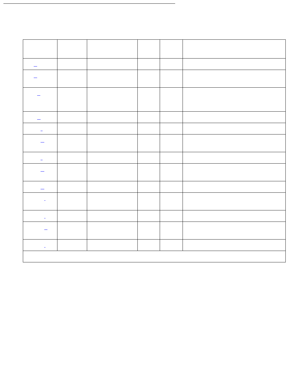
Communication Manager Maintenance-Object Repair Procedures
1706 Maintenance Procedures for Avaya Communication Manager 3.0, Media Gateways and Servers
Hardware Error Log Entries and Test to Clear Values
Notes:
a. Error Type 0: run the short test sequence first. If every test passes, run the long test
sequence. Refer to each test’s description, and follow its procedures.
b. Error Type 1: the circuit pack has stopped functioning. Reset the circuit pack using
busyout board location, reset board location, and release board
location. If the SAKI Sanity test (#53) passes, the on-board circuitry is healthy. If the
SAKI Sanity test (#53) fails, replace the circuit pack.
Maintenance/Test Board Error Log Entries
Error
Type
Aux
Data
Associated Test Alarm
Level1
1. Major or Minor alarms on this MO may have been downgraded to Warning based on the values in set
options.
On/Off
Board
Test to Clear Value
0 (a)0 Any AnyAnytest port location sh r 1
1 (b) 0 SAKI Sanity
test (#53)
MIN ON
18 (c)0 busyout
board
location
WRN OFF release board location
36 (d)0
217 (f)WRNON
257 (e) 0 CC Loop test
(#52)
MIN ON test board location r3
267 (f)WRNON
513 (g) 4352 to
4357
769 (h) 4358
1025 (i) 4363 NPE Audit test
(#50) test board location l
1538 (j)0 MINON
3840 (k) 4096 to
4101
3999 (l) Any None

M/T-BD (Maintenance/Test Circuit Pack)
Issue 1 June 2005 1707
c. Error Type 18: the circuit pack has been busied out by the command busyout board
location. Execute release board location.
d. Error Type 36: a port processor on the circuit pack failed to initialize. Reset the circuit pack
using busyout board location, reset board location, and release board
location. If the problem does not go away, replace the circuit pack.
e. Error Type 257: a Control Channel Protocol error has occurred. This may be due to the
circuit pack detecting an on-board hardware failure. Execute busyout board location
and reset board location to reset the circuit pack. Any such problem will be detected
during initialization, because the circuit pack locks up and appears insane to the system.
f. Error Type 217, 267: an extra TN771D circuit pack has been inserted into the port network.
g. Error Type 513: an on-board hardware failure has been detected by the circuit pack. Enter
the busyout board location, reset board location, and release board
location commands to reset the circuit pack. If the SAKI Sanity test (#53) passes, the
circuitry is healthy. If not, replace the circuit pack.
h. Error Type 769: program logic error; no action is required. This error may lead to errors of
other types being reported against this circuit pack.
i. Error Type 1025: the circuit pack cannot update NPE memory and read it back. This error
type can be ignored, but might lead to errors of other types being reported against this
circuit pack.
j. Error Type 1538: excessive number of messages have been received from the
Maintenance/Test circuit pack. This may be due to a hardware problem on the circuit pack.
The switch takes the board out of service and periodically puts it back into service to see if
the problem has disappeared. If the problem persists, replace the circuit pack.
k. Error Type 3840: the circuit pack received a bad control channel message from the switch.
This error is not service affecting and no action is required.
l. Error Type 3999: the circuit pack sent a large number of control channel messages to the
switch within a short period of time. If Error Type 1538 is also present, then the circuit pack
was taken out-of-service due to hyperactivity. If Error Type 1538 is absent, then the circuit
pack was not taken out-of-service, but it has generated 50% of the messages necessary to
be considered hyperactive. This may be completely normal during heavy traffic periods.
However, if this error type is logged when the circuit pack is being lightly used, it may
indicate a problem with the circuit pack or the equipment attached to it.
Communication Manager Maintenance-Object Repair Procedures
1708 Maintenance Procedures for Avaya Communication Manager 3.0, Media Gateways and Servers
System Technician-Demanded Tests:
Descriptions and Error Codes
Investigate tests in the order presented below. Clearing Error Codes associated with the one
test may also clear errors generated from other tests in the sequence.
Repair procedures for the above tests are described in XXX-BD (Common Port Circuit Pack/
Media Module) on page 2539.
Order of Investigation Short Test
Sequence
Long Test
Sequence
D/ND
Control Channel Loop-Around test (#52) X X Nondestructive
NPE Audit test (#50) X Nondestructive

M/T-DIG (Maintenance/Test Digital Port)
Issue 1 June 2005 1709
M/T-DIG (Maintenance/Test Digital Port)
S8700 | 8710 / S8500
The Maintenance/Test digital port is a port on the TN771D circuit pack. Ports 2 and 3 are digital
ports. The Maintenance/Test digital port provides the ability to perform digital (i.e., ISDN-PRI)
trunk testing via the TDM bus. For an ISDN-PRI test call, connections are set up in the system
as shown in Figure 97: ISDN-PRI Outgoing Test Call on page 1710.
When the Maintenance/Test digital port is participating in an ISDN-PRI test call, the port sends a
stream of pseudo-random data along the connected B channel. The far end loops back this
data, and the Maintenance/Test digital port compares the data to that which was sent. Errors are
recorded on a bit and block basis. Refer to ISDN-TRK (DS1 ISDN Trunk) Maintenance
documentation for more information about ISDN-PRI test calls.
The Maintenance/Test digital port maintenance ensures that the digital trunk testing function is
operating correctly. The Maintenance/Test digital port is alarmed if maintenance determines that
the digital port is operating incorrectly.
Note:
Note: An alarm on the Maintenance/Test digital port reduces service, but does not block
it since the ISDN-TRK has other means to determine the health of the ISDN-PRI
trunk facility. However, to accurately measure the error performance and to
ensure accuracy of the health of the ISDN-PRI trunk, the Maintenance/Test circuit
pack should be replaced when a new circuit pack is available.
MO Name in
Alarm Log
Alarm
Level
Initial SAT Command to Run Full Name of MO
M/T-DIG MIN test port location l Maintenance/Test digital port
M/T-DIG WRN release port location Maintenance/Test digital port
Communication Manager Maintenance-Object Repair Procedures
1710 Maintenance Procedures for Avaya Communication Manager 3.0, Media Gateways and Servers
Figure 97: ISDN-PRI Outgoing Test Call
Hardware Error Log Entries and Test to Clear Values
Looped-back data
stream pattern is
generated by digital
port 1 and checked
by digital port 2 on
the TN771
Digital
Port 1
.
.
.
. .
TN771
Maintenance/Test
SPE
UN332
MSSNET
TN1655
PKT-INT
TDM
Bus
.
.
.
.
.
.
.
.
.
.
.
. . . . . . . . . . . . . . . . .
.
.
.
.
.
.
.
.
.
.
.
.
.
.
.
.
.
.
.
.
.
.
.
.
.
.
.
.
.
.
.
.
.
.
.
.
.
.
.
.
.
.
.
.
.
.
.
.
.
.
.
.
.
.
.
.
.
.
.
.
.
.
.
.
.
.
.
.
.
.
.
.
.
.
.
.
.
.
.
.
.
.
.
.
.
.
.
.
.
.
.
.
.
.
.
.
.
.
.
.
.
.
.
.
.
.
.
.
.
.
.
.
.
.
.
.
.
.
.
.
.
.
.
.
.
.
.
.
.
.
.
.
.
.
.
.
.
.
.
.
.
.
.
.
.
.
.
.
.
.
.
.
.
.
.
.
.
.
.
.
.
.
.
.
.
.
.
.
.
.
.
.
.
.
.
.
.
.
.
.
.
. . . . . . . . . . . . . . . . . . . . . . . . . . . . . . . . . . . . . . . . . . .
.
.
.
.
.
.
.
.
.
.
.
.
.
.
.
.
.
Control
. . . . . .
Loop-back
Circuitry
Far-End
Equipment
B-channel carries
looped-back test signal
D-Channel instructs
far end to connect
loop-back circuitry
across B-channel
signal
External DS1 Facility
PBX Equipment
TN464
DS1
Interface
Packet
Bus
Digital
Port 2
Table 632: M/T-DIG Error Log Entries
Error
Type
Aux
Data
Associated Test Alarm
Level
On/Off
Board
Test to Clear Value
0 (a) 0 Any Any Any test port location
1 (b) 41018 none MIN ON test port location l r 3
18 (c)0 busyout port
location
WRN OFF release port location
1 of 2
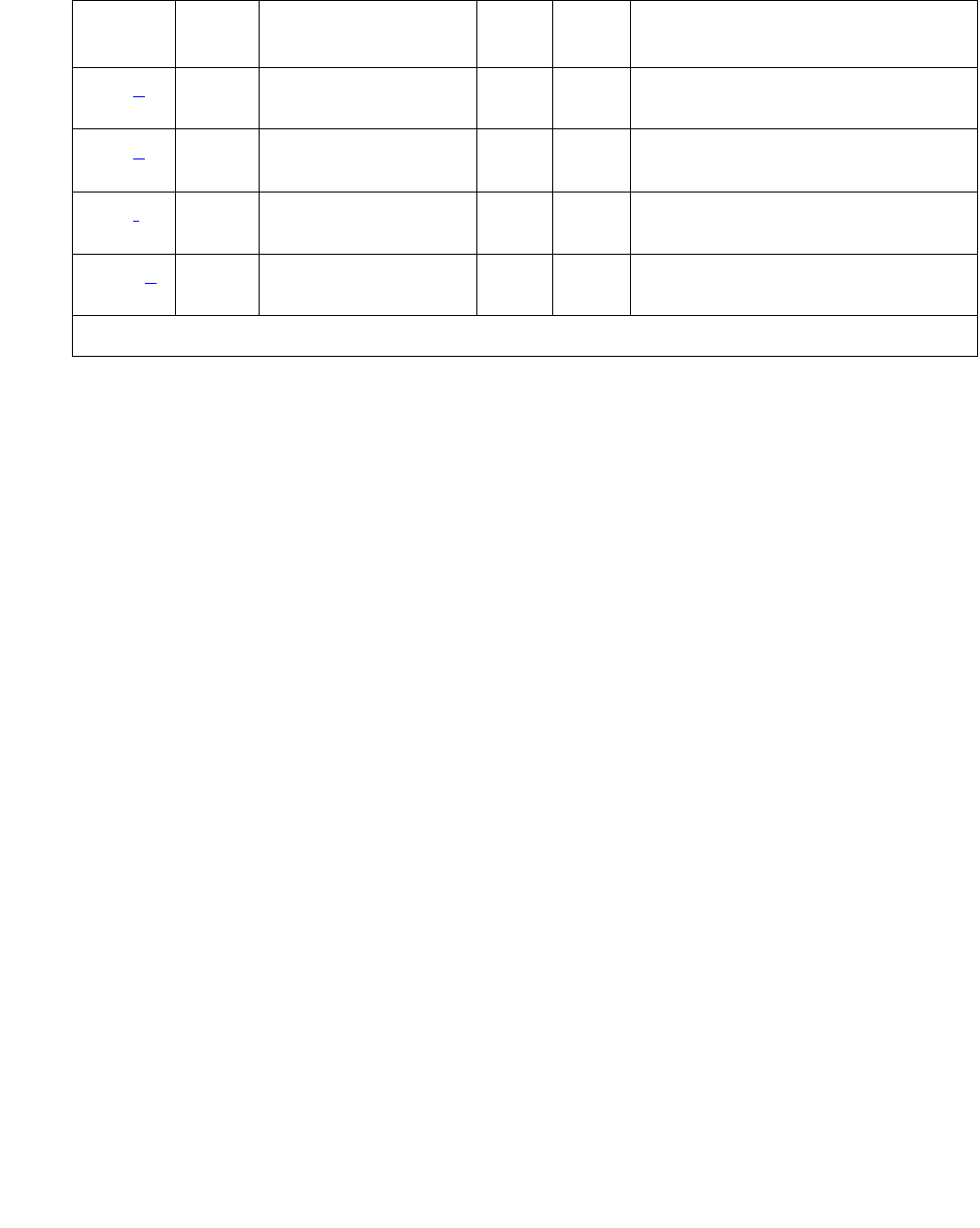
M/T-DIG (Maintenance/Test Digital Port)
Issue 1 June 2005 1711
Notes:
a. Error Type 0: run the short test sequence first. If every test passes, run the long test
sequence. Refer to each test’s description, and follow its procedures.
b. Error Type 1: there was a hardware failure on a digital port’s circuitry. Replace the
Maintenance/Test circuit pack if the alarm is not resolved by the command above.
c. Error Type 18: the port was busied out by busyout port location.
d. Error Type 257: the Maintenance/Test digital port is talking on more than just its assigned
time slot. Replace the Maintenance/Test circuit pack.
e. Error Type 513: the Maintenance/Test digital port has failed its self-test. Because the Digital
Port Sanity test runs only on port 2, but tests both ports 2 and 3, both ports are alarmed
when the test fails. The command indicates to test port 2, even if the error is logged against
port 3.
f. Error Type 769: the Maintenance/Test digital port was unable to successfully loop data from
a tone generator to a tone detector.
g. Error Type 3840: call processing records do not agree with on-board records for the hook
state (on-/off-hook) of the Maintenance/Test digital port. This error is not service-affecting
and no action is required.
257 (d) Any NPE Crosstalk test
(#9)
MIN ON test port location l r 3
513 (e) Any Digital Port Sanity
test (#565)
MIN ON test port location r 2
769 (f) Any Digital Port Loop
Around test (#13)
MIN ON test port location r 3
3840 (g) Any Hook State Inquiry
test (#566)
Table 632: M/T-DIG Error Log Entries (continued)
Error
Type
Aux
Data
Associated Test Alarm
Level
On/Off
Board
Test to Clear Value
2 of 2

Communication Manager Maintenance-Object Repair Procedures
1712 Maintenance Procedures for Avaya Communication Manager 3.0, Media Gateways and Servers
System Technician-Demanded Tests:
Descriptions and Error Codes
Investigate tests in the order presented below. Clearing Error Codes associated with the one
test may also clear errors generated from other tests in the sequence.
NPE Crosstalk Test (#9)
This test is a modified version of the Digital Line NPE Crosstalk test used by DIG-LINE
maintenance.
One or more Network Processing Elements (NPE) reside on each circuit pack with a TDM-bus
interface. The NPE controls port connectivity, gain, and provides conferencing functions on a
per-port basis. The NPE Crosstalk test verifies that this port’s NPE channel talks on the
selected time slot and never crosses over to time slots reserved for other connections. If the
NPE is not working correctly, one-way and/or noisy connections may be observed. This test is
part of a port’s long test sequence and takes approximately 10 to 20 seconds to complete. This
test is a modified version of the Digital Line NPE Crosstalk test used by DIG-LINE maintenance.
Order of Investigation Short Test
Sequence
Long Test
Sequence
D/ND1
1. D = Destructive, ND = Nondestructive
Digital Port Sanity test (#565) X X ND
Digital Port Loop Around test (#13) X X ND
NPE Crosstalk test (#9) X ND
Hook State Inquiry (#566) X X ND
Clear Error Counters (#270) X ND

M/T-DIG (Maintenance/Test Digital Port)
Issue 1 June 2005 1713
Table 633: Test #9 NPE Crosstalk Test
Error
Code
Test
Result
Description / Recommendation
1000 ABRT System resources required to run this test are not available. The port may
be in use on a valid ISDN-PRI test call. Use list isdn-testcall to
determine whether the port is in use (listed in the M/T Port column). If so,
wait for the test call to finish as indicated in the Start Time and Duration
fields, or abort the test call with clear isdn-testcall grp#/mem#,
where grp#/mem# is determined from the B-channel field of list
isdn-testcall.
1. Retry the command at 1-minute intervals up to 5 times.
2. If the test continues to abort and the port is idle, escalate the problem.
1001 ABRT System resources required to run this test are not available.
1. Retry the command at 1-minute intervals up to 5 times.
2. If the test continues to abort, escalate the problem.
1002 ABRT The system could not allocate time slots for the test. The system may be
under heavy traffic conditions or it may have time slots out of service due
to TDM-BUS errors.
1. If the system has no TDM-BUS errors and is not handling heavy traffic,
repeat test at 1-minute intervals up to 5 times.
2. If the test continues to abort, escalate the problem.
1003 ABRT The system could not allocate a tone receiver for the test. The system may
be oversized for the number of tone detectors present or some tone
detectors may be out-of-service.
1. Resolve any TTR-LEV errors.
2. Resolve any TONE-PT errors.
3. If neither condition exists, retry the test at 1-minute intervals up to 5
times.
4. If the test continues to abort, escalate the problem.
1 of 2

Communication Manager Maintenance-Object Repair Procedures
1714 Maintenance Procedures for Avaya Communication Manager 3.0, Media Gateways and Servers
Digital Port Loop-Around Test (#13)
This test is a modification of the Voice and Control Channel Local Loop test used by Digital
Station (DIG-LINE) maintenance. This test does not perform the control channel and secondary
information channel loop around tests as described for DIG-LINE, as these data paths do not
exist for the Maintenance/Test digital port. The primary information channel is tested by first
looping back the data channel onto the TDM bus, and then sending a digital count from the
Tone-Clock circuit pack and receiving the same digital count with a general-purpose tone
detector. A conference test is done next for the primary information channel. This is the same
test as Conference test (#6).
1004 ABRT The port has been seized by a valid ISDN-PRI test call. Use list
isdn-testcall to determine which call is using the port (from the M/
T Port column). Wait for the test call to complete as indicated in the Start
Time and Duration fields of the above display, or abort the test call with
clear isdn-testcall grp#/mem#, where grp#/mem# is determined
screen the B-channel field list isdn-testcall.
1. Retry the command at 1-minute intervals up to 5 times.
2. If the test continues to abort and the port is idle, escalate the problem.
2000 ABRT Response to the test request was not received within the allowable time
period.
2100 ABRT System resources required to run this test are not available.
1. Retry the command at 1-minute intervals up to 5 times.
2. If the test continues to abort, escalate the problem.
Any FAIL The NPE of the tested port was found to be transmitting in error. This will
cause noisy and unreliable connections.
1. If the remaining ports are currently idle (amber LED is off), try to reset
the circuit pack. Then repeat the test.
2. If the test fails again, replace circuit pack.
PASS The port is correctly using its allocated time slots. User-reported troubles on
this port should be investigated using other port tests and by examining
station, trunk, or external wiring.
Table 633: Test #9 NPE Crosstalk Test (continued)
Error
Code
Test
Result
Description / Recommendation
2 of 2

M/T-DIG (Maintenance/Test Digital Port)
Issue 1 June 2005 1715
Only one value (Pass, Fail, or Abort) is generated as a result of the two tests. If it fails or aborts,
the sequence is stopped.
Table 634: Test #13 Digital Port Loop-Around Test
Error
Code
Test
Result
Description / Recommendation
ABRT Internal system error
1. Retry the command at 1-minute intervals up to 5 times.
2. If the test continues to abort, escalate the problem.
1000 ABRT The port is use on a valid ISDN-PRI test call. Use list
isdn-testcall to determine which call is using the port (from the M/T
Port column). Wait for the test call to complete as indicated in the Start
Time and Duration fields, or abort the test call with clear
isdn-testcall grp#/mem#, where grp#/mem# is determined from
the B-channel field of list isdn-testcall.
1. Retry the command at 1-minute intervals up to 5 times.
2. If the test continues to abort and the port is idle, escalate the
problem.
1001 ABRT System resources required to run this test are not available.
1. Retry the command at 1-minute intervals up to 5 times.
2. If the test continues to abort, escalate the problem.
1002 ABRT The system could not allocate time slots for the test. The system may be
under heavy traffic conditions, or it may have time slots out-of-service
due to TDM-BUS errors.
1. If the system has no TDM-BUS errors and is not handling heavy
traffic, repeat the test at 1-minute intervals up to 5 times.
2. If the test continues to abort, escalate the problem.
1003 ABRT The system could not allocate a tone receiver for the test. The system
may be oversized for the number of tone detectors present, or some
tone detectors may be out-of-service.
1. Resolve any TTR-LEV errors.
2. Resolve any TONE-PT errors.
3. If neither condition exists, retry the command at 1-minute intervals
up to 5 times.
4. If the test continues to abort, escalate the problem.
1 of 2

Communication Manager Maintenance-Object Repair Procedures
1716 Maintenance Procedures for Avaya Communication Manager 3.0, Media Gateways and Servers
1004 ABRT The port was seized by a valid ISDN-PRI test call. Use list
isdn-testcall to determine which call is using the port (from the M/T
Port column). Wait for the test call to complete as indicated in the Start
Time and Duration fields of the above display, or abort the test call with
clear isdn-testcall grp#/mem# where grp#/mem# is
determined from the B-channel field of list isdn-testcall.
1. Retry the command at 1-minute intervals up to 5 times.
2. If the test continues to abort and the port is idle, escalate the
problem.
2000 ABRT Response to the test request was not received within the allowable time
period.
1. Retry the test at 1-minute intervals up to 5 times.
2100 ABRT System resources required to run this test are not available.
1. Retry the test at 1-minute intervals up to 5 times.
7 FAIL Conference test failed on the primary information channel. In most
cases, the user may not notice a disruption in service.
1. Run the circuit pack tests to check the Tone Generator circuit pack
and the Tone Detector circuit pack using test board location.
2. Resolve any problems that are detected on the Tone Generator
circuit pack or Tone Detector circuit pack.
3. If the Tone Generator and Tone Detector circuit packs are
functioning properly, and the test still fails, replace the Maintenance/
Test circuit pack.
14 FAIL The primary information channel is not transmitting properly. User
impact may range from nothing to not being able to use this port.
1. Run the circuit pack tests to check the Tone Generator circuit pack
and the Tone Detector circuit pack using test board location.
2. Resolve any problems that are detected on the Tone Generator
circuit pack or Tone Detector circuit pack.
3. If the Tone Generator and Tone Detector circuit packs are
functioning properly, and the test still fails, replace the Maintenance/
Test circuit pack.
PASS The Maintenance/Test digital port digital trunk testing capability is
operating correctly.
Table 634: Test #13 Digital Port Loop-Around Test (continued)
Error
Code
Test
Result
Description / Recommendation
2 of 2

M/T-DIG (Maintenance/Test Digital Port)
Issue 1 June 2005 1717
Clear Error Counters (#270)
This test is not an actual test in the strict sense of the word. Many circuit packs have counters in
the Angel firmware. These counters are used so that Control Channel Message Set (CCMS)
messages are not continuously sent uplink. Using this method, the message will be sent once,
when the counter reaches some preset threshold, and then not sent again until the counter is
cleared.
The ports on the Maintenance/Test circuit pack continually run self-tests, whenever the port is
idle. The Angel uses a counter so that the Background Maintenance Failure message is only
sent uplink once. This test is used to clear the counter, so that if the port continues to fail during
or after Communication Manager demanded testing, the Angel will send a message to indicate
that fact.
This test is only used to send a message to the Angel on the Maintenance/Test circuit pack.
Therefore, this test should never abort or fail.
Digital Port Sanity Test (#565)
This test verifies that the port circuitry involved in the digital trunk testing on the Maintenance/
Test digital port is functioning properly. This circuitry is common to both Maintenance/Test digital
ports on the Maintenance/Test circuit pack. Therefore, this test is only run for port 2. The test
aborts when it is run on port 3, as described in Table 636: Test #565 Digital Port Sanity Test on
page 1718.
The Digital Port Sanity Test (#565) operates by connecting the two Maintenance/Test digital
ports on the TDM bus so that they talk and listen to each other. Four self-tests are attempted:
●sending data from port 2 to port 3 in asynchronous mode
●sending data from port 3 to port 2 in asynchronous mode
●sending data from port 2 to port 3 in synchronous mode
●sending data from port 3 to port 2 in synchronous mode
Table 635: Test #270 Clear Error Counters
Error
Code
Test
Result
Description / Recommendation
Any ABRT This test should never abort.
Any FAIL This test should never fail.
1. Retry the command at 1-minute intervals up to 5 times.
2. If the test continues to fail, escalate the problem.
PASS The message to clear the Maintenance/Test circuit pack’s counter for
Background Maintenance Failures has been sent.

Communication Manager Maintenance-Object Repair Procedures
1718 Maintenance Procedures for Avaya Communication Manager 3.0, Media Gateways and Servers
The test passes if all four self-tests are successful. The test stops when any one of the self-tests
fails.
This test aborts if an ISDN test call is in progress on the Maintenance/Test digital port when the
test is requested, or if an ISDN test call is initiated while the Digital Port Sanity test is in
progress.
Table 636: Test #565 Digital Port Sanity Test
Error
Code
Test
Result
Description / Recommendation
1000 ABRT One of the Maintenance/Test digital ports is busy with background
maintenance.
1. Either wait for the port to become idle, or busyout both Maintenance/
Test digital ports on the Maintenance/Test circuit pack using busyout
port location (02) and busyout port location (03).
2. Release the ports (if they were busied out) using release port
location (02) and release port location (03).
3. Retry the command at 1-minute intervals up to 5 times.
4. If the test continues to abort, escalate the problem.
1002 ABRT The system could not allocate time slots for the test. The system may be
under heavy traffic conditions, or it may have time slots out-of-service due
to TDM-BUS errors.
1. If the system has no TDM-BUS errors, and if not handling heavy
traffic, repeat the test at 1-minute intervals up to 5 times.
2. If the test continues to abort, escalate the problem.
1004 ABRT The port was seized by a valid ISDN-PRI test call. Use list
isdn-testcall to determine which call is using the port (from the M/T
Port column). Wait for the test call to complete as indicated in the Start
Time and Duration fields, or abort the test call with clear
isdn-testcall grp#/mem#, where grp#/mem# is determined from
the B-channel field of list isdn-testcall.
1 of 3

M/T-DIG (Maintenance/Test Digital Port)
Issue 1 June 2005 1719
1019 ABRT An ISDN test call is in progress using this Maintenance/Test circuit pack.
The Maintenance/Test circuit pack cannot perform a self-test on one of its
digital ports while an ISDN test call is using either of the digital ports. Use
list isdn-testcall to determine which call is using the port, from
the M/T Port column. Wait for the test call to complete as indicated in the
Start Time and Duration fields, or abort the test call with clear
isdn-testcall grp#/mem#, where grp#/mem# is determined from
the B-channel field of list isdn-testcall.
1. Retry the command at 1-minute intervals up to 5 times.
2. If the test continues to abort and the port is idle, escalate the problem.
1138 ABRT This test does not run on port 3 of the Maintenance/Test circuit pack. This
test will only run on port 2. Look at the results of the Digital Port Sanity
test for port 2.
1. Run the command again for port 2 using test port location
(02) or test port location (02) l.
2000 ABRT Response to the test request was not received within the allowable time
period.
1. Retry the command at 1-minute intervals up to 5 times.
2100 ABRT System resources required to run this test are not available.
1. Retry the command at 1-minute intervals up to 5 times.
2500 ABRT An internal operation failed; the test could not be completed.
1. Retry the command at 1-minute intervals up to 5 times.
50 FAIL The switch was unable to communicate with the port circuitry used for
digital trunk testing.
100 FAIL Data was not sent from port 2 to port 3 successfully in asynchronous
mode.
1. Reset the circuit pack using busyout board location, reset
board location, and release board location.
2. Test the port again using test port location (02) l.
3. If the test fails again, replace the circuit pack.
Table 636: Test #565 Digital Port Sanity Test (continued)
Error
Code
Test
Result
Description / Recommendation
2 of 3

Communication Manager Maintenance-Object Repair Procedures
1720 Maintenance Procedures for Avaya Communication Manager 3.0, Media Gateways and Servers
101 FAIL Data was not sent from port 3 to port 2 successfully in asynchronous
mode.
1. Reset the circuit pack using busyout board location, reset
board location, and release board location.
2. Test the port again using test port location (02) l.
3. If the test fails again, replace the circuit pack.
102 FAIL Data was not sent from port 2 to port 3 successfully in synchronous
mode.
1. Reset the circuit pack using busyout board location, reset
board location, and release board location.
2. Test the port again using test port location (02) l.
3. If the test fails again, replace the circuit pack.
103 FAIL Data was not sent from port 3 to port 2 successfully in synchronous
mode.
1. Reset the circuit pack using busyout board location, reset
board location, and release board location.
2. Test the port again using test port location (02) l.
3. If the test fails again, replace the circuit pack.
PASS The Maintenance/Test digital port digital trunk testing capability is
operating correctly.
Table 636: Test #565 Digital Port Sanity Test (continued)
Error
Code
Test
Result
Description / Recommendation
3 of 3

M/T-DIG (Maintenance/Test Digital Port)
Issue 1 June 2005 1721
Hook State Inquiry (#566)
This test ensures that the Maintenance/Test digital port maintenance software and call
processing agree on the on-/off-hook status of the Maintenance/Test digital port.
Table 637: Test #566 Hook State Inquiry
Error
Code
Test
Result
Description / Recommendation
1 ABRT Switch hook audit timed out. No response was received from the circuit
pack for information about the switch hook state.
1. Retry the command at 1-minute intervals up to 5 times.
2. If the test continues to abort, replace the circuit pack and repeat the
test.
3. If the test continues to abort, escalate the problem.
2100 ABRT System resources required to run this test are not available.
1. Retry the command at 1-minute intervals up to 5 times.
2. If the test continues to abort, escalate the problem.
Any FAIL Internal system error. This test should never return a failure.
1. Retry the command at 1-minute intervals up to 5 times.
2. If the test continues to fail, reset the circuit pack using busyout
board location, reset board location, and release
board location.
3. Retry the command at 1-minute intervals up to 5 times.
4. If the test continues to fail, escalate the problem.
PASS Call processing and Maintenance/Test digital port maintenance software
agree on the Maintenance/Test digital port hook state.

Communication Manager Maintenance-Object Repair Procedures
1722 Maintenance Procedures for Avaya Communication Manager 3.0, Media Gateways and Servers
M/T-PKT (Maintenance/Test Packet Bus Port)
S8700 | 8710 / S8500
The Maintenance/Test packet-bus port (M/T-PKT) is Port #4 on the TN771D Maintenance/Test
circuit pack. The packet-bus port provides the following packet-bus maintenance functions:
●Packet-bus fault detection
The ability to detect faults (for example, shorts, open leads) on the packet bus
autonomously (i.e., without Communication Manager involvement).
●Packet-bus re-configuration
The ability to swap faulty leads with spare leads autonomously so that the packet bus
remains operational. This is accomplished by sending a message to every circuit pack
using the packet bus (for example, TN556 ISDN-BRI), telling it which spare leads to use on
the bus.
M/T-PKT maintenance ensures that these maintenance functions are operating correctly. The
Maintenance/Test packet-bus port is alarmed if maintenance determines that the port’s
maintenance functions are operating incorrectly.
When M/T-PKT maintenance determines that the packet-bus port is defective, the packet-bus
fault-detection and re-configuration functions provided by the port will be turned off.
M/T-PKT maintenance interacts with packet-bus maintenance. Therefore, there may be alarms
on the packet bus when there is a fault on the M/T-PKT. For further information, refer to the
PKT-BUS MO’s section.
Hardware Error Log Entries and Test to Clear Values
MO Name in
Alarm Log
Alarm
Level
Initial SAT Command to Run Full Name of MO
M/T-PKT MIN test port location l Maintenance/Test Packet Bus port
M/T-PKT WRN release port location Maintenance/Test Packet Bus port
Table 638: M/T-PKT Error Log Entries
Error
Type
Aux
Data
Associated Test Alarm
Level
On/Off
Board
Test to Clear Value
0 (a) 0 Any Any Any test port location
1 (b) 41018 none MIN ON test port location l r 3
1 of 2
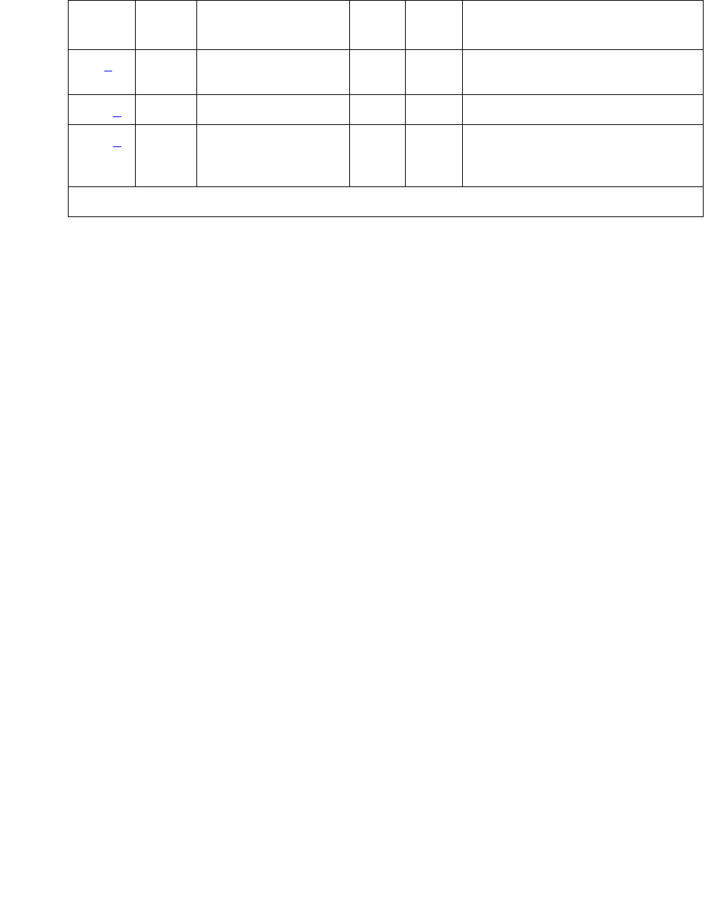
M/T-PKT (Maintenance/Test Packet Bus Port)
Issue 1 June 2005 1723
Notes:
a. Error Type 0: run the short test sequence first. If every test passes, run the long test
sequence. Refer to each test’s description, and follow its procedures.
b. Error Type 1: hardware failure with the port circuitry that provides the packet-bus
maintenance functions. Replace the Maintenance/Test circuit pack if the alarm is not
resolved by the test command above.
c. Error Type 18: the port has been busied out by busyout port location.
d. Error Type 257: the Maintenance/Test packet-bus port reconfigured the packet bus by
swapping a bad lead to a spare. Note that this error is sent up whenever the Maintenance/
Test packet-bus port is initialized (since the packet-bus port reconfigures the packet bus to
whatever state it determines the packet bus is in). This will occur if the circuit pack is
inserted, if the system is restarted, or if the port is released from a busyout state. Therefore,
it is normal for this error to be present in the error log.
If the M/T-PKT reconfigures the packet bus 6 times within 15 minutes, a Minor alarm is
raised indicating that either:
●Packet-bus maintenance functions are not operating correctly
●Many changes are taking place on the packet bus (insertions or removals of circuit
packs)
If the system has been in a stable state for more than 15 minutes, try the following
procedure:
1. Reset the Maintenance/Test circuit pack from a SAT session as follows:
a. Enter the busyout board location command.
b. Enter the reset board location command.
c. Enter the release board location command.
2. Wait 15 minutes.
18 (c)0 busyout port
location
WRN OFF release port location
257 (d) Any none MIN ON
513 (e) Any Packet Bus Port
Health Inquiry
(#567)
MIN ON test port location r 3
Table 638: M/T-PKT Error Log Entries (continued)
Error
Type
Aux
Data
Associated Test Alarm
Level
On/Off
Board
Test to Clear Value
2 of 2
Communication Manager Maintenance-Object Repair Procedures
1724 Maintenance Procedures for Avaya Communication Manager 3.0, Media Gateways and Servers
3. If the error recurs, replace the Maintenance/Test circuit pack.
When this alarm is active, the amber LED will be in one of three states:
●An unlit amber LED indicates no activity on the Maintenance/Test circuit pack. You can
replace the Maintenance/Test circuit pack.
●If there is an indication of an uncorrectable fault on the packet bus, the amber LED will be
blinking at a rate of 1 Hz. It is OK to replace the Maintenance/Test circuit pack. Ignore the
packet-bus error indication, since the Maintenance/Test circuit pack has been determined
to be defective.
●If there is other activity on the Maintenance/Test circuit pack (i.e., ISDN test call), or if
there is an indication of a correctable fault on the packet bus, the amber LED will be on
steady. If there is an ISDN test call in progress, it must be halted using clear
isdn-testcall grp#/mem# prior to replacing the circuit pack. Ignore the packet-bus
error indication, since the Maintenance/Test circuit pack has been determined to be
defective.
e. Error Type 513: indicates a failure of the Packet Bus Port Health Inquiry test. Either the
packet-bus port has reported a self-test failure, or Communication Manager can
communicate with the Maintenance/Test circuit pack but not with the Maintenance/Test
circuit pack packet-bus port. Refer to the description of the Packet Bus Port Health Inquiry
test, and follow the instructions indicated for the failure code that matches the Aux Data
field.
System Technician-Demanded Tests:
Descriptions and Error Codes
Investigate tests in the order presented below. Clearing Error Codes associated with the one
test may also clear errors generated from other tests in the sequence.
Order of Investigation Short Test
Sequence
Long Test
Sequence
D/ND1
1. D = Destructive, ND = Nondestructive
Packet Bus Port Health Inquiry test (#567) X X ND
Clear Error Counters (#270) X ND

M/T-PKT (Maintenance/Test Packet Bus Port)
Issue 1 June 2005 1725
Clear Error Counters (#270)
This test is not an actual test in the strict sense of the word. Many circuit packs have counters in
the Angel firmware. The circuit pack’s Angel continuously runs port self-tests on idle ports and
keeps track of any errors it detects by incrementing a firmware counter. When the counter value
reaches some preset threshold, the Angel sends a single CCMS (Control Channel Message
Set) error message uplink to Communication Manager. No more error messages of that type
are sent uplink until the Communication Manager sends a downlink message to clear the
counter. This strategy keeps a failed port/circuit pack from flooding Communication Manager
with a continuous string of identical error messages. This test is used to clear the counter, so
that if the port continues to fail during or after Communication Manager demanded testing, the
Angel will send a message to indicate that fact.
This test is only used to send a downlink message to the Angel on the Maintenance/Test circuit
pack. Since the Angel normally provides no uplink response to this message, this test should
never abort or fail.
Table 639: Test #270 Clear Error Counters
Error
Code
Test
Result
Description / Recommendation
Any ABRT This test should never abort.
Any FAIL This test should never fail.
1. Retry the command at 1-minute intervals up to 5 times.
2. If the test continues to fail, escalate the problem.
PASS The message to clear the Maintenance/Test circuit pack’s counter for
Background Maintenance Failures has been sent.

Communication Manager Maintenance-Object Repair Procedures
1726 Maintenance Procedures for Avaya Communication Manager 3.0, Media Gateways and Servers
Packet Bus Port Health Inquiry Test (#567)
This test verifies that the packet-bus fault-detection and maintenance function of the M/T-PKT is
functioning properly. This is done by having the M/T-PKT perform a self-test. If the self-test
passes, then the Packet Bus Port Health Inquiry test passes. If the self-test fails or
Communication Manager cannot communicate with the M/T-PKT, then the test fails
Table 640: Test #567 Consistency Test
Error
Code
Test
Result
Description / Recommendation
2000 ABRT Response to the test request was not received within the allowable time
period.
1. Retry the command at 1-minute intervals up to 5 times.
2100 ABRT System resources necessary to run this test are not available.
1. Retry the command at 1-minute intervals up to 5 times.
2500 ABRT An internal operation failed, and the test could not be completed.
1. Retry the command at 1-minute intervals up to 5 times.
2059 FAIL The M/T-PKT has reported a failure of the on-board self-test.
2060 FAIL The M/T-PKT has reported an invalid state for the packet bus.
2061 FAIL Communication Manager cannot communicate with the M/T-PKT, but
can communicate with the Maintenance/Test circuit pack.
1. Retry the command.
2. If the test continues to fail, replace the Maintenance/Test circuit pack,
and retry the command.
3. If the test continues to fail, seePKT-BUS (Packet Bus) on page 1790
or PKT-INT (Packet Interface) on page 1799 to determine whether
the M/T-PKT failure is being caused by a packet-bus fault.
PASS The M/T-PKT packet-bus fault-detection capability is operating correctly.

NO-LIC (No License)
Issue 1 June 2005 1727
NO-LIC (No License)
S8700 | 8710 / S8500 / S8300
Note:
Note: The NO-LIC MO (No License) is non-traditional in that there are no associated
tests or commands that you can execute.
How systems go into No-License mode
The NO-LIC MO works with the LIC-ERR MO to find any errors/violations associated with the
License File. Once a License File error occurs, LIC-ERR logs the error, raises an alarm, and
generates the following SAT login message:
“System Administration Will Be Blocked in Approximately XXX hours.
Contact Your Service Representative.”
Entry into License-Error mode starts a timer that, when expired, causes the system to enter
No-License mode (see Figure 98: License mode algorithm on page 1728). When
Communication Manager enters No-License mode, the following SAT warning message
displays:
“System Administration Is Blocked.
Contact Your Service Representative Immediately.”
The system also responds with these conditions:
●“LICENSE ERROR” displays on all stations and consoles when they go off-hook, but
disappears when the first digit is pressed. This display message does not interfere with the
normal use of any station or console.
●All terminal-login sessions are terminated.
●Any subsequent terminal-login sessions are limited to
- Maintenance commands.
- License File installation command.
MO Name in
Alarm Log
Alarm
Level
Initial Command to Run Full Name of MO
NO-LIC MAJ None NO License
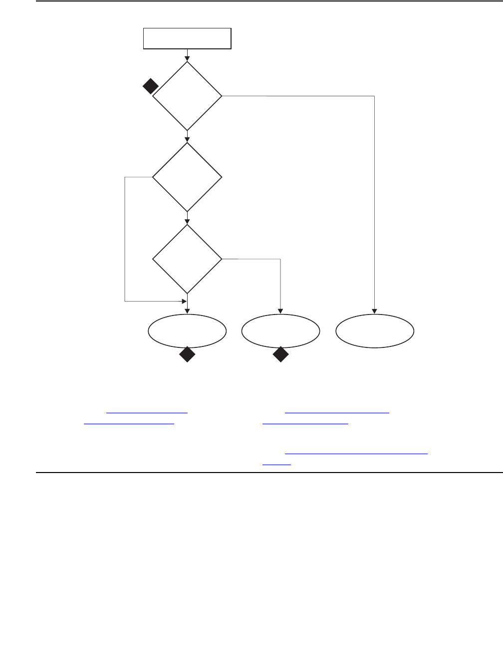
Communication Manager Maintenance-Object Repair Procedures
1728 Maintenance Procedures for Avaya Communication Manager 3.0, Media Gateways and Servers
Figure 98: License mode algorithm
The License File feature is loaded onto a switch during initialization of the switch software,
restore of translations, and periodically thereafter. After initialization, a query is made to a
software module called the license server. This module reads the License File, compares a
serial number in the License File to a serial number in hardware, and compares the software
version in the license with the running software version. If a match occurs, the license server
delivers a new feature mask, an information set that controls which features are enabled or not
on the Customer Options and Special Applications screens.
Figure notes:
1. See Troubleshooting
License File errors on
page 1482.
2. See How systems go into
No-License mode on page 1727.
3. See Troubleshooting License File
errors on page 1482.
System initialization
License-Error
present?
Timer
value
readable?
Timer expired?
fldfmode KLC 052504
License-Error
mode
No-License
mode
License-Normal
mode
Ye s
Ye s
Ye s
No
No
No
1
23
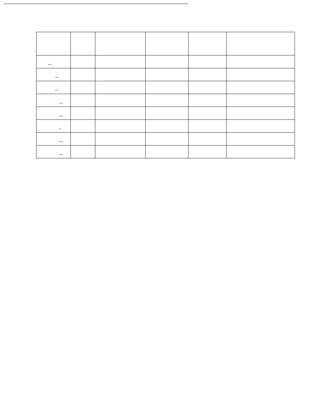
NO-LIC (No License)
Issue 1 June 2005 1729
Error Log Entries and Test to Clear Values
Notes:
a. Error Type 1: S8700 | 8710 / S8500: there is a serial-number mismatch of the reference IPSI
and a subsequent License Error failure. S8300: there is a serial-number mismatch of the
G700 motherboard on which the serial number resides. This error is caused by the:
●S8700 | 8710 / S8500: Reference IPSI not responding.
S8300: G700 motherboard not responding.
●Expiration of the timer.
The system enters No-License mode.
b. Error Type 513: the license has expired and:
●A License Error failure has occurred.
●The timer has expired.
●The system enters No-License mode.
c. Error Type 769: the system is in the Feature Usage Exceeds Limits mode, and a License
Error failure has occurred. System feature use has exceeded limits, and the timer has
expired. The system enters No-License mode.
d. Error Type 1281: a new license was not installed after an upgrade. The timer has expired,
and a License Error failure has occurred. The system enters No-License mode.
e. Error Type 1537: the License File is missing or corrupted. The system enters No-License
mode.
Error
Type
Aux
Data
Associated
Test
Alarm
Level
On/Off
Board
Test to Clear
Value1
1. These Error Types are cleared by installing a valid License File that matches the hardware
ID(s).
1 (a)MAJOFF
513 (b) None MAJ OFF
769 (c) None MAJ OFF
1281 (d) None MAJ OFF
1537 (e) None MAJ OFF
1793 (f) None MAJ OFF
2305 (g) None MAJ OFF
2561 (h) None MAJ OFF

Communication Manager Maintenance-Object Repair Procedures
1730 Maintenance Procedures for Avaya Communication Manager 3.0, Media Gateways and Servers
f. Error Type 1793: a Software Version Mismatch has occurred. The system enters
No-License mode.
g. Error Type 2305: the Offer Category of the License does not match the Offer Category in
translations. The system enters No-License mode.
h. Error Type 2561: during the last attempted License File audit, the license server did not
respond in time.
On-Demand Tests for System Technicians
This MO provides no on-demand tests for system technicians.

NR-CONN (Network-Region Connect)
Issue 1 June 2005 1731
NR-CONN (Network-Region Connect)
S8700 | 8710 / S8500
A network region is a logical grouping of IP endpoints (including IP stations, IP trunks, and
media gateways) sharing the same transmission characteristics and/or VoIP and signaling
resources, such as a Media Processor board or a C-LAN. The Network-Region Connect
(NR-CONN) MO monitors VoIP connectivity between network regions and raises a:
●Warning alarm for a single failure.
This alarm is in response to one failed background ping test between IP endpoints in
separate network regions. This test is part of the background Network Region
Interconnectivity Test (#1417) on page 1733.
●Minor alarm for multiple failures.
Once a single failure is detected, Test #1417 is re-executed between different IP endpoints
in the same pair of network regions. If the test still fails between these network regions:
- Maintenance software marks the connectivity between them as “failed.”
- Communication Manager denies every attempted call between them.
As a background operation during each 2-minute interval, Test #1417 checks the translated
connections between 50 pairs of network regions until every translated connection has been
tested, and then repeats. (The Communication Manager translation table’s maximum capacity
for network-region connections is 31,250. Testing every possible connection would require 625
2-minute test intervals during about 21 hours.)
Repair strategies
●Use display failed-ip-network-region to display pairs of network regions with
failed connectivity. In descending order of severity, this command lists up to 100 network
regions with the most severely broken connectivity.
●Use status ip-network-region to see the status of connections from a particular
network region.
●As an on-demand operation, test failed-ip-network-region retests every
network-region connection marked as “failed.” Those connections that:
- Pass are returned to service.
- Fail are remarked as “failed” and remain on the list of bad connections.
MO Name in
Alarm Log
Alarm
Level
Initial SAT Command to Run Full Name of MO
NR-CONN WRN test failed-ip-network-region Network-Region Connect
NR-CONN MIN test failed-ip-network-region Network-Region Connect

Communication Manager Maintenance-Object Repair Procedures
1732 Maintenance Procedures for Avaya Communication Manager 3.0, Media Gateways and Servers
Error Log Entries and Test to Clear Values
Note:
a. Error Type 1: one or more network-region connections have failed.
1. Enter display failed-ip-network-region to verify that connections between
pairs of network regions are failing.
2. If so, enter test failed-ip-network-region to retest these paths.
3. For each affected network region, check the error log for failures to related MOs, such as:
- IPMEDPRO (IP Media Processor Circuit Pack)
- MEDPRO (Media Processor MAPD Circuit Pack)
- CLAN-BD (Control LAN Circuit Pack)
- DIG-IP-S (Digital IP Station)
- RDIG-STA (Remote Digital Station)
and resolve any problems.
4. Enter test failed-ip-network-region to retest these paths.
5. If errors persist, escalate.
Technician-Demanded Test: Description and Error Code
Table 641: NR-CONN Error Log Entries
Error
Type
Aux
Data
Associated Test Alarm
Level
On/Off
Board
Test to Clear
Value
1(a) 0 Network Region Interconnectivity (#1417) MIN ON
Order of Investigation Short Test
Sequence
Long Test
Sequence
D/ND
Network Region Connectivity test (#1417) X Nondestructive

NR-CONN (Network-Region Connect)
Issue 1 June 2005 1733
Network Region Interconnectivity Test (#1417)
This test is nondestructive.
Test #1417 is a nonstandard test, since it does not specify and list Error Codes in the usual
manner. If this background test detects a failure, the test is retried using different IP endpoints (if
available) from the same two network regions. If the test still fails between these network
regions:
1. Maintenance software marks the connectivity between them as “failed.”
2. Communication Manager denies every attempted call between them.
For this test, devices that can serve as IP endpoints include:
●IPMEDPRO
●MEDPRO
●CLAN-BD
●IP phones or Softphones, with the ability to initiate a ping
For a network region without an IPMEDPRO, MEDPRO, or a CLAN-BD, Test #1417 looks for
another ping-capable endpoint. If found, the region’s testing continues. If not, the test assumes
that the region’s connectivity is okay.
Table 642: Test #1417 Network Region Interconnectivity Test
Error
Code
Test
Result
Description / Recommendation
1
2
11
ABRT Internal error
1. Retry the command at 1-minute intervals up to 3 times.
2. If the problem persists, escalate the problem.
1005 ABRT Incorrect test configuration.
1. Verify Ethernet link is in service on all CLAN boards in source and
destination with status port location or status link n).
1125 ABRT Ethernet link not in service.
1. Verify Ethernet link is in service for all CLAN boards in the source
and destination regions under test using status port location
or status link n. If interface is enabled, the ethernet link is
expected to be in-service for this test to run.
1 of 3

Communication Manager Maintenance-Object Repair Procedures
1734 Maintenance Procedures for Avaya Communication Manager 3.0, Media Gateways and Servers
2000 ABRT Did not receive a response from a circuit pack being used for the test
within the allowable time period.
1. Reset the circuit pack (busyout board location, reset board
location, and release board location).
2. If the test fails again, replace the circuit pack.
2012 ABRT Internal system error.
1. Retry the command at 1-minute intervals, up to 3 times.
2. Escalate if the problem persists.
2100 ABRT Could not locate the necessary system resources to run this test.
1. Retry the command at 1-minute intervals, up to 5 times.
2. Escalate if the problem persists.
2500 ABRT Internal system error.
1. Retry the command at 1-minute intervals, up to 3 times.
2. Escalate if the problem persists.
2801 ABRT No IP address defined.
1. Verify IP interfaces translations and retest.
2802 ABRT Different IP address pinged than software had allocated for the test.
1. Retry the command at 1-minute intervals up to 3 times.
2807 ABRT The board is administered but not enabled in the change
ipserver-interfaces screen.
1003 FAIL Ping to the destination failed due to on-board problems of the source of
the ping. The source of the ping can be a CLAN board or a IPMEDPRO
board for this error to occur.
1. Retry the command at 1-minute intervals, up to 3 times.
2. Look for problems associated with IPMEDPRO or CLAN boards in
this region.
Table 642: Test #1417 Network Region Interconnectivity Test (continued)
Error
Code
Test
Result
Description / Recommendation
2 of 3
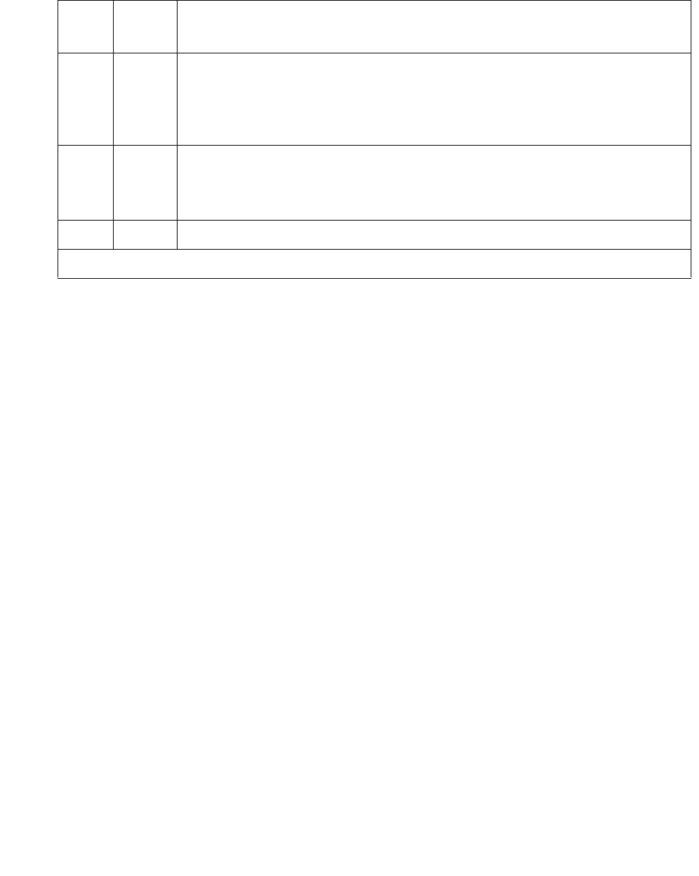
NR-CONN (Network-Region Connect)
Issue 1 June 2005 1735
7
89
1007
FAIL Ping to the destination failed due to the destination down.
1. Verify that at least one destination reachable through the network
regions being tested is up. Ping this destination (ping ip-address
xxx.xxx.xxx.xxx).
2805 FAIL The number of pings received did not match the number sent (normally
one ping is sent). This means that no ping responses were received from
the destination region endpoint being tested back to the source endpoint
sending the ping.
PASS TCP/IP Ping test between network regions is successful.
Table 642: Test #1417 Network Region Interconnectivity Test (continued)
Error
Code
Test
Result
Description / Recommendation
3 of 3
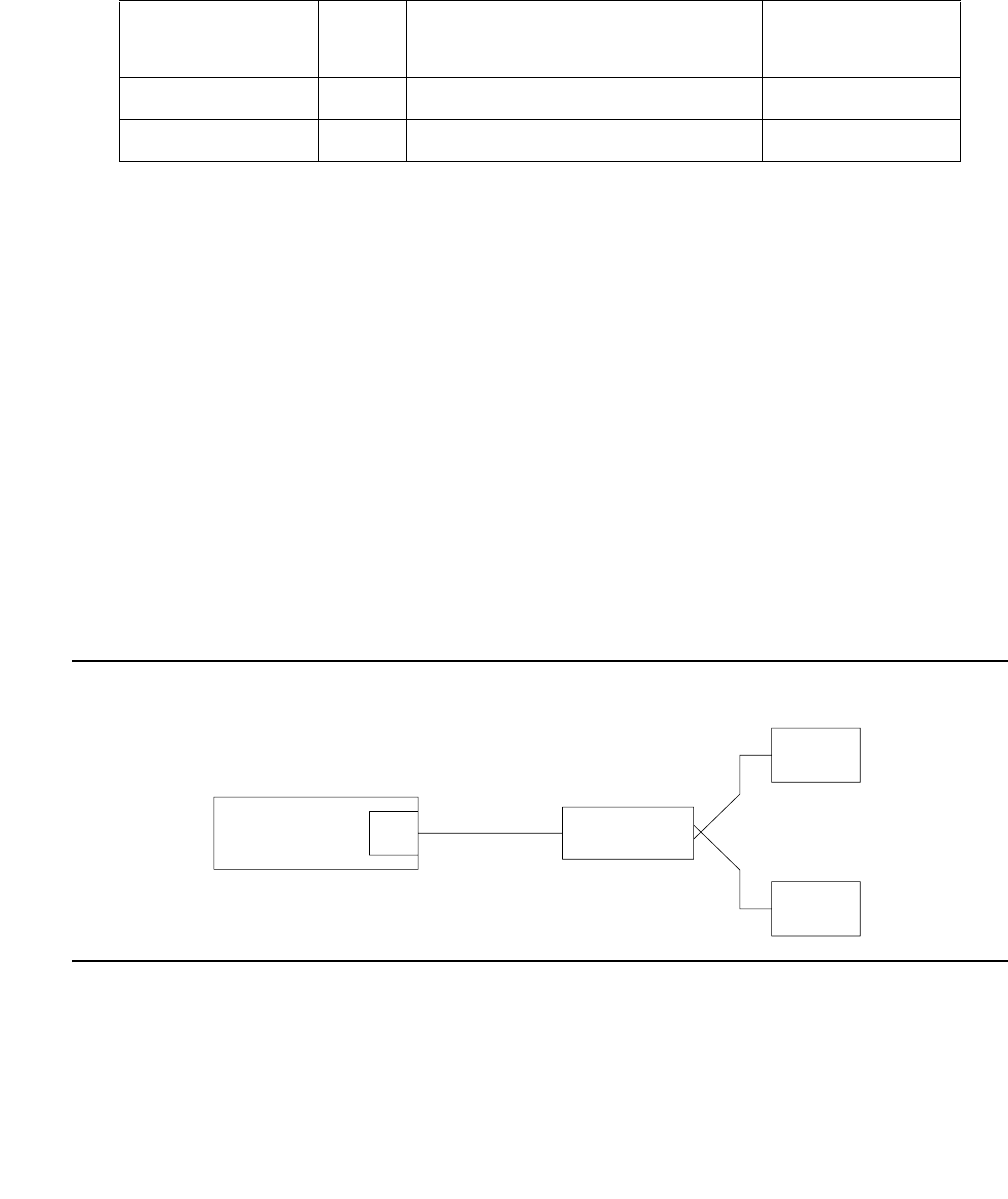
Communication Manager Maintenance-Object Repair Procedures
1736 Maintenance Procedures for Avaya Communication Manager 3.0, Media Gateways and Servers
OPS-LINE (DS1 Off-Premises Station Line)
S8700 | 8710 / S8500
An analog Off-Premises Station (OPS) can be connected to the system through a DS1 link. A
TN767 DS1 Interface circuit pack or a TN464 UDS1 Interface circuit pack can support up to 24
DS1 OPS lines. Since the DS1 OPS is an analog telephone set, a channel multiplexer is
necessary as the remote DS1 endpoint converts the digital signal of a DS1 port to the OPS Line
and vice versa.
The DS1 OPS Line Maintenance provides a strategy to maintain an OPS Line via a trunk port of
the TN767 DS1 Interface circuit pack or the TN464 UDS1 Interface circuit pack. (Throughout
this section, the term DS1 Interface can apply to either of these circuit packs.) The strategy
covers initialization tests, periodic tests, scheduled tests, system technician-demanded tests,
and alarm resolution and escalation. Two service states are specified in a DS1 OPS Line
maintenance. They are: out-of-service, in which the line is in a deactivated state and cannot be
used for either incoming or outgoing calls; or in-service, in which the line is in an activated state
and can be used for both incoming and outgoing calls. If the DS1 Interface circuit pack is
out-of-service, then every line on the DS1 Interface circuit pack is put into the out-of-service
state, and a Warning alarm is raised.
For maintenance of the remote DS1 endpoint (for example, a Channel Division Multiplexer or
D4 Channel Bank), refer to the vendor’s maintenance documentation for details.
Figure 99: DS1 OPS Line Interactions
MO Name in
Alarm Log
Alarm
Level
Initial SAT Command to Run Full Name of MO
OPS-LINE MIN test station extension l DS1 OPS Line
OPS-LINE WRN test station extension DS1 OPS Line
CHANNEL
MULTIPLEXER
ANALOG
STATION
DS1 LINK
ANALOG
STATION
DS1
System
DEFINITY
Communications

OPS-LINE (DS1 Off-Premises Station Line)
Issue 1 June 2005 1737
Error Log Entries and Test to Clear Values
Notes:
a. Error Type 0: run the short test sequence first. If every test passes, run the long test
sequence. Refer to each test’s description, and follow its procedures.
b. Error Type 15: this software audit error does not indicate a hardware malfunction. Run the
short test sequence and investigate associated errors (if any).
c. Error Type 18: the DS1 OPS Line was busied out by busyout station ext. No calls
can be made on this line.
d. Error Type 130: the circuit pack was removed or was insane for more than 11 minutes. To
clear the error, reinsert or replace the circuit pack.
e. Error Type 1793 indicates a problem with the DS1 Interface circuit pack. Because there is
no error against the OPS-LINE port, no alarm is raised against the OPS-LINE port.
However, there should be errors logged against the DS1 Interface circuit pack. Look for
DS1-BD/UDS1-BD errors in the Hardware Error Log, and follow the procedures in DS1-BD
(DS1 Interface Circuit Pack) on page 978.
Table 643: DS1 OPS Maintenance Error Log Entries
Error
Type
Aux
Data
Associated Test Alarm
Level
On/Off
Board
Test to Clear Value
0 (a) 0 Any Any Any test station ext
15 (b) Any Audit and Update test
(#36)
18 (c)0busyout station
ext
WRN OFF release station ext
130 (d) None WRN ON test station ext
1281 Conference Circuit test
(#7)
MIN ON test station ext l r 4
1537 NPE Crosstalk test (#6) MIN ON test station ext l r 3
1793 (e)test board location l

Communication Manager Maintenance-Object Repair Procedures
1738 Maintenance Procedures for Avaya Communication Manager 3.0, Media Gateways and Servers
System Technician-Demanded Tests:
Descriptions and Error Codes
Investigate tests in the order presented below. Clearing Error Codes associated with the one
test may also clear errors generated from other tests in the sequence.
NPE Crosstalk Test (#6)
One or more Network Processing Elements (NPEs) reside on each circuit pack with a TDM-bus
interface. (The TN464 UDS1 circuit pack has one SCOTCH-NPE chip instead of several NPE
chips.) The NPE controls port connectivity and gain, and provides conferencing functions on a
per-port basis. The NPE Crosstalk test verifies that this port’s NPE channel talks on the
selected time slot and never crosses over to time slots reserved for other connections. If the
NPE is not working correctly, one-way and noisy connections may be observed. This test is
usually only part of a port’s long test sequence and takes about 20 to 30 seconds to complete.
Order of Investigation Short Test
Sequence
Long Test
Sequence
D/ND1
1. D = Destructive; ND = Nondestructive
NPE Crosstalk test (#6)
G700: Aborts with Error Code 1412
XND
Conference Circuit test (#7)
G700: Aborts with Error Code 1412
XND
DS1 OPS Switchhook Inquiry test (#312) X X ND
Audit and Update test (#36) X X ND
Table 644: Test #6 NPE Crosstalk Test
Error
Code
Test
Result
Description / Recommendation
ABRT Could not allocate system resources to run this test or an internal
system error (software) occurred.
1. Retry the command at 1-minute intervals up to 5 times.
1000 ABRT Could not seize the port for testing. The port may be in use on a valid
call. Use status station or status trunk to determine when the
port is available for testing.
1. Retry the command at 1-minute intervals up to 5 times.
1 of 4

OPS-LINE (DS1 Off-Premises Station Line)
Issue 1 June 2005 1739
1001 ABRT Could not allocate the necessary system resources to run this test.
1. Retry the command at 1-minute intervals up to 5 times.
1002 ABRT The system could not allocate time slots for the test. The system may be
under heavy traffic conditions or it may have time slots out-of-service
due to TDM-BUS errors. Use status health to determine if the
system is experiencing heavy traffic.
1. If the system has no TDM-BUS errors and is not handling heavy
traffic, repeat test at 1-minute intervals up to 5 times.
1003 ABRT The system could not allocate a tone receiver for the test. The system
may be oversized for the number of Tone Detectors present or some
Tone Detectors may be out-of-service. Use list measurements
tone-receiver to display information about the system’s tone
receivers.
1. Resolve any TTR-LEV errors.
2. Resolve any TONE-PT errors.
3. If neither condition exists, retry the test at 1-minute intervals up to 5
times.
1004 ABRT The test was aborted because the port was seized by a user for a valid
call. Use status station to determine the service state of the port. If
the service state indicates that the port is in use, then the port is
unavailable for certain tests. You must wait until the port is idle before
retesting.
1. Retry the command at 1-minute intervals up to 5 times.
1020 ABRT The test did not run due to an already existing error on the specific port
or due to a more general error on the circuit pack.
1. Examine the error log for existing errors against this port or the
circuit pack and attempt to diagnose the already existing error.
(Error code 1793 indicates a problem with the DS1 interface board,
and any problems on the associated DS1-BD or UDS1-BD should
be resolved first.)
G700:
1412
ABRT This test does not execute on a G700 media gateway.
Table 644: Test #6 NPE Crosstalk Test (continued)
Error
Code
Test
Result
Description / Recommendation
2 of 4

Communication Manager Maintenance-Object Repair Procedures
1740 Maintenance Procedures for Avaya Communication Manager 3.0, Media Gateways and Servers
2000 ABRT Response to the test request was not received within the allowable time
period.
1. Retry the command at 1-minute intervals up to 5 times.
2. If the test aborts with Error Code 2000 again, run short test
sequence on the associated DS1-BD or UDS1-BD. If tests 138
through 145 on the associated DS1-BD or UDS1-BD are also
aborting with Error Code 2000, hyperactivity on the board or facility
is indicated. In this case, the hyperactivity problem should be dealt
with first.
2100 ABRT System resources required for this test are not available.
1. Retry the command at 1-minute intervals up to 5 times.
Any FAIL The test failed. This can be due to on-board or off-board problems.
Off-board problems of concern include EXP-PN, EXP-INTF, or
RMC-ENV faults, TDM-BUS faults, and faults associated with the tone
detectors/tone generators. Clear every off-board problem before
replacing the board. Keep in mind that a TDM-BUS problem is usually
the result of a faulty board connected to the backplane or bent pins on
the backplane.
1. Resolve any TONE-BD and/or TONE-PT errors.
2. Retest when the faults from step 1 are cleared.
PASS The port is correctly using its allocated time slots. User-reported troubles
on this port should be investigated using other port tests and by
examining station, trunk, or external wiring.
Table 644: Test #6 NPE Crosstalk Test (continued)
Error
Code
Test
Result
Description / Recommendation
3 of 4

OPS-LINE (DS1 Off-Premises Station Line)
Issue 1 June 2005 1741
Conference Circuit Test (#7)
One or more Network Processing Elements (NPEs) reside on each circuit pack with a TDM-bus
interface. (The TN464 UDS1 circuit pack has one SCOTCH-NPE chip instead of several NPE
chips). The NPE controls port connectivity and gain, and provides conferencing functions on a
per-port basis. The Conference Circuit test verifies that the NPE channel for the port being
tested can correctly perform the conferencing function. The NPE is instructed to listen to several
different tones and conference the tones together. The resulting signal is then measured by a
Tone Detector port. If the level of the tone is within a certain range, the test passes.
0NO
BOARD
The test could not relate the internal ID to the port (no board). This could
be due to incorrect translations, no board is inserted, an incorrect board
is inserted, or an insane board is inserted.
1. Check to ensure that the board translations are correct. Use list
config, and resolve any problems that are found.
2. If the board was found to be inserted correctly, enter busyout
board location.
3. Enter the reset board location command.
4. Enter the release board location command.
5. Enter test board location long.
This should re-establish the linkage between the internal ID and the
port. If not, ensure that there is a valid board inserted.
Table 644: Test #6 NPE Crosstalk Test (continued)
Error
Code
Test
Result
Description / Recommendation
4 of 4
Table 645: Test #7 Conference Circuit Test
Error
Code
Test
Result
Description / Recommendation
ABRT System resources required for this test are not available.
1. Retry the command at 1-minute intervals up to 5 times.
1000 ABRT Could not seize the port for testing. The port may be in use on a valid call.
Use status station or status trunk to determine when the port is
available for testing.
1 of 5

Communication Manager Maintenance-Object Repair Procedures
1742 Maintenance Procedures for Avaya Communication Manager 3.0, Media Gateways and Servers
1002 ABRT The test was aborted because the system could not allocate time slots
for the test. The system might be under heavy traffic conditions, or it
might have time slots out of service due to TDM-BUS errors. Use
status health to determine if the system is experiencing heavy
traffic.
1. If the system has no TDM-BUS errors, is not handling heavy traffic,
and the port status is idle, retry the command at 1-minute intervals
up to 5 times.
1003 ABRT The system could not allocate a tone receiver for the test. The system
may be oversized for the number of tone detectors present or some of
the tone detectors may be out of service. Enter list measurements
tone-receiver to display basic information about the system's tone
receivers.
1. Resolve any TTR-LEV errors.
2. Resolve any TONE-PT errors.
3. If neither condition exists, retry the test at 1-minute intervals up to 5
times.
1004 ABRT The port has been seized by a user for a valid call. Use status
station or status trunk to determine when the port is available for
testing.
1. Retry the command at 1-minute intervals up to 5 times.
1018 ABRT The test was disabled by translation.
1. You may want to determine why the test has been disabled before
you enable it.
2. To enable the test for the particular analog station being tested, enter
change station extension, and set the Test field on the
Station screen to y.
1020 ABRT The test did not run due to an already existing error on the specific port
or due to a more general error on the circuit pack.
1. Examine the error log for existing errors against this port or the circuit
pack and attempt to diagnose the already existing error. (Error code
1793 indicates a problem with the DS1 interface board, and any
problems on the associated DS1-BD or UDS1-BD should be
resolved first.)
Table 645: Test #7 Conference Circuit Test (continued)
Error
Code
Test
Result
Description / Recommendation
2 of 5

OPS-LINE (DS1 Off-Premises Station Line)
Issue 1 June 2005 1743
G700:
1412
ABRT This test does not execute on a G700 media gateway.
2000 ABRT The test was aborted because response to the test was not received
within the allowable time period.
1. Retry the command at 1-minute intervals up to 5 times.
2. If the test aborts with Error Code 2000 again, run short test sequence
on the associated DS1-BD or UDS1-BD. If Tests 138 through 145 on
the associated DS1-BD or UDS1-BD are also aborting with Error
Code 2000, hyperactivity on the board or facility is indicated. In this
case, the hyperactivity problem should be dealt with first.
2100 ABRT System resources required for this test are not available.
1. Retry the command at 1-minute intervals up to 5 times.
Table 645: Test #7 Conference Circuit Test (continued)
Error
Code
Test
Result
Description / Recommendation
3 of 5

Communication Manager Maintenance-Object Repair Procedures
1744 Maintenance Procedures for Avaya Communication Manager 3.0, Media Gateways and Servers
Any FAIL The NPE of the tested port did not conference the tones correctly. This
can cause noisy and unreliable connections.
1. Enter list configuration board location. If the circuit pack
is a TN767B vintage 8 or 9, replace the circuit pack with a TN767C
V3 or later. The error log may have error type 1281 entries.
2. Test every administered trunk on the board. If one fails, this could be
an off-board problem (such as an incoming seizure or an off-hook
port seizure during the test). Retest the board.
3. If every port fails, check the CARR-POW (see note below).
4. If several ports fail, check the error log for TONE-BD or TONE-PT
errors. If there are such errors, take the appropriate action. When the
TONE errors have cleared, rerun the test.
5. If the retry passes and troubles have been reported, coordinate
isolation with the far-end PBX. Make sure that the near- and far-end
switches and any NTCE equipment (the CSUs) have the correct
administration.
6. Replace the circuit pack.
7. If the conference circuit test fails for every port on a circuit pack, a -5
Volt power problem is indicated. S8700 MC: If a TN736 or TN752
power unit circuit pack is present, either the 631DB AC power unit or
the 676B DC power unit may be defective. (The 631DB power unit is
used in a medium cabinet powered by an AC source. The 645B
power unit is used in a medium cabinet powered by a DC power
source.) The system may contain a TN736 or TN752 power unit or a
631DB AC power unit, but not both types of power units. See
CARR-POW (Carrier Power Supply) on page 770 to investigate
problems with either a 631DB AC or a 645B DC power unit.
S8700 IP: If a TN736 or TN752 power unit circuit pack is present, the
power unit may be defective. See RMC-ENV (Power/Fan
Sensors) on page 1951 to investigate problems with a power unit. If
a red LED is lit on TN736 or TN752 power unit circuit pack, replace
the pack.
PASS The port can correctly conference multiple connections. User-reported
troubles on this port should be investigated using other port tests and by
examining station, trunk, or external wiring.
Table 645: Test #7 Conference Circuit Test (continued)
Error
Code
Test
Result
Description / Recommendation
4 of 5

OPS-LINE (DS1 Off-Premises Station Line)
Issue 1 June 2005 1745
Audit and Update Test (#36)
This test sends port level translation data from switch processor to the DS1 Interface circuit
pack to assure that the trunk’s translation is correct. Translation updates include the following
data: line type, dial type, timing parameters, and signaling bits enabled. The port audit operation
verifies the consistency of the current state of the trunk as kept in the DS1 Interface circuit pack
and in the switch software.
0NO
BOARD
The test could not relate the internal ID to the port (no board). This could
be due to incorrect translations, no board is inserted, an incorrect board
is inserted, or an insane board is inserted.
1. Check to ensure that the board translations are correct. Use list
config, and resolve any problems that are found.
2. If the board was found to be inserted correctly, enter busyout
board location.
3. Enter the reset board location command.
4. Enter the release board location command.
5. Enter test board location long.
This should re-establish the linkage between the internal ID and the port.
If not, ensure that there is a valid board inserted.
Table 645: Test #7 Conference Circuit Test (continued)
Error
Code
Test
Result
Description / Recommendation
5 of 5
Table 646: Test #36 Audit and Update Test
Error
Code
Test
Result
Description / Recommendation
ABRT Internal system error
1. Retry the command at 1-minute intervals up to 5 times.
1 of 3

Communication Manager Maintenance-Object Repair Procedures
1746 Maintenance Procedures for Avaya Communication Manager 3.0, Media Gateways and Servers
1000 ABRT The test was aborted because system resources required to run this
test were not available. The port may be busy with a valid call.
1. Use display port location to determine the station extension
of the port. Use status station to determine the service state of
the port. If the service state indicates that the port is in use, then the
port is unavailable for certain tests. You must wait until the port is
idle before retesting.
2. If the port is idle, retry the command at 1-minute intervals up to 5
times.
1006 ABRT The test was aborted because the station is out of service. This
condition may be accompanied by an error type 18 entry in the error
log. You may want to determine why the station was taken out of
service. (When stations are taken out of service by maintenance
software, the problems that preceded that point must be cleared.)
1. Use status station to check the service state of the port. If the
port is indeed out of service, enter release station to bring the
station back into service.
2. Retry the command at 1-minute intervals up to 5 times.
2000 ABRT Response to the test request was not received within the allowable time
period.
1. Retry the command at 1-minute intervals for a maximum of 5 times.
2. If the test aborts with Error Code 2000 again, run short test
sequence on the associated DS1-BD or UDS1-BD. If tests 138
through 145 on the associated DS1-BD or UDS1-BD are also
aborting with Error Code 2000, hyperactivity on the board or facility
is indicated. In this case, the hyperactivity problem should be dealt
with first.
2100 ABRT Could not allocate the necessary system resources to run this test.
1. Retry the command at 1-minute intervals up to 5 times.
7 or 8 FAIL Test failed due to internal system error. Do not replace port board.
Error code 7: the failure occurred during station translation download (to
DS1 Interface circuit pack).
Error code 8: the failure occurred during station ringer update.
1. Retry the command at 1-minute intervals up to 5 times.
Table 646: Test #36 Audit and Update Test (continued)
Error
Code
Test
Result
Description / Recommendation
2 of 3

OPS-LINE (DS1 Off-Premises Station Line)
Issue 1 June 2005 1747
PASS Trunk translation has been updated successfully. The current trunk
states kept in the DS1 Interface circuit pack and switch software are
consistent.
If the trunk is busied out, the test will not run but will return PASS. To
verify that the station is in-service:
1. Enter status station to verify that the station is in-service. If the
station is in-service, no further action is necessary. If the station is
out-of-service, continue to step 2.
2. Enter release station to put the station back into in-service.
3. Retry the test command.
0NO
BOARD
The test could not relate the internal ID to the port (no board). This
could be due to incorrect translations, no board is inserted, an incorrect
board is inserted, or an insane board is inserted.
1. Check to ensure that the board translations are correct. Use list
config, and resolve any problems that are found.
2. If the board was found to be inserted correctly, enter busyout
board location.
3. Enter the reset board location command.
4. Enter the release board location command.
5. Enter test board location long.
This should re-establish the linkage between the internal ID and the
port. If not, ensure that there is a valid board inserted.
Table 646: Test #36 Audit and Update Test (continued)
Error
Code
Test
Result
Description / Recommendation
3 of 3

Communication Manager Maintenance-Object Repair Procedures
1748 Maintenance Procedures for Avaya Communication Manager 3.0, Media Gateways and Servers
DS1 OPS Switchhook Inquiry Test (#312)
This test initiates the Switchhook Audit test. The test queries the switchhook state of the
Off-Premises-Station in switch software. If the state in switch software disagrees with the state
on the DS1 Interface circuit pack, then the state in the switch software is updated to match the
state on the DS1 Interface circuit pack.
Table 647: Test #312 DS1 OPS Switchhook Inquiry Test
Error
Code
Test
Result
Description / Recommendation
ABRT Internal system error
1. Retry the command at 1-minute intervals up to 5 times.
1004 ABRT The port has been seized by a user for a valid call. Use status
station to determine when the port is available for testing.
1. Retry the command at 1-minute intervals up to 5 times.
1005 ABRT Test failed due to incompatible configuration administered in station
administration.
1. Use display station to verify that the station is not the 24th
port of the DS1 Interface circuit pack while common channel
signaling is specified. Use display ds1 to check the signaling
type of the DS1 circuit pack.
1006 ABRT The test was aborted because the station is out of service. This
condition may be accompanied by an error type 18 entry in the error
log. You may want to determine why the station was taken out of
service. (When stations are taken out of service by maintenance
software, the problems that led up to that must be cleared.)
1. Use status station to check the state of the port. If the port is
indeed out of service, enter release station to bring the station
back into service.
2. Retry the command at 1-minute intervals up to 5 times.
1020 ABRT The DS1 Interface circuit pack is out-of-service.
1. Look for DS1-BD/UDS1-BD errors in Hardware Error Log. If
present, see DS1-BD (DS1 Interface Circuit Pack) on page 978.
2. Retry the command.
1 of 3

OPS-LINE (DS1 Off-Premises Station Line)
Issue 1 June 2005 1749
2000 ABRT The test was aborted because response to the test was not received
within the allowable time period.
1. Retry the command at 1-minute intervals up to 5 times.
2. If the test aborts with Error Code 2000 again, run short test
sequence on the associated DS1-BD or UDS1-BD. If tests 138
through 145 on the associated DS1-BD or UDS1-BD are also
aborting with Error Code 2000, hyperactivity on the board or facility
is indicated. In this case, the hyperactivity problem should be dealt
with first.
2012 ABRT The test was aborted due to a system error.
1. Retry the command at 1-minute intervals up to 5 times.
2100 ABRT Could not allocate the necessary system resources to run this test.
1. Retry the command at 1-minute intervals up to 5 times.
1 FAIL Internal system error.
1. Look for DS1-BD/UDS1-BD errors in the Hardware Error Log. If
present, see DS1-BD (DS1 Interface Circuit Pack) on page 978.
2. If a channel multiplexer is used as the remote DS1 endpoint to
which the station connects, refer to the multiplexer vendor’s
maintenance document for diagnosis.
3. Retry the command at 1-minute intervals up to 5 times.
PASS The station hook states in both switch software and DS1 Interface circuit
pack are consistent.
Table 647: Test #312 DS1 OPS Switchhook Inquiry Test (continued)
Error
Code
Test
Result
Description / Recommendation
2 of 3

Communication Manager Maintenance-Object Repair Procedures
1750 Maintenance Procedures for Avaya Communication Manager 3.0, Media Gateways and Servers
0NO
BOARD
The test could not relate the internal ID to the port (no board). This
could be due to incorrect translations, no board is inserted, an incorrect
board is inserted, or an insane board is inserted.
1. Check to ensure that the board translations are correct. Use list
config, and resolve any problems that are found.
2. If the board was found to be inserted correctly, enter busyout
board location.
3. Enter the reset board location command.
4. Enter the release board location command.
5. Enter test board location long.
This should re-establish the linkage between the internal ID and the
port. If not, ensure that there is a valid board inserted.
Table 647: Test #312 DS1 OPS Switchhook Inquiry Test (continued)
Error
Code
Test
Result
Description / Recommendation
3 of 3

PDMODULE (Processor Data Module)
Issue 1 June 2005 1751
PDMODULE (Processor Data Module)
Error log entries and tests also apply to TDMODULE.
S8700 | 8710 / S8500
The PDMODULE and TDMODULE MOs monitor and test Digital Line circuit pack ports that are
connected to Data Communications Equipment (DCE) or Data Terminal Equipment (DTE). DCE
include processor data modules (MPDM) and Data Adaptors (DA). DTE include trunk data
modules (DTE). These stand-alone data modules provide interfaces between DCP ports on the
Digital Line circuit packs and data equipment such as terminals, host computers, and data
modems. (See the following list and figure.) Data modules are used for dial-up and permanent
circuit-switched data calls.
Digital Line circuit packs also connect to digital terminal data modules (DTDMs), which work in
conjunction with a voice terminal. Those configurations are covered by the DIG-LINE MO.
Circuit pack-level maintenance is covered by DIG-BD whose strategy is described in the
XXX-BD (Common Port Circuit Pack/Media Module) on page 2539.
Digital line circuit packs include the TN754, TN754B, TN413, TN2136. See DIG-LINE for more
information about the characteristics of these circuit packs.
Note:
Note: S8300 / G700: Although the PDMODULE/TDMODULE MO is provided for a G700
media gateway, this MO only partially supports the G700’s MM712 DCP media
module.
MO Name in
Alarm Log
Alarm
Level
Initial SAT Command to Run Full Name of MO
PDMODULE1
1. Digital Terminal Data Modules (DTDM), and Data Adaptors (DA) in linked mode are considered part
of the Digital Line MO. See the DIG-LINE section for maintenance of these devices. DAs in
stand-alone mode are included in PDMODULE.
Some of the alarms that are logged due to PDMODULE and TDMODULE test failures may be
related to circuit-pack problems reported during DIG-BD testing. See XXX-BD (Common Port
Circuit Pack/Media Module) on page 2539.
MIN test port location long Processor Data Module
PDMODULE WRN test port location short Processor Data Module
TDMODULE 2MIN test port location long Trunk Data Module
TDMODULE WRN test port location short Trunk Data Module
Communication Manager Maintenance-Object Repair Procedures
1752 Maintenance Procedures for Avaya Communication Manager 3.0, Media Gateways and Servers
Stand-Alone DCP Data Modules
There are two types of stand-alone DCP data modules as shown in Table 648.
Data Adapters
TN2136 circuit packs use IDCP signaling and a DAA2 Data Adaptor (DA) to interface to DTE.
DAs can operate in either of two modes which are covered by different MOs:
Table 648: Stand-Alone DCP Data Modules
Type Name1
1. Early versions of these data modules were referred to as PDMs and TDMs, respectively. Later models
are designed to provide a variety of interfaces by using interchangeable modules and are thus called
modular data modules. Both types are supported by the tests described in this section
Interfaces to:
MPDM Modular Processor Data Module DTE (data terminals, host computers,
printers, etc.)
MTDM Modular Trunk Data Module DCE (modems, data modules, etc.)
Table 649: Data Adaptor Modes
DA Mode Administered as: Endpoint Maintenance
Object
Stand-Alone PDM data endpoint only PDMODULE
Linked DTDM IDT1/21 and optional data terminal
1. IDT1/2: Italtel Digital Telephone, Model 1 or 2 (also known as Digital Telephones TD7210 and
TD7206).
DIG-LINE

PDMODULE (Processor Data Module)
Issue 1 June 2005 1753
Configurations and Maintenance
The MPDM provides an interface for Data Terminal Equipment (terminals), and the MTDM (see
Note) provides an interface for Data Communications Equipment (transmission equipment such
as modems).
Note:
Note: Early versions of these data modules were referred to as PDMs and TDMs,
respectively. Later models are designed to provide various customer interfaces
through the use of interchangeable interface modules and, therefore, are called
modular data modules. Both versions are supported by the tests described in this
section.
In the following discussion, the general term data module refers to MPDMs, MTDMs, and DAs.
The PBX loop or digital link between a data module and the Digital Line port supports two logical
information channels and one signaling channel. Data modules generally use the primary
information channel for data communications and the signaling channel for dialing and call
supervision. With 4-wire DCP, the secondary information channel can be used to support a
second data module on a shared port.
Besides being used for data calls between terminals, computers, and data communications
equipment, data modules also serve as interfaces to equipment associated with system
features such as System Administration, Station Message Detailed Recording, Message Center
Service, Automatic Call Distribution, Distributed Communications System, and Audio
Information Exchange. Maintenance for data modules associated with these latter services are
covered by other MOs such as PMS-PRNT, JNL-PRNT, and PMS-LINK.
Maintenance of data modules is closely related to and interacts with Digital Line circuit pack
maintenance, and test results for data modules can be affected by the health of the Digital Line
circuit pack. Keep this interaction in mind when investigating customer-reported problems with
data modules.
Data modules provide a variety of option switches to allow the customer to select data rates,
parity, keyboard dialing, local, and remote loop back, etc. (The DAA2 Data Adaptor has an AT
(Hayes) type interface that allows selection of the above parameters as well as mode linked or
stand-alone.) An incorrect selection will not necessarily cause errors, alarms or test failures, but
it can result in service disruption. See the installation manual provided with the data module for
more information about those options.
This discussion occasionally refers to a station’s service state, defined as:
Out-of-Service The port, and thus the data module, have been removed from
service. Causes for this include busyout of the port, removal of the
Digital Line circuit pack and failure of the NPE Crosstalk test (#9).
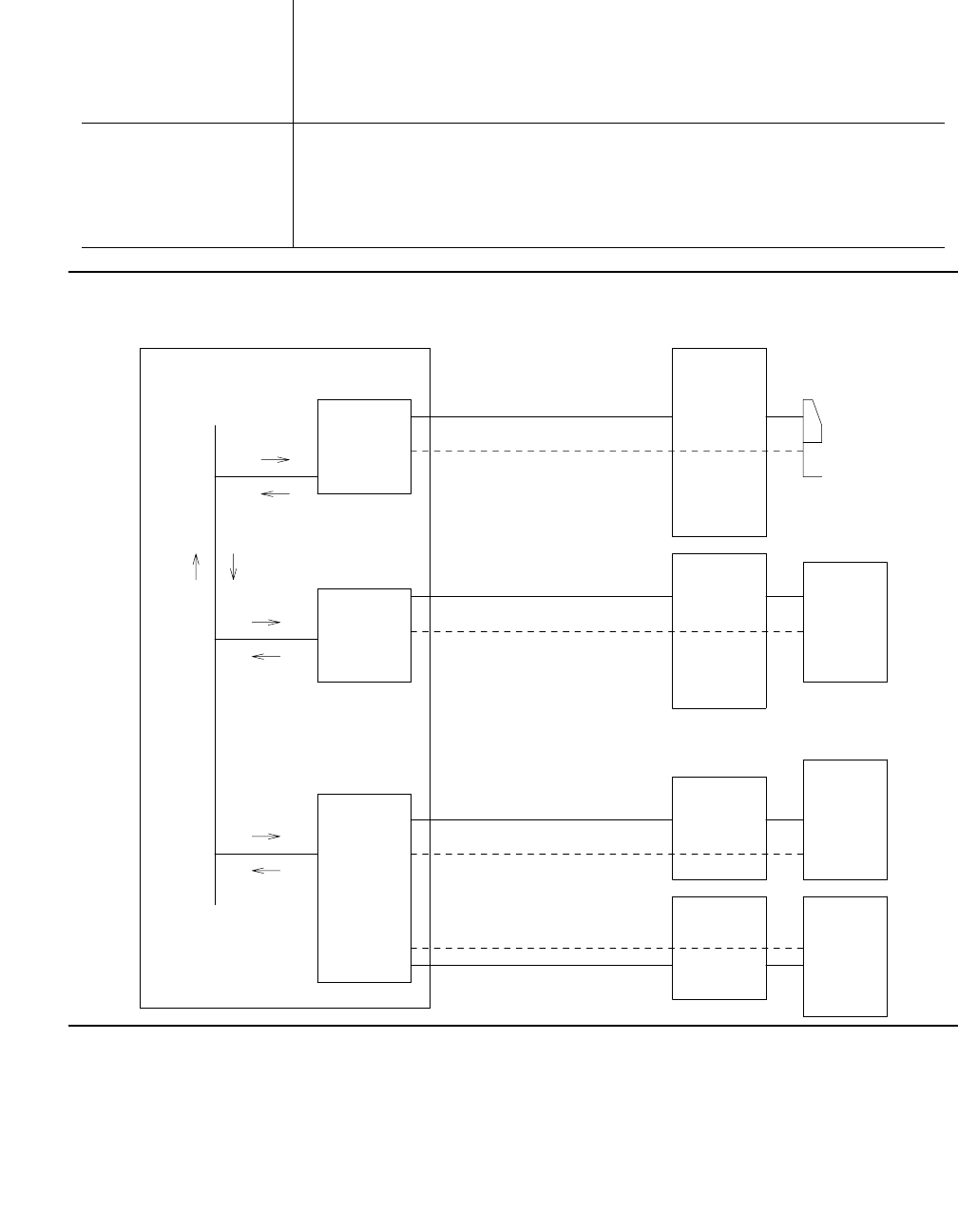
Communication Manager Maintenance-Object Repair Procedures
1754 Maintenance Procedures for Avaya Communication Manager 3.0, Media Gateways and Servers
Figure 100: Typical Data Module Configurations
Disconnected The port is administered but the associated digital link does not
respond. An administered port is put in a disconnected state after a
system reboot or circuit pack insertion. This state persists until a
link-reset-pass message is received from firmware on the circuit
pack.
In-Service When switch software receives a link-reset-pass message from the
port, the port is placed in service. If the link-reset-pass message is
missed, and an off-hook message is received while the port is in the
disconnected state, maintenance software will run an ID request test
and put the port into service upon receiving a correct response.
Signaling
(Secondary Information
Channel unused)
Terminal
G3 PBX
..................
.................
Digital
Line
Circuit
Pack
TDM
BUS
. . . . . . . . . . . . . . . . . . . . . . . . . . . . . . . . . . . . . . . . . . . . . .
MPDM
or DA
in
stand-alone
mode
Primary Information Channel
Physical Connection
Digital
Line
Circuit
Pack
(Secondary Information
Channel unused)
Signaling
Physical Connection
Primary Information Channel
Host
Computer
with
DCE
Interface
MTDM
. . . . . . . . . . . . . . . . . . . . . . . . . . . . . . . . . . . . . . . . . . . . . .
. . . . . . . . . . . . . . . . . . . . . . . . . . . . . .
Physical Connection
Secondary
MTDM
Primary
MTDM
Host
Computer
with
DCE
Interface
Host
Computer
with
DCE
Interface
Primary Information Channel
Physical Connection
Signaling
Digital
Line
Circuit
Pack
Secondary Information Channel
PDMODULE (Processor Data Module)
Issue 1 June 2005 1755
Error Log Entries and Test to Clear Values
Table 650: PDMODULE, TDMODULE Error Log Entries
Error
Type
Aux
Data
Associated Test Alarm
Level
On/Off
Board
Test to Clear Value
0 (a) 0 None
1
(b, n)
40987 None WRN OFF
1
(c, n)
1 –
20
None WRN OFF
15 (d) Any None
18 (e)0busyout port location WRN OFF release port
location
257 (f) 40971 None
513 0 Data Module audits (#17) WRN OFF test port
location sh r 6
769 (g, n) 40988 None WRN OFF
1281 Any Data Module audits (#17) WRN OFF test port
location sh r 4
1537 (h, n) 40968 None WRN OFF
1793 Information Channel and
Control Channel Looparound
(#13)
MIN ON test port
location l r 3
2049 NPE Crosstalk (#9) MIN ON test port
location l r 3
2304 (i) None
2305 (j) 32770 None
2305 (k) 40967 None
2561 (l) Any Data Module Internal
Looparound (#175)
WRN OFF test port
location l r 5
2817 (m) Link GPP Loop (#183)
Against Links
MAJ ON
3841 (n) None

Communication Manager Maintenance-Object Repair Procedures
1756 Maintenance Procedures for Avaya Communication Manager 3.0, Media Gateways and Servers
Notes:
a. Error Type 0 appears in the Error Log only if a Digital Line circuit pack that has ports
administered has been removed since the Error Log was last cleared. Make sure that the
circuit pack has been re-inserted.
b. Error Type 1, Aux Data 40987 indicates an off-board problem detected by the port circuit,
and may result in a noisy port or link. See note n for recommendations.
Note:
Note: Refer to the DEFINITY® Communications System Generic 1 and Generic 3i
Wiring, 555-204-111.
c. Error Type 1, Aux Data 1 - 20 is logged when at least 15 off-board problems have been
detected with the link to the data module. Each error detected increments an on-board
counter. The aux data gives the value of this counter divided by 15. The user could
experience a noisy port or link. See note “n” for recommendations.
Note:
Note: Refer to the DEFINITY® Communications System Generic 1 and Generic 3i
Wiring, 555-204-111.
d. Error Type 15 is an internal that occurs when an audit request fails.
e. Error Type 18 is logged when the port in question is demand busied out Make sure that the
port is released from busyout.
f. Error Type 257: problems with transmitting to the data module. This is usually an on-board
problem and can be ignored if no user complaints are received. Otherwise, check for faulty
wiring.
g. Error Type 769: EPF has been turned off due to the overcurrent condition at the data
module. See the recommendations in note n. This may also be caused by the PTC being in
the “tripped” position due to a short on the power line. You can correct this by removing the
short, unplugging the data module from the wall for about 30 seconds, and plugging it back
in.
Note:
Note: Refer to the DEFINITY® Communications System Generic 1 and Generic 3i
Wiring, 555-204-111.
h. Error Type 1537: an in-line maintenance error generated an off-board warning due to some
problem with the link to the data module. This can be ignored if no user complaints are
received. Otherwise, see Note n for recommendations.
Note:
Note: Refer to the DEFINITY® Communications System Generic 1 and Generic 3i
Wiring, 555-204-111.
i. Error Type 2304: indicates an internal error. No action is necessary.
j. Error Type 2305, Aux Data 32770: the data equipment went off-hook while the associated
link was being initialized (in a disconnected state). Use status data-module to
PDMODULE (Processor Data Module)
Issue 1 June 2005 1757
determine the state of the data module. The off-hook should have changed the service state
to in-service. No action is necessary.
k. Error Type 2305, Aux Data 40967: the link between the circuit pack and the data module
has been reset successfully. The link is normally reset when the circuit pack associated with
an administered port is first plugged in (assuming that the data module is already in place
and connected to the associated port), when a port is first administered (assuming the
associated circuit pack is plugged in and that the data module is connected to the
associated port), or when a data module is first connected to an administered port. No
system technician action is necessary.
l. Error Type 2561: the downlink buffer on the circuit pack has overflowed. No action is
necessary.
m. Error Type 2817: a DCP endpoint may have been disconnected.
n. Error Type 1, 769, 1537, 3841: make sure the data module is connected and operating
properly. Check for faulty wiring. If necessary, reduce the length of the cable between the
data module and the switch to 5000 ft. for 24-gauge wire or 4000 ft. for 24-gauge wire.
If the problem still exists, replace the circuit pack. Once the problem has been resolved, the
alarm will be retired in 60 minutes (90 min. for error 1537). (These error counters use the
leaky bucket mechanism.)
The DA module is not phantom-powered from the port. Thus when it is in linked mode, its
range is limited by the Italtel digital phone’s limit: 0.7 Km (2300 ft.) on 26-gauge wire or 1.8
Km (5900 ft.) on 22-gauge (0.6 mm) wire. If in stand-alone mode, it is limited by the
maximum length of loop allowed from the Digital Line Interface (DLI) component: up to 3.5
km (2 miles) on 22-gauge (0.6 mm) wire.
System Technician-Demanded Tests:
Descriptions and Error Codes
Investigate tests in the order presented below. Clearing Error Codes associated with the one
test may also clear errors generated from other tests in the sequence.
Order of Investigation Short Test
Sequence
Long Test
Sequence
D/ND1
Data Module Internal Loop-around test (#175)
G700: Aborts with Error Code 1412 on a G700 media gateway.
XND
Digital Port Board Network Processing Element Crosstalk test
(#9)
XND
1 of 2

Communication Manager Maintenance-Object Repair Procedures
1758 Maintenance Procedures for Avaya Communication Manager 3.0, Media Gateways and Servers
NPE Crosstalk Test (#9)
The NPE Crosstalk test verifies that this port’s NPE channel talks on the selected time slot and
never crosses over to time slots reserved for other connections. If the NPE is not working
correctly, one-way and noisy connections may be observed. If a secondary data module is
assigned, it is tested after the primary data module. If either test fails, both data modules are
taken out of service. This test usually run only during the long test sequence and takes about 20
to 30 seconds to complete.
Port Circuit Information Channel and Control Channel
Loop-Around (#13)
G700: Aborts with Error Code 1412 on a G700 Media
Gateway.
XND
Data Module Audits test (#17) X X ND
1. D = Destructive; ND = Nondestructive
Order of Investigation Short Test
Sequence
Long Test
Sequence
D/ND1
2 of 2
Table 651: Test #9 NPE Crosstalk Test
Error
Code
Test
Result
Description / Recommendation
1 ABRT During testing of the primary information channel, system resources may
not have been available.
1. Check the port status. Use display port location to determine
the station extension of the port. Use the status station
command to determine the service state of the port. If the service
state indicates that the port is in use, then the port is unavailable for
this test. You must wait until the port is idle.
2. If the port status is idle, then retry the command at one-minute
intervals a maximum of 5 times.
1 of 3

PDMODULE (Processor Data Module)
Issue 1 June 2005 1759
1000 ABRT System resources required to run this test are not available. The port
may be busy with a valid call.
1. Use display port location to determine the extension of the
data module port. Use status data-module to determine the
service state of the port. If the port is in use, wait until the port is idle
before testing.
2. If the port status is idle, then retry the command at 1-minute intervals
up to 5 times.
1001 ABRT System resources to run this test are not available.
1. Retry the command at 1-minute intervals up to 5 times.
1002 ABRT The system could not allocate time slots for the test. The system may be
under heavy traffic conditions or it may have time slots out-of-service due
to TDM-BUS errors.
1. If the system has no TDM-BUS errors and is not handling heavy
traffic, repeat test at 1-minute intervals up to 5 times.
1003 ABRT The system could not allocate a tone receiver for the test. The system
may be oversized for the number of tone detectors present or some tone
detectors may be out-of-service.
1. Resolve any TTR-LEV errors.
2. Resolve any TONE-PT errors.
3. If neither condition exists, retry the test at 1-minute intervals up to 5
times.
1004 ABRT The port may be busy with a valid call.
1. Use display port location to determine the extension of the
data module port. Use status data-module to determine the
service state of the port. If the port is in use, wait until the port is idle
before testing.
2. Retry the command at 1-minute intervals up to 5 times.
1020 ABRT Test disabled by background testing. Use status data-module to
determine when the data module is available for testing.
G700:
1412
ABRT This test does not execute on a G700 media gateway.
Table 651: Test #9 NPE Crosstalk Test (continued)
Error
Code
Test
Result
Description / Recommendation
2 of 3

Communication Manager Maintenance-Object Repair Procedures
1760 Maintenance Procedures for Avaya Communication Manager 3.0, Media Gateways and Servers
2000 ABRT Response to the test request was not received within the allowable time
period.
1. Retry the command at 1-minute intervals up to 5 times.
2020 ABRT The test did not run due to a previously existing error on the specific port
or a more general circuit pack error.
1. Examine Error Log for existing errors against this port or the circuit
pack and attempt to diagnose the previously existing error.
2100 ABRT Could not allocate the necessary system resources to run this test.
1. Retry the command at 1-minute intervals up to 5 times.
2500 ABRT Internal system error
1. Retry the command at 1-minute intervals up to 5 times.
1, 2 FAIL The NPE of the tested port was found to be transmitting in Error Log.
This will cause noisy and unreliable connections. Failure code 1 indicates
that the Crosstalk test failed on the primary channel. Failure code 2
indicates that the Crosstalk test failed on the secondary channel.
1. Replace the circuit pack.
PASS The port is correctly using its allocated time slots.
1. To be sure that this is not an intermittent problem, repeat this test up
to up to 10 times and verify that it continues to pass.
2. If complaints still exist, examine the data module, connections, and
wiring.
Table 651: Test #9 NPE Crosstalk Test (continued)
Error
Code
Test
Result
Description / Recommendation
3 of 3

PDMODULE (Processor Data Module)
Issue 1 June 2005 1761
Information and Control Channel Local Loop
Test (#13)
This is a set of four tests that check the operation of the information and control channels used
between Communication Manager and the Digital Line port circuit. This is an Internal Loop
around test only and does not check building wiring. See Test #175 for external loop around
tests to the data module.
1. Communication Manager first sends a message to the on-board microprocessor to loop
around both the information and control channels for the port. Then, the primary information
channel loop back test is run. The test is performed by sending a digital count from the
Tone-Clock circuit pack on the primary channel time slot and receiving the same digital
count with a General-Purpose Tone Detector. The digital count looks like transparent data to
the on-board microprocessor.
2. With the port still in loop-around mode, the S Channel Loop-around test is performed next.
This test consists of sending four different transparent patterns to the on-board
microprocessor, receiving them back, and comparing them.
3. The third test is a loop around test for the secondary information channel. It is performed
only if a secondary data module is assigned to the port.
4. The fourth test is a Conference test of the primary channel. This is the same test as Analog
Line Conference test (#6).
Only one result is reported for the three tests run. If any test fails or aborts, the sequence is
stopped.
Table 652: Information and Control Channel Local Loop Test
Error
Code
Test
Result
Description / Recommendation
ABRT Internal system error
1. Retry the command at 1-minute intervals up to 5 times.
1000 ABRT System resources required to run this test are not available. The port may
be busy with a valid call.
1. Use display port location to determine the data module
extension. Use status data module with the extension number to
determine the service state of the data module. If the service state
indicates that the data module is in use, then the port is unavailable
for certain tests. You must wait until the port is idle before retesting.
2. If the port status is idle, then retry the command at 1-minute intervals
up to 5 times.
1 of 3

Communication Manager Maintenance-Object Repair Procedures
1762 Maintenance Procedures for Avaya Communication Manager 3.0, Media Gateways and Servers
1001 ABRT System resources required to run this test are not available.
1. Retry the command at 1-minute intervals up to 5 times.
1002 ABRT The system could not allocate time slots for the test. The system may be
under heavy traffic conditions or it may have time slots out-of-service due
to TDM-BUS errors.
1. If the system has no TDM-BUS errors and is not handling heavy
traffic, repeat the test at 1-minute intervals up to 5 times.
1003 ABRT The system could not allocate a tone receiver for the test. The system
may be oversized for the number of tone detectors present or some tone
detectors may be out-of-service.
1. Resolve any TTR-LEV errors.
2. Resolve any TONE-PT errors.
3. If neither condition exists, retry the command at 1-minute intervals up
to 5 times.
1004 ABRT The port was seized by a valid call during the test. The test has been
aborted.
1. Use display port location to determine the data module
extension. Use status data module with the extension number to
determine the service state of the data module. If the data module is
in use, wait until the port is idle before retesting.
G700:
1412
ABRT This test does not execute on a G700 media gateway.
2000 ABRT Response to the test request was not received within the allowable time
period.
1. Retry the command at 1-minute intervals up to 5 times.
:2001 ABRT System resources required to run this test are not available.
1. Retry the test at one-minute intervals a maximum of 5 times.
2100 ABRT System resources required for this test are not available.
1. Retry the command at 1-minute intervals up to 5 times.
2500 ABRT Internal system error
1. Retry the command at 1-minute intervals up to 5 times.
Table 652: Information and Control Channel Local Loop Test (continued)
Error
Code
Test
Result
Description / Recommendation
2 of 3

PDMODULE (Processor Data Module)
Issue 1 June 2005 1763
Data Module Audits Test (#17)
This is a series of six tests that are classified as hardware audits. The processor sends
messages to the on-board microprocessor to perform the following tests:
●Switchhook Inquiry: This is an update of the processor’s software records based on the
on-hook/off-hook status of the data module.
●Bad Scan Inquiry: A message is sent uplink that contains a count generated by certain
events relating to the digital loop’s (link) conditions. This could be an indication of
communication problems between the processor and digital port board.
7 FAIL Conference test failed on the primary information channel. In some cases,
user may not notice disruption in service. In extreme cases, conferencing
feature may not work at all.
14 FAIL The primary information channel is not transmitting properly. User impact
may range from noticing nothing to not being able to use this port.
15 FAIL The control channel between the processor and Digital Line circuit pack is
not transmitting properly. This can cause a wide range of effects. The
user may notice nothing or the port may be totally unusable. This could
also disrupt other users.
1. Run circuit pack tests to check the Tone Generator and the Tone
Detector circuit packs using test board location short.
2. Resolve any problems that are detected on the Tone Generator
circuit pack or Tone Detector circuit pack.
3. If the Tone Generator and Tone Detector circuit packs are functioning
properly, and the test still fails, replace the Digital Line circuit pack.
16 FAIL The secondary information is not transmitting properly. This can cause a
wide range of effects. The user may notice nothing or the port may be
totally unusable.
1. To be sure that this is not an intermittent problem, repeat this test up
to up to 10 times to make sure it continues to pass.
2. If complaints still exist (poor data transmission), examine the data
module, connections, and wiring.
PASS Information and Control Channel Local Loop test passed. Every channel is
transmitting properly.
Table 652: Information and Control Channel Local Loop Test (continued)
Error
Code
Test
Result
Description / Recommendation
3 of 3

Communication Manager Maintenance-Object Repair Procedures
1764 Maintenance Procedures for Avaya Communication Manager 3.0, Media Gateways and Servers
●EPF inquiry: The status of the Electronic Power Feed is sent uplink. EPF is not used for
data modules.
●ID Request: A request is made to the data module for its status. The data module sends its
configuration information and health information back. This information is checked and a
pass/fail result is provided.
●Ringer Update: This updates the data module’s ringer state according to processor
records.
●Translation Update: This is a message normally used with digital stations to refresh the
default value that causes the station to send touch tones only in the primary information
channel. This test is not used with data modules.
Table 653: Test #17 Data Module Audits Test
Error
Code
Test
Result
Description / Recommendation
1 ABRT Switchhook audit timed out.
1. Verify the data module is connected to the PBX and repeat the test.
2. If the test aborts, replace the data module and repeat the test.
3. If the test continues to abort, replace the circuit pack and repeat the
test.
2 ABRT ID request fails, health bit is defective, or no response from on-board
microprocessor.
1. Verify that the correct data module type (PDM versus TDM) is
administered.
2. If the test aborts, replace the data module and repeat the test.
3. If the test aborts, replace the circuit pack and repeat the test.
3 ABRT No response from EPF audit.
4 ABRT Internal system error
1. Resolve any outstanding circuit pack maintenance problems.
2. Retry the command at 1-minute intervals up to 5 times.
1 of 2

PDMODULE (Processor Data Module)
Issue 1 June 2005 1765
5 ABRT Ringer update aborted (data module not in the in-service state)
1. Verify that the data module is powered (power LED on).
2. Make sure data module is connected to the building wiring, check for
faulty wiring, check for faulty data module.
3. Retry the command at 1-minute intervals up to 5 times.
4. Replace the Data Module and repeat the test.
5. If the test continues to abort, replace the Digital Line circuit pack and
repeat the test.
6 ABRT Data module translation update aborted.
1. Verify the data module is connected to the PBX.
2. Retry the command at 1-minute intervals up to 5 times.
1000 ABRT System resources required to run this test are not available.
1. Retry the command at 1-minute intervals up to 5 times.
1392 ABRT This port is currently a TTI port and the test will not execute on it.
1. Verify that the port is a TTI port using display port, where the
display shows that the port is a TTI port, or list config, where
the display shows a t for the port.
2. If list config or display port indicate that the port is not a TTI
port, escalate the problem. If both commands indicate that the port is
a TTI port, the abort is correct, and no action is necessary.
2000 ABRT Response to the test was not received within the allowable time period.
1. Retry the command at 1-minute intervals up to 5 times.
FAIL Internal system error
1. Retry the command at 1-minute intervals up to 5 times.
PASS Data Module audits passed. This digital port circuit pack is functioning
properly.
1. If complaints still exist, investigate by using other port tests and by
examining the data module options, wiring, and connections.
Table 653: Test #17 Data Module Audits Test (continued)
Error
Code
Test
Result
Description / Recommendation
2 of 2
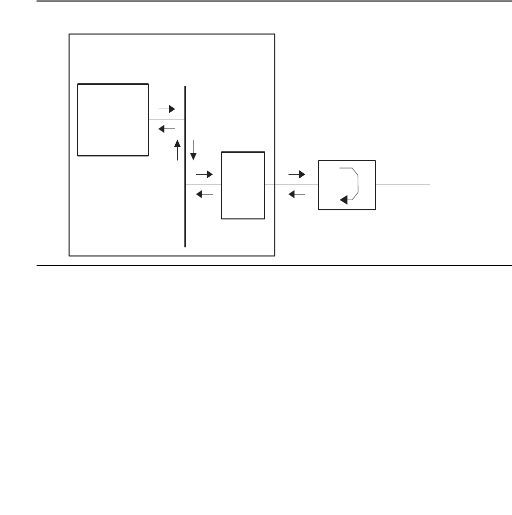
Communication Manager Maintenance-Object Repair Procedures
1766 Maintenance Procedures for Avaya Communication Manager 3.0, Media Gateways and Servers
Data Module Internal Loop-Around Test (#175)
This test verifies that a data message can be sent from the PBX, through the building wiring,
through an internal loop-around path in the data module, and back to the PBX. This path is
illustrated below.
For this test to run, the Remote Loop-Around Test field on the Data Module administration
screen must be set to y, indicating that the data module endpoint supports the test.
Note:
Note: G700: This test aborts with Error Code 1412 on a G700 media gateway.
Figure 101: Internal Loop-Around Test
A signaling message is sent through the digital port circuit pack to the data module, requesting it
to enter loop-around mode. A test pattern is then sent from the TN771D Maintenance/Test
circuit pack, over the path illustrated above, and back to the TN771D where it is checked for
consistency.
The test aborts if any of the following local PBX resources are not available: a digital port on the
TN771D (there are two such digital ports, but only one may be used at a time), two TDM time
slots and an idle digital port connected to the data module.
TN771
Maintenance/
Test circuit
pack
TDM
bus
Data module
(MPDM, DA, MTDM)
Data
equipment
Digital
line
circuit
pack
pdmodul2 LJK 072501
Switch

PDMODULE (Processor Data Module)
Issue 1 June 2005 1767
Table 654: Test #175 Data Module Internal Loop-Around Test
Error
Code
Test
Result
Description / Recommendation
S8700 | 8710 / S8500
1000 ABRT System resources required to run this test are not available. The port may
be in use on a valid call. Use status data-module to determine when
the port is available for testing.
1. Retry the command at 1-minute intervals up to 5 times.
1005 ABRT Loop around testing is not enabled on the data module administration
screen.
1. Set Loop-Around Test field to y on the data module administration
screen.
1042 ABRT The port under test is a TTI port and thus has only default translations
and no assigned extension. The test requires an extension assigned to
the port being tested.
1. If there is a need to execute the test on this particular port, then you
must fully administer the port so that is has an assigned extension.
1180 ABRT A Maintenance/Test circuit pack digital port is not available to carry out
the test.
1. See if the Maintenance/Test digital ports are present. Use list
config board location and look for ports 02 and 03.
2. If the digital ports (02 and 03) on the M/T-BD are absent, see M/
T-DIG (Maintenance/Test Digital Port) on page 1709.
3. If the digital ports are present, try the command again at 1-minute
intervals up to 5 times.
1181 ABRT No time-slots available to connect digital ports for the test.
1. Try the command again at 1-minute intervals up to 5 times.
1182 ABRT Internal system error. Failed to connect the digital ports with time-slots.
1. Retry the command at 1-minute intervals up to 5 times.
1 of 6

Communication Manager Maintenance-Object Repair Procedures
1768 Maintenance Procedures for Avaya Communication Manager 3.0, Media Gateways and Servers
1340 ABRT No Maintenance/Test digital port is currently available to perform this test.
1. Use list config to determine whether any Maintenance/Test
digital ports (ports 02 and 03 on the Maintenance/Test circuit pack)
are present in the system. Because at least one Maintenance/Test
circuit pack must always be present in the PN of S8700
configurations, there should be at least two such ports present. If the
ports are present, proceed to step 2. Otherwise, determine why no
ports appear in the list config display. See M/T-DIG
(Maintenance/Test Digital Port) on page 1709 and M/T-BD
(Maintenance/Test Circuit Pack) on page 1705.
2. Look for M/T-DIG errors in the Error Log. If present, see M/T-DIG
(Maintenance/Test Digital Port) on page 1709.
3. If the ports are present and no errors are logged against them, retry
the command at 1-minute intervals up to 5 times.
4. If the test continues to abort, replace the Maintenance/Test circuit
pack.
1392 ABRT This port is currently a TTI port and the test will not execute on it.
1. Verify that the port is a TTI port using display port where the
display shows that the port is a TTI port, or list config, where the
display shows a t for the port.
2. If list config or display port indicate that the port is not a TTI
port, escalate the problem. If both commands indicate that the port is
a TTI port, the abort is correct for the test, and no action is necessary.
2005 ABRT The handshake between the Maintenance/Test digital port and the Data
Module failed.
1. Look for M/T-DIG errors in the Error Log. If present, see M/T-DIG
(Maintenance/Test Digital Port) on page 1709.
2. If test still aborts on retry, check physical connection of data module
under test. Make sure the switches are on NORM, OFF (between
REM_LP and LOC_LP), 9600, and ASYN.
3. If the test still aborts, replace the Data Module.
Table 654: Test #175 Data Module Internal Loop-Around Test (continued)
Error
Code
Test
Result
Description / Recommendation
2 of 6

PDMODULE (Processor Data Module)
Issue 1 June 2005 1769
2312 ABRT The loop-around test did not complete, failed to receive loop-back data.
1. Check for M/T-DIG error in the Error Log. If present, see M/T-DIG
(Maintenance/Test Digital Port) on page 1709.
2. Retry the test, if still aborts, replace the Data Module.
3. If the test aborts again, replace the Digital Line circuit pack.
2313 ABRT The Maintenance/Test digital port allocated for this test did not respond to
downlinked message.
1. Look for M/T-DIG errors in the Error Log. If present, see M/T-DIG
(Maintenance/Test Digital Port) on page 1709.
2. Retry the command at 1-minute intervals up to 5 times.
3. If the test continues to abort, replace the MTB.
2314 ABRT Data Module did not respond to downlinked message.
1. Check the wiring of the Data Module under test.
2. Verify that the Data Module is powered (power LED on).
3. Make sure the switches are on NORM, OFF (between REM_LP and
LOC_LP), 9600, and ASYN.
4. If the test still aborts, replace the Date Module.
5. If the same abort code appears, replace the Digital Line circuit pack
that is connected to the Data Module.
2500 ABRT Internal system error
1. Retry the command at 1-minute intervals up to 5 times.
FAIL Data received from remote loop back does not match data sent.
1. Check for faulty wiring.
2. Replace the data module and repeat the test.
3. If the test fails, replace the Digital Line circuit pack associated with
the data module and repeat the test.
Table 654: Test #175 Data Module Internal Loop-Around Test (continued)
Error
Code
Test
Result
Description / Recommendation
3 of 6

Communication Manager Maintenance-Object Repair Procedures
1770 Maintenance Procedures for Avaya Communication Manager 3.0, Media Gateways and Servers
1000 ABRT Could not get translation information for port.
1. Verify that port circuit is administered.
2. Wait one minute and attempt the test again.
3. If the test continues to abort and the port is not in use, escalate the
problem.
1005 ABRT This test is not applicable to the given hardware configuration.
1. This abort message can be ignored.
1020 ABRT Internal Software Error.
1. Retry the command at one-minute intervals a maximum of 5 times.
1030 ABRT Internal software group identifier for data module not valid.
1. Verify that port circuit is administered correctly.
2. If administration data correct, escalate the problem.
1031 ABRT Extension number not valid.
1032 ABRT Extension number not correct length.
1. Verify that the data module extension is administered correctly.
2. If the administration data is correct, escalate the problem.
1071 ABRT No auxiliary port on Netcon circuit pack available to test with.
1. Check that the Netcon data channels are administered (the list
data-modules command should show at least one Netcon-type
data module).
2. Test the Network Control (Netcon) circuit pack using the test
data-module command for the Netcon circuit pack.
3. If administration data is correct, escalate the problem.
Table 654: Test #175 Data Module Internal Loop-Around Test (continued)
Error
Code
Test
Result
Description / Recommendation
4 of 6

PDMODULE (Processor Data Module)
Issue 1 June 2005 1771
2000 ABRT Data module disconnected.
1. Verify that the data module is powered (power LED on).
2. Make sure data module is connected to the building wiring. Check for
faulty wiring and faulty data module.
3. Retry the command at one-minute intervals a maximum of 5 times.
4. Replace the Data Module and repeat the test.
5. If the test continues to abort, replace the Digital Line circuit pack and
repeat the test.
2500 ABRT Internal System Error.
1. Retry the command at 1-minute intervals a maximum of 5 times.
3004 ABRT ABRT
1. This error could be caused by the switch setting of the PDM. Verify
that the switch on the PDM is set to the "remote loop" position. When
the remote loop around test is completed, return the switch to the "off"
position.
2. This error could be caused by the Network Control Data Channel.
Look for DATA-CHL errors in the Hardware Error Log.
3. This error could also result if no data equipment is connected to the
data module. Verify that (a) the data equipment is properly connected
to the data module, (b) that power is available to the data equipment,
and that (c) the data equipment is powered on.
4. This error could also occur if the baud rate of the data module is set
to 19.2 Kbps since the Network Control circuit pack used by this test
does not support baud rates greater than 9600 bps. Verify that the
baud rate of the data module is set to 9600 bps or less.
1040 FAIL Data received from remote loop back does not match data sent.
1. Check for faulty wiring.
2. Replace the data module and repeat the test.
3. If the test fails, replace the Digital Line circuit pack associated with
the data module and repeat the test.
Table 654: Test #175 Data Module Internal Loop-Around Test (continued)
Error
Code
Test
Result
Description / Recommendation
5 of 6

Communication Manager Maintenance-Object Repair Procedures
1772 Maintenance Procedures for Avaya Communication Manager 3.0, Media Gateways and Servers
1070 FAIL Internal software response.
1. Wait one minute and attempt the test again.
2. If the same error persists after five attempts in one-minute intervals,
escalate the problem.
1072 FAIL Poor response from auxiliary channel.
1. Test the Network Control (Netcon) circuit pack using the test
data-module command.
2. If the test fails, replace the Digital Line circuit pack.
1073 FAIL Internal System Error.
1. Wait one minute and attempt the test again.
2. If the same error persists after five attempts in one-minute intervals,
escalate the problem.
1074 FAIL Internal System Error
1. Make sure that the data equipment connected to the data module is
powered.
2. For an (M)PDM, verify that the Data Terminal “Ready” LED is ON, or
for an (M)TDM, verify that the Data Set Ready LED is ON. If it is not
on, check the cable from the data equipment to the data module.
1075 FAIL Unknown message received during test.
1. Attempt the test again.
2. If the same error occurs, test the Network Control Data Channel
using the test data-module command and a known working data
module.
3. Replace the Digital Line circuit pack and repeat the test.
4. If the test continues to fail, escalate the problem.
2040 FAIL Internal System Error
1. Repeat the test.
2095 FAIL Internal System Error
1. Repeat the test.
PASS Data Module Loop-around test passed.
Table 654: Test #175 Data Module Internal Loop-Around Test (continued)
Error
Code
Test
Result
Description / Recommendation
6 of 6

PE-BCHL (PRI Endpoint Port)
Issue 1 June 2005 1773
PE-BCHL (PRI Endpoint Port)
S8700 | 8710 / S8500
A PRI endpoint provides ISDN-PRI (Primary Rate Interface) connections application equipment
or terminal adapters that terminate ISDN PRI. The equipment or terminal adapters are
connected to the switch via the TN464C/D UDS1 interface circuit pack. This MO monitors the
PRI endpoint’s port hardware on the UDS1 circuit pack by:
●Logging hardware errors
●Running tests for port initialization
●Running periodic and scheduled maintenance
●Executing demand tests
Wideband Switching
Wideband switching supports end-to-end connectivity between customer endpoints at data
rates from 128 to 1536 kbps over T1 facilities and to 1984 kbps over E1 facilities. Switching
capabilities support wideband calls comprised of multiple DS0s that are switched end-to-end as
a single entity.
Wideband switching is designed for ISDN application equipment such as ISDN video codecs,
but can also interface to non-ISDN application equipment by using PRI terminal adapters. In the
same sense that a data module acts as a DCP or BRI terminal adapter between endpoint data,
such as V.35 and dialing interfaces such as RS-366 and a DCP interface, a PRI terminal
adapter acts as a wideband terminal adapter between endpoint data and dialing interfaces and
a line-side ISDN-PRI interface. Wideband switching introduces PRI endpoints on line-side
interfaces.
A PRI endpoint has a unique extension number and consists of one or more contiguous B
channels on a line-side T1 or E1 ISDN-PRI facility. Endpoints initiate and receive calls via ISDN
SETUP messages indicating the data rate and specific B channels to be used, and
communicate all other call status information via standard ISDN messages. Any ISDN signaling
set such as Avaya, CCITT, or ECMA may be used for a line-side ISDN-PRI facility.
MO Name in
Alarm Log
Alarm
Level
Initial SAT Command to Run Full Name of MO
PE-BCHL1
1. For additional repair information, see also UDS1-BD and Troubleshooting ISDN-PRI endpoints
(wideband) in Maintenance Procedures (03-300192).
MIN test port location lPRI Endpoint Port
PE-BCHL WRN test port location sh PRI Endpoint Port

Communication Manager Maintenance-Object Repair Procedures
1774 Maintenance Procedures for Avaya Communication Manager 3.0, Media Gateways and Servers
Multiple PRI endpoints on one line-side facility are separate and distinct within the facility.
Non-overlapping contiguous sets of B channels are associated with each PRI endpoint, and the
endpoint equipment is expected to initiate calls within these boundaries. The endpoint
application equipment must:
●Use standard ISDN-PRI signaling
●Adhere to the administered PRI endpoint boundaries when initiating calls
●Handle incoming calls appropriately, based on the originating PRI endpoint
Signaling and B-Channel States
PRI ports use a separate channel called the D channel for call-control and signaling messages.
This is called out-of-band signaling. The D channel associated with the set of B channels is an
ISDN-PRI signaling link’s port (ISDN-LNK). The signaling protocol used on the ISDN-PRI
signaling-link port’s D channel is defined by one of the four selectable ISDN-PRI Specifications:
Avaya, CCITT, ECMA, and ANSI.
The ISDN-PRI Specification defines the possible service states for a B channel. The service
state is negotiated with the far-end terminal adapter, changes over time, and can have far- and
near-end components. The service state is initialized to Out-Of-Service/Far-End, and an
attempt is made to negotiate it to In-Service. Use status pri-endpoint extension to
display the service state of a particular PRI endpoint port’s B channel.
If a call is present, the Specification defines the permissible call states as well. There are tests in
the short and long test sequences for the PRI endpoint port designed to audit these states and
ensure agreement between both ends of the PRI wideband connection.
Alarming Based on Service States
A PRI endpoint port’s B channel logs a warning alarm when it is placed in a Maintenance/
Far-End or Out-Of-Service/Far-End state. While in such a state, the port is unusable for calls to
the terminal adapter. However, the user can still use the other remaining ports in the PRI
endpoint to make calls to and from the terminal adapter. When a warning alarm is raised, use
status pri-endpoint extension to determine the exact state of the port. Other alarms
can be diagnosed by using the short and long test sequences. Note that a PRI endpoint port’s B
channel can be placed in a far-end service state by direct action by the far-end terminal adapter
or by inaction of the far-end terminal adapter. For example, if it does not respond to a Remote
Layer 3 Query (see Test #260 for ISDN-LNK) the associated PRI endpoint port’s B channels will
be placed in the Maintenance/Far-End service state.
A PRI endpoint port is a port on a UDS1 interface circuit pack and thus depends on the health of
the circuit pack for proper operation (see the following figure). A problem on the associated
ISDN-LNK’s (ISDN-PRI signaling-link port’s) D channel can also affect the PRI endpoint. In turn,
the ISDN-LNK depends on the SYS-LINK (system link) to the packet interface. Keep this
hierarchy of dependencies in mind when diagnosing problems.

PE-BCHL (PRI Endpoint Port)
Issue 1 June 2005 1775
Figure 102: PRI Endpoint Port Interactions
PRI Endpoint Port Service States
The status pri-endpoint extension command displays the following possible service
states for PRI endpoint ports. The table that follows gives recommended procedures for each
state. The figure following that shows typical progressions from one service state to another.
Refer also to Troubleshooting ISDN-PRI endpoints (wideband) in Maintenance Procedures
(03-300192) for a layered approach to addressing PRI endpoint problems.
●In-Service (INS)
The B channel is in its normal operating state.
●Out-of-Service/Far-End (OOS/FE)
A B channel is initialized to this state when first administered. The switch then sends
messages to the far-end terminal adapter to negotiate the B channel into service. If the
far-end terminal adapter does not respond to the messages within a certain time period, the
port remains out of service, and maintenance will periodically resend the messages. The
port is unusable for incoming and outgoing calls, although other ports in the PRI endpoint
can still be used.
●Out-of-Service/Near-End (OOS/NE)
This is the state of the port when a hardware failure exists on the signaling link, the NPE
Crosstalk test fails, or when the port is busied out by command. In this state, the port is
unusable for calls coming into the switch or going out to the terminal adapter, although other
MSSNET
Circuit
Pack
(UN332)
Packet
Bus
TDM
Bus
PKTINT
Circuit
Pack
(TN1655)
Processor
(UN331)
UDS1
Interface
Circuit
Pack
(TN464C)
Terminal
Adapter
.
.
.
.
.
.
.
.
.
.
.
.
.
.
.
.
.
.
.
.
.
.
.
.
.
.
.
.
Signaling
(Port 24)
ISDN-LNK
PE-BCHL
PE-BCHL
Data
Data
(Port 1)
(Port 23)

Communication Manager Maintenance-Object Repair Procedures
1776 Maintenance Procedures for Avaya Communication Manager 3.0, Media Gateways and Servers
ports in the PRI endpoint can still be used for incoming and outgoing calls. No messages
are sent to the far-end terminal adapter until the signaling link comes back into service or
the port is released by command.
●Maintenance/Far-End (MTC/FE)
This state is reached when the far-end terminal adapter does not respond to messages sent
over the signaling link for a particular port within a certain amount of time. This state is
different from OOS/FE since the signaling link must have initially been up and the B
channels in service. The switch will periodically send messages to the far-end terminal
adapter to try to negotiate the port (B channel) into service. The port is unusable for
outgoing calls to the terminal adapter but will service incoming call requests from the far
end. Other ports of the PRI endpoint can still to place outgoing calls to the terminal adapter.
Transitions into MTC/FE do not drop stable calls. If the service state changes from
in-service to MTC/FE, stable calls are unaffected.
●Maintenance/Near-End (MTC/NE)
Use busyout, test port l or test pri-endpoint l to busy out the signaling link
(SYS-LINK). Transitions into MTC/NE do not drop stable calls. The busyout link
lnk-no command does not drop stable wideband calls. In this state, the B channel is not
usable for new incoming calls to the switch or new outgoing calls to the terminal adapter.
●Pending States (PEND)
If the near end is expecting a timed response from the far end for a request to change the
service state of a port, a pending state is in effect. For example, if the port is out-of-service/
far-end and an in-service message was sent to the far end, then the service state of the port
is OOS/FE-PEND/INS meaning out-of-service/far-end, pending/in-service. The service
state will reflect this pending state until the far end responds or the timer expires.
Table 655: PRI Endpoint Port Service States
Service
State
Alarm Possible Cause Possible Solution
OOS/NE WRN Port has been busied out by
command.
Enter release pri-endpoint
extension.
MIN NPE Crosstalk test (#6) failed. Replace UDS1 circuit pack.
UDS1 circuit pack lost its signal. Is the UDS1 circuit pack removed? Is
the UDS1 cable disconnected? Is
the far-end terminal restarting or
experiencing problems? Check
circuit pack using UDS1-BD
procedure.
1 of 2

PE-BCHL (PRI Endpoint Port)
Issue 1 June 2005 1777
OOS/FE WRN Far-end problems or
incompatibility
Check administration and status of
the corresponding port on the
terminal adapter.
WRN The far-end port is busied out. Check the status of the far-end
terminal adapter.
OOS/FE
PINS
Service message was sent and
the switch is waiting up to 2
minutes for a reply from the
far-end terminal adapter.
Wait 2 minutes, and check service
state after the PINS state has
cleared.
MTC/NE System link demand busied out Check link status. Release with
release link link#.
MTC/FE WRN Signaling channel has been
down for over 90 sec.
Consult ISDN-SGRP, ISDN-LNK
and/or SYS-LINK. Far-end terminal
adapter may currently be restarting.
WRN Repeated failure of far end to
respond to messages.
Maintenance software will
periodically try to resend messages.
You can speed the process with
test port location (Test #256).
WRN The far-end port is being tested. Check status of the far-end terminal
adapter.
MTC/FE
PINS
Service message was sent, and
the switch is waiting up to 2
minutes for a reply from the
far-end terminal adapter.
Wait 2 minutes, and check service
state after the PINS state has
cleared.
INS Normal operating state. ISDN
wideband calls are completing.
Table 655: PRI Endpoint Port Service States (continued)
Service
State
Alarm Possible Cause Possible Solution
2 of 2
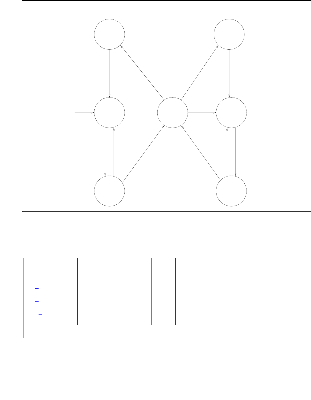
Communication Manager Maintenance-Object Repair Procedures
1778 Maintenance Procedures for Avaya Communication Manager 3.0, Media Gateways and Servers
Figure 103: Common Progressions in PRI Endpoint Service States
Error Log Entries and Test to Clear Values
CRAFT BUSYOUT OF
SIGNALING LINK
"BUSYOUT LINK LINK-NO",
OR TRANSIENT STATE FOR
CRAFT-DEMANDED LONG
TEST OF THE PORT.
CRAFT RELEASE
OF SIGNALING LINK
IF D-CHANNEL
CONTROLLING THE
B-CHANNEL IS UP,
SEND A MESSAGE
REQUESTING
TRANSITION
TO IN-SERVICE
D-CHANNEL HAS BEEN
DOWN FOR AT LEAST
90 SECONDS.
FAILED TO
RECEIVE REPLY
FROM FAR END.
MTCE WILL
PERIODICALLY
TRY TO RESEND
THE MESSAGE
RECEIVED
ACKNOWLEDGEMENT
FROM THE FAR END
RECEIVED
ACKNOWLEDGEMENT
FROM THE FAR END
FAILED TO
RECEIVE REPLY
FROM FAR END.
MTCE WILL
PERIODICALLY
TRY TO RESEND
THE MESSAGE
ADMINISTER
B-CHANNEL AS
MEMBER OF A
PRI ENDPOINT
OUT-OF-
SERVICE
NEAR END
OUT-OF-
SERVICE
FAR END
OUT-OF-
SERVICE
FAR END
PENDING
IN-SERVICE
IN-SERVICE
MAINTENANCE
NEAR END
MAINTENANCE
FAR END
MAINTENANCE
FAR END
PENDING
IN-SERVICE
CRAFT RELEASE OF
A B-CHANNEL OR
NEAR-END LINK
PROBLEM (PI-LINK OR
SYS-LINK) CLEARS UP
IF D-CHANNEL
CONTROLLING THE
B-CHANNEL IS UP,
SEND A MESSAGE
REQUESTING
TRANSITION
TO IN-SERVICE
CRAFT BUSYOUT OF B-CHANNEL
BUSYOUT PORT/PRI-ENDPOINT,
LINK PROBLEM AT NEAR END
(PI-LINK OR SYS-LINK),
DS1 BOARD NOT INSERTED,
OR DS1 BOARD FAILURE.
Table 656: PRI endpoint port Error Log Entries
Error
Type
Aux
Data
Associated Test Alarm
Level
On/Off
Board
Test to Clear Value
0 (a)0Any AnyAnytest port location sh r 1
1 (b)AnyNone test port location sh r 1
15 (c) Any Audit and Update test
(#36)
1 of 2
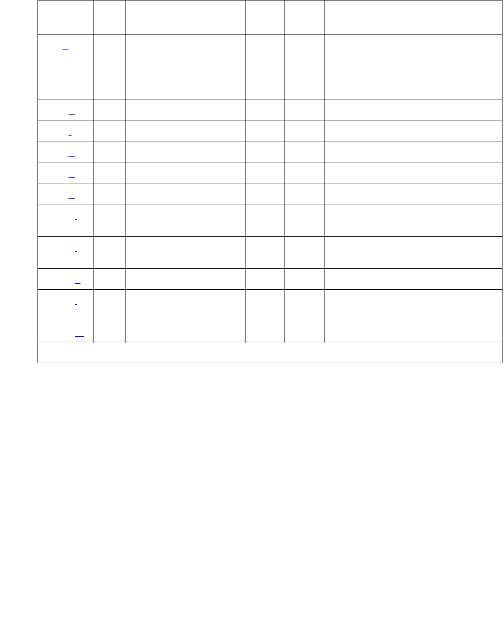
PE-BCHL (PRI Endpoint Port)
Issue 1 June 2005 1779
Notes:
a. Error Type 0: run the short test sequence first. If every test passes, run the long test
sequence. Refer to each test’s description and follow its procedures.
b. Error Type 1: disagreement between this switch and the terminal adapter at the other end
of the connection with regard to the ISDN call state of the PRI endpoint port. This switch will
automatically try to recover by clearing the call (the call will be torn down). Use status
pri-endpoint extension to determine the state of the port.
When running the short test sequence, pay close attention to the results of the Call State
Audit test (#257).
c. Error Type 15: software audit error that does not indicate any hardware malfunction. Run
the short test sequence, and investigate associated errors.
18 (d)0busyout
pri-endpoint
extension
busyout port
location
release pri-endpoint
extension
release port location
129 (e)None WRNOFFtest port location sh r 1
130 (f)None WRNONtest port location sh
257 (g)AnyNone test port location sh r 1
513 (h) Any None WRN OFF test port location sh r 1
769 (g)AnyNone test port location sh r 1
1281 (i) Any Conference Circuit
test (#7)
MIN ON test port location l r 4
1537 (j) Any NPE Crosstalk test
(#6)
MIN ON test port location l r 3
1793 (k)AnyNone test port location sh r 1
3073 (l) Any Service State audit
(#256) test port location sh r 2
3585 (m) Any None None
Table 656: PRI endpoint port Error Log Entries (continued)
Error
Type
Aux
Data
Associated Test Alarm
Level
On/Off
Board
Test to Clear Value
2 of 2

Communication Manager Maintenance-Object Repair Procedures
1780 Maintenance Procedures for Avaya Communication Manager 3.0, Media Gateways and Servers
d. Error Type 18: the PRI endpoint port has been busied out by busyout pri-endpoint
extension or busyout port location. No wideband calls can be made to this port,
although wideband calls can still be made to other ports within this PRI endpoint if they are
in service.
e. Error Type 129: the far-end terminal adapter changed its ISDN service state to
out-of-service or maintenance. This may be a temporary condition due to testing of this port
by the far-end terminal adapter or a hardware problem with the port. Outgoing calls to the
terminal adapter will not be allowed over the port, although calls can still be made to other
ports that are in service within the same PRI endpoint. To investigate the status of the port,
enter status pri-endpoint extension.
f. Error Type 130: the circuit pack has been removed or has been insane for more than 11
minutes. To clear the error, reinsert or replace the circuit pack.
g. Error Types 257, 769: disagreement between this switch and the terminal adapter at the
other end of the connection with regard to the ISDN service state of the PRI endpoint port.
The switch will automatically try to recover by performing a service state audit. Use status
pri-endpoint extension to determine the state of the port.
When running the short test sequence, pay close attention to the results of the Service State
Audit test (#256).
h. Error Type 513: This port is not recognized by the far-end terminal adapter. Investigate the
PRI endpoint administration for both the switch and the terminal adapter, and make sure
they agree.
i. Error Type 1281: The Conference Circuit test (#7) failed on this port. See Test #7 for repair
procedures.
j. Error Type 1537: The NPE Crosstalk test (#6) failed on this port. See Test #6 for repair
procedures.
k. Error Type 1793: failure of the UDS1 Interface circuit pack. The results of the Signaling Link
State Check test (#255 in the short sequence) are important.
l. Error Type 3073: Two Service State audit attempts have failed (see Test #256). The port
will not be usable for any outgoing calls to the terminal adapter until the test passes and the
port state is changed to in-service. Incoming calls from the terminal adapter will be accepted
over this port, and other ports in the PRI endpoint can still be used for both incoming and
outgoing calls to and from the terminal adapter.
m. Error Type 3585: the switch received an ISDN RESTART message for an ISDN port that is
not idle. Because calls are not typically cleared with the RESTART message, this error type
may be associated with a dropped call report from a user.
The following Aux Data values for Error Type 3585 represent the port’s ISDN call state at
the time the unexpected RESTART request was received from the terminal adapter. This
information can be useful if dropped calls are being reported by users of the PRI endpoint.
Aux Data values that do not appear below can be ignored.

PE-BCHL (PRI Endpoint Port)
Issue 1 June 2005 1781
System Technician-Demanded Tests:
Descriptions and Error Codes
Investigate tests in the order presented. By clearing Error Codes associated with the NPE
Crosstalk test (#6), you may also clear errors generated from other tests in the sequence.
Table 657: PE-BCHL - Error 3585 Aux Data Values
Aux
Data
Meaning
10 A call in a stable, talking state (the active state) was cleared
unexpectedly by the far-end terminal adapter with an ISDN RESTART
message.
4
7
8
260
263
A call that has not reached the active state, but has at least reached a
ringing state, was cleared unexpectedly by the far-end terminal adapter
with an ISDN RESTART message.
1
3
6
265
A call that has not yet reached a ringing state was cleared unexpectedly
by the far-end terminal adapter with an ISDN RESTART message.
11
12
19
267
268
531
A call that was already in the process of clearing has been cleared by the
far-end terminal adapter with an ISDN RESTART message. If this
condition occurs frequently, it may mean that the far-end terminal adapter
is attempting to clear ports that it thinks are in a “hung” state. The
RESTART message puts the port in an idle condition.
Order of Investigation Short Test
Sequence
Long Test
Sequence
D/ND1
1. D = Destructive; ND = Nondestructive
NPE Crosstalk test (#6) X ND
Conference Circuit test (#7) X ND
Audit and Update test (#36) X X ND
Signaling Link State Check test (#255) X X ND
Service State Audit test (#256) X X ND
Call State Audit test (#257) X X ND

Communication Manager Maintenance-Object Repair Procedures
1782 Maintenance Procedures for Avaya Communication Manager 3.0, Media Gateways and Servers
NPE Crosstalk Test (#6)
The NPE Crosstalk test verifies that this port’s NPE channel talks on the selected time slot and
never crosses over to time slots reserved for other connections. If the NPE is not working
correctly, one-way and noisy connections may be observed. This test is usually part of a port’s
long test sequence and takes about 20 to 30 seconds to complete.
Table 658: Test #6 NPE Crosstalk Test
Error
Code
Test
Result
Description / Recommendation
ABRT Could not allocate the necessary system resources to run this test.
1. Retry the command at 1-minute intervals up to 5 times.
1000 ABRT System resources required to run this test are not available. The port may
be in use on a valid call. Use status pri-endpoint extension to
determine when the port is available for testing.
1. Retry the command at 1-minute intervals up to 5 times.
1001 ABRT Could not allocate the necessary system resources to run this test.
1. Retry the command at 1-minute intervals up to 5 times.
1002 ABRT The system could not allocate time slots for the test. The system may be
under heavy traffic conditions or it may have time slots out-of-service due
to TDM-Bus errors. Use the status health command to determine
whether the system is experiencing heavy traffic. Investigate and resolve
any errors against TDM-BUS.
1. If the system has no TDM-Bus errors and is not handling heavy traffic,
repeat test at 1-minute intervals up to 5 times.
1003 ABRT The system could not allocate a tone receiver for the test. The system may
be oversized for the number of tone detectors present or some tone
detectors may be out-of-service. The list measurements
tone-receiver command will display information about the system’s
tone receiver.
1. Resolve any errors against TTR-LEV.
2. Resolve any errors against TONE-PT.
3. If neither of the above exists, retry the test at 1-minute intervals up to 5
times.
1 of 2

PE-BCHL (PRI Endpoint Port)
Issue 1 June 2005 1783
1004 ABRT The port has been seized by a user for a valid call. Use status
pri-endpoint extension to determine when the port is available for
testing.
1. Retry the command at 1-minute intervals up to 5 times.
1117 ABRT A service state audit message is outstanding.
1. Wait 2 minutes and then try again.
2000 ABRT Response to the test request was not received within the allowable time
period.
1. Retry the command at 1-minute intervals up to 5 times.
2020 ABRT The test did not run due to an existing error on the specific port or a more
general circuit pack error.
1. Examine the Error Log for existing errors against this port or the circuit
pack, and follow recommended procedures.
2100 ABRT Could not allocate the necessary system resources to run this test.
1. Retry the command at 1-minute intervals up to 5 times.
Any FAIL The NPE of the tested port was found to be transmitting in error. This will
cause noisy and unreliable connections. The PE-BCHL is moved to
out-of-service/near-end state.
1. Replace the circuit pack.
PASS The port can communicate over the TDM bus.
Table 658: Test #6 NPE Crosstalk Test (continued)
Error
Code
Test
Result
Description / Recommendation
2 of 2

Communication Manager Maintenance-Object Repair Procedures
1784 Maintenance Procedures for Avaya Communication Manager 3.0, Media Gateways and Servers
Conference Circuit Test (#7)
The Conference Circuit test verifies that the NPE channel for the port being tested can correctly
perform the conferencing function. The NPE is instructed to listen to several different tones and
conference the tones together. The resulting signal is measured by a tone detector port. If the
level of the tone is within a certain range, the test passes.
Table 659: Test #7 Conference Circuit Test
Error
Code
Test
Result
Description / Recommendation
ABRT Could not allocate the necessary system resources to run this test.
1. Retry the command at 1-minute intervals up to 5 times.
1000 ABRT System resources required to run this test are not available. The port may
be in use on a valid call. Use status pri-endpoint extension
commands to determine when the port is available for testing.
1004 ABRT The port has been seized by a user for a valid call. Use status
pri-endpoint extension to determine when the port is available for
testing.
1. Retry the command at 1-minute intervals up to 5 times.
1020 ABRT The test did not run due to an already existing error on the specific port or a
more general circuit pack error.
1. Examine Error Log for existing errors against this port or the circuit
pack and attempt to diagnose the already existing error.
2000 ABRT Response to the test request was not received within the allowable time
period.
1. Retry the command at 1-minute intervals up to 5 times.
2100 ABRT Could not allocate the necessary system resources to run this test.
1. Retry the command at 1-minute intervals up to 5 times.
Any FAIL The NPE of the tested port did not conference the tones correctly. This will
cause noisy and unreliable connections.
1. Replace the circuit pack. Even though wideband calls do not use the
conferencing feature on the NPE, this failure indicates problems with
the circuit pack hardware.
PASS The port can correctly conference multiple connections. User-reported
troubles on this port should be investigated using other port tests and
examining terminal adapter or external wiring.

PE-BCHL (PRI Endpoint Port)
Issue 1 June 2005 1785
Audit and Update Test (#36)
This test sends port level translation data from switch processor to the UDS1 interface circuit
pack to assure that the port’s translation is correct. The port audit operation verifies the
consistency of the current state of port kept in the UDS1 interface circuit pack and in the switch
software.
Table 660: Test #36 Audit and Update Test
Error
Code
Test
Result
Description / Recommendation
ABRT Internal system error
1. Retry the command at 1-minute intervals up to 5 times.
2000 ABRT Response to the test was not received within the allowable time period.
1. Retry the command at 1-minute intervals up to 5 times.
2100 ABRT Could not allocate the necessary system resources to run this test.
1. Retry the command at 1-minute intervals up to 5 times.
FAIL Test failed due to internal system error.
1. Retry the command at 1-minute intervals up to 5 times.
PASS Port translation has been updated successfully. The current port states
kept in the UDS1 interface circuit pack and switch software are consistent.
If the port is busied out, the test will not run, but will return PASS. To verify
that the port is in-service:
1. Enter status pri-endpoint extension to verify that the port is
in-service. If the port is in-service, no further action is necessary. If the
port is out-of-service, continue to Step 2.
2. Enter release pri-endpoint extension or release port
location command to put port back into in-service.
3. Retry the test command.

Communication Manager Maintenance-Object Repair Procedures
1786 Maintenance Procedures for Avaya Communication Manager 3.0, Media Gateways and Servers
Signaling Link State Check Test (#255)
As noted in the preceding general description, operation of the PRI endpoint port depends on
the health of the UDS1 interface circuit pack and System Link for proper operation. This test
checks the status of those critical elements.
Service State Audit (#256)
As noted in the general description for PRI endpoint port, these ports may be in one of several
service states as defined by the ISDN-PRI Specification. This test performs a service state audit
with the far-end terminal adapter to ensure both sides agree on the service state.
A PASS for this test simply means that an audit message was successfully composed and sent
out to the far-end terminal adapter. The ISDN Specification allows up to 2 minutes for a reply. If
no reply is received within that 2-minute window, this switch will automatically try once again. If
that attempt fails, an error will be logged (Error Type 3073) and the switch will then attempt
recovery by automatically retrying approximately every 15 minutes. If the port was initially in the
INS (in-service) state, it will now be placed in the MTC/FE (maintenance state, far-end problem)
state. Until a Service State audit attempt is successful, no outgoing calls will be placed over this
Table 661: Test #255 Signaling Link State Check Test
Error
Code
Test
Result
Description / Recommendation
ABRT Internal system error
1. Retry the command at 1-minute intervals up to 5 times.
1700 ABRT Rollabout video abort. The PRI terminal adapter associated with this PRI
endpoint extension is detached from the circuit pack. This is a normal
abort when the rollabout video feature is enabled.
1. Either reconnect the disconnected PRI terminal adapter or disable the
rollabout video feature on this circuit pack. To do the latter, enter
change ds1 location and set the Alarm when PRI Endpoint
Detached? field to y.
4 FAIL There is a problem with the Signaling Channel and/or with the System
Link.
1. Consult procedures for the ISDN-GRP and SYS-LINK. See also
ISDN-LNK for useful information.
8 FAIL There is a problem with the UDS1 interface circuit pack.
1. Consult procedures for UDS1-BD.
PASS The signaling link hardware is OK.

PE-BCHL (PRI Endpoint Port)
Issue 1 June 2005 1787
port, but incoming calls will be accepted. The service state of this port does not affect the
service state of other ports in the PRI endpoint. If an incoming call that uses this port is
presented while in such a state, a Service State audit attempt will immediately be attempted
(that is, the switch will not wait for the 15-minute cycle, but will instead try to recover
immediately). To investigate the status of this PRI endpoint port, enter status
pri-endpoint extension.
Table 662: Test #256 Service State Audit Test
Error
Code
Test
Result
Description / Recommendation
1113 ABRT The signaling link has failed, so the system cannot send any messages on
behalf of this port.
1. Check the results of Test #255 (Signaling Link State Check).
1117 ABRT A service state audit message is outstanding.
1. Wait 2 minutes and then try again.
1700 ABRT Rollabout video abort. The PRI terminal adapter associated with this PRI
endpoint extension is detached from the circuit pack. This is a normal abort
when the rollabout video feature is enabled.
1. Either reconnect the disconnected PRI terminal adapter or disable the
rollabout video feature on this circuit pack. To do the latter, enter
change ds1 location and set the Alarm when PRI Endpoint
Detached? field to y.
2100 ABRT Could not allocate the necessary system resources to run this test.
1. Retry the command at 1-minute intervals up to 5 times.
FAIL Internal system error
1. Retry the command at 1-minute intervals up to 5 times.
PASS Wait 4 minutes and then check the Error Log for any new errors of type 3073.
If there are none, then both sides of the ISDN connection agree on the
service state; the negotiation succeeded. If there is a new 3073 error, then
the negotiation failed (the far-end terminal adapter twice failed to respond
within the mandatory 2-minute window). This switch will automatically retry
approximately every 15 minutes. If the port was initially in the INS (in-service)
state, it will now be placed in the MTC/FE (maintenance, far-end problem)
state (see the “Service States” section which precedes the PE-BCHL
“Hardware Error Log Entries and Test to Clear Values” table); incoming calls
will be accepted, but no outgoing calls will be originated this port. If an
incoming call is presented, another Service State audit will be immediately
performed in an attempt to bring the PRI endpoint port the proper state.

Communication Manager Maintenance-Object Repair Procedures
1788 Maintenance Procedures for Avaya Communication Manager 3.0, Media Gateways and Servers
Call State Audit Test (#257)
If a call is active on the port, the switches on both sides of the connection should agree on the
ISDN state of the call as defined in the ISDN Protocol Specification. This test audits internal call
state data by querying the far-end terminal adapter as to the ISDN state of the call. It can be
helpful when trying to clear a hung call. If the internal call state data on the near-end switch is
different than that of the far-end terminal adapter, the call will be torn down.
As with Test #256 (Service State audit), a PASS simply means that an appropriate message
was composed and sent to the far-end terminal adapter. The ISDN Specification allows up to 2
minutes for a reply. If a reply is not received within the 2-minute window, a protocol time-out
violation is recorded in the error log against the associated signaling channel (ISDN-PRI
signaling link’s port, which is listed in the Error Log as ISDN-LNK; the Error Type is 1).
Table 663: Test #257 Call State Audit Test
Error
Code
Test
Result
Description / Recommendation
1019 ABRT An audit is already in progress.
1. Wait 2 minutes and try again.
1113 ABRT The signaling link has failed, so the system cannot send any messages on
behalf of this port.
1. Check the results of Signaling Link State Check test (#255).
1116 ABRT The port is in an out-of-service ISDN service state.
1. A call cannot be present if the port is in an ISDN out-of-service state,
so a call state audit would be inappropriate. No action necessary. Use
status pri-endpoint extension to investigate the ISDN state
of the port.
1700 ABRT Rollabout video abort. The PRI terminal adapter associated with this PRI
endpoint extension is detached from the circuit pack. This is a normal
abort when the rollabout video feature is enabled.
1. Reconnect the disconnected PRI terminal adapter or disable the
rollabout video feature on this circuit pack. To do the latter, enter
change ds1 location and set the Alarm when PRI Endpoint
Detached? field to y.
2100 ABRT Could not allocate the necessary system resources to run this test.
1. Retry the command at 1-minute intervals up to 5 times.
1 of 2
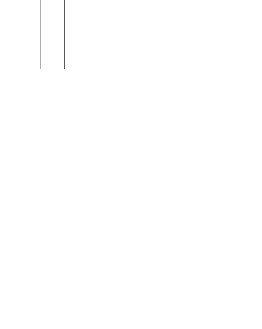
PE-BCHL (PRI Endpoint Port)
Issue 1 June 2005 1789
FAIL Internal system error
1. Retry the command at 1-minute intervals up to 5 times.
PASS This switch sent a call-state auditing message to the far-end terminal
adapter to verify the state of the call active on this port. If a call-state
mismatch is found, then the call is torn down within two minutes. If no call
was active, then no message was sent.
Table 663: Test #257 Call State Audit Test (continued)
Error
Code
Test
Result
Description / Recommendation
2 of 2

Communication Manager Maintenance-Object Repair Procedures
1790 Maintenance Procedures for Avaya Communication Manager 3.0, Media Gateways and Servers
PKT-BUS (Packet Bus)
S8700 | 8710 / S8500
The packet bus consists of a single bus, and one such bus appears in each port network. The
packet bus in each port network is physically independent from those in other port networks, so
each port network has a separate PKT-BUS MO. This bus supports the following types of
connections:
●Logical control links between the media server and every PN
●ISDN-BRI D-channel transport (signaling)
●ASAI D-channel transport (signaling)
●ISDN-PRI D-channel (signaling)
●X.25 system adjunct signaling and traffic
●System Access Ports
The TN2312AP IPSI circuit pack’s Packet Interface circuit provides the media server an
interface to the packet bus. Packet-bus testing depends on the TN771D Maintenance/Test
circuit pack, the TN2312AP IPSI circuit pack’s Packet Interface circuit, TN570 Expansion
Interface circuit pack, and various port circuit packs (including TN556 ISDN-BRI Line, TN553
Packet Data Line, and TN464 Universal DS1). Packet Bus tests may abort if some of these are
absent from the system. The tests may yield inconsistent results if any of this hardware is
defective. The individual test descriptions provide more information.
The interactions between the packet bus and the circuit packs that use the bus are complex.
Circuit pack failures can alarm the packet bus, while packet-bus faults can alarm or interrupt
service to one or more circuit packs and their ports and endpoints. The Isolating and repairing
packet-bus faults section in Maintenance Procedures (03-300192) describes packet-bus
maintenance and interactions with circuit packs. That section should be referenced for all
troubleshooting and repairs. The flowchart is the normal starting point for experienced
technicians.
MO Name in Alarm
Log
Alarm
Level
Initial Command to Run1
1. P is the port-network number indicated in the PORT field from the Alarm or Error Log.
Full Name of MO
PKT-BUS MAJ test pkt P l r 21Packet Bus
PKT-BUS MIN test pkt P lPacket Bus
PKT-BUS WRN test pkt P lPacket Bus

PKT-BUS (Packet Bus)
Issue 1 June 2005 1791
This section on the PKT-BUS MO is limited to a description of the Error and Alarm Log entries
and the test sequence for the packet bus. The following list summarizes some of the important
points to consider when working with the packet bus.
●The Maintenance/Test circuit pack (TN771D) is a critical tool for isolating packet bus faults.
This circuit pack resides in each port network of a critical-reliability system (duplicated
servers and PNC). If a TN771D is absent, one must be taken to the customer site to allow
for proper fault isolation. Isolating and repairing packet-bus faults in Maintenance
Procedures (03-300192) describes the Packet Bus testing facilities of the TN771D and
when one must be taken to the customer site.
●Certain catastrophic packet-bus faults have an effect on maintenance software activities
relating to packet circuit packs, ports, and endpoints:
- Packet circuit pack (BRI-BD, UDS1-BD) in-line errors indicating possible Packet Bus test
failures are logged in the error log, but are not acted upon.
- Port-level (BRI-PORT, ABRI-PORT) in-line errors on Packet circuit packs which indicate
possible Packet Bus failures are not logged or acted upon.
- Circuit pack and port in-line errors that are not relevant to the Packet Bus, or that indicate
a circuit pack failure, are acted upon in the normal fashion.
- Periodic and scheduled background maintenance are not affected.
- Foreground maintenance (for example, a test board command executed at a
terminal) is not affected.
The actions in the previous list serve to reduce the system load, which could become
excessive if many MOs are affected by a packet bus failure. However, such an excessive
load should in no way impede the isolation and the correction of the faults.
When the above actions are implemented, Error Type 3329 is logged against PKT-BUS,
and a Warning alarm is raised. Other Packet Bus errors may raise more severe alarms,
thereby overriding the Warning alarm.
●S8700 MC: Since all packet traffic requires communication with the IPSI’s PKT-INT circuit in
an IPSI connected PN, a PKT-BUS failure in the IPSI connected PN causes packet traffic
in this PN, and every PN controlled by the IPSI connected PN, to fail. In the S8700
Multi-Connect configuration where some PNs are non IPSI connected, an IPSI connected
PN PKT-BUS fault should be investigated first whenever PKT-BUS problems occur in
multiple PNs.
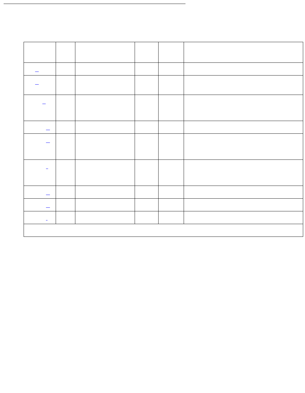
Communication Manager Maintenance-Object Repair Procedures
1792 Maintenance Procedures for Avaya Communication Manager 3.0, Media Gateways and Servers
Hardware Error Log Entries and Test to Clear Value
Notes:
a. Error Type 0: Run the short test sequence first. If every test passes, run the long test
sequence. Refer to each test’s description and follow its procedures.
b. Error Type 1: Within the last minute, packet circuit packs have reported errors that indicate
a possible packet bus failure. The Aux Data value is 1 or 2, indicating that only one or more
than one Packet circuit pack (respectively) have reported a possible packet bus failure.
c. Error Type 513: The Maintenance/Test packet bus port (M/T-PKT) for this port network has
determined that there are more packet bus faults than the port can correct. The Aux Data
value indicates the number of faulty leads.
d. Error Type 1793: Packet circuit packs have detected possible packet bus failures via in-line
error or via background test failure. Examine the Error and Alarm logs for more specific
PKT-BUS errors.
Table 664: PKT-BUS Error Log Entries
Error
Type
Aux
Data
Associated Test Alarm
Level
On/Off
Board1
1. ON-BOARD indicates a problem with the packet bus itself.
Test to Clear Value
0 (a) 0 Any Any Any test pkt port-network
1 (b) 1–2 Packet circuit
pack Audit (#570)
MAJ ON test pkt port-network P l r
2
513 (c)1–2
4
Maintenance/Test
Circuit Pack
Query test (#572)
MAJ ON test pkt port-network P l r
2
1793 (d) Any None
2049 (e) 1–3 Maintenance/Test
Circuit Pack
Query test (#572)
MIN ON test pkt port-network P l r
2
2305 (f)1–2
4
Maintenance/Test
Circuit Pack
Query test (#572)
test pkt port-network P l
3329 (g) 1–7 none WRN ON test pkt port-network P l
3585 (h) Any none MIN ON test pkt port-network P l
3841 (i) Any none MIN OFF

PKT-BUS (Packet Bus)
Issue 1 June 2005 1793
e. Error Type 2049: S8700 MC: The Maintenance/Test packet bus port (M/T-PKT) has detected
a Packet Bus fault and has taken corrective action by swapping to spare leads. This error
appears only in high/critical-reliability systems (duplicated PNC). The Aux Data value
indicates the number of faulty leads. If this is the only active error against the packet bus,
the packet bus is still in service. Due to the disruptive nature of the packet bus Fault
Isolation and Correction procedures, repairs should be deferred until a time when the least
interruption in service would result. This should be determined by consultation with the
customer. However, do not delay repairs for too long, since the switch cannot recover from
another packet bus failure until the current one is resolved. Isolating and repairing
packet-bus faults in Maintenance Procedures (03-300192) contains a sub-section, A
Special Precaution Concerning the TN771D that describes how to ensure that the TN771D
is providing correct information. A new TN771D may need to be taken to the customer site.
f. Error Type 2305: The Maintenance/Test packet bus port (M/T-PKT) has detected open
leads on the packet bus. The Aux Data value indicates the number of open leads.
g. Error Type 3329: Packet circuit pack, port, and endpoint maintenance has been disabled
due to a packet bus failure. The Aux Data value indicates the cause:
Keep in mind that although only packet circuit packs can detect and report packet bus
problems, such problems can be caused by any circuit pack.
h. Error Type 3585: Packet circuit pack, port, and endpoint maintenance has been disabled
due to more than one circuit pack reporting in-line errors. If this occurs more than three
times in 15 minutes a Minor alarm is raised against the packet bus. This happens when
maintenance is disabled due to errors and is then re-enabled because no more errors are
reported.
This error may still be present in the error log even though the Packet Circuit Pack Audit test
(#573) indicates that only one circuit pack is reporting a problem. This happens when more
than one circuit pack has reported errors in any 1-minute interval since the packet bus fault
occurred.
i. Error Type 3841: The Maintenance/Test packet bus port (M/T-PKT) for this port network is
not in service. This alarm does not appear for PNs in standard- or high-reliability systems
since a TN771D is not required there. The error indicates one or more of the following:
Aux Data Cause
1 In-line errors from packet circuit packs
2 Uncorrectable packet-bus fault reported
Maintenance/Test packet-bus port (M/T-PKT)
3 Both of the above
100xPacket-related circuit pack, port, and endpoint maintenance in the
PN has been disabled due to a packet-bus failure in the PN. The
last digit has the same meaning as the single digits listed above.
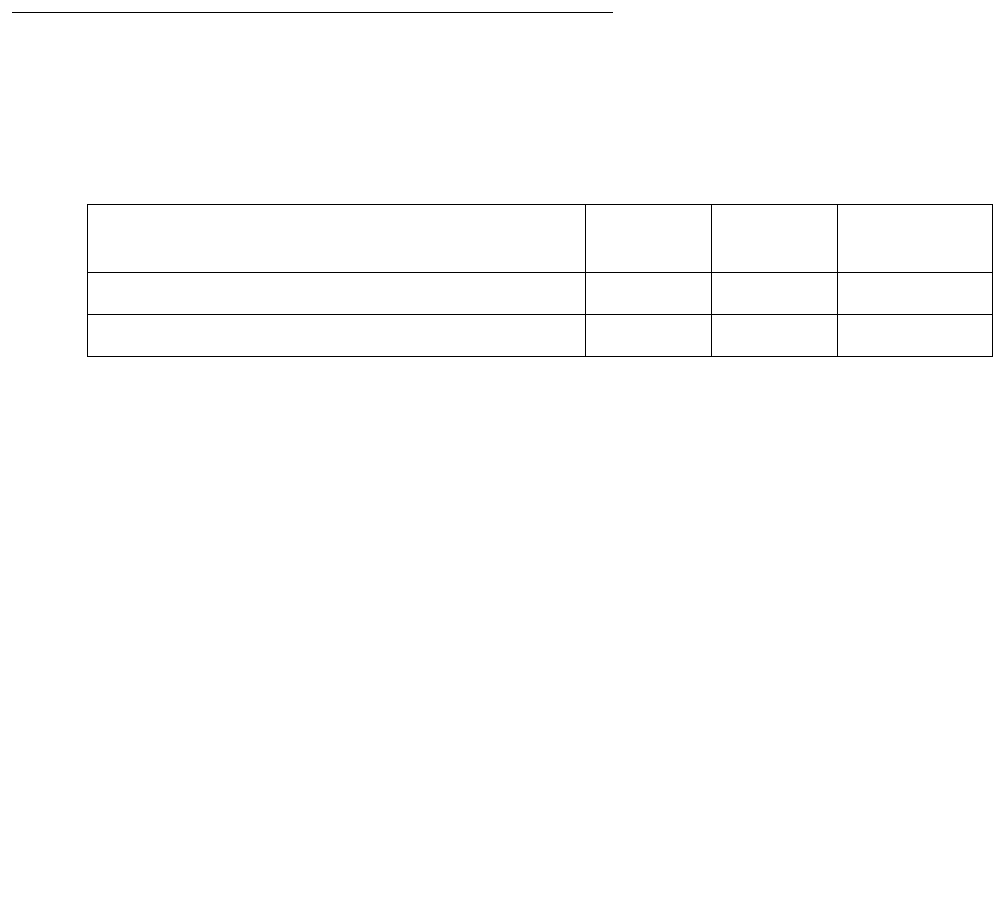
Communication Manager Maintenance-Object Repair Procedures
1794 Maintenance Procedures for Avaya Communication Manager 3.0, Media Gateways and Servers
●The packet bus port has been busied out (indicated by Error Type 18), and a Warning
alarm is active against M/T-PKT in the same port network. Release the port by entering
release port location04.
●The packet bus port has failed. Look for alarms against M/T-PKT, and attempt to resolve
these alarms.
●The Maintenance/Test circuit pack was not recognized by the system at the last system
restart. Replace the Maintenance/Test circuit pack.
●There is no Maintenance/Test circuit pack in this port network. One must be installed.
The TN711 must be installed before other packet bus alarms can be resolved. (Alarms
against a given MO are not resolved until every alarm-generating condition has been
cleared).
System Technician-Demanded Tests:
Descriptions and Error Codes
Investigate tests in the order presented below. Clearing Error Codes associated with the one
test may also clear errors generated from other tests in the sequence.
Maintenance/Test Circuit Pack Query Test (#572)
This test queries the Maintenance/Test packet bus port about the state of health of the packet
bus. If the Maintenance/Test circuit pack indicates that the packet bus has faults, the test fails.
The corresponding failure code describes the severity, type, and number of faults. The test
passes if the packet bus is fault-free.
Note:
Note: A Maintenance/Test circuit pack is usually absent from a standard-, duplex-, or
high-reliability system’s PNs. However, customers may optionally install a
Maintenance/Test circuit pack both to utilize its enhanced analog-trunk and
digital-line testing capabilities and to enhance the system’s ability to quickly
recognize a packet bus failure.
Order of Investigation Short Test
Sequence
Long Test
Sequence
D/ND
Packet Circuit Pack Audit test (#573) X X Nondestructive
Maintenance/Test Circuit Pack Query test (#572) X X Nondestructive

PKT-BUS (Packet Bus)
Issue 1 June 2005 1795
Table 665: Test #572 Maintenance/Test Circuit Pack Query Test
Error
Code
Test
Result
Description / Recommendation
1006 ABRT The packet bus port of the Maintenance/Test circuit pack is out of service.
1. Determine whether the port is busied out. If so, release it with
release port location04. Then retry the test command.
2. If there are alarms active against the packet bus port (MT-PKT), see
M/T-PKT (Maintenance/Test Packet Bus Port) on page 1722 to
resolve them. Then retry the test command.
1142 ABRT No Maintenance/Test circuit pack packet bus port is in service in this PN.
1. If this PN is required by configuration guidelines to have a
Maintenance/Test circuit pack:
●the Maintenance/Test circuit pack for this PN has failed, and
should be replaced,
●the Maintenance/Test circuit pack has been busied out, and should
be released, or
●there is no Maintenance/Test circuit pack in this PN, and one must
be installed.
2. In a PN of a system without PNC duplication, the Maintenance/Test
packet bus Port is not required and may not be present. If it is
present, and is busied out, or has failed, release or replace the circuit
pack. If there is no Maintenance/Test circuit pack, ignore the results of
this test for this PN.
2000 ABRT The test timed-out while waiting for an uplink CCMS response from the
Maintenance/Test packet bus port.
1. Re-enter the command at 1-minute intervals up to 5 times.
2. If the test continues to abort, check for problems with the
Maintenance/Test packet bus port (look for M/T-PKT in the Error and
Alarm Logs).
2059 ABRT The Maintenance/Test packet bus port has reported a hardware failure.
1. See M/T-PKT (Maintenance/Test Packet Bus Port) on page 1722 to
correct the problem.
2. Re-enter the test command.
1 of 3

Communication Manager Maintenance-Object Repair Procedures
1796 Maintenance Procedures for Avaya Communication Manager 3.0, Media Gateways and Servers
2077 ABRT The Maintenance/Test Circuit Pack Query located more than one
Maintenance/Test packet bus port in the PN.
The software should not allow this to occur. This is an internal system
error. Escalate the problem, but also attempt the following work-around
steps.
1. Remove every Maintenance/Test circuit pack from the PN.
2. Insert one Maintenance/Test circuit pack (there should not be more
than one in a PN).
3. Re-enter the test command.
2100 ABRT Maintenance could not allocate every necessary system resource to
perform this test.
1. Retry the command at 1-minute intervals up to 5 times.
2500 ABRT An internal operation failed; the test could not be completed.
1. Retry the command at 1-minute intervals up to 5 times.
FAIL The Maintenance/Test packet bus port has detected faults on the Packet
Bus. The Error Codes are interpreted as follows:
Table 665: Test #572 Maintenance/Test Circuit Pack Query Test (continued)
Error
Code
Test
Result
Description / Recommendation
2 of 3

PKT-BUS (Packet Bus)
Issue 1 June 2005 1797
1xxx The Maintenance/Test packet bus port has reconfigured the packet bus
around the faulty leads. This action only occurs in a high- or
critical-reliability system (duplicated PNC).
2xxx The Maintenance/Test packet bus port is unable to correct every Packet
Bus fault it has detected.
x0xx None of the packet bus faults are open faults.
x1xx At least some of the packet bus faults are open faults. Look for Error Type
2305 in the Error Log. The Aux Data value indicates the number of open
leads.
xxyy The last two digits of the Error Code indicate the total number of faulty
packet bus leads detected.
Examples:
Error Code 2003 FAIL: The Maintenance/Test packet bus port has
detected 3 faulty leads. None of them are opens. At least one was
unable to be corrected.
Error Code 1103 FAIL: The Maintenance/Test Packet Port has
detected 3 faulty leads. At least one is an open. The Maintenance/
Test circuit pack was able to correct all of them by reconfigured.
1. See Isolating and repairing packet-bus faults in Maintenance
Procedures (03-300192).
PASS No faults have been detected on the packet bus by the Maintenance/Test
circuit pack. This is an indication that the packet bus is operating correctly.
Table 665: Test #572 Maintenance/Test Circuit Pack Query Test (continued)
Error
Code
Test
Result
Description / Recommendation
3 of 3

Communication Manager Maintenance-Object Repair Procedures
1798 Maintenance Procedures for Avaya Communication Manager 3.0, Media Gateways and Servers
Packet Circuit Pack Audit Test (#573)
This test determines whether Packet circuit packs have reported Packet Bus-related in-line
errors within the last minute. If so, the failure code indicates whether one or more than one
circuit pack has reported such failures.
If the test has failed within the last 5 minutes, there is a 15 second delay before the result is
returned. This prevents a repeated sequence of this test from always reporting the same result.
If the test passes and a FAIL has not occurred within the last five minutes, a PASS is returned
immediately.
Table 666: Test #573 Packet Circuit Pack Audit Test
Error
Code
Test
Result
Description / Recommendation
2500 ABRT An internal operation failed; the test could not be repeated.
1. Retry the command at 1-minute intervals up to 5 times.
1 FAIL One Packet circuit pack has reported packet bus-related in-line errors
within the last minute.
2 FAIL More than one Packet circuit pack has reported packet bus-related in-line
errors within the last minute.
PASS No Packet circuit packs have reported packet bus-related in-line errors
within the last minute. This indicates that the packet bus is healthy, or that a
packet bus fault is transient or is being caused by a faulty Packet circuit
pack. If this test passes, but there are other signs of a packet bus failure
(for example, logged errors or alarms, or other test failures), see Isolating
and repairing packet-bus faults in Maintenance Procedures (03-300192).
PKT-INT (Packet Interface)
Issue 1 June 2005 1799
PKT-INT (Packet Interface)
S8700 | 8710 / S8500
The Packet Interface (PKT-INT) MO resides on the TN2312 IP Server Interface (IPSI) circuit
pack and serves as an interface between the media server and the packet bus.
The TN1655 PKT-INT and TN2182 Tone-Clock circuit packs’ functions are on the TN2312 IPSI
circuit pack. The IPSI circuit pack also provides:
●PKT-INT packet-bus interface
●Archangel TDM-bus interface
●Tone-Clock functionality
●Ethernet interface for connectivity to media servers
●Ethernet interface for connectivity to services laptop PCs
●S8700 MC: Maintenance board interface for communication with the PN’s Maintenance
board, in Carrier A or B only
The TN2312 IPSI circuit pack is inserted into a PN’s Tone-Clock slot and provides an Ethernet
interface back to the media servers. The PKT-INT interface module on the IPSI is like previous
DEFINITY TN1655 PKT-INT boards. However, the IPSI’s PKT-INT module does not support
DMI Mode-2/-3 data or BX.25 links.
The PKT-INT supports links used for call setup of every port located in a PN. Packet Interface
failure prevents call set-up and tear-down from telephones and trunks connected to PNs.
In addition to affecting telephone service, Packet Interface failure affects the service provided
by circuit packs that connect to the Packet bus. For example:
●TN464, TN2207, TN2464 Universal DS1 circuit pack — ISDN-PRI service
●TN556, TN2198, TN2185 ISDN-BRI Line circuit pack — ISDN-BRI service
●S8700 MC: TN2305, TN2306 ATM
●S8700 MC: TN570 Expansion Interface (EI)
●S8700 MC: TN573 Switch Node Interface (SNI)
●TN799DP Control LAN (C-LAN) packet port circuit pack
●TN2501 Voice Announcements over the LAN (VAL)
MO Name in
Alarm Log
Alarm
Level
Initial SAT Command to Run Full Name of MO
PKT-INT MAJ reset packet-interface location Packet Interface
PKT-INT MIN test packet-interface location Packet Interface
PKT-INT WRN test packet-interface location Packet Interface

Communication Manager Maintenance-Object Repair Procedures
1800 Maintenance Procedures for Avaya Communication Manager 3.0, Media Gateways and Servers
S8700 | 8710: If the active IPSI’s Packet Interface module causes a MAJOR alarm in a high- or
critical-reliability system (with duplicated IPSIs), an IPSI interchange occurs if the standby IPSI’s
state of health (SOH) is high enough to permit the interchange. A MAJOR alarm due to a failure
of the standby IPSI’s Packet Interface module lowers the standby’s state of health (SOH),
preventing a subsequent interchange.
The links that pass through the Packet Interface are identified as application links or system
links as follows:
●Application links are endpoints that require connectivity to the media server via the C-LAN
board’s Socket interface. These links pass over the packet bus, and through C-LAN ports.
The following system features use application links:
- Call Detail Recording (CDR)
- Dial-up administration
- Property Management System (PMS)
- Journal printer
- Wake-up log printer
- Announcement circuit pack upload/download of recorded messages
- IP phones
●System links
- Expansion Archangel links (signaling links for call setup of a PN’s endpoints)
- Center Stage Control Network (CSCN) links
- ISDN-PRI D-channel signaling links
- ISDN-BRI D-channel broadcast and point-to-point signaling links
- Adjunct Switch Application Interface (ASAI) links
- Remote Socket Control Link (RSCL) (C-LAN, VAL)
- BRI (TRK and STA)
Distributed PKT-INTs
In earlier G3r systems, every PKT-INT resided in the Processor Port Network (PPN) and
terminated all of the LAPD links. LAPD links are now terminated by the PKT-INT modules within
IPSIs that are distributed out to the PNs, or out to every PN for the S8700 IP Connect. The
DEFINITY Server R allowed up to three active and three standby PKT-INTs in the PPN.
S8700 MC: As shown in Figure 104: Distributed PKT-INTs on page 1801, PNs 1 and 2 have
IPSIs that terminate LAPD links. PNs 3 and 4 do not have local IPSIs, so their LAPD links are
terminated by IPSIs in PNs 1 and 2.
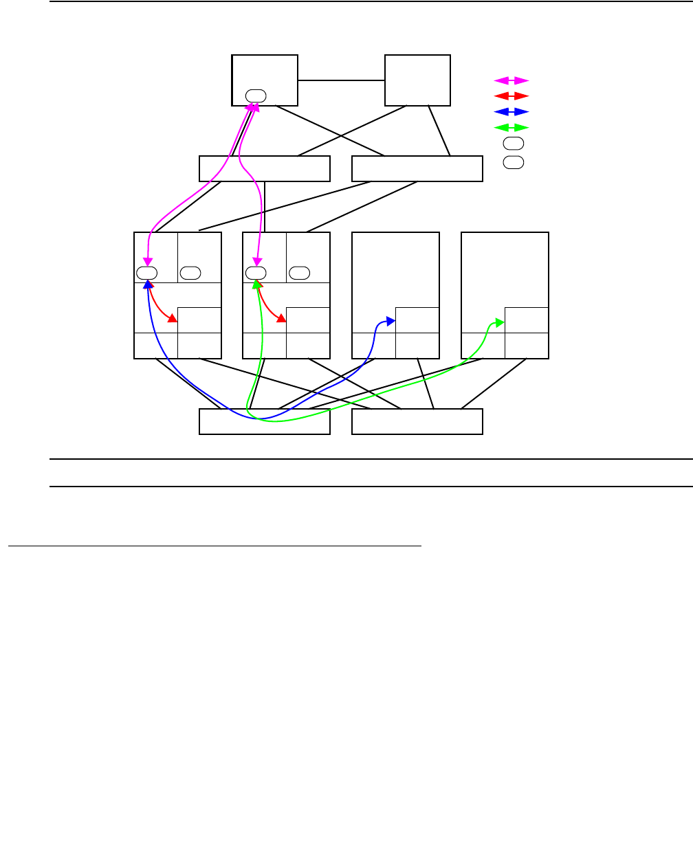
PKT-INT (Packet Interface)
Issue 1 June 2005 1801
S8700 IP: All port networks must have IPSI/PKT-INTs. They can be all simplex (one IPSI per PN)
or all duplex (two IPSI per PN).
Figure 104: Distributed PKT-INTs
S8700 MC
PKT-INT Interchange
In G3r systems, PKT-INT interchange was an integral part of an SPE interchange. In S8700
Multi-Connect, PKT-INT interchange is independent of media server interchange, and a
PKT-INT interchange can occur without a media server interchange and vice versa. In S8700
Multi-Connect, the active media server’s packet control driver (PCD) has sockets to both active
and standby IPSIs and exchanges heartbeats with both. The active PCD is responsible for
bringing up the active PKT-INT, and for bringing up the standby PKT-INT into the standby mode.
This is different than the G3r, where the standby PCD brings up the standby PKT-INT into the
standby mode. The standby PCD also has sockets to both active and standby IPSIs and
exchanges heartbeats with both. The standby PCD only talks to the IPSI SIM, and does not
communicate with the PKT-INTs. In the DEFINITY Server R, the active media server
communicated with the standby media server via the SMM to perform maintenance activities on
IPSI IPSI
EI
PN 1
IPSI IPSI
PN 2 PN 3
Server A Server B
Control Network A Control Network B
PKT pktpktPKT
Bearer Network A Bearer Network B
PCD
PN 4
EI
BRI/PRI
EI EI EI EI EI EI
BRI/PRI BRI/PRI BRI/PRI
Legend:
PCD connection
Local LAPD
Inter-PN LAPD
Inter-PN LAPD
PKT
Active PKT-INT
pkt
Standby PKT-INT

Communication Manager Maintenance-Object Repair Procedures
1802 Maintenance Procedures for Avaya Communication Manager 3.0, Media Gateways and Servers
the standby PKT-INT. In S8700 Multi-Connect, the active media server communicates directly
with both active and standby PKT-INTs and performs maintenance activities on both PKT-INTs
without the standby media server getting involved.
Earlier G3r PKT-INT duplication relied on the duplication hardware to automatically duplicate
and write each command from the processor into the active and standby PKT-INT’s dual-port
RAMs. The standby PKT-INT was always up-to-date with the state of every link terminated by
the active PKT-INT. On S8700 Multi-Connect, there is no dedicated hardware to keep the
standby PKT-INT up-to-date. Instead, the PCD refreshes the standby PKT-INT prior to an
interchange.
Executing a PKT-INT Interchange
There are two ways to interchange PKT-INTs, spontaneous and planned.
●A spontaneous interchange is usually caused by a fault, and:
- Stable calls are retained
- LAPD links are restarted
- Some data may be lost
●A planned interchange can be requested by Services’ personnel or by software for
maintenance or periodic testing.
- LAPD links are migrated from the active to the standby PKT-INT
- No data is lost during the interchange
The active media server’s PCD has socket connections to both active and standby IPSIs. Media
server interchange and IPSI interchange are independent of each other. IPSIs in a PN can be
interchanged independently of IPSIs in other PNs.
Spontaneous PKT-INT Interchange
For S8700 Multi-Connect, the standby PKT-INT is not kept up-to-date with the links terminated
by the active PKT-INT. During a spontaneous interchange of PKT-INTs, the standby PKT-INT is
refreshed with the link information by the active PCD and the standby PKT-INT is activated with
a warm reset. As with G3r, a spontaneous interchange of PKT-INTs may result in loss of some
up-stream and down-stream data.
●PCD maintains socket connections to the active and the standby PKT-INTs, via the SIM.
●Media server sends control and data packets only to the active PKT-INT.
●Standby PKT-INT has no information about the LAPD links.
●On a spontaneous interchange, the standby PKT-INT is “refreshed” by the PCD. That
means the LAT and the LCT are sent to the PKT-INT, and the standby PKT-INT is made
active by a warm interrupt.

PKT-INT (Packet Interface)
Issue 1 June 2005 1803
Planned PKT-INT Interchange (Link Migration)
A planned interchange of PKT-INTs uses link migration to assure that no data is lost during the
interchange. On a planned interchange of PKT-INTs, software initiates the link migration by
sending commands to the active and standby PKT-INTs to make a peer link between the
PKT-INTs and to start the link migration process. Down-stream and up-stream messages can
be processed by the PKT-INTs during the link migration process. As long as the PKT-INT
interchange has not been completed, PCD should continue to send down-stream messages to
the active PKT-INT. If a down-stream data packet is for a link that has not yet been migrated
over to the standby PKT-INT, the active PKT-INT processes it and sends it out.
If a down-stream data packet is for a link that has already migrated over to the standby
PKT-INT, the peer link forwards the down-stream data packet to the standby PKT-INT, and the
standby PKT-INT processes it and sends it out. Up-stream messages during migration are
handled by both PKT-INTs as with the down-stream messages. The PKT-INT that controls the
link (the active PKT-INT if the link has not yet been migrated, and the standby PKT-INT if the
link has been migrated) processes the up-stream data packet and sends it up to the PCD.
During the migration process, both the active and the standby PKT-INTs can send up-stream
messages to the PCD.
On DEFINITY Server R, during the migration process, the standby PKT-INT terminating a link
processes the up-stream packet and forwards it to the active PKT-INT, which sends it up to the
PCD.
On S8700, all down-stream packets go to the active PKT-INT, but the up-stream packets can
come from the active and the standby PKT-INTs during the migration process.
●Link migration is performed to prepare the standby PKT-INT for a hot reset.
●RNRs are not sent to the endpoints at the start of the link migration.
●PCD tells the active and standby PKT-INTs that a link migration is starting.
●LAPD links are migrated from the active-mig PKT-INT to the standby-mig PKT-INT in the
order they appear in the internal list.
●Active-mig PKT-INT continues to accept up-stream messages for the links that are not yet
migrated. The standby-mig PKT-INT starts accepting up-stream messages for the links
that are migrated. Both the active-mig and the standby-mig PKT-INTs send up-stream
messages to the PCD.
●PCD accepts up-stream messages from both the active-mig and standby-mig PKT-INTs.
●PCD sends every down-stream message to the active-mig PKT-INT and has the
active-mig PKT-INT send it out for those links that have not been migrated or forward it to
the standby-mig PKT-INT for those links that have been migrated.
●At the end of the migration, the active-mig PKT-INT tells the PCD that the migration is
finished, and PCD tells the standby-mig PKT-INT to go active (hot interrupt). Some
coordination verifies that every up- and down-stream message has been flushed from the
active-mig PKT-INT before completing the interchange.

Communication Manager Maintenance-Object Repair Procedures
1804 Maintenance Procedures for Avaya Communication Manager 3.0, Media Gateways and Servers
PKT-INT and System Reliability
S8700 IP
A PKT-INT module resides on each IPSI board. On an S8700 IP Connect, there is a duplicated
server, and one server is in active mode and one server is on standby. The control network(s)
for S8700 IP Connect may be implemented in a simplex, see Figure 105: IP Connect Duplex
Reliability - Simplex Control Network on page 1805, or a optional duplicated configuration.
There is only one PKT-INT per port network.
Note:
Note: Duplicated control networks require G650 media gateways (not G600) because
the G600 does not support duplicated clocks. The clock is a component of the
TN2312 IPSI.
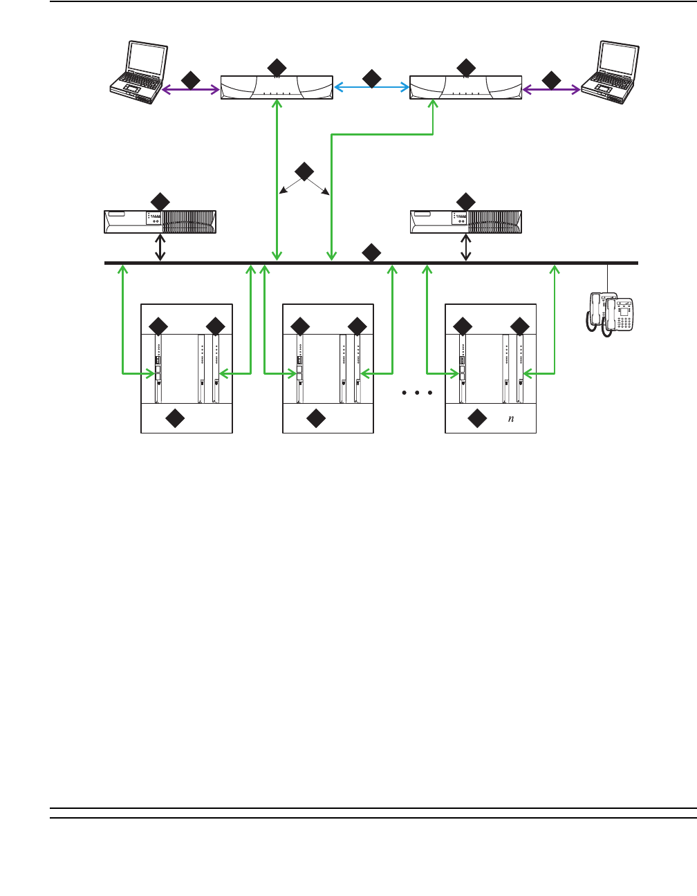
PKT-INT (Packet Interface)
Issue 1 June 2005 1805
Figure 105: IP Connect Duplex Reliability - Simplex Control Network
Figure notes:
1. S8700 Media Server 1 – two are
always present, one in an active mode
and one on standby.
6. UPS units – two required.
2. S8700 Media Server 2 – two are
always present, one in an active mode
and one on standby.
7. Local Area Network
3. Duplication Interface – the Ethernet
connection between the two S8700
media servers.
8. Port Network – optional configuration of
media gateways that provides increased
switch capacity.
4. Services Interface – the S8700 media
servers dedicated Ethernet
connection to a laptop. This link is
active only during on-site
administration or maintenance, and
the services interface can link to the
non-active server through a Telnet
session.
9. IPSI – provides transport of CCMS
messages over IP, allowing the S8700
media server to communicate with the port
networks.
5. Connection from the Servers to the
Local Area Network (LAN).
10. Media Processor - Provides conversion
between Time Division Multiplexed (TDM)
and Internet Protocol (IP) voice signals.
cydsdup KLC 042204
1
12
2
IPSI IPSI
100bT
LINK
TRMT
RCV
BBI
LINK
TRMT
RCV
100bT
LINK
TRMT
RCV
BBI
LINK
TRMT
RCV
100bT
LINK
TRMT
RCV
BBI
LINK
TRMT
RCV
IPSI
Ethernet 1Ethernet 1
Ethernet 0
Ethernet 1
1 2
344
5
6 6
7
PN 1
8PN 2
8PN
8
9 9 910 10 10

Communication Manager Maintenance-Object Repair Procedures
1806 Maintenance Procedures for Avaya Communication Manager 3.0, Media Gateways and Servers
S8700 MC
On S8700 Multi-Connect, a PKT-INT module resides on each IPSI board. LAPD links are
terminated by the PKT-INT modules in the IPSIs that are distributed out to the port networks.
The non IPSI connected port networks do not have their own PKT-INT capability, so their LAPD
links are terminated by IPSIs in the IPSI connected port networks.
S8700 Multi-Connect architecture has three items that can be duplicated for increased
reliability: media server, IPSI, and PNC. They can be duplicated independently. Duplicated
control networks and duplicated IPSIs go together, so that when the IPSIs are duplicated, the
control networks must be duplicated. The set of items in your configuration that are duplicated
depend on the reliability option chosen for your system: duplex, high or critical. See
Table 667: Reliability Options on page 1806.
Duplex-Reliability Configuration
The duplex-reliability configuration shown in Figure 106: Duplex-Reliability Configuration on
page 1807 has duplicated media servers, an unduplicated control network, unduplicated IPSIs
in the IPSI connected PNs, and an unduplicated bearer network. Because the IPSIs are not
duplicated, the PKT-INT modules contained within them are not duplicated.
Table 667: Reliability Options
Configurations Servers Control Networks and
IPSIs
Bearer
Networks
Duplex Reliability Duplicated Unduplicated Unduplicated
High Reliability Duplicated Duplicated Unduplicated
Critical Reliability Duplicated Duplicated Duplicated
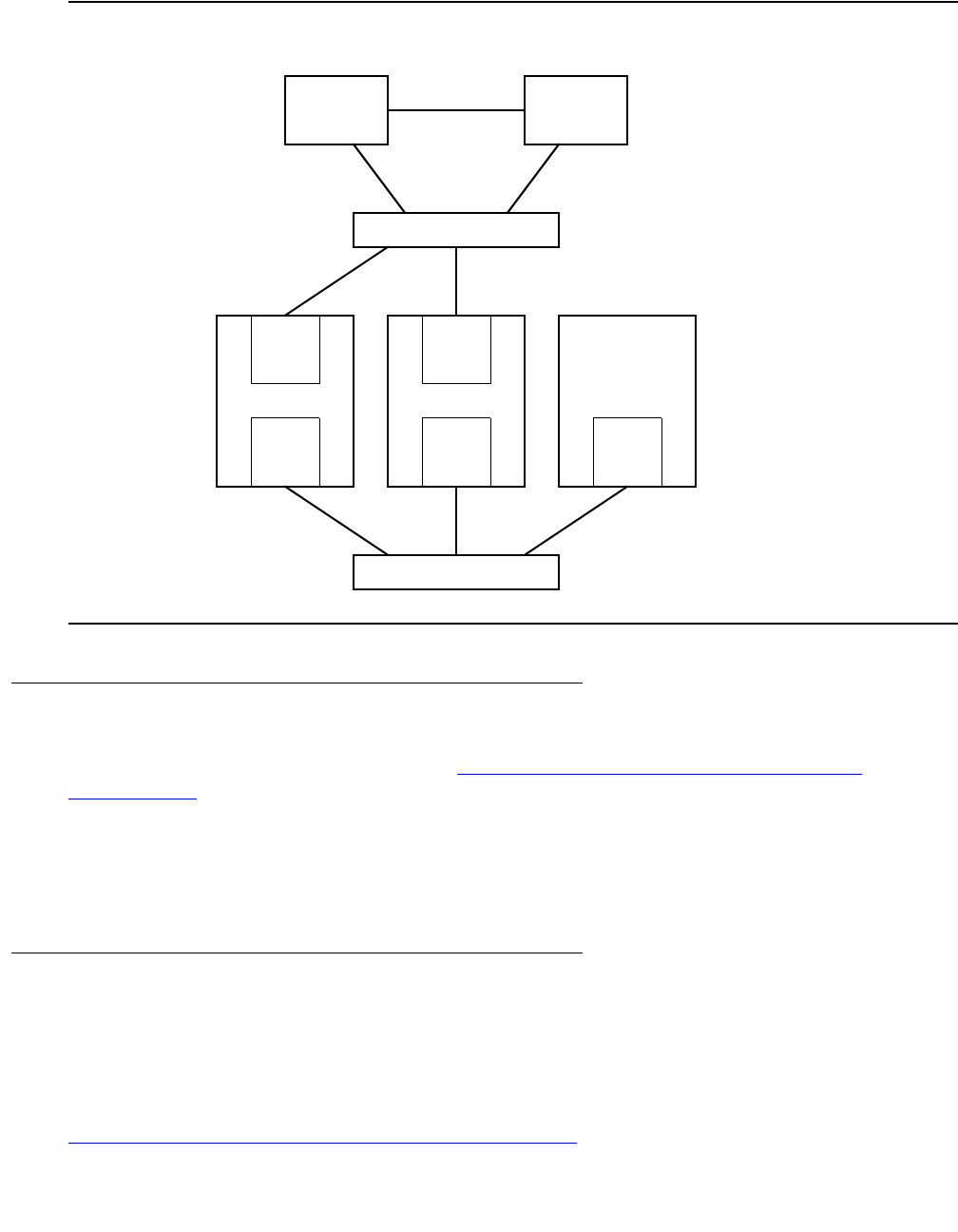
PKT-INT (Packet Interface)
Issue 1 June 2005 1807
Figure 106: Duplex-Reliability Configuration
High-Reliability Configuration - Multi-Connect
The high-reliability configuration shown in Figure 107: High-Reliability Configuration -
Multi-Connect on page 1808 has duplicated media servers, duplicated control networks, and
duplicated IPSIs in the IPSI connected PNs. With this configuration, every IPSI connected PN
must have duplicated IPSIs. The duplicated control network prevents a single fault in the control
network, such as a bad Ethernet switch, from bringing the whole system down. Because the
IPSIs are duplicated in this configuration, the PKT-INT modules are duplicated.
High-Reliability Configuration - IP Connect
The IP Connect high reliability configuration is similar to the multi-connect configuration. There
are no expansion interface circuit packs in the IP connect configuration. There are duplicated
IPSI circuit packs in each port network. Port networks must use the G650 rack mounted carrier
to accommodate the duplicated clock circuits located on the IPSI circuit packs. See
Figure 108: High-Reliability Configuration - IP Connect on page 1808
EI
PN n
Server A Server B
IPSI
EI
PN 2
IPSI
EI
PN 1
Control Network A
Bearer Network
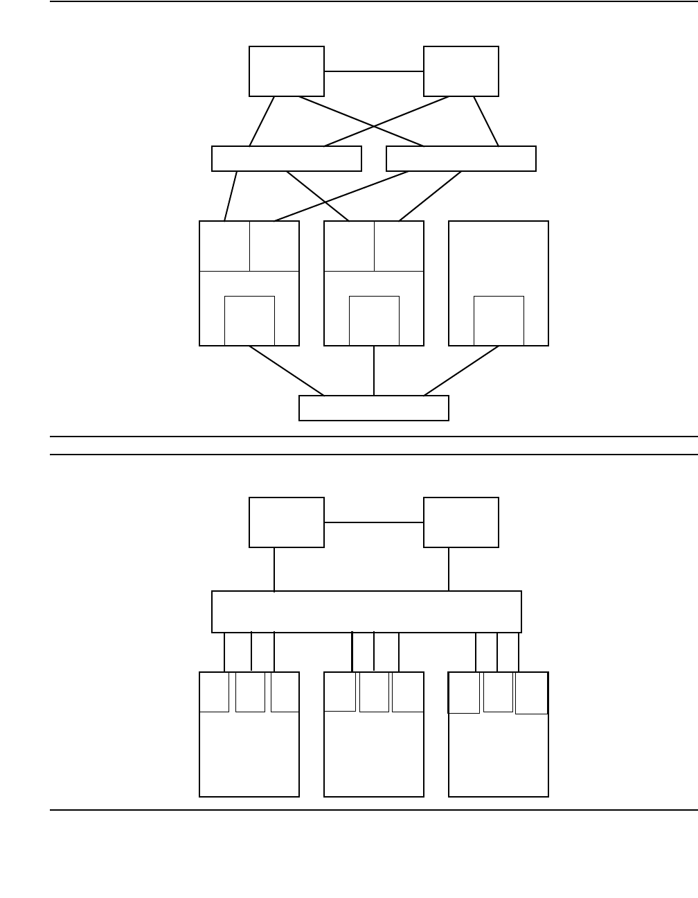
Communication Manager Maintenance-Object Repair Procedures
1808 Maintenance Procedures for Avaya Communication Manager 3.0, Media Gateways and Servers
Figure 107: High-Reliability Configuration - Multi-Connect
Figure 108: High-Reliability Configuration - IP Connect
EI
PN n
Server A Server B
IPSI IPSI
EI
PN 2
IPSI IPSI
EI
PN 1
Control Network A Control Network B
Bearer Network
PN n
Server A Server B
IPSI
PN 2
IPSI
IPSI
PN 1
Customer Corporate LAN
IPSI
IPSI
IPSI
Med
Pro
Med
Pro
Med
Pro
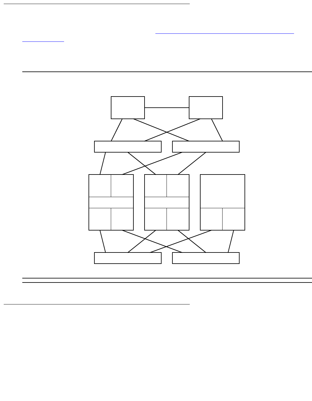
PKT-INT (Packet Interface)
Issue 1 June 2005 1809
Critical-Reliability Configuration - Multi-Connect
The critical-reliability configuration shown in Figure 109: Critical-Reliability Configuration -
Multi-Connect on page 1809 has full duplication of the following options: media servers, control
networks, IPSIs and PNCs (bearer networks). As with the high-reliability configuration, this
configuration requires that IPSI connected PNs have duplicated IPSIs. Because the IPSIs are
duplicated in this configuration, the PKT-INT modules are duplicated.
Figure 109: Critical-Reliability Configuration - Multi-Connect
Packet Interface Service Operations
The following sections provide more background information about service operations for the
Packet Interface.
IPSI IPSI
EI EI
PN 1
IPSI IPSI
EI EI
PN 2
EI EI
PN n
Server A Server B
Control Network A Control Network B
Bearer Network A Bearer Network B

Communication Manager Maintenance-Object Repair Procedures
1810 Maintenance Procedures for Avaya Communication Manager 3.0, Media Gateways and Servers
Administration
PKT-INT modules are automatically administered as a component of an IPSI circuit pack. See
add/remove ipserver-interface and test/status/reset packet-interface in
Maintenance Commands Reference (03-300191).
Packet Interface Circuit Replacement
To replace a Packet Interface module that is part of a TN2312AP IPSI circuit pack, follow the
procedure for replacing an IPSI circuit pack.
Demand Reset of a Packet Interface
System software denies a demand reset of an active IPSI’s Packet Interface (reset
packet-interface) if the Packet Interface is in service, and has not been placed in an
out-of-service state by background maintenance software. A reset of an in-service Packet
Interface causes severe service disruption, including the loss of all existing calls, and dropped
links to adjuncts such as AUDIX. As part of the automatic recovery action initiated when a fatal
hardware-fault condition is detected, the software that controls Packet Interface maintenance
puts a Packet Interface module in the out-of-service state if that IPSI circuit pack has been reset
three times within the last 15 minutes.
A demand reset of a standby Packet Interface is not disruptive and is allowed regardless of the
service state of the associated maintenance software.
Service States
Packet Interface maintenance software maintains a state variable to monitor the service state of
each Packet Interface. To determine the state of a Packet Interface, use status
packet-interface. A Packet Interface can be in the service states:
●in-service - in service and active
●standby - in service and standby
●out-of-service - active or standby Packet Interface not in service
●standby-disabled - IPSI circuit pack with Packet Interface module is present and
administered, but duplication is disabled
●craft-busy - Packet Interface has been demand busied out by craft
●uninstalled - Packet Interface is administered but not physically present

PKT-INT (Packet Interface)
Issue 1 June 2005 1811
S8700 | 8710
If the circuit pack’s diagnostic tests do not pass in a standard- or duplex-reliability system
(unduplicated IPSIs), the failing Packet Interface is placed in an out-of-service state. Every link
handled by that IPSI goes down, and may be re-established using other Packet Interface
resources. Calls associated with these links may drop.
If the standby IPSI (in a high- or critical-reliability system with duplicated IPSIs) has an
acceptable state of health, maintenance software interchanges the IPSIs, instead of resetting
the active IPSI’s Packet Interface module. This is less disruptive than a reset.
An IPSI’s Packet Interface module goes out-of-service if the IPSI has been reset by background
maintenance 3 times in the last 15 minutes, whether or not reset succeeded. Various errors will
lead to a Packet Interface reset. See the “Error Log Entries and Test to Clear values” section.
An extensive set of diagnostic tests is run when the circuit pack is reset.
S8700 | 8710
Duplication Impact
The Packet Interface module is a single point of failure in a standard- or duplex-reliability
system, with unduplicated IPSIs. If not acceptable, an S8700 customer can upgrade to a high-
or critical-reliability system with duplicated IPSIs. Figure 104: Distributed PKT-INTs on
page 1801 shows an S8700 Multi-Connect configuration with duplicated IPSIs. The following
concepts apply to duplicated IPSIs:
●Packet-bus connection
In a high- or critical-reliability system (duplicated IPSIs), the standby IPSI’s Packet Interface
module cannot access the packet bus to write data, except during a planned IPSI
interchange or when the Peer Link test (#888) is run. The Maintenance Loop-Around test
(#886), which requires access to the packet bus, is not run on the standby IPSI’s Packet
Interface module.
●IPSI interchange
Severe Packet Interface module faults that cause system and application links to go down
are detected within 1 second. A fatal fault error message is generated, and the Packet
Interface maintenance software attempts to run the Packet Interface Reset test. In a high-
or critical-reliability system, this results in a requested IPSI interchange, instead of a Packet
Interface reset, since stable calls are preserved across the interchange.

Communication Manager Maintenance-Object Repair Procedures
1812 Maintenance Procedures for Avaya Communication Manager 3.0, Media Gateways and Servers
Maintenance-Object Interactions
●Packet Bus maintenance
A Packet Interface physically interacts with the PKT-BUS. It may be difficult to isolate faults
to one or the other component for certain types of Packet Interface errors. In each of these
cases, Packet Interface maintenance forwards an error report to packet-bus maintenance,
where it records a packet-bus fault in the hardware error log and runs Packet Bus tests.
●Packet Interface maintenance
The operation of the IPSI circuit pack’s Packet Interface module affects the operation and
maintenance of other circuit packs connected to the packet bus. This includes:
1. BRI applications (BRI-PT)
2. Universal DS1 applications (UDS1) for ISDN/PRI applications
3. S8700 MC: Expansion Interface circuit pack maintenance (EXP-INTF)
Some packet errors require examination of the Packet Interface’s operating status. To
obtain this information:
●Examine the Error and Alarm Logs for PKT-INT entries and determine which PKT-INT the
link is accessing.
●Use status sys-link to identify the PKT-INT location in this PN, or use status
sys-link to find the PKT-INT hardware used by the faulted link.
●Use test sys-link to troubleshoot the component.
●Use status packet-interface to determine the:
- service state of the Packet Interface, for example, in service/out of service
- total number of Packet Interface links assigned to a Packet Interface.
For a standby IPSI’s Packet Interface module in a high- or critical-reliability system
(duplicated IPSIs), the module is shown in standby mode if it is not out-of-service
because of a failure condition. The number of links for a standby Packet Interface module
is always zero.
In general, if every link for an active IPSI’s Packet Interface module is shown as a Failed
Link, there may be a fault on either the Packet Interface module or the packet bus that
caused every link to go down. If only a small percentage of the links are shown as Failed
Links, then the Packet Interface is probably not the source of the problem. Some typical
sources of individual link failures include:
●failed BRI telephone set
●disconnected cord to a BRI set, causes three link failures
●S8700 MC: failed or removed EI circuit pack in a PN, causes one link failure

PKT-INT (Packet Interface)
Issue 1 June 2005 1813
For a case where not every link appears in the Failed Links category, examine the alarm
and error logs for failures of the following circuit packs, and follow the repair procedures for
those circuit packs before considering replacing the associated IPSI circuit pack:
●S8700 MC: TN570 Expansion Interface circuit pack (EXP-INTF)
●S8700 MC: TN573 Switch Node Interface circuit pack (SNI-BD)
●S8700 MC: Switch Node Clock circuit pack (SNC-BD)
●ISDN-BRI Line circuit packs, ports, and stations (BRI-BD, BRI-PORT, BRI-SET)
●Universal DS1 circuit packs and ports (UDS1-BD, TIE-DS1)
●TN464, TN2207, TN2464 Universal DS1 circuit pack — ISDN-PRI service
●TN556, TN2198, TN2185 ISDN-BRI Line circuit pack — ISDN-BRI service
●TN2305, TN2306 ATM
●TN799DP Control LAN (C-LAN) packet port circuit pack
●TN2501 Voice Announcements over the LAN (VAL)
Use test sys-link with the faulted path option to test all components in the faulted link.
Error Log Entries and Test to Clear Values
Table 668: Packet Interface Error Log Entries
Error
Type
Aux
Data
Associated Test Alarm
Level
On/Off
Board
Test to Clear Value
0 (a)0Any AnyONtest packet-interface
location l r 2
1 (b) Any None MAJ ON reset packet-interface
location1
10 (c) 0 None
50 (d) 0 None
257 (e) Any None MAJ ON reset packet-interface
location
513 (f) Any None MAJ ON reset packet-interface
location
769
770 (g)
Any Maintenance
Loop-Around test
(#886)
MAJ ON test packet-interface
location s r 2
1 of 2

Communication Manager Maintenance-Object Repair Procedures
1814 Maintenance Procedures for Avaya Communication Manager 3.0, Media Gateways and Servers
Notes:
a. Error Type 0: an alarm was raised but an associated error was not entered into the
hardware error log due to a momentary overload condition caused by a burst of hardware or
software error reports. Run the long test sequence. Refer to the test description and follow
the recommended procedures.
b. Error Type 1: background maintenance software has reset the Packet Interface module on
an IPSI circuit pack as a fault recovery action. It is used to keep track of the number of times
that the Packet Interface is reset, independent of whether or not the Reset test passed.
1025 (h) Any Private Loop-Around
(#885)
MAJ ON reset packet-interface
location1
1281 (i) Any None MAJ ON reset packet-interface
location1
1537 (j) Any Memory Checksum
(884)
MIN ON test packet-interface
location l r 2
1793 (k) Any Memory Checksum
(#884)
MIN ON test packet-interface
location l r 2
2049 (l) Any None WRN ON test packet-interface
location r 25
2305 (m) Any None test packet-interface
location r 2
2561 (n) Any Active-Standby Peer
Link (#888)
MIN OFF test packet-interface
location s r 2
2817 (o) Any Read and Clear test
(#887)
MIN
MAJ
ON test packet-interface
location s
3074
3073
3072 (p)
Any Maintenance
Loop-Around (#886)
WRN OFF test packet-interface
location s r 2
3585 (q) Any None WRN OFF reset packet-interface
location1
3841 (r) Any None MAJ OFF reset packet-interface
location1
1. A Packet Interface module on an active IPSI can only be reset if it has been taken out of service by
background maintenance software. A Packet Interface module on a standby IPSI can be reset independent
of its service state.
Table 668: Packet Interface Error Log Entries (continued)
Error
Type
Aux
Data
Associated Test Alarm
Level
On/Off
Board
Test to Clear Value
2 of 2

PKT-INT (Packet Interface)
Issue 1 June 2005 1815
When 3 of these errors occur in 15 minutes, maintenance places the Packet Interface into
an out-of-service state, and a MAJOR on-board alarm is raised on the Packet Interface
(PKT-INT).
1. See if Error Codes 257, 513, 769, 1025, 1281, or 3841 are present in the hardware error
log. If one or more are present, follow the repair procedures for those errors.
2. If no other Packet Interface errors appear in the error log, and if the Packet Interface is
not in a held reset state as indicated by the absence of a MAJOR alarm with a Service
State of OUT, take no action. If a Packet Interface MAJOR alarm is present and no other
Packet Interface Error Codes are in the hardware error log, use reset
packet-interface location to execute a demand reset, and refer to the repair
procedures for Test #889.
c. Error Type 10: the Packet Interface maintenance software caused an escalating system
WARM restart as part of a recovery action for certain Packet Interface failures. A present
SYSTEM error type 10 indicates that a software-initiated WARM restart occurred.
1. See if Error Types 513, 1025, or 3074 are present in the hardware error log. If any are
present, follow the repair procedures for those errors.
d. Error Type 50: the media server is sending more downlink messages than the Packet
Interface module can process. This is an in-line error not produced by any test. When this
error is reported, application software is slowed down to allow the module to process
existing downlink messages. If there is a hardware problem, the Packet Interface test
causes other errors to be logged. In rare cases when no other PKT-INT errors are logged
but error 50 occurs more than 10 times in the last hour, follow normal escalation
procedures.
e. Error Type 257: the Packet Interface module on the IPSI circuit pack detected a fatal
failure. This error is a very serious. Maintenance software immediately escalates testing to
the Destructive Reset test (#889).
1. If the Packet Interface module has a MAJOR alarm:
a. Use reset packet-interface location to reset the Packet Interface.
b. Refer to the repair procedures for the Packet Interface Reset test (#889).
2. If the Packet Interface is not alarmed, take no action.
f. Error Type 513: Message Handshake failure. A failure with the message protocol between
the media server’s software and the Packet Interface was detected.
1. If the Packet Interface has a MAJOR alarm:
a. Use reset packet-interface location to reset the Packet Interface.
b. Refer to the repair procedures for the Packet Interface Reset test (#889).
2. If the Packet Interface is not alarmed, take no action.

Communication Manager Maintenance-Object Repair Procedures
1816 Maintenance Procedures for Avaya Communication Manager 3.0, Media Gateways and Servers
g. Error Type 769 and 770: failure in the Packet Loop-Around test. A maintenance
loop-around link cannot be established or the Packet Interface cannot send and receive
data correctly as part of the Loop-Around test (#886). If the number of errors exceeds a
defined threshold, a Major alarm is raised.
In a high- or critical-reliability system (duplicated IPSIs), a failure of the Maintenance
Loop-Around test may have caused an IPSI interchange. This results in an alarm
associated with Error Code 769 or 770 being reported against the standby IPSI’s Packet
Interface module.
Test 886 can be run only on the active IPSI. Use busy ipserver-interface followed by
release ipserver-interface to clear the error on the standby IPSI. Then use set
ipserver-interface to force an IPSI interchange.
Error code 770 indicates that old firmware on the IPSI does not support new software
operation.
For more information, refer to the repair procedures of Test #886.
h. Error Type 1025: failure of the Private Loop-around test (#885).
1. If the Packet Interface has a MAJOR alarm:
a. Use reset packet-interface location to reset the Packet Interface.
b. Refer to the repair procedures for the Packet Interface Reset test (#889).
2. If the Packet Interface is not alarmed, take no action.
i. Error Type 1281: the Packet Interface has Translation RAM failures. PKT-INT Translation
RAM is used to convert the addresses of a packet to the destination endpoint address.
1. If the Packet Interface has a MAJOR alarm:
a. Use reset packet-interface location to reset the Packet Interface.
b. Refer to the repair procedures for the Packet Interface Reset test (#889).
2. If the Packet Interface is not alarmed, take no action.
j. Error Type 1537: Boot PROM memory failure. The Packet Interface module may still be
operational if no other errors are reported. However, the module may report a fatal fault
during board initialization. This may occur during a system recovery level more severe than
a WARM restart. For more information, refer to Test #884.
k. Error Type 1793: FLASH Memory test failure. The Packet Interface module may still be
operational if no other errors are reported. However, the module may report a fatal fault
during board initialization. This may occur during a system recovery level more severe than
a WARM restart. For more information, refer to the repair procedures of Test #884.
l. Error Type 2049: LAPD Received Buffer Overflow error. The Packet Interface‘s packet-bus
receive buffer overflowed. For more information, refer to the repair procedures of Test #887.

PKT-INT (Packet Interface)
Issue 1 June 2005 1817
m. Error Type 2305: parity failure was detected by the packet-bus interface. The Packet
Interface received packets with parity errors from the packet bus.
1. Check for errors logged against the packet bus and Maintenance/ Test circuit pack. Refer
to repair procedures to clear those errors first.
2. Check every other circuit pack connected to the packet bus in the same cabinet.
Packet-bus failures may be caused by a faulty circuit pack connected to the backplane or
bent pins on the back plane.
3. If the problem still exists, use test packet-interface, and follow repair procedures
described for Test #887.
n. Error Type 2561: Active-Standby Peer Link test failure indicating a possible failure of the:
●Active IPSI’s Packet Interface
●Standby IPSI’s Packet Interface
If the number of errors exceeds a defined threshold, a Minor alarm is raised. For more
information, refer to the repair procedures of Test #888.
o. Error Type 2817: Standby Packet Interface Translation RAM failure. A MINOR alarm is
raised when there are 1 to 5 bad locations and a MAJOR alarm is raised when there are 5
or more bad locations. Use test packet-interface, and follow repair procedures
described for Test #887.
p. Error Types 3074, 3073, and 3072: PKT-INT Transmit Buffer Overflow, the number of
transmit buffers required by software exceeded the number available. Error Type 3074 is
generated when the PKINT sends an in-line hardware error to maintenance software,
indicating transmit buffer overflow. As part of the background recovery action for this error,
maintenance software automatically runs the Maintenance Loop-Around test (#886). If that
test fails, maintenance software generates Error Types 3073 and 3072, and it requests a
system WARM restart. If, after the WARM restart, transmit buffer overflow errors continue to
be reported, maintenance software generates Error Code 100 and it resets the PKT-INT.
These errors may be the result of system overload due to a problem with communication
between the PKT-INT and the PNs.
1. Check for errors logged against the Expansion Interface circuit pack, the Switch Node
Interface circuit pack, Packet Gateway circuit pack, the Packet Data Line circuit packs
associated with the System Ports, BRI Line circuit packs and BRI endpoints, and the
Universal DS1 circuit packs supporting PRI service. Clear errors against those
components first.
2. Use test packet-interface short against the Packet Interface associated with
the error. If the Maintenance Loop-Around test (#886) passes, the alarm will clear. If the
test fails, repeat the test 5 times.
3. If it continues to fail, follow normal escalation procedures.

Communication Manager Maintenance-Object Repair Procedures
1818 Maintenance Procedures for Avaya Communication Manager 3.0, Media Gateways and Servers
q. Error Type 3585: a packet-bus failure has been detected and that the packet bus is
alarmed. Refer to the packet bus maintenance documentation for further action.
r. Error Type 3841: the Packet Interface reported a fatal fault failure condition that might be
caused by a packet-bus fault on the PN containing the failed PKT-INT.
●If Error Type 3585 has also been reported, see PKT-BUS (Packet Bus) on page 1790.
After the packet-bus fault has been corrected, use reset packet-interface to bring
the Packet Interface back into service.
●If Error Type has not been reported, use reset packet-interface, and follow the
repair steps associated with Test #889.
System Technician-Demanded Tests:
Descriptions and Error Codes
Investigate tests in the order presented below. Clearing Error Codes associated with the one
test may also clear errors generated from other tests in the sequence.
Order of Investigation Short Test
Sequence
Long Test
Sequence
Reset
Board
Sequence
D/ND1
1. D = Destructive; ND = Nondestructive
Packet Interface Reset (#889) X D
Packet Interface Private Loop-Around (#885) X ND
Packet Interface Maintenance Loop- Around
(#886) runs on an active IPSI circuit pack’s
Packet Interface module
XX ND
Packet Interface Memory Checksum test (#884) X ND
Packet Interface Error Counter Read and Clear
#887)
XX ND
Packet Interface Active-Standby Peer Link
(#888) runs on a standby IPSI circuit pack’s
Packet Interface module
XX ND

PKT-INT (Packet Interface)
Issue 1 June 2005 1819
Memory Checksum Test (#884)
This test involves sending a message to the Packet Interface module to run private
nondestructive memory checksum tests on the firmware text residing in Boot PROM and
FLASH memory on the IPSI circuit pack. If the test fails during background testing, the Packet
Interface module remains operational until an executed reset. Then, the initialization firmware
fails and puts the Packet Interface in an out-of-service state.
Table 669: Test #884 Memory Checksum Test
Error
Code
Test
Result
Description / Recommendation
1006
1137
ABRT Because the IPSI’s Packet Interface module is out of service, normal
maintenance tests do not run on the Packet Interface.
1. Use reset packet-interface location to reset the Packet
Interface.
For further action, see the repair procedures in Table 674: Test #889
Reset Test on page 1836 for the Packet Interface Reset test (#889).
1334 ABRT The Packet Interface command queue is full. This should be a temporary
condition caused by a high rate of commands being sent to a Packet
Interface. Continued operation with a full command queue causes a
system WARM restart that may escalate to more severe restart levels.
1. Retry the command at 10-second intervals up to 5 times.
1335 ABRT Internal IPSI error. The Packet Interface module is on the standby IPSI, so
this test is not allowed to execute.
1. Use set ipserver-interface location to make the standby
Packet Interface active.
2. Run the test.
2000 ABRT Response to the test request was not received within the allowable time
period.
1. Retry the command at 1-minute intervals up to 3 times.
2500 ABRT Internal system error
1. Retry the command.
1 of 3

Communication Manager Maintenance-Object Repair Procedures
1820 Maintenance Procedures for Avaya Communication Manager 3.0, Media Gateways and Servers
NO
BOARD The IPSI circuit pack’s Packet Interface module is assigned, but is not
detected as being physically present.
1. If the IPSI circuit pack is present, replace it.
2. If the IPSI circuit pack is not present, insert a TN2312AP IPSI circuit
pack in the assigned slot, and run the test again.
1 FAIL The Boot PROM memory checksum test failed. The circuit pack may still
be operational.
1. This may be the result of old firmware not supporting new software
operation. Verify the IPSI circuit pack’s firmware vintage and download
the new firmware if appropriate.
2. The firmware image on the IPSI circuit pack may have been corrupted.
Download the firmware image.
3. Retry the command.
4. The same Error Code occurs:
a. If this is a standard- or duplex-reliability system, replace the circuit
pack at a time that would cause the least disruption of service. The
circuit pack is still functional but should be replaced since it may not
operate after a system reboot and it will enter a fatal fault state if it is
reset for other reasons.
b. If the Packet Interface module is on the standby IPSI (S8700 MC: and
this is a high- or critical-reliability system), replace that circuit pack.
c. If the Packet Interface module is on the active IPSI (S8700 MC: and
this is a high- or critical-reliability system), use set
ipserver-interface to perform a planned IPSI interchange.
Table 669: Test #884 Memory Checksum Test (continued)
Error
Code
Test
Result
Description / Recommendation
2 of 3

PKT-INT (Packet Interface)
Issue 1 June 2005 1821
Private Loop-around Tests (#885)
This test requests the Packet Interface to execute its two private loop-around tests: Level-2
Loop Around, and Broadcast Path Loop Around. These tests verify the health of the circuit
pack’s packet-bus interface, as well as the translation RAM, inward and outward bound data
paths, parity indications and CRC calculations.
●Level-2 (LAPD) Link Loop Around
LAPD is a link-level protocol that is used for all system links. This test verifies the health of
the processing of these links.
2 FAIL The Flash memory checksum test failed. The circuit pack may still be
operational, but will fail if a reset is executed.
1. This may be the result of old firmware not supporting new software
operation. Verify the IPSI circuit pack’s firmware vintage and download
the new firmware if appropriate.
2. The firmware image on the IPSI circuit pack may have been corrupted.
Download the firmware image.
3. Retry the command.
4. If the same error occurs:
a. If this is a standard- or duplex-reliability system, replace the circuit
pack at a time that would cause the least disruption of service. The
circuit pack is still functional but should be replaced since it may not
operate after a system reboot and it will enter a fatal fault state if it is
reset for other reasons.
b. If the Packet Interface module is on the standby IPSI (S8700 MC: and
this is a high- or critical-reliability system), replace that circuit pack.
c. If the Packet Interface module is on the active IPSI (S8700 MC: and
this is a high- or critical-reliability system), use set
ipserver-interface to perform a planned IPSI interchange.
3 FAIL The Boot PROM memory Checksum test and the Flash memory checksum
test have both failed. Follow the steps listed for FAIL Error Codes 1 and 2.
PASS The circuit pack’s firmware is in a proper state. If problems are still reported
on the circuit pack, check for errors on the Private Loop-around test (#885)
and Maintenance Loop-Around test (#886).
Table 669: Test #884 Memory Checksum Test (continued)
Error
Code
Test
Result
Description / Recommendation
3 of 3

Communication Manager Maintenance-Object Repair Procedures
1822 Maintenance Procedures for Avaya Communication Manager 3.0, Media Gateways and Servers
●Broadcast Link Loop Around
Each ISDN-BRI port has two associated broadcast signaling links, one for call control, and
one for maintenance and management. Since these links have separate routing circuitry
from the Level-2 Loop Around, this test forces a CRC error to verify the CRC hardware
associated with the broadcast data path.
These tests are also run as part of the reset tests. If the Level-2 Loop-Around test fails as
background tests, a fatal-error message is sent to the Packet Interface modules’s maintenance
software, and the Packet Interface is put in the out-of-service state. Repair procedures
associated with Abort Code 1137 (out of service) normally follow failures of the level-2 test.
Table 670: Test #885 Private Loop-Around Tests
Error
Code
Test
Result
Description / Recommendation
1006
1137
ABRT Packet Interface module is out of service, so normal maintenance tests do
not run on the Packet Interface.
1. Use reset packet-interface location to reset the Packet
Interface circuit.
For further action, see the procedures in Table 674: Test #889 Reset
Test on page 1836 for the Packet Interface Reset test (#889).
1334 ABRT The Packet Interface modules’s command queue is full. This condition
should be temporary, caused by a high rate of commands being sent to a
Packet Interface. Continued operation with a full command queue causes
a system WARM restart that may escalate to more severe restart levels.
1. Retry the command at 10-second intervals up to 5 times.
1335 ABRT Internal IPSI error. The Packet Interface module is on the standby IPSI, so
this test is not allowed to execute.
1. Use set ipserver-interface location to make the standby
Packet Interface active.
2. Run the test.
2000 ABRT Response to the test request was not received within the allowable time
period.
1. Retry the command at 1-minute intervals up to 3 times.
2500 ABRT Internal system error
1. Retry the command.
1 of 3

PKT-INT (Packet Interface)
Issue 1 June 2005 1823
NO
BOARD The IPSI circuit pack’s Packet Interface module is assigned, but is not
detected as physically present.
1. If the IPSI circuit pack is present, replace it.
2. If an IPSI circuit pack is not present, insert a TN2312AP IPSI circuit
pack in the assigned slot, and rerun the test.
1 FAIL The Private Link Broadcast Loop-Around test failed. The Packet Interface
module on the IPSI circuit pack enters a fatal-fault state when this occurs,
and the Packet Interface maintenance software should put the Packet
Interface in a out-of-service state. By the time action is taken, the test
should abort with ABRT code 1137, and a demand reset should be used to
test the Packet Interface.
1. This may be the result of old firmware not supporting new software
operation. Verify the IPSI circuit pack’s firmware vintage and download
the new firmware if appropriate.
2. The firmware image on the IPSI circuit pack may have been corrupted.
Download the firmware image.
3. Retry the command.
4. If the same Error Code occurs, use reset packet-interface
location to reset the Packet Interface.
For further action, see the repair procedures in Table 674: Test #889
Reset Test on page 1836 for the Packet Interface Reset test (#889).
5. If the test continues to fail, replace the IPSI circuit pack.
Table 670: Test #885 Private Loop-Around Tests (continued)
Error
Code
Test
Result
Description / Recommendation
2 of 3

Communication Manager Maintenance-Object Repair Procedures
1824 Maintenance Procedures for Avaya Communication Manager 3.0, Media Gateways and Servers
2 FAIL The Private Level-2 Loop-Around test failed. When this occurs, the Packet
Interface module on the IPSI Circuit pack enters a fatal-fault state, and the
Packet Interface maintenance software should put the Packet Interface out
of service. By the time action is taken, the test should abort with ABORT
code 1137, and a demand reset should be used to test the Packet
Interface.
1. This may be the result of old firmware not supporting new software
operation. Verify the IPSI circuit pack’s firmware vintage and download
the new firmware if appropriate.
2. The firmware image on the IPSI circuit pack may have been corrupted.
Download the firmware image.
3. Retry the command.
4. If the same Error Code occurs, enter reset packet-interface
location to reset the Packet Interface.
For further action, see the repair procedures in Table 674: Test #889
Reset Test on page 1836 for the Packet Interface Reset test (#889).
5. If the test continues to fail, replace the IPSI circuit pack.
PASS Every private loop-around test passed. The Packet Interface on the IPSI
circuit pack is functioning properly. If the system is still unable to place
calls, then:
1. Use display errors to display the error log, and check for errors on
the packet bus and Maintenance/Test circuit pack. Clear those errors
first.
2. Check all other circuit packs connected to the packet bus in the same
cabinet. Packet-bus failures are likely to be caused by a faulty circuit
pack connected to the backplane or bent pins on the back plane. See
PKT-BUS (Packet Bus) on page 1790 for repair procedures.
Table 670: Test #885 Private Loop-Around Tests (continued)
Error
Code
Test
Result
Description / Recommendation
3 of 3

PKT-INT (Packet Interface)
Issue 1 June 2005 1825
Maintenance Loop-Around Test (#886)
This test checks whether an IPSI circuit pack’s Packet Interface module correctly sends and
receives data. It establishes a LAPD link from the IPSI’s Packet Interface module back to the
same Packet Interface module, and transmits and receives test data over that testing link. While
timing signals from the packet bus are used for the data transfer, the data itself is looped around
on the circuit pack at the interface to the packet bus and does not get sent over the packet bus.
Note:
Note: In a high- or critical-reliability system (duplicated IPSIs), this test does not run on
a standby IPSI’s Packet Interface module. However, a failure of the Maintenance
Loop-Around test may cause an IPSI interchange that reports an alarm
(associated with the loop-around failure, Error Code 769) against the standby
IPSI’s Packet Interface module. If so, and if every other Packet Interface test in
test packet-interface location long sequence passes, use set
ipserver-interface to force the standby IPSI to go active. Then, use test
packet-interface location to run the Maintenance Loop-Around test, and
verify that the problem cleared.
Table 671: Test #886 Maintenance Loop-Around Test
Error
Code
Test
Result
Description / Recommendation
1006
1137
ABRT Because the IPSI circuit pack’s Packet Interface module is out of service,
normal maintenance tests do not run on that Packet Interface.
1. Use reset packet-interface location to reset the Packet
Interface.
For further action, see the repair procedures in Table 674: Test #889
Reset Test on page 1836 for the Packet Interface Reset test (#889).
1139 ABRT The packet bus is alarmed.
1. Try to retire the alarm associated with the packet bus. Use display
alarms to see the Alarm Log. Refer to the maintenance
documentation for Packet Bus maintenance for further action.
2. Retry the command when the alarm associated with the packet bus is
retired.
1335 ABRT Internal IPSI error. Because the Packet Interface module is on the standby
IPSI, this test is not allowed to execute.
1. Use set ipserver-interface location to make the standby
Packet Interface active.
2. Run the test.
1 of 4

Communication Manager Maintenance-Object Repair Procedures
1826 Maintenance Procedures for Avaya Communication Manager 3.0, Media Gateways and Servers
1373 ABRT Could not establish the link loop around link to run this test.
1. Retry the command at 1-minute intervals up to 3 times.
2060 ABRT Packet link’s bus went down during maintenance loop-around test.
1. Retry the command at 1-minute intervals up to 5 times.
2. If there are errors associated with the packet bus, see PKT-BUS
(Packet Bus) on page 1790.
2100 ABRT Could not allocate the necessary system resources to run this test.
1. Retry the command at 1-minute intervals up to 5 times.
2000 ABRT Response to the test request was not received within the allowable time
period.
1. Retry the command at 1-minute intervals up to 3 times.
2500 ABRT Internal system error
1. Retry the command.
NO
BOARD The IPSI circuit pack’s Packet Interface module is assigned but is not
detected as being physically present.
1. If the IPSI circuit pack is present, replace it.
2. If the IPSI circuit pack is not present, insert a TN2312AP IPSI circuit
pack in the assigned slot, and rerun the test.
Table 671: Test #886 Maintenance Loop-Around Test (continued)
Error
Code
Test
Result
Description / Recommendation
2 of 4

PKT-INT (Packet Interface)
Issue 1 June 2005 1827
1–5 FAIL Fail Codes 1 - 4:
1 = Did not receive looparound data
2 = Looparound data not correct length
3 = Looparound data did not match
4 = Transmit buffer exhaustion
Either maintenance could not establish a loop-around link from the IPSI’s
Packet Interface module back to itself, or it could not receive data that was
sent on one side of the loop-around link.
1. Use test packet-interface location to retry the test.
If the same Error Code is observed, background maintenance
software automatically attempts to reset the Packet Interface and clear
the problem.
2. Retry the command and if the test fails, replace the IPSI circuit pack
with the failing Packet Interface.
3. If the test continues to fail after replacing the IPSI circuit pack, use
test packet P long.
If any of the tests fail, the fault may be on the packet bus. See
PKT-BUS (Packet Bus) on page 1790 for recommended repair
procedures.
4. If the test continues to fail after the IPSI circuit pack is replaced, and
with no other alarms associated with the packet bus or circuit packs
connected to the packet bus, follow normal escalation procedures.
Table 671: Test #886 Maintenance Loop-Around Test (continued)
Error
Code
Test
Result
Description / Recommendation
3 of 4

Communication Manager Maintenance-Object Repair Procedures
1828 Maintenance Procedures for Avaya Communication Manager 3.0, Media Gateways and Servers
Read and Clear Board Counters (#887)
This test involves sending commands to read Packet Interface error counters located on the
IPSI circuit pack. It also verifies the message interface between the media server and the
Packet Interface.
This test checks different Packet Interface counters S8700 MC: depending on whether the
Packet Interface module is on the active or standby IPSI.
1–5 FAIL
(cont’d)
Fail Code 5: old firmware not compatible with new software.
1. Verify the IPSI circuit pack’s firmware vintage and download the new
firmware if appropriate.
Note:
Note: At the Avaya support site (http://support.avaya.com) search
on “Firmware Compatibility Matrix” to find the latest
firmware vintage. Be sure to review the ‘ReadMe’ file that
accompanies the firmware image for any interactions with a
particular software release.
2. The firmware image on the IPSI circuit pack may have been
corrupted. Download and replace the firmware image.
3. Retry the command.
PASS This test passed. The Packet Interface module on the IPSI circuit pack
and its interface are functioning properly. If the system is unable to place
calls on PNs served by this IPSI, then:
1. Check for packet-bus errors, and solve those errors first.
2. Check for errors in the PN where calls cannot be completed, and solve
those errors.
3. Check every other circuit pack connected to the packet bus in the
same cabinet. Packet-bus failures are likely to be caused by a faulty
circuit pack connected to the backplane or bent pins on the back
plane.
4. Check the IPSI circuit pack’s Packet Interface module that serves this
PN for errors, and resolve these errors.
5. If errors continue, escalate.
Table 671: Test #886 Maintenance Loop-Around Test (continued)
Error
Code
Test
Result
Description / Recommendation
4 of 4

PKT-INT (Packet Interface)
Issue 1 June 2005 1829
Running this test on the active IPSI circuit pack’s Packet Interface module reads and clears the
Parity Error counter and FIFO Overflow counter. S8700 MC: Those counters are not used when a
Packet Interface module is in standby mode.
S8700 MC: Running this test on the standby IPSI circuit pack’s Packet Interface module, reads
but does not clear a Translation RAM counter. The Translation RAM counter is not cleared since
the number of bad translation RAM locations indicates bad locations that cannot be used.
For an active Packet Interface module, information about the number of bad Translation
locations is sent to maintenance software as an in-line error from the IPSI circuit pack, so it is
not necessary to read a counter location.
Table 672: Test #887 Read and Clear Board Counters
Error
Code
Test
Result
Description / Recommendation
1006
1137
ABRT The IPSI circuit pack’s Packet Interface module is out of service, so
normal maintenance tests do not run on this Packet Interface.
1. Use reset packet-interface location to reset the Packet
Interface. For repair procedures, see Table 674: Test #889 Reset
Test on page 1836, the Packet Interface Reset test.
1335 ABRT Internal IPSI error. The test is on standby IPSI’s Packet Interface module,
so this test is not allowed to execute.
1. Use set ipserver-interface location to make the standby
Packet Interface active.
2. Run the test.
2000 ABRT Response to the test request was not received within the allowable time
period.
1. Retry the command at 1-minute intervals up to 3 times.
2500 ABRT Internal system error
1. Retry the command.
NO
BOARD The IPSI circuit pack’s Packet Interface module is administered, but is
not detected as physically present.
1. If the IPSI circuit pack is present, replace it.
2. If the IPSI circuit pack is not present, insert a TN2312AP IPSI circuit
pack in the administered slot, and rerun the test.
1 of 4

Communication Manager Maintenance-Object Repair Procedures
1830 Maintenance Procedures for Avaya Communication Manager 3.0, Media Gateways and Servers
256
512
768
FAIL The active IPSI circuit pack’s Packet Interface module has an error
counter set. The following Error Codes are possible: 256 (parity error),
512 (FIFO overflow), 768 (parity error and FIFO overflow error).
1. This may be the result of old firmware not supporting new software
operation. Verify the IPSI circuit pack’s firmware vintage and
download the new firmware if appropriate.
2. The firmware image on the IPSI circuit pack may have been
corrupted. Download the firmware image.
3. Retry the command.
4. If the same Error Code occurs, and Error Code 256 or 768 is
reported, the IPSI’s Packet Interface module received a parity error
off the packet bus.
a. Check for alarms logged against the packet bus. See PKT-BUS
(Packet Bus) on page 1790 to clear those errors first.
b. Check for alarms and errors logged against other circuit packs
connected to the PN’s packet bus. A list of packet circuit packs is
presented in the first section of this repair procedure. Refer to the
repair procedures for those circuit packs, in this manual, to clear
those errors first.
c. S8700 MC: If this is a standard- or duplex-reliability system, replace
the IPSI circuit pack at a time that would cause the least disruption
of service. The circuit pack is still functional but should be
replaced.
d. If this is a high-reliability (S8700 MC: or critical-reliability) system
and if the Packet Interface module is on the standby IPSI. Replace
the standby IPSI circuit pack.
e. If this is a high-reliability (S8700 MC: or critical-reliability) system
and if the Packet Interface module is on the active IPSI, use set
ipserver-interface to perform a planned IPSI interchange.
Replace the standby IPSI circuit pack.
Table 672: Test #887 Read and Clear Board Counters (continued)
Error
Code
Test
Result
Description / Recommendation
2 of 4

PKT-INT (Packet Interface)
Issue 1 June 2005 1831
256
512
768
(cont’d)
FAIL
(cont’d)
5. If Error Code 512 or 768 is reported for an active IPSI’s Packet
Interface module, the receive FIFO in the PKT-INT has overflowed.
This may indicate the need for additional IPSI circuit packs.
For the current hardware configuration, only one IPSI circuit pack is
allowed per PN. Escalate the problem if not corrected by the
following repair steps. Retry the command after one minute if the test
continues to fail.
a. If the Packet Interface module is on the active IPSI (S8700 MC: and
this is a high- or critical-reliability system), use set
ipserver-interface to perform a planned IPSI interchange.
Replace the standby IPSI circuit pack.
b. Otherwise, replace the IPSI circuit pack at a time that would cause
the least service disruption.
6. If Error Code 512 or 768 is reported for a standby IPSI’s Packet
Interface module, replace the standby IPSI circuit pack.
Table 672: Test #887 Read and Clear Board Counters (continued)
Error
Code
Test
Result
Description / Recommendation
3 of 4

Communication Manager Maintenance-Object Repair Procedures
1832 Maintenance Procedures for Avaya Communication Manager 3.0, Media Gateways and Servers
1024–
1096
FAIL Firmware
1. This may be the result of old firmware not supporting new software
operation. Verify the IPSI circuit pack’s firmware vintage and
download the new firmware if appropriate.
2. The firmware image on the IPSI circuit pack may have been
corrupted. Download the firmware image.
3. Retry the command.
4. If the same Error Code occurs:
The standby IPSI’s Packet Interface module has bad Translation RAM
locations. A MINOR alarm is generated when the number of bad
locations is from 1 and 4. A MAJOR alarm is generated if the number of
bad locations is 5 or more. The MAJOR alarm prevents a planned IPSI
interchange. A planned interchange may be administered to occur
automatically every 24 hours, or it may be requested with set
ipserver-interface location.
1. If a MAJOR alarm is associated with this error, replace the alarmed
standby IPSI circuit pack.
2. If a MINOR alarm is associated with this error, replace the alarmed
standby IPSI circuit pack at a time that would cause the least
disruption to service.
PASS The media server can communicate with the IPSI circuit pack’s Packet
Interface module.
1. If problems are still reported on the Packet Interface, check for
failures using the Private Loop-around test (#885) and Maintenance
Loop-around test (#886).
Table 672: Test #887 Read and Clear Board Counters (continued)
Error
Code
Test
Result
Description / Recommendation
4 of 4

PKT-INT (Packet Interface)
Issue 1 June 2005 1833
S8700 MC
Active-Standby Peer Link Test (#888)
The Active-Standby Peer Link test is run only in a system equipped with the high- or
critical-reliability configuration. It verifies that a peer link can be set up between the active and
standby PKT-INTs. A peer link is a logical connection established between the packet bus and
an IPSI circuit pack’s Packet Interface module for both active and standby IPSIs. This link
forwards data and control messages between the active and standby PKT-INT to prepare for a
planned IPSI interchange. This test checks the operation of setting up a Peer Link, and verifies
that the active and standby IPSI’s Packet Interface modules can communicate over the packet
bus.
This test checks the functionality of both the active and standby Packet Interface modules, but it
is run against the standby Packet Interface module.
Table 673: Test #888 Active-Standby Peer Link Test
Error
Code
Test
Result
Description / Recommendation
1006
1137
ABRT An IPSI circuit pack’s Packet Interface module is out of service, so normal
maintenance tests do not run on this Packet Interface.
1. Use reset packet-interface location to request a Packet
Interface module reset.
For further action, see repair procedures in Table 674: Test #889
Reset Test on page 1836, Packet Interface Reset test.
1139 ABRT The packet bus is alarmed.
1. Use display alarms to refer to the Alarm log and try to retire the
alarm associated with the packet bus.
For further action, see PKT-BUS (Packet Bus) on page 1790.
2. Retry the command when the alarm associated with the packet bus is
retired.
1335 ABRT Internal IPSI error. The Packet Interface module is on the standby IPSI, so
this test is not allowed to execute.
1. Use set ipserver-interface location to make the standby
Packet Interface active.
2. Run the test.
1 of 3

Communication Manager Maintenance-Object Repair Procedures
1834 Maintenance Procedures for Avaya Communication Manager 3.0, Media Gateways and Servers
1336 ABRT Internal system error.
1. Use set ipserver-interface location to make the standby
Packet Interface active.
2. Run the test.
1337 ABRT The test is not allowed to run because a PNC interchange is in progress. A
PNC interchange may have been initiated with reset pnc
interchange, or as part of a recovery action.
1. Wait 3 minutes and retry the command.
2000 ABRT Response to the test request was not received within the allowable time
period.
1. Retry the command at 1-minute intervals up to 3 times.
2500 ABRT Internal system error
1. Retry the command.
NO
BOARD The IPSI circuit pack’s Packet Interface module is assigned, but is not
detected as physically present.
1. If the IPSI circuit pack is present, replace it.
2. If the IPSI circuit pack is not present, insert a TN2312AP IPSI circuit
pack in the assigned slot, and rerun the test.
Table 673: Test #888 Active-Standby Peer Link Test (continued)
Error
Code
Test
Result
Description / Recommendation
2 of 3

PKT-INT (Packet Interface)
Issue 1 June 2005 1835
1 FAIL Setting up peer links between the active and standby IPSI circuit pack’s
Packet Interface modules failed. The standby IPSI circuit pack’s Packet
Interface module did not respond to the peer link setup.
1. This may be the result of old firmware not supporting new software
operation. Verify the IPSI circuit pack’s firmware vintage and download
the new firmware if appropriate.
2. The firmware image on the IPSI circuit pack may have been corrupted.
Download the firmware image.
3. Retry the command.
4. If the same Error Code occurs, use display alarms to display
active alarms.
5. If errors related to the packet bus exist, see PKT-BUS (Packet Bus) on
page 1790 and clear those problems first.
6. Retry the test command after a 1-minute delay.
7. If the test continues to fail, replace the standby IPSI circuit pack.
2 FAIL Setting up peer links between the active and standby IPSI circuit pack’s
Packet Interface modules failed. The active IPSI circuit pack’s Packet
Interface module did not respond to the peer link setup.
1. This may be the result of old firmware not supporting new software
operation. Verify the IPSI circuit pack’s firmware vintage and download
the new firmware if appropriate.
2. The firmware image on the IPSI circuit pack may have been corrupted.
Download the firmware image.
3. Retry the command.
4. If the same Error Code occurs, retry the test command after a one
minute delay.
5. If the test continues to fail, replace the IPSI circuit pack.
PASS The media server can communicate with the IPSI circuit pack’s Packet
Interface module.
1. If problems are still reported on the Packet Interface, check for failures
using the Private Loop-around test (#885) and Maintenance
Loop-around test (#886).
Table 673: Test #888 Active-Standby Peer Link Test (continued)
Error
Code
Test
Result
Description / Recommendation
3 of 3

Communication Manager Maintenance-Object Repair Procedures
1836 Maintenance Procedures for Avaya Communication Manager 3.0, Media Gateways and Servers
Reset Test (#889)
The reset action initializes the Packet Interface firmware on the IPSI circuit pack and runs a
comprehensive set of diagnostic tests.
The demand-reset action aborts if the specified IPSI circuit pack’s Packet Interface module is in
the active in-service state.
An IPSI circuit pack’s Packet Interface module is put in the out-of-service state automatically if it
resets 3 times by background maintenance within the last 15 minutes, independent of the
results of the reset action.
If the Packet Interface module is on the standby IPSI (S8700 MC: and this is a high- or
critical-reliability system), the demand reset action runs, independent of the service state.
Table 674: Test #889 Reset Test
Error
Code
Test
Result
Description / Recommendation
1334 ABRT The Packet Interface modules’s command queue is full. This should be a
temporary condition caused by a high rate of commands being sent to a
Packet Interface module. Continued operation with a full command queue
causes a system WARM restart that could escalate to more severe restart
levels.
1. Retry the command at 10 second intervals up to 5 times.
1335 ABRT Internal IPSI error. The Packet Interface module is on the standby IPSI,
and this test is not allowed to execute.
1. Use set ipserver-interface Uc to make the standby Packet
Interface active.
2. Run the test.
1362 ABRT The Reset test is not allowed to run because the Packet Interface is in
service. Resetting an active IPSI circuit pack’s Packet Interface module
while in service is not allowed because this is a destructive test.
1. Use status packet-interface to determine the service state of
the Packet Interface. If the Packet Interface is out of service, try the
Reset command again.
2000 ABRT Response to the test request was not received within the allowable time
period.
1. Retry the command at 1-minute intervals up to 3 times.
2500 ABRT Internal system error
1. Retry the command.
1 of 2

PKT-INT (Packet Interface)
Issue 1 June 2005 1837
NO
BOARD The IPSI circuit pack’s Packet Interface module is assigned but is not
detected as physically present.
1. If the IPSI circuit pack is present, replace it.
2. If not, insert a TN2312AP IPSI circuit pack in the assigned slot, and
rerun the test.
5001 ABRT The TDM clock in the Processor port network has failed.
1. See TDM-CLK (TDM Bus Clock) on page 2252 to clear this failure.
5002 ABRT The packet bus in the Processor port network has failed.
1. See PKT-BUS (Packet Bus) on page 1790 to clear this failure.
Any FAIL The diagnostic tests failed for the IPSI’s Packet Interface module failed. If
the system is equipped with the high-reliability or critical-reliability
configuration on an S8700 Multi-Connect or on an S8700 IP Connect, the
reset runs only on demand if the Packet Interface is on the standby IPSI
circuit pack, or if Packet Interface is in an out-of-service state on the active
IPSI.
1. This may be the result of old firmware not supporting new software
operation. Verify the IPSI circuit pack’s firmware vintage and download
the new firmware if appropriate.
2. The firmware image on the IPSI circuit pack may have been corrupted.
Download the firmware image.
3. Retry the command.
4. If the same Error Code occurs, retry reset packet-interface.
5. If the reset fails, replace the IPSI circuit pack.
PASS The IPSI’s Packet Interface diagnostic software passed. The Packet
Interface is put back into service automatically.
Table 674: Test #889 Reset Test (continued)
Error
Code
Test
Result
Description / Recommendation
2 of 2

Communication Manager Maintenance-Object Repair Procedures
1838 Maintenance Procedures for Avaya Communication Manager 3.0, Media Gateways and Servers
PLAT-ALM (Platform Alarms)
S8700 | 8710 / S8500 / S8300
The PLAT-ALM is a virtual MO used by Communication Manager to keep track of its media
server and G700/G350 media gateway alarms. A MAJOR, MINOR, or WARNING alarm can be
logged against this MO to indicate the presence of one or multiple:
●S8700, S8500, and S8300 media server alarms
●G700 media gateway alarms
Note:
Note: The MO initials “CMG” can be seen in some G700 traps.
A technician who is using the SAT and finds an alarm against the PLAT-ALM MO should:
1. Access the server’s Linux command line, by entering the SAT command go shell.
2. Log into the media server’s Linux shell.
3. View the media server’s current list of alarms, by executing almdisplay -v. (See
Displaying Media Server Alarms on page 33.
Note:
Note: If the almdisplay command returns a failure message, such as:
almdisplay: 4: Unable to connect to Multifilament
enter man almdisplay for command-related information.
4. Troubleshoot and clear the problems, by following the procedures for the MO listed under
either:
-Alarms in Linux Media Servers on page 32.
-G700 Traps and Resolutions on page 305.
An alternative procedure for an alarm against the PLAT-ALM MO requires the technician to:
1. Log into the media server’s Web interface.
2. View the media server’s current list of alarms, by clicking on the Display Alarms option.
3. Troubleshoot and clear the problems, by following the procedures for the appropriate MOs
listed in the display.
Note:
Note: After repairing the media server or media gateway, use the Linux command
almclear to manually clear every media server or media gateway alarm. This
action will also clear any alarms associated with the PLAT-ALM MO. (See
Clearing Media Server Alarms on page 33.
System Technician-Demanded Tests: Descriptions and Error
Codes
This MO provides no on-demand tests for system technicians.

PMS-LINK (Property Management System Link)
Issue 1 June 2005 1839
PMS-LINK (Property Management System Link)
S8700 | 8710 / S8500
Property Management System (PMS) is a stand-alone computer system that environments
such as hotels or hospitals use for services such as reservations, registration, messaging,
housekeeping, night audit, billing, and inventory. The PMS Link provides a communications
channel between the switch and the customer-owned PMS so that the PMS can interrogate the
system for information related to the following features:
●Message Waiting Notification
●Controlled Restriction
●Housekeeping Status
●Check-in/Check-out
●Room Change/Room Swap
The PMS device connects to the system via a data module (PDM, MPDM, DTDM) connected to
a port on a TN754 Digital Line circuit pack which is administered as a data extension. The PMS
link to the processor is via a TN799 C-LAN port. For information about C-LAN connectivity, refer
to CLAN-BD (Control LAN Circuit Pack) on page 789.
PMS Link maintenance provides a strategy for maintaining the link between the switch and a
PMS device. The strategy includes a set of tests for periodic diagnosis, detection of errors
during normal operation, actions for troubleshooting, and raising alarms for serious problems.
PMS Link Maintenance uses a “try-and-wait” mechanism for maintaining the PMS Link. If a
PMS Link is torn down due to an error, PMS Link Maintenance attempts to bring up the link
immediately. If the Link Setup fails, PMS Link Maintenance will wait for five minutes before the
next retry. If the number of retries reaches a threshold (12), a Minor alarm is raised for service
attention.
PMS Link Maintenance does not cover the maintenance of the elements composing the PMS
physical link (the external PMS device, Data Module (PDM/MPDM/DTDM), Digital Line Port of a
TN754 Digital Line circuit pack, ADU, or Data Line Port of TN726B Data Line circuit pack). If
PMS Link Maintenance cannot restore the PMS Link, then the maintenance tests of these
individual components of the PMS Link must be executed to diagnose faults. If test
pms-link fails, no alarm will be generated.
The list pms-down command lists every meaningful event to the PMS that occurred while
the link between the switch and the PMS was down. For example, any room status codes
entered by hotel housekeeping staff during a time of PMS outage would be shown in this report.
MO Name in
Alarm Log
Alarm
Level
Initial SAT Command to Run Full Name of MO
PMS-LINK MIN test pms-link l PMS Link
PMS-LINK WRN test pms-link PMS Link
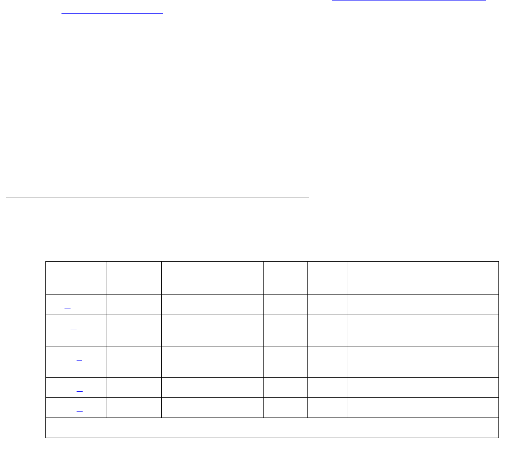
Communication Manager Maintenance-Object Repair Procedures
1840 Maintenance Procedures for Avaya Communication Manager 3.0, Media Gateways and Servers
Procedures for Restoring the PMS Link
1. Determine the status of the PMS Link.
Enter status pms-link, and make sure that the PMS Link is not busied out for
maintenance. If the link is “down,” then continue with the next step.
2. Where does the PMS Link connect?
Enter display system-parameters hospitality, and find out the destinations of the
PMS Link.
3. Determine the status of the data extension.
Enter status data extension, and verify whether the data extension is in the
in-service/idle state. If the data extension is not available, then look for the extension
number in Alt Name field of Hardware Error Log. See XXX-BD (Common Port Circuit
Pack/Media Module) on page 2539 for resolutions.
4. Is the external PMS device available?
Make sure that the PMS device is ON-LINE and ready for service. Check the physical
connectivity between Data Module and the PMS device.
5. If the problem is not found in the above steps, check the C-LAN board for any problems. For
a description about the C-LAN board and its connectivity, refer to Downloading License and
Authentication files from RFA in Maintenance Procedures (03-300192).
When restoring the PMS link, it is necessary to execute maintenance test on different objects
that comprise the PMS link. It is recommended that you busyout the PMS link before trying to
restore the link. When the PMS Link is busied out, every PMS Link maintenance action is
deactivated, and interference with tests of other MOs is prevented.
Hardware Error Log Entries and Test to Clear Values
Table 675: PMS Link Maintenance Error Log Entries
Error
Type
Aux
Data
Associated Test Alarm
Level
On/Off
Board
Test to Clear Value
0 (a)0 Any AnyAnytest pms-link sh r 1
18 (b)0 busyout
pms-link
WRN OFF release pms-link
257 (c) Any Link Retry test
(#215)
MIN
WRN1OFF test pms-link l
513 (d)Any None test pms-link
769 (e)Any None
1 of 2
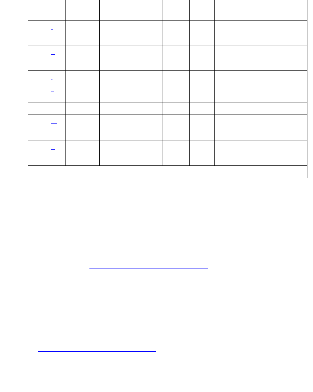
PMS-LINK (Property Management System Link)
Issue 1 June 2005 1841
Notes:
a. Error Type 0: run the short test sequence first. If every test passes, run the long test
sequence. Refer to each test’s description, and follow its procedures.
b. Error Type 18: the PMS Link has been busied out with busyout pms-link. The link is
torn down. Enter release pms-link to restore the link.
c. Error Type 257: the Link Retry test (#215) fails. An error was detected when setting up the
link. Refer to the Procedures for Restoring the PMS Link on page 1840 above.
d. Error Type 513: the PMS physical link is down for one of the following reasons:
●Cable to the PMS device is disconnected.
●The PMS device is powered off.
●The data extension to which the PMS device connects has been busied out.
Check the connectivity of wire and cable among wall jacket, data module, and the PMS
device. Enter status data extension and verify that the data extension of the PMS
device is in the in-service/idle state. If the data extension is not available, then see
Procedures for Restoring the PMS Link on page 1840.
1025 (f) 40–49 None
1281 (g) 10–19 None
1537 (h) N0–N9 None
1793 (i)Any None test pms-link
2049 (j)Any None
2305 (k) 50–59 None release pms-link, or
test pms-link
2561 (l)Any None test pms-link
2817 (m) 100–109
200–209
300–309
None
3073 (n) 70–79 None
3841 (o) 20–29 None
1. Minor alarms on this MO may be down graded to Warning alarms based on the value in set
options.
Table 675: PMS Link Maintenance Error Log Entries (continued)
Error
Type
Aux
Data
Associated Test Alarm
Level
On/Off
Board
Test to Clear Value
2 of 2

Communication Manager Maintenance-Object Repair Procedures
1842 Maintenance Procedures for Avaya Communication Manager 3.0, Media Gateways and Servers
e. Error Type 769: there has been no communication between the switch and the PMS for a
period of time specified in “system hospitality” administration. The PMS Link is torn down.
To clear this error, see Procedures for Restoring the PMS Link on page 1840.
f. Error Type 1025: The link was taken down because the switch could not receive an
incoming message from the PMS. The message from the PMS repeatedly had corrupted
data or the switch received requests for acknowledgment but never received a message to
be processed. If this error type occurs frequently (more than once a month), advise the
customer to call the vendor of the PMS to check out the PMS device. Once the PMS Link is
successfully established, this error disappears from the Hardware Error Log.
g. Error Type 1281: the link was taken down because the switch could not send an outgoing
message. The message, which was sent but not acknowledged, was flushed. If this error
type occurs frequently (more than once a month), advise the customer to call the vendor of
the PMS to check out the PMS device. Once the PMS Link is successfully established, this
error disappears from the Hardware Error Log.
h. Error Type 1537: the PMS has been busied out for maintenance at the request of the PMS.
The PMS Link is torn down. The reason code (N), if present, is that supplied by the PMS in
the request message. If this error type recurs frequently (that is, more than once a month),
advise the customer to call the vendor of the PMS to check out the PMS device. Once the
PMS Link is successfully established, this error disappears from the Hardware Error Log.
No alarm is raised against this error.
i. Error Type 1793: due to heavy call traffic, or the PMS protocol message rate being faster
than the PMS/PBX protocol specifications allow, the PMS Link is torn down. PMS Link
maintenance software will wait for five minutes before attempting to set up the link again. If
this error type occurs frequently (more than once a month), advise the customer to call the
vendor of the PMS to check out the PMS device. Once the PMS Link is successfully
established, this error disappears from the Hardware Error Log. The PMS should be
checked for adherence to message rate defined in the PMS/PBX protocol specifications. No
alarm is raised against this error.
j. Error Type 2049: The attempt to swap the database between PBX and PMS failed three
times consecutively due to excessive PMS/PBX protocol violations, buffer overflows, or
PMS Link outages. The PMS Link is NOT torn down. If this error type occurs frequently
(more than once a month), advise the customer to call the vendor of the PMS to check out
the PMS device. Once the PMS Link is successfully established, this error disappears from
the Hardware Error Log. No alarm is raised against this error.
k. Error Type 2305: The PMS Link was busied out with busyout pms-link, or it was
brought down with test pms-link long. The PMS Link is torn down, and PMS Link
maintenance stops attempts to reestablish the link in the case where the busyout
pms-link was used. When test pms-link long has been used, PMS Link
maintenance continues trying to reset the link. To restore the PMS Link after use a
busyout pms-link, enter release pms-link. To restore the PMS Link after a test
pms-link long, enter test pms-link.

PMS-LINK (Property Management System Link)
Issue 1 June 2005 1843
l. Error Type 2561: the PMS Link is physically established, but the protocol has not been
started by the PMS before the protocol timer expires. The PMS Link is NOT torn down. If
this error type occurs frequently (more than once a month), advise the customer to call the
vendor of the PMS to check out the PMS device. Once the PMS Link is successfully
established, this error disappears from the Hardware Error Log. The PMS should be
checked to make sure that it will attempt to start the protocol according to the PMS/PBX
protocol specifications. No alarm is raised against this error.
m. Error Type 2817: look for the following Aux Data:
The PMS should be assessed for adherence to the PMS/PBX protocol specifications.
n. Error Type 3073: the link was taken down by the switch because the threshold for
application protocol violations has been exceeded by the PMS. The protocol never started
and messages were received and/or messages were received in a state in which they were
not expected. (Refer to Error Type 2817 for recommended strategy.)
o. Error Type 3841: link was taken down by the switch because the threshold for link protocol
violations has been exceeded by the PMS. PMS is sending “garbage” to the switch.
10x The PMS violated the application protocol. The first message after a request
to initiate a database exchange was not the start of a database exchange.
The message is processed. If this error type with this aux data value occurs
frequently (more than once a month), advise the customer to call the vendor
of the PMS to check out the PMS device. Once the PMS Link is successfully
established, this error disappears from the Hardware Error Log.
20x The PMS violated the application protocol. The start of a database exchange
was received in a state in which it was not expected. The message is ignored.
If this error type with this Aux data value occurs frequently (more than once a
month), advise the customer to call the vendor of the PMS to check out the
PMS device. Once the PMS Link is successfully established, this error
disappears from the Hardware Error Log.
30x The PMS violated the application protocol. The end of a database exchange
was received when no exchange was in progress. The message is ignored. If
this error type with this Aux Data value occurs frequently (more than once a
month), advise the customer to call the vendor of the PMS to check out the
PMS device. Once the PMS Link is successfully established, this error
disappears from the Hardware Error Log. No alarm is raised against this error.

Communication Manager Maintenance-Object Repair Procedures
1844 Maintenance Procedures for Avaya Communication Manager 3.0, Media Gateways and Servers
System Technician-Demanded Tests:
Descriptions and Error Codes
Investigate tests in the order presented below. Clearing Error Codes associated with the one
test may also clear errors generated from other tests in the sequence.
Link Tear Down Test (#213)
This test is destructive.
This test disconnects the existing link between the system and the external PMS device. If the
link has been disconnected already, then this test just returns “PASS.” Every resource allocated
for a PMS Link is released after this test.
Order of Investigation Short Test
Sequence
Long Test
Sequence
D/ND
Link Tear Down test (#213) X Destructive
Link Retry test (#215) X X Nondestructive
Table 676: Test #213 Link Tear Down Test
Error
Code
Test
Result
Description / Recommendation
40
50
ABRT Internal system error.
1. Retry the command at 1-minute intervals up to 5 times.
1010 ABRT The PMS Link has been busied out and placed in the out-of-service state.
1. Enter release pms-link to release the PMS Link from busyout
state.
2. Retry test pms-link long to execute the test.
2012 ABRT Internal system error.
1. Retry the command at 1-minute intervals up to 5 times.
FAIL Internal system error.
1. Retry the command at 1-minute intervals up to 5 times.
PASS The PMS Link is torn down.

PMS-LINK (Property Management System Link)
Issue 1 June 2005 1845
Link Retry Test (#215)
This test sends a message to the PMS software process to make a data call to the extension
where the PMS device connects. If the PMS Link is already up, then this test passes without
making any data call.
Table 677: Test #215 Link Retry Test
Error
Code
Test
Result
Description / Recommendation
10
20
ABRT Internal system error.
1. Retry the command at 1-minute intervals up to 5 times.
30 ABRT Internal system error.
1. Refer back to Procedures for Restoring the PMS Link on page 1840
for resolution.
1010 ABRT The PMS Link has been busied out and placed in the out-of-service state.
1. Enter release pms-link to release the PMS Link from busyout
state.
2. Retry test pms-link to execute the test.
2012 ABRT Internal system error.
1. Retry the command at 1-minute intervals up to 5 times.
FAIL The PMS Link CANNOT be established.
1. Refer back to Procedures for Restoring the PMS Link on page 1840
for restoring the PMS Link.
PASS The PMS Link is up.

Communication Manager Maintenance-Object Repair Procedures
1846 Maintenance Procedures for Avaya Communication Manager 3.0, Media Gateways and Servers
PMS-PRNT/JNL-PRNT (PMS Printer Link)
S8700 | 8710 / S8500
A journal printer is a printer to which Emergency Access to Attendant, Wakeup and Property
Management System (PMS) events are printed as they occur. The PMS-log printer is used as a
backup of the PMS output device to print an audit trail of every PMS transaction and
Housekeeping Status Change event when the PMS Printer Link is not available. There may be
one or two journal printers. If there is one, every event is printed there. If there are 2, then
emergency access, wakeup events, and scheduled reports are printed at one printer
(JNL-PRNT), and PMS events are printed at the other (PMS-PRNT).
The scheduled report printer is where summaries of daily wakeup activity and emergency
access activity are printed. If the customer requests a summary report, the report will be printed
exactly once per day.
The distinction between Journal and Scheduled report printers is logical rather than physical.
Whether or not there are two printers, the scheduled reports are always sent to the printer that
journals the wakeup and emergency access events. A scheduled report will temporarily
suspend the journal activity. Upon completion of the scheduled report, journaling will be
resumed after the printing of every withheld event.
The journal printer device connects to the system via a data module (PDM, MPDM, DTDM)
connected to a port on a TN754 Digital Line circuit pack that is administered as a data
extension. A journal printer device can also be connected through an ADU to a port on TN726B
Data Line circuit pack. The journal printer’s link to the processor is via a C-LAN port. For
information about C-LAN connectivity, see CLAN-BD (Control LAN Circuit Pack) on page 789.
PMS/JOURNAL Printer Link Maintenance provides a strategy for maintaining the link between
the system and a PMS device (an external Journal Printer device). The strategy includes a set
of tests for periodic diagnosis, detection of errors during normal operation, actions for
troubleshooting, and raising alarms for serious problems. PMS Printer Link Maintenance uses a
try-and-wait mechanism. If a PMS Printer Link is torn down due to an error, PMS Printer Link
Maintenance will try to bring the link up immediately. If the link setup fails, PMS Link
Maintenance will wait for five minutes before the next trial. If the number of retries reaches a
threshold (15), a Minor alarm is raised for service attention.
MO Name in Alarm
Log
Alarm
Level
Initial Command to Run Full Name of MO
PMS-PRNT/JNL-PRNT MIN test journal [pms-log |
wakeup-log] long
PMS Printer/
Journal Printer
PMS-PRNT/JNL-PRNT WRN test journal [pms-log |
wakeup-log]
PMS Printer/
Journal Printer

PMS-PRNT/JNL-PRNT (PMS Printer Link)
Issue 1 June 2005 1847
PMS Printer Link Maintenance does not cover the maintenance of the elements composing the
journal printer physical link (for instance, the external printer device, Data Module (PDM/MPDM/
DTDM), Digital Line Port or ADU and Data Line Port). If PMS Printer Link maintenance cannot
restore the PMS Printer Link, then the maintenance tests of individual components of the PMS
Link must be executed to diagnose faults.
The list pms-down command lists every meaningful event to the PMS that occurred while
the link between the switch and the PMS was down. For example, any room status codes
entered by hotel housekeeping staff during a time of PMS outage would be reflected in this
report.
Procedures for Restoring the PMS Printer Link
1. Determine the status of the PMS Printer Link.
Enter status journal-printer wakeup-log | pms-log and make sure that the
journal printer link is not busied out for maintenance. If the link is down, then continue to the
next step.
2. Where does the journal printer link connect?
Enter display system-parameters hospitality and find out the destinations of the
PMS Printer Link.
3. Determine the status of the data extension.
Enter status data extension and verify that the data extension is in the in-service/idle
state. If the data extension is not available, look for the extension number in the Alt Name
field of the Hardware Error Log. See XXX-BD (Common Port Circuit Pack/Media
Module) on page 2539 for resolutions.
4. Is the external printer device available?
Make sure that the printer device is ON-LINE and ready for service. Check the physical
connectivity between Data Module and the printer device.
5. If the problem is not found in the above steps, check the C-LAN board for any problems. For
a description of C-LAN connectivity, see CLAN-BD (Control LAN Circuit Pack) on page 789.
It should be noted that when restoring the PMS printer link, it is necessary to execute tests on
different MOs that comprise the link; it is recommended that you busyout the PMS printer link
before trying to restore the link. If the PMS printer Link is busied out, then every PMS printer
Link maintenance action is deactivated, and interference with tests of other MOs is prevented.

Communication Manager Maintenance-Object Repair Procedures
1848 Maintenance Procedures for Avaya Communication Manager 3.0, Media Gateways and Servers
Error Log Entries and Test to Clear Values
Notes:
a. Error Type 0: run the short test sequence first. If every test passes, run the long test
sequence. Refer to each test’s description and follow its procedures. Both PMS Printer and
Journal Printer are administered to the same extension, and the printer is not connected.
Refer to the Procedures for Restoring the PMS Printer Link for resolution.
b. Error Type 18: the Journal Printer Link has been busied out and the link is torn down. Enter
release journal wakeup-log | pms-log to restore the link.
c. Error Type 257: link Retry test (#215) fails. Physical link cannot be set up, usually because
of hardware problems such as power off or cable disconnect. See Procedures for Restoring
the PMS Printer Link on page 1847.
d. Error Type 513: physical link cannot be set up, usually because of hardware problems such
as power off or cable disconnect. The PMS Printer Link physical link is down due to the
following causes: cable to the printer device is disconnected, the printer device is powered
off, or the data extension where the printer device connects to has been busied out. Check
the connectivity of wire and cable among wall jacket, data module, and the printer device.
Enter status data extension and verify that the data extension of the printer device is
in the in-service/idle state. If the data extension is not available, then see Procedures for
Restoring the PMS Printer Link on page 1847.
Table 678: PMS-PRNT/JNL-PRNT Link Maintenance Error Log Entries
Error
Type
Aux
Data
Associated Test Alarm
Level
On/Off
Board
Test to Clear Value
0 (a) 0 Any Any Any test journal wakeup-log |
pms-log sh
18 (b)0 busyout
journal
wakeup-log
| pms-log
WRN OFF release journal wakeup-log |
pms-log
257 (c) Any Link Retry test
(#215)
MIN1
WRN
1. Minor alarms may be downgraded to Warning alarms based on the value used in set options.
OFF test journal wakeup-log |
pms-log long
513 (d)Any test journal wakeup-log |
pms-log
769 (e)

PMS-PRNT/JNL-PRNT (PMS Printer Link)
Issue 1 June 2005 1849
e. Error Type 769: link idle timer; link comes down. The printer device is in an off-line state, for
example, paper jam or paper out. Check the printer device and act promptly to put it back to
on-line state. Enter test journal wakeup-log | pms-log to set up the printer link.
System Technician-Demanded Tests:
Descriptions and Error Codes
Investigate tests in the order presented below. Clearing Error Codes associated with the one
test may also clear errors generated from other tests in the sequence.
Link Tear Down Test (#213)
This test is destructive.
This test disconnects the existing link between the system and the external printer device. If the
link has been disconnected already, this test just returns PASS. Every resource allocated for a
PMS Printer Link is released after this test.
Order of Investigation Short Test
Sequence
Long Test
Sequence
D/ND
Link Tear Down test (#213) X Destructive
Link Retry test (#215) X X Nondestructive
Table 679: Test #213 Link Tear Down Test
Error
Code
Test
Result
Description / Recommendation
40 ABRT Internal system error.
50 ABRT Internal system error.
1. Retry the command at 1-minute intervals up to 5 times.
1010 ABRT The link has been busied out to out-of-service.
1. Enter release journal wakeup-log|pms-log to release the
link from busyout state.
2. Retry test journal wakeup-log|pms-log l to execute the
test.
2012 ABRT Internal system error.
1. Retry the command at 1-minute intervals up to 5 times.
1 of 2

Communication Manager Maintenance-Object Repair Procedures
1850 Maintenance Procedures for Avaya Communication Manager 3.0, Media Gateways and Servers
Link Retry Test (#215)
This test sends a message to the journal printer management software process to make a data
call to the extension where the printer device connects to. If the journal printer link is already up,
this test passes without making any data call.
FAIL Internal System error.
1. Retry the command at 1-minute intervals up to 5 times.
PASS The link is torn down.
Table 679: Test #213 Link Tear Down Test (continued)
Error
Code
Test
Result
Description / Recommendation
2 of 2
Table 680: Test #215 Link Retry Test
Error
Code
Test
Result
Description / Recommendation
10 ABRT Internal system error.
1. Retry the command at 1-minute intervals up to 5 times.
20 ABRT Internal system error.
1. Retry the command at 1-minute intervals up to 5 times.
30 ABRT Internal system error.
1. See Procedures for Restoring the PMS Printer Link on page 1847 for
instructions.
1010 ABRT The PMS Printer Link has been busied out to out-of-service.
1. Enter release journal wakeup-log|pms-log to release the
link from busyout state.
2. Retry test journal wakeup-log|pms-log l to execute the
test.
2012 ABRT Internal system error.
1. Retry the command at 1-minute intervals up to 5 times.
FAIL The link cannot be established.
1. See Procedures for Restoring the PMS Printer Link on page 1847 for
instructions.
PASS The link is up.

PNC-DUP (PNC Duplication)
Issue 1 June 2005 1851
PNC-DUP (PNC Duplication)
S8700 MC only
In systems with the Critical Reliability option, the following components, which together
comprise the Port Network Connectivity (PNC), are duplicated:
●Expansion Interface (EI) TN570 circuit packs in the port networks (PNs)
●Switch Node Interface (SNI) TN573 circuit packs in switch nodes
●DS1 Converter (DS1C) TN574 circuit packs for remote PN connections
●Fiber-optic cables (metallic in certain cases) connecting the above circuit packs
●DS1 facilities between the DS1Cs
●Switch Node Clock (SNC) TN572 circuit packs
●IP Server Interface (IPSI) TN2312AP circuit packs
Although not part of the PNC, Tone-Clock circuit packs are also duplicated in each PN. The
PNC is available in two different configurations: direct connect, in which each port network is
connected directly by fiber optic links to each other PN; and Center Stage Switch (CSS) which
utilizes one or two switch nodes to interconnect the PNs. Direct connect systems can have up to
two PNs. CSS systems with one switch node can have up to 15 PNs. CSS systems with three
switch node can have up to 44 PNs. See the following figures.
PNC duplication architecture utilizes an active/standby duplication scheme, in which one
complete set of PNC components supports call processing, while the duplicate PNC is held in
reserve. All calls on the active PNC are simultaneously set up, or shadowed, on the standby
PNC in order for it to be capable of instantly assuming active status when necessary, allowing
for interchanges without service disruption (in the case of single faults).
The PNC-DUP MO tracks the health of the active and standby PNCs, controls planned and
spontaneous interchanges, and manages related functions such as double call refresh and
unrefresh, anti-thrashing, and so on. The main responsibility of PNC-DUP is to recover the
system to full service in the event of a fault. In the event of multiple faults PNC-DUP will do its
best to maximize service continuity.
PNC duplication does not introduce any additional types of hardware or hardware faults, and
there are no tests associated with the PNC-DUP MO. Instead, error log entries are used to log
useful information about the occurrence and causes of interchanges. This is done in order to
facilitate diagnosis of problems, which can then be addressed by using the documentation for
the individual MO involved.
MO Name in
Alarm Log
Alarm
Level
Initial Command to Run Full Name of MO
PNC-DUP NA status pnc PNC duplication

Communication Manager Maintenance-Object Repair Procedures
1852 Maintenance Procedures for Avaya Communication Manager 3.0, Media Gateways and Servers
PNC-DUP Related Commands
The following commands are described in Maintenance Commands Reference (03-300191).
Busyouts and PNC-DUP
The busyout pnc command puts the standby PNC in the busyout state, and call set up is
turned off.
●The standby PNC is unrefreshed; existing duplicate call connections are removed.
●PNC interchanges are prevented.
Upon release, interchanges are re-enabled and a global refresh of double call setup on the
standby is performed.
When PNC duplication is in effect:
●An active PNC component cannot be busied-out.
●A standby PNC component can only be busied-out when the standby PNC is first
busied-out.
●The standby PNC cannot be released unless all standby PNC components are released.
status pnc Lists information about the operational status of both PNCs including
state of health, alarms, busyouts and locks.
reset pnc
interchange
Initiates a demand PNC interchange. If the standby is healthy with state
of health indexes all 0, there is no effect on service. Otherwise, calls
may be dropped.
set pnc Locks or unlocks the active PNC, preventing interchanges. It does not
interfere with double call setup.
busyout pnc Removes the standby PNC from service. See also Busyouts and
PNC-DUP.
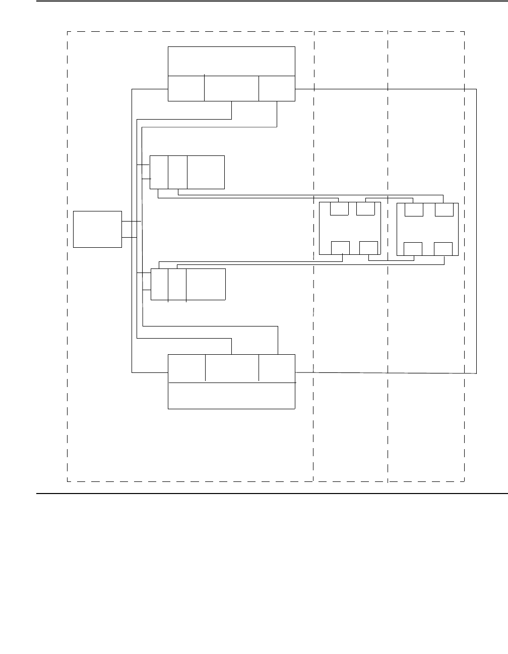
PNC-DUP (PNC Duplication)
Issue 1 June 2005 1853
Figure 110: Duplicated Direct Connect PNC Connectivity
PKT-INT
AAT/C
IPSI A
EPN 1
EI
EI
EI
EI
EI EI EI EI
EI EI EI EI
MAINT/
Tes t
PORT CARRIER
PORT CARRIER
EPN 2 EPN 3
T/C AA PKT-INT
IPSI B
LAN
TDM
TDM
LAN

Communication Manager Maintenance-Object Repair Procedures
1854 Maintenance Procedures for Avaya Communication Manager 3.0, Media Gateways and Servers
Figure 111: Duplicated PNC with Center Stage Switch Connectivity
CSS A
CSS B
EPN
IPSI A
IPSI B
SWITCH NODE SWITCH NODE
SWITCH NODE SWITCH NODE
T/C AA PKT-INT
MAINT/
Test
TDM
LAN
EI
EI EI
EI EI
EI EI
EI EI
EI
S
N
I
S
N
I
S
N
I
S
N
I
S
N
I
S
N
I
S
N
I
S
N
I
S
N
I
S
N
I
S
N
I
S
N
I
S
N
I
S
N
I
EPN 1 EPN 10 EPN 11 EPN 44
5
5
T/C AA PKT-INT
....... ......
LAN
TDM

PNC-DUP (PNC Duplication)
Issue 1 June 2005 1855
Enabling and Removing PNC Duplication
Note:
Note: PNC duplication requires IPSI duplication.
To Enable PNC Duplication
To enable PNC duplication:
1. Enable PNC-DUP on the change system-parameters customer-options screen.
2. Fully administer duplicate fiber link connectivity. Verify by issuing list fiber-link. For
IP Duplication go to Step 3.
3. Fully administer IPSI duplication (ipserver-interface duplication). Verify by using
list ipserver-interface.
4. Turn on PNC-DUP using the change system-parameters duplication screen. This
is not allowed if any component of either PNC (A or B) is busied out.
5. The system must insert all connectivity-related components for both standby and active
PNC. For CSS configurations this takes up to 5 minutes depending upon CSS circuit pack
insertion. For Direct Connect configurations this is declared complete at 5 minutes after the
first appearance of the terminal login prompt.
6. The PNC-DUP initialization anti-thrashing timer must expire (this occurs 5 minutes after
completion of board insertion, PNC interchange, or system reset of level 2 or higher).
To Disable PNC Duplication
To disable PNC duplication perform the following sequence of steps:
1. Verify that the A-PNC is active. A forced interchange may be required. See reset pnc in
Chapter 8.
2. Busyout the standby PNC (B-PNC).
3. Turn off the system parameter for PNC-DUP using change system-parameters
duplication.
After PNC duplication has been removed, configuration audits generate the alarm shown
below and possibly others. To clear this alarm, the B-PNC fibers, circuit packs in switch
node carriers (EIs, SNIs, SNCs, and DS1Cs), and switch node carriers must be removed as
outlined in the following steps.
01D SN_CONF 5000 255
In this case, 01D is the B-PNC switch node from which duplication was removed.

Communication Manager Maintenance-Object Repair Procedures
1856 Maintenance Procedures for Avaya Communication Manager 3.0, Media Gateways and Servers
4. Remove the B-PNC fibers by removing the Endpoint Board Locations on the change
fiber-link screen for all fibers. For fibers using DS1Cs, remove the B-PNC DS1C
Board Locations on the change fiber-link screen.
5. Remove the B-PNC circuit packs starting with the switch node carrier most distant from the
media server complex. Use change circuit-pack location, page to the B-PNC
carrier and remove all of the circuit packs there. Remove all circuit packs in the other
B-PNC switch node carriers.
If the Expansion Interface circuit pack associated with the PN is located in the switch node
carrier closest to the media server, it cannot be removed from translation until it has been
busied-out and disconnected from the carrier slot.
When SNI, SNC, or DS1C circuit packs are removed from a B-PNC carrier, any alarms
against them should be resolved.
6. Remove the B-PNC switch node carriers. Use change cabinet location and enter
not-used for B-PNC carriers.
Any alarm against the carrier such as 01D SN-CONF should be resolved. The B-PNC
carriers and associated circuit packs should not be alarmed.
7. Disable PNC duplication on the change system-parameters customer-options
screen by changing PNC Duplication to no.
If an alarm exists against any Expansion Interface circuit pack connected to a B-PNC
carrier, use test board location long clear to clear the alarm.
Alterations to PNC which involve only the addition of fiber connectivity can be done with
PNC-DUP operational. Alterations requiring the removal of fiber connectivity must be done with
PNC-DUP removed. PNC-DUP must be removed and translations should be saved before any
hardware changes are made.
Steady State LEDs
The LEDs of PNC components in a stable duplicated system should appear as follows:
●The active IPSIs are functioning as archangels in IPSI port networks.
●The active EIs in the PNs are functioning as archangels. Their LEDs flash in a pattern of 2
seconds on 200 milliseconds off (PN without an IPSI).
●The PN standby EIs amber LEDs are off (PN without an IPSI).
●The PN active EI amber LED is on solid (PN with an IPSI).
●The PN standby EI amber LED is off (PN with an IPSI).
●The SNIs on the active switch node(s) have amber LEDs on solid.
●The SNIs on the standby switch node(s) have amber LEDs off.
●Active DS1Cs amber LEDs are on solid.

PNC-DUP (PNC Duplication)
Issue 1 June 2005 1857
●Standby DS1Cs amber LEDs are off.
●DS1C facility green LEDs are on if the corresponding facility is equipped.
PNC State of Health
PNC-DUP software monitors the health of the two PNCs as determined by their state of health
(SOH) vectors, and initiates an interchange when the health of the active falls below that of the
standby (unless prevented from doing so by a PNC lock, busyout, or anti-thrashing
mechanism). Potentially service-disrupting faults which occur in PNC components are reported
to PNC-DUP and incorporated in the state of health for the affected PNC. The SOHs of both
PNCs are displayed on the status pnc screen.
Figure 112: Status PNC Screen with Standby PNC Fully In-Service
PNC State-of-Health Indexes
The Inter-PN and Inter-SN Indexes form the state of health vector, which is used to track and
compare the states of health of both PNCs. The fields making up the indexes are two digit
numbers separated by periods (.), with each field representing a different class of faults. The
fault class fields are arranged in order of decreasing importance from left to right. In other
words, each field in the index supersedes the following fields in determining which PNC is
healthiest. A fault class drives an interchange only when all of the higher priority fault classes
are equal. A zero entry indicates no faults in that class. Increasing numbers indicate
increasingly higher numbers of faults present in that class.
status pnc page 1 of 1
PORT NETWORK CONNECTIVITY
Duplicated? yes
Software Locked? no
Standby Busied? no
Direct Connect? no
Standby Refreshed? yes
Interchange Disabled? no
A-PNC B-PNC
Mode: active Mode: standby
State of Health: functional State of Health: functional
Inter PN Index: 00.00.00.00.00.00 Inter PN Index: 00.00.00.00.00.00
Inter SN Index: 00.00 Inter SN Index: 00.00
Major Alarms: 0 Major Alarms: 0
Minor Alarms: 0 Minor Alarms: 0
Warning Alarms: 0 Warning Alarms: 0
SN Locations: 01E SN Locations: 01D

Communication Manager Maintenance-Object Repair Procedures
1858 Maintenance Procedures for Avaya Communication Manager 3.0, Media Gateways and Servers
The Inter-PN Index contains six fields (XX.XX.XX.XX.XX.XX), and the Inter-SN Index has two
(XX.XX). The Inter-PN Index reports faults in connectivity between port networks and
supersedes the Inter-SN Index, which reports faults in connectivity between switch nodes. (The
Inter-SN Index is only meaningful for systems with a center stage switch having two switch
nodes, each of which is duplicated).
The meaning of each fault class field is given in the following table. A zero entry indicates that
there are no such faults reported. Higher numbers indicate increasing number of faults. All
zeros indicates perfect state of health. Unless the PNCs are locked, the active PNC’s state of
health should always be equal to or better than the standby’s. (Otherwise, the system would
perform a spontaneous interchange.)
After a PNC-related alarm is cleared, the system performs a partial refresh of the standby PNC.
The corresponding fault class field is not updated to reflect the improved state of health until the
refresh is done. The state of health indexes will not agree with the current alarm status during
this period.
Inter SN Index: FC_SNIL s11.s10 FC_SNIHW
Table 681: PNC State-of-Health Fault Classes
Fault Class Priority Description MOs
FC_EAL 1 Number of PNs with EALs down EXP-PN
FC_INL 2 Number of PNs with LINL, RINL, or
EI-SNI neighbor link faults
EXP-PN,
SN-CONF
FC_BFD1
1. BFDLs only exist in Port networks that have an IPSI. Port networks that do not have an IPSI will
have the EI as Archangel and no BFDL faults.
3 Number of PNs with BFDL (Bearer Fault
Detection Link) faults
SYS-LINK
FC_HW 4 Number of PNs affected by hardware
faults in a link having an EI as an
endpoint (Endpoints can be determined
with list fiber-link.)
EXP-INTF,
SN-CONF,
FIBER-LK,
SNI-BD,
DS1C-BD
FC_PER 5 Number of PNs affected by SNI peer link
faults for SNIs connected to EIs
SNI-PEER
FC_DS1 6 Number of PNs affected by DS1C facility
faults
DS1FAC
FC_SNIL 7 Number of inter-switch-node fibers
affected by peer or neighbor link faults
SNI-PEER
FC_SNIHW 8 Number of interswitch-node fibers
affected by hardware faults
SN-CONF,
SNI-BD,
FIBER-LK

PNC-DUP (PNC Duplication)
Issue 1 June 2005 1859
In multi-node CSS configurations FC_DS1 is considered less critical that FC_SNINL since
DS1C constraints affect only one PN and indicate restricted bandwidth. However FC_SNINL
can indicate problems for all PNs on the far end switch node (the one downlink from the PN) If
the DS1C problem is critical (for example, loss of all bandwidth to the affected PN) a constraint
with a higher order fault class will be reported to PNC DUP.
Resolving Poor State of Health
When the SOHs for both PNCs are not all zeros, identify and repair the problem:
1. Look for PNC component alarms (major or minor) for the PNC side whose SOH is not all
zero. First repair the standby PNC.
2. Busy-out the standby PNC.
3. Follow the diagnostic and repair procedures for the alarmed PNC components just as with a
unduplicated PNC. Examine the alarm logs and error logs to isolate the fault.
4. Verify that the related PNC SOH is restored to all zeros.
5. Release the standby PNC for busy-out.
Refresh and Unrefresh of the Standby PNC
In a fully functional PNC with healthy standby and active sides, the standby PNC has a
complete set of call connections corresponding to those in the active PNC. If, however, the state
of health of the standby PNC degrades, a selective unrefresh of those connections which utilize
the faulted component(s) is performed. If the health of the standby PNC improves, a selective
refresh of connections on the affected route is performed, so that call setup is consistent
between the active PNC and the healthy parts of the standby PNC.
The Standby Refreshed field on the status pnc screen does not refer to the selective type of
refresh. It refers only to a global refresh that is performed when:
●The system is initialized and PNC duplication is enabled.
●There has been a spontaneous PNC interchange.
●The standby PNC has been released from busy-out.
●A system reset of level 2 or higher has taken place.
The Refreshed field may show y when the standby is partially unrefreshed. An interchange into
an incompletely refreshed standby results in dropped calls. This can happen when a more
severe fault occurs on the active PNC, or when set pnc interchange is used with the
override option.

Communication Manager Maintenance-Object Repair Procedures
1860 Maintenance Procedures for Avaya Communication Manager 3.0, Media Gateways and Servers
PNC Interchanges
PNC spontaneous interchanges occur when PNC duplication software determines that the SOH
of the standby PNC is better than that of the active PNC. PNC-DUP executes a spontaneous
interchange only when a message from a PNC component MO sends a message indicating that
either a fault has occurred on the active PNC, or a fault has been resolved on the standby PNC
such that the state of health of the active PNC is now lower than that of the standby.
This message will usually indicate the type and location of the failed connectivity component. A
corresponding major or minor alarm is logged by the reporting MO, stimulating an alarm report.
In the less common situation when the resolution of a fault on the standby renders it more
healthy than a simultaneously faulted active PNC, the message will indicate the type and
location of the improved component.
Once the interchange completes, the failed component will be on the standby PNC. A demand
interchange can be requested in the presence or absence of standby PNC faults. The following
sequence of actions can be observed during a fault-free interchange:
1. The Expansion Interfaces currently acting as archangels in the PNs are deactivated as
indicated by the amber LEDs going from flashing to on solid.
2. The EIs in IPSI port networks are interchanged as indicated by the new standby EI amber
LED off and the new active EI amber LED on solid.
3. One by one the EIs in non IPSI port networks are interchanged as indicated by new standby
EI amber LED turning off and the new active EI amber LED flashing (2 seconds on, 200
milliseconds off). At this point the interchange is functionally complete.
4. The SNIs amber LEDs are updated. so that the SNIs on the active SN have amber LEDs
on, while the standby SN’s SNIs amber LEDs turn off.
Certain conditions may interfere with the normal execution of the interchange:
1. In a faulted spontaneous interchange it is possible the PN directly affected by the fault will
be the last to interchange.
2. A user directly affected by the single fault instigating a PNC interchange can experience a
momentary outage of voice path connectivity during the switch.
3. If faults exist on both the standby and active PNC, it is possible to have some PNs go out of
service while others are returned to service.
4. The new standby SNIs amber LED my not be off due to a fault in the line of communication
path to the standby SNIs. In a multi-fault interchange, LEDs on the new active SNIs may not
be on for the same reason.
In any multi-fault situation, use status pnc to determine which is the active PNC.
PNC duplication informs Timing Synchronization maintenance when a PNC interchange has
been completed and indicates which PNC is active. This causes Synchronization to audit and
insure that the primary source for synchronization of Tone-Clocks in each PN is supplied by a
path associated with the active PNC.

PNC-DUP (PNC Duplication)
Issue 1 June 2005 1861
Antithrashing and PNC Interchanges
Following a spontaneous PNC interchange, subsequent PNC interchanges are prevented for 5
minutes. This condition is indicated by a y in the Interchange Disabled field of the status PNC
screen. After 5 minutes, the anti-thrashing, timer expires, interchange decisions are re-enabled,
and the field entry is n.
Note:
Note: Should a catastrophic failure occur on the active PNC during the period when
Interchange Disabled? is set to y, there will be no spontaneous PNC
interchange.
Demand PNC interchanges also invoke anti-thrashing, but only for a period of 30 seconds.
During anti-thrashing mode, demand interchanges are also prevented unless the override
option is specified. Use of this option will cause a service disruption.
Repairs on the Standby PNC Components
!CAUTION:
CAUTION: If there is a TDM-CLK alarm, system timing may be routed through part of the
standby PNC, and circuit switched data may be affected by the following repair
procedures. This can happen, for example, when a slave tone/clock circuit pack
experiences a loss of signal and switches to receive timing from the standby EI.
In this case TDM-CLK 2305 error will be logged, and the clock problem should be
addressed first, if possible.
To repair PNC components in a duplicated PNC:
Most repairs involve fixing a single fault on the standby PNC.
1. Use set pnc lock or busyout pnc to prevent an interchange into the PNC being
repaired.
If a faulty component exists on the currently active PNC, the standby PNC is more severely
faulted. Normally the standby PNC is repaired first because it is the most severely impaired.
2. To repair the active PNC, use reset pnc interchange override-and-lock to
request an interchange and ensure that no subsequent interchange occurs during the repair
of the standby PNC.
The demand interchange may not be necessary if the following conditions drive a
spontaneous interchange:
●The anti-thrashing period from the last interchange has expired.
●The global refresh from releasing the standby PNC has completed.
The standby PNC SOH is better than the active.

Communication Manager Maintenance-Object Repair Procedures
1862 Maintenance Procedures for Avaya Communication Manager 3.0, Media Gateways and Servers
3. At this point, the faulty component is on the standby PNC, and the PNCs are locked in their
current active/standby state. Busy-out the PNC.
4. Use fault isolation and component testing procedures for the individual PNC components.
Replacement of components will not disrupt operation of the active PNC.
5. Once the failed component is replaced, test the standby PNC component from the terminal
to ensure the replacement is functioning properly.
6. When the problem is resolved as indicated by a state of health with all zeros, (status
pnc), unlock and release the pnc.
No further PNC interchange is required because you can test the standby PNC as thoroughly as
the active.
Interactions: Media Server Resets and PNC Interchanges
●A system reset of level 1 (warm), 2 (cold2) or 4 (reboot) does not change which PNC is
active. If a PNC interchange was in progress when the reset took place, the PNC
interchange still goes to completion.
●If a system reset level 1 (warm) takes place during a PNC interchange, the reset is
escalated to level 2 (cold2).
Fault Isolation Using Duplicated PNC
PNC duplication, can, in some cases aid in the isolation of faults. PNC interchanges can be
used to help indict the faulty hardware. Following are two examples demonstrating this
technique.
●There is a fault which can occur in either an IPSI port network’s EI or the PKT-INT which
cannot be readily attributed to one board or the other. If the packet bus transceivers on the
PKT-INT or EI fail, it will be apparent that the two boards cannot communicate, but it will
not be clear which board is at fault. In this case, a planned interchange of the PNC can be
used to indict one of the two boards. If the interchange cures the problem, the EI was at
fault. If the interchange does not cure the problem, the PKT-INT is suspect, provided there
are no PKT-BUS faults.
●A similar relationship exists for the PN Archangel (active EI) and certain TDM bus
problems. If the EAA cannot communicate with a port board over the TDM bus, then the
EAA has a fault, the port board has a fault, or there is a problem with the TDM bus itself.
- If TDM bus maintenance tests find no problems with the bus, then it is either the port
board or the EAA. It may be simpler to replace the port board than to request a PNC
interchange.
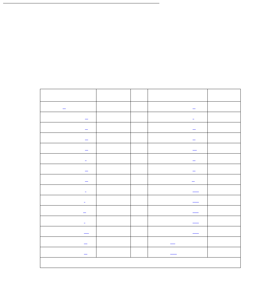
PNC-DUP (PNC Duplication)
Issue 1 June 2005 1863
- If it is not clear which port board may be at fault, or maintenance is being performed
remotely, verify that the EAA is not at fault by executing a PNC interchange. If the
interchange solves the problem, then the EAA is faulty.
- If the problem persists after the interchange, but TDM bus maintenance finds no
problem, then the port board is faulty.
Error Log Entries
When a PNC interchange takes place, an error is logged against PNC-DUP with a code that
conveys information about the cause of the interchange and which PNC became active. There
are no alarms associated with PNC-DUP errors. There should be an alarm against the PNC
component that drove the interchange.
There are no PNC-DUP test sequences. Use status pnc to see information regarding the
status of the PNCs.
The information in the following tables helps identify areas of the Alarm Log to investigate in
order to find the source of the problem.
Error Type Aux Data Error Code Aux Data
00000 (a) None 20200 – 20263 (s)1
10000 – 10063 (b)120300 – 20363 (t)1
10100 – 10163 (c)120400 – 20463 (u)1
10200 – 10263 (d)120500 – 20563 (v)1
10300 – 10363 (e)120601 – 20664 (w)1
10400 – 10463 (f)120701 – 20764 (x)1
10500 – 10563 (g)121000 – 21063 (y)1
10601 – 10664 (h)121100 – 21163 (z)1
10701 – 10764 (i)121200 – 21263 (aa)1
11000 – 11063 (j)121300 – 21363 (ab)1
11100 – 11163 (k)121400 – 21463 (ac)1
11200 – 11263 (l)121601 – 21664 (ad)1
11300 – 11363 (m)121701 – 21764 (ae)1
11400 – 11463 (n)151000 (af)1
11601 – 11664 (o)152000 (ag)1
1 of 2
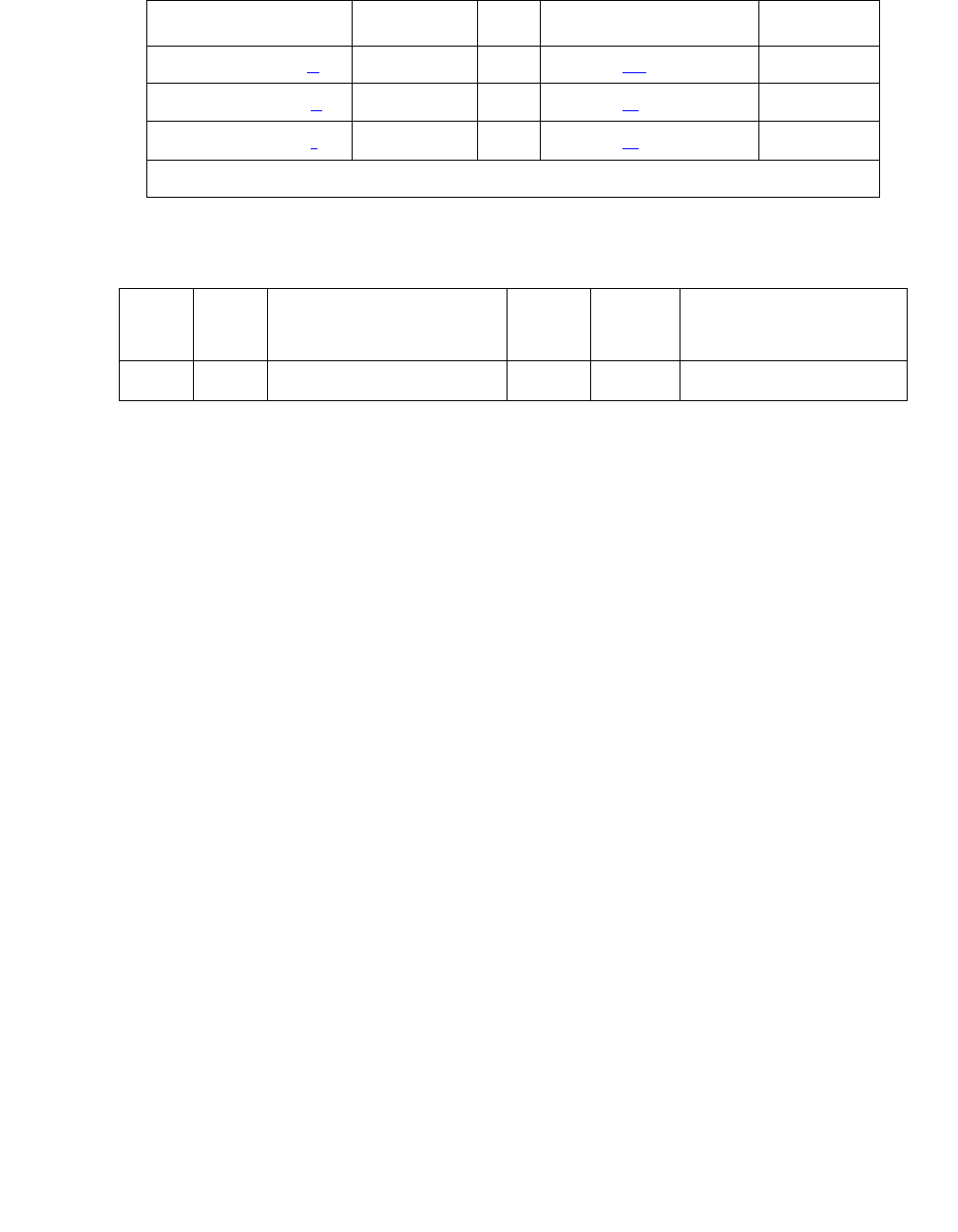
Communication Manager Maintenance-Object Repair Procedures
1864 Maintenance Procedures for Avaya Communication Manager 3.0, Media Gateways and Servers
Notes:
a. Error Type 0: an error took place in generating the Error Code.
b. Error Type 10000-10063: a spontaneous PNC interchange took place in response to the
retiring of an alarm on the A-PNC associated with fault class FC_EAL. Use status pnc to
look at the state of health indexes for the PNCs, and investigate any associated alarms.
Adding 1 to the last two digits of the Error Code gives the PN number of the port network
that reported the retired alarm. (10003 points to port network 4) Use list config
port-network to show the cabinet number associated with a port network.
c. Error Type 10100-10163: a spontaneous PNC interchange took place in response to the
retiring of an alarm on the A-PNC associated with fault class FC_INL. Use status pnc to
look at the state of health indexes for the PNCs, and investigate any associated alarms.
Adding 1 to the last two digits of the Error Code gives the PN number of the port network
that reported the retired alarm. (10003 points to port network 4)Use list config
port-network to show the cabinet number associated with a port network.
d. Error Type 10200-10263: a spontaneous PNC interchange took place in response to the
retiring of an alarm on the A-PNC associated with fault class FC_HW. Use status pnc to
look at the state of health indexes for the PNCs, and investigate any associated alarms.
Adding 1 to the last two digits of the Error Code gives the PN number of the port network
that reported the retired alarm. (10203 points to port network 4.) Use list config
port-network to show the cabinet number associated with a port network.
e. Error Type 10300-10363: a spontaneous PNC interchange took place in response to the
retiring of an alarm on the A-PNC associated with fault class FC_PER. Use status pnc to
look at the state of health indexes for the PNCs, and investigate any associated alarms.
Adding 1 to the last two digits of the Error Code gives the PN number of the port network
that reported the retired alarm. (10303 points to port network 4.) Use list config
port-network to show the cabinet number associated with a port network.
11701 – 11764 (p)153000 (ah)1
20000 – 20063 (q)160801 (ai)1
20100 – 20163 (r)160800 (aj)1
1. The Aux Data indicates which PNC became active after the PNC interchange: “0”
denotes PNC-A; “1” denotes PNC-B.
Error
Type
Aux
Data
Associated Test Alarm
Level
On/Off
Board
Test to Clear Value
18 None busyout pnc-dup WRN ON release pnc-dup
Error Type Aux Data Error Code Aux Data
2 of 2

PNC-DUP (PNC Duplication)
Issue 1 June 2005 1865
f. Error Type 10400-10463: a spontaneous PNC interchange took place in response to the
retiring of an alarm on the A-PNC associated with fault class FC_DS1. Use status pnc to
look at the state of health indexes for the PNCs, and investigate any associated alarms.
Adding 1 to the last two digits of the Error Code gives the PN number of the port network
that reported the retired alarm. (10403 points to port network 4.) Use list config
port-network to show the cabinet number associated with a port network.
g. Error Type 10500-10563: a spontaneous PNC interchange took place in response to the
retiring of an alarm on the A-PNC associated with fault class FC_BFD. Use status pnc to
look at the state of health indexes for the PNCs, and investigate any associated alarms.
Adding 1 to the last two digits of the Error Code gives the PN number of the port network
that reported the retired alarm. (10203 points to port network 4.) Use list config
port-network to show the cabinet number associated with a port network.
h. Error Type 10600-10664: a spontaneous PNC interchange took place in response to the
retiring of an alarm on the A-PNC associated with fault class FC_SNIL. Use status pnc to
look at the state of health indexes for the PNCs, and investigate any associated alarms. The
last two digits of the Error Code indicate the fiber-link number of the fiber that reported the
retired alarm. Use list fiber-link to show the location of the fiber.
i. Error Type 10700-10764: a spontaneous PNC interchange took place in response to the
retiring of an alarm on the A-PNC associated with fault class FC_SNIHW. Use status pnc
to look at the state of health indexes for the PNCs, and investigate any associated alarms.
The last two digits of the Error Code indicate the fiber-link number (01-64) of the fiber that
reported the retired alarm. Use list fiber-link to show the location of the fiber.
j. Error Type 11000 – 11063: a spontaneous PNC interchange took place in response to the
occurrence of a major or minor alarm on the A-PNC associated with fault class FC_EAL.
This indicates that one or more Expansion Archangel Links are down. Investigate any
EXP-PN alarms. Adding 1 to the last two digits of the Error Code gives the PN number of
the port network that reported the alarm. (11003 points to port network 4.) Use list
config port-network to show the cabinet number associated with a port network.
k. Error Type 11100 – 11163: a spontaneous PNC interchange took place in response to the
occurrence of a major or minor alarm on the A-PNC associated with fault class FC_INL.
This indicates that one or more neighbor or indirect neighbor links with an EI as an endpoint
have experienced faults. Investigate any alarms against EXP-PN and SN-CONF. Adding 1
to the last two digits of the Error Code gives the PN number of the port network that
reported the alarm. (11103 points to port network 4.) Use list config port-network
to show the cabinet number associated with a port network.
l. Error Type 12000 – 11263: a spontaneous PNC interchange took place in response to the
occurrence of a major or minor alarm on the A-PNC associated with fault class FC_HW.
This indicates that one or more neighbor or indirect neighbor links with an EI as an endpoint
have experienced faults. Investigate any alarms against EXP-PN and SN-CONF. Adding 1
to the last two digits of the Error Code gives the PN number of the port network that
reported the alarm. (11203 points to port network 4.) Use list config port-network
to show the cabinet number associated with a port network.

Communication Manager Maintenance-Object Repair Procedures
1866 Maintenance Procedures for Avaya Communication Manager 3.0, Media Gateways and Servers
m. Error Type 11300 – 11363: a spontaneous PNC interchange took place in response to the
occurrence of a major or minor alarm on the A-PNC associated with fault class FC_PER.
This indicates one or more faults on peer links that connect SNIs to EIs. Investigate any
alarms against SNI-PEER. Adding 1 to the last two digits of the Error Code gives the PN
number of the port network that reported the alarm. (11303 points to port network 4.) Use
list config port-network to show the cabinet number associated with a port
network.
n. Error Type 11400 – 11463: a spontaneous PNC interchange took place in response to the
occurrence of a major or minor alarm on the A-PNC associated with fault class FC_DS1.
This indicates faults on one or more DS1C facilities. Investigate any alarms against
DS1-FAC. Adding 1 to the last two digits of the Error Code gives the PN number of the port
network that reported the alarm. (11403 points to port network 4.) Use list config
port-network to show the cabinet number associated with a port network.
o. Error Type 11601 – 11664: a spontaneous PNC interchange took place in response to the
occurrence of a major or minor alarm on the A-PNC associated with fault class FC_SNIL.
This indicates one or more faults on peer or neighbor links between SNIs on different switch
nodes. Investigate any alarms against SNI-PEER. The last two digits of the Error Code
indicate the fiber-link number of the fiber that reported the retired alarm. Use list
fiber-link to show the location of the fiber.
p. Error Type 11701 – 11764: a spontaneous PNC interchange took place in response to the
occurrence of a major or minor alarm on the A-PNC associated with fault class FC_SNIHW.
This indicates one or more faults on hardware connecting SNIs on different switch nodes.
Investigate any alarms against SN-CONF, SNI-BD, FIBER-LK. The last two digits of the
Error Code indicate the fiber-link number of the fiber that reported the retired alarm. Use
list fiber-link to show the location of the fiber.
q. Error Type 20000 – 20063: a spontaneous PNC interchange took place in response to the
retiring of an alarm on the B-PNC associated with fault class FC_EAL. Use status pnc to
look at the state of health indexes for the PNCs, and investigate any associated alarms.
Adding 1 to the last two digits of the Error Code gives the PN number of the port network
that reported the retired alarm. (20003 points to port network 4.) Use list config
port-network to show the cabinet number associated with a port network.
r. Error Type 20100 – 20163: a spontaneous PNC interchange took place in response to the
retiring of an alarm on the B-PNC associated with fault class FC_INL. Use status pnc to
look at the state of health indexes for the PNCs, and investigate any associated alarms.
Adding 1 to the last two digits of the Error Code gives the PN number of the port network
that reported the retired alarm. (20103 points to port network 4.) Use list config
port-network to show the cabinet number associated with a port network.
s. Error Type 20200 – 20263: a spontaneous PNC interchange took place in response to the
retiring of an alarm on the B-PNC associated with fault class FC_HW. Use status pnc to
look at the state of health indexes for the PNCs, and investigate any associated alarms.
Adding 1 to the last two digits of the Error Code gives the PN number of the port network
that reported the retired alarm. (20203 points to port network 4.) Use list config
port-network to show the cabinet number associated with a port network.

PNC-DUP (PNC Duplication)
Issue 1 June 2005 1867
t. Error Type 20300 – 20363: a spontaneous PNC interchange took place in response to the
retiring of an alarm on the B-PNC associated with fault class FC_PER. Use status pnc to
look at the state of health indexes for the PNCs, and investigate any associated alarms.
Adding 1 to the last two digits of the Error Code gives the PN number of the port network
that reported the retired alarm. (20303 points to port network 4.) Use list config
port-network to show the cabinet number associated with a port network.
u. Error Type 20400 – 20463: a spontaneous PNC interchange took place in response to the
retiring of an alarm on the B-PNC associated with fault class FC_DS1. Use status pnc to
look at the state of health indexes for the PNCs, and investigate any associated alarms.
Adding 1 to the last two digits of the Error Code gives the PN number of the port network
that reported the retired alarm. (20403 points to port network 4.) Use list config
port-network to show the cabinet number associated with a port network.
v. Error Type 20500 – 20563: a spontaneous PNC interchange took place in response to the
retiring of an alarm on the B-PNC associated with fault class FC_BFD. Use status pnc to
look at the state of health indexes for the PNCs, and investigate any associated alarms.
Adding 1 to the last two digits of the Error Code gives the PN number of the port network
that reported the retired alarm. (20203 points to port network 4.) Use list config
port-network to show the cabinet number associated with a port network.
w. Error Type 20600 – 20664: a spontaneous PNC interchange took place in response to the
retiring of an alarm on the B-PNC associated with fault class FC_SNIL. Use status pnc to
look at the state of health indexes for the PNCs, and investigate any associated alarms. The
last two digits of the Error Code indicate the fiber-link number (01-27) of the fiber that
reported the retired alarm. Use list fiber-link to show the location of the fiber.
x. Error Type 20700 – 20764: a spontaneous PNC interchange took place in response to the
retiring of an alarm on the B-PNC associated with fault class FC_SNIHW. Use status pnc
to look at the state of health indexes for the PNCs, and investigate any associated alarms.
The last two digits of the Error Code indicate the fiber-link number (01-27) of the fiber that
reported the retired alarm. Use list fiber-link to show the location of the fiber.
y. Error Type 21000-21063: a spontaneous PNC interchange took place in response to the
occurrence of a major or minor alarm on the B-PNC associated with fault class FC_EAL.
This indicates that one or more Expansion Archangel Links are down. Investigate any
EXP-PN alarms. Adding 1 to the last two digits of the Error Code gives the PN number of
the port network that reported the alarm. (21003 points to port network 4.) Use list
config port-network to show the cabinet number associated with a port network.
z. Error Type 21100-21163: a spontaneous PNC interchange took place in response to the
occurrence of a major or minor alarm on the B-PNC associated with fault class FC_INL.
This indicates that one or more neighbor or indirect neighbor links with an EI as an endpoint
have experienced faults. Investigate any alarms against EXP-PN and SN-CONF. Adding 1
to the last two digits of the Error Code gives the PN number of the port network that
reported the alarm. (21103 points to port network 4.) Use list config port-network
to show the cabinet number associated with a port network.

Communication Manager Maintenance-Object Repair Procedures
1868 Maintenance Procedures for Avaya Communication Manager 3.0, Media Gateways and Servers
aa. Error Type 21200-21263: a spontaneous PNC interchange took place in response to the
occurrence of a major or minor alarm on the B-PNC associated with fault class FC_HW.
This indicates that one or more neighbor or indirect neighbor links with an EI as an endpoint
have experienced faults. Investigate any alarms against EXP-PN and SN-CONF. Adding 1
to the last two digits of the Error Code gives the PN number of the port network that
reported the alarm. (21203 points to port network 4.) Use list config port-network
to show the cabinet number associated with a port network.
ab. Error Type 21300-21363: a spontaneous PNC interchange took place in response to the
occurrence of a major or minor alarm on the B-PNC associated with fault class FC_PER.
This indicates faults on peer links that connect SNIs to EIs. Investigate any alarms against
SNI-PEER. Adding 1 to the last two digits of the Error Code gives the PN number of the port
network that reported the alarm. (21303 points to port network 4.) Use list config
port-network to show the cabinet number associated with a port network.
ac. Error Type 21400-21463: a spontaneous PNC interchange took place in response to the
occurrence of a major or minor alarm on the B-PNC associated with fault class FC_DS1.
This indicates faults on one or more DS1C facilities. Investigate any alarms against
DS1-FAC. Adding 1 to the last two digits of the Error Code gives the PN number of the port
network that reported the alarm. (21403 points to port network 4.) Use list config
port-network to show the cabinet number associated with a port network.
ad. Error Type 21600-21664: a spontaneous PNC interchange took place in response to the
occurrence of a major or minor alarm on the B-PNC associated with fault class FC_SNIL.
This indicates faults on peer or neighbor links between SNIs on different switch nodes.
Investigate any alarms against SNI-PEER. The last two digits of the Error Code indicate the
fiber-link number (01-27) of the fiber that reported the alarm. Use list fiber-link to
show the location of the fiber.
ae. Error Type 21700-21764: a spontaneous PNC interchange took place in response to the
occurrence of a major or minor alarm on the B-PNC associated with fault class FC_SNIHW.
This indicates faults on hardware connecting SNIs on different switch nodes. Investigate
any alarms against SN-CONF, SNI-BD, FIBER-LK. The last two digits of the Error Code
indicate the fiber-link number (01-27) of the fiber that reported the alarm. Use list
fiber-link to show the location of the fiber.
af. Error Type 51000: a spontaneous PNC interchange took place upon the expiration of the
anti-thrashing timer.
ag. Error Type 52000: a spontaneous PNC interchange took place upon the unlocking of the
PNCs with the set pnc unlock command.
ah. Error Type 53000: a spontaneous PNC interchange took place upon the completion of a
global refresh of the standby.
ai. Error Type 60801: a demand interchange was executed with reset pnc interchange.
aj. Error Type 60800: a demand interchange was executed with reset pnc interchange
using the override-and-lock option.

POWER
Issue 1 June 2005 1869
POWER
S8700 MC
This MO covers maintenance for:
●Battery and Charger for AC-Powered Systems on page 1869
●Battery and Charger for DC-Powered Systems on page 1878
Battery and Charger for AC-Powered Systems
S8700 Multi-Connect systems support two different cabinet types: multicarrier and single
carrier. Single carrier cabinets are used only for PNs. Both cabinet types may be powered by
AC or DC external power source. Environmental maintenance differs according to cabinet type
and external power supply.
AC-powered multicarrier cabinets can be equipped with rechargeable batteries that provide
backup power during short power outages. Battery backup is optional on cabinets powered by
an uninterruptable power supply (UPS), and is required on those that are not. DC-powered
cabinets and single-carrier cabinets do not have battery backup, and this MO is not valid for
those cabinets.
The battery backup for the J58890CH unit consists of one battery assembly and charger. The
battery backup for the J58890CE unit consists of three 48V batteries and a battery charger.
Each cabinet so equipped has its own independent battery backup unit. When power to the
cabinet is interrupted, a warning alarm is logged against AC-POWER and the system draws
power from the backup batteries. This is known as Nominal Power Holdover (NPH). If power is
restored before the NPH time expires, the alarm is resolved. If power does not return, error logs
are saved to the Mass Storage System. The nominal power holdover provided is as follows:
When AC power is restored after an outage, the battery charger fully recharges the batteries
within 30 hours.
MO Name in
Alarm Log
Alarm
Level
Initial Command to Run Full Name of MO
POWER MIN test environment C 1
1. C is the cabinet number indicated in the PORT field from the Alarm or Error Log.
Battery and Battery Charger
PN cabinet Holdover
All carriers 15 seconds
Expansion control carrier 10 minutes

Communication Manager Maintenance-Object Repair Procedures
1870 Maintenance Procedures for Avaya Communication Manager 3.0, Media Gateways and Servers
In a multicarrier-cabinet system, the Battery and Battery Charger MO represents the battery
charger and the battery which are located in the lower left corner of the cabinet. Should
anything go wrong with the battery or charger, they must be replaced using the procedure
described in Replacing the Battery and Battery Charger (J58890CE) on page 1870. The system
will detect one of the following three problems with the batteries or charger:
●Reserve Fault: the charger has detected a problem within itself or the batteries and has
notified the system.
●High Charge Rate: the batteries have been charging at a high charge rate for an
excessively long period of time. This indicates that there is a short in the batteries or the
charger.
●Prepare to Disconnect (Low Battery): the batteries are in danger of being drained to a point
where the batteries would be damaged. This warning often occurs after multiple power
failures.
The batteries take 30 hours to fully charge after being drained. A fully charged battery pack
should bridge two power failures without causing a low battery warning to occur.
Replacing the Battery and Battery Charger
(J58890CE)
1. Move the power switch on the battery charger to OFF.
!WARNING:
WARNING: Always turn off the battery charger before replacing the batteries. Failure to do so
will result in damage to the 397C battery charger.
2. Disconnect the cord from the outlet on the front of the battery charger.
3. Remove the screw at the top left of the cover and open the cover to access the charger.
4. Check the battery voltages at the test points. Check all 3 batteries wired in series (the
voltage should be 144 Volts, 3 X 48 Volts = 144 Volts).
Note:
Note: An ordinary voltmeter can be used to check battery voltages at the test points, but
it may not produce valid results. If the battery voltage readings are below 48 Volts
(the voltages at test points should read 144 Volts, 3 x 48 Volts = 144 Volts), the
battery is probably defective. However, a normal voltage reading does not
necessarily mean the battery is good; under load, a defective battery with a
normal reading on the voltmeter may discharge rapidly.
5. Check the battery dates and the preventive maintenance log. Replace the batteries if they
are more than 2.5 years old.
Note:
Note: If any defective batteries are found, replace all of them. Batteries are ordered in
sets of three and should be replaced as such.
6. If no defective batteries are found, replace the entire charger.

POWER
Issue 1 June 2005 1871
7. Close the cover and secure it with the screw.
8. Reconnect the cord and move the power switch to ON.
Replacing the Battery Assembly (J58890CH)
The batteries are replaced as an entire assembly.
1. Check the battery voltages at the test points on the BIU (Battery Interface Unit).
2. Remove the BIU from the power distribution unit.
3. Disconnect the battery plug from the power distribution unit (J20).
4. Remove the battery assembly from the rear of the cabinet.
5. Install the new battery assembly in the reverse order.
6. Plug the BIU back into the power distribution unit.
Error Log Entries and Test to Clear Values
Notes:
a. Error Type 0: Run the short test sequence first. If every test passes, run the long test
sequence. Refer to each test’s description and follow its procedures.
b. Error Type 3840: See if the battery charger is connected. If the cabinet is powered by a
UPS, there is no battery backup, and this error can be ignored.
Table 682: Battery and Battery Charger Error Log Entries
Error
Type
Aux
Data
Associated Test Alarm
Level
On/Off
Board
Test to Clear Value
0 (a) 0 Any Any Any test environment UU sh r 1
1 Any Battery and Battery
Charger Query test
(#5) (Error Code 8)
MIN ON test environment UU s r 1
257 Any Battery and Battery
Charger Query test
(#5) (Error Code 4)
MIN ON test environment UU s r 1
769 Any Battery and Battery
Charger Query test
(#5) (Error Code 2)
MIN ON test environment UU s r 1
3840 (b) 1005
1028
Associated Battery
and Battery Charger
Query test (#5)
test environment UU s r 1

Communication Manager Maintenance-Object Repair Procedures
1872 Maintenance Procedures for Avaya Communication Manager 3.0, Media Gateways and Servers
System Technician-Demanded Tests:
Descriptions and Error Codes
Investigate tests in the order presented below. Clearing Error Codes associated with the one
test may also clear errors generated from other tests in the sequence.
Notes:
a. See AC-POWER on page 333 for a description.
b. See CARR-POW (Carrier Power Supply) on page 770 for a description.
c. See EMG-XFER (Emergency Transfer) on page 1134 for a description.
d. See CABINET (Cabinet Sensors) on page 758 for a description.
e. See EXT-DEV (External device alarm) on page 1240 for a description.
f. See RING-GEN (Analog Ring Generator) on page 1942 for a description.
Table 683: System Technician-Demanded Tests: POWER
Order of Investigation Short Test
Sequence
Long Test
Sequence
D/ND1
1. D = Destructive, ND = Nondestructive
Battery and Battery Charger Query test (#5) X X ND
AC Power Query test (#78) (a)XXND
Power Unit Query test (carrier E) (#127) (b)XXND
Power Unit Query test (carrier D) (#127) (b)XXND
Power Unit Query test (carrier A) (#127) (b)XXND
Power Unit Query test (carrier B) (#127) (b)XXND
Power Unit Query test (carrier C) (#127) (b)XXND
Emergency Transfer Query test (#124) (c)XXND
Cabinet Sensors Query test (#122) (d)XXND
External Alarm Lead Query test (#120) (e)XXND
Analog Ring Generator Initialization test (#117) (f)X X ND
Analog Ring Generator Query test (#118) (f)XXND

POWER
Issue 1 June 2005 1873
Battery and Battery Charger Query Test (#5)
This test queries the PN’s Maintenance circuit pack for the status of the battery pack and battery
charger, and reports the result. During this test, the status LED on the battery charger is lit and
extinguished if the status of the battery charger is reported as normal. This event is a result of
checking that the battery charger is connected.
Table 684: Test #5 Battery and Battery Charger Query Test
Error
Code
Test
Result
Description / Recommendation
1000 ABRT System resources required to run this test are not available.
1. Retry the command at 1-minute intervals up to 5 times.
1005 ABRT The battery charger is not connected. If the system has a UPS and no
battery charger and batteries, ignore this error since the batteries and
charger are not required with certain UPSs.
1. Verify that the battery charger is switched on.
2. Unplug one battery.
3. Switch off the charger and remove its white power cord.
4. Verify that the power cord has at least 106 VAC.
5. Verify that the connector on the rear of the charger is properly
inserted.
6. Re-insert the charger power cord and switch on the charger.
7. Plug the battery back in.
8. Run the test environment. The batteries may need charging if it
was drained if there were power outages. Reconnect the battery
charger to recharge. If Test #5 is run before the batteries are
completely charged, the test fails with Error Code 2. If Abort 1005
occurs again, escalate the problem.
9. Wait 30 hours and rerun the test.
1 of 5

Communication Manager Maintenance-Object Repair Procedures
1874 Maintenance Procedures for Avaya Communication Manager 3.0, Media Gateways and Servers
2000 ABRT Response to the test request was not received within the allowable
time period.
1. Retry the command at 1-minute intervals up to 5 time.
2. If the test continues to ABORT with Error Code 2000, check for
system powering problems with the A carrier. Look for and resolve
every AC-POWER and CARR-POW alarm in a multicarrier cabinet
system. Repeat the test.
3. If the test continues to ABORT with a 2000 Error Code, check for
and resolve every MAINT (Maintenance circuit pack) error in a PN.
Repeat the test.
2029
2319
2320
2500
ABRT Internal system error
1. Retry the command at 1-minute intervals up to 5 times.
2 FAIL The system is in nominal power holdover, and the battery is so low that
the system will disconnect power very shortly.
1. If power returns, then the port carriers in the PN should power-up
again. Every circuit pack should be reinserted, and the system
should continue to operate normally. There will probably be a
minor alarm against battery and battery charger due to the fact that
the batteries are recharging.
2. If power does not return, the system will shut down to prevent
damage to the batteries. Restore power, and the system will
reboot. No manual intervention is required.
3. Rerun the test. If the test still fails, then the PN’s MAINT
(Maintenance) circuit pack could be reporting this condition
incorrectly. Resolve every alarm on this MO, and rerun the test.
There are failures that can occur on the PN’s Maintenance circuit
pack that will not be detected by their respective maintenance, but
which will cause many, if not every, environment tests to fail. If
many environment tests are failing, the suspect circuit pack,
depending on the system configuration, should be replaced and
the test rerun.
Table 684: Test #5 Battery and Battery Charger Query Test (continued)
Error
Code
Test
Result
Description / Recommendation
2 of 5
POWER
Issue 1 June 2005 1875
4 FAIL The battery is currently being charged.
1. After 30 hours, the battery should be fully charged, and this error
should clear.
2. If after 30 hours the battery is still in the high charge rate, an alarm
will be raised. Use display errors to see the Error Log, and
select the category “environs” to show only environment-related
errors. Look for POWER errors of type 257. The first occurrence of
this error indicates the time when the battery started charging. Use
this time as the starting point to determine whether the battery has
been charging for 30 hours. If so, then replace the battery and
battery charger.
!CAUTION:
CAUTION: Read the section, Replacing the Battery and Battery
Charger (J58890CE) on page 1870 before proceeding.
3. Rerun the test. If the test still fails, then the PN’s MAINT
(Maintenance) circuit pack could be reporting this condition
incorrectly. There are failures that can occur on the PN’s
Maintenance circuit pack that will not be detected by their
respective maintenance, but which will cause many, if not every,
environment test to fail. If many environment tests are failing, the
suspect circuit pack, depending on the system configuration,
should be replaced and the test rerun. Resolve every alarm on
these MOs, and rerun the test.
6 FAIL This indicates that Error Codes 2 and 4 occurred. Refer to these
descriptions. Also, refer to this test’s description for Error Code 14.
Table 684: Test #5 Battery and Battery Charger Query Test (continued)
Error
Code
Test
Result
Description / Recommendation
3 of 5
Communication Manager Maintenance-Object Repair Procedures
1876 Maintenance Procedures for Avaya Communication Manager 3.0, Media Gateways and Servers
8 FAIL For a global AC MCC (J58890CH), use the procedures outlined in
step 3.
There is a reserve power fault. A problem exists with the battery
charger or, less likely, the batteries. Also, this fault could be generated
if the charger is switched off or a battery is unplugged.
1. Replace the battery charger and the battery. The fault should
disappear.
!WARNING:
WARNING: Always turn off the battery charger before replacing the
batteries.
2. Rerun the test. If the test still fails, the PN’s MAINT (Maintenance)
circuit pack could be reporting this condition incorrectly. Resolve
every alarm on this MO, and rerun the test. Some failures on the
PN’s Maintenance circuit pack are not detected by maintenance,
but they cause environment tests to fail. If many environment tests
fail, replace the suspect circuit pack and rerun the test.
3. Procedures for a Global MCC (J58890CH):
a. See if any red LEDs are “on” on any of the rectifier modules or
the BIU (Battery Interface Unit) located in the Power Distribution
Unit (J58890CH).
b. If the BTW (Battery Temp Warning) LED on the BIU is “on,”
check the batteries for an over temp condition. If temp is normal,
replace the BIU. If the test still fails, replace the battery in a
small battery system. For a large battery system, escalate the
problem.
Note: The equipment must be installed in a well-ventilated area.
Maximum equipment performance is obtained at an ambient
room temperature between 40 and 120 degrees Fahrenheit (4
and 49 degrees Celsius) for short term operation (not more than
72 consecutive hours or 15 days in a year) and up to 110
degrees Fahrenheit (43 degrees Celsius) for continuous
operation.
c. If the BNA (Battery Not Available) LED is “on,” check the battery
connections including connector J20.
Table 684: Test #5 Battery and Battery Charger Query Test (continued)
Error
Code
Test
Result
Description / Recommendation
4 of 5

POWER
Issue 1 June 2005 1877
8
(cont’d)
FAIL
(cont’d)
d. If there is an alarm and every LED is OK (PWR OK and
BOK) on the rectifier modules and the BIU (Battery Interface
Unit), make sure the BIU and the RM0850 rectifiers are
seated properly (plugged in). If the BOK LED on the BIU is
OK, check the number of rectifiers serving this cabinet:
No. of carriers/cabinet No. of rectifiers/cabinet
1 2
2 3
3 3
4 4
5 4
If the number of rectifiers is correct replace the maintenance
circuit pack in the PN.
10 FAIL Error codes 2 and 8 have occurred. Refer to these descriptions. Also,
refer to this test’s description for Error Code 14.
12 FAIL Error codes 4 and 8 have occurred. Refer to these descriptions. Also,
refer to this test’s description for Error Code 14.
14 FAIL Error codes 2, 4, and 8 have occurred. Refer to these descriptions.
This could also indicate that the detection logic on the PN’s MAINT
(Maintenance) circuit pack is defective. Such an error will not be
detected by the respective maintenance. If many environment tests are
failing, replace the suspect circuit pack (depending on system
configuration).
PASS The PN’s Maintenance circuit pack has reported that the status of
Battery and Battery Charger is good.
Table 684: Test #5 Battery and Battery Charger Query Test (continued)
Error
Code
Test
Result
Description / Recommendation
5 of 5

Communication Manager Maintenance-Object Repair Procedures
1878 Maintenance Procedures for Avaya Communication Manager 3.0, Media Gateways and Servers
Battery and Charger for DC-Powered Systems
Note:
Note: This MO applies to the J58890CE and the J58890CH-1 with large battery
holdover.
This MO represents the battery backup unit found in AC-powered multicarrier cabinets.
Because the system does not recognize the type of external power, this MO exists in
DC-powered multicarrier cabinets but serves no functional purpose. In such cabinets, every
POWER test should always pass or abort, and no POWER alarms should be raised.
S8700 Multi-Connect systems support two different types of PN cabinets: multicarrier and
single-carrier. Both cabinet types may be powered by either AC or DC external power source.
Environmental maintenance differs according to cabinet type and external power supply.
Error Log Entries and Test to Clear Values
Notes:
a. Error Type 0: run the short test sequence first. If every test passes, run the long test
sequence. Refer to each test’s description, and follow its procedures.
b. Error Type 3840: this error is valid only for AC-powered multicarrier cabinets with battery
backup. For DC-powered cabinets, ignore the error; it cannot be cleared.
MO Name in
Alarm Log
Alarm
Level
Initial SAT Command to Run Full Name of MO
POWER MIN test environment UU 1
1. UU is the cabinet number indicated in the PORT field from the Alarm or Error Log.
Battery and Battery Charger
Table 685: Battery and Battery Charger Error Log Entries
Error
Type
Aux
Data
Associated Test Alarm
Level
On/Off
Board
Test to Clear Value
0 (a) 0 Any Any Any test environment
UU sh r 1
1 Any Battery and Battery Charger
Query (#5) (Error Code 8)
MIN ON test environment
UU s r 1
257 Any Battery and Battery Charge
test (#5) (Error Code 4)
MIN ON test environment
UU s r 1
769 Any Battery and Battery Charger
Query (#5) (Error Code 2)
MIN ON test environment
UU s r 1
3840 (b) 1005,
1028
Associated Battery and
Battery Charger Query (#5) test environment
UU s r 1

POWER
Issue 1 June 2005 1879
Battery Holdover (Large Batteries)
The large batteries are mounted inside a separate battery cabinet and can supply holdover
times of 2 to 8 hours depending on the size of the battery. The batteries are circuit breaker
protected and are charged by the J58890CH-1. The batteries also contain a thermal sensor that
change the charging voltage depending on the battery temperature.
System Technician-Demanded Tests:
Descriptions and Error Codes
Investigate tests in the order presented below. Clearing Error Codes associated with the one
test may also clear errors generated from other tests in the sequence.
Notes:
a. See AC-POWER on page 333 for a description of this test.
b. See CARR-POW (Carrier Power Supply) on page 770 for a description of this test.
Order of Investigation Short Test
Sequence
Long Test
Sequence
D/ND1
1. D = Destructive, ND = Nondestructive
Battery and Battery Charger Query test (#5) X X ND
AC Power Query test (#78) (a)XXND
Power Unit Query test (carrier E) (#127) (b)X XND
Power Unit Query test (carrier D) (#127) (b)X XND
Power Unit Query test (carrier A) (#127) (b)X XND
Power Unit Query test (carrier B) (#127) (b)X XND
Power Unit Query test (carrier C) (#127) (b)X XND
Emergency Transfer Query test (#124) (c)X XND
Cabinet Sensors Query test (#122) (d)XXND
External Alarm Lead Query test (#120) (e)X XND
Analog Ring Generator Initialization test (#117)
(f)
XXND
Analog Ring Generator Query test (#118) (f)X XND

Communication Manager Maintenance-Object Repair Procedures
1880 Maintenance Procedures for Avaya Communication Manager 3.0, Media Gateways and Servers
c. See EMG-XFER (Emergency Transfer) on page 1134 for a description of this test.
d. See CABINET (Cabinet Sensors) on page 758 for a description of this test.
e. See EXT-DEV (External device alarm) on page 1240 for a description of this test.
f. See RING-GEN (Analog Ring Generator) on page 1942 for a description of this test.
Battery and Battery Charger Query Test (#5)
This test queries the PN’s Maintenance circuit pack for the status of the battery pack and battery
charger, and reports the result. In a DC-powered system, this test should never fail. During this
test, the status LED on the battery charger is lit and extinguished if the status of the battery
charger is reported as normal. This event is a result of checking that the battery charger is
connected.
Table 686: Test #5 Battery and Battery Charger Query Test
Error
Code
Test
Result
Description / Recommendation
1000 ABRT System resources required to run this test are not available.
1. Try the command again at 1-minute intervals up to 5 times.
1005 ABRT Battery charger is not connected. DC-powered cabinets do not have
battery backup; ignore this error.
2000 ABRT Response to the test request was not received within the allowable time
period.
1. Try the command again at 1-minute intervals up to 5 times.
2028 ABRT Internal system error prevented the extinguishing of the Battery Charger
status LED.
1. Since this test is not relevant for DC-powered systems, an
occurrence of this error indicates possible existence of internal
system problems.
2029,
2319,
2320,
2500
ABRT Internal system error
1. Try the command again at 1-minute intervals up to 5 times.
any FAIL The PN’s Maintenance circuit pack is incorrectly reporting a problem with
power. If this test fails for a DC-powered cabinet, the circuit pack has a
problem. Replace the suspect circuit pack, and run the test again.
PASS All that can be inferred is that an MCC PN’s Maintenance circuit pack is
working properly for this test.

POW-SUP (power supply)
Issue 1 June 2005 1881
POW-SUP (power supply)
G650
The POW-SUP maintenance object notes the presence of each power supply and the voltage of
each power supply in the G650.
This MO:
●Verifies that a power supply that is administered is physically present
●Verifies that each output voltage (+5V, -5V, and -48V for the power supplies and +12V for
the fan) is within tolerance
●Is used with the recycle carrier command to momentarily turn off and on the power to
a specified power supply or to a specified carrier
●Is used to turn off output voltages from one power supply to verify that the other supply can
support the entire load of the G650 (This is used only when a G650 has redundant power
supplies.)
There is one instance of this MO for each 655A power supply equipped in a G650 stack. Refer
to Figure 115: G650 Cabinet Environmental Hardware Components on page 1959 for further
information.
If you have redundant power supplies, and both are operating, you can unplug one power
supply and leave it unplugged for ten minutes without causing an alarm. If the remaining
operating power supply has an alarm, the system does not wait ten minutes to generate an
alarm. It generates an alarm immediately. If the power supply is unplugged for more than ten
minutes, the system generates a warning alarm with an Error Code 23. If you need the power
supply to be unplugged for more than ten minutes, and you do not want the system to generate
an alarm, use the change circuit pack command to un-administer the power supply.
MO name in
Alarm Log
Alarm level1
1. This is a minor alarm if there is a redundant power supply, and a major alarm if there is only one
power supply.
Initial SAT command to
run
Full name of MO
POW-SUP WRN test board location Power Supply
POW-SUP MIN test board location Power Supply
POW-SUP MAJ test board location Power Supply

Communication Manager Maintenance-Object Repair Procedures
1882 Maintenance Procedures for Avaya Communication Manager 3.0, Media Gateways and Servers
Recycle carrier (demand only, Test #1534)
The recycle carrier command is useful for three different troubleshooting actions:
●To verify that a redundant power supply can carry the full load. This is done by issuing the
SAT command recycle carrier location with the slot number of the power supply
that is to be momentarily shut down.
Each power supply monitors the voltage on the backplane and not the voltages from the
power supply itself. Therefore, when redundant power supplies are present, the only way to
check the voltages from each power supply is to use the recycle power supply command
with the slot number chosen to force the other power supply to be tested when it is the only
supply on the backplane.
●To momentarily shut the power off for an entire carrier to force all the boards in the carrier
to be power cycled. This is done by issuing the SAT command recycle carrier
location.
Note:
Note: When redundant power supplies are present, this test may generate error log
entries for either power supply in the carrier.
●To momentarily shut the power off for a control carrier to force the EPN to go down and
back up with a COLD restart. This is done by issuing the SAT command recycle
carrier location override for a G650 carrier with an active IPSI.
For the case where duplicate IPSIs are present in a port network, the set ipserver
command can be used to put an IPSI in the standby mode, so that a recycle of the carrier
containing that IPSI will not cause a reset of the EPN.
The following test results may be obtained from the recycle carrier command:
Note:
Note: It is unlikely that failure codes 1 or 2 will occur when redundant power supplies
are present, because each power supply is measuring the backplane voltage
instead of the power supply voltage.
Failure
Code
Description
1 Output voltages for the power supply under test are out of tolerance after the
power was restored.
2 When redundant power supplies are present, the output voltages for the other
power supply are out of tolerance after the power was restored.
16 When redundant power supplies are present, and the slot number is specified,
the output voltages for the other power supply are out of tolerance during the
time that power supply is the only power supply providing power.
If it is acceptable to disrupt service temporarily, remove the good power supply
and run test board for the other power supply to verify that it has failed.

POW-SUP (power supply)
Issue 1 June 2005 1883
Error log entries and test-to-clear values
Table 687: POW-SUP Hardware Error Log
Error
Type
Aux
Data
Associated test Alarm
level 1
1. This is a MINOR alarm if there is a redundant power supply, and a MAJOR alarm if there is only one
power supply.
On/Off
board
Test-to-clear value
1 (a)Any Power supply detection test
(#1535)
MAJ
MIN
ON test environment location
test board location
recycle carrier location [override]
23 (b)Power supply recycle test
(#1534)
WRN ON test environment location
test board location
recycle carrier location [override]
257 (c)Power supply recycle test
(#1534)
MAJ
MIN
ON test environment location
test board location
recycle carrier location [override]
513 (d)Power supply voltage test
(#1536)
MAJ
MIN
ON test environment location
test board location
recycle carrier location [override]
769 (e)Power supply voltage test
(#1536)
MAJ
MIN
ON test environment location
test board location
recycle carrier location [override]
1025 (f)Power supply voltage test
(#1536)
MAJ
MIN
ON test environment location
test board location
recycle carrier location [override]
1281 (g)Power supply voltage test
(#1536)
MAJ
MIN
ON test environment location
test board location
recycle carrier location [override]
1537 (h)Any Power supply voltage test
(#1536)
MAJ
MIN
ON test environment location
test board location
recycle carrier location [override]
1793 (i)Any Power supply voltage test
(#1536)
MAJ
MIN
ON test environment location
test board location
recycle carrier location [override]
2049 (j)Power supply voltage test
(#1536)
MAJ
MIN
ON test environment location
test board location
recycle carrier location [override]

Communication Manager Maintenance-Object Repair Procedures
1884 Maintenance Procedures for Avaya Communication Manager 3.0, Media Gateways and Servers
Notes:
a. Error Type 1: power supply not detected.
b. Error Type 23: the power supply is administered, but not present.
1. Verify that the power is plugged in.
2. Check the yellow LED to determine that the power is on.
c. Error Type 257: recycle failed (recycle carrier demand test). Aux Data shows the failure(s),
according to the table below (Aux Data values may be added together).
d. Error Type 513: the +5V is out of tolerance (4.75 to 5.25 V (+/- 5%)).
1. Run test board location.
2. Run status environment.
e. Error Type 769: the -5V is out of tolerance (-4.5 to -5.5 V (+/- 10%).
1. Run test board location.
2. Run status environment.
f. Error Type 1025: the -48V is out of tolerance (-44.2 to -51.8 V (+/- 8%)).
1. Run test board location.
2. Run status environment.
g. Error Type 1281: the +12/14V fan voltage is out of tolerance (+11.4 to +15 V). The nominal
+12V is raised to +14V when there is a hot spot warning or fan failure.
1. Run test board location.
2. Run status environment.
h. Error Type 1537: internal failure.
Aux Data Description
1 The power supply under test did not restore power.
2 The other power supply did not restore power.
16 The power supply under load failed when the other
power supply was specified in the recycle command.

POW-SUP (power supply)
Issue 1 June 2005 1885
1. Run test board location.
i. Error Type 1793: operational failure.
1. Run test board location.
j. Error Type 2049: input power failure.
1. Run test board location.
2. Run status environment.
Aux Data Description
1 Analog-to-digital converter failure
2 Digital-to-analog converter failure
4 Internal Mux failure
8 EEPROM failure
64 Calibration contents CRC check failure
128 Power supply firmware CRC check failure
Aux Data Description
1 No AC or DC input
2 The power supply is off because of a system command.
4 Failure, voltage, temperature, or internal status fault

Communication Manager Maintenance-Object Repair Procedures
1886 Maintenance Procedures for Avaya Communication Manager 3.0, Media Gateways and Servers
System Technician-Demanded Tests:
Descriptions and Error Codes
Investigate tests in the order presented below. Clearing Error Codes associated with the one
test may also clear errors generated from other tests in the sequence.
Power supply recycle test (#1534)
Use the power supply recycle test to verify that the redundant power supply (slot 15) can fully
support the power load for the G650 or to shut down the power to an entire carrier to force all
the circuit boards in the carrier to recycle. This test turns off the DC output voltages for a few
seconds and then turns the voltages back on. This test is run as a scheduled test only if
redundant power supplies are present and then only on one power supply at a time. When
redundant power supplies are present, this test can generate error log entries for either power
supply.
Order of investigation Short test
Sequence
Long test
Sequence
D/ND
Power supply recycle test (#1534) — — D
Power supply detection test (#1535) X X ND
Power supply voltage test (#1536) X X ND
Table 688: Power supply recycle test (#1534)
Error
code
Test
result
Description and recommendation
1035 ABRT The port network is not available.
1. Use the status port-network command to verify that the network
is not up.
2. Look for alarms against EXP-PN, EXP-INT, PK-INT, etc.
3. Use diagnostic procedures for those MOs to clear the problem.
1971 ABRT The power supply is not detected.
1 of 3

POW-SUP (power supply)
Issue 1 June 2005 1887
1973 ABRT The carrier does not contain a redundant power supply.
1977 ABRT There is an active Expansion ArchAngel (EAA) in the carrier that a recycle
was attempted on. Recycling the carrier with the active EAA will result in
loss of network control to the entire port network.
1. If the TN2312 IPSI circuit packs are duplicated, move network control
to the other carrier (IPSI) using the following commands:
●list ipserver-interface to verify that the IPSI in the carrier
of interest is active.
●set ipserver cabinet a or b to move the control to the other
IPSI.
●recycle carrier cabinet a or b to recycle the carrier.
2. If the TN2312 IPSI circuit packs are not duplicated.
●Enter recycle carrier override to recycle the carrier.
1980 ABRT The power supply is in a carrier with an active expansion interface (EI).
1. Use the status port-network nn to verify that the EI (A or B) in
the carrier of interest is active.
2. Enter reset pnc interchange to move port network connectivity
to the other expansion interface.
3. Enter recycle carrier again
2000 ABRT The response to a query was not received in the time allowed.
1. Repeat the command at one-minute intervals 1 to 3 times.
2028 ABRT There is a problem communicating with the environmental maintenance
firmware.
2100 ABRT The system could not allocate resources.
1. Repeat the command at one-minute intervals 1 to 3 times.
2319 ABRT The EPN is out of range.
2500 ABRT An internal operation failed
1. Retry the command.
Table 688: Power supply recycle test (#1534) (continued)
Error
code
Test
result
Description and recommendation
2 of 3
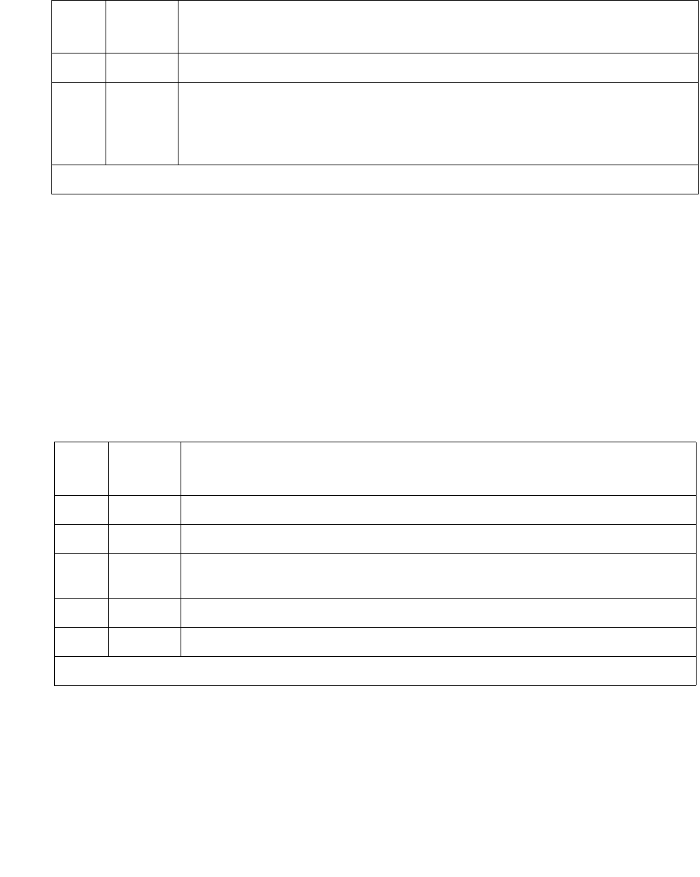
Communication Manager Maintenance-Object Repair Procedures
1888 Maintenance Procedures for Avaya Communication Manager 3.0, Media Gateways and Servers
Power supply detection test (#1535)
The power supply detection test verifies that:
●The power supply is detected.
●No internal failures are reported.
●Input power is present.
When redundant power supplies are present, the micro controller for a power supply may still be
powered, even though input power to the power supply is not present.
PASS The power supply recycle test passes.
NO
BOARD
Power supply is administered but not detected.
1. Verify that the power supply is plugged in.
2. Replace the power supply.
Table 688: Power supply recycle test (#1534) (continued)
Error
code
Test
result
Description and recommendation
3 of 3
Table 689: Test 1535 power supply detection test
Error
code
Test
result
Description and recommendation
1000 ABRT This is an internal system error.
1035 ABRT The port network is not available.
2028 ABRT There is a problem communicating with the environmental maintenance
firmware.
2319 ABRT The EPN is out of range.
2500 ABRT An internal operation failed—Retry the command.
1 of 3

POW-SUP (power supply)
Issue 1 June 2005 1889
11FAIL The system does not detect a power supply.
1. Verify that the power supply is plugged in.
2. Verify that the yellow LED on the power supply is lit and that at least
one of the two green input power LEDs is lit.
●If the yellow LED is OFF and/or the red LED is ON, replace the
power supply.
●If the green input power LEDs are OFF, check the AC and/or DC
input power.
3. Run test board.
●If the serial bus test fails (Test #1531) and there is more than one
power supply in the G650 stack, Test #1531 fails when none of the
power supplies can be accessed over the serial bus. Follow the
instructions for Serial bus communications test (#1531) on
page 1963.
4. Replace the power supply.
21FAIL There is an internal failure in the power supply.
1. Refer to POW-SUP Error Code 1537 for more information.
2. Replace the power supply.
4 FAIL The power supply has an operational failure.
1. Refer to POW-SUP Error Code 1793 for more information.
2. Replace the power supply.
8 FAIL There is no input power.
1. Run test board.
a. Verify that the Input Power field contains dashes.
b. The green power supply LED for AC power and the green LED for
DC power should be OFF when Test #1535 fails with an Error
Code 8.
2. Verify that input power is present. If input power is present, replace
the power supply.
3. The internal AC fuse or DC fuse may be open. This cannot be
repaired by the field technician.
Table 689: Test 1535 power supply detection test (continued)
Error
code
Test
result
Description and recommendation
2 of 3

Communication Manager Maintenance-Object Repair Procedures
1890 Maintenance Procedures for Avaya Communication Manager 3.0, Media Gateways and Servers
Power supply voltage test (#1536)
The TN2312BP IPSI scans the status of each 655A power supply on the serial bus every 5
seconds. This test returns the status of the most recent scan of the 655A DC output voltages.
PASS The power supply detection test passes.
NO
BOARD
Power supply is administered but not detected.
1. Verify that the power supply is plugged in.
2. Replace the power supply.
1. It is unlikely that these failure codes will occur when redundant power supplies are present because each
power supply is measuring the backplane voltage rather than the power supply voltage.
Table 689: Test 1535 power supply detection test (continued)
Error
code
Test
result
Description and recommendation
3 of 3
Table 690: Test #1536 power supply voltage
Error
code
Test
result
Description and recommendation
1000 ABRT There is an internal software error.
1. Retry the command.
2. Escalate the problem if the test continues to abort.
1035 ABRT The port network is not available.
1. Verify with status port-network nn command.
2028 ABRT There is a problem communicating with the environmental maintenance
firmware.
1. Run test maintenance nn
2100 ABRT The system could not allocate resources.
1. Repeat the command at one-minute intervals 1 to 3 times.
2. Escalate the problem if the test continues to abort.
2319 ABRT The EPN is out of range.
1 of 3

POW-SUP (power supply)
Issue 1 June 2005 1891
2500 ABRT An internal operation failed.
1. Retry the command.
2. Escalate the problem if the test continues to abort.
11FAIL The +5V is out of tolerance.
1. Use the status environment command to check the voltages.
a. +5V (+/- 5%) (4.75 to 5.25 V)
2. If redundant power supplies are present, there may be a problem
with the backplane. Verify that each power supply can detect the
problem by using the recycle carrier command, specifying the
slot number of the power supply to be shut down. Refer to the notes
and cautions for this command in Maintenance Commands
Reference (03-300191) before executing the recycle carrier
command.
3. Replace the power supply.
4. If the problem persists, check the backplane for shorts.
21FAIL The -5V is out of tolerance.
1. Use the status environment command to check the voltages:
-5V (+/- 10%) (-4.5 to -5.5 V)
2. If redundant power supplies are present, there may be a problem
with the backplane. Verify that each power supply can detect the
problem by using the recycle carrier command, specifying the
slot number of the power supply to be shut down. Refer to the notes
and cautions for this command in Maintenance Commands
Reference (03-300191) before executing the recycle carrier
command.
3. Replace the power supply.
4. If the problem persists, check the backplane for shorts.
Table 690: Test #1536 power supply voltage (continued)
Error
code
Test
result
Description and recommendation
2 of 3

Communication Manager Maintenance-Object Repair Procedures
1892 Maintenance Procedures for Avaya Communication Manager 3.0, Media Gateways and Servers
41FAIL The -48V is out of tolerance.
1. Use the status environment command to check the voltages: -
48V (+/- 8%) (- 44.2 to 51.8 V)
2. If redundant power supplies are present, there may be a problem
with the backplane. Verify that each power supply can detect the
problem by using the recycle carrier command, specifying the
slot number of the power supply to be shut down. Refer to the notes
and cautions for this command in Maintenance Commands
Reference (03-300191) before executing the recycle carrier
command.
3. Replace the power supply.
4. If the problem persists, check the backplane for shorts.
81FAIL The fan voltage is out of tolerance.
1. Use the status environment command to check the voltages:
+12/14 V (+11.4 to +15 V)
2. If redundant power supplies are present, there may be a problem
with the backplane. Verify that each power supply can detect the
problem by using the recycle carrier command, specifying the
slot number of the power supply to be shut down. Refer to the notes
and cautions for this command in Maintenance Commands
Reference (03-300191) before executing the recycle carrier
command.
3. Replace the power supply.
4. If the problem persists, check the backplane for shorts.
PASS The power supply voltage test passes.
NO
BOARD
Power supply is administered but not detected.
1. Verify that the power supply is plugged in.
2. Replace the power supply.
1. The values of these failure codes might be added together. For example, a value of 3 indicates that both
the +5V and the -5V are out of tolerance or a value of 15 indicates that all four voltages are out of
tolerance.
Table 690: Test #1536 power supply voltage (continued)
Error
code
Test
result
Description and recommendation
3 of 3
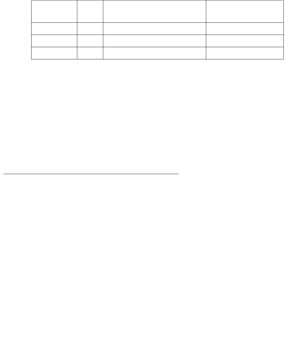
PPP-PT (Control LAN Packet/Port)
Issue 1 June 2005 1893
PPP-PT (Control LAN Packet/Port)
S8700 | 8710 / S8500
The TN799DP Control LAN (C-LAN) packet port circuit pack provides TCP/IP connection to
adjuncts applications such as CMS, INTUITY, and DCS Networking. The C-LAN circuit pack has
1 10baseT Ethernet connection and up to 16 DS0 physical interfaces for PPP connections.
Multiple C-LAN circuit packs in a system gives additional TCP/IP capacity.
An RSCL (remote socket control link) connects the C-LAN and the media server to pass
call-control and other management information. Since one link serves every port on the circuit
pack, maintenance of the RSCL is part of the C-LAN circuit pack maintenance.
Note:
Note: The TN799DP C-LAN circuit pack combines the functions of the PGATE and PI
circuit packs into one circuit pack. The PGATE or PI can be used with the C-LAN
to create an X.25 to TCP/IP bridge for adjunct and DCS connectivity.
Control LAN Congestion Controls
The switch activates congestion controls on C-LAN when it detects buffers exceeding the
threshold. The switch releases the congestion controls when the C-LAN reports that its buffer
level has returned to normal levels.
MO Name in
Alarm Log
Alarm
Level
Initial SAT Command to Run Full Name of MO
PPP-PT MAJ test port location long PPP Port Maintenance
PPP-PT MIN test port location long PPP Port Maintenance
PPP-PT WRN test port location PPP Port Maintenance
If congestion: Then the switch:
Persists for a 14-minute interval Raises MINOR alarm
Exhausts buffers Raises MINOR alarm
Ceases for 12 minutes Retires MINOR alarm
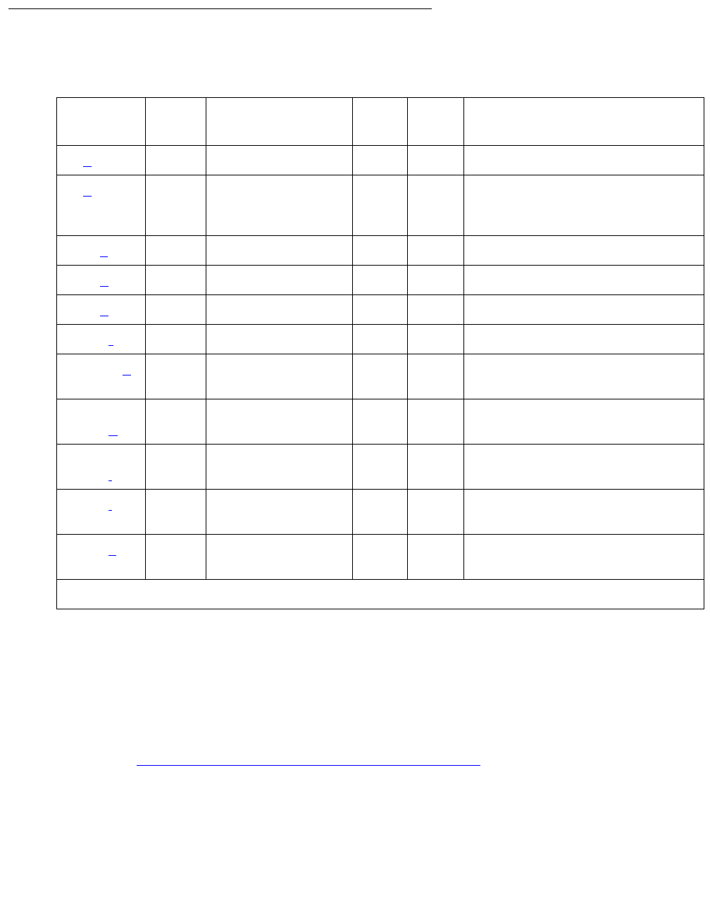
Communication Manager Maintenance-Object Repair Procedures
1894 Maintenance Procedures for Avaya Communication Manager 3.0, Media Gateways and Servers
Error Log Entries and Test to Clear Value
Notes:
a. Error Type 0: run the short test sequence first. If every test passes, run the long test
sequence. Refer to each test’s description, and follow its procedures.
b. Error Type 1: SCOTCH Synchronous Loop-around test (#1275) failed.
1. Test the port (test port location long).
2. See SCOTCH Synchronous Loop-Around Test (#1275) on page 1898 for repair
procedures.
c. Error Type 257: C-LAN port detected overrun or underrun condition that may indicate a
hardware problem.
1. Test for hardware problem (test port location long).
Table 691: PPP-PT Error Log Entries
Error
Type
Aux
Data
Associated Test Alarm
Level
On/Off
Board
Test to Clear Value
0 (a) 0 Any Any Any test port location s
1 (b) 0 SCOTCH Sync
Loop- Around
(#1275)
MIN ON test port location l r 3
257 (c)0 WRNOFF
513 (d)0 MINOFF
769 (e)0 WRNOFF
1281 (f)0
1537-8 (g)See
note
Session Status
test (#1286)
MIN OFF
1793–
1920 (h)
See
note
2305–
2816 (i)
See
note
3329 (j) 35768 TCP/IP Ping test
(#1281)
WRN OFF
3585 (k) 0, 1 TDM Loop-Around
(#1285)
MAJ ON test port location l r 3

PPP-PT (Control LAN Packet/Port)
Issue 1 June 2005 1895
2. See SCOTCH Synchronous Loop-Around Test (#1275) on page 1898 for repair
procedures to verify repair.
3. Clear the alarm (test port location long clear).
d. Error Type 513: PPP link lost end-to-end connectivity.
1. Test for hardware problem (test port location long).
2. Run TDM Loop-Around Test (#1285) on page 1897, and refer to repair procedures if
there is a hardware problem.
If there is no hardware problem, the switch tries to re-establish PPP link.
e. Error Type 769: Port received an invalid frame, which is greater than the maximum length,
contains CRC errors, and/or violates the link level protocol.
1. Test the port (test port location long).
2. Refer to TDM Loop-Around Test (#1285) on page 1897 to verify repair.
3. Clear the alarm (test port location long clear).
f. Error Type 1281: the far end has requested a disconnect of a session on this link. This is a
log-only error.
g. Error Type 1537, 1538: some or all port sessions (sockets) are down:
1. Test the port (test port location short).
2. See Session Status Test (#1286) on page 1902 for repair procedure to verify repair.
h. Error Type 1793-1920: a socket was closed due to an error. Error Type indicates the
application associated with this socket; Aux Data indicates the internal application number.
If the switch indicates that: Then it:
Some of the sessions are down Raises off-board WARNING
Every session is down Raises off-board MINOR alarm
Error Type Application
1793 Unused
1794 DCS
1795 AUDIX
1796 CMS
1797 ISDN Gateway
1798–1920 Reserved for future

Communication Manager Maintenance-Object Repair Procedures
1896 Maintenance Procedures for Avaya Communication Manager 3.0, Media Gateways and Servers
i. Error Type 2305-2816: a session is down. Aux Data indicates the session number. These
are log-only errors:
●Error Types 2305–2560 are for session numbers 1–256.
●Error Types 2561–2816 are for session numbers 257–512.
j. Error Type 3329: TCP/IP Ping test failed.
1. Test the port (test port location short).
2. See TCP/IP Ping Test (#1281) on page 1900 for repair procedures.
k. Error Type 3585: TDM Port Loop-around test (#1285) failed.
1. Test the port (test port location long).
2. See TDM Loop-Around Test (#1285) on page 1897 for repair procedure.
System Technician-Demanded Tests:
Descriptions and Error Codes
Investigate tests in the order presented below. Clearing Error Codes associated with the one
test may also clear errors generated from other tests in the sequence.
Order of Investigation Short Test
Sequence
Long Test
Sequence
D/ND1
1. D = Destructive, ND = Nondestructive
TDM Loop-around test (#1285) X D
SCOTCH Synchronous Loop-around test (#1275) X D
TCP/IP Ping test (#1281) X X ND
Session Status test (#1286) X X ND
PPP Link Status test (#1279) X X ND

PPP-PT (Control LAN Packet/Port)
Issue 1 June 2005 1897
TDM Loop-Around Test (#1285)
This test is destructive.
This test verifies whether the C-LAN PPP port can send and receive data on the TDM bus. This
test has a tone generator send tones on a timeslot, and it has a tone receiver receive tones on
another timeslot. The tones are looped through the ppp port.
Test failure indicates failure of the
●C-LAN (TN799DP) circuit pack
●TDM bus
●Tone generator / tone receiver circuit pack
If the received tones: Then:
Match the tones sent The test passes
Do not match the tones
sent
The test fails
Table 692: Test #1285 TDM Loop-Around Test
Error
Code
Test
Result
Description / Recommendation
1000 ABRT The port is in use.
1. Determine port status (status clan-port location).
2. Retry the command when the port is idle. The port may be forced to
the idle state by executing a busyout port location command.
The busyout port command is destructive, causing every call and link
associated with the port to be torn down.
1002 ABRT No TDM bus timeslots available for the test.
1. Retry the command at 1-minute intervals up to 5 times.
1003 ABRT No more tone receivers idle for use in this test.
1. Retry the command at 1-minute intervals up to 5 times.
1 of 2

Communication Manager Maintenance-Object Repair Procedures
1898 Maintenance Procedures for Avaya Communication Manager 3.0, Media Gateways and Servers
SCOTCH Synchronous Loop-Around Test (#1275)
This test is destructive.
This test verifies the circuit in the data path of a PPP call. This test fails if the data transmitted on
the port does not match the data received in the loop-around mode. Failure of this test indicates
a port hardware fault on the circuit pack.
This test aborts if calls are using the port, or if the PPP link associated with the port is
connected. To avoid this, first enter busyout data-module extension, or busyout port
location, or busyout link link#, which will cause every call and link using the port to be
torn down.
2000 ABRT Did not receive circuit pack test response within the allowable time period.
1. If this problem persists, reset the circuit pack (busyout board
location, reset board location, and release board
location).
2. If the problem persists, replace the circuit pack.
2012 ABRT Internal system error.
1. Retry the command at 1-minute intervals up to 3 times.
2100 ABRT Could not allocate the necessary system resources to run test.
1. Retry the command at 1-minute intervals up to 5 times.
FAIL Received tones do not match transmitted tones.
1. Retry command at 1-minute intervals up to 3 times.
2. If the problem persists, see TDM-BUS (TDM Bus) on page 2237 and
TONE-PT (Tone Generator) on page 2353.
3. If the problem persists, reset the board (busyout board
location, reset board location, and release board
location). Repeat the test.
4. If the problem persists, replace the circuit pack.
PASS Port connections across the TDM bus function properly.
Table 692: Test #1285 TDM Loop-Around Test (continued)
Error
Code
Test
Result
Description / Recommendation
2 of 2

PPP-PT (Control LAN Packet/Port)
Issue 1 June 2005 1899
Table 693: Test #1275 SCOTCH Synchronous Loop-Around Test
Error
Code
Test
Result
Description / Recommendation
1000 ABRT The port is in use or PPP link is connected.
1. Use status clan-port location to determine when the port is
available for testing.
2. Use busyout port location to force the port to the idle state.
This command is destructive, causing every call and link using the port to
be torn down.
1002 ABRT No TDM bus timeslots available for the test.
1. Retry the command at 1-minute intervals up to 5 times.
1963 ABRT Firmware indicates that the port is in use or ppp link is connected.
1. Use status clan-port location to determine when the port is
available for testing.
2. Use busyout port location to force the port to the idle state.
This command is destructive, causing every call and link using the port to
be torn down.
2000 ABRT Did not receive circuit pack test response within the allowable time period.
1. If this problem persists, reset the circuit pack (busyout board
location, reset board location, and release board
location).
2. If the problem persists, replace the circuit pack.
2012 ABRT Internal system error.
1. Retry the command at 1-minute intervals up to 3 times.
2100 ABRT Could not allocate the necessary system resources to run test.
1. Retry the command at 1-minute intervals up to 5 times.
FAIL C-LAN circuit pack detected test failure.
1. If the problem persists, reset the circuit pack (busyout board
location, reset board location, and release board
location).
2. If the problem persists, replace the circuit pack.
PASS Port circuitry functioning properly.

Communication Manager Maintenance-Object Repair Procedures
1900 Maintenance Procedures for Avaya Communication Manager 3.0, Media Gateways and Servers
TCP/IP Ping Test (#1281)
This nondestructive test fails if the endpoint fails to respond. Use this test to check the circuitry
in the data path for a peer-to-peer IP layer connection.
Table 694: Test #1281 TCP/IP Ping Test
Error
Code
Test
Result
Description / Recommendation
1
2
7
11
ABRT Internal error
1. Retry the command at 1-minute intervals up to 3 times
1005 ABRT Test configuration is incorrect.
1. Verity PPP link is in-service (status clan-port location or
status link n).
2. Repeat the test.
1124 ABRT ppp link is not enabled.
1. Verify that the ppp link is enabled (status port location,
status link n, or display data-module).
2. If the link is not enabled, enable the link (change data-module).
3. Repeat the test.
1125 ABRT PPP link not in service.
1. Verify whether ppp link is in service (status port location or
status link n).
2. If the ppp link is not in service, release the link (release link n
or release port location).
3. Repeat the test.
2000 ABRT Response to the test was not received from the C-LAN circuit pack
within the allowable time period.
1. If this result occurs repeatedly, attempt to reset the circuit pack if the
other ports on the board are idle (amber LED is off). Reset the
circuit pack (busyout board location, reset board
location, and release board location).
2. If this result occurs again, replace the circuit pack.
1 of 2

PPP-PT (Control LAN Packet/Port)
Issue 1 June 2005 1901
2012 ABRT Internal system error.
1. Retry the command at 1-minute intervals up to 3 times.
2100 ABRT Could not allocate the necessary system resources to run test.
1. Retry the command at 1-minute intervals up to 5 times.
2500 ABRT Internal system error.
1. Retry the command at 1-minute intervals up to 3 times.
1003 FAIL Ping to the destination failed due to on-board problem.
1. Retry the command at 1-minute intervals up to 3 times.
2. If the problem persists, reset the circuit pack (busyout board
location, reset board location, and release board
location).
3. If the problem persists, re-administer the PPP connection through a
different PPP port, if available.
4. If the problem still persists, or if there are no other available PPP
ports, replace the circuit pack.
1007 FAIL Ping to the destination failed due to the destination down.
1. A PPP destination or a component in the path (e.g., DS1 trunk) may
be down. Check the status of the destination or other components in
the path.
2. If the destination and every component in the path is in-service, ping
the PPP destinations (ping ip-address xxx.xxx.xxx.xxx).
PASS TCP/IP Ping test (#1281) is successful.
Table 694: Test #1281 TCP/IP Ping Test (continued)
Error
Code
Test
Result
Description / Recommendation
2 of 2

Communication Manager Maintenance-Object Repair Procedures
1902 Maintenance Procedures for Avaya Communication Manager 3.0, Media Gateways and Servers
Session Status Test (#1286)
This nondestructive test determines the status of every PPP port session. This test queries the
system software on port session status.
If the system software indicates that: Then the switch:
Every port session is up (ALL UP) Raises no alarm, or retires alarm
Some port sessions are up (SOME UP) Raises MINOR alarm
Every port sessions is down (ALL DOWN) Raises MINOR alarm
Table 695: Test #1286 Session Status Test
Error
Code
Test
Result
Description / Recommendation
1124 ABRT PPP link is not enabled.
1. Verify that the ppp link is enabled (status port location,
status link n, or display data-module).
2. If the link is not enabled, enable the link (change data-module).
3. Repeat the test.
1125 ABRT PPP link not in service.
1. Verify whether PPP link is in service (status port location or
status link n).
2. If the PPP link is not in service, release the link (release link n
or release port location).
3. Repeat the test.
2000 ABRT Did not receive circuit pack test response within the allowable time
period.
1. If the problem persists, reset the circuit pack (busyout port
location, reset board location, and release board
location).
2. If the problem persists, replace the circuit pack.
2100 ABRT Could not locate the necessary system resources to run this test.
1. Retry the command at 1-minute intervals up to 5 times.
1 of 2

PPP-PT (Control LAN Packet/Port)
Issue 1 June 2005 1903
PPP Link Status Inquiry Test (#1279)
This nondestructive test determines the state of the PPP link. The test passes only if the link is
up.
2500 ABRT Internal system error.
1. Retry the command at 1-minute intervals up to 3 times.
1 FAIL System software indicates at least one PPP link session is down (SOME
UP).
1. Isolate downed sessions (status port location or status
link n).
Follow actions based on session information.
2 FAIL System software indicates every PPP session is down (ALL DOWN).
1. Test the port (test port location) to verify the SCOTCH
Synchronous Loop-around test (#1275) result.
2. If test passes, wait for system software to indicate ALL UP.
3. If the test fails, check the destination and other components in the
path.
4. If the destination and other components in the path are in-service,
take action based on session information.
PASS Every session up.
Table 695: Test #1286 Session Status Test (continued)
Error
Code
Test
Result
Description / Recommendation
2 of 2
Table 696: Test #1279 PPP Link Status Inquiry Test
Error
Code
Test
Result
Description / Recommendation
1124 ABRT ppp link is not enabled.
1. Verify that the ppp link is enabled (status port location,
status link n, or display data-module).
2. If the link is not enabled, enable the link (change data-module).
3. Repeat the test.
1 of 2

Communication Manager Maintenance-Object Repair Procedures
1904 Maintenance Procedures for Avaya Communication Manager 3.0, Media Gateways and Servers
1125 ABRT PPP Link is not in service.
1. Verify whether PPP link is in-service (status port location or
status link n).
2. If the PPP link is not in service, release the link (release link n or
release port location).
3. Repeat the test.
2100 ABRT Could not locate the necessary system resources to run this test.
1. Retry the command at 1-minute intervals up to 5 times.
2500 ABRT Internal system error.
1. Retry the command at 1-minute intervals up to 3 times.
FAIL PPP link is down.
1. Test the port (test port location long) to verify the SCOTCH
Synchronous Local Loop Around test (#1275) result.
2. If the test passes, wait for sessions to come up.
3. If the test fails, check the destination and other components in the
path (e.g., DS1 trunks).
4. If the destination and other components in the path are in-service and
the test still fails, execute busyout port location and release
port location, and repeat the test.
5. If the test still fails, reset the circuit pack (busyout board
location, reset board location, and release board
location). Repeat the test.
6. If the problem persists, replace the circuit pack.
PASS PPP link is up.
Table 696: Test #1279 PPP Link Status Inquiry Test (continued)
Error
Code
Test
Result
Description / Recommendation
2 of 2

PRI-CDR (Call Detail Recording Link)
Issue 1 June 2005 1905
PRI-CDR (Call Detail Recording Link)
S8700 | 8710 / S8500
The CDR feature records detailed call information about every incoming and outgoing call on
specified trunk groups and sends this information to a CDR output device. The two physical
links can be administered for connecting external CDR output devices to the system. They are
identified as the primary CDR (PRI-CDR) link and the secondary CDR (SEC-CDR) link. The
CDR device connects to the system via a data module (PDM, MPDM, DTDM) connected to a
port on a TN754 Digital Line circuit pack that is administered as a data extension. A CDR device
can also be connected through an ADU to a port on TN726B. The CDR link to the processor is
through a C-LAN board. For information about C-LAN port connectivity, see CLAN-BD (Control
LAN Circuit Pack) on page 789. External CDR output devices include:
●94A Local Storage Unit (LSU)
●TELESEER CDR Unit
●Call Accounting System (CAS)
●Call Detail Recording Unit (CDRU)
●Printer
●Host computer
●Personal computer (PC)
●Customer-provided equipment
CDR Link Maintenance provides a strategy for maintaining the link between the system and an
external CDR output device. The strategy includes a set of tests for periodic diagnosis,
detection of errors during normal operation, actions for troubleshooting, and raising alarms for
serious problems. CDR Link Maintenance uses a try-and-wait mechanism for maintaining the
CDR link. If the CDR link is torn down due to an error, CDR Link Maintenance tries to bring the
CDR link up. If the Link Setup fails, CDR Link Maintenance will wait for 30 seconds before the
next retry. If the number of retries reaches a threshold (two), a Minor alarm is raised for service
attention.
MO Name in Alarm
Log
Alarm
Level
Initial SAT Command to Run Full Name of MO
PRI-CDR/SEC-CDR MIN test cdr primary |
secondary l
CDR Link
PRI-CDR/SEC-CDR WRN test cdr primary |
secondary
CDR Link

Communication Manager Maintenance-Object Repair Procedures
1906 Maintenance Procedures for Avaya Communication Manager 3.0, Media Gateways and Servers
CDR Link Maintenance does not cover the maintenance of the elements composing the CDR
physical link:
●External CDR output device
●Data Module (PDM/MPDM/DTDM) and Digital Line Port of TN754 Digital Line circuit pack
●ADU and Data Line Port of TN726B Data Line circuit pack
If CDR Link Maintenance cannot restore the CDR link, the maintenance tests of these individual
components of the CDR link must be executed to diagnose faults.
Procedures for Restoring the CDR Link
1. Determine the status of CDR links.
Enter status cdr-link and make sure that the CDR links are not busied out for
maintenance. If the link is down, continue to the next step.
2. Where does the CDR link connect to?
Enter display system-parameters features and find out the destinations of CDR
links. Continue to the next step.
3. Enter status data extension and verify whether the data extension is in the in-service/
idle state. If the data extension is not available, look for the extension number in the Alt
Name field of the Hardware Error Log and see XXX-BD (Common Port Circuit Pack/Media
Module) on page 2539 for resolutions.
4. Is the external CDR output device available?
Make sure that the CDR output device is on-line and ready for service. Check the physical
connectivity between Data Module and the CDR output device.
5. If the problem is not found in the above steps, check the C-LAN board for any problems. For
description about system port and its connectivity, see CLAN-BD (Control LAN Circuit
Pack) on page 789.
When restoring the CDR link it is necessary to execute maintenance test on different objects
that comprise the CDR link. It is recommended that you busyout the CDR link before trying to
restore the link. When the CDR Link is busied out, then every CDR Link maintenance action is
deactivated, and interference to tests of other MOs is prevented.
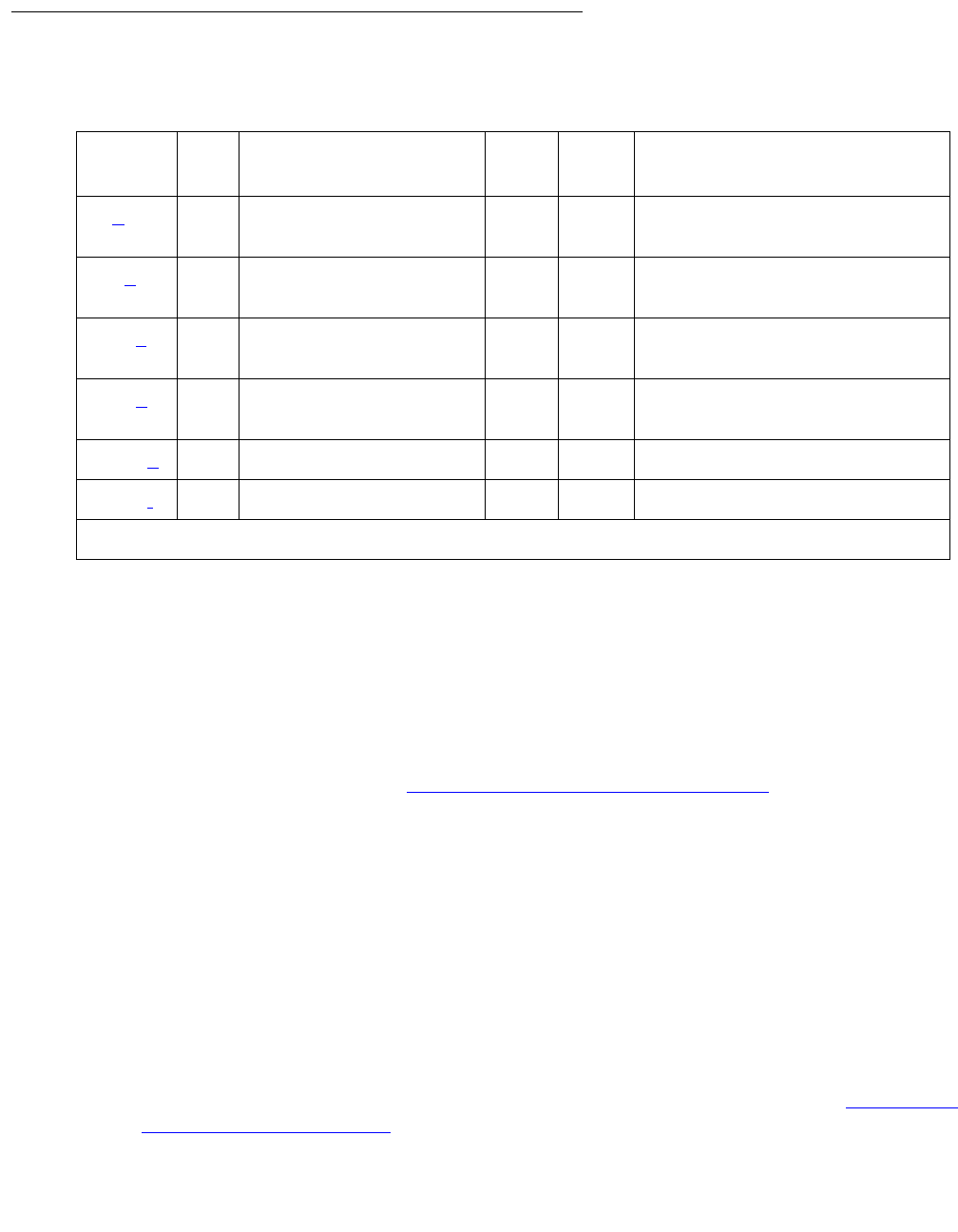
PRI-CDR (Call Detail Recording Link)
Issue 1 June 2005 1907
Error Log Entries and Test to Clear Values
Notes:
a. Error Type 0: run the short test sequence first. If every test passes, run the long test
sequence. Refer to each test’s description, and follow its procedures.
b. Error Type 18: the CDR link is busied out and the CDR link is torn down.
c. Error Type 257: Link Retry test (#215) failed. An error was detected when setting up the
link. See the preceding section Procedures for Restoring the CDR Link on page 1906 for
resolution.
d. Error Type 513: the CDR physical link is down for one of the following reasons:
●Cable to the CDR output device is disconnected.
●CDR output device is powered off.
●The data extension where the CDR output device connects to has been busied out or
there is a scheduled daily interchange.
1. Check the connectivity of wire and cable among wall jacket, data module, and the CDR
output device.
2. Enter status data extension and verify that the data extension of the CDR output
device is in the in-service/idle state. If the data extension is not available, see Procedures
for Restoring the CDR Link on page 1906 for resolution.
Table 697: CDR Link Maintenance Error Log Entries
Error
Type
Aux
Data
Associated Test Alarm
Level
On/Off
Board
Test to Clear Value
0 (a) 0 Any Any Any test cdr-link primary |
secondary sh
18 (b)0 busyout cdr-link
primary|secondary
WRN OFF release cd-link primary
| secondary
257 (c) Any Link Retry test (#215) MIN1
WRN
1. Minor alarms may be downgraded to Warning alarms based on the value used in set options.
OFF test cd-link primary |
secondary l
513 (d)test cdr-link primary |
secondary
1025 (e)
1281 (f)Any

Communication Manager Maintenance-Object Repair Procedures
1908 Maintenance Procedures for Avaya Communication Manager 3.0, Media Gateways and Servers
3. Use display system-parameters maintenance to see the start time of daily
maintenance.
4. If the error occurs and is resolved during of daily maintenance, it can be ignored.
e. Error Type 1025: the CDR output device is in an off-line state, (for example, due to paper
jam or paper out for a printer device). The CDR link is torn down.
1. Check the CDR output device and act promptly to put it back to on-line state.
2. Enter test cdr-link primary | secondary command to set up the CDR link.
f. Error Type 1281: overflow of CDR records generated in the switch due to the heavy trunk
traffic and low speed CDR output device. If both primary and secondary links are ON, the
secondary link is torn down temporarily for two minutes to speed up the output process to
the primary link. No action is necessary for this error type.
System Technician-Demanded Tests:
Descriptions and Error Codes
Investigate tests in the order presented below. Clearing Error Codes associated with the one
test may also clear errors generated from other tests in the sequence.
Order of Investigation Short Test
Sequence
Long Test
Sequence
D/ND
Link Tear Down test (#213) X Destructive
Link Retry test (#215) X X Nondestructive

PRI-CDR (Call Detail Recording Link)
Issue 1 June 2005 1909
Link Tear Down Test (#213)
This test is destructive.
This test disconnects the existing link between the system and the external CDR output device.
If the link has already been disconnected, the test returns PASS. Every resource allocated for a
CDR link is released after this test.
Table 698: Test #213 Link Tear Down Test
Error
Code
Test
Result
Description / Recommendation
40 ABRT Internal system error.
1. Retry the command at 1-minute intervals up to 5 times.
50 ABRT Internal system error.
1. Retry the command at 1-minute intervals up to 5 times.
1010 ABRT The CDR link has been busied out to out-of-service.
1. Enter the release cdr-link primary | secondary
command to release the CDR link from busyout state.
2. Retry the test cdr-link primary | secondary long
command to execute the test.
2012 ABRT Internal system error.
1. Retry the command at 1-minute intervals up to 5 times.
FAIL Internal system error.
1. Retry the command at 1-minute intervals up to 5 times.
PASS The CDR link is torn down.

Communication Manager Maintenance-Object Repair Procedures
1910 Maintenance Procedures for Avaya Communication Manager 3.0, Media Gateways and Servers
Link Retry Test (#215)
This test sends a message to the CDR software process to make a data call to the extension
where the CDR output device connects to. If the CDR link is already up, then this test will be
passed without making any data call.
Table 699: Test #215 Link Retry Test
Error
Code
Test
Result
Description / Recommendation
10 ABRT Internal system error.
20 ABRT Internal system error.
1. Retry the command at 1-minute intervals up to 5 times.
30 ABRT Internal system error.
1. See Procedures for Restoring the CDR Link on page 1906 for
instructions.
1010 ABRT The CDR link has been busied out to out-of-service.
1. Enter release cdr-link primary | secondary to release the
CDR link from busyout state.
2. Retry test cdr-link primary | secondary long to execute
the test.
2012 ABRT Internal system error.
1. Retry the command at 1-minute intervals up to 5 times.
FAIL The CDR link CANNOT be established.
1. See Procedures for Restoring the CDR Link on page 1906 for
instructions.
PASS The CDR link is up.
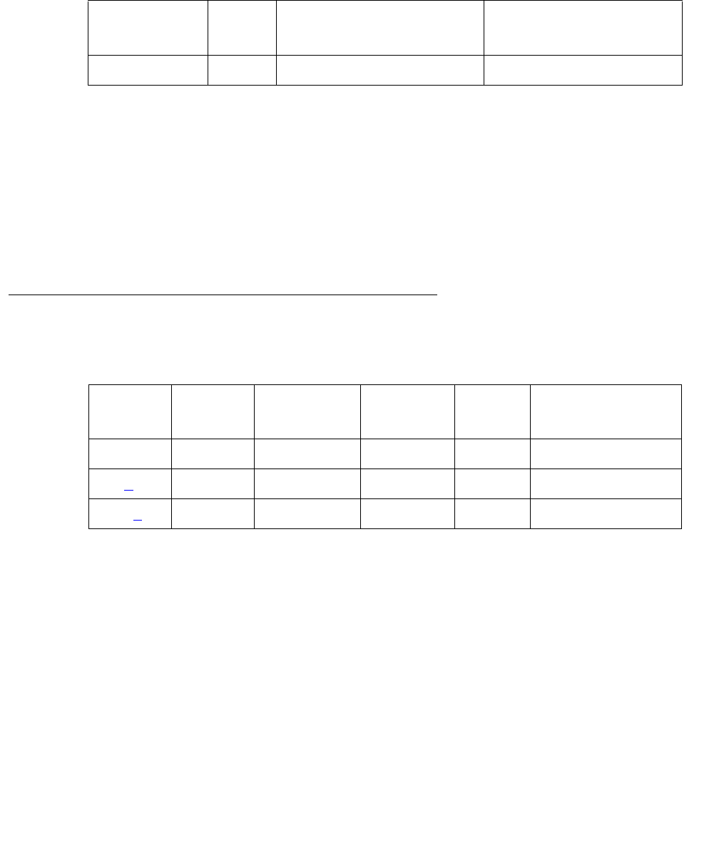
PROC-SAN (Process Sanity Audits)
Issue 1 June 2005 1911
PROC-SAN (Process Sanity Audits)
S8700 | 8710 / S8500
The Process Sanity Audits MO is responsible for monitoring the sanity of software processes in
the system. If the Process Sanity Audits MO detects that a process has gone insane (does not
respond to a sanity message within an allotted time period), the process will be restarted. If the
Process Sanity Audits MO detects that multiple processes (or a single key process) do not
respond to sanity messages within an allotted time period, a system recovery action will be
initiated.
The Process Sanity Audits MO has no alarms and no tests. Certain errors are logged to the
Hardware Error Log for information purposes only.
Error Log Entries and Test to Clear Values
Note:
a. Error Type 10, 204: a system recovery action was taken because one or more software
processes failed to respond to a sanity audit in a timely fashion. As a result of the recovery
action, the system may have temporarily suspended service for a period of time
surrounding the error.
MO Name in
Alarm Log
Alarm
Level
Initial Command to Run Full Name of MO
PROC-SAN none none Process Sanity Audits
Table 700: Process Sanity Audits Error Log Entries
Error
Type
Aux
Data
Associated
Test
Alarm
Level
On/Off
Board
Test to Clear
Value
0 0 Any Any Any none
10 (a) 0 none none none none
204 (a) any none none none none

Communication Manager Maintenance-Object Repair Procedures
1912 Maintenance Procedures for Avaya Communication Manager 3.0, Media Gateways and Servers
PS-RGEN (Power supply ring generator)
G650
The PS-RGEN maintenance object monitors the ringing voltage of each 655A power supply.
The TN2312BP IPSI uses the ring detection circuit on the 655A to monitor ring voltage for the
G650. When the TN2312BP IPSI is used in an MCC1 or SCC1, the ring detector on the tone
clock monitors ringing.
When the G650 is equipped with two power supplies, the 655A power supply on the left (slot 0)
is the primary power supply (master) and the 655A power supply on the right (slot 15) is the
secondary power supply. In normal operation, the primary 655A provides ringing for the G650. If
the primary 655A is unable to provide ringing to the G650 because it has failed or because of a
command from the TN2312BP IPSI, the secondary 655A connects ringing to the backplane
using an arbitration lead.
Normally the ring voltage LED (#5) on the left power supply is ON and the ring voltage LED on
the right power supply is OFF. This changes momentarily when the ringer interchange test is
run. The ring voltage LED will only remain lit on the right power supply when there is a power
supply failure of the left hand supply or the left hand supply is removed.
Only one 655A power supply provides ringing voltage to the backplane. The other power supply
ring voltage output is isolated from the backplane through a relay contact.
Refer to Figure 115: G650 Cabinet Environmental Hardware Components on page 1959 for
further information.
Error log entries and test-to-clear values
MOs name in
Alarm Log
Alarm
level
Initial SAT command to run Full name of MO
PS-RGEN MIN test board location Power Supply Ring Generator
PS-RGEN MAJ test board location Power Supply Ring Generator
Table 701: PS-RGEN Error Log Entries
Error
Type
Aux
Data
Associated test Alarm
level
On/Off
board
Test-to-clear value
10
1 (a) Ring generator
interchange test
(#1539)
MAJ
MIN1ON test environment location
test board location long
1 of 2
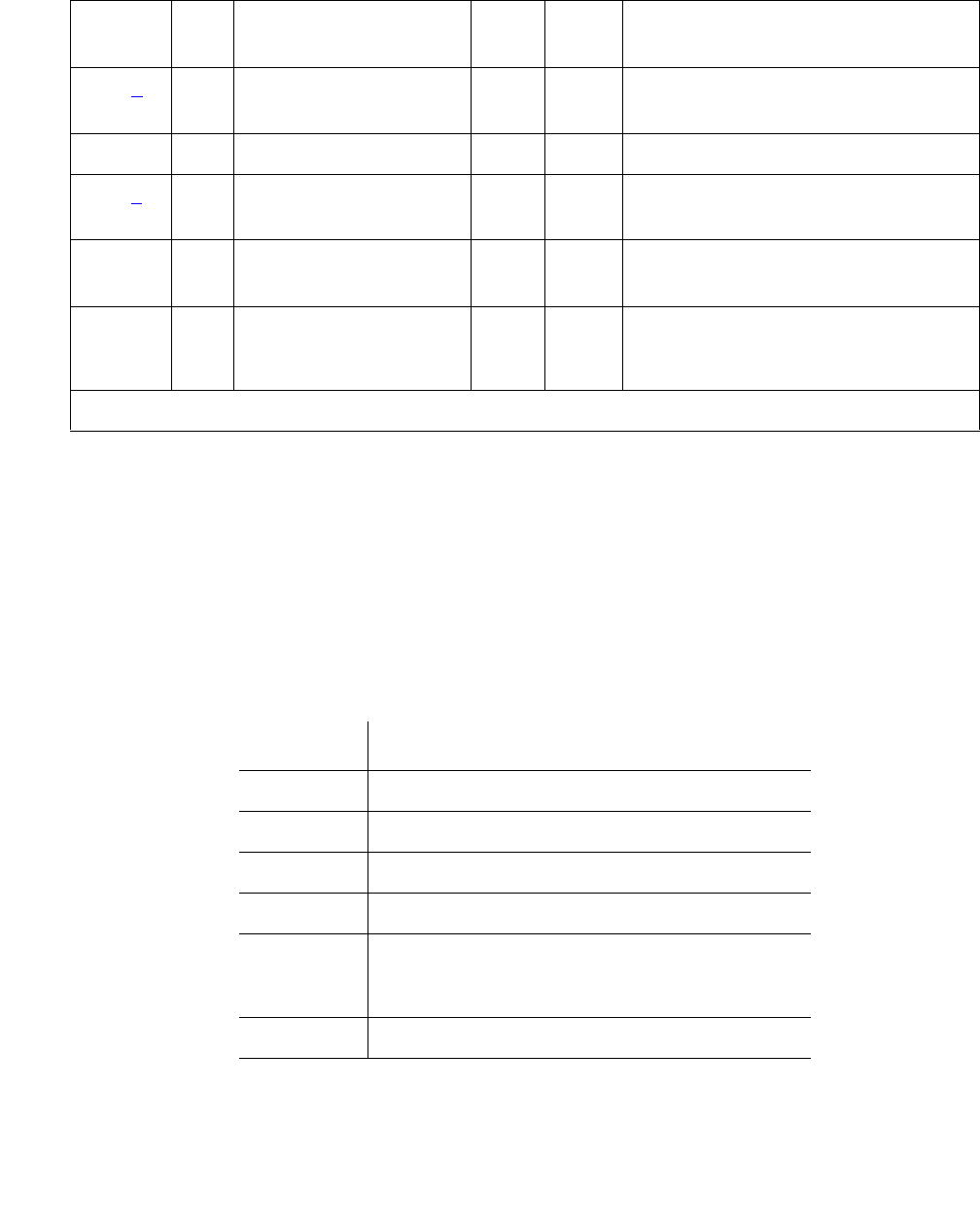
PS-RGEN (Power supply ring generator)
Issue 1 June 2005 1913
Notes:
a. Error Type 1: ring generator interchange failed. Run test environment long. Run
test board long.
b. Error Type 257: ring voltage not detected on backplane.
c. Error Type 513: ring generator operational status failure. Aux Data values give description
(values may be added together).
257 (b) Ring generator status
test (#1540)
MAJ
MIN1ON test environment location
test board location
512 1
513 (c) Any Ring generator status
test (#1540)
MAJ
MIN
ON test environment location
test board location
769 64 Ring generator status
test (#1540)
MAJ
MIN
ON test environment location
test board location
1025 64,
65
Ring generator
interchange test
(#1539)
MAJ
MIN
ON test environment location
test board location
1. This is a minor alarm if there is a redundant power supply, and a major alarm if there is only one power
supply.
Aux Data Description
1 Overload
2 Shorted
4 Internal fault
8 Commanded off
16 When redundant power supplies are
present, the standby ring generator (slot 15)
is providing ringing voltage
32 No ringing voltage on backplane
Table 701: PS-RGEN Error Log Entries (continued)
Error
Type
Aux
Data
Associated test Alarm
level
On/Off
board
Test-to-clear value
2 of 2
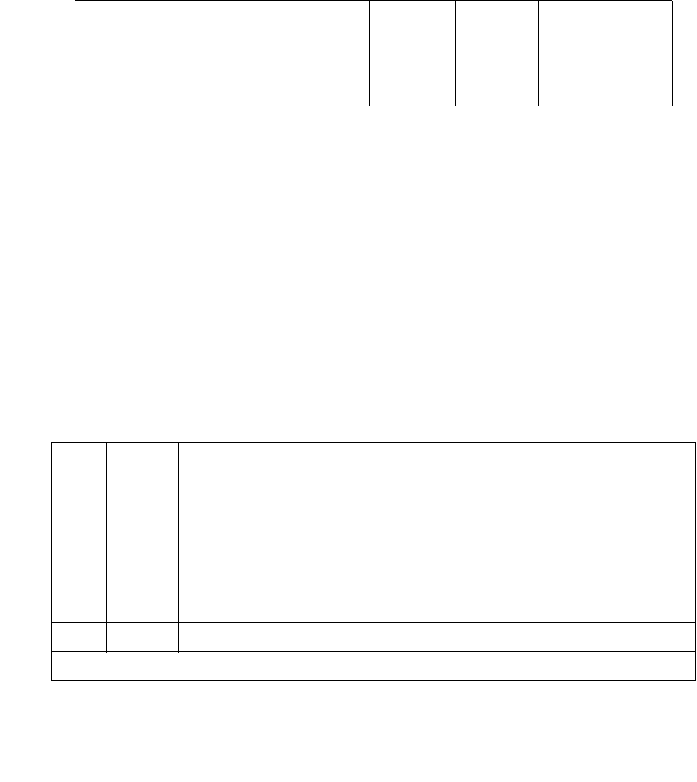
Communication Manager Maintenance-Object Repair Procedures
1914 Maintenance Procedures for Avaya Communication Manager 3.0, Media Gateways and Servers
System technician-demanded tests:
Descriptions and Error Codes
Investigate tests in the order presented below. Clearing Error Codes associated with the one
test may also clear errors generated from other tests in the sequence.
Ring generator interchange test (#1539)
The ring generator interchange test causes a temporary interchange and is only used if the
G650 has redundant power supplies. This test sends a command to the primary power supply in
slot 0 to turn off ringing voltage, the ring arbitration lead changes state, and the secondary
power supply in slot 15 provides ringing voltage to the backplane. The ring detection circuit for
the secondary power supply is checked to verify that the secondary power supply is providing
ringing voltage.
A command is sent to the primary power supply to apply ringing and the ring arbitration lead
changes back to allow the primary power supply to provide ringing voltage. The ring voltage
detection circuit on the primary power supply is checked to verify that the primary supply is
applying ring voltage.
The long test sequence causes a ring interchange. However, the short test, which is the default,
does not cause a ring interchange.
Order of investigation Short test
sequence
Long test
sequence
D/ND
Ring Generator Interchange Test (#1539) — X Nondestructive
Ring Generator Status Test (#1540) X X Nondestructive
Table 702: Test #1539 Ring generator interchange
Error
Code
Test
result
Description and recommendation
1000 ABRT This is an internal system error.
1. Retry the command at 1-minute intervals up to 5 times.
1035 ABRT The port network is not available.
1. Verify that the port network is not available by using the status
port-network command
1990 ABRT Both power supplies in the carrier are turned off.
1 of 2

PS-RGEN (Power supply ring generator)
Issue 1 June 2005 1915
2028 ABRT There is a problem communicating with the environmental maintenance
firmware.
1. Enter test maintenance nn to verify communication with the port
network.
2100 ABRT The system could not allocate resources.
1. Repeat the command at one-minute intervals 1 to 3 times.
2. If the test continues to abort escalate the problem.
2319 ABRT The EPN is out of range.
2500 ABRT An internal operation failed.
1. Repeat the command at one-minute intervals 1 to 3 times.
2. If the test continues to abort escalate the problem.
1 FAIL There is no ringing voltage on the backplane when interchanging the ring
generator to this power supply.
1. Run test board.
64 FAIL Unable to interchange the ringers, because the power supply being tested
has its ringer turned off.
65 FAIL Unable to interchange the ringers, because the power supply not being
tested has its ringer turned off.
PASS The ring generation on redundant power supplies is successfully
interchanged.
NO
BOARD
Power supply is administered but not detected.
1. Verify that the power supply is plugged in.
2. If the power supply was already plugged in, replace the power supply.
Table 702: Test #1539 Ring generator interchange (continued)
Error
Code
Test
result
Description and recommendation
2 of 2

Communication Manager Maintenance-Object Repair Procedures
1916 Maintenance Procedures for Avaya Communication Manager 3.0, Media Gateways and Servers
Ring Generator Status Test (#1540)
The ring generator status test verifies that:
1. The power supply ring voltage detector detects the presence of ringing voltage
2. The operational status information from the ring generator does not indicate that the
generator is:
●Shut down because it has an internal fault or shorted lead
●Active but its output is operating under overload
This test does not fail if the ring selector switch on the 655A power supply is disabled.
Table 703: Test 1540 Ring generator status
Error
Code
Test
Result
Description / Recommendation
1035 ABRT The port network is not available.
1. Verify that the port network is not available by using the status
port-network command
1990 ABRT All inserted power supplies in the carrier are turned off.
2028 ABRT There is a problem communicating with the environmental maintenance
firmware.
Enter test maintenance nn to verify communication with the port
network.
2100 ABRT The system could not allocate resources.
1. Repeat the command at one-minute intervals 1 to 3 times.
2. If the test continues to abort escalate the problem.
2319 ABRT The EPN is out of range.
2500 ABRT An internal operation failed.
1. Repeat the command at one-minute intervals 1 to 3 times.
11FAIL The ring generator is active, but overloaded.
1. Run test board location
2 FAIL The ring generator is inactive because of a short.
1. Run test board location
2. If the test continues to fail replace the power supply.
1 of 2

PS-RGEN (Power supply ring generator)
Issue 1 June 2005 1917
4 FAIL There is an internal fault in the ring generator.
1. Run test board location
2. If the test continues to fail replace the power supply.
8 FAIL The ring generator is off by command.
1. Run test board location
2. If the test continues to fail replace the power supply.
16 FAIL The ringer on the primary power supply is not active.
1. Run test board location
2. If the test continues to fail replace the power supply.
32 FAIL There is no ringing voltage on the backplane.
1. Run test board location
2. If the test continues to fail replace the power supply.
64 FAIL Duplicated power supplies only. Unable to execute the ring test, because
the power supply being tested has its ringer turned off.
PASS The ring voltage was successfully detected.
NO
BOARD
Power supply is administered but not detected.
1. Verify that the power supply is plugged in.
2. If the power supply was already plugged in, replace the power supply.
1. The values of these failure codes might be added together. For example, a value of 36 indicates that the
ringer generator is inactive because of a short and that the ring generator has an internal fault.
Table 703: Test 1540 Ring generator status (continued)
Error
Code
Test
Result
Description / Recommendation
2 of 2

Communication Manager Maintenance-Object Repair Procedures
1918 Maintenance Procedures for Avaya Communication Manager 3.0, Media Gateways and Servers
RANL-STA (Remote Analog Line (Station) Port)
S8700 | 8710 / S8500
A per-port instance of this MO (RANL-STA) is used to maintain the circuitry associated with a
port which has been translated as analog station. The combo blade circuit board has the
capability of having two instances of this type of MO.
Failures of the neon message waiting lamp power and the common ringing application circuitry
are reported as part of common port circuit pack errors; see errors 1281 and 1793 in XXX-BD
(Common Port Circuit Pack/Media Module) on page 2539.
Ringing Caused by Maintenance Testing
Test #48 may cause some terminal equipment to ring briefly during daily maintenance. If this
ringing disturbs the customer or the terminal equipment, disable it in the Tests field of the
change station extension screen. This also disables Test 35 on that station.
Error Log Entries and Test to Clear Values
MO Name in
Alarm Log
Alarm
Level
Initial SAT Command to Run Full Name of MO
RANL-STA MIN test port location lRemote Analog Line Port
RANL-STA WRN test port location sh Remote Analog Line Port
Table 704: Analog Line Error Log Entries
Error
Type
Aux
Data
Associated Test Alarm
Level
On/Off
Board
Test to Clear Value
0 (a) 0 Any Any Any test port location sh r 1
1 (b) 40960
40975
40977
none
15 (c) Any Audits and
Updates test
(#36)
1 of 2
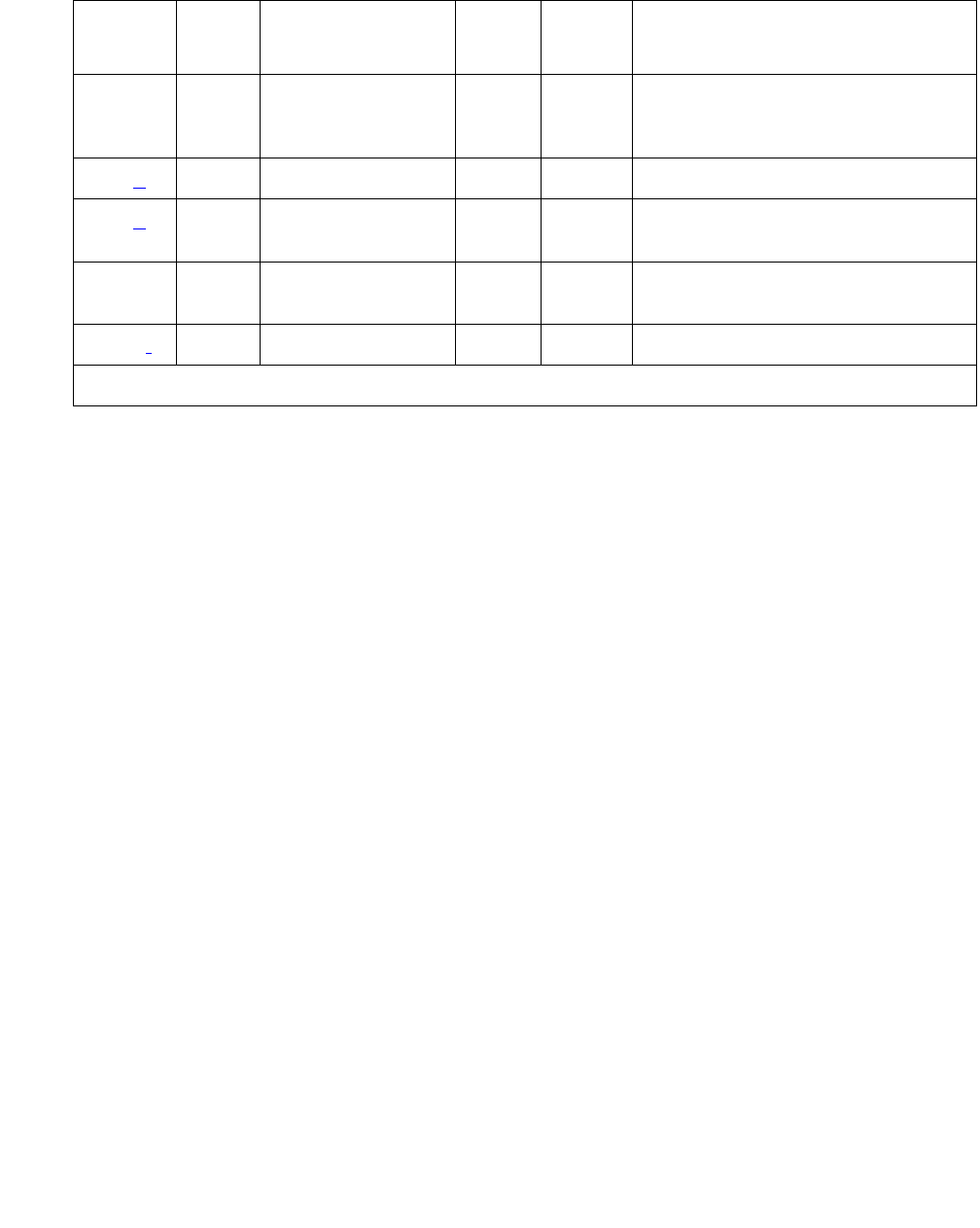
RANL-STA (Remote Analog Line (Station) Port)
Issue 1 June 2005 1919
Notes:
a. Error Type 0: run the short test sequence first. If every test passes, run the long test
sequence. Refer to each test’s description, and follow its procedures.
b. Error Type 1: in-line errors, can only be resolved over time.
●Aux Data 40960 indicates that too many simultaneous incoming ringing attempts were
made on this board. Only 4 ports on a board may ring simultaneously. A 5th incoming call
will cause an inline error from the board.
●Aux Data 40975 indicates that the terminal equipment was on-hook when ring-tip was
detected during ringing. This usually indicates a failure in the terminal equipment or the
type of terminal has a low ringer impedance. Call the terminal equipment and verify that
the terminal rings. If the terminal does not ring, then replace it. Otherwise, enter the test
port location command, and follow the procedure for Test #48.
●Aux Data 40977 indicates that terminal equipment was not connected when ringing was
attempted. Run the short test using the test port location command, and follow
the procedure for the results of Test #48.
c. Error Type 15: A software audit error that does not indicate hardware malfunction. Run the
short test sequence, and investigate associated errors.
d. Error Type 257: An in-line error and can only be resolved over time. This error indicates
that ringing voltage is absent. If only one analog circuit pack in the system has this problem,
then replace the circuit pack. If only analog circuit packs on a particular carrier have this
error, then the ringing generator may not be connected to this carrier. If analog circuit packs
on many carriers have this error, then it is probably a problem with the ringing generator.
18 0 busyout
station
extension
WRN ON release station extension
257 (d) 40973 none
513 (e) Station Present
test (#48)
WRN OFF test port location sh r 2
769 Battery Feed test
(#35)
MIN
WRN1ON test port location sh r 2
2817 (f) Hyperactive MIN OFF
1. Minor alarms on this MO may be downgraded to Warning alarms based on the values used in set
options.
Table 704: Analog Line Error Log Entries (continued)
Error
Type
Aux
Data
Associated Test Alarm
Level
On/Off
Board
Test to Clear Value
2 of 2

Communication Manager Maintenance-Object Repair Procedures
1920 Maintenance Procedures for Avaya Communication Manager 3.0, Media Gateways and Servers
e. Error Type 513: Test #48 may cause some terminal equipment to ring briefly during daily
maintenance. If this disturbs the customer or the terminal equipment, disable it by setting
the Tests field on the change station extension screen to n. On some software
releases, this will also disable Tests #7 and 35.
f. Error Type 2817: the endpoint caused a large number of control channel messages to be
sent to the switch within a short period of time (50 or more CCMS uplinks within 10
seconds). The station will be taken out-of-service for 30 seconds due to the hyperactivity.
This may be completely normal during heavy traffic periods.
System Technician-Demanded Tests:
Descriptions and Error Codes
Investigate tests in the order presented below. Clearing Error Codes associated with the one
test may also clear errors generated from other tests in the sequence.
Battery Feed Test (or Port Diagnostic test) (#35)
The battery feed chip provides power to the telephone equipment, signaling, rotary dial pulsing,
transmission, and balance. This test checks the signaling and switchhook capabilities of the
battery feed chip by terminating the port, applying battery and detecting the resulting current.
Order of Investigation Short Test
Sequence
Long Test
Sequence
D/ND1
1. D = Destructive; ND = Nondestructive
Battery Feed test (#35) X X ND
Station Present test (#48) X X ND
Station Status and Translation Audits and Updates test (#36) X X ND
Table 705: Test #35 Battery Feed Test
Error
Code
Test
Result
Description / Recommendation
ABRT Could not allocate the necessary system resources to run this test.
1. Retry the command at 1-minute intervals up to 5 times.
1 of 3

RANL-STA (Remote Analog Line (Station) Port)
Issue 1 June 2005 1921
1000 ABRT System resources required to run this test are not available. The port may
be busy with a valid call. This result is also reported for the system’s
Music-On-Hold port when it is off-hook, which it usually is.
1. Enter display port location to determine the station’s extension.
Enter status station extension to determine the service state of
the port. If the port is in use, wait until the port is idle.
2. Retry the command at 1-minute intervals up to 5 times.
1004 ABRT The port was seized by a valid call during the test. The test has been
aborted. Use display port location to determine the station
extension. Use status station to determine the service state of the
port. If the port is in use, wait until the port is idle.
1. Retry the command at 1-minute intervals up to 5 times.
1005 ABRT The test was aborted due to a configuration problem. This test may not be
applicable, or it may be disruptive to terminal equipment other than a voice
terminal (for example, the modem pool member or Music On Hold).
1018 ABRT The test has been disabled by administration. The default for the Test field
on the Station screen is y.
1. Determine why this field has been set to n on this station (this may be
due to the ringing application test 48, which can be customer or terminal
disturbing).
2. To enable the test for the particular analog station being tested, enter
change station extension and set the Test field to y.
1392 ABRT This port is currently a TTI port and the test will not execute on it.
1. Verify that the port is a TTI port using display port (the display
shows that the port is a TTI port) or list config (the display shows a
t for the port).
2. If the port is not a TTI port, escalate the problem. If both commands
indicate that the port is a TTI port, the abort is correct for the test, and
no action is necessary.
2000 ABRT Response to the test request was not received within the allowable time
period.
1. Retry the command at 1-minute intervals up to 5 times.
Table 705: Test #35 Battery Feed Test (continued)
Error
Code
Test
Result
Description / Recommendation
2 of 3

Communication Manager Maintenance-Object Repair Procedures
1922 Maintenance Procedures for Avaya Communication Manager 3.0, Media Gateways and Servers
Station Status and Translation Audits and
Updates Test (#36)
This test updates the analog port’s message lamp state (if it has one) and translations with
information in the software.
2100 ABRT Could not allocate the necessary system resources to run this test.
1. Retry the command at 1-minute intervals up to 5 times.
FAIL The port's battery feed chip is unable to supply sufficient power to the
terminal equipment. This could be a marginal test, and the terminal
equipment may be operating satisfactorily.
1. Retry the command at 1-minute intervals up to 5 times.
2. If the test continues to fail, determine whether the customer is
experiencing problems on this line. Replace the circuit pack only if the
customer is experiencing problems.
PASS The port’s battery feed chip can provide power to the station equipment to
detect on-/off-hook, but may not be able to supply power for touch tones. If
touch tones are inoperative on this station, then replace the circuit pack
because this port is inoperative.
User-reported troubles on this port should be investigated by using other port
tests, by examining station wiring, or by examining the station.
Table 705: Test #35 Battery Feed Test (continued)
Error
Code
Test
Result
Description / Recommendation
3 of 3
Table 706: Test #36 Station Status and Translation Audits and Updates
Error
Code
Test
Result
Description / Recommendation
ABRT Could not allocate the necessary system resources to run this test.
1. Retry the command at 1-minute intervals up to 5 times.
1004 ABRT The port was seized by a valid call during the test, and the test was
aborted. Use display port location to determine the station
extension. Use status station to determine the service state of the
port. If the port is in use, wait until port is idle.
1. Retry the command at 1-minute intervals up to 5 times.
1 of 2

RANL-STA (Remote Analog Line (Station) Port)
Issue 1 June 2005 1923
1005 ABRT The test was aborted due to a configuration problem. This test may not be
applicable, or it may be disruptive to terminal equipment other than a voice
terminal (for example, the modem pool member or Music On Hold).
2000 ABRT Response to the test request was not received within the allowable time
period.
1. Retry the command at 1-minute intervals up to 5 times.
2100 ABRT Could not allocate the necessary system resources to run this test.
1. Retry the command at 1-minute intervals up to 5 times.
1 FAIL This does not indicate a hardware problem. The switchhook audit failed.
The other updates were not performed because of this failure. This may
occur when the audit is performed at the same time the terminal equipment
goes off-hook. Use status station to determine when the port is
available.
1. Retry the command at 1-minute intervals up to 5 times.
5 FAIL This may be an internal software error. The message waiting lamp update
failed. The translation and ringer updates were not performed because of
this failure.
1. Retry the command at 1-minute intervals up to 5 times.
7 FAIL The translation update failed. There may be an internal software error. The
ringer update was not performed because of this failure.
1. Retry the command at 1-minute intervals up to 5 times.
8 FAIL This does not indicate a hardware problem. There may be an internal
software error. The ringer update failed.
1. Retry the command at 1-minute intervals up to 5 times.
PASS The software and the port processor have the same status. User-reported
troubles on this port should be investigated by using other port tests, by
examining station wiring, or by examining the station.
Table 706: Test #36 Station Status and Translation Audits and Updates (continued)
Error
Code
Test
Result
Description / Recommendation
2 of 2

Communication Manager Maintenance-Object Repair Procedures
1924 Maintenance Procedures for Avaya Communication Manager 3.0, Media Gateways and Servers
Station Present Test (or Ringing Application Test) (#48)
This test applies momentary ringing voltage to the terminal equipment and monitors resulting
current flow to determine whether the terminal equipment is connected to the port. The test may
cause some terminal equipment to ring briefly during daily maintenance. If this ringing disturbs
the customer or the terminal equipment, disable it using the Tests field on the Station screen.
However, on some software releases, Test #35 is disabled.
Table 707: Test #48 Station Present Test
Error
Code
Test
Result
Description / Recommendation
ABRT Could not allocate the necessary system resources to run this test.
1. Retry the command at 1-minute intervals up to 5 times.
1000 ABRT System resources required to run this test are not available. The port may
be busy with a valid call. Use display port location to determine the
station extension. Use status station to determine the service state of
the port. If the service state indicates that the port is in use. Wait until the
port is idle.
1. Retry the command at 1-minute intervals up to 5 times.
1004 ABRT The port was seized by a valid call during the test, and the test was
aborted. Use display port location to determine the station
extension. Use status station to determine the service state of the
port. If the service state indicates that the port is in use. Wait until the port is
idle.
1. Retry the command at 1-minute intervals up to 5 times.
1005 ABRT The test was aborted due to a configuration problem. This test may not be
applicable, or it may be disruptive to terminal equipment other than a voice
terminal (for example, the modem pool member or Music On Hold).
1008 ABRT Could not allocate a ringing circuit. Either every ringing circuit is in use, or
the ringing generator is defective or incorrectly wired.
1. Retry the command at 1-minute intervals up to 5 times.
2. If the test continues to abort, look for RING-GEN errors in the Error
Log. If an ABORT 1008 occurs for this test on other circuit packs as
well, then the ringing generator may be defective or incorrectly wired
(see errors for RING-GEN). If it does not occur on other ports, then all
four ring phases are in use.
1 of 2

RANL-STA (Remote Analog Line (Station) Port)
Issue 1 June 2005 1925
1018 ABRT The test has been disabled by administration. The default for the Test field
on the change station screen is y. Determine why this field has been set to
n on this station (this may be due to the brief ringing disturbance that this
test may cause).
1. To enable the test for the particular analog station being tested, enter
change station extension and set the Test field on the change
station screen to y.
2000 ABRT Response to the test request was not received within the allowable time
period.
1. Retry the command at 1-minute intervals up to 5 times.
2100 ABRT Could not allocate necessary system resources to run this test.
1. Retry the command at 1-minute intervals up to 5 times.
FAIL The terminal equipment is not connected to the circuit pack. Some terminal
equipment, such as modems, may fail even when connected properly.
1. Remotely test the equipment.
2. If the test fails again, look for RING-GEN errors in the error log. If
present, see RING-GEN (Analog Ring Generator) on page 1942.
3. Check all of the wiring between the station equipment and the switch.
Then, run the test again.
4. If the test still fails, the set may be defective. Check the set and replace
it, if necessary.
5. Some terminal equipment could fail even when it is connected properly.
If so, enter change station extension and set the Test field to n
to disable the test. This also disables Test #35 on this port.
PASS The station is connected properly. This test may also pass if no terminal
equipment is connected and the terminal is located very far from the switch.
Investigate user-reported troubles on this port by using other port tests,
examining station wiring, or examining the station.
Table 707: Test #48 Station Present Test (continued)
Error
Code
Test
Result
Description / Recommendation
2 of 2

Communication Manager Maintenance-Object Repair Procedures
1926 Maintenance Procedures for Avaya Communication Manager 3.0, Media Gateways and Servers
RDIG-STA (Remote Digital Station)
S8700 | 8710 / S8500
A per-port instance of this MO (RDIG-STA) is used to maintain the circuitry associated with a
port which has been translated as a digital station (or DCP Console). The combo blade circuit
board has the capability of having 24 instances of this type of MO.
Remote Digital Station maintenance software provides maintenance for a port administered as
a digital station on the circuit pack. This strategy covers the in-line errors log, initialization tests,
periodic tests, craft-demanded tests, and alarm resolution and escalation. Each port, translated
as a digital station on a digital line board, is running as a separate MO (RDIG-STA) of this type.
Fault conditions discovered on one MO may or may not indicate faults on other MOs of the
same type.
Maintenance testing for the port circuitry on the combo blade circuit packs is handled by
on-board firmware and media server-controlled tests. Maintenance software queries the
firmware for error and alarm information, status, and test results. Firmware automatically reports
in-line error conditions, which results in media server-controlled testing.
There are instances where the service state of a station is mentioned. The different service
states that apply to a remote digital line station are as follows:
MO Name in
Alarm Log
Alarm
Level
Initial SAT Command to Run Full Name of MO
RDIG-STA MIN test station location lRemote Digital Station
RDIG-STA WRN test station location sh Remote Digital Station
Out-of-Service The port, and thus the station, have been removed from service.
Busyout puts the port in the out-of-service state.
Ready-for-Service The port on the circuit pack has been put into service, but the voice
terminal has not yet established signaling communications with the port.
In-Service The voice terminal has established signaling communications with the
port, and the system is ready to process calls to and from that station. A
terminal in the ready-for-service state will progress to the in-service state
if it is functioning normally. It can also be forced into the in-service state
by going off-hook.

RDIG-STA (Remote Digital Station)
Issue 1 June 2005 1927
Downloading of Terminal Parameters
Programmable Terminals
The following information describes how maintenance software interacts with terminal
parameter downloading.
Terminal Types
1. 84xx multi button digital voice terminals (8403D01A, 8410B, 8410D02A, 8434D01A) with
optional expansion module.
2. 603A1 and 603D1 Callmaster terminals for telemarketing applications.
3. 302B1 and 302C1 attendant console.
Downloadable Terminal Parameters
The following parameters are downloaded to programmable terminals:
Table 708: Parameters Downloadable to Programmable Terminals
Parameter Scope Terminal
International Flags (A-/mu-law, display mode, DLI voltage level) System level 84xx,
603x,
302B1
Primary Levels (transmission and sidetone) System level 84xx,
603x,
302B1
Adjunct Levels (transmission and sidetone) System level 84xx
Handset Expander Option System level 84xx
Administrable Options (speakerphone and mute button) Per-terminal 84xx
Administrable Softkeys Per-terminal,
system level
8410D,
8434D

Communication Manager Maintenance-Object Repair Procedures
1928 Maintenance Procedures for Avaya Communication Manager 3.0, Media Gateways and Servers
Nonvolatile Memory
Nonvolatile memory stores downloadable parameters in programmable terminals. Once the
terminal is downloaded, it is not be necessary to download it again, even if power is removed
from the terminal. If nonvolatile memory fails with power still present, the terminal reverts to its
default factory settings except for its A-law/mu-law companding settings which are stored in
RAM. If power is removed after the nonvolatile memory fails, the terminal reverts to its factory
default settings.
Note:
Note: The mu-law companding mode is assigned as a default setting at the factory. For
the United States, a programmable terminal can place calls even though it has
not been downloaded from the system.
Download Actions
There are several different scenarios which causes a terminal to be downloaded. These can
occur as part of background maintenance activity or on demand from the SAT (System Access
Terminal) or from a station.
For the background actions described below, the terminal downloads automatically if a
download retry flag for the terminal is set in software. This flag is set at the time translation is
loaded at boot time, when the translation that affects the parameters of a terminal is changed as
part of system administration actions, or when a port is inserted in software as a result of board
insertion or translation change.
Automatic Download Actions
1. System Reboot/Restart
A global download action is initiated when periodic maintenance tests begin after a system
reboot/restart, regardless of whether the parameters have been downloaded previously.
2. Periodic tests
If the download flag is still set when periodic tests are run on a terminal, a download action
occurs. This action is required in case a terminal could not be downloaded previously,
because the terminal was off-hook when the:
●system first booted
or
●translations associated with downloadable parameters were changed.
Note:
Note: It may take more than an hour for periodic tests to reach the terminal that needs
to be downloaded.

RDIG-STA (Remote Digital Station)
Issue 1 June 2005 1929
3. Terminal Administration
A downloadable terminal is automatically downloaded when translation changes associated
with downloadable parameters are made as part of system administration. As shown in the
previous table, these changes can be for a specified terminal or may be system-wide. If the
change is for a system-level parameter, a background global update request must be
submitted to download every programmable terminal.
Note:
Note: This global update may take more than an hour for a system with several
thousand programmable terminals.
4. Port Insertion
Whenever maintenance software initiates a request to place a port into service, a terminal
download action is begun on that terminal, if that terminal is programmable. This port
insertion action occurs under the following circumstances:
●A digital line circuit pack that is physically inserted into the system and has ports currently
administered for programmable terminals.
●A station port is added to the system by add station or change station.
●A TTI port is activated.
5. Audits
As part of periodic maintenance, the Hardware Status Audit test queries programmable
terminals to determine which levels and/or options are being used. If the reported values
are not equal to the administered values, the system will initiate a terminal download action;
however, this audit does NOT check the parameters used for softkeys.
6. Activation of TTI
A terminal is downloaded automatically when it is activated using the TTI (Terminal
Translation Initialization) feature. Therefore, no special user actions are required for TTI.
Note:
Note: Plugging the station cord into a terminal does not automatically cause the
terminal to be downloaded. If this terminal has factory defaults or if the terminal
has been previously downloaded with parameters different than those desired,
use one of the demand download actions described below to download the
terminal.

Communication Manager Maintenance-Object Repair Procedures
1930 Maintenance Procedures for Avaya Communication Manager 3.0, Media Gateways and Servers
Demand Download Actions
1. Busyout/Release Command
A maintenance demand busyout/release request for a station will cause the terminal to be
downloaded regardless of its previous download status.
2. Feature Access Code
A Refresh Terminal Parameters Feature Access Code can be used to request a terminal
download action. When this code is followed by a “#”, the programmable parameters for the
current terminal are downloaded when the terminal goes on-hook. When this code is
followed by an extension, the programmable parameters for the specified station are
downloaded.
This Refresh Terminal Parameters Feature Access Code is assigned on the third page of
the change feature-access-codes screen.
A confirmation is returned if the download request is accepted. A busy tone is returned if the
request is made from a different station when the target station is off-hook.
As a result of an entry of a Refresh Terminal Parameters Facility Access Code, the first
three green call appearance LEDs on the 84xx 603x terminal are turned on for three
seconds, if the station was successfully downloaded. This is not true for the 302B1 terminal.
There is no visible display on a station for the other background or demand download
actions. As described below, use status station and status attendant to check the
download status of a specified terminal.
Status of Parameter Downloads
The status station and status attendant screens display the current download status
of individual 84xx, 603, and 301B1 terminals in the Download Status field. The possible
download states are:
Status Terminal Download State
Complete The terminal successfully downloaded sometime in the past.
Pending The system is waiting to download the terminal. This may require the
execution of a background periodic test, which could take more than an hour.
As previously described, demand download can also be used to initiate an
immediate download.
Not Applicable Not a programmable terminal.
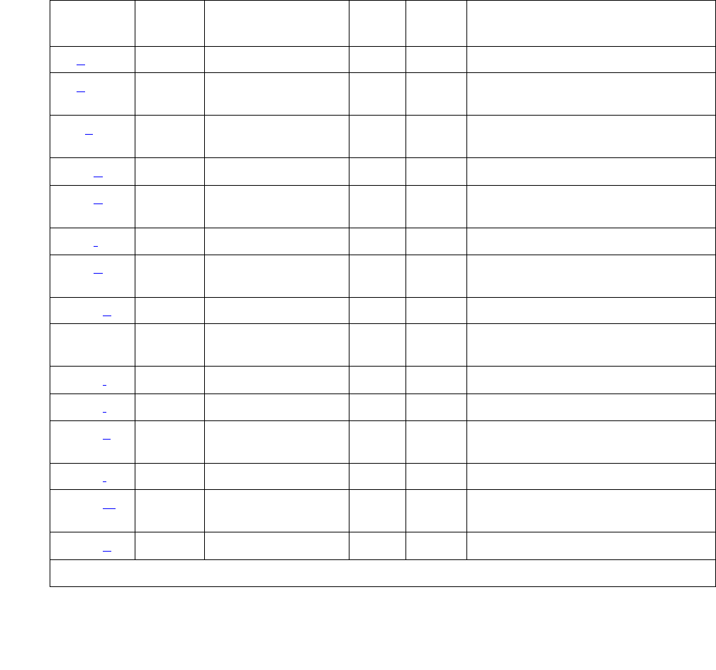
RDIG-STA (Remote Digital Station)
Issue 1 June 2005 1931
Possible reasons for no terminal download include:
●Terminal is off-hook.
●Terminal detected a bad checksum.
●Terminal detected a bad or missing EEPROM (refer to Hardware Error Log).
●Terminal is busy programming data from a previous PROGRAM message.
●Terminal is in the Programming Disabled state.
●Terminal is in the Local Program Options mode.
●Terminal is disconnected or out of service (use status station).
Table 709: Digital Line Error Log Entries
Error
Type
Aux
Data
Associated Test Alarm
Level
On/Off
Board
Test to Clear Value
0 (a) 0 Any Any Any test port location sh r 1
1 (b) 1 – 20,
40987
None WRN OFF
18 (c)0 busyout port
location
WRN OFF release port location
257 (d) 40971 None
513 (e) 0 Station (Digital)
Audits #17)
WRN OFF test port location sh r 6
767 (f) 40964 None WRN OFF
769 (g) 40963,
40988
None WRN OFF
1025 (h) None WRN OFF
1281 Any Station (Digital)
Audits (#17)
WRN OFF test port location sh r 4
1537 (i) 40968 None WRN OFF
2304 (j) None
2305 (k) 32770,
40967
None
2817 (l) Hyperactive MIN OFF
3840 (m) 40965,
40989
None
3841 (n) 41029 None

Communication Manager Maintenance-Object Repair Procedures
1932 Maintenance Procedures for Avaya Communication Manager 3.0, Media Gateways and Servers
Notes:
a. Error Type 0: run the short test sequence first. If every test passes, run the long test
sequence. Refer to each test’s description, and follow its procedures.
b. Error Type 1 with Aux Data 40987: could be caused by a noisy port or link. This is an
off-board problem detected by the port circuit. Check for defective wiring, a defective voice
terminal, or move the voice terminal closer to the switch (in terms of feet of wire from the
jack to the switch). If the problem persists, replace the circuit pack. Once the problem has
been resolved, the alarm disappears after a predetermined amount of time.
Error Type 1 with Aux Data 1-20: occurs when at least 15 off-board problems have been
detected with the link to the terminal. When an error with the link is detected, an on-board
counter is incremented.
The user could experience a noisy port or link. This is an off-board problem detected by the
port circuit. Check for defective wiring, a defective voice terminal, or move the voice
terminal closer to the switch (in terms of feet of wire from the jack to the switch). If the
problem persists, replace the circuit pack. Once the problem has been resolved, the alarm
disappears after a predetermined amount of time.
c. Error Type 18: the port in question is busied out by maintenance personnel. Make sure the
port is released from busyout by release port location.
d. Error Type 257: Indicates problems transmitting to the voice terminal, which can be caused
by defective wiring. Defective wiring can cause varying degrees of problems on different
types of sets.
e. Error Type 513: The result of an ID Request failure to respond to the digital endpoint audit.
f. Error Type 767: An in-line event produces this error type when a favorable response is
received from running the Digital Line Electronic Power Feed test (#11). No craft action is
necessary. This alarm will be resolved with the passing of time.
g. Error Type 769 with Aux Data 40963: The result of an unfavorable response to the
Electronic Power Feed/ Positive Temperature Coefficient test (#11).
Error Type 769 with Aux Data 40988: the EPF/PTC circuit has been turned off due to an
overcurrent condition.
Once the problem has been resolved, it may take up to one hour for the alarm to clear due
to the “leaky bucket” strategy. If the problem cannot be resolved by one of the steps above,
then replace the circuit pack.
h. Error Type 1025: problem with the voice terminal EEPROM. When the voice terminal is
repaired the alarm will be resolved with the passing of time.
i. Error Type 1537: in-line maintenance error has generated an off-board warning due to a
problem with the link to the voice terminal. This can be ignored if no user complaints are
received. Otherwise, make sure the voice terminal is connected, check for defective wiring,
check for a defective voice terminal, and move the voice terminal to a jack that is closer to
the switch (in terms of feet of wiring between the jack and the switch). If the problem
persists, replace the circuit pack. Once the problem has been resolved, the alarm
disappears after a predetermined amount of time.
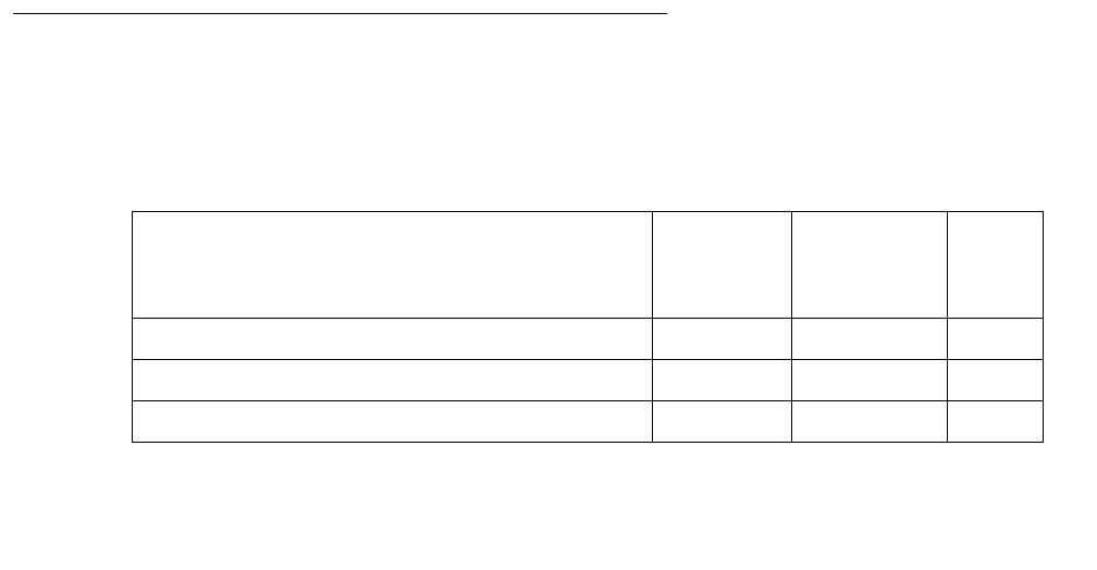
RDIG-STA (Remote Digital Station)
Issue 1 June 2005 1933
j. Error Type 2304: internal system error. No action is necessary.
k. Error Type 2305 with Aux Data 32770: the station went off-hook while it was in the
ready-for-service state. Use the status station command to determine the state of the
station. The off-hook should have moved the station to ready-for-service. No craft action is
necessary.
Error Type 2305 with Aux Data 40967: an in-line maintenance error has generated an
off-board warning due to a problem with the link to the voice terminal. This can be ignored if
no user complaints are received. Otherwise, make sure the voice terminal is connected,
check for defective wiring, check for a defective voice terminal, and move the voice terminal
to a jack that is closer to the switch (in terms of feet of wiring between the jack and the
switch). If the problem persists, replace the circuit pack. Once the problem has been
resolved, the alarm disappears after a predetermined amount of time.
l. Error Type 2817: the endpoint caused a large number of control channel messages to be
sent to the switch within a short period of time (50 or more CCMS uplinks within 10
seconds). The station will be taken out-of-service for 30 seconds due to the hyperactivity.
This may be completely normal during heavy traffic periods.
m. Error Type 3840 with Aux Data 40965: no terminal is connected to the COMBO board. No
maintenance action is required. This is also the code that is generated when the link
between the circuit pack and the voice terminal is successfully reset. No craft action is
necessary.
Error Type 3840 with Aux Data 40989: Indicates an uplink message has been logged
indicating that the Electric Power Feed (EPF) is on with no load on it. No action is
necessary. No craft action is necessary.
n. Error Type 3841: the circuit pack’s message buffer is full. This may be caused by having
many display phones with heavy traffic connected to the circuit pack. No action is
necessary.
System Technician-Demanded Tests:
Descriptions and Error Codes
Investigate tests in the order presented below. Clearing Error Codes associated with the one
test may also clear errors generated from other tests in the sequence.
Order of Investigation Short
Test
Sequence
Long Test
Sequence
D/ND1
1. D = Destructive; ND = Nondestructive
Digital Line Electronic Power Feed test (#11) X ND
DIG-LINE Station Lamp Updates test (#16) X X ND
Station (Digital) Audits test (#17) X X ND

Communication Manager Maintenance-Object Repair Procedures
1934 Maintenance Procedures for Avaya Communication Manager 3.0, Media Gateways and Servers
Digital Line Electronic Power Feed/Positive
Temperature Coefficient/PPF Test (#11)
This is an Electronic Power Feed (EPF) restoration test. In this test, the processor requests that
the EPF be turned on for a given port, and an attempt is made to turn on the power supply to the
station. If no current is drawn, the station is probably not connected. If an overcurrent condition
is sensed, there may be a short in the loop. A message is returned reporting that either the EPF
was successfully turned on, or that an overcurrent condition was sensed. This test is repeated
again 5 seconds later.
Table 710: Test #11 Digital Line Electronic Power Feed Test
Error
Code
Test
Result
Description / Recommendation
ABRT Internal system error.
1. Retry the command at 1-minute intervals up to 5 times.
1000 ABRT System resources required to run this test are not available. The port may
be busy with a valid call.
1. Enter display port WRN to determine the station extension or
attendant number of the port.
2. Use status station or status attendant to determine the
service state of the port.
●If the port is in use, wait until the port is idle before testing.
Attendants are always in use (off-hook) if the handset is plugged in
and the port is not busied out.
●If the port status is idle, then retry the command at 1-minute
intervals up to 5 times.
FAIL Internal system error
1. Retry the command at 1-minute intervals up to 5 times.
1 of 2

RDIG-STA (Remote Digital Station)
Issue 1 June 2005 1935
DIG-LINE Station Lamp Updates Test (#16)
This test lights every lamp on the terminal as specified. The lamp updates will run only if the
station is in-service. The status of the station is checked and the lamp updates are blocked from
taking place, if the station is not in the in-service state. This test does not affect the status of the
Message Waiting lamp.
PASS Electronic Power Feed test passed. The message to turn on the power to
the station was successfully sent to the port. Although this test will never
actually return a FAIL result except for the Internal system error described
above, it will log an error indicating the real results of the test.
1. Check the Error Log for any entries with Error Types 767 or 769 after
the test completes.
●If Error Type 767 appears in the Error Log, the test sensed no
problems with the power to the station. To verify that the station is
powered up correctly, run a self-test on the station and verify that
every feature button is operating.
●If Error Type 769 appears in the Error Log, this indicates some
problem with the power to the station. Check for a short in the
wiring, a damaged jack, a defective voice terminal, or an incorrect
type of terminal.
Table 710: Test #11 Digital Line Electronic Power Feed Test (continued)
Error
Code
Test
Result
Description / Recommendation
2 of 2
Table 711: Test #16 DIG-LINE Station Lamp Updates Test
Error
Code
Test
Result
Description / Recommendation
ABRT Internal system error
1. Retry the command at 1-minute intervals up to 5 times.
1 of 3

Communication Manager Maintenance-Object Repair Procedures
1936 Maintenance Procedures for Avaya Communication Manager 3.0, Media Gateways and Servers
1 ABRT This port may have been busied out by system technician.
1. Look in the Error Log for Error Type 18 (port busied out) for this port. If
this error type is present, then release the port using release
station extension and run the test again.
2. Make sure that the terminal is connected.
3. Retry the command at 1-minute intervals up to 5 times.
3 ABRT Station may be in ready-for-service or out-of-service state.
1. Use the status station command to verify the state of the station.
2. Make sure the terminal is connected.
3. Retry the command at 1-minute intervals up to 5 times.
1000 ABRT System resources required to run this test are not available. The port may
be busy with a valid call.
1. Use display port WRN to determine the station extension or
attendant number of the port.
2. Use status station or status attendant to determine the
service state of the port.
●If the port is in use, wait until the port is idle before testing.
Attendants are always in use (off-hook) if the handset is plugged in
and the port is not busied out.
●If the port status is idle, then retry the command at 1-minute
intervals up to 5 times.
1392 ABRT The port is currently a TTI port and the test will not execute on it.
1. Verify that the port is a TTI port using display port (the display
shows that the port is a TTI port) or the list config (the display
shows a t for the port).
2. If list config or display port indicates that the port is not a TTI
port, escalate the problem. If both commands indicate that the port is a
TTI port, the abort is correct, and no action is necessary.
FAIL Internal system error
1. Retry the command at 1-minute intervals up to 5 times.
Table 711: Test #16 DIG-LINE Station Lamp Updates Test (continued)
Error
Code
Test
Result
Description / Recommendation
2 of 3

RDIG-STA (Remote Digital Station)
Issue 1 June 2005 1937
Digital Station Audits Test (#17)
This is a series of six tests that are classified as audits. The media server sends messages to
the on-board microprocessor to perform the tests. These audits run only if the station is
in-service.
●Switchhook Inquiry test: This updates the media server’s records according to the circuit
pack’s records. This inquiry is sent all the way to the voice terminal.
●Bad Scan Inquiry test: This sends an up-link message containing a generated count based
on certain events relating to the link’s conditions. This indicates communications problems
between the media server and Digital Port circuit pack.
●EPF/PTC Inquiry test: This sends an up-link status message of the Electronic Power Feed
(EPF). Possible conditions are: EPF-on-ok, EPF-off.
●ID Request test: This sends a status request to the station. The station returns its
configuration information and health information. The information is checked, and a pass/
fail result is provided.
●Ringer update: This updates the digital telephone’s ringer state according to the media
server’s records.
●DTMF Administration update: This sends the digital station a message to refresh its default
value (sending touch tones only) in the primary information channel. This value is initially
set when the station is put in-service and each time the station’s state changes from
another state to in-service.
PASS The message to light every station lamp was sent successfully to the port.
1. Observe the station lamps being lit when running the test. If every
lamps does not light, the other Digital Line test results may indicate
related problems that do not allow the lamps to light.
2. Investigate by using other Digital Line port tests, and by examining the
station, wiring, and connections.
Table 711: Test #16 DIG-LINE Station Lamp Updates Test (continued)
Error
Code
Test
Result
Description / Recommendation
3 of 3

Communication Manager Maintenance-Object Repair Procedures
1938 Maintenance Procedures for Avaya Communication Manager 3.0, Media Gateways and Servers
Table 712: Test #17 Station (Digital) Audits Test
Error
Code
Test
Result
Description / Recommendation
1 ABRT Switchhook audit timed out.
1. Make sure voice terminal is connected and repeat test.
2. If test fails, replace voice terminal and repeat test.
2 ABRT ID request fails, health bit returned from voice terminal is bad.
1. Make sure voice terminal is connected and repeat test.
2. If test fails, replace voice terminal and repeat test.
3 ABRT The EPF has detected an overcurrent condition.
1. Use test WRN long. If Test #11 passes, then the EPF condition
was cleared. Rerun the short test sequence. If Test #11 does not pass,
follow the repair procedures described for Test #11.
2. Look for Error Type 769 logged against RDIG-STA, and follow the
procedures in the associated footnote. If any additional problems are
found, rerun the test.
4 ABRT Internal system error
1. Resolve any outstanding circuit pack maintenance problems.
2. Retry the command at 1-minute intervals up to 5 times.
5 ABRT Ringer update aborted due to station being in ready-for-service or
out-of-service state.
6 ABRT This port may have been busied out by a system technician.
1. Look in the Error Log for Error Type 18 (port busied out) for this port. If
this error is present, use release station to release the port.
2. Make sure that the terminal is connected.
3. Retry the command at 1-minute intervals up to 5 times.
1000 ABRT System resources required for this test are not available.
1. Retry the command at 1-minute intervals up to 5 times.
1 of 2

RDIG-STA (Remote Digital Station)
Issue 1 June 2005 1939
1392 ABRT This port is currently a TTI port and the test will not execute on it.
1. Verify that the port is a TTI port using display port, where the
display shows that the port is a TTI port, or list config, where the
display shows a t for the port.
2. If list config or display port indicate that the port is not a TTI
port, escalate the problem. If both commands indicate that the port is a
TTI port, the abort is correct, and no action is necessary.
2000 ABRT Response to the test was not received in the allowable time period.
1. Retry the command at 1-minute intervals up to 5 times.
FAIL Internal system error
1. Retry the command at 1-minute intervals up to 5 times.
PASS Station audits passed. This Digital Port circuit pack is functioning properly.
1. If complaints persist, investigate by using other port tests, and by
examining the station, wiring, and connections.
Table 712: Test #17 Station (Digital) Audits Test (continued)
Error
Code
Test
Result
Description / Recommendation
2 of 2
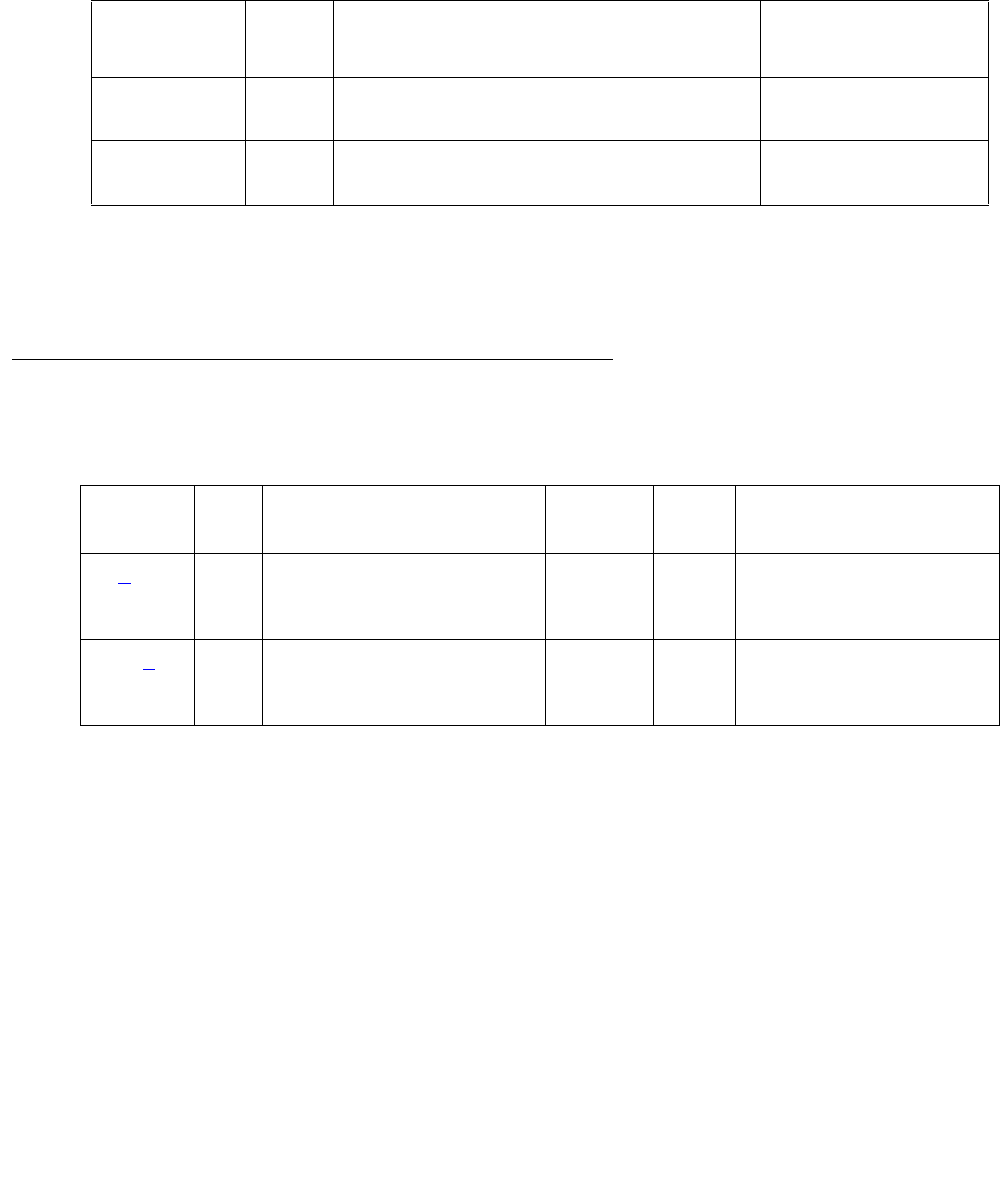
Communication Manager Maintenance-Object Repair Procedures
1940 Maintenance Procedures for Avaya Communication Manager 3.0, Media Gateways and Servers
REM-OFF (Remote Office)
S8700 | 8710 / S8500
An instance of this MO (REM-OFF) is associated with every Remote Office box that is
administered on the switch. This MO monitors keep alive and periodic PING test failures, and if
these errors occur, they are logged against this MO.
Error Log Entries and Test to Clear Values
Notes:
a. Error Type 1: a PING test to the Remote Office has failed, and a MINOR alarm has been
raised.
The PING test verifies that a path to a registered Remote Office is good. When this error is
logged, as many as 26 endpoints (associated with that Remote Office) and several H.323
signaling groups could be out of service.
b. Error Type 257: A Keep-Alive Timer is set for every registered endpoint on the Remote
Office. The switch expects keep-alive update information within a certain time period. If that
time limit is exceeded, an error is logged. The error is a log-only error, because there is no
way to determine which entity has failed.
MO Name in
Alarm Log
Alarm
Level
Initial SAT Command to Run Full Name of MO
REM-OFF MIN ping node-name node-name |
ip-address location
Remote Office
REM-OFF WRN ping node-name node-name |
ip-address location
Remote Office
Table 713: Analog Line Error Log Entries
Error Type Aux
Data
Associated Test Alarm
Level
On/Off
Board
Test to Clear Value
1 (a) A ping test to an endpoint
failed.
MIN OFF ping node-name
node-name |
ip-address addr
257 (b) A keep-alive update
request exceeded the time
limit for an endpoint.
Log only OFF ping node-name
node-name |
ip-address addr

REM-OFF (Remote Office)
Issue 1 June 2005 1941
The aux data associated with this error indicates whether the endpoint that failed to respond
was a DCP, Analog, or Signaling Group type. Aux data with a value of:
●1096 = Analog Line
●1095 = DCP Line
●6179 = H.323 Signaling Group
System Technician-Demanded Tests:
Descriptions and Error Codes
There are no demand tests for this MO. Use ping ip-address | node-name to ping the
Remote Office.

Communication Manager Maintenance-Object Repair Procedures
1942 Maintenance Procedures for Avaya Communication Manager 3.0, Media Gateways and Servers
RING-GEN (Analog Ring Generator)
S8700 | 8710
Analog phones must be provided with a voltage that allows them to ring. The Analog Ring
Generator MO represents the device that provides the ringing voltage for every analog phone
associated with a given cabinet. In a multicarrier cabinet, the ring generator resides in the power
distribution unit. It is protected by a fuse located next to the main circuit breaker on the front of
the unit. In single-carrier cabinets, the ring generator is part of the WP-91153 power supply.
Failure of the ring generator results in loss of ringing on analog phones. Ringing on digital and
hybrid phones is not affected.
The ringing voltage is monitored by the Tone-Clock circuit pack. In a port network with
duplicated Tone-Clocks, the active Tone-Clock performs this function. In a PN made up of
single-carrier cabinets, the Tone-Clock monitors the ringing voltage of only the carrier where it
resides.
The TN2036 Voltage Range circuit pack provides easy access for testing the various voltages
on the backplane pins.
Error Log Entries and Test to Clear Values
Note:
a. Error Type 0: run the short test sequence first. If every test passes, run the long test
sequence. Refer to each test’s description, and follow its procedures.
MO Name in
Alarm Log
Alarm
Level
Initial SAT Command to Run Full Name of MO
RING-GEN MAJ test environment location Analog Ring Generator
Table 714: Analog Ring Generator Error Log Entries
Error
Type
Aux
Data
Associated Test Alarm
Level
On/Off
Board
Test to Clear Value
0 (a) 0 Any Any Any test environment location
1 Analog Ring
Generator Query
(#118)
MAJ ON test environment location r 3

RING-GEN (Analog Ring Generator)
Issue 1 June 2005 1943
System Technician-Demanded Tests:
Descriptions and Error Codes
Investigate tests in the order presented below. Clearing Error Codes associated with the one
test may also clear errors generated from other tests in the sequence.
Notes:
a. See POWER on page 1869 for a description of this test.
b. See CARR-POW (Carrier Power Supply) on page 770, (S8700 IP: RMC-ENV (Power/Fan
Sensors) on page 1951) for a description of this test.
c. See EMG-XFER (Emergency Transfer) on page 1134 for a description of this test.
d. SeeCABINET (Cabinet Sensors) on page 758 for a description of this test.
Order of Investigation Short
Test
Sequence
Long Test
Sequence
D/ND1
1. D = Destructive, ND = Nondestructive
Analog Ring Generator Initialization test (#117) X X ND
Analog Ring Generator Query test (#118) X X ND
Battery and Battery Charger Query test (#5) (a)XXND
AC Power Query test (#78) (b)XXND
S8700 MC: OLS Query test (Carrier E) (#127) (c)XXND
S8700 MC: OLS Query test (Carrier D) (#127) (c)XXND
S8700 MC: OLS Query test (Carrier A) (#127) (c)XXND
S8700 MC: OLS Query test (Carrier B) (#127) (c)XXND
S8700 MC: OLS Query test (Carrier C) (#127) (c)XXND
S8700 MC: Emergency Transfer Query test (#124) (d)X X ND
Cabinet Sensors Query test (#122) (e) (S8700 IP: (d)) X X ND
External Alarm Lead Query test (#120) (f)
S8700 IP: (e)
XXND
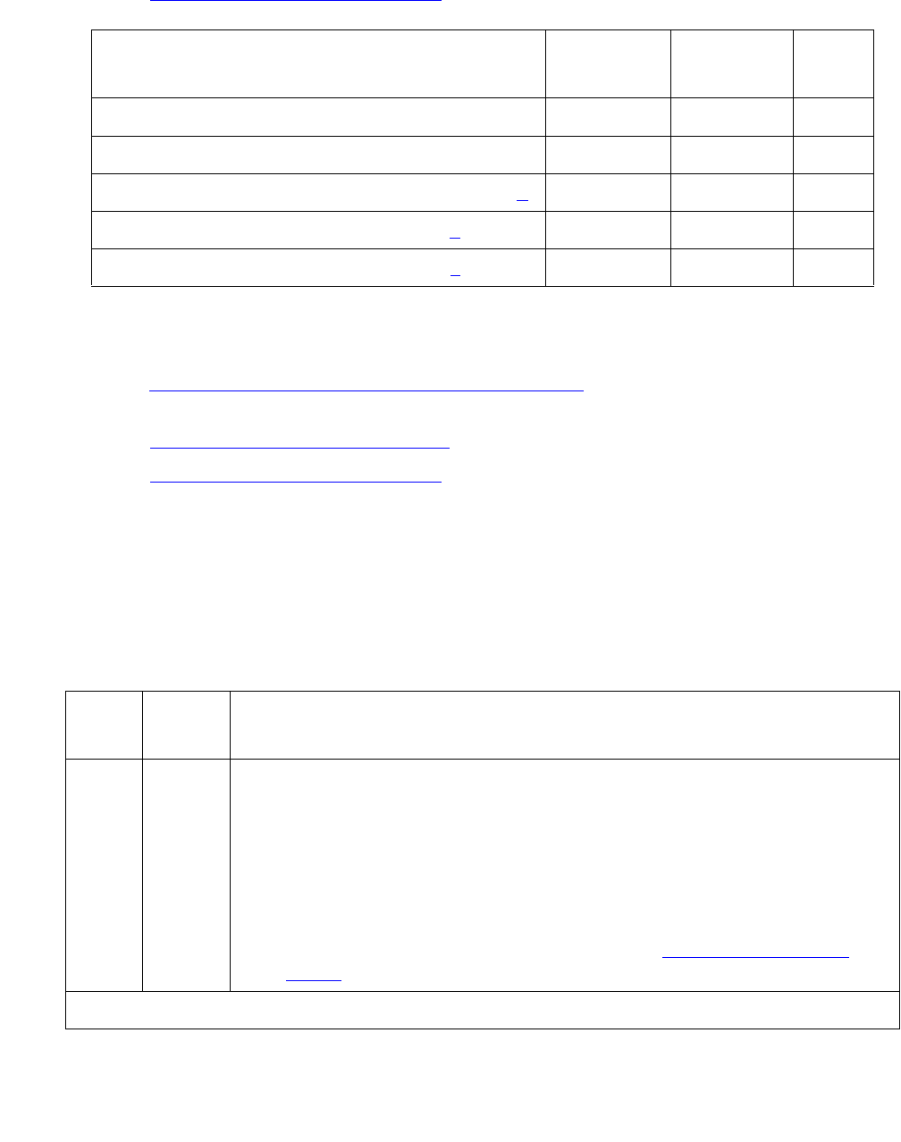
Communication Manager Maintenance-Object Repair Procedures
1944 Maintenance Procedures for Avaya Communication Manager 3.0, Media Gateways and Servers
e. See EXT-DEV (External device alarm) on page 1240 for a description of this test.
Notes:
a. See DC-POWER (Single-Carrier Cabinet Environment) on page 880 for a description of this
test.
b. See EMG-XFER (Emergency Transfer) on page 1134 for a description of this test.
c. See EXT-DEV (External device alarm) on page 1240 for a description of this test.
Analog Ring Generator Initialization Test (#117)
The Analog Ring Generator Initialization test sends a request to the active TN768, TN780,
TN2182 Tone-Clock or TN2312AP IPSI circuit pack’s Tone-Clock circuit to monitor the voltage.
The Tone-Clock responds with an error if the ringing voltage falls too low.
Order of Investigation Short Test
Sequence
Long Test
Sequence
D/ND1
1. D = Destructive, ND = Nondestructive
Analog Ring Generator Initialization test (#117) X X ND
Analog Ring Generator Query test (#118) X X ND
Single-Carrier Cabinet Power Query test (#79) (a)X X ND
Emergency Transfer Query test (#124) (b)XXND
External Alarm Lead Query test (#120) (c)XXND
Table 715: Test #117 Analog Ring Generator Initialization Test
Error
Code
Test
Result
Description / Recommendation
1
1000
1001
1003
1115
2012
2100
ABRT The system software is unable to determine the active Tone-Clock circuit
pack, unable to allocated the resources necessary to run the test, or
unable to send a down link message.
1. Wait for the green LED on the active Tone-Clock to go out.
2. Use status port-network to determine the active Tone-Clock
circuit pack.
3. Rerun the test. If the test aborts again, see TDM-CLK (TDM Bus
Clock) on page 2252.
1 of 2

RING-GEN (Analog Ring Generator)
Issue 1 June 2005 1945
Analog Ring Generator Query Test (#118)
The Analog Ring Generator Query test requests the active Tone-Clock circuit pack to check the
ringing voltage. The Tone-Clock circuit pack replies with PASS if the ringing voltage is adequate
to ring the analog phones. If not, the active Tone-Clock circuit pack replies with a FAIL.
2000 ABRT Response to the request was not received within the allowable time
period.
1. Look for TDM-CLK errors and alarms. Resolve every other
Tone-Clock problem first.
2. Rerun the test.
PASS The active Tone-Clock has successfully been enabled to monitor the
ringing voltage level.
Table 715: Test #117 Analog Ring Generator Initialization Test (continued)
Error
Code
Test
Result
Description / Recommendation
2 of 2
Table 716: Test #118 Analog Ring Generator Query Test
Error
Code
Test
Result
Description / Recommendation
1
1000
1001
1003
1115
2012
2100
ABRT Could not seize the resources to run the test. Other maintenance is
running on the active Tone-Clock circuit pack.
1. Wait for the green LED on the active Tone-Clock circuit pack to go out.
2. Use status port-network to determine the active Tone-Clock
circuit pack.
3. Rerun the test. If the test aborts again, see TDM-CLK (TDM Bus
Clock) on page 2252.
2000 ABRT Response to the request was not received within the allowable time
period.
1. Look for TDM-CLK errors and alarms. Resolve every other
Tone-Clock problem first.
2. Rerun the test.
1 of 4

Communication Manager Maintenance-Object Repair Procedures
1946 Maintenance Procedures for Avaya Communication Manager 3.0, Media Gateways and Servers
FAIL The ringing voltage is below acceptable levels. For a multicarrier cabinet
system:
1. If this is a duplicated system, use status port-network to
determine the active Tone-Clock circuit pack.
2. Use set tone-clock location to make the standby Tone-Clock
circuit pack active
3. Rerun the test.
a. If the test passes, the trouble is with the now standby Tone-Clock
circuit pack. See TONE-BD (Tone-Clock Circuit) on page 2327 for
details on replacing the standby Tone-Clock circuit pack. After the
circuit pack is replaced, use set tone-clock location to
make this Tone-Clock active again, and rerun the test.
b. If the test fails:
4. Resolve CARR-POW alarms first, and then rerun the test.
5. Check fuse on the power distribution unit. Replace if it is open, and
rerun the test. If the test still fails, then an analog line circuit pack
could be defective and causing the ring generator and/or fuse to fail.
6. Unseat every analog circuit pack in the affected cabinet, and rerun the
test.
7. If the test passes, then the ring generator is healthy, and one of the
analog circuit packs is defective. Replace the analog circuit packs one
at a time, and rerun the test to determine which circuit pack is causing
the problem. When the defective analog circuit pack is found, replace
it and rerun the test. If the test still fails, proceed with Step 6.
Table 716: Test #118 Analog Ring Generator Query Test (continued)
Error
Code
Test
Result
Description / Recommendation
2 of 4

RING-GEN (Analog Ring Generator)
Issue 1 June 2005 1947
FAIL
(cont’d)
Since the test still fails, the ring generator is defective.
a. If the reset button on the ring generator is out, press it in.
b. Originate calls to several analog stations on different port circuit
packs in different carriers in the affected port network.
c. If called stations ring, the fault is cleared. Proceed to Step d. If no
stations ring, replace the ring generator.
d. Rerun the test. If the test still fails, proceed to Step 7.
1. The active Tone-Clock may be faulty and incorrectly reporting the
level of the ringing voltage. Replace the active Tone-Clock, and rerun
the test. See TONE-BD (Tone-Clock Circuit) on page 2327 for details
on replacing the Tone-Clock. Rerun the test.
Table 716: Test #118 Analog Ring Generator Query Test (continued)
Error
Code
Test
Result
Description / Recommendation
3 of 4

Communication Manager Maintenance-Object Repair Procedures
1948 Maintenance Procedures for Avaya Communication Manager 3.0, Media Gateways and Servers
Procedure for a single-carrier cabinet system:
This failure indicates that there is no ringing voltage in the carrier where
the active Tone-Clock circuit pack resides. Other carriers may or may not
have ringing voltage.
1. If this is a duplicated system, use status system to determine the
active Tone-Clock circuit pack. Use set tone-clock location to
make the standby Tone-Clock circuit active, and rerun the test.
a. If the test passes, then the trouble is with the “new” stand by
Tone-Clock circuit pack. See TONE-BD (Tone-Clock Circuit) on
page 2327 for details on replacing the standby Tone-Clock circuit
pack. After the circuit pack is replaced, use set tone-clock
location to make this Tone-Clock circuit active, and rerun the
test.
b. If the test fails, then proceed with Step 2.
2. Unseat every analog circuit pack in the cabinet that contains the
active Tone-Clock circuit pack, and rerun the test.
3. If the test passes, then the ring generator is healthy and one of the
analog circuit packs is defective. Replace the analog circuit packs one
at a time, and rerun the test to determine which circuit pack is causing
the problem. Replace the defective analog circuit pack. Rerun the
test. If the test still fails, go to Step 4.
4. Replace the WP-91153 power unit for the affected carrier, and rerun
the test. If the test still fails, go to Step 5.
5. The active Tone-Clock may be faulty and incorrectly reporting the
level of the ringing voltage. Replace the active Tone-Clock, and rerun
the test. See TONE-BD (Tone-Clock Circuit) on page 2327 for details
on replacing the active Tone-Clock circuit pack. Rerun the test.
PASS The analog ringing voltage level is acceptable. For a single-carrier cabinet
stack, ringing voltage is acceptable in the cabinet containing the active
Tone-Clock circuit pack.
Table 716: Test #118 Analog Ring Generator Query Test (continued)
Error
Code
Test
Result
Description / Recommendation
4 of 4

RMB (Remote Maintenance Board)
Issue 1 June 2005 1949
RMB (Remote Maintenance Board)
Remote Maintenance Board (RMB) functionality for selected media servers is provided by a
circuit card that is plugged into the media server. Two different circuit cards are used on the
S8500 and S8500B media servers. The S8500 server uses a Remote Supervisor Adapter
(RSA) board. The S8500B uses a Augmentix Server Availability Management Processor™
(A+SAMP™) board.
In both cases the basic functionality of the RMB cards is:
●Monitor the media server environmental state of health: fans, voltages, and temperature.
●Report server failure.
●Provide the ability to perform remote server power-on and reset capability.
S8500
The remote maintenance board function is implemented in the S8500 media server by the
Remote Supervisor Adapter (RSA) board. For more information on alarms that may be
generated by the S8500 media server regarding the RSA see Remote Maintenance Board
(RMB) Alarms on page 116. These alarms, reported with the Maintenance Object (MO) named
RMB, will be associated with a Product ID beginning with one (1) followed by nine digits.
S8500B
The remote maintenance board function is implemented in the S8500B media server by the
Augmentix Server Availability Management Processor (A+SAMP) board. For more information
on alarms that may be generated by the A+SAMP see S8500B Augmentix Server Availability
Management Processor™ (A+SAMP) Alarms on page 120. These alarms, reported with the
MO named RMB, will be associated with a Product ID beginning with five (5) followed by nine
digits.
MO Name in
Alarm Log
Alarm
Level
Initial SAT Command to Run Full Name of MO
RMB MAJ Not Applicable Remote Maintenance Board

Communication Manager Maintenance-Object Repair Procedures
1950 Maintenance Procedures for Avaya Communication Manager 3.0, Media Gateways and Servers
RMB-REPORT (Remote Maintenance Board - Report)
Remote Maintenance Board functionality for the S8500 and S8500B media servers is
implemented by circuit cards plugged into the servers. These boards monitor the servers for
health and environment integrity. When a problem is detected, the RMB will report it to the
appropriate alarm receiver. These reports are not associated with a maintenance object (MO) in
Avaya Communication Manager because they originated and were reported by the RMB
without Avaya Communication Manager knowledge. The RMB-REPORT MO is associated with
these events in the alarm receiver mechanisms. This allows the alarm receiver to create and
queue alarm tickets in the same manner as Avaya Communication Manager reported errors.
The RMB-REPORT MO will NOT be seen in the Avaya Communication Manager error logs.
For more information about the errors that may be reported and associated with RMB-REPORT
see ENV (Environment) on page 60
MO Name in Alarm
Log
Alarm
Level
Initial SAT
Command to Run
Full Name of MO
Not Applicable (N/A) N/A N/A Remote Maintenance Board - Report

RMC-ENV (Power/Fan Sensors)
Issue 1 June 2005 1951
RMC-ENV (Power/Fan Sensors)
G600 only
The AC Power Supply (650A) for a G600 media gateway (Rack-Mounted Cabinet - RMC)
supports one alarm lead that indicates the state of both the power and fan. The cabinets use
variable-speed fans to reduce noise. The power unit contains thermal speed control. A 3-pin
connector on the variable-speed fan assembly accepts variable input power to control its fan
speed and power its alarm circuitry.
Table 717: LED and Alarm Conditions on page 1951 shows the LED and alarm conditions.
Fan Removal and Replacement
!WARNING:
WARNING: You can remove the fan assembly while the system is running, but you must
replace the new assembly within 60 seconds to avoid a thermal overload.
1. Place the new fan assembly close to the G600.
2. Loosen the thumb screws on the fan assembly, and pull it straight out (unplug it) as shown
in Figure 113: Fan Removal on page 1952. The power for the fan automatically
disconnects when the assembly is unplugged.
3. Plug in the new fan assembly. The power for the fan automatically connects when the fan
assembly is plugged in.
4. Tighten every thumb screw on the fan assembly.
MO Name in
Alarm Log
Alarm
Level
Initial Command to Run Full Name of MO
RMC-ENV MAJ test environment Power/Fan Sensors
Table 717: LED and Alarm Conditions
Condition LED
Status
Alarm
State
Fan/Power Alarm
Normal Red off,
amber on
Open Normal
No input power Red off,
amber off
Closed No input power
DC output not present
(except neon)
Red on,
amber off
Closed DC output not present
(except neon)
Fan alarm Red on,
amber on
Closed Fan/Power alarm
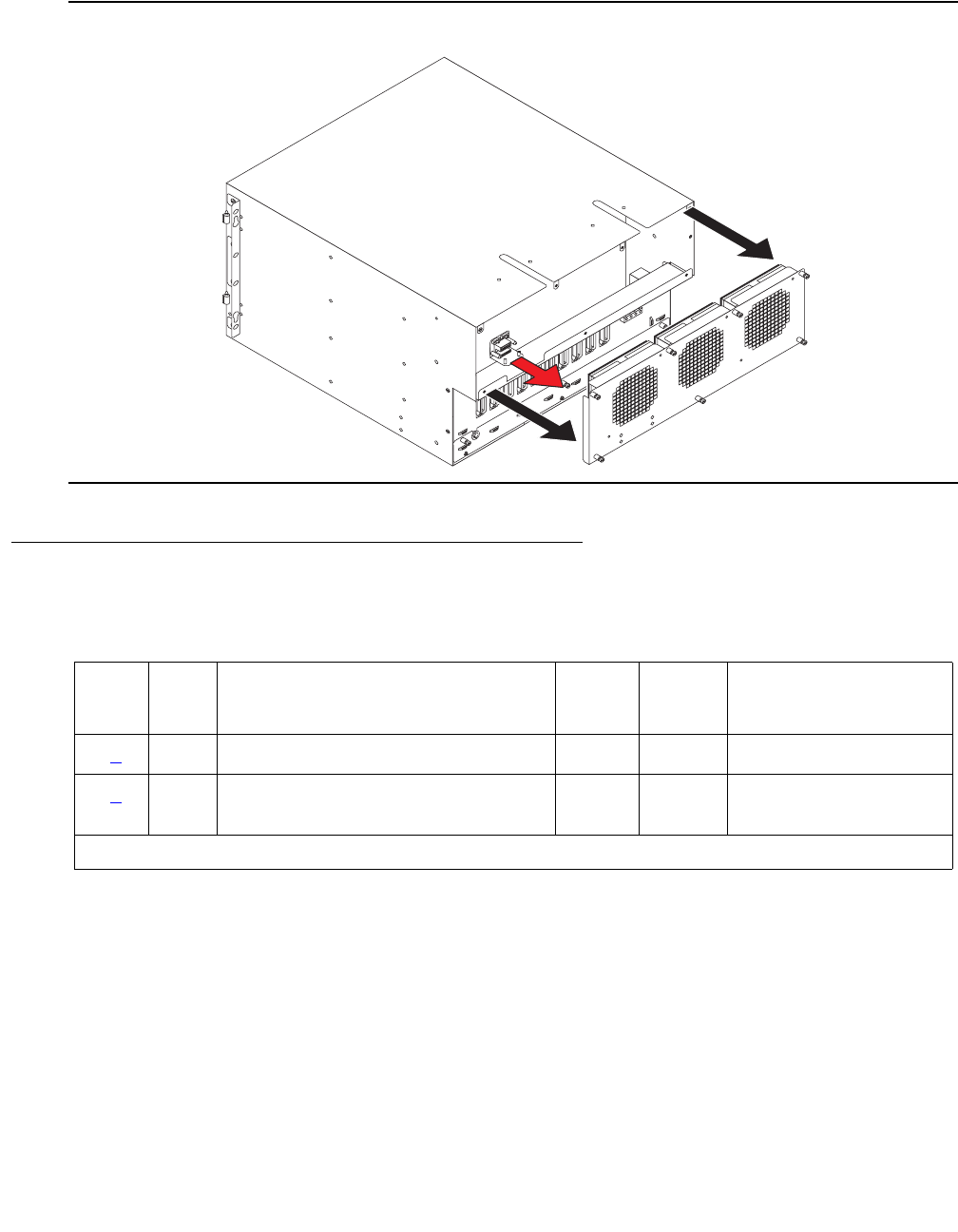
Communication Manager Maintenance-Object Repair Procedures
1952 Maintenance Procedures for Avaya Communication Manager 3.0, Media Gateways and Servers
Figure 113: Fan Removal
Hardware Error Log Entries and Test to Clear Values
Notes:
a. Error Type 0: run the short test sequence first. If every test passes, run the long test
sequence. Refer to each test’s description, and follow its procedures.
b. Error Type 1: the power-/fan-status lead indicates that a G600 media gateway’s power
supply has detected an alarm condition. The condition can be caused by the failure of any
fan’s or any power supply’s output. If more than one G600 exists, every power-/fan-status
lead is tied together. (The fan and power lead is an O-ring of every cabinet’s status lead.)
Since an error condition on a fan’s or power supply’s output could be the result of a
temporary overload (e.g., during board insertion) or caused by the equipment’s location
fndpremv LJK 102600
Table 718: Cabinet sensors error log entries
Error
Type
Aux
Data
Associated Test Alarm
Level
On/Off
Board
Test to Clear Value
0 (a) 0 Any Any Any test environment
1 (b) Any Cabinet Temperature or Voltage
Query test (#122)
MAJ ON test environment
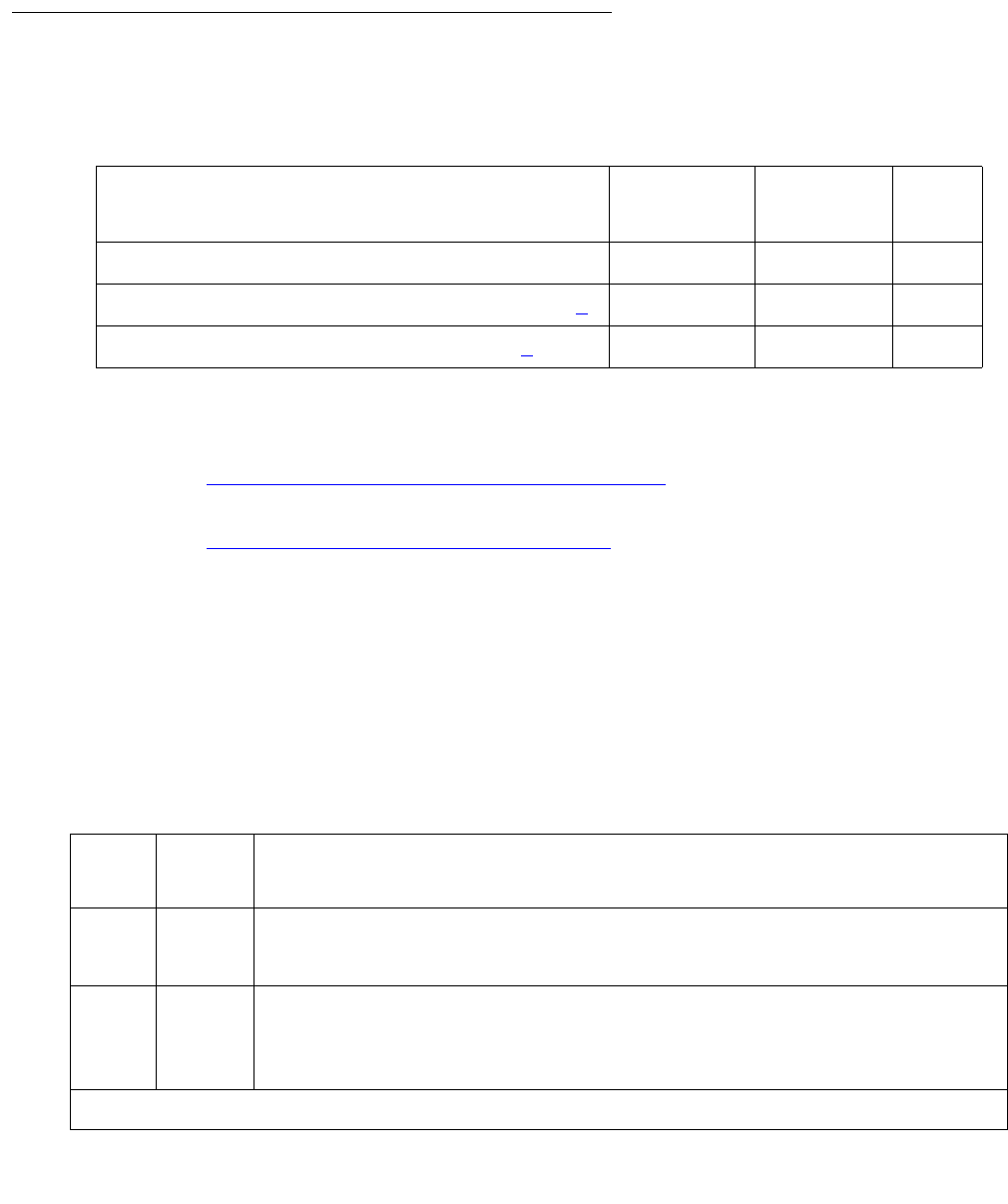
RMC-ENV (Power/Fan Sensors)
Issue 1 June 2005 1953
(e.g., fan blockage), a single event may be an anomaly that eventually clears. However, a
repeating condition causes a major alarm.
On-Demand Tests: Descriptions and Error Codes
Investigate tests in the order presented below. Clearing Error Codes associated with the one
test may also clear errors generated from other tests in the sequence.
Notes:
a. Refer to Analog Ring Generator Initialization Test (#117) on page 1944 for a description of
this test.
b. Refer to Analog Ring Generator Query Test (#118) on page 1945 for a description of this
test.
RMC Power/Fan Query Test (#77)
This test queries the Processor circuit pack for the status of the cabinet sensors in the G600
media gateway (RMC). Only one alarm lead is supported by this cabinet type to indicate a
power, temperature, or a fan problem. This means that a failure of this test can also mean a
power problem, not necessarily just a temperature/fan problem.
Order of Investigation Short Test
Sequence
Long Test
Sequence
D/ND1
1. D = Destructive; ND = Nondestructive
RMC Power/Fan Query test (#77) X X ND
Analog Ring Generator Initialization test (#117) (a)X X ND
Analog Ring Generator Query test (#118) (b)XXND
Table 719: TEST #122 Cabinet Temperature Query Test
Error
Code
Test
Result
Description / Recommendation
1000 ABRT System resources required to run this test are not available.
1. Retry the command at 1-minute intervals up to 5 times.
2000 ABRT Response to the test request was not received within the allowable time
period.
1. Retry the command at 1-minute intervals up to 5 times.
1 of 3

Communication Manager Maintenance-Object Repair Procedures
1954 Maintenance Procedures for Avaya Communication Manager 3.0, Media Gateways and Servers
2029 ABRT Internal system error.
1. Retry the command at 1-minute intervals up to 5 times.
1 FAIL There is a fan, temperature, power, or voltage problem in one or more of
the cabinets. The power supply’s LEDs may indicate the problem’s source.
1. If none of the fans are running, then verify 8- to 14-Volt DC power is
available to the fan units by checking the wiring connector.
●If there is 8- to 14-Volt DC power at the connector, there should be
power to the fans. If the fans still do not run, replace the fan
assembly.
●If not, then the power unit’s fan output is defective or thermally shut
down. Let the power unit cool, and recycle AC input power. If no fan
output, replace the power unit. If the fans still do not run, escalate
the problem.
2. If only one of the fans is not running, replace the fan.
3. If every fan can be started, wait 5 minutes and rerun the test. If the test
fails again, proceed to Step 4 or 5 as applicable.
4. If the fans are not at high speed, measure the cabinet’s temperature at
the air intake and the air exhaust at the top of the cabinet.
●If the 5- to 600-C criteria is met, there is a problem with the fans that
is preventing the fans from operating at high speed. Replace the
fans. If the fans run at high speed, wait 5 minutes to give the
cabinet time to cool down and, rerun the test. If the problem
persists, go to step 5.
●If not, the Processor circuit pack is incorrectly reporting this
condition. Look for and resolve every error on these MOs first, then
rerun the test.
Table 719: TEST #122 Cabinet Temperature Query Test (continued)
Error
Code
Test
Result
Description / Recommendation
2 of 3

RMC-ENV (Power/Fan Sensors)
Issue 1 June 2005 1955
1FAIL
(cont’d)
5. If the fans are running at high speed, check the items on following list.
Any one of these could be restricting or redirecting the cabinet’s air
flow.
●Check filter; if the filter is dirty or clogged it should be cleaned or
replaced. The filter can either be washed with soap and water or
vacuumed.
●Verify that nothing other than circuit packs in the carrier slots that
could be restricting air flow.
●Verify that no circuit-pack blanks or carrier faceplates are missing.
Install and/or replace them as necessary.
●Be sure the cabinet’s doors are properly closed. The doors must be
closed to enable the fans to properly cool the cabinet. Wait 5
minutes to allow the fans to cool the cabinet. Rerun the test. If the
test still fails, proceed to Step 6.
6. At this point, there should be nothing impeding the air flow, and the
fans should be running at high speed. Check the temperatures for the
5- to 600-C criteria.
●If the 5- to 600-C criteria exists, a temperature problem exists, and
the fans (at high speed) should cool down the switch. Wait 5
minutes, and rerun the test. If the test still fails, the ambient room
temperature is probably too high, and the room should be cooled.
If not, the fans are defective. Replace the fan assembly, and rerun
the test. Failures can occur on the Processor circuit pack that is not
detected by the respective MO, but that cause many, if not every,
environment test to fail. If many environment tests are failing, the
suspected circuit pack (depending on the system configuration)
should be replaced and the test rerun.
There is a problem with the environment of the power system:
1. The power unit for the cabinet may be defective.
a. Verify and, if necessary, replace the power unit.
b. Rerun the test. If the test still fails, escalate.
PASS The cabinet does not have a power or fan problem. If a problem is reported,
troubleshoot by using the previous procedures for the FAIL cases.
Table 719: TEST #122 Cabinet Temperature Query Test (continued)
Error
Code
Test
Result
Description / Recommendation
3 of 3


SER-BUS (Serial communication bus)
Issue 1 June 2005 1957
SER-BUS (Serial communication bus)
G650
Each port network of G650s has a Serial Bus that allows the TN231O2BP IPSI to communicate
with the 655A power supplies. This Serial Bus uses 2 previously unused leads in the Universal
Port Slot. SPARE3 (pin 055) now becomes serial data. SPARE4 (pin 155) now becomes serial
clock. The serial communication bus is a two-wire bi-directional half-duplex bus that is provided
on the backplane of the G650. The serial bus consists of a clock line and a data line. Data is
transferred on the data line synchronously in bit-serial fashion a byte at a time. Communication
on the serial bus is at speeds up to 100 kbits per second.
Older TDM/LAN cables did not have these 2 leads so the G650 required a new TDM/LAN cable.
These 2 leads are not terminated on the TDM/LAN Terminators (AHF110). This is an
open-collector bus where each power supply and each TN2312BP IPSI provide a pull-up
resistor to +5VDC for each of the 2 Serial Bus leads. The bus will have logic pulses extending
between 0V and 5V.
The TN2312BP IPSI in the A carrier will act as master of the serial bus and poll each of the
power supplies based on their board address. Only a TN2312BP IPSI in the A carrier can be a
bus master, even if a TN2312BP in carrier B is used for port network connectivity. Therefore,
setting the TN2312BP in the A carrier or B carrier to be active will not clear a problem if the
TN2312BP itself is the reason for the failure. The power supply’s board address is derived from
4 board address leads in the power slot of the backplane. The G650 carrier addressing paddle
card sets 3 of these 4 address leads for the power slot. A G650 can have a maximum of ten
655A power supplies on the serial bus (See Figure 114: Wiring diagram for serial bus data and
clock leads on page 1958).
Note:
Note: The serial bus is provided only to a G650 equipped with TN2312BP IPSI circuit
packs. The serial bus is not available on any other media gateway.
Figure 115: G650 Cabinet Environmental Hardware Components on page 1959 illustrates
these components.
MO name Alarm level Initial SAT command to run Full name of MO
SER-BUS MIN test environment location sh SER communication bus
SER-BUS MAJ test environment location l SER communication bus
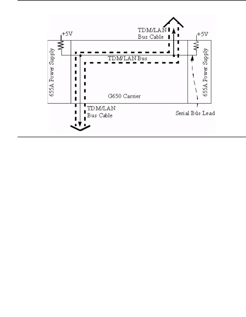
Communication Manager Maintenance-Object Repair Procedures
1958 Maintenance Procedures for Avaya Communication Manager 3.0, Media Gateways and Servers
Figure 114: Wiring diagram for serial bus data and clock leads
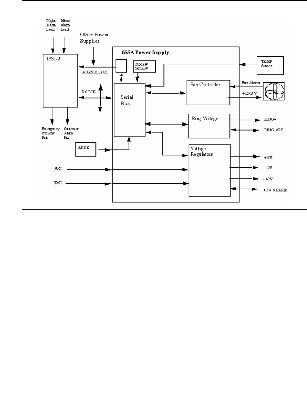
SER-BUS (Serial communication bus)
Issue 1 June 2005 1959
Figure 115: G650 Cabinet Environmental Hardware Components
Use status environment to obtain:
●Inlet temperature - 655A power supply sensor
●Exhaust temperature - G650 carrier exhaust air sensor
●Hot Spot temperature - 655A power supply sensor
- The system generates a warning at 176o Fahrenheit (80o Celsius).
- The power supply shuts down at 194o Fahrenheit (90o Celsius).
●Power supply output voltage measurements, +5VDC, -5VDC, and -48VDC
●Fan Control - The speed of the fans, either mid (normal) or high (fan failure or hot spot
temperature limit exceeded).
●Fan Alarm - Detection of a blocked or failed fan
●Ring Status - OK, overload, shorted, or failed
●Ring Control - Active, standby, disabled, off (shorted or failed)
●Ringer Setting - 20Hz, 25Hz, or other
●Ring Detection - Reports if power supply detects ring on the backplane ring leads

Communication Manager Maintenance-Object Repair Procedures
1960 Maintenance Procedures for Avaya Communication Manager 3.0, Media Gateways and Servers
●Source of input power - AC, DC, or both
●Input power - Indicates the type of power currently in use, AC or DC
●AuxSig signal status
Note:
Note: If the TN 2312BP IPSI cannot get data from the power supplies, the data entries
for status environment will be dashed out.
Use recycle carrier to:
●Shut off all voltage output temporarily
●Shut off ringer voltage output temporarily
Use clear error to:
●Clear the non-volatile source ID cause of the last shutdown
●Clear the serial bus error and time-out counters
Serial Bus Fault Detection and Isolation
Serial Bus faults can be caused by:
●A defective circuit pack inserted into one of the G650 slots
●Bent pins on the G650 backplane
●Defective TDM/LAN bus cables
●Power supply microcontroller failure
●TN2312BP IPSI failure
It is possible that a circuit pack can cause a Serial Bus fault and still exhibit trouble-free
operation. For example, insertions of any circuit pack into a G650 slot may bend the backplane
pins and short two leads together. Or a circuit pack that doesn’t use the Serial Bus could still
have an on board short that shorts one of the Serial Bus leads. Since the Serial Bus is a shared
resource that each circuit pack and power supply has access to, identification of the cause of a
Serial Bus fault can be difficult.
!WARNING:
WARNING: Since the Serial Bus fault isolation procedure involves removing circuit packs and
possibly disconnecting entire carriers, the procedure is extremely destructive to
the port network that is being tested. If possible, arrange to perform this
procedure at a time when traffic is minimal.
As circuit packs are removed or entire carriers are disconnected, any active calls terminating on
those circuit packs or carriers will be dropped. If you have any hints about a particular circuit
pack that may be causing the Serial Bus problem investigate those before performing this
procedure (for example, look at any circuit packs that were inserted into the PN just before the

SER-BUS (Serial communication bus)
Issue 1 June 2005 1961
Serial Bus problem appeared.) Also examine which power supplies the system is unable to
show using list configuration power-supply C and concentrate your efforts on those
carriers and their cabling.
!CAUTION:
CAUTION: When straightening or replacing backplane pins in a carrier, power to that carrier
must be shut off. Failure to follow this procedure may result in damage to circuit
packs and power supplies, and can be hazardous to the technician.
Procedure 1
The procedure removes and reinserts port circuit packs (those in the purple slots) one or more
at a time. Use this procedure for each port circuit pack in the port network until the problem is
resolved or until all circuit packs in the port network have been tried.
If the Serial Bus problem is present when the circuit pack is inserted, but is resolved when the
circuit pack is removed, either the circuit pack or the backplane pins in that slot are causing the
problem. If the backplane pins are intact, replace the circuit pack. If some of the tests fail
regardless of whether the circuit pack is inserted or removed, and the backplane pins are intact,
the circuit pack is not the cause of the problem. In a multiple failure situation, the circuit pack
could be one cause of the Serial Bus problem. However, other simultaneous failures might also
be responsible for Serial Bus faults. In Procedure 2, an option of working either with one circuit
pack at a time or with multiple circuit packs simultaneously is available. In view of this capability,
determine the level of service interruption that will be acceptable during the procedure. If
causing a disruption to all users in the port network is deemed permissible, large groups of
circuit packs should be worked with in order to get the job done quickly. However, if large
service disruptions are to be avoided, work with one circuit pack at a time. This option is slower,
but it disrupts only the users of a single circuit pack.
Refer to the repair procedure steps given under Serial bus communications test (#1531) on
page 1963.
Procedure 2
Procedure 2 attempts to isolate the Serial Bus failure to a particular set of carriers. Only the
circuit packs in selected carriers are checked. Procedure 2 is used if the preceding procedure
fails, because it can help locate multiple circuit pack failures and failures of the carrier hardware
itself. In this procedure, the TDM/LAN Cable Assemblies and TDM/LAN Bus terminators are
replaced. If this action does not resolve the Serial Bus fault, the carriers are reconfigured so that
certain carriers are disconnected from the Serial Bus. This is done by moving the TDM/LAN Bus
terminators (AHF110) on the carrier backplane. To terminate a Serial Bus at the end of a
particular carrier, the Serial Bus cable that connects the carrier to the next carrier should be
unplugged and replaced with the TDM/LAN Bus terminator. When the length of the Serial Bus is
modified the A carrier TN2312BP IPSI circuit pack that is essential to the Serial Bus operation
and Serial Bus maintenance must still be connected to the new shortened Serial Bus.

Communication Manager Maintenance-Object Repair Procedures
1962 Maintenance Procedures for Avaya Communication Manager 3.0, Media Gateways and Servers
After cabling changes are made and verified, power must be restored to the port network.
Circuit packs in carriers that are not part of the shortened bus are not inserted. As a result,
these circuit packs are alarmed. Ignore these alarms for now. All alarms should be resolved
when the cabinet is restored to its original configuration.
Procedure 2 is organized into two parts:
●Part 1 attempts to clear the Serial Bus fault by replacing all the bus cabling and terminators
within a port-network.
●Part 2 attempts to isolate the fault to a particular carrier by extending the Serial Bus from
the A carrier to additional carriers one at a time.
Refer to the repair procedure steps given under Serial bus communications test (#1531) on
page 1963
Error log entries and test-to-clear values
a. Error type 257: serial bus failure. There are no power supplies detected on the serial bus.
System technician-demanded test: Descriptions and error codes
Error
Type
Aux
Data
Associated Test Alarm
Level
On/Off
Board
Test-to-clear value
257 (a) Serial Bus
Communications (#1531)
MIN Off test environment location
Order of investigation Short test
sequence
Long test
sequence
D/ND1
1. D = Destructive, ND = Nondestructive
Serial Bus Communications Test (#1531) X X ND

SER-BUS (Serial communication bus)
Issue 1 June 2005 1963
Serial bus communications test (#1531)
The TN2312BP IPSI requests status information from the power supplies every 5 seconds. If it
does not receive a response, or if it does not detect at least one power supply at initialization, it
generates a serial bus failure error message.
Table 720: Test 1531 Serial bus status
Error
code
Test
result
Description and recommendation
1000 ABRT This is an internal software error.
1. Repeat the command at one-minute intervals 1 to 3 times.
2000 ABRT The response to a query was not received in the time allowed.
1. Repeat the command at one-minute intervals 1 to 3 times.
1 of 5

Communication Manager Maintenance-Object Repair Procedures
1964 Maintenance Procedures for Avaya Communication Manager 3.0, Media Gateways and Servers
FAIL FAIL
1. Enter list configuration power-supply cab and check if any
power supplies are detected.
2. Enter list configuration all and verify that the carrier locations
for the power supplies appear correct. If not, verify that the paddle
boards are inserted in the correct position for the carrier location.
3. Use the following Serial Bus repair procedures:
Start of repair procedures
Procedure 1: - This procedure removes and reinserts port circuit packs
(those in the purple slots) one or more at a time. Use this procedure for
each port circuit pack in the port network until the problem is resolved or
until all circuit packs in the port network have been tried.
1. If the Serial Bus problem is present when the circuit pack is inserted,
but is resolved when the circuit pack is removed, either the circuit pack
or the backplane pins in that slot are causing the problem.
2. If the backplane pins are intact, replace the circuit pack.
If some of the tests fail regardless of whether the circuit pack is inserted or
removed, and the backplane pins are intact, the circuit pack is not the cause
of the problem. In a multiple failure situation, the circuit pack could be one
cause of the Serial Bus problem. However, other simultaneous failures
might also be responsible for Serial Bus faults. Consider removing all circuit
packs in the carrier and replacing them one at a time. However, if large
service disruptions are to be avoided, work with one circuit pack at a time.
This option is slower, but it disrupts only the users of a single circuit pack.
3. Remove one or several circuit packs as appropriate. Any circuit packs
that have been recently inserted should be checked first. If you decide
to remove multiple circuit packs, consider working with an entire carrier
at a time to more quickly and reliably determine which circuit packs are
not the source of trouble. Do not remove the A carrier TN2312BP IPSI
as it is the link back to the server.
Table 720: Test 1531 Serial bus status (continued)
Error
code
Test
result
Description and recommendation
2 of 5

SER-BUS (Serial communication bus)
Issue 1 June 2005 1965
FAIL
(cont’d)
4. Run list configuration power-supply C to determine if some
power supplies are still not showing and the Serial Bus fault is still
present.
5. If the fault is still present:
1. Check if the backplane pins in the removed circuit pack’s slot
appear to be bent.
2. If the backplane pins are not bent, reinsert the circuit pack(s), and
perform this Procedure 1 for the next set of circuit packs.
3. If the backplane pins are bent, remove power to the carrier by
unplugging the two AC cords on the back, and the one DC input
cord on the back, if there is one.
4. Straighten or replace the pins and reinsert the circuit pack.
5. Restore power and repeat Procedure 1, beginning with Step 2, for
the same circuit pack(s).
6. If the fault is not present:
1. Reinsert the circuit pack(s) one at a time, and repeat the following
substeps until all of the circuit packs have been reinserted.
2. Run list configuration power-supply C to determine if the
Serial Bus fault has returned.
3. If any of the power supplies don’t show, the reinserted circuit pack is
defective. Replace this circuit pack and repeat this procedure for the
next circuit pack.
4. If none of the power supplies fail to show when all of the circuit
packs have been reinserted, the problem has been fixed and the
procedure is completed.
Table 720: Test 1531 Serial bus status (continued)
Error
code
Test
result
Description and recommendation
3 of 5

Communication Manager Maintenance-Object Repair Procedures
1966 Maintenance Procedures for Avaya Communication Manager 3.0, Media Gateways and Servers
FAIL
(cont’d)
Procedure 2: - This procedure attempts to isolate the Serial Bus failure to a
particular set of carriers. Only the circuit packs in selected carriers are
checked. Procedure 2 is organized into two parts. Part 1 attempts to clear
the Serial Bus fault by replacing all the bus cabling and terminators within a
port-network. Part 2 attempts to isolate the fault to a particular carrier by
extending the Serial Bus from the A carrier to additional carriers one at a
time.
!WARNING:
WARNING: Power must be removed from the entire port network before
any cables or terminators are removed. Failure to follow this
procedure can cause damage to circuit packs and power
supplies, and can be hazardous to the technician.
Part 1:
1. If spare TDM/LAN Cable assemblies and TDM/LAN Bus Terminators
are not available, go to Part 2 of this procedure.
2. Power down the port network.
3. Replace all of the TDM/LAN Cable Assemblies and both TDM/LAN
Bus Terminators.
4. Restore power to the port network.
5. Run list configuration power-supply C to determine if the
Serial Bus fault is still present.
6. If the Serial Bus fault is resolved, the procedure is completed.
Otherwise, go to Part 2.
Part 2:
1. Terminate the TDM/LAN Bus so that it extends only across the carrier
that contains the A carrier TN2312BP IPSI.
2. Determine if the Serial Bus fault is still present by running list
configuration power-supply C.
Table 720: Test 1531 Serial bus status (continued)
Error
code
Test
result
Description and recommendation
4 of 5

SER-BUS (Serial communication bus)
Issue 1 June 2005 1967
FAIL
(cont’d)
3. If list configuration power-supply C does show a power
supply, extend the TDM/LAN/Serial Bus to another carrier, and repeat
the procedure in the previous step. When a carrier that causes the fault
to recur is added, perform Procedure 1 for only the circuit packs in that
carrier.
4. If list configuration power-supply C fails to show any
power supplies, and Procedures 1 and 2 have not resolved the
problem, the added carrier(s) are defective and must be replaced.
End of repair procedures
5. If the Serial Bus repair procedures were unsuccessful, replace the
TN2312BP IPSI circuit pack.
6. If all else fails, and there is only one power supply in the system,
replace the power supply.
PASS At least one power supply responded to a status query from the TN2312BP
IPSI.
Table 720: Test 1531 Serial bus status (continued)
Error
code
Test
result
Description and recommendation
5 of 5
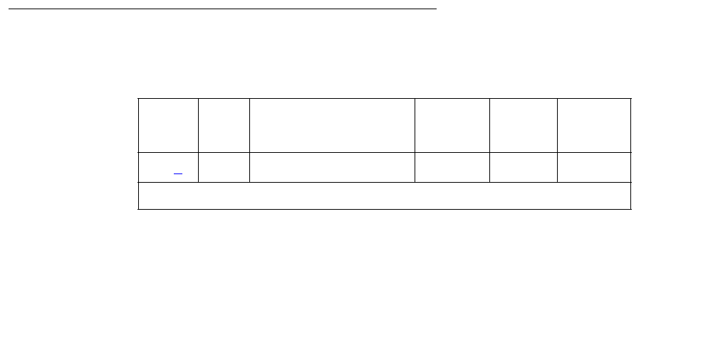
Communication Manager Maintenance-Object Repair Procedures
1968 Maintenance Procedures for Avaya Communication Manager 3.0, Media Gateways and Servers
SIP-BCH (SIP B Channel)
S8700 | 8710 / S8500 / S8300
No maintenance diagnostic tests exist for this object.
SIP signaling is similar to ISDN Q.931 signaling. In order to take advantage of existing ISDN
Avaya™ Communication Manager, SIP trunk AvayaCommunication Manager software includes
SIP signaling groups, SIP D channels and SIP B channels. SIP signaling groups are similar in
concept to ISDN PRI signaling groups. SIP D-channels are an artificial fabrication created only
to allow maximum re-use of system ISDN code. SIP B channels are also an artificial fabrication.
No physical hardware components make up the SIP B-channel object discussed here. Along
with the D channel, these objects allow existing ISDN Communication Manager software to be
re-used for SIP trunking. The SIP signaling group is not a collection of physical D-channels that
exist on one or more DS1 facilities. The SIP signaling group can be considered to be one D
channel that physically rides on a C-LAN port (IP_PROCR port on S8300 systems) and the IP
network. Unlike ISDN D-channels, the SIP D channel may come up and down on a call-by-call
basis. So, the SIP D channel is actually a TCP/IP signaling channel. Layers 1 and 2 of this
signaling channel can be monitored by IP PING testing.
Performance in terms of voice latency for a signaling group is monitored by background
measurements collected by the Media Processor board.
SIP B channels use Media Processor ports to carry the actual bearer. The media processor port
is a service circuit. On a call-by-call basis, any port of a media processor may be serving an
H.323 station or an SIP B channel. Status information may exist for a specific SIP B channel,
and a SIP B channel may be busied out and released, but no maintenance diagnostic tests will
exist for the object.
Errors are logged for craft busyout conditions. The system receives service state updates for
craft-driven busyout/release. Under normal conditions the system automatically places SIP B
channels into or out of service when it receives an SIP signaling-group service state update.
Craft busyout drops active calls.
Error Log Entries and Test to Clear Values
H323-BCH B-Channel Error Log Entries
Error
Type
Aux
Data
Associated Test Alarm
Level
On/Off
Board
Service
State
18 (a) Any B-channel busied out Warning off OOS

SIP-BCH (SIP B Channel)
Issue 1 June 2005 1969
Notes:
a. Error Type 18: Indicates that this specific SIP trunk group member has been craft
busied-out
System Technician Commands
The following commands are available to the system technician:
●busyout port location - on a specific SIP B channel, drops any active call on that
B channel and reduces the trunk group’s capacity by one. No physical piece of hardware
is removed from service.
●release port location - on a specific SIP B channel, increases the trunk group’s
capacity by one. No physical piece of hardware is actually added to service.
●status trunk grp#/mem# - used to find the current status of the specific B channel.
Additional status for an SIP B channel shows near- and far-end IP signaling addresses,
near- and far-end H.245 addresses, tunneling status, call-reference value for an active
call.
●test port location - results in the message No tests applicable to this
object.
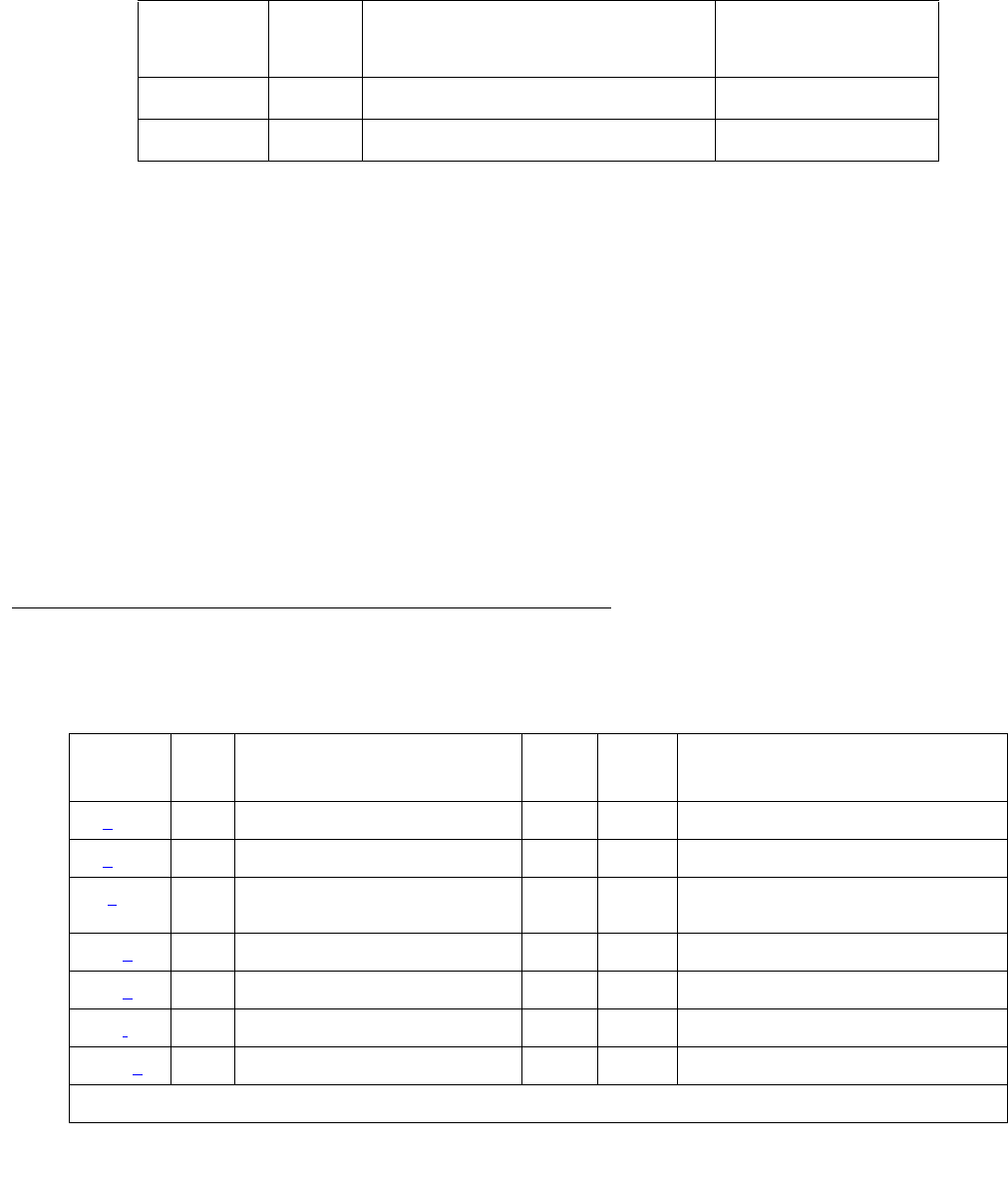
Communication Manager Maintenance-Object Repair Procedures
1970 Maintenance Procedures for Avaya Communication Manager 3.0, Media Gateways and Servers
SIP-SGRP (SIP Signaling Group)
S8700 | 8710 / S8500 / S8300
The SIP Signaling Group (SIP-SGRP) MO supports a signaling channel (D channel) for SIP
trunk connections. The MedPro TN802 and TN2302 circuit pack provides audio connectivity,
working in concert with a C-LAN (TN799DP) circuit pack that provides control signaling to
support an SIP connection.
Note:
Note: In S8300 systems, the audio connectivity is provided through the VoIP media
modules within the S8300 system. The signaling is provided through the native
NIC within the S8300 system.
The SIP signaling group (SIP-SGRP) is a Signaling channel that physically resides on a C-LAN
port (socket), or IP-PROCR in S8300 systems, and the IP network. Unlike ISDN D-channels,
the SIP channel may actually come up and down on a call by call basis. The SIP channel is
actually a TCP/IP signaling channel. Layers 1 and 2 of this signaling channel are monitored by
IP PING testing.
Error Log Entries and Test to Clear Values
MO Name Alarm
Level
Initial SAT Command to Run Full Name of MO
SIP-SGRP MIN test signaling-group grp#SIP Signaling Group
SIP-SGRP WRN test signaling-group grp#SIP Signaling Group
Table 721: SIP-SGRP Signaling Group Error Log Entries
Error
Type
Aux
Data
Associated Test Alarm
Level
On/Off
Board
Test to Clear Value
0 (a)0Any Any test signaling-group grp#
1 (b) Any Ethernet Port Status test (#1386) MIN OFF test signaling-group grp#
18(c)0busyout signaling-group
grp#
WRN OFF release signaling-group grp#
257 (d) Any SIP SGRP PING (#1387) MIN OFF test signaling-group grp#
513 (e) Any SIP SGRP PING (#1387) WRN OFF test signaling-group grp#
770 (f)Any WRNOFF
1025 (g) Any MEDPRO Status test (#1392) MIN OFF test signaling-group grp#
1 of 2
SIP-SGRP (SIP Signaling Group)
Issue 1 June 2005 1971
Notes:
a. Error Type 0: Run the short test sequence first. If every test passes, run the long test sequence. Refer to
each appropriate test’s description, and follow its recommended procedures.
b. Error Type 1: Represents a failure of the C-LAN hardware (IP-PROCR in S8300 systems)
carrying the signaling group channel.
To determine which C-LAN had been administered for this signaling group, find the
near-end node name on the signaling group form; then find the C-LAN or IP-PROCR
with the same node name on the ip-interfaces form.
Check for errors against the CLAN-BD MO.
c. Error Type 18: Logged when the signaling group in question is busied out by Craft. Make
sure, if appropriate, that the signaling group is released from busy using the release
signaling-group grp# command.
d. Error Type 257: Tracks failures of the SIP signaling-group PING test. SIP signaling-group
PING test failures are documented later in this MO.
e. Error Type 513: Tracks excessive round-trip delay of the SIP signaling-group PING test, if
the round-trip delay exceeds 4 seconds.
f. Error Type: 770: Tracks excessive latency and packet-loss from background IP
measurements collected by the Media Processor Board. Indicates that test packets sent
from a media processor circuit pack to the far-end ip address specified on the
signaling-group form have exceeded the IP latency and loss thresholds, as
administered on the system-parameters ip-options form. Exceeding these
thresholds indicates that the IP network may not be providing sufficient quality of service for
adequate transmission of voice. If the signaling group has been administered to enable
BYPASS, then error type 1025 also occurs.
1281 (h) Any MEDPRO Status test (#1392) MIN OFF
1537 (i) Any MEDPRO Status test (#1392 MIN OFF
1794 (j) MEDPRO Status test (#1392) MIN OFF test signaling-group grp#
2561 (k) Any Registered to LSP Inline Error MIN OFF
3073 (l) 19 Far-end TLS Certificate Failure
Inline Error
MIN OFF
3329 (m) 21 Near-end TLS Certificate failure
Inline Error
MIN OFF
Table 721: SIP-SGRP Signaling Group Error Log Entries (continued)
Error
Type
Aux
Data
Associated Test Alarm
Level
On/Off
Board
Test to Clear Value
2 of 2

Communication Manager Maintenance-Object Repair Procedures
1972 Maintenance Procedures for Avaya Communication Manager 3.0, Media Gateways and Servers
g. Error Type 1025: the signaling group has been placed into a BYPASS condition because of
IP network congestion. The signaling group accepts incoming calls, but every outgoing call
is denied. The system routes these calls over a secondary route, if one has been
administered.
h. Error Type 1281: Implies that no medpro resources are in service to provide media
connections for the trunk members of the signaling group.
Check for errors against the MEDPRO and MEDPROPT maintenance objects. This error
causes all SIP B Channels to be in an out-of-service near-end state.
i. Error Type 1537: The far end of the signaling group is not ready to handle audio bearer. If
the other end of this signaling group is also a Communication Manager server, this error
means the server on the other end does not have MEDPRO in-service for its signaling
group.
This error places the SIP B Channels into an out-of-service far-end state.
j. Error Type 1794: The Signaling Group reported that the far end has detected excessive
packet latency or loss. This error places the SIP B channels into an out of service far-end
state.
k. Error Type 2561: This error indicates that the signaling group is registered to an LSP.
l. Error Type 3073: A TLS connection was established with the far-end but authentication
with the far-end’s TLS certificate failed. Due to this condition, the signaling group will be
placed in far-end bypass state so that no outgoing calls will be allowed, the trunks in the
group will be placed in an out of service far end state (OOSFE). Incoming calls will be
accepted, but until the far-end’s TLS certificate is remedied, these will not be successful.
Once the far-end’s certificate is remedied, an incoming call can succeed and the trunk
group will be put back in service.
m. Error Type 3329: This error indicates that the near end TLS certificate is bad. The trunks in
the group will be placed in a near end out of service state and the signaling group will be
placed in bypass. No trunk calls either incoming or outgoing will be allowed until the near
end’s certificate is corrected, the system is warm started (reset system 1), and the signaling
groups go through a busy/release action. If the near end certificate is bad, listen sockets fro
the signaling group will not be created, so this alarm is raised at the creation of the listen
socket stage (i.e., when initially bringing the signaling group into service).
Note:
Note: Near end certificate authentication is the process of validating that the server
certificate is OK, i.e., we have the private key and the certificate is trusted. This
will only break if a user with root access has changed the certificate private key
file.

SIP-SGRP (SIP Signaling Group)
Issue 1 June 2005 1973
System Technician-Demanded Tests:
Descriptions and Error Codes
Always Investigate tests in the order presented in the table below when inspecting errors in the
system. For example, by clearing error codes associated with the CLAN Ethernet Status test
(#1386), you may also clear errors generated from other tests in the testing sequence.
CLAN Ethernet Status Test (#1386)
This test is nondestructive.
This test checks the status of the C-LAN Ethernet port that is the near end gatekeeper for this
signaling group. If the C-LAN Ethernet port is in service, the test passes; if it is OOS (out of
service), the test fails.
Note:
Note: Failure of this test will put the SIG-GRP in the OOS state.
Order of Investigation Short Test
Sequence
Long Test
Sequence
D/ND1
1. D = Destructive; ND = Nondestructive
CLAN Ethernet Status test (#1386) X X ND
MedPro Status test (#1392) X X ND
SIP Signaling Group Ping test (#1387) X X ND
Table 722: Test #1386 CLAN Ethernet Status Test
Error
Code
Test
Result
Description / Recommendation
1125 ABRT Ethernet Link is not in service.
1. Check if the Ethernet link is in service or not. If the link is not in service,
release the link using release link n or release port
location, and repeat the test. This is a normal abort.
2. If the test continues to abort after following the repair procedures,
escalate the problem.
1 of 2

Communication Manager Maintenance-Object Repair Procedures
1974 Maintenance Procedures for Avaya Communication Manager 3.0, Media Gateways and Servers
SIP Signaling Group Ping Test (#1387)
This test is nondestructive.
This test is only run for those signaling groups that have an administered far-end IP address. If
the SIP signaling group does not have an administered far-end IP address, the test will abort.
The test determines the local C-LAN through which the signaling originates, and the far-end
terminating IP address. It then requests the local C-LAN to execute a PING on the far-end
address. If the PING is successful, the test passes; if the ping is not successful, the test fails.
Note:
Note: Multiple failures of this test will cause this signaling group’s associated SIP B
channels to be taken out of service (OOSFE). This will allow incoming calls to be
made when the far-end comes up before the near end has detected it. The
Signaling group will be left in service, but in the far end bypass state.
2000 ABRT Response to the test was not received from the TN799DP C-LAN circuit
pack within the allowable time period.
1. If this result occurs repeatedly, attempt to reset the circuit pack if the
other ports on the board are idle (amber LED is off). Reset the circuit
pack by issuing busyout board location, reset board
location, and release board location.
2. If this result occurs again, replace the circuit pack.
2100 ABRT The necessary system resources to execute the test could not be allocated.
1. Retry the command at 1-minute intervals up to 5 times.
2500 ABRT Internal system error.
1. Retry the command at 1-minute intervals up to 3 times.
FAIL The C-LAN Ethernet port corresponding to the near-end address of the
SIG-GRP that is OOS has failed. Every session is down.
1. Execute test port location long and verify the result of the SIP
Signaling Group Ping test (#1387). If the test continues to fail, escalate
the problem. If the test passes wait for the sessions to come up.
PASS The C-LAN Ethernet port corresponding to the near-end address of the
SIG-GRP that is in service has passed this test. Every session on the
Ethernet link is up.
Table 722: Test #1386 CLAN Ethernet Status Test (continued)
Error
Code
Test
Result
Description / Recommendation
2 of 2

SIP-SGRP (SIP Signaling Group)
Issue 1 June 2005 1975
If the PING is successful, this test looks at the PING round-trip delay. If a round-trip delay of
greater than four (4) seconds is reported, a separate error is logged. Excessive round-trip
delays within the signaling group will not take the signaling group out of service.
Services can execute the standard PING command using the C-LAN board’s address and
far-end IP address from the signaling group screen to see the actual round-trip delay.
This test checks the circuitry involved in the data path of a peer-to-peer IP layer connection.
This test is a nondestructive test. It runs because of in-line errors, during periodic and
scheduled maintenance, and on-demand.
Table 723: Test #1387 SIP Signaling Group Ping Test
Error
Code
Test
Result
Description / Recommendation
1, 2 ABRT Internal Error.
1. Retry the command at 1-minute intervals up to 3 times.
7ABRT Destination unreachable.
1. Verify that the C-LAN has been administered with an IP-Route that
enables the C-LAN to reach the far-end IP address.
2. Once verified, use test sig-group grp# to verify that the SIP
Signaling Group Ping test (#1387) passes.
1005 ABRT Configuration for this test is incorrect.
1. Verity that the link is in service with the status port or status
link. Verify that the routing table has destinations that are reachable
through this port.
2. Repeat the test.
3. If the test aborts with Error Code 7, while step 1 verified, escalate the
problem.
1125 ABRT Link is not in service.
1. Check if the link is in service or not. If the link is not in service, release
the link using release link or release port, and repeat the test.
This is a normal abort.
2. If the test continues to abort after following the repair procedures,
escalate the problem.
1 of 2

Communication Manager Maintenance-Object Repair Procedures
1976 Maintenance Procedures for Avaya Communication Manager 3.0, Media Gateways and Servers
2000 ABRT Response to the test was not received from the C-LAN circuit pack within
the allowable time period.
1. If this result occurs repeatedly, attempt to reset the circuit pack if the
other ports on the board are idle (amber LED is off). Reset the circuit
pack by issuing busyout board location, reset board
location, and release board location.
2. If this result occurs again, replace the circuit pack.
2012 ABRT Internal system error.
1. Retry the command at 1-minute intervals up to 3 times.
2100 ABRT The necessary system resources to execute the test could not be
allocated.
1. Retry the command at 1-minute intervals up to 5 times.
2500 ABRT Internal system error.
1. Retry the command at 1-minute intervals up to 3times.
2800 ABRT No C-LAN in the same region.
1. Verify translations and retest.
2801 ABRT No IP address defined.
1. Verify translations and retest.
2802 ABRT Different IP address pinged than software had allocated for the test.
1. Retry the command at 1-minute intervals up to 3 times.
7
89
1007
FAIL PING to the destination failed through this port because the destination
was down.
1. Verify that at least one destination reachable through this port is “up”.
Once verified, execute test signaling-group grp# to verify that
the SIP Signaling Group Ping test (#1387) passes.
PASS PING through this port was successful.
Table 723: Test #1387 SIP Signaling Group Ping Test (continued)
Error
Code
Test
Result
Description / Recommendation
2 of 2

SIP-SGRP (SIP Signaling Group)
Issue 1 June 2005 1977
MedPro Status Test (#1392)
This test is nondestructive.
This test determines if at least one media processor port exists that is in service, and that
serves the same region as the C-LAN that the signaling group uses. If at least one exists and is
in service, the test passes; otherwise, the test fails.
Table 724: Test #1392 MedPro Status Test
Error
Code
Test
Result
Description / Recommendation
2100 ABRT The necessary system resources to execute the test could not be
allocated.
1. Retry the command at 1-minute intervals up to 5 times.
2500
Any
ABRT Internal system Error.
1. Retry the command at 1-minute intervals up to 3 times
FAIL No MEDPRO ports in this region are in service. Every session is down.
1. Check the system for errors against MEDPRO and MEDPROPT
maintenance objects.
2. Execute test signaling-group grp# and verify the result of the
SIP Signaling Group Ping test (#1387). If the test continues to fail,
escalate the problem. If the test passes, wait for the sessions to come
up.
PASS Every session on the Ethernet link is up.

Communication Manager Maintenance-Object Repair Procedures
1978 Maintenance Procedures for Avaya Communication Manager 3.0, Media Gateways and Servers
S-SYN-BD (Speech Synthesis Circuit Pack)
S8700 | 8710 / S8500
See XXX-BD (Common Port Circuit Pack/Media Module) on page 2539 for errors at the
circuit-pack level. See S-SYN-PT (Speech Synthesis Port) on page 1979 for related port
information.
MO name Alarm Level Initial SAT Command to Run Full Name of MO
S-SYN-BD MIN test board location sh Speech Synthesis circuit pack
S-SYN-BD WRN test board location sh Speech Synthesis circuit pack

S-SYN-PT (Speech Synthesis Port)
Issue 1 June 2005 1979
S-SYN-PT (Speech Synthesis Port)
S8700 | 8710 / S8500
The TN725B Speech Synthesis circuit pack provides four independent Speech Synthesis ports
which may be connected to any of the voice time slots on the Time Division Multiplex (TDM)
Bus. Each Speech Synthesis port consists of a speech synthesizer device (SSD) and is
managed by a custom-coded programmable speech synthesizer (PSS) controller. The PSS
controller is, in turn, controlled by the on-board microprocessor via a command interface
specifically designed for this application. The PSS controller’s main function is the orderly
transfer of encoded speech from the speech vocabulary read-only memory (ROM) to the SSDs.
The SSDs decode it and produce 64-kbps 5-255 PCM (Pulse Code Modulation) speech. The
encoded speech is stored in up to 512 Kbytes of on-board ROM. In addition, each Speech
Synthesis port has an associated dual-tone multifrequency receiver (DTMR) to receive
touch-tone digits from a station set connected to the port via a voice time slot. The station set
may be connected to the Speech Synthesis port through either a line or trunk circuit.
When there is an incoming call to a port, the “listen” network time slot is connected to the DTMF
receiver input and the “talk” network time slot is connected to the SSD output. This enables the
Speech Synthesis port to support speech synthesis features or touch-tone input with voice
response features. Some of the features that use the Speech Synthesis port’s capabilities
include Leave Word Calling, Automatic Circuit Assurance, Automatic Wakeup (hotel-motel), and
Do Not Disturb (hotel-motel).
The Speech Synthesis circuit pack supports different voice features than ones supported by the
Announcement circuit pack.
Error Log Entries and Test to Clear Values
MO name Alarm Level Initial SAT Command to Run Full Name of MO
S-SYN-PT MAJ test port location sh Speech Synthesis port
S-SYN-PT MIN test port location lSpeech Synthesis port
S-SYN-PT WRN test port location sh Speech Synthesis port
Table 725: Speech Synthesis Port Error Log Entries
Error
Type
Aux
Data
Associated Test Alarm
Level
On/Off
Board
Test to Clear Value
0 (a) 0 Any Any Any test port location sh r 1
1 (b) 17672 None
1 of 2
Communication Manager Maintenance-Object Repair Procedures
1980 Maintenance Procedures for Avaya Communication Manager 3.0, Media Gateways and Servers
Notes:
a. Error Type 0: run the short test sequence first. If every test passes, run the long test
sequence. Refer to each appropriate test’s description, and follow its recommended
procedures.
b. Error Type 1: an in-line failure of the on-board microprocessor/PSS handshake has
occurred. Refer to Test #168 for repair procedures.
c. Error Type 130: the circuit pack been removed or has been insane for more than 11
minutes. To clear the error, reinsert or replace the circuit pack.
d. Error Type 2049: a transient error that does not cause an alarm can occasionally occur
during a server, TDM bus, or Tone-Clock interchange. Test the port, and follow the
instructions for the Conference test (#7).
e. Error Type 3840: this error is not service-affecting, and no action is required.
18 0 busyout port location WRN OFF release port location
130 (c)None WRNONtest port location sh
257 Speech Synthesis PSS Handshake
test (#168)
MAJ ON test port location sh r 2
513 17922 Speech Synthesis Memory test
(#166)
MIN ON test port location sh r 2
769 17664 Speech Synthesis DTMF Receiver
Inquiry (#164)
MIN ON test port location sh r 2
1025 17670 Speech Synthesis SSD Inquiry test
(#167)
MIN ON test port location sh r 2
1281 Speech Synthesis DSP Tone test
(#165)
MIN ON test port location sh r 2
1537 Speech Synthesis Memory test
(#166)
MIN ON test port location sh r 2
1793 Speech Synthesis DTMF Receiver
test (#163)
MIN ON test port location l r 2
2049 (d) Conference Circuit test (#7) MIN ON test port location l r 2
2305 NPE Crosstalk test (#6) MIN ON test port location l r 2
3840 (e)Any None
Table 725: Speech Synthesis Port Error Log Entries (continued)
Error
Type
Aux
Data
Associated Test Alarm
Level
On/Off
Board
Test to Clear Value
2 of 2

S-SYN-PT (Speech Synthesis Port)
Issue 1 June 2005 1981
System Technician-Demanded Tests:
Descriptions and Error Codes
Investigate tests in the order presented below. Clearing error codes associated with the one test
may also clear errors generated from other tests in the sequence.
NPE Crosstalk Test (#6)
The NPE Crosstalk test verifies that this port’s NPE channel talks on the selected time slot and
never crosses over to time slots reserved for other connections. If the NPE is not working
correctly, one-way and noisy connections may occur. This test is usually only part of a port’s
long test sequence and takes about 20 to 30 seconds to complete.
Table 726: S-SYN-PT Demand test - order of investigation
Order of Investigation Short Test
Sequence
Long Test
Sequence
D/ND1
1. D = Destructive, ND = Nondestructive
Speech Synthesis PSS Handshake test (#168) X X ND
NPE Crosstalk test (#6) X ND
Conference Circuit test (#7) X ND
Speech Synthesis DTMF Receiver test (#163) X ND
Speech Synthesis Memory test (#166) X X ND
Speech Synthesis DSP Tone test (#165) X X ND
Speech Synthesis SSD Inquiry test (#167) X X ND
Speech Synthesis DTMF Receiver Inquiry test (#164) X X ND
Speech Synthesis Parameter Update test (#169) X X ND

Communication Manager Maintenance-Object Repair Procedures
1982 Maintenance Procedures for Avaya Communication Manager 3.0, Media Gateways and Servers
Table 727: TEST #6 NPE Crosstalk Test
Error
Code
Test
Result
Description / Recommendation
ABRT Could not allocate the necessary system resources to run this test.
1. Retry the command at 1-minute intervals up to 5 times.
1000 ABRT System resources required to run this test are not available. The port may
be busy with a valid call and therefore unavailable for certain tests. Wait
until the port is idle (amber LED is off) before retesting.
1. If the port is idle, retry the command at 1-minute intervals up to 5 times.
1001 ABRT Could not allocate the necessary system resources to run this test.
1. Retry the command at 1-minute intervals up to 5 times.
1002 ABRT The system could not allocate time slots for the test. The system may be
under heavy traffic conditions or it may have time slots out-of-service due to
TDM-BUS errors.
1. If the system has no TDM-BUS errors and is not handling heavy traffic,
repeat test at 1-minute intervals up to 5 times.
1003 ABRT The system could not allocate a tone receiver for the test. The system may
be oversized for the number of Tone Detectors present or some Tone
Detectors may be out-of-service.
1. Resolve any TTR-LEV errors.
2. Resolve any TONE-PT errors.
3. If neither condition exists, retry the test at 1-minute intervals up to 5
times.
1004 ABRT The port was seized by a valid call during the test and the test has been
aborted. Wait until the port is idle (amber LED is off) before retesting.
1. Retry the command at 1-minute intervals up to 5 times.
1020 ABRT The test did not run due to an already existing error on the specific port or a
more general circuit pack error.
1. Examine Error Log for existing errors against this port or the circuit pack
and attempt to diagnose the already existing error.
2000 ABRT Response to the test request was not received within the allowable time
period.
1. Retry the command at 1-minute intervals up to 5 times.
1 of 2

S-SYN-PT (Speech Synthesis Port)
Issue 1 June 2005 1983
Conference Circuit Test (#7)
One or more Network Processing Elements (NPEs) reside on each circuit pack with a TDM-bus
interface. The NPE controls port connectivity and gain, and provides conferencing functions on
a per-port basis. The Conference Circuit test verifies that the NPE channel for the port being
tested can correctly perform the conferencing function. The NPE is instructed to listen to several
different tones and conference the tones together. The resulting signal is then measured by a
Tone Detector port. If the level of the tone is within a certain range, the test passes.
2100 ABRT Could not allocate the necessary system resources to run this test.
1. Retry the command at 1-minute intervals up to 5 times.
Any FAIL The NPE of the tested port was found to be transmitting in error. This will
cause noisy and unreliable connections.
1. Replace the circuit pack.
PASS The port is correctly using its allocated time slots. User-reported troubles on
this port should be investigated using other port tests and by examining the
Error Log.
Table 727: TEST #6 NPE Crosstalk Test (continued)
Error
Code
Test
Result
Description / Recommendation
2 of 2
Table 728: TEST #7 Conference Circuit Test
Error
Code
Test
Result
Description / Recommendation
ABRT Could not allocate the necessary system resources to run this test.
1. Retry the command at 1-minute intervals up to 5 times.
1000 ABRT System resources required to run this test are not available. The port may
be busy with a valid call and therefore unavailable for certain tests. Wait
until the port is idle (amber LED is off) before retesting.
1. If the port is idle, retry the command at 1-minute intervals up to 5 times.
1004 ABRT The port was seized by a valid call during the test and the test has been
aborted. Wait until the port is idle (amber LED is off) before retesting.
1. Retry the command at 1-minute intervals up to 5 times.
1 of 2

Communication Manager Maintenance-Object Repair Procedures
1984 Maintenance Procedures for Avaya Communication Manager 3.0, Media Gateways and Servers
1020 ABRT The test did not run due to an already existing error on the specific port or a
more general circuit pack error.
2. Examine Error Log for existing errors against this port or the circuit
pack and attempt to diagnose the already existing error.
2000 ABRT Response to the test request was not received within the allowable time
period.
1. Retry the command at 1-minute intervals up to 5 times.
2100 ABRT Could not allocate the necessary system resources to run this test.
1. Retry the command at 1-minute intervals up to 5 times.
Any FAIL The NPE of the tested port did not conference the tones correctly. This
causes noisy and unreliable connections.
1. Retry the test.
2. If the test continues to fail, then replace the circuit pack.
PASS The port can correctly conference multiple connections. User-reported
troubles on this port should be investigated using other port tests and by
examining the Error Log.
Table 728: TEST #7 Conference Circuit Test (continued)
Error
Code
Test
Result
Description / Recommendation
2 of 2

S-SYN-PT (Speech Synthesis Port)
Issue 1 June 2005 1985
Speech Synthesis DTMF Receiver Test (#163)
A series of dual-tone multifrequency (DTMF) tones are conferenced from the TDM bus into the
port’s DTMF receiver and checked to see if the correct tones have been detected during the
correct intervals. If every DTMF tone was detected correctly, the test passes. If any of the tones
were not detected correctly, the test fails.
Table 729: TEST #163 Speech Synthesis DTMF Receiver
Error
Code
Test
Result
Description / Recommendation
ABRT Could not allocate the necessary system resources to run this test.
1. Retry the command at 1-minute intervals up to 5 times.
1000 ABRT System resources required to run this test are not available. The port may
be busy with a valid call and therefore unavailable for certain tests. Wait
until the port is idle (amber LED is off) before retesting.
1. If the port is idle, retry the command at 1-minute intervals up to 5 times.
2000 ABRT Response to the test request was not received within the allowable time
period.
1. Retry the command at 1-minute intervals up to 5 times.
2100 ABRT Could not allocate the necessary system resources to run this test.
1. Retry the command at 1-minute intervals up to 5 times.
Any FAIL DTMF tones were not detected. This type of failure may cause features
using touch-tone input to the Speech Synthesis port to malfunction.
1. Verify that the Tone-Clock circuit is functioning correctly by checking
the Error Log and using test tone-clock long.
2. If the test fails again, replace the Speech Synthesis circuit pack.
PASS The port has detected every DTMF tone correctly. User-reported troubles
should be investigated using other tests and by verifying other ports on this
circuit pack are working correctly.

Communication Manager Maintenance-Object Repair Procedures
1986 Maintenance Procedures for Avaya Communication Manager 3.0, Media Gateways and Servers
Speech Synthesis DTMF Receiver Inquiry
Test (#164)
This test determines the sanity of the port’s dual-tone multifrequency (DTMF) receiver. The
on-board microprocessor tests the port’s DTMF receiver and determines if it is in a sane (test
passes) or insane (test fails) condition.
Speech Synthesis DSP Tone Test (#165)
The digital signal processor (DSP) associated with each port can generate a 440-Hz tone
whose presence can be detected by TN748 General-Purpose Tone Detector circuits. A 440-Hz
tone is generated for 500 ms on a specified time slot which is being listened to by the detector
circuit. If the detector determines the tone is present on the time slot, the test passes; otherwise,
it fails.
Table 730: TEST #164 Speech Synthesis DTMF Receiver Inquiry Test
Error
Code
Test
Result
Description / Recommendation
ABRT Could not allocate the necessary system resources to run this test.
1. Retry the command at 1-minute intervals up to 5 times.
1000 ABRT System resources required to run this test are not available. The port may
be busy with a valid call and therefore unavailable for certain tests. Wait
until the port is idle (amber LED is off) before retesting.
1. If the port is idle, retry the command at 1-minute intervals up to 5 times.
2000 ABRT Response to the test request was not received within the allowable time
period.
1. Retry the command at 1-minute intervals up to 5 times.
2100 ABRT Could not allocate the necessary system resources to run this test.
1. Retry the command at 1-minute intervals up to 5 times.
Any FAIL The DTMF receiver for this port is insane.
1. If the test fails again, replace the circuit pack.
PASS The DTMF receiver for this port is sane. User-reported troubles should be
investigated using other tests and by verifying other ports on this circuit pack
are working correctly.

S-SYN-PT (Speech Synthesis Port)
Issue 1 June 2005 1987
Table 731: TEST #165 Speech Synthesis DSP Tone Test
Error
Code
Test
Result
Description / Recommendation
ABRT Could not allocate the necessary system resources to run this test.
1. Retry the command at 1-minute intervals up to 5 times.
1000 ABRT System resources required to run this test are not available. The port may
be busy with a valid call and therefore unavailable for certain tests. Wait
until the port is idle (amber LED is off) before retesting.
1. If the port is idle retry the command at 1-minute intervals up to 5 times.
1001
1002
1003
ABRT System resources required to run this test are not available.
1. Retry the command at 1-minute intervals up to 5 times.
1021 ABRT The 440-Hz tone was not detected by the Tone Detector circuit and
inter-digit time-out has occurred on the Tone Detector circuit.
1. Retry the command at 1-minute intervals up to 5 times.
2. If the test continues to abort, verify that every Tone Detector circuit in
the system is functioning correctly by checking the Error Log and using
test board location long. Replace any faulty circuit packs
containing Tone Detector circuits, and repeat the test.
3. If the test continues to abort, replace the Speech Synthesis circuit pack.
2000 ABRT Response to the test request was not received within the allowable time
period.
1. Retry the command at 1-minute intervals up to 5 times.
2100 ABRT Could not allocate the necessary system resources to run this test.
1. Retry the command at 1-minute intervals up to 5 times.
Any FAIL The 440-Hz tone was not detected by the Tone Detector circuits.
1. If the test fails again, verify that every Tone Detector circuit in the
system is functioning correctly by checking the Error Log and using
test board location long. Replace any circuit packs containing
faulty Tone Detector circuits, and repeat the test.
2. If the test fails again, replace the Speech Synthesis circuit pack.
PASS The 440-Hz tone has been detected correctly. User-reported troubles should
be investigated using other tests and by verifying other ports on this circuit
pack are working correctly.

Communication Manager Maintenance-Object Repair Procedures
1988 Maintenance Procedures for Avaya Communication Manager 3.0, Media Gateways and Servers
Speech Synthesis Memory Test (#166)
The encoded speech for the Speech Synthesis circuit pack is stored in on-board read-only
memory (ROM). A checksum is computed for each 32K speech memory block and compared
against a known checksum value. If every computed checksum value is successfully compared
against the stored checksum values, the test passes. If, while testing the speech complex
memory, the on-board microprocessor finds a memory error, the test is terminated and a failure
is reported. This type of failure may affect other ports on the Speech Synthesis circuit pack,
resulting in errors or alarms on each port.
Table 732: TEST #166 Speech Synthesis Memory Test
Error
Code
Test
Result
Description / Recommendation
ABRT Could not allocate the necessary system resources to run this test.
1. Retry the command at 1-minute intervals up to 5 times.
1000 ABRT System resources required to run this test are not available. The port may
be busy with a valid call and therefore unavailable for certain tests. Wait
until the port is idle (amber LED is off) before retesting.
1. If the port is idle, retry the command at 1-minute intervals up to 5 times.
1019 ABRT Test is already running on a different port, possibly due to background
maintenance activity. Only one of these tests may be active on a circuit
pack at a time.
1. Retry the command at 1-minute intervals up to 5 times.
2000 ABRT Response to the test request was not received within the allowable time
period.
1. Retry the command at 1-minute intervals up to 5 times.
2100 ABRT Could not allocate the necessary system resources to run this test.
1. Retry the command at 1-minute intervals up to 5 times.
Any FAIL The computed checksum from the speech vocabulary ROM did not
compare correctly with the stored checksum. This type of failure may
cause features using the Speech Synthesis port’s speech services to
malfunction and result in degradation of synthesized speech quality
ranging from insignificant to major.
1. Replace the circuit pack.
1 of 2

S-SYN-PT (Speech Synthesis Port)
Issue 1 June 2005 1989
Speech Synthesis SSD Inquiry Test (#167)
This test determines the sanity of the specified port’s speech synthesis device (SSD). The
on-board microprocessor tests the port’s SSD and determines if it is in a sane (test passes) or
insane (test fails) condition. Other ports on the Speech Synthesis circuit pack will continue to
function correctly during this type of failure.
PASS The computed checksum values were successfully compared against the
stored checksum values. User-reported troubles should be investigated
using other tests and by verifying other ports on this circuit pack are working
correctly.
Table 732: TEST #166 Speech Synthesis Memory Test (continued)
Error
Code
Test
Result
Description / Recommendation
2 of 2
Table 733: TEST #167 Speech Synthesis SSD Inquiry Test
Error
Code
Test
Result
Description / Recommendation
ABRT Could not allocate the necessary system resources to run this test.
1. Retry the command at 1-minute intervals up to 5 times.
1000 ABRT System resources required to run this test are not available. The port may
be busy with a valid call and therefore unavailable for certain tests. Wait
until the port is idle (amber LED is off) before retesting.
1. If the port is idle, retry the command at 1-minute intervals up to 5 times.
2000 ABRT Response to the test request was not received within the allowable time
period.
1. Retry the command at 1-minute intervals up to 5 times.
2100 ABRT Could not allocate the necessary system resources to run this test.
1. Retry the command at 1-minute intervals up to 5 times.
Any FAIL The SSD is insane.
1. Replace the circuit pack.
PASS The SSD is sane. User-reported troubles should be investigated using other
tests and by verifying other ports on this circuit pack are working correctly.

Communication Manager Maintenance-Object Repair Procedures
1990 Maintenance Procedures for Avaya Communication Manager 3.0, Media Gateways and Servers
Speech Synthesis PSS Handshake Test (#168)
This test verifies control functionality between the on-board microprocessor and programmable
speech synthesizer (PSS) controller. A failure occurs if either of the following events occur:
●The on-board microprocessor times out while waiting for the PSS controller to respond.
●An invalid command is received by the on-board microprocessor from the PSS controller.
This type of failure will affect all four ports on the Speech Synthesis circuit pack, resulting in
errors or alarms on each port.
Table 734: TEST #168 Speech Synthesis PSS Handshake Test
Error
Code
Test
Result
Description / Recommendation
ABRT Could not allocate the necessary system resources to run this test.
1. Retry the command at 1-minute intervals up to 5 times.
1000 ABRT System resources required to run this test are not available. The port may
be busy with a valid call and therefore unavailable for certain tests. Wait
until the port is idle (amber LED is off) before retesting.
1. If the port is idle, retry the command at 1-minute intervals up to 5 times.
2000 ABRT Response to the test request was not received within the allowable time
period.
1. Retry the command at 1-minute intervals up to 5 times.
2100 ABRT Could not allocate the necessary system resources to run this test.
1. Retry the command at 1-minute intervals up to 5 times.
Any FAIL The on-board microprocessor has timed out while waiting for the PSS
controller to respond or an invalid command has been received by the
on-board microprocessor from the PSS controller. This type of failure may
cause features using the Speech Synthesis port’s speech services to
malfunction.
1. Replace the circuit pack.
PASS The on-board microprocessor/PSS handshake is working correctly.
User-reported troubles should be investigated using other tests and by
verifying other ports on this circuit pack are working correctly.

S-SYN-PT (Speech Synthesis Port)
Issue 1 June 2005 1991
Speech Synthesis Parameter Update Test (#169)
This test updates the dual-tone multifrequency (DTMF) interdigit time-out parameter used by
the Speech Synthesis circuit pack so that it is consistent with that specified by the server.
Table 735: TEST #169 Speech Synthesis Parameter Update Test
Error
Code
Test
Result
Description / Recommendation
ABRT Could not allocate the necessary system resources to run this test.
1. Retry the command at 1-minute intervals up to 5 times.
1000 ABRT System resources required to run this test are not available. The port may
be busy with a valid call and therefore unavailable for certain tests. Wait
until the port is idle (amber LED is off) before retesting.
1. If the port is idle, retry the command at 1-minute intervals up to 5 times.
2100 ABRT Could not allocate the necessary system resources to run this test.
1. Retry the command at 1-minute intervals up to 5 times.
Any FAIL An internal system error has occurred.
PASS The DTMF interdigit time-out parameter has been updated. User-reported
troubles should be investigated using other tests and by verifying that other
ports on this circuit pack are working correctly.

Communication Manager Maintenance-Object Repair Procedures
1992 Maintenance Procedures for Avaya Communication Manager 3.0, Media Gateways and Servers
SN-CONF (Switch Node Configuration)
S8700 MC only
A switch node carrier contains:
●Up to 16 Switch Node Interface (SNI) TN573 circuit packs in slots 2 through 9 and slots 13
through 20
●One or two Switch Node Clock (SNC) TN572 circuit packs in slots 10 and 12
●An Expansion Interface (EI) TN570 circuit pack, a DS1 Converter (DS1C) TN574 circuit
pack, or no circuit pack in slot 1
●An optional DS1 converter circuit pack in slot 21
SN-CONF errors and alarms are generated for two types of failures:
1. Failure of a board in the switch node carrier to insert (be detected by software).
2. A problem found by running the Configuration Audit test (#759). Test 759 is executed for
either an SNI or SNC circuit pack during scheduled maintenance or as part of test board
location.
For SNI circuit packs, test 759 queries the SNI for SNCs in the same switch node carrier,
SNI peers, DS1 converters, and EI or SNI neighbors that the SNI can communicate with
and compares this data to the administered data.
For SNC circuit packs, test 759 queries the SNC for SNCs and SNIs in the same switch
node carrier that the SNC can communicate with and compares this data to the
administered data.
Switch node carriers are part of port-network connectivity (PNC). For background information
about PNC, refer to the Maintenance Architecture and Hardware Configurations chapters and
related MOs.
MO Name Alarm Level Initial SAT Command to Run Full Name of MO
SN-CONF MAJ test board location Switch Node Configuration
SN-CONF MIN test board location1
1. If the error and alarm logs display the switch node carrier location UUC (cabinet and carrier only),
run the long test sequence on the active SNC in the carrier, (slot 10 or 12). If the error and alarm
logs display a circuit pack location, run the short test sequence on the alarmed SNI.
Switch Node Configuration
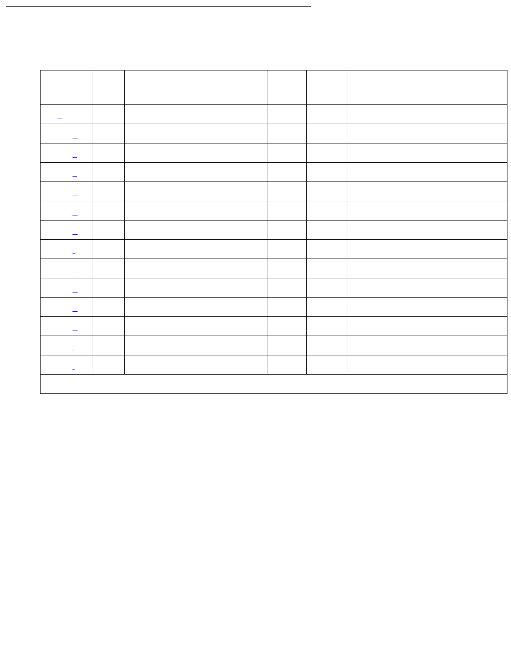
SN-CONF (Switch Node Configuration)
Issue 1 June 2005 1993
Error Log Entries and Test to Clear Values
Notes:
a. Error Type 0: run the short test sequence first. If every test passes, run the long test
sequence. Refer to each appropriate test’s description, and follow its recommended
procedures.
b. Error Type 5000: at least one administered circuit pack in this switch node carrier was not
inserted, or one or more administered circuit packs in this switch node carrier did not
respond to Test 760 with a “board insertion” uplink message.
To resolve this error, run test 760 using test board location l for an SNC in the same
switch node carrier that has this error.
Table 736: SN-CONF Error Log Entries
Error
Type
Aux
Data
Associated Test Alarm
Level
On/Off
Board
Test to Clear Value
0 (a) 0 Any Any Any test board location sh r 1
5000 (b) Any Processor Route Audit (#760) MIN OFF test board location l rep 1
6000 (c) 1 Configuration Audit (#759) MAJ OFF test board location rep 1
6000 (c) 2 Configuration Audit (#759) MAJ OFF test board location rep 1
6001 (d) Any Configuration Audit (#759) MAJ OFF test board location rep 1
6002 (e) 1 Configuration Audit (#759) MAJ OFF test board location rep 1
6002 (e) 2 Configuration Audit (#759) MAJ OFF test board location rep 1
6003 (f) Any Configuration Audit (#759) MAJ OFF test board location rep 1
6004 (g) Any Configuration Audit (#759) MAJ OFF test board location rep 1
6005 (h) Any Configuration Audit (#759) MAJ OFF test board location rep 1
6005 (h) 1 Configuration Audit (#759) MAJ OFF test board location rep 1
6005 (h) 2 Configuration Audit (#759) MAJ OFF test board location rep 1
6006 (i) Any Configuration Audit (#759) MIN OFF test board location rep 1
6007 (j) Any Configuration Audit (#759) MIN OFF test board location rep 1

Communication Manager Maintenance-Object Repair Procedures
1994 Maintenance Procedures for Avaya Communication Manager 3.0, Media Gateways and Servers
c. Error Type 6000: no neighbor link is administered, but the SNI has one. If the Aux Data is 1,
an EI is connected as a neighbor link. If the Aux Data is 2, an SNI is connected as a
neighbor link.
To resolve Error Type 6000 with Aux Data 1, refer to FAIL code 133 for test 759. To resolve
Error Type 6000 with Aux Data 2, refer to FAIL code 134 for the Configuration Audit test
(#759).
d. Error Type 6001: no neighbor link exists between the SNI and its neighbor, but a neighbor
link (that is, fiber link) is administered.
To resolve this error, refer to FAIL code 135 for test 759.
e. Error Type 6002: the physical neighbor type does not match administration. The associated
Aux Data value is the location reported by the neighbor SNI that did not match the fiber link
administration. If the aux data is 1, the type of neighbor administered is an SNI and the type
of neighbor connected is an EI. If the aux data is 2, the type neighbor administered is an EI
and the type of neighbor connected is an SNI.
To resolve error type 6002 with aux data 1, refer to FAIL code 136 for test 759. To resolve
error type 6002 with aux data 2, refer to FAIL code 137 for test 759.
f. Error Type 6003: the neighbor location does not match administration. To resolve this error,
refer to FAIL code 138 for test #759.
g. Error Type 6004: a peer link does not exist to another equipped SNI. The Aux Data equals
the slot number of the SNI to which this SNI or SNC does not have a peer link. To resolve
this error, refer to the FAIL code for test 759 corresponding to the Aux Data on the following
table:
Aux Data
(slot no.)
Test 759
FAIL Code
2102
3103
4104
5105
6106
7107
8108
9109
13 113
14 114
1 of 2

SN-CONF (Switch Node Configuration)
Issue 1 June 2005 1995
h. Error Type 6005: a link does not exist to one of the SNCs. If the Aux Data is not 1 or 2, the
link from this SNI to the active SNC does not exist. If the Aux Data is 1, the link from this
SNC to the active SNC does not exist. If the Aux Data is 2, the link from this SNC to the
standby SNC does not exist.
To resolve this error, refer to FAIL code 112 for the Configuration Audit test (#759).
i. Error Type 6006: the SNI is administered to be connected to a DS1C but is not.
To resolve this error, refer to FAIL code 139 for the Configuration Audit test (#759).
j. Error Type 6007: the SNI is connected to a DS1C, but no DS1C is administered.
To resolve this error, refer to FAIL code 140 for the Configuration Audit test (#759).
System Technician-Demanded Tests:
Descriptions and Error Codes
Investigate tests in the order presented below. Clearing error codes associated with the one test
may also clear errors generated from other tests in the sequence.
15 115
16 116
17 117
18 118
19 119
20 120
Aux Data
(slot no.)
Test 759
FAIL Code
2 of 2
Order of Investigation Short Test
Sequence
Long Test
Sequence
Reset Board
Sequence
D/ND1
1. D = Destructive, ND = Nondestructive
Configuration Audit (#759) X X ND
Processor Route Audit (#760) X ND

Communication Manager Maintenance-Object Repair Procedures
1996 Maintenance Procedures for Avaya Communication Manager 3.0, Media Gateways and Servers
Configuration Audit (#759)
This test is nondestructive.
Note:
Note: For descriptions of result codes for this test see:
●SNC-BD (Switch Node Clock Circuit Pack) on page 2000 when the circuit pack tested is a
Switch Node Clock (circuit pack slots 10 or 12).
●SNI-BD (SNI Circuit Pack) on page 2046 when the circuit pack tested is a Switch Node
Interface (circuit pack slots 2–9 or 13–20).
This test is run using test board short or test board long for SNI circuit packs or SNC
circuit packs.
For SNI circuit packs, this test queries the SNI for SNCs in the same switch node carrier, SNI
peers, DS1Cs, and EI or SNI neighbors that the SNI can communicate with and compares this
data to the administered data.
For SNC circuit packs, this test queries the SNC for SNCs and SNIs in the same switch node
carrier that the SNC can communicate with and compares this data to the administered data.
Failures of this test cause entries in the error and alarm logs against Switch Node Configuration
(SN-CONF) with the board location of the SNI or SNC.
Incorrectly Connected Administered Fibers
Some physically connected fibers that do not match fiber administration can cause port network
problems that are not detected and alarmed by PNC test. The symptoms will usually be phone
calls not working correctly, and port network component alarms because of translation
mismatches.
This test is unable to detect the case where an SNI is connected to the same type of board (EI
or SNI) as administered but located in a different cabinet but the same carrier and same slot as
the administered fiber endpoint. Use list fiber-link to view the administered fiber
endpoint. This test detects if the fiber endpoint connected to the SNI is in a different carrier, slot
location than the administered fiber endpoint.
Incorrectly Connected Administered SNI-
to-EI Fibers
If the SNI is connected to the same type of fiber endpoint as the administered fiber endpoint, but
the location is the same as administered except for the cabinet, every phone call will work
incorrectly; some phone calls will not go through and others will ring the wrong phone.
Use test led to check connectivity.
1. Run test led port-network on each administered port network and verify that the
LEDs on the correct port network are lit.

SN-CONF (Switch Node Configuration)
Issue 1 June 2005 1997
2. If they are not lit, check that the fiber connections to the port network are consistent with the
administered fibers (list fiber-link) that does not light the LEDs as expected.
3. Run test led switch-node on each administered switch node carrier and verify that
the LEDs on the correct carrier are lit.
4. If they are not, check the connectivity to the switch node carrier that does not light the LEDs
as expected.
Incorrectly Connected SNI-to-SNI Fibers
between Three Switch Nodes
If the system has more than 2 switch nodes, SNI-to-SNI fibers administered between 2 switch
nodes could be incorrectly connected to a third switch node. This is a problem that could occur
during installation or when inter-switch node fibers are changed. For multiple fibers to a distant
switch node, an incorrect connection would not appear as a problem unless this fiber is used for
a system-link to a port network connected to the distant switch node. Use status sys-link
to determine the boards in the path from an IPSI connected PN to another specific PN. A
specific SNI-to-SNI fiber connection must be in the system-link path to be checked with the port
network LED test.
Forcing SNI-to-SNI Fiber Connection
To force an SNI-to-SNI fiber connection to be used as a system-link, remove every SNI-to-SNI
connection except the fiber link being tested at the distant switch node by removing SNI boards
in the distant switch node.
1. Use status sys-link to verify that the fiber selected for test is in the path to the PN
connected to the distant switch node that will be used for the LED test.
2. Run test led to a port network as described above to verify this fiber connection.
3. Repeat the above procedure for each of the SNI-to-SNI fibers terminating on the distant
switch node.
Testing Multiple Fiber Connections
To test multiple fiber connections to a distant switch node:
1. Use list fiber-link to determine the number of SNI-to-SNI fibers that are
administered to and terminate on the distant switch node.
2. Run test led port-network on a PN connected to the distant switch node, and verify
the LEDs on the correct PN are lit.
3. Use status sys-link and select the active EI in the IPSI connected PN connected to
the distant PN under test. (The display will show the path from the IPSI connected PN and
the SNI-to-SNI fiber being used.)

Communication Manager Maintenance-Object Repair Procedures
1998 Maintenance Procedures for Avaya Communication Manager 3.0, Media Gateways and Servers
4. If the PN’s LEDs are lit and there are multiple fibers to the distant switch node, remove the
SNC that is listed by list fiber-link for this path.
If not, enter list fiber-link to verify that the fiber connections to the PN are consistent
with the administration assignments.
5. Use status sys-link to determine the new path from the IPSI connected PN to the
distant switch.
6. Run test led port-network on the port network connected to the distant switch node,
and verify that the LEDs on the correct PN are lit.
7. Repeat steps 4 – 6 until every SNI-to-SNI fiber connection to the distant switch has been
tested.
Processor Route Audit Test (#760)
This test is nondestructive.
This test sends a processor route to every SNI in the carrier for which test board location
was run. A processor route enables an SNI board to send up-link messages to the server by
providing the board with a specific sequence of boards for routing messages up to the server.
Without a processor route, an SNI cannot send any in-line errors to the server.
As each SNI receives its processor route, the SNI returns a “board insertion” up-link message,
and (if not already inserted) the server’s software inserts that board. Depending on the
configuration, each SNI board is sent either one or two processor routes.
Use test led or list config carrier to see if the boards are inserted.
The processor route test is run as part of the long test sequence for SNC boards.
Table 737: TEST #760 Processor Route Audit Test
Error
Code
Test
Result
Description / Recommendation
2100 ABRT Could not allocate the necessary system resources to run this test.
1. Retry the command at 1-minute intervals up to 3 times.
2300 ABRT The downlink message necessary to run this test could not be sent.
1. Retry the command at 1-minute intervals up to 3 times.
2301 ABRT The software timer could not be set before sending the downlink message
necessary to run this test.
1. Retry the command at 1-minute intervals up to 3 times.
1 of 2

SN-CONF (Switch Node Configuration)
Issue 1 June 2005 1999
2306 ABRT None of the circuit packs in this switch node carrier are responding to the
processor route messages sent by software.
1. Run test led switch-node for the switch node where this switch
node carrier resides to verify whether the LEDs on any of the boards
light.
2. If none of the LEDs light for the boards in this carrier, fix any problems
associated with the connectivity of this carrier to the server.
a. Use list fiber-link to see the fiber connections to this carrier.
b. Check the LEDs on every SNI and EI, and fix any fiber problems.
c. Enter display errors, and follow the repair procedures for any
EXP-INTF error entries associated with an IPSI connected PN.
d. Also, follow the repair procedures for any SNI-BD, SNC-BD,
FIBER-LK, or SNI-PEER error entries.
2500 ABRT Internal system error
1. Retry the command at 1-minute intervals up to 3 times.
FAIL If this test fails, one or more administered circuit packs in this switch node
carrier did not respond with a “board insertion” uplink message. Use list
config carrier location to verify that administered SNI and SNC
boards match the physically installed SNI and SNC boards. The command
output shows NO BOARD for every board that is administered, but not
inserted.
1. If every administered board is inserted, run this test again.
2. If administration does not match the physical configuration, and is
correct, insert the missing circuit packs in this switch node carrier.
3. If administration does not match the physical configuration, and is
incorrect, change the administration, and run this test again.
4. If none of the administered boards in this switch node carrier were
inserted, fix any other SN-CONF errors by following the repair
procedures for SN- CONF. Use display errors with category pnc
to view SN-CONF errors. Use list sys-link to see if any INLs,
LNLs, or RNLs are down. If any INLs, LNLs, or RNLs are down, see
SYS-LINK (System Links) on page 2175 for fixing link problems.
PASS If this test passes, every administered circuit pack in this switch node carrier
was inserted.
Table 737: TEST #760 Processor Route Audit Test (continued)
Error
Code
Test
Result
Description / Recommendation
2 of 2

Communication Manager Maintenance-Object Repair Procedures
2000 Maintenance Procedures for Avaya Communication Manager 3.0, Media Gateways and Servers
SNC-BD (Switch Node Clock Circuit Pack)
S8700 MC
The Switch Node Clock (SNC) TN572 circuit pack is part of the Center Stage Switch (CSS)
configuration. It resides in a switch node carrier that alone or with other switch nodes make up a
CSS. In a high-reliability system (duplicated server and control network, unduplicated PNC),
each SNC is duplicated such that there are two SNCs in each switch node carrier. In a
critical-reliability system (duplicated server, control network, and PNC), each switch node is fully
duplicated, and there is one SNC in each switch node carrier. SNCs are placed in slots 10 and
12 of the switch node carrier.
The active SNC communicates with each circuit pack in the switch node carrier over the serial
channel bus on the backplane. In addition, the active SNC provides timing to the circuit packs in
the switch node carrier via the clock buses. The active SNC uses Timing Priority Number (TPN)
links with each Switch Node Interface (SNI) and the other SNC to receive and distribute TPNs.
TPNs are used for setting up the correct timing distribution for the switch node carrier. The
active SNC receives timing for the switch node carrier from each SNI circuit pack in the carrier
and chooses the SNI with the best timing reference for the switch node carrier timing signal the
SNC puts out on the clock buses. The timing reference for each SNI is derived from the fiber
signal to each SNI. The active SNC chooses the SNI to receive timing from by choosing the SNI
with the lowest numbered TPN which means that the SNI is closest to the system timing source.
The active SNC also verifies that the SNI reference signal is good before using that SNI as the
timing reference for the switch node carrier. The active SNC then supplies this timing over the
clock buses on the backplane to every SNI and SNC circuit pack in the carrier. For more
information about timing synchronization (including how the SNC fits into the overall
synchronization configuration), see SYNC (Port-Network Synchronization) on page 2143.
The SNC circuit packs are associated with three MOs:
●The SNC-BD (Switch Node Clock Circuit Pack) on page 2000 MO covers general SNC
board errors and errors with the serial communication channel between the active and
standby SNCs.
●The SNC-LINK (Switch Node Clock Link) on page 2039 MO covers errors between the
active SNC and SNIs over the serial channel (Aux Data is 1). Also, the SNC-LINK MO
covers TPN Link errors between the active SNC and SNIs (Aux Data is 2).
●The SNC-REF (Switch Node Clock Reference) on page 2043 MO covers errors the active
SNC detects with SNI reference signals.
SNC circuit packs are part of port-network connectivity (PNC). For background information
about PNC, refer to the Maintenance Architecture and Hardware Configurations chapters.
MO Name Alarm Level Initial SAT Command to Run Full Name of MO
SNC-BD MAJ test board location sSNC Circuit Pack
SNC-BD MIN test board location sSNC Circuit Pack
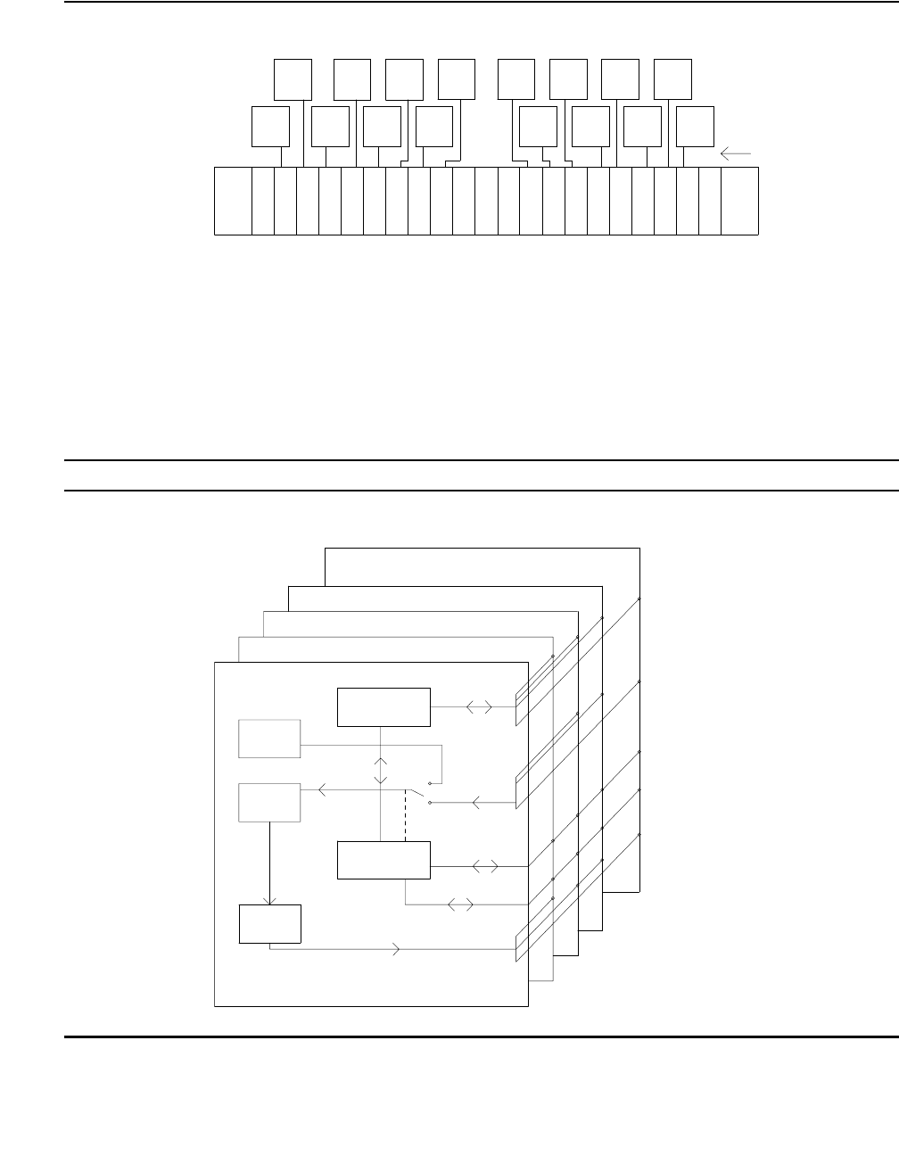
SNC-BD (Switch Node Clock Circuit Pack)
Issue 1 June 2005 2001
Figure 116: A Center Stage Switch Configuration
Figure 117: SNC Functions
Online Switcher (OLS) power supply
carrier
EI
PPN
21
EI
EPN
EI
EPN
EI
EPN EI
EPN
EI
EPN EI
EPN
EI
EPN
EI
EPN
EI
EPN
EI
EPN
EI
EPN
EI
EPN
EI
EPN
EI
EPN
EI
EPN
20 18 17 16 15 14 13 12 11 10 9 8 7 6 5 4 3 2 1
** = A DS1C circuit pack may reside in this slot
Switch Node Clock (SNC) TN572
Switch Node Interface (SNI) TN573
Expansion Interface (EI) TN570
DS1 Converter (DS1C) TN574
OLS OLS
* = An EI or a DS1C circuit pack may reside in this slot
* * *
S
N
C
S
N
C
S
N
I
S
N
I
S
N
I
S
N
I
S
N
I
S
N
I
S
N
I
S
N
I
S
N
I
S
N
I
S
N
I
S
N
I
S
N
I
S
N
I
S
N
I
S
N
I
19 slot number
fiber
links
switch
node
Clock Duplication
9 Clock Busses
SNC-BD
SNC-BD
SNC-LINK
(aux data 1)
SNC-REF
SNC-LINK
(aux data 2)
TPN Links
Reference Signals
Serial Channel
.
Loop
Locked
Phase
Circuit
Generation
Clock
Microcontroller
.
...
Active SNC
Standby SNC
SNI 1e02
SNI 1e20
SNI 1e03
.
Microcontroller
TPN
Oscillator
Stratum 3
Control
16
SNI (TN573)
17

Communication Manager Maintenance-Object Repair Procedures
2002 Maintenance Procedures for Avaya Communication Manager 3.0, Media Gateways and Servers
SNC LEDs
SNC circuit packs have the standard red, green, and yellow LEDs. The red and green LEDs
operate as usual: red means an alarm condition and green indicates maintenance testing in
progress. If the yellow LED is lit, this indicates that the SNC is the active circuit pack, supplying
timing to the carrier. In a duplex- or high-reliability system (unduplicated PNC), the standby SNC
in a carrier is unlit. In a critical-reliability system (duplicated PNC), an SNC in a standby switch
node carrier is lit since it is providing timing for the standby carrier.
Clear Firmware-Counters Command
SNC firmware generates error reports independently of technician-demanded tests. Therefore,
test board location clear does not affect the error status reported by firmware. The
clear firmware-counters command clears every firmware-generated error
unconditionally.
Use clear firmware-counters location to send a downlink message to the SNC circuit
pack, causing it to clear out its firmware error counters and failure database. When the firmware
failure database is cleared, the failure audit test (#777) will pass. If problems still exist, the
firmware increments its error counters and the failure audit test begins failing again.
Do not use this command instead of the repair procedures associated with the hardware error
log entries. This command may be useful if a problem was fixed but the off-board alarms
associated with the problem are still active.
Replacing SNC Circuit Packs
!WARNING:
WARNING: Do not power down a Switch Node carrier to replace a circuit pack. Replacing an
SNC on a system with unduplicated SNCs disrupts service.
Standard-Reliability System (Unduplicated
server, PNC, and SNCs)
This procedure is destructive. Any links through the switch node carrier will go down.
1. Pull out the SNC circuit pack to be replaced.
2. Insert a new SNC circuit pack.
3. Wait for the SNC to reset. (The red and green LEDs light and then go out. The yellow LED
should be on solid.)

SNC-BD (Switch Node Clock Circuit Pack)
Issue 1 June 2005 2003
4. Use test alarm long clear category exp-intf. Do not busyout the Expansion
Interface circuit packs.
5. Wait 5 minutes for SNI-BD, SNI-PEER, FIBER-LK, and DS1C-BD alarms to clear, or enter
clear firmware-counters.
High-Reliability System (Duplicated Server
and SNCs, Unduplicated PNC)
This procedure is nondestructive.
1. If the SNC circuit pack to be replaced is the active SNC in the switch node carrier (yellow
LED is on solid), use set switch-node-clock to set the standby SNC to active.
2. When the SNC circuit pack is in standby mode (yellow LED is off), pull out the SNC circuit
pack to be replaced.
3. Insert a new SNC circuit pack.
4. Wait for the SNC to reset. (The red and green LEDs light and then go out.) The yellow LED
should be off because the SNC circuit pack is in standby mode.
Critical-Reliability System (Duplicated Server
and PNC)
!WARNING:
WARNING: On a system with duplicated PNC, synchronization may be provided over a
combination of active and standby components. This condition is indicated by an
OFF-BOARD WRN alarm against TDM-CLK with Error Type 2305. Repairs to
standby PNC in this state may disrupt service. Otherwise, if the active PNC is
functional, replacement of a standby component will not disrupt service.
To replace an SNC circuit pack in a critical-reliability system:
1. Enter status pnc.
Verify that the component to be replaced is on the standby PNC.
2. Enter busyout pnc.
3. Enter busyout board location.
4. Replace the circuit pack.
5. Enter release board location.
!CAUTION:
CAUTION: Do not busyout any Expansion Interface circuit pack after this point.
6. Enter test alarms long clear for category exp-intf.
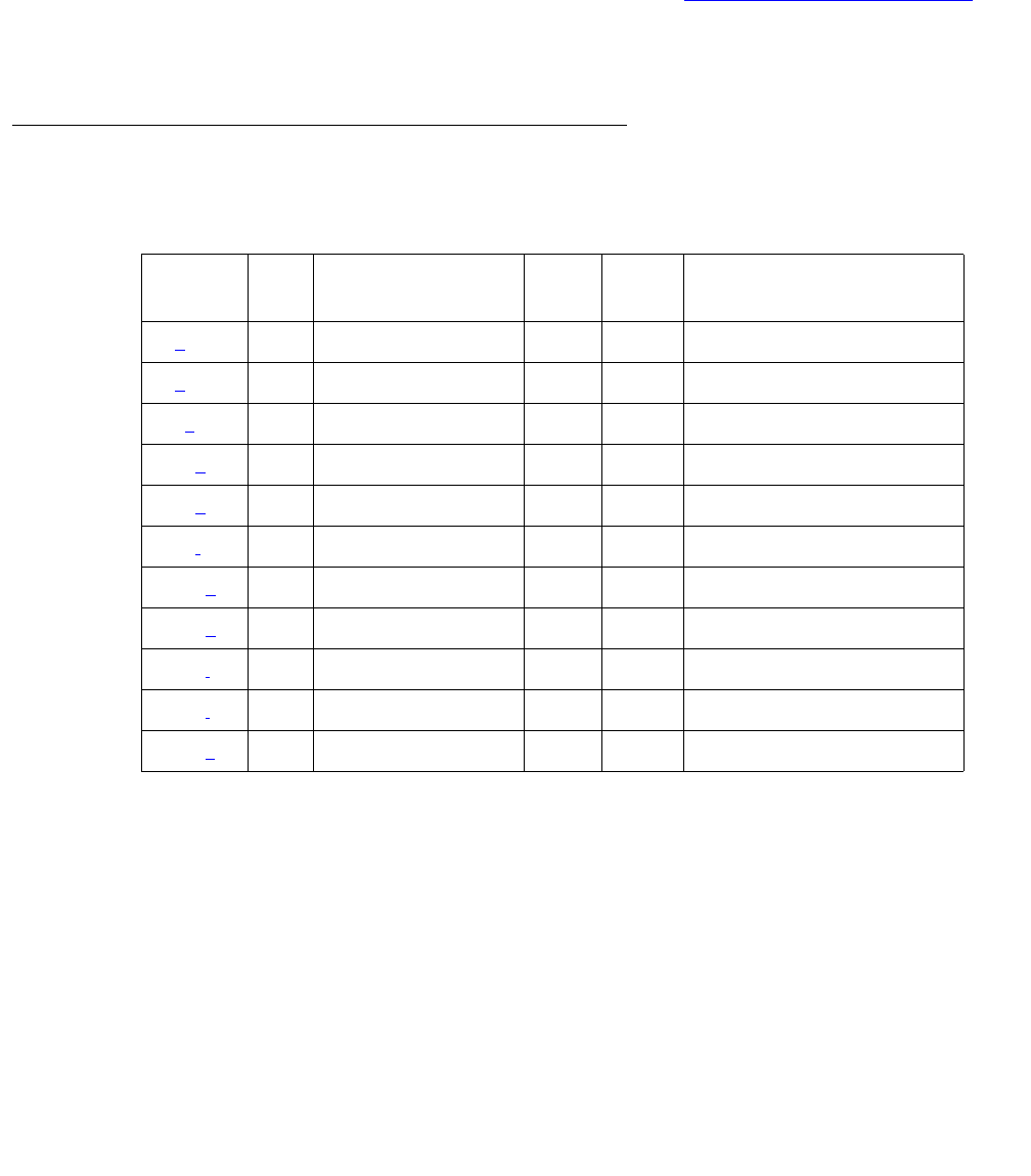
Communication Manager Maintenance-Object Repair Procedures
2004 Maintenance Procedures for Avaya Communication Manager 3.0, Media Gateways and Servers
7. Wait 5 minutes for SNI-BD, SNI-PEER, FIBER-LK, and DS1C alarms to clear, or enter
clear firmware-counters a-pnc | b-pnc. Use the letter designation of the PNC
that holds the replaced component (the standby PNC).
8. Enter status pnc.
If either PNC’s state of health is not “functional”, consult PNC-DUP (PNC Duplication) on
page 1851.
9. Enter release pnc.
Error Log Entries and Test to Clear Values
Notes:
a. Error Type 0: Run the short test sequence first. If every test passes, run the long test
sequence. Refer to each appropriate test’s description, and follow its recommended
procedures.
b. Error Type 1: indicates SNC on-board microcontroller error. (This occurs when the
microcontroller sanity test fails, the ROM has problems, the processor internal or external
RAM is faulty, or the firmware instruction test fails. In addition, this error indicates problems
with the interrupt capabilities, the dual-port RAM and the RTM (real-time monitor) interface
on the faceplate of the SNC.)
1. Replace the SNC circuit pack.
Table 738: SNC Board Error Log Entries
Error
Type
Aux
Data
Associated Test Alarm
Level
On/Off
Board
Test to Clear Value
0 (a)0 Any Any Any test board location r 1
1 (b)Any Failure audit (#777) MAJ ON test board location r 1
18 (c)0 busyout board location WRN OFF release board location
257 (d)Any Failure audit (#777) MAJ OFF test board location r 1
513 (e)Any Failure audit (#777) MIN OFF test board location r 1
769 (f)Any Failure audit (#777) MIN OFF test board location r 1
1025 (g)Any Failure audit (#777) MAJ ON test board location r 1
1281 (h)Any Failure audit (#777) MIN OFF test board location r 1
1537 (i)Any Failure audit (#777) MIN ON test board location r 1
1793 (j)Any Failure audit (#777) MAJ ON test board location r 1
2049 (k)Any Failure audit (#777) MAJ ON test board location r 1

SNC-BD (Switch Node Clock Circuit Pack)
Issue 1 June 2005 2005
c. Error Type 18: the SNC circuit pack was busied out using busyout board location.
To resolve this error, use release board location to release the SNC circuit pack.
d. Error Type 257: these errors occur when firmware detects failure of the phase-locked loop,
inability to lock, or failure of the clock drivers and the problem is off-board.
1. Enter display errors and if SNC-BD Error Type 1793 exists in the hardware error
log, follow the repair procedures for SNC-BD Error Type 1793.
2. Enter display errors and if no SNI-BD 1025 errors exist in the error log, replace the
active SNC.
3. Enter display errors and if any SNI-BD 1025 errors exist in the error log, follow the
repair procedure in the SNI-BD section for these errors.
e. Error Type 513:This error occurs when the active SNC determines that there is a problem
communicating with the standby SNC via the connecting serial channel.
If the switch node carrier is administered with duplicate SNCs:
1. If the standby SNC (the one with its yellow LED off) has this error, escalate the problem.
(status switch-node also shows the active and standby SNCs.)
2. If the system originally had duplicate SNCs and the standby SNC was removed and
never replaced and the active SNC has not been reset after the standby SNC was
removed, this error will occur.
If you do not intend to replace the SNC:
a. Remove the standby SNC from circuit pack administration using change
circuit-pack.
b. If the problem persists, replace the active SNC circuit pack.
Otherwise:
c. Insert an SNC circuit pack.
3. Use display errors to check the error log. If SNIs in the switch node carrier also have
problems communicating with the active SNC (i.e., error code 257 is logged against
SNI-BD), then replace the active SNC.
4. Replace the standby SNC circuit pack.
5. Retry test board. Use display errors to check the error log. If this error is still in the
error log, replace the active SNC.
If the switch node carrier is administered with only one SNC:
●If step 2 above does not apply, replace the SNC.

Communication Manager Maintenance-Object Repair Procedures
2006 Maintenance Procedures for Avaya Communication Manager 3.0, Media Gateways and Servers
f. Error Type 769: the standby SNC determined that there is a problem communicating with
the active SNC through the connecting serial channel.
1. If the active SNC (yellow LED is on) has this error, escalate the problem. (The status
switch-node command also shows the active and standby SNCs.)
2. Use display errors to check the error log. If more than one SNI in the switch node
carrier has problems communicating with the active SNC (that is, Error Type 257 is
logged against SNI-BD), then replace the active SNC.
3. If a single SNI has SNI-BD error 257, replace the SNI circuit pack.
4. Replace the standby SNC circuit pack.
5. Retry test board. Use display errors to check the error log. If this error is still in the
error log, replace the active SNC.
g. Error Type 1025: the firmware detects problems with the various hardware circuit monitors
(for example, loss of reference monitor) that verify correct operation of the reference links.
1. Replace the SNC circuit pack.
h. Error Type 1281: the firmware detects problems with the interface used to track the status
of both SNCs when there are duplicated SNCs in a switch node carrier. When this error
occurs, software may have incorrect information from SNC firmware for which SNC is
active. Therefore, the yellow LEDs on the SNCs must be checked in the following repair
procedure and status switch-node should not be used when this Error Type occurs.
If the switch node carrier has duplicate SNCs:
1. Replace the SNC that does not have its yellow LED lit.
2. Retry test board. Use display errors to check the error log. If the error is still in the
error log, replace the SNC that has its yellow LED lit.
If the switch node carrier has only one SNC, replace the SNC.
i. Error Type 1537: loss of signal from the SNC on-board Stratum-3 oscillator detected by the
firmware.
1. Replace the SNC circuit pack.
j. Error Type 1793: firmware detects failure of the phase-locked loop, inability to lock, or
failure of the clock drivers and the problem is on-board.
1. Replace the SNC circuit pack.
2. If the error persists, follow normal escalation procedures.
k. Error Type 2049: firmware detects problems with the microcontroller used for Timing
Priority Number processing.
1. Replace the SNC circuit pack.

SNC-BD (Switch Node Clock Circuit Pack)
Issue 1 June 2005 2007
System Technician-Demanded Tests:
Descriptions and Error Codes
Investigate tests in the order presented below. Clearing error codes associated with the one test
may also clear errors generated from other tests in the sequence.
Note:
Note: Test #983 is not an actual demand maintenance test. This test number is used to
report the results of clear firmware-counters. Refer to error codes for Test
#777.
Configuration Audit (#759)
This test is nondestructive.
This test is run using test board short or test board long for SNC circuit packs. For
SNC circuit packs, this test queries the SNC for SNCs and SNIs in the same switch node carrier
that the SNC can communicate with and compares this data to the administered data. Failures
of this test cause entries in the error and alarm logs against Switch Node Configuration
(SN-CONF) with the board location of the SNC.
Order of Investigation Short Test
Sequence
Long Test
Sequence
Reset
Board
Sequence
D/ND1
1. D = Destructive, ND = Nondestructive
Configuration Audit (#759) X X ND
Failure audit (#777) X X ND
Processor Route audit (#760) X ND
SNC On-Board test (#778) X X ND
TPN test (#779) X X ND
Switch Node Clock Reset test (#780) X D

Communication Manager Maintenance-Object Repair Procedures
2008 Maintenance Procedures for Avaya Communication Manager 3.0, Media Gateways and Servers
Table 739: TEST #759 Configuration Audit
Error
Code
Test
Result
Description / Recommendation
2100 ABRT Could not allocate the necessary system resources to run this test.
1. Retry the command at 1-minute intervals up to 3 times.
2300 ABRT The downlink message necessary to run this test could not be sent.
1. Retry the command at 1-minute intervals up to 3 times.
2301 ABRT The software timer could not be set before sending the downlink message
necessary to run this test.
1. Retry the command at 1-minute intervals up to 3 times.
2306 ABRT The SNC circuit pack is not responding to test requests sent by software.
1. Run test led switch-node for the switch node where this board
resides to verify whether the LEDs on the board light.
2. If the LEDs on the other boards in the carrier light, but the LEDs on
this board do not light, run test 760 using test board location l
for the active SNC in this carrier. Wait 5 minutes and then try step 1
one more time. If the LEDs on this board still do not light, replace this
board. Replacing an SNC may be service interrupting. See SNC-BD
(Switch Node Clock Circuit Pack) on page 2000 for the procedure for
replacing an SNC.
3. If none of the LEDs light for the boards in the same carrier as this
board, fix any problems associated with the connectivity of this carrier
to the server.
a. Check list fiber-link to see the fiber connections to this
carrier.
b. Check the LEDs on every SNI and EI, and fix any fiber problems.
c. Enter display errors, and follow the repair procedures for any
EXP-INTF error entries associated with the controlling IPSI
connected PN.
d. Follow the repair procedures for any SYNC, SNI-BD, SNC-BD,
FIBER-LK, or SNI-PEER error entries.
2500 ABRT Internal system error
1. Retry the command at 1-minute intervals up to 3 times.
1 of 19

SNC-BD (Switch Node Clock Circuit Pack)
Issue 1 June 2005 2009
102 FAIL The SNC circuit pack cannot communicate with the SNI in slot 2.
1. If a standby SNC (one with its yellow LED off) was tested and resulted
in this error code, follow normal escalation procedures. Use status
switch-node to show the active and standby SNCs.
2. Use list configuration carrier to see if an SNI is physically
present in slot 2. If the Vintage field indicates that a circuit pack is
present, proceed to step 3. If the Vintage field shows no board:
a. If an SNI is not supposed to be installed in slot 2:
1. This failure will not affect service. Use change circuit-pack
to remove the missing SNI from administration.
2. If the error persists, use reset board location to reset the
active SNC circuit pack. If the error still appears, replace the
active SNC circuit pack.
b. If an SNI is supposed to be installed in slot 2, insert one.
3. Enter display errors for category pnc. If the SNC has SNC-BD
error 513, or SNC-LINK errors with Aux Data 1 pointing to other SNIs
besides the one in slot 2, replace the active SNC circuit pack.
4. If SNIs in the same carrier have SNI-BD error 257 logged, (indicating
they are having trouble communicating with the SNC), replace the
active SNC circuit pack.
5. If the SNC being tested has SNC-LINK Error Type 1, replace the SNI
in slot 2. Replacing an SNI may interrupt service. See SNI-BD (SNI
Circuit Pack) on page 2046 for the procedure for replacing an SNI.
6. If the SNC being tested still has SNC-LINK Error Type 1, replace the
SNC circuit pack.
Table 739: TEST #759 Configuration Audit (continued)
Error
Code
Test
Result
Description / Recommendation
2 of 19

Communication Manager Maintenance-Object Repair Procedures
2010 Maintenance Procedures for Avaya Communication Manager 3.0, Media Gateways and Servers
103 FAIL The SNC circuit pack cannot communicate with the SNI in slot 3.
1. If a standby SNC (one with its yellow LED off) was tested and resulted
in this error code, follow normal escalation procedures. Use status
switch-node to show the active and standby SNCs.
2. Use list configuration carrier to determine whether an SNI
is physically present in slot 3. If the Vintage field indicates that a
circuit pack is present, proceed to step 3. If the Vintage field shows
no board:
a. If an SNI is not supposed to be installed in slot 3:
1. This failure will not affect service. Use change circuit-pack
to remove the missing SNI from administration.
2. If the error persists, use reset board location to reset the
active SNC circuit pack. If the error still appears, replace the
active SNC circuit pack.
b. If an SNI is supposed to be installed in slot 3, insert one.
3. Enter display errors for category pnc. If the SNC has SNC-BD
error 513, or SNC-LINK errors with Aux Data 1 pointing to other SNIs
besides the one in slot 3, replace the active SNC circuit pack.
4. If SNIs in the same carrier have SNI-BD error 257 logged, (indicating
they are having trouble communicating with the SNC), replace the
active SNC circuit pack.
5. If the SNC being tested has SNC-LINK Error Type 257, replace the
SNI in slot 3. Replacing an SNI may interrupt service. See SNI-BD
(SNI Circuit Pack) on page 2046 for the procedure for replacing an
SNI.
6. If the SNC being tested still has SNC-LINK Error Type 257, replace
the SNC circuit pack.
Table 739: TEST #759 Configuration Audit (continued)
Error
Code
Test
Result
Description / Recommendation
3 of 19

SNC-BD (Switch Node Clock Circuit Pack)
Issue 1 June 2005 2011
104 FAIL The SNC circuit pack cannot communicate with the SNI in slot 4.
1. If a standby SNC (one with its yellow LED off) was tested and resulted
in this error code, follow normal escalation procedures. Use status
switch-node to show the active and standby SNCs.
2. Use list configuration carrier to determine whether an SNI
is physically present in slot 4. If the Vintage field indicates that a
circuit pack is present, proceed to step 3. If the Vintage field shows
no board:
a. If an SNI is not supposed to be installed in slot 4:
1. This failure will not affect service. Use change circuit-pack
to remove the missing SNI from administration.
2. If the error persists, use reset board location to reset the
active SNC circuit pack. If the error still appears, replace the
active SNC circuit pack.
b. If an SNI is supposed to be installed in slot 4, insert one.
3. Enter display errors for category pnc. If the SNC has SNC-BD
error 513, or SNC-LINK errors with Aux Data 1 pointing to other SNIs
besides the one in slot 4, replace the active SNC circuit pack.
4. If SNIs in the same carrier have SNI-BD error 257 logged, (indicating
they are having trouble communicating with the SNC), replace the
active SNC circuit pack.
5. If the SNC being tested has SNC-LINK Error Type 513, replace the
SNI in slot 4. Replacing an SNI may interrupt service. See SNI-BD
(SNI Circuit Pack) on page 2046 for the procedure for replacing an
SNI.
6. If the SNC being tested still has SNC-LINK Error Type 513, replace
the SNC circuit pack.
Table 739: TEST #759 Configuration Audit (continued)
Error
Code
Test
Result
Description / Recommendation
4 of 19

Communication Manager Maintenance-Object Repair Procedures
2012 Maintenance Procedures for Avaya Communication Manager 3.0, Media Gateways and Servers
105 FAIL The SNC circuit pack cannot communicate with the SNI in slot 5.
1. If a standby SNC (one with its yellow LED off) was tested and resulted
in this error code, follow normal escalation procedures. Use status
switch-node to show the active and standby SNCs.
2. Use list configuration carrier to determine whether an SNI
is physically present in slot 5. If the Vintage field indicates that a
circuit pack is present, proceed to step 3. If the Vintage field shows
no board:
a. If an SNI is not supposed to be installed in slot 5:
1. This failure will not affect service. Use change circuit-pack
to remove the missing SNI from administration.
2. If the error persists, use reset board location to reset the
active SNC circuit pack. If the error still appears, replace the
active SNC circuit pack.
b. If an SNI is supposed to be installed in slot 5, insert one.
3. Enter display errors for category pnc. If the SNC has SNC-BD
error 513, or SNC-LINK errors with Aux Data 1 pointing to other SNIs
besides the one in slot 5, replace the active SNC circuit pack.
4. If SNIs in the same carrier have SNI-BD error 257 logged, (indicating
they are having trouble communicating with the SNC), replace the
active SNC circuit pack.
5. If the SNC being tested has SNC-LINK Error Type 769, replace the
SNI in slot 5. Replacing an SNI may interrupt service. See SNI-BD
(SNI Circuit Pack) on page 2046 for the procedure for replacing an
SNI.
6. If the SNC being tested still has SNC-LINK Error Type 769, replace
the SNC circuit pack.
Table 739: TEST #759 Configuration Audit (continued)
Error
Code
Test
Result
Description / Recommendation
5 of 19

SNC-BD (Switch Node Clock Circuit Pack)
Issue 1 June 2005 2013
106 FAIL The SNC circuit pack cannot communicate with the SNI in slot 6.
1. If a standby SNC (one with its yellow LED off) was tested and resulted
in this error code, follow normal escalation procedures. Use status
switch-node to show the active and standby SNCs.
2. Use list configuration carrier to determine whether an SNI
is physically present in slot 6. If the Vintage field indicates that a
circuit pack is present, proceed to step 3. If the Vintage field shows
no board:
a. If an SNI is not supposed to be installed in slot 6:
1. This failure will not affect service. Use change circuit-pack
to remove the missing SNI from administration.
2. If the error persists, use reset board location to reset the
active SNC circuit pack. If the error still appears, replace the
active SNC circuit pack.
b. If an SNI is supposed to be installed in slot 6, insert one.
3. Enter display errors for category pnc. If the SNC has SNC-BD
error 513, or SNC-LINK errors with Aux Data 1 pointing to other SNIs
besides the one in slot 6, replace the active SNC circuit pack.
4. If SNIs in the same carrier have SNI-BD error 257 logged, (indicating
they are having trouble communicating with the SNC), replace the
active SNC circuit pack.
5. If the SNC being tested has SNC-LINK Error Type 1025, replace the
SNI in slot 6. Replacing an SNI may interrupt service. See SNI-BD
(SNI Circuit Pack) on page 2046 for the procedure for replacing an
SNI.
6. If the SNC being tested still has SNC-LINK Error Type 1025, replace
the SNC circuit pack.
Table 739: TEST #759 Configuration Audit (continued)
Error
Code
Test
Result
Description / Recommendation
6 of 19

Communication Manager Maintenance-Object Repair Procedures
2014 Maintenance Procedures for Avaya Communication Manager 3.0, Media Gateways and Servers
107 FAIL The SNC circuit pack cannot communicate with the SNI in slot 7.
1. If a standby SNC (one with its yellow LED off) was tested and resulted
in this error code, follow normal escalation procedures. Use status
switch-node to show the active and standby SNCs.
2. Use list configuration carrier to determine whether an SNI
is physically present in slot 7. If the Vintage field indicates that a
circuit pack is present, proceed to step 3. If the Vintage field shows
no board:
a. If an SNI is not supposed to be installed in slot 7:
1. This failure will not affect service. Use change circuit-pack
to remove the missing SNI from administration.
2. If the error persists, use reset board location to reset the
active SNC circuit pack. If the error still appears, replace the
active SNC circuit pack.
b. If an SNI is supposed to be installed in slot 7, insert one.
3. Enter display errors for category pnc. If the SNC has SNC-BD
error 513, or SNC-LINK errors with Aux Data 1 pointing to other SNIs
besides the one in slot 7, replace the active SNC circuit pack.
4. If SNIs in the same carrier have SNI-BD error 257 logged, (indicating
they are having trouble communicating with the SNC), replace the
active SNC circuit pack.
5. If the SNC being tested has SNC-LINK Error Type 1281, replace the
SNI in slot 7. Replacing an SNI may interrupt service. See SNI-BD
(SNI Circuit Pack) on page 2046 for the procedure for replacing an
SNI.
6. If the SNC being tested still has SNC-LINK Error Type 1281, replace
the SNC circuit pack.
Table 739: TEST #759 Configuration Audit (continued)
Error
Code
Test
Result
Description / Recommendation
7 of 19

SNC-BD (Switch Node Clock Circuit Pack)
Issue 1 June 2005 2015
108 FAIL The SNC circuit pack cannot communicate with the SNI in slot 8.
1. If a standby SNC (one with its yellow LED off) was tested and resulted
in this error code, follow normal escalation procedures. Use status
switch-node to show the active and standby SNCs.
2. Use list configuration carrier to determine whether an SNI
is physically present in slot 8. If the Vintage field indicates that a
circuit pack is present, proceed to step 3. If the Vintage field shows
no board:
a. If an SNI is not supposed to be installed in slot 8:
1. This failure will not affect service. Use change circuit-pack
to remove the missing SNI from administration.
2. If the error persists, use reset board location to reset the
active SNC circuit pack. If the error still appears, replace the
active SNC circuit pack.
b. If an SNI is supposed to be installed in slot 8, insert one.
3. Enter display errors for category pnc. If the SNC has SNC-BD
error 513, or SNC-LINK errors with Aux Data 1 pointing to other SNIs
besides the one in slot 8, replace the active SNC circuit pack.
4. If SNIs in the same carrier have SNI-BD error 257 logged, (indicating
they are having trouble communicating with the SNC), replace the
active SNC circuit pack.
5. If the SNC being tested has SNC-LINK Error Type 1537, replace the
SNI in slot 8. Replacing an SNI may interrupt service. See SNI-BD
(SNI Circuit Pack) on page 2046 for the procedure for replacing an
SNI.
6. If the SNC being tested still has SNC-LINK Error Type 1537, replace
the SNC circuit pack.
Table 739: TEST #759 Configuration Audit (continued)
Error
Code
Test
Result
Description / Recommendation
8 of 19

Communication Manager Maintenance-Object Repair Procedures
2016 Maintenance Procedures for Avaya Communication Manager 3.0, Media Gateways and Servers
109 FAIL The SNC circuit pack cannot communicate with the SNI in slot 9.
1. If a standby SNC (one with its yellow LED off) was tested and resulted
in this error code, follow normal escalation procedures. Use status
switch-node to show the active and standby SNCs.
2. Use list configuration carrier to determine whether an SNI
is physically present in slot 9. If the Vintage field indicates that a
circuit pack is present, proceed to step 3. If the Vintage field shows
no board:
a. If an SNI is not supposed to be installed in slot 9:
1. This failure will not affect service. Use change circuit-pack
to remove the missing SNI from administration.
2. If the error persists, use reset board location to reset the
active SNC circuit pack. If the error still appears, replace the
active SNC circuit pack.
b. If an SNI is supposed to be installed in slot 9, insert one.
3. Enter display errors for category pnc. If the SNC has SNC-BD
error 513, or SNC-LINK errors with Aux Data 1 pointing to other SNIs
besides the one in slot 9, replace the active SNC circuit pack.
4. If SNIs in the same carrier have SNI-BD error 257 logged, (indicating
they are having trouble communicating with the SNC), replace the
active SNC circuit pack.
5. If the SNC being tested has SNC-LINK Error Type 1793, replace the
SNI in slot 9. Replacing an SNI may interrupt service. See SNI-BD
(SNI Circuit Pack) on page 2046 for the procedure for replacing an
SNI.
6. If the SNC being tested still has SNC-LINK Error Type 1793, replace
the SNC circuit pack.
Table 739: TEST #759 Configuration Audit (continued)
Error
Code
Test
Result
Description / Recommendation
9 of 19

SNC-BD (Switch Node Clock Circuit Pack)
Issue 1 June 2005 2017
112 FAIL The SNC circuit pack cannot communicate with the other SNC.
If this test was run on the active SNC and if the switch node carrier is
administered with duplicate SNCs:
1. If the system originally had duplicate SNCs and the standby SNC was
removed and never replaced, this error will occur. If you do not intend
to replace the SNC:
a. Use change circuit-pack to remove the standby SNC from
administration.
b. If the problem persists, reset the active SNC circuit pack using
reset board location. If the problem persists after the reset,
replace the active SNC circuit pack.
2. Use display errors to check the error log. If SNIs in the switch
node carrier also have problems communicating with the active SNC
(i.e., error code 257 is logged against SNI-BD), replace the active
SNC.
3. Replace the standby SNC circuit pack.
4. Retry test board. If this test continues to fail, replace the active
SNC.
If this test was run on the active SNC and if the switch node carrier is
administered with only one SNC:
1. Replace the SNC.
If this test was run on the standby SNC:
1. Use display errors to check the error log. If more than one SNI in
the switch node carrier has problems communicating with the active
SNC (i.e., error code 257 is logged against SNI-BD), then replace the
active SNC.
2. Replace the standby SNC circuit pack.
3. Retry test board. Use display errors to check the error log. If
this error is still in the error log, replace the active SNC.
Table 739: TEST #759 Configuration Audit (continued)
Error
Code
Test
Result
Description / Recommendation
10 of 19

Communication Manager Maintenance-Object Repair Procedures
2018 Maintenance Procedures for Avaya Communication Manager 3.0, Media Gateways and Servers
113 FAIL The SNC circuit pack cannot communicate with the SNI in slot 13.
1. If a standby SNC (one with its yellow LED off) was tested and resulted
in this error code, follow normal escalation procedures. Use status
switch-node to show the active and standby SNCs.
2. Use list configuration carrier to determine whether an SNI
is physically present in slot 13. If the Vintage field indicates that a
circuit pack is present, proceed to step 3. If the Vintage field shows
no board:
a. If an SNI is not supposed to be installed in slot 13:
1. This failure will not affect service. Use change circuit-pack
to remove the missing SNI from administration.
2. If the error persists, use reset board location to reset the
active SNC circuit pack. If the error still appears, replace the
active SNC circuit pack.
b. If an SNI is supposed to be installed in slot 13, insert one.
3. Enter display errors for category pnc. If the SNC has SNC-BD
error 513, or SNC-LINK errors with Aux Data 1 pointing to other SNIs
besides the one in slot 13, replace the active SNC circuit pack.
4. If SNIs in the same carrier have SNI-BD error 257 logged, (indicating
they are having trouble communicating with the SNC), replace the
active SNC circuit pack.
5. If the SNC being tested has SNC-LINK Error Type 2049, replace the
SNI in slot 13. Replacing an SNI may interrupt service. See SNI-BD
(SNI Circuit Pack) on page 2046 for the procedure for replacing an
SNI.
6. If the SNC being tested still has SNC-LINK Error Type 2049, replace
the SNC circuit pack.
Table 739: TEST #759 Configuration Audit (continued)
Error
Code
Test
Result
Description / Recommendation
11 of 19

SNC-BD (Switch Node Clock Circuit Pack)
Issue 1 June 2005 2019
114 FAIL The SNC circuit pack cannot communicate with the SNI in slot 14.
1. If a standby SNC (one with its yellow LED off) was tested and resulted
in this error code, follow normal escalation procedures. Use status
switch-node to show the active and standby SNCs.
2. Use list configuration carrier to determine whether an SNI
is physically present in slot 14. If the Vintage field indicates that a
circuit pack is present, proceed to step 3. If the Vintage field shows
no board: do one of the following:
a. If an SNI is not supposed to be installed in slot 14:
1. This failure will not affect service. Use change circuit-pack
to remove the missing SNI from administration.
2. If the error persists, use reset board location to reset the
active SNC circuit pack. If the error still appears, replace the
active SNC circuit pack.
b. If an SNI is supposed to be installed in slot 14, insert one.
3. Enter display errors for category pnc. If the SNC has SNC-BD
error 513, or SNC-LINK errors with Aux Data 1 pointing to other SNIs
besides the one in slot 14, replace the active SNC circuit pack.
4. If SNIs in the same carrier have SNI-BD error 257 logged, (indicating
they are having trouble communicating with the SNC), replace the
active SNC circuit pack.
5. If the SNC being tested has SNC-LINK Error Type 2305, replace the
SNI in slot 14. Replacing an SNI may interrupt service. See SNI-BD
(SNI Circuit Pack) on page 2046 for the procedure for replacing an
SNI.
6. If the SNC being tested still has SNC-LINK Error Type 2305, replace
the SNC circuit pack.
Table 739: TEST #759 Configuration Audit (continued)
Error
Code
Test
Result
Description / Recommendation
12 of 19

Communication Manager Maintenance-Object Repair Procedures
2020 Maintenance Procedures for Avaya Communication Manager 3.0, Media Gateways and Servers
115 FAIL The SNC circuit pack cannot communicate with the SNI in slot 15.
1. If a standby SNC (one with its yellow LED off) was tested and resulted
in this error code, follow normal escalation procedures. Use status
switch-node to show the active and standby SNCs.
2. Use list configuration carrier to determine whether an SNI
is physically present in slot 15. If the Vintage field indicates that a
circuit pack is present, proceed to step 3. If the Vintage field shows
no board:
a. If an SNI is not supposed to be installed in slot 15:
1. This failure will not affect service. Use change circuit-pack
to remove the missing SNI from administration.
2. If the error persists, use reset board location to reset the
active SNC circuit pack. If the error still appears, replace the
active SNC circuit pack.
b. If an SNI is supposed to be installed in slot 15, insert one.
3. Enter display errors for category pnc. If the SNC has SNC-BD
error 513, or SNC-LINK errors with Aux Data 1 pointing to other SNIs
besides the one in slot 15, replace the active SNC circuit pack.
4. If SNIs in the same carrier have SNI-BD error 257 logged, (indicating
they are having trouble communicating with the SNC), replace the
active SNC circuit pack.
5. If the SNC being tested has SNC-LINK Error Type 2561, replace the
SNI in slot 15. Replacing an SNI may interrupt service. See SNI-BD
(SNI Circuit Pack) on page 2046 for the procedure for replacing an
SNI.
6. If the SNC being tested still has SNC-LINK Error Type 2561, replace
the SNC circuit pack.
Table 739: TEST #759 Configuration Audit (continued)
Error
Code
Test
Result
Description / Recommendation
13 of 19

SNC-BD (Switch Node Clock Circuit Pack)
Issue 1 June 2005 2021
116 FAIL The SNC circuit pack cannot communicate with the SNI in slot 16.
1. If a standby SNC (one with its yellow LED off) was tested and resulted
in this error code, follow normal escalation procedures. Use status
switch-node to show the active and standby SNCs.
2. Use list configuration carrier to determine whether an SNI
is physically present in slot 16. If the Vintage field indicates that a
circuit pack is present, proceed to step 3. If the Vintage field shows
no board:
a. If an SNI is not supposed to be installed in slot 16:
1. This failure will not affect service. Use change circuit-pack
to remove the missing SNI from administration.
2. If the error persists, use reset board location to reset the
active SNC circuit pack. If the error still appears, replace the
active SNC circuit pack.
b. If an SNI is supposed to be installed in slot 16, insert one.
3. Enter display errors for category pnc. If the SNC has SNC-BD
error 513, or SNC-LINK errors with Aux Data 1 pointing to other SNIs
besides the one in slot 16, replace the active SNC circuit pack.
4. If SNIs in the same carrier have SNI-BD error 257 logged, (indicating
they are having trouble communicating with the SNC), replace the
active SNC circuit pack.
5. If the SNC being tested has SNC-LINK Error Type 2817, replace the
SNI in slot 16. Replacing an SNI may interrupt service. See SNI-BD
(SNI Circuit Pack) on page 2046 for the procedure for replacing an
SNI.
6. If the SNC being tested still has SNC-LINK Error Type 2817, replace
the SNC circuit pack.
Table 739: TEST #759 Configuration Audit (continued)
Error
Code
Test
Result
Description / Recommendation
14 of 19

Communication Manager Maintenance-Object Repair Procedures
2022 Maintenance Procedures for Avaya Communication Manager 3.0, Media Gateways and Servers
117 FAIL The SNC circuit pack cannot communicate with the SNI in slot 17.
1. If a standby SNC (one with its yellow LED off) was tested and resulted
in this error code, follow normal escalation procedures. Use status
switch-node to show the active and standby SNCs.
2. Use list configuration carrier to determine whether an SNI
is physically present in slot 17. If the Vintage field indicates that a
circuit pack is present, proceed to step 3. If the Vintage field shows
no board:
a. If an SNI is not supposed to be installed in slot 17:
1. This failure will not affect service. Use change circuit-pack
to remove the missing SNI from administration.
2. If the error persists, use reset board location to reset the
active SNC circuit pack. If the error still appears, replace the
active SNC circuit pack.
b. If an SNI is supposed to be installed in slot 17, insert one.
3. Enter display errors for category pnc. If the SNC has SNC-BD
error 513, or SNC-LINK errors with Aux Data 1 pointing to other SNIs
besides the one in slot 17, replace the active SNC circuit pack.
4. If SNIs in the same carrier have SNI-BD error 257 logged, (indicating
they are having trouble communicating with the SNC), replace the
active SNC circuit pack.
5. If the SNC being tested has SNC-LINK Error Type 3073, replace the
SNI in slot 17. Replacing an SNI may interrupt service. See SNI-BD
(SNI Circuit Pack) on page 2046 for the procedure for replacing an
SNI.
6. If the SNC being tested still has SNC-LINK Error Type 3073, replace
the SNC circuit pack.
Table 739: TEST #759 Configuration Audit (continued)
Error
Code
Test
Result
Description / Recommendation
15 of 19

SNC-BD (Switch Node Clock Circuit Pack)
Issue 1 June 2005 2023
118 FAIL The SNC circuit pack cannot communicate with the SNI in slot 18.
1. If a standby SNC (one with its yellow LED off) was tested and resulted
in this error code, follow normal escalation procedures. Use status
switch-node to show the active and standby SNCs.
2. Use list configuration carrier to determine whether an SNI
is physically present in slot 18. If the Vintage field indicates that a
circuit pack is present, proceed to step 3. If the Vintage field shows
no board:
a. If an SNI is not supposed to be installed in slot 18:
1. This failure will not affect service. Use change circuit-pack
to remove the missing SNI from administration.
2. If the error persists, use reset board location to reset the
active SNC circuit pack. If the error still appears, replace the
active SNC circuit pack.
b. If an SNI is supposed to be installed in slot 18, insert one.
3. Enter display errors for category pnc. If the SNC has SNC-BD
error 513, or SNC-LINK errors with Aux Data 1 pointing to other SNIs
besides the one in slot 18, replace the active SNC circuit pack.
4. If SNIs in the same carrier have SNI-BD error 257 logged, (indicating
they are having trouble communicating with the SNC), replace the
active SNC circuit pack.
5. If the SNC being tested has SNC-LINK Error Type 3329, replace the
SNI in slot 18. Replacing an SNI may interrupt service. See SNI-BD
(SNI Circuit Pack) on page 2046 for the procedure for replacing an
SNI.
6. If the SNC being tested still has SNC-LINK Error Type 3329, replace
the SNC circuit pack.
Table 739: TEST #759 Configuration Audit (continued)
Error
Code
Test
Result
Description / Recommendation
16 of 19

Communication Manager Maintenance-Object Repair Procedures
2024 Maintenance Procedures for Avaya Communication Manager 3.0, Media Gateways and Servers
119 FAIL The SNC circuit pack cannot communicate with the SNI in slot 19.
1. If a standby SNC (one with its yellow LED off) was tested and resulted
in this error code, follow normal escalation procedures. Use status
switch-node to show the active and standby SNCs.
2. Use list configuration carrier to determine whether an SNI
is physically present in slot 19. If the Vintage field indicates that a
circuit pack is present, proceed to step 3. If the Vintage field shows
no board:
a. If an SNI is not supposed to be installed in slot 19:
1. This failure will not affect service. Use change circuit-pack
to remove the missing SNI from administration.
2. If the error persists, use reset board location to reset the
active SNC circuit pack. If the error still appears, replace the
active SNC circuit pack.
b. If an SNI is supposed to be installed in slot 19, insert one.
3. Enter display errors for category pnc. If the SNC has SNC-BD
error 513, or SNC-LINK errors with Aux Data 1 pointing to other SNIs
besides the one in slot 19, replace the active SNC circuit pack.
4. If SNIs in the same carrier have SNI-BD error 257 logged, (indicating
they are having trouble communicating with the SNC), replace the
active SNC circuit pack.
5. If the SNC being tested has SNC-LINK Error Type 3585, replace the
SNI in slot 19. Replacing an SNI may interrupt service. See SNI-BD
(SNI Circuit Pack) on page 2046 for the procedure for replacing an
SNI.
6. If the SNC being tested still has SNC-LINK Error Type 3585, replace
the SNC circuit pack.
Table 739: TEST #759 Configuration Audit (continued)
Error
Code
Test
Result
Description / Recommendation
17 of 19

SNC-BD (Switch Node Clock Circuit Pack)
Issue 1 June 2005 2025
120 FAIL The SNC circuit pack cannot communicate with the SNI in slot 20.
1. If a standby SNC (one with its yellow LED off) was tested and resulted
in this error code, follow normal escalation procedures. Use status
switch-node to show the active and standby SNCs.
2. Use list configuration carrier to determine whether an SNI
is physically present in slot 20. If the Vintage field indicates that a
circuit pack is present, proceed to step 3. If the Vintage field shows
no board:
a. If an SNI is not supposed to be installed in slot 20
1. This failure will not affect service. Use change circuit-pack
to remove the missing SNI from administration.
2. If the error persists, use reset board location to reset the
active SNC circuit pack. If the error still appears, replace the
active SNC circuit pack.
b. If an SNI is supposed to be installed in slot 20, insert one.
3. Enter display errors for category pnc. If the SNC has SNC-BD
error 513, or SNC-LINK errors with Aux Data 1 pointing to other SNIs
besides the one in slot 20, replace the active SNC circuit pack.
4. If SNIs in the same carrier have SNI-BD error 257 logged, (indicating
they are having trouble communicating with the SNC), replace the
active SNC circuit pack.
5. If the SNC being tested has SNC-LINK Error Type 3841, replace the
SNI in slot 20. Replacing an SNI may interrupt service. See SNI-BD
(SNI Circuit Pack) on page 2046 for the procedure for replacing an
SNI.
6. If the SNC being tested still has SNC-LINK Error Type 3841, replace
the SNC circuit pack.
PASS The administered data and the circuit packs the SNC can communicate
with match.
Table 739: TEST #759 Configuration Audit (continued)
Error
Code
Test
Result
Description / Recommendation
18 of 19

Communication Manager Maintenance-Object Repair Procedures
2026 Maintenance Procedures for Avaya Communication Manager 3.0, Media Gateways and Servers
Processor Route Audit Test (#760)
This test is nondestructive.
This test sends a processor route to every SNI in the carrier for which test board location
was run. A processor route enables an SNI board to send uplink messages to the server by
providing the board with a specific sequence of boards for routing messages up to the server.
Without a processor route, an SNI cannot send any in-line errors to the server.
As each SNI receives its processor route, the SNI returns a “board insertion” uplink message,
and (if not already inserted) the server’s software inserts that board. Depending on the
configuration, each SNI board is sent either one or two processor routes.
Use test led or list config carrier to see if the boards are inserted.
0NO
BOARD
No board was detected by the test.
1. Check that SNC board is properly translated and inserted.
2. Run the test again. If it fails, reset the board. An SNC should be reset
instead of reseating the circuit pack. The reset board command
should almost never be used on an SNC. It may be necessary to use
reset board if the SNC circuit pack gets into a mode where it
cannot communicate with software. If an SNC with active errors and
alarms is reset, the errors and alarms may take a while to come back,
therefore reset board can mask real problems.
3. Run the test again. If it fails, the ID chip on board may be bad.
Replace the board and retest.
Table 739: TEST #759 Configuration Audit (continued)
Error
Code
Test
Result
Description / Recommendation
19 of 19
Table 740: TEST #760 Processor Route Audit Test
Error
Code
Test
Result
Description / Recommendation
2100 ABRT Could not allocate the necessary system resources to run this test.
1. Retry the command at 1-minute intervals up to 3 times.
2300 ABRT The downlink message necessary to run this test could not be sent.
1. Retry the command at 1-minute intervals up to 3 times.
1 of 3

SNC-BD (Switch Node Clock Circuit Pack)
Issue 1 June 2005 2027
2301 ABRT The software timer could not be set before sending the downlink message
necessary to run this test.
1. Retry the command at 1-minute intervals up to 3 times.
2306 ABRT None of the circuit packs in this switch node carrier are responding to the
processor route messages sent by software.
1. Run test led switch-node for the switch node where this switch
node carrier resides to verify whether the LEDs on any of the boards
light.
2. If none of the LEDs light for the boards in this carrier, fix any problems
associated with the connectivity of this carrier to the server.
a. Use list fiber link to obtain a list of the fiber connections to
this carrier.
b. Check the LEDs on every SNI and EI, and fix any fiber problems.
c. Enter display errors, and follow the repair procedures for any
EXP-INTF error entries associated with the controlling IPSI
connected PN.
d. Follow the repair procedures for any SYNC, SNI-BD, SNC-BD,
FIBER-LK, or SNI-PEER error entries.
2500 ABRT Internal system error
1. Retry the command at 1-minute intervals up to 3 times.
Table 740: TEST #760 Processor Route Audit Test (continued)
Error
Code
Test
Result
Description / Recommendation
2 of 3

Communication Manager Maintenance-Object Repair Procedures
2028 Maintenance Procedures for Avaya Communication Manager 3.0, Media Gateways and Servers
FAIL If this test fails, one or more administered circuit packs in this switch node
carrier did not respond with a “board insertion” uplink message. Use list
config carrier location to verify that the administered SNI and
SNC boards match the physically installed SNI and SNC boards. The
output shows NO BOARD for every board that is administered, but not
inserted.
1. If every administered board is inserted, run this test again.
2. If administration does not match the physical configuration, and is
correct, insert the missing circuit packs in this switch node carrier.
3. If none of the administered boards in this switch node carrier were
inserted, fix any other SN-CONF errors by following the repair
procedures for SN-CONF. Use display errors pnc to view
SN-CONF errors. Next check if any INLs, LNLs, or RNLs are down,
see SYS-LINK (System Links) on page 2175 for fixing link problems.
PASS If this test passes, every administered circuit pack in this switch node
carrier was inserted.
0NO
BOARD
No board was detected by the test.
1. Check that SNC board is properly translated and inserted.
2. Run the test again. If it fails, reset the board. An SNC should be reset
instead of reseating the circuit pack. The reset board command
should almost never be used on an SNC. It may be necessary to use
reset board if the SNC circuit pack gets into a mode where it
cannot communicate with software. If an SNC with active errors and
alarms is reset, the errors and alarms may take a while to come back,
therefore reset board can mask real problems.
3. Run the test again. If it fails, the ID chip on board may be bad.
Replace the board and retest.
Table 740: TEST #760 Processor Route Audit Test (continued)
Error
Code
Test
Result
Description / Recommendation
3 of 3
SNC-BD (Switch Node Clock Circuit Pack)
Issue 1 June 2005 2029
Failure Audit (#777)
This test is nondestructive.
This test queries an SNC for any existing failures and any unacknowledged “cleared failure”
messages. Each failure generates an error and alarm entry against SNC-BD, SNC-LINK, or
SNC-REF. A “cleared failure” message is a message an SNI circuit pack sends to software
indicating the resolution of a previous failure. This message is “unacknowledged” if the SNI
circuit pack never receives a response from software indicating it’s own receipt of the original
“cleared failure” message.
If no failures are detected by the SNC circuit pack, this test will pass.
If this test reports failures, the test board screen shows FAIL with no FAIL code. Use
display errors pnc to show the error log and view SNC-related errors: SNC-BD,
SNC-LINK, and SNC-REF.
Table 741: TEST #777 Failure Audit
Error
Code
Test
Result
Description / Recommendation
ABRT Internal system error
1. Retry the command at 1-minute intervals up to 3 times.
2100 ABRT Could not allocate the necessary system resources to run this test.
1. Retry the command at 1-minute intervals up to 3 times.
2300 ABRT The downlink message necessary to run this test could not be sent.
1. Retry the command at 1-minute intervals up to 3 times.
2301 ABRT The software timer could not be set before sending the downlink message
necessary to run this test.
1. Retry the command at 1-minute intervals up to 3 times.
1 of 3

Communication Manager Maintenance-Object Repair Procedures
2030 Maintenance Procedures for Avaya Communication Manager 3.0, Media Gateways and Servers
2306 ABRT The SNC circuit pack is not responding to test requests sent by software.
1. Run test led switch-node for the switch node where this board
resides to verify whether the LEDs on the board light.
2. If the LEDs on the other boards in the carrier light, but the LEDs on
this board do not light, run test 760 using test board location l
for the active SNC in this carrier. Wait 5 minutes and then try step 1
one more time. If the LEDs on this board still do not light, replace this
board. Replacing an SNC may be service interrupting. See SNC-BD
(Switch Node Clock Circuit Pack) on page 2000 for the procedure for
replacing an SNC.
3. If none of the LEDs light for the boards in the same carrier as this
board, fix any problems associated with the connectivity of this carrier
to the server.
a. Use list fiber-link to obtain a list of the fiber connections to
this carrier.
b. Check the LEDs on every SNI and EI, and fix any fiber problems.
c. Enter display errors, and follow the repair procedures for any
EXP-INTF error entries associated with the controlling IPSI
connected PN.
d. Follow the repair procedures for any SYNC, SNI-BD, SNC-BD,
FIBER-LK, or SNI-PEER error entries.
FAIL The SNC circuit pack reported failures or retransmitted a “cleared failure”
message.
1. Check the error and alarm logs for SNC-BD, SNC-LINK, or SNC-REF
entries. Use display errors and display alarms with category
PNC. Fix any problems found by following repair procedures for the
SNC Board, SNC Link, or SNC Reference Error Log Entries tables in
this section.
2. If no SNC-BD, SNC-LINK, or SNC-REF errors exist in the error and
alarm logs, retry the command.
PASS No problems are detected on the board.
Table 741: TEST #777 Failure Audit (continued)
Error
Code
Test
Result
Description / Recommendation
2 of 3

SNC-BD (Switch Node Clock Circuit Pack)
Issue 1 June 2005 2031
SNC On-Board Test (#778)
This test is nondestructive.
This test queries the SNC circuit pack for status of the background tests run on-board. These
background tests include an SNC on-board microcontroller test, clock test, an SNC on-board
Stratum-3 oscillator test, and TPN microcontroller test.
0NO
BOARD
No board was detected by the test.
1. Check that SNC board is properly translated and inserted.
2. Run the test again. If it fails, reset the board. An SNC should be reset
instead of reseating the circuit pack. The reset board command
should almost never be used on an SNC. It may be necessary to use
reset board if the SNC circuit pack gets into a mode where it
cannot communicate with software. If an SNC with active errors and
alarms is reset, the errors and alarms may take a while to come back,
therefore reset board can mask real problems.
3. Run the test again. If it fails, the ID chip on board may be bad.
Replace the board and retest.
Table 741: TEST #777 Failure Audit (continued)
Error
Code
Test
Result
Description / Recommendation
3 of 3
Table 742: TEST #778 SNC On-Board Test
Error
Code
Test
Result
Description / Recommendation
2100 ABRT Could not allocate the necessary system resources to run this test.
1. Retry the command at 1-minute intervals up to 3 times.
2300 ABRT The downlink message necessary to run this test could not be sent.
1. Retry the command at 1-minute intervals up to 3 times.
2301 ABRT The software timer could not be set before sending the downlink message
necessary to run this test.
1. Retry the command at 1-minute intervals up to 3 times.
1 of 3

Communication Manager Maintenance-Object Repair Procedures
2032 Maintenance Procedures for Avaya Communication Manager 3.0, Media Gateways and Servers
2303 ABRT The SNC circuit pack responded that the software test requested is not
valid.
1. Retry the command at 1-minute intervals up to 3 times.
2304 ABRT SNC firmware is not able to run the test.
1. Retry the command at 1-minute intervals up to 3 times.
2306 ABRT The SNC circuit pack is not responding to test requests sent by software.
1. Run test led switch-node for the switch node where this board
resides to verify whether the LEDs on the board light.
2. If the LEDs on the other boards in the carrier light, but the LEDs on
this board do not light, run test 760 using test board location l
for the active SNC in this carrier. Wait 5 minutes and then try step 1
one more time. If the LEDs on this board still do not light, replace this
board. Replacing an SNC may be service interrupting. See SNC-BD
(Switch Node Clock Circuit Pack) on page 2000 for the procedure for
replacing an SNC.
3. If none of the LEDs light for the boards in the same carrier as this
board, fix any problems associated with the connectivity of this carrier
to the server.
a. Use list fiber-link to obtain a list of the fiber connections to
this carrier.
b. Check the LEDs on every SNI and EI, and fix any fiber problems.
c. Enter display errors, and follow the repair procedures for any
EXP-INTF error entries associated with the controlling IPSI
connected PN.
d. Follow the repair procedures for any SYNC, SNI-BD, SNC-BD,
FIBER-LK, or SNI-PEER error entries.
Table 742: TEST #778 SNC On-Board Test (continued)
Error
Code
Test
Result
Description / Recommendation
2 of 3

SNC-BD (Switch Node Clock Circuit Pack)
Issue 1 June 2005 2033
101 FAIL The SNC circuit pack has on-board microcontroller failure.
1. Replace the SNC circuit pack.
128 FAIL The SNC circuit pack has a problem with its clock; firmware has detected
a phase-locked loop failure, an inability to lock, or a failure of the clock
drivers.
1. Replace the SNC circuit pack.
129 FAIL The SNC circuit pack has a problem with the SNC on-board Stratum-3
oscillator.
1. Replace the SNC circuit pack.
130 FAIL The SNC circuit pack has a problem with the TPN microcontroller.
1. Replace the SNC circuit pack.
PASS No problems exist with the on-board functions verified by this test.
0NO
BOARD
No board was detected by the test.
2. Check that SNC board is properly translated and inserted.
3. Run the test again. If it fails, reset the board. An SNC should be reset
instead of reseating the circuit pack. The reset board command
should almost never be used on an SNC. It may be necessary to use
reset board if the SNC circuit pack gets into a mode where it
cannot communicate with software. If an SNC with active errors and
alarms is reset, the errors and alarms may take a while to come back,
therefore reset board can mask real problems.
4. Run the test again. If it fails, the ID chip on board may be bad.
Replace the board and retest.
Table 742: TEST #778 SNC On-Board Test (continued)
Error
Code
Test
Result
Description / Recommendation
3 of 3

Communication Manager Maintenance-Object Repair Procedures
2034 Maintenance Procedures for Avaya Communication Manager 3.0, Media Gateways and Servers
TPN Test (#779)
This test is nondestructive.
This test queries the SNC circuit pack for status of the ROM and internal RAM background tests
for the TPN microcontroller.
Table 743: TEST #779 TPN Test
Error
Code
Test
Result
Description / Recommendation
2100 ABRT Could not allocate the necessary system resources to run this test.
1. Retry the command at 1-minute intervals up to 3 times.
2300 ABRT The downlink message necessary to run this test could not be sent.
1. Retry the command at 1-minute intervals up to 3 times.
2301 ABRT The software timer could not be set before sending the downlink message
necessary to run this test.
1. Retry the command at 1-minute intervals up to 3 times.
2302 ABRT Software received unexpected message data from the SNC circuit pack.
1. Retry the command at 1-minute intervals up to 3 times.
2303 ABRT The SNC circuit pack responded that the software test requested is not
valid.
1. Retry the command at 1-minute intervals up to 3 times.
2304 ABRT SNC circuit pack responded that it is not able to run the test requested by
software.
1. Retry the command at 1-minute intervals up to 3 times.
1 of 2

SNC-BD (Switch Node Clock Circuit Pack)
Issue 1 June 2005 2035
2306 ABRT The SNC circuit pack is not responding to test requests sent by software.
1. Run the test led switch-node for the switch node where this
board resides to verify whether the LEDs on the board light.
2. If the LEDs on the other boards in the carrier light, but the LEDs on
this board do not light, run test 760 using test board location l
for the active SNC in this carrier. Wait 5 minutes and then try step 1
one more time. If the LEDs on this board still do not light, replace this
board. Replacing an SNC may be service interrupting. See SNC-BD
(Switch Node Clock Circuit Pack) on page 2000 for the procedure for
replacing an SNC.
3. If none of the LEDs light for the boards in the same carrier as this
board, fix any problems associated with the connectivity of this carrier
to the server.
a. Use list fiber-link to list the fiber connections to this carrier.
b. Check the LEDs on every SNI and EI, and fix any fiber problems.
c. Enter display errors, and follow the repair procedures for any
EXP-INTF error entries associated with the controlling IPSI
connected PN.
d. Follow the repair procedures for any SYNC, SNI-BD, SNC-BD,
FIBER-LK, or SNI-PEER error entries.
FAIL The test failed. Replace the SNC circuit pack.
PASS No problems exist with the TPN microcontroller.
0NO
BOARD
No board was detected by the test.
1. Check that SNC board is properly translated and inserted.
2. Run the test again. If it fails, reset the board. An SNC should be reset
instead of reseating the circuit pack. The reset board command
should almost never be used on an SNC. It may be necessary to use
reset board if the SNC circuit pack gets into a mode where it
cannot communicate with software. If an SNC with active errors and
alarms is reset, the errors and alarms may take a while to come back,
therefore reset board can mask real problems.
3. Run the test again. If it fails, the ID chip on board may be bad.
Replace the board and retest.
Table 743: TEST #779 TPN Test (continued)
Error
Code
Test
Result
Description / Recommendation
2 of 2

Communication Manager Maintenance-Object Repair Procedures
2036 Maintenance Procedures for Avaya Communication Manager 3.0, Media Gateways and Servers
Switch Node Clock Reset Test (#780)
This test is destructive.
This test resets the SNC circuit pack using reset board location when an SNC circuit
pack location is entered. If the system has PNC duplication, the active SNC on the active PNC
cannot be reset.
If the SNC is active and reset board is executed, an SNI in the same carrier as the SNC will
be told by software to reset the SNC via the TPN link. If no inserted SNIs in the same carrier as
the SNC can successfully reset the SNC, software will send a “reset” message directly to the
SNC. Software first tries to reset the SNC via an SNI in case the SNC is insane because the
latter method (sending the “reset” message directly to the SNC) will not work if the SNC is
insane.
If an active SNC is reset and a standby SNC exists in the same switch node carrier, the standby
SNC becomes active. Use set switch-node-clock location to make a standby SNC
active, not reset board.
If the SNC is standby and reset board is executed, the active SNC is told by software to
reset the standby SNC via the TPN link.
An SNC should be reset instead of reseating the circuit pack. The reset board command
should almost never be used on an SNC. It may be necessary to use reset board if the SNC
circuit pack gets into a mode where it cannot communicate with software.
Table 744: TEST #780 Switch Node Clock Reset Test
Error
Code
Test
Result
Description / Recommendation
2100 ABRT Could not allocate the necessary system resources to run this test.
1. Retry the command at 1-minute intervals up to 3 times.
2300 ABRT The downlink message necessary to run this test could not be sent.
1. Retry the command at 1-minute intervals up to 3 times.
2301 ABRT The software timer could not be set before sending the downlink message
necessary to run this test.
1. Retry the command at 1-minute intervals up to 3 times.
2302 ABRT Software received unexpected message data from the SNC circuit pack.
1. Retry the command at 1-minute intervals up to 3 times.
2303 ABRT The SNC circuit pack responded that the software test requested is not
valid.
1. Retry the command at 1-minute intervals up to 3 times.
1 of 3

SNC-BD (Switch Node Clock Circuit Pack)
Issue 1 June 2005 2037
2304 ABRT SNC circuit pack responded that it is not able to run the test requested by
software.
1. Retry the command at 1-minute intervals up to 3 times.
2306 ABRT The SNC circuit pack is not responding to test requests sent by software.
1. Run the test led switch-node for the switch node where the
SNC resides to verify whether the LEDs on the board light.
2. If the LEDs on the other boards in the carrier light, but the LEDs on
this board do not light, run test 760 using test board location l
for the active SNC in this carrier. Wait 5 minutes and then try step 1
one more time. If the LEDs on this board still do not light, replace this
board. Replacing an SNC may be service interrupting. See SNC-BD
(Switch Node Clock Circuit Pack) on page 2000 for the procedure for
replacing an SNC.
3. If none of the LEDs light for the boards in the same carrier as this
board, fix any problems associated with the connectivity of this carrier
to the server.
a. Use list fiber-link to list the fiber connections to this carrier.
b. Check the LEDs on every SNI and EI, and fix any fiber problems.
c. Enter display errors, and follow the repair procedures for any
EXP-INTF error entries associated with the controlling IPSI
connected PN.
d. Follow the repair procedures for any SYNC, SNI-BD, SNC-BD,
FIBER-LK, or SNI-PEER error entries.
2500 ABRT Internal system error
1. Retry the command at 1-minute intervals up to 3 times.
PASS The “reset” message was sent out successfully to the active SNC or to an
SNI. A PASS does not necessarily mean the SNC circuit pack was
successfully reset. The reset can be verified by checking that the red and
green LEDs turn on and then turn off. If an SNC circuit pack fails one of the
firmware tests run during its reset sequence, the red LED will stay on and
the circuit pack should be replaced.
Table 744: TEST #780 Switch Node Clock Reset Test (continued)
Error
Code
Test
Result
Description / Recommendation
2 of 3

Communication Manager Maintenance-Object Repair Procedures
2038 Maintenance Procedures for Avaya Communication Manager 3.0, Media Gateways and Servers
Clear Firmware-Counters (#983)
This test number is used to report unsuccessful results of clear firmware-counters. This
is not an actual demand maintenance test. If the command aborts, refer to the error codes listed
for Test #777.
0NO
BOARD
No board was detected by the test.
1. Check that SNC board is properly translated and inserted.
2. Run the test again. If it fails, reset the board. An SNC should be reset
instead of reseating the circuit pack. The reset board command
should almost never be used on an SNC. It may be necessary to use
reset board if the SNC circuit pack gets into a mode where it
cannot communicate with software. If an SNC with active errors and
alarms is reset, the errors and alarms may take a while to come back,
therefore reset board can mask real problems.
3. Run the test again. If it fails, the ID chip on board may be bad.
Replace the board and retest.
Table 744: TEST #780 Switch Node Clock Reset Test (continued)
Error
Code
Test
Result
Description / Recommendation
3 of 3
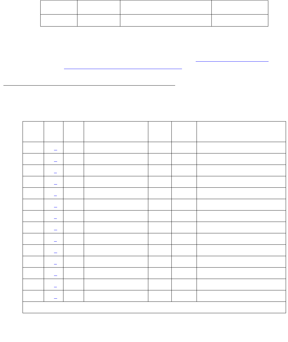
SNC-LINK (Switch Node Clock Link)
Issue 1 June 2005 2039
SNC-LINK (Switch Node Clock Link)
S8700 MC
The SNC-LINK MO reports errors in communications between the active Switch Node Clock
and Switch Node Interfaces over the serial channel (Aux Data 1) and the TPN link (Aux Data 2).
SNC-LINK errors are described on the following pages. For a complete description of SNCs and
SNIs, including circuit pack replacement instructions, see MOs SNI-BD (SNI Circuit Pack) on
page 2046 and SNC-BD (Switch Node Clock Circuit Pack) on page 2000.
Error Log Entries and Test to Clear Values
MO Name Alarm Level Initial SAT Command to Run Full Name of MO
SNC-LINK MIN test board location sSNC Link
Table 745: SNC-LINK Hardware Error Log Entries
Error
Type
Aux
Data
SNI
Slot1
Associated Test Alarm
Level
On/Off
Board
Test to Clear Value
00 (a)Any AnyAnytest board location r 1
11 (b) 2 Failure audit (#777) MIN OFF test board location r 1
12 (c) 2 Failure audit (#777) MIN OFF test board location r 1
257 1 (b) 3 Failure audit (#777) MIN OFF test board location r 1
257 2 (c) 3 Failure audit (#777) MIN OFF test board location r 1
513 1 (b) 4 Failure audit (#777) MIN OFF test board location r 1
513 2 (c) 4 Failure audit (#777) MIN OFF test board location r 1
769 1 (b) 5 Failure audit (#777) MIN OFF test board location r 1
769 2 (c) 5 Failure audit (#777) MIN OFF test board location r 1
1025 1 (b) 6 Failure audit (#777) MIN OFF test board location r 1
1025 2 (c) 6 Failure audit (#777) MIN OFF test board location r 1
1281 1 (b) 7 Failure audit (#777) MIN OFF test board location r 1
1281 2 (c) 7 Failure audit (#777) MIN OFF test board location r 1
1537 1 (b) 8 Failure audit (#777) MIN OFF test board location r 1
1 of 2
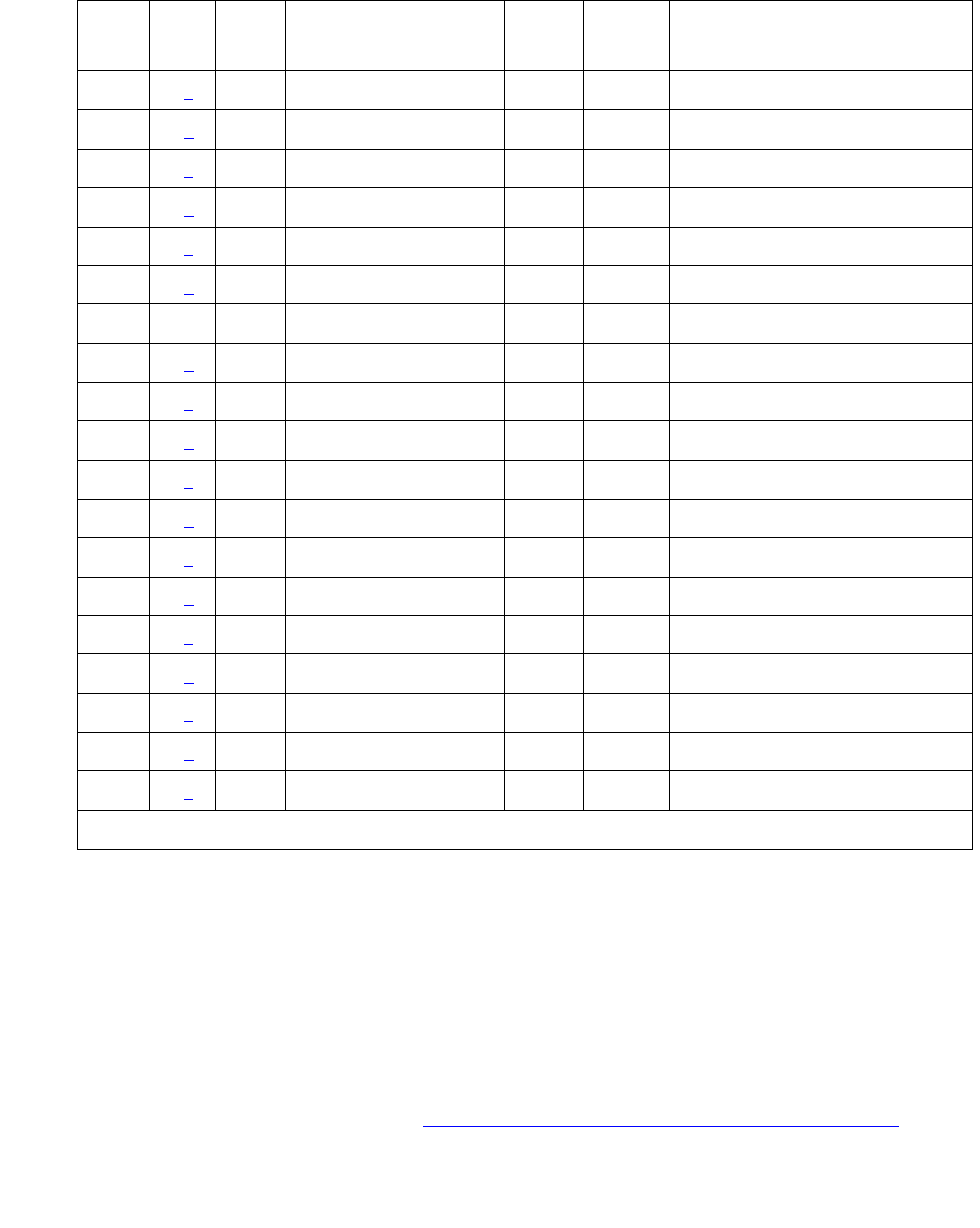
Communication Manager Maintenance-Object Repair Procedures
2040 Maintenance Procedures for Avaya Communication Manager 3.0, Media Gateways and Servers
Notes:
a. Error Type 0: run the short test sequence first. If every test passes, run the long test
sequence. Refer to each appropriate test’s description, and follow its recommended
procedures.
b. This error occurs when the active SNC determines that there is a problem communicating
with an SNI circuit pack in the same carrier via the connecting multiprocessor serial channel
used for transmitting CSCN messages. The slot location of the SNI with which the SNC
cannot communicate is given in Table 745: SNC-LINK Hardware Error Log Entries on
page 2039.
1537 2 (c) 8 Failure audit (#777) MIN OFF test board location r 1
1793 1 (b) 9 Failure audit (#777) MIN OFF test board location r 1
1793 2 (c) 9 Failure audit (#777) MIN OFF test board location r 1
2049 1 (b) 13 Failure audit (#777) MIN OFF test board location r 1
2049 2 (c) 13 Failure audit (#777) MIN OFF test board location r 1
2305 1 (b) 14 Failure audit (#777) MIN OFF test board location r 1
2305 2 (c) 14 Failure audit (#777) MIN OFF test board location r 1
2561 1 (b) 15 Failure audit (#777) MIN OFF test board location r 1
2561 2 (c) 15 Failure audit (#777) MIN OFF test board location r 1
2817 1 (b) 16 Failure audit (#777) MIN OFF test board location r 1
2817 2 (c) 16 Failure audit (#777) MIN OFF test board location r 1
3073 1 (b) 17 Failure audit (#777) MIN OFF test board location r 1
3073 2 (c) 17 Failure audit (#777) MIN OFF test board location r 1
3329 1 (b) 18 Failure audit (#777) MIN OFF test board location r 1
3329 2 (c) 18 Failure audit (#777) MIN OFF test board location r 1
3585 1 (b) 19 Failure audit (#777) MIN OFF test board location r 1
3585 2 (c) 19 Failure audit (#777) MIN OFF test board location r 1
3841 1 (b) 20 Failure audit (#777) MIN OFF test board location r 1
3841 2 (c) 20 Failure audit (#777) MIN OFF test board location r 1
1. The location of the SNI with which the SNC cannot communicate.
Table 745: SNC-LINK Hardware Error Log Entries (continued)
Error
Type
Aux
Data
SNI
Slot1
Associated Test Alarm
Level
On/Off
Board
Test to Clear Value
2 of 2

SNC-LINK (Switch Node Clock Link)
Issue 1 June 2005 2041
1. Use display errors to check the error log.
2. If a SNI-PEER error exists in the hardware error log, follow the repair procedures for
SNI-PEER errors.
3. If the SNC has SNC-LINK errors with Aux Data of 1 against other SNIs and/or has
SNC-BD error 513, replace the SNC circuit pack.
4. If SNIs in the same carrier have SNI-BD error 257 logged indicating they are having
trouble communicating with the SNC, replace the SNC circuit pack.
5. Use list configuration carrier to determine whether an SNI is physically
present in the slot pointed to by the SNC-LINK error.
●If the Vintage field indicates that a circuit pack is present, proceed to step 6.
●If the Vintage field shows no board:
If an SNI is not supposed to be installed in this slot:
- Remove the SNI from circuit pack administration with change circuit-pack.
- If the error remains, re-administer the SNI circuit pack and then remove it from
administration again.
- If the error still remains, replace the active SNC circuit pack.
If an SNI should be installed in this slot, but is missing, insert an SNI circuit pack.
6. Replace the SNI that the SNC is complaining about.
7. Retry the command. If this error is still in the error log:
8. Replace the SNC circuit pack.
9. If a standby SNC (the one with its yellow LED off) has this error, escalate the problem.
Use status switch-node to show the active and standby SNCs.
c. This error occurs when the active SNC determines that there is a problem communicating
with an SNI circuit pack in the same carrier via the TPN communication channel. The slot
location of the SNI with which the SNC cannot communicate is given in
Table 745: SNC-LINK Hardware Error Log Entries on page 2039.
1. Use display errors to check the error log. If more than one SNI in the same carrier
have SNI-BD errors with Error Type 769, replace the SNC.
2. Use display errors to check the error log. If the SNC has more than one SNC-LINK
error with Aux Data of 2, replace the SNC.
3. Verify that the SNI the SNC is complaining about exists in the slot indicated by the error
code. If the SNI does not exist:
If you do not intend to replace the SNI:
a. Use change circuit-pack to remove the SNI from circuit pack administration.
b. If the error remains, re-administer the SNI circuit pack and then remove it from
administration again.
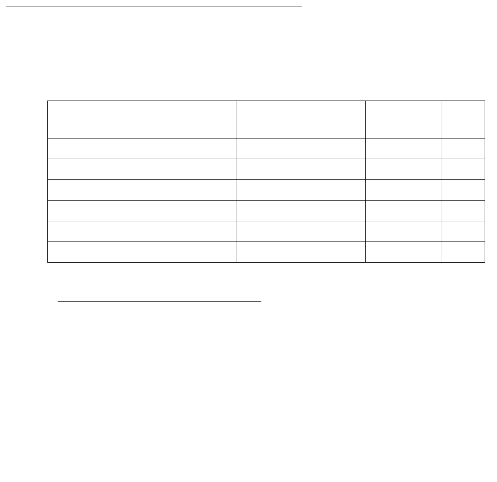
Communication Manager Maintenance-Object Repair Procedures
2042 Maintenance Procedures for Avaya Communication Manager 3.0, Media Gateways and Servers
c. If the problem persists, replace the active SNC circuit pack.
Otherwise:
d. Insert an SNI circuit pack.
4. Replace the SNI circuit pack that the SNC is complaining about.
5. Retry the command. If this error is still in the error log, replace the SNC circuit pack.
6. If a standby SNC (the one with its yellow LED off) has this error, escalate the problem.
Use status switch-node to show the active and standby SNCs.
7. Retry the command. If this error is still in the error log, escalate the problem.
System Technician-Demanded Tests:
Descriptions and Error Codes
Investigate tests in the order presented below. Clearing error codes associated with the one test
may also clear errors generated from other tests in the sequence.
See SNC-BD (Switch Node Clock Circuit Pack) on page 2000 for descriptions of tests and
results.
Order of Investigation Short Test
Sequence
Long Test
Sequence
Reset Board
Sequence
D/ND1
1. D = Destructive, ND = Nondestructive
Configuration audit (#759) X X ND
Failure audit (#777) X X ND
Processor Route audit (#760) X ND
SNC On-Board test (#778) X X ND
TPN test (#779) X X ND
Switch Node Clock Reset test (#780) X D

SNC-REF (Switch Node Clock Reference)
Issue 1 June 2005 2043
SNC-REF (Switch Node Clock Reference)
S8700 MC
The SNC-REF MO reports errors in SNI reference signals detected by the active Switch Node
Clock. Descriptions of SNC-REF errors appear on the following pages. For a complete
description of SNCs and SNIs, including circuit pack replacement instructions, see MOs SNI-BD
(SNI Circuit Pack) on page 2046 and SNC-BD (Switch Node Clock Circuit Pack) on page 2000.
Error Log Entries and Test to Clear Value
MO Name Alarm Level Initial SAT Command to Run Full Name of MO
SNC-REF MAJ test board location sSNC Reference
Table 746: SNC Reference Error Log Entries
Error
Type
Aux
Data
SNI
Slot1
Associated Test Alarm
Level
On/Off
Board
Test to Clear Value
0 (a)0 Any AnyAnytest board location r 1
1 (b) Any 2 Failure audit (#777) MAJ OFF test board location r 1
257 (b) Any 3 Failure audit (#777) MAJ OFF test board location r 1
513 (b) Any 4 Failure audit (#777) MAJ OFF test board location r 1
769 (b) Any 5 Failure audit (#777) MAJ OFF test board location r 1
1025 (b) Any 6 Failure audit (#777) MAJ OFF test board location r 1
1281 (b) Any 7 Failure audit (#777) MAJ OFF test board location r 1
1537 (b) Any 8 Failure audit (#777) MAJ OFF test board location r 1
1793 (b) Any 9 Failure audit (#777) MAJ OFF test board location r 1
2049 (b) Any 13 Failure audit (#777) MAJ OFF test board location r 1
2305 (b) Any 14 Failure audit (#777) MAJ OFF test board location r 1
2561 (b) Any 15 Failure audit (#777) MAJ OFF test board location r 1
2817 (b) Any 16 Failure audit (#777) MAJ OFF test board location r 1
3073 (b) Any 17 Failure audit (#777) MAJ OFF test board location r 1
3329 (b) Any 18 Failure audit (#777) MAJ OFF test board location r 1
1 of 2

Communication Manager Maintenance-Object Repair Procedures
2044 Maintenance Procedures for Avaya Communication Manager 3.0, Media Gateways and Servers
Notes:
a. Error Type 0: run the short test sequence first. If every test passes, run the long test
sequence. Refer to each appropriate test’s description, and follow its recommended
procedures.
b. This error occurs when the active or standby SNC detects problems in its timing reference
with an SNI circuit pack in the same carrier. The slot location of the SNI with which the SNC
cannot communicate is given in the previous error table.
If duplicated SNCs exist in the carrier:
1. If the SNCs are duplicated in the carrier, use display errors to check the error log. If
both SNCs have this error, replace the SNI that the SNCs are complaining about.
2. If the error occurred only on the standby SNC and the active SNC in the carrier does not
have this error, use reset board to reset the standby SNC. Use status
switch-node to show the active and standby SNCs. If the error returns after the
standby has been reset, replace the standby SNC.
3. Retry the command. If this error is still in the error log, continue with the following steps.
4. If the active SNC has this error, use set switch-node-clock to set the standby SNC
to active. If the new active SNC has this error, replace the SNI that the SNC is
complaining about. Otherwise, replace the SNC that originally had this error.
If only one SNC exists in the carrier:
1. Replace the SNI that the SNC is complaining about.
2. Retry the command. If this error is still in the error log, continue with the following step.
3. Replace the SNC.
3585 (b) Any 19 Failure audit (#777) MAJ OFF test board location r 1
3841 (b) Any 20 Failure audit (#777) MAJ OFF test board location r 1
1. The slot location of the SNI with which the SNC cannot communicate.
Table 746: SNC Reference Error Log Entries (continued)
Error
Type
Aux
Data
SNI
Slot1
Associated Test Alarm
Level
On/Off
Board
Test to Clear Value
2 of 2

SNC-REF (Switch Node Clock Reference)
Issue 1 June 2005 2045
System Technician-Demanded Tests:
Descriptions and Error Codes
Investigate tests in the order presented below. Clearing error codes associated with the one test
may also clear errors generated from other tests in the sequence.
See SNC-BD (Switch Node Clock Circuit Pack) on page 2000 for descriptions of tests and
results.
Order of Investigation Short Test
Sequence
Long Test
Sequence
Reset Board
Sequence
D/ND1
1. D = Destructive, ND = Nondestructive
Configuration audit (#759) X X ND
Failure audit (#777) X X ND
Processor Route audit (#760) X ND
SNC On-Board test (#778) X X ND
TPN test (#779) X X ND
Switch Node Clock Reset test (#780) X D

Communication Manager Maintenance-Object Repair Procedures
2046 Maintenance Procedures for Avaya Communication Manager 3.0, Media Gateways and Servers
SNI-BD (SNI Circuit Pack)
S8700 MC
The TN573 Switch Node Interface (SNI) circuit pack is part of the Center Stage Switch (CSS)
configuration. It resides in a switch node carrier that alone or with other switch nodes make up a
CSS. SNIs connect to other SNIs or Expansion Interface (EI) circuit packs via fiber links.
SNI-to-EI fiber links are used to connect port networks to a switch node carrier and SNI-to-SNI
fiber links are used as inter-switch node fibers. In critical-reliability systems, the fiber link
connections are duplicated as part of port-network connectivity (PNC) duplication. In standard-
and high-reliability systems, the PNC is not duplicated.
There may be up to 16 SNIs in a switch node carrier. They are located in slots 2 through 9 and
slots 13 through 20. Slot 11 in a switch node carrier is not used. One or two TN572 boards
(SNCs) must reside in switch node carrier positions 10 and 12. The SNIs connect to other SNIs
in the same carrier via the backplane; these connections within the same carrier are referred to
as peer-links. Each SNI also connects via an optical fiber or metallic connection to another SNI
in another carrier or to an EI in a port network (PN). These connections are referred to as fiber
links.
The Switch Node Clock (SNC) provides timing for the SNIs in the entire carrier. When two SNCs
reside in the same switch node carrier, one is in active mode and one is in standby mode. The
yellow LED on the active SNC will be on solid. The yellow LED on the standby SNC will be off.
See SYNC (Port-Network Synchronization) on page 2143 for an explanation of how SNIs are
involved in timing synchronization.
Figure 118: CSS Configuration with Unduplicated PNC and 1 Switch Node Carrier on
page 2047 shows an unduplicated CSS with one switch node. A single switch node can
accommodate up to 16 port networks. A system with two switch nodes can accommodate up to
22 port networks. Figure 119: CSS Configuration with Duplicated PNC and 4 Switch Node
Carriers on page 2048 shows a two-switch node CSS with duplicated PNC (four switch node
carriers). In this configuration, each PNC (A and B) contains two switch nodes. The cabinet
numbers for the switch node carriers are typical cabinet numbers. The PNs on the top half of the
figure (PNC A) are the same as the PNs on the bottom half of the figure (PNC B).
MO Name Alarm Level Initial SAT Command to Run Full Name of MO
SNI-BD MAJ test board location sSNI Circuit Pack
SNI-BD MIN test board location sSNI Circuit Pack
SNI-BD WRN test board location sSNI Circuit Pack

SNI-BD (SNI Circuit Pack)
Issue 1 June 2005 2047
Figure 118: CSS Configuration with Unduplicated PNC and 1 Switch Node Carrier
TN Numbers:
SNI - TN573
SNC - TN572
EI - TN570
not
used
...
.
.
.
...
.
.
.
...
.
.
.
...
.
.
.
...
.
.
.
.
.
.
.
.
.
.
.
.
.
.
.
.
.
.
.
.
. . . . . . . . . . . . . . . . . . . .
.
.
.
.
.
.
.
.
.
.
.
.
.
.
.
.
.
.
. . . . . . . . . . . . . . . .
. . . . . . . . . . . .
.
.
.
.
.
.
.
. .
.
.
.
.
.
.
.
.
.
.
links
fiber
slot number 19
I
N
S
I
N
S
I
N
S
I
N
S
I
N
S
I
N
S
I
N
S
I
N
S
I
N
S
I
N
S
I
N
S
I
N
S
I
N
S
I
N
S
I
N
S
I
N
S
C
N
S
C
N
S
* * *
* = An EI or a DS1C circuit pack may reside in this slot
** = A DS1C circuit pack may reside in this slot
1 2 3 4 5 6 7 8 9 10 11 12 13 14 15 16 17 18 20
EPN
EI
EPN
EI
EPN
EI
EPN
EI
EPN
EI
EPN
EI
EPN
EI
EPN
EI
EPN
EI
EPN
EI
EPN
EI
EPN
EI
EPN
EI
EPN
EI EPN
EI
21
PPN
EI
carrier
. . .
. . . . . . .
.
.
.
.
.
node
switch
links
peer
. . . . . . . . . . . . . . . . . . . . . . . . . . . . . . . . . . . . . . . . . . . . . . . . . . . . . . . . . . . . . . . . . . . . .
.
.
.
.
.
.
.
.
.
.
.
.
.
.
.
. .
.
....
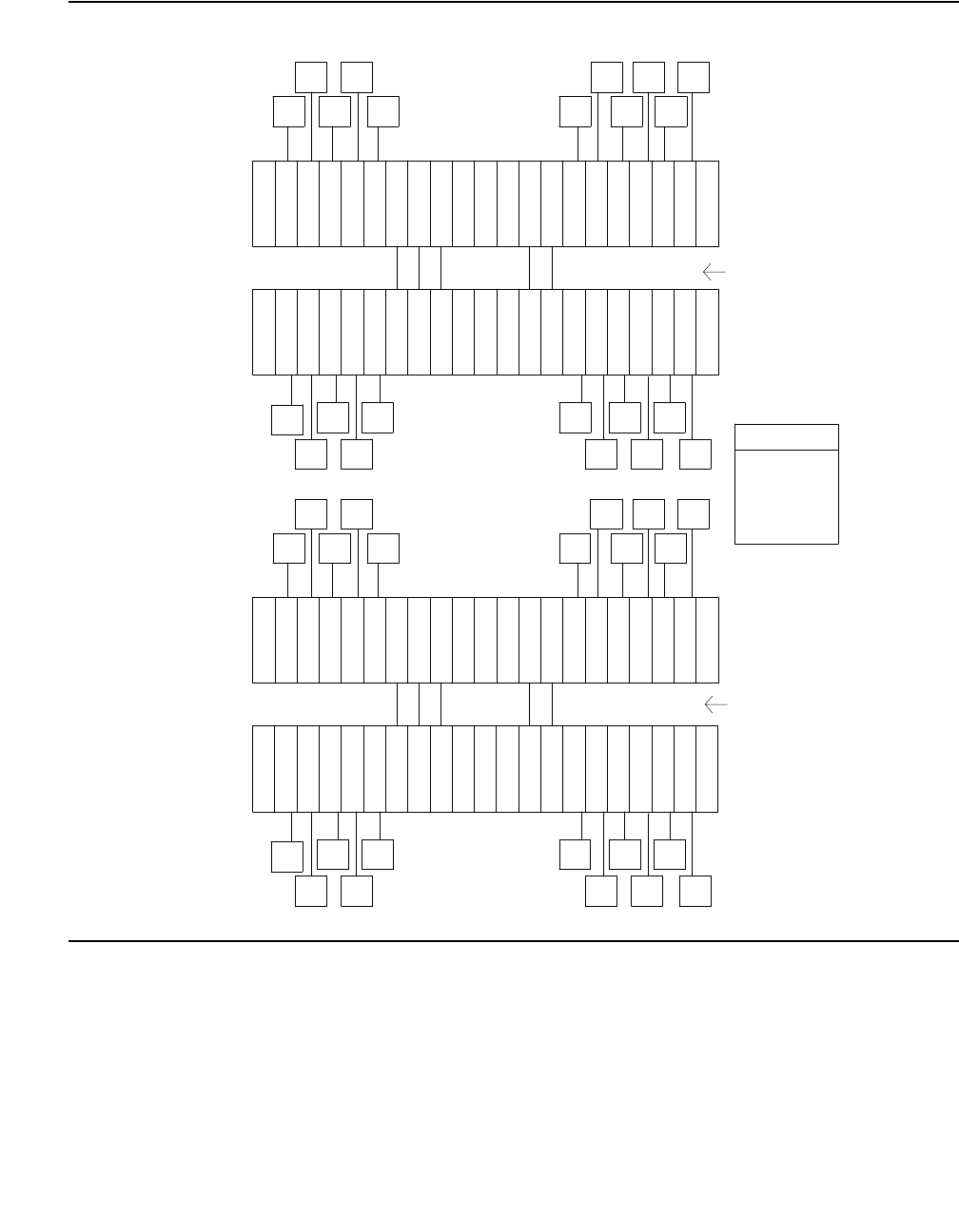
Communication Manager Maintenance-Object Repair Procedures
2048 Maintenance Procedures for Avaya Communication Manager 3.0, Media Gateways and Servers
Figure 119: CSS Configuration with Duplicated PNC and 4 Switch Node Carriers
D
D
2
1 2 3 4 5 6 7 8 9 10 11 12 13 14 15 16 17 18 20 21
carrier
node
switch
slot number 19
I
N
S
I
N
S
I
N
S
I
N
S
I
N
S
I
N
S
I
N
S
I
N
S
I
N
S
I
N
S
I
N
S
I
N
S
I
N
S
I
N
S
I
N
S
I
N
S
EI
PPN
EI
EPN
EI
EI EI EI
EI EI EI EI
EPN EPN
EPN EPN EPN
EPN EPN EPN
EI
EPN
EI
EPN EI
EI
EPN
EPN
EI
EI EI EI
EI EI EI
EI
EPN
EPN EPN EPN
EPN EPN EPN
EPN
EPN
EPN EPN EPN
EPN EPN EPN
EPN
EI
EI EI EI
EI EI EI
EI
EPN
EPN
EI
EI
EPN
EI
EPN
EI
EPN EPN EPN
EPN EPN EPN
EPN EPN
EI EI EI EI
EI EI EI
EI
EPN
EI
PPN
EI
I
N
S
I
N
S
I
N
S
I
N
S
I
N
S
I
N
S
I
N
S
I
N
S
I
N
S
I
N
S
I
N
S
I
N
S
I
N
S
I
N
S
I
N
S
I
N
S
19 slot number
switch
node
carrier
21 20 18 17 16 15 14 13 12 11 10 9 8 7 6 5 4 3 2 1
2 E C
N
S
C
N
S
EC
N
S
C
N
S
I
N
S
I
N
S
I
N
S
I
N
S
I
N
S
I
N
S
I
N
S
I
N
S
I
N
S
I
N
S
I
N
S
I
N
S
I
N
S
I
N
S
I
N
S
I
N
S
19 slot number 21 20 18 17 16 15 14 13 12 11 10 9 8 7 6 5 4 3 2 1
switch
node
carrier
1
PNC A
fibers
node
inter-switch
fibers
node
inter-switch
PNC B
EI - TN570
SNC - TN572
SNI - TN573
TN numbers:
1
carrier
node
switch
19 slot number 21 20 18 17 16 15 14 13 12 11 10 9 8 7 6 5 4 3 2 1
I
N
S
I
N
S
I
N
S
I
N
S
I
N
S
I
N
S
I
N
S
I
N
S
I
N
S
I
N
S
I
N
S
I
N
S
I
N
S
I
N
S
I
N
S
I
N
S
C
N
S
C
N
S
C
N
S
C
N
S
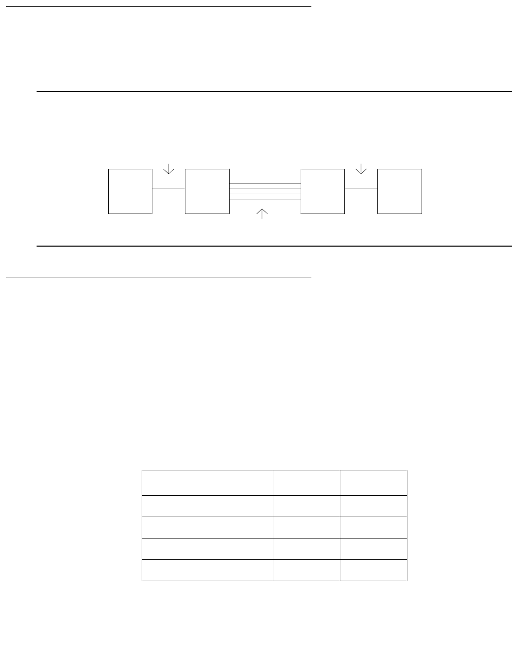
SNI-BD (SNI Circuit Pack)
Issue 1 June 2005 2049
Remote PNs
A DS1 converter complex can used to provide connectivity to a remotely located port network.
The DS1 converter complex consists of two TN574 DS1 converter (DS1C) circuit packs
connected by 1 to 4 DS1 facilities. The DS1C complex is administered as a fiber link.
Figure 120: Fiber Link over a DS1 Converter Complex
SNI LEDs
The SNI circuit pack has red, green, and yellow LEDs. The red and green LEDs have the usual
meaning, with red signifying an on-board alarm, and green signifying maintenance testing in
progress. The red and green LEDs will come on and then turn off when the circuit pack is reset.
Note:
Note: If the red LED is on without any alarms active against the circuit pack, replace the
SNI circuit pack. This indicates that SNI firmware has detected a fault and is
unable to notify software.
The yellow LED indicates status information:
metallic connection
or
optical fiber
metallic connection
or
optical fiber
1 to 4 DS1 Facilities
TN570 TN574 TN574 TN573
SNI DS1C DS1C EI
Table 747: SNI Yellow LED states
Condition LED on LED off
Fiber out of Frame 0.1 second 0.1 second
In frame, No Neighbor 1
1. The fiber is in frame but a communication problem
exists to the neighbor.
0.5 second 0.5 second
SNI active solid on never off
SNI standby never on solid off

Communication Manager Maintenance-Object Repair Procedures
2050 Maintenance Procedures for Avaya Communication Manager 3.0, Media Gateways and Servers
SNI Administration and SNI Board Insertion
The circuit packs in the switch node carrier will not function properly unless administration is
performed first. For example, without fiber link administration, phone calls cannot be made
through the CSS, CSS circuit packs will not be inserted, and maintenance software cannot test
the CSS circuit packs.
For an unduplicated PNC configuration, perform the following administration, in this order,
before inserting SNIs:
1. Cabinet Administration: administer the switch node carriers into the proper cabinets. When
the screen is submitted, switch node numbers are assigned to the carriers. Use list
cabinet to see the switch node numbers for the carriers.
2. Circuit Pack Administration: Every board in the switch node carriers must be administered.
3. Fiber-Link Administration: Use add fiber-link to administer the fibers between the
TN570s and the TN573 (or TN573 to TN573), and to add a DS1C converter complex to a
fiber link.
For a duplicated PNC configuration, perform the following administration, in this order, before
inserting SNIs:
1. Obtain a License File to activate PNC duplication.
2. Cabinet Administration: Administer the switch node carriers and duplicate switch node
carriers into the proper cabinets. When this screen is submitted, switch node numbers are
assigned to the carriers. Use list cabinet to see the switch node numbers for the
carriers.
3. Circuit Pack Administration: Every board in the switch node carriers must be administered.
4. Fiber-Link Administration: Use add fiber-link to administer the fibers between the
TN570s and the TN573 (or TN573 to TN573), and to add a DS1C converter complex to a
fiber link. If the system is being changed from an unduplicated to a duplicated PNC
configuration, use change fiber-link to administer the b-pnc fiber-link endpoints on the
existing fiber links.
5. Use change system-parameters duplication to administer PNC duplication.

SNI-BD (SNI Circuit Pack)
Issue 1 June 2005 2051
Clear Firmware-Counters Command
SNI firmware generates error reports autonomously. This takes place independently of
technician-demanded tests. Therefore, test board location clear does not affect the error
status reported by firmware. The clear firmware-counters command clears every
firmware-generated error unconditionally.
The clear firmware-counters location command sends a downlink message to the
SNI circuit packs, causing them to clear out their firmware error counters and failure databases.
Once the firmware failure database is cleared, the failure audit test (#777) will pass. If problems
still exist, the firmware will increment its error counters and the failure audit test will begin failing
again.
Do not use this command instead of the repair procedures associated with the hardware error
log entries. This command may be useful if a problem was fixed and off-board alarms
associated with the problem are still active.
Replacing SNI Circuit Pack—Unduplicated PNC
!WARNING:
WARNING: Do not power down a Switch Node carrier to replace a circuit pack.
!WARNING:
WARNING: Replacing a Switch Node Interface circuit pack on an unduplicated PNC disrupts
service. This service effect can cause an outage of a single PN.
To replace a Switch Node Interface circuit pack in an unduplicated PNC:
1. Enter busyout board location.
2. Replace the circuit pack.
3. Wait for the circuit pack to reset.
Red and green LEDs will light and then go out.
4. Enter release board location.
!CAUTION:
CAUTION: Do not busyout any Expansion Interface circuit pack after this point.
5. Enter test alarms long clear for category exp-intf.
6. Wait 5 minutes for SNI-BD, FIBER-LK, and DS1C-BD alarms to clear, or enter clear
firmware-counters a-pnc.

Communication Manager Maintenance-Object Repair Procedures
2052 Maintenance Procedures for Avaya Communication Manager 3.0, Media Gateways and Servers
Replacing an SNI Circuit Pack— Duplicated PNC
!WARNING:
WARNING: On a system with duplicated PNC synchronization may be provided over a
combination of active and standby components. This condition is indicated by an
OFF-BOARD WRN alarm against TDM-CLK with Error Type 2305. Repairs to
standby PNC in this state may disrupt service. If the active PNC is functional,
replacement of a standby component does not disrupt service.
To replace a Switch Node Interface circuit pack in an duplicated PNC:
1. Enter status pnc.
Verify that the component to be replaced is on the standby PNC.
2. Enter busyout pnc.
3. Enter busyout board location.
4. Replace the circuit pack.
5. Enter release board location.
!CAUTION:
CAUTION: Do not busyout any Expansion Interface circuit pack after this point.
6. Enter test alarms long clear for category exp-intf.
7. Wait 5 minutes for SNI-BD, SNI-PEER, FIBER-LK, and DS1C alarms to clear, or enter
clear firmware-counters sp 0 a-pnc | b-pnc.
Use the letter designation of the pnc which holds the replaced component (the standby
pnc).
8. Enter status pnc.
If either PNC’s state of health is not “functional”, consult PNC-DUP (PNC Duplication) on
page 1851.
9. Enter release pnc.

SNI-BD (SNI Circuit Pack)
Issue 1 June 2005 2053
Switch Node Interface Manual Loop Back
Procedure
This procedure is destructive.
Use this procedure when an SNI circuit pack cannot be tested by software. This can occur when
communication between the switch node carrier and the server is down. Before using this
procedure, use test board location s to run the configuration audit test (#759) on SNI
circuit packs where possible. Also, use test board location long to run the processor
route audit test (#760) for the active SNC in the switch node carrier. If the active SNC is not
inserted, use test hardware-group pnc P, where P is a-pnc or b-pnc to run test 760.
Before using this procedure, determine if more than one SNI is unable to communicate with
software. Verify SNI and SNC circuit pack insertion using the list configuration
carrier location where location is the cabinet and carrier location of a switch node
carrier. Check for inserted SNIs and SNCs in every administered switch node carrier.
If every SNI and SNC is not inserted, then “NO BOARD” is displayed for each board in the
entire PNC (either the a-pnc or the b-pnc). The link between the IPSI connected PN’s EI (on the
PNC where SNI and SNC circuit packs were not inserted) and the connected SNI does not
function properly. If this applies:
1. Run test board location on the IPSI connected PN’s EI, and fix any problems.
2. Perform the manual loopback procedure for the IPSI connected PN’s EI.
3. Perform the manual loopback procedure for the SNI connected to the IPSI connected PN’s
EI.
4. Replace the active SNC.
If the system has a 2-level switch node carrier configuration (i.e., SNI-to-SNI fiber links exist)
and the SNIs and SNCs in the second switch node carrier only (the switch node carrier that has
no SNI connected to the IPSI connected PN’s EI) are not inserted and at least two SNI-to-SNI
fiber links exist:
1. Run test board location long on the SNIs in the first switch node carrier that are
connected to SNIs in the second switch node carrier and fix any problems.
2. Replace the active SNC.
3. Perform the manual loopback procedure for the SNIs in the second switch node carrier that
are connected to SNIs in the first switch node carrier.
If software is unable to communicate with a PN’s EI but can communicate with the connected
SNI:
1. Run test board location long on the connected SNI and fix any problems.
2. Perform the manual loopback procedure for the PN EI.
If the connection to the SNI circuit pack is fiber, a short length of optical fiber is required for
this procedure. If a metallic cable is used in the connection, remove the metallic connector
from the back of the carrier, and install a lightwave transceiver in its place. The short length
of optical fiber can then be used.

Communication Manager Maintenance-Object Repair Procedures
2054 Maintenance Procedures for Avaya Communication Manager 3.0, Media Gateways and Servers
If this procedure is run on both endpoints on a fiber link (Expansion Interface circuit packs or
Switch Node Interface circuit packs), and both check out fine, then the failure is most likely
in the connection (fiber or metallic) itself if neither endpoint circuit pack is busied out, but the
link remains inactive.
1. Use busyout board location to busyout the circuit pack (Expansion Interface or
SNI).
2. Disconnect the transmit and receive fiber pair from the lightwave transceiver on the back
of the circuit pack (Expansion Interface or Switch Node Interface) slot.
Note:
Note: Note which is the transmit fiber and which is the receive fiber for proper
re-connection at the end of this procedure. The fiber connected to the transmit
side of the lightwave transceiver on one circuit pack should be connected to the
receive side of the lightwave transceiver on the circuit pack on the opposite end
of the fiber.
3. Using a spare fiber jumper cable, interconnect the transmit and receive jacks of the
lightwave transceiver as shown in Figure 121: Interconnection of Lightwave Transceiver
Transmit/Receive Jacks on page 2055.
Note:
Note: Make sure that the total length of the fiber jumper cable does not exceed the
maximum length recommended for the fiber link connections between cabinets.
Test the Expansion Interface or SNI circuit pack within connectivity guidelines so
that test results are not influenced due to improper cable length.
4. Go to the front of the cabinet and inspect the yellow LED.
●If the yellow LED flashes on at a rate of once per second, the Expansion Interface or
Switch Node Interface circuit pack or transceiver should be replaced.
●If the yellow LED flashes on at a rate of five times per second, the circuit pack
(Expansion Interface or Switch Node Interface) or the lightwave transceiver may need
replacement. This may also be due to a faulty system clock on the network containing
the Expansion Interface circuit pack or in the switch node carrier containing the SNI.
●If the yellow LED was blinking before starting this procedure and the yellow LED is not
blinking now, this circuit pack (Expansion Interface or Switch Node Interface) and the
lightwave transceiver are functioning properly.
5. Replace faulty component(s) and reconnect the original fiber. Be sure to reconnect the
fibers properly as noted in Step 2.
6. Use release board location to release the Expansion Interface circuit pack or
Switch Node Interface circuit pack.

SNI-BD (SNI Circuit Pack)
Issue 1 June 2005 2055
Figure 121: Interconnection of Lightwave Transceiver Transmit/Receive Jacks
Error Log Entries and Test to Clear Values
Fiber Jumper
Tx Rx
Transceiver
Lightwave
Back Skin of Cabinet
Table 748: SNI Board Error Log Entries
Error
Type
Aux
Data
Associated Test Alarm
Level
On/Off
Board
Test to Clear Value
0 (a) 0 Any Any Any test board location r 1
1 (b) Any Failure audit (#777)
(c)
MAJ
MIN
WRN
ON test board location r 1
18 (d)0 busyout board
location
WRN OFF release board location
1 of 2

Communication Manager Maintenance-Object Repair Procedures
2056 Maintenance Procedures for Avaya Communication Manager 3.0, Media Gateways and Servers
Notes:
a. Error Type 0: run the short test sequence first. If every test passes, run the long test
sequence. Refer to each test’s description, and follow its procedures.
b. Error Type 1: the SNI may have trouble communicating with every other SNI and SNC
circuit pack in the switch node carrier.
1. Replace the SNI circuit pack.
c. Failure audit (#777):The first time you see an SNI-BD error in the error log, run test
board location. If the failure audit test (#777) fails, enter display errors for this SNI
circuit pack and continue with the repair procedures for SNI-BD errors.
125 (e)None MINON
257 (f) Any Failure audit (#777)
(c)
MAJ
MIN
WRN
OFF test board location r 1
513 (g) Any Failure audit (#777)
(c)
MAJ
MIN
WRN
OFF test board location r 1
769 (h) Any Failure audit (#777)
(c)
MAJ
MIN
WRN
OFF test board location r 1
1025 (i) Any Failure audit (#777)
(c)
MAJ
MIN
WRN
ON/ OFF test board location r 1
1281 (j) Any Failure audit (#777)
(c)
MAJ
MIN
WRN
ON test board location r 1
1537 (k) Any Failure audit (#777)
(c)
MAJ
MIN
WRN
OFF test board location r 1
2561 (l) Any Failure audit (#777)
(c)
MAJ
MIN
WRN
ON test board location r 1
2817 (m) Any Failure audit (#777)
(c)
MAJ
MIN
WRN
ON test board location r 1
Table 748: SNI Board Error Log Entries (continued)
Error
Type
Aux
Data
Associated Test Alarm
Level
On/Off
Board
Test to Clear Value
2 of 2

SNI-BD (SNI Circuit Pack)
Issue 1 June 2005 2057
d. Error Type 18: the SNI circuit pack was busied out using busyout board location. To
resolve this error, use release board location to release the SNI circuit pack.
e. Error Type 125: the SNI circuit pack is incompatible with the TN1654 DS1 Converter board.
A TN573B or higher suffix SNI board must be used when connecting to a TN1654 DS1
Converter board.
1. Replace the SNI circuit pack with a newer suffix.
f. Error Type 257: the SNI cannot communicate with the active SNC.
1. Use display errors to check the error log for other SNI circuit packs with the 257
SNI-BD error. If other SNI circuit packs in the same switch node carrier have error 257,
replace the active SNC.
2. Replace this SNI.
3. Replace the active SNC in the same switch node carrier.
4. Enter display errors. If this error is still in the error log, follow normal escalation
procedures.
g. Error Type 513: the SNI cannot communicate with the DS1-C.
1. Perform the Fiber link fault isolation procedure in Maintenance Procedures (03-300192).
h. Error Type 769: failure communicating synchronization control data with the active SNC.
1. Look at every SNI-BD error in the log using display errors and display alarms to
determine whether to follow Procedure 1 on page 2057 or Procedure 2 on page 2058.
Use the table below that lists pairs of adjacent SNIs:
Use Procedure 2 if either of the following two conditions is present:
●At least one pair of adjacent SNIs in this carrier has Error Type769 with an off-board
alarm logged against both SNIs in the pair.
●The active SNC in this carrier has Error Type 257.
If neither of the above is true, follow Procedure 1.
Procedure 1
Suspect TPN link or clock generation out-of-lock problem:
Adjacent SNI
Slot Numbers
Adjacent SNI
Slot Numbers
2 & 3 13 & 14
4 & 5 15 & 16
6 & 7 17 & 18
8 & 9 19 & 20

Communication Manager Maintenance-Object Repair Procedures
2058 Maintenance Procedures for Avaya Communication Manager 3.0, Media Gateways and Servers
1. Enter display alarms and display errors and follow the procedures for any
on-board SNI-BD error and alarm entries.
2. If more than one SNI circuit pack in the same switch node carrier has SNI-BD error
769 with an off board alarm, replace the active SNC in the same carrier.
3. Replace this SNI.
4. Replace the active SNC in the same carrier.
Procedure 2
Suspect clock generation out-of-lock problem:
5. If only one SNC exists in this switch node carrier, replace the SNC.
6. If two SNCs exist in this switch node carrier, set the standby SNC to active by running
set switch-node-clock location with the standby SNC’s location.
●If the problem goes away, replace the SNC that was previously active. Then use set
switch-node-clock location to set the SNC that was just replaced to active. If
the problem returns, assume that the SNC that was just replaced is not at fault and go
to Step 7.
●If the problem persists, switch back to the previously active SNC using set
switch-node-clock and go to Step 7.
7. Replace the left-most SNI from the pair of adjacent SNIs.
8. Replace the right-most SNI from the pair of adjacent SNIs.
9. If none of the above steps cleared this error, this could be a switch node carrier
backplane problem.
i. Error Type 1025: a failure communicating synchronization control data over the fiber link.
If the error is logged as an ON-BOARD error:
1. Replace the SNI circuit pack.
If the error is logged as an OFF-BOARD error:
1. Enter display errors and follow the repair procedures for FIBER-LK errors.
2. Replace the SNI with this error.
3. Replace the fiber link’s other endpoint if no DS1C complex is administered on the fiber
link. Use list fiber-link to determine if a DS1C complex is administered. If so,
replace the circuit packs in this order:
a. Replace the DS1C circuit pack connected to this SNI.
b. Replace the other DS1C circuit pack.
c. Replace the fiber link’s other endpoint.
j. Error Type 1281: processor complex failure.
1. Replace the SNI circuit pack.

SNI-BD (SNI Circuit Pack)
Issue 1 June 2005 2059
k. Error Type 1537: excessive slips have occurred.
Follow the steps for diagnosing synchronization problems when slips have occurred in
the SYNC section.
l. Error Type 2561: the SNI cannot communicate with its neighbor. The SNI is at fault.
1. Replace the SNI circuit pack.
m. Error Type 2817: the SNI cannot communicate with one of its peers. The SNI is at fault.
1. Replace the SNI circuit pack.
System Technician-Demanded Tests:
Descriptions and Error Codes
Investigate tests in the order presented below. Clearing error codes associated with the one test
may also clear errors generated from other tests in the sequence.
Note:
Note: Test #982 is not an actual demand maintenance test. This test number is used to
report results of clear firmware-counters. Refer to error codes for Test
#777.
Order of Investigation Short Test
Sequence
Long Test
Sequence
Reset Board
Sequence
D/ND1
1. D = Destructive, ND = Nondestructive
Configuration audit (#759) X X ND
Failure audit (#777) X X ND
Fiber Out of Frame query (#989) X X ND
Packet Neighbor test (#767) X X ND
Circuit Path test (#755) X X ND
Destructive Facility test (#757) X D
Off-board Destructive Facility test (#756) X D
Switch Node Interface Reset test (#761) X D

Communication Manager Maintenance-Object Repair Procedures
2060 Maintenance Procedures for Avaya Communication Manager 3.0, Media Gateways and Servers
SNI Circuit Path Test (#755)
This test is nondestructive test of the circuit path.
Table 749: TEST #755 SNI Circuit Path Test
Error
Code
Test
Result
Description / Recommendation
2100 ABRT Could not allocate the necessary system resources to run this test.
1. Retry the command at 1-minute intervals up to 3 times.
2300 ABRT The downlink message necessary to run this test could not be sent.
1. Retry the command at 1-minute intervals up to 3 times.
2301 ABRT The software timer could not be set before sending the downlink message
necessary to run this test.
1. Retry the command at 1-minute intervals up to 3 times.
2302 ABRT Software received incorrect message data from the SNI circuit pack.
1. Retry the command at 1-minute intervals up to 3 times.
2303 ABRT The SNI circuit pack responded that software test requested is not valid.
1. Retry the command at 1-minute intervals up to 3 times.
2304 ABRT SNI circuit pack responded that it is not able to run the test requested by
software.
1. Retry the command at 1-minute intervals up to 3 times.
1 of 11

SNI-BD (SNI Circuit Pack)
Issue 1 June 2005 2061
2306 ABRT The SNI circuit pack is not responding to test requests sent by software.
1. Run test led switch-node for the switch node where the SNI
resides to verify whether the LEDs on the board light.
2. If the LEDs on the other boards in the carrier light, but the LEDs on
this board do not light, run test 760 using test board location l
for the active SNC in this carrier. Wait 5 minutes and then try step 1
one more time. If the LEDs on this board still do not light, replace this
board. Replacing an SNI may be service interrupting. See SNI-BD
(SNI Circuit Pack) on page 2046 for the procedure for replacing an
SNI.
3. If none of the LEDs light for the boards in the same carrier as this
board, fix any problems associated with the connectivity of this carrier
to the server.
a. Check list fiber-link to see the fiber connections to this
carrier.
b. Check the LEDs on every SNI and EI, and fix any fiber problems.
c. Enter display errors, and follow the repair procedures for any
EXP-INTF error entries associated with the controlling IPSI
connected PN.
d. Follow the repair procedures for any SYNC, SNI-BD, SNC-BD,
FIBER-LK, or SNI-PEER error entries.
4. Follow the procedure described above, SNI Manual Loopback to
determine whether the circuit pack or the fiber connection is faulty.
Table 749: TEST #755 SNI Circuit Path Test (continued)
Error
Code
Test
Result
Description / Recommendation
2 of 11

Communication Manager Maintenance-Object Repair Procedures
2062 Maintenance Procedures for Avaya Communication Manager 3.0, Media Gateways and Servers
102 FAIL The SNI circuit pack cannot communicate with the SNI in slot 2 over the
circuit path.
1. Fix any on-board SNI-BD errors against this SNI and the SNI in slot 2.
Use display errors to find any SNI-BD errors and check
display alarms to see if the errors have on-board alarms. Follow
the repair procedures for SNI-BD.
2. Use display errors to check the error log for other SNI circuit
packs with SNI-PEER Error Type 1. If other SNI circuit packs have
SNI-PEER Error Type 1, then replace the SNI in slot 2. Replacing an
SNI may be service interrupting. See SNI-BD (SNI Circuit Pack) on
page 2046 for the procedure for replacing an SNI.
3. If other SNI circuit packs do not have SNI-PEER Error Type 1 errors,
the problem could be at either of the peer SNI boards. It is arbitrary as
to which SNI is replaced first. Proceed as follows:
4. Replace this SNI.
5. Replace the SNI in slot 2.
103 FAIL The SNI circuit pack cannot communicate with the SNI in slot 3 over the
circuit path.
1. Fix any on-board SNI-BD errors against this SNI and the SNI in slot 3.
Use display errors to find any SNI-BD errors and check
display alarms to see if the errors have on-board alarms. Then
follow the repair procedures for SNI-BD.
2. Use display errors to check the error log for other SNI circuit
packs with SNI-PEER Error Type 257. If other SNI circuit packs have
SNI-PEER Error Type 257, then replace the SNI in slot 3. Replacing
an SNI may be service interrupting. See SNI-BD (SNI Circuit Pack) on
page 2046 for the procedure for replacing an SNI.
If other SNI circuit packs do not have SNI-PEER Error Type 257 errors, the
problem could be at either of the peer SNI boards. It is arbitrary as to which
SNI is replaced first.
3. Replace this SNI.
4. Replace the SNI in slot 3.
Table 749: TEST #755 SNI Circuit Path Test (continued)
Error
Code
Test
Result
Description / Recommendation
3 of 11

SNI-BD (SNI Circuit Pack)
Issue 1 June 2005 2063
104 FAIL The SNI circuit pack cannot communicate with the SNI in slot 4 over the
circuit path.
1. Fix any on-board SNI-BD errors against this SNI and the SNI in slot 4.
Use display errors to find any SNI-BD errors and check
display alarms to see if the errors have on-board alarms. Follow
the repair procedures for SNI-BD.
2. Use display errors to check the error log for other SNI circuit
packs with SNI-PEER Error Type 513. If other SNI circuit packs have
SNI-PEER Error Type 513, then replace the SNI in slot 4. Replacing
an SNI may be service interrupting. See SNI-BD (SNI Circuit Pack) on
page 2046 for the procedure for replacing an SNI.
If other SNI circuit packs do not have SNI-PEER Error Type 513 errors, the
problem could be at either of the peer SNI boards. It is arbitrary as to which
SNI is replaced first. Proceed as follows:
3. Replace this SNI.
4. Replace the SNI in slot 4.
105 FAIL The SNI circuit pack cannot communicate with the SNI in slot 5 over the
circuit path.
1. Fix any on-board SNI-BD errors against this SNI and the SNI in slot 5.
Use display errors to find any SNI-BD errors and check
display alarms to see if the errors have on-board alarms. Then
follow the repair procedures for SNI-BD.
2. Use display errors to check the error log for other SNI circuit
packs with SNI-PEER Error Type 769. If other SNI circuit packs have
SNI-PEER Error Type 769, then replace the SNI in slot 5. Replacing
an SNI may be service interrupting. See SNI-BD (SNI Circuit Pack) on
page 2046 for the procedure for replacing an SNI.
If other SNI circuit packs do not have SNI-PEER Error Type 769 errors, the
problem could be at either of the peer SNI boards. It is arbitrary as to which
SNI is replaced first. Proceed as follows:
3. Replace this SNI.
4. Replace the SNI in slot 5.
Table 749: TEST #755 SNI Circuit Path Test (continued)
Error
Code
Test
Result
Description / Recommendation
4 of 11

Communication Manager Maintenance-Object Repair Procedures
2064 Maintenance Procedures for Avaya Communication Manager 3.0, Media Gateways and Servers
106 FAIL The SNI circuit pack cannot communicate with the SNI in slot 6 over the
circuit path.
1. Fix any on-board SNI-BD errors against this SNI and the SNI in slot 6.
Use display errors to find any SNI-BD errors and check
display alarms to see if the errors have on-board alarms. Then
follow the repair procedures for SNI-BD.
2. Use display errors to check the error log for other SNI circuit
packs with SNI-PEER Error Type 1025. If other SNI circuit packs have
SNI-PEER Error Type 1025, then replace the SNI in slot 6. Replacing
an SNI may be service interrupting. See the SNI-BD section for the
procedure for replacing an SNI.
If other SNI circuit packs do not have SNI-PEER Error Type 1025 errors,
the problem could be at either of the peer SNI boards. It is arbitrary as to
which SNI is replaced first. Proceed as follows:
3. Replace this SNI.
4. Replace the SNI in slot 6.
107 FAIL The SNI circuit pack cannot communicate with the SNI in slot 7 over the
circuit path.
1. Fix any on-board SNI-BD errors against this SNI and the SNI in slot 7.
Use display errors to find any SNI-BD errors and check
display alarms to see if the errors have on-board alarms. Then
follow the repair procedures for SNI-BD.
2. Use display errors to check the error log for other SNI circuit
packs with SNI-PEER Error Type 1281. If other SNI circuit packs have
SNI-PEER Error Type 1281, then replace the SNI in slot 7. Replacing
an SNI may be service interrupting. See SNI-BD (SNI Circuit Pack) on
page 2046 for the procedure for replacing an SNI.
If other SNI circuit packs do not have SNI-PEER Error Type 1281 errors,
the problem could be at either of the peer SNI boards. It is arbitrary as to
which SNI is replaced first. Proceed as follows:
3. Replace this SNI.
4. Replace the SNI in slot 7.
Table 749: TEST #755 SNI Circuit Path Test (continued)
Error
Code
Test
Result
Description / Recommendation
5 of 11

SNI-BD (SNI Circuit Pack)
Issue 1 June 2005 2065
108 FAIL The SNI circuit pack cannot communicate with the SNI in slot 8 over the
circuit path.
1. Fix any on-board SNI-BD errors against this SNI and the SNI in slot 8.
Use display errors to find any SNI-BD errors and check
display alarms to see if the errors have on-board alarms. Follow
the repair procedures for SNI-BD.
2. Use display errors to check the error log for other SNI circuit
packs with SNI-PEER Error Type 1537. If other SNI circuit packs have
SNI-PEER Error Type 1537, then replace the SNI in slot 8. Replacing
an SNI may be service interrupting. See SNI-BD (SNI Circuit Pack) on
page 2046 for the procedure for replacing an SNI.
If other SNI circuit packs do not have SNI-PEER Error Type 1537 errors,
the problem could be at either of the peer SNI boards. It is arbitrary as to
which SNI is replaced first. Proceed as follows:
3. Replace this SNI.
4. Replace the SNI in slot 8.
109 FAIL The SNI circuit pack cannot communicate with the SNI in slot 9 over the
circuit path.
1. Fix any on-board SNI-BD errors against this SNI and the SNI in slot 9.
Use display errors to find any SNI-BD errors and check
display alarms to see if the errors have on-board alarms. Then
follow the repair procedures for SNI-BD.
2. Use display errors to check the error log for other SNI circuit
packs with SNI-PEER Error Type 1793. If other SNI circuit packs have
SNI-PEER Error Type 1793, then replace the SNI in slot 9. Replacing
an SNI may be service interrupting. See SNI-BD (SNI Circuit Pack) on
page 2046 for the procedure for replacing an SNI.
If other SNI circuit packs do not have SNI-PEER Error Type 1793 errors,
the problem could be at either of the peer SNI boards. It is arbitrary as to
which SNI is replaced first. Proceed as follows:
3. Replace this SNI.
4. Replace the SNI in slot 9.
Table 749: TEST #755 SNI Circuit Path Test (continued)
Error
Code
Test
Result
Description / Recommendation
6 of 11

Communication Manager Maintenance-Object Repair Procedures
2066 Maintenance Procedures for Avaya Communication Manager 3.0, Media Gateways and Servers
113 FAIL The SNI circuit pack cannot communicate with the SNI in slot 13 over the
circuit path.
1. Fix any on-board SNI-BD errors against this SNI and the SNI in slot
13. Use display errors to find any SNI-BD errors and check
display alarms to see if the errors have on-board alarms. Then
follow the repair procedures for SNI-BD.
2. Use display errors to check the error log for other SNI circuit
packs with SNI-PEER Error Type 2049. If other SNI circuit packs have
SNI-PEER Error Type 2049, then replace the SNI in slot 13.
Replacing an SNI may be service interrupting. See SNI-BD (SNI
Circuit Pack) on page 2046 for the procedure for replacing an SNI.
If other SNI circuit packs do not have SNI-PEER Error Type 2049 errors,
the problem could be at either of the peer SNI boards. It is arbitrary as to
which SNI is replaced first. Proceed as follows:
3. Replace this SNI.
4. Replace the SNI in slot 13.
114 FAIL The SNI circuit pack cannot communicate with the SNI in slot 14 over the
circuit path.
1. Fix any on-board SNI-BD errors against this SNI and the SNI in slot
14. Use display errors to find any SNI-BD errors and check
display alarms to see if the errors have on-board alarms. Then
follow the repair procedures for SNI-BD.
2. Use display errors to check the error log for other SNI circuit
packs with SNI-PEER Error Type 2305. If other SNI circuit packs have
SNI-PEER Error Type 2305, then replace the SNI in slot 14.
Replacing an SNI may be service interrupting. See SNI-BD (SNI
Circuit Pack) on page 2046 for the procedure for replacing an SNI.
If other SNI circuit packs do not have SNI-PEER Error Type 2305 errors,
the problem could be at either of the peer SNI boards. It is arbitrary as to
which SNI is replaced first. Proceed as follows:
3. Replace this SNI.
4. Replace the SNI in slot 14.
Table 749: TEST #755 SNI Circuit Path Test (continued)
Error
Code
Test
Result
Description / Recommendation
7 of 11

SNI-BD (SNI Circuit Pack)
Issue 1 June 2005 2067
115 FAIL The SNI circuit pack cannot communicate with the SNI in slot 15 over the
circuit path.
1. Fix any on-board SNI-BD errors against this SNI and the SNI in slot
15. Use display errors to find any SNI-BD errors and check
display alarms to see if the errors have on-board alarms. Then
follow the repair procedures for SNI-BD.
2. Use display errors to check the error log for other SNI circuit
packs with SNI-PEER Error Type 2561. If other SNI circuit packs have
SNI-PEER Error Type 2561, then replace the SNI in slot 15.
Replacing an SNI may be service interrupting. See SNI-BD (SNI
Circuit Pack) on page 2046 for the procedure for replacing an SNI.
If other SNI circuit packs do not have SNI-PEER Error Type 2561 errors,
the problem could be at either of the peer SNI boards. It is arbitrary as to
which SNI is replaced first. Proceed as follows:
3. Replace this SNI.
4. Replace the SNI in slot 15.
116 FAIL The SNI circuit pack cannot communicate with the SNI in slot 16 over the
circuit path.
1. Fix any on-board SNI-BD errors against this SNI and the SNI in slot
16. Use display errors to find any SNI-BD errors and check
display alarms to see if the errors have on-board alarms. Then
follow the repair procedures for SNI-BD.
2. Use display errors to check the error log for other SNI circuit
packs with SNI-PEER Error Type 2817. If other SNI circuit packs have
SNI-PEER Error Type 2817, then replace the SNI in slot 16.
Replacing an SNI may be service interrupting. See SNI-BD (SNI
Circuit Pack) on page 2046 for the procedure for replacing an SNI.
If other SNI circuit packs do not have SNI-PEER Error Type 2817 errors,
the problem could be at either of the peer SNI boards. It is arbitrary as to
which SNI is replaced first. Proceed as follows:
3. Replace this SNI.
4. Replace the SNI in slot 16.
Table 749: TEST #755 SNI Circuit Path Test (continued)
Error
Code
Test
Result
Description / Recommendation
8 of 11

Communication Manager Maintenance-Object Repair Procedures
2068 Maintenance Procedures for Avaya Communication Manager 3.0, Media Gateways and Servers
117 FAIL The SNI circuit pack cannot communicate with the SNI in slot 17 over the
circuit path.
1. Fix any on-board SNI-BD errors against this SNI and the SNI in slot
17. Use display errors to find any SNI-BD errors and check
display alarms to see if the errors have on-board alarms. Then
follow the repair procedures for SNI-BD.
2. Use display errors to check the error log for other SNI circuit
packs with SNI-PEER Error Type 3073. If other SNI circuit packs have
SNI-PEER Error Type 3073, then replace the SNI in slot 17.
Replacing an SNI may be service interrupting. See SNI-BD (SNI
Circuit Pack) on page 2046 for the procedure for replacing an SNI.
If other SNI circuit packs do not have SNI-PEER Error Type 3073 errors,
the problem could be at either of the peer SNI boards. It is arbitrary as to
which SNI is replaced first. Proceed as follows:
3. Replace this SNI.
4. Replace the SNI in slot 17.
118 FAIL The SNI circuit pack cannot communicate with the SNI in slot 18 over the
circuit path.
1. Fix any on-board SNI-BD errors against this SNI and the SNI in slot
18. Use display errors to find any SNI-BD errors and check
display alarms to see if the errors have on-board alarms. Then
follow the repair procedures for SNI-BD.
2. Use display errors to check the error log for other SNI circuit
packs with SNI-PEER Error Type 3329. If other SNI circuit packs have
SNI-PEER Error Type 3329, then replace the SNI in slot 18.
Replacing an SNI may be service interrupting. See SNI-BD (SNI
Circuit Pack) on page 2046 for the procedure for replacing an SNI.
If other SNI circuit packs do not have SNI-PEER Error Type 3329 errors,
the problem could be at either of the peer SNI boards. It is arbitrary as to
which SNI is replaced first. Proceed as follows:
3. Replace this SNI.
4. Replace the SNI in slot 18.
Table 749: TEST #755 SNI Circuit Path Test (continued)
Error
Code
Test
Result
Description / Recommendation
9 of 11

SNI-BD (SNI Circuit Pack)
Issue 1 June 2005 2069
119 FAIL The SNI circuit pack cannot communicate with the SNI in slot 19 over the
circuit path.
1. Fix any on-board SNI-BD errors against this SNI and the SNI in slot
19. Use display errors to find any SNI-BD errors and check
display alarms to see if the errors have on-board alarms. Follow
the repair procedures for SNI-BD.
2. Use display errors to check the error log for other SNI circuit
packs with SNI-PEER Error Type 3585. If other SNI circuit packs have
SNI-PEER Error Type 3585, then replace the SNI in slot 19.
Replacing an SNI may be service interrupting. See SNI-BD (SNI
Circuit Pack) on page 2046 for the procedure for replacing an SNI.
If other SNI circuit packs do not have SNI-PEER Error Type 3385 errors,
the problem could be at either of the peer SNI boards. It is arbitrary as to
which SNI is replaced first. Proceed as follows:
3. Replace this SNI.
4. Replace the SNI in slot 19.
120 FAIL The SNI circuit pack cannot communicate with the SNI in slot 20 over the
circuit path.
1. Fix any on-board SNI-BD errors against this SNI and the SNI in slot
20. Use display errors to find any SNI-BD errors and check
display alarms to see if the errors have on-board alarms. Follow
the repair procedures for SNI-BD.
2. Use display errors to check the error log for other SNI circuit
packs with SNI-PEER Error Type 3841. If other SNI circuit packs have
SNI-PEER Error Type 3841, then replace the SNI in slot 20.
Replacing an SNI may be service interrupting. See SNI-BD (SNI
Circuit Pack) on page 2046 for the procedure for replacing an SNI.
If other SNI circuit packs do not have SNI-PEER Error Type 3841 errors,
the problem could be at either of the peer SNI boards. It is arbitrary as to
which SNI is replaced first. Proceed as follows:
3. Replace this SNI.
4. Replace the SNI in slot 20.
Table 749: TEST #755 SNI Circuit Path Test (continued)
Error
Code
Test
Result
Description / Recommendation
10 of 11

Communication Manager Maintenance-Object Repair Procedures
2070 Maintenance Procedures for Avaya Communication Manager 3.0, Media Gateways and Servers
122 FAIL The SNI circuit pack cannot communicate with its neighbor via the circuit
path.
1. Fix any on-board errors (SNI-BD, EXP-INTF, and/or DS1C-BD)
against the components of this fiber link by using display errors
and display alarms and following the repair procedures. (Use the
list fiber-link command to find the fiber link associated with
this SNI. The display fiber-link command can then be used to
find the endpoints of the fiber link and the DS1C circuit pack locations
if this fiber link has a DS1 Converter complex administered.)
2. Enter display errors and follow the repair procedures for any
FIBER-LK entries for the fiber this SNI is administered on. Check
list fiber-link to determine the administered fiber.
3. If this fiber link has a DS1 converter complex administered, enter
display errors and display alarms and follow the repair
procedures for any off-board DS1C-BD or DS1-FAC entries for either
of the DS1C boards administered or for the DS1 facilities associated
with either of the DS1C boards administered.
4. Replace this SNI.
PASS The SNI passed the sni circuit path test.
0NO
BOARD
No board was detected by the test.
1. Check that board is properly translated and inserted.
2. Run the test again. If it fails, reset the board. An SNI should be reset
instead of reseating the circuit pack. The reset board command
should almost never be used on an SNI. It may be necessary to use
reset board if the SNI circuit pack gets into a mode where it cannot
communicate with software. If an SNI with active errors and alarms is
reset, the errors and alarms may take a while to come back, therefore
reset board can mask real problems.
3. Run the test again. If it fails, the ID chip on board may be bad.
Replace the board and retest.
Table 749: TEST #755 SNI Circuit Path Test (continued)
Error
Code
Test
Result
Description / Recommendation
11 of 11

SNI-BD (SNI Circuit Pack)
Issue 1 June 2005 2071
SNI Off-Board Destructive Facility Test (#756)
This test is destructive.
The SNI runs a destructive loop around of the on-board and off-board Looparound. This test
returns the result of the off-board loop around, while Test #757 returns the result of the on-board
loop around.
Table 750: TEST #756 SNI Off-Board Destructive Facility Test
Error
Code
Test
Result
Description / Recommendation
1015 ABRT The system will not allow this test to be run because the SNI circuit pack
has not been busied out. Use busyout board to busyout the SNI circuit
pack. Repeat test board location long.
1415 ABRT The lightwave transceiver is absent.
1. If a lightwave transceiver should not be present, do nothing. For
example, an SNI connected to a DS1C circuit pack or an SNI with a
metallic connection does not have a lightwave transceiver. This test
can only be run when a lightwave transceiver exists.
2. Otherwise, check the lightwave transceiver connections.
3. If OK, replace the lightwave transceiver. If a fiber out of frame
condition exists and lightwave transceivers are used, check that the
lightwave transceivers are of the same type, that is, both are 9823a or
both are 9823b. If they are not the same type, replace one of the
lightwave transceivers:
●9823a is used for distances up to 4900 feet.
●9823b is used for distances up to 25,000 feet.
4. If the test continues to abort, replace the SNI circuit pack.
2100 ABRT Could not allocate the necessary system resources to run this test.
1. Retry the command at 1-minute intervals up to 3 times.
2300 ABRT The downlink message necessary to run this test could not be sent.
1. Retry the command at 1-minute intervals up to 3 times.
2301 ABRT The software timer could not be set before sending the downlink message
necessary to run this test.
1. Retry the command at 1-minute intervals up to 3 times.
1 of 3

Communication Manager Maintenance-Object Repair Procedures
2072 Maintenance Procedures for Avaya Communication Manager 3.0, Media Gateways and Servers
2304 ABRT SNI circuit pack responded that it is not able to run the test requested by
software.
1. Retry the command at 1-minute intervals up to 3 times.
2306 ABRT The SNI circuit pack is not responding to test requests sent by software.
1. Run test led switch-node for the switch node where the SNI
resides to verify whether the LEDs on the board light.
2. If the LEDs on the other boards in the carrier light, but the LEDs on
this board do not light, run test 760 using test board location l
for the active SNC in this carrier. Wait 5 minutes and then try step 1
one more time. If the LEDs on this board still do not light, replace this
board. Replacing an SNI may be service interrupting. See SNI-BD
(SNI Circuit Pack) on page 2046 for the procedure for replacing an
SNI.
3. If none of the LEDs light for the boards in the same carrier as this
board, fix any problems associated with the connectivity of this carrier
to the server.
a. Check list fiber-link to see the fiber connections to this
carrier.
b. Check the LEDs on every SNI and EI, and fix any fiber problems.
c. Enter display errors, and follow the repair procedures for any
EXP-INTF error entries associated with the controlling IPSI
connected PN.
d. Follow the repair procedures for any SYNC, SNI-BD, SNC-BD,
FIBER-LK, or SNI-PEER error entries.
4. Follow the procedure described above, SNI Manual Loopback to
determine whether the circuit pack or the fiber connection is faulty.
127 FAIL The data is not correctly looped around.
1. Check the lightwave transceiver or metallic physical connections.
2. If connections OK, replace the lightwave transceiver or the metallic
interconnect.
3. If the test still fails, replace the SNI circuit pack.
PASS No problems associated with this test are detected on the SNI.
Table 750: TEST #756 SNI Off-Board Destructive Facility Test (continued)
Error
Code
Test
Result
Description / Recommendation
2 of 3

SNI-BD (SNI Circuit Pack)
Issue 1 June 2005 2073
SNI Destructive Facility Test (#757)
This test is destructive.
The SNI runs a destructive loop around of the off-board and on-board loop around. This test
returns the result of the on-board loop around, while test 756 returns the result of the off-board
loop around.
0NO
BOARD
No board was detected by the test.
1. Check that board is properly translated and inserted.
2. Run the test again. If it fails, reset the board. An SNI should be reset
instead of reseating the circuit pack. The reset board command
should almost never be used on an SNI. It may be necessary to use
reset board if the SNI circuit pack gets into a mode where it cannot
communicate with software. If an SNI with active errors and alarms is
reset, the errors and alarms may take a while to come back, therefore
reset board can mask real problems.
3. Run the test again. If it fails, the ID chip on board may be bad.
Replace the board and retest.
Table 750: TEST #756 SNI Off-Board Destructive Facility Test (continued)
Error
Code
Test
Result
Description / Recommendation
3 of 3
Table 751: TEST #757 SNI Destructive Facility Test
Error
Code
Test
Result
Description / Recommendation
1015 ABRT The system will not allow this test to be run because the SNI circuit pack
has not been busied out. Busyout the SNI circuit pack with busyout
board. Repeat test board location long.
2100 ABRT Could not allocate the necessary system resources to run this test.
1. Retry the command at 1-minute intervals up to 3 times.
2300 ABRT The downlink message necessary to run this test could not be sent.
1. Retry the command at 1-minute intervals up to 3 times.
1 of 3

Communication Manager Maintenance-Object Repair Procedures
2074 Maintenance Procedures for Avaya Communication Manager 3.0, Media Gateways and Servers
2301 ABRT The software timer could not be set before sending the downlink message
necessary to run this test.
1. Retry the command at 1-minute intervals up to 3 times.
2304 ABRT SNI circuit pack responded that it is not able to run the test requested by
software.
1. Retry the command at 1-minute intervals up to 3 times.
2306 ABRT The SNI circuit pack is not responding to software test requests.
1. Run the test led switch-node for the switch node where the SNI
resides to verify whether the LEDs on the board light.
2. If the LEDs on the other boards in the carrier light, but the LEDs on
this board do not light, run test 760 using test board location l
for the active SNC in this carrier. Wait 5 minutes and then try step 1
one more time. If the LEDs on this board still do not light, replace this
board. Replacing an SNI may be service interrupting. See SNI-BD
(SNI Circuit Pack) on page 2046 for the procedure for replacing an
SNI.
3. If none of the LEDs light for the boards in the same carrier as this
board, fix any problems associated with the connectivity of this carrier
to the server.
a. Check list fiber-link to see the fiber connections to this
carrier.
b. Check the LEDs on every SNI and EI, and fix any fiber problems.
c. Enter display errors, and follow the repair procedures for any
EXP-INTF error entries associated with the controlling IPSI
connected PN.
d. Follow the repair procedures for any SYNC, SNI-BD, SNC-BD,
FIBER-LK, or SNI-PEER error entries.
4. Follow the procedure described above, SNI Manual Loopback to
determine whether the circuit pack or the fiber connection is faulty.
127 FAIL The data is not correctly looped around.
1. Replace the SNI circuit pack.
PASS No problems associated with this test are detected on the SNI.
Table 751: TEST #757 SNI Destructive Facility Test (continued)
Error
Code
Test
Result
Description / Recommendation
2 of 3

SNI-BD (SNI Circuit Pack)
Issue 1 June 2005 2075
Configuration Audit (#759)
This test is nondestructive.
Note:
Note: For descriptions of result codes for this test see:
●SNC-BD (Switch Node Clock Circuit Pack) on page 2000 when the circuit pack tested
is a Switch Node Clock (circuit pack slots 10 or 12).
●SNI-BD (SNI Circuit Pack) on page 2046 when the circuit pack tested is a Switch
Node Interface (circuit pack slots 2–9 or 13–20).
Use test board short or test board long to run this test for SNI circuit packs or SNC
circuit packs.
For SNI circuit packs, this test queries the SNI for SNCs in the same switch node carrier, SNI
peers, DS1Cs, and EI or SNI neighbors that the SNI can communicate with and compares this
data to the administered data.
For SNC circuit packs, this test queries the SNC for SNCs and SNIs in the same switch node
carrier that the SNC can communicate with and compares this data to the administered data.
Failures of this test cause entries in the error and alarm logs against Switch Node Configuration
(SN-CONF) with the board location of the SNI or SNC.
0NO
BOARD
No board was detected by the test.
1. Check that board is properly translated and inserted.
2. Run the test again. If it fails, reset the board. An SNI should be reset
instead of reseating the circuit pack. The reset board command
should almost never be used on an SNI. It may be necessary to use
reset board if the SNI circuit pack gets into a mode where it cannot
communicate with software. If an SNI with active errors and alarms is
reset, the errors and alarms may take a while to come back, therefore
reset board can mask real problems.
3. Run the test again. If it fails, the ID chip on board may be bad.
Replace the board and retest.
Table 751: TEST #757 SNI Destructive Facility Test (continued)
Error
Code
Test
Result
Description / Recommendation
3 of 3

Communication Manager Maintenance-Object Repair Procedures
2076 Maintenance Procedures for Avaya Communication Manager 3.0, Media Gateways and Servers
Incorrectly Connected Administered Fibers
Some physically connected fibers that do not match fiber administration can cause port network
problems that are not detected and alarmed by PNC tests. The symptoms may be many phone
calls not working correctly, and port network component alarms because of translation
mismatches.
This test is unable to detect when an SNI is connected to the same type of board (EI or SNI) as
administered, but is located in a different cabinet but the same carrier and same slot as the
administered fiber endpoint. Use list fiber-link to see the administered fiber endpoint.
This test can only detect if the fiber endpoint connected to the SNI is in a different carrier, slot
location than the administered fiber endpoint.
Incorrectly Connected Administered SNI-
to-EI Fibers
If the SNI is connected to the same type of fiber endpoint as the administered fiber endpoint, but
the location is the same as administered except for the cabinet, many phone calls will not work
correctly. Some phone calls will not go through and some phone calls will ring the wrong phone.
Use test led to check connectivity.
1. Run test led port-network on each administered port network and verify that the
LEDs on the correct port network are lit.
2. If they are not lit, check that the fiber connections to the port network are consistent with the
administered fibers (list fiber-link) that does not light the LEDs as expected.
3. Run test led switch-node on each administered switch node carrier and verify that
the LEDs on the correct carrier are lit.
4. If they are not, check the connectivity to the switch node carrier that does not light the LEDs
as expected.
Incorrectly Connected Administered SNI-
to-SNI Fibers between Three Switch Nodes
If the system has more than 2 switch nodes, SNI-to-SNI fibers administered between 2 switch
nodes could be incorrectly connected to a third switch node. This is a problem that could occur
during installation or when inter-switch node fibers are changed. For multiple fibers to a distant
switch node, an incorrect connection would not appear as a problem unless this fiber is used for
a system-link to a port network connected to the distant switch node. Use status sys-link
to see the boards and fiber links in the path from an IPSI connected PN to a specific port
network. A specific SNI-to-SNI fiber connection must be in the system-link path to be checked
with the port network LED test.
One method to force an SNI-to-SNI fiber connection to be used as a system-link is to physically
remove every SNI-to-SNI connection except the fiber link being tested at the distant switch
node by physically removing SNI boards in the distant switch node.
1. Use status sys-link to verify that this fiber selected for test is in the path to the PN
connected to the distant switch node that will be used for the LED test.

SNI-BD (SNI Circuit Pack)
Issue 1 June 2005 2077
2. Run test led to a port network as described above to verify this fiber connection.
3. Repeat this procedure for each of the other SNI-to-SNI fibers terminating on this distant
switch node.
Another method for testing multiple fiber connections to a distant switch node is described
below.
1. Use list fiber-link to see the number of SNI-to-SNI fibers that are administered to
and terminating on this switch node.
2. Run test led port-network on a PN connected to this distant switch node, and verify
that the LEDs on the correct PN are lit.
3. Use status sys-link and select the active EI in the IPSI connected PN connected to
the distant switch node being tested. This shows the path from the IPSI connected PN and
the SNI-to-SNI fiber being used in this path.
4. If the port network LEDs are lit and multiple SNI-to-SNI fibers connect to this distant switch
node, physically remove the SNI that is listed in the path.
If not lit, check that the fiber connections to the PN are consistent with the administered
fibers (list fiber-link) that do not light the LEDs as expected.
5. Use status sys-link to see the new path from the IPSI connected PN to the this distant
switch.
6. Run test led port-network on a PN connected to the distant switch node and verify
that the LEDs on the correct PN are lit.
7. Repeat Steps 4 – 6 until the last SNI-to-SNI fiber to this distant switch node has been
tested.
Table 752: TEST #759 Configuration Audit
Error
Code
Test
Result
Description / Recommendation
2100 ABRT Could not allocate the necessary system resources to run this test.
1. Retry the command at 1-minute intervals up to 3 times.
2300 ABRT The downlink message necessary to run this test could not be sent.
1. Retry the command at 1-minute intervals up to 3 times.
2301 ABRT The software timer could not be set before sending the downlink message
necessary to run this test.
1. Retry the command at 1-minute intervals up to 3 times.
1 of 13

Communication Manager Maintenance-Object Repair Procedures
2078 Maintenance Procedures for Avaya Communication Manager 3.0, Media Gateways and Servers
2306 ABRT The SNI circuit pack is not responding to test requests sent by software.
1. Run test led switch-node for the switch node where this board
resides to verify whether the LEDs on the board light.
2. If the LEDs on the other boards in the carrier light, but the LEDs on
this board do not light, run test 760 using test board location
for the active SNC in this carrier. Wait 5 minutes and then try step 1
one more time. If the LEDs on this board still do not light, replace this
board. Replacing an SNI may be service interrupting. See SNI-BD
(SNI Circuit Pack) on page 2046 for the procedure for replacing an
SNI.
3. If none of the LEDs light for the boards in the same carrier as this
board, fix any problems associated with the connectivity of this carrier
to the server.
a. Check list fiber-link to see the fiber connections to this
carrier.
b. Check the LEDs on every SNI and EI, and fix any fiber problems.
c. Enter display errors, and follow the repair procedures for any
EXP-INTF error entries associated with the controlling IPSI
connected PN.
d. Follow the repair procedures for any SYNC, SNI-BD, SNC-BD,
FIBER-LK, or SNI-PEER error entries.
4. Follow the procedure described above, SNI Manual Loopback to
determine whether the circuit pack or the fiber connection is faulty.
2500 ABRT Internal system error
1. Retry the command at 1-minute intervals up to 3 times.
Table 752: TEST #759 Configuration Audit (continued)
Error
Code
Test
Result
Description / Recommendation
2 of 13

SNI-BD (SNI Circuit Pack)
Issue 1 June 2005 2079
102 FAIL The SNI circuit pack cannot communicate with the equipped SNI in slot 2.
1. Perform the Fiber link fault isolation procedure in Maintenance
Procedures (03-300192). This will resolve multiple SNI-PEER errors.
2. If the SNI being tested has SNI-PEER Error Type 1, replace the SNI
being tested. Replacing an SNI may be service interrupting. See
SNI-BD (SNI Circuit Pack) on page 2046 for the procedure for
replacing an SNI. To view SNI-PEER errors, use display errors
with category PNC-PEER. Retry the command.
3. If the SNI being tested has SNI-PEER Error Type 1, replace the SNI in
slot 2. Replacing an SNI may be service interrupting. See SNI-BD
(SNI Circuit Pack) on page 2046 for the procedure for replacing an
SNI. Retry the command.
103 FAIL The SNI circuit pack cannot communicate with the equipped SNI in slot 3.
1. Perform the Fiber link fault isolation procedure in Maintenance
Procedures (03-300192). This will resolve multiple SNI-PEER errors.
2. If the SNI being tested has SNI-PEER Error Type 257, replace the
SNI being tested. Replacing an SNI may be service interrupting. See
SNI-BD (SNI Circuit Pack) on page 2046 for the procedure for
replacing an SNI. To view SNI-PEER errors, use display errors
with category PNC-PEER. Retry the command.
3. If the SNI being tested has SNI-PEER Error Type 257, replace the
SNI in slot 3. Replacing an SNI may be service interrupting. See
SNI-BD (SNI Circuit Pack) on page 2046 for the procedure for
replacing an SNI. Retry the command.
Table 752: TEST #759 Configuration Audit (continued)
Error
Code
Test
Result
Description / Recommendation
3 of 13

Communication Manager Maintenance-Object Repair Procedures
2080 Maintenance Procedures for Avaya Communication Manager 3.0, Media Gateways and Servers
104 FAIL The SNI circuit pack cannot communicate with the equipped SNI in slot 4.
1. Perform the Fiber link fault isolation procedure in Maintenance
Procedures (03-300192). This will resolve multiple SNI-PEER errors.
2. If the SNI being tested has SNI-PEER Error Type 513, replace the
SNI being tested. Replacing an SNI may be service interrupting. See
SNI-BD (SNI Circuit Pack) on page 2046 for the procedure for
replacing an SNI. To view SNI-PEER errors, use display errors
with category PNC-PEER. Retry the command.
3. If the SNI being tested has SNI-PEER Error Type 513, replace the
SNI in slot 4. Replacing an SNI may be service interrupting.
SeeSNI-BD (SNI Circuit Pack) on page 2046 for the procedure for
replacing an SNI. Retry the command.
105 FAIL The SNI circuit pack cannot communicate with the equipped SNI in slot 5.
1. Perform the Fiber link fault isolation procedure in Maintenance
Procedures (03-300192). This will resolve multiple SNI-PEER errors.
2. If the SNI being tested has SNI-PEER Error Type 769, replace the
SNI being tested. Replacing an SNI may be service interrupting. See
SNI-BD (SNI Circuit Pack) on page 2046 for the procedure for
replacing an SNI. To view SNI-PEER errors, use display errors
with category PNC-PEER. Retry the command.
3. If the SNI being tested has SNI-PEER Error Type 769, replace the
SNI in slot 5. Replacing an SNI may be service interrupting. See
SNI-BD (SNI Circuit Pack) on page 2046 for the procedure for
replacing an SNI. Retry the command.
Table 752: TEST #759 Configuration Audit (continued)
Error
Code
Test
Result
Description / Recommendation
4 of 13

SNI-BD (SNI Circuit Pack)
Issue 1 June 2005 2081
106 FAIL The SNI circuit pack cannot communicate with the equipped SNI in slot 6.
1. Perform the Fiber link fault isolation procedure in Maintenance
Procedures (03-300192). This will resolve multiple SNI-PEER errors.
2. If the SNI being tested has SNI-PEER Error Type 1025, replace the
SNI being tested. Replacing an SNI may be service interrupting. See
SNI-BD (SNI Circuit Pack) on page 2046 for the procedure for
replacing an SNI. To view SNI-PEER errors, use display errors
with category PNC-PEER. Retry the command.
3. If the SNI being tested has SNI-PEER Error Type 1025, replace the
SNI in slot 6. Replacing an SNI may be service interrupting. See
SNI-BD (SNI Circuit Pack) on page 2046 for the procedure for
replacing an SNI. Retry the command.
107 FAIL The SNI circuit pack cannot communicate with the equipped SNI in slot 7.
1. Perform the Fiber link fault isolation procedure in Maintenance
Procedures (03-300192). This will resolve multiple SNI-PEER errors.
2. If the SNI being tested has SNI-PEER Error Type 1281, replace the
SNI being tested. Replacing an SNI may be service interrupting. See
SNI-BD (SNI Circuit Pack) on page 2046 for the procedure for
replacing an SNI. To view SNI-PEER errors, use display errors
with category PNC-PEER. Retry the command.
3. If the SNI being tested has SNI-PEER Error Type 1281, replace the
SNI in slot 7. Replacing an SNI may be service interrupting. See
SNI-BD (SNI Circuit Pack) on page 2046 for the procedure for
replacing an SNI. Retry the command.
Table 752: TEST #759 Configuration Audit (continued)
Error
Code
Test
Result
Description / Recommendation
5 of 13

Communication Manager Maintenance-Object Repair Procedures
2082 Maintenance Procedures for Avaya Communication Manager 3.0, Media Gateways and Servers
108 FAIL The SNI circuit pack cannot communicate with the equipped SNI in slot 8.
1. Perform the Fiber link fault isolation procedure in Maintenance
Procedures (03-300192). This will resolve multiple SNI-PEER errors.
2. If the SNI being tested has SNI-PEER Error Type 1537, replace the
SNI being tested. Replacing an SNI may be service interrupting. See
SNI-BD (SNI Circuit Pack) on page 2046 for the procedure for
replacing an SNI. To view SNI-PEER errors, use display errors
with category PNC-PEER. Retry the command.
3. If the SNI being tested has SNI-PEER Error Type 1537, replace the
SNI in slot 8. Replacing an SNI may be service interrupting. See
SNI-BD (SNI Circuit Pack) on page 2046 for the procedure for
replacing an SNI. Retry the command.
109 FAIL The SNI circuit pack cannot communicate with the equipped SNI in slot 9.
1. Perform the Fiber link fault isolation procedure in Maintenance
Procedures (03-300192). This will resolve multiple SNI-PEER errors.
2. If the SNI being tested has SNI-PEER Error Type 1793, replace the
SNI being tested. Replacing an SNI may be service interrupting. See
SNI-BD (SNI Circuit Pack) on page 2046 for the procedure for
replacing an SNI. To view SNI-PEER errors, use display errors
with category PNC-PEER. Retry the command.
3. If the SNI being tested has SNI-PEER Error Type 1793, replace the
SNI in slot 9. Replacing an SNI may be service interrupting. See
SNI-BD (SNI Circuit Pack) on page 2046 for the procedure for
replacing an SNI. Retry the command.
Table 752: TEST #759 Configuration Audit (continued)
Error
Code
Test
Result
Description / Recommendation
6 of 13

SNI-BD (SNI Circuit Pack)
Issue 1 June 2005 2083
112 FAIL The SNI circuit pack cannot communicate with the active SNC.
1. Check the error log for other SNI circuit packs in the same carrier with
a 257 SNI-BD error. Use display errors with category PNC to
view SNI-BD errors. If other SNI circuit packs in the same switch node
carrier have error 257, then replace the active SNC in this switch node
carrier. Replacing an SNC may be service interrupting. See SNC-BD
(Switch Node Clock Circuit Pack) on page 2000 for the procedure for
replacing an SNC. If other SNI circuit packs in the same carrier do not
have SNI-BD Error Type 257 logged, proceed to step 2.
2. Replace this SNI. Replacing an SNI may be service interrupting. See
SNI-BD (SNI Circuit Pack) on page 2046 for the procedure for
replacing an SNI.
3. Replace the active SNC in the same switch node carrier. Replacing an
SNC may be service interrupting. See SNC-BD (Switch Node Clock
Circuit Pack) on page 2000 for the procedure for replacing an SNC.
113 FAIL The SNI circuit pack cannot communicate with the equipped SNI in slot
13.
1. Perform the Fiber link fault isolation procedure in Maintenance
Procedures (03-300192). This will resolve multiple SNI-PEER errors.
2. If the SNI being tested has SNI-PEER Error Type 2049, replace the
SNI being tested. Replacing an SNI may be service interrupting. See
SNI-BD (SNI Circuit Pack) on page 2046 for the procedure for
replacing an SNI. To view SNI-PEER errors, use display errors
with category PNC-PEER. Retry the command.
3. If the SNI being tested has SNI-PEER Error Type 2049, replace the
SNI in slot 13. Replacing an SNI may be service interrupting. See
SNI-BD (SNI Circuit Pack) on page 2046 for the procedure for
replacing an SNI. Retry the command.
Table 752: TEST #759 Configuration Audit (continued)
Error
Code
Test
Result
Description / Recommendation
7 of 13

Communication Manager Maintenance-Object Repair Procedures
2084 Maintenance Procedures for Avaya Communication Manager 3.0, Media Gateways and Servers
114 FAIL The SNI circuit pack cannot communicate with the equipped SNI in slot
14.
1. Perform the Fiber link fault isolation procedure in Maintenance
Procedures (03-300192). This will resolve multiple SNI-PEER errors.
2. If the SNI being tested has SNI-PEER Error Type 2305, replace the
SNI being tested. Replacing an SNI may be service interrupting. See
SNC-BD (Switch Node Clock Circuit Pack) on page 2000 for the
procedure for replacing an SNI. To view SNI-PEER errors, use
display errors with category PNC-PEER. Retry the command.
3. If the SNI being tested has SNI-PEER Error Type 2305, replace the
SNI in slot 14. Replacing an SNI may be service interrupting. See
SNI-BD (SNI Circuit Pack) on page 2046 for the procedure for
replacing an SNI. Retry the command.
115 FAIL The SNI circuit pack cannot communicate with the equipped SNI in slot
15.
1. Perform the Fiber link fault isolation procedure in Maintenance
Procedures (03-300192). This will resolve multiple SNI-PEER errors.
2. If the SNI being tested has SNI-PEER Error Type 2561, replace the
SNI being tested. Replacing an SNI may be service interrupting. See
SNI-BD (SNI Circuit Pack) on page 2046 for the procedure for
replacing an SNI. To view SNI-PEER errors, use display errors
with category PNC-PEER. Retry the command.
3. If the SNI being tested has SNI-PEER Error Type 2561, replace the
SNI in slot 15. Replacing an SNI may be service interrupting. See
SNI-BD (SNI Circuit Pack) on page 2046 for the procedure for
replacing an SNI. Retry the command.
Table 752: TEST #759 Configuration Audit (continued)
Error
Code
Test
Result
Description / Recommendation
8 of 13

SNI-BD (SNI Circuit Pack)
Issue 1 June 2005 2085
116 FAIL The SNI circuit pack cannot communicate with the equipped SNI in slot
16.
1. Perform the Fiber link fault isolation procedure in Maintenance
Procedures (03-300192). This will resolve multiple SNI-PEER errors.
2. If the SNI being tested has SNI-PEER Error Type 2817, replace the
SNI being tested. Replacing an SNI may be service interrupting. See
SNI-BD (SNI Circuit Pack) on page 2046 for the procedure for
replacing an SNI. To view SNI-PEER errors, use display errors
with category PNC-PEER. Retry the command.
3. If the SNI being tested has SNI-PEER Error Type 2817, replace the
SNI in slot 16. Replacing an SNI may be service interrupting. See
SNI-BD (SNI Circuit Pack) on page 2046 for the procedure for
replacing an SNI. Retry the command.
117 FAIL The SNI circuit pack cannot communicate with the equipped SNI in slot
17.
1. Perform the Fiber link fault isolation procedure in Maintenance
Procedures (03-300192). This will resolve multiple SNI-PEER errors.
2. If the SNI being tested has SNI-PEER Error Type 3073, replace the
SNI being tested. Replacing an SNI may be service interrupting.
SeeSNI-BD (SNI Circuit Pack) on page 2046 for the procedure for
replacing an SNI. To view SNI-PEER errors, use display errors
with category PNC-PEER. Retry the command.
3. If the SNI being tested has SNI-PEER Error Type 3073, replace the
SNI in slot 17. Replacing an SNI may be service interrupting. See
SNI-BD (SNI Circuit Pack) on page 2046 for the procedure for
replacing an SNI. Retry the command.
Table 752: TEST #759 Configuration Audit (continued)
Error
Code
Test
Result
Description / Recommendation
9 of 13

Communication Manager Maintenance-Object Repair Procedures
2086 Maintenance Procedures for Avaya Communication Manager 3.0, Media Gateways and Servers
118 FAIL The SNI circuit pack cannot communicate with the equipped SNI in slot
18.
1. Perform the Fiber link fault isolation procedure in Maintenance
Procedures (03-300192). This will resolve multiple SNI-PEER errors.
2. If the SNI being tested has SNI-PEER Error Type 3329, replace the
SNI being tested. Replacing an SNI may be service interrupting. See
SNI-BD (SNI Circuit Pack) on page 2046 for the procedure for
replacing an SNI. To view SNI-PEER errors, use display errors
with category PNC-PEER. Retry the command.
3. If the SNI being tested has SNI-PEER Error Type 3329, replace the
SNI in slot 18. Replacing an SNI may be service interrupting. See
SNI-BD (SNI Circuit Pack) on page 2046 for the procedure for
replacing an SNI. Retry the command.
119 FAIL The SNI circuit pack cannot communicate with the equipped SNI in slot
19.
1. Perform the Fiber link fault isolation procedure in Maintenance
Procedures (03-300192). This will resolve multiple SNI-PEER errors.
2. If the SNI being tested has SNI-PEER Error Type 3585, replace the
SNI being tested. Replacing an SNI may be service interrupting. See
SNI-BD (SNI Circuit Pack) on page 2046 for the procedure for
replacing an SNI. To view SNI-PEER errors, use display errors
with category PNC-PEER. Retry the command.
3. If the SNI being tested has SNI-PEER Error Type 3585, replace the
SNI in slot 19. Replacing an SNI may be service interrupting. See
SNI-BD (SNI Circuit Pack) on page 2046 for the procedure for
replacing an SNI. Retry the command.
Table 752: TEST #759 Configuration Audit (continued)
Error
Code
Test
Result
Description / Recommendation
10 of 13

SNI-BD (SNI Circuit Pack)
Issue 1 June 2005 2087
120 FAIL The SNI circuit pack cannot communicate with the equipped SNI in slot
20.
1. Perform the Fiber link fault isolation procedure in Maintenance
Procedures (03-300192). This will resolve multiple SNI-PEER errors.
2. If the SNI being tested has SNI-PEER Error Type 3841, replace the
SNI being tested. Replacing an SNI may be service interrupting. See
SNI-BD (SNI Circuit Pack) on page 2046 for the procedure for
replacing an SNI. To view SNI-PEER errors, use display errors
with category PNC-PEER. Retry the command.
3. If the SNI being tested has SNI-PEER Error Type 3841, replace the
SNI in slot 20. Replacing an SNI may be service interrupting. See
SNI-BD (SNI Circuit Pack) on page 2046 for the procedure for
replacing an SNI. Retry the command.
133 FAIL No neighbor link is administered, but the SNI has an EI neighbor.
1. Administer the SNI on a fiber link to the EI neighbor it is connected to
using add fiber-link next. Or remove both fiber endpoints (i.e.,
this SNI and its EI neighbor) and remove the fiber endpoints from
circuit pack administration using change circuit-pack.
134 FAIL No neighbor link is administered, but the SNI has an SNI neighbor.
1. Administer the SNI on a fiber link to the SNI neighbor it is connected
to using add fiber-link next. Or remove both fiber endpoints
(i.e., this SNI and its SNI neighbor) and remove the fiber endpoints
from circuit pack administration using change circuit-pack.
135 FAIL The SNI circuit pack cannot communicate with its neighbor. The SNI has
an administered neighbor, but cannot communicate with its neighbor.
1. Check if the administered neighbor is inserted. If not, insert the
neighbor circuit pack.
2. Perform the Fiber link fault isolation procedure in Maintenance
Procedures (03-300192).
136 FAIL The SIN’s administered neighbor does not match the physical neighbor
connected. The type of neighbor administered is an SNI and the type of
neighbor physically connected is an EI.
1. Enter list fiber-link, and verify that the fiber-optic and metallic
cable connections are installed as administered.
Table 752: TEST #759 Configuration Audit (continued)
Error
Code
Test
Result
Description / Recommendation
11 of 13

Communication Manager Maintenance-Object Repair Procedures
2088 Maintenance Procedures for Avaya Communication Manager 3.0, Media Gateways and Servers
137 FAIL The SNI’s administered neighbor does not match the physical neighbor
connected. The type of neighbor administered is an EI and the type of
neighbor physically connected is an SNI.
1. Enter list fiber-link, and verify that the fiber-optic cable and
metallic cable connections are installed as administered.
138 FAIL The physical neighbor location does not match administered neighbor
location. The carrier and slot of the administered neighbor do not match
the carrier and slot of the physical neighbor.
1. Enter list fiber-link, and verify that the fiber-optic cable and
metallic cable connections are installed as administered.
2. If the problem does not seem to be caused by a physical connection
problem or an administration problem, replace the neighbor circuit
pack. It is possible for the neighbor circuit pack to have a hardware
problem that causes it to report a wrong angel address (physical
carrier/slot address) to software.
139 FAIL The SNI is administered as connected to a DS1C but is not physically
connected to a DS1C.
If a DS1C is not supposed to be connected to this SNI, change
administration to remove the DS1 converter complex from the fiber link
associated with this SNI:
1. Use list fiber-link to determine the fiber associated with the
SNI.
2. Use remove fiber-link to remove the fiber.
3. Use add fiber-link to add the fiber back, and do not administer
the DS1 converter complex at this time.
Table 752: TEST #759 Configuration Audit (continued)
Error
Code
Test
Result
Description / Recommendation
12 of 13

SNI-BD (SNI Circuit Pack)
Issue 1 June 2005 2089
140 FAIL The SNI is physically connected to a DS1C but is not administered to be
connected to a DS1C.
Either add the DS1 converter complex to the fiber that this SNI is
associated with by:
1. Use list fiber-link to determine the fiber associated with the
SNI.
2. Use remove fiber-link to remove the fiber.
3. Use add fiber-link to add the fiber back, and administer the DS1
converter complex.
Or:
4. Remove the DS1C connection, and connect the SNI directly to its
administered fiber endpoint.
5. Verify that the fiber-optic and metallic cable connections are installed
as administered by entering list fiber-link.
PASS The administered data and the circuit packs the SNI can communicate with
match.
0NO
BOARD
No board was detected by the test.
1. Check that board is properly translated and inserted.
2. Run the test again. If it fails, reset the board. An SNI should be reset
instead of reseating the circuit pack. The reset board command
should almost never be used on an SNI. It may be necessary to use
reset board if the SNI circuit pack gets into a mode where it cannot
communicate with software. If an SNI with active errors and alarms is
reset, the errors and alarms may take a while to come back, therefore
reset board can mask real problems.
3. Run the test again. If it fails, the ID chip on board may be bad.
Replace the board and retest.
Table 752: TEST #759 Configuration Audit (continued)
Error
Code
Test
Result
Description / Recommendation
13 of 13

Communication Manager Maintenance-Object Repair Procedures
2090 Maintenance Procedures for Avaya Communication Manager 3.0, Media Gateways and Servers
Switch Node Interface Reset Test (#761)
This test is destructive.
This test resets the SNI circuit pack using reset board location when an SNI circuit
pack’s location is entered. The SNI is reset via the active SNC circuit pack in the carrier. If the
SNI is connected to an IPSI connected PN’s EI, the SNI is reset via its IPSI connected PN’s EI
neighbor. If an SNI with a non IPSI connected PN’s EI or another SNI as its neighbor cannot be
reset via the active SNC (i.e., if no software communication exists between the active SNC and
the server), an attempt will be made to reset the SNI via its neighbor.
An SNI should be reset instead of reseating the circuit pack. The reset board command
should almost never be used on an SNI. It may be necessary to use reset board if the SNI
circuit pack gets into a mode where it cannot communicate with software.
If an SNI with active errors and alarms is reset, the errors and alarms may take a while to come
back, therefore reset board can mask real problems.
Table 753: TEST #761 Switch Node Interface Reset Test
Error
Code
Test
Result
Description / Recommendation
2100 ABRT Could not allocate the necessary system resources to run this test.
1. Retry the command at 1-minute intervals up to 3 times.
2300 ABRT The downlink message necessary to run this test could not be sent.
1. Retry the command at 1-minute intervals up to 3 times.
2301 ABRT The software timer could not be set before sending the downlink
message necessary to run this test.
1. Retry the command at 1-minute intervals up to 3 times.
2302 ABRT Software received incorrect message data from the SNI circuit pack.
1. Retry the command at 1-minute intervals up to 3 times.
2303 ABRT The SNI circuit pack responded that the software test requested is
invalid.
1. Retry the command at 1-minute intervals up to 3 times.
2304 ABRT SNI circuit pack responded that it is not able to run the test requested by
software.
1. Retry the command at 1-minute intervals up to 3 times.
1 of 3

SNI-BD (SNI Circuit Pack)
Issue 1 June 2005 2091
2306 ABRT The SNI circuit pack is not responding to test requests sent by software.
1. Run the test led switch-node for the switch node where the
SNI resides to verify whether the LEDs on the board light.
2. If the LEDs on the other boards in the carrier light, but the LEDs on
this board do not light, run test 760 using test board location
l for the active SNC in this carrier. Wait 5 minutes and then try step 1
one more time. If the LEDs on this board still do not light, replace this
board. Replacing an SNI may be service interrupting. See SNI-BD
(SNI Circuit Pack) on page 2046 for the procedure for replacing an
SNI.
3. If none of the LEDs light for the boards in the same carrier as this
board, fix any problems associated with the connectivity of this carrier
to the server.
a. Check list fiber-link to see the fiber connections to this
carrier.
b. Check the LEDs on every SNI and EI, and fix any fiber problems.
c. Enter display errors, and follow the repair procedures for any
EXP-INTF error entries associated with the controlling IPSI
connected PN.
d. Follow the repair procedures for any SYNC, SNI-BD, SNC-BD,
FIBER-LK, or SNI-PEER error entries.
4. Follow the procedure described above, SNI Manual Loopback to
determine whether the circuit pack or the fiber connection is faulty.
2316 ABRT The reset of the SNI circuit pack was attempted via the connected DS1C
circuit pack. This ABRT code indicates that the fiber is not administered,
but in this particular case it also indicates a software problem.
1. Retry the command at 1-minute intervals up to 1 time.
2500 ABRT Internal system error
1. Retry the command at 1-minute intervals up to 3 times.
Table 753: TEST #761 Switch Node Interface Reset Test (continued)
Error
Code
Test
Result
Description / Recommendation
2 of 3

Communication Manager Maintenance-Object Repair Procedures
2092 Maintenance Procedures for Avaya Communication Manager 3.0, Media Gateways and Servers
PASS The “reset” message was sent out successfully to the active SNC or to the
SNI’s neighbor. A PASS does not necessarily mean the SNI circuit pack
was successfully reset. The reset can be verified by checking that the red
and green LEDs turn on and then turn off. If an SNI circuit pack fails one of
the firmware tests run during its reset sequence, the red LED will stay on
and the circuit pack should be replaced.
0NO
BOARD
No board was detected by the test.
1. Check that board is properly translated and inserted.
2. Run the test again. If it fails, reset the board. An SNI should be reset
instead of reseating the circuit pack. The reset board command
should almost never be used on an SNI. It may be necessary to use
reset board if the SNI circuit pack gets into a mode where it
cannot communicate with software. If an SNI with active errors and
alarms is reset, the errors and alarms may take a while to come back,
therefore reset board can mask real problems.
3. Run the test again. If it fails, the ID chip on board may be bad.
Replace the board and retest.
Table 753: TEST #761 Switch Node Interface Reset Test (continued)
Error
Code
Test
Result
Description / Recommendation
3 of 3

SNI-BD (SNI Circuit Pack)
Issue 1 June 2005 2093
Packet Neighbor Link Test (#767)
This test is nondestructive.
This test checks the packet path of the neighbor circuit pack and the peer circuit packs. A
packet is sent from the SNI being tested to the peer SNIs and to the neighbor EI or SNI. If the
other EI or SNI sends the same data back in the packet, this test passes. Otherwise, this test
fails.
Table 754: TEST #767 Packet Neighbor Link Test
Error
Code
Test
Result
Description / Recommendation
2100 ABRT Could not allocate the necessary system resources to run this test.
1. Retry the command at 1-minute intervals up to 3 times.
2300 ABRT The downlink message necessary to run this test could not be sent.
1. Retry the command at 1-minute intervals up to 3 times.
2301 ABRT The software timer could not be set before sending the downlink message
necessary to run this test.
1. Retry the command at 1-minute intervals up to 3 times.
2302 ABRT Software received incorrect message data from the SNI circuit pack.
1. Retry the command at 1-minute intervals up to 3 times.
2303 ABRT The SNI circuit pack responded that the software test requested is invalid.
1. Retry the command at 1-minute intervals up to 3 times.
2304 ABRT SNI firmware is not able to run the test. For this particular test, the SNI
circuit pack must be able to communicate with its neighbor.
1. Verify that the SNI can communicate with its neighbor by checking the
yellow LED of the SNI to make sure the SNI is in frame, or by running
test board for the SNI and checking test 989 for fiber out-of-frame.
If the results of Test 989 indicate that the fiber is out-of-frame, follow
the recommendation associated with the test failure. If a DS1
converter complex exists on the fiber link, enter display errors
and follow the repair procedures for any DS1C-BD and DS1-FAC
entries.
2. Retry the command at 1-minute intervals up to 3 times.
1 of 12

Communication Manager Maintenance-Object Repair Procedures
2094 Maintenance Procedures for Avaya Communication Manager 3.0, Media Gateways and Servers
2306 ABRT The SNI circuit pack is not responding to test requests sent by software.
1. Run the test led switch-node for the switch node carrier where
the SNI resides to verify whether the LEDs on the board light.
2. If the LEDs on the other boards in the carrier light, but the LEDs on
this board do not light, run test 760 using test board location l
for the active SNC in this carrier. Wait 5 minutes and then try step 1
one more time. If the LEDs on this board still do not light, replace this
board. Replacing an SNI may be service interrupting. See SNI-BD
(SNI Circuit Pack) on page 2046 for the procedure for replacing an
SNI.
3. If none of the LEDs light for the boards in the same carrier as this
board, fix any problems associated with the connectivity of this carrier
to the server.
a. Check list fiber-link to see the fiber connections to this
carrier.
b. Check the LEDs on every SNI and EI, and fix any fiber problems.
c. Enter display errors, and follow the repair procedures for any
EXP-INTF error entries associated with the controlling IPSI
connected PN.
d. Follow the repair procedures for any SYNC, SNI-BD, SNC-BD,
FIBER-LK, or SNI-PEER error entries.
4. Follow the procedure described above, SNI Manual Loopback to
determine whether the circuit pack or the fiber connection is faulty.
Table 754: TEST #767 Packet Neighbor Link Test (continued)
Error
Code
Test
Result
Description / Recommendation
2 of 12

SNI-BD (SNI Circuit Pack)
Issue 1 June 2005 2095
102 FAIL The SNI circuit pack cannot communicate with the SNI in slot 2 over the
packet path.
1. Fix any on-board SNI-BD errors against this SNI and the SNI in slot 2.
Use the display errors command to find any SNI-BD errors and
use the display alarms command to determine whether the errors
have on-board alarms. Then, follow the repair procedures for the
SNI-BD as described in the Maintenance manual.
2. Use display errors to check the error log for other SNI circuit
packs with SNI-PEER Error Type 1. If other SNI circuit packs have
SNI-PEER Error Type 1 errors, replace the SNI in slot 2. Replacing an
SNI may be service interrupting. See SNI-BD (SNI Circuit Pack) on
page 2046 for the procedure for replacing an SNI.
If other SNI circuit packs do not have SNI-PEER Error Type 1 errors, the
problem could be at either of the peer SNI boards. It is arbitrary as to which
SNI is replaced first.
3. Replace the SNI being tested.
4. Replace the SNI in slot 2.
103 FAIL The SNI circuit pack cannot communicate with the SNI in slot 3 over the
packet path.
1. Fix any on-board SNI-BD errors against this SNI and the SNI in slot 3.
Use display errors to find any SNI-BD errors and use the display
alarms command to determine whether the errors have on-board
alarms. Then, follow the repair procedures for the SNI-BD as
described in the Maintenance manual.
2. Use display errors to check the error log for other SNI circuit
packs with SNI-PEER Error Type 257. If other SNI circuit packs have
SNI-PEER Error Type 257 errors, replace the SNI in slot 3. Replacing
an SNI may be service interrupting. See SNI-BD (SNI Circuit Pack) on
page 2046 for the procedure for replacing an SNI.
If other SNI circuit packs do not have SNI-PEER Error Type 257 errors, the
problem could be at either of the peer SNI boards. It is arbitrary as to which
SNI is replaced first.
3. Replace the SNI being tested.
4. Replace the SNI in slot 3.
Table 754: TEST #767 Packet Neighbor Link Test (continued)
Error
Code
Test
Result
Description / Recommendation
3 of 12

Communication Manager Maintenance-Object Repair Procedures
2096 Maintenance Procedures for Avaya Communication Manager 3.0, Media Gateways and Servers
104 FAIL The SNI circuit pack cannot communicate with the SNI in slot 4 over the
packet path.
1. Fix any on-board SNI-BD errors against this SNI and the SNI in slot 4.
Use display errors to find any SNI-BD errors and use the display
alarms command to determine whether the errors have on-board
alarms. Then, follow the repair procedures for the SNI-BD as
described in the Maintenance manual.
2. Use display errors to check the error log for other SNI circuit
packs with SNI-PEER Error Type 513. If other SNI circuit packs have
SNI-PEER Error Type 513 errors, replace the SNI in slot 4. Replacing
an SNI may be service interrupting. See SNI-BD (SNI Circuit Pack) on
page 2046 for the procedure for replacing an SNI.
If other SNI circuit packs do not have SNI-PEER Error Type 513 errors, the
problem could be at either of the peer SNI boards. It is arbitrary as to which
SNI is replaced first.
3. Replace the SNI being tested.
4. Replace the SNI in slot 4.
105 FAIL The SNI circuit pack cannot communicate with the SNI in slot 5 over the
packet path.
1. Fix any on-board SNI-BD errors against this SNI and the SNI in slot 5.
Use display errors to find any SNI-BD errors and use the display
alarms command to determine whether the errors have on-board
alarms. Then, follow the repair procedures for the SNI-BD as
described in the Maintenance manual.
2. Use display errors to check the error log for other SNI circuit
packs with SNI-PEER Error Type 769. If other SNI circuit packs have
SNI-PEER Error Type 769 errors, replace the SNI in slot 5. Replacing
an SNI may be service interrupting. See SNI-BD (SNI Circuit Pack) on
page 2046 for the procedure for replacing an SNI.
If other SNI circuit packs do not have SNI-PEER Error Type 769 errors, the
problem could be at either of the peer SNI boards. It is arbitrary as to which
SNI is replaced first.
3. Replace the SNI being tested.
4. Replace the SNI in slot 5.
Table 754: TEST #767 Packet Neighbor Link Test (continued)
Error
Code
Test
Result
Description / Recommendation
4 of 12

SNI-BD (SNI Circuit Pack)
Issue 1 June 2005 2097
106 FAIL The SNI circuit pack cannot communicate with the SNI in slot 6 over the
packet path.
1. Fix any on-board SNI-BD errors against this SNI and the SNI in slot 6.
Use display errors to find any SNI-BD errors and use the display
alarms command to determine whether the errors have on-board
alarms. Then, follow the repair procedures for the SNI-BD as
described in the Maintenance manual.
2. Use display errors to check the error log for other SNI circuit
packs with SNI-PEER Error Type 1025. If other SNI circuit packs have
SNI-PEER Error Type 1025 errors, replace the SNI in slot 6.
Replacing an SNI may be service interrupting. SeeSNI-BD (SNI
Circuit Pack) on page 2046 for the procedure for replacing an SNI.
If other SNI circuit packs do not have SNI-PEER Error Type 1025 errors,
the problem could be at either of the peer SNI boards. It is arbitrary as to
which SNI is replaced first.
3. Replace the SNI being tested.
4. Replace the SNI in slot 6.
107 FAIL The SNI circuit pack cannot communicate with the SNI in slot 7 over the
packet path.
1. Fix any on-board SNI-BD errors against this SNI and the SNI in slot 7.
Use display errors to find any SNI-BD errors and use the display
alarms command to determine whether the errors have on-board
alarms. Then, follow the repair procedures for the SNI-BD as
described in the Maintenance manual.
2. Use display errors to check the error log for other SNI circuit
packs with SNI-PEER Error Type 1281. If other SNI circuit packs have
SNI-PEER Error Type 1281 errors, replace the SNI in slot 7.
Replacing an SNI may be service interrupting. See SNI-BD (SNI
Circuit Pack) on page 2046 for the procedure for replacing an SNI.
If other SNI circuit packs do not have SNI-PEER Error Type 1281 errors,
the problem could be at either of the peer SNI boards. It is arbitrary as to
which SNI is replaced first.
3. Replace the SNI being tested.
4. Replace the SNI in slot 7.
Table 754: TEST #767 Packet Neighbor Link Test (continued)
Error
Code
Test
Result
Description / Recommendation
5 of 12

Communication Manager Maintenance-Object Repair Procedures
2098 Maintenance Procedures for Avaya Communication Manager 3.0, Media Gateways and Servers
108 FAIL The SNI circuit pack cannot communicate with the SNI in slot 8 over the
packet path.
1. Fix any on-board SNI-BD errors against this SNI and the SNI in slot 8.
Use display errors to find any SNI-BD errors and use the display
alarms command to determine whether the errors have on-board
alarms. Then, follow the repair procedures for the SNI-BD as
described in the Maintenance manual.
2. Use display errors to check the error log for other SNI circuit
packs with SNI-PEER Error Type 1537. If other SNI circuit packs have
SNI-PEER Error Type 1537 errors, replace the SNI in slot 8.
Replacing an SNI may be service interrupting. See SNI-BD (SNI
Circuit Pack) on page 2046 for the procedure for replacing an SNI.
If other SNI circuit packs do not have SNI-PEER Error Type 1537 errors,
the problem could be at either of the peer SNI boards. It is arbitrary as to
which SNI is replaced first.
3. Replace the SNI being tested.
4. Replace the SNI in slot 8.
109 FAIL The SNI circuit pack cannot communicate with the SNI in slot 9 over the
packet path.
1. Fix any on-board SNI-BD errors against this SNI and the SNI in slot 9.
Use display errors to find any SNI-BD errors and use the display
alarms command to determine whether the errors have on-board
alarms. Then, follow the repair procedures for the SNI-BD as
described in the Maintenance manual.
2. Use display errors to check the error log for other SNI circuit
packs with SNI-PEER Error Type 1793. If other SNI circuit packs have
SNI-PEER Error Type 1793 errors, replace the SNI in slot 9.
Replacing an SNI may be service interrupting. See SNI-BD (SNI
Circuit Pack) on page 2046 for the procedure for replacing an SNI.
If other SNI circuit packs do not have SNI-PEER Error Type 1793 errors,
the problem could be at either of the peer SNI boards. It is arbitrary as to
which SNI is replaced first.
3. Replace the SNI being tested.
4. Replace the SNI in slot 9.
Table 754: TEST #767 Packet Neighbor Link Test (continued)
Error
Code
Test
Result
Description / Recommendation
6 of 12

SNI-BD (SNI Circuit Pack)
Issue 1 June 2005 2099
113 FAIL The SNI circuit pack cannot communicate with the SNI in slot 13 over the
packet path.
1. Fix any on-board SNI-BD errors against this SNI and the SNI in slot
13. Use display errors to find any SNI-BD errors and use the
display alarms command to determine whether the errors have
on-board alarms. Then, follow the repair procedures for the SNI-BD
as described in the Maintenance manual.
2. Use display errors to check the error log for other SNI circuit
packs with SNI-PEER Error Type 2049. If other SNI circuit packs have
SNI-PEER Error Type 2049 errors, replace the SNI in slot 13.
Replacing an SNI may be service interrupting. See SNI-BD (SNI
Circuit Pack) on page 2046 for the procedure for replacing an SNI.
If other SNI circuit packs do not have SNI-PEER Error Type 2049 errors,
the problem could be at either of the peer SNI boards. It is arbitrary as to
which SNI is replaced first.
3. Replace the SNI being tested.
4. Replace the SNI in slot 13.
114 FAIL The SNI circuit pack cannot communicate with the SNI in slot 14 over the
packet path.
1. Fix any on-board SNI-BD errors against this SNI and the SNI in slot
14. Use display errors to find any SNI-BD errors and use the
display alarms command to determine whether the errors have
on-board alarms. Then, follow the repair procedures for the SNI-BD
as described in the Maintenance manual.
2. Use display errors to check the error log for other SNI circuit
packs with SNI-PEER Error Type 2305. If other SNI circuit packs have
SNI-PEER Error Type 2305 errors, replace the SNI in slot 14.
Replacing an SNI may be service interrupting. See SNI-BD (SNI
Circuit Pack) on page 2046 for the procedure for replacing an SNI.
If other SNI circuit packs do not have SNI-PEER Error Type 2305 errors,
the problem could be at either of the peer SNI boards. It is arbitrary as to
which SNI is replaced first.
3. Replace the SNI being tested.
4. Replace the SNI in slot 14.
Table 754: TEST #767 Packet Neighbor Link Test (continued)
Error
Code
Test
Result
Description / Recommendation
7 of 12

Communication Manager Maintenance-Object Repair Procedures
2100 Maintenance Procedures for Avaya Communication Manager 3.0, Media Gateways and Servers
115 FAIL The SNI circuit pack cannot communicate with the SNI in slot 15 over the
packet path.
1. Fix any on-board SNI-BD errors against this SNI and the SNI in slot
15. Use display errors to find any SNI-BD errors and use the
display alarms command to determine whether the errors have
on-board alarms. Then, follow the repair procedures for the SNI-BD
as described in the Maintenance manual.
2. Use display errors to check the error log for other SNI circuit
packs with SNI-PEER Error Type 2561. If other SNI circuit packs have
SNI-PEER Error Type 2561 errors, replace the SNI in slot 15.
Replacing an SNI may be service interrupting. See SNI-BD (SNI
Circuit Pack) on page 2046 for the procedure for replacing an SNI.
If other SNI circuit packs do not have SNI-PEER Error Type 2561 errors,
the problem could be at either of the peer SNI boards. It is arbitrary as to
which SNI is replaced first.
3. Replace the SNI being tested.
4. Replace the SNI in slot 15.
116 FAIL The SNI circuit pack cannot communicate with the SNI in slot 16 over the
packet path.
1. Fix any on-board SNI-BD errors against this SNI and the SNI in slot
16. Use display errors to find any SNI-BD errors and use the
display alarms command to determine whether the errors have
on-board alarms. Then, follow the repair procedures for the SNI-BD
as described in the Maintenance manual.
2. Use display errors to check the error log for other SNI circuit
packs with SNI-PEER Error Type 2817. If other SNI circuit packs have
SNI-PEER Error Type 2817 errors, replace the SNI in slot 16.
Replacing an SNI may be service interrupting. See SNI-BD (SNI
Circuit Pack) on page 2046 for the procedure for replacing an SNI.
If other SNI circuit packs do not have SNI-PEER Error Type 2817 errors,
the problem could be at either of the peer SNI boards. It is arbitrary as to
which SNI is replaced first.
3. Replace the SNI being tested.
4. Replace the SNI in slot 16.
Table 754: TEST #767 Packet Neighbor Link Test (continued)
Error
Code
Test
Result
Description / Recommendation
8 of 12

SNI-BD (SNI Circuit Pack)
Issue 1 June 2005 2101
117 FAIL The SNI circuit pack cannot communicate with the SNI in slot 17 over the
packet path.
1. Fix any on-board SNI-BD errors against this SNI and the SNI in slot
17. Use display errors to find any SNI-BD errors and use the
display alarms command to determine whether the errors have
on-board alarms. Then, follow the repair procedures for the SNI-BD
as described in the Maintenance manual.
2. Use display errors to check the error log for other SNI circuit
packs with SNI-PEER Error Type 3073. If other SNI circuit packs have
SNI-PEER Error Type 3073 errors, replace the SNI in slot 17.
Replacing an SNI may be service interrupting. See SNI-BD (SNI
Circuit Pack) on page 2046 for the procedure for replacing an SNI.
If other SNI circuit packs do not have SNI-PEER Error Type 3073 errors,
the problem could be at either of the peer SNI boards. It is arbitrary as to
which SNI is replaced first.
3. Replace the SNI being tested.
4. Replace the SNI in slot 17.
118 FAIL The SNI circuit pack cannot communicate with the SNI in slot 18 over the
packet path.
1. Fix any on-board SNI-BD errors against this SNI and the SNI in slot
18. Use display errors to find any SNI-BD errors and use the
display alarms command to determine whether the errors have
on-board alarms. Then, follow the repair procedures for the SNI-BD
as described in the Maintenance manual.
2. Use display errors to check the error log for other SNI circuit
packs with SNI-PEER Error Type 3329. If other SNI circuit packs have
SNI-PEER Error Type 3329 errors, replace the SNI in slot 18.
Replacing an SNI may be service interrupting. See SNI-BD (SNI
Circuit Pack) on page 2046 for the procedure for replacing an SNI.
If other SNI circuit packs do not have SNI-PEER Error Type 3329 errors,
the problem could be at either of the peer SNI boards. It is arbitrary as to
which SNI is replaced first.
3. Replace the SNI being tested.
4. Replace the SNI in slot 18.
Table 754: TEST #767 Packet Neighbor Link Test (continued)
Error
Code
Test
Result
Description / Recommendation
9 of 12

Communication Manager Maintenance-Object Repair Procedures
2102 Maintenance Procedures for Avaya Communication Manager 3.0, Media Gateways and Servers
119 FAIL The SNI circuit pack cannot communicate with the SNI in slot 19 over the
packet path.
1. Fix any on-board SNI-BD errors against this SNI and the SNI in slot
19. Use display errors to find any SNI-BD errors and use the
display alarms command to determine whether the errors have
on-board alarms. Then follow the repair procedures for the SNI-BD as
described in the Maintenance manual.
2. Use display errors to check the error log for other SNI circuit
packs with SNI-PEER Error Type 3585. If other SNI circuit packs have
SNI-PEER Error Type 3585 errors, replace the SNI in slot 19.
Replacing an SNI may be service interrupting. See SNI-BD (SNI
Circuit Pack) on page 2046 for the procedure for replacing an SNI.
If other SNI circuit packs do not have SNI-PEER Error Type 3585 errors,
the problem could be at either of the peer SNI boards. It is arbitrary as to
which SNI is replaced first.
3. Replace the SNI being tested.
4. Replace the SNI in slot 19.
120 FAIL The SNI circuit pack cannot communicate with the SNI in slot 20 over the
packet path.
1. Fix any on-board SNI-BD errors against this SNI and the SNI in slot
20. Use display errors to find any SNI-BD errors and use the
display alarms command to determine whether the errors have
on-board alarms. Then, follow the repair procedures for the SNI-BD
as described in the Maintenance manual.
2. Use display errors to check the error log for other SNI circuit
packs with SNI-PEER Error Type 3841. If other SNI circuit packs have
SNI-PEER Error Type 3841 errors, replace the SNI in slot 20.
Replacing an SNI may be service interrupting. See SNI-BD (SNI
Circuit Pack) on page 2046 for the procedure for replacing an SNI.
If other SNI circuit packs do not have SNI-PEER Error Type 3841 errors,
the problem could be at either of the peer SNI boards. It is arbitrary as to
which SNI is replaced first.
3. Replace the SNI being tested.
4. Replace the SNI in slot 20.
Table 754: TEST #767 Packet Neighbor Link Test (continued)
Error
Code
Test
Result
Description / Recommendation
10 of 12

SNI-BD (SNI Circuit Pack)
Issue 1 June 2005 2103
123 FAIL The SNI circuit pack cannot communicate with its neighbor using the
packet path.
1. Fix any on-board errors (SNI-BD, EXP-INTF, and/or DS1C-BD)
against the components of this fiber link by using display errors
and display alarms and following the repair procedures. Use
list fiber-link to find the fiber link associated with this SNI. Use
display fiber-link to find the endpoints of the fiber link and the
DS1C circuit pack locations if this fiber link has a DS1 Converter
complex administered.)
2. Enter display errors and display alarms and follow the repair
procedures for any SNC-BD error entries with corresponding
on-board alarm entries.
3. Enter display errors and follow the repair procedures for any
SYNC entries.
4. If this FIBER-LK has circuit, packet, and control path errors, check the
lightwave transceiver connections or metallic connections. Use the
LED states to verify whether the connections are correct. Also, a test
fiber-link s command can be run to determine whether a fiber out of
frame condition exists on the fiber link; the SNI Fiber Out-of-Frame
Query (#989) reports whether a fiber out of frame condition exists for
an SNI endpoint and the Expansion Interface Fiber Out-of-Frame
Query test (#238) reports whether a fiber out of frame condition exists
for an Expansion Interface endpoint.
5. Replace the lightwave transceivers if present.
6. Replace one of the endpoint boards.
7. Replace the other endpoint board.
8. Replace the DS1 converter circuit packs if a DS1 converter complex
is administered on this fiber.
PASS The SNI can communicate with the peer SNIs and the neighbor over the
packet path.
Table 754: TEST #767 Packet Neighbor Link Test (continued)
Error
Code
Test
Result
Description / Recommendation
11 of 12

Communication Manager Maintenance-Object Repair Procedures
2104 Maintenance Procedures for Avaya Communication Manager 3.0, Media Gateways and Servers
Failure Audit (#777)
This test is nondestructive.
This test queries an SNC for any existing failures and any unacknowledged “cleared failure”
messages. Each failure generates an error and alarm entry against SNC-BD, SNC-LINK, or
SNC-REF. A “cleared failure” message is a message an SNI circuit pack sends to software
indicating the resolution of a previous failure. This message is “unacknowledged” if the SNI
circuit pack never receives a response from software indicating it’s own receipt of the original
“cleared failure” message.
If no failures are detected by the SNI circuit pack, this test will pass.
If this test reports failures, test board shows FAIL with no FAIL code. Use display errors
with category PNC to show the error log and see every SNI-BD and FIBER-LK error. Use
display errors with category PNC-PEER to view every SNI-PEER error.
0NO
BOARD
No board was detected by the test.
1. Check that board is properly translated and inserted.
2. Run the test again. If it fails, reset the board. An SNI should be reset
instead of reseating the circuit pack. The reset board command
should almost never be used on an SNI. It may be necessary to use
reset board if the SNI circuit pack gets into a mode where it cannot
communicate with software. If an SNI with active errors and alarms is
reset, the errors and alarms may take a while to come back, therefore
reset board can mask real problems.
3. Run the test again. If it fails, the ID chip on board may be bad.
Replace the board and retest.
Table 754: TEST #767 Packet Neighbor Link Test (continued)
Error
Code
Test
Result
Description / Recommendation
12 of 12
Table 755: TEST #777 Failure Audit
Error
Code
Test
Result
Description / Recommendation
ABRT Internal system error
1. Retry the command at 1-minute intervals up to 3 times.
1 of 3

SNI-BD (SNI Circuit Pack)
Issue 1 June 2005 2105
2100 ABRT Could not allocate the necessary system resources to run this test.
1. Retry the command at 1-minute intervals up to 3 times.
2300 ABRT The downlink message necessary to run this test could not be sent.
1. Retry the command at 1-minute intervals up to 3 times.
2301 ABRT The software timer could not be set before sending the downlink message
necessary to run this test.
1. Retry the command at 1-minute intervals up to 3 times.
2306 ABRT The SNI circuit pack is not responding to test requests sent by software.
1. Run the test led switch-node for the switch node where the SNI
resides to verify whether the LEDs on the board light.
2. If the LEDs on the other boards in the carrier light, but the LEDs on this
board do not light, run test 760 using test board location l for
the active SNC in this carrier. Wait 5 minutes and then try step 1 one
more time. If the LEDs on this board still do not light, replace this
board. Replacing an SNI may be service interrupting. See SNI-BD
(SNI Circuit Pack) on page 2046 for the procedure for replacing an
SNI.
3. If none of the LEDs light for the boards in the same carrier as this
board, fix any problems associated with the connectivity of this carrier
to the server.
a. Check list fiber-link to see the fiber connections to this
carrier.
b. Check the LEDs on every SNI and EI, and fix any fiber problems.
c. Enter display errors, and follow the repair procedures for any
EXP-INTF error entries associated with the controlling IPSI
connected PN.
d. Follow the repair procedures for any SYNC, SNI-BD, SNC-BD,
FIBER-LK, or SNI-PEER error entries.
4. Follow the procedure described above, SNI Manual Loopback to
determine whether the circuit pack or the fiber connection is faulty.
Table 755: TEST #777 Failure Audit (continued)
Error
Code
Test
Result
Description / Recommendation
2 of 3

Communication Manager Maintenance-Object Repair Procedures
2106 Maintenance Procedures for Avaya Communication Manager 3.0, Media Gateways and Servers
Clear Firmware-Counters (#982)
This test number is used to report unsuccessful results of clear firmware-counters. This
is not an actual demand maintenance test. If the command aborts, refer to the error codes listed
for Test #777.
FAIL The SNI circuit pack reported failures or retransmitted a “cleared failure”
message.
1. If this is the first time this test was run, run the test again. If there were
any previous failure messages that software did not acknowledge, this
test will FAIL even if the failure messages indicate a FAIL to PASS
transition (i.e., a problem has gone away). If this test is run twice and
FAILs both times, then at least one problem still exists.
2. Fix any SNI-BD, SNI-PEER, and FIBER-LK errors by following the
repair procedures. Use display errors and display alarms
with category PNC for SNI-BD and FIBER-LK and category
PNC-PEER for SNI-PEER. Fix any problems found by referring to the
SNI Board or SNI Peer Error Log Entries tables in this section or Fiber
Link Error Log Entries tables in the FIBER-LK (Fiber Link) on
page 1250 section.
3. If no SNI-BD, SNI-PEER, or FIBER-LK entries exist in the error and
alarm logs, retry the command.
PASS No problems are detected on the board.
0NO
BOARD
No board was detected by the test.
1. Check that board is properly translated and inserted.
2. Run the test again. If it fails, reset the board. An SNI should be reset
instead of reseating the circuit pack. The reset board command
should almost never be used on an SNI. It may be necessary to use
reset board if the SNI circuit pack gets into a mode where it cannot
communicate with software. If an SNI with active errors and alarms is
reset, the errors and alarms may take a while to come back, therefore
reset board can mask real problems.
3. Run the test again. If it fails, the ID chip on board may be bad. Replace
the board and retest.
Table 755: TEST #777 Failure Audit (continued)
Error
Code
Test
Result
Description / Recommendation
3 of 3

SNI-BD (SNI Circuit Pack)
Issue 1 June 2005 2107
SNI Fiber Out of Frame Query (#989)
This test is nondestructive.
The SNI circuit pack reports whether a fiber out of frame condition exists, whether a loss of
signal condition exists, and whether the lightwave transceiver is present.
Table 756: TEST #989 SNI Fiber Out of Frame Query
Error
Code
Test
Result
Description / Recommendation
2100 ABRT Could not allocate the necessary system resources to run this test.
1. Retry the command at 1-minute intervals up to 3 times.
1415 ABRT The lightwave transceiver is absent.
1. If a lightwave transceiver should not be present, do nothing. For
example, an SNI connected to a DS1C circuit pack or an SNI with a
metallic connection does not have a lightwave transceiver.
2. Otherwise, check the lightwave transceiver connections.
3. If OK, replace the lightwave transceiver. If a fiber out of frame
condition exists and lightwave transceivers are used, check that the
lightwave transceivers are of the same type, that is, both are 9823a or
both are 9823b. If they are not the same type, replace one of the
lightwave transceivers:
●9823a is used for distances up to 4900 feet.
●9823b is used for distances up to 25,000 feet.
4. If the test continues to abort, replace the SNI circuit pack.
2300 ABRT The downlink message necessary to run this test could not be sent.
1. Retry the command at 1-minute intervals up to 3 times.
2301 ABRT The software timer could not be set before sending the downlink message
necessary to run this test.
1. Retry the command at 1-minute intervals up to 3 times.
2304 ABRT SNI circuit pack responded that it is not able to run the test requested by
software.
1. Retry the command at 1-minute intervals up to 3 times.
1 of 6

Communication Manager Maintenance-Object Repair Procedures
2108 Maintenance Procedures for Avaya Communication Manager 3.0, Media Gateways and Servers
2306 ABRT The SNI circuit pack is not responding to test requests sent by software.
1. Run the test led switch-node for the switch node where the SNI
resides to verify whether the LEDs on the board light.
2. If the LEDs on the other boards in the carrier light, but the LEDs on
this board do not light, run test 760 using test board location l
for the active SNC in this carrier. Wait 5 minutes and then try step 1
one more time. If the LEDs on this board still do not light, replace this
board. Replacing an SNI may be service interrupting. See SNI-BD
(SNI Circuit Pack) on page 2046 for the procedure for replacing an
SNI.
3. If none of the LEDs light for the boards in the same carrier as this
board, fix any problems associated with the connectivity of this carrier
to the server.
a. Check list fiber-link to see the fiber connections to this
carrier.
b. Check the LEDs on every SNI and EI, and fix any fiber problems.
c. Enter display errors, and follow the repair procedures for any
EXP-INTF error entries associated with the controlling IPSI
connected PN.
d. Follow the repair procedures for any SYNC, SNI-BD, SNC-BD,
FIBER-LK, or SNI-PEER error entries.
4. Follow the procedure described above, SNI Manual Loopback to
determine whether the circuit pack or the fiber connection is faulty.
2500 ABRT Internal system error
1. Retry the command at 1-minute intervals up to 3 times.
Table 756: TEST #989 SNI Fiber Out of Frame Query (continued)
Error
Code
Test
Result
Description / Recommendation
2 of 6

SNI-BD (SNI Circuit Pack)
Issue 1 June 2005 2109
141 FAIL The SNI circuit pack has a fiber out of frame condition, but no loss of
signal condition. Also, a lightwave transceiver is connected to the SNI
circuit pack.
1. Check that the connected circuit pack is physically installed. The
connected circuit pack is the other endpoint of the fiber-link if no
DS1C complex is administered (check using list fiber-link).
Otherwise, if a DS1C complex is administered, the connected circuit
pack is the DS1C circuit pack connected to the SNI circuit pack.
2. Perform the Fiber link fault isolation procedure in Maintenance
Procedures (03-300192).
3. Replace this SNI circuit pack.
4. Replace the connected circuit pack.
142 FAIL The SNI circuit pack has a fiber out-of-frame condition, but no loss of
signal condition. Also, no lightwave transceiver is connected to the SNI
circuit pack.
1. Check that the connected circuit pack is physically installed. The
connected circuit pack is the other endpoint of the fiber-link if no
DS1C complex is administered (check using list fiber-link).
Otherwise, if a DS1C complex is administered, the connected circuit
pack is the DS1C circuit pack connected to the SNI circuit pack.
2. If a lightwave transceiver is not supposed to be present, go to step 2.
For example, an SNI connected to a DS1C circuit pack or an SNI with
a metallic connection does not have a lightwave transceiver.
Otherwise, check the lightwave transceiver connections. If OK,
replace the lightwave transceiver. If a fiber out-of-frame condition
exists and lightwave transceivers are used, check that the lightwave
transceivers are of the same type, that is, both are 9823a or both are
9823b. If they are not the same type, replace one of the lightwave
transceivers:
●9823a is used for distances up to 4,900 feet.
●9823b is used for distances up to 25,000 feet.
3. Perform the Fiber link fault isolation procedure in Maintenance
Procedures (03-300192).
4. Replace this SNI circuit pack.
5. Replace the connected circuit pack.
Table 756: TEST #989 SNI Fiber Out of Frame Query (continued)
Error
Code
Test
Result
Description / Recommendation
3 of 6

Communication Manager Maintenance-Object Repair Procedures
2110 Maintenance Procedures for Avaya Communication Manager 3.0, Media Gateways and Servers
143 FAIL The SNI circuit pack has a loss of signal condition, but no fiber out of
frame condition. Also, a lightwave transceiver is connected to the SNI
circuit pack.
1. Check that the connected circuit pack is physically installed. The
connected circuit pack is the other endpoint of the fiber-link if no
DS1C complex is administered (check using list fiber-link).
Otherwise, if a DS1C complex is administered, the connected circuit
pack is the DS1C circuit pack connected to the SNI circuit pack.
2. Perform the Fiber link fault isolation procedure in Maintenance
Procedures (03-300192).
3. Replace this SNI circuit pack.
4. Replace the connected circuit pack.
144 FAIL The SNI circuit pack has a loss of signal condition, but no fiber out of
frame condition. Also, no lightwave transceiver is connected to the SNI
circuit pack.
1. Check that the connected circuit pack is physically installed. The
connected circuit pack is the other endpoint of the fiber-link if no
DS1C complex is administered (check using list fiber-link).
Otherwise, if a DS1C complex is administered, the connected circuit
pack is the DS1C circuit pack connected to the SNI circuit pack.
2. If a lightwave transceiver is not supposed to be present, go to step 2.
For example, an SNI connected to a DS1C circuit pack or an SNI with
a metallic connection does not have a lightwave transceiver.
Otherwise, check the lightwave transceiver connections. If OK,
replace the lightwave transceiver. If a fiber out-of-frame condition
exists and lightwave transceivers are used, check that the lightwave
transceivers are of the same type, that is, both are 9823a or both are
9823b. If they are not the same type, replace one of the lightwave
transceivers:
●9823a is used for distances up to 4900 feet.
●9823b is used for distances up to 25,000 feet.
3. Perform the Fiber link fault isolation procedure in Maintenance
Procedures (03-300192).
4. Replace this SNI circuit pack.
5. Replace the connected circuit pack.
Table 756: TEST #989 SNI Fiber Out of Frame Query (continued)
Error
Code
Test
Result
Description / Recommendation
4 of 6

SNI-BD (SNI Circuit Pack)
Issue 1 June 2005 2111
145 FAIL The SNI circuit pack has a fiber out of frame condition and a loss of signal
condition. Also, a lightwave transceiver is connected to the SNI circuit
pack.
1. Check that the connected circuit pack is physically installed. The
connected circuit pack is the other endpoint of the fiber-link if no
DS1C complex is administered (check using list fiber-link).
Otherwise, if a DS1C complex is administered, the connected circuit
pack is the DS1C circuit pack connected to the SNI circuit pack.
2. Perform the Fiber link fault isolation procedure in Maintenance
Procedures (03-300192).
3. Replace this SNI circuit pack.
4. Replace the connected circuit pack.
146 FAIL The SNI circuit pack has a fiber out of frame condition, and a loss of
signal condition. Also, no lightwave transceiver is connected to the SNI
circuit pack.
1. Check that the connected circuit pack is physically installed. The
connected circuit pack is the other endpoint of the fiber-link if no
DS1C complex is administered (check using list fiber-link).
Otherwise, if a DS1C complex is administered, the connected circuit
pack is the DS1C circuit pack connected to the SNI circuit pack.
2. If a lightwave transceiver is not supposed to be present, go to step 2.
For example, an SNI connected to a DS1C circuit pack or an SNI with
a metallic connection does not have a lightwave transceiver.
Otherwise, check the lightwave transceiver connections. If OK,
replace the lightwave transceiver. If a fiber out-of-frame condition
exists and lightwave transceivers are used, check that the lightwave
transceivers are of the same type, that is, both are 9823a or both are
9823b. If they are not the same type, replace one of the lightwave
transceivers:
●9823a is used for distances up to 4900 feet.
●9823b is used for distances up to 25,000 feet.
3. Perform the Fiber link fault isolation procedure in Maintenance
Procedures (03-300192).
4. Replace this SNI circuit pack.
5. Replace the connected circuit pack.
Table 756: TEST #989 SNI Fiber Out of Frame Query (continued)
Error
Code
Test
Result
Description / Recommendation
5 of 6

Communication Manager Maintenance-Object Repair Procedures
2112 Maintenance Procedures for Avaya Communication Manager 3.0, Media Gateways and Servers
PASS No problems associated with this test are detected on the SNI.
0NO
BOARD
No board was detected by the test.
1. Check that board is properly translated and inserted.
2. Run the test again. If it fails, reset the board. An SNI should be reset
instead of reseating the circuit pack. The reset board command
should almost never be used on an SNI. It may be necessary to use
reset board if the SNI circuit pack gets into a mode where it cannot
communicate with software. If an SNI with active errors and alarms is
reset, the errors and alarms may take a while to come back, therefore
reset board can mask real problems.
3. Run the test again. If it fails, the ID chip on board may be bad.
Replace the board and retest.
Table 756: TEST #989 SNI Fiber Out of Frame Query (continued)
Error
Code
Test
Result
Description / Recommendation
6 of 6

SNI-PEER (SNI Peer Link)
Issue 1 June 2005 2113
SNI-PEER (SNI Peer Link)
S8700 MC only
SNI Peers are Switch Node Interfaces residing on the same Switch Node Carrier. SNI-PEER
maintenance involves testing of the links between SNI Peers. SNI-PEER errors are described
on the following pages. For a full description of SNIs, including circuit pack replacement, see
SNI-BD (SNI Circuit Pack) on page 2046.
Error Log Entries and Test to Clear Values
MO Name Alarm Level Initial SAT Command to Run Full Name of MO
SNI-PEER MAJ test board location sSNI Peer Link
SNI-PEER MIN test board location sSNI Peer Link
SNI-PEER WRN test board location sSNI Peer Link
Table 757: SNI-PEER Hardware Error Log Entries
Error
Type
Aux
Data
SNI
Slot1
Associated Test Alarm
Level
On/Off
Board
Test to Clear Value
020 Any Any Any test board location r 1
1 Any 2 Failure audit (#777) MAJ
MIN
WRN
OFF test board location r 1
257 Any 3 Failure audit (#777) MAJ
MIN
WRN
OFF test board location r 1
513 Any 4 Failure audit (#777) MAJ
MIN
WRN
OFF test board location r 1
769 Any 5 Failure audit (#777) MAJ
MIN
WRN
OFF test board location r 1
1025 Any 6 Failure audit (#777) MAJ
MIN
WRN
OFF test board location r 1
1 of 2

Communication Manager Maintenance-Object Repair Procedures
2114 Maintenance Procedures for Avaya Communication Manager 3.0, Media Gateways and Servers
1281 Any 7 Failure audit (#777) MAJ
MIN
WRN
OFF test board location r 1
1537 Any 8 Failure audit (#777) MAJ
MIN
WRN
OFF test board location r 1
1793 Any 9 Failure audit (#777) MAJ
MIN
WRN
OFF test board location r 1
2049 Any 13 Failure audit (#777) MAJ
MIN
WRN
OFF test board location r 1
2305 Any 14 Failure audit (#777) MAJ
MIN
WRN
OFF test board location r 1
2561 Any 15 Failure audit (#777) MAJ
MIN
WRN
OFF test board location r 1
2817 Any 16 Failure audit (#777) MAJ
MIN
WRN
OFF test board location r 1
3073 Any 17 Failure audit (#777) MAJ
MIN
WRN
OFF test board location r 1
3329 Any 18 Failure audit (#777) MAJ
MIN
WRN
OFF test board location r 1
3585 Any 19 Failure audit (#777) MAJ
MIN
WRN
OFF test board location r 1
3841 Any 20 Failure audit (#777) MAJ
MIN
WRN
OFF test board location r 1
1. Run the short test sequence first. If every test passes, run the long test sequence. Refer to each
appropriate test’s description, and follow its recommended procedures.
2. The slot location of the SNI at the other end of the peer link indicted by the SNI reporting the error.
Table 757: SNI-PEER Hardware Error Log Entries (continued)
Error
Type
Aux
Data
SNI
Slot1
Associated Test Alarm
Level
On/Off
Board
Test to Clear Value
2 of 2

SNI-PEER (SNI Peer Link)
Issue 1 June 2005 2115
Notes:
For every error in Table 757: SNI-PEER Hardware Error Log Entries on page 2113, the SNI
circuit pack reporting the error indicates that it has a problem with the control path, circuit path,
or packet path to the SNI peer in the slot indicated on the error table.
1. Run the Failure Audit test (#777) to confirm if the error still exists.
2. If the SNI reports an SNI-PEER error against a slot that does not contain an SNI, either
change circuit pack administration using change circuit-pack to un-administer the
SNI, or insert an SNI into the indicated slot. Use list configuration carrier to
determine if an SNI circuit pack is inserted. Otherwise, use display errors and look at
every SNI-PEER error in the log. If either of the following two conditions are present, follow
Procedure 2 below:
●Do many SNIs have SNI-PEER errors pointing to the same 2 adjacent SNIs?
●Do 2 adjacent SNIs have SNI-PEER errors pointing to many other SNIs?
3. If neither condition is present, follow Procedure 1 below. When using either procedure, see
SNI-BD (SNI Circuit Pack) on page 2046 or SNC-BD (Switch Node Clock Circuit Pack) on
page 2000 for circuit pack replacement instructions.
Procedure 1
Proceed through the following steps until the problem is resolved:
1. Perform the Fiber link fault isolation procedure in Maintenance Procedures (03-300192).
2. Replace the SNI pointed to by the SNI-PEER Error Type (see the SNI Slot column in
Table 757: SNI-PEER Hardware Error Log Entries on page 2113, Table 757: SNI-PEER
Hardware Error Log Entries on page 2113).
3. Replace the SNI reporting the SNI-PEER error.
4. Replace the active SNC.
Slot Numbers of
Adjacent SNIs
Point to this SNI Pair
2, 3 1, 257
4, 5 513, 769
6, 7 1025, 1281
8, 9 1537, 1793
13, 14 2049, 2305
15, 16 2561, 2817
17, 18 3073, 3329
19, 20 3585, 3841

Communication Manager Maintenance-Object Repair Procedures
2116 Maintenance Procedures for Avaya Communication Manager 3.0, Media Gateways and Servers
Procedure 2
If either of the two patterns described before are present, then the clock signal between active
SNC and 2 Adjacent SNIs is suspect. Proceed through the following steps until the problem is
resolved:
1. If only one SNC exists in this switch node carrier, replace the SNC. If two SNCs exist in this
switch node carrier, perform the following steps:
a. Set the standby SNC to active by executing set switch-node-clock location
with the standby SNC’s location.
b. If the problem persists, switch back to the previously active SNC using set
switch-node-clock and go to Step 2 below.
c. If the problem went away, replace the SNC that was previously active. Then set the
newly replaced SNC to active. If the problem returns, assume that the SNC that was just
replaced was not at fault and go to Step 2 below.
2. Replace the left-most SNI from the pair of adjacent SNIs.
3. Replace the right-most SNI from the pair of adjacent SNIs.
4. This could indicate a problem with the switch-node-carrier backplane.
System Technician-Demanded Tests:
Descriptions and Error Codes
Investigate tests in the order presented below. Clearing error codes associated with the one test
may also clear errors generated from other tests in the sequence.
For descriptions of these tests, see SNI-BD (SNI Circuit Pack) on page 2046.
Order of Investigation Short Test
Sequence
Long Test
Sequence
Reset Board
Sequence
D/ND1
1. D = Destructive, ND = Nondestructive
Configuration audit (#759) X X ND
Failure audit (#777) X X ND
Fiber Out of Frame query (#989) X X ND
Packet Neighbor test (#767) X X ND
Circuit Path test (#755) X X ND
Destructive Facility test (#757) X D
Off-board Destructive Facility test (#756) X D
Switch Node Interface Reset test (#761) X D

SRP-EPN
Issue 1 June 2005 2117
SRP-EPN
S8700 MC only
The Survivable Remote Expansion Port Network (SREPN) provides PN service to the customer
when the link to the main processor fails or is broken, or when the processor or center stage
fails. SREPN is a disaster recovery operation rather than an additional reliability option.
Due to the hardware solution for SRP (Survivable Remote Processor), maintenance tests to
make sure the SRP can go into “survive” mode are not possible.
When the Survivable Remote Processor field on the system-parameters customer-options
screen is y, the following alarming strategy is used:
1. When the SRP is not in control of the SREPN (which is the normal state), then every alarm
associated with the SREPN is downgraded to a WRN alarm. These include the EXP-INTF
in the SRP, the EXP-LINK between the SRP and the SREPN, and every maintenance
component in the SREPN.
2. When the SRP is in control of the SREPN (the EXP-LINK is up between the SRP and
SREPN), the disaster recovery state is in effect. A MAJOR alarm is raised against the
SRP-EPN MO. Every other MO uses its normal alarm strategy.
If the S8700 Multi-Connect’s server loses control (connectivity) to a SREPN, and the SRP
associated with the SREPN does not raise a MAJOR alarm against the SRP-EPN MO, then the
disaster recovery mechanism is not working.
There are no tests associated with the SRP-EPN MO. The only way to resolve the SRP-EPN
alarm is to fix the connectivity problem(s) between the server and the SREPN.
MO Name Alarm Level Full Name of MO
SRP-EPN MAJ SRP-EPN

Communication Manager Maintenance-Object Repair Procedures
2118 Maintenance Procedures for Avaya Communication Manager 3.0, Media Gateways and Servers
STA-FWDL
The Firmware Station Download feature provides the ability to download new firmware to one or
more DCP stations of the same type residing in the same system.
The download image is copied from a tftp file server into Communication Manager memory
through the change tftp command. The transfer of the download image from Communication
Manager memory to the target station is done under switch software control. The image is
downloaded to the target stations flash through the change firmware station-download
command. The target stations must be connected and in service to receive the firmware image.
Firmware station download commands
The following is a list of commands associated with the Firmware Station Download feature.
●change tftp-server - copies the firmware image from the FTP file server into
Communication Manager memory.
●change firmware station-download - downloads firmware to selected range of
stations at a scheduled start/stop time.
●disable firmware station-download - disables a currently running download
schedule while allowing any active terminal downloads to complete.
●display firmware station-download - displays information for the current
scheduled download.
●status firmware station-download - shows the status of the current scheduled
download. Use the following tables for details on the schedule status and interpretation of
error codes:
-Table 761: Schedule States of status firmware station-download command on
page 2125
-Table 762: Reason Codes for status firmware station-download command on page 2126
●status firmware station-download last - shows the status of the previously
completed scheduled download.
●test firmware station-download - resolves any alarms/errors associated with
firmware station download (STA-FWDL).
MO Name Alarm Level Initial Craft Command To Run Full Name of MO
STA-FWDL WRN test firmware
station-download
Firmware Station Download

STA-FWDL
Issue 1 June 2005 2119
Downloading firmware to DCP stations
You can download updated firmware to a range of up to 1000 Avaya 2420 DCP stations. This
eliminates the need to use a FAC (feature access code) to perform the firmware update for each
station. To download firmware to these stations, Communication Manager requires:
●A valid firmware image loaded into Communication Manager memory through the change
tftp command.
●Communication Manager 2.0 or greater software.
●Craft login.
The high-level process for downloading the firmware is to:
1. Download the firmware image on page 2119
2. Read the image into memory on page 2120
3. Schedule the download on page 2121
The target stations are automatically taken out of service before the firmware is downloaded to
them and automatically returned to service after the download is completed. Once a download
has started, the station cannot be used until the download completes. If a station is in use at the
time that it is scheduled to be downloaded, the download to that station will be aborted and the
call will not be affected. The status firmware station-download command and the
error log will provide information on aborted downloads.
Download the firmware image
Customers can access and download the firmware image on site using the Avaya Customer
Support Web site.
1. Go to the Avaya Customer Support Web site (http://support.avaya.com/).
2. From the Support menu, select Software & Firmware Downloads.
3. Select the firmware image(s) you need from the list provided.
4. Download the file(s) to a temporary directory on a PC that has FTP and network access to
the Avaya Media Server.

Communication Manager Maintenance-Object Repair Procedures
2120 Maintenance Procedures for Avaya Communication Manager 3.0, Media Gateways and Servers
Read the image into memory
Before you can download firmware to the target stations, you must first read the image file into
Communication Manager memory:
1. At the System Access Terminal (SAT) using the craft login and password, type change
tftp-server and press Enter.
The TFTP Server Configuration form displays.
2. Enter the node name of the C-LAN that connects over the LAN to the FTP file server in the
Local Node Name field.
3. Enter the host name of the FTP file server in the TFTP Server Node Name field.
4. Enter the port number in the TFTP Server Port field.
5. Enter the name of the File to Retrieve from the FTP file server and submit the command.
6. Enter display tftp-server and press Enter.
7. Verify the file download was successful by checking the File Status field.
change tftp-server Page 1 of 1
TFTP Server Configuration
Local Node Name: clan1
TFTP Server Node Name: tftpserv1
TFTP Server Port: 69
File to Retrieve: 2420v01.bin
File Status:
File Size:
Filename in Memory:
display tftp-server
TFTP Server Configuration
Local Node Name: clan1
TFTP Server Node Name: gingerale
TFTP Server Port: 69
File to Retrieve: 2420v015.bin
File Status: File download successful
File Size: 236
Filename in Memory: 2420v015.bin

STA-FWDL
Issue 1 June 2005 2121
Schedule the download
You can download the new firmware image immediately or schedule the download for a later
time. Due to the potentially large volume of switch activity as a result of the firmware download,
Avaya recommends that you schedule the download for a time when the system will be at its
lowest possible occupancy level. This will also limit the number of stations that are aborted
because they were in use at the scheduled download time.
To schedule a station firmware download:
1. At the System Access Terminal (SAT) using craft login and password, type change
firmware station-download and press Enter.
The Firmware Station-Download form displays.
2. Select parameters for the download:
●Type the firmware filename in the Source File field.
●If you want to schedule the download for a later date/time, type y in the Schedule
Download Field.
- Enter a start time in the Start Date/Time field.
- Enter a stop time in the Stop Date/Time field.
- If you want to stop the firmware download at the scheduled stop date/time and resume
the next day at the scheduled start time, type y in the Continue Daily Until Download
Complete field.
●Enter extension numbers in the Beginning Station and Ending Station fields (maximum
1,000 stations). Only administered stations within this range with a set type matching the
Station Type (Avaya 2420 DCP sets) displayed on this page are available for download.
3. Submit the command.
change firmware station-download Page 1 of 1
FIRMWARE STATION-DOWNLOAD
Source File: 2420v01.bin
Schedule Download? y
Start Date/Time: 10/15/2003 20:00 Stop Date/Time: 10/15/2003 23:00
Continue Daily Until Download Complete? y
Station Type: 2420
Beginning Station: 85001 Ending Station: 86000

Communication Manager Maintenance-Object Repair Procedures
2122 Maintenance Procedures for Avaya Communication Manager 3.0, Media Gateways and Servers
Troubleshooting firmware download problems
You cannot start a station download while there are active STA-FWDL alarms. To clear all active
STA-FWDL alarms, use test firmware station-download. In the event of a STA-FWDL
alarm, you can find more details by using the status firmware station-download
command.
This command displays the Extension of the terminal, the Status, and a Error code if
applicable. All aborted (ABRT), failed (FAIL), and actively downloading (ACTV) terminals are
listed on this screen; pending or completed downloads are not listed. See Table 762: Reason
Codes for status firmware station-download command on page 2126 for a list of these errors
and their descriptions.
Hardware Error Log and Test to Clear Values
status firmware station-download Page 1 of 1
STATUS FIRMWARE STATION DOWNLOAD
Image File: 2420v01.bin
Schedule Download? y Continue daily until completed?: y
Start Date/Time: 10/15/2003 20:00 Stop Date/Time: 10/15/2003 23:00
Status for this download: Active
Terminal type for download: 2420
Extension Range: 85001 to: 86000 Number of stations in range: 35
Stations completed: 0 Stations unsuccessful: 1
Extension Status Error Extension Status Error Extension Status Error
85001 ABRT 513
85002 ACTV
85017 ACTV
85034 ACTV
Table 758: STA-FWDL Hardware Error Log entries
Error
Type
Aux
Data
Associated
Test
Alarm
Level
On/Off
Board
Test to Clear Value
257 (a) 1 None WAR OFF test firmware station-download
257 2 None WAR OFF test firmware station-download
257 3 None WAR OFF test firmware station-download
257 4 None WAR OFF test firmware station-download
257 12 None WAR OFF test firmware station-download
1 of 2

STA-FWDL
Issue 1 June 2005 2123
Notes:
a. Error Type 257: one or more firmware download errors are attributable to the target
terminal for the firmware download. Resolve the alarm with the test firmware
station-download command. The Aux Data values associated with Error Type 257 are
described in Table 759.
257 13 None WAR OFF test firmware station-download
257 14 None WAR OFF test firmware station-download
257 15 None WAR OFF test firmware station-download
258 (b) 5 None WAR OFF test firmware station-download
513 (c) 4 None MIN OFF test firmware station-download
513 8 None MIN OFF test firmware station-download
513 11 None MIN OFF test firmware station-download
513 13 None MIN OFF test firmware station-download
513 14 None MIN OFF test firmware station-download
513 15 None MIN OFF test firmware station-download
Table 759: Error Type 257 Aux Data descriptions
Aux
Data
Description
1 Terminal failed to erase its program flash.
2 Target image file checksum is bad.
3 Target image is incompatible with the terminal (Avaya 2420 DCP sets only).
4 Target terminal rejected image as invalid.
12 Target terminal fails to go into the download mode, timeout occurred.
13 Station firmware download engine timed out waiting for download to
complete.
1 of 2
Table 758: STA-FWDL Hardware Error Log entries (continued)
Error
Type
Aux
Data
Associated
Test
Alarm
Level
On/Off
Board
Test to Clear Value
2 of 2

Communication Manager Maintenance-Object Repair Procedures
2124 Maintenance Procedures for Avaya Communication Manager 3.0, Media Gateways and Servers
b. Error Type 258 with Aux Data 5: one or more terminals in the download list were skipped
and not downloaded because the terminal was not in the appropriate state (in-service and
idle). Resolve the alarm with the test firmware station-download. This error can be
caused by any of these problems:
●One or more target terminals were busied out by craft
●One or more target terminals were in use when the download attempt was made.
●One or more target terminals were out of service for an unknown reason.
Use the status firmware station-download command in conjunction with
Table 762: Reason Codes for status firmware station-download command on page 2126 to
determine the specific cause of the failure to download.
c. Error Type 513: indicates a firmware download error that is not necessarily attributable to
the target terminal. This error will cause the firmware download process to be stopped.
Resolve the alarm with the test firmware station-download. The Aux Data values
associated with Error Type 513 are described in Table 760.
14 Station firmware download to a terminal had too many retries, timeout
occurred.
Table 760: Error Type 513 Aux Data descriptions
Aux
Data
Description
4 Two consecutive terminals failed to download with a failure indicating that
the terminals did not accept the firmware image. It is likely that any
remaining terminals will also fail, so the scheduled download is stopped
and any terminals in the download list that are not yet downloaded are
aborted.
8 The download image file is not present. The change firmware
station-download form requires that the image file be present before
the form can be brought up. This error indicates a problem with the image
file. As a result of this failure, the schedule cannot continue, and any
terminals in the download list that are not yet downloaded are aborted.
11 There was a system error in the download process. The system error could
be due to interprocess calls. Any associated problem should be escalated
as a retry would probably result in the same condition.
1 of 2
Table 759: Error Type 257 Aux Data descriptions (continued)
Aux
Data
Description
2 of 2

STA-FWDL
Issue 1 June 2005 2125
13 Two consecutive terminals failed to download due to internal timeouts. It is
likely that all terminals will fail as well so the schedule is stopped and any
remaining terminals in the download list are aborted.
14 Could not build a list of terminals from the range specified in the change
firmware station-download form. Check the administered stations
for exact extension numbers.
15 The scheduled stop time was reached without completion of all scheduled
terminals. The status firmware station-download command
indicates all terminals not downloaded with a status of ABRT and a Reason
Code of 3 (see Table 762: Reason Codes for status firmware
station-download command on page 2126). If the Continue daily until
completed field is y, this error will not occur because the continuation
option causes the schedule to resume the next day at the scheduled start
time (see Table 761).
Table 761: Schedule States of status firmware station-download command
State Schedule
Done?
Description
Idle No No downloads Pending or Active and there are no unresolved
errors/alarms for the last download
Pending No Download has been scheduled but not yet started. Check the
start time to see when it is scheduled to start.
Active No Download is currently active. Actively downloading terminals
should be listed with a status of ACTV. If the schedule has just
started and no downloads are listed, the system may be
waiting for a FAC requested or terminal requested download
to complete before it begins.
Resume-pending No Download was stopped at the Stop Date/Time but not all of
the terminals have been attempted. Downloading will resume
at the scheduled Start Date/Time listed on the screen.
Aborted Yes Download was aborted for the entire range of terminals. This
could happen if the firmware image was bad, damaged or
lost.
1 of 2
Table 760: Error Type 513 Aux Data descriptions (continued)
Aux
Data
Description
2 of 2

Communication Manager Maintenance-Object Repair Procedures
2126 Maintenance Procedures for Avaya Communication Manager 3.0, Media Gateways and Servers
Failed Yes At least two terminals rejected the firmware as invalid. As a
result, the download was aborted to avoid problems with any
further terminals. Check the Reason Codes of the failed
terminals in the list to find the reason why the download failed
(Table 762: Reason Codes for status firmware
station-download command on page 2126).
Completed Yes The scheduled download has completed either due to all
terminals in the range of extensions having completed or due
to the stop timer.
Disabled Yes An Active schedule was disabled with the disable
firmware station-download command. After an active
schedule is disabled, the Schedule state remains Active until
all currently active terminal downloads have completed.
No Image Yes The download was stopped because there was no firmware
image present in memory.
Restart Yes The download was stopped due to a system restart. You must
schedule a new download for any Aborted terminals.
Sys Fail Yes The download was stopped due to a system error.
Sys Occ No The download has been suspended due to the system’s
occupancy level. The schedule resumes when the occupancy
level drops to a safe level.
Dnld Timeout Yes While the scheduled download was running, two or more
consecutive terminals failed to respond to the download
process.
Table 762: Reason Codes for status firmware station-download command
Reason
Code
Status Description
1 ABRT The firmware image that was noted in the change firmware
station-download form has disappeared. The download schedule had to
be stopped.
2 ABRT The terminal could not be downloaded due to a discrepancy relating to the
maximum number of downloads allowed.
1 of 2
Table 761: Schedule States of status firmware station-download command (continued)
State Schedule
Done?
Description
2 of 2

STA-FWDL
Issue 1 June 2005 2127
3 ABRT The terminal was not downloaded before the scheduled stop time
occurred. Schedule a new download with adequate time for the
downloads to complete, or select the continue daily option to allow the
schedule to resume the following day.
4 ABRT The terminal could not be downloaded because the schedule aborted for
an unknown reason.
5 ABRT The terminal did not respond to the download request.
6 ABRT The terminal that was added to the download list at the scheduled start
time no longer exists. This can occur when a station is removed during an
active download schedule. Download to this terminal was aborted.
18 ABRT The terminal was busied out by craft and could not be downloaded.
32 ABRT Download to the terminal timed out due to an internal error in the station
firmware download process.
1000 ABRT Terminal was in use at the time that it was to be downloaded. Download to
this terminal was aborted.
1012 ABRT An internal error occurred while preparing to download to this station.
3841 ABRT
or
FAIL
The system restarted during an active download. As a result, all terminals
that were not downloaded are marked with a status of ABRT with this
reason code. All terminals that were actively downloading when the reset
occurred are marked with a status of FAIL with this reason code.
128 FAIL The terminal rejected the firmware because the firmware image failed the
checksum test.
129 FAIL The terminal rejected the firmware because the firmware image failed the
image validity test. The firmware image may not be the right image for the
hardware being downloaded to.
130 FAIL The terminal being downloaded could not write its flash memory.
131 FAIL The translated terminal type is valid, however the actual terminal type of
the hardware is not valid for this download schedule.
513 FAIL The terminal was not in service at the time that it was to be downloaded.
Download to this terminal failed.
3584 FAIL The terminal rejected the firmware image.
Table 762: Reason Codes for status firmware station-download command (continued)
Reason
Code
Status Description
2 of 2

Communication Manager Maintenance-Object Repair Procedures
2128 Maintenance Procedures for Avaya Communication Manager 3.0, Media Gateways and Servers
STRAT-3 (Stratum-3 Clock)
S8700 MC only
The Digital Synchronization Network Plan (PUB 60110) specifies a hierarchy of synchronization
nodes consisting of Strata 1 to 4, where the public network’s sole Stratum-1 clock is the most
accurate. Release 5r and later systems support both Stratum-3 and -4 operations. See
Stratum-4 Synchronization on page 2146 for details on Stratum-4 operation.
A Stratum-3 clock derives its timing from two DS1 references connected to a Stratum-3 or better
source. The Stratum-3 clock provides a holdover of at least 24 hours should both DS1
references fail. (After 24 hours, the Stratum-3 clock still provides service but its accuracy may
be degraded). The Digital Synchronization Network Plan (PUB 60110) requires that the
Stratum-3 clock have duplicated components.
The Stratum-3 clock can be configured with only one DS1 input if one of the Clock Input cards is
removed. Also, the Stratum-3 clock can free run (use its internal clock without using DS1 inputs,
if both Clock Input cards are removed).
Only a TN780 Tone-Clock circuit pack recognizes and supports a Stratum-3 clock and its alarm
signals. (The TN780 Tone-Clock circuit pack is also backward- compatible with a TN768
Tone-Clock circuit pack.) The Stratum-3 clock may be connected to a non IPSI PN where a
TN780 Tone-Clock circuit pack resides. The Stratum-3 clock should never be connected to an
IPSI connected PN.
The only operation that software can perform is a query of the alarm leads. The only recovery
action that can be performed on a catastrophic failure of the Stratum-3 clock is using the local
oscillator on the active TN780 Tone-Clock circuit pack. Neither software nor the TN780
Tone-Clock circuit pack can request additional information about the health of the Stratum-3
clock other than the information provided by the alarm leads. Furthermore, neither the software
nor the TN780 Tone-Clock circuit pack can request that the external clock switch references,
change configuration, disable/enable, initialize, and so forth.
In the system, the Stratum-3 clock has been implemented as an external which follows the
specification in PUB 60110 for Stratum 3. The only external Stratum-3 clock that is supported is
the Telecom Solutions Digital Clock Distributor for Customer Premise Timing (DCD-CPT)
Stratum-3 clock. Figure 122: Stratum-3 Clock Hardware Configuration on page 2129 shows
how the Stratum-3 hardware configuration provides clock and alarm signals to the TN780
Tone-Clock circuit pack(s). The reference DS1 facilities connect directly to the Stratum-3 clock
for timing purposes, but the DS1 data may be routed into the switch by using a Y connector
(H-600-274 G1 for the 50-pin DS1 end or H-600-274 G2 for the 15-pin DS1 end).
For more information about installing a Stratum-3 clock, refer to Installing the Avaya S8700
Media Server with the Avaya G600 Media Gateway, the Avaya MCC1 Media Gateway, or the
Avaya SCC1 Media Gateway (Library CD).
MO Name Alarm Level Initial SAT Command to Run Full Name of MO
STRAT-3 MAJ test synchronization Stratum-3 clock
STRAT-3 MIN test synchronization Stratum-3 Clock
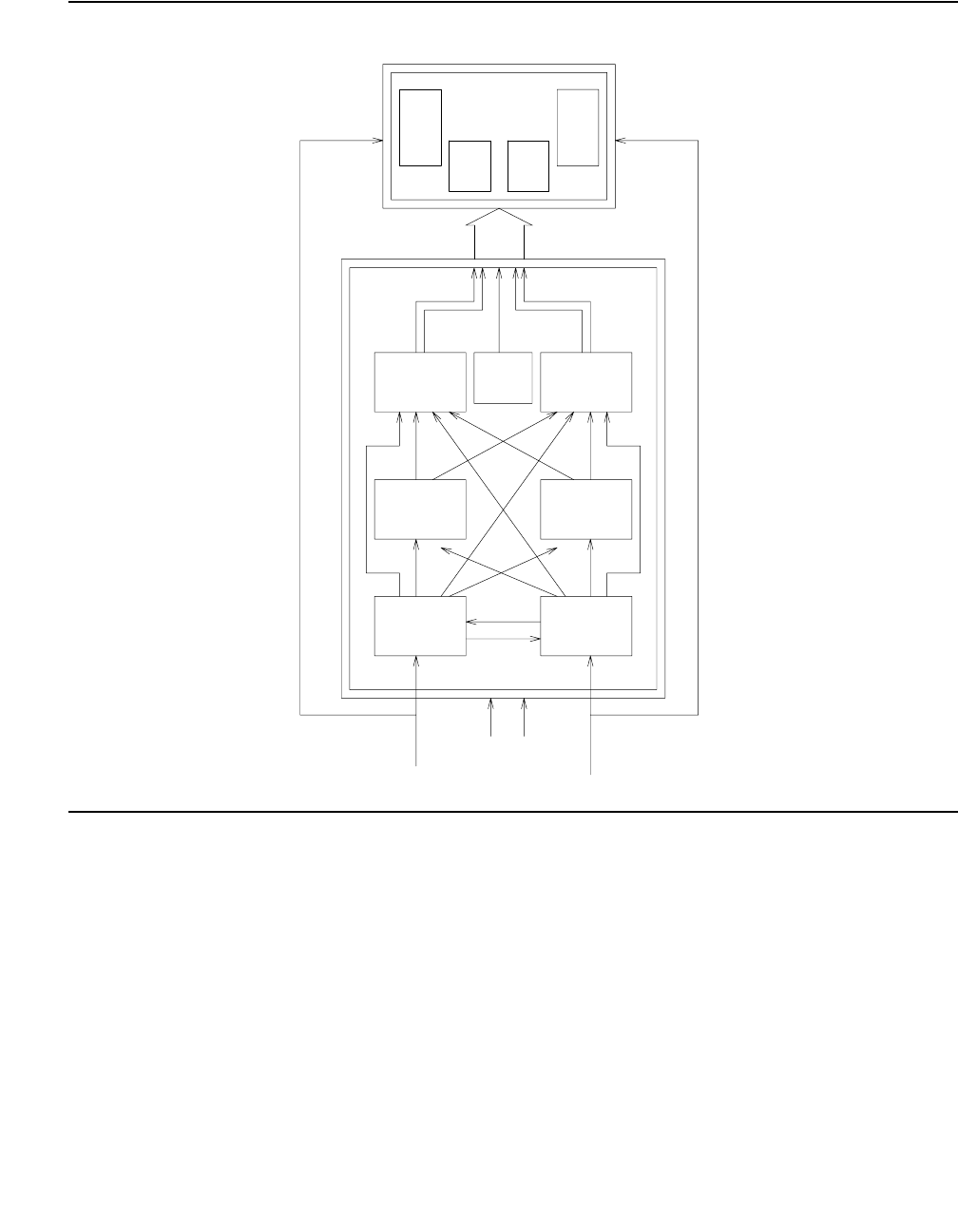
STRAT-3 (Stratum-3 Clock)
Issue 1 June 2005 2129
Figure 122: Stratum-3 Clock Hardware Configuration
Tone-
Clock
TN780
Tone-
Clock
TN780
TOC
DS1
Ref A
PAI
Alarms
PPN
DS1
Ref B
TOC
ST3 ST3
CI CI
A B
A
A
B
B
DS1
TN464
TN767
or
TN722
DS1
TN464
TN767
or
TN722
Timing output Timing output
-48V -48V

Communication Manager Maintenance-Object Repair Procedures
2130 Maintenance Procedures for Avaya Communication Manager 3.0, Media Gateways and Servers
Stratum-3 Clock LED Strategy
Note:
Note: When looking in the Stratum-3 cabinet, “A” card is on the left and “B” card is on
the right.
Note:
Note: The normal LED scheme is not followed for this device. Green LEDs do not
indicate maintenance activity. There are no yellow LEDs, and there are more
than three LEDs per circuit pack.
Note:
Note: Removal of a card in the Stratum-3 clock may cause alarm(s) to be resolved and
the query test to pass. However, the removed cards should still be replaced to
restore the Stratum-3 clock to full service.
The Stratum-3 clock has the following components:
●2 Clock Input cards (CI)
Provides the logic to select the better DS1 reference or Clock Input card. The red FAIL LED
on this card indicates a failure with the card or the DS1 reference connected to it.
●2 Stratum-3 Cards (ST3)
Provides 24-hour holdover. The red FAIL LED on this card indicates a failure with the card.
Replace the card.
●2 Timing Output Cards (TOC)
Provides cable length compensation, multiple output ports, selection of the ST3, and CI
outputs. This type of card has two red failure LEDs: one indicates a failure of the card; the
other indicates a failure in one or more output ports. In either case, replace the card.
●1 PBX (Private Branch Exchange) Alarm Interface (PAI)
Filters power supplied to the clock, provides fuse protection, and provides alarm indications
based on inputs supplied by other cards. The six LEDs on this card provide indications for
the six alarm or status conditions as follows:
- Loss of DS1 reference A
- Loss of DS1 reference B
- Loss of one clock unit
- Loss of both clock units
- Loss of one power supply
- Loss of both power supplies

STRAT-3 (Stratum-3 Clock)
Issue 1 June 2005 2131
The output of the CI and PAI cards go directly to the TN780 Tone-Clock circuit pack via two
25-pair amphenol terminated cables. Every card has red and/or green LEDs for providing status
or alarm indications. The abbreviations used in the table are defined above except for SRC
(source) and PLL (Phase Locked Loop).
Table 763: Stratum-3 Clock LED Indications
Card Name Color Indication
PAI REF A Red Loss of input reference A or CI A failed
REF B Red Loss of input reference B or CI A failed
ST A Red Failed Stratum-3 clock A
ST B Red Failed Stratum-3 clock B
PWR A Green -48VDC A present
PWR B Green -48VDC B present
CI FAIL Red Card failure
DS1 Green DS1 source present
CC Green Composite clock source1 present
1. Composite Clock (CC) source refers to the protocol used to electrically transfer timing
from the Stratum-3 clock to the switch. The Composite Clock source is not relevant to the
system.
SRC
ACTIVE
Green Card is currently on-line
ST3 FAIL Red Card failure
LOCK Red PLL lost sync with reference or holdover
mode
REF A Red Timing Reference from CI A
REF B Red Timing Reference from CI B
TOC FAIL Red Card failure
PORT ALM Red Output port alarm (one or more)
ST Green Reference present from ST clock
INPUT Green Reference present from CI
500’ Green 500-foot phase advance
1000’ Green 1000-foot phase advance
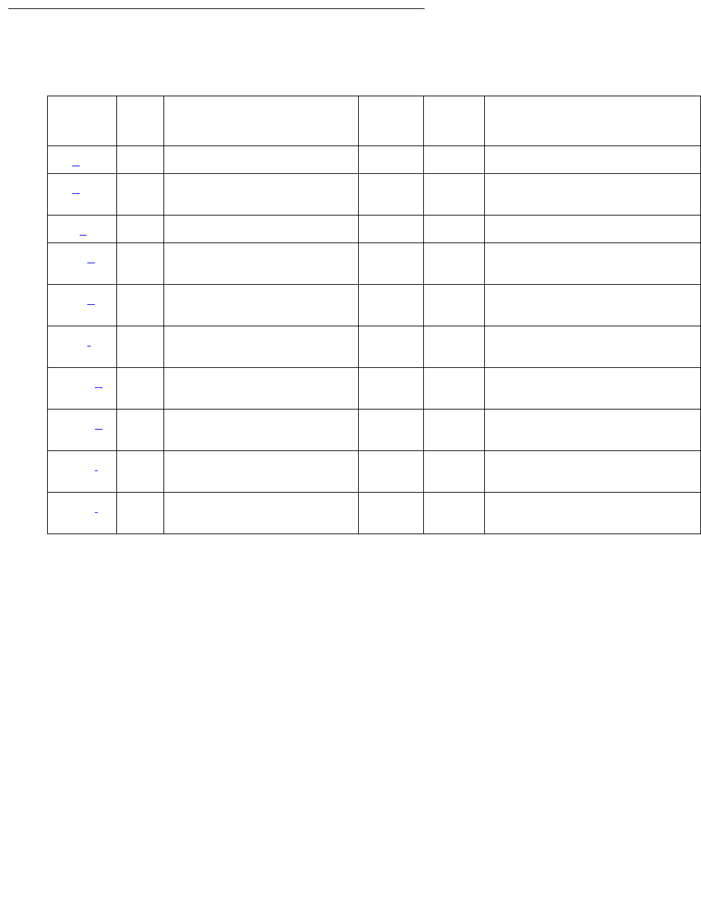
Communication Manager Maintenance-Object Repair Procedures
2132 Maintenance Procedures for Avaya Communication Manager 3.0, Media Gateways and Servers
Error Log Entries and Test to Clear Values
Notes:
a. Error Type 0: Run the short test sequence first. If every test passes, run the long test
sequence. Refer to each test’s description, and follow its procedures.
b. Error Type 1: this Error Type corresponds to FAIL code 1 of the Stratum-3 Clock Alarm
Query test (#649): either reference A failed or the CI card A failed.
c. Error Type 18: Synchronization Maintenance was disabled using disable
synchronization-switch.
1. Execute enable synchronization-switch to enable Synchronization Maintenance
reference switching and to resolve this alarm.
d. Error Type 257: this Error Type corresponds to FAIL code 2 of the Stratum-3 Clock Alarm
Query test (#649): one power supply failed.
e. Error Type 513: this Error Type corresponds to FAIL code 4 of the Stratum-3 Clock Alarm
Query test (#649): one clock unit failed.
Table 764: Stratum-3 Clock Error Log Entries
Error
Type
Aux
Data
Associated Test Alarm
Level
On/Off
Board
Test to Clear Value
0 (a) 0 Any Any Any test synchronization r 4
1 (b) Any Stratum-3 Clock Alarm
Query (#649
MIN OFF test synchronization r 4
18 (c) 0 disable sync WRN OFF enable sync
257 (d) Any Stratum-3 Clock Alarm
Query (#649)
MIN OFF test synchronization r 4
513 (e) Any Stratum-3 Clock Alarm
Query (#649
MIN ON test synchronization r 4
769 (f) Any Stratum-3 Clock Alarm
Query (#649)
MIN ON test synchronization r 4
1025 (g) Any Stratum-3 Clock Alarm
Query (#649)
MIN
MAJ ()
ON test synchronization r 4
1281 (h) Any Stratum-3 Clock Alarm
Query (#649)
MIN
MAJ ()
ON test synchronization r 4
1537 (i) none MIN
MAJ ()
ON
1793 (j) none MIN
MAJ ()
ON
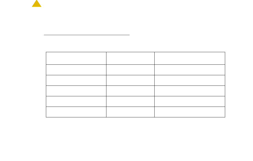
STRAT-3 (Stratum-3 Clock)
Issue 1 June 2005 2133
f. Error Type 769: this Error Type corresponds to FAIL code 8 of the Stratum-3 Clock Alarm
Query test (#649): either reference B failed or the CI card B failed.
g. Error Type 1025: this Error Type corresponds to FAIL code 16 of the Stratum-3 Clock Alarm
Query test (#649): every power supplied failed.
A Minor alarm results if the Stratum-3 clock can still provide timing to the switch; otherwise,
a Major alarm will be raised because the Stratum-3 clock is not providing timing and the
switch is referencing the local oscillator on the TN780 Tone-Clock circuit pack. If only the
active TN780 Tone-Clock circuit pack is faulty, the standby TN780 Tone-Clock circuit pack
becomes active and remains synchronized to the Stratum-3 clock. When the system
switches to the standby Tone-Clock circuit pack, the alarm is resolved, and a TDM-CLK
alarm is raised to indicate a possible problem on the TN780 Tone-Clock circuit pack.
If the alarm is MINOR:
1. Look for a red LED on either or both TOC cards.
2. If there is a red LED, replace the card. If there is no red LED, use the Stratum-3 Wiring
Guide, and check that the wiring installation is correct.
3. After replacing the card or correctly rewiring the installation, clear the alarm by issuing
disable synchronization-switch, followed by enable
synchronization-switch. The latter procedure causes synchronization software to
switch back to using the Stratum-3 clock again.
4. Wait 2 minutes and run status synchronization.
5. If Maintenance Name on the status screen shows “STRAT-3,” the problem is resolved.
!CAUTION:
CAUTION: The disable synchronization-switch command followed by enable
synchronization-switch may cause slip alarms. The circuit packs that can
experience slips and the associated error log entry for slips are listed in
Table 765: Timing Slip Error Types on page 2133.
Table 765: Timing Slip Error Types
Circuit Pack Name Error Log Name Error Log Entry for Slips
DS1 Interface DS1-BD 3073 to 3160
Expansion Interface EXP-INTF 2305
Switch Node Interface SNI-BD 1537
Tone-Clock TDM-CLK 1025
UDS1 Interface UDS1-BD 3073 to 3160

Communication Manager Maintenance-Object Repair Procedures
2134 Maintenance Procedures for Avaya Communication Manager 3.0, Media Gateways and Servers
If the alarm is MAJOR:
●Check connections between the Stratum-3 clock and the switch.
●If there are no loose connections, use the Stratum-3 Wiring Guide and check that the
wiring installation is correct.
●After reconnecting the loose connection or correctly rewiring it, clear the alarm by issuing
disable synchronization-switch, followed by enable
synchronization-switch.
●Wait 1 minute, then run status synchronization.
●If Maintenance Name on the status screen shows “STRAT-3,” then the problem is
resolved.
If the Standby Tone-Clock circuit pack became active:
●Check the connection between the Stratum-3 clock and the TN780 Tone-Clock circuit
pack from which the system has just switched.
●If there are no loose connections, then, replace the circuit pack containing the TN780
Tone-Clock circuit pack.
●Before switching back to the new TN780 Tone-Clock circuit pack, use test
tone-clock location long to check that the Tone-Clock is receiving a signal from
the Stratum-3 clock.
●If every test passes, switch to the new Tone-Clock circuit pack using set tone-clock
location override.
●If Test #651 fails, then the original TN780 Tone-Clock circuit pack should be reinserted,
and the cable between the Stratum-3 clock and the TN780 Tone-Clock circuit pack
should be replaced.
●If Test #651 continues to fail, then escalate the problem.
●If slip alarms exist after following the repair procedures for any of the previous cases,
clear the slip alarms by running test board clear. See Table 765: Timing Slip Error
Types on page 2133 for a list of circuit packs and associated slip error log entries.
●This error indicates that the Tone-Clock circuit pack in the master port network is not a
TN780. If duplicate Tone-Clock circuit packs exist in the master port network, this error
may mean that one or both Tone-Clock circuit packs are not TN780s. Verify that the
Tone-Clock(s) in the master port network are TN780s.
h. Error Type 1281: this Error Type corresponds to FAIL code 32 of the Stratum-3 Clock Alarm
Query test (#649): every clock unit failed.
i. Error Type 1537: An OFF-BOARD alarm on the Stratum-3 clock, indicates a DS1 facility
problem; an ON-BOARD alarm indicates a fault in either the Stratum-3 clock or the
connection between the Stratum-3 clock and the switch. If the Stratum-3 clock cannot be
referenced and the local oscillator on the TN780 Tone-Clock circuit pack must serve as the
reference, a Major alarm is raised. Otherwise, a Minor alarm is raised.
STRAT-3 (Stratum-3 Clock)
Issue 1 June 2005 2135
j. Error Type 1793: this error can be caused by one of the following conditions:
●One or both TOCs (Timing Output Cards) has failed.
●The connection between the Stratum-3 clock and the TN780 Tone-Clock circuit pack is
faulty.
●The TN780 Tone-Clock circuit pack is defective.
System Technician-Demanded Tests:
Descriptions and Error Codes
The test synchronization command also runs the Test Synchronization test (#417). Test
417 is described in SYNC (Port-Network Synchronization) on page 2143.
Stratum-3 Clock Alarm Query (#649)
This test queries the Stratum-3 clock for its alarm status and reports the results of the query.
The Stratum-3 clock provides the system with the following six alarm indications via the TN780
Tone-Clock circuit pack:
●Reference A failed or CI card A failed.
●Reference B failed or CI card B failed.
●One power supply failed.
●Every power supply failed.
●One clock unit failed.
●Every clock unit failed.
!CAUTION:
CAUTION: The removal of a card in the Stratum-3 clock may cause alarm(s) to be resolved
and the query test to pass. However, the removed cards should still be replaced
to restore the Stratum-3 clock to full service.
Order of Investigation Short Test
Sequence
Long Test
Sequence
D/ND
Stratum-3 Clock Alarm Query (#649) X X ND
Communication Manager Maintenance-Object Repair Procedures
2136 Maintenance Procedures for Avaya Communication Manager 3.0, Media Gateways and Servers
Table 766: TEST #161 Loop-Around Test
Error
Code
Test
Result
Description / Recommendation
1001 ABRT The system could not allocate the necessary resources to run this test.
1. Retry the command at 1-minute intervals up to up to 3 times.
1005 ABRT This test aborts when it is run on a Stratum-4 system. Do not change
synchronization to Stratum 3 without consulting the synchronization plan
administrator for this switch.
2500 ABRT Internal system error
1. Retry the command at 1-minute intervals up to 3 times.
1 of 5

STRAT-3 (Stratum-3 Clock)
Issue 1 June 2005 2137
1 FAIL Either Reference A failed or CI card A failed. This condition usually
indicates a failure of the DS1 reference; however, there may also be a
failure of the CI card to which the reference is connected. The system
technician dispatched to investigate this problem should take a spare CI
card in case the CI card caused the failure.
If you are NOT ON-SITE, use the following procedure:
1. Use display errors to look for DS1-BD (DS1 Interface Circuit
Pack) errors. See the DS1-BD Maintenance documentation for
recommended strategy to resolve any DS1-BD errors found.
2. If there are no DS1-BD errors or after resolving every DS1-BD error,
use test synchronization r 4 to see if the alarm still exists. If
every test repetition passes, then the alarm no longer exists.
Otherwise, the system technician should be dispatched with a spare CI
card to use the following instructions on-site.
If you are ON-SITE, use the following procedure:
1. Look for a red LED on CI card A (i.e., the left CI card). If there is a red
LED, then replace the CI card, if a spare is available. If no spare CI is
available on-site, proceed to Step 3. If after replacing the CI card, the
red LED on the new CI card lights also, then proceed to Step 3.
2. If a spare CI card is available, replace the suspect CI card. Otherwise,
use test synchronization r 4 to clear the alarm. If any test
repetitions fail, then follow the procedure for those failures.
3. Use display errors to look for DS1-BD (DS1 Interface Circuit
Pack) errors. See the DS1-BD Maintenance documentation for
recommended strategy to resolve any DS1-BD errors found. If there
are no DS1-BD errors, then proceed to Step 5.
4. After every DS1-BD error has been resolved, use test
synchronization r 4 to clear the alarm and see if the alarm still
exists. If any test repetitions fail, follow the procedures for those
failures.
5. Check the DS1 reference A connections to the Stratum-3 clock.
6. To determine whether the alarm still exists, execute the test
synchronization r 4 command to clear the alarm. If any test
repetitions fail, then follow the procedures for those failures.
Table 766: TEST #161 Loop-Around Test (continued)
Error
Code
Test
Result
Description / Recommendation
2 of 5

Communication Manager Maintenance-Object Repair Procedures
2138 Maintenance Procedures for Avaya Communication Manager 3.0, Media Gateways and Servers
2 FAIL One power supply failed. This error occurs when the Stratum-3 clock has
two power supplies, and one of them has failed. However, the clock can
function with one power supply.
1. Locate the failed power supply (the one with a red LED), and replace it.
The power supplies reside under the Stratum-3 clock’s carrier.
2. To determine whether the alarm still exists, use test
synchronization r 4 to clear the alarm. If any test repetitions fail,
then follow the procedures for those failures.
4 FAIL One clock unit failed.
1. Look at the Stratum-3 cabinet for a red LED on a circuit card marked
“ST3.” Replace the card.
2. To determine whether the alarm still exists, use test
synchronization r 4 to clear the alarm. If any test repetitions fail,
then follow the procedures for those failures.
Table 766: TEST #161 Loop-Around Test (continued)
Error
Code
Test
Result
Description / Recommendation
3 of 5

STRAT-3 (Stratum-3 Clock)
Issue 1 June 2005 2139
8 FAIL Reference B failed or CI card B failed. This condition usually indicates a
failure of the DS1 reference; however, there may also be a failure of the CI
card to which the reference is connected. The system technician dispatched
to investigate this problem should take a spare CI card in case the CI card
caused the failure.
If you are NOT ON-SITE, use the following procedure:
1. If there were no DS1-BD errors or if every DS1-BD error has been
resolved, enter test synchronization r 4 to determine whether
the alarm is still present. If every repetition of the test passes, the
alarm no longer exists. Otherwise, the system technician should be
dispatched with a spare CI card to perform the following instructions
on-site.
If you are ON-SITE, use the following procedure:
1. Look for a red LED on a CI card B (the CI card on the right). If there is
a red LED, then replace the CI card, if a spare is available. If no spare
CI is available on-site, proceed to Step 3. If, after replacing the CI card,
the red LED on the new CI card lights, proceed to step 3.
2. Otherwise, enter test synchronization r 4 to clear the alarm. If
any test repetitions fail, follow the procedure for those failures.
3. Enter display errors and look for DS1-BD errors. If there are any,
see DS1-BD (DS1 Interface Circuit Pack) on page 978. If there are no
DS1-BD errors, proceed to step 5.
4. After every DS1-BD error has been resolved, determine whether the
alarm still exists with test synchronization r 4. If any test
repetitions fail, follow procedures for those failures.
5. Check the DS1 reference A connections to the Stratum-3 clock.
6. Determine whether the alarm still exists with test
synchronization r 4 to clear the alarm. If any test repetitions fail,
then follow procedures for those failures.
Table 766: TEST #161 Loop-Around Test (continued)
Error
Code
Test
Result
Description / Recommendation
4 of 5

Communication Manager Maintenance-Object Repair Procedures
2140 Maintenance Procedures for Avaya Communication Manager 3.0, Media Gateways and Servers
16 FAIL Every power supply failed.
1. Replace the failed power supplies.
2. If battery backup for the Stratum-3 clock is not supplied or if the battery
backup holdover time has been exceeded, then the system will be
referencing the local oscillator on the active TN780 Tone-Clock circuit
pack until software detects that one or both power supplies have been
restored (approximately 40 minutes). To speed up this restoration, use
test synchronization r 4.
3. Every test should pass. If any repetitions should fail, then follow the
procedures for those failures.
Note: The battery backup resides under the Stratum-3 clock’s carrier.
32 FAIL Every clock unit failed.
1. Look at the Stratum-3 cabinet for red LEDs on circuit cards marked
“ST3.” Replace the card(s).
2. To determine whether the alarm still exists, execute
test synchronization r 4 to clear the alarm.
3. If any test repetitions fail, then follow the procedures for those failures.
2101 FAIL The TN780 Tone-Clock circuit pack detects loss of signal. See note h of the
STRAT-3 Hardware Error Log Entries table in the STRAT-3 (Stratum-3
Clock) Maintenance documentation for replacement procedures.
PASS The Stratum-3 clock has reported that it has no alarm conditions. If
synchronization problems have been reported, look for SYNC errors and
see SYNC (Port-Network Synchronization) on page 2143 for recommended
strategy for those errors.
Table 766: TEST #161 Loop-Around Test (continued)
Error
Code
Test
Result
Description / Recommendation
5 of 5

SVC-SLOT (Service Slot)
Issue 1 June 2005 2141
SVC-SLOT (Service Slot)
S8700 | 8710 / S8500
The Service Slot MO detects the insertion of an invalid circuit pack into a dedicated SERVICE
slot. The SERVICE slot is the left-most slot in the J58890BB port carrier, and is identified as slot
location “00” in commands and screen fields.
Because this slot does not provide tip and ring connectivity to the wall field, only the following
circuit packs are allowed:
●TN744 Call Classifier
●TN750 Integrated Announcement
●TN771 Maintenance/Test
●TN725 Speech Synthesizer
●TN433 Speech Synthesizer
●TN457 Speech Synthesizer
●TN748 Tone Detector
●TN420 Tone Detector
When another circuit pack is inserted in a SERVICE slot, a MINOR alarm is generated against
the Service Slot MO. Instead of the illegal circuit pack’s MO name, the “Service Slot” MO name
is used to prevent any attempt to assign a port to the illegal pack physically residing in the
SERVICE slot.
MO Name Alarm Level Initial Command to Run Full Name of MO
SVC-SLOT MIN none Service Slot

Communication Manager Maintenance-Object Repair Procedures
2142 Maintenance Procedures for Avaya Communication Manager 3.0, Media Gateways and Servers
Error Log Entries and Test to Clear Values
Note:
a. Indicates that an invalid circuit pack was inserted in slot 00, the SERVICE slot, of a
J58890BB port carrier. See the previous list of valid circuit packs.
1. To see the invalid circuit pack’s TN code, use list configuration board
location where location specifies the cabinet number, the carrier letter, and the slot
number (always 00) of the alarmed circuit pack.
2. To retire the alarm, remove the invalid circuit pack.
Table 767: Service Slot Error Log Entries
Error
Type
Aux
Data
Associated Test Alarm
Level
On/Off
Board
Test to Clear Value
600 (a)None MINON

SYNC (Port-Network Synchronization)
Issue 1 June 2005 2143
SYNC (Port-Network Synchronization)
S8700 | 8710 / S8500
This section discusses synchronization problems local to the switch. For further information
about synchronization including network synchronization, refer to AT&T Network and Data
Connectivity, 555-025-201.
Synchronization maintenance is composed of both hardware and software components, and its
purpose is to provide a common reference frequency for reliable digital communications
between an media servers and other PBXs, central offices (COs), or customer-premises
equipment (CPE). Synchronization is implemented using several system components including:
●TN2312 IPSI
●TN722, TN767, and TN464 DS1 Interfaces (all suffixes)
●S8700 MC: TN768, TN780, or TN2182 Tone-Clock
●S8700 MC: TN572 Switch Node Clock
●S8700 MC: TN573 Switch Node Interface
●S8700 MC: TN570 Expansion Interface
Note:
Note: If both a primary and secondary references are administered for Stratum-4
synchronization, both references must reside in the same port network (PN).
S8700 MC
Traditional Sync Operation
For a DEFINITY system or for an S8700 Media Server Multi-Connect system, synchronization is
obtained from the public circuit-switched network through:
●A DS1 or BRI interface
●The ATM network
MO Name Alarm Level Initial SAT Command to Run Full Name of MO
SYNC MIN display errors Port Network Synchronization
SYNC WRN test synchronization Port Network Synchronization
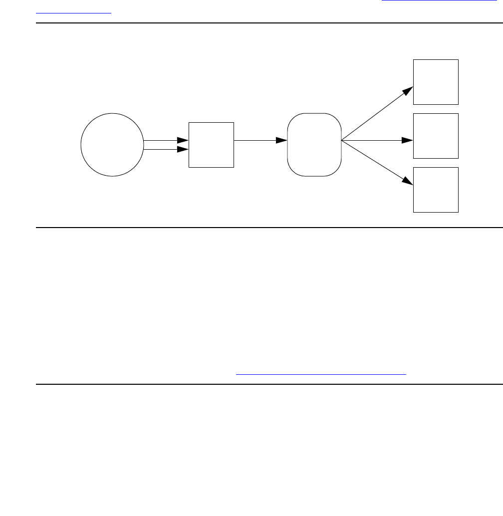
Communication Manager Maintenance-Object Repair Procedures
2144 Maintenance Procedures for Avaya Communication Manager 3.0, Media Gateways and Servers
For DS1- or BRI-based synchronization, a particular DS1 or PRI interface is configured as the
synchronization reference. The IPSI/Tone-Clock board in the same PN locks on to this
reference and regenerates clock signals that are placed on the PN’s backplane. In turn, the
Center Stage Switch (CSS) components transfer this timing to every other PN. These IPSI/
Tone-Clocks then regenerate clock signals for their own PNs at the same rate as the:
●Master PN
●Public network
This creates a hierarchy where the master PN receives timing from the public network, and
every other PN derives its timing from the master through the CSS. See Figure 123: Traditional
Sync Operation on page 2144.
Figure 123: Traditional Sync Operation
Typically, a pair of interfaces from the public network are configured — one as a primary and
one as a secondary. The IPSI/Tone-Clock in the Master PN can:
●Lock onto either interface
●Switch between them in the event of a failure
In the event of a dual failure, the Tone-Clock in the master PN can generate its own timing and
keep every PN synchronized. However, these PNs would not be synchronized with any other
public-network interfaces that exist in any of the PNs.
When a center stage is implemented via an ATM network, it is possible to obtain timing from the
ATM network. For more information, See ATM-SYNC (ATM Synchronization) on page 610.
Master
PN
Center
Stage
Switch
Slave
PN
Slave
PN
Slave
PN
Public
Network
Primary
Secondary
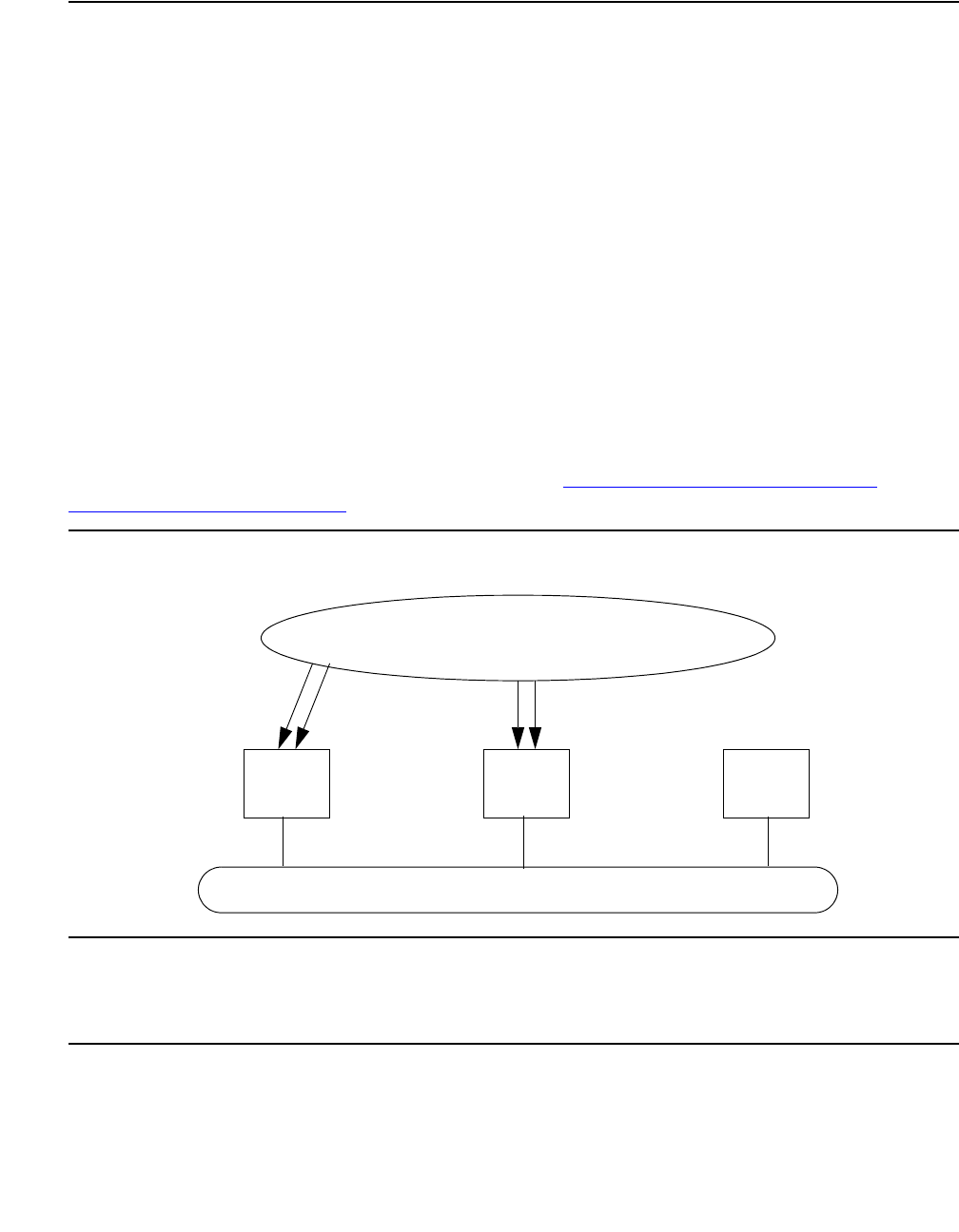
SYNC (Port-Network Synchronization)
Issue 1 June 2005 2145
S8700 IP
IP-Connected S8700 Media Server
Sync Operation
For an S8700 IP Connect system, its port networks (PNs) are connected via the customer’s IP
network. This network cannot be used to transmit timing information between the PNs. The
complete set of PNs need not be synchronized with each other. Inter-PN bearer traffic is carried
as VOIP, while the Media Processors’ internal jitter buffers deal with differences in transmission
rates.
Synchronization is needed for a PN with a public-network digital interface. Each PN with a DS1
or trunk-side BRI interface must be synchronized with an external timing source to prevent slips
between that PN and the external circuit-switched network. Each S8700 Media Server
IP-connected PN needs to operate like a DEFINITY system. Each S8700 IP Connect PN:
●Potentially needs its own external synchronization reference
●Is always locked to an external public-network interface or is running locally.
A typical S8700 IP Connect configuration is shown in Figure 124: S8700 Media Server
IP-Connected Sync Operation on page 2145.
Figure 124: S8700 Media Server IP-Connected Sync Operation
This figure also shows the far-right S8700 IP Connect system’s PN without public-network
digital interface. A PN without public-network connectivity runs off of its local IPSI circuit pack’s
Tone-Clock circuit.
PN PN PN
Public Switched Network
Primary
Primary
Secondary Secondary
IP Network

Communication Manager Maintenance-Object Repair Procedures
2146 Maintenance Procedures for Avaya Communication Manager 3.0, Media Gateways and Servers
Clock Synchronization
Note:
Note: S8700 MC: Stratum-3 clocking is not available for a PN where the Tone-Clock
function is supplied by either a:
●TN2312 IPSI circuit pack’s Tone-Clock circuit
●TN2182 Tone-Clock circuit pack
This section discusses synchronization with Stratum-3 and -4 clocking devices.
S8700 MC
Stratum-3 Synchronization
Since the clock module on the TN2312 does not support synchronization with an external
Stratum-3 clocking device, you may provide Stratum-3 clocking for a S8700 Media Server
system by using the TN780 Tone-Clock circuit pack in a non IPSI connected port network. To
bring in the external Stratum-3 clocking signals into the TN780, a processor carrier is needed.
This new PN control carrier will replace the processor carrier in the old PPN converted to PN 1.
The Stratum-3 clocking must come into Port Network #1 because the S8700 Multi-Connect
software has the Stratum-3 clocking hard-coded to this port network.
Stratum-4 Synchronization
The system can be configured with primary and secondary synchronization references (DS1 or
UDS1 Interface circuit packs) when using Stratum-4 synchronization. If this is the master
synchronization source for the network, then its local oscillator is used and no DS1s are used as
references.
If this system is a slave in the network, a primary reference must be used as the synchronization
reference and a secondary reference is optional:
●If the primary synchronization reference is not providing a valid timing signal, the system
automatically switches to the secondary synchronization reference.
●If the primary synchronization reference is invalid and secondary reference does not
provide a valid timing signal or is not administered as a synchronization reference, an
IPSI’s Tone-Clock circuit or a Tone-Clock circuit pack provides the PN’s timing source.
●If the system is using the local oscillator as the timing source (both the primary and
secondary references are providing invalid timing signals), should either the primary or
secondary reference becomes valid again, the system (PN for S8700 Media Server
systems) switches back to the primary or secondary source.

SYNC (Port-Network Synchronization)
Issue 1 June 2005 2147
●When both the primary and secondary source become valid, the system switches to the
primary source, since the primary source is always preferred over the secondary source
when both sources are equally healthy.
Synchronization Troubleshooting
For Stratum-4 operation, major and minor alarms indicate that there is a problem with the
system synchronization references. These alarms will be resolved when the alarmed
synchronization reference is restored.
The change synchronization command allows primary and secondary references to be
administered per cabinet.
Use status synchronization to show the current synchronization reference per cabinet.
Use display synchronization or list synchronization to show the primary and/or
secondary synchronization references that are administered.
Other commands associated with Synchronization Maintenance are disable
synchronization-switch and enable synchronization-switch. These commands
are used to disable the ability of Synchronization Maintenance to switch between
synchronization references and to enable this switching ability, respectively. Use set
synchronization only after synchronization has been disabled, to manually switch to a
specific synchronization reference. Use set synchronization to help diagnose
synchronization problems by forcing a specific reference (DS1, UDS1, or Tone-Clock) to be the
system synchronization reference to determine if a specific reference is providing a valid timing
signal.
Troubleshooting Approach
Slip errors are the primary symptom associated with being un-synchronized.
A correct Synchronization plan for the network keeps the systems within the network
transmitting data at approximately the same rate to avoid situations where:
●One system transmits data at a rate faster than another system can receive the data (in
which case data is lost).
●One system transmits data at a rate slower than another system expects to receive data
(in which case data is repeated).
Either of these situations, data being lost or repeated, is a slip.
When troubleshooting synchronization problems when slips are the primary error log entry
indications of a synchronization problem, requires that the problem be isolated to:
●A problem outside of the switch (That is, the switch is not properly synchronized to the rest
of the network.)
●A problem internal to the switch
Communication Manager Maintenance-Object Repair Procedures
2148 Maintenance Procedures for Avaya Communication Manager 3.0, Media Gateways and Servers
DS1 and UDS1 circuit packs can be administered with slip detection enabled using the Slip
Detection field set to y on the add ds1 or change ds1 administration screens (See the
Administrators Guide for Avaya Communication Manager - 555-233-506). All DS1 and UDS1
circuit packs administered as slip enabled are counted in the following algorithm:
When over half of the DS1 and UDS1 circuit packs administered as slip enabled are
experiencing slips, and the primary or secondary synchronization reference is the current
synchronization reference, synchronization will try the other administered synchronization
reference.
In situations where one or many circuit packs in the system are experiencing slips, the problem
could be with the synchronization reference, with individual circuit packs, or with phase
modulation of the transmitted digital bit streams due to environmental variations of the
transmission facilities (such as temperature variations that affect the electrical length of a
transmission line). The circuit packs that can experience slips and the associated error log entry
for slips are as follows in Table 768:
When slips occur on any of these circuit packs, first consult the individual circuit pack’s section
in this manual. If slips occur in small amounts, they may be due to environmental conditions as
previously described. If no service degradation is occurring, no action is necessary. When the
system switches synchronization sources, slips can be expected from DS1-BD, UDS1-BD, and
EXP-INTF circuit packs. If service degradation occurs, after following the repair steps in the
individual section, use the following trouble shooting techniques.
Table 768: Error Log Entries for Slip Errors
Circuit Pack Error Log
Name
Error Log Entry for Slips
DS1 Interface DS1-BD 3073 – 3160
Expansion Interface EXP-INTF 2305
Switch Node Interface SNI-BD 1537
IPSI’s Tone-Clock circuit or Tone-Clock circuit pack TDM-CLK 1025
UDS1 Interface UDS1-BD 3073 – 3160

SYNC (Port-Network Synchronization)
Issue 1 June 2005 2149
Table 769 lists circuit packs that can report slips and related circuit packs whose hardware
problems that cause those slips.
Troubleshooting Synchronization Problems
The following flow chart presents a logical approach to troubleshooting synchronization
problems in conjunction with the previous background information. Explanatory notes follow the
charts.
Table 769: Slips and Related Circuit Packs
Circuit Pack Reporting Slips Associated Circuit Packs that Can Cause Slips
DS1 Interface Active Tone-Clock in same PN
Expansion Interface Active Tone-Clock in same PN or circuit pack at
opposite end of fiber or metallic connection
Switch Node Interface Circuit pack at opposite end of fiber or metallic
connection, or active Switch Node Clock circuit pack in
same switch node carrier
IPSI’s Tone-Clock or Tone-Clock
circuit pack
Current DS1 reference
UDS1 Interface Active Tone-Clock in same PN
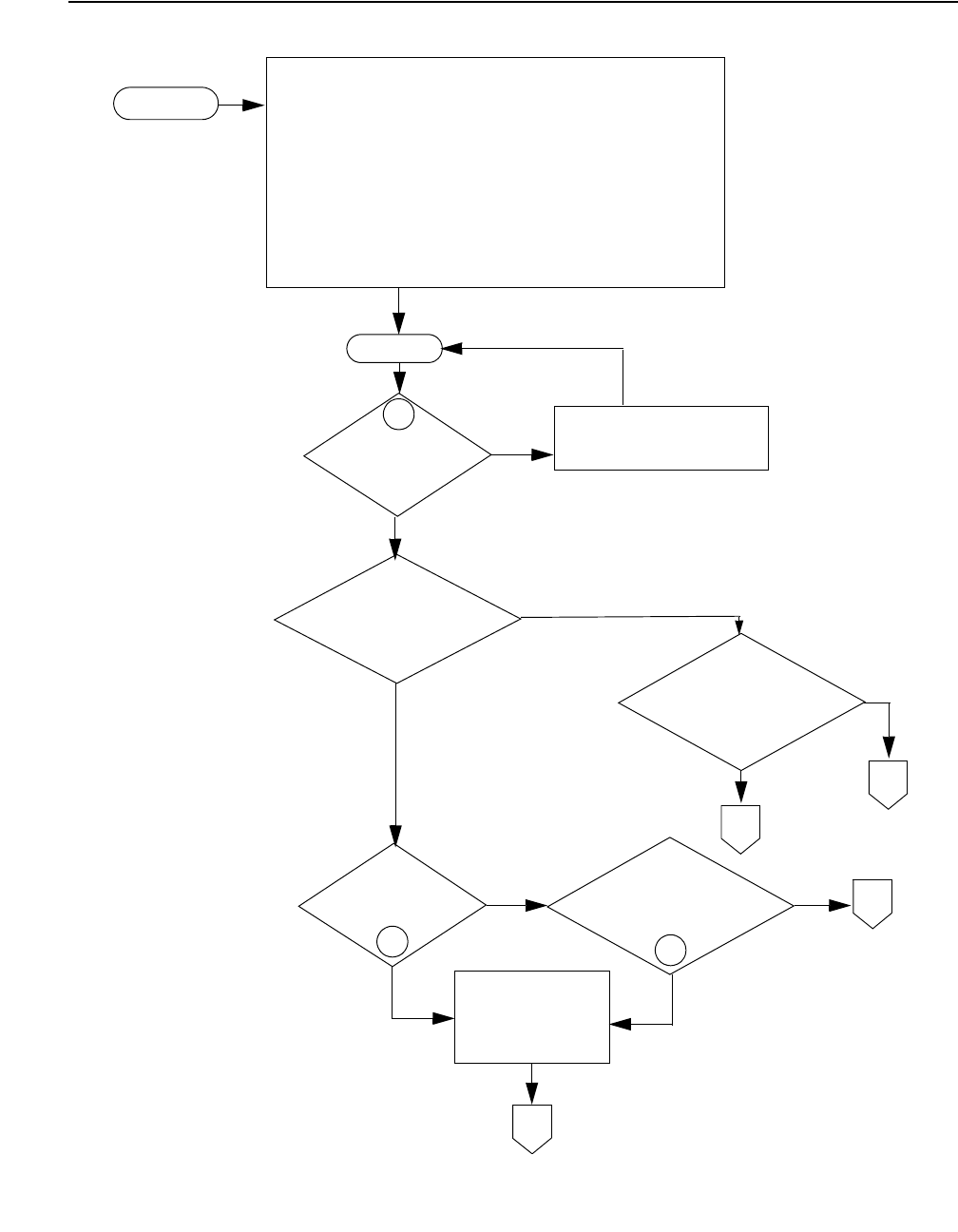
Communication Manager Maintenance-Object Repair Procedures
2150 Maintenance Procedures for Avaya Communication Manager 3.0, Media Gateways and Servers
Figure 125: Synchronization Troubleshooting, Fig. 1 of 5
Slips
No
Yes
A
Is reference a
free-running Tone-Clock
Slips on
DS1 facilities?
SlipsonsomeDS1
facilities in same PN
as reference?
Yes
No
Problem is
in switch.
To F i g 4
To F i g 3
Problems with
reference PN or
synchronization plan
SlipsonIPSIorToneCLK,EIs
SNIs, or non-reference PN DS1s
B
D
1
23
Yes
No
Yes
No
or IPSI?
System is operating as
timing master.
Is the tone clock
or IPSI
designated as the
timing master?
C
Yes
No
To F i g 2
Use list sync to determine
if the tone clock is
designated as the master.
Use
stat sync
to determine
if the tone clock was
switched to.
Review synchronization plan.
Administer and enable
stat sync
stat sync
System is operating
as a timing slave in
the network.
synchronization.
To F i g 3
Is synchronization
administered and
enabled?
Use
display errors
and follow the repair procedures for non-slip errors
against, SYNC, TDM-CLK, TONE-BD, EXP-INTF, SNI-BD, and DS1C-BD
maintenance objects.
Non-Slip errors are those NOT listed below:
Board Type Name in Error Log Log Entry (for slips)
DS1 Interface DS1-BD 3073 to 3160
UDS1 Interface UDS1-BD 3073 to 3160
Expansion Interface EXP-INTF 2305
Switch Node Interface SNI-BD 1537
Tone-Clock TDM-CLK 1025
DS1 Converter DS1C-BD 3329
Start Here
DS1 Facility DS1-FAC 856
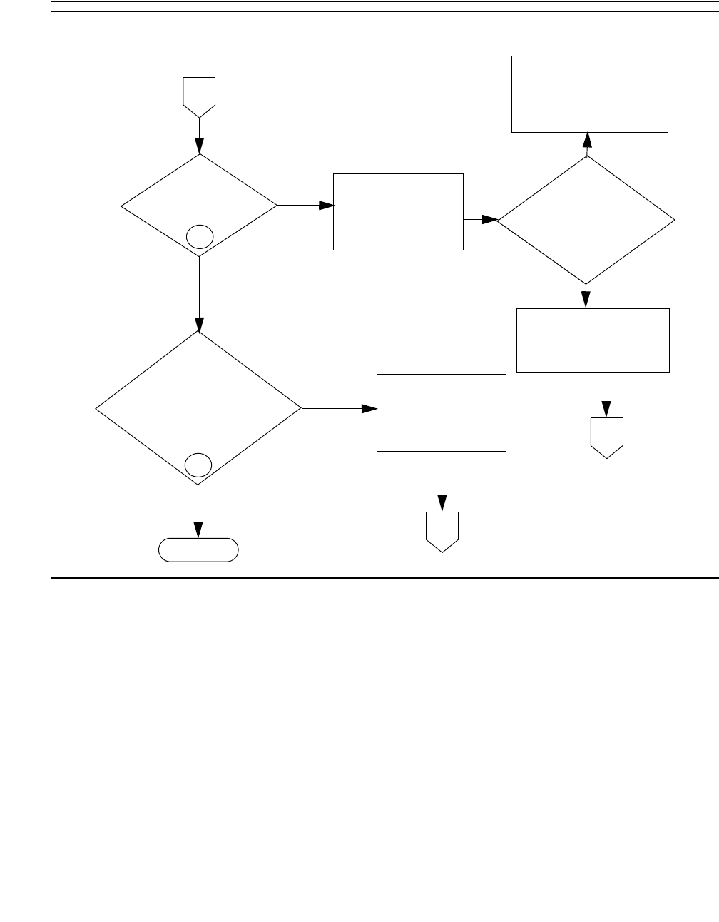
SYNC (Port-Network Synchronization)
Issue 1 June 2005 2151
Figure 126: Synchronization Troubleshooting, Fig. 2 of 5
Examine the
Slips on any DS1
facilities?
No
Yes
Yes
No
Yes
To Fi g 4
From
Fig 1
4
Slips on IPSI or DS1-C or
Tone-Clock, EIs, or SNIs
Done
synchronization plan
Problem is internal to
for the network.
D
A
No
22
Use the list sync
command
E
?
There is an administration
discrepancy. This system is
administered as the timing
master but it should not be
because there are DS1 spans
with more accurate clocks.
This system is administered and
is acting as the timing master.
This is by intent so the slipping
facilities must be tie trunks.
Does the
administration of this
system agree with the
Network synchronization
plan? Make sure that
To F i g 3
there is only one
master clock source.
the switch
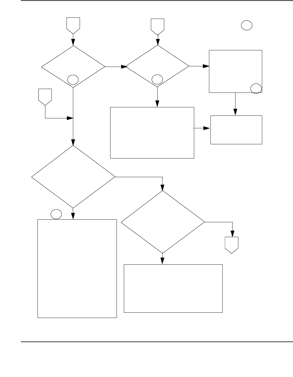
Communication Manager Maintenance-Object Repair Procedures
2152 Maintenance Procedures for Avaya Communication Manager 3.0, Media Gateways and Servers
Figure 127: Synchronization Troubleshooting, Fig. 3 of 5
5
Slips on
Reference
Facilities?
Is there a
loss-of-signal or
network alarm
YesYes
No No
Many
Are there
many facilities
with excessive slips?
Few
7
Escalate, if the
problem is not fixed.
6
B
D
6
C
Perform the following to try and affect the
symptoms:
If duplicated:
- Switch tone clocks
Replace circuit packs:
- IPSI/Tone Clock in the timing master PN.
- DS1 in timing master PN
Are all the facilities
with slips from the
same external
source, i.e.
Network Service
Provider or other
switching vehicle?
No
Yes
Contact the distant end service provider of the
facilities with slips to troubleshoot.
If the distant end is another PBX, verify that one
switch is the master and the other is a slave. If
both think they are the master it will cause slips on
all spans between them.
To F i g 4
Check the overall timing network to
verify the source is traceable back to
the same high stratum level source.
(This does not apply when
Fix any DS1-BD and UDS1-BD
problems present in the system.
Verify that one end of a slipping span
is administered to be the master and the
other is administered to be the slave.
Consider using the facility fault
sectionalization techniques to isolate
the problem. Use slip counts as a
pass/fail indication.
E
A tone clock is acting as the timing
reference and it was switched to from
a higher (primary or secondary)
reference. The primary and, if administered
Work with the service provider (or distant
administration of line coding, frame
formats, etc.
slips are only on tie trunk facilities)
switch, if applicable) to compare
secondary reference must be restored before
troubleshooting may continue on other spans.
See the DS1-BD and
UDS1-BD MOs to resolve
any outstanding alarms.
Investigate external causes
for the loss of the primary
and/or secondary reference.
Change interface boards as
a last resort.
From
Fig 2
From
Fig 1 From
Fig 1
on the DS1 references?
If the distant end is another PBX, verify
that one switch is the master and the
other is a slave. If both think they are the
master it will cause slips on all spans
between them.
12
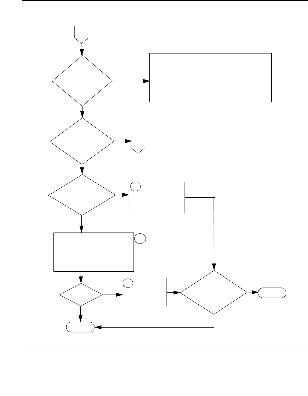
SYNC (Port-Network Synchronization)
Issue 1 June 2005 2153
Figure 128: Synchronization Troubleshooting, Fig. 4 of 5
8
Done
Escalate
From Figure
1, 2, or 3
.
Slipsonmorethan
one slave PN?
8
Slips remain?
Replace
Tone-Clock
slave PN.
Slips remain?
Yes
No
No
To F i g 5
in timing
D
Replace Tone-Clock or IPSI
in Master timing PN.
F
9
Yes
Many DS1 spans
with slips in the
PN containing the
master reference?
No
Yes
CSS
DC
For an S8xxx media server Multi-connect CSS, the problem
is in the IPSI or Tone Clock, EI, or SNI of the PN containing
the master reference. If equipped, switch PNC and/or system
tone clocks to try and change the symptoms. Then change
circuit packs above, one at a time.
Center Stage
Switch (CSS) or
Direct Connect (DC)?
Inspect fiber cables between the timing
master and slave PN for connectivity
issues. Look for crimped cables, loose
connections, bent pins, etc.
Replace expansion interface (EI) boards
between the timing master and the slave
PN with slips.
YES
NO
(The current PN providing
sync source)
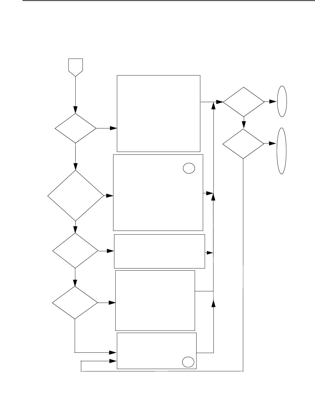
Communication Manager Maintenance-Object Repair Procedures
2154 Maintenance Procedures for Avaya Communication Manager 3.0, Media Gateways and Servers
Figure 129: Synchronization Troubleshooting, Fig 5 of 5
F
Slips in entire
Node Carriers
No
Switch Node
Carrier
If equipped, switch PNC and/or switch
node clocks to try and affect symptoms.
Change interfaces (EI, SNI) to reference PN.
Multiple Switch
Yes
CSS?
Are slips in
DS1C remote
PNs? Yes
Consider all components in the
connection to the DS1C remoted PN.
- SNI/EI boards
- DS1C boards
- Service provider, providing the DS1
Many
Few
If equipped, switch to the standby PNC
and/or tone clocks in the master reference
Slips remain?
D
O
N
E
No
Slips isolated\
E
S
C
A
No
to one PN?
L
A
T
E
Yes
Yes
No
spans to the remote location.
Check switch node carriers for bent pins
or a board that could be affecting the
clock leads.
reference port network to try and affect
Check cabling and transceivers to the
port network with the master reference.
Check cabling and transceivers to the
port network with the master reference.
Check switch node carriers for bent pins
or a board that could be affecting the
clock leads.
Slips on a
single DS1?
No
Yes
Change the DS1 board
Work with the service provider for the span to
Slips
associated with
Verify that span A is operational to the
remote location. Span A provides all
timing to the remote PN.
If equipped, switch PNC and/or tone
clock to try and affect symptoms.
One at a time, replace the EI, SNI, IPSI,
or tone clock for the port network with
slips.
The synchronization issue covers a large portion of the system. The problem is in a
center stage switch (CSS), IPSI or Tone-Clock, EI, SNI, or DS1 spans in port networks (PN)
other than the timing master PN.
This procedure attempts to isolate the problem.
If unduplicated, change the tone-clock in
the master reference PN.
Clear slips recorded against PNs in
multiple switch node carriers.
Clear slips recorded against PNs in
one switch node carrier.
verify line coding, framing, etc.
Change the DS-1 board.
Check the integrity of intervening equipment.
For example Channel Service Units.
From
Fig 4
10
When instructed to do so, perform the steps indicated while slips remain.
Slips in
Slips in a Single
many PNs in a
single Switch Node
Carrier. Don’t include
The service provider must pass timing,
through their network, to the distant
end remote port network.
DS1 remoted
PNs?
the symptoms.
11
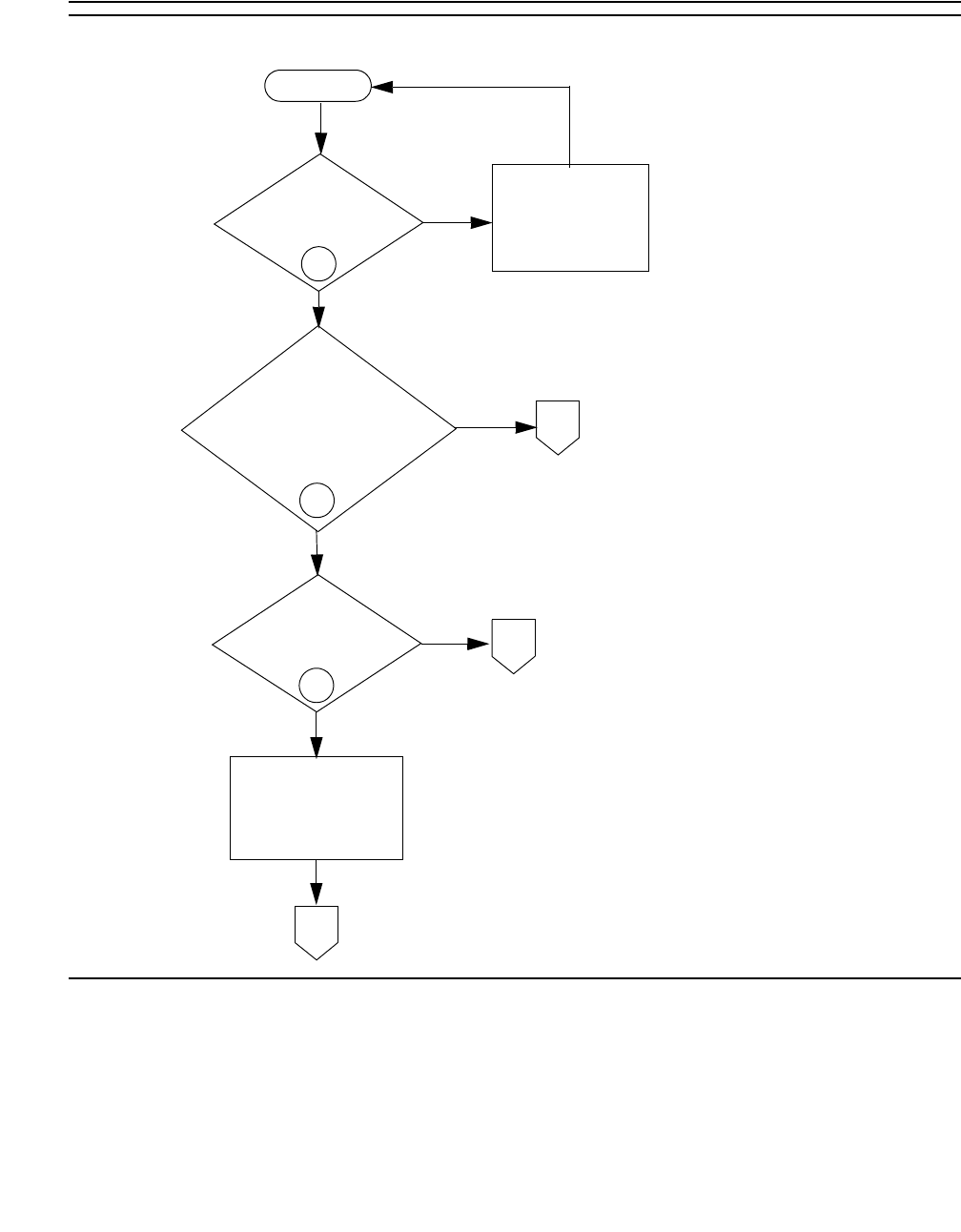
SYNC (Port-Network Synchronization)
Issue 1 June 2005 2155
Figure 130: Synchronization Troubleshooting, Fig. 1 of 4
Slips
No
Yes
Is synchronization
enabled?
A
Is reference a
free-running IPSI
Synchronization is enabled
for this port network.
Fig 2
Slips on
DS1 facilities?
Problem is
in switch.
Fig 3
Fig 4
Problems with
reference PN or
synchronization plan
Slips on IPSI’s Tone CLK circuit
or non-reference PN DS1s
C
B
1
1
2
No
Yes
Yes
No
Tone-Clock circuit?
Enable
synchronization.
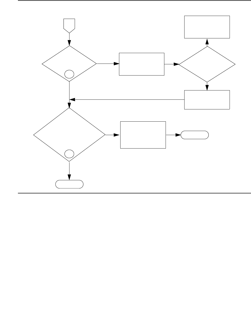
Communication Manager Maintenance-Object Repair Procedures
2156 Maintenance Procedures for Avaya Communication Manager 3.0, Media Gateways and Servers
Figure 131: Synchronization Troubleshooting, Fig. 2 of 4
Examine cabinet’s
2
Slips on DS1
facilities?
Retranslate to
accordingtothe
network’s plan.
Is this DS1
supposed to be PN’s
No
Yes
Yes
No
From
Fig 1
Refer problem for
investigation at other
end of facility.
have DS1 operate
synchronization plan.
A
No
role in network’s timing reference?
Yes
No
Problem is in PN,
IPSI’s Tone-Clock Escalate
or DS1s.
Slips on IPSI’s
Tone-Clock circuit?
Done
3
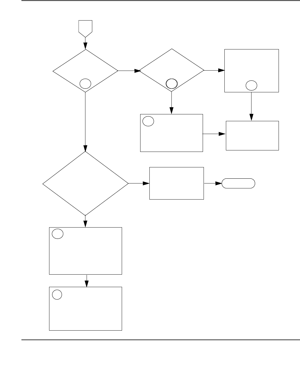
SYNC (Port-Network Synchronization)
Issue 1 June 2005 2157
Figure 132: Synchronization Troubleshooting, Fig. 3 of 4
4
Slips on
DS1 reference
facilities?
5
Is there a
loss-of-signal or
network alarm?
Fix DS1-BD and
UDS1-BD alarms.
YesYes
No No
Many
Are there
many facilities
with excessive slips?
Few
Replace circuit
packs:
– IPSI/Tone-Clock in
the PN
– DS1 in PN
7Check the overall
timing network to
verify the source is
traceable back to the
same source
(for example, Hillsboro, Mo).
Use the facility fault
sectionalization technique
section with slip counts as
the pass/fail indication to
isolate the trouble.
Escalate, if the
problem is not fixed.
7
B
Problem is in PN,
IPSI’s Tone-Clock Escalate
or DS1s.
5
6
5
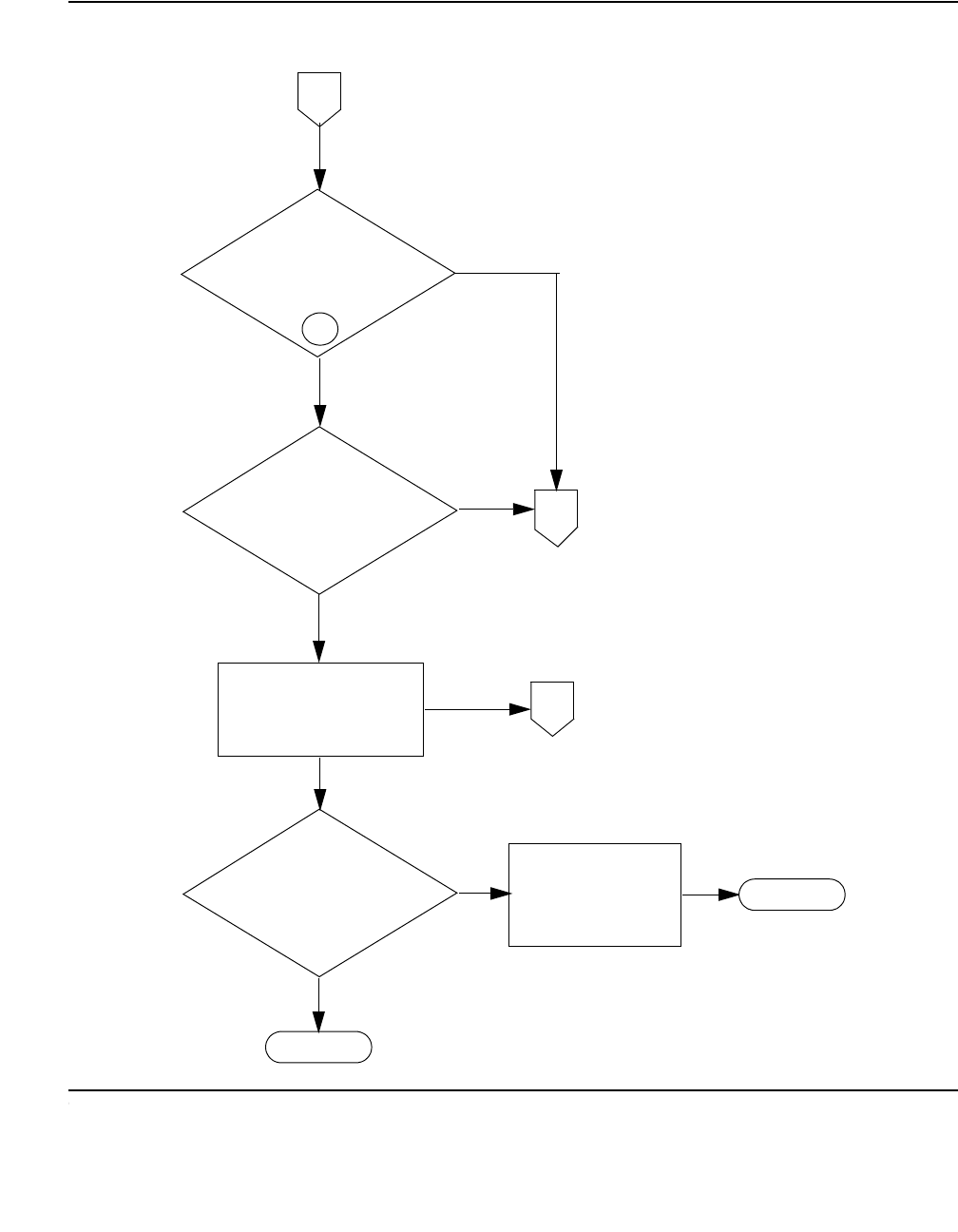
Communication Manager Maintenance-Object Repair Procedures
2158 Maintenance Procedures for Avaya Communication Manager 3.0, Media Gateways and Servers
Figure 133: Synchronization Troubleshooting, Fig. 4 of 4
B
From Fig 1
Yes
Yes
C
To F i g 3
B
To Fi g 3
Yes
No
Problem is in PN,
IPSI’s Tone-Clock Escalate
or DS1s.
Slips on IPSI’s
Tone-Clock circuit?
No
No
Administer the
reference, and enable
synchronization.
Is reference on line?
8
Is the reference
administered and
SYNC enabled?
Done
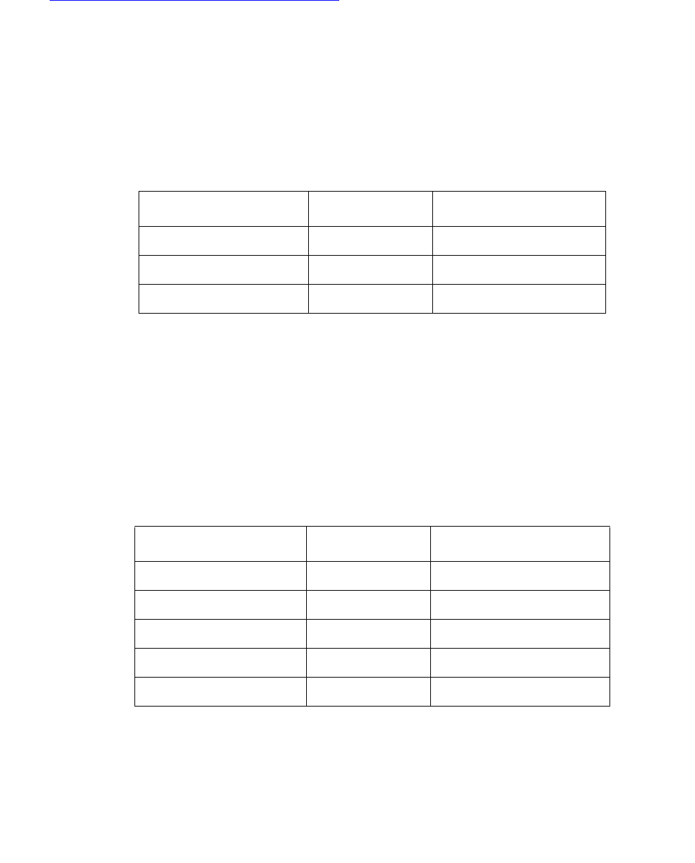
SYNC (Port-Network Synchronization)
Issue 1 June 2005 2159
Notes for Sheet 1 through Sheet 5 flowcharts. (When checking for slip errors, use the previous
Table 768: Error Log Entries for Slip Errors on page 2148.
1. Use status synchronization to see if synchronization is enabled, and to determine
the on-line reference. If the on-line reference is a Tone-Clock board, the switch is operating
in free run mode.
If Stratum 3 is displayed, and no DS1s are connected to the Stratum-3 clock or no DS1
connection existed to the Stratum-3 clock for over 24 hours, then the Stratum-3 clock is in
free run mode.
2. Check for slip errors against DS1-BD and UDS1-BD. In the error log (display errors)
look for the following error types to identify slips against these board types.
For slips on either of these board types, first refer to the individual boards section in this
manual. Follow the test and repair steps in those sections.
3. If Stratum 3 is administered (display synchronization) and on-line (status
synchronization), check for DS1-BD or UDS1-BD slip errors for the DS1(s) or UDS1(s)
used as input to the Stratum-3 clock. Check the LED indications on the Stratum-3 clock to
determine which DS1 is providing input to Stratum 3, and examine the cross-connect
information for that DS1.
4. Check for slips errors against EXP-INTF, SNI-BD, and TDM-CLK. In the error (display
errors) log look for the following error types to identify slips against these board types.
5. Check status synchronization for the current DS1 reference. If a DS1 or UDS1 is the
on-line reference, check for slips on that DS1 or UDS1.
6. Check for LOS, Blue, Yellow, and Red alarms on the on-line reference facility, and fix those
problems first. Check for slips, misframes, minor and major error rates and fix those
Board Type Error log name Log Entry (for slips)
DS1 Interface DS1-BD 3073 - 3160
UDS1 Interface UDS1-BD 3073 - 3160
Board Type Error log name Log Entry (for slips)
Expansion Interface EXP-INTF 2305
Switch Node Interface SNI-BD 1537
Tone Clock TDM-CLK 1025
DS1 Converter DS1C-BD 3329

Communication Manager Maintenance-Object Repair Procedures
2160 Maintenance Procedures for Avaya Communication Manager 3.0, Media Gateways and Servers
problems next. See the DS1-BD and/or UDS1-BD for the error log entries associated with
the previously mentioned alarms. Replace the circuit packs one at a time and wait at least 1
hour to determine if the problem went away. This procedure is disruptive and should be
done after hours if possible.
If problems persist it may be useful to compare translations for line coding and frame
formats with the far end service provider. Make sure the translations match.
If high or critical reliability switch the Port Network Connectivity (PNC) to try and help isolate
the problem.
Instead of replacing the Tone-Clock circuit pack in systems where Tone-Clocks are
duplicated, run set tone-clock to interchange Tone-Clocks. If the problem goes away,
replace the previously active Tone-Clock.
7. If a few facilities experience slips or are unusable references, the clock source for facilities
with slips or that are unusable is not traceable to the same ultimate source as the clock
source for the on-line reference facility.
Examine the overall timing network for the interconnected DS1 to determine if the:
●Clock can be traced back to a single source.
●Reference designations for each location in the distribution of timing is supplied in
accordance with a synchronization plan.
Examine the capability of the external transmission equipment to pass or provide timing.
Verify the integrity of the on-site hardware by using Facility Fault Sectionalization on
page 2161. This:
●Loops the transmit signal to the receive signal.
●Verifies that the excessive slips or the unusable reference are no longer observed.
This is a time-consuming process that disrupts service. Perform it after hours if the service
provided by the system is acceptable as determined by the customer.
8. For a high- or critical-reliability (duplex) system, use set tone-clock to interchange IPSI
circuit packs’ Tone-Clock circuits or Tone Clock circuit packs, as applicable. If slips go away,
replace the previously active Tone-Clock or IPSI circuit pack.
For a standard reliability (simplex) system, change the tone clock.
9. Use list fiber-links to determine the EIs on the active PN and the EIs associated
with the slave PN. If the switch does not have duplication, the EIs are all on the active PN.
10. Replace the circuit packs one at a time, and wait at least 1 hour to determine if the problem
has gone away. This procedure is disruptive and should be done after hours if possible.
Instead of replacing the EI and SNI in systems where the PNC is duplicated, perform a PNC
interchange using reset pnc interchange. If the problem goes away, replace either

SYNC (Port-Network Synchronization)
Issue 1 June 2005 2161
the EI or the SNI on the previously active PNC. Replace one at a time and make the PNC
active again to see if the problem is fixed.
Instead of replacing the Tone-Clock circuit pack in systems where the Tone-Clocks are
duplicated, run set tone-clock to interchange Tone-Clocks. If the problem goes away,
replace the previously active Tone-Clock.
Also, before replacing a Switch Node Clock circuit pack, use set switch-node-clock if
SNCs are duplicated in the carrier. If the problem goes away, replace the previously active
SNC.
11. Use the following steps to disable and enable synchronization to the same source. This
may, in some instances, reset where a port network gets its timing.
a. Use the status synchronization command to determine where synchronization is
currently being obtained.
b. Use the disable synchronization command to temporarily disable the current
synchronization source.
c. Use the set synchronization command to set synchronization source to where it
was before it was disabled. See step a above.
d. Use the enable synchronization command to enable synchronization.
Verify whether or not slips continue.
12. Onsite personnel can determine whether an IPSI or Tone Clock is providing timing by
observing the amber LED on the faceplate.
- If the LED is on 75 percent of the time and off 25 percent of the time, the IPSI or Tone
Clock is externally synchronized to a master clock source.
- If the LED is off 75 percent of the time and on 25 percent of the time, the IPSI or Tone
Clock is providing timing.
Facility Fault Sectionalization
DS1 facility fault sectionalization involves looping around the DS1 signal at on-site access
points to localize the source of the problem to equipment and wiring on either the near side or
far side of the loop-around point.
!WARNING:
WARNING: The facility fault sectionalization technique disrupts service. When you perform
the loop around on a facility, make sure it is not the on-line synchronization
reference or a system outage will occur.
When you use this technique to investigate problems on facilities with multiplex or DACS
equipment, the technique becomes cumbersome because every 64-kbps (B channel) or
subrate channel corresponding to the DS1 facility needs to be looped around.
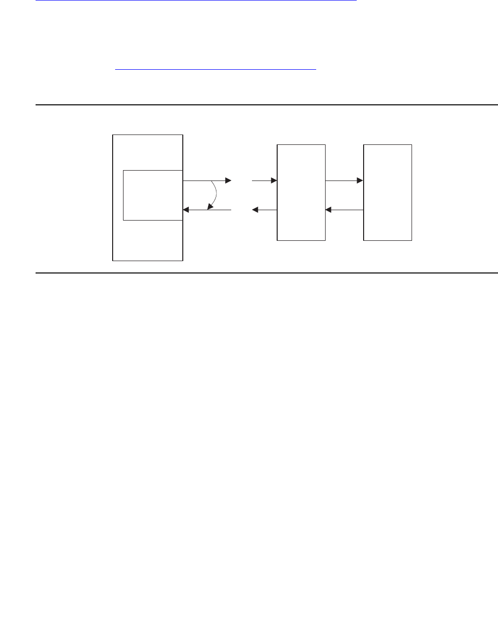
Communication Manager Maintenance-Object Repair Procedures
2162 Maintenance Procedures for Avaya Communication Manager 3.0, Media Gateways and Servers
Figure 134: Manual Loop-Around for Facility Fault Sectionalization on page 2162 shows a
sequence of units (1 though n) that may be connected as the on-site equipment. A typical
example is the case where the only on-site equipment is channel-terminating equipment
designated Unit #1. A more complex, less typical example might have a DACS as Unit #1, a
protection switch as Unit #2, and a DS1-level microwave radio system as Unit #3.
The flowchart in Figure 135: Facility Fault Sectionalization on page 2163 gives an overview of
the facility fault sectionalization technique. It is important that you know the configuration and
wiring of the equipment for the problem facility in order to support this technique.
Figure 134: Manual Loop-Around for Facility Fault Sectionalization
Since the technique is time consuming, fix any DS1-BD, UDS1-BD, STRAT-3, or SYNC errors
first that are not slip errors.
TN722,
TN767, or
TN464
DS1 interface
Manually
wired
loop-around
Pairs open
at next unit
Next unit
(#1)
Next unit
(#N)
Span
line
side
sync4 LJK 072501
Switch

SYNC (Port-Network Synchronization)
Issue 1 June 2005 2163
Figure 135: Facility Fault Sectionalization
Enter busyout board
for the DS1 Interface.
This circuit pack should
not be the on-line
synchronization reference.
Since this technique is time-consuming, first fix any DS1-BD,
UDS1-BD, STRAT-3 or SYNC errors that are not slip errors.
START (DS1 Interface refers to the TN722, TN767 or TN464 circuit pack.)
Loop transmit to receive on the
G3r side of the equipment
connected to the DS1 Interface.
(See Note 1).
NO
Restore service:
enter release
board for the
DS1 Interface.
YES
The fault lies beyond the
loop-around point. Remove
the loop-around and rewire
the connections. Is the
unit just tested the last unit
on the G3r side of the
maintenance boundary?
FAIL
The fault lies before the
loop-around point. Repair
or replace the defective
wiring or circuit pack.
If the problem cannot be
identified, escalate the
problem.
Move the loop-around point
to the next unit toward the
span line side. Loop transmit
to receive on the G3r side of
the next piece of equipment.
Report to the
appropriate
personnel that
the problem is
beyond the
maintenance
boundary.
PASS
Execute the Slip Alarm
Inquiry Test (#144) via
test board command.
(See Note 2).

Communication Manager Maintenance-Object Repair Procedures
2164 Maintenance Procedures for Avaya Communication Manager 3.0, Media Gateways and Servers
Notes to Facility Fault Sectionalization Flowchart
1. Loop transmit to receive on the system side.
Remove the transmit signal from the TN722, TN767, or TN464 circuit pack inputs and
outputs and loop it around to the receive signal going toward the TN722, TN767, or TN464
circuit pack at the first unit wired to the TN722, TN767, or TN464 circuit pack.
The loop-around signal may take different forms depending on the installation.
●In some cases, the unit connected to the system may provide a switch or a terminal
interface to control the desired loop around. Make sure that the signal is looped toward
the system and that the timing signal is looped.
●In most cases, it may be necessary to temporarily rewire connections at the
cross-connect fields to loop the signal back toward the switch.
The point at which the signal is looped should be one at which physical access is easy and
where the signal level is within the line compensation (i.e. equalization) range of the
hardware connected. A few cases exist where access to the loop around cannot be easily
provided at locations where the signal level is within the line compensation range of the
hardware. Use change ds1 location to change the line compensation.
2. Execute test board location for the TN722, TN767 or TN464. Look at results of Test
#144, the Slip Alarm Inquiry test. When this test fails, the error code gives the number of
slips detected since the last Slip Inquiry test was run. If the test fails, run it at least one more
time to ensure that slips have occurred since the loop around was installed.
Timing Loops
A timing loop exists when a system receives timing from another system whose timing
reference is directly or indirectly derived from itself. The system synchronization planner must
avoid creating a timing loop when administering the synchronization references in a system.
Timing loops can lead to loss of digital data between systems that are exchanging data with any
system within the loop. An invalid timing signal will also be generated by any system within the
loop, thus propagating the invalid timing signal to any system(s) using a system within the loop
as a synchronization reference.
A correctly designed network has no loops, and each piece of equipment in the network is
supplied by a clock with an equal or lower stratum number. (For example, the inputs to a
Stratum-3 clock should never be from a Stratum-4 device.)
!CAUTION:
CAUTION: Synchronization administration changes should never be done without consulting
the network’s overall synchronization plan. If you suspect that synchronization
administration changes are needed, follow normal escalation procedures.

SYNC (Port-Network Synchronization)
Issue 1 June 2005 2165
Synchronization Switches away from
Current Timing Reference
Synchronization changes away from a DS1 reference (primary or secondary) if the current DS1
reference does not provide a valid timing signal. The other DS1 reference is used if one is
administered and providing a valid timing signal. Otherwise, the local oscillator of the
Tone-Clock circuit pack in the same port network as the DS1 reference is used. The following
conditions cause a synchronization switch:
●The current DS1 reference is not inserted (list configuration board location
shows no board).
●The current DS1 reference has a loss of signal error (DS1-BD and UDS1-BD Error Type
1281), a blue alarm error (DS1-BD and UDS1-BD Error Type 1793), a red alarm error
(DS1-BD and UDS1-BD Error Type 2049), or a hyperactive angel error (DS1-BD and
UDS1-BD Error Type 1538). A corresponding alarm log entry is not required.
●DS1 and UDS1 circuit packs can be administered with slip detection enabled (the Slip
Detection field is y) on the add ds1 or change ds1 administration screens (See the
Administrators Guide for Avaya Communication Manager - 555-233-506). When over half
of the DS1 and UDS1 circuit packs administered as slip enabled experience slips, and the
primary or secondary synchronization reference is the current synchronization reference,
synchronization tries the other administered synchronization reference if the other
administered reference does not have the previous two conditions. Use list
measurements ds1-log to get an historical perspective of DS1 facility operation.
The following conditions cause a change to the other DS1 reference if one exists and the other
DS1 reference is more healthy:
●The current DS1 reference has a misframe error (DS1-BD Error Type 3329 to 3345 or
UDS1-BD Error Type 3585-3601). A corresponding alarm log entry is not required.
●The current DS1 reference has a slip alarm (DS1-BD and UDS1-BD Error Type 3073 to
3160). A corresponding alarm log entry is required.
If the previous conditions are repaired, synchronization changes back to the primary reference.
LEDs on Tone-Clock Circuit Packs
The specific flashing pattern of a TN768, TN780, or TN2182 Tone-Clock circuit pack’s amber
and green LEDs indicates the circuit pack’s status. For example, these flashing LED patterns
indicate whether the Tone-Clock circuit pack is:
●Deriving timing from an external source
●Providing the timing signal for its PN

Communication Manager Maintenance-Object Repair Procedures
2166 Maintenance Procedures for Avaya Communication Manager 3.0, Media Gateways and Servers
The amber and green LED patterns for TN768, TN780, and TN2182 Tone-Clock circuit packs
are listed in Table 770:
Error Log Entries and Test to Clear Values
S8700 | 8710 / S8500
Table 770: Tone-Clock Amber/Green LED Flashing Codes
Circuit Pack Condition Tone-Clock
State
Explanation
Flashing amber1
2.7 seconds on
0.3 seconds off
1. The external synchronization reference being used is a primary reference, or a secondary reference, or an
external Stratum-3 clock when the Tone-Clock is in the master PN. The external synchronization reference
used in a slave PN is an Expansion Interface circuit pack.
Active An external timing source is being used
as a synchronization reference.
Flashing amber
0.3 seconds on
2.7 seconds off
Active The circuit pack is being used as a
synchronization reference.
Steady amber
on
Active The circuit pack has been reset, but has
not been told which synchronization
reference source to use.
Steady amber
off
Standby The circuit pack is in standby mode
(neither generating tones nor supplying
clocks).
“Jingle Bells” green and amber
0.1 seconds on, 0.2 seconds off,
0.1 seconds on, 0.4 seconds off,
0.4 seconds on, 0.4 seconds off
Standby The system is running maintenance tests
on the standby Tone-Clock circuit pack.
(The standby circuit pack is providing
tones.)
Other green and amber Active The system is running maintenance tests
on the active Tone-Clock circuit pack.
Table 771: Synchronization Maintenance Error Log Entries
Error
Type
Aux
Data
Associated Test Alarm
Level
On/Off
Board
Test to Clear Value
0 (a) 0 Any Any Any test synchronization
1 of 2
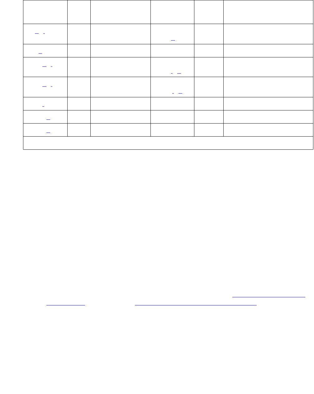
SYNC (Port-Network Synchronization)
Issue 1 June 2005 2167
Notes:
a. Error Type 0: run the short test sequence first. If every test passes, run the long test
sequence. Refer to each test’s description, and follow its procedures.
b. Error Type 1: run the short test sequence first. If every test passes, run the long test
sequence. Refer to each test’s description, and follow its procedures.
This error indicates a problem with the primary DS1 reference. It is cleared when the
primary reference is restored. To find the problem’s source:
1. Enter list configuration board location to check if the primary DS1 Interface
circuit pack is inserted in the carrier.
2. Verify that the administered primary reference matches the DS1 reference from the
network synchronization plan.
3. Enter test board location long to test the primary DS1 Interface circuit pack.
Check the Error Log for DS1-BD or UDS1-BD errors and see DS1-BD (DS1 Interface
Circuit Pack) on page 978 or UDS1-BD (UDS1 Interface Circuit Pack) on page 2374 to
resolve errors associated with the primary DS1 (DS1 or UDS1) interface circuit pack.
If the only errors against DS1-BD or UDS1-BD are slip errors, follow the procedures
described in the previous troubleshooting section. If no errors are listed in the Error Log
for the primary DS1 Interface circuit pack, continue with the following steps.
1 (b)(i) None WRN
MIN (g)
OFF None
18 (c)0disable sync WRN OFF enable sync
257 (d)(i) None WRN
MIN (i)(g)
OFF None
513 (e)(i) None WRN
MAJ (i)(g)
OFF None
769 (f) None MAJ OFF None
1793 (g)10–50 None MAJ OFF None
2049 (h) 0 None WRN OFF None
1. It can take up to 1 hour for these alarms to clear.
Table 771: Synchronization Maintenance Error Log Entries (continued)
Error
Type
Aux
Data
Associated Test Alarm
Level
On/Off
Board
Test to Clear Value
2 of 2

Communication Manager Maintenance-Object Repair Procedures
2168 Maintenance Procedures for Avaya Communication Manager 3.0, Media Gateways and Servers
4. Enter test tone-clock location long to test the active Tone-Clock circuit pack in
the master port network.
Check the Error Log for TDM-CLK errors, and verify that TDM Bus Clock Circuit Status
Inquiry test (#148), passes.
If Test #148 fails with Error Code 2–32, see TDM-CLK (TDM Bus Clock) on page 2252 to
resolve the problem. If not, continue with the following.
5. Use disable synchronization-switch and enable
synchronization-switch. When these two commands are used together, they
change the system synchronization reference to the primary DS1 Interface circuit pack.
6. Check the Error Log and use status synchronization to verify that the primary DS1
Interface circuit pack is still the system synchronization reference.
If the primary DS1 Interface circuit pack is not the system synchronization reference, and
the master port network does not have duplicate Tone-Clock circuit packs, escalate the
problem.
Otherwise, continue with the following.
7. For duplicated Tone-Clock circuit packs in the master port network:
Enter set tone-clock location to interchange Tone-Clocks in the master port
network, and repeat the disable/enable commands described in the previous step.
c. This error indicates that Synchronization Maintenance was disabled using disable
synchronization-switch. Use enable synchronization-switch to enable
Synchronization Maintenance reference switching and to resolve this alarm.
d. This error indicates a problem with the secondary DS1 reference. It is cleared when the
secondary reference is restored. Refer to note (b) to resolve this error substituting
secondary for primary in the preceding resolution steps.
e. This error indicates that the Tone-Clock circuit pack is providing the timing source for the
system. The primary and secondary (if administered) are not providing a valid timing signal.
Investigate errors 1 and 257 to resolve this error.
f. S8700 MC: This error indicates that the external Stratum-3 clock failed to provide the
system’s timing reference. Refer to Stratum-3 clock’s Maintenance document to resolve the
defective synchronization reference.
g. This error indicates excessive switching of system synchronization references has
occurred. When this error occurs, synchronization is disabled and the Tone-Clock circuit
pack (in the master port network) becomes the synchronization reference for the system.
Execute the following steps to resolve this error:
1. Check for timing loops, and resolve any loops that exist.

SYNC (Port-Network Synchronization)
Issue 1 June 2005 2169
2. Test the active Tone-Clock circuit pack in the master port network using test
tone-clock location long.
Check the Error Log for TDM-CLK errors, and verify that TDM bus Clock Circuit Status
Inquiry test (#148) passes.
If Test #148 fails with Error Code 2–32, see TDM-CLK (TDM Bus Clock) on page 2252 to
resolve the problem. If not, continue with the following.
3. For duplicated Tone-Clock circuit packs in the master port network, enter set
tone-clock location to switch the Tone-Clocks.
For unduplicated Tone-Clock circuit packs in the master port network of a Stratum-4 (not
Stratum-3) system, replace the primary and secondary (if assigned) DS1 Interface circuit
packs.
4. Investigate any other SYNC or STRAT-3 errors.
S8700 MC
h. This error indicates that the Expansion Interface circuit packs are experiencing timing slips.
This error increases the bit error rates for data transmission between port networks. The
Expansion Interface circuit packs with timing slips have EXP-INTF error 2305.
1. Check the LEDs on the active Tone-Clock circuit packs in the system and verify that the
system is properly synchronized.
2. Verify that all the TDM/LAN Bus cables on the backplane are marked WP-91716. Also for
a Multi-Carrier Cabinet (MCC), check that the bus terminator type is a ZAHF4 TDM/LAN.
For a Single Carrier Cabinet verify that the bus terminator type is a AHF110 TDM/LAN.
3. Check for timing loops, and resolve any loops that exist.
4. Check the Error Log for any active as well as resolved Expansion Interface circuit pack
errors and see EXP-INTF (Expansion Interface Circuit Pack) on page 1176 to resolve
any errors found.
5. Duplicated Tone-Clock circuit packs in the slave port networks:
●Interchange Tone-Clock circuit packs in the slave port networks where EXP-INTF error
2305 also occurs using set tone-clock location. The error count for this error
should start to decrement once the problem is solved. If the count does not decrease
in 15 minutes, the problem still exists.
●If the problem still exists, switch the Tone-Clock in the slave port network back to the
previous configuration, then perform a PNC interchange using reset pnc
interchange.
●If the problem still exists, switch the PNC back to the previous configuration using
reset pnc interchange. Switch the Tone-Clock circuit packs in the master port
network using set tone-clock location.
●If the problem still exists, switch the Tone-Clock circuit packs in the master port
network back to the previous configuration using set tone-clock location.

Communication Manager Maintenance-Object Repair Procedures
2170 Maintenance Procedures for Avaya Communication Manager 3.0, Media Gateways and Servers
●Replace the active Expansion Interface circuit pack in the master port network.
●In a CSS configuration, replace the Switch Node Interface circuit pack connected to
the active Expansion Interface circuit pack in the master port network. Use list
fiber-link to determine the Switch Node Interface circuit pack that is connected to
the active Expansion Interface circuit pack in the master port network.
●If the system’s synchronization reference is a Tone-Clock circuit pack or a Stratum-3
clock, follow normal escalation procedures.
If the system’s primary synchronization reference is a DS1 Interface circuit pack,
assign a different DS1 Interface as the primary reference. If the problem persists and
slip errors remain, follow the procedures in the troubleshooting section above.
6. For unduplicated Tone-Clock circuit packs in a slave port network:
●Enter set tone-clock location to switch the Tone-Clock in the master port
network.
●If the problem still exists, enter set tone-clock location to switch the
Tone-Clocks in the master port network back to their previous configuration.
Enter test tone-clock location long to test the Tone-Clock in the master and
slave port networks.
Check the Error Log for TDM-CLK errors and verify that TDM Bus Clock Circuit Status
Inquiry test (#148) passes.
If Test #148 fails with an Error Code 2–32, see TDM-CLK (TDM Bus Clock) on
page 2252 to resolve the problem. If not, continue with the following steps.
●If the master and slave Tone-Clock circuit packs do not fail TDM Bus Clock Test #150
(TDM Bus Clock PPM Inquiry test), replace the Expansion Interface circuit packs that
have EXP-INTF error 2305.
●If the system synchronization reference is a Tone-Clock circuit pack and the master
Tone-Clock circuit pack fails TDM Bus Clock Test #150, follow the steps listed in
“TDM-CLK” to replace the master Tone-Clock circuit pack.
●If the system’s synchronization reference is a DS1 Interface circuit pack and the
master Tone-Clock circuit pack fails TDM Bus Clock test (#150), the primary or
secondary (if administered) synchronization references are not providing valid timing
signals for the system.
If the primary synchronization reference is providing the system’s timing, check the
synchronization references administered, and follow the steps outlined in note (b). If
the secondary reference is providing timing, follow note (d).
●If the slave Tone-Clock circuit pack fails TDM Bus Clock Test #150 but the master
Tone-Clock does not fail this test, the master Tone-Clock circuit pack must be
replaced. Follow the Tone-Clock replacement steps listed in TDM-CLK (TDM Bus
Clock).
●Replace the active Expansion Interface circuit pack in the master port network.

SYNC (Port-Network Synchronization)
Issue 1 June 2005 2171
●In a CSS configuration, replace the Switch Node Interface circuit pack connected to
the active Expansion Interface circuit pack in the master port network. Use list
fiber-link to determine the Switch Node Interface circuit pack that is connected to
the active Expansion Interface circuit pack in the master port network.
●If the problem persists and any slip errors remain, follow the procedures described in
the troubleshooting section above.
This error is cleared by a leaky bucket strategy, and takes one hour to clear the error
counter once it is alarmed. Therefore, it may take up to one hour to clear the alarm after the
problem is cleared.
i. Noise on the DS1 line can cause transient alarms on synchronization. Therefore, when a
sync problem occurs on Error Types 1, 257, or 513, a WRN alarm is first raised for 15 to 20
minutes before the alarm is upgraded to a MINOR or MAJOR alarm.
Table 772: Synchronization Error Log Entries
Error
Type
Aux
Data
Associated Test Alarm
Level
On/Off
Board
Test to Clear Value
01
1. Run the Short Test Sequence first. If all tests pass, run the Long Test Sequence. Refer to the appropriate
test description and follow the recommended procedures.
0 Any Any Any test synchronization
1 (a) (g)AnyNone WRN
MIN (j)2
2. This Error Type initially raises a Warning alarm. If this Error Type persists and alarms are not
downgraded on this MO due to the value of set options, then, after a period of time, a Minor or Major
alarm is raised.
OFF None
18 (b)0disable sync WRN OFF enable sync
257 (c)(g)AnyNone WRN
MIN (j)2OFF None
513 (d)(g)AnyNone WRN
MAJ (j)2OFF None
769 (e)None MAJ
WRN3
3. Major alarms on this MO may be downgraded to Warning alarms based on the value used in set
options.
OFF None
17934
4. It can take up to one hour for these SYNC alarms to clear due to "leaky bucket" strategy.
0-50 None MAJ
WRN
OFF enable sync
2049 (f)40 None WRN OFF None
2305 (f) 40 None WRN OFF None

Communication Manager Maintenance-Object Repair Procedures
2172 Maintenance Procedures for Avaya Communication Manager 3.0, Media Gateways and Servers
Notes:
a. Error Type 1: problem with the primary DS1 reference. It is cleared when the primary
reference is restored. The following steps should give an indication of the source of the
problem:
1. Check if the primary DS1 interface circuit pack is inserted in the carrier using list
configuration board location.
2. Check the connection of the cable supplying the external timing source to the primary
DS1 interface circuit pack.
3. Test the primary DS1 interface circuit pack using test board location long. Check
the Error Log for DS1-BD errors and refer to the DS1-BD (DS1 Interface Circuit Pack)
Maintenance documentation to resolve any errors associated with the primary DS1
interface circuit pack. If no errors are listed in the Error Log for the primary DS1 interface
circuit pack, continue with the following steps.
4. Test the active Tone-Clock circuit pack in the master port network using test tone/
clock location long. Check the Error Log for TDM-CLK errors and verify that TDM
Bus Clock Test #148 passes successfully. If Test #148 fails with an Error Code 2 through
32, refer to TDM-CLK (TDM Bus Clock) on page 2252 to resolve the problem. If not,
continue with the following steps.
5. Execute disable synchronization-switch and the enable
synchronization-switch. These two commands (when executed together) switch
the system synchronization reference to the primary DS1 interface circuit pack. Check
the Error Log and execute the status synchronization command to verify that the
primary DS1 interface circuit pack is still the system synchronization reference. If the
primary DS1 interface circuit pack is not the system synchronization reference, continue
with the following step.
b. *Error Type 18: Synchronization Maintenance has been disabled using disable
synchronization-switch. Execute enable synchronization-switch to enable
Synchronization Maintenance reference switching and to resolve this alarm.
c. Error Type 257: problem with the secondary DS1 reference. It is cleared when the
secondary reference is restored. Refer to note (a) to resolve this error substituting
secondary for primary in the preceding resolution steps.
d. Error Type 513: the Tone-Clock circuit pack is providing the timing source for the system.
The primary and secondary (if administered) are not providing a valid timing signal.
Investigate errors 1 and 257 to resolve this error.
e. Error Type 769: excessive switching of system synchronization references has occurred.
When this error occurs, synchronization is disabled and the Tone-Clock circuit pack (in the
master port network) becomes the synchronization reference for the system. Execute the
following steps to resolve this error:
1. Check for timing loops and resolve any loops that exist.
2. Test the active Tone-Clock circuit pack in the master port network using test tone/
clock location long. Check the Error Log for TDM-CLK errors and verify that TDM

SYNC (Port-Network Synchronization)
Issue 1 June 2005 2173
Bus Clock Test #148 passes successfully. If Test #148 fails with an Error Code 2 through
32, refer to the TDM-CLK (TDM Bus Clock) Maintenance documentation to resolve the
problem. If not, continue with the following steps.
3. Replace the primary and secondary (if administered) DS1 Interface circuit packs.
4. Check for an error logged against the primary or secondary DS1 board. If there is an
error, follow the DS1 section to resolve the errors. If there is not, enter enable sync,
and wait for two to five minutes for the primary sync source to come on-line.
f. Error Type 2049: the slave Tone-Clock circuit pack is experiencing loss of signal. Refer to
note (i) for error resolution steps.
The following steps should be executed to resolve error 2049 and 2305:
1. Check for timing loops, and resolve any loops that exist.
2. Error 2049:
●Test the Tone-Clock circuit packs in the master and slave port networks using test
tone/clock location long. Check the Error Log for TDM-CLK errors and verify
that TDM Bus Clock Test #148 passes successfully. If Test #148 fails with an Error
Code 2 through 32, refer to TDM-CLK (TDM Bus Clock) on page 2252 to resolve the
problem. If not, continue with the following steps.
●If the system synchronization reference is a Tone-Clock circuit pack and the master
Tone-Clock circuit pack fails TDM Bus Clock Test #150, follow the steps listed in
TDM-CLK (TDM Bus Clock) on page 2252 to replace the master Tone-Clock circuit
pack.
●If the system synchronization reference is a DS1 interface circuit pack and the master
Tone-Clock circuit pack fails TDM Bus Clock Test #150, the primary or secondary (if
administered) synchronization references are not providing valid timing signals for the
system. Check the system synchronization references administered, and follow the
steps outlined in note (a) if the primary synchronization reference is providing timing
for the system or note (c) if the secondary synchronization reference is providing
timing for the system.
●If the slave Tone-Clock circuit pack fails the TDM Bus Clock Test #150 but the master
Tone-Clock does not fail this test, the master Tone-Clock circuit pack must be
replaced.
If SLIP errors remain follow SLIP ANALYSIS.
3. Error 2305:
●If the problem persists, replace the Tone-Clock circuit pack in the slave port network.
Follow the steps listed in TDM-CLK (TDM Bus Clock) on page 2252 to replace the
Tone-Clock circuit pack.
g. Noise on the DS1 line can cause transient alarms on synchronization. Therefore, when a
synchronization problem occurs causing Error Types 1, 257, or 513, a WRN alarm is first
raised for 15 to 20 minutes before the alarm is upgraded to a MAJOR or MINOR alarm.
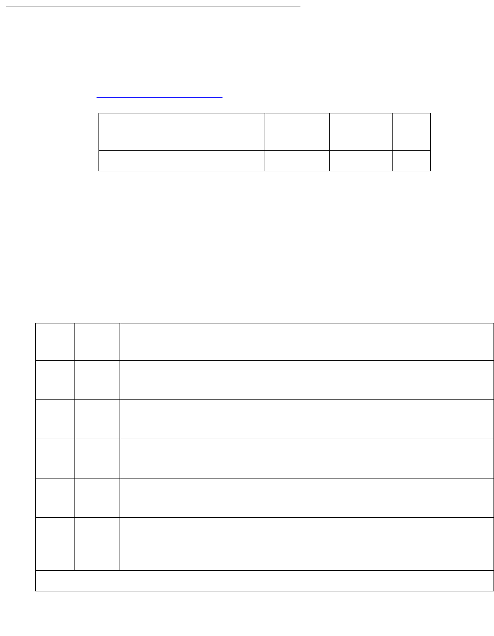
Communication Manager Maintenance-Object Repair Procedures
2174 Maintenance Procedures for Avaya Communication Manager 3.0, Media Gateways and Servers
System Technician-Demanded Tests:
Descriptions and Error Codes
S8700 MC: If Stratum 3 is administered using change synchronization, the Stratum-3 Clock
Alarm Query test (#649) also executes when test synchronization is run. Test #649 is
described in Stratum-3 Synchronization on page 2146.
Test Synchronization Test (#417)
This test updates every Synchronization Maintenance component with the correct information
about its role in providing a system’s synchronization. This test updates every:
●IPSI circuit pack’s Tone-Clock circuit
●Tone-Clock, Expansion Interface, DS1 Interface, and UDS1 Interface circuit pack in the
system. The test either passes or aborts.
Order of Investigation Short Test
Sequence
Long Test
Sequence
D/ND
Test Synchronization test (#417) X X ND
Table 773: Test Synchronization Test (#417)
Error
Code
Test
Result
Description / Recommendation
Blank ABRT Internal system error
1. Retry the command at 1-minute intervals up to 3 times.
1000 ABRT System resources required to run this test are not available.
1. Retry the command at 1-minute intervals up to 3 times.
1115 ABRT Could not allocate the necessary system resources to run this test.
1. Retry the command at 1-minute intervals up to 3 times.
2500 ABRT Internal system error
1. Retry the command at 1-minute intervals up to 3 times.
PASS The Synchronization Maintenance component circuit-pack parameters have
been successfully updated. The system should be synchronized after
successful execution of this test. If synchronization problems still exist, refer
to the Error Log to obtain information about the source of the problem.

SYS-LINK (System Links)
Issue 1 June 2005 2175
SYS-LINK (System Links)
S8700 | 8710 / S8500
System links are packet links that originate at the Packet Interface board and traverse various
hardware components to specific endpoints. The hardware components involved on the forward
and reverse routes can be different, depending upon the configuration and switch
administration. Various types of links are defined by their endpoints:
Recording System Link Events
The system-links MO records every error encountered on the links. Most of these events are not
extraordinary unless they occur with an alarming frequency. The events are logged as they
occur, leaving a “trail” to help analyze abnormal behavior exhibited by the endpoints attached to
the links or the links themselves.
When a link goes down, an alarm is raised immediately. For EAL, INL, BFDL, and PACL link
types a MINOR alarm is raised. For every other link type a WRN alarm is raised. Other alarming
conditions that do not cause the link to go down get a WRN alarm, regardless of the link type.
MO Name Alarm Level Initial SAT Command to Run Full Name of MO
SYS-LINK MIN test sys-link location SYSTEM LINKS
SYS-LINK WRN test sys-link location SYSTEM LINKS
EAL Expansion Archangel Link terminating at an Expansion Interface board. This
link carries CCMS messages.
INL Indirect Neighbor Link terminating at a Switch Node Interface board.
PACL PNC ATM Control Link terminating at a PNC ATM-EI board. This link carries
ATM signaling commands from CAPro to the remote TN2238 (ATM-EI) boards.
PRI ISDN-PRI D-Channel Link terminating at a Universal DS1 board
RSCL Remote Socket Control Link terminating at a C-LAN board
RSL Remote Socket Link terminating at a C-LAN board
BFDL Bearer Fault Detection Link terminating at an Expansion Interface board. This
link provides inter-port-network bearer fault detection for port-networks that do
not use an EAL terminating at the EI board.
MBL Maintenance Board Link terminating at an IPSI board that provides
Environmental maintenance for a G650 rack mounted cabinet. This replaces
the Expansion Port-Network (EPN) maintenance board serial channel.
TACL ATM control link terminating at an ATM-TRK board. This link carries ATM
signaling commands from CAPro to the remote TN??? (ATM-TRK) boards.

Communication Manager Maintenance-Object Repair Procedures
2176 Maintenance Procedures for Avaya Communication Manager 3.0, Media Gateways and Servers
Identifying a System Link
In order to trace problems associated with a system link, it is necessary to find its location. Use
the following methods to find the location of the system link.
Display Errors/Alarms
The output of display errors or display alarms shows the location of the system link for
entries with a Maintenance Name of SYS-LINK. You can restrict the scope of the output of these
commands by specifying sys-link in the Category field on the input screen. The link type and
channel number, if any, are listed under the Alt Name field of the report.
List sys-link
The list sys-link command lists every system link (location, link type, and channel
number) present in the system.
Common Procedure for Repairing Link Problems
The state of a system link is dependent on the state of the various hardware components that it
travels over. To resolve any problems associated with a system link, use the following
procedure.
The switch maintains a list of hardware components over which the link travels, called the
hardware path. There are two hardware paths: the current hardware path and the faulted
hardware path for each of the system links. The current hardware path is present only for those
links that are currently up. When a link is down, the current hardware path is empty. The faulted
hardware path is always present once the link has gone down, and is not cleared when the link
subsequently recovers. The faulted path preserves the path that the link traversed when it last
went down. The time at which the faulted path was last recorded is preserved and is accessible
through status sys-link location and list sys-link. Therefore, the focus of
attention for problems which do not involve a link that is down is the current hardware path. If
the link is down, faulted hardware path is the focus of attention.
The status sys-link location command shows the state of both the hardware paths
(current and faulted) along with the state of each of the components in the hardware path. When
analyzing any system link problem:
1. Look for alarms on the components listed under desired hardware path.
2. If any alarms are present, then follow the maintenance procedures for the alarmed
components to clear those alarms first.
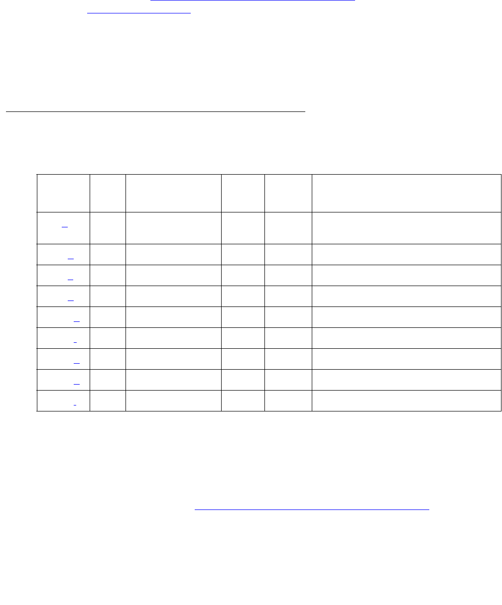
SYS-LINK (System Links)
Issue 1 June 2005 2177
Note:
Note: For systems using ATM-EI (TN2305/6 circuit packs) and where link alarms are
present, see ATM-EI (Expansion Interface Circuit Pack) on page 525 and
Troubleshooting ATM in Maintenance Procedures (03-300192).
3. When every component is alarm free, wait for 3 minutes to allow the links to recover.
4. Test the system link (test sys-link location long clear), and notice any tests
that fail.
5. If there are any failures, fix the problems indicated by the tests and repeat the procedure.
Error Log Entries and Test to Clear Values
Notes:
a. Error Type 13: the link went down. The link may have gone down or never come up. Enter
status sys-link location and check the value of the Faulted Path field. If the value
is default, then the link never came up. If the value is present, then the link came up and
then went down.
1. Follow the information in Common Procedure for Repairing Link Problems on page 2176.
2. Wait for 3–5 minutes before checking the link state.
3. Repeat the procedure until there are no problems.
Table 774: Maintenance Error Log Entries
Error
Type
Aux
Data
Associated Test Alarm
Level
On/Off
Board
Test to Clear Value
13 (a) System Link
Status (#985)
MIN
WRN
OFF
257 (b)WRNOFFtest sys-link location l cl
513 (c)WRNOFFtest sys-link location l cl
772 (d)WRNOFFtest sys-link location l cl
1025 (e)WRNOFFtest sys-link location l cl
1281 (f)WRNOFFtest sys-link location l cl
1537 (g)WRNOFFtest sys-link location l cl
1793 (h)WRNOFFtest sys-link location l cl
2049 (i)WRNOFFtest sys-link location l cl

Communication Manager Maintenance-Object Repair Procedures
2178 Maintenance Procedures for Avaya Communication Manager 3.0, Media Gateways and Servers
b. Error Type 257: the link has experienced uplink flow control, and the endpoint may be
hyperactive. The system link is alarmed if 4 or more errors of this type are detected within
10 minutes.
1. Follow the information in Common Procedure for Repairing Link Problems on page 2176.
2. Clear errors and wait for 10 minutes.
c. Error Type 513: the link has experienced downlink flow control, meaning that some
information packets from the packet interface board have been lost. The link is reset on first
occurrence and Error 1025 is also logged. The system link is alarmed if 2 or more errors of
this type are detected within 10 minutes.
1. Follow the information in Common Procedure for Repairing Link Problems on page 2176.
2. Clear errors and wait for 10 minutes.
d. Error Type 772: the link experienced a temporary disconnect due to excessive resets or
state transitions, meaning that the link is taken down and then brought up again. The
system link is alarmed if 2 or more errors of this type are detected within 10 minutes.
1. Follow the information in Common Procedure for Repairing Link Problems on page 2176.
2. Clear errors and wait for 10 minutes.
e. Error Type 1025: the link has been reset, meaning that information packets queued at the
time of reset are lost. The system link is alarmed if 20 or more errors of this type are
detected within 10 minutes.
1. Follow the information in Common Procedure for Repairing Link Problems on page 2176.
2. Clear errors and wait for 10 minutes.
f. Error Type 1281: the link has experienced slow transmit rate because the remote endpoint
is busy. The effect of this error is that the endpoint location may experience slower
throughput rate and/or noisy transmission. The system link is alarmed if 4 or more errors of
this type are detected within 10 minutes.
1. Ensure that the remote endpoint is functioning properly.
2. Follow the information in the previous section, Common Procedure for Repairing Link
Problems on page 2176.
3. Clear errors and wait for 10 minutes.
g. Error Type 1537: the link has experienced slow transmit rate due to excessive
retransmission. Possible causes may be that the switch is overrunning the endpoint, or that
the endpoint is sick. The effect is that the endpoint location may experience slower
throughput rate. The system link is alarmed if 4 or more errors of this type are detected
within 10 minutes.
1. Follow the information in Common Procedure for Repairing Link Problems on page 2176.
2. Clear errors and wait for 10 minutes.

SYS-LINK (System Links)
Issue 1 June 2005 2179
h. Error Type 1793: This error indicates that the link has experienced slow transmit rate due to
unknown causes, meaning that the endpoint location may experience slower throughput
rate and the Packet Interface may experience backup or congestion. The system link is
alarmed if 4 or more errors of this type are detected within 10 minutes.
1. Follow the information in Common Procedure for Repairing Link Problems on page 2176.
2. Clear errors and wait for 10 minutes.
i. Error Type 2049: the link has transmitted an excess amount of packets. The transmit
buffers of this link have been purged. The system link is alarmed if 4 or more errors of this
type are detected within 10 min.
1. Follow the Common Procedure for Repairing Link Problems on page 2176.
2. Clear errors and wait for 10 min.
System Technician-Demanded Tests:
Descriptions and Error Codes
Testing for system links is different from the standard test procedures for MOs. In addition to
testing the system link MO, the user can test every component in the path of the system link.
There are two paths preserved for the link. The current path, if present, represents the path
traversed by the link currently. This path is absent when the link is down. The other path, the
faulted path, is present if the link has ever gone down or never come up. If the link came up and
went down, then the Faulted Path is marked present. If the link never came up, the Faulted
Path is marked default. In either case, it represents the path on which the link was attempted or
established unsuccessfully.
Test command for the system links, test sys-link location, can be specified with current
or faulted as an optional argument if the user wishes to test every component in the specified
path. The tests executed are the same if the user tests each component manually. In the event
that the user does not specify any path, then only the tests specified for the system links are
executed.
Order of Investigation Short Test
Sequence
Long Test
Sequence
D/ND
System Link Status (#985) X X ND

Communication Manager Maintenance-Object Repair Procedures
2180 Maintenance Procedures for Avaya Communication Manager 3.0, Media Gateways and Servers
System Link Status (#985)
This test is nondestructive. This test queries the switch for the status of the system link and
verifies that every switch component has the same view of the link state.
Table 775: TEST #985 System Link Status
Error
Code
Test
Result
Description / Recommendation
1007 ABRT Could not locate the system link associated with this location
1. Retry the command at 1-minute intervals up to 5 times.
2500 ABRT Internal system error
1. Retry the command at 1-minute intervals up to 5 times.
6 FAIL The system link is down.
1. Follow the procedure for Error Type 13.
PASS The system link is up.

SYS-PRNT (System Printer)
Issue 1 June 2005 2181
SYS-PRNT (System Printer)
S8700 | 8710 / S8500
The Report Scheduler feature provides the capability to schedule printing of output screen
selected administration commands on an asynchronous System Printer (SYS-PRNT) or a
Personal Computer (PC). The System Printer device connects to the system via a data module
(PDM, MPDM, DTDM) connected to a port on a TN754 Digital Line circuit pack which is
administered as a data extension. A System Printer device can also be connected through an
ADU to a port on TN726B Data Line circuit pack. The System Printer link to the processor is via
a C-LAN board. For information about C-LAN connectivity, see CLAN-BD (Control LAN Circuit
Pack) on page 789.
System Printer Link Maintenance provides a strategy for maintaining the link between the
system and an external SYS-PRNT output device. The strategy includes a set of tests for
detection of errors during normal operation, troubleshooting actions, and alarms for serious
problems. System Printer Link Maintenance uses a try-and-wait mechanism for maintaining the
SYS-PRNT link. A minor alarm is raised when the link set-up fails. A warning alarm is raised
when the server has been busied out. Up to two link retry attempts are made. After the second
attempt, set-up attempts are only made by the application software. (The 15-minute timer fires
and jobs are printed unless an immediate job was entered.) After two unsuccessful attempts to
establish the link, a MINOR alarm is raised. If the System Printer Link is torn down due to an
error, System Printer Link Maintenance will raise a MINOR alarm but will not attempt to bring up
the System Printer Link.
System Printer Link Maintenance does not cover the elements comprising the SYS-PRNT
physical link: the external SYS-PRNT output device, the Data Module (PDM/MPDM/DTDM) and
TN754 Digital Line, or the ADU and TN726B Data Line. If System Printer Link Maintenance
cannot restore the System Printer Link, the maintenance tests of these individual components
of the System Printer Link must be executed to diagnose faults.
Procedures for Restoring the System Printer Link
1. Use status sp-link and verify that the Maintenance Busy field is n, which shows that
the System Printer Link is not busied out for maintenance. If the System Printer Link has
been busied out, use release sp-link. If the link is down, proceed to Step 2.
2. Use display system-parameters features to determine the location of the System
Printer Link.
Use status data-module extension and verify that the data extension is in-service/
idle. If the data extension is not available, refer to the Port field. Look for errors and/or
alarms on the circuit pack with which this extension is associated. Follow repair instructions
for the appropriate MO. Continue with Step 3.
MO Name Alarm Level Initial SAT Command to Run Full Name of MO
SYS-PRNT MIN test sp-link l System Printer
SYS-PRNT WRN release sp-link System Printer
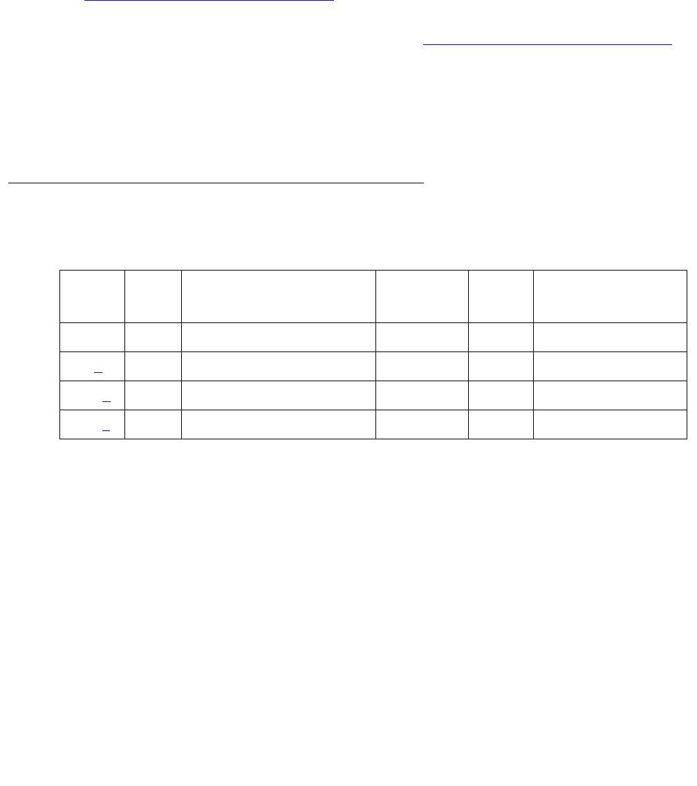
Communication Manager Maintenance-Object Repair Procedures
2182 Maintenance Procedures for Avaya Communication Manager 3.0, Media Gateways and Servers
3. Verify the availability of the external SYS-PRNT output device. Make sure that the output
device is on-line and ready-for-service. Check the physical connectivity between the Data
Module and the SYS-PRNT output device.
4. Verify that there is at least one C-LAN port available. The System Printer Link cannot be
established without an available C-LAN port. For more information about C-LAN ports, see
CLAN-BD (Control LAN Circuit Pack) on page 789.
5. If the problem is not found in the previous steps, check the C-LAN port for problems. For a
description of C-LAN boards and connectivity, see CLAN-BD (Control LAN Circuit Pack) on
page 789.
When restoring the System Printer link, execute tests on different MOs that comprise the
System Printer link. It is recommended that you busyout the System Printer link before trying to
restore the link. When the System Printer Link is busied out, every System Printer Link
maintenance action is deactivated, and interference with tests of other MOs is prevented.
Error Log Entries and Test to Clear Values
Notes:
a. Error Type 18: the System Printer Link has been busied out.
b. Error Type 257: a failure was encountered while attempting to set up the System Printer
Link. This attempt could have been initiated by either Report Scheduler software or by link
maintenance during automatic link retry or as a result of a Link Retry test (#215) request.
The Aux Data field indicates the following:
Table 776: SYS-PRNT Maintenance Error Log Entries
Error
Type
Aux
Data
Associated Test Alarm
Level
On/Off
Board
Test to Clear Value
0 0 Any Any Any test sp-link
18 (a)0 busyout sp-link WRN OFF release sp-link
257 (b) 1, 3-6 Link Retry test (#215) MIN1 WRN
1. Minor alarms can be downgraded to Warning alarms based on the value used in set options.
OFF test sp-link l
513 (c)0 None MIN OFF test sp-link

SYS-PRNT (System Printer)
Issue 1 June 2005 2183
See Procedures for Restoring the System Printer Link on page 2181 for recommended
maintenance strategy.
c. Error Type 513: the SYS-PRNT was interrupted for one of the following reasons:
●The cable to the SYS-PRNT output device is disconnected
●The SYS-PRNT output device is powered off
●The data extension to which the SYS-PRNT output device connects has been busied out
●Internal software error
Check the connectivity of the wires and cables among the wall jacket, data module, and
SYS-PRNT output device. Follow the instructions in Procedures for Restoring the System
Printer Link on page 2181.
System-Technician-Demanded Tests: Descriptions And Error
Codes
Investigate tests in the order presented below. Clearing error codes associated with the one test
may also clear errors generated from other tests in the sequence.
Table 777: Aux Data, Error Type 257
Aux
Data
Description
1 No C-LAN port available. See CLAN-BD (Control LAN Circuit Pack) on
page 789 for explanation.
3, 4 Time-out during setup attempt. Most likely due to problem with physical link
or printer status.
5 Internal system error. Most likely temporary/sporadic failure.
2, 6 The data module the printer is trying to use is busy with another call. Use
status data module to determine when the port is available for testing.
Order of Investigation Short Test
Sequence
Long Test
Sequence
D/ND
Link Tear Down test (#213) X D
Link Retry test (#215) X X ND

Communication Manager Maintenance-Object Repair Procedures
2184 Maintenance Procedures for Avaya Communication Manager 3.0, Media Gateways and Servers
Link Tear Down Test (#213)
This test is destructive.
The Link Tear Down test disconnects the existing link between the media server and the
external SYS-PRNT output device. If the link has already been disconnected, this test returns
PASS. Every resource allocated for a System Printer Link is released after this test.
Table 778: TEST #213 Link Tear Down Test
Error
Code
Test
Result
Description / Recommendation
40
50
ABRT Internal system error.
1. Retry the command at 1-minute intervals up to two times.
1010 ABRT The System Printer Link has been busied out.
1. Use release sp-link to release the System Printer Link from the
busyout state.
2. Enter test sp-link long to execute the test.
2012 ABRT Internal system error.
1. Retry the command at 1-minute intervals up to five times.
FAIL Internal system error.
1. Retry the command at 1-minute intervals up to two times.
PASS The System Printer Link is torn down, or a short test sequence was executed
and the link was not torn down.

SYS-PRNT (System Printer)
Issue 1 June 2005 2185
Link Retry Test (#215)
This test sends a message to the System Printer management software process instructing it to
make a data call to the extension connected to the printer. If the System Printer link is already
up, this test passes without making any data call.
Table 779: TEST #215 Link Retry Test
Error
Code
Test
Result
Description / Recommendation
10
20
ABRT Internal system error.
1. Retry the command at 1-minute intervals up to two times.
30 ABRT Internal system error.
1. See Procedures for Restoring the System Printer Link on page 2181 for
recommended maintenance strategy.
1010 ABRT The System Printer Link has been busied out.
1. Enter release sp-link to release the System Printer Link from the
busyout state.
2. Enter test sp-link long to execute the test.
2012 ABRT Internal system error.
1. Retry the command at 1-minute intervals up to five times.
FAIL The System Printer Link CANNOT be established.
1. See Procedures for Restoring the System Printer Link on page 2181 for
recommended maintenance strategy.
PASS The System Printer Link is up.
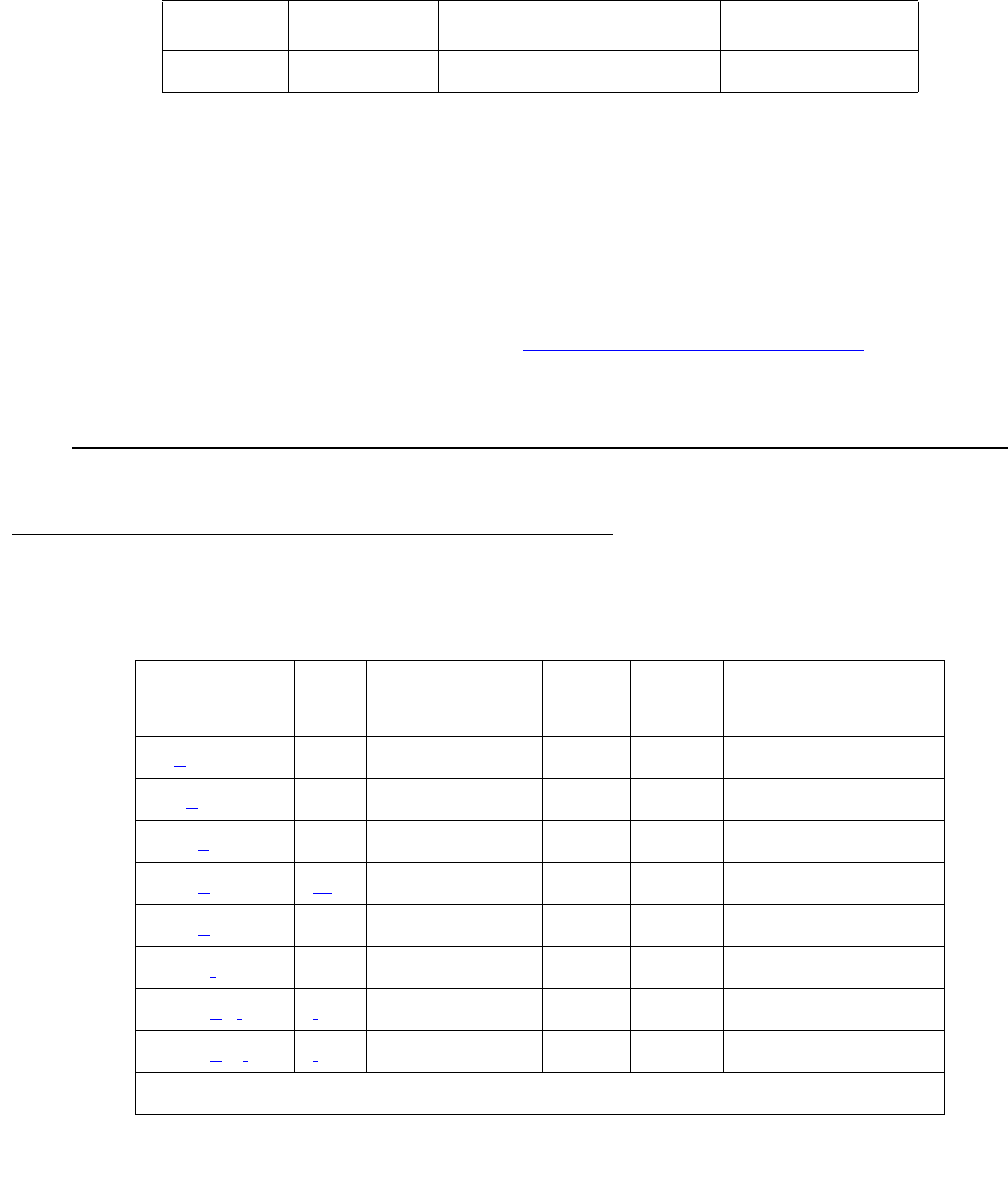
Communication Manager Maintenance-Object Repair Procedures
2186 Maintenance Procedures for Avaya Communication Manager 3.0, Media Gateways and Servers
SYSTEM (System)
S8700 | 8710 / S8500
The SYSTEM maintenance object is used to log information about system resets, including
interchanges. When software encounters a problem with hardware, or with its own processes,
and requests a restart to clear the problem, an error is logged under SYSTEM. For example, if
there is a loss of clocking in a system with duplicated servers, the system switches to the other
clock and then executes a level-2 system reset to recover from hardware problems caused by
the loss of clock. Errors logged under SYSTEM can help to determine the cause of a reset.
For more information about interchanges, see Troubleshooting duplicated servers in
Maintenance Procedures (03-300192).
The display initcauses screen also contains information about the reset.
S8700 | 8710 / S8500
Error Log Entries and Test to Clear Values
MO Name Alarm Level Initial Command to Run1
1. SYSTEM has no associated alarms and thus appears only in the Error Log. There
are no tests that run on SYSTEM.
Full Name of MO
SYSTEM None None System
Table 780: System Error Log Entries
Error
Type
Aux
Data
Associated
Test
Alarm
Level
On/Off
Board
Test to Clear Value
9 (a) Any None
10 (b) Any None
601 (c) Any None
605 (d)(m) None
606 (e) Any None
6001 (f) Any None
6002 (g)(l)(l) None
6003 (h) (l)(l) None
1 of 2

SYSTEM (System)
Issue 1 June 2005 2187
Notes:
a. Error Type 9: software requested a System Restart Level 2.
b. Error Type 10: software requested a System Restart Level 1.
c. Error Type 601: an error occurred during initialization.
d. Error Type 605: a reset system interchange or a scheduled server interchange
failed. The AUX Data indicates the cause of the failure. Consult the table in note p. Enter
the Linux server command to determine the current server status, and resolve any
problems on the standby server that are preventing the server interchange.
e. Error Type 606: a reset system interchange health-override failed. The
standby server’s state of health (SOH) would not allow a spontaneous server interchange.
Enter the Linux server command to determine the current server status, and resolve any
problems on the standby server that are preventing the server interchange.
f. Error Type 6001: an operating system error occurred on the active server. The Aux Data
gives the source of the error:
g. Error 6002: an application error occurred on the active server. See note (l) to diagnose the
error using the Aux Data.
h. Error 6003: an application alarm occurred on the active server. See note (l) to diagnose the
error using the Aux Data.
i. Error 6100: an operating system error occurred on the standby server. See error 6001 (g)
to interpret the Aux Data.
j. Error 6102: an application error occurred on the standby server. See note (l) to diagnose
the error using the Aux Data.
6101 (i) Any None
6102 (j)(l)(l) None
6103 (k)(l)(l) None
Aux Data Operating System Error Type
5 Software Abort
6 Server Bus Error
Table 780: System Error Log Entries (continued)
Error
Type
Aux
Data
Associated
Test
Alarm
Level
On/Off
Board
Test to Clear Value
2 of 2
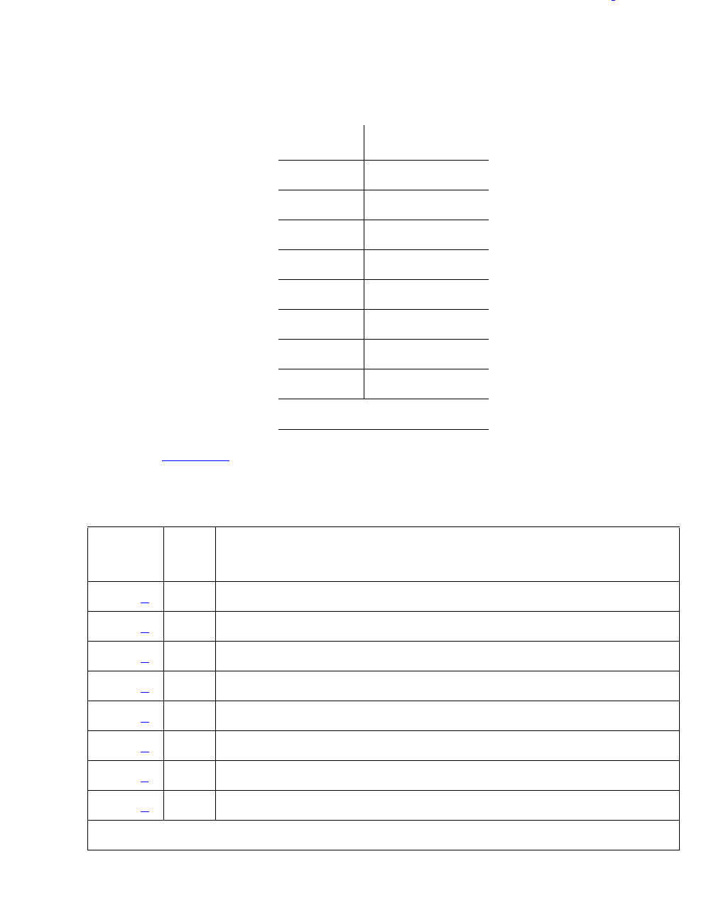
Communication Manager Maintenance-Object Repair Procedures
2188 Maintenance Procedures for Avaya Communication Manager 3.0, Media Gateways and Servers
k. Error 6103: an application alarm occurred on the standby server. See note (l) to diagnose
the error using the Aux Data.
l. Error Types 6002, 6003, 6102, and 6103: the aux-data value points to the MO that the
error or alarm is logged against. The following table lists possible aux-data values and their
associated MOs. Locate the Error Log entry for the indicated MO and follow the instructions
for that error.
m. Aux Data: Table 781 and notes give causes and recommendations for each Aux Data value
for Error Type 605.
Aux Data Implicated MO
4137 PKT-INT
16384 PROCR
16385 MEM-BD
16389 DUPINT
16391 SW-CTL
16392 H-ADAPTR
16397 R-MEDIA
16398 DISK
Table 781: SYSTEM Error 605 Aux Data, Failure of Planned Interchange
Aux
Data
See
Note
Explanation
1352 (a) 1 Standby SOH "non-functional"
1353 (a) 1 Standby SOH not "functional"
1355 (a) 1 Handshake Communication with standby server is down
1356 (a) 1 Memory Shadowing not enabled
1357 (a) 1 Standby memory not refreshed
1358 (b) 2 Mass Storage System was in use
1359 (c) 3 PKT-INT link migration failed
1360 (a) 1 Interchange failed
1 of 2
SYSTEM (System)
Issue 1 June 2005 2189
Notes for SYSTEM Error Type 605 Aux Data:
a. Aux Data 1352, 1353, 1355, 1356, 1357, 1360: from the Linux command line, execute
almdisplay and follow the troubleshooting procedures listed there for “media server
alarms.” After fixing that problem, try the interchange again.
b. Aux Data 1358: Mass Storage System is in use. Check disk for activity. Wait until every
MSS activity completes, then retry the interchange again. If the problem persists, check for
alarms and errors against MSS components.
c. Aux Data 1359, 1396, 1397, 1398, 1399, 1406: test the PKT-INT on both carriers with the
long test sequence. Follow procedures for PKT-INT (Packet Interface) on page 1799. Once
every test of both PKT-INTs passes, try the interchange again.
1361 (d) 4 SW-CTL failure
1369 (g) 7 Could not suspend G3-MT connectivity *
1370 (d) 4 Could not freeze active SW-CTL *
1371 (e) 5 Internal Error associated with processor interrupts *
1372 (f) 6 Minor alarm on standby SYSAM or PKT-INT
1395 Server Duplication not administered
1396 (c) 3 PKT-INT Link Migration failure in Begin Step *
1397 (c) 3 PKT-INT Link Migration denied, (peer test in progress)
1398 (c) 3 PKT-INT Link Migration failure in Completion Step *
1399 (c) 3 PKT-INT Link Migration failure in Finish Step *
1400 (d) 4 Could Not Idle SW-CTL dual port RAM *
1401 (d) 4 Could Not Refresh SW-CTL dual port RAM *
1402 (e) 5 Internal Error (could not get duplication status)
1403 (e) 5 Unable to inhibit standby Maintenance Monitor
1404 (e) 5 Failure to determine standby server’s alarm status
1406 (c) 3 Active server’s PKT-INT in held-reset state
1418 8 Active Duplication Interface circuit pack is in a bad state and
needs to be reset.
2500 (e) 5 Internal Software failure (* sometimes)
Table 781: SYSTEM Error 605 Aux Data, Failure of Planned Interchange (continued)
2 of 2

Communication Manager Maintenance-Object Repair Procedures
2190 Maintenance Procedures for Avaya Communication Manager 3.0, Media Gateways and Servers
d. Aux Data 1361, 1370, 1400, 1401: consult SW-CTL service documentation. Test SW-CTL
on both carriers with the long test sequence. Follow repair instructions for any failures.
Once every test of both SW-CTLs passes, try the interchange again.
e. Aux Data 1371, 1402, 1403, 1404, 2500: ensure that the standby server is refreshed, then
try the interchange again.
f. Aux Data 1372: examine alarm log to determine which of the PKT-INT or SYSAM circuit
packs has a minor alarm against it. Consult the section in this chapter for that circuit pack.
g. Aux Data 1379: run test duplication-interface long, and follow instructions for
any test that does not pass.
Error Log Entries and Test to Clear Values
The Aux Data field may be 0 or the return code from a bad software call, and the following
examples in no way exhaust the possibilities. Often, two errors are logged at the same time for
each problem.
Notes:
a. Error Type 0: run the Short Test Sequence first. If all tests pass, run the Long Test
Sequence. Refer to the appropriate test description and follow the recommended
procedures.
Table 782: System Error Log Entries
Error
Type
Aux
Data
Associated Test Alarm
Level
On/Off
Board
Test to Clear Value
0 (a) 0 Any Any Any None
8 (b) 0 None
9 (c) Any None
10 (d) Any None
21 (e) None
355 (f) Any None
356 (g) Any None
601 (h) None
602 (i) None
603 (j) None

SYSTEM (System)
Issue 1 June 2005 2191
b. Error Type 8: a System Restart Level 3 was requested.
c. Error Type 9: a System Restart Level 2 was requested. This can happen due to a loss of
tones (due to a faulty Tone-Clock circuit pack).
d. Error Type 10: a System Restart Level 1 was requested.
e. Error Type 21: a process trapped.
f. Error Type 355: a Restart Level 2 occurred due to a power loss.
g. Error Type 356: a Restart Level 2 occurred due to a tone clock loss.
h. Error Type 601: an error occurred during initialization.
i. Error Type 602: an error occurred while loading translations and the system requested a
Restart Level 3.
j. Error Type 603: a process was reset.

Communication Manager Maintenance-Object Repair Procedures
2192 Maintenance Procedures for Avaya Communication Manager 3.0, Media Gateways and Servers
TBRI-BD
(TN2185 ISDN Trunk-Side BRI)
S8700 | 8710 / S8500
Note:
Note: G700: The separate, but equivalent MG-BRI MO can reside in slots 1–4 of a G700
media gateway. Refer to MG-BRI (BRI Trunk Media Module MM720) on
page 1586 for information about the MG-BRI MO.
The TN2185 circuit pack contains eight, 4-wire ports that interface to the network at the ISDN S/
T reference point over two 64 Kb/s channels (B1 and B2) and over a 16Kb/s signaling (D)
channel.
The B1 and B2 channels can be simultaneously circuit-switched or individually packet-switched.
Only one channel per trunk can be packet-switched due to PPE (Packet Processing Element)
limitations. The D channel is either circuit-switched or packet-switched. Packet switching uses
the PPE to combine all D channels into a single physical channel, which is then routed via the
concentration highway to the NCE (Network Control Element) and then to the TDM bus. The
circuit-switched connections have a Mu-law or A-law option for voice and operate as 64-kbps
clear data channels. The packet-switched channels support the LAPD protocol and conform
with the CCITT Q.920 Recommendations for D-channel signaling.
LEDs
The three LEDs on the circuit pack’s faceplate indicate board status. When illuminated, the red
LED indicates a board failure or a major or minor on-board alarm, the green LED indicates that
testing is in progress, and the amber LED indicates that the board is in use.
MO Name Alarm Level Initial SAT Command to Run Full Name of MO
TBRI-BD MIN test board location long r# TBRI-BD
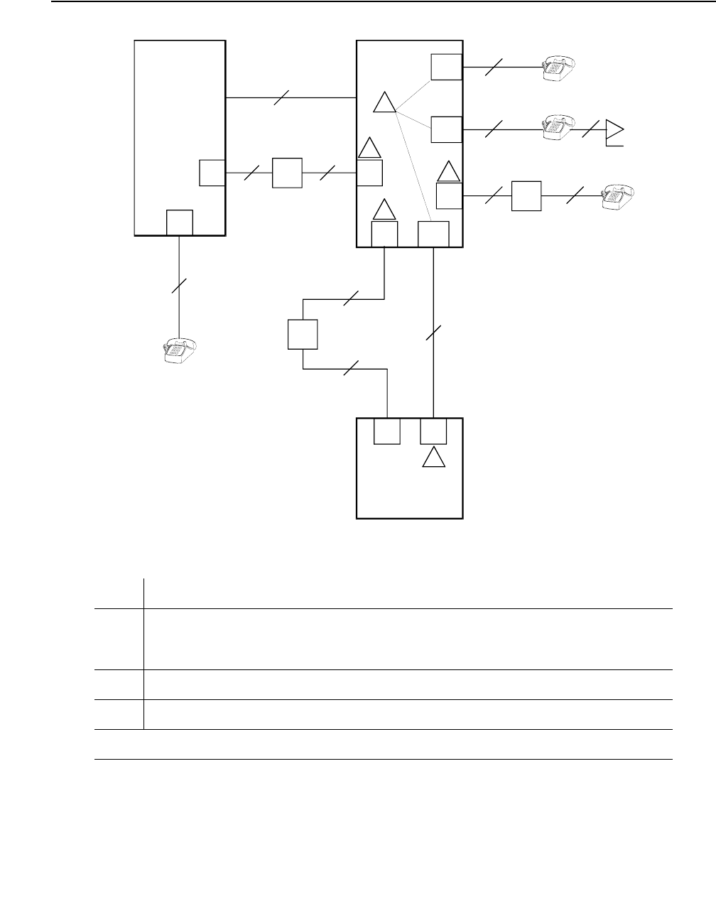
TBRI-BD (TN2185 ISDN Trunk-Side BRI)
Issue 1 June 2005 2193
Figure 136: Integrated Trunk-Side BRI, ISDN Interface Reference Points
Figure notes:ISDN Interface Reference Point definitions
LT Logical Terminal
V Primary Rate user/network (asymmetrical) trunk interface. The ECS is
capable of acting as the user or as the network side of this 1.544 or
2.048-Mbps interface.
R Interface between Terminal Equipment and Network Termination
S Basic Rate network-side 4-wire line interface
1 of 2
CO
NT
2-Wire
NT
2-Wire
NT
2-Wire
NT
4-Wire
4-Wire
4-Wire
NT
2-Wire
NT
4-Wire
PBX
PBX
LT TE
TE TE
cydfisdn RPY 072397
NT2
LT
LT
NT2
NT2
Term in al
Adapter
NT2
S/T
TE
TE
NT1
VPRI
U
U
T
S/T
T
S
S
UT
R
NT1
NT1
ISDN Interface Reference Points
1
2
3
4
5
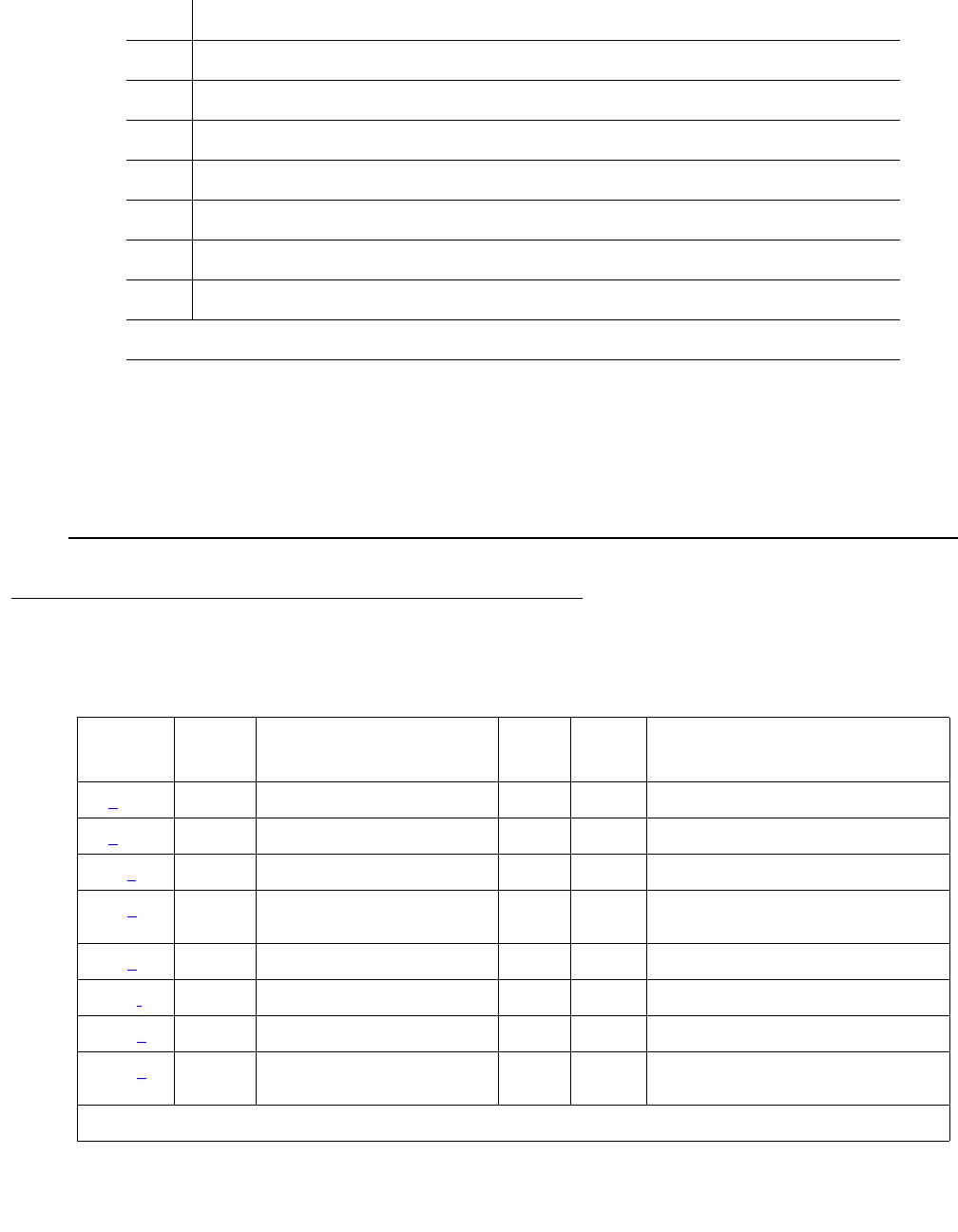
Communication Manager Maintenance-Object Repair Procedures
2194 Maintenance Procedures for Avaya Communication Manager 3.0, Media Gateways and Servers
Hardware Error Log Entries and Test to Clear Values
S/T 4-wire Basic Rate connection to an NT2 Termination1.
T 4-wire Basic Rate interface to an NT Termination.2
TE Terminal Equipment
U Basic Rate network-side 2-wire line interface.
1 TN556B ISDN-BRI 4-Wire S/T-NT Line (A-law)
2 TN2185 ISDN-BRI 4-Wire S Interface (Trunk Side)
3 TN2198 ISDN-BRI 2-Wire U Interface
5 TN2185 ISDN-BRI 4-Wire S Interface (Trunk Side)
1. Network Termination 2 (NT2), that terminates Layer 1 and higher layers. PBXs, LANs, and
terminal controllers typically provide NT2 functionality including protocol handling and
multiplexing for Layers 2 and 3.
2. Network Termination 1 (NT1), that terminates Layer 1 and monitors maintenance,
performance, timing, power transfer, multiplexing, and multidrop termination with contention
resolution.
2 of 2
Table 783: TBRI-BD Error Log Entries
Error
Type
Aux
Data
Associated Test Alarm
Level
On/Off
Board
Test to Clear Value
0 (a) 0 Any Any Any test board location sh r 1
1 (b) Any None MIN ON
257 (c) 65535 Control Channel Loop (#52) MIN ON test board location r 20
513 (d) 4352 -
4357
None ON
769 (e) 4358
1025 (f) NPE/NCE Audit test (#50) None ON
1291 (g) 4359 Clear Error Counters (#270) MIN ON
1294 (h) 46088 -
46096
SAKI Sanity test (#53) MIN ON See (h)
1 of 2
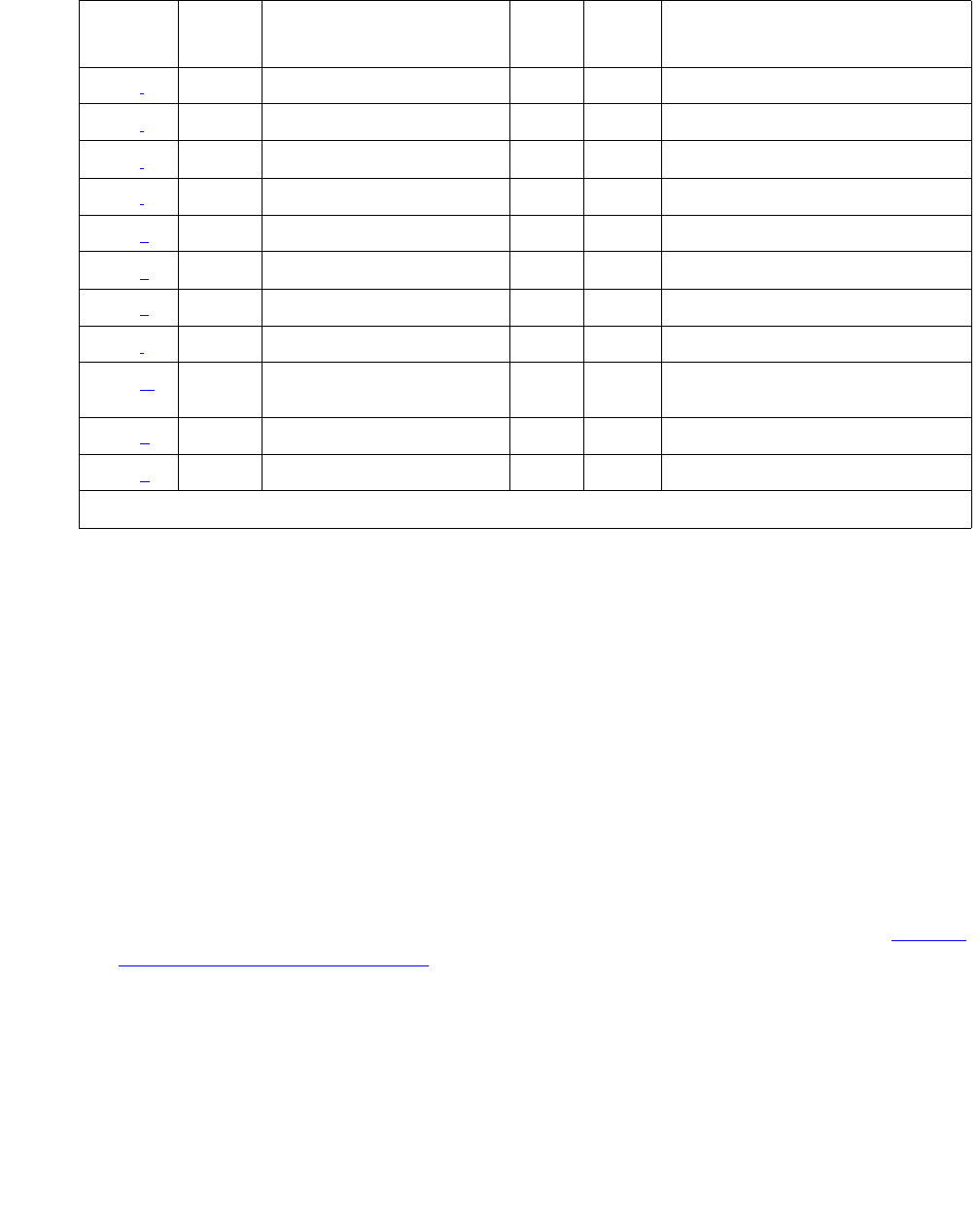
TBRI-BD (TN2185 ISDN Trunk-Side BRI)
Issue 1 June 2005 2195
Notes:
a. Error Type 0: run the short test sequence first. If every test passes, run the long test
sequence. Refer to each appropriate test’s description, and follow its recommended
procedures.
b. Error Type 1: the circuit pack stopped functioning or was physically removed from the
system.
Note:
Note: This alarm logs approximately 11 minutes after removing the circuit pack and/or
the SAKI Sanity test (#53) fails.
If the circuit pack is not in the system, insert a circuit pack in the same slot as the error
indicates. See note (h) for additional information.
c. Error Type 257: transient communication problems between the switch and this circuit
pack. Execute test board location and refer to the repair procedures for the Control
Channel Loop-Around Test (#52) on page 2512.
1537 (i) 46082 MIN ON
1793 (j) 46080 MIN ON
1794 (j) 46094 MIN ON
1795 (j) 46085 MIN ON
2305 (k) 46104 None ON
2306 (k) 46081 None ON
3330 (k) 46083 MIN OFF
3586 (l)MINOFF
3841 (m) 4096 -
4101
3842 (n) 46095
3843 (o) 46097
Table 783: TBRI-BD Error Log Entries (continued)
Error
Type
Aux
Data
Associated Test Alarm
Level
On/Off
Board
Test to Clear Value
2 of 2

Communication Manager Maintenance-Object Repair Procedures
2196 Maintenance Procedures for Avaya Communication Manager 3.0, Media Gateways and Servers
d. Error Type 513: on-board hardware failure. Aux Data values correspond to the following
detected errors:
Use busyout board location and reset board location to reset the circuit pack.
When reset, the circuit pack executes a set of tests to detect the presence of any of the
faults listed above. Detection of one of these errors during initialization causes the circuit
pack to lock-up and appear insane to the system. See the repair procedure in Note (b).
e. Error Type 769: the circuit pack detects a program logic error. While no action is required,
this error can lead to other errors against this circuit pack.
f. Error Type 1025: the circuit pack cannot update and read back NPE/NCE memory. This
error can be ignored, but may lead to other errors against this circuit pack.
g. Error Type 1291: the TN2185 board notifies maintenance software that it has detected a
parity error while accessing its dynamic RAM (memory that stores the board’s translation
information and downloadable application firmware). Maintenance software resets the
circuit pack.
h. Error Type 1294: unable to write LAN Translation RAM Error (internal memory access
error). Translation RAM locations for the call connection attempt are not available, and one
or more RAM locations are bad due to a translation RAM read-back error. Reset the circuit
pack with busyout board location and reset board location. If the Circuit Pack
Restart test (#594) passes, then the on-board circuitry is healthy. Retire the alarm with
test board location long clear. If the Circuit Pack Restart test (#594) fails, replace
the circuit pack.
i. Error Type 1537: frame overrun at Packet bus interface. This condition is due to an
on-board fault or by faulty data received on one of the circuit pack’s external ports. If any of
the ports on this circuit pack is alarmed, refer to the repair procedures for those MOs. If this
error persists, maintenance software removes the board from service; replace the circuit
pack.
4352 External RAM error
4353 Internal RAM error
4355 ROM Checksum error
4357 Instruction set error

TBRI-BD (TN2185 ISDN Trunk-Side BRI)
Issue 1 June 2005 2197
j. Error Type 1792 - 1795: the circuit pack is having problems transmitting/receiving data to/
from the Packet bus.
k. Error Type 2305, 3330: critical failure in the Circuit Pack’s Packet bus interface. Possible
causes include either a Packet bus fault or an on-board fault, for example, the board
received a bad CRC or invalid DLCI. If the Packet bus is alarmed, see Isolating and
repairing packet-bus faults in Maintenance Procedures (03-300192). The number of ISDN
circuit packs displaying this error increases the probability of errors due to Packet bus
problems.
1. If there are no Packet bus alarms, reset the circuit pack with busyout board
location and reset board location.
2. If the Circuit Pack Restart test (#594) passes, then the on-board circuitry is healthy.
Retire the alarm with test board location long clear.
3. If the Circuit Pack Restart test (#594) fails, replace the circuit pack.
Error Type 2306: This is an error in a received frame from the Packet bus, most likely
caused by a packet bus problem, but may be due to a circuit pack fault. An invalid Link
Access Procedure Data (LAPD) frame error occurs if the frame contains a bad Cyclical
Redundancy Check (CRC). If bus parity errors occur, run the LAN Receive Parity Error
Counter test (#595) to determine whether the condition has cleared. Determine whether the
problem is isolated to this circuit pack or is caused by Packet bus faults.
l. Error Type 3586: the server’s software detects an excessive number of up-link messages
from the TN2185 board within a certain time period. To prevent the faulty board from
flooding the switch with data, the switch software takes the board out of service and alarms
it. The switch software also tells the Archangel to ignore up-link messages from the board.
When the board is alarmed due to this error, the switch software periodically puts the board
back in service and tells the Archangel to process up-link messages from the board. If the
problem still exists, the software takes the circuit pack out of service again. If the circuit pack
does not exhibit the problem for a certain time period, then maintenance software resolves
the alarm and the circuit pack is left in service.
m. Error Type 3841: the circuit pack received an inconsistent down-link message (a bad
header, port number, data, sub-qualifier, or logical link) over the Control Channel.
n. Error Type 3842: the board is receiving data from the bus faster than it can distribute the
data to its endpoints, causing the FIFO RAM buffer to overflow. This error can occur
occasionally due to the statistical sizing of the buffers. If it occurs frequently, it may indicate
1793 Parity errors are detected when transmitting data to the Packet bus.
1794 Packet bus transmit buffers overflow.
1795 Circuit pack cannot find end of frame when transmitting to Packet bus.
Clear the alarm with busyout board location, reset board
location, test board location long clear, release board
location. If the error recurs within 10 minutes, replace the circuit pack.

Communication Manager Maintenance-Object Repair Procedures
2198 Maintenance Procedures for Avaya Communication Manager 3.0, Media Gateways and Servers
a LAPD parameter mismatch. LAPD should recover from this problem, but it may degrade
the performance of the LAN bus.
When this error is reported, maintenance reads and clears the board counter and logs the
problem in the maintenance error log.
o. Error Type 3843: bad translation RAM detected, but the call continues by using another
translation location. The circuit pack reports this error when it cannot update NPE/NCE
memory and read it back. This error is not service-affecting and can be ignored, but can
lead to other types of errors against this circuit pack.
System Technician-Demanded Tests:
Descriptions and Error Codes
Investigate tests in the order presented below. Clearing Error Codes associated with the one
test may also clear errors generated from other tests in the sequence.
Control Channel Loop-Around Test (#52)
See the procedure described in XXX-BD (Common Port Circuit Pack/Media Module) on
page 2539.
NPE /NCE Audit Test (#50)
See the procedure described in XXX-BD (Common Port Circuit Pack/Media Module) on
page 2539.
SAKI Sanity Test (#53)
This test is destructive.
See the procedure described in XXX-BD (Common Port Circuit Pack/Media Module) on
page 2539. This test is only run as a part of a reset board procedure.
Order of Investigation Short Test
Sequence
Long Test
Sequence
D/ND
Control Channel Loop-around test (#52) X X Nondestructive
NPE/NCE Audit test (#50) X Nondestructive
LAN Receive Parity Error Counter test (#595) X Nondestructive

TBRI-BD (TN2185 ISDN Trunk-Side BRI)
Issue 1 June 2005 2199
LAN Receive Parity Error Counter Test (#595)
This test is nondestructive. The test reads and clears the circuit pack’s LAN Receive Parity
Error Counter. This counter is incremented by the circuit pack when it detects a parity error in
data received from the Packet bus. These errors may indicate problems with a circuit pack,
Packet bus, or with another circuit pack on the bus. Use this test to verify the repair.
Table 784: Test #595 LAN Receive Parity Error Counter Test
Error
Code
Test
Result
Description / Recommendation
2000 ABRT Response to the test was not received from the circuit pack within the
allowable time period.
1. If the test aborts repeatedly up to 5 times, reset the circuit pack with
busyout board location and reset board location.
2. If the test aborts again, replace the circuit pack.
2100 ABRT Could not allocate the necessary system resources to run this test.
1. Retry the command at 1-minute intervals up to 5 times.
2012 ABRT Internal system error.
1. Retry the command at 1-minute intervals up to 5 times.
1–10 FAIL The circuit pack is still detecting errors of this type. The Error Code
indicates the value of the on-board error counter.
1. Retry the command at 1-minute intervals up to 5 times.
2. If the test continues to fail, verify the validity of the Packet bus. Run the
Packet bus maintenance test with test pkt P long. If any Packet
bus test fails, see PKT-BUS (Packet Bus) on page 1790 for
recommended repair procedures.
3. If the Packet bus test passes, check the validity of the circuit pack.
Execute a test that involves data transmission onto the Packet bus. For
example, test port location may use the connectivity tests of the
BRI-PORT MO. If the test fails, refer to the repair procedures;
otherwise, proceed to the next step.
4. Other circuit packs on the Packet bus may be the cause of the parity
error for the failed test. Use display errors to check the Error Log
for other alarmed circuit packs. Resolve any alarms for other circuit
packs as well. Rerun the LAN Receive Parity Error Counter test (#595).
PASS No errors detected.

Communication Manager Maintenance-Object Repair Procedures
2200 Maintenance Procedures for Avaya Communication Manager 3.0, Media Gateways and Servers
TBRI-PT (ISDN Trunk-Side BRI Port)
S8700 | 8710 / S8500 / S8300
This document describes the port maintenance features of the TN2185 Trunk-Side ISDN-BRI
board. The circuit pack provides 8 S/T ISDN 2B+D ports that interface to either the central office
or another PBX.
The TN2185 circuit pack contains eight, 4-wire ports that interface to the network at the ISDN S/
T reference point over two 64-kbps channels (B1 and B2) and over a 16-kbps signaling (D)
channel. The B1 and B2 channels can be simultaneously circuit-switched, or individually
packet-switched. Only one channel per trunk can be packet-switched due to PPE (Packet
Processing Element) limitations. The D channel is either circuit- or packet-switched. Packet
switching uses the PPE to combine all D channels into a single physical channel, which is then
routed via the concentration highway to the NCE (Network Control Element) and then to the
TDM bus. The circuit-switched connections have a Mu-law or A-law option for voice and
operate as 64-kbps clear data channels. The packet-switched channels support the LAPD
protocol and conform with the CCITT Q.920 Recommendations for D-channel signaling.
Note:
Note: S8300 / G700: Although the TBRI-PT MO is provided for a G700 media gateway,
this MO only partially supports the G700’s MM720 BRI media module.
LEDs
The three LEDs on the circuit pack’s faceplate indicate a board’s status. When illuminated, the
red LED indicates a board failure or a major or minor on-board alarm. The green LED indicates
that testing is in progress. The amber LED indicates that the board is in use.
MO Name Alarm Level Initial SAT Command to Run Full Name of MO
TBRI-PT MAJ test port location l r# TBRI-PT
TBRI-PT MIN test port location l r# TBRI-PT
TBRI-PT WRN test port location sh r# TBRI-PT
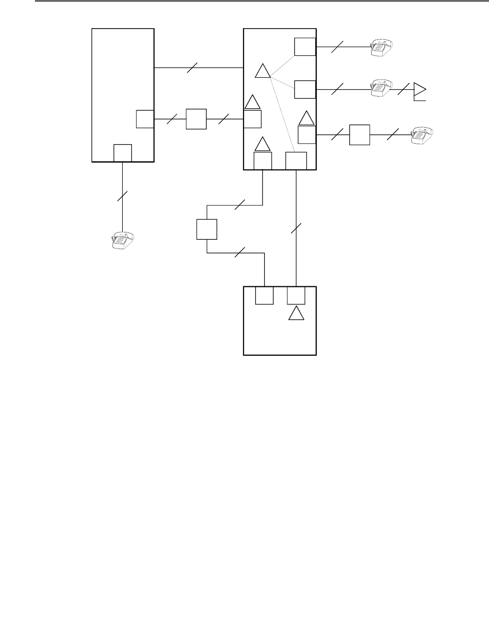
TBRI-PT (ISDN Trunk-Side BRI Port)
Issue 1 June 2005 2201
Figure 137: Integrated Trunk-Side BRI, ISDN Interface Reference points
CO
NT
2-Wire
NT
2-Wire
NT
2-Wire
NT
4-Wire
4-Wire
4-Wire
NT
2-Wire
NT
4-Wire
PBX
PBX
LT TE
TE TE
cydfisdn RPY 072397
NT2
LT
LT
NT2
NT2
Term in al
Adapter
NT2
S/T
TE
TE
NT1
VPRI
U
U
T
S/T
T
S
S
UT
R
NT1
NT1
ISDN Interface Reference Points
1
2
3
4
5
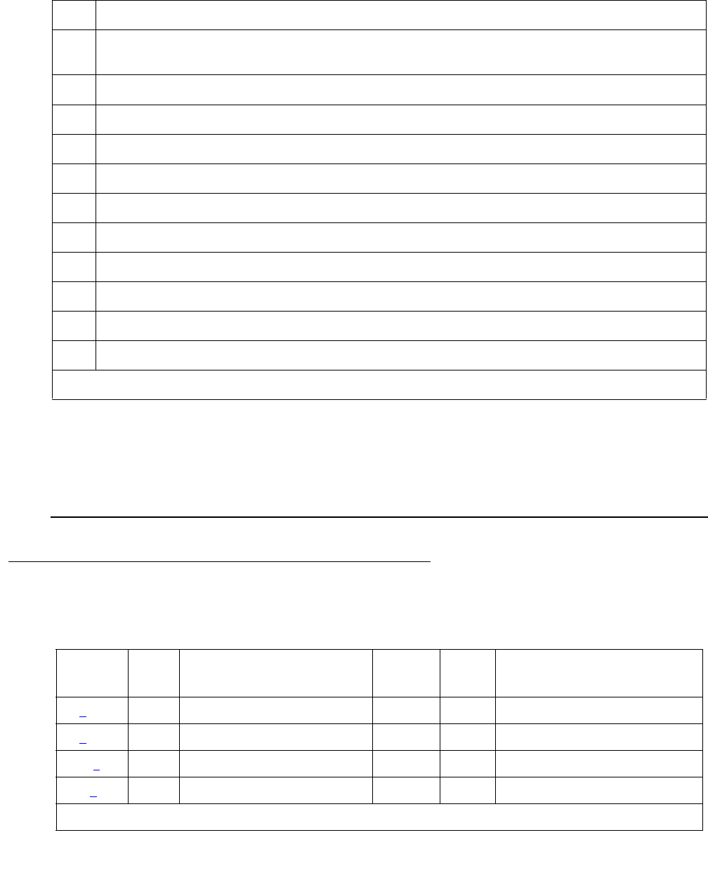
Communication Manager Maintenance-Object Repair Procedures
2202 Maintenance Procedures for Avaya Communication Manager 3.0, Media Gateways and Servers
Figure notes:ISDN Interface Reference Point definitions
Hardware Error Log Entries and Test to Clear Values
LT Logical Terminal
V Primary Rate user/network (asymmetrical) trunk interface. The ECS is capable of acting
as the user or as the network side of this 1.544 or 2.048-Mbps interface.
R Interface between Terminal Equipment and Network Termination
S Basic Rate network-side 4-wire line interface
S/T 4-wire Basic Rate connection to a NT2 Termination1.
1. Network Termination 2 (NT2), that terminates Layer 1 and higher layers. PBXs, LANs, and terminal
controllers typically provide NT2 functionality including protocol handling and multiplexing for Layers 2
and 3.
T 4-wire Basic Rate interface to a NT1 Termination.2
2. Network Termination 1 (NT1), that terminates Layer 1 and monitors maintenance, performance, timing,
power transfer, multiplexing, and multi-drop termination with contention resolution.
TE Terminal Equipment
U Basic Rate network-side 2-wire line interface.
1 TN556B ISDN-BRI 4-Wire S/T-NT Line (A-law)
2 TN2185 ISDN-BRI 4-Wire S Interface (Trunk Side)
3 TN2198 ISDN-BRI 2-Wire U Interface
5 TN2185 ISDN-BRI 4-Wire S Interface (Trunk Side)
Table 785: TBRI-PT Error Log Entries
Error
Type
Aux
Data
Associated Test Alarm
Level
On/Off
Board
Test to Clear Value
0 (a) 0 Any Any Any test port location sh r 1
1 (b) Level 1 Status test (#1242) MIN OFF
129 (c)
257(d)
1 of 2
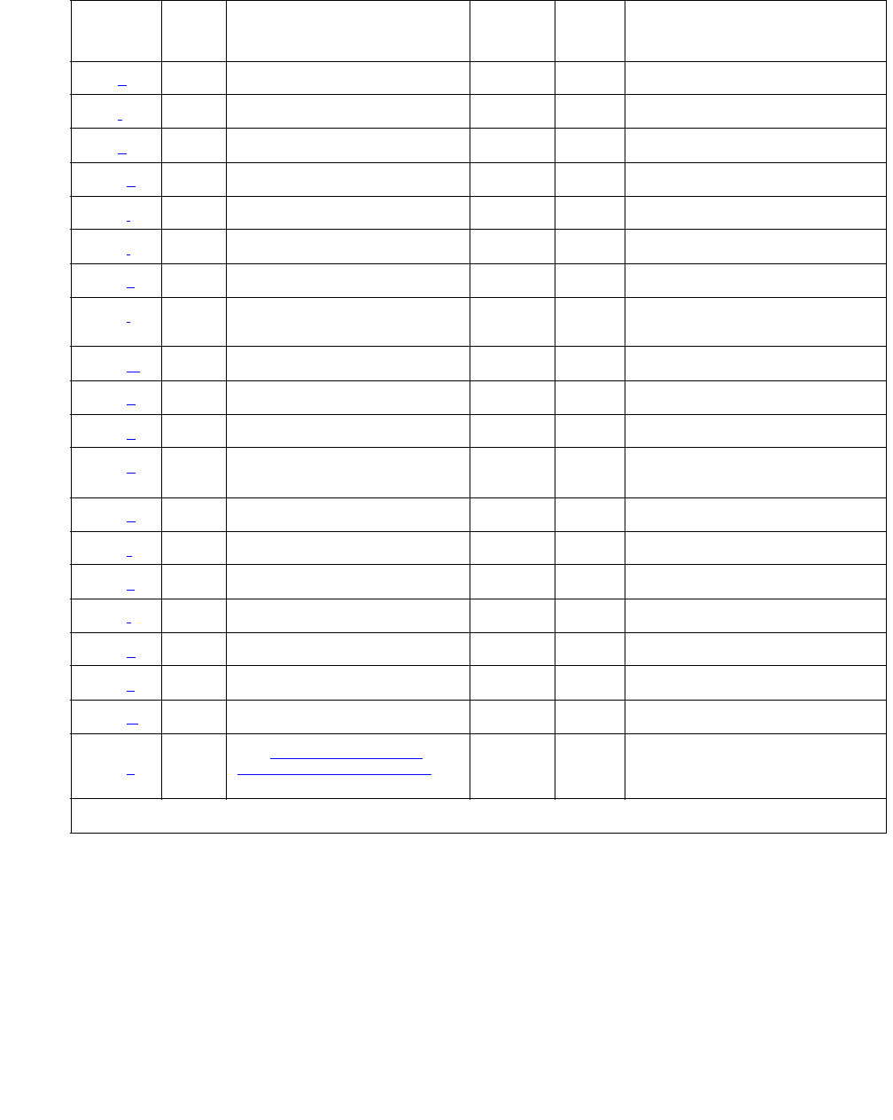
TBRI-PT (ISDN Trunk-Side BRI Port)
Issue 1 June 2005 2203
Notes:
a. Error Type 0: run the short test sequence first. If every test passes, run the long test
sequence. Refer to each appropriate test’s description, and follow its recommended
procedures.
513 (e) 46222 XMIT FIFO Overflow MIN ON
514 (f) XMIT FIFO Overflow (TDM) MIN ON
769 (g) Traffic Hyperactivity MIN OFF
1025 (h)
1281 (i) BRI NPE Crosstalk test (#617) MIN ON
1537 (j) 46210 CRC error (D-channel) MIN OFF
1538 (k) CRC error (TDM D-channel) MIN OFF
1793 (l) BRI Port Local TDM
Loop-around test (#619)
MIN ON
2049 (m)MINOFF
2305 (n) Layer 3 Query (#1243) MIN OFF
3073 (o) Slip Query test (#1244) MIN OFF
3585 (p) Receive FIFO Overflow (TDM
D-channel)
Log Only ON
3586 (q)
3587 (r)
3588 (s) 46223
3589 (t)
3590 (u) 46211
3591 (v)
3592 (w)
3841 -
3942 (x)
See Table 786: Aux Data
Values for Error 3841–3942 on
page 2206
Table 785: TBRI-PT Error Log Entries (continued)
Error
Type
Aux
Data
Associated Test Alarm
Level
On/Off
Board
Test to Clear Value
2 of 2

Communication Manager Maintenance-Object Repair Procedures
2204 Maintenance Procedures for Avaya Communication Manager 3.0, Media Gateways and Servers
b. Error Type 1: loss of continuity of Layer 1 to the far end. It is assumed that Layer 1 remains
active, even when both B channels are idle.
This test determines whether Layer 1 is active or not. If Layer 1 is not active, the test
attempts to activate it. If Layer 1 cannot be activated, the port is taken out of service, and
the test fails.
c. Error Type 129: the far-end switch changed the ISDN service state, the trunk is out of
service on the far end. This may be a temporary condition.
d. Error Type 257: the D channel failed at Layer 2. Expiration of this timer indicates that
attempts to bring the failed link back into service have not succeeded and some recovery
actions should be taken on the associated B channels. Upon expiration, associated
in-service B channels are put in the out-of-service/far-end state. The timer is cleared when
layer 2 is re-established.
e. Error Type 513: on-board hardware failure. The FIFO RAM buffers have overflowed,
indicating a hardware problem. The circuit pack is having problems transmitting data to the
packet bus.
f. Error Type 514: transmit FIFO Overflow - This error indicates that the circuit pack is having
problems transmitting data to the TDM D channel. This error only occurs only a system that
switches the packet implementation of the D channel over the TDM bus. This error indicates
an on-board problem related to the packet implementation of the D channel (R6.2 and
higher).
g. Error Type 769: the port is generating too many uplinks. The link is being suspended. If too
many hyperactive events occur with a certain time, the port is alarmed and taken out of
service.
h. Error Type 1025: an expired timer has created an unexpected event. The timer could be
any of the following:
Timer Event
T3031 ISDN T3031 timeout
T3032 ISDN T3032 timeout
T305 ISDN T305 timeout
T3081 ISDN T3081 timeout
T3082 ISDN T3082 timeout
TL3 Status Inquiry
T304 Setup ACK
T310 Call Proceeding Receive
T313 Connect SEND

TBRI-PT (ISDN Trunk-Side BRI Port)
Issue 1 June 2005 2205
i. Error Type 1281: this error occurs when the BRI NPE Crosstalk test (#617) has failed. The
test will be repeated every 15 minutes until it passes. Follow normal trouble shooting
procedures for BRI NPE Crosstalk test (#617). If this does not fix the problem, follow normal
escalation procedures.
j. Error Type 1537: the board received a bad Cyclical Redundancy Check (CRC) over the D
channel. This error is reported on a per-port basis. When the CRC errors exceed 5 within 15
minutes, the port is taken out of service for 5 seconds. If 5 more CRC errors are received
within 15 minutes of the first set of 5 errors, the port is taken out of service for 1 minute. If 5
more CRC errors are received within 15 minutes of the previous 5, the port is taken out of
service for 15 minutes.
This error is most likely due to a problem with backplane wiring, a noise source, or no
termination (an open circuit). It usually does not indicate a problem with the circuit pack.
1. Check the backplane wiring.
2. If the problem persists escalate the problem.
k. Error Type 1538: this error occurs when a frame with a bad CRC is received over the TDM
D-channel by the BRI trunk board. This error only occurs on a system that switches the
packet implementation of the D channel over the TDM bus. This error indicates an off-board
problem related to the packet implementation of the TDM D channel (R6.2 and later).
l. Error Type 1793: the BRI Port Local TDM Loop Around test (#619) failed. Run the long test
sequence, and pay particular attention to the results of the BRI TDM Port Loop test (#619).
m. Error Type 2049: the Layer 2 Link Query failed. The test is repeated every 15 minutes until
it passes.
n. Error Type 2305: the Remote Layer 3 Query failed. The test is repeated every 15 minutes
until it passes.
o. Error Type 3073: a frame of information had to be repeated or deleted. Slips usually occur
when the received bit rate is not synchronized with the TDM bus clock.
p. Error Type 3585: the circuit pack detected an overflow of its receive buffers. This error
occurs only a system that switches the packet implementation of the D channel over the
TDM bus. This error indicates an on-board problem related to the packet implementation of
the TDM D channel (R6.2 and higher). This error is logged only.
q. Error Type 3586: each port can support up to three Terminal Endpoint Identifiers (TEIs).
Each channel on the port can request a TEI assignment from the switch if it supports
ISDN-BRI TEI assignment procedures. If switch services gets a request for a fourth TEI on
a port, it reports this event to maintenance software and initiates TEI check procedures on
the port. Check to see if the correct number of channels are administered for this port.
The user side supports automatic TEI assignment by the network. Both fixed and automatic
TEI assignment are supported on the network side.
r. Error Type 3587: Service Profile IDentifier (SPID) value is invalid or is a duplicate of
another SPID that is already initialized at Layer 3 on the port. SPIDs are not used on the
TN2185 circuit pack. However there will be related events.

Communication Manager Maintenance-Object Repair Procedures
2206 Maintenance Procedures for Avaya Communication Manager 3.0, Media Gateways and Servers
s. Error Type 3588: the board receives D-channel data from the bus faster than it can process
the data. The FIFO RAM buffers overflowed. This error occurs occasionally due to the
statistical sizing of the buffers; however, frequent occurrences may indicate a LAPD
parameter mismatch between the two endpoints of a packet-switched connection. Run the
long test sequence, and pay particular attention to the results of the Receive FIFO Overflow
test (#625).
t. Error Type (3589: the BRI Port Local LAN Loop Around test (#618) failed. Run the long test
sequence, and pay particular attention to the results of Test #618.
u. Error Type 3590: an activated BRI port receives a frame containing a DLCI over a D
channel for which it does not have a translation. This error normally indicates an off-board
problem related to a state mismatch between the far end and the switch. This error is
logged only.
v. Error Type 3591: the circuit pack received a frame containing a DLCI over the TDM
D-channel for which it does not have a translation. This error occurs only on a system that
switches the packet implementation of the D-channel over the TDM bus, and indicates an
off-board problem related to the state mismatch between the board and the packet
implementation of the TDM D-channel. This error is logged only.
w. Error Type 3592: 1the port is generating too many uplinks and is taken out of service for a
period of time.
x. Error Types 3841–3942: Table 786: Aux Data Values for Error 3841–3942 on page 2206
contains the received ISDN cause values for Errors 3841–3942 that are recorded in the
hardware error logs. Unless otherwise stated, the cause values are D-channel events. The
Aux Data field shows which port caused the error.
Table 786: Aux Data Values for Error 3841–3942
Aux Data
Value
Type of
Problem
Meaning
2 admin No route to specific transit network
3 admin No route to destination (or Germany bcap not imp)
6 admin Channel unacceptable
18 switch
problems
No user responding
38 switch
problems
Network failure
50 subscription Requested facility not subscribed
52 admin Outgoing calls barred
54 admin Incoming calls barred
1 of 2

TBRI-PT (ISDN Trunk-Side BRI Port)
Issue 1 June 2005 2207
System Technician-Demanded Tests:
Descriptions and Error Codes
Investigate tests in the order presented below. Clearing Error Codes associated with the one
test may also clear errors generated from other tests in the sequence.
62 subscription Service not authorized
63 admin/sub Service/option not available
65 admin/sub Bearer capability not implemented
66 admin/sub Channel type not implemented
69 admin/sub Requested facility not implemented
70 admin/sub Only restricted digital BC available
79 admin Service/option not implemented
88 admin Incompatible destination
102 switch
problems
Recovery on timer expired
Table 786: Aux Data Values for Error 3841–3942 (continued)
Aux Data
Value
Type of
Problem
Meaning
2 of 2
Order of Investigation Short Test
Sequence
Long Test
Sequence
D/ND1
BRI Local LAN Port Loop Around test (#618)
S8300 / G700: Aborts with Error Code 1412 on a G700
XD
BRI TDM Port Loop Around test (#619)
S8300 / G700: Aborts with Error Code 1412 on a G700
XD
L1 Status Query test (#1242)
S8300 / G700: Aborts with Error Code 1412 on a G700
XXD
CRC Error Counter test (#623) X ND
Receive FIFO Overflow test (#625) X ND
Layer 3 Query test (#1243) X ND

Communication Manager Maintenance-Object Repair Procedures
2208 Maintenance Procedures for Avaya Communication Manager 3.0, Media Gateways and Servers
Slip Query test (#1244) X X ND
Clear Error Counters test (#270) X X ND
BRI NPE Crosstalk test (#617)
S8300 / G700: Aborts with Error Code 1412 on a G700
XD
1. D = Destructive; ND = Nondestructive
Order of Investigation Short Test
Sequence
Long Test
Sequence
D/ND1
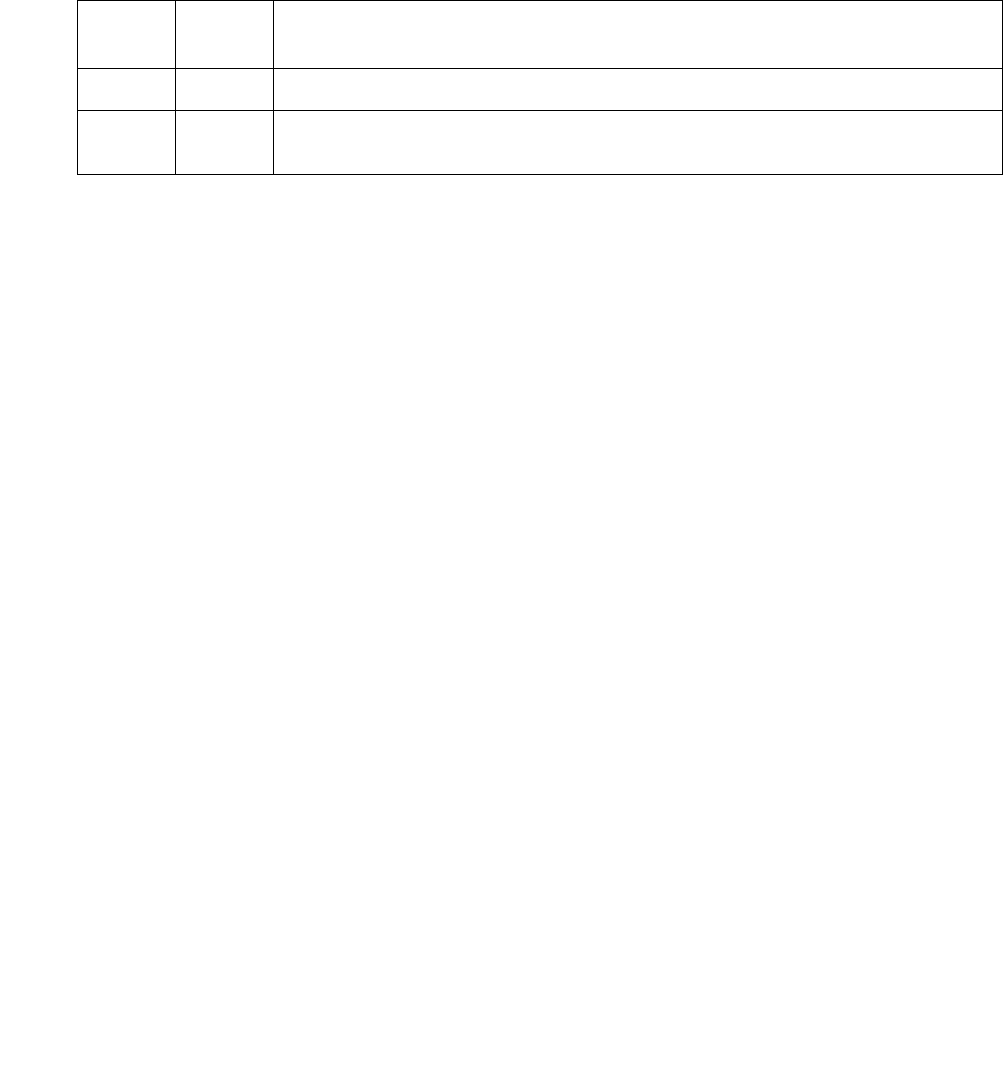
TBRI-PT (ISDN Trunk-Side BRI Port)
Issue 1 June 2005 2209
Clear Error Counters Test (#270)
This test is nondestructive.
This test clears the error counters associated with each TBRI-PT. This test passes if
maintenance software is able to successfully send the downlink messages. The test aborts
otherwise.
BRI NPE Crosstalk Test (#617)
This test is conditionally destructive.
One or more NPEs reside on each circuit pack with a TDM-bus interface. The NPE controls port
connectivity and gain and provides conferencing functions on a per-port basis. The BRI NPE
Crosstalk test verifies that this port’s NPE channel talks on the selected time slot and never
crosses over to time slots reserved for other connections. If the NPE is not working correctly,
1-way and noisy connections may be observed. This test is part of a port’s long test sequence
and takes approximately 20 to 30 seconds to complete. Crosstalk testing is performed on both
B channels (B1 and B2) associated with a BRI port. If this test fails on either channel, any
channel connected to the port is taken out-of-service. This test aborts if the port and its
associated channels are not in the idle state.
Note:
Note: S8300 / G700: This test does not execute on a G700 Media Gateway.
Table 787: Test #270 Clear Error Counters
Error
Code
Test
Result
Description / Recommendation
Any ABRT Maintenance could not send the downlink message.
PASS The message to clear the error counters of the TBRI-PT MO has been
sent.

Communication Manager Maintenance-Object Repair Procedures
2210 Maintenance Procedures for Avaya Communication Manager 3.0, Media Gateways and Servers
Table 788: Test #617 BRI NPE Crosstalk Test
Error
Code
Test
Result
Description / Recommendation
1000 ABRT System resources required to run this test are not available. The
port may be busy with a valid call.
1. Use display port location to determine the station
extension or trunk group/member number of the port. Use
status bri-port location to determine the service state
of the port. If the service state indicates that the port is in use,
then the port is unavailable for certain tests. Wait until the port is
idle before retesting.
2. If the port status is idle, then retry the command at 1-minute
intervals up to 5 times.
1004 ABRT The port has been seized by a user for a valid call. Use status
bri-port location to determine when the port is available for
testing.
1. Retry the command at 1-minute intervals up to 5 times.
2. If the test continues to abort and the port is idle, escalate the
problem.
1005 ABRT This test is not valid for this type of translation. Ports administered as
“ASAI” or “ADJK” cannot run this test, because the B channels
associated with the port are not used by ASAI or Avaya Adjunct
Links. This is a normal condition.
S8300 / G700:
1412
ABRT This test does not execute on a G700 media gateway.
2012 ABRT Internal system error
1. Retry the command at 1-minute intervals up to 5 times.
2100 ABRT Could not allocate the necessary resources to run this test.
1. Retry the command at 1-minute intervals up to 5 times.
1, 2 FAIL The NPE of the tested port was found to be transmitting in error,
causing noisy and unreliable connections. Error code 1 indicates
that the BRI NPE Crosstalk test failed on Channel B1. Error code 2
indicates that the BRI NPE Crosstalk test failed on Channel B2.
1. Replace circuit pack.
1 of 2

TBRI-PT (ISDN Trunk-Side BRI Port)
Issue 1 June 2005 2211
BRI Port Local LAN Loop-Around Test (#618)
This test is destructive.
Note:
Note: S8300 / G700: This test does not execute on a G700 Media Gateway.
This test checks the connectivity of the BRI port across the LAN bus. Because this test is
destructive, it is only attempted if the port is out-of-service. This test is run only as a demand
test.
If the port is in a state other than out-of-service, the BRI Port Local LAN Loop-Around test will
abort. If the port is out-of-service, then the port is put into a local loop-around mode and the
following test is executed.
A loop-around test is performed across the Packet bus for the D channel. The switch sends
data over a packet connection, which is looped back by the BRI port (D channel) and received
back by the switch. The test passes if the packet connection can be established and the
transmitted data is received unaltered. The test aborts if the Packet bus is alarmed in the
Processor Port Network (or the port network where that circuit pack resides) or if the Packet
Interface board is out-of-service. The test fails due to either on-board faults associated with the
BRI port hardware on the circuit pack or problems with the LAN bus.
PASS The port is correctly using its allocated time slots.
1. To be sure that this is not an intermittent problem, repeat this
test up to 10 times to ensure it continues to pass.
2. If complaints still exist, examine the connections and wiring.
Table 788: Test #617 BRI NPE Crosstalk Test (continued)
Error
Code
Test
Result
Description / Recommendation
2 of 2

Communication Manager Maintenance-Object Repair Procedures
2212 Maintenance Procedures for Avaya Communication Manager 3.0, Media Gateways and Servers
Table 789: Test #618 BRI Port Local LAN Loop Around
Error
Code
Test
Result
Description / Recommendation
1015 ABRT The port is not out-of-service.
1. Use status bri-port location to determine the status of
the port.
2. If it is in use, wait until it is idle, and then use busyout port
location to place it in the out-of-service state and repeat this
test.
!CAUTION:
CAUTION: Since the busyout command is destructive, execution
of this command prior to the port being idle causes
every call associated with the BRI port to be torn
down.
1139 ABRT The Packet bus in the port network is out-of-service.
1. Follow the repair procedures for the Packet bus.
2. Run test port location long and verify the repair by
viewing the results of the BRI Port Local LAN Loop-Around test
(#618).
1141 ABRT The PKT-CTRL is out-of-service.
1. Follow the repair procedures for the PKT-CTRL.
2. Run test port location long and verify the repair by
viewing the results of the BRI Port Local LAN Loop-Around test
(#618).
1144 ABRT The Processor Port Network Packet Bus is out-of-service
1. Follow the repair procedures for the Packet Bus.
2. Run the test port location long and verify the repair by
viewing the results of the BRI Port Local LAN Loop-Around test
(#618).
S8300 / G700:
1412
ABRT This test does not execute on a G700 media gateway.
2012
2100
ABRT Internal system error
Could not allocate the necessary system resources to run this test.
1. Retry the command at 1-minute intervals up to 5 times.
1 of 2

TBRI-PT (ISDN Trunk-Side BRI Port)
Issue 1 June 2005 2213
BRI Port Local TDM Loop-Around Test (#619)
This test is conditionally destructive.
Note:
Note: S8300 / G700: This test does not execute on a G700 Media Gateway.
This test verifies the connectivity of a BRI port across the TDM bus. It aborts if calls associated
with the port are in progress. Failure of this test indicates an on-board fault associated with the
port hardware on the circuit pack.
This Loop-Around test runs the following individual tests on the two B channels (B1 and B2)
associated with the port:
●A Loop-Around test across the TDM bus for B1.
●A Conference Circuit test for B1.
●A Loop-around test across the TDM bus for B2.
●A Conference Circuit test for B2.
The tests are run in the above order. If one fails, the remaining tests in the sequence are not
executed, and maintenance software returns an Error Code.
FAIL The Loop-Around test has failed.
1. If the test fails repeatedly, try to reset the circuit pack with
busyout board location and reset board location if
the other ports on the board are idle.
2. If the test fails again, execute test pkt P. If this fails, follow
failure procedures in the PKT-BUS section.
3. If the tests in Step 2 pass, the problem is local to the BRI board.
Replace the trunk circuit pack.
PASS The BRI Port Local LAN Loop-Around test passed.
Table 789: Test #618 BRI Port Local LAN Loop Around (continued)
Error
Code
Test
Result
Description / Recommendation
2 of 2

Communication Manager Maintenance-Object Repair Procedures
2214 Maintenance Procedures for Avaya Communication Manager 3.0, Media Gateways and Servers
Table 790: Test #619 BRI Port Local TDM Loop Around
Error
Code
Test
Result
Description / Recommendation
1000 ABRT The system resources required to run this test are not available. The
port may be busy with a valid call.
1. Use display port location to determine the trunk group/
member number of the port. Use status bri-port
location to determine the service state of the port. If the
service state indicates that the port is in use, the port is
unavailable for certain tests. Wait until the port is idle before
retesting.
2. If the port is idle, retry the command at 1-minute intervals up to 5
times.
1002 ABRT The system could not allocate time slots for the test. The system
may be under heavy traffic conditions or it may have time slots
out-of-service due to TDM-BUS errors.
1. If the system has no TDM-BUS errors and is not handling heavy
traffic, repeat test at 1-minute intervals up to 5 times.
1003 ABRT The system could not allocate a tone receiver for the test. The
system may be oversized for the number of Tone Detectors present
or some Tone Detectors may be out-of-service.
1. Resolve any TTR-LEV errors.
2. Resolve any TONE-PT errors.
3. If neither condition exists, retry the test at 1-minute intervals up
to 5 times.
1004 ABRT The port has been seized by a user for a valid call. Use status
trunk for the trunks associated with this port and determine when
the port is available for testing.
4. Retry the command at 1-minute intervals up to 5 times.
5. If the test continues to abort and the port is idle, escalate the
problem.
1005 ABRT This test is not valid for this type of translation. Ports administered as
ASAI or ADJK cannot run this test because the B channels
associated with the port are not used by ASAI or Avaya Adjunct Links.
This is a normal condition.
S8300 / G700:
1412
ABRT This test does not execute on a G700 media gateway.
1 of 2

TBRI-PT (ISDN Trunk-Side BRI Port)
Issue 1 June 2005 2215
2000 ABRT Response to the test was not received from the BRI-TRUNK circuit
pack within the allowable time period.
1. If this result occurs repeatedly, try to reset the circuit pack with
busyout board location and reset board location if
other ports on the board are idle.
2. If this result occurs again, replace the circuit pack.
2012 ABRT Internal system error
2100 ABRT Could not allocate the necessary resources to run this test.
1. Retry the command at 1-minute intervals up to 5 times.
2103 ABRT The system could not make the conference connection for the test.
1. Retry the command at 1-minute intervals up to 5 times.
1, 2 FAIL The TDM Looparound failed on one of the channels.
●Error Code 1 — TDM Loop Around test failed on B1.
●Error Code 2 — TDM Loop Around test failed on B2.
7, 8 FAIL The Conference Circuit test failed on a B channel.
●Error Code 7 — test failed on B1
●Error Code 8 — test failed on B2.
1. If the test fails repeatedly, try to reset the circuit pack with
busyout board location, reset board location, and
then release board location if other ports on the board
are idle.
2. If the test fails again, replace the circuit pack.
PASS The BRI Port Local TDM Loop Around test passed.
Table 790: Test #619 BRI Port Local TDM Loop Around (continued)
Error
Code
Test
Result
Description / Recommendation
2 of 2

Communication Manager Maintenance-Object Repair Procedures
2216 Maintenance Procedures for Avaya Communication Manager 3.0, Media Gateways and Servers
CRC Error Counter Test (#623)
This test is nondestructive.
This test reads the BRI port’s CRC error counters that are maintained on the BRI circuit pack.
The Cyclic Redundancy Check (CRC) is a means of error detection used to determine the
integrity of data frame contents. The CRC error counter is incremented by the circuit pack when
it detects a CRC error. The test passes if the value of the counter is 0 (that is, the error is
cleared). If the counter is non-zero, the test fails, and the value of the counter is displayed in the
Error Code field.
Receive FIFO Overflow Error
Counter Test (#625)
This test is nondestructive.
This test reads and clears the BRI port’s Receive FIFO Overflow error counter maintained on
the TBRI-BD circuit pack. This counter is incremented by the circuit pack when it detects an
overflow of its receive buffers. The test passes if the value of the counter is 0 (that is, the error is
cleared). If the counter is non-zero, the test fails, and the value of the counter is displayed in the
Error Code field. This error can occur either if:
●Signaling frames are being received from the Packet bus at a rate sufficient to overflow the
receive buffers on the circuit pack for a port
●A hardware fault is causing the receive buffers not to be emptied properly by the circuit
pack.
This test is useful for verifying the repair of the problem.
Table 791: Test #623 CRC Error Counter Test
Error
Code
Test
Result
Description / Recommendation
ANY FAIL This error occurs when a frame with a bad CRC is received over the
D channel by the BRI board. This error is reported on a per-port basis when
the counter goes over the threshold. This error is most likely due to a
problem with the wiring or interference on the wiring caused by a noise
source or no termination. It usually does not indicate a problem with the
circuit pack.
PASS The CRC error counter was read correctly and has a value of 0.

TBRI-PT (ISDN Trunk-Side BRI Port)
Issue 1 June 2005 2217
Level 1 Status Query Test (#1242)
This test is conditionally destructive.
Note:
Note: S8300 / G700: This test aborts with Error Code 1412 on a G700 Media Gateway.
This test determines the state of the transmission facility of a BRI port at the Level 1 (L1)
physical layer: Activated, Pending Activation, or Deactivated.
The Activated state is the correct state for an ISDN-BRI port. In this state, the L1 interface can
send and receive synchronized signals. This test passes if the state of L1 is Activated. This test
also passes if software has taken this port out of service. See the description of the L1
“Deactivated State” below for more details.
Table 792: Test #625 Receive FIFO Overflow Error Counter Test
Error
Code
Test
Result
Description / Recommendation
2000 ABRT Response to the test was not received from the circuit pack within the
allowable time period.
1. If the test aborts repeatedly up to 5 times, reset the circuit pack with
busyout board location and reset board location.
2. If the test aborts again, replace the circuit pack.
2012 ABRT Internal system error
1. Retry the command at 1-minute intervals up to 5 times.
2100 ABRT Could not allocate the necessary system resources to run this test.
1. Retry the command at 1-minute intervals up to 5 times.
value FAIL The TBRI-BD circuit pack is still detecting errors of this type. The Error
Code field contains the value of this counter.
1. Retry the command at 1-minute intervals up to 5 times.
2. If the test continues to fail, run the long test sequence, and pay
particular attention to the Loop-Around tests (#618 and #619). See the
repair procedures for the executed test if it fails. Otherwise, go to the
next step.
3. Replace the circuit pack.
PASS The Receive FIFO Overflow error counter was read correctly and has a
value of 0.

Communication Manager Maintenance-Object Repair Procedures
2218 Maintenance Procedures for Avaya Communication Manager 3.0, Media Gateways and Servers
The Pending Activation state indicates a problem with the channels, the wiring, or the TBRI-BD
circuit pack. When in this state, the Level 1 interface is either not receiving any L1 framing from
the channel, or it is communicating with the channel but cannot transition to the Activated state.
The Deactivated state indicates a problem with the TBRI-BD circuit pack. When in this state, the
Level 1 interface is not active, and an idle signal is transmitted to the channels or that Layer 1
was deactivated by the switch. When an TBRI-PT port is placed in the out-of-service state,
Level 1 is also put into the Deactivated state. This could be due either to the system detecting a
fault with the port or to a busyout port location request.
Table 793: Test #1242 Level 1 Status Query
Error
Code
Test
Result
Description / Recommendation
1187 ABRT The board or port may be busied out.
1. Look in the Error Log for Error Type 18 (port busied out) for this
port and TBRI-BD (board busied out). If this Error Type is
present for TBRI-PT only, then release the port with release
port location and run the test again. If the error is present
for both TBRI-BD and TBRI-PT, then release the board with
release board location and run the test again.
When you release a board, you release every port associated with it.
If certain ports still need to be busied out, use busyout port
location to busy them out.
2. Make sure the endpoint is connected.
3. Retry the command at 1-minute intervals up to 5 times.
S8300 / G700:
1412
ABRT This test does not execute on a G700 media gateway.
2000 ABRT Response to the test was not received from the circuit pack within
the allowable time period.
1. If the test aborts repeatedly up to 5 times, reset the circuit pack
with busyout board location, reset board location,
and release board location.
2. If the test aborts again, replace the circuit pack.
2012 ABRT Internal system error
1. Retry the command at 1-minute intervals up to 5 times.
2100 ABRT Could not allocate the necessary system resources to run this test.
1. Retry the command at 1-minute intervals up to 5 times.
1 of 3

TBRI-PT (ISDN Trunk-Side BRI Port)
Issue 1 June 2005 2219
1 FAIL Received a status of Level 1 Pending Activation. U interface down
indicating a problem with a connection between the switch and the
NT1, a 2- to 4-wire converter that is used to connect 4-wire terminals
to a 2-wire TN2198 or TN2185 circuit pack.
2. Verify that the connections between the switch and the NT1 are
good. Verify that the NT1 has power.
3. Execute test port location and review the results of the
Level 1 Status Query test to verify the repair. If this test still fails,
proceed to Step 3.
4. Follow the manufacturers repair procedures for the NT1. Then
execute test port location and review the results of the
Level 1 Status Query test to verify repair.
2 FAIL Received a status of Level 1 Pending Activation. U interface up, S/T
interface down, which indicates a problem with the NT1 or the wiring
between the NT1 and the BRI endpoint (S/T interface).
5. Execute test port location and review the results of the
Level 1 Status Query test to verify the repair. If this test still fails,
proceed to Step 2.
6. Follow the manufacturer-recommended repair procedures for
the NT1. Then execute test port location and review the
results of the Level 1 Status Query test to verify repair.
Table 793: Test #1242 Level 1 Status Query (continued)
Error
Code
Test
Result
Description / Recommendation
2 of 3

Communication Manager Maintenance-Object Repair Procedures
2220 Maintenance Procedures for Avaya Communication Manager 3.0, Media Gateways and Servers
3 FAIL Received a status of Level 1 Deactivated; the port is out-of-service.
1. Run status bri-port location to verify that the service
state of the port is out-of-service. If the service state of the port
is not out-of-service, escalate the problem to the next tier.
Otherwise, proceed to Step 2.
2. If the port has been placed out-of-service with busyout port
location, try releasing the port by executing release port
location. Then run test port location long and review
the results of Level 1 Status Query test. If this test still fails,
proceed to Step 3.
3. After executing test port location long, review the
results of every test. Follow the repair procedures for any test
that fails. Verify repair of the problem by executing test port
location and by determining that the Level 1 Status test
passes. If the test continues to fail for this reason, escalate the
problem to the next tier.
4 FAIL Received a status of Level 1 Pending Activation. The NT1 has a loss
of power indicating a problem with the NT1.
1. Follow the manufacturer-recommended repair procedures for
the NT1.
2. Execute test port location and review the results of the
Level 1 Status Query test to verify the repair.
PASS This test indicates that Level 1 is activated or that software has taken
the port out of service.
Table 793: Test #1242 Level 1 Status Query (continued)
Error
Code
Test
Result
Description / Recommendation
3 of 3

TBRI-PT (ISDN Trunk-Side BRI Port)
Issue 1 June 2005 2221
Layer 3 Query Test (#1243)
This test is nondestructive.
This test is used to check the application layer communications across the in-service ISDN D
channel. The test passes if a status inquiry message is successfully sent, fails if the signaling
link is down, and aborts if a query is already running or there is an internal error.
Table 794: Test #1243 Layer 3 Query
Error
Code
Test
Result
Description / Recommendation
1005 ABRT The test aborted due to a configuration problem. This test may not be
applicable, or it may be disruptive to terminal equipment other than a voice
terminal (for example, a modem pool member or Music on Hold). This error
can be ignored.
1019 ABRT Test is already running.
1113 ABRT The signaling link is down.
1. Use test port location long to clear any errors which prevent
establishment of the signaling link.
2. Examine the results of Test #626, which is executed with the
command. If this test aborts or fails, follow the repair procedure for the
Signaling Link Status test.
3. Escalate problem if BRI Layer 3 Query test continues to abort.
1187 ABRT The circuit pack or port may have been busied out by a technician.
1. Look in the Error Log for Error Type 18 (busied out) for TBRI-BD or
TBRI-PT.
a. If this Error Type is present for TBRI-PT, then release the port with
release port location and run the test again.
b. If the error is present for both TBRI-BD and TBRI-PT, then release
the circuit pack with release board location and run the test
again.
When you release the circuit pack, you release every port associated with it.
If certain ports still need to be busied out, use busyout port location
to busy them out.
2. Make sure the terminal is connected.
3. Retry the command at 1-minute intervals up to 5 times.
2012 ABRT Internal system error
2100 ABRT Could not allocate the necessary system resources to run this test.
1. Retry the command at 1-minute intervals up to 5 times.
PASS The switch has successfully sent a Status Enquiry message.

Communication Manager Maintenance-Object Repair Procedures
2222 Maintenance Procedures for Avaya Communication Manager 3.0, Media Gateways and Servers
BRI Port Slip Query Test (#1244)
This test is nondestructive.
Slips occur when the transmitter and receiver are not running at precisely the same clock rate.
The BRI Slip Query test polls the total number of slips that have occurred on a link.
When the TN2185 circuit pack detects a slip condition, maintenance software initiates the BRI
Slip Query test to query the slip counters on the TN2185 circuit pack.
If the slip count is over the threshold, a MINOR alarm is raised against the TN2185 circuit pack,
leaving every port of the TN2185 circuit pack in the in-service state. If the TN2185 circuit pack is
used to supply the system synchronization source, the MINOR alarm will initiate a
synchronization source switch. See TDM-BUS (TDM Bus) on page 2237 and SYNC
(Port-Network Synchronization) on page 2143 for additional information.
Table 795: Test #1244 BRI Port Slip Query Test
Error
Code
Test
Result
Description / Recommendation
ABRT Internal system error
1. Retry the command at 1-minute intervals up to 5 times.
2000 ABRT Response to the test request was not received within the allowable
time period. If Error Type 1538 is present in the Error Log, follow the
maintenance strategy recommended for this Error Type.
2012 ABRT Internal system error
1. Retry the command at 1-minute intervals up to 5 times.
2100 ABRT Could not allocate the necessary system resources to run this test.
1. Retry the command at 1-minute intervals up to 5 times.
1 of 2

TBRI-PT (ISDN Trunk-Side BRI Port)
Issue 1 June 2005 2223
1 to 88 FAIL The circuit pack and the remote endpoint are not synchronized to the
same clock rate, which has generated the Slip alarm. The Error
Code equals the number of slips detected by the TN2185 circuit pack
since the last Slip Alarm Inquiry test.
1. Retry the command at 1-minute intervals up to 5 times.
2. If the circuit pack is a TN2185, enter list measurement
ds1-log location to read the error seconds measurement.
3. Verify that both endpoints of the DS1 link are administered using
the same signaling mode, framing mode, and line coding.
4. Check the physical connections of DS1 Interface circuit packs
and cable.
5. Replace the local DS1 Interface circuit pack and repeat the test.
6. Contact T1 Network Service to diagnose the remote DS1
endpoint.
PASS No Slip alarm is detected on the DS1 Interface circuit pack.
0 NO BOARD The DS1 Interface circuit pack is not administered.
1. Use add ds1 location to administer the DS1 Interface circuit
pack.
2. Run the test again.
3. If the test continues to return NO BOARD, escalate the problem.
Table 795: Test #1244 BRI Port Slip Query Test (continued)
Error
Code
Test
Result
Description / Recommendation
2 of 2

Communication Manager Maintenance-Object Repair Procedures
2224 Maintenance Procedures for Avaya Communication Manager 3.0, Media Gateways and Servers
TBRI-TRK (Trunk-Side ISDN BRI Channel)
S8700 | 8710 / S8500 / S8300
The TN2185 circuit pack contains eight, 4-wire ports that interface to the network at the ISDN S/
T reference point over two 64-kbps channels (B1 and B2) and over a 16-kbps signaling (D)
channel.
Note:
Note: S8300 / G700: Although the TBRI-TRK MO is provided for a G700 media gateway,
this MO only partially supports the G700’s MM720 BRI media module.
The B1 and B2 channels can be simultaneously circuit-switched, or individually
packet-switched. Only one channel per trunk can be packet-switched due to PPE (Packet
Processing Element) limitations. The D channel is either circuit- or packet-switched. Packet
switching uses the PPE to combine all D channels into a single physical channel, which is then
routed via the concentration highway to the NCE (Network Control Element) and then to the
TDM bus. The circuit-switched connections have a Mu-law or A-law option for voice and
operate as 64-kbps clear data channels. The packet-switched channels support the LAPD
protocol and conform with the CCITT Q.920 Recommendations for D-channel signaling.
LEDs
The three LEDs on the circuit pack’s faceplate indicate board status. When illuminated, the red
LED indicates a board failure or a major or minor on-board alarm, the green LED indicates that
testing is in progress, and the amber LED indicates that the board is in use.
MO Name Alarm Level Initial SAT Command to Run Full Name of MO
TBRI-TRK1
1. For additional repair information, also see TBRI-BD (TN2185 ISDN Trunk-Side BRI) on page 2192 and
TBRI-PT (ISDN Trunk-Side BRI Port) on page 2200 maintenance documentation.
MAJ2
2. A MAJOR alarm on a trunk indicates that alarms on these trunks are not downgraded by set options
and that at least 75 percent of the trunks in this trunk group are alarmed.
test trunk location lTrunk-Side ISDN BRI Channel
TBRI-TRK MIN test trunk location lTrunk-Side ISDN BRI Channel
TBRI-TRK WRN test trunk location sh Trunk-Side ISDN BRI Channel
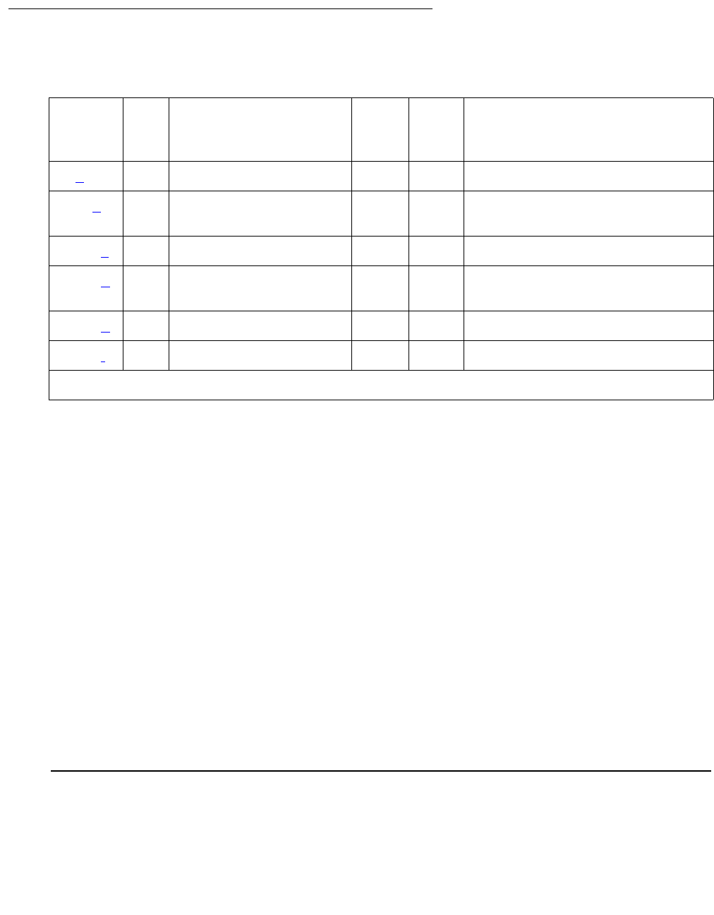
TBRI-TRK (Trunk-Side ISDN BRI Channel)
Issue 1 June 2005 2225
Hardware Error Log Entries and Test to Clear Values
Notes:
a. Error Type 0: run the Short Test Sequence first. If all tests pass, run the Long Test
Sequence. Refer to the appropriate test description and follow the recommended
procedures.
b. Error Type 513: the far-end has reported that this channel is not administered. The trunks
are placed in the out-of-service state.
c. Error Type 1793: the signaling link is down:
●Aux Data 8 indicates the Signaling Link is down.
●Aux Data 9 indicates the Port is out of service.
d. Error Type 3073: the Service State Audit failed. The test will be run every 15 minutes until it
passes.
e. Error Type 3585: unexpected Restart message; this error causes no action and is logged
only.
f. Error Type 3841: B-Channel Rejection Event; this action causes the Service State Audit,
the Call State Audit, and the Test Call Audit to be executed.
Table 796: TBRI-TRK Error Log Entries
Error
Type
Aux
Data
Associated Test Alarm
Level
On/
Off
Board
Test to Clear Value
0 (a) 0 Any Any Any test port location sh r 1
513 (b) Service State Audit
(#256)
WRN OFF
1793 (c)8, 9 WRN OFF
3073 (d) Service State Audit
(#256)
3585 (e)
3841 (f)WRNOFF
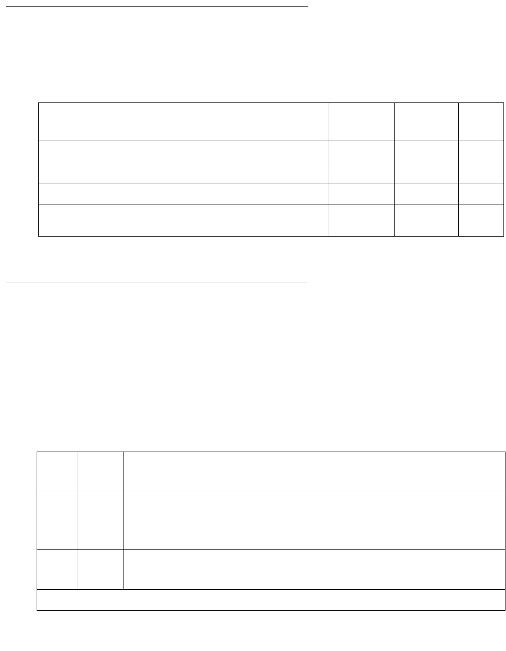
Communication Manager Maintenance-Object Repair Procedures
2226 Maintenance Procedures for Avaya Communication Manager 3.0, Media Gateways and Servers
System Technician-Demanded Tests:
Descriptions and Error Codes
Investigate tests in the order presented below. Clearing Error Codes associated with the one
test may also clear errors generated from other tests in the sequence.
Signaling Link State (#1251)
This test is nondestructive.
This test checks the current state of the signaling link. The test looks at the board-level
translations, checks that the board is physically inserted, gets the state of the D channel and
service state of the port.
The test passes if the signaling link (D channel) is connected and operating normally. The test
fails if the board is not installed, the signaling link is disconnected, or if the port is out of service.
The test aborts otherwise.
Order of Investigation Short Test
Sequence
Long Test
Sequence
D/ND1
1. Destructive; ND = Nondestructive
Signaling Link State Check test (#1251) X X ND
Service State Audit test (#256) X X ND
Call State Audit test (#257) X X ND
ISDN Test Call test (#258)
S8300 / G700: Aborts with Error Code 1412 on a G700.
XND
Table 797: Test #1251 Signaling Link State Test
Error
Code
Test
Result
Description / Recommendation
ABRT Internal system error
1. Retry the command at 1-minute intervals up to 5 times.
2. If the test continues to abort, escalate the problem.
1018 ABRT The test is disabled.
1. Enable the test by entering enable test 1251.
1 of 2

TBRI-TRK (Trunk-Side ISDN BRI Channel)
Issue 1 June 2005 2227
Service State Audit (#256)
This test is nondestructive.
This test performs a service state audit on an ISDN B channel. The test passes if Call
Processing informs Maintenance that the Restart message was transmitted successfully, or if
the B channel was busy and could not send the message.
The test fails if the board is not inserted or translated properly, or if a reply is not received within
a certain amount of time.
The test aborts if the signaling link is disconnected, if a message is already outstanding, or if the
necessary resources could not be allocated.
Use status trunk grp#/mem# to investigate the service state of a TN2185 Trunk-Side ISDN
BRI channel.
1114 ABRT The signaling link is in a transitional state.
1. Retry the command at 1-minute intervals up to 5 times.
2. If the test continues to abort, escalate the problem.
8 FAIL The signaling link is down.
1. Consult the procedures for the TBRI-PT MO.
9 FAIL The port is out of service.
1. Return the port to an in-service state.
PASS The signaling link is connected and operating normally.
Table 797: Test #1251 Signaling Link State Test (continued)
Error
Code
Test
Result
Description / Recommendation
2 of 2
Table 798: Test #256 Service State Audit Test
Error
Code
Test
Result
Description / Recommendation
1000 ABRT System resources required to run this test are not available. The port may
be on a valid call. Use status trunk to determine when a trunk is
available for testing.
1. Check the results of Test #1251 (Signaling Link State Check).
1 of 2

Communication Manager Maintenance-Object Repair Procedures
2228 Maintenance Procedures for Avaya Communication Manager 3.0, Media Gateways and Servers
1005 ABRT The test aborted due to a configuration problem. This test may not be
applicable, or it may be disruptive to terminal equipment other than a voice
terminal (for example, a modem pool member or Music on Hold). This error
can be ignored.
1018 ABRT The test is disabled.
1. Enable maintenance by entering y in the Maintenance Tests field on
page 2 of the change trunk-group screen.
1113 ABRT The signaling link has failed, so the system cannot send any messages on
behalf of this trunk.
1. Check the results of Test #1251 (Signaling Link State test).
1114 ABRT The signaling link is in a transitional state.
1. Retry the command at 1-minute intervals up to 5 times.
1116 ABRT The trunk is not in a service state which is appropriate for running the test.
This test is only performed in the OOS/FE state.
1117 ABRT A service state audit message is outstanding.
1. Wait two minutes and then try again.
2100 ABRT Could not allocate the necessary system resources to run this test.
1. Retry the command at 1-minute intervals up to 5 times.
2. If the test continues to abort, escalate the problem.
FAIL Internal system error
1. Retry the command at 1-minute intervals up to 5 times.
2. If the test continues to fail, escalate the problem.
PASS Wait 4 minutes and then check the Error Log for any new errors of type
3073. If there are none, then both sides of the ISDN connection agree on the
service state; the negotiation succeeded. If there is a new 3073 error, then
the negotiation failed (the far-end switch twice failed to respond within 2
minutes). The switch automatically retries every 15 minutes. If the trunk was
initially in-service, it is now placed in the maintenance/far-end state.
Incoming calls are accepted, but no outgoing calls can be originated. If an
incoming call is presented, another Service State Audit is immediately
performed in an attempt to put the TN2185 Trunk-Side ISDN-BRI channel in
the proper state.
Table 798: Test #256 Service State Audit Test (continued)
Error
Code
Test
Result
Description / Recommendation
2 of 2

TBRI-TRK (Trunk-Side ISDN BRI Channel)
Issue 1 June 2005 2229
Call State Audit Test (#257)
This test is nondestructive.
This test performs a call state audit on an ISDN B channel, and upon successful completion,
guarantees that both sides of the interface are in a consistent call state for connections using
the B channel. The test can be helpful when trying to clear a hung call. If the internal call state
data to the near-end switch is different from that of the far-end switch, the call will be torn down.
The test passes if the audit is successful.
The test fails if the board is not inserted, if there is an internal system error, or if a reply was not
received within a certain amount of time.
The test aborts if the signaling link is disconnected, the request is already active, or if the B
channel is in an out-of-service state.
Table 799: Test #257 Call State Audit Test
Error
Code
Test
Result
Description / Recommendation
1018 ABRT The test is disabled.
1. Enable the test by entering y in the Maintenance Tests field on page 2
of the change trunk-group screen.
1019 ABRT An audit is already in progress.
1. Wait two minutes and try again.
1113 ABRT The signaling link has failed, so the system cannot send any messages on
behalf of this trunk.
1. Check the results of Test #1251 (Signaling Link State Check).
1114 ABRT The signaling link is in a transitional state.
1. Retry the command at 1-minute intervals up to 5 times.
1116 ABRT The trunk is in an out-of-service ISDN service state.
1. A call cannot be present if the trunk is in an ISDN out-of-service state,
so a call state audit would be inappropriate. No action necessary. (Use
status trunk.)
2100 ABRT Could not allocate the necessary system resources to run this test.
1. Retry the command at 1-minute intervals up to 5 times.
2. If the test continues to abort, escalate the problem.
1 of 2

Communication Manager Maintenance-Object Repair Procedures
2230 Maintenance Procedures for Avaya Communication Manager 3.0, Media Gateways and Servers
ISDN Test Call Test (#258)
This test performs a far-end loop around to a far-end switch over an ISDN trunk. The trunk’s
service state must be in-service, maint-NE, or out-of-service/NE, and no call can be active on
the trunk.
Note:
Note: S8300 / G700: This test does not execute on a G700 Media Gateway.
A test call connection is established to a far-end switch over the ISDN trunk to be tested. The
digital port on a TN711D Maintenance/Test circuit pack generates a test-pattern bit stream that
is sent to the far-end switch and echoed back. The received pattern is then compared to the
sent pattern and checked for errors that indicate a loss of integrity on the communications path.
If a test call is running when scheduled maintenance starts, the green LED is turned off. To
determine whether a test call is still running:
●Enter list isdn-testcall and status isdn-testcall.
●Check for a lit amber LED on the Maintenance/Test circuit pack.
There are two ways to place an outgoing test call over trunk-side ISDN-BRI facility:
1. The test call connection is established over the TDM bus of the transmit and receive sides
of the trunk-side ISDN-BRI facility to a digital trunk testing port on the Maintenance/Test
circuit pack. The Maintenance/Test Digital Port generates a pseudo bit stream.
2. The test call connection is established over the TDM bus of the transmit and receive sides
of the trunk-side ISDN-BRI facility to a data channel. This method is selected when no
Maintenance/Test circuit pack resides in the system.
A test is run periodically to check if the call is hung. If so, it gracefully tears down the call to
release the resources.
FAIL Internal system error
1. Retry the command at 1-minute intervals up to 5 times.
2. If the test continues to fail, escalate the problem.
PASS The audit passed successfully.
Table 799: Test #257 Call State Audit Test (continued)
Error
Code
Test
Result
Description / Recommendation
2 of 2

TBRI-TRK (Trunk-Side ISDN BRI Channel)
Issue 1 June 2005 2231
Synchronous Commands
You can demand a synchronous outgoing test call by using the following maintenance
commands:
●test trunk grp#/mem# long [repeat number]
●test board location long [repeat number]
●test port location long [repeat number]
Whenever a circuit translates to a trunk-side ISDN-BRI channel during a long test sequence, an
outgoing test call is invoked, and the duration of the test call is 8.6 seconds. Once the test call
completes, the bit error rate is retrieved from the Maintenance/Test Digital Port. A bit error rate
greater than zero is reported as a failure to the Manager I terminal (MGRI). A failure indicates
the need to run further diagnostics.
If no Maintenance/Test circuit pack exists, an outgoing test call over a trunk-side ISDN-BRI
facility is established over a high-speed data channel on the Network Control (NETCON) circuit
pack (DATA-BD).
Asynchronous Commands
Note:
Note: Only one trunk can be tested in a given port network, until the test call is canceled
or completes.
Table 800: Test #258 ISDN Test Call
Error
Code
Test
Result
Description / Recommendation
4 ABRT There is a problem with the Processor Interface Link.
1. See the PI-LINK (Processor Interface Link) Maintenance
documentation.
1004 ABRT B channel in use.
1. Enter status trunk to determine whether a call is active on
this trunk-side ISDN-BRI channel.
2. When the service state indicates in-service/idle, retry the test.
1005 ABRT Bad Configuration (that is, no Maintenance/Test circuit pack)
Enter test trunk grp#/mem# and make sure there is a
DATA-CHL (NETCON channel) administered.
1018 ABRT Test call is disabled.
1. Enable Maintenance on the Trunk Group screen.
1 of 6

Communication Manager Maintenance-Object Repair Procedures
2232 Maintenance Procedures for Avaya Communication Manager 3.0, Media Gateways and Servers
1024 ABRT (M/T-DIG) Maintenance/Test Digital Port in use.
1. Wait until yellow and green LEDs are turned off on the M/T-BD
(Maintenance/Test circuit pack).
2. Retry the test. If problem persists, see M/T-DIG (Maintenance/
Test Di gita l P ort ) on page 1709.
1113 ABRT The signaling link has failed; the system cannot send any messages
on behalf of this trunk.
1. Check the results of Test #1251 (Signaling Link State Check
Test).
1114 ABRT The signaling link is in a transitional state.
1. Retry the command at 1-minute intervals up to 5 times.
2. If the test continues to abort, escalate the problem.
1116 ABRT The switch could not appropriately change the ISDN service state.
1. Enter status trunk to determine whether a call is active on
this trunk-side ISDN-BRI channel.
2. If not, check the error and alarm logs for problems with this
TBRI-TRK MO.
1117 ABRT ISDN B-channel maintenance message is already outstanding.
1. Wait two minutes, then try again.
1118 ABRT Far end of ISDN trunk is not administered.
1. Check the administration of the far-end ISDN trunk.
2. Enter status trunk, and try the test again.
1119 ABRT The test call was aborted due to a normal call attempt on this trunk.
The test call is performed only if the trunk is idle.
1. Either wait for the normal call to terminate normally, or force it to
be dropped by using busyout trunk.
Table 800: Test #258 ISDN Test Call (continued)
Error
Code
Test
Result
Description / Recommendation
2 of 6

TBRI-TRK (Trunk-Side ISDN BRI Channel)
Issue 1 June 2005 2233
1120 ABRT The trunk-side ISDN-BRI facility is in the ISDN out-of-service/far-end
state.
1. Try to change the service state via Test #256 (Service State
Audit test). Then retry this test. However, the trunk may be in the
out-of-service/far-end state due to problems at the far-end
switch. If that is the case, no remedial action can be taken at this
end.
1122 ABRT There is no test line number for the far-end switch.
1. Check the Trunk Group Administration screen.
1123 ABRT There is no Feature Access Code administration for this Facility test.
1. Check the Dial Plan and Feature Administration forms.
S8300 / G700:
1412
ABRT This test does not execute on a G700 media gateway.
2012
None
2000
ABRT Internal system error
1. Retry the command at 1-minute intervals up to 5 times.
2. If the test continues to abort, escalate the problem.
2035 ABRT The call has timed out, perhaps because of a lack of system
resources.
1. Wait 1 minute and try again.
2. If the test continues to abort, escalate the problem.
2036
2037
ABRT Internal system error
1. Retry the command at 1-minute intervals up to 5 times.
2. If the test continues to abort, escalate the problem.
2038
2039
ABRT A problem occurred while trying to read the test data.
1. Wait one minute and then try again.
2. If the test aborts again in the same manner, there is a serious
internal problem. If so, escalate the problem.
Table 800: Test #258 ISDN Test Call (continued)
Error
Code
Test
Result
Description / Recommendation
3 of 6

Communication Manager Maintenance-Object Repair Procedures
2234 Maintenance Procedures for Avaya Communication Manager 3.0, Media Gateways and Servers
2040 ABRT Internal system error
1. Retry the command at 1-minute intervals up to 5 times.
2. If the test continues to abort, escalate the problem.
2041 ABRT The call has timed out, perhaps because of a lack of system
resources.
1. Retry the command at 1-minute intervals up to 5 times.
2. If the test continues to abort, escalate the problem.
2066 ABRT Could not establish test call.
1. Retry the command at 1-minute intervals up to 5 times.
2. If the test continues to abort, escalate the problem.
2067 ABRT The call has timed out, perhaps because of a lack of system
resources.
1. Retry the command at 1-minute intervals up to 5 times.
2. If the test continues to abort, escalate the problem.
2074 ABRT Bit and Block Error query failed.
1. Retry the command at 1-minute intervals up to 5 times.
2. If the test continues to abort, there may be a serious internal
problem with M/T-DIG (Maintenance/Test Digital Port). If this is
the case, see M/T-DIG (Maintenance/Test Digital Port) on
page 1709.
2075 ABRT Internal system error
1. Retry the command at 1-minute intervals up to 5 times.
2. If the test continues to abort, escalate the problem.
2100 ABRT Could not allocate the necessary system resources to run this test.
1. Retry the command at 1-minute intervals up to 5 times.
2. If the test continues to abort, escalate the problem.
Table 800: Test #258 ISDN Test Call (continued)
Error
Code
Test
Result
Description / Recommendation
4 of 6

TBRI-TRK (Trunk-Side ISDN BRI Channel)
Issue 1 June 2005 2235
2104 ABRT Call dropped or could not be originated.
1. Make sure service is provisioned by the network.
2. Check the administration of the far-end test line extension on the
trunk group administration screen.
3. Check the administration of the test call BCC (Bearer Capability
Class) on the trunk group administration screen.
4. Try the test again.
5. If the test continues to abort, escalate the problem.
2201–
2205
ABRT Internal system error
1. Retry the command at 1-minute intervals up to 5 times.
2. If the test continues to abort, escalate the problem.
2206 ABRT Could not allocate the necessary system resources to run this test.
1. Retry the command at 1-minute intervals up to 5 times.
2. If the test continues to abort, escalate the problem.
2208 ABRT Internal system error
1. Retry the command at 1-minute intervals up to 5 times.
2. If the test continues to abort, escalate the problem.
2209
2210
ABRT Could not allocate the necessary system resources to run this test.
1. Retry the command at 1-minute intervals up to 5 times.
2. If the test continues to abort, escalate the problem.
2211 ABRT Internal system error
1. Retry the command at 1-minute intervals up to 5 times.
2. If the test continues to abort, escalate the problem.
2212 ABRT Call terminated by unexpected disconnect.
1. Wait one minute and then try again.
Table 800: Test #258 ISDN Test Call (continued)
Error
Code
Test
Result
Description / Recommendation
5 of 6

Communication Manager Maintenance-Object Repair Procedures
2236 Maintenance Procedures for Avaya Communication Manager 3.0, Media Gateways and Servers
2213 ABRT The call has timed-out, perhaps because of a lack of system
resources.
1. Retry the command at 1-minute intervals up to 5 times.
2. If the test continues to abort, escalate the problem.
2214 ABRT Call terminated by unexpected disconnect.
1. Wait one minute and then try again.
2215–
2219
ABRT Internal system error
1. Retry the command at 1-minute intervals up to 5 times.
2. If the test continues to abort, escalate the problem.
2220 ABRT Call terminated prematurely.
1. Wait one minute and try again.
2221–
2226
ABRT Internal system error
1. Retry the command at 1-minute intervals up to 5 times.
2. If the test continues to abort, escalate the problem.
2227 ABRT Could not allocate the necessary system resources to run this test.
1. Retry the command at 1-minute intervals up to 5 times.
2. If the test continues to abort, escalate the problem.
2042 FAIL This is the main purpose of the test. The comparison of the data
sent with the data received indicates a loss of integrity on the
communications path.
1. The trunk should be taken out-of-service and the quality of the
ISDN trunk-side BRI facility should be investigated. The
investigation should include an in-depth analysis of the facility
including the transmission facility and any external equipment
such as DACs, CSUs, etc.
PASS The call worked. A test pattern was sent and received properly; the
communications path is OK if the synchronous test call command was
entered. An in-depth analysis of the ISDN trunk-side BRI facility
including the transmission facility and any external equipment such as
DACs, CSUs, and others should take place if the bit and block error
rates are not acceptable.
Table 800: Test #258 ISDN Test Call (continued)
Error
Code
Test
Result
Description / Recommendation
6 of 6

TDM-BUS (TDM Bus)
Issue 1 June 2005 2237
TDM-BUS (TDM Bus)
S8700 | 8710 / S8500
Description
Each port network has a pair of TDM buses, designated TDM bus A and TDM bus B, each with
256 time slots. This division allows for duplication of control channels and dedicated tone time
slots. The first five time slots on each bus are reserved for the control channel, which is active
on only one bus at a time in each port network. The next 17 time slots are reserved for system
tones such as dial tone, busy tone and so on. As with the control channel, these time slots are
active on only one bus, A or B, at a time. The rest of the time slots on each bus are for general
system use such as carrying call-associated voice data. The 17 dedicated tone time slots that
are inactive can also be used for call processing when every other available time slot is in use.
When the system initializes, the control channel is on TDM bus A and the dedicated tones on
TDM bus B in each port network. If a failure occurs on one of the two buses, the system will
switch any control, tone and traffic channels to the other bus. Service will still be provided,
though at a reduced capacity.
The set tdm PC command has the effect of putting both the control channel and tone time
slots on a specified bus, A or B. P specifies the port network’s number, and C specifies the TDM
bus, A or B. Throughout this discussion, PC refers to a specific TDM bus. References to port
circuit packs include every circuit pack that terminates on the TDM bus, including the Expansion
Interface TN570, and the following service circuit port boards: Call Classifier (TN744),
Integrated Announcement (TN750), Maintenance/Test (TN771), Speech Synthesizer (TN725B),
Tone Detector (TN748 or TN420). Other terms used are:
●Control Channel Bus: the TDM bus carrying the active control channel
●Non-Control Channel Bus: the TDM bus with the inactive control channel
●Tone Bus: the TDM bus carrying the active tone time slots
●Non-Tone Bus: the TDM bus with the inactive tone time slots
MO Name Alarm Level Initial Command to Run1
1. P is the port network number. Use list cabinet to find the port network(s)
contained in a cabinet.
Full Name of MO
TDM-BUS MAJ test tdm P TDM bus
TDM-BUS MIN test tdm PTDM bus
TDM-BUS WRN test tdm PTDM bus

Communication Manager Maintenance-Object Repair Procedures
2238 Maintenance Procedures for Avaya Communication Manager 3.0, Media Gateways and Servers
TDM-Bus Fault Detection and Isolation
TDM-bus faults are usually caused by one of the following:
●A defective circuit pack connected to the backplane
●Bent pins on the backplane
●Defective bus cables or terminators
It is possible that a circuit pack can cause a TDM-bus fault and still exhibit trouble-free
operation. For example, insertions of any circuit pack into a slot with TDM bus terminations may
bend the backplane pins and short two leads together. Since the TDM bus is a shared resource,
identification of the cause of a TDM-bus fault can be difficult. If a TDM-bus problem is
suspected, run test tdm P. If any of the resulting tests fail, you must perform a manual TDM
bus isolation procedure to identify the cause of the problem.
!WARNING:
WARNING: Since the procedure for isolating TDM-bus faults involves removing circuit packs
and possibly disconnecting entire carriers, the procedure is extremely destructive
to the port network that contains the TDM bus being tested. If possible, arrange
to perform this procedure at a time when traffic is minimal.
As circuit packs are removed or entire carriers are disconnected, any active calls terminating on
those circuit packs or carriers will be dropped. If you have any hints about a particular circuit
pack that may be causing the TDM bus problem investigate those before performing this
procedure (for example, look at any circuit packs that were inserted into the PN just before the
TDM bus problem appeared.
When straightening or replacing backplane pins in a carrier that contains a CFY1B Current
Limiter, power to the cabinet must be removed. When straightening or replacing backplane pins
in a carrier that does NOT contain a CFY1B Current Limiter, power to that carrier must be shut
off. Failure to follow this procedure may result in damage to circuit packs and power supplies,
and can be hazardous to the technician.
Note:
Note: Maintenance software requires TN748 or TN420 Tone Detector circuit pack to
test the TDM bus. Before starting these procedures, make sure that one of these
is installed in the port network being investigated.

TDM-BUS (TDM Bus)
Issue 1 June 2005 2239
Procedure 1: Isolating TDM-Bus Faults
This procedure is an attempt to isolate the TDM-bus fault to circuit packs that are essential to
the system’s operation. For each of the following circuit packs in the port network where the
TDM-bus fault appears, perform Procedure 1.
1. Display the Alarm Log for the circuit pack using display alarms.
2. If there are alarms for the circuit pack, refer to that section and try to resolve the alarms.
3. Whether or not every alarm can be cleared, test the TDM bus again using test tdm P.
4. If some TDM-bus tests fail, implement Procedure 1 for the next circuit pack.
5. If every TDM-bus test passes, the problem has been fixed.
6. If every circuit pack in the list has been investigated, go to Procedure 2.
Procedure 2: Removing and Reinserting Port
Circuit Packs
Procedure 2 removes and reinserts port circuit packs (those in the carrier’s purple slots) one or
more at a time. Use this procedure for each port circuit pack in the port network until the
problem is resolved or until every circuit pack in the port network have been tried. To execute
diagnostic procedures on the Expansion Interface and Tone-Clock circuit packs, see Procedure
3: Removing and Reinserting PN Control Circuit Packs on page 2241. Although these circuit
packs reside in purple slots, procedure 2 does not apply. This procedure does apply to the Tone
Detector circuit pack.
If the TDM bus problem is present when the circuit pack is inserted, but is resolved when the
circuit pack is removed, either the circuit pack or the backplane pins in that slot are causing the
problem. If the backplane pins are intact, replace the circuit pack. If some of the tests fail
regardless of whether the circuit pack is inserted or removed, and the backplane pins are intact,
the circuit pack is not the cause of the problem. In a multiple failure situation, the circuit pack
could be one cause of the TDM bus problem. However, other simultaneous failures might also
be responsible for TDM-bus faults.
Circuit Pack Error Log Names
Tone-Clock TONE-BD, TONE-PT, and TDM-CLK
MSS/Network Control SW-CTL and H-ADAPTER
Tone Detector DETR-BD, GPTD-PT, and DTMR-PT
Expansion Interface EXP-INTF
Packet Interface PKT-INT

Communication Manager Maintenance-Object Repair Procedures
2240 Maintenance Procedures for Avaya Communication Manager 3.0, Media Gateways and Servers
In Procedure 2, an option of working either with one circuit pack at a time or with multiple circuit
packs simultaneously is available. In view of this capability, determine the level of service
interruption that will be acceptable during the procedure. If causing a disruption to all users in
the port network is deemed permissible, large groups of circuit packs should be worked with in
order to get the job done quickly. However, if large service disruptions are to be avoided, work
with one circuit pack at a time. This option is slower, but it disrupts only the users of a single
circuit pack.
1. Remove one or several circuit packs as appropriate. Any circuit packs that reside on the
TDM bus that were recently inserted should be checked first.
Remove port circuit packs which have failed the NPE Crosstalk Test (#6) first. To find which
circuit packs failed this test, display the Hardware Error Log via the display errors
command. Refer to the Maintenance documentation of each port circuit pack that has port
errors to check if any error indicates the failure of the NPE Crosstalk Test. If no circuit pack
failed the NPE Crosstalk Test (#6), remove one or several purple slot circuit packs.
If you decide to remove multiple circuit packs, consider working with an entire carrier at a
time to more quickly and reliably determine which circuit packs are not the source of trouble.
2. Run test tdm P to determine if the TDM-bus fault is still present.
3. If any of the TDM-bus tests fail:
●Determine whether the backplane pins in the removed circuit pack’s slot appear to be
bent.
●If the backplane pins are not bent, reinsert the circuit pack(s), and perform Procedure 2
for the next set of circuit packs.
●If the backplane pins are bent, remove power to this carrier in the manner described
previously.
●Straighten or replace the pins and reinsert the circuit pack.
●Restore power and repeat Procedure 2, beginning with Step 2, for the same circuit
pack(s).
4. If none of the TDM-bus tests fail:
●Reinsert the circuit pack(s) one at a time, and repeat the following substeps until every
circuit pack has been reinserted.
●Run test tdm P to determine if the TDM-bus fault has returned.
●If any of the TDM-bus tests fail, the reinserted circuit pack is defective. Replace this
circuit pack and repeat this procedure for the next circuit pack.
●If none of the TDM-bus tests fail when every circuit pack has been reinserted, the
problem has been fixed and the procedure is completed.
Continue with Procedure 3 if every port circuit pack has been checked, but the TDM-bus fault is
still not resolved.

TDM-BUS (TDM Bus)
Issue 1 June 2005 2241
Procedure 3: Removing and Reinserting PN
Control Circuit Packs
This procedure removes and reinserts a PN’s control circuit packs. Use this procedure to test:
●TN570 Expansion Interface
●TN768, TN780 Tone-Clock
Check the Tone-Clock circuit pack next-to-last. Check the Expansion Interface circuit pack
(TN570) last, because removing this circuit pack disconnects its PN. In a system with duplicated
PNC, disruption of traffic can be minimized by following the procedure for the standby TN570
Expansion Interface circuit pack, and then entering reset pnc interchange. The formerly
active Expansion Interface will be standby and can be checked without affecting the PN’s
service.
For instructions, at each step in a procedure that requires the removal and/or replacement of a
circuit pack, refer to the documentation for the specific circuit pack’s MO. Server and/or PNC
interchanges may be required to complete these steps with the least amount of service
disruption.
Procedure for PN with Unduplicated PNC
1. Remove the suspected circuit pack.
2. As in Procedure 2: Removing and Reinserting Port Circuit Packs on page 2239, determine
if the backplane pins on the back of the removed circuit pack’s slot are bent.
3. If the backplane pins are bent, do the following:
a. Power down the control carrier as described in the previous warning statement.
b. Straighten or replace the pins.
c. Insert the same circuit pack.
d. Turn the power back on to reboot the system or to restart the PN.
e. Run test tdm P to determine whether the TDM-bus fault still exists.
f. If none of the TDM-bus tests fail, the procedure is complete.
g. If some of the TDM-bus tests fail, replace the suspected circuit pack, and go to step 4.
If not: Replace the circuit pack and turn the power back on to reboot the system.
4. Run test tdm P to determine whether the TDM-bus fault is still present.

Communication Manager Maintenance-Object Repair Procedures
2242 Maintenance Procedures for Avaya Communication Manager 3.0, Media Gateways and Servers
5. If the TDM-bus fault is still present, the suspected circuit pack was not the cause of the
TDM-bus failure. Do the following:
a. Remove the replacement circuit pack that was just inserted and replace it with the
previously suspected circuit pack.
b. Repeat Procedure 3 for the next circuit pack on the list for this procedure.
If none of the TDM-bus tests fail, the procedure is completed.
If Procedure 3 fails to identify the cause of the problem, go to Procedure 4: Isolating TDM-Bus
Failures to Carriers on page 2244.
S8700 MC
Procedure for PN with Duplicated PNC
In this type of configuration, the test procedure is made up of several independent parts. In a
duplicated system, it is desirable to investigate whether circuit packs are causing TDM-bus
problems when they are in active mode, in standby mode, or both. The procedure utilizes a
PNC interchange in a PN. If the TDM-bus fault disappears after an interchange takes place, the
newly standby Expansion Interface (PN), is suspect and should be replaced. If the problem still
exists, the Tone-Clocks are then interchanged. If the TDM-bus failure then disappears, the
newly standby Tone-Clock is suspect and should be replaced. If the TDM-bus problem still
exists, then the procedure begins diagnostics on individual circuit packs and backplane pins.
Part 1 (PN Procedure)
1. Execute status pnc to determine which PNC is currently active.
2. Run reset pnc interchange to make the currently active PNC standby.
3. Run test tdm P to determine whether the TDM-bus fault is still present.
If the TDM-bus fault is gone, replace the formerly active Expansion Interface circuit pack.
4. Run reset pnc interchange again to activate the PNC where the new Expansion
Interface circuit pack resides.
5. Run test tdm P to determine whether the TDM-bus fault is still present.
If the TDM-bus fault is gone, the procedure is finished.
If not, replace the new Expansion Interface circuit pack with the originally suspected circuit
pack, and continue with Part 2.

TDM-BUS (TDM Bus)
Issue 1 June 2005 2243
Part 2
1. Run set tone-clock to make the currently active Tone-Clock standby.
2. Run test tdm P to determine whether the TDM-bus fault is still present.
If the TDM-bus fault is gone:
a. Replace the formerly active Tone-Clock circuit pack.
b. Run set tone-clock again to make the new Tone-Clock circuit pack active.
c. Run test tdm P to determine whether the TDM-bus fault is still present.
If the TDM-bus fault is still present, replace the new Tone-Clock circuit pack with the
originally suspected circuit pack, and continue with Part 3.
Part 3
Use Part 3 for each individual circuit pack listed in the previous table. Run this procedure on
every circuit pack in the standby PNC. If the TDM-bus failure still exists (once every standby
circuit pack has been tested), execute reset pnc interchange, and set tone-clock to
put the currently active circuit packs into standby mode so that this procedure can be run on
each of them.
1. Remove the inactive suspected circuit pack.
2. As in Procedure 2, determine whether any backplane pins on the back of the removed
circuit pack’s slot are bent.
3. If the pins are bent, do the following:
a. Remove power as described in the previous warning statement.
b. Straighten or replace the pins.
c. Restore power.
d. Run test tdm P to determine whether the TDM-bus fault is still present.
If the TDM-bus failure is still present, the problem is with another circuit pack. Reinsert
the originally suspected circuit pack, and repeat Part 3 for the next circuit pack.
e. If the TDM-bus failure has disappeared, reinsert the circuit pack and run test tdm P to
see if the TDM-bus failure is still present.
If any of the TDM-bus tests fail, replace the suspected circuit pack. The procedure is
finished.
If not, the procedure is finished.
If the backplane pins are not bent, run test tdm P to determine whether the TDM-bus
fault is still present.
f. If any of the TDM-bus tests fail, the problem is with another circuit pack. Reinsert the
originally suspected circuit pack, and repeat Part 3 for the next circuit pack.
g. If not, replace the suspected circuit pack. The procedure is finished.
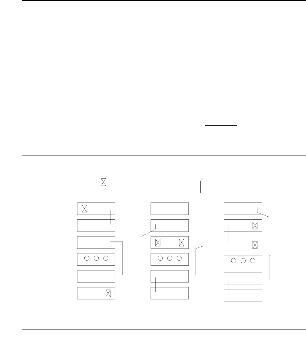
Communication Manager Maintenance-Object Repair Procedures
2244 Maintenance Procedures for Avaya Communication Manager 3.0, Media Gateways and Servers
4. If every standby circuit pack has been tested but the TDM-bus failure still exists, execute
reset pnc interchange and set tone-clock to put the currently active circuit packs
into standby mode. Repeat Part 3 of this procedure for each of the newly active circuit
packs.
Procedure 4: Isolating TDM-Bus Failures to Carriers
Procedure 4 attempts to isolate a TDM-bus failure to a particular set of carriers. Only the circuit
packs in selected carriers are checked. Procedure 4 is used if the preceding procedures fail,
because it can help locate failures of:
●Multiple circuit packs
●The carrier’s hardware itself
In this procedure, the TDM/LAN cable assemblies and TDM/LAN bus terminators are replaced.
If replacement does not resolve the TDM-bus fault, the cabinet is reconfigured so that certain
carriers are disconnected from the TDM bus. This is done by moving the TDM/LAN bus
terminators (ZAHF4) on the carrier’s backplane. To terminate a TDM bus at the end of a
particular carrier, the TDM bus cable that connects the carrier to the next carrier should be
unplugged and replaced with a TDM/LAN bus terminator (see Figure 138). As the length of a
TDM bus is modified, any essential circuit packs to the system’s operation and TDM-bus
maintenance (for example, MSSNET and Tone-Clock), must still be connected to the shortened
TDM bus.
Figure 138: Carrier Rewiring Example — Rear View of 5-Carrier Cabinet
A and B
Include
Extended to
Shortened Bus
(Control Carrier)
to Carrier A Only
Bus Shortened
. . . . . . . . . . . . . .
. . . . . . . . . . . . . .
. . . . . . . . . . .
TDM/LAN Bus Cable TDM/LAN Bus Terminator
(All 5 Carriers
Cabinet
Configured
Normally
Carrier E
Carrier D
Fans
Carrier A
Carrier B
Carrier C
. . . . . . . . . . . . . .
. . . . . . . . . . . . . . . .
. . . . . . . . . . . . . . . .
. . . . . . . . . . . . . . . .
. . . . . . . . . . . . . .

TDM-BUS (TDM Bus)
Issue 1 June 2005 2245
After cabling changes are made and verified, power must be restored to the PN. Circuit packs in
carriers outside the shortened bus are not inserted. As a result, these circuit packs are alarmed.
Ignore these alarms for now. Every alarm should be resolved when the cabinet is restored to its
original configuration.
Procedure 4 is organized into two parts. Part 1 attempts to clear a TDM-bus fault by replacing
every bus cable and terminator within a PN. Part 2 attempts to isolate the fault to a particular
carrier by extending the TDM bus from the control carrier to additional carriers one at a time.
!WARNING:
WARNING: Power must be removed from the entire PN before any cables or terminators are
removed. Failure to follow this procedure can cause damage to circuit packs and
power supplies, and can be hazardous to the technician.
Part 1
1. If spare TDM/LAN cable assemblies and TDM/LAN bus terminators are not available, go to
Part 2 of this procedure.
2. Power down the PN.
3. Replace every TDM/LAN cable assembly and both TDM/LAN bus terminators.
4. Restore power to the PN.
5. Run test tdm P to determine whether the TDM-bus fault is still present.
6. If the TDM-bus fault is resolved, the procedure is finished. Otherwise, continue with Part 2.
Part 2
1. Terminate the TDM bus so that it extends only across the carrier that contains the active
Expansion Interface.
2. Run test tdm P to determine whether the TDM-bus fault is still present.
If the shortened TDM bus does not extend to a carrier continuing the Tone Detector circuit
pack, the:
●Non-control channel test (#297) will not be able to run
●Bus that the non-control channel was on will not be tested
If this is the case, run set tdm PC to move the control channel to the non-active bus. The
status port-network P command shows which bus is currently active. After the bus
switch has occurred, run test tdm P again to determine whether the newly active bus is
faulted.
Another option is to move a Tone Detector circuit pack to an empty slot, if one is available,
in the carrier where the TDM bus is terminated. This would:
●Allow both the control channel and non-control channel tests to run
●Not require set tdm P command to be run

Communication Manager Maintenance-Object Repair Procedures
2246 Maintenance Procedures for Avaya Communication Manager 3.0, Media Gateways and Servers
3. If none of the TDM-bus tests fail, extend the TDM bus to another carrier, and repeat the
procedure in the previous step. When a carrier that causes the fault to recur is added,
perform Procedure 2 for only the circuit packs in that carrier.
4. If any of the TDM-bus tests fail and Procedures 2 and 3 did not resolve the problem, the
added carrier(s) are defective and must be replaced.
Restarting Non-Functioning Port Circuit Packs
A defective TDM-bus control channel or system-timing reference on one of the EPNs can cause
port circuit packs residing outside the PN’s control carrier to enter the reset state. When this
situation occurs, the circuit pack will stop functioning, and its red LED will light. The system does
not detect the presence of a circuit pack when it is in the reset state. Executing list config
board shows that the circuit pack is absent.
If a circuit pack enters the reset state, it remains out of service until it receives a restart
message from the control channel on the same TDM bus (A or B) that was active when it reset,
or until it is powered up again.
To force the system to send a restart message to every circuit pack on a network, try one of the
following methods, depending on the circumstances. Any normally functioning circuit pack (i.e.,
not in reset state) will ignore the restart message.
Procedure 1 (Nondestructive)
If the control channel is on the same TDM bus as it was when the circuit pack entered the reset
state, Enter test tdm P to execute the Idle Time Slot test (#294).
Procedure 2 (Nondestructive)
If you are on-site, reseat the circuit pack. This action causes the circuit pack in the reset state to
begin functioning on the control channel of the current bus.
Procedure 3 (Destructive)
Enter the reset port-network P level 2 command to reset the PN containing the circuit
pack in the reset state. During a PN reset, two restart messages (one on the control channel of
each TDM bus) are sent to each circuit pack in the PN. Resetting the PN disrupts every call
going to and originating from the PN.
Procedure 4 (Destructive)
Execute recycle carrier PC. This command removes and restores power to the
designated port carrier. Thus, any other circuit packs in this carrier will also be temporarily taken
out-of-service.
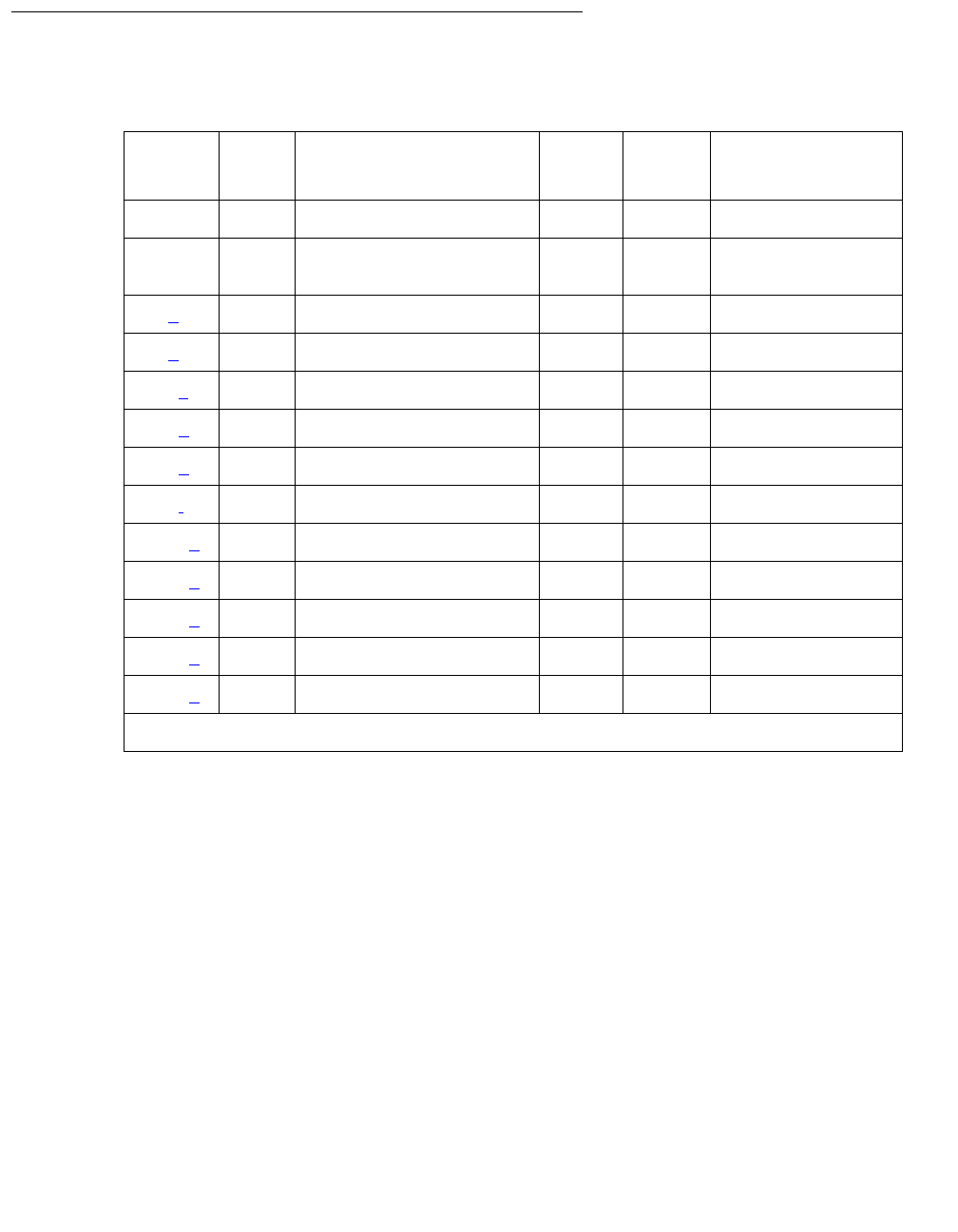
TDM-BUS (TDM Bus)
Issue 1 June 2005 2247
Error Log Entries and Test to Clear Values
Notes:
a. Error Type 18: the TDM bus has been busied out by the technician. The error will retire
when the technician releases the TDM bus.
b. Error Type 35: this error indicates the TDM bus is corrupted. If the corruption was on the
Control Channel bus, TDM bus maintenance automatically switches the control channel
and/or tones to the other bus. The same strategy applies if the corruption was on the bus
carrying the tones.
An Aux Data value of 0 indicates the last reported TDM bus corruption was on the Control
channel bus.
An Aux Data value of 1 indicates the last reported TDM bus corruption was on the
Non-Control channel bus.
Table 801: TDM Bus Error Log Entries
Error
Type
Aux
Data
Associated Test Alarm
Level
On/Off
Board
Test to Clear Value
00Any AnyAnytest tdm P
1 0 Control Channel test
(#296)
MIN ON test tdm P r 3
18 (a)0 busyout tdm PC WRN ON release tdm PC
35 (b) 0-1 TDM bus Corruption MIN ON set tdm PC
257 (c)0 None MAJ ON
513 (d) Any Idle Time Slot test (#294) MIN ON test tdm P r 3
769 (e) Any Idle Time Slot test (#294) WRN ON test tdm P r 3
769 (f) Any Idle Time Slot test (#294) (see Notes)
1025 (g) Any None
3872 (h) Any None
3873 (h) Any None
3874 (h) Any None
3877 (h) Any None
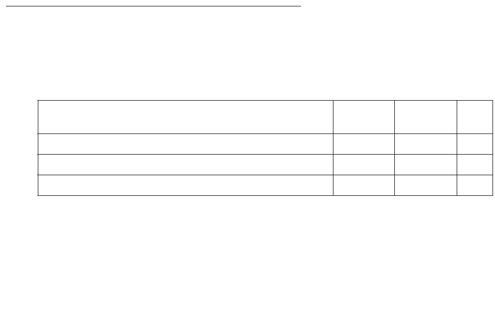
Communication Manager Maintenance-Object Repair Procedures
2248 Maintenance Procedures for Avaya Communication Manager 3.0, Media Gateways and Servers
c. Error Type 357: this error indicates the TDM bus was switched to the other bus due to TDM
bus corruption. The Aux Data value is not meaningful and no action is required. Look for
other TDM-BUS errors to determine the cause of this error.
d. Error Type 513: some time slots are corrupted in the specified TDM bus. The Minor alarm
is raised when there are more than 50 bad time slots in the bus. The Aux Data indicates the
number of bad time slots found by the test.
e. Error Type 769: some time slots are corrupted in the specified TDM bus. The Warning
alarm is raised when there are more than 10 bad time slots but less than or up to 50 bad
ones in the bus. The Aux Data value indicates the number of bad time slots found by the
test.
f. Error Type 769: this error indicates the idle time slot test found less than 10 bad time slots
in the TDM bus. The Aux Data value indicates the number of bad time slots found by the
test. There is no alarm associated with this error.
g. Error Type 1025: the daily TDM bus switch was not successful. The active Expansion
Interface (PN) cannot talk on the bus that software was trying to switch into. There is no
alarm associated with this error.
h. Error Type 3872, 3873, 3874, and 3877: these errors indicate communication problems
which may be causing message loss. TDM bus maintenance may switch the Control
Channel bus and/or Tone bus to the other bus. Test the TDM bus using test tdm P and
follow the procedures according to the Error Codes reported from the test. The Aux Data
value shows the Angel ID number for which a downlink message was lost.
System Technician-Demanded Tests:
Descriptions and Error Codes
Investigate tests in the order presented below. Clearing Error Codes associated with the one
test may also clear errors generated from other tests in the sequence.
Order of Investigation Short Test
Sequence
Long Test
Sequence
D/
ND1
1. D = Destructive; ND = Nondestructive
Control Channel test on the Control Channel Bus (#296) X X ND
Digit Detection test on the Non-Control Channel Bus (#297) X X ND
Idle Time Slot test (#294) X X ND

TDM-BUS (TDM Bus)
Issue 1 June 2005 2249
Idle Time Slot Test on TDM bus A or B (#294)
The Idle Time Slot test detects noisy time slots on the bus and takes them out-of-service. The
Tone Detector circuit is told to listen to idle time slots and if it detects any noise on a time slot, it
returns a failure. At the end of the test, any out-of-service time slots are retested to see if they
are still noisy and restored to service if they are idle. After every time slot has been tested,
maintenance counts the number of bad time slots and reports the number to the technician in
the Error Code field. No more than 220 time slots will be taken out-of-service on one bus and no
more than 300 will be taken out-of-service on both buses at one time.
Table 802: Test #294 Idle Time Slot Test on TDM bus A or TDM bus B
Error
Code
Test
Result
Description / Recommendation
None ABRT Could not allocate the necessary system resources to run this test. For
example, maintenance could be running on the Tone Detector circuit and it
is using the CPTRs.
1115 ABRT Could not allocate the necessary system resources to run this test.
1. Retry the command at 1-minute intervals up to 3 times.
Any FAIL The Error Code indicates the number of bad time slots that were detected.
The cause of this failure is most likely due to a bad port circuit pack and not
the TDM bus itself.
1. Execute the command again.
2. If the error persists, check the Error and Alarm Logs for alarms, on the
port network where the faulted TDM bus resides, on port circuit packs
from the NPE Crosstalk test. Also check for EXP-INTF alarms
associated with Error Type 1537.
3. Refer to the appropriate circuit pack’s documentation to clear the
circuit pack’s problem.
4. Test the TDM bus again. If the error continues, see TDM-Bus Fault
Detection and Isolation on page 2238.
PASS The success of this test indicates every idle time slot that is supposed to be
idle are indeed idle. There is no noise on any of the idle time slots.

Communication Manager Maintenance-Object Repair Procedures
2250 Maintenance Procedures for Avaya Communication Manager 3.0, Media Gateways and Servers
Control Channel Test (#296)
This tests the integrity of the Control Channel bus by ensuring that communication through the
TDM bus is operational. The test attempts to query a circuit pack whose presence is required in
each port network for proper operation (Tone-Clock or Tone Detector). If a reply from the
queried circuit pack is received, the TDM bus is considered operational and the test passes. If
no reply is received, the Bus is not operational and the test fails.
Table 803: Test #296 Control Channel Test
Error
Code
Test
Result
Description / Recommendation
Any
other
than
1005
ABRT Internal system error.
1. Retry the command at 1-minute intervals up to 3 times.
1005 ABRT Since this test is valid only on the control channel bus, it aborts execution
when run on the non-control channel bus. This is a valid response. Use
status port-network to verify which bus is the control channel bus.
None FAIL Communication through the Control Channel is not working. The problem
is not necessarily the TDM bus itself.
1. Display the hardware error and alarm log for the Tone-Clock circuit and
for the Tone Detector circuit in the port network where the faulted TDM
bus resides. See TONE-BD (Tone-Clock Circuit) on page 2327,
TONE-PT (Tone Generator) on page 2353, GPTD-PT
(General-Purpose Tone Detector Port) on page 1308, and DTMR-PT
(Dual-Tone Multifrequency Receiver Port) on page 1115.
2. Resolve the errors and alarms for the Tone-Clock and Tone Detector
circuits.
3. Display the hardware error and alarm log and look for errors and
alarms for the active Expansion Interface circuit pack. See EXP-INTF
(Expansion Interface Circuit Pack) on page 1176 and resolve its errors.
4. Execute test tdm P command.
5. If the test still fails, see TDM-Bus Fault Detection and Isolation on
page 2238.
PASS Communication through the control channel bus is operational.

TDM-BUS (TDM Bus)
Issue 1 June 2005 2251
Digit Detection Test (#297)
This test is executed on the Non-Control Channel bus. The Tone-Clock circuit is told to put a
tone on the Non-Control Channel bus and the Tone Detector circuit is told to listen to it. The test
passes if the tone is successfully transmitted on the Non-Control Channel bus.
Table 804: Test #297 Digit Detection Test
Error
Code
Test
Result
Description / Recommendation
None
1001
2100
ABRT Could not allocate the necessary system resources to run this test.
1005 ABRT Since this test is valid only on the non-control channel bus, it aborts
execution when run on the control channel bus. This is a valid response.
Use status port-network to verify which bus is the control channel
bus.
2000 ABRT Response to the test request was not received within the allowable time
period.
1. Retry the command at 1-minute intervals up to 3 times.
None FAIL This failure indicates that communication on the Non-Control Channel is
not reliable.
1. Execute the command again.
2. If the problem persists, test the active Tone-Clock circuit and Tone
Detector circuit/circuit pack in the port network where the faulted TDM
bus resides, to make sure they are healthy. See TONE-BD
(Tone-Clock Circuit) on page 2327, TONE-PT (Tone Generator) on
page 2353, GPTD-PT (General-Purpose Tone Detector Port) on
page 1308, and DTMR-PT (Dual-Tone Multifrequency Receiver
Port) on page 1115.
3. Execute the command again.
4. If the problems persists, see TDM-Bus Fault Detection and
Isolation on page 2238.
PASS The non-control channel bus is operational.

Communication Manager Maintenance-Object Repair Procedures
2252 Maintenance Procedures for Avaya Communication Manager 3.0, Media Gateways and Servers
TDM-CLK (TDM Bus Clock)
S8700 | 8710 / S8500
Note:
Note: Replacing the Tone-Clock circuit pack or the IPSI requires a special procedure
described in the documentation for TONE-BD (Tone-Clock Circuit) on page 2327.
That section also describes the LED displays for these circuit packs.
The Time Division Multiplex (TDM) Bus Clock resides on the Tone-Clock circuit, providing
clocking signals both for the TDM bus and the LAN Bus. The Tone-Clock circuit is a critical
component in the system and is necessary to ensure the operation of every port circuit pack in
the system. The TDM buses of every EPNs is synchronized together. The system timing
reference can be derived internally from the Tone-Clock circuit in any PN, or from an external
(off-board) timing reference. Currently, the TDM bus Clock supports synchronizing the TDM bus
with interface rates from Digital Signal 1 (DS1) facilities as primary or primary and secondary
references, (S8700 | 8710: and from Stratum-3 clock (STRAT-3) facilities. Only the TN780
tone-clock supports a Stratum-3 clock.)
Moreover, the TN2314 Processor/Tone-Clock circuit pack aids in monitoring and selecting
synchronization references. The TN2314 Processor/Tone-Clock circuit pack, after detecting that
the external source of timing is not valid, will automatically begin its escalation procedure,
according to the facilities administered. In the following table, successive losses of signal cause
escalation from left to right.
Switching back to a DS1 source is handled by synchronization maintenance, once any problems
with it are corrected and tested.
S8700 | 8710: However, once synchronization has been switched to the internal timing source of
the master Tone-Clock circuit, switching back to a Stratum-3 clock must be initiated by a
technician after the external reference has been repaired.
MO Name Alarm Level Initial SAT Command to Run Full Name of MO
TDM-CLK MAJ test tone-clock location short TDM bus Clock
TDM-CLK MIN test tone-clock location short TDM bus Clock
TDM-CLK WRN release tone-clock location TDM bus Clock
Table 805: Synchronization - Tone Clock Roles
Tone-Clock
Role
Synchronization
Facilities
Initial External
Synchronization
Source
Backup External
Synchronization
Source
Internal Source
S8700 MC
MASTER
Stratum-3 clock Source “A” Source “B” Local
oscillator
1 of 2
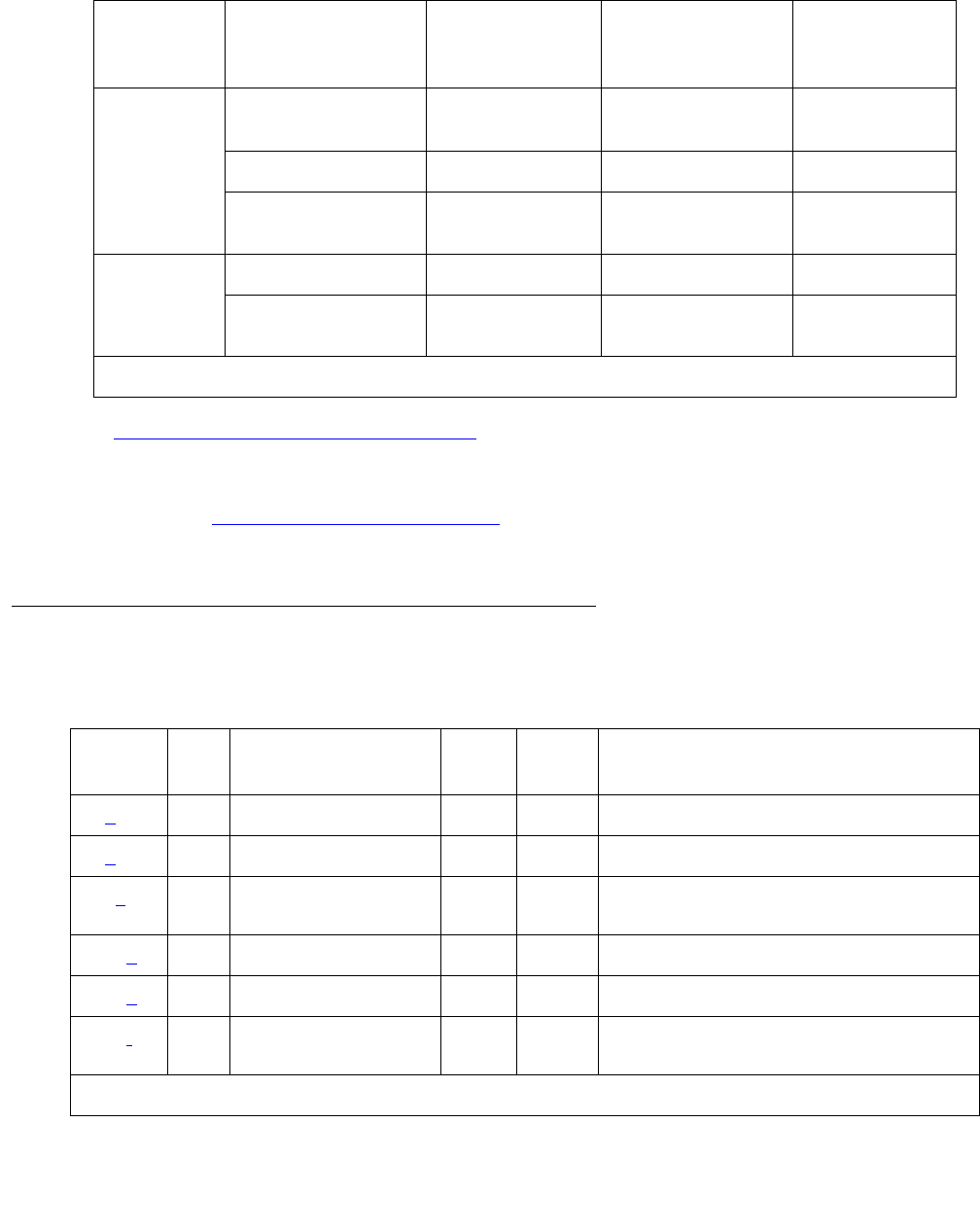
TDM-CLK (TDM Bus Clock)
Issue 1 June 2005 2253
See SYNC (Port-Network Synchronization) on page 2143 for more details about the escalation
plan. There is a strong interdependency among the DS1 Interface circuit pack’s Maintenance,
Synchronization Maintenance, and TDM Bus Clock Maintenance MOs.
S8700 MC: See TONE-BD (Tone-Clock Circuit) on page 2327 for a discussion of the relationship
of Tone-Clock circuits with the various reliability options.
Error Log Entries and Test to Clear Values
MASTER DS1 Primary and
Secondary
DS1 Primary DS1 Secondary Local
oscillator
DS1 Primary Only DS1 Primary None
No External
Source
None None
S8700 MC
SLAVE
PNC Duplication Active EI Standby EI
No PNC
Duplication
Active EI None
Table 805: Synchronization - Tone Clock Roles (continued)
Tone-Clock
Role
Synchronization
Facilities
Initial External
Synchronization
Source
Backup External
Synchronization
Source
Internal Source
2 of 2
Table 806: TDM Bus Clock Error Log Entries
Error
Type
Aux
Data
Associated Test Alarm
Level
On/Off
Board1
Test to Clear Value
0 (a)0Any AnyAnytest tone-clock location sh r 1
1 (b)0 None MIN OFF
18 (c)0 busyout tone-clock
location WRN OFF release tone-clock location
130 (d)None
257 (e)None WRN OFF
513 (f)Any Clock Circuit Status
inquiry (#148)
MIN2OFF test tone-clock location
1 of 2
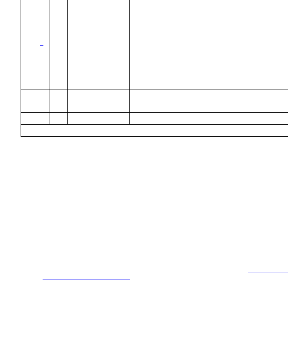
Communication Manager Maintenance-Object Repair Procedures
2254 Maintenance Procedures for Avaya Communication Manager 3.0, Media Gateways and Servers
Notes:
a. Error Type 0: run the short test sequence first. If every test passes, run the long test
sequence. Refer to each appropriate test’s description, and follow its recommended
procedures.
b. Error Type 1: the IPSI or Tone-Clock circuit pack may have a clock at the edge of its
specified frequency. This can cause Expansion Interface circuit packs and SNI circuit packs
to go out-of-frame or report no-neighbor conditions. This can is turn cause EPNs,
Expansion Archangel Links (EALs), Remote Neighbor Links (RNLs), and/or Local Neighbor
Links (LNLs) to go down. When this error is alarmed, Clock Health Inquiry test (#46) will fail
with an Error Code of 1.
1. Replace the IPSI or Tone-Clock circuit pack identified in the error log. See Replacing the
IPSI or Tone-Clock Circuit Pack on page 2337.
c. Error Type 18: the indicated Tone-Clock circuit has been made unavailable using busyout
tone-clock location. It only applies to systems with the high- or critical-reliability
option administered, because only a standby Tone-Clock circuit may be made busy by that
command. To resolve this error, execute release tone-clock location for the
alarmed circuit pack.
d. Error Type 130: the circuit pack has been removed or has been insane for more than 11
minutes. To clear the error, reinsert or replace the circuit pack.
769 (g) Any Clock Circuit Status
inquiry (#148)
MAJ‡ ON test tone-clock location sh r
10
1025 (h)Any Clock Slip
inquiry(#149) test tone-clock location sh
1281
1282 (i)
Any None MIN OFF
1537 Any Clock PPM inquiry
(#150) test tone-clock location sh
2049 (j)Any Standby Reference
Health Check test
(#651)
MAJ2ON test tone-clock location
2305 (k)0 None WRN OFF
1. As a general rule, any on-board errors against the TDM Bus Clock should be resolved before pursuing any
other errors against PNC components. Off-board clock errors may be caused by other board errors, and
should be addressed after on-board errors have been resolved.
2. Major or Minor alarms on this MO may have been downgraded to Warning based on the values in set
options.
Table 806: TDM Bus Clock Error Log Entries (continued)
Error
Type
Aux
Data
Associated Test Alarm
Level
On/Off
Board1
Test to Clear Value
2 of 2

TDM-CLK (TDM Bus Clock)
Issue 1 June 2005 2255
e. Error Type 257: the Tone-Clock circuit pack in PN 1 is not a TN780 although Stratum-3
synchronization is administered. Either:
1. If a Stratum-3 clock is being used, replace this Tone-Clock with a TN780.
2. If not, change synchronization administration to Stratum 4.
f. Error Type 513: the tone-clock has reported an out-of-lock condition. A aux value of 1
indicates this error is an out-of-lock with the primary reference. An Aux Data value of 2
indicates that this error is an out-of-lock with the secondary reference. It could not lock onto
the frequency of that synchronization reference. This will lead to a change in the
synchronization reference if the condition continues.
S8700 | 8710 / S8500
g. Error Type 769: The IPSI’s Tone-Clock circuit or Tone-Clock circuit pack might be defective,
however it may be a software failure that can be corrected by testing.
1. Check to see if the board is duplicated (list cabinet and status port-network)
on the affected port network.
2. If the board is not duplicated, use test tone-clock location long to resolve the
errors. The long test resets the board and is required to reload on-board RAM associated
with the TN2182’s DSPs. The effect is that tone detectors are taken out of service
momentarily and tones are removed from the TDM bus for about 10 seconds, meaning
that no dial tone or touch tones are available during this interval. This will probably not
affect calls in progress, but could cause a call origination to abort or a user not to get dial
tone when going off hook.
3. If every test passes and the alarm does not resolve, retest with test tone-clock
location long clear.
4. If the test passes, terminate the repair process. If the test fails, replace the circuit pack at
the customer’s convenience.
5. If this error was logged against the standby Tone-Clock, and if the Aux Data value was
18369, SYNC (Synchronization) maintenance acts on this error. No corrective action is
required. For any other Aux Data, go to the next step.
6. If the board is duplicated, switch to the standby side (set tone-clock).
7. Test the alarmed board (test tone-clock location long). This resets the board
and is required to reload on-board RAM associated with the TN2182’s DSPs.
8. If every test passes and the alarm does not resolve, retest (test tone-clock
location long clear).
9. If the test passes, terminate the repair process. If the test fails, replace the circuit pack at
the customer’s convenience.

Communication Manager Maintenance-Object Repair Procedures
2256 Maintenance Procedures for Avaya Communication Manager 3.0, Media Gateways and Servers
h. Error Type 1025: Processor/Tone-Clock circuit on-board maintenance has detected one or
more clock slips, timing differences between its internal reference source and the
synchronization signal provided by the master Tone-Clock. Although no clock slip errors are
expected during normal operation, both manual and automatic interchanges of Tone-Clock
circuit, synchronization references, and PNCs could result in clock slip counts.
If Error Type 1281 also is logged for the same Tone-Clock circuit, it is related to this problem
and should be corrected first. Otherwise, continue with the following procedure.
1. Use test tone-clock location, and examine the results of Test #149 to see if slip
errors still appear. If no new slip errors are reported, and if these errors are not causing a
TDM-CLK alarm, they may be ignored. Use test tone-clock location long
clear to clear the errors.
2. Otherwise, enter display errors, and follow corrective procedures for any other
TDM-CLK, TONE-BD, SYNC, DS1C-BD, EXP-INTF, SNC-BD, and SNI-BD errors
logged, except for those in Table 807: Error Log Entries for Slip Errors on page 2256.
3. If Error Type 1025 errors persist, see SYNC (Port-Network Synchronization) on
page 2143.
i. Error Type 1281: the Processor/Tone-Clock circuit has detected a loss of timing signal from
the system’s synchronization reference. The Processor/Tone-Clock circuit has switched
synchronization references.
1. Resolve any errors logged against the SYNC or STRAT-3 MOs.
2. See SYNC (Port-Network Synchronization) on page 2143 maintenance, if the error is not
resolved by step 1.
Error Type 1282: the TN2182 tone-clock was synchronized to a DS1 facility and that the
reference frequency provided by the DS1 drifted beyond a range that could be tracked by
the TN2182. Therefore the TN2182 is no longer synchronized to that DS1 reference. If a
second DS1 is available, the tone-clock may be synchronized to that reference. If no
secondary DS1 reference is available, the tone-clock will run off of its internal clock. This
may result in slips being reported by the tone-clock and every DS1 facility.
Table 807: Error Log Entries for Slip Errors
Circuit Pack Name Error Log Name Error Log Entry for Slips
DS1 Interface DS1-BD 3073 to 3160
Expansion Interface EXP-INTF 2305
Switch Node Interface SNI-BD 1537
Tone-Clock TDM-CLK 1025
UDS1 Interface 3073 to 3160
DS1C Circuit Pack DS1C-BD 3329

TDM-CLK (TDM Bus Clock)
Issue 1 June 2005 2257
j. Error Type 2049:
S8700 MC
The Tone-Clock circuit in the master port network was unable to detect the incoming
synchronization signal, but the other tone-clock was able to detect the references. If the Aux
Data is 0, the problem is with the signal on the primary. If the Aux Data is 1, the problem is
with the signal on the secondary. The system should switch clocks in this situation.
1. If this error is against PN 1’s clock board and the system is using a Stratum-3 clock,
check the cabling that brings the Stratum-3 signal to this clock board.
2. Replace the current standby IPSI or Tone-Clock circuit pack. See Replacing the IPSI or
Tone-Clock Circuit Pack on page 2337.
k. Error Type 2305:
S8700 MC
The indicated Tone-Clock circuit is an active slave Tone-Clock that has detected a loss of
timing signal from its EXP-INTF synchronization source. (A slave Tone-Clock resides in a
PN that does not contain the system’s reference synchronization source.)
1. Enter display errors and display alarms, and follow the repair procedures for
EXP-INTF, TDM-CLK, and TONE-BD error log entries that have on-board alarms.
2. If the 2305 errors persist, follow the repair procedures for EXP-INTF error log entries
257, 769, or 770, or any errors logged against SNI-BD, SNC-BD, or FIBER-LK.
3. If the 2305 errors persist:
a. For Port Networks with more than one Tone-Clock circuit, execute test
synchronization r 10 to see if new 2305 errors against TDM-CLK were reported.
If not, execute reset pnc interchange and test synchronization r 10
again, and recheck for new 2305 errors against TDM-CLK
b. For Port Networks with a single Tone-Clock circuit, execute test
synchronization r 10 to see if new 2305 errors were reported.
If no new instances of the 2305 errors were logged for either test, enter test
tone-clock location long clear to clear the TDM-CLK errors. The procedure is
complete.
4. For Port Networks with more than one Tone-Clock circuit:
a. Enter set tone-clock location to interchange the Tone-Clocks.
b. Run test synchronization r 10 to see if new 2305 errors are reported against
the new active Tone-Clock circuit.

Communication Manager Maintenance-Object Repair Procedures
2258 Maintenance Procedures for Avaya Communication Manager 3.0, Media Gateways and Servers
c. If not, replace the standby Tone-Clock circuit. See Replacing the IPSI or Tone-Clock
Circuit Pack on page 2337.
If this clears the error, the problem has been resolved.
5. Replace the EI circuit pack for the active PNC.
6. If the problem is still not cleared and the IPSI or Tone-Clock circuit pack reported in the
error log has not yet been replaced, replace it. See Replacing the IPSI or Tone-Clock
Circuit Pack on page 2337.
System Technician-Demanded Tests:
Descriptions and Error Codes
Investigate tests in the order presented below. Clearing Error Codes associated with the one
test may also clear errors generated from other tests in the sequence.
Order of Investigation Short Test
Sequence
Long Test
Sequence
Reset
Board
Sequence
D/ND1
1. D = Destructive; ND = Nondestructive
SAKI Reset test (#53) (a)XD
Clock Health test (#46) (b)XXND
Control Channel Loop-Around test (#52) (a)XX ND
Tone Generator Crosstalk test (#90) (c)XND
Tone Generator Transmission test (#40) (c)XX ND
Tone Generator Audit/Update test (#41) (c)XX ND
TDM bus Clock Circuit Status Inquiry (#148) X X ND
TDM bus Clock Slip Inquiry test (#149) (e)XX ND
TDM bus Clock PPM Inquiry test (#150) X X ND
TDM bus Clock Parameter Update test (#151) X X ND
Board Type Check test (#574) X X ND
Standby Reference Health Check test (#651) (d)X ND

TDM-CLK (TDM Bus Clock)
Issue 1 June 2005 2259
Notes:
a. See XXX-BD (Common Port Circuit Pack/Media Module) on page 2539 for a descriptions of
this test.
b. See TONE-BD (Tone-Clock Circuit) on page 2327 for a description of this test.
c. See TONE-PT (Tone Generator) on page 2353 for descriptions of this test.
d. S8700 MC:This test only runs on the standby IPSI or Tone-Clock circuit pack in a port
network with more than one IPSI or Tone-Clock circuit pack (high- or critical-reliability
option). The Tone-Clock circuit pack must be a TN780 code with firmware revision 2 or
above, or be a TN2182.
e. Test #149 is not run on the TN2182.
TDM bus Clock Circuit Status Inquiry Test (#148)
The TDM bus Clock circuitry is checked for sanity. Error codes show any problems that are
found.
Table 808: Test #148 TDM bus Clock Circuit Status Inquiry Test
Error
Code
Test
Result
Description / Recommendation
None
1001
ABRT The system could not allocate the necessary resources for the test.
1. Wait 1-minute, and retry the test.
2000 ABRT Response to the test was not received within the allowable time period.
1. Retry the command at 1-minute intervals up to 5 times.
2100 ABRT System resources required to run this test are not available.
1. Retry the command at 1-minute intervals up to 5 times.
1 of 3

Communication Manager Maintenance-Object Repair Procedures
2260 Maintenance Procedures for Avaya Communication Manager 3.0, Media Gateways and Servers
1 FAIL This error means the Tone-Clock circuit framing verification firmware
reports an error in the clock synchronization signal coming into this port
network.
1. If the Tone-Clock circuit reporting the problem is a master clock, then
the system synchronization reference is providing a bad timing
source. See SYNC (Port-Network Synchronization) on page 2143 or
STRAT-3 (Stratum-3 Clock) on page 2128 to change the system
synchronization reference.
2. If the Tone-Clock circuit is a slave clock, then the EI to which it is
listening is providing a bad timing source. Follow the diagnostic
procedures specified for TDM-CLK Error Code 2305.
3. S8700 | 8710 / S8500: If no problem can be found with the incoming
synchronization signal, replace the IPSI or Tone-Clock circuit pack.
See Replacing the IPSI or Tone-Clock Circuit Pack on page 2337.
2 FAIL This error indicates that Tone-Clock circuit has inaccurately detected loss of
signal on the incoming synchronization timing source.
4
8
FAIL The local oscillator on the Tone-Clock circuit failed.
16
32
FAIL The circuitry on the Processor/Tone-Clock circuit used to detect
synchronization timing errors has failed.
1. Errors 2, 4, 8, 16, and 32 indicate that there is poor synchronization
between port networks and external facilities. It may be noticeable to
the customer in the form of errors in data communications. The
Tone-Clock circuit is defective. See Replacing the IPSI or Tone-Clock
Circuit Pack on page 2337.
64 FAIL This message is only sent when an uplink message has reported the loss
of valid synchronization timing information coming into this port network. It
has been reported in TDM-CLK Error Log entries; one or more of 1025,
1281, 1537, 2049 and 2305.
1. Resolve the errors indicated. No separate corrective action is
required.
Table 808: Test #148 TDM bus Clock Circuit Status Inquiry Test (continued)
Error
Code
Test
Result
Description / Recommendation
2 of 3

TDM-CLK (TDM Bus Clock)
Issue 1 June 2005 2261
TDM Bus Clock Slip Inquiry Test (#149)
This test evaluates the quality of the synchronization source for the IPSI circuit pack’s
Tone-Clock circuit or Tone-Clock circuit pack.
65 FAIL The Processor/Tone-clock is currently not able to lock on to the current
synchronization reference. If this tone-clock is in the master port networK:
1. Examine the error log for any DS1-BD, SYNC or other TDM-CLK
errors and resolve as applicable.
2. Run this test again using test tone-clock location.
3. Examine the DS1 measurements to determine whether the facility is
healthy.
4. Administer a new synchronization reference.
5. Replace the DS1 board currently supplying the reference.
If this tone-clock is in the slave port network:
6. Examine the error log for any SYNC, EXP-INTF, or TDM-CLK errors.
7. Run this test again using test tone-clock location.
66 FAIL There is an on-board failure of TDM clock hardware.
1. Use test tone location long to resolve the problem. The long
test resets the board and is required to reload on-board RAM
associated with the TN2182”s DSPs. The effect is that tone detectors
are taken out of service momentarily and tones are removed from the
TDM bus for about 10 seconds. This means that no dial tone or touch
tones are available during this interval. It probably will not affect calls
in progress, but could cause a call origination to abort or a user will not
get dial tone when going off hook.
2. If the test passes and the alarm does not resolve, retest (test
tone-clock location long clear).
3. If the test passes, terminate the repair process. If it fails, replace the
circuit pack at the customer’s convenience.
PASS TDM bus Clock Circuit Status is sane. There are no clock-detection circuit
problems on the Tone-Clock circuit.
Table 808: Test #148 TDM bus Clock Circuit Status Inquiry Test (continued)
Error
Code
Test
Result
Description / Recommendation
3 of 3
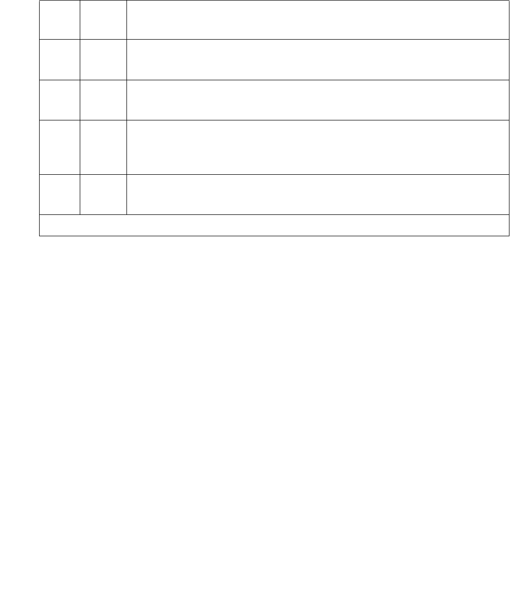
Communication Manager Maintenance-Object Repair Procedures
2262 Maintenance Procedures for Avaya Communication Manager 3.0, Media Gateways and Servers
Note:
Note: This test does not apply to the TN2182.
Table 809: Test #149 TDM bus Clock Slip Inquiry Test
Error
Code
Test
Result
Description / Recommendation
ABRT The system could not allocate the necessary resources for the test.
1. Wait 1-minute, and retry the test.
1001 ABRT The system could not allocate the necessary resources for the test.
1. Wait 1-minute, and retry the test.
2000 ABRT Response to the test request was not received within the allowable time
period
1. Retry the command at 1-minute intervals up to 5 times.
2100 ABRT System resources required to run this test are not available.
1. Retry the command at 1-minute intervals up to 5 times.
1 of 2

TDM-CLK (TDM Bus Clock)
Issue 1 June 2005 2263
Any FAIL The Error Code represents the number of timing slips detected on the
incoming synchronization source since the last slip inquiry was sent to the
Tone-Clock circuit. The incoming synchronization signal can be from one
of the following sources:
1. A DS1 Interface circuit pack, if DS1 Synchronization is administered,
and associated with the circuit pack tested
2. S8700 MC: A Stratum-3 clock, if that option is administered and the
circuit pack tested was the active Tone-Clock in the PN 1.
3. S8700 MC: The local oscillator on the master IPSI’s Tone-Clock circuit
or on the master Tone-Clock circuit pack, if it is providing the PN’s
clocking signals
4. S8700 IP: The local oscillator on the IPSI’s Tone-Clock circuit providing
the media gateway’s clocking signals
5. S8700 MC: An EXP-INTF circuit pack, if the PN on which the test was
executed does not contain the system’s current synchronization
reference
The Error Code is a variable amount ranging from 1 to 255.
1. Small numbers of slips should not result in service degradation. If the
Error Code is small (1 or 2), rerun the test. If the error only occurs
infrequently, it may be ignored.
2. Otherwise, see Synchronization Troubleshooting in SYNC
(Port-Network Synchronization) on page 2143 of this manual.
PASS The IPSI or Processor/Tone-Clock circuit pack does not detect any timing
slips. This indicates that the incoming synchronization timing source is valid
or that the system’s synchronization reference is an IPSI or Processor/
Tone-Clock circuit pack. Use status synchronization to verify that the
desired synchronization reference is providing timing for the system.
Table 809: Test #149 TDM bus Clock Slip Inquiry Test (continued)
Error
Code
Test
Result
Description / Recommendation
2 of 2

Communication Manager Maintenance-Object Repair Procedures
2264 Maintenance Procedures for Avaya Communication Manager 3.0, Media Gateways and Servers
TDM bus Clock PPM Inquiry Test (#150)
This test evaluates the quality of the synchronization source for the Tone-Clock circuit.
Table 810: Test #150 TDM bus Clock PPM Inquiry Test
Error
Code
Test
Result
Description / Recommendation
ABRT The system could not allocate the necessary resources for the test
1. Wait 1-minute, and retry the test.
1001 ABRT The system could not allocate the necessary resources for the test.
1. Wait 1-minute, and retry the test.
255 ABRT The test was not executed because the IPSI or Processor/Tone-Clock
circuit pack was using its local oscillator rather than synchronizing to an
external source.
1. Verify that this IPSI or Processor/Tone-Clock circuit pack is expected to
be the synchronization source. If not, correct the synchronization
information and re-execute the test.
2000 ABRT Response to the test request was not received within the allowable time
period.
1. Retry the command at 1-minute intervals up to 5 times.
2100 ABRT System resources required to run this test are not available.
1. Retry the command at 1-minute intervals up to 5 times.
Any FAIL The Error Code represents the rate (in Parts Per Million, or PPM) at which
clock slip errors have been detected on the incoming synchronization
source since the last PPM inquiry was sent to the IPSI or Processor/
Tone-Clock circuit pack. A failure of this test indicates that we are outside
of (S8700 MC: Stratum-3) or Stratum-4 timing specifications on the incoming
timing source.
The Error Code is a variable amount ranging from 1 to 254.
1. If error 1537 is entered in the hardware error log against TDM-CLK,
then the board has switched timing sources. Follow the procedures
associated with hardware log Error Code 1537.
2. Otherwise, see ‘‘Troubleshooting Approach’’ in the SYNC
(Port-Network Synchronization) on page 2143 section of this manual.
1 of 2

TDM-CLK (TDM Bus Clock)
Issue 1 June 2005 2265
TDM Bus Clock Parameter Update Test (#151)
This test updates the following internal parameters on the IPSI or Tone-Clock circuit pack:
●Disables in-line duplication status messages.
●S8700 MC: Disable in-line subrate frame maintenance messages (TN768, TN780 only).
●S8700 MC: Sets the PPM threshold at 60 PPM for TN768 and TN780.
Sets the PPM threshold at 85 PPM for TN2182 and TN2312.
●Enables PPM threshold switching.
●Sets the number of slips to trigger loss of signal - currently 30 per 5-millisecond period.
●Enables the on-board synchronization switching algorithm (see above).
●Enables holdover operation (TN2182 and TN2312 only).
This is not a test. It always passes without identifying or reporting any IPSI or Tone-Clock circuit
pack errors.
PASS The IPSI or Processor/Tone-Clock circuit pack does not detect timing any
PPM errors. This indicates that the external synchronization timing source is
valid or that the system synchronization reference is an IPSI or Processor/
Tone-Clock circuit pack. Use status synchronization to verify that the
desired synchronization reference is providing timing for the system.
Table 810: Test #150 TDM bus Clock PPM Inquiry Test (continued)
Error
Code
Test
Result
Description / Recommendation
2 of 2
Table 811: Test #151 TDM Bus Clock Parameter Update Test
Error
Code
Test
Result
Description / Recommendation
ABRT Internal system error
1. Retry the command at 1-minute intervals up to 5 times.
FAIL Internal system error
1. Retry the command at 1-minute intervals up to 5 times.
PASS The IPSI or Processor/Tone-Clock circuit pack parameters have been
successfully updated.

Communication Manager Maintenance-Object Repair Procedures
2266 Maintenance Procedures for Avaya Communication Manager 3.0, Media Gateways and Servers
S8700 MC
Board Type Check Test (#574)
This test verifies that a Tone-Clock circuit pack administered with a Stratum-3 clock source has
code TN780.
Table 812: Test #574 Board Type Check Test
Error
Code
Test
Result
Description / Recommendation
2012 ABRT Internal system error
1. Retry the command at 1-minute intervals up to 5 times.
ANY FAIL Stratum-3 clock synchronization is administered for the carrier where this
Tone-Clock circuit pack resides, but the Tone-Clock does not have code
TN780.
1. If the Stratum-3 clock option is incorrectly administered, remove it.
2. Otherwise, replace the circuit pack. See Replacing the IPSI or
Tone-Clock Circuit Pack on page 2337.
PASS The proper Tone-Clock circuit pack code (TN780) is present for Stratum-3
clock synchronization.

TDM-CLK (TDM Bus Clock)
Issue 1 June 2005 2267
Standby Reference Health Check Test (#651)
This test evaluates the quality of the external synchronization timing source for a standby IPSI
or Tone-Clock circuit pack. Every administered synchronization timing source must be valid for
this test to pass. If the Tone-Clock circuit and the synchronization timing sources are in different
port networks, the EI circuit packs transport the timing sources to the tone-clock.
Table 813: Test #651 Standby Reference Health Check Test
Error
Code
Test
Result
Description / Recommendation
ABRT This test may already be running due to a tone-clock installation,
scheduled maintenance, alarm activity, or a technician-demand test from
another terminal. This abort can also occur due to an internal system error.
1. Try the command again at 1-minute intervals up to five times.
1184 ABRT This test requires an external synchronization source to be administered
(DS1 primary, DS1 primary and secondary, or Stratum-3 clock).
1. Administer the external synchronization source and retry the test.
2500 ABRT Internal system error
1. Try the command again at 1-minute intervals up to 5 times.
0 FAIL The external synchronization timing source for side A of the Stratum-3 clock
or for the primary DS1 reference is either absent or invalid. The external
synchronization timing source for side B of the Stratum-3 clock or the
secondary DS1 reference is not yet tested.
1 FAIL The external synchronization timing source for side B of the Stratum-3
clock or for the secondary DS1 reference is either absent or invalid.
1. Correct the synchronization source problem. See SYNC
(Port-Network Synchronization) on page 2143.
2. If the error still exists, replace the IPSI or Tone-Clock circuit pack
reported in the error log. See Replacing the IPSI or Tone-Clock Circuit
Pack on page 2337.
PASS The external synchronization timing source is valid.


TIE-BD (Tie Trunk Circuit Pack)
Issue 1 June 2005 2269
TIE-BD (Tie Trunk Circuit Pack)
S8700 | 8710 / S8500
See XXX-BD (Common Port Circuit Pack/Media Module) on page 2539 for circuit-pack level
errors. See TIE-TRK (Analog Tie Trunk) on page 2302 for trunk information.
MO Name Alarm Level Initial SAT Command To Run Full Name of MO
TIE-BD MIN test board location sh Tie Trunk Circuit Pack
TIE-BD WARNNG test board location sh Tie Trunk Circuit Pack

Communication Manager Maintenance-Object Repair Procedures
2270 Maintenance Procedures for Avaya Communication Manager 3.0, Media Gateways and Servers
TIE-DS1 (DS1 Tie Trunk)
S8700 | 8710 / S8500 / S8300
Note:
Note: Many trunk problems are caused by incorrect settings of parameters on the trunk
group administration form. Settings must be compatible with the local
environment and with parameter settings on the far end. Refer to Administrator
Guide for Avaya Communication Manager, 03-300509 for information on how to
administer trunks. The Application Notes section of that book shows the correct
settings for administrable timers and other parameters on a country-by-country
basis.
The DS1 tie trunk provides both voice and data communications between two PBX switches.
There are two types of DS1 interfaces:
●24 DS0 channels on a 1.544-Mbps link
●31 DS0 channels + 1 framing channel on a 2.048-Mbps link
Note:
Note: 32-channel mode is supported only on TN464 circuit packs.
DS1 Tie Trunks are used widely in the Distributed Communications System (DCS) and Central
Attendant Service (CAS) system features. A DS1 tie trunk can also be used as an access
endpoint which is a non-signaling channel with bandwidth for voice-grade data, 56- or 64-kbps
data. DS1 tie trunk maintenance provides a strategy to maintain a DS1 tie trunk via a port on the
TN722 or TN767 DS1 Interface circuit pack, the TN464 UDS1 Interface circuit pack, or the
MO Name Alarm Level Initial SAT Command to Run Full Name of MO
TIE-DS11
1. For additional repair information, see DS1-BD (DS1 Interface Circuit Pack) on page 978 if the
tie trunk is on a TN722 or TN767 DS1 circuit pack. See UDS1-BD (UDS1 Interface Circuit
Pack) on page 2374 UDS1-BD documentation if the tie trunk is on a TN464 UDS1 circuit pack.
See MG-DS1 (DS1 Interface Media Module) on page 1594 if the tie trunk is on an MM710 DS1
Interface Media Module.
MAJ2
2. A MAJOR alarm on a trunk indicates that alarms on these trunks are not downgraded by set
options and that at least 75% of the trunks in this trunk group are alarmed.
test trunk grp#/mem# long3
3. For TN767B vintage 8 or 9 circuit packs, a failure of Test #136 causes a subsequent failure of
Test #7. Test #136 is part of the short sequence and generates off-board alarms. Test #7 is
part of the long sequence and generates on-board alarms. Before entering busyout, release,
reset or test board long commands, check the vintage number of the circuit pack with list
configuration board location. If it is TN767B vintage 8 or 9, do not use the above
commands until you ensure that Test #136 passes via test board short. Otherwise, extraneous
on-board alarms may be generated.
DS1 Tie Trunk
TIE-DS1 MIN test trunk grp#/mem# long3DS1 Tie Trunk
TIE-DS1 WRN test trunk grp#/mem# DS1 Tie Trunk

TIE-DS1 (DS1 Tie Trunk)
Issue 1 June 2005 2271
MM710 DS1 Interface Media Module. Throughout this TIE-DS1 section, the term DS1 Interface
applies to DS1 or UDS1 circuit packs, or to MM710 Media Modules.
Note:
Note: S8300 / G700: Although the TIE-DS1 MO is provided for a G700 Media Gateways,
this MO only partially supports the MM710 DS1 Media Module.
The DS1 tie trunk maintenance strategy covers logging DS1 tie trunk hardware errors, running
tests for trunk initialization, periodic and scheduled maintenance, system technician-demanded
tests, and alarm escalation and resolution. Three different trunk service states are specified in
DS1 tie trunk maintenance:
If the DS1 Interface circuit pack or media module is out of service, every trunk on the DS1
Interface circuit pack or media module is placed into the out-of-service state and a Warning
alarm is raised.
Hardware Error Log Entries and Test to Clear Values
Out-of-service The trunk is deactivated and cannot be used for
incoming or outgoing calls.
In-service The trunk is activated and can be used for both
incoming and outgoing calls.
Disconnect
(ready-for-service)
The trunk is in an activated state but can only be used
for an incoming call.
Table 814: DS1 Tie Trunk Maintenance Error Log Entries
Error
Type
Aux
Data
Associated Test Alarm
Level
On/Off
Board
Test to Clear Value
0 (a) 0 Any Any Any test trunk grp#/mem#
1 (b) 57476
57477
57485
57487
15 (c) Any Port Audit and
Update (#36)
18 (d)0 busyout trunk
grp#/mem#
WRN OFF release trunk grp#/mem#1
19 (e)0 None
130 (f)None WRNONtest trunk grp#/mem#
1 of 2
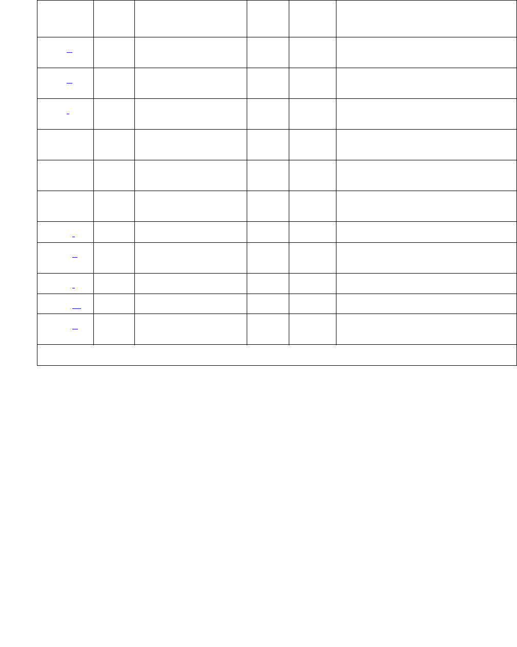
Communication Manager Maintenance-Object Repair Procedures
2272 Maintenance Procedures for Avaya Communication Manager 3.0, Media Gateways and Servers
Notes:
a. Error Type 0: run the short test sequence first. If every test passes, run the long test
sequence. Refer to each appropriate test’s description, and follow its recommended
procedures.
257 (g) 57473
57474
513 (h) 57392 DS1 Tie Trunk
Seizure (#136)
MAJ
MIN2
769 (i) 57393 DS1 Tie Trunk
Seizure (#136)
MAJ
MIN2
1025 DS1 Tie Trunk
Seizure (#136)
MIN
WRN2OFF test trunk grp#/mem# r 2
1281 Conference Circuit
Tes t (# 7)
MIN
WRN2ON test trunk grp#/mem# l r 4 1
1537 NPE Crosstalk Test
(#6)
MIN
WRN2ON test trunk grp#/mem# l r 3 1
1793 (j)test board location long 1
2305 (k) 50944 DS1 Tie Trunk
Seizure (#136)
MAJ
MIN2OFF
2562 (l) 16665
2817 (m) 52992
3840 (n) Any Port Audit and
Update (#36)
1. For TN767B vintage 8 or 9 circuit packs, a failure of Test #136 causes a subsequent failure of
Test #7. Test #136 is part of the short sequence and generates off-board alarms. Test #7 is part
of the long sequence and generates on-board alarms. Before entering busyout, release, reset or
test board long commands, check the vintage number of the circuit pack with list
configuration board location. If it is TN767B vintage 8 or 9, do not use the above
commands until you ensure sure that Test #136 passes via test board short. Otherwise,
extraneous on-board alarms may be generated.
2. *Major or Minor alarms on this MO may have been downgraded to Warning based on the values
in set options.
Table 814: DS1 Tie Trunk Maintenance Error Log Entries (continued)
Error
Type
Aux
Data
Associated Test Alarm
Level
On/Off
Board
Test to Clear Value
2 of 2

TIE-DS1 (DS1 Tie Trunk)
Issue 1 June 2005 2273
b. Error Type 1: the DS1 Interface circuit pack or media module detects a hardware error on
the DS1 tie trunk. This error can be caused by incompatible translations. Make sure the
parameters administered on the DS1 circuit pack or media module form match those
administered on the far-end switch. See Administrator Guide for Avaya Communication
Manager, 03-300509 for details.
The Aux Data field indicates the following hardware Error Types:
If every administration parameter between the switch and the far end match and these
errors continue to recur, follow normal escalation procedures.
c. Error Type 15: this is a software audit error that does not indicate any hardware
malfunction. Run the short test sequence, and investigate associated errors (if any).
d. Error Type 18: the DS1 tie trunk has been busied out with busyout trunk grp#/mem#.
No calls can be made on this trunk except for the Facility Access Test call. See
Administrator Guide for Avaya Communication Manager, 03-300509.
e. Error Type 19: the far end may be out-of-service, or the Electronic Tandem Network may
be busied out.
f. Error Type 130: the circuit pack or media module has been removed or has been insane for
more than 11 minutes. To clear the error, reinsert or replace the circuit pack or media
module.
g. Error Type 257: the DS1 Interface circuit pack or media module detects a hardware error
on the DS1 tie trunk. The trunk cannot communicate with the far end because it is unable to
interpret digits sent from the far-end switch. The Aux Data field indicates the following:
Check with the far-end switch or operating company for proper trunk connection.
h. Error Type 513: the DS1 Interface circuit pack or media module detects a hardware error
on the DS1 tie trunk. The trunk is in-service/active and waiting for an “on-hook” from the
far-end switch. No calls can be routed over the trunk while it is in this state. Aux Data 57392
indicates no external release on PBX disconnect. Check with the far-end switch or
operating company for proper trunk connection.
57476 On-hook before wink
57477 On-hook before ready to receive digits
57485 Wink too short for valid signal
57487 The timer expired while waiting for an off-hook signal from the far end as
a response at end-of-digits dialing. Check the far-end switch for related
problems.
57473 The rotary dial rate is below 8 pulses per second.
57474 The rotary dial rate is above 12 pulses per second.

Communication Manager Maintenance-Object Repair Procedures
2274 Maintenance Procedures for Avaya Communication Manager 3.0, Media Gateways and Servers
i. Error Type 769: the DS1 Interface circuit pack or media module detects a hardware error
on the DS1 tie trunk. This error usually occurs after an occurrence of Error Type 513. The
trunk has received the belated “on-hook” that it has been waiting for from the far-end switch.
The trunk is restored to in-service/idle and can be used for calls. Aux Data 57393 indicates
delayed external release on PBX disconnect. This error can be ignored.
j. Error Type 1793: the DS1 Interface circuit pack or media module is out-of-service. See the
appropriate DS1-BD (DS1 Interface Circuit Pack) on page 978, UDS1-BD (UDS1 Interface
Circuit Pack) on page 2374, or MG-DS1 (DS1 Interface Media Module) on page 1594
documentation for details.
k. Error Type 2305: reorder message. The trunk could not be seized. This error causes the
Trunk Seizure test (#136) to run and is only a problem if the Seizure test fails (in which case
Error Type 1025 also appears). In this case, the trunk may be put in “Ready-for-Service”
state (shown as “disconnected” by the status command), which allows only incoming calls.
Run the Trunk Seizure test (#136) and follow its procedures.
l. Error Type 2562: retry Failure error. This error is logged only. It is not a hardware failure
and hence does not start any testing or generate any alarms. This error comes from call
processing and is generated when a second attempt (retry) to seize an outgoing trunk fails.
m. Error Type 2817: glare error. This error is logged only. It is not a hardware failure and
hence does not start any testing or generate any alarms. This error is the result of a
simultaneous seizure of a 2-way trunk from both the near and the far ends. Attempt to place
the call again. If the error persists, execute the DS1 Tie Trunk Seizure test (#136) and follow
its procedures.
n. Error Type 3840: Port Audit and Update test (#36) failed due to an internal system error.
Enter status trunk, and verify the status of the trunk. If the trunk is out-of-service, enter
release trunk to put it back to in-service. Retry the test command.
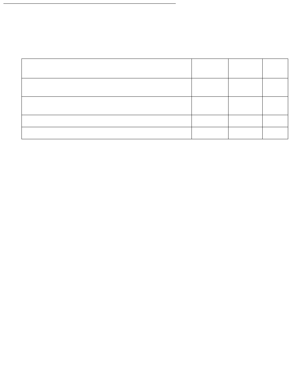
TIE-DS1 (DS1 Tie Trunk)
Issue 1 June 2005 2275
System Technician-Demanded Tests:
Descriptions and Error Codes
Investigate tests in the order presented below. Clearing Error Codes associated with the one
test may also clear errors generated from other tests in the sequence.
Note:
Note: For TN767B vintage 8 or 9 circuit packs, a failure of Test #136 causes a
subsequent failure of Test #7. Test #136 is part of the short sequence and
generates off-board alarms Test #7 is part of the long sequence and generates
on-board alarms. Before entering busyout, release, reset or test board
location long commands, check the vintage number of the circuit pack with
list configuration board location. If it is TN767B vintage 8 or 9, do
not use the above commands until first making sure that Test #136 passes using
test board location short. Otherwise, extraneous on-board alarms may
be generated.
NPE Crosstalk Test (#6)
Note:
Note: S8500 / G700: This test aborts with Error Code 1412 on the G700.
The NPE Crosstalk test verifies that this port’s NPE channel talks on the selected time slot and
never crosses over to time slots reserved for other connections. If the NPE is not working
correctly, 1-way and noisy connections may be observed. This test is usually only part of a
port’s long test sequence and takes on the order of 20 to 30 seconds to complete.
Order of Investigation Short Test
Sequence
Long Test
Sequence
D/ND1
1. D = Destructive; ND = Nondestructive
NPE Crosstalk test (#6)
S8500 / G700: Aborts with Error Code 1412 on a G700.
XND
Conference Circuit test (#7)
S8500 / G700: Aborts with Error Code 1412 on a G700.
XND
DS1 Tie Trunk Seizure test (#136) X X ND
Port Audit and Update test (#36) X X ND

Communication Manager Maintenance-Object Repair Procedures
2276 Maintenance Procedures for Avaya Communication Manager 3.0, Media Gateways and Servers
Table 815: Test #6 NPE Crosstalk Test
Error
Code
Test
Result
Description / Recommendation
ABRT System resources required for this test are not available.
1. Retry the command at 1-minute intervals up to 5 times.
1000 ABRT System resources required to run this test were not available.
The port may be busy with a valid call.
1. Use display port location to determine the trunk
group/member number of the port. Use status trunk to
determine the service state of the port. If the service state
indicates that the port is in use, then the port is unavailable
for certain tests. Wait until the port is idle before retesting.
2. If the port status is active but the port is idle (no calls),
check the error log for Error Type 1025 (see the error log
table for a description of this error and required actions).
The port may be locked up.
3. If the port status is idle, retry the command at 1-minute
intervals up to 5 times.
1001 ABRT System resources required to run this test are not available.
1. Retry the command at 1-minute intervals up to 5 times.
1002 ABRT The system could not allocate time slots for the test. The
system may be under heavy traffic conditions, or it may have
time slots out of service due to TDM-BUS errors.
1. If the system has no TDM-BUS errors and is not handling
heavy traffic and the port status is idle, retry the command
at 1-minute intervals up to 5 times.
1003 ABRT The system could not allocate a tone receiver for the test. The
system may be oversized for the number of tone detectors
present or some of the tone detectors may be out of service.
Enter list measurements tone-receiver to display
basic information about the system's tone receivers.
1. Resolve any TTR-LEV errors.
2. Resolve any TONE-PT errors.
3. If neither condition exists, retry the test at 1-minute
intervals up to 5 times.
1 of 3

TIE-DS1 (DS1 Tie Trunk)
Issue 1 June 2005 2277
1004 ABRT The port was seized by a user for a valid call.
1. Use display port location to determine the trunk
group/member number of the port. Use status trunk to
determine the service state of the port. If the service state
indicates that the port is in use, then the port is unavailable
for certain tests. Wait until the port is idle before retesting.
2. If the port status is idle, retry the command at 1-minute
intervals up to 5 times.
1020 ABRT The test did not run because of a previously existing error on
the specific port or a more general circuit pack error.
1. Examine the Error Log for existing errors against this port
or the circuit pack and attempt to diagnose the already
existing error.
S8500 / G700:
1412
ABRT This test does not execute on a G700 Media Gateway.
2000 ABRT Response to the test request was not received within the
allowable time period.
1. Retry the command at 1-minute intervals up to 5 times.
2100 ABRT System resources required for this test are not available.
1. Retry the command at 1-minute intervals up to 5 times.
2053 ABRT At least one of the following errors is found on the DS1 circuit
pack:
●1281 — Loss of signal
●1793 — Blue alarm
●2049 — Red alarm
●2305 — Yellow alarm
●1537 — Hyperactivity
Look for the above Error Types in the Hardware Error Log and
follow the procedures given in the appropriate DS1-BD or
UDS1-BD maintenance documentation for the listed Error
Types.
Table 815: Test #6 NPE Crosstalk Test (continued)
Error
Code
Test
Result
Description / Recommendation
2 of 3

Communication Manager Maintenance-Object Repair Procedures
2278 Maintenance Procedures for Avaya Communication Manager 3.0, Media Gateways and Servers
FAIL This can be due to either on- or off-board problems. Off-board
problems of concern include EXP-PN and EXP-INTF faults
(S8700 MC), RMC-ENV faults (S8700 IP), TDM-BUS faults, and
faults associated with the tone detectors/tone generators.
Clear every off-board problem before replacing the board.
Keep in mind that a TDM-BUS problem is usually the result of
a faulty board connected to the backplane or bent pins on the
backplane.
1. Resolve any EXP-PN, EXP-INTF, or RMC-ENV errors.
2. Resolve any TDM-BUS errors.
3. Resolve any TONE-BD and/or TONE-PT errors.
4. Retest when the faults from steps 1, 2, and 3 are cleared.
Replace the board only if the test fails.
PASS The port is correctly using its allocated time slots. User-reported
troubles on this port should be investigated using other port
tests and by examining station, trunk, or external wiring.
0 NO BOARD The test could not relate the internal ID to the port (no board).
This could be due to incorrect translations, no board is
inserted, an incorrect board is inserted, or an insane board is
inserted.
1. Check to ensure that the board’s translations are correct.
Use list config, and resolve any problems that are
found.
2. If the board was found to be correctly inserted in step 1,
enter busyout board location.
3. Enter reset board location.
4. Enter release board location.
5. Enter test board location long. This should
re-establish the linkage between the internal ID and the
port. If not, check that there is a valid board inserted.
Table 815: Test #6 NPE Crosstalk Test (continued)
Error
Code
Test
Result
Description / Recommendation
3 of 3

TIE-DS1 (DS1 Tie Trunk)
Issue 1 June 2005 2279
Conference Circuit Test (#7)
Note:
Note: S8500 / G700: This test aborts with Error Code 1412 on the G700.
One or more Network Processing Elements (NPEs) reside on each circuit pack with a TDM-bus
interface. (The TN464 UDS1 circuit pack has one SCOTCH-NPE chip instead of several NPE
chips). The NPE controls port connectivity and gain, and provides conferencing functions on a
per-port basis. The Conference Circuit test verifies that the NPE channel for the port being
tested can correctly perform the conferencing function. The NPE is instructed to listen to several
different tones and conference the tones together. The resulting signal is then measured by a
Tone Detector port. If the level of the tone is within a certain range, the test passes.
Table 816: Test #7 Conference Circuit Test
Error
Code
Test
Result
Description / Recommendation
ABRT System resources required for this test are not available.
1. Retry the command at 1-minute intervals up to 5 times.
1000 ABRT System resources required to run this test were not available. The
port may be busy with a valid call.
1. Use display port location to determine the trunk group/
member number of the port. Use status trunk to determine
the service state of the port. If the service state indicates that
the port is in use, then the port is unavailable for certain tests.
Wait until the port is idle before retesting.
2. If the port status is active but the port is idle (no calls), check
the error log for Error Type 1025 (see the error log table for a
description of this error and required actions). The port may be
locked up.
3. If the port status is idle, retry the command at 1-minute intervals
up to 5 times.
1002 ABRT The system could not allocate time slots for the test. The system
may be under heavy traffic conditions, or it may have time slots out
of service due to TDM-BUS errors. Use status health to
determine if the system is experiencing heavy traffic.
1. If the system has no TDM-BUS errors and is not handling
heavy traffic and the port status is idle, retry the command at
1-minute intervals up to 5 times.
1 of 5

Communication Manager Maintenance-Object Repair Procedures
2280 Maintenance Procedures for Avaya Communication Manager 3.0, Media Gateways and Servers
1003 ABRT The system could not allocate a tone receiver for the test. The
system may be oversized for the number of tone detectors present
or some of the tone detectors may be out of service. Enter list
measurements tone-receiver to display basic information
about the system's tone receivers.
1. Resolve any TTR-LEV errors.
2. Resolve any TONE-PT errors.
3. If neither condition exists, retry the test at 1-minute intervals up
to 5 times.
1004 ABRT The port was seized by a user for a valid call.
1. Use display port location to determine the trunk group/
member number of the port. Use status trunk to determine
the service state of the port. If the service state indicates that
the port is in use, then the port is unavailable for certain tests.
Wait until the port is idle before retesting.
2. If the port status is idle, retry the command at 1-minute intervals
up to 5 times.
1018 ABRT Test disabled by administration. This only applies to analog
stations.
1. To enable test, set the Test field on the Station Administration
form (change station extension) for the particular analog
station being tested to y.
1020 ABRT The test did not run due to a previously existing error on the specific
port or because of a more general circuit pack error.
1. Examine the Error Log for existing errors against this port or
circuit pack, and attempt to diagnose the previously existing
error.
S8500 / G700:
1412
ABRT This test does not execute on a G700 Media Gateway.
2000 ABRT Response to the test request was not received within the allowable
time period.
1. Retry the command at 1-minute intervals up to 5 times.
Table 816: Test #7 Conference Circuit Test (continued)
Error
Code
Test
Result
Description / Recommendation
2 of 5

TIE-DS1 (DS1 Tie Trunk)
Issue 1 June 2005 2281
2100 ABRT System resources required to run this test are not available.
1. Retry the command at 1-minute intervals up to 5 times.
2053 ABRT At least one of the following errors is found on the DS1 circuit pack:
1281 – Loss of signal,1793 – Blue alarm, 2049 – Red alarm, 2305 –
Yellow alarm, or 1537 – Hyperactivity.
Look for the previous Error Types in the Hardware Error Log, and
follow the procedures given in the appropriate DS1-BD or UDS1-BD
maintenance documentation for the listed Error Types.
Table 816: Test #7 Conference Circuit Test (continued)
Error
Code
Test
Result
Description / Recommendation
3 of 5

Communication Manager Maintenance-Object Repair Procedures
2282 Maintenance Procedures for Avaya Communication Manager 3.0, Media Gateways and Servers
FAIL The NPE of the tested port did not conference the tones correctly.
This can cause noisy and unreliable connections.
1. Enter list configuration board location. If the circuit
pack is a TN767B vintage 8 or 9, replace the circuit pack with a
TN767C V3 or later. The error log may have Error Type 1281
entries.
2. Test every administered trunk on the board. If one fails, this
could be an off-board problem (such as an incoming seizure or
an off-hook port seizure during the test). Retest the board.
3. If every port fails, check the CARR-POW (see note below).
4. If several ports fail, check the error log for TONE-BD or
TONE-PT errors. If there are such errors, take the appropriate
action. When the TONE errors have cleared, rerun the test.
5. If the retry passes and troubles have been reported, coordinate
isolation with the far-end PBX. Make sure that the near- and
far-end switches and any NTCE equipment (the CSUs) have
the correct administration.
6. Replace the circuit pack.
Note: If the conference circuit test fails for every port on a circuit
pack, a -5 Volt power problem is indicated.
S8700 MC: If a TN736 or TN752 power unit circuit pack is present,
either the 631DB AC power unit or the 676B DC power unit may be
defective. (The 631DB power unit is used in a medium cabinet
powered by an AC source. The 645B power unit is used in a medium
cabinet powered by a DC power source.) The system may contain a
TN736 or TN752 power unit or a 631DB AC power unit, but not both
types of power units. To investigate problems with a 631DB AC or
645B DC power unit, see CARR-POW (Carrier Power Supply) on
page 770. If a red LED on TN736 or TN752 power unit circuit pack is
on, replace the pack.
S8700 IP: If a TN736 or TN752 power unit circuit pack is present, the
power unit may be defective. To investigate problems with a power
unit, see RMC-ENV (Power/Fan Sensors) on page 1951.
PASS The port can correctly conference multiple connections.
User-reported troubles on this port should be investigated using
other port tests and by examining station, trunk, or external wiring.
Table 816: Test #7 Conference Circuit Test (continued)
Error
Code
Test
Result
Description / Recommendation
4 of 5

TIE-DS1 (DS1 Tie Trunk)
Issue 1 June 2005 2283
0NO
BOARD
The test could not relate the internal ID to the port (no board). This
could be due to incorrect translations, no board is inserted, an
incorrect board is inserted, or an insane board is inserted.
1. Check to ensure that the board’s translations are correct. Use
list configuration, and resolve any problems that are
found.
2. If the board was found to be correctly inserted in step 1, enter
busyout board location
3. Enter reset board location
4. Enter release board location
5. Enter test board location long. This should re-establish
the linkage between the internal ID and the port. If this is not the
case, check to see that there is a valid board inserted.
Table 816: Test #7 Conference Circuit Test (continued)
Error
Code
Test
Result
Description / Recommendation
5 of 5

Communication Manager Maintenance-Object Repair Procedures
2284 Maintenance Procedures for Avaya Communication Manager 3.0, Media Gateways and Servers
Port Audit and Update Test (#36)
This test sends port level translation data from switch processor to the DS1 Interface circuit
pack or media module to ensure that the trunk’s translation is correct. Translation updates
include the following data: trunk type (in/out), dial type, timing parameters, and signaling bits
enabled. The port audit operation verifies the consistency of the current state of the trunk kept
by the DS1 Interface circuit pack or media module and the switch software.
Table 817: Test #36 Port Audit and Update Test
Error
Code
Test
Result
Description / Recommendation
ABRT Internal system error
1. Retry the command at 1-minute intervals up to 5 times.
1000 ABRT System resources required to run this test were not available. The port
may be busy with a valid call.
1. Use display port location to determine the trunk group/
member number of the port. Use status trunk to determine the
service state of the port. If the service state indicates that the port is in
use, then the port is unavailable for certain tests. Wait until the port is
idle before retesting.
2. If the port status is active but the port is idle (no calls), check the error
log for Error Type 1025 (see the error log table for a description of this
error and required actions). The port may be locked up.
3. If the port status is idle, retry the command at 1-minute intervals up to
5 times.
1006 ABRT The test was aborted because the trunk is out of service.
1. Use status trunk to verify that the trunk is out of service.
2. If the trunk is out of service, determine why.
3. If it is OK to put the trunk back in service, enter release trunk to
restore the trunk’s service, and then retry the test.
2000 ABRT Response to the test request was not received within the allowable time
period.
1. Retry the command at 1-minute intervals up to 5 times.
2100 ABRT Could not allocate the necessary system resources to run this test.
1. Retry the command at 1-minute intervals up to 5 times.
1 of 2

TIE-DS1 (DS1 Tie Trunk)
Issue 1 June 2005 2285
FAIL Internal system error.
1. Retry the command at 1-minute intervals up to 5 times.
PASS Trunk translation has been updated successfully. The current trunk states
kept in the DS1 Interface circuit pack or media module and switch
software are consistent. If the trunk is busied out, the test does not run but
returns a PASS. To verify that the trunk is in-service:
1. Enter status trunk to verify that the trunk is in-service. If the trunk
is in-service, no further action is necessary. If the trunk is
out-of-service, continue to step 2.
2. Enter release trunk to put the trunk back into in-service.
3. Retry the test command.
0NO
BOARD
The test could not relate the internal ID to the port (no board). This could
be due to incorrect translations, no board is inserted, an incorrect board is
inserted, or an insane board is inserted.
1. Check to ensure that the board’s translations are correct. Use list
configuration, and resolve any problems that are found.
2. If the board was found to be correctly inserted in step 1, enter
busyout board location
3. Enter reset board location
4. Enter release board location
5. Enter test board location long
This should re-establish the linkage between the internal ID and the port. If
not, check that there is a valid board inserted.
Table 817: Test #36 Port Audit and Update Test (continued)
Error
Code
Test
Result
Description / Recommendation
2 of 2

Communication Manager Maintenance-Object Repair Procedures
2286 Maintenance Procedures for Avaya Communication Manager 3.0, Media Gateways and Servers
DS1 Tie Trunk Seizure Test (#136)
The DS1 Tie Trunk Seizure test is run to verify the trunk’s signaling capability. The test is
composed of two parts. The first part queries the circuit pack or media module for the following
errors: Loss of Signal, Red alarm, Blue alarm, Yellow alarm, and Hyperactivity alarm. The
second part of the test is performed by sending a seizure message to the DS1 Interface circuit
pack or media module and expecting an active reply by the DS1 Interface circuit pack or media
module. If maintenance software does not receive any reply and the timer expires, the test fails.
Once the active message is received, a dial pause message is sent to the DS1 Interface circuit
pack or media module. If the DS1 Interface circuit pack or media module replies with a dial
pulse tone message when the far end responds to the seizure, then the DS1 tie trunk Seizure
test passes. If the far end does not respond to the seizure and the timer expires, and the DS1
Interface circuit pack or media module sends a reorder message back to the maintenance
software, then the test fails.
This second part of this test cannot be run on a trunk if one of the following cases is true:
1. The trunk direction is administered as an incoming only trunk.
2. The trunk is the 24th port on a DS1 Interface circuit pack or media module which is
administered using 24th common-channel signaling.
3. The trunk has been seized by a normal trunk call.
4. The trunk is administered with maintenance test disabled.
5. The outgoing signal type of the trunk is either automatic or immediate-start.
This test always passes if the associated board is the TN802 IP trunk circuit pack.
Table 818: Test #136 DS1 Tie Trunk Seizure Test
Error
Code
Test
Result
Description / Recommendation
ABRT Internal system error
1. Retry the command at 1-minute intervals up to 5 times.
1 of 5

TIE-DS1 (DS1 Tie Trunk)
Issue 1 June 2005 2287
1000 ABRT System resources required to run this test were not available. The port
may be busy with a valid call.
1. Use display port location to determine the trunk group/
member number of the port. Use status trunk to determine the
service state of the port. If the port is in use, wait until the port is idle
before testing.
2. If the port status is active but the port is idle (no calls), check the error
log for Error Type 1025 (see the error log table for a description of this
error and required actions). The port may be locked up.
3. If the port status is idle, retry the command at 1-minute intervals up to
5 times.
1004 ABRT Far end is seizing the trunk while the test is ongoing. A glare situation is
detected. Current test is designed to be aborted.
1. Use display port location to determine the trunk group/
member number of the port. Use status trunk to determine the
service state of the port. If the port is in use, wait until the port is idle
before testing.
2. If the port status is idle, retry the command at 1-minute intervals up to
5 times.
1005 ABRT Test failed due to incompatible configuration administered on Trunk Group
form.
1. Verify the following fields on the Trunk Group administration form:
a. Is trunk direction incoming only?
b. Is trunk outgoing type either automatic or immediate-start?
c. Is trunk the 24th port of the DS1 Interface circuit pack or media
module while common control channel signaling is specified?
2. If the trunk has been administered using the above information, this
test should abort.
1018 ABRT The test was disabled by translation. You might want to determine why the
test has been disabled before you enable it.
1. Verify that the Maintenance Test field on the Trunk Group
administration form is n. To enable the test, change the trunk
administration and enter y in the Maintenance Test field.
2. Repeat the test.
Table 818: Test #136 DS1 Tie Trunk Seizure Test (continued)
Error
Code
Test
Result
Description / Recommendation
2 of 5

Communication Manager Maintenance-Object Repair Procedures
2288 Maintenance Procedures for Avaya Communication Manager 3.0, Media Gateways and Servers
1020 ABRT The test did not run due to an already existing error on the specific port or
due to a more general circuit pack or media module error.
1. Examine the error log for existing errors against this port or the circuit
pack or media module and attempt to diagnose the already existing
error.
2. Retry the test.
1040 ABRT The test is invalid for this trunk port because it is administered as an
access endpoint.
1. Use display port location to verify that this port is administered
as an access endpoint. In this case the test should abort.
2000 ABRT Response to the test request was not received within the allowable time
period.
1. Retry the command at 1-minute intervals up to 5 times.
2053 ABRT/
FAIL
At least one of the following errors is found on the DS1 circuit pack or
media module: 1281 – Loss of Signal, 1793 – Blue alarm, 2049 – Red
alarm, 2305 – Yellow alarm, or 1537 – Hyperactivity.
1. Look for the previous Error Types in the Hardware Error Log, and
follow the procedures given in the appropriate DS1-BD, UDS1-BD, or
MG-DS1 maintenance documentation for the listed Error Types.
Earlier G1 software versions reported Error Code 2053 as a FAIL.
2100 ABRT Could not allocate the necessary system resources to run this test.
1. Retry the command at 1-minute intervals up to 5 times.
Table 818: Test #136 DS1 Tie Trunk Seizure Test (continued)
Error
Code
Test
Result
Description / Recommendation
3 of 5

TIE-DS1 (DS1 Tie Trunk)
Issue 1 June 2005 2289
FAIL The far-end trunk did not respond to the seizure of the near-end trunk
within the allowable time period. This test could have associated in-line
errors in the error log.
1. Enter list configuration board location. If the circuit pack
is a TN767B vintage 8 or 9, a failure of test 136 causes a subsequent
failure of test 7 due to a firmware bug. Eventually, the board and all of
its ports are taken out of service, and extraneous on-board alarms are
generated. Replace the circuit pack with a TN767C V3 or later.
2. Verify that the Trunk Type field on the Trunk Group administration
form matches the trunk type administered on far-end switch.
3. Look for DS1-BD, UDS1-BD, or MG-DS1 errors in the hardware error
log. If present, see DS1-BD (DS1 Interface Circuit Pack) on page 978,
UDS1-BD (UDS1 Interface Circuit Pack) on page 2374, or MG-DS1
(DS1 Interface Media Module) on page 1594 maintenance
documentation.
4. Retry the test at 1-minute intervals up to 5 times.
2000 FAIL Response to the seizure message was not received within the allowable
time period.
1. Enter list configuration board location.
For circuit packs: If the circuit pack is a TN767B vintage 8 or 9, a
failure of test 136 causes a subsequent failure of test 7 due to a
firmware bug. Eventually, the board and all of its ports are taken out of
service, and extraneous on-board alarms are generated. Replace the
circuit pack with a TN767C V3 or later.
G700: Replace the Media Module.
2. Verify that the Trunk Type field on the Trunk Group administration
form matches the trunk type administered on far-end switch.
3. Look for DS1-BD, UDS1-BD, or MG-DS1 errors in the hardware error
log. If present, see the DS1-BD (DS1 Interface Circuit Pack) on
page 978, UDS1-BD (UDS1 Interface Circuit Pack) on page 2374, or
MG-DCP (Digital Line Media Module) on page 1593 maintenance
documentation.
4. Retry the test at 1-minute intervals up to 5 times.
PASS The trunk can be seized for an outgoing call.
Table 818: Test #136 DS1 Tie Trunk Seizure Test (continued)
Error
Code
Test
Result
Description / Recommendation
4 of 5

Communication Manager Maintenance-Object Repair Procedures
2290 Maintenance Procedures for Avaya Communication Manager 3.0, Media Gateways and Servers
0NO
BOARD
The test could not relate the internal ID to the port (no board). This could
be due to incorrect translations, no board is inserted, an incorrect board is
inserted, or an insane board is inserted.
1. Check to ensure that the board’s translations are correct. Use list
config, and resolve any problems that are found.
2. If the board was found to be correctly inserted in step 1, enter
busyout board location
3. Enter reset board location
4. Enter release board location
5. Enter test board location long
This should re-establish the linkage between the internal ID and the port. If
this is not the case, check to see that there is a valid board inserted.
Table 818: Test #136 DS1 Tie Trunk Seizure Test (continued)
Error
Code
Test
Result
Description / Recommendation
5 of 5
TBRI-PT (ISDN Trunk-Side BRI Port)
Issue 1 June 2005 2291
TBRI-PT (ISDN Trunk-Side BRI Port)
Note:
Note: Consult local records for the location and designation of the equipment rack
where the Media Gateway is mounted.
The MM720 Media Module provides 8 S/T ISDN 2B+D ports that interface to either the central
office or another PBX. The MM720 contains eight, 4-wire ports that interface to the network at
the ISDN S/T reference point over two 64 Kb/s channels (B1 and B2) and over a 16Kb/s
signaling (D) channel. The B1 and B2 channels can be simultaneously circuit switched, or
individually packet switched. Only one channel per trunk can be packet switched due to Packet
Processing Element (PPE) limitations. The D-channel is circuit switched. The circuit-switched
connections have a Mu-law or A-law option for voice and operate as 64Kb/s clear data
channels.
LEDs
The three LEDs on the media module’s faceplate indicate board status. When illuminated, the
red LED indicates a board failure or a major or minor on-board alarm, the green LED indicates
that testing is in progress, and the amber LED indicates that the board is in use.
Hardware Error Log Entries and Test to Clear Values
MO Name Alarm Level Initial Command to Run* Full Name of MO
TBRI-PT MAJ test port GGGVSPP l r# TBRI-PT
TBRI-PT MIN test port GGGVSPP l r# TBRI-PT
TBRI-PT WRN test port GGGVSPP s r# TBRI-PT
Table 819: TBRI-PT Error Log Entries
Error
Type
Aux
Data
Associated Test Alarm
Level
On/Off
Board
Test to Clear Value
0 (a) 0 Any Any Any test port location sh r 1
1 (b) Level 1 Status Test
(#1242)
MIN OFF
129 (c)
1 of 2
Communication Manager Maintenance-Object Repair Procedures
2292 Maintenance Procedures for Avaya Communication Manager 3.0, Media Gateways and Servers
Notes:
a. Error Type 0: run the Short Test Sequence first. If all tests pass, run the Long Test
Sequence. Refer to the appropriate test description and follow the recommended
procedures.
257 (d)
513 (e) 46222 XMIT FIFO Overflow MIN ON
514 (f) XMIT FIFO Overflow
(TDM)
MIN ON
769 (g) Traffic Hyperactivity MIN OFF
1025 (h)
1537 (i) 46210 CRC error (D-Channel) MIN OFF
1538 (j) CRC error (TDM
D-Channel)
MIN OFF
2049 (k) MIN OFF
2305 (l) Layer 3 Query (#1243) MIN OFF
3073 (m) Slip Query Test (#1244) MIN OFF
3585 (n) Receive FIFO Overflow
(TDM D-Channel)
Log
Only
ON
3586 (o)
3587 (p)
3588 (q) 46223
3589 (r)
3590 (s) 46211
3591 (t)
3592 (u)
3841-
3942 (v)
Table 819: TBRI-PT Error Log Entries (continued)
Error
Type
Aux
Data
Associated Test Alarm
Level
On/Off
Board
Test to Clear Value
2 of 2

TBRI-PT (ISDN Trunk-Side BRI Port)
Issue 1 June 2005 2293
b. Error Type 1: loss of continuity of Layer 1 to the far-end. It is assumed that Layer 1 remains
active, even when both B-Channels are idle. This test determines whether Layer 1 is active
or not. If Layer 1 is not active, the test attempts to activate it. If Layer 1 cannot be activated,
the port is taken out of service, and the test fails.
c. Error Type 129: the far-end switch changed the ISDN service state. This may be a
temporary condition.
d. Error Type 257: the D-Channel failed at Layer 2. Expiration of this timer indicates that
attempts to bring the failed link back into service have not succeeded and some recovery
actions should be taken on the associated B-Channels. Upon expiration, associated
in-service B-channels are put in the out-of-service/far end state.
e. Error Type 513: 0n-board hardware failure. The FIFO RAM buffers have overflowed,
indicating a hardware problem.
f. Error Type 514: transmit FIFO Overflow - This error indicates that the media module is
having problems transmitting data to the TDM D-Channel. This error only occurs only a
system that switches the packet implementation of the D-channel over the TDM Bus. This
error indicates an on board problem related to the packet implementation of the D-Channel
(R6.2 and higher).
g. Error Type 769: the port is generating too many uplinks. The link is being suspended.
h. Error Type 1025: an expired timer has created an unexpected event. The timer could be
any of the following:
Table 820: Timers and Events
Timer Event
T3031 ISDN T3031 timeout
T3032 ISDN T3032 timeout
T305 ISDN T305 timeout
T3081 ISDN T3081 timeout
T3082 ISDN T3082 timeout
TL3 Status Inquiry
T304 Setup ACK
T310 Call Proceeding Receive
T313 Connect SEND

Communication Manager Maintenance-Object Repair Procedures
2294 Maintenance Procedures for Avaya Communication Manager 3.0, Media Gateways and Servers
i. Error Type 1537: the board received a bad Cyclical Redundancy Check (CRC) over the
D-Channel. This error is reported on a per-port basis. When the CRC errors exceed 5 within
15 minutes, the port is taken out of service for 5 seconds. If 5 more CRC errors are received
within 15 minutes of the first set of 5 errors, the port is taken out of service for 1 minute. If 5
more CRC errors are received within 15 minutes of the previous 5, the port is taken out of
service for 15 minutes. This error is most likely due to a problem with backplane wiring, a
noise source, or no termination (an open circuit). It usually does not indicate a problem with
the media module.
j. Error Type 1538: this error occurs when a frame with a bad CRC is received by the BRI
trunk board. This error only occurs on a system that switches the packet implementation of
the D-channel. This error indicates an off board problem related to the packet
implementation of the TDM D-Channel (R6.2 and later).
k. Error Type 2049: the Layer 2 Link Query failed. The test is repeated every 15 minutes until
it passes.
l. Error Type 2305: the Remote Layer 3 Query failed. The test is repeated every 15 minutes
until it passes.
m. Error Type 3073: a frame of information had to be repeated or deleted. Slips usually occur
when the received bit rate is not synchronized with the TDM Bus clock.
n. Error Type 3585: the media module detected an overflow of its receive buffers. This error
occurs only a system that switches the packet implementation of the D-Channel over the
TDM bus. This error indicates an on board problem related to the packet implementation of
the TDM D-Channel (R6.2 and higher).
o. Error Type 3586: each port can support up to three Terminal Endpoint Identifiers (TEIs).
Each channel on the port can request a TEI assignment from the switch if it supports
ISDN-BRI TEI assignment procedures. If switch services gets a request for a fourth TEI on
a port, it reports this event to maintenance software and initiates TEI check procedures on
the port. Check to see if the correct number of channels are administered for this port. The
user side supports automatic TEI assignment by the network. Both fixed and automatic TEI
assignment are supported on the network side.
p. Error Type 3587: service Profile IDentifier (SPID) value is invalid or is a duplicate of another
SPID that is already initialized at Layer 3 on the port. SPIDs are not used on the TN2185
media module. However there will be related events.
q. Error Type 3588: the board receives D-Channel data from the bus faster than it can
process the data. The FIFO RAM buffers overflowed. This error occurs occasionally due to
the statistical sizing of the buffers; however, frequent occurrences may indicate a LAPD
parameter mismatch between the two endpoints of a packet-switched connection. Run the
Long Test Sequence paying particular attention to the results of the Receive FIFO Overflow
Test (#625).
r. Error Type 3589: the BRI Port Local LAN Loop Around Test (#618) failed. Run the Long
Test Sequence and pay particular attention to the results of Test #618.

TBRI-PT (ISDN Trunk-Side BRI Port)
Issue 1 June 2005 2295
s. Error Type 3590: an activated BRI port receives a frame containing a DLCI over a
D-Channel for which it does not have a translation. This error normally indicates an
off-board problem related to a state mismatch between the far-end and the switch. This
error is logged only.
t. Error Type 3591: the circuit pack received a frame containing a DLCI over the TED
D-channel for which it does not have a translation. This error occurs only on a system that
switches the packet implementation of the D-channel over the TDM bus and indicates an
off-board problem related to the state mismatch between the board and the packet
implementation of the TDM D-channel. This error is logged only.
u. Error Type 3592: the port is generating too many uplinks and is taken out of service.
v. Error Types 3841-3942: Table 821: Aux Data Error Types 3841-3942 on page 2295
contains the received ISDN cause values for Error Types 3841-3942 that are recorded in
the hardware error logs. Unless otherwise stated, the cause values are D-Channel events.
The Aux Data field shows which port caused the error.
Table 821: Aux Data Error Types 3841-3942
Value Type of Problem Meaning
2 admin No route to specific transit network
3 admin No route to destination (or Germany bcap not imp)
6 admin Channel unacceptable
18 switch problems No user responding
38 switch problems Network failure
50 subscription Requested facility not subscribed
52 admin Outgoing calls barred
54 admin Incoming calls barred
62 subscription Service not authorized
63 admin/sub Service/option not available
65 admin/sub Bearer capability not implemented
66 admin/sub Channel type not implemented
69 admin/sub Requested facility not implemented
70 admin/sub Only restricted digital BC available
79 admin Service/option not implemented
88 admin Incompatible destination
102 switch problems Recovery on timer expired

Communication Manager Maintenance-Object Repair Procedures
2296 Maintenance Procedures for Avaya Communication Manager 3.0, Media Gateways and Servers
System Technician-Demanded Tests: Descriptions and Error
Codes
Investigate tests in the order presented below. Clearing Error Codes associated with the one
test may also clear errors generated from other tests in the sequence.
Order of Investigation Short Test
Sequence
Long Test
Sequence
D/ND1
1. D = Destructive; ND = Nondestructive
BRI Local LAN Port Loop Around Test (#618)
Note: This Test ABORTS
XD
BRI TDM Port Loop Around Test (#619)
Note: This Test ABORTS
XD
L1 State Query Test (#1242)
Note: This Test ABORTS
XXD
CRC Error Counter Test (#623) X ND
Receive FIFO Overflow Test (#625) X ND
Layer 3 Query Test (#1243) X ND
Slip Query Test (#1244) X X ND
Clear Error Counters Test (#270) X X ND
NPE Crosstalk Test (#617)
Note: This Test ABORTS
XD

TBRI-PT (ISDN Trunk-Side BRI Port)
Issue 1 June 2005 2297
Clear Error Counters Test (#270)
This test is nondestructive.
This test clears the various error counters associated with each TBRI-PT. This test passes if
maintenance software is able to successfully send the downlink messages; the test aborts
otherwise.
CRC Error Counter Test (#623)
This test is nondestructive.
This test reads the BRI port’s CRC error counters that are maintained on the BRI media module.
The Cyclic Redundancy Check (CRC) is a means of error detection used to determine the
integrity of data frame contents. The CRC error counter is incremented by the media module
when it detects a CRC error. The test passes if the value of the counter is 0 (that is, the error is
cleared). If the counter is non-zero, the test fails, and the value of the counter is displayed in the
Error Code field.
Table 822: TEST #270 Clear Error Counters
Error
Code
Test
Result
Description/ Recommendation
Any ABRT Maintenance could not send the downlink message.
PASS The message to clear the error counters of the TBRI-PT
maintenance object has been sent.
Table 823: TEST #623 CRC Error Counter Test
Error
Code
Test
Result
Description/ Recommendation
ANY FAIL This error occurs when a frame with a bad CRC is received over the
D-Channel by the BRI board. This error is reported on a per-port basis
when the counter goes over the threshold. This error is most likely due to a
problem with the wiring or interference on the wiring caused by a noise
source or no termination. It usually does not indicate a problem with the
media module.
PASS The CRC error counter was read correctly and has a value of 0.

Communication Manager Maintenance-Object Repair Procedures
2298 Maintenance Procedures for Avaya Communication Manager 3.0, Media Gateways and Servers
Receive FIFO Overflow Error Counter Test (#625)
This test is nondestructive.
This test reads and clears the BRI port’s Receive FIFO Overflow error counter maintained on
the TBRI-BD media module. This counter is incremented by the media module when it detects
an overflow of its receive buffers. The test passes if the value of the counter is 0 (that is, the
error is cleared). If the counter is non-zero, the test fails, and the value of the counter is
displayed in the Error Code field.
This error can occur if signaling frames are being received from the Packet Bus at a rate
sufficient to overflow the receive buffers on the media module for a port OR if a hardware fault is
causing the receive buffers not to be emptied properly by the media module. This test is useful
for verifying the repair of the problem.
Table 824: TEST #625 Receive FIFO Overflow Error Counter Test
Error
Code
Test
Result
Description/ Recommendation
2000 ABRT Response to the test was not received from the media module within the
allowable time period.
1. If the test aborts repeatedly a maximum of 5 times, reset the media
module with the busyout board GGGVSpp and reset board
GGGVSpp commands.
2. If the test aborts again, replace the media module.
2012 ABRT Internal system error
1. Retry the command at 1-minute intervals a maximum of 5 times.
2100 ABRT Could not allocate the necessary system resources to run this test.
1. Retry the command at 1-minute intervals a maximum of 5 times.
value FAIL The TBRI-BD media module is still detecting errors of this type. The Error
Code field contains the value of this counter.
1. Retry the command at 1-minute intervals a maximum of 5 times.
2. If the test continues to fail, run the Long Test Sequence. See the repair
procedures for the executed test if it fails. Otherwise, go to the next
step.
3. Replace the media module.
PASS The Receive FIFO Overflow error counter was read correctly and has a
value of 0.

TBRI-PT (ISDN Trunk-Side BRI Port)
Issue 1 June 2005 2299
Layer 3 Query Test (#1243)
This test is nondestructive.
This test is used to check the application layer communications across the in-service ISDN
D-Channel. The test passes if a status enquiry message is successfully sent, fails if the
signaling link is down, and aborts if a query is already running or there is an internal error.
Table 825: TEST #1243 Layer 3 Query
Error
Code
Test
Result
Description/ Recommendation
1005 ABRT The test aborted due to a configuration problem. This test may not be
applicable, or it may be disruptive to terminal equipment other than a voice
terminal (for example, a modem pool member or Music on Hold). This error
can be ignored.
1019 ABRT Test is already running.
1113 ABRT The signaling link is down.
1. Use the test port GGGVSpp long command to clear any errors
which prevent establishment of the signaling link.
2. Examine the results of Test #626, which is executed with the command.
If this test aborts or fails, follow the repair procedure for the Signaling
Link Status Test.
3. Escalate problem if BRI Layer 3 Query Test continues to abort.
1139 ABRT The Packet Bus in the port network is out-of-service.
1. Follow the repair procedures for the Packet Bus.
2. After completing Step 1, execute the test port GGGVSpp command
and review the results of the BRI Port Local LAN Looparound Test to
verify the repair.
1141 ABRT The PKT-CTRL is out-of-service.
1. Consult the repair procedure for PKT-CTRL.
2. If Step 1 does not resolve the problem, escalate to the next tier.
1144 ABRT The Processor Port Network Packet Bus is out-of-service.
1. Follow the repair procedures for the Packet Bus.
2. After completing Step 1, execute the test port GGGVSpp long
command and review the results of the BRI Port Local LAN Looparound
Test to verify the repair.
1 of 2

Communication Manager Maintenance-Object Repair Procedures
2300 Maintenance Procedures for Avaya Communication Manager 3.0, Media Gateways and Servers
Slip Query Test (#1244)
This test is nondestructive.
Slips occur when the transmitter and receiver are not running at precisely the same clock rate.
The Slip Alarm Inquiry Test polls the total number of slips that have occurred on a link. When the
MM720 detects a slip condition, maintenance software initiates the Slip Alarm Inquiry Test to
query the slip counters on the MM720 and total the slip counts in the maintenance software. If
the slip count is over the threshold, a Minor alarm is raised against the MM720, leaving all ports
of the MM720 in the in-service state.
1187 ABRT The media module or port might have been busied out.
1. Look in the Error Log for Error Type 18 (busied out) for TBRI-BD or
TBRI-PT. If this Error Type is present for TBRI-PT, then release the port
with the release port GGGVSpp command and run the test again.
2. If the error is present for both TBRI-BD and TBRI-PT, then release the
media module with the release board GGGVSpp command and run
the test again.
Note:
Note: When you release the media module, you release all ports
associated with it. If certain ports still need to be busied out,
use the busyout port GGGVSpp command to busy them
out.
3. Make sure the terminal is connected.
4. Retry the command at 1-minute intervals a maximum of 5 times.
2012 ABRT Internal system error
1. Retry the command at 1-minute intervals a maximum of 5 times.
2100 ABRT Could not allocate the necessary system resources to run this test.
1. Retry the command at 1-minute intervals a maximum of 5 times.
PASS The switch has successfully sent a Status Enquiry message.
Table 825: TEST #1243 Layer 3 Query (continued)
Error
Code
Test
Result
Description/ Recommendation
2 of 2

TBRI-PT (ISDN Trunk-Side BRI Port)
Issue 1 June 2005 2301
Table 826: TEST #1244 Slip Alarm Inquiry Test
Error
Code
Test
Result
Description/ Recommendation
ABRT Internal system error
2000 ABRT Response to the test request was not received within the allowable time
period.
1. If Error Type 1538 is present in the Error Log, follow the
maintenance strategy recommended for this Error Type.
2100 ABRT Could not allocate the necessary system resources to run this test.
1. Retry the command at 1-minute intervals for a maximum of 5 times.
1 to 88 FAIL The media module and the remote endpoint are not synchronized to the
same clock rate, which has generated the Slip alarm. The Error Code
equals the number of slips detected by the MM720 since the last Slip
Alarm Inquiry Test.
1. Retry the command at 1-minute intervals a maximum of 5 times.
2. If the media module is a MM720, enter the list measurement
ds1-log GGGVSpp command to read the error seconds
measurement.
3. Verify that both endpoints of the link are administered using the
same signaling mode, framing mode, and line coding.
4. Check the physical connections of media modules and cable.
5. Replace the media module and repeat the test.
6. Contact Network Service to diagnose the remote endpoint.
PASS No Slip alarm is detected on the media module.
0NO
BOARD
The media module is not administered.
Run Test #53.
If the test continues to return NO BOARD, escalate the problem.

Communication Manager Maintenance-Object Repair Procedures
2302 Maintenance Procedures for Avaya Communication Manager 3.0, Media Gateways and Servers
TIE-TRK (Analog Tie Trunk)
S8700 | 8710 / S8500
Note:
Note: Many trunk problems are caused by incorrect settings of parameters on the trunk
group administration screen. Settings must be compatible with the local
environment and with parameter settings on the far end. Refer to Administrator
Guide for Avaya Communication Manager, 03-300509. The Application Notes
section of that book shows the correct settings for administrable timers and other
parameters on a country-by-country basis.
The following circuit packs, including every suffix such as TN760D, support analog tie trunks:
Each tie trunk circuit pack occupies a port circuit pack slot and contains 4 port circuits. Each port
circuit supports 1 analog tie trunk used to connect the switch to another PBX across 1- or 2-way
dedicated circuits (see preceding list).
MO Name Alarm Level Initial SAT Command to Run1
1. If ATMS testing is enabled, check the error log for ATMS errors 3840 and 3841. If the error
log indicates that measurements exceeded acceptable thresholds, and no other trouble is
found with test trunk, run the ATMS test call with test analog-testcall port
location full.
Full Name of MO
TIE-TRK MAJ2
2. A Major alarm on a trunk indicates that alarms on these trunks are not downgraded by
set options and that at least 75 percent of the trunks in this trunk group are alarmed.
This alarm does not apply to TN497.
test port location lTie Trunk
TIE-TRK MIN test port location lTie Trunk
TIE-TRK WRN test port location sh Tie Trunk
Table 827: Analog Tie Trunk Circuit Packs
Code Trunk Type Signaling Leads
TN760 4-wire E&M
TN437 4-wire E&M
TN439 2-wire A&B (2-way circuits only)
TN458 4-wire E&M
TN497 2-wire A&B
TN2140 4-wire E&M

TIE-TRK (Analog Tie Trunk)
Issue 1 June 2005 2303
A tie trunk port can also be administered as an access endpoint which is a non-signaling
channel with a voice-grade data bandwidth. Tie trunk maintenance employs up to 6 tests,
depending on the hardware involved, to monitor the operating condition of the trunk and its
connections. The port must be idle for these tests to run. If an incoming call seizes the port
while a test is in progress, the test aborts and the call proceeds (except for TN497).
The test are as follows:
1. NPE Crosstalk Test—Verifies the switch connection operation of the circuit pack. It verifies
that the trunk circuitry talks only on the selected time slot on the TDM Bus and that it never
crosses over to time slots reserved for other connections.
2. Loop Around and Conference Circuit Test—Verifies the transmission operation of the circuit
pack. It verifies that signals are transmitted to and from each port (Loop Around within the
port), and it tests the conference capabilities of all ports.
This test may fail due to noise induced by adjacent electric power lines. Customers having
this problem should resolve it with their local power company. To temporarily alleviate the
alarm caused by the failure of this test, the test may be disabled from trunk administration
test field.
3. Several seizure tests, including the following:
●Tie Trunk Seizure Test verifies the seizure capabilities of the circuit pack. For the
TN2140B circuit pack, this test activates the M lead and checks for a response from the
distant end within 10 seconds. This test ABORTS on trunk ports administered as access
endpoints.
●Seizure Test (for TN497 circuit packs only)—Verifies the seizure capabilities of the circuit
pack. This test seizes the trunk and outpulses a “pause.” The port reports the result of the
seizure attempt uplink. The test can be disabled via Trunk Group Administration.
4. EPF, M, and E Lead Test ABORTS on trunk ports administered as access endpoints. This
test consists of two parts:
●E lead test—Checks for the proper activation and deactivation of the port’s E lead.
●M lead test—Checks the M lead EPF current flow. The results of this test allow for
distinguishing between circuit pack and external facility failures.
5. Port Audit Update Test (Audit & Update Test for the TN497 circuit pack)—Sends
non-disruptive administrative updates to the circuit pack with no expected response. The
test updates the translation information on individual ports of the Tie Trunk. Except for the
TN497 circuit pack, these updates include:
●Immediate, automatic, wink start, or delay dial; for the TN2140B,continuous-seize-ack
●For the TN2140B, continuous or discontinuous.
●Rotary or DTMF senderization in or out
●Disconnect timing
●DMTF time slot

Communication Manager Maintenance-Object Repair Procedures
2304 Maintenance Procedures for Avaya Communication Manager 3.0, Media Gateways and Servers
Additional in-line testing is performed whenever a call is in progress, logging errors that occur
during operation. You can reproduce these types of errors by making a call over the trunk and
then checking the Hardware Error Log.
By making translation and cross-connect changes, circuit packs (except for TN497) can be
configured for back-to-back testing, also known as connectivity testing. Port operation is tested
by connecting two tie trunk ports together in either E&M or simplex modes. See the section
Analog tie trunk back-to-back testing in Maintenance Procedures (03-300192).
Error Log Entries and Test to Clear Values
Table 828: TIE Trunk Error Log Entries
Error
Type
Aux
Data
Associated Test Alarm
Level
On/Off
Board
Test to Clear Value
0 (a) 0 Any Any Any test port location sh r 1
1 (b) 16384 None WRN OFF
1 (c) 57476 None WRN OFF
1 (d) 57477 None WRN OFF
1 (e) 57483 None WRN OFF
1 (f) 57485 None WRN OFF
15 (g) Any Port Audit Update test
(#36)
18 (h)0 busyout trunk
grp#/mem#
WRN OFF release trunk grp#/mem#
130 (i) None WRN ON test trunk grp#/mem#
257 (j) 57473 None WRN OFF
257 (k) 57474 None WRN OFF
257 (l) 57475 None WRN OFF
513 (m) Any EPF M and E Lead
(#74)
MAJ
MIN
WRN1
OFF test port location sh r 3
769 (m) 57481 EPF M and E Lead
(#74)
MAJ
MIN
WRN1
ON test port location sh r 3
1 of 2

TIE-TRK (Analog Tie Trunk)
Issue 1 June 2005 2305
Notes:
a. Error Type 0: run the short test sequence first. If every test passes, run the long test
sequence. Refer to each appropriate test’s description, and follow its recommended
procedures.
1025 (n) Any None MAJ
MIN
WRN1
OFF
1281 (m) Any EPF M and E Lead
(#74)
MAJ
MIN
WRN1
ON test port location sh r 3
1537 Looparound and
Conference (#33)
MAJ
MIN
WRN1
ON test port location l r 3
1793 Tie Trunk Seizure
(#73)
Dial Test #747 for
TN439
MAJ
MIN
WRN1
OFF test port location sh r 2
2049 NPE Crosstalk (#6) MAJ
MIN
WRN1
ON test port location l r 3
2305 (o) 57424
50944
None (l)
2561 (p) 0 None WRN OFF
2562 (q) 16665
2817 (p) 0 None MIN OFF
2817 (r) 52992
3073 (p) 0 None
3840 (s) 8000 Transmission tests
(ATMS) (#844–848)
OFF test analog-testcall
3841 (s) Transmission tests
(ATMS) (#844–848)
MIN OFF test analog-testcall
location r 2
1. Minor alarms on this MO may be downgraded to Warning based on the values used in set
options. If the MINOR alarm is not downgraded, the MINOR alarm is upgraded to a MAJOR
alarm if 75% of the trunks in this trunk group are alarmed. These errors, if applicable, always
log a MINOR alarm for TN439 and TN497.0
Table 828: TIE Trunk Error Log Entries (continued)
Error
Type
Aux
Data
Associated Test Alarm
Level
On/Off
Board
Test to Clear Value
2 of 2

Communication Manager Maintenance-Object Repair Procedures
2306 Maintenance Procedures for Avaya Communication Manager 3.0, Media Gateways and Servers
b. Error Type 1: digit time-out. This occurs when the far-end PBX began transmitting digits too
late (10 seconds) after receiving the signal indicating ready to receive digits (if any). This
can occur on an incoming immediate, wink, or delay dial line. Check the far-end PBX to
ensure a translation match at both ends. This error does not apply to TN497.
c. Error Type 1: rotary dial before wink. This occurs when the far-end PBX starts dialing
before the PBX sends the wink on a wink-start or delay-dial trunk. Check the far-end PBX to
ensure a translation match at both ends. This error does not apply to TN497.
d. Error Type 1: rotary dial too early. This occurs when the far-end PBX starts dialing too soon
(about 50ms) after seizure on a wink start or delay dial line. Check the far-end PBX to
ensure a translation match at both ends. This error does not apply to TN497.
e. Error Type 1: on hook before wink. This occurs when the far end goes on hook before a
wink. Check the far-end PBX to ensure a translation match at both ends. This error applies
only to TN439.
f. Error Type 1: on an outgoing wink-start or delay-dial trunk, the wink time was too short
(less than 80ms) for a valid signal. Check the far-end PBX to ensure a translation match at
both ends. This error does not apply to TN497.
g. Error Type 15: this is a software audit error that does not indicate any hardware
malfunction. Run the short test sequence, and investigate associated errors (if any).
h. Error Type 18: this indicates that the trunk in question has been busied-out by maintenance
personnel.
i. Error Type 130: the circuit pack has been removed or has been insane for more than
11 minutes. To clear the error, reinsert or replace the circuit pack. TN439 does not alarm this
error. This error does not apply to TN497.
j. Error Type 257: the rotary dial rate was too slow — less than 8 pulses per second. Check
the far-end PBX to ensure a translation match at both ends.
k. Error Type 257: the rotary dial rate was too fast — above 12 pulses per second. Check the
far-end PBX to ensure a translation match at both ends.
l. Error Type 257: the time between digits was too short (less than 300ms). Check the far-end
PBX to ensure a translation match at both ends.
m. Error Types 513, 769, 1281: these errors do not apply to TN439 and TN497.
n. Error Type 1025: this indicates that the trunk is still seized with an incoming call. The
far-end PBX is not releasing the trunk after the call was dropped. Check the far-end PBX for
problems.
Once the trunk is released from the call, the severity of this problem is decreased. If Error
Type 1025 does not appear again, this means that the problem has been corrected. Verify
that Error Type 1025 does not reappear in the Error Log.
TIE-TRK (Analog Tie Trunk)
Issue 1 June 2005 2307
o. Error Type 2305: reorder message. The trunk could not be seized. This error causes the
Tie Trunk Seizure test (#73) to run and is considered a problem only if that test fails, logging
error 1793. In this case, the trunk may be placed in the ready-for-service state, allowing only
incoming calls. This service state shows up as disconnected on the Trunk Status screen.
Run the Tie Trunk Seizure test, and follow recommended procedures.
TN439 logs Aux Data 57424 or 50944. Other circuit packs log 50944. This error is
associated with Test #747 for TN439, Test #73 for TN497, and no test for the others.
p. Error Type 2561, 2817: these errors apply only to TN497.
q. Error Type 2562: retry failure error. This error is logged only. It is not a hardware failure and
hence does not start any testing or generate any alarms. This error comes from call
processing and is generated when a second attempt (retry) to seize an outgoing trunk fails.
r. Error Type 2817: glare error. This error is logged only. It is not a hardware failure and
hence does not start any testing or generate any alarms. This error is the result of a
simultaneous seizure of a 2-way trunk from both the near and the far ends. Attempt to place
the call again. If the error persists, execute the Tie Trunk Seizure test (#73), and follow its
outlined procedures.
s. Error Type 3840: indicates measurements were in the marginal range. Use list
testcall detail to examine the specific transmission parameters which are out of spec,
and investigate the trunk for that kind of noise. If the noise is acceptable, then the AMTS
thresholds administered on page 4 of the trunk group screen should be changed.
Error Type 3841: indicates that test calls made by the Automatic Transmission
Measurement System (ATMS) returned measurements in the unacceptable range.
System Technician-Demanded Tests:
Descriptions and Error Codes
Investigate tests in the order presented below. Clearing Error Codes associated with the one
test may also clear errors generated from other tests in the sequence.
Order of Investigation Short Test
Sequence
Long Test
Sequence
D/ND1
NPE Crosstalk test (#6) X ND
Looparound and Conference Circuit test (#33) X ND
Tie Trunk Seizure test (#73) X X ND
Dial test (#747) X X ND
Tie Trunk EPF test (#74) X X ND
1 of 2

Communication Manager Maintenance-Object Repair Procedures
2308 Maintenance Procedures for Avaya Communication Manager 3.0, Media Gateways and Servers
NPE Crosstalk Test (#6)
The NPE Crosstalk test verifies that a port’s NPE channel talks on the time slot assigned to it
and does not cross over to time slots reserved for other connections. If the NPE is not working
correctly, 1-way and noisy connections may be observed. The test takes 20 to 30 seconds to
complete.
Port Audit and Update test (#36) X X ND
Transmission test - ATMS (#844-848)2ND
1. D = Destructive, ND = Nondestructive
2. ATMS tests are not part of either sequence. They are run either on demand with test
analog-testcall, or by the ATMS schedule.
Order of Investigation Short Test
Sequence
Long Test
Sequence
D/ND1
2 of 2
Table 829: Test #6 NPE Crosstalk Test
Error
Code
Test
Result
Description / Recommendation
ABRT Could not allocate the necessary system resources to run this test.
1. Retry the command at 1-minute intervals up to 5 times.
1000 ABRT System resources required to run this test are not available. The trunk
may be busy with a valid call. Use display trunk-group xx to
determine the trunk group/member number of the port. Use status
trunk to determine the service state of the port. If the service state
indicates that the port is in use, then the port is unavailable for certain
tests. Wait until the port is idle before retesting.
1. If the port status is active, but the port is idle (no connected ports),
then check the Error Log for Error Type 1025 (see Error Log table for
description of this error and required actions). The port may be
locked up.
2. If the port status is idle, then retry the command at 1-minute intervals
up to 5 times.
1001 ABRT System resources required to run this test are not available. This could
be due to a failure to seize the port.
1. Retry the command at 1-minute intervals up to 5 times.
1 of 3

TIE-TRK (Analog Tie Trunk)
Issue 1 June 2005 2309
1002 ABRT The system could not allocate time slots for the test. The system may be
under heavy traffic conditions or it may have time slots out-of-service due
to TDM-BUS errors.
1. If the system has no TDM-BUS errors and is not handling heavy
traffic, repeat test at 1-minute intervals up to 5 times.
1003 ABRT The system could not allocate a tone receiver for the test. The system
may be oversized for the number of Tone Detectors present or some
Tone Detectors may be out-of-service.
1. Resolve any TTR-LEV errors.
2. Resolve any TONE-PT errors.
3. If neither condition exists, retry the test at 1-minute intervals up to 5
times.
1004 ABRT The port was seized by a valid call during the test. The test has been
aborted. Use display trunk-group xx to determine the trunk group/
member number of the port. Use status trunk to determine the service
state of the port. If the service state indicates that the port is in use, then
the port is unavailable for certain tests. Wait until the port is idle before
retesting.
2000 ABRT Response to the test request was not received within the allowable time
period.
1. Retry the command at 1-minute intervals up to 5 times.
2100 ABRT Could not allocate the necessary system resources to run this test. This
could be due to a failure to seize the port.
1. Retry the command at 1-minute intervals up to 5 times.
Table 829: Test #6 NPE Crosstalk Test (continued)
Error
Code
Test
Result
Description / Recommendation
2 of 3

Communication Manager Maintenance-Object Repair Procedures
2310 Maintenance Procedures for Avaya Communication Manager 3.0, Media Gateways and Servers
Any FAIL This test can fail due to either on- or off-board problems. Off-board
problems of concern include EXP-PN, EXP-INTF, or RMC-ENV faults,
TDM-BUS faults, and faults associated with the tone detectors/tone
generators. Clear every off-board problem before replacing the board.
Keep in mind that a TDM-BUS problem is usually the result of a faulty
board connected to the backplane or bent pins on the backplane.
1. Resolve any EXP-PN, EXP-INTF, or RMC-ENV errors.
2. Resolve any TDM-BUS errors.
3. Resolve any TONE-BD and/or TONE-PT errors.
4. Test the board when the faults from steps 1, 2, and 3 are cleared.
Replace the board only if the test fails.
PASS The port is correctly using its allocated time slots. User-reported troubles
on this port should be investigated using other port tests and examining
station, trunk or external wiring.
0NO
BOARD
The test could not relate the internal ID to the port (no board).
1. Verify that the board’s translations are correct. Translate the board, if
necessary.
2. Enter busyout board location.
3. Enter reset board location.
4. Enter release board location.
5. Enter test board location long.
This should re-establish the linkage between the internal ID and the port.
Table 829: Test #6 NPE Crosstalk Test (continued)
Error
Code
Test
Result
Description / Recommendation
3 of 3

TIE-TRK (Analog Tie Trunk)
Issue 1 June 2005 2311
Looparound and Conference Circuit Test (#33)
This test verifies signal transmission and conferencing capabilities of a port using 404-, 1004-,
and 2804-Hz tones. This is an on-board test only: each tone is transmitted to and looped around
within the port and then returned.
This test can fail due to noise induced by adjacent electric power lines. If this is the case, the
customer must resolve it with their local power company. To temporarily alleviate an alarm
caused by failure of this test, you can disable it using the Test field on the Trunk
Administration screen.
Table 830: Test #33 Looparound and Conference Circuit Test
Error
Code
Test
Result
Description / Recommendation
ABRT Could not allocate the necessary system resources to run this test. This
could be due to a failure to seize the port.
1. Retry the command at 1-minute intervals up to 5 times.
7 ABRT The conference circuit test was aborted.
1. Retry the command at 1-minute intervals up to 5 times.
129 ABRT The 404-Hz reflective loop around test aborted. Response to the test
request was not received within the allowable time period.
131 ABRT The 1004-Hz reflective loop around test aborted. Response to the test
request was not received within the allowable time period.
133 ABRT The 2804-Hz reflective loop around test aborted. Response to the test
request was not received within the allowable time period.
1. Retry the command at 1-minute intervals up to 5 times.
1000 ABRT System resources required to run this test are not available. The trunk
may be busy with a valid call. Use display trunk-group xx to
determine the trunk group/member number of the port. Use status
trunk to determine the service state of the port. If the service state
indicates that the port is in use, then the port is unavailable for certain
tests. Wait until the port is idle before retesting.
1. If the port status is active, but the port is idle (no calls), then check the
Error Log for Error Type 1025 (see Error Log table for description of
this error and required actions). The port may be locked up.
2. If the port status is idle, then retry the command at 1-minute intervals
up to 5 times.
1 of 4

Communication Manager Maintenance-Object Repair Procedures
2312 Maintenance Procedures for Avaya Communication Manager 3.0, Media Gateways and Servers
1002 ABRT The system could not allocate time slots for the test. The system may be
under heavy traffic conditions or it may have time slots out-of-service due
to TDM-BUS errors.
1. If the system has no TDM-BUS errors and is not handling heavy traffic,
repeat test at 1-minute intervals up to 5 times.
1003 ABRT The system could not allocate a tone receiver for the test. The system may
be oversized force.
1. Resolve any TTR-LEV errors.
2. Resolve any TONE-PT errors.
3. If neither condition exists, retry the command at 1-minute intervals up
to 5 times.
1004 ABRT The port was seized by a valid call during the test. The test has been
aborted. Use display trunk-group xx to determine the trunk group/
member number of the port. Use status trunk to determine the service
state of the port. If the service state indicates that the port is in use, then the
port is unavailable for certain tests. Wait until the port is idle before
retesting.
1018 ABRT The test has been disabled by administration.
1. Verify that the Maintenance Test field on the Trunk Group screen is n.
To enable the test, use change trunk-group x where x is the
number of the trunk group to be tested, and enter y in the
Maintenance Test field.
2000 ABRT Response to the test request was not received within the allowable time
period.
1. Retry the command at 1-minute intervals up to 5 times.
2100 ABRT Could not allocate the necessary system resources to run this test. This
could be due to a failure to seize the port.
1. Retry the command at 1-minute intervals up to 5 times.
Table 830: Test #33 Looparound and Conference Circuit Test (continued)
Error
Code
Test
Result
Description / Recommendation
2 of 4

TIE-TRK (Analog Tie Trunk)
Issue 1 June 2005 2313
7
129
131
133
FAIL The conference capabilities of the port failed (Error Code 7).
The reflective 404-Hz Tone test failed. No transmission was detected to or
from the port (Error Code 129).
The reflective 1004-Hz Tone test failed. No transmission was detected to or
from the port (Error Code 131).
The reflective 2804-Hz Tone test failed. No transmission was detected to or
from the port (Error Code 133).
Fault Isolation: Proceed as follows unless power or tone problems are
suspected.
1. To make sure the problem is on-board, disconnect the port from the
CO and retry the test. Coordinate this with the CO, or do it after busy
hours; otherwise, the CO may put the connection out of service.
2. If the retry fails, replace the circuit pack.
3. If the retry passes and no troubles were reported, disable the test. If
the retry passes and troubles were reported, refer the problem to the
CO.
If the Looparound and Conference Circuit tests fail for every port on a circuit
pack, a -5 Volt power problem is indicated.
S8700 MC: If a TN736 or TN752 power unit circuit pack is present, either the
631DB AC power unit or the 676B DC power unit may be defective. (The
631DB power unit is used in a medium cabinet powered by an AC source.
The 645B power unit is used in a medium cabinet powered by a DC power
source.) The system may contain a TN736 or TN752 power unit or a 631DB
AC power unit, but not both types of power units.
S8700 IP: If a TN736 or TN752 power unit circuit pack is present, the power
unit may be defective.
To investigate problems with a 631DB AC or 645B DC power unit, see
CARR-POW (Carrier Power Supply) on page 770 (S8700 MC), or RMC-ENV
MO (S8700 IP). If a red LED on TN736 or TN752 power unit circuit pack is
on, replace the pack.
If the test fails on more than one port:
1. Check for errors on the TONE-BD or the TONE-PT. If there are errors,
take appropriate actions.
2. When the tone errors are cleared, rerun the test.
3. If the test fails again, see Fault Isolation above.
Table 830: Test #33 Looparound and Conference Circuit Test (continued)
Error
Code
Test
Result
Description / Recommendation
3 of 4

Communication Manager Maintenance-Object Repair Procedures
2314 Maintenance Procedures for Avaya Communication Manager 3.0, Media Gateways and Servers
Audit Update Test (#36)
This test sends to the circuit pack updates of translations for every administered port on the
circuit pack. It is non-disruptive and guards against possible corruption of translation data
contained on the circuit pack. No response is expected from the circuit pack. Port translation
data includes:
●Start type: immediate, automatic, wink-start, or delay dial
●Rotary or DTMF senderization in or out
●Disconnect timing: 10 to 2550 ms in 10-ms increments
●DMTF time slot
●Continuous-seize-ack (TN2140)
PASS Tie trunk Looparound and Conference test is successful. This port is
functioning properly.
1. If users are reporting troubles, examine loop connections to the port.
0NO
BOARD
The test could not relate the internal ID to the port (no board).
1. Verify that the board’s translations are correct. Translate the board, if
necessary.
2. Enter busyout board location.
3. Enter reset board location.
4. Enter release board location.
5. Enter test board location long.
This should re-establish the linkage between the internal ID and the port.
Table 830: Test #33 Looparound and Conference Circuit Test (continued)
Error
Code
Test
Result
Description / Recommendation
4 of 4
Table 831: Test #36 Audit Update Test
Error
Code
Test
Result
Description / Recommendation
ABRT Could not allocate the necessary system resources to run this test.
1. Retry the command at 1-minute intervals up to 5 times.
1 of 2

TIE-TRK (Analog Tie Trunk)
Issue 1 June 2005 2315
1006 ABRT (TN497 circuit pack only.) The port is in the out-of-service state. The test
cannot be run.
1. Retry the command once the port is in service.
2100 ABRT Could not allocate the necessary system resources to run the test. This
could be due to a failure to seize the port.
1. Retry the command at 1-minute intervals up to 5 times.
FAIL Internal system error
1. Retry the command at 1-minute intervals up to 5 times.
PASS This test passed. Translation information was successfully updated on
the circuit pack. If the trunk is busied out, the test does not run but returns
a PASS (except on TN439 and TN497).
1. If signaling troubles are reported, verify translation information for
this port.
(Non-TN497 circuit packs only.) If the trunk is busied out, the test
does not run, but it does return PASS.
2. To verify that the trunk is in-service, enter status trunk to verify
that the trunk is in-service. If the trunk is in-service, no further action
is necessary. If the trunk is out-of-service, continue to Step 2.
3. Enter release trunk to put trunk back into in-service.
4. Retry the test command.
0NO
BOARD
The test could not relate the internal ID to the port (no board).
1. Verify that the board’s translations are correct. Translate the board, if
necessary.
2. Enter busyout board location
3. Enter reset board location
4. Enter release board location
5. Enter test board location long
This should re-establish the linkage between the internal ID and the port.
Table 831: Test #36 Audit Update Test (continued)
Error
Code
Test
Result
Description / Recommendation
2 of 2

Communication Manager Maintenance-Object Repair Procedures
2316 Maintenance Procedures for Avaya Communication Manager 3.0, Media Gateways and Servers
Tie Trunk Seizure Test (#73)
and Tie Trunk Dial Test (#747)
For wink-start, delay-dial and TN2140 (cont-seize-ack or discont-seize-ack) trunks, this test
activates the M lead and checks for a response from the far end within 10 seconds.
For TN497, the test seizes a trunk and outpulses a pause. The port reports uplink the result of
the seizure. This test can be disabled using the Test field on the Trunk Group Administration
screen.
For TN439, Test #747 is run instead of #73. This test seizes a trunk and outpulses a pause digit.
This test aborts on ports administered as access endpoints.
Table 832: Test #73,#747 Tie Trunk Seizure Test
Error
Code
Test
Result
Description / Recommendation
ABRT Could not allocate the necessary system resources to run this test.
1. Retry the command at 1-minute intervals up to 5 times.
1000 ABRT System resources required to run this test are not available. The
trunk may be busy with a valid call. Use display trunk-group
xx to determine the trunk group/member number of the port. Use
status trunk to determine the service state of the port. If the
service state indicates that the port is in use, then the port is
unavailable for certain tests. Wait until the port is idle before
retesting.
1. If the port status is active, but the port is idle (no calls), then
check the Error Log for Error Type 1025 (see Error Log table for
description of this error and required actions). The port may be
locked up. The far-end PBX may not be releasing.
2. If the port status is idle, then retry the command at 1-minute
intervals up to 5 times.
1004 ABRT The port was seized by a valid call during the test. The test has
been aborted. Use display trunk-group xx to determine the
trunk group/member number of the port. Use status trunk to
determine the service state of the port. If the service state indicates
that the port is in use, then the port is unavailable for certain tests.
Wait until the port is idle before retesting.
1. Retry the command at 1-minute intervals up to 5 times.
1 of 3

TIE-TRK (Analog Tie Trunk)
Issue 1 June 2005 2317
1005 ABRT This test is not valid for this trunk translation. Must be a wink-start or
delay dial trunk and must be outgoing or 2-way for this test to run.
For the TN2140, the trunk must also be continuous-seize-ack or
discontinuous-seize-ack.
1. Check trunk translation. If it is not a wink-start or delay dial
trunk, this abort message should be ignored.
1018 ABRT Test disabled via administration.
1. Verify that the Maintenance Tests field on the Trunk Group
screen is n. To enable the test, enter change trunk-group x
where x is the number of the trunk group to be tested, and enter
y in the Maintenance Tests field.
1040 ABRT This test is not performed for trunk ports administered as access
endpoints.
1. Verify this port is an access endpoint by using display port.
2. If the port has been administered as an access endpoint, then
this test should abort.
2000 ABRT Seizure message is not received back within 10 seconds.
1. Retry the command at 1-minute intervals a maximum of 5 times.
2. If the test continues to fail, check the far-end PBX to ensure a
translation match at both ends.
3. Check the facility.
2100 ABRT Could not allocate the necessary system resources to run the test.
This could be due to a failure to seize the port.
1. Retry the command at 1-minute intervals up to 5 times.
3 FAIL No dial tone detected from the other end. (TN439 circuit packs only.)
1. Retry the command at one minute intervals up to five times.
2. If the test continues to fail, check the far-end PBX to ensure a
translation match at both ends.
3. Check the facility.
Table 832: Test #73,#747 Tie Trunk Seizure Test (continued)
Error
Code
Test
Result
Description / Recommendation
2 of 3

Communication Manager Maintenance-Object Repair Procedures
2318 Maintenance Procedures for Avaya Communication Manager 3.0, Media Gateways and Servers
Tie Trunk EPF Test (#74)
The first part of this test checks for proper activation and deactivation of the port’s E lead. The
second part checks the M lead electronic power feed current flow.
S8700 | 8710:
2000
FAIL Seizure message is not received back within 10 seconds.
1. Retry the command at 1-minute intervals up to 5 times.
2. If the test continues to fail, check the far-end PBX to ensure a
translation match at both ends.
3. Check the facility.
PASS The relevant Seizure test passes. This port is functioning properly.
1. If users are reporting troubles, examine loop connections to the
port, wiring, and stations.
0NO
BOARD
The test could not relate the internal ID to the port (no board).
1. Verify that the board’s translations are correct. Translate the
board, if necessary.
2. Enter busyout board location
3. Enter reset board location
4. Enter release board location
5. Enter test board location long
This should re-establish the linkage between the internal ID and the
port.
Table 832: Test #73,#747 Tie Trunk Seizure Test (continued)
Error
Code
Test
Result
Description / Recommendation
3 of 3
Table 833: Test #74 Tie Trunk EPF Test
Error
Code
Test
Result
Description / Recommendation
ABRT Could not allocate the necessary system resources to run the test. This
could be due to a failure to seize the port.
1. Retry the command at 1-minute intervals up to 5 times.
1 of 3

TIE-TRK (Analog Tie Trunk)
Issue 1 June 2005 2319
1 ABRT Internal system error
1. Retry the command at 1-minute intervals up to 5 times.
1000 ABRT System resources required to run this test are not available. The trunk
may be busy with a valid call. Use display trunk-group xx to
determine trunk group/member number of the port. Use status trunk
to determine the service state of the port. If the service state indicates
that the port is in use, then the port is unavailable for certain tests. Wait
until the port is idle before retesting.
1. If the port status is active, but the port is idle (no calls), then check the
Error Log for Error Type 1025 (see Error Log table for description of
this error and required actions). The port may be locked up. The
far-end PBX may not be releasing.
2. If the port status is idle, then retry the command at 1-minute intervals
up to 5 times.
1004 ABRT The port was seized by a valid call during the test. The test has been
aborted. Use display trunk-group xx to determine the trunk group/
member number of the port. Use status trunk to determine the
service state of the port. If the service state indicates that the port is in
use, then the port is unavailable for certain tests. Wait until the port is idle
before retesting.
1. Retry the command at 1-minute intervals up to 5 times.
1005 ABRT This test is not valid for this trunk translation. Must be a type-1 standard
trunk for this test to run.
1. Check trunk configuration. If it is not a type-1 standard trunk, this
abort message should be ignored.
1014 ABRT The test was aborted because the circuit pack has not been inserted into
the system.
1. Use list configuration board to ensure that the circuit pack is
inserted in the carrier.
2. If the board is not inserted, make sure the circuit pack is inserted in
the carrier and fully seated.
Table 833: Test #74 Tie Trunk EPF Test (continued)
Error
Code
Test
Result
Description / Recommendation
2 of 3

Communication Manager Maintenance-Object Repair Procedures
2320 Maintenance Procedures for Avaya Communication Manager 3.0, Media Gateways and Servers
1040 ABRT This test is not performed for trunk ports administered as access
endpoints.
1. Verify this port is an access endpoint by using display port.
2. If the port has been administered as an access endpoint, then this
test should abort.
2000 ABRT Response to the test request was not received within the allowable time
period.
1. Retry the command at 1-minute intervals up to 5 times.
2100 ABRT Could not allocate the necessary system resources to run the test. This
could be due to a failure to seize the port.
1. Retry the command at 1-minute intervals up to 5 times.
1 FAIL The E lead test failed due to an on-board port problem.
1. Replace the circuit pack.
2 FAIL The M lead test failed. The EPF has experienced an overcurrent
condition, perhaps due to the external M lead.
1. To make sure the problem is on-board, disconnect the facility from the
pack and retry the test.
2. If the test fails, replace the circuit pack. Otherwise, check the external
wiring toward the far-end PBX.
PASS Tie Trunk EPF test is successful. This port is functioning properly.
1. If users are reporting troubles, examine loop connections to the port.
0NO
BOARD
The test could not relate the internal ID to the port (no board).
1. Verify that the board’s translations are correct. Translate the board, if
necessary.
2. Enter busyout board location
3. Enter reset board location
4. Enter release board location
5. Enter test board location long
This should re-establish the linkage between the internal ID and the port.
Table 833: Test #74 Tie Trunk EPF Test (continued)
Error
Code
Test
Result
Description / Recommendation
3 of 3

TIE-TRK (Analog Tie Trunk)
Issue 1 June 2005 2321
Transmission Test (#844-848)
This test is nondestructive.
Note:
Note: Tests #844–848 are not supported on an International switch.
These tests are run by the Automatic Transmission Measurement System (ATMS). They are not
part of the long or short trunk test sequences. Instead, they are run on demand with the test
analog-testcall command or as part of ATMS scheduled testing. For more information, see
Automatic Transmission Measurement System in Maintenance Procedures (03-300192).
The test call is run from an analog port on a TN771 Maintenance/Test circuit pack. It attempts to
seize a port and make a call to a terminating test line (TTL) on the trunk’s far end. Transmission
performance measurements are made and compared to administered thresholds. Errors are
generated when results fall outside of “marginal” or “unacceptable” thresholds. Detail and
summary measurement reports are obtainable using the list testcalls command.
Table 834: Test #844-848 Transmission Test
Error
Code
Test
Result
Description / Recommendation
1000 ABRT System resources required to run this test are not available. The port may
be busy with a valid call.
1. Use display port location to determine the trunk group/member
number of the port. Use status trunk to determine the service state
of the port. If the service state indicates that the port is in use, then the
port unavailable for this test. (Refer to section on “status” commands in
Maintenance Commands Reference (03-300191) for a full description
every possible state). Wait until the port is idle before retesting.
2. If the port status is idle, then retry the command at 1-minute intervals
up to 5 times.
1001 ABRT Could not allocate the necessary system resources to run this test.
1. Retry the command at 1-minute intervals up to 5 times.
1002 ABRT The system could not allocate timeslots for the test. The system may be
under heavy traffic conditions or it may have timeslots out of service due to
TDM bus errors.
1. If the system has no TDM bus errors and is not handling heavy traffic,
repeat test at 1-minute intervals up to 5 times.
1 of 5

Communication Manager Maintenance-Object Repair Procedures
2322 Maintenance Procedures for Avaya Communication Manager 3.0, Media Gateways and Servers
1004 ABRT The port has been seized by a user for a valid call. Use status trunk to
determine when the port is available for testing.
1. Retry the command at 1-minute intervals up to 5 times.
1005 ABRT Trunk has been administered as incoming-only; transmission tests can only
be run on outgoing trunks.
1115 ABRT The near end test line on the TN771 circuit pack could not be allocated.
1. Verify that the TN771 circuit pack is in service and that port 1 is
administered and in service with status port.
2. Retry the command at 1-minute intervals up to 5 times.
1900 ABRT The test completion message was not received from the TN771 circuit
pack.
1. Test the TN771 circuit packs.
1901 ABRT This error occurs when the TN771 circuit pack uplinks a message that is
not the proper response for this test. The anticipated uplink messages are
seize, ring or answer.
1. Verify that the Trunk is administered properly.
1905 ABRT Intercept tone detected from far end.
1. Get the test line data and verify it with the far end. Dial the test number
manually to see if the TTL is reached. If it is not, then either the number
is wrong, or the far end is administered incorrectly.
1906 ABRT Reorder tone detected from far end.
1. See actions for Error Code 1905.
1907 ABRT Other unexpected tone detected from far end.
1. See actions for Error Code 1905.
1913 ABRT Audible Ring detected from far end.
1. See actions for Error Code 1905.
1914 ABRT Unidentified interrupted tone detected from far end.
1. See actions for Error Code 1905
Table 834: Test #844-848 Transmission Test (continued)
Error
Code
Test
Result
Description / Recommendation
2 of 5

TIE-TRK (Analog Tie Trunk)
Issue 1 June 2005 2323
1915 ABRT Busy tone detected from far end.
1. Since the test line at the far end was busy. Try the test again.
2. If the test continues to abort, the problem is with the far-end system.
1918 ABRT Test progress tone not removed from far end (type 105 test line only).
1. The problem is with the far-end system; a technician at the far end
should test the test line (TN771 or ADFTC).
1919 ABRT Unexpected far-end release
1. The problem is with the far-end system; a technician at the far end
should test the test line (TN771 or ADFTC).
1920 ABRT No response from far end.
1. The problem is with the far-end system; a technician at the far end
should test the test line (TN771 or ADFTC).
1921 ABRT No data returned from far end.
1. The problem is with the far-end system; a technician at the far end
should test the test line (TN771 or ADFTC).
1922 ABRT Steady, unidentifiable tone from far end.
1. See actions for Error Code 1905.
1923 ABRT Broadband energy detected from far end (such as voice or
announcement).
1. See actions for Error Code 1905.
1924 ABRT No test tone from far end
1. See actions for Error Code 1905.
1938 ABRT Near-end self test failed.
1. Test the TN771 circuit packs.
1939 ABRT Loss self check at 0dBm at 1004 Hz failed.
1. Test the TN771 circuit packs.
Table 834: Test #844-848 Transmission Test (continued)
Error
Code
Test
Result
Description / Recommendation
3 of 5

Communication Manager Maintenance-Object Repair Procedures
2324 Maintenance Procedures for Avaya Communication Manager 3.0, Media Gateways and Servers
1940 ABRT Far-end noise self check failed.
1. The problem is with the far-end system; a technician at the far end
should test the test line (TN771 or ADFTC).
1941 ABRT High frequency singing return loss self check failed.
1. Test the TN771 circuit packs.
1942 ABRT Echo return loss self check failed.
1. Test the TN771 circuit packs.
1943 ABRT Singing return loss self check failed.
1. Test the TN771 circuit packs.
1944 ABRT Loss self check at -16 dBm at 1004 Hz failed.
1. Test the TN771 circuit packs
1945 ABRT Loss self check at -16 dBm at 404 Hz failed.
1. Test the TN771 circuit packs.
1946 ABRT Loss self check at -16 dBm at 2804 Hz failed.
1. Test the TN771 circuit packs.
1947 ABRT Noise with tone self check failed.
1. Test the TN771 circuit packs.
2000 ABRT The test timed out while waiting for a response from the TN771 circuit
pack.
1. Retry the command at 1-minute intervals up to 5 times.
2012 ABRT An internal software error occurred.
1. Retry the command at 1-minute intervals up to 5 times.
2053 ABRT The test call could not be established, but explanatory information is
unavailable.
1. Retry the command at 1-minute intervals up to 5 times.
2056 ABRT An error occurred while trying to obtain results from the TN771 circuit pack.
1. Test the TN771 circuit packs.
Table 834: Test #844-848 Transmission Test (continued)
Error
Code
Test
Result
Description / Recommendation
4 of 5

TIE-TRK (Analog Tie Trunk)
Issue 1 June 2005 2325
FAIL Measured transmission performance was in the unacceptable range as
administered on the trunk group screen. Retrieve a measurement report
using list testcalls. Make sure that ATMS thresholds are set properly
on page 4 of the trunk group screen. Besides the facility, test failures can be
caused by faulty test lines or switch paths. If the measurements point to a
facility problem, report the results to the trunk vendor.
FAIL Measured transmission performance was in the unacceptable range as
administered on the trunk group form. Retrieve a measurement report using
the list testcalls command. Make sure that ATMS thresholds are set
properly on page 4 of the Trunk Group form. Besides the facility, test failures
can be caused by faulty test lines or switch paths. If the measurements point
to a facility problem, report the results to the trunk vendor.
8000 FAIL Measured transmission performance was in the marginal range as
administered on the trunk group screen. This generally means that the trunk
is usable but has an undesirable amount of noise or loss. If the user does
not report unacceptable effects, it may not be necessary to take any action.
Retrieve a measurement report using list testcalls. Make sure that
ATMS thresholds are set properly on page 4 of the Trunk Group screen.
Table 834: Test #844-848 Transmission Test (continued)
Error
Code
Test
Result
Description / Recommendation
5 of 5

Communication Manager Maintenance-Object Repair Procedures
2326 Maintenance Procedures for Avaya Communication Manager 3.0, Media Gateways and Servers
TIME-DAY (Time of Day)
S8700 | 8710 / S8500
The time of day contains the current year, month, day of the week, day of the month, hour,
minute, and second. The Time of Day MO monitors the time-of-day clock, and raises an alarm if
the time-of-day clock is not set or cannot be read by the software. If the time-of-day clock is not
set or cannot be read by the software, many features such as Time-of-Day Routing, CDR, ISDN
Call-by-Call, and duplication, are inoperative or incorrect. Use set time to set the time-of-day
clock when the system is initially powered up.
Use display time to read the time-of-day clock. Use set time to set the time-of-day clock.
The time-of-day clock has a backup battery to save the time of day during power failures.
Error Log Entries and Test to Clear Values
a. Error Type 247: software cannot read the time-of-day clock. During this condition, every
time stamp in Alarm Log entry, Hardware Error Log entry, and Software Error Log entry is
potentially inaccurate. In addition, any features that are sensitive to the time of day (such as
SMDR, Time-of-Day Routing, ISDN Call-by-Call) will not function correctly.
To resolve the alarm:
1. Use set time to set the time of day.
2. Use display time to display the time of day. If the time of day is displayed correctly,
wait 15 minutes and verify that the alarm is retired.
MO Name Alarm Level Initial SAT Command to Run Full Name of MO
TIME-DAY MIN set time Time of Day
Table 835: Time-of-Day Error Log Entries
Error
Type
Aux
Data
Associated Test Alarm
Level
On/Off
Board
Test to Clear Value
0 0 Any Any Any display time
247 (a) 0 none MIN OFF set time

TONE-BD (Tone-Clock Circuit)
Issue 1 June 2005 2327
TONE-BD (Tone-Clock Circuit)
S8700 | 8710 / S8500
S8700 | 8710 / S8500
The TONE-BD MO supports PNs in a system using either a TN2312 IP Server Interface (IPSI)
circuit pack, or for non IPSI EPNs equipped with Tone Clock circuit packs.
For IPSI-equipped EPNs, the TONE-BD MO consists of a module located on the IPSI circuit
pack and provides tone generation, tone detection, call classification, clock generation, and
synchronization. It replaces the TN2182B Tone-Clock board and is inserted into each PN’s
Tone-Clock slot. For non IPSI EPNs, the TN2182B Tone-Clock circuit pack provide the previous
functions.
The TN2312 IPSI circuit pack, for a PN equipped with IPSIs, or the Tone-Clock circuit pack, for
a non IPSI PN, both contains two independent components:
●Tone Generator that provides every tone needed by the system
●Clock that generates the system clocks for both the Time Division Multiplex (TDM) bus and
the packet (LAN) bus
It also aids in monitoring and selecting internal synchronization references.
When resolving an IPSI or Tone-Clock circuit pack’s errors/alarms, the following sections should
also be consulted:
●For non IPSI EPNs, use the set tone-clock location command to establish the
tone and synchronization resources for the system.
●For IPSI EPNs, use set ipserver-interface to establish the tone and
synchronization resources for the system.
●TONE-PT (Tone Generator)
●TDM-CLK (TDM Bus Clock)
●SYNC (Synchronization)
●ETR-PT
●PKT-INT (IPSI only)
MO Name Alarm Level Initial SAT Command to Run Full Name of MO
TONE-BD MAJ test tone-clock location sh Tone-Clock circuit
TONE-BD MIN test tone-clock location sh Tone-Clock circuit
TONE-BD WRN release tone-clock location Tone-Clock circuit

Communication Manager Maintenance-Object Repair Procedures
2328 Maintenance Procedures for Avaya Communication Manager 3.0, Media Gateways and Servers
The TN2182 is a combined Tone-Clock/Detector circuit pack, providing Tone-Clock functionality
to a non IPSI PN. It provides 8 Enhanced Tone Receiver (ETR) ports. Each of these ports
combines the individual capabilities of a DTMR-PT, a GPTD-PT, and a CLAS-PT. Thus, each
TN2182 port offers any tone-detection function previously provided by a TN748, TN420, or
TN744 Tone Detector board.
The TN2182 also provides either Mu-law or A-law tone detection.
Since the TN2182 also provides Tone-Clock function for non IPSI port networks, only one (or
two if your system is duplicated) TN2182 circuit packs may reside in a PN. If more
tone-detection resources are needed, the additional resources must be provided by TN748,
TN420, or TN744 circuit packs.
Tone-Clock and the Reliability Configuration
S8700 IP
A Tone Clock circuit resides on each IPSI board. For increased reliability, there is a duplicated
server, one in active mode and one on standby. However, there is only one control network and
one IPSI per port network as shown in Figure 139. Therefore there is only one Tone Clock
circuit per port network.
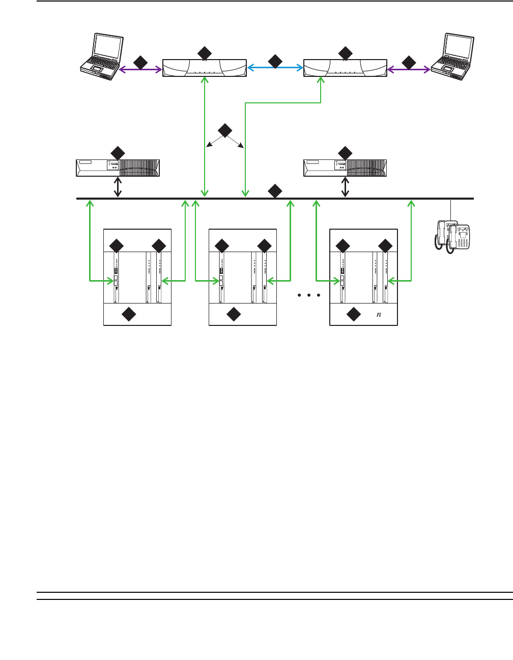
TONE-BD (Tone-Clock Circuit)
Issue 1 June 2005 2329
Figure 139: S8700 IP Connect Duplex Reliability Configuration
Figure notes:
1. S8700 Media Server 1 - two are always
present, one in a active mode and the other
on standby.
6. Ethernet Switch - A device that provides for
port multiplication by having more than one
network segment. In an IP Connect
environment, the Ethernet Switch should
support 802.1 ip/Q, VLAN and 10/100 mbps.
2. S8700 Media Server 2 - two are always
present, one in a active mode and the other
on standby.
7. UPS units - two required.
3. Duplication Interface - The Ethernet
connection between the two S8700 Media
Servers.
8. Port Network - optional configuration of Media
Gateways that provides increased switch
capacity.
4. Services Interface - The S8700 Media
Servers dedicated Ethernet connection to a
laptop. This link is active only during on-site
administration or maintenance and the
services interface can link to the non-active
server through a telnet session.
9. IPSI - provides transport of CCMS messages
over IP allowing the S8700 Media Server to
communicate with the Port Networks.
5. Connection from the Servers to the
Ethernet Switch.
10. Customer LAN
cydsdup KLC 042204
1
12
2
IPSI IPSI
100bT
LINK
TRMT
RCV
BBI
LINK
TRMT
RCV
100bT
LINK
TRMT
RCV
BBI
LINK
TRMT
RCV
100bT
LINK
TRMT
RCV
BBI
LINK
TRMT
RCV
IPSI
Ethernet 1Ethernet 1
Ethernet 0
Ethernet 1
1 2
344
5
6 6
7
PN 1
8PN 2
8PN
8
9 9 910 10 10

Communication Manager Maintenance-Object Repair Procedures
2330 Maintenance Procedures for Avaya Communication Manager 3.0, Media Gateways and Servers
S8700 MC
In IPSI connected port networks, the Tone Clock circuit is found on the IPSI circuit pack. In non
IPSI connected port networks, there is a Tone Clock circuit pack. The following sections
describe the relationship between the various reliability options and the IPSIs or Tone Clock
circuits.
S8700 Multi-Connect architecture has three items that can be duplicated: server, IPSI, and
PNC. Note that duplicated control networks and duplicated IPSIs go together; when the IPSIs
are duplicated, the control networks must be duplicated. While all items can be independently
duplicated, the combination of duplicated bearer networks (PNCs) and unduplicated control
networks is not allowed. See Table 836: S8700 Multi-Connect Reliability Configurations on
page 2330.
Duplex-Reliability Configuration
The duplex-reliability configuration shown in Figure 140 has a duplicated server, an
unduplicated control network, unduplicated IPSIs in the IPSI connected port networks, and an
unduplicated bearer network. Therefore the Tone Clock is not duplicated in the IPSI connected
port network. In the non IPSI connected port network, the Tone Clock boards are also not
duplicated.
Table 836: S8700 Multi-Connect Reliability Configurations
Configuration Server Control Network and IPSI Bearer Network
Duplex Reliability Duplicated Unduplicated Unduplicated
High Reliability Duplicated Duplicated Unduplicated
Critical Reliability Duplicated Duplicated Duplicated
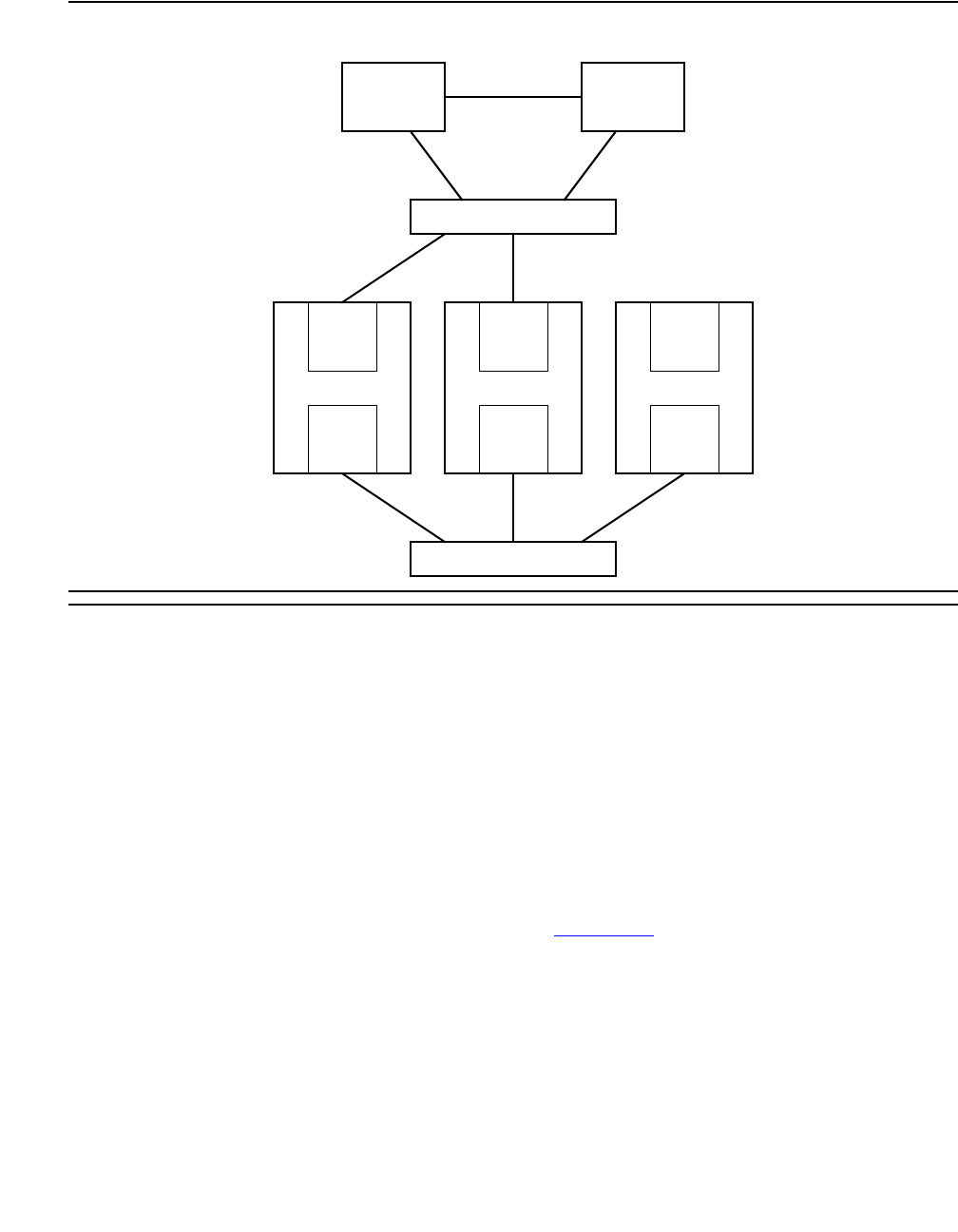
TONE-BD (Tone-Clock Circuit)
Issue 1 June 2005 2331
Figure 140: Duplex-Reliability Configuration
Standard Reliability
Systems with the standard-reliability option (no duplication options) have one Tone-Clock circuit
pack in each port network. For the first Port Network of a cabinet this is in the A carrier. Cabinets
containing a second EPN will also have a Tone-Clock circuit pack in the E carrier. This
Tone-Clock circuit pack generates clocks and provides system tones for every carrier of the port
network it resides in.
High Reliability
S8700 MC: The high-reliability configuration shown in Figure 141 has a duplicated server, a
duplicated control network, and duplicated IPSIs in the IPSI connected port networks. With this
configuration, every IPSI connected PN must have duplicated IPSIs. The control network is
duplicated so that a single fault in the control network, such as a bad Ethernet switch, won’t
bring the whole system down. The non IPSI connected port networks have unduplicated
Tone-Clock boards.
An EPN’s Tone-Clock circuit pack configuration is the same as for the standard-reliability option.
Each PN’s Tone-Clock circuit is active for both tones and clock signals for its port network.
EI
PN 3
Server A Server B
IPSI
EI
PN 2
IPSI
EI
PN 1
Control Network A
Bearer Network
T/C
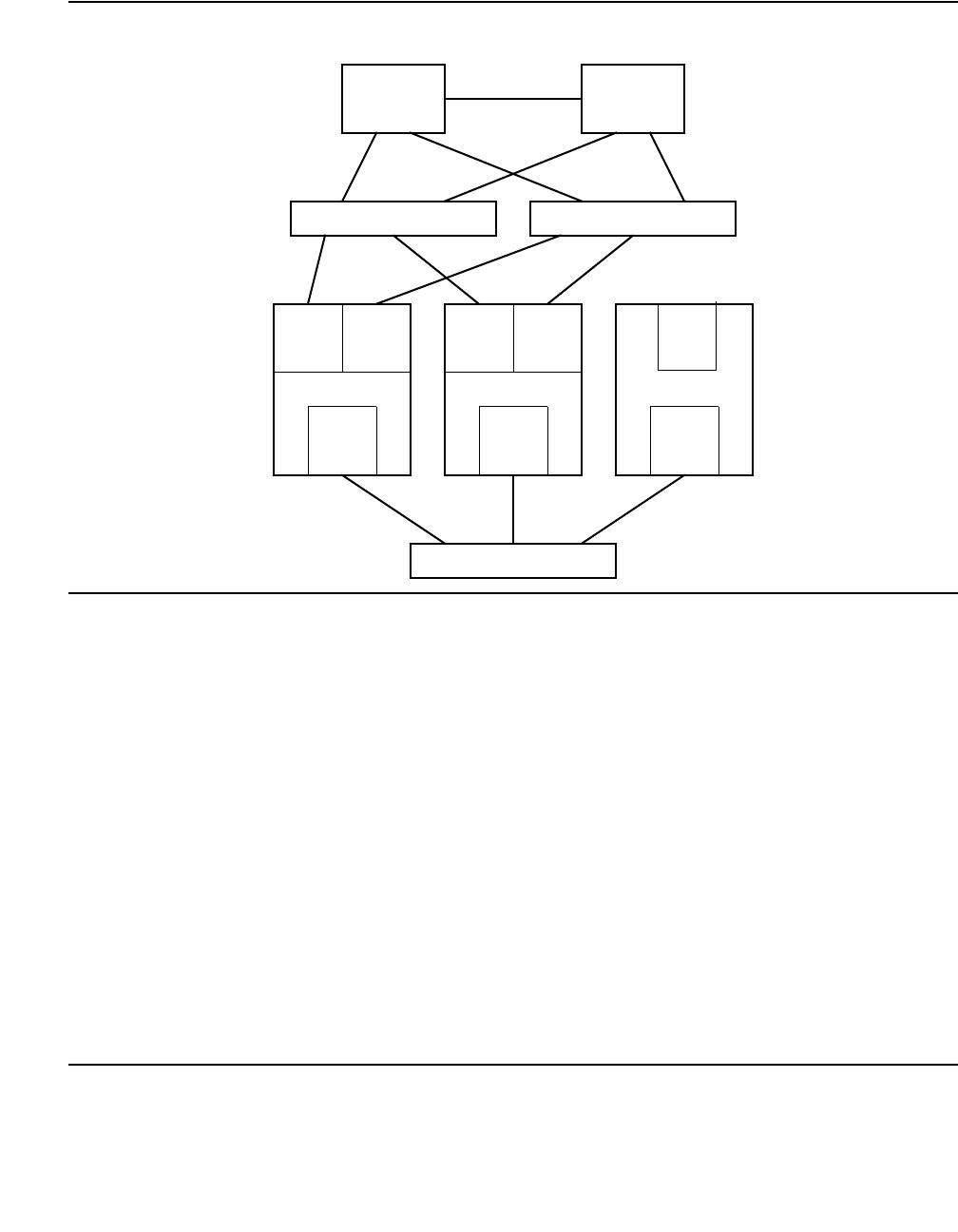
Communication Manager Maintenance-Object Repair Procedures
2332 Maintenance Procedures for Avaya Communication Manager 3.0, Media Gateways and Servers
Figure 141: High-Reliability Configuration
Systems with the High Reliability Option (duplicated SPE, simplex PNC) have one Tone-Clock
circuit pack in each Port Network control carrier, A and B. One Tone-Clock circuit pack will be
actively generating system clock signals for Port Network components, while the other will be in
standby mode, ready to take over in the event of a Tone-Clock interchange. Similarly, one
Tone-Clock circuit pack will be actively providing system tones for the Port Network, while the
other will be in standby mode. Normally, the same Tone-Clock circuit pack will be active for both
tones and clock signals, but these responsibilities may be divided if neither circuit pack is able
to perform both functions. The status port-network command indicates which Tone-Clock
circuit pack is actively performing each function.
For systems using the TN2182 Tone-Clock-Detector circuit pack, tone generation and clock
generation behaves the same as other clock boards with one being active and one being
standby. But the tone detector ports (ETR-PTs) of the TN2182 are always considered available
and in-service regardless of the active/standby state of the tones or clock for a specific circuit
pack.
EPN Tone-Clock circuit pack configuration is the same as for the Standard Reliability Option.
Each EPN Tone-Clock circuit pack will be active for both tones and clock signals for its port
network.
EI
PN 3
Server A Server B
IPSI IPSI
EI
PN 2
IPSI IPSI
EI
PN 1
Control Network A Control Network B
Bearer Network
T/C
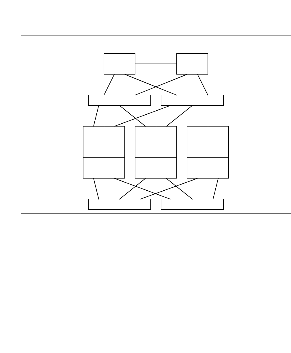
TONE-BD (Tone-Clock Circuit)
Issue 1 June 2005 2333
Critical Reliability
S8700 MC: The critical-reliability configuration shown in Figure 142 has full duplication of the
following options: servers, control networks, IPSIs and PNCs (bearer networks). As with the
high-reliability configuration, this configuration also requires that IPSI connected port networks
have duplicated IPSIs. This configuration also requires that the non IPSI connected port
networks have duplicated Tone-Clock boards (either TN2182 or TN780).
Figure 142: Critical-Reliability Configuration
Tone-Clock Interchange Strategy
There are three types of Tone-Clock interchanges:
●Autonomous interchanges initiated as a part of maintenance software strategy for the
Tone-Clock or IPSI circuit packs.
●Manual interchanges initiated by set tone-clock or set ipserver-interface.
●Firmware-initiated Tone-Clock interchanges
IPSI IPSI
EI EI
PN 1
IPSI IPSI
EI EI
PN 2
Server A Server B
Control Network A Control Network B
Bearer Network A Bearer Network B
T/C T/C
EI EI
PN 3

Communication Manager Maintenance-Object Repair Procedures
2334 Maintenance Procedures for Avaya Communication Manager 3.0, Media Gateways and Servers
Software Initiated Tone-Clock Interchanges
Tone-Clock interchanges may be initiated by software in two ways:
1. A scheduled Tone-Clock or IPSI circuit pack interchange occurs according to the
parameters set by change system-parameters maintenance. This parameter can be
disabled or set to run weekly, the default is for it to occur daily, at a time specified in the
system-parameters list for scheduled maintenance to begin. This interchange will be
blocked, if the non-preferred Tone-Clock or IPSI circuit pack in a PN has been selected with
set tone-clock or set ipserver-interface. Also if the standby Tone-Clock or IPSI
has been set to the busyout state, or if the clock generation capability is known to be
impaired. When this scheduled interchange occurs, the standby Tone-Clock or IPSI circuit
pack becomes active for twenty seconds to test its ability to generate clock signals. For IPSI
scheduled interchanges, the other IPSI modules located on the IPSI circuit pack, i.e. the
Packet interface and Archangel are also tested. After testing the IPSI is returned to standby
mode.
2. For non IPSI Port Networks, unscheduled interchanges occur when on-board Tone-Clock
circuit-pack maintenance, or ongoing switch maintenance test of the TONE-BD, TONE-PT
or the TDM-CLK uncover failures serious enough to raise a MAJOR or MINOR alarm
against the active Tone-Clock circuit pack.
For IPSI Port Networks, unscheduled IPSI/Tone-Clock interchanges may occur any time
as a part of an unscheduled IPSI interchange. The IPSI interchange may be the result of
Tone-Clock, PKT-INT, or EAL faults.
International Settings [G3i V2]
Note:
Note: The following information is for non IPSI port networks.
The TN780 Tone-Clock circuit pack uses three firmware configuration parameters for
international support [G3i V2]. The following two are automatically set by the software load for
the targeted country:
●The circuit pack’s country-code (USA, ITALY, AUSTRALIA, etc.)
●The circuit pack’s companding mode (mu-Law or A-Law)
The third configuration parameter is used only for Italy (country code: ITALY), and selects
whether new versus old ISPT (Istituto Superiore Poste Telegrafi) tones will be used for dial and
confirmation tones. Values for dial confirmation tone can be set independently on the change
tone-generation form. Whenever such changes are made, the effects are immediately
enforced on all TN780 Tone-Clock circuit packs without disrupting tone or timing services.
Tone Default Old ISPT Value
Dial Continuous Cadenced
Confirmation Cadenced Continuous

TONE-BD (Tone-Clock Circuit)
Issue 1 June 2005 2335
In addition the TN780 allows customization of up to six system tones in order to meet specific
country needs. These changes are made using the change system-parameters
country-options form.
The TN2182 allows the same International changes as the TN780 but allows the customization
of up to 24 system tones in order to meet specific country needs. These changes are made
using the change tone-generation form.
Manual Tone-Clock Interchange
In an EPN with duplicated Tone-Clock or IPSI circuit packs, one circuit pack is always preferred
over the other. For the first port network in a cabinet, this is the Tone-Clock or IPSI circuit pack
in carrier A. If a second port network is configured in a cabinet, its preferred Tone-Clock or IPSI
circuit pack is located in carrier E. The intention is that if the preferred Tone-Clock or IPSI circuit
pack has been replaced or repaired, the system will make it active by interchanging to it as soon
as possible.
In a Port Network (PN) with more than one Tone-Clock circuit pack, the intention is to assure
that the one considered most healthy is active at any given time. This is independent of the
server duplication strategy, in the sense that the active Tone-Clock circuit pack need not change
with an interchange of SPE carriers. Rather, except for the effect of the manual intervention
discussed earlier, Tone-Clock interchanges occur only as a result of changes in the health of
Tone-Clock circuit packs, as perceived by maintenance software. When both Tone-Clock circuit
packs are equally healthy, no preference is given to one over the other, regardless of which SPE
carrier is active.
It is possible to manually control Tone-Clock interchanges in three ways.
1. The standby Tone-Clock circuit pack may be made unavailable for most purposes by using
busyout tone-clock location. Such a Tone-Clock may not be selected with console
commands, nor with normal maintenance software activities, until it has been made
available again with restore tone-clock location.
Note:
Note: busyout tone-clock is not allowed for active Tone-Clock circuit packs.
2. The SPE processor lock switches may be used to force a particular SPE to be active. This
method overrides all other Tone-Clock interchange controls. If there is a Tone-Clock circuit
pack in the same carrier as the active SPE, it will become active, regardless of its health. If
the Tone-Clock circuit pack in the selected SPE was in the busyout state (see item 1
above), it will automatically be released and made active. While the lock switches are set for
a particular carrier, no manual intervention or software error detection will cause an
interchange of Tone-Clocks; the Tone-Clock circuit pack in the standby SPE carrier can
never become active. If there is no Tone-Clock circuit pack in the selected SPE at the time
the switches are set, but one is later installed, the system will interchange to it regardless of
its health. If the Tone-Clock circuit pack is removed from an SPE while the switches are set,
no interchange will occur; the system will have no active tone-clock. When the lock switches
are restored to the neutral position, a tone clock interchange will occur only if the standby
Tone-Clock circuit pack is healthier than the active one.

Communication Manager Maintenance-Object Repair Procedures
2336 Maintenance Procedures for Avaya Communication Manager 3.0, Media Gateways and Servers
3. A particular Tone-Clock circuit pack can be made active by issuing the set tone-clock
location [override] command. If the Tone-Clock to be made active is less healthy
than the currently active one, no interchange will occur unless the override option is
specified; without it a message will inform the user that it is required.
Once a Tone-Clock circuit pack is made active by the set tone-clock location
command, it will stay active until either the set tone-clock location command is
entered again to make the other circuit pack active, or until a fault occurs in the active
Tone-Clock circuit pack, which causes the system to interchange Tone-Clocks.
S8700 | 8710 / S8500
Firmware Instigated Tone-Clock Interchanges
Firmware-initiated Tone-Clock interchanges occur when the auto clock switching option is
enabled, and the TN2312 IPSI circuit pack firmware detects a loss of clock or clock errors. After
detecting a loss of clock/clock errors, and rather than waiting for system software to request a
switch, the IPSI firmware will automatically switch the clock (when auto clock switching is
enabled). The auto clock switching option is disabled during system restarts.
Note:
Note: The auto clock switching option is required by the IPSI circuit pack since the EAL
connection to the PKT-INT (one of the IPSI circuit packs many functions) is over
the server packet bus which must have a good clock for proper operation.
S8700 MC
Clock Synchronization
Note:
Note: Stratum-3 clocking is not available for a port network supported by a TN2312
(IPSI) circuit pack, or a port network where the Tone-Clock function is supplied by
a TN2182.
This section discusses synchronization with a Stratum-3 or -4 clocking device.

TONE-BD (Tone-Clock Circuit)
Issue 1 June 2005 2337
Stratum 3
Since the clock module on the TN2312 does not support synchronization with an external
Stratum-3 clocking device, you may provide Stratum-3 clocking for a S8700 Media Server
system by using the TN780 Tone-Clock circuit pack in a non-IPSI connected port network. To
bring in the external Stratum-3 clocking signals into the TN780, a processor carrier is needed.
This new PN control carrier will replace the processor carrier in the old Processor Port Network
(PPN) converted to PN 1. The Stratum-3 clocking must come into Port Network #1 because the
S8700 Multi-Connect software has the Stratum-3 clocking hard-coded to this port network.
Stratum 4
In G3r, a PPN always resided in the system and was used as a backup synchronization source
when either a:
●Synchronization source was not administered
●Designated master and secondary synchronization source failed
With S8700 Multi-Connect, PN 1 may or may not exist and thus cannot be relied on as the
backup synchronization source. If a S8700 Multi-Connect system does not have an
administered synchronization source, it uses the first PN that comes up as its source. If the
designated master and secondary synchronization sources fail, the system uses any other PN
as its source. No preference is given to PN 1.
Replacing the IPSI or Tone-Clock Circuit Pack
Replacing a TN2312 IPSI circuit pack or Tone-Clock circuit pack is a service-disrupting
procedure in a PN with a single Tone-Clock, because the IPSI or Tone-Clock circuit pack is
always needed to generate clocks for its PN. When the circuit pack is removed, every call is
immediately dropped, the PN enters emergency transfer within one minute, and no calls can be
set up from or to that PN.
However, if the Processor Port Network (PPN) Tone-Clock is removed for replacement in a
Standard Reliability Option system, the System Emergency Transfer feature is activated within
milliseconds, and the entire system is disrupted; no calls can be placed, and existing calls are
dropped.
However, if the Processor Port Network (PPN) Tone-Clock is removed for replacement in a
standard-reliability system, the System Emergency Transfer feature is activated within
milliseconds, and the entire system is disrupted; no calls can be placed, and existing calls are
dropped.
When replacing an IPSI or Tone-Clock circuit pack, always be sure to replace it with the
appropriate IPSI or Tone-Clock circuit pack for the system.

Communication Manager Maintenance-Object Repair Procedures
2338 Maintenance Procedures for Avaya Communication Manager 3.0, Media Gateways and Servers
S8700 | 8710
The following circuit-pack code(s) are supported:
S8700 MC:
TN768
This is a general-purpose Tone-Clock circuit pack for EPNs. It can be used in
every situation, except as the Master Tone-Clock circuit pack when a Stratum-3
clock is administered.
S8700 MC:
TN780
The Stratum-3 clock feature requires the use of this circuit pack code in PN 1.
The Stratum-3 clock will operate only with this code as the Master Tone-Clock
circuit pack. The TN780 circuit pack is upward compatible with the TN768 code,
and can be used in any place a TN768 would be allowed. The TN780 is used in
many countries outside the U.S. where the TN768 does not provide local tones.
S8700 MC:
TN2182
This Tone-Clock-Detector may be used anywhere a TN768 or TN780 is used,
with the exception of configurations requiring Stratum-3 clock. The TN2182 may
be used in all country configurations.
TN2312 The TN2312 IPSI circuit pack supplies Tone-Clock functionality for S8700
systems.
System Type Tone-Clock Circuit Pack Code
One-port network single-carrier cabinet system
without High or Critical Reliability.
TN756, TN768, TN780 TN2182
[G3iV4-386]
One-port network system without High or Critical
Reliability (multicarrier cabinet).
TN768, TN780
Two-port network single-carrier cabinet system
without High or Critical Reliability.
TN768, TN780 TN2182 [G3iV4-386]
One- or two-port network without High or Critical
Reliability.
TN768, TN780 TN2182 [G3iV4-386]

TONE-BD (Tone-Clock Circuit)
Issue 1 June 2005 2339
Port Networks with a Single Tone-Clock
Circuit Pack
This procedure is destructive.
1. Pull out the defective IPSI or Tone-Clock circuit pack. This will remove the clocks and cause
the system to activate emergency measures. If this is an IPSI supported port network, use
busyout ipserver-interface:
●All calls to and from the PN will drop, and the PN will activate Emergency Transfer within
about one minute. But the rest of the system should operate normally.
2. Insert a new IPSI or Tone-Clock circuit pack. The system will detect the return of the clocks
and will automatically recover as follows:
●The system will reset the PN (PN cold restart), and all of the PN’s red LEDs will come on
and go off within 30 seconds.
3. If the red LEDs come on but do not go off within 30 seconds, pull the circuit pack out and
reseat it. If the LEDs perform as expected this time, continue with step 6. Otherwise, there
may be a problem with the TDM bus; possibly a bent pin in the IPSI or Tone-Clock circuit
pack’s slot. Follow the directions in the TDM-BUS maintenance section.
4. If the red LEDs did light, as explained above, then go to Step 6. If the red LEDs do NOT
light, as explained above, then go on to Step 5.
5. Restart the affected port network:
●Restart the PN by resetting its Expansion Interface circuit pack using reset
port-network P level 2, using the port network’s number of the affected PN. (Use
the list cabinet C command to determine the port network’s number for a given
cabinet and carrier.)
6. Test the new IPSI or Tone-Clock circuit pack to verify that it is functioning properly, using
test tone-clock location long, and verify that the system is operational by placing
several phone calls. Where possible, try calls into, out from, and within the affected port
network.
Port Networks with Two Tone-Clock
Circuit Packs
Notes:
1. Use list cabinet C to determine the port network’s number of the cabinet and carrier
containing the Tone-Clock circuit pack to be replaced. If both of a PN’s Tone-Clock circuit
packs need to be replaced, first replace and test the one in standby mode by either:
●Entering status port-network to display its status
●Making sure its amber LED is off
Make sure it is healthy and active before replacing the second one.

Communication Manager Maintenance-Object Repair Procedures
2340 Maintenance Procedures for Avaya Communication Manager 3.0, Media Gateways and Servers
The active/standby state of a Tone-Clock circuit pack may also be determined by looking at its
LED. A continuously lit red LED on the Tone-Clock circuit pack indicates a reported fault on one
or more of the maintenance objects on the circuit pack. Flashing patterns of the yellow and
green LEDs correspond to the following service states:
1. If the Tone-Clock circuit pack to be replaced is active, then switch to the other Tone-Clock
circuit pack by the following procedure:
a. set tone-clock location, where location is the physical address of the standby
Tone-Clock circuit pack.
Condition Tone-Clock
Circuit State
Explanation
Flashing yellow 2.7 seconds
on,.3 seconds off
Active An external timing source is being used as
a synchronization reference.1
1. For a Tone-Clock in the master port network, the external source is the primary or secondary DS1 source,
or a Stratum 3 clock. For a Tone-Clock in a slave port network, the external source is the Expansion
Interface circuit pack.
Flashing yellow.3 seconds on,
2.7 seconds off
Active The local oscillator on the Tone-Clock
circuit pack is being used as a
synchronization reference.
Yellow on continuously Active The circuit pack has been reset but has not
been told which synchronization source to
use.
Yellow LED off Standby The circuit pack is in standby mode,
(neither generating tones nor supplying
clocks).
“Jingle bells” green and yellow.1
sec on,.2 sec off,.1 sec on,.4
sec off,.4 sec on,.4 sec off
Standby Maintenance software is testing the
standby circuit pack (the standby
Tone-Clock is providing tones).
Double blink yellow.3 sec on,.3
sec off,.3 sec on, 2.4 sec off
Active TN2182 has lost all external references
and is in holdover mode.
Other green and yellow patterns Active Maintenance software is testing the active
circuit pack.
Random yellow Standby If the circuit pack is a TN2182, the yellow
LED may come on and off intermittently as
ETR-PTs on the board are used for tone
detection services.

TONE-BD (Tone-Clock Circuit)
Issue 1 June 2005 2341
Note:
Note: For a critical-reliability system (duplicated PNC), the system generally expects a
PN to have its “preferred” Tone-Clock circuit pack active. For the first PN in a
given cabinet, this is carrier A. For a second PN in the cabinet, this is carrier E.
b. status system — Verify the Tone-Clock circuit pack switched to the other Tone-Clock
circuit pack or check the LEDs. The amber LED of the new standby Tone-Clock circuit
pack should be off (provided maintenance is not running on it) and the amber LED of the
active Tone-Clock circuit pack should be blinking.
c. If the interchange was not successful, the standby Tone-Clock circuit pack may be
defective. In particular, if the error message must use override is displayed, fix the
standby Tone-Clock circuit pack before attempting to replace the active one.
2. Pull out the defective Tone-Clock circuit pack. No calls should be affected. If this is a
TN2182 circuit pack, some ETR-PTs may be in use and removal of the pack will affect some
individual users. It may be less disruptive to busyout the standby TN2182 before removing
it.
3. Insert a new Tone-Clock circuit pack of the appropriate code in the same slot where the
defective Tone-Clock circuit pack was removed.
4. Test the new Tone-Clock circuit pack using test tone-clock location long to make
sure it is functioning properly. If the Tone-Clock circuit pack is being replaced due to loss of
clocks, the Clock Health Inquiry (#46) will still report a failure, proceed with the next step.
5. To verify that the new Tone-Clock circuit pack can generate clocks for the system, switch to
the new Tone-Clock with set tone-clock location override, and execute test
tone-clock location. If the new Tone-Clock circuit pack is able to generate system
clocks, there will be no system disruption.
!CAUTION:
CAUTION: If the new Tone-Clock circuit pack is not able to generate system clocks, this
procedure becomes destructive. The system will detect a loss of clock and
recover by resetting the PN (PN cold restart).
After the restart, the faulty Tone-Clock circuit pack will be in standby mode.
6. Place several phone calls.
IPSI/Tone Clock LED States
For the TN2312 IPSI circuit pack, there are four LEDs on the IPSI’s faceplate. The top three
LEDs are the standard ones found on any TN circuit pack. The fourth LED imitates the
TN2182B Tone-Clock’s amber LED. The active/standby state of an IPSI or Tone-Clock circuit
pack may also be determined by looking at its LEDs. A continuously lit red LED on the circuit
pack indicates a reported fault on one or more of its MOs. Flashing patterns of the yellow and
green LEDs correspond to the following service states:

Communication Manager Maintenance-Object Repair Procedures
2342 Maintenance Procedures for Avaya Communication Manager 3.0, Media Gateways and Servers
Table 837: LED Condition/Tone-Clock Circuit States
Condition Tone-Clock
Circuit State
Explanation
Flashing yellow
2.7 seconds on
0.3 seconds off
Active An external timing source is being used as
a synchronization reference1.
1. For a Tone-Clock in the master PN, the external source is a primary or secondary DS1 source, or a
Stratum-3 clock. For a Tone-Clock in a slave PN, the external source is the Expansion Interface circuit
pack.
Flashing yellow
0.3 seconds on
2.7 seconds off
Active The local oscillator on the IPSI or
Tone-Clock circuit pack is being used as a
synchronization reference.
Yellow
on continuously
Active The circuit pack has been reset but has not
been told which synchronization source to
use.
S8700 MC:
yellow
LED off
Standby The circuit pack is in standby mode,
(neither generating tones nor supplying
clocks).
S8700 MC:
“Jingle bells”
green and yellow
0.1 sec on, 0.2 sec off,
0.1 sec on, 0.4 sec off,
0.4 sec on, 0.4 sec off
Standby Maintenance software is testing the
standby circuit pack (the standby
Tone-Clock is providing tones).
Double blink
yellow
0.3 sec on, 0.3 sec off,
0.3 sec on, 2.4 sec off,
Active TN2312 or TN2182 has lost all external
references and is in holdover mode.
Other green and yellow patterns Active Maintenance software is testing the active
circuit pack.
S8700 MC:
random yellow
Standby If the circuit pack is a TN2182, the amber
LED may come on and off intermittently as
ETR-PTs on the board are used for
tone-detection services.
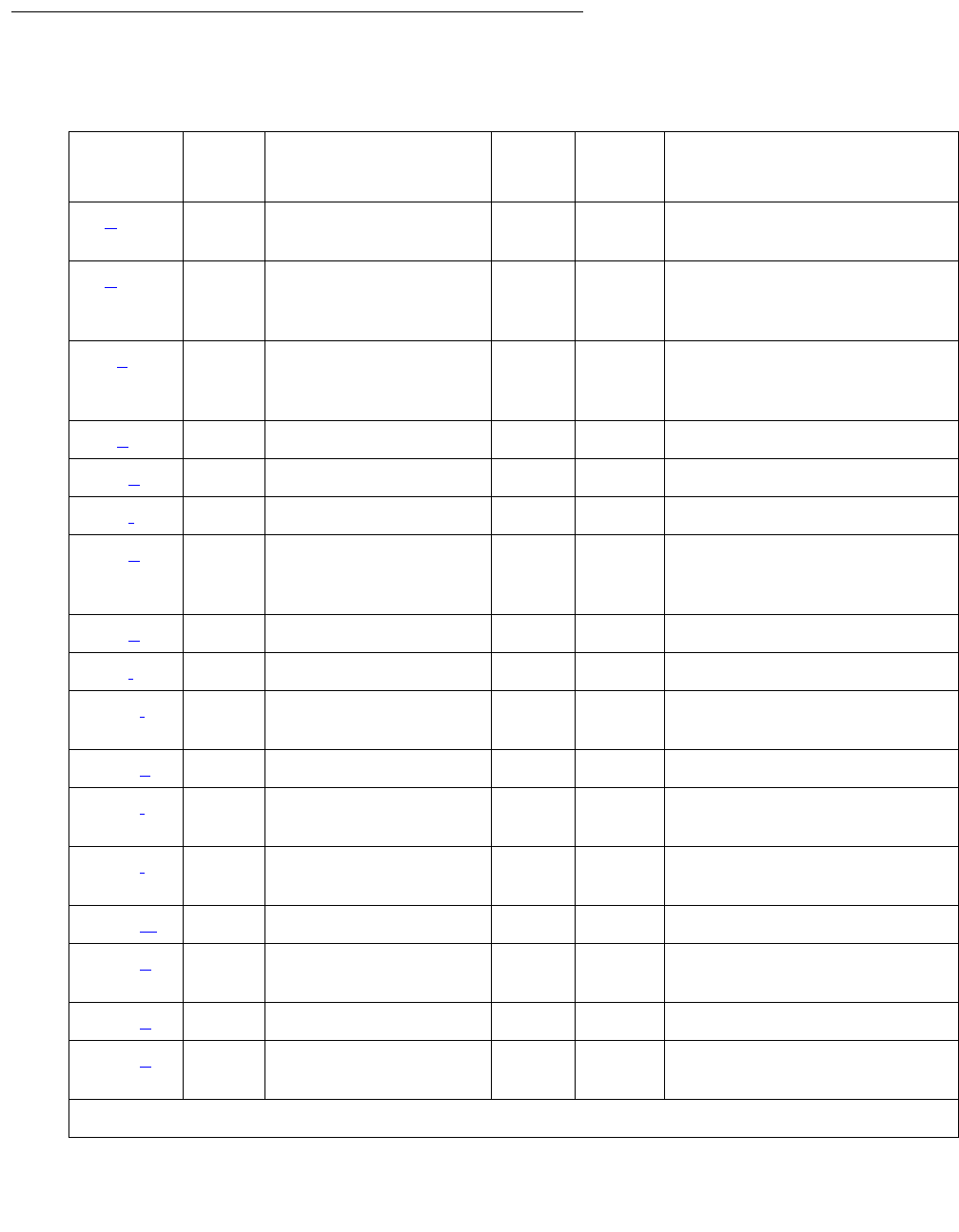
TONE-BD (Tone-Clock Circuit)
Issue 1 June 2005 2343
Error Log Entries and Test to Clear Values
Table 838: Tone-Clock Circuit Pack Error Log Entries
Error
Type
Aux
Data
Associated Test Alarm
Level
On/Off
Board
Test to Clear Value
0 (a) 0 Any Any Any test tone-clock
location sh
1 (b) 0 Circuit pack removed
or SAKI Sanity test
(#53)
MIN ON
18 (c)0 busyout
tone-clock
location
WRN OFF release tone-clock
location
23 (d)0 None WRNOFF
125 (e)None MINON
126 (f)None MINON
257 (g)Any
65535
None
Control Channel test
(#52)
MIN ON test tone-clock
location r 20
513 (h)AnyNone
769 (i)4358None
1025 (j) 4363 NPE Audit test (50) test tone-clock
location sh
1538 (k)Any None MIN ON
2049 (l) 0 Clock Health Inquiry
(#46)
MAJ ON set tone-clock
location override1
2305 (l) 0 Clock Health Inquiry
(#46)
MAJ ON set tone-clock
location override1
2561 (m)Any None MAJ ON
3329 (n)0 None MIN
WRN2OFF set tone-clock
location override1
3840 (o)Any None
3848 (p) 0 Clock Health Inquiry
(#46) set tone-clock
location override1
1 of 2
Communication Manager Maintenance-Object Repair Procedures
2344 Maintenance Procedures for Avaya Communication Manager 3.0, Media Gateways and Servers
Notes:
a. Error Type 0: run the short test sequence first. If every test passes, run the long test
sequence. Refer to each appropriate test’s description, and follow its recommended
procedures.
b. Error Type 1: this error indicates the circuit pack totally stopped functioning or it was
physically removed from the system.
Note:
Note: The alarm is logged approximately 11 minutes after the circuit pack is removed/
SAKI Sanity test (#53) fails.
If the circuit pack is not present in the system, insert a circuit pack in the slot indicated by
the error to resolve the error.
If the circuit pack is present in the system, it is faulty and must be replaced. See Replacing
the IPSI or Tone-Clock Circuit Pack on page 2337.
If the faulty circuit pack is in standby mode, a MINOR alarm is raised, but no other system
action is taken. If the circuit pack is the active Tone-Clock, further effects of this error
depend on the system’s reliability option.
3856 (q)MAJONset tone-clock
location override1
3857
3858 (r)
NONE MAJ ON busyout/release
ipserver-interface
3872 (s)0 None set tone-clock
location override1
3999 (t)Any None
1. *For a TN2312 IPSI supported port network, use the command set ipserver-interface.
2. Minor alarms on this MO may be downgraded to Warning based on the value in set options.
Table 839: Effects of Tone-Clock Failures Depending on Reliability
Reliability Option Effects
Standard EPN goes down
Duplex PN goes down.
1 of 2
Table 838: Tone-Clock Circuit Pack Error Log Entries (continued)
Error
Type
Aux
Data
Associated Test Alarm
Level
On/Off
Board
Test to Clear Value
2 of 2

TONE-BD (Tone-Clock Circuit)
Issue 1 June 2005 2345
If an interchange is attempted in an MCC PN and the system is unable to activate the
standby Tone-Clock, Emergency Transfer is activated. When this happens, both circuit
packs are faulty and must be replaced. See Replacing the IPSI or Tone-Clock Circuit
Pack on page 2337.
If a successful interchange occurs in response to a failure of the active Tone-Clock or if a
standby Tone-Clock fails, the faulty Tone-Clock should be replaced.
c. Error Type 18: the indicated IPSI or Tone-Clock circuit pack has been made unavailable by
busyout tone-clock location or busyout ipserver-interface location.
This error applies only to high- or critical-reliability systems (an active Tone-Clock may not
be busied out). To resolve this error, execute release tone-clock location, or
release ipserver-interface location.
d. Error Type 23: the circuit pack has been logically administered but not physically installed.
Installing the circuit pack will resolve the alarm.
e. Error Type 125: a wrong circuit pack is inserted in the slot where this circuit pack is logically
administered. To resolve this problem, either:
1. Remove the wrong circuit pack, and insert the logically administered circuit pack.
or
Use the change circuit-pack command to re-administer this slot to match the circuit
pack inserted.
f. Error Type 126: the port network specified in the PORT field of the error log entry booted
up without a Tone-Clock circuit pack, or with a one that cannot communicate at all with the
system. The error is logged five minutes after the port network is restarted. If no circuit pack
is present, install one of the proper code. If there is a circuit pack present, replace it. See
Replacing the IPSI or Tone-Clock Circuit Pack on page 2337.
g. Error Type 257: this error indicates transient communication problems with this circuit pack.
This error is not service-affecting and no action is required.
h. Error Type 513: this circuit pack has an on-board hardware failure. Replace the circuit pack
using the procedure described in Replacing the IPSI or Tone-Clock Circuit Pack on
page 2337.
i. Error Type 769: this error can be ignored, but look for other errors on this circuit pack.
High IPSI interchange in IPSI connected PN
non IPSI connected PN goes down
Critical IPSI interchange in IPSI connected PN
Interchange to standby Tone-Clock circuit pack in non IPSI
connected PN
Table 839: Effects of Tone-Clock Failures Depending on Reliability (continued)
Reliability Option Effects
2 of 2

Communication Manager Maintenance-Object Repair Procedures
2346 Maintenance Procedures for Avaya Communication Manager 3.0, Media Gateways and Servers
j. Error Type 1025: this error is not service-affecting, and no action is required.
k. Error Type 1538: the circuit pack was taken out of service because of an excessive rate of
uplink messages. Use test tone-clock location long to reset the circuit pack and
put it back into service. If the command is not successful, replace the circuit pack using the
procedure described in Replacing the IPSI or Tone-Clock Circuit Pack on page 2337. If the
alarmed circuit pack is the active Tone-Clock of a duplicated pair, first interchange
Tone-Clocks using set tone-clock location to avoid a service outage. If the error
occurs again within 15 minutes, follow normal escalation procedures.
l. Error Type 2049 or 2305: these errors indicate the loss of one or more clock signals from
the reported IPSI or Tone-Clock circuit pack, which was active at the time of the error. The
effect of any of these errors is described in the table for Error Type 1. Diagnosis of the
problem is the same for all four Error Types, with the exception noted below.
1. Examine the Hardware Error Log for errors reported against circuit packs in the same
port network, especially TDM-CLK, TONE-BD, and EXP-INTF. Follow the repair or
replacement procedures indicated for any such errors found.
2. If the error is not corrected by resolving errors found in step 1, the IPSI or Tone-Clock
circuit pack should be replaced. See Replacing the IPSI or Tone-Clock Circuit Pack on
page 2337.
Note:
Note: Replacing the circuit pack and retesting it with test tone-clock is not
adequate to retire this alarm and return the IPSI or Tone-Clock circuit pack to full
service; the Clock Health Inquiry test (#46) will continue to fail. Because the
ability to generate clocks was considered lost, once any repairs have been made
it is necessary to execute set tone-clock location override, forcing the
circuit pack to become active. If the problem was not corrected, this action may
cause a disruption in service for active digital facilities users.
3. If error 2305 or 3848 persists, all clock signals from the indicated board were lost.
If the reported Tone-Clock circuit is in a port network with duplicated Tone-Clocks, the
problem may lie with the circuit pack responsible for selecting the active Tone-Clock
circuit (the t/c selector, the active EXP-INTF circuit pack).
The t/c selector circuit pack of interest is the one which was active at the time the error
was logged. This is the currently active t/c selector, unless there has been an EXP-INTF
link switch. In order to determine whether an interchange has occurred since the
TONE-BD error, examine the display initcauses log for EXP-LNK entries in the
hardware error log for expansion link interchanges.
If the t/c selector circuit pack was not replaced as part of the previous step, replace it
now. Follow procedures described in EXP-INTF (Expansion Interface Circuit Pack) on
page 1176 for the Expansion Interface, or Reseating and replacing circuit packs in
Maintenance Procedures (03-300192).

TONE-BD (Tone-Clock Circuit)
Issue 1 June 2005 2347
4. If the error has not been corrected at this point, there is a problem with the TDM bus
within the port network containing the reported Tone-Clock circuit. This may include TDM
bus intercarrier cables, bus terminators, bent pins on the backplane, and errors on any
circuit pack plugged into the same port network. See TDM-BUS (TDM Bus) on
page 2237.
m. Error Type 2561: a Tone-Clock circuit pack, with a different circuit-pack code as required for
this system, has been inserted in the port slot as shown in the Hardware Error Log. To
resolve this error, see Replacing the IPSI or Tone-Clock Circuit Pack on page 2337 for an
appropriate circuit pack code and replace the Tone-Clock circuit pack according to the
procedures indicated for this system. The meanings of the Aux Data values are as follows:
n. Error Type 3329: the system attempted but failed to interchange IPSI or Tone-Clock circuit
packs. (This error occurs only in port networks with duplicated Tone-Clocks.) The fault may
lie in the standby Tone-Clock or in the circuit pack that controls selection of the active
Tone-Clock (the t/c selector). The goal of the following procedure is to ensure that both
Tone-Clocks can be interchanged to while either t/c-selector circuit pack is active.
1. Examine the Error Log for errors reported against circuit packs in the same port network,
paying special attention to TDM-CLK, TONE-BD, DUPINT, SW-CTL, and EXP-INTF.
Follow the procedures indicated for any such errors found. After eliminating the above
potential problem sources, proceed with the following steps.
2. Determine which circuit pack was controlling the choice of Tone-Clock at the time the
error occurred.
The t/c-selector circuit pack of interest is the one which was active at the time the error
was logged. An EXP-LNK interchange since the time of the error may have made that
circuit pack the current standby. Determine whether an interchange affecting the t/c
selector has occurred since the TONE-BD error. Look for EXP-LNK entries in the
hardware error log for PNC interchanges, which would affect the EXP-INTF.
3. If the t/c selector has not undergone an interchange since the error occurred, go to the
next step. If such an interchange has taken place, interchange back to the formerly active
t/c selector. Use set expansion-interface. If the interchange attempt fails due to
other errors, resolve those problems first.
1002 A TN756 Tone-Clock circuit pack (instead of a TN2312) is in a standard- or
duplex-reliability system’s PN.
1003 Either a TN741, TN714, TN768, TN780, or TN2182 Tone-Clock circuit pack
(instead of a TN2312 IPSI) is in a standard- or duplex-reliability system’s
PN.
1004 Either a TN741 or TN714 Tone-Clock circuit pack (instead of a TN768,
TN780, TN2182, or TN2312) is in a high- or critical-reliability system’s PN.
1005 Same as for aux value 1004.

Communication Manager Maintenance-Object Repair Procedures
2348 Maintenance Procedures for Avaya Communication Manager 3.0, Media Gateways and Servers
4. Interchange the IPSI or Tone-Clock circuits, using set tone-clock location. If the
command succeeds, the interchange that previously failed has been accomplished and
the problem has been satisfactorily resolved. If it fails, proceed to the next step. You may
want to proceed in any case to definitively test all relevant components.
5. Interchange the t/c selector using set expansion-interface. If errors prevent this
interchange, resolve them first.
6. Attempt again to interchange Tone-Clocks with set tone-clock location.
If the Tone-Clock interchange failed for both t/c selectors, replace the standby
Tone-Clock circuit pack which could not be interchanged into and return to this step. (See
Replacing the IPSI or Tone-Clock Circuit Pack on page 2337.) Test the new circuit pack
as follows:
a. Execute set tone-clock location.
b. Execute set expansion-interface.
c. Execute the set tone-clock location command again.
If these commands successfully complete, the problem has been resolved.
If these commands successfully complete, the problem has been resolved.
If the IPSI or Tone-Clock circuit packs successfully interchange when one EXP-INTF is
active, but not when the other one is, the t/c-selector circuit pack on the failing side is
suspect.
d. Replace the EXP-INTF board that is active when the Tone-Clock interchange fails. For
the Expansion Interface, see EXP-INTF (Expansion Interface Circuit Pack) on
page 1176. Follow procedures in Reseating and replacing circuit packs in
Maintenance Procedures (03-300192), and “Reliability Systems: A Maintenance Aid”
for the DUPINT circuit pack
e. Make sure the new t/c selector is active and execute set tone-clock location.
f. If both Tone-Clocks can be interchanged into, and interchanges succeed when either
t/c selector is active, the problem has been resolved.
o. Error Type 3840: this error is not service-affecting and can be ignored. It indicates that the
circuit pack has received a bad control message from the switch.
p. Error Type 3848: the IPSI or Tone-Clock circuit pack had a loss of clock. If error 2305 is
also logged, see Note k.
q. Error Type 3856: the IPSI or Tone-Clock circuit pack had a loss of clock. If error 2305 is
also logged, see the note for Error Type 2305.
r. Error Type 3857 and 3858: these errors are reported by software when an uplink message
is received from the active IPSI’s Archangel firmware. Both Error Types indicate that a loss
of one or more clock signals were detected by the archangel, and subsequently restored by
changing the CLKSEL lead.

TONE-BD (Tone-Clock Circuit)
Issue 1 June 2005 2349
Note:
Note: Whenever, the active archangel detects a loss of clock, it will alternate the state
of the CLKSEL lead until the lost clock signals are restored.
If the IPSI archangel restores the clock signals by activating the [A] IPSI/
Tone-Clock, then Error Type 3857 is reported. If the clock signals are restored by
activating the [B] IPSI/Tone-Clock, then Error Type 3858 is reported. A Cold 2
Restart should occur in a port network immediately after Error Type 3857 or 3858
is reported.
Duplex Reliability — Since there is only one IPSI in the port network, Error Type 3858 can
never occur. When Error Type 3857 occurs, it means the [A] IPSI archangel experienced a
loss of clock, but clocking was subsequently restored using the [A] IPSI/Tone-Clock.
High or Critical Reliability — If the [B] IPSI is active and the [A] IPSI is healthy when Error
Type 3857 is reported, then software attempts to initiate an IPSI interchange to activate the
archangel and PKT-INT on the [A] IPSI, thereby ensuring that the active Tone-Clock,
PKT-INT, and archangel are all on the same IPSI. If the [A] IPSI is unhealthy, then software
initiates a transition to EI-Fallback mode. If the [A] IPSI is active when Error Type 3857 is
reported, it means the archangel for the [A] IPSI had to switch the state of the CLKSEL lead
more than once to restore the lost clock signals.
When Error Type 3858 is reported, if the [A] IPSI is active and the [B] IPSI is healthy, then
software attempts to initiate an IPSI interchange to activate the archangel and PKT-INT on
the [B] IPSI. If the [B] IPSI is unhealthy, then software initiates a transition to EI-Fallback
mode. If the [B] IPSI is active when Error Type 3858 is reported, it means the archangel for
the [B] IPSI had to switch the state of the CLKSEL lead more than once to restore the lost
clock signals.
For the high and critical reliability configurations, Error Type 2305 should be logged against
MO_TGEN_BD for the standby IPSI/Tone-Clock after Error Type 3857 or 3858 is reported.
s. Error Type 3872: an IPSI or Tone-Clock circuit pack had a loss of Data Clocks. This error
will impact mainly users on station connected to Digital circuit packs. These users could be
with out service. If error 2049 is also logged see Note k.
t. Error Type 3999: the circuit pack sent a large number of control channel messages to the
switch within a short period of time. If Error Type 1538 is also present, then the circuit pack
was taken out of service due to hyperactivity. If Error Type 1538 is not present, then the
circuit pack has not been taken out of service, but it has generated 50% of the messages
necessary to be considered hyperactive. This may be completely normal during heavy
traffic periods. However, if this Error Type is logged when the circuit pack is being lightly
used, it may indicate a problem with the circuit pack or the equipment attached to it.

Communication Manager Maintenance-Object Repair Procedures
2350 Maintenance Procedures for Avaya Communication Manager 3.0, Media Gateways and Servers
System Technician-Demanded Tests:
Descriptions and Error Codes
Investigate tests in the order presented below. Clearing Error Codes associated with the one
test may also clear errors generated from other tests in the sequence.
For a system with a TN768, TN780, orTN2182 circuit pack
Table 840: TONE-BD System Technician-Demanded Tests
(for TN768, TN780, or TN2182 Tone-Clock Circuit Pack)
Order of Investigation Short
Test
Sequence
Long
Test
Sequence
Reset
Board
Sequence
D/
ND1
1. D = Destructive; ND = Nondestructive
SAKI Sanity test (#53) (a)XD
Clock Health test (#46) X X ND
Control Channel Loop-Around test (#52) (a)X X ND
Tone Generator Crosstalk test (#90) (b)XND
Tone Generator Transmission test (#40) (b)X X ND
Tone Generator Audit/Update test (#41) (b)XX ND
Tone Detector Verification test (#42) (e)XX ND
Tone Detector Audit/Update test (#43) (e)XX ND
TDM Bus Clock Circuit Status Inquiry (#148) (c)X X ND
TDM Bus Clock Slip Inquiry test (#149) (c, e, d)X X ND
TDM Bus Clock PPM Inquiry test (#150) (c)X X ND
TDM Bus Clock Parameter Update test (#151)
(c)
XX ND
Board Type Check test (#574) (c)XXND
Standby Reference Health Check test (#651)
(c, d)
XND

TONE-BD (Tone-Clock Circuit)
Issue 1 June 2005 2351
Notes:
a. See XXX-BD (Common Port Circuit Pack/Media Module) on page 2539 for descriptions of
these tests.
b. See TONE-PT (Tone Generator) on page 2353 for descriptions of these tests.
c. See TDM-CLK (TDM Bus Clock) on page 2252 for descriptions of these tests.
d. This test runs only on the standby IPSI or Tone-Clock circuit in a port network with
duplicated Tone-Clocks (high- or critical-reliability systems). The circuit pack must be a
TN780 with firmware version 2 or above.
e. See ETR-PT (Enhanced Tone Receiver Port) on page 1167 for test description.
Clock Health Inquiry Test (#46)
This inquiry reads special data stored in memory to determine if this IPSI or Tone-Clock circuit
pack had a loss of any of three clock types:
●SYSCLK
●SYSFM
●SYSDCLK
If this data indicates this IPSI or Tone-Clock circuit pack had a loss of any of these clocks, the
inquiry reports FAIL. In addition, if TDM-CLK error 1 is at threshold, this test will FAIL. TDM-CLK
error 1 indicates a suspect clock is at the edge of its specified frequency. If the circuit pack did
not have a loss of clock or TDM-CLK error 1 at threshold, the inquiry reports PASS.
This is not really a test, in the sense that it simply reports status held by the system, and does
not generate new information or raise alarms. If this test fails with no Error Code, there is at
least one Major alarm against an IPSI or Tone-Clock circuit pack. If this test fails with an Error
Code of 1, there is at least one Minor off-board alarm against a TDM-CLK.
Table 841: Test #46 Clock Health Inquiry Test
Error
Code
Test
Result
Description / Recommendation
ABRT Internal system error.
Retry the command at 11-minute intervals up to 5 times.
1 of 2

Communication Manager Maintenance-Object Repair Procedures
2352 Maintenance Procedures for Avaya Communication Manager 3.0, Media Gateways and Servers
None FAIL This Tone-Clock or IPSI circuit pack had an apparent loss of clock. One or
more of Error Types 2049, 2305, 3834, 3857, 3858 and 3872 will appear in
the error log. Correct the problem according to the appropriate error log
entries.
Tone -Clock circuit pack – If this test fails for a Tone-Clock circuit pack, the
only way to make it pass, and to retire its associated alarm, is to repair the
problem and to execute set tone-clock location override against
the indicated or Tone-Clock circuit pack.
IPSI’s Tone-Clock circuit – If this test fails for an IPSI circuit pack’s
Tone-Clock circuit, the only way to make it pass, and to retire the associated
alarm, is to repair the problem, and to execute busy
ipserver-interface, then enter release ipserver-interface
against the indicated IPSI circuit pack.
To restore the TONE-BD to service you must execute the set tone spe
health-override command.
1 FAIL This IPSI or Tone-Clock circuit pack is suspected of having a clock at the
edge of its specified frequency. A Tone-Clock circuit pack with this problem
can cause Expansion Interface circuit packs and SNI circuit packs to go
out-of-frame or report no neighbor conditions, thus causing EPNs,
Expansion Archangel Links (EALs), Remote Neighbor Links (RNLs), and/or
Local Neighbor Links LNLs) to go down.
1. Replace the IPSI or Tone-Clock circuit pack identified in the error log.
See Replacing the IPSI or Tone-Clock Circuit Pack on page 2337.
PASS This IPSI or Tone-Clock circuit pack has not reported a loss of clock.
Table 841: Test #46 Clock Health Inquiry Test (continued)
Error
Code
Test
Result
Description / Recommendation
2 of 2

TONE-PT (Tone Generator)
Issue 1 June 2005 2353
TONE-PT (Tone Generator)
S8700 | 8710 / S8500
Note:
Note: Replacing the IPSI or Tone-Clock circuit pack requires a special procedure which
is described in TONE-BD (Tone-Clock Circuit) on page 2327. That section also
describes the LED display for this board.
The tone generator resides on the IPSI or Tone-Clock circuit pack and provides all system tones
such as dial tone, busy tone, and so on. If an active tone generator fails, its port network may
not have tones (see the Tone Generator Transmission Test (#40) on page 2357. For instance, a
user may go off-hook and hear no dial tone. This problem will affect only users on the same port
network where the faulty IPSI or Tone-Clock circuit pack resides. The system will be able to
process certain type of calls (that is, internal calls will succeed while outgoing calls will not).
The IPSI or Tone-Clock circuit pack also provides the clocks for the system and can serve as
the synchronization reference. Therefore, when resolving alarms, use the TDM-CLK (TDM Bus
Clock) on page 2252, SYNC (Port-Network Synchronization) on page 2143, and TONE-BD
(Tone-Clock Circuit) on page 2327.
See TONE-BD (Tone-Clock Circuit) on page 2327 for a discussion of the relationship of
Tone-Clock circuit packs with the various reliability options.
Error Log Entries and Test to Clear Values
MO Name Alarm Level Initial SAT Command to Run Full Name of MO
TONE-PT MAJ test tone-clock location sh Tone Generator
TONE-PT MIN test tone-clock location sh Tone Generator
TONE-PT WRN release tone-clock location Tone Generator
Table 842: Tone Generator Error Log Entries
Error
Type
Aux
Data
Associated Test Alarm
Level
On/Off
Board
Test to Clear Value
0 (a)0Any AnyAnytest tone-clock
location1 r 1
1 (b) 17664 Tone Generator Audit/
Update (41)
MAJ
MIN2ON test tone-clock
location r 2
1 of 2
Communication Manager Maintenance-Object Repair Procedures
2354 Maintenance Procedures for Avaya Communication Manager 3.0, Media Gateways and Servers
Notes:
a. Error Type 0: run the short test sequence first. If every test passes, run the long test
sequence. Refer to each appropriate test’s description, and follow its recommended
procedures.
b. Error Type 1: A failure in the tone generation facility on the indicated circuit pack has been
detected. Replace the circuit pack. See Replacing the IPSI or Tone-Clock Circuit Pack on
page 2337.
c. Error Type 18: the IPSI or Tone-Clock circuit pack has been made unavailable using
busyout tone-clock location. It only applies to systems which have the high- or
critical-reliability option administered, because only a standby Tone-Clock circuit may be
made busy by that command. To resolve this error, execute release tone-clock
location for the alarmed circuit pack.
Note:
Note: IPSI circuit packs require the location qualifier; Tone-Clock circuit packs do
not.
d. Error Type 130: the circuit pack has been removed or has been insane for more than
11-minutes. To clear the error, reinsert or replace the circuit pack.
e. Error Type 257: the tone generation facility is having problems verifying that tones have
been connected as requested
f. Error Type 513: The tone generation facility may or may not be able to generate tones.
18 (c) 0 busyout tone-clock location WRN OFF release
tone-clock
location
130 (d) None MIN ON test tone-clock
location sh
257 (e)(g) 17667 None MIN ON
513 (f)(g) 17666 Tone Generator Audit/
Update (41)
MIN ON test tone-clock
location r 3
1281 (h) Any Tone Generator Audit/
Update (41)
MIN ON test tone-clock
location r 3
1. IPSI circuit packs require the location qualifier; Tone-Clock circuit packs do not.
2. MAJOR alarm if the alarmed IPSI or Tone-Clock circuit pack is not duplicated; MINOR if it is duplicated
within the same PN.
Table 842: Tone Generator Error Log Entries (continued)
Error
Type
Aux
Data
Associated Test Alarm
Level
On/Off
Board
Test to Clear Value
2 of 2

TONE-PT (Tone Generator)
Issue 1 June 2005 2355
g. Error Types 257 and 513: infrequent errors, at a rate which does not bring up an alarm,
probably do not affect service, unless there are customer complaints of no tones, or
incorrect tones which can not be explained in any other way. However, if an alarm is raised
because this error is being repeatedly logged, then the circuit pack should be replaced. See
Replacing the IPSI or Tone-Clock Circuit Pack on page 2337.
h. Error Type 1281: tone-generation administration requires a TN780 or TN2182
Tone-Clock, or a TN2312 IPSI circuit pack, but the existing Tone-Clock circuit does not
provide the needed functionality. The Base Tone Generation Set on page 1 or the custom
tones beginning on page 2 of the tone-generation screen may have values not
supported by the existing Tone-Clock.
Error Type 1281 indicates that the tone-generation screen has custom tones translated
and that the alarmed tone board does not support the customized tones. TN768 tone
boards do not support any customized tones. TN780 tone boards support up to 6 of the
following customized frequencies/levels only:
Silence 404Hz at 11.0 dB
350Hz at 17.25 dB 404Hz at 16.0 dB
425Hz at 4.0 dB 480Hz + 620Hz at 24.0 dB
425Hz at 11.0 dB 404Hz + 425Hz at 11.0 dB
425Hz at 17.25 dB 375Hz + 425Hz at 15.0 dB
440Hz at 17.25 dB 404Hz + 450Hz at 11.0 dB
350Hz + 425Hz at 4.0 dB 1000Hz at 0.0 dB
350Hz + 440Hz at 13.75 dB 1000Hz at +3.0 dB
480Hz at 17.25 dB 525Hz at 11.0 dB
620Hz at 17.25 dB 1400Hz at 11.0 dB
440Hz + 480Hz at 19.0 dB

Communication Manager Maintenance-Object Repair Procedures
2356 Maintenance Procedures for Avaya Communication Manager 3.0, Media Gateways and Servers
System Technician-Demanded Tests:
Descriptions and Error Codes
Investigate tests in the order listed. By clearing Error Codes associated with the SAKI Reset test
for example, you may also clear errors generated from other tests in the sequence.
Notes:
a. See XXX-BD (Common Port Circuit Pack/Media Module) on page 2539 for descriptions of
these tests.
b. See TONE-BD (Tone-Clock Circuit) on page 2327 for descriptions of these tests.
c. See TDM-CLK (TDM Bus Clock) on page 2252 for descriptions of these tests.
d. This test only runs on the standby IPSI or Tone-Clock circuit in a PN with more than one
IPSI or Tone-Clock circuit pack (high- or critical-reliability system). The circuit pack must be
a TN780 code with firmware revision 2 or above.
e. Test #149 does not run on the TN2182 or TN2312.
Order of Investigation Short Test
Sequence
Long Test
Sequence
D/ND1
1. D = Destructive; ND = Nondestructive
SAKI Reset test (#53) (a)XD
Clock Health test (#46) (b)XXND
Control Channel Loop-around test (#52) (a)XXND
Tone Generator Crosstalk test (#90) X ND
Tone Generator Transmission test (#40) X X ND
Tone Generator Audit/Update test (#41) X X ND
TDM bus Clock Circuit Status Inquiry test (#148) (c)X XND
TDM Bus Clock Slip Inquiry test (#149) (c)(e)XXND
TDM bus Clock PPM Inquiry test (#150) (c)XXND
TDM bus Clock Parameter Update test (#151) (c)X XND
Board Type Check test (#574) (c)XXND
Standby Reference Health Check test (#651) (c, d)XND

TONE-PT (Tone Generator)
Issue 1 June 2005 2357
Tone Generator Transmission Test (#40)
The purpose of this test is to verify that the tone generation hardware on the IPSI or Tone-Clock
circuit pack is capable of generating a subset of system tones and a set of test tones. This test
does not verify all system tones the tone generator produces during normal system operation.
The test is performed in two parts. For the first part, the Tone Generator is told to generate the
touch-tone digits. The digits are received and checked by a Tone Detector’s touch-tone
detector. If any of the digits fail, the test is repeated using a touch-tone detector in another Tone
Detector circuit pack.
For the second part, the Tone Generator is told to generate call-progress tones that are
detected and identified by a tone detector. These tones are:
●440 Hz
●2225 Hz
●Digital Count
The tone generator is then told to generate a sequence of test tones whose output levels are
measured by a tone detector. These tones are:
●404 Hz at 0 dB
●1004 Hz at -16 dB
●1004 Hz at 0 dB
●2804 Hz at 0 dB
A Tone Detector’s general-purpose tone detector listens for tones and measures their quality. If
any of the measured values are not within limits, the test is repeated using a general-purpose
tone detector in a different Tone Detector circuit pack. If the values are still out of the limits, the
test will fail.
For every failure case of Test #40, do the following:
1. Check that all Tone Detector circuit packs have the same companding mode as that
administered for the system. Correct the situation if there is a mismatch.
2. Run the long test sequence: test tone-clock location l r 1.
3. If the problem persists, replace the IPSI or Tone-Clock circuit pack by following the steps
outlined in Replacing the IPSI or Tone-Clock Circuit Pack on page 2337.

Communication Manager Maintenance-Object Repair Procedures
2358 Maintenance Procedures for Avaya Communication Manager 3.0, Media Gateways and Servers
Table 843: Test #40 Tone Generator Transmission Test
Error
Code
Test
Result
Description / Recommendation
None ABRT The system was not able to allocate all the resources needed for this
test or there was an Internal system error.
1. Retry the command at 1-minute intervals up to 5 times.
1 ABRT The system could not allocate all the resources needed to test the
DTMF tones.
1. Retry the command at 1-minute intervals up to 5 times.
1001 ABRT The system was not able to put the tone generation facility in the
appropriate mode to test it.
1. Retry the command at 1-minute intervals up to 5 times.
1002 ABRT The system could not allocate time slots for the test connection. This
can happen when the system is heavily loaded. If the system is not
heavily loaded, use test tdm port-network P to test the TDM
bus.
1. Retry the command at 1-minute intervals up to 5 times.
1003 ABRT The system could not allocate a tone receiver for the test connection.
This can happen when the system is heavily loaded or there is not an
IPSI or Tone Detector circuit pack in the port network where this test is
being executed.
1. Make sure there is an IPSI or Tone Detector circuit pack in the
same port network.
2. If the circuit pack is missing, install one in the same port network.
3. Allow approximately 1-minute for Tone Detector maintenance to
run on the newly inserted IPSI or Tone Detector circuit pack.
4. Retry the command at 1-minute intervals up to 5 times.
1022 ABRT Tone detection for the system is administered as wide broadband (tone
detection mode 5), and the Tone Detector used for this test was not a
TN420C (the only circuit pack with this capability). GPTD ports on other
types of Tone Detector circuit packs are taken out of service since they
cannot provide the administered function. Either:
●Change the tone-detection mode administered on the
system-parameters country-options screen.
●Remove all non-TN420C circuit packs from the system.
1 of 2
TONE-PT (Tone Generator)
Issue 1 June 2005 2359
Notes:
Except in EPNs containing more than one IPSI or Tone-Clock circuit pack, replacing an IPSI or
Tone-Clock circuit pack is a service disrupting procedure. The test should be run several times
with more than one failure before the replacement policy specified in the following notes is
executed. Use the procedure described in Replacing the IPSI or Tone-Clock Circuit Pack on
page 2337.
2000 ABRT Response to the test request was not received within the allowable
time period. System resources required for this test are not available.
1. Retry the command at 1-minute intervals up to 5 times.
2100 ABRT System resources required for this test are not available.
1. Retry the command at 1-minute intervals up to 5 times.
1 (a) FAIL DTMF generation failed for the active tone generator.
105 (a) FAIL Generation of 440-Hz failed.
109 (a) FAIL Generation of 2225-Hz failed.
110 (b) FAIL Generation of 404-Hz level invalid.
111 (b) FAIL Generation of 1004-Hz low level invalid.
112 (b) FAIL Generation of 1004-Hz high level invalid.
113 (b) FAIL Generation of 2804-Hz level invalid.
115 (b, c) FAIL Generation of digital count sequence invalid.
120 (a) FAIL Generation of quiet tone failed.
1044 (a) FAIL DTMF generation failed to generate Digit 1 for the standby tone
generator.
1045 (a) FAIL DTMF generation failed to generate Digit 5 for the standby tone
generator.
1046 (a) FAIL DTMF generation failed to generate Digit 9 for the standby tone
generator.
1047 (a) FAIL DTMF generation failed to generate Digit D for the standby tone
generator.
PASS The tone generation facility is able to generate and transmit all the
tones.
Table 843: Test #40 Tone Generator Transmission Test (continued)
Error
Code
Test
Result
Description / Recommendation
2 of 2

Communication Manager Maintenance-Object Repair Procedures
2360 Maintenance Procedures for Avaya Communication Manager 3.0, Media Gateways and Servers
a. All the failure Error Codes marked with (a) may affect users if the failure is on the active
tone generator. When this type failure is detected, the system will attempt to move the tone
generation function to the alternate IPSI or Tone-Clock circuit pack, if one is present in the
affected port network. When the tone generation facility fails in this way, especially in a port
network without duplicated IPSI or Tone-Clock circuit packs, the faulty IPSI or Tone-Clock
circuit pack should be replaced promptly. See warning below.
b. All the failure Error Codes marked with (b) are almost transparent to the user. Again, when
this type failure is detected, the system will attempt to move the tone generation function to
the alternate IPSI or Tone-Clock circuit pack, if one is present in the affected port network.
Users may or may not hear any noisy tones. This type of failure affects maintenance on
other objects. Maintenance may not be able to run on other objects which use the tone
generation facility (that is, Tone Detector circuit maintenance). In this case, the IPSI or
Tone-Clock circuit pack can be replaced as suitable to the customer.
c. Error code 115 may also be caused by TDM bus corruption. This normally means a physical
problem with bent backplane pins, TDM/LAN bus cabling, or TDM/LAN bus terminators.
Such physical problems should especially be suspected if board replacement or other
physical activity has occurred just before this error is observed.
Use display errors to look for errors on other circuit packs in the carriers of the same
port network as the indicated Tone-Clock circuit. If any are found, they should be resolved if
possible, and the IPSI or Tone-Clock circuit pack retested. If this does not clear the problem,
the IPSI or Tone-Clock circuit pack should be replaced and the new one tested. If the
problem persists, follow instructions for TDM bus maintenance in this manual.
Tone Generator Update/Audit Test (#41)
The active tone generation facility is refreshed with all the time slot tone information. This test
also triggers in-line error messages the IPSI or Tone-Clock circuit pack generates when it
detects problems by itself.
A check is also made between the type of Tone-Clock being tested and the type of Tone-Clock
needed based on system administration. The administration on the system-parameters
country-options screen may imply that a TN780 is required.
Table 844: Test #41 Tone Generator Update/Audit Test
Error
Code
Test
Result
Description / Recommendation
none ABRT The system was not able to allocate all the resources needed for this test.
1. Retry the command at 1-minute intervals up to 5 times.
2100 ABRT System resources required for this test are not available.
1. Retry the command at 1-minute intervals up to 5 times.
1 of 2

TONE-PT (Tone Generator)
Issue 1 June 2005 2361
Tone Generator Crosstalk Test (#90)
This test checks the ability of the Tone Generator to talk on a specific time slot. The tone
generator is told to talk on a specific time slot. The other idle time slots are checked to make
sure the Tone Generator put the tone on only the specified time slot.
1 FAIL The system requires a TN780, TN2182, or TN2312 Tone-Clock circuit to
support the administered tone-generation parameters.
1. Check the administration on the tone-generation screen.
Specifically, the Base Tone Generation Set on page 1 and any custom
tone administration beginning on page 2.
2. Replace any existing IPSI with a TN2312., or an existing Tone-Clock
circuits packs with a TN780 or TN2182.
PASS The tone generation facility has been successfully refreshed with its
time-slot translation and system administration is consistent with this type
of Tone-Clock.
1. Display the Hardware Error Log using display errors to make sure
this circuit pack did not generate new errors.
Table 844: Test #41 Tone Generator Update/Audit Test (continued)
Error
Code
Test
Result
Description / Recommendation
2 of 2
Table 845: Test #90 Tone Generator Crosstalk Test
Error
Code
Test
Result
Description / Recommendation
None ABRT Internal system error
1. Retry the command at 1-minute intervals up to 5 times.
1001 ABRT The system was not able to put the tone generation facility in the
appropriate mode to test it.
1002 ABRT The system could not allocate time slots for the test connection. This can
happen when the system is heavily loaded. If the system is not heavily
loaded, then test the TDM-BUS using test tdm port-network P.
1 of 2

Communication Manager Maintenance-Object Repair Procedures
2362 Maintenance Procedures for Avaya Communication Manager 3.0, Media Gateways and Servers
2000 ABRT Response to the test request was not received within the allowable time
period.
1. Retry the command at 1-minute intervals up to 5 times.
2100 ABRT Could not allocate the necessary system resources to run this test.
1. Retry the command at 1-minute intervals up to 5 times.
FAIL The Tone Generator could be defective. In a port network with more than
one IPSI or Tone-Clock circuit pack, the system will attempt to move the
tone generation function to the alternate one.
1. Test the IPSI or Tone-Clock circuit pack again using test
tone-clock location.
2. If the test fails again, look at the Hardware Error Log for Tone Detector
circuit pack errors.
3. If there are Tone Detector circuit pack errors, see Tone Detector
maintenance documentation (DTMR-PT (Dual-Tone Multifrequency
Receiver Port) on page 1115, GPTD-PT (General-Purpose Tone
Detector Port) on page 1308, CLSFY-PT (Call Classifier Port) on
page 811, ETR-PT (Enhanced Tone Receiver Port) on page 1167 to
resolve these errors first.
4. If there are no Tone Detector circuit pack errors, then the IPSI or
Tone-Clock circuit pack should be replaced. See Replacing the IPSI or
Tone-Clock Circuit Pack on page 2337.
PASS The tone generation facility is able to put tones out.
Table 845: Test #90 Tone Generator Crosstalk Test (continued)
Error
Code
Test
Result
Description / Recommendation
2 of 2

TR-LN-BD (Trunk Line Board)
Issue 1 June 2005 2363
TR-LN-BD (Trunk Line Board)
S8700 | 8710 / S8500 / G700
The TN797 Analog Trunk and Line circuit pack provides 8 ports, any of which may be
administered as one of the following:
Note:
Note: G700: The separate, but equivalent, MG-ANA MO can reside in slots 1–4 of a
G700 media gateway. Refer to MG-ANA (ANALOG MM711) on page 1583 for
information about this MO.
In the U.S., Canada, and like countries, every CO trunk port of TN797 Analog Trunk and Line
circuit packs should be administered as GS (ground-start) trunks rather than as loop-start
trunks, because GS signaling provides disconnect supervision, and loop start does not. If for
some reason a port on the TN797 must be administered as loop start, it must be administered
as 1-way only – either incoming or outgoing – not only at the switch, but also at the CO switch.
This is necessary to avoid collisions (i.e., “glare”) and other highly undesirable conditions.
The TN797 Analog Trunk and Line circuit pack does not support Neon Lamp MWI (Message
Waiting Indication). No maintenance of the terminal connected to the Neon Analog Line circuit
pack is performed.
For circuit pack problems, see XXX-BD (Common Port Circuit Pack/Media Module) on
page 2539.
Table 846: TN797 Analog Trunk and Line circuit pack – port administration
Function Group Type Trunk Type LED MWI
Central Office trunk (CO) co
fx
wats
loop start
ground start
CAMA/E911 trunk cama
Direct Inward Dialing (DID) trunk did wink start
immed start
Analog Line
on-or-off premises
n/a n/a with/without
MWI

Communication Manager Maintenance-Object Repair Procedures
2364 Maintenance Procedures for Avaya Communication Manager 3.0, Media Gateways and Servers
TSC-ADM (Administered Temporary
Signaling Connections)
S8700 | 8710 / S8500
No alarms are generated for Administered Temporary Signaling Connections (TSC-ADM, also
called ADM TSCs).
Administered temporary signaling connections (TSC) provide a path through ISDN-PRI
networks for supplementary D-channel messages. ISDN-PRI applications such as the
Distributed Communications System (DCS) use temporary signaling connections to exchange
user information across an ISDN-PRI network. What makes Administered TSCs unique is that
these particular TSCs stay active for an extended period of time, similar to a permanent data
connection. These ADM TSCs are used for DCS features that require Non-Call Associated
(NCA) TSCs, and the ADM TSC provides the logical channel function in a DCS network.
An NCA TSC is a virtual connection established within a D channel without associating any
B-channel connections. The connection provides user-to-user service by exchanging USER
INFORMATION messages without associated B-channel connections.
An Administered TSC is a special NCA TSC defined for the DCS over the ISDN-PRI D channel.
The ADM TSC has an administratively defined endpoint and is established for an extended
period of time.
There are two types of ADM TSCs:
●Permanent: these are established by the originating PBX (near-end ADM TSC) or by the
terminating PBX (far-end ADM TSC). Once these ADM TSCs are established, they remain
active.
●As-Needed: these are established only when needed.
ADM TSC maintenance provides a strategy to verify that a far end can respond to an ISDN-PRI
USER INFORMATION TSC heartbeat message, thereby indicating that user-user signaling is
functioning. In addition, maintenance can retrieve the status of the ADM TSC’s connection
state.
Since ADM TSCs are administered on a per signaling-group basis, the health of an ADM TSC
also depends on the state of the D channel or D-channel pair administered per signaling group.
See ISDN-SGR (ISDN-PRI Signaling Group) on page 1429 documentation for details on
ISDN-PRI NFAS and D-channel backup maintenance.
The two administration commands for ADM TSCs are as follows:
●add signaling-group number
●change signaling-group number
MO Name Alarm
Level
Initial Command
to Run
Full Name of MO
TSC-ADM none none Administered Temporary Signaling Connections

TSC-ADM (Administered Temporary Signaling Connections)
Issue 1 June 2005 2365
The two maintenance commands for ADM TSCs are as follows:
●test tsc-administered signaling-group-number [/tsc-index]
●status tsc-administered signaling-group-number [/tsc-index]
Error Log Entries and Test to Clear Values
Note:
a. Error Types 3840 - 3967: there is no Test to Clear Value for these Error Types which
provide the following additional data that may prove useful when tracking down problems.
Any of these errors indicates that a TSC Heartbeat Inquiry test was run on an active far-end
Administered TSC from the switch. Upon receiving the heartbeat message, the network
communicated that the call was unable to complete. As a result, the error was logged.
1. Check the signaling group status of the D channel or D-channel pair using status
signaling-group grp# for the Administered TSC.
2. Check the status of the Administered TSC using status tsc-administered.
3. Also check the administration of the Administered TSC on the switch.
This error may only be affecting service for some DCS customers. Upon receipt of this error
condition, the switch will tear down and re-establish the ADM TSC within 20 minutes.
The Port field in the error log contains the signaling group number for TSC-ADM errors.
System Technician-Demanded Tests:
Descriptions and Error Codes
Table 847: ADM TSC Error Log Entries
Error
Type
Aux
Data
Associated Test Alarm
Level
On/Off
Board
Test to Clear Value
3840-
3967 (a)
tsc index # test tsc-administered
Order of Investigation Short Test
Sequence
Long Test
Sequence
D/ND
TSC Heartbeat Inquiry test (#604) Nondestructive

Communication Manager Maintenance-Object Repair Procedures
2366 Maintenance Procedures for Avaya Communication Manager 3.0, Media Gateways and Servers
TSC Heartbeat Inquiry Test (#604)
This test can be invoked by system technician personnel for any ADM TSC administered in the
switch. Most of the error conditions on the following table will not log an error, but switched
services may take some type of recovery action in certain instances.
This test sends a USER INFORMATION TSC heartbeat message inquiry across an ADM TSC
to determine whether the far end can respond to a USER INFORMATION TSC heartbeat
message.
Table 848: Test #604 TSC Heartbeat Inquiry Test
Error
Code
Test
Result
Description / Recommendation
2100 ABRT Could not allocate the necessary system resources to run this test.
1. Execute the test tsc-administered command at 1-minute
intervals up to 5 times.
1005 ABRT The Administered TSC does not exist.
1. Display the administration for the Administered TSC.
2. If an Administered TSC exists, execute the test
tsc-administered.
1113 ABRT The D channel is out-of-service.
1. See ISDN-PLK (ISDN-PRI Signaling Link Port) on page 1423.
1145 ABRT There is congestion in the network.
1. Enter the status tsc-administered command at 1-minute
intervals up to 5 times.
2. If the congestion does not clear, disable and enable the Administered
TSC using change signaling-group grp#.
NOTE: To disable the Administered TSC, display the (administration)
Signaling Group screen using change signaling-group grp#,
where group is the number of the signaling group under which the
suspect TSC is administered. Set the Enable field to n. To enable the
ADM TSC, set the Enable field to y.
3. If the congestion still does not clear, check other nodes in the network.
1 of 4

TSC-ADM (Administered Temporary Signaling Connections)
Issue 1 June 2005 2367
1146 ABRT The congestion just occurred in the network.
1. Enter status tsc-administered at 1-minute intervals up to 3
times.
2. If congestion does not clear, disable and enable the Administered TSC
using change signaling-group grp#.
NOTE: To disable the Administered TSC, display the Signaling Group
administration screen using change signaling-group grp#,
where grp# is the number of the signaling group under which the
suspect TSC is administered. Set the Enable field to n. To enable the
ADM TSC, set the Enable field to y.
3. If congestion still does not clear, check the other nodes in the network.
1147 ABRT The ADM TSC is being torn down.
1. Enter status tsc-administered at 1-minute intervals up to 3
times.
2. If ADM TSC is still down, disable and enable the ADM TSC using
change signaling-group grp#.
NOTE: To disable the ADM TSC, display the Signaling Group
administration screen using change signaling-group grp#,
where grp# refers to the number of the signaling group under which
the suspect TSC is administered. Set the Enable field to n. To enable
the ADM TSC, set the Enable field to y.
3. If the ADM TSC is still down, check the other nodes in the network.
1148 ABRT The ADM TSC is enabled, but inactive (near end).
1. Disable and enable the ADM TSC.
2. Execute test tsc-administered.
3. If the ADM TSC is still inactive, check the other nodes in the network.
1149 ABRT The ADM TSC is disabled.
1. Enable the TSC, and see if the status indicates active.
2. Execute test tsc-administered.
3. If the TSC still disabled, remove the ADM TSC from the system.
Table 848: Test #604 TSC Heartbeat Inquiry Test (continued)
Error
Code
Test
Result
Description / Recommendation
2 of 4

Communication Manager Maintenance-Object Repair Procedures
2368 Maintenance Procedures for Avaya Communication Manager 3.0, Media Gateways and Servers
1181 ABRT Ran out of ADM TSC resources.
1. Execute test tsc-administered at 1-minute intervals up to 3
times.
1182 ABRT The BX.25 link is down at the gateway.
1. Disable the ADM TSC.
2. Check the status of the gateway link using status link lnk#.
3. Once the gateway link indicates an in-service state, enable the
Administered TSC.
4. Execute test tsc-administered.
2000 ABRT The Administered TSC is not responding to a TSC heartbeat inquiry.
1. Retry test tsc-administered at 1-minute intervals up to 3 times.
2. If the problem continues to fail, obtain the status of the D channel or
D-channel pair associated with the ADM TSC using status
signaling-group grp#. If the D channel is INS (i.e., in-service) and
the status of the ADM TSC appears to be active, then disable and
enable the ADM TSC through administration.
NOTE: To disable the ADM TSC, display the Signaling Group
administration screen using change signaling-group grp# where
group refers to the number of the signaling group under which the
suspect TSC is administered. Set the Enable field to n. To enable the
ADM TSC, set the Enable field to y.
3. Execute test tsc-administered.
4. If the test fails, check the ADM TSC node on the other side of the
network to verify that the ADM TSC is indeed active.
2012 ABRT Internal system error.
1. Execute test tsc-administered at 1-minute intervals up to 5
times.
Table 848: Test #604 TSC Heartbeat Inquiry Test (continued)
Error
Code
Test
Result
Description / Recommendation
3 of 4

TSC-ADM (Administered Temporary Signaling Connections)
Issue 1 June 2005 2369
1 FAIL The Administered TSC is not active (far end).
1. Execute test tsc-administered.
2. Verify that the Administered TSC node on the other side of the network
is active.
3. Disable and enable the Administered TSC.
4. Retry test tsc-administered.
2 FAIL Facility IE (Information Element) reject.
1. Check every other node in the network, and make sure Administered
TSC is active.
PASS The Administered TSC responded to a heartbeat.
Table 848: Test #604 TSC Heartbeat Inquiry Test (continued)
Error
Code
Test
Result
Description / Recommendation
4 of 4

Communication Manager Maintenance-Object Repair Procedures
2370 Maintenance Procedures for Avaya Communication Manager 3.0, Media Gateways and Servers
TTR-LEV (TTR Level)
S8700 | 8710 / S8500
TN748 and TN420 Tone Detector circuit packs and TN744 Call Classifier circuit packs provide
tone receivers for detecting various types of signaling tones. These circuit packs are shared
resources that serve every user of the PBX. This discussion uses the following terms and
abbreviations (note that the Maintenance-Related System-Parameters screen uses different
names than the alarm and error logs):
TN748s and TN420s each have 4 DTMR-PTs and 2 GPTD-PTs. DTMR-PTs interpret dual-tone
multifrequency (DTMF) calling signals and translate them into logical digits 0 through 9, *, and
#. GPTD-PTs detect call-progress tones, modem answer tones, and transmission test tones.
TN744 Call Classifier circuit packs have 8 CLSFY-PTs. These ports detect DTMF tones and
classify network and MFC (multifrequency compelled) signaling tones. (That is, CLSFY-PTs can
function as DTMR-PTs or GPTD-PTs, and have other additional capacities).
When a user goes off-hook to place a call, dial tone is returned to the user, indicating that a tone
detector is connected and ready to receive and interpret tones. The tone detector is in use until
the total number of digits needed is collected or until a time-out occurs. If every tone detector in
the system is being used simultaneously, the next user to go off-hook will not receive dial tone
until a tone detector becomes available. It is therefore necessary to have a sufficient number of
tone detectors in the system to prevent delays in receiving dial tone. The list
measurements tone-receiver command shows the level of tone detector usage.
In order to prevent dial-tone delays and other shortcomings in system performance, threshold
levels for the 3 types of tone receivers are administered on the System-Parameters
Maintenance screen. Whenever the number of tone receivers in service falls below the
administered threshold for that type of tone receiver, an alarm is logged against the TTR Level
MO. At this point, the system is operating properly, but call processing capacity is reduced.
MO Name Alarm Level Initial Command to Run Full Name of MO
TTR-LEV WRN See the Repair Procedure for TTR-LEV. TTR Level
TTR-LEV MIN See the Repair Procedure for TTR-LEV. TTR Level
TTR-LEV MAJ See the Repair Procedure for TTR-LEV. TTR Level
Type of Tone Receiver MO Also Known As Location
Dual-Tone Multifrequency
Tone Receiver
DTMR-PT Touch-Tone Receiver
(TTR)
4 per TN420/TN748
General-Purpose Tone
Detector
GPTD-PT Call-Progress Tone
Receiver (CPTR)
2 per TN420/TN748
Call Classifier CLSFY-PT Call-Classification Tone
Receiver (CCTR)
8 per TN744

TTR-LEV (TTR Level)
Issue 1 June 2005 2371
Another alarm is logged if the number falls to zero. At this point, system operation is severely
compromised.
Typical causes of these events are:
1. The threshold for GPTD-PTs or DTMR-PTs is administered incorrectly on the
Maintenance-Related System-Parameters screen.
2. Too many GPTD-PTs, DTMR-PTs, or CLSFY-PTs have been taken out of service, possibly
by maintenance software or a demand busyout.
3. A tone detector circuit pack has been removed or suffered a fatal failure, resulting in the
loss of all its ports.
4. The system has an insufficient number of TN748/TN744/TN420 circuit packs.
Repair Procedure for TTR-LEV
To resolve a TTR-LEV alarm:
1. Enter display errors and use the TTR-LEV Error Log Table to determine which type of
tone receiver has fallen below its threshold.
2. Enter change system-parameters maintenance, and check the administered value.
On the screen, TTR represents DTMR-PTs, CPTR represents GPTD-PTs, and Call
Classifier represents CLSFY-PTs. If the threshold value is set too high, change it to a lower
value and wait a minute for the alarm to clear.
To determine the correct thresholds, first find the total number of TN478/TN420 Tone
Detector and TN744 Call Classifier circuit packs in the system using list
configuration. Then calculate the total number of tone receiver ports of each type. Each
Tone Detector circuit pack has 4 TTR (DTMR) ports and 2 CPTR (GPTD) ports. Each
TN744 Call Classifier circuit pack has 8 Call Classifier (CLSFY-PT) ports.
For each type of tone receiver, if the total number of ports installed in the system is less than
the administered threshold, either add more circuit packs to the system or reduce the
threshold to match the number already in the system. If the TTR Level alarm is still present,
proceed to Step 3.
3. Enter display errors for Error Type 18 and look for GPTD-PTs, DTMR-PTs, or
CLSFY-PTs that have been busied out.
For each of the busied-out ports:
a. Determine why the port was busied out.
b. If the port can be placed back into service, test the port using test port location.
c. If every test passes, enter release port and wait 1 minute for the TTR Level alarm to
clear.
If this does not clear the TTR Level alarm, proceed to Step 4.

Communication Manager Maintenance-Object Repair Procedures
2372 Maintenance Procedures for Avaya Communication Manager 3.0, Media Gateways and Servers
4. Enter display alarms and determine the location of the circuit pack with the alarmed
GPTD-PT, DTMR-PT, or GPTD-PT.
Run test board location l r 3 for that circuit pack.
If this does not clear the TTR Level alarm, replace the Tone Detector or Call Classifier circuit
pack with the alarmed GPTD-PT, DTMR-PT, or CLSFY-PT.
Error Log Entries and Test to Clear Values
!WARNING:
WARNING: The Alarm is upgraded to MAJOR if the Base Tone Generator is set to 12
(France).
Notes:
a. Error Type 1: does not indicate a current error condition. It indicates that the number of
DTMR ports in service was below the administered threshold, but is now equal to or greater
than the threshold. These errors are typically generated during boot time or other
transitional states when the ports are being brought into service.
b. Error Type 2: the total number of DTMR ports currently in service is below the administered
threshold. To clear the alarm, see Repair Procedure for TTR-LEV on page 2371.
c. Error Type 3: does not indicate a current error condition. It indicates that the number of
GPTD ports in service was below the administered threshold, but is now equal to or greater
Table 849: TTR Level Error Log Entries
Error
Type
Aux
Data
Associated Test Alarm
Level
On/Off
Board
Test to Clear Value
1 (a) 1 None
2 (b) 2 WRN
(See message below)
OFF
3 (c) 3 None
4 (d)4 WRN OFF
5 (e) 5 None
6 (f)6 WRN OFF
7 (g)7 MAJ OFF
8 (h)8 MIN OFF
9 (i)9 MIN OFF

TTR-LEV (TTR Level)
Issue 1 June 2005 2373
than the threshold. These errors are typically generated during boot time or other
transitional states when the ports are being brought into service.
d. Error Type 4: the total number of GPTD ports currently in service is below the administered
threshold. To clear the alarm, see Repair Procedure for TTR-LEV on page 2371.
e. Error Type 5: does not indicate a current error condition. It indicates that the number of Call
Classifier ports (CLSFY-PT) service was below the administered threshold, but is now equal
to or greater than the threshold. These errors are typically generated during boot time or
other transitional states when the ports are being brought into service.
f. Error Type 6: the total number of Call Classifier ports (CLSFY-PT) currently in service is
below the administered threshold. To clear the alarm, see Repair Procedure for
TTR-LEV on page 2371.
g. Error Type 7: there are currently no DTMR ports in service. To clear the alarm, see Repair
Procedure for TTR-LEV on page 2371.
h. Error Type 8: there are currently no GPTD ports in service. To clear the alarm, see Repair
Procedure for TTR-LEV on page 2371.
i. Error Type 9: there are currently no Call Classifier ports (CLSFY-PT) in service. To clear the
alarm, see Repair Procedure for TTR-LEV on page 2371.

Communication Manager Maintenance-Object Repair Procedures
2374 Maintenance Procedures for Avaya Communication Manager 3.0, Media Gateways and Servers
UDS1-BD (UDS1 Interface Circuit Pack)
S8700 | 8710 / S8500
Note:
Note: G700: The separate, but equivalent, MG-DS1 MO can reside in slots 1–4 of a
G700 Media Gateway.
The UDS1 Interface circuit pack provides an interface to the DS1 facility.
The maintenance strategy for the TN464 UDS1 Interface circuit pack (UDS1-BD) is very similar
to the maintenance strategy for the TN767 DS1 Interface circuit pack (DS1-BD). The same
commands are used for administering and testing the boards. The differences in maintenance
strategy between the boards are due to the UDS1 circuit pack’s direct interface to the Packet
bus which is used for ISDN-PRI signaling (ISDN-LNK). While both the TN464 and TN767 can
support ISDN-PRI B channels, ISDN-PRI D-channel signaling applications require a TN464
UDS1 circuit pack. See the following table for a list of USD1 Interface circuit packs:
Note:
Note: For information about other DS1 circuit packs, see DS1-BD (DS1 Interface Circuit
Pack) on page 978.
The UDS1 maintenance strategy includes logging in-line errors reported by the UDS1 Interface
circuit pack, running tests for error diagnosis and recovery, and raising or clearing maintenance
alarms.
MO Name Alarm Level Initial SAT Command to Run Full Name of MO
UDS1-BD MAJ test board location sh UDS1 Interface Circuit Pack
UDS1-BD MIN test board location lUDS1 Interface Circuit Pack
UDS1-BD WRN test board location sh UDS1 Interface Circuit Pack
Circuit Pack
Code
24-
Channel
32-
Channel
Tie Trunk
Signaling
CO Trunk
Signaling
DID Trunk
Signaling
OPS Line
Signaling
TN2242 X X X
TN464C/D/E/F
TN464GP
XX X X X X
(24-chl only)
TN2464 X X X X X X

UDS1-BD (UDS1 Interface Circuit Pack)
Issue 1 June 2005 2375
The TN464F or later circuit pack combined with an 120A1 CSU module forms an Enhanced
Integrated CSU. The 120A1 CSU module, when combined with the functionality provided by the
TN464F hardware and firmware, and switch software, provides functionality equivalent to an
external stand-alone ESF T1 CSU. The 120A1 CSU module connects to the TN464F circuit
pack on the I/O connector panel on the back of the port carrier. The CSU module thus becomes
an integrated part of the system. Throughout the document, the term 120A1 will mean a 120A1
or higher suffix CSU module.
The Enhanced Integrated CSU is for use in the United States of America with 1.544-Mbps DS1
service. For further details on the 120A1 CSU module refer to DEFINITY® Communications
System Generic 1, Generic 2 and Generic 3 V1 and 2 – Integrated Channel Service Unit (CSU)
Module Installation and Operation, 555-230-193.
The UDS1-BD and 120A1 CSU module support on-demand loop-back tests that assist in the
detection of faults between the UDS1-BD circuit pack and the CSU module, between the
Integrated CSU and the optional Customer Premises Loop-Back Jack, or between the
Integrated CSU and remote CSU.
These loop-back tests are explained in detail later in this UDS1-BD MO, but Figure 143 gives a
high level overview of the loop-back points.
Figure 143: High Level Overview Of Loopback Points
The following list of acronym definitions are for the Figure 143: High Level Overview Of
Loopback Points:
●PLB = Payload Loopback
CPE
LPBK
JACK
NET
SMRT
JACK
CSU
MOD
NET
SMRT
JACK
CPE
LPBK
JACK
DS1
BRD
CSU
MOD
DS1
BRD
NET-
WORK
CSU module to CSU module
Remote end
NETWORK ENVIRONMENT
Local end
NETWORK
SMRT
JACK
BLB
R-LLB
CPE
LPBK
JACK
DS1
BOARD
NETWORK
SMRT
JACK
CSU*
MOD
CSU
MOD
CLJ-LB LLB RLB ELB
PLB
CPE
LPBK
JACK
DS1
BOARD
Local end loop backs

Communication Manager Maintenance-Object Repair Procedures
2376 Maintenance Procedures for Avaya Communication Manager 3.0, Media Gateways and Servers
●BLB = Board Loopback
●ELB = Equipment Loopback
●LLB = Line Loopback
●RLB = Repeater Loopback
●CLJ = Loop-Back Jack Loopback
●R-LLB = Remote Line Loopback
●SMRT = Smart Jack
●LPBK = Loopback
2Mbit Japan Trunk (TN2242)
The TN2242 2-Mbit, 30-port trunk circuit pack supports Japanese TTC private networking
environments. This circuit pack interfaces only with network equipment or other circuit packs of
the same model and is incompatible with every other digital trunk circuit pack.
The maintenance strategy for the TN2242 is similar to that of the TN464F or higher suffix DS1
interface circuit pack. The TN2242 circuit pack is functionally the same as the TN464F (without
ICSU) with the following exceptions:
●The Blue Alarm Inquiry test (#139) always passes for the TN2242.
●The test ds1-loop command is not executed for the TN2242.
●When reset board is run on a TN2242, a different initialization message is sent for the
local loop-around test (Test #135) is executed.
●Since an ICSU (Integrated Channel Service Unit) is not supported on this circuit pack,
tests associated with an ICSU are not executed.
●Tests associated with new functionality available with the video-enabled TN464F are not
executed for the TN2242.
●CRC (cyclical redundancy check) is not defined for this circuit pack.
●The D channel can be user-assigned to any port 1 – 30, when the signaling mode is ISDN
PRI.
●Wideband is not supported.
●OPS (off-premises stations) are not supported.
The TN2242 circuit pack also supports specialized versions of CAS (channel- associated
signaling) and ISDN-PRI signaling that pertain to the TTC private networking environment in
Japan.
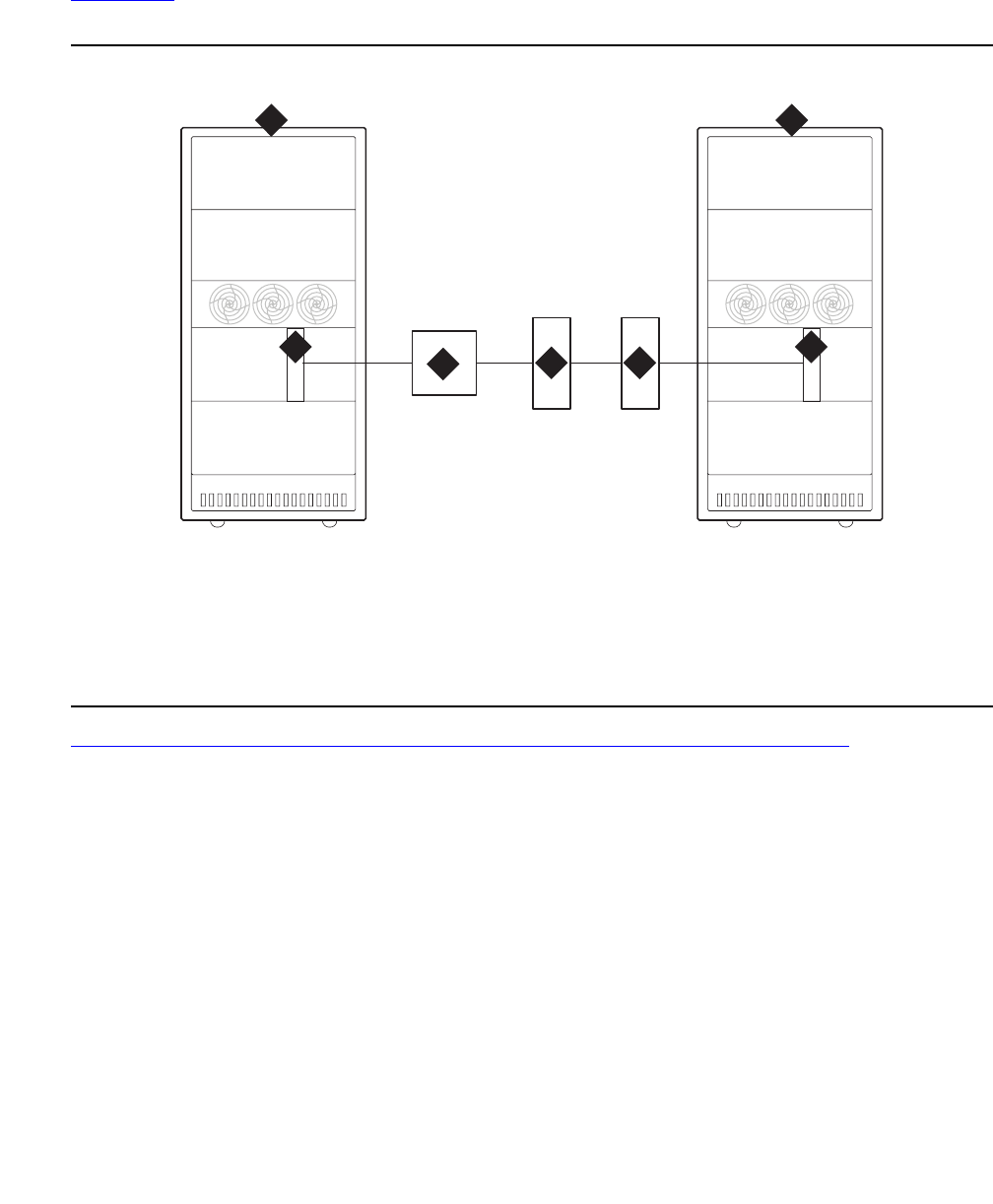
UDS1-BD (UDS1 Interface Circuit Pack)
Issue 1 June 2005 2377
Upgrading to TN2242
Figure 144 shows the hardware connections for public network access in Japan. The upgrade
procedure requires removing the JRC (Japan Radio Corporation) external converter.
Figure 144: Japanese TTC public network connections
Figure 145: TN2242 Japan trunk TTC private network connections on page 2378 shows the
hardware connections for private network access using the TN2242 circuit pack.
Figure notes:
1. Communications System 3. JRC (Japan Radio Corporation)
external converter
2. UDS1-BD DS1-CONV circuit pack
(24-trunk digital tie trunk)
4. TDM facilities
1 1
2 2
34 4
cydfjap1 LJK 012899
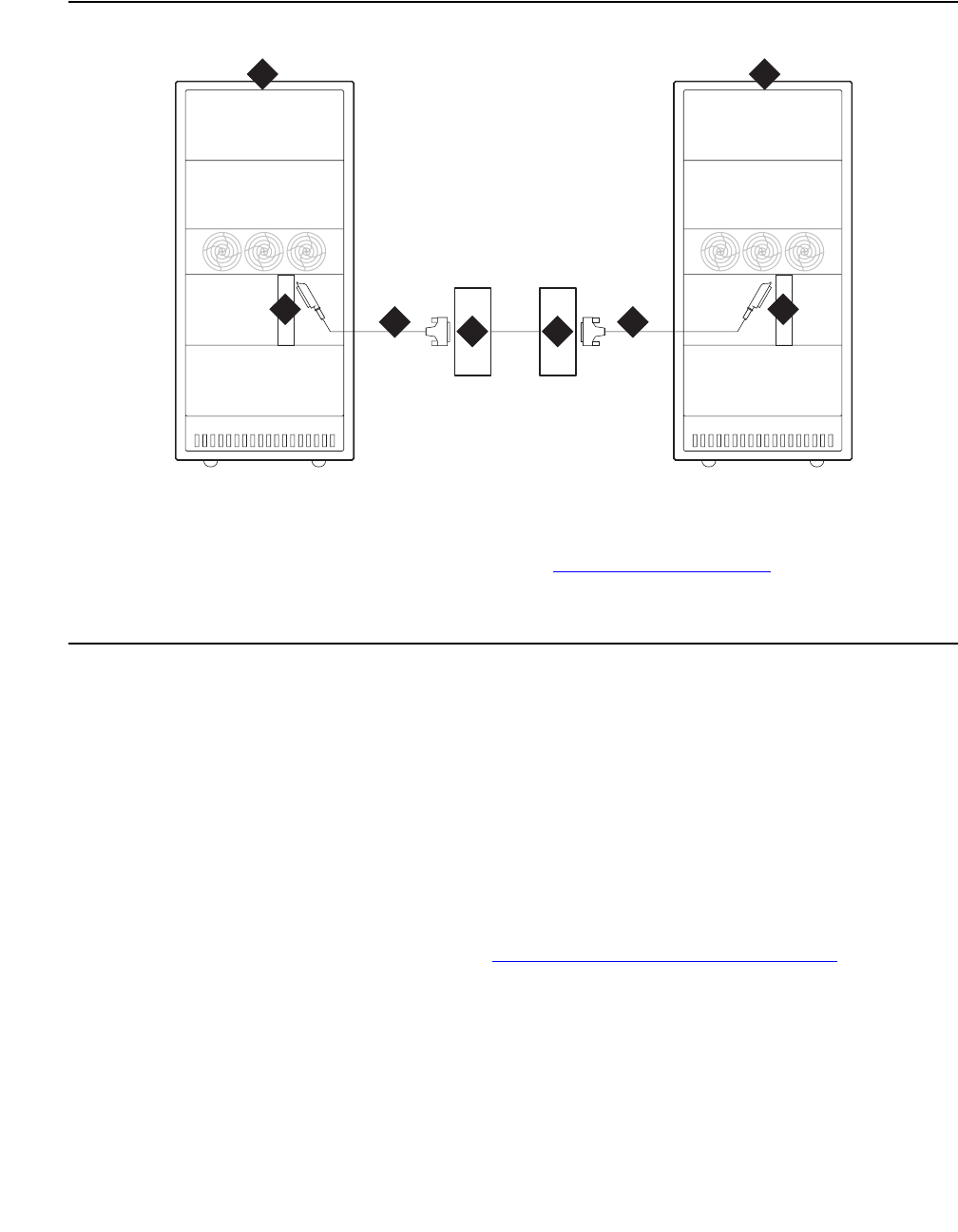
Communication Manager Maintenance-Object Repair Procedures
2378 Maintenance Procedures for Avaya Communication Manager 3.0, Media Gateways and Servers
Figure 145: TN2242 Japan trunk TTC private network connections
To upgrade a system to the TN2242 circuit pack:
1. Busyout the UDS1-BD DS1-CONV circuit pack (busyout board location).
2. Remove the TN464 administration (change circuit pack, change ds1, and change
trunk group grp#).
3. Remove the UDS1-BD circuit packs.
4. Remove the JRC (Japan Radio Corporation) external converter and cable.
5. Insert the TN2242 circuit packs.
6. Connect the TN2242 to the TDM with the H600-513 cable assembly.
7. Administer the TN2242 circuit pack (see TN2242 Administration on page 2379).
Figure notes:
1. Communications System 3. H600-513 cable assembly cable (see
H600-513 Cable Pinout on page 2379)
2. TN2242 2-Mbit Japan trunk circuit
pack
4. TDM facilities
1 1
22
3 3
cydfjap2 LJK 012999
4 4
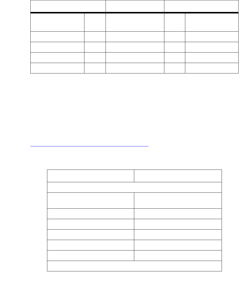
UDS1-BD (UDS1 Interface Circuit Pack)
Issue 1 June 2005 2379
H600-513 Cable Pinout
The following table shows the pinout for the H600-513 cable assembly:
TN2242 Administration
The TN2242 circuit pack requires board-level translation data. Before administering any ports
on the circuit pack, administer the following forms:
●Circuit pack (change circuit-pack)
●DS1 (add ds1)
●Trunk group (add trunk-group n)
Table 850: TN2242 administration on page 2379 outlines the trunk group administration
parameters that are required for this interface to operate successfully in Japan.
TN2242 TDM
50-pin connection
pin number
Color Lead Designation Color 15-pin connection
pin number
22 W-BL Line in + W-BL 4
23 W-O Line out - W-O 9
47 Bl-W Line in - Bl-W 11
48 O-W Line out + O-W 2
Table 850: TN2242 administration
Field Value
Trunk Group screen, Page 1
Trunk Type (in/out) wink, delay, immed (every
permutation)
Trunk Signaling Type blank
Answer Supervision Timeout 0
Receive Answer Supervision y
Disconnect Supervision - In? y
Disconnect Supervision - Out? y
1 of 2

Communication Manager Maintenance-Object Repair Procedures
2380 Maintenance Procedures for Avaya Communication Manager 3.0, Media Gateways and Servers
Incoming Dial Type tone,
rotary,
mf (to other Avaya systems only)
Wink Timer for wink type 300
Wink Timer for delay type 4500
Trunk Group screen, Page 3 (Administrable Timers)
Incoming Disconnect 100
Incoming Glare Guard 800ms or higher
Incoming Dial Guard 10
Incoming Incomplete Dial Alarm 25 or higher
Incoming Partial Dial 18
PPS 10 or 20
Make (for PPS 10) 35
Break (for PPS 10) 65
Make (for PPS 20) 15
Break (for PPS 20) 35
Outgoing Disconnect 100
Outgoing Glare Guard 800 or higher
Outgoing Rotary Dial Interdigit 800
Outgoing Seizure Response 5
Table 850: TN2242 administration (continued)
Field Value
2 of 2

UDS1-BD (UDS1 Interface Circuit Pack)
Issue 1 June 2005 2381
LEDs
The LEDs on the faceplate of the TN2242 circuit pack indicate its status as described in
Table 851: TN2242 LED interpretation on page 2381.
Interactions with Other MOs
The TN2242 MO directly interacts with these MOs:
●Synchronization on page 2381
●TN2242 Trunk Ports on page 2381
●Call Processing on page 2381
Synchronization
The DS1 facility plays a vital role in the synchronization subsystem. The IPSI or Tone-Clock
circuit pack uses either the primary or secondary timing reference, whether internal (local – IPSI
or Tone-Clock circuit pack) or external. TN2242 circuit packs can be administered as “primary”
or “secondary” synchronization references.
The TN2242 circuit pack sends DS1 link status information to the synchronization reference
switching algorithm. This algorithm determines whether timing references should be switched
due to failure or restore conditions.
TN2242 Trunk Ports
The TN2242 circuit pack MO is responsible for monitoring the health of the DS1 facility. If a DS1
facility goes down, then that facility’s DS1 circuit pack instructs every MO associated with the
DS1facility to place its trunks (or ISDN-PRI signaling link) in an out-of-service state.
Call Processing
The busyout board command tears down every call and signaling link associated with a
TN2242 circuit pack.
Table 851: TN2242 LED interpretation
LED Meaning
Red ●MAJOR alarm
●MINOR alarm
●Firmware initialization during circuit pack insertion
Amber A port on the circuit pack is in use.
Green Maintenance testing is in progress on the circuit pack or its ports.

Communication Manager Maintenance-Object Repair Procedures
2382 Maintenance Procedures for Avaya Communication Manager 3.0, Media Gateways and Servers
TN2242 Serviceability
Hardware Connections
This circuit pack can be:
●Mated to another circuit pack of the same type when interconnecting two Communication
Manager systems
●Directly connected to the TDM network device
●Directly connected to another vendor PBX using ISDN-PRI signaling
Loopbacks
There is no automatic process to signal the remote end to provide loopbacks for testing
purposes. Every loop back to be tested with a single circuit pack must be a local loop back on
the circuit pack.
Remote loopbacks may be possible with the TDM network equipment with appropriate
coordination between BCS Services Technicians and the service technicians of the TDM
equipment (considered a CPE device).
TN464GP/TN2464BP UDS1 Circuit Packs with
Echo Cancellation
The TN464GP and TN2464BP UDS1 circuit packs feature an integrated echo canceller. Echo
cancellation is a Software Right-To-Use feature that can be turned on as needed. Echo
cancellation supports channels carrying voice and is not intended for channels that support
data. The TN464GP/TN2464BP have the capability to detect modem tone and turn off echo
cancellation accordingly for the duration of a data call. Echo cancellation on the TN464GP/
TN2464BP is administrable per channel. The echo cancellation circuitry on a given TN464GP/
TN2464BP is driven by administrable parameters.
The TN464GP/TN2464BP circuit packs are intended for use with ATM, IP, wideband, or other
complex services which are likely to have problems with echo.
Echo cancellation on a TN464GP/TN2464BP is a right-to-use feature that is activated by means
of the License File. Echo cancellation is enabled on the System-Parameters Customer-Options
screen. The Maximum Number of DS1 Boards with Echo Cancellation field on the
System-Parameters Customer-Options screen indicates the number of DS1 boards on which
echo cancellation is activated for a specific customer.

UDS1-BD (UDS1 Interface Circuit Pack)
Issue 1 June 2005 2383
The DS1 Circuit Pack screen for the TN464GP/TN2464BP circuit packs has fields to support
echo cancellation: Echo Cancellation, EC Direction, and EC Configuration. The Echo
Cancellation field appears when the Echo Cancellation feature is activated on the
System-Parameters Customer Options screen. The EC Direction and EC Configuration fields
appear when the DS1 Echo Cancellation field is enabled.
●EC Direction determines the direction from which echo will be eliminated, ether inward or
outward.
●EC Configuration is the set of parameters used when cancelling echo. This information is
stored in firmware on the UDS1 circuit pack.
Echo cancellation is turned on or off on a per trunk-group basis using change trunk-group.
If the TRUNK GROUP field, DS1 Echo Cancellation is y, echo cancellation is applied to every
TN464GP/TN2464BP trunk member in that trunk group. The echo cancellation parameters
used for a given trunk member are determined by the Echo Cancellation Configuration Number
administered on the DS1 Circuit Pack screen for that specific trunk’s board.
Note:
Note: It is not necessary to busyout a port or trunk group to change the DS1 Echo
Cancellation field on the Trunk Group screen. However, the modified setting does
not take effect until one of the following occurs:
●Port is busied out/released
●Trunk Group is busied out/released
●Test trunk group is executed
●Periodic maintenance runs
Echo cancellation on the TN464GP/TN2464BP is selectable per channel, even though it is
administrable on a per trunk-group basis. For example, if all but two ports on a TN464GP/
TN2464BP need to have echo cancellation applied, those two ports must be put in a trunk
group where the DS1 Echo Cancellation field is n. The remaining ports are in a trunk group(s)
where the DS1 Echo Cancellation field is y. A user can cancel echo coming from the network
(far-end echo) or coming from the switch (near-end echo).

Communication Manager Maintenance-Object Repair Procedures
2384 Maintenance Procedures for Avaya Communication Manager 3.0, Media Gateways and Servers
The TN464 UDS1 Circuit Pack
The TN464C, D, E, F, and GP Universal DS1 Interface circuit packs provide an interface to the
DS1 facility, and are designed to support 24 DS0 channels on a 1.544-Mbps DS1 link, or 32
DS0 channels on a 2.048-Mbps link. (The 32-channel interface is not supported on G3r V1
systems.) The DS0 channels can be administered as trunks to other switches, lines to
off-premises stations, ports to line-side PRI terminating devices, or ports to other line-side
non-PRI terminating devices. (DS0 channels on TN464/Bs can only be administered as trunks
to other switches.) For more information about how TN464 ports can be used, see the following
MOs:
●ISDN-SGR (ISDN-PRI Signaling Group) on page 1429
●ISDN-TRK (DS1 ISDN Trunk) on page 1446
●ISDN-PLK (ISDN-PRI Signaling Link Port) on page 1423
●PE-BCHL (PRI Endpoint Port) on page 1773
●TIE-DS1 (DS1 Tie Trunk) on page 2270
●CO-DS1 (DS1 CO Trunk) on page 817
●DID-DS1 (Direct Inward Dial Trunk) on page 886
●OPS-LINE (DS1 Off-Premises Station Line) on page 1736
●WAE-PORT (Wideband Access Endpoint Port) on page 2531
Note:
Note: For information about other DS1 circuit packs, see DS1-BD (DS1 Interface Circuit
Pack) on page 978.
Note:
Note: The TN464GP provides Echo Cancellation, and in addition, the TN464GP
firmware may be updated using the firmware download feature.
Throughout this Maintenance Object (UDS1-BD), the term TN464 will mean any TN464C or
higher suffix UDS1 circuit pack. If part of this section refers to a specific suffix TN464 board, it
will be noted as such.
TN464 circuit packs support the following:
●Digital Tie, CO, and DID trunks
●DS1 off-premises (OPS) lines
●Narrowband and wideband access endpoint ports
●ISDN-PRI trunks and accompanying signaling channel
●PRI endpoint ports (PE-BCHL) and accompanying signaling channel

UDS1-BD (UDS1 Interface Circuit Pack)
Issue 1 June 2005 2385
The TN464 supports digital Tie, CO, and DID trunks, and OPS lines. On-board firmware
performs call control signaling for the Tie, CO and DID trunks and OPS lines. ISDN-PRI trunk
and PRI-endpoint signaling (Q.921, Q.931) is received and generated by system software and
is transmitted on a system link through the TN1655 Packet Interface and packet bus to the
UDS1 where it is placed on the D channel. Signaling over the DS1 link has to be synchronized
between the transmitting and receiving ends to ensure error-free communication. See SYNC
(Port-Network Synchronization) on page 2143 in this MO for details.
Each trunk, line, or endpoint has its own maintenance strategy, but all depend on the health of
the UDS1 Interface circuit pack. See the following Maintenance Objects for details: TIE-DS1
(DS1 Tie Trunk) on page 2270, CO-DS1 (DS1 CO Trunk) on page 817, DID-DS1 (Direct Inward
Dial Trunk) on page 886, OPS-LINE (DS1 Off-Premises Station Line) on page 1736, ISDN-TRK
(DS1 ISDN Trunk) on page 1446, ISDN-PLK (ISDN-PRI Signaling Link Port) on page 1423,
ISDN-SGR (ISDN-PRI Signaling Group) on page 1429, WAE-PORT (Wideband Access
Endpoint Port) on page 2531 and PE-BCHL (PRI Endpoint Port) on page 1773.
Circuit Pack Administration and Options
The DS1 configuration for each circuit pack is administered on the DS1 Circuit Pack screen. Bit
Rate is set to 1.544 Mbps for 24-channel systems, and 2.048 Mbps for 32-channel systems.
Country Protocol is used to drive layer-3 protocol decisions based on PRI specifications for a
given country (not those related to specific features). Different UDS1 circuit packs may be
administered with different Country Protocols, allowing the switch to act as a gateway between
two incompatible ISDN-PRI implementations (for example, between two different countries). US
systems use country protocol 1.
Set Near-End CSU Type to other for no CSU installed or for an external CSU such as an ESF
T1 CSU, or set to integrated for the 120A1 CSU module or the 401A T1 sync splitter. Setting
the field to integrated causes additional fields to appear for administering the Enhanced
Integrated CSU module. Set E1 Sync-Splitter to y if a 402A or 403A E1 sync splitter is used to
provide timing to an ATM switch. Set Echo Cancellation to y if the echo cancellation
right-to-use feature is enabled and the TN464GP/TN2464BP or higher suffix board is to supply
echo cancellation.
Note:
Note: Set the Echo Cancellation Plan on the EC Configuration field of the DS1
Circuit Pack screen. Note that Plan 1 uses a 96-ms echo tail and introduces 6dB
of loss for additional cancellation.
In addition, other fields define such parameters as framing modes, line coding, companding
mode and so on. For further details refer to DEFINITY® Communications System Generic 1,
Generic 2 and Generic 3 V1 and 2 – Integrated Channel Service Unit (CSU) Module Installation
and Operation, 555-230-193.
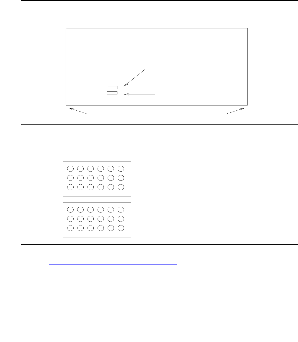
Communication Manager Maintenance-Object Repair Procedures
2386 Maintenance Procedures for Avaya Communication Manager 3.0, Media Gateways and Servers
Two option jumpers located on the side of the TN464C/D circuit pack must be installed correctly.
The figures on the following page show how to configure the circuit pack for 24- or 32-channel
DS1, and for 75*W (coaxial) or 120*W trunk connections. The channel selection must match the
parameters administered on the corresponding DS1 Circuit Pack screen. (US applications use
24 Channels.)
Figure 146: TN464C/D DS1 Option Jumpers
Figure 147: TN464C/D DS1 Option Jumpers (cont’d)
The option switch located on the component side of the TN464E/F circuit pack must be set
correctly. Figure 148: TN464E/F DS1 Option switches on page 2387 shows how to configure
the circuit pack for 24-channel or 32-channel DS1. The channel selection must match the
parameters administered on the corresponding DS1 Circuit Pack screen. (US applications use
24 Channels.)
Back
p
lane Connectors
24/32 Channel Selector
75/120 Ohm Selector
Top
Bottom
Face
p
late
TN464C/D
Insert the jumpers into the blocks
so as to join the center row of
pins and the row designating the
desired options.
120 OHM
32 CHNL
24 CHNL
75 OHM
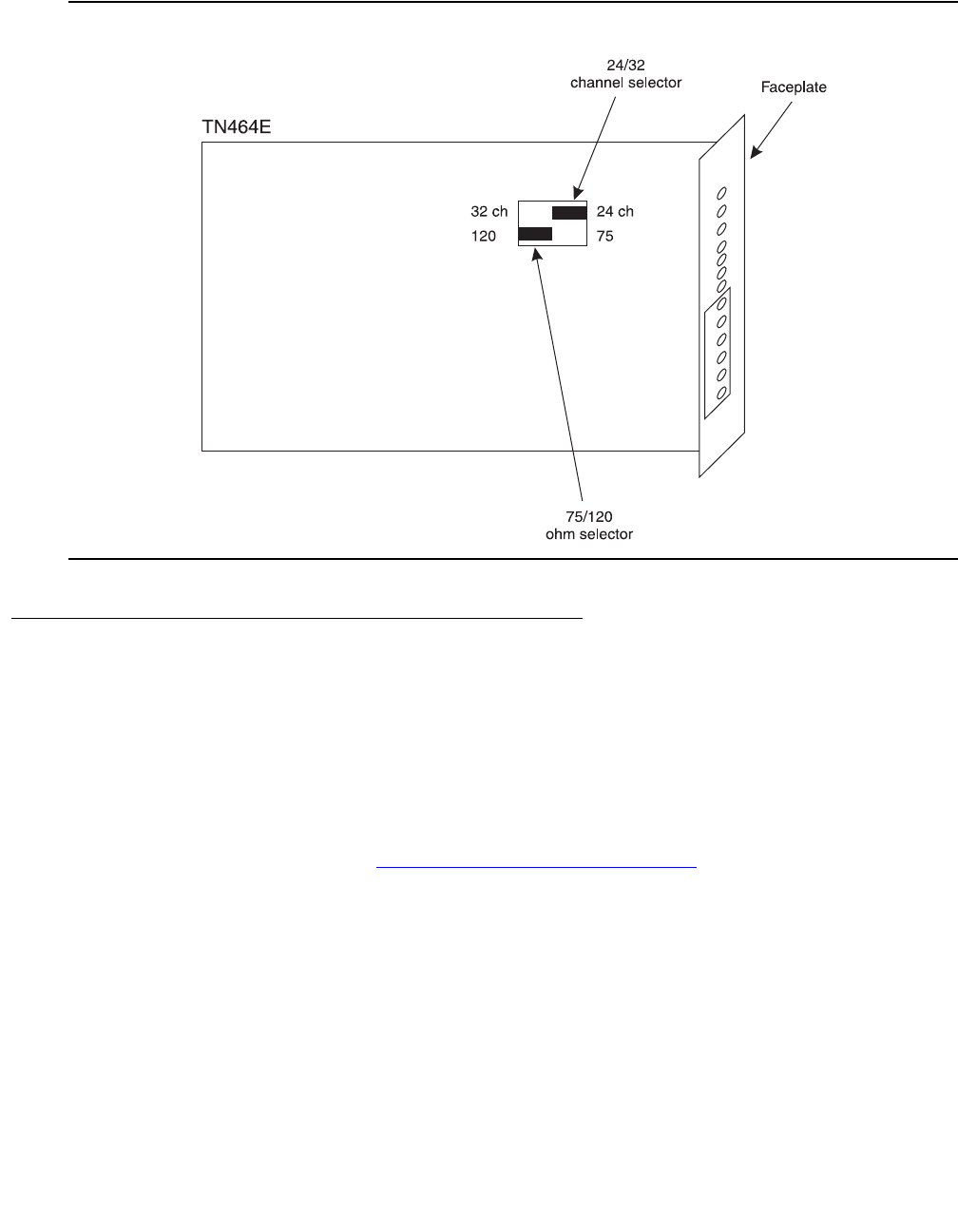
UDS1-BD (UDS1 Interface Circuit Pack)
Issue 1 June 2005 2387
Figure 148: TN464E/F DS1 Option switches
Firmware Download Feature
Firmware Download allows new firmware to be downloaded to one or more UDS1 circuit boards
residing in the system. The download image is copied onto a source (C-LAN) board, using FTP.
The image is then copied to a target board’s flash memory over the TDM bus. The transfer of
the download image from the source board to a target board is done under switch software’s
control. This process is initiated using the SAT interface.
If the firmware download fails for this circuit pack, an error is logged, and an alarm raised (see
Error Type 174 for this MO). See FW-DWNLD (Firmware Download) on page 1298 for more
information and for the firmware download procedure.
ΩΩ

Communication Manager Maintenance-Object Repair Procedures
2388 Maintenance Procedures for Avaya Communication Manager 3.0, Media Gateways and Servers
Error Log Entries and Test to Clear Values
Table 852: DS1 Interface Circuit Pack Maintenance Error Log Entries
Error
Type
Aux
Data
Associated Test Alarm
Level
On/Off
Board
Test to Clear Value
010Any AnyAnytest board location
1(a) 0 Circuit pack removed or
SAKI (#53) failed
WRN2
MIN
ON
18(b) 0 busyout board location WRN OFF release board
location
23(c)0 WRNOFFadd ds1 location
125(d) none
or 3
None WRN3
MIN
ON
257 65535 Control Channel Loop test
(#52)
MIN ON test board location
l r 20
257(e) Any None
513(f)Any WRN3
MIN
ON
514(g) 46086 WRN3
MIN
ON
769(h) 46085 WRN3
MIN
ON
770(i) 46096 WRN3
MIN
ON
1025(e) 4363 NPE Audit test (#50)
1281 Any Loss of Signal Alarm
Inquiry (#138)
WRN3
MIN
OFF test board location
1300(j) Any Loss Of Signal Alarm
Inquiry (#138)
WRN OFF test board location
1301(k) Any Loss Of Signal Alarm
Inquiry (#138)
WRN OFF test board location
1302(l) Any Loss Of Signal Alarm
Inquiry (#138)
WRN3
MIN
OFF test board location
1303 (m) Any Loss Of Signal Alarm
Inquiry (#138)
WRN3
MIN
ON test board location
1310(n) Any Board Loopback test
(#1209)
MIN ON test board location
ds1/csu-loopback-tests
1 of 3

UDS1-BD (UDS1 Interface Circuit Pack)
Issue 1 June 2005 2389
1311(o) Any Equipment Loopback test
(#1210)
WRN3
MIN
OFF test board location
ds1/csu-loopback-tests
1312(p) Any Repeater Loopback test
(#1211)
WRN3
MIN
OFF test board location
ds1/csu-loopback-tests
1313(q) Any CPE Loop-Back Jack test
(#1212)
WRN3
MIN
OFF test board location
end-loopback/span-test
1314(r) Any Far CSU Loopback test
(#1213)
WRN3
MIN
OFF test board location
end-loopback/span-test
1320 Any Loss of Signal Alarm
Inquiry (#138)
WRN3
MIN
OFF test board location
1321 Any Loss of Signal Alarm
Inquiry (#138)
WRN3
MIN
OFF test board location
1322 Any Loss of Signal Alarm
Inquiry (#138)
MIN ON test board location
1323 Any Loss of Signal Alarm
Inquiry (#138)
WRN3
MIN
OFF test board location
1324 Any Loss of Signal Alarm
Inquiry test (#138)
WRN OFF test board location
1400
1401(s)
Any Loss of Signal Alarm
Inquiry test (#138) and
Echo Cancellation test
(#1420)
MIN ON test board location
1537(t) 46082 WRN3
MIN
ON
1538(u)Any WRN3
MIN
ON
1793 Any Blue Alarm Inquiry test
(#139)
WRN
MIN
MAJ4
OFF test board location
1794 Any Blue Alarm Inquiry test
(#139)
WRN
MIN
MAJ4
OFF test board location
1795 Any Blue Alarm Inquiry test
(#139)
WRN
MIN
MAJ4
OFF test board location
2049 Any Red Alarm Inquiry test
(#140)
WRN3
MIN
OFF test board location
Table 852: DS1 Interface Circuit Pack Maintenance Error Log Entries (continued)
Error
Type
Aux
Data
Associated Test Alarm
Level
On/Off
Board
Test to Clear Value
2 of 3
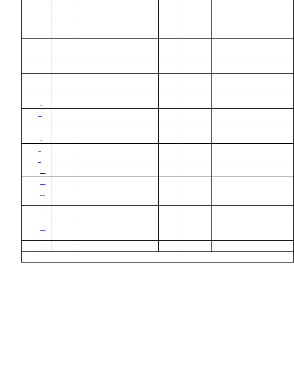
Communication Manager Maintenance-Object Repair Procedures
2390 Maintenance Procedures for Avaya Communication Manager 3.0, Media Gateways and Servers
2305 Any Yellow Alarm Inquiry test
(#141)
WRN3
MIN
OFF test board location
2306 Any Yellow Alarm Inquiry test
(#141)
WRN3
MIN
OFF test board location
2561 Any Major Alarm Inquiry test
(#142)
WRN3
MIN
OFF test board location
2817 Minor Alarm Inquiry test
(#143)
WRN3
MIN
OFF test board location
3073 to
3160 (v)
Any Slip Alarm Inquiry test
(#144)
WRN3
MIN
OFF test board location
r 6
3330(w) 46083 WRN3
MIN
ON
3585 to
3601 (x)
Any Misframe Alarm Inquiry
test (#145)
WRN3
MIN
OFF test board location
r 6
3840(y) Any None
3841(z4358
3842 (aa) 46097
3843 (ab) 46081
3900 (ac) Any CPE Loop-Back Jack test
(#1212)
3901 (ad) Any Far CSU Loopback test
(#1213)
3902 (ae) Any One-Way Span test
(#1214)
3999 (af) Any None
1. Run the short test sequence first. If every test passes, run the long test sequence. Refer to the appropriate
test’s description, and follow its recommended procedures.
2. If ports are assigned to the circuit pack, then a minor alarm is raised. If no ports are assigned to the circuit
pack, then a warning alarm is raised. The alarm is raised after the circuit pack has been missing for a
period of 15 minutes. Warning alarms are also raised against any ports administered on the circuit pack.
3. Minor alarms on this MO may be downgraded to Warning based on values on the set options screen.
4. Major alarms on this MO may be downgraded to minor or warning alarms based on values set on the set
options screen.
Table 852: DS1 Interface Circuit Pack Maintenance Error Log Entries (continued)
Error
Type
Aux
Data
Associated Test Alarm
Level
On/Off
Board
Test to Clear Value
3 of 3

UDS1-BD (UDS1 Interface Circuit Pack)
Issue 1 June 2005 2391
Notes:
a. Error Type 1: indicates that the circuit pack has stopped functioning or is not fully
administered. The alarm is logged about 15 minutes after the circuit pack has been
removed or 11 minutes after the SAKI test (#53) fails.
To be fully administered, a UDS1 circuit pack must meet all of the following conditions:
●Have an entry in the circuit plan using change circuit-pack
●Be administered using add ds1 location
●Be physically inserted into the correct slot
If the circuit pack has an entry in the circuit plan and either of the other conditions are not
met, a MINOR alarm is logged. To resolve the error:
1. Make sure that all conditions for administration are met and that a functioning UDS1
circuit pack is inserted in the correct slot.
or
2. Completely remove the UDS1-BD from the system:
a. Remove any administered DS1 trunks, access endpoints or PRI endpoints associated
with the circuit pack from their trunk groups.
b. Execute remove ds1 location and change circuit-pack location.
If every administration condition is met for this circuit pack and the red LED is still on, follow
the instructions for LED alarms without Alarm Log entry or with Error Type 1 on page 258.
b. Error Type 18: the UDS1 Interface circuit pack was busied out by busyout board
location.
c. Error Type 23: the UDS1-BD circuit pack is not completely administered. To be fully
administered, the UDS1 circuit pack must:
●Have an entry in the circuit plan using change circuit-pack
●Be administered using add ds1 location
●Be physically inserted into the correct slot
A DS1 (UDS1-BD and DS1-BD) differs from most circuit packs in that inserting the circuit
pack into the switch is not enough to make the board usable. It must also be administered
with add ds1.
d. Error Type 125: (no Aux Data): an incorrect circuit pack is inserted in the slot where the
USD1 circuit pack is logically administered. To resolve this problem, do one of the following:
●Remove the incorrect circuit pack, and insert the correct logically administered circuit
pack.
●Use change circuit-pack to re-administer this slot to match the circuit pack
inserted.

Communication Manager Maintenance-Object Repair Procedures
2392 Maintenance Procedures for Avaya Communication Manager 3.0, Media Gateways and Servers
Aux Data 3: the 24-/32-channel option jumper setting on the circuit pack does not match
the option set on the DS1 Circuit Pack administration screen. The circuit pack must be
physically removed to see the setting of the jumper.
e. Error Type 257: associated with the Common Port Circuit Pack Maintenance test. See
XXX-BD (Common Port Circuit Pack/Media Module) on page 2539 for details.
f. Error Type 513: the UDS1 Interface circuit pack has detected a transient hardware
problem. The value in the Aux Data field indicates the type of hardware problem:
If the UDS1 board detects only one of these hardware problems, then the error will
disappear when none of these faults are detected for 10 minutes. If the same Aux Data
value is logged more than once in a 24-hour period, the circuit pack should be replaced.
g. Error Type 514: LAN External RAM Error. This error occurs when there is a hardware fault
in the external RAM. The RAM is used for message buffering to and from the Packet bus.
This error should not occur frequently. If it does (10 times within 30 minutes), the circuit
pack should be replaced.
h. Error Type 769: transmit FIFO Underflow Error. This error occurs when the circuit pack
cannot find the “end of frame” bit when transmitting a frame to the Packet bus. An alarm is
raised if this error occurs three times within 10 minutes. Clear the alarm using the following
commands: busyout board location, reset board location, test board
location long, release board location. If the error recurs within 10 minutes,
replace the circuit pack.
i. Error Type 770: unable to Write LAN Translation RAM Error. This error occurs when a call
is aborted because there are no available translation RAM locations for the call connection
attempt. An alarm is raised if this error occurs two times within 10 minutes. Clear the alarm
using the following commands: busyout board location, reset board location,
test board location long, release board location. If the error recurs within 10
minutes, replace the circuit pack.
j. Error Type 1300: CSU module/T1 sync splitter missing or E1 synchronization splitter
(E1SS) missing.
CSU module/T1 sync splitter missing: The Near-End CSU Type field on the add ds1
screen is integrated but the 120A1 CSU module or the 401A T1 sync splitter is not
physically connected (or is improperly connected) to the UDS1 board on the back of the port
carrier.
If using the 120A1 CSU module or the 401A T1 sync splitter, plug (or replug) the CSU
module/T1 sync splitter into the UDS1 circuit pack’s connector on the I/O connector panel
Aux Data Problem
4352 External RAM failure
4353 Internal RAM failure
4355 Internal ROM failure

UDS1-BD (UDS1 Interface Circuit Pack)
Issue 1 June 2005 2393
on back of the carrier. Otherwise, set the Near-End CSU Type field using the change ds1
screen to other.
If this error remains after plugging the CSU module/T1 sync splitter into the board’s
connector, there could be a problem with the I/O connector panel.
E1 synchronization splitter missing: The E1 Sync-Splitter field on the add ds1 screen
is y, but the 402A or 403A E1 synchronization splitter is not physically connected (or is
improperly connected) to the UDS1 board on the back of the port carrier.
If using the 402A or 403A E1 synchronization splitter, plug (or replug) the E1SS into the
UDS1 circuit pack’s connector on the I/O connector panel on back of the carrier. Otherwise,
set the E1 Sync-Splitter field using the change ds1 screen to n.
If this error remains after plugging the E1SS into the board’s connector, there could be a
problem with the I/O connector panel.
k. Error Type 1301: CSU module/T1 sync splitter not expected or E1 synchronization splitter
not expected.
CSU Module/T1 Sync Splitter not expected: The 120A1 CSU module or the 401A T1
sync splitter is physically connected to the UDS1 board on the back of the port carrier, but
the Near-End CSU Type field on the add ds1 screen is not set to integrated.
If the 120A1 CSU module or the 401A T1 sync splitter is to be used, use change ds1 to
set the Near-End CSU Type field to integrated. Otherwise, physically remove the 120A1
CSU module or the 401A T1 sync splitter from the back of the port carrier.
E1 synchronization splitter not expected: The 402A or 403A E1 synchronization splitter
is physically connected to the UDS1 board on the back of the port carrier, but the E1
Sync-Splitter field on the add ds1 screen is not set to y.
If the 402A or 403A E1 synchronization splitter is to be used, use change ds1 to set the
E1 Sync-Splitter field to y. Otherwise, physically remove the 402A or 403A E1
synchronization splitter from the back of the port carrier.
l. Error Type 1302: DS1 configuration error. Attempting to use the 120A1 CSU module with a
UDS1 circuit pack that is configured for 32-channel (2.048-Mbps) operation. The CSU
module only works with a DS1 board configured for 24-channel (1.544-Mbps) operation in
the United States of America.
m. Error Type 1303: DS1 circuit pack suffix incorrect for CSU module/T1 sync splitter or for E1
synchronization splitter.
DS1 circuit pack suffix incorrect for CSU module/T1 sync splitter: The Near-End CSU
Type field on the add ds1 screen is set to integrated but the DS1 circuit pack is not a
TN464F or higher suffix UDS1 board.
If the 120A1 CSU module or the 401A T1 sync splitter is to be used, remove the circuit pack
and replace it with a TN464F or higher suffix board. Otherwise, use change ds1 to set the
Near-End CSU Type field to other.

Communication Manager Maintenance-Object Repair Procedures
2394 Maintenance Procedures for Avaya Communication Manager 3.0, Media Gateways and Servers
DS1 circuit pack suffix incorrect for E1 synchronization splitter: The E1 Sync-Splitter
field on the add ds1 screen is set to y but the DS1 circuit pack is not a TN464F or higher
suffix UDS1 board.
If the 402A or 403A E1 synchronization splitter is to be used, remove the circuit pack and
replace it with a TN464F or higher suffix board. Otherwise, use change ds1 to set the E1
Sync-Splitter field to n.
n. Error Type 1310: BLB failure. This error occurs when the DS1 Board Loopback (BLB)
demand test fails. Repeat the test using busyout board location, test ds1-loop
location ds1/csu-loopback-tests, release board location. If the BLB test
continues to fail, replace the TN464F circuit pack.
o. Error Type 1311: ELB failure. This error occurs when the Equipment Loopback (ELB) test
fails for the Integrated CSU (I-CSU) module/T1 sync splitter or for the 402A or 403A E1
synchronization splitter. This test is executed by the I-CSU/E1SS during I-CSU/E1SS
power-up/reset (i.e.- UDS1 board physically inserted and 120A1 CSU module, the 401A T1
sync splitter, or the 402A or 403A E1SS is already installed) or when the 120A1 CSU
module, the 401A T1 sync splitter, or the 402A or 403A E1SS is plugged on to an already
initialized UDS1 DS1 board.
Note:
Note: For the I-CSU/T1 sync splitter only, the ELB test is also executed as part of
test ds1-loop location ds1/csu-loopback-tests. Try to clear the
alarm using busyout board location, test ds1-loop location ds1/
csu-loopback-tests, and release board location. If the ELB test
continues to fail, then either the UDS1 board, the CSU module, or the I/O cable
between the backplane and the CSU module, or any combination thereof, failed.
Try to isolate where the failure is occurring by re-executing the test and by
replacing one piece of hardware at a time.
p. Error Type 1312: RLB failure. This error occurs when the Repeater Loopback (RLB) test
fails for the Integrated CSU (I-CSU) module/T1 sync splitter or for the 402A or 403A E1
synchronization splitter. This test is executed by the I-CSU/E1SS during I-CSU/E1SS
power-up/reset (i.e., DS1 board physically inserted and 120A1 CSU module or the 401A T1
sync splitter, or the 402A or 403A E1SS is already installed) or when the 120A1 CSU
module or the 401A T1 sync splitter, or the 402A or 403A E1SS is plugged on to an already
initialized DS1 board.
Note:
Note: For the I-CSU/T1 sync splitter only, the RLB test is also executed as part of the
test ds1-loop location ds1/csu-loopback-tests. Try to clear the
alarm using busyout board location, test ds1-loop location ds1/
csu-loopback-tests, and release board location. If the RLB test
continues to fail, replace the CSU module.

UDS1-BD (UDS1 Interface Circuit Pack)
Issue 1 June 2005 2395
q. Error Type 1313: CPE Loop-Back Jack deactivation error. This error occurs when the
UDS1 circuit pack could not deactivate a CPE Loop-Back Jack on power-up/reset or upon
software request.
Try to clear the alarm using busyout board location, test ds1-loop location
end-loopback/span-test, and release board location. If the attempt to
deactivate the CPE Loop-Back Jack continues to fail, other steps must be taken to
deactivate the loopback.
r. Error Type 1314: far CSU Loopback deactivation error. This error occurs when the UDS1
circuit pack could not deactivate a far-end CSU loop back on power-up/reset or upon
software request.
Try to clear the alarm using busyout board location, test ds1-loop location
end-loopback/span-test, and release board location. If the attempt to
deactivate the Far CSU loop back continues to fail, escalate the problem.
s. Error Types 1400, 1401: echo cancellation errors are logged when:
●Error 1400: echo canceller function failed. The Echo Canceller Function test, which is
executed by firmware, failed.
●Error 1401: echo canceller memory failed. The Echo Canceller Memory test, which is
executed by firmware, failed.
Echo Cancellation is no longer being supplied by the board. Clear the alarm using the
following commands: busyout board location, test board location long, and
release board location. If Test #1420 (Echo Canceler test) fails, replace the circuit
pack.
t. Error Type 1537: LAN Bus Timeout Error. This error occurs when the circuit pack transmits
too many bytes on the LAN bus for a single frame. This condition may be caused by an
on-board fault or by faulty data received on one of the circuit pack’s external ports. If any of
the ports on this circuit pack are alarmed, refer to the repair procedures for those
Maintenance Objects.
If the error occurs three times within 10 minutes, the board is isolated from the Packet bus
and the board is alarmed. To clear the alarm and restore the board to the Packet bus, use
busyout board location, reset board location, test board location
long, and release board location.
If the problem persists, and there are no PKT-BUS alarms or port alarms, then replace the
circuit pack.
u. Error Type 1538: the hyperactive circuit pack is out-of-service and may exhibit one or more
of the following symptoms:
●The common circuit pack level tests such as Test #50 and/or Test #52 abort with Error
Code 2000.
●The tests run on the ports of this circuit pack return a NO-BOARD result.
●A busyout/release of the circuit pack has no effect on test results.
●A list configuration command shows that the circuit pack and ports are properly
installed.

Communication Manager Maintenance-Object Repair Procedures
2396 Maintenance Procedures for Avaya Communication Manager 3.0, Media Gateways and Servers
The circuit pack is isolated from the system and every trunk or port on this circuit pack is
placed into the out-of-service state. The system will try to restore the circuit pack within
20-30 minutes. When no faults are detected for 20-30 minutes, the UDS1 Interface circuit
pack is restored to normal operation. Every trunk or port of the UDS1 Interface circuit pack
is then returned to the in-service state.
If the board is not restored to normal operation or the error recurs after the board was
restored to normal operation, escalate the problem.
v. Error Types 3073 to 3160: for releases of G3V4 and higher, Error Type 3073 shows that
this board is receiving slips. The Aux Data contains the last slip count reported.
w. Error Type 3330: LAN critical error. A critical failure has been detected in the Packet bus
interface of the circuit pack. This failure may be due to an on-board fault or a Packet bus
fault. If the Packet bus is alarmed, see PKT-INT (Packet Interface) on page 1799 for
recommended repair procedures.
This error isolates the board from the Packet bus and raises an alarm. If the Packet bus is
not alarmed, enter busyout board location, reset board location, test board
location, and release board location. This should clear the alarm and restore the
board to the Packet bus.
If the problem persists, and there are no PKT-BUS alarms, then replace the circuit pack.
x. Error Types 3585 to 3601: for later releases of G3V4 and beyond, Error Type 3585 shows
that this board is receiving misframes. The AUX Data contains the last misframe count
reported.
y. Error Type 3840: not service-affecting. No action is required. These errors are reported by
the circuit pack when it receives a bad control channel message from the switch. The
auxiliary data identifies the following error events:
z. Error Type 3841: the UDS1 Interface circuit pack has detected a transient hardware logic
error (for example, program logic inconsistency). This error will disappear when no faults
are detected for 100 minutes. The value in Aux Data indicates the type of hardware
problem.
Aux Data Event
4096 Bad major heading
4097 Bad port number
4098 Bad data
4099 Bad sub-qualifier
4100 State inconsistency
4101 Bad logical link

UDS1-BD (UDS1 Interface Circuit Pack)
Issue 1 June 2005 2397
aa. Error Type 3842: bad translation RAM location found error. This error is not
service-affecting. No action is required. A Bad Translation RAM is detected, but the call
continues by using another translation location.
ab. Error Type 3843: LAN Receive Parity Error. This error occurs when the circuit pack detects
an error in a received frame from the Packet bus. These errors are most likely caused by a
Packet bus problem, but may be due to a circuit pack fault.
See PKT-INT (Packet Interface) on page 1799 to determine whether the problem is isolated
to this circuit pack or is caused by Packet bus faults.
ac. Error Type 3900: provides status information about a CPE Loop-Back Jack test. The value
in the Aux Data field indicates the status of the loop-back test.
ad. Error Type 3901: provides status information about a Far CSU Loopback test. The value in
the Aux Data field indicates the status of the loop-back test.
ae. Error Type 3902: provides status information about a One-Way Span test. The value in the
Aux Data field indicates the status of the span test.
Aux Data Test Status
1 Test is currently running
2 Failed because loop back could not be activated
3 Failed because test pattern could not be detected
4 Test has been terminated
Aux Data Test Status
1 Test is currently running
2 Failed because loop back could not be activated
3 Failed because test pattern could not be detected
4 Test has been terminated
Aux Data Test Status
1 Test is currently running
2 Failed because test could not be activated
3 Test pattern was not received from the far end
4 Test has been terminated
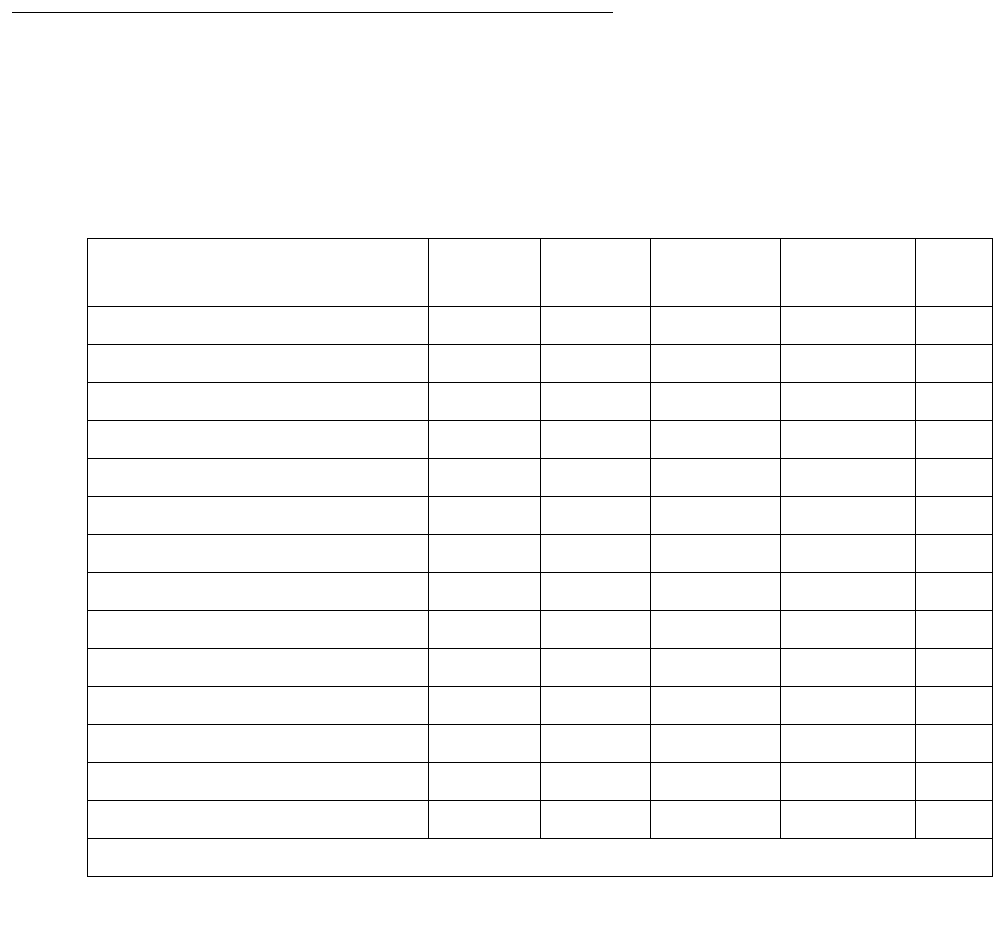
Communication Manager Maintenance-Object Repair Procedures
2398 Maintenance Procedures for Avaya Communication Manager 3.0, Media Gateways and Servers
Note:
Note: G700: If the One-Way Span test is run between a circuit pack and an MM710 DS1
Interface Media Module on a G700 Media Gateway, the test will fail, because the
MM710 does not frame-align its test pattern.
af. Error Type 3999: indicates that the circuit pack sent a large number of control channel
messages to the switch within a short period of time. If Error Type 1538 is also present, then
the circuit pack was taken out-of-service due to hyperactivity. If Error Type 1538 is absent,
then the circuit pack was not taken out-of-service, but it has generated 50% of the
messages necessary to be considered hyperactive. This might be completely normal during
heavy traffic periods. However, if this Error Type is logged when the circuit pack is being
lightly used, it might indicate a problem with the circuit pack or the equipment attached to it.
System Technician-Demanded Tests:
Descriptions and Error Codes
Investigate tests in the order presented below. Clearing Error Codes associated with one test
may also clear errors generated from other tests in the sequence.
Table 853: UDS1 - Demand Test order of investigation
Order of Investigation Short Test
Sequence
Long Test
Sequence
Reset Board
Sequence
test ds1-loop D/ND1
Echo Cancellation test (#1420) X D
NPE Connection Audit test (#50) X ND
Control Channel Loop test (#52) X ND
Loss of Signal Alarm Inquiry test (#138) X X ND
Blue Alarm Inquiry test (#139) X X ND
Red Alarm Inquiry test (#140) X X ND
Yellow Alarm Inquiry test (#141) X X ND
Major Alarm Inquiry test (#142) X X ND
Minor Alarm Inquiry test (#143) X X ND
Slip Alarm Inquiry test (#144) X X ND
Misframe Alarm Inquiry test (#145) X X ND
Translation Update test (#146) X X ND
ICSU Status LEDs test (#1227) X X ND
SAKI Sanity test (#53) X D
1 of 2
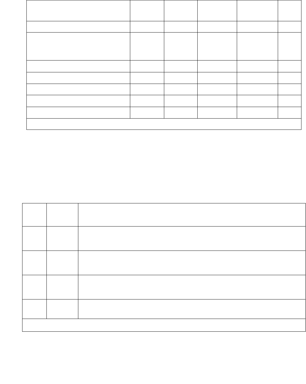
UDS1-BD (UDS1 Interface Circuit Pack)
Issue 1 June 2005 2399
NPE Connection Audit Test (#50)
The system sends a message to the circuit pack’s on-board microprocessor to update the
network-connectivity translation for its SCOTCH-NPE chip.
Internal Loop-Around test (#135) X D
DS1/CSU Loopback tests:
DS1 Board Loopback test (#1209)
CSU Equipment Loopback test (#1210)
CSU Repeater Loopback test (#1211)
X
X
X
D
D
D
CPE Loop-Back Jack test (#1212) X D
Far CSU Loopback test (#1213) X D
One-Way Span test (#1214) X D
Inject Single Bit Error (#1215) X D
End Loopback/Span test (#1216) X D
1. D = Destructive; ND = Nondestructive
Table 853: UDS1 - Demand Test order of investigation (continued)
Order of Investigation Short Test
Sequence
Long Test
Sequence
Reset Board
Sequence
test ds1-loop D/ND1
2 of 2
Table 854: Test #50 NPE Connection Audit Test
Error
Code
Test
Result
Description / Recommendation
None
2100
ABRT System resources required for this test are not available.
1. Retry the command at 1-minute intervals up to 5 times.
1019 ABRT The test aborted because a test was already running on the port.
1. Retry the command at 1-minute intervals up to 5 times.
FAIL Internal system error
1. Retry the command at 1-minute intervals up to 5 times.
PASS The circuit pack’s SCOTCH-NPE chip has been updated with its
translation.
1 of 2

Communication Manager Maintenance-Object Repair Procedures
2400 Maintenance Procedures for Avaya Communication Manager 3.0, Media Gateways and Servers
Control Channel Loop-Around Test (#52)
This test queries the circuit pack for its code and vintage and verifies its records.
0NO
BOARD
The test could not relate the internal ID to the port (no board). This could
be due to incorrect translations, no board is inserted, an incorrect board is
inserted, or an insane board is inserted.
1. Verify that the board’s translations are correct. Execute add ds1
location to administer the UDS1 interface if it is not already
administered.
2. If the board was already administered correctly, check the error log to
determine whether the board is hyperactive. If this is the case, the
board is shut down. Reseating the board will re-initialize it.
3. If the board was found to be correctly inserted in step 1, enter
busyout board location
4. Enter reset board location
5. Enter release board location
6. Enter test board location long
This should re-establish the linkage between the internal ID and the port.
Table 854: Test #50 NPE Connection Audit Test (continued)
Error
Code
Test
Result
Description / Recommendation
2 of 2
Table 855: Test #52 Control Channel Loop-Around Test
Error
Code
Test
Result
Description / Recommendation
None
2100
ABRT System resources required for this test are not available.
1. Retry the command at 1-minute intervals up to 5 times.
FAIL The circuit pack failed to return the its code or vintage.
1. Retry the command up to 5 times.
2. If the problem continues and if the circuit pack is a port circuit pack,
replace the circuit pack.
3. Retry the command several times up to 5 times.
1 of 2

UDS1-BD (UDS1 Interface Circuit Pack)
Issue 1 June 2005 2401
SAKI Sanity Test (#53)
This test is destructive.
This test resets the circuit pack. The test is highly destructive and can only be initiated with
reset board location.
PASS Communication with this circuit pack is successful.
0NO
BOARD
The test could not relate the internal ID to the port (no board). This could
be due to incorrect translations, no board is inserted, an incorrect board
is inserted, or an insane board is inserted.
1. Verify that the board’s translations are correct. Execute add ds1
location to administer the UDS1 interface if it is not already
administered.
2. If the board was already administered correctly, check the error log
to determine whether the board is hyperactive. If this is the case, the
board is shut down. Reseating the board will re-initialize it.
3. If the board was found to be correctly inserted in step 1, enter
busyout board location
4. Enter reset board location
5. Enter release board location
6. Enter test board location long
This should re-establish the linkage between the internal ID and the port.
Table 855: Test #52 Control Channel Loop-Around Test (continued)
Error
Code
Test
Result
Description / Recommendation
2 of 2
Table 856: Test #53 SAKI Sanity Test
Error
Code
Test
Result
Description / Recommendation
None ABRT System resources required for this test are not available.
1. Retry reset board location at 1-minute intervals up to 5 times.
1 of 3

Communication Manager Maintenance-Object Repair Procedures
2402 Maintenance Procedures for Avaya Communication Manager 3.0, Media Gateways and Servers
1005 ABRT Wrong circuit pack configuration to run this test. This error applies only to
DS1 Interface circuit packs. It means the DS1 Interface circuit pack is
providing timing for the system, and therefore, it cannot be reset without
major system disruptions.
1. If the circuit pack needs to be reset, then set synchronization to
another DS1 Interface circuit pack or to the IPSI or Tone-Clock circuit
pack and try again. See SYNC (Port-Network Synchronization) on
page 2143.
1015 ABRT Port is not out-of-service.
1. Busyout the circuit pack.
2. Execute reset board location again.
2100 ABRT System resources required for this test are not available.
1. Retry the reset board location at 1-minute intervals up to 5
times.
1 FAIL The circuit pack failed to reset.
2 FAIL The circuit pack failed to restart.
1. Execute reset board location again.
2. If the problem persists, replace the circuit pack.
PASS The circuit pack initializes correctly.
1. Run the short test sequence.
Table 856: Test #53 SAKI Sanity Test (continued)
Error
Code
Test
Result
Description / Recommendation
2 of 3

UDS1-BD (UDS1 Interface Circuit Pack)
Issue 1 June 2005 2403
Internal Loop-Around Test (#135)
This test is destructive.
The Internal Loop-Around test is run by looping the transmitted DS1 bit stream back into the
UDS1 board’s receiver. The loop occurs just before the DS1 facility interface. The test is highly
destructive and can only be initiated by reset board location.
Each trunk or port on the UDS1 Interface circuit pack must be busied out using busyout
board before running the Internal Loop-Around test. When the Internal Loop-Around test is
initiated, maintenance software sends appropriate messages to the UDS1 Interface circuit pack
to start the test. The test uses the Tone Generator and Tone Detector to exercise a bit-pattern
consistency test for every port. If the transmitted and received bit patterns on a trunk or port are
different, the test fails.
When the test completes, the maintenance software sends a stop loop around message to the
UDS1 Interface circuit pack to put the circuit pack back into the normal operation mode. Every
trunk or port of the UDS1 Interface circuit pack is restored to the in-service state after release
board is entered.
0NO
BOARD
The test could not relate the internal ID to the port (no board). This could
be due to incorrect translations, no board is inserted, an incorrect board is
inserted, or an insane board is inserted.
1. Verify that the board’s translations are correct. Execute add ds1
location to administer the UDS1 interface if it is not already
administered.
2. If the board was already administered correctly, check the error log to
determine whether the board is hyperactive. If this is the case, the
board is shut down. Reseating the board will re-initialize it.
3. If the board was found to be correctly inserted in step 1, enter
busyout board location.
4. Enter reset board location.
5. Enter release board location.
6. Enter test board location long.
This should re-establish the linkage between the internal ID and the port.
Table 856: Test #53 SAKI Sanity Test (continued)
Error
Code
Test
Result
Description / Recommendation
3 of 3

Communication Manager Maintenance-Object Repair Procedures
2404 Maintenance Procedures for Avaya Communication Manager 3.0, Media Gateways and Servers
Table 857: Test #135 Internal Loop-Around Test
Error
Code
Test
Result
Description / Recommendation
1002 ABRT The system could not allocate time slots for the test. The system may be
under heavy traffic conditions or it may have time slots out-of-service due
to TDM-BUS errors.
1. If system has no TDM-BUS errors and is not handling heavy traffic,
repeat test at 1-minute intervals up to 5 times.
1003 ABRT The system could not allocate a tone receiver for the test. The system
may be oversized for the number of Tone Detectors present or some Tone
Detectors may be out-of-service.
1. Resolve any TTR-LEV errors.
2. Resolve any TONE-PT errors.
3. If neither condition exists, retry reset board location at
1-minute intervals up to 5 times.
1004 ABRT Received an incoming call on a port of the UDS1 circuit pack during the
test.
1. Enter busyout board location to put every trunk or port of the
UDS1 Interface circuit pack in the out-of-service state.
2. Retry reset board location at 1-minute intervals up to 5 times.
1015 ABRT Ports on the UDS1 Interface circuit pack have not been busied out.
1. Enter busyout board location to put every trunk or port of the
UDS1 Interface circuit pack into the out-of-service state.
2. Retry reset board location.
1039 ABRT The UDS1 Interface circuit pack is providing timing for the system.
Executing this test could cause a major system disruption.
If the UDS1 Interface circuit pack needs to be tested, set the
synchronization reference to another UDS1 Interface circuit pack or to the
IPSI or Tone-Clock circuit pack via the following command sequence:
1. Enter disable synchronization-switch.
2. Enter set synchronization location.
3. Enter enable synchronization-switch.
2000 ABRT Response to the test request was not received within the allowable time
period. If Error Type 1538 is present in the Error Log, follow the
maintenance strategy recommended for this Error Type.
1 of 4

UDS1-BD (UDS1 Interface Circuit Pack)
Issue 1 June 2005 2405
2012 ABRT Internal system error
1. Retry the reset board location command at 1-minute intervals
up to 5 times.
2100 ABRT Could not allocate the necessary system resources to run this test.
1. Retry reset board location at 1-minute intervals up to 5 times.
FAIL The UDS1 Interface circuit pack failed the Internal Loop-Around test.
If the UDS1 connects to a T1 network facility or another switch:
1. Retry reset board location at 1-minute intervals up to 5 times.
2. Enter list measurement ds1-log location to read the error
seconds measurement.
3. Verify that both endpoints of the DS1 link are administered using the
same signaling mode, framing mode, and line coding.
4. Check the physical connectivity of DS1 Interface circuit packs and
cable.
5. Replace the local UDS1 Interface circuit pack and repeat the test.
6. Contact T1 Network Service to diagnose the remote DS1 endpoint.
More information follows...
Table 857: Test #135 Internal Loop-Around Test (continued)
Error
Code
Test
Result
Description / Recommendation
2 of 4

Communication Manager Maintenance-Object Repair Procedures
2406 Maintenance Procedures for Avaya Communication Manager 3.0, Media Gateways and Servers
FAIL
(cont’d)
If the UDS1 connects to a line-side terminating device such as a PRI
terminal adapter:
1. Retry reset board location at 1-minute intervals up to 5 times.
2. Enter list measurement ds1-log location to read the error
seconds measurement.
3. Verify that the switch DS1 and the line-side terminating device are
administered using the same signaling mode, framing mode, and line
coding.
4. Investigate the maintenance status of the line-side terminating
device. Obtain the error seconds measurement on the terminating
device (if possible). Refer to the line-side terminating device
operating manual for information.
5. Check the physical connection of the UDS1 Interface circuit pack to
the terminating device. Check premise distribution system (or
intra-premise wiring) for physical connection failures. If the error
seconds measurement is severe, investigate premise distribution
system wiring for noise and distance limitation.
6. Replace the local UDS1 Interface circuit pack, and repeat the test.
7. Contact the vendor of the line-side terminating device to diagnose the
equipment.
PASS Every administered trunk or port of the UDS1 Interface circuit pack passes
the Internal Loop-Around test. The bit pattern consistency test is executed
successfully over the path that covers a DS1 port, cable, and the external
NCTE device.
Table 857: Test #135 Internal Loop-Around Test (continued)
Error
Code
Test
Result
Description / Recommendation
3 of 4

UDS1-BD (UDS1 Interface Circuit Pack)
Issue 1 June 2005 2407
Loss of Signal Alarm Inquiry Test (#138)
This test verifies the synchronization status, echo cancellation, and continuity of the DS1 link.
The Loss of Signal alarm indicates that the UDS1 Interface circuit pack is unable to derive the
synchronization clock from the DS1 facility. If the UDS1 Interface circuit pack is administered as
a timing source and it detects a Loss of Signal alarm, the circuit pack will stop providing the
synchronization clock for the system and will transmit a Yellow alarm to the remote DS1
endpoint.
When the Loss of Signal alarm is confirmed, every trunk or port of the UDS1 Interface circuit
pack is put into the out-of-service state. The inquiry test will run every 10 minutes until the loss
of signal has been restored.
The UDS1 Interface circuit pack raises a Loss of Signal alarm after the signal has been lost for
about 1 second. It will not retire the alarm until the signal has returned for about 10 seconds.
0NO
BOARD
The test could not relate the internal ID to the port (no board). This could
be due to incorrect translations, no board is inserted, an incorrect board is
inserted, or an insane board is inserted.
1. Verify that the board’s translations are correct. Execute add ds1
location to administer the UDS1 interface if it is not already
administered.
2. If the board was already administered correctly, check the error log to
determine whether the board is hyperactive. If this is the case, the
board is shut down. Reseating the board will re-initialize it.
3. If the board was found to be correctly inserted in step 1, enter
busyout board location
4. Enter reset board location.
5. Enter release board location.
6. Enter test board location long.
This should re-establish the linkage between the internal ID and the port.
Table 857: Test #135 Internal Loop-Around Test (continued)
Error
Code
Test
Result
Description / Recommendation
4 of 4

Communication Manager Maintenance-Object Repair Procedures
2408 Maintenance Procedures for Avaya Communication Manager 3.0, Media Gateways and Servers
120A1 CSU Module/Sync Splitter
This test is also used to maintain the 120A1 CSU module or the 401A T1 sync splitter, and the
402A or 403A E1 synchronization splitter. The CSU module, when combined with the
functionality provided by the UDS1 circuit pack, provides functionality equivalent to an external
stand-alone ESF T1 CSU. The combination of the UDS1 and 120A1 CSU module is known as
an Enhanced Integrated CSU (I-CSU).
The 401A T1 synchronization splitter, when combined with the functionality provided by the
UDS1 circuit pack, allows an ATM switch to derive its timing from a T1 connected to the UDS1
in the S8700 Multi-Connect.
The 402A or 403A E1 synchronization splitter, when combined with the functionality provided by
the UDS1 circuit pack, allows an ATM switch to derive its timing from an E1 connected to the
UDS1 in the S8700 Multi-Connect.
If a UDS1 circuit pack detects certain I-CSU/Sync Splitter hardware errors, it notifies the
maintenance software. When the maintenance software receives notification of the I-CSU/Sync
Splitter error, it executes the Loss of Signal Alarm Inquiry test (#138). The test queries for a
Loss of Signal alarm condition, and queries the UDS1 board to confirm the I-CSU/Sync Splitter
error. A Minor or Warning alarm is raised depending on the severity of the I-CSU/Sync Splitter
error. The trunks on the board may be taken out of service if the I-CSU/Sync Splitter error is
deemed serious.
If a Loss Of Signal alarm and an I-CSU/Sync Splitter error coexist, the Loss Of Signal alarm
condition takes priority, and the board and all of its trunks are put in the out-of-service state.
Errors are logged for both.
When the maintenance software receives notification that the I-CSU/Sync Splitter hardware
error condition no longer exists, maintenance restores the board and its trunks to their previous
service state if the alarm can be cleared (no other I-CSU/Sync Splitter errors or Loss Of Signal
alarms exist).
Echo Cancellation
If the TN464GP/TN2464BP or higher suffix UDS1 firmware detects a serious echo canceller
hardware error, it notifies maintenance software. When the maintenance software receives
notification of the echo cancellation error, it executes the Loss Of Signal Alarm Inquiry test.
This test, in addition to querying for a loss-of-signal condition and ICSU errors, also queries the
TN464GP/TN2464BP to confirm the echo canceller error. A minor alarm is raised if the error is
confirmed. The board’s trunks remain in-service since the board is still functional except for its
echo-cancellation capability.
If a loss-of-signal condition coexists with ICSU and/or echo-canceller errors, the loss of signal
condition takes priority, and the board and every trunk on the board is put in the out-of-service
state. Errors are logged, however, for each Error Type.
When the maintenance software receives notification that the echo-canceller hardware’s error
condition no longer exists, the maintenance software restores the board and its trunks to their
previous service state if the alarm can be cleared (no other ICSU errors or loss-of-signal
conditions exist).

UDS1-BD (UDS1 Interface Circuit Pack)
Issue 1 June 2005 2409
Table 858: Test #138 Loss of Signal Alarm Inquiry Test
Error
Code
Test
Result
Description / Recommendation
ABRT Internal system error
1. Retry the command at 1-minute intervals up to 5 times.
2000 ABRT Response to the test was not received within the allowable time period.
This may be due to hyperactivity. Error Type 1538 in the error log indicates
hyperactivity. The hyperactive circuit pack is out of service, and one or
more of the following symptoms may be exhibited.
●The UDS1-BD tests (such as Tests #138 and #139) are aborting with
Error Code 2000.
●The tests run on the ports of this circuit pack are returning a
no-board result.
●A busyout or a release command has no effect on the test
results.
●A list config shows that the circuit pack and the ports are
properly installed.
When hyperactivity occurs, the circuit pack is isolated from the system, and
all of its trunks are placed into the out-of-service state. The system tries to
restore the circuit pack within 15 minutes. When no faults are detected for
15 minutes, the UDS1 interface circuit pack is restored to normal operation.
Every UDS1 interface trunk is returned to the in-service state. Hyperactivity
is often caused by the associated facility. In such a case, faults (such as
slips, misframes, or blue alarms) are entered in the error log. In addition,
many hardware errors are logged against the associated trunk circuits. If
the facility is OK and the error occurs again after 15 minutes, replace the
circuit pack.
2100 ABRT Could not allocate the necessary system resources to run this test.
1. Retry the command at 1-minute intervals up to 5 times.
1 of 9

Communication Manager Maintenance-Object Repair Procedures
2410 Maintenance Procedures for Avaya Communication Manager 3.0, Media Gateways and Servers
FAIL UDS1 Interface circuit pack detects a Loss of Signal alarm. The physical
link is broken or the remote DS1 endpoint is down. Every trunk or port of
this UDS1 interface circuit pack is out-of-service. If the UDS1 Interface
circuit pack is designated as the supplier of the system synchronization
source, the system synchronization maintenance adopts a source
elsewhere. See SYNC (Port-Network Synchronization) on page 2143 for
details.
If the UDS1 connects to a T1 network facility:
1. Check the physical connection of the UDS1 Interface circuit pack and
the cable. If a CSU module or a Sync Splitter is physically connected
to a UDS1-BD board on the back of the port carrier, check the
physical connection of the CSU module/Sync Splitter and make sure
the Network Interface cable is plugged into the CSU module’s/Sync
Splitter’s NETWORK jack.
2. If the UDS1 Interface circuit pack connects to a T1 facility, call the
vendor of the T1 carrier to diagnose the remote DS1 endpoint.
3. If the UDS1 Interface circuit pack connects directly to a switch, call the
system technician of the remote switch to diagnose the DS1 endpoint.
If the UDS1 connects to a line-side terminating device such as a PRI
terminal adapter:
4. Check the physical connection of the UDS1 Interface circuit pack to
the terminating device. Check premise distribution system (or
intra-premise wiring) for physical connection failures. If a CSU module
or Sync Splitter is physically connected to a UDS1-BD board on the
back of the port carrier, check the physical connection of the CSU
module/Sync Splitter and make sure the Network Interface cable is
plugged into the CSU module’s/Sync Splitter’s NETWORK jack.
5. Contact the vendor of the line-side terminating device to diagnose the
equipment.
Table 858: Test #138 Loss of Signal Alarm Inquiry Test (continued)
Error
Code
Test
Result
Description / Recommendation
2 of 9

UDS1-BD (UDS1 Interface Circuit Pack)
Issue 1 June 2005 2411
1300 FAIL The CSU module/T1 sync splitter or the E1 Sync Splitter is missing.
The CSU module/T1 sync splitter is missing: The Near-End CSU Type
field on the add ds1 screen has been administered as integrated but the
120A1 CSU module or the 401A T1 sync splitter is not physically
connected to the UDS1 board on the back of the port carrier.
1. If using the 120A1 CSU module or the 401A T1 sync splitter, plug the
CSU module/T1 sync splitter into the UDS1 circuit pack’s connector
on the I/O connector panel on back of the carrier. Otherwise, set the
Near-End CSU Type field using the change ds1 screen to other.
2. Run the test again.
The E1 Sync Splitter is missing: The E1 Sync-Splitter? field on the add
ds1 screen has been administered as y but the 402A or 403A E1 Sync
Splitter is not physically connected to the UDS1 board on the back of the
port carrier.
1. If using the 402A or 403A E1 synchronization splitter, plug the E1SS
into the UDS1 circuit pack’s connector on the I/O connector panel on
back of the carrier. Otherwise, set the E1 Sync-Splitter field using the
change ds1 screen to n.
2. Run the test again.
Table 858: Test #138 Loss of Signal Alarm Inquiry Test (continued)
Error
Code
Test
Result
Description / Recommendation
3 of 9

Communication Manager Maintenance-Object Repair Procedures
2412 Maintenance Procedures for Avaya Communication Manager 3.0, Media Gateways and Servers
1301 FAIL The 120A1 CSU module or the 401A T1 sync splitter, or the 402A or 403A
E1 synchronization splitter is not expected.
The 120A1 CSU module or the 401A T1 sync splitter is not expected: The
120A1 CSU module/T1 sync splitter is physically connected to the UDS1
board on the back of the port carrier, but the Near-End CSU Type field on
the add ds1 screen has not been administered as integrated.
1. If the 120A1 CSU module/T1 sync splitter is to be used, use change
ds1 to set the Near-End CSU Type field to integrated. Otherwise,
physically remove the 120A1 CSU module/T1 sync splitter from the
back of the port carrier.
2. Run the test again.
The 402A or 403A E1 synchronization splitter is not expected: The 402A
or 403A E1 synchronization splitter is physically connected to the UDS1
board on the back of the port carrier, but the E1 Sync-Splitter? field on
the add ds1 screen has not been administered as y.
1. If the 402A or 403A E1 synchronization splitter is to be used, use
change ds1 to change the E1 Sync-Splitter field to y. Otherwise,
physically remove the 402A or 403A E1 synchronization splitter from
the back of the port carrier.
2. Run the test again.
1302 FAIL Attempting to use the 120A1 CSU module with a UDS1 circuit pack that is
configured for 32-channel (2.048-Mbps) operation. The CSU module only
works with a DS1 board configured for 24-channel (1.544-Mbps)
operation in the United States of America.
1. If the 120A1 CSU module is to be used, physically remove the UDS1
circuit pack and reconfigure it for 24-channel (1.544-Mbps) operation.
2. Reinsert the circuit pack and run the test again.
Table 858: Test #138 Loss of Signal Alarm Inquiry Test (continued)
Error
Code
Test
Result
Description / Recommendation
4 of 9

UDS1-BD (UDS1 Interface Circuit Pack)
Issue 1 June 2005 2413
1303 FAIL The UDS1 circuit pack Suffix is incorrect for CSU module/T1 sync splitter
or E1 Sync Splitter administration.
The UDS1 circuit pack Suffix is incorrect for CSU module/T1 sync splitter
administration. The Near-End CSU Type field on the add ds1 screen
has been administered as integrated but the UDS1 circuit pack is not a
TN464F or higher suffix UDS1 board.
1. If the CSU module/T1 sync splitter is to be used, and the Near-End
CSU Type field is set to integrated to allow for CSU module/T1 sync
splitter administration, remove the circuit pack and replace it with a
TN464F or higher suffix board. Otherwise, use change ds1 to set
the Near-End CSU Type field to other.
The UDS1 circuit pack Suffix is incorrect for E1 Sync Splitter
administration. The E1 Sync-Splitter? field on the add ds1 screen has
been administered as y but the UDS1 circuit pack is not a TN464F or
higher suffix UDS1 board.
1. If the E1 Sync Splitter is to be used, and the E1 Sync-Splitter field is
set to y to allow for E1SS administration, remove the circuit pack and
replace it with a TN464F or higher suffix board. Otherwise, use
change ds1 to set the E1 Sync-Splitter field to n.
1310 FAIL The UDS1 Board Loopback (BLB) demand test (#1209) failed.
1. Repeat the test using test ds1-loop location ds1/
csu-loopback-tests
2. If the BLB test continues to fail, then replace the UDS1-BD circuit
pack.
3. Run this test again.
Table 858: Test #138 Loss of Signal Alarm Inquiry Test (continued)
Error
Code
Test
Result
Description / Recommendation
5 of 9

Communication Manager Maintenance-Object Repair Procedures
2414 Maintenance Procedures for Avaya Communication Manager 3.0, Media Gateways and Servers
1311 FAIL The Integrated CSU (I-CSU) Module Equipment Loopback (ELB) test
(#1210) failed. This test is executed by the I-CSU during I-CSU power-up/
reset (i.e., the UDS1 board is physically inserted and a CSU module or a
Sync Splitter is already installed) or when the CSU module/Sync Splitter is
plugged on to an already initialized UDS1 board. The ELB test is also
executed as part of test ds1-loop location ds1/
csu-loopback-tests for the CSU module and T1 sync splitter.
1. Execute the test ds1-loop location ds1/
csu-loopback-tests command.
2. If the ELB test continues to fail, then either the UDS1 board, the CSU
module/T1 sync splitter, or the I/O cable between the backplane and
the CSU module/T1 sync splitter (or any combination thereof) has
failed. Attempt to isolate the problem to one of these areas. Replace
the CSU module/T1 sync splitter and run test ds1-loop
location ds1/csu-loopback-tests again.
3. If the ELB test continues to fail, replace the UDS1 board, and run
test ds1-loop location ds1/csu-loopback-tests again.
4. If the ELB test continues to fail, the problem could be in the I/O cable
between the backplane and the CSU module/T1 sync splitter.
1312 FAIL The Integrated CSU (I-CSU) Module Repeater Loopback (RLB) test
(#1211) failed. This test is executed during I-CSU/Sync Splitter power-up/
reset (i.e., the UDS1 board is physically inserted and the CSU module or
the Sync Splitter is already installed) or when the CSU module/Sync
Splitter is plugged on to an already initialized UDS1 board. The RLB test
is also executed as part of test ds1-loop location ds1/
csu-loopback-tests for the CSU module/T1 sync splitter.
1. Execute test ds1-loop location ds1/csu-loopback-tests
2. If the RLB test continues to fail, then replace the CSU module/T1 sync
splitter.
3. Run this test again.
Table 858: Test #138 Loss of Signal Alarm Inquiry Test (continued)
Error
Code
Test
Result
Description / Recommendation
6 of 9

UDS1-BD (UDS1 Interface Circuit Pack)
Issue 1 June 2005 2415
1313 FAIL The UDS1 circuit pack could not deactivate a CPE Loop-Back Jack
loopback.
1. Execute test ds1-loop location end-loopback/span-test
2. If the attempt to deactivate the CPE Loop-Back Jack is not
successful, check the cabling and investigate the problem at the CPE
Loop-Back Jack.
3. Run the test again.
1314 FAIL The UDS1 circuit pack could not deactivate a far-end CSU loopback.
4. Execute test ds1-loop location end-loopback/
span-test
1320 FAIL Either a CSU module/Sync Splitter hardware failure or an ICSU/Sync
Splitter serial-interface audit failure was detected by the UDS1 circuit pack.
5. Replace the CSU module/Sync Splitter, and then run the test again.
6. If the test continues to fail with this Error Code, replace the UDS1-BD
circuit pack, and run the test again.
7. If the test continues to fail with this Error Code, then the problem
could be in the I/O cable between the backplane and the CSU
module/Sync Splitter.
1321 FAIL DTE LOS (loss of signal) was detected between the UDS1 board and the
CSU module or the Sync Splitter. Either the UDS1 board, the CSU module/
Sync Splitter, or the I/O cable between the backplane and the CSU module/
Sync Splitter (or any combination thereof) has failed. Attempt to isolate the
problem to one of these areas.
8. Replace the CSU module/Sync Splitter, and run the test again.
9. If the test continues to fail with this Error Code, then replace the
UDS1-BD board, and run the test again.
10. If the test continues to fail with this Error Code, the problem could be
in the I/O cable between the backplane and the CSU module/Sync
Splitter.
Table 858: Test #138 Loss of Signal Alarm Inquiry Test (continued)
Error
Code
Test
Result
Description / Recommendation
7 of 9

Communication Manager Maintenance-Object Repair Procedures
2416 Maintenance Procedures for Avaya Communication Manager 3.0, Media Gateways and Servers
1322 FAIL No 5-Volt power detected from the UDS1 circuit pack to the CSU module or
the Sync Splitter. Problem is probably due to an open fuse on the UDS1
board or to a faulty ICSU/Sync Splitter.
Note: Do not immediately swap a UDS1 board as this may blow the fuse
on the new board.
11. If the test continues to fail with this Error Code, then replace the CSU
module/Sync Splitter, and run the test again.
12. Remove the UDS1 from the system and reinsert.
13. Run the test again once the board has finished its reset.
14. If the test continues to fail with this Error Code, then replace the
UDS1-BD board, and run the test again.
15. If the test continues to fail with this Error Code, the problem could be
in the I/O cable between the backplane and the CSU module/Sync
Splitter.
1323 FAIL A service-affecting CSU module/Sync Splitter audit failure was detected
by the UDS1 circuit pack. Every administered port on the UDS1 circuit
pack is affected, and maintenance software will place the ports into the
out-of-service state.
1. Replace the CSU module or the Sync Splitter.
1324 FAIL A non-service-affecting CSU module/Sync Splitter audit failure was
detected by the UDS1 circuit pack. No ports should be affected. No
immediate action is required. These errors indicate that the CSU module/
Sync Splitter hardware may have a problem, and that it should be replaced
when practical to avoid further deterioration.
1400 FAIL Echo Canceller function failed. This could be a hardware problem on the
TN464GP/TN2464BP:
1. Enter busyout board location.
2. Enter reset board location.
3. Enter test board location long.
4. Enter release board location.
5. If Test 1420 still fails, replace the TN464GP/TN2464BP.
Table 858: Test #138 Loss of Signal Alarm Inquiry Test (continued)
Error
Code
Test
Result
Description / Recommendation
8 of 9

UDS1-BD (UDS1 Interface Circuit Pack)
Issue 1 June 2005 2417
1401 FAIL Echo Canceller memory failed. This could be a hardware problem on the
TN464GP/TN2464BP:
1. Enter busyout board location.
2. Enter reset board location.
3. Enter test board location long.
4. Enter release board location.
5. If the test still fails, replace the TN464GP/TN2464BP.
PASS DS1 signal is present and the physical link is healthy. In addition, no
Integrated CSU/Sync Splitter errors or echo cancellation errors are
detected.
0NO
BOARD
The test could not relate the internal ID to the port (no board). This could
be due to incorrect translations, no board is inserted, an incorrect board is
inserted, or an insane board is inserted.
1. Verify that the board’s translations are correct. Execute add ds1
location to administer the UDS1 interface if it is not already
administered.
2. If the board was already administered correctly, check the error log to
determine whether the board is hyperactive. If so, the board is shut
down. Reseating the board will re-initialize it.
3. If the board was found to be correctly inserted in step 1, enter
busyout board location
4. Enter reset board location.
5. Enter release board location.
6. Enter test board location long.
This should re-establish the linkage between the internal ID and the port.
Table 858: Test #138 Loss of Signal Alarm Inquiry Test (continued)
Error
Code
Test
Result
Description / Recommendation
9 of 9

Communication Manager Maintenance-Object Repair Procedures
2418 Maintenance Procedures for Avaya Communication Manager 3.0, Media Gateways and Servers
Blue Alarm Inquiry Test (#139)
The Blue alarm is a signal sent by the remote DS1 endpoint when it is out-of-service. The Blue
Alarm Inquiry test checks the blue alarm status of the remote DS1 endpoint.
When the UDS1 Interface circuit pack detects a Blue Alarm signal from the remote DS1
endpoint, the circuit pack transmits a Yellow alarm to the remote DS1 endpoint and sends a
BLUE ALARM message to the maintenance software. When the Blue alarm is confirmed, the
maintenance software places every trunk or port of the UDS1 Interface circuit pack into the
out-of-service state. The inquiry test runs every 10 minutes until the Blue alarm is cleared.
The UDS1 Interface circuit pack takes one second to recognize and report a Blue alarm and 16
seconds to recognize and report the resolution of a Blue alarm. When the Blue alarm is cleared,
the UDS1 Interface circuit pack stops transmitting the Yellow alarm and places the trunks or
ports back into the service state they were in before the Blue alarm occurred.
Line Loop-Back Alarm
The LLB (Line Loopback) is used by the remote UDS1 endpoint to put the ICSU or UDS1 board
into a loop-back mode. When the ICSU or UDS1 board is in the LLB mode, the arriving bit
pattern is regenerated and sent back. The LLB Alarm activates when the in-band activated LLB
bit pattern arrives continuously for 5 seconds on the DS1 line. The LLB deactivates when the
in-band deactivated LLB bit pattern arrives continuously for 5 seconds on the DS1 line.
Because LLB is a maintenance condition rendering every DS0 channel unavailable for signaling
or bearer traffic, maintenance software treats this the same as a Blue Alarm.
Payload Loopback Alarm
The PLB (Payload Loopback) is used by the remote UDS1 endpoint to put the switch UDS1 into
a loop-back mode. The PLB Alarm activates when a network protocol activated bit pattern
arrives over the 4-kbps ESF data link on the DS1 line. The PLB deactivates when a network
protocol deactivated bit pattern arrives over the 4-kbps ESF data link on the DS1 line.
Because PLB is a maintenance condition rendering every DS0 channel unavailable for
signaling or bearer traffic, maintenance software treats this the same as a Blue Alarm.
Table 859: Test #139 Blue Alarm Inquiry Test
Error
Code
Test
Result
Description / Recommendation
ABRT Internal system error
1. Retry the command at 1-minute intervals up to 5 times.
1 of 3

UDS1-BD (UDS1 Interface Circuit Pack)
Issue 1 June 2005 2419
2000 ABRT Response to the test was not received within the allowable time period.
This may be due to hyperactivity. Error Type 1538 in the error log
indicates hyperactivity. The hyperactive circuit pack is out of service, and
one or more of the following symptoms may be exhibited.
1. The UDS1-BD tests (such as Test #138 and #139) are aborting with
Error Code 2000.
2. The tests run on the ports of this circuit pack are returning a no-board
result.
3. A busyout or a release command has no effect on the test results.
4. A list config shows that the circuit pack and the ports are
properly installed.
When hyperactivity occurs, the circuit pack is isolated from the system, and
all of its trunks are placed into the out-of-service state. The system tries to
restore the circuit pack within 15 minutes. When no faults are detected for
15 minutes, the UDS1 interface circuit pack is restored to normal operation.
Every UDS1 interface trunk is then returned to the in-service state.
Hyperactivity is often caused by the associated facility. In such a case,
faults (such as slips, misframes, or blue alarms) would be entered in the
error log. In addition, many hardware errors would be logged against the
associated trunk circuits. If the facility is OK and the error occurs again
after 15 minutes, replace the circuit pack.
2100 ABRT Could not allocate the necessary system resources to run this test.
1. Retry the command at 1-minute intervals up to 5 times.
FAIL The remote UDS1 endpoint is out-of-service.
1,
1794
FAIL The UDS1 Interface circuit pack detects a Line Loopback Alarm (LLB).
If the UDS1 interface circuit pack connects to a T1 facility, call the vendor of
the T1 carrier to diagnose the remote UDS1 endpoint.
If the UDS1 interface circuit pack connects directly to a switch, call the
system technician of the remote switch to diagnose the UDS1 endpoint.
If the UDS1 interface circuit pack connects directly to a line-side
terminating device (for example, a PRI terminal adapter), call the vendor of
the terminating device to diagnose the equipment.
Table 859: Test #139 Blue Alarm Inquiry Test (continued)
Error
Code
Test
Result
Description / Recommendation
2 of 3

Communication Manager Maintenance-Object Repair Procedures
2420 Maintenance Procedures for Avaya Communication Manager 3.0, Media Gateways and Servers
1795 FAIL The UDS1 Interface circuit pack detects a Payload Loopback Alarm (PLB).
If the UDS1 Interface circuit pack connects to a leased T1 facility, call the
vendor of the T1 carrier to diagnose the remote DS1 endpoint. If the UDS1
Interface circuit pack connects directly to another DS1 board, call the
system technician of the remote switch to diagnose the DS1 endpoint. If
the UDS1 Interface circuit pack connects directly to a line-side terminating
device such as a PRI terminal adapter contact the vendor of the
terminating device to diagnose the equipment.
PASS Remote DS1 endpoint is in-service. Neither a Blue alarm nor a Line
Loopback alarm nor a Payload Loopback Alarm is detected by the UDS1
Interface circuit pack.
0NO
BOARD
The test could not relate the internal ID to the port (no board). This could
be due to incorrect translations, no board is inserted, an incorrect board is
inserted, or an insane board is inserted.
1. Verify that the board’s translations are correct. Execute add ds1
location to administer the UDS1 interface if it is not already
administered.
2. If the board was already administered correctly, check the error log to
determine whether the board is hyperactive. If so, the board is shut
down. Reseating the board will re-initialize it.
3. If the board was found to be correctly inserted in step 1, enter
busyout board location
4. Enter reset board location.
5. Enter release board location.
6. Enter test board location long.
This should re-establish the linkage between the internal ID and the port.
Table 859: Test #139 Blue Alarm Inquiry Test (continued)
Error
Code
Test
Result
Description / Recommendation
3 of 3
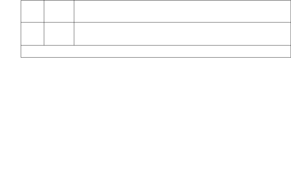
UDS1-BD (UDS1 Interface Circuit Pack)
Issue 1 June 2005 2421
Red Alarm Inquiry Test (#140)
A UDS1 Interface circuit pack raises a Red alarm when the framing pattern of the incoming DS1
bit stream has been lost. The Red Alarm Inquiry test checks the framing status of a UDS1
Interface circuit pack. A UDS1 Interface circuit pack takes 3 seconds to recognize and report a
Red alarm and 10 seconds to recognize and report the resolution of a Red alarm.
When the UDS1 Interface circuit pack detects a Red alarm, the circuit pack transmits a Yellow
alarm to the remote DS1 endpoint and sends a Red alarm message to the maintenance
software. After the Red alarm is confirmed, the maintenance software places every trunk or port
of the circuit pack into the out-of-service state. The inquiry test runs every 10 minutes until the
Red alarm is cleared.
When the Red alarm is cleared, the UDS1 Interface circuit pack stops transmitting the Yellow
alarm to the remote DS1 endpoint. The maintenance software restores all trunks or ports of the
UDS1 Interface circuit pack to the service state they were in before the Red alarm occurred.
Loss of Multiframe Alarm
If the UDS1 Interface circuit pack is administered using DMI-BOS signaling, the UDS1 Interface
circuit pack raises a LMA (Loss of Multiframe Alarm) when it cannot interpret the incoming
signaling bits to synchronize to the multiframe pattern received in the 24th channel. Once the
UDS1 Interface circuit pack detects an LMA, the circuit pack transmits a RMA (Remote
Multiframe Alarm) to the remote DS1 endpoint. Maintenance software handles both Red and
LMA alarms using the same mechanism.
Table 860: Test #140 Red Alarm Inquiry Test
Error
Code
Test
Result
Description / Recommendation
ABRT Internal system error
1. Retry the command at 1-minute intervals up to 5 times.
1 of 5

Communication Manager Maintenance-Object Repair Procedures
2422 Maintenance Procedures for Avaya Communication Manager 3.0, Media Gateways and Servers
2000 ABRT Response to the test was not received within the allowable time period.
This may be due to hyperactivity. Error Type 1538 in the error log
indicates hyperactivity. The hyperactive circuit pack is out of service, and
one or more of the following symptoms may be exhibited.
1. The UDS1-BD tests (such as Test #138 and #139) are aborting with
Error Code 2000.
2. The tests run on the ports of this circuit pack are returning a no-board
result.
3. A busyout or a release command has no effect on the test results.
4. A list config shows that the circuit pack and the ports are
properly installed.
When hyperactivity occurs, the circuit pack is isolated from the system, and
all of its trunks are placed into the out-of-service state. The system will try
to restore the circuit pack within 15 minutes. When no faults are detected
for 15 minutes, the UDS1 interface circuit pack is restored to normal
operation. Every UDS1 interface trunk is then returned to the in-service
state. Hyperactivity is often caused by the associated facility. In such a
case, faults (such as slips, misframes, or blue alarms) would be entered in
the error log. In addition, many hardware errors would be logged against
the associated trunk circuits. If the facility is OK and the error occurs again
after 15 minutes, replace the circuit pack.
Table 860: Test #140 Red Alarm Inquiry Test (continued)
Error
Code
Test
Result
Description / Recommendation
2 of 5

UDS1-BD (UDS1 Interface Circuit Pack)
Issue 1 June 2005 2423
FAIL The UDS1 interface circuit pack detected a Red alarm. An out-of-frame
condition occurred on the UDS1 interface circuit pack. The UDS1 interface
circuit pack will transmit a Yellow alarm to the remote UDS1 endpoint until
the Red alarm is retired.
If the UDS1 connects to a T1 network facility or to another switch, do the
following.
1. Verify that both endpoints of the DS1 link are administered using the
same signaling mode, framing mode, and line coding.
2. Contact T1 Network Service or a technician at the far-end switch to
diagnose the remote DS1 endpoint.
3. Check the physical connectivity of the UDS1 packs and of the cable.
4. Replace the local UDS1 interface circuit pack, and repeat the test.
If the UDS1 connects to a line-side terminating device (for example, a PRI
terminal adapter), do the following.
1. Verify that the switch DS1 and the line-side terminating device are
administered using the same signaling mode, framing mode, and line
coding.
2. Investigate the maintenance status of the line-side terminating device.
3. Contact the vendor of the line-side terminating device to diagnose the
equipment.
4. Check the physical connection of the UDS1 interface circuit pack to
the terminating device, and check the premise distribution system (or
the intra-premise wiring) for physical connection failures.
5. Replace the local UDS1 interface circuit pack and repeat the test.
Table 860: Test #140 Red Alarm Inquiry Test (continued)
Error
Code
Test
Result
Description / Recommendation
3 of 5

Communication Manager Maintenance-Object Repair Procedures
2424 Maintenance Procedures for Avaya Communication Manager 3.0, Media Gateways and Servers
1 FAIL The test failed. The UDS1 interface circuit pack detected a loss of
multiframe alarm (LMA). An out-of-frame condition occurred on the UDS1
interface circuit pack. The UDS1 interface circuit pack will transmit a
remote multiframe alarm (RMA) to the remote UDS1 endpoint until the LMA
is retired.
If the UDS1 connects to a T1 network facility or to another switch, do the
following:
1. Verify that both endpoints of the DS1 link are administered using the
same signaling mode, framing mode, and line coding.
2. Contact T1 Network Service or a technician at the far-end switch to
diagnose the remote DS1 endpoint.
3. Check the physical connectivity of the UDS1 packs and of the cable.
4. Replace the local UDS1 interface circuit pack, and repeat the test.
If the UDS1 connects to a line-side terminating device (for example, a PRI
terminal adapter), do the following.
1. Verify that the switch DS1 and the line-side terminating device are
administered using the same signaling mode, framing mode, and line
coding.
2. Investigate the maintenance status of the line-side terminating device.
Refer to the 'Line-Side Terminating Device Operating Manual' for
information.
3. Contact the vendor of the line-side terminating device to diagnose the
equipment.
4. Check the physical connection of the UDS1 interface circuit pack to
the terminating device, and check the premise distribution system (or
the intra-premise wiring) for physical connection failures.
5. Replace the local UDS1 interface circuit pack and repeat the test.
PASS No Red alarm is detected on the UDS1 Interface circuit pack.
Table 860: Test #140 Red Alarm Inquiry Test (continued)
Error
Code
Test
Result
Description / Recommendation
4 of 5

UDS1-BD (UDS1 Interface Circuit Pack)
Issue 1 June 2005 2425
Yellow Alarm Inquiry Test (#141)
Receiving a Yellow alarm from a remote DS1 endpoint indicates that the remote DS1 endpoint
has an out-of-frame condition. The UDS1 Interface circuit pack takes 500 msec to recognize
and report a Yellow alarm, and 500 msec to recognize and report that the alarm’s condition is
cleared.
Once the alarm is confirmed, the maintenance software places every trunk or port on the circuit
pack into the out-of-service state. The Inquiry test runs every 10 minutes until the Yellow alarm
is cleared.
When the Yellow alarm is cleared, the maintenance software restores every trunk or port on the
UDS1 Interface circuit pack back to its previous service state before the alarm was raised.
This Yellow alarm corresponds to the yellow F2 state documented in CCITT Recommendation
I.431.
Remote Multiframe Alarm
An RMA (Remote Multiframe Alarm) indicates that the remote DS1 endpoint is in a Loss of
Multiframe Alarm condition while the UDS1 Interface circuit pack is administered using the
DMI-BOS common-channel signaling. The RMA is handled as a Yellow alarm.
0NO
BOARD
The test could not relate the internal ID to the port (no board). This could
be due to incorrect translations, no board is inserted, an incorrect board is
inserted, or an insane board is inserted.
1. Verify that the board translations are correct. Execute add ds1
location to administer the UDS1 interface if it is not already
administered.
2. If the board was already administered correctly, check the error log to
determine whether the board is hyperactive. If so, the board is shut
down. Reseating the board will re-initialize it.
3. If the board was found to be correctly inserted in step 1, enter
busyout board location
4. Enter reset board location.
5. Enter release board location.
6. Enter test board location long.
This should re-establish the linkage between the internal ID and the port.
Table 860: Test #140 Red Alarm Inquiry Test (continued)
Error
Code
Test
Result
Description / Recommendation
5 of 5

Communication Manager Maintenance-Object Repair Procedures
2426 Maintenance Procedures for Avaya Communication Manager 3.0, Media Gateways and Servers
Yellow F5 Fault Alarm
For 32-channel E1 operation with CRC4 on, the F5 fault state is defined as a fault in the
user-network interface, specifically in the direction from the user (PBX) to the network. Refer to
CCITT recommendation I.431.
Table 861: Test #141 Yellow Alarm Inquiry Test
Error
Code
Test
Result
Description / Recommendation
ABRT Internal system error
1. Retry the command at 1-minute intervals up to 5 times.
2000 ABRT Response to the test was not received within the allowable time period.
This may be due to hyperactivity. Error Type 1538 in the error log
indicates hyperactivity. The hyperactive circuit pack is out of service, and
one or more of the following symptoms may be exhibited.
1. The UDS1-BD tests (such as Test #138 #139) are aborting with Error
Code 2000.
2. The tests run on the ports of this circuit pack are returning a no-board
result.
3. A busyout or a release command has no effect on the test results.
4. A list config shows that the circuit pack and the ports are
properly installed.
When hyperactivity occurs, the circuit pack is isolated from the system, and
all of its trunks are placed into the out-of-service state. The system will try
to restore the circuit pack within 15 minutes. When no faults are detected
for 15 minutes, the UDS1 interface circuit pack is restored to normal
operation. Every UDS1 Interface trunk is then returned to the in-service
state. Hyperactivity is often caused by the associated facility. In such a
case, faults (such as slips, misframes, or blue alarms) would be entered in
the error log. In addition, many hardware errors would be logged against
the associated trunk circuits. If the facility is OK and the error occurs again
after 15 minutes, replace the circuit pack.
1 of 5

UDS1-BD (UDS1 Interface Circuit Pack)
Issue 1 June 2005 2427
FAIL The UDS1 interface circuit pack detected a Yellow alarm sent by the
remote DS1 endpoint. An out-of-frame condition occurred at the DS1
endpoint.
If the UDS1 connects to a T1 network facility or to another switch, do the
following:
1. Verify that both endpoints of the DS1 link are administered using the
same signaling mode, framing mode, and line coding.
2. Contact T1 Network Service or a technician at the far-end switch to
diagnose the remote DS1 endpoint.
3. Check the physical connectivity of the UDS1 packs and of the cable.
4. Replace the local UDS1 interface circuit pack, and repeat the test.
If the UDS1 connects to a line-side terminating device (for example, a PRI
terminal adapter), do the following:
1. Verify that the switch DS1 and the line-side terminating device are
administered using the same signaling mode, framing mode, and line
coding.
2. Investigate the maintenance status of the line-side terminating
device. Refer to the 'Line-Side Terminating Device Operating Manual'
for information.
3. Contact the vendor of the line-side terminating device to diagnose the
equipment.
4. Check the physical connection of the UDS1 interface circuit pack to
the terminating device, and check the premise distribution system (or
the intra-premise wiring) for physical connection failures.
5. Replace the local UDS1 interface circuit pack and repeat the test.
Table 861: Test #141 Yellow Alarm Inquiry Test (continued)
Error
Code
Test
Result
Description / Recommendation
2 of 5

Communication Manager Maintenance-Object Repair Procedures
2428 Maintenance Procedures for Avaya Communication Manager 3.0, Media Gateways and Servers
1 FAIL The UDS1 interface circuit pack detected a remote multiframe alarm
(RMA) sent by the remote DS1 endpoint. An out-of-frame condition
occurred at the DS1 endpoint.
If the UDS1 connects to a T1 network facility or to another switch, do the
following:
1. Verify that both endpoints of the DS1 link are administered using the
same signaling mode, framing mode, and line coding.
2. Contact T1 Network Service or a technician at the far-end switch to
diagnose the remote DS1 endpoint.
3. Check the physical connectivity of the UDS1 packs and of the cable.
4. Replace the local UDS1 interface circuit pack, and repeat the test.
If the UDS1 connects to a line-side terminating device (for example, a PRI
terminal adapter), do the following:
1. Verify that the switch DS1 and the line-side terminating device are
administered using the same signaling mode, framing mode, and line
coding.
2. Investigate the maintenance status of the line-side terminating
device. Refer to the 'Line-Side Terminating Device Operating Manual'
for information.
3. Contact the vendor of the line-side terminating device to diagnose the
equipment.
4. Check the physical connection of the UDS1 interface circuit pack to
the terminating device, and check the premise distribution system (or
the intra-premise wiring) for physical connection failures.
5. Replace the local UDS1 interface circuit pack and repeat the test.
Table 861: Test #141 Yellow Alarm Inquiry Test (continued)
Error
Code
Test
Result
Description / Recommendation
3 of 5

UDS1-BD (UDS1 Interface Circuit Pack)
Issue 1 June 2005 2429
2 FAIL The UDS1 interface circuit pack is reporting a Yellow F5 fault alarm. There
is a fault in the User-Network interface from the user (PBX) to the network.
An out-of-frame condition occurs on the remote DS1 endpoint.
If the UDS1 connects to a T1 network facility:
1. Verify that both endpoints of the DS1 link are administered using the
same signaling mode, framing mode, and line coding.
2. Contact T1 Network Service to diagnose the remote DS1 endpoint.
3. Check the physical connectivity of the DS1 Interface circuit packs and
cable.
4. Replace the local UDS1 Interface circuit pack and repeat the test.
If the UDS1 connects to a line-side terminating device such as a PRI
terminal adapter:
1. Verify that the switch DS1 and the line-side terminating device are
administered using the same signaling mode, framing mode, and line
coding.
2. Investigate the maintenance status of the line-side terminating
device. Refer to the 'Line-Side Terminating Device Operating Manual'
for information.
3. Contact the vendor of the line-side terminating device to diagnose the
equipment.
4. Check the physical connection of the UDS1 Interface circuit pack to
the terminating device. Check premise distribution system (or
intra-premise wiring) for physical connection failures.
5. Replace the local UDS1 Interface circuit pack and repeat the test.
PASS Neither a Yellow alarm nor a Remote Multiframe Alarm nor a F5 state
alarm is being received from the remote DS1 endpoint.
Table 861: Test #141 Yellow Alarm Inquiry Test (continued)
Error
Code
Test
Result
Description / Recommendation
4 of 5

Communication Manager Maintenance-Object Repair Procedures
2430 Maintenance Procedures for Avaya Communication Manager 3.0, Media Gateways and Servers
Major Alarm Inquiry Test (#142)
The Major Alarm Inquiry test is used to determine if the received DS1 bit error rate is greater
than 1/1000. The UDS1 Interface circuit pack takes 10 seconds to recognize and report a Major
alarm and 10 seconds to recognize and report that a Major alarm condition is cleared.
When the UDS1 Interface circuit pack detects a Major alarm, it sends a MAJOR-ALARM
message to the maintenance software. (32-channel interfaces send a YELLOW alarm to the far
end). After the maintenance software receives a MAJOR alarm message, the Major Alarm
Inquiry test is initiated to confirm the Major alarm on the UDS1 Interface circuit pack. The
Inquiry test runs every 10 minutes until the Major alarm is cleared. The maintenance software
places every trunk or port on the circuit pack in the out-of-service state if the Major alarm
persists for more than 20 minutes.
When the Major alarm is cleared, the maintenance software restores every trunk or port on the
circuit pack to its previous service state before a Major alarm occurs.
0NO
BOARD
The test could not relate the internal ID to the port (no board). This could
be due to incorrect translations, no board is inserted, an incorrect board is
inserted, or an insane board is inserted.
1. Verify that the board’s translations are correct. Execute add ds1
location to administer the UDS1 interface if it is not already
administered.
2. If the board was already administered correctly, check the error log to
determine whether the board is hyperactive. If so, the board is shut
down. Reseating the board will re-initialize it.
3. If the board was found to be correctly inserted in step 1, enter
busyout board location
4. Enter reset board location.
5. Enter release board location.
6. Enter test board location long.
This should re-establish the linkage between the internal ID and the port.
Table 861: Test #141 Yellow Alarm Inquiry Test (continued)
Error
Code
Test
Result
Description / Recommendation
5 of 5

UDS1-BD (UDS1 Interface Circuit Pack)
Issue 1 June 2005 2431
Table 862: Test #142 Major Alarm Inquiry Test
Error
Code
Test
Result
Description / Recommendation
ABRT Internal system error
1. Retry the command at 1-minute intervals up to 5 times.
2000 ABRT Response to the test was not received within the allowable time period.
This may be due to hyperactivity. Error Type 1538 in the error log
indicates hyperactivity. The hyperactive circuit pack is out of service, and
one or more of the following symptoms may be exhibited.
1. The UDS1-BD tests (such as Test #138 and #139) are aborting with
Error Code 2000.
2. The tests run on the ports of this circuit pack are returning a
no-board result.
3. A busyout or a release command has no effect on the test
results.
4. A list config shows that the circuit pack and its ports are
properly installed.
When hyperactivity occurs, the circuit pack is isolated from the system,
and all of its trunks are placed into the out-of-service state. The system
will try to restore the circuit pack within 15 minutes. When no faults are
detected for 15 minutes, the UDS1 interface circuit pack is restored to
normal operation. Every UDS1 Interface trunk is then returned to the
in-service state. Hyperactivity is often caused by the associated facility. In
such a case, faults (such as slips, misframes, or blue alarms) would be
entered in the error log. In addition, many hardware errors would be
logged against the associated trunk circuits. If the facility is OK and the
error occurs again after 15 minutes, replace the circuit pack.
2100 ABRT Could not allocate the necessary system resources to run this test.
1. Retry the command at 1-minute intervals up to 5 times.
1 of 3

Communication Manager Maintenance-Object Repair Procedures
2432 Maintenance Procedures for Avaya Communication Manager 3.0, Media Gateways and Servers
FAIL If the UDS1 connects to a T1 network facility or to another switch, do the
following:
1. The performance of the DS1 link between the UDS1 interface circuit
pack and the remote DS1 endpoint is very poor. Enter list
measurement ds1-log location to read the error seconds
measurement.
2. Verify that both endpoints of the DS1 link are administered using the
same signaling mode, framing mode, and line coding.
3. Contact T1 Network Service or the technician at the remote switch to
diagnose the equipment.
4. Check the physical connectivity of the UDS1 interface circuit packs
and the cable.
5. Replace the local UDS1 interface circuit pack, and repeat the test.
If the UDS1 connects to a line-side terminating device (for example, a
PRI terminal adapter), do the following:
1. The performance of the DS1 link between the UDS1 interface circuit
pack and the line-side terminating device is very poor. Enter list
measurement ds1-log location to read the error seconds
measurement.
2. Verify that the switch DS1 and the line-side terminating device are
administered using the same signaling mode, framing mode, and
line coding.
3. Investigate the maintenance status of the line-side terminating
device. Refer to the 'Line-Side Terminating Device Operating
Manual' for information.
4. Contact the vendor of the line-side terminating device to diagnose
the equipment.
5. Check the physical connection of the UDS1 interface circuit pack to
the terminating device, and check the premise distribution system (or
the intra-premise wiring) for physical connection failures.
6. Replace the local UDS1 interface circuit pack and repeat the test.
PASS No Major alarm is detected in the UDS1 Interface circuit pack.
Table 862: Test #142 Major Alarm Inquiry Test (continued)
Error
Code
Test
Result
Description / Recommendation
2 of 3

UDS1-BD (UDS1 Interface Circuit Pack)
Issue 1 June 2005 2433
Minor Alarm Inquiry Test (#143)
The Minor Alarm Inquiry test is used to determine if the received DS1 bit error rate is greater
than 1/1,000,000 and less than 1/1000. When D4 framing mode is selected, the UDS1 Interface
circuit pack takes 41 minutes to recognize and report a Minor alarm and 41 minutes to
recognize and report that a Minor alarm condition has cleared. If ESF framing mode is selected,
the UDS1 Interface circuit pack takes 10 minutes to recognize and report a Minor alarm and 10
minutes to recognize and report that a Minor alarm condition has cleared.
When the UDS1 Interface circuit pack detects a Minor alarm condition, it sends a
MINOR-ALARM message to the maintenance software. After the maintenance software
receives a MINOR-ALARM message, the Minor Alarm Inquiry test is initiated to confirm the
Minor alarm. Every trunk or port on the circuit pack is kept in the in-service state after the Minor
alarm is confirmed. The Minor Alarm Inquiry test runs every 10 minutes until the Minor alarm is
cleared.
0NO
BOARD
The test could not relate the internal ID to the port (no board). This could
be due to incorrect translations, no board is inserted, an incorrect board
is inserted, or an insane board is inserted.
1. Verify that the board’s translations are correct. Execute add ds1
location to administer the UDS1 interface if it is not already
administered.
2. If the board was already administered correctly, check the error log
to determine whether the board is hyperactive. If so, the board is
shut down. Reseating the board will re-initialize it.
3. If the board was found to be correctly inserted in step 1, enter
busyout board location.
4. Enter reset board location.
5. Enter release board location.
6. Enter test board location long.
This should re-establish the linkage between the internal ID and the port.
Table 862: Test #142 Major Alarm Inquiry Test (continued)
Error
Code
Test
Result
Description / Recommendation
3 of 3

Communication Manager Maintenance-Object Repair Procedures
2434 Maintenance Procedures for Avaya Communication Manager 3.0, Media Gateways and Servers
Table 863: Test #143 Minor Alarm Inquiry Test
Error
Code
Test
Result
Description / Recommendation
ABRT Internal system error
1. Retry the command at 1-minute intervals up to 5 times.
2000 ABRT Response to the test was not received within the allowable time period.
This may be due to hyperactivity. Error Type 1538 in the error log
indicates hyperactivity. The hyperactive circuit pack is out of service, and
one or more of the following symptoms may be exhibited.
1. The UDS1-BD tests (such as Tests #138 and #139) are aborting with
Error Code 2000.
2. The tests run on the ports of this circuit pack are returning a no-board
result.
3. A busyout or a release command has no effect on the test results.
4. A list config shows that the circuit pack and its ports are properly
installed.
When hyperactivity occurs, the circuit pack is isolated from the system,
and all of its trunks are placed into the out-of-service state. The system will
try to restore the circuit pack within 15 minutes. When no faults are
detected for 15 minutes, the UDS1 interface circuit pack is restored to
normal operation. Every UDS1 Interface trunk is then returned to the
in-service state. Hyperactivity is often caused by the associated facility. In
such a case, faults (such as slips, misframes, or blue alarms) would be
entered in the error log. In addition, many hardware errors would be
logged against the associated trunk circuits. If the facility is OK and the
error occurs again after 15 minutes, replace the circuit pack.
2100 ABRT Could not allocate the necessary system resources to run this test.
1. Retry the command at 1-minute intervals up to 5 times.
1 of 3

UDS1-BD (UDS1 Interface Circuit Pack)
Issue 1 June 2005 2435
FAIL Minor alarms are often accompanied by slip and misframe alarms against
the board. Trunk alarms and hardware error logs may occur on the
associated trunks.
If the UDS1 connects to a T1 network facility or to another switch, do the
following:
1. The performance of the DS1 link between the UDS1 interface circuit
pack and the remote DS1 endpoint is poor. Enter list
measurement ds1-log location to read the error seconds
measurement.
2. Verify that both endpoints of the DS1 link are administered using the
same signaling mode, framing mode, and line coding.
3. Contact T1 Network Service or the technician at the remote switch to
diagnose the equipment.
4. Check the physical connectivity of the UDS1 interface circuit packs
and the cable.
5. Replace the local UDS1 interface circuit pack, and repeat the test.
If the UDS1 connects to a line-side terminating device (for example, a
PRI terminal adapter), do the following:
1. The performance of the DS1 link between the UDS1 interface circuit
pack and the line-side terminating device is very poor. Enter list
measurement ds1-log location to read the error seconds
measurement.
2. Verify that the switch DS1 and the line-side terminating device are
administered using the same signaling mode, framing mode, and line
coding.
3. Investigate the maintenance status of the line-side terminating
device. Obtain the error seconds measurement on the terminating
device (if possible). Refer to the 'Line-Side Terminating Device
Operating Manual' for information.
4. Contact the vendor of the line-side terminating device to diagnose the
equipment.
5. Check the physical connection of the UDS1 interface circuit pack to
the terminating device, and check the premise distribution system (or
the intra-premise wiring) for physical connection failures.
6. Replace the local UDS1 interface circuit pack and repeat the test.
Table 863: Test #143 Minor Alarm Inquiry Test (continued)
Error
Code
Test
Result
Description / Recommendation
2 of 3

Communication Manager Maintenance-Object Repair Procedures
2436 Maintenance Procedures for Avaya Communication Manager 3.0, Media Gateways and Servers
Slip Alarm Inquiry Test (#144)
Slips occur when the transmitter and receiver are not running at precisely the same clock rate.
The UDS1 Interface circuit pack can detect both positive and negative slips on the DS1 facility.
The Slip Alarm Inquiry test is used to acquire the total number of slips that have occurred on a
DS1 link.
When the UDS1 Interface circuit pack detects a slip condition, the circuit pack increments the
on-board slip counter by one. A SLIP-COUNT message is spontaneously sent to the system
software after the counter reaches a threshold (for example, 88). When the maintenance
software receives the SLIP-COUNT message, the Slip Alarm Inquiry test is initiated to query the
slip counters on a UDS1 Interface circuit pack and total the slip counts in the maintenance
software.
If the count of slips is over the threshold, a Minor alarm is raised against the UDS1 Interface
circuit pack. Every trunk or port of the UDS1 Interface circuit pack remains in the in-service
state. If the UDS1 Interface circuit pack is used to supply the system synchronization source,
the MINOR alarm will initiate a synchronization source switch. See TDM-BUS (TDM Bus) on
page 2237 and SYNC (Port-Network Synchronization) on page 2143 for details.
PASS No Minor alarm is detected in the UDS1 Interface circuit pack.
0NO
BOARD
The test could not relate the internal ID to the port (no board). This could
be due to incorrect translations, no board is inserted, an incorrect board
is inserted, or an insane board is inserted.
1. Verify that the board’s translations are correct. Execute add ds1
location to administer the UDS1 interface if it is not already
administered.
2. If the board was already administered correctly, check the error log to
determine whether the board is hyperactive. If so, the board was shut
down. Reseating the board will re-initialize it.
3. If the board was found to be correctly inserted in step 1, enter
busyout board location.
4. Enter reset board location.
5. Enter release board location.
6. Enter test board location long.
This should re-establish the linkage between the internal ID and the port.
Table 863: Test #143 Minor Alarm Inquiry Test (continued)
Error
Code
Test
Result
Description / Recommendation
3 of 3

UDS1-BD (UDS1 Interface Circuit Pack)
Issue 1 June 2005 2437
Table 864: Test #144 Slip Alarm Inquiry Test
Error
Code
Test
Result
Description / Recommendation
ABRT Internal system error
1. Retry the command at 1-minute intervals up to 5 times.
2000 ABRT Response to the test was not received within the allowable time period.
This may be due to hyperactivity. Error Type 1538 in the error log
indicates hyperactivity. The hyperactive circuit pack is out of service,
and one or more of the following symptoms may be exhibited.
1. The UDS1-BD tests (such as Tests #138 and #139) are aborting
with Error Code 2000.
2. The tests run on the ports of this circuit pack are returning a
no-board result.
3. A busyout or a release command has no effect on the test
results.
4. A list config shows that the circuit pack and its ports are
properly installed.
When hyperactivity occurs, the circuit pack is isolated from the system,
and all of its trunks are placed into the out-of-service state. The system
will try to restore the circuit pack within 15 minutes. When no faults are
detected for 15 minutes, the UDS1 interface circuit pack is restored to
normal operation. Every UDS1 Interface trunk is then returned to the
in-service state. Hyperactivity is often caused by the associated facility.
In such a case, faults (such as slips, misframes, or blue alarms) would
be entered in the error log. In addition, many hardware errors would be
logged against the associated trunk circuits. If the facility is OK and the
error occurs again after 15 minutes, replace the circuit pack.
2100 ABRT Could not allocate the necessary system resources to run this test.
1. Retry the command at 1-minute intervals up to 5 times.
1 of 3

Communication Manager Maintenance-Object Repair Procedures
2438 Maintenance Procedures for Avaya Communication Manager 3.0, Media Gateways and Servers
1 to 88 FAIL The test failed because the UDS1 interface circuit pack and the remote
DS1 endpoint are not synchronized to the same clock rate. The UDS1
interface circuit pack detected a slip alarm. The Error Code equals the
number of slips detected by the UDS1 interface circuit pack since the
last slip alarm inquiry test.
If the UDS1 connects to a T1 network facility or to another switch, do
the following:
1. Retry the command at 1-minute intervals up to 5 times.
2. If the DS1 interface circuit pack is a TN464C, enter list
measurement ds1-log location to read the error seconds
measurement.
3. Verify that both endpoints of the DS1 link are administered using
the same signaling mode, framing mode, and line coding.
4. Check the active alarm and error logs for recent alarms and errors
against the synchronization (SYNC). Follow the suggested repair
procedure for these errors.
5. Contact T1 Network Service or the technician at the remote switch
to diagnose the remote DS1 endpoint.
6. Check the physical connectivity of the UDS1 interface circuit packs
and the cable.
7. Replace the local UDS1 interface circuit pack, and repeat the test.
Table 864: Test #144 Slip Alarm Inquiry Test (continued)
Error
Code
Test
Result
Description / Recommendation
2 of 3

UDS1-BD (UDS1 Interface Circuit Pack)
Issue 1 June 2005 2439
1 to 88 FAIL
(cont’d)
If the UDS1 connects to a line-side terminating device (for example, a
PRI terminal adapter), do the following:
1. Retry the command at 1-minute intervals up to 5 times.
2. Enter list measurement ds1-log location to read the
error seconds measurement.
3. Verify that the switch DS1 and the line-side terminating device are
administered using the same signaling mode, framing mode, and
line coding.
4. Investigate the maintenance status of the line-side terminating
device.
5. Contact the vendor of the line-side terminating device to diagnose
the equipment.
6. Check the physical connection of the UDS1 interface circuit pack to
the terminating device, and check the premise distribution system
(or the intra-premise wiring) for physical connection failures.
7. Replace the local UDS1 interface circuit pack and repeat the test.
PASS No Slip alarm is detected on the UDS1 Interface circuit pack.
0NO
BOARD
The test could not relate the internal ID to the port (no board). This
could be due to incorrect translations, no board is inserted, an incorrect
board is inserted, or an insane board is inserted.
1. Verify that the board’s translations are correct. Execute add ds1
location to administer the UDS1 interface if it is not already
administered.
2. If the board was already administered correctly, check the error log
to determine whether the board is hyperactive. If so, the board was
shut down. Reseating the board will re-initialize it.
3. If the board was found to be correctly inserted in step 1, enter
busyout board location.
4. Enter reset board location.
5. Enter release board location.
6. Enter test board location long.
This should re-establish the linkage between the internal ID and the port.
Table 864: Test #144 Slip Alarm Inquiry Test (continued)
Error
Code
Test
Result
Description / Recommendation
3 of 3

Communication Manager Maintenance-Object Repair Procedures
2440 Maintenance Procedures for Avaya Communication Manager 3.0, Media Gateways and Servers
Misframe Alarm Inquiry Test (#145)
A Misframe Alarm indicates that framing bits observed on a UDS1 Interface circuit pack are in
error. The Misframe Alarm Inquiry test queries the total number of misframes that have occurred
on a UDS1 Interface circuit pack since the last inquiry.
When the UDS1 Interface circuit pack detects a misframe error, it increments its misframe
counter by one. If the counter reaches a specified threshold (i.e., 17), a MISFRAME-COUNT
message is automatically sent to the switch maintenance software. After the maintenance
software receives the MISFRAME-COUNT message, the Misframe Alarm Inquiry test is initiated
to collect the misframe counts from the UDS1 Interface circuit pack.
If the UDS1 Interface circuit pack is supplying the system synchronization source, when the
threshold of misframes is reached, then a switching synchronization source message is sent to
the TDM bus Clock. See TDM-BUS (TDM Bus) on page 2237 for details. A Minor alarm against
the UDS1 Interface circuit pack is raised, but every trunk or port of the UDS1 Interface circuit
pack remains in the in-service state.
Table 865: Test #145 Misframe Alarm Inquiry Test
Error
Code
Test
Result
Description / Recommendation
ABRT Internal system error
1. Retry the command at 1-minute intervals up to 5 times.
1 of 5

UDS1-BD (UDS1 Interface Circuit Pack)
Issue 1 June 2005 2441
2000 ABRT Response to the test was not received within the allowable time period.
This may be due to hyperactivity. Error Type 1538 in the error log
indicates hyperactivity. The hyperactive circuit pack is out of service, and
one or more of the following symptoms may be exhibited.
1. The UDS1-BD tests (such as Tests #138 and #139) are aborting with
Error Code 2000.
2. The tests run on the ports of this circuit pack are returning a
no-board result.
3. A busyout or a release command has no effect on the test
results.
4. A list config shows that the circuit pack and the ports are
properly installed.
When hyperactivity occurs, the circuit pack is isolated from the system,
and all of its trunks are placed into the out-of-service state. The system
will try to restore the circuit pack within 15 minutes. When no faults are
detected for 15 minutes, the UDS1 interface circuit pack is restored to
normal operation. Every UDS1 Interface trunk is then returned to the
in-service state. Hyperactivity is often caused by the associated facility. In
such a case, faults (such as slips, misframes, or blue alarms) would be
entered in the error log. In addition, many hardware errors would be
logged against the associated trunk circuits. If the facility is OK and the
error occurs again after 15 minutes, replace the circuit pack.
2100 ABRT Could not allocate the necessary system resources to run this test.
1. Retry the command at 1-minute intervals up to 5 times.
Table 865: Test #145 Misframe Alarm Inquiry Test (continued)
Error
Code
Test
Result
Description / Recommendation
2 of 5

Communication Manager Maintenance-Object Repair Procedures
2442 Maintenance Procedures for Avaya Communication Manager 3.0, Media Gateways and Servers
1 to 17 FAIL The test failed because the UDS1 interface circuit pack detected errors in
the received framing bits pattern. The Error Code equals the number of
misframes detected by the UDS1 interface circuit pack since the last
misframe alarm inquiry test. Major bit and minor bit error rate (Error Types
2561 and 2817) error logs often accompany misframe alarms. Clearing
the cause of these error logs may clear the misframes which are
occurring.
If the UDS1 connects to a T1 network facility or to another switch, do the
following:
1. Retry the command at 1-minute intervals up to 5 times.
2. If the DS1 interface circuit pack is a TN464C, enter list
measurement ds1-log location to read the error seconds
measurement.
3. Verify that both endpoints of the DS1 link are administered using the
same signaling mode, framing mode, and line coding.
4. Check the active alarm and error logs for recent alarms and errors
against the synchronization (SYNC). Follow the suggested repair
procedure for these errors.
5. Contact T1 Network Service or the technician at the remote switch to
diagnose the remote DS1 endpoint.
6. Check the physical connectivity of the UDS1 interface circuit packs
and the cable.
7. Replace the local UDS1 interface circuit pack, and repeat the test.
Table 865: Test #145 Misframe Alarm Inquiry Test (continued)
Error
Code
Test
Result
Description / Recommendation
3 of 5

UDS1-BD (UDS1 Interface Circuit Pack)
Issue 1 June 2005 2443
1 to 17 FAIL
(cont’d)
If the UDS1 connects to a line-side terminating device such as a PRI
terminal adapter:
1. Retry the command at 1-minute intervals up to 5 times.
2. Enter the list measurement ds1-log location command to
read the error seconds measurement.
3. Verify that the switch DS1 and the line-side terminating device are
administered using the same signaling mode, framing mode, and
line coding.
4. Investigate the maintenance status of the line-side terminating
device. Refer to the Line-Side Terminating Device Operating Manual
for information.
5. Contact the vendor of the line-side terminating device to diagnose
the equipment.
6. Check the physical connection of the UDS1 interface circuit pack to
the terminating device, and check the premise distribution system
(or the intra-premise wiring) for physical connection failures.
7. Replace the local UDS1 interface circuit pack and repeat the test.
PASS No Misframe alarm is detected on the UDS1 Interface circuit pack.
Table 865: Test #145 Misframe Alarm Inquiry Test (continued)
Error
Code
Test
Result
Description / Recommendation
4 of 5

Communication Manager Maintenance-Object Repair Procedures
2444 Maintenance Procedures for Avaya Communication Manager 3.0, Media Gateways and Servers
Translation Update Test (#146)
The Translation Update test sends the circuit-pack-level information specified by System
Administration to the UDS1 Interface circuit pack. Translation includes the following data
administered for a UDS1 Interface circuit pack (see output of display ds1 location): DS1
Link Length between two DS1 endpoints, Synchronization Source Control, All Zero
Suppression, Framing Mode, Signaling Mode, Time Slot Number of 697-Hz Tone, Time Slot
Number of 700-Hz Tone, etc.
If a TN464F or later UDS1 circuit pack is combined with a 120A1 CSU module or the 401A T1
sync splitter to screen an Integrated CSU module/T1 sync splitter, this test will also send the
administration for this Integrated CSU to the circuit pack to assure the board’s translations are
correct. The administration of the CSU module/T1 sync splitter is done using the DS1 Circuit
Pack administration screen. Translation for the CSU module/T1 sync splitter includes the
following data: Transmit LBO, Receive ALBO, Supply CPE Loop-Back Jack Power.
0NO
BOARD
The test could not relate the internal ID to the port (no board). This could
be due to incorrect translations, no board is inserted, an incorrect board
is inserted, or an insane board is inserted.
1. Verify that the board’s translations are correct. Execute add ds1
location to administer the UDS1 interface if it is not already
administered.
2. If the board was already administered correctly, check the error log
to determine whether the board is hyperactive. If so, the board was
shut down. Reseating the board will re-initialize it.
3. If the board was found to be correctly inserted in step 1, then enter
busyout board location.
4. Enter reset board location.
5. Enter release board location.
6. Enter test board location long.
This should re-establish the linkage between the internal ID and the port.
Table 865: Test #145 Misframe Alarm Inquiry Test (continued)
Error
Code
Test
Result
Description / Recommendation
5 of 5

UDS1-BD (UDS1 Interface Circuit Pack)
Issue 1 June 2005 2445
DS1 Board Loop-back Test (#1209)
This test is destructive.
The DS1 BLB (Board Loopback) test causes a loop back at the DS1 board edge and tests DS1
board internal circuitry.
The test is destructive and can only be initiated by test ds1-loop location ds1/
csu-loopback-tests
Each trunk or port on the UDS1 Interface circuit pack must be busied out using busyout
board location before running the BLB test.
Table 866: Test #146 Translation Update Test
Error
Code
Test
Result
Description / Recommendation
ABRT Internal system error
1. Retry the command at 1-minute interval s up to 5 times.
FAIL Internal system software error.
1. Enter display ds1 location to verify the UDS1 Interface circuit
pack translation.
PASS Translation data has been downloaded to the UDS1 Interface circuit pack
successfully.
0NO
BOARD
The test could not relate the internal ID to the port (no board). This could
be due to incorrect translations, no board is inserted, an incorrect board
is inserted, or an insane board is inserted.
1. Verify that the board’s translations are correct. Execute add ds1
location to administer the UDS1 interface if it is not already
administered.
2. If the board was already administered correctly, check the error log to
determine whether the board is hyperactive. If so, the board was shut
down. Reseating the board will re-initialize it.
3. If the board was found to be correctly inserted in step 1, enter
busyout board location.
4. Enter reset board location.
5. Enter release board location.
6. Enter test board location long.
This should re-establish the linkage between the internal ID and the port.

Communication Manager Maintenance-Object Repair Procedures
2446 Maintenance Procedures for Avaya Communication Manager 3.0, Media Gateways and Servers
When the BLB test is initiated, maintenance software sends an appropriate message to the
UDS1 Interface circuit pack to start the test. The board sets up the BLB loopback, transmits a
test pattern, and verifies that the pattern is received unaltered through the loopback. If the
transmitted and received pattern is different, the test fails.
When the test is complete, each trunk or port on the TN464GP/TN2464BPTN UDS1 Interface
circuit pack is restored to the in-service state after release board location is entered.
Table 867: Test #1209 DS1 Board Loop-Back Test
Error
Code
Test
Result
Description / Recommendation
ABRT Internal system error
1. Retry test ds1-loop location ds1/csu-loopback-tests at
1-minute intervals up to 5 times.
1005 ABRT UDS1 Board Loopback test cannot be executed in the current
configuration. To run this, the TN464F or higher suffix UDS1 must be
administered for 24-channel operation. The “Bit Rate” field on the DS1
circuit pack administration screen must be set to “1.544” for 24-channel
operation.
1015 ABRT Ports on the UDS1 Interface circuit pack have not been busied out to
out-of-service.
1. Enter busyout board location to put every trunk or port of the
UDS1 Interface circuit pack into the out-of-service state.
2. Retry the command.
1039 ABRT The UDS1 Interface circuit pack is providing timing for the system.
Executing this test could cause major system disruption.
If the UDS1 Interface circuit pack needs to be tested, set the
synchronization reference to another DS1 Interface circuit pack or to the
IPSI or Tone-Clock circuit pack via the following command sequence:
1. Enter disable synchronization-switch.
2. Enter set synchronization location.
3. Enter enable synchronization-switch.
Rerun the test. If the test aborts again, a different ABRT Error Code will be
generated. Follow the recommended maintenance procedures for that
Error Code.
1 of 3

UDS1-BD (UDS1 Interface Circuit Pack)
Issue 1 June 2005 2447
1950 ABRT Another loopback/span test is already executing on the DS1 board or the
board is in a network-requested loop-back mode (line loopback or payload
loopback). The hardware error log will indicate whether a Customer
Loop-Back Jack test, Far CSU Loopback test, or the One-Way Span test is
executing or if the board is in line-loopback or payload-loop-back mode.
Only one long-duration loopback/span test can be active at a given time.
Thus, if a loopback/span test is already active, that test must be terminated
using test ds1-loop location end-loopback/span-test in
order to execute this test.
2000 ABRT Response to the test was not received within the allowable time period.
This may be due to hyperactivity. Error Type 1538 in the error log
indicates hyperactivity. The hyperactive circuit pack is out of service, and
one or more of the following symptoms may be exhibited.
1. The UDS1-BD tests (such as Tests #138 and #139) are aborting with
Error Code 2000.
2. The tests run on the ports of this circuit pack are returning a no-board
result.
3. A busyout or a release command has no effect on the test results.
4. A list config shows that the circuit pack and the ports are
properly installed.
When hyperactivity occurs, the circuit pack is isolated from the system, and
all of its trunks are placed into the out-of-service state. The system will try
to restore the circuit pack within 15 minutes. When no faults are detected
for 15 minutes, the UDS1 interface circuit pack is restored to normal
operation. Every UDS1 interface trunk is then returned to the in-service
state. Hyperactivity is often caused by the associated facility. In such a
case, faults (such as slips, misframes, or blue alarms) would be entered in
the error log. In addition, many hardware errors would be logged against
the associated trunk circuits. If the facility is OK and the error occurs again
after 15 minutes, replace the circuit pack.
2100 ABRT Could not allocate the necessary system resources to run this test.
1. Retry the command at 1-minute intervals up to 5 times.
FAIL UDS1 Interface circuit pack failed the DS1 Board Loopback test.
1. Retry test ds1-loop location ds1/csu-loopback-tests
2. If the BLB test continues to fail, then replace the UDS1 circuit pack.
PASS The BLB test executed successfully. The test pattern was transmitted and
received successfully up to the DS1 board edge.
Table 867: Test #1209 DS1 Board Loop-Back Test (continued)
Error
Code
Test
Result
Description / Recommendation
2 of 3

Communication Manager Maintenance-Object Repair Procedures
2448 Maintenance Procedures for Avaya Communication Manager 3.0, Media Gateways and Servers
CSU Equipment Loop-Back Test (#1210)
This test is destructive.
The CSU Equipment Loopback (ELB) test causes a loopback at the near-edge of the local
120A1 CSU module or the 401A T1 sync splitter and tests the connection from the DS1 board to
the CSU module/T1 sync splitter (DS1 board edge interconnecting cable, and CSU module/T1
sync splitter edge). This test is only performed if the 120A1 CSU module or the 401A T1 sync
splitter is present, administered, and connected to a 1.544-Mbps DS1 circuit pack on the back
of the port carrier.
The test is destructive and can only be initiated by a system technician demanded test
ds1-loop location ds1/csu-loopback-tests command.
Each trunk or port on the UDS1 Interface circuit pack must be busied out using the busyout
board location command before running the ELB test.
When the ELB test is initiated, maintenance software sends an appropriate message to the
UDS1 Interface circuit pack to start the test. The board sets up the ELB loopback, transmits a
test pattern, and verifies that the pattern is received unaltered through the loopback. If the
transmitted and received pattern is different, the test fails.
0NO
BOARD
The test could not relate the internal ID to the port (no board). This could
be due to incorrect translations, no board is inserted, an incorrect board is
inserted, or an insane board is inserted.
1. Verify that the board’s translations are correct. Execute add ds1
location to administer the UDS1 interface if it is not already
administered.
2. If the board was already administered correctly, check the error log to
determine whether the board is hyperactive. If so, the board was shut
down. Reseating the board will re-initialize it.
3. If the board was found to be correctly inserted in step 1, enter
busyout board location.
4. Enter reset board location.
5. Enter release board location.
6. Enter test board long location.
This should re-establish the linkage between the internal ID and the port.
Table 867: Test #1209 DS1 Board Loop-Back Test (continued)
Error
Code
Test
Result
Description / Recommendation
3 of 3

UDS1-BD (UDS1 Interface Circuit Pack)
Issue 1 June 2005 2449
When the test is complete, each trunk or port on the UDS1 Interface circuit pack is restored to
the in-service state after the release board location command is entered.
Table 868: Test #1210 CSU Equipment Loop-Back Test
Error
Code
Test
Result
Description / Recommendation
ABRT Internal system error
1. Retry test ds1-loop location ds1/csu-loopback-tests at
1-minute intervals up to 5 times.
1005 ABRT CSU Equipment Loopback test cannot be executed in the current
configuration. To run this test, the Near-End CSU Type field on the DS1
circuit pack administration screen must be set to integrated and the Bit
Rate field on the DS1 circuit pack administration screen must be set to
1.544 (24-channel configuration).
1. Use change ds1 location to set the Near-End CSU Type field on
the DS1 circuit pack administration screen to integrated, and/or
change the Bit Rate field to 1.544 if the board is to be used in
24-channel configuration.
2. Retry test ds1-loop location ds1/csu-loopback-tests.
1015 ABRT Ports on the UDS1 Interface circuit pack have not been busied out to
out-of-service.
1. Enter busyout board location to put every trunk or port of the
UDS1 Interface circuit pack into the out-of-service state.
2. Retry the command.
1039 ABRT The UDS1 Interface circuit pack is providing timing for the system.
Executing this test could cause major system disruption.
If the UDS1 Interface circuit pack needs to be tested, set the
synchronization reference to another DS1 Interface circuit pack or to the
IPSI or Tone-Clock circuit pack via the following command sequence:
1. Enter disable synchronization-switch.
2. Enter set synchronization location.
3. Enter enable synchronization-switch.
Rerun the test. If the test aborts again, a different ABRT code will be
generated. Follow the recommended maintenance procedures for the Error
Code.
1 of 3

Communication Manager Maintenance-Object Repair Procedures
2450 Maintenance Procedures for Avaya Communication Manager 3.0, Media Gateways and Servers
1950 ABRT Another loopback/span test is already executing on the DS1 board or the
board is in a network-requested loop-back mode (line loopback or payload
loopback). The hardware error log will indicate whether a Customer
Loop-Back Jack test, Far CSU Loopback test, or the One-Way Span test is
executing or if the board is in line-loopback or payload-loop-back mode.
Only one long-duration loopback/span test can be active at a given time.
Thus, if a loopback/span test is already active, that test must be terminated
using test ds1-loop location end-loopback/span-test in
order to execute this test.
1951 ABRT The CSU Equipment Loopback test could not be executed because the
120A1 CSU module or the 401A T1 sync splitter was not physically
installed. Physically connect the 120A1 CSU module or the 401A T1 sync
splitter to the UDS1-BD board on the back of the port carrier.
2000 ABRT Response to the test was not received within the allowable time period.
This may be due to hyperactivity. Error Type 1538 in the error log
indicates hyperactivity. The hyperactive circuit pack is out of service, and
one or more of the following symptoms may be exhibited.
1. The UDS1-BD tests (such as Tests #138 and #139) are aborting with
Error Code 2000.
2. The tests run on the ports of this circuit pack are returning a no-board
result.
3. A busyout or a release command has no effect on the test results.
4. A list config shows that the circuit pack and the ports are
properly installed.
When hyperactivity occurs, the circuit pack is isolated from the system, and
all of its trunks are placed into the out-of-service state. The system will try
to restore the circuit pack within 15 minutes. When no faults are detected
for 15 minutes, the UDS1 interface circuit pack is restored to normal
operation. Every UDS1 Interface trunk is then returned to the in-service
state. Hyperactivity is often caused by the associated facility. In such a
case, faults (such as slips, misframes, or blue alarms) would be entered in
the error log. In addition, many hardware errors would be logged against
the associated trunk circuits. If the facility is OK and the error occurs again
after 15 minutes, replace the circuit pack.
2100 ABRT Could not allocate the necessary system resources to run this test.
1. Retry the command at 1-minute intervals up to 5 times.
Table 868: Test #1210 CSU Equipment Loop-Back Test (continued)
Error
Code
Test
Result
Description / Recommendation
2 of 3

UDS1-BD (UDS1 Interface Circuit Pack)
Issue 1 June 2005 2451
FAIL UDS1 Interface circuit pack failed the CSU Equipment Loopback test.
1. Retry test ds1-loop location ds1/csu-loopback-tests.
2. If the ELB test continues to fail, then either the UDS1-BD board, the
CSU module/T1 sync splitter, or the I/O cable between the backplane
and the CSU module/T1 sync splitter (or any combination thereof) has
failed. Attempt to isolate the problem to one of these areas.
3. Replace the CSU module/T1 sync splitter and run test ds1-loop
location ds1/csu-loopback-tests again.
4. If the ELB test continues to fail, replace the UDS1-BD board, and run
test ds1-loop location ds1/csu-loopback-tests again.
5. If the ELB test continues to fail, the problem could be in the I/O cable
between the backplane and the CSU module/T1 sync splitter.
PASS The ELB test executed successfully. The test pattern was transmitted and
received successfully over the connection from the DS1 board to the
near-edge of the 120A1 CSU module or the 401A T1 sync splitter.
0NO
BOARD
The test could not relate the internal ID to the port (no board). This could
be due to incorrect translations, no board is inserted, an incorrect board is
inserted, or an insane board is inserted.
1. Verify that the board’s translations are correct. Execute add ds1
location to administer the UDS1 interface if it is not already
administered.
2. If the board was already administered correctly, check the error log to
determine whether the board is hyperactive. If so, the board was shut
down. Reseating the board will re-initialize it.
3. If the board was found to be correctly inserted in step 1, enter
busyout board location.
4. Enter reset board location.
5. Enter release board location.
6. Enter test board location long.
This should re-establish the linkage between the internal ID and the port.
Table 868: Test #1210 CSU Equipment Loop-Back Test (continued)
Error
Code
Test
Result
Description / Recommendation
3 of 3

Communication Manager Maintenance-Object Repair Procedures
2452 Maintenance Procedures for Avaya Communication Manager 3.0, Media Gateways and Servers
CSU Repeater Loop-Back Test (#1211)
This test is destructive.
The CSU Repeater Loopback (RLB) test causes a loopback at the far-edge of the local 120A1
CSU module or the 401A T1 sync splitter and tests the connection from the DS1 board up to
and including the CSU module/T1 sync splitter circuitry. This test is only performed if the 120A1
CSU module or the 401A T1 sync splitter is present, administered, and connected to a
1.544-Mbps DS1 circuit pack on the back of the port carrier.
The test is destructive and can only be initiated by test ds1-loop location ds1/
csu-loopback-tests.
Each trunk or port on the UDS1 Interface circuit pack must be busied out using busyout
board location before running the RLB test.
When the RLB test is initiated, maintenance software sends an appropriate message to the
UDS1 Interface circuit pack to start the test. The board sets up the RLB loopback, transmits a
test pattern, and verifies that the pattern is received unaltered through the loopback. If the
transmitted and received pattern is different, the test fails.
When the test is complete, each trunk or port on the UDS1 Interface circuit pack is restored to
the in-service state after release board location is entered.
Table 869: Test #1211 CSU Repeater Loop-Back Test
Error
Code
Test
Result
Description / Recommendation
ABRT Internal system error
1. Retry test ds1-loop location ds1/csu-loopback-tests at
1-minute intervals up to 5 times.
1005 ABRT CSU Repeater Loopback test cannot be executed in the current
configuration. To run this test, the Near-End CSU Type field on the DS1
Circuit Pack administration screen must be set to integrated and the Bit
Rate field on the DS1 Circuit Pack administration screen must be set to
1.544 (24-channel configuration).
1. Use change ds1 location to set the Near-End CSU Type field on
the DS1 Circuit Pack administration screen to integrated, and/or
change the Bit Rate field to 1.544 if the board is to be used in
24-channel configuration.
2. Retry test ds1-loop location ds1/csu-loopback-tests.
1 of 4

UDS1-BD (UDS1 Interface Circuit Pack)
Issue 1 June 2005 2453
1015 ABRT Ports on the UDS1 Interface circuit pack have not been busied out to
out-of-service.
1. Enter busyout board location to put each trunk or port of the
UDS1 Interface circuit pack into the out-of-service state.
2. Retry the command.
1039 ABRT The UDS1 Interface circuit pack is providing timing for the system.
Executing this test could cause major system disruption.
If the UDS1 Interface circuit pack needs to be tested, set the
synchronization reference to another DS1 Interface circuit pack or to the
IPSI or Tone-Clock circuit pack via the following command sequence:
1. Enter disable synchronization-switch.
2. Enter set synchronization location.
3. Enter enable synchronization-switch.
Rerun the test. If the test aborts again, a different ABRT code will be
generated. Follow the recommended maintenance procedures for the Error
Code.
1950 ABRT Another loopback/span test is already executing on the DS1 board or the
board is in a network-requested loop-back mode (line loopback or payload
loopback). The hardware error log will indicate whether a Customer
Loop-Back Jack test, Far CSU Loopback test, or the One-Way Span test is
executing or if the board is in line-loopback or payload-loop-back mode.
Only one long-duration loopback/span tests can be active at a given time.
Thus, if a loopback/span test is already active, that test must be terminated
using test ds1-loop location end-loopback/span-test in
order to execute this test.
1951 ABRT The CSU Repeater Loopback test could not be executed because the
120A1 CSU module or the 401A T1 sync splitter was not physically
installed. Physically connect the 120A1 CSU module or the 401A T1 sync
splitter to the UDS1 board on the back of the port carrier.
Table 869: Test #1211 CSU Repeater Loop-Back Test (continued)
Error
Code
Test
Result
Description / Recommendation
2 of 4

Communication Manager Maintenance-Object Repair Procedures
2454 Maintenance Procedures for Avaya Communication Manager 3.0, Media Gateways and Servers
2000 ABRT Response to the test was not received within the allowable time period.
This may be due to hyperactivity. Error Type 1538 in the error log
indicates hyperactivity. The hyperactive circuit pack is out of service, and
one or more of the following symptoms may be exhibited.
1. The UDS1-BD tests (such as Tests #138 and #139) are aborting with
Error Code 2000.
2. The tests run on the ports of this circuit pack are returning a no-board
result.
3. A busyout or a release command has no effect on the test results.
4. A list config shows that the circuit pack and its ports are properly
installed.
When hyperactivity occurs, the circuit pack is isolated from the system, and
all of its trunks are placed into the out-of-service state. The system will try
to restore the circuit pack within 15 minutes. When no faults are detected
for 15 minutes, the UDS1 interface circuit pack is restored to normal
operation. Every UDS1 Interface trunk is then returned to the in-service
state. Hyperactivity is often caused by the associated facility. In such a
case, faults (such as slips, misframes, or blue alarms) would be entered in
the error log. In addition, many hardware errors would be logged against
the associated trunk circuits. If the facility is OK and the error occurs again
after 15 minutes, replace the circuit pack.
2100 ABRT Could not allocate the necessary system resources to run this test.
1. Retry the command at 1-minute intervals up to 5 times.
FAIL UDS1 Interface circuit pack failed the CSU Repeater Loopback test.
1. Retry test ds1-loop location ds1/csu-loopback-tests
2. If the RLB test continues to fail, and the CSU Equipment Loopback
test (#1210) passed, then replace the CSU module/T1 sync splitter.
PASS The RLB test executed successfully. The test pattern was transmitted and
received successfully over the connection from the UDS1 board to the
far-edge of the 120A1 CSU module or the 401A T1 sync splitter.
Table 869: Test #1211 CSU Repeater Loop-Back Test (continued)
Error
Code
Test
Result
Description / Recommendation
3 of 4

UDS1-BD (UDS1 Interface Circuit Pack)
Issue 1 June 2005 2455
CPE Loop-Back Jack Test (#1212)
This test is destructive.
The CPE Loop-Back Jack (CLJ-LB) test causes a loopback at the CPE Loop-Back Jack and
tests the building wiring connection between the UDS1-BD DS1 board and the CPE Loop-Back
Jack.
The test is highly destructive and can only be initiated by test ds1-loop location
cpe-loopback-jack-test-begin [number-of-bits bit-pattern]. The technician
has the choice of entering a loopback activation code on the command line or using the default
code 0x47F.
Each trunk or port on the UDS1 Interface circuit pack must be busied out using busyout
board location before running the CPE Loop-Back Jack test.
The CPE Loop-Back Jack test has the UDS1 Interface circuit pack transmit a loopback
activation code to the CPE Loop-Back Jack, waits up to 10 seconds for return of the code to
verify the loopback has been established, transmits a framed 3-in-24 test pattern, begins
counting bit errors in the received test pattern, and returns a PASS result to indicate that the
pattern was successfully sent. If the loopback is not established within the 10 seconds, the test
returns FAIL or ABRT.
0NO
BOARD
The test could not relate the internal ID to the port (no board). This could
be due to incorrect translations, no board is inserted, an incorrect board is
inserted, or an insane board is inserted.
1. Verify that the board’s translations are correct. Execute add ds1
location to administer the UDS1 interface if it is not already
administered.
2. If the board was already administered correctly, check the error log to
determine whether the board is hyperactive. If so, the board was shut
down. Reseating the board will re-initialize it.
3. If the board was found to be correctly inserted in step 1, then enter
busyout board location.
4. Enter reset board location.
5. Enter release board location.
6. Enter test board location long.
This should re-establish the linkage between the internal ID and the port.
Table 869: Test #1211 CSU Repeater Loop-Back Test (continued)
Error
Code
Test
Result
Description / Recommendation
4 of 4

Communication Manager Maintenance-Object Repair Procedures
2456 Maintenance Procedures for Avaya Communication Manager 3.0, Media Gateways and Servers
The status of the CPE Loop-Back Jack test is available in the hardware error log via Error Type
3900. Several distinct Aux values give the user information about the status of the test.
The list measurements ds1 summary command shows the length of time the test has
been running (Test Duration field) and number of bit errors detected (Loopback/Span Test
Bit-Error Count field). If the test pattern is being passed through the loopback cleanly, the
number of bit errors should be very low. The command will also display the type of Loopback/
Span test executing (Test field), the type of pattern generated for the Loopback/Span test
(Pattern field), and whether the pattern (i.e., 3-in-24 Pattern) is synchronized (Synchronized
field).
To terminate the test, enter test ds1-loop location end-loopback/span-test or
release board location. Using release board restores each trunk or port on the UDS1
Interface circuit pack to the in-service state.
Table 870: Test #1212 CPE Loop-Back Jack Test
Error
Code
Test
Result
Description / Recommendation
ABRT Internal system error
1. Retry test ds1-loop location
cpe-loopback-jack-test-begin at 1-minute intervals up to 5
times.
1005 ABRT CPE Loop-Back Jack test cannot be executed in the current configuration.
To run this test, the TN464F or higher suffix UDS1 must be administered for
24-channel operation. The Bit Rate field on the DS1 circuit pack
administration screen must be set to 1.544 for 24-channel operation.
1015 ABRT Ports on the UDS1 Interface circuit pack have not been busied out to
out-of-service.
1. Enter busyout board location to put each trunk or port of the
UDS1 Interface circuit pack into the out-of-service state.
2. Retry the command.
1 of 4

UDS1-BD (UDS1 Interface Circuit Pack)
Issue 1 June 2005 2457
1039 ABRT The UDS1 Interface circuit pack is providing timing for the system.
Executing this test could cause major system disruption.
If the UDS1 Interface circuit pack needs to be tested, set the
synchronization reference to another DS1 Interface circuit pack or to the
IPSI or Tone-Clock circuit pack via the following command sequence:
1. Enter disable synchronization-switch.
2. Enter set synchronization location.
3. Enter enable synchronization-switch.
Rerun the test. If the test aborts again, a different ABRT code will be
generated. Follow the recommended maintenance procedures for the Error
Code.
1950 ABRT Another loopback/span test is already executing on the DS1 board or the
board is in a network-requested loop-back mode (line loopback or payload
loopback). The hardware error log will indicate whether a Customer
Loop-Back Jack test, Far CSU Loopback test, or the One-Way Span test is
executing or if the board is in line-loopback or payload-loop-back mode.
Only one long-duration loopback/span test can be active at a given time. If a
loopback/span test is already active, terminate the test with test
ds1-loop location end-loopback/span-test in order to execute
this test.
Table 870: Test #1212 CPE Loop-Back Jack Test (continued)
Error
Code
Test
Result
Description / Recommendation
2 of 4

Communication Manager Maintenance-Object Repair Procedures
2458 Maintenance Procedures for Avaya Communication Manager 3.0, Media Gateways and Servers
2000 ABRT Response to the test was not received within the allowable time period. This
may be due to hyperactivity. Error Type 1538 in the error log indicates
hyperactivity. The hyperactive circuit pack is out of service, and one or more
of the following symptoms may be exhibited.
●The UDS1-BD tests (such as Tests #138 and #139) are aborting with
Error Code 2000.
●The tests run on the ports of this circuit pack are returning a no-board
result.
●A busyout or a release command has no effect on the test results.
●A list config shows that the circuit pack and its ports are
properly installed.
When hyperactivity occurs, the circuit pack is isolated from the system, and
all of its trunks are placed into the out-of-service state. The system will try to
restore the circuit pack within 15 minutes. When no faults are detected for
15 minutes, the UDS1 interface circuit pack is restored to normal operation.
Every UDS1 Interface trunk is then returned to the in-service state.
Hyperactivity is often caused by the associated facility. In such a case,
faults (such as slips, misframes, or blue alarms) would be entered in the
error log. In addition, many hardware errors would be logged against the
associated trunk circuits. If the facility is OK and the error occurs again after
15 minutes, replace the circuit pack.
2100 ABRT Could not allocate the necessary system resources to run this test.
1. Retry the command at 1-minute intervals up to 5 times.
2 FAIL The CLJ-LB test failed because it was not set up properly. The UDS1
interface pack could not successfully put the CPE loopback jack into
loop-back mode.
1. Rerun test ds1-loop location
cpe-loopback-jack-test-begin
2. If the test continues to fail, the problem could be with the UDS1-BD
board, the CPE loopback jack equipment, or somewhere between.
Run test ds1-loop location ds1/csu-loopback-tests to
determine whether the loop-back tests that are closer to the UDS1-BD
board are successful. If any of these tests fail, follow the maintenance
strategy that is associated with the failing test.
Table 870: Test #1212 CPE Loop-Back Jack Test (continued)
Error
Code
Test
Result
Description / Recommendation
3 of 4

UDS1-BD (UDS1 Interface Circuit Pack)
Issue 1 June 2005 2459
3 FAIL The CPE Loop-Back Jack test was not set up properly. The framed 3-in-24
test pattern, generated by the UDS1 Interface circuit pack and looped
back through the CPE Loop-Back Jack, could not be detected properly by
the UDS1 circuit pack.
1. Retry test ds1-loop location
cpe-loopback-jack-test-begin
2. If the CPE Loop-Back Jack test continues to fail, the problem could be
with the UDS1-BD board, the CPE Loop-Back Jack equipment, or
somewhere in between. Run test ds1-loop location ds1/
csu-loopback-tests to see if the loop-back tests closer to the
UDS1-BD board are successful. If any of those loop-back tests fail,
follow the maintenance strategy associated with those loopbacks.
PASS The CPE Loop-Back Jack test has successfully begun executing. The test
will continue to run until the system technician enters test ds1-loop
location end-loopback/span-test or release board location
0NO
BOARD
The test could not relate the internal ID to the port (no board). This could
be due to incorrect translations, no board is inserted, an incorrect board is
inserted, or an insane board is inserted.
1. Verify that the board’s translations are correct. Execute add ds1
location to administer the UDS1 interface if it is not already
administered.
2. If the board was already administered correctly, check the error log to
determine whether the board is hyperactive. If so, the board was shut
down. Reseating the board will re-initialize it.
3. If the board was found to be correctly inserted in step 1, enter
busyout board location
4. Enter reset board location.
5. Enter release board location.
6. Enter test board location long.
This should re-establish the linkage between the internal ID and the port.
Table 870: Test #1212 CPE Loop-Back Jack Test (continued)
Error
Code
Test
Result
Description / Recommendation
4 of 4

Communication Manager Maintenance-Object Repair Procedures
2460 Maintenance Procedures for Avaya Communication Manager 3.0, Media Gateways and Servers
Far CSU Loop-Back Test (#1213)
This test is destructive.
The Far CSU Loopback (R-LLB) test causes a loopback at the far-end CSU and tests all
circuitry and facilities from the local DS1 board to the far-end CSU.
The test is destructive and can only be initiated by test ds1-loop location
far-csu-loopback-test-begin
Each trunk or port on the UDS1 Interface circuit pack must be busied out using busyout
board location before running the Far CSU Loopback test.
If the DS1 is administered for ami-zcs line coding, and the far-end CSU is not a 120A1 CSU
module or the 401A T1 sync splitter, density protection must be disabled on the CSU/T1SS
during the test due to the large number of zero’s in the 3-in-24 test pattern.
The Far CSU Loopback test has the UDS1 Interface circuit pack transmit a loopback activation
code to the remote CSU, waits up to 15 seconds for return of the code to verify the loopback
has been established, transmits a framed 3-in-24 test pattern, begins counting bit errors in the
received test pattern, and returns a PASS result. If the loopback is not established within the 15
seconds, the test fails.
The status of the Far CSU Loopback test is available in the hardware error log via Error Type
3901. Several distinct Aux values give the user information about the status of the test.
The list measurements ds1 summary command shows the length of time the test has
been running (Test Duration field) and number of bit errors detected (Loopback/Span Test
Bit-Error Count field). If the test pattern is being passed through the loopback cleanly, the
number of bit errors should be very low. The command will also display the type of Loopback/
Span test executing (Test field), the type of pattern generated for the type of Loopback/Span
test (Pattern field), and whether the pattern (i.e., 3-in-24 Pattern) is synchronized
(Synchronized field).
To terminate the test, enter test ds1-loop location end-loopback/span-test or
release board location. Using release board restores each trunk or port on the UDS1
Interface circuit pack to the in-service state.
Table 871: Test #1213 Far CSU Loop-Back Test
Error
Code
Test
Result
Description / Recommendation
ABRT Internal system error
1. Retry test ds1-loop location
far-csu-loopback-test-begin at 1-minute intervals up to 5
times.
1 of 4

UDS1-BD (UDS1 Interface Circuit Pack)
Issue 1 June 2005 2461
1005 ABRT Far CSU Loopback test cannot be executed in the current configuration. To
run this test, the TN464F or higher suffix UDS1 must be administered for
24-channel operation. The Bit Rate field on the DS1 circuit pack
administration screen must be set to 1.544 for 24-channel operation.
1015 ABRT Ports on the UDS1 Interface circuit pack have not been busied out to
out-of-service.
1. Enter busyout board location to put each trunk or port of the
UDS1 Interface circuit pack into the out-of-service state.
2. Retry the command.
1039 ABRT The UDS1 Interface circuit pack is providing timing for the system.
Executing this test could cause major system disruption.
If the UDS1 Interface circuit pack needs to be tested, set the
synchronization reference to another DS1 Interface circuit pack or to the
IPSI or Tone-Clock circuit pack via the following command sequence:
1. Enter disable synchronization-switch.
2. Enter set synchronization location.
3. Enter enable synchronization-switch.
Rerun the test. If the test aborts again, a different ABRT code will be
generated. Follow the recommended maintenance procedures for the
Error Code.
1950 ABRT Another loopback/span test is already executing on the DS1 board or the
board is in a network requested loop-back mode (line loopback or payload
loopback). The hardware error log will indicate whether a Customer
Loop-Back Jack test, Far CSU Loopback test, or the One-Way Span test is
executing or if the board is in line-loopback or payload-loop-back mode.
Only one long-duration loopback/span test can be active at a given time.
Thus, if a loopback/span test is already active, that test must be terminated
using test ds1-loop location end-loopback/span-test in
order to execute this test.
Table 871: Test #1213 Far CSU Loop-Back Test (continued)
Error
Code
Test
Result
Description / Recommendation
2 of 4

Communication Manager Maintenance-Object Repair Procedures
2462 Maintenance Procedures for Avaya Communication Manager 3.0, Media Gateways and Servers
2000 ABRT Response to the test was not received within the allowable time period.
This may be due to hyperactivity. Error Type 1538 in the error log
indicates hyperactivity. The hyperactive circuit pack is out of service, and
one or more of the following symptoms may be exhibited.
1. The UDS1-BD tests (such as Tests #138 and #139) are aborting with
Error Code 2000.
2. The tests run on the ports of this circuit pack are returning a no-board
result.
3. A busyout or a release command has no effect on the test results.
4. A list config shows that the circuit pack and its ports are properly
installed.
When hyperactivity occurs, the circuit pack is isolated from the system, and
all of its trunks are placed into the out-of-service state. The system will try
to restore the circuit pack within 15 minutes. When no faults are detected
for 15 minutes, the UDS1 interface circuit pack is restored to normal
operation. Every UDS1 Interface trunk is then returned to the in-service
state. Hyperactivity is often caused by the associated facility. In such a
case, faults (such as slips, misframes, or blue alarms) would be entered in
the error log. In addition, many hardware errors would be logged against
the associated trunk circuits. If the facility is OK and the error occurs again
after 15 minutes, replace the circuit pack.
2100 ABRT Could not allocate the necessary system resources to run this test.
1. Retry the command at 1-minute intervals up to 5 times.
2 FAIL The test failed because it was not set up properly. The UDS1 pack could
not successfully put the far-end CSU into loop-back mode.
1. Rerun test ds1-loop location
far-csu-loopback-test-begin.
2. If the test continues to fail, the problem could be with the UDS1-BD
board, the CPE loopback jack equipment, or somewhere between.
Run test ds1-loop location
cpe-loopback-jack-test-begin to determine whether the CPE
loopback jack loop-back test is successful. If a CPE loopback jack
device is not being used, enter test ds1-loop location ds1/
csu-loopback-tests instead. If the closer loop-back test fails,
follow the maintenance strategy associated with that test.
Table 871: Test #1213 Far CSU Loop-Back Test (continued)
Error
Code
Test
Result
Description / Recommendation
3 of 4

UDS1-BD (UDS1 Interface Circuit Pack)
Issue 1 June 2005 2463
3 FAIL The Far CSU Loopback test was not set up properly. The framed 3-in-24
test pattern, generated by the UDS1 Interface circuit pack and looped
back through the far-end CSU, could not be detected properly by the
UDS1 circuit pack.
1. Retry test ds1-loop location
far-csu-loopback-test-begin.
2. If the Far CSU Loopback test continues to fail with this Error Code,
the problem could be with the UDS1-BD board, the far-end CSU
equipment, or somewhere in between. Run test ds1-loop
location cpe-loopback-jack-test-begin to see if the CPE
Loop-Back Jack test which is closer to the UDS1-BD board is
successful. (If a CPE Loop-back Jack device is not being used, run
test ds1-loop location ds1/csu-loopback-tests to see if
these even closer loop-back tests succeed). If the closer loop-back
test fails, follow the maintenance strategy associated with that
loopback.
PASS The Far CSU Loopback test has successfully began executing. The test
will continue to run until the system technician enters test ds1-loop
location end-loopback/span-test or release board
location.
0NO
BOARD
The test could not relate the internal ID to the port (no board). This could
be due to incorrect translations, no board is inserted, an incorrect board is
inserted, or an insane board is inserted.
1. Verify that the board’s translations are correct. Execute add ds1
location to administer the UDS1 interface if it is not already
administered.
2. If the board was already administered correctly, check the error log to
determine whether the board is hyperactive. If so, the board was shut
down. Reseating the board will re-initialize it.
3. If the board was found to be correctly inserted in step 1, enter
busyout board location.
4. Enter reset board location.
5. Enter release board location.
6. Enter test board location long.
This should re-establish the linkage between the internal ID and the port.
Table 871: Test #1213 Far CSU Loop-Back Test (continued)
Error
Code
Test
Result
Description / Recommendation
4 of 4

Communication Manager Maintenance-Object Repair Procedures
2464 Maintenance Procedures for Avaya Communication Manager 3.0, Media Gateways and Servers
One-Way Span Test (#1214)
This test is destructive.
The One-Way Span test allows 1-way span testing to and from remote test equipment or
another Avaya communications system. This tests all circuitry and facilities from the local UDS1
board to the remote test equipment or other Avaya communications system.
The test is destructive and can only be initiated with the test ds1-loop location
one-way-span-test-begin command.
Each trunk or port on the UDS1 Interface circuit pack must be busied out using busyout
board location before running the One-Way Span test.
The One-Way Span test has the UDS1 Interface circuit pack transmit a framed 3-in-24 test
pattern and attempt to receive and verify the pattern. If the UDS1-BD board receives a framed
3-in-24 test pattern sent from another Avaya communications system or test equipment at the
far end of the DS1, it begins counting bit errors within the received pattern.
Note:
Note: G700: If the One-Way Span test is run between a UDS1 Interface circuit pack and
an MM710 DS1 Interface Media Module on a G700 Media Gateway, the test will
fail because the MM710 does not frame-align its test pattern.
The status of the One-Way Span test is available in the hardware error log via Error Type 3902.
Several distinct Aux values give the user information of the status of the test.
The list measurements ds1 summary command shows the length of time the test has
been running (Test Duration field) and number of bit errors detected (Loopback/Span Test
Bit-Error Count field). If the test pattern is being sent cleanly over the span from the far end,
the number of bit errors should be very low. The Test Duration field will show 0 until the test
pattern is received from the far-end. Upon receiving the test pattern, the board will begin
calculating the test duration and number of bit errors. The command will also display the
Loopback/Span test executing (Test field), the type of pattern generated for the Loopback/Span
test (Pattern field), and whether the pattern (i.e., 3-in-24 Pattern) is synchronized
(Synchronized field).
To terminate the test, enter test ds1-loop location end-loopback/span-test or
release board location. Using release board restores each trunk or port on the
UDS1 Interface circuit pack to the in-service state.
Table 872: Test #1214 One-Way Span Test
Error
Code
Test
Result
Description / Recommendation
ABRT Internal system error
1. Retry test ds1-loop location one-way-span-test-begin
at 1-minute intervals up to 5 times.
1 of 4

UDS1-BD (UDS1 Interface Circuit Pack)
Issue 1 June 2005 2465
1005 ABRT One-Way Span test cannot be executed in the current configuration. To run
this, the TN464F or higher suffix UDS1 must be administered for
24-channel operation. The Bit Rate field on the DS1 Circuit Pack
administration screen must be set to 1.544 for 24-channel operation.
1015 ABRT Ports on the UDS1 Interface circuit pack have not been busied out.
1. Enter busyout board location to put each trunk or port of the
UDS1 Interface circuit pack into the out-of-service state.
2. Retry the command.
1039 ABRT The UDS1 Interface circuit pack is providing timing for the system.
Executing this test could cause major system disruption.
If the UDS1 Interface circuit pack needs to be tested, set the
synchronization reference to another DS1 Interface circuit pack or to the
IPSI or Tone-Clock circuit pack via the following command sequence:
1. Enter disable synchronization-switch.
2. Enter set synchronization location.
3. Enter enable synchronization-switch.
Rerun the test. If the test aborts again, a different ABRT code will be
generated. Follow the recommended maintenance procedures for the Error
Code.
1950 ABRT Another loopback/span test is already executing on the DS1 board or the
board is in a network requested loop-back mode (line loopback or payload
loopback). The hardware error log will indicate whether a Customer
Loop-Back Jack test, Far CSU Loopback test, or the One-Way Span test is
executing or if the board is in line-loopback or payload-loop-back mode.
Only one long-duration loopback/span test can be active at a given time.
Thus, if a loopback/span test is already active, that test must be terminated
using test ds1-loop location end-loopback/span-test in order
to execute this test.
Table 872: Test #1214 One-Way Span Test (continued)
Error
Code
Test
Result
Description / Recommendation
2 of 4

Communication Manager Maintenance-Object Repair Procedures
2466 Maintenance Procedures for Avaya Communication Manager 3.0, Media Gateways and Servers
2000 ABRT Response to the test was not received within the allowable time period.
This may be due to hyperactivity. Error Type 1538 in the error log indicates
hyperactivity. The hyperactive circuit pack is out of service, and one or
more of the following symptoms may be exhibited.
1. The UDS1-BD tests (such as Tests #138 and #139) are aborting with
Error Code 2000.
2. The tests run on the ports of this circuit pack are returning a no-board
result.
3. A busyout or a release command has no effect on the test results.
4. A list config shows that the circuit pack and its ports are properly
installed.
When hyperactivity occurs, the circuit pack is isolated from the system, and
all of its trunks are placed into the out-of-service state. The system will try
to restore the circuit pack within 15 minutes. When no faults are detected
for 15 minutes, the UDS1 interface circuit pack is restored to normal
operation. Every trunk for the UDS1 interface circuit pack is then returned
to the in-service state. Hyperactivity is often caused by the associated
facility. In such a case, faults (such as slips, misframes, or blue alarms)
would be entered in the error log. In addition, many hardware errors would
be logged against the associated trunk circuits. If the facility is OK and the
error occurs again after 15 minutes, replace the circuit pack.
2100 ABRT Could not allocate the necessary system resources to run this test.
1. Retry the command at 1-minute intervals up to 5 times.
PASS The One-Way Span test has successfully began transmitting a framed
3-in-24 test pattern. The runs until the system technician enters test
ds1-loop location end-loopback/span-test or release board
location.
Table 872: Test #1214 One-Way Span Test (continued)
Error
Code
Test
Result
Description / Recommendation
3 of 4

UDS1-BD (UDS1 Interface Circuit Pack)
Issue 1 June 2005 2467
Inject Single Bit Error Test (#1215)
This test is destructive.
The Inject Single Bit Error test causes a single bit error to be sent within an active framed
3-in-24 test pattern.
The test is highly destructive and can only be initiated by a test ds1-loop location
inject-single-bit-error command. An attempt to use this command is rejected if none
of the three long-duration DS1 loopback/span tests (CPE Loop-Back Jack test, Far CSU
Loopback test, One-Way Span test) are active on a UDS1-BD circuit pack.
Each trunk or port on the UDS1 Interface circuit pack must be busied out using busyout
board location before running the Inject Single Bit Error test.
0NO
BOARD
The test could not relate the internal ID to the port (no board). This could
be due to incorrect translations, no board is inserted, an incorrect board is
inserted, or an insane board is inserted.
1. Verify that the board’s translations are correct. Execute add ds1
location to administer the UDS1 interface if it is not already
administered.
2. If the board was already administered correctly, check the error log to
determine whether the board is hyperactive. If so, the board was shut
down. Reseating the board will re-initialize it.
3. If the board was found to be correctly inserted in step 1, enter
busyout board location.
4. Enter reset board location.
5. Enter release board location.
6. Enter test board location long.
This should re-establish the linkage between the internal ID and the port.
Table 872: Test #1214 One-Way Span Test (continued)
Error
Code
Test
Result
Description / Recommendation
4 of 4

Communication Manager Maintenance-Object Repair Procedures
2468 Maintenance Procedures for Avaya Communication Manager 3.0, Media Gateways and Servers
The list measurements ds1 summary command shows the number of bit errors detected
(Loopback/Span Test Bit-Error Count field). Injecting this single bit error should increment the
bit error count of the loopback/span test by one.
Table 873: Test #1215 Inject Single Bit Error Test
Error
Code
Test
Result
Description / Recommendation
ABRT Internal system error
1. Retry test ds1-loop location inject-single-bit-error
at 1-minute intervals up to 5 times.
1015 ABRT Ports on the UDS1 Interface circuit pack have not been busied out.
1. Enter busyout board location to put each trunk or port of the
UDS1 Interface circuit pack into the out-of-service state.
2. Retry the command.
2000 ABRT Response to the test was not received within the allowable time period.
This may be due to hyperactivity. Error Type 1538 in the error log
indicates hyperactivity. The hyperactive circuit pack is out of service, and
one or more of the following symptoms may be exhibited.
1. The UDS1-BD tests (such as Tests #138 and #139) are aborting with
Error Code 2000.
2. The tests run on the ports of this circuit pack are returning a no-board
result.
3. A busyout or a release command has no effect on the test results.
4. A list config shows that the circuit pack and the ports are
properly installed.
When hyperactivity occurs, the circuit pack is isolated from the system,
and all of its trunks are placed into the out-of-service state. The system will
try to restore the circuit pack within 15 minutes. When no faults are
detected for 15 minutes, the UDS1 interface circuit pack is restored to
normal operation. Every trunk for the UDS1 interface circuit pack is then
returned to the in-service state. Hyperactivity is often caused by the
associated facility. In such a case, faults (such as slips, misframes, or blue
alarms) would be entered in the error log. In addition, many hardware
errors would be logged against the associated trunk circuits. If the facility is
OK and the error occurs again after 15 minutes, replace the circuit pack.
2100 ABRT Could not allocate the necessary system resources to run this test.
1. Retry the command at 1-minute intervals up to 5 times.
1 of 2

UDS1-BD (UDS1 Interface Circuit Pack)
Issue 1 June 2005 2469
End Loopback/Span Test (#1216)
This test is destructive.
The End Loopback/Span test terminates an active loopback or span test on a UDS1 circuit
pack. Bit error counting against the received test pattern stream is terminated and sending of
the framed 3-in-24 test pattern is halted. If either the CPE Loop-Back Jack or the far-end CSU is
looped, the appropriate loopback deactivate code is sent. If the loopback cannot be
deactivated, then the test returns FAIL, and a MINOR alarm is noted in the alarm log until the
loopback is cleared.
The test is highly destructive and can only be initiated by a test ds1-loop location
end-loopback/span-test command. Since only one of these three different long-duration
loopback/span tests can be active at a time, the UDS1-BD circuit pack knows which loopback/
span test to terminate.
Each trunk or port on the UDS1 Interface circuit pack must be busied out using busyout
board location before running this End Loopback/Span test.
PASS A single bit error has been successfully injected into an active framed
3-in-24 test pattern.
0NO
BOARD
The test could not relate the internal ID to the port (no board). This could
be due to incorrect translations, no board is inserted, an incorrect board is
inserted, or an insane board is inserted.
1. Verify that the board’s translations are correct. Execute add ds1
location command to administer the UDS1 interface if it is not
already administered.
2. If the board was already administered correctly, check the error log to
determine whether the board is hyperactive. If so, the board was shut
down. Reseating the board will re-initialize it.
3. If the board was found to be correctly inserted in step 1, enter
busyout board location.
4. Enter reset board location.
5. Enter release board location.
6. Enter test board location long.
This should re-establish the linkage between the internal ID and the port.
Table 873: Test #1215 Inject Single Bit Error Test (continued)
Error
Code
Test
Result
Description / Recommendation
2 of 2

Communication Manager Maintenance-Object Repair Procedures
2470 Maintenance Procedures for Avaya Communication Manager 3.0, Media Gateways and Servers
The list measurements ds1 summary command will display the length of time the test ran
(Test Duration field) and number of bit errors detected (Loopback/Span Test Bit-Error Count
field).
To restore the trunks or ports on the UDS1 Interface circuit pack to the in-service state, execute
release board location.
Table 874: Test #1216 End Loopback/Span Test
Error
Code
Test
Result
Description / Recommendation
ABRT Internal system error
1. Retry test ds1-loop location end-loopback/span-test at
1-minute intervals up to 5 times.
1005 ABRT End Loopback/Span test cannot be executed in the current configuration.
To run this test, the TN464F or higher suffix DS1 board must be
administered for 24-channel operation. The Bit Rate field on the DS1
circuit pack administration screen must be set to 1.544 for 24-channel
operation.
1015 ABRT Ports on the UDS1 Interface circuit pack have not been busied out.
1. Enter busyout board location to put each trunk or port of the
UDS1 Interface circuit pack into the out-of-service state.
2. Retry the command.
1 of 3

UDS1-BD (UDS1 Interface Circuit Pack)
Issue 1 June 2005 2471
2000 ABRT Response to the test was not received within the allowable time period.
This may be due to hyperactivity. Error Type 1538 in the error log
indicates hyperactivity. The hyperactive circuit pack is out of service, and
one or more of the following symptoms may be exhibited.
1. The UDS1-BD tests (such as Tests #138 and #139) are aborting with
Error Code 2000.
2. The tests run on the ports of this circuit pack are returning a no-board
result.
3. A busyout or a release command has no effect on the test results.
4. A list config shows that the circuit pack and its ports are properly
installed.
When hyperactivity occurs, the circuit pack is isolated from the system, and
all of its trunks are placed into the out-of-service state. The system will try
to restore the circuit pack within 15 minutes. When no faults are detected
for 15 minutes, the UDS1 interface circuit pack is restored to normal
operation. Every trunk for the UDS1 interface circuit pack is then returned
to the in-service state. Hyperactivity is often caused by the associated
facility. In such a case, faults (such as slips, misframes, or blue alarms)
would be entered in the error log. In addition, many hardware errors would
be logged against the associated trunk circuits. If the facility is OK and the
error occurs again after 15 minutes, replace the circuit pack.
2100 ABRT Could not allocate the necessary system resources to run this test.
1. Retry the command at 1-minute intervals up to 5 times.
1313 FAIL The UDS1 circuit pack could not deactivate the loopback through the
Customer Loop-Back Jack.
1. Retry test ds1-loop location end-loopback/span-test at
1-minute intervals up to 5 times.
1314 FAIL The UDS1 circuit pack could not deactivate the loopback through the
far-end CSU.
1. Make sure that the far-end DS1 is installed if the far-end CSU is a
120A1 CSU module/T1 sync splitter.
2. Retry test ds1-loop location end-loopback | span-test
at 1-minute intervals up to 5 times.
PASS The active long-duration loopback or span test on the UDS1-BD circuit
pack was successfully terminated.
Table 874: Test #1216 End Loopback/Span Test (continued)
Error
Code
Test
Result
Description / Recommendation
2 of 3

Communication Manager Maintenance-Object Repair Procedures
2472 Maintenance Procedures for Avaya Communication Manager 3.0, Media Gateways and Servers
ICSU Status LEDs Test (#1227)
The UDS1 circuit pack has four status LEDs on the faceplate in addition to the three standard
faceplate LEDs. These four status LEDs are associated with the 120A1 Channel Service Unit
(CSU) Module that can be connected to the UDS1-BD board through the I/O connector panel on
the back of the port carrier. The UDS1-BD circuit pack, combined with the 120A1 CSU module
or the 401A T1 sync splitter, forms an Integrated CSU (I-CSU).
This test is a visual test. It lights the four status LEDs red for 5 seconds, then lights them green
for 5 seconds, then lights them yellow for 5 seconds, then turns the LEDs off and returns control
of the status LEDs to the circuit pack.
This test is only be executed on TN464F or higher suffix UDS1 circuit packs administered for
24-channel operation (1.544 bit rate).
0NO
BOARD
The test could not relate the internal ID to the port (no board). This could
be due to incorrect translations, no board is inserted, an incorrect board is
inserted, or an insane board is inserted.
1. Verify that the board’s translations are correct. Execute add ds1
location to administer the UDS1 interface if it is not already
administered.
2. If the board was already administered correctly, check the error log to
determine whether the board is hyperactive. If so, the board was shut
down. Reseating the board will re-initialize it.
3. If the board was found to be correctly inserted in step 1, enter
busyout board location.
4. Enter reset board location.
5. Enter release board location.
6. Enter test board location long.
This should re-establish the linkage between the internal ID and the port.
Table 874: Test #1216 End Loopback/Span Test (continued)
Error
Code
Test
Result
Description / Recommendation
3 of 3

UDS1-BD (UDS1 Interface Circuit Pack)
Issue 1 June 2005 2473
If the 120A1 CSU module or the 401A T1 sync splitter is not physically installed, the status
LEDs are always off and this test aborts.
Table 875: Test #1227 ICSU Status LEDs Test
Error
Code
Test
Result
Description / Recommendation
ABRT Internal system error
1. Retry the command at 1-minute intervals up to 5 times.
1005 ABRT The ICSU Status LEDs test cannot be executed for the current
configuration. The test applies only to TN464F or later UDS1 circuit packs
administered for 24-channel (1.544-Mbps) operation.
2. If the circuit pack is a TN464F or higher suffix UDS1 circuit pack, then
retry the command.
1951 ABRT The ICSU Status LEDs test cannot be executed because a 120A1 or higher
suffix CSU module or a 401A or higher suffix T1 sync splitter is not
physically installed. If using a 120A1 CSU module or the 401A T1 sync
splitter, physically connect it to the UDS1-BD board on the back of the port
carrier. Otherwise, ignore this abort.
2100 ABRT Could not allocate the necessary system resources to run this test.
1. Retry the command at 1-minute intervals up to 5 times.
2500 ABRT Internal system error.
1. Retry the command.
PASS The ICSU Status LEDs test executed successfully. A PASS result,
however, does not necessarily mean that the status LEDs behaved
properly. It only means that the software successfully attempted to light the
status LEDs. This is a visual test. The service technician must visually
examine the behavior of the LEDs while the test is running. The LEDs are
functioning properly if the four status LEDs are lit red for 5 seconds, then lit
green for 5 seconds, then lit yellow for 5 seconds. If the LEDs behave
differently, the board should be replaced at the customer’s convenience.
1 of 2

Communication Manager Maintenance-Object Repair Procedures
2474 Maintenance Procedures for Avaya Communication Manager 3.0, Media Gateways and Servers
Echo Canceller Test (#1420)
This test is destructive.
Note:
Note: This test is executed only for TN464GP/TN2464BP circuit packs that have been
administered on the DS1 circuit pack screen to provide echo cancellation. The
TN464GP/TN2464BP must be busied out before this demand test is run.
This test is for the TN464GP and TN2464BP circuit packs. The test originates from a manually
initiated test board long demand test of a TN464GP/TN2464BP circuit pack. The test
instructs firmware to test the echo cancellation circuity. The TN464GP/TN2464BP firmware
tests echo cancellation on a subset of channels. If any channel fails twice or if any two channels
fail once, the test fails, and echo cancellation is bypassed on every channel of the board.
Otherwise, the test passes, and echo cancellation is configured to the administered parameters.
0NO
BOARD
The test could not relate the internal ID to the port (no board). This could
be due to incorrect translations, no board is inserted, an incorrect board is
inserted, or an insane board is inserted.
1. Verify that the board’s translations are correct. Execute add ds1
location to administer the UDS1 interface if it is not already
administered.
2. If the board was already administered correctly, check the error log to
determine whether the board is hyperactive. If so, the board was shut
down. Reseating the board will re-initialize it.
3. If the board was found to be correctly inserted in step 1, enter
busyout board location.
4. Enter reset board location.
5. Enter release board location.
6. Enter test board location long.
This should re-establish the linkage between the internal ID and the port.
Table 875: Test #1227 ICSU Status LEDs Test (continued)
Error
Code
Test
Result
Description / Recommendation
2 of 2

UDS1-BD (UDS1 Interface Circuit Pack)
Issue 1 June 2005 2475
Table 876: Test #1420 Echo Canceller Test
Error
Code
Test
Result
Description / Recommendation
1015 ABRT The board is not busied out. This test will abort if the UDS1 circuit pack
under test is in service.
2000 ABRT Response to the test was not received within the allowable time period.
This may be due to hyperactivity. Error Type 1538 in the error log
indicates hyperactivity. The hyperactive circuit pack is out of service, and
one or more of the following symptoms may be exhibited.
1. The UDS1-BD tests (such as Tests #138 and #139) are aborting with
Error Code 2000.
2. The tests run on the ports of this circuit pack are returning a no-board
result.
3. A busyout or a release command has no effect on the test results.
4. A list config shows that the circuit pack and its ports are properly
installed.
When hyperactivity occurs, the circuit pack is isolated from the system,
and all of its trunks are placed into the out-of-service state. The system will
try to restore the circuit pack within 15 minutes. When no faults are
detected for 15 minutes, the UDS1 interface circuit pack is restored to
normal operation. Every trunk for the UDS1 interface circuit pack is then
returned to the in-service state. Hyperactivity is often caused by the
associated facility. In such a case, faults (such as slips, misframes, or blue
alarms) would be entered in the error log. In addition, many hardware
errors would be logged against the associated trunk circuits. If the facility is
OK and the error occurs again after 15 minutes, replace the circuit pack.
2012 ABRT Internal system error.
1. Retry the command at 1-minute intervals up to 5 times.
2100 ABRT Could not allocate the necessary system resources to run this test.
1. Retry the command at 1-minute intervals up to 5 times.
2500 ABRT Internal system error.
1. Retry the command at 1-minute intervals up to 5 times.
1 of 2

Communication Manager Maintenance-Object Repair Procedures
2476 Maintenance Procedures for Avaya Communication Manager 3.0, Media Gateways and Servers
1400,
1401
FAIL The Echo Cancellation test has failed:
●Error 1400 - Echo canceller function failed. The Echo Canceller
Function test, which is executed by firmware, failed.
●Error 1401 - Echo canceller memory failed. The Echo Canceller
Memory test, which is executed by firmware, failed.
Echo Cancellation is no longer being supplied by the board. Clear the
alarm using the following commands: busyout board location,
test board location long, release board location. If the test
still fails, replace the circuit pack.
When this test fails, echo cancellation will be bypassed on every channel
of the board. The circuit pack can still be used for a T1/E1 line interface
without echo cancellation. This capability provides limited service for the
customer until the circuit pack can be changed out.
PASS The Echo Cancellation feature is functioning properly.
0NO
BOARD
The test could not relate the internal ID to the port (no board). This could
be due to incorrect translations, no board is inserted, an incorrect board
is inserted, or an insane board is inserted.
1. Verify that the board’s translations are correct. Execute add ds1
location to administer the UDS1 interface if it is not already
administered.
2. If the board was already administered correctly, check the error log to
determine whether the board is hyperactive. If so, the board was shut
down. Reseating the board will re-initialize it.
3. If the board was found to be correctly inserted in step 1, enter
busyout board location.
4. Enter reset board location.
5. Enter release board location.
6. Enter test board location long.
This should re-establish the linkage between the internal ID and the port.
Table 876: Test #1420 Echo Canceller Test (continued)
Error
Code
Test
Result
Description / Recommendation
2 of 2

VAL-BD (Voice Announcements over LAN Circuit Pack)
Issue 1 June 2005 2477
VAL-BD (Voice Announcements
over LAN Circuit Pack)
S8700 | 8710 / S8500 / G700
Voice Announcements over the LAN Circuit Pack
The Voice Announcements over the LAN (VAL) board (TN2501AP) provides per-pack
announcement storage time of up to one hour, up to 31 playback ports, and allows for
announcement file portability over a LAN. The VAL circuit pack also allows for LAN backup and
restore of announcement files and the use of user-provided (.WAV) files. The circuit pack also
provides the ability to download new versions of the firmware to itself.
Note:
Note: G700: The MG-ANN MO can reside in virtual slot 9 of a G700 Media Gateway.
Refer to MG-ANN (Voice Announcements) on page 1585 for information about
this MO.
VAL Congestion Controls
The switch activates congestion controls on VAL when it detects buffers exceeding the
threshold. The switch releases the congestion controls when the VAL reports that its buffer level
has returned to normal levels.
MO Name Alarm Level Initial SAT Command to Run Full Name of MO
VAL-BD MIN test board location long Voice Announcements over
the LAN Circuit Pack
VAL-BD WRN test board location short Voice Announcements over
the LAN Circuit Pack
If congestion: Then the server:
Persists for a 14-minute interval, Raises MINOR alarm.
Exhausts buffers, Raises MINOR alarm.
Ceases for 12 minutes, Retires MINOR alarm.
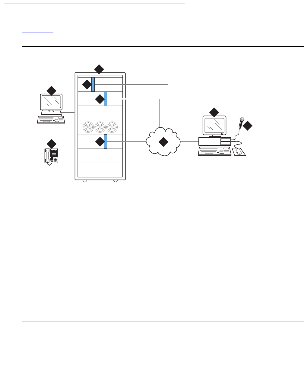
Communication Manager Maintenance-Object Repair Procedures
2478 Maintenance Procedures for Avaya Communication Manager 3.0, Media Gateways and Servers
Configurations
Figure 149 shows the configuration options for the TN2501AP (VAL) circuit pack within a
system.
Figure 149: VAL configuration options
Figure notes:
1. TN2501AP VAL announcement
circuit pack
6. Your LAN (See LAN cable on
page 2483)
2. System access terminal (SAT) 7. Computer or remote recording
studio for:
●recording and storing
announcements
●FTP client application
VAL Manager application (PC
only)
3. Switch 8. Microphone
4. Phone for recording
announcements
5. TN799C (C-LAN) is required when
using IP SAT or VAL Manager.
cydfval LJK 032001
1
1
2
3
5
7
8
789
5
0
46
#
2
13
46

VAL-BD (Voice Announcements over LAN Circuit Pack)
Issue 1 June 2005 2479
Hardware specifications
The following table contains a list of the required VAL hardware.
Faceplate LEDs
The following figure shows the 9 LEDs on the TN2051AP faceplate. Descriptions of each LED
are in Table 877.
Part Number
TN2501AP 1
Backplane Adapter (Label reads IP Media Processor) 1
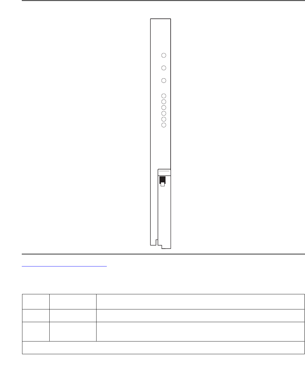
Communication Manager Maintenance-Object Repair Procedures
2480 Maintenance Procedures for Avaya Communication Manager 3.0, Media Gateways and Servers
Figure 150: TN2501AP faceplate LEDs
Table 877: TN2501AP LEDs on page 2480 lists the TN2501AP faceplate LEDs, the type of
behavior (on, off, flashing, or intermittent), and a description of the condition.
Table 877: TN2501AP LEDs
LED Behavior Description
Red On solid Circuit pack failure or a major or minor on-board alarm
Green On solid Firmware is self-downloading to the circuit pack or testing in
progress.
1 of 2
LINK
TRMT
RCV
100M
FDX
COL
fpdfval LJK 032101
VAL-BD (Voice Announcements over LAN Circuit Pack)
Issue 1 June 2005 2481
Amber On solid Firmware is self-downloading to the circuit pack.
!CAUTION:
CAUTION: You can lose the resident firmware image file if you
reset the circuit pack during firmware download. If
this happens, FTP a new firmware image file to the
VAL circuit pack and perform the Firmware download
procedure again.
Amber Fast flash
(100 ms on/
100 ms off)
Occurs during circuit pack insertion or circuit pack reset which the
announcement files are being copied from FLASH to RAM. If you
reset the circuit pack during this time, your announcement files
remain intact.
Amber Slow flash
(200 ms on/
200 ms off)
Flashes during autosave while copying announcement files from
RAM to FLASH.
!CAUTION:
CAUTION: You can lose the announcements on the circuit pack
if you reset it during an autosave.
LINK On/off Active Ethernet link
TRMT Intermittent Transmit
RCV Intermittent Receive
100M On/off Off = 10-Mbps Ethernet connection
On = 100-Mbps Ethernet connection
FDX On/off Off = half-duplex connection
On = full-duplex connection
COL On/off Off = no collisions detected
On = collisions detected
Table 877: TN2501AP LEDs (continued)
LED Behavior Description
2 of 2
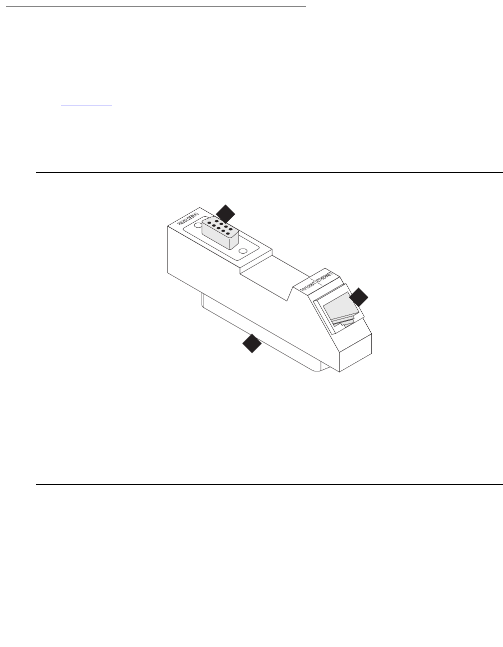
Communication Manager Maintenance-Object Repair Procedures
2482 Maintenance Procedures for Avaya Communication Manager 3.0, Media Gateways and Servers
Other hardware
To establish LAN connections the TN2501AP circuit pack requires a
●Backplane Adapter that attaches to the Amphenol connector on the back of the cabinet,
corresponding to the TN2501AP integrated announcement circuit pack slot.
●LAN cable on page 2483 that attaches to the Backplane Adapter.
Backplane Adapter
The following figure shows the Backplane Adapter (label reads IP Media Processor).
Figure 151: Backplane Adapter
Figure notes:
1. Amphenol connector attaches to
the back of the switch cabinet,
corresponding to the TN2501AP
circuit pack’s slot.
2. RJ-45 LAN cable connection
●10 Mbps uses Category 3
cable
●100 Mbps uses Category 5
cable
This connector is not used for VAL.
addfipm2 KLC 083000
1
2
3
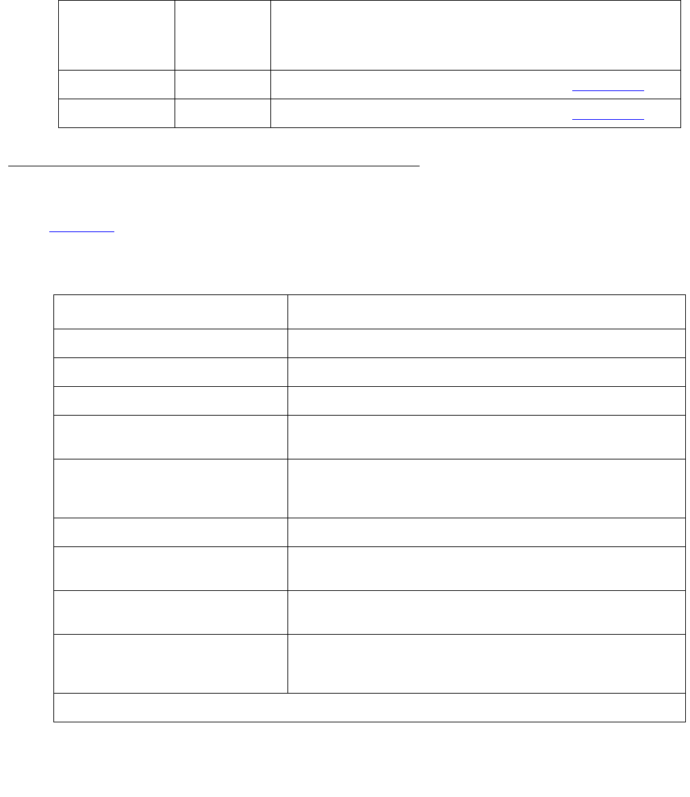
VAL-BD (Voice Announcements over LAN Circuit Pack)
Issue 1 June 2005 2483
LAN cable
The TN2501AP circuit pack does not include cables to connect the circuit pack to your LAN.
The following table lists the cable category and connection port.
VAL Maintenance Commands
Table 878 lists several VAL-related maintenance commands and how to use the command for
troubleshooting.
Ethernet
connection
speed
Cable Connection description
10 Mbps Category 3 Connects through the RJ45 jack (note #2 in Figure 151),
100 Mbps Category 5 Connects through the RJ45 jack (note #2 in Figure 151),
Table 878: VAL maintenance commands
Command Use this command to
test board Run both circuit pack- and port-level tests.
test port Test any of the ports on the VAL circuit pack.
test mo Test either of the 2 MOs on the VAL circuit pack.
busyout board Curtail activity on the circuit pack before resetting it (reset
board).
release board Resume activity on the circuit pack after busying out the
VAL circuit pack or ports on it (busyout board or busyout
port).
busyout port Isolate a specific port usually during troubleshooting.
release port Resume activity after busying out a port on the VAL circuit
pack (busyout port).
reset board Re-initialize the circuit pack in the system and upload
announcement file information.
reset val Reset the circuit pack if it is in the insane state and to
override querying the board to determine whether an
announcement autosave is in process.
1 of 2

Communication Manager Maintenance-Object Repair Procedures
2484 Maintenance Procedures for Avaya Communication Manager 3.0, Media Gateways and Servers
status data-module Obtain general information about the data-module
connection to port 33 on the VAL circuit pack
status firmware download Obtain information about a demand or scheduled
firmware download.
list sys-link Generate a list of administered links and the general
status of each.
status sys-link Generate a detailed status report for a specific
administered system link.
status link Generate a status report about a specific administered
Ethernet link. (For VAL this means the administered
Ethernet link.)
status val-ip Generate an IP-related, MIB data status report.
netstat ip-route Generate a report showing the status of the VAL IP routes
on the VAL circuit pack.
list directory See the file contents of a VAL circuit pack by location.
remove file Delete an announcement or firmware image file on a VAL
circuit pack.
enable filesystem Begin an FTP session into a specific TN2501AP circuit
pack.
disable filesystem End an FTP session into a specific TN2501AP circuit
pack.
set ethernet-options Manually or automatically set the Ethernet connection’s
parameters.
get ethernet options Generate a report about a specific Ethernet connection.
set boot-image Direct the system to use 1 of 2 possible firmware image
files on the TN2501AP circuit pack.
get boot-image View the two firmware image parameters on the VAL
circuit pack.
Table 878: VAL maintenance commands (continued)
Command Use this command to
2 of 2
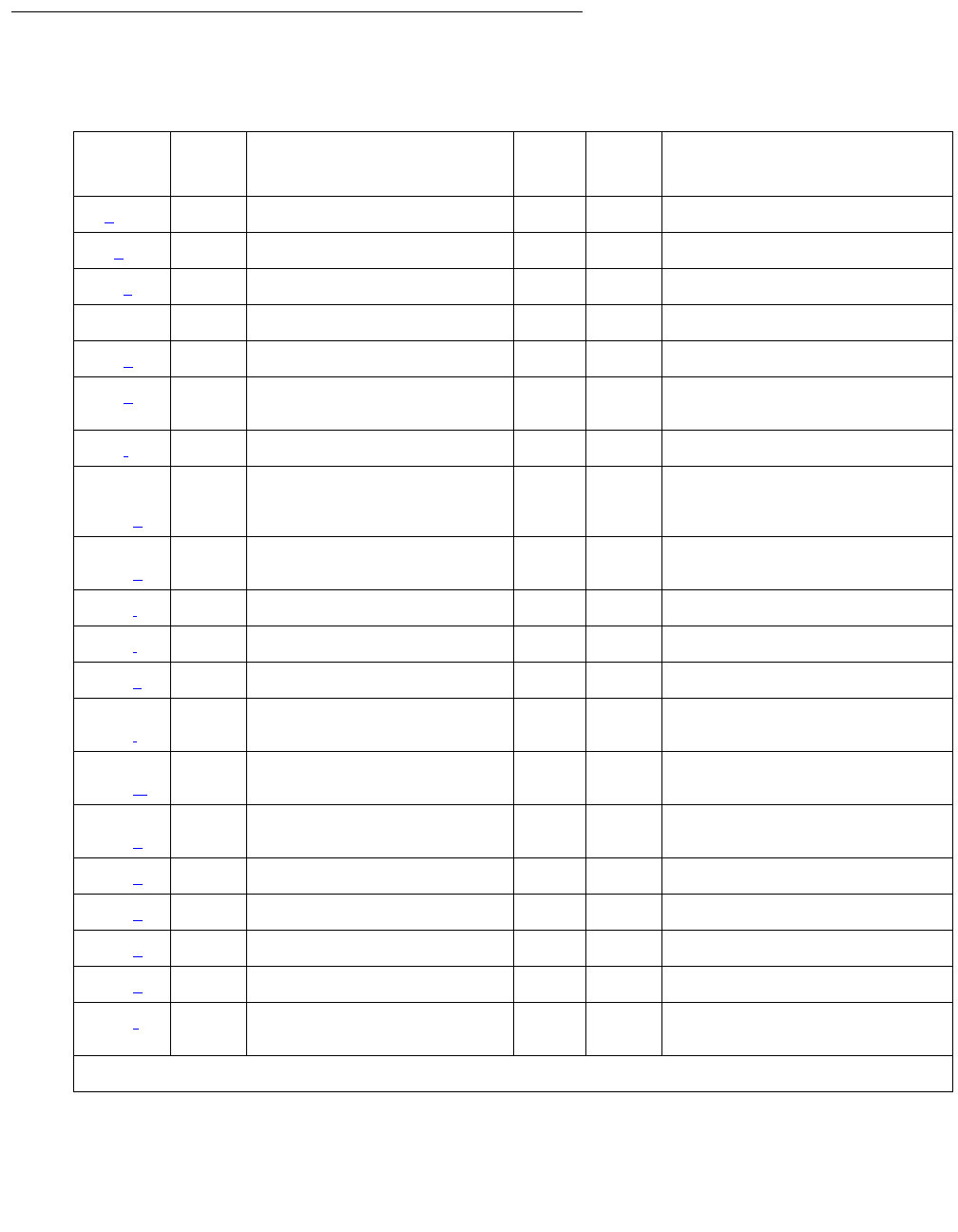
VAL-BD (Voice Announcements over LAN Circuit Pack)
Issue 1 June 2005 2485
Error Log Entries and Test to Clear Values
Table 879: VAL Hardware Error Log entries
Error
Type
Aux
Data
Associated Test Alarm
Level
On/Off
Board
Test to Clear Value
1 (a)0 Sanity MINON
18 (b)0 WRNOFFrelease board location
217 (c)0 None WRNON
257 65535 Control Channel Loop (#52) MIN ON test board location l r 20
257 (d)
513 (e) 4352–
4357
MIN ON
769 (f) 4358
1281,
1290–
1295 (g)
Any MIN ON reset board location
1537,
1796 (h)
Any MIN ON
1794 (i)MINON
1798 (j)
2049 (k) Packet Interface test (#598) MIN ON test board location l r 3
2305,
2306 (l)
2561–
2668 (m)
Any
2817,
2819 (n)
Congestion Query (#600) MIN ON test board location s r 3
3073 (o) Link Status test (#601) MIN ON test board location s
3330 (p)MINONreset board location
3586 (q)
3999 (q) Any None
3840 (r) 4096–
4102
1 of 2
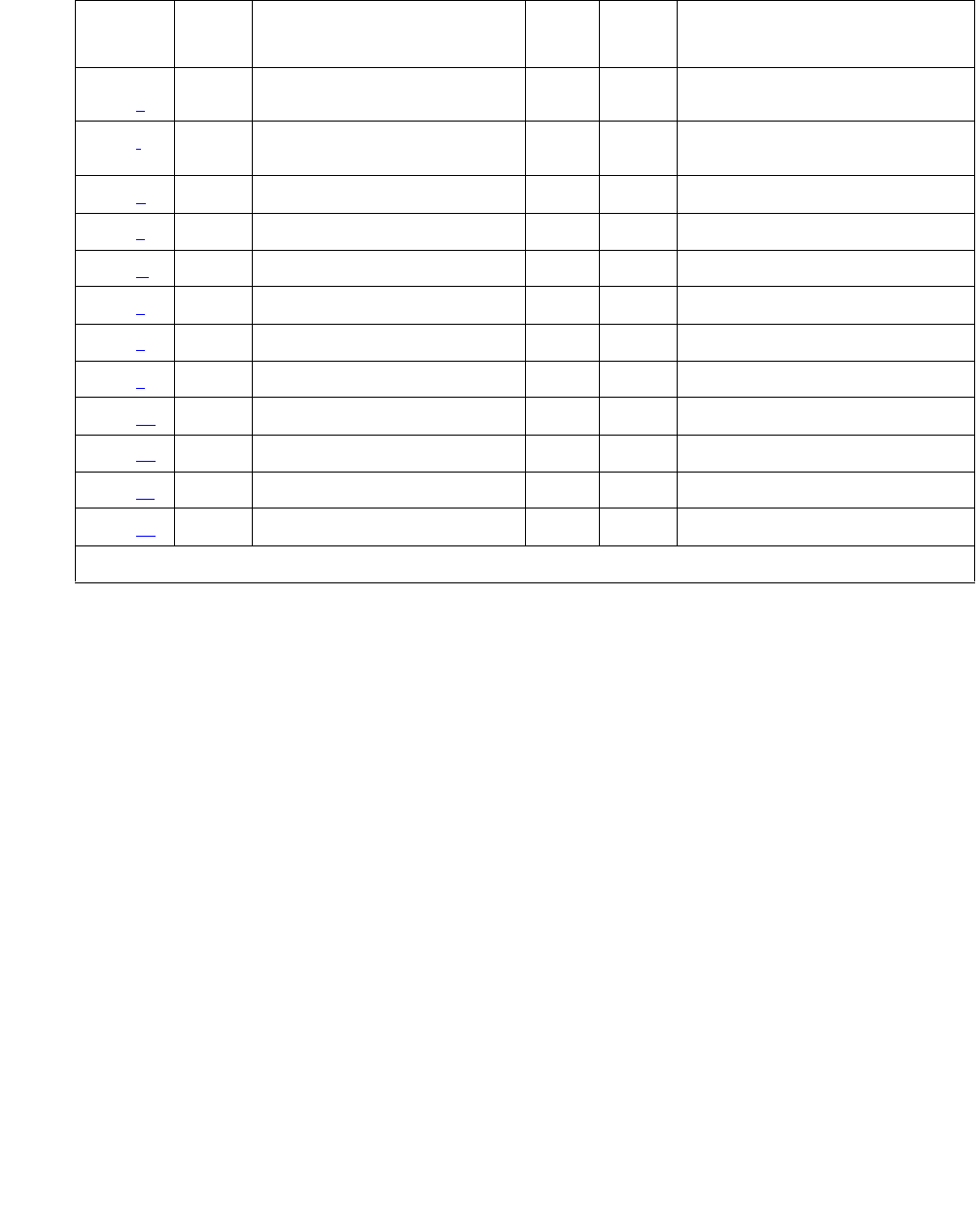
Communication Manager Maintenance-Object Repair Procedures
2486 Maintenance Procedures for Avaya Communication Manager 3.0, Media Gateways and Servers
Notes:
a. Error Type 1: circuit pack stopped functioning or is not physically present.
1. Verify that the circuit pack is present.
2. If circuit pack is present, reset the circuit pack (reset board location).
3. If the error persists, replace the circuit pack.
b. Error Type 18: the VAL circuit pack is busied out.
c. Error Type 217: applies to 10 circuit packs:
1. Remove the circuit pack(s) against which the error is logged.
d. Error Type 257: transient communication problem between switch and circuit pack; does
not affect service and can be ignored.
1. Ignore this error, unless the Control Channel Loop test (#52) fails.
2. If Test #52 fails, replace the circuit pack.
Repetitive failures of the Control Channel Loop test indicate circuit pack hardware failure.
3841,
3843 (s)
3842 (t) Receive FIFO Overflow Error
Counter test (#596)
3844 (u)Any
3845 (v)Any
3846 (w)Any
3848 (x)Any
3851 (y)Any
3852 (z)Any
3853 (aa Any
3854 (ab)Any
3855 (ac)Any
3856 (ad)Any
Table 879: VAL Hardware Error Log entries (continued)
Error
Type
Aux
Data
Associated Test Alarm
Level
On/Off
Board
Test to Clear Value
2 of 2

VAL-BD (Voice Announcements over LAN Circuit Pack)
Issue 1 June 2005 2487
e. Error Type 513: circuit pack detected and reported hardware failure.
1. Reset the circuit pack (reset board location).
Aux Data:
f. Error Type 769: logic error. By itself this error can be ignored, but it can result in other Error
Types being reported.
g. Error Type 1281, 1290–1295: critical hardware or firmware error.
Error Type descriptions are as follows:
1. Attempt to clear the alarm (reset board location).
2. If alarm persists, replace circuit pack.
h. Error Type 1537, 1796: a hyperactive VAL circuit pack that has exceeded the error
threshold has been removed from service.
1. Attempt to clear the alarm (reset board location).
2. If the error recurs within 15 minutes, replace the circuit pack.
4352 External RAM error
4353 Internal RAM error
4355 ROM Checksum error
4356 Angel Message Corruption error
4357 Instruction set error
If the switch detects: Then the switch:
1 error, Resets circuit pack.
3 errors in 15 minutes, Raises MINOR alarm.
1290 Global HDLC error
1291 Main RAM/ROM error
1292 CPU error
1293 Insane on-board processor
1294 On-board translation RAM error
1295 (Aux 3) RSCL link down
(Aux 0) RSCL keep alive failure

Communication Manager Maintenance-Object Repair Procedures
2488 Maintenance Procedures for Avaya Communication Manager 3.0, Media Gateways and Servers
i. Error Type 1794: packet bus transmit buffers have overflowed.
1. Attempt to clear the alarm (reset board location).
2. If the error recurs within 15 minutes, replace the circuit pack.
j. Error Type 1798: unable to write translation RAM.
1. Attempt to clear alarm (reset board location).
2. If alarm recurs within 15 minutes, replace the circuit pack.
k. Error Type 2049: packet Interface test (#598) failed.
1. Attempt to clear the alarm (test board location l r 3).
2. If alarm does not clear, reset the circuit pack (reset board location).
3. If circuit pack resets, execute Packet Interface test (#598) several times.
4. If Packet Interface test (#598) continues to fail, replace the circuit pack.
l. Error Type 2305-2306: error in received frame from packet bus.
Most likely cause — packet bus problem.
Other cause — circuit pack fault.
Invalid LAPD frame errors occur when the frame:
●contains a bad Cyclic Redundancy Check (CRC)
●is greater than the maximum length
●violates the link-level protocol
1. Retry the (test board location) and see if the condition clears.
2. If condition persists, execute PPE/LANBIC Receive Parity Error Counter test (#597) and
determine whether the condition clears.
3. If condition persists, execute Packet Interface test (#598) to verify circuit pack integrity.
4. If Packet Interface test (#598) fails, consult repair procedure for the packet bus.
m. Error Type 2561–2668: system software received an indication that the socket was closed
due to an error. Errors are reported as log only. Errors logged here are for the sockets that
had no processor channels associated with them, for example, sockets to read SNMP data.
The counter base is offset by the application type of the application associated with this
socket that is down. The Aux Data field of the log entry contains this application’s number,
for example, a SNMP application would have its application number in the Aux Data field.
Error Type: Description
2305 Received invalid LAPD frame.
2306 Detected parity error on received frame.

VAL-BD (Voice Announcements over LAN Circuit Pack)
Issue 1 June 2005 2489
Note:
Note: 2561–2668 is a range of reserved numbers for future applications. 2570 currently
represents an SNMP socket failure.
n. Error Type 2817–2819: Congestion Query test (#600) failed.
The Error Types correspond to the descriptions:
1. See Congestion Query Test (#600) on page 2499 for Error Code 3601 ABRT and FAIL
information.
o. Error Type 3073: Remote Socket Control Link (RSCL) or Link Status test (#601) failed. This
failure can be due to:
●This circuit pack
●The packet bus
●The packet interface circuit pack.
p. Error Type 3330: critical failure in Packet bus interface.
Below, Error Types correspond to descriptions.
1. Attempt to clear the alarm (reset board location).
2. If alarm persists, replace circuit pack.
2817 Every buffer exhausted.
2819 Utilized buffers exceed threshold.
If: Then:
Active buffers exceed threshold, VAL enters congested state.
If: Then:
RSCL disconnects at link level Link fails
Link cannot be reconnected quickly Switch raises MINOR alarm
If the switch detects: Then it:
1 error, Resets circuit pack.
2 errors in 15 minutes, Raises MINOR alarm.

Communication Manager Maintenance-Object Repair Procedures
2490 Maintenance Procedures for Avaya Communication Manager 3.0, Media Gateways and Servers
q. Error Type 3586 and 3999: switch removed hyperactive circuit pack that reported threshold
number of errors. One or more of the following symptoms can be present:
●Circuit pack port tests return NO BOARD.
●List configuration command shows circuit pack and ports are installed properly.
1. Enter busyout board location and release board location to reset the circuit
pack.
2. Allow 30 minutes for condition to clear itself.
3. To re-establish circuit pack into service manually, enter busyout board location,
reset board location, and release board location.
4. If error recurs within 15 minutes, replace the circuit pack.
5. If the same error occurs on a different circuit pack, follow normal escalation procedures.
r. Error Type 3840: circuit pack received bad control channel message from switch.
Aux Data:
If Error Type 3999: And traffic
volume is:
Then:
Does not accompany Error
Type 3586
Heavy Circuit pack is in service, but sent at least half
hyperactive threshold. With heavy traffic, this is
normal.
Does not accompany Error
Type 3586
Light Circuit pack is in service, but sent at least half
hyperactive threshold. With light traffic, this error
indicates a problem with the circuit pack, its
links, or the equipment attached to the links.
Accompanies Error Type
3586,
Either Light
or Heavy
Switch removed hyperactive circuit pack.
4096 Bad major heading
4097 Bad port number
4098 Bad data
4099 Bad sub-qualifier
4100 State inconsistency
4101 Bad logical link
4102 Bad application identifier

VAL-BD (Voice Announcements over LAN Circuit Pack)
Issue 1 June 2005 2491
s. Error Type 3841, 3843: errors do not affect service.
Below, Error Types correspond to descriptions.
These errors do not affect service, however, they can cause reports of other errors that do
affect service.
If Error Type 3843 begins to affect service, it escalates to Error Type 1294 (See Note g).
t. Error Type 3842: packet interface receive buffers overflowed.
If this error occurs frequently, the overflow can be congesting the circuit pack.
See Receive FIFO Overflow Error Counter Test (#596) on page 2496.
u. Error Type 3844: LAPD frame contains LAPD Protocol Error. By themselves, these errors
do not affect service.
v. Error Type 3845: Angel interprocessor error. By themselves, these errors do not affect
service.
w. Error Type 3846: main interprocessor error. By themselves, these errors do not affect
service.
x. Error Type 3848: main internal channel error. By themselves, these errors do not affect
service.
y. Error Type 3851: unable to write LAN translation RAM error. By themselves, these errors
do not affect service.
z. Error Type 3852: LAN external RAM error. By themselves, these errors do not affect
service.
aa. Error Type 3853: interprocessor LAPD frame error. By themselves, these errors do not
affect service.
ab. Error Type 3854: interprocessor LAPD protocol error. By themselves, these errors do not
affect service.
ac. Error Type 3855: memory allocation error. By themselves, these errors do not affect
service.
ad. Error Type 3856: high CPU occupancy error. By themselves, these errors do not affect
service.
3841 Internal firmware error
3843 Bad translation RAM. Call uses another translation location.

Communication Manager Maintenance-Object Repair Procedures
2492 Maintenance Procedures for Avaya Communication Manager 3.0, Media Gateways and Servers
System Technician-Demanded Tests:
Descriptions and Error Codes
Investigate tests in the order presented below. Clearing Error Codes associated with the one
test may also clear errors generated from other tests in the sequence.
Order of Investigation Short Test
Sequence
Long Test
Sequence
D/ND1
1. D = Destructive; ND = Nondestructive
Control Channel Loop-around test (#52) X X ND
Circuit Pack Restart test (#594) D
Invalid LAPD Frame Error Counter test (#597) X ND
PPE/LANBIC Receive Parity Error Counter test (#595) X ND
Receive FIFO Overflow Error Counter test (#596) X ND
Packet Interface test (#598) X X ND
Congestion Query test (#600) X X ND
Link Status test (#601) X X ND

VAL-BD (Voice Announcements over LAN Circuit Pack)
Issue 1 June 2005 2493
Control Channel Loop-Around Test (#52)
This nondestructive test fails if the circuit pack does not return to a sane state after being reset.
This test queries the circuit pack for its code and vintage, and verifies its records.
Table 880: Test #52 Control Channel Loop-Around Test
Error
Code
Test
Result
Description / Recommendation
None,
2100
ABRT Could not allocate the necessary system resources to run test.
1. Retry the command at 1-minute intervals up to 5 times.
2. If the problem persists, escalate the problem.
FAIL The circuit pack failed to return the code or vintage.
1. Retry command at 1-minute intervals up to 5 times.
2. Reset the board (reset board location).
3. If reset aborts with Error Code 1115, use busyout board
location, reset board location, and release board
location.
4. If test continues to fail, replace the circuit pack.
5. Escalate the problem if failures continue.
PASS Test successful.

Communication Manager Maintenance-Object Repair Procedures
2494 Maintenance Procedures for Avaya Communication Manager 3.0, Media Gateways and Servers
Circuit Pack Restart Test (#594)
This test is destructive.
Execute this test (not part of either short or long demand test sequence) to reset the circuit pack
only if there are PPCPU errors. This test fails if the circuit pack does not return to a sane state
after being reset. The circuit pack resets through the SAKI Sanity test (#53).
Table 881: Test #594 Circuit Pack Restart Test
Error
Code
Test
Result
Description / Recommendation
None ABRT Could not allocate the necessary system resources to run test.
1. Retry the command at 1-minute intervals up to 5 times.
2. If the problem persists, escalate the problem.
1015 ABRT Port is not out-of-service.
1. Busyout the circuit pack (busyout board location).
2. Retry the command at 1-minute intervals up to 5 times.
3. If the problem persists, escalate the problem.
1966 ABRT The board is in the process of running the autosave command to save
announcements.
1. Retry the command again later.
2100 ABRT Could not allocate the necessary system resources to run test.
1. Retry the command at 1-minute intervals up to 5 times.
2. If the problem persists, escalate the problem.
1, 2 FAIL The circuit pack failed to reset.
1. Retry command at 1-minute intervals up to 5 times.
2. If the problem persists, pull out and reseat the circuit pack.
3. If the problem persists, replace the circuit pack.
PASS The circuit pack initialized correctly.

VAL-BD (Voice Announcements over LAN Circuit Pack)
Issue 1 June 2005 2495
PPE/LANBIC Receive Parity Error Counter
Test (#595)
This test is nondestructive. When the VAL circuit pack detects a parity error with a received
frame, it increments the PPE/LANBIC Receive Parity error counter. This test reads and clears
the counter, and can verify repair of the problem.
Errors can indicate a problem with:
●This circuit pack
●A packet bus
●Another circuit pack on the bus
Table 882: Test #595 PPE/LANBIC Receive Parity Error Counter Test
Error
Code
Test
Result
Description / Recommendation
2000 ABRT Did not receive circuit pack test response within the allowable time period.
1. Retry command at 1-minute intervals up to 5 times.
2. If the problem persists, reset the circuit pack (reset board
location).
3. If the problem persists, replace the circuit pack.
2100 ABRT Could not allocate the necessary system resources to run test.
1. Retry the command at 1-minute intervals up to 5 times.
2. If the problem persists, escalate the problem.
2500 ABRT Internal system error.
1. Retry the command at 1-minute intervals up to 5 times.
2. If the problem persists, escalate the problem.
1–10 FAIL Circuit pack detects parity errors. The Error Code indicates the value of the
on-board error counter.
1. Retry the command at 1-minute intervals up to 5 times.
2. If the test continues to fail, execute the Packet Interface test (#598)
(test board location).
3. If Packet Interface test (#598) fails, see repair procedures for Test
#598.
PASS Circuit pack detects no errors.

Communication Manager Maintenance-Object Repair Procedures
2496 Maintenance Procedures for Avaya Communication Manager 3.0, Media Gateways and Servers
Receive FIFO Overflow Error Counter Test (#596)
This test is nondestructive. When the VAL circuit pack detects packet bus buffer overflow, it
increments the error on the FIFO Overflow error counter. This test reads and clears the counter.
If errors are occasional, then they can be due to statistical buffer sizing.
Table 883: Test #596 Receive FIFO Overflow Error Counter Test
Error
Code
Test
Result
Description / Recommendation
2000 ABRT Did not receive circuit pack test response within the allowable time period.
1. Retry command at 1-minute intervals up to 5 times.
2. If the problem persists, reset the circuit pack (reset board
location).
3. If the problem persists, replace the circuit pack.
2100 ABRT Could not allocate the necessary system resources to run test.
1. Retry the command at 1-minute intervals up to 5 times.
2. If the problem persists, escalate the problem.
2500 ABRT Internal system error
1. Retry the command at 1-minute intervals up to 5 times.
2. If the problem persists, escalate the problem.
1–10 FAIL Circuit pack detects overflow errors. The Error Code indicates the value of
the on-board error counter.
1. Retry the command at 1-minute intervals up to 5 times.
2. If the test continues to fail, execute the Packet Interface test (#598)
(test board location).
3. If Packet Interface test (#598) fails, see repair procedures for Test
#598.
PASS Circuit pack detects no errors.

VAL-BD (Voice Announcements over LAN Circuit Pack)
Issue 1 June 2005 2497
Invalid LAPD Frame Error Counter Test (#597)
This test is nondestructive.
The VAL circuit pack detects invalid frames when it receives
●a frame with a CRC error.
●an unrecognizable frame.
●a recognizable frame in an unexpected state.
When the VAL circuit pack detects an invalid LAPD frame, it increments the Invalid LAPD Frame
error counter. This test reads and clears the counter, and verifies the repair of the problem.
Errors can indicate a:
●circuit pack problem.
●packet bus problem.
●problem with another circuit pack on the bus.
Table 884: Test #597 Invalid LAPD Frame Error Counter Test
Error
Code
Test
Result
Description / Recommendation
2000 ABRT Did not receive circuit pack test response within the allowable time period.
1. Retry command at 1-minute intervals up to 5 times.
2. If the problem persists, reset the circuit pack (reset board
location).
3. If the problem persists, replace the circuit pack.
2100 ABRT Could not allocate the necessary system resources to run this test.
1. Retry the command at 1-minute intervals up to 5 times.
2. If the problem persists, escalate the problem.
2500 ABRT Internal system error.
1. Retry the command at 1-minute intervals up to 5 times.
2. If the problem persists, escalate the problem.
1 of 2

Communication Manager Maintenance-Object Repair Procedures
2498 Maintenance Procedures for Avaya Communication Manager 3.0, Media Gateways and Servers
Packet Interface Test (#598)
This nondestructive test checks the packet bus interface circuitry on the VAL circuit pack. Test
failure indicates faulty circuit pack.
1–10 FAIL The circuit pack detects LAPD frame errors. The Error Code indicates the
value of the on-board error counter.
1. Retry the command at 1-minute intervals up to 5 times.
2. If the test continues to fail, execute the Packet Interface test (#598)
(test board location long).
3. If Packet Interface test (#598) fails, see repair procedures for Test
#598.
PASS Circuit pack detects no errors.
Table 884: Test #597 Invalid LAPD Frame Error Counter Test (continued)
Error
Code
Test
Result
Description / Recommendation
2 of 2
Table 885: Test #598 Packet Interface Test
Error
Code
Test
Result
Description / Recommendation
2000 ABRT Did not receive circuit pack test response within the allowable time period.
1. Retry command at 1-minute intervals up to 5 times.
2. If the problem persists, reset the circuit pack (reset board
location).
3. If the problem persists, replace the circuit pack.
2012 ABRT Could not allocate the necessary system resources to run test.
1. Retry the command at 1-minute intervals up to 5 times.
2. If the problem persists, escalate the problem.
2100 ABRT Internal system error.
1. Retry the command at 1-minute intervals up to 5 times.
2. If the problem persists, escalate the problem.
1 of 2

VAL-BD (Voice Announcements over LAN Circuit Pack)
Issue 1 June 2005 2499
Congestion Query Test (#600)
This nondestructive test queries the number of used buffers to determine whether the VAL
circuit pack is congested.
Normal call handling resumes when the VAL circuit pack has recovered from congestion.
FAIL Circuit pack has detected a failure of the Packet Interface test (#598).
1. Retry command at 1-minute intervals up to 5 times.
2. If the problem persists, reset the circuit pack (reset board
location).
3. If the test continues to fail, replace the circuit pack.
PASS The Packet Interface test (#598) passed.
Table 885: Test #598 Packet Interface Test (continued)
Error
Code
Test
Result
Description / Recommendation
2 of 2
If: Then:
Used buffers are, or are nearly, exhausted The test fails.
The test fails The switch alarms, and announcements can fail.
Table 886: Test #600 Congestion Query Test
Error
Code
Test
Result
Description / Recommendation
2000 ABRT Did not receive circuit pack test response within the allowable time period.
1. Retry command at 1-minute intervals up to 5 times.
2. If the problem persists, reset the circuit pack (reset board
location).
3. If the problem persists, replace the circuit pack.
1 of 2

Communication Manager Maintenance-Object Repair Procedures
2500 Maintenance Procedures for Avaya Communication Manager 3.0, Media Gateways and Servers
2012 ABRT Could not allocate the necessary system resources to run test.
1. Retry the command at 1-minute intervals up to 5 times.
2. If the problem persists, escalate the problem.
2100 ABRT Internal system error.
1. Retry the command at 1-minute intervals up to 5 times.
2. If the problem persists, escalate the problem.
1 FAIL The buffer level is nearly exhausted.
2 FAIL The VAL is congested, and no buffers are available.
1. Retry command at 1-minute intervals up to 5 times.
2. If command continues to fail, examine the VAL port measurements to
determine which ports are heavily utilized and the processor
occupancy of the circuit pack.
A Low processor occupancy when VAL is congested indicates circuit pack
failure.
1. If the problem persists, reset the circuit pack (reset board
location).
2. If congestion recurs, replace the circuit pack.
High processor occupancy indicates the VAL is congested due to traffic
load.
●To relieve congestion in the short term, selectively busyout ports
(busyout port location) on the VAL circuit pack.
●To achieve a more permanent resolution, it could be necessary
reassign announcements to other integrated announcement circuit
packs.
Consider replacing affected VAL ports with new ports.
3 FAIL The VAL circuit pack is not operating normally and is congested.
PASS Hardware setting and attached cable type match VAL circuit pack
administration. The circuit pack detects no errors.
Table 886: Test #600 Congestion Query Test (continued)
Error
Code
Test
Result
Description / Recommendation
2 of 2

VAL-BD (Voice Announcements over LAN Circuit Pack)
Issue 1 June 2005 2501
Link Status Test (#601)
This nondestructive test determines the state of the call-control signaling link for VALs. If the
signaling link is physically connected, the test sends a test frame over the link and checks for a
response. The test passes only if both the signaling link is connected and the test frame is
successfully transmitted.
A failure can indicate a problem with:
●this circuit pack
●the packet bus
●the Packet Interface circuit pack
Table 887: Test #601 Link Status Test
Error
Code
Test
Result
Description / Recommendation
1125 ABRT RSCL link or VAL board not in service.
1. Release the board.
2. Repeat the test.
3. Escalate if the problem persists.
2012 ABRT Could not allocate the necessary system resources to run this test.
1. Retry the command at 1-minute intervals up to 5 times.
2. If the problem persists, escalate the problem.
2100 ABRT Internal system error.
1. Retry command at 1-minute intervals up to 5 times.
2. If the problem persists, escalate the problem.
2 FAIL The RSCL control link disconnected.
1. Retry command at 1-minute intervals up to 5 times.
2. If the test continues to fail, execute the Packet Interface test (#598)
(test board location) to see if the problem is in the circuit pack.
●If the Packet Interface test (#598) fails, see Packet Interface Test
(#598) repair procedures.
●If the Packet Interface test (#598) passes, see Packet Interface Test
(#598) and Packet bus repair procedures.
1 of 2

Communication Manager Maintenance-Object Repair Procedures
2502 Maintenance Procedures for Avaya Communication Manager 3.0, Media Gateways and Servers
3 FAIL Received no response to RSCL control link test frame.
1. Retry command at 1-minute intervals up to 5 times.
2. If the problem persists, reset the circuit pack (reset board
location).
3. If test continues to fail, replace the circuit pack.
PASS RSCL control link connected.
Table 887: Test #601 Link Status Test (continued)
Error
Code
Test
Result
Description / Recommendation
2 of 2

VAL-PT (Voice Announcements over LAN Packet/Port)
Issue 1 June 2005 2503
VAL-PT (Voice Announcements over LAN Packet/Port)
S8700 | 8710 / S8500 / S8300
Note:
Note: G700: Although the VAL-PT MO can reside in a G700 Media Gateway, neither of
the tests described herein execute against a G700 VAL-PT.
S8300 / G700
For the G700, the MG-ANN (Voice Announcements) MO working with this maintenance object
provides per board announcement storage time of up to 20 minutes (15 playback ports and 1
recording port that can also be used as a playback port), and allows for announcement file
portability via LAN connectivity. MG-ANN also allows for LAN backup and restore of
announcement files and the use of customer provided waveform (.WAV) files.
The MG-ANN hardware is located on the G700 motherboard. Communication Manager
maintenance supports the MG-ANN by using a virtual board concept to allow for board insertion
and maintenance testing. The virtual slot location is V9.
S8700 | 8710 / S8500
An RSCL (remote socket control link) connects the VAL and the server to pass call-control and
other management information. Because one link serves every port on the circuit pack,
maintenance of the RSCL is part of the VAL circuit pack maintenance.
MO Name Alarm Level Initial SAT Command to Run Full Name of MO
VAL-PT MAJ test port location long VAL Port Maintenance
VAL-PT MIN test port location long VAL Port Maintenance
VAL-PT WRN test port location short VAL Port Maintenance

Communication Manager Maintenance-Object Repair Procedures
2504 Maintenance Procedures for Avaya Communication Manager 3.0, Media Gateways and Servers
VAL Congestion Controls
The switch activates congestion controls on VAL when it detects buffers exceeding the
threshold. The switch releases the congestion controls when the VAL reports that its buffer level
has returned to normal levels.
Error Log Entries and Test to Clear Value
Notes:
a. Error Type 0: there is no short test sequence for this MO. Every test is available in the long
test sequence. Refer to each appropriate test’s description, and follow its recommended
procedures.
b. Error Type 1: SCOTCH Synchronous Loop-Around Test (#1275) failed.
1. Test the port (test port location long).
2. See SCOTCH Synchronous Loop-Around Test (#1275) on page 2507 repair procedures.
c. Error Type 257: VAL port detected overrun or underrun condition that can indicate a
hardware problem.
1. Test for hardware problem (test port location long).
If congestion: Then the switch:
Persists for a 14-minute interval Raises MINOR alarm
Exhausts buffers Raises MINOR alarm
Ceases for 12 minutes Retires MINOR alarm
Error
Type
Aux
Data
Associated Test Alarm
Level
On/Off
Board
Test to Clear Value
0 (a) 0 Any Any Any test port location
l
1 (b) 0 SCOTCH Sync
Loop-Around (#1275)
MIN ON test port location
l r 3
257 (c)0 WRNOFF
3585 (d) 0, 1 TDM Loop-Around Test
(#1285)
MAJ ON test port location
l r 3

VAL-PT (Voice Announcements over LAN Packet/Port)
Issue 1 June 2005 2505
2. See SCOTCH Synchronous Loop-Around Test (#1275) on page 2507 repair procedures
to verify repair.
3. Clear the alarm (test port location long clear).
d. Error Type 3585: TDM Port Loop-Around Test (#1285) failed.
1. Test the port (test port location long).
2. See the TDM Loop-Around Test (#1285) repair procedure.
System Technician-Demanded Tests:
Descriptions and Error Codes
Investigate tests in the order presented below. Clearing Error Codes associated with the one
test may also clear errors generated from other tests in the sequence.
TDM Loop-Around Test (#1285)
This test is destructive.
Note:
Note: G700: On the G700, this test aborts with Error Code 1412.
This test verifies whether the VAL port can send and receive data on the TDM bus. This test has
a tone generator send tones on a timeslot, and it has a tone receiver receive tones on another
timeslot. The tones are looped through the record/playback port.
Order of Investigation Short Test
Sequence
Long Test
Sequence
D/ND1
1. D = Destructive, ND = Nondestructive
TDM Loop-Around Test (#1285)
G700: this test aborts with Error Code 1412.
XD
SCOTCH Synchronous Loop-Around Test (#1275)
G700: this test aborts with Error Code 1412.
XD
If the received tones... Then...
Match the tones sent The test passes.
Do not match the tones sent The test fails.

Communication Manager Maintenance-Object Repair Procedures
2506 Maintenance Procedures for Avaya Communication Manager 3.0, Media Gateways and Servers
Test failure indicates failure of one or more of the following components:
●VAL (TN2501) circuit pack
●TDM bus
●Tone generator / tone receiver circuit pack
Table 888: Test #1285 TDM Loop-Around Test
Error
Code
Test
Result
Description / Recommendation
1000 ABRT The port is in use.
1. Retry the command when the port is idle. You can force the port to the
idle state with busyout port location.
2. Escalate if the problem persists.
Note: This command is destructive, tearing down every call and link using
the port.
1002 ABRT No TDM bus timeslots available for the test.
1. Retry the command at 1-minute intervals up to 5 times.
2. Escalate if the problem persists.
1003 ABRT No more tone receivers idle for use in this test.
1. Retry the command at 1-minute intervals up to 5 times.
2. Escalate if the problem persists.
G700:
1412
ABRT On the G700, this test aborts with Error Code 1412.
2000 ABRT Did not receive circuit pack test response within the allowable time period.
1. If this problem persists, reset the circuit pack (busyout board
location, reset board location, and release board
location).
2. Repeat the test.
3. If the problem persists, replace the circuit pack.
2012 ABRT Internal system error.
1. Retry the command at 1-minute intervals up to 3 times.
2. Escalate if the problem persists.
2100 ABRT Could not allocate the necessary system resources to run test.
1. Retry the command at 1-minute intervals up to 5 times.
2. Escalate if the problem persists.
1 of 2

VAL-PT (Voice Announcements over LAN Packet/Port)
Issue 1 June 2005 2507
SCOTCH Synchronous Loop-Around Test (#1275)
This test is destructive.
Note:
Note: G700: On the G700, this test aborts with Error Code 1412.
This test verifies the circuit in the data path of a VAL announcement port call. This test fails if the
data transmitted on the port does not match the data received in the loop-around mode. Failure
of this test indicates a port hardware fault on the circuit pack.
This test aborts if calls are using the port, or if the VAL link associated with the port is
connected. To avoid this, at the SAT type busyout port location, which tears down every
call and link using the port.
FAIL Received tones do not match transmitted tones.
1. Retry command at 1-minute intervals up to 3 times.
2. If the problem persists, see TDM-BUS (TDM Bus) on page 2237,
TONE-PT (Tone Generator) on page 2353, and Tone Receiver repair
procedures.
3. If the problem persists, reset the board (busyout board location,
reset board location, and release board location).
Repeat the test.
4. If the problem persists, replace the circuit pack.
PASS Port connections across the TDM bus function properly.
Table 888: Test #1285 TDM Loop-Around Test (continued)
Error
Code
Test
Result
Description / Recommendation
2 of 2
Table 889: Test #1275 SCOTCH Synchronous Loop-Around Test
Error
Code
Test
Result
Description / Recommendation
1000 ABRT The port is in use.
1. Retry the command when the port is idle. You can force the port to the
idle state with busyout port location.
Note: This command is destructive, tearing down every call and link
using the port.
1 of 2

Communication Manager Maintenance-Object Repair Procedures
2508 Maintenance Procedures for Avaya Communication Manager 3.0, Media Gateways and Servers
1002 ABRT No TDM bus timeslots available for the test.
1. Retry the command at 1-minute intervals up to 5 times.
2. Escalate if the problem persists.
G700:
1412
ABRT On the G700, this test aborts with Error Code 1412.
1963 ABRT The port is in use.
1. Retry the command when the port is idle. You can force the port to the
idle state with busyout port location.
Note: This command is destructive, tearing down every call and link
using the port.
2000 ABRT Did not receive circuit pack test response within the allowable time period.
●If this problem persists, reset the circuit pack (busyout board
location, reset board location, and release board
location).
●If the problem persists, replace the circuit pack.
2012 ABRT Internal system error.
1. Retry the command at 1-minute intervals up to 3 times.
2. Escalate if the problem persists.
2100 ABRT Could not allocate the necessary system resources to run test.
1. Retry the command at 1-minute intervals up to 5 times.
2. Escalate if the problem persists.
FAIL VAL circuit pack detected test failure.
●If the problem persists, reset the circuit pack (busyout board
location, reset board location, and release board
location).
●If the problem persists, replace the circuit pack.
PASS Port circuitry functioning properly.
Table 889: Test #1275 SCOTCH Synchronous Loop-Around Test (continued)
Error
Code
Test
Result
Description / Recommendation
2 of 2
VC-BD
Issue 1 June 2005 2509
VC-BD
S8700 | 8710 / S8500
!CAUTION:
CAUTION: If the TN788 Voice Conditioner circuit pack (VC-BD) is not Vintage 2 or later, it
must be replaced.
The TN788 Voice Conditioner circuit pack (VC-BD) is a service circuit pack that provides
conditioning for the audio signals from multimedia equipment based on the CCITT H.221
standard. The TN788 transcodes, gain adjusts, and bridges the audio bit streams demultiplexed
by the TN787 (MMI) circuit pack and transmits encoded, exclusive audio conference sums onto
the TDM bus so that the MMI can multiplex the audio, video, and data streams for the H.221
endpoints.
Error Log Entries and Test to Clear Values
MO Name Alarm Level Initial SAT Command to Run Full Name of MO
VC-BD MAJ test board location l r# Voice Conditioner circuit pack
VC-BD MIN test board location l r# Voice Conditioner circuit pack
VC-BD WRN1
1. See XXX-BD (Common Port Circuit Pack/Media Module) on page 2539.
test board location s r# Voice Conditioner circuit pack
Table 890: VC-BD Error Log Entries
Error
Type
Aux
Data
Associated Test Alarm
Level
On/Off
Board
Test to Clear Value
0 (a) 0 Any Any Any test board location sh r 1
1 (b)AnyNone MINON
18 (c)0 busyout board location WRN OFF release board location
257 (d) Any Control Channel Loop (#52) MIN ON test board location r 20
513 (e) 4352-
4357
769 (f)4358
1025 (g) 4363 NPE Audit test (#50)
1281 (h) Any SAKI Sanity test (#53) MAJ ON
1293 -
1294 (i)
46088-
46096
SAKI Sanity test (#53) MIN ON
1 of 2

Communication Manager Maintenance-Object Repair Procedures
2510 Maintenance Procedures for Avaya Communication Manager 3.0, Media Gateways and Servers
Notes:
a. Error Type 0: run the short test sequence first. If every test passes, run the long test
sequence. Refer to each appropriate test’s description, and follow its recommended
procedures.
b. Error Type 1: the circuit pack stopped functioning or it was removed from the system. This
alarm is logged approximately 11 minutes after the circuit pack is removed and/or the SAKI
Sanity test (#53) fails.
To resolve this error, insert a circuit pack in the same slot as the error indicates, if the circuit
pack is not already in the system. Or, if the circuit pack is in the system and the red LED is
on, then follow instructions for Red alarms.
!CAUTION:
CAUTION: If the TN788 Voice Conditioner circuit pack (VC-BD) is not Vintage 2 or later, it
must be replaced.
c. Error Type 18: this circuit pack is busied out by busyout board location.
d. Error Type 257: transient communication problems exist between the switch and this circuit
pack. Execute test board location and see the repair procedures for the Control
Channel Loop-Around Test (#52) on page 2512.
e. Error Type 513: the circuit pack detected an on-board hardware failure. The reported Aux
Data values correspond to the following detected errors:
Reset the circuit pack by executing busyout board location, reset board
location, and release board location. When it is reset, the circuit pack executes a
set of tests to detect the presence of any of the above faults. The detection of one these
errors during initialization causes the circuit pack to lock-up and appear insane to the
system. See the repair procedures in footnote (a) for Error Type 1.
1538 (j) 46082 MIN ON
Error Description
4352 External RAM error
4353 Internal RAM error
4355 ROM Checksum error
4357 Instruction set error
Table 890: VC-BD Error Log Entries (continued)
Error
Type
Aux
Data
Associated Test Alarm
Level
On/Off
Board
Test to Clear Value
2 of 2

VC-BD
Issue 1 June 2005 2511
f. Error Type 769: the circuit pack detects a program logic error. While no action is required,
this error may lead to errors of other types being reported against this circuit pack.
g. Error Type 1025: the circuit pack cannot update NPE memory and read it back. This Error
Type can be ignored, but it may lead to other Error Types being reported against this circuit
pack.
h. Error Type 1281: a critical hardware failure has been detected on the circuit pack. Use
busyout board location, reset board location, followed by release board
location. If Test #53 passes, the on-board circuitry is healthy. Use test board
location long clear to retire the alarm. If Test #53 fails, replace the circuit pack.
i. Error Type 1293 and 1294: the circuit pack detected a critical hardware failure. Reset the
circuit pack with busyout board location, reset board location, and release
board location. If the Circuit Pack Restart test (#594) passes, then the on-board
circuitry is healthy. Retire the alarm by issuing test board location long clear. If
the Circuit Pack Restart test (#594) fails, replace the circuit pack.
The reported Error Types correspond to the following detected errors:
j. Error Type 1538: the circuit pack is hyperactive — it is flooding the switch with messages
sent over the control channel. The circuit pack is taken out of service when a threshold
number of these errors is reported to the switch. Clear the alarm by using busyout board
location, reset board location, test board location long clear, and
release board location. If the error recurs within 10 minutes, then replace the circuit
pack.
Error Type Description
1293 On-board auxiliary processor insane
1294 Internal memory access error

Communication Manager Maintenance-Object Repair Procedures
2512 Maintenance Procedures for Avaya Communication Manager 3.0, Media Gateways and Servers
System Technician-Demanded Tests:
Descriptions and Error Code
!CAUTION:
CAUTION: If the TN788 Voice Conditioner circuit pack (VC-BD) is not Vintage 2 or later, it
must be replaced.
Control Channel Loop-Around Test (#52)
See the repair procedure described in XXX-BD (Common Port Circuit Pack/Media Module) on
page 2539 as Control Channel Loop-Around Test (#52).
Order of Investigation Short Test
Sequence
Long Test
Sequence
D/ND
Control Channel Loop-around test (#52)1
1. See repair procedures described in XXX-BD (Common Port Circuit Pack/Media Module) on
page 2539.
X X Nondestructive

VC-DSPPT
Issue 1 June 2005 2513
VC-DSPPT
S8700 | 8710 / S8500
Each Voice Conditioner circuit pack (VC-BD) provides two types of resources:
●Transcoder Resources used for encoding and decoding audio formats
●Summer Resources used for summing audio from different sources
The eight Voice Conditioner DSP ports are the transcoder resources on the VC-BD.
Error Log Entries and Test to Clear Values
MO Name Alarm Level Initial SAT Command to Run Full Name of MO
VC-DSPPT MAJ test port location Voice Conditioner DSP Port
VC-DSPPT MIN test port location Voice Conditioner DSP Port
VC-DSPPT WRN test port location Voice Conditioner DSP Port
Table 891: VC-DSPPT Error Log Entries
Error
Type
Aux
Data
Associated Test Alarm
Level
On/Off
Board
Test to Clear Value
0 (a) 0 Any Any Any test port location sh r 1
18 (b)0 busyout port
location
WRN OFF release port location
257 (c) Any NPE Crosstalk test (#6) MIN ON test port location 1 r 3
513 (d) Any VC DSP Port Local TDM
Loopback test (#1104)
MIN ON test port location sh r 3
778
-781 (e)
Any VC Port Reset DSP test
(#1106)
MAJ ON
1025 (f)WRNON
1281 (g) Any VC DSP Port DSP
Loopback test (#1105)
MIN ON test port location sh r 3
3840 (h)
Communication Manager Maintenance-Object Repair Procedures
2514 Maintenance Procedures for Avaya Communication Manager 3.0, Media Gateways and Servers
Notes:
a. Error Type 0: run the short test sequence first. If every test passes, run the long test sequence. Refer to
each appropriate test’s description, and follow its recommended procedures.
b. Error Type 18: this port has been busied out by busyout port location.
c. Error Type 257: the VC DSP Port NPE Crosstalk test (#1103) failed.
d. Error Type 513: the VC DSP Port Local TDM Loopback test (#1104) failed. Run the long
test sequence.
e. Error Type 778 - 781: a critical hardware failure has been detected on the circuit pack.
Reset the port by busyout port location and reset port location. If the VC
Reset DSP test (#1106) passes, then the on-board circuitry is healthy. Retire the alarm with
test port location long clear.
f. Error Type 1025: the VC DSP port reported loss of framing on the Service Channel
between the VC and MMI circuit packs.
g. Error Type 1281: the VC DSP Port DSP Loopback test (#1105) failed.
h. Error Type 3840: the DSP corresponding to this port on the VC circuit pack reported a
firmware error. No action is required.
System Technician-Demanded Tests:
Descriptions and Error Codes
Investigate tests in the order presented below. Clearing Error Codes associated with one test
may also clear errors generated from other tests in the sequence.
DSP NPE Crosstalk Test (#1103)
This test is destructive.
The NPE Crosstalk test verifies that this port’s NPE channel talks on the selected time slot and
never crosses over to time slots reserved for other connections. If the NPE is not working
correctly, 1-way and noisy connections may be observed. This test is part of the port’s long test
sequence and takes approximately 20 to 30 seconds to complete.
Order of Investigation Short Test
Sequence
Long Test
Sequence
D/ND1
1. D = Destructive; ND = Nondestructive
DSP NPE Crosstalk test (#1103) X D
TDM Loopback test (#1104) X X D
DSP Loopback test (#1105) X X D

VC-DSPPT
Issue 1 June 2005 2515
VC DSP Port Local TDM Loop-Back Test (#1104)
This test is destructive.
This test verifies the connectivity of a VC DSP Port across the TDM bus. It aborts if calls
associated with the port are in progress. Failure of this test indicates an on-board fault
associated with the port hardware on the circuit pack. The Loopback test runs the following
tests:
1. A loop-around test across the TDM bus.
2. A conference circuit test.
The tests are run in the above order; if one test fails, an Error Code is returned and the
remaining tests in the sequence are not executed.
Table 892: Test #1103 NPE Crosstalk Test
Error
Code
Test
Result
Description / Recommendation
1000
1001
ABRT System resources required to run this test are not available. The port may
be busy with a valid call.
1. Retry the command at 1-minute intervals up to 5 times.
2012 ABRT Internal system error
1. Retry the command at 1-minute intervals up to 5 times.
2100 ABRT Could not allocate the necessary resources for this test.
1. Retry the command at 1-minute intervals up to 5 times.
0-3 FAIL The NPE of the tested port was transmitting in error, causing noisy and
unreliable connections.
1. Replace the circuit pack.
PASS The port is correctly using its allocated time slots.
1. To be sure that this is not an intermittent problem, repeat this test up to
10 times.
2. If complaints still persist, examine the station, connections, and wiring.
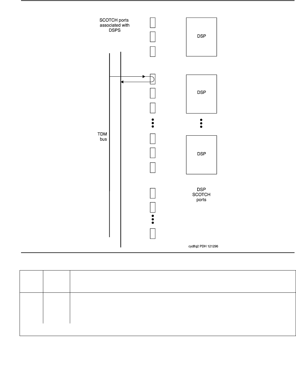
Communication Manager Maintenance-Object Repair Procedures
2516 Maintenance Procedures for Avaya Communication Manager 3.0, Media Gateways and Servers
Figure 152: VC Circuit Pack DSP Port Local TDM Loop-Back Test
Table 893: Test #1104 VC DSPPT Local TDM Loop-Back Test
Error
Code
Test
Result
Description / Recommendation
1000
1001
ABRT System resources required to run this test are not available, or the port is
busy with a valid call.
1. Retry the command at 1-minute intervals up to 5 times.
1 of 3

VC-DSPPT
Issue 1 June 2005 2517
1002 ABRT The system could not allocate time slots for the test. The traffic load on the
system is very high, or time slots may be out-of-service due to TDM-BUS
errors.
1. If the system has no TDM-BUS errors and is not handling heavy traffic,
repeat the test at 1-minute intervals up to 5 times.
1003 ABRT The system could not allocate a Tone Detector for the test. The system is
oversized for the number of Tone Detectors present, or some Tone
Detectors are out-of-service.
1. Resolve any TTR-LEV errors.
2. Resolve any TONE-PT errors.
3. If neither condition exists, retry the command at 1-minute intervals up to
5 times.
1004 ABRT The port is seized by a user for a valid call. Use status station for the
station associated with this port and determine whether the port is available
for testing.
1. Retry the command at 1-minute intervals up to 5 times.
2000 ABRT Response to the test was not received from the VC-BD circuit pack within
the allowable time period.
1. If this result occurs repeatedly, attempt to reset the port by using
busyout port location and reset port location.
2. If this result occurs again, replace the circuit pack.
2012 ABRT Internal system error
1. Retry the command at 1-minute intervals up to 5 times.
2100 ABRT Could not allocate the necessary resources to run this test.
1. Retry the command at 1-minute intervals up to 5 times.
2103 ABRT The system could not make the conference connection for the test.
1. Retry the command at 1-minute intervals up to 5 times.
0–3 FAIL The TDM Loop-Around test failed.
1. Replace circuit pack.
Table 893: Test #1104 VC DSPPT Local TDM Loop-Back Test (continued)
Error
Code
Test
Result
Description / Recommendation
2 of 3

Communication Manager Maintenance-Object Repair Procedures
2518 Maintenance Procedures for Avaya Communication Manager 3.0, Media Gateways and Servers
VC-DSP Port DSP Loop-Back Test (#1105)
This test is destructive.
This test verifies the connectivity of a VC-DSPPT across the TDM bus. It aborts if calls
associated with the port are in progress. Failure of this test indicates an on-board fault
associated with the port hardware on the circuit pack.
4–7 FAIL The Conference Circuit test failed.
1. Replace circuit pack.
PASS The VC DSP Port Local TDM Loop-Around test passed.
Table 893: Test #1104 VC DSPPT Local TDM Loop-Back Test (continued)
Error
Code
Test
Result
Description / Recommendation
3 of 3
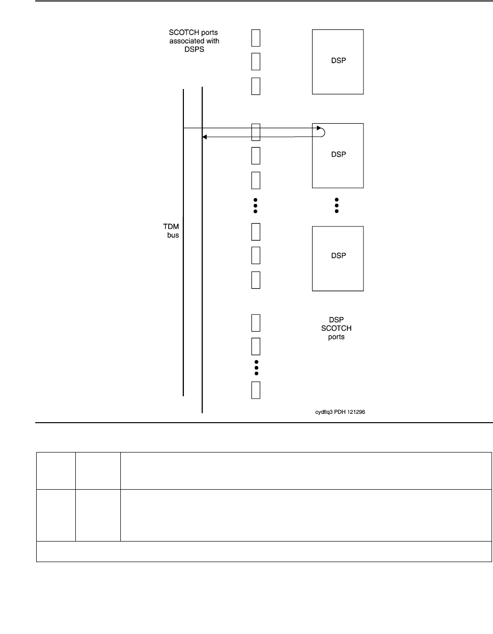
VC-DSPPT
Issue 1 June 2005 2519
Figure 153: VC Circuit pack DSP Port DSP Loop-Around Test
Table 894: Test #1105 VC-DSP Port DSP Loop-Back Test
Error
Code
Test
Result
Description / Recommendation
1000 ABRT System resources required to run this test are not available, or the port is
busy with a valid call.
1. Retry the command at 1-minute intervals up to 5 times.
1 of 2

Communication Manager Maintenance-Object Repair Procedures
2520 Maintenance Procedures for Avaya Communication Manager 3.0, Media Gateways and Servers
1002 ABRT The system could not allocate time slots for the test, the traffic load on the
system is very high, or time slots are out-of-service due to TDM-BUS
errors.
1. If the system has no TDM-BUS errors and is not handling heavy traffic,
retry the command at 1-minute intervals up to 5 times.
1003 ABRT The system could not allocate a Tone Detector for the test, the system is
oversized for the number of Tone Detectors present, or some Tone
Detectors are out-of-service.
1. Resolve any TTR-LEV errors.
2. Resolve any TONE-PT errors.
3. If neither condition exists, retry the command at 1-minute intervals up
to 5 times.
1004 ABRT The port has been seized by a user for a valid call. Use status station
for the station associated with this port and determine whether the port is
available for testing.
1. Retry the command at 1-minute intervals up to 5 times.
2000 ABRT Response to the test request was not received from the VC-BD circuit pack
within the allowable time period.
1. If this result occurs repeatedly, reset the circuit pack if the other ports
are idle by using busyout port location and reset port
location.
2. If this result occurs again, replace the circuit pack.
2012 ABRT Internal system error
1. Retry the command at 1-minute intervals up to 5 times.
2100 ABRT Could not allocate the necessary system resources to run this test.
1. Retry the command at 1-minute intervals up to 5 times.
0, 1 FAIL The VC-DSPPT DSP Loopback test failed.
1. Replace the circuit pack.
PASS The VC DSPPT DSP Loopback test passed
Table 894: Test #1105 VC-DSP Port DSP Loop-Back Test (continued)
Error
Code
Test
Result
Description / Recommendation
2 of 2

VC-DSPPT
Issue 1 June 2005 2521
VC Port Reset DSP Test (#1106)
This test is destructive.
This test resets the VC-DSPPT and the DSP associated with it. As part of the reset procedure,
the VC-DSPPT will execute a series of self-tests on the hardware. If these self-tests fail, the test
will fail; otherwise the test will pass.
Before executing the test, the VC-DSPPT must be busied out by executing busyout port
location. After the completion of the test, the VC-DSPPT must be released by executing
release port location.
Table 895: Test #1106 VC Port Reset DSP Test
Error
Code
Test
Result
Description / Recommendation
1000 ABRT System resources required to run this test are not available, or the port may
be busy with a call.
1. Retry the command at 1-minute intervals up to 5 times.
1015 ABRT The VC-DSPPT is not busied out.
1. Busyout the VC-DSPPT by executing busyout port location,
then retry the test.
2000 ABRT Response to the test was not received from the VC-DSPPT within the
allowable time period.
1. Retry the command at 1-minute intervals up to 5 times.
2. If this result occurs again, replace the circuit pack.
2012 ABRT Internal system error
1. Retry the command at 1-minute intervals up to 5 times.
2100 ABRT Could not allocate the necessary resources to run this test.
1. Retry the command at 1-minute intervals up to 5 times.
FAIL The reset of the VC-DSPPT was unsuccessful.
1. Replace circuit pack.
PASS The VC-DSPPT was successfully reset.
1. Release the VC-DSPPT by executing release port location.

Communication Manager Maintenance-Object Repair Procedures
2522 Maintenance Procedures for Avaya Communication Manager 3.0, Media Gateways and Servers
VC-LEV (Voice Conditioner DSP Port Level)
S8700 | 8710 / S8500
The MMCH feature must be enabled on the System-Parameters Customer-Options screen
before you can change these fields.
The Voice Conditioner (VC) Port Level MO monitors VC efficiency by tracking the number of VC
ports that are in-service, and then comparing that number with the value entered in the VC field
on the System-Parameters Maintenance screen. This VCs field is located under the Minimum
Maintenance Thresholds section. The VCs field contains the minimum number of VC ports
needed for the Multimedia Call Handling (MMCH) feature, and is an administrable field. The
VCs field must contain a number between 0 and 126, and is entered by the system
administrator. The MMCH feature must be enabled in the License File and corroborated by the
System-Parameters Customer-Options screen before the VCs field can be changed to a
number greater than 0. For example, administering 8 in that field means 1 circuit pack. The
algorithm for determining that a low level of VC resources exists uses the number entered in the
VCs field, and the number of VCs that are in-service in the system.
Each VC circuit pack contains 16 physical ports: 8 ports are reserved for VC-DSPPT ports, and
the remaining 8 ports are designated as VC-SUMPT ports. The 8 DSP ports are made up of 4
encoder and 4 decoder resources that encode and decode audio formats. Thus, one VC circuit
pack is required for every 8 ports of MMCH port capacity. If the number of in-service VC ports
falls below the MMCH port capacity (value entered on the System-Parameters Maintenance
screen under the Minimum Maintenance Thresholds section and in the VCs field), a VEC-LEV
error is logged. If this outage continues for 15 minutes a MAJOR alarm is raised.
Resolving VC-LEV Errors/Alarms
VC ports are a key part of the MMCH feature, any loss in the number of ports available for use
degrades the MMCH customer defined service level.
If a VC circuit pack or port is busied out using busyout board or busyout port, these
out-of-service ports are not included in the VC level calculation, thus allowing a technician to
busyout a VC circuit pack for maintenance reasons without causing a MAJOR alarm to be
raised.
Note:
Note: When diagnosing a VC-LEV problem, resolve any alarms raised against VC-BD
or VC-DSPPT MOs. Clearing VC-BD or VC-DSPPT alarms may clear the
VC-LEV alarm.
MO Name Alarm Level Initial Command to Run Full Name of MO
VC-LEV MAJ See Resolving VC-LEV Errors/Alarms VC-LEV

VC-LEV (Voice Conditioner DSP Port Level)
Issue 1 June 2005 2523
The VC circuit pack is maintained by the software similarly to the Tone Detector circuit pack.
Tone Detector circuit packs may be removed and reinserted in any port-board slot without
administration. The same rule applies to VC circuit packs. If a VC circuit pack is removed from
service logically (by failing the Archangel sanity scan test) or is removed from service physically
(by physically removing the circuit pack from the carrier), no error/alarm is raised against VC-BD
or VC-DSPPT MOs. Therefore, if a VC-LEV error/alarm exists, and none has been raised
against VC-BD or VC-DSPPT MOs, a VC circuit pack may have been removed from service
causing the VC-LEV error/alarm. To resolve a VC-LEV MAJOR alarm, restore the number of VC
ports available for service to be equal to or more than the calculated port capacity (value
entered in the VCs field).
To determine how many VC circuit packs are needed for the MMCH feature:
1. Display the System-Parameters Maintenance screen by executing display
system-parameters maintenance.
2. Locate the number listed in the Minimum Maintenance Threshold (VCs) field. The MMCH
feature requires one VC circuit pack for each four ports listed in the Minimum Maintenance
Threshold (VCs) field.
3. Divide the Minimum Maintenance Threshold value by 8 to determine the number of VC
circuit packs needed. For example, a port capacity of 12 listed in the Minimum Maintenance
Threshold (VCs) field would require 2 VC circuit packs.
4. Use list configuration to verify that the number of VC circuit packs listed agrees with
the required number of VC circuit packs (determined in step 3). If the number of VC circuit
packs listed in the step 3 differs from the calculated number, restore the number of VC
circuit packs to the correct value, in order to resolve the VC-LEV alarm.

Communication Manager Maintenance-Object Repair Procedures
2524 Maintenance Procedures for Avaya Communication Manager 3.0, Media Gateways and Servers
Error Log Entries and Test to Clear Values
Notes:
a. Error Type 1: the number of VC resources in the system that are in service has fallen below
the calculated minimum value. If the number of in-service VC ports falls below the MMCH
port capacity (value entered in the Minimum Maintenance Threshold VCs field on the
system parameters maintenance screen), a VEC-LEV error is logged.
If this outage continues for 15 minutes a MAJOR alarm is raised. To resolve this alarm,
correct the out-of-service problem:
1. See VC-DSPPT on page 2513 and VC-BD on page 2509 to resolve any associated
alarms.
2. If a VC-LEV error/alarm exist and none has been raised against VC-BD or VC-DSPPT
MOs, a VC circuit pack may have been removed from service causing the VC-LEV error/
alarm. To resolve a VC-LEV MAJOR alarm, restore the number of VC ports available for
service to be equal to or more than the calculated port capacity. See Resolving VC-LEV
Errors/Alarms on page 2522 for details.
System Technician-Demanded Tests:
Descriptions and Error Code
There are no System Technician-Demanded test for VC-LEV.
Table 896: VC-LEV Error Log Entries
Error
Type
Aux
Data
Associated Test Alarm
Level
On/Off
Board
Test to Clear Value
1 (a) Any None MAJ OFF
VC-SUMPT
Issue 1 June 2005 2525
VC-SUMPT
S8700 | 8710 / S8500
Each Voice Conditioner circuit pack (VC-BD) provides two types of resources:
●Transcoder Resources that are used for encoding and decoding audio formats
●Summer Resources that are used for summing audio formats from different sources.
The Voice Conditioner Summer ports (VC-SUMPT) are the summer resources on the VC-BD.
There are 8 such ports on a VC-BD.
Error Log Entries and Test to Clear Values
Notes:
a. Error Type 0: run the short test sequence first. If every test passes, run the long test sequence. Refer to
each appropriate test’s description, and follow its recommended procedures.
b. Error Type 18: this port has been busied out with busyout port location.
c. Error Type 130: the circuit pack has been removed or has been insane for more than
11 minutes. To clear the error, replace or reinsert the circuit pack.
MO Name Alarm Level Initial SAT Command to Run Full Name of MO
VC-SUMPT MAJ test port location Voice Conditioner Summer Port
VC-SUMPT MIN test port location Voice Conditioner Summer Port
VC-SUMPT WRN test port location Voice Conditioner Summer Port
Table 897: VC-SUMPT Error Log Entries
Error
Type
Aux
Data
Associated Test Alarm
Level
On/Off
Board
Test to Clear Value
0 (a)0 Any AnyAny test port location sh r 1
18 (b)0 busyout port location WRN OFF release port location
130 (c)WRNONtest port location sh
257 (d) Any Control Channel Loop test
(#52)
MIN ON test board location 1 r 3
513 (e) Any VC Summer Port Local
Loopback test (#1100)
MIN ON test board location sh r 3

Communication Manager Maintenance-Object Repair Procedures
2526 Maintenance Procedures for Avaya Communication Manager 3.0, Media Gateways and Servers
d. Error Type 257: the NPE Crosstalk test (#1103) failed.
e. Error Type 513: the VC Summer Port Local TDM Loopback test (#1100) failed.
System Technician-Demanded Tests:
Descriptions and Error Codes
Investigate tests in the order presented below. Clearing Error Codes associated with the one
test may also clear errors generated from other tests in the sequence.
VC-SUMPT Port NPE Crosstalk Test (#6)
This test is destructive.
The NPE controls port connectivity and gain and provides conferencing functions. The NPE
Crosstalk test verifies that this port’s NPE channel talks on the selected time slot and never
crosses over to time slots reserved for other connections. If the NPE is not working correctly,
1-way and noisy connections may be observed. This test is part of the port’s long test sequence
and takes approximately 20 to 30 seconds to complete.
Order of Investigation Short Test
Sequence
Long Test
Sequence
D/ND
NPE Crosstalk test (#6) X Destructive
TDM Loopback test (#1100) X X Destructive
Table 898: Test #6 VC-SUMPT Port NPE Crosstalk Test
Error
Code
Test
Result
Description / Recommendation
1000
1001
ABRT System resources required to run this test are not available. The port may
be busy with a valid call.
1. Retry the command at 1-minute intervals up to 5 times.
2012 ABRT Internal system error
1. Retry the command at 1-minute intervals up to 5 times.
2100 ABRT Could not allocate the necessary resources for this test.
1. Retry the command at 1-minute intervals up to 5 times.
1 of 2

VC-SUMPT
Issue 1 June 2005 2527
VC Summer Port Local TDM Loopback
Test (#1100)
This test is destructive.
This test verifies the connectivity of a VC Summer Port across the TDM bus. It aborts if calls
associated with the port are in progress. Failure of this test indicates an on-board fault
associated with the port hardware on the circuit pack. The Loopback test runs the following
tests:
●A Loop-Around test across the TDM bus.
●A conference circuit test.
The tests are run in the above order. If the first test fails, the switch returns an Error Code, and
the second test is not executed.
0–3 FAIL The NPE of the tested port was transmitting in error. This causes noisy and
unreliable connections.
1. Replace circuit pack.
PASS The port is correctly using its allocated time slots.
1. Verify that this is not an intermittent problem by repeating this test up to
10 times.
2. If complaints continue, examine the station, connections, and wiring.
Table 898: Test #6 VC-SUMPT Port NPE Crosstalk Test (continued)
Error
Code
Test
Result
Description / Recommendation
2 of 2
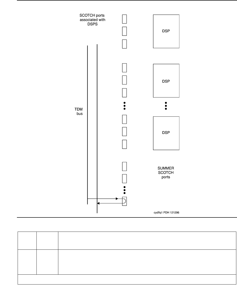
Communication Manager Maintenance-Object Repair Procedures
2528 Maintenance Procedures for Avaya Communication Manager 3.0, Media Gateways and Servers
Figure 154: VC Circuit Pack Summer Port Loop-Back Test
Table 899: Test #1100 VC Summer Port Local TDM Loop-Back Test
Error
Code
Test
Result
Description / Recommendation
1000 ABRT System resources required to run this test are not available, or the port
may be busy with a valid call.
1. Retry the command at 1-minute intervals up to 5 times.
1 of 3

VC-SUMPT
Issue 1 June 2005 2529
1002 ABRT The system could not allocate time slots for the test. The traffic load on the
system is very high, or time slots are out-of-service due to TDM-BUS
errors.
1. If the system has no TDM-BUS errors and is not handling heavy traffic,
retry the command at 1-minute intervals up to 5 times.
1003 ABRT The system could not allocate a Tone Detector for the test, the system is
oversized for the number of Tone Detectors present, or some Tone
Detectors are out-of-service.
1. Resolve any TTR-LEV errors.
2. Resolve any TONE-PT errors.
3. If neither condition exists, retry the command at 1-minute intervals up
to 5 times.
1004 ABRT The port has been seized by a user for a valid call. Use status station
for the station associated with this port to determine whether the port is
available for testing.
1. Retry the command at 1-minute intervals up to 5 times.
2000 ABRT Response to the test request was not received from the VC-BD circuit
pack within the allowable time period.
1. If this result occurs repeatedly, reset the circuit pack if the other ports
are idle. Reset the circuit pack by issuing busyout board
location and reset board location.
2. If this result occurs again, replace the circuit pack.
2012 ABRT Internal system error
1. Retry the command at 1-minute intervals up to 5 times.
2100 ABRT Could not allocate the necessary system resources to run this test.
1. Retry the command at 1-minute intervals up to 5 times.
2103 ABRT The system could not make the conference connection for the test.
1. Retry the command at 1-minute intervals up to 5 times.
0 FAIL The TDM Loop-Around test failed.
Table 899: Test #1100 VC Summer Port Local TDM Loop-Back Test (continued)
Error
Code
Test
Result
Description / Recommendation
2 of 3

Communication Manager Maintenance-Object Repair Procedures
2530 Maintenance Procedures for Avaya Communication Manager 3.0, Media Gateways and Servers
1 FAIL The Conference Circuit test failed.
1. Replace circuit pack.
PASS The VC Summer Port Local TDM Loopback test passed.
Table 899: Test #1100 VC Summer Port Local TDM Loop-Back Test (continued)
Error
Code
Test
Result
Description / Recommendation
3 of 3

WAE-PORT (Wideband Access Endpoint Port)
Issue 1 June 2005 2531
WAE-PORT (Wideband Access Endpoint Port)
S8700 | 8710 / S8500 / S8300
Wideband Switching supports end-to-end connectivity between customer endpoints at data
rates from 128 to 1536 kbps over T1 facilities and to 1984 kbps over E1 facilities.
Communication Manager switching capabilities support wideband calls comprised of multiple
DS0s that are switched end-to-end as a single entity.
Wideband Switching extends the Administered Connections feature to include non-signaling
wideband access endpoints. Endpoint application equipment with direct T1 or E1 interfaces
may connect directly to the switch’s line-side facilities; application equipment without T1 or E1
interfaces requires a terminal adapter such as a DSU/CSU. The terminal adapter or endpoint
application equipment is connected to the TN464C Universal DS1 circuit pack, and to the
MM710 DS1 Interface Media Module (G700).
Note:
Note: G700: Although the WAE-PORT MO is provided for a G700 Media Gateway, this
MO only partially supports the MM710 DS1 Media Module.
These endpoints are administered as wideband access endpoints and have no signaling
interface to switch; they simply transmit and receive data. (Some applications detect and
respond to the presence or absence of data). Calls are initiated from these endpoints using the
Administered Connections feature.
Multiple access endpoints on one line-side UDS1 circuit pack or MM710 Media Module facility
are separate and distinct within the facility. Endpoint application equipment must be
administered to send and receive the correct data rate over the correct DS0s. Every
Administered Connection originating from a wideband access endpoint uses the entire
bandwidth administered for the endpoint. An incoming call with a different data rate than that
administered for the endpoint cannot be routed to the endpoint.
Although Wideband Access Endpoints are used primarily for line-side facilities, these endpoints
can also be administered on network DS1 facilities to connect Communication Manager to
non-switched network services, such as the Avaya fractional T-1 service. An example of this is
the Avaya Static Integrated Network Access, where a trunk group to AT&T 4ESS Switched
Services shares an access T-1 facility with a Wideband Access Endpoint. In this case, the
Wideband Access Endpoint is connected to the AT&T fractional T-1 service, and it does not
terminate on local endpoint equipment, but is connected to a far-end CPE via the dedicated
fractional T-1. All Wideband Access Endpoint functionality and operation is identical on both
line-side and network facilities. However, because maintenance capabilities are limited to the
MO Name Alarm Level Initial SAT Command to Run1
1. For additional repair information, see also DIG-BD (Digital Line Circuit Pack) on page 915 and MG-DS1
(DS1 Interface Media Module) on page 1594.
Full Name of MO
WAE-PORT MIN test access-endpoint extension l Wideband Access
WAE-PORT WRN test access-endpoint extension Endpoint Port
Communication Manager Maintenance-Object Repair Procedures
2532 Maintenance Procedures for Avaya Communication Manager 3.0, Media Gateways and Servers
Wideband Access Endpoint interface, and because faults can occur end-to-end,
troubleshooting procedures based on an end-to-end view of the network is required.
Wideband access endpoint port maintenance provides a strategy to maintain a wideband
access endpoint port via a port on the Universal DS1 interface circuit pack or the MM710 DS1
Interface Media Module hardware. The maintenance strategy covers logging wideband access
endpoint port hardware errors, running tests for port initialization, periodic and scheduled
maintenance, demand tests, and alarm escalation and resolution. Two different port service
states are specified in the wideband access endpoint port maintenance:
●out-of-service: the port is in a deactivated state and cannot be used for calls
●in-service: the port is in an activated state and can be used for calls
If the UDS1 Interface circuit pack or the MM710 DS1 Interface Media Module is out of
service, every port on it is taken out of service, and a Warning alarm is raised.
Error Log Entries and Test to Clear Values
Notes:
a. Error Type 18: the wideband access endpoint has been busied out by busyout
access-endpoint extension. No calls can be made to this extension.
Table 900: Wideband Access Endpoint Maintenance Error Log Entries
Error
Type
Aux
Data
Associated Test Alarm
Level
On/Off
Board
Test to Clear Value
01
1. Run the short test sequence first. If every test passes, run the long test sequence. Refer to each appropriate
test’s description, and follow its recommended procedures.
0 Any Any Any test access-endpoint extension
sh r 1
18 (a)0 busyout access-endpoint
extension
WRN OFF release access-endpoint
extension
130 (b)None WRNONtest access-endpoint extension
1281 (c) Conference Circuit (#7) MIN ON test access-endpoint extension l
r 4
1537 (d) NPE Crosstalk Test (#6) MIN ON test access-endpoint extension l
r 3
1793 (e)None test board location long
3840 (f) Any Port Audit and Update (#36)

WAE-PORT (Wideband Access Endpoint Port)
Issue 1 June 2005 2533
b. Error Type 130: the circuit pack or media module has been removed or has been insane for
more than 11 minutes. To clear the error, reinsert or replace the circuit pack or media
module.
c. Error Type 1281: the Conference Circuit test (#7) failed on this port. See Test #7 for repair
procedures.
d. Error Type 1537: the NPE Crosstalk test (#6) failed on this port. See Test #6 for repair
procedures.
e. Error Type 1793: the TN464C UDS1 Interface circuit pack or the MM710 DS1 Interface
Media Module has failed. See UDS1-BD (UDS1 Interface Circuit Pack) on page 2374 or
MG-DS1 (DS1 Interface Media Module) on page 1594.
f. Error Type 3840: the Port Audit and Update test (#36) failed due to an internal system
error. Enter status access-endpoint extension and verify the status of the port. If
the wideband access endpoint port is out of service, enter release access-endpoint
extension to put it back into service. Retry the test command.
System Technician-Demand Tests: Descriptions and Error Codes
Investigate tests in the order listed below when inspecting errors in the system. By clearing
Error Codes associated with the NPE Crosstalk test (#6), you may also clear errors generated
from other tests in the testing sequence.
Order of Investigation Short Test
Sequence
Long Test
Sequence
D/ND1
1. D = Destructive; ND = Nondestructive
NPE Crosstalk test (#6)
G700: On the G700, this test aborts with Error Code 1412.
XND
Conference Circuit test (#7)
G700: On the G700, this test aborts with Error Code 1412.
XND
Port Audit and Update test (#36) X X ND

Communication Manager Maintenance-Object Repair Procedures
2534 Maintenance Procedures for Avaya Communication Manager 3.0, Media Gateways and Servers
NPE Crosstalk Test (#6)
Note:
Note: G700: On the G700, this test aborts with Error Code 1412.
The NPE Crosstalk test verifies that this port’s NPE channel talks on the selected time slot, and
does not cross over to time slots reserved for other connections. If the NPE is not working
correctly, 1-way and noisy connections may be observed. This test is usually part of a port’s
long test sequence and takes 20 to 30 seconds to complete
Table 901: Test #6 NPE Crosstalk Test
Error
Code
Test
Result
Description / Recommendation
ABRT System resources required for this test are not available.
1. Retry the command at 1-minute intervals up to 5 times.
1000 ABRT System resources required to run this test are not available. The port may
be in use on a valid call. Use status access-endpoint extension to
determine when the port is available for testing.
1. Retry the command at 1-minute intervals up to 5 times.
1001 ABRT System resources required for this test are not available.
1. Retry the command at 1-minute intervals up to 5 times.
1002 ABRT The system could not allocate time slots for the test. The system may be
under heavy traffic conditions or it may have time slots out-of-service due
to TDM-BUS errors. Use status health to determine whether the
system is experiencing heavy traffic.
1. If the system has no TDM-BUS errors and is not handling heavy traffic,
retry the command at 1-minute intervals up to 5 times.
1003 ABRT The system could not allocate a tone receiver for the test. The system may
be too big for the number of Tone Detectors present, or some Tone
Detectors may be out of service. Use list measurement
tone-receiver to show information about the system’s tone receivers.
1. Resolve any TTR-LEV errors.
2. Resolve any TONE-PT errors.
3. If neither condition exists, retry the command at 1-minute intervals up
to 5 times.
1 of 2

WAE-PORT (Wideband Access Endpoint Port)
Issue 1 June 2005 2535
Conference Circuit Test (#7)
Note:
Note: G700: On the G700, this test aborts with Error Code 1412.
The Conference Circuit test verifies that the NPE channel for the port being tested can correctly
perform the conferencing function. The NPE is instructed to listen to several different tones and
conference the tones together. The resulting signal is then measured by a Tone Detector port. If
the level of the tone is within a certain range, the test passes.
1004 ABRT The port has been seized by a user for a valid call. Use status
access-endpoint extension to determine when the port is available
for testing. The port is available when it is in the in-service/idle state.
1. Retry the command at 1-minute intervals up to 5 times.
1020 ABRT The test did not run because of a previously existing error on the specific
port or a more general circuit pack error.
1. Examine the Error Log for existing errors against this port or the circuit
pack and attempt to diagnose the already existing error.
G700:
1412
ABRT On the G700, this test aborts with Error Code 1412.
2000 ABRT Response to the test request was not received within the allowable time
period.
1. Retry the command at 1-minute intervals up to 5 times.
2100 ABRT System resources required for this test are not available.
1. Retry the command at 1-minute intervals up to 5 times.
FAIL The NPE of the tested port was found to be transmitting in error. This
causes noisy and unreliable connections.
1. Replace the circuit pack.
PASS The port is correctly using its allocated time slots.
1. Investigate user-reported troubles on this port using other port tests
and by examining the terminal adapter or external wiring.
Table 901: Test #6 NPE Crosstalk Test (continued)
Error
Code
Test
Result
Description / Recommendation
2 of 2

Communication Manager Maintenance-Object Repair Procedures
2536 Maintenance Procedures for Avaya Communication Manager 3.0, Media Gateways and Servers
Table 902: Test #7 Conference Circuit Test
Error
Code
Test
Result
Description / Recommendation
ABRT System resources required for this test are not available.
1. Retry the command at 1-minute intervals up to 5 times.
1000 ABRT System resources required to run this test are not available. The port may
be in use on a valid call. Use status access-endpoint extension to
determine when the port is available for testing.
1004 ABRT The port has been seized by a user for a valid call. Use status
access-endpoint extension to determine when the port is available
for testing. The port is available when it is in the in-service/idle state.
1. Retry the command at 1-minute intervals up to 5 times.
1020 ABRT The test did not run due to a previously existing error on the specific port or
because of a more general circuit pack error.
1. Examine the Error Log for existing errors against this port or circuit
pack, and attempt to diagnose the previously existing error.
G700:
1412
ABRT On the G700, this test aborts with Error Code 1412.
2000 ABRT Response to the test was not received within the allowable time period.
1. Retry the command at 1-minute intervals up to 5 times.
2100 ABRT System resources required for this test are not available.
1. Retry the command at 1-minute intervals up to 5 times.
FAIL The NPE of the tested port did not conference the tones correctly. This
causes noisy and unreliable connections. Even though wideband calls do
not use the conferencing feature on the NPE, this failure indicates
problems with the circuit pack hardware.
1. Replace the circuit pack.
PASS The port can correctly conference multiple connections.
1. Investigate user-reported troubles on this port using other port tests
and by examining the terminal adapter or external wiring.

WAE-PORT (Wideband Access Endpoint Port)
Issue 1 June 2005 2537
Port Audit and Update Test (#36)
This test sends port level translation data from switch processor to the UDS1 Interface circuit
pack to ensure that the wideband access endpoint port’s translation is correct.
Table 903: Test #36 Port Audit and Update Test
Error
Code
Test
Result
Description / Recommendation
ABRT Internal system error
1. Retry the command at 1-minute intervals up to 5 times.
1006 ABRT The port is out-of-service. If the port is busied out:
1. Enter release access-endpoint extension to put
the port back into in-service.
2. Retry the test command.
If the port is not busied out:
3. Check the error and alarm logs for WAE-PORT, and
UDS1-BD or MG-DS1 errors and alarms and follow the
recommended repair procedures.
2000 ABRT Response to the test request was not received within the
allowable time period.
1. Retry the command at 1-minute intervals up to 5 times.
2100 ABRT Could not allocate the necessary system resources to run this
test.
1. Retry the command at 1-minute intervals up to 5 times.
FAIL Internal system error
1. Retry the command at 1-minute intervals up to 5 times.
PASS Port translation has been updated successfully.
1 of 2

Communication Manager Maintenance-Object Repair Procedures
2538 Maintenance Procedures for Avaya Communication Manager 3.0, Media Gateways and Servers
Any NO
BOARD
The test could not relate the internal ID to the port (no board).
This could be due to incorrect translations, no board is inserted,
an incorrect board is inserted, or an insane board is inserted.
1. Ensure that the board translations are correct. Execute the
add ds1 location command to administer the board
interface if it is not already administered.
2. If the board was already administered correctly, check the
error log to determine whether the board is hyperactive. If
this is the case, the board is shut down. Reseating the
board will re-initialize the board.
3. If the board was found to be correctly inserted in step 1,
then enter the busyout board location.
4. Enter the reset board location.
5. Enter the release board location.
6. Enter the test board location long.
This should re-establish the linkage between the internal ID and
the port.
Table 903: Test #36 Port Audit and Update Test (continued)
Error
Code
Test
Result
Description / Recommendation
2 of 2

XXX-BD (Common Port Circuit Pack/Media Module)
Issue 1 June 2005 2539
XXX-BD (Common Port Circuit Pack/Media Module)
S8700 | 8710 / S8500 / S8300
Common Port Circuit Pack maintenance is a set of common tests used by every circuit pack or
media module listed in the following tables. The common portion of these circuit packs is the
generic hardware that interfaces with the TDM bus. The XXX-BD designation is also used on
SAT displays when reset board is entered with an empty circuit pack or media module slot,
or with a circuit pack or media module type that is in conflict with the actual board type
administered for that slot. Every circuit pack or media module suffix (B,C, D, and so forth) are
supported by “XXX-BD.”
When any of the Common Port circuit packs are physically removed from the backplane, no
alarm will be logged for approximately 11 minutes. In the case of the following, approximately 21
minutes will elapse before an alarm is logged:
●TN754 Digital Line,TN566 EMBEDDED AUDIX, and TN758 Pooled Modem circuit packs
for systems supporting circuit packs
●G700: MM712 Digital Line, MM720, and INTUITY AUDIX for systems supporting media
modules
When a circuit pack or media module that has been removed is alarmed, the alarm type is minor
and is classified as an on-board alarm. The time delay permits maintenance activity to be
performed without triggering an additional alarm.
Alarms are logged against only those common port circuit packs or media modules on which
ports have been administered. In a heavily loaded system, the interval between the removal of a
Common Port circuit pack or media module and the logging of the alarm may be several
minutes longer. The circuit packs in Table 904: XXX-BD Common Circuit Packs on page 2540
contain ports on the TDM bus. Suffixes are not shown; for a list of every circuit pack supported,
see the table in Cicrcuit Packs in Maintenance Procedures (03-300192).
Those that appear in bold type are documented separately under their own MO name. The
circuit packs in Table 904: XXX-BD Common Circuit Packs on page 2540 are listed by
apparatus code.
MO Name Alarm Level Initial SAT Command to Run Full Name of MO
XXX-BD1
1. Refer to the appropriate circuit pack or media module documentation for the correct MO name
displayed in this field. It usually ends with BD.
MAJ test board location Common Port Circuit Pack/
Media Module maintenance
XXX-BD1 MIN test board location Common Port Circuit Pack/
Media Module maintenance
XXX-BD1 WRN test board location Common Port Circuit Pack/
Media Module maintenance

Communication Manager Maintenance-Object Repair Procedures
2540 Maintenance Procedures for Avaya Communication Manager 3.0, Media Gateways and Servers
Table 904: XXX-BD Common Circuit Packs
Apparatus
Code
Name Type
CPP1 Memory Expansion Control
ED-1E546
(TN2169)
(TN2170)
(TN566)
(TN567)
EMBEDDED AUDIX R3 System Port Assembly
ED-1E546
(TN2208)
(TN2170)
Call Visor ASAI over the DEFINITY (LAN) Gateway R1 Port Assembly
TN417 Auxiliary Trunk Port
TN419B Tone-Clock Control
TN420B/C Tone Detector Service
TN429 Direct Inward/Outward Dialing (DIOD) Trunk Port
TN433 Speech Synthesizer Service
TN436B Direct Inward Dialing Trunk Port
TN437 Tie Trunk Port
TN438B Central Office Trunk Port
TN439 Tie Trunk Port
TN447 Central Office Trunk Port
TN457 Speech Synthesizer Service
TN458 Tie Trunk Port
TN459B Direct Inward Dialing Trunk Port
TN464C/D/E/F DS1/E1 Interface – 24-channel T1, 32-channel E1 Port
TN465/B/C Central Office Trunk Port
TN467 Analog Line Port
TN468B Analog Line Port
TN479 Analog Line Port
TN497 Tie Trunk Port
1 of 3

XXX-BD (Common Port Circuit Pack/Media Module)
Issue 1 June 2005 2541
TN556/B ISDN-BRI 4-Wire S/T-NT Line (A-Law) Port
TN722B Digital Signal Level 1 Tie Trunk Port
TN725B Speech Synthesizer Service
TN726/B Data Line Port
TN735 MET Line Port
TN742 Analog Line Port
TN744/B Call Classifier Service
TN744/C/D Call Classifier - Detector Service
TN746/B Analog Line Port
TN747B Central Office Trunk Port
TN748/B/C/D Tone Detector Service
TN750/B/C Announcement Service
TN753 Direct Inward Dialing Trunk Port
TN754/B Digital Line 4-Wire DCP Port
TN756 Tone Detector Service
TN758 Pooled Modem Port
TN760B/C/D Tie Trunk Port
TN762B Hybrid Line Port
TN763B/C/D Auxiliary Trunk Port
TN767B/C/D/E DS1 Interface - T1, 24 Channel Port
TN769 Analog Line Port
TN771D Maintenance/Test Service
TN777/B Network Control Control
TN778 Packet Control Control
TN787F Multimedia Interface Service
Table 904: XXX-BD Common Circuit Packs (continued)
Apparatus
Code
Name Type
2 of 3

Communication Manager Maintenance-Object Repair Procedures
2542 Maintenance Procedures for Avaya Communication Manager 3.0, Media Gateways and Servers
TN788/B Multimedia Voice Conditioner Service
TN789 Radio Controller Control
TN793 Analog Line, 24-Port, 2-Wire Port
TN797 Analog Trunk and Line Port
TN800 Multi-Application Platform for DEFINITY (MAPD) Service
TNPRI/BRI PRI-to-BRI Converter Port
TN2135 Analog Line Port
TN2136 Digital Line 2-Wire DCP Port
TN2138 Central Office Trunk Port
TN2139 Direct Inward Dialing Trunk Port
TN2140/B Tie Trunk Port
TN2144 Analog Line Port
TN2146 Direct Inward Dialing Trunk Port
TN2147/C Central Office Trunk Port
TN2149 Analog Line Port
TN2180 Analog Line Port
TN2181 Digital Line 2-Wire DCP Port
TN2183 Analog Line Port
TN2184 DIOD Trunk Port
TN2198 ISDN-BRI 2-Wire U Interface Port
TN2199 Central Office Trunk Port
TN2202 Ring Generator Power
TN2224 Digital Line, 24-Port, 2-Wire DCP Port
Table 904: XXX-BD Common Circuit Packs (continued)
Apparatus
Code
Name Type
3 of 3

XXX-BD (Common Port Circuit Pack/Media Module)
Issue 1 June 2005 2543
Additional circuit packs specific to S8700 MC systems are listed in Table 905: XXX-BD
Common Circuit Packs - S8700 MC Specific on page 2543.
.
Table 906: XXX-BD Common Media Modules on page 2543 lists common media modules by
apparatus code
.
Table 905: XXX-BD Common Circuit Packs - S8700 MC Specific
Apparatus
Code
Name Type
TN570/B/C Expansion Interface Port
TN572 Switch Node Clock Control
TN573/B Switch Node Interface Control
TN574 DS1 Converter - T1, 24 Channel Port
TN755B Neon Power Unit Power
TN768 Tone-Clock Control
TN775/B Maintenance Service
TN776 Expansion Interface Port
TN780 Tone-Clock Control
TN1654 DS1 Converter - T1, 24 Channel/E1, 32 Channel Port
TN2182/B Tone-Clock, Tone Detector, and Call Classifier Control
Table 906: XXX-BD Common Media Modules
Apparatus
Code
Name Type
MM710 DS1/E1 Interface - T1, 24 Channel -
E1, 32 Channel,
Port
MM711 Analog Trunk and Line Port
MM712 Digital Line, 8-Port, 2-Wire DCP Port
Communication Manager Maintenance-Object Repair Procedures
2544 Maintenance Procedures for Avaya Communication Manager 3.0, Media Gateways and Servers
Error Log Entries and Test to Clear Values
Notes:
a. Error Type 1: the circuit pack or media module stopped functioning or has been physically
removed from the system. This Error Type does not apply to ANN-BD, DETR-BD,
S-SYN-BD, M/T-BD, or CLSFY-BD. The alarm is logged approximately 11 minutes after
removal of the circuit pack or failure of the SAKI Sanity Test (#53).
Check for the physical presence of the circuit pack or media module in the slot indicated by
the alarm. If the circuit pack or media module is absent, insert one of the proper type. If the
circuit pack or media module is present and its red LED is lit, see LED alarms without Alarm
Log entry or with Error Type 1 on page 258.
Table 907: Common Port Circuit Pack Maintenance Error Log Entries
Error
Type
Aux
Data
Associated Test Alarm
Level
On/Off
Board
Test to Clear Value
01
1. Run the short test sequence first. If every test passes, run the long test sequence. Refer to each
appropriate test’s description, and follow its recommended procedures.
0Any AnyAnytest board location sh r 1
1 (a) 0 Circuit pack or Media Module
removed or SAKI Sanity (#53)
MIN ON
18 (b)0 busyout board location WRN OFF release board location
23 (c) 0 None WRN OFF
36 (d) 4368 none
125 (e) None MIN ON
217 (f) 0 None WRN ON
257 (g) 65535 Control Channel Test (#52) MIN ON test board location sh r 20
267 (h) 0 None WRN ON
513 (i) Any None MIN ON test board location sh
769 (j) 4358 None
1025 (k) 4363 NPE Audit Test (#50) test board location l r 20
1281 (l) Ringing Application Test (#51) MIN ON test board location r 2
1538 (m) Any None WRN
MIN
ON
1793 (n) Neon Test (#220) MIN ON test board location r 2
3840 (o) Any None
3999 (p) Any None

XXX-BD (Common Port Circuit Pack/Media Module)
Issue 1 June 2005 2545
b. Error Type 18: the circuit pack or media module has been busied out. Release the circuit
pack or media module using release board location.
c. Error Type 23: the circuit pack or media module has been logically administered but not
physically installed. The alarm should clear when the circuit pact or media module is
installed.
If the circuit pack or media module is already installed:
1. Run test board location long and look at any test failures or Error Codes
generated.
2. If the test does not clear error 23, then execute reset board location and run the
long test again.
3. If the reset/test does not clear error 23, replace the circuit pack or media module.
d. Error Type 36: this error applies only to the Maintenance/Test circuit pack (TN771B or
TN771C). The error indicates that the hardware associated with the Analog Trunk Testing
port of the circuit pack failed to initialize. Note that when this error occurs, the Maintenance/
Test circuit pack may report an invalid vintage. Although this error is not service-affecting,
the Maintenance/Test circuit pack should be replaced.
e. Error Type 125: the circuit pack or media module physically installed in the slot does not
match the type that is administered for that slot. Do one of the following:
●Remove the incorrect circuit pack or media module and replace it with one of the type
that is administered for that slot.
●Use change circuit-pack or change media-module to re-administer the slot so
that it matches the board that is installed, and follow with reset board location.
f. Error Type 217: this error applies to the Maintenance/Test circuit pack (TN771D), Tone
Detector (TN748B, TN748C, or TN748D), and Call Classifier (TN748) circuit packs. For the
Maintenance/Test circuit pack, the error indicates that there is more than one Maintenance/
Test circuit pack in the port network. For the Tone Detector or Call Classifier packs, the error
indicates that there are more than 10 circuit packs in the system. Remove the circuit pack
against which the error is logged.
g. Error Type 257: Aux Data - Any: transient communication problems with this circuit pack.
This error is not service-affecting and no action is required.
h. Error Type 267: transient communication problems with this circuit pack or media module.
This error is not service-affecting and no action is required.
i. Error Type 513: this error, when reported with Aux Data in the range of 4352 to 4358,
indicates that the circuit pack or media module has reported an on-board hardware failure.
The circuit pack or media module will continuously test the hardware and report the results
approximately every 10 minutes. If the hardware problem is resolved, the “leaky bucket”
strategy should clear the alarm in approximately 30 minutes. However, if the alarm does
NOT clear in 30 minutes, then the circuit pack or media module should be replaced.
j. Error Type 769: this error can be ignored, but look for other errors on this circuit pack or
media module.

Communication Manager Maintenance-Object Repair Procedures
2546 Maintenance Procedures for Avaya Communication Manager 3.0, Media Gateways and Servers
k. Error Type 1025: this error is not service-affecting and no action is required.
l. Error Type 1281: no ringing current is detected. Run Test #51, Ringing Application Test,
and follow the procedures for Test #51. G700: On the G700, the associated test for this Error
Type aborts with Error Code 1412.
m. Error Type 1538: the hyperactive circuit pack or media module is out-of-service and may
exhibit one or more of the following symptoms:
1. The common circuit pack/media module level tests such as Test #51 and/or Test #220
are aborting with Error Code 2000.
2. The tests run on the ports of this circuit pack or media module are returning with a
NO-BOARD.
3. A busyout/release of the circuit pack or media module has no effect on test results.
4. A list configuration command shows that the circuit pack or media module and
ports are properly installed.
If the XXX-BD is not a TN754 Digital Line Circuit Pack (DIG-BD) or Digital Line Media
Module, and if this error happens again within 15 minutes, then replace the circuit pack or
media module. If the XXX-BD is a TN754 Digital Line Circuit Pack (DIG-BD) or Digital Line
Media Module, then check the alarm level. If the alarm level is a WARNING, this indicates
that users are probably causing the hyperactivity by adjusting or changing their digital
stations. If the circuit pack or media module is very hyperactive, then this alarm will be
upgraded to a MINOR alarm within 1 hour. If the alarm level is a MINOR alarm, then replace
the circuit pack or media module.
n. Error Type 1793: no neon current is detected. Run test board location short and
follow the procedures for Test #220. This error applies to TN769 and TN746 Analog Line
circuit packs and to MM711 Analog Line Media Modules.
o. Error Type 3840: this error is not service-affecting and no action is required.
p. Error Type 3999: the circuit pack or media module sent a large number of control channel
messages to the switch within a short period of time. If Error Type 1538 is also present, then
the circuit pack or media module was taken out-of-service due to hyperactivity. If Error Type
1538 is absent, then the circuit pack or media module was not taken out-of-service, but it
has generated 50% of the messages necessary to be considered hyperactive. This may be
completely normal during heavy traffic periods. However, if this Error Type is logged when
the circuit pack or media module is being lightly used, it may indicate a problem with the
circuit pack or media module, or the equipment attached to it.

XXX-BD (Common Port Circuit Pack/Media Module)
Issue 1 June 2005 2547
System Technician-Demand Tests: Descriptions and Error Codes
Investigate tests in the order presented below. Clearing Error Codes associated with the one
test may also clear errors generated from other tests in the sequence.
Table 908: XXX-BD System Technician Demand Tests
Order of Investigation Short Test
Sequence
Long Test
Sequence
Reset Board
Sequence
D/
ND1
1. D = Destructive; ND = Nondestructive
NPE Audit test (#50)
G700: Aborts with Error Code 1412 on G700/
G350
XND
Ringing Application test (#51)
Note: This test is applicable to TN746 and TN769
Analog Line circuit packs.
G700: Aborts with Error Code 1412 on G700/
G350
XX ND
Control Channel Loop-Around test (#52) X X ND
SAKI Sanity test (#53)
Note: The SAKI Sanity test is run in the long test
sequence for the Tone-Clock circuit packs
(TN768, TN780) only. The test is run on other
circuit packs or media modules only when they
are reset using reset board location.
XD
Neon test (#220)
Note: This test is applicable to TN746 and TN769
Analog Line circuit packs.
G700: Aborts with Error Code 1412 on G700/
G350
XX ND

Communication Manager Maintenance-Object Repair Procedures
2548 Maintenance Procedures for Avaya Communication Manager 3.0, Media Gateways and Servers
NPE Audit Test (#50)
Note:
Note: G700: On the G700/G350, this test aborts with Error Code 1412.
The system sends a message to the on-board microprocessor to update the network
connectivity translation for every NPE (Network Processing Element) on the circuit pack.
Table 909: Test #50 NPE Audit Test
Error
Code
Test
Result
Description / Recommendation
None
2100
ABRT System resources required for this test are not available.
1019 ABRT Test already in progress.
G700:
1412
ABRT This test does not execute on a G700 Media Gateway.
FAIL Internal system error
1. Retry the command at 1-minute intervals up to 5 times.
PASS The circuit pack’s NPEs have been updated with their translation.
EXTRA
BD
Certain circuit packs have limitations on how many circuit packs can be in
the system or port network such as the Maintenance/Test circuit pack
(TN771B or TN771C), the Tone Detector circuit pack (TN748B, TN748C or
TN748D) and the Call Classifier (TN744). The Maintenance/Test circuit
pack allows only one circuit pack per port network. The Tone Detector and
Call Classifier allow only 10 circuit packs in each system. All additional
circuit packs will return EXTRA-BD and should be removed.
Any NO
BOARD
This is normal if the test is being done when: (a) the board is not
physically in the system or (b) the system is booting up. Otherwise, there
is some inconsistency between the physical configuration and the data
kept in the system.
1. Verify that the board is physically in the system.
2. Verify that the system is not in a stage of booting up.
3. Retry the command at 1-minute intervals up to 5 times.

XXX-BD (Common Port Circuit Pack/Media Module)
Issue 1 June 2005 2549
Ringing Application Test (#51)
This test checks the ringing application circuitry common to every port on an Analog Line circuit
pack.
Table 910: Test #51 Ringing Application Circuit Test
Error
Code
Test
Result
Description / Recommendation
ABRT Internal system error. Could not allocate the necessary system resources
to run test. The circuit pack is not installed.
1000
2100
ABRT Could not allocate the necessary system resources to run test.
1. Retry the command at 1-minute intervals up to 5 times.
1004 ABRT The port was seized by a valid call during the test. The test has been
aborted.
1. Use display port location to determine the station extension.
Use status station to determine the service state of the port. If
the service state indicates that the port is in use, then the port is
unavailable for certain tests. (Refer to Chapter 8, for a full description
of all possible states). Wait until the port is idle before retesting.
2. Retry the command at 1-minute intervals up to 5 times.
1008 ABRT Could not allocate a ringing circuit for one of the following reasons: all the
ringing circuits are in use; the ringing generator is defective; ringing
generator is not wired correctly.
1. If the test continues to abort, look for RING-GEN error in Error Log.
a. If there are RING-GEN errors, see RING-GEN (Analog Ring
Generator) on page 1942 and try to resolve any problem(s). Then,
go to step 2.
b. If there are no RING-GEN errors, and the test continues to abort,
enter test board location on other TN742, TN769, or TN746
Analog circuit packs. If an ABRT with Error Code 1008 occurs for
this test on other circuit packs as well, then the ringing generator
may be defective or may not be wired properly. See RING-GEN
(Analog Ring Generator) on page 1942 maintenance
documentation for details. If an ABRT with Error Code 1008 does
NOT occur on the other ports, then all four ring generators are in
use. Exit from this documentation.
2. Retry the command.
1 of 2

Communication Manager Maintenance-Object Repair Procedures
2550 Maintenance Procedures for Avaya Communication Manager 3.0, Media Gateways and Servers
G700:
1412
ABRT G700: On the G700, this test aborts with Error Code 1412.
2000 ABRT There was no response from the board.
1. If Error Type 1538 (hyperactivity) is present in the error log, follow the
maintenance strategy that is recommended for this Error Type.
2. Run busyout board location, reset board location, and
release board location, and retest.
3. If the test still aborts, dispatch with the circuit pack.
4. Check the off-board wiring and the terminal, and, if there are no
problems found, replace the circuit pack.
FAIL No ringing current is detected. The ringing application circuitry on this
circuit pack probably is not healthy.
1. Retry the command again.
2. If the test continues to fail, look for RING-GEN error in Error Log.
a. If there are RING-GEN errors, see RING-GEN (Analog Ring
Generator) on page 1942 and try to resolve any problem(s).
b. If there are no RING-GEN errors, then replace the circuit pack.
3. Retry the command again.
PASS Ringing current is detected or this vintage of the Analog Line circuit pack
does not support the Ringing Application Circuit Test. Analog Line circuit
packs that DO NOT support Test #51 include TN712 Vintage 13 and earlier
and TN742 Vintage 3 and earlier.
Any NO
BOARD
This is normal if the test is being done when (a) the board is not physically
in the system or (b) the system is booting up. Otherwise, there is some
inconsistency between the physical configuration and the data kept in the
system.
1. Verify that the board is physically in the system.
2. Verify that the system is not in a stage of booting up.
3. Retry the command at 1-minute intervals up to 5 times.
Table 910: Test #51 Ringing Application Circuit Test (continued)
Error
Code
Test
Result
Description / Recommendation
2 of 2

XXX-BD (Common Port Circuit Pack/Media Module)
Issue 1 June 2005 2551
Control Channel Loop-Around Test (#52)
This test queries the circuit pack or media module for its code and vintage, and verifies its
records.
Table 911: Test #52 Control Channel Loop-Around Test
Error
Code
Test
Result
Description / Recommendation
None
2100
ABRT System resources required for this test are not available.
1. Retry the command at 1-minute intervals up to 5 times.
FAIL The test failed because the circuit pack or media module failed to return
the code or vintage.
1. Retry the command up to 5 times.
2. If the test still fails, enter busyout board location, reset
board location, and release board location, and then
retest.
3. If the problem continues, replace the circuit pack or media module.
4. Run the test again.
PASS Communication with this circuit pack or media module is successful.
The next test result is for systems supporting circuit packs only.
S8700 |
8710 /
S8500
EXTRA
BD
This result should only appear when more than one TN771D
Maintenance/Test circuit pack has been installed in this port network.
Remove this circuit pack.
S8700 |
8710 /
S8500 /
Any
NO
BOARD
This is normal if the test is being done when (a) the board is not
physically in the system or (b) the system is booting up. Otherwise,
there is some inconsistency between the physical configuration and the
data kept in the system.
1. Verify that the board is physically in the system.
2. Verify that the system is not in a stage of booting up.
3. Retry the command at 1-minute intervals up to 5 times.

Communication Manager Maintenance-Object Repair Procedures
2552 Maintenance Procedures for Avaya Communication Manager 3.0, Media Gateways and Servers
SAKI Sanity Test (#53)
This test is destructive.
This test resets the circuit pack or media module. It is executed as part of the long test
sequence only for the Tone-Clock circuit pack and DS1 interface circuit packs, and for the
MM710 DS1 Interface Media Module. Other common circuit packs and media modules can be
reset with the reset board location command which also executes this test.
Table 912: Test #53 SAKI Sanity Test
Error
Code
Test
Result
Description / Recommendation
None ABRT System resources required for this test are not available.
1. Retry the command at 1-minute intervals up to 5 times.
1005 ABRT S8700 | 8710 / S8500:
Wrong circuit pack configuration to run this test. This error applies only to
DS1 interface circuit packs. It means the DS1 interface circuit pack is
providing timing for the system and, therefore, it cannot be reset without
major system disruptions.
1. If the circuit pack needs to be reset, then set synchronization to
another DS1 interface circuit pack or the Tone-Clock circuit pack and
try again. See SYNC (Port-Network Synchronization) on page 2143.
G700:
If this is a G700 media gateway system, and the MM710 DS1 interface
Media Module under test is providing timing for the platform, it cannot be
reset without major platform disruptions
Note: For this type of system the sync timing source is local to the G700.
1. If the MM710 Media Module needs to be reset, then set the
synchronization timing source to another MM710 DS1 interface Media
Module located in the same G700 and retest. See Setting G700
synchronization in Maintenance Procedures (03-300192).
1015 ABRT Port is not out-of-service.
1. Busy out the circuit pack or media module.
2. Execute command again.
2100 ABRT System resources required for this test are not available.
1. Retry the command at 1-minute intervals up to 5 times.
1 FAIL The circuit pack or media module failed to reset.
1 of 2

XXX-BD (Common Port Circuit Pack/Media Module)
Issue 1 June 2005 2553
2 FAIL The circuit pack or media module failed to restart.
1. Execute command again.
2. If the problem persists, replace the circuit pack or media module.
PASS The circuit pack or media module initializes correctly.
1. Run the short test sequence.
Any NO
BOARD
This is normal if the test is being done when (a) the board is not physically
in the system or (b) the system is booting up. Otherwise, there is some
inconsistency between the physical configuration and the data kept in the
system.
1. Verify that the board is physically in the system.
2. Verify that the system is not in a stage of booting up.
3. Retry the command at 1-minute intervals up to 5 times.
Table 912: Test #53 SAKI Sanity Test (continued)
Error
Code
Test
Result
Description / Recommendation
2 of 2

Communication Manager Maintenance-Object Repair Procedures
2554 Maintenance Procedures for Avaya Communication Manager 3.0, Media Gateways and Servers
Neon Test (#220)
This test checks the voltage required to light the neon lamp on an analog terminal. A relay
connects a 150V DC source from the backplane of the circuit pack onto the voltage bus, and
another relay connects a 2K shunt from the bus to ground. Current in the line is then monitored
to determine if the voltage is present.
The neon test runs only for TN746 and TN769 Analog circuit packs and for the MM711 Analog
Line Media Module. If the circuit pack is not a TN746 or TN769, the test will return PASS, but
the test is not actually run.
Table 913: Test #220 Neon Test
Error
Code
Test
Result
Description / Recommendation
ABRT Cannot get the list of translated ports on the circuit pack.
1004 ABRT The port was seized by a valid call during the test. The test has been
aborted.
1. Use display port location to determine the station extension.
Use status station to determine the service state of the port. If the
service state indicates that the port is in use, then the port is
unavailable for certain tests. Wait until the port is idle before retesting.
2. Retry the command at 1-minute intervals up to 5 times.
1008 ABRT Could not allocate a ringing circuit. Either all the ringing circuits are in use,
or the ringing generator is defective or is not wired correctly.
1. Retry the command at 1-minute intervals up to 5 times.
2. If the test continues to abort, look for RING-GEN errors in the Error
Log. If an ABRT 1008 occurs for this test on other circuit packs as well,
then the ringing generator may be defective or is not wired correctly
(see errors for RING-GEN). If it does not occur on port test 48 for
ANL-16-L, then all four ring phases are in use.
1 of 3

XXX-BD (Common Port Circuit Pack/Media Module)
Issue 1 June 2005 2555
1018 ABRT There are not any translated ports on the circuit pack, or if there are ports,
then none are administered to have "neon."
1. Verify that there are ports administered on the circuit pack. If no ports
are administered, no further action is required.
2. Verify that you have neon sets connected (Avaya sets that may be
neon sets are 500 and 2500 series, also some non-Avaya may also be
neon sets). If no neon sets are connected to the circuit pack, the test
continues to abort, but no further action is required.
3. If there are no neon sets connected to the circuit pack, at least one
port needs to be translated with neon. To check if a port is translated
with neon, use the display port location command to
determine the station extension of any station on this circuit pack. Use
the display station extension to determine if the port is
administered with neon. The field "Message Waiting Indicator:" must
be set to "neon" for at least one of the administered ports. If this field is
not administered to "neon" the test continues to abort. This is
acceptable because not all stations have neon lamps on their analog
terminals. If none of the terminals have neon lamps, the test continues
to abort, but no further action is required.
4. Retry the command again.
5. Retry the command at 1-minute intervals a maximum of 5 times.
6. If the test continues to abort, look for RING-GEN errors in the Error
Log. If an ABRT 1008 occurs for this test on other circuit packs as well,
then the ringing generator may be defective. If it does not occur on
port test 48 for ANL-16-L, all four ring phases are in use.
7. Retry the command again.
G700:
1412
ABRT This test does not execute on a G700 Media Gateway.
2000 ABRT Response to the request was not received within the allowable time period.
2100 ABRT Could not allocate the necessary system resources to run this test.
1. Retry the command at 1-minute intervals up to 5 times.
Table 913: Test #220 Neon Test (continued)
Error
Code
Test
Result
Description / Recommendation
2 of 3

Communication Manager Maintenance-Object Repair Procedures
2556 Maintenance Procedures for Avaya Communication Manager 3.0, Media Gateways and Servers
ABRT Could not allocate the necessary system resources to run this test. Internal
system error.
1. If Error Type 1538 is present in the Error Log, follow the recommended
maintenance strategy.
FAIL The test failed because no neon current was detected.
1. Determine if there is a TN755 or TN752 power unit circuit pack
installed in the same carrier as the TN746 or TN769 analog line circuit
pack that failed the test. Look for the failure of test 220 on other TN746
or TN769 circuit packs in the carrier. If test 220 fails on the other circuit
packs, replace the TN755 or TN752 power unit circuit pack.
2. Retry the command again.
3. If the test continues to fail, replace the circuit pack.
4. Retry the command again.
PASS This circuit pack is a TN746 or TN769 Analog Line circuit pack and the neon
current is detected. If this test passes, it can also mean that this circuit pack
is not a TN746 or TN769 Analog Line circuit pack.
Any NO
BOARD
This is normal if the test is being done when (a) the board is not physically
in the system or (b) the system is booting up. Otherwise, there is some
inconsistency between the physical configuration and the data kept in the
system.
1. Verify that the board is physically in the system.
2. Verify that the system is not in a stage of booting up.
3. Retry the command at 1-minute intervals up to 5 times.
Table 913: Test #220 Neon Test (continued)
Error
Code
Test
Result
Description / Recommendation
3 of 3

Issue 1 June 2005 2557
Index
Index
Symbols
_TM, see Translation Manager
_WD, see Watchdog
Numerical
8-port analog line (ANL-LINE, ANL-NE-L) . . . 404, 425
A
abort code 1412 . . . . . . . . . . . . . . . . . .331
ABRI-PORT (ASAI ISDN-BRI Port) MO . . . . . . .332
AC power
AC-powered systems . . . . . . . . . . 333, 1869
distribution
in multicarrier cabinets . . . . . . . . . . . .772
unit . . . . . . . . . . . . . . . . . . . . .772
to UPS . . . . . . . . . . . . . . . . . . . . . 93
ACK LED . . . . . . . . . . . . . . . . . . . . . 30
acpfindvers Linux command . . . . . . . . . . . . 39
AC-POWER MO . . . . . . . . . . . . . . . . . .333
ADM-CONN (Administered Connection) MO . . . . .341
administered temporary signaling connections, see
TSC-ADM
administration
circuit packs . . . . . . . . . . . 258, 1596, 2385
trunks . . . . . . . . . . . . . . . . . . . . .817
admonishments . . . . . . . . . . . . . . . . . . 18
ADM-TSC, see TSC-ADM
ADX16A-BD (16-Port AUDIX Circuit Pack) MO . . .354
ADX16A-PT (16-Port AUDIX Analog Line) MO . . . .363
ADX16D-B (16-Port AUDIX Circuit Pack) MO . . . .353
ADX16D-P (16-Port AUDIX Digital Port) MO . . . . .355
ADX8D-BD . . . . . . . . . . . . . . . . . . . .670
ADXCL-PT (AUDIX Control Link) MO . . . . . . . .363
AESV-LNK MO . . . . . . . . . . . . . . . . . .371
AESV-SESS MO. . . . . . . . . . . . . . . . . .375
alarm format
G700 media gateway . . . . . . . . . . . . . .304
ALARM LED. . . . . . . . . . . . . . . . . . . . 30
alarming
alarm log . . . . . . . . . . . . . . . . . . . . 31
dialup modem access . . . . . . . . . . . . . . 31
G700 LEDs. . . . . . . . . . . . . . . . . . . 30
G700 Media Gateway . . . . . . . . . . . . . . 27
Layer 2 Switching Processor . . . . . . . . . . 27
Media Module . . . . . . . . . . . . . . . . . 27
Media Server . . . . . . . . . . . . . . . . . . 27
alarming, (continued)
S8300 Functioning in Local Survivable Mode . . . 34
servers . . . . . . . . . . . . . . . . . . . . . 27
VPN access. . . . . . . . . . . . . . . . . . . 31
ALARM-PT (Alarm Port) MO . . . . . . . . . . . 378
Alarms
Remote Supervisor Adapter (RMB) . . . . . . . 116
alarms . . . . . . . . . . . . . . . . . . . . . . . 29
classifications . . . . . . . . . . . . . . . . . . 28
generation, in server
RALM-SVC MO . . . . . . . . . . . . . 76, 78
SME alarm. . . . . . . . . . . . . . . . . . 78
INADS Link MO . . . . . . . . . . . . . . . .1351
levels (alarm severities) . . . . . . . . . . . . 255
levels of . . . . . . . . . . . . . . . . . . . 255
Linux
commands
almclear command . . . . . . . . . . . . 38
almdisplay command . . . . . . . . . . . 33
almsuppress command . . . . . . . . . . 33
logs
clearing
media-server alarms . . . . . . . . . . . 33
displaying
media-server alarms . . . . . . . . . . . 33
major . . . . . . . . . . . . . . . . . . . . . . 28
major and minor alarms . . . . . . . . . . . . 255
messaging . . . . . . . . . . . . . . . . . . . 27
minor . . . . . . . . . . . . . . . . . . . . . . 28
notification . . . . . . . . . . . . . . . . . . . 32
on voice terminals . . . . . . . . . . . . . 256
via PLAT-ALM virtual MO . . . . . . . . . .1838
off-board . . . . . . . . . . . . . . . . . . . . 28
on-board . . . . . . . . . . . . . . . . . . . . 28
reporting
SME media-server alarm . . . . . . . . . . . 78
suppression . . . . . . . . . . . . . . . . . 33
severities (alarm levels) . . . . . . . . . . . . 255
viewing . . . . . . . . . . . . . . . . . . . . . 27
virtual analog angel . . . . . . . . . . . . . . 116
voip-callqos . . . . . . . . . . . . . . . . . . . 31
voip-systemqos . . . . . . . . . . . . . . . . . 31
voip-terminalqos. . . . . . . . . . . . . . . . . 31
warning . . . . . . . . . . . . . . . . . . . . . 28
warning alarms . . . . . . . . . . . . . . . . 255
almclear Linux command . . . . . . . . . . . . . . 33
analog
ring generator (RING-GEN) . . . . . . . . . .1942
analog DID trunks . . . . . . . . . . . . . . . . 1583

2558 Maintenance Procedures for Avaya Communication Manager 3.0, Media Gateways and Servers
Index
Analog Media Module . . . . . . . . 328, 1583, 1651
port administration . . . . . . . . . . . . . . 1583
ANL-16-L (16-Port Analog Line) MO . . . . . . . .384
ANL-BD (Analog Line Circuit Pack) MO . . . . . . .403
ANL-LINE (8-Port Analog Line) MO . . . . . . 404, 425
ANL-LN-PT (Analog Line Port) MO . . . . . . . . .426
ANL-NE-L (8-Port Neon Analog Line) MO . . . 404, 425
ANN-BD MO. . . . . . . . . . . . . . . . . . . .447
ANNOUNCE (announce) . . . . . . . . . . . . . .477
ANNOUNCE MO . . . . . . . . . . . . . . . . .477
ANN-PT (announcement port) . . . . . . . . . . .465
ANN-PT MO . . . . . . . . . . . . . . . . . . . .465
Apache HTTP Linux daemon, see HTTP Linux daemon
ARB (Arbiter) Linux process
alarms, in media server . . . . . . . . . . . . . 38
MO . . . . . . . . . . . . . . . . . . . . . . 37
ASAI-ADJ MO . . . . . . . . . . . . . . . . . . .481
ASAI-BD MO . . . . . . . . . . . . . . . . . . .482
ASAI-EPT MO . . . . . . . . . . . . . . . . . . .484
ASAI-PT MO . . . . . . . . . . . . . . . . . . .494
ASAI-RES/E-DIG-RES MO . . . . . . . . . . . . .506
at Linux daemon (atd)
and SVC_MON Event #1 . . . . . . . . . . . . 80
ATM
B channel . . . . . . . . . . . . . . . . . . .598
circuit emulation service (CES) . . . . . . . . .598
D channel . . . . . . . . . . . . . . . . . . .598
signaling group . . . . . . . . . . . . . . . . .598
trunking . . . . . . . . . . . . . . . . . . . .598
ATM PNC-DUP MO . . . . . . . . . . . . . . . . 587
ATM-BCH MO . . . . . . . . . . . . . . . . . . .507
ATM-DCH MO . . . . . . . . . . . . . . . . . . .522
ATM-EI MO . . . . . . . . . . . . . . . . . . . .525
ATM-INTF MO. . . . . . . . . . . . . . . . . . .573
ATM-NTWK MO . . . . . . . . . . . . . . . . . .576
ATMS . . . . . . . . . . . . . . . . . . . . . . 1696
ATM-SGRP MO . . . . . . . . . . . . . . . . . .598
ATM-SYNC MO . . . . . . . . . . . . . . . . . .610
ATM-TRK MO . . . . . . . . . . . . . . . . . . .617
ATM-WSP MO. . . . . . . . . . . . . . . . . . .649
attendant console
LEDs . . . . . . . . . . . . . . . . . . . . .257
audits (tests), see tests and audits
AUDIX
circuit packs
ADX12-BD MO . . . . . . . . . . . . . . .671
ADX8D-BD MO . . . . . . . . . . . . 344, 670
AXA12-BD MO . . . . . . . . . . . . . . .670
digital ports (ADX8D-PT MO) . . . . . . . . . .345
reserved slots
ADX8D-RS MO . . . . . . . . . . . . . . .674
AXA12-RS MO . . . . . . . . . . . . . . .674
AXD12-RS MO . . . . . . . . . . . . . . .674
AUDIX-BD MO . . . . . . . . . . . . . . . . . .656
AUDIX-PT MO. . . . . . . . . . . . . . . . . . .657
Augmentix Server Availability Management Processor
(A+SAMP) . . . . . . . . . . . . . . . . . . . 120
AUX-BD MO . . . . . . . . . . . . . . . . . . . 658
AUX-TRK MO . . . . . . . . . . . . . . . . . . 659
Avaya Communication Manager Web Interface
viewing alarms . . . . . . . . . . . . . . . . . 28
Avaya Ethernet switch, LEDs . . . . . . . . . . . 268
AXA12-BD/ADX8D-BD/AXD12-BD MO . . . . . . 670
AXA12-RS/ADX8D-RS/AXD12-RS MO . . . . . . 674
B
backup and restore
S8300 Media Server traps . . . . . . . . . . . . 35
backup power . . . . . . . . . . . . . . . . . . 774
Bash commands, see Linux, commands
batteries
charger . . . . . . . . . . . . . . . . . . . . 773
in UPS . . . . . . . . . . . . . . . . . . . 94
in UPS . . . . . . . . . . . . . . . . . . . . . 93
BRI Media Module . . . . . . . . . . . . . 328, 1586
BRI-BD/LGATE-BD MO . . . . . . . . . . . 677, 1477
BRI-DAT MO . . . . . . . . . . . . . . . . . . . 684
BRI-PORT, ABRI-PORT MO . . . . . . . . . . . 685
BRI-SET, BRI-DAT MO . . . . . . . . . . . . . . 708
bypass
mode, of UPS . . . . . . . . . . . . . . . . 93, 94
power, to UPS . . . . . . . . . . . . . . . . . 94
C
CAB-CALM MO . . . . . . . . . . . . . . . . . 737
CAB-EXFR MO. . . . . . . . . . . . . . . . . . 739
Cabinet Maintenance . . . . . . . . . . . . . . . 744
CABINET MO . . . . . . . . . . . . . . . . . . 758
CAB-PFL MO . . . . . . . . . . . . . . . . . . 749
CAB-TEMP MO . . . . . . . . . . . . . . . . . 753
caller ID . . . . . . . . . . . . . . . . . . . . .1583
cannot create pattern, in trace log . . . . . . . . . . 44
CARR-POW MO . . . . . . . . . . . . . . . . . 770
caution symbol . . . . . . . . . . . . . . . . . . . 18
CDR-LNK MO . . . . . . . . . . . . . . . . . . 788
center stage switches (CSSs) . . . . . . . . . . . 1179
channel-associated signaling (CAS) . . . . . . . .2376
charger, battery . . . . . . . . . . . . . . . . . 773
chmod command . . . . . . . . . . . . . . .101, 104
circuit breaker . . . . . . . . . . . . . . . .772, 778
circuit emulation service (CES) . . . . . . . . . . 598
circuit packs
administration . . . . . . . . . . .258, 1596, 2385
combined tone/generators . . . . . . . . . . . 1167
DS1 CONV
LEDs . . . . . . . . . . . . . . . . . . . 261
duplication interface, LEDs . . . . . . . . . . . 265

Issue 1 June 2005 2559
Index
circuit packs, (continued)
expansion interface (EI) . . . . . . . . . . . . 1186
LEDs . . . . . . . . . . . . . . . . . . . .259
green LEDs . . . . . . . . . . . . . . . . . .257
LEDs . . . . . . . . . . . . . . . . . . . . .257
maintenance/test, LEDs . . . . . . . . . . . . .266
TN2182 . . . . . . . . . . . . . . . . . . . 2327
TN2242 . . . . . . . . . . . . . . . . . . . 2376
TN2305 . . . . . . . . . . . . . . . . . . . .598
TN2306 . . . . . . . . . . . . . . . . . . . .598
TN464 . . . . . . . . . . . . . . . . . . . . .978
TN464F . . . . . . . . . . . . . . . . . . . 2376
TN570 . . . . . . . . . . . . . . . . . 259, 1176
TN722 . . . . . . . . . . . . . . . . . . . . .978
TN767 . . . . . . . . . . . . . . . . . . . . .978
TN768 . . . . . . . . . . . . . 2252, 2327, 2353
TN775 . . . . . . . . . . . . . . . . . 1184, 1186
TN780 . . . . . . . . . . . . . . . . . . . . 2252
TN802 MAP-D . . . . . . . . . . . . . . . . 1508
tone-clock . . . . . . . . . . . . . . . 1186, 2327
LEDs . . . . . . . . . . . . . . . . . . . .266
universal DS1 (UDS1) interface . .978, 1508, 1539,
1551, 2374
yellow LEDs . . . . . . . . . . . . . . . . . .257
cksum Linux command . . . . . . . . . . . . . . . 39
CLAN
CLAN-BD MO . . . . . . . . . . . . . . . . .789
CLAN-BD MO . . . . . . . . . . . . . . . . . . .789
clearing media-server alarms . . . . . . . . . . . . 33
clock, inaccurate in server . . . . . . . . . . . . . 84
clocks, system . . . . . . . . . . . . . . .2252, 2327
CLSFY-BD MO . . . . . . . . . . . . . . . . . .810
CLSFY-PT MO . . . . . . . . . . . . . . . . . . 811
CO-BD MO . . . . . . . . . . . . . . . . . . . .816
CO-DS1 MO. . . . . . . . . . . . . . . . . . . .817
combined tone generator/detectors, circuit packs . 1167
commands
Bash commands, see Linux, commands
Linux commands, see Linux, commands
Communication Manager
alarms . . . . . . . . . . . . . . . . . . . . . 27
G700 maintenance subsystems . . . . . . . . .327
maintenance subsystems . . . . . . . . . . . .326
MO escalation procedure . . . . . . . . . . . . 331
MOs . . . . . . . . . . . . . . . . . . . . . .325
SAT . . . . . . . . . . . . . . . . . . . . . .326
viewing alarms . . . . . . . . . . . . . . . . .329
Communication Manager application
and ARB Event #9 . . . . . . . . . . . . . . . 42
companding . . . . . . . . . . . . . . . . . . . 1167
CONFIG MO . . . . . . . . . . . . . . . . . . .862
configure
G700 with S8300 . . . . . . . . . . . . . . . .301
control and port circuit pack status LEDs . . . . . .287
Control LAN circuit pack (CLAN-BD MO) . . . . . . 789
See also CLAN
See also TN799
corrupt
server memory . . . . . . . . . . . . . . . . . 39
CO-TRK MO . . . . . . . . . . . . . . . . . . . 835
CPU occupancy
profiling . . . . . . . . . . . . . . . . . . . . 114
CRC
on optical duplication link . . . . . . . . . . . . 55
CRC, on
Arbiter files . . . . . . . . . . . . . . . . . . . 39
cron Linux daemon (crond)
and SVC_MON Event #2 . . . . . . . . . . . . 81
CUST-ALM MO . . . . . . . . . . . . . . . . . 869
D
daemons, see Linux, daemons
DAJ1
alarm log entries . . . . . . . . . . . . . . . . 51
alarms, in media server . . . . . . . . . . . 54, 78
buffers, reading from and writing to . . . . . . . . 55
error codes . . . . . . . . . . . . . . . . . . . 52
local loop test . . . . . . . . . . . . . . . . . . 53
DAJ1 server MO . . . . . . . . . . . . . . . . . . 49
danger symbol . . . . . . . . . . . . . . . . . . . 18
DAT-LINE MO . . . . . . . . . . . . . . . . . . 870
DC power
distribution unit . . . . . . . . . . . . . . . . 778
relay . . . . . . . . . . . . . . . . . . . . . 773
DCP Media Module . . . . . . . . . . . . . . . . 328
DC-POWER MO . . . . . . . . . . . . . . . . . 880
DC-powered systems . . . . . . . . . . . . 338, 1878
debug server (dbgserv)
and SVC_MON Event #6 . . . . . . . . . . . . 85
debugger, Gemini . . . . . . . . . . . . . . . . . 85
Denial Events . . . . . . . . . . . . . . . . . . 125
Event Data . . . . . . . . . . . . . . . . . . 127
Event Type number ranges . . . . . . . . . . 126
Interpreting Event Data 2
Cause Values . . . . . . . . . . . . . . . 128
ISDN Invalid Message Cause Values . . . . 161
ISDN Normal Cause Values . . . . . . . . 134
ISDN Protocol Error Cause Values . . . . . 165
ISDN Resource Unavailable Cause Values . 147
ISDN Service or Option not Implemented Cause
Values . . . . . . . . . . . . . . . . . . 158
ISDN Sevice or Option not Available Cause
Values . . . . . . . . . . . . . . . . . . 151
Location Codes . . . . . . . . . . . . . . 130
Transmission Protocols . . . . . . . . . . . . 131

2560 Maintenance Procedures for Avaya Communication Manager 3.0, Media Gateways and Servers
Index
Denial Events, (continued)
Type
Call Processing (1225 - 1899) . . . . . . . .193
Call Processing Events (1001 - 1172) . . . . .177
Call Processing Events (2021- 2299) . . . . .238
Connection Manager Events (2300 - 2399) . .247
Contact Closure Events (3500 - 3503) . . . .253
Data Error Events (3400 - 3499) . . . . . . .252
Data Manager Events (3001 - 3003) . . . . .249
Dial Access Plan Events (3101 - 3200) . . . .250
Dial Plan Manager Events (2400 - 2406) . . .249
ESS Events (3600 - 3604) . . . . . . . . . .254
IP Events (1900 - 1906) . . . . . . . . . . .226
ISDN, IP, and SIP (1173 - 1224) . . . . . . .189
LSP Events (3300 - 3399) . . . . . . . . . .252
Meet Me Conference Events (3201 - 3299) . .250
User Manager Events (1900 - 1906) . . . . .226
DETR-BD MO . . . . . . . . . . . . . . . . . . .884
device manager
LEDs . . . . . . . . . . . . . . . . . . . . .288
diagnostics
G700 . . . . . . . . . . . . . . . . . . . . .301
dialup modem access . . . . . . . . . . . . . . . 31
procedures . . . . . . . . . . . . . . . . . . . 31
DID-BD MO . . . . . . . . . . . . . . . . . . . .885
DID-DS1 MO . . . . . . . . . . . . . . . . . . .886
DID-TRK MO . . . . . . . . . . . . . . . . . . .898
DIG-BD MO . . . . . . . . . . . . . . . . . . . .915
DIG-IP-STN MO . . . . . . . . . . . . . . . . . .916
Digital Line Media Module . . . . . . . . . . . . 1593
DIG-LINE MO . . . . . . . . . . . . . . . . . . .924
DIOD-BD MO . . . . . . . . . . . . . . . . . . .951
DIOD-DS1 MO . . . . . . . . . . . . . . . . . .952
DIOD-TRK MO . . . . . . . . . . . . . . . . . .964
displaying
media-server alarms . . . . . . . . . . . . . . 33
distribution unit, power . . . . . . . . . . . . . . .778
DLY-MTCE MO . . . . . . . . . . . . . . . . . .975
downloading firmware, see firmware downloads
DS0 channels . . . . . . . . . . . . . . .1594, 2384
DS1
converter (DS1C-BD) . . . . . . . . . . . . . 1077
convertor complex . . . . . . . . . . . . . . 1181
facility
administering . . . . . . . . . . . . . . . 1055
installing . . . . . . . . . . . . . . . . . 1056
removing . . . . . . . . . . . . . . . . . 1057
replacing . . . . . . . . . . . . . . . . . 1056
facility LEDs . . . . . . . . . . . . . . . . . .262
facility, busying out . . . . . . . . . . . . . . 1055
interface circuit packs978, 1508, 1539, 1551, 1594,
2374
line compensation . . . . . . . . . . . 1058, 1060
option jumpers . . . . . . . . . . . . . . . . 2386
signaling . . . . . . . . . . . . . . . . . . . .978
trunks . . . . . . .1508, 1539, 1551, 1594, 2374
DS1 CONV
circuit packs
LEDs . . . . . . . . . . . . . . . . . . . 261
complex . . . . . . . . . . . . . . . . . . .1053
fiber link . . . . . . . . . . . . . . . 1181, 1250
DS1 CONV-BD MO. . . . . . . . . . . . . . . . 1077
DS1 Converter LEDs . . . . . . . . . . . . . . . 261
DS1 Converter Performance Measurements report . 1060
DS1 Interface Circuit Pack . . . . . . . . . . . . 978
DS1 Interface Media Module . . . . . . . . . . .1594
DS1-BD MO . . . . . . . . . . . . . . . . . . . 978
DS1-FAC (DS1 Facility) MO. . . . . . . . . . . .1053
DT-LN-BD MO . . . . . . . . . . . . . . . . . . 1114
DTMR-PT MO . . . . . . . . . . . . . . . . . . 1115
DUP server MO . . . . . . . . . . . . . . . . . . 56
duplication
of PNC . . . . . . . . . . . . . . . . . . . . 1178
of servers
DAJ1 card, failures . . . . . . . . . . . . . . 57
DUP (Duplication Manager) alarms . . . . . . 57
link, failures . . . . . . . . . . . . . . . . . 58
server MOs
DAJ1 . . . . . . . . . . . . . . . . . . . . 49
DUP. . . . . . . . . . . . . . . . . . . . . 56
FSY . . . . . . . . . . . . . . . . . . . . . 67
E
E1/T1 Media Module
LEDs . . . . . . . . . . . . . . . . . . . . . 296
echo canceller . . . . . . . . . . . 1595, 1607, 1640
E-DIG-BD MO . . . . . . . . . . . . . . . . . . 1121
E-DIG-RES MO . . . . . . . . . . . . . . . . . 1123
E-DIG-STA MO. . . . . . . . . . . . . . . . . . 1124
electrical components in power-distribution unit. . . 772
electromagnetic
interference filter . . . . . . . . . . . . . . . 772
electromagnetic interference . . . . . . . . . . . . 18
E-MAINT MO. . . . . . . . . . . . . . . . . . . 744
Emergency Transfer (ET) . . . . . . . . . . . . . 1137
EMG-XFER MO . . . . . . . . . . . . . . . . . 1134
EMI filter . . . . . . . . . . . . . . . . . . . . . 772
enhanced
integrated CSU . . . . . . . . . . . . . . . .2375
tone receiver (ETR) ports . . . . . . . . . . . 1168
Enterprise Survivable Server (ESS)
MO . . . . . . . . . . . . . . . . . . . . . . 1146
ENV (Environment) server MO . . . . . . . . . . . 60
EPN-SNTY MO. . . . . . . . . . . . . . . . . . 1143
ERR-LOG MO . . . . . . . . . . . . . . . . . . 1145
error log . . . . . . . . . . . . . . . . . . . . . . 27
escalation procedure . . . . . . . . . . . . . . . 331
ESS MO . . . . . . . . . . . . . . . . . . . . . 1146
ETH-PT MO . . . . . . . . . . . . . . . . . . . 1153
ETR-PT MO . . . . . . . . . . . . . . . . . . . 1167

Issue 1 June 2005 2561
Index
event log . . . . . . . . . . . . . . . . . . . . . 31
event logging, failures . . . . . . . . . . . . . . . 83
expansion interface (EI)
circuit packs . . . . . . . . . . . . . . . . . 1186
fiber links, viability . . . . . . . . . . . . . . 1186
TN570 circuit packs . . . . . . . . . . . 259, 1176
tone-clock interactions . . . . . . . . . . . . 1186
EXP-INTF MO . . . . . . . . . . . . . . . . . . 1176
EXP-PN MO . . . . . . . . . . . . . . . . . . . 1235
EXT-DEV ADMIN? N MO. . . . . . . . . . . . . 1243
EXT-DEV ADMIN? Y MO. . . . . . . . . . . . . 1246
EXT-DEV MO . . . . . . . . . . . . . . . . . . 1240
F
fans
in 631DA power converters . . . . . . . . . . .778
in UPS . . . . . . . . . . . . . . . . . . . . . 94
speed in servers . . . . . . . . . . . . . . . . 66
fiber
links
DS1 converter complex . . . . . . . 1181, 1250
extending range . . . . . . . . . . . . . . 1053
FIBER-LK MO. . . . . . . . . . . . . . . 1250
FIBER-LK MO . . . . . . . . . . . . . . . . . . 1250
file synchronization
and ARB Event #12 . . . . . . . . . . . . . . . 46
failures . . . . . . . . . . . . . . . . . . . . . 68
filters
air filter. . . . . . . . . . . . . . . . . . . . .759
alarm filtering . . . . . . . . . . . . . . . . . .600
circuits . . . . . . . . . . . . . . . . . . . . .778
echo cancellation . . . . . . . . . . . . . . . .645
EMI filtering . . . . . . . . . . . . . . . . . .334
tone filtering . . . . . . . . . . . . . . . . . .417
firmware
downloads
error-log entries . . . . . . . . . . . . . . 1298
Firmware Download test (#1413) . . . . . . 1305
FW-DWNLD MO . . . . . . . . . . . . . 1298
forced server interchanges
using server -if command 80, 81, 82, 83, 84, 85, 86,
87, 102, 105, 106
FSY (File Synchronization) server MO. . . . . . . . 67
FSY Linux process
alarm, in media servers . . . . . . . . . . . . . 68
fuses
20-Amp fuses, in J58890CE-2 . . . . . . . . . .772
in UPS . . . . . . . . . . . . . . . . . . . 91, 95
FW-DWNLD (Firmware Download) MO . . . . . . 1298
FW-DWNLD MO . . . . . . . . . . . . . . . . . 1298
see also, firmware downloads
G
G700
abort code 1412 . . . . . . . . . . . . . . . . 331
additional LEDs . . . . . . . . . . . . . . . . 291
alarm format . . . . . . . . . . . . . . . . . 304
diagnostics . . . . . . . . . . . . . . . . . . 301
fault detection . . . . . . . . . . . . . . . . . . 27
front panel LEDs . . . . . . . . . . . . . . . 291
LED Panel . . . . . . . . . . . . . . . . . . 289
LED push buttons . . . . . . . . . . . . . . . 292
LEDs, navigation with . . . . . . . . . . . . . 292
list config . . . . . . . . . . . . . . . . . . . 326
maintenance objects. . . . . . . . . . . . . . 327
MSTR LEDs . . . . . . . . . . . . . . . . . 291
traps . . . . . . . . . . . . . . . . . . . . . 305
traps and alarms . . . . . . . . . . . . . . . 301
using LEDs . . . . . . . . . . . . . . . . . . 292
G700 LEDs
alarming . . . . . . . . . . . . . . . . . . . . 30
G700 Media Gateway
SNMP alarming . . . . . . . . . . . . . . . . 301
G700 media gateway
LEDs . . . . . . . . . . . . . . . . . . . . . 288
maintenance subsystems . . . . . . . . . . . 326
Gemini debugger, and SVC_MON Event #6 . . . . . 85
global
AC MCC (J58890CH) . . . . . . . . . . . . .1876
AC/DC power distribution in MCCs . . . . . . . 775
Global Maintenance Manager . . . . . . . . . . . . 32
GPTD-PT MO . . . . . . . . . . . . . . . . . .1308
ground start . . . . . . . . . . . . . . . . . . .1583
H
H.323
B Channel . . . . . . . . . . . . . . 1313, 1968
H323-SGRP . . . . . . . . . . . . . 1315, 1970
IP Station . . . . . . . . . . . . . . . . . . .1323
H323-BCH MO . . . . . . . . . . . . . . 1313, 1968
H323-SGRP MO . . . . . . . . . . . . . 1315, 1970
H323-STN MO . . . . . . . . . . . . . . . . . .1323
hard reboot. . . . . . . . . . . . . . . . . . . . 114
hard-disk partitions, monitoring and cleaning . . . . . 86
hardware sanity
timer . . . . . . . . . . . . . . . . . . . . . 114
HDD (Hard Disk Drive)
MO . . . . . . . . . . . . . . . . . . . . . . . 69
HDD Linux
alarm, in media servers . . . . . . . . . . . . . 69
high-monitor thread . . . . . . . . . . . . . . . . 113

2562 Maintenance Procedures for Avaya Communication Manager 3.0, Media Gateways and Servers
Index
HTTP Linux daemon (httpd)
and SVC_MON Event #8 . . . . . . . . . . . . 87
HYB-BD MO. . . . . . . . . . . . . . . . . . . 1328
HYB-LINE MO . . . . . . . . . . . . . . . . . . 1329
I
inaccurate clock and time stamps . . . . . . . . . . 84
INADS . . . . . . . . . . . . . . . . . . . . 29, 32
INADS MO . . . . . . . . . . . . . . . . . . . 1351
incomplete command time-out . . . . . . . . . . .976
inet (internet server) daemon
and SVC_MON Event #3 . . . . . . . . . . . . 82
initialization
E1/T1 LEDs . . . . . . . . . . . . . . . . . .298
interarb pattern, in trace log. . . . . . . . . . . . . 40
interchanges
forced server interchange 80, 81, 82, 83, 84, 85, 86,
87, 102, 105, 106
interchange-prep
pattern, in trace log . . . . . . . . . . . . . 46
thread, and ARB Event #12 . . . . . . . . . 46
tone-clocks . . . . . . . . . . . . . . . . . . 2333
Internet Telephony Server (ITS-E) . . . . . . . . 1508
IPMEDPRO 320 MO . . . . . . . . . . . . . . . 1380
IPMEDPRO MO . . . . . . . . . . . . . . . . . 1356
IPSI
connectivity
and ARB Event #9 . . . . . . . . . . . . . . 42
LEDs . . . . . . . . . . . . . . . . . . . . .270
IPSV-CTL MO . . . . . . . . . . . . . . . . . . 1405
IP-SVR MO . . . . . . . . . . . . . . . . . . . 1415
ISDN-PLK MO . . . . . . . . . . . . . . . . . . 1423
ISDN-PRI
DS0 channels . . .1508, 1539, 1551, 1594, 2374
ISDN-SGR MO . . . . . . . . . . . . . . . . . 1429
ISDN-TRK MO. . . . . . . . . . . . . . . . . . 1446
J
Japan Radio Corporation external converter .2377, 2378
JNL-PRNT MO . . . . . . . . . . . . . . . . . 1475
K
KRN Linux
alarm, in media servers . . . . . . . . . . . . . 73
L
Layer 2 Switching Processor
alarming . . . . . . . . . . . . . . . . . . . . 27
viewing alarms . . . . . . . . . . . . . . . . . 28
LED locations
Media Module . . . . . . . . . . . . . . . . . 296
LED Panel
G700 . . . . . . . . . . . . . . . . . . . . . 289
location . . . . . . . . . . . . . . . . . . . . 289
LEDs
ACK . . . . . . . . . . . . . . . . . . . . . . 30
added for G700 . . . . . . . . . . . . . . . . 291
alarm . . . . . . . . . . . . . . . . . . . . . . 30
and
typical circuit packs. . . . . . . . . . . . . 257
attendant console . . . . . . . . . . . . . . . 257
Avaya Ethernet switch . . . . . . . . . . . . . 268
circuit packs. . . . . . . . . . . . . . . . . . 257
control and port circuit pack status . . . . . . . 287
definitions. . . . . . . . . . . . . . . . . . . 294
device manager . . . . . . . . . . . . . . . . 288
differences for S8300 Media Server . . . . . . 284
DS1 Converter . . . . . . . . . . . . . . . . 261
duplication memory card . . . . . . . . . . . . 274
E1/T1 Media Module . . . . . . . . . . .296, 297
E1/T1 Media Module, initialization . . . . . . . 298
EXT 1 . . . . . . . . . . . . . . . . . . . . 291
EXT 2 . . . . . . . . . . . . . . . . . . . . 291
G700 . . . . . . . . . . . . . . . . . . . 30, 288
G700 MSTR . . . . . . . . . . . . . . . . . 291
interpretation . . . . . . . . . . . . . . . . . 288
IPSI . . . . . . . . . . . . . . . . . . . . . 270
lighting sequence, S8300 . . . . . . . . . . . 287
maintenance circuit packs . . . . . . . . . . . 260
maintenance/test circuit pack. . . . . . . . . . 266
Media Module . . . . . . . . . . . . . . .288, 296
modifications from Cajun P330 . . . . . . . . . 288
name . . . . . . . . . . . . . . . . . . . . . 294
navigation, G700 . . . . . . . . . . . . . . . 292
number . . . . . . . . . . . . . . . . . . . . 294
on
circuit packs
red LEDs . . . . . . . . . . . . . . . . 257
DS1 circuit packs. . . . . . . . . . . . . . 262
DS1 CONV circuit packs . . . . . . . . . . 261
expansion interface (EI) circuit packs . . . . 259
IPSI board
in IP Connect system . . . . . . . . . . 271
in Multi-Connect system . . . . . . . . . 272
maintenance/test circuit packs . . . . . . . 266
SNI circuit packs . . . . . . . . . . . . . . 265
tone-clock circuit packs . . . . . . . . . . . 266
push buttons . . . . . . . . . . . . . . . . . 292
red ALM . . . . . . . . . . . . . . . . . 30, 291
S8300 Media Server . . . . . . . . . . . . . . 283
S8300 media server . . . . . . . . . . . . . . 283
S8300 states . . . . . . . . . . . . . . . . . 285
S8500 media server . . . . . . . . . . . . . . 282
S8700 media server . . . . . . . . . . . . . . 279

Issue 1 June 2005 2563
Index
LEDs, (continued)
standard DEFINITY server LEDs . . . . . . . .288
states . . . . . . . . . . . . . . . . . . . . .294
testing
server LEDs. . . . . . . . . . . . . . . . .280
Tone-Clock circuit packs . . . . . . . . . . . .266
UPS . . . . . . . . . . . . . . . . . . . . . .269
LGATE-AJ MO . . . . . . . . . . . . . . . . . 1476
LGATE-BD MO . . . . . . . . . . . . . . . . . 1477
LGATE-PT MO . . . . . . . . . . . . . . . . . 1478
license files
LIC-ERR (License-Error Mode) MO . . . . . . 1479
NO-LIC (No License) MO . . . . . . . . . . . 1727
troubleshooting errors . . . . . . . . . . . . . 1482
LIC-ERR (License-Error Mode) MO . . . . . . . . 1479
LIC-ERR MO . . . . . . . . . . . . . . . . . . 1479
line compensation . . . . . . . . . . . . .1058, 1060
Linux . . . . . . . . . . . . . . . . . . . . . . . 32
commands
acpfindvers . . . . . . . . . . . . . . . . . 39
almclear . . . . . . . . . . . . . . . . 33, 38
almdisplay . . . . . . . . . . . . . . . . . 33
almsuppress . . . . . . . . . . . . . . . . 33
chmod . . . . . . . . . . . . . . . . 101, 104
cksum . . . . . . . . . . . . . . . . . . . 39
listhistory . . . . . . . . . . . . . . . . 47, 112
logv. . . . . . . . . . . . . . . . . . . . . 40
man . . . . . . . . . . . . . . . . . 33, 1838
pingall . . . . . . . . . . . . . . . . . . . 38
server. . . . . . . . . . . . . . . . . . . . 38
server -if80, 81, 82, 83, 84, 85, 86, 87, 102, 105,
106
shutdown . . . . . . . . . . . . . . . . . . 45
start . . . . . . . . . . . . . . . . . . . . 48
statapp . . . . . . . . . . . . . . . . . . . 38
stop . . . . . . . . . . . . . . . . . . 47, 112
testdupboard . . . . . . . . . . . . . . 51, 55
daemons
and ARB Event #9 . . . . . . . . . . . . . . 42
atd . . . . . . . . . . . . . . . . . . . . . 80
crond . . . . . . . . . . . . . . . . . . . . 81
filesyncd . . . . . . . . . . . . . . . . . . 68
httpd . . . . . . . . . . . . . . . . . . . . 87
inet . . . . . . . . . . . . . . . . . . . . . 82
xntpd . . . . . . . . . . . . . . . . . . . . 84
services
and ARB Event #9 . . . . . . . . . . . . . . 42
dbgserv . . . . . . . . . . . . . . . . . . . 85
prune . . . . . . . . . . . . . . . . . . . . 86
threads
high-monitor. . . . . . . . . . . . . . . . . 113
interchange-prep . . . . . . . . . . . . . . 46
lo-monitor . . . . . . . . . . . . . . . . . . 113
Linux server
MOs and alarms list. . . . . . . . . . . . . . . 35
list config. . . . . . . . . . . . . . . . . . . . . 326
listhistory Linux command. . . . . . . . . . . 47, 112
also see, list history (SAT command)
load
on UPS . . . . . . . . . . . . . . . . . . . . . 94
log
event . . . . . . . . . . . . . . . . . . . . . . 31
trap. . . . . . . . . . . . . . . . . . . . . . . 31
login
process alarm, in media server . . . . . . . 115, 116
Login server MO
media server
MOs
Login Alarms . . . . . . . . . . . . . . . 74
logins
alarms, in media server . . . . . . . . . . . . . 74
LOG-SVN MO . . . . . . . . . . . . . . . . . . 1487
logv Linux command . . . . . . . . . . . . . . . . 40
lo-monitor thread . . . . . . . . . . . . . . . . . 113
loop start. . . . . . . . . . . . . . . . . . . . .1583
M
M/T-ANL MO . . . . . . . . . . . . . . . . . . .1696
M/T-BD MO . . . . . . . . . . . . . . . . . . . 1705
M/T-DIG MO . . . . . . . . . . . . . . . . . . .1709
M/T-PKT MO . . . . . . . . . . . . . . . . . . .1722
MAINT MO. . . . . . . . . . . . . . . . . . . .1490
maintenance
common port circuit pack . . . . . . . . . . .2539
test circuit pack LEDs . . . . . . . . . . . . . 266
wideband access endpoint port. . . . . . . . .2532
maintenance circuit packs
LEDs . . . . . . . . . . . . . . . . . . . . . 260
maintenance object repair procedures
ADJ-IP/ASAI-IP (ASAI Adjunct IP Link) . . . . . 341
ADM-CONN (administered connection) . . . . . 341
ANNOUNCE (announce). . . . . . . . . . . . 477
ANN-PT (announcement port) . . . . . . . . . 465
ASAI-IP (ASAI Adjunct IP Link) . . . . . . . . . 494
BRI-DAT (ISDN-BRI Data Module) . . . . . . . 684
BRI-PORT (ISDN-BRI Port), ABRI-PORT (ASAI
ISDN-BRI Port) . . . . . . . . . . . . . . . 685
BRI-SET, ASAI-ADJ, BRI-DAT . . . . . . . . . 708
CDR-LNK (CDR Link) . . . . . . . . . . . . . 789
EXT-DEV ADMIN? N (External Device Alarm) . . 1243
M/T-DIG (Maintenance/Test Digital Port) . . . . 1709
M/T-PKT (Maintenance/Test Packet Bus Port). .1722
PKT-BUS (Packet Bus) . . . . . . . . . . . .1799
PKT-INT (Packet Interface) . . . . . . . . . .1838
PMS-PRNT/JNL-PRNT (PMS Printer Link) . . .1838
PR-ADX (Processor Board - AUDIX Port) . . . .1905
SW-CTL (Switch Control) . . . . . . . . . . . 2143
TIE-BD (Tie Trunk Circuit Pack) . . . . . . . .2269
TRANS-STO (Translation Storage) . . . . . . . 2363

2564 Maintenance Procedures for Avaya Communication Manager 3.0, Media Gateways and Servers
Index
maintenance objects . . . . . . . . . . . . . . . . 27
abort code 1412 . . . . . . . . . . . . . . . .331
Analog Media Module . . . . . . . . . . 328, 1583
BRI Trunk Media Module . . . . . . . . . . . .328
Communication Manager . . . . . . . . . . . .325
DCP Media Module . . . . . . . . . . . . . . .328
Digital Line Media Module . . . . . . . . . . . 1593
DS1 Interface Media Module . . . . . . . . . 1594
G700 media gateway . . . . . . . . . . . . . .327
groupings by Media Module type. . . . . . . . . 328
MED-GTWY . . . . . . . . . . . 327, 1581, 1650
MEDPRO-C . . . . . . . . . . . . . . . . . 1551
MG-ANA . . . . . . . . . . . . . . . . . . . .327
MG-ANN . . . . . . . . . . . . . . . . 327, 1585
MG-BRI . . . . . . . . . . . . . . . . . . . .327
MG-DS1 . . . . . . . . . . . . . . . . 327, 1594
MG-ICC . . . . . . . . . . . . . . . . . . . .327
MG-VOIP . . . . . . . . . . . . . . . . . . .327
MM712. . . . . . . . . . . . . . . . . . . . 1593
T1/E1 Media Module . . . . . . . . . . . . . .328
voice announcements . . . . . . . . . . . . . .329
Voice over IP . . . . . . . . . . . . . . . . . 1651
VoIP Media Module . . . . . . . . . . . . . . .329
maintenance SAT command syntax . . . . . . . . . 329
maintenance subsystem
maintenance objects . . . . . . . . . . . . . .325
maintenance tasks . . . . . . . . . . . . . . . . . 13
maintenance users. . . . . . . . . . . . . . . . . 16
maintenance/test
circuit pack (M/T-BD) . . . . . . . . . . . . . 1705
digital port . . . . . . . . . . . . . . . . . . 1709
packet-bus port (M/T-PKT) . . . . . . . . . . 1722
major alarms . . . . . . . . . . . . . . . . .28, 255
man Linux command . . . . . . . . . . . . . 33, 1838
management information system (MIS) . . . . . . 1654
MAP-D . . . . . . . . . . . . . . . . . . . . . 1553
MAPD-BD MO . . . . . . . . . . . . . . . . . . 1508
Med Pro DSP Port . . . . . . . . . . . . . . . . 1650
MED-GTWY . . . . . . . . . . . . . 327, 1581, 1650
MED-GTWY MO . . . . . . . . . . . . . . . . . 1581
Media Gateway Processor CLI
viewing alarms . . . . . . . . . . . . . . . . . 28
Media Module
alarming . . . . . . . . . . . . . . . . . . . . 27
Analog Media Module . . . . . . . . . . . . . .328
BRI Trunk . . . . . . . . . . . . . . . . . . .328
DCP Media Module . . . . . . . . . . . . . . .328
E1/T1 LEDs . . . . . . . . . . . . . . . . . .297
E1/T1 LEDs, initialization . . . . . . . . . . . .298
E1/T1 synchronization . . . . . . . . . . . . .298
LED locations . . . . . . . . . . . . . . . . .296
LEDs . . . . . . . . . . . . . . . . . . . . .288
maintenance object groupings by type . . . . . .328
MM E1/T1 administration and options . . . . . 1596
MM710 E1/T1 . . . . . . . . . . . . . . . . 1594
Media Module, (continued)
MM711 Analog . . . . . . . . . . . . 1583, 1651
MM712 DCP . . . . . . . . . . . . . . . . .1593
MM760 VoIP . . . . . . . . . . . . . . . . .1650
T1/E1. . . . . . . . . . . . . . . . . . . . . 328
VoIP . . . . . . . . . . . . . . . . . . . . . 329
Media Modules
LEDs . . . . . . . . . . . . . . . . . . . . . 296
Media Processor . . . . . . . . . . . . . . . . .1553
Media Server
alarming . . . . . . . . . . . . . . . . . . . . 27
media server
alarms
_TM alarm . . . . . . . . . . . . . . . . . . 88
_WD alarms . . . . . . . . . . . . . . . . 100
ARB alarms . . . . . . . . . . . . . . . . . 38
DAJ1 alarms . . . . . . . . . . . . . . . 54, 78
DUP alarms . . . . . . . . . . . . . . . . . 57
ENV alarms . . . . . . . . . . . . . . . . . 60
FSY alarm . . . . . . . . . . . . . . . . . . 68
HDD alarm. . . . . . . . . . . . . . . . . . 69
KRN alarm. . . . . . . . . . . . . . . . . . 73
login alarm. . . . . . . . . . . . . . . 115, 116
Login alarms . . . . . . . . . . . . . . . . . 74
NIC alarms . . . . . . . . . . . . . . . . . 75
SME alarm. . . . . . . . . . . . . . . . . . 78
SVC_MON alarms . . . . . . . . . . . . . . 80
UPS alarms . . . . . . . . . . . . . . . . . 92
MOs
_TM (Translation Manager) . . . . . . . . . . 88
_WD (Watchdog). . . . . . . . . . . . . . . 99
ARB (Arbiter) . . . . . . . . . . . . . . . . 37
DAJ1 (Duplication Memory Board) . . . . . . 49
DUP (Duplication Manager) . . . . . . . . . . 56
ENV (Environment). . . . . . . . . . . . . . 60
FSY (File Synchronization) . . . . . . . . . . 67
HDD (Hard Disk Drive) . . . . . . . . . . . . 69
NIC (network interface card) . . . . . . . . . 75
SVC_MON (Service Monitor) . . . . . . . . . 79
Media Server traps . . . . . . . . . . . . . . . . . 32
MEDPRO MO . . . . . . . . . . . . . . . . . .1539
MEDPRO-C MO . . . . . . . . . . . . . . . . .1551
MEDPROPT MO . . . . . . . . . . . . . . . . .1553
memory
corruption, in server . . . . . . . . . . . . . . . 39
errors
multibit . . . . . . . . . . . . . . . . . . . 55
single-bit. . . . . . . . . . . . . . . . . . . 54
messaging alarms . . . . . . . . . . . . . . . . . 27
MET line (MET-LINE) . . . . . . . . . . . . . . . 1561
MET-BD MO . . . . . . . . . . . . . . . . . . .1560
MET-LINE MO . . . . . . . . . . . . . . . . . .1561
MG-ANA . . . . . . . . . . . . . . .327, 1583, 1651
MG-ANA MO . . . . . . . . . . . . . . . . . . .1583
MG-ANN . . . . . . . . . . . . . . . . . . 327, 1585

Issue 1 June 2005 2565
Index
MG-ANN MO . . . . . . . . . . . . . . . . . . 1585
MG-BRI . . . . . . . . . . . . . . . . . . 327, 1586
MG-BRI MO . . . . . . . . . . . . . . . . . . . 1586
MG-DCP . . . . . . . . . . . . . . . . . . . . 1593
MG-DCP MO . . . . . . . . . . . . . . . . . . 1593
MG-DS1 . . . . . . . . . . . . . . . . . 327, 1594
MG-DS1 MO . . . . . . . . . . . . . . . . . . 1594
MG-IAMM MO . . . . . . . . . . . . . . . . . . 1643
MG-ICC . . . . . . . . . . . . . . . . . . . . . .327
MG-ICC MO . . . . . . . . . . . . . . . . . . . 1650
MG-VOIP . . . . . . . . . . . . . . . . . 327, 1650
MG-VOIP MO . . . . . . . . . . . . . . . . . . 1651
minor alarms . . . . . . . . . . . . . . . . .28, 255
MIS MO . . . . . . . . . . . . . . . . . . . . . 1654
MM710 . . . . . . . . . . . . . . . . . . . . . 1594
MM711 . . . . . . . . . . . . . . . . . .1583, 1651
MM712 . . . . . . . . . . . . . . . . . . . . . 1593
MM720 . . . . . . . . . . . . . . . . . . . . . 1586
MM760 . . . . . . . . . . . . . . . . . . . . . 1650
MMI-BD MO . . . . . . . . . . . . . . . . . . . 1655
MMI-LEV MO . . . . . . . . . . . . . . . . . . 1666
MMI-PT MO . . . . . . . . . . . . . . . . . . . 1669
MMI-SYNC MO . . . . . . . . . . . . . . . . . 1675
modem
dialup access. . . . . . . . . . . . . . . . . . 31
modem testing, see USB1 . . . . . . . . . . . . . 95
MODEM-BD MO . . . . . . . . . . . . . . . . . 1677
MODEM-PT MO . . . . . . . . . . . . . . . . . 1678
MOs (maintenance objects)
ABRI-PORT . . . . . . . . . . . . . . . . . .332
AC-POWER . . . . . . . . . . . . . . . . . .333
ADM-CONN . . . . . . . . . . . . . . . . . .341
ADX16A-BD . . . . . . . . . . . . . . . . . .354
ADX16A-PT . . . . . . . . . . . . . . . . . .363
ADX16D-B . . . . . . . . . . . . . . . . . . .353
ADX16D-P . . . . . . . . . . . . . . . . . . .355
ADX8D-BD . . . . . . . . . . . . . . . . . . .344
ADX8D-PT . . . . . . . . . . . . . . . . . . .345
ADXCL-BD . . . . . . . . . . . . . . . . . . .354
ADXCL-PT . . . . . . . . . . . . . . . . . . .363
AESV-LNK . . . . . . . . . . . . . . . . . . .371
AESV-SESS . . . . . . . . . . . . . . . . . .375
ALARM-PT . . . . . . . . . . . . . . . . . . .378
ANL-16-L . . . . . . . . . . . . . . . . . . .384
ANL-BD . . . . . . . . . . . . . . . . . . . .403
ANL-LINE . . . . . . . . . . . . . . . . 404, 425
ANL-NE-L . . . . . . . . . . . . . . . . 404, 425
AN-LN-PT . . . . . . . . . . . . . . . . . . .426
ANN-BD . . . . . . . . . . . . . . . . . . . .447
ANNOUNCE . . . . . . . . . . . . . . . . . .477
ANN-PT . . . . . . . . . . . . . . . . . . . .465
ASAI-ADJ . . . . . . . . . . . . . . . . . . .481
ASAI-BD . . . . . . . . . . . . . . . . . . . .482
ASAI-EPT . . . . . . . . . . . . . . . . . . .484
ASAI-PT . . . . . . . . . . . . . . . . . . . .494
MOs (maintenance objects), (continued)
ASAI-RES/E0DIG-RES . . . . . . . . . . . . 506
ATM PNC-DUP . . . . . . . . . . . . . . . . 587
ATM-BCH. . . . . . . . . . . . . . . . . . . 507
ATM-DCH . . . . . . . . . . . . . . . . . . 522
ATM-EI . . . . . . . . . . . . . . . . . . . . 525
ATM-INTF . . . . . . . . . . . . . . . . . . 573
ATM-NTWK. . . . . . . . . . . . . . . . . . 576
ATM-SGRP . . . . . . . . . . . . . . . . . . 598
ATM-SYNC . . . . . . . . . . . . . . . . . . 610
ATM-TRK . . . . . . . . . . . . . . . . . . . 617
ATM-WSP . . . . . . . . . . . . . . . . . . 649
ATT-ADJ . . . . . . . . . . . . . . . . . . . 654
AUDIX-BD . . . . . . . . . . . . . . . . . . 656
AUDIX-PT . . . . . . . . . . . . . . . . . . 657
AUX-BD . . . . . . . . . . . . . . . . . . . 658
AUX-TRK . . . . . . . . . . . . . . . . . . . 659
AXA12-BD/ADX8D-BD/AXD12-BD . . . . . . . 670
AXA12-RS/ADX8D-RS/AXD12-RS . . . . . . . 674
BRI-BD/LGATE-BD . . . . . . . . . . . 677, 1477
BRI-DAT . . . . . . . . . . . . . . . . . . . 684
BRI-PORT, ABRI-PORT . . . . . . . . . . . . 685
BRI-SET, BRI-DAT . . . . . . . . . . . . . . 708
CAB-CALM . . . . . . . . . . . . . . . . . . 737
CAB-EXFR . . . . . . . . . . . . . . . . . . 739
CABINET . . . . . . . . . . . . . . . . . . . 758
CAB-PFL . . . . . . . . . . . . . . . . . . . 749
CAB-TEMP . . . . . . . . . . . . . . . . . . 753
CARR-POW . . . . . . . . . . . . . . . . . 770
CDR-LNK . . . . . . . . . . . . . . . . . . . 788
CLAN-BD . . . . . . . . . . . . . . . . . . . 789
CLSFY-BD . . . . . . . . . . . . . . . . . . 810
CLSFY-PT . . . . . . . . . . . . . . . . . . 811
CO-BD . . . . . . . . . . . . . . . . . . . . 816
CO-DS1 . . . . . . . . . . . . . . . . . . . 817
CONFIG . . . . . . . . . . . . . . . . . . . 862
CO-TRK . . . . . . . . . . . . . . . . . . . 835
CUST-ALM . . . . . . . . . . . . . . . . . . 869
DAT-LINE. . . . . . . . . . . . . . . . . . . 870
DC-POWER . . . . . . . . . . . . . . . . . 880
DETR-BD . . . . . . . . . . . . . . . . . . . 884
DID-BD . . . . . . . . . . . . . . . . . . . . 885
DID-DS1 . . . . . . . . . . . . . . . . . . . 886
DID-TRK . . . . . . . . . . . . . . . . . . . 898
DIG-BD . . . . . . . . . . . . . . . . . . . . 915
DIG-IP-STN. . . . . . . . . . . . . . . . . . 916
DIG-LINE . . . . . . . . . . . . . . . . . . . 924
DIOD-BD . . . . . . . . . . . . . . . . . . . 951
DIOD-DS1 . . . . . . . . . . . . . . . . . . 952
DIOD-TRK . . . . . . . . . . . . . . . . . . 964
DLY-MTCE . . . . . . . . . . . . . . . . . . 975
DS1 CONV-BD . . . . . . . . . . . . . . . .1077
DS1-BD . . . . . . . . . . . . . . . . . . . 978
DS1-FAC . . . . . . . . . . . . . . . . . . .1053
DT-LN-BD . . . . . . . . . . . . . . . . . . 1114

2566 Maintenance Procedures for Avaya Communication Manager 3.0, Media Gateways and Servers
Index
MOs (maintenance objects), (continued)
DTMR-PT . . . . . . . . . . . . . . . . . . 1115
E-DIG-BD . . . . . . . . . . . . . . . . . . 1121
E-DIG-RES. . . . . . . . . . . . . . . . . . 1123
E-DIG-STA . . . . . . . . . . . . . . . . . . 1124
E-MAINT . . . . . . . . . . . . . . . . . . . .744
EMG-XFER . . . . . . . . . . . . . . . . . 1134
EPN-SNTY . . . . . . . . . . . . . . . . . . 1143
ERR-LOG . . . . . . . . . . . . . . . . . . 1145
ESS . . . . . . . . . . . . . . . . . . . . . 1146
ETH-PT . . . . . . . . . . . . . . . . . . . 1153
ETR-PT . . . . . . . . . . . . . . . . . . . 1167
EXP-INTF . . . . . . . . . . . . . . . . . . 1176
EXP-PN . . . . . . . . . . . . . . . . . . . 1235
EXT-DEV . . . . . . . . . . . . . . . . . . 1240
EXT-DEV ADMIN? N . . . . . . . . . . . . . 1243
EXT-DEV ADMIN? Y . . . . . . . . . . . . . 1246
FIBER-LK . . . . . . . . . . . . . . . . . . 1250
FW-DWNLD . . . . . . . . . . . . . . . . . 1298
GPTD-PT . . . . . . . . . . . . . . . . . . 1308
H323-BCH . . . . . . . . . . . . . . .1313, 1968
H323-SGRP . . . . . . . . . . . . . .1315, 1970
H323-STN . . . . . . . . . . . . . . . . . . 1323
HYB-BD . . . . . . . . . . . . . . . . . . . 1328
HYB-LINE . . . . . . . . . . . . . . . . . . 1329
INADS . . . . . . . . . . . . . . . . . . . . 1351
IPMEDPRO . . . . . . . . . . . . . . . . . 1356
IPMEDPRO 320 . . . . . . . . . . . . . . . 1380
IPSV--CTL . . . . . . . . . . . . . . . . . . 1405
IP-SVR. . . . . . . . . . . . . . . . . . . . 1415
ISDN-PLK . . . . . . . . . . . . . . . . . . 1423
ISDN-SGR . . . . . . . . . . . . . . . . . . 1429
ISDN-TRK . . . . . . . . . . . . . . . . . . 1446
JNL-PRNT . . . . . . . . . . . . . . . . . . 1475
LGATE-AJ . . . . . . . . . . . . . . . . . . 1476
LGATE-BD . . . . . . . . . . . . . . . . . . 1477
LGATE-PT . . . . . . . . . . . . . . . . . . 1478
LIC-ERR . . . . . . . . . . . . . . . . . . . 1479
LOG-SVN . . . . . . . . . . . . . . . . . . 1487
M/T-ANL . . . . . . . . . . . . . . . . . . . 1696
M/T-BD . . . . . . . . . . . . . . . . . . . 1705
M/T-DIG . . . . . . . . . . . . . . . . . . . 1709
M/T-PKT . . . . . . . . . . . . . . . . . . . 1722
MAINT . . . . . . . . . . . . . . . . . . . . 1490
MAPD-BD . . . . . . . . . . . . . . . . . . 1508
MED-GTWY . . . . . . . . . . . . . . . . . 1581
MEDPRO . . . . . . . . . . . . . . . . . . 1539
MEDPROPT . . . . . . . . . . . . . . . . . 1553
MET-BD . . . . . . . . . . . . . . . . . . . 1560
MET-LINE . . . . . . . . . . . . . . . . . . 1561
MG-ANA . . . . . . . . . . . . . . . . . . . 1583
MG-ANN . . . . . . . . . . . . . . . . . . . 1585
MG-BRI . . . . . . . . . . . . . . . . . . . 1586
MG-DCP . . . . . . . . . . . . . . . . . . . 1593
MG-DS1 . . . . . . . . . . . . . . . . . . . 1594
MOs (maintenance objects), (continued)
MG-IAMM. . . . . . . . . . . . . . . . . . . 1643
MG-ICC . . . . . . . . . . . . . . . . . . .1650
MG-VOIP . . . . . . . . . . . . . . . . . . .1651
MIS. . . . . . . . . . . . . . . . . . . . . .1654
MMI-BD . . . . . . . . . . . . . . . . . . .1655
MMI-LEV . . . . . . . . . . . . . . . . . . .1666
MMI-PT. . . . . . . . . . . . . . . . . . . .1669
MMI-SYNC . . . . . . . . . . . . . . . . . .1675
MODEM-BD . . . . . . . . . . . . . . . . .1677
MODEM-PT. . . . . . . . . . . . . . . . . . 1678
NO-LIC . . . . . . . . . . . . . . . . . . . .1727
NR-CONN . . . . . . . . . . . . . . . . . .1731
OPS-LINE . . . . . . . . . . . . . . . . . . 1736
PDMODULE/TDMODULE . . . . . . . . . . .1751
PE-BCHL . . . . . . . . . . . . . . . . . . .1773
PKT-BUS . . . . . . . . . . . . . . . . . . .1790
PKT-INT . . . . . . . . . . . . . . . . . . .1799
PLAT-ALM . . . . . . . . . . . . . . . . . .1838
PMS-LINK . . . . . . . . . . . . . . . . . .1839
PMS-PRNT/JNL-PRNT . . . . . . . . . . . .1846
PNC-DUP. . . . . . . . . . . . . . . . . . .1851
POWER . . . . . . . . . . . . . . . . . . .1869
POW-SUP . . . . . . . . . . . . . . . . . .1881
PPP-PT. . . . . . . . . . . . . . . . . . . .1893
PRI-CDR/SEC-CDR . . . . . . . . . . . . . . 1905
PROC-SAN . . . . . . . . . . . . . . . . . . 1911
PS-RGEN. . . . . . . . . . . . . . . . . . . 1912
RANL-STA . . . . . . . . . . . . . . . . . .1918
RDIG-STA . . . . . . . . . . . . . . . . . .1926
REM-OFF. . . . . . . . . . . . . . . . . . . 1940
RING-GEN . . . . . . . . . . . . . . . . . .1942
RMB . . . . . . . . . . . . . . . . . . . . .1949
RMB-REPORT . . . . . . . . . . . . . . . .1950
RMC-ENV . . . . . . . . . . . . . . . . . .1951
SER-BUS . . . . . . . . . . . . . . . . .15, 1957
SNC-BD . . . . . . . . . . . . . . . . . . .2000
SNC-LINK . . . . . . . . . . . . . . . . . .2039
SN-CONF. . . . . . . . . . . . . . . . . . . 1992
SNC-REF . . . . . . . . . . . . . . . . . . .2043
SNI-BD . . . . . . . . . . . . . . . . . . . .2046
SNI-PEER . . . . . . . . . . . . . . . . . . 2113
SRP-EPN . . . . . . . . . . . . . . . . . . . 2117
S-SYN-BD . . . . . . . . . . . . . . . . . .1978
S-SYN-PT . . . . . . . . . . . . . . . . . .1979
STRAT-3 . . . . . . . . . . . . . . . . . . . 2128
SVC-SLOT . . . . . . . . . . . . . . . . . .2141
SYNC . . . . . . . . . . . . . . . . . . . .2143
SYS-LINK. . . . . . . . . . . . . . . . . . . 2175
SYS-PRNT . . . . . . . . . . . . . . . . . .2181
SYSTEM . . . . . . . . . . . . . . . . . . .2186
TBRI-BD . . . . . . . . . . . . . . . . . . . 2192
TBRI-PT . . . . . . . . . . . . . . . . . . . 2200
TBRI-TRK . . . . . . . . . . . . . . . . . . 2224
TDM-BUS. . . . . . . . . . . . . . . . . . .2237

Issue 1 June 2005 2567
Index
MOs (maintenance objects), (continued)
TDM-CLK . . . . . . . . . . . . . . . . . . 2252
TDMODULE . . . . . . . . . . . . . . . . . 2268
TIE-BD. . . . . . . . . . . . . . . . . . . . 2269
TIE-DS1 . . . . . . . . . . . . . . . . . . . 2270
TIE-TRK . . . . . . . . . . . . . . . . . . . 2302
TIME-DAY . . . . . . . . . . . . . . . . . . 2326
TONE-BD . . . . . . . . . . . . . . . . . . 2327
TONE-PT . . . . . . . . . . . . . . . . . . 2353
TR-LN-BD . . . . . . . . . . . . . . . . . . 2363
TSC-ADM . . . . . . . . . . . . . . . . . . 2364
TTR-LEV. . . . . . . . . . . . . . . . . . . 2370
UDS1-BD . . . . . . . . . . . . . . . . . . 2374
VAL-BD . . . . . . . . . . . . . . . . . . . 2477
VAL-PT . . . . . . . . . . . . . . . . . . . 2503
VC-BD . . . . . . . . . . . . . . . . . . . . 2509
VC-DSPPT . . . . . . . . . . . . . . . . . . 2513
VC-LEV . . . . . . . . . . . . . . . . . . . 2522
VC-SUMPT . . . . . . . . . . . . . . . . . 2525
WAE-PORT . . . . . . . . . . . . . . . . . 2531
XXX-BD . . . . . . . . . . . . . . . . . . . 2539
N
NetMeeting . . . . . . . . . . . . . . . . . . . 1323
network regions
interconnectivity test . . . . . . . . . . . . . 1733
NR-CONN MO . . . . . . . . . . . . . . . . 1731
network time protocol daemon (xntpd). . . . . . . . 84
networking services, failures . . . . . . . . . . . . 82
NIC alarms, in media server . . . . . . . . . . . . 75
NIC server MO . . . . . . . . . . . . . . . . . . 75
NO-LIC (No License) MO. . . . . . . . . . . . . 1727
NO-LIC MO . . . . . . . . . . . . . . . . . . . 1727
notification, of
alarms
on voice terminals . . . . . . . . . . . . . .256
NR-CONN MO. . . . . . . . . . . . . . . . . . 1731
O
off-board alarms . . . . . . . . . . . . . . . . . . 28
Off-Premises Station (OPS) line . . . . . . . . . 1736
on-board alarms . . . . . . . . . . . . . . . . . . 28
OPS-LINE MO. . . . . . . . . . . . . . . . . . 1736
option jumpers
TN464 . . . . . . . . . . . . . . . . . . . . 2386
universal DS1 (UDS1) interface circuit packs . . 2386
Originating Test Line (OTL). . . . . . . . . . . . 1696
P
packet bus
fault detection . . . . . . . . . . . . . . . . .1722
reconfiguration . . . . . . . . . . . . . . . .1722
packet control driver (PCD) . . . . . . . . . . . .1801
pcANYWHERE . . . . . . . . . . . . . . . . . .1514
PDMODULE/TDMODULE MO. . . . . . . . . . . 1751
PE-BCHL MO . . . . . . . . . . . . . . . . . . 1773
periodic services, failures . . . . . . . . . . . . . . 81
ping commands
pingall Linux command . . . . . . . . . . . . . 38
pinout, H600-513 cable . . . . . . . . . . . . . .2379
PKT-BUS MO . . . . . . . . . . . . . . . . . . 1790
PKT-INT MO . . . . . . . . . . . . . . . . . . .1799
PLAT-ALM (Platform Alarm) MO. . . . . . . . . .1838
also see, Linux
PLAT-ALM MO . . . . . . . . . . . . . . . . . .1838
PMS
printer link (PMS-PRNT/JNL-PRNT) . . . . . .1846
PMS-LINK MO . . . . . . . . . . . . . . . . . .1839
PMS-PRNT/JNL-PRNT MO . . . . . . . . . . . .1846
PNC
duplication (PNC-DUP) . . . . . 1405, 1415, 1851
PNC-DUP MO . . . . . . . . . . . . . . . . . .1851
port networks (PNs) . . . . . . . . . . . 1184, 1186
Sanity Handshake test #106 . . . . . . . . . .1494
power . . . . . . . . . . . . . . . . . . . . . . 774
converter (631DA) . . . . . . . . . . . . . . . 778
distribution in multicarrier cabinets
AC . . . . . . . . . . . . . . . . . . . . 772
AC/DC . . . . . . . . . . . . . . . . . . 775
distribution unit . . . . . . . . . . . . . . . . 778
electrical components . . . . . . . . . . . 772
single-carrier cabinets . . . . . . . . . . . . . 333
units
397B . . . . . . . . . . . . . . . . . . . 773
397C . . . . . . . . . . . . . . . . . . . 773
electrical components . . . . . . . . . . . 772
POWER MO . . . . . . . . . . . . . . . . . . .1869
POW-SUP MO . . . . . . . . . . . . . . . . . .1881
PPP-PT MO . . . . . . . . . . . . . . . . . . .1893
precautions, safety . . . . . . . . . . . . . . . . . 18
PRI
endpoint port (PE-BCHL) . . . . . . . . . . . 1773
PRI-CDR/SEC-CDR MO . . . . . . . . . . . . .1905
process sanity audits (PROC-SAN) . . . . . . . . 1911
PROC-SAN MO . . . . . . . . . . . . . . . . . 1911
property management system (PMS) . . . 1839, 1846
link (PMS-LINK) . . . . . . . . . . . . . . . . 1839
Proshare . . . . . . . . . . . . . . . . . . . . .1323
prune Linux service
and SVC_MON Event #7 . . . . . . . . . . . . 86
PS-RGEN MO . . . . . . . . . . . . . . . . . .1912

2568 Maintenance Procedures for Avaya Communication Manager 3.0, Media Gateways and Servers
Index
R
R2-MFC signaling . . . . . . . . . . . . . . . . 1167
RALM-SVC MO . . . . . . . . . . . . . . . . 76, 78
RAM errors
multibit . . . . . . . . . . . . . . . . . . . . . 55
single-bit . . . . . . . . . . . . . . . . . . . . 54
RANL-STA MO . . . . . . . . . . . . . . . . . 1918
RDIG-STA MO . . . . . . . . . . . . . . . . . 1926
reboots
hard reboot. . . . . . . . . . . . . . . . . . . 114
red ALM LED . . . . . . . . . . . . . . . . . . . 30
relay, DC power . . . . . . . . . . . . . . . . . .773
REM-OFF MO . . . . . . . . . . . . . . . . . . 1940
remote
alarming problems, and SME Event #1 . . . . . . 78
replacement procedures, tone-cock circuit packs. . 2337
reports
DS1 Converter Performance Measurements . . 1060
reqsvr thread
and _WD Event #13 . . . . . . . . . . . . . .105
and _WD Event #14 . . . . . . . . . . . . . .106
and _WD Event #5 . . . . . . . . . . . . . . .102
reset
SAT commands
reset translation-id . . . . . . . . . . . . . 1942
resolving vs. clearing
server alarms. . . . . . . . . . . . . . . . . . 33
RING-GEN (Analog Ring Generator) MO . . . . . 1942
RMB alarms . . . . . . . . . . . . . . . . . . . . 116
RMB MO . . . . . . . . . . . . . . . . . . . . 1949
RMB-REPORT MO . . . . . . . . . . . . . . . 1950
RMC-ENV MO. . . . . . . . . . . . . . . . . . 1951
RNG-GEN MO. . . . . . . . . . . . . . . . . . 1942
RS-232
connector . . . . . . . . . . . . . . . . . . .772
S
S8100 media server alarms. . . . . . . . . . . . . 119
S8300
alarm content. . . . . . . . . . . . . . . . . . 30
green LED . . . . . . . . . . . . . . . . . . .284
S8300 Functioning in Local Survivable Mode
alarming . . . . . . . . . . . . . . . . . . . . 34
S8300 Media Server
backup and restore traps . . . . . . . . . . . . 35
hard drive shutdown . . . . . . . . . . . . . .284
LED differences . . . . . . . . . . . . . . . .284
LED states . . . . . . . . . . . . . . . . . . .285
LEDs . . . . . . . . . . . . . . . . . . . . .283
LEDs lighting sequence . . . . . . . . . . . . .287
LEDs, additional . . . . . . . . . . . . . . . .283
RJ45 jack LEDs . . . . . . . . . . . . . . . .284
S8300 media server
LEDs . . . . . . . . . . . . . . . . . . . . . 283
S8500 media server
LEDs . . . . . . . . . . . . . . . . . . . . . 282
safety labels . . . . . . . . . . . . . . . . . . . . 18
safety precautions . . . . . . . . . . . . . . . . . 18
SAMP . . . . . . . . . . . . . . . . . . . . . . 120
sanity
audits. . . . . . . . . . . . . . . . . . . . . 1911
SAT
command syntax . . . . . . . . . . . . . . . 329
Communication Manager . . . . . . . . . . . 326
scheduled
Linux services, failures. . . . . . . . . . . . . . 80
S-CONF MO . . . . . . . . . . . . . . . . . . .1992
SDRAM errors
multibit . . . . . . . . . . . . . . . . . . . . . 55
single-bit . . . . . . . . . . . . . . . . . . . . 54
semaphore, stuck. . . . . . . . . . . . . . . . . 114
SER-BUS MO . . . . . . . . . . . . . . . .15, 1957
server
alarming . . . . . . . . . . . . . . . . . . . . 27
server alarms
alarm content . . . . . . . . . . . . . . . . . . 30
alarm management . . . . . . . . . . . . . . . 31
backup and restore traps. . . . . . . . . . . . . 35
clearing . . . . . . . . . . . . . . . . . . . . . 33
content . . . . . . . . . . . . . . . . . . . . . 30
displaying alarms . . . . . . . . . . . . . . . . 33
hardware traps . . . . . . . . . . . . . . . . . 34
INADS . . . . . . . . . . . . . . . . . . . . . 32
Linux servers . . . . . . . . . . . . . . . . . . 32
login alarms . . . . . . . . . . . . . . . . . . 115
MOs and alarms list . . . . . . . . . . . . . . . 35
QoS alarms . . . . . . . . . . . . . . . . . . . 31
Remote Supervisor Adapter (RMB) . . . . . . . 116
S8100 media server . . . . . . . . . . . . . . 119
S8500B Augmentix Server Availability Management
Processor (A+SAMP) . . . . . . . . . . . . 120
S8710 Environmental Alarms . . . . . . . . . 121
virtual announcement . . . . . . . . . . . . . 116
server Linux command . . . . . . . . . . . . . . . 38
with -if argument80, 81, 82, 83, 84, 85, 86, 87, 102,
105, 106
server MOs
UPS (uninterruptable power supply) . . . . . . . 89
servers
clearing alarms . . . . . . . . . . . . . . . . . 33
clock, inaccurate . . . . . . . . . . . . . . . . 84
LEDs . . . . . . . . . . . . . . . . . . . . . 279
states, corrupt. . . . . . . . . . . . . . . . . . 39
service slot (SVC-SLOT) . . . . . . . . . . . . .2141
severities, of alarms . . . . . . . . . . . . . . . 255
shutdown Linux command . . . . . . . . . . . . . 45
signaling groups
and ATM . . . . . . . . . . . . . . . . . . . 598

Issue 1 June 2005 2569
Index
single-carrier cabinets
environment (DC-POWER) . . . . . . . . . . .880
power system . . . . . . . . . . . . . . . . .333
SME alarm, in media server . . . . . . . . . . . . 78
SNC-BD MO. . . . . . . . . . . . . . . . . . . 2000
SNC-LINK MO. . . . . . . . . . . . . . . . . . 2039
SNC-REF MO . . . . . . . . . . . . . . . . . . 2043
snd2Inads string, in trace log . . . . . . . . . . . . 78
SNI
circuit pack (SNI-BD) . . . . . . . . . . . . . 2046
LEDs . . . . . . . . . . . . . . . . . . . . .265
peer link (SNI-PEER) . . . . . . . . . . . . . 2113
SNI-BD MO . . . . . . . . . . . . . . . . . . . 2046
SNI-PEER MO. . . . . . . . . . . . . . . . . . 2113
SNMP. . . . . . . . . . . . . . . . . . . . . . . 31
card in UPS . . . . . . . . . . . . . . . . . . 93
trap manager . . . . . . . . . . . . . . . . . . 32
SNMP alarming on G700 . . . . . . . . . . . . . .301
sockets
and ARB Event #11 . . . . . . . . . . . . . . . 44
SRP-EPN . . . . . . . . . . . . . . . . . . . . 2117
SRP-EPN MO . . . . . . . . . . . . . . . . . . 2117
S-SYN-BD MO . . . . . . . . . . . . . . . . . 1978
S-SYN-PT MO. . . . . . . . . . . . . . . . . . 1979
standby mode
of the UPS . . . . . . . . . . . . . . . . . . . 94
start Linux command . . . . . . . . . . . . . . . . 48
statapp Linux command . . . . . . . . . . . . . . 38
state of health (SOH)
and ARB Event #9 . . . . . . . . . . . . . . . 41
stop command. . . . . . . . . . . . . . . . . 47, 112
STRAT-3 MO . . . . . . . . . . . . . . . . . . 2128
SVC_MON (Service Monitor) process alarms, in media
server . . . . . . . . . . . . . . . . . . . . . . 80
SVC_MON (Service Monitor) server MO. . . . . . . 79
SVC-SLOT MO . . . . . . . . . . . . . . . . . 2141
switch node
interface (SNI), see SNI
SYNC MO . . . . . . . . . . . . . . . . . . . . 2143
synchronization . . . . . . . . . . . . . . . . . .298
SYNC MO . . . . . . . . . . . . . . . . . . 2143
SYS-LINK MO . . . . . . . . . . . . . . . . . . 2175
SYS-PRNT MO . . . . . . . . . . . . . . . . . 2181
system
resets . . . . . . . . . . . . . . . . . . . . .258
SYSTEM MO . . . . . . . . . . . . . . . . . . 2186
T
T1/E1 Media Module . . . . . . . . . . . . . . . .328
TBRI-BD MO . . . . . . . . . . . . . . . . . . 2192
TBRI-PT MO . . . . . . . . . . . . . . . . . . 2200
TBRI-TRK MO . . . . . . . . . . . . . . . . . . 2224
TDM bus
clocks . . . . . . . . . . . . . . . . .2252, 2327
TDM bus (TDM-BUS) . . . . . . . . . . . . . . .2237
TDM bus clock (TDM-CLK) . . . . . . . . . . . . 2252
TDM-BUS MO . . . . . . . . . . . . . . . . . . 2237
TDM-CLK MO . . . . . . . . . . . . . . . . . .2252
TDMODULE MO . . . . . . . . . . . . . . . . .2268
temperature
of server’s motherboard . . . . . . . . . . . . . 60
of UPS . . . . . . . . . . . . . . . . . . . . . 93
terminal
alarm notification . . . . . . . . . . . . . . . 256
alarms . . . . . . . . . . . . . . . . . . . 256
blocks . . . . . . . . . . . . . . . . . . . . 778
Terminating Test Line (TTL) . . . . . . . . . . . .1696
testdupboard Linux command . . . . . . . . . . . . 55
testing
common port circuit pack maintenance . . . . .2539
technician-demanded1198, 1361, 1386, 1542, 1555,
2398
tests and audits
#0 Dial Tone Test . . . . . . . . . . . . . . . 843
#106 Sanity Handshake Test738, 741, 750, 755, 757,
1241, 1495, 1888, 1890, 1914, 1916, 1963
#11 Digital Line Electronic Power Feed Test942, 1934
#114 Diagnostic Test—Auxiliary Trunk Test . . . 669
#115 Customer-Provided Alarming Device Test . 1507
#117 Analog Ring Generator Initialization Test .1944
#118 Analog Ring Generator Query Test . . . . 1945
#120 External Device Alarm Test . . . . . . . . 1248
#1201 Digital Terminal Remote Loop Around Test 937
#1209 Board Loopback Test . . . . . . . . . . 1024
#1209 DS1 Board Loopback Test . . . 1025, 2446
#1210 CSU Equipment Loopback Test . 1027, 1028,
2449
#1211 CSU Repeater Loopback Test . . 1031, 2452
#1212 CPE Loopback Jack Test . . . . 1035, 2456
#1213 Far CSU Loopback Test. . . . . 1039, 2460
#1214 One-Way Span Test . . . . . . 1042, 2464
#1215 Inject Single Bit Error Test . . . . 1046, 2468
#1216 End Loopback/Span Test . . . . 1048, 2470
#122 Cabinet Temperature Query Test . . . . . 763
#122 Cabinet Temperature Query Test [Non-Variable
Speed Fans]. . . . . . . . . . . . . . . . .1953
#1227 ICSU Status LEDs Test . . . . . 1051, 2473
#124 Emergency Transfer Query Test . . . . . 1141
#1243 Layer 3 Query Test . . . . . . . . . . .2221
#126 OLS Recycle Test . . . . . . . . . . . . 782
#127 OLS Query Test . . . . . . . . . . . . . 783
#1275 SCOTCH Synchronous Loop-Around Test1899
#1278 Ethernet Local Loop-Around Test . . . . 1157
#1279 PPP Link Status Inquiry Test . . . . . . 1903
#1281 TCP/IP Ping Test . . . . . . . . 1158, 1900
#1286 Session Status Test. . . . . . . 1162, 1902
#1291 Remote Layer 3 Query . . . . . . . . . 608
#13 Analog Port Digital Loop Around Test. . . . 1700
#13 Voice and Control Channel Local Loop Test 350,
351, 944, 1129

2570 Maintenance Procedures for Avaya Communication Manager 3.0, Media Gateways and Servers
Index
tests and audits, (continued)
#135 Customer-Provided Alarming Device Test. 1507
#135 Internal Loop Around Test . . . . . 994, 2404
#136 DS1 Tie Trunk Seizure Test . . . . . . . 2286
#1371 IP Address Query Test . . . . . . . . . 1546
#1373 Signaling Path PING Test. . . . . . . . 1326
#1379 Ping Test . . . . . . . . 1366, 1391, 1547
#138 Loss of Signal Alarm Inquiry Test996, 997, 2409
#1380 TDM NIC Loop-Around Test . . . . . . 1557
#1381 NT Reset Test . . . . . . . . . . . . . 1548
#1383 NIC Query Test . . . . . . . . .1365, 1390
#1386 CLAN Ethernet Status Test . . . .1318, 1973
#1387 H.323 Signaling Group Ping Test 1319, 1974,
1975
#139 Blue Alarm Inquiry Test . . . . . .1004, 2418
#1392 MedPro Status Test . . . . . . .1322, 1977
#140 Red Alarm Inquiry Test . . 1006, 1007, 2421
#1402 Processor Intitialization Test . . . . . . 1392
#1407 Port Status Query Test . . . . . . . . . 1559
#140AY Loop Around Test . . . . . . . . . . .459
#141 Yellow Alarm Inquiry Test . 1009, 1010, 2426
#1413 Firmware Download Test . . . . . . . . 1305
#1417 Network Region Interconnectivity Test . . 1733
#142 Major Alarm Inquiry Test . . . . . .1013, 2431
#1420 Echo Canceller test . . . . . . . . . . 2475
#143 Minor Alarm Inquiry Test . . . . . .1015, 2434
#144 Slip Alarm Inquiry Test. . . 1018, 2222, 2437
#145 Misframe Alarm Inquiry Test 1020, 1021, 2440
#146 Translation Update Test . . 1024, 1537, 2445
#148 TDM Bus Clock Circuit Status Inquiry Test 2259
#1484 License File Test . . . . . . . . . . . . 1481
#149 TDM Bus Clock Slip Inquiry Test . . . . . 2261
#150 TDM Bus Clock PPM Inquiry Test . . . . 2264
#1505 Short IP 2-Way Transmission Test 1371, 1394
#1506 Long IP 2-Way Transmission Test.1374, 1397
#151 TDM Bus Clock Parameter Update Test . 2265
#16 DIG-LINE Station Lamp Updates Test 946, 1132,
1935
#163 Speech Synthesis DTMF Receiver . . . . 1985
#164 Speech Synthesis DTMF Receiver Inquiry Test .
1986
#165 Speech Synthesis DSP Tone Test . . . . 1987
#166 Speech Synthesis Memory Test . . . . . 1988
#167 Speech Synthesis SSD Inquiry Test . . . 1989
#168 Speech Synthesis PSS Handshake Test . 1990
#169 Speech Synthesis Parameter Update Test 1991
#17 Data Module Audits Test . . . . . . . . . 1764
#17 Station (Digital) Audits Test . . . . . 949, 1938
#171 Digital Loop Around Test. . . . . . . . . .876
#175 Data Module Internal Loop Around Test. . 1767
#19 License File Test . . . . . . . . . . . . . 1481
#205 Channel Administration Memory Array (CAMA)
Test . . . . . . . . . . . . . . . . . . . . .470
#206 Playback Speech Memory Array (PSMA) Test472
#208 Angel-Speech Processor (SP) Handshake Test .
454
tests and audits, (continued)
#209 Announcement Checksum Test . . . . . . 455
#211 Super Frame Match Inquiry Test . . . . . 462
#213 Link Tear Down Test .1844, 1849, 1909, 2184
#215 Link Retry Test . . .1845, 1850, 1910, 2185
#220 Neon Test . . . . . . . . . . . . . . . .2554
#222 140AY Channel Sanity Inquiry Test . . . . 475
#228 Management Terminal Channel Local Loop-Around
Test. . . . . . . . . . . . . . . . . . . . .1497
#229 Serial Channel Local Loop Around Test . .1498
#237 Expansion Interface Neighbor Query Test 1199,
1256
#238 Expansion Interface Fiber Out-of-Frame Query Test
1201, 1258
#2383 Link Integrity Inquiry Test . . . . . . . . 1160
#240 Expansion Interface Local Looparound606, 1202
#241 Expansion Interface 2-way Transmission Test1206
#242 Expansion Interface Lightwave Transceiver
Looparound . . . . . . . . . . . . . . . . .1212
#252 Circuit Pack Restart Test . . . . . . . . . 801
#255 Signaling Link State Check Test513, 1461, 1786
#256 Service State Audit Test . . . 515, 1463, 1787
#257 Call State Audit Test . . . . .516, 1465, 1788
#258 ISDN Test Call . . . . . . . . . . . 517, 1469
#270 Clear Error Counters . . . . . . . . 505, 2209
#294 Idle Time Slot Test on TDM Bus A or TDM
Bus B . . . . . . . . . . . . . . . . . . . .2249
#296 Control Channel Test. . . . . . . . . . .2250
#297 Digit Detection Test . . . . . . . . . . .2251
#3 CO Demand Diagnostic Test . . . . . . . . 846
#303 PN Maintenance Circuit Pack Sanity Maze
Test. . . . . . . . . . . . . . . . . 1500, 1504
#306 PN Maintenance Circuit Pack Reset Test .1501
#312 DS1 OPS Switchhook Inquiry Test . . . . 1748
#314 DS1 CO Dial Tone Seizure Test . . .831, 961
#316 Expansion Interface Control Channel Test .1217
#33 Loop Around and Conference Circuit Test852, 906,
972, 2311
#336 Expansion Interface Reset Test . . . . . . 1220
#337 PN Maintenance Circuit Pack Serial Link Test1505
#35 Battery Feed Test . . . . . . . . . . . . . 379
#35 Battery Feed Test Results . . . . . . . . . 411
#35 Port Diagnostic Test . . . . . . . . . 911, 1567
#36 Audit and Update Test. . . . 1460, 1745, 1785
#36 Audit Update Test . . . . . . . . . . 875, 2314
#36 Port Audit and Update Test829, 896, 960, 2284,
2537
#36 Port Audit Update Test . . . . . 856, 913, 974
#36 Station Status and Translation Audits and Updates
Test. . . . . . . . . . . . .381, 395, 414, 1922
#3985 System Link Status . . . . . . . . . . .2180
#40 Tone Generator Transmission Test. . . . .2358
#41 Tone Generator Update/Audit Test . . . . .2360
#417 Test Synchronization Test . . . . . . . . 616
#42 Tone Detection Verification Test813, 1117, 1170,
1310

Issue 1 June 2005 2571
Index
tests and audits, (continued)
#43 Tone Detector Audit/Update Test815, 1119, 1173,
1312
#46 Clock Health Inquiry Test . . . . . . . . . 2351
#47 Loop Around and Conference Test . . . . . 417
#48 Station Present Test . . . . . .397, 422, 1924
#5 Battery & Battery Charger Query Test .1873, 1880
#50 NPE Audit Test . . . . . . . . . . . . . . 2548
#50 NPE Connection Audit Test . . 989, 1530, 2399
#50 NPE/NCE Audit Test . . . . . . . . . . . 1646
#51 Ringing Application Circuit Test . . . . . . 2549
#52 Control Channel Loop-Around Test800, 990, 1532,
1543, 2400, 2551
#53 SAKI Sanity Test 992, 1533, 1545, 1550, 2401,
2552
#56 Hybrid Electronic Power Feed Test . . . . 1335
#56 MFAT Electronic Power Feed Test. . . . . 1570
#565 Digital Port Sanity Test . . . . . . . . . 1718
#567 Consistency Test . . . . . . . . . . . . 1726
#57 Hybrid Circuit and Conference Circuit Test .1337,
1572
#572 Maintenance/Test Circuit Pack Query Test 1795
#573 Packet Circuit Pack Audit Test . . . . . . 1798
#574 Board Type Check Test . . . . . . . . . 2266
#58 Hybrid Line Local Digital Loop Around Test. 1341
#589 Expansion Interface Packet Interface Test 1225
#59 Hybrid Line Remote Digital Loop Around Test1343
#595 LANBIC Receive Parity Error Counter Test 683,
802, 2199
#596 Receive FIFO Overflow Error Counter Test .803
#597 Invalid LAPD Frame Error Counter Test. . .804
#598 Packet Interface Test . . . . . . . . . . .805
#599 Packet Gateway Switched Port Loop-Around
Test . . . . . . . . . . . . . . . . . . . . 1897
#6 NPE Crosstalk Test366, 407, 662, 821, 849, 872,
889, 903, 956, 970, 1332, 1457, 1564, 1738,
1782, 2276, 2308, 2534
#60 Hybrid Line Lamp Updates Test . . . . . . 1345
#60 MET Line Station Lamp Updates Test . . . 1575
#600 Congestion Query Test . . . . . . . . . .806
#601 Link Status Test . . . . . . . . . . . . . .808
#604 TSC Heartbeat Inquiry Test . . . . . . . 2366
#61 Hybrid Line Audits Test . . . . . . . . . . 1347
#61 MET Line Station Audits Test . . . . . . . 1577
#617 NPE Crosstalk Test . . . . . . . . 692, 2210
#618 BRI Port Local LAN Loop Around. . 498, 2212
#619 BRI Port Local TDM Loop Around . . . . 2214
#62 Hybrid Line Ringer Update Test . . . . . . 1349
#620 Electronic Power Feed Restoral . . . . . .699
#621 Level 1 Status Inquiry . . . . . . . 500, 2218
#623 CRC Error Counter Test . . . . . . 502, 2216
#624 Layer 1 Transmission Error Counter Test . .503
#625 Receive FIFO Error Counter Test. . . . . .504
#625 Receive FIFO Overflow Error Counter Test 2217
#626 Signaling Link Status Test . . . . . . . . .492
#629 BRI Layer 3 Query . . . . . . . . . . . .727
#630 BRI Set Audits . . . . . . . . . . . . . .731
tests and audits, (continued)
#637 Remote Layer 3 Query . . . 1366, 1391, 1438
#639 Secondary Signaling Link Hardware Check 1441
#643 Signaling Link Board Check . . . . . . . 1426
#651 Standby Reference Health Check Test . .2267
#7 Conference Circuit Test 390, 825, 874, 892, 958,
1459, 1741, 1784, 1983, 2279, 2536
#73 Tie Seizure Test . . . . . . . . . . . . .2316
#747 Tie Trunk Dial Test . . . . . . . . . . . . 2316
#755 SNI Circuit Path Test . . . . . . . . . . . 2060
#756 SNI Off-Board Destructive Facility Test1260, 2071
#757 SNI Destructive Facility Test . . . 1263, 2073
#759 Configuration Audit. . . . . . . . 1265, 2077
#760 Processor Route Audit Test. . . . 1998, 2026
#761 Switch Node Interface Reset Test . . . . .2090
#767 Packet Neighbor Link Test . . . . . . . .2093
#768 Fiber Link Reset Test . . . . . . . . . .1287
#777 Failure Audit . . . . . . . . 1288, 2029, 2104
#778 SNC On-Board Test . . . . . . . . . . .2031
#779 TPN Test . . . . . . . . . . . . . . . .2034
#78 Power Query Test . . . . . . . . . . . 336, 340
#780 Switch Node Clock Reset Test . . . . . .2036
#787 Reset Board . . . . . . . . . . . . . . . 1102
#788 Far-end DS1 Converter Board Loopback Test1103
#789 Far-end FOT (Lightwave Transceiver) Loopback
Test. . . . . . . . . . . . . . . . . . . . . 1106
#79 Single Carrier Cabinet Power Query Test . . 882
#790 DS1 Facilities Connectivity Loopback Test.1109
#797 Far-End Internal Loopback Test. . . . . . 1070
#798 DS1 Interface Options Audit . . . . . . . 1072
#799 Near-end External Loopback Test. . . . .1074
#844-848 Transmission Test . . . . . . . 858, 2321
#884 Memory Checksum Test . . . . . . . . .1819
#885 Private Loop Around Tests . . . . . . . .1822
#886 Maintenance Loop Around Test . . . . . . 1825
#887 Read and Clear Board Counters . . . . .1829
#9 Digital Line NPE Crosstalk Test . . . . 940, 1127
#9 NPE Crosstalk Test.349, 359, 1698, 1713, 1758
#90 Tone Generator Crosstalk Test. . . . . . .2361
#939 Signaling Port LAN Loopback . . . . . . . 1428
#949 Failure Audit . . . . . . . . . . . 1076, 1113
#955 PN Cold Restart . . . . . . . . . . . . . 1238
#956 PN Warm Restart . . . . . . . . . . . .1239
#96 Modem Pool NPE Crosstalk Test. . . . . .1683
#97 Modem Pool Conference Test . . . . . . .1686
#976 Session Status Query Test . . . . . . . .1327
#98 Modem Pool Conversion Resource Loop Around
Test. . . . . . . . . . . . . . . . . . . . .1689
#985 System Link Status. . . . . . . . . . . .2180
#989 SNI Fiber Out of Frame Query . . 1289, 2107
DAJ1 Local Loop test . . . . . . . . . . . . . . 54
Read Error Register test . . . . . . . . . . . . . 53
Signaling Path PING Test . . . . . . . . . . . 919
USB Reset test . . . . . . . . . . . . . . . . . 98
USB1 Handshake test . . . . . . . . . . . . . . 97
USB1 Off-Hook test . . . . . . . . . . . . . . . 98

2572 Maintenance Procedures for Avaya Communication Manager 3.0, Media Gateways and Servers
Index
threads, see Linux, threads
tickling, of server’s hardware sanity timer . . . . . . 114
tie trunk circuit pack (TIE-BD) . . . . . . . . . . . 2269
TIE-BD MO . . . . . . . . . . . . . . . . . . . 2269
TIE-DS1 MO. . . . . . . . . . . . . . . . . . . 2270
TIE-TRK MO . . . . . . . . . . . . . . . . . . 2302
time stamps, inaccurate . . . . . . . . . . . . . . 84
TIME-DAY MO . . . . . . . . . . . . . . . . . 2326
time-division multiplex (TDM) . . . . . . . . . . . 2237
timers
and trunk-group administration 817, 898, 952, 964,
1446, 2270, 2302
anti-thrashing. . . . . . . . . . . 589, 1413, 1855
D channel failed . . . . . . . . . . . . . . . 2204
download map . . . . . . . . . . . . . . . . 1299
file transfer . . . . . . . . . . . . . . . . . . 1301
incomplete dial . . . . . . . . . . . . . . . . .902
ISDN 30xx . . . . . . . . . . . . . . . . . . 2204
keep alive endpoint . . . . . . . . . . .1317, 1940
layer-3 messages. . . . . . . . . . . . . 486, 712
maintenance . . . . . . . . . . . . . . . . . . 511
printer link idle . . . . . . . . . . . . . . . . 1849
SOH validation . . . . . . . . . . . . . . . . .596
T310 . . . . . . . . . . . . . . . . . . . . . 1436
UPS shutdown timer . . . . . . . . . . . . . . 92
Watchdog
hardware timer . . . . . . . . . . . . . . . 114
wink . . . . . . . . . . . . . . . . . . . . . 2380
WSP activation . . . . . . . . . . . . . . . . .649
Timing Priority Number (TPN) link. . . . . . . . . 2000
TN1654 DS1 Converter circuit pack . . . . . . . . 1053
TN1655 circuit packs . . . . . . . . . . . . 1211, 1222
TN2182 circuit packs
enhanced tone receiver (ETR) ports . . . . . . 1168
interchanges . . . . . . . . . . . . . . . . . 2333
replacing . . . . . . . . . . . . . . . . . . . 2337
time division multiplex (TDM) bus clocks . . . . 2252
tone-clock . . . . . . . . . . . . . . . . . . 2327
TN2242 . . . . . . . . . . . . . . . . . . . . . 2376
TN2501AP (integrated announcements)
faceplate LEDs, interpretation . . . . . . . . . 2480
TN2602 . . . . . . . . . . . . . . . . . . . . . 1380
TN264 circuit packs . . . . . . . . . . . . . . . 1736
TN2793B . . . . . . . . . . . . . . . . . . . . .426
TN464 circuit packs
DS1 interface. . . . . . . . . . . . . . 978, 1594
option jumpers . . . . . . . . . . . . . . . . 2386
trunks . . . . . . . . . . . . . . . . . . . . 2384
TN464 UDS1 circuit packs . . . . . . . . . . . . 2374
TN464C . . . . . . . . . . . . . . . . . . . . . .978
TN570 circuit packs . . . . . . . . . . . . . . . 1176
TN573 circuit packs
LEDs . . . . . . . . . . . . . . . . . . . . .265
switch node interface (SNI) . . . . . . . . . . . 265
TN722 circuit packs . . . . . . . . . . . . . . . .978
TN767 circuit packs . . . . . . . . . . . . 978, 1736
TN768 circuit packs
description . . . . . . . . . . . . . . . . . .2327
interchanges . . . . . . . . . . . . . . . . .2333
replacing . . . . . . . . . . . . . . . . . . .2337
time division multiplex (TDM) bus clocks . . . . 2252
tone generator . . . . . . . . . . . . . . . .2353
TN775 circuit packs
port networks (PNs) . . . . . . . . . . . . . . 1186
TN775 circuit packs, in port networks . . . . . . . 1184
TN775C . . . . . . . . . . . . . . . . . 1184, 1186
TN780 circuit packs
interchanges . . . . . . . . . . . . . . . . .2333
replacing . . . . . . . . . . . . . . . . . . .2337
time division multiplex (TDM) bus clocks . . . . 2252
tone generator . . . . . . . . . . . . . . . .2353
TN793B . . . . . . . . . . . . . . . . . . . . . 426
TN797 . . . . . . . . . . . . . . . . . . . 426, 2363
TN799 (C-LAN). . . . . . . . . . . . . . . . . . 789
TN799C in VAL application . . . . . . . . . .2478
TN802 MAPD Interface circuit packs . . . . . . . .1508
TN802B . . . . . . . . . . . . . . 1356, 1539, 1553
TN802B MedPro circuit packs . . . . . . . 1539, 1551
tone detectors, enhanced tone receiver ports . . . . 1167
tone generators . . . . . . . . . . . . . 2327, 2353
TONE-BD MO . . . . . . . . . . . . . . . . . .2327
tone-clock circuit packs
LEDs . . . . . . . . . . . . . . . . . . . . . 266
replacing . . . . . . . . . . . . . . . . . . .2337
time division multiplex (TDM) bus clocks . . . . 2252
TN2182. . . . . . . . . . . . . . . . . . . .2327
tone generators . . . . . . . . . . . . . . . .2353
tone-clock circuits . . . . . . . . . . . . . . . . 1186
interchange strategy . . . . . . . . . . . . . .2333
TONE-PT MO . . . . . . . . . . . . . . . . . .2353
trace-log patterns
cannot create . . . . . . . . . . . . . . . . . . 44
dup . . . . . . . . . . . . . . . . . . . . . 57, 58
file sync failed . . . . . . . . . . . . . . . . . . 68
interarb . . . . . . . . . . . . . . . . . . . . . 40
interchange-prep . . . . . . . . . . . . . . . . 46
Translation Manager
process alarm, in media server . . . . . . . . . . 88
server MO . . . . . . . . . . . . . . . . . . . 88
translations
failures, reading or loading . . . . . . . . . . . . 88
trap
definition . . . . . . . . . . . . . . . . . . . . 29
log . . . . . . . . . . . . . . . . . . . . . . . 31
traps
G700 . . . . . . . . . . . . . . . . . . .301, 305
Media Server . . . . . . . . . . . . . . . . . . 32
TR-LN-BD (Trunk Line Board) MO . . . . . . . . . 2363
TR-LN-BD MO . . . . . . . . . . . . . . . . . . 2363
troubleshooting . . . . . . . . . . . . . . . . . . . 13
VAL . . . . . . . . . . . . . . . . . . . . .2483

Issue 1 June 2005 2573
Index
trunk
data module (TDMODULE) . . . . . . . . . . 2268
trunking
ATM . . . . . . . . . . . . . . . . . . . . . .598
trunks
administration . . . . . . . . . . . . . . . . .817
DS1 . . . . . . . . . . . . . . . . . . . . . 1594
TIE-DS1 . . . . . . . . . . . . . . . . . . . 1508
UDS1 . . . . . . . . . . . . . . . . . . . . 2374
trunks, DS1 . . . . . . . . . . . . . . . .1539, 1551
TSC-ADM MO . . . . . . . . . . . . . . . . . . 2364
TTC private networking (Japan). . . . . . . . . . 2376
TTR-LEV MO . . . . . . . . . . . . . . . . . . 2370
U
UDS1-BD MO . . . . . . . . . . . . . . . . . . 2374
uninterruptable supply, see UPS
uninterruptible power supply, see UPS
universal DS1 (UDS1) interface circuit packs 978, 1508,
1539, 1551, 2374, 2386
UPS . . . . . . . . . . . . . . . . . . . . . . .774
alarms, to media server . . . . . . . . . . . . . 92
LEDs . . . . . . . . . . . . . . . . . . . . .269
server MO . . . . . . . . . . . . . . . . . . . 89
SNMP traps . . . . . . . . . . . . . . . . . . 89
USB1 (Modem Testing) MO . . . . . . . . . . . . 95
handshake test . . . . . . . . . . . . . . . . . 97
off-hook test . . . . . . . . . . . . . . . . . . 97
resetting the modem . . . . . . . . . . . . . . 98
V
VAA. . . . . . . . . . . . . . . . . . . . . . . . 116
VAL-BD MO . . . . . . . . . . . . . . . . . . . 2477
VAL-PT MO . . . . . . . . . . . . . . . . . . . 2503
VC-BD MO . . . . . . . . . . . . . . . . . . . 2509
VC-DSPPT MO . . . . . . . . . . . . . . . . . 2513
VC-LEV MO . . . . . . . . . . . . . . . . . . . 2522
VC-SUMPT MO . . . . . . . . . . . . . . . . . 2525
view alarms
CLI . . . . . . . . . . . . . . . . . . . . . . 31
SAT . . . . . . . . . . . . . . . . . . . . . . 31
web interface . . . . . . . . . . . . . . . . . . 31
viewing alarms
Communication Manager . . . . . . . . . . . .329
virtual analog angel . . . . . . . . . . . . . . . . 116
virtual announcement alarms . . . . . . . . . . . . 116
voice announcements . . . . . . . . . . . 329, 1585
Voice Announcements over LAN (VAL) . . . . . . 2477
backplane adapter
comcode . . . . . . . . . . . . . . . . . 2479
installing . . . . . . . . . . . . . . . . . 2482
equipment configuration. . . . . . . . . . . . 2478
troubleshooting commands . . . . . . . . . . 2483
Voice over IP. . . . . . . . . . . . . . . . . . .1651
VoIP (Voice over IP)
connectivity . . . . . . . . . . . . . . . . . .1731
VoIP Media Module . . . . . . . . . . . . . . . . 329
voip-callqos . . . . . . . . . . . . . . . . . . . . 31
voip-systemqos. . . . . . . . . . . . . . . . . . . 31
voip-terminalqos . . . . . . . . . . . . . . . . . . 31
voltage
of
motherboard’s CPU . . . . . . . . . . . . . 64
server’s motherboard . . . . . . . . . . . . . 62
to UPS . . . . . . . . . . . . . . . . . . . . . 94
VPN . . . . . . . . . . . . . . . . . . . . . . . . 32
access . . . . . . . . . . . . . . . . . . . . . 32
W
WAE-PORT MO . . . . . . . . . . . . . . . . .2531
warning alarms . . . . . . . . . . . . . . . . 28, 255
warning symbol. . . . . . . . . . . . . . . . . . . 18
Watchdog
alarms, in media server . . . . . . . . . . . . 100
Watchdog (_WD) server MO . . . . . . . . . . . . 99
watchdog timer . . . . . . . . . . . . . . . . . . . 34
Web interface
failures . . . . . . . . . . . . . . . . . . . . . 87
web interface
viewing alarms . . . . . . . . . . . . . . . . . 27
wideband access endpoints . . . . . . . . . . . .2531
X
xntpd Linux daemon
and SVC_MON Event #5 . . . . . . . . . . . . 84
XXX-BD MO . . . . . . . . . . . . . . . . . . .2539

2574 Maintenance Procedures for Avaya Communication Manager 3.0, Media Gateways and Servers
Index
