Avaya S83001 User Manual 96b29151 3632 4c21 8bfd 4329861df5a1
User Manual: avaya s83001 Avaya Home Theater Server S8300 User Guide |
Open the PDF directly: View PDF ![]() .
.
Page Count: 370 [warning: Documents this large are best viewed by clicking the View PDF Link!]
- Installation and Upgrades for Avaya G700 Media Gateway and Avaya S8300 Media Server
- Contents
- About This Book
- 1 Roadmap and Reference
- Wizards for Installations and Upgrades
- Installation Roadmap and Task Lists
- Connection and Login Methods
- Connection Overview
- Laptop Configuration for a Direct Connection to the Services Port
- Connection Methods
- Connect Laptop to Services Port of S8300
- Connect Laptop to the G700 Serial Port
- Connect Laptop to Customer LAN
- Connect the External Modem to the S8300 Media Server:
- Set up Windows for Modem Connection to the Media Server (Windows 2000 or XP)
- Configure the Remote PC for PPP Modem Connection (Windows 2000 or XP, Terminal Emulator, or ASA)
- Use Windows for PPP Modem Connection (Windows 2000 or XP)
- Use Avaya Terminal Emulator for LAN Connection to Communication Manager
- Use Avaya Terminal Emulator for Modem Connection to Communication Manager
- Log in Methods
- Log in to the Media Server from Your Laptop using Telnet
- Log in to the S8300 Web Interface from Your Laptop
- Open the Replace variable w/ ProductName SAT Screens
- Log in to the P330 stack Processor with a Direct Connection to the Services Port
- Log in to the P330 Stack Processor with a LAN Connection
- Log in to the P330 Stack Processor with a Direct Serial Connection
- Log in to the P330 Stack Processor with Device Manager
- Avaya Site Administration
- Navigational Aid for CLI Commands
- Terminal Emulation Function Keys for Communication Manager
- 2 Installing Hardware for the G700 Media Gateway and S8300 Media Server
- Getting Started
- Installation and Cabling
- On Site Checklist
- Unpack and Check the Order
- Install the G700 Media Gateway
- Insert the Avaya S8300 Media Server (If Necessary for Standalone Service or LSP)
- Insert the Media Modules
- Insert an Expansion Module
- Insert an Avaya X330STK Stacking Module
- Cable Multiple Units
- Attach Ground Conductors
- Connect AC Power
- Check and Connect DC Power
- 3 Installing a New G700 with an S8300
- Installation Overview
- Before Going to the Customer Site
- Off-site Tasks
- Get Planning Forms from the Project Manager
- Get the Serial Number of the G700, if Necessary
- Check FTP Server for Backing up Data
- License File and Communication Manager Versions for a Local Survivable Processor
- Complete and Download the License File to Your Laptop
- Run the Automatic Registration Tool (ART) for the INADS IP Address, if Necessary
- Obtain the Static Craft Password
- Download Software Update (patch) file to Your Laptop, if Necessary
- Off-site Tasks
- On-Site Preparation for the Installation
- Install New Software on the S8300
- Verify the Time, Date, and Time Zone
- Configure the S8300
- Configure Server Screen
- Select Method Screen
- Set Server Identities Screen
- Configure Ethernet Interfaces Screen
- Configure Local Survivable Processor Screen
- Ethernet Adjuncts Screen
- External DNS Server Configuration Screen
- Set Network Routes Screen
- Network Time Server Screen
- Set Modem Interface Screen
- Warning Screen
- Updating System Files Screen
- Provide the keys.install File (If Necessary)
- Configure the G700 Media Gateway
- Install New Firmware on the G700
- Administer Communication Manager
- Considerations for IP Phones Supported by a Local Survivable Processor
- Set Up SNMP Alarming on the G700
- Complete the Installation of S8300 (if the Primary Controller)
- Complete the Installation Process
- 4 Installing a New G700 without an S8300
- 5 Upgrading an Existing G700 with an S8300 - R1.x to R2.0
- System Access
- Task Summary
- Before Going to the Customer Site
- On-site Preparation for the Upgrade
- Upgrade the S8300
- Install the Pre-Upgrade Software Update (patch)
- Back Up the System Files (Linux Migration Web Procedure)
- Upgrade the S8300
- Verify Software Version
- Copy Files to the S8300
- Configure the Network Parameters
- If Upgrading from a Pre-1.2 Release
- Verify Connectivity
- Restore the Linux Migration Backup File
- If IA770 Is Being Used, Ensure that Messaging Is Disabled
- Verify the Time, Date, and Time Zone
- Install Post-Upgrade Communication Manager Update File from Your Laptop, if any
- Verify Media Server Configuration
- Install the New License File
- Install the New Authentication File
- Save Translations
- Verify Operation
- Next Steps
- Upgrade the Firmware on the G700
- If the S8300 is Using IA770
- Complete the Upgrade Process (S8300 is the Primary Controller)
- 6 Upgrading an Existing G700 with an S8300 - R2.0 to R2.x
- System Access
- Task Summary
- Before Going to the Customer Site
- On-site Preparation for the Upgrade
- Access to the S8300
- Pre-Upgrade Tasks - If the Target S8300 is the Primary Controller
- Get IA770 (AUDIX) Data and Stop IA770 (if IA770 is being used)
- Back up recovery system files
- Install New License and Authentication Files, If Necessary
- Run Save Translations (Only If New License and/or Authentication Files Installed)
- Transfer Files from a CD or Laptop
- Upgrade the S8300
- Upgrade the Firmware on the G700
- Complete the Upgrade Process (S8300 is the Primary Controller)
- 7 Upgrading an Existing G700 without an S8300
- 8 Connecting Telephones and Adjunct Systems
- Installation and Wiring Telephones and Power Supplies
- Complete the Telephone Installation Process
- IA 770 INTUITY AUDIX Messaging Application
- INTUITY AUDIX LX Messaging System
- ASAI Co-Resident DEFINITY LAN Gateway (DLG)
- Call Center
- Avaya Integrated Management
- Avaya ATM WAN Survivable Processor Manager
- Avaya Directory Enabled Management
- Avaya MultiService Network Manager
- Avaya MultiService SMON Manager
- Avaya Fault and Performance Manager
- Avaya Proxy Agent
- Avaya Configuration Manager
- Avaya Site Administration
- Avaya Terminal Configuration
- Avaya Terminal Emulator
- Avaya Voice Announcement Over LAN Manager
- Avaya VoIP Monitoring Manager
- Uninterruptible Power Supply (UPS)
- A Technical Information
- B Information Checklists
- C Equipment List
- D Replacing the G700 Media Gateway
- Index

Installation and Upgrades
for
Avaya G700 Media Gateway
and
Avaya S8300 Media Server
555-234-100
Issue 4.1
December 2003

Copyright 2003, Avaya Inc.
All Rights Reserved
Notice
Every effort was made to ensure that the information in this document
was complete and accurate at the time of printing. However,
information is subject to change.
Warranty
Avaya Inc. provides a limited warranty on this product. Refer to your
sales agreement to establish the terms of the limited warranty. In
addition, Avaya’s standard warranty language as well as information
regarding support for this product, while under warranty, is available
through the following Web site: http://www.avaya.com/support.
Preventing Toll Fraud
“Toll fraud” is the unauthorized use of your telecommunications
system by an unauthorized party (for example, a person who is not a
corporate employee, agent, subcontractor, or is not working on your
company's behalf). Be aware that there may be a risk of toll fraud
associated with your system and that, if toll fraud occurs, it can result
in substantial additional charges for your telecommunications
services.
Avaya Fraud Intervention
If you suspect that you are being victimized by toll fraud and you need
technical assistance or support, in the United States and Canada, call
the Technical Service Center's Toll Fraud Intervention Hotline at
1-800-643-2353.
How to Get Help
For additional support telephone numbers, go to the Avaya support
Web site: http://www.avaya.com/support. If you are:
• Within the United States, click the Escalation Management link.
Then click the appropriate link for the type of support you need.
• Outside the United States, click the Escalation Management link.
Then click the International Services link that includes telephone
numbers for the international Centers of Excellence.
Providing Telecommunications Security
Telecommunications security (of voice, data, and/or video
communications) is the prevention of any type of intrusion to (that is,
either unauthorized or malicious access to or use of) your company's
telecommunications equipment by some party.
Your company's “telecommunications equipment” includes both this
Avaya product and any other voice/data/video equipment that could be
accessed via this Avaya product (that is, “networked equipment”).
An “outside party” is anyone who is not a corporate employee, agent,
subcontractor, or is not working on your company's behalf. Whereas, a
“malicious party” is anyone (including someone who may be
otherwise authorized) who accesses your telecommunications
equipment with either malicious or mischievous intent.
Such intrusions may be either to/through synchronous (time-
multiplexed and/or circuit-based) or asynchronous (character-,
message-, or packet-based) equipment or interfaces for reasons of:
• Utilization (of capabilities special to the accessed equipment)
• Theft (such as, of intellectual property, financial assets, or toll
facility access)
• Eavesdropping (privacy invasions to humans)
• Mischief (troubling, but apparently innocuous, tampering)
• Harm (such as harmful tampering, data loss or alteration,
regardless of motive or intent)
Be aware that there may be a risk of unauthorized intrusions
associated with your system and/or its networked equipment. Also
realize that, if such an intrusion should occur, it could result in a
variety of losses to your company (including but not limited to,
human/data privacy, intellectual property, material assets, financial
resources, labor costs, and/or legal costs).
Responsibility for Your Company’s Telecommunications Security
The final responsibility for securing both this system and its
networked equipment rests with you - Avaya’s customer system
administrator, your telecommunications peers, and your managers.
Base the fulfillment of your responsibility on acquired knowledge and
resources from a variety of sources including but not limited to:
• Installation documents
• System administration documents
• Security documents
• Hardware-/software-based security tools
• Shared information between you and your peers
• Telecommunications security experts
To prevent intrusions to your telecommunications equipment, you and
your peers should carefully program and configure:
• Your Avaya-provided telecommunications systems and their
interfaces
• Your Avaya-provided software applications, as well as their
underlying hardware/software platforms and interfaces
• Any other equipment networked to your Avaya products
TCP/IP Facilities
Customers may experience differences in product performance,
reliability and security depending upon network configurations/design
and topologies, even when the product performs as warranted.
Standards Compliance
Avaya Inc. is not responsible for any or television interference caused
by unauthorized modifications of this equipment or the substitution or
attachment of connecting cables and equipment other than those
specified by Avaya Inc. The correction of interference caused by such
unauthorized modifications, substitution or attachment will be the
responsibility of the user. Pursuant to Part 15 of the Federal
Communications Commission (FCC) Rules, the user is cautioned that
changes or modifications not expressly approved by Avaya Inc. could
void the user’s authority to operate this equipment.
Product Safety Standards
This product complies with and conforms to the following
international Product Safety standards as applicable:
Safety of Information Technology Equipment, IEC 60950, 3rd Edition
including all relevant national deviations as listed in Compliance with
IEC for Electrical Equipment (IECEE) CB-96A.
Safety of Information Technology Equipment, CAN/CSA-C22.2
No. 60950-00 / UL 60950, 3rd Edition
Safety Requirements for Customer Equipment, ACA Technical
Standard (TS) 001 - 1997
One or more of the following Mexican national standards, as
applicable: NOM 001 SCFI 1993, NOM SCFI 016 1993, NOM 019
SCFI 1998
The equipment described in this document may contain Class 1
LASER Device(s). These devices comply with the following
standards:
• EN 60825-1, Edition 1.1, 1998-01
• 21 CFR 1040.10 and CFR 1040.11.

The LASER devices operate within the following parameters:
• Maximum power output: -5 dBm to -8 dBm
• Center Wavelength: 1310 nm to 1360 nm
Luokan 1 Laserlaite
Klass 1 Laser Apparat
Use of controls or adjustments or performance of procedures other
than those specified herein may result in hazardous radiation
exposures. Contact your Avaya representative for more laser product
information.
Electromagnetic Compatibility (EMC) Standards
This product complies with and conforms to the following
international EMC standards and all relevant national deviations:
Limits and Methods of Measurement of Radio Interference of
Information Technology Equipment, CISPR 22:1997 and
EN55022:1998.
Information Technology Equipment – Immunity Characteristics –
Limits and Methods of Measurement, CISPR 24:1997 and
EN55024:1998, including:
• Electrostatic Discharge (ESD) IEC 61000-4-2
• Radiated Immunity IEC 61000-4-3
• Electrical Fast Transient IEC 61000-4-4
• Lightning Effects IEC 61000-4-5
• Conducted Immunity IEC 61000-4-6
• Mains Frequency Magnetic Field IEC 61000-4-8
• Voltage Dips and Variations IEC 61000-4-11
• Powerline Harmonics IEC 61000-3-2
• Voltage Fluctuations and Flicker IEC 61000-3-3
Federal Communications Commission Statement
Part 15:
Part 68: Answer-Supervision Signaling
Allowing this equipment to be operated in a manner that does not
provide proper answer-supervision signaling is in violation of Part 68
rules. This equipment returns answer-supervision signals to the public
switched network when:
• answered by the called station,
• answered by the attendant, or
• routed to a recorded announcement that can be administered by
the customer premises equipment (CPE) user.
This equipment returns answer-supervision signals on all direct
inward dialed (DID) calls forwarded back to the public switched
telephone network. Permissible exceptions are:
• A call is unanswered.
• A busy tone is received.
• A reorder tone is received.
Avaya attests that this registered equipment is capable of providing
users access to interstate providers of operator services through the use
of access codes. Modification of this equipment by call aggregators to
block access dialing codes is a violation of the Telephone Operator
Consumers Act of 1990.
REN Number
For MCC1, SCC1, CMC1, G600, and G650 Media Gateways:
This equipment complies with Part 68 of the FCC rules. On either the
rear or inside the front cover of this equipment is a label that contains,
among other information, the FCC registration number, and ringer
equivalence number (REN) for this equipment. If requested, this
information must be provided to the telephone company.
For G350 and G700 Media Gateways:
This equipment complies with Part 68 of the FCC rules and the
requirements adopted by the ACTA. On the rear of this equipment is a
label that contains, among other information, a product identifier in
the format US:AAAEQ##TXXXX. The digits represented by ## are
the ringer equivalence number (REN) without a decimal point (for
example, 03 is a REN of 0.3). If requested, this number must be
provided to the telephone company.
For all media gateways:
The REN is used to determine the quantity of devices that may be
connected to the telephone line. Excessive RENs on the telephone line
may result in devices not ringing in response to an incoming call. In
most, but not all areas, the sum of RENs should not exceed 5.0. To be
certain of the number of devices that may be connected to a line, as
determined by the total RENs, contact the local telephone company.
REN is not required for some types of analog or digital facilities.
Means of Connection
Connection of this equipment to the telephone network is shown in the
following tables.
For MCC1, SCC1, CMC1, G600, and G650 Media Gateways:
Note: This equipment has been tested and found to comply with
the limits for a Class A digital device, pursuant to Part 15 of the
FCC Rules. These limits are designed to provide reasonable
protection against harmful interference when the equipment is
operated in a commercial environment. This equipment generates,
uses, and can radiate radio frequency energy and, if not installed
and used in accordance with the instruction manual, may cause
harmful interference to radio communications. Operation of this
equipment in a residential area is likely to cause harmful
interference in which case the user will be required to correct the
interference at his own expense.
Manufacturer’s Port
Identifier FIC Code SOC/REN/
A.S. Code Network
Jacks
Off premises station OL13C 9.0F RJ2GX,
RJ21X,
RJ11C
DID trunk 02RV2-T 0.0B RJ2GX,
RJ21X
CO trunk 02GS2 0.3A RJ21X
02LS2 0.3A RJ21X
Tie trunk TL31M 9.0F RJ2GX
Basic Rate Interface 02IS5 6.0F, 6.0Y RJ49C
1.544 digital interface 04DU9-BN 6.0F RJ48C,
RJ48M
04DU9-IKN 6.0F RJ48C,
RJ48M
04DU9-ISN 6.0F RJ48C,
RJ48M
120A4 channel service unit 04DU9-DN 6.0Y RJ48C

For G350 and G700 Media Gateways:
For all media gateways:
If the terminal equipment (for example, the media server or media
gateway) causes harm to the telephone network, the telephone
company will notify you in advance that temporary discontinuance of
service may be required. But if advance notice is not practical, the
telephone company will notify the customer as soon as possible. Also,
you will be advised of your right to file a complaint with the FCC if
you believe it is necessary.
The telephone company may make changes in its facilities, equipment,
operations or procedures that could affect the operation of the
equipment. If this happens, the telephone company will provide
advance notice in order for you to make necessary modifications to
maintain uninterrupted service.
If trouble is experienced with this equipment, for repair or warranty
information, please contact the Technical Service Center at
1-800-242- 2121 or contact your local Avaya representative. If the
equipment is causing harm to the telephone network, the telephone
company may request that you disconnect the equipment until the
problem is resolved.
A plug and jack used to connect this equipment to the premises wiring
and telephone network must comply with the applicable FCC Part 68
rules and requirements adopted by the ACTA. A compliant telephone
cord and modular plug is provided with this product. It is designed to
be connected to a compatible modular jack that is also compliant. It is
recommended that repairs be performed by Avaya certified
technicians.
The equipment cannot be used on public coin phone service provided
by the telephone company. Connection to party line service is subject
to state tariffs. Contact the state public utility commission, public
service commission or corporation commission for information.
This equipment, if it uses a telephone receiver, is hearing aid
compatible.
Canadian Department of Communications (DOC) Interference
Information
This Class A digital apparatus complies with Canadian ICES-003.
Cet appareil numérique de la classe A est conforme à la norme
NMB-003 du Canada.
This equipment meets the applicable Industry Canada Terminal
Equipment Technical Specifications. This is confirmed by the
registration number. The abbreviation, IC, before the registration
number signifies that registration was performed based on a
Declaration of Conformity indicating that Industry Canada technical
specifications were met. It does not imply that Industry Canada
approved the equipment.
Declarations of Conformity
United States FCC Part 68 Supplier’s Declaration of Conformity
(SDoC)
Avaya Inc. in the United States of America hereby certifies that the
equipment described in this document and bearing a TIA TSB-168
label identification number complies with the FCC’s Rules and
Regulations 47 CFR Part 68, and the Administrative Council on
Terminal Attachments (ACTA) adopted technical criteria.
Avaya further asserts that Avaya handset-equipped terminal
equipment described in this document complies with Paragraph
68.316 of the FCC Rules and Regulations defining Hearing Aid
Compatibility and is deemed compatible with hearing aids.
Copies of SDoCs signed by the Responsible Party in the U. S. can be
obtained by contacting your local sales representative and are
available on the following Web site: http://www.avaya.com/support.
All Avaya media servers and media gateways are compliant with FCC
Part 68, but many have been registered with the FCC before the SDoC
process was available. A list of all Avaya registered products may be
found at: http://www.part68.org by conducting a search using “Avaya”
as manufacturer.
European Union Declarations of Conformity
Avaya Inc. declares that the equipment specified in this document
bearing the “CE” (Conformité Europeénne) mark conforms to the
European Union Radio and Telecommunications Terminal Equipment
Directive (1999/5/EC), including the Electromagnetic Compatibility
Directive (89/336/EEC) and Low Voltage Directive (73/23/EEC). This
equipment has been certified to meet CTR3 Basic Rate Interface (BRI)
and CTR4 Primary Rate Interface (PRI) and subsets thereof in CTR12
and CTR13, as applicable.
Copies of these Declarations of Conformity (DoCs) can be obtained
by contacting your local sales representative and are available on the
following Web site: http://www.avaya.com/support.
Japan
This is a Class A product based on the standard of the Voluntary
Control Council for Interference by Information Technology
Equipment (VCCI). If this equipment is used in a domestic
environment, radio disturbance may occur, in which case, the user
may be required to take corrective actions.
To order copies of this and other documents:
Call: Avaya Publications Center
Voice 1.800.457.1235 or 1.207.866.6701
FAX 1.800.457.1764 or 1.207.626.7269
Write: Globalware Solutions
200 Ward Hill Avenue
Haverhill, MA 01835 USA
Attention: Avaya Account Management
E-mail: totalware@gwsmail.com
For the most current versions of documentation, go to the Avaya
support Web site: http://www.avaya.com/support.
Manufacturer’s Port
Identifier FIC Code SOC/REN/
A.S. Code Network
Jacks
Ground Start CO trunk 02GS2 1.0A RJ11C
DID trunk 02RV2-T AS.0 RJ11C
Loop Start CO trunk 02LS2 0.5A RJ11C
1.544 digital interface 04DU9-BN 6.0Y RJ48C
04DU9-DN 6.0Y RJ48C
04DU9-IKN 6.0Y RJ48C
04DU9-ISN 6.0Y RJ48C
Basic Rate Interface 02IS5 6.0F RJ49C
Contents
Installation and Upgrades for G700 and S8300 5
December 2003
Contents
About This Book 21
•Overview 21
• Audience 21
• Using this book 21
• Conventions 22
Terminology 22
Typography 22
Commands 22
Keys 23
User input 23
System output and field names 23
• Downloading this book 24
Downloading this book 24
• Safety labels and security alert labels 24
• Related resources 25
• Technical assistance 25
International 26
• Trademarks 26
• Ordering Documentation 26
• Sending us comments 26
1 Roadmap and Reference 27
• Wizards for Installations and Upgrades 28
Wizard Reference Web Page 28
Wizard Summary 28
The Avaya Installation Wizard (IW) 30
What the IW Does and Does Not Do 30
Electronic Worksheets and Templates 31
The Upgrade Tool 32
You cannot use the Upgrade Tool to do the following: 32
The Avaya Gateway Installation Wizard 33
• Installation Roadmap and Task Lists 34
Checklist 1:
Install a New G700
with an S8300 (Primary or LSP) 35

Contents
6 Installation and Upgrades for G700 and S8300
December 2003
Checklist 2:
Install a New G700 without an S8300 38
Checklist 3
Upgrade an Existing G700 with an
S8300 (R1.x to R2.0) 40
Checklist 4
Upgrade an Existing G700 with an
S8300 (R2.0 to R2.x) 42
Checklist 5:
Upgrade an Existing G700 without
an S8300 44
• Connection and Login Methods 45
Connection Overview 46
Summary of S8300 and G700 Access Methods and Tasks 46
Laptop Configuration for a Direct Connection to the Services Port 47
Settings for a Direct Connection to S8300,
S8500, or S8700 Services Port 47
Connection Methods 51
Connect Laptop to Services Port of S8300 51
Connect Laptop to the G700 Serial Port 51
Connect Laptop to Customer LAN 52
Connect the External Modem to the S8300 Media Server: 52
Set up Windows for Modem Connection to the
Media Server (Windows 2000 or XP) 53
Configure the Remote PC for PPP Modem
Connection (Windows 2000 or XP, Terminal Emulator, or ASA) 53
Use Windows for PPP Modem Connection (Windows 2000 or XP) 54
Use Avaya Terminal Emulator for LAN
Connection to Communication Manager 54
Use Avaya Terminal Emulator for Modem
Connection to Communication Manager 55
Log in Methods 56
Log in to the Media Server from Your Laptop using Telnet 57
Log in to the S8300 Web Interface from Your Laptop 57
Open the Replace variable w/ ProductName SAT Screens 62
Log in to the P330 stack Processor with a
Direct Connection to the Services Port 62
Log in to the P330 Stack Processor with a LAN Connection 63
Log in to the P330 Stack Processor with a Direct Serial Connection 63
Log in to the P330 Stack Processor with Device Manager 64
Avaya Site Administration 64
Configure Avaya Site Administration 64
Contents
Installation and Upgrades for G700 and S8300 7
December 2003
• Navigational Aid for CLI Commands 66
• Terminal Emulation Function Keys for Communication Manager 67
2 Installing Hardware for the G700 Media Gateway and
S8300 Media Server 69
• Getting Started 70
G700 Media Gateway 70
G700 Media Gateway Chassis and Processors 70
Media Modules 71
Data Expansion Modules 72
S8300 LED Indicators 73
Media Servers 73
S8300 Media Server 74
S8500 Media Server 74
S8700 Media Server 75
Endpoint and Adjunct Components 75
Plan the Installation 75
Use the Planning Documentation 76
SSO Authentication Login 76
Site Verification 76
Network Integration 77
• Installation and Cabling 78
On Site Checklist 78
Environmental Verification 78
Power Verification 79
Grounding Verification 79
Unpack and Check the Order 79
Install the G700 Media Gateway 80
Prepare the G700 Media Gateway 81
Mount the G700 Media Gateway in the Rack 81
Insert the Avaya S8300 Media Server
(If Necessary for Standalone Service or LSP) 83
Insert the Media Modules 85
Insert an Expansion Module 87
Insert an Avaya X330STK Stacking Module 88
Cable Multiple Units 89
Attach Ground Conductors 92
General Grounding Requirements 92

Contents
8 Installation and Upgrades for G700 and S8300
December 2003
Approved Grounds 93
Connect the Safety Ground 94
Connect AC Power 95
Power Requirements 95
Test the AC Outlet 95
Plug in AC Power 97
Check and Connect DC Power 98
3 Installing a New G700 with an S8300 101
• Installation Overview 102
G700 components 102
Software and firmware files 102
System Access 102
Initial Access to the G700 102
Access to the S8300 and G700 102
• Before Going to the Customer Site 104
Off-site Tasks 104
Get Planning Forms from the Project Manager 104
Get the Serial Number of the G700,
if Necessary 104
Check FTP Server for Backing up Data 104
License File and Communication Manager
Versions for a Local Survivable Processor 105
Complete and Download the License File to Your Laptop 105
Run the Automatic Registration Tool (ART)
for the INADS IP Address, if Necessary 106
Obtain the Static Craft Password 106
Download Software Update (patch) file
to Your Laptop, if Necessary 106
• On-Site Preparation for the Installation 108
Install the New License File, If Necessary 108
If Necessary, Rename Old License and
Authentication Files from S8300 FTP Directory 108
Load License File (from Your Laptop) 108
If Necessary, Install License and Authentication Files 110
Run Save Translations
(Only If New License and/or Authentication Files Installed) 111
Determine Necessary Upgrades to the S8300 111
Transfer Files from a CD or Laptop 111
Download Files Screen 112
Contents
Installation and Upgrades for G700 and S8300 9
December 2003
• Install New Software on the S8300 114
Verify the Time, Date, and Time Zone 114
Install New Software 114
Configure the S8300 123
Configure Server Screen 123
Select Method Screen 124
Set Server Identities Screen 125
Configure Ethernet Interfaces Screen 126
Configure Local Survivable Processor Screen 127
Ethernet Adjuncts Screen 128
External DNS Server Configuration Screen 129
Set Network Routes Screen 130
Network Time Server Screen 131
Set Modem Interface Screen 133
Warning Screen 133
Updating System Files Screen 134
Provide the keys.install File (If Necessary) 135
• Configure the G700 Media Gateway 137
Assign the IP Addresses of the G700 Media Gateway Components 137
Check for IP Connections 140
Set up the Controller List for the G700 Media Gateway 141
Set the LSP Transition Points 143
Configure an X330 Expansion Module (If Necessary) 144
• Install New Firmware on the G700 145
Verify the Contents of the tftpboot Directory 145
Determine Which Firmware to Install on the G700 145
Install New Firmware on the P330 Stack Processor 146
Install New Firmware on the G700 Media Gateway Processor 147
Install New Firmware on the Media Modules 148
• Administer Communication Manager 151
The Primary Controller is an S8300 151
Assign Node Names and IP Addresses for the LSPs 151
Administer Network Regions 152
Associate LSPs with Network Regions 153
Administer IP Interfaces 154
Administer the LSP Form 154
The Primary Controller is an S8500 or S8700
(the S8300 Is an LSP) 155

Contents
10 Installation and Upgrades for G700 and S8300
December 2003
Assign Node Names and IP Addresses for the C-LANs and LSPs 156
Administer Network Regions 156
Assign LSPs to the Network Regions 158
Administer IP Interfaces 159
Administer the LSP Form 160
Administer the Media Gateway 161
• Considerations for IP Phones Supported by a Local Survivable Processor 164
Transition of Control from Primary Controller to LSP 165
• Set Up SNMP Alarming on the G700 166
• Complete the Installation of S8300
(if the Primary Controller) 168
• Complete the Installation Process 169
4 Installing a New G700 without an S8300 171
• Installation Overview 171
System Components 171
G700 components 171
Firmware files 171
TFTP Server 171
Initial Access to the G700 172
Access to the S8300 and G700 172
• Before Going to the Customer Site 174
Off-site Tasks 174
Get the Serial Number of the G700,
if Necessary 174
Set Up the TFTP Server on Your Laptop or
on a Customer PC, if Necessary 174
Download G700 Firmware Files to Your TFTP Directory 176
For a Bundled Firmware File 176
For Individual Firmware Files 176
• Configure the G700 178
Assign the IP Addresses of the G700 Media Gateway Components 178
Check for IP Connections 181
Assign the IP Addresses of the G700 Media Gateway Components 183
Check for IP Connections 186
Set up the Controller List for the G700 Media Gateway 187
Set the LSP Transition Points 189
Configure an X330 Expansion Module (If Necessary) 190
Contents
Installation and Upgrades for G700 and S8300 11
December 2003
• Prepare to Install Firmware on the G700 191
Access the P330 Stack Processor 191
Verify the Contents of the tftpboot Directory 191
Determine Which Firmware to Install on the G700 191
• Install New Firmware on the G700 Media Gateway 194
Firmware Installation Procedures 194
Install New Firmware on the P330 Stack Processor 194
Install New Firmware on the G700 Media Gateway Processor 194
Install New Firmware on the Media Modules 196
• Administer Communication Manager 198
The Primary Controller is an S8300 198
Assign Node Names and IP Addresses for the LSPs 198
Administer Network Regions 199
Associate LSPs with Network Regions 200
Administer IP Interfaces 200
Administer the LSP Form 201
The Primary Controller is an S8500 or S8700 201
Assign Node Names and IP Addresses for the C-LANs and LSPs 202
Administer Network Regions 202
Assign LSPs to the Network Regions 204
Administer IP Interfaces 205
Administer the LSP Form 206
• Complete the Installation Process 209
5 Upgrading an Existing G700 with an S8300 —
R1.x to R2.0 211
System Access 211
• Task Summary 212
Before Going to the Site 212
On-site Preparation Tasks 212
S8300 Upgrade Tasks 212
G700 Upgrade Using the Wizards 213
G700 Manual Upgrade Tasks 213
G700 Pre-upgrade Tasks 213
G700 Upgrade Tasks 213
Post-Upgrade Tasks 213

Contents
12 Installation and Upgrades for G700 and S8300
December 2003
• Before Going to the Customer Site 214
Get USB CD-ROM Drive 214
Collect Upgrade Information 214
If Upgrading from Release 1.1, Fill in the EPW 214
Get Planning Forms from the Project Manager 214
Get the Serial Number of the G700,
if Necessary 214
Check Number of Allocated Ports 215
Check FTP Server for Backing up Data 215
Get Software/Firmware Files 215
Download Software Update (patch) file
to Your Laptop, if Necessary 216
Complete the RFA Process
(Obtain license and password file) 217
License File and Communication Manager
Versions for a Local Survivable Processor 217
Complete and Download the License File to Your Laptop 217
Run the Automatic Registration Tool (ART)
for the INADS IP Address, if Necessary 218
Obtain the Static Craft Password 218
• On-site Preparation for the Upgrade 219
Access to the S8300 219
Access the S8300 via Telnet 219
Access the S8300 via the Maintenance Web interface 219
Access SAT 219
Check Current Software Release 220
Pre-Upgrade Tasks — If the S8300 is the Primary Controller 221
Clear Alarms 221
Check Link Status 221
Record All Busyouts 222
Disable Scheduled Maintenance 222
Check for Translation Corruption 222
Stop the LSPs (if applicable) 222
Disable Alarm Origination 223
Get IA770 (AUDIX) Data and Stop IA770
(if IA770 is being used) 224
Back up recovery system files 224
Back up data 224
Contents
Installation and Upgrades for G700 and S8300 13
December 2003
Record Configuration Information 226
If Upgrading from 1.2 or Later 226
If Upgrading from Pre-1.2 Release 226
• Upgrade the S8300 227
Install the Pre-Upgrade Software Update (patch) 227
Update procedure 227
Back Up the System Files (Linux Migration Web Procedure) 229
Linux Migration Backup 229
Upgrade the S8300 232
Copy Remastering Program (RP) file to the S8300 hard drive 232
Install the RP software 232
Set Telnet Parameters 233
Remaster Hard Drive and Install the Upgrade Software 233
Verify Software Version 236
Copy Files to the S8300 236
Configure the Network Parameters 238
If Upgrading from a Pre-1.2 Release 239
Restore Translations 239
Configure the Server 239
Verify Connectivity 240
Restore the Linux Migration Backup File 240
If IA770 Is Being Used, Ensure that Messaging Is Disabled 243
Verify the Time, Date, and Time Zone 243
Install Post-Upgrade Communication Manager
Update File from Your Laptop, if any 244
Verify Media Server Configuration 245
Install the New License File 246
Install the New Authentication File 247
Save Translations 247
Verify Operation 249
Next Steps 249
• Upgrade the Firmware on the G700 250
Using the Installation Wizard 250
Using the Upgrade Tool 250
Manual Upgrade Procedures 250
Verify the Contents of the tftpboot Directory 250
Determine Which Firmware to Install on the G700 251
Install New Firmware on the P330 Stack Processor 252

Contents
14 Installation and Upgrades for G700 and S8300
December 2003
Install New Firmware on the G700 Media Gateway Processor 253
Install New Firmware on the Media Modules 254
Install New Firmware on Other G700 Media Gateways 256
• If the S8300 is Using IA770 257
Install and Restart IA770 257
Save Translations 259
Install IA770 update (patch) files, if any 259
• Complete the Upgrade Process
(S8300 is the Primary Controller) 260
Check Media Modules 260
Enable Scheduled Maintenance 260
Busy Out Trunks 260
Check for Translation Corruption 260
Resolve Alarms 260
Re-enable Alarm Origination 261
Back up the System 261
Restart LSPs (if any) 261
6 Upgrading an Existing G700 with an S8300 —
R2.0 to R2.x 263
System Access 263
• Task Summary 264
Before Going to the Site 264
On-Site Preparation Tasks 264
If the S8300 is a Primary Controller 264
S8300 is Either a Primary Controller or LSP 264
S8300 Upgrade Tasks 264
G700 Upgrade Using the Wizards 264
G700 Manual Upgrade Tasks 265
G700 Pre-Upgrade Tasks 265
G700 Upgrade Tasks 265
Post-upgrade Tasks 265
• Before Going to the Customer Site 266
Collect Upgrade Information 266
Get Planning Forms from the Project Manager 266
Get the Serial Number of the G700,
if Necessary 266
Check Number of Allocated Ports 266
Contents
Installation and Upgrades for G700 and S8300 15
December 2003
Check FTP Server for Backing up Data 267
Get Software/Firmware Files 267
Complete the RFA Process (Obtain license and password file) 267
License File and Communication Manager
Versions for a Local Survivable Processor 268
Complete and Download the License File to Your Laptop 268
Run the Automatic Registration Tool (ART)
for the INADS IP Address, if Necessary 268
Obtain the Static Craft Password 269
Download Software Update (patch) file
to Your Laptop, if Necessary 269
• On-site Preparation for the Upgrade 270
Access to the S8300 270
Access the S8300 via Telnet 270
Access the S8300 via the Maintenance Web interface 270
Access SAT 270
Pre-Upgrade Tasks — If the Target S8300 is the Primary Controller 271
Clear Alarms 271
Check Link Status 271
Record All Busyouts 271
Disable Scheduled Maintenance 272
Check for Translation Corruption 272
Stop the LSPs (if applicable) 272
Disable Alarm Origination 273
Get IA770 (AUDIX) Data and Stop IA770
(if IA770 is being used) 273
Back up recovery system files 274
Back up data 275
Install New License and
Authentication Files, If Necessary 276
If Necessary, Rename Old License and
Authentication Files from S8300 FTP Directory 276
Load License File (from Your Laptop) 276
If Necessary, Install License and Authentication Files 278
Run Save Translations
(Only If New License and/or Authentication Files Installed) 279
Transfer Files from a CD or Laptop 279
Download Files Screen 280

Contents
16 Installation and Upgrades for G700 and S8300
December 2003
• Upgrade the S8300 282
Install the Upgrade Software 282
Using the Wizard 282
Manual Installation 282
Install New Software 282
Make the Upgrade Permanent 289
Install Post-Upgrade Communication Manager
Update File from Your Laptop, if any 290
Install IA770 update (patch) files, if any 290
• Upgrade the Firmware on the G700 291
Using the Installation Wizard 291
Using the Upgrade Tool 291
Manual Upgrade Procedures 291
Verify the Contents of the tftpboot Directory 291
Determine Which Firmware to Install on the G700 292
Install New Firmware on the P330 Stack Processor 293
Install New Firmware on the G700 Media Gateway Processor 294
Install New Firmware on the Media Modules 295
Install New Firmware on Other G700 Media Gateways 297
• Complete the Upgrade Process
(S8300 is the Primary Controller) 298
Check Media Modules 298
Enable Scheduled Maintenance 298
Busy Out Trunks 298
Check for Translation Corruption 298
Resolve Alarms 298
Re-enable Alarm Origination 298
Back up the System 299
Restart LSPs (if any) 299
7 Upgrading an Existing G700 without an S8300 301
• Upgrade Overview 301
System Components 301
G700 components 301
Firmware files 301
TFTP Server 301
System Access 302
Access to the G700 302
Contents
Installation and Upgrades for G700 and S8300 17
December 2003
• Before Going to the Customer Site 303
Off-site Tasks 303
Get the Serial Number of the G700,
if Necessary 303
Set Up the TFTP Server on Your Laptop or
on a Customer PC, if Necessary 303
Download G700 Firmware Files to Your TFTP Directory 305
For a Bundled Firmware File 305
For Individual Firmware Files 305
• On-Site Preparation for the Upgrade 307
Access the P330 Stack Processor 307
Verify the Contents of the tftpboot Directory 307
Determine Which Firmware to Install on the G700 307
• Install New Firmware on the G700 Media Gateway 310
Firmware Installation Procedures 310
Install New Firmware on the P330 Stack Processor 310
Install New Firmware on the G700 Media Gateway Processor 310
Install New Firmware on the Media Modules 312
8 Connecting Telephones and Adjunct Systems 315
• Installation and Wiring Telephones and Power Supplies 316
Connectable Telephones and Consoles 316
Connect Telephones 317
Install and Wire Telephone Power Supplies 317
Typical Adjunct Power Connections 317
Adjunct Power Connections End-to-End 318
Auxiliary Power for an Attendant Console 319
1152A1 Mid-Span Power Distribution Unit 320
P333T-PWR Power over Ethernet Stackable Switch 324
1151B1 and 1151B2 Power Supplies 326
Install Emergency Transfer Unit and
Associated Telephones 328
Connect an Analog Station or 2-Wire Digital Station 329
• Complete the Telephone Installation Process 331
Install the Coupled Bonding Conductor 331
Install Circuit Protection 331
Over-Voltage and Sneak-Current Protection 331

Contents
18 Installation and Upgrades for G700 and S8300
December 2003
• IA 770 INTUITY AUDIX Messaging Application 333
Shared Resources of Coresidency 333
CWY1Board and Software 333
No Data Link and No Voice Ports to Connect 334
AUDIX Hunt Group Still Necessary 334
IA 770 INTUITY AUDIX Installations and S8300
Upgrades for IA 770 INTUITY AUDIX 334
• INTUITY AUDIX LX Messaging System 335
• ASAI Co-Resident DEFINITY LAN Gateway (DLG) 335
Administration Task Summary (for the S8300 Media Server) 336
Supported Ethernet Interfaces 336
• Call Center 337
Avaya G700 Announcement Software 337
• Avaya Integrated Management 339
Avaya ATM WAN Survivable Processor Manager 339
Avaya Directory Enabled Management 339
Avaya MultiService Network Manager 340
Avaya MultiService SMON Manager 340
Avaya Fault and Performance Manager 340
Avaya Proxy Agent 341
Avaya Configuration Manager 341
Avaya Site Administration 341
Avaya Terminal Configuration 341
Avaya Terminal Emulator 341
Avaya Voice Announcement Over LAN Manager 342
Avaya VoIP Monitoring Manager 342
• Uninterruptible Power Supply (UPS) 343
A Technical Information 345
• Avaya G700 Media Gateway Technical Specifications 345
• Cabling Equipment 346
B Information Checklists 347
• Installer's Checklist 347
• Serial Number and Login Information 349
G700 Serial Numbers 349
Logins 349
Contents
Installation and Upgrades for G700 and S8300 19
December 2003
• Set-Up for P330 Stack Processor 350
• Set Up for G700 Media Gateway Processor (MGP) 351
• Set Up for VoiP Resources 352
• Set Up for S8300 Media Server 353
• Installation Site Information 354
• Stack Layout 355
C Equipment List 357
D Replacing the G700 Media Gateway 365
Index 367

Contents
20 Installation and Upgrades for G700 and S8300
December 2003

About This Book
Overview
Installation and Upgrades for G700 and S8300 21
December 2003
About This Book
Overview
This document provides procedures to install, upgrade, or add to an Avaya G700 Media Gateway
controlled by an Avaya S8300, S8500, or S8700 Media Server. It also includes information on connecting
telephones and adjuncts to the G700.
This chapter provides information about the document including: the intended audience, the organization,
conventions used, how to get help, and how to download, order, and comment on the document.
Audience
This book is for the following audiences:
•Trained field installation and maintenance personnel
•Technical support personnel
•Network engineers and technicians
•Authorized Business Partners
Using this book
This book is organized into five installation and/or upgrade scenarios:
•Chapter 3, “Installing a New G700 with an S8300”
•Chapter 4, “Installing a New G700 without an S8300”
•Chapter 5, “Upgrading an Existing G700 with an S8300 — R1.x to R2.0”
•Chapter 6, “Upgrading an Existing G700 with an S8300 — R2.0 to R2.x”
•Chapter 7, “Upgrading an Existing G700 without an S8300”
Read Chapter 1, “Roadmap and Reference”, before you begin the installation. Chapter 1 contains
checklists for the four installation and upgrade scenarios. Then read and follow the procedures in the
chapters that apply to the installation or upgrade scenario you are working with. Chapter 1 also contains
information on alternative methods to connect to and access a G700 system.
Read Chapter 2, “Installing Hardware for the G700 Media Gateway and S8300 Media Server” for
instructions on installing and cabling the hardware.
Read Chapter 8, “Connecting Telephones and Adjunct Systems” if you need to install phones or adjuncts.
Chapter 7 covers the IA 770 INTUITYTM AUDIX® Messaging Application, the INTUITYTM LX
Messaging System, the G700 Sourced Announcements, Avaya Integrated Management, the
Uninterruptible Power Supply (UPS), and Universal Serial Bus (USB) Modems.

About This Book
Conventions
22 Installation and Upgrades for G700 and S8300
December 2003
See the following appendices for system specifications, forms you must complete for the installation, and
comcodes and other information that you need to order equipment:
•Appendix A, “Technical Information” contains specifications and other technical information
that you need to install an S8300 Media Server with a G700 Media Gateway.
•Appendix B, “Information Checklists” contains the pre-installation worksheets that you will need
to have filled in before you start an installation or upgrade.
•Appendix C, “Equipment List” contains the information that you need to order equipment.
•Appendix D, “Replacing the G700 Media Gateway” contains a high-level procedure for
replacing an installed G700 with a new one.
Conventions
This section describes the conventions that we use in this book.
Physical dimensions
•All physical dimensions in this book are in English units followed by metric units in parentheses.
•Wire gauge measurements are in AWG followed by the diameter in millimeters in parentheses.
Terminology
Avaya Communication Manager is the application that provides call control and the Avaya telephony
feature set. This application was referred to as MultiVantage Software or as Avaya Call Processing (ACP)
in previous releases. The term Multivantage is still used in some CLI commands and in the Web interface.
In most of these cases, it is synonymous with Communication Manager.
Typography
This section describes the typographical conventions for commands, keys, user input, system output, and
field names.
Commands
•Commands are in constant-width bold type.
Example:
Type change-switch-time-zone and press Enter.
•Command variables are in bold italic type when they are part of what you must type, and in plain
italic type when they are not part of what you must type.
Example:
Type ch ma machine_name, where machine_name is the name of the call delivery machine.
About This Book
Conventions
Installation and Upgrades for G700 and S8300 23
December 2003
•Command options are in bold type inside square brackets.
Example:
At the DOS prompt, type copybcf [-F34].
Keys
•The names of keys are in bold sans serif type.
Example:
Use the Down Arrow key to scroll through the fields.
•When you must press and hold a key and then press a second or third key, we separate the names
of the keys are separated with a plus sign (+).
Example:
Press ALT+D.
•When you must press two or more keys in sequence, we separate the names of the keys are
separated with a space.
Example:
Press Escape J.
•When you must press a function key, we provide the function of the key in parentheses after the
name of the key.
Example:
Press F3 (Save).
User input
•User input is in bold type, whether you must type the input, select the input from a menu, or click
a button or similar element on a screen or a Web page.
Example:
—Type
exit, and then press Enter.
—On the File menu, click Save.
— On the Network Gateway page, click Configure > Hardware.
System output and field names
•System output and field names on the screen are in monospaced type.
Example:
— The system displays the following message:
The installation is in progress.
—Type
y in the Message Transfer? field.

About This Book
Downloading this book
24 Installation and Upgrades for G700 and S8300
December 2003
Downloading this book
You can view or download the latest version of the Installation and Upgrades for Avaya G700 Media
Gateway and Avaya S8300 Media Server, 555-234-100, from the Avaya Web site at:
http://support.avaya.com. You must have access to the Internet, and a copy of Acrobat Reader must be
installed on your personal computer.
Avaya makes every effort to ensure that the information in this book is complete and accurate. However,
information can change after we publish this book. Therefore, the Avaya Web site might also contain new
product information and updates to the information in this book. You can also download these updates
from the Avaya Support Web site.
Downloading this book
To download the latest version of this book:
1Access the Avaya web site at http://support.avaya.com.
2On the left side of the page, click Product Documentation.
3The system displays the Welcome to Product Documentation page.
4On the right side of the page, type 555-234-100, and then click Search.
5The system displays the Product Documentation Search Results page.
6Scroll down to find the latest issue number, and then click the book title that is to the right of the
latest issue number.
7On the next page, scroll down and click one of the following options:
—PDF Format to download the book in regular PDF format
—ZIP Format to download the book in zipped PDF format
Safety labels and security alert labels
Observe all caution, warning, and danger statements to help prevent loss of service, equipment damage,
personal injury, and security problems. This book uses the following safety labels and security alert
labels:
CAUTION:
A caution statement calls attention to a situation that can result in harm to software, loss of
data, or an interruption in service.
!
WARNING:
A warning statement calls attention to a situation that can result in harm to
hardware or equipment.

About This Book
Related resources
Installation and Upgrades for G700 and S8300 25
December 2003
!
WARNING:
Use an ESD warning to call attention to situations that can result in ESD damage to
electronic components.
!
DANGER:
A danger statement calls attention to a situation that can result in harm to personnel.
SECURITY ALERT:
!
A security alert calls attention to a situation that can increase the potential for
unauthorized use of a telecommunications system.
Related resources
For a summary of what is new in the December 2003 release of Avaya Communication Manager, see
Highlights of Avaya Communication Manager, 555-245-704.
For more information on the Avaya G700 Media Gateway and related features, see the following books:
Technical assistance
Avaya provides the following resources for technical assistance.
Within the United States
For help with:
•Feature administration and system applications, call the Avaya DEFINITY Helpline at
1-800-225-7585
•Maintenance and repair, call the Avaya National Customer Care Support Line at
1-800-242-2121
•Toll fraud, call Avaya Toll Fraud Intervention at 1-800-643-2353
Title Number
Overview for Avaya G700 Media Gateway and Avaya S8300 Media
Server 555-234-200
Maintenance Commands Reference 555-245-101
Maintenance Alarms Reference 555-245-102
Maintenance Procedures 555-245-103
Quick Start: Avaya G700 Media Gateway Hardware Installation 555-233-150

About This Book
Trademarks
26 Installation and Upgrades for G700 and S8300
December 2003
International
For all international resources, contact your local Avaya authorized dealer.
Trademarks
All trademarks identified by the ® or TM are registered trademarks or trademarks, respectively, of Avaya
Inc. All other trademarks are the property of their respective owners.
Ordering Documentation
In addition to this book, other description, installation, maintenance, and administration books, and
documentation library CDs, are available.
This document (555-234-100) and any other Avaya documentation can be ordered directly from the
Avaya Publications Center toll free at 1-800-457-1235 (voice) and 1-800-457-1764 (fax). International
customers should use +1.207.866.6701 (voice) and +1.207.626.7269 (fax).
Sending us comments
Avaya welcomes your comments about this book. To reach us by:
•Mail, send your comments to:
Avaya Inc.
Product Documentation Group
Room B3-H13
1300 W. 120 Ave.
Westminster, CO 80234 USA
•E-mail, send your comments to:
document@avaya.com
•Fax, send your comments to:
1-303-538-1741
Ensure that you mention the name and number of this book, Installation and Upgrades for Avaya G700
Media Gateway and Avaya S8300, 555-234-100.

1
Roadmap and Reference
Installation and Upgrades for G700 and S8300 27
December 2003
1Roadmap and Reference
This chapter provides guidance on how to use this book along with connection, login, and other reference
information that you will need to perform the installation an upgrade procedures in later chapters.
This Chapter is organized as follows:
•Wizards for Installations and Upgrades
•Installation Roadmap and Task Lists
•Connection and Login Methods
•Navigational Aid for CLI Commands
•Terminal Emulation Function Keys for Communication Manager
1Roadmap and Reference
Wizards for Installations and Upgrades
28 Installation and Upgrades for G700 and S8300
December 2003
Wizards for Installations and Upgrades
To save time on installations and upgrades, three distinct tools are available for your use — the Avaya
Installation Wizard, the Gateway Installation Wizard, and the Upgrade Tool.
NOTE:
These tools do not replace all normal installation or upgrade procedures described in this
document. However, they do automate some or many of the tasks associated with an
installation or an upgrade. The tasks that these tools automatically perform are noted in
subsequent chapters of this document.
Wizard Reference Web Page
You can find the most recent versions of the wizards, as well as wizard Job Aids at
http://support.avaya.com/avayaiw.
Tip:
Field- and page-level online help is available with all the wizards.
Wizard Summary
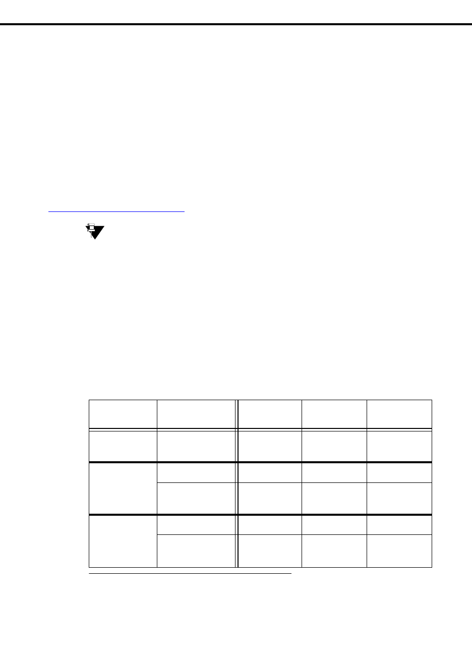
The following table shows at-a-glance when you would use each tool.
Table Legend:
IW= Avaya Installation Wizard
UT = Upgrade Tool
GIW = Gateway Installation Wizard).
Component Use New
Installation Upgrade
Software Upgrade
Firmware
S8500 or
S8700 as a Primary
Controller IW IW
S8300
as an LSP IW IW, UT*
* Use the UT to schedule upgrades of multiple LSPs. Use the IW on site for an immediate
upgrade of a single LSP.
as a Primary
Controller IW IW
G350
or
G700
with an S8300 IW IW, UT†
† Use UT to schedule upgrades of multiple gateways. Use the IW on site for an immediate
upgrade of a single gateway or G700 stack.
without an
S8300 GIW UT

1
Roadmap and Reference
Wizards for Installations and Upgrades
Installation and Upgrades for G700 and S8300 29
December 2003
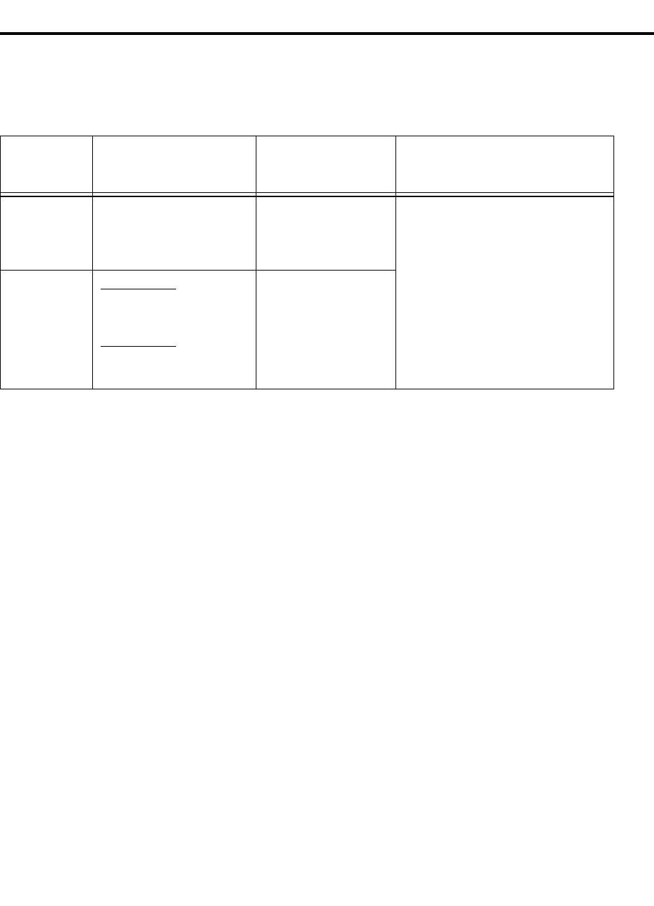
The following table summarizes when you would use each tool and what it does for you.
If you need to: Then use:
Install new or upgrade existing
S8300, S8500 or S8700 Media
Servers, including:
•The G350 or G700 that
contains an S8300
•Other G700s in the stack
•G350/G700 media
modules
The Avaya Installation Wizard (IW) on site, with a laptop
connection to the Services port on the media server.
NOTE:
Since the source files for an upgrade are large, the IW
requires that these source files be accessible (to the
media server running the IW) over a high-bandwidth
connection. The files could be on the media server’s
hard drive (ftp/pub directory), on a CD-ROM drive
connected to the media server, or on the CD-ROM
drive or hard drive on a technician’s laptop directly
connected to the media server. If the source files are
available on one of these media, you could use the
IW from a remote location using a dialup PPP
connection to the media server (with modem
enabled) running the IW.
This wizard installs new (or upgrades existing) software on media
servers and performs the initial configuration. It upgrades firmware
on new or existing media gateway processors and media modules.
You will also use the Electronic Pre-installation Worksheet, which
you get from your project manager. For the S8300/G700, you may
also use the Name and Number List and the Custom Template with
the wizard for more comprehensive custom installations.
Install a new G350 or G700 that
does not contain an S8300 The Gateway Installation Wizard (GIW) on site, with a laptop
connection to the G350 or G700.
This wizard configures the IP addresses for the gateway, including
the gateway processors, the controller list, and the VoIP engine.
The GIW does not install firmware on the G350 or G700 or their
media modules. You can install firmware manually, or use the UT.
Schedule upgrades of multiple,
geographically-distributed LSPs
or G350/G700 gateways, all of
which have the same remote
primary controller — S8300,
S8500, or S8700.
The Upgrade Tool (UT), running on the primary controller, using a
remote network connection.
This tool enables you to upgrade:
•the software on all LSPs registered with the primary
controller
•the processor and media module firmware for all gateways
currently or previously registered with the primary
controller.
NOTE: If the customer has purchased and installed the
MultiService Software Update Manager, you may wish to use it,
instead, to upgrade G350 or G700 Media Gateways. However, the
Software Update Manager cannot upgrade LSPs.

1Roadmap and Reference
Wizards for Installations and Upgrades
30 Installation and Upgrades for G700 and S8300
December 2003
The Avaya Installation Wizard (IW)
You can use the Avaya Installation Wizard (IW) as a tool to assist you in the installation and upgrade
processes for S8300, S8500, and S8700 Media Servers and G350 and G700 Media Gateways. The
Installation Wizard is designed to get you up and running in a basic installation as quickly as possible.
For customized installations, optional custom templates are also available.
The Avaya Installation Wizard ships with the media server software and is accessible on the home page
of the Integrated Management web interface. The most recent version of IW, as well as its
documentation, can be accessed online at http://support.avaya.com/avayaiw.
NOTE:
To use the IW, Communication Manager Release 2.0 or later must be running on the
media server (S8300, S8500, or S8700). If the correct release of Communication Manager
has not been installed on the media server, you need to upgrade the software before you
begin using the IW.
What the IW Does and Does Not Do
The IW does not automate all tasks in an S8300 Media Server installation.
Of the tasks described in Chapter 3, Installing a New G700 with an S8300, the IW automates the
following:
•Transfer Files from a CD or Laptop on page 111 and its subtasks
•Install New Software on the S8300 on page 114 and its subtasks
•Configure the S8300 on page 123
•Configure the G700 Media Gateway on page 137 and its subtasks
•“Install Communication Manager Patch Files from Your Laptop, if Any”, which is a subtask of
Install New Software on the S8300 on page 114
•“Administer Network Regions” for an S8300 Media Server as primary controller, which is a
subtask of Administer Communication Manager on page 151.
NOTE:
The IW administers the S8300 network region as the default, 1.
•Administer the Media Gateway on page 161
NOTE:
In addition, you can use the IW to upgrade media server software or gateway firmware on
a previously-installed system.
The IW automates similar tasks in Chapters 4–6.
You must perform the following tasks manually, even though you are using the IW:
•Install all hardware
•Tasks in Before Going to the Customer Site on page 104
•Set custom LSP transition points when the defaults are not adequate (see Set the LSP Transition
Points on page 84)

1
Roadmap and Reference
Wizards for Installations and Upgrades
Installation and Upgrades for G700 and S8300 31
December 2003
•Any tasks related to adding LSPs to the primary controller you are installing, as documented in
Administer Communication Manager on page 151:
•Any tasks related to administration of the primary controller in Administer Communication
Manager on page 151
•Set Up SNMP Alarming on the G700 on page 166, if required
Electronic Worksheets and Templates
To enable the IW to automatically configure and install the system, get the following Excel spreadsheet
files from the project manager and load them onto your laptop:
•Electronic Pre-installation Worksheet
•Names/Number List Template (for S8300/G700 only)
•Customization Template
NOTE:
Information on how to use these files is contained within the files themselves.
Electronic Pre-installation Worksheet
For greatest efficiency, obtain the Electronic Pre-Installation Worksheet (EPW), which is filled in by the
customer and Avaya project manager. This worksheet is an Excel spreadsheet from which IW
automatically pulls data to configure and install the S8300/S8500/S8700 Media Servers, G350/G700
Media Gateways, P330 Stack Processor, and VoiP Engines. The EPW also can be used to supply basic
translations for the S8300/G700 configuration.
The default values used by the wizard can be viewed at http://support.avaya.com/avayaiw under the
"View Default Parameters" link. If the wizard defaults do not meet the customer’s needs, you can use a
custom template.
Once the EPW has been imported, all the values from the EPW appear as defaults in the wizard.
Names/Number List Template (for S8300/G700 only)
The Names/Number Template, like the EPW, is an Excel spreadsheet that contains user administration
data. The IW pulls this data to automatically administer users on the new system. This administration
includes users’ names, extensions, telephone types, classes of service, languages, locations, and voice
mail capability. The native display name (unicode) is included.
As each user's name and accompanying data is imported, the wizard will administer the station using the
provided information along with default values for other station fields. After the import has completed,
each station will be ready to be plugged into the wall jack and activated. Analog and digital phones will
be ready for a TTI registration sequence. IP phones will be ready for an IP registration sequence.
Customization Template
The Customization Template is a third Excel spreadsheet that allows automatic administration of key
custom Communication Manager translations. These are:
•Classes of Service
•Feature Access Codes
•Trunk Access Codes

1Roadmap and Reference
Wizards for Installations and Upgrades
32 Installation and Upgrades for G700 and S8300
December 2003
•Telephone button assignments
•TTI codes
•Voice mail hunt group number and coverage path
The Upgrade Tool
The LSP/Gateway Upgrade Tool allows you to schedule automatic upgrades of Local Survivable
Processors (LSPs) and G350 and G700 Media Gateways from the primary controller. The primary
controller can be an S8300, S8500 or an S8700. With the upgrade tool, you do not have to physically be
at the LSP and gateway locations in order to perform the upgrades. Additionally, you do not have to run
the upgrades one by one. You simply enter the needed information for all LSPs, G350s, and G700s into
the upgrade tool. Then, at the scheduled time, the Upgrade Tool automatically upgrades the software and
firmware on all the specified LSPs and gateways.
NOTE:
You must still complete the normal prerequisite tasks such as completing the RFA process
for license files and uploading the most recent .tar file (for an LSP) to the
/var/home/ftp/pub directory or uploading the most recent firmware (for a media gateway)
to a TFTP server.
You cannot use the Upgrade Tool to do the
following:
•Install a new LSP or G350 or G700 Media Gateway. For each new installation, you must be on
site and use the Avaya Installation Wizard (for an LSP), the Avaya Gateway Installation Wizard
(for a media gateway), or perform a manual installation.
•Upgrade LSPs to Avaya Communication Manager 2.0. An LSP must already have
Communication Manager 2.0 or higher. Thus, the Upgrade Tool is used for upgrades to software
higher than Communication Manager 2.0.
•Upgrade an active LSP (one that has taken control of calls because of a problem with the primary
controller)
•Upgrade the S8300 Media Server acting as the primary controller.
•Upgrade an S8500 or S8700 Media Server.
•Upgrade P330 Expansion modules.
•Upgrade G600, G650, CMC1, SCC1, or MCC1 Media Gateways.
The Upgrade Tool ships with the media servers and is available on the home page of the media server’s
Maintenance Web Interface. For more information, see Job Aid: Upgrade Tool and Worksheets.

1
Roadmap and Reference
Wizards for Installations and Upgrades
Installation and Upgrades for G700 and S8300 33
December 2003
The Avaya Gateway Installation Wizard
Use the Avaya Gateway Installation Wizard (GIW) to configure a new G350 or G700 Media Gateway
that is controlled by a remote media server but does not have an S8300 installed in slot V1. The GIW
allows you to configure the gateway IP addresses without having to enter CLI commands.
The Avaya Gateway Installation Wizard (GIW) allows you to configure the G700 Media Gateway IP
addresses and avoid entering P330 and MG CLI commands to configure the media gateway. Use the GIW
to configure a new G700 Media Gateway that is controlled by a remote S8300, S8500, or S8700 Media
Server and does not have an S8300 LSP.
NOTE:
The GIW allows you to configure IP addresses only. You must complete the normal
installation tasks such as uploading the most recent firmware to a TFTP server and
installing the firmware on the media gateway and its components. Also, you cannot use
the GIW to configure an X330 Expansion module.
The GIW can be accessed online at http://support.avaya.com/avayaiw. For more information, see Job
Aid: Avaya Gateway Installation Wizard and Pre-installation Worksheet.
1Roadmap and Reference
Installation Roadmap and Task Lists
34 Installation and Upgrades for G700 and S8300
December 2003
Installation Roadmap and Task Lists
From your planning sheets, you can determine what type of installation or upgrade is involved with the
G700 Media Gateway. Use the following table to determine which task list is most appropriate for your
upgrade or installation.
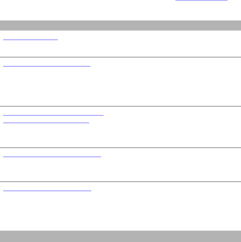
G700
with an S8300
(Primary or LSP) G700
without an S8300
G700 Controlled by an S8300
with IA 770 INTUITY AUDIX
Messaging
New
Installation
Checklist 1
Chapter 2
Chapter 3
Checklist 2
Chapter 2
Chapter 4 See Installation Checklists in the IA
770 INTUITY AUDIX Messaging
documentation, available on the
Avaya S8300, S8500, and S8700
Media Server Library CD, 555-233-
825
Upgrade
an Existing
System
R1.x to R2.0:
Checklist 3
Chapter 5
R2.0 to R2.x:
Checklist 4
Chapter 6
Checklist 5
Chapter 7
1
Roadmap and Reference
Installation Roadmap and Task Lists
Installation and Upgrades for G700 and S8300 35
December 2003
Checklist 1:
Install a New G700
with an S8300 (Primary or LSP)
Use the following checklist to install a G700 Media Gateway with the following characteristics:
•The G700 has an S8300 Media Server configured as the primary controller, or,
•The G700 has an S8300 Media Server configured as an LSP and is controlled by an S8300,
S8500, or an S8700 Media Server.
You will use Chapters 2 and 3 with this checklist.
For help with connecting to and logging in to the G700 or S8300, see Connection Methods in this chapter.
Table 1: Install New G700 with an S8300 (Primary or LSP)
Major Tasks Subtasks
Installation Overview on page 102 - G700 components
- Software and firmware files
- Access to the S8300 and G700
Before Going to the Customer Site on
page 104 - Get planning forms
- Get the G700 serial number
- Check FTP server for backups
- Complete the RFA process
- Download update (Patch) software to laptop, if
necessary
Installing Hardware for the G700 Media
Gateway and S8300 Media Server on
page 69
- On site checklist
- Unpack and check the order
- Install the G700
- Cable multiple units
- Attach ground conductors
On-Site Preparation for the Installation
on page 108 - Install new license file, if necessary
- Install authentication file, if necessary
- Save translations
- Determine software to install
Install New Software on the S8300 on
page 114 - Set time, date, and timezone
- Install new software
- Make the Upgrade Permanent
- Install Communication Manager Update (patch),
if any
- Install IA770 update (patch), if any
1 of 3

1Roadmap and Reference
Installation Roadmap and Task Lists
36 Installation and Upgrades for G700 and S8300
December 2003
Configure the S8300 on page 123 - Backup data
- Set server indentities
- Configure Ethernet interfaces
- Configure LSP
- Configure Ethernet adjuncts
- Configure External DNS server
- Set Static network routes, if necessary
- Configure network time server
- Set modem interface
- Update system
- Load Key files, if necessary
Configure the G700 Media Gateway on
page 137 - Assign IP addresses to the G700 processors
- Set up IP routing for the stack
- Set up default IP route for the G700
- Check IP connections
- Set up controller list for the G700
- Configure X330 Expansion Module, if necessary
Install New Firmware on the G700 on
page 145 - Verify contents of the tftp directory
- Determine which firmware to install
- Install firmware on the P330 stack processor
- Install firmware on the G700 media gateway
processor
- Install firmware on the media modules
- Install firmware on other G700s in the stack or
network, if any
Administer Communication Manager
on page 151 - Reboot the system
- Assign node names, if necessary
- Administer network regions
- Assign LSPs to network regions
- Administer IP interfaces
- Administer the LSP form
- Add media gateway
- Verify changes
- Enable announcements, if necessary
- Save translations
Considerations for IP Phones Supported
by a Local Survivable Processor on
page 164
Set Up SNMP Alarming on the G700
on page 166
Table 1: Install New G700 with an S8300 (Primary or LSP) Continued
Major Tasks Subtasks
2 of 3

1
Roadmap and Reference
Installation Roadmap and Task Lists
Installation and Upgrades for G700 and S8300 37
December 2003
Complete the Installation of S8300 (if
the Primary Controller) on page 168 - Register the system
- Back up the system
- Check planning documentation
- Connect and administer test endpoints
- Complete electrical installation
- Enable adjunct systems
Complete the Installation Process on
page 169 - Check planning documentation
- Connect and administer test endpoints
- Complete electrical installation
- Enable adjunct systems
Table 1: Install New G700 with an S8300 (Primary or LSP) Continued
Major Tasks Subtasks
3 of 3

1Roadmap and Reference
Installation Roadmap and Task Lists
38 Installation and Upgrades for G700 and S8300
December 2003
Checklist 2:
Install a New G700 without an S8300
Use the following checklist to install a G700 Media Gateway with the following characteristics:
•The G700 does not have an S8300 and is controlled by an external S8300, S8500, or S8700 Media
Server.
You will use Chapters 2 and 4 with this checklist.
For help with connecting to and logging in to the G700, see Connection Methods in this chapter.
Table 2: Install a New G700 without an S8300
Major Task Subtasks
Before Going to the Customer Site on
page 174 - Get planning forms
- Get the G700 serial number
- Set up TFTP server, if necessary
- Download firmware files
Installing Hardware for the G700
Media Gateway and S8300 Media
Server on page 69
- On site checklist
- Unpack and check the order
- Install the G700
- Cable multiple units
- Attach ground conductors
Configure the G700 on page 178 - Assign IP addresses to the G700 processors
- Set up IP routing for the stack
- Set up default IP route for the G700
- Check IP connections
- Set up controller list for the G700
- Configure X330 Expansion Module, if necessary
Prepare to Install Firmware on the
G700 on page 191 - Verify contents of the tftp directory
- Determine which firmware to install
on page 193 - Install firmware on the P330 stack processor
- Install firmware on the G700 media gateway
processor
- Install firmware on the media modules
- Install firmware on other G700s in the stack or
network, if any
1 of 2

1
Roadmap and Reference
Installation Roadmap and Task Lists
Installation and Upgrades for G700 and S8300 39
December 2003
Administer Communication Manager
on page 198 - Reboot the system
- Assign node names, if necessary
- Administer network regions
- Assign LSPs to network regions
- Administer IP interfaces
- Administer the LSP form
- Add media gateway
- Verify changes
- Enable announcements, if necessary
- Save translations
Complete the Installation Process on
page 209 - Check planning documentation
- Connect and administer test endpoints
- Complete electrical installation
- Enable adjunct systems
Table 2: Install a New G700 without an S8300 Continued
Major Task Subtasks
2 of 2

1Roadmap and Reference
Installation Roadmap and Task Lists
40 Installation and Upgrades for G700 and S8300
December 2003
Checklist 3
Upgrade an Existing G700 with an
S8300 (R1.x to R2.0)
Use the following checklist to upgrade a G700 Media Gateway with the following characteristics:
•The G700 has an S8300 Media Server configured as the primary controller.
or,
•The G700 has an S8300 Media Server configured as an LSP and is controlled by either an S8300,
S8500, or S8700 Media Server.
You will use Chapter 5 with this checklist. For help with connecting to and logging in to the G700 or
S8300, see Connection Methods in this chapter.
Table 3: Task List to Upgrade an Existing G700 with an S8300 (R1.x to R2.0)
Major Tasks Subtasks
Before Going to the Customer Site on
page 214 - Get the USB CD-ROM drive
- Fill in EPW (if upgrading from 1.1)
- Get planning form
- Get the G700 serial number
- Check number of allocated ports
- Check FTP server for back up
- Get software/firmware files
- Download update (Patch) software to laptop, if necessary
- Complete the RFA process
On-site Preparation for the Upgrade
on page 219 - Check current software release
- Pre-Upgrade tasks — If the Target S8300 is the Primary
Controller
- Get IA770 data and stop IA770
- Back up recover system files
- Record configuration information
- Install the pre-upgrade update
- Back up the system files
1 of 2

1
Roadmap and Reference
Installation Roadmap and Task Lists
Installation and Upgrades for G700 and S8300 41
December 2003
Upgrade the S8300 on page 227 Install the Upgrade Software:
- Copy RP files to hard drive
- Install the RP software
- Set telnet parameters
- Install the upgrade software
- Verify software version
- Copy licence and authentication files to the S8300
- Configure S8300 network parameters
- If upgrading from a pre-1.2 release
- Restore Linux Migration backup files
- Disable messaging
- Verify date and time
- Install post-upgrade patch, if necessary
- Verify S8300 configuration
- Install license file
- Install authentication file, if necessary
- Save translations (if not using IA770)
- Verify operation
Upgrade the Firmware on the G700 on
page 250 - Decide whether to use the Installation Wizard
If not using the Wizard:
- Verify contents of the tftp directory
- Determine which firmware to install
- Install firmware on the P330 stack processor
- Install firmware on the G700 media gateway processor
- Install firmware on the media modules
- Install firmware on other G700s in the stack or network, if
any
- Install and restart IA770, if being used
- Install IA770 update (patch), if any
- Save translations (if using IA770)
Complete the Upgrade Process (S8300
is the Primary Controller) on page 260 - Check media modules
- Enable scheduled maintenance
- Busyout trunks
- Check for translation corruption
- Resolve alarms
- Re-enable alarm origination
- Back up system
- Restart LSPs, if any
Table 3: Task List to Upgrade an Existing G700 with an S8300 (R1.x to R2.0) Continued
Major Tasks Subtasks
2 of 2

1Roadmap and Reference
Installation Roadmap and Task Lists
42 Installation and Upgrades for G700 and S8300
December 2003
Checklist 4
Upgrade an Existing G700 with an
S8300 (R2.0 to R2.x)
Use the following checklist to upgrade a G700 Media Gateway with the following characteristics:
•The G700 has an S8300 Media Server configured as the primary controller.
or,
•The G700 has an S8300 Media Server configured as an LSP and is controlled by either an S8300,
S8500, or S8700 Media Server.
You will use Chapter 6 with this checklist. For help with connecting to and logging in to the G700 or
S8300, see Connection Methods in this chapter.
Table 4: Task List to Upgrade an Existing G700 with an S8300 (R2.0 to R2.x)
Major Tasks Subtasks
Before Going to the Customer Site on
page 266 - Get planning form
- Get the G700 serial number
- Check number of allocated ports
- Check FTP server for back up
- Get software/firmware files
- Complete the RFA process
- Download update (Patch) software to laptop, if necessary
On-site Preparation for the Upgrade
on page 270 - Pre-Upgrade tasks — If the Target S8300 is the Primary
Controller
- Get IA770 data and stop IA770
- Back up recover system files
- Install new license and authentication files, if necessary
- Save translations, if new license and/or authentication
files installed
- Transfer files from CD or laptop
Upgrade the S8300 on page 282 Install the Upgrade Software:
- Decide whether to use the Wizard
- Manual installation
- Configure S8300
- Make the upgrade permanent
- Install Communication Manager update (patch), if any
- Install IA770 update (patch), if any
1 of 2

1
Roadmap and Reference
Installation Roadmap and Task Lists
Installation and Upgrades for G700 and S8300 43
December 2003
Upgrade the Firmware on the G700 on
page 291 - Decide whether to use the Installation Wizard
If not using the Wizard:
- Verify contents of the tftp directory
- Determine which firmware to install
- Install firmware on the P330 stack processor
- Install firmware on the G700 media gateway processor
- Install firmware on the media modules
- Install firmware on other G700s in the stack or network, if
any
Complete the Upgrade Process (S8300
is the Primary Controller) on page 298 - Check media modules
- Enable scheduled maintenance
- Busy out trunks
- Check for translation corruption
- Resolve alarms
- Re-enable alarm origination
- Back up system
- Restart LSPs, if any
Table 4: Task List to Upgrade an Existing G700 with an S8300 (R2.0 to R2.x) Continued
Major Tasks Subtasks
2 of 2

1Roadmap and Reference
Installation Roadmap and Task Lists
44 Installation and Upgrades for G700 and S8300
December 2003
Checklist 5:
Upgrade an Existing G700 without
an S8300
Use the following checklist to upgrade a G700 Media Gateway with the following characteristics:
•The G700 does not have an S8300 and is controlled by an external S8300, S8500, or S8700 Media
Server.
You will use Chapter 7 with this checklist. For help with connecting to and logging in to the G700, see
Connection Methods in this chapter.
Table 5: Task List to Upgrade an Existing G700 without an S8300
Major Tasks Subtasks
Before Going to the Customer Site on
page 303 - Get planning forms
- Get the G700 serial number
- Set up TFTP server, if necessary
- Download firmware files
Installing Hardware for the G700 Media
Gateway and S8300 Media Server on
page 69
- On site checklist
- Unpack and check the order
- Install the G700
- Cable multiple units
- Attach ground conductors
On-Site Preparation for the Upgrade on
page 307 - Verify contents of the tftp directory
- Determine which firmware to install
Install New Firmware on the G700
Media Gateway on page 310 - Install firmware on the P330 stack processor
- Install firmware on the G700 media gateway processor
- Install firmware on the media modules
- Install firmware on other G700s in the stack or network, if any

1
Roadmap and Reference
Connection and Login Methods
Installation and Upgrades for G700 and S8300 45
December 2003
Connection and Login Methods
This section describes the various ways of connecting to, and logging into, the Avaya™ S8300 Media
Server and the Avaya™ G700 Media Gateway. Use this chapter as a reference for the other chapters in
this book.
The procedures in this book assume that you are connecting to the S8300 and/or the G700 with an Avaya
Services laptop. However, the methods apply for any type of PC.
This chapter is organized with the following sections:
•Connection Overview
•Laptop Configuration for a Direct Connection to the Services Port
•Connection Methods
•Log in Methods
•Navigational Aid for CLI Commands
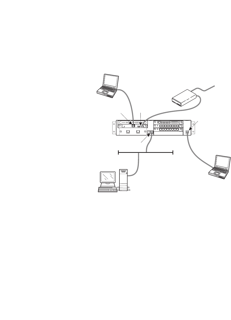
1Roadmap and Reference
Connection and Login Methods
46 Installation and Upgrades for G700 and S8300
December 2003
Connection Overview
Review Physical Access Methods
1Check the following figure for the location of the S8300 Services port.
Summary of S8300 and G700 Access Methods
and Tasks
2If you are installing or upgrading a G700 that does not have an internal S8300, check for the
location of the ethernet ports (EXT 1 / EXT 2). You will need to connect the G700 to the
customer’s LAN via one of these ports for loading the latest software.
Technician
laptop
System admin
computer
Initial Configuration and
Maintenance S8300
Onsite Tasks:
Tools:
1. Configure media server
2. Install license and authentication
files, and upgrade software
3. Verification testing
4. Run diagnostics
5. Upgrade software and configuration
1. Avaya Installation Wizard
2. Web Interface
3. Command Line Interface
4. System Access Terminal (SAT)
Initial Configuration and
Maintenance G700 Media
Gateway (when no S8300)
Onsite Tasks:
Tools:
1. Configure master and stack
2. Configure MGP, MM and ports
3. Update configuration
4. Run diagnostics
1. Gateway Installation Wizard
2. Command Line Interface
System Admin Computer or
Technician Laptop
Administration via Corporate LAN
Tasks:
Tools:
1. Backup and restore data
2. Upgrade and configuration
3. Administer network
4. Admin Telephony features
1.
2. Web Interface
3. Native Configuration Manager
4. System Access Terminal (SAT)
Avaya Installation Wizard
Remote Access of S8300
and G700
1. Diagnosis of media server
2. Alarm notification
cydcacc2 KLC 091003
V1
USB
modem
Services port USB ports
Console port
Ethernet ports
LAN
USB cable
Crossover
cable
Crossover
cable
Straight
cable
Serial cable
Technician
laptop
To analog
trunk
1
Roadmap and Reference
Connection and Login Methods
Installation and Upgrades for G700 and S8300 47
December 2003
Laptop Configuration for a Direct Connection
to the Services Port
There is a special configuration that you need to use for a direct connection to the S8300 or S8700
Services port.
NOTE:
Avaya Service technicians can use the NetSwitcher program to configure alternate
network profiles so they can easily connect to a number of different systems. NetSwitcher
configures a profile for each type of system for easy future access without requiring you to
reset TCP/IP properties or browser settings manually. NetSwitcher is available from an
Avaya Services CTSA.
Settings for a Direct Connection to S8300,
S8500, or S8700 Services Port
A laptop connected directly to the Services Ethernet interface on the S8300, S8500, or S8700 Media
Server requires a specific configuration as described in this section.
On any operating system, the network settings need to reflect the following:
•TCP/IP properties. Set the laptop’s TCP/IP properties as follows:
— IP address: 192.11.13.5
— Subnet mask: 255.255.255.252
•Browser settings. Configure the browser for a direct connection to the Internet. Do not use
proxies.
•Server address. Access the S8300 media server using the URL http://192.11.13.6
The names of the dialog boxes and buttons vary on different operating systems and browser releases. Use
your computer’s help system if needed to locate the correct place to enter this information.
The S8300 Media Server uses the same access configuration as an Avaya S8100 Media Server with a
CMC1 or G600 Media Gateway. If you already have a NetSwitcher profile for the S8100 Media Server
(formerly called DEFINITY One), try using that profile first before configuring a new one.
Set TCP/IP properties on Windows systems
TCP/IP administration varies among Windows systems as described below.
NOTE:
Make a record of any IP addresses, DNS servers, or WINS entries that you change when
you configure your services computer. Unless you use the NetSwitcher program or an
equivalent, you will need to restore these entries to connect to other networks.
Check Your Version of Windows
1Log in to your laptop, and double-click the My Computer icon on your desktop.
The My Computer window opens.
2Click Help on the My Computer window’s toolbar.
The Help menu opens and displays the version of Windows installed on your laptop.

1Roadmap and Reference
Connection and Login Methods
48 Installation and Upgrades for G700 and S8300
December 2003
3Follow one of the two procedures below, depending on your operating system.
Change TCP/IP Properties and Network Settings (Windows 2000 and XP)
1Right-click My Network Places on your desktop or under the Start menu in XP.
2Select Properties to display the Network and Dial-up Connections window.
Windows should have automatically detected the Ethernet card in your system and created a LAN
connection for you. More than one connection may appear.
3Right-click the correct Local Area Connection from the list in the window.
4Select Properties to display the Local Area Connection Properties dialog box.
5Select Internet Protocol (TCP/IP)
6Click the Properties button. The Internet Protocol (TCP/IP) Properties screen appears.
7On the General tab, select the radio button Use the following IP address. Enter the following:
— IP address: 192.11.13.5
— Subnet mask: 255.255.255.252
NOTE:
Record any IP addresses, DNS settings, or WINS entries that you change. You may need
to restore them later to connect to another network.
8Disable DNS service as follows:
aClick the radio button labeled Use the following DNS server addresses. The entries for
Preferred DNS server and Alternate DNS server should both be blank.
bClick the Advanced button at the bottom of the screen. The Advanced TCP/IP Settings
screen appears.
cClick the DNS tab. Verify that no DNS server is administered (the address field should be
blank).
9Disable WINS Resolution as follows:
aClick the WINS tab. Make sure WINS is not administered (the address field should be
blank).
bClick OK. If warned about an empty primary WINS address, click Yes to continue.
10 Click OK twice to accept the address information and close the TCP/IP and Local Area
Connection Properties dialog boxes.
11 Reboot the system if directed to do so.
After you have made these changes to your computer’s network configuration information, the
Network and Dial-up Connections window shows the status of the Local Area Connection:
— Enabled appears when the laptop's Ethernet cable is connected to the server.
— Disabled or unplugged appears if the NIC is not connected to anything.
Change TCP/IP properties (Windows 95, 98, NT 4.0, and Millennium Edition [ME])
1Access your computer's network information. On your desktop:
—Windows 95, 98, and NT: Right-click Network Neighborhood.
—Windows ME: Right-click My Network Places.
2Select Properties to display the Network dialog box.
1
Roadmap and Reference
Connection and Login Methods
Installation and Upgrades for G700 and S8300 49
December 2003
3Locate the TCP/IP properties as follows:
—Windows 95, 98, and ME: On the Configuration tab, scroll through the installed network
components list to the TCP/IP part of the devices list. Select the TCP/IP device that
corresponds to your Ethernet card.
—Windows NT: On the Protocols tab, select TCP/IP in the installed network components list.
4Select the Properties button.
5In the TCP/IP Properties box, click the IP Address tab.
6Click the radio button to Specify an IP address, and enter the following:
— IP address: 192.11.13.5
— Subnet mask: 255.255.255.252
NOTE:
Record any IP addresses, DNS settings, or WINS entries that you change. You may need
to restore them later to connect to another network.
7Disable DNS service as follows:
—Windows 95, 98, and Me: Click the DNS Configuration tab. Verify that the Disable DNS
radio button is selected.
—Windows NT: Click the DNS tab.
•If any IP addresses appear under DNS Service Search Order, make a note of them
in case you need to restore them later.
•Select each IP address in turn and click the Remove button.
8Disable WINS Resolution as follows:
—Windows 95, 98, and Me: Click the WINS Configuration tab. Verify that the Disable
WINS Resolution radio button is selected.
—Windows NT: Click the WINS Address tab.
•If any IP addresses appear for the Primary and Secondary WINS servers, make a
note of them in case you need to restore them later.
•Clear each server entry.
•Clear the checkbox for Enable DNS for WINS Resolution.
9Click OK twice to accept the address information and close the Network dialog box.
10 Reboot the system if directed to do so.

1Roadmap and Reference
Connection and Login Methods
50 Installation and Upgrades for G700 and S8300
December 2003
Disable/bypass proxy servers in browser
If you are connecting a laptop directly to the Services Ethernet interface on the S8300 faceplate, you must
either disable or bypass proxy servers as described below.
NOTE:
The Microsoft Internet Explorer (IE) browser is recommended. If you use IE, it must be
version 5.5 or higher. You can use Netscape, but some features of the web interface may
not work properly. If you use Netscape, it must be version 6.2 or higher.
To check or change proxy settings:
1Open your Internet browser.
2Verify that you have a direct connection with no proxies as follows:
For Internet Explorer
aSelect Tools > Internet Options.
bClick the Connections tab.
cClick the LAN Settings button.
dIf Use a proxy server for your LAN is not selected, no change is necessary; click Cancel
to exit.
eIf Use a proxy server for your LAN is selected, you can:
— deselect it and click OK to exit
— or you can leave it selected and configure your browser to bypass the proxy server
whenever you are connected to the S8300 services port as follows:
•click Advanced
•Type 192.11.13.6 in the Exceptions box. If there are other entries in this box, add
to the list of entries and separate entries with a “;”.
•Click OK to exit.
For Netscape
aSelect Edit > Preferences.
bUnder Category, click Advanced.
cClick Proxies.
dIf Direct connection to the Internet is selected, no change is necessary; click Cancel to
exit.
eIf Direct connection to the Internet is not selected, you can:
— select it and click OK to exit;
— or you can leave it unselected and configure your browser to bypass the proxy server
whenever you are connected to the S8300 services port as follows:
•Select Manual Proxy Configuration and click View
•Type 192.11.13.6 in the Exceptions box (or in the No Proxy for: box in later
versions of Netscape). If there are other entries in this box, add to the list of entries
and separate entries with a ";".
•Click OK to exit.

1
Roadmap and Reference
Connection and Login Methods
Installation and Upgrades for G700 and S8300 51
December 2003
Connection Methods
Connect Laptop to Services Port of S8300
To connect your laptop directly to the S8300 Media Server:
1Make sure your laptop meets the hardware and software requirements.
2Plug an Ethernet crossover cable (MDI to MDI-X) into the 10/100 BaseT Ethernet network
interface card (NIC) on your laptop.
— Crossover cables of various lengths are commercially available.
— See the following table for pinout connections if needed. Crossover of the transmit and
receive pairs (as shown) is required.
3Connect the other end of the crossover cable to the Services port on the front of the S8300.
4If your laptop is configured with the correct network settings, you can now open your Internet
browser or start a Telnet session and log in. When accessing the server from a directly connected
laptop, always type the following IP address in the browser's Address or Location field to access
the server: 192.11.13.6
Connect Laptop to the G700 Serial Port
To configure a G700 that does not have an S8300, you may need to set up a direct connection from your
laptop’s serial port to the G700 Console (serial) port.
To connect a laptop directly to the serial port on the G700 Media Gateway:
1For a stacked configuration, locate the device that contains the master controller for the stack.
Check the LED panel on the upper left of each G700 or P330 device in the stack as follows:
— G700 Media Gateway: a lit MSTR LED indicates that this unit is the stack master.
— A non-G700 P330 device: a lit SYS LED indicates that this unit is the stack master.
Crossover cable pinout chart
Pin to
S8300
Services
Port Connects
to
Pin to
Laptop
Ethernet
card
88
7 7
62
5 5
44
3 1
26
1 3

1Roadmap and Reference
Connection and Login Methods
52 Installation and Upgrades for G700 and S8300
December 2003
2Connect the RS-232 serial cable and DB-9 adapter cable provided with the G700 between your
laptop and the G700:
— Attach one end of the RS-232 cable to the RJ-45 jack on the front of the G700 that is the
stack master. The serial port is on the lower right side of the chassis, labeled Console.
— Plug the other end of the RS-232 cable into the RJ-45 jack on the DB-9 adapter cable.
— Connect the other end of the DB-9 adapter cable to the 9-pin serial port on your laptop.
3Use a serial-connection program such as HyperTerminal to access the P330 stack processor.
Connect Laptop to Customer LAN
To connect to the customer’s LAN, either on site or remotely over the Internet, your PC must be assigned
an IP address on the LAN. The IP address can be a static address on the customer’s LAN that you enter in
the TCP/IP properties or it can be assigned dynamically with DHCP. Ask the customer how they want
you to make the connection.
Connect the External Modem to the S8300
Media Server:
Each S8300 Media Server requires a Universal Serial Bus (USB) modem for maintenance access and to
call out an alarm. The external modem may be connected to the S8300 Media Server through a universal
serial bus (USB) connection, providing dial-up access. The modem requires its own external analog line.
•The modem type is not optional and must be the specific modem that is shipped with the S8300.
•The remote connection should support a data speed of at least 33.6 Kbps.
•The remote PC must be administered for PPP connections in order to connect through a modem.
A dial-up connection is typically used only for services support of the server, not for routine
administration. If the Server is administered to report OSS alarms, it uses the same line for alarm
notification. The server cannot report any new alarms while this line is in use.
1Connect one end of the modem’s USB cable to an available USB port on the S8300 Media
Server’s faceplate. Either USB1 or USB2 can be used.
2Connect the other end of the cable to the external modem.
3Connect the modem to an external analog line.
NOTE:
The modem that is shipped with the S8300 obtains its power from the USB interface.
There is no power connection.
4Verify operation as instructed by the modem’s documentation.
5To enable the modem, access the S8300 Media Server’s Maintenance Web Pages (see Log in to
the S8300 Web Interface from Your Laptop on page 57), and click Enable/Disable Modem on the
main menu
The system displays the Enable/Disable Modem window.

1
Roadmap and Reference
Connection and Login Methods
Installation and Upgrades for G700 and S8300 53
December 2003
6Click the radio button for one of the following:
— Enable modem for one incoming call — use this option if you want to provide one-time
access to the Media Server over the modem.
— Enable modem for unlimited incoming calls — use this option if you want to provide
regular dial-up access to the Media Server for Services personnel or some other reason.
The modem is now ready to receive calls.
Set up Windows for Modem Connection to the
Media Server (Windows 2000 or XP)
NOTE:
The remote dial-up PC must be configured for PPP access. Also, Avaya Terminal
Emulator does not support Windows XP.
1Right-click My Network Places and click Properties.
2Click Make New Connection and follow the Network Connection Wizard:
3Select Dial-up to private network on the Network Connection Type screen.
4In the Phone number field, enter the appropriate telephone number inserting special digits such
as 9 and 1 or *70, if necessary.
5On the Connection Availability screen, click For all users or Only for myself, as appropriate.
6On the Completing the Network Connection Wizard screen, type the name you want to use for
this connection. This name will appear in the Network and Dial-up Connections list.
7Check the Add a shortcut to my desktop, if desired, and click Finish.
8If a Connect screen appears, click Cancel.
Configure the Remote PC for PPP Modem
Connection (Windows 2000 or XP, Terminal
Emulator, or ASA)
1On your PC’s desktop, right-click My Network Places and click Properties.
The system deploys the Network and Dial-up Connections window.
2Double click the connection name you made in the previous task, Set up Windows for Modem
Connection to the Media Server (Windows 2000 or XP).
NOTE:
Depending on your system, the Connect screen may appear, from which you must select
Properties.
3Click the Security tab.
4Select the Advanced (custom settings) radio button.
5Check the Show terminal window checkbox.
6Click the Networking tab.
7In the Components box, verify that Internet Protocol (TCP/IP) and Client for Microsoft Networks
are both checked.
8Select Internet Protocol (TCP/IP) and click Properties.

1Roadmap and Reference
Connection and Login Methods
54 Installation and Upgrades for G700 and S8300
December 2003
9Click the Advanced button.
10 Uncheck (clear) the Use default gateway on remote network box.
11 Click OK three times to exit and save the changes.
Use Windows for PPP Modem Connection
(Windows 2000 or XP)
NOTE:
To access the system, you may need RAS access and ASG Mobile access.
1Return to the Network and Dial-up Connections window and right-click the connection you just
created.
2Select Connect.
3Leave the User Name, Password, and Domain fields blank. If the Dial field is blank, enter the
appropriate telephone number.
4Click the Dial button. When the media server’s modem answers, the system displays the After
Dial Terminal window.
5Log on to the LAN.
aEnter your remote access login name and password.
bWhen the Start PPP Now! message appears, click Done.
The system displays a small double-computer icon in the lower right portion of your
screen.
6Double click the double-computer icon.
7The system displays the connection’s Dialup Status box.
8Click on the Details tab.
9Note the Server IP address.
10 Open a telnet session to the S8300:
Type telnet <ip-address>, where <ip-address> is the Server IP address as noted in the Dialup
Status box from Step 9.
11 Access SAT or use the CLI commands as needed.
Use Avaya Terminal Emulator for LAN
Connection to Communication Manager
You can download the Avaya Terminal Emulator from the Integrated Management main menu. Simply
click Download next to the Administration menu item and follow the instructions.
Once the Terminal Emulator is installed on your PC, use the following steps to establish a LAN
connection to your Media Server.
NOTE:
The remote dial-up PC must be configured for PPP access.

1
Roadmap and Reference
Connection and Login Methods
Installation and Upgrades for G700 and S8300 55
December 2003
1Double-click the Terminal Emulator icon off of your desktop. Alternatively, go to the Start menu,
select Programs, then select Avaya, and finally select Terminal Emulator.
The system displays the Terminal Emulator.
2From the menu bar across the top of the screen, select Phones, then select Connection List.
The system displays the Connections window.
3From the menu bar across the top, select Connection, then select New Connection.
The system displays the Connection Settings window.
4Put in a name for the connection. Usually, this will be the name of your Media Server.
5In the Host window, click Telnet.
6Click the Emulation tab at the top.
The system displays the Emulation tab.
7From the Emulator dragdown box, select the emulator you desire, usually 513BCT (default),
AT&T 4410, AT&T or DECVT100.
8In the Keyboard window, select pbx.
9Click the Network tab.
The system displays the Network tab.
10 In the IP address field, type the IP address of the Media Server.
11 In the TCP/IP port number field, leave 23 if you want to log in at the Linux command line. Type
5023 if you want to log in directly to the Communication Manager SAT command line.
12 Click OK.
The Connection Settings window disappears.
13 On the Connections window, double-click. the name of the connection you just set up.
If you used port 5023, the Login prompt for the Communication Manager software appears. If
you used port 23, the Login prompt for the S8300 Linux software appears.
14 Log in to Communication Manager to access the SAT command prompt screen. If you are logging
in as craft, you log in to the S8300 Linux software. Then, see Open the Replace variable w/
ProductName SAT Screens on page 62.
Use Avaya Terminal Emulator for Modem
Connection to Communication Manager
You can download the Avaya Terminal Emulator from the main menu for Integrated Management.
Simply click Download next to the Administration menu item and follow the instructions.
Once the Terminal Emulator is installed on your PC, use the following steps to establish a LAN
connection to your Media Server.
1Double-click the Terminal Emulator icon off of your desktop. Alternatively, go to the Start menu,
select Programs, then select Avaya, and finally select Terminal Emulator.
The system displays the Terminal Emulator.
2From the menu bar across the top of the screen, select Phones, then select Connection List.
The system displays the Connections window.

1Roadmap and Reference
Connection and Login Methods
56 Installation and Upgrades for G700 and S8300
December 2003
3From the menu bar across the top, select Connection, then select New Connection.
The system displays the Connection Settings window.
4Put in a name for the connection. Usually, this will be the name of your Media Server.
5In the Host window, click Telnet.
6Click the Emulation tab at the top.
The system displays the Emulation tab.
7From the Emulator dragdown box, select the emulator you desire, usually 513BCT (default),
AT&T 4410, AT&T or DECVT100.
8In the Keyboard window, select pbx.
9Click the Modem tab.
The system displays the Modem tab.
10 In the IP address field, type the IP address of the connection’s Dialup Status box as noted in Step
9 on page 54.
11 In the TCP/IP port number field, leave 23 if you want to log in at the Linux command line. Type
5023 if you want to log in directly to the Communication Manager SAT command line.
12 In the Modem field, use the dragdown box to select the type of modem that your PC uses.
13 In the Serial port field, select the COM port you are using for your modem connection.
14 In the Baud rate field, select 9500 from the dragdown box.
15 Click the Dial Numbers tab.
The system displays the Display Numbers tab.
16 Type the phone number of the Media Server as appropriate. Enter 1 in the Country Code field for
long-distance.
17 Click OK.
18 On the Connections window, double-click. the name of the connection you just set up.
The PC dials up the Media Server, and when connected, the login prompt for the Communication
Manager software appears.
19 Log in to Communication Manager to access the SAT command prompt screen. If you are logging
in as craft, you log in to the S8300 Linux software. Then, see Open the Replace variable w/
ProductName SAT Screens on page 62.
Log in Methods
This section describes how to log on to the S8300, S8500, or S8700 Media Servers using Telnet or the
built-in Web Interface and how to start a SAT session. These procedures assume:
•You have a crossover cable directly connected from your laptop to the Services port on the media
server and your laptop is configured for a direct connection
•Or, you are connected to the S8300, S8500, or S8700 Media Server over the customer’s LAN,
either remotely or on site. In this case, your laptop must be configured to connect to the
customer’s LAN and you would use the LAN IP address of the S8300 instead of 192.11.13.6.
The last procedure in this section describes logging in to the P330 stack processor when you have a direct
serial connection to the G700 Console port.
1
Roadmap and Reference
Connection and Login Methods
Installation and Upgrades for G700 and S8300 57
December 2003
Log in to the Media Server from Your Laptop
using Telnet
To run telnet:
1Make sure you have an active Ethernet or serial connection from your computer to the Media
Server.
2Access the telnet program; for example:
— On a Windows system, go to the Start menu and select Run.
—Type
telnet 192.11.13.6 to access the media server CLI.
3When the login prompt appears, type the appropriate user name (such as cust or craft).
4When prompted, enter the appropriate password.
5If you log in as craft, you are prompted to suppress alarm origination. Generally you should
accept the default value (yes).
6Enter your terminal type. Accept the default value, or enter the appropriate type for your
computer. For example, you may use type ntt, a terminal type available for Windows NT4.0 or
Windows 98. For Windows 2000, use w2ktt.
7If prompted for a high-priority session, typically answer n.
The system displays the telnet prompt. It may take the form <username@devicename>.
Log in to the S8300 Web Interface from Your
Laptop
To run the Web Interface:
1Open Internet Explorer (5.5 or later) on your computer.
2In the Address (or Location) field of your browser, type the 192.11.13.6 (or, for a LAN
connection, the IP address of the media server on the customer LAN) and press Enter.
If your browser does not have a valid security certificate, you will see a warning screen and
instructions to load the security certificate.
1Roadmap and Reference
Connection and Login Methods
58 Installation and Upgrades for G700 and S8300
December 2003
3The system displays the Welcome screen.
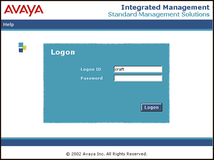
1
Roadmap and Reference
Connection and Login Methods
Installation and Upgrades for G700 and S8300 59
December 2003
4Click the Continue button.
5Accept the Client Authentication and Security Certificate to access the Login screen.
The system displays the Login screen.
6Log in as craft.
7Select yes for Suppress Alarm Origination.
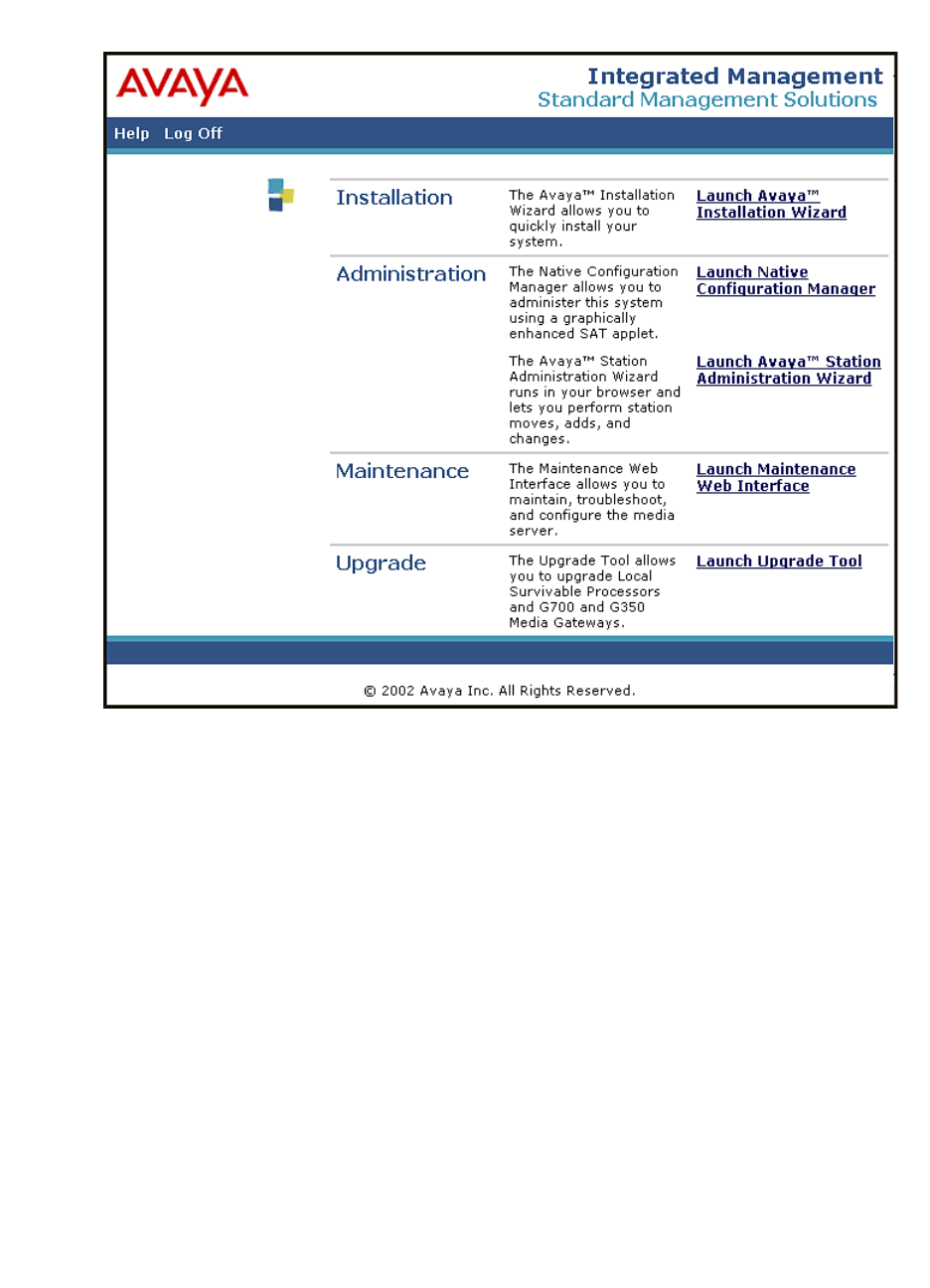
1Roadmap and Reference
Connection and Login Methods
60 Installation and Upgrades for G700 and S8300
December 2003
The system displays the main menu for the Integrated Management Suite.
8Click on the link for Launch Maintenance Web Interface
The system displays the S8300 main menu in the left panel and a usage-agreement notice in the
right window.
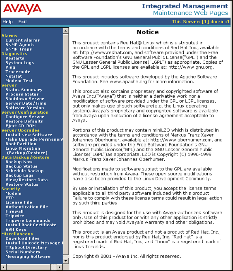
1
Roadmap and Reference
Connection and Login Methods
Installation and Upgrades for G700 and S8300 61
December 2003
S8300 Main Menu
9Check the top of the left panel.
— The Avaya media server you are logged into is identified by name and server number.
— The S8300 media server number is always 1.

1Roadmap and Reference
Connection and Login Methods
62 Installation and Upgrades for G700 and S8300
December 2003
Open the Replace variable w/ ProductName
SAT Screens
To run SAT:
1If you already have a valid telnet session in progress, access the SAT program by typing sat or
dsat at the telnet prompt.
Or, to open SAT directly from your laptop,
click Start > Run and type telnet 192.11.13.6 5023 and press Enter.
2Log in to the Replace variable w/ ProductName as craft or dadmin.
Enter your login confirmation information as prompted:
—Password prompt. Type your password in the Password field, and click Login or press
Enter again.
—ASG challenge. If the login is Access Security Gateway (ASG) protected, you will see a
challenge screen. Enter the correct response and click Login or press Enter.
3Enter your terminal type. Accept the default value, or enter the appropriate type for your
computer. For example, you may use type ntt, a terminal type available for Windows NT4.0 or
Windows 98. For Windows 2000, use w2ktt.
The system displays the SAT interface.
4Enter SAT commands as appropriate.
Log in to the P330 stack Processor with a
Direct Connection to the Services Port
NOTE:
If you are upgrading an S8300/G700 remotely, connect to the customer LAN and telnet to
the IP address of the P330 stack master (that is, the P330 stack processor running as the
stack master). The IP address is the address assigned on the customer LAN, not
192.11.13.6.
1With a direct connection to the S8300 services port, telnet to the S8300 IP address:
Type telnet 192.11.13.6.
2Login as craft or cust.
3Telnet to the P330 stack master stack processor.
Type telnet <xxx.xxx.xxx.xxx>, where <xxx.xxx.xxx.xxx> is the IP address of the P330 stack
master processor on the customer’s LAN.
4Login at the Welcome to Avaya P330 screen.
Login: xxx from the planning documentation
Password: xxx from the planning documentation
You are now logged-in at the Supervisor level. The prompt appears as P330-1(super)#.
NOTE:
To check the syntax of a command in the command line interface, type as much of the
command as you know followed by help. For example:
P330-1(super)#> set help
1
Roadmap and Reference
Connection and Login Methods
Installation and Upgrades for G700 and S8300 63
December 2003
you will be given the current list of set commands available. If you type:
P330-1(super)#> set interface help
you will be given a much more restricted list of command possibilities that address the possible
interfaces to be set.
For a complete list of command line interface commands, type help or refer to the "Avaya P330 User’s
Guide" (available at www.avaya.com/support).
Log in to the P330 Stack Processor with a
LAN Connection
1With a connection to the customer’s LAN (either remotely or on site), telnet to the P330 stack
processor IP address:
Type telnet <xxx.xxx.xxx.xxx>, where <xxx.xxx.xxx.xxx> is the IP address of the P330 stack
master processor on the customer’s LAN.
2Login at the Welcome to Avaya P330 screen.
Login: xxx from the planning documentation
Password: xxx from the planning documentation
You are now logged-in at the Supervisor level. The prompt appears as P330-1(super)#.
Log in to the P330 Stack Processor with a
Direct Serial Connection
Use this procedure to access the G700 processors when your laptop is directly connected to the Console
port via a serial cable.
To access the G700 via the Console (serial) port
1Launch Windows® HyperTerminal or any other terminal emulation program.
NOTE:
For most Windows-based PCs, you access the HyperTerminal program from the Start
menu by selecting Programs, then Accessories.
2Choose Call - Connect (for HyperTerminal) or the appropriate call command for your terminal
emulation program.
3Login at the Welcome to Avaya P330 screen.
Login: xxx from the planning documentation
Password: xxx from the planning documentation
You are now logged-in at the Supervisor level. The prompt appears as P330-1(super)#.

1Roadmap and Reference
Connection and Login Methods
64 Installation and Upgrades for G700 and S8300
December 2003
Log in to the P330 Stack Processor with
Device Manager
To access the Device Manager, you must have access to the corporate LAN in which the P330 Stack
Processor resides. Then, to access Device Manager, do the following:
1Open a compatible Internet browser on your computer. Currently this includes Internet Explorer
5.0 (or higher) and Netscape Navigator 4.7 and 6.2. The Java Plug-in 1.2.2 or 1.3.1 is required.
2In the Address (or Location) field of your browser, type the IP address or name of the P330 Stack
Processor and press Enter.
— If the network includes a domain name service (DNS) server that has been administered
with this IP device’s name, you can type the processor's name into the address field
instead of the IP address. For example, http://P330-stack1.mycompany.com
NOTE:
The Device Manager is not available through the S8300 Media Server. You must be
connected to either the P330 Stack Processor or G700 Media Gateway processor through
the corporate LAN.
3A GUI rendering of the stack devices appears. Proceed with Media Gateway or stack device
administration.
Avaya Site Administration
Avaya Site Administration is part of the Avaya Integrated Management Standard Plus package. Normally,
the customer can simply select Download next to the Administration item on the Media Server Home
Page to download Avaya Site Administration. The customer then follows the directions presented by the
download/installation wizard.
Configure Avaya Site Administration
When Avaya Site Administration is initially installed on a client machine, it needs to be configured to
communicate with Communication Manager on the S8300 Media Server.
When it runs initially, after downloading, you need to create a new entry for the switch connection. To
create new entries for the switch, follow the procedure Adding an S8300 Switch Administration Item on
page 64.
Adding an S8300 Switch Administration Item
1Click File > New > Voice System.
The system displays the Add Voice System window.
2Enter a name in the Voice System Name: field. As a technician configuring Avaya Site
Administration on your laptop, use a generic name, as you will be able to use this connection item
for all S8300 Media Servers.
3Click Next. The connection type dialog box displays.
4Click the Network connection radio button.
5Click Next. The Network Connection dialog box displays.
6Enter the IP address used to connect to the S8300.
1
Roadmap and Reference
Connection and Login Methods
Installation and Upgrades for G700 and S8300 65
December 2003
7Click Next. The Network Connection/Port Number dialog box displays.
8TCP/IP Port Number: For the port number, ALWAYS use port 23 for the craft login. Use port
5023 for the customer login.
9Click Next. The Network Connection/Timeout Parameters dialog box displays. Leave the default
values for the timeout parameters.
10 Click Next. The login type dialog box displays.
11 Click the “I want to login manually each time” radio button.
12 Click Next. The switch summary dialog box displays.
13 Check the information, use the Back button to make corrections if necessary, and click the Test
button to test the connection.
14 When the connection is successfully tested, click Next and then Finish.
Logging in to the S8300 with ASA
To start Avaya Site Administration, click Start > Programs > Avaya > Site Administration. Avaya Site
Administration supports a terminal emulation mode, which is directly equivalent to SAT command
interface. Avaya Site Administration also supports a whole range of other features, including the GEDI
and Data Import. For more information refer to the Online Help, Guided Tour, and Show Me accessed
from the Avaya Site Administration Help menu.
To use Avaya Site Administration, open the application and select the switch (media server) you want to
access. When prompted, log in.
When you are logged in, click Start GEDI.

1Roadmap and Reference
Navigational Aid for CLI Commands
66 Installation and Upgrades for G700 and S8300
December 2003
Navigational Aid for CLI Commands
This section describes a few Command Line Interface commands that you will need to navigate between
the processors on the G700.
Log in to the P330 stack processor. Default mode is "Supervisor" with a P330-1(super)# command-line
prompt.
The command-line prompts in an MGP session use the media gateway’s name that is assigned when it is
configured.
You can telnet to another processor from a current telnet session.
Command Purpose Prompt
super change to supervisor mode P330-y(super)#
or <MG-xxx>-y(super)#
where xxx is the media gateway number
assigned on the "add media-gateway" form,
and y is the "module number" of the G700 in
the stack.
configure change to configuration
mode
P330-1(configure)#
or <MG-001>-1(configure)#
session <module #> mgp
(from a stack processor session) open a CLI session on the
mgp processor
<MG-001>-1(super)#
session <module #> stack
(from an MGP session) open a CLI session on the
stack processor
P330-1(super)#
session icc
(from an MGP session) open a CLI session on the
S8300 processor
craft@<host name>>
session <#> open a session on the stack
processor in module (i.e.
another G700)<#> in the
stack
P330-<#>(super)#
exit close the current session
(and revert to the previous
session)
<command> help displays help for
<command>

1
Roadmap and Reference
Terminal Emulation Function Keys for Communication Manager
Installation and Upgrades for G700 and S8300 67
December 2003
Terminal Emulation Function Keys for Communication
Manager
When you log in to the Communication Manager SAT screens, your terminal emulation may not display
function keys on the screen to help you determine which function keys to press. Use the following table
as a guide for ntt terminal emulation.
The following table lists key presses for w2ktt terminal emulation.
Key Sequence Function
Key Function
ESC (alpha O) P F1 Cancel
ESC (alpha O) Q F2
ESC (alpha O) R F3 Execute
ESC (alpha O) S F4
ESC (alpha O) T F5 Help
ESC (alpha O) U F6 Go to Page
"N"
ESC (alpha O) V F7 Next Page
ESC (alpha O) W F8 Previous
Page
Key Sequence Function
Key Function
ESC x F1 Cancel
ESC F2
ESC e F3 Execute
ESC F4
ESC h F5 Help
ESC F6
ESC n F7 Next Page
ESC p F8 Previous
Page

1Roadmap and Reference
Terminal Emulation Function Keys for Communication Manager
68 Installation and Upgrades for G700 and S8300
December 2003

2
Installing Hardware for the G700 Media Gateway and S8300 Media Server
Installation and Upgrades for G700 and S8300 69
December 2003
2Installing Hardware for the
G700 Media Gateway and
S8300 Media Server
The Avaya G700 Media Gateway is part of a family of components that provides data, voice, fax, and
messaging services over an IP network. Its standards-based IP communications infrastructure allows high
reliability of critical applications and multi-service networking with feature transparency. The G700 can
be controlled by an Avaya S8300, S8500, S8700 Media Server running Avaya Communication Manager.
The G700 with a call controller converges the power of the Communication Manager with the power of
distributed switching from the Avaya P330 product line to support stackable, redundant architectures.
Configurations using the G700 consist of three main elements: the G700 Media Gateway, the S8300,
S8500, or S8700 Media Server, and Avaya Communication Manager.
This chapter is organized in two main sections:
Getting Started - Describes the G700 and S8300 components.
Installation and Cabling. - Provides hardware installation and cabling procedures.
NOTE:
See Quick Start: Avaya G700 Media Gateway Hardware Installation, 555-233-150, for an
overview of the G700 hardware and cabling.
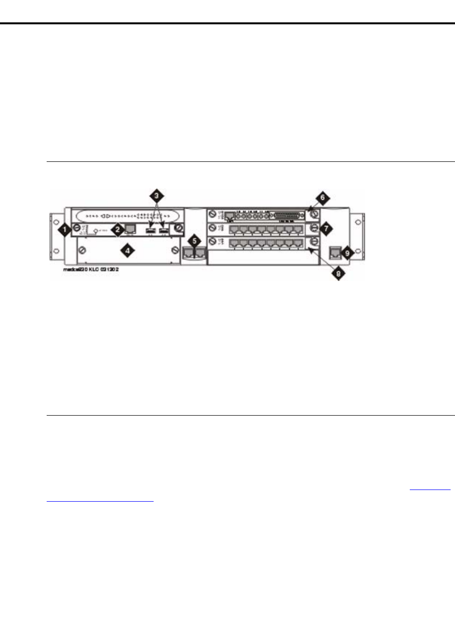
2Installing Hardware for the G700 Media Gateway and S8300 Media Server
Getting Started
70 Installation and Upgrades for G700 and S8300
December 2003
Getting Started
This section describes the components of an Avaya G700 Media Gateway and an Avaya S8300 Media
Server.
G700 Media Gateway
The main elements of a G700 Media Gateway are: (1) the G700 chassis and processors, (2) the media
modules, and (3) the Avaya Data Expansion Modules.
Figure 1: G700 Media Gateway with an S8300 Media Server: Front View
G700 Media Gateway Chassis and Processors
The G700 Media Gateway chassis is a 19-inch, 2u rack-mountable unit modeled after the Avaya P330
stackable switching products. A partial list of technical specifications of the G700 appears in Appendix
A, “Technical Information”.
The G700 has three internal processors:
•P330 stack processor (also known as Layer 2 switching processor)
•Media gateway processor (MGP)
•Voice over IP (VoIP) processor
NOTE:
An AC/DC version of the G700 will be available 1st-Quarter 2004.
Figure notes
1Media module slot #1 (V1)
2S8300 services port (used with cross-over
ethernet cable)
3S8300 USB ports
4Expansion module slot
510/100 Base-T Ethernet ports (ext1, ext2)
6media module slot #2 (V2)
7Media module slot #3 (V3)
8Media module slot #4 (V4)
9Console interface
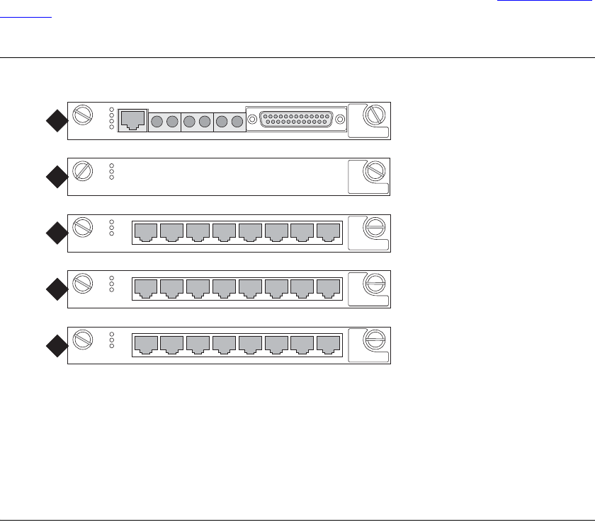
2
Installing Hardware for the G700 Media Gateway and S8300 Media Server
Getting Started
Installation and Upgrades for G700 and S8300 71
December 2003
Media Modules
Media modules are optional, plug-in circuit assemblies. They provide traditional interfacing of service
provider network access solutions (such as T1/E1) and connections to TDM-based endpoints (such as
DCP digital phones and analog phones). The available media modules are (as shown in Figure 2, Media
modules, on page 71):
Figure 2: Media modules
1Avaya MM710 T1/E1 Media Module
2Avaya MM760 VoIP Media Module for additional VoIP resources
3Avaya MM711 Analog Media Module for connection to 8 analog stations or CO trunks
4Avaya MM712 DCP Media Module for connection to 8 DCP stations
5Avaya MM720 BRI Media Module for connection to 8 ports for international BRI trunks
For detailed descriptions of the media modules see Hardware Guide for Avaya Communication Manager.
NOTE:
A shielded cable for the MM710 Media Module is required to meet emission
requirements in European Union countries. The use of a shielded cable for the MM710 is
preferred for installations worldwide.
The media modules enable the G700, with its primary controller, to host a variety of functions ranging
from IP phones to traditional analog telephony ports. The media modules contain trunk or line interfaces
and their associated circuitry. Each of the four media module slots has access to the 512-time-slot TDM
bus, a 10/100 base T port, power (+5V, -48 V phantom) and ground. Each media module can be accessed
and reset from the G700 Media Gateway Processor (MGP) or from the primary controller, and its status is
indicated by an LED display.
E1/T1 EIA 530A DCE
ALM
TST
ACT
SIG
EISO EMSM EOSI
1
ALM
TST
ACT
2
ALM
TST
ACT
123456 87
3
ALM
TST
ACT
123456 87
4
mmdc7 KLC 082202
ALM
TST
ACT
123456 87
5
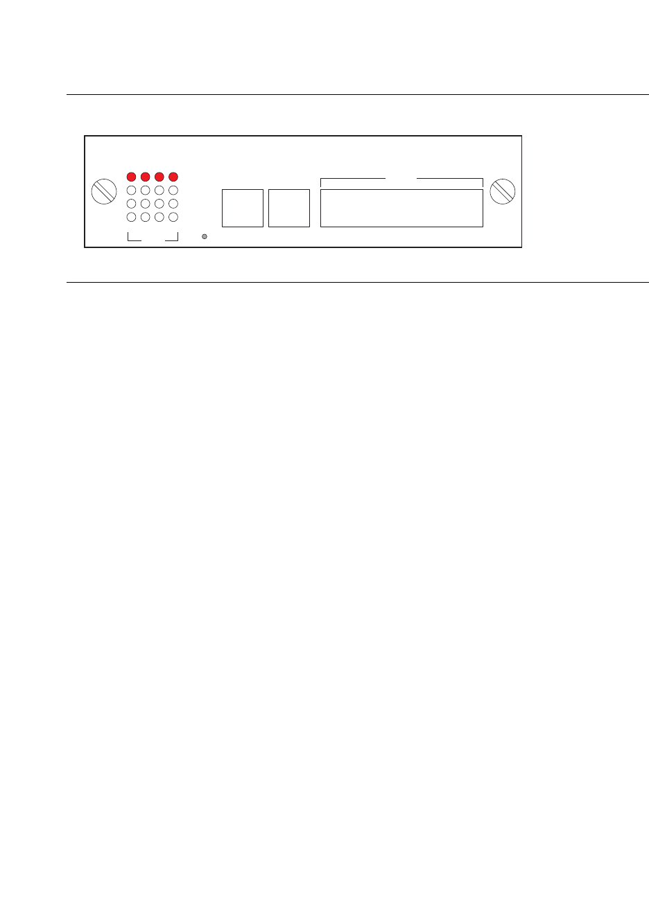
2Installing Hardware for the G700 Media Gateway and S8300 Media Server
Getting Started
72 Installation and Upgrades for G700 and S8300
December 2003
Data Expansion Modules
The G700 Media Gateway can accommodate any of the Avaya™ Data Expansion Modules. With
expansion modules, customers can add additional LAN and WAN access modules directly to the G700.
Figure 3: Expansion Module (example)
Two expansion modules that the customer may purchase are:
•Avaya X330 WAN Access Routing Module
•Avaya P330 LAN Expansion Module
The Avaya X330 WAN Access Routing Module
Customers with multiple branch offices need network solutions that are simple, flexible, and scalable.
These customers may purchase the Avaya™ X330 WAN Access Routing Module as part of their
configuration. This WAN Access Module provides WAN routing to the P330. The Avaya X330 WAN
Access Routing Module can be managed by three methods:
•Integrated Web-based management
•Avaya MultiService Network Manager
•Command Line Interface (CLI)
The Avaya X330 WAN Access Routing Module provides WAN access that can be used with external
firewalls or VPN Gateways.
The Avaya P330 LAN Expansion Module
Another Data Expansion that customers might purchase as part of their network is the Avaya™ P330 LAN
Expansion Module. Features of this Data Expansion Module include:
•Maximum flexibility to the data stack
•Standard auto-negotiation
•Link Aggregation Group (LAG)
•LAG redundancy
•Link redundancy
X330W-4DS1
WAN
1234
1234
E1/T1
RJ48
ETHCONSOLE
ALM
TST
ACT
SYN
RJ45RJ45
h1dcdmod KLC 030102
RSDETV

2
Installing Hardware for the G700 Media Gateway and S8300 Media Server
Getting Started
Installation and Upgrades for G700 and S8300 73
December 2003
•Congestion control
•802.1Q/p VLAN priority
CAUTION:
Avaya Expansion Modules and Octaplane Stacking Modules are not hot-swappable. The
G700 Media Gateway must be turned off before you remove or insert an Expansion
Module. If there is an S8300 present that is also turned on, the S8300 should be shut down
first, by pressing the Shutdown button until the OK to Remove LED shows a steady light.
S8300 LED Indicators
A set of LED indicators the faceplate of the S8300 are separate from those of the G700. A shutdown
button is also on the faceplate, which when depressed for about three seconds, will shut down the system,
including the operating software on the S8300. The LED flashes when shutdown is in progress and
remains on steady when it is safe to remove the S8300 or to power down.
The functions of the other LEDs are:
•The red Major Alarm indicator on the S8300 is off when the system is operational unless a Major
Alarm has been raised.
•The green Test LED on the S8300 is on when a test is in progress.
•The yellow ACT LED on the S8300 is on whenever a G700, an IP telephone, or an IP console is
registered with the S8300. It is off when none of these IP endpoints are registered.
•The green OK-to-Remove LED on the S8300 indicates that shutdown is complete and that it is
safe to remove the server or power down the system.
When the S8300 is a local survivable processor (LSP), no LEDs will be lit during normal operations. In
case of a network failure or loss of contact with the primary S8300 (or S8500 or S8700), the G700 Media
Gateway will register with the LSP. At that time, the red Alarm LED will light.
When you first power up the S8300, the red Major Alarm LED will be lit. During startup, an LED test
will run, after which all LEDs will be off. At this point, you can connect to the S8300. There will be
another flash of LEDs when Communication Manager starts.
Media Servers
Each G700 is associated with a primary call controller. The primary controller may be an S8300, S8500,
or S87 00 Media Server. The S8300 is on a circuit pack that is always installed in slot V1 of a G700. The
S8500 or S8700 is housed in a separate box that connects to the G700 over a network through a C-LAN
circuit pack. Both media servers can support multiple G700s.
The S8300 Media Servers can be configured as either a primary server or a Local Survivable Processors
(LSP). The G700 with a media server supports the entire range of adjuncts and peripheral equipment
supported by Communication Manager.

2Installing Hardware for the G700 Media Gateway and S8300 Media Server
Getting Started
74 Installation and Upgrades for G700 and S8300
December 2003
Figure 4: Avaya S8300 Media Server
S8300 Media Server
The S8300 Media Server is an Intel processor complex that mounts in the first media module slot (V1) of
the G700 Media Gateway. The S8300 Media Server has:
•Avaya™ Communication Manager (For a full description see: http://www.avaya.com/support)
•Administration and maintenance provisioning software
•20 G hard drive (40 G available January 2004)
•256 MB RAM (512 MB available January 2004)
•Web server
•Linux OS (Redhat)
•Support of H.248 and H.323 Protocols
•TFTP server and other IP services
A new version of the S8300 is expected to be available January 2004. The S8300B will be backward
compatible with current version and will have a 40 G hard drive and 512 MB RAM (in two 256 MB
DIMM strips).
Local Survivable Processor (LSP)
The S8300 Media Server can act as a survivable call-processing server for remote or branch customer
locations. As an LSP, the S8300 Media Server carries a complete set of Communication Manager
features, and its license file allows it to function as a survivable call processor. If the link between the
remote G700 Media Gateways and the primary controller is broken, those telephones and G700s that are
designated to receive backup service from the LSP will register with the LSP. The LSP will provide
control to those registered devices in a license error mode (see Hardware Guide for Avaya™
Communication Manager).
S8500 Media Server
The G700 Media Gateway can be controlled by an external S8500 Media Server. The S8500 is connected
to the G700 over the network through a C-LAN circuit pack in the G600, SCC1, or MCC1.

2
Installing Hardware for the G700 Media Gateway and S8300 Media Server
Getting Started
Installation and Upgrades for G700 and S8300 75
December 2003
S8700 Media Server
The G700 Media Gateway can be controlled by an external S8700 Media Server (sometimes referred to
as an ECC configuration). Both the S8700 with the G600 Media Gateway (IP Connect) and the 8700 with
the SCC1 or the MCC1 Media Gateways (MultiConnect) can control the G700. The S8700 is connected
to the G700 over the network through a C-LAN circuit pack in the G600, SCC1, or MCC1.
Information on installing the G700 using the S8500 or S8700 as the primary controller can be found in
Chapters 4 and 6 in this book.
Endpoint and Adjunct Components
Additional components and adjunct systems provide sets of tools that allow the customer to obtain the
best possible performance. Other components and adjunct systems that make up the S8300 Media Server
with a G700 Media Gateway include:
•Analog phones and fax machines
•DCP phones
•IP phones
•IP Softphones
•LAN Ethernet switches
•Avaya Integrated Management
•INTUITY AUDIX LX Messaging System
•IA 770 INTUITY AUDIX Messaging Application
•ASAI Co-Resident DEFINITY LAN Gateway (DLG)
•Call Center
•Uninteruptible Power Supply (UPS)
•Universal Serial Bus (USB) Modems
See "Chapter 8, “Connecting Telephones and Adjunct Systems” or Avaya Communication Manager,
Avaya DEFINITY®Servers, and Avaya S8100 Media Server Library CD, 555-245-801, for more
information on installing adjuncts.
Plan the Installation
In the following sections of this installation guide, you will be guided through the installation of several
configurations. Before the G700 components are physically installed on the customer’s site, several steps
will already have been completed to assure that the actual installation will go smoothly:
•Sales personnel have verified that the product is suited to the customer’s application.
•Planning and implementation personnel have conducted preliminary inspections of the site and of
the other equipment to assure that the S8300/G700 solution will operate at its full potential.
•A data network readiness assessment has been completed to assure that the solution will function
optimally within the customer’s network.
Each of these processes have been documented before the installation. You should verify that you have all
the necessary information before going to the site (see Appendix B, “Information Checklists”).

2Installing Hardware for the G700 Media Gateway and S8300 Media Server
Getting Started
76 Installation and Upgrades for G700 and S8300
December 2003
Use the Planning Documentation
To guide you in your preparations for the installation, use the Installer’s Checklists (see Appendix B,
“Information Checklists”) to verify that you have the tools, software, and information that you need to
install the G700.
The planning documentation will provide you with information about:
•What equipment you will be installing
•What kind of system you will be integrating
•Whom to contact on site about delivery, system questions, or network concerns
•Whom to contact at your home office in case of questions
•Whether you need a special pass or an escort
•How to gain entrance to the installation location if it is locked
•Where to install equipment
•Where to find a telephone near the installation location
SSO Authentication Login
You should obtain a personal Single Sign-On (SSO) for Remote Feature Activation (RFA) website
authentication login before going to the site for installation. You must complete the authentication
process before you can be assigned an SSO authentication login.
As a first-time user:
•Business Partners should point their browsers to the Business Partner portal option sales_market,
services-voice, training tools and procedures to select RFA (or go directly to:
http://rfa.avaya.com).
•Associates should point their browsers to the Avaya Associate portal (or go directly to:
http://rfa.avaya.com).
•Contractors should point their browsers to Avaya.com (or go directly to: http://rfa.avaya.com).
From that point, log into SSO and complete the process to obtain your personal login.
Site Verification
A pre-installation site inspection allows you to verify that the site requirements have been met for
adequate environmental conditions, power and grounding availability, safety, and security conditions. If
you find discrepancies between the specifications necessary for proper installation of equipment and the
conditions on site, contact your Project Manager before proceeding with the installation.
2
Installing Hardware for the G700 Media Gateway and S8300 Media Server
Getting Started
Installation and Upgrades for G700 and S8300 77
December 2003
Network Integration
Integration into the customer’s network will require coordination with the network manager and the
planning and implementation personnel. They will ascertain the customer’s need for DHCP service and
the intended network configuration and applications. In addition, Avaya offers Network Readiness
services to assist in evaluating and preparing the network for all configurations.
The Project Manager will provide information to be used by the installers. The documentation must
include dial plans and other telephony information, as well as IP addresses, IP masks, and other network
information. This information will be specific to each customer. To install the solution in an efficient
manner, you must collect and organize this information before going to the site.

2Installing Hardware for the G700 Media Gateway and S8300 Media Server
Installation and Cabling
78 Installation and Upgrades for G700 and S8300
December 2003
Installation and Cabling
The Avaya G700 Media Gateways can be installed in a variety of configurations:
•as a standalone unit with one G700
•with multiple G700 Media Gateways in a stack
•in combinations of Media Gateways and Avaya P330 family devices.
Up to ten G700 Media Gateways and/or Avaya P330s devices can be combined in a single stack.
The G700s can be controlled by an Avaya S8300, S8500, or S8700 Media Server.
In a typical installation, you will arrive at the site equipped with all the tools and information needed to
install a G700 and, possibly, an S8300. You will complete the following procedures:
NOTE:
When installing a G700, complete all tasks in this chapter to install the gateway before
doing the media server administration (e.g., add media-gateway).
On Site Checklist
When you reach the customer's site, you should have each item on the Installer’s Checklist (see Appendix
B, “Information Checklists”.) However, it is recommended that you consult with the customer network
manager for IP and DNS addressing, as well as for testing the installation. Also, before proceeding with
the installation, you should verify that the proper environmental and safety conditions exist.
Environmental Verification
Verify that temperatures and clearances are within the recommended technical parameters. Consult the
table of Technical Specifications in Appendix A, “Technical Information”.
CAUTION:
Verify that temperature and clearance ranges are within tolerable limits. The thermal
sensors may shut down equipment if it is subjected to conditions beyond the
recommended limits. Equipment can be damaged if these restrictions are not respected.
Installation Process Steps
On Site Checklist on page 78
Unpack and Check the Order on page 79
Install the G700 Media Gateway on page 80
Cable Multiple Units on page 89
Attach Ground Conductors on page 92

2
Installing Hardware for the G700 Media Gateway and S8300 Media Server
Installation and Cabling
Installation and Upgrades for G700 and S8300 79
December 2003
Power Verification
Check that an adequate number of power outlets are available.Verify that the G700 Media Gateways and
the other equipment in the rack do not present a possible overcurrent or overload to the customer’s branch
circuit and/or power distribution strip. Power requirements are listed in Appendix A, “Technical
Information”.
!
WARNING:
Do not overload the power circuit.
Grounding Verification
Ensure that the installation site has access to approved grounds and that either a trained technician or a
licensed electrician will be verifying all grounds and installing the Supplementary Ground Conductor
(consult Attach Ground Conductors).
!
WARNING:
Installation in a Restricted Access Location and secure access are required in
Finland and Norway.
The G700 Media Gateway relies on two ground connections (mains plug with an earth contact and a
permanent Supplementary Ground Conductor). Because of unreliable earthing concerns in Finland and
Norway, the G700 Media Gateway must be installed in a Restricted Access Location (RAL). An RAL is
defined as an access that can be gained only by trained service personnel or customers who have been
instructed about the reasons for the restricted access and any safety precautions that must be taken. In
these cases, access to the G700 Media Gateway is gained by the use of a tool (such as a lock and key) or
other means of security.
If you have any questions about the safety conditions, contact your Project Manager. When you have
verified that the site is ready for a safe installation, proceed with the installation.
Unpack and Check the Order
Cross-check your customer's order with the planning documentation you have been given. media
modules, telephones and other equipment are listed on your planning and shipping documentation.
Placement for the media modules and other equipment are indicated, as well.
Verify that all necessary elements have been received and are in good condition. If there are missing or
damaged elements, contact the Project Manager for instructions. The planning documentation will list
contact information for the Project Manager and other key personnel.
CAUTION:
Wear an anti-static wrist ground strap whenever handling components of an Avaya™
G700 Media Gateway. Connect the strap to an approved ground, such as an unpainted
metal surface.
If you have any questions about the equipment order, or if the equipment has been damaged, contact your
Project Manager. When you have verified that the order is complete and that you have all of the necessary
components and tools, proceed with the installation.
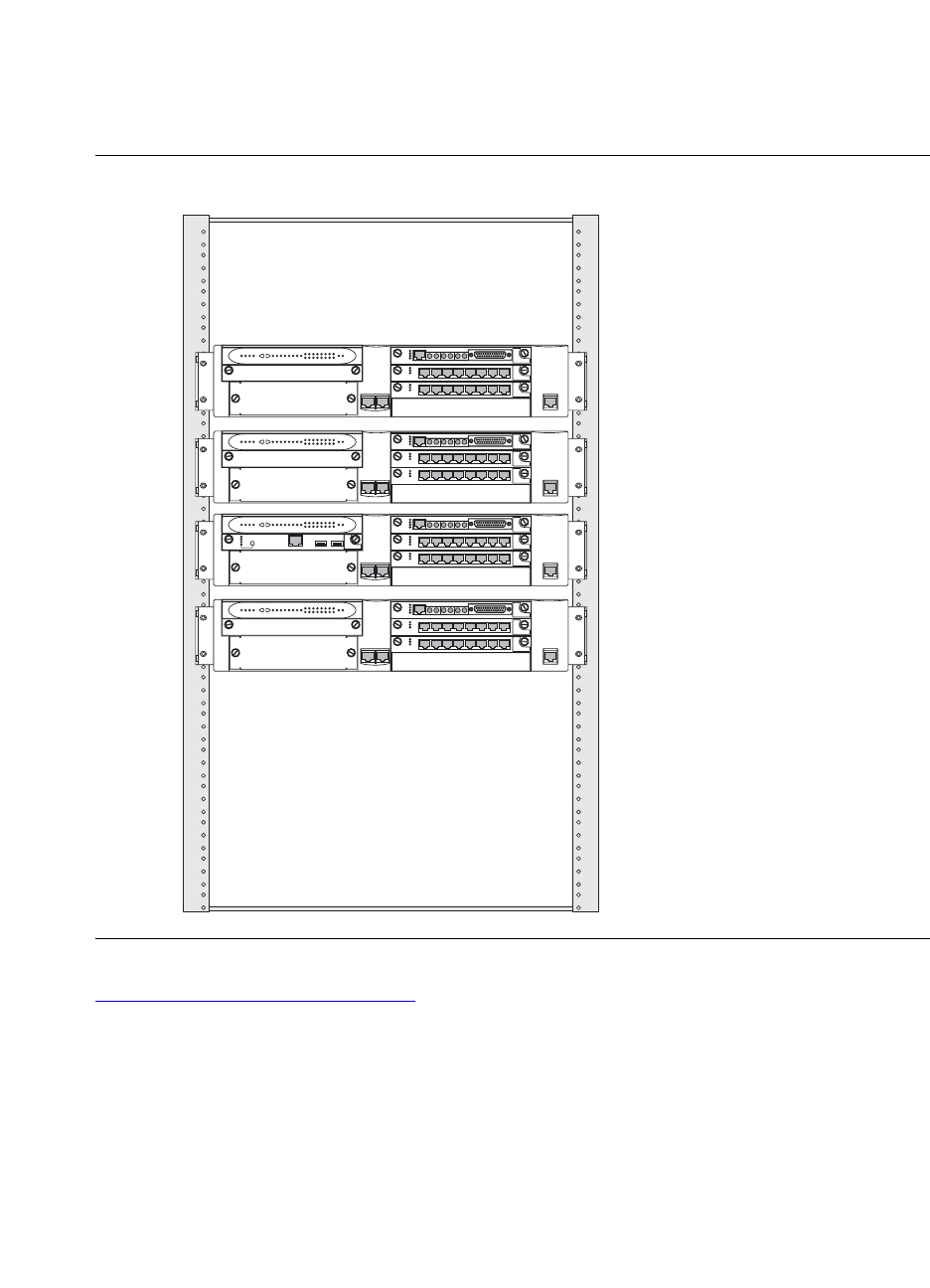
2Installing Hardware for the G700 Media Gateway and S8300 Media Server
Installation and Cabling
80 Installation and Upgrades for G700 and S8300
December 2003
Install the G700 Media Gateway
After you have verified the site conditions and the shipment, you will proceed with the installation of the
hardware.
Figure 5: Avaya G700 Media Gateways
Figure 5, Avaya G700 Media Gateways, on page 80 shows a stack of four G700 Media Gateways
installed in a rack-mounted configuration. Of the four G700s, only one contains an S8300 Media Server
in slot V1 (second up from the bottom).
ALM
TST
ACT
123456 87
ALM
TST
ACT
123456 87
E1/T1 EIA 530A DCE
ALM
TST
ACT
SIG
EISO EMSM EOSI
ALM
TST
ACT
123456 87
ALM
TST
ACT
123456 87
E1/T1 EIA 530A DCE
ALM
TST
ACT
SIG
EISO EMSM EOSI
ALM
TST
ACT
123456 87
ALM
TST
ACT
123456 87
E1/T1 EIA 530A DCE
ALM
TST
ACT
SIG
EISO EMSM EOSI
ALM
TST
ACT
123456 87
ALM
TST
ACT
123456 87
REMOVE
ALM
TST
ACT
OK TO SHUT DOWN
SERVICES USB 1 USB2
E1/T1 EIA 530A DCE
ALM
TST
ACT
SIG
EISO EMSM EOSI
scdcrck4 LAO 030203

2
Installing Hardware for the G700 Media Gateway and S8300 Media Server
Installation and Cabling
Installation and Upgrades for G700 and S8300 81
December 2003
Prepare the G700 Media Gateway
The instructions that follow guide you through a process of preparing the Avaya™ G700 Media Gateway
after you have mounted the empty chassis in the rack. It is possible to equip an empty G700 chassis
before positioning it in the rack. If you are working where space is limited, you may wish to prepare the
G700 before rack insertion.
CAUTION:
When handling any components of an S8300 Media Server with G700 Media Gateways,
wear an anti-static wrist ground strap. Connect the strap to an approved ground such as an
unpainted metal surface.
The G700 can stand on a flat surface or be mounted in the standard 19-inch rack. If the G700 is to be
mounted in a rack, you have the choice of fastening the unit to the rack either at the front of the unit or at
the middle. This positioning choice will depend on space arrangements. In either case, mounting brackets
must be attached to the sides of the chassis, either at the center or to the front of the chassis.
Affix Mounting Brackets to the G700
1Remove the screws from the bracket kit.
2Position a bracket over the desired mounting position.
3Affix the bracket to the chassis with the screws provided.
4Tighten with the screwdriver.
5Repeat on the other side.
If the G700 is to be a table-top unit, four feet must be attached to the bottom of the unit. The procedure to
do this is the following:
Affix Feet on the Table-Top G700
Use this procedure only if the G700 will be installed as a table-top unit (not in a data rack).
1Remove the four feet from their packaging.
2Turn the G700 Media Gateway over to allow the feet to be mounted.
3Position one foot into the mounting site near the corner of the chassis.
4Press the plastic rivet into the foot with a stylus until it is firmly seated on the chassis.
You have now prepared the G700 Media Gateway for mounting, and, assuming you are going to use a
data rack, you are ready to mount the chassis in the rack.
Mount the G700 Media Gateway in the Rack
The G700 Media Gateway mounts in a standard 19-inch rack. It is held in place by screws through the
two mounting ears. The unit can be mounted either in the center of the unit or at the front of the unit;
however, only the front mount allows use of the guides for electrical cables. To avoid balancing problems
and cabling complications, the racks should be filled from the bottom; that is, mount units in the lower
positions first.
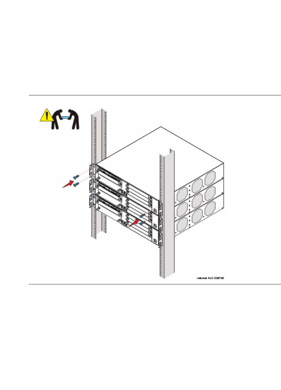
2Installing Hardware for the G700 Media Gateway and S8300 Media Server
Installation and Cabling
82 Installation and Upgrades for G700 and S8300
December 2003
Before mounting the G700, check for the following:
•Ensure that the rack is bolted to the floor and is earthquake-protected, if required. If the rack is not
securely fixed in place, do not proceed with the installation.
•If the G700 is being mounted in a rack with other equipment already installed, the G700 must be
positioned to avoid imbalance.
•The G700 is shipped with 3 sets of four mounting screws. Choose the set of screws that match the
screw holes in the rack being used.
•The G700 weighs 22.5 pounds (10 kg) empty and between 27 and 34 pounds (between 12 and 16
kg) when equipped with media modules. Two people may be needed to mount the G700 Media
Gateway in the rack.
Figure 6: Rack Mounting
Mount the G700 Media Gateway in the Rack
1Position the G700 in the rack. Assure that there is adequate ventilation.
2Verify that the screw holes are aligned with the rack hole positions.
3Insert the mounting screws. Use two screws on each side.
4Tighten the mounting screws. Avoid overtightening.
5Verify that ventilation vents are not obstructed.
6Repeat to add other G700 Media Gateways to the rack as described in the planning documents.
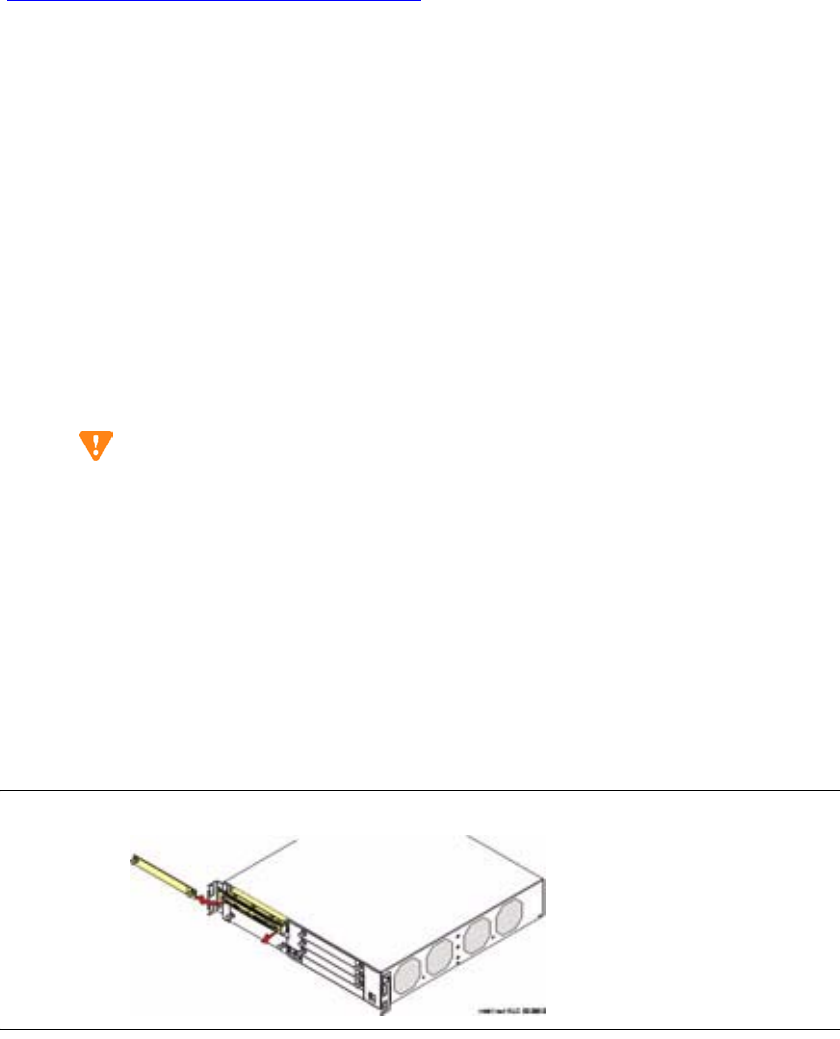
2
Installing Hardware for the G700 Media Gateway and S8300 Media Server
Installation and Cabling
Installation and Upgrades for G700 and S8300 83
December 2003
If you are installing multiple G700s, continue building the stack. Up to 10 units can be linked together
(Figure 13, Cabling Multiple Units in a Single Rack, on page 90); these may be G700s or Avaya P330
family switches.
At this point, you have mounted the G700 chassis in the rack and are ready to insert S8300 Media Servers
and media modules as required in the planning documentation.
Insert the Avaya S8300 Media Server
(If Necessary for Standalone Service or LSP)
The S8300 Media Server is inserted into the G700 Media Gateway slot #1 (v1), whether it is the primary
server or configured as a Local Survivable Processor (LSP). The S8300 can only be inserted in the slot
(v1) on the left side of the G700 Media Gateway. The LED module must be pulled from the G700 chassis
to provide clearance for the S8300 Media Server.
NOTE:
If you need to install the CWY1 card (for embedded messaging) on the S8300, do so now.
CAUTION:
If you are removing an S8300, use the shutdown button to stop the operating system (press
and hold for 2-3 seconds). The OK to Remove LED will flash while the shutdown is in
progress and will turn steady green when it is safe to remove the S8300.
Insert the S8300 into Slot #1 of the G700 Media Gateway
1Clear the left side of the G700 Media Gateway.
aRemove the blank plate from slot #1.
bThen, disengage the LED module and remove it from the G700 Media Gateway.
2Line up the Avaya S8300 Media Server module squarely with its bay opening.
Figure 7: Clear the left side of the G700 Media Gateway
3Engage both sides of the S8300 Media Server module in the interior guides and guide the module
halfway into the chassis.
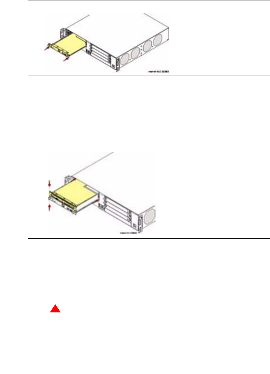
2Installing Hardware for the G700 Media Gateway and S8300 Media Server
Installation and Cabling
84 Installation and Upgrades for G700 and S8300
December 2003
Figure 8: Insert S8300
4Align the LED module in its guides and gently push it into place, keeping the LED module safely
within its guides and maintaining an even pressure to assure that the module does not become
twisted or disengage from the guides.
Guide the longer, left side of the LED module into the chassis until the shorter, right edge of the
module can engage in its guides.
Figure 9: Align the LED module and the S8300 Media Server
5Push steadily and firmly until the faceplates of the S8300 Media Server and the LED module are
even and then push the two units into the housing together.
6Apply firm pressure to engage the connectors.
The connector has different length pins. The long pins will engage first to provide grounding.
Medium length and short pins will provide power and signal.
7Tighten the captive screws on the S8300 Media Server module.
!
WARNING:
To prevent access to electrical hazards by unauthorized personnel and to ensure
continued compliance to radiated emissions requirements, all captive screws must be
securely tightened such that they cannot be loosened without the use of a tool.
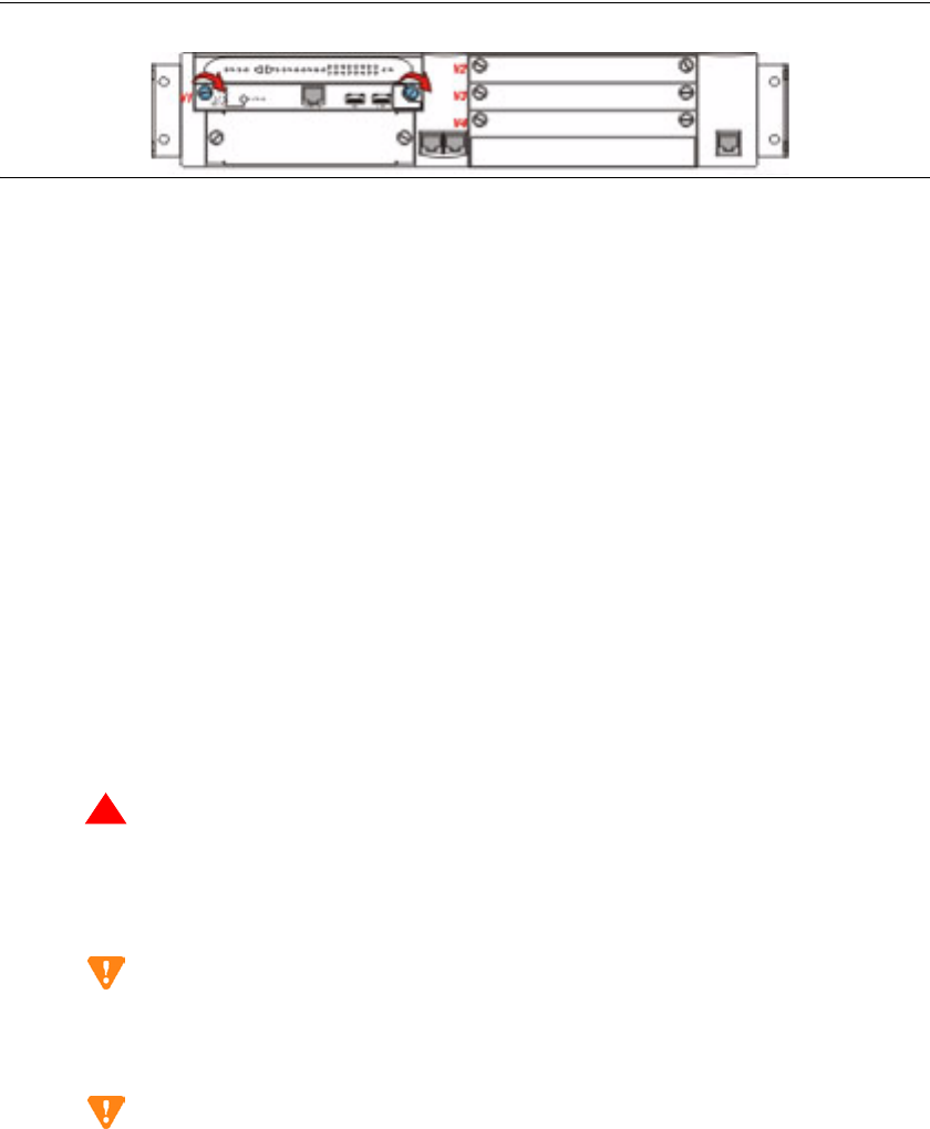
2
Installing Hardware for the G700 Media Gateway and S8300 Media Server
Installation and Cabling
Installation and Upgrades for G700 and S8300 85
December 2003
Figure 10: Tighten screws
Insert the Media Modules
Following the planning documentation, you can insert the required media modules into their designated
bays. The G700 Media Gateway can accommodate up to four media modules, or plug-in circuit packs.
The choice of media modules is dictated by the offer selected by the customer and the configuration of
the system.
Consult the planning documentation and the order form to determine which modules you will be
installing. The planning documents also indicate into which slots the modules are to be inserted. The
media modules available at this time are:
•Avaya™ MM710 T1/E1 Media Module
•Avaya™ MM760 VoIP Media Module
•Avaya™ MM711 Analog Media Module
•Avaya™ MM712 DCP Media Module
•Avaya™ MM720 BRI Media Module
For detailed descriptions of the media modules see Hardware Guide for Avaya Communication Manager.
!
WARNING:
The Avaya G700 Media Gateway must not be operated with any slots open. Failure
to cover empty slots with the supplied blank plates can cause overheating due to
inadequate air distribution.
CAUTION:
The connector pins can be bent or damaged if the module is handled roughly, or if
misaligned and then forced into position.
CAUTION:
Separate ESD paths to the chassis ground connect to the media modules at the spring-
loaded captive screws. Use a screw driver to ensure the captive screws are securely
tightened to prevent damage to the equipment.
Insert media modules
1Remove the blank plate from the empty bay.
2Position the media module squarely before the selected bay on the front of the G700 Media
Gateway chassis and engage both sides of the module in the interior guides.
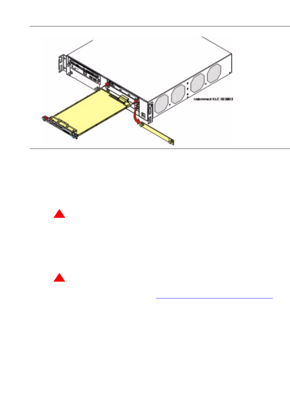
2Installing Hardware for the G700 Media Gateway and S8300 Media Server
Installation and Cabling
86 Installation and Upgrades for G700 and S8300
December 2003
3Slide the module slowly into the chassis, maintaining an even pressure to assure that the module
does not become twisted or disengaged from the guides.
Figure 11: Insert Media Module
4Apply firm pressure to engage the connectors.
The media module connector has different length pins. The long pins will engage first to provide
grounding. Medium length and short pins will provide power and signal.
5Lock the media module into the chassis by tightening the spring-loaded captive screws on the
front of the module.
!
WARNING:
To prevent access to electrical hazards by unauthorized personnel and to ensure
continued compliance to international radiated emissions requirements, all captive
screws must be securely tightened such that they cannot be loosened without the use
of a tool.
!
WARNING:
After you have connected telephones to the various media modules, be sure to add
circuit protection to the lines (see Complete the Telephone Installation Process on
page 331).
At this point, you have readied the G700 inserted the S8300 if required, and inserted the media modules,
as described in the planning documentation. Next, if required, the Expansion Module should be inserted
into its bay.

2
Installing Hardware for the G700 Media Gateway and S8300 Media Server
Installation and Cabling
Installation and Upgrades for G700 and S8300 87
December 2003
Insert an Expansion Module
The Expansion Modules provide increased networking and connectivity capabilities. These modules may
be mounted on the G700 Media Gateway in the slot on the lower left side of the unit below slot V1 (see
G700 Media Gateway with an S8300 Media Server: Front View on page 70).
CAUTION:
The Expansion Module is not hot-swappable. That is, the G700 must be powered off
before you insert or remove an Expansion Module. If there is an active S8300 present, the
S8300 should be shut down by pressing and holding the Shutdown button for 2-3 seconds.
The OK to remove LED will flash during shutdown and turn on steady when it is safe to
power down.
Insert an Expansion Module into the G700 Media Gateway
Turn off the power to the unit if the equipment has been in operation.
1Remove the blank plate covering the bay.
2Align the printed circuit board with the interior guide rails.
NOTE:
The printed circuit board fits into the guide rail. The metal base plate does not.
3Firmly press the Expansion Module into the G700 Media Gateway until it is completely inserted.
4Tighten the two screws on the front panel of the Expansion Module.
!
WARNING:
To prevent access to electrical hazards by unauthorized personnel and to ensure
continued compliance to international radiated emissions requirements, all captive
screws must be securely tightened such that they cannot be loosened without the use
of a tool.
!
WARNING:
The Avaya G700 Media Gateway must not be operated with any slot open. Empty
slots must be covered with the supplied blank plates.
At this point, you have readied the G700, inserted the S8300, if required, inserted the media modules and
the Expansion Module, as required in the planning documents. If more than one unit (G700 and/or Level
2 switches and routers) will be connected in the configuration you are installing, the next step will be to
insert an Avaya X330STK Stacking Sub-Module.
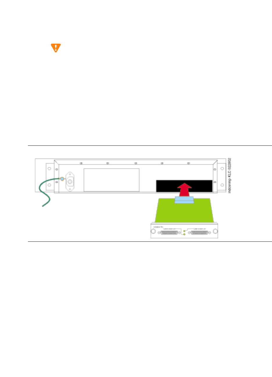
2Installing Hardware for the G700 Media Gateway and S8300 Media Server
Installation and Cabling
88 Installation and Upgrades for G700 and S8300
December 2003
Insert an Avaya X330STK Stacking Module
G700 Media Gateways can be mounted in equipment stacks with routers, switches, or other G700s. The
stack is limited to ten elements. To link multiple units, each G700 must be equipped with an Avaya
X330STK Stacking Module, which is mounted through the rear panel (back view) of the G700.
CAUTION:
The Stacking Sub-Module is not hot-swappable. That is, the G700 must be powered off
before you insert or remove a Stacking Module. If there is an active S8300 present, the
S8300 should be shut down by pressing the Shutdown button. Hold the button in 2–3
seconds until the OK to Remove LED starts flashing. When the LED turns on steady,
power can be safely turned off.
Insert an Avaya X330STK Stacking Module
1Remove the blank plate from the back of the G700.
2Insert the Avaya X330STK Stacking Module gently in the bay in the back of the G700, ensuring
that the metal base plate is aligned with the guide rails.
Figure 12: Insert Stacking Module in G700 (back view)
3Press the Avaya X330STK Stacking Module in firmly until the connector at the back of the
module is completely inserted into the internal connector on the G700.
4Tighten the screws on either side of the module.
At this point, the required modules and cabling units have been inserted into the G700 Media Gateway.
The next step will be to install cabling.
2
Installing Hardware for the G700 Media Gateway and S8300 Media Server
Installation and Cabling
Installation and Upgrades for G700 and S8300 89
December 2003
Cable Multiple Units
Avaya G700 Media Gateways can be mounted in equipment stacks with routers, switches, or other Media
Gateways. These elements are all compatible and are installed similarly. Consult Avaya™ P333T User
Guide for installation and cabling information. To link multiple units, each G700 Media Gateway must be
equipped with an Avaya X330STK Stacking Module on the rear panel. Then, each unit in the stack is
linked to the one above it. Finally, the bottom unit is linked to the top unit. Stacks should always be built
from the bottom, and new units should be added at the top. Up to 10 units can be stacked in this way.
When deciding where to position the unit, ensure that:
•It is accessible and cables can be connected easily.
•Cabling is away from sources of electrical noise such as radio transmitters, broadcast amplifiers,
power lines and fluorescent lighting fixtures.
•Water or moisture cannot enter the case of the unit.
•There is a free flow of air around the unit and the vents in the sides of the case are not blocked.
The two ends of the Octaplane cables incorporate different connectors. Each connector can only be
connected to its matching interface.The following cables are used to connect stacked units:
•Short Octaplane cable (Avaya X330SC) - light, ivory-colored cable used to connect adjacent
units.
•Long Octaplane and Extra-Long Octaplane cables (Avaya X330LC/X330L-LC) - light, ivory-
colored cable used to connect units from two different physical stacks or those separated by more
than 12 inches (30 cm).
•Redundant and Long Redundant cables (Avaya X330RC/X330L-RC) - black cable used to
connect the top and bottom switches of a stack.
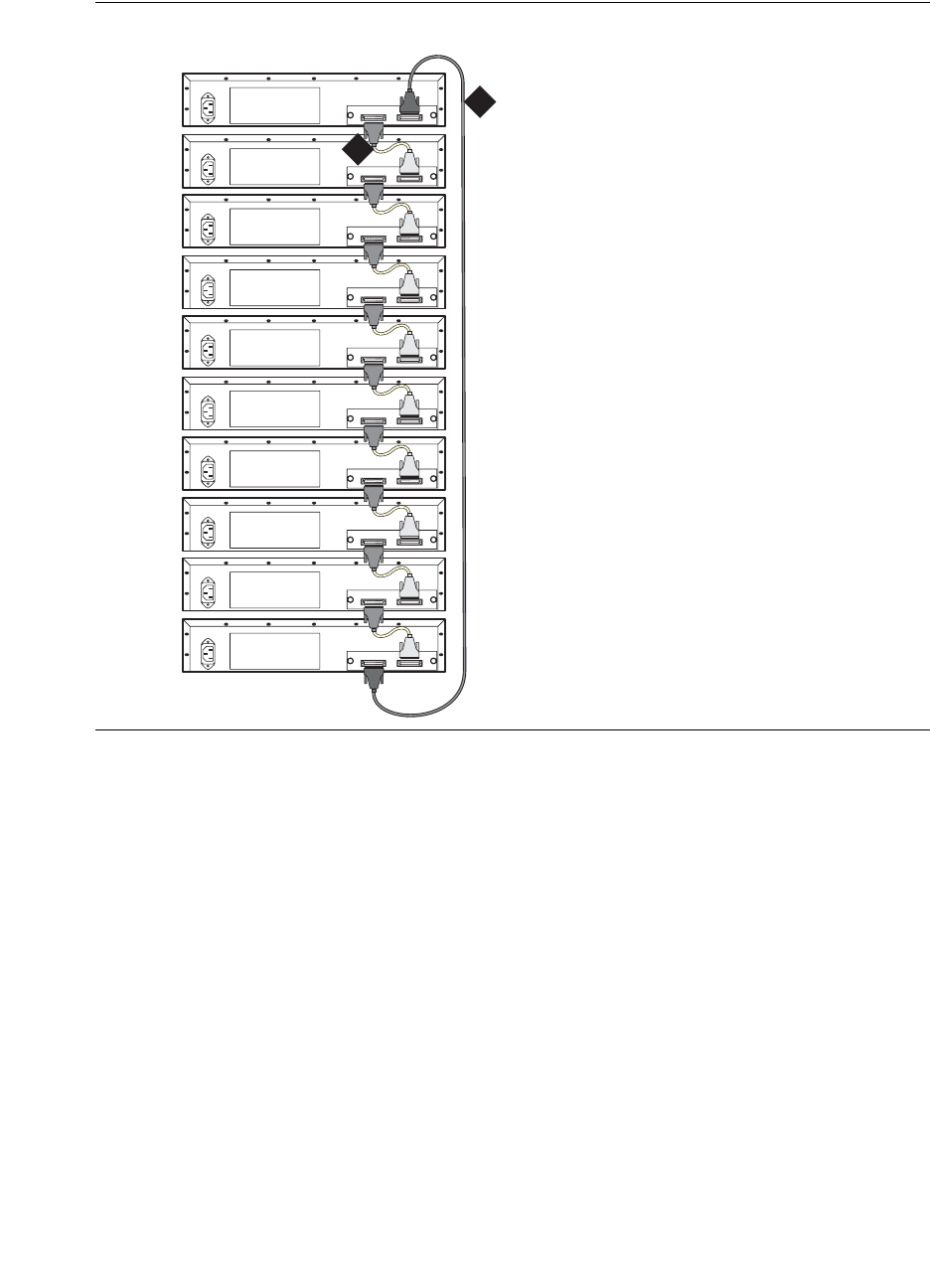
2Installing Hardware for the G700 Media Gateway and S8300 Media Server
Installation and Cabling
90 Installation and Upgrades for G700 and S8300
December 2003
Figure 13: Cabling Multiple Units in a Single Rack
Connect Units within a Single Stack
1Connect the light grey connector of the short Avaya X330SC cable (12 in, 30 cm) to the port
marked “to upper unit” in the bottom-most stack element.
2Connect the dark grey connector of the same short X330SC cable to the port marked “to the lower
unit” in the unit above.
3Repeat until you reach the top element in the stack. Up to ten G700s and/or other Cajun devices
can be stacked together.
To implement stack redundancy:
4Use the Redundant Cable to connect the port marked “to lower unit” on the bottom element to the
port marked “to upper unit” on the top element of the stack.
If you have elements of a stack in two racks, you must use the Avaya X330LC cable to connect them. You
may not link more than 10 units to form a stack, but those units can be mounted in more than one rack.
cadc2cbl LAO 030203
1
2
1Short Octaplane cable (X330SC)
2Redundant cable (X330RC)
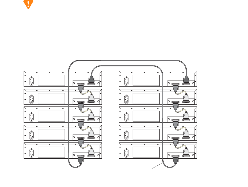
2
Installing Hardware for the G700 Media Gateway and S8300 Media Server
Installation and Cabling
Installation and Upgrades for G700 and S8300 91
December 2003
Link Elements in Multiple Racks
1Use the long (6ft, 2 m) Avaya X330LC cable to connect elements in two racks.
2Connect the Avaya X330LC cable (dark grey connector) to the port on first unit of the stack
marked “to the lower unit.”
3Connect the Avaya X330LC cable (light grey connector) to the port on the last unit in the stack
marked “to the upper unit.”
To implement stack redundancy:
4Connect the dark grey connector of the black Redundant Cable to the port marked “to lower unit”
on the bottom unit of the stack.
5Connect the light grey connector of the black Redundancy Cable to the port marked “to upper
unit” on top unit of the stack.
CAUTION:
Do not cross-connect two stack elements with two Octaplane (light-colored) cables. If you
wish to cross-connect for redundancy, use a black redundancy cable.
Figure 14: Linking Units in Multiple Racks
You have now mounted the fully equipped Avaya G700 Media Gateway in the rack, and cabled units
together as described in the planning documents. When all the units are mounted, and cabled, you are
ready to connect to electrical ground conductors.
cadc2stk LAO 030203 X330LC or X330L-LC Cable

2Installing Hardware for the G700 Media Gateway and S8300 Media Server
Installation and Cabling
92 Installation and Upgrades for G700 and S8300
December 2003
Attach Ground Conductors
To assure safe installation and operation, carefully read all requirements, recommendations and
instructions. Pay special attention to all CAUTION, WARNING, and DANGER statements.
!
WARNING:
Make sure that the G700 has a reliable earth ground connection, whether it is
connected directly to a branch circuit or to a power distribution strip.
!
WARNING:
Installation in a Restricted Access Location and secure access are required in
FInland and Norway.
CAUTION:
System grounding must comply with the general rules for grounding provided in Article
250 of the National Electrical Code (NEC), National Fire Protection Agency (NFPA) 70,
or the applicable electrical code in the country of installation.
General Grounding Requirements
For AC Input: Two safety grounds are required to ensure safe operation of the G700 Media Gateway —
the ground conductor that is part of the AC power cord and the field-installed green/yellow conductor
referred to as the Supplementary Ground Conductor. Both safety grounds must be connected to an
approved ground. If a power cord accompanies the G700, use that cord whenever possible.
For DC Input: The +48Vdc lead provided for DC power input to the G700 Media Gateway must be
grounded at the source to an approved ground. The -48Vdc is the active lead. Both leads must be floating
at the input to the G700. In addition, the Supplementary Ground Conductor must be installed on the G700
and connected to an approved ground.
The customer must select a location for the G700 Media Gateway installation that is no more than 50 feet
(15 m) from an approved ground. If this location requirement is not met, the customer must contact a
licensed electrician to install a Supplementary Ground Conductor per Article 250 of the National
Electrical Code (NEC).
!
WARNING:
If the installation location is greater than 50 feet (15 m) from an approved ground, do
not install the Avaya G700 Media Gateway until a licensed electrician is present to
install a Supplementary Ground Conductor.
A 55-foot (16-m) Supplementary Ground Conductor is provided with the equipment, and is constructed
of 10 AWG (4.0 mm2) wire, with an insulated ring terminal crimped to one end that is suitable for the #8
(M4) stud/screw on the rear of the G700 chassis.
The customer will need to provide a means of connecting this Supplementary Ground Conductor to an
approved ground according to Article 250 of the National Electrical Code (NEC).

2
Installing Hardware for the G700 Media Gateway and S8300 Media Server
Installation and Cabling
Installation and Upgrades for G700 and S8300 93
December 2003
A ground block is available for use when multiple G700 Media Gateways are being installed. The ground
block, intended for rack mounting, has ten terminals available for terminating Supplementary Ground
Conductors. Up to ten G700 Media Gateways can be grounded at the block installed close to the
equipment (on a rack) and then a single ground conductor can be routed from the same block to an
approved ground. If the ground block is to be used, it must be ordered separately.
!
DANGER:
Failure to install both grounds will void the Product Safety certifications (UL and the
CE Mark) on the product, as well as allow a hazard to be present that could result in
death or severe personal injury.
Because of unreliable earthing concerns in Finland and Norway, the G700 Media Gateway must be
installed in a restricted access location. A restricted access location is defined as access that can be gained
by only Service Personnel or Customers who have been instructed about the reasons for the restricted
access and any safety precautions that must be taken. In these cases, access to the G700 Media Gateway
is gained by the use of a tool (such as a lock and key) or other means of security.
!
WARNING:
For Installations in Finland and Norway, the Avaya G700 Media Gateway relies on
two ground connections (mains plug with an earth contact, and a Supplementary
Ground Conductor).
Approved Grounds
An approved ground is the closest acceptable medium for grounding the building entrance protector,
entrance cable shield, or a single-point ground of electronic telephony equipment. If more than one type
of approved ground is available on the premises, the grounds must be bonded together as required in
Section 250-81 of the NEC for the US or per the local electrical code regulations in the country of
installation.
• Grounded Building Steel: The metal frame of the building where it is effectively grounded by one
of the following grounds: acceptable metallic water pipe, concrete encased ground, or a ground
ring.
•Acceptable Water Pipe: A metal underground water pipe, at least 1/2-in. (1.3 cm) in diameter, in
direct contact with the earth for at least 10 ft. (3m). The pipe must be electrically continuous (or
made electrically continuous by bonding around insulated joints, plastic pipe, or plastic water
meters) to the point where the protector ground wire connects. A metallic underground water pipe
must be supplemented by the metal frame of the building, a concrete-encased ground, or a ground
ring. If these grounds are not available, the water pipe ground can be supplemented by one of the
following types of grounds:
— Other local metal underground systems or structures - Local underground structures such
as tanks and piping systems.
— Rod and pipe electrodes - A 5/8-in. (1.6 cm) solid rod or 3/4-in. (2 cm) conduit or pipe
electrode driven to a minimum depth of 8 ft. (2.4 m).
— Plate electrodes - Must have a minimum of 2 sq. ft. (0.185 sq. m) of metallic surface
exposed to the exterior soil.
•Concrete Encased Ground: An electrode encased by at least 2 in. (5.1 cm) of concrete and located
within and near the bottom of a concrete foundation or footing in direct contact with the earth.
The electrode must be at least 20 ft. (6.1 m) of one or more steel reinforcing bars or rods, 1/2-in.
(1.3 cm) in diameter, or at least 20 ft. (6.1 m) of bare solid copper, 4 AWG (26mm2) wire.

2Installing Hardware for the G700 Media Gateway and S8300 Media Server
Installation and Cabling
94 Installation and Upgrades for G700 and S8300
December 2003
•Ground Ring: A buried ground that encircles a building or structure at a depth of at least 2.5 ft
(0.76 m) below the earth’s surface. The ground ring must be at least 20 ft. (6.1 m) of 2 AWG (35
mm2), bare copper wire.
•Approved Floor Grounds: Floor grounds are those grounds on each floor of a high-rise building
that are suitable for connection to the ground terminal in the riser closet and to the cabinet single-
point ground terminal. Approved floor grounds may include the following:
— Building steel
— The grounding conductor for the secondary side of the power transformer feeding the
floor
— Metallic water pipes.
— Power-feed metallic conduit supplying panel boards on the floor.
— A grounding point specifically provided in the building for that purpose.
!
WARNING:
If the approved ground or approved floor ground can only be accessed inside a
dedicated power equipment room, then connections to this ground must be made by
a licensed electrician.
Connect the Safety Ground
Proper grounding of the G700 Media Gateway installation safeguards the system, users and service
personnel by providing protection from lightning, power surges, AC mains faults, power crosses on
central office trunks, and electrostatic discharge (ESD).
Local electrical installation codes must be followed when installing G700 Media Gateways.
!
WARNING:
Connection of both grounds (through the AC or DC Power Cord and the
Supplementary Ground Conductor) is required for safe operation of the G700 Media
Gateway.
!
WARNING:
An improper ground can cause electrical shock as well as equipment failures and
service outages.
Attach the Ground Wires
1 Remove the ground screw on the rear of the chassis adjacent to the ground symbol:
2Place the ring terminal of the 10 AWG (4.0 mm2) Supplementary Ground Conductor on the screw.
3Replace the ground screw to the chassis and securely tighten the screw such that it cannot be
loosened without the use of a tool.
If the ground block has been purchased: The ground block is provided for use with more than
one G700 (or other Cajun devices) in the rack. It is usually mounted by the customer electrician.

2
Installing Hardware for the G700 Media Gateway and S8300 Media Server
Installation and Cabling
Installation and Upgrades for G700 and S8300 95
December 2003
4Cut the Supplementary Ground Conductor (which has one end attached to the grounding screw on
the chassis) to the length needed to terminate it into one of the terminals of the ground block. Do
not coil the Supplementary Ground Conductor.
5Attach one end of the remaining 10 AWG (4mm2) ground wire to one of the terminals in the
ground block and the other end to an approved ground.
6Cut this ground wire to the length needed to reach the approved ground. Do not coil this wire.
If the ground block is not being used, simply:
7 Attach the Supplementary Ground Conductor to an approved ground.
8Connect the AC power cable to the inlet receptacle on the rear of the chassis.
You have now mounted the fully equipped G700 Media Gateway in the rack, cabled units together as
described in the planning documents, and connected to electrical ground conductors. When all the units
are mounted, cabled, and grounded, you are ready to apply power.
Connect AC Power
For North American installations, the AC Power Cord terminates on one end with a NEMA-15P plug to
connect to the AC main socket-outlet at the wall. For installations in other regions, the plug to be used
must comply with the local regulations and be marked as such, be suitable for the current and voltage
being used, and contain an earthing pin for connection to ground at the AC mains socket-outlet through
the cord.
To prevent accidental interruption of power to the G700 Media Gateway, do not connect the G700 Media
Gateway to a switch-controlled AC wall socket-outlet. In addition, Avaya Inc. highly recommends that
the customer use a UPS for back-up power.
Advise your customer to verify through a licensed electrician that the ground connection at the AC outlet
to be used is attached to an approved ground.
Power Requirements
The G700 Media Gateway uses an auto-ranging 100-240 Vac power supply, 50 to 60 Hz, 5 A maximum
at 100-120 Vac and 2 A maximum at 200-240 Vac. The AC power source is to be single phase, 3-
conductor (Line, Neutral and Ground) with a 15 A circuit breaker for 100-120 Vac or a 10 A circuit
breaker for 200-240 Vac.
Test the AC Outlet
!
WARNING:
The following recommended test equipment, tests and diagrams are intended only
for North American installations at 110 to 125 Volts AC. For installations in other
regions, have a licensed electrician verify the ground and voltages.
!
WARNING:
If the AC outlet tests indicate that the power requirements are not met, your
customer must contact a licensed electrician. DO NOT install the system until all
requirements are met.

2Installing Hardware for the G700 Media Gateway and S8300 Media Server
Installation and Cabling
96 Installation and Upgrades for G700 and S8300
December 2003
Fault Conditions
If the AC outlet tests that follow reveal any of the following conditions, they must be corrected BEFORE
the system is to be installed.
•Open ground
•Hot and neutral reversed
•Open hot
•Open neutral
•Hot and ground reversed
!
WARNING:
Hazardous voltages are present during this test. Follow all instructions carefully
when working the AC power line voltages.
Verify Ground Using an Ideal 61-035 Circuit Tester (or equivalent)
1Plug the circuit tester into the outlet that you want to test.
If the circuit is properly grounded, the yellow and white lights on the tester illuminate.
2Unplug the tester.
!
WARNING:
If the tester indicates any type of ground fault, your customer must contact a licensed
electrician. DO NOT install the system.
Verify Voltages Using a Volt-Ohm Millimeter (VOM) (U.S. and countries using 110 to 125
Vac power)
!
WARNING:
Hazardous voltages are present during this test. Follow all instructions carefully
when working with AC power line voltages.
1 Ensure that the VOM is set to read Volts AC
NOTE:
The following example is for North American voltages (110 to 125 Vac). Use the
appropriate voltages for local power.
2Set the VOM to the lowest scale on which you can read 130 Vac.

2
Installing Hardware for the G700 Media Gateway and S8300 Media Server
Installation and Cabling
Installation and Upgrades for G700 and S8300 97
December 2003
3Measure the AC voltages in the following order:
If the voltage readings do not measure the values given, the AC outlet is improperly wired — DO NOT
INSTALL THE SYSTEM. Advise the customer to have a licensed electrician correct the problem.
You are now ready to power the system.
Plug in AC Power
Once the ground and voltages have been verified to be correct for the installation,
connect to AC power.
1Plug the power cord into the G700
2Plug the power cord into the outlet that was tested.
NOTE:
There is no On/Off power switch on the G700 Media Gateway. The AC inlet serves as the
disconnect device. To disconnect power from the G700 Media Gateway, remove the
power cord plug from the AC inlet.
The G700 Media Gateway will power up. The LEDs on the media modules, the S8300 Media
Server, and the G700 Media Gateway will flash at power-up. Each element will conduct a series
of self-tests.
3The LEDs on the G700 LED panel will flash, and the red ALM LED will light up until the self-
tests on the G700 Media Gateway have completed.
4The LEDs on the S8300 Media Server will light as described in the following sequence:
aALM - RED - lights up, then turns off
bTEST - GREEN – lights up, then turns off
cACTIVE - YELLOW – lights up, then turns off
dOK To REMOVE - GREEN - lights up, then turns off
eLEFT LED in SERVICES port - GREEN (10 MB link speed) lights up, then turns off
fLEFT LED in SERVICES port - YELLOW (100 MB link speed) lights up, then turns off
gRIGHT LED in SERVICES port - GREEN lights up, then turns off
When you first power up the S8300, the red Major Alarm LED will be lit. During startup, self-
tests will run, after which all LEDs will be off. At this point, you can connect to the S8300. There
will be another flash of LEDs when Communication Manager starts.
1Phase to neutral should be 110 to 125 Vac.
2Neutral to ground should be less than 1
Vac.
3Phase to ground should be 110 to 125
Vac.

2Installing Hardware for the G700 Media Gateway and S8300 Media Server
Installation and Cabling
98 Installation and Upgrades for G700 and S8300
December 2003
5Verify that:
— media modules: all LEDs are extinguished.
NOTE:
If the initial administration of all media modules is not completed, an alarm LED will
light.
— The master LED (labeled MSTR) or the system LED (labeled SYS) lights on one and only
one module in the stack.
— G700 Media Gateway: the green CPU LED is illuminated when both the P330 stack
processor (Layer 2 Switching Processor) and the G700 Media Gateway Processor (MGP)
are in a normal operational state.
The red ALM LED is illuminated whenever an alarm exists in the G700 Media Gateway
Processor. The ALM LED might signal either a hardware failure or a software or firmware
condition that could be cleared by resetting the processor. It will also be illuminated because the
license file for the S8300 has not yet been installed.
Check and Connect DC Power
NOTE:
The AC/DC version of the G700 will be available 1st-Quarter 2004.
Perform this check procedure only if you are installing a G700 that is using the DC input-power option
rather than AC input-power.
Before you connect the G700 media gateway DC feed cable to the DC power source, check the DC power
source using a KS-20599 digital voltmeter (or equivalent). To check DC power:
1Verify that the meter reads between -41Vdc and -56 Vdc across the -48Vdc and -48V Return
distribution leads from the DC source.
2Verify that the meter reads 0V between the -48V Return lead of the DC power source and the
approved ground.
3If either step 1 or step 2 fails the verification, DO NOT PROCEED with step 4. Request that a
qualified electrician resolve the problem.
4Connect the DC feed cable for each G700 to the G700 chassis.
5Connect the DC feed cable for each G700 to the DC power source.
aConnect the red insulated 10 AWG lead to the -48Vdc Return (positive) source.
bConnect the black insulated 10 AWG lead to the -48Vdc (negative) source.
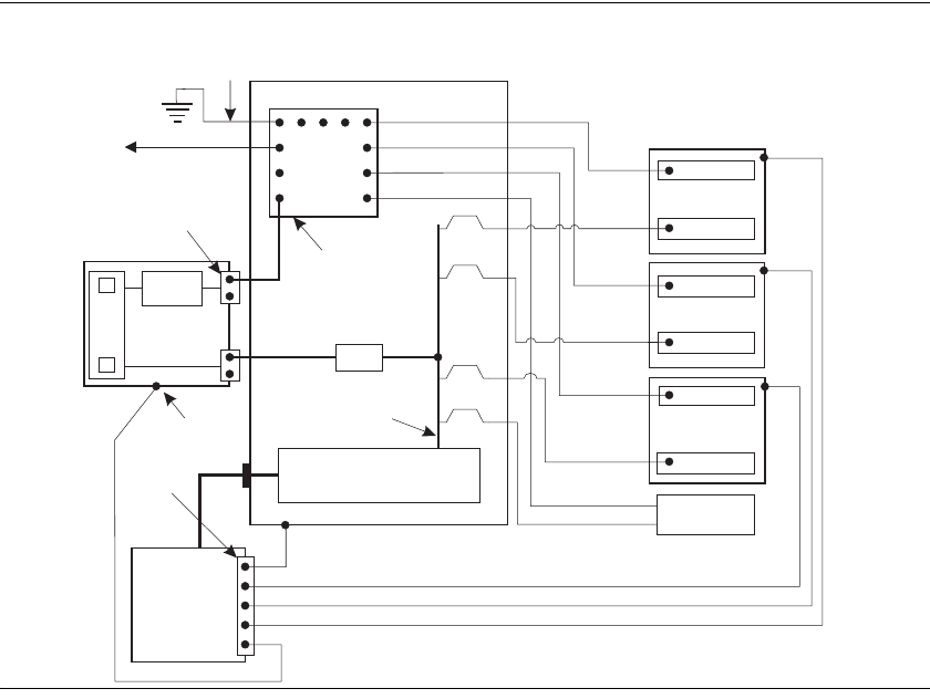
2
Installing Hardware for the G700 Media Gateway and S8300 Media Server
Installation and Cabling
Installation and Upgrades for G700 and S8300 99
December 2003
Figure 15: DC Wiring Diagram
You have now completed the initial installation of the G700 Media Gateway.
Ground
discharge
bar
DC power cabinet
To
CBC ground terminal
bar at the MDF
30A
30A
30A
30A
-48
VDC
-48 V
-48 V
-48 V
-48 V RTN
-48 V RTN
-48 V RTN
To next
G650
Main AC
supply
(AC mains)
1 AWG
ground wire
Approved
ground
System single
point ground
Ground
connection
terminal
Single point
ground
block
G650
G650
G65
Frame ground
10 AWG
RED
10 AWG
6 AWG
10 AWG
10 AWG
10 AWG
10 AWG
BLACK
RTN
cydf_dc2 LAO 072403
BLACK
10 AWG
RED
BLACK
10 AWG
RED
10 AWG
RED
10 AWG
BLACK
Battery
circuit
breaker
DC battery
cabinet
+
-
LVD
Rectifiers
DC power
from rectifiers
+
-
Green/Yellow
Green/Yellow
Green/Yellow
G700
G700
G700
G700

2Installing Hardware for the G700 Media Gateway and S8300 Media Server
Installation and Cabling
100 Installation and Upgrades for G700 and S8300
December 2003

3
Installing a New G700 with an S8300
Installation and Upgrades for G700 and S8300 101
December 2003
3Installing a New G700 with an
S8300
This chapter covers the procedures to install a new Avaya G700 Media Gateway with an Avaya S8300
Media Server. The S8300 can be configured as either the primary controller or as a local survivable
processor (LSP).
The new S8300 ships with the Communication Manager software installed on the hard drive. The G700
ships with the firmware installed on the G700 processors and media modules. However, you may need to
upgrade Communication Manager, G700 firmware, and/or media module firmware if the latest available
versions are not currently installed.
If the S8300 is configured as an LSP, the primary controller, running Avaya Communication Manger, can
be either another S8300, or an S8500 or S8700 Media Server.
NOTE:
Procedures to install or upgrade an S8500 or S8700 Media Server are not covered in this
document. See Avaya S8300, S8500, and S8700 Media Server Library, which is on the
Avaya Support website (http://www.avaya.com/support) or on the CD, 555-233-825.
The steps to install an S8300 configured as an LSP are the same as the steps to install an S8300
configured as the primary controller, with the following additional considerations:
•The version of Communication Manager on the LSP must be the same as, or later than, the
version running on the primary controller.
•For an LSP, you administer Communication Manager translations on the primary controller, not
on the LSP. The primary controller then copies the translations to the LSP.
Tip:
The Avaya Installation Wizard (IW) performs tasks automatically starting with Transfer
Files from a CD or Laptop on page 111. However, the IW does not install and configure an
X330 Expansion module. This task must still be performed as described in this document.
In addition, for an S8300 Media Server, IW administers only the Media Gateway screen
(add media-gateway). IW also administers only default values for the IP region. Finally,
you must define any LSPs on the S8300 Media Server manually using the procedures in
this document.

3Installing a New G700 with an S8300
Installation Overview
102 Installation and Upgrades for G700 and S8300
December 2003
Installation Overview
G700 components
A P330 stack processor is built into the G700 Media Gateway. (This processor is also known as the Layer
2 switching processor). The G700 also contains an MGP processor, a VoIP processor, and media
modules. Updating the firmware for one or more of these processors and/or media modules is a required
part of most S8300 software upgrades.
Software and firmware files
A new S8300 Media Server should already have a current release of Communication Manager software
installed on its hard drive. The G700 components should have current releases of firmware installed. It
may be necessary to upgrade the S8300 software to a later release, or to install an update (patch), and/or
upgrade the G700 and media module firmware.
The file containing the S8300 software and G700 firmware has a *.tar extension. The *.tar file is on a
CD-ROM that you take to the site. Additional files that may be needed are the most recent versions of the
software update (patch) file and G700 firmware files. You may need to obtain these files from the Avaya
Support web site.
System Access
Initial Access to the G700
Before the P330 stack processor is configured with an IP address, the only way to access it is with a direct
connection from your laptop to the Console port on the G700. With this connection, you can assign the IP
addresses to the G700 processors, which can then be accessed over the customer LAN.
Access to the S8300 and G700
You can access the S8300 and G700 in several ways with either a direct connection or LAN connection.
NOTE:
Before the Upgrade Tool can be used to upgrade software on an LSP or firmware on a
G700, as summarized below, the LSP must be administered on the primary controller.
Direct connection to target S8300
If you are at the location of the target S8300 (primary or LSP), you can connect directly to the S8300
Services port and:
1Upgrade the S8300 software by
— Opening the Web interface and using the Avaya Installation Wizard
— Or, opening the Web interface and using the main menu
2Upgrade the G700 firmware by
3
Installing a New G700 with an S8300
Installation Overview
Installation and Upgrades for G700 and S8300 103
December 2003
— Opening the Web interface and using the Upgrade Tool
— Or, telnet to the S8300 and then telnet to the P330 stack processor
Direct connection to the remote primary server (S8300, S8500, or S8700)
In this case, the target S8300 is an LSP. If you are at the remote location of the primary server, you can
connect directly to the server’s Services port and:
1Upgrade the S8300 (LSP) software by
— Opening the Web interface and using the Upgrade Tool
2Upgrade the G700 firmware by
— Opening the Web interface and using the Upgrade Tool
— Or, telnet to the primary server and then telnet to the P330 stack processor and perform the
installation commands
For direct connections, the TFTP server must be on the Customer LAN, not on your laptop.
LAN connections
If you can connect to the customer’s LAN, you can:
1Upgrade the S8300 software by
— Opening the Web interface on the S8300 and using the Avaya Installation Wizard
— Or, Opening the Web interface on the S8300 and using the main menu
2Upgrade the G700 firmware by
— Opening the Web interface on the primary server and using the Upgrade Tool
— Or, telnet to the P330 stack processor and perform the installation commands
For LAN connections the TFTP server can be your laptop or a customer computer on the LAN.
See "Connection and Login Methods" in Chapter 1 for details on how to connect and log into the G700.

3Installing a New G700 with an S8300
Before Going to the Customer Site
104 Installation and Upgrades for G700 and S8300
December 2003
Before Going to the Customer Site
The procedures in this section should be completed before going to the customer site or before starting a
remote installation.
Off-site Tasks
Get Planning Forms from the Project Manager
The project manager should provide you with forms that contain all the information needed to prepare for
this installation. The information primarily consists of IP addresses, subnet mask addresses, logins,
passwords, people to contact, the type of system, and equipment you need to install.
Verify that the information provided by the project manager includes all the information requested in
your planning forms.
Tip:
Appendix B, Information Checlists, provides several checklists to help you gather the
installation and upgrade information.
Get the Serial Number of the G700,
if Necessary
For an upgrade of an existing G700, the existing license file can usually be reused. However, if the
customer is adding feature functionality (for example, adding BRI trunks), or if the upgrade is between
major releases (for example, 1.3 to 2.0), you will need the serial number of the G700. To get this number,
ask the customer’s administrator to log in to the S8300 web page and select View License Status from
the main menu to display the serial number.
For a new installation, you need the serial number of the G700 Media Gateway in order to complete the
creation of the customer’s license file on the rfa.avaya.com web site. To get this number, look for the
serial number sticker on the back of the G700 chassis. If the unit is delivered directly to the customer and
you will not have phone or LAN line access from the customer site to access the rfa.avaya.com web site,
this task will require a preliminary trip to the customer site.
Check FTP Server for Backing up Data
During the installation and upgrade procedures, you will need to back up the system data to an FTP
server. Normally, you will use an FTP server on the customer’s LAN for backups. To do this, you will
need information on how to get to the backup location — login ID and password, and the IP address and
directory path on the FTP server. Check with your project manager or the customer for this information.

3
Installing a New G700 with an S8300
Before Going to the Customer Site
Installation and Upgrades for G700 and S8300 105
December 2003
CAUTION:
Before going to the customer site, make sure that you can use a customer server for
backups.
Every S8300 media server and local survivable processor (LSP) requires a current and correct version of
a license file in order to provide the expected call-processing service.
The license file specifies the features and services that are available on the S8300 media server, such as
the number of ports purchased. The license file contains a software version number, hardware serial
number, expiration date, and feature mask. The license file is reinstalled to add or remove call-processing
features. New license files may be required when upgrade software is installed.
The Avaya authentication file contains the logins and passwords to access the S8300 media server. This
file is updated regularly by Avaya services personnel, if the customer has a maintenance contract. All
access to Communication Manager from any login is blocked unless a valid authentication file is present
on the S8300 media server.
A new license file and the Avaya authentication file may be installed independently of each other or any
other server upgrades.
NOTE:
For an upgrade, you do not normally need to install a new authentication file (with a .pwd
extension). However, if one is required, follow the same steps as with a license file.
License File and Communication Manager
Versions for a Local Survivable Processor
The license file of the S8300 as an LSP must have a feature set that is equal to or greater than that of the
media server that acts as primary controller (an S8300 or S8700). This is necessary so that if control
passes to the LSP, it can allow the same level of call processing as that of the primary controller.
Additionally, the LSP must have a version of Communication Manager that is identical to that of the
primary controller.
The license file requirements of the LSP should be identified in your planning documentation.
Complete and Download the License File to
Your Laptop
1Use Windows File Explorer or another file management program to create a directory on your
laptop for storing license and authentication files (for example, C:\licenses).
2Access the Internet from your laptop and go to rfa.avaya.com.
3Use the System ID or the SAP ID of the customer to locate the license and authentication files for
the customer.
4Check that the license and authentication files are complete. You might need to add the serial
number of the customer’s G700.
5If the files are not complete, complete them.

3Installing a New G700 with an S8300
Before Going to the Customer Site
106 Installation and Upgrades for G700 and S8300
December 2003
6Use the download or E-mail capabilities of the RFA web site to download the license and
authentication files to your laptop.
Run the Automatic Registration Tool (ART)
for the INADS IP Address, if Necessary
This step is normally not necessary for an upgrade of an existing system.
NOTE:
ART is available only to Avaya associates. Business Partners call 800-295-0099.
The ART tool is a software tool that generates an IP address for a customer’s INADS alarming modem.
This IP address is required for configuring the S8300’s modem for alarming.
NOTE:
You must generate a license and authentication file before you use the ART tool. Also, the
ART process is available only to Avaya personnel. You need an ART login ID and
password, which you can set up at the ART web site. Non-Avaya personnel must contact
their service support or customer care center for INADS addresses, if required.
1Access the ART web site on your laptop at http://art.dr.avaya.com.
2Select Administer S8x00 Server products for installation script, log in, enter the customer
information, select Installation Script, and click Start Installation script & IP Addr Admin.
A script file is created and downloaded or emailed to you.
3You can use the installation script to automatically set up an IP address and other alarming
parameters.
Obtain the Static Craft Password
After installing new software and new Authentication file, you will need to use a static craft password to
access the customer’s system. This static password will enable you to log in to the S8300 with a direct
connection to the Services port without the ASG challenge/response. To obtain the static password, call
the ASG Conversant number, 800-248-1234 or 720-444-5557 (or 877-295-0099 for Avaya Business
Partners), and follow the prompts to get the password. In addition to your credentials, you will need to
enter the customer’s Product ID or the FL or IL number.
Download Software Update (patch) file
to Your Laptop, if Necessary
Skip to the next section if a software update is not required for this installation or upgrade, or if the
software for the required updates are on your software CD.
If one or more updates are required for this installation or upgrade procedure, and the update file is not on
your software CD, download the update file from the Avaya Support web site to your laptop:
1On your laptop, create a directory to store the file (for example, c:\S8300download).
2Connect to the LAN using a browser on your laptop or the customer’s PC and access
http://www.avaya.com/support on the Internet to copy the required Communication Manager
update file to the laptop.
3
Installing a New G700 with an S8300
Before Going to the Customer Site
Installation and Upgrades for G700 and S8300 107
December 2003
3At the Avaya support site, select the following sequence of links:
— Software & Firmware Downloads
— G700 Media Gateway & S8300 Media Server
— Software Downloads
—Avaya Communication Manager Software Updates for MV x.x.x (where x.x.x is the
release that is currently running on the S8300)
4Locate the file name that matches the load listed in your planning documentation. The file name
ends with .tar.gz (for example only, 03.0.526.5-5767.tar.gz).
5Double-click the file name. The system displays a File Download window.
6Click on Save this file to disk.
Save the file to an appropriate directory on your laptop.

3Installing a New G700 with an S8300
On-Site Preparation for the Installation
108 Installation and Upgrades for G700 and S8300
December 2003
On-Site Preparation for the Installation
Perform these tasks before starting the software installation on the S8300.
Install the New License File, If Necessary
For new installations, you typically need to load a licences file.
NOTE:
If the S8300 is already set up for remote access, Avaya services personnel can copy new
license and authentication files directly into the FTP directory on the server. Avaya
personnel will notify you when the new files are in place as agreed (for example, by
telephone or E-mail). After they are loaded into the FTP directory, install them using the
License File and Authentication File screens from the S8300 main menu web-page.
NOTE:
Before an upload or download, be sure the S8300 FTP directory (/var/home/ftp/pub)
contains no files with a .pwd or .lic extension. Only one of these files can exist in a
directory. If one exists, move, rename, or delete it.
If Necessary, Rename Old License and
Authentication Files from S8300 FTP
Directory
Before an upload or download, be sure the S8300 FTP directory (/var/home/ftp/pub) contains no files
with a .pwd or .lic extension. Only one of these files can exist in a directory. If one exists, move, rename,
or delete it.
1Log in to a telnet session on the S8300.
2At the command line, type cd /var/home/ftp/pub and press Enter.
3Type ls -l and press Enter.
The system displays a list of files.
4Check the list of files to see if any files with .lic or .pwd suffixes are in the directory.
5If any .lic or .pwd files exist, rename them. For example, type mv <filename>.lic <filename>
.lic.old or mv <filename>.pwd <filename> .pwd.old and press Enter.
6Leave the telnet session open for a later task.
Load License File (from Your Laptop)
Use this procedure to transfer the license and password files from the CD or hard drive on your laptop to
the S8300 hard drive.
1Log on to the S8300 Web Interface
2In the main menu under Miscellaneous, click Download Files.

3
Installing a New G700 with an S8300
On-Site Preparation for the Installation
Installation and Upgrades for G700 and S8300 109
December 2003
Download Files Screen
3Select "Files to download from the machine I’m using to connect to the server" and click Browse
for the first field.
The S8300 displays the Choose File screen, which allows you to select files from your laptop.
Choose File Screen
4Locate the customer's license (.lic) file.
5When you have selected the .lic file, click Open in the dialog box.
6Click Browse for the second field.
7Locate the customer's .pwd file on your laptop.
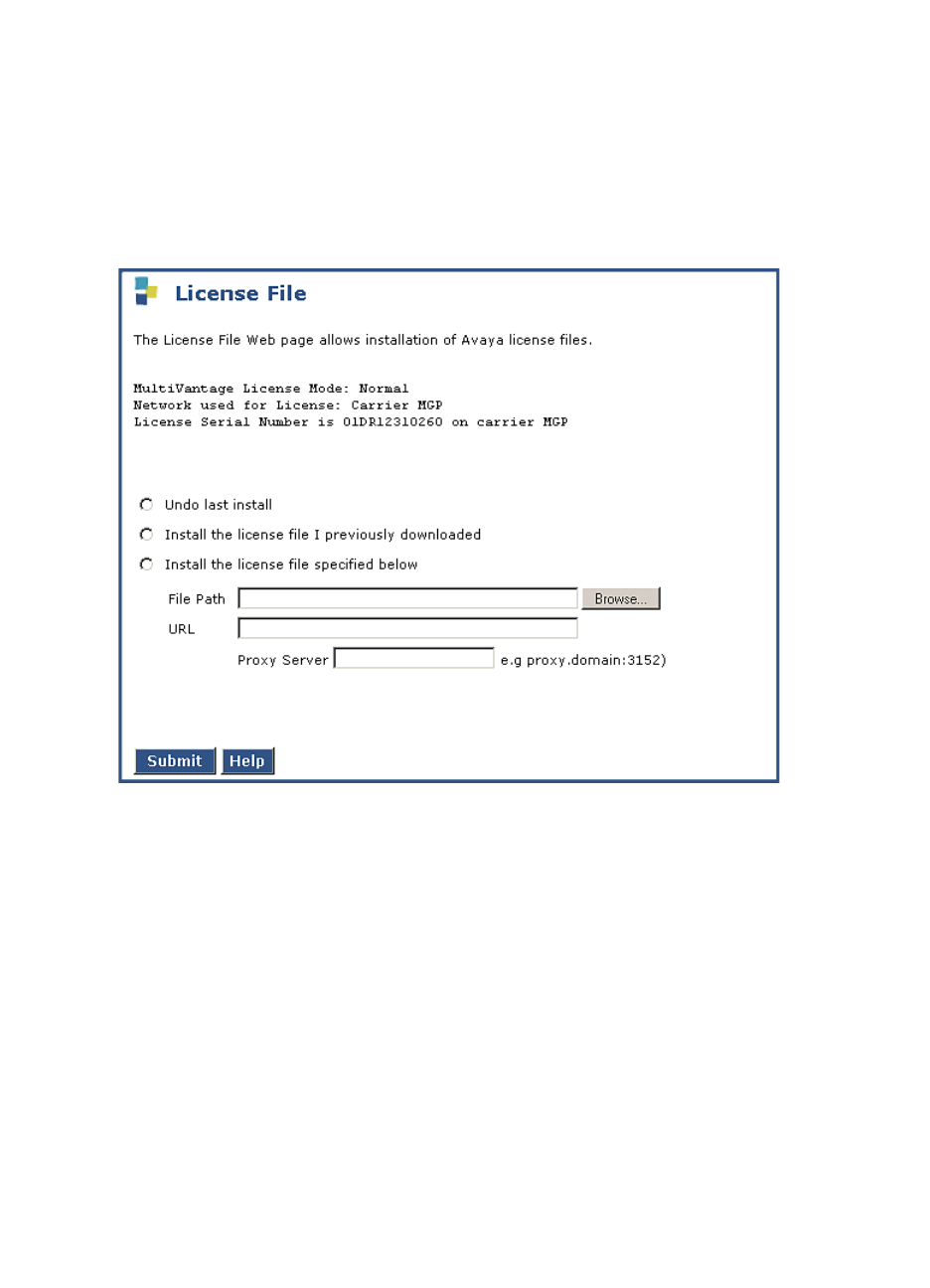
3Installing a New G700 with an S8300
On-Site Preparation for the Installation
110 Installation and Upgrades for G700 and S8300
December 2003
8When you have selected the .pwd file, click Open in the dialog box.
9When you have finished entering the files to be uploaded, click Load File.
When the files are successfully transferred, the system displays the status screen.
If Necessary, Install License and
Authentication Files
1Under Security, select License File
License File Screen
2Select "Install the license file I previously downloaded" and click Submit.
The system tells you the license is installed successfully.
3Under Security, select Authentication File.
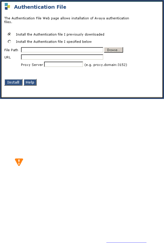
3
Installing a New G700 with an S8300
On-Site Preparation for the Installation
Installation and Upgrades for G700 and S8300 111
December 2003
Install Authentication Screen
4Select "Install the Authentication file I previously downloades" and click Install.
The system tells you the authentication is installed successfully
Run Save Translations
(Only If New License and/or Authentication
Files Installed)
CAUTION:
This procedure saves the official passwords for the customer’s system. If you fail to perform
this step now, you may be irretrievably locked out of the system later in the installation when
the system reboots.
1In the telnet session, open a SAT session. and log in again as craft (or dadmin).
2At the SAT prompt, type save translation and press Enter. When the save is finished, the system
displays the message, Command successfully completed.
Determine Necessary Upgrades to the S8300
This procedure determines whether you need to upgrade Communication Manager on the S8300. If you
do not need to upgrade Communication Manager, skip to Configure the S8300.
Transfer Files from a CD or Laptop
Normally, during an upgrade, you will have the CD-ROM that contains the latest software to install. The
latest software for the S8300 has a file name that has a .tar extension and reflects the most recent load of
software (For example only: S8300-02.0-00.0.218.6.tar; for systems with IA770, the filename would be
similar to S8300msg-02.0-00.0.218.6.tar). The latest update (patch) software for Communication
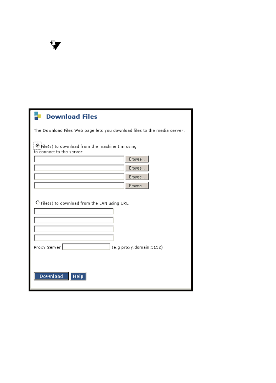
3Installing a New G700 with an S8300
On-Site Preparation for the Installation
112 Installation and Upgrades for G700 and S8300
December 2003
Manager has a .tar.gz extension and a file name that reflects the most recent load of software (for
example, 03.0.110.4-4925.tar.gz).
This .tar file will also contain the most recent firmware for the G700 Media Gateway, the various media
modules, and the P330 stack processor.
Tip:
The Avaya Installation Wizard performs tasks automatically starting with this section.
1Log in to the S8300 Web interface.
2Choose Download Files under Miscellaneous on the left pane of the main menu.
Download Files Screen
3Select "Files to download from the machine I’m using to connect to the server," then click
Browse for the first file. The S8300 displays the Choose File window, which allows you to select
files from your laptop.
4Browse to the tarfiles directory on the CD (or to where the .tar files are stored on your laptop).
Double-click the filename of the .tar file for the upgrade software (for example, S8300-02.0-
00.0.219.1.tar or S8300msg-02.0-00.0.219.1.tar if using IA770). You need only one .tar file for
the upgrade software.
5Repeat the previous two steps for each additional file that you want to upload. (For example, the
lastest software update file, if any).
6Click Download.

3
Installing a New G700 with an S8300
On-Site Preparation for the Installation
Installation and Upgrades for G700 and S8300 113
December 2003
When the files are successfully transferred, the system displays the Download Files Results
screen with the following message: "The following files have been successfully uploaded to the
server."
CAUTION:
At this point you are finished with the software CD-ROM. Remove the CD from your
laptop now to avoid possible problems the next time your laptop is rebooted.
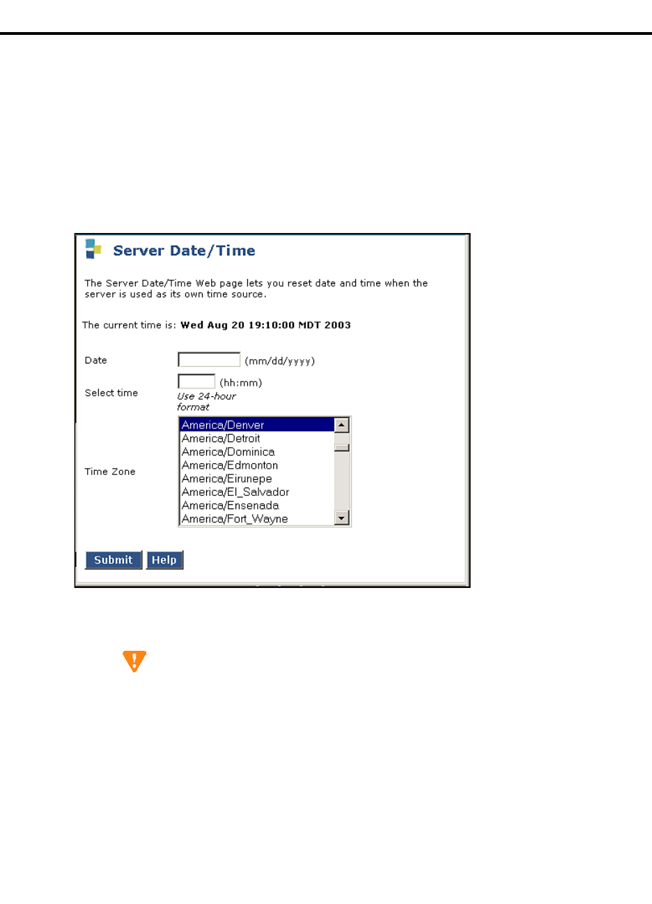
3Installing a New G700 with an S8300
Install New Software on the S8300
114 Installation and Upgrades for G700 and S8300
December 2003
Install New Software on the S8300
Although this is a new installation and a version of Communication Manager already exists on the S8300,
there may be new software loads available that you need to install. If necessary, follow the steps in this
section to install the most recent version of Communication Manager.
Verify the Time, Date, and Time Zone
1Under Server click Server Date/Time.
Server Date/Time Window
2Verify or set the media server’s time close enough to the NTS’s time, date, and time zone that
synchronization can occur (within about 5 minutes).
CAUTION:
For a new installation, be sure to set the time and time zone before installing the S8300
software. Failure to do so may cause network problems.
Install New Software
1Launch the Maintenance Web Interface.
2Choose Install New Software under Server Upgrades from the left pane of the main menu.
The S8300 displays the Install New Software screen.

3
Installing a New G700 with an S8300
Install New Software on the S8300
Installation and Upgrades for G700 and S8300 115
December 2003
Choose Software Screen
3 On the Choose Software screen, select the software release number that you want to install (for
example, the release listed in your planning documentation). Click Continue.
The S8300 displays the Choose License Source screen.

3Installing a New G700 with an S8300
Install New Software on the S8300
116 Installation and Upgrades for G700 and S8300
December 2003
Choose License Source Screen
4If you have installed the license and authentication files, select the following:
— I want to reuse the license files from the currently active partition on this server.
—Do not update authentication information.
For a normal installation, the license and authentication files should have been installed at this
point. If these files have not been installed, select the following:
—I will supply the license/authentication files myself when prompted later in this
process.
—Update authentication information as well as license information.
5Click Continue. The system displays the Review Notices screen.
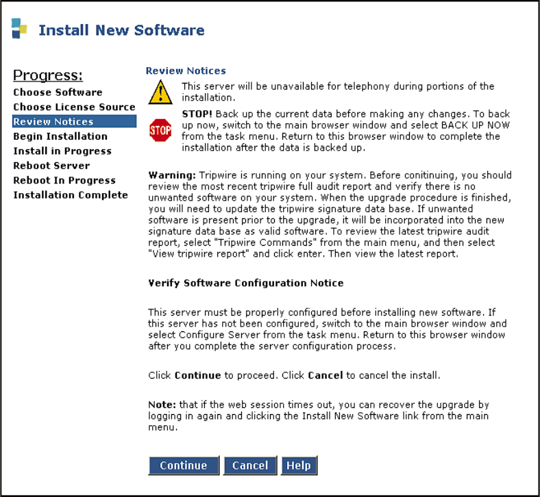
3
Installing a New G700 with an S8300
Install New Software on the S8300
Installation and Upgrades for G700 and S8300 117
December 2003
Review Notices Screen
6For a new installation, or if you previously ran a backup, you do not need to run a backup at this
time. If your planning documents instruct you to enable Tripwire, follow the instructions to reset
the signature database.
7Click Continue.
The S8300 displays the Begin Installation screen, which summarizes the request you have made.
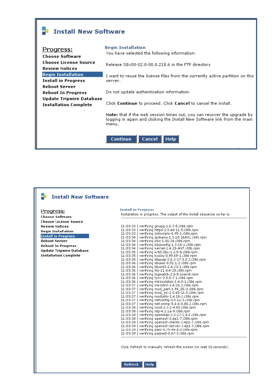
3Installing a New G700 with an S8300
Install New Software on the S8300
118 Installation and Upgrades for G700 and S8300
December 2003
Begin Installation Screen
8At the Begin Installation screen, click Continue.
The S8300 displays the Install in Progress screen.
Install in Progress Screen
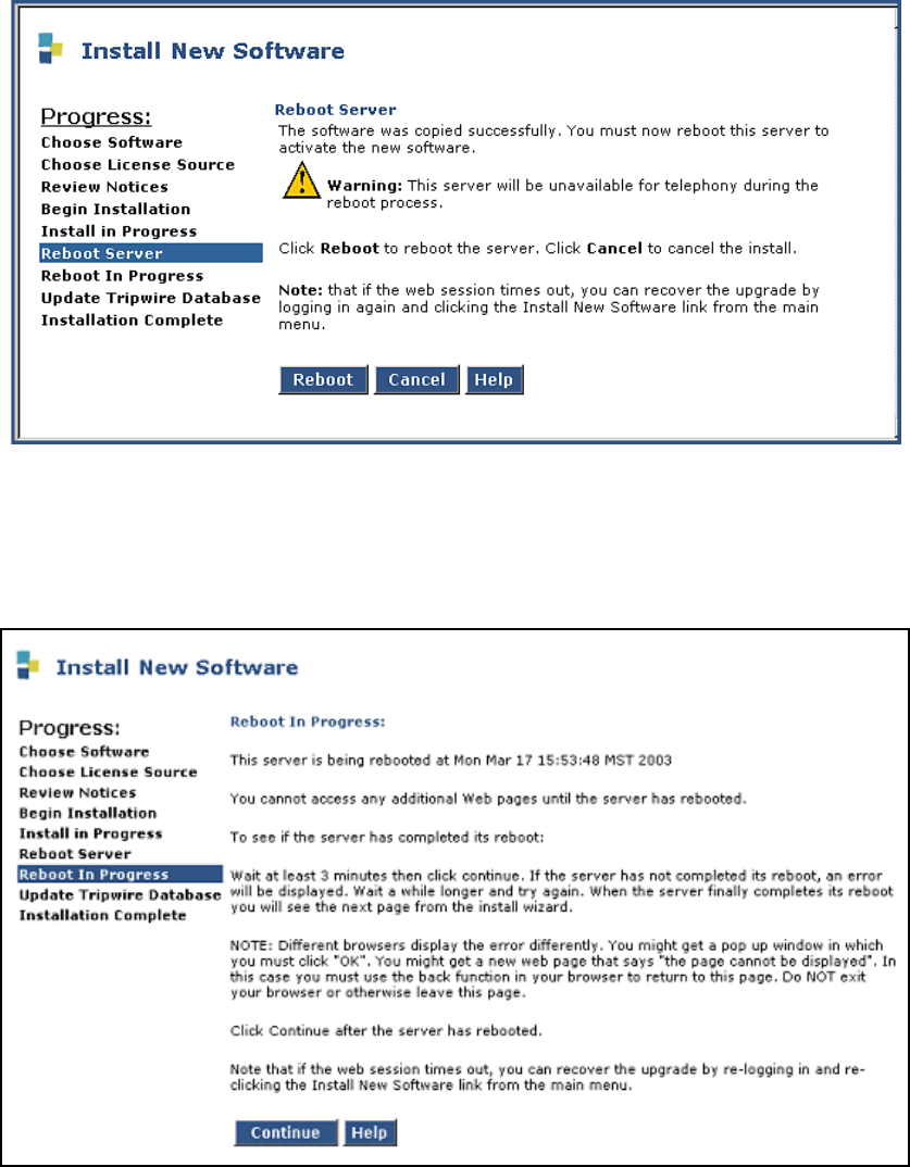
3
Installing a New G700 with an S8300
Install New Software on the S8300
Installation and Upgrades for G700 and S8300 119
December 2003
9The installation will take approximately 10 to 20 minutes. The Install in Progress screen refreshes
every 10 seconds or on demand by clicking the Refresh button. When complete, the S8300
displays the Reboot Server screen.
Reboot Server Window
10 Click Reboot.
If IA770 is being used, it may take approximately 5 minutes to shut down IA770 before the reboot
begins. The S8300 displays the Reboot in Progress screen.
Reboot in Progress Screen
NOTE:
The reboot can take 20 minutes or longer. The system does not automatically tell you
when the reboot is complete.
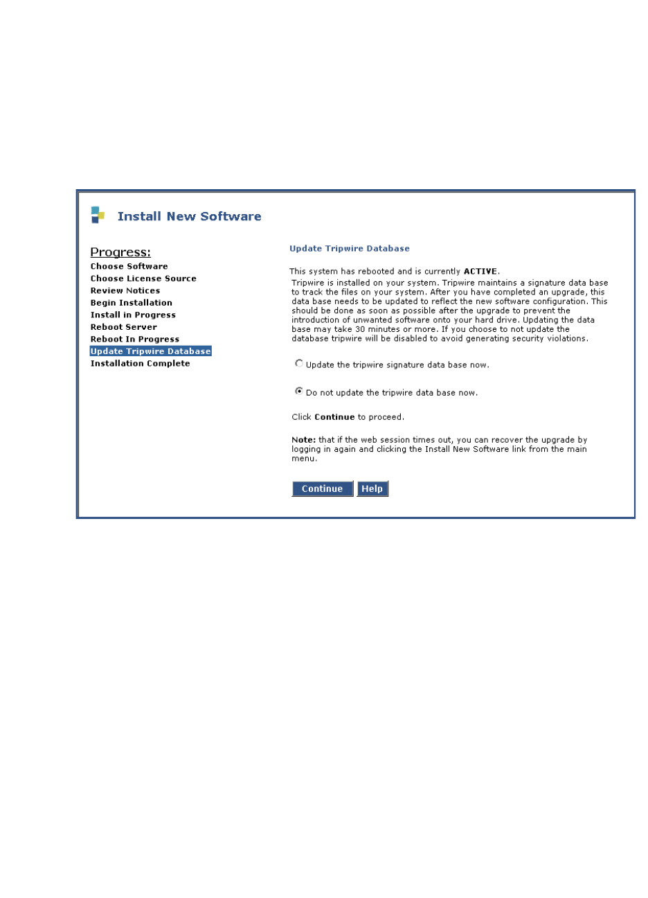
3Installing a New G700 with an S8300
Install New Software on the S8300
120 Installation and Upgrades for G700 and S8300
December 2003
Wait 5 minutes (or about 20 minutes if running IA770) and then click Continue. If you click
Continue before the reboot is finished, the screen will display "Expired Page." If you see the
Expired Page message, refresh the browser. Or, if the Session Timeout screen appears, close the
screen, logoff, and log on again. Click the Pickup button.
You can also monitor the LEDs on the S8300 for progress on the installation. The Services port
jack should have one yellow LED on the left that stays lit. The green LED on the right flashes
until the reboot is complete.
11 When the reboot is complete, clicking Continue will display the Update Tripwire Database
screen.
12 Unless instructed in your planning documents to update the tripwire database, select "Do not
update the tripwire data base now" and click Continue.
The system displays the Installation Complete screen.
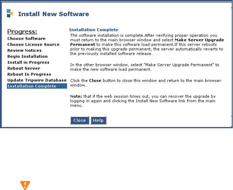
3
Installing a New G700 with an S8300
Install New Software on the S8300
Installation and Upgrades for G700 and S8300 121
December 2003
Installation Complete Screen
13 Click Close. You are returned to the main menu.
14 Under Server, click Software Version to verify the new software version.
Make the Upgrade Permanent
CAUTION:
You must make the upgrade of the software permanent so that the software is recognized and
kept on the S8300. If you fail to make software permanent, then the next time you reboot, old
software will become active.
1From the S8300 main menu, under Server Upgrades click Make Upgrade Permanent .
The S8300 displays the Make Server Upgrade Permanent window.
2Click Submit.
When the new S8300 upgrade software is permanent, the S8300 displays the message: The
commit operation completed successfully.
Install Communication Manager update (patch) files, if any
NOTE:
Skip this procedure if there are no Communication Manager update files to install.
1From your laptop, start a telnet session to the S8300.
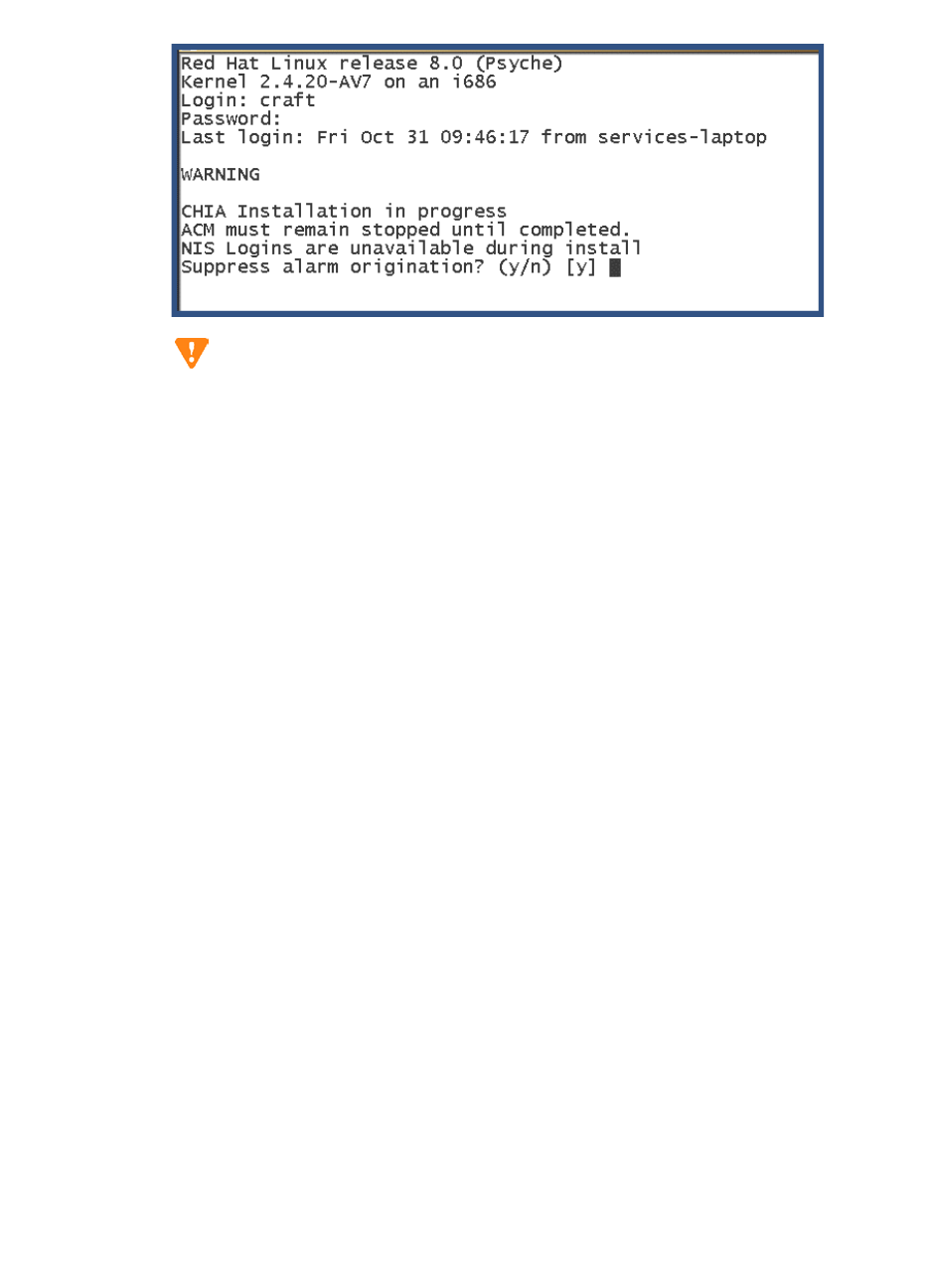
3Installing a New G700 with an S8300
Install New Software on the S8300
122 Installation and Upgrades for G700 and S8300
December 2003
If the AUDIX installation has not completed, the following warning screen will appear.
CAUTION:
If this warning screen appears, close the telnet session, wait about 5 minutes, and try
again.
2At the telnet prompt, type cd /var/home/ftp/pub and press Enter to access the FTP directory.
3At the prompt, type ls -ltr and press Enter to list files in the FTP directory.
The S8300 displays a list of files in the FTP directory.
4Verify that the directory contains the update .tar.gz file you have uploaded, if any.
5Type update_unpack <update> .tar.gz, where <update> is the release or issue number of the
latest update file. (For example, 00.0.218.4-1003.tar.gz). Press Enter.
6Type update_show again and press Enter to list Communication Manager files to verify the new
software file was installed.
7Type update_activate <update>, where <update> is the release or issue number of the latest
update file. (For example, 00.0.218.4-1003. Do not use the .tar.gz extension at the end of the file
name). Press Enter.
The S8300 goes through a software reset system 4. The S8300 also may display the message
/opt/ecs/sbin/drestart 1 4 command failed. Ignore this message. You must wait until the
restart/reset has completed before entering additional commands.
The S8300 displays a message that the update was applied.
8Type update_show again and press Enter to list Communication Manager files to verify the new
software file was applied.
Install IA770 update (patch) files, if any
If IA770 is being used, a post-upgrade update (patch) for IA770 may be required. See the IA770
documentation for procedures to install an update. The documentation can be found on the Avaya
Support Web Site at http://support.avaya.com. Then click on Product Documentation and then
Messaging and scroll down to the INTUITY document links.
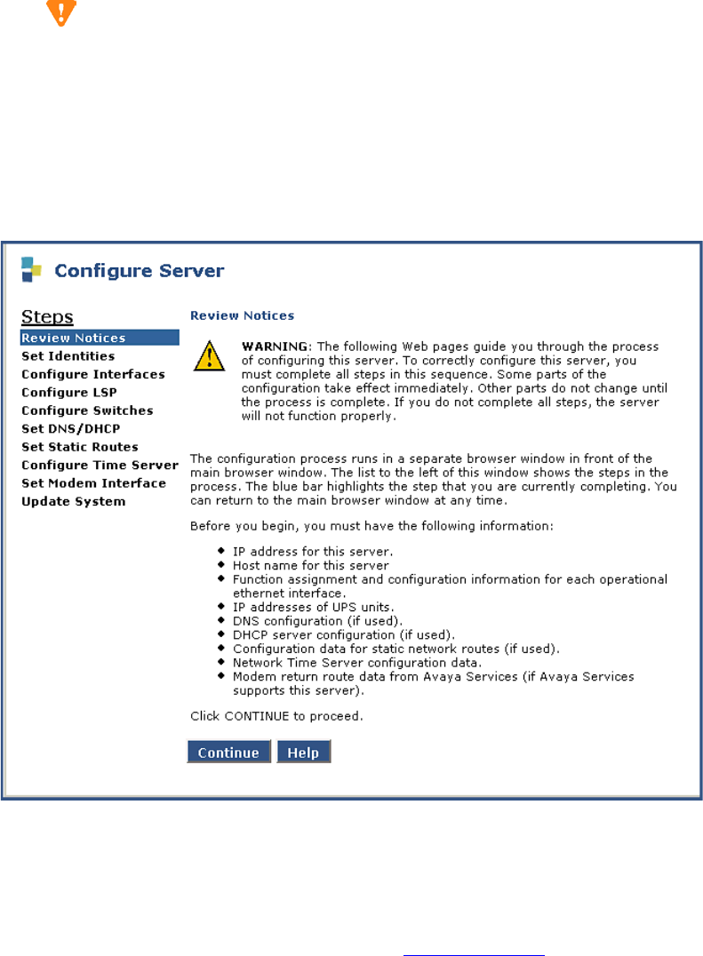
3
Installing a New G700 with an S8300
Install New Software on the S8300
Installation and Upgrades for G700 and S8300 123
December 2003
Configure the S8300
CAUTION:
For a new installation, be sure you have set the time and timezone before proceeding.
Failure to do so may cause network problems later.
1On the S8300 Web page main menu, click on Configure Server under Server Configuration and
Upgrade. The system displays the Configure Server screen.
Configure Server Screen
2Click Continue.
The system displays the Back Up Data Notice screen.
•For a new installation, a backup at this point is unnecessary. You will perform a backup after the
installation.
•For an upgrade, perform the backup, as described in Back up the System on page 168.
3Click Continue.
The Select Method screen appears.
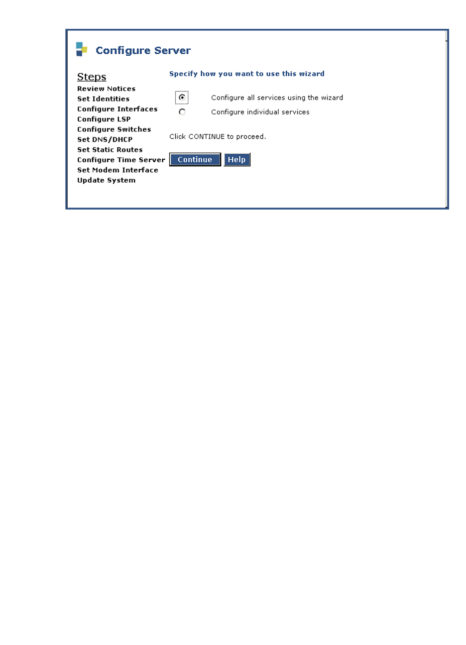
3Installing a New G700 with an S8300
Install New Software on the S8300
124 Installation and Upgrades for G700 and S8300
December 2003
Select Method Screen
4Click Configure all services using the wizard. With this option, the wizard will guide you
through the screens to configure all of the IP services.
NOTE:
This option is for the built-in configuration wizard, not the Avaya Installation Wizard
(IW).
If you are upgrading an existing system, you may also click Configure individual services. This
method is useful after an initial configuration has been completed and one or more services need
to be changed.
5Click Continue.
The Set Server Identities screen appears.
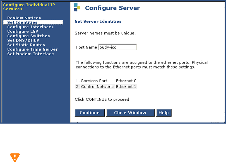
3
Installing a New G700 with an S8300
Install New Software on the S8300
Installation and Upgrades for G700 and S8300 125
December 2003
Set Server Identities Screen
6Enter the host name for this server in the Host Name field (see your planning forms).
The host name uniquely identifies this server.
CAUTION:
If the S8300 on the G700 is hosting an IA 770 INTUITY AUDIX Messaging Application
with Digital Networking, the name must be 10 characters or less.
The screen also lists the current physical cabling to the server. For example, the Services laptop is
connected to Ethernet interface 0. Ethernet functions are fixed on the S8300 media server and
cannot be changed.
7Click Continue.
The Configure Ethernet Interfaces screen appears.
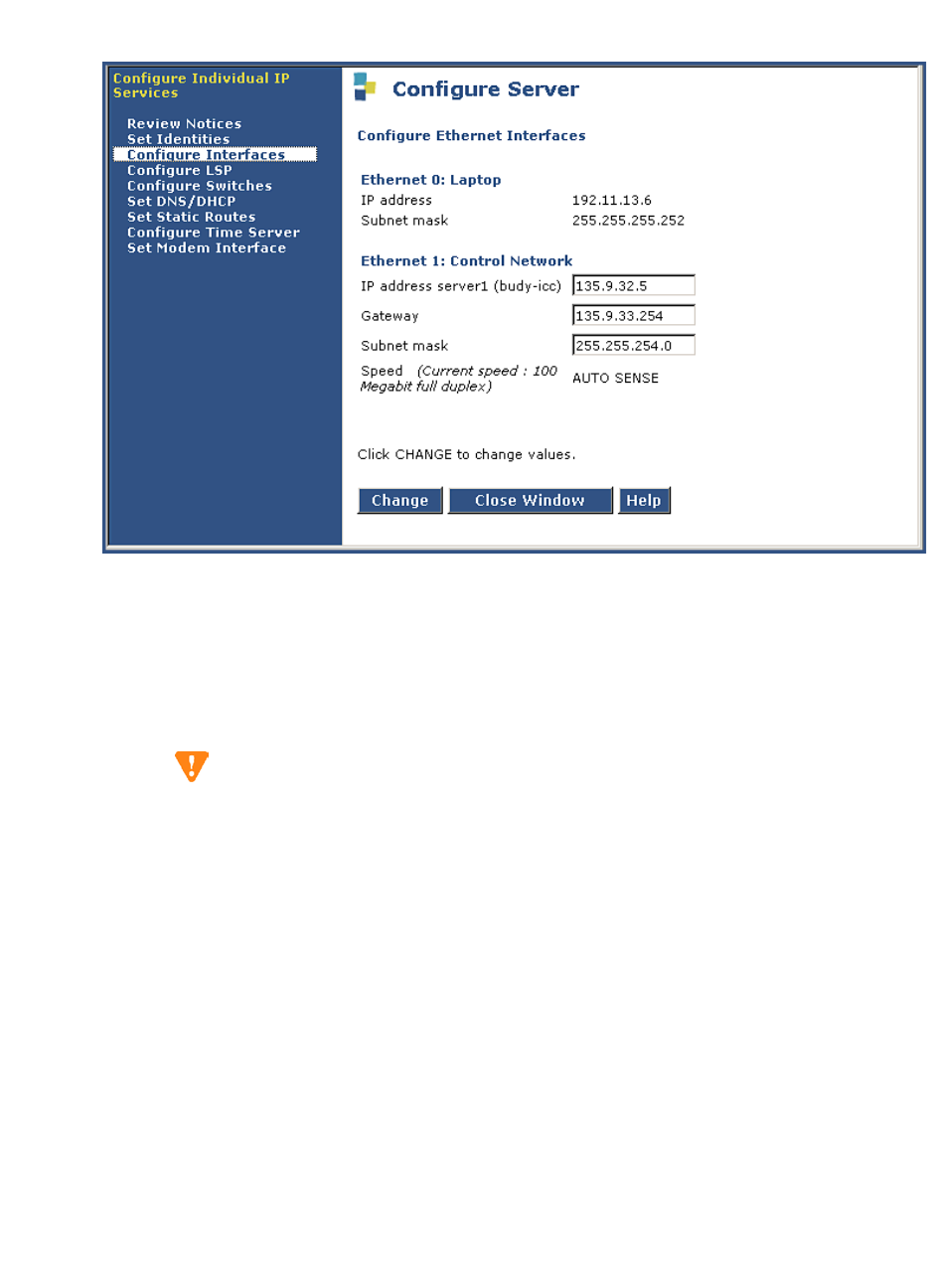
3Installing a New G700 with an S8300
Install New Software on the S8300
126 Installation and Upgrades for G700 and S8300
December 2003
Configure Ethernet Interfaces Screen
8Use your planning forms to complete the fields for the:
—IP Address assigned to the S8300 Media Server. Check your planning forms.
—Gateway with the IP address of the default gateway of the subnet.
—Subnet Mask with the value of the subnet mask of the hosting subnet.
—Speed which should be set to Auto Sense.
CAUTION:
Do not guess on the addresses on this screen. If you enter the wrong addresses, service
will be disrupted across the customer’s network and may be difficult to correct.
9Click Continue.
The Configure Local Survivable Processor screen appears.
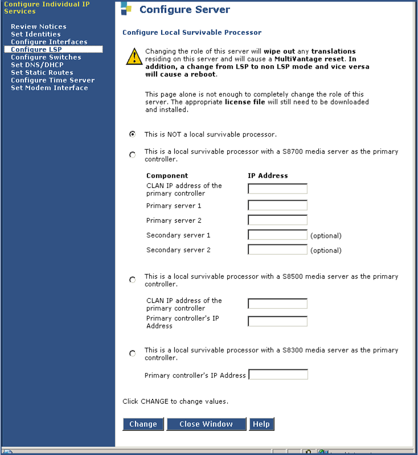
3
Installing a New G700 with an S8300
Install New Software on the S8300
Installation and Upgrades for G700 and S8300 127
December 2003
Configure Local Survivable Processor Screen
10 Select one of the following options:
— This is NOT a local survivable processor.
— This is a local survivable processor (LSP) with an S8700 media server as the primary
controller.
— This is a local survivable processor (LSP) with an S8500 media server as the primary
controller.
— This is a local survivable processor with a S8300 media server as the primary controller.
11 If you clicked the LSP option with an S8500 or S8700, complete the additional fields as follows:
CLAN IP address of the primary controller — Enter the IP address of any CLAN board in the
S8700 media server configuration.
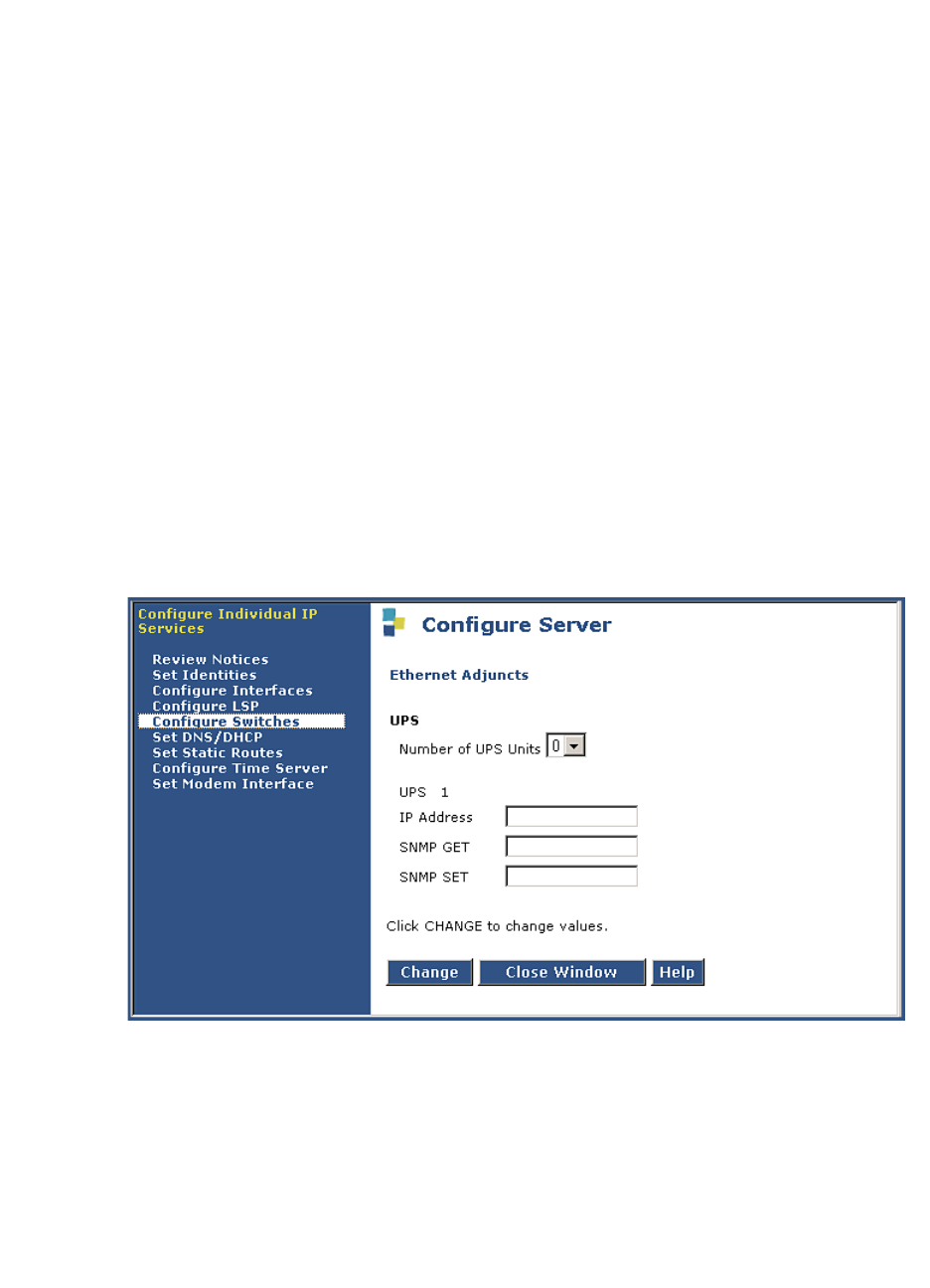
3Installing a New G700 with an S8300
Install New Software on the S8300
128 Installation and Upgrades for G700 and S8300
December 2003
IP address of server 1 (required) — Enter the IP address of the primary S8700 server.
IP address of server 2 (optional) — Enter the IP address of the duplicated primary S8700 server.
If server 2 is present, this specific IP address must also be entered.
IP address of secondary server 1 (optional) — Enter the IP address of the secondary S8700
server.
IP address of secondary server 2 (optional) — Enter the IP address of the duplicated secondary
S8700 server
NOTE:
The CLAN boards must be TN799DP running version 5 or greater firmware. Be sure to
check the firmware version for these boards on the S8500 or S8700. For information on
how to upgrade the firmware on the S8500 or S8700, please see the section "Upgrade
Firmware in Selected Port Cabinet Packs" in Upgrading the Avaya Media Server
Configuration in the S8700 documentation portion of this documentation CD (‘‘Avaya
S8300, S8500, and S8700 Media Server Library CD, 555-233-825’’).
12 If you clicked the LSP option with an S8300, simply enter the IP address of the S8300 server.
13 Click Continue.
The Ethernet Adjuncts screen appears.
Ethernet Adjuncts Screen
14 In the Number of UPS Units field, select the number of Uninterruptible Power Supplies (UPS)
units connected to the S8300 Media Server. This number is usually 0 or 1.
15 If you enter 1 in the Number of UPS Units field, enter its IP address in the UPS 1 IP address field.
The system will use this address to trap power loss signals from the UPS.
16 (Optional) If you enter 1 in the Number of UPS Units field, enter the SNMP community strings
for the UPS in the SNMP Get and Set fields.
17 Click Continue.
The External DNS Server Configuration screen appears.
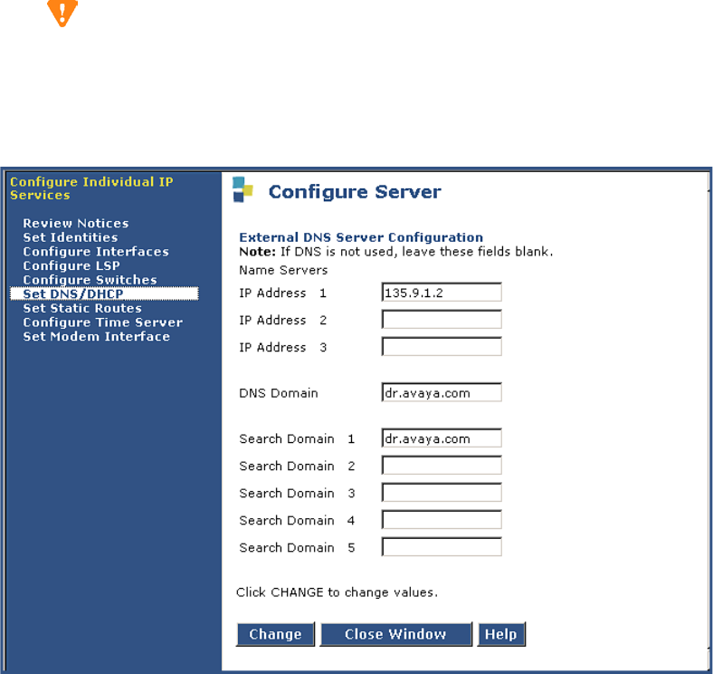
3
Installing a New G700 with an S8300
Install New Software on the S8300
Installation and Upgrades for G700 and S8300 129
December 2003
Most corporate networks have one or more domain name service (DNS) servers that associate an
IP address with a device’s name. When the DNS is administered with the S8300 Media Server
name, you will be able to access the S8300 server by name as well as IP address over the
corporate network.
CAUTION:
If you configure an external DNS server, the DNS will be an extra device that, if not
working properly, can cause delays in S8300 access.
External DNS Server Configuration Screen
18 Enter the appropriate IP addresses from your planning documentation. Then, click Continue.
In the Name Servers fields, enter the IP addresses for up to 3 DNS servers on the corporate
network. The S8300 Media Server checks the DNS servers in the order in which their addresses
are entered for name-to-IP address resolution.
In the DNS Domain field, enter the name for the part of the network on which the DNS server(s)
reside (for example, mycompany.com). Internet domains are sets of addresses generally organized
by location or purpose.
In the Search Domain fields, 1 to 5, enter the names of the domains that will be searched, in
order, if a user enters an unqualified or incomplete name (such as a host name only without its
domain).
NOTE:
For Search Domain 1, enter the same domain name you entered in the DNS Domain field
above.
19 Click Continue.
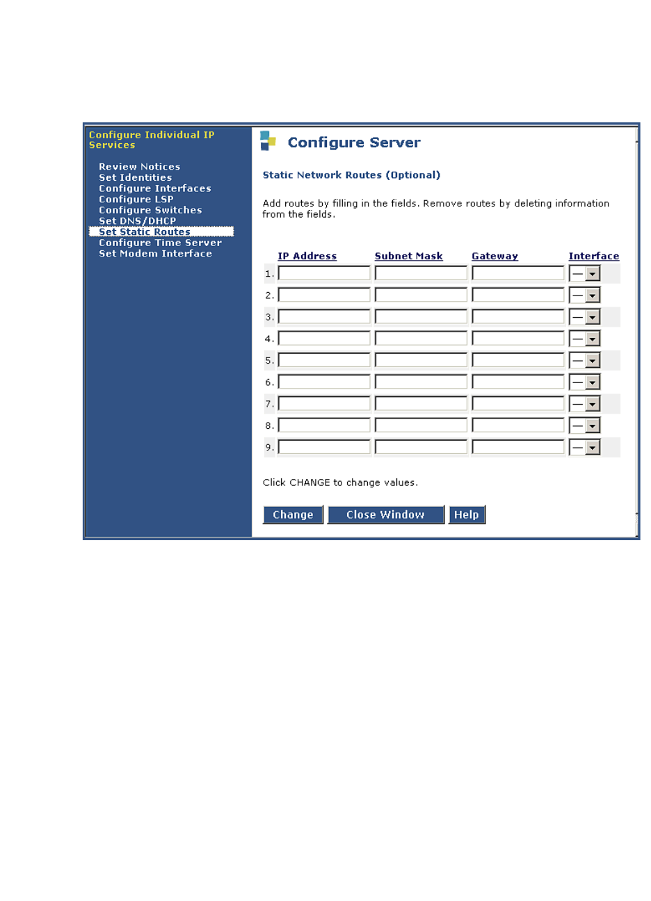
3Installing a New G700 with an S8300
Install New Software on the S8300
130 Installation and Upgrades for G700 and S8300
December 2003
The Static Network Routes screen appears.
Static Network Routes are used only if the customer has defined additional routes for IP packets
other than through the default gateway.
Set Network Routes Screen
20 Leave these entries blank, unless the planning documentation supplies routing information.
21 Click Continue.
The system displays the Network Time Server screen.
The Network Time Server screen allows you to set up the Network Time Protocol (NTP) Service.
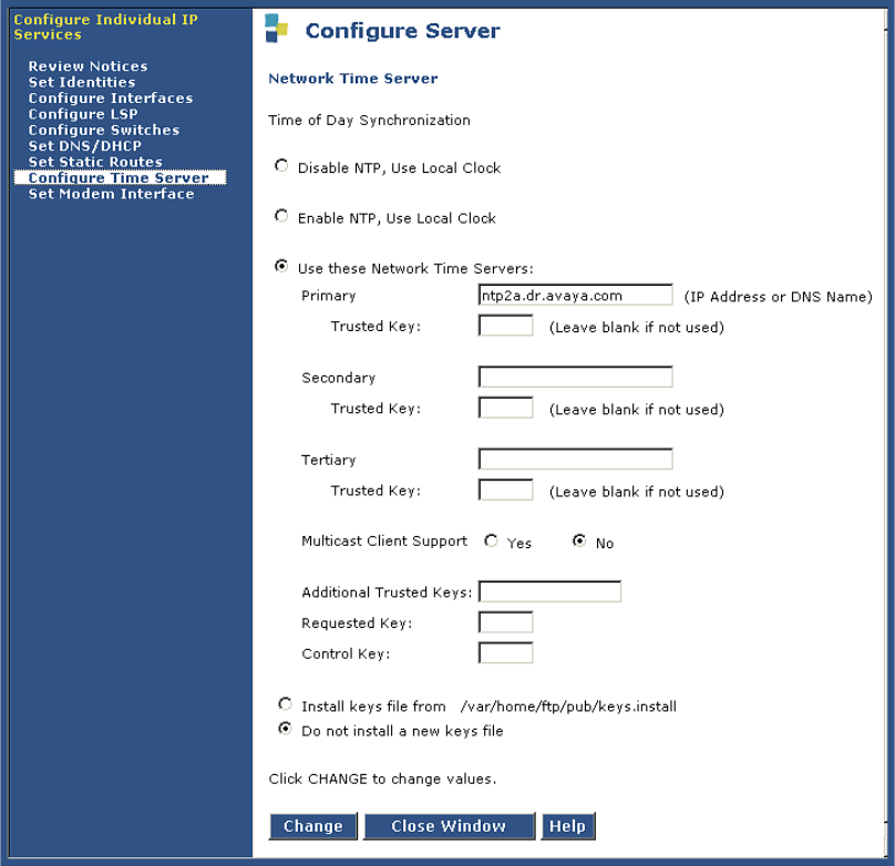
3
Installing a New G700 with an S8300
Install New Software on the S8300
Installation and Upgrades for G700 and S8300 131
December 2003
Network Time Server Screen
You will be able to make the following choices, according to the planning documentation:
— Choose Disable NTP if the user does not want the Network Time Protocol to run on the
S8300 Media Server. Select this option to disable Network Time Protocol (NTP) and use
the media server's own clock as a time source. You typically choose this option if this is
the only media server in the configuration and it will not be synchronized with an external
time source.
— Choose Enable NTP if the S8300 Media Server will be the primary NTP server.
Optionally, you can provide the address of the survivable S8300 Media Server in the local
survivable configuration. Select this option to enable NTP and use the media server's own
clock as a time source. You typically choose this option if there is more than one media
server in the configuration (for example, this or another media server may be acting as an
LSP standby unit), and an external time source is not available to provide synchronization
between the units. Select this option to enable NTP and use its own clock as a time source.
You need to set up the time clock with Set Server Time/Timezone option. You need to set
the server clock using the Set Server Time / Timezone screen. You can do this now, then
return to the Configure Server window.

3Installing a New G700 with an S8300
Install New Software on the S8300
132 Installation and Upgrades for G700 and S8300
December 2003
— Choose Use these Network Time Servers to enter up to three time servers. Select this
option to enable NTP and be synchronized with an external time source on the corporate
network.
22 If you did not select Use these Network Time Servers in the previous step, click Continue and
go to the next step
If you selected Use these Network Time Servers in the previous step, complete the following
fields. Specify up to three network time servers by IP address or DNS name in the order in which
you want the S8300 Media Server to check them. You should always specify at least two.
Primary — Enter an IP address or DNS name. If a trusted key is required, enter a valid key
number in the Trusted Key field.
Secondary — Enter an IP address or DNS name. If a trusted key is required, enter a valid key
number in the Trusted Key field.
Tertiary — Enter an IP address or DNS name. If a trusted key is required, enter a valid key
number in the Trusted Key field.
Multicast Client Support — Select Yes if the NTS routinely broadcasts its timing messages to
multiple clients. Select No if the S8300 Media Server is to poll (directly request the time from) the
NTS.
Additional trusted keys (optional) — If you want to encrypt the messages between an NTS and
the S8300 Media Server, list the valid key numbers, up to 3, provided by your LAN administrator
on the pre installation worksheet. Trusted keys function like a checksum to make sure the time
packets are valid. Use a blank space as a delimiter if there is more than one key (for example, 2 3
6 to specify valid keys 2, 3, and 6). These numbers are associated with encryption codes in a
"keys" file.
Request key — Enter a key to send a remote query request. Only 1 key is allowed in this field.
Control key — Enter a key to query and request changes to an NTS. Only 1 key is allowed in this
field.
23 If you have a file named keys.install to allow the media server to communicate with the NTS,
select Install keys from var/home/ftp/keys.install. If you do not have a keys.install file, select
Do not install a new keys file.
If you have a keys.install file, upload or create it now, if possible. See Provide the keys.install File
(If Necessary) on page 135. If you upload the keys file later, you have to run the Configure Server
wizard again to have the system recognize it.
Click Continue.
24 At the next screen, Set Modem Interface, you can set up the Modem Interface IP Address for
Avaya-provided service.
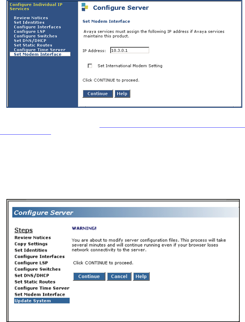
3
Installing a New G700 with an S8300
Install New Software on the S8300
Installation and Upgrades for G700 and S8300 133
December 2003
Set Modem Interface Screen
The Modem IP Address for the Avaya INADS alarming is assigned by the ART tool. You should have
obtained this address when you performed Run the Automatic Registration Tool (ART) for the INADS IP
Address, if Necessary on page 106.
Click Continue.
The next Warning screen indicates that the data entry process has concluded and that the system is ready
to be configured.
Warning Screen
This is the final step in configuring the system. When you click Continue, all the configuration
information will be written to disk and implemented. This step normally completes in about 5
minutes.
This is your last chance to cancel or correct the configuration.
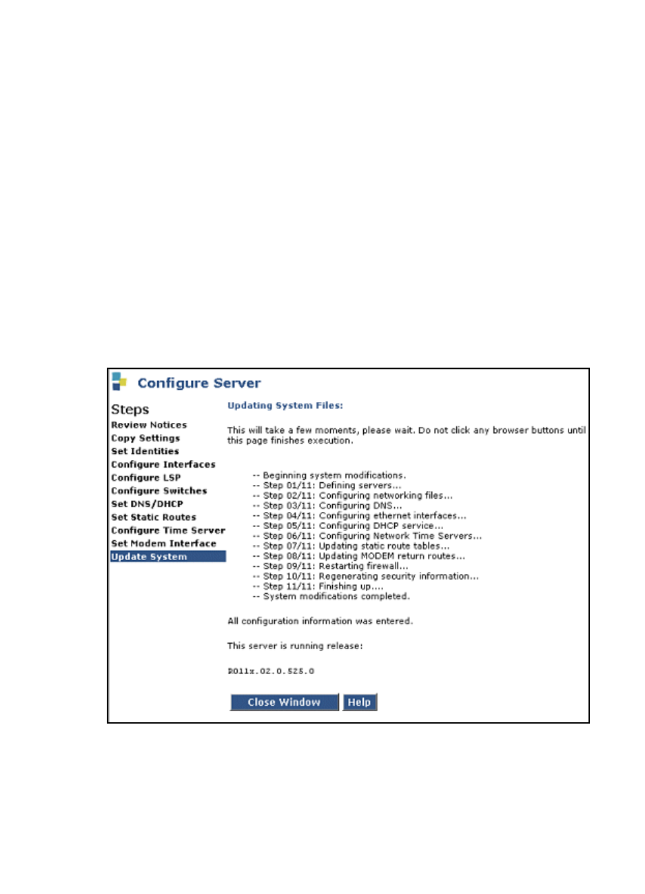
3Installing a New G700 with an S8300
Install New Software on the S8300
134 Installation and Upgrades for G700 and S8300
December 2003
25 To check, or possibly change, something you entered on a previous screen, use your browser’s
Back button to page back through the Configure Server screens.
26 Check or change the items in question.
27 Click the Continue button to move forward again, whether you change anything or not. If you
don’t do this, information in the wizard may not be processed correctly.
NOTE:
For any configuration, it is always safe to Cancel the configuration, and run the Configure
Server wizard again later from the beginning. You might use this option if you are
checking or modifying settings on a server that has already been configured, and there is
not a large amount of new information to enter.
28 On the Update System screen, if you are satisfied that everything is set correctly, click Continue.
You can watch the progress of the configuration at the Updating System Files screen. If the
configuration status displays stops updating at some point and the screen appears to freeze, you
may have lost contact with the server. In this case, the configuration process will continue and you
can log back on and pick up where left off.
Updating System Files Screen
When the process is complete, you will receive a notification. Click Close Window and continue the
configuration of the G700 Media Gateway on the command line interface.
3
Installing a New G700 with an S8300
Install New Software on the S8300
Installation and Upgrades for G700 and S8300 135
December 2003
Provide the keys.install File (If Necessary)
Use this procedure only if you selected one of the customer-provided keys options in the previous
procedure.
If encryption between the NTS and S8300 Media Server is to be used for additional security, you must
provide a keys.install file that specifies for each key:
•The key number
•The encryption type
•The key code
If the keys file is short, the network administrator can create one now during configuration if needed:
Create the key file
1On a directly connected laptop or other computer, create a flat-text file named keys.install with
the correct keys information using any ASCII application.
2Next, upload the keys.install file using the Upload Files to Server screen as described earlier.
3When finished, click on the Configure Server wizard window to resume server configuration.
The keys file can be loaded in one of the following ways.
Upload the keys file
If a keys.install file was previously created on or downloaded to the services laptop or another computer
on the network, it can be installed now as follows.
1In the main menu under Miscellaneous, click the Upload Files to Server link.
2Locate the keys.install file on your computer or network, then click Load File. The file is
uploaded to the media server’s FTP directory.
3When finished, click on the Configure Server wizard window to resume server configuration.
Download or copy the keys file
Longer files may be transferred from the network time server to the S8300 Media Server as follows:
1Using either the Download Files to Server screen or the Transfer files using an FTP procedure to
access the keys file listed on your pre installation worksheet.
In both cases, the file is transferred to the media server’s FTP directory.
2When finished, click on the Configure Server wizard window to resume server configuration.
3After the keys.install file is uploaded, select the location where it resides, usually in the
/var/home/ftp subdirectory. (Services personnel may direct you to use the /tmp directory.)
4If a keys file is not used, or if the correct keys.install file is already installed, select the option to
not install a new keys file.
Set the media server’s time now
1In the main menu under Server, click Set Server Time / Timezone.
The S8300 displays the Set Server Time/Timezone window.
2Set the media server’s time close enough to the NTS’s time, date, and time zone that
synchronization can occur (within about 5 minutes).

3Installing a New G700 with an S8300
Install New Software on the S8300
136 Installation and Upgrades for G700 and S8300
December 2003
3When finished, click on the Configure Server wizard window to continue.
After NTP is enabled, time changes greater than 15 minutes will disrupt the synchronization with
the NTS and NTP will shut down. You need to set the server’s clock now so that synchronization
can take place.
4When finished, click Continue.

3
Installing a New G700 with an S8300
Configure the G700 Media Gateway
Installation and Upgrades for G700 and S8300 137
December 2003
Configure the G700 Media Gateway
This section describes the procedures for assigning IP addresses to the G700 components and for
assigning IP routing.
Assign the IP Addresses of the G700 Media
Gateway Components
NOTE:
The Gateway Installation Wizard (GIW) performs this task automatically.
This section describes how to assign the IP addresses and IP routes to the G700 Media Gateway and its
components. The IP addresses should be available to you on the IP Addressing Planning Form. The
command arguments you will be supplying include:
Access the P330 stack processor
1Set up a direct connection to the G700 Console (serial) port and access the P330 stack processor
using Hyperterm (or similar terminal emulation application).
2Login as root.
Assign the IP address to the P330 stack processor
CAUTION:
The nvram init command initializes the switch parameters to the factory defaults. This
command is normally used only for new installations.
1Initialize NVRAM: type nvram init
2Change mode to configure: type configure
3At the P330-1(super)# prompt, type configure.
vlan –Virtual Local Area Network: a defined network segment that allows
users on that segment to have priority services in sharing information
with each other.
If the network is not using VLANs, the VLAN should be 1. Otherwise,
use the VLAN numbers indicated in your planning forms. The G700
Media Gateway should be assigned the same VLAN as the VLAN to
which the Ethernet ports are connected. The P330 stack processor might
or might not be assigned to the customer’s network management VLAN.
IP address –the unique identifier assigned to an entity on the customer LAN
netmask –the subnet mask for the customer’s LAN segment
destination –distant networks that the IP route command needs to send packets to.
Usually generalized to 0.0.0.0 for networks other than the local segment.
default gateway –the gateway the ip route command specifies to get to the distant
networks

3Installing a New G700 with an S8300
Configure the G700 Media Gateway
138 Installation and Upgrades for G700 and S8300
December 2003
4At the P330-1(configure)# prompt, type
set interface inband <vlan> <ip_address> <netmask> to assign an IP address to the P330 stack
processor.<vlan> is the vlan number, usually 1, to be established on the S8300 for the G700
Media Gateways. The <ip_address> <netmask> is the assigned addresses for the P330 stack
processor.
5Type reset and press Enter to reset the stack.
6Select Yes at the dialog box that asks if you want to continue.
All LEDs will flash. As the unit powers up, self-tests will be run. When the G700 mpg or P330
stack processor has reset, login again to continue.
7Login at the Welcome to P330 menu.
The prompt P330-1(super)# appears.
8Type configure to obtain the P330-1(configure)# prompt.
Establish the IP Routing for the Stack
1Type show interface inband to verify that the Avaya P330 stack server (Layer 2 Switching
Processor) has the correct address.
2Type set ip route 0.0.0.0 <default-gateway> to set the destination and gateway IP addresses. You
will find these addresses in the planning documentation.
<default-gateway> is the IP address of the customer’s network gateway.
3Press Enter to save the destination and gateway IP addresses.
4Type show ip route.
The route net and route host tables appear. Verify that the information is correct.
Check the serial number of the G700 Media Gateway processor
After you have configured the P330 stack processor, you will assign an IP address to the G700
Media Gateway Processor (MGP). Your first step is to check the serial number of the MGP.
1At the P330-1(configure)# prompt, type session mgp.
2At the MG-???-1(super)# prompt, type show system to list various attributes of the G700.
The system displays a list of attributes, as shown in the following example:

3
Installing a New G700 with an S8300
Configure the G700 Media Gateway
Installation and Upgrades for G700 and S8300 139
December 2003
Show System List for G700 Media Gateway
3Write the serial number on your planning document. Make sure it matches the serial number
sticker on the back of the G700 Media Gateway chassis. If there is a difference, the serial number
in the displayed list is correct.You will need this later.
Assign the IP Address to the G700 Media Gateway Processor
1At the MG-???-n(super)# prompt, type configure to change to configuration mode.
2Type nvram init to recondition the processor.
This procedure re initializes the G700 software back to factory defaults so new IP addresses can
be stored correctly in the software. It also clears all configuration and administration on the G700
Media Gateway.
The system prompts you to verify that you want to erase the configuration.
3Answer the prompt by typing y(es).
The G700 Media Gateway re initializes.
4At the P330-1(configure)# prompt, type session mgp.
5At the MG-???-1(super)# prompt, type configure to change to configuration mode.
6Type set interface mgp <vlan> <ip_address> <netmask> to assign an IP address to the G700
Media Gateway. <vlan> is the vlan to be established on the customer’s local network. This is
usually 1. The <ip_address> <netmask> is the assigned addresses for the G700 Media Gateway.
CAUTION:
If this G700 contains an S8300 configured as an LSP, use the VLAN administered on the
primary controller.
7At the MG-???-n(configure)# prompt, type reset mgp.
A system prompt asks to confirm the reset.
MG-001-1(super)# show sys
Uptime(d,h:m:s): 1, 08:17:12
System Name : -- Empty --
System Location: -- Empty --
System Contact : -- Empty --
MAC Address : 00-04-0D-02-04-EF
Serial No : 02DR07428721
Model No : G700
HW Vintage : 00
HW Suffix : A
FW Vintage : 230
Media Gateway Power Supplies
VOLTAGE(V) ACTUAL(V) STATUS
---------- ---------- ----------
DSP Complex 3.4 3.359 OK
MGP 5.1 5.000 OK
Fans 1.2 0.000 OK
Media Modules -48.0 -47.259 OK
VoIP DSP 1.6 1.570 OK
VoIP 8260 2.5 2.470 OK
Aux -48.0 0.000 OK
--type q to quit or space key to continue--
MG-???-1(super)#

3Installing a New G700 with an S8300
Configure the G700 Media Gateway
140 Installation and Upgrades for G700 and S8300
December 2003
8Select Yes at the dialog box that asks if you want to continue.
The prompt will change to P330-1(configure)#
The G700 Media Gateway processor will reset. The LEDs on the G700 Media Gateway and the
Media Modules will flash. These elements will each conduct a series of self-tests. When the LEDs
on the Media Modules are extinguished and the active status LEDs on the G700 Media Gateway
are on, the reset is complete.
9When the mgp reset is complete, type session mgp.
10 At the MG-???-1(super)# prompt, type configure to reach the configuration level of the
command line interface.
11 Type show interface mgp to verify that the G700 Media Gateway has the correct IP address.
Assign an IP Route for the Default Gateway
The default gateway is a router or switch that routes packets to destinations outside of the local
subnetwork.
1At the MG-???-n(configure)# prompt, type set ip route <destination> <netmask>
<default_gateway_ip_address>. Both <destination> and <netmask> are 0.0.0.0 for the default
gateway. <default_gateway_ip_address> is the IP address of the router or switch that is
designated to handle packets addressed to destinations outside of the local subnetwork.
2Type show ip route mgp to view the results.
3Repeat <~Link>step 1 for additional ip routes, if needed. Usually, only a default route is needed.
Refer to your planning document.
Assign IP Addresses to the VoIP Resources
From the G700 Media Gateway Processor command line interface, you will assign IP addresses to
the VoIP resource resident on the G700 Media Gateway and to any installed MM760 VoIP Media
Modules.
1At the MG-???-n(configure)# prompt, type set interface voip <number> <ip address>
For example: set interface voip v0 132.236.73.3
<number> is the slot number of the VoIP media module. v0 designates the VoIP resource resident
on the G700 Media Gateway motherboard. The MM760 VoIP Media Modules are designated
according the slot (for example, v1, v2, v3, v4) in which the Media Module has been installed.
<ip address> is the IP address of the VoIP resource.
2Type show interface to display a table of all configured interfaces, including all VoIP Media
Modules.
3Type show voip v0 to display the VoIP resource on the motherboard.
NOTE:
It is not necessary to configure the VLAN, netmask, or IP routes for VoIP engines. The
media gateway parameters are applied automatically.
Check for IP Connections
After you have assigned IP addresses to the P330 Stack Processor (Layer 2 Switching Processor), the
G700 Media Gateway MGP, Media Modules, and the VoIP resources, do the following procedure to
validate the IP connections.

3
Installing a New G700 with an S8300
Configure the G700 Media Gateway
Installation and Upgrades for G700 and S8300 141
December 2003
Run the ping command
1At the MG-???-n(config)# prompt, type ping mgp <IP_address>
where <IP_address> is the address of an S8300, S8500, or S8700 Media Server, the VoIP engine,
or any other functioning endpoint accessible on the customer’s LAN. It is recommended to ping
endpoints on both the same subnet and a different subnet.
Ping results appear on the screen, similar to the following example.
Ping MGP Results
2Check that the same number of packets transmitted were also received.
3Type ping voip v0 <IP_address>, where <IP_address> is the address of the G700, or any other
functioning endpoint on the customer’s LAN. Ping results appear on the screen, similar to the
following example.
Ping VoIP Results
Set up the Controller List for the G700 Media
Gateway
NOTE:
The Avaya Gateway Installation Wizard (GIW) performs this task automatically.
To complete the configuration of the G700 Media Gateway, you need to administer a list of primary and
alternate controllers. This list begins with the IP address of the primary controller. In the event that the
G700 Media Gateway loses contact with its primary controller, it will seek to re-register with the primary
controller first, then with the other controllers on this list. The other controllers are S8500 or S8700
Media Servers that can act as the primary controller, or S8300 Media Servers configured as Local
Survivable Processors (LSPs).
Up to four IP addresses separated by commas can be entered to form the controller list.
1At the MG-???-n(configure)# prompt, type the following commands to designate the primary,
secondary, and LSP controllers for this G700:
MG-???-1(configure)# ping mgp 135.122.49.55
PING 135.122.49.55: 56 data bytes
64 bytes from 135.122.49.55: icmp_seq=0. time=0. ms
64 bytes from 135.122.49.55: icmp_seq=1. time=0. ms
64 bytes from 135.122.49.55: icmp_seq=2. time=0. ms
64 bytes from 135.122.49.55: icmp_seq=3. time=0. ms
64 bytes from 135.122.49.55: icmp_seq=4. time=0. ms
----135.122.49.55 PING Statistics----
5 packets transmitted, 5 packets received, 0% packet loss
round-trip (ms) min/avg/max = 0/0/0
MG-???-1(configure)# ping voip v0 135.122.49.55
----135.122.49.55 PING Statistics----
5 packets transmitted, 5 packets received, 0 packet loss
round-trip(ms) min/avg/max = 0/1/0

3Installing a New G700 with an S8300
Configure the G700 Media Gateway
142 Installation and Upgrades for G700 and S8300
December 2003
clear mgc list
set mgc list <ip_address> [,<ip_address> [,<ip_address> [,<ip_address>]]]
where, the first <ip_address> is the IP address of the primary controller for this G700. If the
primary controller is an S8700, this is the IP address of a C-LAN board that is connected to a pair
of duplicated S8700s. If the Primary controller is an S8300, this is the IP address of the S8300.
The next three <ip_address> parameters are optional IP addresses of up to three alternate
controllers. Each of the three optional controllers can be an S8700 duplicated pair or an S8300
configured as an LSP, depending on the G700’s primary controller.
CAUTION:
If you need to change the mgc list, you must run clear mgc list before running set mgc
list again.
The following table describes the possible optional controllers for an S8300 and S8700 primary
controller:
For an S8500 or S8700 primary controller, the last three IP addresses in the list can be either the
addresses of C-LANS (which are connected to the same S8500 or pair of S8700s that act as
primary controllers) or addresses of LSPs. If you enter a combination of both, you must list C-
LANs first and the LSPs last, after the C-LANs.
2Type reset mgp at the MG-???-n(configure)# prompt to reset the G700 Media Gateway
processor.
A system prompt asks to confirm the reset.
3Select Yes at the dialog box that asks if you want to continue.
The G700 Media Gateway processor will reset. The LEDs on the G700 Media Gateway and the
Media Modules will flash. These elements will each conduct a series of self-tests. When the LEDs
on the Media Modules are extinguished and the active status LEDs on the G700 Media Gateway
are on, the reset is complete.
The system ultimately returns you to the P330-1 (configure) prompt.
At the P330-1(configure)# prompt, type session mgp.
At the MG-001-1(super)# prompt, type configure to change to the configuration mode.
NOTE:
Because the G700 media gateway has registered with its primary controller, the prompt
name has changed; for example, to MG-001-1.
Primary Server Controller IP Addresses
S8300
First: IP address of the S8300 primary controller.
Next three: one, two, or three IP addresses of S8300s configured as
LSPs.
S8500 or S8700
First: IP address of the C-LAN for the S8500 or S8700 primary
controller.
Next three: one, two, or three IP addresses of alternate C-LANs and/or
LSPs.

3
Installing a New G700 with an S8300
Configure the G700 Media Gateway
Installation and Upgrades for G700 and S8300 143
December 2003
Type show mgc to display the list of available servers and their IP addresses.
For example:
Show Call Controller Status Screen
The Gateway will have registered with the primary controller, if present. If the primary controller
is running and has been administered properly, the Registered field says YES and the H248 Link
Status says UP. If the controller is not running, the Registered field says NO and the H248 Link
Status says DOWN.
Set the LSP Transition Points
You must set the time that the G700 searches, in the event of a network problem, for primary controllers
(for example, additional CLAN connections) with which to register. After this search time has elapsed,
the G700 will search for an LSP with which to register. You must also set the total time the G700 searches
for either a primary controller and an LSP, after which the G700 resets. And finally, you must define how
many primary controllers, from 1 to 4, are in the controller list you just defined.
1At the MG-001-1(configure)# prompt, type set mgp reset-times primary-search <search-time>
where <search-time> is the time in minutes that the G700 searches for a primary controller
before looking for an LSP. The range is from 1 to 60.
2At the MG-001-1(configure)# prompt, type set mgp reset-times total-search <search-time>
where <search-time> is the time in minutes that the G700 searches for both primary controllers
or LSPs. The range is from 1 to 60.
3At the MG-001-1(configure)# prompt, type set mgp reset-times transition-point
<#_of_primary>
where <#_of_primary> is the number of primary controllers in the controller list. If the primary
controller is an S8500 or S8700, the range is from 1 to 4. If the primary controller is an S8300,
<#_of_primary> must be 1.
MG-001-1(configure)# show mgc
CALL CONTROLLER STATUS
------------------------------------------
Registered : YES
Active Controller : 135.9.71.95
H248 Link Status : UP
H248 Link Error Code: 0x0
MGC List Management : Static
CONFIGURED MGC HOST DHCP SPECIFIED MGC HOST
-------------------- -----------------------
135.9.71.95 -- Not Available --
- Not Available -- -- Not Available --
- Not Available -- -- Not Available --
- Not Available -- -- Not Available --

3Installing a New G700 with an S8300
Configure the G700 Media Gateway
144 Installation and Upgrades for G700 and S8300
December 2003
Configure an X330 Expansion Module (If
Necessary)
NOTE:
You cannot use the IW to perform this task.
1See the Avaya X330W-2DS1 Access Router Module Quick Start Guide. This document is available
at the Avaya Support website:
Support > Technical Database > LAN, Backbone, and Edge Access Switches > P330 Stackable Switching
System > All Documents
2Select the Quick Start Guide for X330WAN 2DS1

3
Installing a New G700 with an S8300
Install New Firmware on the G700
Installation and Upgrades for G700 and S8300 145
December 2003
Install New Firmware on the G700
This section describes the procedures to install firmware on the G700 Media Gateway processors and
media modules.
Verify the Contents of the tftpboot Directory
Before proceeding with the G700 firmware installation, you should check the tftpboot directory on the
TFTP server to make sure the firmware versions match those listed in the planning documentation.
Determine Which Firmware to Install on the
G700
Conduct the following procedure to compare software versions running on the G700 processors and
media modules with the versions in you planning documents. If the versions do not match, new firmware
for those components is necessary.
Determine if new firmware for the P330 stack processor is necessary.
1At either the P330-1(super)# or P330-1(configure)# prompt, type dir.
The system displays the list of software.
Directory List for P300 Processor
2Check the version number (ver num) of the EW_Archive file to see if it matches the Release
Letter. If not, you must upgrade the P330 stack processor.
3Type show image version
The system displays the list of software.
Show Image Version List for P330 Processor
M# file ver num file type file location file description
-- ---- ------- ---------- ------------- ----------------
1 module-config N/A Running Conf Ram Module Configuration
1 stack-config N/A Running Conf Ram Stack Configuration
1 EW_Archive 3.8.6 SW Web Image NV-Ram WEB Download
1 Booter_Image 3.2.5 SW BootImage NV-Ram Booter Image
Mod Module-Type Bank Version
------ ----------- ---- -------
3 Avaya G700 Media Gateway A 0.0.0
3 Avaya G700 Media Gateway B 3.9.0

3Installing a New G700 with an S8300
Install New Firmware on the G700
146 Installation and Upgrades for G700 and S8300
December 2003
4Check the version number of the stack software image file in Band B to see if it matches the your
planning document. If not, you must upgrade the P330 stack processor.
Determine if new firmware is required for the MGP, VoIP Module, and installed media
modules.
1Type session mgp
2At the MG-001-1(super)# prompt, type show mg list_config
The system displays the list of software.
Show MG List_Config
3Refer to the list to check the FW vintage number of the G700. In the TYPE column, find G700,
then check the matching field in the FW VINTAGE column to see if it matches the vintage
number in your planning forms. If not, you must install new firmware on the G700 Media
Gateway. Also check if the release number in the FW VINTAGE column contains (A) or (B) to
designate the software bank. If the list shows B, you will upgrade A. If the list shows A, you will
upgrade B.
4Refer to the VOIP FW column and row for slot V0 (same row occupied by the G700 information)
to see if the number matches the VoIP firmware identified in your planning forms. If not, you
must also upgrade the G700 Media Gateway motherboard VoIP module.
NOTE:
The VoIP processor on the motherboard is upgraded using the same firmware image file
as the VoIP media modules; for example, the file mm760v8.fdl is vintage #8.
5Check the FW VINTAGE column for vintages of each of the installed Media Modules: MM710,
MM711, MM712, MM720, and/or MM760 to see if they match the FW vintages in the planning
forms. If not, you must upgrade them, as well.
Install New Firmware on the P330 Stack
Processor
Install P330 stack processor firmware
1From your S8300 telnet session, telnet back to the P330 stack processor:
Type telnet <xxx.xxx.xxx.xxx>, where <xxx.xxx.xxx.xxx> is the IP address of the P330 stack
master processor on the customer’s LAN.
eyp
SLOT TYPE CODE SUFFIX HW VINTAGE FW VINTAGE VOIP FW
---- ------ ----- ------ ---------- ---------- -------
V0 G700 DAF1 A 00 210(B) 2
V1 ICC S8300 A 72 00 N/A
V2 DCP MM712 A 2 52 N/A
V3 ANA MM711 A 2 12 N/A
V4 DS1 MM710 A 1 54 N/A

3
Installing a New G700 with an S8300
Install New Firmware on the G700
Installation and Upgrades for G700 and S8300 147
December 2003
1At the P330-1(configure)# prompt, type
copy tftp SW_image <file> EW_archive <ew_file> <tftp_server_address> <Module#>
where
<file> is the full-path name for the image file with format and vintage number similar to
viisa3_8_2.exe,
<ew_file> is the full-path name for the embedded web application file with format similar to
p330Tweb.3.8.6.exe,
<tftp_server_ip_address> is the IP address of the TFTP server, and
<Module#> is the number, 1 through 10, of the media gateway in the stack. If there is only one
G700 Media Gateway, the number is 1.
2To verify that the download was successful when the prompt returns:
—type
show image version <module #> and check the version number in the Version
column for Bank B.
—type
dir <module #> and check the version number in the ver num column for the
EW_Archive file.
3Type reset <module #>
Install New Firmware on the G700 Media
Gateway Processor
Install MGP firmware
1At the P330-1(configure)# prompt, type session mgp to reach the G700 Media Gateway
processor.
2Type configure at the MG-???-1(super)# prompt to enter configuration mode, which will change
the prompt to MG-???-1(configure)#.
3At the MG-???-1(configure)# prompt, type show mgp bootimage to determine which disk
partition (bank) is in the Active Now column. You will update the bank that is not listed as Active
Now. The system displays the following screen:
Example: Show mgp bootimage
4At the MG-???-1(configure)# prompt, type
copy tftp mgp-image <bank> <filename> <tftp_server_ip_address>
to transfer the mgp image from the tftp server to the G700, where
<bank> is the bank that is not Active Now (Bank A in the example).
FLASH MEMORY IMAGE VERSION
Bank A 109
Bank B 210
ACTIVE NOW ACTIVE AFTER REBOOT
Bank B Bank B

3Installing a New G700 with an S8300
Install New Firmware on the G700
148 Installation and Upgrades for G700 and S8300
December 2003
<filename> is the full path name of the mgp firmware image file, which begins with mgp and will
be similar to the name mgp_8_0.bin.
<tftp_server_ip_address> is the IP address of the S8300. See the following example:
copy tftp mgp-image a mgp_8_0.bin 195.123.49.54.
The screen will show the progress.
5Type set mgp bootimage <bank> where <bank> is the same letter you entered in the previous
step.
6At the MG-???-1(configure)# prompt, type reset mgp.
A system prompt asks to confirm the reset.
7Select Yes at the dialog box that asks if you want to continue.
The G700 Media Gateway processor will reset. The LEDs on the G700 Media Gateway and the
Media Modules will flash. These elements will each conduct a series of self-tests. When the LEDs
on the Media Modules are extinguished and the active status LEDs on the G700 Media Gateway
are on, the reset is complete.
8When the P330-1(super)# prompt appears, type session mgp.
9At the MGP-???-1(super)# prompt, type configure.
10 Verify that the download was successful when the prompt returns.
Type show mg list_config. The system displays the list of software.
Example: Show mg list_config
Install New Firmware on the Media Modules
For upgrades of active media modules, you need to take the media modules out of service before
initiating the upgrade process. To do this, go to a SAT session on the primary controller and issue a
busyout command.
NOTE:
Skip this busyout procedure if the media modules are not in service; for example during an
initial installation.
Busyout board (for active media modules)
1Go to a SAT session on the primary controller and enter the command,
busyout board vx
where x is the slot number of the media module to be upgraded.
SLOT TYPE CODE SUFFIX HW VINTAGE FW VINTAGE VOIP FW
---- ------ ----- ------ ---------- ---------- -------
V0 G700 DAF1 A 00 230(A) 67
V1 ICC S8300 A 72 00 N/A
V2 DCP MM712 A 2 58 N/A
V3 ANA MM711 A 2 57 N/A
V4 DS1 MM710 A 1 58 N/A

3
Installing a New G700 with an S8300
Install New Firmware on the G700
Installation and Upgrades for G700 and S8300 149
December 2003
2Verify the response, Command Successfully Completed.
3Repeat for each media module to be upgraded.
Install media module firmware
1Be sure that you have checked for the current vintage of the VoIP Module for the v0 slot (on the
G700 motherboard) (see Determine Which Firmware to Install on the G700). This VoIP module
does not occupy a physical position like other Media Modules.
2At the P330-1(configure)# prompt, type session mgp.
3At the MG-001-1(super)# prompt, type configure to change to the configuration mode.
4Type copy tftp mm-image v<slot #> <filename mm> <tftp_server_ip_address>
where <slot #> is the slot of the specific media module as identified when you performed
Determine Which Firmware to Install on the G700,
<filename mm> the full-path name of the media module firmware file in a format such
mm712v58.fdl, and
<tftp_server_ip_address> is the ip address of the S8300.
Two or three minutes will be required for most upgrades. The VoIP Media Module upgrade takes
approximately 5 minutes. Screen messages indicate when the transfer is complete.
5After you have upgraded all the media modules, verify that the new versions are present. At the
MG-???-1(configure)# prompt, type show mg list_config
The list of software appears
Show MG List_Config
6In the TYPE column, find the particular media module (v1 through v4), then check the matching
field in the FW VINTAGE column to see if it matches the planning documentation. Note that slot
V1 can contain either a media module or the S8300, which will show as Type "ICC".
7Check the VOIP FW column and row for slot v0 to see if the number matches the VoIP firmware
identified in the planning documentation.
8Type reset <module #> where <module #> is the number of the G700 in the stack.
9When the reset is finished, type show mm to verify the upgrade.
Release board (if media module was busied out)
1When the upgrade procedure is complete, go to the SAT session and release the board:
type release board vx where x is the slot number of the upgraded media module.
2Verify the response, Command Successfully Completed.
SLOT TYPE CODE SUFFIX HW VINTAGE FW VINTAGE VOIP FW
---- ------ ----- ------ ---------- ---------- -------
V0 G700 DAF1 A 00 230(A) 67
V1 ICC S8300 A 72 00 N/A
V2 DCP MM712 A 2 58 N/A
V3 ANA MM711 A 2 57 N/A
V4 DS1 MM710 A 1 58 N/A

3Installing a New G700 with an S8300
Install New Firmware on the G700
150 Installation and Upgrades for G700 and S8300
December 2003
NOTE:
If you see the response, Board Not Inserted, this means that the media module is still
rebooting. Wait one minute and repeat the release board command.
3Repeat the release board command for each media module that was busied out.

3
Installing a New G700 with an S8300
Administer Communication Manager
Installation and Upgrades for G700 and S8300 151
December 2003
Administer Communication Manager
Perform one of the following two administration procedures in this section:
•The Primary Controller is an S8300, or
•The Primary Controller is an S8500 or S8700 (the S8300 Is an LSP)
The Primary Controller is an S8300
CAUTION:
This administration applies only to an S8300 that serves as the primary controller for the
target G700. The S8300 primary controller can be in the target G700 or in another,
possibly remote, G700. If the S8300 is an LSP, do not administer Communication
Manager on it. Translations are automatically copied to the LSP from the S8300 primary
controller.
If the primary controller is an S8500 or S8700, skip this section and go to The Primary Controller is an
S8500 or S8700 (the S8300 Is an LSP) on page 155
This document covers only the administration of Communication Manager required for the G700 Media
Gateway to communicate with the primary controller over a customer’s network. For the majority of
administration required, see ‘‘Administrator’s Guide to Avaya Communication Manager, 555-233-506,’’
or ‘‘Administration for Network Connectivity for Avaya Communication Manager, 555-233-504.’’
In this section, you will use the SAT interface to:
•Assign Node Names for LSPs
•Define the IP Network Region
•Add a Media Gateway.
CAUTION:
Before continuing, be sure you have saved translations in Communication Manager.
Reset the System
1Telnet to the S8300, log in, and open a SAT session (type sat or dsat).
2At the SAT prompt, type reset system 4
The system reboots.
3After the reboot is complete, telnet to the S8300, login, and open a SAT session.
Assign Node Names and IP Addresses for the
LSPs
If the S8300 network configuration includes LSPs, they must be specifiied on the Node Names form.
Assign node names
1At the S8300 SAT prompt, type change node-names ip to open the Node Names screen.

3Installing a New G700 with an S8300
Administer Communication Manager
152 Installation and Upgrades for G700 and S8300
December 2003
Example Node Names Screen
2Enter the name and IP addresses for the LSPs.
3Press F3 (ENTER) when complete.
Administer Network Regions
Before assigning an IP network region to a G700, you must define network region on the IP Network
Region form. After a network region is defined, you can assign it to the various network elements
(servers, gateways, IP phones).
The information you need to do this should be provided in your planning documentation. Use the system
defaults if the planning documentation does not specify otherwise.
For a G700 with an S8300 as primary controller, there will usually be one network region, defined as 1.
The procedure below uses 1 for the network region number as an example but the procedure applies for
any network region number from 1 to 250.
Define IP network region 1
CAUTION:
Defining IP network regions can be quite complex. For detailed information on the use and
administration of IP network regions, see ‘‘Administration for Network Connectivity for
Avaya Communication Manager, 555-233-504.’’
1At the SAT prompt, type change ip-network-region 1.
The S8300 displays the IP Network Region screen.
change node-names ip Page 1 of 1
IP NODE NAMES
Name IP Address Name IP Address
default_________ 0__.0__.0__.0__ _______________ ___.___.___.___
node-10-lsp 192.168.1 _.50_ _______________ ___.___.___.___
node-11-lsp 192.168.1 _.51_ _______________ ___.___.___.___
__________ ___.___.___. _ _______________ ___.___.___.___
__________ ___.___.___. _ _______________ ___.___.___.___
__________ ___.___.___. _ _______________ ___.___.___.___

3
Installing a New G700 with an S8300
Administer Communication Manager
Installation and Upgrades for G700 and S8300 153
December 2003
IP Network Region Screen
2If necessary, complete the fields as described in ‘‘Administration for Network Connectivity for
Avaya Communication Manager, 555-233-504.’’
NOTE:
It is strongly recommended to use the defaults in the screen. However, for the RTCP
Enabled and RSVP Enabled fields, the entry should be n (no).
3Press F3 (ENTER) to submit the screen.
Associate LSPs with Network Regions
If the primary controller has LSPs, you can associate each LSP with one or more network regions. In the
event of a network failure, IP telephones assigned to a network region will register with an LSP
associated with that region.
This procedure associates up to six LSPs with a network region.
Associate LSPs with a network region
1On the IP Network Region screen, go to page 2.
IP Network Region Screen, page 3
change ip-network-region 1 Page 1 of 19
IP NETWORK REGION
Region: 1
Location: Home Domain:
Name:
Intra-region IP-IP Direct Audio: yes
AUDIO PARAMETERS Inter-region IP-IP Direct Audio: yes
Codec Set: 1 IP Audio Hairpinning? y
UDP Port Min: 2048
UDP Port Max: 3028 RTCP Reporting Enabled? n
RTCP MONITOR SERVER PARAMETERS
DiffServ/TOS PARAMETERS Use Default Server Parameters? y
Call Control PHB Value: 34
Audio PHB Value: 46
802.1P/Q PARAMETERS
Call Control 802.1p Priority: 7
Audio 802.1p Priority: 6 AUDIO RESOURCE RESERVATION PARAMETERS
H.323 IP ENDPOINTS RSVP Enabled? n
H.323 Link Bounce Recovery? y
Idle Traffic Interval (sec): 20
Keep-Alive Interval (sec): 5
Keep-Alive Count: 5
change ip-network-region 1 Page 2 of 19
IP NETWORK REGION
LSP NAMES IN PRIORITY ORDER
1 node-10-LSP_____
2 ________________
3 ________________
4 ________________
5 ________________
6 ________________

3Installing a New G700 with an S8300
Administer Communication Manager
154 Installation and Upgrades for G700 and S8300
December 2003
2Enter the names of up to six LSPs to be associated with region 1. The LSP names must be the
same as administered on the Node Names form.
3Submit the form.
4Repeat for each network region with which you want to associate LSPs.
Administer IP Interfaces
This procedure assigns network region 1, as an example, to the S8300 Media Server.
Assign the network region to the S8300
1At the SAT prompt, type change ip-interfaces procr.
The S8300 displays the IP Interfaces screen for the media server.
IP Interfaces Screen
2The field Eth Port should indicate Y (yes). The Node Name should be the IP address of the S8300
Media Server.
Administer the LSP Form
If the primary controller has LSPs, you must enter the LSP node names on the LSP form to enable the
LSPs to get translations updates from the primary controller. Once the LSPs are successfully entered on
the LSP form, their status can be viewed with the display lsp command.
NOTE:
The LSP node names must be administered on the node-names-ip form before they can be
entered on the LSP form.
Add LSP names to the LSP form
1At the S8300 SAT prompt, type change lsp to open the LSP form.
change ip-interfaces procr Page 1 of 1
IP INTERFACES
Type: PROCR
Node Name: procr
IP Address: 135.9.41.146
Subnet Mask: 255.255.255.0
Enable Ehternet Port?
Nework Region: 1

3
Installing a New G700 with an S8300
Administer Communication Manager
Installation and Upgrades for G700 and S8300 155
December 2003
LSP Screen
2Enter the node name for each LSP supported by the primary controller and submit the form.
The Primary Controller is an S8500 or S8700
(the S8300 Is an LSP)
CAUTION:
This administration applies only to an S8500 or S8700 that serves as the primary
controller for the target G700. Do not administer Communication Manager on the S8300
(LSP). Translations are automatically copied to the LSP from the S8700 primary
controller after a save translations command or a data backup.
If the primary controller is an S8300, skip this section and go to The Primary Controller is an S8300 on
page 151.
NOTE:
Some of the procedures in this section should have been completed previously as part of a
normal S8500 or S8700 installation.
This document covers only the administration of Communication Manager required for the G700 Media
Gateway to communicate with the primary controller over a customer’s network. For the majority of
required administration, see ‘‘Administrator’s Guide to Avaya Communication Manager, 555-233-506,’’
or ‘‘Administration for Network Connectivity for Avaya Communication Manager, 555-233-504.’’
In this section, you will use the SAT interface to:
•Assign Node Names
•Define the IP Network Region
•Add a Media Gateway
change lsp Page 1 of 16
LOCAL SURVIVABLE PROCESSOR
Number NAME IP Address Service Translations
State? Updated
1 node-10-LSP_ 192.168.1.50 in-service 14:21 5/4/2003
2 ____________ out-of-service
3 ____________ out-of-service
4 ____________ out-of-service
5 ____________ out-of-service
6 ____________ out-of-service
7 ____________ out-of-service
8 ____________ out-of-service
9 ____________ out-of-service
10 ____________ out-of-service
11 ____________ out-of-service
12 ____________ out-of-service
13 ____________ out-of-service
14 ____________ out-of-service
15 ____________ out-of-service
16 ____________ out-of-service

3Installing a New G700 with an S8300
Administer Communication Manager
156 Installation and Upgrades for G700 and S8300
December 2003
NOTE:
For information on installing the CLAN boards on the S8500 or S8700 port networks and
complete information on installing an S8700 Media Server, see the Installation
documentation on the ‘‘Avaya S8300, S8500, and S8700 Media Server Library CD, 555-
233-825.’’
Assign Node Names and IP Addresses for the
C-LANs and LSPs
NOTE:
The CLAN boards must be TN799DP running version 5 or greater firmware. Be sure to
check the firmware version for these boards on the S8700. For information on how to
upgrade the firmware on the S8700, please see the section "Upgrade Firmware in Selected
Port Cabinet Packs" in Upgrading the Avaya Media Server Configuration in the S8700
documentation portion of this documentation CD, ‘‘Avaya S8300, S8500, and S8700
Media Server Library CD, 555-233-325.’’
Assign node names and IP addresses
1At the SAT prompt, type change node-names ip to open the Node Names screen.
Example Node Names Screen
2Enter the name and IP address for the C-LANs and LSPs.
3Press F3 (ENTER) when complete.
Administer Network Regions
Before assigning an IP network region to a G700, you must define network region on the IP Network
Region form. After a network region is defined, you can assign it to the various network elements
(servers, gateways, IP phones).
The information you need to do this should be provided in your planning documentation. Use the system
defaults if the planning documentation does not specify otherwise.
For a G700 with an S8300 LSP and an S8500 or S8700 as the primary controller, there may be more than
one network region, since there can be up to 250 G700 Media Gateways connected to the S8500 or S8700
with thousands of telephones in the network. In this case, you define a network region for each CLAN
board on the S8500 or S8700 port networks, though they may also have the same network region.
The G700, in this case, may also share the same network region as the CLAN board(s). However, it may
have a different network region because of the geographic distances of the connections between the G700
change node-names ip Page 1 of 1
IP NODE NAMES
Name IP Address Name IP Address
default_________ 0__.0__.0__.0__ _______________ ___.___.___.___
node-1-clan __ 192.168.1 _.124 _______________ ___.___.___.___
node-2-clan 192.168.1 _.97_ _______________ ___.___.___.___
node-10-lsp 192.168.1 _.50_ _______________ ___.___.___.___
node-11-lsp 192.168.1 _.51_ _______________ ___.___.___.___
__________ ___.___.___. _ _______________ ___.___.___.___
__________ ___.___.___. _ _______________ ___.___.___.___
__________ ___.___.___. _ _______________ ___.___.___.___

3
Installing a New G700 with an S8300
Administer Communication Manager
Installation and Upgrades for G700 and S8300 157
December 2003
and the S8500 or S8700. The G700 network region may also differ because of the nature of the endpoints
connected to it.
Define IP network regions for the G700 and CLAN board(s)
CAUTION:
Defining IP network regions can be quite complex. For detailed information on the use and
administration of IP network regions, see ‘‘Administration for Network Connectivity for
Avaya Communication Manager, 555-233-504.’’
1On the SAT screen of the primary controller for the G700 Media Gateway, type change ip-
network-region <network_region>, where the <network_region> is the region you will assign
to the G700 Media Gateway. This region number may or may not match the network region of the
S8500 or S8700 CLAN boards.
The system displays the IP Network Region screen.
IP Network Region Screen
2Complete the fields as described in ‘‘Administration for Network Connectivity for Avaya
Communication Manager, 555-233-504.’’
NOTE:
It is strongly recommended to use the defaults in the screen.
3If the network region of the G700 (1 in this example) is different from that of the S8500 or S8700
CLAN board(s), you must interconnect the two regions. Press NextPage twice to display page 3,
Inter Network Region Connection Management.
The system displays page 3 of the IP Network Region screen. This screen shows the source region
(1) and the first 15 destination network region numbers. (Pages 4–19 show destination regions
16–250).
change ip-network-region 1 Page 1 of 19
IP NETWORK REGION
Region: 1
Location: Home Domain:
Name:
Intra-region IP-IP Direct Audio: yes
AUDIO PARAMETERS Inter-region IP-IP Direct Audio: yes
Codec Set: 1 IP Audio Hairpinning? y
UDP Port Min: 2048
UDP Port Max: 3028 RTCP Reporting Enabled? n
RTCP MONITOR SERVER PARAMETERS
DiffServ/TOS PARAMETERS Use Default Server Parameters? y
Call Control PHB Value: 34
Audio PHB Value: 46
802.1P/Q PARAMETERS
Call Control 802.1p Priority: 7
Audio 802.1p Priority: 6 AUDIO RESOURCE RESERVATION PARAMETERS
H.323 IP ENDPOINTS RSVP Enabled? n
H.323 Link Bounce Recovery? y
Idle Traffic Interval (sec): 20
Keep-Alive Interval (sec): 5
Keep-Alive Count: 5

3Installing a New G700 with an S8300
Administer Communication Manager
158 Installation and Upgrades for G700 and S8300
December 2003
IP Network Region Screen, Page 3
4Type the number for the type of codec set (1–7) that the S8500 or S8700 will use to interconnect
the G700 and the C-LAN board(s) in the row corresponding to the region of the C-LAN. In this
example, the C-LAN is in region 9 and codec-set type 3 is to be used for the interconnection
between region 1 and region 9. (In this example, codec type 1 is used for communication within
region 1)
The SAT command, list ip-codec-set, lists the types of codecs available on this server.
For more detail about the Inter Network Region Connection Management form, see
‘‘Administration for Network Connectivity for Avaya Communication Manager, 555-233-504.’’
5Press F3 (ENTER) when complete.
Assign LSPs to the Network Regions
If the primary controller has LSPs, you can assign the LSPs to network regions. In the event of a network
failure, IP telephones assigned to a network region will register with the LSPs assigned to that region.
This procedure assigns up to six LSPs to a network region.
Assign LSPs to a network region
1On the IP Network Region screen, go to page 3.
IP Network Region Screen, page 3
display ip-network-region 1 Page 3 of 19
Inter Network Region Connection Management
src dst
rgn rgn codec-set direct-WAN WAN-BW-limints Intervening-regions
11 1
12
13
14
15
16
17
18
19 3
110
111
112
113
114
115
change ip-network-region 1 Page 2 of 19
IP Network Region
LSP NAMES IN PRIORITY ORDER
1 node-10-LSP______
2 ________________
3 ________________
4 ________________
5 ________________
6 ________________

3
Installing a New G700 with an S8300
Administer Communication Manager
Installation and Upgrades for G700 and S8300 159
December 2003
2Enter the names of up to six LSPs to be assigned to region 1. The LSP names must be the same as
administered on the Node Names form.
3Submit the form.
4Repeat for each network region to which you want to assign LSPs.
Administer IP Interfaces
Define the IP interfaces of the S8500 or S8700 port network CLAN boards
NOTE:
This should have already been established as a part of normal S8500 or S8700 installation.
1Type change ip-interfaces to open the IP Interfaces screen.
IP Interfaces Screen
2Complete the fields as described the in the following table.
change ip-interfaces procr Page 1 of 1
IP INTERFACES
Type: C-LAN
Slot: 01A03
Code/Suffix: TN799 d
Node Name: procr
IP Address: 135.9.41.146
Subnet Mask: 255.255.255.0
Gateway Address: 135.9.41.254
Enable Ehternet Port? y
Nework Region: 1
VLAN: 0
Number of CLAN Sockets Before Warning: 400
Field Conditions/Comments
Type Either C-LAN.
Slot The slot location for the circuit pack.
Code/Suffix Display only. This field is automatically populated with TN799 for C-
LAN.
Node name The unique node name for the IP interface. The node name here must
already be administered on the Node Names screen.
IP Address The IP address (on the customer LAN) of the C-LAN.
Subnet Mask The subnet mask associated with the IP address for this IP interface.
For more information on IP addresses and subnetting, see
“Administration for Network Connectivity for Avaya Communication
Manager, 555-233-504”.
Gateway Address The address of a network node that serves as the default gateway for
the IP interface.
1 of 2

3Installing a New G700 with an S8300
Administer Communication Manager
160 Installation and Upgrades for G700 and S8300
December 2003
3Close the screen.
Administer the LSP Form
If the primary server has LSPs, you must enter the LSP node names on the LSP form to enable the LSPs
to get translations updates from the primary controller. Once the LSPs are successfully entered on the
LSP form, their status can be viewed with the display lsp command.
NOTE:
The LSP node names must be administered on the node-names-ip form before they can be
entered on the LSP form.
Add LSP names to the LSP form
1At the SAT prompt, type change lsp to open the LSP form.
LSP Screen
2Enter the node name for each LSP supported by the primary controller and submit the form.
Enable Ethernet
Port? The Ethernet port must be enabled (y) before it can be used. The port
must be disabled (n) before changes can be made to its attributes on
this screen.
Network Region The region number for this IP interface.
VLAN The VLAN number assigned to the C-LAN, if any.
Number of CLAN
Sockets Before
Warning
The threshold for the number of sockets used by this C-LAN that
triggers a warning message to be sent to the error log.
Field Conditions/Comments
2 of 2
change lsp Page 1 of 16
LOCAL SURVIVABLE PROCESSOR
Number NAME IP Address Service Translations
State? Updated
1 node-10-LSP_ 192.168.1.50 in-service 14:21 5/4/2003
2 ____________ out-of-service
3 ____________ out-of-service
4 ____________ out-of-service
5 ____________ out-of-service
6 ____________ out-of-service
7 ____________ out-of-service
8 ____________ out-of-service
9 ____________ out-of-service
10 ____________ out-of-service
11 ____________ out-of-service
12 ____________ out-of-service
13 ____________ out-of-service
14 ____________ out-of-service
15 ____________ out-of-service
16 ____________ out-of-service

3
Installing a New G700 with an S8300
Administer Communication Manager
Installation and Upgrades for G700 and S8300 161
December 2003
Administer the Media Gateway
To perform the procedures in this section, telnet to the primary controller, log in, and open a SAT session.
CAUTION:
Before administering a media gateway, make sure that the gateway has been fully configured.
Add Media Gateway
1At the SAT prompt, type add media-gateway <number>
where <number> is the gateway number from 1 to n . (n is 50 for an S8300 and 250 for an S8500
or S8700).
The S8300 displays the Media Gateway screen.
Add Media Gateway Screen
2Complete the Name field with the hostname assigned to the G700 Media Gateway.
3Complete the Identifier field with the serial number of the G700 Media Gateway. You can obtain
the serial number by typing the show system command at the MGP command line.
CAUTION:
Be sure the serial number for the G700 Media Gateway you enter in this procedure matches
exactly the serial number displayed in the show system command. The serial number is case-
sensitive, and if entered incorrectly, will prevent the S8300 Media Server from
communicating with the G700 Media Gateway.
4Complete the Network Region field with the value supplied in the planning documentation.
5If specifically requested by the customer or your planning documents, type gateway-
announcements in the V9 field. This field allows you to enable announcements on the G700
Media Gateway. V9 is a virtual slot. There is no announcement board associated with it. The
announcements for the G700 are available in the G700 firmware and are administered in the same
way as announcements on the TN2301 circuit pack used on S8500 or S8700 port networks.
If there are multiple G700 Media Gateways sharing announcements, then enable announcements
on the G700 whose trunks will receive the announcements most often.
6Press F3 (ENTER) to save your changes.
change media-gateway 1 Page 1 of 1
MEDIA GATEWAY
Number: 1 IP Address: 135.9.41.150
Type: g700 FW Version/HW Vintage: 21.13.0 /0
Name: Swainsons MAC Address:
Serial No: 012X06230551 Encrypt Link? y
Network Region: 1 Location: 1
Registered? n Controller IP Address:
Site Data:
Slot Module Type Name
V1:
V2:
V3:
V4:
V8:
V9:

3Installing a New G700 with an S8300
Administer Communication Manager
162 Installation and Upgrades for G700 and S8300
December 2003
If properly administered, the G700 should register with the primary controller within 1–2
minutes. The IP Address, MAC Address, and Module Type fields are populated automatically
after the G700 Media Gateway registers with the server.
7Type change media-gateway to view the Media Gateway form.
Media Gateway Screen (After Registration with Primary Controller)
The media modules installed in the G700 are listed next to their slot numbers.
To verify that a G700 Media Gateway has been successfully added:
Verify Changes
1At the SAT prompt, type list media-gateway.
List Media-Gateway Screen
2Verify that the G700 Media Gateway has registered.
The y in the registered field signifies that the G700 Media Gateway has registered. If the G700
should become unregistered, the y will become an n, but the IP address will remain assigned to
the G700 Media Gateway. If the G700 has never been registered, the IP Address field will be
blank.
If the G700 fails to register, two common causes might be:
— The serial number added as the identifier for the G700 is wrong. To check, log back into
the G700 gateway and type show system. Check the serial number that appears.
— There is no IP connection between the G700 and the S8300. To check, type show mgc
and then ping mgp <controller_address>.
change media-gateway 1 Page 1 of 1
MEDIA GATEWAY
Number: 1 IP Address: 135.9.41.150
Type: g700 FW Version/HW Vintage: 21.13.0 /0
Name: Swainsons MAC Address: 00:04:0d:02:06:ca
Serial No: 012X06230551 Encrypt Link? y
Network Region: 1 Location: 1
Registered? y Controller IP Address: 135.9.41.146
Site Data:
Slot Module Type Name
V1: S8300 ICC MM
V2: MM712 DCP MM
V3: MM711 ANA MM
V4: MM710 T1/E1 MM
V8:
V9:
list media-gateway
MEDIA-GATEWAY REPORT
Number Name Serial No/ IP Address/ Type NetRgn Reg?
FW Ver/HW Vint Cntrl IP Addr
1 LabA 01DR07128730 135.177.49.57 g700 1 y
21 .13 .0 /0 135.177.49.59
2 Data MG2 02DR01130356 135.177.49.90 g350 1 n
11 .2 .0 /0 135.177.49.40
3
Installing a New G700 with an S8300
Administer Communication Manager
Installation and Upgrades for G700 and S8300 163
December 2003
Enable Announcements, If Necessary
1Only if specifically requested by the customer or your planning documents, at the SAT prompt,
type enable announcement-board <gateway_number> V9, where <gateway_number> is the
number of the G700 Media Gateway you just added and V9 is the virtual slot (for example, 2V9
means Media Gateway number 2, slot V9.
2Press ENTER to enable announcements.
The system displays the message Command successfully completed.
Save Communication Manager Translations
Save translations again after all Communication Manager administration is complete.
— At the SAT prompt, type save translation.

3Installing a New G700 with an S8300
Considerations for IP Phones Supported by a Local Survivable Processor
164 Installation and Upgrades for G700 and S8300
December 2003
Considerations for IP Phones Supported by a Local
Survivable Processor
A DHCP server assigns IP addresses to IP endpoints dynamically. Avaya IP phones perform a DHCP
discover request to receive an IP address, as well as receive parameters necessary to function correctly.
These parameters include the location of the call control server, the location of the TFTP server, as well
as the directory on the TFTP server from which the phone receives its upgrades.
When preparing a DHCP server to work with Avaya IP phones, there is an option that must be
administered to allow the Avaya phone to receive the DHCP offer. This option is “site-specific-option-
number” (sson) 176. Different DHCP servers allow for this administration in different ways, but the sson
option must be mapped to 176. Then the option can be set up to send the information desired to the Avaya
phones for the intended activity.
The sson option sends a string that includes the IP address of the Avaya Call Controller with which the
phone will register (“MCIPADD=www.xxx.yyy.zzz”). In an S8500 or S8700 system, this is a CLAN
address; in an S8300 system, this is the IP address of the S8300. Multiple addresses can be administered
to allow for LSP failover. The second address in the MCIPADD list may be an IP address for a second
S8700 CLAN board or an LSP. If a second CLAN board is used, then the third address must be the LSP,
and any subsequent addresses should be alternate LSPs. Local LSPs should appear first in the list, with
remote LSPs later in the list as possible back ups.
If an IP phone looses its connection to the primary controller, it will try to register with an LSP associated
with its network region (as defined on page 3 of the IP Network Region form). However, if the phone
resets, it looses this information and goes to the DHCP server for a controller. If the only controller in the
MCIPADD list is the primary controller, and if the connection to the primary controller is down, the
phone cannot register. Having an LSP in the MCIPADD list gives the IP phones an alternate controller in
this situation.
NOTE:
It is strongly recommended that at least one LSP be administered in the MCIPADD list.
Also included in the sson option string is the “MCPORT=1719”. This is the port the phone will listen on
for signalling traffic to the call controller. Next is the tftp server field. This field indicates to the phone
where it is to receive firmware updates, along with the tftp directory field.
All phones for which the DHCP server has an LSP as the second address in the MCIPADD list should be
administered to be in the same network region. Or, if administered to be in different network regions, the
network regions involved should be interconnected. Use the ip-network-map form on the primary
controller to put the IP phones in the same network region. On the ip-network-map form, a range of IP
addresses (or a subnet) can be specified to be in a single network region. Enter the IP address range, or
subnet, that contains the IP addresses of the IP phones and enter the desired network region number for
that address range. The same address range or subnet must then be administered on the DHCP server. If it
is not desired that all the phones be in the same network region, the form “ip-network-region #” should be
used to interconnect all the network regions that contain those phones.
3
Installing a New G700 with an S8300
Considerations for IP Phones Supported by a Local Survivable Processor
Installation and Upgrades for G700 and S8300 165
December 2003
Transition of Control from Primary Controller
to LSP
When the network connection between the G700 and the S8500 or S8700 goes down, control of
endpoints connected to the G700 goes to the next point in the primary controller list, which will be either
a second CLAN board or the LSP. At this point, the S8500 or S8700 alarms to notify the customer and
services personnel that the network connection between the S8500 or S8700 and G700 has problems. If
control passes to the LSP, the LSP’s license allows it to support the G700 endpoints for up to 10 days,
within which the network problems should be resolved.
The customer must pass control back to the S8500 or S8700 manually, by selecting Shutdown this
server from the S8300 web page (includes selecting the option to restart after shutdown), or a technician
must run reset system 4 from the Linux command line. When the system reboots, the G700 and its
endpoints reregister with the primary controller, in this case the S8500 or S8700.

3Installing a New G700 with an S8300
Set Up SNMP Alarming on the G700
166 Installation and Upgrades for G700 and S8300
December 2003
Set Up SNMP Alarming on the G700
Setting up SNMP alarm reporting involves two main tasks:
•Configuring the primary server to report alarms to a services support agency
•Configuring the G700 Media Gateway to send its traps to a network management system (NMS),
which can be the primary server (S8300, S8500, or S8700).
The primary server may be an S8300, S8500, or S8700 Media Server. The media server supports two
methods for reporting alarms. Either, both, or no alarm-reporting method may be used at a given site.
•OSS Method. The server’s software applications and hardware devices under its control can
generate Operations Support System (OSS) alarms. These alarms are recorded in the server logs,
and may be reported to Avaya’s Initialization and Administration System (INADS) or another
services support agency over the server’s modem interface.
To activate OSS alarm notification: The server requires a USB connection to a modem that is
connected to an analog line. The modem must be configured using the Web Interface, in the Set
Modem Interface screen, and enabled to send and receive calls using the Enable/Disable Modem
screen. Configuration of the OSS alarming method can only be done using Linux shell
commands.
• SNMP Method. SNMP traps may be sent in User Datagram Protocol (UDP) to a corporate
network management system (NMS) using the Configure Trap Destinations screen. The OSS and
SNMP alarm-notification methods operate independently of each other; either or both may be
used. Currently, the following NMSs are supported:
— Avaya Fault and Performance Manager, as a standalone application, or integrated within
— Avaya MultiService™ Network Manager
— HP Openview
To activate SNMP alarm notification: On the server Web Interface, use the Configure Trap
Destinations screen to set up SNMP destinations in the corporate NMS.
Add INADS phone numbers and Enable alarms to INADS
The following procedure, using the primary server’s Linux shell commands, administers the dial-out
modem to send alarms in the OSS method. In this example, the primary server is an S8300, and the
services support agency is Avaya’s Initialization and Administration System (INADS).
Perform this task after all Communication Manager administration is complete.
NOTE:
Do these steps only if the S8300 is the primary controller and the customer has a
maintenance contract with Avaya. Use the information you acquired from the ART tool
(see Run the Automatic Registration Tool (ART) for the INADS IP Address, if
Necessary). Also, a USB modem must have already been installed.
1With a direct connection to the S8300 Services port, start a Telnet session and log in as craft (or
dadmin).
2At the prompt, type almcall -f INADS phone number -s <second-number> and press Enter.
3At the prompt, type almenable -d b -s y and press Enter.
4Type almenable and press Enter to verify that the alarms are enabled.
3
Installing a New G700 with an S8300
Set Up SNMP Alarming on the G700
Installation and Upgrades for G700 and S8300 167
December 2003
5Log off.
Configure an SNMP Community String for Traps
Configuring the G700 Media Gateway to send SNMP traps to the primary server can be accomplished by
two commands:
•P330 stack processor CLI command set snmp community trap [community string]
•Media Gateway Processor (MGP) CLI command set snmp trap <IP address> enable
SNMP requires community strings to be used for each SNMP ’request’. You can set only three
community strings on the G700 — one each for read requests, write requests, and traps. The command
for traps is:
set snmp community trap [community string].
1Telnet to the P330 stack processor.
2Log in as root.
3At the P330-1(super)# prompt, type set snmp community trap [community string] and press
Enter.
4Type exit
Configure the Destination for G700 SNMP Traps
Events occurring on the G700 cause SNMP traps to be generated. The G700 MGP can be configured to
send SNMP traps to any network management system (NMS) in the network, including the primary
server (S8300, S8500, or S8700). The MGP CLI set snmp trap command is the way to configure the
NMS network element that will receive those traps.
The command syntax is:
set SNMP trap <IP address> {enable|disable}
[{all|power|temp|app|module|config|voice|operations}]
where <IP address> is the IP address of the NMS trap receiver that will be receiving the traps
from the G700, and
[{all|power|temp|app|module|config|voice|operations}] indicates the groups whose traps will
be sent to the specified receiver. If no keywords follow the IP address entry, then ’all’ traps will be
enabled for the specified receiver.
If ’enable’ or ’disable’ is used without a trap designation keyword, then ’all’ traps is assumed. Up
to ten trap receivers can be configured.
1At the P330-1(super)# prompt, type session mgp
2At the mg-xxx-n(super-user)# prompt, type configure and press Enter.
3At the mg-xxx-n(configure)# prompt,
type set snmp trap <IP address> enable and press Enter.
4Type exit

3Installing a New G700 with an S8300
Complete the Installation of S8300 (if the Primary Controller)
168 Installation and Upgrades for G700 and S8300
December 2003
Complete the Installation of S8300
(if the Primary Controller)
Consult the planning documentation to obtain the necessary information to complete the installation. Part
of the final process will be to:
•Connect and administer test endpoints
•Test the endpoints
•Administer Communication Manager for trunks, features, networking, or other items required by
the customer.
•Complete the electrical installation
•Enable adjunct systems
Register the system
Follow the existing process and procedures to register the S8300.
Back up the System
1Make sure you have the IP address of the customer’s FTP backup server.
2On the S8300 main menu, select Backup Now.
The system displays the Backup Now screen.
3Select the type of data you want to back up by selecting the appropriate data set.
4Select a backup method, normally FTP, to indicate the destination to which the system sends the
backup data.
5Complete the following fields:
User name. You must enter a valid user name to enable the media server to log in to the FTP
server. If you want to use the anonymous account, type "anonymous" in this field. If you do not
want to use the anonymous account, type the actual user name in this field.
Password. You must enter a password that is valid for the user name you entered. If you are using
anonymous as the user name, you must use your email address as the password. However, the
FTP site may have a different convention.
Host name. Enter the DNS name or IP address of the FTP server to which the backup data is sent.
To enter an IP address, use the dotted decimal notation (for example, 192.11.13.6).
Directory. Enter the directory on the corporate repository to which you want to copy the backup
file. When you enter a forward slash (/) in the directory field, the system copies the backup file to
the default directory. The default directory for backup data on the FTP server is /var/home/ftp. If
you do not want to use the default directory, you must enter the path name for the directory.
6Click Start Backup.
The system displays the results of your backup procedure on the Backup Now results screen.

3
Installing a New G700 with an S8300
Complete the Installation Process
Installation and Upgrades for G700 and S8300 169
December 2003
Complete the Installation Process
Consult the planning documentation to obtain the necessary information to complete the installation. Part
of the final process will be to:
•Connect and administer test endpoints.
•Test the endpoints.
•Complete the electrical installation
•Enable adjunct systems
This completes the installation of the G700 Media Gateway with and S8300 Media Server.

3Installing a New G700 with an S8300
Complete the Installation Process
170 Installation and Upgrades for G700 and S8300
December 2003

4
Installing a New G700 without an S8300
Installation Overview
Installation and Upgrades for G700 and S8300 171
December 2003
4Installing a New G700
without an S8300
This chapter covers the procedures to install the firmware on an new Avaya G700 Media Gateway
without an Avaya S8300 Media Server. The G700 is controlled by an external primary server running
Avaya Communication Manger. The primary server can be an Avaya S8500 or S8700 Media Server or an
S8300 residing in another G700.
NOTE:
Procedures to install or upgrade an S8500 or S8700 Media Server are not covered in this
document. See Avaya S8300, S8500, and S8700 Media Server Library, which is on the
Avaya Support website (http://www.avaya.com/support) or on the CD, 555-233-825.
Tip:
The Avaya Gateway Installation Wizard (GIW) performs these tasks automatically: , ,
Check for IP Connections, and Set the LSP Transition Points sections. However, the GIW
does not configure an X330 Expansion module. This task you must still perform as
described in this document.
Installation Overview
System Components
G700 components
A P330 stack processor is built into the G700 Media Gateway. (This processor is also known as the Layer
2 switching processor). The G700 also contains an MGP processor, a VoIP processor, up to four media
modules, and possibly an expansion module. Installing the firmware for one or more of these processors
and/or media modules is a required part of most new installations.
Firmware files
You should obtain the firmware files for the G700 before going on-site. You can obtain the firmware files
in bundled form on a CD or you can go to the Avaya Support website and download the individual
firmware files onto your services laptop.
TFTP Server
To install firmware on a G700 without an S8300 or LSP, you must first copy the firmware files to an
external TFTP server on the customer LAN. The TFTP server can be a customer computer or it can be set
up on your services laptop.

4Installing a New G700 without an S8300
Installation Overview
172 Installation and Upgrades for G700 and S8300
December 2003
Initial Access to the G700
Before the P330 stack processor is configured with an IP address, the only way to access it is with a direct
connection from your laptop to the Console port on the G700. With this connection, you can assign the IP
addresses to the G700 processors, which can then be accessed over the customer LAN.
Access to the S8300 and G700
You can access the S8300 and G700 in several ways with either a direct connection or LAN connection.
NOTE:
Before the Upgrade Tool can be used to upgrade software on an LSP or firmware on a
G700, as summarized below, the LSP must be administered on the primary controller.
Direct connection to target S8300
If you are at the location of the target S8300 (primary or LSP), you can connect directly to the S8300
Services port and:
1Upgrade the S8300 software by
— Opening the Web interface and using the Avaya Installation Wizard
— Or, opening the Web interface and using the main menu
2Upgrade the G700 firmware by
— Opening the Web interface and using the Upgrade Tool
— Or, telnet to the S8300 and then telnet to the P330 stack processor
Direct connection to the remote primary server (S8300, S8500, or S8700)
In this case, the target S8300 is an LSP. If you are at the remote location of the primary server, you can
connect directly to the server’s Services port and:
1Upgrade the S8300 (LSP) software by
— Opening the Web interface and using the Upgrade Tool
2Upgrade the G700 firmware by
— Opening the Web interface and using the Upgrade Tool
— Or, telnet to the primary server and then telnet to the P330 stack processor and perform the
installation commands
For direct connections, the TFTP server must be on the Customer LAN, not on your laptop.
LAN connections
If you can connect to the customer’s LAN, you can:
1Upgrade the S8300 software by
— Opening the Web interface on the S8300 and using the Avaya Installation Wizard
— Or, Opening the Web interface on the S8300 and using the main menu
4
Installing a New G700 without an S8300
Installation Overview
Installation and Upgrades for G700 and S8300 173
December 2003
2Upgrade the G700 firmware by
— Opening the Web interface on the primary server and using the Upgrade Tool
— Or, telnet to the P330 stack processor and perform the installation commands
For LAN connections the TFTP server can be your laptop or a customer computer on the LAN.
See "Connection and Login Methods" in Chapter 1 for details on how to connect and log into the G700.

4Installing a New G700 without an S8300
Before Going to the Customer Site
174 Installation and Upgrades for G700 and S8300
December 2003
Before Going to the Customer Site
The procedures in this section should be completed before going to the customer site or before starting a
remote installation.
Off-site Tasks
Get Planning Forms from the Project Manager
The project manager should provide you with forms that contain all the information needed to prepare for
this installation. The information primarily consists of IP addresses, subnet mask addresses, logins,
passwords, people to contact, the type of system, and equipment you need to install.
Verify that the information provided by the project manager includes all the information requested in
your planning forms.
Tip:
Appendix B, Information Checlists, provides several checklists to help you gather the
installation and upgrade information.
Get the Serial Number of the G700,
if Necessary
For an upgrade of an existing G700, the existing license file can usually be reused. However, if the
customer is adding feature functionality (for example, adding BRI trunks), or if the upgrade is between
major releases (for example, 1.3 to 2.0), you will need the serial number of the G700. To get this number,
ask the customer’s administrator to log in to the S8300 web page and select View License Status from
the main menu to display the serial number.
For a new installation, you need the serial number of the G700 Media Gateway in order to complete the
creation of the customer’s license file on the rfa.avaya.com web site. To get this number, look for the
serial number sticker on the back of the G700 chassis. If the unit is delivered directly to the customer and
you will not have phone or LAN line access from the customer site to access the rfa.avaya.com web site,
this task will require a preliminary trip to the customer site.
Set Up the TFTP Server on Your Laptop or
on a Customer PC, if Necessary
A tar.gz file, which you obtain from a CD-ROM or a website, contains new G700 software. To load this
software on a G700 Media Gateway, you must place this tar.gz file either on your laptop or on a PC
connected to the customer’s LAN. Later, you will log in to the G700 and use its TFTP capability to pull
the new software from your laptop or the customer’s PC. As a result, either the customer must configure
a TFTP server on a PC connected to the customer’s LAN or you, the installer, must set up your laptop as
a TFTP server and later connect it to the customer’s LAN.

4
Installing a New G700 without an S8300
Before Going to the Customer Site
Installation and Upgrades for G700 and S8300 175
December 2003
NOTE:
A Linux or Unix TFTP server should be used only if the customer already has an existing
one. In these cases, you download the tar.gz file to your laptop and give it to the customer
for proper placement and execution.
1On the hard drive of your laptop or the customer’s PC, create a directory into which you will load
the G700 software. It is recommended that you create a directory called C:\tftp.
2Connect to the LAN using a browser on your laptop or the customer’s PC and access
http:// www.avaya.com/support on the Internet.
3At the Avaya support site, select the following sequence of menu options:
4Double-click on one of the links listed with "TFTP Server"; for example,
4630 IP Telephone R 1.73 and TFTP Server.
5Scroll to bottom of page to find the TFTP Server Application file, iptel_avaya_tftp.exe.
6Double-click on the program and download it to your laptop or the customer PC that will serve as
the TFTP server. Remember where the iptel_avaya_tftp.exe file is installed on your laptop or PC
and write it down.
7You may also wish to download and view or print the file iptel.pdf, which provides instructions on
installing the iptel_avaya_tftp.exe for Windows servers.
8After downloading the iptel_avaya_tftp.exe file to the PC, double-click it and follow instructions
to install it. By default, the installation program creates the directory, C:\Program
Files\Walusoft\TFTPSuite that contains the application files.
9When the file has been installed, go to the directory where the software was installed and double-
click the file tftpserver32.exe to open the program.
The TFTP Server window appears. It reflects the IP address of the PC in the upper border, plus
port 69.
10 Enable the TFTP server as follows:
— Click on System from menu bar and select setup.
— The server option window appears.
— Select the Outbound tab, and enter C:\tftp - (or your alternate tftp location) for the
outbound file path.
— Under Options tab, enter 69 in the Use Port field (default).
— Select No Incoming (default). However, if you wish to copy files as a backup prior to
performing an upgrade of software, leave this field unchecked.
> Software Downloads
>4600 Series IP Telephones
> Telephones and End User Devices
> Software & Firmware Downloads

4Installing a New G700 without an S8300
Before Going to the Customer Site
176 Installation and Upgrades for G700 and S8300
December 2003
— Select the Inbound tab, and enter C:\tftp (or your alternate tftp location) for the inbound
file path.
—Click
OK.
Download G700 Firmware Files to Your TFTP
Directory
To install new firmware for the G700 processors and the media modules, you first need to move the new
firmware files to a directory on the TFTP server. The installation program reads the new firmware files
from this directory on the TFTP server.
Perform one of the two procedures in this section, depending on whether you have a bundled tar.gz file on
a CD or wish to download individual firmware files from the Avaya Support website.
For a Bundled Firmware File
NOTE:
Your laptop (or the customer’s PC) must have WinZip or other file zipping software for
this procedure.
Copy the tar.gz File from CD-ROM to Your TFTP Directory and Unzip It
1Insert the G700 software CD into your laptop or PC CD-ROM drive.
2Use Windows File Explorer or another file management program to access the files on the CD-
ROM drive.
3Copy the tar.gz file (G700-11.3-0009.0.tar.gz or similar identifier) to the C:\tftp directory (or your
alternate tftp location).
4Use winZIP or another zipfile tool to unzip the file. You may need to unzip an additional tar.gz
file embedded in the original file. You should continue to unzip tar.gz files until you see listed
files with extensions as shown in the table "Firmware File Formats" below.
For Individual Firmware Files
Download the Firmware Files from the Web to Your TFTP Directory
NOTE:
The sequence of links on the website may be somewhat different than described here.
1Access the www.avaya.com/support website.
2At the Avaya support site, click on Software & Firmware Downloads and then click on the
following sequence:
> G700 Media Gateway & S8300 Media Server.
> Firmware Downloads
> G700 Firmware Downloads.
The system displays a list of firmware files.
3Locate the file names that match the files listed in your planning documentation. The file names
will approximate those listed in the following table:

4
Installing a New G700 without an S8300
Before Going to the Customer Site
Installation and Upgrades for G700 and S8300 177
December 2003
Firmware File Formats
4Double-click the file name.
The system displays a File Download window.
5Click on Save this file to disk.
6Save the file to the C:\tftp directory (or your alternate tftp location).
7Use Winzip or another zip file tool to unzip the file, if necessary.
Component Firmware Version
Format Example
P330 Stack Processor viisa<version id> viisa3_12_1.exe
P330 Stack Processor p330<version id> p330Tweb.3.8.6.exe
G700 Media Gateway mgp<version id> mgp_8_0.bin
VoIP Media Module and
Motherboard VoIP mm760<version id> mm760v3.fdl
DCP Media Module mm712<version id> mm712v2.fdl
Analog Port/Trunk Media
Module mm711<version id> mm711v4.fdl
E1/T1 Media Module mm710<version id> mm710v3.fdl
BRI Media Module mm720<version id> mm720v2.fdl

4Installing a New G700 without an S8300
Configure the G700
178 Installation and Upgrades for G700 and S8300
December 2003
Configure the G700
Tip:
The Avaya Gateway Installation Wizard (GIW) performs tasks automatically in the , ,
Check for IP Connections, and Set the LSP Transition Points sections. However, the GIW
does not configure an X330 Expansion module. This task you must still perform as
described in this document.
For a new installation of a G700 Media Gateway, you must complete the following configuration tasks:
•Assign IP addresses to the G700 processors
•Assign IP routes for the gateway
•Set up the controller list
Assign the IP Addresses of the G700 Media
Gateway Components
NOTE:
The Gateway Installation Wizard (GIW) performs this task automatically.
This section describes how to assign the IP addresses and IP routes to the G700 Media Gateway and its
components. The IP addresses should be available to you on the IP Addressing Planning Form. The
command arguments you will be supplying include:
Access the P330 stack processor
1Set up a direct connection to the G700 Console (serial) port and access the P330 stack processor
using Hyperterm (or similar terminal emulation application).
2Login as root.
vlan –Virtual Local Area Network: a defined network segment that allows
users on that segment to have priority services in sharing information
with each other.
If the network is not using VLANs, the VLAN should be 1. Otherwise,
use the VLAN numbers indicated in your planning forms. The G700
Media Gateway should be assigned the same VLAN as the VLAN to
which the Ethernet ports are connected. The P330 stack processor might
or might not be assigned to the customer’s network management VLAN.
IP address –the unique identifier assigned to an entity on the customer LAN
netmask –the subnet mask for the customer’s LAN segment
destination –distant networks that the IP route command needs to send packets to.
Usually generalized to 0.0.0.0 for networks other than the local segment.
default gateway –the gateway the ip route command specifies to get to the distant
networks

4
Installing a New G700 without an S8300
Configure the G700
Installation and Upgrades for G700 and S8300 179
December 2003
Assign the IP address to the P330 stack processor
CAUTION:
The nvram init command initializes the switch parameters to the factory defaults. This
command is normally used only for new installations.
1Initialize NVRAM: type nvram init
2Change mode to configure: type configure
3At the P330-1(super)# prompt, type configure.
4At the P330-1(configure)# prompt, type
set interface inband <vlan> <ip_address> <netmask> to assign an IP address to the P330 stack
processor.<vlan> is the vlan number, usually 1, to be established on the S8300 for the G700
Media Gateways. The <ip_address> <netmask> is the assigned addresses for the P330 stack
processor.
5Type reset and press Enter to reset the stack.
6Select Yes at the dialog box that asks if you want to continue.
All LEDs will flash. As the unit powers up, self-tests will be run. When the G700 mpg or P330
stack processor has reset, login again to continue.
7Login at the Welcome to P330 menu.
The prompt P330-1(super)# appears.
8Type configure to obtain the P330-1(configure)# prompt.
Establish the IP Routing for the Stack
1Type show interface inband to verify that the Avaya P330 stack server (Layer 2 Switching
Processor) has the correct address.
2Type set ip route 0.0.0.0 <default-gateway> to set the destination and gateway IP addresses. You
will find these addresses in the planning documentation.
<default-gateway> is the IP address of the customer’s network gateway.
3Press Enter to save the destination and gateway IP addresses.
4Type show ip route.
The route net and route host tables appear. Verify that the information is correct.
Check the serial number of the G700 Media Gateway processor
After you have configured the P330 stack processor, you will assign an IP address to the G700
Media Gateway Processor (MGP). Your first step is to check the serial number of the MGP.
1At the P330-1(configure)# prompt, type session mgp.
2At the MG-???-1(super)# prompt, type show system to list various attributes of the G700.
The system displays a list of attributes, as shown in the following example:

4Installing a New G700 without an S8300
Configure the G700
180 Installation and Upgrades for G700 and S8300
December 2003
Show System List for G700 Media Gateway
3Write the serial number on your planning document. Make sure it matches the serial number
sticker on the back of the G700 Media Gateway chassis. If there is a difference, the serial number
in the displayed list is correct.You will need this later.
Assign the IP Address to the G700 Media Gateway Processor
1At the MG-???-n(super)# prompt, type configure to change to configuration mode.
2Type nvram init to recondition the processor.
This procedure re initializes the G700 software back to factory defaults so new IP addresses can
be stored correctly in the software. It also clears all configuration and administration on the G700
Media Gateway.
The system prompts you to verify that you want to erase the configuration.
3Answer the prompt by typing y(es).
The G700 Media Gateway re initializes.
4At the P330-1(configure)# prompt, type session mgp.
5At the MG-???-1(super)# prompt, type configure to change to configuration mode.
6Type set interface mgp <vlan> <ip_address> <netmask> to assign an IP address to the G700
Media Gateway. <vlan> is the vlan to be established on the customer’s local network. This is
usually 1. The <ip_address> <netmask> is the assigned addresses for the G700 Media Gateway.
CAUTION:
If this G700 contains an S8300 configured as an LSP, use the VLAN administered on the
primary controller.
7At the MG-???-n(configure)# prompt, type reset mgp.
A system prompt asks to confirm the reset.
MG-001-1(super)# show sys
Uptime(d,h:m:s): 1, 08:17:12
System Name : -- Empty --
System Location: -- Empty --
System Contact : -- Empty --
MAC Address : 00-04-0D-02-04-EF
Serial No : 02DR07428721
Model No : G700
HW Vintage : 00
HW Suffix : A
FW Vintage : 230
Media Gateway Power Supplies
VOLTAGE(V) ACTUAL(V) STATUS
---------- ---------- ----------
DSP Complex 3.4 3.359 OK
MGP 5.1 5.000 OK
Fans 1.2 0.000 OK
Media Modules -48.0 -47.259 OK
VoIP DSP 1.6 1.570 OK
VoIP 8260 2.5 2.470 OK
Aux -48.0 0.000 OK
--type q to quit or space key to continue--
MG-???-1(super)#
4
Installing a New G700 without an S8300
Configure the G700
Installation and Upgrades for G700 and S8300 181
December 2003
8Select Yes at the dialog box that asks if you want to continue.
The prompt will change to P330-1(configure)#
The G700 Media Gateway processor will reset. The LEDs on the G700 Media Gateway and the
Media Modules will flash. These elements will each conduct a series of self-tests. When the LEDs
on the Media Modules are extinguished and the active status LEDs on the G700 Media Gateway
are on, the reset is complete.
9When the mgp reset is complete, type session mgp.
10 At the MG-???-1(super)# prompt, type configure to reach the configuration level of the
command line interface.
11 Type show interface mgp to verify that the G700 Media Gateway has the correct IP address.
Assign an IP Route for the Default Gateway
The default gateway is a router or switch that routes packets to destinations outside of the local
subnetwork.
1At the MG-???-n(configure)# prompt, type set ip route <destination> <netmask>
<default_gateway_ip_address>. Both <destination> and <netmask> are 0.0.0.0 for the default
gateway. <default_gateway_ip_address> is the IP address of the router or switch that is
designated to handle packets addressed to destinations outside of the local subnetwork.
2Type show ip route mgp to view the results.
3Repeat <~Link>step 1 for additional ip routes, if needed. Usually, only a default route is needed.
Refer to your planning document.
Assign IP Addresses to the VoIP Resources
From the G700 Media Gateway Processor command line interface, you will assign IP addresses to
the VoIP resource resident on the G700 Media Gateway and to any installed MM760 VoIP Media
Modules.
1At the MG-???-n(configure)# prompt, type set interface voip <number> <ip address>
For example: set interface voip v0 132.236.73.3
<number> is the slot number of the VoIP media module. v0 designates the VoIP resource resident
on the G700 Media Gateway motherboard. The MM760 VoIP Media Modules are designated
according the slot (for example, v1, v2, v3, v4) in which the Media Module has been installed.
<ip address> is the IP address of the VoIP resource.
2Type show interface to display a table of all configured interfaces, including all VoIP Media
Modules.
3Type show voip v0 to display the VoIP resource on the motherboard.
NOTE:
It is not necessary to configure the VLAN, netmask, or IP routes for VoIP engines. The
media gateway parameters are applied automatically.
Check for IP Connections
After you have assigned IP addresses to the P330 Stack Processor (Layer 2 Switching Processor), the
G700 Media Gateway MGP, Media Modules, and the VoIP resources, do the following procedure to
validate the IP connections.

4Installing a New G700 without an S8300
Configure the G700
182 Installation and Upgrades for G700 and S8300
December 2003
Run the ping command
1At the MG-???-n(config)# prompt, type ping mgp <IP_address>
where <IP_address> is the address of an S8300, S8500, or S8700 Media Server, the VoIP engine,
or any other functioning endpoint accessible on the customer’s LAN. It is recommended to ping
endpoints on both the same subnet and a different subnet.
Ping results appear on the screen, similar to the following example.
Ping MGP Results
2Check that the same number of packets transmitted were also received.
3Type ping voip v0 <IP_address>, where <IP_address> is the address of the G700, or any other
functioning endpoint on the customer’s LAN. Ping results appear on the screen, similar to the
following example.
Ping VoIP Results
MG-???-1(configure)# ping mgp 135.122.49.55
PING 135.122.49.55: 56 data bytes
64 bytes from 135.122.49.55: icmp_seq=0. time=0. ms
64 bytes from 135.122.49.55: icmp_seq=1. time=0. ms
64 bytes from 135.122.49.55: icmp_seq=2. time=0. ms
64 bytes from 135.122.49.55: icmp_seq=3. time=0. ms
64 bytes from 135.122.49.55: icmp_seq=4. time=0. ms
----135.122.49.55 PING Statistics----
5 packets transmitted, 5 packets received, 0% packet loss
round-trip (ms) min/avg/max = 0/0/0
MG-???-1(configure)# ping voip v0 135.122.49.55
----135.122.49.55 PING Statistics----
5 packets transmitted, 5 packets received, 0 packet loss
round-trip(ms) min/avg/max = 0/1/0
4
Installing a New G700 without an S8300
Configure the G700
Installation and Upgrades for G700 and S8300 183
December 2003
Assign the IP Addresses of the G700 Media
Gateway Components
Tip:
The Avaya Gateway Installation Wizard (GIW) performs this task automatically.
This section describes how to assign the IP addresses and IP routes to the G700 Media Gateway and its
components. The IP addresses should be available to you on the IP Addressing Planning Form. The
command arguments you will be supplying include:
Access the P330 stack processor
1Set up a direct connection to the G700 Console (serial) port and access the P330 stack processor
using Hyperterm (or similar terminal emulation application).
2Login as root.
Assign the IP address to the P330 stack processor
1At the P330-1(configure)# prompt, type
set interface inband <vlan> <ip_address> <netmask> to assign an IP address to the
P330 stack processor.<vlan> is the vlan number, usually 1, to be established on the S8300 for the
G700 Media Gateways. The <ip_address> <netmask> is the assigned addresses for the P330
stack processor.
2Type reset and press Enter to reset the stack.
3Select Yes at the dialog box that asks if you want to continue.
All LEDs will flash. As the unit powers up, self-tests will be run. When the G700 mpg or P330
stack processor has reset, login again to continue.
4Login at the Welcome to P330 menu.
The prompt P330-1(super)# appears.
5Type configure to obtain the P330-1(configure)# prompt.
vlan –Virtual Local Area Network: a defined network segment that allows
users on that segment to have priority services in sharing information
with each other.
If the network is not using VLANs, the VLAN should be 1. Otherwise,
use the VLAN numbers indicated in your planning forms. The G700
Media Gateway should be assigned the same VLAN as the VLAN to
which the Ethernet ports are connected. The P330 stack processor might
or might not be assigned to the customer’s network management VLAN.
IP address –the unique identifier assigned to an entity on the customer LAN
netmask –the subnet mask for the customer’s LAN segment
destination –distant networks that the IP route command needs to send packets to.
Usually generalized to 0.0.0.0 for networks other than the local segment.
default gateway –the gateway the ip route command specifies to get to the distant
networks

4Installing a New G700 without an S8300
Configure the G700
184 Installation and Upgrades for G700 and S8300
December 2003
Establish the IP Routing for the Stack
1Type show interface inband to verify that the Avaya P330 stack server (Layer 2 Switching
Processor) has the correct address.
2Type set ip route 0.0.0.0 <default-gateway> to specify the gateway to handle addresses
outside of the local subnet.
<default-gateway> is the IP address of the customer’s default network gateway. This address
should be available in the planning documentation.
3Press Enter to save the destination and gateway IP addresses.
4Type show ip route.
The route net and route host tables appear. Verify that the information is correct.
Check the serial number of the G700 Media Gateway processor
After you have configured the P330 stack processor, you will assign an IP address to the G700
Media Gateway Processor (MGP). Your first step is to check the serial number of the MGP.
1At the P330-1(configure)# prompt, type session mgp.
2At the MG-???-1(super)# prompt, type show system to list various attributes of the G700.
The system displays a list of attributes, as shown in the following example:
Show System List for G700 Media Gateway
3Write the serial number on your planning document. Make sure it matches the serial number
sticker on the back of the G700 Media Gateway chassis. If there is a difference, the serial number
in the displayed list is correct.You will need this later.
MG-001-1(super)# show sys
Uptime(d,h:m:s): 1, 08:17:12
System Name : -- Empty --
System Location: -- Empty --
System Contact : -- Empty --
MAC Address : 00-04-0D-02-04-EF
Serial No : 02DR07428721
Model No : G700
HW Vintage : 00
HW Suffix : A
FW Vintage : 230
Media Gateway Power Supplies
VOLTAGE(V) ACTUAL(V) STATUS
---------- ---------- ----------
DSP Complex 3.4 3.359 OK
MGP 5.1 5.000 OK
Fans 1.2 0.000 OK
Media Modules -48.0 -47.259 OK
VoIP DSP 1.6 1.570 OK
VoIP 8260 2.5 2.470 OK
Aux -48.0 0.000 OK
--type q to quit or space key to continue--
MG-???-1(super)#

4
Installing a New G700 without an S8300
Configure the G700
Installation and Upgrades for G700 and S8300 185
December 2003
Assign the IP Address to the G700 Media Gateway Processor
If, after you have assigned an IP address to the G700 processor, you telnet directly to the G700
Media Gateway processor, you will need to login, and the login name and password will be
provided in the planning documentation.
1At the MG-???-n(super)# prompt, type configure to change to configuration mode.
2Type nvram init to recondition the processor. (This command ensures that any existing
configuration information is cleared so you can enter the IP address and IP route information).
The system prompts you to verify that you want to erase the configuration.
3Answer the prompt by typing y(es).
This procedure re initializes the G700 software back to factory defaults so new IP addresses can
be stored correctly in the software. It also clears all configuration and administration on the G700
Media Gateway.
The G700 Media Gateway re initializes.
4At the P330-1(configure)# prompt, type session mgp.
5At the MG-???-1(super)# prompt, type configure to change to configuration mode.
6Type set interface mgp <vlan> <ip_address> <netmask> to assign an IP address to the
G700 Media Gateway. <vlan> is the vlan to be established on the customer’s local network. This
is usually 1. The <ip_address> <netmask> is the assigned addresses for the G700 Media
Gateway.
CAUTION:
If this G700 contains an S8300 configured as an LSP, use the VLAN administered on the
primary controller.
7At the MG-???-n(configure)# prompt, type reset mgp.
A system prompt asks to confirm the reset.
8Select Yes at the dialog box that asks if you want to continue.
The G700 Media Gateway processor will reset. The LEDs on the G700 Media Gateway and the
media modules will flash. These elements will each conduct a series of self-tests. When the LEDs
on the media modules are extinguished and the active status LEDs on the G700 Media Gateway
are on, the reset is complete.
9Log in again at the Welcome to P330 menu.
10 At the P330-1(configure)# prompt, type session mgp.
11 At the MG-???-1(super)# prompt, type configure to reach the configuration level of the
command line interface.
12 Type show interface mgp to verify that the G700 Media Gateway has the correct IP address.
Assign the Default IP Route to the G700 Media Gateway
1At the MG-???-n(configure)# prompt, type
set ip route 0.0.0.0 0.0.0.0 <default_gateway>
to specify the gateway to handle addresses outside of the local subnet. <default_gateway> is the
IP address of the default network gateway. This address should be available in the planning
documentation.
2Type show ip route mgp to view the results.

4Installing a New G700 without an S8300
Configure the G700
186 Installation and Upgrades for G700 and S8300
December 2003
3Repeat Step 1 for additional ip routes, if needed. Usually, only a default route is needed. Refer to
your planning document.
Assign IP Addresses to the VoIP Resources
From the G700 Media Gateway Processor command line interface, you will assign IP addresses to
the VoIP resource resident on the G700 Media Gateway and to any installed MM760 VoIP Media
Modules.
1At the MG-???-n(configure)# prompt, type set interface voip <number> <ip address>
<number> is the slot number of the VoIP media module. v0 designates the VoIP resource resident
on the G700 Media Gateway motherboard. The MM760 VoIP Media Modules are designated
according the slot (for example, v1, v2, v3, v4) in which the media module has been installed. <ip
address> is the IP address of the VoIP resource.
For example: set interface voip v0 132.236.73.3
2Type show interface to display a table of all configured interfaces, including all VoIP Media
Modules.
3Type show voip v0 to display the VoIP resource on the motherboard.
NOTE:
It is not necessary to configure the VLAN, netmask, or IP routes for VoIP engines. The
media gateway parameters are applied automatically.
Check for IP Connections
After you have assigned IP addresses to the P330 Stack Processor (Layer 2 Switching Processor), the
G700 Media Gateway MGP, media modules, and the VoIP resources, do the following procedure to
validate the IP connections.
Run the ping command
1At the MG-???-n(config)# prompt, type ping mgp <IP_address>
where <IP_address> is the address of an S8300, S8500, or S8700 Media Server, the VoIP engine,
or any other functioning endpoint accessible on the customer’s LAN. It is recommended to ping
endpoints on both the same subnet and a different subnet.
Ping results appear on the screen, similar to the following example.
Ping MGP Results
2Check that the same number of packets transmitted were also received.
MG-???-1(configure)# ping mgp 135.122.49.55
PING 135.122.49.55: 56 data bytes
64 bytes from 135.122.49.55: icmp_seq=0. time=0. ms
64 bytes from 135.122.49.55: icmp_seq=1. time=0. ms
64 bytes from 135.122.49.55: icmp_seq=2. time=0. ms
64 bytes from 135.122.49.55: icmp_seq=3. time=0. ms
64 bytes from 135.122.49.55: icmp_seq=4. time=0. ms
----135.122.49.55 PING Statistics----
5 packets transmitted, 5 packets received, 0% packet loss
round-trip (ms) min/avg/max = 0/0/0

4
Installing a New G700 without an S8300
Configure the G700
Installation and Upgrades for G700 and S8300 187
December 2003
3Type ping voip v0 <IP_address>, where <IP_address> is the address of the G700, or any
other functioning endpoint on the customer’s LAN.
Ping results appear on the screen, similar to the following example.
Ping VoIP Results
Set up the Controller List for the G700 Media
Gateway
NOTE:
The Avaya Gateway Installation Wizard (GIW) performs this task automatically.
To complete the configuration of the G700 Media Gateway, you need to administer a list of primary and
alternate controllers. This list begins with the IP address of the primary controller. In the event that the
G700 Media Gateway loses contact with its primary controller, it will seek to re-register with the primary
controller first, then with the other controllers on this list. The other controllers are S8500 or S8700
Media Servers that can act as the primary controller, or S8300 Media Servers configured as Local
Survivable Processors (LSPs).
Up to four IP addresses separated by commas can be entered to form the controller list.
1At the MG-???-n(configure)# prompt, type the following commands to designate the primary,
secondary, and LSP controllers for this G700:
clear mgc list
set mgc list <ip_address> [,<ip_address> [,<ip_address> [,<ip_address>]]]
where, the first <ip_address> is the IP address of the primary controller for this G700. If the
primary controller is an S8700, this is the IP address of a C-LAN board that is connected to a pair
of duplicated S8700s. If the Primary controller is an S8300, this is the IP address of the S8300.
The next three <ip_address> parameters are optional IP addresses of up to three alternate
controllers. Each of the three optional controllers can be an S8700 duplicated pair or an S8300
configured as an LSP, depending on the G700’s primary controller.
CAUTION:
If you need to change the mgc list, you must run clear mgc list before running set mgc
list again.
MG-???-1(configure)# ping voip v0 135.122.49.55
----135.122.49.55 PING Statistics----
5 packets transmitted, 5 packets received, 0 packet loss
round-trip(ms) min/avg/max = 0/1/0

4Installing a New G700 without an S8300
Configure the G700
188 Installation and Upgrades for G700 and S8300
December 2003
The following table describes the possible optional controllers for an S8300 and S8700 primary
controller:
For an S8500 or S8700 primary controller, the last three IP addresses in the list can be either the
addresses of C-LANS (which are connected to the same S8500 or pair of S8700s that act as
primary controllers) or addresses of LSPs. If you enter a combination of both, you must list C-
LANs first and the LSPs last, after the C-LANs.
2Type reset mgp at the MG-???-n(configure)# prompt to reset the G700 Media Gateway
processor.
A system prompt asks to confirm the reset.
3Select Yes at the dialog box that asks if you want to continue.
The G700 Media Gateway processor will reset. The LEDs on the G700 Media Gateway and the
Media Modules will flash. These elements will each conduct a series of self-tests. When the LEDs
on the Media Modules are extinguished and the active status LEDs on the G700 Media Gateway
are on, the reset is complete.
The system ultimately returns you to the P330-1 (configure) prompt.
At the P330-1(configure)# prompt, type session mgp.
At the MG-001-1(super)# prompt, type configure to change to the configuration mode.
NOTE:
Because the G700 media gateway has registered with its primary controller, the prompt
name has changed; for example, to MG-001-1.
Type show mgc to display the list of available servers and their IP addresses.
For example:
Primary Server Controller IP Addresses
S8300
First: IP address of the S8300 primary controller.
Next three: one, two, or three IP addresses of S8300s configured as
LSPs.
S8500 or S8700
First: IP address of the C-LAN for the S8500 or S8700 primary
controller.
Next three: one, two, or three IP addresses of alternate C-LANs and/or
LSPs.

4
Installing a New G700 without an S8300
Configure the G700
Installation and Upgrades for G700 and S8300 189
December 2003
Show Call Controller Status Screen
The Gateway will have registered with the primary controller, if present. If the primary controller
is running and has been administered properly, the Registered field says YES and the H248 Link
Status says UP. If the controller is not running, the Registered field says NO and the H248 Link
Status says DOWN.
Set the LSP Transition Points
You must set the time that the G700 searches, in the event of a network problem, for primary controllers
(for example, additional CLAN connections) with which to register. After this search time has elapsed,
the G700 will search for an LSP with which to register. You must also set the total time the G700 searches
for either a primary controller and an LSP, after which the G700 resets. And finally, you must define how
many primary controllers, from 1 to 4, are in the controller list you just defined.
1At the MG-001-1(configure)# prompt, type set mgp reset-times primary-search <search-time>
where <search-time> is the time in minutes that the G700 searches for a primary controller
before looking for an LSP. The range is from 1 to 60.
2At the MG-001-1(configure)# prompt, type set mgp reset-times total-search <search-time>
where <search-time> is the time in minutes that the G700 searches for both primary controllers
or LSPs. The range is from 1 to 60.
3At the MG-001-1(configure)# prompt, type set mgp reset-times transition-point
<#_of_primary>
where <#_of_primary> is the number of primary controllers in the controller list. If the primary
controller is an S8500 or S8700, the range is from 1 to 4. If the primary controller is an S8300,
<#_of_primary> must be 1.
MG-001-1(configure)# show mgc
CALL CONTROLLER STATUS
------------------------------------------
Registered : YES
Active Controller : 135.9.71.95
H248 Link Status : UP
H248 Link Error Code: 0x0
MGC List Management : Static
CONFIGURED MGC HOST DHCP SPECIFIED MGC HOST
-------------------- -----------------------
135.9.71.95 -- Not Available --
- Not Available -- -- Not Available --
- Not Available -- -- Not Available --
- Not Available -- -- Not Available --

4Installing a New G700 without an S8300
Configure the G700
190 Installation and Upgrades for G700 and S8300
December 2003
Configure an X330 Expansion Module (If
Necessary)
NOTE:
You cannot use the IW to perform this task.
1See the Avaya X330W-2DS1 Access Router Module Quick Start Guide. This document is available
at the Avaya Support website:
Support > Technical Database > LAN, Backbone, and Edge Access Switches > P330 Stackable Switching
System > All Documents
2Select the Quick Start Guide for X330WAN 2DS1

4
Installing a New G700 without an S8300
Prepare to Install Firmware on the G700
Installation and Upgrades for G700 and S8300 191
December 2003
Prepare to Install Firmware on the G700
Before installing new firmware on the G700 processors and medial modules need to:
•Have the firmware files loaded on a TFTP server
•Determine which G700 components need new firmware
as described in this section.
Access the P330 Stack Processor
See Connection and Login Methods on page 45 for details on how to set up a connection and login.
Log on to the P330 stack processor using one of the following methods:
•Using a LAN connection, telnet to the IP address of the P330 stack processor and log in.
•If you are not using your laptop as the TFTP server, you can connect your Laptop directly to the
G700 Console (Serial) Port. Then use HyperTerm or a similar terminal emulation application to
log in to the P330 stack processor Command Line Interface.
You are now logged-in at the Supervisor level with prompt P330-1(super)#.
Verify the Contents of the tftpboot Directory
Before proceeding with the G700 firmware installation, you should check the tftpboot directory on the
TFTP server to make sure the firmware versions match those listed in the planning documentation.
Determine Which Firmware to Install on the
G700
Conduct the following procedure to compare software versions running on the G700 processors and
media modules with the versions in you planning documents. If the versions do not match, new firmware
for those components is necessary.
Determine if new firmware for the P330 stack processor is necessary.
1At either the P330-1(super)# or P330-1(configure)# prompt, type dir.
The system displays the list of software.

4Installing a New G700 without an S8300
Prepare to Install Firmware on the G700
192 Installation and Upgrades for G700 and S8300
December 2003
Directory List for P300 Processor
2Check the version number (ver num) of the EW_Archive file to see if it matches the Release
Letter. If not, you must upgrade the P330 stack processor.
3Type show image version
The system displays the list of software.
Show Image Version List for P330 Processor
4Check the version number of the stack software image file in Band B to see if it matches the your
planning document. If not, you must upgrade the P330 stack processor.
Determine if new firmware is required for the MGP, VoIP Module, and installed media
modules.
1Type session mgp
2At the MG-001-1(super)# prompt, type show mg list_config
The system displays the list of software.
Show MG List_Config
3Refer to the list to check the FW vintage number of the G700. In the TYPE column, find G700,
then check the matching field in the FW VINTAGE column to see if it matches the vintage
number in your planning forms. If not, you must install new firmware on the G700 Media
M# file ver num file type file location file description
-- ---- ------- ---------- ------------- ----------------
1 module-config N/A Running Conf Ram Module Configuration
1 stack-config N/A Running Conf Ram Stack Configuration
1 EW_Archive 3.8.6 SW Web Image NV-Ram WEB Download
1 Booter_Image 3.2.5 SW BootImage NV-Ram Booter Image
Mod Module-Type Bank Version
------ ----------- ---- -------
3 Avaya G700 Media Gateway A 0.0.0
3 Avaya G700 Media Gateway B 3.9.0
eyp
SLOT TYPE CODE SUFFIX HW VINTAGE FW VINTAGE VOIP FW
---- ------ ----- ------ ---------- ---------- -------
V0 G700 DAF1 A 00 210(B) 2
V1 ICC S8300 A 72 00 N/A
V2 DCP MM712 A 2 52 N/A
V3 ANA MM711 A 2 12 N/A
V4 DS1 MM710 A 1 54 N/A
4
Installing a New G700 without an S8300
Prepare to Install Firmware on the G700
Installation and Upgrades for G700 and S8300 193
December 2003
Gateway. Also check if the release number in the FW VINTAGE column contains (A) or (B) to
designate the software bank. If the list shows B, you will upgrade A. If the list shows A, you will
upgrade B.
4Refer to the VOIP FW column and row for slot V0 (same row occupied by the G700 information)
to see if the number matches the VoIP firmware identified in your planning forms. If not, you
must also upgrade the G700 Media Gateway motherboard VoIP module.
NOTE:
The VoIP processor on the motherboard is upgraded using the same firmware image file as
the VoIP media modules; for example, the file mm760v8.fdl is vintage #8.
5Check the FW VINTAGE column for vintages of each of the installed Media Modules: MM710,
MM711, MM712, MM720, and/or MM760 to see if they match the FW vintages in the planning
forms. If not, you must upgrade them, as well.

4Installing a New G700 without an S8300
Install New Firmware on the G700 Media Gateway
194 Installation and Upgrades for G700 and S8300
December 2003
Install New Firmware on the G700 Media Gateway
Follow the procedures in this section to install firmware on the G700 processors and media modules.
Firmware Installation Procedures
Install New Firmware on the P330 Stack
Processor
Install P330 stack processor firmware
1Access the P330 stack processor.
1At the P330-1(configure)# prompt, type
copy tftp SW_image <file> EW_archive <ew_file> <tftp_server_address> <Module#>
where
<file> is the full-path name for the image file with format and vintage number similar to
viisa3_8_2.exe,
<ew_file> is the full-path name for the embedded web application file with format similar to
p330Tweb.3.8.6.exe,
<tftp_server_ip_address> is the IP address of the TFTP server, and
<Module#> is the number, 1 through 10, of the media gateway in the stack. If there is only one
G700 Media Gateway, the number is 1.
2To verify that the download was successful when the prompt returns:
—type
show image version <module #> and check the version number in the Version
column for Bank B.
—type
dir <module #> and check the version number in the ver num column for the
EW_Archive file.
3Type reset <module #>
Install New Firmware on the G700 Media
Gateway Processor
Install MGP firmware
1At the P330-1(configure)# prompt, type session mgp to reach the G700 Media Gateway
processor.
2Type configure at the MG-???-1(super)# prompt to enter configuration mode, which will change
the prompt to MG-???-1(configure)#.
3At the MG-???-1(configure)# prompt, type show mgp bootimage to determine which disk
partition (bank) is in the Active Now column. You will update the bank that is not listed as Active
Now. The system displays the following screen:

4
Installing a New G700 without an S8300
Install New Firmware on the G700 Media Gateway
Installation and Upgrades for G700 and S8300 195
December 2003
Example: Show mgp bootimage
4At the MG-???-1(configure)# prompt, type
copy tftp mgp-image <bank> <filename> <tftp_server_ip_address>
to transfer the mgp image from the tftp server to the G700, where
<bank> is the bank that is not Active Now (Bank A in the example).
<filename> is the full path name of the mgp firmware image file, which begins with mgp and will
be similar to the name mgp_8_0.bin.
<tftp_server_ip_address> is the IP address of the S8300. See the following example:
copy tftp mgp-image a mgp_8_0.bin 195.123.49.54.
The screen will show the progress.
5Type set mgp bootimage <bank> where <bank> is the same letter you entered in the previous
step.
6At the MG-???-1(configure)# prompt, type reset mgp.
A system prompt asks to confirm the reset.
7Select Yes at the dialog box that asks if you want to continue.
The G700 Media Gateway processor will reset. The LEDs on the G700 Media Gateway and the
Media Modules will flash. These elements will each conduct a series of self-tests. When the LEDs
on the Media Modules are extinguished and the active status LEDs on the G700 Media Gateway
are on, the reset is complete.
8When the P330-1(super)# prompt appears, type session mgp.
9At the MGP-???-1(super)# prompt, type configure.
10 Verify that the download was successful when the prompt returns.
Type show mg list_config. The system displays the list of software.
FLASH MEMORY IMAGE VERSION
Bank A 109
Bank B 210
ACTIVE NOW ACTIVE AFTER REBOOT
Bank B Bank B

4Installing a New G700 without an S8300
Install New Firmware on the G700 Media Gateway
196 Installation and Upgrades for G700 and S8300
December 2003
Example: Show mg list_config
Install New Firmware on the Media Modules
For upgrades of active media modules, you need to take the media modules out of service before
initiating the upgrade process. To do this, go to a SAT session on the primary controller and issue a
busyout command.
NOTE:
Skip this busyout procedure if the media modules are not in service; for example during an
initial installation.
Busyout board (for active media modules)
1Go to a SAT session on the primary controller and enter the command,
busyout board vx
where x is the slot number of the media module to be upgraded.
2Verify the response, Command Successfully Completed.
3Repeat for each media module to be upgraded.
Install media module firmware
1Be sure that you have checked for the current vintage of the VoIP Module for the v0 slot (on the
G700 motherboard) (see Determine Which Firmware to Install on the G700). This VoIP module
does not occupy a physical position like other Media Modules.
2At the P330-1(configure)# prompt, type session mgp.
3At the MG-001-1(super)# prompt, type configure to change to the configuration mode.
4Type copy tftp mm-image v<slot #> <filename mm> <tftp_server_ip_address>
where <slot #> is the slot of the specific media module as identified when you performed
Determine Which Firmware to Install on the G700,
<filename mm> the full-path name of the media module firmware file in a format such
mm712v58.fdl, and
<tftp_server_ip_address> is the ip address of the S8300.
Two or three minutes will be required for most upgrades. The VoIP Media Module upgrade takes
approximately 5 minutes. Screen messages indicate when the transfer is complete.
SLOT TYPE CODE SUFFIX HW VINTAGE FW VINTAGE VOIP FW
---- ------ ----- ------ ---------- ---------- -------
V0 G700 DAF1 A 00 230(A) 67
V1 ICC S8300 A 72 00 N/A
V2 DCP MM712 A 2 58 N/A
V3 ANA MM711 A 2 57 N/A
V4 DS1 MM710 A 1 58 N/A

4
Installing a New G700 without an S8300
Install New Firmware on the G700 Media Gateway
Installation and Upgrades for G700 and S8300 197
December 2003
5After you have upgraded all the media modules, verify that the new versions are present. At the
MG-???-1(configure)# prompt, type show mg list_config
The list of software appears
Show MG List_Config
6In the TYPE column, find the particular media module (v1 through v4), then check the matching
field in the FW VINTAGE column to see if it matches the planning documentation. Note that slot
V1 can contain either a media module or the S8300, which will show as Type "ICC".
7Check the VOIP FW column and row for slot v0 to see if the number matches the VoIP firmware
identified in the planning documentation.
8Type reset <module #> where <module #> is the number of the G700 in the stack.
9When the reset is finished, type show mm to verify the upgrade.
Release board (if media module was busied out)
1When the upgrade procedure is complete, go to the SAT session and release the board:
type release board vx where x is the slot number of the upgraded media module.
2Verify the response, Command Successfully Completed.
NOTE:
If you see the response, Board Not Inserted, this means that the media module is still
rebooting. Wait one minute and repeat the release board command.
3Repeat the release board command for each media module that was busied out.
SLOT TYPE CODE SUFFIX HW VINTAGE FW VINTAGE VOIP FW
---- ------ ----- ------ ---------- ---------- -------
V0 G700 DAF1 A 00 230(A) 67
V1 ICC S8300 A 72 00 N/A
V2 DCP MM712 A 2 58 N/A
V3 ANA MM711 A 2 57 N/A
V4 DS1 MM710 A 1 58 N/A

4Installing a New G700 without an S8300
Administer Communication Manager
198 Installation and Upgrades for G700 and S8300
December 2003
Administer Communication Manager
Perform one of the two administration procedures in this section:
•When the The Primary Controller is an S8300, or
•When the The Primary Controller is an S8500 or S8700
The Primary Controller is an S8300
This document covers only the administration of Communication Manager required for the G700 Media
Gateway to communicate with the primary controller over a customer’s network. For the majority of
administration required, see ‘‘Administrator’s Guide to Avaya Communication Manager, 555-233-506,’’
or ‘‘Administration for Network Connectivity for Avaya Communication Manager, 555-233-504.’’
In this section, you will use the SAT interface to:
•Assign Node Names for LSPs
•Define the IP Network Region
•Add a Media Gateway.
CAUTION:
Before continuing, be sure you have saved translations in Communication Manager.
Reset the System
1Telnet to the S8300, log in, and open a SAT session (type sat or dsat).
2At the SAT prompt, type reset system 4
The system reboots.
3After the reboot is complete, telnet to the S8300, login, and open a SAT session.
Assign Node Names and IP Addresses for the
LSPs
If the S8300 network configuration includes LSPs, they must be specifiied on the Node Names form.
Assign node names
1At the S8300 SAT prompt, type change node-names ip to open the Node Names screen.
Example Node Names Screen
change node-names ip Page 1 of 1
IP NODE NAMES
Name IP Address Name IP Address
default_________ 0__.0__.0__.0__ _______________ ___.___.___.___
node-10-lsp 192.168.1 _.50_ _______________ ___.___.___.___
node-11-lsp 192.168.1 _.51_ _______________ ___.___.___.___
__________ ___.___.___. _ _______________ ___.___.___.___
__________ ___.___.___. _ _______________ ___.___.___.___
__________ ___.___.___. _ _______________ ___.___.___.___

4
Installing a New G700 without an S8300
Administer Communication Manager
Installation and Upgrades for G700 and S8300 199
December 2003
2Enter the name and IP addresses for the LSPs.
3Press F3 (ENTER) when complete.
Administer Network Regions
Before assigning an IP network region to a G700, you must define network region on the IP Network
Region form. After a network region is defined, you can assign it to the various network elements
(servers, gateways, IP phones).
The information you need to do this should be provided in your planning documentation. Use the system
defaults if the planning documentation does not specify otherwise.
For a G700 with an S8300 as primary controller, there will usually be one network region, defined as 1.
The procedure below uses 1 for the network region number as an example but the procedure applies for
any network region number from 1 to 250.
Define IP network region 1
CAUTION:
Defining IP network regions can be quite complex. For detailed information on the use and
administration of IP network regions, see ‘‘Administration for Network Connectivity for
Avaya Communication Manager, 555-233-504.’’
1At the SAT prompt, type change ip-network-region 1.
The S8300 displays the IP Network Region screen.
IP Network Region Screen
2If necessary, complete the fields as described in ‘‘Administration for Network Connectivity for
Avaya Communication Manager, 555-233-504.’’
NOTE:
It is strongly recommended to use the defaults in the screen. However, for the RTCP
Enabled and RSVP Enabled fields, the entry should be n (no).
change ip-network-region 1 Page 1 of 19
IP NETWORK REGION
Region: 1
Location: Home Domain:
Name:
Intra-region IP-IP Direct Audio: yes
AUDIO PARAMETERS Inter-region IP-IP Direct Audio: yes
Codec Set: 1 IP Audio Hairpinning? y
UDP Port Min: 2048
UDP Port Max: 3028 RTCP Reporting Enabled? n
RTCP MONITOR SERVER PARAMETERS
DiffServ/TOS PARAMETERS Use Default Server Parameters? y
Call Control PHB Value: 34
Audio PHB Value: 46
802.1P/Q PARAMETERS
Call Control 802.1p Priority: 7
Audio 802.1p Priority: 6 AUDIO RESOURCE RESERVATION PARAMETERS
H.323 IP ENDPOINTS RSVP Enabled? n
H.323 Link Bounce Recovery? y
Idle Traffic Interval (sec): 20
Keep-Alive Interval (sec): 5
Keep-Alive Count: 5

4Installing a New G700 without an S8300
Administer Communication Manager
200 Installation and Upgrades for G700 and S8300
December 2003
3Press F3 (ENTER) to submit the screen.
Associate LSPs with Network Regions
If the primary controller has LSPs, you can associate each LSP with one or more network regions. In the
event of a network failure, IP telephones assigned to a network region will register with an LSP
associated with that region.
This procedure associates up to six LSPs with a network region.
Associate LSPs with a network region
1On the IP Network Region screen, go to page 2.
IP Network Region Screen, page 3
2Enter the names of up to six LSPs to be associated with region 1. The LSP names must be the
same as administered on the Node Names form.
3Submit the form.
4Repeat for each network region with which you want to associate LSPs.
Administer IP Interfaces
This procedure assigns network region 1, as an example, to the S8300 Media Server.
Assign the network region to the S8300
1At the SAT prompt, type change ip-interfaces procr.
The S8300 displays the IP Interfaces screen for the media server.
IP Interfaces Screen
change ip-network-region 1 Page 2 of 19
IP NETWORK REGION
LSP NAMES IN PRIORITY ORDER
1 node-10-LSP_____
2 ________________
3 ________________
4 ________________
5 ________________
6 ________________
change ip-interfaces procr Page 1 of 1
IP INTERFACES
Type: PROCR
Node Name: procr
IP Address: 135.9.41.146
Subnet Mask: 255.255.255.0
Enable Ehternet Port?
Nework Region: 1

4
Installing a New G700 without an S8300
Administer Communication Manager
Installation and Upgrades for G700 and S8300 201
December 2003
2The field Eth Port should indicate Y (yes). The Node Name should be the IP address of the S8300
Media Server.
Administer the LSP Form
If the primary controller has LSPs, you must enter the LSP node names on the LSP form to enable the
LSPs to get translations updates from the primary controller. Once the LSPs are successfully entered on
the LSP form, their status can be viewed with the display lsp command.
NOTE:
The LSP node names must be administered on the node-names-ip form before they can be
entered on the LSP form.
Add LSP names to the LSP form
1At the S8300 SAT prompt, type change lsp to open the LSP form.
LSP Screen
2Enter the node name for each LSP supported by the primary controller and submit the form.
The Primary Controller is an S8500 or S8700
If the primary controller is an S8500 or S8700.
This document covers only the administration of Communication Manager required for the G700 Media
Gateway to communicate with the primary controller over a customer’s network. For the majority of
required administration, see ‘‘Administrator’s Guide to Avaya Communication Manager, 555-233-506,’’
or ‘‘Administration for Network Connectivity for Avaya Communication Manager, 555-233-504.’’
In this section, you will use the SAT interface to:
•Assign Node Names
•Define the IP Network Region
•Add a Media Gateway
change lsp Page 1 of 16
LOCAL SURVIVABLE PROCESSOR
Number NAME IP Address Service Translations
State? Updated
1 node-10-LSP_ 192.168.1.50 in-service 14:21 5/4/2003
2 ____________ out-of-service
3 ____________ out-of-service
4 ____________ out-of-service
5 ____________ out-of-service
6 ____________ out-of-service
7 ____________ out-of-service
8 ____________ out-of-service
9 ____________ out-of-service
10 ____________ out-of-service
11 ____________ out-of-service
12 ____________ out-of-service
13 ____________ out-of-service
14 ____________ out-of-service
15 ____________ out-of-service
16 ____________ out-of-service

4Installing a New G700 without an S8300
Administer Communication Manager
202 Installation and Upgrades for G700 and S8300
December 2003
NOTE:
For information on installing the CLAN boards on the S8500 or S8700 port networks and
complete information on installing an S8700 Media Server, see the Installation
documentation on the ‘‘Avaya S8300, S8500, and S8700 Media Server Library CD, 555-
233-825.’’
Assign Node Names and IP Addresses for the
C-LANs and LSPs
NOTE:
The CLAN boards must be TN799DP running version 5 or greater firmware. Be sure to
check the firmware version for these boards on the S8700. For information on how to
upgrade the firmware on the S8700, please see the section "Upgrade Firmware in Selected
Port Cabinet Packs" in Upgrading the Avaya Media Server Configuration in the S8700
documentation portion of this documentation CD, ‘‘Avaya S8300, S8500, and S8700
Media Server Library CD, 555-233-325.’’
Assign node names and IP addresses
1At the SAT prompt, type change node-names ip to open the Node Names screen.
Example Node Names Screen
2Enter the name and IP address for the C-LANs and LSPs.
3Press F3 (ENTER) when complete.
Administer Network Regions
Before assigning an IP network region to a G700, you must define network region on the IP Network
Region form. After a network region is defined, you can assign it to the various network elements
(servers, gateways, IP phones).
The information you need to do this should be provided in your planning documentation. Use the system
defaults if the planning documentation does not specify otherwise.
For a G700 with an S8300 LSP and an S8500 or S8700 as the primary controller, there may be more than
one network region, since there can be up to 250 G700 Media Gateways connected to the S8500 or S8700
with thousands of telephones in the network. In this case, you define a network region for each CLAN
board on the S8500 or S8700 port networks, though they may also have the same network region.
The G700, in this case, may also share the same network region as the CLAN board(s). However, it may
have a different network region because of the geographic distances of the connections between the G700
change node-names ip Page 1 of 1
IP NODE NAMES
Name IP Address Name IP Address
default_________ 0__.0__.0__.0__ _______________ ___.___.___.___
node-1-clan __ 192.168.1 _.124 _______________ ___.___.___.___
node-2-clan 192.168.1 _.97_ _______________ ___.___.___.___
node-10-lsp 192.168.1 _.50_ _______________ ___.___.___.___
node-11-lsp 192.168.1 _.51_ _______________ ___.___.___.___
__________ ___.___.___. _ _______________ ___.___.___.___
__________ ___.___.___. _ _______________ ___.___.___.___
__________ ___.___.___. _ _______________ ___.___.___.___

4
Installing a New G700 without an S8300
Administer Communication Manager
Installation and Upgrades for G700 and S8300 203
December 2003
and the S8500 or S8700. The G700 network region may also differ because of the nature of the endpoints
connected to it.
Define IP network regions for the G700 and CLAN board(s)
CAUTION:
Defining IP network regions can be quite complex. For detailed information on the use and
administration of IP network regions, see ‘‘Administration for Network Connectivity for
Avaya Communication Manager, 555-233-504.’’
1On the SAT screen of the primary controller for the G700 Media Gateway, type change ip-
network-region <network_region>, where the <network_region> is the region you will assign
to the G700 Media Gateway. This region number may or may not match the network region of the
S8500 or S8700 CLAN boards.
The system displays the IP Network Region screen.
IP Network Region Screen
2Complete the fields as described in ‘‘Administration for Network Connectivity for Avaya
Communication Manager, 555-233-504.’’
NOTE:
It is strongly recommended to use the defaults in the screen.
3If the network region of the G700 (1 in this example) is different from that of the S8500 or S8700
CLAN board(s), you must interconnect the two regions. Press NextPage twice to display page 3,
Inter Network Region Connection Management.
The system displays page 3 of the IP Network Region screen. This screen shows the source region
(1) and the first 15 destination network region numbers. (Pages 4–19 show destination regions
16–250).
change ip-network-region 1 Page 1 of 19
IP NETWORK REGION
Region: 1
Location: Home Domain:
Name:
Intra-region IP-IP Direct Audio: yes
AUDIO PARAMETERS Inter-region IP-IP Direct Audio: yes
Codec Set: 1 IP Audio Hairpinning? y
UDP Port Min: 2048
UDP Port Max: 3028 RTCP Reporting Enabled? n
RTCP MONITOR SERVER PARAMETERS
DiffServ/TOS PARAMETERS Use Default Server Parameters? y
Call Control PHB Value: 34
Audio PHB Value: 46
802.1P/Q PARAMETERS
Call Control 802.1p Priority: 7
Audio 802.1p Priority: 6 AUDIO RESOURCE RESERVATION PARAMETERS
H.323 IP ENDPOINTS RSVP Enabled? n
H.323 Link Bounce Recovery? y
Idle Traffic Interval (sec): 20
Keep-Alive Interval (sec): 5
Keep-Alive Count: 5

4Installing a New G700 without an S8300
Administer Communication Manager
204 Installation and Upgrades for G700 and S8300
December 2003
IP Network Region Screen, Page 3
4Type the number for the type of codec set (1–7) that the S8500 or S8700 will use to interconnect
the G700 and the C-LAN board(s) in the row corresponding to the region of the C-LAN. In this
example, the C-LAN is in region 9 and codec-set type 3 is to be used for the interconnection
between region 1 and region 9. (In this example, codec type 1 is used for communication within
region 1)
The SAT command, list ip-codec-set, lists the types of codecs available on this server.
For more detail about the Inter Network Region Connection Management form, see
‘‘Administration for Network Connectivity for Avaya Communication Manager, 555-233-504.’’
5Press F3 (ENTER) when complete.
Assign LSPs to the Network Regions
If the primary controller has LSPs, you can assign the LSPs to network regions. In the event of a network
failure, IP telephones assigned to a network region will register with the LSPs assigned to that region.
This procedure assigns up to six LSPs to a network region.
Assign LSPs to a network region
1On the IP Network Region screen, go to page 3.
IP Network Region Screen, page 3
display ip-network-region 1 Page 3 of 19
Inter Network Region Connection Management
src dst
rgn rgn codec-set direct-WAN WAN-BW-limints Intervening-regions
11 1
12
13
14
15
16
17
18
19 3
110
111
112
113
114
115
change ip-network-region 1 Page 2 of 19
IP Network Region
LSP NAMES IN PRIORITY ORDER
1 node-10-LSP______
2 ________________
3 ________________
4 ________________
5 ________________
6 ________________
4
Installing a New G700 without an S8300
Administer Communication Manager
Installation and Upgrades for G700 and S8300 205
December 2003
2Enter the names of up to six LSPs to be assigned to region 1. The LSP names must be the same as
administered on the Node Names form.
3Submit the form.
4Repeat for each network region to which you want to assign LSPs.
Administer IP Interfaces
Define the IP interfaces of the S8500 or S8700 port network CLAN boards
NOTE:
This should have already been established as a part of normal S8500 or S8700 installation.
1Type change ip-interfaces to open the IP Interfaces screen.
IP Interfaces Screen
2Complete the fields as described the in the following table.
change ip-interfaces procr Page 1 of 1
IP INTERFACES
Type: C-LAN
Slot: 01A03
Code/Suffix: TN799 d
Node Name: procr
IP Address: 135.9.41.146
Subnet Mask: 255.255.255.0
Gateway Address: 135.9.41.254
Enable Ehternet Port? y
Nework Region: 1
VLAN: 0
Number of CLAN Sockets Before Warning: 400
Field Conditions/Comments
Type Either C-LAN.
Slot The slot location for the circuit pack.
Code/Suffix Display only. This field is automatically populated with TN799 for C-
LAN.
Node name The unique node name for the IP interface. The node name here must
already be administered on the Node Names screen.
IP Address The IP address (on the customer LAN) of the C-LAN.
Subnet Mask The subnet mask associated with the IP address for this IP interface.
For more information on IP addresses and subnetting, see
“Administration for Network Connectivity for Avaya Communication
Manager, 555-233-504”.
Gateway Address The address of a network node that serves as the default gateway for
the IP interface.
1 of 2

4Installing a New G700 without an S8300
Administer Communication Manager
206 Installation and Upgrades for G700 and S8300
December 2003
3Close the screen.
Administer the LSP Form
If the primary server has LSPs, you must enter the LSP node names on the LSP form to enable the LSPs
to get translations updates from the primary controller. Once the LSPs are successfully entered on the
LSP form, their status can be viewed with the display lsp command.
NOTE:
The LSP node names must be administered on the node-names-ip form before they can be
entered on the LSP form.
Add LSP names to the LSP form
1At the SAT prompt, type change lsp to open the LSP form.
LSP Screen
2Enter the node name for each LSP supported by the primary controller and submit the form.
To perform the procedures in this section, telnet to the primary controller, log in, and open a SAT session.
Enable Ethernet
Port? The Ethernet port must be enabled (y) before it can be used. The port
must be disabled (n) before changes can be made to its attributes on
this screen.
Network Region The region number for this IP interface.
VLAN The VLAN number assigned to the C-LAN, if any.
Number of CLAN
Sockets Before
Warning
The threshold for the number of sockets used by this C-LAN that
triggers a warning message to be sent to the error log.
Field Conditions/Comments
2 of 2
change lsp Page 1 of 16
LOCAL SURVIVABLE PROCESSOR
Number NAME IP Address Service Translations
State? Updated
1 node-10-LSP_ 192.168.1.50 in-service 14:21 5/4/2003
2 ____________ out-of-service
3 ____________ out-of-service
4 ____________ out-of-service
5 ____________ out-of-service
6 ____________ out-of-service
7 ____________ out-of-service
8 ____________ out-of-service
9 ____________ out-of-service
10 ____________ out-of-service
11 ____________ out-of-service
12 ____________ out-of-service
13 ____________ out-of-service
14 ____________ out-of-service
15 ____________ out-of-service
16 ____________ out-of-service

4
Installing a New G700 without an S8300
Administer Communication Manager
Installation and Upgrades for G700 and S8300 207
December 2003
CAUTION:
Before administering a media gateway, make sure that the gateway has been fully configured.
Add Media Gateway
1At the SAT prompt, type add media-gateway <number>
where <number> is the gateway number from 1 to n . (n is 50 for an S8300 and 250 for an S8500
or S8700).
The S8300 displays the Media Gateway screen.
Add Media Gateway Screen
2Complete the Name field with the hostname assigned to the G700 Media Gateway.
3Complete the Identifier field with the serial number of the G700 Media Gateway. You can obtain
the serial number by typing the show system command at the MGP command line.
CAUTION:
Be sure the serial number for the G700 Media Gateway you enter in this procedure matches
exactly the serial number displayed in the show system command. The serial number is case-
sensitive, and if entered incorrectly, will prevent the S8300 Media Server from
communicating with the G700 Media Gateway.
4Complete the Network Region field with the value supplied in the planning documentation.
5If specifically requested by the customer or your planning documents, type gateway-
announcements in the V9 field. This field allows you to enable announcements on the G700
Media Gateway. V9 is a virtual slot. There is no announcement board associated with it. The
announcements for the G700 are available in the G700 firmware and are administered in the same
way as announcements on the TN2301 circuit pack used on S8500 or S8700 port networks.
If there are multiple G700 Media Gateways sharing announcements, then enable announcements
on the G700 whose trunks will receive the announcements most often.
6Press F3 (ENTER) to save your changes.
If properly administered, the G700 should register with the primary controller within 1–2
minutes. The IP Address, MAC Address, and Module Type fields are populated automatically
after the G700 Media Gateway registers with the server.
7Type change media-gateway to view the Media Gateway form.
change media-gateway 1 Page 1 of 1
MEDIA GATEWAY
Number: 1 IP Address: 135.9.41.150
Type: g700 FW Version/HW Vintage: 21.13.0 /0
Name: Swainsons MAC Address:
Serial No: 012X06230551 Encrypt Link? y
Network Region: 1 Location: 1
Registered? n Controller IP Address:
Site Data:
Slot Module Type Name
V1:
V2:
V3:
V4:
V8:
V9:

4Installing a New G700 without an S8300
Administer Communication Manager
208 Installation and Upgrades for G700 and S8300
December 2003
Media Gateway Screen (After Registration with Primary Controller)
The media modules installed in the G700 are listed next to their slot numbers.
To verify that a G700 Media Gateway has been successfully added:
Verify Changes
1At the SAT prompt, type list media-gateway.
List Media-Gateway Screen
2Verify that the G700 Media Gateway has registered.
The y in the registered field signifies that the G700 Media Gateway has registered. If the G700
should become unregistered, the y will become an n, but the IP address will remain assigned to
the G700 Media Gateway. If the G700 has never been registered, the IP Address field will be
blank.
If the G700 fails to register, two common causes might be:
— The serial number added as the identifier for the G700 is wrong. To check, log back into
the G700 gateway and type show system. Check the serial number that appears.
— There is no IP connection between the G700 and the S8300. To check, type show mgc
and then ping mgp <controller_address>.
change media-gateway 1 Page 1 of 1
MEDIA GATEWAY
Number: 1 IP Address: 135.9.41.150
Type: g700 FW Version/HW Vintage: 21.13.0 /0
Name: Swainsons MAC Address: 00:04:0d:02:06:ca
Serial No: 012X06230551 Encrypt Link? y
Network Region: 1 Location: 1
Registered? y Controller IP Address: 135.9.41.146
Site Data:
Slot Module Type Name
V1: S8300 ICC MM
V2: MM712 DCP MM
V3: MM711 ANA MM
V4: MM710 T1/E1 MM
V8:
V9:
list media-gateway
MEDIA-GATEWAY REPORT
Number Name Serial No/ IP Address/ Type NetRgn Reg?
FW Ver/HW Vint Cntrl IP Addr
1 LabA 01DR07128730 135.177.49.57 g700 1 y
21 .13 .0 /0 135.177.49.59
2 Data MG2 02DR01130356 135.177.49.90 g350 1 n
11 .2 .0 /0 135.177.49.40

4
Installing a New G700 without an S8300
Complete the Installation Process
Installation and Upgrades for G700 and S8300 209
December 2003
Enable Announcements, If Necessary
1Only if specifically requested by the customer or your planning documents, at the SAT prompt,
type enable announcement-board <gateway_number> V9, where <gateway_number> is the
number of the G700 Media Gateway you just added and V9 is the virtual slot (for example, 2V9
means Media Gateway number 2, slot V9.
2Press ENTER to enable announcements.
The system displays the message Command successfully completed.
Save Communication Manager Translations
Save translations again after all Communication Manager administration is complete.
— At the SAT prompt, type save translation.
Complete the Installation Process
Consult the planning documentation to obtain the necessary information to complete the installation. Part
of the final process will be to:
•Connect and administer test endpoints.
•Test the endpoints.
•Complete the electrical installation
•Enable adjunct systems
This completes the upgrade procedures.

4Installing a New G700 without an S8300
Complete the Installation Process
210 Installation and Upgrades for G700 and S8300
December 2003

5
Upgrading an Existing G700 with an S8300 — R1.x to R2.0
Installation and Upgrades for G700 and S8300 211
December 2003
5Upgrading an Existing G700
with an S8300 —
R1.x to R2.0
This chapter covers the procedures to upgrade the software on an installed Avaya S8300 Media Server
from release 1.x to 2.0. It also covers the procedures to upgrade the firmware on an installed Avaya G700
Media Gateway. The S8300 can be configured as either the primary controller or as a local survivable
processor (LSP). When the S8300 is an LSP, the primary controller running Avaya Communication
Manager can be either another S8300 or an Avaya S8500 or S8700 Media Server.
The steps to upgrade an S8300 configured as an LSP are the same as the steps to upgrade an S8300
configured as the primary controller, with the following additional considerations:
•The version of Communication Manager running on the LSP must be the same as, or later than,
the version running on the primary controller.
•If upgrading both the primary controller and the LSP, the LSP must be upgraded first. Then, with
Communication Manager turned off on the LSP, the primary controller is upgraded.
Upgrading Communication Manager from a pre-2.0 release to Release 2.0 requires upgrading the
operating system to a newer version of Red Hat Linux. The upgrade process includes remastering
(reformatting) the hard drive and loading the new software and operating system from a CD-ROM
containing the new operating system and Release 2.0 of Communication Manager.
CAUTION:
This upgrade procedure, including remastering the hard drive on the S8300, requires a
service interruption of approximately 4 hours, or up to 6 hours if IA770 is being used.
NOTE:
This upgrade procedure requires the use of an external USB CD-ROM drive.
Tip:
Due to the necessary reformatting of the S8300 hard drive for the new operating system,
the Avaya Installation Wizard (IW) cannot support upgrades of Communication Manager
from a pre-2.0 release to a 2.0(+) release. However, the IW and the Upgrade Tool can still
be used for the media gateway and media module firmware upgrades.
System Access
To access the S8300 on-site, you will normally connect the technician’s laptop directly to the Services
port on the S8300 using a crossover cable. See Connection and Login Methods on page 45 for
instructions on accessing the S8300 and G700.

5Upgrading an Existing G700 with an S8300 — R1.x to R2.0
Task Summary
212 Installation and Upgrades for G700 and S8300
December 2003
Task Summary
Before Going to the Site
•Get USB CD-ROM Drive on page 214
•If Upgrading from Release 1.1, Fill in the EPW on page 214
•Get Planning Forms from the Project Manager on page 214
•Get the Serial Number of the G700, if Necessary on page 214
•Check Number of Allocated Ports on page 215
•Check FTP Server for Backing up Data on page 215
•Get Software/Firmware Files on page 215
•Download Software Update (patch) file to Your Laptop, if Necessary on page 216
•Complete the RFA Process (Obtain license and password file) on page 217
On-site Preparation Tasks
•Check Current Software Release on page 220
•Pre-Upgrade Tasks — If the S8300 is the Primary Controller on page 221
•Get IA770 (AUDIX) Data and Stop IA770 (if IA770 is being used) on page 224
•Back up recovery system files on page 224
•Record Configuration Information on page 226
•Install the Pre-Upgrade Software Update (patch) on page 227
•Back Up the System Files (Linux Migration Web Procedure) on page 229
S8300 Upgrade Tasks
•Copy Remastering Program (RP) file to the S8300 hard drive on page 232
•Install the RP software on page 232
•Set Telnet Parameters on page 233
•Remaster Hard Drive and Install the Upgrade Software on page 233
•Verify Software Version on page 236
•Copy Files to the S8300 on page 236
•Configure the Network Parameters on page 238
•If Upgrading from a Pre-1.2 Release on page 239
•Verify Connectivity on page 240
•Restore the Linux Migration Backup File on page 240
•If IA770 Is Being Used, Ensure that Messaging Is Disabled on page 243
•Verify the Time, Date, and Time Zone on page 243

5
Upgrading an Existing G700 with an S8300 — R1.x to R2.0
Task Summary
Installation and Upgrades for G700 and S8300 213
December 2003
•Install Post-Upgrade Communication Manager Update File from Your Laptop, if any on page 244
•Verify Media Server Configuration on page 245
•Install the New License File on page 246
•Install the New Authentication File on page 247
•Save Translations on page 247
•Verify Operation on page 249
G700 Upgrade Using the Wizards
•Using the Installation Wizard on page 250
•Using the Upgrade Tool on page 250
G700 Manual Upgrade Tasks
G700 Pre-upgrade Tasks
•Verify the Contents of the tftpboot Directory on page 250
•Determine Which Firmware to Install on the G700 on page 251
G700 Upgrade Tasks
•Install New Firmware on the P330 Stack Processor on page 252
•Install New Firmware on the G700 Media Gateway Processor on page 253
•Install New Firmware on the Media Modules on page 254
•Install New Firmware on Other G700 Media Gateways on page 256
Post-Upgrade Tasks
•Install and Restart IA770 on page 257
•Save Translations on page 259
•Install IA770 update (patch) files, if any on page 259
•Check Media Modules on page 260
•Enable Scheduled Maintenance on page 260
•Busy Out Trunks on page 260
•Check for Translation Corruption on page 260
•Resolve Alarms on page 260
•Re-enable Alarm Origination on page 261
•Back up the System on page 261
•Restart LSPs (if any) on page 261

5Upgrading an Existing G700 with an S8300 — R1.x to R2.0
Before Going to the Customer Site
214 Installation and Upgrades for G700 and S8300
December 2003
Before Going to the Customer Site
The procedures in this section should be completed before going to the customer site or before starting a
remote installation.
Get USB CD-ROM Drive
Upgrading Communication Manager on an S8300 from release 1.x to release 2.0 requires an external
USB CD-ROM Drive. Be sure that you have the drive before going to the customer site.
Collect Upgrade Information
If Upgrading from Release 1.1, Fill in the EPW
If you upgrading from release 1.1, you will need to do a complete configuration of the S8300 after the
upgrade to release 2.0. The most efficient way to do this is to fill in the Electronic Pre-installation
Worksheet (EPW) and use the Avaya Installation Wizard to complete the server configuration task. You
should download the latest version of the EPW from http://support.avaya.com/avayaiw/ to your laptop.
You can fill in most or all of the configuration information before going to the site. Any missing
information can be added to the EPW at the site by viewing the configuration screens using the
Maintenance Web Interface before the upgrade.
Get Planning Forms from the Project Manager
The project manager should provide you with forms that contain all the information needed to prepare for
this installation. The information primarily consists of IP addresses, subnet mask addresses, logins,
passwords, people to contact, the type of system, and equipment you need to install.
Verify that the information provided by the project manager includes all the information requested in
your planning forms.
Tip:
Appendix B, “Information Checklists” provides several checklists to help you gather the
installation and upgrade information.
Get the Serial Number of the G700,
if Necessary
For an upgrade of an existing G700, the existing license file can usually be reused. However, if the
customer is adding feature functionality (for example, adding BRI trunks), or if the upgrade is between
major releases (for example, 1.3 to 2.0), you will need the serial number of the G700. To get this number,
ask the customer’s administrator to log in to the S8300 web page and select View License Status from
the main menu to display the serial number.

5
Upgrading an Existing G700 with an S8300 — R1.x to R2.0
Before Going to the Customer Site
Installation and Upgrades for G700 and S8300 215
December 2003
For a new installation, you need the serial number of the G700 Media Gateway in order to complete the
creation of the customer’s license file on the rfa.avaya.com web site. To get this number, look for the
serial number sticker on the back of the G700 chassis. If the unit is delivered directly to the customer and
you will not have phone or LAN line access from the customer site to access the rfa.avaya.com web site,
this task will require a preliminary trip to the customer site.
Check Number of Allocated Ports
Release 2.0 of Communication Manager supports a maximum of 900 ports if the S8300 is a primary
controller. If the existing system has more than 900 ports allocated, then there may be a problem with the
upgrade and you need to escalate.
Ask the customer to check the system for the maximum number of ports. This can be done via the SAT
command, display system-parameters customer options. Verify that the Maximum Ports: field is
900 or less.
Check FTP Server for Backing up Data
During the installation and upgrade procedures, you will need to back up the system data to an FTP
server. Normally, you will use an FTP server on the customer’s LAN for backups. To do this, you will
need information on how to get to the backup location — login ID and password, and the IP address and
directory path on the FTP server. Check with your project manager or the customer for this information.
CAUTION:
Before going to the customer site, make sure that you can use a customer server for
backups.
Get Software/Firmware Files
The file containing the software for the S8300 has a *.tar extension and contains both the S8300 software
and the G700 firmware. The *.tar file is on a CD-ROM that you take to the site. Additional files that may
be needed are license and authentication files and the most recent versions of the software update (patch)
files and G700 firmware files.
:The process for upgrading to Release 2.0 of Communication Manager varies slightly, depending on the
release you are upgrading from.

5Upgrading an Existing G700 with an S8300 — R1.x to R2.0
Before Going to the Customer Site
216 Installation and Upgrades for G700 and S8300
December 2003
To upgrade just the G700 processor and media module firmware, you can obtain the individual firmware
image files from the Avaya Support Web site. In this case, you cannot use the S8300 as the TFTP server.
Download Software Update (patch) file
to Your Laptop, if Necessary
Skip to the next section if a software update is not required for this installation or upgrade, or if the
software for the required updates are on your software CD.
If one or more updates are required for this installation or upgrade procedure, and the update file is not on
your software CD, download the update file from the Avaya Support web site to your laptop:
1On your laptop, create a directory to store the file (for example, c:\S8300download).
2Connect to the LAN using a browser on your laptop or the customer’s PC and access
http://www.avaya.com/support on the Internet to copy the required Communication Manager
update file to the laptop.
3At the Avaya support site, select the following sequence of links:
— Software & Firmware Downloads
— G700 Media Gateway & S8300 Media Server
— Software Downloads
—Avaya Communication Manager Software Updates for MV x.x.x (where x.x.x is the
release that is currently running on the S8300)
4Locate the file name that matches the load listed in your planning documentation. The file name
ends with .tar.gz (for example only, 03.0.526.5-5767.tar.gz).
5Double-click the file name. The system displays a File Download window.
6Click on Save this file to disk.
Save the file to an appropriate directory on your laptop.
Table 6: Upgrade requirements depending on pre-upgrade release
Software Release Before
Upgrade to Release 2.0 Upgrade Requirement
Release 1.1.x and all other
1.x.x releases not listed below
R011x.01.xxx.x
No pre-upgrade update (patch) required. You need to back up only
translation files. Once the hard drive is remastered and the new
software is installed, you must reconfigure the media server as if it
were a new installation using the Avaya Installation Wizard.
Release 1.2.x, 1.3.0.
R011x.02.110.4
R011x.03.526.6
You must apply a pre-upgrade update (patch) to the system files
before backing up all the system files, including translations. Once
the hard drive is remastered and the new software is installed, you
can restore all the files.
Release 1.3.1.
R011x.03.1.531.0
R011x.03.1.5xx.x
No pre-upgrade update (patch) required. Back up all the system
files, including translations. Once the hard drive is remastered and
the new software is installed, you can restore all the files.
5
Upgrading an Existing G700 with an S8300 — R1.x to R2.0
Before Going to the Customer Site
Installation and Upgrades for G700 and S8300 217
December 2003
Complete the RFA Process
(Obtain license and password file)
Every S8300 media server and local survivable processor (LSP) requires a current and correct version of
a license file in order to provide the expected call-processing service.
The license file specifies the features and services that are available on the S8300 media server, such as
the number of ports purchased. The license file contains a software version number, hardware serial
number, expiration date, and feature mask. The license file is reinstalled to add or remove call-processing
features. New license files may be required when upgrade software is installed.
The Avaya authentication file contains the logins and passwords to access the S8300 media server. This
file is updated regularly by Avaya services personnel, if the customer has a maintenance contract. All
access to Communication Manager from any login is blocked unless a valid authentication file is present
on the S8300 media server.
A new license file and the Avaya authentication file may be installed independently of each other or any
other server upgrades.
NOTE:
For an upgrade, you do not normally need to install a new authentication file (with a .pwd
extension). However, if one is required, follow the same steps as with a license file.
License File and Communication Manager
Versions for a Local Survivable Processor
The license file of the S8300 as an LSP must have a feature set that is equal to or greater than that of the
media server that acts as primary controller (an S8300 or S8700). This is necessary so that if control
passes to the LSP, it can allow the same level of call processing as that of the primary controller.
Additionally, the LSP must have a version of Communication Manager that is identical to that of the
primary controller.
The license file requirements of the LSP should be identified in your planning documentation.
Complete and Download the License File to
Your Laptop
1Use Windows File Explorer or another file management program to create a directory on your
laptop for storing license and authentication files (for example, C:\licenses).
2Access the Internet from your laptop and go to rfa.avaya.com.
3Use the System ID or the SAP ID of the customer to locate the license and authentication files for
the customer.
4Check that the license and authentication files are complete. You might need to add the serial
number of the customer’s G700.
5If the files are not complete, complete them.
6Use the download or E-mail capabilities of the RFA web site to download the license and
authentication files to your laptop.

5Upgrading an Existing G700 with an S8300 — R1.x to R2.0
Before Going to the Customer Site
218 Installation and Upgrades for G700 and S8300
December 2003
Run the Automatic Registration Tool (ART)
for the INADS IP Address, if Necessary
This step is normally not necessary for an upgrade of an existing system.
NOTE:
ART is available only to Avaya associates. Business Partners call 800-295-0099.
The ART tool is a software tool that generates an IP address for a customer’s INADS alarming modem.
This IP address is required for configuring the S8300’s modem for alarming.
NOTE:
You must generate a license and authentication file before you use the ART tool. Also, the
ART process is available only to Avaya personnel. You need an ART login ID and
password, which you can set up at the ART web site. Non-Avaya personnel must contact
their service support or customer care center for INADS addresses, if required.
1Access the ART web site on your laptop at http://art.dr.avaya.com.
2Select Administer S8x00 Server products for installation script, log in, enter the customer
information, select Installation Script, and click Start Installation script & IP Addr Admin.
A script file is created and downloaded or emailed to you.
3You can use the installation script to automatically set up an IP address and other alarming
parameters.
Obtain the Static Craft Password
After installing new software and new Authentication file, you will need to use a static craft password to
access the customer’s system. This static password will enable you to log in to the S8300 with a direct
connection to the Services port without the ASG challenge/response. To obtain the static password, call
the ASG Conversant number, 800-248-1234 or 720-444-5557 (or 877-295-0099 for Avaya Business
Partners), and follow the prompts to get the password. In addition to your credentials, you will need to
enter the customer’s Product ID or the FL or IL number.

5
Upgrading an Existing G700 with an S8300 — R1.x to R2.0
On-site Preparation for the Upgrade
Installation and Upgrades for G700 and S8300 219
December 2003
On-site Preparation for the Upgrade
Perform the tasks in this section before starting the software upgrade on the S8300.
Access to the S8300
To perform the installation and upgrade procedures you will need to connect your laptop to the S8300
Services port using a crossover cable. You will use both Telnet and the Maintenance Web Interface to
perform the procedures.
For a direct connection to the S8300 Services port, your laptop must be properly configured. See Laptop
Configuration for a Direct Connection to the Services Port on page 47.
Access the S8300 via Telnet
1Click Start > Run to open the Run dialog box.
2Type telnet 192.11.13.6 and press Enter.
3Log in as craft or dadmin. Accept the defaults for Suppress Alarm Origination (y) and Terminal
Type (vt100).
At this point, you will get the bash prompt and will be able to enter CLI commands.
Access the S8300 via the Maintenance Web
interface
1Launch the Web browser.
2Type 192.11.13.6 in the Address field to open the logon page.
3Log on as craft or dadmin when prompted.
4Click Launch Maintenance Web Interface to get to the Main Menu.
Access SAT
1From the bash CLI, type SAT and press Enter.
Or, to open SAT directly from your laptop,
click Start > Run and type telnet 192.11.13.6 5023 and press Enter.
2Log in as craft or dadmin.
3Enter w2ktt for the Terminal Type (if you are running Windows 2000 on your laptop).
4Accept the default (y) for Suppress Alarm Origination.
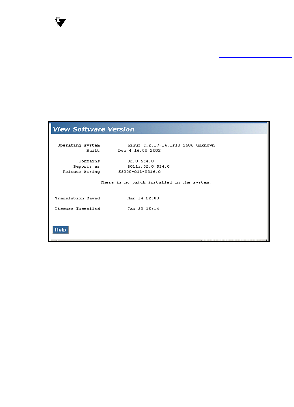
5Upgrading an Existing G700 with an S8300 — R1.x to R2.0
On-site Preparation for the Upgrade
220 Installation and Upgrades for G700 and S8300
December 2003
Check Current Software Release
Tip:
The Upgrade Tool performs this task automatically.
Check the release of Communication Manager currently running on the S8300 to determine whether a
pre-upgrade update is required. If the current release is 2.0.0 or later, go to Upgrading an Existing G700
with an S8300 — R2.0 to R2.x.
1Log in to the Web interface on the S8300 and launch the Maintenance Web Interface.
2Choose View Software Version under Server Configuration and Upgrades.
The system displays the Software Version screen.
Software Version Screen
3Check the Reports as: field for the release number of the S8300 software. In this example, the
release number is reported as R011x.02.0.524.0. This corresponds to release 1.2.0.

5
Upgrading an Existing G700 with an S8300 — R1.x to R2.0
On-site Preparation for the Upgrade
Installation and Upgrades for G700 and S8300 221
December 2003
The following table maps the release number to the Reports as: field and specifies whether or not
a pre-upgrade update is required.
Pre-Upgrade Tasks — If the S8300 is the
Primary Controller
Skip to Upgrade the S8300 on page 227, if the S8300 is configured as an LSP.
CAUTION:
If you are upgrading an S8300 primary controller that has LSPs registered to it, the LSPs
must be upgraded before the primary controller. (You can use the SAT command, list
media-gateway, to see if there are LSPs registered to the S8300.)
Perform the following procedures if you are upgrading an S8300 that is configured as a primary
controller.
NOTE:
It is no longer necessary to disable Terminal Translation Initialization (TTI) before an
upgrade or to enable it after an upgrade.
Clear Alarms
1On the Maintenance Web Interface under Alarms and Notification (Alarms for R2.0), click View
Current Alarms (Current Alarms for R2.0).
2If no alarms are listed, skip the next two steps.
3If alarms are listed, click Clear All.
4Resolve any remaining major alarms through the Communication Manager SAT.
Check Link Status
1Open a SAT session.
Software Release Numbers
Release Number
Reported as Release
Number
Pre-upgrade
update
Required?
From: R011x.01.0.xxx
To: R011x.01.9.xxx 1.1.0 to 1.1.9 No
From: R011x.02.0.xxx
To: R011x.03.0.xxx 1.2.0 to 1.3.0 Yes
From: R011x.03.1.xxx
To: R011x.03.9.xxx
1.3.1 to 1.3.9 No
From: R012x.00.0.xxx
To: R012x.00.9.xxx 2.0.0 to 2.0.9 No

5Upgrading an Existing G700 with an S8300 — R1.x to R2.0
On-site Preparation for the Upgrade
222 Installation and Upgrades for G700 and S8300
December 2003
2Enter display communication-interface links.
3Note all administered links.
4Enter status link number for each administered link.
5Enter list signaling group.
6Note the signaling groups listed by number.
7For each of the signaling groups listed, enter status signaling group number.
8Make a note of any links that are down.
Record All Busyouts
1At the SAT prompt, type display errors and press Enter.
2Look for type 18 errors and record any trunks that are busied out — you will return them to their
busy-out state after the upgrade.
Disable Scheduled Maintenance
To prevent scheduled daily maintenance from interfering with the upgrade:
1At the SAT prompt, type change system-parameters maintenance and press Enter.
2If scheduled maintenance is in progress, set the Stop Time field to 1 minute after the current
time.
or
If scheduled maintenance is not in progress, set the Start Time field to a time after the
upgrade will be completed.
For example, if you start the upgrade at 8:00 P.M. and the upgrade takes 90 minutes, set the
Start Time field to 21:30.
Check for Translation Corruption
1At the SAT prompt, type newterm and press Enter.
2Enter your terminal type and press Enter.
If you see the following message: Warning: Translation corruption found, then follow the normal
escalation procedure for translation corruption before continuing the upgrade.
Stop the LSPs (if applicable)
Skip this procedure if no LSPs are registered to the S8300.
For configurations with LSPs, the LSPs and the primary controller (S8300, S8500, or S8700) must run
the same version Communication Manager. Therefore, an upgrade to an LSP is usually accompanied by
an upgrade of the primary controller. You should upgrade the LSP before you upgrade the primary
controller.
Before you upgrade the primary controller, you need to shut down Communication Manager on the LSPs.
This prevents the phones and other endpoints attached to the G700 from trying to register with the LSPs
while you are upgrading the primary controller.

5
Upgrading an Existing G700 with an S8300 — R1.x to R2.0
On-site Preparation for the Upgrade
Installation and Upgrades for G700 and S8300 223
December 2003
To stop Communication Manager on an LSP:
1Open a telnet session on the S8300 (LSP).
2Telnet to the LSP.
3At the command line, type stop -acfn and press Enter.
The S8300 (LSP) shuts down Communication Manager.
CAUTION:
The LSP’s Communication Manager must remain shutdown while you upgrade the
primary Controller. When you complete the primary controller upgrade, run save
translation on the primary controller before restarting Communication Manager on the
LSP. The save translations process will automatically cause the G700’s endpoints to
reregister with the primary controller.
After the primary controller has been upgraded, you need to restart the LSPs.
Disable Alarm Origination
If alarm origination is enabled during the upgrade, unnecessary alarms will be sent to the Operations
Support System (OSS) destination number(s). Even if you selected "Suppress Alarm Origination" when
you logged in, alarm origination will be automatically re-enabled when the system reboots after the
software upgrade. Use this procedure to prevent alarm origination from being re-enabled after reboot.
CAUTION:
If you do not disable Alarm Origination, the system can generate alarms during the
upgrade, resulting in unnecessary trouble tickets.
To prevent alarm outcalling:
1Logoff the SAT session
2At the command prompt, type almenable -d n -s n, where
-d n sets the dialout option to neither (number)
-s n disables SNMP alarm origination
NOTE:
Be sure to reset alarm origination after the upgrade.
3Type almenable (without any options) to verify the alarm origination status. You should see:
incoming: enable
Dial Out Alarm Origination: neither
SNMP Alarm Origination: N

5Upgrading an Existing G700 with an S8300 — R1.x to R2.0
On-site Preparation for the Upgrade
224 Installation and Upgrades for G700 and S8300
December 2003
Get IA770 (AUDIX) Data and Stop IA770
(if IA770 is being used)
Skip to Back up recovery system files on page 224 if IA770 is not being used.
If IA770 is being used, you need to collect some data, leave a test message, and shut down IA770 before
backing up the files.
1To test IA770 after the migration, write down the number of a test voice mailbox, or create one if
none exists. Also write down the number of the IA770 hunt group.
2Leave a message on the test mailbox that will be retrieved after the migration.
3Click Start > Run to open the Run dialog box.
4Type telnet 192.11.13.6 and press Enter.
5Log in as craft or dadmin.
6Type stop -s Audix and press Enter to shut down AUDIX.
The shutdown will take a few minutes.
7Type watch /VM/bin/ss and press Enter to monitor the shutdown.
When the shutdown is complete, you will see only the voicemail and audit processes. For
example:
voicemail:(10)
audit http:(9)
Press Ctrl+C to break out of the watch command.
8Type /vs/bin/util/vs_status and press Enter to verify that AUDIX is shut down. When AUDIX is
shut down, you will see "voice system is down."
NOTE:
After the S8300 upgrade, you must upgrade the G700 and media module firmware before
restarting IA770.
Back up recovery system files
CAUTION:
If the current release is 1.1.x, you must backup the Communication Manager translations
(and AUDIX data if IA770 is installed) using this procedure.
Before installing the S8300 upgrade software, you should back up the system data in case there’s a need
to back out of the upgrade. To do this, you need an FTP address, directory path, and a user ID and
password to access an FTP server on the customer’s network. Check with your project manager or the
customer for this information.
Back up data
1Under Data Backup/Restore, click Backup Now.
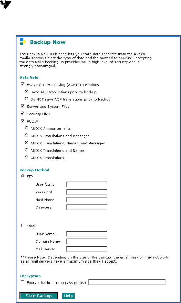
5
Upgrading an Existing G700 with an S8300 — R1.x to R2.0
On-site Preparation for the Upgrade
Installation and Upgrades for G700 and S8300 225
December 2003
Tip:
Depending on the Communication Manager software version, the following screen may
look slightly different.
2Select all data sets:
•Avaya Call Processing (ACP) Translations
•Save ACP translations prior (do not save ACP translations if this is an LSP).
•Server and System Files
•Security Files
3If the AUDIX options are available, select AUDIX and select AUDIX Translations, Names, and
Messages.

5Upgrading an Existing G700 with an S8300 — R1.x to R2.0
On-site Preparation for the Upgrade
226 Installation and Upgrades for G700 and S8300
December 2003
4Select the FTP backup method and fill in the User Name, Password, Host Name, and Directory
fields with information provided by the customer.
5Click Start Backup to back up the files.
If the AUDIX options are available, repeat Steps 3–5 for AUDIX Announcements. The announcements
cannot be restored to the 2.0 system but they should be backed up in case it is necessary to revert to the
1.x system.
Record Configuration Information
If you have not already done so, you must record the current server configuration data, which will be re-
entered after the upgrade. If you are upgrading from release 1.2 or later, most of the configuration data
will be re-entered automatically with the Linux Migration Restore process. However, if you are
upgrading from a pre-1.2 release, you will need to re-enter all of the server configuration data.
To view the current configuration data:
1Launch the Maintenance Web Interface.
2Under Server Configuration and Upgrades, click Configure Server.
3Click Continue on the first and second screen.
4On the "Select method for configuring server" screen, select "Configure all services using the
wizard" and click Continue.
5View and record the configuration information on each screen and click Continue to move to the
next screen.
The best way to record the configuration data is to fill in the Electronic Pre-installation Worksheet
(EPW). You then have the option to use the Installation Wizard to do the server configuration task. If you
do not have the EPW, you can record the current configuration data and enter it manually after the
upgrade.
If Upgrading from 1.2 or Later
Record the data on the Configure Interface screen. That is, server IP address, gateway IP address, and
subnet mask. You can skip the remaining configuration screens.
If Upgrading from Pre-1.2 Release
Record the data from all configuration screens except the Static Network Routes screen. (Static routes are
not used in release 2.0)

5
Upgrading an Existing G700 with an S8300 — R1.x to R2.0
Upgrade the S8300
Installation and Upgrades for G700 and S8300 227
December 2003
Upgrade the S8300
This section describes the procedures for upgrading the S8300 Media Server from a pre-2.0 release of
Communication manager to release 2.0.
Upgrading S8300 from a pre-2.0 release to release 2.0 requires an upgrade to the Linux operating system.
This is accomplished by running a special software application (included on the 2.0 software CD), which
reformats the S8300 hard drive, installs the new operating system, and installs Release 2.0 of
Communication Manager. These procedures are described in this section.
CAUTION:
This upgrade procedure, including remastering the hard drive on the S8300, requires a
service interruption of approximately 4 hours, or up to 6 hours if IA770 is being used.
Tip:
Due to the necessary reformatting of the S8300 hard drive for the new operating system,
the Avaya Installation Wizard (IW) cannot support upgrades of Communication Manager
from a pre-2.0 release to a 2.0(+) release. However, the IW can still be used for the media
gateway and media module firmware upgrades.
Install the Pre-Upgrade Software Update
(patch)
If the current software release is between 1.1.0 and 1.1.9, skip this update installation procedure and go to
Upgrade the S8300 on page 232.
If the current software release is 1.3.1, skip this update installation procedure and go to Back Up the
System Files (Linux Migration Web Procedure) on page 229.
If the current software release is between 1.2.0 and 1.3.0, you must install the pre-upgrade software
update (patch) before backing up the system files.
Update procedure
NOTE:
Typically, any existing updates (patches) should be removed before installing a new
update. However, removing existing updates is not necessary for this procedure.
Copy pre-upgrade update file to the media server
1Make sure the software CD is in the CD-ROM drive of your laptop.
2On the Maintenance Web Interface, under Miscellaneous click Upload Files to Server (via
browser).
3Browse to the directory on the software CD (or laptop) that contains the pre-upgrade update file.
4Select the pre-upgrade update file and click Load File.

5Upgrading an Existing G700 with an S8300 — R1.x to R2.0
Upgrade the S8300
228 Installation and Upgrades for G700 and S8300
December 2003
Install the pre-upgrade update (patch)
1Use Telnet to access the media server.
aClick Start > Run to open the Run dialog box.
bType telnet 192.11.13.6 and press Enter.
cLog in as craft.
2Type cd /var/home/ftp and press Enter to access the ftp directory.
3At the prompt, type ls -ltr and press Enter to list files in the ftp directory.
The S8300 displays a list of files in the ftp directory.
4Verify that the directory contains the *.tar.gz file you have uploaded.
5Type sudo patch_install patch.tar.gz, where patch is the release or issue number of the update
file. (For example, 03.0.526.5-1003.tar.gz). Press Enter.
6Type patch_show again and press Enter to list Communication Manager files to verify the new
software file was installed.
7Type sudo patch_apply patch, where patch is the release or issue number of the update file.
(For example, 03.0.526.5-1003. Do not use the *.tar.gz extension at the end of the file name).
Press Enter.
The media server goes through a software reset system 4. You must wait until the restart/reset has
completed before entering additional commands. The reset should take 1–2 minutes (or longer if
messaging is enabled).
8Type patch_show again and press Enter to list Communication Manager files to verify the new
software file was applied.
9Before proceeding, type statapp -c to view the status of the processes. Make sure everything
except dupmgr shows UP. Communication Manger should show 65/65 UP or, if IA770 is installed,
67/67 UP. To stop the continual refresh of the statapp command, type Ctrl-C.
NOTE:
The number of processes (65/65) may vary depending on the configuration. For a normal
state, the second number should not be greater than the first number. For example, the
numbers 64/65 UP would indicate that a process did not come up and should be
investigated before proceeding.
10 Close the browser.
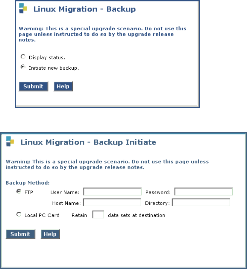
5
Upgrading an Existing G700 with an S8300 — R1.x to R2.0
Upgrade the S8300
Installation and Upgrades for G700 and S8300 229
December 2003
Back Up the System Files (Linux Migration
Web Procedure)
If the current software release is between 1.2.0 and 1.3.9, you must back up the system files using the
Linux Migration backup procedure.
Linux Migration Backup
1Launch the Maintenance Web Interface. Under Server Configuration click Linux Migration
(Backup/Restore).
2Select "Initiate new backup or restore" and click Submit
3Under Backup Method, select FTP; fill in the User Name, Password, Host Name (or host IP
address) and Directory fields for the back up location. The backup location should be a server on
the customer’s LAN.
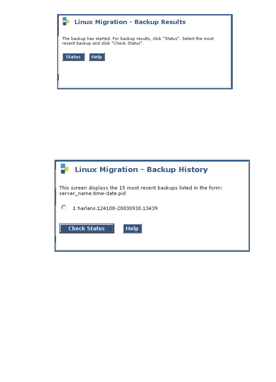
5Upgrading an Existing G700 with an S8300 — R1.x to R2.0
Upgrade the S8300
230 Installation and Upgrades for G700 and S8300
December 2003
Click Submit.
.
4Click Status to see the backup progress.
NOTE:
The Linux Migration backup status function is not enabled for release 1.3.1. To check the
backup status when upgrading from 1.3.1, select Backup Status under Data
Backup/Restore on the Maintenance Web Interface menu. Then select the backup set and
click Check Status.
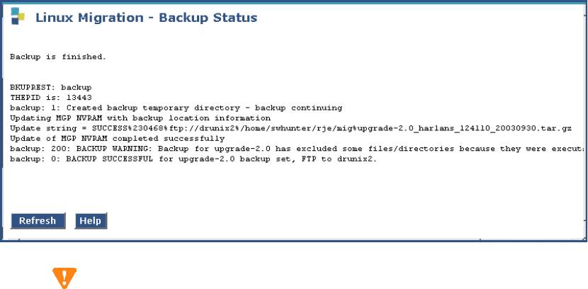
5
Upgrading an Existing G700 with an S8300 — R1.x to R2.0
Upgrade the S8300
Installation and Upgrades for G700 and S8300 231
December 2003
5Select the backup set and click Check Status to see the backup results. If the backup is in
progress, click on Refresh until the "Backup is finished" message appears.
CAUTION:
The screen will show "Backup is finished" when the backup is completed. However, also
verify that the message, "Backup Successful" also appears in the last line. If any error
messages appear stating that the backup failed, follow the normal escalation procedures.

5Upgrading an Existing G700 with an S8300 — R1.x to R2.0
Upgrade the S8300
232 Installation and Upgrades for G700 and S8300
December 2003
Upgrade the S8300
To upgrade the Communications Manager software to Release 2.0, you must remaster the hard drive
before installing the software.
NOTE:
These procedures assume that you have a USB CD-ROM drive connected to one of the
USB ports on the S8300.
Copy Remastering Program (RP) file to the
S8300 hard drive
1Insert the CD containing the software into the CD-ROM drive on the laptop and close the drawer.
2On the Maintenance Web Interface, under Miscellaneous, click Upload Files to Server.
3Click Browse to locate the RP file on the CD. The RP file is in the tarfiles directory and is called
S8300-00.0-0000.0.
4Double-click the filename (or highlight the filename and click Open).
5Click Load File. When the upload is complete, the system displays "File has been successfully
uploaded."
Install the RP software
1When the file has been copied, remove the CD from the laptop and insert it into the external CD-
ROM drive connected through the USB port on the media server.
NOTE:
The next step loads the RP software onto the backup partition. The currently running
release remains on the other partition, just as it always does during an upgrade.
2Under Server Configuration and Upgrades click Install New Software Release.
3Select from the menu the upgrade file you just uploaded (i.e., S8300-00.0-0000.0) Click
Continue to complete the software installation.
4On the Choose License Source page, select "I want to reuse the license files from the currently
active partition on this server." and "Do not update authentication information." and click
Continue.
5The Click Continue on the next several pages until the RP files are installed. Ignore backup and
Tripwire messages.
6When you get to the Reboot Server screen, click Reboot.
7Close the Browser.
The reboot takes 3–10 minutes. After the system reboots, the RP software redirects the system to
boot from the CD-ROM drive. Note that no telephony support is provided by this software. Its
only purpose is to reformat the hard drive and install a clean copy of the Avaya Communication
Manager server software.
NOTE:
To monitor the progress of the reboot, you can open a command window on your laptop
and enter the ping -t 192.11.13.6 command. When the reboot is finished, the server will
start replying to the pings. Type Ctrl+c to stop the pings.
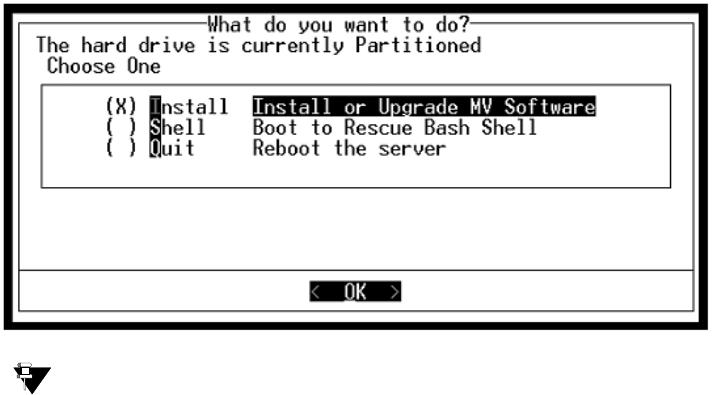
5
Upgrading an Existing G700 with an S8300 — R1.x to R2.0
Upgrade the S8300
Installation and Upgrades for G700 and S8300 233
December 2003
Set Telnet Parameters
The Microsoft Telnet application may be set to send a carriage return (CR) and line feed (LF) each time
you press Enter. The installation program sees this as 2 key presses. You need to correct this before you
Telnet to the server.
1Click Start > Run to open the Run dialog box.
2Type telnet and press Enter to open a Microsoft Telnet session.
3Type unset crlf and press Enter.
4Type display and press Enter to confirm that "Sending only CR" is set.
5Close the window by clicking on the X in the upper-right corner.
This resets your Microsoft Telnet defaults and does not need to be done each time you use Telnet.
Remaster Hard Drive and Install the Upgrade
Software
NOTE:
This procedure accesses the information on the CD from the USB CD-ROM drive.
1Type telnet 192.11.13.6 and press Enter to view the first screen.
Tip:
To navigate on these screens, use the arrow keys to move to an option, then press the space
bar to select the option. Press Enter to submit the screen.
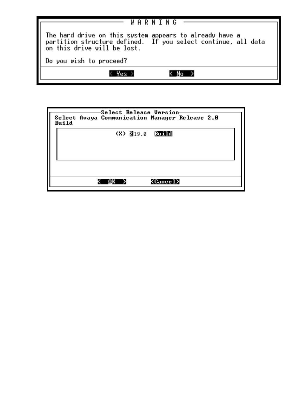
5Upgrading an Existing G700 with an S8300 — R1.x to R2.0
Upgrade the S8300
234 Installation and Upgrades for G700 and S8300
December 2003
2Select Install, make sure OK is highlighted, and press Enter.
3Select <Yes> and press Enter.
NOTE:
After this step, the previous disk image cannot be recovered by rebooting.
4Select the appropriate release version (if more than one) then select <OK> and press Enter.
At this point, the following processes are initiated:
•The S8300 hard drive is reformatted
•The new Linux operating system is installed
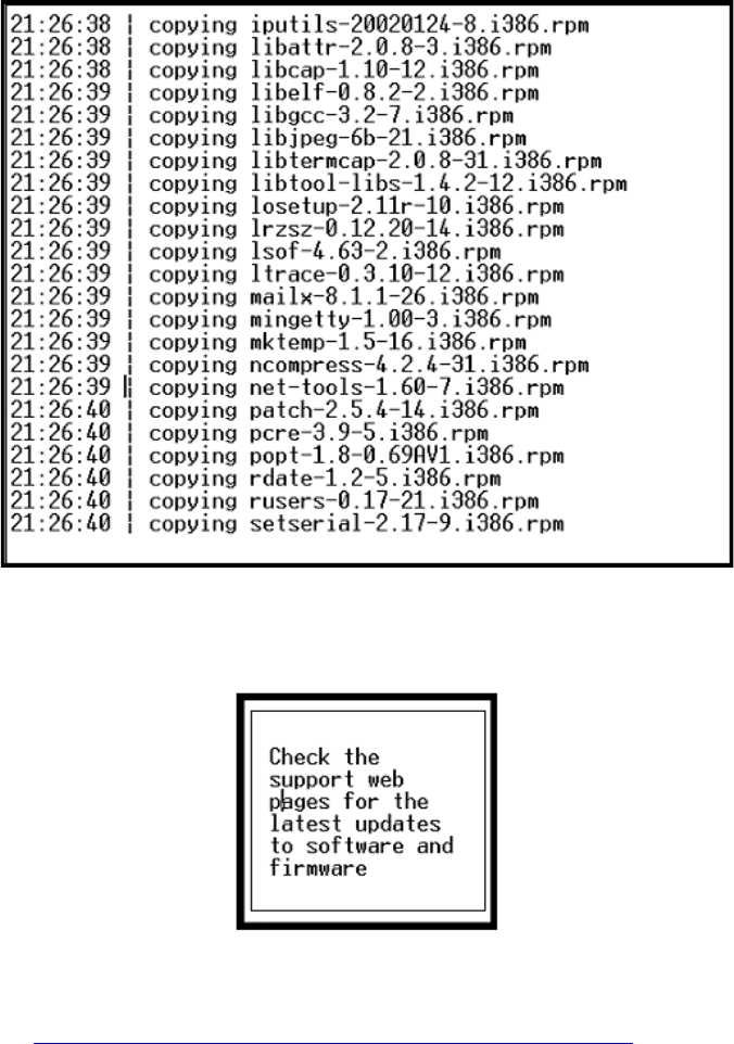
5
Upgrading an Existing G700 with an S8300 — R1.x to R2.0
Upgrade the S8300
Installation and Upgrades for G700 and S8300 235
December 2003
•Once the drive is properly configured, the program begins installing Communication Manager
software and reports the progress.
•These processes take 15–20 minutes. When the media server is ready to reboot, the CD drive door
opens and the following screen flashes for about 5 seconds. At this point, you are finished with
the CD and CD drive.
NOTE:
In this screen, "latest updates to software" refers to the latest software updates (patches).
See Download Software Update (patch) file to Your Laptop, if Necessary on page 216.
When the installation process is complete, the system reboots automatically. The reboot takes 1–3
minutes.

5Upgrading an Existing G700 with an S8300 — R1.x to R2.0
Upgrade the S8300
236 Installation and Upgrades for G700 and S8300
December 2003
Verify Software Version
NOTE:
Since the system is now running a new software release, you must login with the initial
craft ID and password. (You cannot use dadmin at this point.)
1Log on to Integrated Management and launch the Maintenance Web Interface.
2Under Server, click Software Version.
3Verify that the media server is running Release 2.0 software. The Report as: string should show
R012x at the beginning of the string. For example, R012x.00.0.219.0.
Tip:
Normally, you would need to use the Make Upgrade Permanent function on the Web
Interface at this point. However, this is not necessary for this upgrade because there is no
previous software version in the alternate partition.
Copy Files to the S8300
During reformatting of the hard drive, a new directory, /var/home/ftp/pub, was created. For release 2.0
and later, this pub directory will be used as the /var/home/ftp directory that was used in previous releases.
You must upload the remaining required files to the pub directory on the S8300 hard drive. This includes,
but is not limited to, the post-upgrade software update, license file, Avaya authentication file (if needed),
and new firmware files.
NOTE:
Before an upload, be sure the /var/home/ftp/pub directory contains no files with a *.pwd
or *.lic extension. Only one of these files can exist in a directory. If more than one exists,
move, rename, or delete all but the valid file.
1Log on to Integrated Management and launch the Maintenance Web Interface.
NOTE:
Since the system is now running a new software release, you must login with the initial
craft ID and password. (You cannot use dadmin at this point.)
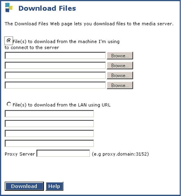
5
Upgrading an Existing G700 with an S8300 — R1.x to R2.0
Upgrade the S8300
Installation and Upgrades for G700 and S8300 237
December 2003
2Under Miscellaneous click Download Files.
3Select "Files to download from the machine I’m using to connect to the server" and browse to
each file you want to move to the S8300.
NOTE:
To manually FTP files from your laptop to /var/home/ftp/pub, you must cd to pub after
starting ftp and logging in.
4Click on Download to copy the files to the S8300. The transfer is complete when you see the
message, "Files have been successfully uploaded to the server."
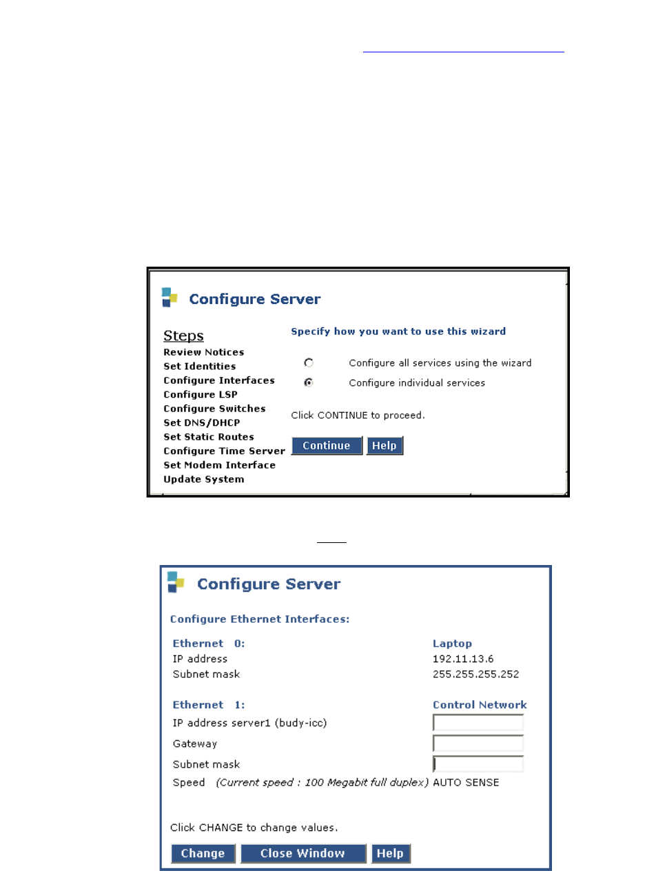
5Upgrading an Existing G700 with an S8300 — R1.x to R2.0
Upgrade the S8300
238 Installation and Upgrades for G700 and S8300
December 2003
Configure the Network Parameters
If you have upgraded from a pre-1.2 release, skip to If Upgrading from a Pre-1.2 Release on page 239.
NOTE:
For this procedure, you must have the host name, subnet mask, and IP address of the
S8300 and the IP address of the default gateway.
Because the software upgrade resets the configuration data, you must reconfigure the network parameters
on the S8300 before restoring the backup files. Also, it is possible that the new software added or
changed some of the configuration fields or screens.
1Under Server Configuration click Configure Server to start the configure server process.
2Click Continue through the Review Notices to get to the Select Method for Configuring Server
page.
3Select "Configure individual services" and click Continue.
4Click Configure Interfaces from the Steps list.

5
Upgrading an Existing G700 with an S8300 — R1.x to R2.0
Upgrade the S8300
Installation and Upgrades for G700 and S8300 239
December 2003
5Fill in the correct server IP address, Gateway, and Subnet mask. (If these fields are already filled
in, overwrite them with the correct information if necessary.)
Click Change to update the system files. When the configuration change is complete, the screen
displays "Successfully configured ethernet interfaces."
6When the configuration change is complete, click Close Window.
At this point, the system resets the IP interfaces.
If Upgrading from a Pre-1.2 Release
If you have upgraded from a 1.2 or later release, skip to Verify Connectivity on page 240.
Restore Translations
If upgrading from a pre-1.2 release:
1Select View/Restore Data under Data Backup/Restore.
2Select FTP and enter the information for the FTP backup server. Click View.
3Select the Communication Manager translations backup set to restore (filename begins with
"xln". Click Restore.
NOTE:
Do not restore the system or security backup sets (filenames beginning with "os" and
"security"). If you backed up the AUDIX data, you will need to restore the AUDIX
backup set as a separate step. The AUDIX translations, names, and messages backup set
filename begins with "audix-tr-name-msg". Do not restore the announcement backup set
(filename beginning with "audix-ann").
Configure the Server
If you have upgraded from a pre-1.2 release, you must enter all server configuration information. If you
have filled in the Electronic Pre-installation Worksheet (EPW), you should use the Avaya Installation
Wizard at this point. The Installation Wizard will do the server configuration and install the license and
password files. When finished with the Wizard, return to If IA770 Is Being Used, Ensure that Messaging
Is Disabled on page 243.
Or, you can enter the configuration information manually:
1Select Configure Server on the Maintenance Web Interface menu.
2Click Continue on the first two screens. When you get to the screen titled "Specify how you want
to use this wizard," select "Configure all services using the wizard." Then enter the configuration
information on each configuration screen.
NOTE:
You do not need to enter Static Network Route information.
3When you complete all the new fields, if necessary, click Continue on the Update System screen.
The Update System screen displays each configuration task as it completes. When done, the
screen displays the line "All configuration information was entered."
4Click Close Window.
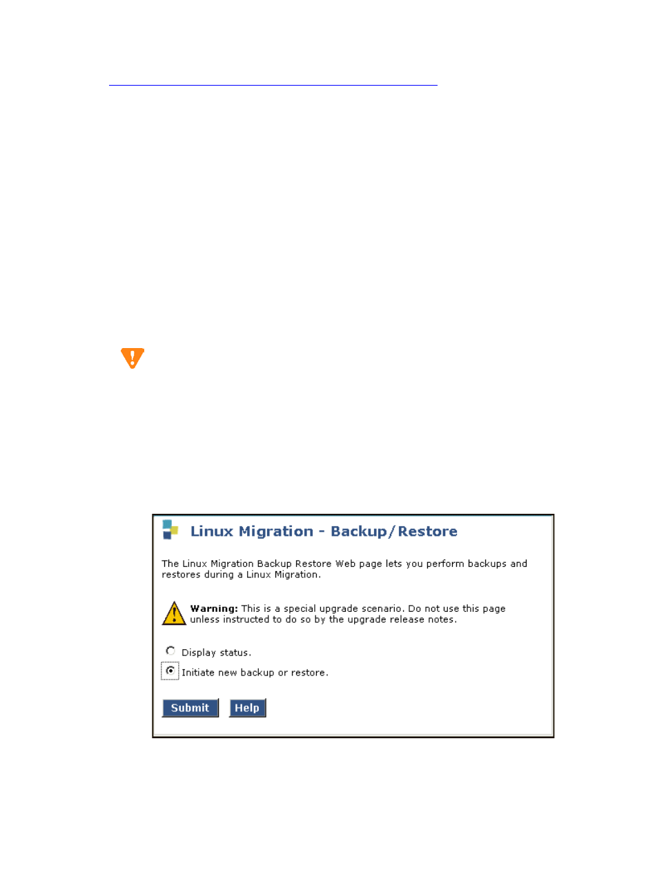
5Upgrading an Existing G700 with an S8300 — R1.x to R2.0
Upgrade the S8300
240 Installation and Upgrades for G700 and S8300
December 2003
5Log on to a Telnet session.
6Type /opt/ws/drestart 1 4 to capture the configuration data. You should see the response,
"Killed".
Skip to If IA770 Is Being Used, Ensure that Messaging Is Disabled on page 243.
Verify Connectivity
To verify that the Ethernet port is working, ping the FTP server where the Linux-Migration backup file is
stored.
1On the Maintenance Web Interface, under Diagnostics click Ping.
2Enter the IP address where the Linux-Migration backup file is stored. Click Execute Ping.
3If the ping is successful, continue with restoring the system files. Otherwise, check the IP address
and connectivity to the server.
Restore the Linux Migration Backup File
CAUTION:
Restore must be run only once. Running restore more than once may corrupt the system
data. If a restore appears to have not completed, check Backup History and Backup Logs
on the Web Interface, and check the system log in the bash CLI. If all of these sources
indicate that a restore has not completed, you can safely rerun the restore.
1On the Maintenance Web Interface, under Server Upgrades click Linux Migration
(Backup/Restore).
2Select "Initiate new backup or restore" and click Submit
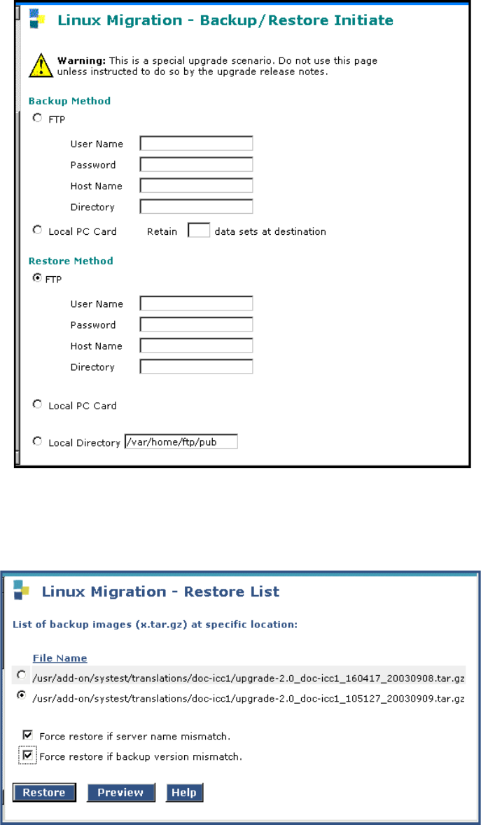
5
Upgrading an Existing G700 with an S8300 — R1.x to R2.0
Upgrade the S8300
Installation and Upgrades for G700 and S8300 241
December 2003
3Under Restore Method, select FTP. Fill in the User Name, Password, Host Name (enter host IP
Address), and Directory fields for the location of the backup file on the customer’s server. If the
you backed up the Linux-Migration backup file to your laptop, use anonymous for User Name,
your email address for Password, 192.11.13.5 for Host Name, and \ for Directory. Click Submit.
.
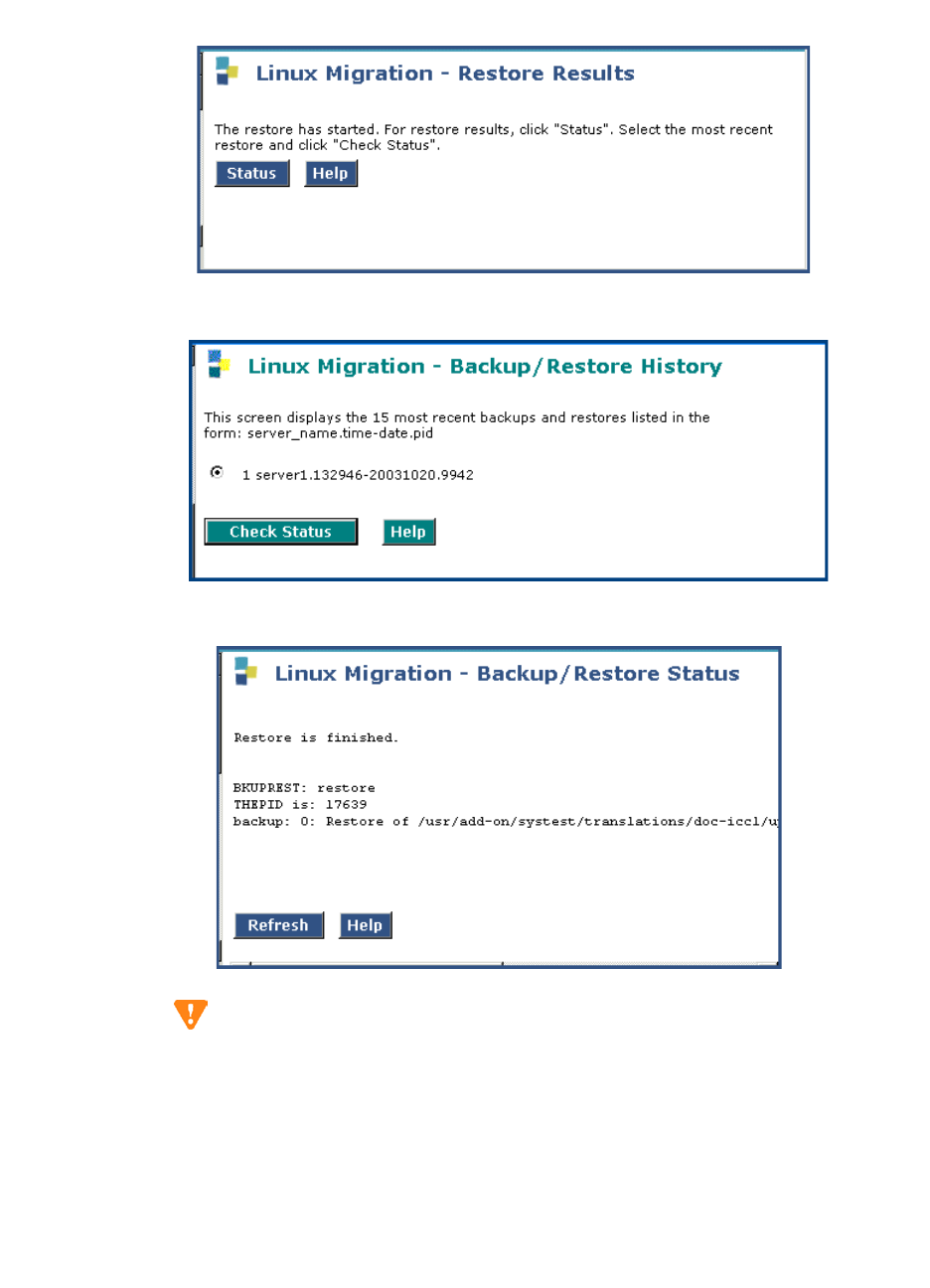
5Upgrading an Existing G700 with an S8300 — R1.x to R2.0
Upgrade the S8300
242 Installation and Upgrades for G700 and S8300
December 2003
4Select the backup set to restore and both Force options and click Restore.
5Click Status to view the restore progress
6Select the backup set and click Check Status to view the restore progress.
CAUTION:
At this point, you should not use any customer logins. Use only the craft login.
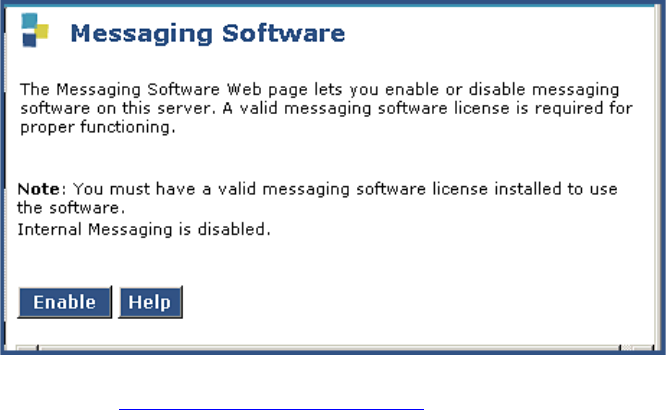
5
Upgrading an Existing G700 with an S8300 — R1.x to R2.0
Upgrade the S8300
Installation and Upgrades for G700 and S8300 243
December 2003
If IA770 Is Being Used, Ensure that Messaging
Is Disabled
If the system is using IA770:
1Click Messaging Software under Miscellaneous.
2If the Enable button shows at the bottom of the screen, messaging is currently disabled — go to
the next step, Verify the Time, Date, and Time Zone on page 243. If the Disable button is
showing, messaging in currently enabled so click the Disable button to disable messaging.
Verify the Time, Date, and Time Zone
1Under Server click Server Date/Time.
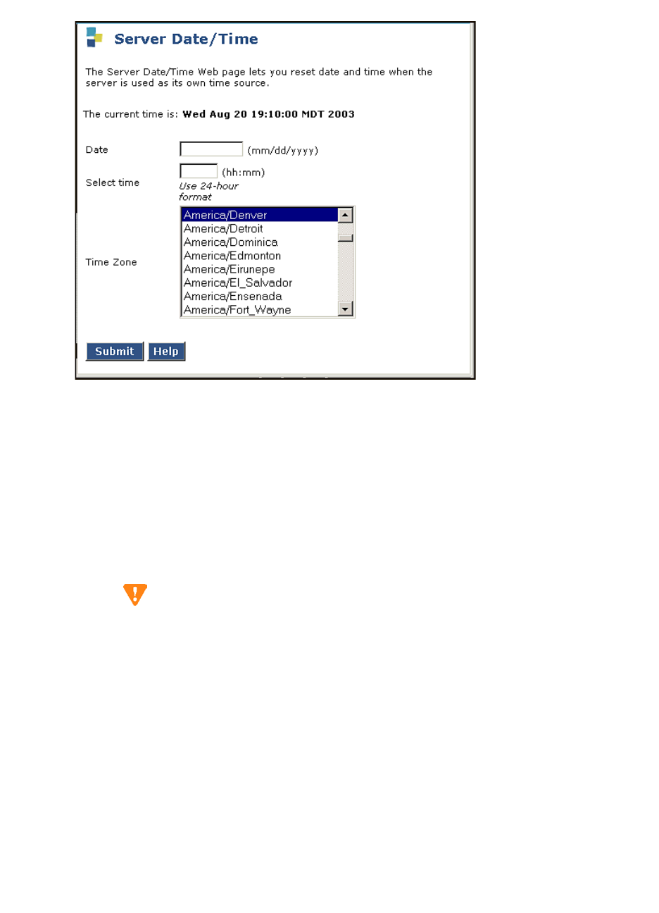
5Upgrading an Existing G700 with an S8300 — R1.x to R2.0
Upgrade the S8300
244 Installation and Upgrades for G700 and S8300
December 2003
Server Date/Time Window
2Verify or set the media server’s time close enough to the NTS’s time, date, and time zone that
synchronization can occur (within about 5 minutes).
Install Post-Upgrade Communication Manager
Update File from Your Laptop, if any
NOTE:
Skip this procedure if there is no Communication Manager update file to install.
CAUTION:
The software update may or may not be call-preserving.
Use a telnet session to install the software update.
1Click Start > Run to open the Run dialog box.
2Type telnet 192.11.13.6 and press Enter.
3Log in with the initial craft ID and password. (You cannot use dadmin at this point.)
4Type cd /var/home/ftp/pub and press Enter to access the pub directory.
5At the prompt, type ls -ltr and press Enter to list files in the pub directory.
The media server displays a list of files in the FTP directory. Verify that the directory contains the
Communication Manager .tar.gz file you have uploaded, if any.
6Type sudo update_unpack <update>.tar.gz, where <update> is the release or issue number of
the latest update file. (For example, 03.0.219.0-4925.tar.gz). Press Enter.
7Type update_show and press Enter to list Communication Manager files to verify the new
software file was installed.
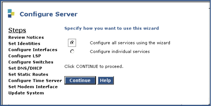
5
Upgrading an Existing G700 with an S8300 — R1.x to R2.0
Upgrade the S8300
Installation and Upgrades for G700 and S8300 245
December 2003
8Type sudo update_activate <update>, where <update> is the release or issue number of the
latest software file. (For example, 03.0.219.0-4925. Do not use the .tar.gz extension at the end of
the file name). Press Enter.
The system may initiate a software reset system 4. You must wait until the restart/reset has
completed before entering additional commands.
If the system displays the message — /opt/ecs/sbin/drestart 1 4 command failed — ignore this
message.
9Type update_show again and press Enter to list Communication Manager files to verify the new
software file was applied.
Verify Media Server Configuration
At this point, you should not have to enter configuration information. In the following procedure, click
Continue to open each configuration screen and verify the that configuration information is correct.
1Under Server Configuration click Configure Server to start the configure server process. Click
Continue until you reach the screen titled "Specify how you want to use this wizard."
2Select "Configure all services using the wizard."
3Click Continue through all the screens, checking for new screens and new fields on existing
screens as mentioned in the planning forms.
NOTE:
You must click Continue through all the screens whether there are changes or not. You do
not need to enter Static Network Route information.
4When you complete all the new fields, if necessary, click Continue on the Update System screen.
The Update System screen displays each configuration task as it completes. When done, the
screen displays the line "All configuration information was entered."
5Click Close Window.
6Log on to a Telnet session.
7Type /opt/ws/drestart 1 4 to capture the configuration data. You should see the response,
"Killed".
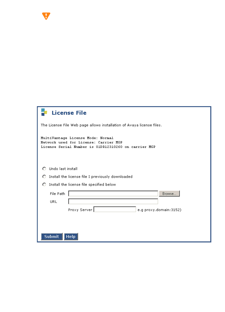
5Upgrading an Existing G700 with an S8300 — R1.x to R2.0
Upgrade the S8300
246 Installation and Upgrades for G700 and S8300
December 2003
Install the New License File
CAUTION:
Be sure to install the license file before the authentication file.
You need to load a new license file when upgrading to a new major release of Communication Manager
or when changing the feature set.
NOTE:
If the S8300 is already set up for remote access, Avaya services personnel can copy new
license and authentication files directly into the /pub directory on the server. Avaya
personnel will notify you when the new files are in place as agreed (for example, by
telephone or E-mail). After they are loaded into the /pub directory, install them using the
License File and Authentication File screens under Security on the Maintenance Web
Interface.
1On the Maintenance Web Interface under Security, click License File.
2Select "Install the license file I previously downloaded," browse to the license file on the services
laptop, and click Submit.
The system tells you the license is installed successfully.
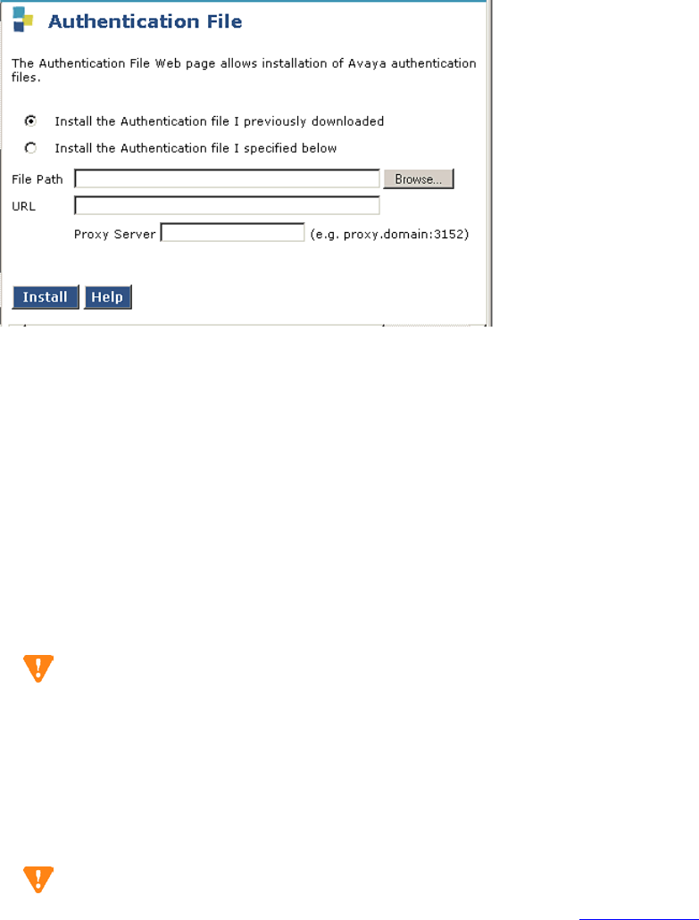
5
Upgrading an Existing G700 with an S8300 — R1.x to R2.0
Upgrade the S8300
Installation and Upgrades for G700 and S8300 247
December 2003
Install the New Authentication File
1Click Authentication File
2Select "Install the Authentication file I previously downloaded" and Click Install.
The system tells you the authentication is installed successfully
3Verify that the restoration of the backup files was successful by testing the craft login.
Telnet to 192.11.13.6 and login as craft using the normal craft password.
NOTE:
You may need to use the static craft password at this point. The static password will
enable you to log in to the S8300 with a direct connection to the Services port without the
ASG challenge/response. To obtain the static password, call the ASG Conversant number,
800-248-1234 or 720-444-5557 (or 877-295-0099 for Avaya Business Partners), and
follow the prompts to get the password. In addition to your credentials, you will need to
enter the customer’s Product ID or the FL or IL number.
CAUTION:
After you install new license and authentication files, be sure to run save translation. This
task saves the official passwords for the customer’s system. If you fail to perform this step,
you may be irretrievably locked out of the system later in the installation when the system
reboots.
Save Translations
CAUTION:
If the system is using IA770, do not save translations at this time. Skip to Verify Operation
on page 249. You will save translations after installing the new IA770 software.
1In the telnet session, open a SAT session.
2Log in again as craft.
3Type save translation and press Enter.

5Upgrading an Existing G700 with an S8300 — R1.x to R2.0
Upgrade the S8300
248 Installation and Upgrades for G700 and S8300
December 2003
When the save is finished, the system displays the message, "Command successfully completed."
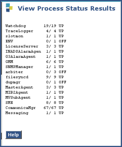
5
Upgrading an Existing G700 with an S8300 — R1.x to R2.0
Upgrade the S8300
Installation and Upgrades for G700 and S8300 249
December 2003
Verify Operation
Using the Maintenance Web Interface:
1Under Server click Process Status.
2Select "Summary and Display once" and click View to access the View Process Status Results
page.
3Make sure everything except ENV, arbiter, and dupmgr shows UP. Communication Manger should
show 65/65 UP or, if IA770 is installed, 67/67 UP.
The number of processes (67/67) may vary depending on the configuration. For a normal state,
the second number should not be greater than the first number. For example, the numbers 66/67
UP would indicate that a process did not come up and should be investigated before proceeding.
4Using a telephone, make test calls to verify that call processing is working.
Next Steps
This completes the S8300 upgrade process for upgrading from a 1.x software release to release 2.0. You
now must upgrade the G700 and media module firmware and then install and restart IA770, if installed
on the S8300.

5Upgrading an Existing G700 with an S8300 — R1.x to R2.0
Upgrade the Firmware on the G700
250 Installation and Upgrades for G700 and S8300
December 2003
Upgrade the Firmware on the G700
The tasks in this section can be completed most efficiently by using the Avaya Installation Wizard or the
Upgrade Tool. If the S8300 is a primary controller, use the Installation Wizard. If the S8300 is one of
several LSPs controlled by the same primary controller, use the Upgrade Tool. Or, in either case, you can
complete the tasks manually as described below.
Go to http://support.avaya.com/avayaiw to download job aids for using the Installation Wizard or
Upgrade Tool.
CAUTION:
If the passwords to log on to the P300 stack or the MGP have been changed from the
defaults, you must change them back to the original default passwords before using the
Installation Wizard or Upgrade Tool.
Using the Installation Wizard
On the Integrated Management main menu, click Launch Avaya Installation Wizard. To use the
Installation Wizard to upgrade firmware on the G700, be sure to select the "Upgrade a previously
installed Media Server with new software and/or Media Gateway firmware" on the Usage Options screen.
The Usage Options screen appears in the Installation Wizard after a few introductory screens.
Using the Upgrade Tool
On the Integrated Management main menu, click Launch Upgrade Tool. Follow the instruction to
upgrade the G700 and media module firmware.
Manual Upgrade Procedures
If you are using the Avaya Installation Wizard or the Upgrade Tool:
•Skip to If the S8300 is Using IA770 on page 257 if IA770 is being used, or
•Skip to Complete the Upgrade Process (S8300 is the Primary Controller) on page 260 if IA770 is
not being used.
If you are not using the Avaya Installation Wizard or Upgrade Tool, conduct the following manual
procedures to update the firmware running on the G700 Media Gateway processors and media modules.
Verify the Contents of the tftpboot Directory
Before proceeding with the G700 firmware installation, you should check the tftpboot directory on the
TFTP server to make sure the firmware versions match those listed in the planning documentation.

5
Upgrading an Existing G700 with an S8300 — R1.x to R2.0
Upgrade the Firmware on the G700
Installation and Upgrades for G700 and S8300 251
December 2003
Determine Which Firmware to Install on the
G700
Conduct the following procedure to compare software versions running on the G700 processors and
media modules with the versions in you planning documents. If the versions do not match, new firmware
for those components is necessary.
Determine if new firmware for the P330 stack processor is necessary.
1At either the P330-1(super)# or P330-1(configure)# prompt, type dir.
The system displays the list of software.
Directory List for P300 Processor
2Check the version number (ver num) of the EW_Archive file to see if it matches the Release
Letter. If not, you must upgrade the P330 stack processor.
3Type show image version
The system displays the list of software.
Show Image Version List for P330 Processor
4Check the version number of the stack software image file in Band B to see if it matches the your
planning document. If not, you must upgrade the P330 stack processor.
Determine if new firmware is required for the MGP, VoIP Module, and installed media
modules.
1Type session mgp
2At the MG-001-1(super)# prompt, type show mg list_config
The system displays the list of software.
M# file ver num file type file location file description
-- ---- ------- ---------- ------------- ----------------
1 module-config N/A Running Conf Ram Module Configuration
1 stack-config N/A Running Conf Ram Stack Configuration
1 EW_Archive 3.8.6 SW Web Image NV-Ram WEB Download
1 Booter_Image 3.2.5 SW BootImage NV-Ram Booter Image
Mod Module-Type Bank Version
------ ----------- ---- -------
3 Avaya G700 Media Gateway A 0.0.0
3 Avaya G700 Media Gateway B 3.9.0

5Upgrading an Existing G700 with an S8300 — R1.x to R2.0
Upgrade the Firmware on the G700
252 Installation and Upgrades for G700 and S8300
December 2003
Show MG List_Config
3Refer to the list to check the FW vintage number of the G700. In the TYPE column, find G700,
then check the matching field in the FW VINTAGE column to see if it matches the vintage
number in your planning forms. If not, you must install new firmware on the G700 Media
Gateway. Also check if the release number in the FW VINTAGE column contains (A) or (B) to
designate the software bank. If the list shows B, you will upgrade A. If the list shows A, you will
upgrade B.
4Refer to the VOIP FW column and row for slot V0 (same row occupied by the G700 information)
to see if the number matches the VoIP firmware identified in your planning forms. If not, you
must also upgrade the G700 Media Gateway motherboard VoIP module.
NOTE:
The VoIP processor on the motherboard is upgraded using the same firmware image file
as the VoIP media modules; for example, the file mm760v8.fdl is vintage #8.
5Check the FW VINTAGE column for vintages of each of the installed Media Modules: MM710,
MM711, MM712, MM720, and/or MM760 to see if they match the FW vintages in the planning
forms. If not, you must upgrade them, as well.
Install New Firmware on the P330 Stack
Processor
Install P330 stack processor firmware
1From your S8300 telnet session, telnet back to the P330 stack processor:
Type telnet <xxx.xxx.xxx.xxx>, where <xxx.xxx.xxx.xxx> is the IP address of the P330 stack
master processor on the customer’s LAN.
1At the P330-1(configure)# prompt, type
copy tftp SW_image <file> EW_archive <ew_file> <tftp_server_address> <Module#>
where
<file> is the full-path name for the image file with format and vintage number similar to
viisa3_8_2.exe,
<ew_file> is the full-path name for the embedded web application file with format similar to
p330Tweb.3.8.6.exe,
<tftp_server_ip_address> is the IP address of the TFTP server, and
eyp
SLOT TYPE CODE SUFFIX HW VINTAGE FW VINTAGE VOIP FW
---- ------ ----- ------ ---------- ---------- -------
V0 G700 DAF1 A 00 210(B) 2
V1 ICC S8300 A 72 00 N/A
V2 DCP MM712 A 2 52 N/A
V3 ANA MM711 A 2 12 N/A
V4 DS1 MM710 A 1 54 N/A

5
Upgrading an Existing G700 with an S8300 — R1.x to R2.0
Upgrade the Firmware on the G700
Installation and Upgrades for G700 and S8300 253
December 2003
<Module#> is the number, 1 through 10, of the media gateway in the stack. If there is only one
G700 Media Gateway, the number is 1.
2To verify that the download was successful when the prompt returns:
—type
show image version <module #> and check the version number in the Version
column for Bank B.
—type
dir <module #> and check the version number in the ver num column for the
EW_Archive file.
3Type reset <module #>
Install New Firmware on the G700 Media
Gateway Processor
Install MGP firmware
1At the P330-1(configure)# prompt, type session mgp to reach the G700 Media Gateway
processor.
2Type configure at the MG-???-1(super)# prompt to enter configuration mode, which will change
the prompt to MG-???-1(configure)#.
3At the MG-???-1(configure)# prompt, type show mgp bootimage to determine which disk
partition (bank) is in the Active Now column. You will update the bank that is not listed as Active
Now. The system displays the following screen:
Example: Show mgp bootimage
4At the MG-???-1(configure)# prompt, type
copy tftp mgp-image <bank> <filename> <tftp_server_ip_address>
to transfer the mgp image from the tftp server to the G700, where
<bank> is the bank that is not Active Now (Bank A in the example).
<filename> is the full path name of the mgp firmware image file, which begins with mgp and will
be similar to the name mgp_8_0.bin.
<tftp_server_ip_address> is the IP address of the S8300. See the following example:
copy tftp mgp-image a mgp_8_0.bin 195.123.49.54.
The screen will show the progress.
5Type set mgp bootimage <bank> where <bank> is the same letter you entered in the previous
step.
FLASH MEMORY IMAGE VERSION
Bank A 109
Bank B 210
ACTIVE NOW ACTIVE AFTER REBOOT
Bank B Bank B

5Upgrading an Existing G700 with an S8300 — R1.x to R2.0
Upgrade the Firmware on the G700
254 Installation and Upgrades for G700 and S8300
December 2003
6At the MG-???-1(configure)# prompt, type reset mgp.
A system prompt asks to confirm the reset.
7Select Yes at the dialog box that asks if you want to continue.
The G700 Media Gateway processor will reset. The LEDs on the G700 Media Gateway and the
Media Modules will flash. These elements will each conduct a series of self-tests. When the LEDs
on the Media Modules are extinguished and the active status LEDs on the G700 Media Gateway
are on, the reset is complete.
8When the P330-1(super)# prompt appears, type session mgp.
9At the MGP-???-1(super)# prompt, type configure.
10 Verify that the download was successful when the prompt returns.
Type show mg list_config. The system displays the list of software.
Example: Show mg list_config
Install New Firmware on the Media Modules
For upgrades of active media modules, you need to take the media modules out of service before
initiating the upgrade process. To do this, go to a SAT session on the primary controller and issue a
busyout command.
NOTE:
Skip this busyout procedure if the media modules are not in service; for example during
an initial installation.
Busyout board (for active media modules)
1Go to a SAT session on the primary controller and enter the command,
busyout board vx
where x is the slot number of the media module to be upgraded.
2Verify the response, Command Successfully Completed.
3Repeat for each media module to be upgraded.
Install media module firmware
1Be sure that you have checked for the current vintage of the VoIP Module for the v0 slot (on the
G700 motherboard) (see Determine Which Firmware to Install on the G700). This VoIP module
does not occupy a physical position like other Media Modules.
2At the P330-1(configure)# prompt, type session mgp.
SLOT TYPE CODE SUFFIX HW VINTAGE FW VINTAGE VOIP FW
---- ------ ----- ------ ---------- ---------- -------
V0 G700 DAF1 A 00 230(A) 67
V1 ICC S8300 A 72 00 N/A
V2 DCP MM712 A 2 58 N/A
V3 ANA MM711 A 2 57 N/A
V4 DS1 MM710 A 1 58 N/A

5
Upgrading an Existing G700 with an S8300 — R1.x to R2.0
Upgrade the Firmware on the G700
Installation and Upgrades for G700 and S8300 255
December 2003
3At the MG-001-1(super)# prompt, type configure to change to the configuration mode.
4Type copy tftp mm-image v<slot #> <filename mm> <tftp_server_ip_address>
where <slot #> is the slot of the specific media module as identified when you performed
Determine Which Firmware to Install on the G700,
<filename mm> the full-path name of the media module firmware file in a format such
mm712v58.fdl, and
<tftp_server_ip_address> is the ip address of the S8300.
Two or three minutes will be required for most upgrades. The VoIP Media Module upgrade takes
approximately 5 minutes. Screen messages indicate when the transfer is complete.
5After you have upgraded all the media modules, verify that the new versions are present. At the
MG-???-1(configure)# prompt, type show mg list_config
The list of software appears
Show MG List_Config
6In the TYPE column, find the particular media module (v1 through v4), then check the matching
field in the FW VINTAGE column to see if it matches the planning documentation. Note that slot
V1 can contain either a media module or the S8300, which will show as Type "ICC".
7Check the VOIP FW column and row for slot v0 to see if the number matches the VoIP firmware
identified in the planning documentation.
8Type reset <module #> where <module #> is the number of the G700 in the stack.
9When the reset is finished, type show mm to verify the upgrade.
Release board (if media module was busied out)
1When the upgrade procedure is complete, go to the SAT session and release the board:
type release board vx where x is the slot number of the upgraded media module.
2Verify the response, Command Successfully Completed.
NOTE:
If you see the response, Board Not Inserted, this means that the media module is still
rebooting. Wait one minute and repeat the release board command.
3Repeat the release board command for each media module that was busied out.
SLOT TYPE CODE SUFFIX HW VINTAGE FW VINTAGE VOIP FW
---- ------ ----- ------ ---------- ---------- -------
V0 G700 DAF1 A 00 230(A) 67
V1 ICC S8300 A 72 00 N/A
V2 DCP MM712 A 2 58 N/A
V3 ANA MM711 A 2 57 N/A
V4 DS1 MM710 A 1 58 N/A

5Upgrading an Existing G700 with an S8300 — R1.x to R2.0
Upgrade the Firmware on the G700
256 Installation and Upgrades for G700 and S8300
December 2003
Install New Firmware on Other G700 Media
Gateways
Stack Configuration
If the customer has multiple G700 media gateways connected in an IP stack, you can stay connected to
the master G700/P330 and "session" over from the master P330 stack processor to the next G700 in the
stack. If you are dialed in remotely, you should have automatically dialed in to the stack master. For a
local installation, you should have plugged your laptop into the stack master P330, which you can
identify by the LED panel on the upper left of each G700 or P330 device in the stack. The LEDs signal as
follows:
•On the G700 Media Gateway: a lit MSTR LED indicates that this unit is the stack master.
•On the P330 device: a lit SYS LED indicates that this unit is the stack master.
The G700 and P330 at the bottom of the stack is module number 1, the next module up is number 2,. and
so on. However, the stack master can be any module in the stack, depending on the actual model, the
vintage firmware it runs, and whether the S8300 is inserted into it.
NOTE:
You do not need to configure the other P330 stack processors in the stack. These will use
the IP address and IP route of the master stack processor. However, you will need to check
firmware on all devices of the other G700s in the stack, including the media gateways
themselves, and update the firmware as required.
You may also use the "session stack" command to access other standalone P330
processors in the stack (those that are not part of a G700 unit).
1At the MG-001-1(configure)# prompt, type session stack
The P330-1(configure)# prompt appears.
2At the P330-1(configure)# prompt, type session <mod_num> mgp
<mod_num> is the next P330 processor in the stack. If you are currently logged in to the master
stack processor, <mod_num> would be 2, for the second G700/P330 processor in the stack.
3For other G700s in the stack, repeat the steps described previously to install firmware for the stack
processor, MGP, and media modules.
Remote, No Stack Configuration
If additional G700 media gateways are supported in the configuration, but they are not attached as a
stack, then you must configure each G700, with all of its devices, including the P330 processors.
Additionally, you must check firmware and update the firmware as required.
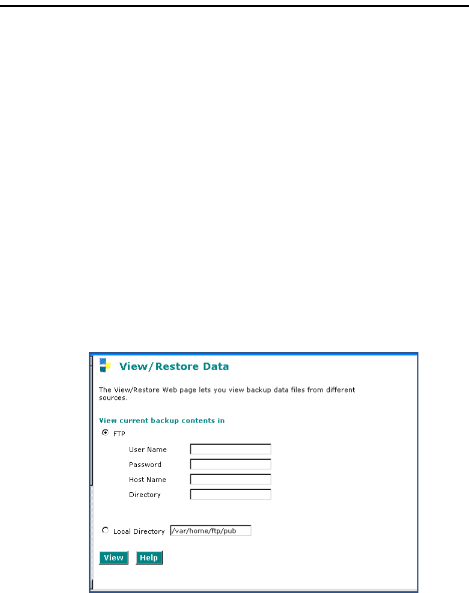
5
Upgrading an Existing G700 with an S8300 — R1.x to R2.0
If the S8300 is Using IA770
Installation and Upgrades for G700 and S8300 257
December 2003
If the S8300 is Using IA770
Install and Restart IA770
1Telnet to 192.11.13.6
2Log in as craft or dadmin.
3Type cd /usr/CHIA
4Install IA770:
aType sudo ./autoinstall
bWhen prompted to stop call processing, select y. The installation should take about 10
minutes from this point.
NOTE:
Communication Manager will shutdown.
cEnsure that the autoinstall script completed successfully. You will see the message,
"Successful Completion of IA770 Automatic Installation."
5Enable messaging:
aGo to the Web Interface and select Messaging Software under Miscellaneous.
bIf the Enable button shows at the bottom of the screen, click it to enable messaging. If the
Disable button is showing, messaging is already enabled.
6Restore AUDIX data:
aUnder Data Backup/Restore, click View/Restore Data.
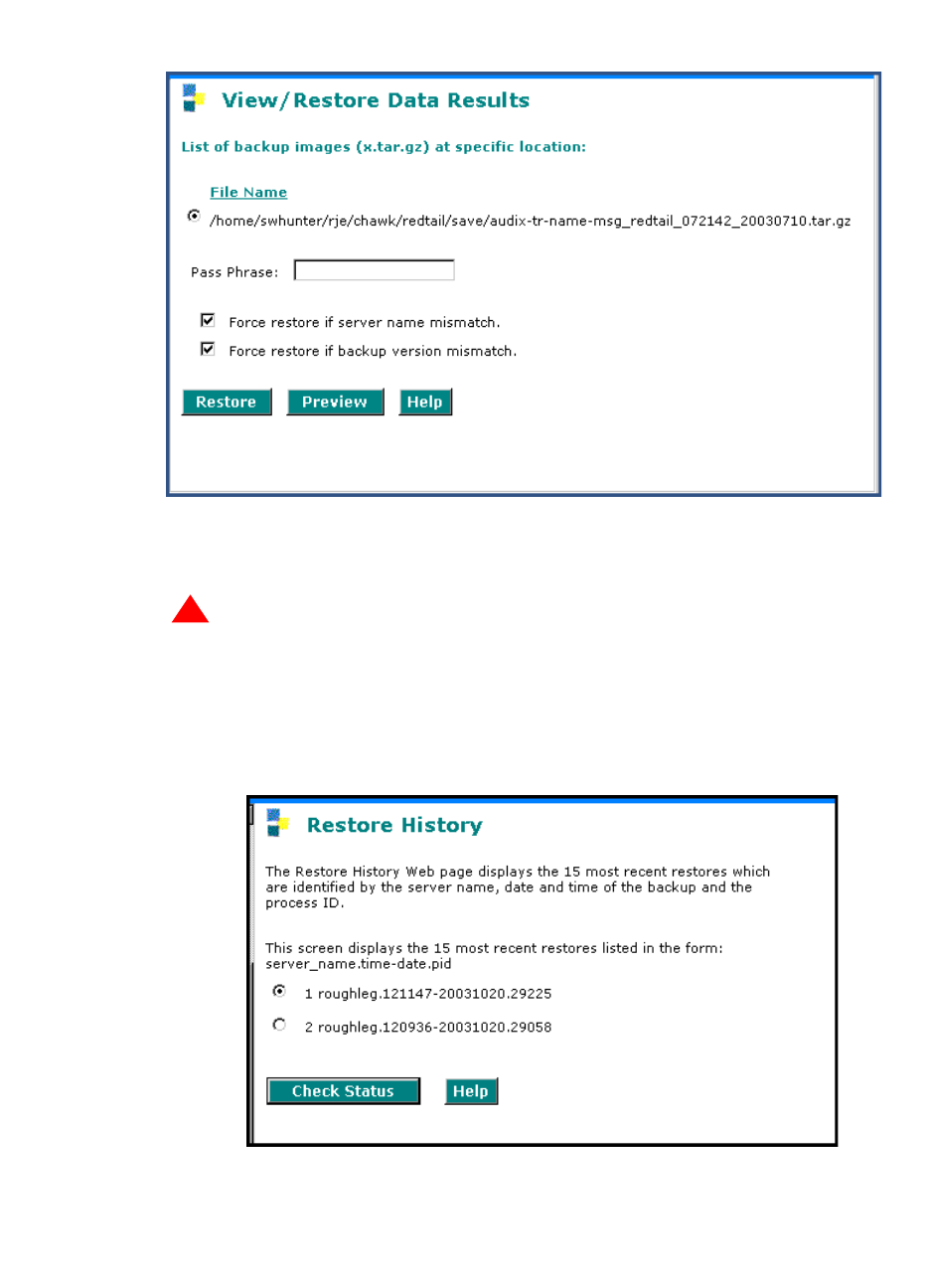
5Upgrading an Existing G700 with an S8300 — R1.x to R2.0
If the S8300 is Using IA770
258 Installation and Upgrades for G700 and S8300
December 2003
bSelect FTP and enter the information for the location of the backed up AUDIX
Translations, Names, and Messages and click View.
cSelect the AUDIX Translations, Names, and Messages backup set, select both Force
options, and click Restore.
!
WARNING:
AUDIX announcement sets from Communication Manager 1.x releases are not
compatible with Release 2.0. Do not restore 1.x announcements onto a 2.0 system.
dTo monitor the restore progress:
— select Restore History
—select the backup set being restored and click Check Status
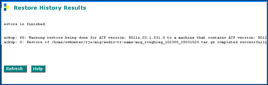
5
Upgrading an Existing G700 with an S8300 — R1.x to R2.0
If the S8300 is Using IA770
Installation and Upgrades for G700 and S8300 259
December 2003
—click Refresh periodically until "Completed Successfully" appears
7Restart Communication Manager:
aOpen a Telnet session to the S8300 and type start -ac
bEnsure that all Communication Manager processes come up.
cAfter all Communication Manager processes are up, monitor the startup of IA770:
Type watch /VM/bin/ss
Press Ctrl+C to break out of the watch command.
8Run an IA770 sanity test:
aType /vs/bin/display
bAll states should be "Inserv" with an associate phone number.
cRetrieve the test message saved before the upgrade.
Save Translations
1In the telnet session, open a SAT session.
2Log in again as craft.
3Type save translation and press Enter.
When the save is finished, the system displays the message, Command successfully completed.
4If an IA770 post-upgrade update (patch) is required, see the IA770 documentation for procedures
to install the update.
Install IA770 update (patch) files, if any
If IA770 is being used, a post-upgrade update (patch) for IA770 may be required. See the IA770
documentation for procedures to install an update. The documentation can be found on the Avaya
Support Web Site at http://support.avaya.com. Then click on Product Documentation and then
Messaging and scroll down to the INTUITY document links.

5Upgrading an Existing G700 with an S8300 — R1.x to R2.0
Complete the Upgrade Process (S8300 is the Primary Controller)
260 Installation and Upgrades for G700 and S8300
December 2003
Complete the Upgrade Process
(S8300 is the Primary Controller)
Telnet to the S8300 (primary controller) and open a SAT session to complete the following procedures.
Check Media Modules
1Type list configuration all and press Enter.
2Verify that the software is communicating with all media modules and that all media modules are
listed in the reports.
3Make test telephone calls to verify that Communication Manager is working.
Enable Scheduled Maintenance
1Type change system-parameters maintenance and press Enter.
2Ensure that the Start Time and Stop Time fields’ administration is the same as before the
upgrade.
Busy Out Trunks
1Busy out trunks that were busied out before the upgrade (see Pre-Upgrade Tasks — If the S8300
is the Primary Controller on page 221).
Check for Translation Corruption
1Type newterm and press Enter.
If you do not get a login prompt and see the following message:
Warning: Translation corruption detected
follow the normal escalation procedure for translation corruption before continuing the upgrade.
Resolve Alarms
1On the Maintenance Web Interface, under Alarms click Current Alarms to examine the alarm
log.
2If any alarms are listed, click Clear All.
3Resolve new alarms since the upgrade through Communication Manager using the appropriate
maintenance book.
5
Upgrading an Existing G700 with an S8300 — R1.x to R2.0
Complete the Upgrade Process (S8300 is the Primary Controller)
Installation and Upgrades for G700 and S8300 261
December 2003
Re-enable Alarm Origination
1Telnet to the S8300 and log on.
2At the command prompt, type almenable -d b -s y, where
-d b sets the dialout option to both (numbers)
-s y enables SNMP alarm origination
3Type almenable (without any options) to verify that alarm origination status.
Back up the System
Using the Maintenance Web Interface, back up the system as you did before the upgrade selecting Save
Translations and all backup sets.
Restart LSPs (if any)
To restart Communication Manager on the LSP after the upgrade:
1Open a Telnet session on the S8300 (LSP).
2Telnet to the LSP.
3At the command line, type start -ac and press Enter.
This completes the upgrade process for a G700 with an S8300.

5Upgrading an Existing G700 with an S8300 — R1.x to R2.0
Complete the Upgrade Process (S8300 is the Primary Controller)
262 Installation and Upgrades for G700 and S8300
December 2003

6
Upgrading an Existing G700 with an S8300 — R2.0 to R2.x
Installation and Upgrades for G700 and S8300 263
December 2003
6Upgrading an Existing G700
with an S8300 —
R2.0 to R2.x
This chapter covers the procedures to upgrade the software on an installed Avaya S8300 Media Server
from release 2.0 to a later (2.x) release. It also covers the procedures to upgrade the firmware on an
installed Avaya G700 Media Gateway. The S8300 can be configured as either the primary controller or as
a local survivable processor (LSP). When the S8300 is an LSP, the primary controller, running Avaya
Communication Manager, can be either another S8300 or an Avaya S8500 or S8700 Media Server.
The steps to upgrade an S8300 configured as an LSP are the same as the steps to upgrade an S8300
configured as the primary controller, with the following additional considerations:
•The version of Communication Manager running on the LSP must be the same as, or later than,
the version running on the primary controller.
•If upgrading both the primary controller and the LSP, the LSP must be upgraded first. Then, with
Communication Manager turned off on the LSP, the primary controller is upgraded.
CAUTION:
This upgrade procedure requires a service interruption of approximately 2 hours, or up to
4 hours if IA770 is being used.
Tip:
The Upgrade Tool performs the following tasks automatically:
Upgrade the S8300 on page 282
Determine Which Firmware to Install on the G700 on page 292
Upgrade the Firmware on the G700 on page 291.
System Access
To access the S8300 on-site, you will normally connect the technician’s laptop directly to the Services
port on the S8300 using a crossover cable. See Connection and Login Methods on page 45 for
instructions on accessing the S8300 and G700.

6Upgrading an Existing G700 with an S8300 — R2.0 to R2.x
Task Summary
264 Installation and Upgrades for G700 and S8300
December 2003
Task Summary
Before Going to the Site
•Get Planning Forms from the Project Manager on page 266
•Get the Serial Number of the G700, if Necessary on page 266
•Check Number of Allocated Ports on page 266
•Check FTP Server for Backing up Data on page 267
•Get Software/Firmware Files on page 267
•Complete the RFA Process (Obtain license and password file) on page 267
•Download Software Update (patch) file to Your Laptop, if Necessary on page 269
On-Site Preparation Tasks
If the S8300 is a Primary Controller
•Pre-Upgrade Tasks — If the Target S8300 is the Primary Controller on page 271
•Get IA770 (AUDIX) Data and Stop IA770 (if IA770 is being used) on page 273
S8300 is Either a Primary Controller or LSP
•Back up recovery system files on page 274
•Install New License and Authentication Files, If Necessary on page 276
•Run Save Translations (Only If New License and/or Authentication Files Installed) on page 279
•Transfer Files from a CD or Laptop on page 279
S8300 Upgrade Tasks
•Install New Software on page 282
•Make the Upgrade Permanent on page 289
•Install Post-Upgrade Communication Manager Update File from Your Laptop, if any on page 290
•Install IA770 update (patch) files, if any on page 290
G700 Upgrade Using the Wizards
•Using the Installation Wizard on page 291
•Using the Upgrade Tool on page 291

6
Upgrading an Existing G700 with an S8300 — R2.0 to R2.x
Task Summary
Installation and Upgrades for G700 and S8300 265
December 2003
G700 Manual Upgrade Tasks
G700 Pre-Upgrade Tasks
•Verify the Contents of the tftpboot Directory on page 291
•Determine Which Firmware to Install on the G700 on page 292
G700 Upgrade Tasks
•Install New Firmware on the P330 Stack Processor on page 293
•Install New Firmware on the G700 Media Gateway Processor on page 294
•Install New Firmware on the Media Modules on page 295
•Install New Firmware on Other G700 Media Gateways on page 297
Post-upgrade Tasks
•Check Media Modules on page 298
•Enable Scheduled Maintenance on page 298
•Busy Out Trunks on page 298
•Check for Translation Corruption on page 298
•Resolve Alarms on page 298
•Re-enable Alarm Origination on page 298
•Back up the System on page 299
•Restart LSPs (if any) on page 299

6Upgrading an Existing G700 with an S8300 — R2.0 to R2.x
Before Going to the Customer Site
266 Installation and Upgrades for G700 and S8300
December 2003
Before Going to the Customer Site
The procedures in this section should be completed before going to the customer site or before starting a
remote installation.
Collect Upgrade Information
Get Planning Forms from the Project Manager
The project manager should provide you with forms that contain all the information needed to prepare for
this installation. The information primarily consists of IP addresses, subnet mask addresses, logins,
passwords, people to contact, the type of system, and equipment you need to install. Verify that the
information provided by the project manager includes all the information requested in your planning
forms.
Tip:
Appendix B, “Information Checklists” provides several checklists to help you gather the
installation and upgrade information.
Get the Serial Number of the G700,
if Necessary
For an upgrade of an existing G700, the existing license file can usually be reused. However, if the
customer is adding feature functionality (for example, adding BRI trunks), or if the upgrade is between
major releases (for example, 1.3 to 2.0), you will need the serial number of the G700. To get this number,
ask the customer’s administrator to log in to the S8300 web page and select View License Status from
the main menu to display the serial number.
For a new installation, you need the serial number of the G700 Media Gateway in order to complete the
creation of the customer’s license file on the rfa.avaya.com web site. To get this number, look for the
serial number sticker on the back of the G700 chassis. If the unit is delivered directly to the customer and
you will not have phone or LAN line access from the customer site to access the rfa.avaya.com web site,
this task will require a preliminary trip to the customer site.
Check Number of Allocated Ports
Release 2.0 of Communication Manager supports a maximum of 900 ports if the S8300 is a primary
controller. If the existing system has more than 900 ports allocated, then there may be a problem with the
upgrade and you need to escalate. Ask the customer to check the system for the maximum number of
ports.
Access the SAT command interface
1Access the S8300 media server using a terminal emulation application or Avaya Site
Administration. Use 192.11.13.6 as the address and 5023 as the port.
2Log on as craft.

6
Upgrading an Existing G700 with an S8300 — R2.0 to R2.x
Before Going to the Customer Site
Installation and Upgrades for G700 and S8300 267
December 2003
3Type display system-parameters customer options and press Enter.
4Verify that the Maximum Ports: field is 900 or less.
Check FTP Server for Backing up Data
During the installation and upgrade procedures, you will need to back up the system data to an FTP
server. Normally, you will use an FTP server on the customer’s LAN for backups. To do this, you will
need information on how to get to the backup location — login ID and password, and the IP address and
directory path on the FTP server. Check with your project manager or the customer for this information.
CAUTION:
Before going to the customer site, make sure that you can use a customer server for
backups.
Get Software/Firmware Files
The file containing the S8300 software and G700 firmware has a *.tar extension. The *.tar file is on a
CD-ROM that you take to the site. Additional files that may be needed are the most recent versions of the
software update (patch) files and G700 firmware files. You may need to obtain these files from the Avaya
Support web site.
Complete the RFA Process (Obtain license and
password file)
Every S8300 media server and local survivable processor (LSP) requires a current and correct version of
a license file in order to provide the expected call-processing service.
The license file specifies the features and services that are available on the S8300 media server, such as
the number of ports purchased. The license file contains a software version number, hardware serial
number, expiration date, and feature mask. The license file is reinstalled to add or remove call-processing
features. New license files may be required when upgrade software is installed.
The Avaya authentication file contains the logins and passwords to access the S8300 media server. This
file is updated regularly by Avaya services personnel, if the customer has a maintenance contract. All
access to Communication Manager from any login is blocked unless a valid authentication file is present
on the S8300 media server.
A new license file and the Avaya authentication file may be installed independently of each other or any
other server upgrades.
NOTE:
For an upgrade, you do not normally need to install a new authentication file (with a .pwd
extension). However, if one is required, follow the same steps as with a license file.

6Upgrading an Existing G700 with an S8300 — R2.0 to R2.x
Before Going to the Customer Site
268 Installation and Upgrades for G700 and S8300
December 2003
License File and Communication Manager
Versions for a Local Survivable Processor
The license file of the S8300 as an LSP must have a feature set that is equal to or greater than that of the
media server that acts as primary controller (an S8300 or S8700). This is necessary so that if control
passes to the LSP, it can allow the same level of call processing as that of the primary controller.
Additionally, the LSP must have a version of Communication Manager that is identical to that of the
primary controller.
The license file requirements of the LSP should be identified in your planning documentation.
Complete and Download the License File to
Your Laptop
1Use Windows File Explorer or another file management program to create a directory on your
laptop for storing license and authentication files (for example, C:\licenses).
2Access the Internet from your laptop and go to rfa.avaya.com.
3Use the System ID or the SAP ID of the customer to locate the license and authentication files for
the customer.
4Check that the license and authentication files are complete. You might need to add the serial
number of the customer’s G700.
5If the files are not complete, complete them.
6Use the download or E-mail capabilities of the RFA web site to download the license and
authentication files to your laptop.
Run the Automatic Registration Tool (ART)
for the INADS IP Address, if Necessary
This step is normally not necessary for an upgrade of an existing system.
NOTE:
ART is available only to Avaya associates. Business Partners call 800-295-0099.
The ART tool is a software tool that generates an IP address for a customer’s INADS alarming modem.
This IP address is required for configuring the S8300’s modem for alarming.
NOTE:
You must generate a license and authentication file before you use the ART tool. Also, the
ART process is available only to Avaya personnel. You need an ART login ID and
password, which you can set up at the ART web site. Non-Avaya personnel must contact
their service support or customer care center for INADS addresses, if required.
1Access the ART web site on your laptop at http://art.dr.avaya.com.
2Select Administer S8x00 Server products for installation script, log in, enter the customer
information, select Installation Script, and click Start Installation script & IP Addr Admin.
A script file is created and downloaded or emailed to you.
3You can use the installation script to automatically set up an IP address and other alarming
parameters.

6
Upgrading an Existing G700 with an S8300 — R2.0 to R2.x
Before Going to the Customer Site
Installation and Upgrades for G700 and S8300 269
December 2003
Obtain the Static Craft Password
After installing new software and new Authentication file, you will need to use a static craft password to
access the customer’s system. This static password will enable you to log in to the S8300 with a direct
connection to the Services port without the ASG challenge/response. To obtain the static password, call
the ASG Conversant number, 800-248-1234 or 720-444-5557 (or 877-295-0099 for Avaya Business
Partners), and follow the prompts to get the password. In addition to your credentials, you will need to
enter the customer’s Product ID or the FL or IL number.
Download Software Update (patch) file
to Your Laptop, if Necessary
Skip to the next section if a software update is not required for this installation or upgrade, or if the
software for the required updates are on your software CD.
If one or more updates are required for this installation or upgrade procedure, and the update file is not on
your software CD, download the update file from the Avaya Support web site to your laptop:
1On your laptop, create a directory to store the file (for example, c:\S8300download).
2Connect to the LAN using a browser on your laptop or the customer’s PC and access
http://www.avaya.com/support on the Internet to copy the required Communication Manager
update file to the laptop.
3At the Avaya support site, select the following sequence of links:
— Software & Firmware Downloads
— G700 Media Gateway & S8300 Media Server
— Software Downloads
—Avaya Communication Manager Software Updates for MV x.x.x (where x.x.x is the
release that is currently running on the S8300)
4Locate the file name that matches the load listed in your planning documentation. The file name
ends with .tar.gz (for example only, 03.0.526.5-5767.tar.gz).
5Double-click the file name. The system displays a File Download window.
6Click on Save this file to disk.
Save the file to an appropriate directory on your laptop.

6Upgrading an Existing G700 with an S8300 — R2.0 to R2.x
On-site Preparation for the Upgrade
270 Installation and Upgrades for G700 and S8300
December 2003
On-site Preparation for the Upgrade
Perform these tasks before starting the software upgrade on the S8300.
Access to the S8300
To perform the installation and upgrade procedures you will need to connect your laptop to the S8300
Services port using a crossover cable. You will use both Telnet and the Maintenance Web Interface to
perform the procedures.
For a direct connection to the S8300 Services port, your laptop must be properly configured. See Laptop
Configuration for a Direct Connection to the Services Port on page 47.
Access the S8300 via Telnet
To access the S8300 using Telnet, you
1Click Start > Run to open the Run dialog box.
2Type telnet 192.11.13.6 and press Enter.
3Log in as craft or dadmin.
Access the S8300 via the Maintenance Web
interface
1Launch the Web browser.
2Type 192.11.13.6 in the Address field to open the logon page.
3Log on as craft or dadmin when prompted.
4Click Launch Maintenance Web Interface to get to the Main Menu.
Access SAT
1From the bash CLI, type SAT and press Enter.
Or, to open SAT directly from your laptop,
click Start > Run and type telnet 192.11.13.6 5023 and press Enter.
2Log in as craft or dadmin.
3Enter w2ktt for the Terminal Type (if you are running Windows 2000 on your laptop).
4Accept the default (y) for Suppress Alarm Origination.

6
Upgrading an Existing G700 with an S8300 — R2.0 to R2.x
On-site Preparation for the Upgrade
Installation and Upgrades for G700 and S8300 271
December 2003
Pre-Upgrade Tasks — If the Target S8300 is the
Primary Controller
If the S8300 is configured as an LSP, skip to Upgrade the S8300 on page 282.
CAUTION:
If you are upgrading an S8300 primary controller that has LSPs registered to it, the LSPs
must be upgraded before the primary controller. (You can use the SAT command, list
media-gateway, to see if there are LSPs registered to the S8300.)
Perform the following procedures if you are upgrading an S8300 that is configured as a primary
controller.
NOTE:
It is no longer necessary to disable Terminal Translation Initialization (TTI) before an
upgrade or to enable it after an upgrade.
Clear Alarms
1On the Maintenance Web Interface under Alarms and Notification (Alarms for R2.0), click View
Current Alarms (Current Alarms for R2.0).
2If no alarms are listed, skip the next two steps.
3If alarms are listed, click Clear All.
4Resolve any remaining major alarms through the Communication Manager SAT.
Check Link Status
1Open a SAT session.
2Enter display communication-interface links.
3Note all administered links.
4Enter status link number for each administered link.
5Enter list signaling group.
6Note the signaling groups listed by number.
7For each of the signaling groups listed, enter status signaling group number.
8Make a note of any links that are down.
Record All Busyouts
1At the SAT prompt, type display errors and press Enter.
2Look for type 18 errors and record any trunks that are busied out — you will return them to their
busy-out state after the upgrade.

6Upgrading an Existing G700 with an S8300 — R2.0 to R2.x
On-site Preparation for the Upgrade
272 Installation and Upgrades for G700 and S8300
December 2003
Disable Scheduled Maintenance
To prevent scheduled daily maintenance from interfering with the upgrade:
1At the SAT prompt, type change system-parameters maintenance and press Enter.
2If scheduled maintenance is in progress, set the Stop Time field to 1 minute after the current
time.
or
If scheduled maintenance is not in progress, set the Start Time field to a time after the
upgrade will be completed.
For example, if you start the upgrade at 8:00 P.M. and the upgrade takes 90 minutes, set the
Start Time field to 21:30.
Check for Translation Corruption
1At the SAT prompt, type newterm and press Enter.
2Enter your terminal type and press Enter.
If you see the following message: Warning: Translation corruption found, then follow the normal
escalation procedure for translation corruption before continuing the upgrade.
Stop the LSPs (if applicable)
Skip this procedure if no LSPs are registered to the S8300.
For configurations with LSPs, the LSPs and the primary controller (S8300, S8500, or S8700) must run
the same version Communication Manager. Therefore, an upgrade to an LSP is usually accompanied by
an upgrade of the primary controller. You should upgrade the LSP before you upgrade the primary
controller.
Before you upgrade the primary controller, you need to shut down Communication Manager on the LSPs.
This prevents the phones and other endpoints attached to the G700 from trying to register with the LSPs
while you are upgrading the primary controller.
To stop Communication Manager on an LSP:
1Open a telnet session on the S8300 (LSP).
2Telnet to the LSP.
3At the command line, type stop -acfn and press Enter.
The S8300 (LSP) shuts down Communication Manager.
CAUTION:
The LSP’s Communication Manager must remain shutdown while you upgrade the
primary Controller. When you complete the primary controller upgrade, run save
translation on the primary controller before restarting Communication Manager on the
LSP. The save translations process will automatically cause the G700’s endpoints to
reregister with the primary controller.
After the primary controller has been upgraded, you need to restart the LSPs.

6
Upgrading an Existing G700 with an S8300 — R2.0 to R2.x
On-site Preparation for the Upgrade
Installation and Upgrades for G700 and S8300 273
December 2003
Disable Alarm Origination
If alarm origination is enabled during the upgrade, unnecessary alarms will be sent to the Operations
Support System (OSS) destination number(s). Even if you selected "Suppress Alarm Origination" when
you logged in, alarm origination will be automatically re-enabled when the system reboots after the
software upgrade. Use this procedure to prevent alarm origination from being re-enabled after reboot.
CAUTION:
If you do not disable Alarm Origination, the system can generate alarms during the
upgrade, resulting in unnecessary trouble tickets.
To prevent alarm outcalling:
1Logoff the SAT session
2At the command prompt, type almenable -d n -s n, where
-d n sets the dialout option to neither (number)
-s n disables SNMP alarm origination
NOTE:
Be sure to reset alarm origination after the upgrade.
3Type almenable (without any options) to verify the alarm origination status. You should see:
incoming: enable
Dial Out Alarm Origination: neither
SNMP Alarm Origination: N
Get IA770 (AUDIX) Data and Stop IA770
(if IA770 is being used)
If IA770 is being used, you need to collect some data, leave a test message, and shut down IA770 before
backing up the files.
1To test IA770 after the migration, write down the number of a test voice mailbox, or create one if
none exists. Also write down the number of the IA770 hunt group.
2Leave a message on the test mailbox that will be retrieved after the migration.
3Telnet to 192.11.13.6 and log in as craft or dadmin.
4Type stop -s Audix and press Enter to shut down AUDIX.
The shutdown will take a few minutes.
5Type watch /VM/bin/ss and press Enter to monitor the shutdown.
When the shutdown is complete, you will see only the voicemail and audit processes. For
example:
voicemail:(10)
audit http:(9)
Press Ctrl+C to break out of the watch command.

6Upgrading an Existing G700 with an S8300 — R2.0 to R2.x
On-site Preparation for the Upgrade
274 Installation and Upgrades for G700 and S8300
December 2003
6Type /vs/bin/util/vs_status and press Enter to verify that AUDIX is shut down. When AUDIX is
shut down, you will see "voice system is down."
NOTE:
After the S8300 upgrade, you must upgrade the G700 and media module firmware before
restarting IA770.
Back up recovery system files
Before installing the S8300 software, you should back up the system data in case there’s a need to back
out of the upgrade. You should back up to an FTP server on the customer’s network. To do this, you need
an FTP address and directory path and a user ID and password to access the customer’s network. Check
with your project manager or the customer for this information. You can also back up the system data to
the S8300 hard drive.
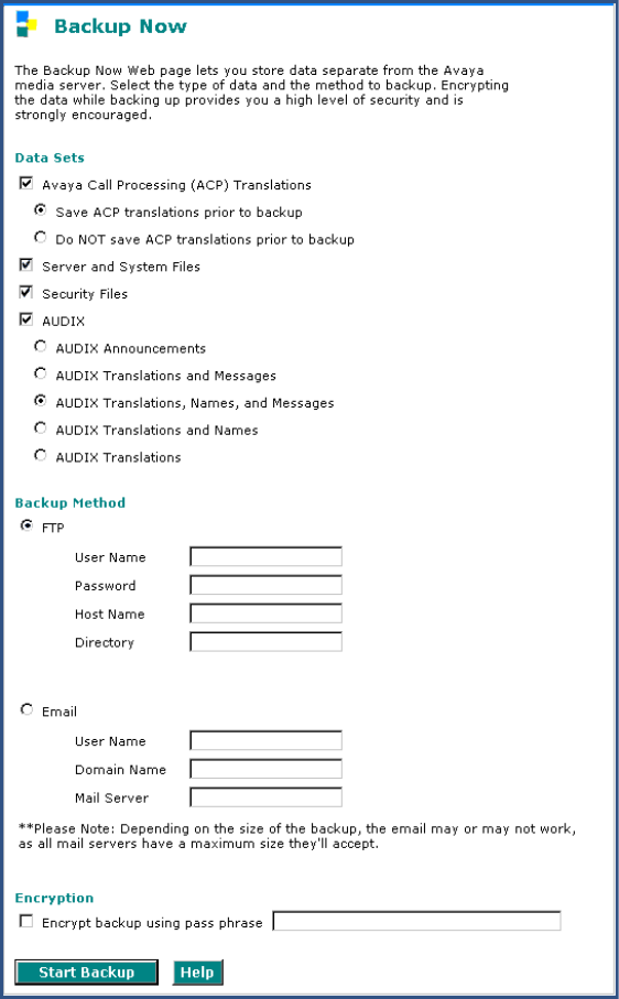
6
Upgrading an Existing G700 with an S8300 — R2.0 to R2.x
On-site Preparation for the Upgrade
Installation and Upgrades for G700 and S8300 275
December 2003
Back up data
1Under Data Backup/Restore, click Backup Now.
2Select all data sets:
•Avaya Call Processing (ACP) Translations
•Save ACP translations prior (do not save ACP translations if this is an LSP).
•Server and System Files
•Security Files
3If the AUDIX options are available, select AUDIX and select AUDIX Translations, Names, and
Messages
4Select the FTP for the backup method and fill in the appropriate fields with information provided
by the customer.

6Upgrading an Existing G700 with an S8300 — R2.0 to R2.x
On-site Preparation for the Upgrade
276 Installation and Upgrades for G700 and S8300
December 2003
5Click Start Backup to back up the files.
6If the AUDIX options are available, repeat Steps 3–5 for AUDIX Announcements. The
announcements cannot be restored to the 2.0 system but they should be backed up in case it is
necessary to revert to the 1.x system.
Install New License and
Authentication Files, If Necessary
Skip to Transfer Files from a CD or Laptop on page 279 if you are not installing a new license or
password file.
For an upgrade, you need to load a new license file only when upgrading to a new major release of
Communication Manager (for example, R2.x to R3.x) or when the feature set has changed.
NOTE:
If the S8300 is already set up for remote access, Avaya services personnel can copy new
license and authentication files directly into the FTP directory on the server. Avaya
personnel will notify you when the new files are in place as agreed (for example, by
telephone or E-mail). After they are loaded into the FTP directory, install them using the
License File and Authentication File screens from the S8300 main menu web-page.
NOTE:
Before an upload or download, be sure the S8300 FTP directory (/var/home/ftp/pub)
contains no files with a .pwd or .lic extension. Only one of these files can exist in a
directory. If one exists, move, rename, or delete it.
If Necessary, Rename Old License and
Authentication Files from S8300 FTP
Directory
Before an upload or download, be sure the S8300 FTP directory (/var/home/ftp/pub) contains no files
with a .pwd or .lic extension. Only one of these files can exist in a directory. If one exists, move, rename,
or delete it.
1Log in to a telnet session on the S8300.
2At the command line, type cd /var/home/ftp/pub and press Enter.
3Type ls -l and press Enter.
The system displays a list of files.
4Check the list of files to see if any files with .lic or .pwd suffixes are in the directory.
5If any .lic or .pwd files exist, rename them. For example, type mv <filename>.lic <filename>
.lic.old or mv <filename>.pwd <filename> .pwd.old and press Enter.
6Leave the telnet session open for a later task.
Load License File (from Your Laptop)
Use this procedure to transfer the license and password files from the CD or hard drive on your laptop to
the S8300 hard drive.
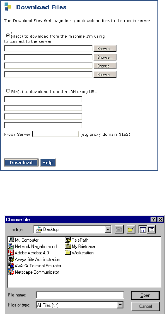
6
Upgrading an Existing G700 with an S8300 — R2.0 to R2.x
On-site Preparation for the Upgrade
Installation and Upgrades for G700 and S8300 277
December 2003
1Log on to the S8300 Web Interface
2In the main menu under Miscellaneous, click Download Files.
Download Files Screen
3Select "Files to download from the machine I’m using to connect to the server" and click Browse
for the first field.
The S8300 displays the Choose File screen, which allows you to select files from your laptop.
Choose File Screen
4Locate the customer's license (.lic) file.
5When you have selected the .lic file, click Open in the dialog box.
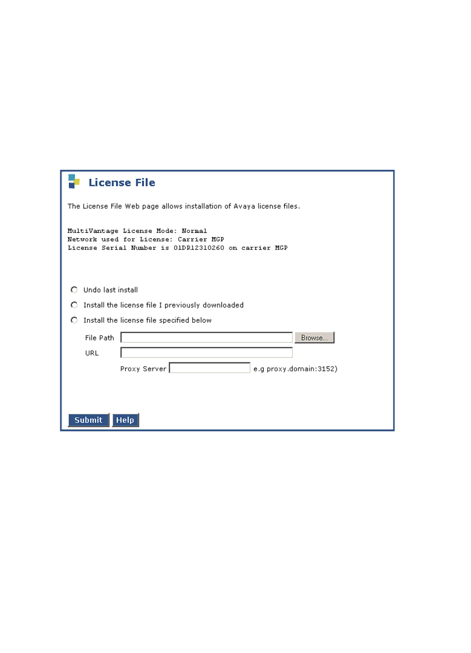
6Upgrading an Existing G700 with an S8300 — R2.0 to R2.x
On-site Preparation for the Upgrade
278 Installation and Upgrades for G700 and S8300
December 2003
6Click Browse for the second field.
7Locate the customer’s .pwd file on your laptop.
8When you have selected the .pwd file, click Open in the dialog box.
9When you have finished entering the files to be uploaded, click Load File.
When the files are successfully transferred, the system displays the status screen.
If Necessary, Install License and
Authentication Files
1Under Security, select License File
License File Screen
2Select "Install the license file I previously downloaded" and click Submit.
The system tells you the license is installed successfully.
3Under Security, select Authentication File.
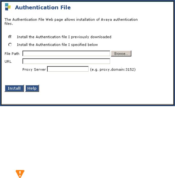
6
Upgrading an Existing G700 with an S8300 — R2.0 to R2.x
On-site Preparation for the Upgrade
Installation and Upgrades for G700 and S8300 279
December 2003
Install Authentication Screen
4Select "Install the Authentication file I previously downloades" and click Install.
The system tells you the authentication is installed successfully
Run Save Translations
(Only If New License and/or Authentication
Files Installed)
CAUTION:
This procedure saves the official passwords for the customer’s system. If you fail to perform
this step now, you may be irretrievably locked out of the system later in the installation when
the system reboots.
1In the telnet session, open a SAT session. and log in again as craft (or dadmin).
2At the SAT prompt, type save translation and press Enter. When the save is finished, the system
displays the message, Command successfully completed.
Transfer Files from a CD or Laptop
Normally, during an upgrade, you will have the CD-ROM that contains the latest software to install. The
latest software for the S8300 has a file name that has a .tar extension and reflects the most recent load of
software (For example only: S8300-02.0-00.0.218.6.tar; for systems with IA770, the filename would be
similar to S8300msg-02.0-00.0.218.6.tar). The latest update (patch) software for Communication
Manager has a .tar.gz extension and a file name that reflects the most recent load of software (for
example, 03.0.110.4-4925.tar.gz).
This .tar file will also contain the most recent firmware for the G700 Media Gateway, the various media
modules, and the P330 stack processor.
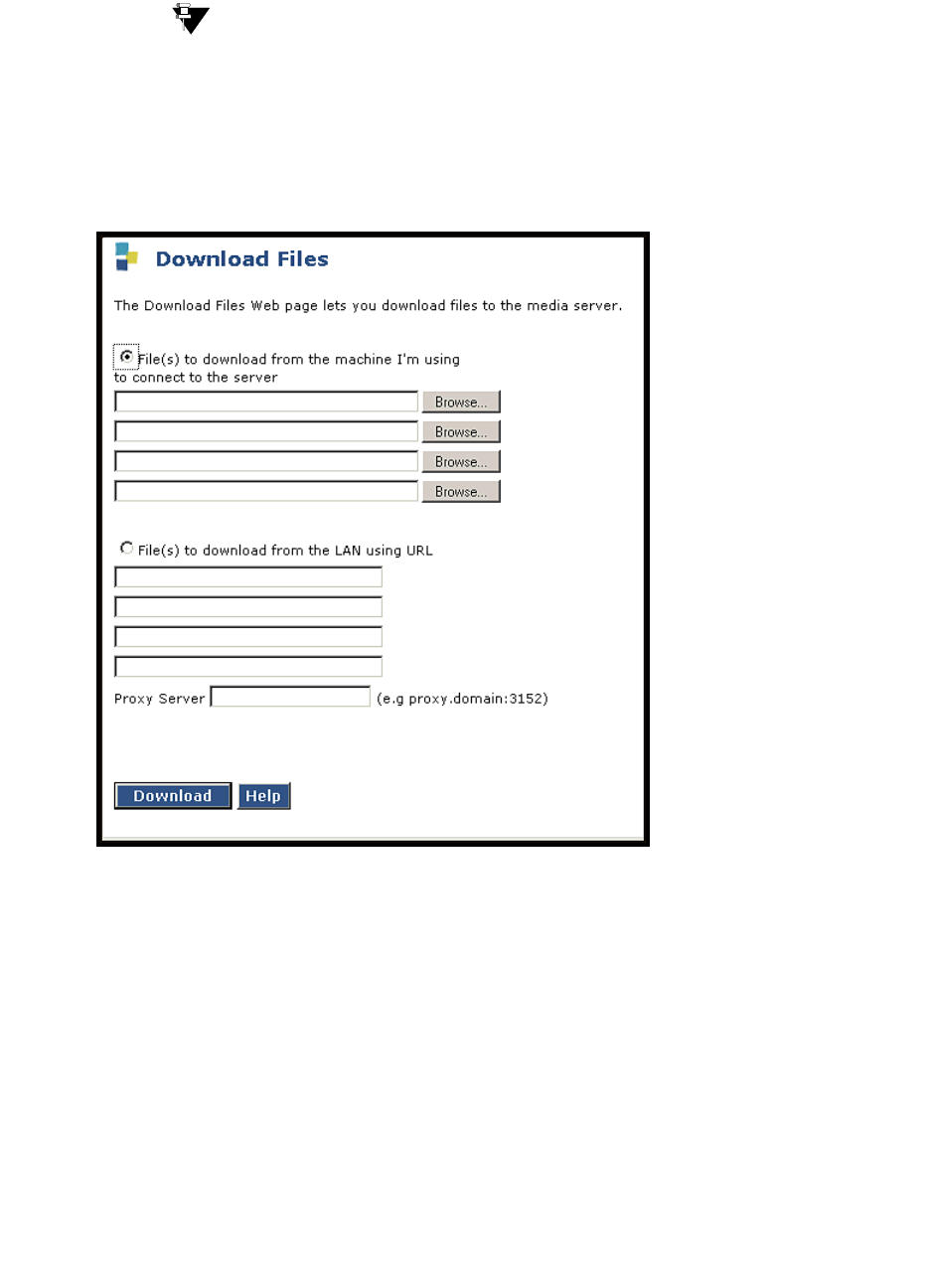
6Upgrading an Existing G700 with an S8300 — R2.0 to R2.x
On-site Preparation for the Upgrade
280 Installation and Upgrades for G700 and S8300
December 2003
Tip:
The Avaya Installation Wizard performs tasks automatically starting with this section.
1Log in to the S8300 Web interface.
2Choose Download Files under Miscellaneous on the left pane of the main menu.
Download Files Screen
3Select "Files to download from the machine I’m using to connect to the server," then click
Browse for the first file. The S8300 displays the Choose File window, which allows you to select
files from your laptop.
4Browse to the tarfiles directory on the CD (or to where the .tar files are stored on your laptop).
Double-click the filename of the .tar file for the upgrade software (for example, S8300-02.0-
00.0.219.1.tar or S8300msg-02.0-00.0.219.1.tar if using IA770). You need only one .tar file for
the upgrade software.
5Repeat the previous two steps for each additional file that you want to upload. (For example, the
lastest software update file, if any).
6Click Download.
When the files are successfully transferred, the system displays the Download Files Results
screen with the following message: "The following files have been successfully uploaded to the
server."

6
Upgrading an Existing G700 with an S8300 — R2.0 to R2.x
On-site Preparation for the Upgrade
Installation and Upgrades for G700 and S8300 281
December 2003
CAUTION:
At this point you are finished with the software CD-ROM. Remove the CD from your
laptop now to avoid possible problems the next time your laptop is rebooted.

6Upgrading an Existing G700 with an S8300 — R2.0 to R2.x
Upgrade the S8300
282 Installation and Upgrades for G700 and S8300
December 2003
Upgrade the S8300
This section describes the procedures to upgrade the S8300 Media Server from Release 2.0 of
Communication Manager to a later release. To upgrade from a pre-2.0 release to 2.0, use the procedures
in Chapter 5, “Upgrading an Existing G700 with an S8300 — R1.x to R2.0”.
Install the Upgrade Software
Using the Wizard
You can complete the tasks in this section manually, as described. However, these tasks can be completed
most efficiently by using the Avaya Installation Wizard or the Upgrade Tool. If the S8300 is a primary
controller, use the Installation Wizard. If the S8300 is one of several LSPs controlled by the same primary
controller, use the Upgrade Tool.
To use the Installation Wizard, go to the Integrated Management main menu and click Launch Avaya
Installation Wizard. To use the Upgrade Tool, go to the Integrated Management main menu and click
Launch Avaya Upgrade Tool.
Manual Installation
If you are not using the Avaya Installation Wizard or Upgrade Tool, follow the steps in this section to
upgrade the S8300 to the most recent load of software.
CAUTION:
For a new installation, be sure to set the time and time zone before installing the S8300
software. Failure to do so may cause network problems.
Install New Software
1Launch the Maintenance Web Interface.
2Choose Install New Software under Server Upgrades from the left pane of the main menu.
The S8300 displays the Install New Software screen.
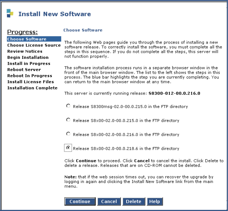
6
Upgrading an Existing G700 with an S8300 — R2.0 to R2.x
Upgrade the S8300
Installation and Upgrades for G700 and S8300 283
December 2003
Choose Software Screen
3 On the Choose Software screen, select the software release number that you want to install (for
example, the release listed in your planning documentation). Click Continue.
The S8300 displays the Choose License Source screen.
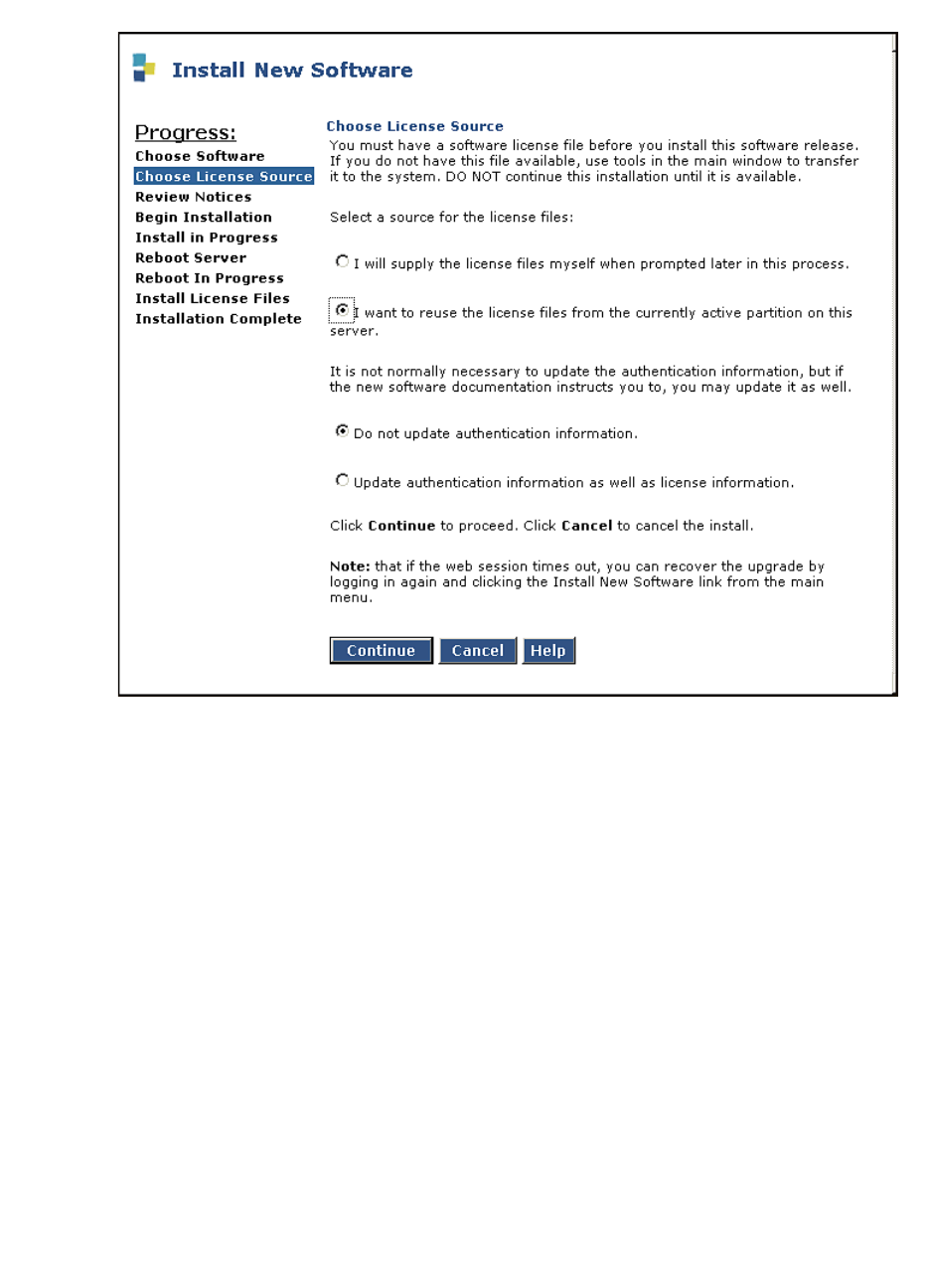
6Upgrading an Existing G700 with an S8300 — R2.0 to R2.x
Upgrade the S8300
284 Installation and Upgrades for G700 and S8300
December 2003
Choose License Source Screen
4If you have installed the license and authentication files, select the following:
— I want to reuse the license files from the currently active partition on this server.
—Do not update authentication information.
For a normal installation, the license and authentication files should have been installed at this
point. If these files have not been installed, select the following:
—I will supply the license/authentication files myself when prompted later in this
process.
—Update authentication information as well as license information.
5Click Continue. The system displays the Review Notices screen.

6
Upgrading an Existing G700 with an S8300 — R2.0 to R2.x
Upgrade the S8300
Installation and Upgrades for G700 and S8300 285
December 2003
Review Notices Screen
6For a new installation, or if you previously ran a backup, you do not need to run a backup at this
time. If your planning documents instruct you to enable Tripwire, follow the instructions to reset
the signature database.
7Click Continue.
The S8300 displays the Begin Installation screen, which summarizes the request you have made.

6Upgrading an Existing G700 with an S8300 — R2.0 to R2.x
Upgrade the S8300
286 Installation and Upgrades for G700 and S8300
December 2003
Begin Installation Screen
8At the Begin Installation screen, click Continue.
The S8300 displays the Install in Progress screen.
Install in Progress Screen

6
Upgrading an Existing G700 with an S8300 — R2.0 to R2.x
Upgrade the S8300
Installation and Upgrades for G700 and S8300 287
December 2003
9The installation will take approximately 10 to 20 minutes. The Install in Progress screen refreshes
every 10 seconds or on demand by clicking the Refresh button. When complete, the S8300
displays the Reboot Server screen.
Reboot Server Window
10 Click Reboot.
If IA770 is being used, it may take approximately 5 minutes to shut down IA770 before the reboot
begins. The S8300 displays the Reboot in Progress screen.
Reboot in Progress Screen
NOTE:
The reboot can take 20 minutes or longer. The system does not automatically tell you
when the reboot is complete.

6Upgrading an Existing G700 with an S8300 — R2.0 to R2.x
Upgrade the S8300
288 Installation and Upgrades for G700 and S8300
December 2003
Wait 5 minutes (or about 20 minutes if running IA770) and then click Continue. If you click
Continue before the reboot is finished, the screen will display "Expired Page." If you see the
Expired Page message, refresh the browser. Or, if the Session Timeout screen appears, close the
screen, logoff, and log on again. Click the Pickup button.
You can also monitor the LEDs on the S8300 for progress on the installation. The Services port
jack should have one yellow LED on the left that stays lit. The green LED on the right flashes
until the reboot is complete.
11 When the reboot is complete, clicking Continue will display the Update Tripwire Database
screen.
12 Unless instructed in your planning documents to update the tripwire database, select "Do not
update the tripwire data base now" and click Continue.
The system displays the Installation Complete screen.
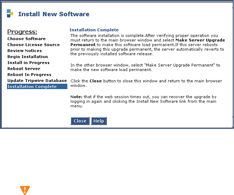
6
Upgrading an Existing G700 with an S8300 — R2.0 to R2.x
Upgrade the S8300
Installation and Upgrades for G700 and S8300 289
December 2003
Installation Complete Screen
13 Click Close. You are returned to the main menu.
14 Under Server, click Software Version to verify the new software version.
Make the Upgrade Permanent
CAUTION:
You must make the upgrade of the software permanent so that the software is recognized and
kept on the S8300. If you fail to make software permanent, then the next time you reboot, old
software will become active.
1From the S8300 main menu, under Server Upgrades click Make Upgrade Permanent .
The S8300 displays the Make Server Upgrade Permanent window.
2Click Submit.
When the new S8300 upgrade software is permanent, the S8300 displays the message: The
commit operation completed successfully.

6Upgrading an Existing G700 with an S8300 — R2.0 to R2.x
Upgrade the S8300
290 Installation and Upgrades for G700 and S8300
December 2003
Install Post-Upgrade Communication Manager
Update File from Your Laptop, if any
NOTE:
Skip this procedure if there is no Communication Manager update file to install.
CAUTION:
The software update may or may not be call-preserving.
Use a telnet session to install the software update.
1Click Start > Run to open the Run dialog box.
2Type telnet 192.11.13.6 and press Enter.
3Log in with the initial craft ID and password. (You cannot use dadmin at this point.)
4Type cd /var/home/ftp/pub and press Enter to access the pub directory.
5At the prompt, type ls -ltr and press Enter to list files in the pub directory.
The media server displays a list of files in the FTP directory. Verify that the directory contains the
Communication Manager .tar.gz file you have uploaded, if any.
6Type sudo update_unpack <update>.tar.gz, where <update> is the release or issue number of
the latest update file. (For example, 03.0.219.0-4925.tar.gz). Press Enter.
7Type update_show and press Enter to list Communication Manager files to verify the new
software file was installed.
8Type sudo update_activate <update>, where <update> is the release or issue number of the
latest software file. (For example, 03.0.219.0-4925. Do not use the .tar.gz extension at the end of
the file name). Press Enter.
The system may initiate a software reset system 4. You must wait until the restart/reset has
completed before entering additional commands.
If the system displays the message — /opt/ecs/sbin/drestart 1 4 command failed — ignore this
message.
9Type update_show again and press Enter to list Communication Manager files to verify the new
software file was applied.
Install IA770 update (patch) files, if any
If IA770 is being used, a post-upgrade update (patch) for IA770 may be required. See the IA770
documentation for procedures to install an update. The documentation can be found on the Avaya
Support Web Site at http://support.avaya.com. Then click on Product Documentation and then
Messaging and scroll down to the INTUITY document links.

6
Upgrading an Existing G700 with an S8300 — R2.0 to R2.x
Upgrade the Firmware on the G700
Installation and Upgrades for G700 and S8300 291
December 2003
Upgrade the Firmware on the G700
The tasks in this section can be completed most efficiently by using the Avaya Installation Wizard or the
Upgrade Tool. If the S8300 is a primary controller, use the Installation Wizard. If the S8300 is one of
several LSPs controlled by the same primary controller, use the Upgrade Tool. Or, in either case, you can
complete the tasks manually as described below.
Go to http://support.avaya.com/avayaiw to download job aids for using the Installation Wizard or
Upgrade Tool.
CAUTION:
If the passwords to log on to the P300 stack or the MGP have been changed from the
defaults, you must change them back to the original default passwords before using the
Installation Wizard or Upgrade Tool.
Using the Installation Wizard
On the Integrated Management main menu, click Launch Avaya Installation Wizard. To use the
Installation Wizard to upgrade firmware on the G700, be sure to select the "Upgrade a previously
installed Media Server with new software and/or Media Gateway firmware" on the Usage Options screen.
The Usage Options screen appears in the Installation Wizard after a few introductory screens.
Using the Upgrade Tool
On the Integrated Management main menu, click Launch Upgrade Tool. Follow the instruction to
upgrade the G700 and media module firmware.
Manual Upgrade Procedures
If you are using the Avaya Installation Wizard or the Upgrade Tool:
•Skip to Complete the Upgrade Process (S8300 is the Primary Controller) on page 298 if IA770 is
being used, or
•Skip to Complete the Upgrade Process (S8300 is the Primary Controller) on page 298 if IA770 is
not being used.
If you are not using the Avaya Installation Wizard or Upgrade Tool, conduct the following manual
procedures to update the firmware running on the G700 Media Gateway processors and media modules.
Verify the Contents of the tftpboot Directory
Before proceeding with the G700 firmware installation, you should check the tftpboot directory on the
TFTP server to make sure the firmware versions match those listed in the planning documentation.

6Upgrading an Existing G700 with an S8300 — R2.0 to R2.x
Upgrade the Firmware on the G700
292 Installation and Upgrades for G700 and S8300
December 2003
Determine Which Firmware to Install on the
G700
Conduct the following procedure to compare software versions running on the G700 processors and
media modules with the versions in you planning documents. If the versions do not match, new firmware
for those components is necessary.
Determine if new firmware for the P330 stack processor is necessary.
1At either the P330-1(super)# or P330-1(configure)# prompt, type dir.
The system displays the list of software.
Directory List for P300 Processor
2Check the version number (ver num) of the EW_Archive file to see if it matches the Release
Letter. If not, you must upgrade the P330 stack processor.
3Type show image version
The system displays the list of software.
Show Image Version List for P330 Processor
4Check the version number of the stack software image file in Band B to see if it matches the your
planning document. If not, you must upgrade the P330 stack processor.
Determine if new firmware is required for the MGP, VoIP Module, and installed media
modules.
1Type session mgp
2At the MG-001-1(super)# prompt, type show mg list_config
The system displays the list of software.
M# file ver num file type file location file description
-- ---- ------- ---------- ------------- ----------------
1 module-config N/A Running Conf Ram Module Configuration
1 stack-config N/A Running Conf Ram Stack Configuration
1 EW_Archive 3.8.6 SW Web Image NV-Ram WEB Download
1 Booter_Image 3.2.5 SW BootImage NV-Ram Booter Image
Mod Module-Type Bank Version
------ ----------- ---- -------
3 Avaya G700 Media Gateway A 0.0.0
3 Avaya G700 Media Gateway B 3.9.0

6
Upgrading an Existing G700 with an S8300 — R2.0 to R2.x
Upgrade the Firmware on the G700
Installation and Upgrades for G700 and S8300 293
December 2003
Show MG List_Config
3Refer to the list to check the FW vintage number of the G700. In the TYPE column, find G700,
then check the matching field in the FW VINTAGE column to see if it matches the vintage
number in your planning forms. If not, you must install new firmware on the G700 Media
Gateway. Also check if the release number in the FW VINTAGE column contains (A) or (B) to
designate the software bank. If the list shows B, you will upgrade A. If the list shows A, you will
upgrade B.
4Refer to the VOIP FW column and row for slot V0 (same row occupied by the G700 information)
to see if the number matches the VoIP firmware identified in your planning forms. If not, you
must also upgrade the G700 Media Gateway motherboard VoIP module.
NOTE:
The VoIP processor on the motherboard is upgraded using the same firmware image file
as the VoIP media modules; for example, the file mm760v8.fdl is vintage #8.
5Check the FW VINTAGE column for vintages of each of the installed Media Modules: MM710,
MM711, MM712, MM720, and/or MM760 to see if they match the FW vintages in the planning
forms. If not, you must upgrade them, as well.
Install New Firmware on the P330 Stack
Processor
Install P330 stack processor firmware
1From your S8300 telnet session, telnet back to the P330 stack processor:
Type telnet <xxx.xxx.xxx.xxx>, where <xxx.xxx.xxx.xxx> is the IP address of the P330 stack
master processor on the customer’s LAN.
1At the P330-1(configure)# prompt, type
copy tftp SW_image <file> EW_archive <ew_file> <tftp_server_address> <Module#>
where
<file> is the full-path name for the image file with format and vintage number similar to
viisa3_8_2.exe,
<ew_file> is the full-path name for the embedded web application file with format similar to
p330Tweb.3.8.6.exe,
<tftp_server_ip_address> is the IP address of the TFTP server, and
eyp
SLOT TYPE CODE SUFFIX HW VINTAGE FW VINTAGE VOIP FW
---- ------ ----- ------ ---------- ---------- -------
V0 G700 DAF1 A 00 210(B) 2
V1 ICC S8300 A 72 00 N/A
V2 DCP MM712 A 2 52 N/A
V3 ANA MM711 A 2 12 N/A
V4 DS1 MM710 A 1 54 N/A

6Upgrading an Existing G700 with an S8300 — R2.0 to R2.x
Upgrade the Firmware on the G700
294 Installation and Upgrades for G700 and S8300
December 2003
<Module#> is the number, 1 through 10, of the media gateway in the stack. If there is only one
G700 Media Gateway, the number is 1.
2To verify that the download was successful when the prompt returns:
—type
show image version <module #> and check the version number in the Version
column for Bank B.
—type
dir <module #> and check the version number in the ver num column for the
EW_Archive file.
3Type reset <module #>
Install New Firmware on the G700 Media
Gateway Processor
Install MGP firmware
1At the P330-1(configure)# prompt, type session mgp to reach the G700 Media Gateway
processor.
2Type configure at the MG-???-1(super)# prompt to enter configuration mode, which will change
the prompt to MG-???-1(configure)#.
3At the MG-???-1(configure)# prompt, type show mgp bootimage to determine which disk
partition (bank) is in the Active Now column. You will update the bank that is not listed as Active
Now. The system displays the following screen:
Example: Show mgp bootimage
4At the MG-???-1(configure)# prompt, type
copy tftp mgp-image <bank> <filename> <tftp_server_ip_address>
to transfer the mgp image from the tftp server to the G700, where
<bank> is the bank that is not Active Now (Bank A in the example).
<filename> is the full path name of the mgp firmware image file, which begins with mgp and will
be similar to the name mgp_8_0.bin.
<tftp_server_ip_address> is the IP address of the S8300. See the following example:
copy tftp mgp-image a mgp_8_0.bin 195.123.49.54.
The screen will show the progress.
5Type set mgp bootimage <bank> where <bank> is the same letter you entered in the previous
step.
FLASH MEMORY IMAGE VERSION
Bank A 109
Bank B 210
ACTIVE NOW ACTIVE AFTER REBOOT
Bank B Bank B

6
Upgrading an Existing G700 with an S8300 — R2.0 to R2.x
Upgrade the Firmware on the G700
Installation and Upgrades for G700 and S8300 295
December 2003
6At the MG-???-1(configure)# prompt, type reset mgp.
A system prompt asks to confirm the reset.
7Select Yes at the dialog box that asks if you want to continue.
The G700 Media Gateway processor will reset. The LEDs on the G700 Media Gateway and the
Media Modules will flash. These elements will each conduct a series of self-tests. When the LEDs
on the Media Modules are extinguished and the active status LEDs on the G700 Media Gateway
are on, the reset is complete.
8When the P330-1(super)# prompt appears, type session mgp.
9At the MGP-???-1(super)# prompt, type configure.
10 Verify that the download was successful when the prompt returns.
Type show mg list_config. The system displays the list of software.
Example: Show mg list_config
Install New Firmware on the Media Modules
For upgrades of active media modules, you need to take the media modules out of service before
initiating the upgrade process. To do this, go to a SAT session on the primary controller and issue a
busyout command.
NOTE:
Skip this busyout procedure if the media modules are not in service; for example during
an initial installation.
Busyout board (for active media modules)
1Go to a SAT session on the primary controller and enter the command,
busyout board vx
where x is the slot number of the media module to be upgraded.
2Verify the response, Command Successfully Completed.
3Repeat for each media module to be upgraded.
Install media module firmware
1Be sure that you have checked for the current vintage of the VoIP Module for the v0 slot (on the
G700 motherboard) (see Determine Which Firmware to Install on the G700). This VoIP module
does not occupy a physical position like other Media Modules.
2At the P330-1(configure)# prompt, type session mgp.
SLOT TYPE CODE SUFFIX HW VINTAGE FW VINTAGE VOIP FW
---- ------ ----- ------ ---------- ---------- -------
V0 G700 DAF1 A 00 230(A) 67
V1 ICC S8300 A 72 00 N/A
V2 DCP MM712 A 2 58 N/A
V3 ANA MM711 A 2 57 N/A
V4 DS1 MM710 A 1 58 N/A

6Upgrading an Existing G700 with an S8300 — R2.0 to R2.x
Upgrade the Firmware on the G700
296 Installation and Upgrades for G700 and S8300
December 2003
3At the MG-001-1(super)# prompt, type configure to change to the configuration mode.
4Type copy tftp mm-image v<slot #> <filename mm> <tftp_server_ip_address>
where <slot #> is the slot of the specific media module as identified when you performed
Determine Which Firmware to Install on the G700,
<filename mm> the full-path name of the media module firmware file in a format such
mm712v58.fdl, and
<tftp_server_ip_address> is the ip address of the S8300.
Two or three minutes will be required for most upgrades. The VoIP Media Module upgrade takes
approximately 5 minutes. Screen messages indicate when the transfer is complete.
5After you have upgraded all the media modules, verify that the new versions are present. At the
MG-???-1(configure)# prompt, type show mg list_config
The list of software appears
Show MG List_Config
6In the TYPE column, find the particular media module (v1 through v4), then check the matching
field in the FW VINTAGE column to see if it matches the planning documentation. Note that slot
V1 can contain either a media module or the S8300, which will show as Type "ICC".
7Check the VOIP FW column and row for slot v0 to see if the number matches the VoIP firmware
identified in the planning documentation.
8Type reset <module #> where <module #> is the number of the G700 in the stack.
9When the reset is finished, type show mm to verify the upgrade.
Release board (if media module was busied out)
1When the upgrade procedure is complete, go to the SAT session and release the board:
type release board vx where x is the slot number of the upgraded media module.
2Verify the response, Command Successfully Completed.
NOTE:
If you see the response, Board Not Inserted, this means that the media module is still
rebooting. Wait one minute and repeat the release board command.
3Repeat the release board command for each media module that was busied out.
SLOT TYPE CODE SUFFIX HW VINTAGE FW VINTAGE VOIP FW
---- ------ ----- ------ ---------- ---------- -------
V0 G700 DAF1 A 00 230(A) 67
V1 ICC S8300 A 72 00 N/A
V2 DCP MM712 A 2 58 N/A
V3 ANA MM711 A 2 57 N/A
V4 DS1 MM710 A 1 58 N/A
6
Upgrading an Existing G700 with an S8300 — R2.0 to R2.x
Upgrade the Firmware on the G700
Installation and Upgrades for G700 and S8300 297
December 2003
Install New Firmware on Other G700 Media
Gateways
Stack Configuration
If the customer has multiple G700 media gateways connected in an IP stack, you can stay connected to
the master G700/P330 and "session" over from the master P330 stack processor to the next G700 in the
stack. If you are dialed in remotely, you should have automatically dialed in to the stack master. For a
local installation, you should have plugged your laptop into the stack master P330, which you can
identify by the LED panel on the upper left of each G700 or P330 device in the stack. The LEDs signal as
follows:
•On the G700 Media Gateway: a lit MSTR LED indicates that this unit is the stack master.
•On the P330 device: a lit SYS LED indicates that this unit is the stack master.
The G700 and P330 at the bottom of the stack is module number 1, the next module up is number 2,. and
so on. However, the stack master can be any module in the stack, depending on the actual model, the
vintage firmware it runs, and whether the S8300 is inserted into it.
NOTE:
You do not need to configure the other P330 stack processors in the stack. These will use
the IP address and IP route of the master stack processor. However, you will need to check
firmware on all devices of the other G700s in the stack, including the media gateways
themselves, and update the firmware as required.
You may also use the "session stack" command to access other standalone P330
processors in the stack (those that are not part of a G700 unit).
1At the MG-001-1(configure)# prompt, type session stack
The P330-1(configure)# prompt appears.
2At the P330-1(configure)# prompt, type session <mod_num> mgp
<mod_num> is the next P330 processor in the stack. If you are currently logged in to the master
stack processor, <mod_num> would be 2, for the second G700/P330 processor in the stack.
3For other G700s in the stack, repeat the steps described previously to install firmware for the stack
processor, MGP, and media modules.
Remote, No Stack Configuration
If additional G700 media gateways are supported in the configuration, but they are not attached as a
stack, then you must configure each G700, with all of its devices, including the P330 processors.
Additionally, you must check firmware and update the firmware as required.

6Upgrading an Existing G700 with an S8300 — R2.0 to R2.x
Complete the Upgrade Process (S8300 is the Primary Controller)
298 Installation and Upgrades for G700 and S8300
December 2003
Complete the Upgrade Process
(S8300 is the Primary Controller)
Telnet to the S8300 (primary controller) and open a SAT session to complete the following procedures.
Check Media Modules
1Type list configuration all and press Enter.
2Verify that the software is communicating with all media modules and that all media modules are
listed in the reports.
3Make test telephone calls to verify that Communication Manager is working.
Enable Scheduled Maintenance
1Type change system-parameters maintenance and press Enter.
2Ensure that the Start Time and Stop Time fields’ administration is the same as before the
upgrade.
Busy Out Trunks
1Busy out trunks that were busied out before the upgrade (see Record All Busyouts).
Check for Translation Corruption
1Type newterm and press Enter.
If you do not get a login prompt and see the following message:
Warning: Translation corruption detected
follow the normal escalation procedure for translation corruption before continuing the upgrade.
Resolve Alarms
1On the Maintenance Web Interface, under Alarms click Current Alarms to examine the alarm
log.
2If any alarms are listed, click Clear All.
3Resolve new alarms since the upgrade through Communication Manager using the appropriate
maintenance book.
Re-enable Alarm Origination
1Telnet to the S8300 and log on.
2At the command prompt, type almenable -d b -s y, where
6
Upgrading an Existing G700 with an S8300 — R2.0 to R2.x
Complete the Upgrade Process (S8300 is the Primary Controller)
Installation and Upgrades for G700 and S8300 299
December 2003
-d b sets the dialout option to both (numbers)
-s y enables SNMP alarm origination
3Type almenable (without any options) to verify that alarm origination status.
Back up the System
Using the Maintenance Web Interface, back up the system as you did before the upgrade selecting Save
Translations and all backup sets.
Restart LSPs (if any)
To restart Communication Manager on the LSP after the upgrade:
1Open a Telnet session on the S8300 (LSP).
2At the command line, type start -ac and press Enter.
This completes the upgrade process for a G700 with an S8300.

6Upgrading an Existing G700 with an S8300 — R2.0 to R2.x
Complete the Upgrade Process (S8300 is the Primary Controller)
300 Installation and Upgrades for G700 and S8300
December 2003

7
Upgrading an Existing G700 without an S8300
Upgrade Overview
Installation and Upgrades for G700 and S8300 301
December 2003
7Upgrading an Existing G700
without an S8300
This chapter covers the procedures to upgrade the firmware on an existing Avaya G700 Media Gateway
without an Avaya S8300 Media Server. The G700 is controlled by an external primary server running
Avaya Communication Manger. The primary server can be an Avaya S8500 or S8700 Media Server or an
S8300 residing in another G700.
NOTE:
Procedures to install or upgrade an S8500 or S8700 Media Server are not covered in this
document. See Avaya S8300, S8500, and S8700 Media Server Library, which is on the
Avaya Support website (http://www.avaya.com/support) or on the CD, 555-233-825.
NOTE:
The Upgrade Tool performs the following tasks automatically: Determine Which
Firmware to Install on the G700 and Install New Firmware on the G700 Media Gateway.
Upgrade Overview
System Components
G700 components
A P330 stack processor is built into the G700 Media Gateway. (This processor is also known as the Layer
2 switching processor). The G700 also contains an MGP processor, a VoIP processor, up to four media
modules, and possibly an expansion module. Installing the firmware for one or more of these processors
and/or media modules is a required part of most new installations.
Firmware files
You should obtain the firmware files for the G700 before going on-site. You can obtain the firmware files
in bundled form on a CD or you can go to the Avaya Support website and download the individual
firmware files onto your services laptop.
TFTP Server
To install firmware on a G700 without an S8300 or LSP, you must first copy the firmware files to an
external TFTP server on the customer LAN. The TFTP server can be a customer computer or it can be set
up on your services laptop.

7Upgrading an Existing G700 without an S8300
Upgrade Overview
302 Installation and Upgrades for G700 and S8300
December 2003
System Access
Access to the G700
See "Connection and Login Methods" in Chapter 1 for details on how to connect and log into the G700.
You can access the G700 in several ways.
Direct connections
1If you are at the location of the primary server, you can connect directly to the Services port on the
server and:
— Open the Web Interface and use the Upgrade Tool.
— Or, telnet to the server and then telnet to the P330 stack processor
2If you are at the location of the G700, you can connect directly to the G700 Console port and open
a Hyperterm session to access the P330 stack processor.
For direct connections, the TFTP server must be on the Customer LAN, not on your laptop.
LAN connections
If you can connect to the customer’s LAN, you can:
1Use your Internet Explorer browser to access the Web Interface on the primary server and use the
Upgrade Tool.
2Telnet to the P330 stack processor and perform the installation commands.
For LAN connections the TFTP server can be your laptop or a customer computer on the LAN.

7
Upgrading an Existing G700 without an S8300
Before Going to the Customer Site
Installation and Upgrades for G700 and S8300 303
December 2003
Before Going to the Customer Site
Off-site Tasks
Get Planning Forms from the Project Manager
The project manager should provide you with forms that contain all the information needed to prepare for
this installation. The information primarily consists of IP addresses, subnet mask addresses, logins,
passwords, people to contact, the type of system, and equipment you need to install.
Verify that the information provided by the project manager includes all the information requested in
your planning forms.
Tip:
Appendix B, Information Checlists, provides several checklists to help you gather the
installation and upgrade information.
Get the Serial Number of the G700,
if Necessary
For an upgrade of an existing G700, the existing license file can usually be reused. However, if the
customer is adding feature functionality (for example, adding BRI trunks), or if the upgrade is between
major releases (for example, 1.3 to 2.0), you will need the serial number of the G700. To get this number,
ask the customer’s administrator to log in to the S8300 web page and select View License Status from
the main menu to display the serial number.
For a new installation, you need the serial number of the G700 Media Gateway in order to complete the
creation of the customer’s license file on the rfa.avaya.com web site. To get this number, look for the
serial number sticker on the back of the G700 chassis. If the unit is delivered directly to the customer and
you will not have phone or LAN line access from the customer site to access the rfa.avaya.com web site,
this task will require a preliminary trip to the customer site.
Set Up the TFTP Server on Your Laptop or
on a Customer PC, if Necessary
A tar.gz file, which you obtain from a CD-ROM or a website, contains new G700 software. To load this
software on a G700 Media Gateway, you must place this tar.gz file either on your laptop or on a PC
connected to the customer’s LAN. Later, you will log in to the G700 and use its TFTP capability to pull
the new software from your laptop or the customer’s PC. As a result, either the customer must configure
a TFTP server on a PC connected to the customer’s LAN or you, the installer, must set up your laptop as
a TFTP server and later connect it to the customer’s LAN.
NOTE:
A Linux or Unix TFTP server should be used only if the customer already has an existing
one. In these cases, you download the tar.gz file to your laptop and give it to the customer
for proper placement and execution.

7Upgrading an Existing G700 without an S8300
Before Going to the Customer Site
304 Installation and Upgrades for G700 and S8300
December 2003
1On the hard drive of your laptop or the customer’s PC, create a directory into which you will load
the G700 software. It is recommended that you create a directory called C:\tftp.
2Connect to the LAN using a browser on your laptop or the customer’s PC and access
http:// www.avaya.com/support on the Internet.
3At the Avaya support site, select the following sequence of menu options:
4Double-click on one of the links listed with "TFTP Server"; for example,
4630 IP Telephone R 1.73 and TFTP Server.
5Scroll to bottom of page to find the TFTP Server Application file, iptel_avaya_tftp.exe.
6Double-click on the program and download it to your laptop or the customer PC that will serve as
the TFTP server. Remember where the iptel_avaya_tftp.exe file is installed on your laptop or PC
and write it down.
7You may also wish to download and view or print the file iptel.pdf, which provides instructions on
installing the iptel_avaya_tftp.exe for Windows servers.
8After downloading the iptel_avaya_tftp.exe file to the PC, double-click it and follow instructions
to install it. By default, the installation program creates the directory, C:\Program
Files\Walusoft\TFTPSuite that contains the application files.
9When the file has been installed, go to the directory where the software was installed and double-
click the file tftpserver32.exe to open the program.
The TFTP Server window appears. It reflects the IP address of the PC in the upper border, plus
port 69.
10 Enable the TFTP server as follows:
— Click on System from menu bar and select setup.
— The server option window appears.
— Select the Outbound tab, and enter C:\tftp - (or your alternate tftp location) for the
outbound file path.
— Under Options tab, enter 69 in the Use Port field (default).
— Select No Incoming (default). However, if you wish to copy files as a backup prior to
performing an upgrade of software, leave this field unchecked.
— Select the Inbound tab, and enter C:\tftp (or your alternate tftp location) for the inbound
file path.
—Click
OK.
> Software Downloads
>4600 Series IP Telephones
> Telephones and End User Devices
> Software & Firmware Downloads
7
Upgrading an Existing G700 without an S8300
Before Going to the Customer Site
Installation and Upgrades for G700 and S8300 305
December 2003
Download G700 Firmware Files to Your TFTP
Directory
To install new firmware for the G700 processors and the media modules, you first need to move the new
firmware files to a directory on the TFTP server. The installation program reads the new firmware files
from this directory on the TFTP server.
Perform one of the two procedures in this section, depending on whether you have a bundled tar.gz file on
a CD or wish to download individual firmware files from the Avaya Support website.
For a Bundled Firmware File
NOTE:
Your laptop (or the customer’s PC) must have WinZip or other file zipping software for
this procedure.
Copy the tar.gz File from CD-ROM to Your TFTP Directory and Unzip It
1Insert the G700 software CD into your laptop or PC CD-ROM drive.
2Use Windows File Explorer or another file management program to access the files on the CD-
ROM drive.
3Copy the tar.gz file (G700-11.3-0009.0.tar.gz or similar identifier) to the C:\tftp directory (or your
alternate tftp location).
4Use winZIP or another zipfile tool to unzip the file. You may need to unzip an additional tar.gz
file embedded in the original file. You should continue to unzip tar.gz files until you see listed
files with extensions as shown in the table "Firmware File Formats" below.
For Individual Firmware Files
Download the Firmware Files from the Web to Your TFTP Directory
NOTE:
The sequence of links on the website may be somewhat different than described here.
1Access the www.avaya.com/support website.
2At the Avaya support site, click on Software & Firmware Downloads and then click on the
following sequence:
> G700 Media Gateway & S8300 Media Server.
> Firmware Downloads
> G700 Firmware Downloads.
The system displays a list of firmware files.
3Locate the file names that match the files listed in your planning documentation. The file names
will approximate those listed in the following table:

7Upgrading an Existing G700 without an S8300
Before Going to the Customer Site
306 Installation and Upgrades for G700 and S8300
December 2003
Firmware File Formats
4Double-click the file name.
The system displays a File Download window.
5Click on Save this file to disk.
6Save the file to the C:\tftp directory (or your alternate tftp location).
7Use Winzip or another zip file tool to unzip the file, if necessary.
Component Firmware Version
Format Example
P330 Stack Processor viisa<version id> viisa3_12_1.exe
P330 Stack Processor p330<version id> p330Tweb.3.8.6.exe
G700 Media Gateway mgp<version id> mgp_8_0.bin
VoIP Media Module and
Motherboard VoIP mm760<version id> mm760v3.fdl
DCP Media Module mm712<version id> mm712v2.fdl
Analog Port/Trunk Media
Module mm711<version id> mm711v4.fdl
E1/T1 Media Module mm710<version id> mm710v3.fdl
BRI Media Module mm720<version id> mm720v2.fdl

7
Upgrading an Existing G700 without an S8300
On-Site Preparation for the Upgrade
Installation and Upgrades for G700 and S8300 307
December 2003
On-Site Preparation for the Upgrade
Before installing new firmware on the G700 processors and medial modules you need to:
•Have the firmware loaded onto a TFTP server
•Determine which G700 components need new firmware
as described in this section.
Access the P330 Stack Processor
See Connection and Login Methods on page 45 for details on how to set up a connection and login.
Log on to the P330 stack processor using one of the following methods:
•Using a LAN connection, telnet to the IP address of the P330 stack processor and log in.
•If you are not using your laptop as the TFTP server, you can connect your Laptop directly to the
G700 Console (Serial) Port. Then use HyperTerm or a similar terminal emulation application to
log in to the P330 stack processor Command Line Interface.
You are now logged-in at the Supervisor level with prompt P330-1(super)#.
Verify the Contents of the tftpboot Directory
Before proceeding with the G700 firmware installation, you should check the tftpboot directory on the
TFTP server to make sure the firmware versions match those listed in the planning documentation.
Determine Which Firmware to Install on the
G700
Conduct the following procedure to compare software versions running on the G700 processors and
media modules with the versions in you planning documents. If the versions do not match, new firmware
for those components is necessary.
Determine if new firmware for the P330 stack processor is necessary.
1At either the P330-1(super)# or P330-1(configure)# prompt, type dir.
The system displays the list of software.

7Upgrading an Existing G700 without an S8300
On-Site Preparation for the Upgrade
308 Installation and Upgrades for G700 and S8300
December 2003
Directory List for P300 Processor
2Check the version number (ver num) of the EW_Archive file to see if it matches the Release
Letter. If not, you must upgrade the P330 stack processor.
3Type show image version
The system displays the list of software.
Show Image Version List for P330 Processor
4Check the version number of the stack software image file in Band B to see if it matches the your
planning document. If not, you must upgrade the P330 stack processor.
Determine if new firmware is required for the MGP, VoIP Module, and installed media
modules.
1Type session mgp
2At the MG-001-1(super)# prompt, type show mg list_config
The system displays the list of software.
Show MG List_Config
3Refer to the list to check the FW vintage number of the G700. In the TYPE column, find G700,
then check the matching field in the FW VINTAGE column to see if it matches the vintage
number in your planning forms. If not, you must install new firmware on the G700 Media
M# file ver num file type file location file description
-- ---- ------- ---------- ------------- ----------------
1 module-config N/A Running Conf Ram Module Configuration
1 stack-config N/A Running Conf Ram Stack Configuration
1 EW_Archive 3.8.6 SW Web Image NV-Ram WEB Download
1 Booter_Image 3.2.5 SW BootImage NV-Ram Booter Image
Mod Module-Type Bank Version
------ ----------- ---- -------
3 Avaya G700 Media Gateway A 0.0.0
3 Avaya G700 Media Gateway B 3.9.0
eyp
SLOT TYPE CODE SUFFIX HW VINTAGE FW VINTAGE VOIP FW
---- ------ ----- ------ ---------- ---------- -------
V0 G700 DAF1 A 00 210(B) 2
V1 ICC S8300 A 72 00 N/A
V2 DCP MM712 A 2 52 N/A
V3 ANA MM711 A 2 12 N/A
V4 DS1 MM710 A 1 54 N/A
7
Upgrading an Existing G700 without an S8300
On-Site Preparation for the Upgrade
Installation and Upgrades for G700 and S8300 309
December 2003
Gateway. Also check if the release number in the FW VINTAGE column contains (A) or (B) to
designate the software bank. If the list shows B, you will upgrade A. If the list shows A, you will
upgrade B.
4Refer to the VOIP FW column and row for slot V0 (same row occupied by the G700 information)
to see if the number matches the VoIP firmware identified in your planning forms. If not, you
must also upgrade the G700 Media Gateway motherboard VoIP module.
NOTE:
The VoIP processor on the motherboard is upgraded using the same firmware image file
as the VoIP media modules; for example, the file mm760v8.fdl is vintage #8.
5Check the FW VINTAGE column for vintages of each of the installed Media Modules: MM710,
MM711, MM712, MM720, and/or MM760 to see if they match the FW vintages in the planning
forms. If not, you must upgrade them, as well.

7Upgrading an Existing G700 without an S8300
Install New Firmware on the G700 Media Gateway
310 Installation and Upgrades for G700 and S8300
December 2003
Install New Firmware on the G700 Media Gateway
NOTE:
The Upgrade Tool performs this task automatically.
Follow the procedures in this section to install firmware on the G700 processors and media modules
Firmware Installation Procedures
Install New Firmware on the P330 Stack
Processor
Install P330 stack processor firmware
1Access the P330 stack processor.
1At the P330-1(configure)# prompt, type
copy tftp SW_image <file> EW_archive <ew_file> <tftp_server_address> <Module#>
where
<file> is the full-path name for the image file with format and vintage number similar to
viisa3_8_2.exe,
<ew_file> is the full-path name for the embedded web application file with format similar to
p330Tweb.3.8.6.exe,
<tftp_server_ip_address> is the IP address of the TFTP server, and
<Module#> is the number, 1 through 10, of the media gateway in the stack. If there is only one
G700 Media Gateway, the number is 1.
2To verify that the download was successful when the prompt returns:
—type
show image version <module #> and check the version number in the Version
column for Bank B.
—type
dir <module #> and check the version number in the ver num column for the
EW_Archive file.
3Type reset <module #>
Install New Firmware on the G700 Media
Gateway Processor
Install MGP firmware
1At the P330-1(configure)# prompt, type session mgp to reach the G700 Media Gateway
processor.
2Type configure at the MG-???-1(super)# prompt to enter configuration mode, which will change
the prompt to MG-???-1(configure)#.

7
Upgrading an Existing G700 without an S8300
Install New Firmware on the G700 Media Gateway
Installation and Upgrades for G700 and S8300 311
December 2003
3At the MG-???-1(configure)# prompt, type show mgp bootimage to determine which disk
partition (bank) is in the Active Now column. You will update the bank that is not listed as Active
Now. The system displays the following screen:
Example: Show mgp bootimage
4At the MG-???-1(configure)# prompt, type
copy tftp mgp-image <bank> <filename> <tftp_server_ip_address>
to transfer the mgp image from the tftp server to the G700, where
<bank> is the bank that is not Active Now (Bank A in the example).
<filename> is the full path name of the mgp firmware image file, which begins with mgp and will
be similar to the name mgp_8_0.bin.
<tftp_server_ip_address> is the IP address of the S8300. See the following example:
copy tftp mgp-image a mgp_8_0.bin 195.123.49.54.
The screen will show the progress.
5Type set mgp bootimage <bank> where <bank> is the same letter you entered in the previous
step.
6At the MG-???-1(configure)# prompt, type reset mgp.
A system prompt asks to confirm the reset.
7Select Yes at the dialog box that asks if you want to continue.
The G700 Media Gateway processor will reset. The LEDs on the G700 Media Gateway and the
Media Modules will flash. These elements will each conduct a series of self-tests. When the LEDs
on the Media Modules are extinguished and the active status LEDs on the G700 Media Gateway
are on, the reset is complete.
8When the P330-1(super)# prompt appears, type session mgp.
9At the MGP-???-1(super)# prompt, type configure.
10 Verify that the download was successful when the prompt returns.
Type show mg list_config. The system displays the list of software.
FLASH MEMORY IMAGE VERSION
Bank A 109
Bank B 210
ACTIVE NOW ACTIVE AFTER REBOOT
Bank B Bank B

7Upgrading an Existing G700 without an S8300
Install New Firmware on the G700 Media Gateway
312 Installation and Upgrades for G700 and S8300
December 2003
Example: Show mg list_config
Install New Firmware on the Media Modules
For upgrades of active media modules, you need to take the media modules out of service before
initiating the upgrade process. To do this, go to a SAT session on the primary controller and issue a
busyout command.
NOTE:
Skip this busyout procedure if the media modules are not in service; for example during an
initial installation.
Busyout board (for active media modules)
1Go to a SAT session on the primary controller and enter the command,
busyout board vx
where x is the slot number of the media module to be upgraded.
2Verify the response, Command Successfully Completed.
3Repeat for each media module to be upgraded.
Install media module firmware
1Be sure that you have checked for the current vintage of the VoIP Module for the v0 slot (on the
G700 motherboard) (see Determine Which Firmware to Install on the G700). This VoIP module
does not occupy a physical position like other Media Modules.
2At the P330-1(configure)# prompt, type session mgp.
3At the MG-001-1(super)# prompt, type configure to change to the configuration mode.
4Type copy tftp mm-image v<slot #> <filename mm> <tftp_server_ip_address>
where <slot #> is the slot of the specific media module as identified when you performed
Determine Which Firmware to Install on the G700,
<filename mm> the full-path name of the media module firmware file in a format such
mm712v58.fdl, and
<tftp_server_ip_address> is the ip address of the S8300.
Two or three minutes will be required for most upgrades. The VoIP Media Module upgrade takes
approximately 5 minutes. Screen messages indicate when the transfer is complete.
SLOT TYPE CODE SUFFIX HW VINTAGE FW VINTAGE VOIP FW
---- ------ ----- ------ ---------- ---------- -------
V0 G700 DAF1 A 00 230(A) 67
V1 ICC S8300 A 72 00 N/A
V2 DCP MM712 A 2 58 N/A
V3 ANA MM711 A 2 57 N/A
V4 DS1 MM710 A 1 58 N/A

7
Upgrading an Existing G700 without an S8300
Install New Firmware on the G700 Media Gateway
Installation and Upgrades for G700 and S8300 313
December 2003
5After you have upgraded all the media modules, verify that the new versions are present. At the
MG-???-1(configure)# prompt, type show mg list_config
The list of software appears
Show MG List_Config
6In the TYPE column, find the particular media module (v1 through v4), then check the matching
field in the FW VINTAGE column to see if it matches the planning documentation. Note that slot
V1 can contain either a media module or the S8300, which will show as Type "ICC".
7Check the VOIP FW column and row for slot v0 to see if the number matches the VoIP firmware
identified in the planning documentation.
8Type reset <module #> where <module #> is the number of the G700 in the stack.
9When the reset is finished, type show mm to verify the upgrade.
Release board (if media module was busied out)
1When the upgrade procedure is complete, go to the SAT session and release the board:
type release board vx where x is the slot number of the upgraded media module.
2Verify the response, Command Successfully Completed.
NOTE:
If you see the response, Board Not Inserted, this means that the media module is still
rebooting. Wait one minute and repeat the release board command.
3Repeat the release board command for each media module that was busied out.
This completes the firmware upgrade procedures.
SLOT TYPE CODE SUFFIX HW VINTAGE FW VINTAGE VOIP FW
---- ------ ----- ------ ---------- ---------- -------
V0 G700 DAF1 A 00 230(A) 67
V1 ICC S8300 A 72 00 N/A
V2 DCP MM712 A 2 58 N/A
V3 ANA MM711 A 2 57 N/A
V4 DS1 MM710 A 1 58 N/A

7Upgrading an Existing G700 without an S8300
Install New Firmware on the G700 Media Gateway
314 Installation and Upgrades for G700 and S8300
December 2003

8
Connecting Telephones and Adjunct Systems
Installation and Upgrades for G700 and S8300 315
December 2003
8 Connecting Telephones and
Adjunct Systems
To administer dial plans and trunks and other features, you will use Avaya Communication Manager, as
usual. Consult the Administrator’s Guide for Avaya Communication Manager, 555-233-506.
In addition, you may need to install one or more of the following adjunct systems or devices:
•IA 770 INTUITY AUDIX Messaging Application
•INTUITY AUDIX LX Messaging System
•ASAI Co-Resident DEFINITY LAN Gateway (DLG)
•Call Center
•Avaya Integrated Management
•Uninterruptible Power Supply (UPS)
For these adjunct systems, consult the documentation specific to the system for complete installation
instructions.
Your planning documentation specifies the equipment you will be installing. To locate installation
instructions, use the documentation indicated below.
!
WARNING:
To reduce the risk of fire, use only 26 AWG or larger telecommunication line cords when installing
telephones or adjuncts.
!
WARNING:
Attention: Pour réduire les risques d’incendie, utiliser uniquement des conductors de
télécommmunications 26 AWG ou de section supérieure.

8Connecting Telephones and Adjunct Systems
Installation and Wiring Telephones and Power Supplies
316 Installation and Upgrades for G700 and S8300
December 2003
Installation and Wiring Telephones and Power
Supplies
The wiring procedures are the same for most Avaya telephones and other equipment.
This section provides wiring examples of similar installation procedures. These are examples only; actual
wiring procedures may vary at each site. For a complete description of wiring procedures, refer to
"Installing and Wiring Telephones" in Installing the Avaya S8700 Media Server with the Avaya MCC1 or
the Avaya SCC1 Media Gateway. After installing the hardware, the data for the telephone features must
be administered. These procedures are provided in the Administrator’s Guide for Avaya Communication
Manager. Refer to the Installation for Adjuncts and Peripherals for Avaya Communication Manager to
install the necessary peripheral equipment
These references are on the Avaya S8300, S8500, and S8700 Media Server Library CD, 555-233-825.
Connectable Telephones and Consoles
Table 7, Connectable Telephone and Consoles, on page 316 lists the telephones and consoles supported
by the Avaya S8300 Media Server with G700 Media Gateways (consult: http://support.avaya.com).
In addition, you may need to install an 808A Emergency Transfer Panel. See Install Emergency Transfer
Unit and Associated Telephones.
Table 7: Connectable Telephone and Consoles
Telephone and Console Models Type
46xx series:
4602, 4606, 4612, 4620, 4624, 4630 Internet Protocol (IP)
2420 Digital
64xx series:
6402, 6402D, 6408D+, 6416D+M, 6424D+M Digital
603F Avaya Callmaster IV Digital
607A Avaya Callmaster V ACD Console Digital
606A Avaya CallMaster VI ACD Console Digital
Enhanced Attendant Consoles:
302D Digital
62xx series:
6211, 6219 Analog
2500, 2554 Analog
9040 Avaya TransTalk Wireless
3127 Avaya Soundstation/SoundPoint Speakerphones:
3127-ATR, -STD, -EXP, -APE, -APX, -MIC, -PMI Analog
3127 Avaya Soundstation/SoundPoint Speakerphones:
3127-DCP, -DCS, -DCE, -DPE, -DPX, -DDP, -DDX, -MIC, -PMI Digital

8
Connecting Telephones and Adjunct Systems
Installation and Wiring Telephones and Power Supplies
Installation and Upgrades for G700 and S8300 317
December 2003
Connect Telephones
Various analog, digital, and IP telephones can be connected to the Media Gateway. Typical examples of
these procedures follow:
•Typical Adjunct Power Connections
•Connect an Analog Station or 2-Wire Digital Station
Install and Wire Telephone Power Supplies
This section provides information and wiring examples of installation procedures for various telephone
and console power supplies. These are examples only and actual wiring procedures may vary at each site.
NOTE:
Refer to the Installation for Adjuncts and Peripherals for Avaya Communication Manager,
555-233-116, to install the necessary peripheral equipment.
The power is provided to telephones or consoles either locally or centrally.
Centrally located power supplies include
•1152A1 Mid-Span Power Distribution Unit on page 320
•P333T-PWR Power over Ethernet Stackable Switch on page 324
Local power supplies include
•1151B1 and 1151B2 Power Supplies on page 326
Typical Adjunct Power Connections
The 400B2 adapter is convenient for connecting local -48 VDC power to a modular plug. See 400B2
Adapter Connecting to a Modular Plug on page 318.
Each port network can provide power for up to three attendant consoles. This source of power is preferred
for the attendant consoles because it has the same battery backup as the G700 Media Gateway.
Adjunct power can be provided locally at the telephone or console by either the 1151A1 or 1151A2
power supply. The 1151A1 is a standard (no battery backup) power supply unit. The 1151A2 is a battery
backup version of the 1151A1. Either power supply can support one telephone with or without an
adjunct. The maximum loop range is 250 feet (76 meters). Two modular jacks are used. Power is
provided on the PHONE jack, pins 7 and 8 (- and +, respectively).Adjunct power can be provided from
the equipment room or equipment closet with the 1145B power unit.
Refer to Avaya S8300, S8500, and S8700 Media Server Library CD, 555-233-825, for detailed power
supply information and installation procedures.
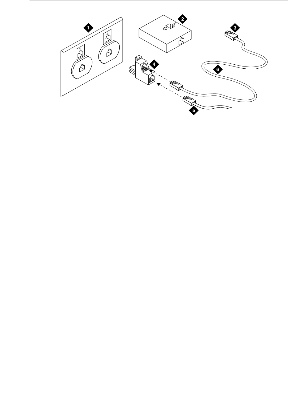
8Connecting Telephones and Adjunct Systems
Installation and Wiring Telephones and Power Supplies
318 Installation and Upgrades for G700 and S8300
December 2003
Figure 16: 400B2 Adapter Connecting to a Modular Plug
Adjunct Power Connections End-to-End
Figure 17, Example Adjunct Power Connections, on page 319 shows typical connection locations for
adjunct power.
Figure notes
1Flush-Mounted Information Outlet
2Surface-Mounted Information Outlet
3To Individual Power Unit
4400B2 Adapter
5To Telephone
6Destination Service Access Point (DSAP)
Power Cord
r749428 KLC 060396
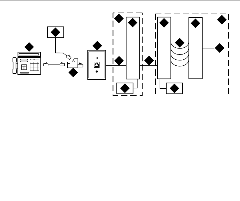
8
Connecting Telephones and Adjunct Systems
Installation and Wiring Telephones and Power Supplies
Installation and Upgrades for G700 and S8300 319
December 2003
Figure 17: Example Adjunct Power Connections
Auxiliary Power for an Attendant Console
The nonessential functions of an attendant console and its optional 26A1 or 24A1 selector console derive
power from an auxiliary power source. Provide auxiliary power for an attendant console through this
cable so the console remains fully operational during short power outages.
NOTE:
Only 1 console can derive auxiliary power from the system and through the auxiliary
cable located in the trunk/auxiliary field.
A console’s maximum distance from its auxiliary power source is:
•800 feet (244 m) for a 302A1
•350 feet (107 m) for a 301B1 and 302D
An attendant console can also derive auxiliary power from:
•Individual 1151B or 1151B2 power supply
•MSP-1 power supply
•258A-type adapters
•Bulk power supplies
Figure notes
1Typical display telephone
2Individual power supply (Such as
1151B) (Not used if item 14 is used)
3400B2 adapter
4Information outlet (modular jack)
54-pair D-Inside Wire (DIW) cable
6Satellite site or adapter location
725-pair D-Inside Wire (DIW) cable
8Station side of MDF
9100P6A patch cord or jumpers
10 System side of MDF
11 25-pair cable to digital line modular
jack
12 Equipment room
13 Satellite location
14 Bulk power supply. Install at satellite
location or equipment room (not both).
cydmapwr EWS 052898
1
2
3
4
5
6
7
8
9
10
11
12
13
14 14

8Connecting Telephones and Adjunct Systems
Installation and Wiring Telephones and Power Supplies
320 Installation and Upgrades for G700 and S8300
December 2003
Local and Phantom Power
An attendant console’s maximum distance from the system is limited.
See Table 8, Attendant Console Cabling Distances, on page 320.
1152A1 Mid-Span Power Distribution Unit
The 1152A1 Mid-Span Power Distribution Unit (PDU) is an Ethernet power supply that provides power
to up to 24 46xx-series IP telephones or wireless LAN (WLAN) access points. This unit is used with a
10/100BaseTx standard Ethernet network over a standard TIA/EIA-568 Category 5, 6 or 6e cabling plant.
The 1152A1 meets the current requirements of the IEEE802.3af standard for resistive detection.
The 1152A1 PDU complies with the Underwriters Laboratories Inc. (UL) standard UL 1950, second
edition.
For safety instructions, see Important Safety Instructions on page 320. For installation instructions, see
Connect the Cables on page 322.
Important Safety Instructions
Please read the following helpful tips. Retain these tips for later use.
When using this switch, the following safety precautions should always be followed to reduce the risk of
fire, electric shock, and injury to persons.
— Read and understand all instructions.
— Follow all warnings and instructions marked on this switch.
Table 8: Attendant Console Cabling Distances
Enhanced Attendant
Console (302D)
24 AWG Wire (0.26 mm2)26 AWG Wire (0.14 mm2)
Feet Meters Feet Meters
With Selector Console
Phantom powered 800 244 500 152
Locally powered 5000 1524 3400 1037
Without Selector Console
Phantom powered 1400 427 900 274
Locally powered 5000 1524 3400 1037
Table 9: 1152A1 PDU UL 1950 Compliance
Complies UL 1950
Approved CSA C22.2 No.950 Std.
Approved CE Regulatory Compliance
Approved EN 60950
Approved TUV EN 60950

8
Connecting Telephones and Adjunct Systems
Installation and Wiring Telephones and Power Supplies
Installation and Upgrades for G700 and S8300 321
December 2003
— This product can be hazardous if immersed in water. To avoid the possibility of electrical
shock, do not use it near water.
— The 1152A1 PDU contains components sensitive to electrostatic discharge. Do not touch
the circuit boards unless instructed to do so.
— This product should be operated only from the type of AC (and optional DC) power
source indicated on the label. If you are not sure of the type of AC power being provided,
contact a qualified service person.
— Do not allow anything to rest on the power cord. Do not locate this product where the cord
will be abused by persons walking on it.
— Do not overload wall outlets and extension cords as this can result in the risk of line or
electric shock.
— Disconnect the cords on this product and refer servicing to qualified service personnel
under the following conditions:
•If the power supply cord or plug is damaged or frayed.
•If liquid has been spilled into it.
•If it has been exposed to rain or water.
•If it was dropped or the housing has been damaged.
•If it exhibits a distinct change in performance.
•If it does not operate normally when following the operating instructions.
Using the 1152A1 PDU
The 1152A1 PDU is used to power the 46xx series of IP telephones in addition to providing 10/100
megabits per second Ethernet connection.
Generation 1 Avaya IP telephones can receive power from the 1152A1 via an in-line adapter. This adapter
provides the resistive signature so that the 1152A1 allows power to flow to the telephone. The generation
2 telephones do not need an adapter.
The 1152A1 PDU has 24, 10/100 Base-T ports, each can supply up to 16.8 watts using the internal power
supply and operates on a 100-240 volts AC, 60/50 hertz power source.
The 1152A1 PDU is 1U high and fits in most standard 19-inch racks. It can also be mounted on a shelf.
Refer to the user’s guide that comes with the unit for complete installation instructions.
Connect the 1152A1 PDU
CAUTION:
The 1152A1 PDU has no ON/OFF switch. To connect or disconnect power to the
1152A1 PDU, simply insert or remove the power cable from the AC power receptacle on
the rear of the 1152A1 PDU.
1Plug a power cord into the power socket on the rear of the 1152A1 Power Distribution Unit.
2Plug the other end of the power cord into the power receptacle.
The 1152A1 PDU powers up, and the internal fans begin operating.
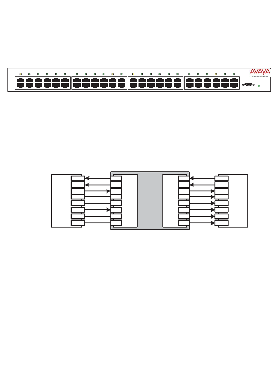
8Connecting Telephones and Adjunct Systems
Installation and Wiring Telephones and Power Supplies
322 Installation and Upgrades for G700 and S8300
December 2003
The 1152A1 PDU then runs through its Power On Self Test (POST), which takes less than 10 seconds.
During the test, all the ports on the unit are disabled and the LEDs light up. For more information on the
test, refer to the user’s guide that comes with the unit.
Connect the Cables
All of the ports on the front of the 1152A1 PDU are configured as data route-through ports for all data
wires (pins 1, 2, 3 and 6).
Use a standard CAT5, CAT6 or CAT6e straight-through Ethernet cable (not supplied), including all 8
wires (4 pairs) as shown in Connecting cables to telephones and other end devices on page 322.
Figure 18: Connecting telephones and other end devices to the 1152A1 PDU
For Data-In ports connect the Ethernet cable leading from the Ethernet Switch/Hub to the Data port. For
Data & Power Out ports connect the Ethernet cable leading to the telephone or other end device to the
corresponding Data & Power port.
NOTE:
Be certain to connect correspondingly numbered Data and Data & Power ports.
Connecting cables to telephones and other end devices
The 1152A1 PDU contains line-sensing capabilities that enable it to send power only to end devices
designed to receive power from the LAN. These end devices, termed Power over LAN Enabled, receive
power once they are connected to the 1152A1 PDU.
To safeguard devices that are not enabled, the 1152A1 PDU detects devices that are not enabled so does
not send power. Note that data continues to flow via the Ethernet cable regardless of the status of the end
device.
AC
Console
123456 13 14 15 16 17 18 19 20 21 22 23 24
789 101112
1152A1 Power
Distribution Unit
Data &
Power
Data
48Vdc
End Device
1
2
3
4
5
6
7
8
1
2
3
4
5
6
7
8
1
2
3
4
5
6
7
8
1
2
3
4
5
6
7
8
RJ-45 IN RJ-45 OUT
Ethernet
Switch/Hub
RJ-45
RJ-45
data
data
data
DC +
data
DC -
data
data
data
data
spare
spare
spare
spare
Data In
Data & Power Out
DC +
DC -
1152A1 Power Distribution Unit
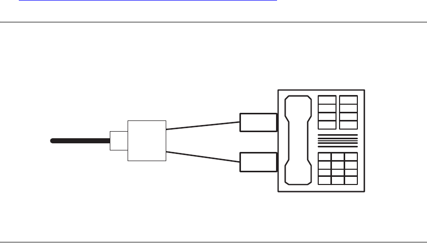
8
Connecting Telephones and Adjunct Systems
Installation and Wiring Telephones and Power Supplies
Installation and Upgrades for G700 and S8300 323
December 2003
End devices that are not enabled to receive power directly may receive power and data through an
external splitter. The external splitter separates the power and data prior to connection to the end device
(see Figure 19, Connecting an IP telephone with an external splitter, on page 323).
Figure 19: Connecting an IP telephone with an external splitter
Before connecting telephones or other end devices to the 1152A1 PDU, determine if
•It is Power over LAN Enabled or not.
If not, you may safely connect the telephone; however, the port supplies no power and functions
as a normal Ethernet data port.
•It requires an external splitter or whether it requires only a single RJ45 connection.
If an external splitter is needed, be certain to use a splitter with the correct connector and polarity.
•It’s power requirements are consistent with the 1152A1 PDU voltage and power ratings. Refer to
Appendix B in the user’s guide that comes with the unit for voltage and power ratings.
To connect telephones and other end devices to the 1152A1 PDU:
1Connect an Ethernet cable to the telephone using an external splitter or directly (if the device is
Power over LAN Enabled).
2Connect the opposite end of the same cable to the RJ45 wall outlet.
3On the front panel of the 1152A1 PDU, monitor the response of the corresponding port LED. If it
lights up GREEN, the unit has identified your telephone as a Power over LAN
RJ-45
Male Connector
DC Power
Connector
RJ-45
Female Socket Data
Power
IP
Phone
Connection to
Power over LAN Hub

8Connecting Telephones and Adjunct Systems
Installation and Wiring Telephones and Power Supplies
324 Installation and Upgrades for G700 and S8300
December 2003
P333T-PWR Power over Ethernet Stackable
Switch
The P333T-PWR power supply complies with the Underwriters Laboratories Inc. (UL) standard UL
1950, second edition.
For safety instructions, see P333T-PWR switch Important Safety Instructions on page 324. For
installation instructions, see Connect the P333T-PWR switch on page 325.
P333T-PWR switch Important Safety Instructions
Please read the following helpful tips. Retain these tips for later use.
When using this switch, the following safety precautions should always be followed to reduce the risk of
fire, electric shock, and injury to persons.
•Read and understand all instructions.
•Follow all warnings and instructions marked on this switch.
•This product can be hazardous if immersed in water. To avoid the possibility of electrical shock,
do not use it near water.
•The Avaya P333T-PWR switch and modules contain components sensitive to electrostatic
discharge. Do not touch the circuit boards unless instructed to do so.
•This product should be operated only from the type of AC (and optional DC) power source
indicated on the label. If you are not sure of the type of AC power being provided, contact a
qualified service person.
•Do not allow anything to rest on the power cord. Do not locate this product where the cord will be
abused by persons walking on it.
•Do not overload wall outlets and extension cords as this can result in the risk of line or electric
shock.
•Disconnect the cords on this product and refer servicing to qualified service personnel under the
following conditions:
— If the power supply cord or plug is damaged or frayed.
— If liquid has been spilled into it.
— If it has been exposed to rain or water.
— If it was dropped or the housing has been damaged.
— If it exhibits a distinct change in performance.
— If it does not operate normally when following the operating instructions.
Table 10: P333T-PWR UL 1950 Compliance
Complies UL 1950
Approved C22.2 No.950 Std.
Approved CE
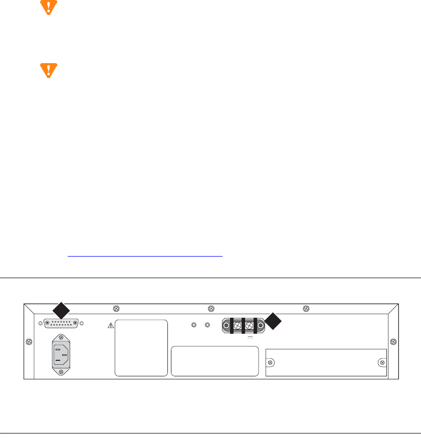
8
Connecting Telephones and Adjunct Systems
Installation and Wiring Telephones and Power Supplies
Installation and Upgrades for G700 and S8300 325
December 2003
Using the P333T-PWR switch
The P333T-PWR Power over Ethernet Stackable Switch can be used to power 46xx series IP telephones
in addition to providing a 10/100 megabits per second Ethernet connection. The switch can form part of a
stack with the G700 Media Gateway or members of the P330 stackable switching system.
CAUTION:
The Avaya P333T-PWR switch does not contain any user-serviceable components inside.
Do not open the case.
CAUTION:
The P333T-PWR switch can be used only indoors and in a controlled environment.
The P333T-PWR switch has 24, 10/100 Base-T ports, each of which can supply up to 16.5 watts using the
internal power supply and operates on a 100–240 volts AC, 5.3 amperes, 50/60 hertz power source with
the option of using the 44~57 volts DC, 15 amperes to boost the InLine power.
The P333T-PWR switch can be placed in a wiring closet or on a flat, stable surface like a desk. Screws
are provided for mounting in a standard 19-inch rack.
Connect the P333T-PWR switch
Power up—AC input
1Insert the power cord into the power connector (BUPS or AC Power Supply) on the rear of the
unit. See Connectors on the P333T-PWR switch on page 325.
Figure 20: Connectors on the P333T-PWR switch
2Insert the other end of the power cord into a nonswitched electrical outlet or the connector on the
BUPS.
The unit powers up and performs a self-test procedure. The LEDs flash at regular intervals after
the self-test procedure is completed successfully.
Figure notes
1BUPS connector 2AC connector
scdlp333 KLC 082002
INPUT
Amax
Vin 44-57V 15A
BUPS
INPUT
12

8Connecting Telephones and Adjunct Systems
Installation and Wiring Telephones and Power Supplies
326 Installation and Upgrades for G700 and S8300
December 2003
Power up—DC input (optional)
The P333T-PWR switch can operate on the AC input only. However, you may wish to use the optional
DC input for the following:
•Backup for the power over Ethernet ports
•To provide more than 200 watts for the power over Ethernet ports
NOTE:
Please refer to the P333T-PWR switch User’s Guide for more information.
Connect the Cables
Connect IP telephones, PCs, servers, routers, workstations, and hubs.
1Connect the Ethernet connection cable (not supplied) to a 10/100 megabits per second port on the
front panel of the Avaya P333T-PWR switch.
NOTE:
Use standard RJ45 connections and a CAT5 cable for 100 megabits per second operation.
2Connect the other end of the cable to the Ethernet port of the PC, server, router, workstation, IP
telephone, switch, or hub.
NOTE:
Use a crossover cable when connecting the Avaya P333T-PWR switch to a switch or hub.
3Check that the appropriate link (LNK) LEDs light up.
1151B1 and 1151B2 Power Supplies
The 1151B1 and 1151B2 power supplies are a local power supply. The telephones or consoles connect
directly to them through an RJ45 connector. The 1151B2 has a battery backup.
These power supplies comply with the Underwriters Laboratories Inc. (UL) Standard UL 60950 third
edition.
For safety instructions, see Important Safety Instructions for 1151B1 and 1151B2 Power Supplies on
page 327. For installation instructions, see Connect the 1151B1 or 1151B2 Power Supplies on page 328.
Table 11: 1151B1 and 1151B2 Power Supply UL 60950 Compliance
Complies UL 60950
Certified CSA 22.2
Approved EN6950
Approved CE

8
Connecting Telephones and Adjunct Systems
Installation and Wiring Telephones and Power Supplies
Installation and Upgrades for G700 and S8300 327
December 2003
Important Safety Instructions for 1151B1 and
1151B2 Power Supplies
Please read the following helpful tips. Retain these tips for later use.
When using this power supply, the following safety precautions should always be followed to reduce the
risk of fire, electric shock, and injury to persons.
•Read and understand all instructions.
•Follow all warnings and instructions marked on this power supply.
•This product can be hazardous if immersed in water. To avoid the possibility of electrical shock,
do not use it near water.
•To reduce the risk of electric shock, do not disassemble this product except to replace the battery.
•This product should be operated only from the type of AC power source indicated on the label. If
you are not sure of the type of AC power being provided, contact a qualified service person.
•Do not allow anything to rest on the power cord. Do not locate this product where the cord will be
abused by persons walking on it.
•Do not overload wall outlets and extension cords as this can result in the risk of line or electric
shock.
•Disconnect the cords on this product and refer servicing to qualified service personnel under the
following conditions:
— When the power supply cord or plug is damaged or frayed.
— If liquid has been spilled into the product.
— If the product has been exposed to rain or water.
— If the product was dropped or the housing has been damaged.
— If the product exhibits a distinct change in performance.
— If the product does not operate normally by following the operating instructions.
Using 1151B1 and 1151B2 Power Supplies
The 1151B1 and 1151B2 Power Supplies can be used to supply local power to ISDN-T 85xx and 84xx
series and 46xx series telephones connected to a media gateway and to the 302D Attendant Console that
requires auxiliary power for its display. The unit can supply power to adjunct equipment such as S201A
and CS201A speakerphones or a 500A Headset Adapter attached to any currently manufactured analog,
DCP, or ISDN-T telephone equipped with an adjunct jack.
CAUTION:
The power supply can be used only with telecommunications equipment, indoors, and in a
controlled environment.
The power supply has a single output of -48 volts DC, 0.4 amperes and can operate from either a
120 volts AC 60 hertz power source (105 to 129 volts AC) or a 220/230/240 volts AC 50 hertz power
source (198 to 264 volts AC). Input voltage selection is automatic. The output capacity is 19.2 watts.
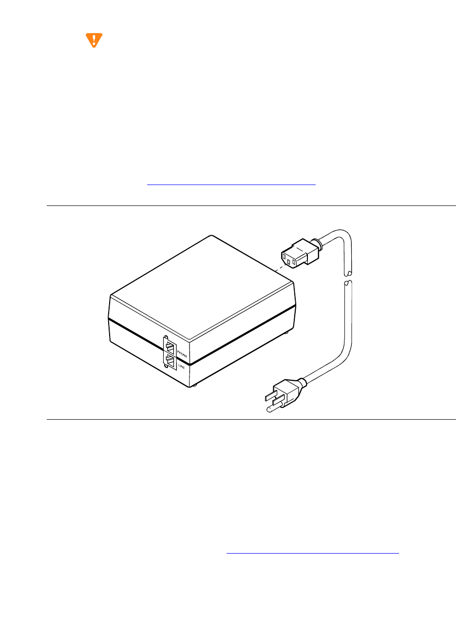
8Connecting Telephones and Adjunct Systems
Installation and Wiring Telephones and Power Supplies
328 Installation and Upgrades for G700 and S8300
December 2003
The power supply can be placed on a flat surface such as a desk. For wall-mounting, keyhole slots are
provided on the bottom of the chassis.
CAUTION:
Do not locate the unit within 6 inches (15 centimeters) of the floor.
Connect the 1151B1 or 1151B2 Power Supplies
The 1151B1 is a standard (no battery backup) power supply unit. The 1151B2 is a battery backup version
of the 1151B1. Either power supply can support one telephone with or without an adjunct. The maximum
loop range is 250 feet (76 meters). Two modular jacks are used. Power is provided on the PHONE jack,
pins 7 and 8 (- and +, respectively).
The PHONE and LINE jacks are 8-pin female nonkeyed 657-type jacks that can accept D4, D6, and D8
modular plug cables. See Figure 21, 1151B2 Power Supply — Front, on page 328.
Figure 21: 1151B2 Power Supply — Front
Install Emergency Transfer Unit and
Associated Telephones
NOTE:
Install only 1 emergency transfer power panel per system.
Emergency transfer capability is provided by an 808A Emergency Transfer Panel (or equivalent)
mounted next to the trunk/auxiliary field. See Figure 22, 808A Emergency Transfer Panel, on page 329.
Use analog telephones for emergency transfer. The 2500-type telephones can also be used as normal
extensions. Emergency transfer capability may be provided on analog CO and Wide Area
Telecommunications Service (WATS) trunks.
pwr_sup1 CJL 051496
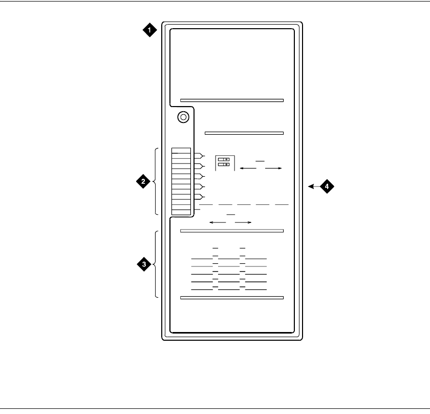
8
Connecting Telephones and Adjunct Systems
Installation and Wiring Telephones and Power Supplies
Installation and Upgrades for G700 and S8300 329
December 2003
The transfer panel provides emergency trunk bypass or power-fail transfer for up to 5 incoming CO trunk
loops to 5 selected station sets. The 808A equipment’s Ringer Equivalency Number (REN) is 1.0A.
For information on installing the 808A Emergency Transfer Panel, see 808A Emergency Transfer Panel
Installation Instructions, which ships with the Emergency Transfer Panel.
Figure 22: 808A Emergency Transfer Panel
Connect an Analog Station or 2-Wire Digital
Station
This example is typical of the 2-wire digital stations (2420, 64xx, 302D), 2-wire analog stations (2500),
analog Central Office (CO) trunks, Direct Inward Dial (DID) trunks, and external alarms.
1Choose a peripheral to connect (such as a 2-wire digital station).
2Choose the Media Module to use and its Media Gateway and slot number; for example, MM711
Analog Media Module, Media Gateway 002, Slot V2.
3Choose a port circuit on the MM711 Media Module; for example, port 03.
Figure notes
1808A emergency transfer panel
2Circuit start selection switches
3Trunk identification label
425-pair male connector
1
2
3
4
5
6
7
8
9
10
1
2
3
4
5
12
EMERGENCY
TRANSFER
PANEL
CIRCUIT
1
2
POWER
TRUNK/TEST SWITCHES
TRUNK OPTION
LOOP
START GROUND
START
BOTH SWITCHES MUST BE
THROWN TO ACTIVATE
TRUNK OPTION
TRANSFER TEST SWITCH
ACTIVATED NORMAL
OPERATION
TRUNK IDENTIFICATION
TRUNK
LINE EXT LOC
808A
led808a LJK 040896

8Connecting Telephones and Adjunct Systems
Installation and Wiring Telephones and Power Supplies
330 Installation and Upgrades for G700 and S8300
December 2003
4Install cross-connect jumpers to connect the pins from the 2-wire digital station to the appropriate
pins on the MM711 Media Module. Table 12, Two-Wire Station Pinout Chart, on page 330 shows
a pinout chart for two-wire stations.
5Administer using Administrator’s Guide for Avaya Communication Manager.
Figure 23: 2500-Type Analog Telephone Wiring
Table 12: Two-Wire Station Pinout Chart
Jack Name 1 2 3 4 5 6 7 8
BRI-T +TX +RX -RX -TX -V GND
ADJUNCT +Vadj T0 -V GNDVoice RRVoic
e+V S0 TTVoice
DSS
(QUEST) DTX DRX OKdi
g-V +V
DSS (ISDN)
BRI-A GND TX RX -V
BRI-U TX RX -V GND
DCP TX1 TX2 RX1 RX2 -V +V
ANALOG TIP RING
HANDSET -TX +RX -RX +TX
Figure notes
12500-Type Analog Station 2MM711 Analog Media Module,
Position 1V301
2500wire RBP 071996
3
28
03
2T
R
T.3
R.3

8
Connecting Telephones and Adjunct Systems
Complete the Telephone Installation Process
Installation and Upgrades for G700 and S8300 331
December 2003
Complete the Telephone Installation Process
Consult the planning documentation to obtain the necessary information to complete the installation. Part
of the final process will be to:
•Complete the electrical installation
•Enable adjunct systems
Install the Coupled Bonding Conductor
The Coupled Bonding Conductor (CBC) provides mutual inductance coupling between the CBC and the
telephone cables that are exposed to lightning. The conductor can be a 10 AWG (4 mm2) wire tie wrapped
to the exposed cables, a metal cable shield around the exposed cables, or six spare pairs from the exposed
cable. In a high-rise building, connect the CBC to an approved building ground on each floor.
Before you begin, be sure the telephone lines are cross-connected to the appropriate media module(s).
Install the CBC
1Connect one end of the conductor to a telephone cable building entrance protector ground that is
connected to an approved ground.
2Route the rest of the conductor next to the exposed telephone cables being protected until they
reach the cross-connect nearest to the telephone system.
3Terminate the other end to the single-point ground block provided for the telephone system.
NOTE:
Position the non-exposed telephone cables at least 12 inches (30.5 cm) away from exposed
telephone cables whenever possible.
Install Circuit Protection
Over-voltage and sneak fuse protection measures are necessary for the safe operation of the G700 Media
Gateway system.
Over-Voltage and Sneak-Current Protection
Out-of-building installations of telephones or other standard (tip/ring) devices/terminals that connect to
the Avaya G700 Media Gateway Media Modules require over-voltage and sneak current protection at
both building entry points. Sneak current protectors must have a maximum of 350 mA and a minimum
voltage rating of 600V. The following devices have been evaluated or tested and approved to protect the
Media Modules from over-voltages and sneak current protection:
•Avaya MM712 DCP: either 146E IROB (In-Range Out-of-Building) or 4C3S-75 solid state
protectors for surge and sneak current.
•Avaya MM710 T1/E1: over-voltage and sneak protection for the Avaya MM710 T1/E1 Media
Module is provided on the Media Module itself.

8Connecting Telephones and Adjunct Systems
Complete the Telephone Installation Process
332 Installation and Upgrades for G700 and S8300
December 2003
•Avaya MM711 Analog: analog trunks use the 507B or 110-SCP-9 sneak current protectors. Over-
voltage protection is normally provided by the local telephone company. Analog voice terminals
use one of the following types of combined over-voltage and sneak current protection:
— Gas tube with heat coil: 4B1E-W
— Solid state with heat coil: 4C1S
— IROB: 146C (4-lines) or 146F (25-lines)
!
WARNING:
Only service-trained personnel are to install these circuit protection devices.

8
Connecting Telephones and Adjunct Systems
IA 770 INTUITY AUDIX Messaging Application
Installation and Upgrades for G700 and S8300 333
December 2003
IA 770 INTUITY AUDIX Messaging Application
NOTE:
For complete information on IA 770 INTUITY AUDIX Installations, including the S8300
hard drive replacement, see the IA INTUITY AUDIX documentation on the Avaya S8300,
S8500, and S8700 Media Server Library CD, 555-233-825, or the IA 770 INTUITY
AUDIX Messaging Application Installation Checklist and Instructions, 585-313-159. Both
of these documents are included in the IA 770 INTUITY AUDIX Messaging Application
Technician Kit.
The IA 770 INTUITY AUDIX Messaging Application runs only on a G700 Media Gateway controlled
by an S8300 Media Server.
Shared Resources of Coresidency
Because it is coresident on the S8300, the INTUITY AUDIX system uses many of the S8300 resources
for call processing, data storage, and access and use of administrative tools. Specifically, the INTUITY
AUDIX system uses the following:
•The S8300 hard drive for data storage and retrieval
•The S8300 TFTP server
•License file downloads and updates
•Backup and restore of data
•Software updates and upgrades
•The IP address of the S8300 for remote administration access and TCP/IP networking functions
such as Digital Networking, Message Manager, and Internet Messaging.
•The S8300 license file for feature activation
•The S8300 General Alarm Manager for alarm display
As a result, the administrator administers some functions of the INTUITY AUDIX system by directly
administering the INTUITY AUDIX application, while the administrator administers other functions of
the INTUITY AUDIX system by administering the S8300 platform. To access the INTUITY AUDIX
administration screens and web pages, you simply click on the Messaging Administration link from the
S8300 Main Menu.
CWY1Board and Software
The INTUITY AUDIX system software is loaded directly onto the S8300 hard drive. The INTUITY
AUDIX system also requires the use of a CWY1 board. This board connects directly to the S8300
processor through the S8300 Time Division Multiplexing (TDM) bus. Once installed, this board hosts
portions of the INTUITY AUDIX platform software. INTUITY AUDIX uses this board to convert
messages to the code-excited linear prediction (CELP) format, convert text to speech, and process
touchtones.

8Connecting Telephones and Adjunct Systems
IA 770 INTUITY AUDIX Messaging Application
334 Installation and Upgrades for G700 and S8300
December 2003
No Data Link and No Voice Ports to Connect
In earlier versions of INTUITY AUDIX that ran on a separate PC connected to a switch, the voice
communication (messages, announcements, greetings, and so on) occurred over analog voice ports, while
control messages (timestamps, called and calling party data, message-waiting signals, and so on)
occurred over a data link on the LAN or through X.25 protocol connections.
Since the IA 770 INTUITY AUDIX system runs on a CWY1 circuit board that you plug directly into the
S8300 processor, the analog voice ports and the data link do not use physical ports. Instead, the INTUITY
AUDIX software and the switch software send voice signals to one another using virtual ports over the
TDM bus connection of the CWY1 board and processor board.
AUDIX Hunt Group Still Necessary
The logic of voice ports, however, remains the same. This logic means that an INTUITY AUDIX hunt
group must still be defined with 4 or 8 virtual voice ports and extension numbers. Other switch
adminstration tasks that are associated with proper hunt group functions, such as creating COR, COS, and
coverage paths, are also required. The S8300 and INTUITY AUDIX software applications send control
messages to each other by using the same shared S8300 processor, and therefore, administration of a data
link is not required.
IA 770 INTUITY AUDIX Installations and S8300
Upgrades for IA 770 INTUITY AUDIX
To install an IA 770 INTUITY AUDIX system, you must install the CWY1 board and install the
INTUITY AUDIX software. The INTUITY AUDIX software is included in the S8300 software load (the
.tar file), but it must be installed using INTUITY AUDIX installation tools.
To install the IA 770 INTUITY AUDIX system on an S8300 Release 1.1 system, you must first replace
the hard drive of the S8300 and upgrade the S8300 software first. The hard drive replacement requires a
backup of translations to your laptop and a subsequent restore of translations.
For complete information on IA 770 INTUITY AUDIX Installations, including the S8300 hard drive
replacement, see the IA INTUITY AUDIX documentation on the Avaya S8300, S8500, and S8700 Media
Server Library CD, 555-233-825, or the IA 770 INTUITY AUDIX Messaging Application Installation
Checklist and Instructions, 585-313-159. Both of these documents are included in the IA 770 INTUITY
AUDIX Messaging Application Technician Kit

8
Connecting Telephones and Adjunct Systems
INTUITY AUDIX LX Messaging System
Installation and Upgrades for G700 and S8300 335
December 2003
INTUITY AUDIX LX Messaging System
The process of integrating an INTUITY AUDIX LX system with an Avaya S8300 Media Server involves
a series of tasks to prepare the switch to work with the INTUITY AUDIX LX system.
The procedures for this process are fully documented in INTUITYTM AUDIX® LX Release 1.0
Documentation, 585-313-818. The information is contained in a document with the title INTUITYTM
AUDIX® LX Release 1.0 LAN Integration with S8300 and DEFINITY® Systems.
ASAI Co-Resident DEFINITY LAN Gateway (DLG)
The DEFINITY LAN Gateway (DLG) is an application that enables communications between TCP/IP
clients and Communication Manager call processing. In more technical terms, the DLG application is
software that both routes Internet work messages from one protocol to another (ISDN to TCP/IP) and
bridges all ASAI message traffic (by way of a TCP/IP tunnel protocol).
The DLG listens for client connections (a specific IP Address) over a well-known TCP port (5678). The
client accesses the DLG's services by connecting to TCP port 5678 at the IP address of the DLG’s
Ethernet interface, which can be a MAPD (TN801B), a Processor (TN2314), or a C-LAN (TN799). The
client then exchanges TCP Tunnel Protocol messages with the DLG to request a connection to a specific
CTI link. The DLG authenticates the client based on its administration and then establishes or refuses the
connection. Once a connection is established, the ASAI layer 3 messages are transparently passed
through the DLG (that is, the DLG does not process any message content). Each TCP connection to the
DLG has a one-to-one correspondence with a CTI link.
The DLG application is packaged either externally on a separate circuit pack (the TN801 MAPD circuit
pack) or internally, where it co-resides with Communication Manager. The externally packaged DLG is
referred to as the MAPD DLG, and the internally packaged DLG is referred to as the Co-Resident DLG.
The Co-Resident DLG and the MAPD DLG accomplish the same basic function (ASAI to Ethernet
transport).
The Co-Resident DLG is application software that co-resides with Communication Manager on the
Media Server running Communication Manager. No physical installation or MAPD-specific
administration is required for the Co-Resident DLG. In terms of switch-based connectivity, the Co-
Resident DLG is supported by the following platforms:
•Communication Manager S8100 Media Server configurations (formerly DEFINITY ONE and
IP600)
•Avaya S8300 Media Server with Avaya G700 Media Gateway
Administration of the Co-Resident DLG is carried out on the switch using the change ip-services SAT
command. When the service type DLG is specified on the IP Services form, the DLG administration page
displays. The Co-Resident DLG does not rely on ports. Port allocation is not required for administering
the Co-Resident DLG.
For Avaya S8100 Media Server configurations, the Co-Resident DLG cab use the C-LAN (TN799), the
Processor Card (TN2314), or both as its Ethernet interface. For Avaya S8300 Media Server with Avaya
G700 Media Gateway, the Co-Resident DLG relies on the S8300 Media Server for Ethernet connectivity.

8Connecting Telephones and Adjunct Systems
ASAI Co-Resident DEFINITY LAN Gateway (DLG)
336 Installation and Upgrades for G700 and S8300
December 2003
Administration Task Summary (for the S8300
Media Server)
On the SAT interface of the S8300 Media Server with G700 Media Gateway, follow these steps:
1Type display system-parameters customer-options. Go to page 4 and make sure that Processor
Ethernet is enabled.
2Type display ip-interfaces, and make sure the PROCR is administered and its Ethernet port is
enabled. If the PROCR is not listed (PROCR should appear in the Type option field), add the
PROCR.
To administer CTI links:
1Use the display system-parameters customer-options command and make sure the following
option is set to yes:
Co-Res DEFINITY LAN GATEWAY (y)
2Use the add cti-link command to administer a CTI link.
3Use the change ip-services command and specify a Service Type of DLG.
When Service Type DLG is entered, the system adds a DLG Administration page as the last of the
form.
4Complete the DLG Administration page to add your client information.
NOTE:
A CTI link must be administered before a link number can be entered. For more
information and detailed procedures, refer to CallVisor® ASAI Technical Reference, 555-
230-220.
Supported Ethernet Interfaces
Table 13, Ethernet Interfaces, on page 336 summarizes Ethernet interfaces used by several current
switching platforms:
Table 13: Ethernet Interfaces
Platform
Processor
Ethernet
Interface?
C-LAN
(TN799)
Ethernet
Interface
DEFINITY Servers csi, si,
and r No Yes
Avaya S8100 Media
Server (formerly
DEFINITY ONE/IP600)
Yes Yes
Avaya S8300 Media
Server with Avaya G700
Media Gateway
Yes No

8
Connecting Telephones and Adjunct Systems
Call Center
Installation and Upgrades for G700 and S8300 337
December 2003
Call Center
The S8300 Media Server provides a excellent solution for a small call center. The S8300 Media Server
with the G700 Media Gateway supports the following call center capabilities:
•All three Avaya call center packages:
— Avaya Call Center Basic
— Avaya Call Center Deluxe
— Avaya Call Center Elite
•Up to 450 agents
•A maximum of 16 ASAI links
•Avaya G700 announcement software
Avaya G700 Announcement Software
Voice announcements are used in a call center environment to announce delays, direct customers to
different departments, and entertain and inform calling parties. The announcement capability is standard
and comes co-resident on the G700. The G700 announcement software has many of the functions of the
TN2501AP VAL circuit pack.
See Table 14, Comparison between the G700 Announcement software and the VAL circuit pack, on page
337 for differences between the Avaya G700 Announcement software and the VAL circuit pack. For
more information on Avaya G700 Announcement software, see the Administrator’s Guide for Avaya
Communication Manager, 555-233-506, Chapter 13, "Managing Announcements".
Table 14: Comparison between the G700 Announcement software and the VAL circuit
pack
Area description TN2501AP (VAL) circuit
pack Avaya G700 announcement
software
Requires hardware Yes No
Maximum storage
time per board for
TN750 or
TN2501AP
Up to 60 minutes at 64 Kbps
sample rate Up to 20 minutes at 64Kbps
uncompressed speech
Concurrent Calls
per Announcement 50 when using a DEFINITY
Server SI or DEFINITY Server
CSI
1,000 when using the
DEFINITY Server R, S8500, or
S8700 Media Server
1,000
Backup and restore
over LAN Yes Yes
Recording Method Use PC or telephone Use PC or telephone
1 of 2

8Connecting Telephones and Adjunct Systems
Call Center
338 Installation and Upgrades for G700 and S8300
December 2003
File portability to
multiple DEFINITY
or Communication
Manager servers
Yes Yes
Playback quality Toll quality Toll quality
Backup speed 2.6 seconds for each 60 seconds
of announcement time 2.6 seconds for each 60 seconds
of announcement time
Reliability High High
Firmware
downloadable Yes Yes
Number of boards
per system 5 on the DEFINITY® CSI and
DEFINITY SI
10 on the DEFINITY R and
S8500 or S8700 Media Server
10 per configuration
Announcements per
board 256 256
Maximum number
of announcements
in a configuration
128 DEFINITY Server CSI or
DEFINITY Server Si
1,000 DEFINITY Server R
3,000 S8500, or S8700 Media
Server
3,000 over multiple G700
Media Gateways
Format CCITT A-law or u-law CCITT A-law or u-law
Sample bits 8 8
Sample rate 8,000 KHz 8,000 KHz
Channels Mono Mono
Table 14: Comparison between the G700 Announcement software and the VAL circuit
pack Continued
Area description TN2501AP (VAL) circuit
pack Avaya G700 announcement
software
2 of 2

8
Connecting Telephones and Adjunct Systems
Avaya Integrated Management
Installation and Upgrades for G700 and S8300 339
December 2003
Avaya Integrated Management
Avaya Integrated Management provides a comprehensive set of network and system management
solutions for the converged voice and data environment. Avaya Integrated Management is available in
several different offers. Each offer includes an appropriate set of applications to meet different business
needs. Contact your client executive to learn which offer best meets the needs of your enterprise.
Avaya Integrated Management architecture provides standards-based infrastructure for integrated
management applications. The individual applications over time will become integrated with a common
look and feel. The available products include:
•Avaya ATM WAN Survivable Processor Manager
•Avaya Directory Enabled Management
•Avaya MultiService Network Manager
•Avaya MultiService SMON Manager
•Avaya Fault and Performance Manager
•Avaya Proxy Agent
•Avaya Configuration Manager
•Avaya Site Administration
•Avaya Terminal Configuration
•Avaya Terminal Emulator
•Avaya Voice Announcement Over LAN Manager
•Avaya VoIP Monitoring Manager
Avaya ATM WAN Survivable Processor
Manager
Avaya ATM WAN Survivable Processor Manager is a Windows (98/NT/2000) client/server software tool
with which administrators can upload translations from a main Media Server to the Avaya ATM WAN
Survivable Processor Manager workstation. Once translations are uploaded, administrators can then
download them from the workstation to a maximum of 15 separate ATM WSP Media Servers via LAN
connectivity.
Avaya Directory Enabled Management
Avaya Directory Enabled Management is a web-based software solution that provides real-time
Directory-based (LDAP) read/write access to Media Servers. Avaya Directory Enabled Management
provides the capability to keep data, such as station and subscriber data, synchronized with its image in
the LDAP data store, and provides a rules engine that facilitates the management of these
servers/applications, based on events (add/delete/modify) that take place at servers or applications.
Currently, Avaya Directory Enabled Management operates only with Microsoft Internet Explorer.

8Connecting Telephones and Adjunct Systems
Avaya Integrated Management
340 Installation and Upgrades for G700 and S8300
December 2003
Avaya MultiService Network Manager
Avaya MultiService Network Manager provides customers with either a standalone product or one that
can integrate with the HP OpenView NMS, and includes applications that allow customers to manage
network devices. These applications include:
•Avaya MultiService Address Manager — displays a centralized list of hosts in the network, and
correlates among IP addresses, MAC addresses, and device port connectivity.
•Avaya MultiService Configuration Manager — provides quick network setup and installation,
fast recovery for faulty devices, downloading/uploading configuration data, backup of
configuration files, and export of configuration files to other sources for reporting or analysis.
Accessible from within Avaya MultiService Configuration Manager, Avaya MultiService
EZ2Rule Manager is a campus-wide application that provides Quality of Service (QoS)
management for small sites with limited bandwidth resources. In addition, Avaya MultiService
EZ2Rule Manager enables the user to preview the application of new rules before network
deployment, ensuring accurate and consistent deployment of priorities in the network.
•Avaya MultiService Console — provides the discovery of IP-enabled devices, hierarchical map
representation, device status, fault monitoring, and a launch point for device managers.
•Avaya MultiService Software Update Manager — downloads software to managed Avaya
MultiService devices, and performs all necessary software maintenance operations. These
operations include checking current software versions against the latest versions available from
the Avaya Web site, recommending updates, and providing an inventory of Avaya MultiService
data devices residing on the network.
•Avaya MultiService VLAN Manager — a graphical application for VLAN management that
allows for configuration and monitoring of VLAN use. Avaya MultiService VLAN Manager
assigns and maintains VLAN numbering and naming, tracks additions and changes to the
network, validates VLAN name and tag values, and monitors the number of VLANs in order to
assist in maintenance tasks.
Avaya MultiService Network Manager supports converged network environments composed of multi-
vendor equipment from key vendors and will be enhanced to support all Avaya IP voice systems and data
devices to create a full convergence solution.
Avaya MultiService SMON Manager
Avaya MultiService SMON Manager monitors the Ethernet and provides complete visibility of all
switched traffic in the network. Although SMON Manager is an application provided with Avaya
MultiService Network Manager, SMON Manager requires a license key before it can be used.
Avaya Fault and Performance Manager
Avaya Fault and Performance Manager operates standalone or with Avaya MultiService Network
Manager and/or HP OpenView to provide a network map or system view of a converged network. Use it
to view fault and performance data, busyout boards and ports, acknowledge exceptions, and configure
collection times and information.
8
Connecting Telephones and Adjunct Systems
Avaya Integrated Management
Installation and Upgrades for G700 and S8300 341
December 2003
Avaya Proxy Agent
Avaya Proxy Agent is the SNMP proxy agent that provides an interface to Media Servers running
DEFINITY® Release 9 software through and including current versions of Avaya Communication
Manager. Avaya Proxy Agent provides a protocol conversion between the proprietary OSSI protocol and
SNMP.
Avaya Configuration Manager
Avaya Configuration Manager allows you to administer Media Servers running DEFINITY® Release 9
software through and including Avaya current versions of Avaya Communication Manager. Multiple
administrators can access multiple Media Servers. Administrators can perform station
moves/adds/changes, print button labels, as well as many other common administrative activities. Avaya
Configuration Manager provides a web-based Graphical User Interface (GUI) client that runs in the
supported browsers and allows administrators access Communication Manager from any workstation on
the network.
Avaya Site Administration
Avaya Site Administration is a PC-based Windows (98/NT/2000) tool that lets you administer Media
Servers running DEFINITY® Release 9 software through and including current versions of Avaya
Communication Manager, and AUDIX Messaging Systems. Avaya Site Administration simplifies
administration with an easy-to-use interface that offers wizards and GEDI (Graphically Enhanced
DEFINITY Interface), as well as terminal emulation.
Avaya Terminal Configuration
Avaya Terminal Configuration is a new web-based client application that allows end users to access
Media Servers in order to configure personal station set preferences and features. Avaya Terminal
Configuration runs on top of Avaya Directory Enabled Management software, and therefore requires that
Avaya Directory Enabled Management software be installed.
Avaya Terminal Emulator
Avaya Terminal Emulator is a Windows (98/NT/2000) application that provides direct connectivity
capabilities. It can be run either as a standalone application or run from Avaya Site Administration. Avaya
Terminal Emulator includes the following features:
Connection List — lets you store and organize information about the systems to which you regularly
connect and allows you to connect to them by double-clicking.
FTP Manipulator — lets you transfer files to and from your computer to a remote system.
Icon Manager — lets you assign functionality to icons that come as part of Avaya Terminal Emulator or
to your own icons.

8Connecting Telephones and Adjunct Systems
Avaya Integrated Management
342 Installation and Upgrades for G700 and S8300
December 2003
Telnet connection — lets you launch a telnet session to remote systems that you are accessing over a
LAN or WAN.
Terminal Emulator — lets you access systems using a modem, data module, PDM, or direct connection.
Avaya Voice Announcement Over LAN
Manager
Avaya Voice Announcement over LAN Manager lets you use your LAN to transfer recorded
announcements to the TN2501AP boards located in remote Media Servers. This product offers the
following capabilities:
•View the current status of TN2501AP board announcements
•Simplified administration to add/change/remove announcements
•Copy/backup announcement files from a supported TN2501AP board to Avaya Voice
Announcement over LAN Manager via a customer’s LAN
•Copy/restore announcement files to a supported TN2501AP board from Avaya Voice
Announcement over LAN Manager via a customer’s LAN
Avaya VoIP Monitoring Manager
Avaya VoIP Monitoring Manager is Windows 2000 application that allows you to monitor real-time
Quality of Service (QoS) measurements for VoIP systems. Avaya VoIP Monitoring Manager offers a
client GUI accessible from your LAN or via remote access. Avaya VoIP Monitoring Manager can
generate traps associated with VoIP QoS sent to any NMS, and can receive RTCP packets from IP
telephones, IP soft phones, VoIP engines (on G700 Media Gateways), and Prowler boards. Avaya VoIP
Monitoring Manager can operate as a standalone application, or it can be integrated with Avaya
MultiService Network Manager.

8
Connecting Telephones and Adjunct Systems
Uninterruptible Power Supply (UPS)
Installation and Upgrades for G700 and S8300 343
December 2003
Uninterruptible Power Supply (UPS)
Several varieties of the Avaya Uninterruptible Power Supply (UPS) are available. A typical example, the
700 VA 120 V Online UPS provides 700 VA/490 Watts/5.8 amps at 120 Volts AC and battery holdover of
9 minutes at full load. Two optional Extended Battery Modules (EBM24) extend the run time to 156
minutes at full load. The UPS groups the six available 5-15R receptacles into two groups of three to make
it possible for customers to shutdown one set of loads to allow longer run times for more critical loads
during a power failure. Power management is included. The UPS chassis can be installed in a tower or
mounted in a data rack. Serial interface capabilities and alarm contacts are standard.
The types of UPS units available include:
•AS1 700VA 120V Online UPS
•AS1 700VA 230V Online UPS
•AS1 700VA 100V Online UPS Japan
•AS1 700VA 200V Online UPS Japan
•AS1 1500VA 120V Online UPS
•AS1 1500VA 230V Online UPS
•AS1 1500VA 100V Online UPS Japan
•AS1 1500VA 200V Online UPS Japan
UPS add-on modules include the following:
•Extended Battery Module - EBM24 700-1000 VA
•UPS Extended Battery Module - EBM48 1500-2000 VA
•SNMP MODULE 700-2000 VA
•BYPASS DISTRIBUTION MODULE 120V 700-1500 VA
•PWR UPS BYPASS DISTR MOD S1 700 VA - 2K VA
Full Details on these units can be found in Hardware Guide for Avaya Communication Manager.

8Connecting Telephones and Adjunct Systems
Uninterruptible Power Supply (UPS)
344 Installation and Upgrades for G700 and S8300
December 2003

A
Technical Information
Avaya G700 Media Gateway Technical Specifications
Installation and Upgrades for G700 and S8300 345
December 2003
ATechnical Information
This appendix collects some of the detailed technical information you will need to install the Avaya G700
Media Gateway with an Avaya S8300 Media Serve. More complete information can be found in
Hardware Guide for Avaya Communication Manager.
Avaya G700 Media Gateway Technical Specifications
The table of technical specifications provides detailed information on the physical dimensions and
tolerances of the G700 Media Gateway.
Table 15: Technical Specifications
Chassis Dimensions
Height 2U (3.5 in) 88 mm Depth 17.7 in 450 mm
Width 19 in 482.6 mm Weight empty 22.25 lbs 10 kg
Weight 34-27 lbs 16-12 kg
Required Clearances
Front 12 in 30 cm consistent with EIA 464 data rack standards
Rear 18 in 45 cm
Temperature Tolerances
Recommended 65 to 85 deg Farenheit 18 to 29 deg Celsius
Continuous operation +41 deg F to +104 deg F 5 deg C to 40 deg C
Humidity Tolerances
Recommended 20 to 60% relative humidity
Relative humidity range 5% to 95% non-condensing
Altitude
Recommended up to 10,000 feet or 3,000 meters

ATechnical Information
Cabling Equipment
346 Installation and Upgrades for G700 and S8300
December 2003
Cabling Equipment
The G700 Media Gateway Cables and Peripherals chart lists the types and specifications of the cables
used to connect the Media Gateway. See also “Avaya P333T User’s Guide”.
Table 16: Media Gateway Cables and Peripherals
Cable Description Length Length
(metric)
X330SC Short OctaplaneTM Cable
(30 cm) (Catalog No. CB0223) Short Octaplane cable - light-
colored, used to connect adjacent
switches or switches separated by
one Backup Universal Power
Supply (BUPS) unit.
12 in 30 cm
X330LC Long Octaplane Cable (2
m) (Catalog No. CB0225) Long Octaplane cable - light-
colored, used to connect switches
from two different physical stacks
6 ft 2 m
X330RC Redundant Octaplane
Cable (2 m) (Catalog No.
CB0222)
Redundant cable - black, used to
connect the top and bottom
switches of a stack.
6ft 2 m
X330L-LC Extra Long Octaplane
Cable (8 m) (Catalog No.
CB0270)
Extra-Long Octaplane cable -
light-colored, used to connect
switches from two different
physical stacks
24 ft 8 m
X330L-RC Long Redundant
Octaplane Cable (8 m) (Catalog
No. CB0269)
Long Redundant cable - black,
used to connect the top and
bottom switches of a stack.
24 ft 8 m
Stacking Sub-Module X330STK Stacking Sub-Module provides
two backplane links

B
Information Checklists
Installer’s Checklist
Installation and Upgrades for G700 and S8300 347
December 2003
BInformation Checklists
This appendix is can be used as an aid for collecting the necessary information for the installation of a
G700 Media Gateway and an S8300 Media Server. The following lists are provided
Installer’s Checklist
Installer’s Checklist: Tools, software, laptop settings, customer network
information.
Serial Number and Login Information: Serial numbers of the G700s and login/passwords
for various access methods.
Set-Up for P330 Stack Processor: IP addresses and setup commands for the P330
stack processor.
Set Up for G700 Media Gateway Processor (MGP): IP addresses and setup commands for the MGP.
Set Up for VoiP Resources: IP addresses, slot numbers, and setup commands
for the VoIP media modules.
Set Up for S8300 Media Server: IP addresses and setup commands for the S8300.
Installation Site Information: Customer and site contact information
Stack Layout: G700 stack arrangement and slot assignments.
tools
laptop with 32 MB RAM
40 MB available disk space
RS-232 port connector
cross-over Ethernet cables
direct Ethernet cable
serial cable and adapter
Ethernet network connection (NIC card)
screwdriver
software
Windows 95/98/ME/XP/NT/2000 operating system
FTP Program
TFTP Program
Telnet Program
Terminal emulation program: HyperTerminal or other
TCP/IP networking software: bundled with Windows OS
Web browser: Netscape 4.7x or Internet Explorer 5.0

BInformation Checklists
Installer’s Checklist
348 Installation and Upgrades for G700 and S8300
December 2003
Ethernet connections
laptop default address and mask: 192.11.13.5, 255.255.255.252
Browser: no proxies
laptop default address and mask: 192.11.13.5, 255.255.255.252
Communications Properties: 9600 baud rate; no parity; 8 data bits, 1 stop bit; no flow control
SSO login
Obtaining this login will require that you complete the authentication process. You will not be
able to obtain the license file or to perform remote feature activation without the SSO login
authentication process. You will not be able to obtain the license file or to perform remote feature
activation without the SSO login.
dial plan
IP addressing plan
List of customer-provided IP services
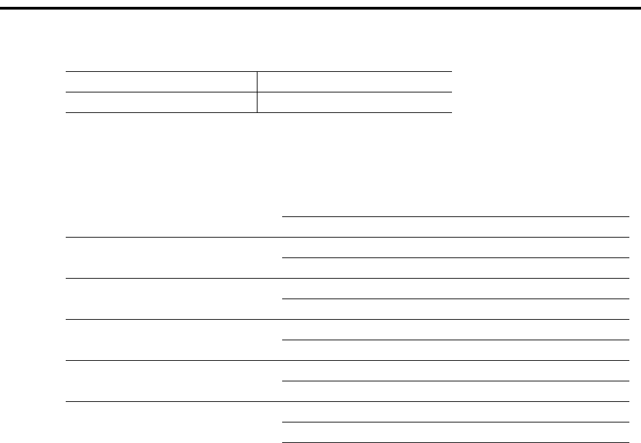
B
Information Checklists
Serial Number and Login Information
Installation and Upgrades for G700 and S8300 349
December 2003
Serial Number and Login Information
G700 Serial Numbers
Logins
Name & Password
S8300 Media Server
P330 Stack
G700 Media Gateway
SSO Authentication Login
ftp anonymous
email address
Communication Manager SAT

BInformation Checklists
Set-Up for P330 Stack Processor
350 Installation and Upgrades for G700 and S8300
December 2003
Set-Up for P330 Stack Processor
Located in G700 Media Gateway#
Prompt: P330-1(super)# type configure to change prompt to: P330-1(configure)#
For the Stack Master:
Command Requested Field Information to be Entered
set interface inband vlan 1
IP address
netmask
set ip route destination IP address
gateway IP address
set time protocol sntp-protocol | time-protocol
set time server IP address of time server
set timezone zone name
- <hours> (offset from GMT)
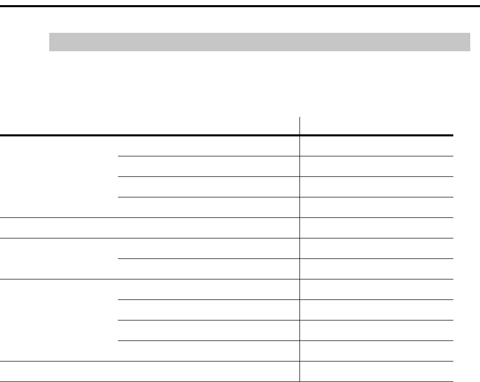
B
Information Checklists
Set Up for G700 Media Gateway Processor (MGP)
Installation and Upgrades for G700 and S8300 351
December 2003
Set Up for G700 Media Gateway Processor (MGP)
G700 Media Gateway #
Prompt:
MG-???-n (super)# type configure to change prompt to MG-???-n (configure)#
Command Requested Field Information to be Entered
set interface mgp vlan 1
IP address
netmask
gateway IP address
set hostname hostname
set ip route destination IP address
gateway IP address
set mgc list IP address
IP address
IP address
IP address
show system serial number

BInformation Checklists
Set Up for VoiP Resources
352 Installation and Upgrades for G700 and S8300
December 2003
Set Up for VoiP Resources
G700 Media Gateway #
Command Requested Field Information to be Entered
set interface voip number V0 for resident VoIP resource of the G700
ip address
number (v + slot #)
ip address
number (v + slot #)
ip address
number (v + slot #)
ip address
number (v + slot #)
ip address
G700 Media Gateway #
Command Requested Field Information to be Entered
set interface voip number V0 for resident VoIP resource of the G700
ip address
number (v + slot #)
ip address
number (v + slot #)
ip address
number (v + slot #)
ip address
number (v + slot #)
ip address

B
Information Checklists
Set Up for S8300 Media Server
Installation and Upgrades for G700 and S8300 353
December 2003
Set Up for S8300 Media Server
Location: slot #1 of G700 _______________________ survivable processor?
Web Interface: 192.11.13.6 (default)
Screen Title Field Information to be Entered
Login Name
Password
Set Time and Date Time & Date
Configure Server
Set Server Identities hostname
Server IP address
netmask
default gateway IP address
Configure VLAN VLAN ID
IP address
gateway IP address
netmask
DNS Server Configuration Enable/Disable DHCP Disable
Network Time Server Enable/Disable NTP
IP addresses of designated
Network Time Servers
Trusted Key, Requested Key,
Control Key leave blank
Do Not Install a New Keys File Default
Set Modem Interface IP address

BInformation Checklists
Installation Site Information
354 Installation and Upgrades for G700 and S8300
December 2003
Installation Site Information
Site Name Main Phone
Installation Address
Shipping Address
Customer Contact
Name
Title
Phone:
FAX:
Mobile:
Pager:
email:
Off-hours contact:
Salesperson/ Account Exec
Sales/AE phone:
Other Contact Info:
Notes to installer: access procedures, safety/security procedures
Access Contact
Name
Title
Phone:
FAX:
Mobile:
Pager:
email:
Off-hours contact:
Installer Name
Date of Installation

B
Information Checklists
Stack Layout
Installation and Upgrades for G700 and S8300 355
December 2003
Stack Layout
Label each unit in the stack. Make photocopies if needed. There can be no more than 10 units per stack.
.
.
.
Media Gateway (module) #
or P330 switch #
v1 v2
v3
Expansion Module v4
Media Gateway (module) #
or P330 switch #
v1 v2
v3
Expansion Module v4
Media Gateway (module) #
or P330 switch #
v1 v2
v3
Expansion Module v4
Media Gateway (module) #
or P330 switch #
v1 v2
v3
Expansion Module v4
Media Gateway (module) #
or P330 switch #
v1 v2
v3
Expansion Module v4

BInformation Checklists
Stack Layout
356 Installation and Upgrades for G700 and S8300
December 2003
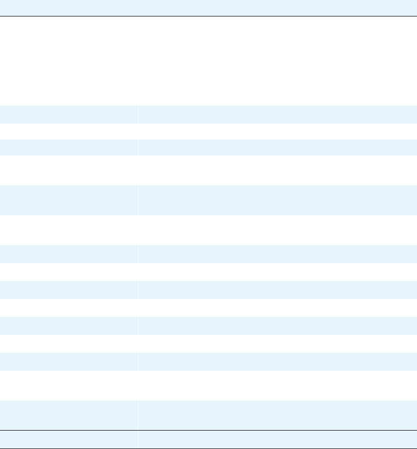
C
Equipment List
Installation and Upgrades for G700 and S8300 357
December 2003
CEquipment List
The following lists contain information necessary for ordering Avaya G700 Media Gateway and Avaya
S8300 Media Server equipment.
NOTE:
If ordering parts, use the 9-digit "Comcode" numbers, not the 6-digit numbers.
Table 17: Equipment List: Avaya S8300 Media Server with G700 Media Gateways
Avaya G700 Media Gateway
The Avaya G700 Media Gateway is a 19-inch 2u rack-mountable device with a physical design
modeled after the Avaya P330 stackable switching products. The G700 Media Gateway contains VoIP
resources, a layer 2 switch, modular interface connectivity for traditional trunk and station access and
performs the function of a gateway/gatekeeper. It also houses four Media Module Bays as well as a
single, standard Avaya Expansion Module interface slot. The Avaya G700 Media Gateway is
designed to offer options and scalability. A customer will be able to mix and match Media Modules,
as well as stack and/or add additional Avaya G700 Media Gateways as they grow in size.
Material Code: 170896 Apparatus Code: MGW1 Not Optional
Avaya G700 Media Gateway ComCode (for Services Ordering Only)
ComCode Number of Items Description
700259898 1 G700 Media Gateway
(AC only version)
700284607 1G700 Media Gateway
(AC/DC version)
700017932 1 Rack mount screw set (attach ears
to rack)
700021769 2Rack Mount Ears
901342105 6 Rack Mount screw set ear to box
700051055 4Feet
700169998 1 Tech Laptop Cable
700057060 3Media Module Blanks
700179195 1 Avaya Expansion Blank
700179203 1Avaya Octaplane Blank
700179526 1 Documentation, CIB 3246
FCC/Safety G700
700236680 0Grounding Kit for multiple G700s
in a 19" rack

CEquipment List
358 Installation and Upgrades for G700 and S8300
December 2003
Table 18: Equipment List: G700 Media Gateway Power Cords
G700 Media Gateway Power Cords
Supplies Power to the G700 Media Gateway. One cord per gateway is required, and there are
various cords depending on the power required for the country in which the unit will be installed.
Material Code: 170904 Apparatus Code: none Not Optional
When you order this material code, a descriptive attribute will be required; the attributes are:
Attribute Option Comcode: Description
CRD 30 405362641: PWR CORD
9X10 IN USA 17505
CRD 31 407786623: PWR CORD
98IN EUROPE 12013S
CRD 32 407786599: PWR CORD
98IN UNITED KINGDOM
14012
CRD 33 407786631: PWR CORD
98IN AUSTRALIA 15012
CRD 34 407790591: PWR CORD
INDIA P250CIM
CRD 42 408161453: PWR CORD
96IN ARGENTINA
CRD 700252638: DC PWR CORD
C
Equipment List
Installation and Upgrades for G700 and S8300 359
December 2003
Table 19: Equipment List: Avaya S8300 Media Server
Server
S8300 Media Server
The Avaya S8300 Media Server is an Intel™-based server complex that carries:
*Avaya Communication Manager
*administration and maintenance provisioning software
*20G Hard drive (Field-replaceable. Comcode: 700258891)
*256 MB RAM
*Web serve
*Linux OS (Redhat v6.X)
*H.248 Media Gateway Signaling Protocol
*CCMS messages tunneled over H.248 Signaling Protocol
*TFTP server
The S8300 Media Server can act as the primary server of the G700 Media Gateway, or it can
serve as a local survivable processor for remote/branch customer locations.
Material Code: 170902 Apparatus Code: Optional
ComCode (for Services Ordering Only): 700293103
Table 20: Equipment List: Media Modules
Media Modules
Avaya MM710 T1/E1 Media Module
The MM710 T1/E1 Media Module offers the combined features of a DEFINITY DS1 circuit
pack and will include the following:
*A built-in CSU
*AMI-BASIC
*Both A-law for E1 and µ -law for T1
*Line Coding: AMI, ZCS, B8ZS for T1 and HDB3 or AMI for E1
*Stratum 3 Clock compatibility
*Trunk signaling for supporting US and International CO trunks and tie trunks as currently in
existence
The MM710 T1/E1 Media Module supports the universal DS1 conforming to 1.544 Mbps T1
standard and 2.048 Mbps E1 standard
ISDN PRI is also supported for T1 or E1 revenue-associated option
Material Code: 170900 Apparatus Code: MM710 Optional
ComCode (for Services Ordering Only): 700221161
DEF DS1 LOOPBACK JACK 700A
1 of 3

CEquipment List
360 Installation and Upgrades for G700 and S8300
December 2003
Provides the ability to remotely troubleshoot the MM 710 T1/E1 Media Module. It is required for
any customer with a maintenance contract and highly recommended for any other customer.
Material Code: 107988867 Apparatus Code: None Required for any customer
with a maintenance contract
and an MM710 T1/E1 Media
Module, highly recommend
for other customers to avoid
expensive technician visits.
MM711 Analog Media Module
The MM711 Analog Media Module supports eight analog interfaces allowing the connectivity of
Loop Start, Ground Start, Analog DID trunks, and 2-wire analog Outgoing CAMA E911 trunks.
As well, the MM711 Analog Media Module allows connectivity of analog, tip/ring devices such
as single line telephones, modems or group 3 fax machines. Each port may be configured as
either a trunk interface or a station interface.
Also included is support for caller ID signaling, ring voltage generation for a variety of
international frequencies and cadences and administrable line termination styles.
Material Code: 170899 Apparatus Code: MM711 Optional
ComCode (for Services Ordering Only): 700221146
MM712 DCP Media Module
The MM712 DCP Media Module allows connectivity of up to 8 two-wire DCP voice terminals.
MM712 will not support 4-Wire DCP telephones.
Signal timing specifications for the MM712 support TDM Bus Timing in receive and transmit
modes. The G700 Media Gateway supplies only +5 VDC and –48 VDC to the MM712 Media
Module. Any other required voltages must be derived on the module.
Loop range secondary protection is provided on the MM712. The MM712 is also self-protecting
from an over current condition on a tip and ring interface.
Material Code: 170898 Apparatus Code: MM712 Optional
ComCode (for Services Ordering Only): 700221153
MM720 BRI Media Module
Table 20: Equipment List: Media Modules Continued
Media Modules
2 of 3

C
Equipment List
Installation and Upgrades for G700 and S8300 361
December 2003
The MM720 BRI Media Module contains eight ports that interface to the central office at the
ISDN T reference point. Information is communicated in two ways:
Over two 64 Kbps channels called B1 and B2 that can be circuit-switched simultaneously
Over a 16 Kbps channel called the D channel that is used for signaling. The D channel occupies
one time slot for all eight D channels.
The circuit switched connections have a u-law or A-law option for voice operation. The circuit
switched connections operate as 64 Kbps clear channels when in the data mode.
The MM720 BRI Media Module does not support BRI stations, or combining both B channels
together to form a 128 Kbps channel.
Material Code: Apparatus Code: MM720 Optional
ComCode (for Services Ordering Only): 700221138
MM760 VoIP Media Module
The MM760 VoIP Media Module is a clone of the motherboard VoIP engine. It provides an
additional 64 VoIP channels with G.711 compression. Each chassis base system can support up to
64 G.711 single channel calls. If the desire is to have an essentially non-blocking system, an
additional MM760 VoIP Media Module needs to be added if more than two MM710 T1/E1
Media Modules are used in a single chassis. This will provide for an additional 64 channels.
This VoIP conversion resource in the G700 Media Gateway is an improved version of the
Prowler board resource and from a configuration perspective, the two are the same. The capacity
is 64 G.711 TDM/IP simultaneous calls, or 32 compression codec (G.729 or G.723) TDM/IP
simultaneous calls. These call types can be mixed on the same resource, so we say that the
simultaneous call capacity of the resource is 64 “G.711 Equivalent Calls”.
Material Code: 170901 Apparatus Code: MM760 Optional
ComCode (for Services Ordering Only): 700221179
Table 20: Equipment List: Media Modules Continued
Media Modules
3 of 3

CEquipment List
362 Installation and Upgrades for G700 and S8300
December 2003
Table 21: Avaya P330 Equipment
Avaya P330 Equipment
Avaya P330 Stacking Sub-Module (optional)
Material Code: 108562943 P330 MOD P330 STACKING
CASCADE CABLES
Material code: 108592445 Avaya P330 CABLE OCTAPLANE STACKING 1FT
Material code: 108592437 Avaya P330 CABLE OCTAPLANE STACKING 6FT
Material code: 108563453 Avaya CABLE ASSY X330RC REDUN STACKING
EXPANSION MODULES
Material code: 108562927 Avaya MOD P330 1000BSX
UPLINK 2PT The X330-S2 provides
1000Base-SX connectivity
with two Multimode Fiber
ports (up to 550 m,1804 ft)
with LAG and Load Sharing
Material code: 108563032 Avaya MOD P330 1000BLX
UPLINK 2PT The X330-L2 provides
1000Base-LX connectivity
with two Single Mode Fiber
ports (up to 5 km,3.11 miles)
with Link Aggregation
(LAG) and Load Sharing
Material code: 108562992 Avaya MOD P330 1000BSX
UPLINK 1PT The X330-S1 provides
1000Base-SX connectivity
with one Multimode Fiber
port (up to 550 m,1804 ft)
Material code: 108562976 Avaya MOD P330 1000BLX
UPLINK 1PT The X330-L1 provides
1000Base-LX connectivity
with one Single Mode Fiber
port (up to 5 km,3.11 miles)
Material code: 108562968 Avaya MOD P330 10/100TX
UPLINK 16PT The X330-T16 adds 16
10/100Base-T ports. It
allows up to 64 ports in a
single switch and an
impressive 640 per stack.
Two LAGs can be created,
with up to eight ports per
group.
1 of 2
C
Equipment List
Installation and Upgrades for G700 and S8300 363
December 2003
Material code: 108562950 Avaya MOD P330 100FX
UPLINK 2PT The X330-F2 adds two
100Base-FX ports which can
be aggregated using LAG to
provide a 200 Mbps link for
backbone or high-speed
server applications.
Material code: 108659178 Avaya P330 MOD EXP
GBIC 2PT The X330-G2 provides GBIC
connectivity with an adapter
for standard GBIC
transceivers.
Material code: 700214612 Avaya X330 WAN-2DS1 The X330 WAN-2DS1
provides two T1/E1 ports and
a 10/100BaseT port.
Material code: 700247570 Avaya X330 WAN-2USP The X330 WAN-2USP
provides two serial ports
supporting V.35, X.21,
RS530 and a 10/100BaseT
port.
Material code: 700247588 V.35 DTE Cable Used with the X330 WAN-
2USP.
Material code: 108659194 Avaya MOD DUAL SPEED
OC12/0C3 SMF 15KM
Material code: 108659186 Avaya MOD DUAL SPEED
OC12 OC3 MMF 500M
Table 21: Avaya P330 Equipment Continued
Avaya P330 Equipment
2 of 2

CEquipment List
364 Installation and Upgrades for G700 and S8300
December 2003
D
Replacing the G700 Media Gateway
Installation and Upgrades for G700 and S8300 365
December 2003
DReplacing the G700 Media Gateway
Circumstances may require that the G700 Media Gateway be replaced, either because of
hardware/firmware failure, or because of newer technology. Depending upon these circumstances, some
or all of the components inserted into the G700 (S8300 Media Server, LED Panel, Avaya Expansion
Module, Avaya Octaplane Module, or various Media Modules) may be reused in the replacement G700.
To replace the G700, follow these steps:
1If the original G700 is still in operation, power down the system. This should be done at a time
when there will be the minimum interruption in service.
aPerform a shutdown of the S8300 Media Server, if present, using either the Web interface
or manually, using the shutdown button on the S8300 faceplate.
bPower down the G700 by removing the power cord from the wall power source.
2Remove all media modules from the G700, and carefully set aside (assuming they will be reused).
3Reversing the procedures documented in Chapter 2, remove the G700 from its rack mount.
4Then, following these same procedures, install the replacement G700 hardware into the rack
mount.
5Proceed as you would for the installation of a new G700.
6Install the S8300 Media Server, LED Panel, and media modules.
7Contact RFA, if you have not already done so, and download new license and authentication files
to match the serial number of the replacement G700.
8Power up the system, and install the new license and authentication files.
9In Communication Manager, running on the primary server, use the change media-gateway SAT
command to enter the new G700 serial numbers and other data.

DReplacing the G700 Media Gateway
366 Installation and Upgrades for G700 and S8300
December 2003

Index
Numerics
Installation and Upgrades for G700 and S8300 367
December 2003
Index
Numerics
1151A1 and 1151A2 power supply,327, 328
1151A1 power supply,326
1151A2 power supply,326
2-wire digital station
connecting,329
pinout chart,330
wiring,329
400B2 Adapter,318
A
AC power,95
adding
switch configuration,64
adjunct power connections,319
Adjuncts
connecting,315
alarm wiring,329
analog station
connecting,329
wiring,329
announcements,337
approved grounds,93
ART, Automatic Registration Tool,106, 218, 268
ASAI Co-Resident DLG,335
assigning G700 IP addresses,137, 178, 183
Attendant Console, Aux power,319
AUDIX
IA 770,333
LX,335
Avaya ATM WAN Survivable Processor Manager,339
Avaya Configuration Manager,341
Avaya Data Expansion Modules,72
Avaya Directory Enabled Management,339
Avaya Fault and Performance Manager,340
Avaya Gateway Installation Wizard,33
Avaya Integrated Management,339
Avaya MultiService Network Manager,340
Avaya MultiService SMON™ Manager,340
Avaya P330 LAN Expansion Module,72
Avaya Proxy Agent,341
Avaya S8700 Media Server,75
Avaya Site Administration,64, 341
adding new switch configuration,64
configuring,64
Avaya Terminal Configuration,341
Avaya Terminal Emulator,341
Avaya Voice Announcement over LAN Manager,342
Avaya X330 WAN Access Routing Module,72
Avaya X330STK Stacking Sub-Module
installation,88
B
backup
to FTP server,215
to laptop,215
backup, Linux Migration,229
bonding conductor, install,331
C
cabling
multiple units,89
Octaplane Cables,89, 345, 346
Call Center,337
G700 announcements,337
CBC,331
Checklist 1, Install new G700 with S8300,35
Checklist 2, Install new G700 without S8300,38
Checklist 3, Upgrade G700 with S8300,40, 42
Checklist 4, Upgrade G700 without S8300,44
checklists,76
Circuit Protection
Media Modules,331
circuit protection, install,331
CLI commands,66
CO trunk wiring,329
Command Line Interface Help,62, 63
configure
G700 Media Gateway,137
G700 with S8300,101
administer Communication Manager,151
completing installation,168
G700 serial number,104, 174, 214, 266, 303
IP connectivity,140, 181, 186
LSP transition points,143, 189
SNMP alarming setup,166
G700 with S8700,171
administer Communication Manager,198, 201
completing installation,169, 209
Expansion Module,144, 190
G700 firmware installation,194
tar.gz file,176, 305
TFTP server setup,174, 303
configuring
Avaya Site Administration,64
switches,64
connect AC power,97
consoles
connectable,316
controller list for G700,141, 187
Co-Resident DLG,335
administration tasks,336
ethernet interfaces,336

Index
D
368 Installation and Upgrades for G700 and S8300
December 2003
coupled bonding conductor, install,331
Customization Template for Avaya Installation
Wizard,31
CWY1 Board,333
D
DC
wiring diagram,99
DC power,98
default for media gateway,140, 181, 185
DEFINITY LAN Gateway,335
DHCP server,164
DID trunk wiring,329
DLG,335
E
Equipment List
Avaya Expansion Modules,362
G700,357
Loopback Jack,359
MM710 T1/E1,359
MM711 Analog,360
MM712 DCP,360
MM760 VoIP,361
Octaplane Cables,362
Power Cords,358
S8300,359
X330STK Stacking Sub Module,362
Expansion Module
G700 with S8700,144, 190
installation,87
external alarm wiring,329
F
FTP server,215
G
G600 Media Gateway,75
G700 Media Gateway
rack mounting,81
replace,365
SNMP alarming setup,166
Gateway Installation Wizard,33
grounding
approved,93
conductors,92
connections,94
requirements,92
safety,94
I
Initial Administration Tasks,151, 155, 198, 201
inserting
Expansion Module,87
X330STK Stacking Sub-Module,88
install
license file,246, 276
installation
checklists,76
roadmap,34
Installation Wizard
Customization Template,31
Electronic Pre-Installation Worksheet,31
gateway installation,33
Names/Number Template,31
installing
telephone power supplies
procedures,317
Intuity AUDIX
hunt group,334
IA 770,333
LX,335
IP address
assigning G700 components,137, 178, 183
IP phones
LSP configuration,164
IP route,138, 140, 179, 181, 184, 185
K
keys.install file,135
L
laptop
as FTP server,215
direct Ethernet connection,144, 190
LEDs,73
license file
install,246, 276
S8300 upgrade,108
Linux Migration backup,229
Local Survivable Processor,74
LSP,74
IP phones,164
transition of control,165
LSP/G700 Upgrade Tool,32
M
Media Modules,71
Messaging
IA770,333
LX,335
multiple units,89

Index
N
Installation and Upgrades for G700 and S8300 369
December 2003
N
Names/Number Template for Avaya Installation
Wizard,31
network integration,77
P
P333T-PWR power over Ethernet stackable switch,324
pinout chart
2-wire station,330
Planning
documentation,76
Logins,349
S8300 Information,353
Serial Numbers,349
power
AC,95
AC Outlet Test,95
Connecting,97
DC,98
Requirements,95
Testing the AC Outlet,95
power supplies
installation,316
wiring,316
power supplies for telephones
1151A1 -48V,326
1151A2 -48V,326
installing and wiring,317
P333T-PWR,324
power up,97
Pre-installation Worksheet for Avaya Installation
Wizard,31
R
RAL,79
remaster hard drive,232
Remote Feature Activation,76
replacing a G700,365
Restricted Access Location,79
S
S8300
LEDs,73
remaster hard drive,232
S8700 Media Server,75
safety instructions
1151A1 and 1151A2 power supply,327
Single Sign-On SSO
RFA Single Sign-On,76
site verification,76
site-specific-option-number (sson),164
SNMP alarming on G700,166
stack,138, 179, 184
stacks
multiple units,89
supplementary ground conductor,79
switches
adding new switch configuration,64
T
task list,34
new G700 with S8700,38
upgrade G700 with S8300,40, 42
upgrade G700 with S8700,44
Technical Specifications Table,345
Telephones
connecting,315
telephones
connectable,316
installation,316
wiring,316
telnet
set parameters,233
terminal emulation
ntt,67
w2ktt,67
TFTP server setup,174, 303
U
Uninteruptable Power Supply,343
upgrade
G700 with S8300,211, 263
completing upgrade (S8300 primary
controller),260, 298
configure G700 Media Gateway,250, 291
license file,108
G700 with S8700,301
G700 firmware installation,310
Upgrade Tool for LSP/G700,32
UPS,343
W
wiring
2-wire digital station,329
alarm,329
analog station,329
CO trunk,329
DID trunk,329
wiring diagram
DC,99
wiring telephone power supplies
procedures,317

Index
W
370 Installation and Upgrades for G700 and S8300
December 2003
