Avid DekoCast Products User’s Guide Deko Cast 4.3 Ug V4.3
User Manual: avid Avid DekoCast - 4.3 - User’s Guide Free User Guide for Avid Deko Software, Manual
Open the PDF directly: View PDF ![]() .
.
Page Count: 448 [warning: Documents this large are best viewed by clicking the View PDF Link!]
- Title Page
- Contents
- Symbols and Conventions
- If You Need Help
- Getting Started
- Why Use DekoCast?
- DekoCast Products and Applications
- DekoCast Workflow
- Controlling DekoCast On-Air Video Output
- Before You Begin
- Starting and Closing DekoCast Applications
- Switching Between Video Formats
- Configuring Your DekoCast System
- Basic Components
- Understanding Files and File Types
- Viewing Information About Your DekoCast System
- Quick Start: Fading a Graphic On and Off
- Using the Sample Scenes and Media
- Working with Scenes and Objects
- Editing Objects in the Scene
- Using an Object Editor
- Editing Video Out Objects
- Editing Video In Objects
- Using the Target and Position Tabs
- Using the Levels and Mixer Tabs
- Working with Deko Objects
- Playing Back Audio
- Capturing Audio
- Playing Back Clips
- Capturing Clips
- Creating Cel Animations
- Using Group Objects
- Capturing Video Images (Frame Grab)
- Working with VBI Objects
- Creating Crawls
- Creating Crawl Text Using the Crawl Object
- Creating a Roll
- Controlling the Crawl Display
- Changing Crawl Text
- Using a Text File for a Crawl
- Controlling the Crawl Text Display
- Changing the Appearance of Crawl Text
- Setting the Crawl Object Rectangle and Position
- Adding Non-Text Objects to Crawl Text
- Adding Non-Text Objects as Linked Files
- Controlling the Position of Non-Text Objects in a Crawl
- Deleting and Replacing Rules
- Example: Inserting Objects into a Crawl
- Example: Applying a Parameter Value to an Inserted Object
- Using an Inserted Object to Trigger an Action
- Inserting Objects by Using Crawl Object Tags
- Adding Non-Text Objects as Custom Typefaces
- Adding Plug-in Objects
- Working with Charts and Graphs
- Accessing the Chart Designer
- Basic Procedure for Creating Charts
- Working with Advanced Controls
- Adding Actions to a Scene
- Understanding Actions
- Using the Timeline Editor
- Creating Actions
- Adding an Action to the Action List
- Working in Animate Mode
- Adding Action Parameters
- Adding Parameters from the Parameters Tab
- Understanding Keyframes and the Timeline Graph
- Adjusting Timing in the Timeline Bar Editor
- Creating Trigger Actions
- Creating Actions Over Time
- Preserving Passive Parameters for Scenes with Multiple Actions
- Reordering Parameters in the List
- Playing Actions
- Editing Actions
- Creating Actions Check List
- Creating Sample Actions
- Working with Parameters
- Using DekoCast Central
- Using Sequence to Play Back Actions
- Configuring DekoCast
- DekoCast Tips
- Index

Avid® DekoCast™ Products
User’s Guide
2
Copyright and Disclaimer
Product specifications are subject to change without notice and do not represent a commitment on the part of
Avid Technology, Inc.
This product is subject to the terms and conditions of a software license agreement provided with the software. The product
may only be used in accordance with the license agreemen.
Avid products or portions thereof are protected by one or more of the following United States Patents: 5,267,351; 5,309,528;
5,355,450; 5,396,594; 5,440,348; 5,467,288; 5,513,375; 5,528,310; 5,557,423; 5,577,190; 5,584,006; 5,640,601; 5,644,364;
5,654,737; 5,724,605; 5,726,717; 5,745,637; 5,752,029; 5,754,851; 5,799,150; 5,812,216; 5,828,678; 5,842,014; 5,852,435;
5,986,584; 5,999,406; 6,038,573; 6,061,758; 6,069,668; 6,141,007; 6,211,869; 6,532,043; 6,546,190; 6,596,031; 6,636,869;
6,747,705; 6,763,523; 6,766,357; 6,813,622; 6,847,373; 7,081,900; RE40,107; 7,403,561; 7,433,519; 7,671,871; D352,278;
D372,478; D373,778; D392,267; D392,268; D392,269; D395,291; D396,853; D398,912. Other patents are pending.
Avid products or portions thereof are protected by one or more of the following European Patents: 0506870; 0635188;
0674414; 0752174; 1111910; 1629675. Other patents are pending.
This document is protected under copyright law. An authorized licensee of Avid DekoCast may reproduce this publication for
the licensee’s own use in learning how to use the software. This document may not be reproduced or distributed, in whole or in
part, for commercial purposes, such as selling copies of this document or providing support or educational services to others.
This document is supplied as a guide for Avid DekoCast. Reasonable care has been taken in preparing the information it
contains. However, this document may contain omissions, technical inaccuracies, or typographical errors. Avid Technology,
Inc. does not accept responsibility of any kind for customers’ losses due to the use of this document. Product specifications
are subject to change without notice.
Copyright © 2010 Avid Technology, Inc. and its licensors. All rights reserved. Printed in USA.
The following disclaimer is required by Apple Computer, Inc.:
APPLE COMPUTER, INC. MAKES NO WARRANTIES WHATSOEVER, EITHER EXPRESS OR IMPLIED, REGARDING
THIS PRODUCT, INCLUDING WARRANTIES WITH RESPECT TO ITS MERCHANTABILITY OR ITS FITNESS FOR ANY
PARTICULAR PURPOSE. THE EXCLUSION OF IMPLIED WARRANTIES IS NOT PERMITTED BY SOME STATES. THE
ABOVE EXCLUSION MAY NOT APPLY TO YOU. THIS WARRANTY PROVIDES YOU WITH SPECIFIC LEGAL RIGHTS.
THERE MAY BE OTHER RIGHTS THAT YOU MAY HAVE WHICH VARY FROM STATE TO STATE.
The following disclaimer is required by Sam Leffler and Silicon Graphics, Inc. for the use of their TIFF library:
Copyright © 1988–1997 Sam Leffler
Copyright © 1991–1997 Silicon Graphics, Inc.
Permission to use, copy, modify, distribute, and sell this software [i.e., the TIFF library] and its documentation for any purpose
is hereby granted without fee, provided that (i) the above copyright notices and this permission notice appear in all copies of
the software and related documentation, and (ii) the names of Sam Leffler and Silicon Graphics may not be used in any
advertising or publicity relating to the software without the specific, prior written permission of Sam Leffler and Silicon
Graphics.
THE SOFTWARE IS PROVIDED “AS-IS” AND WITHOUT WARRANTY OF ANY KIND, EXPRESS, IMPLIED OR
OTHERWISE, INCLUDING WITHOUT LIMITATION, ANY WARRANTY OF MERCHANTABILITY OR FITNESS FOR A
PARTICULAR PURPOSE.
IN NO EVENT SHALL SAM LEFFLER OR SILICON GRAPHICS BE LIABLE FOR ANY SPECIAL, INCIDENTAL, INDIRECT
OR CONSEQUENTIAL DAMAGES OF ANY KIND, OR ANY DAMAGES WHATSOEVER RESULTING FROM LOSS OF USE,
DATA OR PROFITS, WHETHER OR NOT ADVISED OF THE POSSIBILITY OF DAMAGE, AND ON ANY THEORY OF
LIABILITY, ARISING OUT OF OR IN CONNECTION WITH THE USE OR PERFORMANCE OF THIS SOFTWARE.
The following disclaimer is required by the Independent JPEG Group:
This software is based in part on the work of the Independent JPEG Group.
The following disclaimer is required by Paradigm Matrix:
Portions of this software licensed from Paradigm Matrix.
3
The following disclaimer is required by Ray Sauers Associates, Inc.:
“Install-It” is licensed from Ray Sauers Associates, Inc. End-User is prohibited from taking any action to derive a source code
equivalent of “Install-It,” including by reverse assembly or reverse compilation, Ray Sauers Associates, Inc. shall in no event be
liable for any damages resulting from reseller’s failure to perform reseller’s obligation; or any damages arising from use or
operation of reseller’s products or the software; or any other damages, including but not limited to, incidental, direct, indirect,
special or consequential Damages including lost profits, or damages resulting from loss of use or inability to use reseller’s
products or the software for any reason including copyright or patent infringement, or lost data, even if Ray Sauers Associates
has been advised, knew or should have known of the possibility of such damages.
The following disclaimer is required by Videomedia, Inc.:
“Videomedia, Inc. makes no warranties whatsoever, either express or implied, regarding this product, including warranties with
respect to its merchantability or its fitness for any particular purpose.”
“This software contains V-LAN ver. 3.0 Command Protocols which communicate with V-LAN ver. 3.0 products developed by
Videomedia, Inc. and V-LAN ver. 3.0 compatible products developed by third parties under license from Videomedia, Inc. Use
of this software will allow “frame accurate” editing control of applicable videotape recorder decks, videodisc recorders/players
and the like.”
The following disclaimer is required by Altura Software, Inc. for the use of its Mac2Win software and Sample
Source Code:
©1993–1998 Altura Software, Inc.
The following disclaimer is required by Ultimatte Corporation:
Certain real-time compositing capabilities are provided under a license of such technology from Ultimatte Corporation and are
subject to copyright protection.
The following disclaimer is required by 3Prong.com Inc.:
Certain waveform and vector monitoring capabilities are provided under a license from 3Prong.com Inc.
Attn. Government User(s). Restricted Rights Legend
U.S. GOVERNMENT RESTRICTED RIGHTS. This Software and its documentation are “commercial computer software” or
“commercial computer software documentation.” In the event that such Software or documentation is acquired by or on behalf
of a unit or agency of the U.S. Government, all rights with respect to this Software and documentation are subject to the terms
of the License Agreement, pursuant to FAR §12.212(a) and/or DFARS §227.7202-1(a), as applicable.
Trademarks
Trademarks
003, 192 Digital I/O, 192XD I/O, 888 I/O, AirPlay, AirSPACE, AirSPACE HD, AirSpeed, ALEX, Alienbrain, AniMatte,
AudioMarket, AudioPages, AudioSuite, AudioVision, AutoSync, Avid, Avid Advanced Response, Avid DNA, Avid DNxcel,
Avid DNxHD, AVIDdrive, Avid DS Assist Station, Avid EditStar, Avid Learning Excellerator, Avid Liquid,
Avid Liquid Chrome Xe, Avid MEDIArray, Avid Mojo, AvidNet, AvidNetwork, Avid NewStar, Avid Remote Response,
AVIDstripe, Avid Unity, Avid Unity ISIS, Avid VideoRAID, Avid Xpress, AVoption, AVX, Beauty Without The Bandwidth, Boom,
C|24, CaptureManager, ChromaCurve, ChromaWheel, Command|24, Conectiv, CountDown, DAE, Dazzle,
Dazzle Digital Video Creator, Deko, DekoCast, D-Fi, D-fx, DigiDelivery, Digidesign, Digidesign Audio Engine,
Digidesign Intelligent Noise Reduction, DigiDrive, DigiLink, DigiMeter, DigiSerial, DigiStudio, DigiStudio Control,
Digital Nonlinear Accelerator, DigiTranslator, DINR, DNxchange, do more, DVD Complete, D-Verb, Eleven, Equinox,
EveryPhase, ExpertRender, Fastbreak, Fast Track, FieldPak, Film Composer, FilmScribe, Flexevent, FluidMotion, FXDeko,
G7, G-Rack, HD Core, HD Process, HDPack, HYBRID, HyperControl, HyperSPACE, HyperSPACE HDCAM, IllusionFX,
Image Independence, iNEWS, iNEWS Assign, iNEWS ControlAir, Instantwrite, Instinct,
Intelli-sat Broadcasting Recording Manager, Intelli-Sat, InterFX, Interplay, inTONE, Intraframe, iS9, iS18, iS23, iS36, ISIS,
IsoSync, KeyRig, KeyStudio, LaunchPad, LeaderPlus, Lightning, ListSync, Lo-Fi, Magic Mask, Make Anything Hollywood,
make manage move | media, Marquee, M-Audio, M-Audio Micro, Maxim, Mbox, MCXpress, Media Browse, Media Composer,
MediaDock, MediaDock Shuttle, Media Fusion, Media Illusion, MediaLog, Media Reader, Media Recorder, MEDIArray,
MediaShare, MediaStream, Media Suite, Meridien, MetaFuze, MetaSync, MicroTrack, Midiman, MissionControl, Mix Rack,
MixLab, Moviebox, Moviestar, NaturalMatch, Nearchive, NetReview, NewsCutter, Nitris, NRV-10 interFX, Octane, OMF,
OMF Interchange, OMM, OnDVD, Open Media Framework, Open Media Management, Palladium, Pinnacle,
Pinnacle DistanTV, Pinnacle Geniebox, Pinnacle HomeMusic, Pinnacle MediaSuite, Pinnacle Mobile Media, Pinnacle Studio,
Pinnacle Studio MovieBoard, Pinnacle Systems, ProEncode, ProServices, ProSessions, Pro Tools, QuietDrive, Recti-Fi,
Reel Tape Delay, Reel Tape Flanger, Reel Tape Saturation, RetroLoop, rS9, rS18, Salesview, Sci-Fi, Scorch, Scorefitter,
ScriptSync, SecureProductionEnvironment, Session, Show Center, Sibelius, SIDON, Soft SampleCell, Soft-Clip Limiter,
Sound Designer II, SPACE, SPACEShift, SpectraGraph, SpectraMatte, Sputnik, Starplay, SteadyGlide, Streamfactory,
Streamgenie, StreamRAID, Strike, Structure, Studiophile, SubCap, Sundance Digital, Sundance, Symphony, SYNC HD,
4
SynchroScience, SynchroScope, Syntax, TDM FlexCable, Thunder, Titan, Titansync, TL Aggro, TL AutoPan, TL Drum Rehab,
TL Everyphase, TL Fauxlder, TL In Tune, TL MasterMeter, TL Metro, TL Space, TL Utilities, Torq, Torq Xponent, Transfuser,
Trigger Finger, Trillium Lane Labs, TruTouch, UnityRAID, Vari-Fi, Velvet, Venom, VideoRAID, Video Slave Driver, VideoSPACE,
VideoSpin, Vortx, Xdeck, X-Form, Xmon, Xponent, and X-Session are either registered trademarks or trademarks of Avid
Technology, Inc. in the United States and/or other countries.
Adobe and Photoshop are either registered trademarks or trademarks of Adobe Systems Incorporated in the
United States and/or other countries. Apple and Macintosh are trademarks of Apple Computer, Inc., registered
in the U.S. and other countries. Windows is either a registered trademark or trademark of Microsoft
Corporation in the United States and/or other countries.
iNEWS, iNEWS ControlAir, and Media Browse are either registered trademarks or trademarks of iNews, LLC.
All other trademarks contained herein are the property of their respective owners.
GOT FOOTAGE?
Editors — Filmmakers — Special Effects Artists — Game Developers — Animators — Educators — Broadcasters — Content
creators of every genre — Just finished an incredible project and want to share it with the world?
Send us your reels and we may use your footage in our show reel or demo!*
For a copy of our release and Avid’s mailing address, go to www.avid.com/footage.
*Note: Avid cannot guarantee the use of materials submitted.
Avid DekoCast Products User Guide • 0130-07809-01 Rev B • April 2010
Contents
Symbols and Conventions . . . . . . . . . . . . . . . . . . . . . . . . . . . . . . . . . . . . . . . . . . . . 18
If You Need Help. . . . . . . . . . . . . . . . . . . . . . . . . . . . . . . . . . . . . . . . . . . . . . . . . . . . 19
Accessing the Online Library . . . . . . . . . . . . . . . . . . . . . . . . . . . . . . . . . . . . . . . . . . 19
How to Order Documentation . . . . . . . . . . . . . . . . . . . . . . . . . . . . . . . . . . . . . . . . . . 20
Avid Training Services . . . . . . . . . . . . . . . . . . . . . . . . . . . . . . . . . . . . . . . . . . . . . . . 20
Chapter 1 Getting Started . . . . . . . . . . . . . . . . . . . . . . . . . . . . . . . . . . . . . . . . . . . . . . 21
Why Use DekoCast?. . . . . . . . . . . . . . . . . . . . . . . . . . . . . . . . . . . . . . . . . . . . . . . . . 22
DekoCast Products and Applications . . . . . . . . . . . . . . . . . . . . . . . . . . . . . . . . . . . . 23
DekoCast Workflow. . . . . . . . . . . . . . . . . . . . . . . . . . . . . . . . . . . . . . . . . . . . . . . . . . 25
Controlling DekoCast On-Air Video Output. . . . . . . . . . . . . . . . . . . . . . . . . . . . . . . . 26
Before You Begin . . . . . . . . . . . . . . . . . . . . . . . . . . . . . . . . . . . . . . . . . . . . . . . . . . . 27
Starting and Closing DekoCast Applications. . . . . . . . . . . . . . . . . . . . . . . . . . . . . . . 27
Switching Between Video Formats . . . . . . . . . . . . . . . . . . . . . . . . . . . . . . . . . . . . . . 29
Configuring Your DekoCast System . . . . . . . . . . . . . . . . . . . . . . . . . . . . . . . . . . . . . 29
Basic Components . . . . . . . . . . . . . . . . . . . . . . . . . . . . . . . . . . . . . . . . . . . . . . . . . . 30
DekoCast Main Window. . . . . . . . . . . . . . . . . . . . . . . . . . . . . . . . . . . . . . . . . . . 30
Scenes . . . . . . . . . . . . . . . . . . . . . . . . . . . . . . . . . . . . . . . . . . . . . . . . . . . . . . . . 31
Objects . . . . . . . . . . . . . . . . . . . . . . . . . . . . . . . . . . . . . . . . . . . . . . . . . . . . . . . . 31
Scene Tree. . . . . . . . . . . . . . . . . . . . . . . . . . . . . . . . . . . . . . . . . . . . . . . . . . . . . 32
Object Editors. . . . . . . . . . . . . . . . . . . . . . . . . . . . . . . . . . . . . . . . . . . . . . . . . . . 33
Actions and the Timeline Editor . . . . . . . . . . . . . . . . . . . . . . . . . . . . . . . . . . . . . 34
Performance Tab . . . . . . . . . . . . . . . . . . . . . . . . . . . . . . . . . . . . . . . . . . . . . . . . 34
Parameters Tab . . . . . . . . . . . . . . . . . . . . . . . . . . . . . . . . . . . . . . . . . . . . . . . . . 35
Log Pane . . . . . . . . . . . . . . . . . . . . . . . . . . . . . . . . . . . . . . . . . . . . . . . . . . . . . . 36
Adjusting the DekoCast Window . . . . . . . . . . . . . . . . . . . . . . . . . . . . . . . . . . . . 36
Online Help. . . . . . . . . . . . . . . . . . . . . . . . . . . . . . . . . . . . . . . . . . . . . . . . . . . . . 37
Understanding Files and File Types . . . . . . . . . . . . . . . . . . . . . . . . . . . . . . . . . . . . . 37
6
Setting Up Directories . . . . . . . . . . . . . . . . . . . . . . . . . . . . . . . . . . . . . . . . . . . . 37
Scene Files . . . . . . . . . . . . . . . . . . . . . . . . . . . . . . . . . . . . . . . . . . . . . . . . . . . . 40
Supported File Formats. . . . . . . . . . . . . . . . . . . . . . . . . . . . . . . . . . . . . . . . . . . 41
Copying Files. . . . . . . . . . . . . . . . . . . . . . . . . . . . . . . . . . . . . . . . . . . . . . . . . . . 42
Viewing Information About Your DekoCast System. . . . . . . . . . . . . . . . . . . . . . . . . 44
Quick Start: Fading a Graphic On and Off . . . . . . . . . . . . . . . . . . . . . . . . . . . . . . . . 45
Before You Begin . . . . . . . . . . . . . . . . . . . . . . . . . . . . . . . . . . . . . . . . . . . . . . . 45
Creating a Scene. . . . . . . . . . . . . . . . . . . . . . . . . . . . . . . . . . . . . . . . . . . . . . . . 46
Adding Objects . . . . . . . . . . . . . . . . . . . . . . . . . . . . . . . . . . . . . . . . . . . . . . . . . 47
Adding Actions . . . . . . . . . . . . . . . . . . . . . . . . . . . . . . . . . . . . . . . . . . . . . . . . . 51
Playing the Scene in DekoCast Central . . . . . . . . . . . . . . . . . . . . . . . . . . . . . . 55
Using the Sample Scenes and Media . . . . . . . . . . . . . . . . . . . . . . . . . . . . . . . . . . . 57
Chapter 2 Working with Scenes and Objects . . . . . . . . . . . . . . . . . . . . . . . . . . . . . . 59
Scenes Pane and Toolbar . . . . . . . . . . . . . . . . . . . . . . . . . . . . . . . . . . . . . . . . . . . . 59
Creating a New Scene . . . . . . . . . . . . . . . . . . . . . . . . . . . . . . . . . . . . . . . . . . . . . . . 61
Renaming and Saving a Scene . . . . . . . . . . . . . . . . . . . . . . . . . . . . . . . . . . . . . . . . 62
Opening an Existing Scene . . . . . . . . . . . . . . . . . . . . . . . . . . . . . . . . . . . . . . . . . . . 63
Working with Objects . . . . . . . . . . . . . . . . . . . . . . . . . . . . . . . . . . . . . . . . . . . . . . . . 64
Adding Objects to the Scene Tree . . . . . . . . . . . . . . . . . . . . . . . . . . . . . . . . . . 64
Objects Overview . . . . . . . . . . . . . . . . . . . . . . . . . . . . . . . . . . . . . . . . . . . . . . . 66
Renaming Objects. . . . . . . . . . . . . . . . . . . . . . . . . . . . . . . . . . . . . . . . . . . . . . . 69
Working with the Scene Tree . . . . . . . . . . . . . . . . . . . . . . . . . . . . . . . . . . . . . . . . . . 70
Expanding or Collapsing a Branch . . . . . . . . . . . . . . . . . . . . . . . . . . . . . . . . . . 70
Deleting Objects . . . . . . . . . . . . . . . . . . . . . . . . . . . . . . . . . . . . . . . . . . . . . . . . 71
Inserting a Scene within a Scene Tree . . . . . . . . . . . . . . . . . . . . . . . . . . . . . . . 71
How Objects Are Composited . . . . . . . . . . . . . . . . . . . . . . . . . . . . . . . . . . . . . . 72
Understanding Grouped Objects. . . . . . . . . . . . . . . . . . . . . . . . . . . . . . . . . . . . 73
Rearranging Objects in the Scene Tree . . . . . . . . . . . . . . . . . . . . . . . . . . . . . . 73
Understanding Parent-Child Relationships . . . . . . . . . . . . . . . . . . . . . . . . . . . . 74
Selecting Scenes for Output. . . . . . . . . . . . . . . . . . . . . . . . . . . . . . . . . . . . . . . . . . . 75
Multiple Scenes and Stacking Order . . . . . . . . . . . . . . . . . . . . . . . . . . . . . . . . . . . . 76
Chapter 3 Editing Objects in the Scene. . . . . . . . . . . . . . . . . . . . . . . . . . . . . . . . . . . 79
Using an Object Editor . . . . . . . . . . . . . . . . . . . . . . . . . . . . . . . . . . . . . . . . . . . . . . . 80
7
Editing Video Out Objects. . . . . . . . . . . . . . . . . . . . . . . . . . . . . . . . . . . . . . . . . . . . . 81
Setting Background Color and Opacity . . . . . . . . . . . . . . . . . . . . . . . . . . . . . . . 81
Selecting a Custom Background Color . . . . . . . . . . . . . . . . . . . . . . . . . . . . . . . 82
Editing Video In Objects . . . . . . . . . . . . . . . . . . . . . . . . . . . . . . . . . . . . . . . . . . . . . . 84
Selecting a Video Input Port. . . . . . . . . . . . . . . . . . . . . . . . . . . . . . . . . . . . . . . . 84
Changing the Opacity of a Video Input Object . . . . . . . . . . . . . . . . . . . . . . . . . . 85
Using the Target and Position Tabs . . . . . . . . . . . . . . . . . . . . . . . . . . . . . . . . . . . . . 86
Arranging Objects for Video Output . . . . . . . . . . . . . . . . . . . . . . . . . . . . . . . . . . 86
Using Screen Coordinates . . . . . . . . . . . . . . . . . . . . . . . . . . . . . . . . . . . . . . . . . 87
Using Thumbwheel Controls . . . . . . . . . . . . . . . . . . . . . . . . . . . . . . . . . . . . . . . 88
Using the Target Tab . . . . . . . . . . . . . . . . . . . . . . . . . . . . . . . . . . . . . . . . . . . . . 89
Defining a Target Rectangle . . . . . . . . . . . . . . . . . . . . . . . . . . . . . . . . . . . . 89
Scaling an Object in Relation to Its Target Rectangle. . . . . . . . . . . . . . . . . 91
Using The Position Tab . . . . . . . . . . . . . . . . . . . . . . . . . . . . . . . . . . . . . . . . . . . 95
Changing an Object’s Position and Scale . . . . . . . . . . . . . . . . . . . . . . . . . . 95
Cropping an Object . . . . . . . . . . . . . . . . . . . . . . . . . . . . . . . . . . . . . . . . . . . 96
Designing Your Layout. . . . . . . . . . . . . . . . . . . . . . . . . . . . . . . . . . . . . . . . . . . . 96
Guidelines for Using Target Rectangles . . . . . . . . . . . . . . . . . . . . . . . . . . . 97
Suggestions for Preparing Your Layout. . . . . . . . . . . . . . . . . . . . . . . . . . . . 99
Transferring a Layout to a Scene . . . . . . . . . . . . . . . . . . . . . . . . . . . . . . . 100
Example: Defining a Target Rectangle for Video In . . . . . . . . . . . . . . . . . 100
Using the Levels and Mixer Tabs . . . . . . . . . . . . . . . . . . . . . . . . . . . . . . . . . . . . . . 103
Using the Levels Tab . . . . . . . . . . . . . . . . . . . . . . . . . . . . . . . . . . . . . . . . . . . . 103
Using the Mixer Tab . . . . . . . . . . . . . . . . . . . . . . . . . . . . . . . . . . . . . . . . . . . . . 105
Understanding Color Coding in the Levels and Mixing Tabs . . . . . . . . . . . . . . 106
Working with Deko Objects . . . . . . . . . . . . . . . . . . . . . . . . . . . . . . . . . . . . . . . . . . . 108
Adding a Deko Object to a Scene . . . . . . . . . . . . . . . . . . . . . . . . . . . . . . . . . . 109
Example: Deko Object with Ten Text Layers . . . . . . . . . . . . . . . . . . . . . . 112
Guidelines for Adding Deko Objects . . . . . . . . . . . . . . . . . . . . . . . . . . . . . 113
Editing and Updating Deko Objects . . . . . . . . . . . . . . . . . . . . . . . . . . . . . . . . . 114
Naming Layers in PostDeko Lite . . . . . . . . . . . . . . . . . . . . . . . . . . . . . . . . . . . 114
Positioning and Sizing a Deko Object . . . . . . . . . . . . . . . . . . . . . . . . . . . . . . . 115
Adjusting Opacity . . . . . . . . . . . . . . . . . . . . . . . . . . . . . . . . . . . . . . . . . . . . . . . 116
8
Working with Text . . . . . . . . . . . . . . . . . . . . . . . . . . . . . . . . . . . . . . . . . . . . . . 116
Using the Text Override Option . . . . . . . . . . . . . . . . . . . . . . . . . . . . . . . . 117
Using the Contents Tab . . . . . . . . . . . . . . . . . . . . . . . . . . . . . . . . . . . . . . 119
Using Text Files . . . . . . . . . . . . . . . . . . . . . . . . . . . . . . . . . . . . . . . . . . . . 121
Displaying Crawls and Rolls . . . . . . . . . . . . . . . . . . . . . . . . . . . . . . . . . . . 123
Transition Options for Deko Object Text . . . . . . . . . . . . . . . . . . . . . . . . . 125
Looping Options for Deko Object Text . . . . . . . . . . . . . . . . . . . . . . . . . . . 127
Managing Text Display . . . . . . . . . . . . . . . . . . . . . . . . . . . . . . . . . . . . . . . 128
Using Embedded Tags with Deko Object Text. . . . . . . . . . . . . . . . . . . . . 128
Displaying Clocks . . . . . . . . . . . . . . . . . . . . . . . . . . . . . . . . . . . . . . . . . . . . . . 131
Displaying a Time-of-Day Clock . . . . . . . . . . . . . . . . . . . . . . . . . . . . . . . . 131
Displaying a Count-Up or Count-Down Timer . . . . . . . . . . . . . . . . . . . . . 133
Deko Object Clock Formats . . . . . . . . . . . . . . . . . . . . . . . . . . . . . . . . . . . 133
Displaying Temperature . . . . . . . . . . . . . . . . . . . . . . . . . . . . . . . . . . . . . . . . . 136
Playing Back Audio . . . . . . . . . . . . . . . . . . . . . . . . . . . . . . . . . . . . . . . . . . . . . . . . 136
Capturing Audio . . . . . . . . . . . . . . . . . . . . . . . . . . . . . . . . . . . . . . . . . . . . . . . . . . . 138
Playing Back Clips . . . . . . . . . . . . . . . . . . . . . . . . . . . . . . . . . . . . . . . . . . . . . . . . . 140
Understanding Clip Playback . . . . . . . . . . . . . . . . . . . . . . . . . . . . . . . . . . . . . 141
Managing Clip Playback . . . . . . . . . . . . . . . . . . . . . . . . . . . . . . . . . . . . . . . . . 143
Clip Playback File and Compression Formats. . . . . . . . . . . . . . . . . . . . . . . . . 143
Adding and Defining a Clip Playback Object. . . . . . . . . . . . . . . . . . . . . . . . . . 144
Clip Playback Object Options . . . . . . . . . . . . . . . . . . . . . . . . . . . . . . . . . . . . . 147
Playing and Looping Clips. . . . . . . . . . . . . . . . . . . . . . . . . . . . . . . . . . . . . . . . 148
Transcoding SD Clips to MPEG-2 MXF I-Frame. . . . . . . . . . . . . . . . . . . . . . . 149
Suggested Workflow for Transcoding. . . . . . . . . . . . . . . . . . . . . . . . . . . . 151
Transcoding Clips Through the Transcode Application . . . . . . . . . . . . . . 152
Transcoding By Dragging Clips to the Transcode Icon . . . . . . . . . . . . . . 158
Transcoding Clips By Using a Watch Folder . . . . . . . . . . . . . . . . . . . . . . 159
Transcoding Through a Default Watch Folder . . . . . . . . . . . . . . . . . . . . . 160
Transcoding Through a Custom Watch Folder. . . . . . . . . . . . . . . . . . . . . 161
Transcoding Clips When a Scene Opens. . . . . . . . . . . . . . . . . . . . . . . . . 163
Capturing Clips. . . . . . . . . . . . . . . . . . . . . . . . . . . . . . . . . . . . . . . . . . . . . . . . . . . . 165
Setting Up Clip Capture (Corsica Systems) . . . . . . . . . . . . . . . . . . . . . . . . . . 166
9
Setting Up Clip Capture (TARGA Systems). . . . . . . . . . . . . . . . . . . . . . . . . . . 168
Capturing a Clip . . . . . . . . . . . . . . . . . . . . . . . . . . . . . . . . . . . . . . . . . . . . . . . . 172
Creating Cel Animations . . . . . . . . . . . . . . . . . . . . . . . . . . . . . . . . . . . . . . . . . . . . . 173
Rules for Creating Cel Animations . . . . . . . . . . . . . . . . . . . . . . . . . . . . . . . . . . 173
Defining the Source File for a Cel Animation . . . . . . . . . . . . . . . . . . . . . . . . . . 175
Controlling Appearance . . . . . . . . . . . . . . . . . . . . . . . . . . . . . . . . . . . . . . . . . . 176
Controlling Playback Behavior Within the Scene . . . . . . . . . . . . . . . . . . . . . . . 177
Controlling Cel Animation Playback Through Commands. . . . . . . . . . . . . 177
Controlling Cel Animation Updates . . . . . . . . . . . . . . . . . . . . . . . . . . . . . . 179
Displaying Individual Frames . . . . . . . . . . . . . . . . . . . . . . . . . . . . . . . . . . . . . . 181
Using Group Objects. . . . . . . . . . . . . . . . . . . . . . . . . . . . . . . . . . . . . . . . . . . . . . . . 181
Adding a Group Object. . . . . . . . . . . . . . . . . . . . . . . . . . . . . . . . . . . . . . . . . . . 183
Setting the Opacity and Softness for a Group . . . . . . . . . . . . . . . . . . . . . . . . . 183
Setting the Compositing Style for a Group. . . . . . . . . . . . . . . . . . . . . . . . . . . . 184
Capturing Video Images (Frame Grab). . . . . . . . . . . . . . . . . . . . . . . . . . . . . . . . . . 186
Working with VBI Objects . . . . . . . . . . . . . . . . . . . . . . . . . . . . . . . . . . . . . . . . . . . . 188
How VBI Objects Work. . . . . . . . . . . . . . . . . . . . . . . . . . . . . . . . . . . . . . . . . . . 189
Data Types. . . . . . . . . . . . . . . . . . . . . . . . . . . . . . . . . . . . . . . . . . . . . . . . . . . . 190
Field Identifier Strings. . . . . . . . . . . . . . . . . . . . . . . . . . . . . . . . . . . . . . . . . . . . 191
Creating Crawls. . . . . . . . . . . . . . . . . . . . . . . . . . . . . . . . . . . . . . . . . . . . . . . . . . . . 192
Creating Crawl Text Using the Crawl Object . . . . . . . . . . . . . . . . . . . . . . . . . . 193
Creating a Roll . . . . . . . . . . . . . . . . . . . . . . . . . . . . . . . . . . . . . . . . . . . . . . . . . 195
Controlling the Crawl Display . . . . . . . . . . . . . . . . . . . . . . . . . . . . . . . . . . . . . . 196
Changing Crawl Text . . . . . . . . . . . . . . . . . . . . . . . . . . . . . . . . . . . . . . . . . . . . 197
Using a Text File for a Crawl . . . . . . . . . . . . . . . . . . . . . . . . . . . . . . . . . . . . . . 199
Controlling the Crawl Text Display . . . . . . . . . . . . . . . . . . . . . . . . . . . . . . . . . . 200
Changing the Appearance of Crawl Text . . . . . . . . . . . . . . . . . . . . . . . . . . . . . 201
Setting the Crawl Object Rectangle and Position. . . . . . . . . . . . . . . . . . . . . . . 204
Adding Non-Text Objects to Crawl Text. . . . . . . . . . . . . . . . . . . . . . . . . . . . . . 205
Adding Non-Text Objects as Linked Files . . . . . . . . . . . . . . . . . . . . . . . . . 206
Controlling the Position of Non-Text Objects in a Crawl . . . . . . . . . . . . . . 208
Deleting and Replacing Rules . . . . . . . . . . . . . . . . . . . . . . . . . . . . . . . . . . 209
Example: Inserting Objects into a Crawl . . . . . . . . . . . . . . . . . . . . . . . . . . 210
10
Example: Applying a Parameter Value to an Inserted Object . . . . . . . . . 212
Using an Inserted Object to Trigger an Action . . . . . . . . . . . . . . . . . . . . . 214
Inserting Objects by Using Crawl Object Tags . . . . . . . . . . . . . . . . . . . . . 215
Adding Non-Text Objects as Custom Typefaces . . . . . . . . . . . . . . . . . . . 216
Adding Plug-in Objects. . . . . . . . . . . . . . . . . . . . . . . . . . . . . . . . . . . . . . . . . . . . . . 217
Working with Charts and Graphs . . . . . . . . . . . . . . . . . . . . . . . . . . . . . . 219
Accessing the Chart Designer . . . . . . . . . . . . . . . . . . . . . . . . . . . . . . . . . . . . . . . . 220
Basic Procedure for Creating Charts . . . . . . . . . . . . . . . . . . . . . . . . . . . . . . . . . . . 222
Creating a Series. . . . . . . . . . . . . . . . . . . . . . . . . . . . . . . . . . . . . . . . . . . . . . . 222
Configuring Chart Settings . . . . . . . . . . . . . . . . . . . . . . . . . . . . . . . . . . . . . . . 224
(Optional) Assigning Interactivity for the Mouse . . . . . . . . . . . . . . . . . . . . . . . 225
Assigning Data to a Series . . . . . . . . . . . . . . . . . . . . . . . . . . . . . . . . . . . . . . . 227
Working with Advanced Controls . . . . . . . . . . . . . . . . . . . . . . . . . . . . . . . . . . . . . . 229
Using Series Controls . . . . . . . . . . . . . . . . . . . . . . . . . . . . . . . . . . . . . . . . . . . 229
Setting the Series Attributes . . . . . . . . . . . . . . . . . . . . . . . . . . . . . . . . . . . 230
Setting the Series Data Labels . . . . . . . . . . . . . . . . . . . . . . . . . . . . . . . . . 233
Setting the Series Data Points . . . . . . . . . . . . . . . . . . . . . . . . . . . . . . . . . 236
Setting the Series Legend . . . . . . . . . . . . . . . . . . . . . . . . . . . . . . . . . . . . 237
Setting the Series Markers . . . . . . . . . . . . . . . . . . . . . . . . . . . . . . . . . . . . 238
Modifying the Series List . . . . . . . . . . . . . . . . . . . . . . . . . . . . . . . . . . . . . 239
Using Axes Controls . . . . . . . . . . . . . . . . . . . . . . . . . . . . . . . . . . . . . . . . . . . . 240
Setting the Axes Appearance . . . . . . . . . . . . . . . . . . . . . . . . . . . . . . . . . . 241
Setting the Axes ConstLines . . . . . . . . . . . . . . . . . . . . . . . . . . . . . . . . . . 242
Setting the Axes Gridlines . . . . . . . . . . . . . . . . . . . . . . . . . . . . . . . . . . . . 244
Setting the Axes Labels . . . . . . . . . . . . . . . . . . . . . . . . . . . . . . . . . . . . . . 245
Setting the Axes Paging . . . . . . . . . . . . . . . . . . . . . . . . . . . . . . . . . . . . . . 246
Setting the Axes Position . . . . . . . . . . . . . . . . . . . . . . . . . . . . . . . . . . . . . 248
Setting the Axes Stripes . . . . . . . . . . . . . . . . . . . . . . . . . . . . . . . . . . . . . . 249
Setting the Axes Ticks . . . . . . . . . . . . . . . . . . . . . . . . . . . . . . . . . . . . . . . 251
Setting the Axes Title . . . . . . . . . . . . . . . . . . . . . . . . . . . . . . . . . . . . . . . . 252
Using Background Controls. . . . . . . . . . . . . . . . . . . . . . . . . . . . . . . . . . . . . . . 254
Setting the Background Appearance . . . . . . . . . . . . . . . . . . . . . . . . . . . . 254
Setting the Basic Frame Background. . . . . . . . . . . . . . . . . . . . . . . . . . . . 256
11
Setting the Image Frame Background. . . . . . . . . . . . . . . . . . . . . . . . . . . . 257
Using Labels Controls . . . . . . . . . . . . . . . . . . . . . . . . . . . . . . . . . . . . . . . . . . . 260
Setting the Label Appearance . . . . . . . . . . . . . . . . . . . . . . . . . . . . . . . . . . 260
Setting the Label Format . . . . . . . . . . . . . . . . . . . . . . . . . . . . . . . . . . . . . . 262
Setting the Label Position . . . . . . . . . . . . . . . . . . . . . . . . . . . . . . . . . . . . . 263
Creating the Label List. . . . . . . . . . . . . . . . . . . . . . . . . . . . . . . . . . . . . . . . 265
Using Legend Controls. . . . . . . . . . . . . . . . . . . . . . . . . . . . . . . . . . . . . . . . . . . 266
Setting the Legend Appearance . . . . . . . . . . . . . . . . . . . . . . . . . . . . . . . . 266
Setting the Legend Layout. . . . . . . . . . . . . . . . . . . . . . . . . . . . . . . . . . . . . 267
Setting the Legend Marks . . . . . . . . . . . . . . . . . . . . . . . . . . . . . . . . . . . . . 269
Setting the Legend Position. . . . . . . . . . . . . . . . . . . . . . . . . . . . . . . . . . . . 270
Setting the Legend Titles. . . . . . . . . . . . . . . . . . . . . . . . . . . . . . . . . . . . . . 272
Using Walls Controls . . . . . . . . . . . . . . . . . . . . . . . . . . . . . . . . . . . . . . . . . . . . 273
Setting the Wall Appearance. . . . . . . . . . . . . . . . . . . . . . . . . . . . . . . . . . . 273
Setting the Wall Size . . . . . . . . . . . . . . . . . . . . . . . . . . . . . . . . . . . . . . . . . 275
Using Watermarks Controls . . . . . . . . . . . . . . . . . . . . . . . . . . . . . . . . . . . . . . . 276
Setting the Watermark Appearance . . . . . . . . . . . . . . . . . . . . . . . . . . . . . 276
Setting the Basic Frame Watermarks . . . . . . . . . . . . . . . . . . . . . . . . . . . . 278
Setting the Watermark Position. . . . . . . . . . . . . . . . . . . . . . . . . . . . . . . . . 279
Creating the Watermark List . . . . . . . . . . . . . . . . . . . . . . . . . . . . . . . . . . . 281
Using Lighting Controls . . . . . . . . . . . . . . . . . . . . . . . . . . . . . . . . . . . . . . . . . . 282
Setting the Lighting Appearance . . . . . . . . . . . . . . . . . . . . . . . . . . . . . . . . 282
Setting the Lighting Attenuation. . . . . . . . . . . . . . . . . . . . . . . . . . . . . . . . . 284
Setting the Lighting Attributes . . . . . . . . . . . . . . . . . . . . . . . . . . . . . . . . . . 285
Setting the Lighting Direction. . . . . . . . . . . . . . . . . . . . . . . . . . . . . . . . . . . 286
Setting the Lighting Position . . . . . . . . . . . . . . . . . . . . . . . . . . . . . . . . . . . 287
Creating the Lighting Source List . . . . . . . . . . . . . . . . . . . . . . . . . . . . . . . 288
Using View Controls. . . . . . . . . . . . . . . . . . . . . . . . . . . . . . . . . . . . . . . . . . . . . 289
Setting the Global Setup View. . . . . . . . . . . . . . . . . . . . . . . . . . . . . . . . . . 289
Setting the View Margins. . . . . . . . . . . . . . . . . . . . . . . . . . . . . . . . . . . . . . 290
Setting the View Projection . . . . . . . . . . . . . . . . . . . . . . . . . . . . . . . . . . . . 291
Setting the View Size. . . . . . . . . . . . . . . . . . . . . . . . . . . . . . . . . . . . . . . . . 292
Setting the Text Size . . . . . . . . . . . . . . . . . . . . . . . . . . . . . . . . . . . . . . . . . 293
12
Template Configuration Controls. . . . . . . . . . . . . . . . . . . . . . . . . . . . . . . . . . . 294
Configuring Your Templates. . . . . . . . . . . . . . . . . . . . . . . . . . . . . . . . . . . 295
Chapter 5 Adding Actions to a Scene . . . . . . . . . . . . . . . . . . . . . . . . . . . . . . . . . . . 297
Understanding Actions . . . . . . . . . . . . . . . . . . . . . . . . . . . . . . . . . . . . . . . . . . . . . . 297
Using the Timeline Editor . . . . . . . . . . . . . . . . . . . . . . . . . . . . . . . . . . . . . . . . . . . . 299
Creating Actions. . . . . . . . . . . . . . . . . . . . . . . . . . . . . . . . . . . . . . . . . . . . . . . . . . . 300
Adding an Action to the Action List . . . . . . . . . . . . . . . . . . . . . . . . . . . . . . . . . 301
Working in Animate Mode . . . . . . . . . . . . . . . . . . . . . . . . . . . . . . . . . . . . . . . . 303
Adding Action Parameters. . . . . . . . . . . . . . . . . . . . . . . . . . . . . . . . . . . . . . . . 304
Adding Parameters from the Parameters Tab. . . . . . . . . . . . . . . . . . . . . . . . . 306
Understanding Keyframes and the Timeline Graph . . . . . . . . . . . . . . . . . . . . 307
Adjusting Timing in the Timeline Bar Editor. . . . . . . . . . . . . . . . . . . . . . . . . . . 308
Creating Trigger Actions . . . . . . . . . . . . . . . . . . . . . . . . . . . . . . . . . . . . . . . . . 309
Creating Actions Over Time . . . . . . . . . . . . . . . . . . . . . . . . . . . . . . . . . . . . . . 311
Creating Actions with Defined Beginning and Ending Parameters. . . . . . 312
Creating Time Capture Actions . . . . . . . . . . . . . . . . . . . . . . . . . . . . . . . . 314
Adding a Capture Keyframe . . . . . . . . . . . . . . . . . . . . . . . . . . . . . . . . . . . 315
Preserving Passive Parameters for Scenes with Multiple Actions . . . . . . . . . 316
Reordering Parameters in the List. . . . . . . . . . . . . . . . . . . . . . . . . . . . . . . . . . 317
Playing Actions. . . . . . . . . . . . . . . . . . . . . . . . . . . . . . . . . . . . . . . . . . . . . . . . . . . . 317
Editing Actions . . . . . . . . . . . . . . . . . . . . . . . . . . . . . . . . . . . . . . . . . . . . . . . . . . . . 318
Copying and Pasting Actions . . . . . . . . . . . . . . . . . . . . . . . . . . . . . . . . . . . . . 318
Copying and Pasting Parameters . . . . . . . . . . . . . . . . . . . . . . . . . . . . . . . . . . 319
Detaching and Attaching Parameters . . . . . . . . . . . . . . . . . . . . . . . . . . . . . . . 320
Replacing One Parameter with Another . . . . . . . . . . . . . . . . . . . . . . . . . . . . . 320
Editing Curves and Keyframes in the Timeline Graph. . . . . . . . . . . . . . . . . . . 321
Editing the Motion Curve . . . . . . . . . . . . . . . . . . . . . . . . . . . . . . . . . . . . . 321
Selecting a Keyframe . . . . . . . . . . . . . . . . . . . . . . . . . . . . . . . . . . . . . . . . 325
Adding or Deleting a Keyframe. . . . . . . . . . . . . . . . . . . . . . . . . . . . . . . . . 325
Adjusting the Timing or Value of a Keyframe . . . . . . . . . . . . . . . . . . . . . . 326
Editing the Value of a Keyframe . . . . . . . . . . . . . . . . . . . . . . . . . . . . . . . . 326
Creating Actions Check List . . . . . . . . . . . . . . . . . . . . . . . . . . . . . . . . . . . . . . . . . . 327
Creating Sample Actions . . . . . . . . . . . . . . . . . . . . . . . . . . . . . . . . . . . . . . . . . . . . 330
13
Example 1: Squeeze and Tease . . . . . . . . . . . . . . . . . . . . . . . . . . . . . . . . . . . 330
Example 2: Unsqueeze . . . . . . . . . . . . . . . . . . . . . . . . . . . . . . . . . . . . . . . . . . 331
Example 3: Crossfade (Dissolve). . . . . . . . . . . . . . . . . . . . . . . . . . . . . . . . . . . 332
Example 4: Lower-Third Reveal. . . . . . . . . . . . . . . . . . . . . . . . . . . . . . . . . . . . 333
Chapter 6 Working with Parameters . . . . . . . . . . . . . . . . . . . . . . . . . . . . . . . . . . . . 335
Using the Parameters Tab . . . . . . . . . . . . . . . . . . . . . . . . . . . . . . . . . . . . . . . . . . . 336
Searching for a Parameter Value . . . . . . . . . . . . . . . . . . . . . . . . . . . . . . . . . . . . . . 337
Editing a Parameter Value . . . . . . . . . . . . . . . . . . . . . . . . . . . . . . . . . . . . . . . . . . . 338
Creating User Parameters . . . . . . . . . . . . . . . . . . . . . . . . . . . . . . . . . . . . . . . . . . . 340
Creating an Action that Triggers Another Action. . . . . . . . . . . . . . . . . . . . . . . . . . . 340
Replacing a Parameter with Results of a Database Query. . . . . . . . . . . . . . . . . . . 343
Chapter 7 Using DekoCast Central . . . . . . . . . . . . . . . . . . . . . . . . . . . . . . . . . . . . . 351
Understanding DekoCast Central . . . . . . . . . . . . . . . . . . . . . . . . . . . . . . . . . . . . . . 352
Working with DekoCast Central . . . . . . . . . . . . . . . . . . . . . . . . . . . . . . . . . . . . . . . 354
Configuring DekoCast Central for Automation . . . . . . . . . . . . . . . . . . . . . . . . . . . . 355
Configuring Data Streams . . . . . . . . . . . . . . . . . . . . . . . . . . . . . . . . . . . . . . . . 355
Configuring GPIs . . . . . . . . . . . . . . . . . . . . . . . . . . . . . . . . . . . . . . . . . . . . . . . 358
Configuring Local GPIs (Local RS-232 COM Port) . . . . . . . . . . . . . . . . . . 359
Configuring External GPIs (RS-232 GPI Box). . . . . . . . . . . . . . . . . . . . . . 360
Logging DekoCast Central Events . . . . . . . . . . . . . . . . . . . . . . . . . . . . . . . . . . 360
Automation Control Interface . . . . . . . . . . . . . . . . . . . . . . . . . . . . . . . . . . . . . . . . . 361
Viewing DekoCast Central Resources . . . . . . . . . . . . . . . . . . . . . . . . . . . . . . . 362
Using the Asset Viewer Utility . . . . . . . . . . . . . . . . . . . . . . . . . . . . . . . . . . . . . 363
Viewing Automation Notes . . . . . . . . . . . . . . . . . . . . . . . . . . . . . . . . . . . . . . . . 363
Ports for Automation Control . . . . . . . . . . . . . . . . . . . . . . . . . . . . . . . . . . . . . . 363
Triple i Command Formats. . . . . . . . . . . . . . . . . . . . . . . . . . . . . . . . . . . . . . . . 364
The M Command. . . . . . . . . . . . . . . . . . . . . . . . . . . . . . . . . . . . . . . . . . . . 364
The W Command . . . . . . . . . . . . . . . . . . . . . . . . . . . . . . . . . . . . . . . . . . . 364
The Y Command . . . . . . . . . . . . . . . . . . . . . . . . . . . . . . . . . . . . . . . . . . . . 366
Using Command Queues. . . . . . . . . . . . . . . . . . . . . . . . . . . . . . . . . . . . . . . . . 367
Defining House IDs . . . . . . . . . . . . . . . . . . . . . . . . . . . . . . . . . . . . . . . . . . . . . . . . . 370
Playing Multiple Actions . . . . . . . . . . . . . . . . . . . . . . . . . . . . . . . . . . . . . . . . . . 371
House ID Files . . . . . . . . . . . . . . . . . . . . . . . . . . . . . . . . . . . . . . . . . . . . . . . . . 372
14
Overriding Object Parameter Values. . . . . . . . . . . . . . . . . . . . . . . . . . . . . . . . 372
Working with the Playback Controller. . . . . . . . . . . . . . . . . . . . . . . . . . . . . . . . . . . 374
Playing Events. . . . . . . . . . . . . . . . . . . . . . . . . . . . . . . . . . . . . . . . . . . . . . . . . 377
Copying Today’s Playlist to Tomorrow’s List. . . . . . . . . . . . . . . . . . . . . . . . . . 378
Working with the Graphical User Interface. . . . . . . . . . . . . . . . . . . . . . . . . . . . . . . 378
Setting the Size of Action Buttons . . . . . . . . . . . . . . . . . . . . . . . . . . . . . . . . . . 379
Setting Up Scenes in the GUI . . . . . . . . . . . . . . . . . . . . . . . . . . . . . . . . . . . . . 380
Working with Actions in the GUI . . . . . . . . . . . . . . . . . . . . . . . . . . . . . . . . . . . 381
Prestarting, Starting, and Exiting Actions . . . . . . . . . . . . . . . . . . . . . . . . . 382
Changing a Deko Object’s Text Value. . . . . . . . . . . . . . . . . . . . . . . . . . . . . . . 382
DekoCast Central Utilities . . . . . . . . . . . . . . . . . . . . . . . . . . . . . . . . . . . . . . . . . . . 383
Using the Sequencer Control Utility. . . . . . . . . . . . . . . . . . . . . . . . . . . . . . . . . 383
Using the Deko Page Recall Utility . . . . . . . . . . . . . . . . . . . . . . . . . . . . . . . . . 385
Using the Temperature Probe Interface Utility . . . . . . . . . . . . . . . . . . . . . . . . 386
Configuring the DGH Temperature Probe . . . . . . . . . . . . . . . . . . . . . . . . 387
Configuring the Sensatronics Temperature Probe . . . . . . . . . . . . . . . . . . 390
Using the Aut File Sequencer Utility . . . . . . . . . . . . . . . . . . . . . . . . . . . . . . . . 393
Using the Emergency Alert System Interface. . . . . . . . . . . . . . . . . . . . . . . . . . . . . 395
Creating an EAS Scene . . . . . . . . . . . . . . . . . . . . . . . . . . . . . . . . . . . . . . . . . 395
Starting and Configuring the EAS Interface. . . . . . . . . . . . . . . . . . . . . . . . . . . 396
Chapter 8 Using Sequence to Play Back Actions. . . . . . . . . . . . . . . . . . . . . . . . . . 401
Starting Sequence . . . . . . . . . . . . . . . . . . . . . . . . . . . . . . . . . . . . . . . . . . . . . . . . . 402
Creating a Sequence . . . . . . . . . . . . . . . . . . . . . . . . . . . . . . . . . . . . . . . . . . . . . . . 403
Editing Sequence Items . . . . . . . . . . . . . . . . . . . . . . . . . . . . . . . . . . . . . . . . . . . . . 407
Editing a Sequence List . . . . . . . . . . . . . . . . . . . . . . . . . . . . . . . . . . . . . . . . . . . . . 407
Deleting and Replacing Items . . . . . . . . . . . . . . . . . . . . . . . . . . . . . . . . . . . . . 407
Copying and Pasting Sequence Items . . . . . . . . . . . . . . . . . . . . . . . . . . . . . . 408
Changing an Action’s Timing . . . . . . . . . . . . . . . . . . . . . . . . . . . . . . . . . . . . . . . . . 408
Controlling Playback. . . . . . . . . . . . . . . . . . . . . . . . . . . . . . . . . . . . . . . . . . . . . . . . 409
Editing Action Parameters . . . . . . . . . . . . . . . . . . . . . . . . . . . . . . . . . . . . . . . . . . . 411
Using the Sequence Toolbar . . . . . . . . . . . . . . . . . . . . . . . . . . . . . . . . . . . . . . . . . 412
Appendix A Configuring DekoCast . . . . . . . . . . . . . . . . . . . . . . . . . . . . . . . . . . . . . . . 415
Opening the Preferences Dialog Box. . . . . . . . . . . . . . . . . . . . . . . . . . . . . . . . . . . 415
15
Video Hardware Options. . . . . . . . . . . . . . . . . . . . . . . . . . . . . . . . . . . . . . . . . . . . . 416
Video Format Settings . . . . . . . . . . . . . . . . . . . . . . . . . . . . . . . . . . . . . . . . . . . 417
Video Standard and Aspect Ratio Options . . . . . . . . . . . . . . . . . . . . . . . . 417
Dolby-E Passthrough Option. . . . . . . . . . . . . . . . . . . . . . . . . . . . . . . . . . . 418
Encode/Decode Option . . . . . . . . . . . . . . . . . . . . . . . . . . . . . . . . . . . . . . . 418
Hardware Configuration Settings . . . . . . . . . . . . . . . . . . . . . . . . . . . . . . . . . . . 419
Video Output Configuration Settings . . . . . . . . . . . . . . . . . . . . . . . . . . . . . 420
Audio Output Configuration Settings . . . . . . . . . . . . . . . . . . . . . . . . . . . . . 421
VBI Source and Extra Lines . . . . . . . . . . . . . . . . . . . . . . . . . . . . . . . . . . . 422
Horizontal Delay . . . . . . . . . . . . . . . . . . . . . . . . . . . . . . . . . . . . . . . . . . . . 423
Video Input Configuration . . . . . . . . . . . . . . . . . . . . . . . . . . . . . . . . . . . . . 423
Audio Source Configuration. . . . . . . . . . . . . . . . . . . . . . . . . . . . . . . . . . . . 424
Shape Input and Output . . . . . . . . . . . . . . . . . . . . . . . . . . . . . . . . . . . . . . 425
XML Configuration . . . . . . . . . . . . . . . . . . . . . . . . . . . . . . . . . . . . . . . . . . . . . . . . . 427
Application Options . . . . . . . . . . . . . . . . . . . . . . . . . . . . . . . . . . . . . . . . . . . . . . . . . 428
Output Frame Coordinates . . . . . . . . . . . . . . . . . . . . . . . . . . . . . . . . . . . . . . . . . . . 429
Transcode and Scene Options . . . . . . . . . . . . . . . . . . . . . . . . . . . . . . . . . . . . . . . . 430
Appendix B DekoCast Tips . . . . . . . . . . . . . . . . . . . . . . . . . . . . . . . . . . . . . . . . . . . . . 435
Index . . . . . . . . . . . . . . . . . . . . . . . . . . . . . . . . . . . . . . . . . . . . . . . . . . . . . 439
16

Using This Guide
Congratulations on your purchase of the Avid® DekoCast™ application. Avid DekoCast
provides broadcasters with a wide range of on-air edge applications including channel
branding, in-program promotions and advertising, sophisticated credit sequences, and
weather and other data-driven alerts. The Avid DekoCast family consists of the Avid
DekoCast and Avid DekoCast Authoring Station systems, which are available as either
standard definition (SD), high definition (HD), or hybrid (SD/HD) models.The following
applications are included with all DekoCast and DekoCast Authoring systems: Avid
DekoCast, Avid PostDeko Lite, Avid Sequence, and Avid DekoCast Central.
This guide provides task-oriented instructions, conceptual information, and reference
material for using the features of the DekoCast family of products. This guide is intended for
all DekoCast users who develop, manage, and control edge applications in a broadcast
environment. The audience includes artists who create edge graphics, operators who control
video output, and video engineers who configure the DekoCast system.
The DekoCast products are installed and run on the Microsoft® Windows® XP operation
system. This guide assumes that you have a basic working knowledge of Windows XP.
nThis documentation describes the features and hardware of all models. Therefore, your
system might not contain certain features and hardware covered in the documentation.
nIf you are reading a black-and-white hardcopy printout of this document, you will find it
useful to view the color images in the online PDF version of this document, which is
available in the Online Library for your application.

18
Symbols and Conventions
Avid documentation uses the following symbols and conventions:
Symbol or Convention Meaning or Action
nA note provides important related information,
reminders, recommendations, and strong suggestions.
cA caution means that a specific action you take could
cause harm to your computer or cause you to lose data.
> This symbol indicates menu commands (and
subcommands) in the order you select them. For
example, File > Import means to open the File menu
and then select the Import command.
tThis symbol indicates a single-step procedure.
Multiple arrows in a list indicate that you perform one
of the actions listed.
Italic font Italic font is used to emphasize certain words and to
indicate variables.
Courier Bold font
Courier Bold font identifies text that you type.
Ctrl+key or mouse action Press and hold the first key while you press the last
key or perform the mouse action, for example,
Ctrl+drag.
If You Need Help
19
If You Need Help
If you are having trouble using Avid DekoCast:
1. Retry the action, carefully following the instructions given for that task in this guide. It
is especially important to check each step of your workflow.
2. Check for the latest information that might have become available after the
documentation was published.
- A ReadMe file is supplied on your Avid application CD as a PDF document
(ReadMe.pdf).
- The latest version is available online on the Avid Knowledge Base. To view the
online version, select ReadMe from the Help menu or visit the Knowledge Base at
www.avid.com/readme
cYou should always check online for the most up-to-date release notes or ReadMe
because the online version is updated whenever new information becomes available.
3. Check the documentation that came with your Avid application or your hardware for
maintenance or hardware-related issues.
4. Visit the online Knowledge Base at www.avid.com/onlinesupport. Online services are
available 24 hours per day, 7 days per week. Search this online Knowledge Base to find
answers, to view error messages, to access troubleshooting tips, to download updates,
and to read or join online message-board discussions.
Accessing the Online Library
The Avid DekoCast Online Library CD-ROM contains all the product documentation in
PDF format.
nYou need Adobe® Reader® to view the documentation online. You can download the latest
version from the Adobe web site www.adobe.com.
To access the online library from the Online Library CD-ROM:
1. Insert the Online Library CD-ROM into the drive.
2. If the opening screen of the library does not open automatically, double-click the
appropriate CD drive letter. If necessary, double-click the Mainmenu file.
20
How to Order Documentation
To order additional copies of this documentation from within the United States, call Avid
Sales at 800-949-AVID (800-949-2843). If you are placing an order from outside the United
States, contact your local Avid representative.
Avid Training Services
Avid makes lifelong learning, career advancement, and personal development easy and
convenient. Avid understands that the knowledge you need to differentiate yourself is always
changing, and Avid continually updates course content and offers new training delivery
methods that accommodate your pressured and competitive work environment.
To learn about Avid's new online learning environment, Avid Learning Excellerator™
(ALEX), visit http://learn.avid.com.
For information on courses/schedules, training centers, certifications, courseware, and
books, please visit www.avid.com/training or call Avid Sales at 800-949-AVID
(800-949-2843).

Chapter 1
1Getting Started
Avid DekoCast combines real-time video, graphics, effects, and audio capabilities into a
single system that you can operate manually from Master Control or integrate with any
traffic or automation system. The following sections provide basic information about
DekoCast and its components:
•Why Use DekoCast?
•DekoCast Products and Applications
•DekoCast Workflow
•Controlling DekoCast On-Air Video Output
•Before You Begin
•Starting and Closing DekoCast Applications
•Switching Between Video Formats
•Configuring Your DekoCast System
•Basic Components
•Understanding Files and File Types
•Viewing Information About Your DekoCast System
•Quick Start: Fading a Graphic On and Off
•Using the Sample Scenes and Media
1 Getting Started
22
Why Use DekoCast?
DekoCast provides you with tools that you can use for channel branding, in-program
promotions and advertising, sophisticated credit sequences, and data-driven alerts such as
weather and school closings. DekoCast combines a comprehensive set of real-time
capabilities — including character generator (CG), video, graphics, effects, and audio —
into a single system that you can integrate with any traffic or automation system. DekoCast
generates real-time Deko graphics layers, including multi-row crawls, rolls, still images, and
animated text. DekoCast can also capture and play back independent video clips. DekoCast's
audio capture, playback, and mixing system can mix audio stored with video clips, in
addition to audio files such as sound effects and brand music stored on DekoCast.
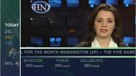
For example, DekoCast lets you create a layout that modifies the studio camera input of a
news anchor with the following additions:
• Crop the anchor video and add a moving background.
• At the bottom of the screen, add a national headline news crawl.
• Add stock quotes and RSS data feeds.
• Add a weather or traffic report graphic that is a looping cel animation or a static graphic.
• Include a time-of-day stamp that loops through each time zone of the region.
The following illustration shows an example of a DekoCast layout.
DekoCast makes the design of your layout more flexible by letting you associate objects
with defined areas of the video output frame called target rectangles. When confined to a
target rectangle, objects always display in the same position on the video output, which
allows you to develop one scene for both standard- and high-definition output.

DekoCast Products and Applications
23
The following illustration shows the target rectangles used to create the layout in the
preceding example.
For more information, see “Arranging Objects for Video Output” on page 86.
DekoCast Products and Applications
The Avid DekoCast family consists of Avid DekoCast and the Avid DekoCast Authoring
Station. These products are available in three models:
• DekoCast SD (standard definition)
The current version of DekoCast SD ships with the Corsica video board. Older SD
systems were shipped with the TARGA® board. There are differences between these
two models. For example, Corsica-based systems use MPEG-2 MXF I-Frame as the
native file format for clip capture and playback, while TARGA-based systems use either
DV 25, MPEG-2 LongGOP, or MPEG-2 I-Frame. Where appropriate, these differences
are described in this guide.Where appropriate, these differences are described in these
Help topics.
• DekoCast HD (high definition)
The current version of DekoCast HD ships with the Corsica video board. Older HD
versions were also shipped with the Corsica board. There is no functional difference
between these models.
• DekoCast SD/HD (hybrid)
DekoCast SD/HD systems allow you to work in either standard definition or high
definition. This model ships with the Corsica video board. For more information, see
“Switching Between Video Formats” on page 29.
Layout with target
rectangles
1 Getting Started
24
Artists can develop on-air edge graphics using either DekoCast or the DekoCast Authoring
Station. The Authoring Station is a fully featured DekoCast system designed for creating
and previewing content, but is not intended for on-air use. (Authoring Station video output is
watermarked.) For information on moving projects from one system to another, see
“Copying Files” on page 42.
nThe user interface for the DekoCast and DekoCast Authoring Station applications are
identical.
Two options are available for DekoCast:
• The Clip Player is an option that provides multi-stream clip playback and storage for
clips. See “Playing Back Clips” on page 140.
• The Cel Animation Player is an option that lets a DekoCast system import and cycle
through a series of numbered image files for animated playout. See “Creating Cel
Animations” on page 173.
The following applications are included with all DekoCast and DekoCast Authoring
systems:
•Avid PostDeko Lite
PostDeko Lite is a full-color video-character generator provided as a graphics creation
tool for DekoCast. Although PostDeko Lite does not support features found in on-air
Deko® systems, such as motions, cel animations, effects, and sequences, it does have all
of the power of Deko 3000 for building text and graphic layers. Graphic files built in
PostDeko Lite (.dko files) can be used seamlessly in other Deko products (and files built
in Deko products can be used in PostDeko Lite).
PostDeko Lite controls the default directories for the Deko graphics files used by
DekoCast (see “Setting Up Directories” on page 37). For information about using
PostDeko Lite to create content for DekoCast, see the Avid Deko Products User’s Guide,
which is included with your DekoCast documentation.
• Avid DekoCast Central
You can use DekoCast Central as a standalone playout application or in conjunction
with a station’s automation system to control playout of a scene on the on-air DekoCast
system. For more information, see “Using DekoCast Central” on page 351.
• Avid Sequence
The Sequence application controls the playback and timing of actions in scenes without
using or modifying original scenes or actions. For more information, see “Using
Sequence to Play Back Actions” on page 401.
DekoCast Workflow
25
DekoCast Workflow
How you integrate DekoCast into your workflow depends on the requirements of your
facility. Here is one typical workflow for creating DekoCast scenes and controlling video
output:
1. Create or otherwise obtain the content for DekoCast source files.
Content includes graphics, animations, clips, and audio. Artists create graphics content
for DekoCast using Deko, PostDeko Lite, or other image-editing applications. You must
use Deko files (.dko) if the text information is to be updated with automation or text
files. Crawls are usually linked to a Deko graphic that contains a text layer. Cel
animations, clips, and audio files are typically created in other programs and linked
within DekoCast.
2. Using an offline DekoCast or DekoCast Authoring Station, assemble a scene, which is
the basic file for DekoCast output.
3. Transfer all of the scene files to the local disk of the on-air DekoCast system. Ensure
that all of the files, file names, and the complete paths for scenes are the same on both
DekoCast systems.
All DekoCast systems in a workflow must be configured to use the same drive structure.
Use drive D for elements, scenes, and graphics that are static images. Use drive E for
clips and audio files. You can save cel animation source files in a directory on either
drive D or E.
nAlways copy the DekoCast source files to the on-air DekoCast system’s local disk. A network
failure that prevents a DekoCast system’s access to files stored over a network might
interrupt on-air broadcasting.
4. Use DekoCast Central to play the DekoCast scene to air.
1 Getting Started
26
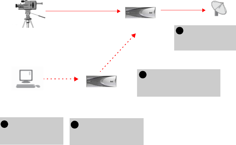
The following illustration shows a possible configuration and workflow.
Controlling DekoCast On-Air Video Output
There are several ways to control the DekoCast on-air video output:
• Use DekoCast Central, which you can control through a graphical-user interface (GUI)
or by General Purpose Interface (GPI) and Triple i automation. Automation control can
be through RS-232 (COM 1 or COM 2) or RS-422 (COM 3 or COM 4). For more
information, see “Using DekoCast Central” on page 351.
• Use XML to control DekoCast. This involves a user-written or third-party application
that sends XML commands through either a serial connection (COM port) or a network
socket. If you have such an application, specify the COM port or network port used to
send XML commands. For more information, see “XML Configuration” on page 427.
• Use a custom Application Programming Interface (API) developed by third-party
developers. For COM control, use the application API. For serial control, use the Byte
Stream Command Interface (BCI). See the Rocket Engine API documentation and the
Rocket Engine BCI documentation, which are available on the Avid Customer Service
Knowledge Base (www.avid.com/onlinesupport).
33Transfer files from the offline
to the on-air system. Make
sure the systems have
matching drive configurations.
2Use the offline DekoCast
to create a scene and add
graphics to video.
Studio feed
(router)
Video In A
On-air DekoCast system Use DekoCast
Central to play out
to air
Offline DekoCast
or DekoCast
Authoring Station
PostDeko Lite or other
graphics creation system
1
4
Video Out A
Transfer source
images to the offline
DekoCast system.
Before You Begin
27
• Use the Avid Sequence application to set up a series of actions from scenes whose
playout can be controlled by GPIs. For more information, see “Using Sequence to Play
Back Actions” on page 401.
cBefore running DekoCast on air, close all applications not directly related to on-air
play to conserve resources. If DekoCast is on air, do not use the DekoCast authoring
interface. DekoCast must be offline to preview or add scenes. Close DekoCast before
running DekoCast Central on air.
Before You Begin
Before you start DekoCast, set up your system and install the DekoCast product applications
as described in the Avid On-Air Graphics Setup and Configuration Guide.
Make sure that all DekoCast systems in a workflow are configured to use the same drive
structure. Use drive D for elements, scenes, and graphics that are static images. Use drive E
for clips and audio files. You can save cel animation source files in a folder on either drive D
or drive E. For more information, see “Setting Up Directories” on page 37.
DekoCast operates with Serial Digital Interface (SDI) video. To have video input, your
system needs to be connected to an SDI input device such as a router.
DekoCast does not display any output on your Windows desktop. To view work in progress,
attach a video output monitor to your DekoCast system. Always set your video output
monitor to the underscan setting to prevent peripheral material from being present in the
video output that displays on this monitor.
cInstalling any third-party software on your DekoCast that has not been explicitly
recommended by Avid could void your support agreement. Never install third-party
software without first consulting both the third party and Avid Technology, Broadcast
Support.
Starting and Closing DekoCast Applications
After installation, there are five Avid desktop shortcuts on your desktop: DekoCast,
PostDeko Lite, Sequence, DekoCast Central, and Transcode. Double-click a shortcut to open
its application.
nSee the Avid On-Air Graphics Setup and Configuration Guide for complete instructions on
using the physical components of your system.

1 Getting Started
28
To start the DekoCast application:
1. Set the two switches for the dual power supply at the rear of the unit to the On position.
2. Turn on the DekoCast system by pressing the On button on the front of the unit.
3. Log on to Windows XP Professional.
4. Do one of the following:
tDouble-click the DekoCast shortcut on the desktop.
tClick the Start button and select All Programs > DekoCast > DekoCast.
The DekoCast main window opens.
nIf you have a DekoCast SD/HD hybrid system, see “Switching Between Video Formats” on
page 29.
To exit the DekoCast application, do one of the following:
tFrom the menu bar, select File > Exit.
tClick the close button in the main DekoCast window.
When you exit DekoCast, you are prompted to save each scene that you have changed,
one scene at a time.
To start PostDeko Lite, Sequence, DekoCast Central, or Transcode, do one of the
following:
tDouble-click the shortcut on the desktop.
tClick the Start button and select All Programs > PostDekoLite > PostDekoLite.
tClick the Start button, select All Programs > DekoCast, and select the appropriate
application.
You can run DekoCast and the other applications simultaneously. Press Alt + Tab to switch
between open applications.
• For information on using PostDeko Lite, see the Avid Deko Products User’s Guide or
the Avid Deko Help.
• For information on using Transcode, see “Transcoding SD Clips to MPEG-2 MXF
I-Frame” on page 149.
• For information on using Sequence, see “Using Sequence to Play Back Actions” on
page 401.
• For information on using DekoCast Central, see “Using DekoCast Central” on
page 351.
Switching Between Video Formats
29
Switching Between Video Formats
If you have a DekoCast SD/HD hybrid system, you can switch from an SD format to an HD
format, or from an HD format to an SD format. For example, you can work in an NTSC
project, and then switch to a 1080i/59.94 HD project.
For more information about available formats, see “Video Hardware Options” on page 416.
To switch from one video format to another:
1. Select Options > Preferences.
2. Click the Video Hardware Options tab.
3. In the Video Format section, select the desired format from the Standard list.
4. If necessary, select the appropriate aspect ratio (4 x 3 or 16 x 9).
5. Click OK.
6. If you are switching from HD to SD, or SD to HD, follow the screen prompts to restart
the application.
Restarting the application is not required when switching between NTSC and PAL or
between HD formats.
Configuring Your DekoCast System
Before using your DekoCast system, you need to configure DekoCast for your particular
installation. Configuration includes defining input and output channels and other hardware
settings. For complete information, see “Configuring DekoCast” on page 415.
A DekoCast system has two video input ports. By default, a DekoCast system is configured
for one video input, but you can configure it to have two video inputs, or to have one video
input and one key input.
A DekoCast system is configured by default with one video output. A second video output
port exists that can be configured as a key channel. A DekoCast system is usually installed
downstream of the switcher. When a DekoCast system is installed upstream as a keying
device into the switcher, it must be configured with Output A as the video fill and Output B
as the key signal. Use the Video Hardware Options tab in the Options dialog box to
configure DekoCast’s input and output ports. See “Hardware Configuration Settings” on
page 419.
TARGA-based SD systems support 16-bit audio. Corsica-based SD systems support 20-bit
audio, and Corsica-based HD systems support 24-bit audio.
1 Getting Started
30
Basic Components
This section presents an overview of the most important components of DekoCast. For an
example of how to use these component to build and play out a scene, see “Quick Start:
Fading a Graphic On and Off” on page 45.
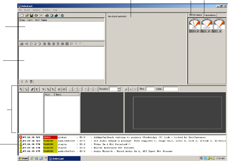
DekoCast Main Window
After you start the DekoCast application, the DekoCast main window opens with a set of
empty panes. This window provides the interface for developing DekoCast projects.
The major areas (or panes) of the window are the Scenes pane, the Object pane (where the
Scene Tree is displayed), the Object Editor pane, the Timeline editor, and the Log pane. You
can resize each of these panes to suit your current working style by selecting a border of a
pane and dragging it to another position.
Performance tab
Log pane
Scenes pane
Object pane
Timeline editor
Object Editor pane Parameters tab
Basic Components
31
Scenes
The main organizing tool for creating DekoCast projects is the scene. A scene consists of a
set of objects that you assemble and animate through actions and save as a scene file. The
DekoCast system composites one or more scene files for on-air broadcast.
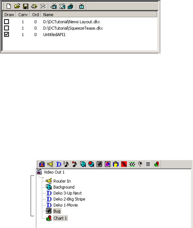
Scenes are displayed in the Scenes pane.
The Scenes pane includes a toolbar and a shortcut menu that you access by right-clicking the
pane. For more information, see “Working with Scenes and Objects” on page 59.
Objects
Objects are the “actors” that you explicitly add to a scene to perform a task. An object can
represent live video, video clips, audio clips, Deko graphics (either the entire graphic or
selected layers), charts, and cel animations (bugs). When you add an object, it appears in the
Scene Tree in the Objects pane.
You can control an object’s appearance and behavior by changing its properties, such as
scale, position, and opacity (see “Object Editors” on page 33).
Scenes Pane
Objects in a
Scene tree
Objects Pane
1 Getting Started
32
nAvid does not recommend accessing linked files over a network due to performance
variability.
The Objects pane includes a toolbar and a shortcut menu that you access by right-clicking
the pane. For more information, see “Editing Objects in the Scene” on page 79.
The content that you assemble in DekoCast to create projects is developed outside of
DekoCast using PostDeko Lite or third-party graphics applications. For example, a graphic
artist might use Adobe® Photoshop® to create a static image file to use in a Deko
graphic.You can then use PostDekoLite to create a finished graphic that combines the image
with text, including text that you update in DekoCast through text files or object parameters.
An artist might use Adobe After Effects® to create a series of images to be linked to a cel
animation object or a video clip to be linked to a clip object. You can use Digidesign®
Pro Tools® to create audio clips.
You link source files to objects through file selections you make in the object editor. For
information about supported file types, see “Supported File Formats” on page 41.
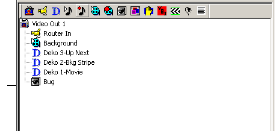
Scene Tree
Objects in the Scene Tree are organized hierarchically in a tree structure. The position of an
object in the tree determines the order in which the application draws it for video output. The
application composites the objects in the Scene Tree object-by-object, from the top of the
tree downward, and displays them as video output. The lowest object in the tree is processed
last (and appears in front of all other objects). For more information, see “How Objects Are
Composited” on page 72.
Objects
in a
Scene
tree
Objects Pane
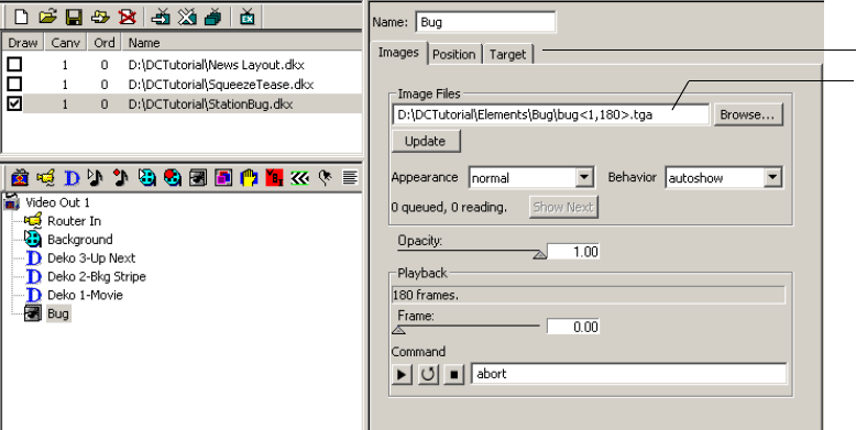
Basic Components
33
According to how you arrange objects within the tree hierarchy, objects can function as
independent objects, as parent objects with child objects, or as child objects under the
control of a parent object. Individual objects that are combined into a group object are child
objects of the group. Groups can be nested within other groups. See “Using Group Objects”
on page 181.
Object Editors
When you select an object, its object editor displays to the right of the Scene Tree. Each
object type has its own editor. Using the editor, you link an object, such as a Deko graphic or
clip, to its source file on your hard drive. The editor also allows you to configure parameters,
which control the object’s behavior, such as its position on video output, scale, opacity, and
playback commands. Each object type has its own set of parameters. Select each tab in an
object editor to view the controls that you can set for that object.
For more information, see “Editing Objects in the Scene” on page 79.
Object editor for Cel Animation object (Bug)
Linked file
Tabs
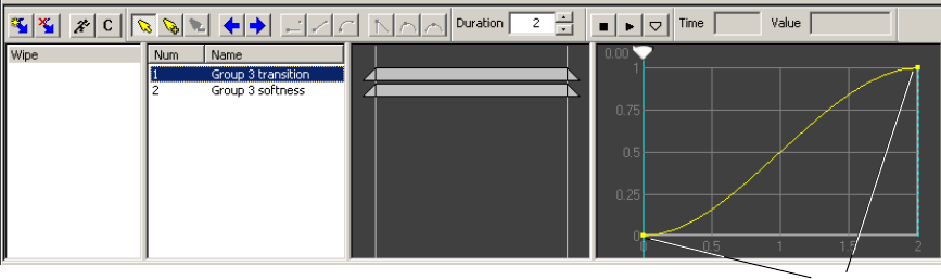
1 Getting Started
34
Actions and the Timeline Editor
Scenes are animated through actions, which are recorded changes in object parameters over
time, such as an object’s position, size, and opacity. Actions can turn clips on and off, start
and stop cel animations (bugs), and squeeze back a video input frame. Any parameter value
that can be changed is a potential action, and an action can control multiple parameters. You
can define any number of actions for a scene. Actions allow you to control multiple
parameters simultaneously in a user-definable order.
The Timeline editor has four sections: the Action list, the Action Parameter list, the Timeline
Bar editor, and the Timeline graph. The Timeline editor includes a toolbar. The Action list
and Action Parameter list include shortcut menus that you access by right-clicking within
the list.
You animate actions using the keyframe-based Timeline graph. You can set the parameters
for an action to occur at beginning and ending points (keyframes) on the Timeline graph. You
can also add keyframes and set parameters at any other point on the Timeline graph.
For more information, see “Adding Actions to a Scene” on page 297.
Performance Tab
The Performance tab gives you an overview of the state of the application’s current
processing through a set of three meters (one set for each installed video board).
• The Overall meter measures total system performance.
• The Composite meter measures layer-by-layer compositing of objects in the Scene Tree.
• The Resize meter measures the amount of resources DekoCast utilizes as it resizes an
object, such as the resizing required to create a squeeze-back.
Action list Action Parameter list Timeline Bar editor Timeline graph Keyframes
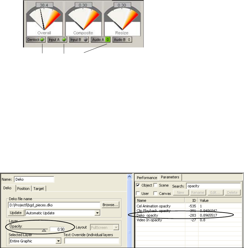
Basic Components
35
While the application processes your work, pay attention to the meters. Video processing
resources have been exceeded when the meters enter the red zone. As you develop scenes,
Avid recommends not exceeding 80 percent on any meter. Otherwise, you might be
exceeding the system’s processing capability, which could compromise your output.
Lights below the meters indicate whether a source is present for Genlock, Input A and B, or
Audio A and B. A green light means that the source is available. If the light is not green, the
source is not available.
The Performance tab and the Parameters tab share the same pane in the upper-right corner of
the DekoCast window. Click the Performance tab to bring the tab to the front.
Parameters Tab
The Parameters tab consolidates the scene’s parameter data. It lists parameters and their
values for the currently selected scene, the objects within that scene, and installed video
boards. You can search for parameters, change their values, and even define your user
parameters to expedite scene creation. For information on how to use the Parameters tab, see
“Working with Parameters” on page 335.
Green = Source available
Parameters tab showing
Opacity parameters in a scene
Deko Object editor with Opacity parameter
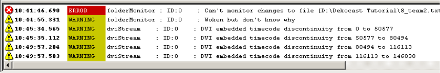
1 Getting Started
36
The Performance tab and the Parameters tab share the same pane in the upper-right corner of
the DekoCast window. Click the Parameters tab to bring the tab to the front.
cAfter you are finished using the Parameters tab, click the Performance tab. Keeping
the Parameters tab displayed might slow down updating of the user interface for a
large scene.
Log Pane
System-generated information about DekoCast’s activity displays in the Log pane of the
DekoCast window. You can set the severity level of the information to be recorded in this
log. In certain cases, DekoCast might generate many warnings that are insignificant.
To restrict logging messages:
1. Select Options > Preferences.
2. Change the minimum logging severity level from Warning to Severe.
For more information, see “Application Options” on page 428.
nTo hide the Log pane, click the lower border of the Timeline Editor window and drag it over
the log pane.
Adjusting the DekoCast Window
You can adjust the DekoCast window for your current tasks. For example, if you are working
exclusively in the Timeline editor, you might increase its size and reduce the size of other
panes. You can adjust and save up to three custom window layouts (Layout 1, 2, and 3).
Layouts persist after you exit the application.
To save a custom layout:
1. Open the layout you want to save by selecting Window > Layout x.
2. Resize the DekoCast main window’s panes as you desire.
The layout is associated with the currently selected layout (1, 2, or 3) and remains the
same until you change it.
Understanding Files and File Types
37
To switch to a different layout:
tSelect Window > Layout x.
To return all layouts to their default configuration:
tSelect Window > Reset to Default.
Online Help
DekoCast includes online Help. The Help is a searchable, hypertext version of this guide, the
Avid DekoCast Products User’s Guide.
To view online Help for DekoCast:
1. Do one of the following:
tSelect Help > DekoCast Help.
tPress F1.
2. Use the Contents, Search, or Index tab to find the information you need.
For complete information on using Help, including options for Search, see “Using Help” in
the DekoCast Help.
Understanding Files and File Types
This section describes the application’s file types and file-naming conventions. It also covers
steps to take when copying files from one DekoCast system to another. When you transfer
files from an Authoring Station to an on-air DekoCast system, all of the scene’s source files
must be copied to the local disk of the on-air DekoCast system.
Setting Up Directories
The DekoCast system includes two physical drives. As shipped, one drive has two partitions:
C: System and D: Graphics. The other drive has a single partition: E: Clips. These partitions
function as drives.
Avid recommends that you organize your files in directories and save them to the following
drives:
• Drive C: All applications.
• Drive D: DekoCast projects and all static components and elements.
• Drive E: All clips and audio files.
nYou can save cel animation source files in a directory on either drive D or drive E.
1 Getting Started
38
You need to make sure PostDeko Lite and DekoCast use the same directories. If the
applications are on different machines, the paths need to match. The default directories that
you set in PostDeko Lite are used by DekoCast to process Deko graphics and all components
of Deko graphics. The PostDeko Lite application defines the default directories in DekoCast
for these kinds of files:
• Graphics and automation
• Styles, preset styles, and shaders
•Macros
• Custom typeface files
nAvid recommends that you use the same directory for all types of Deko files and their
components. If you use many custom typefaces, you might want to set up a separate
directory for custom typefaces.
To set the default directories in PostDeko Lite:
1. Start PostDeko Lite.
2. Select Options > Preferences.
3. Click the Paths tab.
In the current directory text box, type the complete path for the directory, such as
D:\Dekographics or D:\News. This is the directory where this file type is automatically
saved.
nIf you need to set up a directory for custom typefaces, do not use a space or an underscore in
the name. Use the same custom typefaces directory for all projects at the same location.
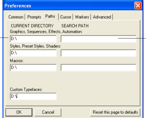
Understanding Files and File Types
39
If DekoCast fails to find a graphic by searching the path listed in the Current Directory,
it searches the paths listed in the Search Path.
4. In the Search Path text box, type one or more additional paths where DekoCast can
search for the file. Type the complete path and include semicolons to separate multiple
search paths; for example: D:\Deko; E:\DekoBugs.
If DekoCast opens a file from the search path, that search path becomes the Current
Directory.
5. To save changes, select Options > Save Settings Now.
6. Click OK.
nIf a graphic does not appear in the scene, make sure the graphic and its components are
saved in the default directories. Open the graphic in PostDeko Lite and check where it is
saved.
If a scene opens with a letter where you expected to see an image, check the Custom
Typefaces path.
Search path
Current directory
1 Getting Started
40
Scene Files
A scene file is saved with all its objects, links to files associated with objects, and animated
actions in the DKX file format.
Prior to DekoCast 4.0, DekoCast scene files were binary files with the DKC format.
Although you can open these older files, you must save them in the DKX format to take
advantage of DekoCast’s newest features. By default, DekoCast saves DKC files as DKX
files but does not modify the previous DKC file.
When prompted to delete the DKC version of the file, click Yes. Avid recommends that you
delete DKC versions of files that were saved as DKX files to avoid having two versions of
the same file.
nAfter you have upgraded a scene to the newer format, the scene is not compatible with
earlier versions.
If you open a scene that references files that the application cannot find, it prompts you to
search or browse for them. After you select a folder, the application searches this folder for
any other missing scene files.
cIf your facility has more than one DekoCast or DekoCast Authoring station, Avid
recommends that you upgrade all units to DekoCast 4.0 simultaneously. Also upgrade
all scenes to the DKX format in all online and offline directories.
DekoCast Central supports DKX and the older DKC format.

Understanding Files and File Types
41
Supported File Formats
DekoCast supports specific file formats for specific objects. You can view the supported file
formats for an object after you click the Browse button to navigate to a file. Supported file
formats are listed in the Select File dialog box’s “Files of type” menu. The supported source
file formats for objects are listed in the following table.
Supported File Formats
Object Type Supported Formats Requirements
Clip Capture and Clip Playback
SD video clip files
(TARGA® systems)
AVI, DV, and DIF
MXF
DV 25 compression
DV 25
MPEG-2 4:2:0
MPEG-2 4:2:2
I-Frame or IBP compression
Clip Capture and Clip Playback
SD and HD video clip files
(Corsica systems)
MXF MPEG-2 4:2:0
MPEG-2 4:2:2 (playback only)
I-Frame compression
nYou can convert clips to
these supported formats
with the Transcode feature
(see “Transcoding SD
Clips to MPEG-2 MXF
I-Frame” on page 149).
Clip Capture and Clip Playback
Key video clip files Same as for Clip Playback video objects
Audio Capture and Playback:
Audio files WAV
AVI (playback only)
48khz, 16-bit stereo
Cel animation Usually a series of TGA or TIF files. Other
supported formats are AVI, BMP, DIB, G
(Avid Thunder format), GIF, JPG, PCD,
PCT, PSD, and SGI.

1 Getting Started
42
Copying Files
You can develop DekoCast scenes using a different DekoCast system than the one that plays
scenes on air. In this case, ensure that all of the scene’s source files have been copied to the
local disk of the on-air DekoCast system. The file names and complete path for scenes
should be the same on the authoring system and the on-air system.
You need to update all of the asset files on all DekoCast systems. Be aware, however, that
one asset type—the Deko graphic—might contain many related files. The PostDeko Lite
application provides a way for you to copy all of the components of a Deko graphic, as long
as all components reside in the same directory. If you have a Deko graphic in a scene that
uses textures, macros, and custom typefaces, you must copy all reference, source, or
component files, such as source texture files and source text files (TXT), and save them on
the alternate DekoCast system with the identical directory structures and file names.
Deko DKO, AUT, and ATX
Key: Deko and PostDeko Lite accept static
images with key from other graphics
applications in the following formats: TIF,
TGA, PICT, and PSD.
Full-screen image formats (no key): JPG,
BMP, PCD, G (Avid Thunder format),
PCS, WMF, DIB, RLE, PCT, and PNG. To
use these formats, open the file in
PostDeko Lite and save it as a Deko
(*.dko) graphic.
Text Data TXT, AUT, and ATX
Frame Grab TGA
Supported File Formats (Continued)
Object Type Supported Formats Requirements

Understanding Files and File Types
43
To copy all the components of a Deko graphic from PostDeko Lite:
1. Open PostDeko Lite and select Files > Copy File.
nTo copy the contents of a folder, select Files > Copy Directories.
2. In the Source pane, click Add and select one or more Deko graphics.
3. In the Target pane, click Select and navigate to the Target directory where you want the
files copied.

1 Getting Started
44
4. Select the options that you want:
- Select “Append full source path” if you want the source folder structure recreated in
the target directory.
- Select “Copy related files” to copy all files that are associated with the graphic.
- Select an overwrite option.
5. Click Copy to copy all the components of a Deko graphic to the target directory.
nTrueType fonts are not included in the Copy File feature. In PostDeko Lite, select
File > Information, and open the graphic. A macro window opens that displays which
TrueType fonts are used. You need to copy these fonts manually.
Alternatively, you can examine a Deko graphic layer-by-layer in PostDeko Lite to determine
its components and manually copy those components.
Viewing Information About Your DekoCast System
To view information about your DekoCast system:
tSelect Help > About DekoCast.
The “Enabled Options” line indicates which options are installed on your system. The Clip
Player and Cel Animation Player are optional features and must be purchased for DekoCast
systems (see “DekoCast Products and Applications” on page 23).
The HASP ID number is the number of your application key (dongle).
Quick Start: Fading a Graphic On and Off
45
The System Information pane indicates how much CPU memory is installed, how much
space is available on drive C, and the largest amount of contiguous video memory (free
chunk of memory, in megabytes) available on the video board.
To view your system’s configuration settings:
tSelect Options > Preferences.
If necessary, ask your video engineer to select the correct video format and other
settings, as described in “Configuring DekoCast” on page 415.
Quick Start: Fading a Graphic On and Off
This section takes you step-by-step through the process of creating a simple scene. You’ll be
adding two objects to your scene:
• A Video In object for a studio feed
• A Deko object linked to a Deko graphic
You’ll also be creating two actions:
• Fading a graphic on
• Fading a graphic off
A typical application of this type of scene is displaying a station ID.
Before You Begin
This example requires a graphic that has already been created in a graphics program such as
PostDeko Lite. An ideal graphic would be a station logo that appears a corner of the screen,
but if necessary you can use any type of image.
This scene also requires a video input into your DekoCast system for the Video In object,
such as a studio feed. If you don’t have access to a studio feed, the background appears
black.
nNew DekoCast systems are supplied with sample scenes and media. See “Using the Sample
Scenes and Media” on page 57.
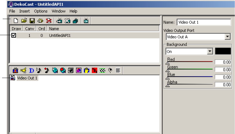
1 Getting Started
46
Creating a Scene
Start by creating a scene, which is the basic file for DekoCast output. For information about
scenes, see “Working with Scenes and Objects” on page 59.
To create a new scene:
1. Do one of the following:
tSelect File > New.
tClick the New button in the toolbar.
A new, untitled scene appears in the Scene Pane. Notice the draw box and the Video Out
object, which are added by default.
The draw box is selected (checked) by default. If the draw box is selected, your scene
can be played out through your Video Out channel. The Video Out object enables all
other objects in the scene to play out. There is only one Video Out object in a scene. The
Video Out object is the top of your Object Tree.
2. Do one of the following:
tSelect File > Save.
tClick the Save icon.
3. Navigate to a folder, type a name for your scene (for example, MyScene), and click
Save.
New button
Draw box
Video Out
object
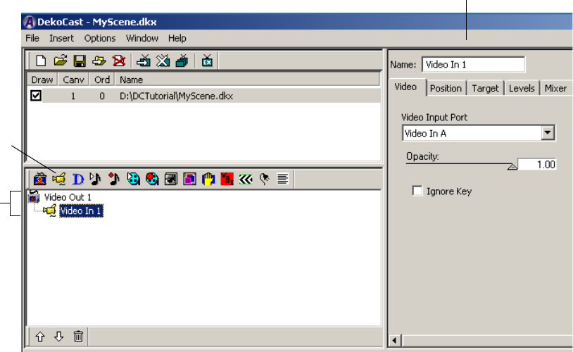
Quick Start: Fading a Graphic On and Off
47
The scene is saved as MyScene.dkx. The extension .dkx indicates a DekoCast scene file.
cDekoCast does not include an Undo, so save early and save often.
Adding Objects
Now that you’ve created a scene, you can add objects to it. In this example, you will add a
Video In object (a studio feed) and a Deko object (a graphic). For more information about
objects, see “Editing Objects in the Scene” on page 79.
To add objects to your scene:
1. Click the Video Out object that appears in the Object Tree to select it.
2. Click the Video In icon to add a Video In object to the Object Tree.
Notice that the Video In object appears indented from the Video Out object, which
indicates that it is a child of the Video Out object. This relationship is required so that
the Video In object plays out to air.
Video In
icon
Object
tree
Object editor and
Name field
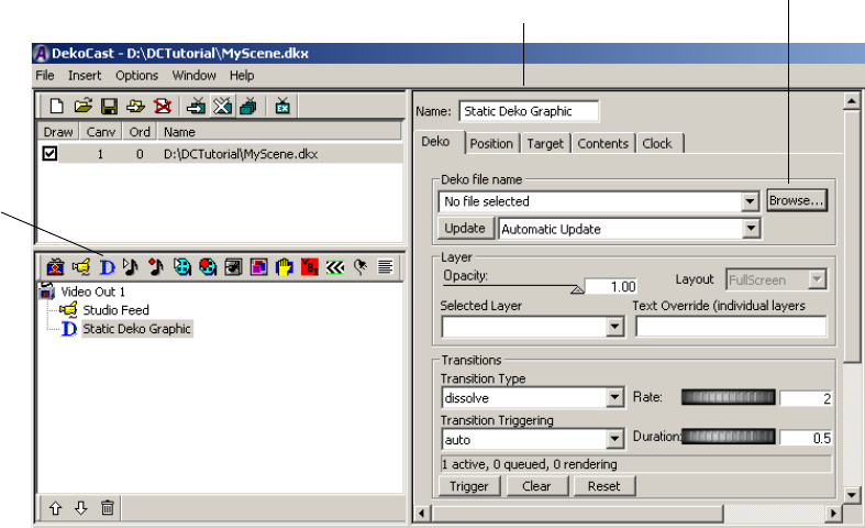
1 Getting Started
48
If video is physically connected to an input on your DekoCast system, it should now be
playing full screen through DekoCast to the Video Out channel and should be displayed
on your video output monitor. It does not appear on your computer monitor.
3. Select the Video In object.
The object editor now displays parameters for the Video In object. There are multiple
tabs that organize the types of parameters.
4. Select the Name field at the top of the object editor and type “Studio Feed.”
It’s a good idea to always name objects in a meaningful way.
5. Select the Video Out object.
6. Click the Deko object icon in the toolbar.
DekoCast adds the Deko object to the Object Tree. The object editor now reflects
parameters for a Deko object.
7. In the object editor, rename the Deko object “Static Deko Graphic.”
8. In the object editor, click the Browse button and navigate to the graphic file you want to
add to a scene.
This graphic could be a static station ID that was created in PostDeko Lite or in Deko.
See “Before You Begin” on page 45.
Deko
object
Object editor and
Name field
Browse button
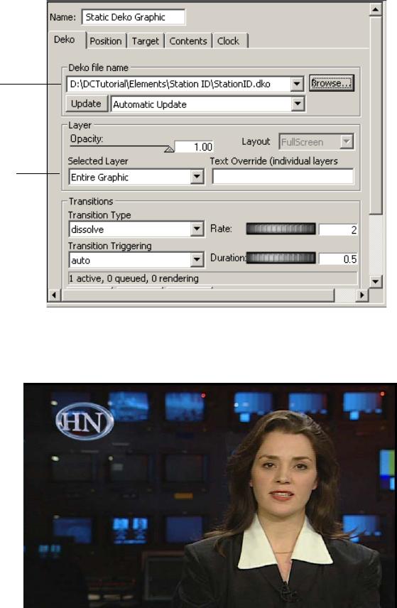
Quick Start: Fading a Graphic On and Off
49
9. Click Open.
The Deko object is now linked to the Deko graphic.
You should see the graphic on your video output monitor, on top of the video feed. The
following illustration is an example of a station ID on top of a video feed.
nIf you are using a full-screen graphic without an alpha channel, the graphic might
completely cover the video feed. You can crop the graphic as described in the next step.
Linked
file
Selected
layer list
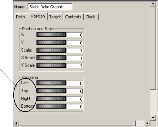
1 Getting Started
50
Notice that Entire Graphic is selected in the Selected Layer list of the Deko object
editor. If a graphic is created with layers, you can select individual layers, which results
in more efficient processing. Processing an entire screen of pixels can take a lot of
system resources, so in this example you can save processing power by cropping.
10. If necessary, click the Position tab of the Deko object editor and use the Cropping
controls to remove the unused part of the graphic.
Use the thumbwheels or type a number so that you remove blank parts of the graphic
while keeping the image itself visible.
The controls are based on an X/Y grid, with dimensions based on the video format. For
example, in NTSC, the full screen width is 720 pixels, so a Left crop of 360 crops off
everything from the middle of the screen to the left edge. To return to the default setting,
click the parameter label.
11. (Option) If you want to change the position or scale of the graphic, use the Position and
Scale controls.
12. Select the Deko object (named Static Deko Graphic) in the Scene Tree.
Cropping
parameter
labels
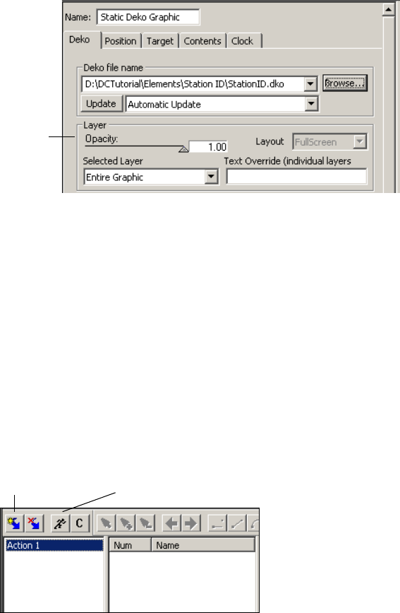
Quick Start: Fading a Graphic On and Off
51
13. In the object editor, click the Deko tab and locate the Opacity parameter.
You’ll be creating an action for this parameter. Drag the arrow back and forth between 0 (no
opacity) and 1 (completely opaque) to view how this parameter changes the graphic.
Adding Actions
Now that you have your objects, you need to animate them by adding actions to the scene. In
this example, you will create two actions in the Timeline editor. For more information about
actions, see “Adding Actions to a Scene” on page 297.
To add actions to your scene:
1. Add an action by clicking the Create Action button on the Timeline editor toolbar.
A new action appears in the Actions List.
2. Rename the action Fade ON by pressing F2 or right-clicking and selecting Rename.
Now that you’ve created an action, associate it with an object and change the
parameters. You do this by entering Animate mode.
Opacity
parameter
Create Action
button
Animate
Mode button

1 Getting Started
52
3. Click the Animate Mode button on the Timeline editor toolbar.
The icon on the Animate Mode button resembles a running man. When the Animate
Mode button is selected (depressed), you are in Animate mode.
Animate mode creates keyframes for every parameter that you select while you are in this
mode. The time value (the time when the keyframe plays in the action) is determined by the
placement of the Scrub bar. The Scrub bar defaults to the first keyframe with all new actions.
cKeep the Animate Mode button selected only when necessary. Any parameters you
click or select are recorded in Animate mode.
4. In the Timeline graph, make sure the scrub bar is all the way to the left (0 seconds).
Positioning the scrub bar at 0 seconds lets you create a keyframe at the beginning of the
action. The Duration box shows that the action is 2 seconds long. This duration is also
shown on the X axis of the Timeline graph.
Animate Mode
button selected
Duration: 2
seconds
Timeline graph: Scrub
bar at 0 seconds
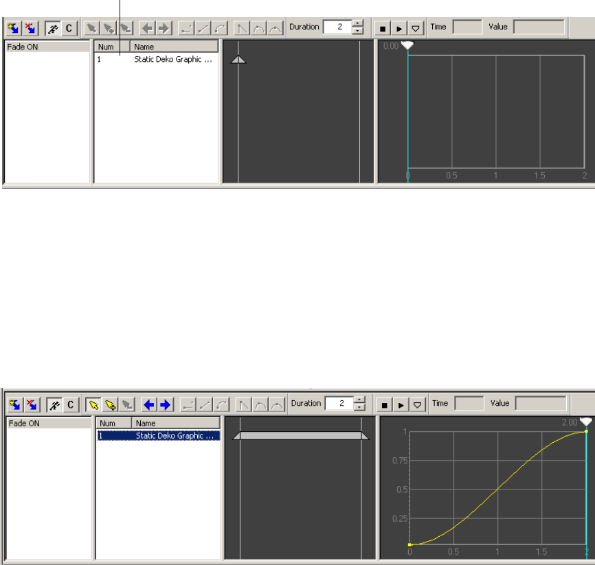
Quick Start: Fading a Graphic On and Off
53
5. Select the Static Deko Graphic object. In the object editor, drag the Opacity slider all the
way to the left, or type 0.00 in the object editor’s Opacity field.
With Opacity set to 0, the graphic is not visible. Notice how the parameter is added to
the Action Parameter list. The name of the parameter is the object name plus the type
of parameter.
6. Create a final keyframe by dragging the scrub bar all the way to the right and setting the
Opacity level at 1.00 (drag the slider all the way to the right or type 1.00).
You now have a complete action that fades the graphic on. Select the parameter in the
Action Parameter list to view a graphical representation of the action: a graphic
changing from not visible to completely visible over 2 seconds.
nIf more than one parameter appears in your Action Parameter list, you accidently created
parameters by clicking in the object editor. Delete all but the Opacity parameter by
right-clicking the parameter and selecting Delete.
Opacity parameter in the
Action Parameter list.
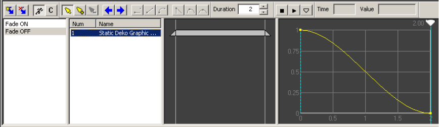
1 Getting Started
54
7. Preview the action by selecting the Action in the Action list and pressing the space bar.
You should see the graphic fade up in the video output monitor.
Now create another action that fades down the graphic. Remember that you’re still in
Animate mode (the Animate Mode button is selected), so be careful to click or select
only the parameters you want to record. If you create an extra parameter, you can always
delete it.
8. To create a new action, click the Create Action button.
9. Rename the second action Fade OFF.
10. In the Timeline graph, make sure the Scrub bar is all the way to the left (0 seconds, the
default). Drag the Opacity slider to 1 (100% opacity), or type 100 in the Opacity field, or
click the Opacity label to reset it to the default (1). The graphic should be completely
visible on your video output.
11. Create a final keyframe by dragging the scrub bar all the way to the right and setting the
Opacity level at 0 (drag the slider all the way to the left or type 0).
You now have two complete actions: one that fades the graphic on and one that fades the
graphic off.
12. Preview the Fade OFF action.
13. Click the Animate Mode button to leave Animate mode.
Remember to deselect the Animate Mode button after creating parameters for an action.
14. Save the scene.
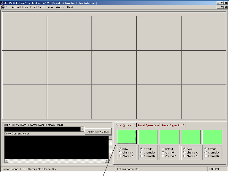
Quick Start: Fading a Graphic On and Off
55
Playing the Scene in DekoCast Central
You can use DekoCast Central to play the actions. For more information about playout and
DekoCast Central, see “Using DekoCast Central” on page 351. These instructions describe
the basics of playing actions in the Graphical User Interface (GUI).
To load a scene and play an action:
1. Do one of the following:
tDouble-click the DekoCast Central desktop icon.
tClick the Start button and select All Programs > DekoCast > DekoCast Central.
The DekoCast Central application opens. The following illustration shows the GUI.
2. If the GUI is not displayed, select View > Graphical User Interface.
Preset Scene button
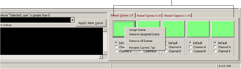
1 Getting Started
56
3. Assign your scene to a Preset Scene button by doing one of the following:
- Right-click the Preset Scene button and select Assign Scene from the menu.
- Select Preset Scenes > Assign Scene.
4. In the Assign DekoCast Scene files dialog box, navigate to the scene you created.
5. Click Open.
The scene is listed on the Scene button you selected.
6. Click the Scene button.
The button turns red and a button is displayed for each action in the scene.
Scene buttons

Using the Sample Scenes and Media
57
7. Click the Fade ON button to play the action, then left-click the Fade OFF button.
You’ve now completed the Quick Start. The following chapters provide detailed conceptual
information and step-by-step instructions for using DekoCast.
Using the Sample Scenes and Media
New DekoCast systems are shipped with sample scenes and media in the following
locations:
• D:\DekoCast4.0\Finance (graphics, scenes, text files)
• E:\DekoCast_Media (audio, cel animations, clips)
If your system includes this material, you can use it explore the capabilities of DekoCast. If
you are new to DekoCast, consider completing the Quick Start before using the sample
material. As you learn more about DekoCast, you can use the sample material to understand
how particular features can be implemented.

1 Getting Started
58
Several versions of the sample scene are included with the installed material. Select the
video format that is appropriate for your system.
To play a sample scene:
1. Select File > Open or click the Open button and navigate to the following folder:
D:\DekoCast4.0\Finance
2. Select a scene in the appropriate video format (for example,
Test_PowerFinance_1080i5994.dkx).
3. In the Scene pane, check the Draw box.
Because of the way the scene is created, you need to play an action to see the
components of the scene.
4. In the Actions pane, double-click the “On” action.
The scene should resemble the following illustration. If your system is configured for a
video input, the video appears in the upper left area.
5. Explore the various objects in the scene tree and how they appear in the scene.
6. To stop the action, double-click “Off.”
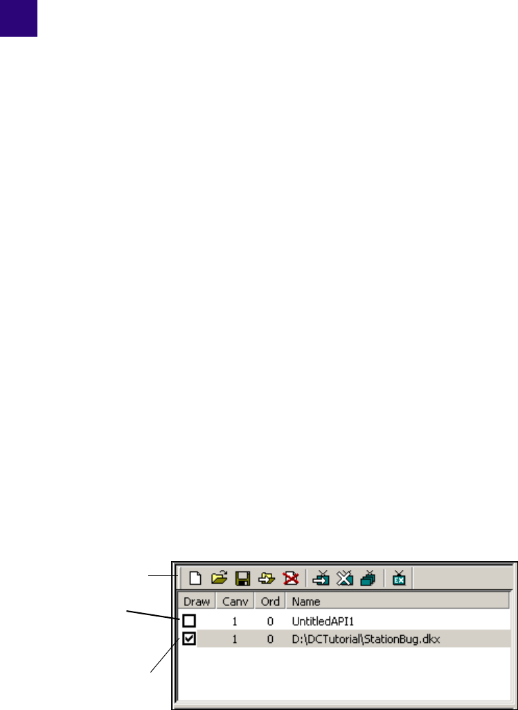
Chapter 2
2Working with Scenes and Objects
A scene consists of objects, such as passthrough video, Avid Deko graphics, animated logos,
and internal video clips that you organize in a Scene Tree. You then animate the objects by
creating actions that modify the object’s parameters.
The following topics provide basic information about how to work with scenes and objects:
•Scenes Pane and Toolbar
•Creating a New Scene
•Renaming and Saving a Scene
•Opening an Existing Scene
•Working with Objects
•Working with the Scene Tree
•Selecting Scenes for Output
•Multiple Scenes and Stacking Order
Scenes Pane and Toolbar
The Scenes pane is the area of the DekoCast window in which you organize DekoCast
scenes for a project. As you create new scenes and open existing ones, they are listed in the
Scenes pane.
Scenes toolbar
New scene
Saved scene with
Draw box
selected for video
output.
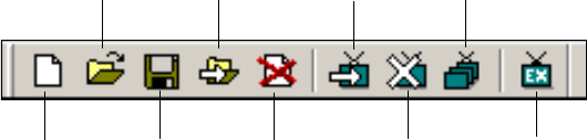
2 Working with Scenes and Objects
60
Scenes are listed in the Scenes pane by name. A new scene is named UntitledAPI (API
stands for Application Program Interface) and numbered according to the number of scenes
you have added during the DekoCast session. You can rename a scene only when you save it.
The Scenes pane includes four columns:
• Draw: The Draw box determines if a scene is played to video output. See “Selecting
Scenes for Output” on page 75.
• Canv (Canvas): The Canvas number indicates which video board is being used for
processing. Currently shipping systems include only one video board.
• Ord (Order): The Order number determines the order in which multiple scenes are
processed. See “Multiple Scenes and Stacking Order” on page 76.
• Name: The default filename or the complete file path for a saved scene.
The Scenes pane has its own toolbar and shortcut menu.
The New Scene, Open Scene, Save Scene, Save As Scene, and Close Scene tools have
equivalent commands in the main File menu. The Show Scene, Hide Scene, Change Scene
Order, and Exclusive Show Scene tools can be accessed only through their toolbar buttons.
nTo display a brief description of a tool, move the mouse pointer over its button without
clicking.
The shortcut menu commands are New (Insert), Open (Ctrl+O), Close (Del), and Save
(Ctrl+S). Select a scene in the Scenes pane and right-click it to display this menu.
Scenes that you have created using the DekoCast application appear in the Scenes pane in
black typeface. The Scenes pane also contains scenes that are open in DekoCast Central.
These names are italicized and in blue typeface.
Scenes created through another program, such as a program developed using the Application
Programming Interface (API), also appear in blue italics. If you modify scenes not created in
DekoCast, save them with another name using the Save As command before closing the
New
Open
Save
Save As
Close
Show Scene Change Scene Order
Hide Scene Exclusive Show Scene
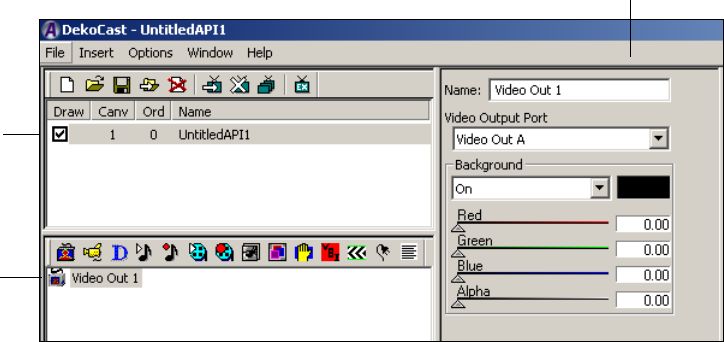
Creating a New Scene
61
scene to avoid changing the original scene file. When you rename a scene, DekoCast
considers it created in DekoCast, and when you reopen it, the renamed scene appears in the
list in black typeface
Creating a New Scene
To create a new scene, do one of the following:
tSelect File > New.
tClick the New icon in the Scene Pane toolbar.
After DekoCast creates a new scene, the following changes appear in the DekoCast window:
• A new, untitled scene is added to the Scenes pane. Scenes that you add during a
DekoCast session are named sequentially. New scenes that you add to the Scene Tree
are always selected to be drawn to video output (the scene’s Draw box is selected).
• A Video Out object is added to the Object pane. When you create a scene, it
automatically has video output associated with it.
Video output is required if the result of your DekoCast scene is to be output to a monitor
or played to air. DekoCast draws changes you make to this scene in real-time and can
display them on a video output monitor.
• The Video Out object editor is displayed. Object editors allow you to control an object’s
parameters. The Video Out object editor lets you select the port and adjust the video
frame’s background color and opacity.
New
scene with
Draw box
selected
for video
output.
Video Out
object
Video Out object editor
2 Working with Scenes and Objects
62
For more information about the Video Out object editor, see “Editing Video Out Objects” on
page 81.
nWhen creating scenes, pay attention to the Performance meters in the upper-right corner of
the DekoCast window (see “Performance Tab” on page 34). Video processing resources
have been exceeded when the meters enter the red zone. As you develop scenes, try not to
exceed 80 percent on any of the meters. See “DekoCast Tips” on page 435 for suggestions
on the most efficient use of system resources.
Renaming and Saving a Scene
To rename a scene, you need to save it with a new name.
To rename a scene:
1. Do one of the following:
tSelect File > Save As.
tClick the Save As button.
The Save As dialog box opens.
2. Navigate to the directory where you want to save the scene, type a new name, and click
Save.
By default, DekoCast scene files are saved as DKX files in the directory in which you last
opened or saved a scene.
To save a scene:
1. Select File > Save.
If the scene has not yet been saved, the Save As dialog box opens.
2. Navigate to the directory where you want to save the scene, type a name, and click Save.
cSave your work frequently to avoid losing any part of your project. DekoCast does not
have an autosave feature or an undo function.
To close a DekoCast scene:
1. Select the scene.
2. Do one of the following:
tSelect File > Close.
tClick the Close button on the Scenes Pane toolbar.
You are prompted to save any changes.
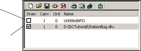
Opening an Existing Scene
63
nAlthough you can modify scenes created in other applications (their names appear in the
Scenes list in italics and blue typeface), you must save them with another file name using the
Save As command. See “Scenes Pane and Toolbar” on page 59.
Opening an Existing Scene
A scene always opens in the state in which it was last saved or closed.
An existing scene file that you open is not automatically enabled. After adding an existing
scene to the Scenes pane, select its Draw box to have DekoCast draw the scene to video
output.
DekoCast scenes are saved as DKX files. Although you can open older DKC files, you must
save them in the DKX format to take advantage of DekoCast’s newest features. DekoCast
automatically adds the .dkx extension when you attempt to save an older DKC file. When
prompted to delete the DKC version of the file, click Yes.
nAvid recommends that you delete DKC versions of files that were saved as DKX files to avoid
having two versions of the same file.
To open an existing scene:
1. Do one of the following:
tSelect File > Open.
tClick the Open icon on the Scenes Pane toolbar.
2. Navigate to the file you want to open and click Open.
The scene is added to the Scenes pane.
New scene
Saved scene with
Draw box
selected for video
output.
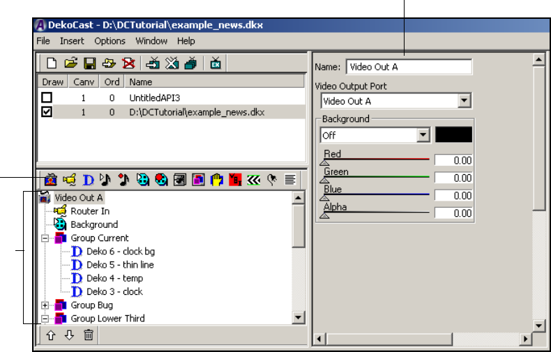
2 Working with Scenes and Objects
64
Working with Objects
A scene can have any number of objects. Depending on how you arrange objects within the
tree hierarchy, objects can function as independent objects, parent or group objects with
child objects, or child objects under the control of a parent or group object. The arrangement
of objects in a scene is called a Scene Tree.
The following topics describe how to add objects to a Scene Tree and provide basic
information about objects. Additional information about the Scene Tree is provided in
“Working with the Scene Tree” on page 70.
Adding Objects to the Scene Tree
A new scene always begins with a Video Out object. When you create a scene, a Video Out
object labeled Video Out 1 is automatically added to the Scene Tree. As you build your
scene, you add other objects to the Scene Tree.
Objects in a
Scene Tree
Object editor
Object
toolbar
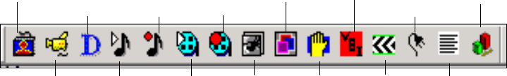
Working with Objects
65
Newly added objects are placed as the last object in the Scene Tree list unless you select an
object in the Scene Tree before adding an object. In this case, the new object is placed
directly below the selected object. In this way the new object becomes a child of the parent
object.
To add an object to the Scene Tree:
1. If you want to add an object as a child, select the parent object.
For example, select the Video Out object before adding a Video In object. Some objects
cannot be added as children. See “Understanding Parent-Child Relationships” on
page 74.
2. Do one of the following:
tSelect the object from the Insert menu.
tClick the object’s icon in the Object toolbar.
nTo display a brief description of a tool, hold the cursor over its button without clicking.
When you add an object to the Scene Tree, the application assigns it a default name,
ending in a number, starting at 1. You should rename objects appropriately as described
in “” on page 66.
nIf you are adding a Deko object, you need to decide which method to use: adding it from the
Insert menu or adding it from the Object toolbar. The method you choose determines the
characteristics of the Deko object. For more information, see “Adding a Deko Object to a
Scene” on page 109.
Video Out
Video In
Deko
Object
Text Data
Crawl
VBI Object
Plug-in
Cel
Animation
Group
Frame
Grab
Clip
Capture
Clip
Playback
Audio
Playback
Audio
Capture
Chart
2 Working with Scenes and Objects
66
Objects Overview
This topic provides a brief description of each of the application objects. Detailed
information about working with an object are provided in “Editing Objects in the Scene” on
page 79. A specific cross-reference is provided for each of the objects.
Object Icon Object Name Description
Video Out A Video Out object makes a composite of objects placed
beneath it in the Scene Tree and sends the result to a video
output port. Everything that is placed below a Video Out object
is layered as a single SDI video signal (with encoded audio).
If you delete the Video Out object, its child objects remain in
the Scene Tree but cannot can be drawn to output. See “Editing
Video Out Objects” on page 79.
Video In A Video In object takes live video from a physical input port
and passes it to Video Out. It also patches and mixes the
embedded audio present at the input port. Your system should
have its Video Input port connected to a device with an SDI
feed such as a router. Although you can add multiple Video In
objects to the Scene Tree, video input functioning is
determined by the number of actual video input ports that the
system supports.
You must explicitly add a Video In object to the Scene Tree.
Using the Video In object editor, you can position, crop,
change the opacity, and scale the Video In signal. The
application also provides level and routing controls for audio
embedded in the video. See “Editing Video In Objects” on
page 83.
Working with Objects
67
Deko Deko objects include text and graphic elements generated in
PostDeko Lite or other applications. These graphics can have
borders, drop shadows, extrusions, kerning and leading, and
textures. The Deko object’s editor allows you to control cuts
and dissolves between text fields, and to roll and crawl text
fields.
You can import a Deko graphic object as an entire Deko
graphic (the layers are flattened into a single layer), a single
layer, or instruct the application to create a separate Deko
object for each layer in the graphic.
The text displayed in a Deko object can be changed at any
time, independent of other scene elements. You can edit Deko
objects within a scene by opening their files in PostDeko Lite
and saving them with the same file name. See “Working with
Deko Objects” on page 110.
Audio Playback The application recognizes WAV and AVI files as source
files for Audio Playback objects. After you select an
audio file, it plays back from the system’s hard drive.
Playback controls allow you to queue, play, and stop the
audio file, either manually or through actions that you
define in the Timeline Editor. See “Playing Back Audio”
on page 136.
Audio Capture The Audio Capture object records audio and saves it to files in
the WAV format. See “Capturing Audio” on page 137.
Clip Playback Clip Playback (available with the Clip Player option)
With the Clip Playback object, you can use internally stored
video clips with associated key files in much the same way as
Video In. See “Playing Back Clips” on page 139.
Clip Capture The Clip Capture object encodes video and writes the encoded
stream with audio to the hard disk. After you record clips, you
can play them back using the Clip Player. See “Capturing
Clips” on page 161.
Object Icon Object Name Description
2 Working with Scenes and Objects
68
Cel Animation Cel Animation (available with the Cel Animation Player
option)
A Cel Animation object, sometimes called a bug, consists of a
series of similar images, each with a slightly different
orientation. When played back in rapid succession, these
images create the illusion of motion. The application reads the
first file in the series and continues loading files until it
encounters a break in the numbering sequence.
Because of the amount of video processing resources required
to process a cel animation, smaller cel animations are
preferable to larger ones. Pay attention to the Performance
meters when working with cel animations. See “Creating Cel
Animations” on page 169 and “DekoCast Tips” on page 429.
Group Group objects are collections of other objects. By grouping
objects, you can set parameters and actions that affect the
entire group and continue to work with each object separately.
For example: A scene includes text that crawls over a banner
and a logo. With the Group object selected, add three Deko
objects to the group—one for the banner layer, one for the text
layer, and one for the logo graphic layer. Then you can assign
the Group object a position, opacity, and actions that affect all
three Deko objects. See “Using Group Objects” on page 177.
Frame Grab The Frame Grab object can capture one or more images from a
video source and saves each image, or frame, as a TARGA
(TGA) file. See “Capturing Video Images (Frame Grab)” on
page 183.
VBI The VBI (Vertical Blanking Interval) object extracts timecode
and closed-caption data, making it available to API clients to
trigger events based on time codes or command streams
contained in closed-caption data. See “Working with VBI
Objects” on page 186.
nYou need to include a VBI object in your scene only if
your installation has a special program that can use this
data.
Crawl A Crawl object moves a continuous stream of text, cel
animations, or clips from one side of the output frame to the
other, or for a roll, from the bottom to the top of the output
frame. A crawl object can also include audio playback. See
“Creating Crawls” on page 190.
Object Icon Object Name Description
Working with Objects
69
Renaming Objects
When you add an object to the Scene Tree, the application assigns it a default name that ends
in a number. For example, a new scene always begins with a Video Out object, which the
application adds automatically as the first item in the Scene Tree. The first Video Out object
you add after launching the application is labeled Video Out 1. Every time you create a new
scene in the session, the number is incremented by one. To avoid being confused by a scene
that begins with an object named Video Out 4 or Video Out 7, specify an appropriate name
for each object.
An object’s name should reflect its object type and be as specific as possible. For example, if
you are adding multiple Crawl objects, the first might be lower third crawl and the second
coming_up_next. When working with a multiple-layer Deko graphic, your naming scheme
might be as follows: bar yellow L3, bar thin white, bkg photo, crawl text, headline text, and
image for OTS. Assign descriptive names for audio files and clips, such as jungle audio,
purple swirl clip, or purple clip for L3.
To rename an object in the Scene Tree:
tEdit the name in the object editor’s Name text box.
The name you use is a descriptive name for your organizational purposes only, and can
contain any characters.
nWhen editing a text box, press the Esc key if you need to cancel your changes.
Plug-Ins These are special utilities provided by Avid and third parties
that add functionality to the application. See “Adding Plug-in
Objects” on page 217.
Text Data A Text Data object, which is automatically added when you
add a Crawl object, can read plain text, AUT, and ATX files to
drive crawls. This object includes rules that you set to
determine how non-text objects are inserted between lines of
text in crawls. Source text files can include programming tags
to control how DekoCast formats the text and how non-text
objects are inserted between lines of text. See “Creating
Crawls” on page 190.
nDo not add Text Data as a separate object.
Chart Chart objects are charts that are created by using the Chart
Designer.
See “Working with Charts and Graphs” on page 219.
Object Icon Object Name Description
2 Working with Scenes and Objects
70
nTo better distinguish between objects and groups in Action parameters, use lower-case
letters for object names and capital letters for group names.
Working with the Scene Tree
The following topics describe how to build and use the Scene Tree as part of your scene.
Expanding or Collapsing a Branch
Adding objects as children of a parent object creates a child-parent branch in the Scene Tree.
Objects in the Scene Tree that are preceded by a plus or minus sign can be expanded or
collapsed. Collapsing a branch you are not working with provides a better view of other
objects in the Scene Tree.
To expand a branch:
tClick the plus sign (+).
All children of the parent object are displayed.
To collapse a branch:
tClick the minus sign (–).
Only the parent object is visible.
Delete
Branch
expanded with
children visible
Branch
collapsed
Working with the Scene Tree
71
Deleting Objects
To delete an object from the Scene Tree:
tSelect it and click the Trash icon at the bottom of the Object pane.
Deleting a collapsed parent object deletes all of its child objects. Deleting a Group
object deletes all of the children within the group. If you delete a Video Out object,
every child object associated with it no longer appears in the video output.
Inserting a Scene within a Scene Tree
If you have created scenes that you want to combine into a single scene, you can insert the
scenes into an existing scene.
To insert a DekoCast scene:
1. Select the location in the Scene Tree for the new scene.
If the scene to be inserted does not have a Video Out object at the top of its own Scene
Tree hierarchy, it is inserted in the current scene under the currently selected object.
Otherwise, it is inserted as a separate scene at the bottom of the Scene Tree.
2. Select Insert > Scene.
The Open dialog box opens.
3. Select an existing DekoCast scene file (.dkx).
4. Click Open.
An entire DekoCast scene, including objects, along with their parameters, hierarchical
order, and actions, is added to the Scene Tree in the selected location.
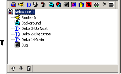
2 Working with Scenes and Objects
72
How Objects Are Composited
DekoCast composites the objects in the Scene Tree object-by-object, from the top of the tree
downward, with the last object appearing on top in the video output. This last object has
priority in the Scene Tree. When positioning objects in the Scene Tree, visualize how the
application prioritizes each object and how one object affects all other objects.
The following illustration shows a Scene Tree with various objects arranged in priority
order, with the object at the bottom of the tree appearing on top in the video output.
The position of objects in the Scene Tree determines how the objects are displayed in the
video output. When a Video In object (Router In), which is full-frame, is placed below the
Video Out object, it completely fills the video output. Therefore, any image in the Video Out
object is completely covered and cannot be viewed. Then, because a full-frame Clip
Playback object (Background) has a higher priority, it completely obscures the Video In
object. For at least part of both objects to be visible simultaneously, you must position, scale,
crop, or make transparent the topmost object in the Scene Tree.
nThe Position tab in the object editor provides controls for cropping visible objects. A visible
object is an object that is drawn to video output.
In this example, a Cel Animation object (Bug) is the topmost object and has the highest
priority. When the application composites the scene, the bug overlays all of the other objects,
but covers only a small part of the video output in the upper-left corner—not the full frame.
How the application prioritizes objects becomes apparent when you add objects to a Scene
Tree and observe the results on a video output monitor.
nYou can bring a Deko graphic into the application with layers or flattened to one layer.
When you add the Deko object to a Scene Tree, the application composites a Deko graphic
layer the same as it does any other layer.
Objects are
composited from
the top of a Scene
Tre e d ownward.
The object at the
bottom of the tree
appears on top in
the video output
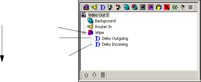
Working with the Scene Tree
73
Understanding Grouped Objects
Objects that you organize into groups within the Scene Tree are composited from the top of
the group downward. This processing order works the same way for objects in groups as it
does for objects in a Scene Tree. The last object in a group, which appears at the bottom of
the group, appears on top of the other objects in the video output.
Groups have parental status while objects under the control of a group are its children.
Grouping enables you to set parameters for a set of objects as if they were a single object,
but you must consider how the application layers each of the group’s component objects.
Information about working with Group objects is provided in “Using Group Objects” on
page 181.
Rearranging Objects in the Scene Tree
You might need to rearrange the priority of objects in the Scene Tree to produce the desired
video output. The bottom object in a Scene Tree or group appears on top of those above it in
the video output.
To rearrange objects in the Scene Tree, do one of the following:
tRight-click an object in the Scene Tree and select Copy. Position the cursor in another
location, right-click, and select Paste. If you want to delete the object you copied, select
the object and click the Trash icon.
tSelect a child object and drag it to another parent object. You can also select a group
object and drag it (and its children) onto a Group object, which then becomes its parent.
Group objects are
composited from the top
of a group downward
Group object (parent)
Last child in Group (In a
Wipe this object obscures
child objects above it.)
First child in Group
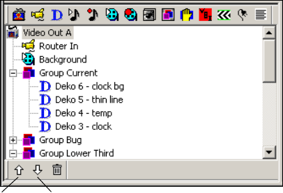
2 Working with Scenes and Objects
74
tSelect the object and click the Up or Down Arrow buttons at the bottom of the Scenes
pane window.
You can move objects (or groups) to other positions in the tree hierarchy and place them as
children of parent objects as long as the object is capable of serving in that role. If it is not, a
message informs you that the object cannot be a parent or child for the specified object and
you are not allowed to insert it.
Understanding Parent-Child Relationships
A scene’s objects are organized hierarchically in the Scene Tree. Within the tree, an object
might be a separate object, a parent object with children, or the child of a parent object. The
application prevents you from setting up parent-child relationships that are not allowed.
The following rules apply to parent-child relationships in the Scene Tree:
• A Video Out object is the parent object for all other play-to-air objects in the Scene
Tree. It is required for video output of its child objects. Any object other than objects
that record input must be a child of a Video Out object in order to be displayed.
• The objects that record input — Video Out, Clip Capture, Audio Capture, and Frame
Grab — are root objects and can have no parents.
• Only Video Out, Group, Crawl, and Text Data objects can have children.
• If you delete a collapsed parent object in the Scene Tree, all of its children are also
deleted.
• Groups have parental status while objects under the control of a group are its children.
Move
object
up
Move
object
down
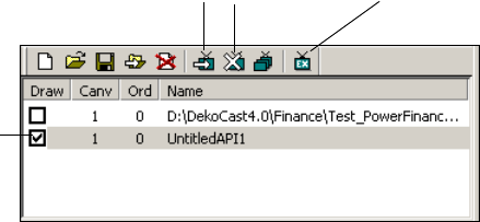
Selecting Scenes for Output
75
Opacity levels for child objects are determined by their parent’s opacity level. For
example, if a child object has 50 percent opacity and its parent has 50 percent opacity,
then the child object’s opacity is 25 percent (half that of its parent).
Selecting Scenes for Output
Several DekoCast scenes can be open simultaneously, and some, all, or none of them can be
active on the outputs simultaneously. Scenes whose Draw boxes are selected (checked) are
active. When you add a new scene, its Draw box is selected automatically.
To select a scene for video output:
tSelect the scene’s Draw box.
To remove a scene from video output:
tDeselect the scene’s Draw box.
nYou can also use the Show Scene and Hide Scene tools in the Scene toolbar to select and
remove scenes.
To set one scene as the exclusive scene for output:
tSelect the scene and click the Exclusive Show Scene tool in the Scene toolbar. The
selected scene is selected for drawing and the others are removed from output (and
deselected).
The Exclusive Show Scene tool switches between being active and inactive. When it is
active, only one scene (the last one you checked) is active. Click the tool again to allow
multiple scenes to be selected as active scenes for output.
Draw box
selected
Show Scene Hide Scene Exclusive Show Scene
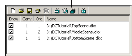
2 Working with Scenes and Objects
76
Multiple Scenes and Stacking Order
DekoCast gives you the option of using a single scene or multiple scenes.
nA typical project consists of a single scene. If you work with multiple scenes, be aware that
each scene is independent. You cannot control one scene from another scene without using
an API program developed for that purpose.
The Order (shown in the Ord column) refers to the stack order for video processing and
video output. The stacking order is important only if your project contains multiple scenes,
and then only when the video output for a scene overlays another scene.
When DekoCast processes multiple scenes, it places scenes in a buffer queue and draws
them according to their assigned stack number, beginning with the highest number and
ending with the lowest number. For example, for scenes assigned stack number 1, 2, and 3,
the scene assigned as stack number 3 (the highest number) is placed first in the queue for
processing. The scene assigned stack number 2 is placed directly behind stack number 3 in
the queue and is processed next. The scene assigned stack number 1 (the lowest number) is
placed last in the queue, following the other two scenes. This final scene, which has the
highest priority, appears on top in the video output.
The following illustration shows this stacking order and priority.
To display objects in scenes that overlay other scenes, turn off the Background of the Video
Out object for all scenes except the scene with the highest order number (see “Editing Video
Out Objects” on page 81.
nIf you have multiple scenes for output, you must set the stack order for each scene.
Otherwise DekoCast draws the scenes in a random order and then outputs the drawn scene
to video.
Processed first
Processed last
(highest priority)
Change Scene Order

Multiple Scenes and Stacking Order
77
To set the stack order for a scene:
1. Select the scene in the list.
2. Click the Change Scene Order tool on the Scenes toolbar.
3. Enter the new number, and click OK.
cScenes stacked in the queue might consume resources even if they are inactive. For
example, if a clip associated with an inactive scene in the stack is running, the codec is
in use and not available to the active scene as it is being drawn to video output. When
working with multiple scenes, consider how all scenes interact. Try to ensure that
active scenes have sufficient resources.
2 Working with Scenes and Objects
78

Chapter 3
3Editing Objects in the Scene
Each object type has an object editor that allows you to view and edit its properties, which
are called parameters. Actions that you create using the Timeline editor reflect changes
made to an object’s parameters.
The following topics describe how to edit objects in the scene:
•Using an Object Editor
•Editing Video Out Objects
•Editing Video In Objects
•Using the Target and Position Tabs
•Using the Levels and Mixer Tabs
•Working with Deko Objects
•Playing Back Audio
•Capturing Audio
•Playing Back Clips
•Capturing Clips
•Creating Cel Animations
•Using Group Objects
•Capturing Video Images (Frame Grab)
•Working with VBI Objects
•Creating Crawls
•Adding Plug-in Objects
•Working with Charts and Graphs
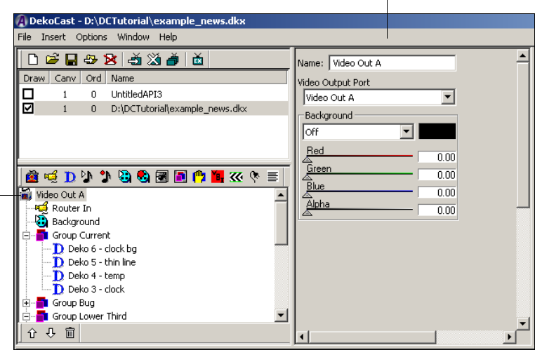
3 Editing Objects in the Scene
80
Using an Object Editor
Each object is associated with an editor, as shown in the following illustration. The object’s
editor opens whenever you select an object in a Scene Tree or add an object to it. The
following illustration shows the Video Out object and the Video Out Object editor.
An object editor includes settings, filenames, and other properties that define the object.
These properties are referred to as an object’s parameters. You animate an object by creating
actions that control the object’s parameters, as described in “Adding Actions to a Scene” on
page 297.
nYou can also use the Parameters tab to modify parameters. See “Working with Parameters”
on page 335.
Video
Out
object
Video Out Object editor
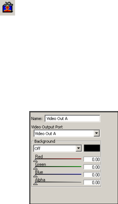
Editing Video Out Objects
81
Editing Video Out Objects
When you create a new scene, the Video Out object is added as the first object in the Scene
Tree. A DekoCast system has one video output. You can, however, set up a second video
output for a key signal. When a DekoCast system is installed upstream as a keying device
into the switcher, it must be configured with Output A as the video fill and Output B as the
key signal.
nUse the Video Hardware Options tab in the Options dialog box to configure DekoCast’s
input and output ports. See “Video Hardware Options” on page 416.
To specify a video output port:
tSelect a port from the Video Output Port menu:
- For video only, select Video Out A.
- For key signal only, select Video Out B.
The Video Out editor also allows you to control the opacity, color, and transparency of areas
of the video frame that are not covered by objects.
Setting Background Color and Opacity
You can select a color for the background of a scene. This is useful if you do not have
Video In input into your device and need to view an object that includes black, such as a
black banner of a Deko object. Because the default background is black, the black banner
will be invisible unless you have video coming in or the Background turned on. You can turn
the Background on, change it to a color other than black, and use it for testing. A
Background matte set to a color is not recommended for use on air.
Video Out
button
3 Editing Objects in the Scene
82
When the Background is set to On, the color of the background behind the objects in a scene
is controlled by the Red, Green, and Blue sliders on the Video Output object editor. If the
system is configured with a key output, then the value of the key signal is controlled by the
Alpha slider. A typical scene has a single Video Out object.
nOn a Corsica-based system, the Red, Green, and Blue background colors are multiplied by
the value of the Alpha slider to determine the background color. You need to set a value for
the alpha even if the video output is not configured for key.
Any Video Out objects lower in the bottom-to-top compositing order are obscured by the
Background. This situation might occur if you are combining multiple scenes (see “Multiple
Scenes and Stacking Order” on page 76.
When the Background is set to Off, the Red, Green, Blue, and Alpha sliders have no effect,
and the background is black.
To set the background color and opacity:
1. In the Background section of the Video Out object editor, select On.
2. Click a color slider and drag it to change the selected color from full transparency (0.00)
to full opacity (1.00).
Any background color you select is displayed in the adjacent color rectangle.
To preview the output on a Corsica based system, drag the Alpha slider to a value other
than 0.
3. (Option) Click and drag other color sliders to blend the background color.
If Red, Green, and Blue are set to 1.00, the background is white. If set to 0.00, the
background is black. If Red and Green are set to 1.00 and Blue is set to 0.00, the
background is yellow. The individual values for Red, Green, and Blue can vary from
0.00 to 1.00.
To set the value of the key signal:
tAdjust the Alpha slider.
Selecting a Custom Background Color
You can use the color palette to select a custom color for the background opacity.
nCustom Colors are remembered within your current session only.
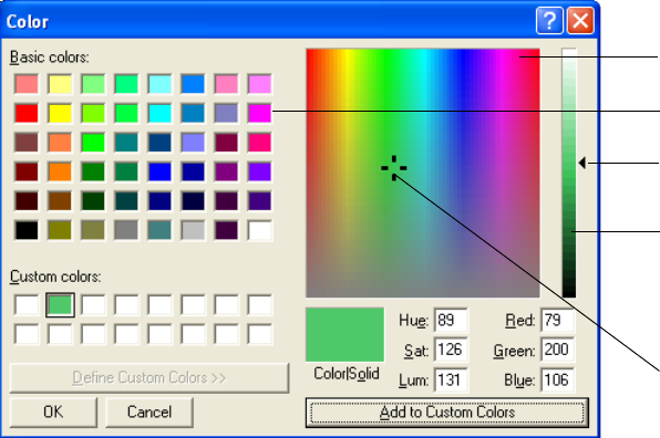
Editing Video Out Objects
83
To select a custom color:
1. In the Video Out object editor, click the color rectangle.
The color palette opens.
2. Do one of the following:
tSelect one of the color chips
tClick a hue in the Color Spectrum.
tDrag the pointer in the Color Spectrum.
3. To change the color’s value (relative darkness or lightness), select and drag the
Luminance slider.
4. Click OK.
nWhen Luminance is set to 0, which is black, dragging the Luminance Slider upward displays
lighter colors.
To modify a value using the keyboard:
tEdit the values for the Hue, Sat (Saturation), Lum (Luminance), or Red, Green, and
Blue text boxes and click OK.
To add a new color for this session only:
tAdjust the color using the Color Spectrum and Value Spectrum controls, then click Add
to Custom Colors and click OK.
Your currently selected color is displayed in the Color/Solid area.
Color chip
Color Spectrum
Value Spectrum
Luminance slider
Drag the pointer
to change hue

3 Editing Objects in the Scene
84
Editing Video In Objects
The Video In object editor allows you to select the video input port, set the opacity of the
video input, and define video input key information.
The Video In object editor has the following tabs: Video, Position, Target, Levels, and
Mixer. Only the Video tab is unique to the Video In object.
The Target and Position tabs, which enable you to position and size objects for video output,
are the same for all objects that the application draws to video output. All audio-related
objects share the Levels and Mixer tabs. For instructions on using the Position and Target
tabs, see “Using the Target and Position Tabs” on page 86. For instructions on using the
Levels and Mixer tabs, see “Using the Levels and Mixer Tabs” on page 103.
nWhen the scene is used upstream from a switcher, do not add a Video Input object to the
Scene Tree. The Video Input key is a full-raster key that prevents objects underneath the
Video Input object from being drawn to output.
Selecting a Video Input Port
A DekoCast system has two video input ports. By default, a system is configured for one
video input, in the Video Hardware Options tab (see “Video Hardware Options” on
page 416). You can configure it to have two video inputs (such as a facility feed and video
from a server), or to have one video input and one key input. Use the Video Hardware
Options tab to configure the DekoCast system’s input ports. To use two video inputs, you
need to add two Video In objects to the Scene Tree and select a different port for each.
Video In
button
Editing Video In Objects
85
To select a video input port:
tIn the Video Input object editor, select a port from the Video Input Port menu:
- For video input only, select Video In A.
- For a second video input, or for a key input, select Video In B.
You might need to author and transfer a scene to a different system in which Input B has
been enabled and set as key, even though your system is not configured for video key input.
In this case, you can select an option while authoring a scene so that the your system
discards the video input key information. Deselect this option before you transfer the scene.
To have the application discard key information while authoring:
tSelect the Ignore Key option.
To add the key information before transferring:
tDeselect the Ignore Key option.
Changing the Opacity of a Video Input Object
You might want to set the opacity of a Video Input object, for example, when creating an
action to fade in the video.
To change the opacity of a video input object:
tIn the Video Input object editor, drag the Opacity slider to vary the Video In object’s
opacity from full transparency (0.00) to full opacity (1.00).
cAs of the DekoCast 4.0 release, you have to explicitly add a Video In object to the Scene
Tree.
3 Editing Objects in the Scene
86
Using the Target and Position Tabs
The Target and Position tabs are common to most visible objects, that is, objects the
application draws to video output. These objects include Video In, Deko, Clip Playback, Cel
Animation, and Group.
The Target and Position tabs are related, but have different functions. These functions are
described in the following topics:
•“Arranging Objects for Video Output” on page 86
•“Using Screen Coordinates” on page 87
•“Using Thumbwheel Controls” on page 88
•“Using the Target Tab” on page 89
•“Using The Position Tab” on page 95
•“Designing Your Layout” on page 96
Arranging Objects for Video Output
By default, DekoCast aligns the top-left corner of most visible objects with the top-left
corner (0,0) of the video output frame. (The exception is the Crawl object, which by default
is placed in the lower portion of the video output.) You can change this default behavior by
using the Position and Target tabs in the object editor to position objects anywhere on the
video output frame.
nUse of the Position and Target tabs is optional. If you do not apply either tab, the entire
object is displayed as normal size and placed in its default location.
Avid recommends that you use the Target tab to arrange objects for video output. By using
the Target tab, you can associate an object with a defined area of the video frame called a
target rectangle. For example, to have movie credits play alongside local news teasers,
define a target rectangle for a Clip object (movie credits) on one side of the output frame and
define a target rectangle for the source Video In object (news feed) on the other side.
News Anchor
(Video In object)
Movie Credits
(Clip object)
Using the Target and Position Tabs
87
The purpose of using target rectangles is to create scenes in an aspect ratio that is
video-resolution independent. By using target rectangles to scale and align elements in a
scene, you can create a scene in 16:9 SD and it will be ready to air from a 16:9 HD system.
If you use the Position tab to scale and align elements in a scene, you must recreate the scene
for playing out at a different video resolution.
nUsing target rectangles does not allow scenes built in one aspect ratio to work in another.
For example, a 16:9 SD scene converts well to a 16:9 HD scene, but a 4:3 SD scene does not
convert well to a 16:9 HD scene.
For information about creating target rectangles, see “Using the Target Tab” on page 89. For
examples of how to use target rectangles in a page layout, see “Designing Your Layout” on
page 96.
nIf you link a Deko object to one or more layers in a graphic, and you want to control a
layer’s position with a target rectangle, you must select Layer as the Layout option in the
Deko object editor. See “Guidelines for Adding Deko Objects” on page 113.
Another advantage to using target rectangles is that you can prevent overlapping objects,
because the objects are confined to the corresponding target rectangles.
Both the Target tab and the Position tab allow you to scale an object and to change its default
position for video output. However, you can crop an image only in the Position tab. The
application applies parameters set by the Position tab to an object after it applies any
parameters set by the Target tab. After defining a target rectangle for an object, you can use
the Position tab to fine-tune the scale and position of the entire target rectangle, and crop it.
nScenes that are built with only Position parameters are still valid, and you can continue to
build scenes using only the Position tab. If you import scene files with only Position
parameters, you can either use these parameters or define new target rectangles.
Using Screen Coordinates
Both the Position tab and the Target tab use the X- and Y- coordinates of the screen. When
you place an object using Position tab parameters, you use X- and Y- coordinates to identify
the object’s position on the video output. However, when you place an object using Target
tab parameters, you use the coordinates to identify the target rectangle’s position. Then the
object’s position on video output is defined in relation to its target rectangle’s top, bottom,
left, and right coordinates.
The default coordinates used by both tabs are determined by the video standard. For
example, the X-coordinates for Standard Definition NTSC range from left (0) to right (720),
and the Y-coordinates range from top (0) to bottom (487).

3 Editing Objects in the Scene
88
nBy default, screen coordinates are set with 0, 0 as the top left corner. To revise these
coordinates, select Options > Preferences and click the Coordinates tab. See “Output Frame
Coordinates” on page 429.
Using Thumbwheel Controls
The Target and Position tabs have thumbwheel controls that use screen coordinates to
determine position. You select and drag to define values for an object or a target rectangle.
This example shows the thumbwheel controls for defining a target rectangle.
Use the thumbwheels in the following ways:
• To make coarse adjustments, hold down the Shift key while dragging a thumbwheel to
the right or left. To make fine adjustments, hold down the Ctrl key while dragging.
• Type an integer or decimal number in the text box to the right of a thumbwheel and
press Enter.
• To revert to a thumbwheel’s default value, click the text description to the left of the
thumbwheel. For example, to return to the default target rectangle parameters (full
screen), click the text that reads Left, Top, Right, or Bottom.
• To revert to the default target rectangle full-screen coordinates, click the Reset button.
0,0
Default point of origin 0,720
0,487
Type a value in text box and
press Enter.
Click the text label
to return to the
default value. Select and drag
thumbwheel.
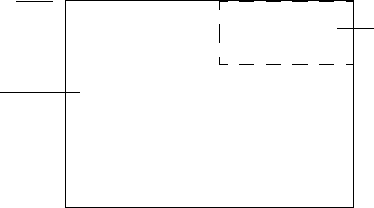
Using the Target and Position Tabs
89
nYou can disable rounding to whole pixels through the App Options tab. Select Preferences >
Options and click the App Options tab. See “Application Options” on page 428.
Using the Target Tab
Visible objects are objects that the application draws to video output, such as the Deko, Clip
Playback, and Cel Animation objects. A visible object’s editor includes a Target tab, which
enables you to define the location and size of an object’s target rectangle. You then specify
how the object is to be placed on the video output in relation to its target rectangle.
The purpose of using target rectangles is to create scenes in an aspect ratio that is
video-resolution independent. See “Arranging Objects for Video Output” on page 86.
nUse of an object’s Target tab is optional. If you do not want to define a rectangular area of
the video frame for an object, select Disable in the Target tab.
Defining a Target Rectangle
The application places most visible objects in the upper-left corner of the video output,
where the X and Y coordinates are 0,0. Using a target rectangle lets you specify how the
object is to be placed on the video output in relation to the target rectangle. The following
illustration shows the default target rectangle and a smaller target rectangle you could define.
nTo practice using a target rectangle, add a visible object such as Video In or a Deko object to
the Scene Tree and work with its Target tab while reading these instructions.
0,0
The entire output
frame is the default
target rectangle
A defined target
rectangle is a
subdivision of the
output frame
Default point of origin
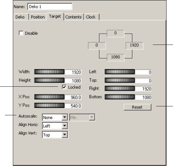
3 Editing Objects in the Scene
90
To define a target rectangle for a visible object in a scene:
1. Select the object’s Target tab in the object editor.
2. Make sure the Disable option is not selected if you want to define a target rectangle.
3. Select and drag the Left, Top, Right, and Bottom thumbwheels to define the position of
the target rectangle on the video output, or enter coordinate values that define it.
As you change target rectangle coordinates, the current positions display in real time in
the upper right of the tab. You can always click the Reset button to return to the default
target rectangle value, which is full screen.
For information on using the thumbwheels, see “Using Thumbwheel Controls” on
page 88.
4. (Option) Select and drag the X and Y Position thumbwheel controls to move the center
of the rectangle to the right and left on the X-axis, or up and down on the Y-axis.
5. (Option) Select and drag the Width and Height thumbwheels to resize the target
rectangle.
nYou cannot change the Width and Height of a target rectangle whose Autoscale option is set
to None, which means that the target rectangle is to always maintain its original size.
Reset button
Coordinates of target
rectangle
Locked
option
Autoscale
option
Using the Target and Position Tabs
91
6. To maintain a desired aspect ratio between width and height, select the Locked option.
7. Set the Autoscale parameters that tell the application how to place the object in relation
to the target rectangle:
- None: Maintains the object’s original size while being aligned horizontally and
vertically in respect to the target rectangle. If you select None, you must also select
the horizontal and vertical alignment for the target rectangle.
- Fit: Stretches the object to fill the entire rectangle. (The object’s aspect ratio is lost.)
- Preserve: Maintains the object’s aspect ratio in respect to its the target rectangle:
inside (minimum), outside (maximum), horizontally, or vertically.
See the diagrams for these three parameters in the next topic.
Scaling an Object in Relation to Its Target Rectangle
The following diagrams show the placement of objects in relation to target rectangles when
you select None, Fit, or Preserve as the Autoscale option.
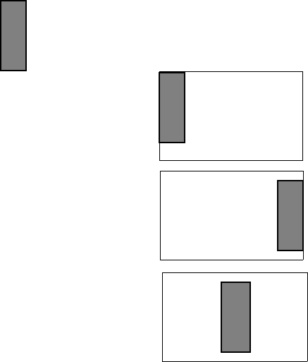
3 Editing Objects in the Scene
92
None
The None Autoscale option maintains the original size of an object and lets you choose how
to align it in its target rectangle:
• Select Left, Right, or Center as its Align Horizontal option.
• Select Top, Bottom, or Center as its Align Vertical option.
Object
Horizontal Alignment: Left
Vertical Alignment: Top Object maintains size and is
aligned in left, top of target.
Object maintains size and is
aligned at right, center of target.
Object maintains size and is
aligned at center in the center
of the target.
Horizontal Alignment: Right
Vertical Alignment: Center
Horizontal Alignment: Center
Vertical Alignment: Center
Autoscale: None
Target Rectangle of Any Size

Using the Target and Position Tabs
93
Fit
The Fit Autoscale option maps the object entirely onto the target rectangle without
preserving the aspect ratio of the object. The object is stretched to fully fill the target
rectangle, regardless of the size of the object.
Preserve
The Preserve Autoscale option resizes the object without changing its aspect ratio. When
you select Preserve, specify where the object is to be placed in relation to the target rectangle
by selecting one of four Autoscale options:
• Minimum: Maps the object onto a destination that is completely contained by the target
rectangle.
• Maximum: Maps the object onto a destination that completely covers the target
rectangle.
• Horizontal: Maps the object’s left and right edges onto the target rectangle’s left and
right edges, scaling the object vertically to preserve the aspect ratio.
• Vertical: Maps the object’s top and bottom edges onto the target rectangle’s top and
bottom edges, scaling the object horizontally to preserve the aspect ratio.
Object
Object stretched to fully
cover Target Rectangle
Target Rectangle of Any Size
Autoscale: FIt
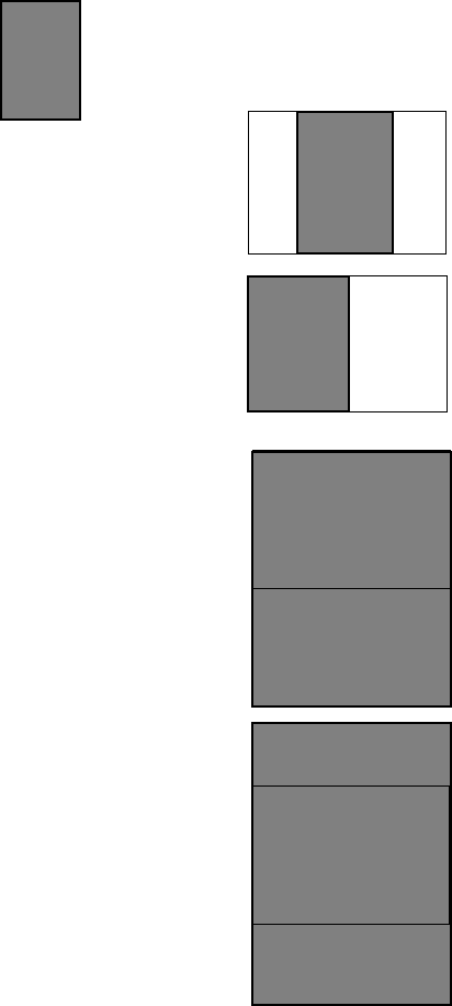
3 Editing Objects in the Scene
94
After you select a Preserve Autoscale option, you can align the object vertically and
horizontally in relation to the target rectangle, if appropriate.
Target Rectangle of Any Size
Object
Preserve Minimum:
Horizontal Alignment: Center
Vertical Alignment:
Not Applicable (N/A)
Object scaled to fit inside of
target. Aspect ratio maintained.
Centered.
Autoscale Preserve: Minimum and Maximum Options
Preserve Minimum:
Horizontal Alignment: Left
Vertical Alignment: N/A
Object scaled to fit inside of
target. Aspect ratio maintained.
Left alignment.
Preserve Maximum:
Horizontal Alignment: N/A
Vertical Alignment: Top
Object scaled to cover target.
Aspect ratio maintained.
Top alignment.
Preserve Maximum:
Horizontal Alignment: N/A
Vertical Alignment: Center
Object scaled to cover target.
Aspect ratio maintained.
Center alignment.
Target Rectangle
Target Rectangle
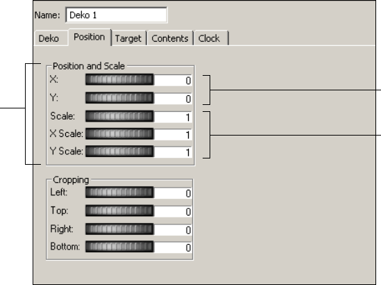
Using the Target and Position Tabs
95
Using The Position Tab
Using the Position tab, you can change an object’s position to any area of the video output,
scale it relative to its normal size, and crop it. Setting cropping parameters enables you to
control the visible region on which the application draws the object to video output.
nWhen you change an object’s position using the Position tab (as opposed to using the Target
tab), the scene that contains the object might not appear the same at different video
resolutions. See “Arranging Objects for Video Output” on page 86.
The application applies parameters set by the Position tab to an object after it applies any
parameters set by the Target tab. After defining a target rectangle for an object, you can use
the Position tab to fine-tune the scale and position of the entire target rectangle, and crop it.
Changing an Object’s Position and Scale
To change the position of the object:
tIn the object editor, select and drag the X or Y thumbwheel to the right or left until the
desired new position is displayed in the text box to the right of the thumbwheel. This
position is relative to the left and right X coordinates and to the top and bottom Y
coordinates.
X,Y coordinates
Position and
Scale
thumbwheels
Scale values
3 Editing Objects in the Scene
96
To change the scale of the object:
tSelect and drag one of the following thumbwheels to scale the object:
-Scale
-X Scale
-Y Scale
Drag the thumbwheel to the right or left to attain the desired scale; the value is relative
to a scale of 1, which represents the object’s normal size.
A positive number greater than 1 enlarges the object and a positive number less than 1
reduces its size.
For more information about using thumbwheels, see “Using Screen Coordinates” on
page 87.
Cropping an Object
When you scale a video frame to less than 100 percent, you might see extraneous video or
black around the edges of that frame. The Cropping thumbwheels allow you to eliminate
edges by trimming the top, bottom, and sides of the frame.
To set cropping parameters:
tIn the object editor, click and drag the Left, Right, Top, and Bottom thumbwheels until
the desired cropping of the object is obtained.
The controls display a positive number (greater than 0) as you trim towards the center of
the object.
nIf working with a Deko object that uses the Entire Graphic or is a Background, crop it so
that only the desired area is rendered.
Designing Your Layout
Before creating your scene, plan what you want your scene to accomplish and how you want
it to look. Your goal is to design the layout that viewers see on their television screens, which
translates in the application to how objects display on video output. As part of your design
process:
• Consider the object tools that you have to develop a scene. Only visible objects, that is,
objects that the application draws to output, such as Deko, Clip Playback, Cel
Animation, and Video In objects, have object editors with the Position and Target tabs.
The Target tab controls parameters that define the target rectangle.
Using the Target and Position Tabs
97
nObjects that the application does not draw to video output, such as the Frame Grab, have no
need to be positioned or placed in target rectangles on the output frame. If an object does
not have Position and Target tabs in its object editor, it is not a visible object.
• How do you want to subdivide the screen into rectangles? For example, you might place
video-in feed in the center, a logo in the upper-right corner, and crawl text scrolling in
the lower third. Each of these divisions is associated with a visible object.
• How do you want to place the object in relation to the rectangle? For example, an object
can be aligned in the exact center of a rectangle while maintaining its aspect ratio, or
stretched to fill the rectangle without keeping its aspect ratio.
• Will the rectangle change dynamically? If you plan to apply an action to create a
squeeze-back, what are the object’s beginning and ending positions? Actions you create
using target rectangles are also independent of resolution and video standard.
Guidelines for Using Target Rectangles
When working with target rectangles, consider the following guidelines:
• When you add a visible object to the Scene Tree, the application displays it in a default
position on the video output. You can do one of the following:
- Leave the object in its default position.
- Reposition it using the Position tab (not recommended if you want the same scene
to play out at different video resolutions).
- Set up a target rectangle to control where and how the object appears on video
output using the Target tab.
• A target rectangle is associated with a visible object. It does not exist as a rectangle
independent of its object.
• If you link a Deko object to one or more layers in a graphic, and you want to control
their positions with target rectangles, you must select Layer as the Layout option in the
Deko object editor. See “Adding a Deko Object to a Scene” on page 109.
• Group objects can also have target rectangles that apply to the group.
• Only visible objects can have target rectangles. Only object editors for visible objects
have a Target tab.
• The default target rectangle is full screen.
• Each of the four sides (left, top, right, bottom) of the target rectangle is a parameter of
the object.
• If you select Disable in the Target tab, the object has no target rectangle. You can
reposition the object using its Position tab.
3 Editing Objects in the Scene
98
• An object is positioned with respect to its target rectangle according to which option
(None, Fit, or Preserve) you select from the Target tab’s Autoscale menu.
-None. The object can maintain its original size (no change = None) while being
aligned horizontally and vertically in respect to the target rectangle. If you select
None, you must also select the horizontal and vertical alignment of the object to the
target rectangle.
-Fit. The object can be stretched to fit the entire rectangle. (The object’s aspect ratio
is lost.)
nTo better view an object target rectangle’s region on video output, add a background color to
the Video Out object, then apply the Fit Autoscale option.
-Preserve. The object can be made to preserve its aspect ratio in respect to its target
rectangle. There are four possible Preserve Autoscale options: Min, Max,
Horizontal, and Vertical.
Select whether the application is to contain the object within the target rectangle
(the Minimum option) while maintaining the object’s aspect ratio, or scale the
object so that it covers the target rectangle (the Maximum option while maintaining
the object’s aspect ratio). The object can be placed within the rectangle horizontally
or vertically. After you assign the Autoscale placement, you can align the object
horizontally (top, bottom, center) and vertically (top, bottom, and center) as
appropriate.
nSee “Scaling an Object in Relation to Its Target Rectangle” on page 91 for diagrams of each
Autoscale option.
• A target rectangle has no visible borders. To “see” an object’s target rectangle, set its
Autoscale option to Fit, which causes the object to dynamically fill the rectangle as you
adjust the thumbwheel controls. Observe how the object stretches to fill the target
rectangle and does not maintain its aspect ratio.
• When you define a target rectangle for a group, all of the child objects are encompassed
by it.
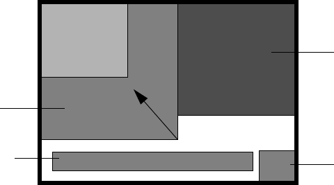
Using the Target and Position Tabs
99
Suggestions for Preparing Your Layout
For a simple layout, such as placing a Cel Animation object in the lower-right corner,
designing “on the fly” using the Target tab is sufficient. For a more complex layout that
requires rectangles of a set size, you might use Deko layers to block out rectangles as you
want them to appear on the video output frame. Keep in mind that each rectangle is
associated with a specific object. A target rectangle has no border lines—its size changes as
you adjust the object’s thumbwheel controls. If you design your layout using a drawing
program, you can open it within the application and use it as a template for “tracing”
rectangles. To make it easier to transfer your layout, assign a different color to each
rectangle.
nIf you do not use a template file, add a Video Out background color to gauge the rectangle’s
boundaries (see “Editing Video Out Objects” on page 81). You can also set the Autoscale
option to Fit to have the object completely fill the rectangle as you adjust it using the
thumbwheel controls.
You might find it helpful to create a template file in a drawing program other than PostDeko
Lite. In this case, the rectangles must have the same dimensions as you want them to have in
the video output frame. In the drawing program, save the file as a BMP file and link to it as a
Cel Animation object. Be aware that this is not a real Cel Animation object, but a
workaround to use a file created in another drawing program as a template. You have to
delete this Cel Animation object (or clear its file name) before saving the scene. For more
information, see “Defining the Source File for a Cel Animation” on page 175.
News Clip
Object
Logo Cel
Animation Object
News Crawl
Object
News Anchor Video
In Object
Squeeze - End
Rectangle
Squeeze - Start
Rectangle
Sample of a Video Output Frame Segmented Into Target Rectangles for Objects
3 Editing Objects in the Scene
100
Transferring a Layout to a Scene
If you use a graphics tool to design a layout to use as a template, you need to transfer it to a
scene.
To transfer a layout to a scene:
1. Create a new scene.
2. If you created a layout template as a file in PostDeko Lite, add a Deko object and link it
to the file.
nIf you created a layout in a different graphics program, import it into PostDeko Lite, export
it as a .dko file, and link it to a Deko object. You can also import the file directly as a Cel
Animation object (see “Suggestions for Preparing Your Layout” on page 99).
The template file’s rectangular divisions display on the video output. This object’s only
purpose is for layout design. Delete this object after you have finished using it as a
template.
3. Add a visible object to the Scene Tree, such as a Clip Playback, Deko object, or Cel
Animation object.
4. Select the Target tab in the object’s editor, which opens to the right of the Scene Tree.
nIf you select Disable in the Target tab, a target rectangle cannot be defined.
5. (Option) As a means to “see” the target rectangle as you adjust the thumbwheel
controls, set the Autoscale option to Fit.
The Fit option stretches the object to the borders of the rectangle, making it easier to see
the area you are defining. Unless you want the object to fill the rectangle in your actual
scene, however, you need to select one of the other Autoscale options after you have
specified the left, top, right, and bottom coordinates of the target rectangle.
6. Define the target rectangle for the object using its Target tab. See “Example: Defining a
Target Rectangle for Video In” on page 100. Also see, “Using the Target Tab” on
page 89.
7. Add additional visible objects and define their target rectangles.
8. After deleting any object used only for tracing purposes, save the scene.
Example: Defining a Target Rectangle for Video In
In this example, you will define a target rectangle for a Video In feed. You want the target
rectangle to fill the right half of the screen. You want the Video In object to keep its aspect
ratio while filling the width of the target rectangle and aligning with the top of the target
rectangle.
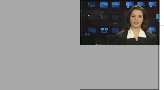
Using the Target and Position Tabs
101
nTarget rectangles are designed to allow you to reuse an SD 16 x 9 layout as an HD layout
without needing to adjust the layout. This example uses a 16 x 9 layout.
This example gives you an opportunity to experiment with how an image fits in a target
rectangle. Even if you do not have a live feed, you can use the black shape of the Video In
object to become familiar with how target rectangles work.
To define the target rectangle for a Video In object:
1. Create a new scene.
2. (Option) Select the Video Out object and add a background color. See “Setting
Background Color and Opacity” on page 81.
Using a colored background is useful if you do not have a live feed for the Video In
object.
3. Add a Video In object to the scene.
The Video In object fills the screen and covers the Video Out background.
4. Click the Target tab in the Video In object’s editor.
5. To make sure the target rectangle values are set at their default values, click Reset.
The default target rectangle is the full screen, so the Video In object completely fills the
target rectangle.
6. Select Autoscale >Preserve.
The Preserve option maintains an object’s aspect ratio, so it is the most appropriate
selection for positioning the Video In object.
Video In
object aligned
at top of the
target
rectangle
Target
Rectangle
extends to
bottom of
video output
3 Editing Objects in the Scene
102
7. For the Preserve option, select Minimum (Min) to place the Video In within the target
rectangle.
8. For the Vertical alignment, select Top.
This selection aligns the Video In with the top of the target rectangle. The Horizontal
option does not apply because in this case the Video In will fill the target from left to
right.
9. Select and drag the Left thumbwheel to the right. Stop dragging the thumbwheel when
the Video In is positioned to the desired size.
By dragging the Left thumbwheel to the right, you are resizing the target rectangle from
the default full-screen size. The Video In object’s size reduces in a succession of smaller
and smaller rectangles, while its aspect ratio does not change.
10. To see the exact size of the target rectangle you just defined, select Autoscale > Fit.
The Autoscale Fit option is not appropriate because it does not maintain the aspect ratio,
but for this example it helps you see the size of the target rectangle. The target rectangle
has the same left boundary as the Video In, but extends to the bottom of the video
output.
11. Select Autoscale > None.
Because Video In is normally full screen, None is not an option. Because the Video In
object does not change in size, only the left part of the video displays in the target
rectangle.
12. Select Autoscale > Preserve, Min, Align Vertical Top.
The Video In object should be correctly positioned. Try the other Vertical options
(Bottom and Center) to see how the position of the Video In changes.
13. (Option) Select Autoscale > Fit and use the thumbwheels on the Target tab to
experiment with sizing and positioning the target rectangle.
14. Save the scene.
Using the Levels and Mixer Tabs
103
Using the Levels and Mixer Tabs
Object editors with an audio component include a Levels tab and a Mixer tab.
Using the Levels Tab
The Levels tab includes controls for any audio component present for the selected object.
To set a master level for all audio channels associated with a selected object, do one
of the following:
tSelect and drag the Port Level dB slider to the desired level.
tType a value in the Port Level dB text box.
The default setting is 0 dB.

3 Editing Objects in the Scene
104
To control levels for each audio channel associated with a selected object, do one of
the following.
tSelect and drag a Channel Level dB slider to the desired level.
tType a value in one or more text boxes and press Enter.
Pressing the Tab key selects the value in the next channel level’s text box for editing.
The default setting of each channel is 0 dB.
nColors in the Levels and Mixer tabs represent features supported by different systems. See
“Understanding Color Coding in the Levels and Mixing Tabs” on page 106.
Port Level db Slider
Channel Level db
Sliders
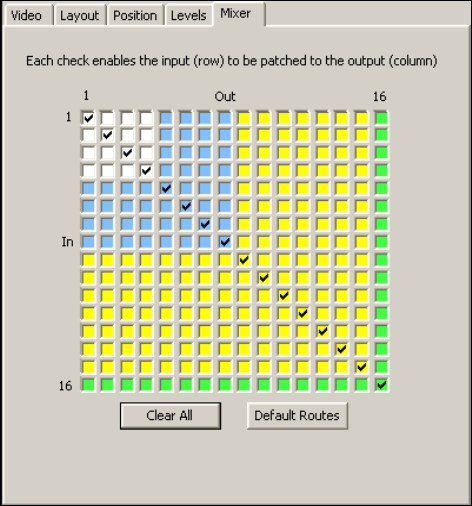
Using the Levels and Mixer Tabs
105
Using the Mixer Tab
The Mixer tab allows you to route audio channels associated with a selected object. The
Mixer tab has a 16 x 16 mixer routing grid that allows you to set a custom audio-channel
configuration. Click any box to select or deselect a routing choice.
To clear all of the routing configurations:
tClick Clear All.
To restore the default mixer routes:
tClick Default Routes.
Each input channel is routed to its matching output channel.
nColors in the Levels and Mixer tabs represent features supported by different DekoCast
systems. See “Understanding Color Coding in the Levels and Mixing Tabs” on page 106.
3 Editing Objects in the Scene
106
Understanding Color Coding in the Levels and Mixing Tabs
A DekoCast system’s video-board configuration determines which features are supported.
Where appropriate, the DekoCast user interface uses colors to indicate features supported by
different configurations. Knowing the capabilities of each DekoCast configuration enables
you to author scenes for playout on a system with different capabilities. For example, you
can use a DekoCast SD system to develop scenes for play out on a DekoCast HD system.
There are three levels of coloring used for certain features in the user interface. Each higher
level supports lower-level features.
• White (or no color) means that these features are specific to a lower-end DekoCast SD
system.
• Blue indicates that these features are specific to a higher-end DekoCast SD system.
Features coded white (or no color) and blue are functional.
• Yellow indicates that these features are specific to a DekoCast HD system. DekoCast
HD supports all DekoCast features.
• Green indicates the maximum capability of the specific DekoCast system that you are
using to author scenes.
The following illustrations shows how the display in the Mixer tab uses these colors. The
higher-end DekoCast SD system has a maximum of 8 channels compared to a maximum of
16 on DekoCast HD. The green color-coding shows the limits of both systems.
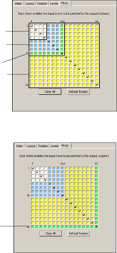
Using the Levels and Mixer Tabs
107
DekoCast with a Maximum of 8 Channels
DekoCast HD with a Maximum of 16 Channels
Green = Maximum
System Capability
White = Lower-end
DekoCast SD system
Blue = Higher-end
DekoCast SD system
Yellow = DekoCast HD
system
Green = Maximum
System Capability
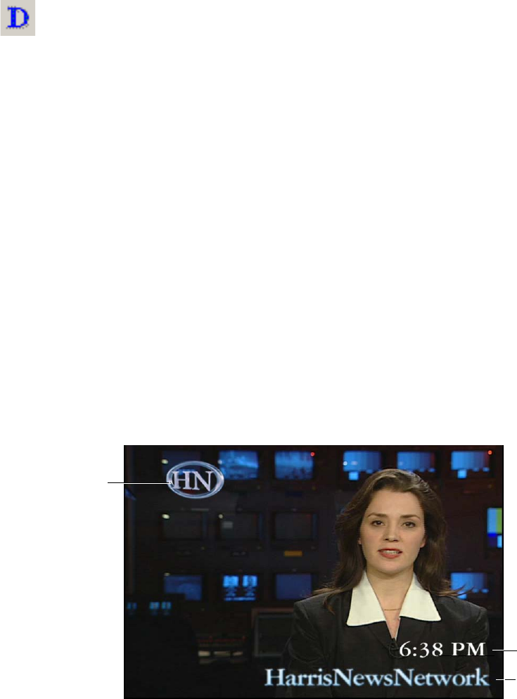
3 Editing Objects in the Scene
108
Working with Deko Objects
You can use the Deko object to do the following:
• Display a DKO graphic file created in Deko or PostDeko Lite. You can use a single
layer of the graphic, all of its layers, or the entire graphic flattened to a single layer. A
Deko graphic can consist of multiple graphic elements, such as a solid rectangle, a
circle, and one or more text layers. Only text layers can have transition effects, such as
dissolves and cuts.
• Display any string of text that adopts the positioning, formatting, and styles defined by a
text layer in a DKO file. When you edit or add text to the layer, it also assumes these
characteristics.
• Display a cycle of several lines of text that changes automatically at a specific interval.
This continuous stream of text is called a crawl for horizontal text, or a roll for vertical
text.
nYou can also create crawls and rolls using the Crawl object, which simplifies the procedure
and allows you to intersperse non-text objects, such as Video In, Cel Animation, Clip
Playback, and Audio Playback objects. See “Creating Crawls” on page 192.
• Display a digital clock or date, either time-of-day or count-up/down, and control its
format and behavior. You can also display the temperature.
nA temperature probe must be purchased and installed in order to display temperature. See
“Using the Temperature Probe Interface Utility” on page 386.
The following illustration shows some typical Deko objects composited over a video feed.
Deko
object
button
Clock
(Text layer)
Text layer
DKO
graphic

Working with Deko Objects
109
The following topics describe how to work with Deko objects:
•“Adding a Deko Object to a Scene” on page 109
•“Editing and Updating Deko Objects” on page 114
•“Naming Layers in PostDeko Lite” on page 114
•“Adjusting Opacity” on page 116
•“Working with Text” on page 116
•“Displaying Clocks” on page 131
•“Displaying Temperature” on page 136
Adding a Deko Object to a Scene
There are two ways to add a Deko object to a scene. The method you choose determines the
characteristics of the Deko object.
• Click the Deko object tool button to create a single Deko object from a source file. If the
file consists of layers, the layers are flattened into a single layer. You can then link the
Deko object to the entire graphic or to any one of its layers.
• Select Insert > Deko Graphic to create a single Deko object from a source file or to
create a Deko object for each layer in the graphic. Each Deko object is automatically
named with the file name (for a single object) or a combination of the file name and
layer name (for multiple objects).
To add a single Deko object:
1. Click the Deko object tool button.
2. Click the Browse button to navigate to the object’s source DKO, AUT, or ATX file, or
type its complete path.
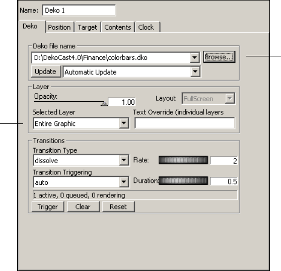
3 Editing Objects in the Scene
110
3. From the Selected Layer list, select Entire Graphic or a desired layer.
A layer might be the background or any numbered layer with a name other than unused.
To add a single Deko object or to create a Deko object for each layer:
1. Select Insert > Deko Graphic.
The Select Deko File dialog box opens
2. Select the file and click Open.
Browse button
Selected
layer
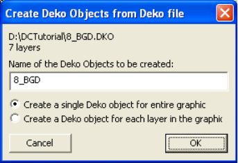
Working with Deko Objects
111
The Create Deko Objects from Deko File dialog box opens.
3. (Option) Edit the file name or type a new name.
4. Do one of the following:
tTo add a single Deko object to the Scene Tree, select “Create a single Deko object
for entire graphic” and click OK.
A Deko object with the filename or the name you entered is added to the bottom of
the Scene Tree. You still have the option of selecting individual layers from the
Selected Layer menu.
tTo add each layer of the Deko graphic as a separate Deko object, select “Create a
Deko object for each layer in the graphic” and click OK.
The objects are added to the bottom of the Scene Tree with the filename or the name
you entered (in descending layer-number order) followed by the layer name. For
example, a Deko object you named Three Layers would be added to Scene Tree as
Three Layers Background, Three Layers 3, Three Layers 2, and Three Layers 1.
When you create a Deko object for each layer, each layer is added to the Scene Tree as an
object, including the background layer. Every layer, even an unused layer or a blank
background, uses a full screen of pixels, so to conserve processing resources, delete any
unnecessary background layers.
To remove an unnecessary background object:
tRight-click the Deko background object in the Scene Tree, and select Delete from the
menu.

3 Editing Objects in the Scene
112
Example: Deko Object with Ten Text Layers
The following illustrations show sample video output for a Deko object with ten text layers.
These ten layers are named:
• TONIGHT
• SHOW TITLE, SHOW TIME
• SHOW TITLE, SHOW TIME
• SHOW TITLE, SHOW TIME
• NEXT:, SHOW TITLE
• RECTANGLE
The following illustration shows text updated for two of these layers: the first pair of SHOW
TITLE and SHOW TIME. The Rectangle layer is a graphic design.
Each layer of the Deko graphic file was added as a separate Deko object so that the text of
each text layer can be replaced. The following illustration shows the SHOW TITLE layer
with text overwritten.
Rectangle layer
SHOW TITLE and
SHOW TIME text layers
updated
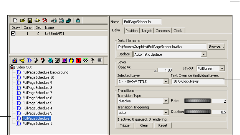
Working with Deko Objects
113
For more information about replacing text, see “Working with Text” on page 116.
Guidelines for Adding Deko Objects
When adding a Deko graphic to your scene, note the following guidelines:
• In PostDeko Lite, always name Deko layers and refer to them by name (see “Naming
Layers in PostDeko Lite” on page 114).
• Scale, crop, and position the graphic associated with the Deko object so that only the
portions of the graphic you want to use are visible at the right size. This prevents
rendering power from being used to process unnecessary areas, such as blank areas not
used in the graphic. Use only the layers that you need. For more information, see
“DekoCast Tips” on page 435.
• You can reposition and resize layers after adding them to a scene using either the
Position or Target tab (see “Positioning and Sizing a Deko Object” on page 115).
• Do not use an entire graphic with a transparent background. If you create a graphic with
a transparent background in Deko for use with DekoCast, and you do not need to control
the individual layers, flatten the layers of the graphic into the background so that Deko
renders one full screen area rather than the background area and each layer.
Text overrides text
in the layer
Text layer
3 Editing Objects in the Scene
114
nIn PostDeko Lite, to flatten the layers into the Deko background, highlight the Graphic
window, and select Layer > Layers to Background. After the layers have merged into the
background, open the Layer Browser (View > Layer Browser) and delete each of the layers.
Editing and Updating Deko Objects
Deko objects can be created in PostDeko Lite or in Deko. You can edit a Deko object within
a scene by opening its file in PostDeko Lite or in Deko and saving it with the same file name.
You can then update the graphic automatically or manually to view those changes on your
video output.
To select how to update Deko objects, do one of the following:
tFrom the Update list in the Deko object editor, select Automatic Update (the default).
This setting causes the application to update the Deko object whenever the file name,
layer number, or text override values change.
nAutomatic Update does not automatically update the scene when the same Deko graphic has
been edited and resaved. Modifying and resaving the graphic requires you to click the
Update button to view the changes in the output.
tFrom the Update list in the Deko object editor, select Manual Update. When you want to
update the graphic, you must either click the Update button or trigger the Update Deko
file parameter in the Parameters list (see “Using the Parameters Tab” on page 336).
cOnce a Deko graphic is included in a scene, changing the original graphic might
produce unexpected results.
Naming Layers in PostDeko Lite
Layer names in a PostDeko Lite graphic can be automatically linked to the name of the Deko
object in the Scene Tree.
To name layers in PostDeko Lite:
1. Do one of the following:
tFrom the PostDeko Lite menu bar, select View > Layer Browser. Right-click the
thumbnail image of the layer and select Edit layer name. Type the name of the layer.
tWithin the Graphic window, press the Page Up key to select the boundary for the
layer you want to name. From the menu bar, select View > Style. In the Text dialog
box, click the Layer tab. Click the More tab at the bottom of the tab. In the Name
text box, type the layer’s name.
2. Save the file.
Working with Deko Objects
115
To import a PostDeko Lite graphic with layer names:
1. Select Insert > Deko Graphic.
The Create Deko Objects from Deko File dialog box opens.
2. Select “Create a Deko object for each layer in the graphic” and click OK.
When you add each layer of the Deko graphic as a separate Deko object (not as an entire
graphic), each layer is added to the Scene Tree as a Deko object with the name of its
layer (see “Adding a Deko Object to a Scene” on page 109). Using this method allows
DekoCast to recognize changes to the level priority in a Deko graphic. To update a
graphic, see “Editing and Updating Deko Objects” on page 114.
3. (Option) Select each Deko object and rename it based on its function through the object
editor’s Name text field.
Renaming the Deko object layers might break the link for updating.
Positioning and Sizing a Deko Object
You can size and place a Deko object using either the Target or the Position tab. See “Using
the Target and Position Tabs” on page 86.
If you link an object to a layer rather than an entire graphic, the Layout option in the Deko
tab of the Deko object editor becomes available. You can select one of the following
settings:
• Full Screen: This setting outputs the layer in the home position as it was created in the
Deko graphic.
• Layer: This setting discards the layer’s position in the Deko graphic and the layer
appears at the top left of the output monitor. If this setting is selected, the Target settings
determine the position of the layer. For more information, see “Arranging Objects for
Video Output” on page 86.
The Layer setting is required if you are including a Deko object as part of a Crawl
Object or if you want to use the Target dimensions, autoscale, and justification settings
to determine the position of the Deko layer.
Both settings are resolution independent. Neither setting has a resource advantage, because
the application uses only the layer size in processing the scene. You can save resources by
scaling or cropping the layer.
To position, scale, and crop a Deko object using the Position tab:
1. Select the Deko object in the Scene Tree to display its Deko object editor.
2. Click the Position tab.
3 Editing Objects in the Scene
116
3. Click and drag the thumbwheels to position and scale the Deko object.
Deko objects are scaled about the center of the selected layer, or about the center of the
screen if the entire graphic is selected. Position is relative to the layer’s position in the
original graphic. For example, if the layer was positioned in the upper-left corner of the
original graphic, that is where it appears in the scene with X and Y position controls in
the home (0,0) position.
4. Use the cropping settings to set the distance in pixels either inward or outward from the
edges of the layer boundary, or if the entire graphic is selected, from the edges of the
screen.
Deko objects with Cut or Dissolve transition styles are not cropped at all if the Cropping
value on an edge is 0: all the non-clear pixels are displayed, whether they are inside or
outside of the layer boundary. Deko objects with Scroll transition types are always
cropped to the edge of the layer boundary modified by the Cropping values.
nNegative cropping on a Horizontal Scroll sets a gap between the text lines displayed. See
“Displaying Crawls and Rolls” on page 123.
For more information, see “Using The Position Tab” on page 95.
Adjusting Opacity
To adjust opacity of a Deko object:
tIn the Deko tab of the Deko object editor, click the opacity slider and drag it to your
desired setting.
Working with Text
A typical workflow when you are working with text is to build a scene that is kept dynamic
by sending new data streams of text to one or more text layers of a Deko object. You can
change the text in a Deko object layer at any time, independent of the other elements in the
scene. The source text can be text created in the Deko graphic, text you type directly to
override the current text, or text contained in a text file.
During scene development or when the system is otherwise off air, you can override text by
typing directly into text boxes. For example, you might change headlines that remain static
throughout the entire scene. While a system is on air, you can replace text by editing the
contents of the Deko object’s text source file. Open the text file from any computer that can
access the file, type new text, and save the file. The text you just typed replaces the previous
text. You can configure text changes to occur with automatic transitions such as dissolves,
horizontal and vertical scrolls, rolls, and crawls.
Working with Deko Objects
117
nA text source file must be either in the TXT format, such as you create using Notepad (All
Programs > Accessories > Notepad), or for control by automation systems, in the AUT or
ATX format.
The following topics describe the techniques and options you can use when working with
text:
•“Using the Text Override Option” on page 117
•“Using the Contents Tab” on page 119
•“Using Text Files” on page 121
•“Displaying Crawls and Rolls” on page 123
•“Transition Options for Deko Object Text” on page 125
•“Looping Options for Deko Object Text” on page 127
•“Managing Text Display” on page 128
•“Using Embedded Tags with Deko Object Text” on page 128
Using the Text Override Option
One way to add new text to video output is to use a text layer of a Deko graphic with the Text
Override option. In this technique you type a line of text in the Text Override box and press
Enter.
Use the following conventions:
• When you want a layer to appear blank, press the space bar to place a space in the Text
Override text box. If you only press Enter (sometimes referred to as inserting a carriage
return or New Line Feed), the application displays the text in the selected layer (the
placeholder text).
• If Automatic Update is selected, and you type a value into the Text Override text box
and press Enter, the application transitions to the new value, whether or not the text has
actually changed.
• A line break can be included in a line by inserting a <br/> tag. For example:
first line<br/>second line
For other tags, see “Using Embedded Tags with Deko Object Text” on page 128.
To override text:
1. Add a Deko object to the Scene Tree and link to a Deko source file that includes a text
layer (see “Adding a Deko Object to a Scene” on page 109).
2. If necessary, adjust position, scale, and opacity (see “Positioning and Sizing a Deko
Object” on page 115 and “Adjusting Opacity” on page 116).
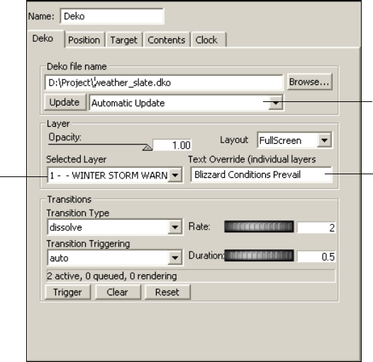
3 Editing Objects in the Scene
118
3. In the Deko object editor, click the Deko tab.
4. Select Automatic Update from the Update list (see “Editing and Updating Deko
Objects” on page 114).
5. Select the text layer from the Selected Layer list.
6. Select how you want transitions to be displayed when the Deko object is updated.
- Select the kind of transition from the Transition Type list.
- Select when you want the transition to begin from the Transition Triggering list.
For information about Transition options, see “Transition Options for Deko Object
Text” on page 125. For information about creating rolls and scrolls, see “Displaying
Crawls and Rolls” on page 123.
7. Using the Deko tab, type text in the Text Override text box and press Enter.
The new text appears on the video output.
Type text to override
text in selected layer
Text layer
selected
Automatic Update
selected.
Working with Deko Objects
119
Using the Contents Tab
You can use the Contents tab of the Deko object editor with a text layer of a Deko graphic to
display one or more lines of text. In this technique, you type text into the Value text box and
click the Accept button. The application copies each line sequentially into the Text Override
text box at the interval specified by the Interval text box. The application uses the transition
options you specify on the Deko tab (see “Transition Options for Deko Object Text” on
page 125).
To display text using the Contents tab:
1. Add a Deko object to the Scene Tree and link to a Deko source file that includes a text
layer (see “Adding a Deko Object to a Scene” on page 109).
2. If necessary, adjust position, scale, and opacity (see “Positioning and Sizing a Deko
Object” on page 115 and “Adjusting Opacity” on page 116).
3. In the Deko object editor, click the Deko tab.
4. Select Automatic Update from the Update list (see “Editing and Updating Deko
Objects” on page 114).
5. Select the text layer from the Selected Layer list.
6. Select how you want transitions to be displayed when the Deko object is updated.
- Select the kind of transition from the Transition Type list.
- Select when you want the transition to begin from the Transition Triggering list.
For information about Transition options, see “Transition Options for Deko Object
Text” on page 125. For information about creating rolls and scrolls, see “Displaying
Crawls and Rolls” on page 123.
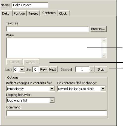
3 Editing Objects in the Scene
120
7. Click the Contents tab.
8. Type one or more lines of text into the Value text box. Separate each row by pressing
Enter.
- To display a blank line, press the space bar and press Enter. If you want a blank line,
make sure to press the space bar. As in the Text Override text box, an empty line
displays the original text contents of the layer (placeholder text).
To avoid a problem with unintentionally revealing placeholder text, keep the cursor
at the end of the last entry in a series and do not press Enter.
- You can include a line break in a line by inserting a <br/> tag. For other tags, see
“Using Embedded Tags with Deko Object Text” on page 128.
nThe Cancel and Accept buttons are activated when you make any changes within the Value
text box.
9. Click Cancel to undo the changes made to the Value text box.
10. Click Accept to start using the new lines of text, starting with the first line.
11. Select the looping options (see “Looping Options for Deko Object Text” on page 127).
Value text box
Accept button
Stop button
Working with Deko Objects
121
12. To determine when to display changes to the contents of the Value text box, select an
option from the Reflect changes in contents file menu.
tSelect “Immediately” to display changes as soon as they are typed. This is a good
choice for continuously updated lists such as stock prices.
tSelect “At next interval” to display changes at the end of a line of text. This is a
good choice for a series of blurbs or headlines.
tSelect “At end of list” to display changes after a complete cycle displaying text
existing prior to the changes. This is a good choice for displaying information in
paragraph form or changing to completely unrelated text.
13. To determine where in the Value text box to begin to display once changes are in effect,
select an option from the On contents file/list change menu:
tSelect “Rewind line index” to start display from the beginning of the Value text box,
effectively skipping items from the point where changes take place to the end of the
text box. Avoid this choice for lists that update continuously, such as stock prices,
otherwise items at the end of the list might not ever display.
tSelect “Leave line index unchanged” to continue displaying contents from the
current line in the Value text box.
14. Click Stop to stop the display.
Using Text Files
You can use a text file to automatically update text that is displayed on your video output.
Text files are useful for continuously updated information such as school closings. The
power of using text files is that you can update a file across the network quickly and have an
immediate effect on the video output.
The application can accept data from a simple ASCII text file (*.txt) such as a file created in
Windows Notepad. If you use another word processing program, be sure to save the file
without special formatting and save it with a .txt extension. Follow these guidelines:
• Separate each line of text with Enter or a carriage return.
• Use the space bar for blank lines.
• Do not use a carriage return or press Enter at the end of the last line of text.
If you modify the text file using a text editor such as Notepad and save the changes, the
application automatically detects a change and does the following:
• Re-reads the files.
• Displays the new contents in the Value text box.
• Begins cycling through the new text, beginning at the first line.
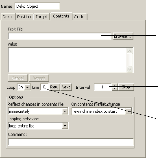
3 Editing Objects in the Scene
122
To display contents of a text file:
1. Add a Deko object to the Scene Tree and link to a Deko source file that includes a text
layer (see “Adding a Deko Object to a Scene” on page 109).
2. If necessary, adjust position, scale, and opacity (see “Positioning and Sizing a Deko
Object” on page 115 and “Adjusting Opacity” on page 116.
3. In the Deko object editor, click the Deko tab.
4. Select Automatic Update from the Update list (see “Editing and Updating Deko
Objects” on page 114).
5. Select the text layer from the Selected Layer list.
6. Select how you want transitions to be displayed when the Deko object is updated:
tSelect the kind of transition from the Transition Type list.
tSelect when you want the transition to begin from the Transition Triggering list.
For information about Transition options, see “Transition Options for Deko Object
Text” on page 125. For information about creating rolls and scrolls, see “Displaying
Crawls and Rolls” on page 123.
7. Click the Contents tab.
Text File Selection
Value text box
Interval: Set to 0 if Value text
box is not to be updated from
text file
Line
Working with Deko Objects
123
8. Do one of the following to select a text file:
tIn the Text File text box, type the complete path of a text file you want the
application to read and display automatically.
tClick Browse and navigate to the file. Click OK.
The text contained in the file is displayed in the Value text box, and the text begins to
cycle. Click Stop if you want to stop the cycling.
9. Select the looping options (see “Looping Options for Deko Object Text” on page 127).
10. Select an Interval value to select the frequency in seconds that the application checks the
text file for updates and the delay between displaying lines of text.
nSet the Interval value to 0 if the Value text box does not need to update from the text file.
11. To determine when to display changes to the contents of the Value text box, select an
option from the “Reflect changes in contents file” list.
tSelect “Immediately” to display changes as soon as they are typed. This is a good
choice for continuously updated lists such as stock prices.
tSelect “At next interval” to display changes at the end of a line of text. This is a
good choice for a series of blurbs or headlines.
tSelect “At end of list” to display changes after a complete cycle displaying text
existing prior to the changes. This is a good choice for displaying information in
paragraph form or changing to completely unrelated text.
12. To determine where in the Value text box to begin to display once changes are in effect,
select an option from the On contents file/list change menu:
tSelect “Rewind line index” to start display from the beginning of the Value text box,
effectively skipping items from the point where changes take place to the end of the
text box. Avoid this choice for lists that update continuously, such as stock prices,
otherwise items at the end of the list might not ever display.
tSelect “Leave line index unchanged” to continue displaying contents from the
current line in the Value text box.
13. Click Stop to stop the display.
Displaying Crawls and Rolls
You can use controls in the Deko object editor to add a crawl or a roll to a scene. A crawl
scrolls text horizontally across the screen; a roll scrolls the text vertically.
nCrawls and rolls can also be created using the Crawl object, which simplifies the procedure
and allows you to intersperse non-text objects, such as Video In, Cel Animation, Clip
Playback, and Audio Playback objects. See “Creating Crawls” on page 192.
3 Editing Objects in the Scene
124
To display a roll or a crawl:
1. Add a Deko object to the Scene Tree and link to a Deko source file that includes a text
layer (see “Adding a Deko Object to a Scene” on page 109).
2. If necessary, adjust position, scale, and opacity (see “Positioning and Sizing a Deko
Object” on page 115 and “Adjusting Opacity” on page 116).
3. In the Deko object editor, click the Deko tab.
4. Select Automatic Update from the Update list (see “Editing and Updating Deko
Objects” on page 114).
5. Select the text layer.
6. Select a scroll type from the Transition Type list.
For a description of the scroll options and transition triggering options, see “Transition
Options for Deko Object Text” on page 125.
7. Do one of the following:
tIn the Contents tab, type text in the Value text box. Press Enter after each line
except for the last line. See “Using the Contents Tab” on page 119.
tLink the text layer of the Deko object to a text file. See “Using Text Files” on
page 121.
8. Click Accept.
Select when these changes are to take effect from the Reflect changes in contents file
menu: immediately, at next interval, or at the end of the list.
9. Select the looping options (see “Looping Options for Deko Object Text” on page 127).
10. Set the update interval between lines by typing a time in seconds into the Interval text
box. For example, typing the number 3 changes the text every three seconds.
Use the up/down arrows to make small adjustments (in quarter seconds) to the interval.
Click the Stop button to set the value back to 0 and stop the updates. Type a non-zero
interval and press Enter to resume the scroll.
11. (Option) To change the text, edit the Value text box and click Accept.
The new text starts cycling, beginning with the first line. The displayed text does not
change until you click Accept. Click Cancel to cancel your changes.
12. In the Deko tab, click and drag the Rate thumbwheel to control the speed of the Scroll
transitions in scan lines or pixels per field.
Positive values scroll the text right-to-left or bottom-to-top. Negative values scroll the
text left-to-right or top-to-bottom. A setting of 1 produces a slow scroll through; a
setting of 5 produces a faster scroll through.

Working with Deko Objects
125
13. Click and drag the Duration thumbwheel to change the amount of time between the
scroll in and out. Duration does not apply to Crawl or Roll options.
To change the size of the text:
tIn the Position tab, click and drag the Scale thumbwheel. All of the Position and Scale
parameters can be adjusted.
To crop the text layer:
tIn the Position tab, use the Cropping thumbwheels to crop the text’s layer boundary.
You can also use crop adjustments to change the spacing between elements in a Crawl or
Roll.
Adjusting the layer boundary also moves the boundary in which scrolling occurs.
nText extending past the right of the layer boundary is all rendered in a Scroll transition and
is visible at some point in the transitions. To use text wider or higher than the screen, the
Deko graphic must be created with the horizontal or vertical scroll property (or both). To set
the scroll property, select Text > Horizontal Scrolling or Vertical Scrolling in Deko or
PostDeko Lite before saving the document.
Transition Options for Deko Object Text
The following tables provide information about options in the Transitions section of the
Deko tab in the Deko object editor.
Transition Type Options
Option Description
Cut Switches from the old text to the new text instantly.
Dissolve Fades out the old text while fading in the new text. Specify the duration of the fade
in seconds using the Duration thumbwheel or type it.
Scrolls: Vertical (vscroll)
and Horizontal (hscroll)
Scrolls the old text out of the layer boundary while the new text is scrolled in. The
text is clipped to this layer's boundary defined within the Deko graphic and
modified by any cropping settings under the Position tab. The duration of the
scroll in/out is set by the Duration thumbwheel control. If the Rate thumbwheel
control value is positive, the text scrolls right-to-left or bottom-to-top. If the Rate
is negative, the text scrolls left-to-right or top-to-bottom.

3 Editing Objects in the Scene
126
Rate thumbwheel: Controls the speed of the Scroll transitions in scan lines or pixels per
field. Positive values scroll the text right-to-left or bottom-to-top. Negative values scroll the
text left-to-right or top-to-bottom. A setting of 1 produces a slow scroll through; a setting of
5 produces a faster scroll through.
Duration thumbwheel: Sets the transition duration in seconds. Duration affects only the
Dissolve and Scroll transitions. Duration has no effect on Cut or Scroll transitions.
Scroll Pad variations
• vscrollpad
• hscrollpad
• crawlpad
• rollpad
Usually, the text moves just enough to get the visible pixels in or out of the layer
boundary so a small amount of text moves a shorter distance than a large amount
of text. This might look awkward in some applications, so the Pad variations
always scroll the text by the dimensions of the layer boundary, keeping the scroll
distances consistent.
Crawl
Roll
Scrolls the new Deko text through the layer boundary at a constant rate. The text
displayed is clipped to this layer's boundary defined within the Deko graphic,
modified by any cropping settings under the Position tab, though the total size of
the text might be larger than the layer boundary. The scroll rate is set with the Rate
thumbwheel control, measured in scan lines per field for the Crawl, and pixels per
field for the Roll. If the Rate value is positive, the text scrolls right-to-left or
bottom-to-top. If the Rate is negative, the text scrolls left-to-right or
top-to-bottom.
nWhen using Deko layers for a Crawl, deselect the word wrap feature in the
Deko Layer in PostDeko Lite. You can add a gap between elements in a
Crawl by setting a negative left cropping value.
If the current text is still scrolling into the layer boundary, the new text is
positioned to abut the edge of the old text. New text values are made visible as
they enter the layer boundary.
Transition Triggering Options
Option Description
Auto Begins the transition automatically when Deko finishes rendering the new text, or
when the current transition completes, if rendered text is queued waiting for
display. Typically, this transition occurs as soon as you type in text and press
Enter.
Manual Allows transition to begin only when the Trigger button is clicked.
Transition Type Options (Continued)
Option Description

Working with Deko Objects
127
Looping Options for Deko Object Text
The following table provides information about Looping options in the Contents tab in the
Deko object editor.
Deko Contents Tab: Looping Options
Option Description
Loop Set On for indefinite looping, type or select a number to specify the
number of loops, or select 0 to stop the display. Use the Looping
Behavior list to specify whether DekoCast is to loop the entire contents
of the Value text box, or only one line.
nTo loop one line, specify the line number in the Line text box.
If you select a limited number of loops, after the crawl begins to play, the
Loop text box shows the number of loops remaining.
Line Displays the line that is ready to be played.
To display one line from the Value text box rather than the entire
contents, type the number of the line and press Enter. Type 0 to display
the first line, type 1 to display the second, and so on. Select “loop current
line” from the Looping Behavior list.
If you are displaying the entire list, the Line text box displays -1 after the
last line is displayed (indicating no lines left to play).
Rew Click to return to the beginning of the list in the Value text box (line 0).
Next If you are manually controlling the display, click to display the next line
in the Value text box. To manually control the display, set the Interval to
0 and in the Deko tab, set Transition Triggering to Manual.
Interval To set the interval in seconds (frequency) at which a new line of text is
displayed, type a number and press Enter.
Stop Click to set Interval to 0 and stop the display.
3 Editing Objects in the Scene
128
Managing Text Display
Several controls on the Deko tab let you manage the text as it is displayed on the video
output.
To view the display status of text values:
tView the Active-Queued-Rendering counts as shown in the Display status (above the
Trigger, Clear, and Reset buttons on the Deko tab).
These status values indicate the number of text values (bit maps) currently Active
(visible on video output), Queued (rendered by the application but waiting to be
displayed), or Rendering (in the process of being rendered).
To clear queued and rendering text awaiting display:
tClick the Clear button.
Clicking this button erases all queued text and text in the process of being rendered from
the queue that is awaiting display. It does not clear currently displaying text. With
Transition triggering set to Auto, a transition generally occurs too quickly to use Clear.
To clear all active, queued, and rendered text:
tClick the Reset button.
To reload cleared/reset text:
tMove the pointer to the end of the text and press Enter.
Using Embedded Tags with Deko Object Text
DekoCast provides tags that you can embed in text, either in the Deko object editor or in a
text file. An embedded tag is a code that has a special format that is recognized and used by
DekoCast to perform a specific function. One simple tag is
<br/>
, which is used to create a
line break. For example:
Today’s weather:<br/>Cloudy with a chance of showers
results in
Today’s weather:
Cloudy with a chance of showers
You can include tags in text to control its formatting. Typically, you use these tags in a text
file to change the text properties of text in a crawl. Most tags refer to files that you create
with Deko or PostDeko Lite.
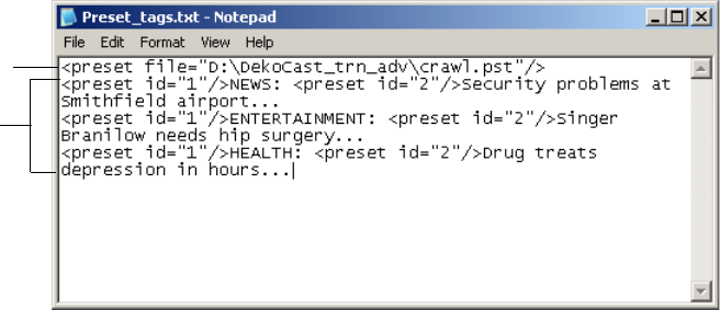
Working with Deko Objects
129
Embedded tags are particularly useful for including more than one text format in a single
text layer. The following file, which is used for a news crawl, includes tags that refer to a
Deko preset file and to two different Deko presets:
• The tag
<preset file="D:\DekoCast_trn_adv\crawl.pst"/>
refers to a preset
file created in Deko PostDeko Lite. This tag selects and loads the preset file.
• The tags
<preset id=”1”>
and
<preset id=”2”>
refer to two preset text styles:
black type for the headline and white type for the news text. Each tag loads the style for
the text that follows the tag.
For information on creating text layers and presets in PostDeko Lite, see the PostDeko Lite
Help. For information on creating text files, see “Using Text Files” on page 121. For
information on using embedded tags with custom typefaces, see “Adding Non-Text Objects
as Custom Typefaces” on page 216.
Preset
file tag
Preset
ID tags

3 Editing Objects in the Scene
130
The following table lists and describes embedded tags.
Embedded Tags for Deko Objects
Tag Description
<br/>
Inserts a new line into a text string.
<preset
file=”D:\directory_name\x.pst”/>
Selects and loads a new preset file (where x is the
file name). The ID and file attributes can be
combined in the same tag.
<preset id=”n”/>
Selects a style preset from the current set (where n
is 1 to 8). For example, specify a preset for a
custom typeface.
<layer id=”n”/>
Switches to a different layer in the current graphic
(where n is the layer id number). The Layer option
in the Deko object editor determines which layer is
visible, or if all layers are visible. Generally use this
tag with “All layers” selected to change the text in
multiple layers within a single text file.
<style file=”x.sty”/>
Sets the current style from a style file (where x is
the file name).
<graphic file=”x.dko”/>
Opens a specific Deko file (where x is the file
name). The default is the file name specified in the
Deko object file name parameter field. If this field
is empty, the Deko object is ignored, so generally
set the field to Preview when using this tag.
<graphic/>
Opens a new blank graphic (contains a single
empty text layer with the current style).
<macro>macro<macro/>
Executes a Deko macro (where macro is the macro
text).
<macro file=”x.mcr”/>
Executes the specified Deko macro file (where x is
the file name).
<auto file=”x.aut”/>
<auto file=”x.atx”/>
Opens the named automation file (where x is the
file name).
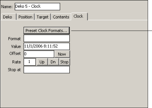
Working with Deko Objects
131
Displaying Clocks
You can use a Deko source graphic with at least one text layer and the Clock tab of the Deko
object editor to display a digital clock or timer on video output. The application provides
many formats you can use. The Deko object clock uses the Windows system time-of-day
clock.
The following topics provide more information on displaying clocks:
•Displaying a Time-of-Day Clock
•Displaying a Count-Up or Count-Down Timer
•Deko Object Clock Formats
Displaying a Time-of-Day Clock
To display a time-of-day clock:
1. Add a Deko object to your Scene Tree.
2. Select a source DKO file that has a text layer.
3. From the Selected Layer menu, select a text layer. Do not specify a clock created in
Deko.
4. Click the Clock tab of the Deko object editor.
Preset Clock Formats button
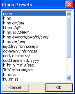
3 Editing Objects in the Scene
132
5. Click the Preset Clock Formats button.
The Clock Presets dialog box opens.
nThe clock uses picture format strings similar to those used in Excel and Visual Basic.
6. Select your choice and click OK.
For a 12-hour clock format, select h:nn:ss. For a 24-hour clock format, select hh:nn:ss.
Other formats are described in “Deko Object Clock Formats” on page 133. You can
modify these preset formats to customize the clock display.
7. To make slight corrections in the clock, or to display a different time zone, type an offset
in the clock Offset text box, either in seconds, such as 3600, or in minutes:seconds, or
hour:minutes:seconds; for example, 1:00 for 1 minute or 1:00:00 for 1 hour.
8. Click the Now button to start the clock running and reset the offset to 0.
The resulting text is inserted into the Text Override field of the Deko object, but only if
there is currently no text queued waiting to transition. If you specify a clock that
changes every second, but use a transition that takes 2 seconds, you see only every other
second displayed.
nClicking the clock's Stop button freezes the clock.
9. Type an explicit clock setting in the Value text box to set the clock to a specific date and
time using a month/date/year hour:minutes:seconds format; for example, 10/13/01
4:47:00.
10. Click the clock Up button to start the clock running from the new value. Click the Now
button to start the clock running and set its value back to the system clock.

Working with Deko Objects
133
11. Click the Deko tab to show the Transitions controls. Use the Transition Type chooser to
select different effects to use when the clock changes. The rules for updating vary
between the different effects. See “Transition Options for Deko Object Text” on
page 125.
12. Use the Position tab or Target tab to adjust the position, opacity and scale. See “Using
the Target and Position Tabs” on page 86.
Displaying a Count-Up or Count-Down Timer
To display a count-up or count-down timer:
1. Set up a clock as you did in the previous topic, but type or select a format that uses only
the text boxes appropriate to your up/down counter; for example, n:ss for a
minutes/seconds counter. See “Deko Object Clock Formats” on page 133.
2. Type a time value in the Stop at text box, in the same format you used in the Value text
box, to have the clock automatically stop at that time.
3. Type the starting time in the clock Value text box, using an hours:minutes:seconds,
minutes:seconds, or seconds format.
4. Click the clock's Up button to start counting up, the Dn button to count down, or the
Stop button to freeze the counter.
Deko Object Clock Formats
The format for the Deko object clock is represented by a line of text with a code sequence
replaced by the corresponding time or date value. For example, h:nn:ss might be
translated as 11:17:33, where h, nn, and ss are codes that represent hour, minute, and
second, respectively; the colons are text literals that are copied into the resulting clock text.
The codes used in creating these formats are described in the following table.
Clock Formats
Format Code Description
hHour in 0-23 format. To use a 12-hour clock in 1-12 format, include one of
the am/pm indicators somewhere in the format.
hh Hour in 00-23 format, or 01-12 if an am/pm code appears somewhere in the
format.
h0 Hour in blank-23 format, which is like 0-23 format, but displays nothing
when the value is 0. Used in hour:minute count up/down clocks where the
hour digit should not be displayed when zero.
nMinutes in 1-59 format.

3 Editing Objects in the Scene
134
nn Minutes in 01-59 format.
n0 Minutes in blank-59 format.
nnn Minutes in 0-86400 format – total minutes in the count, up to one day, not
calculated modulo-60. Useful for min:sec clocks that must count up/down
past 60 minutes.
nnn0 Minutes in blank-86400 format. Like “nnn” but displaying nothing instead of
0.
sSeconds in 0-59 format.
ss Seconds in 00-59 format.
sss Seconds in 0-5184000 format – total seconds, not modulo-60, up to one day.
am/pm Displays “am” for values before noon and “pm” for values after noon. Like all
am/pm codes, causes the “h” codes to use a 12-hour clock instead of a
24-hour clock.
a/p Displays “a” before noon, “p” after.
AM/PM Displays “AM” before noon, “PM” after.
A/P Displays “A” before noon, “P” after.
a=<string>/ Displays the text in <string> before noon.
p=<string>/ Displays the text in <string> if it is after noon. There is no need to
single-quote the characters within <string>. To include a / within the string,
use //:
“h:nn a=morn/p=aft//eve/” would show something like “9:45 morn” before
noon, and “1:15 aft/eve” after noon.
Using “a=/” in a format is a simple way to get “h” to use a 12-hour clock
without having to show a visible “am/pm” indicator.
mMonth in 1-12 format.
mm Month in 01-12 format.
mmm Short month name: “Jan”, “Feb”, …
mmmm Long month name: “January”, “February”, …
dDate in month in 1-31 format.
Clock Formats (Continued)
Format Code Description

Working with Deko Objects
135
You can customize a clock by editing the code displayed in the Format box of the Deko
Clock tab. You can use single quotes to insert literal text, for example:
'Today is 'dddd
results in
Today is Monday
You can use the tag
<br/>
to create line breaks in the format string. For example,
dddd<br/>m/d/yy
results in:
Saturday
10/13/07
Be careful when using codes embedded in the middle of words. The format string
n
minutes
might appear as
17 10i17ute33
, because
n
is the code for minutes,
m
is the code
for month, and
s
is the code for seconds. To avoid such undesired code substitution,
surround the literal text by single quote characters, for example,
n 'minutes'.
To display
a single quote in the clock output, use two single quotes within a single-quoted string. For
example:
'It''s 'h:nn
results in
It's 11:17
nThe exact appearance of the text depends on the justification, word wrap, and shrink-to-fit
settings established for the selected layer in the Deko graphic file.
dd Date in month in 01-31 format.
ddd Short day name: “Sun”, “Mon”, …
dddd Long day name: “Sunday”, “Monday”, …
yy Year in 2-digit form: 1999 is “99”, 2006 is “06.”
yyyy Year in 4-digit form.
Clock Formats (Continued)
Format Code Description

3 Editing Objects in the Scene
136
Displaying Temperature
You can display the temperature using the DekoCast Central Temperature Probe utility.
To display temperature:
1. Set up the temperature probe as described in “Using the Temperature Probe Interface
Utility” on page 386.
2. Add a Deko object with a text layer to the scene.
3. Rename the Deko object Temperature.
4. Link to a DKO file to define the display style.
When the Temperature Probe saves the temperature to a text file, it also queries all open
scenes in DekoCast. If it finds a Deko object whose name is Temperature, it sets the text
override parameter value to the new temperature value.
nIf you do not name the Deko object Temperature, you have to link the Deko object to the text
file in which the Temperature Probe utility saves the data.
Playing Back Audio
DekoCast recognizes WAV and AVI files with embedded audio as source files for Audio
Playback objects. After you select an audio file, it plays back from the system’s hard drive.
Playback controls allow you to queue, play, and stop the audio file, either manually or
through actions that you define in the Timeline editor.
For information about setting up the Levels and Mixer tabs, see “Using the Levels and Mixer
Tabs” on page 103.
Audio
Playback
button
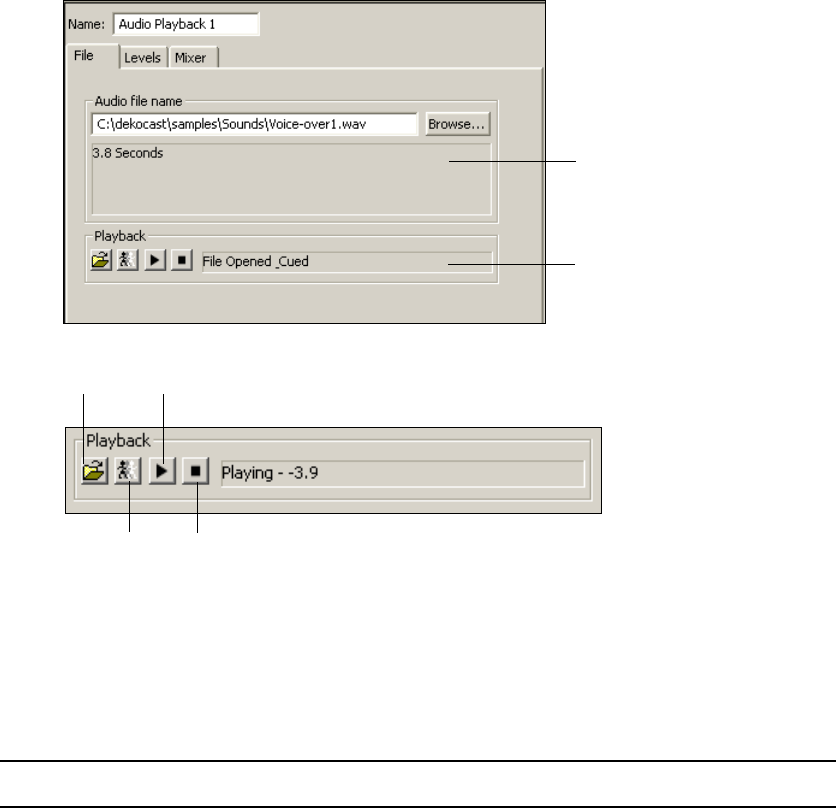
Playing Back Audio
137
To include audio playback in a scene:
1. Add an Audio Playback object to the scene tree.
The Audio Playback object editor opens.
2. In the Audio file name text box, type the complete path for an audio file or click the
Browse button and select a source file.
nSave all audio files to drive E.
3. Control the playback as described in the following table:
Audio File Status
Audio Object Status
Stop
Open
Cue
Play
Option Description
Open Opens the source audio file. If you attempt to open a file not recognized by the
application, an error message displays in the Audio File Status section. The Audio
Object Status reads File Opened.
3 Editing Objects in the Scene
138
Capturing Audio
The Audio Capture object records audio and saves it to files in the WAV format.
• For Corsica-based systems, DekoCast records audio through a video input port, such as
Video In A. You set this input in both the Video In object and the Audio Capture object.
• For TARGA-based systems, DekoCast also records audio through a video input port, so
set this input in the Video In object. However, you need to set a Video output port in the
Audio Capture object. If a scene has video input with audio and also audio playback, the
Audio Capture object captures both.
To determine the video board used in a DekoCast system:
1. Select Options > Preferences.
2. Click the Video Hardware Options tab.
The name of the video board is listed at the top of the tab.
To capture audio to a WAV file:
1. Add an Audio Capture object to the scene tree.
The Audio Capture object editor opens.
Cue Allocates audio playback hardware and loads audio samples for immediate Play.
The Audio Object Status reads File Opened_Cued. If the file is not already open,
the application attempts to open the file.
Play Plays the audio file. The Audio Object Status reads Playing (including elapsed
runtime of Audio object file). If the file has not been cued already, the application
cues the file.
Stop Stops the currently playing audio file. The Audio Object Status states that the file
is stopped. This Stop is not a pause function. You cannot click Play and expect the
file to resume where you stopped it. Clicking this button stops playback, uncues,
and closes the audio file.
Option Description
Audio
Capture
button
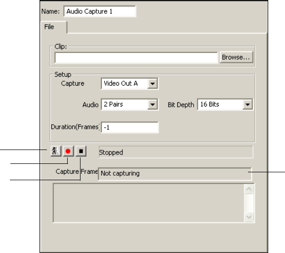
Capturing Audio
139
2. In the Clip text box, type the complete path for the WAV file to which you want to save
the audio, or click the Browse button and select a source file.
3. In the Setup pane, select the source for the audio capture. The options depend on your
video-board configuration:
- For Corsica-based systems, select Video In A or B.
- For TARGA-based systems, select Video Out A or B.
4. For the Audio options, your selection depends on your video-board configuration: 1 Pair
(one left and right stereo), 2 Pairs (two left and two right stereo), 3 Pairs, and 4 Pairs.
5. Select the audio resolution (bit depth), depending on your video-board configuration:
16-bit or 20-bit for Standard Definition or 24-bit for High Definition.
6. Set the duration of the capture by doing one of the following:
Cue
Capture Status
Record
Stop

3 Editing Objects in the Scene
140
tIf you want manual control over the length of the capture, set the Duration (Frames)
option to -1. The capture does not stop until you click the Stop button.
tIf you want to capture a specific duration, type the number of video frames for
which there is audio to capture in the Duration (Frames) text box.
Initially, the Capture Frame text box reads Not Capturing.
To cue the capture:
tClick the Cue button.
The status changes from Stopped to Cued.
nIf you cue the capture before pressing the Record button, there is a 1-second delay before the
system starts recording. If you do not cue the capture before pressing the Record button,
there is a 3-second delay
To start recording:
tClick the Record (red dot) button.
The status changes to Record, and the Capture Frame text changes to Capturing.
To stop recording:
tClick the Stop (black square) button.
The status is now Stopped.
Any error messages are displayed in the text box at the bottom of the dialog box.
Playing Back Clips
The Clip Playback object lets you play back clips in various video formats. Depending on
your system’s hardware and the type of clip, you can play out up to four clips (four video
streams). Clip playback is available as part of the Clip Player option.
nThe Clip Playback button and Insert > Clip Playback menu option appear available even if
the Clip Player option has not been activated. If you attempt to cue or play a clip using the
Clip Playback object without having this option enabled, the clip neither cues nor plays. To
determine if your system has the Clip Player option enabled, select Help > About DekoCast.
Clip
Playback
button
Playing Back Clips
141
Understanding Clip Playback
When you use one or more Clip Playback objects in a scene, you need to be aware of how
many clips the scene requires and how many clips your system can play out. This playout is
determined by the number of streams available from your system’s video board.
DekoCast systems use either a TARGA video board or a Corsica video board, depending on
your system and model. Standard-definition playout can be through a TARGA video board
or a Corsica video board. High-definition playout is through a Corsica video board only.
To determine the video board used in a DekoCast system:
1. Select Options > Preferences.
2. Click the Video Hardware Options tab.
The name of the video board is listed at the top of the tab.
nFor more information about your system’s video board, see the Avid On-Air Graphics Setup and
Configuration Guide.
The two boards process streams in different ways:
•TARGA video board: DekoCast SD systems prior to version 4.1 were shipped with a
TARGA video board. This video board incorporates two hardware codecs into its
architecture.
Each codec (a term derived from “compressor/decompressor”) is capable of decoding
clips through two video streams, for a total of four streams. The video board can
simultaneously play back a maximum of two clips. These two clips can each include a
key, which requires use of all four streams.
The following illustration shows the maximum number of streams and clips the TARGA
board can play out.
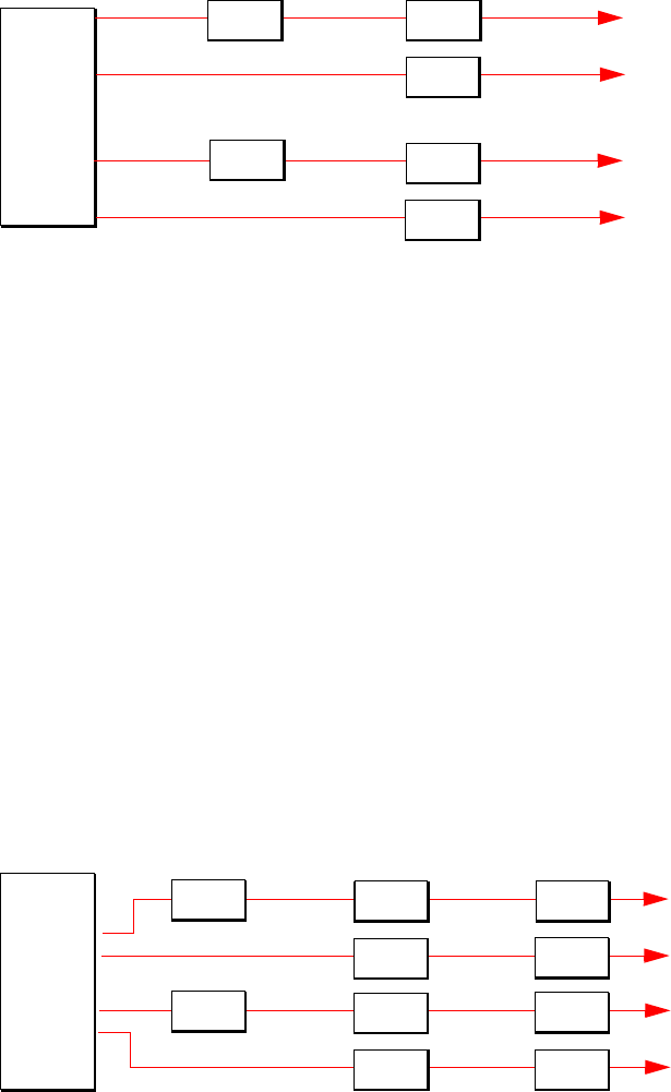
3 Editing Objects in the Scene
142
Although you can place more than two clips in a scene, the video board cannot play
more than two clips simultaneously. You can, however, append one clip to another,
which allows you to play several clips without the loss of frames. Appended clips can
play as cuts only; they cannot have transitions or effects between them. For more
information, see “Adding and Defining a Clip Playback Object” on page 144. See also
“Managing Clip Playback” on page 143.
•Corsica video board: All DekoCast systems shipped with version 4.1 and later ship
with a single Corsica video board. This video board incorporates one hardware codec
into its architecture.
This codec is capable of decoding clips through four video streams. The video board can
simultaneously play back a maximum total of four clips or two clips with key, either of
which require use of all four streams.
The following illustration shows the maximum number of streams and clips the Corsica
video board can play out.
TAR GA
video
board
OR
Stream 1 out
Stream 2 out
TARGA video board
Clip
Key
OR Stream 1 out
Stream 2 out
Clip
Key
Clip
Clip
OR
Stream 1 out
Stream 2 out
Corsica video board
Clip
Key
OR
Stream 3 out
Stream 4 out
Clip
Key
Clip
Clip
Clip
Clip
Clip
Clip
Corsica
video
board

Playing Back Clips
143
Corsica-based systems, like TARGA-based systems, allow you to append clips for
playout of several clips without the loss of frames.
nYou need to configure a Corsica-based system to use these codecs as decoders or encoders
or a combination of the two. See “Encode/Decode Option” on page 418.
Managing Clip Playback
It’s important to keep track of how many streams are required by your output, because your
system can play out only a limited number of streams. Keeping track is especially important
when you have cued clips or transitions.
• Clip playback objects consume codec resources whenever clips are playing or are cued.
A single clip playback can consume twice as many codecs if it is playing one clip and
has another cued.
• Any transition between two clips, other than a cut, requires that you count the clips
transitioning off as well as transitioning on. This includes key clips.
To determine how many streams are currently available:
1. Click the Parameters tab in the upper-right corner of the main DekoCast window.
2. Search for the value of the “Canvas-number codecs free” parameter.
For example, a value of 2 means there are two free streams (here referred to as codecs)
for this video board (canvas).
Clip Playback File and Compression Formats
DekoCast supports the following file and compression formats for video clips, depending on
whether the system uses a TARGA video board or a Corsica video board.
Supported File Formats: TARGA Video Board (SD)
Supported File
Formats
Supported Compression
Formats Comments
DV, DIF, and AVI DV 25 Up to 2 streams with audio
MXF DV 25, MPEG-2 4:2:0, MPEG-2 4:2:2
I-Frame or IBP
Up to 2 streams with audio
3 Editing Objects in the Scene
144
Note the following:
• Both video files and key files are supported in these formats.
• Clips created in Deko and Thunder MX are correctly formatted for any DekoCast
system.
• All clips should be stored and played back from drive E.
• For Corsica-based systems, you can use the Transcode feature to convert various file
types to the supported MPEG-2 formats. See “Transcoding SD Clips to MPEG-2 MXF
I-Frame” on page 149.
For more information, see “Understanding Files and File Types” on page 37.
Adding and Defining a Clip Playback Object
The following procedure describes the basic steps for adding and defining a Clip Playback
object. Instructions for playing clips, looping a segment of a clip, and setting the key file to
start before or after the clip file are provided in“Playing and Looping Clips” on page 148.
To define a Clip Playback object:
1. Select Options > Preferences and from the Encode/Decode list select either “4
decoders” or “1 encoder 2 decoders.” For more information, see “Encode/Decode
Option” on page 418.
2. Add a Clip Playback object to a scene tree.
3. Edit the name in the object editor’s Name text box.
4. In the File tab, select the source clip file by doing one of the following:
- Click the Browse button, navigate to a clip file, and click Open.
- Type the clip file’s complete file path.
Supported File Formats: Corsica Video Board (SD and HD)
Supported File
Formats
Supported Compression
Formats Comments
MXF MPEG-2 4:2:0, MPEG-2 4:2:2
I-Frame Only
Up to 4 streams with audio

Playing Back Clips
145
When a clip file is open, the Clip File Info pane shows the video format, the number of
frames in the file, and other file information.
nIf you are working on a Corsica-based system, clips must use the MPEG-2 MXF I-Frame
format. Clips in other formats need to be transcoded. See “Transcoding SD Clips to
MPEG-2 MXF I-Frame” on page 149.
5. (Option) Select a key file using the Key text box or Browse button.
nThe same formats are supported for video files and key files.
Avid recommends that you name your key file filename_key. For example, a file and its
corresponding key might be named Background.mxf and Background_key.mxf.
6. Specify the Object options as described in the following table.
7. Click the Cue button to add the clip (and key) file to the playlist.
Clip file path
Browse button
Key file path
Open/Close file
Key Offset
Clip file status
User messages
Clip file information
Clear button
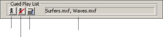
3 Editing Objects in the Scene
146
The Cue button allocates a video codec stream and readies it for play. Clicking Cue
automatically opens the file if it is not open.
8. (Option) Add another source (and key) file to this object’s playlist:
a. Open a file by typing its name or using the Browse button.
b. Click the Cue Append button, which adds the clip file to the Cued Play List.
9. (Option) Append additional clips as described above.
To remove all files from the cue list:
tClick the Uncue List button in the Cued Play List set of button.
To revert to the Not Cued and Not Playing states:
tClick the Clear button.
To position and size a clip or define a target rectangle for it, see “Using the Target and
Position Tabs” on page 86. To adjust associated audio, see “Using the Levels and Mixer
Tabs” on page 103.
Cue Cue Append
Uncue list
Cued playlist

Playing Back Clips
147
Clip Playback Object Options
The following table describes options you can select in the Clip Playback object editor.
Clip Playback Object Options
Option Description
Loop Loops the clip file or files until you explicitly stop it.
Cue Frame Sets an option for which frame to show when cuing a clip: None (black), Full Frame,
or First Field. Select First Field to avoid stuttering if there is motion between fields
(interlaced formats only). Select Full Frame for better resolution.
Last Frame Sets an option for which frame to show when ending a clip: None (black), Full Frame,
or Second Field. Select Second Field to avoid stuttering if there is motion between
fields (interlaced formats only). Select Full Frame for better resolution.
Keying Key: Activates the associated key file. Deselect it if you do not want the key file to
play back with the clip file.
Shape: Sets whether the clip is shaped or unshaped. If the edges appear blurry or
jagged, select Shape to sharpen the edges.
NoScale: Relates to the key levels of the clip. Key levels can be on a scale of 0-255 or
16-235. When NoScale is selected, the application interprets the clip's key as already
0-255 and does not stretch or scale it from a 16-235 level.
KOf (Key Offset): This text box (in the File section of the object editor) is set to 0 (no
offset) by default. To have the key file start playback a specified number of frames
after the clip file, type the number of frames that the key file is to be offset (played
after the start) from the clip file.
nThe key offset can be either positive or negative; the key can be frame matched
against a specified number of frames ahead or behind in the clip.
Audio Allows audio to play. By default, audio is set to on.
Reverse Dominance Reverses the interlaced scan decoding from odd/even or even/odd, depending on the
setting.
Compress Color Similar to key levels, colors can be on a scale of 0-255 or 16-235. When this option is
selected, colors are compressed to 16-235.
Play on Load Starts the clip playing as soon as the file is read into memory, without being opened or
cued.
Cue on Load Cues the clip as soon as the file is read into memory.
Opacity Sets the transparency level of the clip. Fully transparent is 0; Fully opaque is 1.
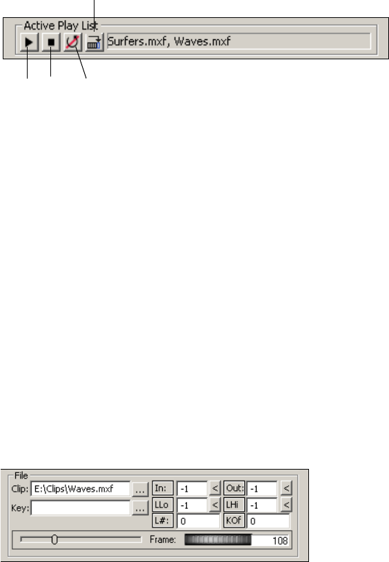
3 Editing Objects in the Scene
148
Playing and Looping Clips
You have several options for playing back and looping clips.
To play the clips manually in the order shown in the Cue Play List:
tClick the Play button.
To stop playout:
tClick the Stop button.
To manually control the playback of the clip, do one of the following:
tSelect and drag the scrubber (to the left of the Frame thumbwheel).
tSelect and drag the Frame thumbwheel.
tType a frame number in the text box next to the Frame thumbwheel.
To append a clip to an already playing playlist:
tOpen the clip file and click the Play Append button in the Active Play List set of
buttons.
By default, a clip plays from the first to the last frame. In the File pane, the value for In is –1
(start play at the first frame), and the value for Out is –1 (continue to play to the last frame).
You can select a different in or out frame to play a partial clip.
Play Stop
Play Append
End Loop
Playing Back Clips
149
To play a partial clip:
1. Type the frame numbers that represents the In (first) frame and Out (last) frame of the
clip that the application is to play.
Use the scrubber or thumbwheel to determine the frame number.
2. Play the clip.
For example, if you want to start playing at frame 20, select First and type
20
in the In
text box. To stop the clip at a specific frame, select Last and type the frame number in
the Out text box.
To loop an entire clip, including appended clips:
tSelect the Loop setup option in the Object pane of the File tab and play the clip.
You can also loop a selected part of a clip by setting the Loop Low (LLo) and Loop High
(LHi) frame numbers. By default, these values are –1, which means that no internal looping
is to occur.
To loop part of a clip a set number of times.
1. In the File pane, type the frame number at which the loop is to start in the LLo text box.
2. Type the frame number at which the loop is to stop in the LHi text box.
3. Type the number of times that you want this internal loop to occur in the Loop Number
(L#) text box.
Frames that follow the LHi frame play after the Loop Number (L#) of iterations of the
internal loop.
To stop a loop:
tClick the End Loop button in the Active Play List set of buttons.
Transcoding SD Clips to MPEG-2 MXF I-Frame
DekoCast systems that have a Corsica video board use MPEG-2 MXF I-Frame as a native
file format for clip playback. If you need to work with scenes and clips created on a
TARGA-based DekoCast SD system, you might need to transcode clips so that they play
natively on a Corsica-based system. DekoCast includes tools to help you manage clips and
scenes that are shared among DekoCast systems with different hardware.
nTo determine if a Corsica video board is used in your DekoCast system, select Options >
Preferences and click the Video Hardware Options tab. The name of the video board is listed
at the top of the tab.
3 Editing Objects in the Scene
150
The most efficient workflow in an environment that includes TARGA-based and
Corsica-based DekoCast systems is to create clips in the MPEG-2 MXF I-Frame format.
MPEG-2 MXF I-Frame clips are compatible with all DekoCast systems.
However, if you need to work with DV 25 clips or clips in other formats, you can use the
Transcode application or a DekoCast watch folder to convert the files to MPEG-2 MXF
I-Frame. You might find this necessary if you are transferring projects that were created on a
TARGA-based SD system, which supports DV 25 for playback (see “Clip Playback File and
Compression Formats” on page 143). Other file formats you can transcode are .m2v, .mov,
.mxf, .avi, .dif, .tmf, and .vbs.
The Transcode application provides several different ways to transcode clips. In all cases,
the application adds _IF (for I-Frame) to the filename of the transcoded clips. If the filename
ends with _V (for video) or _K (for key), DekoCast adds IF_V or IF_K to the filename.
cTranscoding uses CPU resources and could interfere with playout to air. Avid
recommends that you perform transcoding on a DekoCast Authoring Station or when a
DekoCast system is not on-air.
There are two basic methods for transcoding clips:
• Transcode in standalone mode by opening the Transcode application and creating jobs
or by dragging files to the Transcode application icon.
• Transcode automatically by using watch folders or scene options. In this method
DekoCast starts the Transcode application.
The following topics describe these different methods:
•“Suggested Workflow for Transcoding” on page 151
•“Transcoding Clips Through the Transcode Application” on page 152
•“Transcoding By Dragging Clips to the Transcode Icon” on page 158
•“Transcoding Clips By Using a Watch Folder” on page 159
•“Transcoding Through a Default Watch Folder” on page 160
•“Transcoding Through a Custom Watch Folder” on page 161
•“Transcoding Clips When a Scene Opens” on page 163
Playing Back Clips
151
Suggested Workflow for Transcoding
The following is a suggested workflow for efficient transcoding and management of clips in
an environment that includes TARGA-based systems and new Corsica-based DekoCast
systems. This workflow uses a default watch folder, which lets you transcode clips without
having to open the Transcode application manually. For details on using a watch folder, see
“Transcoding Through a Default Watch Folder” on page 160.
To copy and transcode clips:
1. Set up a watch folder on a new Corsica-based DekoCast system.
For example, you can set E:\Clips as a default watch folder and include all subfolders in
the path.
2. Copy clips from a TARGA-based system to the watch folder.
Any clips that are not compatible with Corsica hardware are transcoded to MPEG-2
MXF I-Frame clips.
Transcoding through a watch folder works only if you copy clips to the watch folder, so
make sure to set up the watch folder before you copy the clips.
3. Copy scenes to the Corsica-based system.
After you complete this workflow, your scenes can play on any machine and you should
not need to do any further transcoding on your Corsica-based system. When you create
new clips, create them in the MPEG-2 MXF I-Frame format, which is compatible with
all DekoCast systems.
To verify that a scene and the newly transcoded clips work correctly:
1. In a Windows folder, select all original clips (such as .dv clips). You can sort by file type
to more easily select the original clips.
2. Cut the selected clips and paste them into a new folder.
3. Play your scene. Make sure all clips are playing.
4. After you're confident that all your scenes work correctly, you can delete the original
clips to save storage space.
nIf you edit a scene on Corsica-based system and then copy it to a TARGA-based system,
make sure to copy any clips also.

3 Editing Objects in the Scene
152
Transcoding Clips Through the Transcode Application
Using the Transcode application provides you with the most control over the Transcoding
process. When you open the Transcode application (or drag clips to the Transcode icon), you
are running Transcode in standalone mode. Use this method as an alternative to using a
watch folder for transferring scenes and clips from a TARGA-based system to a new
Corsica-based system.
For example, you can use the following workflow to transcode clips from a TARGA-based
system:
1. Copy the contents of your D: drive and E: drive from a TARGA-based system to a
Corsica-based system, preferably to a DekoCast Authoring Station or to an off-air
DekoCast system. (As a rule, you should store clips in folders on the E: drive).
2. On the Corsica-based system, use the Transcode application to transcode the clips that
are not supported on the Corsica-based system.
You can also open and run Transcode on the TARGA-based system and specify that
Transcode should write the transcoded files over a network to a folder on the Corsica-based
system.
If your clips are contained in several different folders and you want to preserve the same
folder structure, you need to create different jobs in the Transcode application. The
Transcode application lets you process multiple jobs simultaneously.
cTranscoding uses CPU resources and could interfere with playout to air. Avid
recommends that you perform transcoding on a DekoCast Authoring Station or when a
DekoCast system is not on-air.
Although you can run Transcode without the DekoCast application open, you need to
specify default settings in the Transcode and Scene Options tab of the DekoCast Options
dialog box (see “Transcode and Scene Options” on page 430). You can override these
settings in the Transcode application, but changes you make in the Transcode application are
not saved as defaults.
The Transcode application is installed by default as C:\DekoCast\bin\Transcode.exe. The
installation program adds an icon for the application to the desktop.
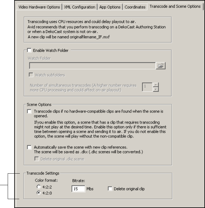
Playing Back Clips
153
To transcode clips through the Transcode application:
1. Select Options > Preferences.
2. Click the Transcode and Scene Options tab.
3. Select the desired Transcode Settings (Color format and Bitrate).
For more information on these options, see “Transcode and Scene Options” on
page 430.
nThe “Delete original clip” option does not apply when you transcode clips by opening the
Transcode application or by dragging clips to the Transcode icon. This option applies only
when you transcode through a default watch folder or automatically when a scene opens.
Transcode
settings
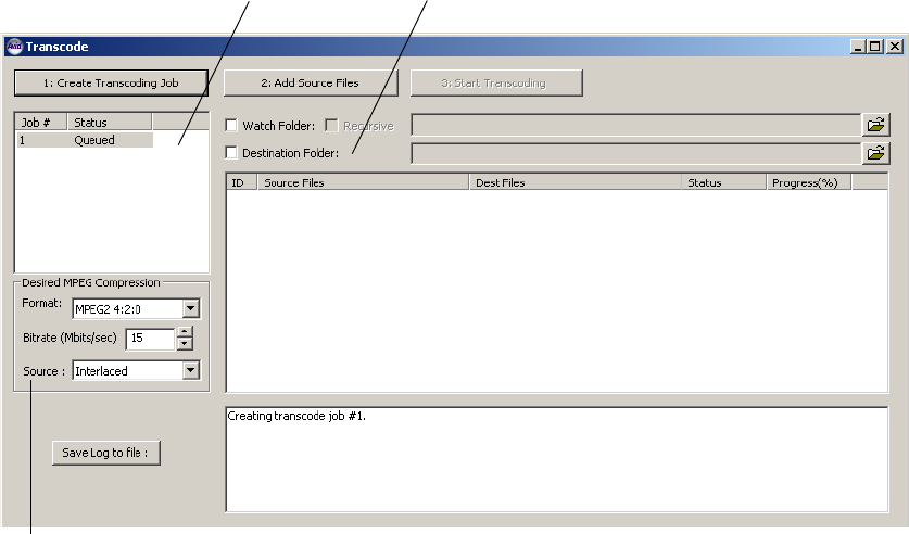
3 Editing Objects in the Scene
154
4. Click OK.
Your settings are saved as the defaults for the Transcode application.
5. Double-click the Transcode icon.
The Transcode window opens, with the default settings you selected. A numbered job is
displayed in the Job list with the Queued status.
6. (Option) Select different Desired MPEG Compression settings that override the default
settings.
Settings you select in the Transcode application do not change the default settings.
7. In the Source list, select Progressive or Interlaced, depending on the format of the
source file.
Job list Destination folder option
Source list
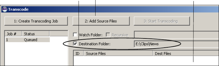
Playing Back Clips
155
8. (Option) Select the destination folder.
The default location is the folder that holds the original clip. If you want to change the
destination folder, do the following:
a. Select the Destination Folder option.
b. Click the Browse button, navigate to a folder, and click OK.
I
9. Add files to a job by doing one of the following:
tDrag one or more files from a Windows folder to the clip list.
tClick the Add Source Files button or right-click in the clip list and select “Add
Source files.”
The Open dialog box opens. Navigate to the files you want to transcode, select the
files you want to transcode, and click Open. You can use the “Files of type” list to
specify which type of files you want displayed.
You can add files of different formats to a single job, but all files will be transcoded with
the same MPEG compression options. The files appear in the clip list, with the
destination filename, the status, and the current progress.
Destination folder option and path Clip list
Add Source Files button
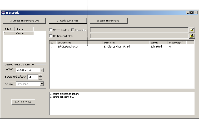
3 Editing Objects in the Scene
156
You cannot add a folder to the clip list; you need to add the contents of the folder.
10. (Option) If you want to create an additional job, click Create Transcoding Job and
follow the preceding steps, beginning with step 6.
DekoCast processes multiple jobs in First In/First Out (FIFO) order, except if you are
transcoding a clip from within DekoCast. Transcoding a clip from within DekoCast is
an immediate job, which takes precedence over other jobs (background jobs).
Job list Clip list Start Transcoding button
Log window
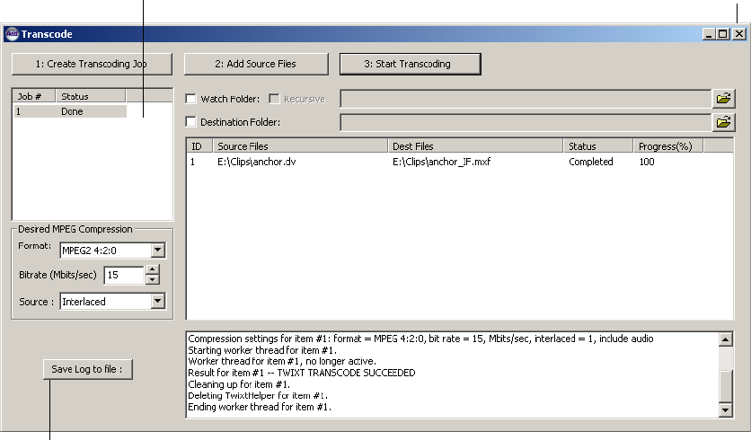
Playing Back Clips
157
11. Click Start Transcoding.
The application begins the transcoding process. The clip list displays the status and the
percent of each file in the job and the log window displays messages about the job. As
each file is transcoded, it is written to the folder that you specified.
The following illustration shows a completed job. In this example, the transcoded clip is
saved in the same folder as the original clip.
nYou can add files to a job while it is processing. You can also minimize the application
window during the transcode process.
To save the log to a file:
tClick “Save Log to file,” navigate to a folder, type a name for the file, and click Save.
To stop or delete a job:
tRight-click the job in the Job list and select “Remove selected job.”
To close the Transcode window:
tClick the close box.
Job list Close box
Save Log to File button
3 Editing Objects in the Scene
158
Transcoding By Dragging Clips to the Transcode Icon
You can transcode clips without opening the Transcode application by dragging clips to the
Transcode icon. Transcoding through this method uses the default settings you selected in
the Transcode and Scene Options tab. Transcoded clips are stored in the same folder as the
original clips.
If you want to use different settings, create a transcoding job. For more information, see
“Transcoding Clips Through the Transcode Application” on page 152.
When you drag clips to the Transcode icon (or open the Transcode application), you are
running Transcode in standalone mode.
cTranscoding uses CPU resources and could interfere with playout to air. Avid
recommends that you perform transcoding on a DekoCast Authoring Station or when a
DekoCast system is not on-air.
To transcode clips by dragging clips to the Transcode icon:
1. Select Options > Preferences.
2. Click the Transcode and Scene Options tab.
3. Select the desired Transcode Settings (Color format, Bitrate).
For more information on these options, see “Transcode and Scene Options” on
page 430.
nThe “Delete original clip” option does not apply when you transcode clips by opening the
Transcode application or by dragging clips to the Transcode icon. This option applies only
when you transcode through a default watch folder or automatically when a scene opens.
4. Click OK.
5. Drag one or more files from a Windows Explorer folder to the Transcode icon.
The Transcode window opens as a minimized window in the Windows Task Bar. The
transcoding process takes place using the default settings and the transcoded file is
saved in the same folder as the original file. You can open the Transcode window to
check the progress of the job.
Playing Back Clips
159
Transcoding Clips By Using a Watch Folder
Watch folders provide you with a convenient way to transcode clips before you open a scene.
A watch folder is a Windows folder that lets you transcode clips without opening the
Transcode application. If you copy one or more clips to the watch folder, the Transcode
application determines if a clip needs to be transcoded and transcodes the clip according to
the settings you selected in the Transcode and Scene Preference tab.
You can select subfolders so that the Transcode application searches the watch folder
recursively. For example, you can select the folder E:\Clips as a watch folder and select the
“Watch subfolders” option. Then any clips that you copy to E:\Clips or its subfolders are
transcoded, if required.
Using a watch folder is the suggested method for transcoding all clips on a new
Corsica-based DekoCast system. See “Suggested Workflow for Transcoding” on page 151.
You set a default watch folder in the Transcode and Scene Options tab. You can also set a
custom watch folder in the Transcode application, but it does not persist as the default watch
folder. These methods are described in the following topics:
•“Transcoding Through a Default Watch Folder” on page 160
•“Transcoding Through a Custom Watch Folder” on page 161
nDekoCast does not transcode clips that are already in the watch folder when you start a new
transcoding job. This prevents the existing clips from being transcoded again. If you delete a
clip from the watch folder, and later want to transcode it again, delete it from the clip list, or
create a new job and add the clip to the clip list.
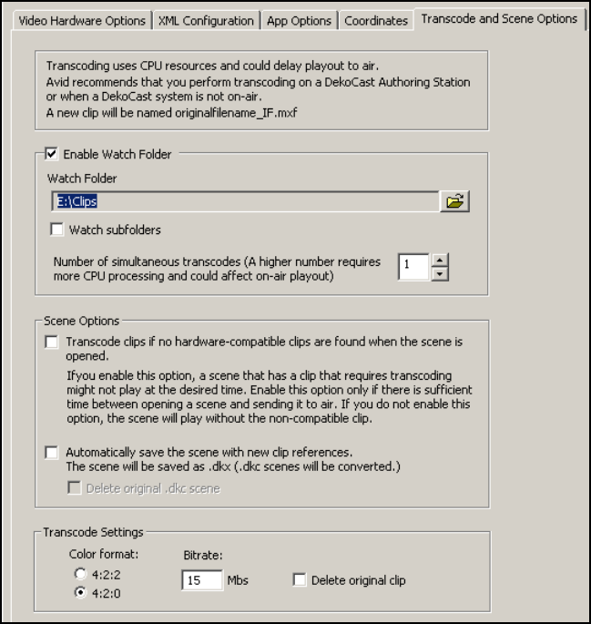
3 Editing Objects in the Scene
160
Transcoding Through a Default Watch Folder
You can set a watch folder in the Transcode and Scene Preference tab that DekoCast uses as
the default.
To transcode through a default watch folder:
1. Select Options > Preferences.
2. Click the Transcode and Scene Options tab.
3. Select “Enable Watch Folder.”
Selecting this option causes the Transcode application to start whenever you start
DekoCast. If you select this option and click OK, Transcode starts immediately, if it is
not currently running.
Playing Back Clips
161
nThe Transcode application must be running for the watch folder to work. You can minimize
the Transcode application, but make sure not to close it.
4. Click the Browse button, navigate to the desired folder, and click OK.
5. (Option) Select “Watch subfolders” if you want Transcode to recursively search any
folders contained in the watch folder.
6. Select the number of simultaneous transcodes.
cBecause multiple transcode jobs require more CPU processing, specify a number
higher than 1 only if you plan to transcode clips when the system is off-air.
7. Select the desired Transcode Settings (Color format, Bitrate, Delete original clip).
Select “Delete original clip” only if you have tested your workflow and are confident
that transcoding works successfully.
For more information on these options, see “Transcode and Scene Options” on
page 430.
8. Click OK.
The Transcode application starts. Any clips that you then copy to the watch folder (or its
subfolders) are transcoded automatically with the settings you selected and are saved in
the same folder. You can add files to a job while it is processing by adding files to the
watch folder.
The default watch folder remains active if it is selected in the Transcode and Scene
Options tab, if DekoCast is running, and if the Transcode application is running,
Transcoding Through a Custom Watch Folder
You can set a custom watch folder in the Transcode application that overrides the default
watch folder. If there is no default watch folder, you can specify one here, but it does not
persist as the default.
One advantage of using a watch folder with the Transcode application is that you can create
multiple jobs to transcode the clips into different formats or to different locations. Then,
when you copy clips to the watch folder, the Transcode application runs the multiple jobs
and stores the transcoded clips according to how you set up each job.
When you transcode through a custom watch folder, you are running Transcode in
standalone mode.
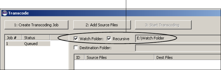
3 Editing Objects in the Scene
162
To transcode through a custom watch folder:
1. Double-click the Transcode icon.
The Transcode window opens, with the default settings you selected, included the
default watch folder, if you selected one. A numbered job is displayed in the Job list
with the Queued status.
2. Select the Watch Folder option. Select the Recursive option if you want the application
to watch folders nested inside the folder you specify.
3. Click the Browse button, navigate to the desired folder, and click OK.
The Transcode application is ready to monitor the folder you specified and transcode
any clips added to this folder or its subfolders. Clips that are already stored in the folder
are not transcoded.
4. (Option) Select the destination folder.
The default location is the folder that holds the original clip, in this case the watch
folder. If you want to change the destination folder, do the following:
a. Select the Destination Folder option.
b. Click the Browse button, navigate to a folder, and click OK.
5. (Option) Create another job with different settings and specify the same watch folder.
By specifying the same watch folder, you can transcode the same clips to different
formats or to different locations automatically.
cBecause multiple transcode jobs require more CPU processing, process multiple jobs
only if you plan to transcode clips when the system is off-air.
6. (Option) Minimize the Transcode application.
nThe Transcode application must remain open so that a watch folder remains active.
Watch Folder options and path
Playing Back Clips
163
7. Copy the clips you want to transcode to the watch folder.
DekoCast adds the clips to the clip list and begins the transcoding process. The clip list
displays the status and the percent of each file in the job. As each file is transcoded, it is
written to the same folder or to a folder that you specified. You can add files to a job
while it is processing by adding files to the watch folder.
The custom watch folder remains active if it is selected in the Transcode application and
the Transcode application is open.
Transcoding Clips When a Scene Opens
If you follow the suggested practices for transcoding (see “Suggested Workflow for
Transcoding” on page 151), any scene that is opened on any DekoCast system should lay
without problems. However, you can configure your system so that when a scene opens, any
required transcoding is performed.
For example, you might open a scene that includes clips in the DV 25 format. When you
open the scene, DekoCast looks for hardware-compatible MXF versions of the clips in the
scene. If it cannot find hardware-compatible clips, it identifies the clips that need to be
transcoded and starts the Transcode application, which automatically transcodes them
according to your preferences. If you do not select this option, the scene plays but does not
play the clips that require transcoding.
Selecting this option also automatically transcodes clips that you link to through the Clip
Playback object editor.
cUse this option carefully. If you configure your system to automatically transcode clips,
a scene might not play at the desired time. Enable this option only if there is sufficient
time between opening a scene and sending it to air.
You can also select an option so that any time DekoCast plays a hardware-compatible clip
that was not referenced in the open scene, DekoCast saves the scene with the new clip
reference.
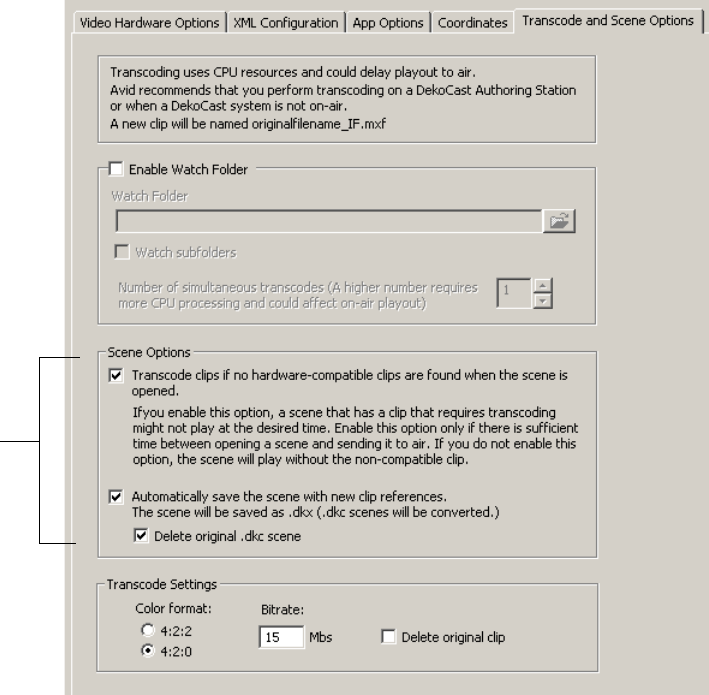
3 Editing Objects in the Scene
164
To transcode clips when a scene opens:
1. Select Options > Preferences.
2. Click the Transcode and Scene Options tab.
3. In the Scene options section, select “Transcode clips if no hardware-compatible clips are
found when the scene is opened.”
The Transcode application automatically runs and transcodes clips using the settings
you select in this tab.
Scene
options

Capturing Clips
165
4. (Option) Select “Automatically save the scene with new clip references.”
For example, if the scene references “OTSleft.dv” and DekoCast finds and plays
“OTSleft_IF.MXF,” the scene is saved with a reference to “OTSleft_IF.MXF.” Saving a
scene with this option keeps references to the actual clips that played, and minimizes
confusion if you copy the scene to different machines.
DekoCast saves the scene with the .dkx extension. If the original scene used the .dkx
extension, DekoCast overwrites the file. If the original scene used the .dkc extension (an
older format), DekoCast converts the scene to .dkx and saves it.
If you do not select this option, the scene is not changed, and DekoCast searches for the
compatible clip every time the scene is opened.
5. (Option) Select “Delete original .dkc scene.”
If you select “Automatically save the scene with new clip references” and the original
file used the .dkc extension, both versions of the scene are saved. As a result, you might
open or modify the wrong scene. If you select “Delete original .dkc scene,” DekoCast
automatically deletes the original .dkc scene, which can help reduce confusion.
Select this option only if you are sure you do not need the old file.
6. Select the desired Transcode Settings (Color format, Bitrate, Delete original clip).
Select “Delete original clip” only if you have tested your workflow and are confident
that transcoding works successfully.
For more information on these options, see “Transcode and Scene Options” on
page 430.
7. Click OK.
Now whenever you open a scene that includes clips not supported on a Corsica-based
system, Transcode starts and automatically transcodes the clips using the default
settings.
Capturing Clips
The Clip Capture object allows you to record video or audio (or both) through the inputs of
your DekoCast system. The recorded clips are saved to a file, which you can open and play
back using the Clip Playback object or other applications that support MXF files (such as
Avid Deko or Avid Thunder).
• For Corsica-based systems, DekoCast records the signal that is coming in through a
video input port, such as Video In A. Set this input in both the Video In object and the
Clip Capture Object.
• For TARGA-based systems, DekoCast records the signal that is going out through the
Video Out port, which means that you will be recording any objects that are included in
the output. If you want to record only the signal that is coming in through a video input
Clip
Capture
button
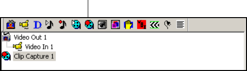
3 Editing Objects in the Scene
166
port, include only the following objects in the scene tree: Video Out, Clip Capture, and
Video In. Set the desired video input in both the Video In object and the Clip Capture
object.
You capture the clips by using the Cue, Record, and Stop buttons in the Clip Capture object
editor. Alternatively, you can capture by specifying actions and setting keyframes to cue,
start, and stop recording. For more information, see “Adding Actions to a Scene” in the
DekoCast Help. Also, you can capture video and key simultaneously, but you need to create
an action that will cue the recordings and start them simultaneously.
The following topics describe how to capture clips using the Clip Capture object:
•“Setting Up Clip Capture (Corsica Systems)” on page 166
•“Setting Up Clip Capture (TARGA Systems)” on page 168
•“Capturing a Clip” on page 172
Setting Up Clip Capture (Corsica Systems)
The following procedure describes the settings you need to select to capture a clip on a
Corsica-based system.
To set up clip capture:
1. Connect a video source (such as a live feed) to one of the Video In connections on your
Corsica-based DekoCast system.
2. Select Options > Preferences and from the Encode/Decode list select either “2
encoders” or “1 encoder 2 decoders.” For more information, see “Encode/Decode
Option” on page 418.
3. Create a new scene or open an existing scene.
4. Add a Video In object to the scene tree and select the source for the video capture from
the Video Input Port list, for example, Video In A.
5. Add the Clip Capture object to a Scene Tree by doing one of the following:
tSelect Insert > Clip Capture from the Scene menu bar.
tClick the Clip Capture button in the Object toolbar.
Clip Capture icon
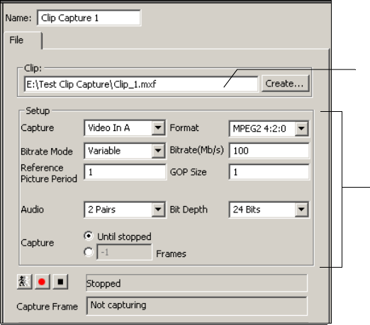
Capturing Clips
167
nThe Clip Capture object, like other objects that record input, are root objects and cannot have
parent objects.
The Clip Capture editor opens.
6. Name the clip by doing one of the following:
tIn the Clip text box, type the complete path for the file to which the recorded clip is
to be saved, including the extension .mxf.
tClick the Create button, which opens the Select Clip File dialog box. Navigate to
the folder where you want to store the clip, type the file name, including the
extension .mxf, and click Open.
7. From the Capture list in the Setup pane, select the Video Input port that matches the one
you set for the Video In object.
8. The Format list displays the format MPEG2 4:2:0, which is the only format used by a
Corsica-based DekoCast system to capture a clip. Clips are created as I-Frame MXF
files. Set the values for MPEG-2 compression as described in the following table.
File name for recorded clip
Setup pane

3 Editing Objects in the Scene
168
9. Capture the clip as described in “Capturing a Clip” on page 172.
Setting Up Clip Capture (TARGA Systems)
The following procedure describes the settings you need to select to capture a clip on a
TARGA-based system. On a TARGA-based system, DekoCast capture the output of the
Video Out object.
To set up clip capture:
1. Connect a video source (such as a live feed) to one of the Video In connections on your
TARGA-based DekoCast system.
nYou cannot capture audio from Video In B, even if it is enabled in the Video Hardware Options
tab of the Preferences dialog box.
2. Create a new scene, which by default includes a Video Out object.
3. In the Video Out editor, select an output from the Video Output Port list, for example,
Video Output A.
MPEG-2 Compression Format Options (Corsica-Based Systems)
Option Description
Bitrate Mode Variable (only choice): Uses a higher bitrate for more complex video segments and a
lower bitrate for less complex segments. Provides the best quality-to-storage ratio.
Bitrate in Megabits per
second for video
compression
A larger bitrate number results in a superior image, but uses more disk storage and
network bandwidth. The default value is 100. Select a value from 2 Mb/s to
100 Mb/s. For SD, the suggested bitrate is between 15 Mb/s and 25 Mb/s.
Reference Picture Period The system sets a value of 1, the only legal value.
GOP Size The system sets a value of 1, the only legal value.
Audio Select 1 Pair (one left channel and one right channel), 2 Pairs (two left channels and
two right channels), 3 Pairs, or 4 Pairs.
Bit Depth The system uses 20-bit audio for SD and 24-bit audio for HD.
Capture (Duration) Select one of the following:
• Select “Until stopped” if you want the system to keep recording until you click
the Stop button.
• Specify the number of frames you want the system to record (duration in frames).
When the number of frames is set to -1, recording does not stop until you click
the Stop button.

Capturing Clips
169
4. Add a Video In object to a Scene Tree and select the source for the video capture from
the Video Input Port list, for example, Video In A.
5. Add the Clip Capture object to a Scene Tree by doing one of the following:
tSelect Insert > Clip Capture from the Scene menu bar.
tClick the Clip Capture icon in the Object toolbar.
cWhen capturing clips on TARGA-based systems, include only the following objects in the
scene tree: Video Out, Video In, and Clip Capture.
nThe Clip Capture object, like other objects that record input, are root objects and cannot have
parent objects.
The Clip Capture editor opens.
Clip Capture icon
File name for recorded clip
Setup pane

3 Editing Objects in the Scene
170
6. Name the clip by doing one of the following:
tIn the Clip text box, type the complete path for the file to which the recorded clip is
to be saved. Include the appropriate extension: .dv for DV 25 files, and .mxf for
MPEG-2 files.
tClick the Create button, which opens the Select Clip File dialog box. Navigate to
the folder where you want to store the clip, type the file name, including the
extension .dv or .mxf, and click Open.
7. From the Capture list in the Setup pane, select the Video Output port that matches the
one you set for the Video Out object.
8. From the Format list, select the video compression format:
- MPEG2 4:2:0 (long-GOP or I-Frame)
- MPEG2 4:2:2 (long-GOP or I-Frame)
-DV25
nIf you are working in an environment that has both TARGA-based and Corsica-based systems,
capture as MPEG-2 MXF I-Frame so that both systems can share the clips.
nMPEG-2 can be of any GOP format, although typically it is either long-GOP (Group of Picture),
or I-frame. Long GOP is defined by the MPEG convention of using 12 pictures in a GOP for
those frame rates near 24/25/50, and 15 pictures in a GOP for frame rates near 30/60.
I-frame is a GOP size of one picture.
9. If you selected an MPEG-2 format, select options as described in the following table.
(These settings are ignored if you selected DV 25 as the format.)
MPEG-2 Compression Format Options (TARGA-Based Systems)
Option Description
Bitrate Mode The following options are available for TARGA-SD systems:
• Variable: Uses a higher bitrate for more complex video segments and a lower
bitrate for less complex segments. Variable is recommended for most
applications, because it provides the best quality-to-storage ratio.
• Constant: Provides a relatively constant bitrate. Useful for streaming from a
server.
• Statistical: A version of the Variable bitrate suitable only when set to 4:2:0
LongGOP (GOP = 15, Picture Ref = 3). Useful for long recordings (15 minutes or
longer).

Capturing Clips
171
10. If you selected an MPEG-2 or DV 25 format, select options as described in the
following table.
11. Capture the clip as described in “Capturing a Clip” on page 172.
Bitrate in Megabits per
second for video
compression
A larger bitrate number results in a superior image, but uses more disk storage and
network bandwidth. The default value is 15.
• Chroma 4:2:2: Select a value from 2 Megabits per second (Mbs) to 50 Mbs.
• Chroma 4:2:0: Select a value from 2 Mbs to 15 Mbs.
Reference Picture Period The value determines the method for IBP compression. The Picture Reference
represents one more than the number of B frames between each P frame. The legal
values depend on the chroma: for chroma 4:2:2 select either 1 or 2; for chroma 4:2:0
select 1, 2, or 3.
GOP Size The GOP size number determines the number of pictures to encode into each GOP
(Group of Pictures). If the GOP size is set equal to 1, then the recording is I-Frame
only.
The GOP Size must be an integer multiple of the Picture Reference Period value. If
you are using video plus key for playback, the recommended GOP size is 1.
MPEG-2 Compression Format Options (TARGA-Based Systems) (Continued)
Option Description
MPEG-2 and DV 25 Compression Options (TARGA-based Systems)
Option Description
Audio Select 1 Pair (one left and right stereo) or 2 Pairs (two left and two right stereos).
Bit Depth The system uses 16-bit audio.
Capture (Duration) Select one of the following:
• Select “Until stopped” if you want the system to keep recording until you click
the Stop button.
• Specify the number of frames you want the system to record (duration in frames).
When the number of frames is set to –1, recording does not stop until you click
the Stop button.
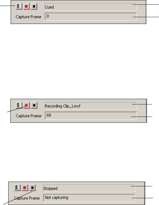
3 Editing Objects in the Scene
172
Capturing a Clip
This section applies to both Corsica-based systems and TARGA-based systems.
To capture a clip:
1. After selecting your settings, click the Cue button.
The status changes from Stopped to Cued. Because the recording has not yet started, the
Capture Frame count equals 0.
nIf you cue the capture before pressing the Record button, there is a 1-second delay before the
system starts recording. If you do not cue the capture before pressing the Record button,
there is a 3-second delay.
2. Click the Record button.
The status shows the clip that is being recorded, and the Capture Frame count updates to
show the number of frames captured.
To stop recording:
tClick the Stop button.
The status changes to Stopped, and Capture Frame count shows Not Capturing.
Any error messages are displayed in the text box at the bottom of the dialog box.
Cue button Status = Cued
Capture Frame = 0
Status =
Recording to file
Number of
captured frames
Record button
Status = Stopped
Stop button
Not capturing

Creating Cel Animations
173
To play back a recorded clip file:
1. Add a Clip Playback object to the Scene Tree and select it as the clip file in the Clip
Playback object editor.
nThe Clip Playback object must be a child of the Video Out object to play back on your video
output.
2. Click the Play button (right arrow) in the Active Play List.
For more information, see “Playing Back Clips” on page 140.
Creating Cel Animations
A Cel Animation object consists of a series of images of the same design, each with a
slightly different orientation. When played back in rapid succession, these images create the
illusion of motion, similar to flipping pages in a flipbook. A spinning logo, or bug, is an
example of a cel animation.
nCel Animation Player is an option. The Cel Animation button and Insert > Cel Animation
menu item appear available, even if this option has not been activated. If you attempt to
import an object that has not been enabled, it does not display. Select Help > About
DekoCast to view options that are enabled for your system.
Each image in a cel animation is a separate file in a series of files, usually in the TGA or TIF
format. DekoCast also supports the use of AVI, BMP, DIB, G, GIF, JPG, PCD, PSD, PCT,
and SGI files for cel animations.
nThe playback rate for cel animations is two cels per frame. Therefore, for NTSC the
playback rate is 60 cels per second, and for PAL the rate is 50 cels per second.
nIf your system includes sample media, you can experiment with using the Cel Animations
contained in the folder E:\DekoCast_Media\CAPS.
Rules for Creating Cel Animations
Share these rules with your art department so that the artists create cel animations more
efficiently:
• Create a cel animation that occupies no more than one-quarter of the video output.
For HD, in creating cel animations, follow a resource guideline of 600 pixels (width) x
600 pixels (height) x 300 (frames). For SD, follow a guideline of 200 pixels (width) x
200 pixels (height) x 200 (frames). Using these guidelines, a typical scene can contain
Cel
Animation
button
3 Editing Objects in the Scene
174
two to four cel animations. depending on what other resources are included in the scene.
These are guidelines only. You can increase the number of frames by decreasing the size
of the image, or increase the size of the image and decrease the number of frames.
• The number of files and size of each file cannot exceed active memory capacity. The
larger the frame size, the fewer files that can comprise the animation. Smaller cel
animations are preferable to larger ones.
For information about using resources efficiently, see “DekoCast Tips” on page 435.
• Use an aspect ratio that defines precisely how much area the cel animation needs.
You can set the aspect ratio of the image to the width and height of a 4:3 ratio or a 16:9
ratio, instead of a square ratio as described in the previous guideline.
• Each frame is represented in an individual file. The application reads the cel animation
as progressive frames, insuring that the cel animation’s playback is resolution
independent. To play a cel animation, the play command is automatically inserted in the
command field to read play frame 0. To play every other file of a cel animation to slow
the speed, edit the command to read play update 2 frame 0. This command reads every
other frame. See “Controlling Playback Behavior Within the Scene” on page 177.
• The files in the series should be numbered consecutively. A break in the numbering
signals that the end of the file series has been reached. Name each file with a number at
the end; for example, filename001.tga, filename002.tag, and so forth.
For instructions on positioning and sizing a Cel Animation object on video output, see
“Using the Target and Position Tabs” on page 86.
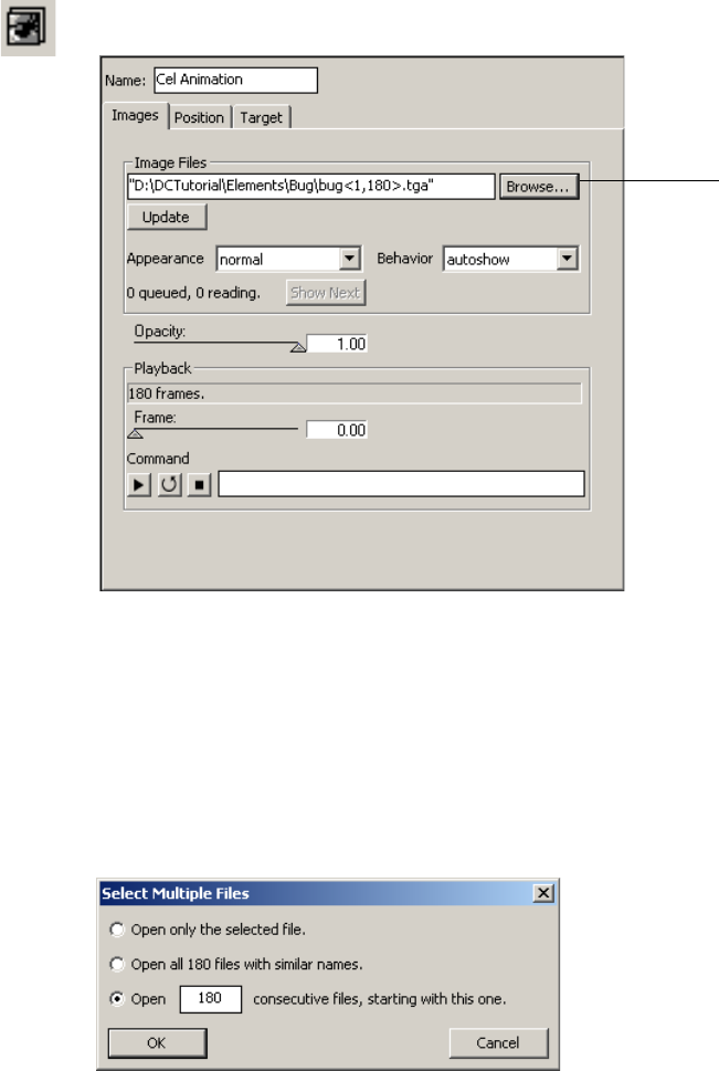
Creating Cel Animations
175
Defining the Source File for a Cel Animation
To define the source file for a cel animation:
1. Add a Cel Animation object to a scene tree.
2. In the Cel Animation editor, click the Browse button to navigate to the directory that
contains the first file in the series.
nIf your system includes sample media, you can experiment with using the Cel Animations
contained in the folder E:\DekoCast_Media\CAPS.
3. Select the first file.
The Select Multiple Files dialog box opens.
Select source files
3 Editing Objects in the Scene
176
4. Select “Open x consecutive files, starting with this one.”
nThere are three choices for importing Cel Animation objects. Do not select Open only the
selected file if you want the cel animation to loop and play. This option selects a single
static image.
5. Click OK.
If the cel animation is not obstructed by another object in the Scene Tree, it displays on
the video output. The image is static until you click the Play or Loop buttons.
You can also define the source files by typing one or more source file names separated by
spaces into the Image Files text box (if the file name contains spaces, surround the name
with double quotes).
• Select a set or sequence of files by including the file number within brackets (< >). For
example, typing filename<17>.tga tells the application to read filename17.tga, or
filename 017.tga, or filename0017.tga, and so forth. The application also automatically
reads all files following the referenced file in sequence. For this example, that would
mean filename18.tga, filename19.tga, and so on.
• To specify how many consecutive files you want the application to read, identify the first
file, type a comma, then the total number of files. For example, typing
file <17,5>.tga
tells the application to read files 17, 18, 19, 20, and 21.
Controlling Appearance
To control the appearance of the Cel Animation object:
1. In the Cel Animation editor, select Normal, Shaped, or Use 8-Bits Only from the
Appearance menu.
- Color images that have been shaped by the key replace transparent areas with the
color black. If the image you are viewing appears crisp, with defined edges, select
Normal.
- If the edges appear blurry or jagged, select Shaped to sharpen the edges. Unshaped
images appear too bright in transparent areas or around the edges in the image if
displayed using the Normal setting.
- Select Use 8-Bits Only when you want to use the Cel Animation object as a mask or
a wipe pattern in a group object. This mode keeps only the key or alpha portion of
an image, saving video memory. If the image file does not contain an alpha
component, the luminance component, or overall brightness, is used to make an
alpha or key image. Select this appearance for objects that are not intended to be
viewed in a scene directly but only indirectly as a mask or wipe pattern. For details
on masks and wipes, see “Using Group Objects” on page 181.
2. Set the opacity for the images by clicking and dragging the Opacity slider.
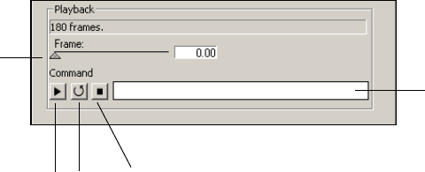
Creating Cel Animations
177
Full transparency is 0 and full opacity is 1.
nCel objects are imported with the Normal appearance setting as a default. If you need a
shaped key or an 8-bit key, make your selection before importing the cel images. If you
imported a cel image as Normal and you want to change it, you need to delete the object,
switch the Appearance option, and then select the first image of the Cel animation series.
Controlling Playback Behavior Within the Scene
You can control how a Cel Animation object plays back during the scene.
To play, loop, or stop an animation:
tClick the Play, Loop, or Stop button.
- Play executes playback from the first frame to the last.
- Loop begins playback at the first frame, plays to the end, and then repeats
continuously from beginning to end.
- Stop ends playback.
You can also control playback through commands, as described in the next topic.
To select a specific frame from the current set of images:
tDrag the Frame slider to the desired frame.
Controlling Cel Animation Playback Through Commands
You can control playback of Cel Animation objects through commands.
The Cel Animation command field (Images > Command) is automatically filled in when you
click the Play, Loop, or Stop button. You can insert additional commands into the command
field and then execute them. All commands are accessible through a keyframe in an action
that animates the controls.
Play, Loop, Stop buttons
Frame
slider
Command text box
3 Editing Objects in the Scene
178
To execute a command:
tType one or more commands in the Command text box and press Enter.
There are two types of commands: immediate commands and queued commands.
• Immediate commands execute immediately, even when they are part of a series of other
commands.
• Queued commands are queued behind any currently active commands. Most commands
are Queued commands.
The following tables describes both types of commands:
Immediate Command Options
Option Description
abort Clears all commands previously queued and stops immediately on the
current frame.
break Immediately stops execution of the current command and begins
executing the next command in the queue.
endloop Plays out the current loop through the last frame, then starts executing the
next command. This can be a smooth termination of an endless loop.
Queued Command Options
Option Command
play Starts playback from the current frame to the end of the series and stops on the
final frame.
play loop Plays from the current frame to the end of the sequence, then plays from the
first frame to the last repeatedly.
play loop # Plays from the current frame to the end of the sequence, then plays from the
first frame to the last the specified number of times. For example, “play loop
3” starts play from the current frame to the end, then plays from the first frame
to the last three more times.
play frame # Plays from the selected frame to the end of the series, then stops. For example,
“play frame 17” plays from frame 17 to the end, then stops.

Creating Cel Animations
179
You can combine commands. For example,
play rate 3 update 4
plays by
incrementing the frame by three every four fields.
You can queue several commands separated by semicolons. For example:
play; play rate –1; play hi 7 loop 3; play rate –1
This series of commands would start play from the current frame to the last frame, then
play from the last frame to the first frame, then from the first frame through frame 7 a
total of four times (once, followed by three loops), then play from frame 7 down to
frame 0 and stop.
cSetting the frame number parameters clears the command queue.
Controlling Cel Animation Updates
When you change the name of an image file or click the Update button, the Cel Animation
object submits a request to the application to read the new set of files. After it is read, the set
goes into a queue of sets waiting to be displayed.
You can view the playback status in the Image format section:
•“x Queued” is the number of sets finished reading, waiting to be displayed.
•“x Reading” is the number of sets waiting to be read for this Cel Animation object.
play loop lo# hi # Plays from the current frame through the high numbered frame, then from the
low numbered frame to the high numbered frame repeatedly. For example,
“play loop lo 13 high 29” plays from the current frame through frame
twenty-nine, then plays from frame thirteen through twenty-nine repeatedly. If
lo or hi is omitted, the first and last frames respectively are the defaults.
play update # For example, “play update 4.” plays from the current frame to the end,
changing to the next frame every four fields.
play rate # For example, “play rate 3” plays from the current frame to the end,
incrementing the frame number by three every field.
play frame # rate # An example would be play frame “9999 rate –1.” This would start playback at
frame 9999, or default to the end if there is no frame 9999 and decrement the
frame every field, stopping at the first frame. In other words, you can play the
clip backwards with this command.
Queued Command Options (Continued)
Option Command
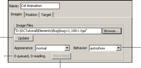
3 Editing Objects in the Scene
180
To display a new set of cel animations immediately:
tSet the Behavior option to Autoshow.
To play files only when you click the Show Next button:
tSet the Behavior option to Manual.
The files are queued until you click Show Next.
Behavior option
Update button
Playback status
Show Next button

Using Group Objects
181
Displaying Individual Frames
You can view frames from image formats other than Deko (.dko) by using the Cel Animation
object.
To display a frame on the video output:
1. In the Scene Tree, add a Cel Animation object.
2. In the Cel Animation object editor, do one of the following:
tType the complete path for the TGA file.
tClick the Browse button and select the TGA file from the Select the First Image File
dialog box. Click Open.
3. In the Select Multiple Files dialog box, select “Open only the selected file” and click
OK.
The captured frame displays on the video output.
nYou can also open the image in PostDeko Lite and save it as a Deko graphic file. Then create
a Deko object and link to the file to view the image. See “Working with Deko Objects” on
page 108.
Using Group Objects
When working with several objects related to the same visual element, you can add a Group
object and make the related objects children of this group. You can then manipulate these
objects as a group or individually. Groups can also be nested within other groups.
As a rule, you should group objects for organization, or if you plan to apply any effect on
them as a unit. The Group object editor allows you to adjust parameters that affect the entire
group, such as opacity, composite styles, transition and softness, as well as position and
cropping parameters. The Composite Style menu provides a variety of transition options,
such as crossfade (dissolve), mask, and wipe.
Group
button
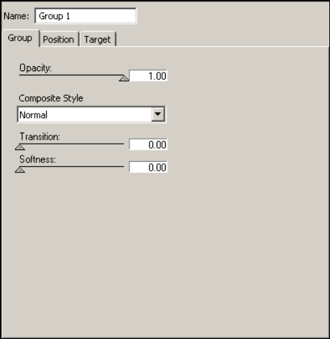
3 Editing Objects in the Scene
182
The following examples describe several ways of using the Group object:
• If there are five objects that you want to dissolve in or out of a scene together, you can
group them and dissolve the group in a single step. Otherwise, you have to dissolve each
object independently, which takes five steps.
• If you want to display a banner with logo and text, you create three Deko objects: one
for the banner layer, one for the text layer, and one for the logo graphic. Then next these
three Deko objects under one Group object. You can then use the Group object editor to
specify a position, opacity, and actions that would affect all three Deko objects.
• If you want to transition from one object to another, create a group of two or more
objects and select a Composite Style. For example, you might want to create a dissolve
or a wipe between two Deko graphics.

Using Group Objects
183
The following illustration shows a simple group.
You can set Group objects to fade, wipe, and mask, between the Group's children. See
“Example 3: Crossfade (Dissolve)” on page 332.
Adding a Group Object
To add a Group object to a Scene Tree, do one of the following:
tSelect Insert > Group from the Scene menu bar.
tClick the Group button in the Object toolbar.
To add children to a Group object:
tSelect the Group object and click the appropriate button.
Setting the Opacity and Softness for a Group
To set the opacity for a group of objects:
tDrag the Opacity slider to vary the objects in the group from full transparency (0.00) to
full opacity (1.00).
Opacity levels for child objects are determined by their parent’s opacity level. For
example, if a child object has 50 percent opacity and its parent has 50 percent opacity,
then the child object’s opacity is 25 percent (half that of its parent).
To control the softness of the edge of the wipe for the group:
tDrag the Softness slider between 0 (the edge is sharp) and 1 (the edge is soft).
Group object (parent)
Last (top) child in Group (in a Wipe this
object obscures child objects beneath).
First (bottom) child in Group
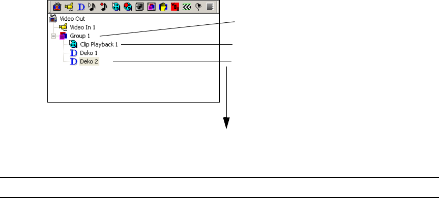
3 Editing Objects in the Scene
184
Setting the Compositing Style for a Group
To specify how objects in a group transition among themselves:
tSelect an appropriate compositing style from the Composite Style menu. For a
description of these options, see “Composite Style Options” on page 184.
The position of the object in the Group determines how compositing works.
The application composites Group
objects from the bottom to the top of
the Group
Group object (parent)
Last (top) child in Group (in a Wipe this
object obscures child objects beneath).
First (bottom) child in Group
Composite Style Options
Option Description
Normal This is the default style. Each object is layered on top of the one listed below it, just
as in the rest of the Scene Tree. The first child in the Group tree appears to be beneath
all of the others. The last child in the tree appears to be on top of all the others. The
transition slider is not used with this compositing style.
Crossfade This compositing style is used in conjunction with the transition slider. As the
transition slider moves from zero to one, the last child (at the bottom of the tree) fades
out and the second child fades in. This is a dipless crossfade, one with no visible
change in brightness. Any visible object—Video In, Cel Animation, Deko object, or
Clip Playback—can be used for a crossfade.
nUsing a crossfade in groups with more than two children might have
unpredictable results.

Using Group Objects
185
Mask The last (top) child in the Group object’s tree is treated as a mask, limiting how much
of the children above it in the tree are visible. With mask compositing, you do not use
the transition slider. Any visible object—Video In, Cel Animation, Deko object, or
Clip Playback—can be used as a mask.
Typically, for a mask, you create an object that is a black and white gradient, such as
a Deko graphic with a full screen rectangle with a black and white ramp as the face
shader. This object is the first object in the group.
Where the Mask child is opaque white, the other children are visible. Where it is
transparent black, the other children are not visible. Also, each color component of
the mask affects the corresponding component of the child being masked. If the mask
is opaque blue, only the blue components of the other children are visible.
nTARGA-based systems are limited to compositing on a single level only. You
cannot mask one element with another, and then use the result as a mask for
something else.
Mask Using Key Only The alpha component of the mask child is used as a mask for all the masked
children's components, RGB, and A. The color of the mask element does not matter.
Mask Using Color Only Only colors behind the mask that are the same color as the mask are visible.
The green component (an approximation of the luminance of the mask) is used for all
components of the masked children. This allows a mask element with no key
information to mask the visibility of another element.
Wipe The last (top) child in the Group object’s tree acts as a wipe image and wipes over the
other children beneath it in the tree. The transition and softness sliders control the
wipe. As the transition slider moves from zero to one, the remaining children are
wiped over, one at a time. The softness slider controls the sharpness of the transition.
Wipe Between This compositing style is similar to the Wipe, except that it is performed between the
next-to-the-last child in the Group tree and the rest of the children. As the transition
slider moves from zero to one, the next-to-the last image wipes off, and the rest of the
children wipe on.
Sum This style adds rather than blends the child objects. It can be used for push
transitions, where one child slides on and one slides off screen. It can also be used for
reveal transitions, where one child is cropped off as one child is cropped on. Using
the Sum style ensures that there is not a seam in which the background is visible
between the two children. Performing this transition requires an action that animates
the position or crop settings of the child objects.
Crossfade - Skip First
Child
The first child object is skipped and the transition begins with the second child.
Composite Style Options (Continued)
Option Description
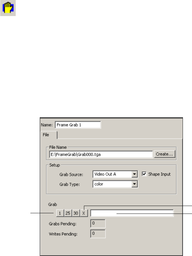
3 Editing Objects in the Scene
186
nTARGA-based and Corsica-based systems exhibit different behavior for a wipe. Because
a Corsica-based system does not use luminance as an alpha source for wipes, any source to
be used as a wipe pattern should either have the wipe pattern contained in the alpha
component, or the Cel Animation object that loads the wipe pattern should be set to 8-bit
mode, which converts luminance to alpha.
Capturing Video Images (Frame Grab)
You can use the Frame Grab object to capture one or more images from a video source and
save each image, or frame, as a TARGA (TGA) file. Each frame that is grabbed is saved as a
single file. For example, if you select 30 frames to be captured, the application creates 30
TGA files.
After you capture the images, use the Cel Animation object to display an image in a scene.
See “Displaying Individual Frames” on page 181.
To capture video images as frames:
1. (Option) Create a new folder if you are capturing multiple frames.
2. Add a Frame Grab object by doing one of the following:
tSelect Insert > Frame Grab from the Scene menu bar.
tClick the Frame Grab button in the Object toolbar.
Frame
Grab
button
Stop button
Grab buttons Enter Grab xx in
text box
Capturing Video Images (Frame Grab)
187
3. Do one of the following:
- In the File Name text box, type the complete path for the first file that you want to
create in the grab, such as E:\FrameGrab\Grab000.tga.
- Click the Browse button to display the Select Grab File dialog box. Navigate to the
directory you want and type the file name for the first file you want to create in the
grab, such as Grab000.tga.
nMake sure to type the extension .tga.
nFor DekoCast to recognize files for a frame grab, the file name before the TGA extension
must always end in numbers. After the grab completes, the last file name in the series is
shown in the File Name text box.
4. In the Setup pane, select the source for the frame grab from the Grab Source menu:
Video In A or B, or one of the Video Out ports.
By default, the video output is shaped. Deselect Shape Input to clear this option. For
more information, see “Audio Source Configuration” on page 424.
5. Select whether you want to capture color and key (opacity) information, key
information only, or color information only with each frame.
6. To capture frames, do one of the following:
tClick the Grab button for the number of frames you want to capture: 1, 25, or 30.
tSelect a different number of frames by typing “Grab” followed by the number into
the Frame Grab text box; for example, to capture 72 frames, type
Grab 72
.
nThe limit on the number of grabs is based on DekoCast’s system memory. To calculate the
amount of memory used for a single frame, multiply the pixel width times pixel height times
4 bytes. In an HD format, grabbing more than 30 frames might result in stuttering video and
an aborted capture.
The number of Grabs Pending and Writes Pending displays as DekoCast processes the
grabs. If you click a Grab Number button multiple times, or if you click more than one
button at a time, additional frames are captured. For example, clicking the 25 button
followed by the 30 button causes DekoCast to capture 55 frames. The frame grab stops after
the requested number has been captured.
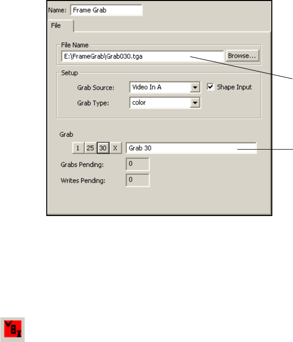
3 Editing Objects in the Scene
188
To interrupt an ongoing frame grab:
tClick the Stop button.
Working with VBI Objects
The Vertical Blanking Interval (VBI) is the part of a television transmission signal that has
no viewable content and is used for broadcasting closed captions and other information. The
DekoCast VBI object decodes VBI data and presents it as interpretable text. You can include
a VBI object in your scene only if your installation has a special program that can use this
data. For example, a program might monitor decoded closed-capture text for the name of
corporations. When the program detects a name, it triggers the display of the corporation’s
stock price in the crawl text.
The VBI object captures Vertical Interval Time Code (VITC) and Closed Caption (CC) data
from a video input port, decodes this data, and displays it as text in the Data text box of the
VBI object editor. A program can be developed to read the decoded data and respond as
directed.
VBI objects are used to set up triggers with applications that communicate with the
application through the application API or XML. For more information, see the Rocket
Engine API documentation or the Rocket Engine BCI documentation, which are available
on the Avid Customer Service Knowledge Base (www.avid.com/onlinesupport).
30 frames captured
Last file name in series
VBI
button
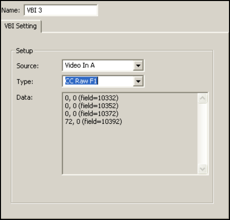
Working with VBI Objects
189
To set up the VBI object editor:
1. Configure your system for VBI preservation. See “VBI Source and Extra Lines” on
page 422.
2. Add the VBI object to the scene.
3. With the VBI object selected in the Scene Tree, select the Video In source using the VBI
object editor.
4. Select one of the data types for decoding as described in “Data Types” on page 190.
5. View the decoded data in the Data text box of the dialog box.
How VBI Objects Work
The following rules apply to VBI objects:
• Video is searched for VITC on lines 14, 16, and 18 in both F1 and F2 (NTSC and PAL).
The first line of VITC detected sets the data parameter for the VBI object; subsequent
lines are ignored.
• Closed Caption (CC) data is decoded from line 21 in both F1 and F2 (NTSC and PAL).
• The VBI object cannot collect raw VBI lines from the video input, only CC and VITC.
3 Editing Objects in the Scene
190
Data Types
The data-type options are as follows:
•VITC Time
When selected, the VBI object decodes the incoming VITC on the video. The data
parameter is set to the timecode string. When a semicolon, as opposed to a colon,
separates seconds from frames, the timecode is Drop Frame. The number of the field
from which the data was decoded is included in the data string.
The decoded data resembles the following:
[hh]:[mm]:[ss]:[ff] (field=[field])
04:17:03:29 (field=17268)
04:17:03;29 (field=17268)
nField Identifiers are described in "Field Identifier Strings" on page 191.
• VITC Time and User
When selected, the VBI object operates the same as VITC Time mode, but also includes
the values of the VITC user bits. Each nibble, or aggregation of four bits, of the user-bit
string indicates the value of a VITC User Group. User Group 1 is the left-most nibble in
the string; User Group 8 is the right-most nibble in the string.
[hh]:[mm]:[ss]:[ff]
(user=[ug1][ug2][ug3][ug4][ug5][ug6][ug7][ug8])(field=[field])
04:17:03:29 (user=8f4a6002) (field=17268)
04:17:03;29 (user=8f4a6002) (field=17268)
• CC Text options
When data type CC Text is selected, the VBI object decodes the incoming CC data
according to the standard CC protocol, accumulating ASCII text into a string. When a
line is complete, the VBI object’s data parameter is set to the most recently accumulated
data string, and the accumulator is emptied and starts to accumulate text again.
The decoded data resembles the following:
[string]
THIS DATA WAS DECODED FROM CC
- The F1 (field 1) version decodes CC from F1 line 21.
- The F2 (field 2) version decodes CC from F2.
- The Chan 1 version decodes data channel 1 as defined in the CC protocol.
Working with VBI Objects
191
- The Chan 2 version decodes data channel 2. When Both is selected, then data from
both fields is decoded. Other protocols, such as XDS, are not implemented.
Normally, the field identifier string is not appended to the text string when decoding in
text mode. To cause a field identifier to be appended, the VBI object parameter
cc text field
must be set to a non-zero value.
• CC Raw Options
When data type CC Raw is selected, the VBI object decodes the incoming CC data to its
two 7-bit character codes and sets the data parameter to a string that identifies these
codes. The number of the field from which the data was decoded is included in the data
string.
The decoded data resembles the following:
([byte1], [byte2]) (field=[field])
32, 17 (field=17268)
- The F1 version decodes CC from F1 line 21.
- The F2 version decodes CC from F2.
- The Both version decodes both lines of CC and returns them in the following
format:
[byte1], [byte2], [byte3], [byte4] (field=[field])
32, 17, 66, 99 (field=17268)
Field Identifier Strings
The field identifier string for VBI data provides the field number at which the video input
frame will appear in the video output. For example, assume you have selected VITC and
have received a string such as
12:03:04:15 (field=100)
using the NTSC non-drop
timecode. To schedule an event to occur on the frame that contains the VITC timecode
12:03:05:00, in 15 frames, you need to schedule the command to execute at field 130
(100+15*2), where 100 = previous field, 15 = number of frames, and 2 = number of
fields.
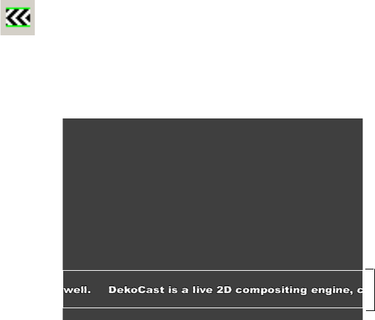
3 Editing Objects in the Scene
192
Creating Crawls
Crawl objects move a continuous stream of text from one side of the output frame to the
other. You can also use a crawl object to create a roll, which moves text from the bottom to
the top of the output frame. The Crawl object uses a special rectangle called the crawl
rectangle. The crawl rectangle is a specified region of the video output frame and functions
like a target rectangle. You can add multiple Crawl objects at different positions on the video
output.
You can insert non-text objects between lines of text and have them crawl across the video
output in relation to the boundaries of the crawl rectangle. You can insert a Video In, Cel
Animation, Clip Playback, Group, or Audio Playback object.
nYou cannot use the crawl rectangle exclusively to adjust the positioning for a Cel animation
if you are moving a project from one format to another. For example, a Cel Animation added
to an SD scene needs some additional adjustments in the HD version of the scene because
the Position pixels for SD do not match the pixel positions for HD.
The Crawl object is associated with two objects that are automatically added to the Scene
Tree when you add a Crawl object: a Text Data object and a Deko object.
• The Text Data object, which is a child of the Crawl object, controls the contents of the
crawl text and its looping behavior. The Text Data object also allows you to set rules for
how DekoCast inserts non-text objects between lines of crawl text and to set values for
scene parameters in relation to the non-text object’s on and off-screen position.
Crawl
button
Crawl rectangle
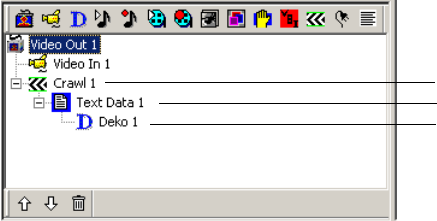
Creating Crawls
193
• The Deko object, which is a child of the Text Data Object, defines the text style for the
crawl.
The default Deko object of a Crawl object is created with macro code in the filename
field. This macro creates white, Arial Black, 23 point style. To change this default style,
create a Deko graphic with a text layer and link the Deko object to the text layer in the
Deko object editor. See “Changing the Appearance of Crawl Text” on page 201.
The following topics describe how to use the Crawl object:
•“Creating Crawl Text Using the Crawl Object” on page 193
•“Creating a Roll” on page 195
•“Controlling the Crawl Display” on page 196
•“Changing Crawl Text” on page 197
•“Using a Text File for a Crawl” on page 199
•“Controlling the Crawl Text Display” on page 200
•“Changing the Appearance of Crawl Text” on page 201
•“Setting the Crawl Object Rectangle and Position” on page 204
•“Adding Non-Text Objects to Crawl Text” on page 205
Creating Crawl Text Using the Crawl Object
To create a crawl text using the Crawl object:
1. Create a scene.
2. Add a Crawl object to the Scene Tree.
When you add the Crawl object, DekoCast adds the Text Data object as a child of the
Crawl object. It also adds a Deko object as a child of the Text Data object.
Default text starts crawling across the video output within the crawl rectangle.
Text Data object
Deko object
Crawl object
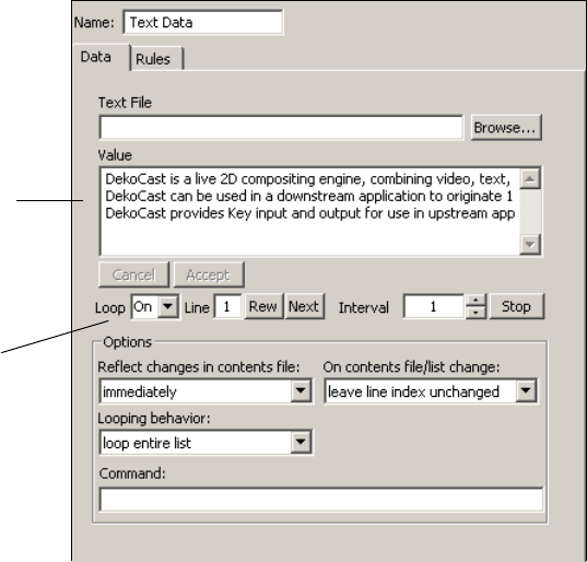
3 Editing Objects in the Scene
194
To view the text that is displayed in the crawl:
1. Select the Text Data object in the Scene Tree.
2. In the Text Data object editor, click the Data tab.
The default text appears in the Value text box and continues to stream as long as Loop is
set to On (the default). The default text consists of three lines.
nIf the crawl text stops after the lines in the Value text box are displayed, make sure the Loop
option is set to On.
As an option, you can view copies of the Deko object called clones. Clones are added to the
Scene Tree as children of the Crawl object as each line of the crawl is buffered for output.
You might want to view clone activity when you are creating a Crawl object, and then turn it
off afterwards. See “Application Options” on page 428.
nA Crawl object works best with a single Text Data object. Create a new Crawl object instead
of adding more than one Text Data object to a Crawl object.
Default
crawl text
Loop On
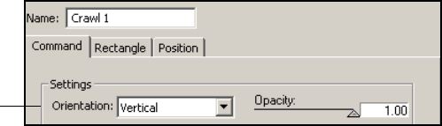
Creating Crawls
195
Creating a Roll
The Crawl object editor’s Command tab provides controls for changing the orientation of the
crawl. Most of the information in this section that applies to crawls also applies to rolls.
To create a roll:
1. Create a scene.
2. Add a Crawl object to the Scene Tree.
When you add the Crawl object, DekoCast adds the Text Data object as a child of the
Crawl object. It also adds a Deko object as a child of the Text Data object.
Default text starts crawling across the video output within the crawl rectangle. You can
edit the text in the Value box or use text from a file. See “Changing Crawl Text” on
page 197 and “Using a Text File for a Crawl” on page 199.
3. Select the Crawl object.
4. In the Crawl object editor, click the Command tab.
5. From the Orientation list, select Vertical.
The text rolls from bottom to top of the target rectangle.
6. Adjust the size of the crawl rectangle. See “Setting the Crawl Object Rectangle and
Position” on page 204.
Orientation
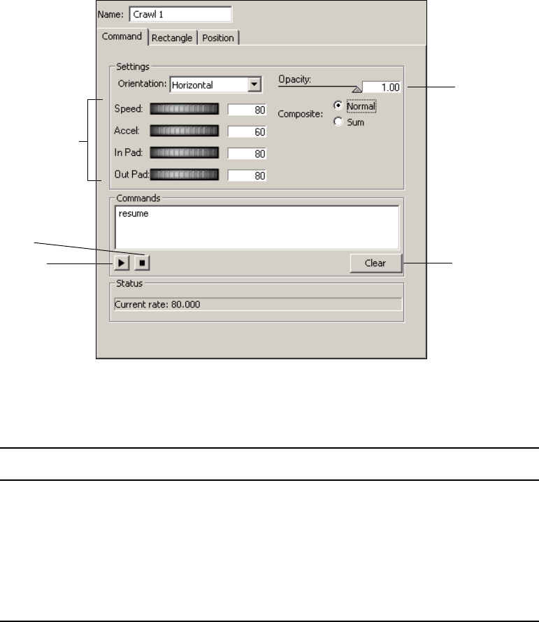
3 Editing Objects in the Scene
196
Controlling the Crawl Display
The Crawl object editor’s Command tab provides options to control how the crawl is
displayed.
To adjust the speed and acceleration of the crawl and the space between lines:
tClick and drag the thumbwheels to adjust the following parameters:
Clear
Stop
Resume
Thumbwheels
Opacity
Parameter Description
Speed Speed of the crawl expressed in pixels per second.
Acceleration The rate at which the crawl obtains its speed, expressed in pixels per
second per frame. and the rate at which it halts its forward progress when
you stop the crawl.
In Pad The amount of space in pixels before each text line or object in the crawl.
Out Pad The amount of space in pixels after each text line or object in the crawl.
Creating Crawls
197
nWhen creating a crawl, you can view the results more quickly by increasing the speed of the
crawl or by reducing the amount of text in a line.
To change the opacity of the crawl and its child objects:
tDrag the Opacity slider to vary the object from full opacity (1.00) to full transparency
(0.00).
The Command tab’s Stop, Resume, and Clear buttons enable manual control of the crawl.
You can incorporate these commands into actions (see “Adding Actions to a Scene” on
page 297).
To stop the crawl:
tClick the Stop button in the Crawl object editor’s Command tab.
To resume the crawl:
tClick the Resume button in the Crawl object editor’s Command tab.
If there is buffered text, or looping is on, the crawl automatically resumes.
To immediately clear the queue and current display on the video output:
tClick the Clear button.
The Crawl composite options affect how overlapping text and objects are rendered. These
act in the same way as the Composite options for the Group object of the same name.
To adjust how crawls are composited:
tSelect one of the following options:
- Normal: (Default) Each object is layered on top of the one listed before it. The first
object in the list appears to be beneath all of the others. The last object in the list
appears to be on top of all the others.
- Sum: This style adds rather than blends the child objects. Using the Sum style
ensures that there is not a seam in which the background is visible between the two
children.
Changing Crawl Text
The Text Data object controls the Crawl text. It can drive crawls based on text you type, or
extract text from source TXT, AUT, and ATX files. A typical DekoCast workflow is to build
a scene that is kept dynamic by sending new data streams of text to it. While the DekoCast
system is off air, you can type text into the Value text box as you create and modify scenes.
Whatever text displays in the Value text box displays as the crawl text.
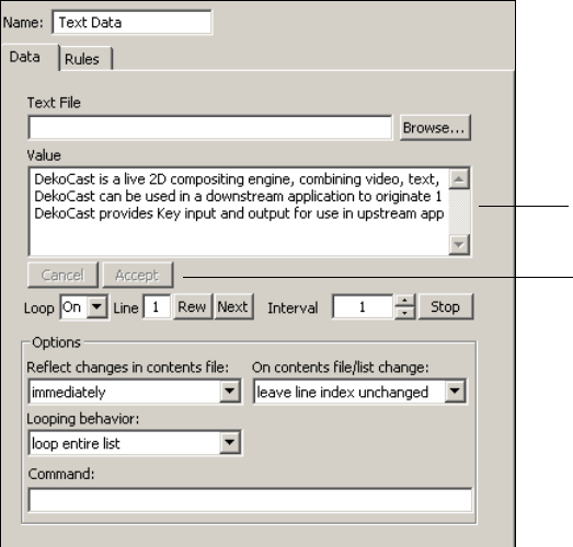
3 Editing Objects in the Scene
198
nIn addition to text, you can use tags to insert non-text objects between crawl text in your text
source file. See “Inserting Objects by Using Crawl Object Tags” on page 215.
To change the crawl text:
1. Select the Text Data child object of the Crawl in the Scene Tree.
2. In the Text Data’s object editor, edit the text that displays in the Value text box.
3. Click Accept.
The text in the Value text box crawls across the video output.
nSet the Loop options to On to display the text continuously; otherwise, the text entered in the
Value text box displays once, or a number of set loops, and then stops.
Value text box
Accept button
Creating Crawls
199
Using a Text File for a Crawl
In addition to directly entering text in the Value text box of the Text Data object editor, you
can link to a text (.txt) file and update the crawl text by editing the text file.
When you link the Text Data object to a source text file, the text contained in the file displays
as the crawl text. You can open a TXT file from any computer that you can access and type
new text. After you save the file, the Crawl text is updated. Updating TXT files is a means to
update crawl text while a DekoCast system in on air. AUT and ATX source text files for
crawls can be controlled by automation systems.
To obtain crawl text from a text file:
1. Create a text (.txt) file in Notepad or another text editor and save the file.
2. In the Data tab of the Text Data object editor, click the Browse button and navigate to
the text file.
3. Click Open.
The contents of the file are copied into the Value text box.
DekoCast automatically detects changes made to the source text file and reads it based on
the option selected in the “Reflect changes in contents file setting” list. Select an option from
this menu in the Options pane:
• Select “Immediately” to display changes as soon as they are typed and saved. This is
good choice for continuously updated lists such as stock prices.
• Select “At next interval” to display changes at the end of a line of text. This is a good
choice for a series of blurbs or headlines.
• Select “At end of list” to display changes after a complete cycle displays the text prior to
your changes. This is a good choice for displaying information in paragraph form or for
changing to completely unrelated text.
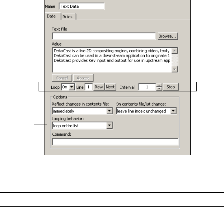
3 Editing Objects in the Scene
200
Controlling the Crawl Text Display
The Data tab of the Text Data object controls how the text itself is displayed, such as
whether the text is looped.
The following table describes options on the Data tab for controlling the text display.
Text display
options
Looping
behavior list
Data Tab Options: Text Display
Option Description
Loop Set On for indefinite looping, type or select a number to specify the
number of loops, or select 0 to stop the display. Use the Looping
Behavior list to specify whether DekoCast is to loop the entire contents
of the Value text box, or only one line.
nTo loop one line, specify the line number in the Line text box.
If you select a limited number of loops, after the crawl begins to play, the
Loop text box shows the number of loops remaining.

Creating Crawls
201
Changing the Appearance of Crawl Text
The Deko object controls the appearance of the crawl text. You can define a font style in
PostDeko Lite and have the Deko object apply it to the crawl text.
nThe default Deko layer is created with a special macro in the Deko filename field in the Deko
tab. This macro is used for an easy built-in display and is not the typical way to link a Deko
layer style to a crawl. To change the appearance of the default text in the crawl, create a
custom graphic as described in the following procedure and link that graphic's layer to the
Deko object.
Line Displays the line that is ready to be played.
To display one line from the Value text box rather than the entire
contents, type the number of the line and press Enter. Type 0 to display
the first line, type 1 to display the second, and so on. Select “loop current
line” from the Looping Behavior list.
If you are displaying the entire list, the Line text box displays –1 after the
last line is displayed (indicating no lines left to play).
Rew Click to return to the beginning of the list in the Value text box (line 0).
Next If you are manually controlling the display, click to display the next line
in the Value text box. To manually control the display, set the Interval to
0 and in the Deko object editor, set Transition Triggering to Manual.
Interval To set the interval in seconds (frequency) at which a new line of text is
displayed, type a number and press Enter.
Stop Click to set Interval to 0 and stop the display.
Data Tab Options: Text Display (Continued)
Option Description
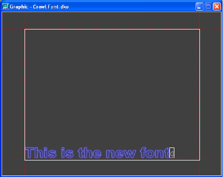
3 Editing Objects in the Scene
202
To define a font style in PostDeko Lite:
1. Open PostDeko Lite.
2. Select one of the preset styles and enter some placeholder text.
3. Press Ctrl+Shift+A to highlight the text.
4. Select an appropriate font size.
5. In the Layer tab, for Justification, select off for Horizontal and bottom for Vertical, so
that the text is positioned on the Deko graphic to appear at the bottom of the screen.
6. Deselect Word wrap.
7. Save the DKO file with a name that defines the style.
8. Exit PostDeko Lite (Alt + F4).
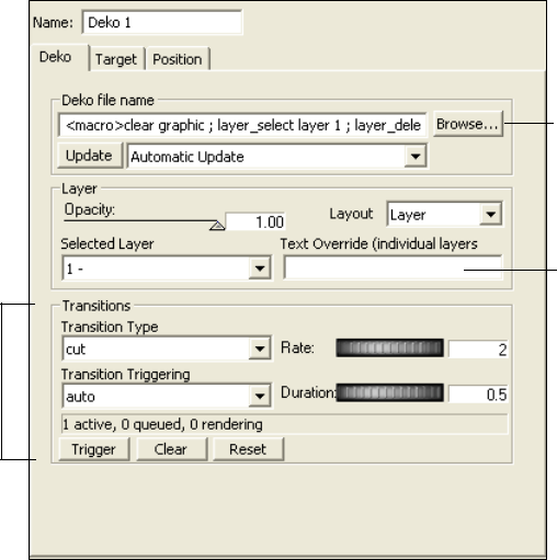
Creating Crawls
203
To link the font style to the crawl text:
1. In DekoCast, select the Deko object that is a child of the Crawl object’s Text Data object
in the Scene Tree.
2. Select the Deko tab in the Deko object editor.
3. Click the Browse button and select the DKO file that you just created.
4. Set the Selected Layer field to the text layer in the Deko graphic just created.
The default for the Layout option is Layer. The Layer setting allows the crawl rectangle
to control positioning of the layer information.
5. Click the Update button to apply the new style.
If Automatic Update is selected, you do not have to click the Update button. If the crawl
text is still looping, crawl text that has not already been buffered reflects the new style.
nFor the crawl text to loop, the Loop option in the Text Data object editor’s Data tab must be
set to On. See “Controlling the Crawl Text Display” on page 200.
Browse to DKO
file with Text
Style
Not used for
Crawl object
Not used for
Crawl object
3 Editing Objects in the Scene
204
Setting the Crawl Object Rectangle and Position
The crawl rectangle is the height in which the text, or combined text and non-text objects,
crawl across the entire output frame. Use the Crawl object’s Rectangle tab to define the
boundaries of the crawl rectangle. Afterwards, you can use the controls on the Crawl
object’s Position tab to crop, change the scale, and position the entire crawl rectangle.
nYou cannot use the crawl rectangle exclusively to adjust the positioning for a Cel animation
if you are moving a project from one format to another. For example, a Cel Animation added
to an SD scene needs some additional adjustments in the HD version of the scene because
the Position pixels for SD do not match the pixel positions for HD.
To change the position of the crawl rectangle:
1. Select the Crawl object in the Scene Tree.
2. In the Crawl object editor, select the Rectangle tab.
3. Do one of the following:
tClick the Top thumbwheel and drag it until you move the crawl rectangle to the
desired position. If necessary, adjust using the Bottom thumbwheel as well.
tCalculate the desired number of pixels from the top of the video output to the top of
the crawl rectangle. Type that value in the Top text box, and press Enter.
Calculate the desired number of pixels from the top of the video output to the
bottom of the crawl rectangle. Type that value in the Bottom text box, and press
Enter.
nThe default crawl rectangle is sized and positioned for text to crawl across the full screen. To
crop the left, right, top, or bottom of the rectangle, you need to click the Position tab and add
a small value (1 or 2) in the Crop field. This value triggers the Target rectangle to crop the
crawl information.
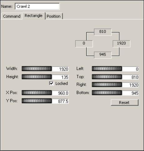
Creating Crawls
205
The following illustration shows a crawl rectangle positioned for NTSC display.
Adding Non-Text Objects to Crawl Text
You can place one or more Video In, Cel Animation, Clip Playback, Group, and Audio
Playback objects between lines of text in a crawl.
You create rules to control when a non-text object is inserted into the crawl in relation to a
line.
There are three ways you can add non-text objects:
• Add an object that is linked to a file (such as a graphic) or video input. You can use the
Cel Animation object to display a single image or a series of images. See “Adding
Non-Text Objects as Linked Files” on page 206.
• Link the object in the Crawl object and use the <object> command in the text file (see
“Inserting Objects by Using Crawl Object Tags” on page 215).
• Create the graphic as a custom typeface and use an embedded tag to place it in a text file
as a preset style id (see “Adding Non-Text Objects as Custom Typefaces” on page 216).
3 Editing Objects in the Scene
206
The following topics provide more information about adding non-text objects to a crawl:
•“Adding Non-Text Objects as Linked Files” on page 206
•“Controlling the Position of Non-Text Objects in a Crawl” on page 208
•“Deleting and Replacing Rules” on page 209
•“Example: Inserting Objects into a Crawl” on page 210
•“Example: Applying a Parameter Value to an Inserted Object” on page 212
•“Using an Inserted Object to Trigger an Action” on page 214
•“Inserting Objects by Using Crawl Object Tags” on page 215
•“Adding Non-Text Objects as Custom Typefaces” on page 216
Adding Non-Text Objects as Linked Files
The following procedure describes the basic steps for adding non-text objects. For additional
information, see “Example: Inserting Objects into a Crawl” on page 210.
nIf you are adding a Clip Playback object, you should create only one rule to control the
playback of the clip. Creating a second rule creates a second Clip Playback object for the
same clip, which can prevent the desired effect. For example, if you want an inserted clip to
start playing, and then stop playing, you should create a single rule with two parameters:
one to start the playback, and one to stop playback.
To add a non-text object to crawl text and specify a rules
1. Create a new scene.
2. Add a Crawl object to the Scene Tree.
A Text Data object is added as a child of the Crawl object and a Deko object is added as
a child of the Text Data object. The text begins to crawl across the video output within
the crawl rectangle because by default, Loop is set to On in the Text Data’s Data tab. See
“Creating Crawl Text Using the Crawl Object” on page 193.
3. (Option) While creating a crawl, select the Crawl object’s Command tab. Drag the
Speed thumbwheel to the right to increase the speed of the crawl so that you can see the
results of adding non-text objects to lines of text more quickly.
4. If you are adding an object other than, or in addition to, the Deko object, select the Text
Data object and add the new object.
For example, you could add a Cel Animation object.
nNon-text objects to be inserted in a crawl must be children of the Text Data object.
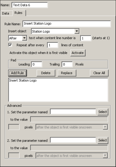
Creating Crawls
207
5. In the object editor, link the object you added with the appropriate file or video input.
For Cel Animation, select either “Open only the selected file” or “open x consecutive
files,” depending on what you want to display.
The object does not appear in the crawl until you define a rule for it.
6. In the scene tree, select the inserted object, click its Target tab, and set its Autoscale
option (Preserve, Fit, or None). See “Controlling the Position of Non-Text Objects in a
Crawl” on page 208.
7. With the Text Data object selected, click the Rules tab in the object editor.
nYou can apply rules to a non-text object only if it is a child of the Text Data object. The Text
Data object editor is the only editor with the Rules tab.
8. Assign a name for the rule, such as “Insert Station Logo.”
3 Editing Objects in the Scene
208
9. Select the object from the Insert Object list.
The Insert Object list displays the names of all objects in the scene. In this example, the
Cel Animation is named “Station Logo.”
10. Select when you want the rule to be activated, either before or after a line of text.
11. Indicate the line before which or after which you want the object to be added. The
application numbers each line of a text file. The default value is 1 (first line).
12. Accept or adjust the values for Pad (spacing in pixels) before (leading) and after
(trailing) the inserted object to separate it from the beginning and end of text.
13. For Clip Playback and Cel Animation Objects, click Activate. See “Example: Inserting
Objects into a Crawl” on page 210
14. Click Add Rule to save the rule.
The rule is displayed in the Rules text box. The object is inserted into the crawl text after
the text is buffered and processed.
15. Make other adjustments as described in “Controlling the Crawl Display” on page 196.
Controlling the Position of Non-Text Objects in a Crawl
When you insert non-text objects between lines of text, you might need to scale these objects
in relation to the crawl rectangle.
To control the position of non-text objects in a crawl:
1. Select the non-text object and click the editor’s Target tab.
2. Select an Autoscale option.
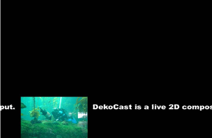
Creating Crawls
209
Preserve/Minimum is usually the most appropriate choice. When you select Preserve, the
object is placed within the crawl rectangle while maintaining its aspect ratio. Preserve is
especially appropriate for video-in feeds in which a miniature video output is to display
between lines of text.
The Fit option fits the object within the boundaries of the crawl rectangle, but selecting this
option could change the aspect ratio or shape of the object.
The None option places the object at its original size within the crawl rectangle. You can
align it vertically: top, bottom, or center. You can select this option if the object is created in
the correct size.
For more information, see “Scaling an Object in Relation to Its Target Rectangle” on
page 91.
nYou cannot use the crawl rectangle exclusively to adjust the positioning for a Cel animation
if you are moving a project from one format to another. For example, a Cel Animation added
to an SD scene needs some additional adjustments in the HD version of the scene because
the Position pixels for SD do not match the pixel positions for HD.
Deleting and Replacing Rules
All of the rules defined for non-text objects in a crawl are active for the Crawl object until
you delete or replace them.
To edit a rule:
1. Select the rule in the list.
2. Edit any of its values in the Rules tab.
3. Click Replace.
Example: Preserve option
3 Editing Objects in the Scene
210
To delete a rule:
tSelect the rule in the list, and click the Delete button.
To delete all rules for this Crawl object:
tClick Clear All.
Example: Inserting Objects into a Crawl
This example creates a crawl that includes a Clip Playback object and a Cel Animation
object alternately playing between each line of text (text 1, object 1, text 2, object 2, text 3,
object 1...). This example assumes that the text consists of an even number of lines, so that
the inserted objects alternate without repeating.
nIf you are inserting a clip into a crawl, make sure that you have a stream available to play it.
See “Managing Clip Playback” on page 143.
To add non-text objects to crawl text:
1. Create a new scene.
2. Add a Crawl object to the Scene Tree.
A Text Data object is added as a child of the Crawl object, and a Deko object is added as
a child of the Text Data object. The default text begins to crawl across the video output
within the crawl rectangle.
3. (Option) Select the Crawl object’s Command tab. Drag the Speed thumbwheel to the
right to increase the speed of the crawl so that you can see the results of adding non-text
objects to lines of text more quickly.
4. Select the Text Data object and add a Clip Playback object. The Clip Playback object is
added as a child of the Text Data object. Do not cue or play the clip.
5. Select the Clip Playback object’s Target tab and set its Autoscale option to
Preserve/Minimum. For more information, see “Controlling the Position of Non-Text
Objects in a Crawl” on page 208.
The Clip Playback object will be placed within the crawl rectangle with its aspect ratio
maintained after you define and add a rule.
6. Add a Cel Animation object that is to be animated. When you link it to its source file,
select “Open x all consecutive files, starting with this one.”
nIf your system includes sample media, you can experiment by using the Cel Animations in
E:\DekoCast_Media\CAPS.
Like the Clip Playback object, this object becomes a child of the Text Data object, but
do not appear in the crawl until you define and add a rule. Do not play the Cel
Animation object.
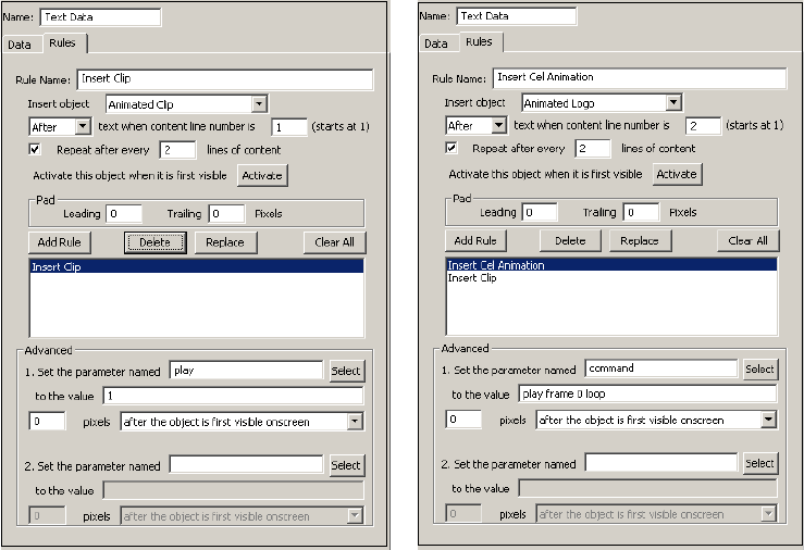
Creating Crawls
211
7. Using the Cel Animation object’s Target tab, set its Autoscale option to
Preserve/Minimum.
To specify rules for the inserted objects:
1. With the Text Data object selected, click the Rules tab in its object editor.
Set up one rule at a time.
nYou can apply rules to a non-text object only if it is a child of the Text Data object. The Text
Data object editor is the only editor with the Rules tab.
2. Type a name for the first rule, such as “Insert Clip.”
3. Select the Clip Playback object (such as Animated Clip) from the Insert Object list.
4. Select when you want the rule to be activated, either before or after a line of text. Select
After.
5. Indicate the line after which you want the object to be added. Accept the default value 1
to insert the object after the first line.
6. Set the repeat after every line value to 2 because you are going to add a second non-text
object every other line.
3 Editing Objects in the Scene
212
7. Accept the default values for the padding (spacing in pixels) before (leading) and after
(trailing) the inserted object that separate it from the beginning and end of text. Adjust
these later, if desired.
8. Click Activate.
The
play
parameter is added to the rule in the Advanced pane.
9. Click Add Rule to save the rule.
The rule displays in the Rules text box. The Clip Playback object is inserted in the crawl
text after it is buffered and processed. Wait for it to appear after the first line of text.
nIf you do not click Activate before adding the rule, the inserted object will not play. If you
forget to Activate an object, you need to edit and replace the rule.
10. For the animated logo, create a new rule by typing a name in the Rule Name text box,
such as “Insert Cel Animation.”
11. Select the Cel Animation object (such as Animated Logo) from the Insert Object menu.
12. The logo is to be inserted after the second line of text. Set the start-after line to 2 and set
the repeat line to 2.
13. Click Activate.
A dialog box asks if you want to replace the first parameter settings. Click OK.
The
command
parameter
play frame 0 loop
is added to the rule in the Advanced
pane.
14. Click Add Rule to add the rule to the Rules text box.
The Cel Animation appears in the crawl.
15. Select the Crawl object in the Scene Tree and click its Command tab. Use these controls
to adjust the speed of the crawl, the spacing between objects or text lines, and the
opacity of the entire crawl object. See “Controlling the Crawl Display” on page 196.
nYou cannot use a rule to loop a Clip Playback object. To loop a Clip Playback object in a
crawl, select the Loop option in the File tab of the Clip Playback editor.
Example: Applying a Parameter Value to an Inserted Object
The Advanced pane of the Text Data Rules tab allows you to specify a value for any of the
scene’s parameters and have it take effect in relation to the position of the non-text object as
it crawls across the video output.
The Advanced pane allows you to specify up to two parameter values (two activations) that
are applied in relation to the inserted object. You can use an API program or data using an
XML string to add additional activations.
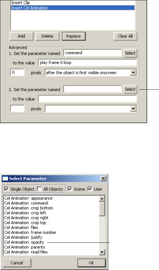
Creating Crawls
213
The following example reduces the opacity of a Cel Animation as it travels across the crawl.
To reduce the opacity of a Cel Animation object inserted in crawl text:
1. Add a Cel Animation object to a crawl and define a rule for it (see “Example: Inserting
Objects into a Crawl” on page 210).
The Advanced pane in the Data tab should include a parameter to animate the cel.
2. To set a second parameter, click the second Select button in the Advanced pane.
3. In the Select Parameters list, select Single Object, which refers to the object that is
inserted into the crawl by this rule.
nAny scene parameter is a potential option when you use this Advanced feature.
Select button
Opacity parameter
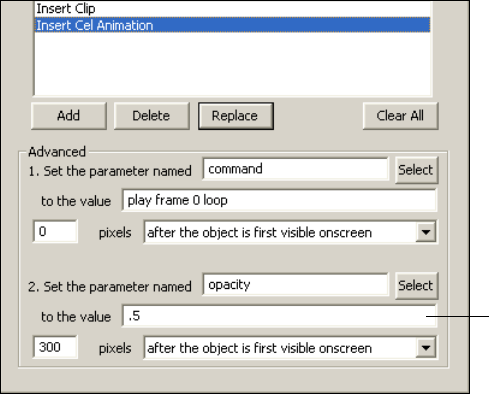
3 Editing Objects in the Scene
214
4. Select the opacity parameter for the object and click OK.
5. Type the value for the opacity parameter in the value text box.
For example, .5 results in an object that is half transparent.
6. Specify where you want the opacity to change. Type the number of pixels before or after
the object has reached the position within the crawl that you select from the menu. For
example, “300 pixels after the object is first visible onscreen.”
7. Click Replace to update the rule for the Crawl object.
The updated crawl is displayed.
Using an Inserted Object to Trigger an Action
You can also use a parameter value for a non-text object in a crawl to trigger an action. For
example, you could have the Video In object squeeze back when the non-text object in the
crawl reaches the mid-point of the video output frame.
To use a non-text object to trigger an action:
1. Create an action in the Timeline editor.
Some examples of actions are squeezing back a Video In feed, displaying a clip, or
fading the inserted object. See “Adding Actions to a Scene” on page 297.
2. Create a crawl and insert a non-text object (see “Adding Non-Text Objects to Crawl
Text” on page 205 and “Example: Inserting Objects into a Crawl” on page 210).
3. Add another parameter to the rule you created by clicking the Rules tab, selecting the
rule, and clicking the second Select button in the Advanced pane.
Value text box
Creating Crawls
215
4. For the option in the Select Parameters list, select Scene.
5. Select the action you created from the list (such as Squeezeback command) and click
OK.
The action is added as a parameter name in the Advanced pane.
6. In the value field, type
play
.
Enter a pixel value and an action to define when and how you want the action played.
For example, “360 pixels after the object is first visible onscreen” (360 pixels is
mid-frame in NTSC).
7. Click Replace to apply the edited rule to the Crawl object.
The updated crawl is displayed.
Inserting Objects by Using Crawl Object Tags
You can insert non-text objects into a crawl by embedding the objects as content in the Text
Data object’s Value text box, either by inserting the Crawl object embedded tags or by
importing a text file that includes these tags. This topic provides several examples.
For example, typing
<object>Sun</object>
into the Value text box after a particular line
of text inserts the graphic object named “sun” into the crawl after that text.
Los Angeles 76
º
<object>sun</object>
New York 20
º
You can also use an object ID number with the
<object>
tag, for example:
<object>-1272</object>.
To insert a clip object with the name Clip To Crawl into a crawl and trigger it to play 20
pixels before it being displayed on the screen, use the <object> tag with these attributes and
parameters:
<object>Clip To Crawl<onActivating paramName="play"
offsetPos="-20">1</onActivating></object>
To insert a cel animation with the object ID-2212 into a crawl and trigger it to play in a loop
50 pixels after it is first drawn on video output, and then trigger it to stop 50 pixels before it
starts to leave the video output, use the following tags:
<object>-2212<onActivating paramName="command" offsetPos="50">play
frame 0 loop</onActivating><onInactivating paramName="command"
offsetPos="50">abort</onInactivating></object>
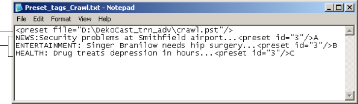
3 Editing Objects in the Scene
216
Adding Non-Text Objects as Custom Typefaces
You can use embedded tags to insert a static image that is defined as a Deko custom typeface
into a crawl. This technique is particularly useful if you use a single file of custom typefaces
or want to insert more than two non-text objects into a crawl. For more information on using
embedded tags, see “Using Embedded Tags with Deko Object Text” on page 128.
nThese tags are different from the Crawl object tags described in “Inserting Objects by Using
Crawl Object Tags” on page 215.
To add a non-text object as a custom typeface:
1. In PostDeko Lite, create a custom typeface from a graphic and associate it with a letter
or number. Adjust the size so that it fits into the crawl and assign it a preset number. For
information on creating a custom typeface and saving a preset, see the Deko Products
User’s Guide or the Deko Products Help.
Make sure to define the paths for DekoCast and PostDeko Lite correctly. See “Setting
Up Directories” on page 37.
2. In a text file, use the <preset file> and <preset_ID> tags to identify and insert the static
image.
For example, the following file produces a different custom typeface (static image) at
the end of each news item. Style information is included in the file crawl.pst as id 3. The
first custom typeface is associated with the letter A, the second with the letter B, and the
third with the letter C.
3. Save the text file.
Depending on your settings, the crawl is immediately updated. See “Using a Text File
for a Crawl” on page 199.
Preset file tag
Preset ID tags

Adding Plug-in Objects
217
Adding Plug-in Objects
The Plug-in object lets you add special to scenes to provide additional functionality. See the
Avid Knowledge Base (www.avid.com/onlinesupport) for information about using
DekoCast plug-ins.
To add a plug-in object to a scene:
1. Select the plug-in tool from the Object toolbar.
2. Select the plug-in from the Select Object Plug-in list.
3. Click OK.
Plug-in
button
3 Editing Objects in the Scene
218

4Working with Charts and Graphs
DekoCast enables you to create your own charts and graphs using the Chart Designer dialog
box. The Chart Designer dialog box enables you to add a series, and assign data to your
chart.
The following topics describe how to access the Chart Designer and to create charts and
graphs:
•“Accessing the Chart Designer” on page 220
•“Basic Procedure for Creating Charts” on page 222
•“Working with Advanced Controls” on page 229
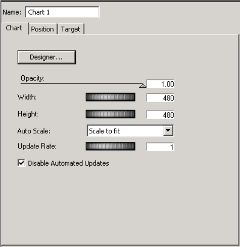
4 Working with Charts and Graphs
220
Accessing the Chart Designer
In DekoCast, a chart is treated similar to a rendered single cell animation. This topic shows
you how to access the Chart Designer in DekoCast.
To access the Chart Designer in DekoCast:
1. Add an object to a scene by clicking the object from the Object toolbar.
The right side of the screen changes to reflect the Chart object.
2. In the Chart tab, you can perform the following optional steps:
a. If desired, use the Opacity slider to change the opacity of the chart.
b. Use the Width thumbwheel to change the width of the chart, given the aspect ratio
selected. For more information on setting the aspect ratio, see “Setting the View
Size” on page 292.
c. Use the Height thumbwheel to change the height of the chart, given the aspect ratio
selected. For more information on setting the aspect ratio, see “Setting the View
Size” on page 292.
d. In the Auto Scale drop list, select the method you want to use to scale your object,
given the aspect ratio selected. For more information on setting the aspect ratio, see
“Setting the View Size” on page 292.
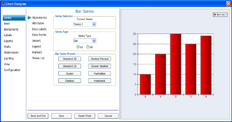
Accessing the Chart Designer
221
e. Use the Update Rate thumbwheel to set how often you want to request an update to
the Chart.
This is only useful when the Chart is dynamically linked to a database. It defines
how often in seconds to get the Chart to query the Database and generate the chart
given with any changed values in the bound database.
f. Select the Disable Automated Updates check box if you want to disable automated
updates to the chart.
nThe Width and Height can be animated using an Action, but it will not be real time, and it
will not be a smooth transition from start to end value. It will be jerky. The Engine will
optimize the calls to make best use it can of the Chart Rendering Engine. If you want to
make a smooth transition, you should use the Scaling values of the Position tab.
3. Select the Designer button to set up the type of chart you want to create.
The Chart Designer dialog box opens.
4. Next you can use the Chart Designer dialog box to add a series, and assign data to your
chart.
For more information on using the Chart Designer in both Deko and DekoCast, see
“Basic Procedure for Creating Charts” on page 222.

4 Working with Charts and Graphs
222
Basic Procedure for Creating Charts
The Chart Designer enables you to create custom charts from information that is populated
in your database. The database must be linked to your Deko or DekoCast system. When
creating a chart, there are three required tasks you must perform:
• Create (or add) a Series. A Series is the type of chart you want to create. Examples
include Bar series, Pie series, Line series, and so on. For more information, see
“Creating a Series” on page 222.
• Assign data to your chart. For more information, see “Assigning Data to a Series” on
page 227.
Creating a Series
When working in the Chart Designer, the first task you must perform is to create a Series,
which is the type of chart you want to create. There are a number of different charts and
variations that you can choose from. Examples are Bar chart, Pie chart, Line chart, and so
on.
To create a series:
1. Access the Chart Designer dialog box. For more information, see “Accessing the Chart
Designer” on page 220.
The Chart Designer dialog box opens.
2. If not already selected, select Series in the left column.
Basic Procedure for Creating Charts
223
nThe Appearance tab should be preselected by default.
The Series > Appearance page appears. The Series Selection area displays the current
series. As shown in the preceding example, this is Series 1.
3. In the Series Type field, select the Series type from the drop down list.
This is the type of chart that you want to make. Options are: Area, Bar, Line, Pie, and so
on.
4. Select whether you want your chart to be two dimensional or three dimensional by
clicking on the appropriate option. Choices are 2D or 3D.
5. Select the presets for the type of series you selected by clicking on one of the presets to
view what your series will look like with these presets applied.
The Series Presets area contains various presets for the series you selected. In the
previous example, a Bar chart was selected, therefore, the presets listed all apply to a
Bar Chart.
nYou can try different presets until you find the right one for your series.
6. (Optional) If you want to add another series, do the following:
a. Select Series List in the second column from the left.
b. Type a name for the new series in the bottom row of the Series List table.
c. Press the Add button.
7. Select attributes for your chart by clicking the Attributes tab. You can then change
certain attributes for your series.
The attribute information that you can change is different based on the type of chart you
selected.
8. Click Save and Exit to save your changes and close the Chart Designer.
9. Next, you can use the Chart Designer dialog box to configure chart settings. For more
information, see “Configuring Chart Settings” on page 224.

4 Working with Charts and Graphs
224
Configuring Chart Settings
The second required task when creating a chart in the Chart Designer is to assign visual
effects to your series (chart). The Jitter is especially important to set. Jittering is a special
visual effect that enables you to anti-alias the whole scene. The idea behind it is very simple:
the control renders several samples of the image, each with a small offset in the X and Y
directions. These samples are then added together to produce the final image.
nNote that jittering slows down the rendering speed.
This procedure assumes that you have already added a series as described in “Creating a
Series” on page 222.
To assign visual effects:
1. Select Configuration in the left column.
The Configuration > Chart Settings page displays enabling you to assign visual effects
to the selected series.
2. In the Chart Antialias Properties area, the Enable Antialiasing check box by default is
selected. If you do not want to enable anti-aliasing, deselect it.
Basic Procedure for Creating Charts
225
3. In the Chart Jitter Properties area, do the following:
a. If you want to turn jittering on, select the Enable Jittering check box to turn jittering
on. The Jittering Steps field becomes active.
b. In the Jittering Steps area, click the arrow, and from the list, select the number of
sample (steps) of jittering you want to apply to your chart.
c. Use the Jittering Deviation slide bar to control the maximum offset along the X and
Y directions of the generated samples relative to the original image.
4. In the Chart Blend Properties area, select the Enable Double Pass Blending check box if
you want to enable double pass blending.
5. Click Save and Exit to save your changes and close the Chart Designer. Your next step is
to determine interactivity for a series. For more information, see “(Optional) Assigning
Interactivity for the Mouse” on page 225.
(Optional) Assigning Interactivity for the Mouse
An optional task you can perform now when creating a chart in the Chart Designer is to
determine what the mouse controls when it is moved over the Preview window.
This procedure assumes that you have already added a series as described in “Creating a
Series” on page 222.
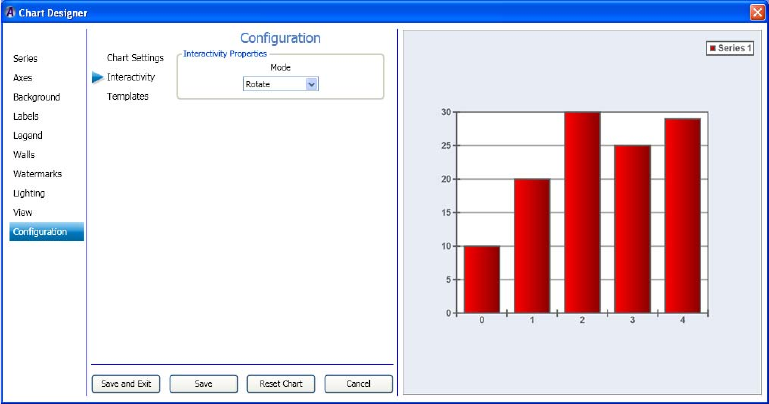
4 Working with Charts and Graphs
226
To determine interactivity for the mouse:
1. Select the Interactivity submenu from the Configuration tab.
The Configuration > Interactivity page displays enabling you to determine the what the
mouse controls when it is moved over the Preview window.
2. In the Interactivity Properties area, select the mode that reflects what you want the
mouse to control when it is moved over the Preview window. Options include the
following:
tDisabled - Mouse movements over the Preview window will have no effect on the
chart.
tRotate - Mouse movements over the Preview window will modify the
View/Projection Rotation and Elevation values of the chart. This option only works
for 3D charts.
tZoom - Mouse movements over the Preview window will modify the
View/Projection zoom value of the chart. This option only works for 3D charts.
tOffset - Mouse movements over the Preview window will modify the View/Margin
values of the chart.
nThe left mouse button must be held down during mouse movements over the Preview window
for any parameter modifications to take place.
3. Click Save and Exit to save your changes and close the Chart Designer. Your next step is
to assign data to a series. For more information, see “Assigning Data to a Series” on
page 227.
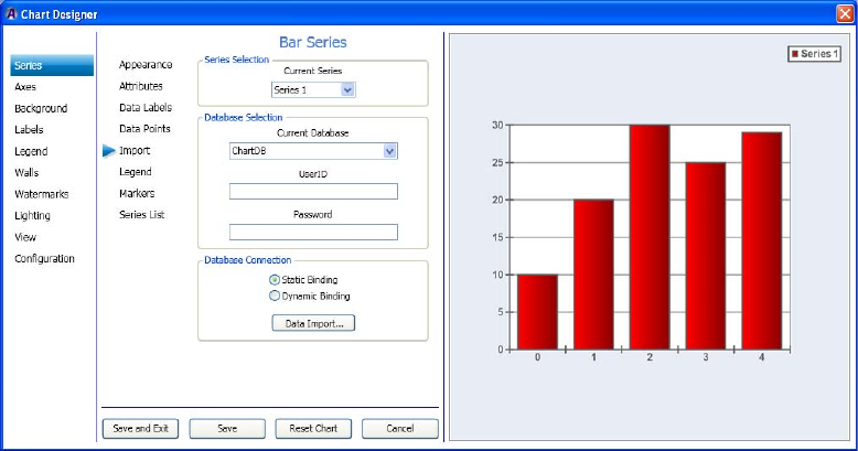
Basic Procedure for Creating Charts
227
Assigning Data to a Series
The third required task when creating a chart in the Chart Designer is to assign data to your
series (chart). The data you assign comes from an existing ODBC database that you must
select. This procedure assumes that you have already added a series as described in
“Creating a Series” on page 222.
To assign data to a series:
1. Select Series, then select the Import submenu.
The Series > Import page enables you to select your database, connect to a database, and
import data.
2. In the Series Selection area, select the series for which you want to assign data to.
3. In the Database Selection area, do the following:
a. Select the database you want to connect to for this series from the Database drop
list. When you click the drop down arrow, a list of currently defined ODBC
databases appears.
b. In the UserID field, type the username to access the selected database.
c. In the Password field, type the password for the user.
4 Working with Charts and Graphs
228
4. In the Database Connection area, select the check box that indicates how you want to
load the data. Options are:
a. Static Binding - Select Static Binding if you want to load the data now, without
updates.
b. Dynamic Binding - Select Dynamic Binding if you want to continually load the
data, and update the chart when the data changes.
nYou will not see the chart update when looking in the Chart Designer window. In Dynamic
Binding mode, the chart will update in the Deko or DekoCast application windows when the
data changes.
5. Select the Data Import button. The dialog box changes to enable you to select the
Database Table, and Data Series Assignments. Do the following:
nMake sure you click on the database that contains the data you want to use.
a. In the Current Database Table drop down list, select the database table that you
want to use.
b. In the Data Series Assignments drop down list, do the following in the Database
Column for each Data Series:
tSelect the values you want to use in your series. These values are graphically
represented as points on the chart.
tSelect the labels you want to use in your series. These are typically represented
as names (such as Company names, and so on).
tSelect the Fill effects you want to use in your series.
t(Optional) Select the line properties you want to use in your series.
6. Select the View Database button to view the information in the database.
7. Select the Import button to import the information from the database into the selected
Data Series.
8. Repeat Steps 1-5 for each Series you create.
9. Click Exit Data Import to close the Data Import screen, then click Save and Exit to save
your changes and close the Chart Designer.
Working with Advanced Controls
229
Working with Advanced Controls
This section contains information regarding Advanced Controls that are available for use in
the Chart Designer. Advanced Controls are the remaining controls in the Chart Designer that
you can use to tweak your charts to a more precise degree than you can using the “Basic
Procedure for Creating Charts” on page 222 presented previously in this chapter.
In this section, we organized the Advanced Controls by their Menu order. Therefore, see the
following sections for more information on the Advanced Controls that you are interested in
changing for your series (chart):
•Using Series Controls
•Using Axes Controls
•Using Background Controls
•Using Labels Controls
•Using Legend Controls
•Using Walls Controls
•Using Watermarks Controls
•“Using Lighting Controls” on page 282
•“Using View Controls” on page 289
•“Template Configuration Controls” on page 294
Using Series Controls
This section contains information on using the Series Controls to further adjust the look of
your series.
Procedures for Series Appearance, and Series Import are described in the section “Basic
Procedure for Creating Charts” on page 222.
For more information on setting specific axes controls, see one of the following topics:
•“Setting the Series Attributes” on page 230
•“Setting the Series Data Labels” on page 233
•“Setting the Series Data Points” on page 236
•“Setting the Series Legend” on page 237
•“Setting the Series Markers” on page 238
•“Modifying the Series List” on page 239
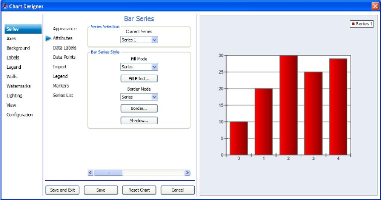
4 Working with Charts and Graphs
230
Setting the Series Attributes
This procedure contains information on how to set the series attributes (attributes, style and
text) for your series.
This procedure assumes that you have already added a series as described in “Creating a
Series” on page 222.
To set the series attributes:
1. Select Series in the left column, and then select the Attributes submenu.
The Series > Attributes page displays enabling you to set the series attributes, style,
Properties and Dimensions for the selected series.
2. In the Series Style area, click the arrow in the Fill Mode field, and from the list, select
the Fill mode (Series, Data Points or Pre defined) you want to apply to your series.
3. Click the Fill Effect button.
The Fill Effect Editor dialog box opens, allowing you to change the fill effect for your
chart.
4. Click the arrow in the Border Mode field, and from the list, select the Border mode
(Series, Data Points or Pre defined) you want to apply to your chart.
5. Click the Border button.
The Line Properties Editor dialog box opens, allowing you to change the line properties
for your chart.

Working with Advanced Controls
231
6. Click the Shadow button.
The Shadow Editor dialog box opens, allowing you to change the shadow properties for
your chart.
7. Use the slider to get to the next page.
The Series Properties area displays, allowing you to change the series properties for
your chart.
Do the following to change your series properties:
- In the Multi Bar Mode drop list, if you have created more than one series, select the
series you want to modify attributes for.
nThis list box is always disabled on the first series. If you have only created one series, it will
always be disabled. If you have created more than one series, and all of the series are the
same type (e.g. all are Bar series or all are Area series), it will be enabled.
- In the Style drop list, select the type of series.
- Select the Has Top Edge check box if you want the series to have a top edge.
- Select the Has Bottom Edge check box if you want the series to have a bottom edge.
- Use the Edge Percentage slider to determine the percentage of the edge of the
series.
- Select the Inflate Margins check box to make the margins larger.
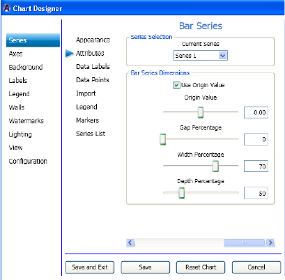
4 Working with Charts and Graphs
232
8. Use the slider to get to the next screen.
The Series Dimensions area displays, allowing you to change the series dimensions for
your chart.
Do the following to change your series dimensions:
- (Optional) If the Use Origin Value check box is selected, it indicates that the
"Origin Value" slider below it should be used to control the origin value, instead of
defaulting to begin at the minimum series value.
- Use the Origin Value slider to control the origin value of the series.
- Use the Gap Percentage slider to control the gap percentage of the series.
- Use the Width Percentage slider to control the width percentage of the series.
- Use the Depth Percentage slider to control the depth percentage of the series.
9. Use the slider to return to the initial Series Attributes page.
10. Click Save and Exit to save your changes and close the Chart Designer.
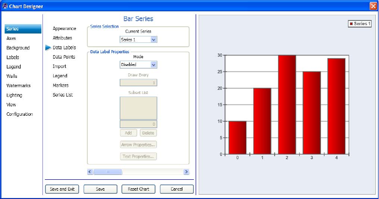
Working with Advanced Controls
233
Setting the Series Data Labels
If you want, you can then set the series data label properties for your series.
This procedure assumes that you have already added a series as described in “Creating a
Series” on page 222.
To set the series data label properties:
1. Select Series in the left column, then select the Data Labels submenu.
The Series > Labels page displays enabling you to set the series data labels for the
selected series.
2. In the Series Selection area, select the series you want to change from the list.
3. In the Data Label Properties area, click the arrow in the Mode list box, and select the
mode that you wan to use. When you select the Every option, the Draw Every field
becomes enabled. If you select the Subset option, the Subset List becomes enabled.
4. If you selected Every, do the following:
a. In the Draw Every field, type the number that represents how often/quickly you
want the Chaert Designer to control how often the labels are re-drawn.
nIf the "Every" field is set to N, then the labels are drawn on every Nth data point.
b. If you want to change the arrow properties for your chart, click the Arrow
Properties button. The Line Properties Editor dialog box opens. Make your changes
and click OK to save and close the dialog box.
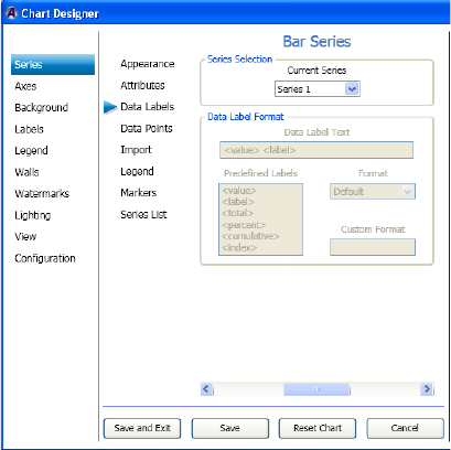
4 Working with Charts and Graphs
234
c. If you want to change the text properties for your chart, click the Text Properties
button. The Text Properties Editor dialog box opens. Make your changes and click
OK to save and close the dialog box.
5. Use the slider to get to the next page. The Data Label Format area displays.
Do the following to format your data label:
a. In the Data Label Text field, select the parameters (e.g., <value>, <label>, etc.) for
your data labels.
b. Use the Format drop list to select a predefined format for the data labels.
c. (Optional) In the Custom format text box, select a custom format for the data labels.
If the Format drop-down box is set to "Custom Number" or "Custom Date/Time",
then the "Custom Format" textbox is enabled.
For more information regarding the format specifier that you can use in the Custom
format text box, refer to the “Formatting Types” section of the .NET Programming
Guide.
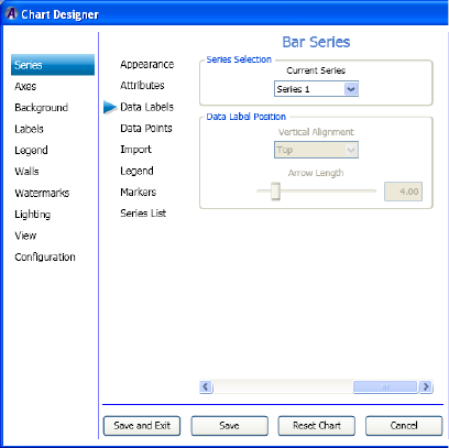
Working with Advanced Controls
235
6. Use the slider button to get to the next page.
The Data Label Position area displays.
Do the following to position your data label:
a. In the Vertical Alignment drop list, select the vertical alignment (Top, Center, or
Bottom) for your data label.
b. Use the Arrow length slider to control the arrow length you want to use for the data
labels.
7. Use the slider to return to the initial Series Data Labels page.
8. Click Save and Exit to save your changes and close the Chart Designer.
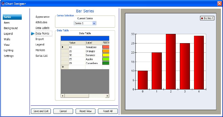
4 Working with Charts and Graphs
236
Setting the Series Data Points
If you want, you can then set the series data point properties for your series.
This procedure assumes that you have already added a series as described in “Creating a
Series” on page 222.
To set the series data point properties:
1. Select Series in the left column, then select the Data Points submenu.
The Series > Data Points page displays enabling you to set the series data point
properties for the selected series.
2. In the Series Selection area, select the series you want to change from the list.
3. In the Data Table area, the following fields appear in the table. Edit any of these fields
by either typing in a new value or label, or clicking on a fill effect, or line property to
bring up the associated dialog box.
4. Click Save and Exit to save your changes and close the Chart Designer.
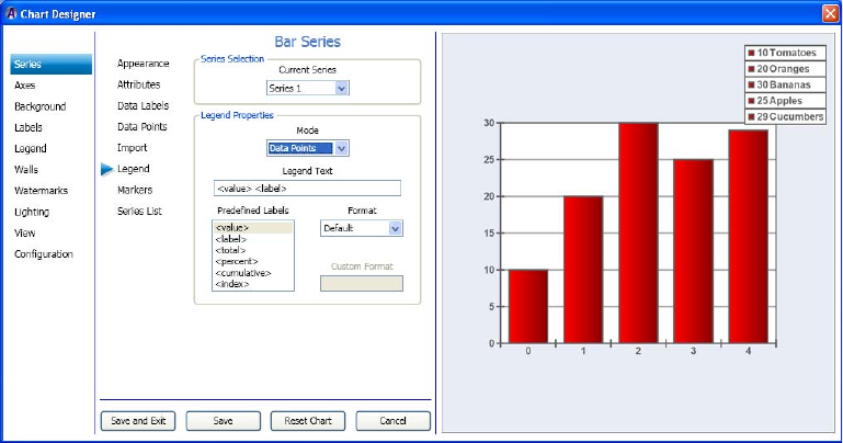
Working with Advanced Controls
237
Setting the Series Legend
If you want, you can then set the series legend properties for your series.
This procedure assumes that you have already added a series as described in “Creating a
Series” on page 222.
To set the series legend properties:
1. Select Series in the left column, then select the Legend submenu.
The Series > Legend page displays enabling you to set the series legend for the selected
series.
2. In the Series Selection area, select the series you want to change from the list.
3. In the Legend Properties area, click the arrow in the Mode list box, and select the mode
that you wan to use. When you select the Data Points option, the rest of the screen
becomes active.
4. In the Data Label Text field, do the following:
a. Select the parameters (e.g., <value>, <label>, etc.) for your Legend.
b. Use the Format drop list to select a predefined format for the Legend.
c. (Optional) In the Custom format field, to select a custom format for the Legend.
5. Click Save and Exit to save your changes and close the Chart Designer.
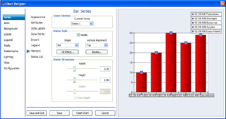
4 Working with Charts and Graphs
238
Setting the Series Markers
This procedure contains information on how to set the series markers (attributes, style and
text) for your series.
This procedure assumes that you have already added a series as described in “Creating a
Series” on page 222.
To set the series markers:
1. Select Series in the left column, and then select the Markers submenu.
The Series > Markers page displays enabling you to set the marker Style, and
Dimensions for the selected series.
2. In the Series Selection area, select the series you want to change from the list in the
Current Series list box.
3. In the Marker Style area, click the arrow in the Shape field, and from the list, select the
shape of the marker you want to apply to your chart.
4. Click the Fill Effect button.
The Fill Effect Editor dialog box opens, allowing you to change the fill effect for your
marker.
5. Click the arrow in the Vertical Alignment field, and from the list, select the type of
vertical alignment (Top, Center, Bottom) you want to apply to your marker.
6. Click the Border button.
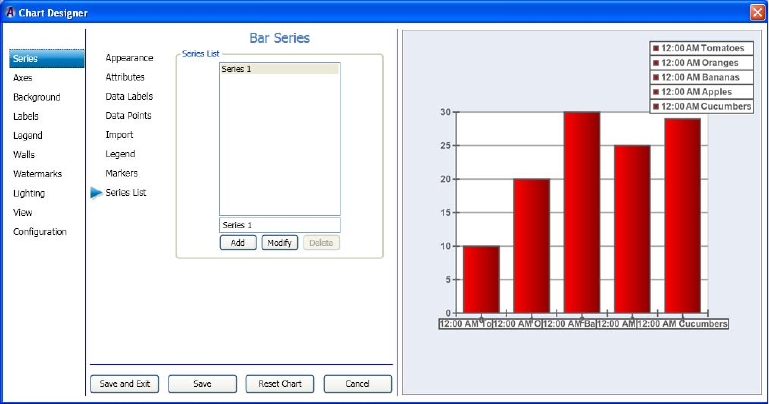
Working with Advanced Controls
239
The Line Properties Editor dialog box opens, allowing you to change the line properties
for your chart.
7. In the Marker Dimensions area, do the following: select the series you want to change
from the list in the Current Series list box.
a. Use the Width slider to change the width of the marker.
b. Use the Height slider to change the height of the marker.
c. Use the Depth slider to change the depth of the marker. (for 3D charts only).
d. Select the Auto Depth check box if you want to depth to set automatically (for 3D
charts only).
8. Click Save and Exit to save your changes and close the Chart Designer.
Modifying the Series List
This procedure contains information on how to modify the series list.
This procedure assumes that you have already added a series as described in “Creating a
Series” on page 222.
To modify the series list:
1. Select Series in the left column, and then select the Series List submenu.
The Series > Series List page displays enabling you to modify the series list.
4 Working with Charts and Graphs
240
2. In the Series List area, select the series you want to modify, and do one of the following:
tTo add another series to the list, click the Add button. This copies the existing
series.
tTo modify a series, click the Modify button. This modifies the title of the series. For
example, if the series is called “Series 1” and you want to change it to be “Bar
Series”, you select “Series 1” in the Series List, then type “Bar Series” in the edit
box (just above the Modify button), then press the Modify button.
tTo delete a series from the list, click the Delete button.
3. Click Save and Exit to save your changes and close the Chart Designer.
Using Axes Controls
This section contains information on using the Axes Controls to further adjust the look of
your series.
For more information on setting specific axes controls, see one of the following topics:
•“Setting the Axes Appearance” on page 241
•“Setting the Axes ConstLines” on page 242
•“Setting the Axes Gridlines” on page 244
•“Setting the Axes Labels” on page 245
•“Setting the Axes Paging” on page 246
•“Setting the Axes Position” on page 248
•“Setting the Axes Stripes” on page 249
•“Setting the Axes Ticks” on page 251
•“Setting the Axes Title” on page 252
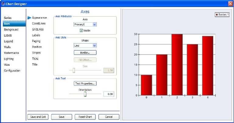
Working with Advanced Controls
241
Setting the Axes Appearance
This procedure contains information on how to set the axis appearance (attributes, style and
text) for your series.
This procedure assumes that you have already added a series as described in “Creating a
Series” on page 222.
To set the axes appearance:
1. Select Axes in the left column.
The Axes > Appearance page displays enabling you to set the axis attributes, style and
text for the selected series.
2. In the Axis Attributes area, select the Axis that you want to change from the list.
Available options are described below:
- Vertical Axes - The Vertical axes are named PrimaryY and SecondaryY and are
positioned on the left and right side of the chart. The PrimaryY axis is displayed on
the front, and the SecondaryY axis is displayed on the back.
nThe vertical axes are used to scale the series in the Y dimension. By default, all series are
scaled on the PrimaryY axis. The SecondaryY axis is, by default, not visible.
- Horizontal Axes - The Horizontal axes are named PrimaryX and SecondaryX and
are positioned on the top and bottom sides of the chart. The PrimaryX axis is
displayed on the front while the SecondaryX axis is displayed on the back.
4 Working with Charts and Graphs
242
nThe horizontal axes are used to scale the series in the X dimension. By default, all series are
scaled on the PrimaryX axis. The SecondaryX axis is, by default, not visible.
- Depth Axis - The Depth axis (there is only one) is by default displayed on the
bottom right-hand chart edge. It is used to scale the series along the chart depth
dimension. All chart series are scaled on the depth axis.
- Special Axes - Two special axes are available. These (called Radar and Polar) can
be used by the Radar and Polar Series.
3. Select or deselect the Visible check box depending on whether you want the number on
the selected axis to be visible.
4. In the Axis Style area, click the arrow in the Shape field, and from the list, select the
shape (Line, Bar or Tube) you want to apply to your chart.
5. In the Axis Text area, click the Text Properties button, and change the text properties for
your chart.
6. Use the Jittering Deviation slide bar to control the maximum offset along the X and Y
directions of the generated samples relative to the original image.
Setting the Axes ConstLines
ConstLines stands for Constant Lines and are lines that are drawn at constant axis values (X,
Y or Depth axis) of a chart. These lines are used to ponit out particular axis values. Besides
being able to specify the axis value for the constline, one can also specify properties of the
line including thickness and color.
If you want, you can then set the axes Constlines (attributes, Line List, Line Style, and Line
values) for your chart.
This procedure assumes that you have already added a series as described in “Creating a
Series” on page 222.

Working with Advanced Controls
243
To set the axes Constlines:
1. Select Axes in the left column, and then select the ConstLines submenu.
The Axes > ConstLines page displays enabling you to set the Axis attributes, Line List,
Line style, and Line values for the selected series.
2. In the Axis Attributes area, select the axis you want to change from the list.
3. Select or deselect the Visible check box depending on whether you want the number on
the selected axis to be visible.
4. In the Line List area, click the Add button to add the amount of Line numbers you want
to display in your chart. The rest of the dialog box becomes enabled.
5. In the Line Style area, click the arrow in the Shape field, and from the list, select the
shape (Line or Plane) you want to apply to your chart.
tIf you selected Line from the Shapelist, click the Line Properties button, if you want
to change the Line properties for your chart.
tIf you selected Plane from the Line Style area, in the Axis Text area, you can click
the Fill Effect button if you want to change the Fill effect for your chart.
6. Use the Constant Value slide bar to control the location of the line along the X and Y
directions.
7. If you want to change the Begin value or End value for a Line, select the Enable
Begin/End check box, and then use the appropriate slide bar to change the location.
These only work when the “Current Axis” is set to “PrimaryY”. They do not work for
the “PrimaryX” axis.

4 Working with Charts and Graphs
244
Setting the Axes Gridlines
If you want, you can then set the axis Gridlines (attributes, major and minor gridlines) for
your series.
This procedure assumes that you have already added a series as described in “Creating a
Series” on page 222.
To set the axes Gridlines:
1. Select Axes in the left column, and then select the Gridlines submenu.
The Axes > Gridlines page displays enabling you to set the axis attributes, and major
and minor gridlines for the selected series.
2. In the Axis Attributes area, select the axis you want to change from the list.
3. In the Major Gridlines area, do the following:
a. Select or deselect the check box to reflect which major gridlines you want to be
visible.
b. If you want to change the line properties for the selected major gridlines, click the
Line Properties button, and make your changes in the Line Properties Editor dialog
box.
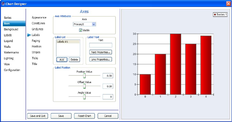
Working with Advanced Controls
245
4. In the Minor Gridlines area, do the following:
a. Select or deselect the check box to reflect which minor gridlines you want to be
visible.
b. If you want to change the line properties for the selected minor gridlines, click the
Line Properties button, and make your changes in the Line Properties Editor dialog
box.
5. Click Save and Exit to save your changes and close the Chart Designer.
Setting the Axes Labels
If you want, you can then set the axes labels (attributes, list, text, and position) for your
series.
This procedure assumes that you have already added a series as described in “Creating a
Series” on page 222.
To set the axes labels:
1. Select Axes in the left column, then select the Labels submenu.
The Axes > Labels page displays enabling you to set the axis attributes, label list, label
text, and label position for the selected series.
2. In the Axis Attributes area, select the axis you want to change from the list.
3. Select or deselect the Visible check box depending on whether you want the number on
the selected axis to be visible.
4 Working with Charts and Graphs
246
4. In the Label List area, click the Add button to add the amount of Line numbers you want
to display in your chart. The rest of the dialog box becomes active.
5. In the Label Text area, do the following:
a. Type the label text you want to appear for the selected label list.
b. If you want to change the text properties for your chart, click the Text Properties
button. The Text Properties Editor dialog box opens. Make your changes and click
OK to save and close the dialog box.
c. If you want to change the line properties for your chart, click the Line Properties
button. The Line Properties Editor dialog box opens. Make your changes and click
OK to save and close the dialog box.
6. In the Label Position area, do the following to position your label:
a. Use the Position Value slide bar to control the location of the selected label along
the X or Y axes.
b. Use the Offset Value slide bar to control the location of the selected label. The
Offset value will move according to how the angle is set, whereas, the position
value will not. If you have the angle value set to 0, the Offset and Position values
will appear to do the same thing.
c. Use the Angle Value slide bar to control the angle location of the selected label.The
Angle Value slider allows you to control the direction of the offset specified by the
Offset value.
7. Click Save and Exit to save your changes and close the Chart Designer.
Setting the Axes Paging
If you want, you can then set the axis paging (attributes, Page mode, and Current page) for
your series.
Axis rulers can be configured to work in paging mode. When operating in Paging mode, the
axis shows only a fraction of the total axis scale or, one of the several axis pages. By default
rulers do not use paging.
Before you enable paging in your chart, you must first determine how you want to specify
the ruler page size. You can do this in two ways:
• Specify the total number of pages that the ruler will possess regardless of the axis scale.
• Specify a fixed scale size for the axis page and let the page count vary depending on the
total axis scale.
This procedure assumes that you have already added a series as described in “Creating a
Series” on page 222.

Working with Advanced Controls
247
To set the axes paging:
1. Select Axes in the left column, then select the Paging submenu.
The Axes > Paging page displays enabling you to set the axis attributes, style and text
for the selected series.
2. In the Axis Attributes area, select the axis you want to change from the list.
3. In the Page Mode area, do the following:
a. Select the option on how you want to display the page (Disabled, Fixed Page Count,
Fixed Page size). If you select anything other than disable, the remainder of the
dialog box becomes active, and you can change parameters for the page count or
page size.
b. Use the Page Count slider to specify how many pages the axis should have. The
page size is automatically calculated.
c. Use the Page Size slider to specify the size of the pages. The actual page count is
determined automatically.
4 Working with Charts and Graphs
248
4. In the Current Page area, select the option on how you want to display the page (Index
mode or Value Mode):
If you select anything other than disable, the remainder of the dialog box becomes
active, and you can change parameters for the page count or page size. Once you have
chosen the paging mode, you must specify the currently shown page of the axis. This
can be achieved in two ways: either specify the exact index of an axis page, or simply
specify a beginning value.
a. Index Mode: In this mode, you specify the page index of the currently visible page
with the "Current page index" scroller.
b. Value Mode: In this mode, you specify the value at which the currently displayed
axis should begin using the "Current page value" scroller.
c. Use the Current Page Index or Current Page Value slide bar to control the currently
displayed axis page.
5. Click Save and Exit to save your changes and close the Chart Designer.
Setting the Axes Position
If you want, you can then set the axes position (attributes, and position) for your series.
This procedure assumes that you have already added a series as described in “Creating a
Series” on page 222.
To set the axes position:
1. Select Axes in the left column, then select the Position submenu.
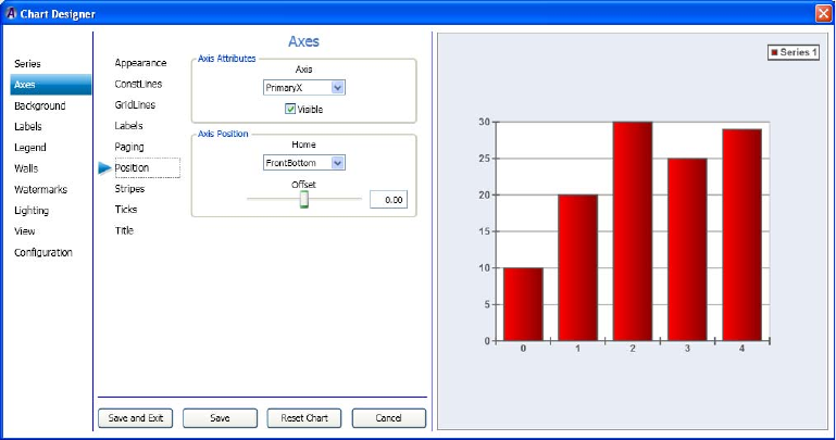
Working with Advanced Controls
249
The Axes > Position page displays enabling you to set the axis attributes, and position
for the selected series.
2. In the Axis Attributes area, select the axis you want to change from the list.
3. Select or deselect the Visible check box depending on whether you want the number on
the selected axis to be visible.
4. In the Axis Position area, click the arrow in the Home field, and from the list, select the
home position (FrontBottom, FrontTop, or BackTop) you want to apply to your chart.
5. Use the Offset slide bar to control the offset along the X or Y directions of the generated
axis relative to the original image.
6. Click Save and Exit to save your changes and close the Chart Designer.
Setting the Axes Stripes
If you want, you can then set the axis stripes (attributes, style and text) for your series.
This procedure assumes that you have already added a series as described in “Creating a
Series” on page 222.
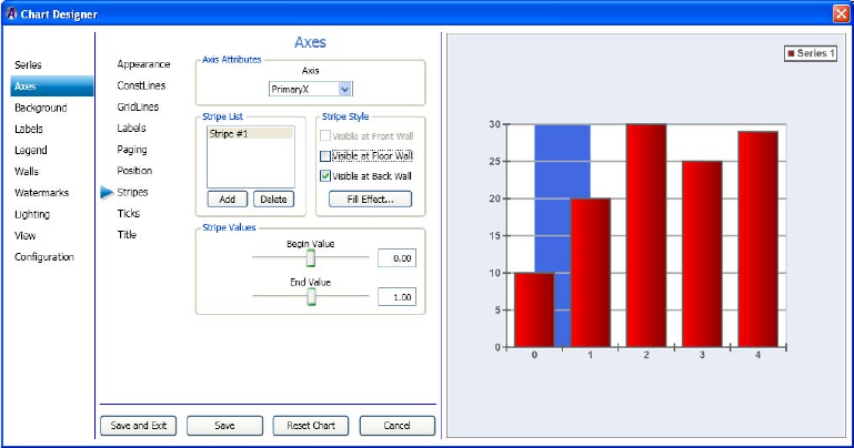
4 Working with Charts and Graphs
250
To set the axes stripes:
1. Select Axes in the left column, then select the Stripes submenu.
The Axes > Stripes page displays enabling you to set the axis attributes, stripe list, stripe
style, and stripe values for the selected series.
2. In the Axis Attributes area, select the axis you want to change from the list.
3. In the Stripe List area, click the Add button to add a stripe number to the chart.
4. In the Stripe Style area, do the following:
a. Select the check box that best denotes where you want the stripe to be visible.
b. If you want to change the color of the stripe, click the Fill Effect button. The Fill
Effect Editor dialog box opens. Make your changes and click OK to save and close
the dialog box.
c. If you want to change the line properties for your chart, click the Line Properties
button. The Line Properties Editor dialog box opens. Make your changes and click
OK to save and close the dialog box.
5. In the Stripe Values area, use the Begin Value and End Value slide bars to control the
location of where the stripe begins and ends.
6. Click Save and Exit to save your changes and close the Chart Designer.
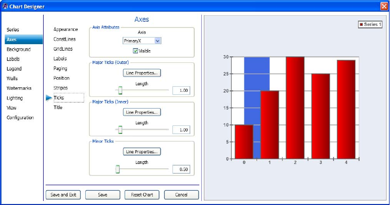
Working with Advanced Controls
251
Setting the Axes Ticks
If you want, you can then set the axis ticks (attributes, major ticks (outer and inner), and
minor ticks) for your series.
This procedure assumes that you have already added a series as described in “Creating a
Series” on page 222.
To set the axes ticks:
1. Select Axes in the left column, then select the Ticks submenu.
The Axes > Ticks page displays enabling you to set the axis attributes, major tick (inner
and outer), and minor ticks for the selected series.
2. In the Axis Attributes area, select the axis you want to change from the list.
3. Select or deselect the Visible check box depending on whether you want the ticks on the
selected axis to be visible.
4. In the Major Ticks (Outer) area, do the following:
a. Click the Line Properties button. The Line Properties Editor dialog box opens.
Make changes to the line properties of the Major outer ticks, and click OK to save
your changes and close the dialog box.
b. If you want to change the length of the ticks, use the Length slide bar to change the
length of the ticks as they appear in the selected axis.
4 Working with Charts and Graphs
252
5. In the Major Ticks (Inner) area, do the following:
a. Click the Line Properties button. The Line Properties Editor dialog box opens.
Make changes to the line properties of the Major inner ticks. and click OK to save
your changes and close the dialog box.
b. If you want to change the length of the ticks, use the Length slide bar to change the
length of the ticks as they appear in the selected axis.
6. In the Minor Ticks area, do the following:
a. Click the Line Properties button. The Line Properties Editor dialog box opens.
Make changes to the line properties of the Minor ticks. and click OK to save your
changes and close the dialog box.
b. If you want to change the length of the ticks, use the Length slide bar to change the
length of the ticks as they appear in the selected axis.
7. Click Save and Exit to save your changes and close the Chart Designer.
Setting the Axes Title
If you want, you can then set the axis title for your series.
This procedure assumes that you have already added a series as described in “Creating a
Series” on page 222.
To set the axes title:
1. Select Axes in the left column, then select the Title submenu.
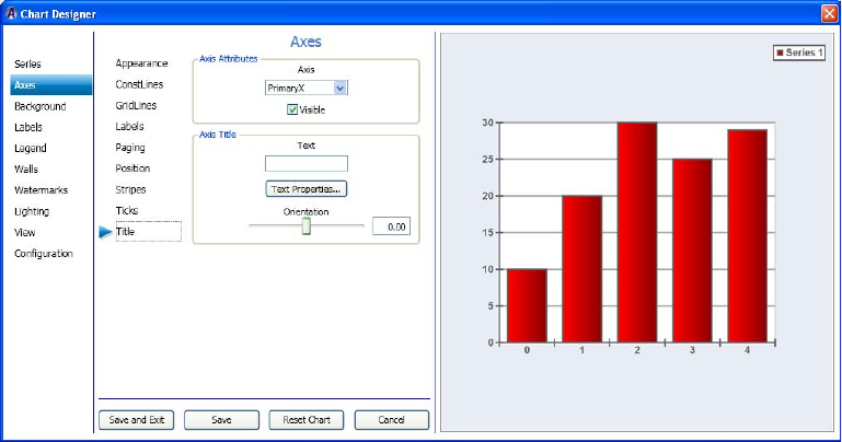
Working with Advanced Controls
253
The Axes > Title page displays enabling you to set the axis titles for the selected series.
2. In the Axis Attributes area, select the axis you want to change from the list.
3. Select or deselect the Visible check box depending on whether you want the selected
axis to be visible.
4. In the Axis Title area, do the following:
a. In the Text field, type the text for the title you are adding to the selected axis of the
chart.
b. Click the Text Properties button. The Text Properties Editor dialog box opens. Make
changes to the text properties title, and click OK to save your changes and close the
dialog box.
c. If you want to change the length of the ticks, use the Length slide bar to change the
length of the ticks as they appear in the selected axis.
5. Click Save and Exit to save your changes and close the Chart Designer.
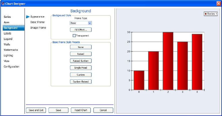
4 Working with Charts and Graphs
254
Using Background Controls
This section contains information on using the Background Controls to further adjust the
background of your series.
For more information on setting specific background controls, see one of the following
topics:
•“Setting the Background Appearance” on page 254
•“Setting the Axes ConstLines” on page 242
•“Setting the Axes Title” on page 252
Setting the Background Appearance
If you want, you can then set the background appearance for your series.
This procedure assumes that you have already added a series as described in “Creating a
Series” on page 222.
To set the background appearance:
1. Select Background in the left column.
The Background > Appearance page displays enabling you to set the background style
for the selected series.
Working with Advanced Controls
255
2. In the Background Style area, select the frame type you want for this series. Options are:
tNone - If selected, you cannot make any changes, other than Fill Effect, to the
background of this series.
tBasic - If selected, you can access the Basic Frame submenu to further modify the
Basic frame style border, color, bevel properties, and size.
tImage - If selected, you can access the Image Frame submenu to further modify the
image frame style, corner widths, tube sizes, edge rounding, and light properties.
3. (Option) In the Background Style area, select the Transparent checkbox if you want the
background of the chart to be transparent.
4. Click the Fill Effect button.
The Fill Effect Editor dialog box opens.
5. Make changes in the Fill Effect Editor dialog box to select the desired fill effect for the
background of your chart.
6. If you selected:
tBasic in the Frame Type drop list, the dialog box shows the Basic Frame Style
Presets. Select the preset frame style that you want to use for the background of
your chart. Once you save your changes, you can click on the Basic Frame submenu
and follow the instructions in the topic “Setting the Basic Frame Background” on
page 256.
tImage in the Frame Type drop list, the dialog box shows the Image Frame Style
Presets. Select the preset frame style that you want to use for the background of
your chart. Once you save your changes, you can click on the Image Frame
submenu and follow the instructions in the topic “Setting the Image Frame
Background” on page 257.
7. Click Save to save your changes, or click Save and Exit to save your changes and exit
the Chart Designer.
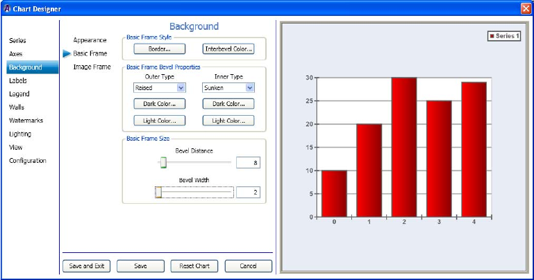
4 Working with Charts and Graphs
256
Setting the Basic Frame Background
If you want, you can then set the appearance for a Basic Frame background for your series.
This procedure assumes that you have already added a series as described in “Creating a
Series” on page 222.
To set the Basic Frame background:
1. Select Background in the left column, then select the Basic Frame submenu.
The Background > Basic Frame page displays enabling you to set the basic frame
background style for the selected series.
2. In the Basic Frame Style area, do the following:
a. If you want to change the line properties for your frame border, click the Border
button. The Line Properties dialog box opens. Set the line properties for the frame
border, and click OK.
b. If you want to change the color of the area between the outer and inner bevels, click
the Interbevel Color button. The Color dialog box opens. Make your color
selections, and click OK.
Working with Advanced Controls
257
3. In the Basic Frame Bevel Properties area, do the following:
a. In the Outer Type field, select the type of Outer bevel you want for your frame.
Options are (None, Raised, or Sunken).
b. To change the dark color of the Outer bevel, click the Dark Color button below the
Outer Type field, and select the color.
c. To change the light color of the Outer bevel, click the Light Color button below the
Outer Type field, and select the color.
d. In the Inner Type field, select the type of Inner bevel you want for your frame.
Options are (None, Raised, or Sunken).
e. To change the dark color of the Inner bevel, click the Dark Color button below the
Inner Type field, and select the color.
f. To change the light color of the Inner bevel, click the Light Color button below the
Inner Type field, and select the color.
4. In the Basic Frame Size area, do the following:
a. Use the Bevel Distance slider to change the bevel distance.
b. Use the Beval Width slider to change the bevel width.
5. Click Save to save your changes, or click Save and Exit to save your changes and exit
the Chart Designer.
Setting the Image Frame Background
If you want, you can then set the appearance for a Image Frame background for your series.
This procedure assumes that you have already added a series as described in “Creating a
Series” on page 222.

4 Working with Charts and Graphs
258
To set the Image Frame background:
1. Select Background in the left column, then select the Image Frame submenu.
The Background > Image Frame page displays enabling you to set the Image frame
background style for the selected series.
2. In the Image Frame Style area, do the following:
a. In the Type drop list, select the type of frame.
b. If you want to change the fill effect for your frame, click the Fill Effect button. The
Fill Effect Editor dialog box opens. Set the fill effect for the frame border, and click
OK.
c. If you want to change the shadow of the frame bevel area, click the Shadow button.
The Shadow Editor dialog box opens. Make your shadow selections, and click OK.
d. If you want to change the border for your frame, click the Border button. The Line
Properties dialog box opens. Set the line properties for the frame border, and click
OK.
e. If you want to change the background color of the frame, click the Bkgnd Color
button. The Color dialog box opens. Make your background color selections, and
click OK.
3. In the Image Frame Corner Widths area, do the following:
a. In the drop list, select the image frame corner width you want to change. Options
are (All Corners, Left Corner, Right Corner, Top Corner, and Bottom Corner).
b. Use the slider beneath the drop list to adjust the corner(s) you selected.
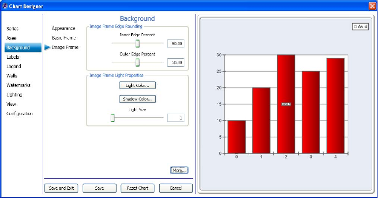
Working with Advanced Controls
259
4. In the Image Frame Tube Sizes area, do the following:
a. In the drop list, select the image frame tube you want to change.
b. Use the slider beneath the drop list to adjust the tube you selected.
5. Click the More button.
The Background > Image Frame page displays more information enabling you to set the
Image frame edge rounding and light properties for the selected series.
6. In the Image Frame Edge Rounding area, do the following:
a. Use the Inner Edge Percent slider to adjust the inner edge of the image frame.
b. Use the Outer Edge Percent slider to adjust the outer edge of the image frame.
7. In the Image Frame Light Properties area, do the following:
a. If you want to change the light color of the image frame area, click the Light Color
button. The Color dialog box opens. Make your light color selections, and click OK.
b. If you want to change the shadow color for your image frame, click the Shadow
Color button. The Color dialog box opens. Make your shadow color selections for
for the image frame, and click OK.
c. Use the Light Size slider to adjust the light size of the image frame background
border.
8. Click Save to save your changes, or click Save and Exit to save your changes and exit
the Chart Designer.
4 Working with Charts and Graphs
260
Using Labels Controls
This section contains information on using the Labels controls to further adjust the look of
your series.
For more information on setting specific labels controls, see one of the following topics:
•“Setting the Label Appearance” on page 260
•“Setting the Label Format” on page 262
•“Setting the Label Position” on page 263
•“Creating the Label List” on page 265
Setting the Label Appearance
If you want, you can then set how labels appear in your series.
Before you can set the appearnce of a label, you must add a label in the Labels > Label List
page as described in the topic “Creating the Label List” on page 265.
This procedure assumes that you have already added a series as described in “Creating a
Series” on page 222.
To set the label appearance:
1. Select Label in the left column.

Working with Advanced Controls
261
The Label > Appearance page displays enabling you to set the label attributes, and style
for the selected series.
2. In the Label Selection area, select the label you want to modify or create from the
Current Label list.
3. In the Label Text area, type the text you want to appear on the label.
4. In the Label Style area, do any of the following to modify the appearance of your label:
a. If you want to change the color of the area within the label, click the Fill Effect
button. The Fill Effect Editor dialog box opens allowing you to select your color.
Click OK to save your selections and close the dialog box.
b. If you want to change the border style of the label, click the Border button. The Line
Properties dialog box opens. Set the line properties for the label border, and click
OK.
c. If you want to change the shadow of the area within the Label, click the Shadow
button. The Shadow Editor dialog box opens. Make your shadow selections, and
click OK.
d. If you want to change the font of the area within the Label, click the Font button.
The Font dialog box opens allowing you to select your color. Click OK to save your
selections and close the dialog box.
e. If you want to change the backplane of the area within the Label, click the
Backplane button. The Backplane Object Editor dialog box opens allowing you to
change the backplane properties of the label. Click OK to save your selections and
close the dialog box.

4 Working with Charts and Graphs
262
5. Click Save to save your changes, or click Save and Exit to save your changes and exit
the Chart Designer.
Setting the Label Format
If you want, you can then set the format properties for the labels in your series.
Before you can set the label format, you must add a label in the Labels > Label List page as
described in the topic “Creating the Label List” on page 265.
This procedure assumes that you have already added a series as described in “Creating a
Series” on page 222.
To set the label format:
1. Select Label in the left column, then select the Format submenu.
The Label > Format page displays enabling you to set the format properties for your
label.
2. In the Label Selection area, select the label you want to modify from the Current Label
list.
3. In the Label Text area, type the text you want to appear on the label.
Working with Advanced Controls
263
4. In the Format Properties area, do any of the following to modify the appearance of your
label:
a. In the Text Type drop list, select one of the following text type options:
tSimple - Used for normal text that is displayed as the label.
tXML Formatted - XML formatted text that can set the font, fill effect, border
and shadow of the text on a per-character basis is desired.
b. In the Tab Size field, type a number indicating the size of the tab. This field
specifies how many spaces actually replaces the tab if the Replace Tabs box is
checked.
c. If you want to replace tabs, select the Replace Tabs check Box. Otherwise, leave it
blank.
If a Tab is included in the text (such as, the Tab key on the keyboard was pressed,
this setting specifies whether to replace the tab with spaces.
5. Click Save to save your changes, or click Save and Exit to save your changes and exit
the Chart Designer.
Setting the Label Position
If you want, you can then set the position of the labels in your series.
This procedure assumes that you have already added a series as described in “Creating a
Series” on page 222.
To set the label position:
1. Select Label in the left column, and then select the Position submenu.

4 Working with Charts and Graphs
264
The Label > Position page displays, enabling you to set the position properties for the
label.
2. In the Label Selection area, select the label you want to set position properties for from
the Current Label list.
3. In the Position Properties area, do any of the following to modify the position properties
of your label:
a. If you want to change the horizontal alignment of the label, select the type of
horizontal alignment you want to use from the Hoirizontal Alignemnt list. Options
are Center, Left, and Right.
b. If you want to change the vertical alignment of the label, select the type of
horizontal alignment you want to use from the Vertical Alignment list. Options are
Center, Top, and Bottom.
c. Use the Horizontal Offset slider to change the horizontal offset of the label.
d. Use the Vertical Offset slider to change the vertical offset of the label.
e. Use the Orientation slider to change the orientation of the label.
4. Click Save to save your changes, or click Save and Exit to save your changes and exit
the Chart Designer.
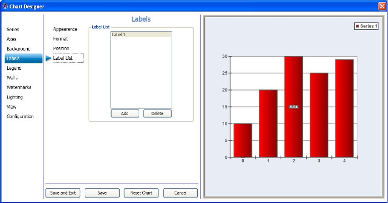
Working with Advanced Controls
265
Creating the Label List
This topic contains information on how to add labels to your series. Once you have added a
label, you can change it’s appearance, format, and position properties.
This procedure assumes that you have already added a series as described in “Creating a
Series” on page 222.
To create the label list:
1. Select Label in the left column, and then select the Label List submenu.
The Label > Label List page displays enabling you to add or delete labels for the
selected series.
2. In the Label List area, do one of the following:
tTo add a label, click the Add button.
tTo delete a label, select a label, and click the Delete button.
3. Click Save to save your changes, or click Save and Exit to save your changes and exit
the Chart Designer.
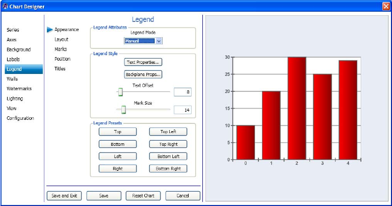
4 Working with Charts and Graphs
266
Using Legend Controls
This section contains information on using the Legend controls to further adjust the look of
your series.
For more information on setting specific legend controls, see one of the following topics:
•“Setting the Legend Appearance” on page 266
•“Setting the Legend Layout” on page 267
•“Setting the Legend Marks” on page 269
•“Setting the Legend Position” on page 270
•“Setting the Legend Titles” on page 272
Setting the Legend Appearance
If you want, you can then set the Legend appearance for your series.
This procedure assumes that you have already added a series as described in “Creating a
Series” on page 222.
To set the legend appearance:
1. Select Legend in the left column.
The Legend > Appearance page displays enabling you to set the legend attributes, and
style for the selected series.
Working with Advanced Controls
267
2. In the Legend Attributes area, select the Legend Mode you want to use from the list.
Options are: The legend can operate in three modes: Disabled, Automatic, and Manual.
tDisabled - In disabled mode the legend is not displayed.
tAutomatic - When you set the mode to Automatic, the legend data is supplied by
the series of the charts associated with the legend.
tManual - In manual mode, you control the displayed legend data items through the
MarkList under the Marks sub-tab.
3. In the Legend Style area, do the following:
a. Click the Text Properties button, and change the text properties for your chart. The
Text Properties Editor opens. Make your changes, and click OK.
b. Click the Backplane Props button, and change the backplane properties for your
chart. The Backplane Properties Editor opens. Make your changes, and click OK.
c. Use the Text Offset slide bar to control the text offset for the Legend.
d. Use the Mark Size slide bar to control the mark size for the Legend.
4. In the Legend Presets area, select the button to indicate where you want the preset to
appear on your chart.
nAutomatic must be selected for the Legend Presets area to be available.
5. Click Save to save your changes, or click Save and Exit to save your changes and exit
the Chart Designer.
Setting the Legend Layout
If you want, you can then set the Legend layout and cell properties for your series.
This procedure assumes that you have already added a series as described in “Creating a
Series” on page 222.
To set the legend layout:
1. Select Legend in the left column, and then select the Layout submenu.
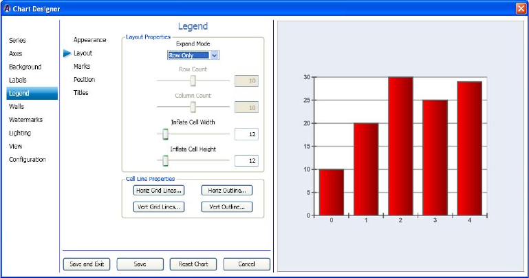
4 Working with Charts and Graphs
268
The Legend > Layout page displays enabling you to set the legend layout and cell
properties for the selected series.
2. In the Layout Properties area, do the following:
a. In the Expand Mode drop list, select the Expand mode you want to use for the
layout of this chart.
- Selecting the Rows Fixed option enables the Row Count slider.
- Selecting the Columns Fixed option enables the Column Count slider.
b. Use the Row Count slider to adjust the number of rows in the layout.
c. Use the Column Count slider to adjust the number of columns in the layout.
d. Use the Inflate Cell Width slider to adjust the width of the cells in the layout
e. Use the Inflate Cell Height slider to adjust the height of the cells in the layout
3. In the Cell Line Properties area, do the following:
a. If you want to change the horizontal grid lines for your chart, click the Horiz Grid
Lines button. The Line Properties Editor opens. Make your changes, and click OK.
b. If you want to change the vertical grid lines for your chart, click the Vert Grid Lines
button. The Line Properties Editor opens. Make your changes, and click OK.
c. If you want to change the horizontal outline for your chart, click the Horiz Outline
button. The Line Properties Editor opens. Make your changes, and click OK.
d. If you want to change the vertical outline for your chart, click the Vert Outline
button. The Line Properties Editor opens. Make your changes, and click OK.
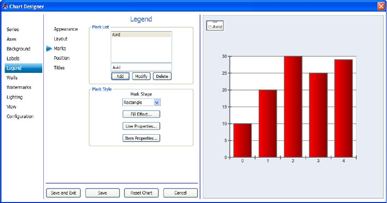
Working with Advanced Controls
269
4. Click Save to save your changes, or click Save and Exit to save your changes and exit
the Chart Designer.
Setting the Legend Marks
If you want, you can then set the Legend marks for your series.
This procedure assumes that you have already added a series as described in “Creating a
Series” on page 222.
To set the legend marks:
1. Select Legend in the left column, then select the Marks submenu.
nManual must be selected in the Legend > appearance page for the Marks submenu to be
active.
The Legend > Marks area displays enabling you to set the Mark list, and Mark style for
the selected series.
2. In the Mark List area, do the following to add legend text to your chart:
a. Type any text you want to appear in the legend in the box directly above the Add
button.
b. Click the Add button, to add the text to the legend of your chart.
nIf you want to modify or delete information already added to a legend, click the Modify or
Delete buttons.
4 Working with Charts and Graphs
270
3. In the Mark Style area, do the following:
a. Select the mark shape (the shape that appears directly in front of the Legend text)
you want to use from the list.
b. If you want to change the color of the area within the Legend mark, click the Fill
Effect button. The Fill Effect Editor dialog box opens allowing you to select your
color. Click OK to save your selections and close the dialog box.
c. If you want to change the line properties of the Legend mark, click the Line
Properties button. The Line Properties Editor dialog box opens allowing you to
select your color. Click OK to save your selections and close the dialog box.
d. If you want to change the Line properties item data, click the Item Properties
button. The Line Properties Editor dialog box opens allowing you to select your
color. You have to increase the “Item Properties” width value in order to see
anything. Click OK to save your selections and close the dialog box.
4. Click Save to save your changes, or click Save and Exit to save your changes and exit
the Chart Designer.
Setting the Legend Position
If you want, you can then set the Legend position for your series.
This procedure assumes that you have already added a series as described in “Creating a
Series” on page 222.
To set the legend position:
1. Select Legend in the left column, and then select the Position submenu.
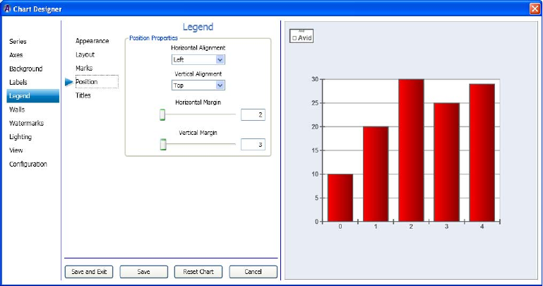
Working with Advanced Controls
271
The Legend > Position area displays enabling you to set the legend position properties
for the selected series.
2. In the Position Properties area, do the following:
a. In the Horizontal Alignment drop list, select the area where you want to align the
Legend horizontally (Left, Center, or Right).
b. In the Vertical Alignment drop list, select the area where you want to align the
Legend vertically (Top, Bottom, or Center).
c. In the Horizontal Margin slider to adjust the location of the legend horizontally
along the chart.
d. In the Vertical Margin slider to adjust the location of the legend vertically along the
chart.
3. Click Save to save your changes, or click Save and Exit to save your changes and exit
the Chart Designer.
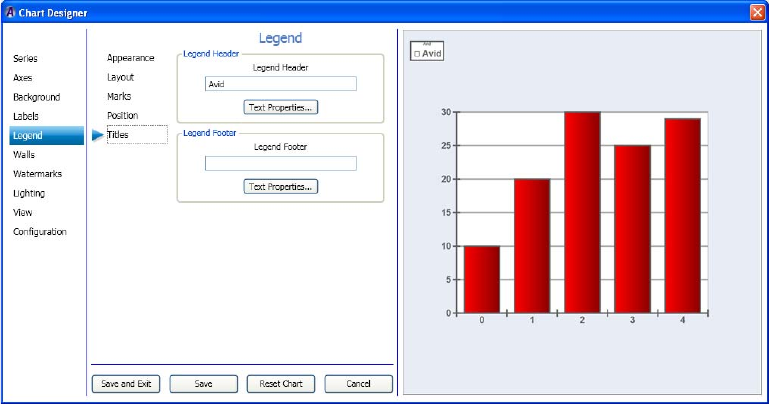
4 Working with Charts and Graphs
272
Setting the Legend Titles
If you want, you can then set the Legend titles for your chart.
This procedure assumes that you have already added a series as described in “Creating a
Series” on page 222.
To set the legend titles:
1. Select Legend in the left column, and then select the Titles submenu.
The Legend > Titles area displays enabling you to set the legend attributes, and Legend
text, and Legend footer for the selected series.
2. (Option) In the Legend Header area, do the following to add legend title header text
(appears above the legend) to your chart:
a. Type any text you want to appear as a title for the legend in the Text field directly
above the Text Properties button.
b. Click the Text Properties button if you want to change the formatting and position
of the text.
The Text Properties dialog box opens allowing you to adjust your text formatting.
Click OK to save your selections and close the dialog box.
Working with Advanced Controls
273
3. (Option) In the Legend Footer area, do the following to add legend title footer text
(appears beneath the Legend) to your chart.
a. Type any text you want to appear as a title to appear below the legend in the Text
field directly above the Text Properties button.
b. Click the Text Properties button if you want to change the formatting and position
of the text.
The Text Properties dialog box opens allowing you to adjust your text formatting.
Click OK to save your selections and close the dialog box.
4. Click Save to save your changes, or click Save and Exit to save your changes and exit
the Chart Designer.
Using Walls Controls
This section contains information on using the Walls controls to further adjust the look of
your series.
For more information on setting a specific wall style for a series, see the following topic:
•“Setting the Wall Appearance” on page 273
•“Setting the Wall Size” on page 275
Setting the Wall Appearance
If you want, you can then set the appearance of the walls for your chart. If you are working
on a 2D chart, you can only set the Wall style for the Back wall of the selected series. If you
are working on a 3D chart (as selected in the Series > Appearance tab), you can set the wall
style for the Back, Floor, Front, Left, Polar, Radar, and Right wall of the selected series.
This procedure assumes that you have already added a series as described in “Creating a
Series” on page 222.
To set the Walls style:
1. Select Walls in the left column.
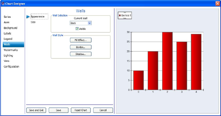
4 Working with Charts and Graphs
274
The Walls > Appearance area displays enabling you to set the Wall Style for the selected
series.
2. In the Wall Selection area, do the following:
a. In the Current Wall drop list, select the submenu for the Wall style you want to
change.
nFor 2D charts, the only submenu available is Back. For 3D charts, available submenus
include Back, Floor, Front, Left, Polar, Radar, and Right.
b. Select the Visible check box for the wall style if you want the wall style to be
visible. If not, deselect the Visible check box.
3. In the Wall Style area, do the following:
a. Click the Fill Effect button to change the color between the lines for the part of the
chart you have selected. The Fill Effect Editor dialog box opens. Click OK once you
have made your changes.
b. Click the Border button to change the line properties for the part of the chart you
have selected. The Line Properties Editor dialog box opens. Click OK once you
have made your changes.
c. Click the Shadow button to change the shadow properties for the part of the chart
you have selected. The Shadow Editor dialog box opens. Click OK once you have
made your changes.
4. (Optional) If working with a 3D chart, repeat Steps 2-3 for any other Wall Styles you
want to change.
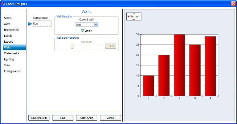
Working with Advanced Controls
275
5. Click Save to save your changes, or click Save and Exit to save your changes and exit
the Chart Designer.
Setting the Wall Size
If you want, you can then set the size of the walls for your chart. If you are working on a 2D
chart, you can only set the Wall size for the Back wall of the selected series. If you are
working on a 3D chart (as selected in the Series > Appearance tab), you can set the wall size
for the Back, Floor, Front, Left, Polar, Radar, and Right wall of the selected series.
This procedure assumes that you have already added a series as described in “Creating a
Series” on page 222.
To set the Walls size for a chart:
1. Select Walls in the left column, and then select the Size submenu.
The Walls > Size area displays enabling you to set the Wall size and thickness for the
selected series.
2. In the Wall Selection area, do the following:
a. In the Current Wall drop list, select the submenu for the Wall style you want to
change.
nFor 2D charts, the only submenu available is Back. For 3D charts, available submenus
include Back, Floor, Front, Left, Polar, Radar, and Right.
4 Working with Charts and Graphs
276
b. Select the Visible check box for the wall if you want the wall to be visible. If not,
deselect the Visible check box.
3. In the Wall Size Properties area, use the Thickness slide bar to control the thickness of
the selected wall.
4. If working with a 3D chart, repeat Steps 2-3 for any other Wall Styles you want to
change.
5. Click Save to save your changes, or click Save and Exit to save your changes and exit
the Chart Designer.
Using Watermarks Controls
This section contains information on creating and using the Watermarks controls to further
adjust the look of your series.
For more information on setting a specific watermark style for a series, see the following
topics:
•“Setting the Watermark Appearance” on page 276
•“Setting the Basic Frame Watermarks” on page 278
•“Setting the Watermark Position” on page 279
•“Creating the Watermark List” on page 281
Setting the Watermark Appearance
If you want, you can then set the appearance of Watermarks in your chart.
This procedure assumes that you have already added a series as described in “Creating a
Series” on page 222, and also added a Watermark to the list, as described in “Creating the
Watermark List” on page 281.
To set the Watermark appearance for a chart:
1. Select Watermarks in the left column, the select the Appearance tab.
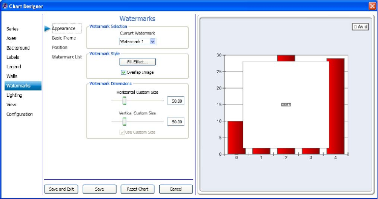
Working with Advanced Controls
277
The Watermarks > Appearance page displays enabling you to set the Watermark
appearance for the selected series.
2. In the Wartermark Selection area, select the watermark you want to change the style and
dimensions for from the Current Watermark drop list.
3. In the Watermark Style area, do the following:
a. Click the Fill Effect button to change the color between the lines of the warteramrk.
The Fill Effect Editor dialog box opens. Click OK once you have made your
changes.
b. Select the Overlap Image check box if you want the watermark to be visible on top
of the chart. If not, deselect the Overlap Image check box.
4. In the Watermark Dimensions area, do the following:
a. Use the Horizontal Custom Size slide bar to control the horizontal (width) of the
watermark.
b. Use the Vertical Custom Size slide bar to control the vertical (height) of the
watermark.
c. Select the Use Custom Size check box if you want to use the custom size the for the
watermark. If not, deselect the Use Custom Size check box.
5. Click Save to save your changes, or click Save and Exit to save your changes and exit
the Chart Designer.
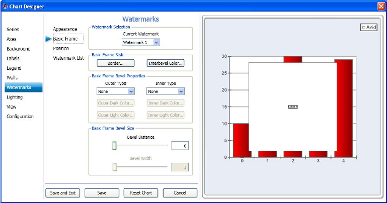
4 Working with Charts and Graphs
278
Setting the Basic Frame Watermarks
If you want, you can then set the Basic Frame style and size for Watermarks.
This procedure assumes that you have already added a series as described in “Creating a
Series” on page 222, and also added a Watermark to the list, as described in “Creating the
Watermark List” on page 281.
To set the basic frame watermarks for a chart:
1. Select Watermarks in the left column, and then select the Basic Frame submenu.
The Watermarks > Basic Frame page displays enabling you to set the basic frame style
for selected watermarks.
2. In the Watermark Selection area in the Current Watermark drop list, select the
watermark for which you want to change the basic frame style and properties.
3. In the Basic Frame Style area, do the following:
a. If you want to change the line properties for your watermark frame border, click the
Border button. The Line Properties dialog box opens. Set the line properties for the
watermark frame border, and click OK.
b. If you want to change the color of the watermark frame bevel area, click the
Interbevel Color button. The Color dialog box opens. Make your color selections,
and click OK.
Working with Advanced Controls
279
4. In the Basic Frame Bevel Properties area, do the following:
a. In the Outer Type field, select the type of Outer bevel you want for your watermark
frame. Options are (None, Raised, or Sunken).
b. To change the dark color of the Outer bevel, click the Outer Dark Color button
below the Outer Type field, and select the color.
c. To change the light color of the Outer bevel, click the Outer Light Color button
below the Outer Type field, and select the color.
d. In the Inner Type field, select the type of Inner bevel you want for your frame.
Options are (None, Raised, or Sunken).
e. To change the dark color of the Inner bevel, click the Inner Dark Color button below
the Inner Type field, and select the color.
f. To change the light color of the Inner bevel, click the Inner Light Color button
below the Inner Type field, and select the color.
5. In the Basic Frame Bevel Size area, do the following:
a. Use the Bevel Distance slider to change the bevel distance.
b. Use the Beval Width slider to change the bevel width.
6. Click Save to save your changes, or click Save and Exit to save your changes and exit
the Chart Designer.
Setting the Watermark Position
If you want, you can then set the position of the watermark on your series.
This procedure assumes that you have already added a series as described in “Creating a
Series” on page 222.
To set the watermark position:
1. Select Watermarks in the left column, and then select the Position submenu.
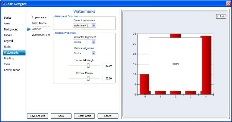
4 Working with Charts and Graphs
280
The Watermarks > Position page displays enabling you to set the position of the
watermarks for the selected series.
2. In the Watermark Selection area in the Current Watermark drop list, select the
watermark for which you want to change the position properties.
3. In the Position Properties area, do the following:
a. In the Horizontal Alignment drop list, select the area where you want to align the
watermark horizontally (Left, Center, or Right).
b. In the Vertical Alignment drop list, select the area where you want to align the
watermark vertically (Top, Bottom, or Center).
c. Use the Horizontal Margin slider to adjust the location of the watermark
horizontally along the chart.
d. Use the Vertical Margin slider to adjust the location of the watermark vertically
along the chart.
4. Click Save to save your changes, or click Save and Exit to save your changes and exit
the Chart Designer.
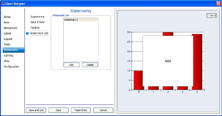
Working with Advanced Controls
281
Creating the Watermark List
This topic contains information on how to add watermarks to your chart. Once you have
added a watermark, you can change it’s appearance, format, and position properties.
This procedure assumes that you have already added a series as described in “Creating a
Series” on page 222.
To create the watermark list:
1. Select Watermark in the left column, and then select the Watermark List submenu.
The Watermark > Watermark List page displays enabling you to add or delete
watermarks for the selected series.
2. In the Watermark List area, do one of the following:
tTo add a watermark, click the Add button.
tTo delete a watermark, select it and click the Delete button.
3. Click Save to save your changes, or click Save and Exit to save your changes and exit
the Chart Designer.
4 Working with Charts and Graphs
282
Using Lighting Controls
This section contains information on creating and using the Lighting controls to further
adjust the look of your series.
For more information on setting a specific lighting style for a series, see the following
topics:
•“Setting the Lighting Appearance” on page 282
•“Setting the Basic Frame Watermarks” on page 278
•“Setting the Watermark Position” on page 279
•“Creating the Watermark List” on page 281
Setting the Lighting Appearance
This topic contains information on how to set the appearance, including properties and
presets for light sources in your chart.
nThis is only available for 3D charts.
You must have added at least one Light source to be able to use this submenu. For more
information, see “Creating the Lighting Source List” on page 288.
This procedure assumes that you have already added a series as described in “Creating a
Series” on page 222.
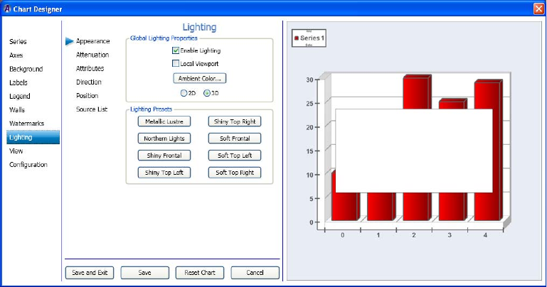
Working with Advanced Controls
283
To set the Lighting appearance for a chart:
1. Select Lighting in the left column.
The Lighting > Appearance page displays enabling you to set the lighting appearance
for the selected series.
2. To enable the fields in the Appearance submenu, you must select the 3D option in the
Global Lighting Properties area.
3. Select the Enable Lighting check box to enable the lighting properties to be visible. If
not, deselect the Enable Lighting check box.
4. Select the Local Viewport check box if you want the local viewport to be visible. If not,
deselect the Local Viewport check box.
5. Click the Ambient Color button to select the color between the lines. The Color dialog
box opens. Click OK once you have made your changes.
6. In the Lighting Presets area, select the lighting preset(s) that you want to apply to your
chart.
7. Click Save to save your changes, or click Save and Exit to save your changes and exit
the Chart Designer.
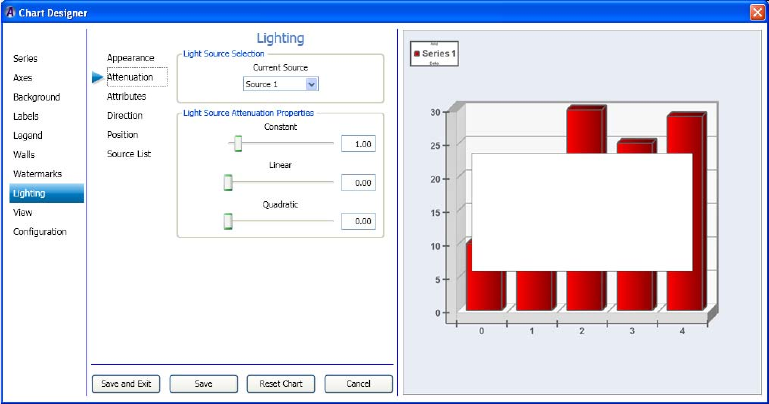
4 Working with Charts and Graphs
284
Setting the Lighting Attenuation
If you want, you can then set the Lighting Attenuation for your series.
This procedure assumes that you have already added a series as described in “Creating a
Series” on page 222.
To set the lighting attenuation for a chart:
1. Select Lighting in the left column, and then select the Attenuation submenu.
The Lighting > Attenuation page displays enabling you to set the lighting attenuation
for the selected series.
2. In the Light Source Selection area in the Current Source drop list, select the light source
for which you want to change the attenuation properties.
3. In the Light Source Attenuation Properties area, do the following:
a. Use the Constant slider to adjust the location of the constant attuenuation
properties.
b. Use the Linear slider to adjust the location of the linear attenuation properties.
c. Use the Quadratic slider to adjust the location of the quadratic attenuation
properties.
4. Click Save to save your changes, or click Save and Exit to save your changes and exit
the Chart Designer.

Working with Advanced Controls
285
Setting the Lighting Attributes
If you want, you can then set the attributes of the lighting for your chart.
This procedure assumes that you have already added a series as described in “Creating a
Series” on page 222.
To set the lighting attributes:
1. Select Lighting in the left column, and then select the Attributes submenu.
The Lighting > Attributes page displays enabling you to set the attributes of the light
source style and properties for the selected series.
2. In the Light Source Selection area, select the light source you want to change from the
Current Source list.
3. In the Light Source Style area, do the following:
a. In the Source Type list, select the source type for the light source style.
b. Click the Ambient Color button to change the ambient color of the light source.
c. Click the Diffuse Color button to change the diffuse color of the light source.
d. Click the Specular Color button the change the specular color of the light source.
4. In the Light Source Spotlight Properties area, do the following:
a. Use the Cutoff slider to change the light source spotlight cutoff values.
b. Use the Exponent slider to change the light source spotlight exponent values.
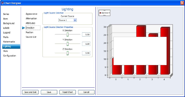
4 Working with Charts and Graphs
286
5. Click Save to save your changes, or click Save and Exit to save your changes and exit
the Chart Designer.
Setting the Lighting Direction
If you want, you can then set the direction of the lighting on your chart.
This procedure assumes that you have already added a series as described in “Creating a
Series” on page 222.
To set the lighting direction:
1. Select Lighting in the left column, and then select the Direction submenu.
The Lighting > Direction page displays enabling you to set the position of the
watermarks for the selected series.
2. In the Light Source Selection area, select the light source you want to change from the
Current Source list.
3. In the Light Source Direction Properties area, do the following:
a. Use the X Direction slider to change the light source X direction values.
b. Use the Y Direction slider to change the light source Y direction values.
c. Use the Z Direction slider to change the light source Z direction values. For 3D
charts only.
4. Click Save to save your changes, or click Save and Exit to save your changes and exit
the Chart Designer.
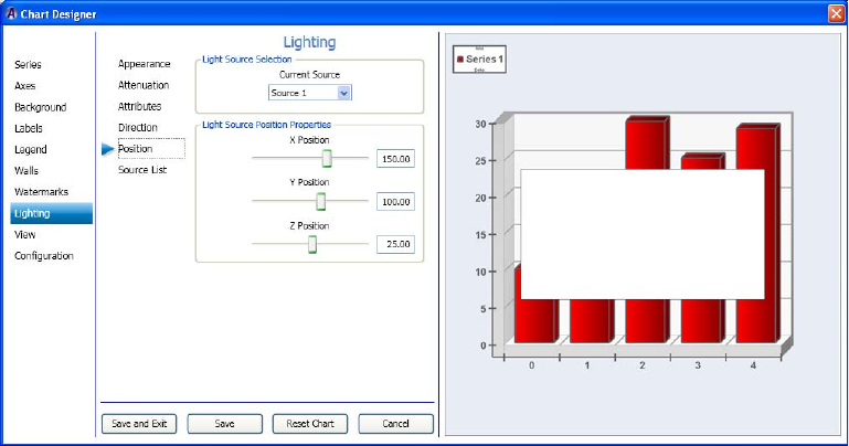
Working with Advanced Controls
287
Setting the Lighting Position
If you want, you can then set the position of the lighting on your chart.
This procedure assumes that you have already added a series as described in “Creating a
Series” on page 222.
To set the lighting position:
1. Select Lighting in the left column, and then select the Position submenu.
The Lighting > Position page displays enabling you to set the position of the lighting for
the selected series.
2. In the Light Source Selection area, select the light source you want to change from the
Current Source list.
3. In the Light Source Position Properties area, do the following:
a. Use the X Position slider to change the light source X position values.
b. Use the Y Position slider to change the light source Y position values.
c. Use the Z Position slider to change the light source Z position values. For 3D charts
only.
4. Click Save to save your changes, or click Save and Exit to save your changes and exit
the Chart Designer.
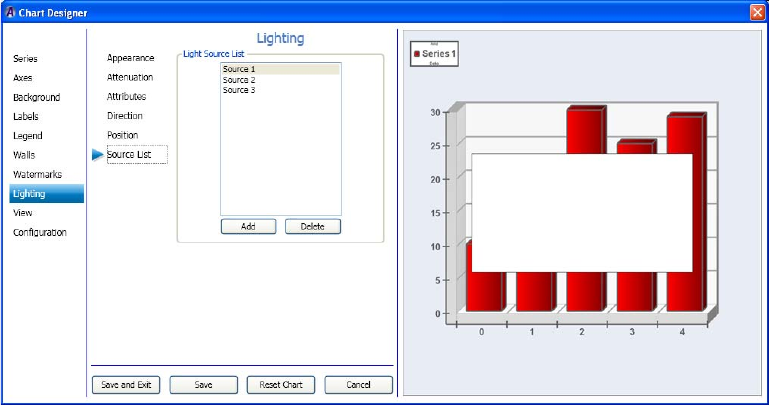
4 Working with Charts and Graphs
288
Creating the Lighting Source List
This topic contains information on how to add a Lighting source to your chart. Once you
have added a Lighting source, you can change it’s appearance, attenuation, attributes,
direction, format, and position properties.
This procedure assumes that you have already added a series as described in “Creating a
Series” on page 222.
To create the Lighting Source list:
1. Select Lighting in the left column, and then select the Source List submenu.
The Lighting > Source List page displays enabling you to add or delete lighting sources
for the selected series.
2. In the Light Source List area, do one of the following:
tTo add a light source, click the Add button.
tTo delete a light source, click the Delete button.
nLight sources are deleted from the list in reverse order. For instance Light Source 3 is deleted
before Light Source 2, and so on.
3. Click Save to save your changes, or click Save and Exit to save your changes and exit
the Chart Designer.
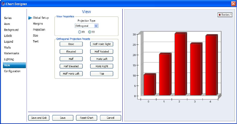
Working with Advanced Controls
289
Using View Controls
This section contains information on creating and using the View controls to further adjust
the margins, projection, size and text for your chart.
For more information on setting a specific lighting style for a series, see the following
topics:
•“Setting the Global Setup View” on page 289
•“Setting the View Margins” on page 290
•“Setting the Watermark Position” on page 279
•“Creating the Watermark List” on page 281
Setting the Global Setup View
This topic contains information on how to set the appearance, including properties and
presets for light sources in your series.
This procedure assumes that you have already added a series as described in “Creating a
Series” on page 222.
To set the Global setup view:
1. Select View in the left column.
The View > Global Setup page displays enabling you to gloablly set the view for the
selected series.

4 Working with Charts and Graphs
290
2. To enable the fields in the Projection Type submenu, you must select the 3D option in
the View Properties area.
3. In the Projection Type field, select the projection type from the drop down list.
This is the type of view that you want to change projection presets for.
4. Select the presets for the type of series you selected by clicking on one of the presets to
view what your view will look like with these presets applied.
The Projection Presets area contains various presets for the series you selected.
nYou can try different presets until you find the right one for your series view.
5. Click Save to save your changes, or click Save and Exit to save your changes and exit
the Chart Designer.
Setting the View Margins
If you want, you can then set the view margins for your series.
This procedure assumes that you have already added a series as described in “Creating a
Series” on page 222.
To set the view margins:
1. Select View in the left column, and then select the Margins submenu.
The View > Margins page displays enabling you to set the view margins for the selected
series.

Working with Advanced Controls
291
2. In the Margin Properties area in the Mode drop list, select the mode for which you want
to change the margin properties.
3. In the Margin Properties area, do the following:
a. Use the Left Margin slider to adjust the location of the left margin properties.
b. Use the Right Margin slider to adjust the location of the right margin properties.
c. Use the Top Margin slider to adjust the location of the top margin properties.
d. Use the Bottom Margin slider to adjust the location of the bottom margin properties.
4. Click Save to save your changes, or click Save and Exit to save your changes and exit
the Chart Designer.
Setting the View Projection
If you want, you can then set the view projection for your series.
This procedure assumes that you have already added a series as described in “Creating a
Series” on page 222.
To set the view projection:
1. Select View in the left column, and then select the Projection submenu.
The View > Projection page displays enabling you to set the orthogonal projection
properties for the selected series.

4 Working with Charts and Graphs
292
2. In the Orthogonal Projection Properties area, do the following:
a. Use the X Rotation slider to set the projection properties for the X rotation.
b. Use the Y Rotation slider to set the projection properties for the Y rotation.
c. Use the Z Rotation slider to set the projection properties for the Z rotation.
d. Use the Zoom slider to set the zoom.
e. Use the Perspective angle slider to set the perspective angle properties.
f. Use the X Depth slider to set the projection properties for the X depth.
g. Use the Y Depth slider to set the projection properties for the Y depth.
3. Click Save to save your changes, or click Save and Exit to save your changes and exit
the Chart Designer.
Setting the View Size
If you want, you can then set the view size for your series.
This procedure assumes that you have already added a series as described in “Creating a
Series” on page 222.
To set the view size:
1. Select View in the left column, and then select the Size submenu.
The View > Size page displays enabling you to set the size of the view for the selected
series.
Working with Advanced Controls
293
2. In the Chart Size area, do the following:
a. Use the Chart Width slider to change the width of the chart.
b. Use the Chart Height slider to change the height of the chart.
c. Use the Chart Depth slider to change the depth of the chart. For 3D charts only.
3. In the Image Aspect Ratio area, do the following:
a. Select the radio button that you want to set for the aspect ratio of the chart. Options
are:
t1x1
t4x3
t16x9
tCustom (If selected, the Custom Value slider is enabled.)
b. (Optional) If you selected Custom for your aspect ratio, use the Custom Value slider
to change the aspect ratio of the chart.
4. Click Save to save your changes, or click Save and Exit to save your changes and exit
the Chart Designer.
Setting the Text Size
If you want, you can then set the size of the text for your series.
This procedure assumes that you have already added a series as described in “Creating a
Series” on page 222.
To set the text size:
1. Select View in the left column, and then select the Text submenu.
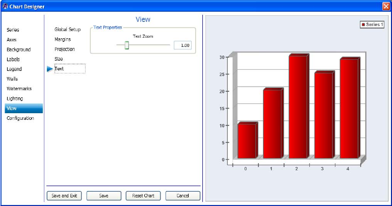
4 Working with Charts and Graphs
294
The View > Text page displays enabling you to set the text size for the selected series.
2. In the Text Properties area, use theText Zoom slider to change the text size for your
chart.
3. Click Save to save your changes, or click Save and Exit to save your changes and exit
the Chart Designer.
Template Configuration Controls
This section contains information on controls used to configure your templates.
For more information on configuring tamplates, see the following topics:
•“Configuring Chart Settings” on page 224
•“(Optional) Assigning Interactivity for the Mouse” on page 225
•“Configuring Your Templates” on page 295
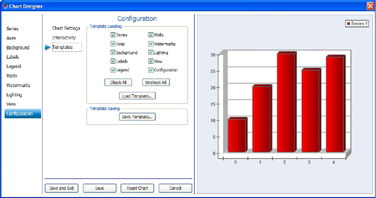
Working with Advanced Controls
295
Configuring Your Templates
This topic contains information on how to load and save various Chart Designer templates.
This procedure assumes that you have already added a series as described in “Creating a
Series” on page 222.
To configure your template:
1. Select Configuration in the left column, then select Templates.
The Configuration > Templates page displays enabling you to load and save templates.
2. In the Template Loading area, select components that you want to load in your template.
To select all components, click the Check All button.
To deselect all components, click the Uncheck All button.
3. When you have selected the components you want to include, click the Load Template
button.
The Load Chart Designer Template dialog box opens. Navigate to the location where
you want to load your Chart Designer template, and click the Open button.
4. In the Template Saving area, click the Save Template button.
The Save Chart Designer Template dialog box opens. Navigate to the location where
you want to save your Chart Designer template, and click the Save button.
5. Click Save to save your changes, or click Save and Exit to save your changes and exit
the Chart Designer.
4 Working with Charts and Graphs
296

Chapter 5
5Adding Actions to a Scene
After you add objects to a scene, you can animate these objects by recording and playing
actions. An example of a simple action is moving a bug on screen and then moving it off.
The following topics describe animating objects through actions:
•Understanding Actions
•Using the Timeline Editor
•Creating Actions
•Playing Actions
•Editing Actions
•Creating Actions Check List
•Creating Sample Actions
Understanding Actions
Each scene can have one or more actions that animate its objects. An action consists of
changes to one or more parameters of an object. An action can change the opacity, position,
and size of an object, start and stop a video clip, change the transition between objects, or
make other changes in your scene. Any value that you can change in an object’s editor is a
parameter that can be included in an action.
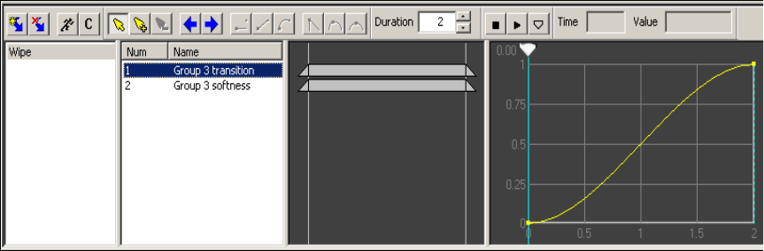
5 Adding Actions to a Scene
298
The following illustration shows a simple wipe action as it appears in the Timeline editor.
This action uses two parameters for the Group object: transition and softness. Step-by-step
instructions for creating this wipe are described in “Example 3: Crossfade (Dissolve)” on
page 332.
When planning your scene, consider the actions that you want to use during playback.
Individual actions can be played out under the control of an automation system, or you can
manually execute actions through DekoCast Central. The Sequence application allows for
the playout of actions in an ordered sequence.
Actions can occur immediately or take place over time. An example of an action that is
triggered immediately is a clock that you set to run in a particular position. When the Clock
action is executed, the clock appears in the designated place on the video output and displays
the time. To remove the clock, you need to create another action. An example of a
time-related action is a Video In object (such as a live feed) that is squeezed back from
full-screen to quarter-screen over several seconds.
Actions share these characteristics:
• Each action can control one, some, or all of the object parameters in a scene.
• Actions can start from a fixed location or start at an object’s current location and then
move the object to a fixed location.
• You can trigger multiple actions simultaneously.
• You can trigger specific actions while other actions are playing, even if they control the
same parameters. In this case, the most recently triggered actions assume control of the
affected parameters.
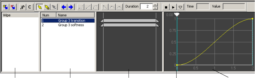
Using the Timeline Editor
299
There are three kinds of actions:
•Trigger actions: These actions occur instantly, rather than over time, such as the clock
described earlier in this topic. To define a trigger action, set the parameters only at the
start of the action. For more information, see “Creating Trigger Actions” on page 309.
•Timed actions with defined starting and ending parameters: To create this kind of
action, set parameters at the start and at the end of the action and set the amount of time
(duration) that elapses between them. An example is an action that moves a static bug
from the top left to the bottom left of the video output over two seconds and then turns
on looping. For more information, see “Creating Actions with Defined Beginning and
Ending Parameters” on page 312
•Time Capture actions: To create this kind of action, set only a duration and parameters
at the end of an action. The application sets the parameters at the start of the action by
capturing the current object properties and values when the action begins. There are no
fixed parameters but rather an instruction to load the current position, scale, transition,
and other parameters as the first keyframe whenever the action is initiated. The
application captures parameters in their current state when the action starts and then,
over time, changes them to the ending parameters you defined.
A Time Capture action is appropriate when you are concerned only about where the
action ends up, not its beginning or intermediate characteristics. An example is if you
intend to move objects from various positions in a scene but want all of the objects to
end in the same location. For more information, see “Creating Time Capture Actions”
on page 314.
Using the Timeline Editor
You create and control actions using tools in the Timeline editor. The Timeline editor has its
own toolbar and four panes: Action list, Action Parameter list, Timeline Bar editor, and
Timeline graph. The Timeline graph includes a scrub bar.
Action list Timeline graph
Timeline Bar editor
Action Parameter list Scrub bar
5 Adding Actions to a Scene
300
•Action list: Displays the actions that you create and name. Each scene can include
multiple actions, and each action can control multiple object parameters at a given time
or over a duration of time. Right-click inside the Action list pane to display a shortcut
menu. See “Adding an Action to the Action List” on page 301.
•Action Parameter list: Displays all parameters associated with a selected action. Any
value that you can change in an object’s editor is a parameter that can be included in an
action. Right-click inside the Action Parameter list pane to display a shortcut menu. See
“Adding Action Parameters” on page 304.
nThe Action Parameter list displays parameters that you added to an action; the Parameters
tab, which is located in the upper-right of the DekoCast main window, displays all actions in
a scene. See “Working with Parameters” on page 335.
•Timeline Bar editor: Displays a Timeline bar for each parameter in an action.
Shortening, lengthening, or moving the bar affects whether its parameter happens over a
shorter or longer period of time or sooner or later in the action. See “Adjusting Timing
in the Timeline Bar Editor” on page 308.
•Timeline graph: Displays a curve graph for each parameter. Each point on the graph
represent a keyframe, which acts as a command to set a parameter’s value at a specific
point in time. You can drag the scrub bar backward and forward to view how the
parameter changes during the action. See “Understanding Keyframes and the Timeline
Graph” on page 307.
You can resize the Timeline editor window and panes within the window by selecting and
dragging a boundary line to the left, right, top, or bottom.
Detailed instructions for using the Timeline editor are provided in the remaining topics in
this chapter.
Creating Actions
The basic steps in creating an action are:
1. Add an action to the action list.
2. Enter Animate mode by selecting the Animate Mode button.
3. Place the scrub bar in the location in the Timeline graph where the keyframe is to be
recorded.
4. Select the object from the Scene Tree.
5. Modify the object's parameters (for example, opacity or scale).
Creating Actions
301
6. Exit Animate mode by deselecting the Animate Mode button.
7. Preview the action.
The following topics describe techniques that you use when defining any action:
•“Adding an Action to the Action List” on page 301
•“Working in Animate Mode” on page 303
•“Adding Action Parameters” on page 304
•“Adding Parameters from the Parameters Tab” on page 306
•“Understanding Keyframes and the Timeline Graph” on page 307
•“Adjusting Timing in the Timeline Bar Editor” on page 308
The following topics provide instructions for creating specific types of actions:
•“Creating Trigger Actions” on page 309
•“Creating Actions Over Time” on page 311
•“Creating Actions with Defined Beginning and Ending Parameters” on page 312
•“Creating Time Capture Actions” on page 314
The following topics provide special instructions for creating actions:
•“Preserving Passive Parameters for Scenes with Multiple Actions” on page 316
•“Reordering Parameters in the List” on page 317
For examples of creating actions, see “Quick Start: Fading a Graphic On and Off” on
page 45 and “Creating Sample Actions” on page 330.
Adding an Action to the Action List
After you add an action to a scene, it appears in the Action list pane of the Timeline editor.
All actions for a scene appear in the list. After you add an action to the list, you define it by
changing parameters in the object editor. The following illustration shows actions listed in
the Action list.

5 Adding Actions to a Scene
302
To add an action to the Action list:
tClick the Create Action button on the Timeline editor toolbar.
An action is added to the list. The application names actions in the list Action 1, Action
2, Action 3, and so on, but in most cases you need to rename them in a meaningful way.
Choose names that describe the action, such as Logo on, Squeeze-back, or Clock start.
To rename an action do one of the following:
tSelect the action, press F2, and type the new name.
tRight-click the action, select Rename, and type the new name.
To copy and paste an action:
1. Right-click the action and select Copy.
2. Right-click within the Action list pane, and select Paste.
The action is added at the end of the list with the same name as the original action.
3. Rename this action.
Create
Action
Delete Selected
Action
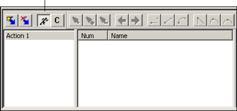
Creating Actions
303
To select multiple actions:
tPress the Shift key while selecting contiguous actions, or the Ctrl key while selecting
non-contiguous actions.
To delete an action:
tSelect the action and click the Delete Selected Action button.
To delete multiple actions:
tSelect the actions and press the Delete key.
nIf several Deko objects change simultaneously, they are queued up to render sequentially, so
although they change in the same frame, they will change sequentially during output. How
noticeable this sequential change is depends on the complexity of your scene.
Working in Animate Mode
To create an action, you need to work in Animate mode. In Animate mode, any change you
make to an object’s parameter is recorded as a keyframe, so it’s important to keep the
Animate Mode button selected only when you want to record a change.
For the basics steps in creating an action, see “Creating Actions” on page 300.
To enter Animate mode:
tClick the Animate Mode button in the Timeline editor toolbar so that the button is
selected (depressed).
The Animate Mode button looks like a running man.
To exit Animate mode:
tClick the Animate Mode button so that the button is not selected.
Animate Mode button selected
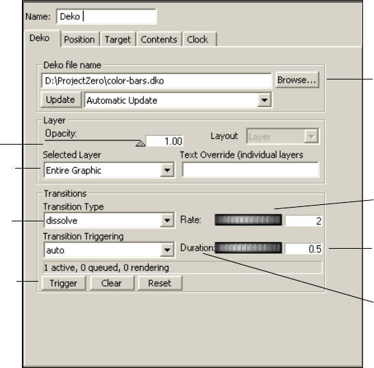
5 Adding Actions to a Scene
304
You use Animate mode with the scrub bar to add parameters to an action, as described in the
next section.
Adding Action Parameters
After you create an action and enter Animate mode, you add parameters to the action, and
set values for the parameters. Any value that you can change in an object’s editor is a
parameter that can be included in an action.
The basic way to add a parameter is to click or adjust a parameter in the object editor. The
value of that parameter is placed in a keyframe wherever the scrub bar is located on the
Timeline graph. The parameter’s name is added to the Action Parameter list.
The following illustration shows the Deko object editor and the various controls for adding a
parameter.
Type a value in a
text box and press
Enter.
Select and drag
a thumbwheel.
Click the text label
to return to the
default value.
Select a file.
Select a layer.
Drag or click
a slider.
Select a menu
option.
Click a button.

Creating Actions
305
To add a parameter to an action:
1. Place the scrub bar at the point in the Timeline graph where you want to add the
parameter.
2. In the Scene Tree, make sure the object whose parameters you want to change is
selected, so that the object’s parameters appear in the object editor pane.
3. Click the Animate Mode button (see “Working in Animate Mode” on page 303).
4. If you want your action to invoke the currently set parameter, click the appropriate
control (such as a thumbwheel or slider) without changing it.
5. If you want to change a value, do one of the following:
tSelect and drag a thumbwheel.
tType a value and press Enter.
tSelect a Deko layer from a menu.
tOverwrite a text field.
tSelect a file by using the Browse button.
tSelect an option, such as a transition type.
tDrag a slider.
tClick a button (such as Update, Trigger, or Clear).
tDouble-click a parameter in the Parameters tab (see “Adding Parameters from the
Parameters Tab” on page 306).
The parameter is added as a keyframe on the Timeline graph and its name is added to the
Action Parameter list.
Action list Action Parameter list Timeline Bar editor Timeline graph Keyframes
5 Adding Actions to a Scene
306
6. Edit the action as described in one of the following topics:
-“Creating Trigger Actions” on page 309
-“Creating Actions with Defined Beginning and Ending Parameters” on page 312
-“Creating Time Capture Actions” on page 314
7. When you are finished, click the Animate Mode button to exit Animate mode.
nWhen Text Override is animated in an action, the text transitions at every keyframe, whether
the text changes at that keyframe or not.
nBecause the application processes parameters from the top to the bottom of the list for each
frame, pay attention to the order of items. See “Reordering Parameters in the List” on
page 317.
Adding Parameters from the Parameters Tab
All parameters for a scene are listed in the Parameters tab (see “Parameters Tab” on
page 35). You can add a parameter from the Parameters tab to an action. These parameters
can include user-created parameters (see “Creating User Parameters” on page 340).
You can also use the Parameters tab to create an action that triggers another action or to
create a looping action. For more information, see “Creating an Action that Triggers
Another Action” on page 340.
To add a parameter to an action:
1. Select the action in the Action list.
2. In the Timeline graph, position the scrub bar where you want to add a keyframe.
3. Click the Animate Mode button to enter Animate mode.
4. In the Parameters tab located in the upper right of the DekoCast main window,
double-click the parameter.
The Edit Value dialog box opens.
5. Do one of the following:
tClick OK to accept the current value.
tEdit the value and click OK.
A keyframe is added automatically at the current position.
6. Click the Animate Mode button to exit Animate mode.
nAnother way to access the Edit Value dialog box is to select any keyframe and double-click
it. When you open the Edit Value dialog box from a keyframe, you have the added option of
creating a Capture keyframe. See “Editing the Value of a Keyframe” on page 326.
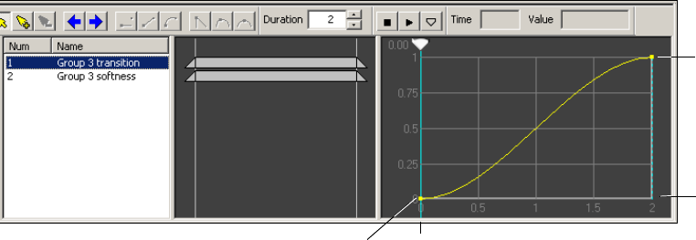
Creating Actions
307
cAfter you are finished using the Parameters tab, click the Performance tab. Keeping
the Parameters tab displayed might slow down updating of the user interface for a
large scene.
Understanding Keyframes and the Timeline Graph
Each parameter in the Action Parameter list has a curve graph associated with it. Points on
the graph represent keyframes for that parameter in an action. Each keyframe has a value
associated with it (for example, Scale = 1) and a time value of when the keyframe happens
within the duration of the action.
A parameter can have only one keyframe at a given point in time. However, an action can
contain many different keyframes for the same parameter as long as each keyframe has a
unique point in time.
When the Timeline graph is a curve, it depicts a change in parameter values between
keyframes. This curve depicts the change over time (the time value shown in the Duration
text box) of the selected parameter for this action. The X-axis shows the time (in seconds)
and the Y-axis represents the value of the parameter over time. The following illustration
shows the change over time for a Transition parameter.
X-axis
Duration =
2 secs.
Y-a x is
Transition values= 0 - 1
Keyframe:
Transition value= 0
Keyframe:
Transition
value= 1
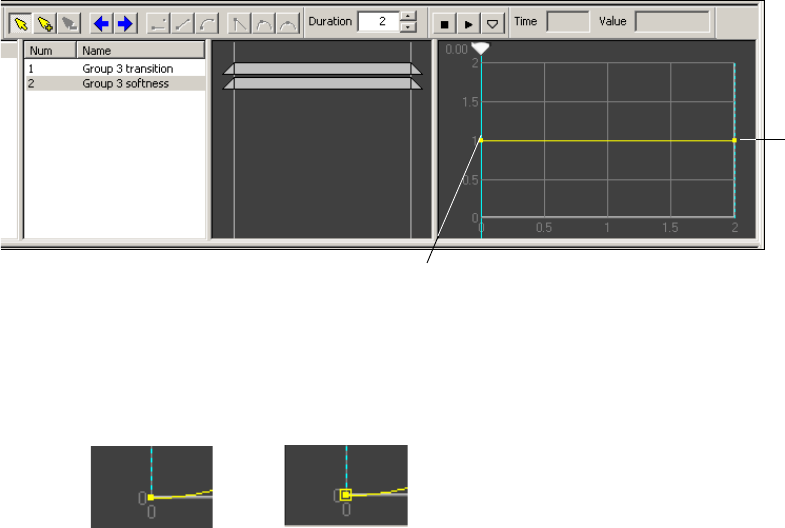
5 Adding Actions to a Scene
308
Compare the preceding Timeline graph with the following graph, for a parameter whose
value does not change over time, in this case the Softness parameter. The graph line is flat.
A keyframe that represents a numeric value is indicated by a small yellow mark. Keyframes
that represent text, capture, or database values are indicated by a yellow box around the
mark. Selected keyframes are red.
For more information on the different types of values for a keyframe, see “Editing the Value
of a Keyframe” on page 326.
Adjusting Timing in the Timeline Bar Editor
Each parameter in the Action Parameter list has an associated timing bar or Timeline bar.
Use the Timeline Bar editor to view or modify the timing of parameter changes for the
currently selected action. Each a parameter has a corresponding Timeline bar showing its
start, end, and duration. Timeline bars can be moved, shortened, or lengthened to change the
timing of the corresponding item in the Action Parameter list.
Keyframe:
Softness
value= 1
Keyframe:
Softness value= 1
Numeric keyframe Text, capture, or
database keyframe
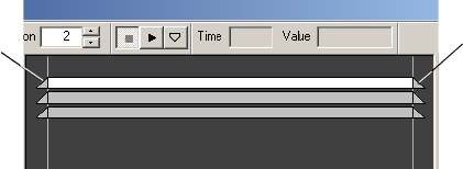
Creating Actions
309
The following illustration shows the parameter value changing over the entire duration of the
action. Drag the beginning or ending triangles of the Timeline bar to reduce the time of the
parameter in relations to the action.
To adjust start and end times:
tClick the triangles at the start or end of the bar and drag them.
To select and move multiple bars together:
1. Press Shift or Ctrl and click a part of each bar you want to select.
2. Click one of the selected parts and drag it to move all of the selected parts.
To make an animation longer:
1. Increase the duration using the Duration text box in the Timeline editor toolbar.
2. Select the ends of the bars and drag them outward to make them longer.
nBars cannot be moved beyond the start or end time of the action. Increase the duration to
extend the Timeline bar.
To make an animation shorter:
1. Drag the ends of the bars inward to make them shorter.
2. Adjust the duration of the action.
To slide a bar along the Timeline:
tClick the middle section of the bar and drag it.
Creating Trigger Actions
A trigger action occurs when you play it. In a trigger action, the parameters you set do not
change over time.Decide how the parameters need to be set to accomplish the action, and
then set the start parameters for one or more objects. A simple trigger action is using the
opacity parameter to show a graphic on air, for example, showing a time display. Parameters
can include position, scale, target rectangles, cropping, names of clips or graphic files,
setting looping on or off, queueing, stopping, and playing audio or clip files, and so on.
End-time triangle
Start-time
triangle

5 Adding Actions to a Scene
310
nRemember that the scrub bar must be in the start position (leftmost position), and the
Animate Mode button selected before you can record parameters for a Trigger action. The
scrub bar’s position determines where a keyframe is inserted when a parameter is recorded.
To create a trigger action:
1. In a scene, select the object for which you want to create an action.
The object editor is displayed.
2. Click the Add Action button to add a new action in the Action list.
3. Press F2 and rename the action.
4. In the Timeline graph, move the scrub bar to the leftmost (start) position.
5. Click the Animate Mode (record action) button to select it.
The application enters Animate mode. Because the scrub bar is positioned at the left, the
application applies the parameters that you select at the beginning of the action. When
you play the action, the parameters occur immediately.
6. In the Scene Tree, make sure the object whose parameters you want to change is
selected. Use the techniques described in “Adding Action Parameters” on page 304 to
add parameters and values to the action.
For example, set the Opacity value, or change the position or scale values. Notice as the
parameter values change, a resulting parameter description appears in the Action
Parameter list and a keyframe appears in the graph. To view the graph, select the
parameter in the Action Parameter list.
Scrub bar in leftmost position =
Start of action
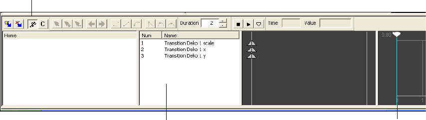
Creating Actions
311
nThe application processes actions from the top to the bottom of the Action Parameter list.
See “Reordering Parameters in the List” on page 317.
7. Click the Animate Mode button to deselect it.
nRemember that if you don’t deselect the Animate Mode button, any keystrokes are created as
parameters and keyframes for the selected action.
8. Preview the action by selecting the action and pressing the space bar or by using another
technique, as described in “Playing Actions” on page 317.
9. Save the scene.
nBe sure to select the Draw box next to the scene name to have the scene display on video
output.
Creating Actions Over Time
A time-related action modifies an object’s parameters over time. The duration of an action is
determined by the value (in seconds) that you enter in the Duration text box. This value
determines how many vertical lines are in the Timeline graph (one vertical line per second).
Keep in mind that parameters are not the same at the end of the action as they were at the
beginning unless the action specifically resets those parameters to their start values. As you
design and create actions, you should initialize parameters at the beginning of an action or
reset the parameter values at the end of an action to ensure that the action always plays the
same way.
You can add keyframes at any point on the Timeline graph. These keyframes record changes
to parameters that you set between the start and end parameters (see “Editing Curves and
Keyframes in the Timeline Graph” on page 321).
Scrub bar at left
Animate Mode button
selected (recording)
Action Parameter list
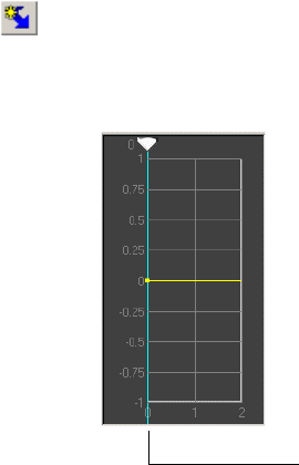
5 Adding Actions to a Scene
312
nRemember that the scrub bar must be in the start position (leftmost position), and the
Animate Mode (Record) button selected before you can record start parameters. Move the
scrub bar to the end position (rightmost position) before recording the ending parameters.
Keep the Animate Mode button selected until after you have set both the beginning and
ending parameters.
The following topics describe how to create actions over time:
•“Creating Actions with Defined Beginning and Ending Parameters” on page 312
•“Creating Time Capture Actions” on page 314
•“Adding a Capture Keyframe” on page 315
Creating Actions with Defined Beginning and Ending Parameters
The following procedure provides the basic steps you take to create an action with defined
beginning and ending parameters. For more specific examples, see “Creating Sample
Actions” on page 330.
To create an action over time with defined beginning and ending parameters:
1. In a scene, select the object for which you want to create an action.
The object editor is displayed.
2. Click the Add Action button to add a new action in the Action list.
3. Press F2 and rename the action.
4. In the Timeline graph, move the scrub bar to the leftmost (start) position.
5. On the Timeline editor toolbar, type the duration of action in the Duration text box.
The duration is set in seconds. A typical setting is 2.
Scrub bar in leftmost position =
Start of action
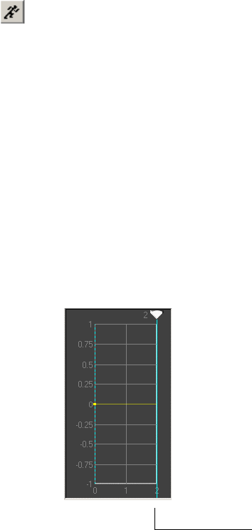
Creating Actions
313
6. Click the Animate Mode (record action) button to select it.
When selected, the Animate Mode button records parameters that you change (or
preserve) in the object editor.
7. In the Scene Tree, make sure the object whose parameters you want to change is
selected. Use the techniques described in “Adding Action Parameters” on page 304 to
add parameters and values to the action.
Parameters for the action selected in the Action list are displayed in the Action
Parameter list.
8. If there are parameters that you do not want to change in this action, but that might
change in other actions in the scene, click those parameters to preserve their value for
this action. See “Creating Time Capture Actions” on page 314.
Each parameter that you set appears in the Action Parameter list area of the Timeline
editor.
9. Drag the scrub bar to the far right to its end position.
With the scrub bar in this position, any parameters you change are assigned to the end of
the action.
10. Change the ending parameters for any of those you modified.
11. Click the Animate Mode button to deselect it.
12. To view a graph for a parameter, click the parameter name in the Action Parameter list.
13. Preview the action by selecting the name of the action and pressing the space bar or by
using another technique, as described in “Playing Actions” on page 317.
14. Save the scene.
Scrub bar in rightmost position =
End of action
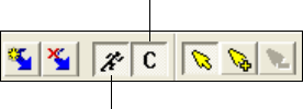
5 Adding Actions to a Scene
314
Creating Time Capture Actions
With Time Capture actions, you define parameters for objects as you want them to be at the
end of the action. Time Capture actions begin by adopting current object parameters and
change over time to defined ending parameters. For example, you might create an action in
which a bug (Cel Animation object) always ends up in the lower-right corner of the video
output, regardless of where it is located at the beginning of the action.
nRemember that a Time Capture action is initiated by selecting the Auto Capture button. You
also need to select the Animate Mode button and move the Scrub bar to its rightmost (end)
position on the Timeline graph.
To create a Time Capture action:
1. Decide how and where you want the object to appear on video output at the end of the
action.
Regardless of the object’s parameters at the beginning of the action, it ends up as you set
it using the Auto Capture button.
2. Add a new action and rename it; for example: BugLowerRight.
3. In the Timeline graph, select and drag the scrub bar to in its rightmost position on the
Timeline graph so that the application applies the parameters you set to the end of the
action.
4. Change the object parameters to those desired at the end of the action. For example, in
the Position tab of the Cel Animation object, use the X and Y thumbwheels to position
the bug.
5. Click the Auto Capture button.
6. Click the Animate Mode button to record changes to parameters.
7. Select a parameter in the Action Parameter list.
A Capture keyframe is placed at the beginning of the action. Whenever the action plays,
the Capture keyframe assumes the current parameter values. The action begins with the
object in its most recent position, size, opacity, and so on.
Auto Capture button
Animate Mode button
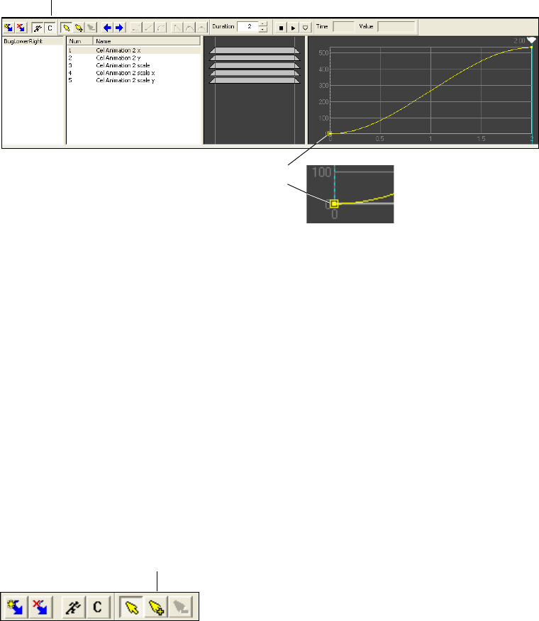
Creating Actions
315
A Capture keyframe is represented by a box around the keyframe.
8. Click the Animate Mode and Auto Capture buttons to deselect them.
9. Preview the action by selecting the name of the action and pressing the space bar or by
using another technique, as described in “Playing Actions” on page 317.
10. Save the scene.
Adding a Capture Keyframe
You can manually add a Capture keyframe or change an existing keyframe to a Capture
keyframe. A Capture keyframe captures the current state of a selected parameter at the
keyframe’s point on the Timeline graph.
To add a Capture keyframe:
1. Click the Add Keyframe button and click at any point within the Timeline graph to add
a default (numeric) keyframe.
2. Double-click the keyframe (small yellow point).
The Edit Value dialog box opens.
Capture keyframe
Auto Capture button
Add Keyframe
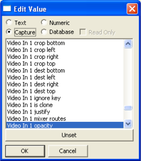
5 Adding Actions to a Scene
316
3. Select Capture.
The parameters in the Action Parameter list are listed. The current parameter is
highlighted.
4. (Option) Click Unset and select another parameter from the list whose values are to be
captured at this point in time.
5. Click OK.
The rectangular Capture keyframe is added to the Timeline graph. When the action
plays at that point, the parameter assumes the current value of the parameter selected in
the Edit Value dialog box.
Preserving Passive Parameters for Scenes with Multiple Actions
Actions can change the parameters of other actions. If there are parameters in an action that
you do not want to change (passive parameters), you can preserve their current values. If the
parameters are changed as a result of another action, they are reset when you replay the
action. Each parameter that you set as a passive parameter appears in the Action Parameter
list.
To preserve a current parameter value:
tClick its thumbwheel or slider handle.
The parameter is added to the Action Parameter list.
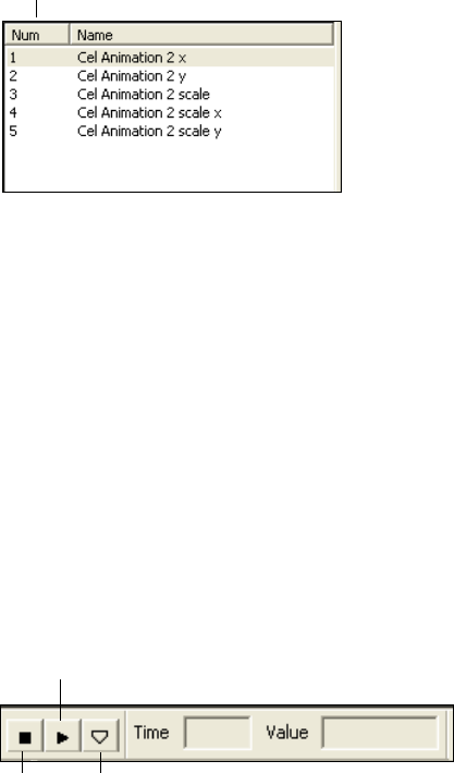
Playing Actions
317
Reordering Parameters in the List
The application processes parameters from the top to the bottom of the Action Parameter
list. The order of parameters might become important if you have an action with multiple
parameters.
To change the position of a parameter in the Action Parameter list, do one of the
following:
tSelect the parameter’s number in the Number (Num) column and type a new number.
The item is moved to that position in the list, and the list is renumbered.
tSelect a parameter and drag it to another position.
t(Option) Select more than one parameter by using the Ctrl (non-contiguous selection) or
the Shift key (contiguous selection) and drag them to another position.
Playing Actions
You can play actions in DekoCast for testing purposes. Use DekoCast Central or Sequence
to play actions to air.
Number column
Play
Stop Scrub
5 Adding Actions to a Scene
318
To play an action:
tDo one of the following:
- Click the Play button on the Timeline editor toolbar.
- With the action selected, press the space bar.
- Double-click the action in the Action list area.
- Select the scrub bar and drag it to scrub through the action. The scrub tool on the
toolbar is always active.
To stop playback:
tClick the Stop button.
Editing Actions
You can edit actions and set parameters to control the effect you want. Procedures for editing
actions are described in the following topics:
•“Copying and Pasting Actions” on page 318
•“Copying and Pasting Parameters” on page 319
•“Detaching and Attaching Parameters” on page 320
•“Replacing One Parameter with Another” on page 320
•“Editing Curves and Keyframes in the Timeline Graph” on page 321
Copying and Pasting Actions
You can save time by copying one or more actions within a scene or from one scene to
another.
To copy and paste actions within a scene:
1. Select one or more actions in the Action list.
2. Do one of the following:
tPress Ctrl+C.
tRight-click a selected action and select Copy.
3. Do one of the following:
tPress Ctrl+V.
tRight-click one of the selected actions and select Paste.
4. Edit the action as required.
Editing Actions
319
To copy and paste actions from one scene to another:
1. Select one or more actions in the Action list.
2. Do one of the following:
tPress Ctrl+C.
tRight-click a selected action and select Copy.
3. Open another scene or display an open scene by clicking it in the Scene list.
4. Do one of the following:
tPress Ctrl+V.
tRight-click one of the selected actions and select Paste.
Because you copied the actions into a new scene, all parameters for the actions lose their
links to specific objects (the word “detached” is substituted for the object name). They
might also lose their values.
5. Select the object to which you want to link an action.
6. Right-click one or more parameters and select Attach to Selected Object.
The parameters are linked to the selected object.
7. If necessary, adjust the parameters in the object editor.
nYou can substitute one parameter for another. See “Replacing One Parameter with Another”
on page 320.”
Copying and Pasting Parameters
You can save time by copying parameters from one action to another. You can copy from one
action to another within the same scene, or copy from one action to another action in a
different scene.
To copy and paste parameters between actions:
1. Select one or more parameters in the Action Parameter list.
2. Do one of the following:
tPress Ctrl+C.
tRight-click an action and select Copy.
3. If you are copying to another scene, open the scene or display an open scene by clicking
it in the Scene list.
4. Select or create the action in which to paste the items.
5 Adding Actions to a Scene
320
5. Do one of the following:
tPress Ctrl+V.
tRight-click a selected action and select Paste.
If the you paste the items into a different scene, you need to reattach them to parameters
in the new scene.
6. If necessary, select an object, right-click one or more parameters, and select Attach to
Selected Object.
The parameters are linked to the selected object.
nYou can substitute one parameter for another. See “Replacing One Parameter with Another”
on page 320.”
Detaching and Attaching Parameters
Parameters in the Action Parameter list are linked to particular objects. You can use the
Action Parameter list’s shortcut menu to unlink (detach) a parameter from one object and
link (attach) it to another object. If you copy an action or parameter from one scene to
another, parameters are automatically detached and you need to reattach them.
To unlink a parameter from an object:
tRight-click one or more parameters and select Detach.
To link a parameter to an object:
tRight-click one or more parameters and select Attach to Selected Object.
The application reassigns the parameters to the identically named parameters in the
selected object.
Replacing One Parameter with Another
You can use the Action Parameter shortcut menu to replace one parameter with another
parameter.
To replace one parameter with another:
1. Right-click the parameter.
2. Select Change Parameter.
The Select Parameter dialog box opens.
3. Select a parameter and click OK.
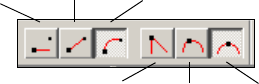
Editing Actions
321
Editing Curves and Keyframes in the Timeline Graph
Each parameter in the Action Parameter list has an associated curve graph, which shows a
value versus time plot for the current parameter. You can use this to view the way in which a
parameter changes over time. You can modify the change by modifying the shape of the
motion curve.
The motion curve’s shape controls how a parameter plays back. Abrupt changes in the
curve’s shape lead to abrupt changes in the object’s state, and gradual changes in the curve
lead to gradual changes in the state.
Keyframes control parameters by setting a parameter’s value at a specific point in time. You
can edit the position and values of keyframes and add additional keyframes to a curve.
Editing the Motion Curve
You can control how a parameter plays by changing the shape of its motion curve. You can
edit a motion curve by dragging a keyframe or using the keyframe style buttons.
To change the shape of a motion curve, do one of the following:
tSelect a keyframe and drag it.
tSelect a keyframe and click a keyframe style button on the Timeline editor toolbar, as
described in the following table. If you click the Cusp or Continuous button, drag a
tangent handle.
Constant Linear Curved
Cusp Continuous Smooth
Keyframe style buttons
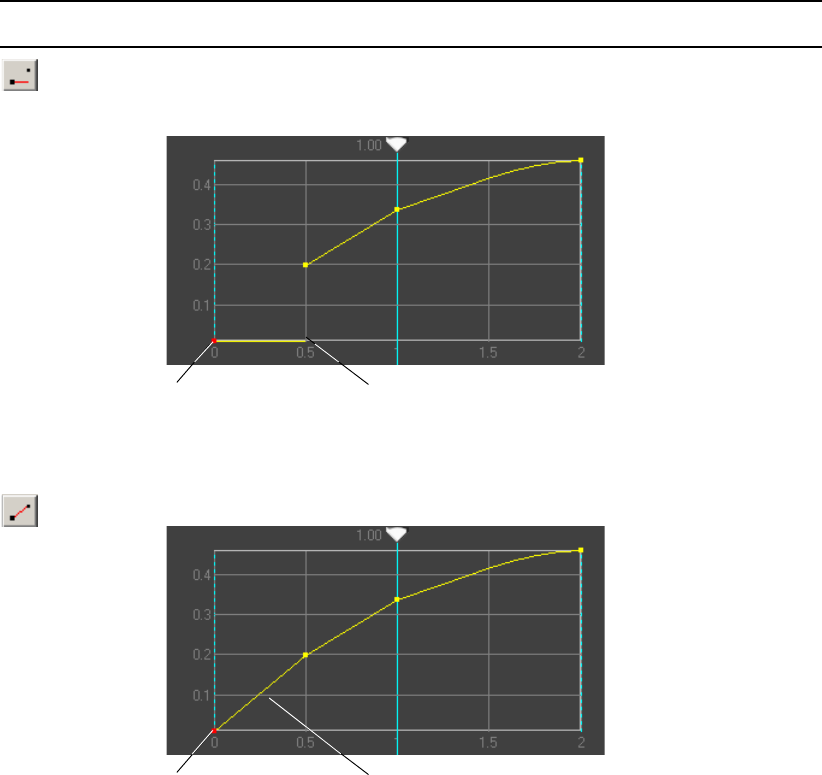
5 Adding Actions to a Scene
322
Keyframe Style Buttons
Button Description
Constant—No
Interpolation at
Keyframe
Maintains a constant parameter value over time. The Constant setting uses the latest
value interpolation from the selected keyframe to the next keyframe, possibly
resulting in a discontinuous animation.
Linear
Interpolation at
Keyframe
Maintains a straight-line interpolation between keyframes.
Selected keyframe Discontinuous animation before
the next keyframe
Selected keyframe Straight-line interpolation to next
keyframe.
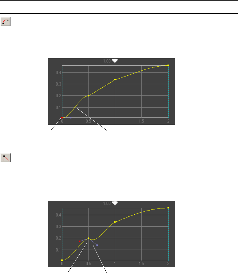
Editing Actions
323
Curved
Interpolation at
Keyframe
Causes the segment following the selected keyframe to interpolate along a curve to
the next keyframe.
Cusp at Keyframe
Allows you to change the slope of the curve abruptly at the selected keyframe.
Tangent handles are displayed when the keyframe is selected, allowing separated
control of the curve on each side of the keyframe.
Keyframe Style Buttons (Continued)
Button Description
Selected keyframe Curved interpolation before the
next keyframe
Selected keyframe Cusp tangent handles allow control of
curve on each side of the keyframe
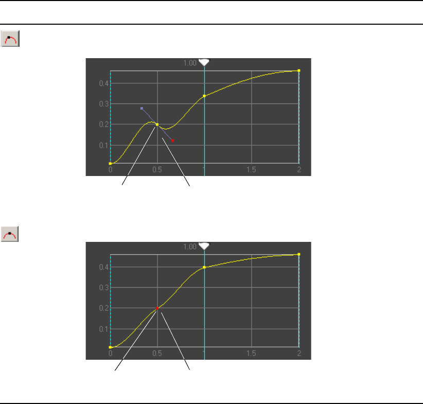
5 Adding Actions to a Scene
324
Continuous at
Keyframe
Provides tangent handles at the selected keyframe to give control over the slope at this
point, but keeps the slope continuous.
Smooth at
Keyframe
(Default) Provides a smoothly curved transition at the keyframe.
Keyframe Style Buttons (Continued)
Button Description
Selected keyframe Continuous tangent handles
control a single slope.
Selected keyframe Smoothly curved transition.
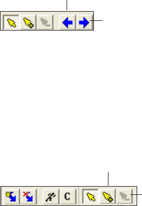
Editing Actions
325
Selecting a Keyframe
To select a keyframe before or after the currently selected keyframe, do one of the
following:
tClick the Previous Keyframe button to select the keyframe to the left of the currently
selected keyframe on the Timeline graph.
tClick the Next Keyframe button to select the keyframe to the right of the currently
selected keyframe on the Timeline graph.
Adding or Deleting a Keyframe
To add a new keyframe:
tClick the Add Keyframe button, then click the location on the Timeline graph where you
want to add the keyframe.
To delete a keyframe:
tSelect the keyframe (which then turns red), then click the Delete Keyframe button on
the toolbar.
Next Keyframe
Previous Keyframe
Delete Keyframe
Add Keyframe
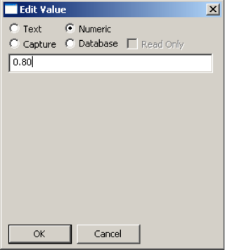
5 Adding Actions to a Scene
326
Adjusting the Timing or Value of a Keyframe
To adjust the timing or value of a keyframe, do one of the following:
tClick the keyframe in the Timeline graph and drag it along the X axis (time) or
Yaxis(value).
nYou cannot drag keyframes beyond the start or end of the parameter’s animation. You can
adjust the start and end ranges of the animation in the Timeline Bar editor. See “Adjusting
Timing in the Timeline Bar Editor” on page 308,
tEdit the time in seconds in the Time text box or edit the value in the Value text box on
the Timeline editor toolbar.
tDouble-click the keyframe to display the Edit Values dialog box, and then edit the
values, as described in the following procedure.
Editing the Value of a Keyframe
You can edit a keyframe by using the Edit Values dialog box. This dialog box lets you
specify the type of value that the keyframe represents as well as the value itself.
To edit the value of a keyframe:
1. In the Timeline graph, double-click the keyframe whose value you want to change.
The Edit Value dialog box opens.

Creating Actions Check List
327
2. Select the type of value you want to create.
The contents of the dialog box change depending on the type of value, as described in
the following table.
3. Type the value for the keyframe.
4. Click OK.
Creating Actions Check List
As you design and create actions, be sure to initialize parameters at the beginning of an
action or reset the parameter values at the end of an action to ensure that the action works the
same every time that you play it. For example, assume that you have created one action that
moves an object from the bottom left to the bottom right and another that moves an object
from bottom left to top left. If you do not set the starting location for these actions and play
one after the other, the object moves from bottom left to bottom right and then from bottom
right to top left. It does not reset to bottom left before moving to top left.
Timeline editor tool buttons and the location of the scrub bar determine the action type. This
check list describes the basic setup for each kind of action.
Edit Value Dialog Box Options
Option Description
Text Displays a single text box in which to view and modify the text.
A text keyframe is indicated by a yellow box around the keyframe point.
Numeric Displays a single text box in which to view and modify a number.
A numeric keyframe is indicated by a yellow keyframe point.
Capture Displays a list of all the parameters in the scene, sorted alphabetically.
Scroll to a parameter and select it, or click the Unselect button to select
none. See “Adding a Capture Keyframe” on page 315.
A capture keyframe is indicated by a yellow box around the keyframe
point.
Database Displays an ODBC (Open Database Compliant) data source browser,
query editor, and viewer. See “Replacing a Parameter with Results of a
Database Query” on page 343.
A database keyframe is indicated by a yellow box around the keyframe
point.

5 Adding Actions to a Scene
328
nThe order of actions in the Action list makes a difference. The application processes actions
items from the top to the bottom for each frame.
Creating Actions Check List
Action Type Steps
Trigger 1. Add an action.
2. Drag the scrub bar to its start position (leftmost position) if it isn’t
already there.
3. Select the Animate Mode (Record) button to record parameters.
4. Change one or more parameters. Each change is reflected in the
Action Parameter list.
5. Deselect the Animate Mode button.
6. Select the action and press the space bar to play it.
Timed Action with
Defined Start and End
Parameters
1. Add an Action
2. Drag the scrub bar to the start position (leftmost position).
3. Select the Animate Mode (Record) button.
4. Change parameters to the desired start configuration.
5. Drag the scrub bar to the end position (rightmost position).
6. Set the end parameter values.
7. Deselect the Animate Mode button.
nKeep the Animate Mode button selected until after you have set
both the beginning and ending parameters.
8. (Option) Add keyframes and change parameters at intermediate
positions on the Timeline graph.
9. Select the action and press the space bar to play it.

Creating Actions Check List
329
Time Capture Action 1. Add an action.
2. Drag the Scrub bar to its rightmost (end) position in the Timeline
graph.
3. Select the Auto Capture button.
4. Select the Animate Mode button.
5. Change one or more parameters.
6. Select a parameter in the Action Parameter list.
The application places a Capture keyframe (small yellow square) at
the beginning of the Timeline graph. There must be a Capture
keyframe for the action to assume the object’s current parameter
value.
7. Deselect the Auto Capture button.
8. (Option) Add keyframes and change parameters at intermediate
positions on the Timeline graph.
9. Deselect the Animate Mode button.
10. Select the action and press the space bar to play it.
If there is a problem with playout, examine the current parameter
values that the Capture keyframe uses in the action.
Creating Actions Check List (Continued)
Action Type Steps

5 Adding Actions to a Scene
330
Creating Sample Actions
This section includes procedures for creating the following sample actions
•“Example 1: Squeeze and Tease” on page 330
•“Example 2: Unsqueeze” on page 331
•“Example 3: Crossfade (Dissolve)” on page 332
•“Example 4: Lower-Third Reveal” on page 333
nResize the Timeline editor window (and areas within the window) by selecting and dragging
a boundary line to the left, right, top, or bottom.
Example 1: Squeeze and Tease
In this example, you create an action that repositions a full-frame video to the upper-right
corner over two seconds. As the video frame is squeezed, it reveals an underlying Deko
object called a tease whose purpose is to entice viewers to stay tuned.
To create a squeeze and tease:
1. Create a new scene and add a Deko graphic (the tease) as the first object in the Scene
Tree.
The Deko graphic might consist of images and text that describe the upcoming
programs.
2. Add a Video In object.
3. Click the Create Action button on the Timeline editor toolbar.
Action 1 appears in the Action list.
4. Rename Action 1 by selecting it, pressing F2, and typing UpperRight.
When a new Action is added, the scrub bar appears in the Timeline graph at the leftmost
(start) position.
Full Video Frame Full Video FrameSqueezed Video Input Reveals Tease
Creating Sample Actions
331
5. From the Timeline editor toolbar, select the Animate Mode (running man) button.
With Animate mode on, each change you make to a parameter in an object editor is
recorded in the Action Parameter list.
6. Click the Video In object editor’s Target tab.
7. For the target rectangle, select Preserve Minimum as the Autoscale option.
You want to preserve the Video In object’s aspect ratio and fit it within the target
rectangle whose coordinate parameters you specify.
The Video In object is full frame by default. You want to record the full-frame
parameters at the start of the action. Whenever you click the Reset button in the Target
tab, the target rectangle reverts to its default size.
8. Click Reset to set a full-frame Video In object at the start of the action.
The four parameters added to the list are target left, target right, target top, and target
bottom.
nClicking the text to the left of the Left, Top, Right, and Bottom thumbwheels also records the
start parameters as the default full-screen target rectangle. This is the same as clicking the
Reset button as long as the initial parameter values have not been changed.
9. Drag the scrub bar to the far right of the Timeline graph to its end position. The value in
the Duration text box determines the duration of the action from start to finish. It should
be set to 2.0 seconds.
10. In the Target tab, click the Left thumbwheel and drag it to the right until the video input
is positioned in the upper-right corner of the video output frame.
Because you added a Deko object above the Video In object in the Scene Tree, the Deko
object tease is revealed (as an L-shaped graphic).
11. Click the Animate Mode button to deselect it.
12. Select UpperRight in the Action list and press the space bar to play the squeeze action.
Example 2: Unsqueeze
Create a second action that reverses the squeeze by returning the video to full frame (an
unsqueeze). Because you want the tease text to be read by viewers, the complete unsqueeze
takes almost 3 seconds.
To create a second action to return the squeeze to full-screen:
1. Create a new action and name it FullScreen.
2. Select the Upper Right action and play it once (press the space bar) to place the Video In
object in the UpperRight position.
5 Adding Actions to a Scene
332
3. Select the Full Screen action in the Action list, and drag the scrub bar to the start
position.
4. Change the duration to 2.75 seconds by clicking the Up arrow to the right of the
Duration text box.
5. Click the Animate Mode button and record the ending position of the UpperRight action
by clicking the center of the Left, Top, Right, and Bottom thumbwheels in the Target
tab.
This sets your initial keyframes for the FullScreen action to the ending keyframes of the
UpperRight action.
6. Move the scrub bar to the end position of the Timeline graph, and click the Reset button
to return the target rectangle to its default full-screen value.
7. Turn off the Animate Mode button.
Now you have created two actions: UpperRight Action scales Video In to the upper right
over 2 seconds, and FullScreen Action scales Video In from the upper right to full frame
with a 2.75 second duration.
Example 3: Crossfade (Dissolve)
This action is a crossfade (or dissolve) that uses the Group object’s composite style. The
second object in the group gradually fades in over the first, completely obscuring it.
To create a crossfade:
1. Create a new scene.
2. Add a Group object to the Scene Tree.
3. Add two visual objects as children of the Group object and link them to their source
files. The second object will wipe over the first object.
4. Click the Group tab, and select Crossfade from the Composite Style list.
5. Preview the crossfade by dragging the Transition slider from 0 to 1 and back again.
6. With the Group object selected in the Scene Tree, click the Create Action button in the
Timeline editor toolbar.
An action is added to the Action list.
7. Press F2 and edit its name from Action 1 to Crossfade.
8. (Option) Change the Duration of the action from the default 2 seconds to another value,
if desired by typing the new duration in seconds in the Duration text box.
9. With the scrub bar moved to the start (leftmost) position in the Timeline graph, click the
Animate Mode button to record changes you make to parameters in the object editor.
Creating Sample Actions
333
10. Position the Transition slider to 0 and click the slider’s handle.
The slider’s parameter value of 0 is recorded at the start position of the wipe.
11. Drag the scrub bar to the far right of the Timeline graph, which is the end position of the
action.
12. Drag the Transition slider to the 1 position and click the slider’s handle.
13. Deselect the Animate Mode button.
14. Select the Wipe action in the Action list and press the space bar to play the wipe.
You can create another action that reverses the crossfade. Use this procedure but reverse the
positions of the Transition slider parameter.
Example 4: Lower-Third Reveal
In this example, you create an action that reveals a clock counter in the lower third of the
video frame. If you have a temperature probe interface attached, you can also display the
temperature.
To create a lower-third reveal:
1. Create a new scene.
2. To add a clock to the scene, add a Deko object with a text layer to the Scene Tree. In the
Deko tab, select the text layer from the Selected Layer menu. Set up the clock as
described in “Displaying Clocks” on page 131.
3. In the Position tab, use the X and Y Position and Scale thumbwheels to move the clock
output to the lower-right corner of the video frame.
4. (Option) Add a second Deko object with a text layer to display the temperature. Select
the text layer. In the Contents tab, click the Browse tab to navigate to the TXT file in
which the temperature probe records its data. Position the temperature probe output to
the right of the Clock output.
5. Add a Video In object after the Deko objects.
The Clip clock/temperature probe output is obscured by the Video In full-frame object.
6. With the Video In object selected, click the Create Action button in the Timeline editor
toolbar.
7. Press F2 and rename the action LowerThirdReveal.
8. Click the Animate Mode button to record parameter values for the action.
9. At the start of the action, set the Cropping values in the Position tab to their default
values by clicking the text—Left, Top, Right, and Bottom.
10. Drag the scrub bar to the end position.
5 Adding Actions to a Scene
334
11. Drag the Bottom cropping thumbwheel to the right until the clock/temperature probe
output is visible (with an appropriate margin between the display and the video output).
12. Click the Bottom thumbwheel in its center to record the crop’s current parameter value.
13. Deselect the Animate Mode button.
14. With the LowerThirdReveal action selected, press the space bar to play it.
nAs an alternative, you can place the Video In object above the Deko objects in the Scene
Tree. At the start of the action, set the Deko object’s opacity to full transparency (0). At the
end of the action, set the opacity to full opacity (1).

Chapter 6
6Working with Parameters
The Parameters tab consolidates parameter data for a scene. It provides a way to display and
edit parameter values for a scene, objects within the scene, and the system’s video board (or
canvas). You can search for parameters, create and edit user-defined parameters, add a
parameter value to a keyframe, and replace a value with the results of a database query. You
can also use the Parameters tab to link objects directly to ODBC-compliant databases in
order to cycle updated results on air.
The following topics describe how to work with parameters:
•Using the Parameters Tab
•Searching for a Parameter Value
•Editing a Parameter Value
•Creating User Parameters
•Creating an Action that Triggers Another Action
•Replacing a Parameter with Results of a Database Query
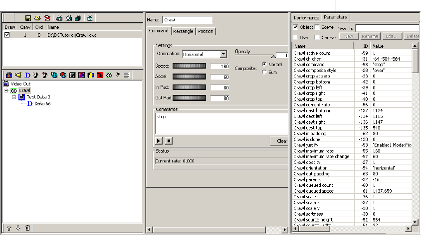
6 Working with Parameters
336
Using the Parameters Tab
The Parameters tab provides a list of parameters for the currently selected scene. You can
use the Parameters tab to locate and edit the following types of parameters:
• Object: Parameters for objects in the scene, such as opacity and scaling values.
• Scene: Parameters specific to the scene, such as the name of the scene and its draw state.
Actions you create are also listed as scene parameters.
• User: Custom parameters created by a user.
• Canvas parameters: Parameters that represent characteristics of the system’s current
state, such as the aspect ratio and the current state of the codecs for clip playback.
To display the Parameters list:
1. Select a scene in the Scenes pane.
2. Click the Parameters tab.
3. Select which parameter types you want to display in the list:
- Object: Displays parameters for all objects in the scene.
- User: Displays user-created parameters.
- Scene: Displays parameters for the current scene.
Parameters tab
Searching for a Parameter Value
337
- Canvas: Displays parameters for system settings.
nYou can select one or more parameter types to display in the list.
The list displays the name, ID number, and current value of each parameter.
To adjust the size of a column:
tClick the border between two columns and drag it to the left or to the right.
cAfter you are finished using the Parameters tab, click the Performance tab. Keeping
the Parameters tab displayed might slow down updating of the user interface for a
large scene.
Searching for a Parameter Value
You can display and edit any object, scene, user, or canvas parameter.
nThe object editor and parameters tab are updated simultaneously so that the values in both
are always current.
To search for a parameter value:
1. Select which type or types of parameters you want to search.
The selected parameters display in the list.
2. Type search characters in the search text box.
The application displays any parameter containing these characters.
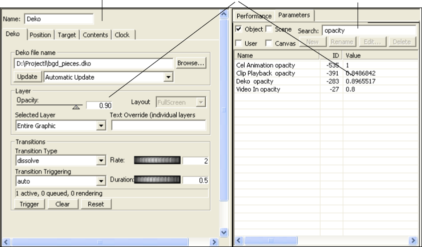
6 Working with Parameters
338
The following illustration shows the results of a search for “opacity” and calls out the
relationship between the opacity level set in the object editor and the opacity level listed in
the Parameters tab.
Editing a Parameter Value
You can edit a parameter in the Parameters list. Edits you make for a parameters are
reflected in the application’s user interface.
To edit a parameter:
1. In the Parameters tab, do one of the following:
tDouble-click a parameter in the list.
tSelect a parameter and click Edit.
Opacity value
Object Editor Search text box

Editing a Parameter Value
339
The Edit Value dialog box opens.
2. Edit the value for the parameter.
Your options depend on the type of value the parameter represents: Text, Numeric,
Capture, or Database. See the following table.
Edit Value Dialog Box Options
Option Description
Text Displays a single text box in which to view and modify the text.
A text keyframe is indicated by a yellow box around the keyframe point.
Numeric Displays a single text box in which to view and modify a number.
A numeric keyframe is indicated by a yellow keyframe point.
Capture Displays a list of all the parameters in the scene, sorted alphabetically.
Scroll to and click on a parameter to select it, or click the Unselect button
to select none. See “Adding a Capture Keyframe” on page 315.
A capture keyframe is indicated by a yellow box around the keyframe
point.
Database Displays an ODBC (Open Database Compliant) data source browser,
query editor, and viewer. See “Replacing a Parameter with Results of a
Database Query” on page 343.
A database keyframe is indicated by a yellow box around the keyframe
point.
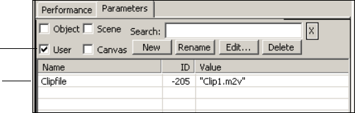
6 Working with Parameters
340
3. Click OK.
nYou can also use this dialog box to edit the value of a keyframe. For more information, see
“Editing the Value of a Keyframe” on page 326.
Creating User Parameters
When you select User as the parameter type, you can create or modify a user-defined
parameter. One use of a User parameter is to store extra data, if available, from an external
program with a scene. User parameters are typically used with applications that
communicate with the application through the application API or XML. For more
information, see the Rocket Engine API and Rocket Engine BCI documentation, which is
available on the Avid Customer Service Knowledge Base (www.avid.com/onlinesupport).
The Edit button allows you to edit any type of parameters selected in the list. The New,
Rename, and Delete buttons are active only when you select the User parameter.
To create a user parameter:
1. Select the User as the parameter type.
2. Click the New button.
3. In the Set Parameter Name text box, type a name for the parameter and click OK.
The application assigns an ID number.
4. With the name of the user parameter selected, click Edit.
5. Edit the parameter value as described in “Editing a Parameter Value” on page 338.
Creating an Action that Triggers Another Action
You can use the Parameters tab to create an action that starts or triggers another action. You
can trigger multiple actions in a single action and you can create an action that loops.
User selected as
parameter type
User parameter
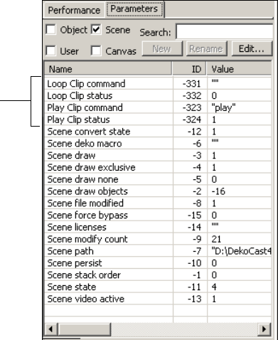
Creating an Action that Triggers Another Action
341
The first procedure in this topic describes how to insert an action into an action, and the
second procedure describes how to create a looped action.
To create an action that triggers another action:
1. Create a new action (see “Creating Actions” on page 300).
2. Click the Parameters tab and select the Scene option.
The Scene parameters are displayed. Scene parameters include actions created in the
scene.
3. Select the scene you just created and position the scrub bar where you want to insert the
action.
4. Click the Animate Mode button to enter Animate mode.
Actions
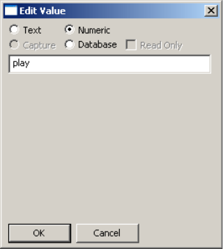
6 Working with Parameters
342
5. In the Parameters tab, double-click the action you want to insert.
The Edit Value dialog box opens.
6. Edit the value as appropriate.
For example, for an action that plays a clip, select Text, type “play” (without the quotes),
and click OK.
A keyframe is created in the action where you inserted the second action.
7. Click the Animate Mode button to leave Animate mode.
8. Play the action.
To create a looped action:
1. Create a complete action.
For example, create an action that plays a clip, named “Play Clip.”
2. Click the Create Action button to create another action. You want this action to loop the
first action.
For example, create an action and name it “Loop Clip.”
3. Click the Parameters tab and select the Scene option.
The actions you created are displayed.
4. In the Action list, select Loop Clip.
5. Move the scrubber bar to the beginning of the Timeline graph.
6. Click the Animate Mode button to enter Animate mode.
7. In the Parameters tab, double-click “Play Clip command.”
Replacing a Parameter with Results of a Database Query
343
8. In the Edit Value text box, select Text, type “play” (without quotes), and click OK.
9. Move the scrubber bar to the end of the Timeline graph.
10. In the Parameters tab, double-click “Loop Clip command.”
11. In the Edit Value text box, select Text, type “play” (without quotes), and click OK.
12. Click the Animate Mode button to exit Animate mode.
13. Play the Loop Clip action.
The Loop Clip action now calls itself, creating a loop that continuously plays a clip.
14. To stop play, click the Stop button on the Timeline toolbar or create an action that stops
the clip from playing.
Replacing a Parameter with Results of a Database
Query
The Database option allows you to replace a parameter value with the results of a database
query. This option allows you to link objects directly to ODBC-compliant databases that
cycle updated results on air.
cTo use the Database option, you should understand database structure and how to
register ODBC databases in the Windows operating system.
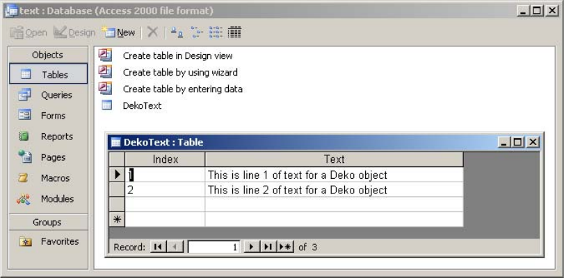
6 Working with Parameters
344
This example uses a simple Microsoft Access database named text.mdb to access parameter
values for a text parameter. The following illustration shows the values in the database, as
listed in a table named DekoText.
In this example, the Database option lets you replace the text in a Text Override parameter
for a Deko object. For more information on Text Overrides, see “Working with Deko
Objects” on page 108.
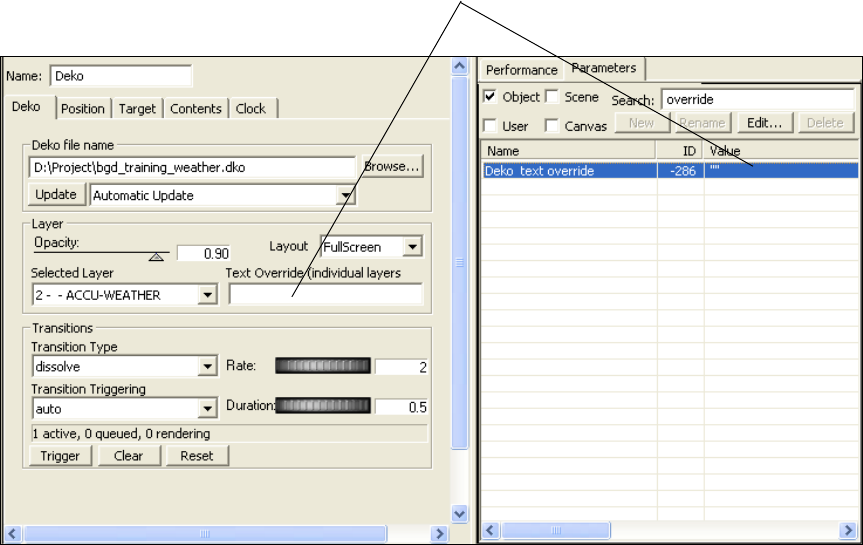
Replacing a Parameter with Results of a Database Query
345
The following illustration shows the Text Override parameter in the Parameters tab and the
object editor.
The following procedures use this example.
To locate the parameter to edit:
1. Click the Parameters tab.
2. Select the kinds of parameters to be edited: Object, Scene, User, or Canvas.
3. Type the parameter name in the Search field, such as the term override.
The application displays the parameter in the list.
4. Double-click the parameter name in the list.
The Edit Value dialog box opens.
Text override value is empty
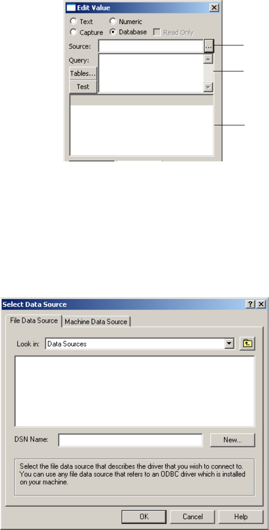
6 Working with Parameters
346
To replace a parameter with the results of a database query:
1. Click the Database button in the Edit Value dialog box.
The application displays a data source browser, a query editor, and a viewer.
2. Type or paste an existing data source name into the Source field and proceed to Step 3,
or do the following to create a new data source name.
a. Click the Browse button.
The Select Data Source dialog box opens.
Browse button
Query editor
Viewer
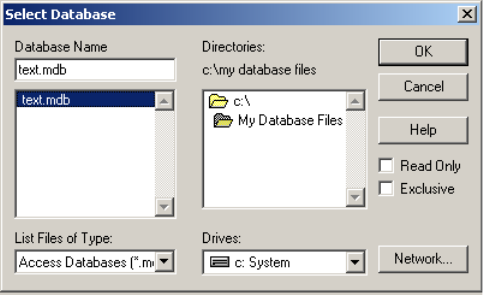
Replacing a Parameter with Results of a Database Query
347
b. Click New.
The Create New Data Source dialog box opens.
c. Follow the online instructions to select the database driver and specify the data
source name.
The application displays a summary screen with the new data source name and the
database driver to be used.
d. Click Finish.
e. Follow any additional online instructions related to your database driver.
The Select Database dialog box opens.
f. Navigate to the database file you want to use and click OK.
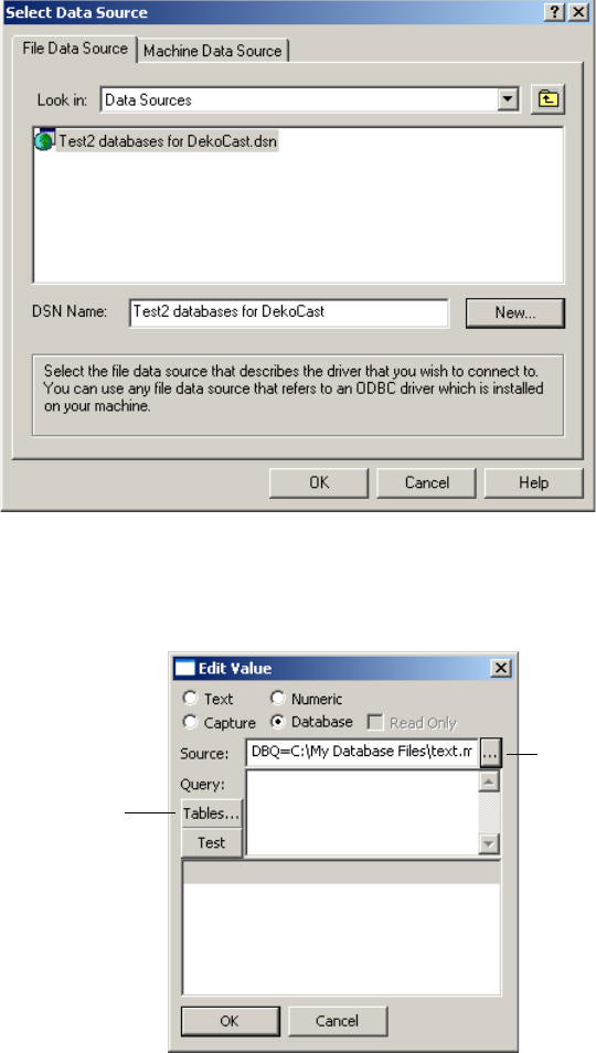
6 Working with Parameters
348
The data source name you specified appears in the Select Data Source dialog box.
g. Select the data source name and click OK
The database name appears in the Source field.
3. Click the Tables button to display a list of all the tables defined in that data source.
4. Select a table from the list. DekoText is the name in this example.
Database name
Tables button
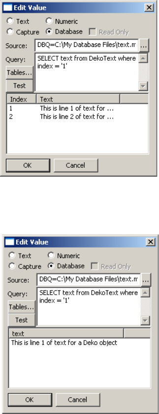
Replacing a Parameter with Results of a Database Query
349
5. Do one of the following:
tPress Use in Query to close the table list and place a “SELECT * from <table>”
query into the Query field. Then modify the query to search for a specific item.
tType a query into the Query field.
The following illustration shows the completed query and the two items from the table.
6. Click Test to perform the query and display the result in the table viewer.
The following illustration shows the query and the test results.
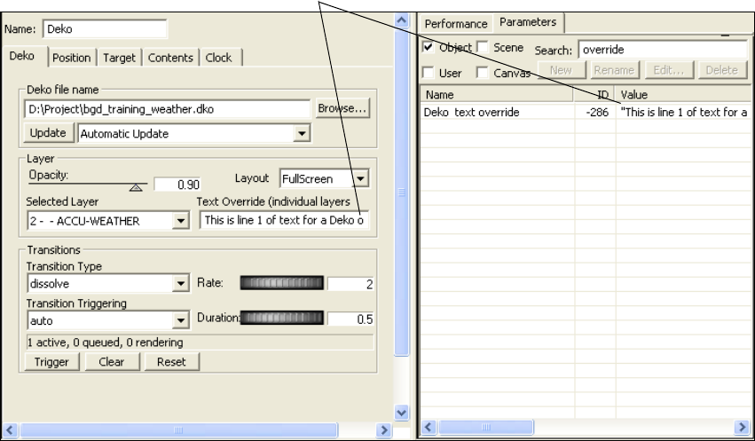
6 Working with Parameters
350
7. Click OK.
The application updates the parameter value as shown in the following illustration.
To continually refresh the values from a database:
1. Create an action that updates the database by clicking the Update button on the Deko
tab.
2. Create another action that loops the first action every 5 seconds.
Play the second action to refresh the values from the database every five seconds. For
more specific information, see “Creating an Action that Triggers Another Action” on
page 340.
Updated parameter value

Chapter 7
7Using DekoCast Central
This chapter covers all aspects of DekoCast Central: startup, configuration, using the
graphical user interface to control scenes and actions, and working with automation systems.
It also describes each of the DekoCast Central utilities, such as the Temperature Probe and
the Sequencer Control utility.
The following topics describe how to use DekoCast Central:
•Understanding DekoCast Central
•Working with DekoCast Central
•Configuring DekoCast Central for Automation
•Automation Control Interface
•Defining House IDs
•Working with the Playback Controller
•Working with the Graphical User Interface
•DekoCast Central Utilities
•Using the Emergency Alert System Interface
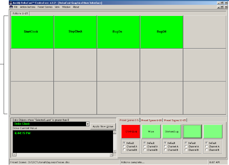
7 Using DekoCast Central
352
Understanding DekoCast Central
DekoCast Central has two main interfaces: a graphical user interface (GUI) and the
Automation Control Interface. You can use DekoCast Central’s graphical user interface to
play actions in real time by clicking buttons that represent an action, or by pressing the
buttons if you have a touchscreen.
Action
Buttons
DekoCast Graphical User Interface (GUI)
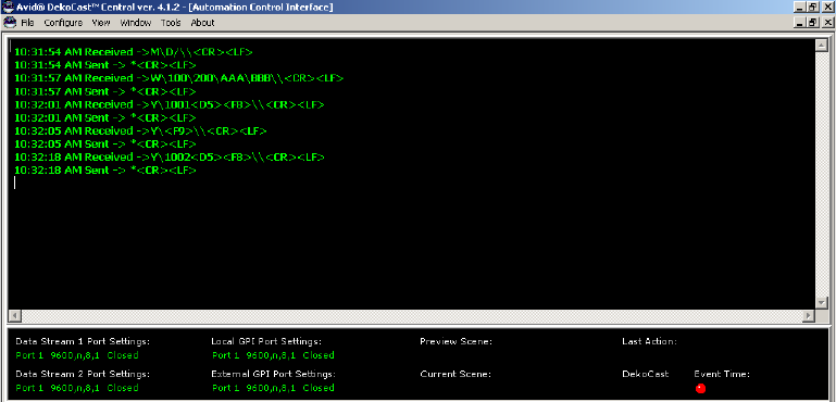
Understanding DekoCast Central
353
You can configure DekoCast Centrals Automation Control Interface to work with your
automation system to control the playback of actions.
DekoCast Central can serve as an automation interface for Triple i (I.I.I automation
protocol) and General Purpose Interface (GPI). You can configure DekoCast Central for use
with a wide variety of third-party automation systems that employ the Triple i automation
protocol to control standard Character Generators. You can also configure DekoCast Central
to associate a General Purpose Interface (GPI) with a specific scene or action. Two internal
or ten external GPIs are available.
You can set up a House ID with one or more actions and, if you want, you can override the
value of object parameters in a scene. When Triple i automation receives a command to play
a House ID, it plays all of the actions associated with it (and replaces the value of any object
parameter saved with this ID with your specified value). If you import a scene into the
DekoCast Central GUI that has been used as a source for a House ID, the House ID is added
as an Action button. You can use the Playback Controller to schedule the playback of House
IDs by time of day.
Automation Control Interface
7 Using DekoCast Central
354
Working with DekoCast Central
To start DekoCast Central, do one of the following:
tDouble-click the desktop icon
tClick Start and select All Programs > DekoCast > DekoCast Central.
The DekoCast Central files are located by default in C:\Dekocast\DekoCastCentral.
DekoCast Central has two main windows: the Automation Control Interface, which displays
the communications received and sent on automation ports, and the Graphical User Interface
(GUI), which has buttons for assigning and selecting scenes and triggering actions.
DekoCast Central initially opens with the Automation Control Interface window displayed.
Whenever you restart DekoCast Central, it opens with the interface window that was last
open prior to closing the application. Use the View command on each of the windows to
switch between interfaces.
To switch between the GUI and Automation Control interface, do one of the following:
tFrom the GUI, select View > Automation Control Interface.
tFrom the Automation Control Interface, select View > Graphical User Interface.
To open both interfaces in the DekoCast Central window:
tSelect Window > Tile Horizontally (one on top of the other) or Tile Vertically
(side-by-side).
By default, both interfaces are open at the same time and are contained in the DekoCast
Central application window. You can minimize an interface window while keeping it open,
or you can close it by clicking the close box or selecting File > Close.
The Playback Controller also opens by default. For more information, see “Working with the
Playback Controller” on page 374.
To close DekoCast Central:
tClick the application window’s Close button.
Configuring DekoCast Central for Automation
355
Configuring DekoCast Central for Automation
You use the DekoCast Central Configuration dialog box to configure DekoCast Central for
automation systems.
To open the Configuration dialog box, do one of the following:
tSelect Configure from the Automatic Control Interface’s menu bar.
tSelect View > Configure from the GUI window’s menu bar.
The dialog box includes three tabs: Data Streams for specifying data streams, GPIs for
configuring local and external GPIs, and Logging for specifying which events DekoCast
Central writes to log files.
nGPIs can be triggered only on an RS-232 port. Triple i commands can be sent on either an
RS-232 or RS-422 port.
Configuring Data Streams
You can configure up to two ports to accept Triple i commands. Either port can be RS-232 or
RS-422. These streams are not independent and are complementary. Therefore, if Data
Stream 1 receives a command to change directories or folders, and then receives a command
to change to a different directory on Data Stream 2, all Triple i commands received
afterwards point at the second directory. Typically, a single data stream is configured
although some automation systems use both streams. For example, the W commands might
be sent on COM1 and the Y commands on COM2.
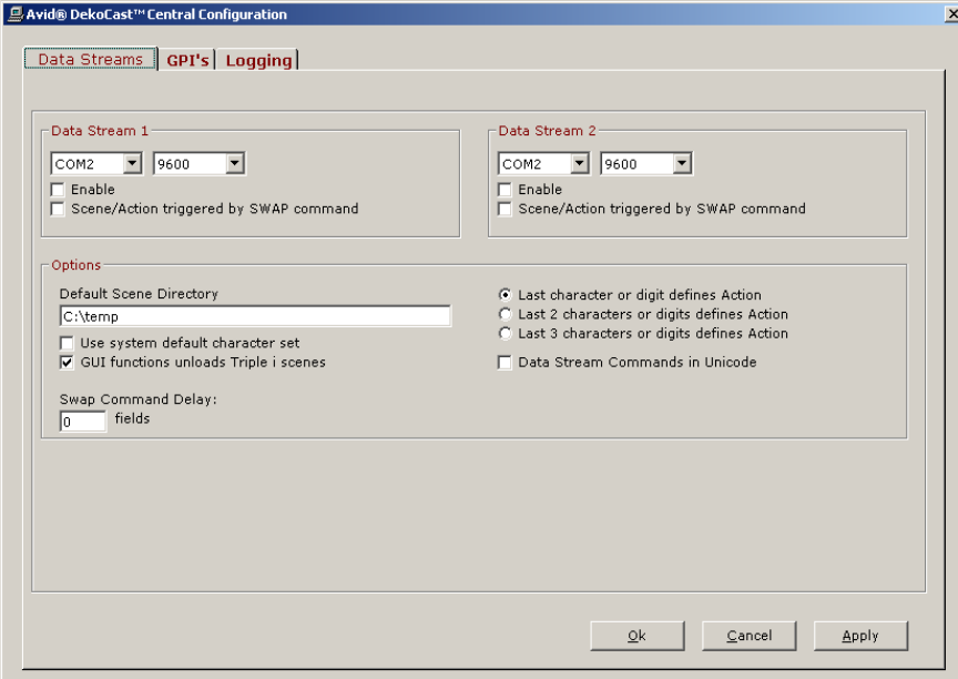
7 Using DekoCast Central
356
To configure a data stream:
1. Do one of the following:
tSelect Configure from the Automatic Control Interface’s menu bar.
tSelect View > Configure from the GUI window’s menu bar.
2. Click the Data Streams tab.
3. Specify the COM port for each data stream you want to configure.
4. Select Enable to have DekoCast Central listen for commands on the selected port.
5. Set the baud rate, which is typically 9600.
6. Select “Scene/Action triggered by SWAP command” if you have a Louth Automation®
system or any automation system that sends the <F9> command to trigger a play.
Some automation systems use the Y command to cue a scene/action and the <F9>
(hex F9) command to play the scene/action. Other automation systems expect the Y
command to trigger the play.
Configuring DekoCast Central for Automation
357
7. Type the Default Scene Directory for your application, unless your system uses the M
command.
The M command can specify the directory for a specified scene.
nMost automation systems other than Louth Automation systems override the default
directory value.
8. Select “Use system default character set” if the font that displays in the Automation
Control Interface window is not supported by your system.
9. Select “GUI function overrides Triple i scenes” if you want the GUI function to
temporarily override the automation system.
In DekoCast Central, asynchronous Triple i commands always override anything you do
using the GUI. When you select this option, if you open a scene that has not already
been opened by Triple i, both the preview and program Triple i scenes are aborted, and
the GUI function temporarily overrides the automation system until DekoCast Central
receives another Triple i command.
10. For the three options that specify how the last number of characters or digits defines
actions, select how DekoCast Central is to interpret the data being sent by automation
for the Y command. See “The Y Command” on page 366.
11. If the GPI and Triple i data stream commands are in Unicode, select this option.
12. Click Apply.
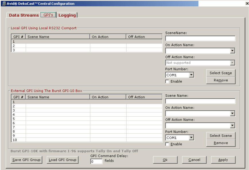
7 Using DekoCast Central
358
Configuring GPIs
You can configure either local or external GPIs, but not both. To trigger a scene or an action,
you can configure as many as two GPIs wired to an RS-232 COM port (local GPIs). If you
require more than two GPIs, you must configure an external GPI box. With an external GPI,
you can trigger an action on and off. The GPI’s tab has two panes, one for configuring local
GPIs and the other for configuring external GPIs.
You can configure and save a group of GPIs.
Configuring DekoCast Central for Automation
359
Configuring Local GPIs (Local RS-232 COM Port)
To trigger a scene or action, you can configure a maximum of two GPIs wired to an RS-232
COM port. With local GPIs, you are limited to triggering two actions only. For example, you
might want to trigger an emergency slate on and then off.
nIf you require more than two GPIs, you have to configure an external GPI box.
Local GPIs are triggered by a momentary (5 millisecond) contact closure across two pins of
the COM port. GPI 1 is triggered by a short across pins 8 and 7, and GPI 2 is triggered by a
short across pins 6 and 7.
To configure a GPI to trigger an action:
1. Do one of the following:
tSelect Configure from the Automatic Control Interface’s menu bar.
tSelect View > Configure from the GUI window’s menu bar.
2. Click the GPI’s tab.
3. Click the Select Scene button.
The DekoCast Scene Files dialog box opens.
4. Select a scene.
5. Click Open.
6. Select the action to be triggered from the On Action Name menu.
nThe Off Action applies to External GPI setup only.
7. Choose the port number and select Enable to have DekoCast Central start listening for
commands on this port.
8. Click Apply.
9. Repeat these steps to configure a second GPI.
To remove a configured GPI:
tSelect a configured GPI from the list and click the Remove button.
To save a group of GPIs:
tClick Save GPI Group.
The group is saved as an .ini file in the DekoCast Central application directory.
To load a saved GPI Group:
tClick Load GPI Group and select the saved group.
7 Using DekoCast Central
360
Configuring External GPIs (RS-232 GPI Box)
The steps for configuring external GPIs are the same as those for configuring local GPIs
except that you can associate a GPI with both an on action and an off action.
An external GPI can be triggered by any device that sends an ASCII code to trigger the GPI.
Up to ten GPIs can be triggered using a three-character ASCII string, which is defined as an
asterisk followed by two digits for the GPI number (for example, “*01”, “*02”,…,”*10”).
nTo purchase an external RS-232 box with ten additional GPIs from Avid, contact your
Avid Sales Representative.
Burst™ Electronics sells a GPI to RS-232 Converter device, the GPI-10, that converts a
contact closure into these ASCII commands. DekoCast Central supports GPI On and Off
using the GPI-10 firmware version I-96 on external GPIs. See the Burst Electronics Web site
for more details: www.burstelectronics.com.
Logging DekoCast Central Events
DekoCast Central can log events that you select in the Logging tab: data streams (GPI and
Triple i commands), system errors, all actions played in the GUI, and service messages.
To specify which events DekoCast saves to log files:
1. Do one of the following:
tSelect Configure from the Automatic Control Interface’s menu bar.
tSelect View > Configure from the GUI window’s menu bar.
2. Click the Logging tab.
3. Select any of the activities other than service messages.
nDo not select Service Messages unless directed to do so by Avid Technology,
Broadcast Support.
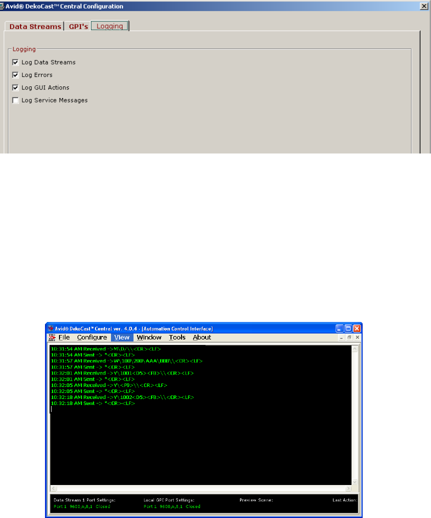
Automation Control Interface
361
To view log files:
1. From the Automation Control Interface select View > Log Files.
2. From the Open Log File dialog box, select a .log file and click Open.
Automation Control Interface
The Automation Control Interface window is divided into two areas. The top section of the
window displays the communications received and sent on automation ports (incoming and
outgoing automation or GPI commands). You can select a font and style for this text.
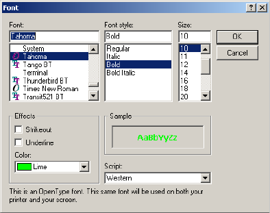
7 Using DekoCast Central
362
To change the font style:
1. Select File > Change Font.
2. In the Font dialog box, choose any font, font style, size, color, and so forth.
To clear all of the text from the display window:
tSelect File > Clear Display.
The lower section of the ACI window provides the following information:
• Datastream/GPI Port settings and status.
• The name of the current scene and the last action played.
Viewing DekoCast Central Resources
A complete description of resources is available through the DekoCast Central Resources
dialog box. The amount of free video memory and the number of free codecs are shown, as
well as the video standard (NTSC or PAL) and the total number of scenes opened in the
application engine.
Each scene that DekoCast Central has open is associated with its owner, which can be one of
the following:
• A preview or current scene associated with Triple i or the GUI.
A Preview scene is rendered into a preview buffer before it becomes the current scene.
• Local or External GPI.
•Other or Unknown owner refers to another client application that has one or more scenes
open of which DekoCast Central is not aware, such as third-party applications that use
the application engine.
Automation Control Interface
363
The Draw column shows which scene is currently being processed, and Stack number shows
the order of processing (higher numbers are processed first).
To view DekoCast Central resources:
tSelect View > Resources.
To view the DekoCast Central version number:
tSelect Help > About.
Using the Asset Viewer Utility
The Asset Viewer is a utility for Avid Service use. Use it when requested by Avid Service.
To open the Asset Viewer utility, do one of the following:
tIn the GUI, select View > Asset Viewer.
tIn the Automation Control Interface, select Tool > Asset Viewer.
Viewing Automation Notes
Automation notes provide setup and other information about working with automation
systems.
To view automation notes:
tSelect View > Automation Notes.
Ports for Automation Control
The DekoCast system includes one or more COM ports for sending XML commands
directly to the DekoCast application, For information about user-written programs that send
commands to DekoCast using the XML command set, see the Rocket Engine BCI XML
Bytestream Command Interface, which is available in PDF format from the Avid Customer
Support Knowledge Base (www.avid.com/onlinesupport). Search for “XML Bytestream.”
You can configure the COM ports to work with DekoCast Central and an external
automation system. To trigger a scene or action, DekoCast Central accepts Triple i
commands or GPIs. GPIs can be triggered only on an RS-232 port. Triple i commands can
be sent on either an RS-232 or RS-422 port. See “Configuring DekoCast Central for
Automation” on page 355.
nTo determine your system’s port configuration, see the Avid On-Air-Graphics Setup and
Configuration Guide and the back panel of your DekoCast machine.
7 Using DekoCast Central
364
Triple i Command Formats
You can use commands to specify the default scene directory, write to the automation data
file, open the scene file, and trigger the action. DekoCast Central supports a subset of the
Triple i command set: the M, W, and Y commands. The M command specifies the directory
in which scenes are located. The W command writes text data to a layer within a Deko file.
The Y command specifies which action within a scene to play. For a description of the
command format for each of the three supported DekoCast Central Triple i commands, see
the following sections:
•The M Command
•The W Command
•The Y Command
The M Command
The M command, which sets the scene directory, has the following format:
M\Drive_letter/FolderName\\CheckSum<CR><LF>
where <CR> adds a carriage return and <LF> a line feed to advance to the next line.
Specify the Drive_Letter without a colon (:). The directory name is preceded by the forward
slash (/) rather than the back slash (\). To specify subdirectories, type a forward slash
between each subdirectory’s name. The checksum is an optional field, which is validated.
The following M command instructs DekoCast Central to search the D:\Scenes\Squeezes
directory for any DekoCast scenes:
M\D/Scenes/Squeezes\\<CR><LF>
nIf no M command is sent, the Triple i class sets the default scene directory to C:\temp.
You can set the default scene directory using the Data Streams tab of the DekoCast Central’s
Configuration dialog box if your host system does not support the M command.
The W Command
The W command, which writes text data to a layer within a Deko file, has the following
format:
W\NewFileName\TemplateName\layer 1 text\...
\layer n text\\CheckSum<CR><LF>
Automation Control Interface
365
The NewFileName field specifies the name of a file to be created, which is named
NewFileName and has the extension .atx. This new file contains the exact string sent in the
W command. The checksum is an optional field, which is validated.
For example, the following W command creates a file named NewFileName.atx:
W\NewFileName\TemplateName\Layer 1 Text\Layer 2 Text\\
If you open this file with Notepad, it contains the single line:
W\NewFileName\TemplateName\Layer 1 Text\Layer 2 Text\\
To update Deko text layers:
1. Create a Deko template named TemplateName.dko that has two replaceable layers.
2. Add a Deko object to your scene and link it to NewFileName.atx.
3. Create an action in your scene that updates the file-name parameter of the Deko object.
When DekoCast Central receives the W command, it creates a new .atx file. When DekoCast
Central receives a Y command, it plays the action that updates the file-name parameters of
the Deko object, which results in the display of the new data.

7 Using DekoCast Central
366
The Y Command
The Y command, which specifies which action within a scene to play, has the following
format:
Y\SceneAction<F8>\\CheckSum<CR><LF>
where:
- <F8> is the hex value F8.
-SceneAction is a sequence of characters parsed according to the rules set up in the
configuration.
You can indicate whether the last one, two, or three characters of the string specifies the
action’s name. The remaining characters at the beginning of the string specify the scene
name. The checksum is an optional field, which is validated.
In the following example, the last three characters ABC define the action name. The
command is parsed such that the scene is named SceneName.dkx, and the action ABC
within that scene is played.
Y\SceneNameABC<F8>\<CR><LF>
If there is an action within the scene whose name ends in these three characters, it is played.
Should there be multiple actions whose names end with ABC, only the first such action is
played.
Different scene and action names based on the length of the last characters or digits are
described in the following table. For example, if the last two characters define the action,
and the command is
Y\1234<f8>\\<CR><LF>
, the Scene is named 12.dkx and the action
could be named, Action 34, Squeeze 34, Roll Clip 34, and so on.
Command Received
Last Char. or Digit
Defines Action
Last 2 Chars. or
Digits Define Action
Last 3 Chars. or Digits
Define Actions
Y\1234<F8>\\<CR><LF> Scene = 123.dkx
Action = [any text]4
Scene=12.dkx
Action=[any text]34
Scene=1.dkx
Action=[any text]234
Y\SceneA<F8>\\<CR><LF> Scene = Scene.dkx
Action = [any text]A
Scene=Scen.dkx
Action=[any text]eA
Scene=Sce.dkx
Action=[any text]neA
Y\1234<F8>\\<CR><LF> Scene = 123.dkx
Action = [any text]4
Scene=12.dkx
Action=[any text]34
Scene=1.dkx
Action=[any text]234
Automation Control Interface
367
Some automation systems send Y commands in a form that emulates a Chyron keyboard
command, which DekoCast Central interprets in the same manner. For example, instead of
sending the
Y\1234<F8>\\<CR><LF
>, the command could be sent as
Y\<C1><C2><C3><C4><F8>\\<CR><LF>
.
To execute a single action:
tSend the Y command with a scene name in which only the last character defines the
action number.
For example, sending the command
Y\2001<F8>\\
loads scene 200 and plays the
action named Action 1.
Using Command Queues
Command queues allow for a fixed length timing of commands between the time they are
received by the serial port and the time they are executed either for Triple i or GPI.
The only Triple i command this is affected by is the SWAP command. The SWAP command
is the triggering mechanism that initiates a scene on air or an action to play. Some scenes
have hundreds of actions and the lookup for these varies in time. This feature allows for a
constant time.
To set a command delay for the SWAP command:
1. Do one of the following:
tSelect Configure from the Automatic Control Interface’s menu bar.
tSelect View > Configure from the GUI window’s menu bar.
2. Click the Data Streams tab.
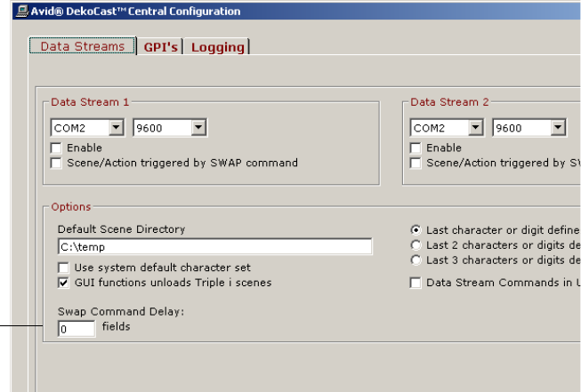
7 Using DekoCast Central
368
3. Type the timing (in fields) in the Swap Command Delay text box.
Swap Command
Delay text box.
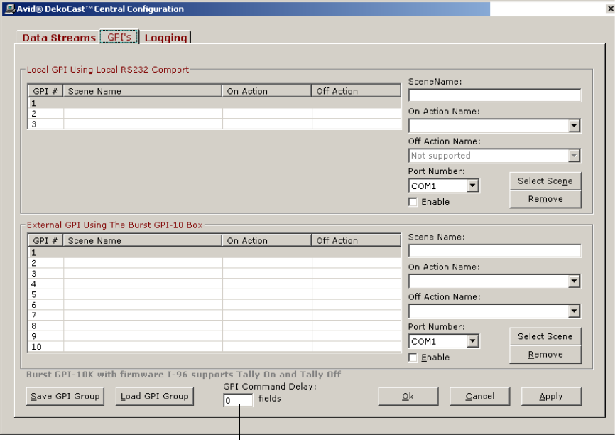
Automation Control Interface
369
To set a command delay for GPI:
1. Click the GPI’s tab.
2. Type the timing (in fields) in the GPI Command Delay text box.
GPI Command
Delay text box
7 Using DekoCast Central
370
Defining House IDs
You can configure a Lookup Table that maps multiple actions in a DekoCast scene to a
single House ID. The Lookup Table also allows you to override the values of specified
object parameters in the scene. For example, you might define a House ID “scene” named
1234 that plays three actions (LogoOn, TimeOn, and TemperatureOn) and changes the
Station Logo object parameter’s file name from D:\Logos\Evening.dko to
D:\Logos\Morning.dko. When Scene 1234 is called, it plays these three actions, and the
Station Logo object reflects the contents of the Morning.dko file. You can use the DekoCast
Central Playback Controller to schedule the playback of House IDs by time of day.
House ID “scenes” can also be played from the DekoCast Central GUI. When you assign a
scene associated with a House ID to a Scene button, the description assigned to a House ID
is mapped to an Action button.
nThe Lookup Table accepts DKX files only. Convert any of the older DKC scene files to DKX
by opening them and saving them as DKX files before using them as House ID source files.
See “Scene Files” on page 40.

Defining House IDs
371
Playing Multiple Actions
To configure a House ID Lookup Table to play multiple actions:
1. From the Automation Control Interface, select View > Lookup Table.
2. Click New House ID, type a number or name of your choosing in the text box, and then
click OK.
3. Enter a description for the House ID in the text box and click OK.
This description is mapped to the Action button in the DekoCast Central GUI.
nTo avoid having two Action buttons with the same name, the House ID description should
not duplicate any other action name in the scene.
7 Using DekoCast Central
372
4. In the Maps to Scene Name text box, do one of the following:
tType the complete path to the scene with the desired actions to map or parameter
values to be overridden when this House ID is played.
tClick Browse and navigate to this scene.
5. To add actions from the scene to the Available Actions list, do one of the following:
tIf the scene is a DKX file, you can click the Import button to import all actions from
the scene with a description that is the scene name. Click Modify to edit this
description.
tFor individual actions or non-DKX files, click Add Available Action, type the
action name, and then click OK. Type a description and click OK.
6. Move Available Actions from the list to the Plays Actions list on the left by selecting
one action at a time and clicking the Move (< < <) button.
7. To save this set of actions for this House ID, click Save House ID.
To modify a saved House ID:
1. Select the House ID from the House ID menu.
2. Make your edits and save the House ID.
To delete a House ID:
tSelect the ID from the menu and click Remove House ID.
House ID Files
House IDs are saved in an XML file named LookupTable.xml in the DekoCast Central
directory. You can distribute the XML file to any DekoCast system. If this file is modified
through the Lookup Table dialog box, DekoCast Central automatically reloads the file. This
means that House ID updates can be made from another location.
If the XML file has been modified, click the Reload Lookup Tables from Disk button to
update the House IDs in the Lookup Table.
Overriding Object Parameter Values
You can also configure the Lookup Table so that the value for an object parameter in a DKX
scene file is overridden with a value you specify when the House ID is played.
To view a scene’s object parameter values:
1. Open the DekoCast application.
2. Open the DKX file whose object parameters are to be overridden.

Defining House IDs
373
3. Select the scene in the Scenes pane.
4. Click the Parameters tab in the upper-right of the DekoCast window.
5. Select Object as the only type of parameter to display in the list.
6. Scroll through the listing to view the current values for each object parameter.
7. Use the Lookup Table in DekoCast Central to modify values.
To override object parameters for a DKX scene file:
1. In DekoCast Central, click the Import button in the Lookup Table dialog box to open the
Object Override dialog box.
2. Select the object from the Objects menu. The object’s parameters are listed.
3. Select an object parameter whose value you want overridden when this House ID is
played.
7 Using DekoCast Central
374
4. Edit the new parameter value in the Object Parameter Value text box and a description in
the Description text box. Click Modify to edit this description.
5. Click Apply to add the object with the new parameter to the Available Object Parameter
Overrides list.
6. Add any other parameters that you want to make available to be overridden for this
House ID, either by you or another user who modifies this House ID.
7. Move the Available Parameters to the Override Parameters list on the left by selecting
one action at a time and clicking the Move (< < <) button.
8. To save your changes for this House ID, click Save House ID.
To add available objects to the list manually:
1. Click the Add Available Override button.
2. In the dialog box that opens, type the object name in the text box and click OK.
3. Type the name of the parameter for the object to be overridden and click OK.
4. Type the parameter value in the text box and click OK.
5. Add any other parameters that you want to make available for overriding when this
House ID is played.
6. Move the Available Parameters to the Override Parameters list on the left by selecting
one action at a time and clicking the Move (< < <) button.
7. To save your changes for this House ID, click Save House ID.
To modify an action or object parameter description:
1. Select the action or parameter from the Available list and click the Modify button.
2. Edit the description.
Working with the Playback Controller
The DekoCast Central Playback Controller provides time-of-day automatic playback of
House IDs (events), or you can control playback manually.
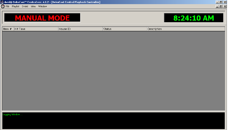
Working with the Playback Controller
375
To open the Playback Controller:
tSelect View > Playback Controller from either DekoCast Central interface.
The Playback Controller opens in manual mode.
To exit the Playback Controller:
tSelect File > Exit.
To add an event to the playlist:
1. Select Event > Add Event.
2. In the Add Event dialog box, select the month and year from the menus, and click the
day on the calendar.
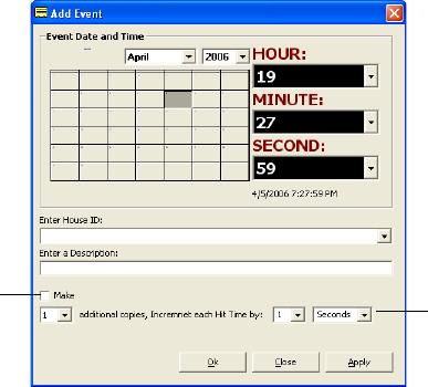
7 Using DekoCast Central
376
3. Select the hour, minute, and second for the event to be triggered.
4. Select a House ID from the menu.
5. Type a description for the House ID.
6. Click Apply to add the event to the list of events.
Events are inserted into the playlist and sorted by the number of times played.
7. Enter as many events as appropriate.
These events are added to the playlist.
8. Click Apply.
You can create one or more copies of an event and increment the hit time for playout of a
succession of the same event by a specified time.
To schedule a copy of an event for incremental playout:
1. Select the Make option in the Add Event dialog box.
2. Select the number of copies.
3. Select to increment each hit time from 1 to 30.
You can also type a number for the hit time.
4. Select either seconds, minutes, hours, or days.
To delete an event:
1. Select the event in the playlist.
2. Select Event > Delete Event.
Copy Events/Increment hit time
Make Option
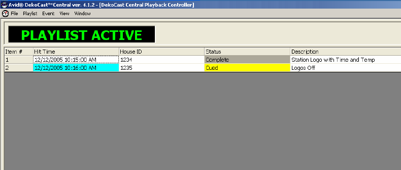
Working with the Playback Controller
377
To modify an event:
1. Select the event in the playlist.
2. Select Event > Modify Event.
To save a playlist:
tSelect File > Save Playlist.
Playlists are saved as .bin files.
Playing Events
The playlist must be enabled (activated) in order to play events.
To activate the playlist, do one of the following:
tSelect File > Open Playlist.
tPress F1.
The Playback Controller status is Playlist Active. The playlist searches for the next event
based on its assigned playback time (hit time). When the Hit Time for an item turns light
blue, its associated House ID is the next event to be triggered. After an event is played, its
status changes to Complete, and the next event in the list is cued. The cue time is 10 seconds.
nThe Playback Controller cannot advance to the next event in the playlist until the previous
action is complete. Looping actions halt the execution of subsequent events.
When the Playback Controller is in manual mode, you can play events manually. Disable the
playlist to return to manual mode.
7 Using DekoCast Central
378
To disable (deactivate) the playlist, do one of the following:
tSelect Disable Playlist.
tPress F2.
To play events manually, do one of the following:
tWith the Playback Controller in manual mode, select one of the following:
-Event > Cue
-Event > Play
tRight-click an event name and select Cue or Play.
Copying Today’s Playlist to Tomorrow’s List
You can set up a playlist of events for today that you would also like to play tomorrow.
To copy events for today’s playlist to a playlist for tomorrow:
tSelect Event > Copy selected, Add 1 day, and Paste.
This action copies all the selected events, increments the day by one day and adds the
new events to the playlist.
Working with the Graphical User Interface
You can use DekoCast Central’s Graphical User Interface to control the playout of actions
and to change the text values of Deko layers. You can import as many as fifteen DekoCast
scenes, which are organized in sets of five under three Preset Scene tabs. After you assign
scenes to buttons, the Preset Scenes appear in the same configuration whenever you open
DekoCast Central. If you save this configuration, you can work with the same scenes and
presets on different DekoCast systems.
If you import a scene into the GUI that is defined in a House ID, the House ID is added as an
Action button. See “House ID Files” on page 372.
To open the Graphical User Interface:
tFrom the menu bar, select View > Graphical User Interface.
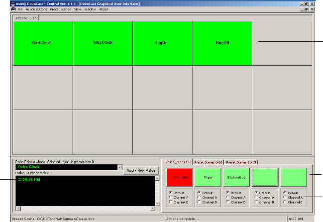
Working with the Graphical User Interface
379
The Graphical User Interface window has a set of Scene buttons, and each button can be
assigned, or mapped to a scene. Each of the scene’s actions is mapped to an Action button.
When you select a Scene button, it turns red and its Action buttons are displayed. You can
trigger one or more actions simultaneously.
The Channel options below each Scene button allow you to force a scene to output to a
channel other than the channel for which the scene was designed.
cIf any button on the Graphical User Interface is colored yellow instead of green or
gray, something is wrong. Immediately close all scenes and then close and restart
DekoCast Central. A yellow button indicts an immediate application failure.
Setting the Size of Action Buttons
You can set the size of the Action buttons that are displayed in the GUI. The size determines
the number of buttons that are displayed. The default size is Large, which displays
15 buttons.
To set the size of the Action buttons:
1. From the menu bar, select View > Graphical User Interface.
2. Select Action Buttons > Size > size.
Tex t
Window
Action
buttons
Channel
Scene
buttons
7 Using DekoCast Central
380
Setting Up Scenes in the GUI
You need to assign scenes to buttons. You can also organize scenes by Preset tabs.
To assign a scene to a button:
1. From the menu bar, select View > Graphical User Interface.
2. Do one of the following:
tRight-click the Scene button and select Assign Scene.
tSelect Preset Scenes > Assign Scene
nThe Scene button shortcut menu and the Preset Scenes menus have the same commands.
3. Select the scene from the Assign DekoCast Scene files dialog box.
nDekoCast Central supports DekoCast DKX and the older DKC files.
After assignment, the scene button is labeled with the scene name. You can add additional
scenes in the same way, mapping as many scenes to buttons as there are buttons (15 total).
Scene buttons are organized by tabs named Preset Scenes 1-5, Preset Scenes 5-10, and
Preset Scenes 10-15 whose names you can change. A tab can contain one-to-five assigned
scenes.
Presets enable you to group scenes. By default, scenes are assigned to the same presets
whenever you open DekoCast Central on the same system (unless a scene has been
removed). You do not need to save presets unless you want to use the same scenes and
presets on a different system.
To save preset scenes:
1. Assign scenes to buttons in one or more Preset Scene tabs.
2. Select File > Save Preset Group.
DekoCast Central saves all assigned scenes as they are configured in the Present Scenes
tabs, even if one tab is not completely filled and another tab has only one assigned
scene. The group is saved as a .psg file.
3. Open this group from another DekoCast system by choosing File > Open Preset Group.
4. The Open Preset Group dialog box opens.
5. Select the file.
To rename a tab:
tRight-click a button in the tab and select Rename Current tab from the menu.
Working with the Graphical User Interface
381
To remove a button’s scene assignment:
tRight-click the button and select Remove Assigned Scene from the menu.
To remove all scenes from the currently selected Preset Scenes tab:
tSelect Preset Scenes > Remove All Scenes.
Working with Actions in the GUI
In addition to triggering an action by itself or triggering multiple actions simultaneously, you
can change the duration (in seconds) of an action, and rename Action buttons.
To trigger an action:
1. From the menu bar, select View > Graphical User Interface.
2. Click the Scene button for the scene whose actions you want to play.
The Scene button turns red when activated. An Action button is created for each action
in the scene. If there are no actions in the scene, no buttons are changed and the Action
tab reads No Actions.
3. Click the Action button.
nA scene can have an unlimited number of actions. There are fifteen buttons for actions per
Action tab. If there are more than fifteen actions in the scene, select an Action tab at the top
of the window to display the next set of buttons.
To trigger multiple actions simultaneously:
tHold down the Ctrl key and select the actions by clicking their buttons, then release the
Ctrl key.
To change the duration of an action:
1. Right-click the action and select Edit Duration.
2. Type the new duration in seconds in the dialog box and click OK.
To rename an action:
1. Right-click the Action button and select Rename Button.
The Add New Caption dialog box opens.
2. Type the new name and click the close button.
If you close the dialog box without typing a name, the button has no name.
7 Using DekoCast Central
382
To view recent actions:
tSelect Window > Recent Actions List.
A text file opens in Notepad that shows the time, complete path of a DekoCast file, and
the name of recent actions.
Prestarting, Starting, and Exiting Actions
Default actions apply to scenes initialized in the DekoCast Central GUI. If you define a
default Start action, DekoCast Central executes it whenever the scene is loaded. If you
define a default Exit action, that action plays before the scene closes. You can also define a
Prestart action to set the scene is to a certain state before it displays.
To define a default Start and Exit Action:
1. From the menu bar, select View > Graphical User Interface.
2. Select View > Default Actions.
3. Type the name for the Start and Exit actions and click OK.
The names you have chosen appear as the Start/Resume action name and the Stop/Pause
action name in the Aut File Sequencer utility. See “Using the Aut File Sequencer Utility” on
page 393.
To define a Prestart Action:
tDefine a Start action, such as Squeezeback, and define another action of the same name
except that it begins with a period (.); for example, .Squeezeback.
The Prestart action plays before the scene is displayed (before the Scene’s draw
parameter is set to 1). The Start action plays after the scene is visible.
Changing a Deko Object’s Text Value
You can overwrite a Deko object’s current text value and have the new value display to video
output immediately. This change is for one instance only. For example, if you change the
text in a Deko object crawl, the change is in effect for a single crawl. The subsequent crawl
reverts to the saved value.
To override a Deko object’s text value:
1. From the menu bar, select View > Graphical User Interface.
2. Select the Deko object from the Deko Objects menu in the lower-left corner of the GUI
window.
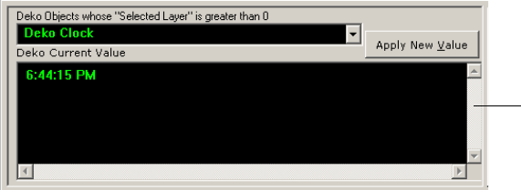
DekoCast Central Utilities
383
The current value for the Deko object’s text is displayed in the text window.
3. Edit the text.
4. Click the Apply New Value button.
DekoCast Central Utilities
You can open the following DekoCast Central utilities by selecting them from the
Automation Control Interface’s Tool menu:
• Sequencer Control
• Deko Page Recall
• Temperature Probe Interface
• Aut File Sequencer
Using the Sequencer Control Utility
The Sequencer Control utility allows you to play Sequence files (.rks) files, which you build
using the Sequence program. Use the top row of buttons to create and refine your playlist.
Use the lower row of buttons to control the playout of Sequence files.
Text window
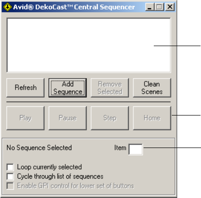
7 Using DekoCast Central
384
To open the Sequencer Control utility:
tIn the Automation Control Interface, select Tool > Sequencer Control.
To add Sequence files to the playlist:
tClick Add Sequence button, select the RKS file from the Open dialog box, and click
Open.
To remove a Sequence file from the playlist:
tSelect the file in the playlist and click Remove Selected.
To remove all Sequence files from the playlist:
tClick Clean Scenes.
The Item box in the Status pane shows the currently playing Sequence item number.
To play all of the files in the playlist:
tSelect “Cycle through list of sequences.”
To play selected files in the playlist continuously:
1. Select one or more files in the playlist.
2. Select “Loop currently selected option.”
To stop the playout of Sequence files:
tClick the Stop button.
Currently playing
Sequence Item
Play control buttons
Playlist
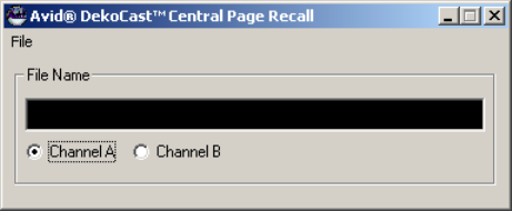
DekoCast Central Utilities
385
To control the playout of Sequence files (.rks files) via external GPIs:
tSelect the option “Enable GPI control for lower set of buttons.”
The GPIs are mapped to the control buttons as follows:
GPI 1=Play
GPI 2=Pause
GPI 3=Step
GPI 4=Rewind (Home)
Using the Deko Page Recall Utility
The Deko Page Recall utility allows you to operate DekoCast as if it were a page-based CG.
You can open a file to serve as a cut effect or as a dissolve effect. The application creates a
scene with one Deko object and sets the file-name parameter of the object to the name of the
opened file.
To open the Deko Page Recall utility:
tIn the Automation Control Interface, select Tool > Deko Page Recall.
To open a file for a cut effect:
1. Select File > Open File as Cut Effect (F9).
The Open Deko File dialog box opens.
2. Select the file and click Open.
To open a file for a dissolve effect:
1. Select File > Open File as Dissolve Effect (F11).
The Open Deko File dialog box opens.
2. Select the file and click Open.
7 Using DekoCast Central
386
To clear the screen, do one of the following:
tSelect File > Screen Cut Effect (F7).
tSelect File > Clear Screen Dissolve Effect (F8).
Using the Temperature Probe Interface Utility
The Temperature Probe Interface utility enables the outside temperature to be displayed on
the video output. You need to purchase a temperature probe and attach it outdoors; typically
the probe is placed on a building’s roof. The probe connects to the DekoCast system through
an RS-232 COM port. The Temperature Probe Interface saves the data as a text file (TXT) in
a directory that you specify.
When a scene with a linked temperature is active, the temperature automatically displays.
The Temperature text file can be linked to any Deko object in a scene that has text layer.
When the Temperature Probe Interface saves the temperature to a text file, it also queries all
open scenes in DekoCast. If it finds a Deko object whose name is “Temperature,” it sets the
text override parameter value to the new temperature value.
This utility requires a temperature probe. The Temperature Probe Interface Utility supports
two models of temperature probe:
• DGH D1331, manufactured by DGH Corporation. For more information, see their Web
site www.dghcorp.com.
• Sensatronics™ Series E and F, manufactured by Sensatronics. For more information, see
their Web site www.sensatronics.com.
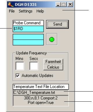
DekoCast Central Utilities
387
Configuring the DGH Temperature Probe
To open the DGH temperature probe interface:
tIn the Automation Control Interface, select Tool > Temperature Probe Interface > DGH
D1331 Series.
The DGH D1331 Interface window opens.
Temperature TXT file
COM port status
Menu
Probe
command
DGH D1331 Interface

7 Using DekoCast Central
388
To configure the COM port:
1. Select Settings from the menu.
The Communication Settings dialog box opens.
2. Set the Baud rate.
3. Set the Data Bits, Stop Bits, Echo, and Parity.
By default, the settings are Data Bits = 8; Stop Bits = 1; Echo = Off; and Parity = None.
4. Set the COM port for the probe communication.
5. Set the Flow Control to the default value None.
6. Type the complete path for the Temperature.txt file in the Text File Location text box.
Enter complete path for
Temperature.txt file.
DekoCast Central Utilities
389
7. Type the Response Delay time in milliseconds.
After the Probe command is sent to the probe requesting the temperature, you can set a
delay time that instructs the probe to respond a specified number of milliseconds after it
receives the command. The delay/response time depends on the length of the cable.
8. Click OK.
Use the DGH D1331 Interface to set up and start the temperature probe.
To set up and start the Temperature Probe:
1. In the Temperature Probe Interface utility, select either Fahrenheit or Celsius by clicking
the appropriate button.
2. Enter the rate that you want the temperature to be updated (in minutes/seconds).
3. Click Send.
The Probe command is the command sent to the probe to ask for the temperature. See your
probe’s documentation for command information.
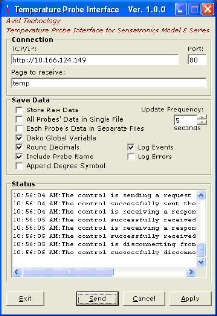
7 Using DekoCast Central
390
Configuring the Sensatronics Temperature Probe
To configure the Sensatronics temperature probe interface:
1. In the Automation Control Interface, select Tool > Temperature Probe Interface >
Sensatronics Series E and F.
The Temperature Probe Interface window opens.

DekoCast Central Utilities
391
2. Complete the configuration as described in the following table.
Temperature Probe Interface Configuration Options
Option Description
Connection section Options for connecting the probe.
TCP/IP The IP address of the Sensatronics module.
Port The module port for the probe. The default is port 80.
Page to receive The page sent from the module. For temperature only data use “temp” in
lower case.
Save Data section Options for what to do with the raw data retrieved by the probe.
Store Raw Data Stores data in the application’s subdirectory
Data
in a file named
RawData.txt
. This is useful to those macro users who want to parse this
data manually.
The following is an example of the raw data.
Probe 1| 71.3|Probe 2|34.5|Probe 3| 77.0|Probe 4| 52.3
Update Frequency Specifies how often to update the data.
All Probes’ Data in
Single File
Stores data for each of the 4 probes in a single text file on separate lines.
This is useful for DekoCast to allow for cycling the data. Set the Text File
parameter of a Deko object to this file and you can cycle the data. This
data is stored in the application’s subdirectory
Data
in a file named
ProbeData.txt
.
See the example at the end of this topic.
Each Probe’s Data in
Separate Files
Stores data for each of the 4 probes into separate text and macro files. This
data is stored in the application’s subdirectory
Data
in files named by the
probe’s names, for example:
Probe 1.txt
and
Probe 1.mcr
.
Macro files are created so that Deko users can use them immediately. Set a
Deko Layer to Macro and set the Macro text box to this file name. If the
Probe name has spaces in it, they will be removed from the macro file
name.
The following Deko Macro can also be used to read the text file. Put this
macro in the Macro text box
return (readtext "Probe 1.txt"
"E:\Sensatronics.Temperature.probe\Data")

7 Using DekoCast Central
392
3. Click Apply to accept the settings.
4. Click Send to send the Probe command to the probe to ask for the temperature.
5. Click OK to close the window.
Deko Global Variable Use this setting ONLY if the Temperature Probe module is running on the
Deko machine. If so, this is the preferred method for displaying the data.
Using this setting allows the Temperature Probe module to create native
Deko global variables so the probe data can be displayed without having
to save any data to disk. The variable names are $PROBE1,$PROBE2,
$PROBE3, and $PROBE4. Set the Deko layer to Macro and set the Macro
text box to “return $PROBE1.
Round Decimals Rounds numerical data to decimal values. When the fractional part is
exactly 0.5, the application rounds it to the nearest even number. For
example, 0.5 rounds to 0, and 1.5 rounds to 2.
Include Probe Name Includes the probe’s name in all return values. If your probe name is
“Springfield,” the return data might be
Springfield 76
.
Append Degree
Symbol
Adds the degree symbol in all return values. The return data might be
Springfield 76
o
.
Log Events Copies all the data from the log window into a text file. Files are saved for
14 days.
Log Errors Copies any errors reported by the application into an error file. Select this
option only if you experience any issues or problems.
Temperature Probe Interface Configuration Options
Option Description
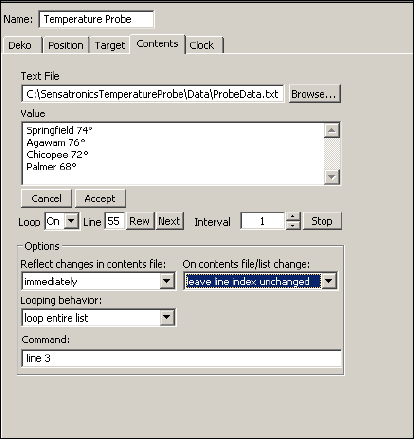
DekoCast Central Utilities
393
Example
The following illustration shows a Deko object named Temperature Probe. In this example,
data from four probes are stored in a single text file (ProbeData.txt) and can be cycled on
separate lines.
Using the Aut File Sequencer Utility
You can use the Aut File Sequencer utility to cycle .aut or .atx automation files (an .atx file is
the text version of a binary .aut file). If your automation system constantly sends W
commands to DekoCast Central, this utility enables DekoCast Central to write and store the
automation files locally and to update text layers for Deko objects. You can then play these
files with the updated layer text to air whenever you choose. You might use this utility to
display lower-third sports scores.
nThe W command writes text data to a layer within a Deko file. See “The W Command” on
page 364.
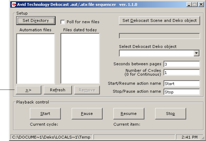
7 Using DekoCast Central
394
The Aut File Sequencer dialog box has two parts. The left side allows you to set up and
control the playback of automation files. The right side allows you to select layers that are to
be replaced with text specified by the W command.
To set up the automation files:
1. In the Automation Control Interface, select Tool > Aut File Sequencer.
2. Click Set Directory and select the directory location of the automation (.aut or .atx)
files.
The individual automation files are added to the Automation Files list.
3. Select a file and click the Move (>>) button to add the file to the Files Dated Today list.
Files dated today are files for the current day. For example, if the directory contains .atx
files of sports scores from yesterday and today, you can choose to air only today’s files.
4. Select “Poll for new files” to have DekoCast check for new automation files and add
them to the Automation files list.
5. Click the “Set DekoCast Scene and Deko object” button and select the scene with the
Deko object whose text layer is to be updated.
6. From the “Select the DekoCast Deko object” list, select the object whose layer is to be
replaced with the text specified in the W command.
Move
button
Using the Emergency Alert System Interface
395
7. Type the number of Seconds between pages, which is the time in seconds that a page
displays on air before it is replaced by another page.
For example, if you are cycling sports scores, specify how long you want each score to
remain on air.
8. Type the number of Cycles, which is the number of times to play each file in the list
(one is the default).
9. Type the Start/Resume action name and the Stop/Pause action name (as set in DekoCast
Central).
The names you have chosen appear as the Start/Resume action name and the Stop/Pause
action name in the Aut File Sequencer utility. See “Working with Actions in the GUI”
on page 381.
To control playback of the automation files:
tClick buttons in the Playback Controller pane to start, pause, resume, and stop the
playout of the automation files.
To delete files from the automation list:
tSelect the file and click Remove.
Click the Refresh button to update the listing.
Using the Emergency Alert System Interface
The DekoCast Emergency Alert System (EAS) module provides an interface for EAS
encoders and lets you create scenes to display EAS messages in different formats. The
DekoCast EAS interface is designed for encoders that use the TFT EAS 911 interface.
You can design message-specific scenes, based on the EAS event code. For example, if you
want to create a scene for “Blizzard” (event code BZQ) you can link the message with a
scene composed of clips and graphics that depict blizzard conditions.
Creating an EAS Scene
Use the EAS interface to link a DekoCast scene that you created for a type of EAS event.
Note the following requirements for this scene:
• Use the name of the EAS event code to name your scene. For example, for a blizzard
scene, name the scene BZQ.dkx.
• Scenes must be in the default directory: C:\DekoCast\DekoCastCentral\EASScenes\
• All EAS scenes must have a Deko object named EAS.
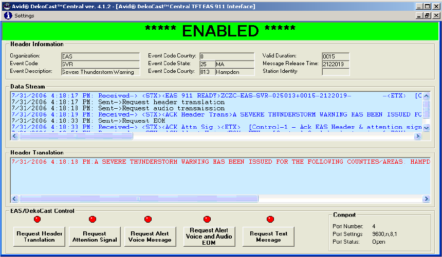
7 Using DekoCast Central
396
• The EAS interface uses a default scene named EAS.dkx. You can design this scene with
a generic background.
Starting and Configuring the EAS Interface.
To open the EAS interface:
tSelect View > Emergency Alert System Interface.
The EAS window opens.

Using the Emergency Alert System Interface
397
To configure DekoCast for EAS:
1. Click Settings in the EAS window menu bar.
The EAS Configuration dialog box opens.
2. Select Enable EAS to open the serial port for receiving EAS messages. This setting is
persistent: after you select it, it remains set until you deselect it.
3. Complete the configuration as described in the following table.
EAS Interface Configuration Options
Option Description
Comport Number Defines the serial port receiving the EAS message. The port
settings are 9600, n, 8 and are set by the DekoCast EAS
module.
Loop Count Defines the number of crawl loops.

7 Using DekoCast Central
398
Scene Name The default scene name. This entry is not configurable. The
EAS module looks for scene names based on the EAS event
code. If no scene exists by that name, it defaults to the name
defined by the scene name setting. If an EAS message is sent
for a “Severe Thunderstorm Warning” event code “SVA,” the
module looks for a scene by the name of
“E:\DekoCastCentral\EASScenes\SVA.dkx.” If this scene
doesn’t exist, it defaults to
“E:\DedkoCastcentral\EASScenes\EAS.dkx.”
Show EAS scene
exclusively
Sets the Show Exclusive parameter of the EAS scene to “1,”
so that it is displayed on top of all other scenes. All other
scenes have their Draw parameter set to “0.” When the EAS
“End of Message” is received or the “EAS Message
Complete Action” is complete, the scene whose Draw
parameter was set from 1 to 0 is set back to 1 and the EAS
scene is unloaded from the application engine.
If this option is not checked then all open scenes stay open
and their Draw parameter stays as is. The EAS scene is
appended to all open scenes. The EAS scene is unloaded
when complete.
Scene Text Object Name The default Deko Object name. This name is not
configurable. All EAS scenes must have a Deko object
named EAS.
EAS Message Begin
Action Name
(Option) Defines a DekoCast action name to execute when an
EAS Message is received. For example, use Squeezeback to
begin a squeezeback action. This action needs to be in the
EAS scene.
EAS Message Complete
ActionName
(Option) Defines a DekoCast action name to execute when an
EAS Message End-of-Message (EOM) is received. For
example, use Bringfull to return video to full screen. This
action needs to be in the EAS scene.
During an EAS
Transmission
Options to allow during an EAS Transmission.
Allow GPI’s Allows GPI’s to be executed during an EAS transmission.
EAS Interface Configuration Options (Continued)
Option Description

Using the Emergency Alert System Interface
399
4. Click Apply to apply the selected options.
5. Click OK to close the dialog box.
Allow Automation
commands to be
processed
Allows serial port automation commands to be processed
during EAS transmissions. If this option is not selected,
commands are received and acknowledgements are sent back
to the automation system but the commands are not
processed.
Allow use of the
Graphical User
Interface
Allows the use of the DekoCast GUI during EAS
transmissions.
EAS Interface Configuration Options (Continued)
Option Description
7 Using DekoCast Central
400

Chapter 8
8Using Sequence to Play Back Actions
The Avid Sequence application allows you or an automation system to play sequences of
actions from DekoCast scenes without modifying the original scene or actions. A sequence
is a select list of actions from scenes that is saved as a file in the .rks format. Working with a
Sequence file, you can manually execute a single action, automatically play the entire list,
and change the timing between actions or the parameter data for an action. To control
playback of actions in Sequence files, use tools in the Sequence application or DekoCast
Central’s Sequence Control utility such as the Play, Pause, and Stop buttons. You can also
configure GPI automation in DekoCast Central for playback of actions in Sequence files.
The following topics describe how to use Sequence:
•Starting Sequence
•Creating a Sequence
•Editing Sequence Items
•Editing a Sequence List
•Changing an Action’s Timing
•Controlling Playback
•Editing Action Parameters
•Using the Sequence Toolbar
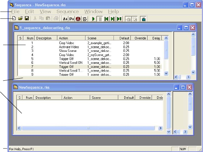
8 Using Sequence to Play Back Actions
402
Starting Sequence
To start the Sequence application, do one of the following:
tGo to Start > DekoCast > Sequence.
tDouble-click the Sequence icon on the desktop.
The Sequence window opens. This window contains the menu bar and toolbar for the
application.
You can work with multiple Sequence files. Each Sequence file has its own window within
the main Sequence window, which is the name of the RKS file.
When a window is active, its RKS file name appears in the main window’s title bar. The
Status Bar displays brief descriptions of the tools and menu items as you move the pointer
over them.
When working with multiple Sequence files, there are two Windows commands that help
you organize windows:
• When you copy and paste among multiple Sequence files, you can arrange the windows
one above another by selecting Window > Tile.
Toolbar
Sequence
File
Windows
Sequence
Items
Menu
Status Bar

Creating a Sequence
403
• If you minimize Sequence files, selecting Window > Arrange Icons places the
minimized files into the lower-left corner of the Sequence application window.
For a description of each of the tools in the Sequence toolbar, see “Using the Sequence
Toolbar” on page 412.
Creating a Sequence
A Sequence consists of a list of actions that you select from DekoCast scenes and organize
for playout. Each action is associated with a single scene. In addition to the actual actions in
a scene, there are six special actions in this list that you can add to a Sequence. Four of these
have an equivalent View Control tool in the toolbar. See “Using the Sequence Toolbar” on
page 412.
To create a new Sequence file, do one of the following:
tSelect File > New.
tClick the New button on the toolbar.
A blank Untitled Sequence window is displayed.
To select a DekoCast scene and add actions to a Sequence:
tDo one of the following:
- Select Edit > Add Action.
- Click the Add Action button on the toolbar.
The Add Actions to Sequence dialog box for this Sequence file is displayed.
Action Description
Activate Video Sequence automatically controls the video-out hardware. Same as the
manual View Control tool that toggles between Activate and Deactivate.
Deactivate Video DekoCast automatically controls the video-out hardware. Same as the
manual View Control tool that toggles between Activate and Deactivate
Hide Scene Does not send the actions for this scene in the Sequence list to video
output. Same as the manual Hide Scene tool.
Nothing A Sequence item that has no associated action. You might add Nothing as
a Sequence item to add a stop or duration at a point in the Sequence.
Show Only Scene Specifies that the scene is the only scene that is displayed on video output.
Show Scene Automatically displays the actions in the Sequence for this scene on video
output. Same as the manual Show Scene tool.
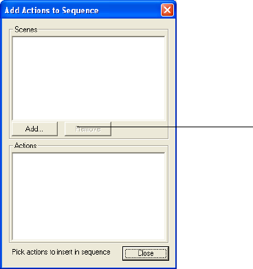
8 Using Sequence to Play Back Actions
404
nEach Sequence file has an associated Add Actions to Sequence dialog box.
6. Click the Add button to select a DekoCast scene whose actions you want to add to the
Sequence.
The Open dialog box opens.
7. Select the DKX file and click Open.
nSequence can open scene files in the older DKC format. Avid recommends that you open
DKC files in DekoCast and save them as DKX files (and then delete the source DKC file).
All of the actions in this scene (and the additional six Sequence-specific actions) are
displayed in the Actions pane.
Click Add to select a
scene
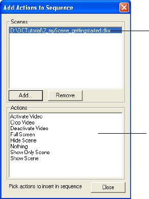
Creating a Sequence
405
nActions are displayed by scene. If there are multiple scenes, select the scene whose actions
you want to display in the Actions pane.
8. Click an action to add it to the Sequence list. Select actions one at a time. In most cases,
you want to add one of the two actions that allows the scene to be visible on video
output: Show Scene or Show Only Scene.
A scene is automatically drawn to video output only if one of its actions in the Sequence
list is Show Scene or Show Only Scene. As an alternative, you can manually click the
Show Scene button to display the scene.
nEach click adds an action to the Sequence list in the Sequence file. Clicking multiple times
adds duplicate actions to the list in the Sequence File window.
Actions are added to the Sequence File window in the order selected. Subsequently, you
can change the order of Sequence items by copying and pasting them.
9. To add actions to a Sequence from another scene, click the Add button and select the
DekoCast file.
The actions in the selected scene are added to the Sequence list. The actions for each
scene display separately.
Select an action to adds it to
the Sequence file.
Select a scene to display
its actions below.
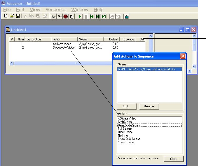
8 Using Sequence to Play Back Actions
406
10. Select any actions from this scene that you want to add to the Sequence list.
Selected action added
to Sequence list.
Sequence actions
Sequence columns

Editing Sequence Items
407
Editing Sequence Items
You can manually edit any of the columns for a Sequence item in the list other than S and
Default. A description of each column follows.
Editing a Sequence List
You can delete, replace, copy, paste, and move items in the Sequence list.
Deleting and Replacing Items
To delete an item from the Sequence, do one of the following:
tSelect the item from the list and select Edit > Cut.
tSelect the item and click the Cut button on the toolbar.
To replace an item in the Sequence:
1. Select the item.
2. Double-click its action column.
Sequence Items Columns
Column Description
S (step) An open arrow (>) indicates the currently playing item.
Num The number of the items within the list. Edit it to rearrange the position of items.
Description By default, any parameters set for the action. (Option) Enter a description of the
item.
Action The name of the action. Triple-click an action to open a menu from which you can
select another action from the same scene.
Scene The scene in which the action is a part.
Default The default duration of the action as specified in the scene.
Override (Option) A value that changes an action’s duration (timing).
Delay The number of seconds in which the action is to be delayed.
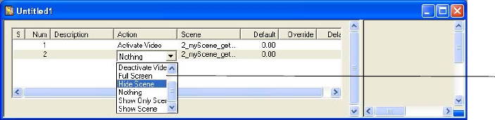
8 Using Sequence to Play Back Actions
408
3. Select another action in the scene from the menu that is displayed.
Copying and Pasting Sequence Items
You can cut, copy, and paste items in the Sequence File window. When you move an action,
it is automatically renumbered. Copy and Paste is an effective way to reuse actions that are
similar but have different parameters. You can also cut, copy, or paste actions from one
Sequence file to another.
To move an item to another position in the list, do one of the following:
tSelect the number in the list and type a new number. The item is moved to that position
in the list and the list is renumbered.
tSelect the item to be moved and click the Copy button. Select the item in the list directly
after the action to be pasted. Click the Paste tool. The copied item is placed before the
selected item, and the list is renumbered.
To remove a scene from the Add Actions to Sequence dialog box:
tSelect the scene from the Scenes list and click Remove.
nOnly scenes whose actions are not used in the Sequence file can be removed from the Add
Actions to Sequence dialog box.
To save a Sequence file:
1. Click the Save button on the toolbar.
If the file is new, the Save As dialog box opens.
2. Type a file name and click Save.
Changing an Action’s Timing
You can change the duration of an action and specify the delay between two actions.
Select another
action
Controlling Playback
409
To change the duration of an action:
1. Click the Sequence item’s Override column to display a text box.
2. Type a value (in seconds) in the text box.
For example, type 3.00 to change the value to 3 seconds. This value overrides the default
duration until you select and delete the override value.
To clear the Override field:
tSelect the value and press the Delete key.
To delay the start of an action:
1. Click the Sequence item’s Delay column to display a text box.
2. Type a value (in seconds) for the duration of the delay.
For example, if Action 3 is a Squeezeback and Action 4 is a Logo Out, entering a delay
of 2.00 (two seconds) for Action 3 causes Action 4 to start two seconds after Action 3
triggers.
Controlling Playback
The Sequence application provides Playback Control buttons on the toolbar and Sequence
menu commands for controlling the playback of actions.
nYou can also control the playback of actions in Sequence files through DekoCast Central
(using the Sequence Control utility or by configuring GPI automation).
To play the actions in the Sequence:
tClick the Play button on the toolbar.
If no item is selected in the list, the items are played from the first to the last. If an item
is selected, playout starts with that item. If looping is not set, the playout stops.
The currently playing action is indicated by an open arrow (>) in the Step column.
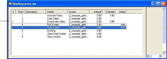
8 Using Sequence to Play Back Actions
410
To pause playout:
tClick the Pause button.
To stop the Sequence after an item in the list:
1. Select the last item in the list that you want to play before the stop.
2. Do one of the following:
tSelect Sequence > Set Stop.
tClick the Stop button on the toolbar.
The word stop is added in the Delay column. The Sequence stops after this item. You
can restart the Sequence by clicking the Play button, but the Sequence always stops
when it encounters a stop in the Delay column.
Although the Sequence stops, the playout to video does not necessarily stop. For
example, if you set a stop at an item whose action plays a looped clip, the clip continues
to play until another action stops it.
To remove a stop:
tSelect the Delay column and delete the word stop.
To resume playout:
tClick the Play button.
> = currently
playing
action

Editing Action Parameters
411
Editing Action Parameters
You can add or modify parameter values for a action within a Sequence. The original action
in the scene is unchanged.
To add a parameter value for an action:
1. Select the action and click the Add Parameter tool.
The Add Parameters to Sequence Item dialog box opens.
2. Select the parameter from the list.
3. Double-click the Set To column to display a text box.
4. Type the parameter value in the text box.
Some actions, such as those associated with object parameters, can be readily modified. For
example, you might edit text strings associated with a parameter, or change the source file
for a Cel Animation object.
To modify the parameters for an action:
1. Select the parameter from the list.
2. Double-click the Prompt column to insert a text box.
3. Type the replacement parameter value in the text box.
Text box
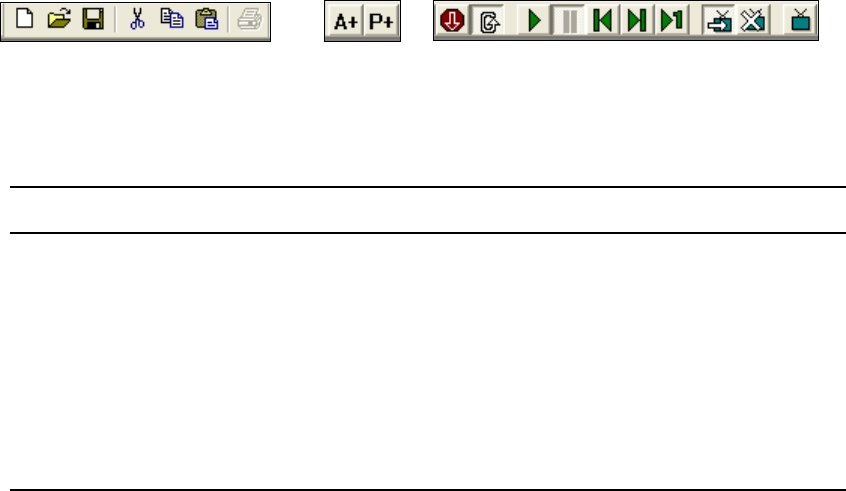
8 Using Sequence to Play Back Actions
412
Using the Sequence Toolbar
The toolbar provides quick, one-click access to common Sequence tools.
nTo display a brief description of a tool, move the cursor over its button.
The following tables describe these tools.
nThere is no print capability available for this version.
File and Edit Tools Setup Tools Playback Tools View Control Tools
File and Edit Tools
Tool Description
New Creates a new Sequence file.
Open Opens an existing Sequence (.rks) file.
Save Saves the Sequence file. Prompts for a new file name.
Cut Places the currently selected action on the Clipboard, removing it from the list.
Copy Copies the currently selected action to the Clipboard.
Paste Pastes the most recently cut or copied action from the Clipboard to the Sequence
list.

Using the Sequence Toolbar
413
nThe action that is currently playing has the open arrow (>) next to its number.
Sequence Setup Tools
Tool Description
Add Action Opens the Add Action dialog box and choose a scene from which you can select
one or more actions to add to the Sequence.
Add Parameter Opens the Add Parameter dialog box to add a parameter value.
Playback Control Tools
Tool Description
Insert Stop Inserts a Stop into the Sequence after the selected action. (Use the Pause button to
pause a playing Sequence.)
Loop Switches to loop back to the top of the Sequence after playing or stepping through
the last action. When the button is selected, looping is on; when not selected,
looping is off.
Play Plays the Sequence, beginning with the selected action.
Pause Pauses a playing Sequence.
Start of Sequence Moves the currently playing action to the start of the Sequence.
End of Sequence Moves the currently playing action to the end of the Sequence.
Step Steps through one action at a time starting with the currently selected action.
View Control Tools
Tool Description
Show Scene By default, the actions in the Sequence file display on video output when played.
Hide Scene Stops display of the Sequence file to video output.
Activate Video Output Determines whether Sequence or DekoCast controls the video output. Select to
have Sequence control the video-out hardware. When the button is not selected,
DekoCast controls it.
8 Using Sequence to Play Back Actions
414
Appendix A
Configuring DekoCast
Settings in the Preferences dialog box let you configure DekoCast for your installation and
requirements. These settings control video hardware parameters, specify XML settings, set
applications options such as the level of logging, and define the coordinates for the output
frame.
The following topics describe how to configure DekoCast:
•Opening the Preferences Dialog Box
•Video Hardware Options
•XML Configuration
•Application Options
•Output Frame Coordinates
•Transcode and Scene Options
Opening the Preferences Dialog Box
To open the Preferences dialog box:
tFrom the DekoCast menu bar, select Options > Preferences.
The Preferences dialog box has four tabs: Video Hardware Options, XML
Configuration, Application (App) Options, and Coordinates.
To save changes you made in the Preferences dialog box:
tClick OK to apply any new settings.
If prompted to restart the system after making changes, click OK, and then exit and
restart the DekoCast application.
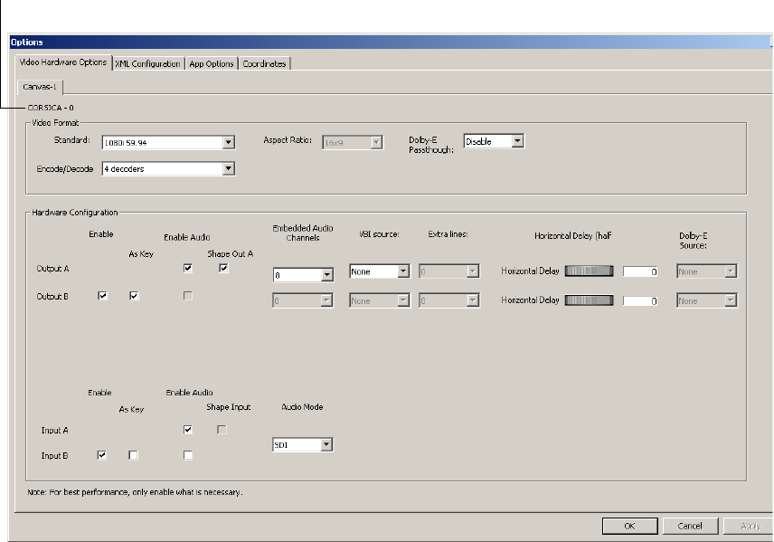
Appendix A Configuring DekoCast
416
Video Hardware Options
Use the Video Hardware Options tab to configure options for your system’s video board
(canvas). The type of video board (TARGA or Corsica) is listed near the top of the tab.
The following topics describe options in the two sections of this dialog box:
•“Video Format Settings” on page 417
•“Hardware Configuration Settings” on page 419
Type of video board
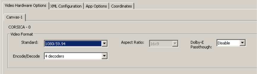
Video Hardware Options
417
Video Format Settings
The video format settings in the Video Hardware Options tab determine the expected format
of video inputs, outputs, and clip playback files for the video board. Changes to these
settings take effect after you restart the application. DekoCast is available in a standard
definition model (DekoCast SD), a high-definition model (DekoCast HD) and a hybrid
model (DekoCast SD/HD). The options that appear in this tab depend on the model of your
system.
The following topics provide information about the video format settings.
Video Standard and Aspect Ratio Options
Your options available for the video standard depend on the model of your DekoCast system.
If you have a hybrid system, you can switch between an SD and an HD format. For more
information, see “Switching Between Video Formats” on page 29.
To set the video standard:
1. Select Options > Preferences.
2. Click the Video Hardware Options tab.
3. From the Standard menu, select one of the following:
-NTSC
-PAL
- 720p 59.94
- 720p 60
- 1080i 50
- 1080i 59.94
- 1080i 60
4. If necessary, select the appropriate aspect ratio.
Appendix A Configuring DekoCast
418
For SD, you can select 4 x 3 or 16 x 9. HD formats always use 16 x 9.
5. Click OK.
Dolby-E Passthrough Option
If you select Enable from the Dolby-E Passthrough list, all typical audio processing, such as
mixer routing and level changes, is disabled. With this option enabled, DekoCast passes
through the compressed audio streams unaltered and delayed the same as the video.
For each output port listed in the Hardware Configuration section, select the input port for
the compressed audio from the output port’s Dolby-E Source menu. No other manipulations
of the audio stream are possible in this passthrough mode. When DekoCast is started, audio
passthrough occurs immediately and continues until DekoCast is shut down.
If you select Disable, normal audio processing occurs. In normal DekoCast processing,
audio is not heard on output unless a scene is created or opened that has a video input object
as a child of a video output object. Audio level settings and mixer route settings are applied
normally.
To enable Dolby-E passthrough:
1. Select Options > Preferences.
2. Click the Video Hardware Options tab.
3. From the Dolby-E Passthrough list, select Enable.
4. For each output port listed in the Hardware Configuration section, select the input port
for the audio from the output port’s Dolby-E Source menu.
5. Click OK to apply your settings and close the dialog box.
Encode/Decode Option
This option is available only on Corsica-based systems.
A Corsica video board is designed to function with four codec streams. These streams are
used by the DekoCast application to encode (capture) and decode (render and play) video
media. A Corsica video board can encode up to two independent streams of video (one clip
with key or two clips) and can decode a combination of video and key for a total of four
streams (for example, one clip with key and two clips without key, or four clips without key).
For more information, see “Playing Back Clips” on page 140 and “Capturing Clips” on
page 165.
You have three options for assigning these streams:
•4 decoders (streams used for playback)
•2 encoders (streams used for capture)
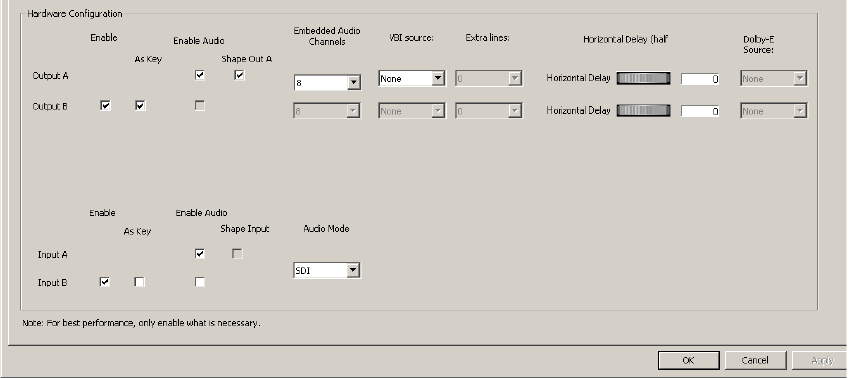
Video Hardware Options
419
• 1 encoder, 2 decoders (1 stream for used for capture, 2 streams used for playback)
To set the encoding/decoding option:
1. Select Options > Preferences.
2. Click the Video Hardware Options tab.
3. Select the setting you need for your task (playback, capture, or both).
After you change the encoder/decoder setting, the video board shuts down, the clip and
audio capture and playback objects stop, and the video board is reprogrammed with the
new configuration. During this process, which takes from 15 to 20 seconds, the OK and
Cancel buttons in the dialog box are not available.
4. Click OK.
Hardware Configuration Settings
Hardware configuration settings in the Video Hardware Options tab let you configure input
and output ports.
nEnable additional video ports only when necessary. Using video ports consumes a portion of
the total pixel-processing power of the system.
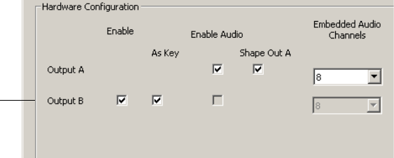
Appendix A Configuring DekoCast
420
The following topics describe hardware configuration settings:
•“Video Output Configuration Settings” on page 420
•“Audio Output Configuration Settings” on page 421
•“VBI Source and Extra Lines” on page 422
•“Horizontal Delay” on page 423
•“Video Input Configuration” on page 423
•“Audio Source Configuration” on page 424
•“Shape Input and Output” on page 425
Video Output Configuration Settings
A DekoCast system has one video output port, Output A, which is always active. You can
configure a second video output port (Output B) for upstream mode operation.
To use an output port in upstream mode:
1. Select Options > Preferences.
2. Click the Video Hardware Options tab.
3. In the Hardware Configuration section, select Enable for Output B.
4. Select the As Key option.
5. Click OK.
nTo view the keyable objects in a DekoCast scene, you have to delete or reduce the size of the
Video Input object because its full-screen key obstructs the individual keyable elements in
the scene.
Output B set
for upstream
mode with
key
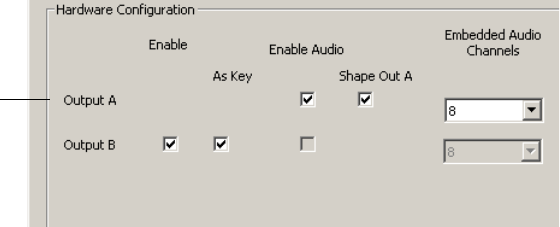
Video Hardware Options
421
Audio Output Configuration Settings
You can enable embedded audio for one output port, Output A. Enable audio output only if
you need it because a port with audio enabled consumes audio mixer hardware resources,
leaving fewer resources available for voice-overs or audio associated with video clips.
nDisabling audio on Output A disables all audio in DekoCast.
To enable embedded audio output:
1. Select Options > Preferences.
2. Click the Video Hardware Options tab.
3. In the Hardware Configuration section, select the Enable Audio option.
4. From the Embedded Audio Channels list, select the number of audio channels available
for the output:
- DekoCast SD can process up to 8 channels of embedded audio.
- DekoCast HD can process up to 16 channels of embedded audio.
The number of output channels is always selected in pairs.
5. Click OK.
Changes to these settings do not take effect until you restart DekoCast.
nTARGA-based SD systems support 16-bit audio. Corscia-based SD systems support 20-bit
audio, and Corsica-based HD systems support 24-bit audio.
Output A
configured for
8 channels of
embedded
audio
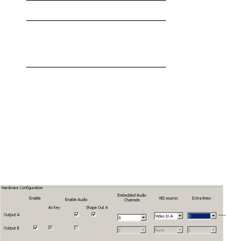
Appendix A Configuring DekoCast
422
VBI Source and Extra Lines
You can select the video input source for Vertical Blanking Interval data used with the VBI
object (see “Working with VBI Objects” on page 188).
The following table shows which lines of vertical blanking are passed from the selected
input to the output for each video standard.
The Extra Lines setting, which is used in conjunction with the VBI Source setting, sets the
number of additional lines at the top of the visible picture that are to be considered part of
the VBI data. These lines are copied from the VBI source and protected from modification
resulting from DVEs and overlaid graphics. The setting selects from 0 to 10 lines per field.
nEnable the VBI Source and Extra Lines options only when necessary. Each of these
consumes a portion of the total pixel processing power of the system.
To enable VBI preservation:
1. Select Options > Preferences.
2. Click the Video Hardware Options tab.
3. In the Hardware Configuration section, select the input port from the VBI source list:
Video In A or Video In B.
4. From the Extra lines list, select the number of extra lines to be passed to output.
5. Click OK.
Standard
First Line
of VBI
No. of Lines
of VBI
NTSC 10 10 per field
PAL 13 10 per field
1080i 6 15 per field
720p 6 20 per frame
VBI source
selected with
3 extra lines
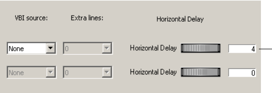
Video Hardware Options
423
Changes to these settings do not take effect until you restart DekoCast.
Horizontal Delay
By adjusting the Horizontal Delay thumbwheels, you can set the video output horizontal
timing delay relative to the current reference. Units are in pixel components. If an analog
video or black burst signal is present on the reference port, it is used as the system timing
reference. If neither is present, the first video input port is used. The setting can be positive
for delay and negative for advance to reference. For example, a setting of 4 delays the output
four components, or two pixels relative to reference.
To set the video output horizontal timing delay:
1. Select Options > Preferences.
2. Click the Video Hardware Options tab.
3. In the Hardware Configuration section, click and drag the Horizontal Delay thumbwheel
for the appropriate output port. Units are in pixel components.
4. Click OK.
Changes made to this setting take effect immediately.
Video Input Configuration
A DekoCast system has two video input ports. Video Input A is enabled by default. Input B
can be enabled as a second video in, or set as key.
To enable a second video input port:
1. Select Options > Preferences.
2. Click the Video Hardware Options tab.
Horizontal
timing delay
set for 4 pixel
components
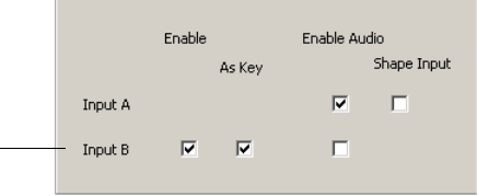
Appendix A Configuring DekoCast
424
3. In the Hardware Configuration section, select the Enable option for Input B.
4. (Option) Select the As Key option.
5. Click OK.
Audio Source Configuration
You can enable audio input for Input A or Input B. Depending on your system, you can also
select the audio mode.
• On a DekoCast SD system, only SDI audio is available (Audio Mode is dimmed).
• On a DekoCast HD system, the Audio Mode menu lets you choose either SDI or AES.
A DekoCast HD system might include a special board that includes two AES input
connectors. Each connector carries a stereo pair. Each Video Input object in DekoCast has
associated audio controls and when in AES mode, the Video Input objects obtain their audio
from the AES connectors. Both video input ports obtain the same audio from these AES
connectors. That is, they both obtain channels of audio from AES ports 1/ 2 and 3/ 4.
When Dolby-E passthrough is enabled, you can select SDI or AES input. See “Dolby-E
Passthrough Option” on page 418.
To enable audio input:
1. Select Options > Preferences.
2. Click the Video Hardware Options tab.
Input B
enabled
as key
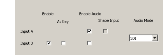
Video Hardware Options
425
3. In the Hardware Configuration section, select the Enable Audio option for Input A or
Input B.
4. (DekoCast HD only) Select the Audio Mode: SDI or AES.
5. Click OK.
nAn Audio Input or Output is available only if the corresponding Video Input or Output is
enabled.
Shape Input and Output
Select the Shape Input option for Video Input A or Video Input B signals to have the video
multiplied by its key (shaped).
By default, the outputs of the HD video board are shaped, which means that the video is
multiplied by its key. (Deko graphics are shaped.) The transparent areas of a shaped graphic
are black. When the video is multiplied by a key of zero, the result is zero for the video
component and by definition, zero is black.
nSD output is always shaped.
Some mixers require unshaped video. In this case, DekoCast HD systems can output video
that is not multiplied by the corresponding key output. Unshaped output can be selected only
when the video output is configured to have a video plus a key.
For example, Video Out A can be set to unshaped only if Video Out B is configured as key.
To unshape a video source, the corresponding key that shaped the video is required.
To configure shaped input and output:
1. Select Options > Preferences.
2. Click the Video Hardware Options tab.
Input A
enabled
for audio
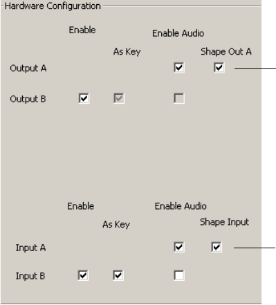
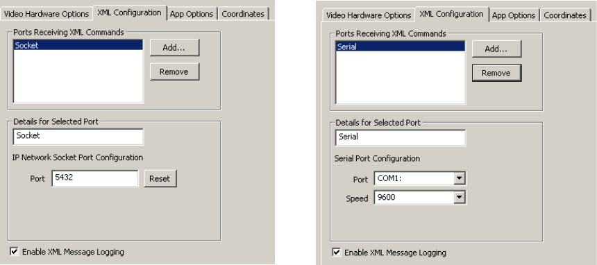
XML Configuration
427
XML Configuration
DekoCast can accept external XML commands through IP sockets or serial ports. The XML
Configuration tab lists the ports that can receive XML commands and displays details about
a selected port’s settings that you can modify. XML commands and output are included in
the DekoCast message log file.
For more information, see “Ports for Automation Control” on page 363.
To add a port for receiving XML commands:
1. Select Options > Preferences.
2. Click the XML Configuration tab.
3. Select Add New Serial Port or Add New IP Socket Port.
Information about the port is displayed.
4. If desired, modify the socket port or the serial port configuration.
5. Click OK.
To remove a port from the list:
tSelect it from the list, click Remove, and click OK.
To turn off DekoCast logging of XML commands and output:
tDeselect Enable XML Message Logging and click OK.
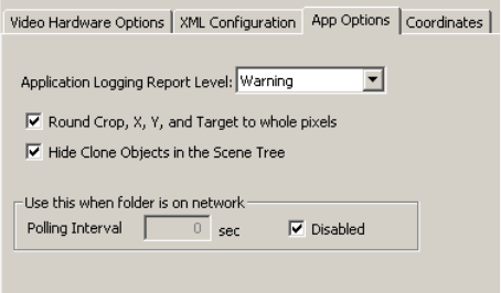
Appendix A Configuring DekoCast
428
Application Options
The App Options tab lets you set these DekoCast options:
• Application Logging Report Level
Use the Application Logging Report Level option to specify the level of messages to be
recorded in the log window. In decreasing order of severity, the levels are Fatal, Severe,
Warning (the default), Info, and Verbose, which records everything. All messages up to
and including the selected severity level are written to the DekoCast log file.
nThe DekoCast log files are located in the same directory as the application.
• Rounding Options
By default, pixels are rounded to whole pixels for cropping, X and Y coordinates, and
Target Rectangles. If you want fractional control of pixel positions, deselect this option.
• Hide Clone Objects in the Scene Tree
Copies of the objects called clones are added to the Scene Tree as children of the Crawl
object as each line of the crawl is buffered for output. By default, cloned objects are not
shown in the Scene Tree. Select this option to have clones display in the Scene Tree.
Clones are deleted when the object no longer displays on the video output (has crawled
off). A changing list of clones indicates that the text continues to crawl. When the clones
disappear from the Scene Tree, the text has stopped crawling. Objects that you insert
between lines of text also generate clones that function in the same way.
Output Frame Coordinates
429
• Polling Interval for Folder on Network
Normally, DekoCast relies on the Windows Notification application to inform it when a
.txt file linked to a Deko object (in the Contents tab of the Deko object editor) has
changed. Sometimes, particularly when a .txt file is located on a remote node, Windows
Notification fails. In this case, select this option to set how often DekoCast checks for an
updated file.
Click OK to save your settings.
Output Frame Coordinates
The Coordinates tab lets you define the coordinates for the output frame. Changing the
coordinates in this tab does not change the video resolution or aspect ratio, but it does
change how the coordinates map to the user interface for the Target tab.
For example, DekoCast's point of origin is at the top left, so by default the Top setting and
the Left setting are both 0 (zero). If in a 1080i project you prefer to use the center of the
screen as the point of origin for Target rectangles, you can change the scene coordinates to
Top –540, Left –960, Right 960, Bottom 540. Create a new scene using the 1080i standard
and notice that the Target rectangle reflects these new coordinates.
However, keep in mind that changing the output frame coordinates in this way is for the
user’s preference and does not change the actual resolution of the scene. To change the
resolution of the scene, change your hardware settings.
You can select to be prompted to enter scene coordinates each time a scene is opened or
created.
nAny currently opened scene has to be reopened before the new coordinates take effect.
To set the output frame coordinates:
1. Select Options > Preferences.
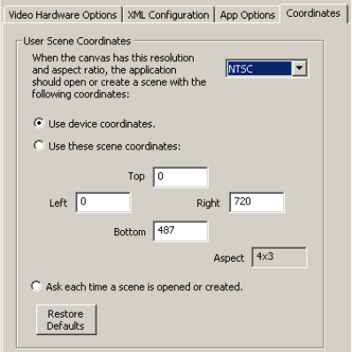
Appendix A Configuring DekoCast
430
2. Click the Coordinates tab.
3. Select a video format from the list in the upper right.
4. Select one of the three options:
- Use device coordinates: The application uses the default coordinates of the video
format.
- Use these scene coordinates: type coordinates in each text box.
- Ask each time a scene is opened or created: When you open a scene, a dialog asks
you which coordinates you want to use: coordinates for the default format or
coordinates that you have set.
5. Click OK.
Transcode and Scene Options
If your system uses a Corsica video board, you can use the Transcode and Scene Options tab
to configure options for transcoding clips to the native playback format MPEG-2
MXF I-Frame. This topic describes options on this tab. For more information on transcoding
clips and using the Transcode application, see “Transcoding SD Clips to MPEG-2 MXF I-
Frame” on page 149.
cTranscoding uses CPU resources and could delay playout to air. Avid recommends that
you perform transcoding on a DekoCast Authoring Station or when a DekoCast system
is not on-air.
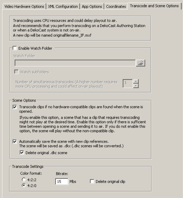
Transcode and Scene Options
431
To set the transcode preferences:
1. Select Options > Preferences.
2. Click the Transcode and Scene Options tab.

Appendix A Configuring DekoCast
432
3. Select the options you want and click OK.
The following table describes the options you can select.
Transcode and Scene Options
Option Description
Enable Watch Folder Enables the watch folder you specify. To specify a watch
folder, click the browse button, navigate to the folder you want
to use, and click OK. When you copy non-compatible clips
into this folder, they are automatically transcoded using the
settings in this tab. Transcoded clips are saved in the watch
folder. See “Transcoding Clips By Using a Watch Folder” on
page 159.
This option also sets the Transcode application to start
automatically whenever DekoCast starts. Setting this option
and clicking OK starts Transcode immediately, if it is not
currently running.
Disabling this option does not close Transcode immediately.
Transcode continues to process any current jobs and closes
when no jobs are in process.
Watch subfolders Specifies that Transcode should watch for clips that need
transcoding in all folders that are contained in the watch folder
you specify.
Number of simultaneous transcodes Specifies the number of jobs that Transcode can process
simultaneously, from 1 to 4. This number is used only when
Transcode is automatically started. If you open Transcode
manually (standalone mode), Transcode processes up to four
simultaneous jobs.
Specify a number higher than 1 only if you plan to transcode
clips when the system is off-air.
Scene Options section Lists options for how Transcode opens and closes a scene if
the scene references clips not compatible with the Corsica
hardware (for example, DV clips).

Transcode and Scene Options
433
Transcode clips if no hardware-
compatible clips are found when
the scene is opened.
Sets Transcode to automatically transcode any
non-hardware-compatible clips if it cannot find corresponding
hardware-compatible clips. If this option is not set, the scene
plays but does not play the non-hardware-compatible clips.
See “Transcoding Clips When a Scene Opens” on page 163.
cIf you enable this option, a scene might not play at
the desired time. Enable this option only if there is
sufficient time between opening a scene and sending
it to air.
Selecting this option also enables automatic transcoding of
clips that you link to through the Clip Playback editor.
Automatically save the scene
with new clip references
Sets DekoCast to save a scene that references
hardware-compatible clips when you close the scene. This
option takes effect if the original scene referenced
non-hardware-compatible clips and compatible clips were
found. Selecting this option overwrites the original .dkx scene
or converts a .dkc scene (created on an earlier version of
DekoCast) and saves the scene using the extension .dkx.
For example, if the scene references “OTSleft.dv” and
DekoCast finds and plays “OTSleft_IF.MXF,” the scene is
saved with a reference to “OTSleft_IF.MXF.” Saving a scene
with this option keeps references to the actual clips that
played, and minimizes confusion if you copy the scene to
different machine.
If you do not select this option, the scene is not changed, and
DekoCast searches for the compatible clip every time the
scene is opened.
Delete original .dkc scene Sets DekoCast to delete the original .dkc scene to avoid
confusion about which scene file is correct.
Transcode Settings section Lists options for default transcode settings
Color format Sets MPEG-2 4:2:2 or MPEG-2 4:2:0. Both are MXF I-Frame
formats.
Bitrate Sets the bitrate for the clip. A larger bitrate number results in a
superior image, but uses more disk storage and network
bandwidth. In most cases, use the bitrate of the source file;
using a bitrate higher than that of the source does not improve
the image.
Transcode and Scene Options (Continued)
Option Description

Appendix A Configuring DekoCast
434
Delete original clip Sets Transcode to delete the clip that uses the non-compliant
format. This option does not apply when you transcode clips
by opening the Transcode application or by dragging clips to
the Transcode icon. This option applies only when you
transcode through a default watch folder or automatically
when a scene opens.
Select this option only if you have tested your workflow and
are confident that transcoding works successfully.
Transcode and Scene Options (Continued)
Option Description

Appendix B
BDekoCast Tips
The following tips can help you manage your system resources and work more efficiently.
cSave your work frequently to avoid losing any part of your project. DekoCast does not
have an autosave feature or an undo command.
• When creating projects, be aware of DekoCast resource limitations. If the output is
jittery, you have exceeded the limit.
• Check the Performance meters. The video processing resources for your system are
exceeded when the meters enter the red zone. As you develop your scenes, it is best not
to exceed 80 percent on any of the meters. See “Performance Tab” on page 34.
• Determine how much video memory is available (free). To do so, select Help > About
DekoCast. Clip Playback and Clip Capture objects consume a significant amount when
clips are cued or playing. Cel Animation objects consume a variable amount. Other
objects consume little or no additional video memory. To compute the amount of video
memory used by a Cel Animation object, use this formula:
Memory requirement (in bytes) = width (in pixels) x height (in lines) x total frames x 4
For example, for a Cel Animation object that measures 200 x 200 and has 30 frames:
200 x 200 x 30 x 4 = 4,800,000 bytes = 4.8 Mb
Cel animation frames should be created as small as possible.
• When you create a Cel Animation objects and specify a set of files, those files are stored
in memory. If you are working with several Cel Animation objects, and you need to free
memory, clear the file name of one of the Cel Animation objects.
• Determine how many streams (sometimes called codecs) are in use. For information
about how your DekoCast system uses codecs, see “Understanding Clip Playback” on
page 141.
B DekoCast Tips
436
• Clip playback objects consume codec resources whenever clips are playing or are cued.
A single clip playback can consume twice as many codecs if it is playing one clip and
has another cued. You can monitor the number of streams available by checking the
value of the Canvas-number codecs free parameter in the Parameters tab of the main
DekoCast window. For example, a value of 2 means there are two free streams available
from the video board’s codec.
• DekoCast processing resources can be estimated in full screens of pixels (or full-screen
layers).
- A DekoCast SD system with a TARGA video board has an approximate limit of
six-to-eight screens of pixels.
- A DekoCast SD system with a Corsica video board has an approximate limit of 20
screens of pixels (full-screen layer).
- A DekoCast HD systems with a Corsica video board has an approximate limit of
six-to-eight screens of pixels.
To conserve processing resources, do not build a full-screen layer (even if it is mostly
empty). For example, one object might cover one-third of a screen (the upper-third),
another object might coves the middle-third, and another object might cover the
lower-third of the screen. These three objects together equal one screen of pixels. If the
objects are built full screen, but contain graphics or text that covers only a third of the
screen, then each full-screen layer is counted as one screen of pixels.
• Avoid using Deko objects set to Entire Graphic when only one layer is desired. Doing so
forces the object to be resized or resampled, which slows processing and produces a soft
appearance.
• Graphics should be 720 x 486 pixels for NTSC and 768 x 576 for PAL.
• The home position of a PostDeko graphic is the position of the layer in the original
graphic (DKO file).Therefore, when the values of X and Y are set to their default of
zero, the layer is in the home position. The default value for Scale is 1, and the size is
that of the original graphic.
• X Position parameters should always be integers.
• Y Position parameters should always be even integers.
The following tips can help you work more efficiently.
• Create only one custom typeface directory. It is recommended to create one custom
typeface directory called D:\CustomTypefaces. Keep all custom typefaces together in
this directory. Be sure that the preferences in PostDeko Lite (select Options >
Preferences > Paths) use the Custom Typeface field with the correct directory location.
If you use macros in PostDeko Lite to change directories, then name the directory
CustomTypefaces. (Macros do not recognize a space between names for a directory.)
You should also avoid using underscores and spaces in directory names.
437
• Directory defaults for Deko graphics and all components of Deko graphics are set
within PostDeko Lite.
• Always name Deko layers and refer to them by name in DekoCast.
• If DekoCast is on air, do not use the DekoCast interface. DekoCast must be offline to
edit or add scenes.
• Close DekoCast before running DekoCast Central on air.
• Keep data sources local, not networked. Whenever possible, keep the data sources of
text files or databases local to the DekoCast computer instead of having the scene access
files across a network. Six-to-ten layers in a DekoCast scene updating every second
across a network could result in varied runtimes and various networking issues.
B DekoCast Tips
438
A
Action list
using 301
Action Parameter list
described 304
reordering items 317
Action parameters See Parameters
Actions
adding to Action list 301
basic steps for creating 300
changing timing in Sequence 408
check list for creating 327
copying and pasting 318
defined 297
defined parameters 312
deleting 301
editing 318
example, lower-third reveal 333
example, squeeze and tease 330
example, unsqueeze 331
example, wipe 332
executing using Y command 367
looping 340
mapping to House ID 370
playing 317
recording 303
renaming 301
selecting multiple 301
specifying with Y command 366
text override 306
Time Capture 314
time-related 311
triggering another action 340
types of 299
Active text status 128
Adobe After Effects 32
Adobe Photoshop 32
Alpha channel
for Cel Animation objects 176
for Deko objects 185
Alpha slider 81
Animate mode
working in 303
API
application 26
controlling scenes through 76
custom third-party 26
VBI objects and API clients 68
with Crawl object tags 215
with VBI 188
App Options tab 428
Appending
clips 148
Aspect ratio
configuring 417
for cel animation 173
preserving in Crawl rectangle 208
preserving in target rectangle 93
Asset Viewer utility 363
Attach to Selected Object command 320
ATX files 42
cycling using Aut File Sequencer 393
source for crawl text 197
Audio
channel routing 105
editing 103
output, configuring 421
playback 136
source, configuring 424
supported file formats 41
Audio Capture objects
described 138
Audio Playback objects
Index
Index
440
described 136
source files 136
Aut File Sequencer 393
AUT files 42
source for crawl text 197
Automation Control Interface (DekoCast Central)
described 354
fonts 361
window 361
Automation files
Aut File Sequencer control 393
Aut File Sequencer playback 393
Automation system
M command 355, 364
W command 364
Y command 355, 366
Autoscale options
Fit 93
illustrated 91
None 92
Preserve 93
AVI files
playback 143
playing back embedded audio 136
B
Background
color 81
Deko object layer 113
opacity 81
setting custom colors 82
Bug
defined 68
Byte Stream Command Interface (BCI) 26, 363
C
Canvas
described 60
Canvas parameters
described 336
Capture keyframes
adding 315
Capturing
clips, overview 165
clips, procedure 172
setting up (Corsica systems) 166
setting up (TARGA systems) 168
Carriage return
with text 117
Cel Animation objects
appearance 176
brief description 68
commands for playback 177
described 173
displaying individual frames as 181
playback 177
playback status 179
updating 179
Cel animations
aspect ratio 173
defining source file 175
guidelines for creating 173
memory requirements 435
playback rate 173
supported file formats 41
Change Parameter command 320
Channel Level dB 103
Chart Designer
accessing 220
Charts and Graphs 219
Chyron keyboard commands 367
Clip Capture objects
described 165
supported file formats 41
Clip Playback objects
adding 144
appending clips in 148
brief description 67
codecs 141
described 140
file and compression formats 143
keys for 147
looping 148
managing playback 143
options 147
stopping clip playback 148
supported file formats 41
Clips
capturing 165
Clocks
displaying 131
formats for defining 133
Index
441
Clone objects
setting preference 428
Clones (with Crawl object) 194
Closed caption data 188
Closing
DekoCast 27
Codecs
for clip playback 141
managing for playback 143
Collapsing
branch in Scene Tree 70
Command queues 367
Commands
embedded tags for Deko object text 128
for Cel Playback objects 177
Compositing
Crawl objects 197
group objects 184
objects 72
Configuring
overview 29
Constant keyframe style 322
Continuous keyframe style 324
Coordinates
defining for output frame 429
Coordinates tab 429
Copying
files 42
Corsica video board
codec for 141
Count timer
displaying 133
Crawl objects
adding 193
adding non-text objects 205
adding non-text objects as custom typefaces 216
adding non-text objects, example 210
composite options 197
described 192
opacity 196
pads in and out 196
parameter values for inserted objects 212
positioning non-text objects 208
roll 195
rules for non-text objects 209
spacing 196
specifying rules 206
speed 196
triggering actions 214
using crawl object tags objects 215
Crawl rectangle
setting 204
Crawl text
changing 197
changing appearance 201
controlling display 200
Crawls
Crawl object 192
Deko object 123
Creating Charts
advaned controls 229
basic procedure 222
Cropping objects 96
Curved keyframe style 323
Cusp keyframe style 323
Custom typeface directory 436
Custom typefaces
for inserting non-text object in a crawl 216
D
Data streams tab 355
Data tab (Text Data object) 200
Database
linking objects to 343
Decoders
configuring for 418
Deko clips
playback 143
Deko graphics
copying 42
layers 108
linking with Deko object 109
supported file formats 42
Deko objects
adding to scene 109
as part of Crawl object 192
background layer 113
clock formats 133
clocks 131
Contents tab 119
crawls 123
cropping 115
described 108
Index
442
editing 114
file formats 42
guidelines for adding 113
looping options 127
mask 185
opacity 116
overriding text value in DekoCast Central 382
positioning 115
removing background object 111
rolls 123
scaling 115
scroll padding 126
sizing 115
text 116
text files 121
text layers, example 112
text transition options 125
text, overriding 117
transition triggering options 125
updating 114
updating text layers using W command 364
Deko Page Recall utility 385
DekoCast
configuring 415
configuring, overview 29
products 23
tips for managing resources 435
workflow 25
DekoCast application
closing 27
directory setup 37
enabled options 44
installing 27
starting 27
version 44
video memory 44
DekoCast Central 26
Aut File Sequencer 393
Automation control 363
Automation Control Interface 361
automation notes 363
closing application 354
command queues 367
configuration for Triple i command port 355
configuring for automation 355
configuring GPIs 358
Deko Page Recall utility 385
Emergency Alert System interface 395
GUI action setup 381
GUI/Automation Control interfaces 354
House IDs 370
logging 360
opening the GUI 378
overview 352
scene setup in GUI 380
Sequencer Control utility 383
starting application 354
Temperature Probe utility 386
utilities 383
viewing resources 362
DekoCast Central Playback Controller
adding playlist event 374
copying playlists 378
deleting events 374
looping actions 377
modifying events 374
opening 374
playing events 377
scheduling events 374
DekoCast log files
location 428
DekoCast window
adjusting 36
described 30
Detach command 320
DGH temperature probe
configuring 387
described 386
DIF files
playback 143
Digidesign Pro Tools 32
Directories
setting up 37
DKC files
converting to DKX files 40
DKO files 42
DKX files
described 40
Dolby-E passthrough 418
Draw box
described 60
DV files
playback 143
Index
443
E
EAS (Emergency Alert System) interface 395
configuring 396
creating scene 395
Edit Value dialog box 326
Embedded tags
for Deko objects 128
Emergency Alert System (EAS) interface 395
configuring 396
creating scene 395
Encoders
configuring for 418
Exit actions 382
Expanding
branch in Scene Tree 70
External RS-232 GPI box 360
F
Field Identifier strings 191
Files
copying 42
supported formats 41
text 121
Fit (Autoscale option) 93
Formats
for clip playback 143
Frame Grab objects
described 186
supported formats 42
Frames
displaying individual 181
Full-screen images
supported file formats 42
G
GPIs
configuration 358
external RS-232 box configuration 360
local configuration 359
GPIs tab 358
Graphical User Interface (DekoCast Central)
action setup 381
described 354
Exit actions 382
opening 378
Pre-Start actions 382
scene setup 380
setting size of buttons 379
Start actions 382
Group objects
adding 183
compositing styles 184
described 181
opacity 183
H
Hardware Configuration settings 419
High-definition model 23
Horizontal delay 423
House IDs 370
configuring to play multiple actions 371
deleting 371
Lookup Table 370
modifying 371
overriding object parameters 372
XML files 372
Hybrid model 23
switching formats 29
I
Immediate commands
for Cel Animation objects 177
In-line tags
for Deko objects 128
K
Key
as mask with Deko objects 185
configuring for output 81
configuring for video output 420
discarding key information 84
for Cel Animation objects 176
for Clip Playback object 147
supported file formats for clips 41
supported formats for Cel Animation 41
video input 423
video input, selecting 84
Key option (Clip Playback objects) 147
Index
444
Keyframe style
constant 322
continuous 324
curved 323
cusp 323
linear 322
smooth 324
Keyframe style buttons 321
Keyframes
adding 325
adjusting time and value 326
defined 300
deleting 325
editing value 326
in Timeline graph 307
selecting 325
style buttons 321
KOf (Key Offset)
with Clip Playback objects 147
L
Layers
in Deko graphics 108
naming in PostDeko Lite 114
Layouts
custom window layouts 36
designing 96
suggestions for preparing 99
transferring to a scene 100
Levels tab
color coding 106
using 103
Linear keyframe style 322
Logs
DekoCast Central 360
described 36
location 428
report level options 428
Service Messages 360
XML commands 427
LookupTable.xml 372
Looping
actions 340
clips 148
Deko objects 127
text 121
Lower-third reveal action 333
M
M command 355, 364
Masks
for Cel Animation objects 176
Meters
monitoring 34
Mixer tab
color coding 106
using 105
Motion curve
editing 321
MPEG-2 files
playback 143
MXF files
playback 143
N
Network polling interval 428
New Line Feed
with text 117
None (Autoscale option) 92
Non-text objects
adding to crawl 205
triggering action within crawl 214
Normal Crawl composite option 197
Normal option (Cel Animation objects) 176
NoScale option (Clip Playback objects) 147
O
Object editor
described 33
using 80
Object parameters
described 336
overriding 372
Object toolbar 64
Objects
adding to Scene Tree 64
arranging for video output 86
brief descriptions 66
changing scale 95
composite order 72
Index
445
cropping 96
deleting 71
grouped 73
naming 69
parent-child relationships 74
rearranging in Scene Tree 73
renaming 69
scaling in relation to target rectangle 91
video output position 95
ODBC databases 343
On-air video output control 26
Online help 37
Opacity
Cel Animation objects 176
Crawl objects 196
Deko objects 116
Group objects 183
Video In objects 85
Order number
described 60
P
Padding
in Crawl objects 196
Parameters
adding from Parameters tab 306
adding to an action 304
attaching 320
copying and pasting 319
defined 80
detaching 320
editing in Sequence 411
editing values 338
overriding 372
preserving passive 316
reordering 317
replacing 320
replacing with database results 343
searching for 337
types of 336
user 340
Parameters tab
described 35
using 336
Parent-child relationships 74
Performance
tips for managing 435
Performance meters 62
Performance tab
described 34
Pixel rounding options
configuring 428
Playback
controlling through Sequence 409
through DekoCast Central 352
Plug-in objects
adding to scenes 217
Polling interval 428
Port Level dB 103
Ports
automation 361
COM 363
enabling 419
Triple i command 355
video input 423
video input, selecting 84
video output 420
video output, selecting 81
Position tab
using 95
PostDeko Lite
copying Deko graphics 42
default directories 37
defining font style for crawl text 201
described 24
naming layers 114
Preferences
setting 415
Preferences dialog box
opening 415
Preserve (Autoscale option) 93
Pre-Start actions 382
Pro Tools 32
Q
Queued
text status 128
Queued commands
for Cel Animation playback 177
Quick Start
fading a graphic on and off 45
Index
446
R
Rendering
text status 128
Resources
tips for managing 435
Rolls
Crawl object 195
Rolls (Deko object) 123
Rules
deleting and replacing 209
for Crawl objects 206
S
Sample scenes and media
using 57
Scaling
in Position tab 95
objects 95
objects in target rectangle 91
Video in objects 84
Scene directory, setting with M command 364
Scene files
described 40
Scene parameters
described 336
Scene Tree
described 32
expanding and collapsing 70
parent-child relationships 74
rearranging objects 73
using 70
Scenes
closing 62
creating 61
described 31
inserting into another scene 71
new 61
opening existing 63
pane 59
removing from video output 75
renaming 62
saving 62
selecting for video output 75
setting for exclusive output 75
single versus multiple 76
stack order 76
toolbar 59
Scroll pad
with Deko objects 126
Scrub bar
defined 300
Sensatronics temperature probe
configuring 390
defined 386
Sequence
application toolbar 412
changing action timing 408
copying and pasting items 408
creating list of actions 403
deleting and replacing items 407
editing a list 407
editing action parameters 411
editing items 407
external GPI control of files 383
playback 409
starting the application 402
Sequencer Control utility 383
Serial Digital Interface (SDI) input 27
Service Messages logging 360
Shape option (Clip Playback objects) 147
Shaped input/output
configuring 425
Shaped option (Cel Animation objects) 176
Smooth keyframe style 324
Squeeze and tease example 330
Stack order 76
Standard-definition model 23
Start actions 382
Starting DekoCast 27
Streams
for clip playback 141
managing for playback 143
Sum
Crawl composite option 197
Group composite option 185
SWAP command 367
Switching formats 29
System resources
monitoring 34
Index
447
T
TARGA video board
codecs for 141
Target rectangles
defined 86
defining 89
disabling 89
example, Video In 100
guidelines for using 97
scaling within 91
using 86
Target tab
using 89
Temperature
displaying 136
Temperature probe
displaying results 136
Temperature Probe utility
configuring DGH probe 387
configuring Sensatronics probe 390
described 386
Text
clearing 128
crawls (Crawl object) 192
crawls (Deko object) 123
display status 128
embedded tags for Deko objects 128
overriding 117
overriding in actions 306
rolls
Deko object 123
rolls (Crawl object) 192
using Contents tab 119
using text files 121
working with 116
Text Data objects 199
described 192
supported formats 42
Text files
source for crawl text 199
source for Deko objects 121
Text transition options 125
Text values
overriding in DekoCast Central 382
Third-party software
installing 27
Thumbwheel controls
using 88
Thunder clips
playback 143
Time Capture actions
creating 314
described 299
Timed actions
described 299
Timeline Bar editor
using 308
Timeline editor
described 34
using 299
Timeline graph
described 307
editing motion curve 321
modifying 321
Time-of-day clock
displaying 131
Timers
displaying 131
Timing bar 308
Transcode and Scene Options tab 430
Transcode application
using 152
Transcoding
dragging clips to icon 158
overview 149
preferences 430
suggested workflow 151
using a custom watch folder 161
using a default watch folder 160
using a watch folder 159
using the Transcode application 152
when a scene opens 163
Transition options
for text 125
Trigger actions
creating 309
described 299
Triple i commands
M command 355, 364
port configuration for 355
W command 364
Y command 355, 366
Index
448
U
Unsqueeze action 331
Updating
Cel Animation objects 179
Deko objects 114
Use 8-Bits Only option (Cel Animation objects) 176
User parameters
creating 340
described 336
V
Values
types of 326
Vertical Blanking Interval
See VBI objects
VBI data input source 422
VBI objects
as triggers through API or XML 188
data types 190
defined 188
functionality 189
short description 68
Vertical Interval Time Code (VITC) 188
Video clip file formats
playback 143
Video Format settings 417
Video formats
switching between 29
Video Hardware Options tab 416
Video In objects
editing 84
setting opacity 85
Video input ports
configuring 423
Video Out A signal
selecting 81
Video Out B key signal
selecting 81
Video Out objects
editing 81
setting background 81
setting custom background 82
Video output
arranging objects for 86
configuring 420
specifying ports 81
X, Y coordinates 87
Video standard
configuring 417
Visible objects
arranging 86
defined 86
VITC (Vertical Interval Time Code) 188
W
W command 364
Watch folder
custom 161
default 160
described 159
WAV files
playing back 136
Wipes
creating an action 332
TARGA and Corsica behavior 186
Workflows
DekoCast 25
X
X, Y coordinates
using 87
XML
and VBI objects 188
COM ports 363
command set 363, 363
control of DekoCast 26
message logging 427
port configuration 427
XML Configuration tab 427
Y
Y command 355, 366
