Avid Interplay Central Services Installation & Configuration Guide 1.8 And ICS V1 8 ICG EN
User Manual: avid Interplay Central Services - 1.8 - Installation and Configuration Guide Free User Guide for Avid Interplay Software, Manual
Open the PDF directly: View PDF ![]() .
.
Page Count: 218 [warning: Documents this large are best viewed by clicking the View PDF Link!]
- ICS Version: 1.8 Document Version: 1.0.1
- Important Information
- Revision History
- Part I: Introduction & Overview
- Welcome
- About this Guide
- Licensing and Additional Installation Information
- Intended Audiences and Prerequisites
- Deployment Options
- Port Requirements
- Caching in ICS
- Working with Linux
- RAIDs in ICS
- Introduction to Clustering
- Part II: Installing & Configuring
- Installation Workflow
- Before You Begin
- Obtaining the Software
- Preparing the ICS Installation USB Key
- Installing the Network Interface Cards
- Setting the System Clock and Disabling HP Power Saving Mode
- Setting Up the RAID Level 1 Mirrored System Drives
- Setting Up the RAID Level 5 Cache Drives
- Installing RHEL and the ICS Software
- Booting RHEL for the First Time
- Editing the Network Connections
- Synching the System Clock
- Creating the File Cache on the RAID
- Installing the Interplay Central Distribution Service
- Configuring ICS for Interplay MAM
- Configuring ICS for Interplay Central and/or Interplay Sphere
- Configuring Workflow
- Before You Begin
- Configuring the Interplay Central UI
- Logging into Interplay Central
- Changing the Administrator Password
- Configuring iNEWS Settings
- Configuring Interplay Production Settings
- Configuring ICPS for Interplay
- Configuring the ICPS Player
- Configuring the ICPS Player for Interplay Sphere
- Configuring the ISIS Connection(s)
- Mounting the ISIS System(s)
- Verifying the ISIS Mount
- Verifying Video Playback
- Configuring Wi-Fi Only Encoding for Facility-Based iOS Devices
- Part III: Clustering
- Setting up the Server Cluster
- Clustering Workflow
- Configuring the Hosts File and Name Services File
- Setting Up DRBD
- Starting the Cluster Services
- Joining the Cluster
- Replicating the Cluster File Caches
- Before You Begin
- Mounting the USB Key
- Installing Gluster
- Unmounting and Removing the USB Key
- Creating the Trusted Storage Pool
- Configuring the GlusterFS Volumes
- Making Cache Directories and Changing Ownership
- Mounting the GlusterFS Volumes in Linux
- Testing the Cache
- Ensuring Gluster is On at Boot
- Reconfiguring the ICPS Player for Interplay Central in a Cluster
- Part IV: Post-Installation
- Post-Installation Steps
- Determining the Installed ICS Version
- Verifying Cache Directory Permissions
- Securing the System
- Enabling and Securing the Player Demonstration Web Page
- Backing up the ICS System Settings and the ICS Database
- Monitoring Services and Resources
- Monitoring the AAF Generator Service
- Monitoring ICS High-Availability
- Monitoring Load Balancing
- Observing Failover in the Cluster
- Testing the Cluster Email Service
- Changing the Cluster Administrator Email Address
- Reconfiguring Interplay Central Settings in a Cluster
- Taking a Cluster Node Off-Line Temporarily
- Permanently Removing a Node from a Cluster
- Adding a New Node to a Cluster
- Retrieving ICS Logs
- Log Cycling
- Using SNMP Monitoring on the ICPS Server
- Migrating the ICP Database from Windows to Linux
- Backing up and Restoring the ICS Database
- Appendix A: Installing ICS on Non-HP Hardware
- Appendix B: Table of Deployment Options and Requirements
- Appendix C: Configuring Port Bonding for Interplay MAM (Optional)
- Appendix D: Handling SSL Certificates
- Built-In Browser Functionality
- SAN Certificates
- Understanding the “Certificate Not Trusted” Warning
- Eliminating the Certificate not Trusted and Name Mismatch Warnings
- Generating a Self-Signed Certificate for a Single Server
- Generating a Self-Signed Certificate for a Server Cluster
- Obtaining a Trusted CA-signed Certificate
- Adding a CA-Signed Certificate to a Single Server
- Adding a CA-Signed Certificate to a Server Cluster
- Configuring Google Chrome (Windows)
- Configuring Internet Explorer (Windows)
- Configuring Safari (Mac OS)
- Launching the Windows Import SSL Certificate Directly
- The Interplay Central Application Properties File
- Appendix E: Migrating the UMS Database with the User Management Utilities Tool
- Appendix F: Installing the Chrome Extension for Interplay Central MOS Plug-Ins
- Appendix G: Enabling Interplay Central MOS Plug-Ins in IE9
- Appendix H: Unicast Support in Clustering
- Appendix I: Installing the Interplay Production License for Interplay Central
- Appendix J: Configuring iNEWS for Integration with Interplay Central
- Appendix K: Installing and Configuring the Avid Central Mobile Application for the iPad or iPhone
- Appendix L: Installation Pre-Flight Checklist
- Copyright and Disclaimer

Interplay® Central Services
Version 1.8 Installation & Configuration Guide
ICS Version: 1.8
Document Version: 1.0.1
Important Information
This document provides instructions to install and configure Avid Interplay Central Services (ICS)
version 1.8 for use with Interplay Central 1.8, Sphere (latest plug-in for Media Composer 6.5.x
and 7.0.x and corresponding NewsCutter versions), and Interplay MAM 4.3.x.
For the latest information on the Interplay Central Services, see the documentation available
from the Interplay Central Services page of the Avid Knowledge Base. Updates are occasionally
issued after initial release.
http://avid.force.com/pkb/articles/en_US/readme/Avid-Interplay-Central-Services-Version-1-8-
Documentation
Important: Search the Avid Knowledge Base ICS 1.8 web page for the most up-to-date
ICS 1.8 Installation and Configuration Guide, which contains the latest information that
might have become available after this document was published.
Note: For information on upgrading to ICS 1.8 from an earlier release, see the ICS 1.8
Upgrading Guide, available from the Avid Knowledge Base ICS 1.8 web page.
Revision History
Date Revised
Version
Changes Made
March 24, 2014 1.0 First publication
July 30, 2014
1.0.1
New section “Verifying the hosts file Contents”.
Updated “Adding Host Names and IP Addresses to the hosts File”.
Removed redundant editing of rc.local file from “Mounting the
GlusterFS Volumes in Linux”.
ICS 1.8 Installation & Configuration Guide
2
About ICS 1.8
Please see the Interplay Central Services 1.8 ReadMe and any ReadMe documents pertaining to
the solution(s) by which ICS is used.
ICS 1.8 Installation & Configuration Guide
3
Contents
Important Information ....................................................................................................................... 1
Revision History .................................................................................................................................. 1
PART I: INTRODUCTION & OVERVIEW ........................................................................................................... 10
Welcome .................................................................................................................................................. 11
About this Guide ...................................................................................................................................... 12
Licensing and Additional Installation Information ................................................................................... 12
Front End License Configuration .......................................................................................................... 12
Delivery of Licenses on Back-End Systems ........................................................................................... 13
Installing the iPhone and iPad Apps ..................................................................................................... 13
Intended Audiences and Prerequisites .................................................................................................... 13
Basic Installation Skills .......................................................................................................................... 14
Clustering Skills ..................................................................................................................................... 14
Interplay MAM Skills ............................................................................................................................ 14
Deployment Options ................................................................................................................................ 15
Interplay Central – iNEWS Only ............................................................................................................ 15
Interplay Central – Interplay Production Only ..................................................................................... 16
Interplay Central – iNEWS and Interplay Production ........................................................................... 17
Interplay Sphere Only ........................................................................................................................... 18
Both Interplay Central and Interplay Sphere (Shared ICS) ................................................................... 19
Interplay MAM ..................................................................................................................................... 20
Port Bonding in Interplay MAM ........................................................................................................ 21
Port Requirements ................................................................................................................................... 21
Caching in ICS ........................................................................................................................................... 22
The Dedicated Caching Volume ........................................................................................................... 22
Caching for Interplay MAM .................................................................................................................. 23
Caching for iOS Devices in Interplay Central ........................................................................................ 23
Caching for Sphere ............................................................................................................................... 23
Working with Linux .................................................................................................................................. 24
Installing Linux ...................................................................................................................................... 24
Linux Concepts ..................................................................................................................................... 24
Key Linux Directories ............................................................................................................................ 25
Linux Command Line ............................................................................................................................ 25
ICS 1.8 Installation & Configuration Guide
4
Linux Text Editor (vi) ............................................................................................................................. 27
Linux Usage Tips ................................................................................................................................... 28
Volumes in Linux .................................................................................................................................. 29
Clock Synchronization in Linux ............................................................................................................. 29
Time Zones in RHEL .............................................................................................................................. 30
RAIDs in ICS .............................................................................................................................................. 30
Introduction to Clustering ........................................................................................................................ 31
Single Server Deployment .................................................................................................................... 32
Cluster Deployment .............................................................................................................................. 33
Multicast vs Unicast ............................................................................................................................. 33
Working with Gluster ........................................................................................................................... 34
PART II: INSTALLING & CONFIGURING ........................................................................................................... 35
Installation Workflow............................................................................................................................... 36
Before You Begin ...................................................................................................................................... 39
Make Sure the Host Solutions Are Installed and Running ................................................................... 39
Make Sure You Have the Following Items ............................................................................................ 39
Make Sure You Can Answer the Following Questions ......................................................................... 40
Make Sure You Have All the Information You Need ............................................................................ 42
Make Sure You Change the Default Passwords ................................................................................... 42
Obtaining the Software ............................................................................................................................ 43
Obtaining the ICS Installation Package ................................................................................................. 43
Obtaining Red Hat Enterprise Linux ..................................................................................................... 44
Obtaining Gluster ................................................................................................................................. 45
Obtaining Additional Packages ............................................................................................................. 45
Preparing the ICS Installation USB Key .................................................................................................... 46
Transferring ICS and Linux to the USB Key ........................................................................................... 46
Copying Gluster to the USB Key ........................................................................................................... 48
Installing the Network Interface Cards .................................................................................................... 49
Connecting to ISIS Proxy Storage ......................................................................................................... 49
Connecting to non-ISIS Proxy Storage .................................................................................................. 50
Setting the System Clock and Disabling HP Power Saving Mode ............................................................ 51
Setting Up the RAID Level 1 Mirrored System Drives .............................................................................. 52
Setting Up the RAID Level 5 Cache Drives ............................................................................................... 54
ICS 1.8 Installation & Configuration Guide
5
Installing RHEL and the ICS Software ....................................................................................................... 56
Booting RHEL for the First Time ............................................................................................................... 58
Booting from the System Drive ............................................................................................................ 59
Changing the root Password ................................................................................................................ 60
Verifying the Date and Time................................................................................................................. 60
Setting the Time Zone .......................................................................................................................... 61
Editing the Network Connections ............................................................................................................ 62
Identifying NIC Interfaces by Sight ....................................................................................................... 62
Verifying the NIC Interface Name ........................................................................................................ 63
Swapping NIC Interface Names ............................................................................................................ 64
Removing the MAC Address Hardware References ............................................................................. 65
Configuring the Hostname and Static Network Route ......................................................................... 66
Verifying the hosts file Contents .......................................................................................................... 68
Verifying Network and DNS Connectivity ............................................................................................. 69
Synching the System Clock ....................................................................................................................... 70
Creating the File Cache on the RAID ........................................................................................................ 72
Partitioning the RAID ............................................................................................................................ 72
Creating the Logical Volume and Mounting the Cache ........................................................................ 73
Installing the Interplay Central Distribution Service ................................................................................ 76
Determining Where to Install ICDS ...................................................................................................... 76
Before You Begin .................................................................................................................................. 77
Configuring ICS for Interplay MAM .......................................................................................................... 78
Configuring ICS for Interplay Central and/or Interplay Sphere ............................................................... 80
Configuring Workflow .......................................................................................................................... 80
Before You Begin .................................................................................................................................. 82
Configuring the Interplay Central UI .................................................................................................... 83
Logging into Interplay Central .............................................................................................................. 84
Changing the Administrator Password ................................................................................................. 88
Configuring iNEWS Settings .................................................................................................................. 88
Configuring Interplay Production Settings ........................................................................................... 89
Configuring ICPS for Interplay .............................................................................................................. 90
Configuring the ICPS Player .................................................................................................................. 92
Configuring the ICPS Player for Interplay Sphere ................................................................................. 92
ICS 1.8 Installation & Configuration Guide
6
Configuring the ISIS Connection(s) ....................................................................................................... 93
Mounting the ISIS System(s) ................................................................................................................ 94
Verifying the ISIS Mount ....................................................................................................................... 95
Verifying Video Playback ...................................................................................................................... 96
Configuring Wi-Fi Only Encoding for Facility-Based iOS Devices ......................................................... 97
PART III: CLUSTERING .................................................................................................................................. 98
Setting up the Server Cluster ................................................................................................................... 99
Clustering Workflow .............................................................................................................................. 101
Before You Begin ................................................................................................................................ 102
Configuring the Hosts File and Name Services File ................................................................................ 103
Adding Host Names and IP Addresses to the hosts File ..................................................................... 103
Optimizing the Lookup Service Order: Editing the Name Service Switch File .................................... 104
Setting Up DRBD .................................................................................................................................... 105
Starting the Cluster Services .................................................................................................................. 108
Joining the Cluster .................................................................................................................................. 111
Replicating the Cluster File Caches ........................................................................................................ 112
Before You Begin ................................................................................................................................ 112
Mounting the USB Key ....................................................................................................................... 113
Installing Gluster................................................................................................................................. 114
Unmounting and Removing the USB Key ........................................................................................... 115
Creating the Trusted Storage Pool ..................................................................................................... 115
Configuring the GlusterFS Volumes ................................................................................................... 117
Making Cache Directories and Changing Ownership ......................................................................... 119
Mounting the GlusterFS Volumes in Linux ......................................................................................... 121
Testing the Cache ............................................................................................................................... 122
Ensuring Gluster is On at Boot ........................................................................................................... 122
Reconfiguring the ICPS Player for Interplay Central in a Cluster........................................................ 123
PART IV: POST-INSTALLATION .................................................................................................................... 124
Post-Installation Steps ........................................................................................................................... 125
Determining the Installed ICS Version................................................................................................ 125
Verifying Cache Directory Permissions .............................................................................................. 125
Securing the System ........................................................................................................................... 126
Enabling and Securing the Player Demonstration Web Page ............................................................ 126
ICS 1.8 Installation & Configuration Guide
7
Backing up the ICS System Settings and the ICS Database ................................................................ 127
Monitoring Services and Resources ................................................................................................... 130
Monitoring the AAF Generator Service .............................................................................................. 133
Monitoring ICS High-Availability......................................................................................................... 135
Monitoring Load Balancing ................................................................................................................ 136
Observing Failover in the Cluster ....................................................................................................... 137
Testing the Cluster Email Service ....................................................................................................... 140
Changing the Cluster Administrator Email Address ........................................................................... 141
Reconfiguring Interplay Central Settings in a Cluster......................................................................... 142
Taking a Cluster Node Off-Line Temporarily ...................................................................................... 142
Permanently Removing a Node from a Cluster .................................................................................. 142
Adding a New Node to a Cluster ........................................................................................................ 142
Retrieving ICS Logs ............................................................................................................................. 145
Log Cycling .......................................................................................................................................... 146
Using SNMP Monitoring on the ICPS Server ...................................................................................... 146
Migrating the ICP Database from Windows to Linux ......................................................................... 146
Backing up and Restoring the ICS Database ....................................................................................... 146
Appendix A: Installing ICS on Non-HP Hardware ................................................................................... 148
Non-HP Installation Notes .................................................................................................................. 148
Appendix B: Table of Deployment Options and Requirements ............................................................. 150
Appendix C: Configuring Port Bonding for Interplay MAM (Optional) .................................................. 152
Verifying the Ethernet Ports ............................................................................................................... 152
Configuring the Port Bonding ............................................................................................................. 153
Appendix D: Handling SSL Certificates ................................................................................................... 155
Built-In Browser Functionality ........................................................................................................ 155
SAN Certificates .............................................................................................................................. 156
Understanding the “Certificate Not Trusted” Warning ...................................................................... 156
Eliminating the Certificate not Trusted and Name Mismatch Warnings ........................................... 157
Generating a Self-Signed Certificate for a Single Server .................................................................... 158
Generating a Self-Signed Certificate for a Server Cluster .................................................................. 160
Before You Begin ............................................................................................................................ 161
Obtaining a Trusted CA-signed Certificate ......................................................................................... 168
Adding a CA-Signed Certificate to a Single Server .............................................................................. 171
ICS 1.8 Installation & Configuration Guide
8
Adding a CA-Signed Certificate to a Server Cluster ............................................................................ 176
Configuring Google Chrome (Windows) ............................................................................................ 178
Configuring Internet Explorer (Windows) .......................................................................................... 182
Configuring Safari (Mac OS) ............................................................................................................... 186
Launching the Windows Import SSL Certificate Directly .................................................................... 187
The Interplay Central Application Properties File .............................................................................. 188
Appendix E: Migrating the UMS Database with the User Management Utilities Tool .......................... 189
Appendix F: Installing the Chrome Extension for Interplay Central MOS Plug-Ins ................................ 192
Setting Up Your Browser .................................................................................................................... 192
Enabling MOS ..................................................................................................................................... 192
Installing Plug-Ins ............................................................................................................................... 192
Uninstalling the Chrome Extension .................................................................................................... 193
Appendix G: Enabling Interplay Central MOS Plug-Ins in IE9................................................................. 194
Sample ActiveX Object in the Preferences File .................................................................................. 195
Appendix H: Unicast Support in Clustering ............................................................................................ 197
Appendix I: Installing the Interplay Production License for Interplay Central ....................................... 200
Appendix J: Configuring iNEWS for Integration with Interplay Central ................................................. 201
Verifying Interplay Central Licenses on iNEWS .................................................................................. 201
Editing SYSTEM.CLIENT.VERSIONS ..................................................................................................... 202
Editing SYSTEM.CLIENT.WINDOWS .................................................................................................... 203
Appendix K: Installing and Configuring the Avid Central Mobile Application for the iPad or iPhone ... 205
Before You Begin ................................................................................................................................ 205
iNEWS Configuration for iPad and iPhone Integration ...................................................................... 205
Editing SYSTEM.CLIENT.VERSIONS ..................................................................................................... 206
Adding iPad and iPhone Devices to the iNEWS Configuration File .................................................... 207
Installing Avid Central on the iPad or iPhone ..................................................................................... 208
Appendix L: Installation Pre-Flight Checklist .......................................................................................... 210
Default Password Information ........................................................................................................... 210
Contact Information ........................................................................................................................... 210
Hardware ............................................................................................................................................ 211
Software ............................................................................................................................................. 211
Network Settings ................................................................................................................................ 211
NTP Time Server ................................................................................................................................. 212
ICS 1.8 Installation & Configuration Guide
9
ICS Server Information ....................................................................................................................... 212
Cluster Information ............................................................................................................................ 213
iNEWS Information ............................................................................................................................. 214
Interplay Central and Interplay Sphere Information .......................................................................... 214
Interplay Production Information ...................................................................................................... 215
ISIS Information .................................................................................................................................. 216
Interplay MAM Information ............................................................................................................... 217
Copyright and Disclaimer ....................................................................................................................... 218
ICS 1.8 Installation & Configuration Guide
10
PART I: INTRODUCTION & OVERVIEW

ICS 1.8 Installation & Configuration Guide
11
Welcome
Welcome to the ICS Installation and Configuration Guide. This document will guide you through
the installation and set up of the Interplay Central Services (ICS) software components. It
provides step by step instructions to visually verify the hardware setup, install Linux and the ICS
software, and configure the software systems that will make use of ICS. It also provides detailed
steps for optional activities, for example: setting up a cluster of ICS servers, or configuring for an
iPad-only deployment.
Note: Beginning with version 1.6, the term “Interplay Central Services” replaces
“Interplay Common Services.” In addition, the term “Interplay Central Playback Service”
replaces “Interplay Common Playback Service.”
ICS is a set of software services running under the Linux operating system. ICS serves layouts for
applications, provides user authentication, manages system configuration settings, and provides
proxy-based playback of video assets over the network to web-based and mobile clients.
ICS supports several different Avid Integrated Media Enterprise (IME) solutions, including
Interplay Central, and Interplay Sphere, and Interplay MAM. ICS installs on its own set of
servers, distinct from the IME solution it is supporting. Multiple ICS servers can be clustered
together to obtain one or more of high-availability, load balancing and scalability.
Note: Refer to the “How to Buy Hardware for Interplay Central Services” guide for
detailed information on hardware specifications and deployment options. The guide is
available on the Avid Knowledge Base ICS 1.8 web page.
The installation and configuration steps vary depending on the deployment model, target
hardware, and optional steps. For example, installations on qualified HP servers can use an
express process involving a USB key and the supplied Red Hat Enterprise Linux kickstart (ks.cfg)
file. Kickstart files are commonly used in Linux installs to automatically answer questions for
hardware known in advance. On non-HP servers you must install Red Hat Enterprise Linux
manually.
Note: All decisions pertaining to hardware, deployment model, optional activities (such
as setting up a cluster), network connections (GigE vs 10GigE), must be made before
beginning the installation. If these decisions have not been taken, or, to verify a non-HP
server, please consult an Avid representative.
Red Hat Enterprise Linux — sometimes just called Red Hat, but referred to in this guide as RHEL
— is a commercially supported, open source version of the popular Linux operating system. No
matter what the deployment model and target hardware, the installation of RHEL is mandatory.
Note: ICS requires RHEL 6.3. Do not install any OS updates, patches. Do not upgrade to
RHEL 6.4 or higher. Do not run the Linux yum update command.
For more information on Red Hat see “Working with Linux” on page 24. RHEL licensing and
support options are covered in the “How to Buy Hardware for Interplay Central Services” guide,
available on the Avid Knowledge Base ICS 1.8 web page.

ICS 1.8 Installation & Configuration Guide
12
Note: Clock setting and synchronization play an important role in some ICS deployments.
For a discussion of the issues associated with clock synchronization and using a time
server to set the system clock, see “Clock Synchronization in Linux” on page 29.
About this Guide
This guide provides all the instructions you need to set up ICS 1.8. The installation and
configuration is complex and can be difficult, particularly if you are unfamiliar with Linux.
The following tips will ensure a smooth installation:
• Read the whole guide, thoroughly and all the way through, before beginning the
installation process.
• Gather all the information required to perform the install before you start. Waiting until
the information is called for by an installation step will result in considerable delays.
• For a list of required information, see “Appendix L: Installation Pre-Flight Checklist” on
page 210.
• Complete all the relevant sections in the pre-flight checklist for your deployment.
Licensing and Additional Installation Information
Licenses must be installed on an iNEWS server, an Interplay Production server, or both. No
licenses are installed on the Interplay Central Services server.
For Interplay Production, the license types are J (Interplay Production Base license) and G
(Advance license).
• Base license: Can connect to only one system type: iNEWS or Interplay Production.
Access is limited to specific panes.
• Advance license: Can connect to both system types: iNEWS and Interplay Production,
with access to all panes.
Note: Please refer to the “Interplay Central Administration Guide” for licensing details,
such as the panes and features made available by each license type. The guide is
available with other Interplay Central v1.8 documentation on the Avid Knowledge Base:
http://avid.force.com/pkb/articles/en_US/readme/Avid-Interplay-Central-Version-1-8-
1-8-Documentation
Front End License Configuration
You specify the type of license for each Interplay Central role in the Details tab of the Users
layout. For more information, see "Interplay Central Client Licensing" in the Avid Interplay
Central Administration Guide.

ICS 1.8 Installation & Configuration Guide
13
Delivery of Licenses on Back-End Systems
An iNEWS client license or an Interplay Central mobile license for a specified number of clients is
sent to the customer through email along with specific installation instructions. However, to
ensure proper licensed integration between Interplay Central and iNEWS, additional
modification to system files in the iNEWS database is also required.
For more information see “Appendix J: Configuring iNEWS for Integration with Interplay
Central” on page 201.
An Interplay Production license for a specified number of clients is supplied to the customer on
a USB flash drive as a file with the extension nxn.
For more information, see “Appendix I: Installing the Interplay Production License for Interplay
Central” on page 200.
Installing the iPhone and iPad Apps
The Avid Central mobile application is a native user interface designed to run on the Apple iPad
touch-screen tablet and the Apple iPhone touch-screen phone, and enable direct, secure access
to your station’s iNEWS newsroom computer system.
For installation information, see “Appendix K: Installing and Configuring the Avid Central
Mobile Application for the iPad or iPhone” on page 205.
Intended Audiences and Prerequisites
This guide is aimed at the person responsible for performing a fresh install of ICS, or upgrading
or maintaining an existing ICS installation. It can also be used by someone creating a cluster of
ICS nodes out of a non-clustered setup. In particular, the following audiences have been
identified:
• Avid Professional Services: Avid personnel whose responsibilities include installing and
upgrading the ICS system, on-site at a customer’ facility.
• Avid Channel Partners and Resellers: Selected organizations qualified by Avid to educate,
market, sell, install, integrate and provide support for the Avid product line, including ICS.
• In-House Installers: Clients with a sophisticated in-house IT department that has expertise
in systems integration and Linux (including networking, port-bonding, etc.). This kind of
person might be called on to add a new server to an already established cluster of ICS
servers, for example.

ICS 1.8 Installation & Configuration Guide
14
Basic Installation Skills
The following skills are needed to perform the basic installation:
• Windows: Format a USB key, unzip files, etc.
• Server: Access to the physical server, booting/rebooting, interrupting startup screens to
enter BIOS and other utilities, navigating and altering BIOS, setting up RAIDs.
• Network Interface Cards (NICs): Identify a NIC, knowledge of which NIC interface is
being used.
• Linux (install): Previous experience installing Linux is preferred but not essential,
knowledge of manually installing RPM files will be helpful.
• Linux (general): Work with Linux directories (cd, mkdir, ls), create volumes,
mount/unmount directories, volumes and devices (e.g. USB key), verify the status of a
Linux service.
• Linux (file editing): Use the Linux text editor (vi) to open/create files, add/delete text,
save/close files, etc.
• Networking: An understanding of network topologies and Ethernet protocols (TCP/IP),
using ping command, verify/change a NIC card Ethernet interface (i.e. eth0).
• System Clocks: Setting the system clock in BIOS and in Linux. For a discussion of system
clock options, see “Clock Synchronization” on page 29.
Clustering Skills
The following skills are desirable for setting up a cluster of ICS nodes:
• Gluster: Familiarity with Gluster, as it is used to create a shared pool of storage,
including starting/stopping Gluster services, creating shared storage pools, creating
GlusterFS volumes, etc.
• Networking: A basic understanding of unicast or multicast and IP networking. An
advanced understanding of networking in Linux would be helpful, but is not essential,
since all instructions are provided.
Interplay MAM Skills
The following skills are desirable or setting up ICS for Interplay MAM (port bonding optional):
• Port Bonding (general): Knowledge of theory and practice of port bonding (also called
link aggregation).
• Port Bonding (Linux): Understanding contents and purpose of Linux network-scripts
directory, editing interface configuration (ifcfg-ethN) files, restarting network services.
Note: Port bonding is an option that is exclusive to Interplay MAM installations. Do not
perform port bonding when performing any other kind of install.
• Interplay MAM configuration: Ability to work as administrator in Interplay MAM.
ICS 1.8 Installation & Configuration Guide
15
Deployment Options
ICS is a collection of software services designed to support a number of Avid enterprise solutions
and deployment options. Since each deployment scenario has different hardware and software
configuration requirements (and playback characteristics), it will be helpful to have a high-level
overview of the deployment of interest before proceeding.
As noted, the installation follows one of these basic deployment models:
• ICS for Interplay Central
o iNEWS only
o Interplay Production only
o iNEWS and Interplay Production
• ICS for Interplay Sphere
• ICS for Interplay Central and Interplay Sphere (Shared ICS)
• ICS for Interplay MAM
This section provides an overview of each of these deployments.
For a detailed technical summary of deployment options, see “Appendix B: Table of
Deployment Options and Requirements” on page 150.
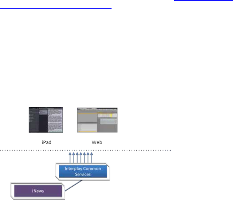
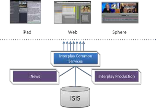
Interplay Central – iNEWS Only
One of the most straightforward deployments is ICS for Interplay Central in an iNEWS-only
environment; that is, with connections to iNEWS but no connection to Interplay Production. In
this deployment ICS provides the ability to browse and edit iNEWS content (queues, stories)
from a remote web client. The ability to browse, play and edit associated video requires
Interplay Production and is not provided by the iNEWS-only deployment.
Interplay Central for iNEWS:
ICS 1.8 Installation & Configuration Guide
16
The iNEWS-only deployment typically requires a RAID 1 (mirrored RAID) for the Linux operating
system. Since ICS is not providing playback of any video assets, there is no need for caching, so
the media cache volume referred to in this guide is not required. Typically, a single ICS server is
sufficient. Two ICS servers configured as a cluster provide high-availability.
Note: The iNEWS-only deployment can be on smaller, less expensive server hardware.
Refer to the “How to Buy Hardware for Interplay Central Services” guide for detailed
information on hardware specifications and deployment options. The guide is available
on the Avid Knowledge Base ICS 1.8 web page.
Deployment Summary:
• Browse and edit iNEWS content
• RAID 1 required
• Media cache volume not required
• Clustering yields high-availability
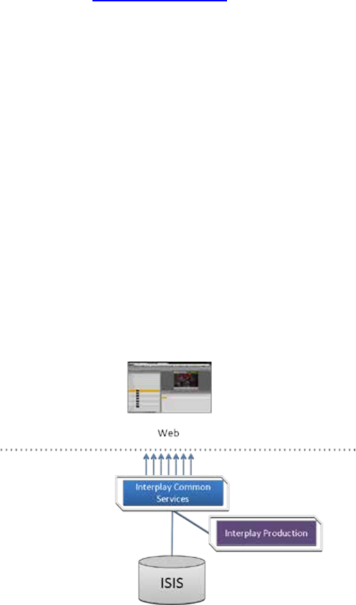
Interplay Central – Interplay Production Only
ICS for Interplay Central with Interplay Production has connections to Interplay Production only.
In this deployment ICS serves layouts for applications, provides user authentication, manages
system configuration settings, and provides proxy-based playback of video assets over the
network to web-based and mobile clients. ICS decodes the source format and streams images
and sound to the remote web-based Interp
l
ay Central c
li
ent
.
Interplay Central for Interplay Production:
This deployment typically requires two HDs configured as a RAID 1 (mirrored RAID) for the Linux
operating system. No iOS devices implies no special caching requirements; however, Multicam
requires a media drive. You can configure two or more ICS servers as a cluster to obtain high-
availability and load balancing.
ICS 1.8 Installation & Configuration Guide
17
Deployment Summary:
• Browse and play video assets
• RAID 1 required
• Media cache volume required
o RAID 5, or
o RAID 1, or
o Single HD
• Clustering yields high-availability and load-balancing
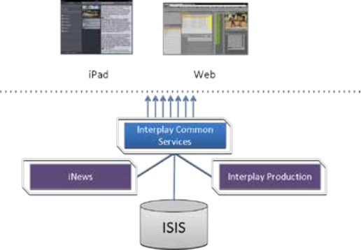
Interplay Central – iNEWS and Interplay Production
ICS for Interplay Central with iNEWS and Interplay Production has both iNEWS connectivity and
Interplay Production connectivity. Similarly to the iNEWS-only deployment, this provides the
ability to browse and edit iNEWS content (queues, stories) from a remote web client. Interplay
Production connectivity provides the ability to browse, play and edit associated video.
In this deployment ICS serves layouts for applications, provides user authentication, manages
system configuration settings, and provides proxy-based playback of video assets over the
network to web-based and mobile clients. ICS decodes ISIS source formats and streams images
and sound to the remote web-based Interplay Central client.
Interplay Central with iNEWS and Interplay Production:
This deployment typically requires two HDs configured as a RAID 1 (mirrored RAID) for the Linux
operating system. In a configuration where the iOS application is used, the ICS server should also
have a media cache volume. Multicam also requires a media cache volume. You can configure
two or more ICS servers as a cluster to obtain high-availability and load balancing.
ICS 1.8 Installation & Configuration Guide
18
Deployment Summary:
• Browse and edit iNEWS content
• Browse and play the associated video assets
• RAID 1 required
• Media cache volume required
o RAID 5, or
o RAID 1, or
o Single HD
• Clustering yields high-availability and load-balancing
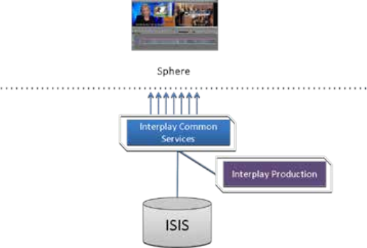
Interplay Sphere Only
ICS for Interplay Sphere provides playback of different format v
i
deo assets reg
i
stered by
Interplay Production and residing on an ISIS
.
ICS decodes the source format and streams
images and sound to the remote Interp
l
ay Sphere enabled Media Composer or NewsCutter
.
Interplay Sphere:
This deployment typically requires two HDs configured as a RAID 1 (mirrored RAID) for the
Linux operating system. A media cache is also required. In its most basic form, the Interplay
Sphere deployment is a single ICS server. You can configure two or more ICS servers as a cluster
to obtain high-availability and load balancing.
Deployment Summary:
• Browse and play the video assets for Sphere enabled Media Composer and/or
NewsCutter
• RAID 1 required
• Media cache volume required
ICS 1.8 Installation & Configuration Guide
19
o RAID 5, or
o RAID 1, or
o Single HD
• Clustering yields high-availability and load-balancing
Both Interplay Central and Interplay Sphere (Shared ICS)
Interplay Central and Interplay Sphere can easily share the same ICS server(s). In this
deployment, ICS serves layouts for applications, provides user authentication, and manages
system configuration settings. ICS also provides proxy-base playback over the network of
different format v
i
deo assets reg
i
stered by Interplay Production and residing on an ISIS
.
ICS
decodes the source format and streams images and sound to the remote web-based Interplay
Central and/or Interp
l
ay Sphere c
li
ents
.
This is the most sophisticated deployment model, since other elements can also be present,
such as iNEWS with corresponding iOS device applications.
Interplay Central and Interplay Sphere (Shared ICS):
This deployment typically requires a RAID 1 (mirrored RAID) for the Linux operating system. In a
configuration with iOS devices (as with iNEWS), the ICS server should also have a media cache
volume. If iOS devices are not deployed, it has no media cache volume requirements; however,
multicam requires a media cache volume. You can configure two or more ICS servers as a cluster
to obtain high-availability and load balancing.
Deployment Summary:
• Browse and play video assets
• Browse and play video assets
for Sphere enabled Media Composer and/or NewsCutter
• RAID 1 required
ICS 1.8 Installation & Configuration Guide
20
• Media cache volume required
o RAID 5, or
o RAID 1, or
o Single HD
• Clustering yields high-availability and load-balancing
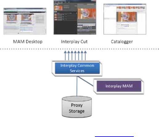
Interplay MAM
In an Interplay MAM deployment, ICS provides playback of video assets registered as a browse
proxies by Interplay MAM. The registered browse proxies can reside on standard filesystem
storage, or proprietary storage that provides a standard system gateway. The Interplay MAM
deployment presents two main options – setting up a media cache volume, and port bonding to
improve throughput.
Interplay MAM:
This deployment typically requires a RAID 1 (mirrored RAID) for the Linux operating system.
Under some circumstances – see “Caching in ICS” on page 22 – the ICS server should also have a
media cache volume. You can configure two or more ICS servers as a cluster to obtain high-
availability and load balancing.
Deployment Summary:
• Browse and play video assets
• RAID 1 required
• Media cache volume might be required
o RAID 5, or
o RAID 1, or
o Single HD
• Clustering yields high-availability and load-balancing

ICS 1.8 Installation & Configuration Guide
21
Port Bonding in Interplay MAM
Port bonding (also called link aggregation) is an OS-level technique for combining multiple
Ethernet ports into a group, making them appear and behave as a single port. Ethernet ports
correspond to the physical connectors in a NIC card where network cables are plugged in.
Bonded ports retain their individual cable connections to the network router or switch.
However, they are seen by the network as a single port.
Port bonding must be configured in “round-robin” mode. In this mode, Ethernet packets are
automatically sent, in turn, to each of the bonded ports, reducing bottlenecks and increasing the
available bandwidth. For example, bonding two ports together in round-robin increases
bandwidth by approximately 50% (some efficiency is lost due to overhead).
In MAM deployments of ICS, port bonding improves playback performance when multiple
clients are making requests of the ICS server simultaneously. With port bonding, more
concurrent playback requests can be sustained by a single server, especially for file-based
playback. File-based playback is a playback method for which a single port-bonded ICS server
can support thousands of requests.
For instructions on port bonding see “Appendix C: Configuring Port Bonding for Interplay MAM
(Optional)“ on page 152.
Port Requirements
The following table lists the ICS port requirements for the client-side applications (the browser-
based Interplay Central application and mobile applications). Ports 80 and 443 are required for
the HTTP(S) traffic. In addition, the Adobe Flash Player (running inside the browser) requires
ports 843 and 5000.
For more information see the ICS Security Architecture and Analysis document.
Component Port Protocol and
Direction Usage
Interplay Central
Web application
80
TCP inbound
Interplay Central Playback Service (ICPS)
HTTP calls
443
Secure TCP
Inbound
IPC HTTPS calls
843
TCP Inbound
Serving Flash Player socket policy files
5000
TCP Inbound
Playback service (loading assets, serving
JPEG images, and audio, etc.). Output flow
to client serving inbound request.
Interplay Central
mobile applications
80
TCP Inbound
ICPS HTTP calls
443
Secure TCP
Inbound
ICPS HTTPS calls

ICS 1.8 Installation & Configuration Guide
22
The following table lists the server-side port requirements. For more information see the ICS
Security Architecture and Analysis document.
Service Name Port
Interplay Central
80, 443
ICPS
843 (Flash), 80, 5000, 26000
ICS
8000 (optional Admin UI), 8183 (bus cluster info)
ISIS
5000 – 5399 (UPD and TCP)
RabbitMQ
5672 (AMQP), 15672 (Management UI/API)
MongoDB
27017
PostgreSQL
53087
System
22, ICMP, 111, 24007, 24008, 24009-(24009 + number of bricks
across all volumes for gluster). If you will be using NFS, open
additional ports 38465-(38465 + number of Gluster servers). Some
MAM configuration might require additional NFS ports (111, 2049
tcp & udp) or CIFS (137,138 udp and 137,139 tcp). Other filesystems
will have to be checked individually (Isilon, Harmonic Omneon,
etc.).
Caching in ICS
In its work to provide proxy-based playback of video assets over a network, ICS generates
temporary files in certain workflows. For example, ICS deployed for Interplay MAM typically
generates a multitude of temporary files as it converts proxies from their native MAM formats
into formats compatible with the player. The ICS multicam feature introduced in ICS 1.5
produces numerous temporary files. By default, ICS caches temporary files on the system drive.
Better performance is achieved by allocating a dedicated media cache volume (separate from
the system drive) for the temporary files. In a cluster setup, an open-source software solution
called Gluster is also used.
Note: All Interplay Central deployments making use of multicam require a dedicated volume
for media caching. Gluster is also required, for file replication between clustered caches.
Note: This document provides instructions for creating a media cache volume as a RAID
5 using multiple disks in the server enclosure. However, other configurations are
possible, including two drives in a RAID 1 configuration, or a single drive. For details, see
the “How to Buy Hardware for Interplay Central Services” guide.
The Dedicated Caching Volume
All ICS servers require a RAID 1 that mirrors the operating system across two HD drives. Some
deployments also require a media cache volume consisting of the remaining disks in the
ICS 1.8 Installation & Configuration Guide
23
enclosure, used exclusively for ICS file caching. In a RAID 5 volume (recommended), the disk
controller automatically distributes (stripes) data across all the disks in the RAID 5, yielding
increased performance and redundancy.
In an ICS server cluster the media cache volume is taken one step further. An open source
software solution called Gluster is used to replicate the contents of the media cache volumes
across each server in the cluster. In this way, each ICS server in the cluster can make use of file
data already transcoded and cached by the others.
Note: All Interplay Central deployments making use of multicam require a dedicated media
cache volume for caching. Gluster is also required, for file replication between clustered caches.
Caching for Interplay MAM
For caching, it is important to understand how MAM browse proxies get from proxy storage to
the MAM desktop. For each playback request, ICS does one of the following:
• File-based playback (native): When MAM proxies are in a format that an Adobe Flash-
based player can play natively, ICS serves the proxy file as-is to the remote web-based
client. Adobe Flash-based players natively play MP4-wrapped h.264/aac or FLV. This is
the least CPU-intensive playback mode.
• File-based playback (alternate): When file-based playback requests are made of proxy
formats that cannot be played natively by an Adobe Flash-based player, ICS transcodes
the proxy into FLV, which is stored in the ICS file cache on the media cache volume. This
is then served to the remote web-based client. ICS regularly scans the media cache, and,
when necessary, the least-requested files are purged.
The above playback method has a one-time CPU hit on initial playback request for each
asset, but is subsequently very light because the same cached file is served.
• Frame-based playback: This playback mode is the same one used by Interplay Central,
and is required in MAM for “growing file” workflows and variable-speed playback. In
this case ICS decodes the proxy and streams images and audio to the remote web-based
client frame-by-frame. This is the most CPU-intensive playback mode.
ICS for Interplay MAM requires a dedicated media cache volume when registered browse
proxies include formats that cannot be natively loaded in the Adobe Flash player. For example, if
MAM registered browse proxies are MPEG-1, Sony XDCAM, MXF or WMV, a media cache
volume are needed in ICS. This guide includes instructions for setting up a RAID level 5 cache.
Caching for iOS Devices in Interplay Central
In an Interplay Central deployment where an iOS application is used, the ICS server should have
a dedicated media cache volume.
Caching for Sphere
Interp
l
ay Sphere caches the video and audio it receives locally on the editor (Media Composer
and/or NewsCutter). With the introduction of multicam support for Sphere (in ICS 1.5) there
ICS 1.8 Installation & Configuration Guide
24
is also a dedicated media cache volume requirement for Sphere. This is a result of server-side
caching of the multicam “grid” of proxy images. Sphere continues to cache video and audio
locally.
Working with Linux
As noted, RHEL is a commercially supported, open source version of the Linux operating system.
If you have run DOS commands in Windows or have used the Mac terminal window, the Linux
environment will be familiar to you. While many aspects of the ICS installation are automated,
much of it requires entering commands and editing files using the Linux command-line.
Note: RHEL is not free, and Avid does not redistribute it or include it as part of the ICS
installation. RHEL licensing and support options are covered in the “How to Buy
Hardware for Interplay Central Services” guide.
Installing Linux
Installations on qualified HP servers can use an express process involving a USB key and the
supplied RHEL kickstart (ks.cfg) file. Kickstart files are commonly used in Linux installs to
automate the OS installation. A kickstart file automatically answers questions posed by the Linux
installer, for hardware known in advance.
Since RHEL is a licensable product, redistribution by Avid is not possible. However, the ICS
installation package includes a Windows executable (ISO2USB) for creating a bootable USB drive
from a RHEL installation DVD or image (.iso) file. We use ISO2USB to prepare the USB drive to
install the ICS components too.
Note: The USB key and kickstart file shortcuts apply only to ICS installations performed
on qualified HP hardware. For non-HP hardware, see “Appendix A: Installing ICS on Non-
HP Hardware” on page 148.
Linux Concepts
Once RHEL is installed you can begin the work of setting up the server for ICS. This involves
simple actions such as verifying the system time. It also involves more complex actions, such as
verifying and modifying hardware settings related to networking, and editing files. Depending
on the deployment, you may also be required to create logical volumes, configure port bonding,
and perform other advanced actions.
Advance knowledge of the following Linux concepts will be helpful:
• root user: The root user (sometimes called the “super” user) is the Linux user with
highest privileges. All steps in the installation are performed as root.
• mounting: Linux does not recognize HDs or removable devices such as USB keys unless
they are formally mounted.
• files and directories: In Linux, everything is a file or a directory.

ICS 1.8 Installation & Configuration Guide
25
Key Linux Directories
Like other file systems, the Linux filesystem is represented as a hierarchical tree. In Linux
directories are reserved for particular purposes. The following table presents some of the key
Linux directories encountered during the ICS installation and configuration:
Directory Description
/
The root of the filesystem.
/dev
Contains device files, including those identifying HD partitions,
USB and CD drives, and so on. For example, sda1 represents the
first partition (1) of the first hard disk (a).
/etc
Contains Linux system configuration files, including the
filesystem table, fstab, which tells the operating system what
volumes to mount at mount at boot-time.
/etc/udev/rules.d
Contains rules used by the Linux device manager, including
network script files where persistent names are assigned to
network interfaces.
In Linux, every network interface has a unique name. If a NIC
card has four connection “ports”, for example, they might be
named eth0 through eth3.
/etc/sysconfig/network-
scripts
Contains, amongst other things, files providing Linux with boot-
time network configuration information, including which NIC
interfaces to bring up.
/media
Contains the mount points for detachable storage, such as USB
keys. In Linux, volumes and removable storage must be
mounted before they can be accessed.
/opt
Contains add-on application packages that are not a native part
of Linux, including the ICS components.
/usr
Contains user binaries, including some ICS components.
/tmp
The directory for temporary files.
/var
Contains data files that change in size (variable data), including
the ICS server log files.
Linux Command Line
The Linux command line is a powerful tool that lets you perform simple and powerful actions
alike with equal speed and ease. For example, entering the Linux list command, ls, at the root
directory produces results similar to the following.
# ls
/bin
/boot
/dev
/etc
/lib
/media
/mnt
/opt
/sbin
/srv
/tmp
/usr

ICS 1.8 Installation & Configuration Guide
26
/var
In the above command, the pound sign (#) indicates the presence of the Linux command
prompt. You do not type a dollar sign. Linux commands, paths, and file names are case-sensitive.
The following table presents a few of the more commonly used Linux commands.
Command Description
ls
Lists directory contents. Use the –l option (hyphen lower-case
L) for a detailed listing.
cd
Changes directories.
cat
Outputs the contents of the named file to the screen.
clear
Clears screen.
cp
Copies files and directories.
<tab>
Auto-completes the command based on contents of the
command line and directory contents.
For example, typing cd and the beginning of a directory name,
then pressing the tab key fills in the remaining letters in the
name.
|
| more
“Pipes” the output from one command to the input of another.
For example, to view the output of a command one screen at a
time, pipe into the more command, as in:
ls | more
dmesg
Displays messages from the Linux kernel buffer. Useful to see if
a device (such as USB key) mounted correctly.
find
Searches for files.
For example, the following use of the find command searches
for <filename> on all local filesystems (avoiding network
mounts):
find / -mount -name <filename>
grep
Searches for the named regular expression. Often used in
conjunction with the pipe command, as in:
ps | grep avid
lvdisplay
Displays information about logical volumes.
man
Presents help (the “manual page”) for the named command.
mkdir
Creates a new directory.
mount
umount
Mounts and unmounts an external device to a directory. A
device must be mounted before its contents can be accessed.

ICS 1.8 Installation & Configuration Guide
27
Command Description
ps
Lists the running processes.
passwd
Changes the password for the logged-in user.
scp
Securely copies files between machines (across an ssh
connection).
service
Runs an initialization script.
e.g. service avid-all
tail
Shows you the last 10 (or n) lines in a file.
e.g.
tail <filename>
tail -50 <filename>
tail –f <filename>
The “-f” option keeps the tail command outputting appended
data as the file grows. Useful for monitoring log files.
udevadm
Requests device events from the Linux kernel. Can be used to
replay device events and create/update the
70-persistent-net.rules file.
e.g. udevadm trigger --action=add
vi
Starts a vi editing session.
Linux Text Editor (vi)
Linux features a powerful text editor called vi. To invoke vi, type the vi command followed by
the target file at the command prompt.
$ vi <filename>
Vi operates in one of two modes, insert mode and command mode. Insert mode lets you
perform text edits – insertion, deletion, etc. Command mode acts upon the file as a whole – for
example, to save it or to quit without saving.
• Press the “i” (as in Indigo) key to switch to insert mode.
• Press the colon (“:”) key to switch to command mode.
The following table presents a few of the more useful vi commands.
Key Press Description
Command Mode
:
Prefix to commands in command mode
:wq
Write file and quit vi (in command mode)

ICS 1.8 Installation & Configuration Guide
28
Key Press Description
:q!
Quit without writing (in command mode)
Insert Mode
i
Insert text before the cursor, until you press <Esc>
I
Insert text at beginning of current line
a
Insert text after the cursor
A
Insert text at end of current line
<Esc>
Turn off Insert mode and switch to command mode.
w
Next word
b
Previous word
Shift-g
Move cursor to last line of the file
D
Delete remainder of line
x
Delete character under the cursor
dd
Delete current line
yy
“Yank” (copy) a whole line in command mode.
p
Paste the yanked line in command mode.
For a series of short and helpful vi tutorials, see:
http://www.unix-manuals.com/tutorials/vi/vi-in-10-1.html
Linux Usage Tips
The following table presents tips that will make it easier to work in RHEL.
Tip Description
Getting Help
For help with Linux commands, the Linux System Manual (“man” pages)
are easily available by typing the man command followed by the item of
interest.
For example, for help with the ls command, type:
man ls
Searching within
a man page
To search for a string within a Linux man page, type the forward slash (“/”)
followed by the string of interest. This can be helpful for finding a
parameter of interest in a long man entry.
“command not
found” error
A common experience for users new to the Linux command line is to
receive a “command not found” after invoking a command or script that is
definitely in the current directory.
Linux has a PATH variable, but for reasons of security, the current directory
— “.” in Linux — is not included in it by default.

ICS 1.8 Installation & Configuration Guide
29
Tip Description
Thus, to execute a command or script in a directory that is unknown to the
PATH variable you must enter the full path to the script from the root
directory (“/”) or from the directory containing the script using dot-slash
(“./”) notation, which tells Linux the command you are looking for is in the
current directory.
cat
Prints the contents of a file to the command line.
| more
Piping (“|”) the output of a command through the more command breaks
up the output into screen-sized chunks.
For example to view the contents of a large directory one screen at a time,
type the following:
ls | more
less
Similar to the cat command, but automatically breaks up the output in to
screen-sized chunks, with navigation. Useful for navigating large amounts
of text on screen at a time.
For example:
less <filename>
Volumes in Linux
For those more familiar with Windows, the steps to creating usable volume in Linux are similar
to preparing a new HD for use in Windows.
In Windows, you initialize the disk, create a partition, and assign it a drive letter. You must then
format the disk, specify its file system, its allocation unit size, and assign it a volume label.
In Linux, you must also initialize the disk (this takes place during RHEL installation) and create a
partition. You also format the disk and specify its file system and sector size. Volume labels do
not apply, but have a parallel in the Linux device names (for example /dev/hda or /dev/hdb in
the case of HDs).
Linux builds up to a usable volume in a series of “layers”, each building upon the previous. From
lowest to highest they are physical volumes, volume groups, logical volumes. The filesystem is
built on top of the logical volume.
Clock Synchronization in Linux
The basic mechanism for clock synchronization under Linux is the Network Time Protocol (NTP)
daemon, ntpd, which can be used to automatically maintain synchronization of the system clock
with a specified time server. The time server might be a master clock within a firewall, or one of
the numerous time-servers based on an atomic clock and available via the internet. For reasons
of security, it ought to be a Linux NTP server (or compatible solution) within the corporate
firewall.

ICS 1.8 Installation & Configuration Guide
30
It is particularly important when setting up a cluster of ICS nodes that each node should have
precisely the same time.
Clock synchronization is covered in “Synching the System Clock” on page 70.
Time Zones in RHEL
Like most operating systems, RHEL needs to know the time zone in which it is operating. In RHEL
this is set by assigning geographic information and/or a specific time zone. For example the
following are all valid time zone specifications in RHEL:
• America/EST
• America/Los_Angeles
• Australia/Sydney
• Brazil/East
• Europe/Amsterdam
The installation script automatically sets the time zone to Eastern Standard Time. You will have
the opportunity to set the time zone to something more appropriate when you boot RHEL for
the first time.
RAIDs in ICS
RAID stands for redundant array of inexpensive (or independent) disks. RAIDs are used in ICS to
provide data redundancy and for efficiency in caching large amounts of data across multiple
disks. On supported HP servers, you implement these RAIDs at the level of the HP disk
controller, using the HP RAID configuration BIOS utility.
ICS makes use of the following RAID types:
• RAID 1: All ICS implementations require a RAID 1 (mirror) for the system (OS) drive. This
RAID provides redundancy in the event of HD failure.
• RAID 5: Certain deployments also require additional disks configured as a RAID 5 (data
striping with parity blocks) for caching file data. This RAID provides redundancy and
increased performance.
Note: This document provides instructions for creating a media cache volume as a
RAID 5 using multiple disks in the server enclosure. However, other configurations are
possible, including two drives in a RAID 1 configuration, or a single drive. For details, see
the “How to Buy Hardware for Interplay Central Services” guide.
The following deployments typically benefit from the configuration of a media cache volume:
• Interplay MAM: Interplay MAM deployments require a media cache volume when
registered browse proxies include formats that cannot be natively loaded by the Adobe
Flash-based player. That is, for non MP4 h.264 browse proxies (such MPEG-1, Sony
XDCAM, MXF, and WMV), media on proxy storage is transcoded to FLV and stored.
ICS 1.8 Installation & Configuration Guide
31
• Interplay Central: Interplay Central installations deploying the iNEWS iOS (Apple mobile
operating system) app require a media cache volume. In this case, media on the ISIS are
transcoded to MPEG-TS (MPEG-2 transport stream), and stored.
With regards to particular servers:
• HP DL360: The HP DL360 may have up to 8 drives present. Configure two as RAID 1 for
the system drive. The additional drives (up to 6), if present, can be configured as a
RAID 5 volume for caching per deployment requirements.
• Other Servers: Other servers will have different hard drive capacities. Configure two
drives as RAID 1 for the system drive and the remaining drives as a RAID 5 volume for
caching.
Introduction to Clustering
Redundancy and scale for ICS is obtained by setting up a cluster of two or more servers. Within
the cluster, requests for media are automatically distributed to the available servers. An ICS
server cluster provides the following:
• Redundancy/High-availability. If any node in the cluster fails, connections to that node
will automatically be redirected to another node.
• Scale/Load balancing. All incoming playback connections are routed to a cluster IP
address, and are subsequently distributed evenly to the nodes in the cluster.
• Replicated Cache: The media transcoded by one node in the cluster is automatically
replicated in the other nodes. If another node receives the same playback request, the
media is immediately available without the need to re-transcode.
• Cluster monitoring. You can monitor the status of the cluster by entering a command. If
a node fails (or if any other serious problem is detected by the cluster monitoring
service), an e-mail is automatically sent to one or more e-mail addresses.
Generally speaking, clusters consist of nodes with identical hardware profiles. However, this is
not required. You can use different hardware profiles for the servers in a cluster.
Note: For detailed information on how ICS servers operate in a cluster, see the “ICS 1.8
Service and Server Clustering Overview” guide.
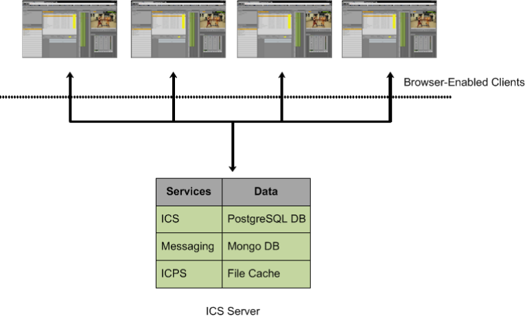
ICS 1.8 Installation & Configuration Guide
32
Single Server Deployment
In a single server deployment, all ICS services and the ICPS playback service run on the same
server. This server also holds the ICS database and the dedicated media cache volume.
The following diagram illustrates a typical single-server deployment.
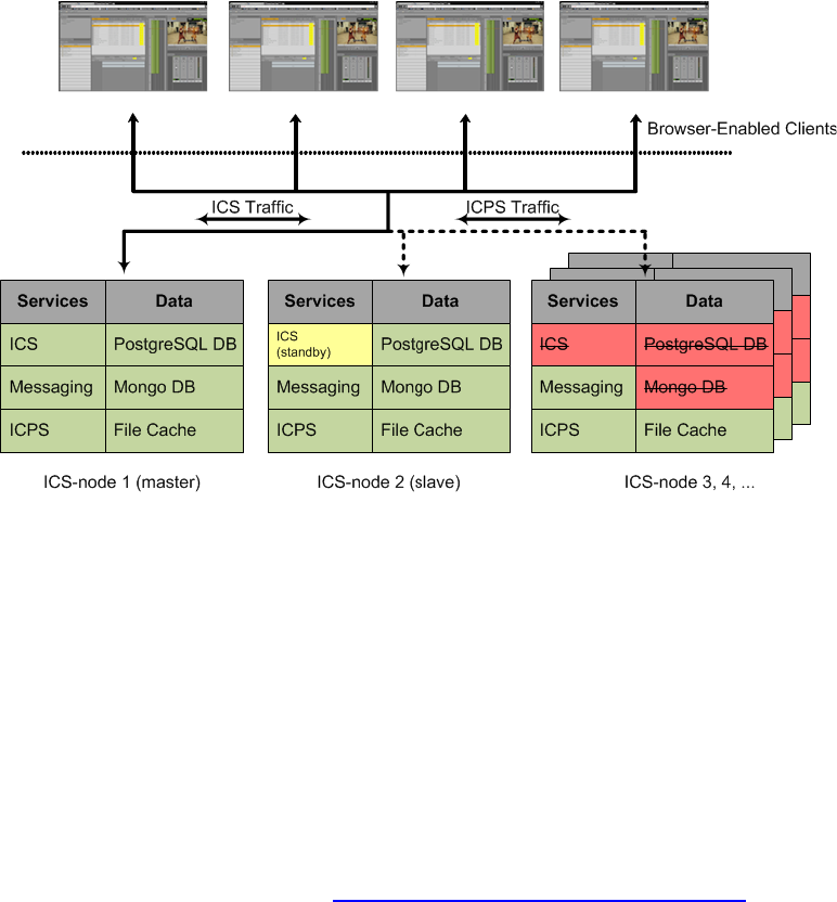
ICS 1.8 Installation & Configuration Guide
33
Cluster Deployment
In a cluster deployment, there is one master-slave pair of nodes (providing high-availability and
failover), and additional nodes supporting transcoding (for scale and load-balancing). In a
cluster, all ICS traffic is routed to the master node. Player requests, handled by the ICPS playback
service, are distributed by the master to all available nodes. Key ICS services and databases are
replicated on the slave node, which is ready to assume the role of master at any time. Other
nodes perform transcoding, but do not participate in failovers; that is, they do not take on the
role of master or slave.
The following diagram illustrates a typical cluster deployment.
Multicast vs Unicast
Network communication can be of three basic types: unicast, multicast and broadcast. Unicast is
a one-to-one connection between client and server, with data transmitted to a single IP address.
Multicast transmits to a set of hosts configured as members of a multicast group, and relies on
multicast enabled routers to replicate and forward the data. Broadcasting submits data to an
entire subnetwork.
ICS clustering supports both unicast and multicast. The default configuration, as set up by the
cluster installation script (and covered in the body of this guide) is for multicast. For facilities
lacking multicast enabled routers, you will need to configure clustering for unicast. Unicast
configuration effort is covered in “Appendix H: Unicast Support in Clustering” on page 197.

ICS 1.8 Installation & Configuration Guide
34
Working with Gluster
Recall that the ICS server transcodes media from the format in which it is stored on the ISIS (or
standard filesystem storage) into an alternate delivery format, such as an FLV or MPEG-2
Transport Stream.
In a deployment with a single ICS server, the ICS server maintains a cache where it keeps
recently-transcoded media. In the event that the same media is requested by the web client
again, the ICS server delivers the cached media, avoiding the need to re-transcode.
In an ICS cluster, the cache maintained by each ICS server is replicated across the others. Each
ICS server sees and has access to all the media transcoded by the others. When one ICS server
transcodes media, the other ICS servers can also make use of it, without re-transcoding.
The replication process is set up and maintained by Gluster, an open source software solution
for creating shared filesystems. In ICS, Gluster manages data replication using its own highly
efficient network protocol.
For more information on Gluster, see: http://www.gluster.org.
Note: The correct functioning of the cluster cache requires that the clocks on each server in
the cluster are set to the same time. This is done in “Setting the System Clock and Disabling
HP Power Saving Mode” on page 51.
ICS 1.8 Installation & Configuration Guide
35
PART II: INSTALLING & CONFIGURING

ICS 1.8 Installation & Configuration Guide
36
Installation Workflow
The following table describes each of the main installation steps.
If you are setting up a server cluster, be sure to read “Clustering Workflow” on page 101 too.
Step Task Time Est.
1
Appendix L: Installation Pre-Flight Checklist
1–2 hr
varies
Make sure you have all the information related to the server hardware
(including disk drives and NIC cards in the enclosure), network topography,
IP addresses, etc., required to perform installation.
2
Before You Begin
varies
A quick check to make sure you have everything in place for an efficient and
successful installation.
3
Obtaining the Software
varies
If you are missing any software, this section tells you how to obtain it.
4
Preparing the ICS Installation USB Key
1 hr
In this procedure, you create the USB key you will use to install the ICS
software.
Note: This step is for HP servers only. For non-HP installations, refer to the
guidelines in “Appendix A: Installing ICS on Non-HP Hardware” on page
148.
5
Installing the Network Interface Cards
30 min
This step explains the slots where the NIC cards should be placed to simplify
the software installation and configuration, and what connections need to
be made.
6
Setting the System Clock and Disabling HP Power Saving Mode
15 min
Before installing the Operating System, you must make a few changes in the
BIOS.
7
Setting Up the RAID Level 1 Mirrored System Drives
5 min
You make use of two of the server’s hard disks to create a mirrored RAID
disk array for the operating system. This is done in the BIOS.
8
Setting Up the RAID Level 5 Cache Drives
5 min
In this step you create a RAID 5 disk array for the file cache used by ICS to
store proxies.†
Note: This step is required only if your Interplay MAM deployment requires
a file cache, or you are deploying iOS devices in Interplay Central.†

ICS 1.8 Installation & Configuration Guide
37
Step Task Time Est.
9
Installing RHEL and the ICS Software
20 min
In this step you install RHEL and ICS on the RAID 1 disk array.
10
Booting RHEL for the First Time
10 min
Like most operating systems, the first time you boot RHEL you need to set
some system information. It is minimal, in the case of RHEL.
11
Editing the Network Connection
15 min
In this step you make sure the physical interface used to connect the ICS
server to the network is called eth0.
12
Synching the System Clock
5 min
With the network connections established and verified, you can set up the
system to synchronize its clock with a Linux Network Time Protocol (NTP)
server.
13
Creating the File Cache on the RAID
15 min
Here, you tell ICS to use the RAID 5 disk array for its file cache.
Note: This step is required for all deployments using the ICS multicam
feature. It is also required for certain Interplay MAM deployment, or if you
are deploying iOS devices in Interplay Central.†
14
Appendix C: Configuring Port Bonding for Interplay MAM (Optional)
20 min
Configure multiple network interfaces to appear to the network as a single
IP address for higher throughput.
Note: This step is optional.
15
Configuring ICS for Interplay MAM
5 min
Configure ICS to mount the file systems on which Interplay MAM browse
proxies reside.
Configure Interplay MAM to use the ICS server or server cluster
16
Installing the Interplay Central Distribution Service
5 min
Install and configure the Interplay service that coordinates jobs with Avid
Media Services. This step is performed on a Windows machine in the Media
Services network.
Note: ICDS is only required for Interplay Central, and requires Interplay
Production.
17
Configuring ICS for Interplay Central and/or Interplay Sphere
10 min
Perform the needed configuration steps so ICS and its built-in player can
communicate with Interplay Production and the ISIS client(s). Once
configured, you can verify video playback.

ICS 1.8 Installation & Configuration Guide
38
Step Task Time Est.
18
Replicating the Cluster File Caches
30 min
If you are creating a cluster of ICS nodes, we recommend that you replicate
(mirror) the RAID 5 file cache volume across each server in the cluster.
Note: This step is required only if your Interplay MAM deployment requires
a file cache, or you are deploying iOS devices in Interplay Central.†
19
Setting up the Server Cluster
2-3 hr
Installing ICS on more than one server and create a server cluster provides
numerous benefits, including high-availability and failover protection.
Note: Setting up a server cluster can be a requirement, depending on the
details of your deployment model.
20
Post-Installation Steps
5 min
Presents monitoring and logging requirements, and a technique for verifying
that cluster failover performs as expected.
†Interplay Central installations deploying the iNEWS iOS (Apple mobile
operating system) app require a RAID 5 cache volume. In this case, media on
the ISIS are transcoded to MPEG-TS (MPEG-2 transport stream), and stored.
In an iNEWS-only deployment —that is, with connections to iNEWS but no
connection to Interplay Production, hence no video playback — no RAID 5 is
required
Interplay MAM deployments require a RAID 5 cache volume when
registered browse proxies include formats that cannot be natively loaded by
the Adobe Flash-based player. That is, for non MP4 h.264 browse proxies
(such MPEG-1, Sony XDCAM, MXF, and WMV), media on proxy storage is
transcoded to FLV and stored.

ICS 1.8 Installation & Configuration Guide
39
Before You Begin
Make sure you have everything in place to ensure an efficient and successful installation. Do not
proceed with the installation if something is missing.
Make Sure the Host Solutions Are Installed and Running
The host system(s) for the deployment must already be installed, set up, and running, for
example:
¨ iNEWS
¨ Interplay Production
¨ Sphere-enabled Media Composer or NewsCutter
¨ Interplay MAM
¨ ISIS
Make Sure You Have the Following Items
The following items are needed for the installation:
¨ ICS server(s), physically connected to the network and/or ISIS
¨ ICS installation package (Interplay_Central_Services_<version>_Linux.zip)
¨ RHEL installation image (.iso) file or DVD media
¨ Gluster RPM packages (optional)
¨ Interplay Central Distribution Service (Interplay Central only)
¨ 16GB USB key (for installations on supported HP hardware)
¨ Windows XP/Vista/7 laptop or desktop computer with an Internet connection and a
supported web browser (e.g. Google Chrome)
For Interplay Production deployments using send to playback (STP), the following software is
also required (and should be installed before proceeding):
¨ Interplay STP Encode
Note: Interplay STP Encode is only required for send-to-playback that includes XDCAM
workflows.
¨ Interplay Transcode
If you are missing software, please see “Obtaining the Software” on page 43.
Note: It is particularly important that the server(s) on which you are installing the ICS software
should be physically installed in the engineering environment, and the appropriate ISIS and/or
the house network connection(s) should be known to you.
You also require access to the ICS server console(s):

ICS 1.8 Installation & Configuration Guide
40
¨ Directly by connecting a monitor and keyboard to the server, or via a KVM (keyboard,
video and mouse) device. Direct access is needed for the initial setup and Linux install,
but is a hindrance in later stages of the install, when it is preferable to open multiple
windows at the same time.
¨ Indirectly (optional) using SSH from another machine’s command prompt or shell, for
ICS software installation and configuration. On Windows, Putty.exe is a good option:
http://www.chiark.greenend.org.uk/~sgtatham/putty/download.html
Make Sure You Can Answer the Following Questions
If you do not know the answers to all of the following questions, review the hardware
specifications in your possession, the deployment model you are pursuing and the
environment into which ICS is being installed, before proceeding.
¨ What kind of server? HP or Other.
• ICS supports Interplay Central and Sphere on HP hardware only.
• ICS supports Interplay MAM on both HP and non-HP hardware.
• ICS supports deployments that do not require video playback on both HP and
non-HP hardware. An iNEWS-only deployment with connections to iNEWS but
no connection to Interplay Production in a non-video deployment.
For non-HP hardware, see “Appendix A: Installing ICS on Non-HP Hardware” on page
148 before proceeding.
¨ What kind of install? Interplay Central or Interplay Sphere or Interplay MAM.
While the installation steps are very similar for Interplay Central and Interplay Sphere
and Interplay MAM, the configuration steps are different. For Interplay MAM, refer to
the Interplay MAM configuration guide.
¨ What kind of server setup? Single or Cluster.
A server cluster provides high-availability and load-balancing. The OS and ICS install
identically on each server in the cluster, but additional steps are required to configure
the servers as a cluster. Further, some configuration steps are not needed on the non-
master nodes.
¨ Do I need a RAID 1? Yes.
Yes. All ICS servers require a RAID 1 that mirrors the operating system across two HD
drives.

ICS 1.8 Installation & Configuration Guide
41
¨ Do I need a dedicated media cache volume (e.g. RAID 5)? Yes or No.
Almost all Interplay Central deployments require a dedicated media cache volume, for
the multicam caching requirements. This includes Sphere deployments. The single
exception is the iNEWS-only deployment. However, if the iNEWS iOS application is used,
a dedicated media cache volume is required.
In addition, some Interplay MAM generate a great number of temporary files as ICS
converts proxies from their native MAM formats into formats compatible with player.
Those MAM deployments require a dedicated media cache volume.
For details, see “Caching in ICS” on page 22.
Note: This document provides instructions for creating a media cache volume as a
RAID 5 using multiple disks in the server enclosure. However, other configurations are
possible, including two drives in a RAID 1 configuration, or a single drive. For details, see
the “How to Buy Hardware for Interplay Central Services” guide.
¨ Static or Dynamic IP addresses?
All network interface ports and bonded ports (optional) require IP addresses. While
these can be dynamically assigned (via DHCP) or static, static IP addresses are
recommended. Work with your network administrator to make the correct
determination. Static IP addresses are the only option for clustering.
¨ Does the Interplay MAM installation require port bonding? Yes or No.
Normally, on a server with multiple network interfaces (i.e. Ethernet connectors), each
interface has its own IP address. However, ICS servers in Interplay MAM can benefit
from port bonding, in which several network interfaces appear as a single IP address.
Port bonding is an optional installation feature for Interplay MAM deployments only.
For more information:
• “Port Bonding in Interplay MAM” on page 21.
• “Appendix C: Configuring Port Bonding for Interplay MAM (Optional)” on page
152.
¨ Is this a shared ICS setup? Interplay Central and Interplay Sphere?
An ICS server or cluster can serve Interplay Central and Interplay Sphere simultaneously.
In this case, simply install an ICS server or ICS server cluster as indicated in this
document.

ICS 1.8 Installation & Configuration Guide
42
¨ A Multicast or Unicast Network? (Clustering only)
ICS clusters support both unicast and multicast network communication. This body of
this guide provides instructions for configuring a cluster in a multicast environment.
However, multicast requires multicast enabled routers. If your network does not
support multicasting, follow the instruction in the body of this guide, then perform the
additional configuration steps required for unicast. See “Appendix H: Unicast Support in
Clustering” on page 197.
¨ Are you deploying the Interplay Central iNEWS iOS app? Yes or No.
For Interplay Central installations deploying the iNEWS app for iOS (Apple mobile
operating system) devices (such as an iPhone or iPad), a dedicated media cache volume
(e.g. RAID 5) is required for server-side caching. In an iNEWS-only deployment —that is,
with connections to iNEWS but no connection to Interplay Production, hence no video
playback — no dedicated media cache volume is required.
¨ What kind of clock setting/synchronization is required?
Clock setting and synchronization play an important role in some deployments,
particularly when creating a cluster. For a discussion, see “Clock Synchronization in
Linux” on page 29.
Make Sure You Have All the Information You Need
During the ICS installation procedures, you are required to enter a great deal of information
pertaining to the ICS servers, network settings, IP addresses, system administrator email
addresses, and so on. It is important to gather this information before you begin. Waiting until
the information is called for by an installation step will result in considerable delays.
For a list of information required to perform the install, see “Appendix L: Installation Pre-Flight
Checklist” on page 210.
Make Sure You Change the Default Passwords
For reasons of security it is strongly recommended that you change the default administrator-
level passwords at the first opportunity. The RHEL installation script sets up a default login
password for the root user (the Linux user with administrator privileges). Similarly, Interplay
Central is supplied with a default user name and password for the administrator.
• RHEL: Change the root password when you boot into Linux for the first time.
• Interplay Central: Change the Administrator default password the first time you log in to
the Interplay Central UI.
Before you begin obtain the new passwords from the customer where the system is being
installed.
ICS 1.8 Installation & Configuration Guide
43
Obtaining the Software
Note: For version information see the ICS 1.8 ReadMe.
To perform the installation, the following software is required
¨ ICS Installation Packages (required): A zip file containing Windows and Linux software
needed for the installation.
¨ RHEL (required): The operating system installed on the server. An installation image
(.iso) file or DVD media is required.
¨ Gluster (optional): An open source software package used to mirror the file caches in a
server cluster.
Interplay Central deployments (excluding iNEWS-only deployments) require the following
software:
¨ Interplay Central Distribution Service (ICDS): This Interplay service coordinates jobs
with Avid Media Services for sequence mixdowns and send-to-playback.
Deployments of Interplay Central for Interplay Production using send to playback (STP) require
the following software:
¨ Interplay STP Encode: This service exports and encodes Long GOP media, then passes
the media to the Transfer Engine for a send-to-playback operation. The STP Encode
service supports various XDCAM media formats. Required for XDCAM workflows only.
¨ Interplay Transcode: The Interplay Transcode service mixes down audio for script
sequences and checks the sequence into the Interplay Engine. No video mixdown is
required when sending a script sequence to a playback device.
Note: ICDS, Interplay STP Encode and Interplay Transcode are required for Interplay Central
deployments only (but not iNEWS-only Interplay Central deployments).
Interplay Transcode is required when configuring Interplay Central to connect to an Interplay
Production Engine.
Interplay STP Encode is only required for send-to-playback that includes XDCAM workflows.
Obtaining the ICS Installation Package
On a Windows machine with an internet connection, log in to your Avid Download Center
account (or Avid Master Account) and download the ICS installation package from the Download
Center (DLC).
The ICS installation package is a ZIP file with a name of the form:
Interplay_Central_Services_<version>_LInux.zip
For example:
Interplay_Central_Services_1.8_Linux.zip
Note: If the ICS installation package is not available via the DLC, please contact your Avid
representative to obtain it.

ICS 1.8 Installation & Configuration Guide
44
The ZIP file contains the following:
Item Description
ICS_installer_<version>.tar.gz
The ICS Server Installation package.
This compressed tar file contains numerous files, including the
following useful shell script:
ics_version.sh
It outputs version/build information for the following
processes:
• UMS - User Management Services
• IPC - Interplay Central
• ICPS - Interplay Central Playback Services
• ICPS Manager - Interplay Central Playback Services
Manager (player-to-server connection manager)
• ACS - Avid Common Services (“the bus”)
• ICS - Interplay Central Services installer
Once ICS is installed, a symlink is created and you can simply
type the following to execute the script:
ics_version
The Interplay Central version/build number is needed, for
example, when configuring iNEWS. See “Appendix J:
Configuring iNEWS for Integration with Interplay Central” on
page 201.
iso2usb.exe
iso2usb.patch
iso2usb_LICENSE.html
iso2usb_README.rtf
Used in creating the ICS installation USB key.
ks.cfg
ks_upgrade.cfg
The Linux kickstart files for fresh installations and for upgrade
installations.
system-backup.sh
Prepares for an upgrade by backing up important data,
including system settings, network settings, the Jetty keystore
and application.properties file, and the UMS database.
to-install
List of packages (used internally).
Obtaining Red Hat Enterprise Linux
Log in to your Red Hat Network account and download the DVD image (.iso) file or purchase a
DVD. Either format can be used for the ICS installation.

ICS 1.8 Installation & Configuration Guide
45
Note: At the time of this document’s publication, the RHEL 6.3 ISOs were available by
choosing Red Hat Enterprise Linux Server (v. 6 for 64-bit x86_64) from the Downloads
page, then expanding the “View ISO Images for Older Releases” at the bottom of that
page. RHEL 6.3 downloads do not appear in the main downloads list. RHEL 6.4 is not
supported.
Note: ICS requires RHEL 6.3. Do not install any OS updates or patches. Do not upgrade to
RHEL 6.4 or higher.
Obtaining Gluster
Navigate to the download directory at gluster.org containing the GlusterFS version supported by
ICS:
http://download.gluster.org/pub/gluster/glusterfs/3.3/3.3.1/RHEL/epel-6Server/x86_64
Download following packages:
¨ glusterfs-3.3.1-1.el6.x86_64.rpm
¨ glusterfs-fuse-3.3.1-1.el6.x86_64.rpm
¨ glusterfs-server-3.3.1-1.el6.x86_64.rpm
¨ glusterfs-geo-replication-3.3.1-1.el6.x86_64.rpm
Note: If the specified version of Gluster is no longer available, contact your Avid
representative.
Obtaining Additional Packages
The following software packages can be obtained at the Download Center for Avid Video
Products, via your Download Center account (or Avid Master Account).
• ICDS: The Interplay Central Distribution Service (ICDS) package is found in the list of Avid
Interplay Central packages: http://esd.avid.com/ProductInformation.aspx?id=84.
Note: The Interplay Central Distribution Service (ICDS) is available from the Interplay
Servers installation media. Open the Installers folder at the top level, open the
CentralDistributionService folder, double-click setup.exe and follow the installation
instructions.
• Interplay STP Encode Provider: The Interplay STP Encode Provider installer is supplied as
part of the Interplay Production installer package.
• Interplay STP Encode Provider patch: The Interplay STP Encode Provider patch is found
in the list of Avid Interplay patches:
http://esd.avid.com/ProductInformation.aspx?id=76.
• Interplay Transcode Provider: The Interplay Transcode Provider installer is supplied as
part of the Interplay Production installer package.
• Interplay Transcode Provider patch: The Transcode patch is found in the list of Avid
Interplay patches: http://esd.avid.com/ProductInformation.aspx?id=76.
ICS 1.8 Installation & Configuration Guide
46
As noted, the above software is required for Interplay Central deployments only (excluding
iNEWS-only Interplay Central deployments). It is not required for Interplay MAM deployments.
Note: As of ICS 1.5 and Interplay Production 3.0 the Interplay STP Encode and Interplay
Transcode patches are not required. However, the patches are required when configuring
Interplay Central to connect to an earlier version of the Interplay Production engine (e.g.
Interplay Production 2.3–2.7).
Preparing the ICS Installation USB Key
Installing ICS requires a bootable USB key containing all the files required for installing ICS,
including RHEL. In this step you prepare the USB key.
For this procedure you require the following items:
¨ The ICS installation package Interplay_Central_Services_<version>_Linux.zip
¨ RHEL installation image (.iso) file or DVD media
Note: Only RHEL 6.3 OS is supported. Do not install patches, updates, or upgrade to RHEL
6.4.
¨ A 16GB USB key
Note: There have been problems with some USB keys. If the server does not boot from
the USB key, or fails to complete the boot, try using a USB key from another
manufacturer, or a larger sized key.
¨ A Windows XP/Vista/7 laptop or desktop computer
Follow this procedure only if you are installing ICS software components on a supported HP
server.
Transferring ICS and Linux to the USB Key
Due to licensing restrictions, Avid is not able to redistribute the RHEL installation media. You
must download the RHEL installation image (.iso) file from Red Hat directly—or get it from the
RHEL Installation DVD that came with your ICS server.
Note: Make sure the RHEL image (.iso) file is accessible locally (preferable) or over the
network from your computer. You should complete this procedure with only the USB key
you’re preparing inserted in the server. If you have more than one USB key inserted,
make sure you choose the right one when performing this procedure.
Note: You must not simply drag and drop files onto the USB key. Use the ISO2USB utility to
create USB key, as instructed here.
To prepare the ICS Installation USB key:
1. Log into a Windows laptop or desktop.
2. Format the USB key as a FAT32 volume.
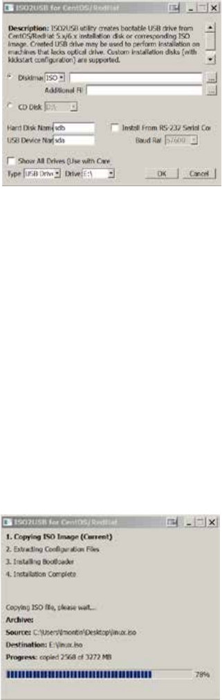
ICS 1.8 Installation & Configuration Guide
47
3. Extract the contents of the Interplay_Central_Services_<version>_Linux.zip (e.g.
Interplay_Central_Services_1.8_Linux.zip) file to the desktop (or your preferred
destination directory).
4. Browse into the newly created Interplay_Central_Services_<version>_Linux folder.
5. Double-click iso2usb.exe to launch the application.
6. Choose the Diskimage radio button then browse to the RHEL image (.iso) file (named
rhel-server-6.3-x86_64-dvd or similar).
7. Verify the Hard Disk Name and USB Device Name are correct:
• Hard Disk Name: sdb
• USB Device Name: sda
Note: These values have changed since RHEL 6.0, where the hard disk name was sda and
the USB device name was sdb.
8. In the “Additional Files” field browse to the Interplay_Central_Services_<version>_Linux
folder on the desktop (or wherever you expanded it to) and then select the directory
name.
9. Click OK in the main dialog.
10. A process begins to copy the RHEL image (.iso) file and the ICS installation files to the
USB key.
The process takes 10-20 minutes. Once complete, the USB key has everything it needs
for a complete RHEL and ICS installation.

ICS 1.8 Installation & Configuration Guide
48
Note: Copying the RHEL image (.iso) file to the USB key is a one-time process. To install
ICS to more than one server, or to re-install ICS, you do not need to repeat these steps.
To prepare for mirroring cluster file caches, proceed to “Copying Gluster to the USB Key” on
page 48.
Otherwise, proceed to “Installing the Network Interface Cards” on page 49.
Copying Gluster to the USB Key
To prepare for mirroring the file caches in a cluster setup, copy the GlusterFS RPMs you
downloaded earlier to the USB key.
Note: This step is only for those setting up a cluster of ICS servers in an Interplay MAM
deployment or an Interplay Central deployment that includes the iNEWS app for iOS
devices. If you think you might set up a cluster in the future, perform this step now to
ensure availability of compatible Gluster software.
For this procedure you require the following items:
¨ An 8GB USB key
¨ glusterfs-3.3.1-1.x86_64.rpm
¨ glusterfs-fuse-3.3.1-1.el6.x86_64.rpm
¨ glusterfs-server-3.3.1-1.el6.x86_64.rpm
¨ glusterfs-geo-replication-3.3.1-1.el6.x86_64.rpm
¨ A Windows XP/Vista/7 laptop or desktop computer
It is recommended that you copy the files to the ICS installation USB key. (Advanced Linux users
may wish to create a network share to install these components instead.)
To add GlusterFS to the ICS Installation USB key:
1. Log into the Windows laptop or desktop where you saved the Gluster RPM packages.
2. Create a directory called Gluster at the root level on the USB key.
3. Copy the RPM packages to the new directory.
Proceed to “Installing the Network Interface Cards” on page 49.
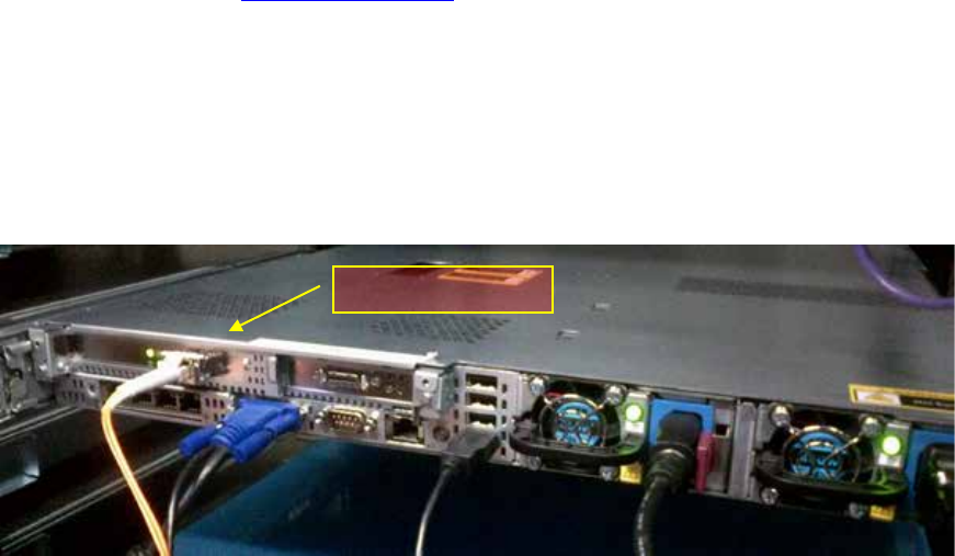
ICS 1.8 Installation & Configuration Guide
49
Installing the Network Interface Cards
As already noted, for Interplay Central and Interplay Sphere, ICS provides a number of services,
including playback of v
i
deo assets reg
i
stered by Interplay Production and residing on an ISIS
.
ICS decodes the source format and streams images and sound to the remote web-based
Interplay Central and/or Interp
l
ay Sphere c
li
ents
.
For an Interplay Central and/or Interplay Sphere installation, the ICS server(s) must be installed
and connected to an ISIS via a Zone 1 (direct), Zone 2 (through a switch) or Zone 3
(recommended) connection. In this case you must use a GigE or 10GigE network interface.
For Interplay MAM, ICS provides playback of video assets registered as browse proxies by
Interplay MAM. The connection required depends on where the browse proxies are stored. For
non-ISIS storage, a connection to the network can be made using one of the server’s built-in
network interfaces. No additional NIC is required. However, if the browse proxies reside on an
ISIS, the connection to the ISIS must be over a Zone 1, Zone 2, or Zone 3 (recommended)
connection, using a GigE or 10GigE network interface.
iNEWS-only deployments do not require any ISIS connection, and can make use of the server’s
built-in network interfaces.
Note: Refer to the “How to Buy Hardware for Interplay Central Services” guide for
detailed information on hardware specifications and deployment options. The guide is
available on the Avid Knowledge Base ICS 1.8 web page.
Connecting to ISIS Proxy Storage
The HP DL360 G8 has a full height PCI slot in the upper left corner. Use this slot for either the
Myricom 10GigE or the HP NC365T 4-port GigE NIC. The “built-in” Ethernet ports can also be
used, if the server is provisioned with the HP 366FLR 4-port GigE NIC.
HP DL360 backplane (indicating Myricom 10GigE):
Myricom 10GigE
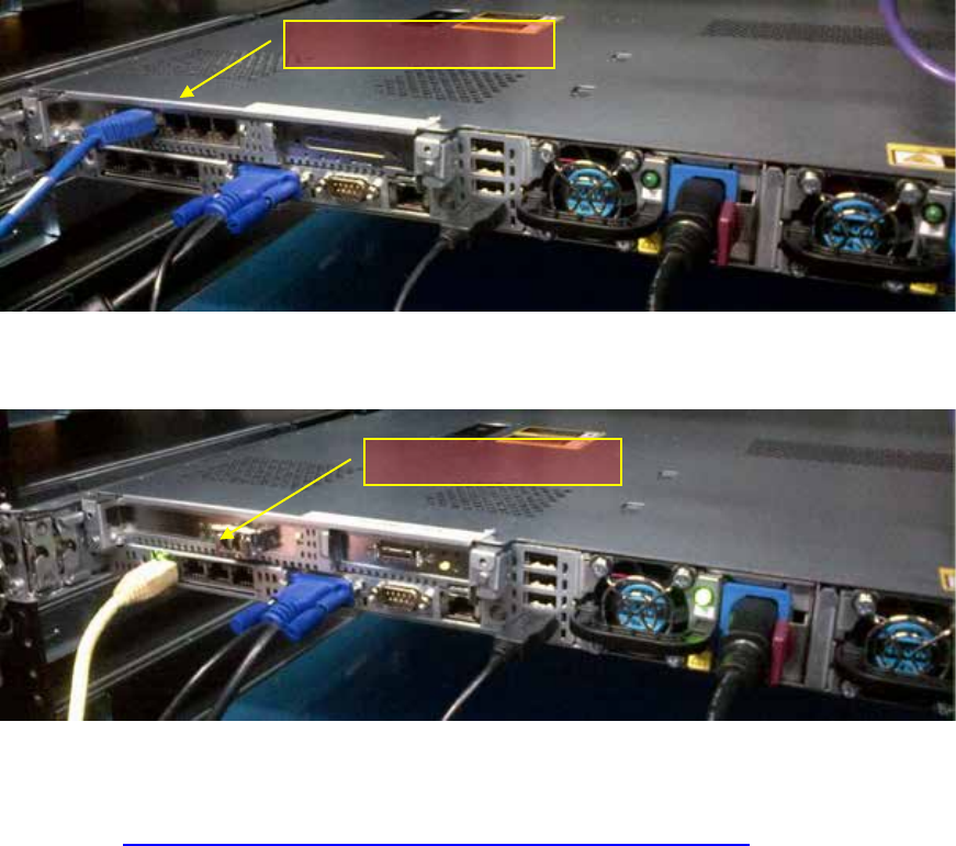
ICS 1.8 Installation & Configuration Guide
50
HP DL360 backplane (indicating HP NC365T 4-Port GigE):
HP DL360 backplane (indicating HP 366FLR 4-port GigE):
Proceed to “Setting the System Clock and Disabling HP Power Saving Mode” on page “51”.
Connecting to non-ISIS Proxy Storage
Interplay MAM deployments where browse proxies reside on non-ISIS storage do not require
additional NIC cards. They make use of the Ethernet ports built in to the HP server. Visually
verify that one of the built-in ports is connected to the network. For a 10GigE connection to
non-ISIS storage, use a 10GigE NIC of your choosing.
Note: If MAM browse proxies reside on an ISIS, the connection to the ISIS must be over a
Zone 1, Zone 2, or Zone 3 (recommended) connection, using a GigE or 10GigE network
interface.
HP NC365T 4-Port GigE
HP 366FLR 4-port GigE
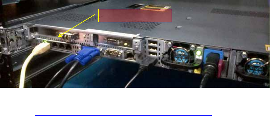
ICS 1.8 Installation & Configuration Guide
51
HP DL360 backplane (showing built-in Ethernet ports):
Note: This applies to Interplay MAM deployments only.
Proceed to “Setting the System Clock and Disabling HP Power Saving Mode” on page “51”.
Setting the System Clock and Disabling HP Power Saving
Mode
To ensure the smooth installation of RHEL and ICS, the system clock must be set. When setting
up an ICS node cluster, setting the system clocks accurately is particularly important.
HP servers are frequently shipped with BIOS settings set to Power-Saving mode. ICS is makes
intensive use of the server’s CPUs and memory, especially when under heavy load. You will get
much better performance by ensuring that the server is set to operate at Maximum
Performance.
Note: While setting the system clock and power saving mode can be done after the
installation process, we recommend making the change immediately.
To start the server and access the BIOS:
1. Power up the server.
2. When the console displays the option to enter the Setup menu, press F9.
The BIOS responds by indicating F9 was pressed.
The ROM-Based Setup Utility appears after a few moments.
Built-in Ethernet Ports
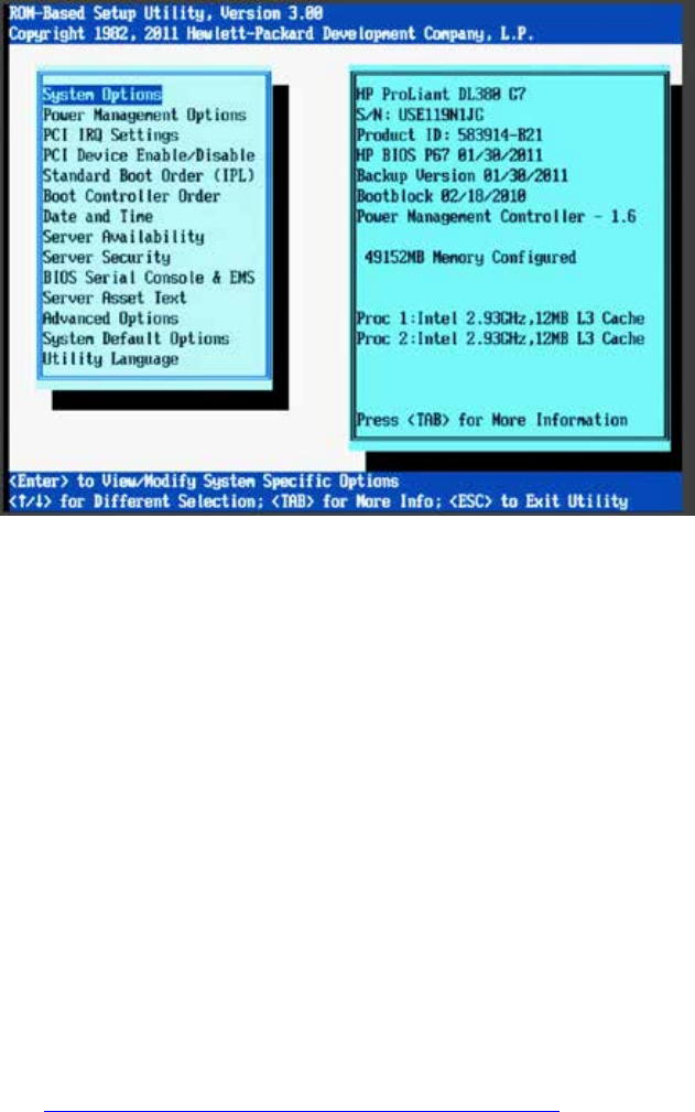
ICS 1.8 Installation & Configuration Guide
52
3. Choose Date and Time and press Enter.
Date and Time options appear.
Set the date (mm-dd-yyyy) and time (hh:mm:ss).
4. Press Enter to save the changes and return to the Setup Utility menu.
5. Choose Power Management Options.
Power Management options appear.
6. Choose HP Power Profile.
Power Profile options appear.
7. Choose Maximum Performance.
You are returned to the HP Power Management options menu.
8. Press Esc to return to main menu.
9. Exit the Setup utility Esc and press F10 to save.
The server reboots with new options.
Proceed to “Setting Up the RAID Level 1 Mirrored System Drives” on page 52.
Setting Up the RAID Level 1 Mirrored System Drives
In this step you configure two of the HD drives in the server enclosure as a RAID Level 1 – a
mirrored RAID – where the RHEL and ICS software will be installed. This is done using the Option
ROM Configuration for Arrays utility, in the HP server’s BIOS.
Note: If the list of available disks does not appear as expected, it may be that a RAID has
already been created. Deleting a RAID destroys all the data it contains, so verify it is safe
to do so first.
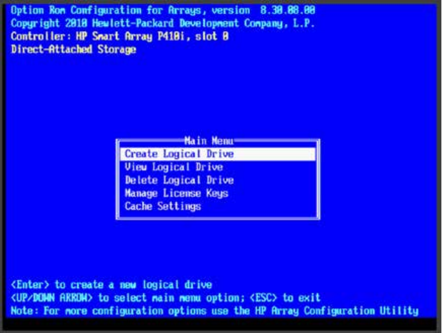
ICS 1.8 Installation & Configuration Guide
53
To set up the mirrored disks for the operating system:
1. Reboot the server and press any key (spacebar recommended) when prompted to
display the HP ProLiant “Option ROM” messages.
Note: Do not press F9 or F11. Press any key other than F9 or F11 (spacebar
recommended).
Detailed messages now appear as the server boots up.
2. As soon as you see the prompt to enter the Option ROM Configuration for Arrays utility,
press F8.
Note: The prompt to press F8 can flash by quite quickly. If you miss it, reboot and try
again.
3. From the Main Menu, select Create Logical Drive.
4. Select the following two HD drives in Available Physical Drives:
• Box 1 Bay 1
• Box 1 Bay 2
5. Deselect all the other available HD drives (if any).
6. Ensure RAID 1 is selected in RAID Configurations.
Note: In older firmware versions, the choice presented may be RAID 1+0. Since you
are only using two HD drives, this is identical to a RAID 1.
7. Ensure Disable (4GB maximum) is selected in Maximum Boot partition:
8. Ensure nothing is selected in Parity Group Count.
9. Ensure nothing is selected in Spare.
10. Press Enter to create the logical drive.

ICS 1.8 Installation & Configuration Guide
54
A message appears summarizing the RAID 1 setup.
11. Press F8 to save the configuration.
A message appears confirming the configuration has been saved.
12. Press Enter to finalize the RAID 1 setup.
Note: Do not press the Escape key to exit, since this reboots the server. Wait until you have
set up the RAID 5 cache drives (optional) or have inserted the USB key.
Proceed to “Setting Up the RAID Level 5 Cache Drives” on page 54 (if applicable).
Otherwise, insert the USB key and proceed to “Installing RHEL and the ICS Software” on page
56.
Setting Up the RAID Level 5 Cache Drives
In this step you configure the remaining HD drives in the server enclosure as a RAID Level 5. In a
RAID 5 data is automatically distributed across all the disks in the RAID for increased
performance and redundancy. This is done using the Option ROM Configuration for Arrays
utility, in the HP server’s BIOS.
Note: If the list of available disks does not appear as expected, it may be that a RAID has
already been created. Deleting a RAID destroys all the data it contains, so verify it is safe
to do so first.
Note: This document provides instructions for creating a media cache volume as a
RAID 5 using multiple disks in the server enclosure. However, other configurations are
possible, including two drives in a RAID 1 configuration, or a single drive. For details, see
the “How to Buy Hardware for Interplay Central Services” guide.
To set up the remaining disks as the ICS cache:
1. If you are arriving to this procedure from setting up the RAID 1 mirrored system drives,
proceed to Step 3, below.
Otherwise, reboot the server and press any key when prompted (spacebar
recommended) to display the HP ProLiant “Option ROM” messages.
Note: Do not press F9 or F11. Press any key other than F9 or F11 (spacebar
recommended).
Detailed messages now appear as the server boots up.
2. As soon as you see the prompt to enter the Option ROM Configuration for Arrays utility,
press F8.
Note: The prompt to press F8 can flash by very quickly. If you miss it, reboot and try
again.
3. From the Main Menu, select Create Logical Drive.
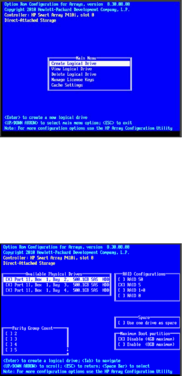
ICS 1.8 Installation & Configuration Guide
55
4. Ensure the HD drives to be included in the RAID 5 are selected in Available Physical
Drives:
• Box 2 Bays 3-8 (typical configuration)
5. Ensure RAID 5 is selected in RAID Configurations.
6. Ensure Disable (4GB maximum) is selected in Maximum Boot partition.
7. Ensure nothing is selected in Parity Group Count.
8. Ensure nothing is selected in Spare.
The following screen snapshot shows a RAID 5 consisting of three HD drives in Box 1.
The use of three HDs in RAID 5 is a non-standard configuration, shown here for
illustration purposes only.

ICS 1.8 Installation & Configuration Guide
56
9. Press Enter to create the logical drive.
A message appears summarizing the RAID 5 setup.
10. Press F8 to save the configuration.
A message appears confirming the configuration has been saved.
11. Press Enter to finalize the RAID 5.
Note: Do not press the Escape key to exit, since this reboots the server.
Proceed to “Installing RHEL and the ICS Software” on page 56.
Installing RHEL and the ICS Software
Use the ICS installation USB key prepared earlier to install ICS on an HP server. It accelerates the
process by installing the RHEL operating system and ICS software components at the same time.
To initiate the process, you simply reboot the server with the USB key inserted.
Caution: If you are in the process of upgrading from ICS 1.4.x or earlier, it is a fresh
install, and will overwrite your current ICS settings and databases.
Before proceeding with the upgrade, back up your current settings:
¨ Database: The ICS settings and database using the backup script (system-
backup.sh) provided. See “Backing up the ICS Settings” on page 127.
¨ SSL Private Key(s): If you deployment makes use of CA-signed certificates, back
up private(s), regardless of the upgrade path.
¨ Corosync Configuration File: If you configured ICS 1.4.x for unicast, you made
changes to the corosync configuration (corosync.conf) file. The installation script
overwrites this file. To preserve your changes, back up the file before beginning
the upgrade, and restore it after.
Note: For workflow details on upgrading to ICS 1.8 from an earlier release, see the ICS
1.8 Upgrading Guide, available from the Avid Knowledge Base ICS 1.8 web page.
To boot the server from the USB key and run the installer:
1. Before rebooting the server ensure the USB key is inserted.
Note: If you have just created the RAID 1 or RAID 5, press the Escape key to exit the
Option ROM configuration menu to proceed to the boot menu, and boot from there.
Note: For HP installs, an error message may appear: "[Firmware Bug]: the BIOS has
corrupted hw-PMU resources". You can ignore this error. For more information, see:
http://h20000.www2.hp.com/bizsupport/TechSupport/Document.jsp?objectID=c032651
32.
2. Wait for the RHEL Welcome screen to appear.
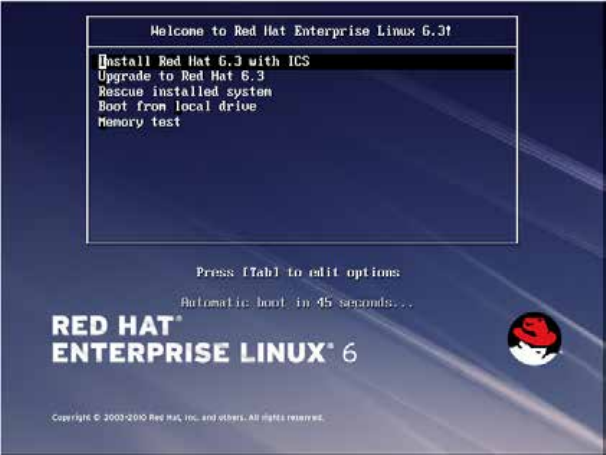
ICS 1.8 Installation & Configuration Guide
57
This screen welcomes you to the installation process and presents different installation
options.
Note: It has been reported that under some circumstances the installation bypasses the
RHEL Welcome screen. This will not affect the install process. The correct installation
choice is always selected by default.
3. Select “Install Red Hat with ICS” to install a new ICS and press Enter.
Note: If you are upgrading your system, do not use the “Upgrade” option. For upgrading
instructions, see the ”ICS 1.8 Upgrading Guide”.
The RHEL and ICS packages are installed—this takes about 20 minutes.
Note: Installations on supported HP hardware automatically makes use of a “kickstart”
(ks.cfg) file to accelerate RHEL installation. Normally, the kickstart file operates silently
and invisibly without the need for intervention.
Unable to download kickstart file
If you see the above message, it indicates the partition where the Linux installation
program expects to find the kickstart file (sda) is already in use. The most likely cause is a
KVM with “virtual media” capability reserving the sda partition to facilitate the mapping
of removable drives to the attached server.
To resolve the issue, disable the virtual media capability. Alternately, unplug the KVM
and connect to the server directly using an external monitor and USB keyboard.
4. If you just created the RAIDs a warning screen appears indicating a device (i.e. the
RAIDs) needs to be reinitialized. This is normal. Select Re-Initialize or Re-Initialize All as
needed.
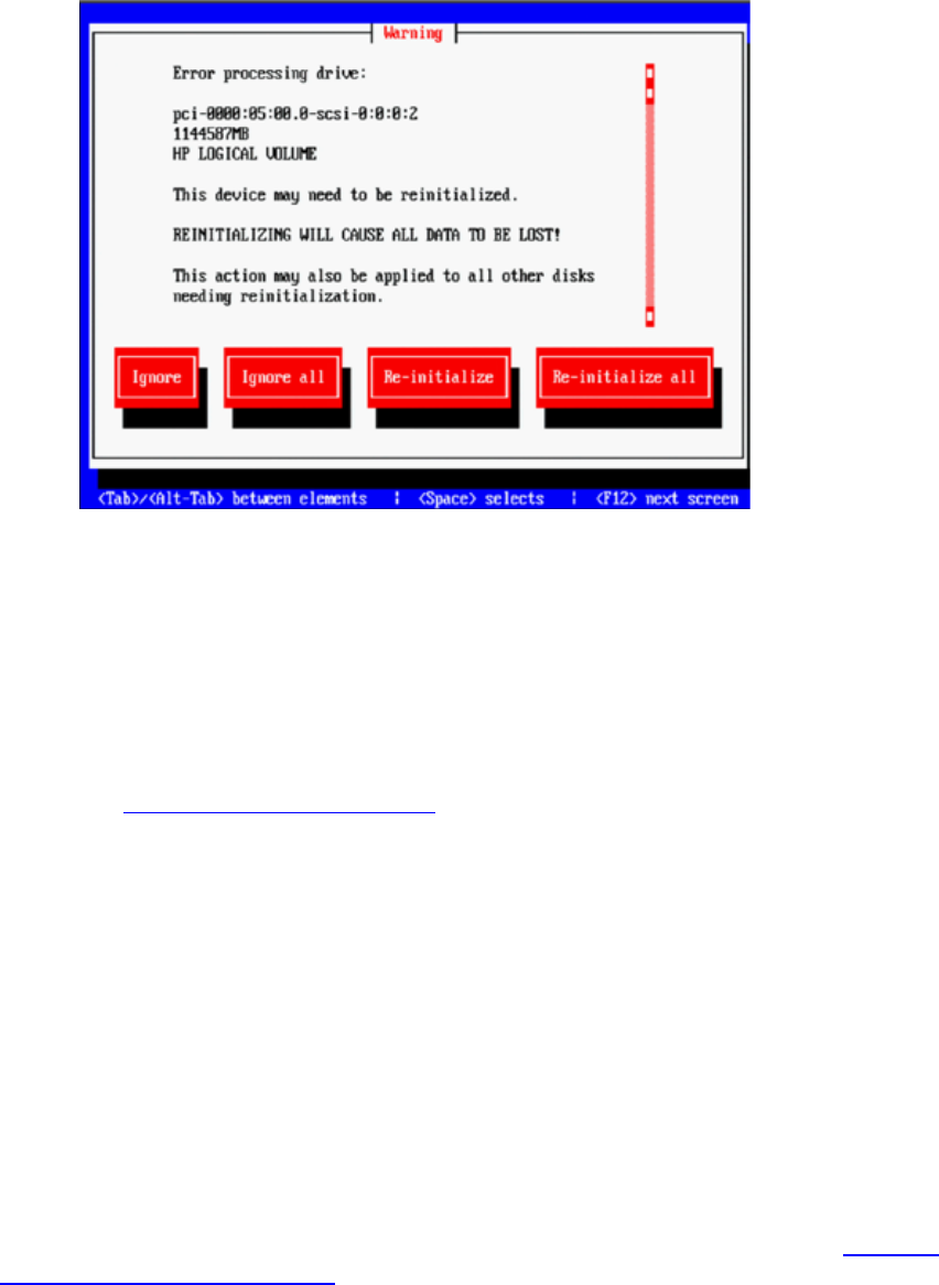
ICS 1.8 Installation & Configuration Guide
58
5. When the installation process is complete, you are prompted to reboot. DO NOT
REBOOT before removing the USB key.
If you reboot without removing the USB key the server will reboot from the USB key
again and re-launch the installer.
Note: If you pressed Enter by mistake, remove the USB key as quickly as possible (before
the system boots up again). If this is not possible, you need to perform the installation
again.
Proceed to “Booting RHEL for the First Time” on page 58.
Booting RHEL for the First Time
Like most operating systems, when you boot RHEL for the first time, you need to set up a few
items. In RHEL a “first boot” causes the RHEL Configuration screen to appear, providing access to
system set-up menus.
Note: You can re-enter the first boot set-up menus at any time by typing “setup”
(without quotes) at the Linux command prompt.
Note: Some ICS software components depend on the language for RHEL being set to
English. This is done automatically by the ICS installation scripts. Do not change the input
language afterwards.
The procedures in this section make use of the following information you entered in “Appendix
L: Installation Pre-Flight Checklist” on page 210:
¨ Default root password
¨ New Linux root password.
Note: Please contact your Avid representative for the default root password.
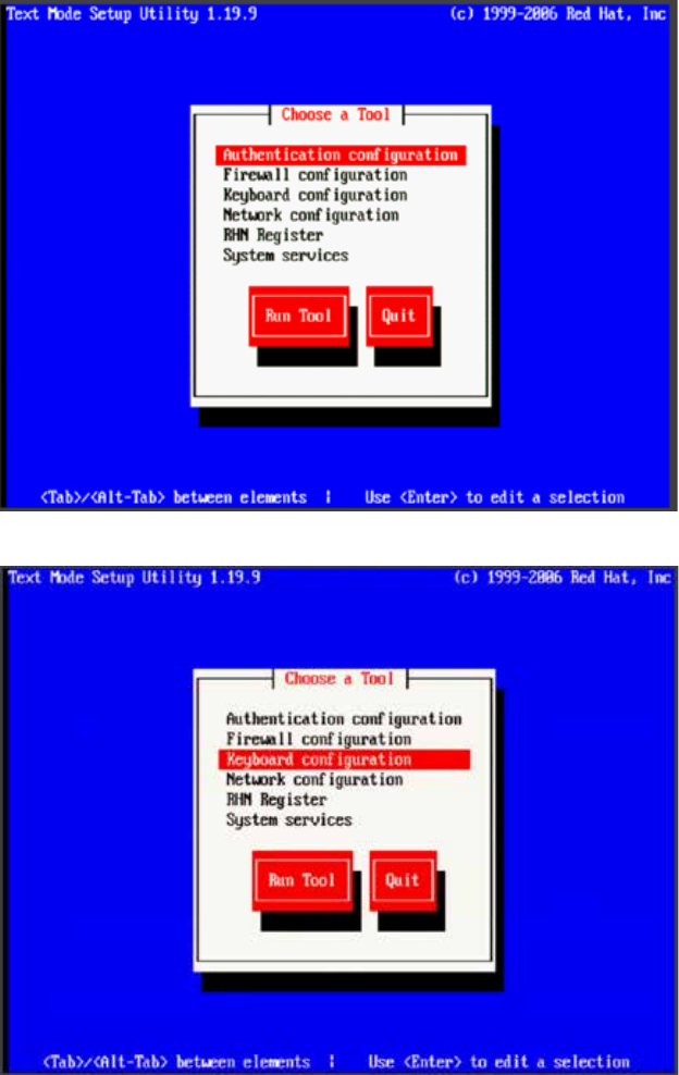
ICS 1.8 Installation & Configuration Guide
59
Booting from the System Drive
When installing RHEL and ICS you booted from the ICS Installation USB key. This time you boot
from the system drive where the OS and software were installed.
To boot the server from the system drive for the first time:
Note: If the USB key is still in the server, remove it.
1. Press Enter in the post-installation dialog.
Rebooting the server triggers a first-time boot up from the system drive. The RHEL
Configuration screen appears.
2. From the Choose a Tool menu, select Keyboard Configuration. Press Enter.

ICS 1.8 Installation & Configuration Guide
60
3. Choose the Language option for your keyboard.
4. Focus the OK button. Press Enter.
5. From the Choose a Tool menu, select Quit. Press Enter.
6. Log in a the Linux prompt
Default user name: root
default password: _
Note: Please contact your Avid representative for the default root password.
You can re-enter the first boot set-up menus at any time by typing “setup” (without quotes) at
the Linux command prompt.
Proceed to “Changing the root Password” below.
Changing the
root
Password
For reasons of security it is strongly suggested that you change the password for the root user.
To change the root password:
1. While logged in as the root user type the Linux change password command:
passwd
2. Follow the prompts to change the password.
Use a strong password that is in accordance with the customer’s password enforcement
policies.
Proceed to “Verifying the Date and Time” below.
Verifying the Date and Time
Although you set the time and date in the BIOS in an earlier step, it is worth verifying that it is
still set correctly before proceeding. Linux takes ownership of the BIOS time and date setting,
and may have altered it during the install.
To verify the date and time:
1. If you have not already done so log in.
Log in as the root user (i.e. username = root).
Note: Please contact your Avid representative for the default root password.
2. To check the date type date and press enter.
The date is displayed.
3. If the date is incorrect, change it. For example, for September 2nd, 2012, at 11:03 a.m.
enter:
date 090211032012

ICS 1.8 Installation & Configuration Guide
61
The required format is MMDDHHmmYYYY. (Month-Date-Hour-Minute-Year)
4. When you press enter the reset date is displayed:
Sun Sep 2 11:03:00 EDT 2012
Proceed to “Setting the Time Zone” below.
Setting the Time Zone
The installation script sets the location to Montreal and the time zone to Eastern Standard Time.
Please customize your setup by setting the location more appropriately. In this step you edit the
RHEL file that controls how the operating system interprets values in the system clock.
Note: This step requires the use of vi, the command-line text editor supplied with RHEL. For
an introduction to vi, see “Working with Linux” on page 24.
To set the time zone:
1. Using Linux commands, list the contents of the directory containing RHEL time zone
information:
ls /usr/share/zoneinfo
A list of time zone regions is presented. For example, US time zones are located under
/usr/share/zoneinfo/America (replicates IANA time zone database) and
/usr/share/zoneinfo/US (standard US timezones), European time zones are in
/usr/share/zoneinfo/Europe, and so on.
2. Locate the time zone of interest in the subdirectories of /usr/share/zoneinfo (e.g.
US/Eastern) and take note of it for the next steps.
3. Using Linux commands, navigate to the directory containing the clock file read by RHEL
at boot-time:
cd /etc/sysconfig
4. List the contents of the directory:
ls -l
5. Using the Linux text editor vi, open the clock file for editing:
vi clock
6. Locate the ZONE information, and replace “America/Montreal” with the appropriate
information, for example:
ZONE=”America/Los_Angeles”
Navigate using the arrow keys, then press A (append) and replace the information.
7. Save and exit the clock file by typing the following command from within the vi editing
session:
<Esc>:wq

ICS 1.8 Installation & Configuration Guide
62
8. That is, tap the Escape key, then the colon, then type wq and press Return.
The file is saved and you are returned to the Linux prompt.
9. Create the symbolic link RHEL needs to make use of the new time zone information:
ln –sf /usr/share/zoneinfo/<yourzone> /etc/localtime
In the above command, <yourzone> is the path you entered in the clock file (e.g.
America/Los_Angeles).
10. Verify the settings using the date command:
date
The local time and time zone should now be shown.
Proceed to “Editing the Network Connections” on page 62.
Editing the Network Connections
Under the Linux operating system, every physical network connector, called an interface in
Linux, has a name. By default, when installing RHEL, the installer scans the NIC cards in the
machine and labels the interfaces it finds, in the order it finds them. In this step, you verify that
the interface you want ICS to use has the name eth0. If not, you rename the interface.
Note: This step requires the use of vi, the command-line text editor supplied with RHEL. For
an introduction to vi, see “Working with Linux” on page 24.
The procedures in this section make use of the following information:
¨ NIC cards present in the enclosure
¨ NIC card used to connect the server to the network
¨ Whether your facility uses static or dynamic IP addressing
¨ Whether you are setting up a cluster of ICS server nodes
¨ Facility network settings (static IP address, netmask, default gateway IP, etc., as
applicable)
¨ Server name
Note: You collected the above information in “Appendix L: Installation Pre-Flight Checklist” on
page 210.
Identifying NIC Interfaces by Sight
RHEL provides a simple means for visually identifying the NIC ports on a server, whether they
are active or not. The ethtool command can be used cause ports to blink for a pre-determined
amount of time.
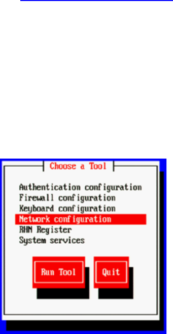
ICS 1.8 Installation & Configuration Guide
63
To visually identify a NIC Interface:
1. Use the Linux ethtool command, identify the port currently named eth0 by causing it to
blink for 60 seconds:
ethtool --identify eth0 60
Note the use of a double-dash. In Linux, a single- or double-dash distinguishes options
from arguments. A double-dash often precedes a word (i.e. human readable) option.
The system responds by causing the adapter to blink on the eth0 port.
2. If needed, repeat the above to identify other ports.
Proceed to “Verifying the NIC Interface Name” below.
Verifying the NIC Interface Name
In this step you verify the NIC interface you are using to connect to the network is correctly
named eth0.
To verify the NIC interface name:
1. Enter the RHEL Configuration screens by typing the following at the command prompt:
setup
2. From the Choose a Tool menu, select Network Configuration. Press Enter.
3. From the Network Configuration menu, select Device Configuration. Press Enter.
A list of NIC cards contained in the server enclosure appears.
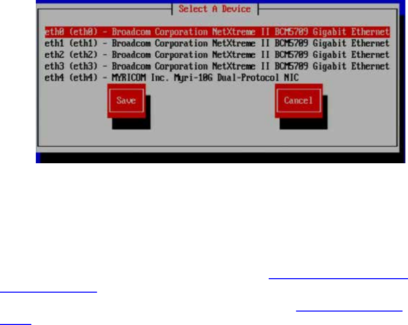
ICS 1.8 Installation & Configuration Guide
64
4. Use the arrow keys to locate the NIC card used to connect to the network. Press Enter
to view its details.
5. Note the name assigned to the NIC card interface of interest (e.g. eth0, eth1, ethn) and
record it here: _______
6. Perform the action required at each menu (Quit, Exit, etc.) to return to the Linux
prompt.
If the selected NIC card interface is named eth0 proceed to “Configuring the Hostname and
Static Network Route” on page 66.
If the selected NIC card’s interface is not named eth0, proceed to “Swapping NIC Interface
Names” below.
Swapping NIC Interface Names
If you discover the NIC interface you are using to connect to the network is not named eth0, you
must rename it. You must also rename the NIC interface currently using the name. To make
these changes permanent you must edit the network script file where Linux stores NIC interface
names.
1. Using Linux commands, navigate to the directory containing the network script file
where persistent names are assigned to network interfaces:
cd /etc/udev/rules.d
2. List the files in the directory to see if 70-persistent-net.rules exists:
ls –l
Note: One a server with just one NIC card installed, the file will not be present.
3. If needed, create the file:
udevadm trigger –action=add
4. Using the Linux text editor, vi, open the 70-persistent-net.rules file for editing:
vi 70-persistent-net.rules

ICS 1.8 Installation & Configuration Guide
65
5. Locate the lines corresponding to the NIC card you want to name eth0 and the one
already using the name.
Use the arrow keys on the keyboard to navigate the file.
6. Press the A key to append to the end of the line:
NAME="eth0"
7. Change NAME="ethX" (e.g. eth1, eth2, etc.) to the following:
NAME="eth0"
8. Locate the line corresponding to the NIC card that was already using the name eth0 and
rename it:
NAME="ethX"
where “X” is the number you removed in step 5 (e.g. eth1, eth2, etc.); that is, swap the
names.
9. Save and exit the 70-persistent-net.rules file by typing the following command from
within the vi editing session:
<Esc>:wq
That is, tap the Escape key, then the colon, then type wq and press Return.
You are returned to the Linux prompt.
Proceed to “Removing the MAC Address Hardware References” below.
Removing the MAC Address Hardware References
Even though you renamed a NIC interface to eth0 and made the changes permanent by editing
the network script file, there is one more step. In this step you remove the hardware references
– generally known as MAC addresses – from the affected NIC interface configuration files.
Recall that every NIC card is assigned a unique hardware identifier -- called a MAC address -- by
the manufacturer. The MAC address uniquely identifies the NIC card hardware, and is
permanently stored in the NIC card’s firmware. When Linux scans for NICs, it obtains this
hardware identifier and writes it to an interface configuration file. Further, the Linux installation
scripts create an interface configuration file (e.g. ifcfg-eth0, ifcfg-eth1, etc.) for each NIC
interface found. For example, a NIC card with four network interfaces will have four interface
configuration files.
For each card where you renamed a NIC interface, you must edit the corresponding interface
configuration file -- that was already created by Linux -- and remove the hardware identifier.
Otherwise, Linux will override the changes you made earlier and reassign the old interface
names the next time it boots (or you restart the Linux network services).
To remove the hardware references from the interface configuration file:
Note: This procedure must be performed twice – once for each of the NIC interfaces you
renamed.

ICS 1.8 Installation & Configuration Guide
66
1. Using Linux commands, navigate to the directory containing the network scripts files:
cd /etc/sysconfig/network-scripts
2. List the contents of the directory:
ls –l
3. Using the Linux text editor, vi, open the interface configuration file for one of the
renamed interfaces (e.g. ifcfg-eth0):
vi ifcfg-eth0
In Linux, each NIC interface has its own configuration file.
4. Locate the line containing the hardware identifier. It has the following form:
HWADDR = 00:00:00:00:00:00
In Linux, each NIC interface has its own configuration file.
5. Remove the whole line.
6. Save and exit the file by typing the following command from within the vi editing
session:
<Esc>:wq
That is, tap the Escape key, then the colon, then type wq and press Return.
You are returned to the Linux prompt.
7. Repeat the above steps for the other NIC interface you renamed (e.g. ethX).
8. Once you have finished removing the hardware references for both the renamed NIC
interfaces, reboot the server to restart the network services and make the effects
permanent:
reboot
Note: You must reboot, rather than simply restarting network services, since you
changed the contents of the /etc/udev/rules.d file, in the previous procedure.
Proceed to “Configuring the Hostname and Static Network Route” below.
Configuring the Hostname and Static Network Route
Now that the NIC interface you will use to connect the ICS server to the network has been
named eth0, you are ready to configure the server to make the connection. This is done using
the RHEL configuration facility.
This procedure make us of the facility network settings information you entered in “Appendix L:
Installation Pre-Flight Checklist” on page 210.
To configure the hostname and static network route for eth0:
1. Enter the RHEL Configuration screens by typing the following at the command prompt:
setup
ICS 1.8 Installation & Configuration Guide
67
2. From the Choose a Tool menu, select Network Configuration. Press Enter.
3. From the Network Configuration menu, select Device Configuration. Press Enter.
A list of NIC cards contained in the server enclosure appears.
4. Use the arrow keys to locate the NIC card and interface named eth0. Press Enter to view
its details
5. Ensure the following information is correctly set:
¨ Default name: eth0
¨ Default device: eth0
¨ DHCP is disabled (Spacebar to disable)
6. Disabling the Dynamic Host Configuration Protocol (DHCP) allows you to enter the
following static network route information:
¨ Facility Static IP address
¨ Facility Netmask
¨ Default Gateway IP
¨ Primary DNS server
¨ Secondary DNS server
7. Select OK. Press Enter.
You are returned to the list of NIC cards in the enclosure.
8. Select Save. Press Enter.
9. From the Choose a Tool menu, select DNS Configuration. Press Enter.
10. Give the machine a name (host name) and enter its DNS information:
¨ Enter the hostname: <machine name>
(e.g. ics-dl360-1)
¨ DNS entries from step 6
¨ If you are using a static IP addresses (recommended), enter the DNS search path
domain
¨ If you are using DHCP, leave the DNS search path domain blank.
Note: The host name indicated above is the host name only (e.g. ics-dl360-1),that is, the
name of the machine. Do not use the fully qualified domain name (e.g. ics-dl360-
1.mydomain.com or ics-dl360-1.mydomain.local).
11. Select Save & Quit. Press Enter.
12. Select Quit. Press Enter.
You may be prompted to login to the server.
13. Verify the DNS Server information has been stored in the RHEL resolver configuration
(resolv.conf) file:

ICS 1.8 Installation & Configuration Guide
68
cat /etc/resolv.conf
The information you entered for the DNS search path and DNS servers should be
present in the file.
14. Deleted any backup resolver configuration (resolv.conf.save) file that might have been
automatically created by the OS:
rm /etc/resolv.conf.save
Note: Due to a caveat in Linux, if you do not delete the resolv.conf.save file, when you
reboot, Linux overwrites the changes you just made.
15. Remove the USB key (if it is still in the server) and reboot the server:
reboot
Proceed to “Verifying the hosts file Contents” below.
Verifying the
hosts
file Contents
The hosts file is used by the operating system to map hostnames to IP addresses. It allows
network transactions on the computer to resolve the right targets on the network when the
instructions carry a human readable host name (e.g. ics-dl360-1) rather than an IP address (e.g.
192.XXX.XXX.XXX).
By default the hosts file on a computer resolves the machine’s own IP address to localhost. In
this step, you verify the content of the hosts file, and remove any extra entries, if present. In
addition, since the active hosts file can be reset to its default configuration when a server fails or
is rebooted you also verify the system default hosts file.
The active hosts file is located here:
/etc/hosts
The system default hosts file (if present) is located here:
/etc/sysconfig/networking/profiles/default/hosts
Note: You can edit the file /etc/hosts while the system is up and running without disrupting
user activity.
To verify the hosts file:
1. Open the active hosts (/etc/hosts) file for editing.
vi /etc/hosts

ICS 1.8 Installation & Configuration Guide
69
It should look similar to the following:
127.0.0.1 localhost localhost.localdomain localhost4 localhost4.localdomain4
::1 localhost localhost.localdomain localhost6 localhost6.localdomain6
The entries shown above map the default localhost IP address (127.0.0.1) to various
forms of localhost, for both ipv4 and ipv6 systems.
2. In some cases, the entries incorrectly includes an explicit call-out of the computer’s own
host name (e.g. ics-node-1).
For example, a machine named ics-node-1 might have additional entries as shown
below (in bold):
127.0.0.1 localhost localhost.localdomain localhost4 localhost4.localdomain4
ics-node-1
::1 localhost localhost.localdomain localhost6 localhost6.localdomain6
ics-node-1
3. If the computer’s own host name is present (e.g. ics-node-1), remove it:
127.0.0.1 localhost localhost.localdomain localhost4 localhost4.localdomain4
::1 localhost localhost.localdomain localhost6 localhost6.localdomain6
4. Save and exit the file (<Esc>:wq).
5. Perform the same actions for the system default hosts file:
vi /etc/sysconfig/networking/profiles/default/hosts
Proceed to “Verifying Network and DNS Connectivity” below.
Verifying Network and DNS Connectivity
Before continuing, take a moment to verify that network connectivity is now established.
To verify network connectivity:
On any other network connected machine, use the Linux ping command to reach the host in
question:
ping –c 4 <hostname>
For example:

ICS 1.8 Installation & Configuration Guide
70
r
ping –c 4 ics-dl360-1
The system responds by outputting its efforts to reach the specified host, and the results. For
example, output similar to the following indicates success:
PING ics-dl360-1.fqdn.com (172.XXX.XXX.XXX) 56(88) bytes of data
64 bytes from ics-dl360-1.fqdn.com (172.XXX.XXX.XXX):
64 bytes from ics-dl360-1.fqdn.com (172.XXX.XXX.XXX):
64 bytes from ics-dl360-1.fqdn.com (172.XXX.XXX.XXX):
64 bytes from ics-dl360-1.fqdn.com (172.XXX.XXX.XXX):
A summary of the results is also presented.
Proceed to “Synching the System Clock” below.
Synching the System Clock
In this step you set the Network Time Protocol (NTP) daemon to automatically synchronize the
system clock with an NTP time server every 30 minutes. This is done by creating a job for the
Linux cron utility. The cron job runs the NTP daemon, ntpd.
Note: Setting up ntpd to run as a service at startup is also a possibility. However, some
consider it a security risk to run ntpd in “continuous” mode. The technique shown here
keeps the system clock synchronized while minimizing exposure to risk by causing ntpd
to exit after it fetches the correct time.
Note: The use of the iburst option within the cron job is not recommended. It produces
very rapid time shifts and can lead to synchronization problems with other nodes, the
ISIS, and so on.
This procedure makes use of the following information:
¨ In-House NTP server:
To synchronize the system clock:
1. Verify that the NTP server of interest is reachable by querying it:
ntpdate -q <server_address>
2. Edit the NTP configuration (ntp.conf) file using a text editor (such as vi):
vi /etc/ntp.conf
3. Add a line for the NTP server. For example, if the address of the NTP server is
ntp.myhost.com, add the following line:
server ntp.myhost.com
You can supply the IP address instead (e.g. 192.XXX.XXX.XXX)

ICS 1.8 Installation & Configuration Guide
71
4. Comment out any out-of-house servers that may already be present, for security. For
example:
# server 0.rhel.pool.ntp.org
# server 1.rhel.pool.ntp.org
# server 2.rhel.pool.ntp.org
5. Save and exit the file.
<Esc>:wq
6. Set up a cron job by editing (or creating) a file containing instructions for cron:
vi /etc/cron.d/ntpd
7. Add a line with the instructions for cron:
30 * * * * root /usr/sbin/ntpd -q -u ntp:ntp
The command above instructs cron to:
• Run the cron job every 30 minutes as root
• The job is /usr/sbin/ntpd
• The -q switch tells ntpd to exit after it sets the system clock
• The -u switch tells Linux to run the job as user ntp, in user group ntp
8. Save and exit the file.
<Esc>:wq
9. Set the system clock now by running the NTP daemon:
/usr/sbin/ntpd -q -u ntp:ntp
The system responds with a message similar to the following:
ntpd: time set +9.677029s
The NTP daemon sets the time when there are large changes, and slews (slowly adjusts) the
time for small changes (significantly less than a second).
10. Verify the system time and date:
date
The system responds with a message similar to the following:
Wed Jun 5 14:53:17 EDT 2013
Proceed to “Creating the File Cache on the RAID” below.

ICS 1.8 Installation & Configuration Guide
72
Creating the File Cache on the RAID
In an earlier step you created a RAID 5 for the cache using the “arrays” utility built-in to the HP
server’s BIOS. In this step you finalize caching. First, you partition the RAID. Next you create a
logical volume for the RAID and mount the ICS cache on it.
For a discussion of caching, see “Caching in ICS” on page 22.
For a discussion of RAIDs, see “RAIDs in ICS” on page 30.
Partitioning the RAID
In this procedure you partition the RAID and write the new partition table entry to disk using the
GNU parted disk partitioning utility.
The enclosure contains two devices of interest, the system disk (/dev/sda) and the RAID
(/dev/sdb). Partitioning the system disk was performed automatically by the RHEL installer. You
only need to partition the RAID, as indicated in this section.
Note: Starting with RHEL 6.3, Red Hat creates a GPT volume when the ICS installation
scripts initialize the cache volume during OS installation. GPT volumes must be handled
using the GNU parted utility (rather than the Linux fdisk utility).
To partition the RAID:
1. Use the GNU parted utility to ensure the RAID 5 HD device exists:
parted –l
Note: Note the command take a lower-case “L” (not a numerical “one”).
Note: The Linux “fdisk -l” command can also be used to list the devices. However, it
returns the following warning:
WARNING: GPT (GUID Partition Table) detected on '/dev/sdb'! The
util fdisk doesn't support GPT. Use GNU Parted.
2. Find the free space on the /dev/sdb device:
parted /dev/sdb p free
Information similar to the following is displayed:
Model: HP LOGICAL VOLUME (scsi)
Disk /dev/sdb: 2500GB
Sector size (logical/physical): 512B/512B
Partition Table: gpt
Number Start End Size File system Name Flags
17.4kB 2500GB 2500GB Free Space
3. Create a primary partition on the RAID 5 using all the available space (2500 GB in the
sample output provided above):
parted -a optimal /dev/sdb mkpart primary ext2 0% 2500GB
ICS 1.8 Installation & Configuration Guide
73
The system might respond with the following message:
Information: You may need to update /etc/fstab
The message can be ignored. You will update fstab when you create the logical volume
and mount the cache for the new partition.
4. Set the partition to type logical volume, and it’s state to on.
parted /dev/sdb set 1 lvm on
5. Run the parted utility again to view your changes:
parted -l
Creating the Logical Volume and Mounting the Cache
In this procedure you work with the newly partitioned RAID 5 using the Linux Logical Volume
Manager (LVM). The hierarchy of volumes in Linux is as follows: physical volume, volume group
and logical volume.
To create the logical volume and mount the cache:
1. Create the physical volume:
pvcreate --metadatasize=64k /dev/sdb1
Note the name of the physical volume (/dev/sdb1) takes a 1 (one).
LVM feedback indicates the successful creation of the physical volume.
2. Create a volume group, vg_ics_cache, containing the physical volume /dev/sdb1:
vgcreate -s 256k -M 2 vg_ics_cache /dev/sdb1
LVM feedback indicates the successful creation of the volume group.
3. Before creating the logical volume, obtain a value for the volume group’s physical
extents:
vgdisplay vg_ics_cache
A list of properties for the volume groups appear, including the physical extents (Free
PE). Physical extents are the chunks of disk space that make up a logical volume.
Sample output is shown below:
--- Volume group ---
VG Name vg_ics_cache
System ID
Format lvm2
Metadata Areas 1
Metadata Sequence No 2
VG Access read/write
VG Status resizable
MAX LV 0
Cur LV 1
ICS 1.8 Installation & Configuration Guide
74
Open LV 1
Max PV 0
Cur PV 1
Act PV 1
VG Size 1.09 TiB
PE Size 256.00 KiB
Total PE 4578332
Alloc PE / Size 0 / 0
Free PE / Size 4578332 / 1.09 TiB
VG UUID cyWpGZ-s3PG-8UqH-4TBl-rvBA-33oJ-3uZt0u
Use the “Free PE” value to create a logical volume occupying the entire volume group
(below).
4. Create the logical volume, lv_ics_cache, containing the volume group vg_ics_cache:
lvcreate -l <Free_PEs> -r 1024 -n lv_ics_cache vg_ics_cache
In the above command, replace <Free_PEs> with the value obtained in the previous
step.
Note the first switch in lvcreate is lower case “L”.
LVM feedback indicates the successful creation of the logical volume. Note that Linux
may override the sector size you specified. That is OK.
5. Create a filesystem on the logical volume (i.e. format it):
mkfs.ext4 /dev/vg_ics_cache/lv_ics_cache
Note in the above command you specify logical volume by its Linux block device name
(/dev/<volume_group>/<logical_volume>).
As in other operating systems, formatting in RHEL is a slow operation. Please be patient.
Feedback similar to the following indicates success:
This filesystem will be automatically checked every 38 mounts or
180 days, whichever comes first. Use tune2fs -c or -i to override.
6. Navigate to the directory containing the filesystem table:
cd /etc
7. Open the filesystem table file, fstab, for editing:
vi fstab
8. Add an entry at the end of the file:
/dev/mapper/vg_ics_cache-lv_ics_cache /cache ext4 rw 0 0
This automates the mapping of the logical volume to a file system directory (/cache in
this case).
9. Save and exit the file by typing the following command from within the vi editing
session:
<Esc>:wq
ICS 1.8 Installation & Configuration Guide
75
That is, tap the Escape key, then the colon, then type wq and press Return.
You are returned to the Linux prompt.
10. Mount the volume:
mount /dev/mapper/vg_ics_cache-lv_ics_cache /cache
Alternately, since you added an entry to fstab, you ought to be able to mount the cache
as follows:
mount /cache
Note: If you receive an error indicating the mount point /cache does not exist, create the
cache manually and issue the mount command again:
mkdir /cache
mount /dev/mapper/vg_ics_cache-lv_ics_cache /cache
11. Verify that /cache has been mounted correctly:
df –h
The following information is displayed about the cache: size, used, available, user % and
mount point (mounted on), similar to the following:
Filesystem Size Used Avail Use% Mounted on
/dev/mapper/vg_ics_cache-lv_ics_cache
29G 585M 27G 3% /cache
12. Verify that /cache has the correct ownership and read-write-exec settings:
ls -la /cache
Information is displayed about the cache ownership, similar to the following:
drwxr-xr-x 5 maxmin maxmin 4096 Mar 22 10:02 .
13. If the ownership is of /cache is not set to user maxmin, change its ownership:
chown maxmin:maxmin /cache
14. If the /cache directory does not have its read-write-exec settings are not rwx for owner,
group, other, change the permissions:
chmod 0777 /cache
15. Verify that /cache now has the correct ownership, read-write-exec settings, and setgid
special permission:
ls -la /cache
Updated information is displayed, which ought to be similar to the following:

ICS 1.8 Installation & Configuration Guide
76
drwxrwxrwx 5 maxmin maxmin 4096 Mar 22 10:04 .
Note: User maxmin owns the ICS process that writes to the cache. Avid processes will create
subdirectories in /cache, on an as-needed basis.
Proceed to one of the following:
• “Appendix C: Configuring Port Bonding for Interplay MAM (Optional)” on page 152.
• “Installing the Interplay Central Distribution Service” on page 76.
• “Configuring ICS for Interplay MAM” on page 78.
• “Configuring ICS for Interplay Central and/or Interplay Sphere” on page 80.
Installing the Interplay Central Distribution Service
The Interplay Central Distribution Service (ICDS) is an Interplay service that coordinates jobs
with Avid Media Services for send to playback (STP). You can install it on a server that is already
hosting an Interplay Production component (such as an Interplay Transcode server) or on a
separate server in the Interplay Production workgroup.
You can install ICDS on two or more servers. Multiple ICDS servers provide a high-availability
configuration and failover capability in case one server fails. For more information about ICDS,
ICDS failover, and STP, see the Avid Interplay Central Administration Guide.
Note: ICDS is not required for Interplay MAM, iNEWS-only or Sphere-only deployments.
Determining Where to Install ICDS
ICDS can be installed on any server currently configured in an Interplay Production workgroup
except for servers hosting the following components:
• Media Services Engine (port conflict)
• Interplay Engine (should not have Avid Service Framework installed)
• Interplay Archive Engine (should not have Avid Service Framework installed)
ICDS can also be installed on a separate server.
Hardware requirements: ICDS is a lightweight application. It requires a minimum 512 MB RAM
and approximately 380 MB of hard drive space. It requires port 8080 for normal http
communication and port 8443 for http security protocol.
Software requirements: ICDS requires the following:
• Windows 7
• Avid Service Framework (ASF)
• ISIS client software
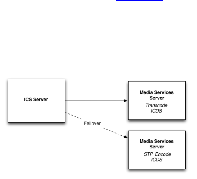
ICS 1.8 Installation & Configuration Guide
77
If you install ICDS on a server that is already hosting an Interplay Production component, ASF
and the ISIS client should already be installed. If you install ICDS on a separate server, you need
to install ASF and ISIS client software. See “Before You Begin”, below.
Example
The following illustration shows ICDS installed on a server running Media Services Transcode
and another instance installed on a server running STP Encode. The ICS server communicates
with one instance of ICDS, in this case the one running on the Media Services Transcode server.
In case this server goes down, the ICS server can communicate with the ICDS instance on the
STP Encode server.
Before You Begin
Make sure you have the following item:
¨ Interplay Central Distribution Service installation program
The program is available from the Avid Download Center (DLC) with the Avid Interplay
Central packages.
If you are installing ICDS on its own server, you also need the following items:
¨ ASF installation program. Use the version that matches the Interplay Production
configuration.
ICDS is a 32-bit application, so you can install either the 32-bit version of ASF or the 64-
bit version (if the machine is a 64-bit machine). To ensure that a 32-bit application can
see the 64-bit ASF, open the Workgroup Properties tool and connect to the Lookup
service. See the Avid Interplay ReadMe for details.
¨ Avid ISIS client installation program. Use the version that matches the Interplay
Production configuration.
Configure access for the following:
¨ Port 8080 for normal http communication and port 8443 for http security protocol

ICS 1.8 Installation & Configuration Guide
78
To install the Interplay Central Distribution Service:
1. If you are installing ICDS on its own server, install ASF and the Avid ISIS client software.
2. Copy the unzipped CentralDistributionService installer folder to the server on which you
are installing ICDS.
Note: The Interplay Central Distribution Service (ICDS) is also available from the Interplay
Servers installation media. Open the Installers folder at the top level, open the
CentralDistributionService folder, double-click setup.exe and follow the installation
instructions.
3. Open the installer folder and double-click setup.exe.
The welcome screen of the installer is displayed.
4. Click Next.
5. Accept the license agreement and click Next.
6. Accept the default installation location, or click Change to install to a different folder.
7. Click Next.
8. Click Install to begin the installation.
The installation should take only a few minutes.
9. When the installation is completed, click Finish.
The Interplay Central Distribution Service is automatically started as a Windows service.
Proceed to “Configuring ICS for Interplay Central and/or Interplay Sphere” on page 80.
Configuring ICS for Interplay MAM
For ICS to play Interplay MAM media, the filesystem containing the MAM proxies must be
mounted on the ICS servers. The mounting is done at the level of the OS using standard Linux
command for mounting volumes (mount). To automate the mounting of the MAM filesystem,
create an entry in /etc/fstab.
In the Interplay Central UI, you must create a special user for use by Interplay MAM. To see
information in the Interplay Central Load Balancer page, you must also configure the ICPS
Player.
Note: Some proprietary storage solutions may require that you install and configure
proprietary filesystem drivers or client software. Consult the documentation for the
storage solution to be used by the Interplay MAM system.
To determine the correct path to be mounted, examine the path associated with the MAM
essence pool to which ICS is being given access. This is found in the Interplay MAM

ICS 1.8 Installation & Configuration Guide
79
Administrator interface under the Essence Management Configuration tab. Look for the
“MORPHEUS” entry and tease out the path information. It is likely that ICS has been given access
to more than one MAM essence pool. Be sure to mount all the associated filesystems.
Note: Configuration must also take place on the Interplay MAM side, to set up
permissions for ICS to access MAM storage, to point Interplay MAM to the ICS server or
server cluster, etc. For instructions on this aspect of setup and configuration, please refer
to the Interplay MAM documentation.
Note: This step can be performed at any time during the installation.
To create an Interplay Central user for Interplay MAM:
1. With the server up and running, log in to Interplay Central as an administrator level-
user.
See “Logging into Interplay Central” on page 84.
2. Select Users from the Layout selector.
3. Create a special role for the MAM user by clicking on the Create Role button in the Roles
pane.
4. Click the Create Role button.
5. In the Details pane, type the properties for the new role:
• Role name (e.g. MAM)
• Advance License
• Do not assign the MAM role any layouts
6. Click Apply to save your changes.
The new MAM role is added to the Roles pane.
7. Create a MAM user by clicking the Create User button.
8. In the Details pane, type the properties for the new user:
• User name (e.g. MAM)
• Password
• Uncheck “User must change password at next sign-in”
• Check “User cannot change password
9. Drag the MAM role from Roles pane to the Role section of the Details pane for the new
user.
10. Click Save to save your changes.
The new MAM user is added to the User Tree, as a top-level user.
11. Ensure Interplay MAM is configured to make use of the assigned user name and
password.

ICS 1.8 Installation & Configuration Guide
80
For more information on creating users and roles, see the “Interplay Central Administration
Guide”.
Proceed to “Clustering Workflow” on page 101 (optional).
Configuring the ICPS Player to take advantage of load balancer reporting:
This procedure makes use of the following information:
¨ ICS server hostname (e.g. ics-dl360-1)
1. Log in to Interplay Central as a user with administrator privileges.
See “Logging into Interplay Central” on page 84.
2. Select System Settings from the Layout selector.
3. In the Settings pane, click Player.
4. Enter the ICS server hostname (e.g. ics-dl360-1).
5. Click Apply to save your changes.
Now you can monitor load balancing on the Load Balancer page. For more information, see
“Monitoring Load Balancing” on page 136.
Proceed to “Clustering Workflow” on page 101 (optional).
Configuring ICS for Interplay Central and/or Interplay Sphere
Now that you have installed the operating system, ICS software components, and ICDS software
(Interplay Central only), you are ready to configure the ICS server.
As an independent ISIS client, ICS has its own connection to ISIS, and uses a separate set of ISIS
credentials to read media assets for playback and to write audio assets for voice-over recorded
by Interplay Central end-users.
To configure ICS for Interplay Sphere you log into Interplay Central using a web browser.
Note: If you are setting up a cluster, only the master node requires configuration. You do
not need to configure any other nodes. The slave node obtains its settings from the
master node via the clustering mechanisms. The other nodes participate in load-
balancing only, and do not require configuring separately.
Configuring Workflow
The following table describes each of the main configuring steps.
Step Task Time Est.
1
Before You Begin
varies

ICS 1.8 Installation & Configuration Guide
81
Step Task Time Est.
Make sure you have everything you need to perform the configuration.
2
Configuring the Interplay Central UI
1 min
Streamline the UI by removing support for the Avid IME solutions you
won’t be using.
3
Logging into Interplay Central
1 min
Log in to Interplay Central for the first time.
4
Changing the Administrator Password
1 min
For security it is highly recommended you change the administrator
password.
5
Configuring Interplay Production Settings
1 min
In this step you tell ICS where it can find the Interplay Production server,
and the Interplay Central Distribution Service.
6
Configuring ICPS for Interplay
1 min
ICPS communicates directly with Interplay Production. In this step you
provide the user name and password used by ICPS for Interplay
Production, and other information it needs.
7
Configuring the ICPS Player for Interplay Central
1 min
In this step you tell ICPS where to find the Interplay Central server.
8
Configuring the ISIS Connection(s)
ICS communicates with the ISIS system directly. In this step, you specify
the type of connection (Zone 1, Zone 2, Zone 3), and the network-level
connection information. A Zone 3 connection is recommended.
9
Mounting the ISIS System(s)
1 min
In this step you mount the ISIS so the system can gain access to media.
10
Verifying the ISIS Mount
1 min
A validation step to make sure all the ISIS and its workgroups are
accessible.
11
Verifying Video Playback
1 min
Playing some video is a simple technique for verifying the success of the
configuration.
12
Configuring Wi-Fi Only Encoding for Facility-Based iOS Devices (optional)
1 min
When Wi-Fi is the only connection used, you can improve the encoding
capacity of the ICS server by reducing the number of streams
automatically encoded.

ICS 1.8 Installation & Configuration Guide
82
Step Task Time Est.
13
Configure Unicast Support in Clustering
5 min
ICS clustering supports both unicast and multicast. For facilities
lacking multicast enabled routers, you will need to configure the
cluster for unicast. See “Appendix H: Unicast Support in Clustering”
on page 197.
Before You Begin
Make sure you have the following items:
¨ Windows XP/Vista/7 laptop or desktop computer
¨ Network connection
¨ Web browser supported by Interplay Central.
The procedures in this section make use of the following information:
¨ Host name of the ICS server (e.g. ics-dl360-1))
or
Static IP address of the ICS cluster (e.g.: 192.XXX.XXX.XXX)
¨ New Interplay Central Administrator password.
¨ Knowledge of whether or not MOS plug-ins are used (iNEWS workflows)
¨ Knowledge of whether the facility routers support multicast.
¨ Interplay Workgroup name
¨ Lookup server hostname(s)
¨ Knowledge of whether multi-resolution workflows are being used
¨ ISIS hostname(s)
¨ ISIS user name and password reserved for ICS (e.g. ics-interplay)
Note: For multi-ISIS setups, ensure the same user credentials have been created for ICS
across all ISIS storage systems.
¨ Knowledge of the ICS connection(s):
o Zone 1 (direct connection)
o Zone 2 (layer 1 network switch)
o Zone 3 (layer 2 network switch -- recommended)
Note: The host names indicated above are host names only (e.g. ics-dl360-1),that is, the
name of the machine. Do not use the fully qualified domain names (e.g. ics-dl360-
1.mydomain.com or ics-dl360-1.mydomain.local)
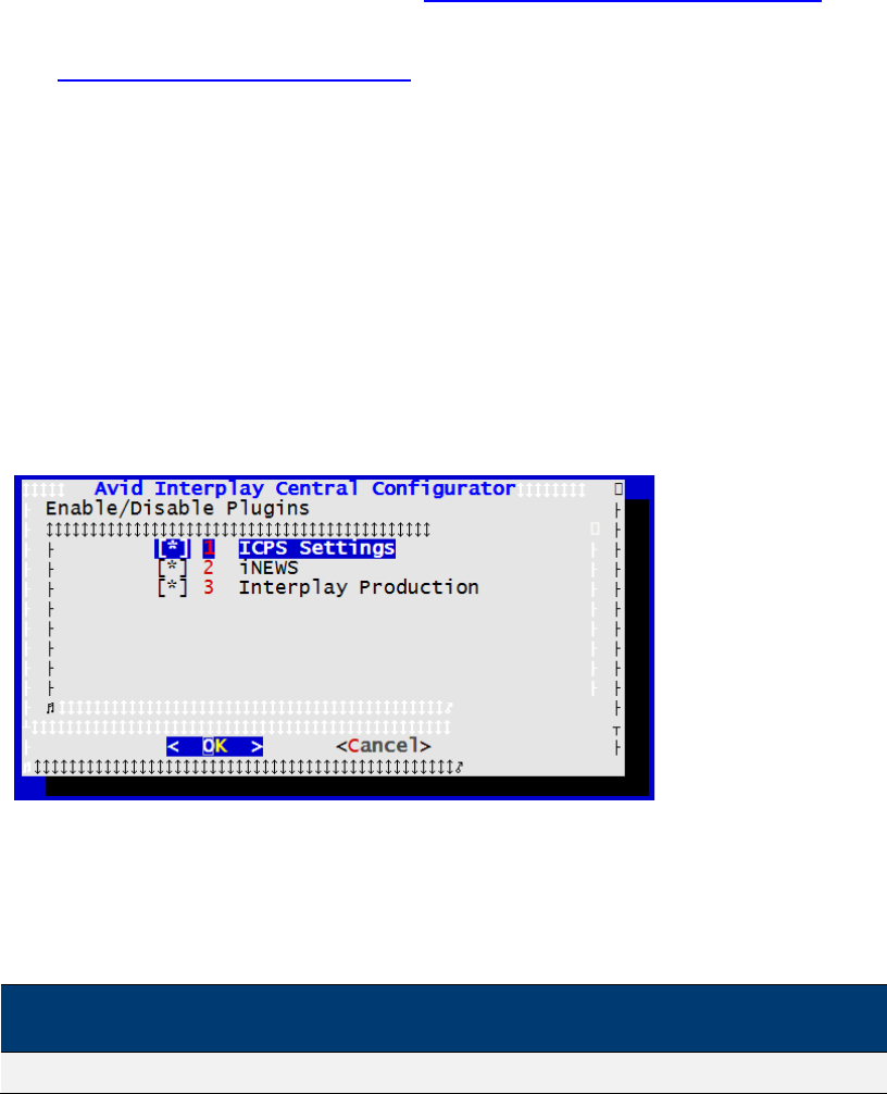
ICS 1.8 Installation & Configuration Guide
83
When the ICS connection to ISIS is Zone 3 the following information is also needed:
¨ Network Device name(s) used by connection (e.g. eth1, eth2)
¨ Network Device name(s) ignored by connection (e.g. eth1, eth2)
¨ Zone 3 NIC bandwidth (GigE vs 10GigE)
¨ ISIS System Director(s) IP address(es)
Note: You collected the above information in “Appendix L: Installation Pre-Flight Checklist” on
page 210.
Proceed to “Configuring the Interplay Central UI” below.
Configuring the Interplay Central UI
By default, the Interplay Central UI contains functionality for all the IME solutions it supports.
You can easily remove support for functions that are not needed.
To configure the Interplay Central UI:
1. Start the configurator by typing the following at the Linux prompt:
/opt/avid/avid-interplay-central/configurator
The configuration UI appears.
Note: Interplay Pulse appears in the configurator UI if it has been installed on the system (via
a separate installer).
2. Select the appropriate application profile settings.
The following table outlines typical settings by deployment type:
ICPS Settings
Interplay
Production
iNEWS
Pulse
Interplay Central & Pulse
ON
ON
ON
ON

ICS 1.8 Installation & Configuration Guide
84
ICPS Settings
Interplay
Production
iNEWS
Pulse
Standard Interplay Central
ON
ON
ON
OFF
Interplay Production Only
ON
ON
OFF
OFF
Interplay Sphere
ON
ON
OFF
OFF
Interplay MAM
ON
OFF
OFF
OFF
iNEWS Only
OFF
OFF
ON
OFF
For example, for an iNEWS-only deployment without video playback, you would enable
iNEWS and disable ICPS Settings and Interplay Production.
Note what each selection controls:
• ICPS Settings: Toggles the ICPS group in the System Settings layout. This group
provides access to the Load Balancer, Playback Service and Player settings
details pages.
• Interplay Production: Toggles the Interplay Production settings group.
• iNEWS: Toggles the iNEWS settings group.
• Pulse: Toggles the Interplay Pulse layout.
3. Use the Up and Down arrow keys to move between the options, Left and Right arrow
keys to move between OK and Cancel, SPACEBAR to toggle the asterisks, and press
Enter to confirm.
• Asterisk = enabled
• No Asterisk = disabled
Now when you launch Interplay Central, the UI will be correctly configured for your
deployment.
Proceed to “Logging into Interplay Central” below.
Logging into Interplay Central
ICS servers are configured using the Interplay Central System Settings. You need access to the
ICS server(s) you are configuring, and you need to launch a web browser. Before configuring
Interplay Central or Interplay Sphere, you should change the ICS administrator’s account
password.
Note: If you are setting up a cluster, only the master node requires configuration. You do
not need to configure any other nodes. The slave node obtains its settings from the
master node via the clustering mechanisms. The other nodes participate in load-
balancing only, and do not require configuring separately.
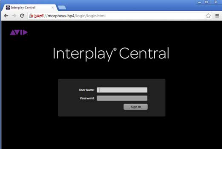
ICS 1.8 Installation & Configuration Guide
85
When you sign in to Interplay Central for the first time (in this procedure) you are prompted to
sign in to an iNEWS server, an Interplay Production system, or both.
This procedure makes use of the following information:
¨ Interplay Central Administrator password.
¨ Host name of the ICS server (e.g. ics-dl360-1))
¨ iNEWS Server hostname
¨ iNEWS user name and password
¨ Interplay Production user name and password.
To log into Interplay Central for the first time:
1. Launch a web browser supported by Interplay Central.
For example, Google Chrome, IE (with Google Chrome Frame plug-in), or Safari (on Mac
OS).
2. Enter the URL of the ICS server In the address bar:
• https://<hostname> where <hostname> is the host name of the ICS server
The Interplay Central sign-in screen appears.
Note: In place of the sign-in screen, you might see a warning indicating the site’s security
certificate is not trusted. For the purposes of installing and configuring, proceed anyway.
For information on configuring a trusted certificate, see “Appendix D: Handling SSL
Certificates” on page 155.
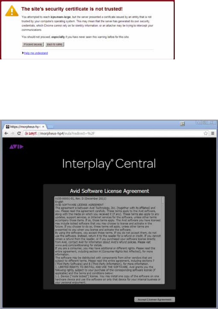
ICS 1.8 Installation & Configuration Guide
86
3. Sign in using the default administrator credentials (case-sensitive):
• User name: Administrator
Signing in takes you to an Interplay Central layout.
4. The first time any user signs in, the Avid Software License Agreement is presented. Click
the Accept License Agreement button to proceed.
5. You are also asked to enter iNEWS and Interplay Production credentials:
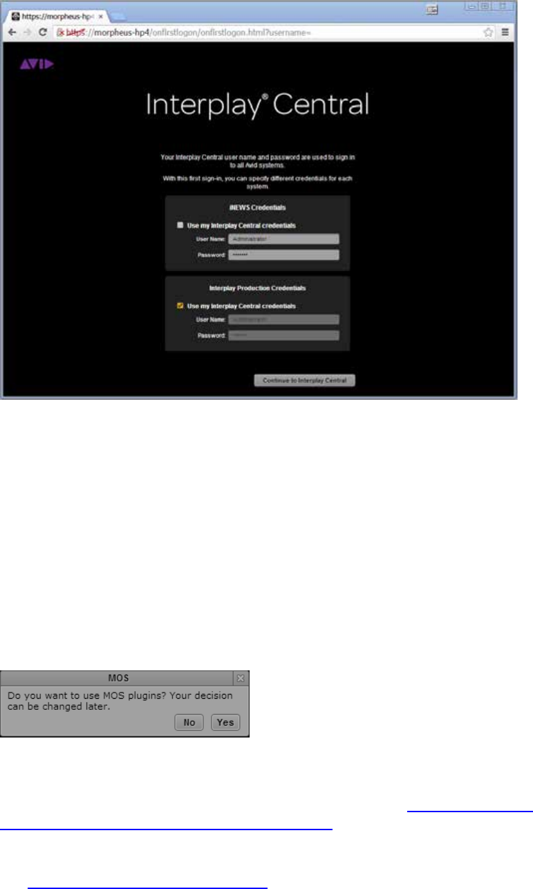
ICS 1.8 Installation & Configuration Guide
87
If you created iNEWS and Interplay Production users called Administrator with the
default Interplay Central Administrator password, you can check “Use my Interplay
Central Credentials”.
Otherwise, enter the user names and passwords for the iNEWS system, and the
Interplay Production system.
Note: If the security settings for one of these systems is inaccurate, you will see a warning
message that states that the application is unable to authorize the sign-in name or
password. This will be the case for any iNEWS credentials entered, since you have not yet
specified the iNEWs server to be used. If you receive a warning, click the link provided and
verify your security settings.
6. If you are using a Chrome browser, the first time you sign in to Interplay Central a dialog
box asks if you want to use MOS plug-ins.
MOS plug-ins are used in certain iNEWS workflows.
Note: Selecting “yes” installs only the container needed for Active X controls. To make use of
MOS plug-ins you need to install additional software as described in “Appendix F: Installing
the Chrome Extension for Interplay Central MOS Plug-Ins” on page 192.
Proceed to “Changing the Administrator Password” below.
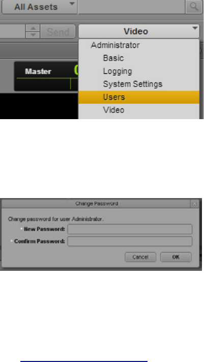
ICS 1.8 Installation & Configuration Guide
88
Changing the Administrator Password
For reasons of security it is strongly suggested that you change the password for the
Administrator user.
This procedure makes use of the following information:
¨ Interplay Central Administrator password.
To change the Administrator password:
1. While logged in as the Administrator user, select Users from the Layout selector.
2. Expand the list of administrators in the User Tree and locate the Administrator user.
3. Double-click the Administrator user to view its details.
4. Click the Change Password button in the Details pane, and enter a new password for the
Administrator user.
Use a strong password that is in accordance with the client’s password enforcement
policies.
5. Click OK update the password information.
A message appears indicating that the password was successfully changed.
Proceed to “Configuring iNEWS Settings” below.
Configuring iNEWS Settings
If you did not configure the iNEWS server settings upon signing in, you can do so now.
This procedure makes use of the following information:
¨ iNEWS server hostname
To configure iNEWS settings:

ICS 1.8 Installation & Configuration Guide
89
1. Select System Settings from the Layout selector.
2. In the Settings pane, click iNEWS.
3. Configure the iNEWS Server.
a. Hostname: The computer name of the server that hosts the iNEWS database. If
the computer name includes a suffix such as -a, do not include it. Not including
the suffix allows for load balancing and failover.
4. Configure the Pagination.
a. Maximum Number: The maximum number of items listed in the Queue/Story
pane or the Project/Story pane. To view more items beyond the number
displayed, users can click the Show More Results button.
5. Click Apply to save your changes.
Proceed to “Configuring Interplay Production Settings” below.
Configuring Interplay Production Settings
ICS communicates with Interplay Production directly. In this procedure you tell ICS which
Interplay Production server it will use, and configure ICS with the user credentials and
workgroup properties it needs to interact with Interplay Production.
Interplay Central and Interplay Sphere end-users log in with their own credentials and use their
own Interplay credentials to browse media assets. However, ICS itself uses a separate set of
Interplay credentials to resolve playback requests and check-in voice-over assets recorded by
Interplay Central users.
This procedure makes use of the following information:
¨ Interplay Production server (Interplay Engine) hostname
¨ Interplay Central Distribution Service – Service URL (e.g. https://<server>:<port>)
Note: The host name indicated above is the host name only (e.g. ip-mtl-1),that is, it is the
name of the machine. Do not use the fully qualified domain name (e.g. ip-mtl-
1.mydomain.com or ip-mtl-1.mydomain.local). It can also be the IP address.
To configure Interplay Production settings:
1. Select System Settings from the Layout selector.
2. In the Settings pane, click Interplay Production.

ICS 1.8 Installation & Configuration Guide
90
3. Configure Interplay Production credentials:
a. Enter the Interplay Production server (the Interplay engine) hostname or IP
address. If you have an Interplay Engine cluster, specify the virtual server, not an
individual server.
b. Enter the Service URL of the Interplay Central Distribution Service (e.g
https://<server>:<port>). You can enter a hostname or IP address for the
server.
If your Interplay workgroup is configured for multiple ICDS servers, specify the
multiple URLs separated by a comma and a space. The first server listed is the active
ICDS server. Multiple ICDS servers provide a failover capability. For more
information on failover for multiple ICDS servers, or other system settings, click the
Pane Menu button and select Help or see the Avid Interplay Central Administration
Guide.
4. Click Apply to save your changes.
Proceed to “Configuring ICPS for Interplay” below.
Configuring ICPS for Interplay
Now that ICS can communicate with Interplay Production, you can configure the user name and
password used by the Interplay Central Playback Service (ICPS) to log into the Interplay
Production server. ICPS is one of the software services that runs on the ICS server. ICPS is
responsible for the compression and playback of video and audio media on Internet-connected
clients. It requires its own set of user credentials.
This procedure makes use of the following information:
¨ Interplay Production user name and password reserved for ICS (e.g. ics-interplay). This
needs to be created in the Interplay Production workgroup to which you are connecting.
¨ High Availability Group (HAG) availability in Interplay Production.
¨ Media Indexer host name
¨ Interplay Workgroup name
¨ Lookup server hostname(s)
¨ Knowledge of whether multi-resolution workflows are being used

ICS 1.8 Installation & Configuration Guide
91
Note: The host names indicated above is the host name only (e.g. mi-mtl-1),that is, it is the
name of the machine. Do not use the fully qualified domain name
(e.g. mi-mtl-1.mydomain.com or mi-mtl-1.mydomain.local). It can also be the IP address.
To configure ICPS for Interplay:
1. Select System Settings from the Layout selector.
2. In the Settings pane, click Playback Service.
3. Configure the Player Settings:
a. Save Failed AAF: Check this box to automatically save AAF files that do not
parse properly to a dedicated folder. Helpful for troubleshooting.
4. Configure the Interplay Workgroup Properties:
a. User: Enter the name of the Interplay Production user reserved for ICS.
b. Password: Enter the password for that user.
c. Connect to HAG: Check this box to connect to an Interplay Production Media
Indexer High Availability Group (HAG). The HAG must already be configured in
Interplay Production.
Note: Interplay Central connects to the primary node of the HAG only. It does not
participate in HAG redundancy.
Checking the Connect to HAG box grays-out the MI Host field. Any entry in the
field is still available, should you decide to connect to a MI Host directly in the
future, by unchecking the box.
d. MI Host: Enter the Media Indexer (MI) host.
Note: The host name indicated above is the host name only (e.g. mi-mtl-1),that
is, it is the name of the machine. Do not use the fully qualified domain name
(e.g. mi-mtl-1.mydomain.com or mi-mtl-1.mydomain.local). It can also be the
IP address.
Note: For a Media Indexer connected to a High Availability Group (HAG), enter
the host name of the active Media Indexer.
e. Workgroup Name. This is case-sensitive. Use the same case as defined in the
Interplay engine.
f. Lookup Servers: Enter the host name(s) for the Lookup server(s).
5. Enable Dynamic Relink: For multi-resolution workflows, select Enable Dynamic Relink.
6. Click Apply to save your changes.
Proceed to “Configuring the ICPS Player” below.

ICS 1.8 Installation & Configuration Guide
92
Configuring the ICPS Player
The ICPS Player communicates directly with the ICS server to obtain media for playback, using
the credentials of the logged-in user for validation. In this step you tell the ICPS Player where to
find the ICS server.
This procedure makes use of the following information:
¨ ICS server hostname (e.g. ics-dl360-1)
¨ ICS cluster static IP address address (e.g. 192.XXX.XXX.XXX) or host name (e.g ics-
cluster)
Note: If you are in the process of setting up the first server in a cluster, do not enter the
cluster IP address or cluster host name yet. Enter the information for the first server. You will
switch to the cluster information later.
Note: In previous releases the ICPS Player required a separate user name and password to
connect to the ICS server. As of ICS 1.8, this is no longer the case. The Player uses the
credentials of the user logged in to connect to the ICS server.
To configure the ICPS Player:
1. Select System Settings from the Layout selector.
2. In the Settings pane, click Player.
3. Enter the ICS server hostname (e.g. ics-dl360-1).
4. Click Apply to save your changes.
Proceed to “Configuring the ICPS Player for Interplay Sphere” below.
Configuring the ICPS Player for Interplay Sphere
In this step you provide user credentials for Interplay Sphere.
This procedure makes use of the following information:
¨ User name and password reserved for the Sphere user (e.g. sphere)
To configure the ICPS Player for Sphere:
1. Select System Settings from the Layout selector.
2. In the Settings pane, click Player.
3. Enter the user name and password reserved for Sphere (e.g. sphere).
4. Click Apply to save your changes.
The Sphere Playback User is created, and automatically assigned a special “Sphere
User” role. You can see the new user and role by selecting Users from the Layout
selector.

ICS 1.8 Installation & Configuration Guide
93
5. Be sure to configure Sphere itself to make use of the user name and password entered
above.
For instructions on configuring Sphere, see the Avid Interplay Sphere Installation and
Configuration Guide.
To delete the ICPS Player for Sphere:
• You are advised to delete the Sphere Playback User from the Player settings pane in the
System Settings Layout (rather than in the Users layout)
Proceed to “Configuring the ISIS Connection(s)” below.
Configuring the ISIS Connection(s)
ICS is an ISIS client, maintaining its own connection to an ISIS system. Normally, only one active
network connection is needed on the ICS server for this purpose. The single GigE or 10GigE
connection functions for:
• Communication with the ISIS
• Playback of compressed media generated on the ICS server over the network
Multiple connections are possible. When you maintain other active connections on the ICS
server, you must indicate which network connections are reserved for ISIS, and which are used
for other network activity.
This procedure make use of the following information:
¨ Knowledge of the ISIS connection(s):
o Zone 1 (direct connection)
o Zone 2 (layer 2 network switch)
o Zone 3 (layer 3 network switch -- recommended)
¨ Connection bandwidth (GigE vs 10GigE)
¨ Name(s) of the NIC interfaces used to connect to ISIS (e.g. eth0)
¨ Name(s) of the NIC interfaces used for other network activity
To configure the ISIS connection:
1. Select System Settings from the Layout selector.
2. In the Settings pane click Playback Service.
3. For a Zone 3 (recommended) connection, put a checkmark in Enable Remote Host.
For a Zone 1 or Zone 2 connection leave Enable Remote Host unchecked.
4. Select the NIC interface bandwidth ( e.g. GigE, 10GigE).

ICS 1.8 Installation & Configuration Guide
94
5. For an ICS server with more than one active connection:
a. In the Use Network Device field, enter the network interface name(s) used to
connect to the ISIS system, separated by commas.
b. In the Ignore Network Device field, enter the network interface name(s) to be
ignored by ICS.
For an ICS server with only one active network connection (e.g. eth0) you can leave the
fields blank.
6. Click Apply.
The information is sent to the ICS server, triggering a reconfiguration that may take
a few moments.
Proceed to “Mounting the ISIS System(s)” below.
Mounting the ISIS System(s)
Now that you have specified what NIC interface connection(s) are used to reach the ISIS, you
can mount the ISIS system(s). ICS communicates with ISIS storage directly. It uses a separate set
of ISIS credentials from the end-user to read media assets for playback and to write audio assets
for voice-over recorded by Interplay Central end-users.
In this procedure you configure ICS with the user credentials it needs to connect to the ISIS
system(s). In some network configuration scenarios, additional settings are required.
This procedure make use of the following information:
¨ ISIS Virtual Host Name(s)
¨ ISIS user name and password reserved for ICS (e.g. ics-interplay)
Note: For multi-ISIS setups, ensure the same user credentials have been created for ICS
across all ISIS storage systems.
¨ Knowledge of the ICS connection(s) to the ISIS:
o Zone 1 (direct connection)
o Zone 2 (layer 2 network switch)
o Zone 3 (layer 3 network switch -- recommended)
Note: The host name indicated above is the host name only (e.g. isis-mtl-1),that is, it is the
name of the machine. Do not use the fully qualified domain name
(e.g. isis-mtl-1.mydomain.com or isis-mtl-1.mydomain.local). It can also be the IP address.
When the ICS connection to the ISIS is Zone 3 the following information is also needed:
¨ ISIS System Director IP address(es)
To mount the ISIS system(s):

ICS 1.8 Installation & Configuration Guide
95
1. Select System Settings from the Layout selector.
2. In the Settings pane click Playback Service.
3. Click the plus (+ ) button to add the ISIS as a storage location.
A New File System dialog appears.
4. In the dialog, enter a nickname (label) to refer to the ISIS, indicate its type (ISIS), then
click OK.
A new storage location is added to the list for the ISIS.
Since you have not yet configured ICS with user credentials for it, the status is
disconnected.
5. Specify the necessary configuration details for the ISIS:
a. Virtual Host Name
b. User name
c. Password
Note: The host name indicated above is the host name only (e.g. isis-mtl-1),that is, it is
the name of the machine. Do not use the fully qualified domain name
(e.g. isis-mtl-1.mydomain.com or isis-mtl-1.mydomain.local). It can also be the IP
address.
6. For a Zone 3 connection, enter list of IP addresses for the ISIS System Director. Separate
each entry by a semi-colon, no spaces.
7. Click Apply.
The status changes to Connected.
8. Repeat the above for each additional ISIS (Zone 2 and Zone 3 only).
Proceed to “Verifying the ISIS Mount” below.
Verifying the ISIS Mount
Although the validity of the ISIS mount was authenticated in the previous procedure when the
status of the storage changed to “Connected”, it is also possible to verify the ISIS is mounted at
the command line, using the following Linux commands:
• service avid-isis status
• mount -t fuse.avidfos
• df -h
Further, you can explore the ISIS workspaces by navigating them as a Linux filesystem
directories.

ICS 1.8 Installation & Configuration Guide
96
To verify the ISIS mount(s):
1. Verify the status of the avid-isis service:
service avid-isis status
The system responds with output showing the ISIS mounts, similar to the following:
ISIS mount: morphisis1 /mnt/ICS_Avid_Isis/morphisis1 fuse.avidfos
rw,nosuid,nodev,relatime,user_id=0,group_id=0,default_permissions
,allow_other 0 0
The output above indicates an ISIS called morphisis1 mounted at /isis/morphisis1.
“Fuse” is the RHEL filesystem type reserved for third-party filesystems.
2. You can use the Linux mount command directly to display all mounted filesystems of
type fuse.avidfos (the ISIS filesystem)
mount -t fuse.avidfos
The system responds with output showing the ISIS mounts, similar to the following:
morphisis1 on /mnt/ICS_Avid_Isis/morphisis1 type fuse.avidfos
(rw,nosuid,nodev,allow_other,default_permissions)
3. The Linux df command displays disk usage information for all the mounted filesystems:
df -h
The system responds with output similar to the following:
Filesystem Size Used Avail Use% Mounted on
/dev/mapper/vg_icps-lv_cache
527G 6.3G 494G 2% /
tmpfs 24G 0 24G 0% /dev/shm
/dev/sda1 485M 33M 428M 8% /boot
morphisis1 15T 5.7T 8.9T 40% /mnt/ICS_Avid_Isis/morphisis1
/dev/sdb1 7.3G 5.5G 1.9G 75% /media/usb
4. Finally, you can explore the mounted ISIS and its workspaces by navigating it as you
would any Linux filesystem.
For example, for the sample output shown above, to view the workspaces available to
the ICPS player, list the contents of the mounted ISIS:
ls /mnt/ICS_Avid_Isis/morphisis1
Proceed to “Verifying Video Playback” below.
Verifying Video Playback
Playing some video is a simple technique for verifying that the configuration has had the desired
effect.
To verify video playback:
1. Select Story from the Layout selector.
2. In the Launch pane select one of the mounted systems by double-clicking it.

ICS 1.8 Installation & Configuration Guide
97
3. Navigate the filesystem hierarchy and select a clip.
4. Double-click the clip to load it into the player.
5. Experiment with the player controls to play and scrub the clip.
Proceed to “Configuring Wi-Fi Only Encoding for Facility-Based iOS Devices” below (optional).
Or, proceed to “Clustering Workflow” on page 101 (optional).
Or, proceed to “Post-Installation Steps” on page 125.
Configuring Wi-Fi Only Encoding for Facility-Based iOS Devices
By default, ICS servers encode three different media streams for Interplay Central applications
detected on iOS devices -- for Wi-Fi, 3G, and Edge connections. For Wi-Fi only facilities, it is
recommended that you disable the 3G and Edge streams, to improve the encoding capacity of
the ICS server.
To disable 3G and Edge streams:
1. Log in as root and edit the following file using a text editor (such as vi):
/usr/maxt/maxedit/share/MPEGPresets/MPEG2TS.mpegpreset
2. In each of the [Edge] and [3G] areas, set the active parameter to active=0.
3. Save and close the file.
Proceed to “Clustering Workflow” on page 101 (optional).
Or, proceed to “Post-Installation Steps” on page 125.
ICS 1.8 Installation & Configuration Guide
98
PART III: CLUSTERING
Note: For detailed information on how ICS servers operate in a cluster, see the “ICS 1.8
Service and Server Clustering Overview” guide.
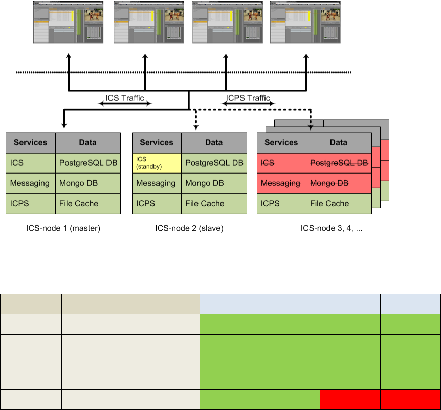
ICS 1.8 Installation & Configuration Guide
99
Setting up the Server Cluster
Clustering adds high-availability, load-balancing and scale to ICS. To set up a cluster, each server
in the cluster must have RHEL and ICS installed. One server must also be fully configured for the
deployment of interest. The other servers need only RHEL and ICS installed. A typical cluster is
shown in the following illustration:
The following table lists the additional software components that are installed during cluster
setup and are required for clustering:
Software
Functioning
ICS-node 1
ICS-node 2
ICS-node 3
ICS-node n
Corosync
Cluster Engine Data Bus
ON
ON
ON
ON
Pacemaker
Cluster Management
& Service Failover
ON
ON
ON
ON
GlusterFS
File Cache Mirroring
ON
ON
ON
ON
DRBD
Database Volume Mirroring
ON
ON
OFF
OFF
Note the following:
• Corosync and Pacemaker work in tandem to detect server and application failures, and
allocate resources for failover scenarios.
• Gluster mirrors media cached on an individual RAID 5 drive to all other RAID 5 drives in
the cluster.
• DRBD mirrors the ICS databases on two servers in a master-slave configuration. This
provides redundancy in case of a server failure

ICS 1.8 Installation & Configuration Guide
100
The following table lists some of the more important services involved in clustering, and where
they run:
Services
ICS-node 1
ICS-node 2
ICS-node 3
ICS-node n
ICS
Middleware
IPC
ON
OFF
OFF
OFF
User Mgmt
UMS
ON
OFF
OFF
OFF
Configuration
ACS
ON
OFF
OFF
OFF
Messaging
ACS
ON
ON
ON
ON
Playback Service
ICPS
ON
ON
ON
ON
Note the following:
• All ICS services run on the Master node in the cluster.
• Most ICS services are off on the Slave node but start automatically during a failover.
• On all other nodes, the ICS services never run.
• The Playback service (ICPS) runs on all nodes for Performance Scalability (load balancing
supports many concurrent clients and/or large media requests ) and High Availability
(the service is always available ).
Note: Clustering in ICS makes use of the corosync clustering engine and infrastructure. The
infrastructure includes a cluster resource monitor utility, crm_mon, that displays the state of
the cluster. We recommend you maintain a separate terminal window where you can use the
utility to view results as you build the cluster. If you are working from a terminal attached
directly to the server, simply run crm_mon periodically to view the results of your clustering
operations.
The procedures in this section make use of the following information you entered in “Appendix
L: Installation Pre-Flight Checklist” on page 210:
¨ The static IP address allocated for the cluster
¨ IP address that is always available (e.g. network router)
¨ Email addresses of network administrators
¨ Interplay MAM Port bonding IP address (if applicable)
¨ Port bonding interface name (if applicable, e.g. bond0)
¨ Device name for each NIC interface used in port bonding (e.g. eth0, eth1, etc.)
Note: For Interplay MAM deployments using port bonding, bond the ports before setting up the
cluster. See “Appendix C: Configuring Port Bonding for Interplay MAM (Optional)” on page 152.

ICS 1.8 Installation & Configuration Guide
101
Clustering Workflow
Clustering requires that you set up one server completely before creating a cluster. That is, set
up ICS on a server as if you were performing a non-clustered installation. Once that is done, you
can set up the other ICS servers and add them to the cluster.
The following table outlines the clustering installation workflow:
Note: If you are setting up a cluster, only the master node requires configuring. You do
not need to configure any other nodes. The slave node obtains its settings from the
master node via the clustering mechanisms. The other nodes participate in load-
balancing only, and do not require configuring separately.
Step Task Time Est.
1
Setting up and Configuring a Single ICS Server
2–3 hr
If you have not already done so, set up a fully operational ICS server.
See “Installation Workflow” on page 36.
This includes establishing the network and storage connections, setting
up the RAID 1 and RAID 5 (if required), installing RHEL and ICS, ICDS
(Interplay Central only), etc.
Importantly, it also includes all the configuration steps for the IME
solution of choice (Interplay Central, Interplay Sphere, Interplay MAM),
and verifying video playback.
2
Installing RHEL and ICS on the Other Servers in the Cluster
1 hr
Perform the same setup and installation steps outlined above, with the
exception of configuring the server for the IME solution. These other
servers in the cluster will inherit the settings of the master server, once
they are added to the cluster.
You do not need to configure the other ICS servers in the cluster.
3
Configuring the Hosts File and Name Services File
5 mins
Configure the /etc/hosts file and nsswitch.conf file for optimal cluster
performance.
4
Setting Up DRBD
5 min
Initiate replication of the ICS PostgreSQL database.
DRBD runs on the master and slave node, but not any others.
5
Starting the Cluster Services
5 min
Start the cluster services on the fully set up ICS server (the master
node).
6
Joining the Cluster
10 min

ICS 1.8 Installation & Configuration Guide
102
Step Task Time Est.
Connect to the master node — the fully operational node — from the
other ICS nodes.
7
Replicating the Cluster File Caches
20 min
Set up Gluster to mirror the caches, so each server in the cluster can
easily use material transcoded by the others.
This step is only required if your ICS nodes make use of a dedicated
media cache volume (e.g. RAID 5).
8
Reconfiguring the ICPS Player for Interplay Central in a Cluster
5 min
Reconfigure the ICPS player to point to the cluster IP address or host
name, so the master node can determine which node serves the video.
9
Post-Installation Steps
5 min
Verify the cluster is working and intended.
Proceed to “Replicating the Cluster File Caches” on page 112.
Before You Begin
Ensure you have everything you need to set up clustering. Make sure of the following:
¨ RHEL and ICS software components are installed on all servers in the cluster
¨ All servers are on the network and are assigned IP addresses
¨ You have an assigned cluster IP address (distinct from the servers in the cluster)
¨ If your network already uses multicast, IT must issue you a multicast address to avoid
potential conflicts. If your network does not use multicast, the cluster can safely use a
default multicast address.
¨ If your network is not multicast-ready, you can configure clustering for a unicast
environment. See “Appendix H: Unicast Support in Clustering” on page 197.

ICS 1.8 Installation & Configuration Guide
103
Configuring the Hosts File and Name Services File
The hosts file is used by the operating system to map hostnames to IP addresses. It allows
network transactions on the computer to resolve the right targets on the network when the
instructions carry a human readable host name (e.g. ics-dl360-1) rather than an IP address (e.g.
192.XXX.XXX.XXX).
Although there are other means of resolving IP addresses from host names, the hosts file can be
accessed directly and more quickly by the computer on which the file resides. If the host name is
not defined in the hosts file the OS will use other means to resolve it to an IP address, such as a
Domain Name System (DNS) server.
In this section, you edit the hosts file residing at the following path:
/etc/hosts
You also edit the default hosts file, at the following location:
/etc/sysconfig/networking/profiles/default/hosts
In addition, you optimize the lookup service order by editing the Name Service Switch file in this
location:
/etc/nsswitch.conf
Adding Host Names and IP Addresses to the
hosts
File
In this step you add entries to the hosts file so Linux can quickly resolve host names to IP
addresses, for all nodes in the cluster.
In addition, since the active hosts file can be reset to its default configuration when a server fails
or is rebooted you must also edit the default hosts file.
Note: You can edit the file /etc/hosts while the system is up and running without disrupting
user activity.
To add host names and IP addresses to the hosts file:
1. Open the active hosts (/etc/hosts) file for editing.
vi /etc/hosts
It should look similar to the following:
127.0.0.1 localhost localhost.localdomain localhost4 localhost4.localdomain4
::1 localhost localhost.localdomain localhost6 localhost6.localdomain6
2. Added entries that resolve host names to IP addresses for all cluster nodes (including
the local host).
For a four node cluster, for example, you would add four lines similar to the following:

ICS 1.8 Installation & Configuration Guide
104
127.0.0.1 localhost localhost.localdomain localhost4 localhost4.localdomain4
::1 localhost localhost.localdomain localhost6 localhost6.localdomain6
10.106.131.41 ics-node-1.csglobal.lab ics-node-1
10.106.131.42 ics-node-2.csglobal.lab ics-node-2
10.106.131.43 ics-node-3.csglobal.lab ics-node-3
10.106.131.44 ics-node-4.csglobal.lab ics-node-4
…where ics-node1, ics-node2, ics-node3, and ics-node4 are the host names of the four nodes
in the cluster.
3. Save and exit the file.
Note: It is a good idea to declare the nodes in the hosts file in order of latency,
ascending. Run a ping command to each node and add the lines to the file in order of
the ping return. For example, if node-2 returns a ping after 30ms and node-3 after 20ms,
put in the line for node-3 before node-2.
4. Edit the default hosts file to match:
vi /etc/sysconfig/networking/profiles/default/hosts
Optimizing the Lookup Service Order: Editing the Name Service
Switch File
As noted, Linux can look up host names and IP addresses in different places. For example, it can
resolve a host name to an IP address by looking up the /etc/hosts file or a DNS server. Editing
/etc/hosts files to map host names and IP addresses for an entire network of computers can be
tedious and is prone to error. Using a DNS server is a more efficient way in many cases.
However, the lookup process that uses a DNS server is vulnerable to network latency and
occasionally timeouts.
In an ICS cluster, it is very important to minimize the time to the lookup servers. As a result using
the local /etc/hosts file is preferred. It is therefore important to configure all ICS nodes in a
cluster to first try to resolve host names to IP addresses using the hosts file, and if a specific host
name is not declared in that file, then refer to a DNS.
To optimize the lookup service order:
6. Open the Name Service Switch (/etc/nsswitch.conf) file for editing and look for the
section (about halfway into the file) that looks similar to the following:
#hosts: db files nisplus nis dns
hosts: files dns
7. Make sure in the second hosts line that files (in bold, above) appears in the line before
dns.
8. Save and exit the file.
Proceed to “Setting Up DRBD” below.

ICS 1.8 Installation & Configuration Guide
105
Setting Up DRBD
In a clustered configuration, ICS uses the open source Distributed Replicated Block Device
(DRBD) storage system software to replicate its PostgreSQL database across all nodes in the
cluster. In this step, you set up DRBD and initialize the replication using the command provided.
Note: DRBD runs on a master node and a non-master node only, even in a cluster with more
than two nodes.
Note: This procedure assumes a 20 GB partition exists on the RAID 1 mirrored system drive
(/dev/sda). If you are installing ICS on supported HP hardware using the USB key, the
required partition (/dev/sda2) was automatically created. If you are installing ICS for
Interplay MAM on non-HP hardware, see “Appendix A: Installing ICS on Non-HP Hardware”
on page 148 for details.
Explanation (do not type this example)
This procedure uses the drbd_setup command:
drbd_setup
[primary_host="<hostname>"] [secondary_host="<hostname>"]
{[primary_ip="<ip>"] [secondary_ip="<ip >"]}
{[primary_disk="<device>"] [secondary_disk="<device>"]}
where:
primary_host: Host name (e.g. ics-dl360-1) of the machine to serve as master node for DRBD.
secondary_host: Host name (e.g. ics-dl360-2) of the non-master machine (the machine to serve as fail-
over for DRBD).
primary_ip: Optional. IP address (e.g. 192.XXX.XXX.XXX) of the primary host. Helpful when host
primary_host specified does not resolve.
secondary_ip: Optional. IP address (e.g. 192.XXX.XXX.XXX) of the secondary host. Helpful when
secondary_host does not resolve.
primary_disk: Optional. Name of the disk device reserved for DRBD on the primary machine (/dev/sda2
by default).
secondary_disk: Optional. Name of the disk device reserved for DRBD on the primary machine
(/dev/sda2 by default).
Note: The primary_disk and secondary_disk parameters are provided for special cases in which the
partitions reserved for DRBD are in a non-standard location. In most cases, the /dev/sda2 values supplied
by default will be sufficient.
Note: The DRBD setup script is case-sensitive. The host names you enter must exactly match those defined
for the master and non-master.

ICS 1.8 Installation & Configuration Guide
106
For the man page for the drbd_setup command, run the command at the Linux prompt without
specifying any parameters:
/opt/avid/cluster/bin/drbd_setup
To set up DRBD:
Note: Before beginning this procedure, please note the following:
• The DRBD setup script is case-sensitive. The host names you enter must exactly match
those defined for the master and non-master.
• To check the spelling and capitalization of a host, use the Linux hostname command.
• In addition, make sure the host name returned by the hostname command is not a “fully
qualified domain name” (FQDN). DRBD requires the standard “short” host name (e.g. ics-
dl360), not the FQDN (e.g ics-dl360.mydoman.com).
• Once started (in this procedure) DRBD needs to remain running until you start the cluster
services on the master and slave using the setup-cluster script in “Starting the Cluster
Services” on page 108 and “Joining the Cluster” on page 111. Once the cluster is formed,
Pacemaker manages DRBD from then on.
1. On the fully operational node to serve as master log in as root.
2. Change to the directory containing the drbd_setup script:
cd /opt/avid/cluster/bin
3. Run the drbd_setup script:
./drbd_setup primary_host=”<hostname of master machine>”
secondary_host=”<hostname of non-master machine>”
In the command above, the “./” tells Linux to look for the script in the current directory.
Note: If an error message indicates the IP addresses cannot be identified using the host
names provided, provide IP addresses as well as host names for the primary and secondary
hosts:
./drbd_setup primary_host=”<hostname of master machine>”
secondary_host=”<hostname of non-master machine>”
primary_ip=”<ip of master machine>”
secondary_ip=”<ip of non-master machine>”
4. You might receive an error message indicating the bus is not running and/or a path does not
exist, similar to the following:
- error: bus is not running
- error: Given --path is not exist:
These errors can be ignored.
5. You may also receive the following message:
ICS 1.8 Installation & Configuration Guide
107
Found some data
==> This might destroy existing data! <==
Do you want to proceed?
[need to type 'yes' to confirm]
This indicates the DRBD setup script has found the 20GB partition set aside for it and is
about to take ownership of it.
6. Type “yes” at the prompt to continue with the setup.
The system responds, and waits for the other DRBD node, with output similar to the
following:
Writing meta data...
initializing activity log
NOT initializing bitmap
New drbd meta data block successfully created.
success
Waiting for secondary node ...
7. Run the same command on the secondary host (non-master node).
The system responds with output similar to the following (on the master node only)
Secondary node found
Node initialized with role: Primary
Stopping postgresql-9.1 service: [ OK ]
mke2fs 1.41.12 (17-May-2010)
Filesystem label=
OS type: Linux
Block size=4096 (log=2)
Fragment size=4096 (log=2)
Stride=0 blocks, Stripe width=0 blocks
128000 inodes, 511975 blocks
25598 blocks (5.00%) reserved for the super user
First data block=0
Maximum filesystem blocks=524288000
16 block groups
32768 blocks per group, 32768 fragments per group
8000 inodes per group
Superblock backups stored on blocks:
32768, 98304, 163840, 229376, 294912
Writing inode tables: 0/16 1/16 2/16 3/16 4/16 5/16 6/16 7/16 8/16
9/1610/1611/1612/1613/1614/1615/16 done
Creating journal (8192 blocks): done
Writing superblocks and filesystem accounting information: done
This filesystem will be automatically checked every 23 mounts or
180 days, whichever comes first. Use tune2fs -c or -i to override.
partition mounted at /mnt/drbd
Starting postgresql-9.1 service: [ OK ]
Note: A fail message may appear when the drbd_setup script tries to start postgres. This is
normal.

ICS 1.8 Installation & Configuration Guide
108
Finally, information indicating synchronization is underway appears in the output, similar to
the following (on the master node only). The synchronization process can take some time,
since DRBD replicates at the block level.
Node synchronization started
5% synchronized
…
55% synchronized
97% synchronized
Node synchronization finished
8. Wait until node synchronization is completed before proceeding to the next step.
Proceed to “Starting the Cluster Services” below.
Starting the Cluster Services
Now that you have set up DRBD, you are ready to start and configure the cluster services.
Scripts have been provided that simplify this process.
Before you can join all the ICS servers together in a cluster, you must start the cluster services
on one machine. This is done on the one node you have fully installed and configured — the
fully operational ICS server — using scripts provided.
Note: If you are working remotely using a remote shell session, this is a good moment to
open a separate terminal window where you can run the cluster resource manager utility,
crm_mon. Otherwise, run the utility now and then in the same terminal where you are doing
your work.
Note: Recall that DRBD runs on two nodes only: the master node, and one non-master node.
If your cluster has more than two nodes, use the special form of the setup-cluster command
to exclude the non-DRBD nodes from starting the PostgreSQL database. The special form of
the setup-cluster command is indicated in the procedure below.
To set up the master node in the cluster:
1. On the fully operational node do one of the following commands:
Note: In the instructions below, be sure to substitute the actual interface name you are
putting to use (eth0 recommended) in the appropriate places.
• On a network that has no other multicast activity, use the default multicast address
by issuing the following command:
/opt/avid/cluster/bin/cluster setup-corosync
--corosync-bind-iface=eth0
--rabbitmq_master=<master>
• <master> is the master node (e.g. ics-dl360-1). This should be the same as the DRBD
master node specified earlier.

ICS 1.8 Installation & Configuration Guide
109
• On a network with other multicast activity, use the following command:
/opt/avid/cluster/bin/cluster setup-corosync
--corosync-bind-iface=eth0
--corosync-mcast-addr="<multicast address>"
--rabbitmq_master=<master>
• <multicast address> is the multicast address that IT provided for the cluster (e.g.
239.XXX.XXX.XXX).
Note: The “default” multicast address used for ICS clustering is 239.192.1.1. This is set by
the setup-corosync script, if you do not specify one. If an ICS cluster already exists, and
your new cluster will co-exist alongside it (in a test setting, for example), use a different
multicast address for the new cluster (e.g. 239.192.1.2).
Note: For port bonding, assign the name of the port bonding interface instead (e.g.
bond0).
Messages appear echoing the Corosync network binding process. The Avid UMS service
is temporarily shut down. A message appears indicating the Corosync cluster engine has
successfully started.
The following is sample output:
bind_iface=eth0 bind_network=xxx.xx.xx.x mcast_addr=xxx.xx.x.x
.
.
.
Shutting down UMS [ OK ]
2012-11-19 15:39:36.477 -0500 - info: Done. System is up-to-date.
generic – stop [ OK ]
boot – stop [ OK ]
Starting Corosync Cluster Engine (corosync): [ OK ]
Starting Pacemaker Cluster Manager: [ OK ]
2. If you are using the recommended interface name (eth0), enter the following command:
/opt/avid/cluster/bin/cluster setup-cluster
--cluster_ip="<cluster IP address>"
--pingable_ip="<router IP address>"
--admin_email="<comma separated e-mail list>"
--drbd_exclude="<comma separated list of non-DRBD nodes>"
• <cluster IP address> is the IP address provided by IT for the cluster (e.g.:
192.XXX.XXX.XXX)
• <router IP address> is an IP address that will always be available on the
network -- for example, the IP address of a network router
• <comma separated e-mail list> is a comma separated list of e-mail
addresses to which cluster status notifications are automatically sent
Note: At least one cluster administrator email address is mandatory (though not
validated by the system). To change the email address later, see “Changing the
Cluster Administrator Email Address” on page 141.
ICS 1.8 Installation & Configuration Guide
110
• <comma separated list of non-DRBD nodes> is a comma separated
list of the non-DRBD nodes in the cluster (e.g. "ics-dl360-3,ics-dl360-4"). This
parameter prevents the non-DRBD nodes from running PostgreSQL.
3. Otherwise, if you are not using the recommended interface name, enter the following
command instead:
/opt/avid/cluster/bin/cluster setup-cluster
--cluster_ip="<cluster IP address>"
--pingable_ip="<router IP address>"
--cluster_ip_iface="<interface_name>"
--admin_email="<comma separated e-mail list>"
--drbd_exclude="<comma separated list of non-DRBD nodes>"
• <interface_name> is the name of the NIC interface being used by the cluster
(shown in bold above).
4. Error messages appear indicating missing resources and attributes.
For example:
ERROR: resource <resource name> does not exist
Error: performing operation: The object/attribute does not exist
These can be ignored.
5. Warning, error and info messages may also appear, similar to the following:
WARNING: 125: AvidConnectivityMon: specified timeout 20s for
start is smaller than the advised 60
ERROR: 125: rsc-options: attribute admin-email does not exist
INFO: 125: commit forced
These can be ignored.
6. Finally, the cluster configuration file is output to screen.
It identifies the node name, and various internal configuration information.
7. You can view the contents of the configuration file, at any time, by typing:
crm configure show
8. If necessary, press Q to get back to the Linux command line prompt.
9. Restart the following services so they register correctly on the newly created instance of
the message bus:
service acs-ctrl-messenger restart
service avid-aaf-gen restart
service avid-mpd restart
Note: Restarting the Interplay Pulse (avid-mpd) service is only needed if Interplay Pulse
(separate installer) is installed on the system.

ICS 1.8 Installation & Configuration Guide
111
10. Now that the clustering services are up and running on the master node, start the
cluster monitoring tool to view progress as you add the other nodes to the cluster:
crm_mon
Proceed to “Joining the Cluster” below.
Joining the Cluster
With the clustering services up and running on the master node – the fully configured ICS server
– add the other servers to the cluster.
To add other servers to the cluster:
1. On each of the non-master servers in the cluster, do one of the following commands:
Note: In the instructions below, be sure to substitute the actual interface name you are
putting to use (eth0 recommended) in the appropriate places.
• On a network that has no other multicast activity, use the default multicast address with
the following command:
/opt/avid/cluster/bin/cluster setup-corosync
--corosync-bind-iface=eth0
--rabbitmq_master=<master>
• <master> is the master node (e.g. ics-dl360-1). This should be the same as the DRBD
master node specified earlier.
• On a network with other multicast activity, use the following command:
/opt/avid/cluster/bin/cluster setup-corosync
--corosync-bind-iface=eth0
--corosync-mcast-addr="<multicast address>"
--rabbitmq_master=<master>
<multicast address> is the multicast address that IT provided for the cluster (e.g.
239.XXX.XXX.XXX).
Note: For port bonding, assign the value of the port bonding interface instead (e.g. bond0).
As in the previous step, messages appear echoing the Corosync network binding
process. The Avid UMS service is temporarily shut down. A message appears indicating
the Corosync cluster engine has successfully started.
The following is sample output:
bind_iface=eth0 bind_network=xxx.xx.xx.x mcast_addr=xxx.xx.x.x
Shutting down UMS [ OK ]
2012-11-19 15:48:57.891 -0500 - info: Done. System is up-to-date.
generic – stop [ OK ]
boot – stop [ OK ]
Starting Corosync Cluster Engine (corosync): [ OK ]

ICS 1.8 Installation & Configuration Guide
112
2. Restart the following services so they register correctly on the newly created instance of the
message bus:
service acs-ctrl-messenger restart
service avid-aaf-gen restart
service avid-mpd restart
Note: Restarting the Interplay Pulse (avid-mpd) service is only needed if Interplay Pulse
(separate installer) is installed on the system.
Proceed to “Replicating the Cluster File Caches” on page 112.
Replicating the Cluster File Caches
Before you set up a server cluster you should enable the automatic replication of cluster file
caches between all servers. This is done using Gluster, an open source software solution for
creating shared filesystems. In ICS it is used to automate replication of the dedicated media
cache volumes (e.g. RAID 5) across all ICS servers in the cluster.
Recall that the ICS server transcodes media from the format in which it is stored on the ISIS (or
Standard FS storage) into an alternate delivery format. Further, in certain deployments you are
required to set up a RAID 5 volume where ICS caches these temporary files:
• Interplay MAM deployments require a RAID 5 cache volume when registered browse
proxies include formats that cannot be natively loaded by the Adobe Flash-based player.
That is, for non MP4 h.264 browse proxies (such MPEG-1, Sony XDCAM, MXF, and
WMV), media on proxy storage is transcoded to FLV and stored.
• Interplay Central installations deploying the iNEWS iOS (Apple mobile operating system)
app require a RAID 5 cache volume. In this case, media on the ISIS are transcoded to
MPEG-TS (MPEG-2 transport stream) and stored.
In a deployment with a single ICS server, the ICS server maintains a cache where it stores
recently-transcoded media. In the event that the same media is requested again, the ICS server
can deliver the cached media, without the need to re-transcode it. In a cluster, the contents of
the RAID 5 volumes are replicated across all the nodes, giving each server access to all the
transcoded media.
Note: The correct functioning of cache replication requires that the clocks on each server
in the cluster are set to the same time. This was performed in “Synching the System Clock”
on page 70.
Before You Begin
The procedures in this section require the following:
• The 8GB ICS Installation USB key containing the Gluster RPMs

ICS 1.8 Installation & Configuration Guide
113
If you did not prepare the USB key, return to “Copying Gluster to the USB Key” on page 48
before continuing.
The procedures in this section make us of the following information you entered in “Appendix L:
Installation Pre-Flight Checklist” on page 210:
• Machine name (host name) of each server in the cluster (e.g. ics-dl360-1, ics-
dl380-1)
Note: The host name indicated above is the host name only (e.g. ics-dl360-1),that is, it is
the name of the machine. Do not use the fully qualified domain name
(e.g. ics-dl360-1.mydomain.com or ics-dl360-1.mydomain.local). It can also be the IP
address.
Proceed to “Mounting the USB Key” below.
Mounting the USB Key
Before you can gain access to the Gluster RPM files on the ICS Installation USB key, you must
mount the USB key on the ICS server where they will be installed. Mounting is a Linux operation
that makes a device available to the Linux operating system. In Linux, all hardware devices (USB
keys, CD drives, HDs) must be mounted before they can be used.
To mount the USB key as a device:
1. On each server in the cluster, Insert the USB key into the ICS server.
Note: Advanced Linux users may prefer to mount the USB key as a network share to install
the Gluster components on each server more easily.
2. Verify the name of the device using the dmesg command:
dmesg
Linux information relating to hardware appears on the screen.
Information for the USB key will appear near the end of the output, near the list of SCSI
devices. The name of the USB key is found inside square brackets (e.g. sdc). This is the name
you use to mount the key.
3. Create a mount point for the USB key:
mkdir /media/usb
4. Mount the USB key at the mount point you just created:
mount /dev/sdc1 /media/usb
Note the name of the USB key, sdc (in this case), takes a 1 (one) in the mount command.
This simply indicates a partition exists on the USB key. Formatting the USB key in Windows,
earlier, created the partition.
The USB key is now mounted and available for use.

ICS 1.8 Installation & Configuration Guide
114
5. Verify the USB key has been mounted:
df -h
Information is displayed about all mounted filesystems and devices, and should include
information about the USB key, similar to the following (other output has been omitted, for
clarity):
Filesystem Size Used Avail Use% Mounted on
/dev/sdc1 7.5G 4.5G 3.0G 61% /media/usb
Proceed to “Installing Gluster” below.
Installing Gluster
Once the ICS Installation USB key is mounted on the Linux server, you can install Gluster. In this
step, you both install the Gluster RPMs and create the folders where the caches will be located.
Caution: As a safety precaution, once you are finished installing Gluster, unmount and
remove the USB key from the server before proceeding. If you re-boot with the server with
the USB key still in place, RHEL will be re-installed and all your work will be lost.
To install the software and create the cache folders:
1. On each server in the cluster, install the Gluster packages using the Linux rpm command.
Install them in the following order:
rpm -Uvh /media/usb/Gluster/glusterfs-3.3.1-1.el6.x86_64.rpm
rpm -Uvh /media/usb/Gluster/glusterfs-fuse-3.3.1-1.el6.x86_64.rpm
rpm –Uvh /media/usb/Gluster/glusterfs-server-3.3.1-1.el6.x86_64.rpm
rpm -Uvh /media/usb/Gluster/glusterfs-geo-replication-3.3.1-
1.el6.x86_64.rpm
2. Ensure Gluster daemon, glusterd, is running:
service glusterd status
3. If not, start it:
service glusterd start
4. Create the physical folders where the original data will reside:
mkdir -p /cache/gluster/gluster_data_download
mkdir -p /cache/gluster/gluster_data_fl_cache
mkdir -p /cache/gluster/gluster_data_metadata
mkdir –p /cache/gluster/gluster_data_multicam
Proceed to “Unmounting and Removing the USB Key” below.

ICS 1.8 Installation & Configuration Guide
115
Unmounting and Removing the USB Key
As a safety precaution, once you have installed Gluster, unmount and remove the USB key from
the server before proceeding. If you re-boot with the server with the USB key still in place, RHEL
will be re-installed and all your work will be lost.
To unmount the USB key:
1. Ensure you are not currently on the USB key by changing directories:
cd
Note: In Linux the cd command without any arguments takes you directly to the user’s home
directory. If you are logged in as root, it takes you to the /root directory. You must be off the USB
key to unmount it.
2. Unmount the USB key:
umount /media/usb
The USB key is now available for use in another server.
If you receive an error message that the USB device is busy, it typically indicates the Linux
ISO on the USB key was automounted. Verify what is mounted using the df -h command
and/or the mount command. Then, dismount the Linux ISO first, followed by the USB device:
umount /sysinstall
umount /media/usb
Alternatively, unmount the USB key using the “lazy” (“-l”) option:
umount –l /media/usb
Linux unmounts the filesystem, even when in use.
3. Remove the USB key from the server.
Removing the USB key prevents accidental rebooting and re-imaging of the system disk.
Proceed to “Creating the Trusted Storage Pool” below.
Creating the Trusted Storage Pool
With Gluster installed and running on each ICS server in the cluster, you can create the trusted
storage pool. This is done by using the probe command:
gluster peer probe <hostname>
The command adds <hostname> to the trusted storage pool. It must be issued once for each
server in the cluster, though not for the one from which it is being issued.

ICS 1.8 Installation & Configuration Guide
116
Example (do not type this example)
To illustrate the command, consider an ICS server cluster consisting of three servers, ics-dl360-1, ics-
dl360-2 and ics-dl360-3.
To create the GlusterFS trusted storage pool from ics-dl360-1, you would issue the following commands:
gluster peer probe ics-dl360-2
gluster peer probe ics-dl360-3
This procedure requires the following information:
• Machine name (host name) of each server in the cluster (e.g. ics-dl360-1, ics-
dl360-2)
To create the trusted storage pool:
Note: Perform this procedure just once, on any server in the cluster. It doesn’t matter which one.
1. On any server in the cluster, ensure network connectivity by issuing the Linux ping
command for the server(s) you want to join the pool:
ping <hostname>
For example, ping ics-dl360-2.
Linux responds by indicating the success or failure of the connection attempt.
Note: Press Ctrl+C to stop the ping command.
2. Form the trusted storage pool using the gluster probe command:
gluster peer probe <hostname2>
gluster peer probe <hostname3>
Note: Only probe the other servers in the cluster, not the server from which you are
entering the probe commands.
For each successful “join”, the system responds as follows:
Probe successful
3. Verify peer status.
gluster peer status
The system responds by indicating the number of peers, their host names and connection
status, plus other information.
Proceed to “Configuring the GlusterFS Volumes” below.

ICS 1.8 Installation & Configuration Guide
117
Configuring the GlusterFS Volumes
Gluster uses its own file system, GlusterFS, which includes its own notion of volumes. GlusterFS
volumes consist of underlying directories from the trusted storage pools. When you create a
GlusterFS volume, you also configure its behavior. In ICS we make use of Gluster’s ability to
automatically distribute and replicate data (mirror) across the trusted storage.
Explanation (do not type this example)
In this procedure, you create GlusterFS volumes for the physical cache folders already created:
/cache/gluster/gluster_data_download
/cache/gluster/gluster_data_fl_cache
/cache/gluster/gluster_data_metadata
/cache/gluster/gluster_data_multicam
This is done using the gluster volume create command, specifying the name of the GlusterFS volume and
the underlying directory assets it consists of:
gluster volume create gluster-cache replica <N> transport tcp
<hostname1>:/gluster_mirror_data/
<hostname2>:/gluster_mirror_data/
continuing, in the same line, for each host name, up to:
<hostnameN>:/gluster_mirror_data/
Where <N> is the total number of nodes used.
And <hostname1> through <hostnameN> are the machine names (host names) of the nodes in the
cluster.
The procedure in this section makes use of the following information:
¨ Machine name (host name) of each server in the cluster (e.g. ics-dl360-1, ics-dl380-1)
¨ The number of servers in the cluster
Example (do not type this example)
To illustrate the command, consider an ICS server cluster consisting of three servers, ics-dl360-1, ics-
dl360-2 and ics-dl360-3. Further, suppose you want to replicate a directory called /cache.
To create a GlusterFS volume called gluster-cache consisting of the /cache directories from each server
in the cluster, you would issue the following command:
gluster volume create gluster-cache replica 3 transport tcp
ics-dl360-1:/cache
ics-dl360-2:/cache
ics-dl360-3:/cache
ICS 1.8 Installation & Configuration Guide
118
To create and start the GlusterFS volumes:
Note: Perform this procedure just once, on any server in the cluster. It doesn’t matter
which one.
1. Create a GlusterFS volume called gl-cache-dl consisting of the
/cache/gluster/gluster_data_download folders:
gluster volume create gl-cache-dl replica <N> transport tcp
<hostname1>:/cache/gluster/gluster_data_download
<hostname2>:/cache/gluster/gluster_data_download
continuing, in the same line, for each host name, up to:
<hostnameN>:/cache/gluster/gluster_data_download
Where <N> is the total number of nodes used.
And <hostname1> through <hostnameN> are the machine names (host names) of the
nodes in the cluster.
2. Create a GlusterFS volume called gl-cache-fl consisting of the
/cache/gluster/gluster_data_fl_cache folders:
gluster volume create gl-cache-fl replica <N> transport tcp
<hostname1>:/cache/gluster/gluster_data_fl_cache
<hostname2>:/cache/gluster/gluster_data_fl_cache
continuing, in the same line, for each host name, up to:
<hostnameN>:/cache/gluster/gluster_data_fl_cache
3. Create a GlusterFS volume called gl-cache-md consisting of the
/cache/gluster/gluster_data_metadata folders:
gluster volume create gl-cache-md replica <N> transport tcp
<hostname1>:/cache/gluster/gluster_data_metadata
<hostname2>:/cache/gluster/gluster_data_metadata
continuing, in the same line, for each host name, up to:
<hostnameN>:/cache/gluster/gluster_data_metadata
4. Create a GlusterFS volume called gl-cache-mcam consisting of the
/cache/gluster/gluster_data_multicam folders:
gluster volume create gl-cache-mcam replica <N> transport tcp
<hostname1>:/cache/gluster/gluster_data_multicam
<hostname2>:/cache/gluster/gluster_data_multicam
continuing, in the same line, for each host name, up to:
<hostnameN>:/cache/gluster/gluster_data_multicam
5. Start the GlusterFS volumes.

ICS 1.8 Installation & Configuration Guide
119
This step only needs to be done once, on the server where the GlusterFS volume was
created:
gluster volume start gl-cache-dl
gluster volume start gl-cache-fl
gluster volume start gl-cache-md
gluster volume start gl-cache-mcam
Proceed to “Making Cache Directories and Changing Ownership” below.
Making Cache Directories and Changing Ownership
With the GlusterFS volumes now created and Gluster service running, you can configure the
local cache on each server in the cluster.
To mount the GlusterFS volumes in Linux:
Note: Perform this procedure on each server in the cluster.
1. On each server in the cluster create the following cache folders:
mkdir /cache/download
mkdir /cache/fl_cache
mkdir /cache/metadata
mkdir /cache/mob-fetch
mkdir /cache/render
mkdir /cache/spooler
Note: If you are creating a cluster for a system that has already been set up and run, the
above folders already exist.
2. Change ownership of the following directories:
chown maxmin:maxmin /cache/download
chown maxmin:maxmin /cache/fl_cache
3. Set the group ID bit for the following two directories. This ensures new files written to the
directories are owned by the group of the parent directory — maxmin, in this case — rather
than by the process writing the files:
chmod 2777 /cache/download
chmod 2777 /cache/fl_cache
Note: Setting the setgid special permission bit ensures files (and subdirectories) newly created in
the directory inherit the group affiliation of the directory (maxmin), rather than inheriting it from
the user/shell doing the writing. The setgid special permission — the “2” in the above chmod
command — is especially important for deployments where the iOS application is used.
4. Verify the success of the operations:
ls -la /cache/download
ls –la /cache/fl_cache
ICS 1.8 Installation & Configuration Guide
120
Updated information is displayed, which ought to be similar to the following:
drwxrwsrwx 2 maxmin maxmin 4096 Feb 28 10:15 download
drwxrwsrwx 2 maxmin maxmin 4096 Feb 28 10:15 fl_cache
The “s” in the group position indicates a special permission has been applied.
5. Change permissions on the following directories:
chmod 0777 /cache/metadata
chmod 0777 /cache/spooler
chmod 0777 /cache/mob-fetch
4. Verify the success of all the changes:
ls -la /cache
Output similar to the following ought to be presented:
drwxrwxrwx 9 maxmin maxmin 4096 Feb 26 10:13 .
drwxr-xr-x 33 root root 4096 Feb 26 13:34 ..
drwxrwsrwx 2 maxmin maxmin 4096 Feb 24 20:04 download
drwxrwsrwx 5 maxmin maxmin 4096 Feb 24 20:03 fl_cache
drwxrwxrwx 6 maxmin maxmin 4096 Feb 24 16:04 metadata
drwxrwxrwx 55 root root 4096 Feb 26 13:50 mob-fetch
drwxrwxrwx 2 maxmin maxmin 4096 Feb 20 10:04 render
drwxrwxrwx 9 root root 4096 Feb 25 14:05 spooler
Note that in the output above the dot (“.”) directory represents the current directory, that
is, /cache.
5. Navigate to the directory used by Linux to organize scripts run by the RHEL init program:
cd /etc/rc.d
6. Open the local run command (rc.local) file for editing:
vi rc.local
The rc.local file contains commands to be run at the end of the boot cycle, but before Linux
displays the command prompt.
7. Add the following lines:
/bin/mount /cache/download
/bin/mount /cache/fl_cache
/bin/mount /cache/metadata
/bin/mount /cache/render
/bin/mount /cache/spooler
/bin/mount /cache/mob-fetch
/sbin/service avid-all restart
The above lines mount the cache at the end of the boot cycle, when the network services
are up. Restarting the avid-all service ensures the backend services have access to the newly
mounted caches.

ICS 1.8 Installation & Configuration Guide
121
8. Save and exit the file:
<Esc>:wq
Proceed to “Mounting the GlusterFS Volumes in Linux” below.
Mounting the GlusterFS Volumes in Linux
With the GlusterFS volumes now created and Gluster service running, you can configure the
local cache on each server in the cluster.
To mount the GlusterFS volumes in Linux:
Note: Perform this procedure on each server in the cluster.
1. Give the maxmin:maxmin user access to the following two folders (original data folders, not
the cache folders created in the procedure above):
chown maxmin:maxmin /cache/gluster/gluster_data_download
chown maxmin:maxmin /cache/gluster/gluster_data_fl_cache
Note: There is no need to change ownership of the metadata folder.
Note: If you are creating a cluster for a system that has already been set up and run, the
ownership has already been changed.
2. Mount the folders using the Linux mount command, specifying the type as glusterfs:
mount -t glusterfs <hostname>:/gl-cache-dl /cache/download
mount -t glusterfs <hostname>:/gl-cache-fl /cache/fl_cache
mount -t glusterfs <hostname>:/gl-cache-md /cache/metadata
mount -t glusterfs <hostname>:/gl-cache-mcam /cache/render
Where <hostname> is the name of the server you are working on (e.g. ics-dl360-1).
9. Verify that caches have been mounted correctly:
df –h
The following information is displayed about the caches: size, used, available, user % and
mount point (mounted on).
10. Navigate to the directory containing the filesystem table:
cd /etc
11. Open the filesystem table file, fstab, for editing:
vi fstab
12. Navigate to the end of the file and add the following three lines (A to append):
<hostname>:/gl-cache-dl /cache/download glusterfs defaults,noauto 0 0
<hostname>:/gl-cache-fl /cache/fl_cache glusterfs defaults,noauto 0 0
<hostname>:/gl-cache-md /cache/metadata glusterfs defaults,noauto 0 0
<hostname>:/gl-cache-mcam /cache/render glusterfs defaults,noauto 0 0

ICS 1.8 Installation & Configuration Guide
122
Where <hostname> is the name of the server you are working on (e.g. ics-dl360-1).
These lines automate the mounting of the GlusterFS volumes to the folders used by ICS for
caching (/cache/download, /cache/fl_cache, /cache/metadata and /cache/render).
13. Save and exit the file by typing the following command from within the vi editing session:
<Esc>:wq
That is, tap the Escape key, then the colon, then type wq and press Return.
Proceed to “Testing the Cache” below.
Testing the Cache
It is a good idea to test that Gluster is replicating the caches correctly.
Test the cache setup by writing a file to one of the GlusterFS cache folders
(e.g. /cache/download) on one server and verify it appears on the other servers.
For example, the following Linux command creates a file called toto.txt in /cache/download:
touch /cache/download/toto.txt
touch /cache/render/sample.txt
Proceed to “Ensuring Gluster is On at Boot” on page 122.
Ensuring Gluster is On at Boot
You must ensure that the Gluster service starts at boot.
To ensure Gluster is on at boot:
Note: Perform this once on each server in the cluster.
1. Check the Gluster service configuration:
chkconfig --list glusterd
This command returns the current Gluster service configuration. It likely looks like this:
glusterd 0:off 1:off 2:off 3:off 4:off 5:off 6:off
But it should look like this:
glusterd 0:off 1:off 2:on 3:on 4:on 5:on 6:off
2. If all 6 run levels are off, type the following
chkconfig glusterd on
You can verify that run levels 2-5 are now on by repeating the command in the previous
step.
Proceed to “Reconfiguring the ICPS Player for Interplay Central in a Cluster” below.

ICS 1.8 Installation & Configuration Guide
123
Reconfiguring the ICPS Player for Interplay Central in a Cluster
Recall that when you set up a single server to completion, it involved numerous configuration
tasks performed via the Interplay Central UI. In “Configuring the ICPS Player for Interplay
Central” on page 92 you pointed the ICPS player to the server that would handle its playback
requests (e.g. ics-dl360-1). That was fine for a single-server deployment, but it is insufficient for
a cluster setup. In a cluster setup, video playback is distributed to all nodes in the cluster, for
load-balancing.
In a cluster setup, you must point the ICPS player to the cluster IP address (e.g.
192.XXX.XXX.XXX) or host name (e.g ics-cluster). If not, video will be served by the server
named earlier, and only that server. In a cluster, you want the master node to determine which
node serves the video. In a cluster, the master node holds the cluster host name and IP address.
In this step you change configuration settings to tell the ICPS player where to find the cluster.
Note: If you make any other configuration changes (e.g. add/remove an ISIS, change the
Media Indexer host name) be sure to propagate the information to the other nodes in the
cluster. See “Reconfiguring Interplay Central Settings in a Cluster” on page 142.
This procedure makes use of the following information:
¨ Interplay Central Administrator password
¨ ICS cluster static IP address (e.g. 192.XXX.XXX.XXX) or host name (e.g ics-cluster)
To configure ICPS for Interplay Central:
1. Launch a web browser supported by Interplay Central.
2. Enter the URL of the cluster In the address bar and sign in to Interplay Central as
Administrator:
• Enter https://<cluster-IP> where <cluster-IP> is the static IP address you provisioned
for the ICS cluster
• Or, enter https://<cluster-host> where <cluster-host> is the host name associated
with the cluster IP address.
• User name (case sensitive): Administrator
3. Select System Settings from the Layout selector.
4. In the Settings pane, click Player.
5. Enter the ICS cluster IP address (e.g. 192.XXX.XXX.XXX).
6. Leave the Sphere Playback User user name and password as-is (e.g. sphere).
7. Click Apply to save your changes.
Proceed to “Post-Installation Steps” on page 125.
ICS 1.8 Installation & Configuration Guide
124
PART IV: POST-INSTALLATION
ICS 1.8 Installation & Configuration Guide
125
Post-Installation Steps
The procedures in this section are helpful in verifying the success of the installation, and in
preparing for post-installation management.
Determining the Installed ICS Version
You can verify the version/build numbers of the ICS installed services. To verify the version
numbers, connect to the ICS server console as the root user and type:
ics_version
…then press Enter.
Service version numbers are returned as follows:
UMS Version: 1.8.x.x
IPC Version: 1.8.x.x
ICPS Version: 1.8.x.x
ICPS Manager Version: 1.8.x.x
ACS Version: 1.8.x.x
ICS installer: 1.8 (Build XX)
Created on <installer creation date>
Note: For precise version numbers for this release, see the ICS 1.8 ReadMe.
Verifying Cache Directory Permissions
As part of the installation (or upgrading) process, you created a number of cache directories,
changing ownership and setting their permissions. In this section, you verify the permissions are
set correctly.
To verify cache directory permissions:
1. Verify the ownership and permissions for of all cache directories:
ls -la /cache
Output similar to the following ought to be presented:
drwxrwxrwx 9 maxmin maxmin 4096 Feb 26 10:13 .
drwxr-xr-x 33 root root 4096 Feb 26 13:34 ..
drwxrwsrwx 2 maxmin maxmin 4096 Feb 24 20:04 download
drwxrwsrwx 5 maxmin maxmin 4096 Feb 24 20:03 fl_cache
drwxrwxrwx 6 maxmin maxmin 4096 Feb 24 16:04 metadata
drwxrwxrwx 55 root root 4096 Feb 26 13:50 mob-fetch
drwxrwxrwx 2 maxmin maxmin 4096 Feb 20 10:04 render
drwxrwxrwx 9 root root 4096 Feb 25 14:05 spooler
Note that in the output above the dot (“.”) directory represents the current directory, that
is, /cache.

ICS 1.8 Installation & Configuration Guide
126
2. The following directories must be owned by user maxmin:
/cache
/cache/download
/cache/fl_cache
/cache/metadata
/cache/render
3. The following directories must have the SGID special bit set:
/cache/download
/cache/fl_cache
4. If the ownership and permissions are not set correctly, refer to the instructions in “Making
Cache Directories and Changing Ownership” on page 119.
Securing the System
For reasons of security, it is strongly recommended you perform the following password
changes (if you have not done so already):
• Change the RHEL root user password
See “Changing the root Password” on page 60
• Change the Interplay Central Administrator password
See “Changing the Administrator Password” on page 88.
Enabling and Securing the Player Demonstration Web Page
The player demonstration web page (http://<host-domain>/player/index.html) is a powerful tool
for verification and troubleshooting. However, since it is accessible by way of an unrestricted
URL, it is not installed by default (as of ICS 1.6). You must install it explicitly, using the Linux rpm
command.
Note: The player demonstration web page is accessible by way of an unrestricted URL.
This may be considered a security concern at customer sites. Moving or renaming its
index.html file will prevent loading of the page. When not in use, move the player
demonstration index.html file to a folder not accessible through http, such as the root
user home directory (/root). The root user home directory is visible only to the root user.
This is not to be confused with the root directory (/), which is visible to all users.
To install/uninstall the player demonstration web page:
1. Log in to the master node as root.
For help identifying the master node, see “Observing Failover in the Cluster” on page 137.
2. Determine the name of the maxcut-devel RPM file containing the player demonstration web
page:
ICS 1.8 Installation & Configuration Guide
127
ls /opt/avid/Packages/
3. Manually install the maxcut-devel RPM:
rpm -ivh /opt/avid/Packages/maxcut-devel-<version>-
<build>.x86_64.rpm
Recall that tapping the tab key invokes the Linux autocomplete functionality and ensures
accuracy when typing long file names.
Some feedback appears indicating the success of the installation.
4. To verify the package has been installed:
rpm –qa | grep max
5. Log in to the slave node as root and repeat the process.
6. To launch the player demo web page by opening a browser and navigating to the following
URL:
http://<host-domain>/player/index.html
Where <host-domain> is the host name or FQDN of the node where you installed the player
demonstration page. For a cluster, enter the virtual host name of the cluster instead.
7. To erase/remove the package (should you wish to uninstall):
rpm –e maxcut-devel
To move the player demonstration web page to a secure location:
mv /var/www/html/player/index.html /root
Backing up the ICS System Settings and the ICS Database
With the Interplay Central or Interplay MAM server or server cluster set up and running,
consider this an excellent moment to back up the system settings. In the event you need to re-
image the server, or upgrade ICS, having a backup of the settings is invaluable.
The system-backup script provided for this task backs up important files and directories,
including NIC card settings, DNS settings, and so on. In addition, the script calls the avid-db
command, which dumps and backs up the contents of the ICS database. The ICS database
contains ACS (Avid Common Services, “the bus”), UMS (User Management Services) and ICPS
(Interplay Central Playback Services) data. It collects all this information and backs it up to the
USB key itself.
Note: In a cluster, the ICS database is replicated across the master and slave node, but it is
only mounted on the master. Thus, the ICS database is only available for dumping and
backup on the master node.
If you are backing up multiple nodes in a cluster, rename the backup file for each node before
proceeding to the next node. If you do not rename the backup file obtained from the master

ICS 1.8 Installation & Configuration Guide
128
node, it will be overwritten by the backup from a non-master node and the contents of the
ICS database will be lost (including user information).
The following table lists the files and directories backed up and restored by the system-backup
script.
Note: RHEL user names and passwords (such as the root user) are not backed up or
restored by the system-backup script. After an upgrade, for example, logging in as “root”
requires the default password. For the default root user password, contact your Avid
representative.
Directory/File Description
/etc/sysconfig/*
Network settings
/etc/fstab (restored in /root)
Filesystem settings
/etc/resolv.conf
DNS config file
/etc/ntp.conf
Network Time Protocol config file
/etc/snmp/snmpd.conf
Simple Network Management Protocol
(network monitor)
/usr/maxt/maxedit/etc/*
Maxedit settings (used by ICPS)
/etc/udev/rules.d/70-persistent-net.rules
NIC card settings
/usr/maxt/maxedit/share/MPEGPresets/MPEG2TS.
mpegpreset
Defines encoding for iOS playback
/etc/localtime
Time zone info
/etc/sudoers
List of users with sudo privileges
/opt/avid/etc/avid/avid-interplay-
central/ssl/jetty.keystore
/opt/avid/etc/avid/avid-interplay-
central/config/application.properties
Jetty keystore and SSL certificates and
usage passwords.
Pacemaker configuration
(restored as /root/pcmk.conf)
Pacemaker configuration
/etc/corosync/corosync.conf
Corosync config file
/etc/drbd.d/r0.res
DRDB config file
ICS database
ICS database, including user
information.
RHEL user names and passwords.
Not backed up.

ICS 1.8 Installation & Configuration Guide
129
To back up the system settings and ICS database:
1. Mount the USB key containing the system-backup script.
See “Mounting the USB Key” on page 113.
2. Change to the mount point. For example:
cd /media/usb
3. Back up the ICS settings and database using the backup script.
./system-backup.sh –b
A backup file is written to the USB key:
/media/usb/sys-backup/ics_setup_files.tar.gz
Since the system-backup script also calls the avid-db command, a backup of the ICS
database is also written to the following directory (on the ICS server):
/var/lib/avid/db/dumps
The backup file on the server has a name has the following form:
ALL-YYYYMMDD_HHMMSSZ.sql.gz.cr
Note: Note the time stamp appended to the file name uses the Universal Time Code
(UTC), not the local time.
The following message indicates success:
Backup setup successful!
4. Rename the backup file using the Linux mv command. For example:
mv sys-backup sys-backup-<nodename>
The above command renames the directory containing the backup file just created. The
backup file itself (ics_setup_files.tar.gz) remains unchanged inside the directory.
Note: Renaming the backup file is particularly important if you are backing up multiple
nodes in a cluster. Only the master node backup contains a complete set of backup
information. If you do not rename the master node backup file, it will be overwritten by the
backup from a non-master node.
5. Unmount the USB key.
See “Unmounting and Removing the USB Key” on page 115.
To restore the system settings and ICS database:
1. Mount the USB key containing the system-backup script.
See “Mounting the USB Key” on page 113.

ICS 1.8 Installation & Configuration Guide
130
2. Change to the mount point. For example:
cd /media/usb
3. If you renamed the backup file, restore it to the original name.
mv sys-backup-<nodename> sys-backup
4. Restore the ICS settings and database using the backup script.
./system-backup.sh –r
You are asked to confirm the restoration of the ICS database:
Would you like to restore the database now? (y/n)
5. Type “y” (without the quotes) to confirm the action.
You are asked to confirm the shutting down of the Avid services:
All Avid services will be shut down before performing a database
restore operation.
Would you like to continue? [yes/no]
6. Type “yes” (spelled out in full, without the quotes) to confirm the action.
Note: Be careful when typing your response to this question. Typing anything other
than “yes” results in the script exiting without restoring the ICS database. Other
items are restored, but not the ICS database.
Services are shut down, the ICS database is restored, and services are restarted.
The ICS database service is stopped, and you are prompted to restore the database.
The following message indicates success:
Restoration done!
Your old fstab settings were saved in /root/fstab
Please remove the USB key and reboot the server.
Note: The filesystem table (fstab) file contains information to automate mounting
volumes at boot time. It is not restored automatically.
7. Once the settings are restored, unmount and remove the USB key.
See “Unmounting and Removing the USB Key” on page 115.
Monitoring Services and Resources
The following table provides a list of essential services that need to be running for Interplay
Central 1.8. The state of each of these services can be verified by typing the following command
into the IPC server command line:
service <servicename> status
If the service is not active, it can be restarted by using the following command:

ICS 1.8 Installation & Configuration Guide
131
service <servicename> restart
The table also includes cluster resources managed by Pacemaker. As noted, resources are
collections of services grouped together for oversight by Pacemaker. Pacemaker sees and
manages resources, not individual services. The state of a cluster resource can be verified by
typing the following command:
crm resource <resource> status
Service/Resource Description
All Nodes
avid-ics
A utility script (not a service) that can be used to verify
the status of all the major ICS services.
Verifies the status of the following services:
- avid-all
- avid-interplay-central
- acs-ctrl-messenger
- acs-ctrl-core
- avid-ums
The utility script enables you to stop, start and view the
status of all the services it encapsulates at once:
avid-ics status
avid-ics stop
avid-ics start
Note that the utility script cannot be invoked like a true
service. The form “service avid-ics status” will not work.
avid-all
Encapsulates all ICPS back-end services:
- avid-config
- avid-isis
- avid-fps
- avid-jips
- avid-spooler
- avid-edit
pacemaker
Cluster Management and Service Failover Management
corosync
Cluster Engine Data Bus
glusterd
GlusterFS daemon responsible for cache replication

ICS 1.8 Installation & Configuration Guide
132
Service/Resource Description
rabbitmq-server
Messaging broker/queue for ACS (the message bus).
Maintains its own cluster functionality to deliver high-
availability.
avid-aaf-gen
AAF Generator service, the service responsible for
saving sequences.
To reduce bottlenecks when the system is under heavy
load, five instances of this service run concurrently, by
default.
Installed on all nodes but only used on the master or
slave node, depending on where the IPC Core service
(avid-interplay-central) is running.
This service is not managed by Pacemaker, therefore
you should check its status regularly, and restart it if
any instance has failed. See “Monitoring the AAF
Generator Service” on page 133.
acs-ctrl-messenger
The services related to the IPC end-user messaging
feature:
• “messenger” service (handles delivery of user
messages)
• “mail” service (handles mail-forwarding feature)
This service registers itself on the message bus. All
instances are available for handling requests, which are
received by way of the message bus via a round-robin-
type distribution system.
This service operates independently, and is not
managed by Pacemaker.
avid-mpd
Interplay Pulse services.
Operates similarly to the acs-ctrl-messenger service
described above.
This service is only available when Interplay Pulse
(separate installer) is installed on the system.
Master Node Only
avid-interplay-central
IPC Core service

ICS 1.8 Installation & Configuration Guide
133
Service/Resource Description
acs-ctrl-core
Essential bus services needed for the overall platform to
work:
• “boot” service (provides registry services to bus
services)
• “attributes” services (provides system
configuration of IPC)
• “federation” service (initializes multi-zone
configurations)
If acs-ctrl-core is not running, services such as acs-ctrl-
messenger will not function.
avid-ums
User Management Service
postgresql-9.1
PostgreSQL database for user management and
attributes data
mongod
Mongo database for central messaging service (acc-ctrl-
messenger) data , ACS message bus (acs-ctrl-core)
registry
Cluster Resources Managed by Pacemaker/Corosync†
drbd_postgres
Encapsulates:
- drbd
- postgresql-9.1
AvidIPC
Encapsulates:
- avid-interplay-central
AvidUMS
Encapsulates:
- avid-ums
AvidACS
Encapsulates:
- acs-ctrl-core
†Pacemaker and Corosync manage numerous other cluster resources. This table lists the
most important ones.
Note: All available services can be found in /etc/init.d
Monitoring the AAF Generator Service
The AAF Generator service (avid-aaf-gen) is responsible for saving sequences. To reduce the
possibility of bottlenecks when many users attempt to save sequences at the same time,
multiple instances of the service run simultaneously (by default, five). As a result, Interplay
ICS 1.8 Installation & Configuration Guide
134
Central has the ability to save multiple sequences concurrently, significantly reducing overall
wait-times under heavy load.
In a cluster deployment, this service is installed and running on all nodes. However, it is only
involved in saving sequences on the node where the IPC core service (avid-interplay-central) is
currently running.
The service is not managed by Pacemaker. It is therefore important to regularly verify its status.
If one or more instances of it have failed, restart the service. An instance can fail, for example, if
an invalid AAF is used within a sequence. If all instances fail, responsibility for saving transfers to
the Interplay Central core service (avid-interplay-central), and bottlenecks can arise.
Logs are stored in /var/log/avid/avid-aaf-gen/log_xxx.
To verify the status and/or stop the AAF Generator service:
1. Log in to both the master and slave nodes as root.
Though the AAF Generator service is active in saving sequences only on the master node,
you should verify its status on the slave node too, to prepare for any failover.
2. Verify the status of the AAF Generator service:
service avid-aaf-gen status
The system outputs the status of each instance, similar to the following:
avid-aaf-gen_1 process is running [ OK ]
avid-aaf-gen_2 process is running [ OK ]
avid-aaf-gen_3 process is running [ OK ]
avid-aaf-gen_4 process is running [ OK ]
avid-aaf-gen_5 process is running [ OK ]
An error would look like this:
avid-aaf-gen_1 process is not running [WARNING]
3. In the event of an error, restart the service as follows:
service avid-aaf-gen restart
Output similar to the following indicates the service has restarted correctly:
Starting process avid-aaf-gen_1 - Stat: 0 [ OK ]
Starting process avid-aaf-gen_2 - Stat: 0 [ OK ]
Starting process avid-aaf-gen_3 - Stat: 0 [ OK ]
Starting process avid-aaf-gen_4 - Stat: 0 [ OK ]
Starting process avid-aaf-gen_5 - Stat: 0 [ OK ]
4. If you need to stop the service this must be done in two steps. First, configure 0 instances of
the service (there are 5 by default):
echo 0 > /opt/avid/avid-aaf-gen/DEFAULT_NUM_PROCESSES
5. With zero instances configured, you can stop the service normally:
service avid-aaf-gen-stop
ICS 1.8 Installation & Configuration Guide
135
To restart the service, reset the number of instances to the default (5) then restart it in the
usual way.
Monitoring ICS High-Availability
If you have configured a highly-available and load-balanced ICS cluster, see the following
commands to monitor the cluster for problems and if necessary, resolve them.
If the following procedure does not resolve problems with the ICS cluster, please contact an Avid
representative.
To monitor the status of the cluster:
Enter the following command as root.
crm_mon -f
This returns the status of services on all nodes. Error messages may appear. A properly running
cluster of 2 nodes named burl-ics1 and burl-ics2 will return something like the following:
============
Last updated: Tue Oct 29 13:17:56 2013
Last change: Mon Oct 28 17:37:30 2013 via cibadmin on burl-ics1
Stack: openais
Current DC: burl-ics1 - partition with quorum
Version: 1.1.7-6.el6-148fccfd5985c5590cc601123c6c16e966b85d14
2 Nodes configured, 2 expected votes
14 Resources configured.
============
Online: [ burl-ics1 burl-ics2 ]
Clone Set: AvidConnectivityMonEverywhere [AvidConnectivityMon]
Started: [ burl-ics1 burl-ics2 ]
AvidClusterMon (lsb:avid-monitor): Started burl-ics1
MongoDB (lsb:mongod): Started burl-ics1
Resource Group: postgres
postgres_fs (ocf::heartbeat:Filesystem): Started burl-ics1
AvidClusterIP (ocf::heartbeat:IPaddr2): Started burl-ics1
pgsqlDB (ocf::avid:pgsql_Avid): Started burl-ics1
Master/Slave Set: ms_drbd_postgres [drbd_postgres]
Masters: [ burl-ics1 ]
Slaves: [ burl-ics2 ]
Clone Set: AvidAllEverywhere [AvidAll]
Started: [ burl-ics1 burl-ics2 ]
AvidIPC (lsb:avid-interplay-central): Started burl-ics1
AvidUMS (lsb:avid-ums): Started burl-ics1
AvidACS (lsb:acs-ctrl-core): Started burl-ics1
Migration summary:
* Node burl-ics1:
* Node burl-ics2:
Note the line identifying the master node:

ICS 1.8 Installation & Configuration Guide
136
• AvidClusterIP
This is the node you will put into standby mode to observe failover (burl-ics1 in the
above example).
Note that the master node always runs the following services:
• AvidIPC (avid-interplay-central)
• AvidUMS (avid-ums)
• AvidACS (acs-ctrl-core)
In the bullet list above, the actual service name, as it would appear at the Linux
command line, is shown in parentheses.
Note: The prefix lsb shown in the cluster resource monitor indicates the named service
conforms to the Linux Standard Base project, meaning these services support standard
Linux commands for scripts (e.g. start, stop, restart).
• If you see errors in the crm_mon report about services not running, enter the
following (as root):
/opt/avid/cluster/bin/cluster rsc-start
• If you see fail counts listed (in the Migration Summary area), reset them following
the instructions in “Observing Failover in the Cluster” below.
Monitoring Load Balancing
Incoming playback requests are routed to the cluster IP address, then distributed evenly
throughout the cluster. Load balancing is automatic, supports many concurrent clients
simultaneously. The load balancing daemon/service, xmd, runs multiple instances on each node
in the cluster.
Note: To monitor load balancing in an Interplay MAM deployment, you must specify a
server hostname in the Player section of the ICPS settings. See “Configuring ICS for
Interplay MAM” on page 78.
To monitor load-balancing:
1. Sign in to Interplay Central using the default Administrator credentials (case-sensitive):
• User name: Administrator
2. Select System Settings from the Layout selector.
3. In the Settings pane, click Load Balancer.
The nodes involved in load balancing appear in the details pane.
The following table explains the information:
Service Description
Service
The xmd service is the playback service responsible for delivering
video from the ICS server to the player embedded in the web

ICS 1.8 Installation & Configuration Guide
137
Service Description
browser.
User
Reserved for future use.
Host
The IP address of the client machine (and end-user) to which
video is being served.
Session ID
The session ID associated with the playback session.
Session Start
The time (MM.DD.YYYY HH:SS) at which the player embedded in
the browser connected to the ICS server.
Session End
The time at which the session was terminated.
Observing Failover in the Cluster
You can verify the cluster is working as expected by putting the master node into standby mode
and observing the failover. You can then bring the node back up and observe as it rejoins the
cluster.
Note that a node failure count is retained by the system, and should be reset after a failover.
This is somewhat critical, as the threshold for failures is two (2), the default for all services
except AvidAll. The cluster will failover automatically when the threshold is reached. Using the
cleanup command will reset the failure count.
To monitor failover in the cluster:
1. Log in to any node in the cluster as root and open the cluster resource monitoring
utility:
crm_mon
This returns the status of all cluster-related services on all nodes, with output similar to
the following example using two nodes (e.g. burl-ics1 & burl-ics2).
============
Last updated: Tue Oct 29 13:17:56 2013
Last change: Mon Oct 28 17:37:30 2013 via cibadmin on burl-ics1
Stack: openais
Current DC: burl-ics1 - partition with quorum
Version: 1.1.7-6.el6-148fccfd5985c5590cc601123c6c16e966b85d14
2 Nodes configured, 2 expected votes
14 Resources configured.
============
Online: [ burl-ics1 burl-ics2 ]
Clone Set: AvidConnectivityMonEverywhere [AvidConnectivityMon]
Started: [ burl-ics1 burl-ics2 ]
AvidClusterMon (lsb:avid-monitor): Started burl-ics1
MongoDB (lsb:mongod): Started burl-ics1
ICS 1.8 Installation & Configuration Guide
138
Resource Group: postgres
postgres_fs (ocf::heartbeat:Filesystem): Started burl-ics1
AvidClusterIP (ocf::heartbeat:IPaddr2): Started burl-ics1
pgsqlDB (ocf::avid:pgsql_Avid): Started burl-ics1
Master/Slave Set: ms_drbd_postgres [drbd_postgres]
Masters: [ burl-ics1 ]
Slaves: [ burl-ics2 ]
Clone Set: AvidAllEverywhere [AvidAll]
Started: [ burl-ics1 burl-ics2 ]
AvidIPC (lsb:avid-interplay-central): Started burl-ics1
AvidUMS (lsb:avid-ums): Started burl-ics1
AvidACS (lsb:acs-ctrl-core): Started burl-ics1
2. Note the line identifying the master node:
• AvidClusterIP
This is the node you will put into standby mode to observe failover (burl-ics1 in the
above example).
Note that the master node always runs the following services:
• AvidIPC (avid-interplay-central)
• AvidUMS (avid-ums)
• AvidACS (acs-ctrl-core)
In the bullet list above, the actual service name, as it would appear at the Linux
command line, is shown in parentheses.
Note: The prefix lsb shown in the cluster resource monitor indicates the named service
conforms to the Linux Standard Base project, meaning these services support standard
Linux commands for scripts (e.g. start, stop, restart).
3. In a separate terminal session log in to any node as root and bring the master node into
standby mode:
crm node standby <master node name>
In the above command, replace <master node name> with the name of the master node
(e.g. morpheus-hp1).
4. Observe the failover in the crm_mon utility within the other terminal session as the
master node is reassigned to one of the remaining nodes and the associated services are
brought up on the new master.
Note too that any active Interplay Central client windows will receive a message
indicating the need to log back in. Playback might be briefly affected.
5. Bring the standby node back online:
crm node online <original master node name>
6. Observe in the crm_mon window as the offline node is brought back up and rejoins the
cluster.
ICS 1.8 Installation & Configuration Guide
139
To reset the fail count:
1. Verify the cluster fail counts:
crm_mon -f
The fail count for each node is displayed, similar to the following:
Migration summary:
* Node burl-ics1:
AvidIPC: migration-threshold=2 fail-count=1
AvidAll:0: migration-threshold=1000000 fail-count=58
* Node burl-ics2:
AvidAll:2: migration-threshold=1000000 fail-count=77
2. Run the cluster resource manager cleanup command to reset any observed failure
counts:
crm resource cleanup <rsc> [<node>]
• <rsc> is the resource name of interest: AvidIPC, AvidUMS, AvidACS, pgsqlDB (or
another)
• <node> (optional) is the node of interest. Omitting the node cleans up the resource
on all nodes.
Note: If you receive an “object/attribute does not exist” error message, it indicates the
resource is active on more than one node. Repeat the command using the group name
for the resource (the “everywhere” form). For example, for the AvidAll resource, use
AvidAllEverywhere. For AvidConnectivityMon, use AvidConnectivityMonEverywhere.
Note: You can address the services contained in the postgres resource group
(postgres_fs, AvidClusterIP and pgsqlDB) individually, or as a group.
For example, to reset the fail count for AvidALL resource, issue the following command:
crm resource cleanup AvidAllEverywhere
3. Run crm_mon again to observe the results:
crm_mon -f
It should report a clean slate with no failures:
Migration summary:
* Node burl-ics1:
* Node burl-ics2:
ICS 1.8 Installation & Configuration Guide
140
Testing the Cluster Email Service
The cluster automatically sends email notifications to the administrator email address. This
requires that the Linux postfix email service is running on the master node (and slave node, for
failovers). In this section you verify that the postfix service is operating as expected.
To test the cluster email service:
1. Verify the email service is running:
service postfix status
2. The system should respond with the following:
master (pid XXXX) is running...
3. If it is not running:
a. Check the postfix service run-level configuration:
chkconfig –-list postfix
The configuration returned should look like this (run levels 2–5 on):
postfix 0:off 1:off 2:on 3:on 4:on 5:on 6:off
b. To enable run levels 2–5, type the following:
chkconfig postfix on
c. Start the service:
service postfix start
4. Compose and send Linux mail command:
mail –v <email address>
The system responds by opening an email shell and prompting your for a subject line:
Subject:
5. Enter a subject line and press Return:
The system responds by moving the cursor into the body of the email.
Type a line or two of text, as desired.
Note: If the Backspace key types “^H” rather than deleting, exit the email shell by typing
Ctrl-c (twice). Next, type the following at the Linux command line, and try again (do not type
the quotation marks: “stty erase ^H”.
6. Type Ctrl-d to exit the email shell and send the email.
The system responds with the following:
Mail Delivery Status Report will be mailed to <root>.
7. Check the in-box of the addressee for the email.
ICS 1.8 Installation & Configuration Guide
141
Changing the Cluster Administrator Email Address
When you set up the cluster, you provided an administrator email address where the system
sends emails related to cluster performance. You can change the email address (or add others)
at any time using the Corosync-Pacemaker command-line interface for configuration and
management, crm.
For more information on the crm tool, type the following at the Linux prompt:
man crm
To change the cluster administrator email address:
Note: Please be careful when editing the cluster configuration settings. Incorrect settings will
break the cluster.
1. Load the crm configuration file into the Linux vi editor:
crm configure edit
Note: Due to a bug in the Cluster Resource Manager, you must enter “crm configure edit” in
one line. You cannot enter the Cluster Resource Manager in steps (that is crm -> configure ->
edit). If you do, the changes are not saved.
2. Scroll to the bottom of the file, or jump to it directly (Shift-g).
3. Locate the line indicating the cluster administrator email address, for example:
admin-email="email_A@temp.net"
4. Edit the admin-email string as desired, for example.
admin-email="email_A@temp.net,email_B@temp.net"
5. Save and exit the file (<Esc> :wq).
The system responds by writing the updated configuration file to a temporary location
and outputting an error message similar to the following:
"/tmp/tmpjve4D9" 72L, 3258C written
ERROR: rsc-options: attribute admin-email does not exist
Do you still want to commit?
6. Type yes to commit your changes.
7. Verify the changes have been made by displaying the Cluster Resource Manager
configuration information:
crm configure show
Look for the “admin-email” entry, near the bottom of the file.
8. Press Q to exit.
9. The new email address(es) are now active.

ICS 1.8 Installation & Configuration Guide
142
Reconfiguring Interplay Central Settings in a Cluster
If you reconfigure Interplay Central settings via the Interplay Central UI, for example, to
add/remove an ISIS, note that the new settings are retained by the master node only. You must
update the non-master nodes using the avid-all service.
On each non-master node, log in as root and run the following command:
service avid-all reconfigure
Taking a Cluster Node Off-Line Temporarily
If you need to take a node offline make sure to let your users know that playback may stop. In
the best case, the client will automatically re-connect to one of the remaining available nodes,
though it may take several seconds. In the worst case, the end-user be required to log in to
Interplay Central again, in which case playback will be stopped.
To take a cluster node off-line temporarily, log in as root on any node and issue the following
command:
crm node standby <node name>
In the above command, replace <node name> with the name of the node to be brought off-line.
Permanently Removing a Node from a Cluster
Permanently removing a node from a cluster takes the following main steps:
1. Bringing the cluster into maintenance mode
2. Unmounting the GlusterFS volumes
3. Recreating the GlusterFS volumes, without the eliminated node
4. Reconfigure the cluster, and bring the cluster back up.
For guidelines, see “Adding a New Node to a Cluster” below.
Note: Even after performing the above steps, a “node offline” message may remain in the
cluster monitoring tool (crm_mon). To eliminate the “ghost” node, delete node from the
cluster using the following command:
crm node delete <node>
Adding a New Node to a Cluster
To add a node to an cluster you must take down the cluster and rebuild it. It consists of the
following main steps:
1. Preparing the new node
2. Bringing the cluster into maintenance mode
3. Unmounting the GlusterFS volumes
4. Recreating the GlusterFS volumes, including the new node

ICS 1.8 Installation & Configuration Guide
143
5. Reconfiguring the cluster, including the new node and bring the cluster back up
To prepare the new node:
To prepare the new node, install RHEL and ICS. There is no need to configure it for IME solution.
Like the other nodes, the new one will acquire configuration settings from the master node. See
“Clustering Workflow” on page 101.
To bring the cluster into maintenance node:
Put each node in the cluster into standby mode (maintenance mode) using the crm utility:
crm node standby <node name>
In the above command, replace < node name> with the name of each node, in turn.
To unmount the GlusterFS volumes:
In this step you dismantle GlusterFS (the Gluster filesystem). This must be done so Gluster will
recognize the new node, later. If you leave traces of the old GlusterFS behind, gluster will refuse
to integrate the new node.
1. On each server in the cluster, unmount the GlusterFS volumes from the Linux filesystem:
umount /cache/download
umount /cache/fl_cache
umount /cache/metadata
2. One any server in the cluster, stop the GlusterFS volumes:
gluster volume stop gl-cache-dl
gluster volume stop gl-cache-fl
gluster volume stop gl-cache-md
3. One any server in the cluster, delete the GlusterFS volumes:
gluster volume delete gl-cache-dl
gluster volume delete gl-cache-fl
gluster volume delete gl-cache-md
4. On each server in the cluster, remove the Linux extended attributes for the /cache
directories:
setfattr -x trusted.glusterfs.volume-id /cache/gluster/gluster_data_download
setfattr -x trusted.glusterfs.volume-id /cache/gluster/gluster_data_metadata
setfattr -x trusted.glusterfs.volume-id /cache/gluster/gluster_data_fl_cache
setfattr -x trusted.gfid /cache/gluster/gluster_data_download
setfattr -x trusted.gfid /cache/gluster/gluster_data_metadata
setfattr -x trusted.gfid /cache/gluster/gluster_data_fl_cache
5. Remove the hidden files used by Gluster:
rm -rf /cache/gluster/gluster_data_download/.glusterfs
rm -rf /cache/gluster/gluster_data_metadata/.glusterfs
rm -rf /cache/gluster/gluster_data_fl_cache/.glusterfs

ICS 1.8 Installation & Configuration Guide
144
To re-create the GlusterFS filesystem and include the new node:
In this step you set up Gluster from scratch, this time including the new node. For the most part,
you can follow the instructions in “Replicating the Cluster File Caches” on page 112 exactly as
they are written.
Note the following points:
1. Install Gluster and create cache directories as instructed on the new server only.
The other nodes already have Gluster and the cache directories.
2. Create the trusted storage pool as instructed.
3. Configure and start the GlusterFS volumes as instructed.
4. Mount the GlusterFS volumes in Linux as instructed.
You will receive appropriate error messages for some steps, where the work has already
been done on all but the new node (such as creating /cache subdirectories).
Similarly, the filesystem table (/etc/fstab) does not need to be altered for the old nodes,
just the new one.
5. Test the cache as instructed.
6. Ensure Gluster is on at boot for the new node.
It is already set to be on at boot on the old nodes.
To bring the cluster back up with the new node:
In this step, you run the setup-cluster script on an existing master or slave node, as you did when
originally setting up the cluster, excluding the new node from DRBD. Next, you join the new
node to the cluster.
1. On either the master or slave node, run the setup-cluster script.
For details on the form of the command, see “Starting the Cluster Services” on page
108.
Be sure to exclude the new node (and all other load-balancing-only nodes) from DRBD.
2. On the new node, run the setup-corosync script.
Observes as the new node joins the cluster.
Follow the instructions in “Joining the Cluster” on page 111.
3. Bring the other nodes out of maintenance (standby) mode:
crm node online <node name>
Note the following points:
1. Do not set up DRBD again.
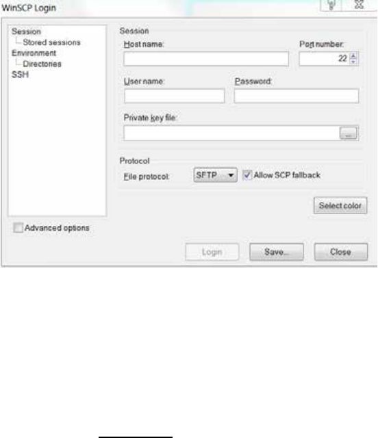
ICS 1.8 Installation & Configuration Guide
145
It is already set up on the master-slave pair, and does not run on any other nodes.
2. The node where you run the setup-cluster script becomes the master, but it must be run
on either the master or slave node from the old cluster.
Retrieving ICS Logs
This step is not required at installation, but as you use Interplay Central you may encounter
performance problems or playback failure. You should report these occurrences to an Avid
representative. Avid may ask you to retrieve system and component logs from your ICS
server(s). ICS logs reside in the following directory:
/var/log/avid
The simplest way to retrieve logs residing on a Linux machine is using an application that
supports SCP/SFTP such as WinSCP (Windows) or muCommander (MacOS).
To retrieve ICS logs using an SCP/SFTP client:
1. Launch the SCP/SFTP client (WinSCP shown) and enter the session information.
• Hostname:
http://<hostname> where <hostname> is either the ICS host name (if you only have
a single server)
Or, http://<cluster-IP> where <cluster-IP> is the IP address you provisioned for the
ICS cluster
• User name: root
• Password: _
Note: Note that you changed the root password during the installation process.

ICS 1.8 Installation & Configuration Guide
146
Note: Please contact your Avid representative for the default root password.
2. Once connected, navigate to the directory where the logs are stored:
/var/log/avid
3. Use the SCP/SFTP client’s built-in functionality to retrieve the logs.
The logs can be quite big and may take some time to transfer.
Log Cycling
Like other Linux logs, the ICS server logs are stored under the /var/log directory, in
/var/log/avid. Logs are automatically rotated on a daily basis as specified in /etc/logrotate.conf.
Using SNMP Monitoring on the ICPS Server
The Avid System Monitor application and ICS server can be configured to collect information
from the ICS server. This allows you to monitor the status of mandatory ICS services and display
graphs for activities such as CPU usage, network usage, and system memory usage. The
following items are graphed over time in the Avid System Monitor web page interface:
• Average CPU load
• Number of CPU interrupts per second
• System uptime
• Swap space (disk space reserved for memory when RAM is fully loaded)
• System memory usage
• CPU usage
Contact your Avid representative for information about Avid System Monitor. A qualified Avid
support representative can upgrade an Avid System Monitor system to work with ICS.
Migrating the ICP Database from Windows to Linux
See “Appendix E: Migrating the UMS Database with the User Management Utilities Tool” on
page 189.
Backing up and Restoring the ICS Database
The ICS database is automatically backed up on a daily basis, but you can use the same tool it
uses, avid-db, to back up and restore the database (plus perform other operations) at any time.
The avid-db command has the following format:
/opt/avid/bin/avid-db <parameter-list> <command> [ <args>... ]
For example, to back up the contents of the ICS database to /opt/avid/share/avid/db/dumps:
/opt/avid/bin/avid-db -–dump-base=/opt/avid/share/avid/db/dumps dumpall

ICS 1.8 Installation & Configuration Guide
147
For a list of all the parameters and arguments, issue the following:
/opt/avid/bin/avid-db help
Note: Restoring the ICS database in cluster has special requirements. Due to the automatic
restarting of halted services in a cluster, you cannot use the avid-db restore command by
itself. Follow the procedure as outlined below.
To restore the ICS database in a cluster:
1. Log in to the master and slave nodes as root.
For help identifying nodes, see “Observing Failover in the Cluster” on page 137.
2. Stop pacemaker on both nodes:
service pacemaker stop
3. Start DRBD on both nodes:
service drbd start
4. Make the master node the DRBD primary (on the master node):
drbdadm primary r0
5. Mount the DRBD drive on the master node:
mount /dev/drbd1 /mnt/drbd
6. Start the PostGres database on the master node:
service postgresql-9.1 start
7. Restore the ICS database on the master node:
/opt/avid/bin/avid-db --drop-db="no" restoreall
Once the ICS database has been restored you can begin handing control back to
pacemaker in the steps below.
8. Stop PostGres on the master node:
service postgresql-9.1 stop
9. Unmount the DRBD drive on the master node:
umount /mnt/drbd
10. Stop DRBD on both nodes:
service drbd stop
11. Restart Pacemaker (which restarts all needed services) on both nodes, master node first,
slave node second:
service pacemaker start
ICS 1.8 Installation & Configuration Guide
148
Appendix A: Installing ICS on Non-HP Hardware
For the most part the steps provided in the main body of this guide for installing and configuring
ICS on supported HP hardware are easily generalized to non-HP hardware. There are two main
differences.
Note: This section provides tips for installing RHEL and ICS for Interplay MAM on non-HP
hardware. ICS supports Interplay Central and Sphere on HP Hardware only. ICS supports
Interplay MAM on both HP and non-HP hardware.
The first main difference is the express installation using a USB key cannot be followed on a non-
HP install. That is, you must install RHEL and ICS as separate steps. In addition, there is no
guarantee the supplied RHEL “kickstart” (ks.cfg) file will work on non-HP hardware. However,
you can examine its contents and mimic them during a manual installation, or create a kickstart
file for your own hardware. A kickstart file is a Linux convenience that speeds up installation by
automatically answering some questions for hardware that is known in advance. However,
creating a kickstart file is not necessary.
Second, as of the ICS 1.4 release, three partitions are required on the (mirrored) system drive.
The first is the boot partition (/boot). The second partition is used by the DRBD (Distributed
Replicated Block Device) storage system. ICS uses DRBD to replicate its PostgreSQL database, in
a clustered configuration. The third is the system partition (/).
On HP hardware, the kickstart file on the USB key creates the second partition on the OS drive
automatically. On non-HP machines you must create it manually. After the second partition has
been created the steps for setting up DRBD are the same on both HP and non-HP machines.
Note: The second partition on the system drive is required only for cluster deployments.
However, it is recommended you create it even for a single ICS server deployment, to keep
open the possibility of clustering.
Non-HP Installation Notes
The following notes pertain to the main installation steps for non-HP hardware:
1. Set Up the Non-HP Server Hardware
¨ Create a RAID 1 (mirror) for the system disk using the hardware BIOS utilities.
¨ Set the system clock before installing RHEL, if possible; otherwise, set it at the
appropriate stage in the RHEL installation process.
2. Install RHEL manually.
¨ Select BASIC SERVER during the RHEL installation process.
¨ When prompted to create storage, create two partitions on the OS drive. One
partition is for RHEL. The other ones is used by DRBD. The DRBD partition should be
20GB in size.
ICS 1.8 Installation & Configuration Guide
149
Note: Some ICS software components depend on the language for RHEL being set to
English. Please select English as the language of installation. Do not change the input
language afterwards.
3. Install ICS.
¨ Mount the RHEL DVD under /sysinstall (this is where the install script looks for it):
mount /dev/sdX /sysinstall
In the above command, substitute the optical drive device name for sdX (e.g. sr0)
Note: RHEL will automatically create an alias for the optical drive on /CDROM. Thus the
following mount command can also be used:
mount /CDROM /sysinstall
¨ Unpack the ICS installer file:
tar –zxovf ICS_installer_v1.8.tar.gz
¨ Change directories to the ICS_installer_v1.8 folder and run the installation script:
./install.sh
4. Set up the cluster (optional), configure ICS for MAM, etc., as instructed in the main body of
this guide.

ICS 1.8 Installation & Configuration Guide
150
Appendix B: Table of Deployment Options and Requirements
The following table summarizes the requirements for each deployment.
Interplay Central Interplay
Sphere
Interplay
Central
&
Interplay
Sphere
(Shared ICS)
Interplay
MAM
High
Avail. Load
Bal. iNEWS Interplay
Production
iNEWS and
Interplay
Production
HARDWARE
ICS Server
(RHEL 6.3) ● ●
HP
DL360
DL380
G7/G8
HP
DL360
DL380
G7/G8
HP
DL360
DL380
G7/G8
HP
DL360
DL380
G7/G8
HP
DL360
DL380
G7/G8
Any Vendor
RAID 1 System
Disk ● ● ● ● ● ● ●
RAID 5 File
Cache / Gluster ● ● 1.5 iOS,
Multicam
1.4 iOS
1.5 iOS,
Multicam 1.5 Multicam 1.4 iOS
1.5 iOS,
Multicam
MPEG-1,
XDCAM,
WMV, MXF
proxies
Additional NIC ● GigE,10GigE GigE,10GigE GigE,10GigE GigE,10GigE 10GigE
Port Bonding ● ●
ISIS
2000/5000/70
00
● ● ● ● ● Supported,
but unlikely
Proxy Storage ● ●
ICDS Server
(Windows 7)
ICDS may be
installed on
certain existing
Interplay
servers
● ● ● ●
CLIENTS
iOS App
●
1.5
●
●
Web Client ● ● ● ●
Sphere-
enabled Media
Composer,
NewsCutter
● ●
MAM Desktop ●
Interplay Cut
●
Catalogger ●
RV
IC
Middleware
(IPC)
● ● ● ● ●

ICS 1.8 Installation & Configuration Guide
151
Interplay Central Interplay
Sphere
Interplay
Central
&
Interplay
Sphere
(Shared ICS)
Interplay
MAM
High
Avail. Load
Bal. iNEWS Interplay
Production
iNEWS and
Interplay
Production
User
Management
(UMS)
● ● ● ● ●
Configuration
(ACS) ● ● ● ● ● ● ●
Messaging
(ACS) ● 1.5 1.5 1.5 1.5 (also non-
Sphere MC) 1.5 (also non-
Sphere MC)
Playback (ICPS)
●
●
●
●
●
●
●
Frame-based
Playback ● ● ● ● ● ●
File-based
Playback ● ● iOS iOS iOS ●
High-availability (redundancy) is provided by two servers operating in a master/slave
configuration.
Load-balancing refers to video playback and is provided by a cluster of two or more servers.
Video playback is provided by the ICPS service (“Playback (ICPS)” in the table above), and is
designed to run on all servers in the cluster such that playback sessions are distributed, or load-
balanced, across all servers. Because of this, adding servers to a cluster accommodates
increased capacity.

ICS 1.8 Installation & Configuration Guide
152
Appendix C: Configuring Port Bonding for Interplay MAM
(Optional)
In MAM deployments of ICS, port bonding improves playback performance when multiple
clients are making requests of the ICS server simultaneously. With port bonding, more
concurrent playback requests can be sustained by a single server, especially for file-based
playback.
Port bonding is only possible for Interplay MAM deployments. It does not apply to Interplay
Central and/or Interplay Sphere deployments. Interplay Central and Interplay Sphere cannot
make use of port bonding.
The procedures in this section make use of information you entered in “Appendix L: Installation
Pre-Flight Checklist” on page 210:
¨ Device name for each NIC Ethernet port used in port bonding (e.g. eth0, eth1, etc.)
¨ Port bonding IP address
¨ Port bonding interface name (e.g. bond0)
For a discussion of port bonding, see “Port Bonding in Interplay MAM” on page 20.
Verifying the Ethernet Ports
Before bonding the ports together, verify the ports you allocated exist using the RHEL set-up
menus.
To verify the Ethernet ports for port bonding:
1. Enter the RHEL set-up menus by typing setup at the command prompt:
setup
The setup screen appears.
2. From the Choose a Tool menu, select the Network Configuration option. Press Enter.
3. Choose the Device Configuration option. Press Enter.
A list of network interface ports appears.
4. Verify that the ports you designated for port bonding are available.
5. Exit the set-up menus without making any changes by pressing Cancel and Quit.
Proceed to “Configuring the Port Bonding” below.
ICS 1.8 Installation & Configuration Guide
153
Configuring the Port Bonding
Configuring port bonding requires that you modify the contents of the interface configuration
(ifcfg-ethX) file for each port you are bonding together, create a new interface configuration file
for the bond group, and restart the network services.
To configure port bonding for Interplay MAM:
1. Navigate to the directory containing the interface configuration files (the
/etc/sysconfig/network-scripts directory).
cd /etc/sysconfig/network-scripts
2. List the directory contents to view the files.
ls
3. Using the Linux editor vi, open the interface configuration file for the first interface to be
included in the port bond (e.g. ifcfg-eth0):
vi ifcfg-eth0
4. When you open it for editing, the file should look something like this:
DEVICE=eth0
NM_CONTROLLED=yes
ONBOOT=yes
DHCP_HOSTNAME=$HOSTNAME
BOOTPROTO=static
TYPE=Ethernet
USERCTL=no
PEERDNS=yes
IPV6INIT=no
5. Add port bonding configuration information for the device by inserting the following line
(shown in bold):
DEVICE=eth0
NM_CONTROLLED=yes
ONBOOT=yes
MASTER=bond0
DHCP_HOSTNAME=$HOSTNAME
BOOTPROTO=static
TYPE=Ethernet
USERCTL=no
PEERDNS=yes
IPV6INIT=no
• DEVICE=eth0 specifies the name of the physical Ethernet interface device. This
line will be different for each device. It must correspond to the name of the file itself
(e.g. ifcfg-eth0).
• MASTER=bond0 specifies the name of the port bonding interface. This must be
the same in each network script file in the port bonded group.

ICS 1.8 Installation & Configuration Guide
154
• ONBOOT=yes must be set to “yes” so Linux brings up the port at boot time.
6. Save and exit the file by typing the following command from within the vi editing session:
<Esc> :wq
That is, press the Escape key, then the colon, then type wq and press Return.
You are returned to the Linux prompt.
7. Perform the above steps for each interface to be included in the port bond (e.g. eth1,
eth2, etc.)
8. Create a port bonding network script file in the same directory. Use vi to create the file:
vi ifcfg-bond0
ifcfg-bond0 is the name of the port-bonding group (e.g. ifcfg-bond0).
9. Add the following lines to the newly created file:
DEVICE=bond0
ONBOOT=yes
BOOTPROTO=static
USERCTL=no
BONDING_OPTS="mode=0"
• DEVICE=bond0 specifies the name of the port bonding group interface. It must
correspond to the name of the file itself.
• BOOTPROTO=static lets you assign IP address of the device explicitly
(recommended), or allow the OS to assign of the IP address device dynamically. Can
be static (recommended) or dhcp (system assigned).
• If you assign the IP addresses statically you are also required to have IPADDR and
NETMASK entries.
• BONDING_OPTS="mode=0" specifies the type of port bonding (mode=0
specifies round-robin).
10. Save and exit the file by typing the following command from within the vi editing session:
<Esc> :wq
11. Restart the network service (as root):
/etc/init.d/network restart
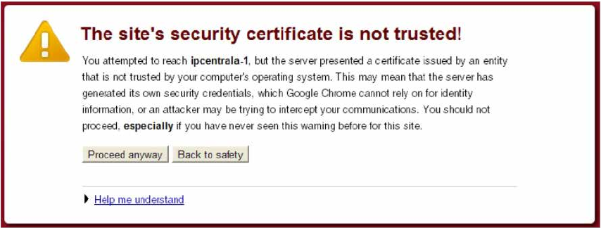
ICS 1.8 Installation & Configuration Guide
155
Appendix D: Handling SSL Certificates
For security Interplay Central uses the Secure Sockets Layer (SSL) for its server-to-browser
connections. This is indicated by https:// in the browser address bar, rather than the usual
http://. (Some browsers also show a locked padlock icon for an SSL connection.) SSL enables the
secure transmission of information between web servers and web browsers. It is a web-based
security protocol with the following important features:
• All data (web pages, etc.) passing between the server and browser is encrypted in such a
way that even if interception takes place the risk of decryption is virtually nil.
• SSL establishes a relationship of trust between the browser -- and the person doing the
browsing -- and the server. That is to say, the browser making the connection
understands it has connected to the correct site, and not a fraudulent one posing as the
site.
• Any tampering with the data transmitted via an SSL connection is immediately
detectable by both parties.
To operate correctly, SSL relies on a properly configured digital certificate, which the server
passes to the browser when it tries to access a secure web page. Amongst other things, the
certificate contains the “name” of the server for which the certificate has been issued, an
encoded signature unique to the domain, the domain’s public key, and the validity period of the
certificate itself. If the certificate has been digitally signed by a Certificate Authority (CA), it also
contains the CA’s name and signature. In addition to establishing a relationship of trust, the
certificate allows the server and browser to negotiate the encryption algorithm and encryption
key used for the browsing session.
Built-In Browser Functionality
Web browsers have functionality built-in for handling SSL certificates, negotiating the secure
connection with the server, encrypting and decrypting data, and so on. When the browser
“recognizes” the SSL certificate, all this takes place seamlessly and requires no user intervention.
However, if the browser detects something unusual in the certificate, it issues a warning such as
the following (issued by Google Chrome):
ICS 1.8 Installation & Configuration Guide
156
This appendix presents the basic issues surrounding SSL certificates. It explains why browsers
issue “certificate not trusted” and other SSL warnings, and presents three approaches to
handling them:
• Ignoring the warnings
• Generating a new self-signed certificate and adding it to the browser’s Trusted Root
Certification Authorities Store
• Purchasing a CA-signed certificate from a trusted Certificate Authority (CA) and adding it
to the ICS server’s keystore.
SAN Certificates
If you decide to purchase a certificate/signature from a CA, or are yourself a CA, we recommend
you obtain or authorize a Subject Alternative Name (SAN) certificate. SAN certificates can have a
number of associated host names, domain names, IP addresses, etc., all within the same
certificate.
A SAN certificate containing all the names associated with Interplay Central will eliminate the
possibility of “name mismatch” warnings. Name mismatch warnings arise when the name in the
browser (e.g. ics-dl360-1) does not match the “issued to” name contained in the SSL certificate
(e.g. ics-dl360-1.mydomain.com). To avoid browser name-mismatch complaints, the URL typed
into the browser and the address contained in the certificate must match. A SAN certificate can
easily contain the server host name, IP address, and/or FQDN you might use to access Interplay
Central.
SAN certificates are particularly valuable when you have a sophisticated network, complex
topology, subnets, use browser redirects, or simply wish to give users different ways to connect
to Interplay Central. It could arise that some users must connect to Interplay Central using the
FQDN (e.g. https://ics-dl360-1.mydomain.com). Others might only need to use the shorter host
name (e.g. https://ics-dl360-1). In this scenario, both names must be in the certificate if both
user types are to avoid name mismatch errors.
Understanding the “Certificate Not Trusted” Warning
During the installation process, the first time the Jetty web server starts it automatically
generates an SSL certificate, which ICS then sends to browsers when they connect. This is known
as a “self-signed” certificate, since it is generated/signed and used by the same server, rather
than signed by a recognized CA. The certificate is perfectly legitimate; however, it will cause
most browsers to issue a warning each time a user connects to the Interplay Central sign-in
page, for two main reasons.
First, browsers only accept certificates signed by recognized CA’s without complaint. Self-signed
certificates are a breach in the established “chain of trust” that starts with a recognized CA,
whose own root level digital certificates are installed by default with all web browsers. Since
self-signed certificates are neither signed by a CA nor pre-installed with browsers, they are
flagged as untrusted.
Second, as noted, some browsers may in addition complain of a name mismatch. This is because
the URL used to connect to the ICS server (e.g. http://ics-dl360) contains a name that does not
match the “issued to” name contained in the certificate. In manually generated certificates, the

ICS 1.8 Installation & Configuration Guide
157
“issued to” name is most commonly the Fully Qualified Domain Name (FQDN) (e.g. ics-dl360-
1.mydomain.com), permitting access the most complex network topologies. In the case of the
self-signed certificate generated by Jetty during the install, the “issued to” name is usually a
variation on localhost (e.g. localhost.mydomain.com or simply localhost).
Recall that you named the ICS server during the first installation steps. However, by this time,
Jetty has already generated the SSL certificate using localhost. Thus, the self-signed SSL
certificate automatically created during the installation process is perfectly valid, but will
nevertheless flag browser warnings.
Eliminating the Certificate not Trusted and Name Mismatch
Warnings
With the cause of the “certificate not trusted” and name mismatch warnings understood, it can
be seen that ignoring the warnings is always a possibility. However, the first and simplest
approach to permanently eliminating warnings is to generate a new certificate and configure
the browser — the operating system, in fact — to trust it. Telling the browser to trust the
certificate eliminates the “certificate not trusted” warning. Generating a new certificate
eliminates the most common name-mismatch issues that can arise even after the browser trusts
the certificate.
Generating a new SSL certificate is uncomplicated, and all browsers can be configured to accept
self-signed SSL certificates as trusted. The Jetty web server used by Interplay Central for its SSL
connections can automatically generate a new self-signed certificate containing the renamed
server. For cluster setups, you can generate a certificate “manually”, specifying the cluster
FQDN, hostname, or IP address, as desired.
Note: The self-signed certificate automatically generated by Jetty cannot be used for a cluster of
servers. In the case of a cluster, you must generate a self-signed certificate manually. In addition,
since any node in the cluster can take on the role of master, you must also install the new
certificate on each server in the cluster.
The second approach to eliminating the warning is to purchase and install an SSL certificate from
a trusted Certificate Authority. Certificate Authorities — such as VeriSign, Thawte, Digicert,
Comodo, GoDaddy, GlobalSign, etc. — are entities entitled to issue root certificates in the name
of applicants. They are responsible for carefully authenticating individual certificate requests.
The SSL certificate issued by a CA contains the CA’s own signature. Certificates issued by a CA
are, generally speaking, automatically trusted by browsers.
The pros and cons of each approach are presented in the following table:
Method Description
Ignoring the
warning
Ignore the warning and proceed to the Interplay Central sign-in page.
Pros:
• No configuration
required
Cons:
• Users might be reluctant to proceed to an
“untrusted” site
• Depending on the browser, MOS plug-ins might
not work if the certificate is not trusted

ICS 1.8 Installation & Configuration Guide
158
Method Description
Configuring
Browsers
Generate a new certificate, and use the browser’s built-in means for permanently accepting
the self-signed certificates as trusted.
Pros:
• Relatively
straightforward
• Free
Cons:
• Browser acceptance must be performed client-
side, for each machine
• Alternately, distribute the certificate to client
computers from your Windows domain controller
using a Group Policy Object (GPO)
Purchasing a CA
Certificate
Purchase a certificate from a recognized CA and install it on the ICS server.
Pros:
• Performed server-
side, once
• Browsers
automatically accept
Cons:
• More complex
• Not free
• Delays between issuing the certificate request and
receiving the certificate
• Obtaining the correct certificate type can be a
challenge
• Requires a deeper understanding of certificate
issues and network topology
In a facility where all connections to Interplay Central will be made using a limited number of
browsers and browser types, it is probably easiest to regenerate the self-signed certificate and
configure each user’s browser to accept it. In a situation where connections will occur from
across a complex network topology using a variety of browsers, obtaining a certificate issued
from a trusted CA makes more sense.
Note: You can streamline the acceptance of a self-signed certificate by pushing it to client
computers using a Windows Group Policy Object (GPO) that contains the certificate. This is done
via a Windows domain controller, by applying a new Group Policy to the domain where the user
and computer accounts of interest reside. Using a GPO, all computers in the domain receive and
accept the self-signed certificate automatically. Since the steps vary depending on the domain
controller used by your facility, details of the procedure are beyond the scope of this document.
For more information, consult the documentation that came with the Windows server hosting
your domain controller.
Generating a Self-Signed Certificate for a Single Server
As noted, during the installation process you gave the ICS server a name (e.g. ics-dl360-1) via the
RHEL Network Configuration menu. However, the self-signed certificate created by Jetty was
automatically generated prior to that stage, and contains a variation of “localhost” in the “issued
to” field. As a result, most browsers will flag an SSL certificate name mismatch. This will happen
even after you tell the browser to trust the self-signed certificate.
ICS 1.8 Installation & Configuration Guide
159
To eliminate the “name mismatch” error, you must first generate a new certificate, containing
the correct ICS server name. Once generated, you eliminate the “untrusted” warning by
configuring the browsers to trust the self-signed certificate.
In this step, you take advantage of the following Interplay Central feature. If the avid-interplay-
central service starts up and discovers there is no keystore, it creates one, automatically
populating it with a self-signed certificate. (The keystore is the file where Jetty stores SSL
certificates and the public-private key pairs used during the encryption process.) Since the ICS
server is now named, the new certificate automatically picks up the new name (e.g. ics-dl360-1
or ics-dl360-1.mydomain.com).
Note: Jetty picks up the name from the DNS Search Path entry in the server’s Linux resolve.conf
file. This value was set by you in “Configuring the Hostname and Static Network Route” on page
44.
Note: Once you generate the new certificate and install the certificate in the Trusted Certificate
Store, users may need to enter the Fully Qualified Domain Name (FQDN) into the browser
address bar, to avoid name-mismatch warnings.
Note: This procedure in this section only applies to a single-server installation. If you have set up
a cluster, refer to the instructions in “Generating a Self-Signed Certificate for a Server Cluster” on
page 160 instead.
To generate a new self-signed certificate for a single server:
1. Log in to the ICS server as root and navigate to the directory containing the Jetty keystore:
cd /opt/avid/etc/avid/avid-interplay-central/ssl
2. Verify the status of the avid-interplay-central service:
service avid-interplay-central status
The system responds that Avid Interplay Central is running.
3. Stop the service:
service avid-interplay-central stop
The system responds that Avid Interplay Central has been stopped.
4. Delete the Jetty keystore (which contains the current self-signed SSL certificate):
rm jetty.keystore
You are asked to confirm the deletion.
5. Start the avid-interplay-central service (which also restarts the Jetty web server):
service avid-interplay-central start
The system responds that the Avid Interplay Central process has been started. The new
keystore and SSL certificate are created automatically by Jetty.
6. Verify the new Jetty keystore has been created:
ls -l

ICS 1.8 Installation & Configuration Guide
160
The system lists the contents of the directory, including the following file:
jetty.keystore
Now that you have eliminated potential name-mismatch browser SSL warnings, you must
configure each browser to trust the certificate. This is done by installing the certificate into the
OS-level Trusted Root Certification Authorities store.
Proceed to one or more of the following:
• ”Configuring Google Chrome (Windows)” on page 178.
• ”Configuring Internet Explorer (Windows)” on page 182.
• ”Configuring Safari (Mac OS)” on page 186.
Generating a Self-Signed Certificate for a Server Cluster
Recall that you address a cluster using the host name (e.g. ics-cluster) or IP address (e.g.
192.XXX.XXX.XXX) allocated for it by the IT department. In any event, this means that in a
cluster setup, the address entered into the browser is unrelated to the IP addresses (or names)
of the servers inside the cluster.
However, the SSL certificate that is automatically generated by Jetty picks up the FQDN of the
machine on which it is generated. It does not pick up the cluster name (or IP address). Further,
for each node in the cluster Jetty will generate a certificate with a different embedded FQDN.
Note: Jetty picks up the FQDN from the DNS Search Path entry in the server’s Linux resolve.conf
file. This value was set by you in “Configuring the Hostname and Static Network Route” on page
66.
As a result of the different SSL certificates served by the cluster, each with different “issued to”
values, name mismatches will be repeatedly flagged by the browser. This will be the case even if
the certificate is otherwise trusted. Thus, using automatically generated SSL certificates in a
cluster setup is not possible. To eliminate the name mismatch warning, you generate a new self-
signed certificate for each server in the cluster, specifying its contents explicitly. In particular,
you specify the FQDN of the cluster itself, not the individual servers within the cluster.
In this procedure you use the Java keytool utility to generate a new self-signed certificate with
contents set explicitly. The utility also generates the private-public key pair associated with a
certificate, and the keystore where they are all stored. You also update the Interplay Central
application properties file so it can make use of the new certificate.
Making use of a self-signed certificate in a cluster consists of the following main steps:
1. Identifying the master and non-master nodes.
Make changes to the non-master nodes first and the master node last.
2. Generating the new self-signed certificate for the cluster.
In this step you generate a new SSL certificate and keystore, for each non-master node
in the cluster.
ICS 1.8 Installation & Configuration Guide
161
Note: To save time and ensure accuracy, consider creating the Jetty keystore once only,
and copying the updated keystore to each machine in the cluster using the Linux secure
copy (scp) command.
3. Add certificate usage passwords to the Interplay Central Application Properties file.
Since both the SSL certificate and the keystore itself are password-protected, in this step
you update the Interplay Central Application Properties (application.properties) file with
the new passwords. Interplay Central needs the passwords so it can serve the SSL
certificates.
Note: Similarly to the above step, consider modifying the Interplay Central application
properties file once only, and copying the updated file to each machine in the cluster
using the Linux scp command.
4. Update the master node and restart it.
With the updated Jetty keystores and Application Properties files in place on the non-
master nodes, you can update the master nodes and restart the AvidIPC resource so it
picks up the changes.
5. Trigger a failover to verify the success of the procedures
In this step, you verify the certificates were installed correctly by triggering a failover in
the cluster. As a best-practice, you ought to trigger failovers until each node in the
cluster has taken on the role of master. This will ensures configuration changes were
successful on each node.
Note: The AvidIPS resource/avid-interplay-central service will not start up correctly if
there is an SSL configuration error.
Before You Begin
The procedures in this section requires the following:
• The name associated with the static IP address allocated for the cluster (e.g. ics-cluster).
To identify the master and non-master nodes:
1. Log in to any node in the cluster as root and open the cluster resource monitoring
utility:
crm_mon
This returns the status of all cluster-related services on all nodes, with output similar to
the following example using two nodes (e.g. burl-ics2 & burl-ics2).
============
Last updated: Tue Oct 29 13:17:56 2013
Last change: Mon Oct 28 17:37:30 2013 via cibadmin on burl-ics1
Stack: openais
Current DC: burl-ics1 - partition with quorum
Version: 1.1.7-6.el6-148fccfd5985c5590cc601123c6c16e966b85d14
2 Nodes configured, 2 expected votes
14 Resources configured.
ICS 1.8 Installation & Configuration Guide
162
============
Online: [ burl-ics1 burl-ics2 ]
Clone Set: AvidConnectivityMonEverywhere [AvidConnectivityMon]
Started: [ burl-ics1 burl-ics2 ]
AvidClusterMon (lsb:avid-monitor): Started burl-ics1
MongoDB (lsb:mongod): Started burl-ics1
Resource Group: postgres
postgres_fs (ocf::heartbeat:Filesystem): Started burl-ics1
AvidClusterIP (ocf::heartbeat:IPaddr2): Started burl-ics1
pgsqlDB (ocf::avid:pgsql_Avid): Started burl-ics1
Master/Slave Set: ms_drbd_postgres [drbd_postgres]
Masters: [ burl-ics1 ]
Slaves: [ burl-ics2 ]
Clone Set: AvidAllEverywhere [AvidAll]
Started: [ burl-ics1 burl-ics2 ]
AvidIPC (lsb:avid-interplay-central): Started burl-ics1
AvidUMS (lsb:avid-ums): Started burl-ics1
AvidACS (lsb:acs-ctrl-core): Started burl-ics1
2. Note the line identifying the master node:
• AvidClusterIP
You will update the master node last.
Note that the master node also always runs the following resources (the corresponding
services are shown in parentheses):
• AvidIPC (avid-interplay-central)
• AvidUMS (avid-ums)
• AvidACS (acs-ctrl-core)
Once you update the master node, you will restart its AvidIPC resource (that controls
the avid-interplay-central service) so it makes use of the updated Jetty keystore.
To generate a new self-signed certificate for the cluster:
1. On any non-master node in the cluster log in as the root user.
2. Use the Linux ping command to obtain the FQDN of the cluster:
ping <cluster_name>
Where <cluster_name> is the name associated with the static IP address allocated for
the cluster.
Record the FQDN returned for use below to generate the new certificate. You can also
use the “short name”, that is, the <cluster_name> if you prefer.
3. Change to a writable directory, for example, /tmp.

ICS 1.8 Installation & Configuration Guide
163
cd /tmp
4. Begin the process of generating a new self-signed certificate and inserting it into the
Jetty keystore:
keytool -keystore jetty.keystore -alias jetty -genkey -keyalg RSA
-storepass <password> -keypass <password> -validity 10950
For simplicity, it is suggested you use the same password for both storepass and
keypass.
Take note of the password used. You will need it to update the application properties
file, below. Otherwise, Interplay Central cannot make use of the new certificate.
The meaning of each parameter is presented in the following table:
Parameter Description
-keystore
The path and name of the keystore file.
The default name of the file is jetty.keystore (recommended).
You can use a different name and/or path for your keystore, but you must
then change settings in the Interplay Central application properties
(application.properties) file.
-keysize
The length of the public-private key pairs generated.
Optional for self-signed certificates. However, since December 2010, most
CAs require a key length (-keysize) of 2048 bits.
-alias
A human-readable identifier for the certificate within the key store.
Keystores can hold multiple certificates. A simple alias makes the
certificate easy to refer to in any subsequent operations.
-genkey
The option to generate a new certificate and public-private key pair.
-keyalg
The SSL algorithm used for the certificate.
The default is RSA.
You can use a different algorithm, but you must then change the settings
in the application.properties file.
-storepass
A password protecting the certificate within the keystore.
-keypass
A password protecting the keystore itself.
-validity
A validity period for the certificate.
The default validity period is 30 years (365x30=10950).
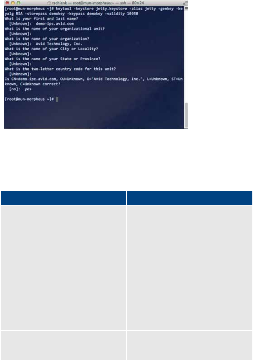
ICS 1.8 Installation & Configuration Guide
164
5. A series of questions appears, used by Jetty to populate the certificate. This information
is visible when end-users examine the certificate using a browser.
6. Answer the questions.
Note: For a self-signed certificate, only the first answer indicating the FQDN (e.g. icps-
cluster.mydomain.com) or short name (e.g. icps-cluster) is required.
The following table provides details on the questions and answers.
Question Answer
What is your first and last name?
Mandatory.
Enter the fully qualified domain name (FQDN) of
the cluster (e.g. icps-cluster.mydomain.com).
This can also be the short name for the cluster
(e.g. icps-cluster).
This is the short name or FQDN of the cluster
itself, obtained in step 2, above. It is not the
short name or FQDN of the individual server
within the cluster.
This is the name end-users will enter into the
browser address bar to connect to Interplay
Central.
Note: Recall that when you configured the
cluster you made use of the IP address allocated
by the IT department for the cluster. Now it is
the short name or FQDN that is required.
What is the name of your organizational unit?
The department within your company issuing
the request (e.g. IT).
Optional.

ICS 1.8 Installation & Configuration Guide
165
What is the name of your organization?
The legal name of your company (e.g. Avid
Technology Inc.).
Optional.
What is the name of your City or Locality?
The city or jurisdiction where you are located.
Optional.
What is the name of your State or Province?
State, province, department, prefecture, etc.
Optional.
What is the two-letter country code for this
unit?
The ISO country code.
Optional.
7. Confirm your responses by typing yes to complete the creation of the new keystore and
self-signed certificate.
8. Copy the new Jetty keystore containing the freshly generated self-signed certificate to
its final location:
cp jetty.keystore
/opt/avid/etc/avid/avid-interplay-central/ssl/jetty.keystore
You will be prompted to overwrite the exiting keystore. Type “y” to overwrite.
9. Repeat the above steps on the other non-master servers in the cluster.
Use the same password on each server.
Note: To save time and ensure accuracy, consider creating the Jetty keystore once only,
and copying the updated keystore to each non-master machine in the cluster using the
Linux secure copy (scp) command: scp [path to source file] root@[host]:[target
directory].
For example:
scp /opt/avid/etc/avid/avid-interplay-central/ssl/jetty.keystore
root@server2:/opt/avid/etc/avid/avid-interplay-central/ssl/
To add certificate usage passwords to the Interplay Central Application Properties file:
In this procedure you obtain obfuscated (disguised) passwords from Jetty and add them to the
Interplay Central application properties file. This allows Interplay Central to make use of the SSL
certificate.
Be sure to add two (2) passwords to the Application Properties file (similar to the following):
system.org.ops4j.pax.web.ssl.password=OBF\:1c3x1mf71jnb1sov1jk71mbf1c35
system.org.ops4j.pax.web.ssl.keypassword=OBF\:1c3x1mf71jnb1sov1jk71mbf1c35
Note: Plain-text passwords can also be used. For reasons of security it is recommended
you use obfuscated passwords instead.
ICS 1.8 Installation & Configuration Guide
166
1. On any non-master node in the cluster log in as the root user.
2. Obtain an obfuscated string for the password(s) used to create the keystore and certificate
in the previous procedure:
java -cp /opt/avid/avid-interplay-central/lib/org.eclipse.jetty.jetty-
util.jar org.eclipse.jetty.util.security.Password <password>
Where <password> is the password you used to protect the certificate within the keystore.
The system responds by outputting the password, the obfuscated password string (OBF:)
and its MD5 hash value (MD5:).
The following represents sample output. It is the string following OBF that is needed
(“XXXXXX” indicates the password you entered is echoed to the command line in plain-text):
XXXXXX
OBF:1c3x1mf71jnb1sov1jk71mbf1c35
MD5:4c88dafcf38a9b90b1e32efe798f95f0
3. If you used a different password to protect the Jetty keystore itself, repeat the step for the
second password.
4. Edit (or create) the Interplay Central application properties file using a text editor such as vi:
vi /opt/avid/etc/avid/avid-interplay-central/config/application.properties
Note: In most cases, this Application Properties file will not exist. Create the file using vi
and add the lines indicated in the steps below.
Note: You can examine the contents of the default file in the following directory:
/opt/avid/avid-interplay-central/config. However, do not make your changes in that file,
since it will be overwritten any time you upgrade ICS. Make your changes in the file you
create in the /opt/avid/etc/avid/avid-interplay-central/config, as indicated in this step.
Note: If you use the default file as a model, the one you create should only contain the
values you wish to override.
5. Locate (or add) the entry for the password used to protect the certificate (sometimes
referred to as the export password):
system.org.ops4j.pax.web.ssl.password=OBF\:1c3x1mf71jnb1sov1jk71mbf1c35
Replace obfuscated string (shown in bold, above) with the one you generated.
Note: Those upgrading from ICS 1.2 or below (i.e. from a Windows server to a Linux
server) please note the following difference in Linux syntax. If you are re-using the
obfuscated string from the Windows server, be sure to add the Linux “escape” character
(“\”) in front of the colon in the entry for the password.
A plain text entry would like the following:
system.org.ops4j.pax.web.ssl.password=visible password
Note: For reasons of security it is recommended you use obfuscated passwords.
6. Locate (or add) the entry for the password used to protect the Jetty keystore:
system.org.ops4j.pax.web.ssl.keypassword=OBF\:1c3x1mf71jnb1sov1jk71mbf1c35
ICS 1.8 Installation & Configuration Guide
167
Replace obfuscated string (shown in bold, above) with the one you generated.
7. Save and exit the file:
<Esc>:wq
8. Repeat the above steps on the other non-master servers in the cluster.
Note: To save time and ensure accuracy, consider editing/creating the Application Properties
file once only, then copying it to each machine in the cluster using the Linux secure copy (scp)
command. For example: scp [path to source file] root@[host]:[target directory].
For example:
scp /opt/avid/etc/avid/avid-interplay-central/config/application.properties
root@server2:/opt/avid/etc/avid/avid-interplay-central/config/
To update the master node keystore and Application Properties file and restart the node:
1. Log in to the master node as root.
2. Navigate to the directory containing the Jetty keystore:
cd /opt/avid/etc/avid/avid-interplay-central/ssl
3. Securely copy the Jetty keystore from any non-master node to the master node:
scp root@[host]:/opt/avid/etc/avid/avid-interplay-
central/ssl/jetty.keystore ./
In the command above, substitute the name of a non-master node for the [host]
parameter (e.g. morpheus-hp2). Do not type the square brackets. The “dot slash” in the
above command indicates the current directory.
You will be prompted to overwrite the existing keystore. Type “y” to overwrite.
4. Navigate to the directory containing the Application Properties file:
cd /opt/avid/etc/avid/avid-interplay-central/config
5. Securely copy the Application Properties file from any non-master node to the master
node:
scp root@[host]:/opt/avid/etc/avid/avid-interplay-
central/config/application.properties ./
You will be prompted to overwrite the existing file. Type “y” to overwrite.
6. Restart the AvidIPC resource (that controls the avid-interplay-central service) so
Interplay Central picks up the new passwords:
crm resource restart AvidIPC
Once the resource restarts, the master node can begin serving the new certificate.

ICS 1.8 Installation & Configuration Guide
168
To trigger a failover and verify the success of the steps:
• For instructions on triggering a failover, see “Observing Failover in the Cluster” on page
137.
• The success of the steps to generate a self-signed certificate for a server cluster is seen
when a new master node is assigned to the cluster, and comes up without generating
any error messages that pertain to the Jetty keystore. That is, the new master node
reads the keystore without complaint.
• There are no obvious error messages when there is a problem with the Jetty keystore
configuration. The AvidIPC resource (avid-interplay-central service) simply fails to start.
• If a node does not start up correctly, verify the configuration of the keystore and
Application Properties file.
Now that you have eliminated the name-mismatch warnings, you must configure each browser
to trust the certificate. This is done by installing the certificate into the OS-level Trusted Root
Certification Authorities store.
Proceed to one or more of the following:
• ”Configuring Google Chrome (Windows)” on page 178.
• ”Configuring Internet Explorer (Windows)” on page 182.
• ”Configuring Safari (Mac OS)” on page 186.
Obtaining a Trusted CA-signed Certificate
SSL certificates obtained and signed by a CA are automatically trusted by browsers. No warnings
appear when a connection is made to a secure web page, nor do you need to add them to the
Trusted Root Certification Authorities store (since the CA’s root certificate is already there).
Note: Standard SSL certificates secure a single host name, IP address or FQDN. SAN certificates
can contain secure multiple servers and contain name variations, and is the recommended
certificate. For details, see “SAN Certificates” on page 156.
This procedure requires the following information:
¨ Two-letter ISO country code (e.g. US, CA, DE)
¨ State, Province, Prefecture, etc. (spelled out – no abbreviations)
¨ City, locality or jurisdiction (e.g. Paris)
¨ Organization Name (e.g. Avid Technology)
¨ Organizational Unit (e.g. IT)
¨ Common Name: host name, IP address, or FQDN (e.g. icps-cluster.mydomain.com) of
the ICS server or cluster
Note: Some CAs will not issue a CA-signed certificate for a simple host name. However,
host names can be added to SAN certificates.
¨ Email Address: Contact email address (optional)
ICS 1.8 Installation & Configuration Guide
169
¨ Challenge password (optional)
¨ Optional Company Name (optional)
To obtain a trusted CA-signed certificate:
The process for obtaining a certificate varies with each CA, but always involves generating a
Certificate Signing Request (CSR), and installing the new signed certificate into the keystore. The
steps are summarized below.
1. Log in as root and change directories to a secure location:
cd /root
Note: The root user home directory (/root) is visible only to the root user. This is not to
be confused with the root directory (/), which is visible to all users.
2. Generate a CSR and private key using openssl.
openssl req -out jetty.csr -new -newkey rsa:2048 -nodes -keyout
jettyPrivateKey.key
Note: Since December 2010, most CAs require a key length of 2048 bits, as shown in the
above example. Fewer bits are considered insecure, and may be rejected by the CA.
Answer the questions as prompted. Your responses are inserted into the CSR, and will
appear in the CA-signed SSL certificate. The details are visible to end-users when they view
certificate details in a browser.
The openssl req command produces two files, jetty.csr and JettyPrivateKey.key.
• jetty.csr: This is the CSR you will submit to the CA. It contains the information you
entered, and a public key. It does not contain your private key.
• jettyPrivateKey.key: This is your enterprise’s private key for the certificate just
created.
Note: Keep the private key in a safe place (such as the root user home directory, /root).
You will need it later to add the CA-signed key to the keystore.
Note: Although your private key will be stored in the in the Jetty keystore, Jetty does not
provide a means for extracting the key. Should you lose your private key, use a third-
party too, such as jksExportKey, to extract it from the Jetty keystore.
The CSR (jetty.csr) file has contents similar to the following:
-----BEGIN NEW CERTIFICATE REQUEST-----
XXXCuTCCAaECAQAwdDELMAkGA1UEBhMCQ0ExDzANBgNVBAgTBlF1ZWJlYzERMA8GA1UEBxMITW9u
dHJlYWwxDTALBgNVBAoTBEF2aWQxCzAJBgNVBAsTAlFBMSUwIwYDVQQDExxoYS1pY3BzLTAyLmds
b2JhbC5hdmlkd3cuY29tMIIBIjANBgkqhkiG9w0BAQEFAAOCAQ8AMIIBCgKCAQEAjoSSGeAskozI
G454aQ6RK3qOKix4gYapEAGgzJ+f+6LN/j0U5sIznW2F5RG047ChMiMdENVK2v4jlI1RtHozD4Yd
RO/xHVBejmP+SDAhtfNcXX2ThZYzGbHWm7mcxOnyXH5vU0KVWaWfz9K3Oh1FPwEgI6T4sb1TBY7h
F8r7uObeoUbXnaXObGHJnSzlX/PC3YcsHPPI4BFAmK/6oQpgUbnN+L7y7oBCIBwv5tY3Z16q9vgy
V9H8NpEIEkh9anJXWlo13aGeMYa0yM4g2cRsiBGAPRkmvx2lYUBf5TOcSk9mFZAZRudK1j5+mCtY
VljC9q5cZzL0IZ52U+kbW1IrRwIDAQAtT7bwDQYJKoZIhvcNAQEFBQADggEBAEObhmbSxAPwfyD7
jO6uR6R/1oN2fu29bxx9yTMBS8OeiLb1NcSaBAPxxcZaaHnmXeKIzh0ReHXt4GUNXGOL2HYVKjLa
OFqY9mhUgrEdIIEbbpXtOI41qzdQqP/CCv5j6fx8M5gdCVZghtk0+G+MME92e4YSib9Ghs+WVXCj
1uwzr4VwlpsaSAvGpNhLV6wTHgeYcGoKOi6gycdTNPIySc+KDGfZFVCAeg6nDqkanjvYUKInPByC
s3cD8B+ZxvHSIzRf4mbPSOm596XxpiaiJUEYo9jNWZjgdGJghlI2SKryjkWG8wJMWjDBGaHzcXXX
ET/c/veHF0c2XNjFSU/hHEA=
ICS 1.8 Installation & Configuration Guide
170
-----END NEW CERTIFICATE REQUEST-----
The private key (jettyPrivateKey.key) file is structured similarly.
3. Before submitting the CSR to your CA, validate its contents using one of the many online CSR
validation tools.
Generally, this involves cutting and pasting the contents of the CSR file into a web browser
and viewing the parsed results. To ensure the CSR complies with your CA’s requirements,
use their CSR validation tool, if possible.
4. To check your CSR immediately, use the following openssl command:
openssl req -text -noout -verify -in jetty.csr
The system should respond with an “OK" and a structured dump of the CSR contents.
5. Doublecheck the validity of the private key you created:
openssl rsa -in jettyPrivateKey.key -check
The system should respond with an “OK" and a structured dump of the private key contents.
6. Submit the CSR to your CA, and take receipt of the CA-signed Certificate.
The CA will provide you with a PEM (.pem) file. Also known as a concatenated certificate
container file, this file contains the CA-signed certificate. Its contents resemble the following
(abbreviated for convenience):
-----BEGIN CERTIFICATE-----
XXXXfDCCBGSgAwIBAgIQfju3hLvGVKvSuNZ37MOUqDANBgkqhkiG9w0BAQUFADCB
jDELMAkGA1UEBhMCVVMxFzAVBgNVBAoTDlZlcmlTaWduLCBJbmMuMTAwLgYDVQQL
EydGb3IgVGVzdCBQdXJwb3NlcyBPbmx5LiAgTm8gYXNzdXJhbmNlcy4xMjAwBgNV
BAMTKVZlcmlTaWduIFRyaWFsIFNlY3VyZSBTZXJ2ZXIgUm9vdCBDQSAtIEcyMB4X
DTA5MDQwMTAwMDAwMFoXDTE5MDMzMTIzNTk1OVowgcsxCzAJBgNVBAYTAlVTMRcw
FQYDVQQKEw5WZXJpU2lnbiwgSW5jLjEwMC4GA1UECxMnRm9yIFRlc3QgUHVycG9z
ZXMgT25seS4gIE5vIGFzc3VyYW5jZXMuMUIwQAYDVQQLEzlUZXJtcyBvZiB1c2Ug
CCsGAQUFBwEMsdfEwX6FdoFswWTBXMFUWCWltYWdL2dpZjAhMB8wBwYFKw4DAhoE
FI/l0xqGrI2Oa8PPgGrUSBgsexkuMCUWI2h0dHA6Ly9sb2dvLnZlcmlzaWduLmNv
bS92c2xvZ28uZ2lmMB0GA1UdDfjdsBQoFxOKvdaitdwGLLe2jtoQZmBu5TAfBgNV
HSMEGDAWgBRIGeeSb5KdNGOZwPCZyNaljIx/ZTANBgkqhkiG9w0BAQUFAAOCAQEA
NgvA9cj2h5yFC2SJMmE8a9trUmjnorZWO/Ifmdf5ADuQuf+k8arodHpdSeq/f2Gj
wDIo3oYL2bT/66tw46Kx3Q/Z02pp7YW+BRvKejBYXN9FJxsXEkPKpz4SRvSQLl5Y
Bst7q03nK0lZQ4/LE+hufgvx08JdqGd4o4cOvZ6o4MQaMgX/0lwNjC+4PWuKfmrK
mr+RhpSkc72cEEO9//XsYesTMetY3nOuqXAQqiH4lz3KAzqNgohXXcF8W1F3ytTT
q1yWbMkJonRpXbE3U0rWI33ywiS7LAk8n4dR8tNoqqIrP6sDtvolx9/+qTPWGnYy
tV0P/hcJt5CbqE7008EnPQ==
-----END CERTIFICATE-----
The PEM file and CA-signed certificate it contains is a public documents. It does not contain
any private information and does not need to be stored securely. However, it is
recommended you keep it in a safe place such as the root user home directory (/root).
7. To verify the contents of the PEM file in human-readable form:
openssl x509 -in blah.crt.pem -noout -text
Technical information for the certificate include the issuer (e.g VeriSign, Thawte, Digicert),
the certificate’s validity, public key, and the information you supplied in the CSR.

ICS 1.8 Installation & Configuration Guide
171
Adding a CA-Signed Certificate to a Single Server
Once you have obtained an SSL certificate that has been signed by a recognized Certificate
Authority (CA) you can add it to the ICS server Jetty keystore. This is a two-step process:
1. Combine the PEM (.pem) file with your private key (.key) file.
The PEM file and private key files must be combined into a password-protected Public-
Key Cryptography Standards (.pkcs12) file . This is the format required by the Jetty
keystore. In this step you also import the file into the keystore.
2. Add certificate usage passwords to the Interplay Central Application Properties file.
In order to make use of the CA-signed certificate, Interplay Central must be supplied
with the passwords that a) protect the certificate, and b) protect the keystore itself.
The procedures require that you have the following files:
¨ PEM (.pem) file: The file containing the CA-signed certificate.
¨ Key (.key) file: The file containing the private used to generate the CSR.
The procedures require that you create the following passwords:
¨ Export Password:
Required when you use openssl to combine the key file and PEM file into a PKCS file.
This password protects the PKCS file. It also protects the certificate once it is inside the
keystore.
In another procedure, you will add this password to the Interplay Central Application
Properties file, so it can be used by Interplay Central to serve (i.e. export) the certificate
from the keystore.
¨ Destination Keystore Password:
Required when you use keytool to create the Jetty keystore.
Similarly, in another procedure you will add this password to the Interplay Central
Application Properties file, so it can be used by Interplay Central to gain access to the
keystore.
Note: For simplicity, it is recommended you use the same password for both entries.
The procedures require that you have the following passwords in your possession:
¨ Import Password:
This is the password you used to combine the key file and PEM file into a PKCS file,
(“Export Password”) above. It is required when you use openssl to verify the PKCS file
was created correctly.
¨ PEM Pass phrase:
This is the password used to create the PEM file in the previous procedure.
¨ Source Keystore Password:
ICS 1.8 Installation & Configuration Guide
172
This is the password you used to combine the key file and PEM file into a PKCS file,
(“Export Password”) above. It is required when you use keytool to create the Jetty
keystore.
Adding a trusted certificate to the ICS server keystore:
1. Log in to the ICS server as the root user.
2. Change to the directory containing the private key you generated to obtain the CSR:
cd /root
3. Back up the Jetty keystore:
cp /opt/avid/etc/avid/avid-interplay-central/ssl/jetty.keystore
/tmp/jetty.keystore.bak
Note: Do not back up the keystore to the /ssl directory. Jetty reads all files in the keystore
directory. Unnecessary files can result in errors.
4. Copy the PEM (.pem) file (e.g. jetty.pem) received from the CA to your current directory.
5. Combine the PEM file and private key into a single Public-Key Cryptography Standards
(.pkcs12) file:
openssl pkcs12 -inkey <privatekeyfile>.key -in <certificatefile>.pem
-export -out jetty.pkcs12
Note: The key file you specify in the above command must be the same one that was used to
generate the CSR.
6. Enter and verify an export password as prompted.
Take note of the export password for the next step.
7. Doublecheck the PKCS file was created correctly:
openssl pkcs12 -info -in jetty.pkcs12
Enter an “import password” as prompted. This is the password you used to create the PKCS
file in the step above.
A structured dump of the PKCS file is displayed. Verify its contents, including the “issuer”
values.
8. At the end of the dump, you are prompted to enter the PEM password/passphrase. Enter
the password used to create the private key, to obtain an encrypted output of the private
key.
9. Create the Jetty keystore, and import the file you created into it:
keytool -importkeystore -srckeystore jetty.pkcs12 -srcstoretype
PKCS12 -destkeystore jetty.keystore
At the prompts provide a destination password for the Jetty keystore, and enter the export
password (source keystore password) used in the previous step.
For simplicity, it is suggested you use the same password for both.
ICS 1.8 Installation & Configuration Guide
173
10. Before proceeding, verify the contents of the keystore:
keytool –list –keystore jetty.keystore
At the prompt enter the keystore password (the “Destination Keystore Password” , above).
The contents of the keystore are displayed, in a structured form, similar to the following:
Keystore type: JKS
Keystore provider: SUN
Your keystore contains 1 entry
1, Apr 5, 2013, PrivateKeyEntry,
Certificate fingerprint (MD5):
3C:35:2F:D5:40:8F:CF:18:4C:9A:BE:F1:9C:15:2C:D3
Take note of the MD5 fingerprint. You can use it later when browsing to Interplay Central, to
verify the correct certificate is being served.
11. Stop the Avid Interplay Central service:
service avid-interplay-central stop
For a cluster, use the following command instead (on the master node only):
crm resource stop AvidIPC
Note: In a cluster the avid-interplay-central service runs on the master node only, where
it is controlled by the AvidIPC resource. There is nothing to stop on the non-master
nodes.
12. Copy the new Jetty keystore containing the CA certificate to its final location:
cp jetty.keystore
/opt/avid/etc/avid/avid-interplay-central/ssl/jetty.keystore
13. For a cluster, use the Linux scp command to copy the keystore to the other non-master
nodes in the cluster:
scp jetty.keystore
root@[host]:/opt/avid/etc/avid/avid-interplay-
central/ssl/jetty.keystore
14. For a cluster, use the Linux md5sum command to check that the jetty.keystore files are
identical on each node.
md5sum jetty.keystore
Before restarting the Interplay Central services (or updating the master node, for a cluster), add
the certificate usage passwords to the properties file, below.

ICS 1.8 Installation & Configuration Guide
174
Adding certificate usage passwords to the Interplay Central Application Properties file:
In this procedure you obtain obfuscated passwords from Jetty and add them to the Interplay
Central application properties file. This allows Interplay Central to make use of the SSL
certificate.
Be sure to add two (2) passwords to the application properties file (similar to the following):
system.org.ops4j.pax.web.ssl.password=OBF\:1c3x1mf71jnb1sov1jk71mbf1c35
system.org.ops4j.pax.web.ssl.keypassword=OBF\:1c3x1mf71jnb1sov1jk71mbf1c35
Note: Plain-text passwords can also be used. For reasons of security it is recommended
you use obfuscated passwords instead.
1. Log in to the ICS server as the root user.
2. Obtain an obfuscated string for the password used to create the jetty.pkcs12 file in the
previous procedure:
java -cp /opt/avid/avid-interplay-central/lib/org.eclipse.jetty.jetty-
util.jar org.eclipse.jetty.util.security.Password <Export_Password>
Where <Export_Password> is the password you specified when creating the jetty.pks12 file.
The system responds by outputting the Interplay Central administrator name, the
obfuscated password string (OBF:) and the MD5 hash value (MD5:).
The following represents sample output. It is the string following OBF that is needed
(“XXXXXXX” represents the clear-text password):
XXXXXXX
OBF:1c3x1mf71jnb1sov1jk71mbf1c35
MD5:4c88dafcf38a9b90b1e32efe798f95f0
3. If you used a different password to create the Jetty keystore (“Destination Keystore
Password”), repeat the step for the second password.
4. Change to the directory containing the custom Application Properties file:
cd /opt/avid/etc/avid/avid-interplay-central/config
5. Edit the Interplay Central application properties file using a text editor such as vi:
vi application.properties
Note: In most cases, this Application Properties file will not exist. Create the file using vi
and add the lines indicated in the steps below.
6. Locate (or add) the entry for the Export Password:
system.org.ops4j.pax.web.ssl.password=OBF\:1c3x1mf71jnb1sov1jk71mbf1c35
Replace obfuscated string (shown in bold, above) with the one you generated.
Note: Those upgrading from ICS 1.2 or below (i.e. from a Windows server to a Linux
server) please note the following difference in Linux syntax. If you are re-using the
obfuscated string from the Windows server, be sure to add the Linux “escape” character
(“\”) in front of the colon in the entry for the obfuscated password.

ICS 1.8 Installation & Configuration Guide
175
A plain text entry would look like the following:
system.org.ops4j.pax.web.ssl.password=visible password
7. Locate (or add) the entry for the Destination Keystore password:
system.org.ops4j.pax.web.ssl.keypassword=OBF\:1c3x1mf71jnb1sov1jk71mbf1c35
Replace obfuscated string (shown in bold, above) with the one you generated to create the
Jetty keystore.
8. Save and exit the file:
<Esc>:wq
9. For a cluster, use the Linux scp command to copy the Application Properties file to the other
non-master nodes in the cluster:
scp application.properties
root@[host]:/opt/avid/etc/avid/avid-interplay-
central/config/application.properties
10. For a cluster, use the Linux md5sum command to check that the jetty.keystore files are
identical on each node:
md5sum application.properties
11. Restart Interplay Central:
service avid-interplay-central start
For a cluster, update the master node Jetty keystore and Application Properties file first. See
“Adding a CA-Signed Certificate to a Server Cluster” on page 176.
Once Interplay Central has restarted, it serves the trusted certificate for its HTTPS connections.
Restoring the original Jetty keystore and Interplay Central configuration file:
In the event that you are dissatisfied with the results of the CA-signed certificate, restore the
original settings following this procedure.
1. Stop the Avid Interplay Central service:
service avid-interplay-central stop
For a cluster, use the following commands instead (on the master node):
service pacemaker stop
service corosync stop
2. Overwrite the Jetty keystore you created with the original:
cp /tmp/jetty.keystore.bak /opt/avid/etc/avid/avid-interplay-
central/ssl/jetty.keystore
3. Delete the modified Interplay Central properties file:
rm /opt/avid/etc/avid/avid-interplay-central/config/application.properties

ICS 1.8 Installation & Configuration Guide
176
4. Restart the Avid Interplay Central service:
service avid-interplay-central start
For a cluster, use the following command instead (on the node you took offline, above):
service corosync restart
Adding a CA-Signed Certificate to a Server Cluster
Making use of a CA-signed certificate in a cluster consists of the following main steps:
1. Identifying the master and non-master nodes.
Make changes to the non-master nodes first and the master node last.
For instructions on identifying the master and non-master nodes, see “Observing
Failover in the Cluster” on page 137.
2. Importing the CA-signed signed certificate.
In this step you combine the private key (.key) file and the PEM (.pem) file, then import
it into the keystore, for each non-master node in the cluster.
Note: To save time and ensure accuracy, consider performing this operation once only,
and copying the updated keystore to each machine in the cluster using the Linux secure
copy (scp) command.
For instructions, see “Adding a CA-Signed Certificate to a Single Server” on page 171.
3. Add certificate usage passwords to the Interplay Central Application Properties file.
Since both the SSL certificate and the keystore itself are password-protected, in this step
you update the Interplay Central Application Properties (application.properties) file with
the new passwords. Interplay Central needs the passwords so it can serve the SSL
certificates. This is also done for each non-master node in the cluster.
Note: Similarly to the above step, consider modifying the Interplay Central application
properties file once only, and copying the updated file to each machine in the cluster
using the Linux scp command.
For instructions, see “Adding a CA-Signed Certificate to a Single Server” on page 171.
4. Update the master node and restart it.
With the updated Jetty keystores and Application Properties files in place on the non-
master nodes, you can update the same files on the master node. To do so, you
temporarily remove the node from the cluster by putting it into standby mode.
See the procedure below.
5. Trigger a failover to verify the success of the procedures
In this step, you verify the certificates were installed correctly by triggering a failover in
the cluster. That is, you verify that a new master node can read the keystore without
complaint.

ICS 1.8 Installation & Configuration Guide
177
As a best-practice, you ought to trigger failovers until each node in the cluster has taken
on the role of master. This will ensures configuration changes were successful on each
node.
For instructions on triggering a failover, see “Observing Failover in the Cluster” on page
137.
To update the master node keystore and Application Properties file and restart the node:
1. Log in to the master node as root.
2. Put the master node into standby mode:
crm node standby <node_name>
This command triggers a failover in the cluster, causing the named node to lose its
status as master. Another node becomes master.
3. Navigate to the directory containing the Jetty keystore:
cd /opt/avid/etc/avid/avid-interplay-central/ssl
4. Securely copy the Jetty keystore from any other node to the current (standby) node:
scp root@[host]:/opt/avid/etc/avid/avid-interplay-
central/ssl/jetty.keystore ./
In the command above, substitute the name of the node you are copying from for the
[host] parameter (e.g. morpheus-hp2). Do not type the square brackets. The “dot slash”
in the above command indicates the current directory.
You will be prompted to overwrite the existing keystore. Type “y” to overwrite.
5. Navigate to the directory containing the Application Properties file:
cd /opt/avid/etc/avid/avid-interplay-central/config/application.properties
6. Securely copy the Application Properties file from any other node to the current
(standby) node:
scp root@[host]:/opt/avid/etc/avid/avid-interplay-
central/config/application.properties ./
You will be prompted to overwrite the existing file. Type “y” to overwrite.
7. Bring the current node back online, adding it back into the cluster:
crm node online <node_name>
The node is added back into the cluster, as a regular node. That is, it is no longer master.
However, the next time this node takes that role, it will serve the new certificate.
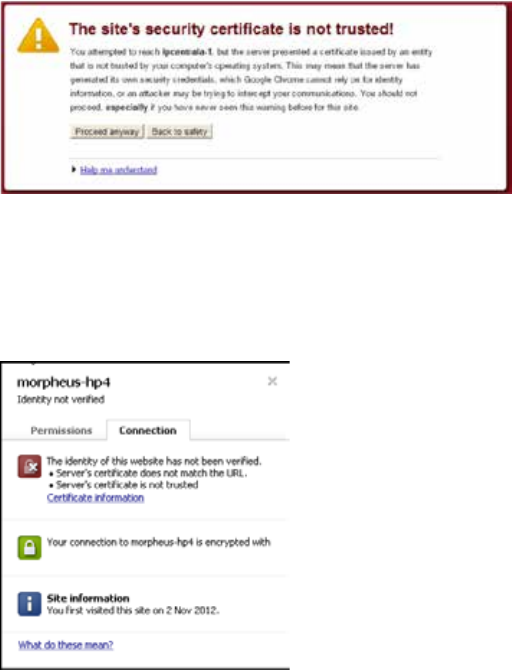
ICS 1.8 Installation & Configuration Guide
178
Configuring Google Chrome (Windows)
Trusting a self-signed certificate in Google Chrome is a two-step process. First, you export the
certificate from the browser. Next, you import the certificate into the Trusted Root Certification
Authorities store. Both these procedures are performed via Chrome menus.
To export the certificate from the browser:
1. Launch Google Chrome and enter the URL of the ICS server or cluster in the address bar.
• http://<FQDN>, where <FQDN> is the Fully Qualified Domain Name of the ICS server
cluster
• http://<hostname>, where <hostname> is the short name of the ICS server cluster
What you enter in the address bar depends on the name you used to generate the self-
signed certificate.
Note that you are automatically redirected to the secure (SSL) connection.
A warning appears indicating a problem with the SSL certificate.
2. Click on the “Proceed anyway” button.
3. Click on the padlock icon in the Chrome address bar.
Details pertaining to the warning appear in a pop-up.
4. Click on the Certificate Information link.
5. A dialog pertaining to the SSL certificate appears.
6. In the Certificate dialog, click on the Details tab, then the Copy to File button.
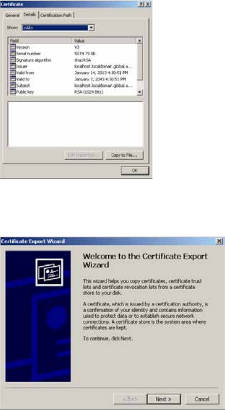
ICS 1.8 Installation & Configuration Guide
179
This starts the Certificate Export wizard.
7. Follow the prompts in the wizard to export the certificate from the browser, saving it in a
convenient temporary location, such as the local desktop.
Once you have exported the certificate, you can use the browser to add it to the Trusted
Root Certification Authorities store, as described below.
To add the certificate to the trusted certificates store:
1. Click on Google Chrome Customize icon on right edge of the address bar.
A dropdown customization menu appears.
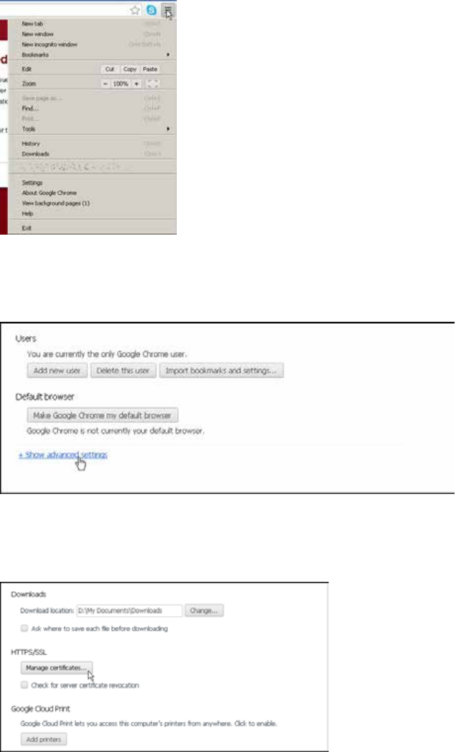
ICS 1.8 Installation & Configuration Guide
180
2. Choose Settings from the dropdown menu.
The Chrome Settings page appears.
3. Click on the “Show advanced settings” link.
The page expands to show more settings.
4. Click on the Manage
Certificates button in the HTTPS/SSL
category.
5. A Certificates dialog appears showing certificates arranged by category.
6. In the Certificates dialog, click the Import button.
The Windows Certificate Import Wizard appears.
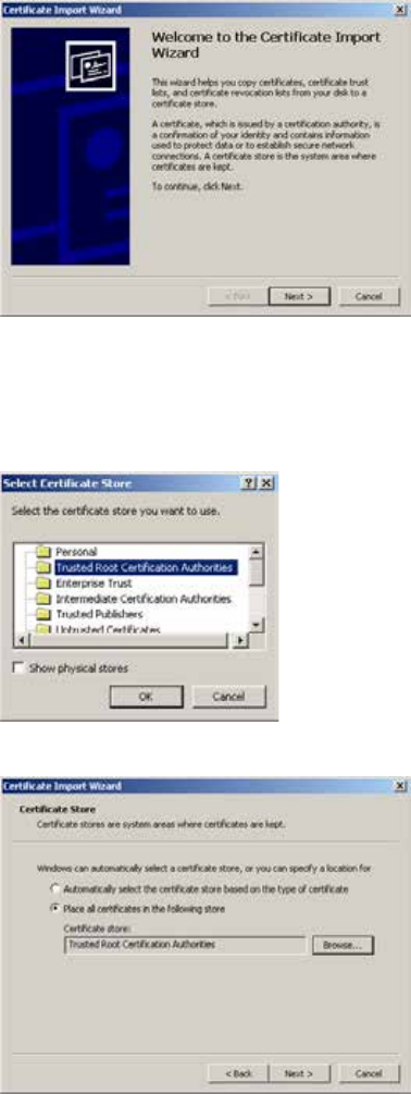
ICS 1.8 Installation & Configuration Guide
181
7. Click Next to continue, and in the File to Import dialog, click the Browse button to locate
your certificate, and click Next.
8. In the dialog that appears, select “Place all certificates in the following store”. Browse to the
“Trusted Root Certification Authorities” store and click OK to select the store.
9. The storage location you selected appears in the wizard.
Note: Be sure to place the certificate into the Trusted Root Certification Authorities store.
10. Click Next, then Finish.
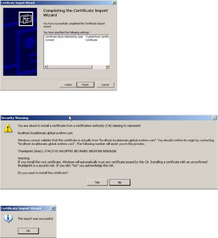
ICS 1.8 Installation & Configuration Guide
182
11. A final security warning dialog appears, asking you to confirm installation of the certificate.
Click Yes.
A confirmation dialog appears indicting success.
12. Restart Chrome and enter the FQDN of the ICS server or cluster in the address bar.
The browser loads Interplay Central without issuing certificate warnings.
Configuring Internet Explorer (Windows)
Internet Explorer provides an efficient mechanism for adding self-signed (or otherwise
untrusted) certificates to the Trusted Root Certification Authorities store.
To add a certificate to the trusted certificates store:
1. Launch Internet Explorer and enter the URL of the ICS server or cluster in the address bar.
• http://<FQDN>, where <FQDN> is the Fully Qualified Domain Name of the ICS server
cluster
• http://<hostname>, where <hostname> is the short name of the ICS server cluster
What you enter in the address bar depends on the name you used to generate the self-
signed certificate.
Note that you are automatically redirected to the secure (SSL) connection.
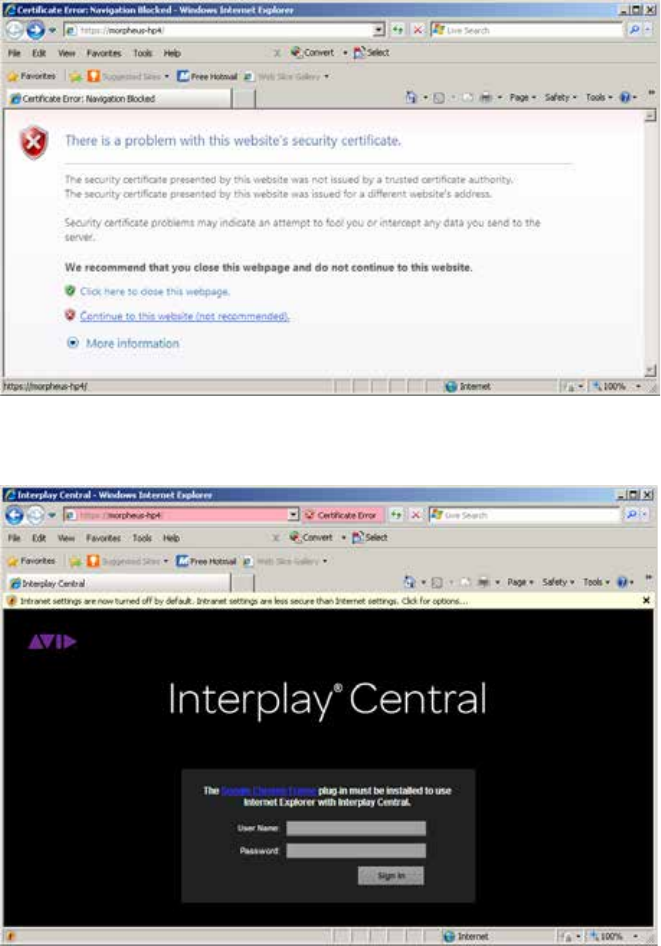
ICS 1.8 Installation & Configuration Guide
183
A warning appears indicating a problem with the SSL certificate.
2. Click on the “Continue to this website” link.
3. Click on the Certificate Error button in the address bar.
4. In the Certificate Invalid popup dialog, click on the View Certificates link.
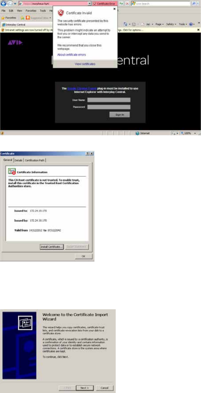
ICS 1.8 Installation & Configuration Guide
184
Details relating to the certificate are presented in a certificate dialog:
If you do not see the Install Certificate button, close IE, then right-click its icon and select
Run as Administrator.
5. In the Certificate Dialog, click on the Install Certificate… button.
The Windows Certificate Import Wizard appears.
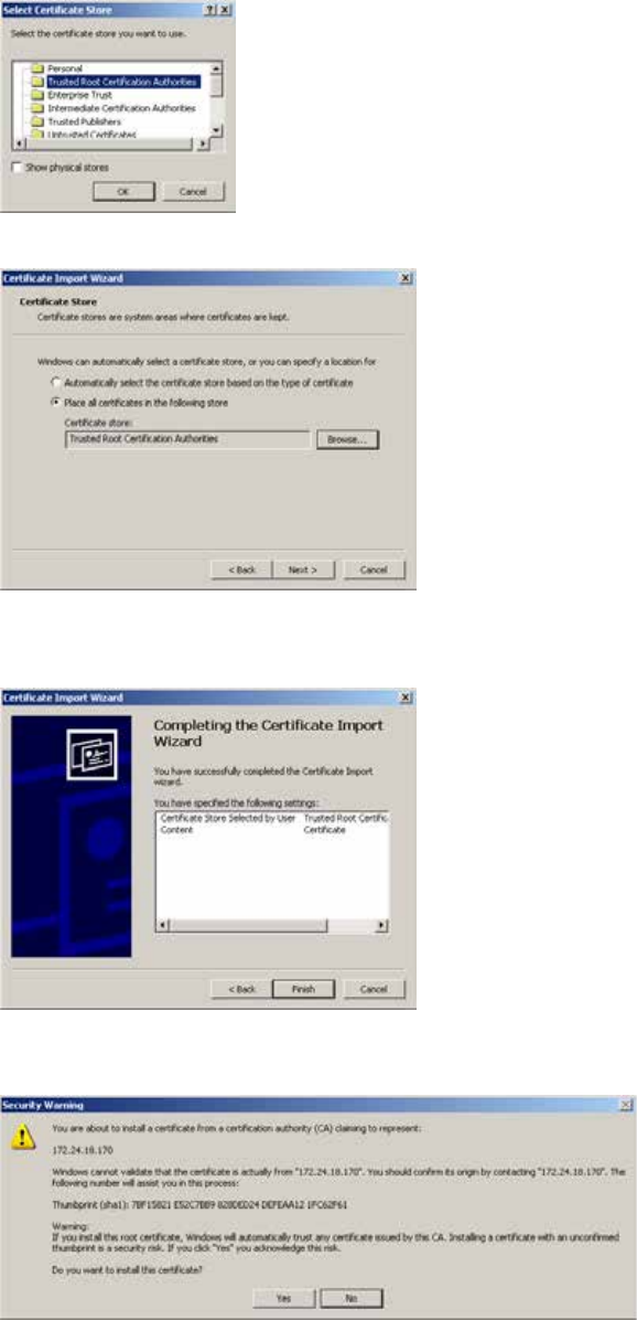
ICS 1.8 Installation & Configuration Guide
185
6. Click Next to continue, and in the dialog that appears, select “Place all certificates in the
following store”. Browse to the “Trusted Root Certification Authorities” store and click OK to
select the store.
The storage location you selected appears in the wizard.
Note: Be sure to place the certificate into the Trusted Root Certification Authorities store.
7. Click Next, then Finish.
8. A final security warning dialog appears, asking you to confirm installation of the certificate.
Click Yes.
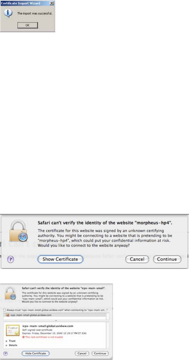
ICS 1.8 Installation & Configuration Guide
186
The Certificate Import Wizard indicates success.
9. Restart Internet Explorer and enter the FQDN of the ICS server or cluster in the address bar.
The browser loads Interplay Central without issuing certificate warnings.
Configuring Safari (Mac OS)
In Mac OS, you must add the self-signed certificate to the Mac OS system keychain. This is easily
done via the Safari browser itself.
To add a certificate to the trusted certificates store:
1. Launch Safari and enter the URL of the ICS server or cluster in the address bar.
• http://<FQDN> where <FQDN> is the Fully Qualified Domain Name of the ICS server or
cluster.
• http://<FQDN>, where <FQDN> is the Fully Qualified Domain Name of the ICS server
cluster
• http://<hostname>, where <hostname> is the short name of the ICS server cluster
What you enter in the address bar depends on the name you used to generate the self-
signed certificate.
Note that you are automatically redirected to the secure (SSL) connection.
A warning appears indicating a problem with the SSL certificate.
2. Click the Show Certificate button to display details about the certificate.
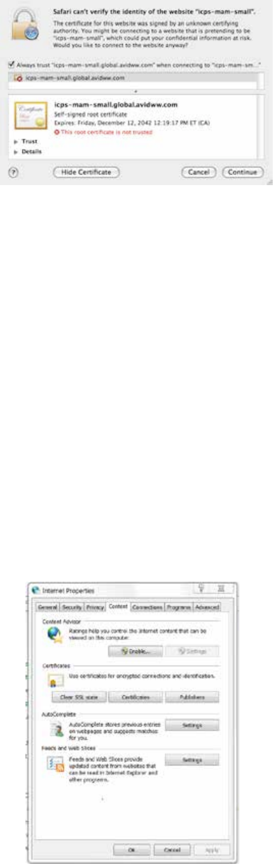
ICS 1.8 Installation & Configuration Guide
187
3. Put a checkmark in the “Always trust” checkbox and click Continue.
4. Enter the Administrator password and click OK.
The self-signed certificate is added to the Mac OS system keychain and the browser
continues to the log-in page without further complaint.
5. To view the certificate, use the Mac OS Keychain Access utility.
Launching the Windows Import SSL Certificate Directly
The procedures in this appendix have made use of the browser menus for importing SSL
certificates. However, the certificate import wizard launched from the browsers (Windows) is an
OS-level wizard. You can launch it directly from the Windows control panel. If you will be
installing the self-signed certificate into the Trusted Root Certification Authorities store on
numerous machines or devices, it may be faster to do so by launching the wizard directly.
To launch the Windows Import SSL Certificate wizard:
1. Open the Windows Control Panel.
2. Choose Internet Options.
3. In the Internet Properties dialog that appears, click the Certificates button on the Content
tab.
4. The wizard for importing certificates is launched.

ICS 1.8 Installation & Configuration Guide
188
The Interplay Central Application Properties File
The following table summarizes the entries in the Interplay Central application properties file that are
related to SSL certificates. Interplay Central makes use of these values to send SSL certificates to
browsers.
Keys Description
system.org.osgi.service.ssl.password
The password protecting the certificate within the keystore.
Must match the value given for the -storepass parameter
when you generate the new certificate.
Clear text or Jetty obfuscated (recommended).
system.org.osgi.service.ssl.keypassword
The password protecting the keystore itself.
Must match the value given for -keypass when you
generated the new keystore.
Clear text or Jetty obfuscated (recommended).
system.org.osgi.service.ssl.algorithm
The encryption algorithm.
Must match the value given for -keyalg when you generated
the new keystore.
Default is RSA.
system.org.osgi.service.https.keystore.path
The path and name of the key store file.
Must match the value given for -keystore when you
generated the new keystore.
The path is relative to the standard SSL folder used for
storing the key store file.
ICS 1.8 Installation & Configuration Guide
189
Appendix E: Migrating the UMS Database with the User
Management Utilities Tool
Some ICS upgrade paths require that you migrate your existing Windows-based User
Management Services (UMS) database to the new Linux-based ICS server. For example, updating
from Interplay Central 1.2.x to Interplay Central 1.3 (or higher) involves the decommissioning
and/or repurposing of the Windows server where middleware and UMS ran under Interplay
Central 1.2.x. To preserve the UMS database, you must migrate it from the Windows sever to
the Linux server.
Migrating the Windows UMS database to the new Linux ICS server is a straightforward process
performed using the User Management Utilities tool provided for the task. It consists of two
main steps:
1. Migrate the Database
In the first step, you copy the Windows UMS database from the Windows machine to
the RHEL server. Once there, you use the migration tool to migrate its contents into the
new Linux system.
2. Migrate the System Settings
In this step, you extract the system settings from the updated Linux UMS database and
export them into the Avid Common Service (ACS) bus.
Note: The initial installation of UMS on the Linux server creates a default user name and
password. After you migrate the database from Windows, the default user name and
password change on Linux. The default user name and password are replaced by those used
for the existing Windows database that you have migrated.
Note: If you are migrating a cluster, you only need to perform the procedures in this appendix
once, on the master node. Perform them after you have set up the fully operational ICS
server, but before you install RHEL and ICS on the other servers in the cluster. In this way, the
clustering software itself will take care of replicating the UMS database across all nodes in
the cluster.
Note: You need to log in to the Linux server as root to complete the procedures in this section.
To migrate the database:
In this procedure you copy the UMS database from the Windows machine to the Linux server,
and migrate its contents into the Linux UMS database.
1. On the Windows server that is home to your current database, open the Windows Task
Manager by pressing Ctrl-Shift-Esc.
2. The Windows Task Manager appears.
3. Locate the Interplay Central User Management service on the Services tab, right-click it
and select Stop Service.
4. Verify there is no database lock (database.lock.db) file in the UMS database directory:
ICS 1.8 Installation & Configuration Guide
190
C:\ProgramData\Avid\Avid Interplay Central User Management
Service\db
If the database lock file is present, wait for the UMS to stop completely and for the lock
file to be removed.
Note: Attempting to migrate a locked database can result in data corruption.
5. Copy the UMS database (database.h2.db) file from the Windows server to an available
directory on the new RHEL server (e.g. /tmp).
The Windows database file is located here:
C:\ProgramData\Avid\Avid Interplay Central User Management
Service\db\database.h2.db
Caution: Do not rename the database file.
6. On the RHEL server, ensure the ICS UMS is running by typing the following at the Linux
command prompt:
service avid-ums status
Output similar to the following should appear:
avid-ums (pid xxxxx) is running...
7. Start the database migration by typing the following at the Linux command prompt:
avid-ums-admin-tool -mdb [admin-password] [h2-DB-path] [postgres-
superuser-name] [postgres-superuser-password]
For example:
avid-ums-admin-tool -mdb xxxxx /tmp/database.h2.db postgres
Note the following:
• [admin-password]: This is the root password.
• [postgres-superuser-password]: Leave this field blank.
An error message informs you if you type an incorrect path for your database file.
A message informs you when the UMS database migration is complete
Migration is successfully done.
To migrate the system settings:
In this procedure you extract the system settings from the freshly updated Linux UMS database,
and export them export them into the Avid Common Service (ACS) bus.
Note: Only the system settings are migrated to the ACS bus. User settings remain in the UMS
database.
ICS 1.8 Installation & Configuration Guide
191
• Type the following command at the Linux command prompt:
avid-ums-admin-tool -ms [acs-bus-url] [ums-admin-password]
For example:
avid-ums-admin-tool -ms localhost:61616 xxxxx
In the above example, the default ACS bus URL and port is used (localhost:61616).
A message informs you when the settings migration completes:
Migration completed successfully.
If you receive an error such as the following, it indicates the incorrect host/port was
specified in the avid-ums-admin-tool command:
ERROR: Cloud bus error: Bus access factory is not available
ICS 1.8 Installation & Configuration Guide
192
Appendix F: Installing the Chrome Extension for Interplay
Central MOS Plug-Ins
Interplay Central provides support for MOS Active-X plug-ins. For example, Deko Select is a plug-
in for a newsroom computer system’s interface that allows a user, such as a reporter, to drag
and drop graphic templates directly into the story, as well as alter replaceable text or graphics in
the selected template. You can also use the Avid Deko Select plug-in to add graphics to the
video for a story sequence. Other plug-ins are available through third-party manufacturers.
These plug-ins are specific to iNEWS workflows, and they are available only in Rundown and
Story layouts.
Note: The ICS installation program installs only the container needed for Active X controls.
You need to install additional software as described in the following sections.
Setting Up Your Browser
The Chrome browser requires an extension that lets you use MOS plug-ins. The first time you
sign in to Interplay Central, a dialog box asks if you want to use MOS plug-ins.
• If you click yes, an installer is downloaded from the Interplay Central Services server.
Allow pop-ups from the Interplay Central Services server if you are informed that a pop-
up was blocked, and then refresh the page. Double-click the .exe file to install the
program.
After installation is complete, you must close Chrome and then reopen it for the
extension to be accessible by Interplay Central. Recent Chrome versions disable third-
party plug-ins. Make sure that Chrome Tools > Extensions displays Enabled next to the
Avid ActiveX extension.
• If you click no, and later want to use plug-ins, enable MOS as described below. The next
time you sign in or refresh the application, a blank window opens and the installer is
downloaded. Click the .exe file to install the extension.
Active X plug-ins are not supported in the Safari browser.
Enabling MOS
To use the plug-ins for a user you need to enable MOS in Interplay Central. Select Home > User
Settings > MOS and then select “MOS enabled.”
Installing Plug-Ins
For procedures on how to install plug-ins, see the documentation for the plug-in.
After installation and configuration, plug-ins are listed at the bottom of the Panes menu.
ICS 1.8 Installation & Configuration Guide
193
Uninstalling the Chrome Extension
If you need to uninstall the Chrome Extension, use the Windows Control Panel. Do not use the
Chrome Extensions page.
1. Click Start and select Control Panel.
2. Click Programs and Features.
3. Right-click Avid interplay Central MOS plugin and select Uninstall. Click Yes and follow
the prompts.
For more information about MOS plug-ins, see the Avid Interplay Central User’s Guide or the
Avid Interplay Central Help.
ICS 1.8 Installation & Configuration Guide
194
Appendix G: Enabling Interplay Central MOS Plug-Ins in IE9
The instructions in this appendix were produced for Internet Explorer 9.0.8112.16421 using
Google Chrome Frame 65.169.107 on Windows 7 x86_64 SP1. Updates to any of these
applications may change the steps below, including the order in which you perform them.
Once you complete the procedure, the Avid ActiveX container is available in IE9. When a MOS-
enabled user logs in, a list of their installed ActiveX plug-ins appears at the bottom of the Panes
menu. Opening a plug-in will create a new tab. (Press F5 if the tab is empty when loaded.) The
tab can be dragged out of Internet Explorer, permitting drag and drop into the IPC page.
To enable Interplay Central MOS plug-ins in IE:
1. Launch Internet Explorer and enter the URL of the ICS server (or cluster) in the address
bar (e.g. https://<hostname>).
Bypass the certificate warning, if one is present.
The Interplay Central sign-in page informs you that the Google Chrome Frame is
required.
2. Install Google Chrome Frame using the link on the sign in page.
Note: Google Chrome Frame must be installed as an administrator user. The Avid ActiveX
container also requires administrator elevation.
3. A dialog should appear indicating the ChromeFrame BHO add-on from Google Inc is
ready for use. Select Enable in that dialog.
4. Navigate once again to ICS server or cluster (e.g. https://<hostname>) and log in as a
user for whom MOS plug-ins are enabled.
Note: To enable MOS for the logged in user, in Interplay Central, select Home -> User
Settings -> MOS and then select “MOS enabled”
5. Download and run setup.exe as prompted.
If your receive a "This webpage is not available" message, refresh with F5, and then say
Yes to proceed.
Follow the instructions appearing in the Avid Interplay Central MOS plugin installation
wizard, and accept the defaults to install the extension.
ICS 1.8 Installation & Configuration Guide
195
6. Close and re-open Internet Explorer. Navigate to Interplay Central and log in as the
same user. Do not download setup.exe again. Sign out of Interplay Central and close IE.
This step forces Chrome Frame to register the Avid extension.
7. In Windows Explorer, navigate to the following directory:
C:\Users\<username>\AppData\Local\Google\Chrome Frame\User Data\iexplorer\Default
8. Open the “Preferences” file in Notepad.
9. Locate the “known_disabled” key and delete the line.
"known_disabled": [ "lmcebpepkojaapaoliodbjagahkpedph" ],
10. Search for the term "ActiveX" to find the "Avid MOS ActiveX Chrome Extension" object,
and modify the “state” value from 0 to 1.
"state": 1,
11. Save and close the Preferences file.
12. Once again, Launch IE, navigate to the ICS server or cluster (e.g. https://<hostname>),
and log in as the user for whom MOS plug-ins are enabled.
Installed ActiveX plug-ins are now visible in Interplay Central, on the Panes menu.
Sample ActiveX Object in the Preferences File
For reference, the full ActiveX object after completion of the procedure is included below. Some
values may be different for your particular installation.
"lmcebpepkojaapaoliodbjagahkpedph": {
"ack_prompt_count": 1,
"active_permissions": {
"api": [ "plugin" ]
},
"creation_flags": 1,
"from_bookmark": false,
"from_webstore": false,
"initial_keybindings_set": true,
"install_time": "13029963342661257",
"location": 3,
"manifest": {
"description": "Avid MOS ActiveX Chrome Extension",
"key":
"MIGfMA0GCSqGSIb3DQEBAQUAA4GNADCBiQKBgQCa6DtGBLy26p0nWU7mfBTutgDZpGZw0t
a30LRo1Av6J1LUgL3AxJu5BP4TJxlXXbIKd0H2X6oLgKU3GIw5+r1YKK8BKVfgjpSanEWzg
vWsbjXcnH4XVF8thXYvutkTj5telkhFmOba1UG0zauqMqpnWus9ADGyMGBUIPsTlLhXDwID
AQAB",
"manifest_version": 2,
"name": "Avid MOS ActiveX hosting plugin",
"plugins": [ {
"path": "npchmos.dll",
"public": true
} ],
"version": "1.0.1.10"
},
ICS 1.8 Installation & Configuration Guide
196
"path": "lmcebpepkojaapaoliodbjagahkpedph\\1.0.1.10_0",
"state": 1,
"was_installed_by_default": false
},
ICS 1.8 Installation & Configuration Guide
197
Appendix H: Unicast Support in Clustering
ICS clustering supports both unicast and multicast. The default configuration, as set up by the
cluster installation script (and covered in the body of this guide) is for multicast. In facilities
where the routers do not support multicast (i.e. are not multicast enabled) you must configure
the cluster for unicast.
Configuring a cluster for unicast requires altering the contents of the corosync configuration
(corosync.conf) file. The file is found here: /etc/corosync/corosync.conf.
By default, the corosync configuration file looks something like this:
totem {
version: 2
secauth: off
threads: 0
interface {
ringnumber: 0
bindnetaddr: 10.16.35.0
mcastaddr: 226.95.1.1
mcastport: 5405
}
}
The changes needed are indicated below:
totem {
version: 2
secauth: off
threads: 0
interface {
member {
memberaddr: 10.16.35.101
}
member {
memberaddr: 10.16.35.102
}
ringnumber: 0
bindnetaddr: 10.16.35.0
mcastport: 5405
}
transport: udpu
}
As illustrated by the example above, the following configuration changes are required:
1. Remove mcastaddr from the file (leave mcastport).
2. Add the new transport (that indicates unicast): udpu.
3. Create a member{} section for each node in the cluster, following the example, but
replacing the values for memberaddr with the IP address of your own cluster nodes.

ICS 1.8 Installation & Configuration Guide
198
To configure unicast support in clustering:
Note: If you are working remotely using a KVM, this is a good moment to open a separate
terminal window where you can run the cluster resource manager utility, crm_mon.
Otherwise, run the utility now and then in the same terminal where you are doing your work.
Note: Recall that DRBD runs on two nodes only: the master node, and one non-master node.
If your cluster has more than two nodes, be sure to substitute the special form of the setup-
cluster command to exclude the non-DRBD nodes from starting the PostgreSQL database.
The special form of the setup-cluster command is indicated in “Starting the Cluster Services”
on page 108.
1. On each node in the cluster, run the setup-corosync command following the instructions in
the body of this guide.
The most commonly used form of the command is provided below (for reference):
/opt/avid/cluster/bin/cluster setup-corosync
--corosync-bind-iface=eth0
--rabbitmq_master=<master>
• <master> is the master node (e.g. ics-dl360-1). This should be the same as the DRBD
master node specified earlier.
See “Starting the Cluster Services” on page 108 for details (and the appropriate form of the
setup-corsync command).
2. Stop the pacemaker services (used by corosync):
service pacemaker stop
3. Stop the clustering services via corosync:
service corosync stop
4. Edit the corosync configuration file:
vi /etc/corosync/corosync.conf
• Remove mcastaddr and mcastport from the file.
• Add the new transport (that indicates unicast): udpu.
• Create a member{} section for each node in the cluster, following the example, but
replacing the values for memberaddr with the IP addresses of your own cluster nodes.
5. Restart corosync on the node:
service corosync start
6. Restart the pacemaker service on the node:
service pacemaker start

ICS 1.8 Installation & Configuration Guide
199
7. Once you have completed the above instructions on each node in the cluster, run the setup-
cluster command on the DRBD master node only, following the instructions in the body of
this guide.
• To identify the master node, run the Cluster Resource Monitor (crm_mon)
command from any node. The node with the AvidClusterIP resource is the master
node. For details on identifying the master node, see “Observing Failover in the
Cluster” on page 137.
• The most commonly used form of the setup-cluster command is provided below (for
reference):
/opt/avid/cluster/bin/cluster setup-cluster
--cluster_ip="<cluster IP address>"
--pingable_ip="<router IP address>"
--admin_email="<comma separated e-mail list>"
--drbd_exclude="<comma separated list of non-DRBD nodes>"
See “Starting the Cluster Services” on page 108 for details (and the appropriate form of the
setup-cluster command).
Note: The final step in the procedure above (setup-cluster) is run on the DRBD master node
only.
ICS 1.8 Installation & Configuration Guide
200
Appendix I: Installing the Interplay Production License for
Interplay Central
The Avid Interplay Administrator is a client application that can be installed on any computer in
your network and then used to manage either the Interplay Engine or the Interplay Archive
Engine. You can use the Licenses view of the Interplay Administrator to install the Interplay
Production license needed for integration with Interplay Central. For more information about
this application, see the “Avid Interplay Engine and Avid Interplay Archive Engine Administrator’s
Guide”.
To install the Interplay Production license for Interplay Central:
1. Start and log in to the Interplay Administrator.
2. Make a folder for the license file on the root directory (C:\) of the Interplay Central
middleware server. For example:
C:\Interplay_Licenses
3. Insert the USB flash drive into any USB port.
If the USB flash drive does not automatically display:
a. Double-click the computer icon on the desktop.
b. Double-click the USB flash drive icon to open it.
4. Copy the license file (*.nxn) into the new folder you created.
5. In the Server section of the Interplay Administrator window, click the Licenses icon.
6. Click the Import License button.
7. Select the file and click Open. The type of licenses (J or G) are displayed in the License
Types area.

ICS 1.8 Installation & Configuration Guide
201
Appendix J: Configuring iNEWS for Integration with Interplay
Central
Before you can connect to an iNEWS newsroom computer system from an Interplay Central
workstation, you must edit two system files in iNEWS so that iNEWS recognizes Interplay Central
as a properly licensed device.
The files to edit are:
• SYSTEM.CLIENT.VERSIONS
• SYSTEM.CLIENT.WINDOWS
Note: Additional files must be edited to ensure proper licensing for iNEWS integration with the
Interplay Central mobile application. For more information, see “Appendix K: Installing and
Configuring the Avid Central Mobile Application for the iPad or iPhone” on page 205.
Verifying Interplay Central Licenses on iNEWS
Before you can use Interplay Central to connect to any back-end system, such as an iNEWS
newsroom computer system, you must ensure iNEWS is configured with the proper number of
Interplay Central devices authorized to connect to the system based on the purchased licenses.
You can view iNEWS licensing limits from the iNEWS console.
To display iNEWS licensing limits, at the console, type:
t NRCS-A$ status license
A message similar to the following will appear on your screen:
A is ONLINE and has been CONFIGURED. ID is INWS.
System is AB. Master is A.
Disk status is OK. The database is OPEN.
Site Key............. : 009999
CPUs................. : 3
Workstation addresses : 3000
Workstation resources : 1000
COM resources........ : 5
Web Access resources. : 2
Web Client resources. : 10
Web API resources.... : 5
Wire Server resources : 8
Instinct resources... : 10
Mobile devices allowed: 2000
Community Sessions... : allowed.
The three lines to pay attention to are:
• Workstation addresses—indicates how many IP and/or MAC addresses can be specified
in the SYSTEM.CLIENT.WINDOWS story. This story may be deleted from the iNEWS
ICS 1.8 Installation & Configuration Guide
202
database if Workstation addresses shows a “site” license and IP-specific restriction is not
wanted.
• Workstation resources—the number of clients that can simultaneously connect to
iNEWS, including iNEWS workstations, Interplay Central workstations, Apple iPad
tablets, and Apple iPhone devices.
• Mobile devices allowed—the number of mobile devices that can simultaneously connect
to iNEWS.
Note: Any time the iNEWS newsroom computer system is configured, your licensing information is
checked. An error message appears in iNEWS if the configuration file defines more devices than are
licensed.
To change license allowances:
• Contact an Avid sales representative.
Editing SYSTEM.CLIENT.VERSIONS
Some steps in the following procedure are conducted at the iNEWS console in superuser mode.
For more information, see “The iNEWS Console” chapter in the “iNEWS Installation and
Configuration Guide”.
To edit the SYSTEM.CLIENT.VERSIONS story in iNEWS:
1. Sign in to an iNEWS workstation as a system administrator, or any user account with
write access to the System directory.
2. Navigate to SYSTEM.CLIENT.VERSIONS and open the first story in that queue.
3. On a new line, add the version of the Interplay Central service that will run on the
Interplay Central middleware server. You must use a four-segment build number. For
example, for version Interplay Central version 1.8.0, type: 1.8.0.xx (where “xx” are the
final digits).
Note: To verify the version/build numbers for ICS, connect to an ICS server as the root
user and type ics_version at the command prompt.
Note: Installing an ICS hot fix update results in a mismatch between the build numbers
returned by the ics_version command and the build number of the ICS iNEWS JAR file
used in iNEWS validation. If you install an ICS hot fix update, do not automatically
change the value already set in SYSTEM.CLIENT.VERSIONS.
To verify the correctness of the value, refer to the Interplay Central Modules pane. In
Interplay Central, select System Settings from the Layout selector. In the Settings pane,
click Modules. Locate the entry for “com.avid.central.iNews”. It is the version number
associated with this entry that must be used in SYSTEM.CLIENT.VERSIONS.
4. Save the story.

ICS 1.8 Installation & Configuration Guide
203
5. Reconfigure the system. From the iNEWS console:
a. Select the master computer, which is typically server A.
b. Enter superuser mode, using the correct password.
The dollar sign ($) at the end of the console’s server prompt will change to a
pound sign (#).
c. Take the system offline by typing:
NRCS-A# offline
d. Reconfigure the system by typing:
NRCS-A# configure
e. When the prompt reappears, bring the system back online by typing:
NRCS-A# online
f. Press Ctrl+D to leave superuser mode.
The pound sign (#) at the end of the console’s server prompt will change back to
a dollar sign ($).
Editing SYSTEM.CLIENT.WINDOWS
The following procedure only applies to sites that are not using a “site” license as Workstation
addresses in iNEWS. You can review your site license information from the iNEWS console. For
more information, see “Verifying Interplay Central Licenses on iNEWS” above.
Some steps in the following procedure are conducted at the iNEWS console in superuser mode.
For more information, see “The iNEWS Console” chapter in the “iNEWS Installation and
Configuration Guide”.
To edit the SYSTEM.CLIENT.WINDOWS story in iNEWS:
1. Sign in to an iNEWS workstation as a system administrator, or any user account with
write access to the System directory.
2. Navigate to SYSTEM.CLIENT.WINDOWS and open the first story in that queue.
3. Add the IP address of the Interplay Central middleware server to a new line. Use a
semicolon to add helpful commentary for future reference to the end of the line.
For instance, type:
125.1.100.5 ;Interplay Central middleware server
If there are multiple middleware (Web application) servers, you will need to add the IP
address for each one on individual lines in the story.
Note: You do not need to add to SYSTEM.CLIENT.WINDOWS the IP addresses of any
Interplay Central client computers or devices.
ICS 1.8 Installation & Configuration Guide
204
4. Save the story.
5. Reconfigure the system. From the iNEWS console:
a. Select the master computer, which is typically server A.
b. Enter superuser mode, using the correct password.
The dollar sign ($) at the end of the console’s server prompt will change to a
pound sign (#).
c. Take the system offline by typing:
NRCS-A# offline
d. Reconfigure the system by typing:
NRCS-A# configure
e. When the prompt reappears, bring the system back online by typing:
NRCS-A# online
f. Press Ctrl+D to leave superuser mode.
The pound sign (#) at the end of the console’s server prompt will change back to
a dollar sign ($).

ICS 1.8 Installation & Configuration Guide
205
Appendix K: Installing and Configuring the Avid Central
Mobile Application for the iPad or iPhone
The Avid Central mobile application is a native user interface designed to run on the Apple iPad
touch-screen tablet and the Apple iPhone touch-screen phone, and enable direct, secure access
to your station’s iNEWS newsroom computer system.
You can use the Avid Central mobile application to view and approve news stories, navigate the
news directory, play video sequences associated with stories and view a show’s scripts in
presenter mode (iPad only) while signed in to your station’s iNEWS newsroom computer system.
This appendix describes the installation and configuration verification procedures necessary for
the Avid Central mobile application.
There are various connection options available when using the Avid Central mobile application:
• Wi-Fi
• Carrier-specific cellular service— for example, 3G or 4G
Note: The application automatically selects the first available connection from the list of options
according to the priority shown in the list.
Before You Begin
Before you can use the Avid Central mobile application with an iNEWS newsroom computer
system, you need to verify some important information and install the application on the
device(s).
Ensure the following tasks are completed.
¨ Confirm that iNEWS is properly configured for licensed integration with the Avid Central mobile
application.
See “Appendix J: Configuring iNEWS for Integration with Interplay Central” on page 201.
¨ Install Avid Central on the device(s).
See “Installing Avid Central on the iPad or iPhone”, below.
iNEWS Configuration for iPad and iPhone Integration
Before you can connect to an iNEWS newsroom computer system from a device running the
Avid Central mobile application, you must view and, if necessary, edit two system files in iNEWS
so that iNEWS recognizes the Avid Central mobile application as a properly licensed device.
The files to check are:
• SYSTEM.CLIENT.VERSIONS
• iNEWS configuration file
ICS 1.8 Installation & Configuration Guide
206
Editing SYSTEM.CLIENT.VERSIONS
You use the iNEWS console in superuser mode, for some steps in the following procedure. For
more information, see “The iNEWS Console” chapter in the “iNEWS Installation and
Configuration Guide”.
1. Sign in to an iNEWS workstation as a system administrator, or any user account with
write access to the System directory.
2. Navigate to SYSTEM.CLIENT.VERSIONS and open the first story in that queue.
3. Confirm that the Interplay Central server version appears as a line in the story.
4. If the version is correct, then close the story. You do not need to complete the rest of
the steps in this procedure.
5. If the version does not appear, on a new line, add the version of the Interplay Central
service that will run on the Interplay Central middleware server. You must use a four-
segment build number. For example, for version Interplay Central version 1.8.0, type:
1.8.0.xx (where “xx” are the final digits).
Note: To verify the version/build numbers for ICS, connect to an ICS server as the root
user and type ics_version at the command prompt.
Note: Installing an ICS hot fix update results in a mismatch between the build numbers
returned by the ics_version command and the build number of the ICS iNEWS JAR file
used in iNEWS validation. If you install an ICS hot fix update, do not automatically
change the value already set in SYSTEM.CLIENT.VERSIONS.
To verify the correctness of the value, refer to the Interplay Central Modules pane. In
Interplay Central, select System Settings from the Layout selector. In the Settings pane,
click Modules. Locate the entry for “com.avid.central.iNews”. It is the version number
associated with this entry that must be used in SYSTEM.CLIENT.VERSIONS.
6. Save the story.
7. Reconfigure the system. From the iNEWS console:
a. Select the master computer, which is typically server A.
b. Enter superuser mode, using the correct password.
The dollar sign ($) at the end of the console’s server prompt will change to a
pound sign (#).
c. Take the system offline by typing:
NRCS-A# offline
d. Reconfigure the system by typing:
NRCS-A# configure
e. When the prompt reappears, bring the system back online by typing:
NRCS-A# online
f. Press Ctrl+D to leave superuser mode.
ICS 1.8 Installation & Configuration Guide
207
The pound sign (#) at the end of the console’s server prompt will change back to
a dollar sign ($).
Adding iPad and iPhone Devices to the iNEWS Configuration File
The configuration file (/site/config) lists all devices, servers, and resources configured to run on
your iNEWS newsroom computer system and how they are connected. If a mobile device does
not appear in the configuration file, you cannot use it with the iNEWS newsroom computer
system.
The Avid Central mobile application uses the same G (inws) sessions in the configuration file as
other Interplay Central Web clients or as iNEWS workstations. You need to confirm that there
are enough sessions configured to handle simultaneous connections from these types of devices
available to users at your site.
Note: You need to edit the configuration file only if there are not enough sessions.
If you need to edit the configuration file, see “The iNEWS Console” and “System Configuration”
chapters in the “iNEWS Installation and Configuration Guide”. Also, some steps require use of
ed, the line editor. If you do not know how to use the line editor to modify lines in the file, see
“The Line Editor, ed” in the “iNEWS Installation and Configuration Guide”.
To edit /site/config for the Avid Central mobile application:
1. Select all servers.
Caution: Whenever you make changes to any iNEWS site file, such as the configuration
file, you must select all servers in your system at the console. Unlike database stories,
site files are not automatically mirrored from one computer’s disk to another.
2. Type the following and press Enter:
ed /site/config
The editor displays a numerical value indicating the file size expressed as the number of
characters, including spaces and returns.
The configuration file has two major sections: the host section and the device section.
For the Avid Central mobile integration, you must edit both.
3. In the host section, add a resource list entry, using the following format.
reslist <device # or range> ; <comments>
For example:
reslist 2001:2005 ;iNEWS and IPC sessions
Note: For dual or triple server systems, the configuration file has multiple host sections
to define which server handles which devices under various circumstances. You should
add resource list entries to each host section.
ICS 1.8 Installation & Configuration Guide
208
4. In the INWS sessions section, add a resource line for the devices, using the following
format:
inws <device # or range> - gnews <device name> ;<comment>
For example:
inws 2001:2005 - gnews –
5. Type w to write (save) your changes to disk.
Caution: Do not use an uppercase W in this step. Uppercase W appends the file you edit to
the existing file. The resulting file might be unreadable and lead to problems with running
your iNEWS system.
6. Type q to quit the line editor.
7. (Optional) Use the configure command to test your configuration changes, using the
following syntax:
configure /site/config <system> <computer>
For example:
configure /site/config ab a
When the prompt reappears, the configuration file has been checked. If the system
detects any errors, it displays appropriate “bad configuration” messages.
8. Reconfigure the system. From the iNEWS console:
a. Select the master computer, which is typically server A.
b. Enter superuser mode, using the correct password.
The dollar sign ($) at the end of the console’s server prompt changes to a pound
sign (#).
c. Take the system offline by typing: NRCS-A# offline
d. Reconfigure the system by typing: NRCS-A# configure
e. When the prompt reappears, bring the system back online by typing: NRCS-A#
online
f. Press Ctrl+D to leave superuser mode.
The pound sign (#) at the end of the console’s server prompt changes back to a
dollar sign ($).
Installing Avid Central on the iPad or iPhone
The following procedure assumes licensing, setup, and configuration of the Interplay Central and
iNEWS servers have already been completed.
To install Avid Central on the iPad or iPhone:
ICS 1.8 Installation & Configuration Guide
209
1. Open iTunes (the Apple market).
2. Locate the Avid Central mobile application.
3. Tap Download.
When the Avid Central mobile application is installed on your touch-screen device, an
icon representing the application appears on the home screen. You can move it
elsewhere like the icons for other applications.

ICS 1.8 Installation & Configuration Guide
210
Appendix L: Installation Pre-Flight Checklist
This section lists all the information needed to perform the installation. Please gather the
information from the customer before beginning the installation process. Take care to collect all
the information relevant to the ICS deployment you are undertaking.
Default Password Information
The installation scripts establish login credentials for RHEL and Interplay Central at the
administrator level. These enable you to carry out the work of installing and configuring ICS with
the needed level of authority. It is highly recommended you secure the system by changing the
default passwords at the first opportunity, as described in this guide.
Note: Obtain new administrator passwords that are in accordance with the customer’s
own password enforcement policies.
For Linux the following default log in credentials are created:
¨ Linux administrator user name and password (case-sensitive):
Default administrator user name: root
Default root password:
Note: Please contact your Avid representative for the default root password.
For Interplay Central the following default login credentials are created:
¨ Interplay Central administrator user name and password (case-sensitive):
Default administrator user name: Administrator
Default administrtor password:
Note: Please contact your Avid representative for the default Administrator password.
Contact Information
Before beginning, please obtain contact information for the following people:
Avid Contact:
Phone Number: Email:
In-House IT Specialist:
Phone Number: Email:
Network Administrator:

ICS 1.8 Installation & Configuration Guide
211
Phone Number: Email:
Pre-Flight Product Team Contact:
Phone Number: Email:
Interplay MAM Administrator:
Phone Number: Email:
Interplay MAM Configuration Specialist:
Phone Number: Email:
Hardware
¨ Windows Machine (32-bit or 64-bit) (e.g. Window XP/Vista/7 laptop or desktop
computer): Used to download software from the Internet and prepare the USB key.
¨ 8GB USB Key: Used to contain RHEL OS, the ICS installation scripts, etc.
¨ ICS Servers: Already installed or ready to install in the machine room where they will
reside.
Software
¨ ICS installation package: Interplay_Central_Services_<version>_Linux.zip
¨ RHEL 6.3 installation DVD or image (.iso) file
¨ GlusterFS files (needed for clustering)
If you do not have all the software you need, see “Obtaining the Software” on page 43.
Network Settings
Obtain the following information from your network administrator and enter it in the spaces
provided. These items are needed by Linux.
¨ Facility Static IP address:
¨ Facility Netmask:
¨ Default Gateway IP:
¨ Primary DNS server:

ICS 1.8 Installation & Configuration Guide
212
¨ Secondary DNS server:
¨ DNS Search Path Domain:
NTP Time Server
Record the Network Time Protocol (NTP) time server address, for use in synchronizing the
system clock. This is optional for a single-server deployment, but a must-have for a cluster. For
reasons of security, it is recommended you synchronize to in-house NTP servers only.
¨ In-House NTP server:
ICS Server Information
For each ICS server record the information indicated in this section. You might find it helpful to
print this page, once for each server.
Please indicate how you will be gaining access the server(s):
¨ Directly by connecting a monitor and keyboard to the server(s)
¨ Directly via KVM (keyboard, video and mouse) device, or comparable solution
¨ Indirectly using SSH from another machine’s command prompt or shell. (Once
network connectivity is established.)
For each server, record the following information in the spaces provided.
Server Machine Name (e.g. ics-dl360-1, ics-dl380-1):
Note: This is the host name only (e.g. ics-dl360-1),that is, the name of the machine. Do not
use the fully qualified domain names (e.g. ics-dl360-1.mydomain.com or ics-dl360-
1.mydomain.local)
Type:
¨ HP Proliant DL360 G8
¨ HP ProliantDL380 G7
¨ Other:
Hard Drives1:
Number of Hard Drives Used for the OS (e.g. 2):
Number of Hard Drives Reserved for the Cache (e.g. 6):
System Drives Bay and Slots (e.g. Bay 1 Slots 1 &2):
Cache Drives Bay and Slots (e.g. Bay 2 Slots 1 to 8):
1 The number and location of the hard drives might only be known once you boot the server and enter the
BIOS screens.

ICS 1.8 Installation & Configuration Guide
213
Network Interface Cards (NICs) Present in the Enclosure:
¨ Myricom 10GigE
¨ Qualified Intel PRO/1000 (e1000) based GigE NIC
¨ Other:
Indicate the Network Interface Card (NICs) used to connect ICS to the network:
¨ Myricom 10GigE
¨ Qualified Intel PRO/1000 (e1000) based GigE NIC
¨ Other:
Cluster Information
¨ Are you setting up a cluster? YES / NO
¨ Does your network already use multicasting? YES / NO
¨ How many ICS servers will be in the cluster?
¨ Provide the machine names for each one (e.g. ics-dl360-1, ics-dl380-1):
Note: This is the host name only (e.g. ics-dl360-1),that is, the name of the machine. Do not
use the fully qualified domain names (e.g. ics-dl360-1.mydomain.com or ics-dl360-
1.mydomain.local)
¨ Obtain the following information from your network administrator and enter it in the
spaces provided:
• The static IP address allocated for the cluster (e.g.: 192.XXX.XXX.XXX):
• The host name associated with the static IP address (e.g.: ics-cluster):
• If your network already uses multicasting, obtain a distinct multicast address for use
by ICS. If there is no other multicast activity on the network, write “use default
multicast address”:
Note: The “default” multicast address used for ICS clustering is 239.192.1.1. This is set by
the setup-corosync script, if you do not specify one. If an ICS cluster already exists, and
your new cluster will co-exist alongside it (in a test setting, for example), use a different
multicsast address for the new cluster (e.g. 239.192.1.2).

ICS 1.8 Installation & Configuration Guide
214
• An IP address that is always available/pingable (e.g. a network router):
• The email addresses of those to whom automated notifications about the status of
the cluster should be sent (e.g. network administrators):
Port Bonding. If you will be using a cluster for Interplay MAM, enter the port bonding IP address
below:
iNEWS Information
¨ iNEWS Server Hostname:
¨ iNEWS login credentials (user name & password):
¨ Are MOS plug-ins used? YES / NO
Interplay Central provides support for MOS Active-X plug-ins. For example, Deko Select is a
plug-in for a newsroom computer system’s interface that allows a user to drag and drop
graphic templates directly into the story. These plug-ins are specific to iNEWS workflows,
and they are available only in Rundown and Story layouts.
Interplay Central and Interplay Sphere Information
¨ Interplay Credentials (e.g. ics-interplay):
Log into Interplay Central as an Interplay administrator, and create a unique set of user
credentials (user name and password) for use by the ICS software, with the following
attributes:
• The credentials should not be shared with any human users
• Permission to read all folders in the workgroup
• We recommend using a name that indicates the purpose of the user credentials
(e.g. ics-interplay)
¨ Interplay Sphere Playback User
Interplay Sphere requires a unique user name and password reserved for it. They are used
to enable Sphere playback. Interplay Sphere supplies these credentials to the ICPS Player,
which uses them to request video from the ICS server.

ICS 1.8 Installation & Configuration Guide
215
o Sphere Playback user name:
o Sphere Playback password:
¨ Interplay Central UI
The Interplay Central UI is used to configure ICS.
For future reference, record the IP address of Interplay Central (e.g. http://<hostname> or
http://<cluster-IP>) as determined during the installation process2:
Interplay Central default administrator user name and password (case-sensitive):
Default administrator user name: Administrator
Default root password:
Note: Please contact your Avid representative for the default Interplay Central
Administrator password.
Interplay Production Information
Obtain the following information from the Interplay administrator and enter it in the spaces
provided.
¨ Are you making use of an Interplay Production Media Indexer (MI) High-Availability
Group (HAG)? YES / NO
Note: Interplay Central connects to the MI leader in the HAG. (The MI with the highest
weight is the leader of the HAG.) It does not participate in HAG redundancy.
¨ Interplay Production (Interplay Engine) server hostname:
¨ User name reserved for ICS (e.g. ics-interplay):
¨ Password for above user:
¨ Interplay Central Distribution Service – Service URL
(e.g. https://<server>:<port>):
¨ Media Indexer host name:
Note: If the Interplay media indexer is connected to a High Availability Group (HAG), enter
the host name of the active Media Indexer.
¨ Interplay Workgroup name:
Lookup server host name:
Will you be making use of multi-resolution workflows? YES / NO
2 The IP Address of the ICS Portal will only be known once you install the ICS software.

ICS 1.8 Installation & Configuration Guide
216
ISIS Information
¨ What kind of connection will you make to the ISIS:
¨ Zone 1 (direct connection)
¨ Zone 2 (layer 2 network switch)
¨ Zone 3 (layer 3 network switch – recommended)
¨ Zone 2 & Zone 3 Information
If connecting the ICS server(s) to the ISIS via a Zone 2 connection, obtain the following
information from your ISIS and/or network administrator:
ISIS System Director(s) IP addresses:
¨ Indicate the speed of the connection to the ISIS:
¨ GigE
¨ 10GigE
¨ Is more than network connection available? YES / NO
If yes, obtain the following information from your ISIS and/or network administrator and
enter it in the spaces provided.
NIC device name used for ISIS connection (e.g. eth0):
All other active NIC device names not used by ISIS (e.g. eth1, eth2):
¨ ISIS Credentials (e.g. ics-isis):
While logged in to the ISIS as administrator, create a unique set of user credentials for use
by the ICS software, with the following attributes:
• The credentials should not be shared with any human users
• Permission to read all workspaces, and to write to the workspace flagged as VO (voice-
over) workspace
• We recommend using a name that indicates the purpose of the user credentials (e.g. ics-
isis)
• In multi-ISIS setups, create the same user credentials across all ISIS storage systems.
¨ Other ISIS Information
Obtain the following information from your ISIS administrator and enter it in the spaces
provided.

ICS 1.8 Installation & Configuration Guide
217
Virtual ISIS host name(s):
User name created for ICS (e.g. ics-interplay):
Password for above user:
Media Indexer host name:
Interplay MAM Information
¨ Are you setting up port bonding? YES / NO
¨ If yes, enter the name you will apply to the port bonding interface (e.g. bond0):
¨ Also, record the device name for each NIC Ethernet port to be used in port bonding (e.g.
eth0, eth1, etc.):
¨ Interplay MAM user name for ICPS Player (e.g. MAM):
¨ Interplay MAM password for ICPS Player:
From your Interplay MAM system administrator, obtain the following information:
¨ Path to the Essence Pool to which ICS is being given access:
Note: The above information is found in the Interplay MAM Administrator interface, under the
Essence Management Configuration tab. Look for the “MORPHEUS” entry.
Note: It is likely that ICS has been given access to more than one MAM essence pool. Be sure to
mount all the associated file systems.

ICS 1.8 Installation & Configuration Guide
218
Copyright and Disclaimer
Product specifications are subject to change without notice and do not represent a commitment on the part of Avid Technology, Inc.
The software described in this document is furnished under a license agreement. You can obtain a copy of that license by visiting the Avid Web
site at www.avid.com. The terms of that license are also available in the product in the same directory as the software. The software may not
be reverse assembled and may be used or copied only in accordance with the terms of the license agreement. It is against the law to copy the
software on any medium except as specifically allowed in the license agreement.
No part of this document may be reproduced or transmitted in any form or by any means, electronic or mechanical, including photocopying
and recording, for any purpose without the express written permission of Avid Technology, Inc.
Copyright © 2013 Avid Technology, Inc. and its licensors. All rights reserved.
Attn. Government User(s). Restricted Rights Legend
U.S. GOVERNMENT RESTRICTED RIGHTS. This Software and its documentation are “commercial computer software” or “commercial computer
software documentation.” In the event that such Software or documentation is acquired by or on behalf of a unit or agency of the U.S.
Government, all rights with respect to this Software and documentation are subject to the terms of the License Agreement, pursuant to FAR
§12.212(a) and/or DFARS §227.7202-1(a), as applicable.
This product may be protected by one or more U.S. and non-U.S patents. Details are available at www.avid.com/patents.
Trademarks
Adrenaline, AirSpeed, ALEX, Alienbrain, Archive, Archive II, Assistant Avid, Avid Unity, Avid Unity ISIS, Avid VideoRAID, CaptureManager,
CountDown, Deko, DekoCast, FastBreak, Flexevent, FXDeko, iNEWS, iNEWS Assign, iNEWSControlAir, Instinct, IntelliRender, Intelli-Sat, Intelli-
sat Broadcasting Recording Manager, Interplay, ISIS, IsoSync, LaunchPad, LeaderPlus, ListSync, MachineControl, make manage move | media,
Media Composer, NewsCutter, NewsView, OMF, OMF Interchange, Open Media Framework, Open Media Management, SIDON, SimulPlay,
SimulRecord, SPACE, SPACEShift, Sundance Digital, Sundance, Symphony, Thunder, Titansync, Titan, UnityRAID, Video the Web Way,
VideoRAID, VideoSPACE, VideoSpin, and Xdeck are either registered trademarks or trademarks of Avid Technology, Inc. in the United States
and/or other countries.
All other trademarks contained herein are the property of their respective owners.
ICS 1.8 Installation and Configuration Guide • 30 July 2014
• This document is distributed by Avid in online (electronic) form only, and is not available for purchase in printed form.
