Avid ISIS 7500 | 7000 Setup Guide 4.6 SG V4 6 EN
User Manual: avid ISIS 7000 - 4.6 - Setup Guide Free User Guide for Avid ISIS Software, Manual
Open the PDF directly: View PDF ![]() .
.
Page Count: 221 [warning: Documents this large are best viewed by clicking the View PDF Link!]
- Title Page
- Contents
- Avid Software and Hardware Install Checklist
- Avid ISIS 7500 | 7000 System Overview
- Connecting the ISIS Equipment
- Installing Software and Configuring 10-Gb Link Aggregation
- IP Addressing Overview
- Configuration Overview
- Software Installation
- Loading the Software
- Product Recovery Needs to be Copied to the USB Flash Drive
- Activating the License Key
- Installing the Optional Application Key
- Creating an Active File System on the System Director
- Binding the Storage Managers
- Checking the Status of the System Director
- Installing Software on the Engines
- Engine Does Not Appear in Add Engine List
- Check Switch IP Address
- Loading Client Software
- Configuring Client Software
- Adding a Remote Host for Zone 3 and 4 Clients
- Avid Interplay Authentication
- Configuring a 10-Gb Link Aggregation Group
- Avid ISIS Software Licensing
- Configuring Two Stacks of ISIS Engines
- Configuring the System for Failover
- Status LEDs and Stacking Problems
- Avid ISIS 7500 | 7000 Upgrade Guidelines
- Avid ISIS Upgrade Utility
- Avid ISIS Recommended Maintenance
- Adding and Replacing Hardware
- Using the Product Recovery USB for 64-bit System Directors
- Specifications and Notices
- Dimensions and Weight
- Environment
- Electrical
- Uninterruptible Power Supply (UPS)
- Supported Cabling
- Warnings and Cautions
- FCC Notice
- Canadian Notice (Avis Canadien)
- LED Safety Notices
- European Union Declaration of Conformity
- Disposal of Waste Equipment by Users in the European Union
- Argentina Conformity
- Australia and New Zealand EMC Regulations
- Japan EMC Regulations
- Korean EMC Regulations
- Taiwan EMC Regulations
- Index

Avid® ISIS® 7500 | 7000
Setup Guide
2
Legal Notices
Product specifications are subject to change without notice and do not represent a commitment on the part of Avid Technology, Inc.
This product is subject to the terms and conditions of a software license agreement provided with the software. The product may
only be used in accordance with the license agreement.
Avid ISIS products or portions thereof are protected by one or more of the following United States Patents: 6,374,336; 6,415,373;
6,449,688; 7,660,947; 6,760,808; 6,785,768; 7,111,115; 7,487,309; 7,660,947; 7,844,775; 7,917,696; 8,140,755 Other patents are
pending.
Avid products or portions thereof are protected by one or more of the following European Patents: 1040419.
Other patents are pending.
Part of the software embedded in this product is gSOAP software.
Portions created by gSOAP are Copyright (C) 2001-2004 Robert A. van Engelen, Genivia inc. All Rights Reserved.
THE SOFTWARE IN THIS PRODUCT WAS IN PART PROVIDED BY GENIVIA INC AND ANY EXPRESS OR IMPLIED
WARRANTIES, INCLUDING, BUT NOT LIMITED TO, THE IMPLIED WARRANTIES OF MERCHANTABILITY AND FITNESS FOR
A PARTICULAR PURPOSE ARE DISCLAIMED. IN NO EVENT SHALL THE AUTHOR BE LIABLE FOR ANY DIRECT, INDIRECT,
INCIDENTAL, SPECIAL, EXEMPLARY, OR CONSEQUENTIAL DAMAGES (INCLUDING, BUT NOT LIMITED TO,
PROCUREMENT OF SUBSTITUTE GOODS OR SERVICES; LOSS OF USE, DATA, OR PROFITS; OR BUSINESS
INTERRUPTION) HOWEVER CAUSED AND ON ANY THEORY OF LIABILITY, WHETHER IN CONTRACT, STRICT LIABILITY,
OR TORT (INCLUDING NEGLIGENCE OR OTHERWISE) ARISING IN ANY WAY OUT OF THE USE OF THIS SOFTWARE, EVEN
IF ADVISED OF THE POSSIBILITY OF SUCH DAMAGE.
This document is protected under copyright law. An authorized licensee of Avid ISIS 7000 may reproduce this publication for the
licensee’s own use in learning how to use the software. This document may not be reproduced or distributed, in whole or in part, for
commercial purposes, such as selling copies of this document or providing support or educational services to others. This document
is supplied as a guide for Avid ISIS 7000. Reasonable care has been taken in preparing the information it contains. However, this
document may contain omissions, technical inaccuracies, or typographical errors. Avid Technology, Inc. does not accept
responsibility of any kind for customers’ losses due to the use of this document. Product specifications are subject to change without
notice.
Copyright © 2010 Avid Technology, Inc. and its licensors. All rights reserved.
The following disclaimer is required by Sam Leffler and Silicon Graphics, Inc. for the use of their TIFF library:
Copyright © 1988–1997 Sam Leffler
Copyright © 1991–1997 Silicon Graphics, Inc.
Permission to use, copy, modify, distribute, and sell this software [i.e., the TIFF library] and its documentation for any purpose is
hereby granted without fee, provided that (i) the above copyright notices and this permission notice appear in all copies of the
software and related documentation, and (ii) the names of Sam Leffler and Silicon Graphics may not be used in any advertising or
publicity relating to the software without the specific, prior written permission of Sam Leffler and Silicon Graphics.
THE SOFTWARE IS PROVIDED “AS-IS” AND WITHOUT WARRANTY OF ANY KIND, EXPRESS, IMPLIED OR OTHERWISE,
INCLUDING WITHOUT LIMITATION, ANY WARRANTY OF MERCHANTABILITY OR FITNESS FOR A PARTICULAR PURPOSE.
IN NO EVENT SHALL SAM LEFFLER OR SILICON GRAPHICS BE LIABLE FOR ANY SPECIAL, INCIDENTAL, INDIRECT OR
CONSEQUENTIAL DAMAGES OF ANY KIND, OR ANY DAMAGES WHATSOEVER RESULTING FROM LOSS OF USE, DATA OR
PROFITS, WHETHER OR NOT ADVISED OF THE POSSIBILITY OF DAMAGE, AND ON ANY THEORY OF LIABILITY, ARISING
OUT OF OR IN CONNECTION WITH THE USE OR PERFORMANCE OF THIS SOFTWARE.
The following disclaimer is required by the Independent JPEG Group:
This software is based in part on the work of the Independent JPEG Group.
This Software may contain components licensed under the following conditions:
Copyright (c) 1989 The Regents of the University of California. All rights reserved.
Redistribution and use in source and binary forms are permitted provided that the above copyright notice and this paragraph are
duplicated in all such forms and that any documentation, advertising materials, and other materials related to such distribution and
use acknowledge that the software was developed by the University of California, Berkeley. The name of the University may not be
used to endorse or promote products derived from this software without specific prior written permission. THIS SOFTWARE IS
PROVIDED ``AS IS'' AND WITHOUT ANY EXPRESS OR IMPLIED WARRANTIES, INCLUDING, WITHOUT LIMITATION, THE
IMPLIED WARRANTIES OF MERCHANTABILITY AND FITNESS FOR A PARTICULAR PURPOSE.
Copyright (C) 1989, 1991 by Jef Poskanzer.
3
Permission to use, copy, modify, and distribute this software and its documentation for any purpose and without fee is hereby
granted, provided that the above copyright notice appear in all copies and that both that copyright notice and this permission notice
appear in supporting documentation. This software is provided "as is" without express or implied warranty.
Copyright 1995, Trinity College Computing Center. Written by David Chappell.
Permission to use, copy, modify, and distribute this software and its documentation for any purpose and without fee is hereby
granted, provided that the above copyright notice appear in all copies and that both that copyright notice and this permission notice
appear in supporting documentation. This software is provided "as is" without express or implied warranty.
Copyright 1996 Daniel Dardailler.
Permission to use, copy, modify, distribute, and sell this software for any purpose is hereby granted without fee, provided that the
above copyright notice appear in all copies and that both that copyright notice and this permission notice appear in supporting
documentation, and that the name of Daniel Dardailler not be used in advertising or publicity pertaining to distribution of the software
without specific, written prior permission. Daniel Dardailler makes no representations about the suitability of this software for any
purpose. It is provided "as is" without express or implied warranty.
Modifications Copyright 1999 Matt Koss, under the same license as above.
Copyright (c) 1991 by AT&T.
Permission to use, copy, modify, and distribute this software for any purpose without fee is hereby granted, provided that this entire
notice is included in all copies of any software which is or includes a copy or modification of this software and in all copies of the
supporting documentation for such software.
THIS SOFTWARE IS BEING PROVIDED "AS IS", WITHOUT ANY EXPRESS OR IMPLIED WARRANTY. IN PARTICULAR,
NEITHER THE AUTHOR NOR AT&T MAKES ANY REPRESENTATION OR WARRANTY OF ANY KIND CONCERNING THE
MERCHANTABILITY OF THIS SOFTWARE OR ITS FITNESS FOR ANY PARTICULAR PURPOSE.
This product includes software developed by the University of California, Berkeley and its contributors.
The following disclaimer is required by Paradigm Matrix:
Portions of this software licensed from Paradigm Matrix.
The following disclaimer is required by Ray Sauers Associates, Inc.:
“Install-It” is licensed from Ray Sauers Associates, Inc. End-User is prohibited from taking any action to derive a source code
equivalent of “Install-It,” including by reverse assembly or reverse compilation, Ray Sauers Associates, Inc. shall in no event be liable
for any damages resulting from reseller’s failure to perform reseller’s obligation; or any damages arising from use or operation of
reseller’s products or the software; or any other damages, including but not limited to, incidental, direct, indirect, special or
consequential Damages including lost profits, or damages resulting from loss of use or inability to use reseller’s products or the
software for any reason including copyright or patent infringement, or lost data, even if Ray Sauers Associates has been advised,
knew or should have known of the possibility of such damages.
The following disclaimer is required by Videomedia, Inc.:
“Videomedia, Inc. makes no warranties whatsoever, either express or implied, regarding this product, including warranties with
respect to its merchantability or its fitness for any particular purpose.”
“This software contains V-LAN ver. 3.0 Command Protocols which communicate with V-LAN ver. 3.0 products developed by
Videomedia, Inc. and V-LAN ver. 3.0 compatible products developed by third parties under license from Videomedia, Inc. Use of this
software will allow “frame accurate” editing control of applicable videotape recorder decks, videodisc recorders/players and the like.”
The following disclaimer is required by Altura Software, Inc. for the use of its Mac2Win software and Sample Source
Code:
©1993–1998 Altura Software, Inc.
The following disclaimer is required by Interplay Entertainment Corp.:
The “Interplay” name is used with the permission of Interplay Entertainment Corp., which bears no responsibility for Avid products.
This product includes portions of the Alloy Look & Feel software from Incors GmbH.
This product includes software developed by the Apache Software Foundation (http://www.apache.org/).
© DevelopMentor
4
This product may include the JCifs library, for which the following notice applies:
JCifs © Copyright 2004, The JCIFS Project, is licensed under LGPL (http://jcifs.samba.org/). See the LGPL.txt file in the Third Party
Software directory on the installation CD.
Avid Interplay contains components licensed from LavanTech. These components may only be used as part of and in connection
with Avid Interplay.
Attn. Government User(s). Restricted Rights Legend
U.S. GOVERNMENT RESTRICTED RIGHTS. This Software and its documentation are “commercial computer software” or
“commercial computer software documentation.” In the event that such Software or documentation is acquired by or on behalf of a
unit or agency of the U.S. Government, all rights with respect to this Software and documentation are subject to the terms of the
License Agreement, pursuant to FAR §12.212(a) and/or DFARS §227.7202-1(a), as applicable.
Trademarks
003, 192 Digital I/O, 192 I/O, 96 I/O, 96i I/O, Adrenaline, AirSpeed, ALEX, Alienbrain, AME, AniMatte, Archive, Archive II, Assistant
Station, AudioPages, AudioStation, AutoLoop, AutoSync, Avid, Avid Active, Avid Advanced Response, Avid DNA, Avid DNxcel, Avid
DNxHD, Avid DS Assist Station, Avid Ignite, Avid Liquid, Avid Media Engine, Avid Media Processor, Avid MEDIArray, Avid Mojo, Avid
Remote Response, Avid Unity, Avid Unity ISIS, Avid VideoRAID, AvidRAID, AvidShare, AVIDstripe, AVX, Beat Detective, Beauty
Without The Bandwidth, Beyond Reality, BF Essentials, Bomb Factory, Bruno, C|24, CaptureManager, ChromaCurve,
ChromaWheel, Cineractive Engine, Cineractive Player, Cineractive Viewer, Color Conductor, Command|24, Command|8,
Control|24, Cosmonaut Voice, CountDown, d2, d3, DAE, D-Command, D-Control, Deko, DekoCast, D-Fi, D-fx, Digi 002, Digi 003,
DigiBase, Digidesign, Digidesign Audio Engine, Digidesign Development Partners, Digidesign Intelligent Noise Reduction,
Digidesign TDM Bus, DigiLink, DigiMeter, DigiPanner, DigiProNet, DigiRack, DigiSerial, DigiSnake, DigiSystem, Digital
Choreography, Digital Nonlinear Accelerator, DigiTest, DigiTranslator, DigiWear, DINR, DNxchange, Do More, DPP-1, D-Show, DSP
Manager, DS-StorageCalc, DV Toolkit, DVD Complete, D-Verb, Eleven, EM, Euphonix, EUCON, EveryPhase, Expander,
ExpertRender, Fader Pack, Fairchild, FastBreak, Fast Track, Film Cutter, FilmScribe, Flexevent, FluidMotion, Frame Chase, FXDeko,
HD Core, HD Process, HDpack, Home-to-Hollywood, HYBRID, HyperSPACE, HyperSPACE HDCAM, iKnowledge, Image
Independence, Impact, Improv, iNEWS, iNEWS Assign, iNEWS ControlAir, InGame, Instantwrite, Instinct, Intelligent Content
Management, Intelligent Digital Actor Technology, IntelliRender, Intelli-Sat, Intelli-sat Broadcasting Recording Manager, InterFX,
Interplay, inTONE, Intraframe, iS Expander, iS9, iS18, iS23, iS36, ISIS, IsoSync, LaunchPad, LeaderPlus, LFX, Lightning, Link &
Sync, ListSync, LKT-200, Lo-Fi, MachineControl, Magic Mask, Make Anything Hollywood, make manage move | media, Marquee,
MassivePack, Massive Pack Pro, Maxim, Mbox, Media Composer, MediaFlow, MediaLog, MediaMix, Media Reader, Media
Recorder, MEDIArray, MediaServer, MediaShare, MetaFuze, MetaSync, MIDI I/O, Mix Rack, Moviestar, MultiShell, NaturalMatch,
NewsCutter, NewsView, NewsVision, Nitris, NL3D, NLP, NSDOS, NSWIN, OMF, OMF Interchange, OMM, OnDVD, Open Media
Framework, Open Media Management, Painterly Effects, Palladium, Personal Q, PET, Podcast Factory, PowerSwap, PRE,
ProControl, ProEncode, Profiler, Pro Tools, Pro Tools|HD, Pro Tools LE, Pro Tools M-Powered, Pro Transfer, QuickPunch,
QuietDrive, Realtime Motion Synthesis, Recti-Fi, Reel Tape Delay, Reel Tape Flanger, Reel Tape Saturation, Reprise, Res Rocket
Surfer, Reso, RetroLoop, Reverb One, ReVibe, Revolution, rS9, rS18, RTAS, Salesview, Sci-Fi, Scorch, ScriptSync,
SecureProductionEnvironment, Serv|GT, Serv|LT, Shape-to-Shape, ShuttleCase, Sibelius, SimulPlay, SimulRecord, Slightly Rude
Compressor, Smack!, Soft SampleCell, Soft-Clip Limiter, SoundReplacer, SPACE, SPACEShift, SpectraGraph, SpectraMatte,
SteadyGlide, Streamfactory, Streamgenie, StreamRAID, SubCap, Sundance, Sundance Digital, SurroundScope, Symphony, SYNC
HD, SYNC I/O, Synchronic, SynchroScope, Syntax, TDM FlexCable, TechFlix, Tel-Ray, Thunder, TimeLiner, Titansync, Titan, TL
Aggro, TL AutoPan, TL Drum Rehab, TL Everyphase, TL Fauxlder, TL In Tune, TL MasterMeter, TL Metro, TL Space, TL Utilities,
tools for storytellers, Transit, TransJammer, Trillium Lane Labs, TruTouch, UnityRAID, Vari-Fi, Video the Web Way, VideoRAID,
VideoSPACE, VTEM, Work-N-Play, Xdeck, X-Form, Xmon and XPAND! are either registered trademarks or trademarks of Avid
Technology, Inc. in the United States and/or other countries.
Apple, Macintosh, and Safari are either registered trademarks or trademarks of Apple Computer, Inc., registered in the U.S. and
other countries. HP is a registered trademark of Hewlett-Packard Company. Intel is a registered trademark of Intel Corporation. Java
is a trademark of Sun Microsystems in the United States and/or other countries. Kingston is a registered trademarks of Kingston
Technology Corporation. All other marks may be the property of their respective titleholders. Windows is either a registered
trademark or trademark of Microsoft Corporation in the United States and/or other countries. All other trademarks contained herein
are the property of their respective owners.
Avid ISIS 7500 | 7000 Setup Guide • 0175-30978-00 Rev. B • December 2013 • Created 12/6/13
5
Contents
Using This Guide. . . . . . . . . . . . . . . . . . . . . . . . . . . . . . . . . . . . . . . . . . . . . . . 12
Symbols and Conventions . . . . . . . . . . . . . . . . . . . . . . . . . . . . . . . . . . . . . . . . . . . . . . . 12
If You Need Help. . . . . . . . . . . . . . . . . . . . . . . . . . . . . . . . . . . . . . . . . . . . . . . . . . . . . . . 13
Accessing the Online Documentation . . . . . . . . . . . . . . . . . . . . . . . . . . . . . . . . . . . . . . . 13
Avid Training Services . . . . . . . . . . . . . . . . . . . . . . . . . . . . . . . . . . . . . . . . . . . . . . . . . . 14
Chapter 1 Avid Software and Hardware Install Checklist . . . . . . . . . . . . . . . . . . . . . . . 15
Software Upgrade . . . . . . . . . . . . . . . . . . . . . . . . . . . . . . . . . . . . . . . . . . . . . . . . . . . . . . 15
Hardware Upgrade . . . . . . . . . . . . . . . . . . . . . . . . . . . . . . . . . . . . . . . . . . . . . . . . . . . . . 17
New System Director and Engine Installation . . . . . . . . . . . . . . . . . . . . . . . . . . . . . . . . . 18
Switch and ISB Upgrade Utility . . . . . . . . . . . . . . . . . . . . . . . . . . . . . . . . . . . . . . . . . . . . 19
Recreating a File Systems . . . . . . . . . . . . . . . . . . . . . . . . . . . . . . . . . . . . . . . . . . . . . . . 19
Chapter 1 Avid ISIS 7500 | 7000 System Overview . . . . . . . . . . . . . . . . . . . . . . . . . . . . 21
Hardware Overview and Naming Convention . . . . . . . . . . . . . . . . . . . . . . . . . . . . . . . . . 21
System Director. . . . . . . . . . . . . . . . . . . . . . . . . . . . . . . . . . . . . . . . . . . . . . . . . . . . . . . . 24
System Director Front Panel . . . . . . . . . . . . . . . . . . . . . . . . . . . . . . . . . . . . . . . . . . 24
System Director Rear Panel. . . . . . . . . . . . . . . . . . . . . . . . . . . . . . . . . . . . . . . . . . . 26
Second System Director. . . . . . . . . . . . . . . . . . . . . . . . . . . . . . . . . . . . . . . . . . . . . . 26
Engine . . . . . . . . . . . . . . . . . . . . . . . . . . . . . . . . . . . . . . . . . . . . . . . . . . . . . . . . . . . . . . . 27
Engine Front View . . . . . . . . . . . . . . . . . . . . . . . . . . . . . . . . . . . . . . . . . . . . . . . . . . 27
Engine Rear View. . . . . . . . . . . . . . . . . . . . . . . . . . . . . . . . . . . . . . . . . . . . . . . . . . . 28
Power Supplies . . . . . . . . . . . . . . . . . . . . . . . . . . . . . . . . . . . . . . . . . . . . . . . . . . . . 28
Integrated Ethernet Switches . . . . . . . . . . . . . . . . . . . . . . . . . . . . . . . . . . . . . . . . . . 29
Storage Configurations . . . . . . . . . . . . . . . . . . . . . . . . . . . . . . . . . . . . . . . . . . . . . . . . . . 30
Storage Group Size . . . . . . . . . . . . . . . . . . . . . . . . . . . . . . . . . . . . . . . . . . . . . . . . . 30
Chunk Size Support With ISB . . . . . . . . . . . . . . . . . . . . . . . . . . . . . . . . . . . . . . 31
Adding an ISB to the File System . . . . . . . . . . . . . . . . . . . . . . . . . . . . . . . . . . . 31
Adding or Removing ISBs (Mirrored or RAID). . . . . . . . . . . . . . . . . . . . . . . . . . 31
6
Moving Workspaces Between Storage Groups. . . . . . . . . . . . . . . . . . . . . . . . . 31
Mirrored Storage Groups, Single ISB Failure . . . . . . . . . . . . . . . . . . . . . . . . . . 32
RAID-6 Storage Groups . . . . . . . . . . . . . . . . . . . . . . . . . . . . . . . . . . . . . . . . . . . . . . 32
RAID-6 Storage Groups, Single ISB Failure . . . . . . . . . . . . . . . . . . . . . . . . . . . 33
RAID-6 Storage Groups, Dual ISB Failure . . . . . . . . . . . . . . . . . . . . . . . . . . . . 34
Automatic Redistribution on Disk Failure . . . . . . . . . . . . . . . . . . . . . . . . . . . . . . . . . . . . 34
Client . . . . . . . . . . . . . . . . . . . . . . . . . . . . . . . . . . . . . . . . . . . . . . . . . . . . . . . . . . . . . . . . 35
Network Zone Configurations . . . . . . . . . . . . . . . . . . . . . . . . . . . . . . . . . . . . . . . . . . . . . 36
Zone 1 Clients (Direct Connected). . . . . . . . . . . . . . . . . . . . . . . . . . . . . . . . . . . . . . 37
Zone 2 Clients (Indirect Connect) Configuration . . . . . . . . . . . . . . . . . . . . . . . . . . . 38
Zone 1 and Zone 2 Clients Mixed Configuration . . . . . . . . . . . . . . . . . . . . . . . . . . . 40
Zone 3 and Zone 4 Client Configuration . . . . . . . . . . . . . . . . . . . . . . . . . . . . . . . . . 41
Link Aggregation Support. . . . . . . . . . . . . . . . . . . . . . . . . . . . . . . . . . . . . . . . . . . . . 42
Cabling . . . . . . . . . . . . . . . . . . . . . . . . . . . . . . . . . . . . . . . . . . . . . . . . . . . . . . . . . . . . . . 43
Connecting the Engine CX-4 Cable . . . . . . . . . . . . . . . . . . . . . . . . . . . . . . . . . . . . . 43
Removing the Avid Engine Interconnect Cable . . . . . . . . . . . . . . . . . . . . . . . . . . . . 43
10-Gb Link Aggregation Overview . . . . . . . . . . . . . . . . . . . . . . . . . . . . . . . . . . . . . . 44
Supported in Link Aggregation . . . . . . . . . . . . . . . . . . . . . . . . . . . . . . . . . . . . . . . . 45
Load Balancing. . . . . . . . . . . . . . . . . . . . . . . . . . . . . . . . . . . . . . . . . . . . . . . . . . . . . 45
Failover. . . . . . . . . . . . . . . . . . . . . . . . . . . . . . . . . . . . . . . . . . . . . . . . . . . . . . . . . . . 45
Recommended Topologies . . . . . . . . . . . . . . . . . . . . . . . . . . . . . . . . . . . . . . . . . . . 46
Supported Functionality . . . . . . . . . . . . . . . . . . . . . . . . . . . . . . . . . . . . . . . . . . . . . . 46
Other Functionality . . . . . . . . . . . . . . . . . . . . . . . . . . . . . . . . . . . . . . . . . . . . . . . . . . 46
Chapter 2 Connecting the ISIS Equipment. . . . . . . . . . . . . . . . . . . . . . . . . . . . . . . . . . . 47
Rack-Mounting the Equipment . . . . . . . . . . . . . . . . . . . . . . . . . . . . . . . . . . . . . . . . . . . . 47
Rack-Mounting Examples . . . . . . . . . . . . . . . . . . . . . . . . . . . . . . . . . . . . . . . . . . . . 47
Installing Rack-Mount Rails and Brackets . . . . . . . . . . . . . . . . . . . . . . . . . . . . . . . . 50
Rack-mount Requirements . . . . . . . . . . . . . . . . . . . . . . . . . . . . . . . . . . . . . . . . 51
Positioning the server in the Rack. . . . . . . . . . . . . . . . . . . . . . . . . . . . . . . . . . . 52
Separating the Slide Rails . . . . . . . . . . . . . . . . . . . . . . . . . . . . . . . . . . . . . . . . . 53
Attaching Inner Slide Rails to the System Director . . . . . . . . . . . . . . . . . . . . . . 53
Attaching the Outer Rails to a Square-Hole Rack . . . . . . . . . . . . . . . . . . . . . . . 54
Attaching the Outer Rails to a Round-Hole Rack . . . . . . . . . . . . . . . . . . . . . . . 56
7
Securing the System Director in a Rack . . . . . . . . . . . . . . . . . . . . . . . . . . . . . . 58
Mounting the Engine . . . . . . . . . . . . . . . . . . . . . . . . . . . . . . . . . . . . . . . . . . . . . 59
Installing Blades and Power Supplies . . . . . . . . . . . . . . . . . . . . . . . . . . . . . . . . . . . . . . . 60
Installing IXS and ISS Switches . . . . . . . . . . . . . . . . . . . . . . . . . . . . . . . . . . . . . . . . 62
Connecting a Keyboard, Monitor, and Mouse. . . . . . . . . . . . . . . . . . . . . . . . . . . . . . . . . 62
Connecting the Optional Application Key . . . . . . . . . . . . . . . . . . . . . . . . . . . . . . . . . . . . 63
Connecting Power to Equipment. . . . . . . . . . . . . . . . . . . . . . . . . . . . . . . . . . . . . . . . . . . 64
Connecting Power Cords . . . . . . . . . . . . . . . . . . . . . . . . . . . . . . . . . . . . . . . . . . . . . 65
Three 20-Amp V AC Circuits for Three Engines . . . . . . . . . . . . . . . . . . . . . . . . . . . 65
Three 20-Amp V AC Circuits for Two Engines . . . . . . . . . . . . . . . . . . . . . . . . . . . . . 66
Two 20-Amp V AC Circuits for Two Engines . . . . . . . . . . . . . . . . . . . . . . . . . . . . . . 66
Turning System On and Off . . . . . . . . . . . . . . . . . . . . . . . . . . . . . . . . . . . . . . . . . . . 67
Connecting ISIS Hardware . . . . . . . . . . . . . . . . . . . . . . . . . . . . . . . . . . . . . . . . . . . . . . . 67
Engine Configuration v2.x Hardware Guidelines . . . . . . . . . . . . . . . . . . . . . . . . . . . 68
Setting-Up Network Addresses In the Stack . . . . . . . . . . . . . . . . . . . . . . . . . . . . . . 69
Two-Engine Stacking . . . . . . . . . . . . . . . . . . . . . . . . . . . . . . . . . . . . . . . . . . . . . . . . 71
Three- to Twelve-Engine Stacking Summary With v2.x Switches . . . . . . . . . . . . . . 73
Three- to Twelve-Engine Connections With v2.x Switches . . . . . . . . . . . . . . . . . . . 74
Hi-Gig Link Aggregation Group . . . . . . . . . . . . . . . . . . . . . . . . . . . . . . . . . . . . . . . . 79
Chapter 3 Installing Software and Configuring 10-Gb Link Aggregation . . . . . . . . . . 81
IP Addressing Overview . . . . . . . . . . . . . . . . . . . . . . . . . . . . . . . . . . . . . . . . . . . . . . . . . 81
Configuration Overview. . . . . . . . . . . . . . . . . . . . . . . . . . . . . . . . . . . . . . . . . . . . . . . . . . 84
Software Installation . . . . . . . . . . . . . . . . . . . . . . . . . . . . . . . . . . . . . . . . . . . . . . . . . . . . 85
Loading the Software . . . . . . . . . . . . . . . . . . . . . . . . . . . . . . . . . . . . . . . . . . . . . . . . 85
Product Recovery Needs to be Copied to the USB Flash Drive . . . . . . . . . . . . . . . 87
Activating the License Key . . . . . . . . . . . . . . . . . . . . . . . . . . . . . . . . . . . . . . . . . . . . 87
Installing the Optional Application Key . . . . . . . . . . . . . . . . . . . . . . . . . . . . . . . . . . . 87
Creating an Active File System on the System Director. . . . . . . . . . . . . . . . . . . . . . 88
Binding the Storage Managers. . . . . . . . . . . . . . . . . . . . . . . . . . . . . . . . . . . . . . . . . 89
Checking the Status of the System Director. . . . . . . . . . . . . . . . . . . . . . . . . . . . . . . 90
Installing Software on the Engines. . . . . . . . . . . . . . . . . . . . . . . . . . . . . . . . . . . . . . 91
Engine Does Not Appear in Add Engine List . . . . . . . . . . . . . . . . . . . . . . . . . . . . . . 94
Check Switch IP Address . . . . . . . . . . . . . . . . . . . . . . . . . . . . . . . . . . . . . . . . . . . . . 95
8
Loading Client Software . . . . . . . . . . . . . . . . . . . . . . . . . . . . . . . . . . . . . . . . . . . . . . 96
Configuring Client Software . . . . . . . . . . . . . . . . . . . . . . . . . . . . . . . . . . . . . . . . . . . 98
Adding a Remote Host for Zone 3 and 4 Clients. . . . . . . . . . . . . . . . . . . . . . . . . . . . . . 100
Avid Interplay Authentication. . . . . . . . . . . . . . . . . . . . . . . . . . . . . . . . . . . . . . . . . . . . . 101
Configuring a 10-Gb Link Aggregation Group. . . . . . . . . . . . . . . . . . . . . . . . . . . . . . . . 101
Chapter 4 Avid ISIS Software Licensing. . . . . . . . . . . . . . . . . . . . . . . . . . . . . . . . . . . . 105
What You Need to Activate the ISIS Software License. . . . . . . . . . . . . . . . . . . . . . . . . 106
License Activation Using an Internet Connection . . . . . . . . . . . . . . . . . . . . . . . . . . . . . 106
License Activation Without an Internet Connection. . . . . . . . . . . . . . . . . . . . . . . . . . . . 108
Deactivating the License . . . . . . . . . . . . . . . . . . . . . . . . . . . . . . . . . . . . . . . . . . . . . . . . 111
License Requirement with Host Name Change . . . . . . . . . . . . . . . . . . . . . . . . . . . . . . 111
Chapter 5 Configuring Two Stacks of ISIS Engines . . . . . . . . . . . . . . . . . . . . . . . . . . 112
ISIS Two Stack Configuration . . . . . . . . . . . . . . . . . . . . . . . . . . . . . . . . . . . . . . . . . . . . 113
External Switch Link Aggregation Connection Guidelines . . . . . . . . . . . . . . . . . . . 115
IP Address Classes . . . . . . . . . . . . . . . . . . . . . . . . . . . . . . . . . . . . . . . . . . . . . . . . 116
IP Addressing With Two Stacks . . . . . . . . . . . . . . . . . . . . . . . . . . . . . . . . . . . . . . . 116
Static IP Addresses Available . . . . . . . . . . . . . . . . . . . . . . . . . . . . . . . . . . . . . 118
Connecting Two Stacks of Engines . . . . . . . . . . . . . . . . . . . . . . . . . . . . . . . . . . . . . . . 118
Setting-Up Two Stacks. . . . . . . . . . . . . . . . . . . . . . . . . . . . . . . . . . . . . . . . . . . . . . 119
Reconfiguring One Stack into Two Stacks . . . . . . . . . . . . . . . . . . . . . . . . . . . . . . . 119
Chapter 6 Configuring the System for Failover . . . . . . . . . . . . . . . . . . . . . . . . . . . . . . 122
System Director Failover. . . . . . . . . . . . . . . . . . . . . . . . . . . . . . . . . . . . . . . . . . . . . . . . 122
Enabling a System Director . . . . . . . . . . . . . . . . . . . . . . . . . . . . . . . . . . . . . . . . . . 123
Setting IP Addresses for Crossover Link . . . . . . . . . . . . . . . . . . . . . . . . . . . . . . . . . . . 123
Configure a Failover Connection. . . . . . . . . . . . . . . . . . . . . . . . . . . . . . . . . . . . . . . . . . 124
Stopping and Restarting the System Directors . . . . . . . . . . . . . . . . . . . . . . . . . . . . . . . 132
Binding Order for Health Monitoring . . . . . . . . . . . . . . . . . . . . . . . . . . . . . . . . . . . . . . . 133
Chapter 7 Status LEDs and Stacking Problems . . . . . . . . . . . . . . . . . . . . . . . . . . . . . 135
LED Locations and Colors . . . . . . . . . . . . . . . . . . . . . . . . . . . . . . . . . . . . . . . . . . . . . . 135
LED Summaries . . . . . . . . . . . . . . . . . . . . . . . . . . . . . . . . . . . . . . . . . . . . . . . . . . . . . . 136
Recovering from Stacking Problems. . . . . . . . . . . . . . . . . . . . . . . . . . . . . . . . . . . . . . . 138
Set One Switch Back to Default . . . . . . . . . . . . . . . . . . . . . . . . . . . . . . . . . . . . . . . 138
Rebuilding the Stack . . . . . . . . . . . . . . . . . . . . . . . . . . . . . . . . . . . . . . . . . . . . . . . 139
9
Chapter 8 Avid ISIS 7500 | 7000 Upgrade Guidelines . . . . . . . . . . . . . . . . . . . . . . . . . 141
Health Check. . . . . . . . . . . . . . . . . . . . . . . . . . . . . . . . . . . . . . . . . . . . . . . . . . . . . . . . . 141
Software Upgrade . . . . . . . . . . . . . . . . . . . . . . . . . . . . . . . . . . . . . . . . . . . . . . . . . . . . . 142
Component Requirements From Previous ISIS 7500 | 7000 Releases . . . . . . . . . 144
ISIS 7500 | 7000 Upgrades . . . . . . . . . . . . . . . . . . . . . . . . . . . . . . . . . . . . . . . . . . 144
Copying the Metadata to the New Default Location On the System Director . . . . 149
Avid ISIS Software Installation From the USB Flash Drive . . . . . . . . . . . . . . . . . . 150
Intel Network Driver and BIOS Update. . . . . . . . . . . . . . . . . . . . . . . . . . . . . . . . . . 152
64-bit System Director BIOS Upgrade. . . . . . . . . . . . . . . . . . . . . . . . . . . . . . . 152
Intel RAID Controller Driver Update . . . . . . . . . . . . . . . . . . . . . . . . . . . . . . . . 152
Record IP Addresses on the System Director . . . . . . . . . . . . . . . . . . . . . . . . . . . . 154
Post Upgrade System Verification . . . . . . . . . . . . . . . . . . . . . . . . . . . . . . . . . . . . . . . . 155
Preupgrade Information . . . . . . . . . . . . . . . . . . . . . . . . . . . . . . . . . . . . . . . . . . . . . . . . 158
Zone 2 Switch Information . . . . . . . . . . . . . . . . . . . . . . . . . . . . . . . . . . . . . . . . . . . 158
System Director Information. . . . . . . . . . . . . . . . . . . . . . . . . . . . . . . . . . . . . . . . . . 159
ISIS Engine/Switch Information . . . . . . . . . . . . . . . . . . . . . . . . . . . . . . . . . . . . . . . 160
On Site Spares . . . . . . . . . . . . . . . . . . . . . . . . . . . . . . . . . . . . . . . . . . . . . . . . . . . . 162
Spares Checklist . . . . . . . . . . . . . . . . . . . . . . . . . . . . . . . . . . . . . . . . . . . . . . . . . . 163
Additional spares for a comprehensive spares parts list: . . . . . . . . . . . . . . . . 163
Chapter 9 Avid ISIS Upgrade Utility . . . . . . . . . . . . . . . . . . . . . . . . . . . . . . . . . . . . . . . 164
Overview and Requirements. . . . . . . . . . . . . . . . . . . . . . . . . . . . . . . . . . . . . . . . . . . . . 164
Functional Description . . . . . . . . . . . . . . . . . . . . . . . . . . . . . . . . . . . . . . . . . . . . . . 164
Software Component Design . . . . . . . . . . . . . . . . . . . . . . . . . . . . . . . . . . . . . . . . . 165
Software Interface . . . . . . . . . . . . . . . . . . . . . . . . . . . . . . . . . . . . . . . . . . . . . . . . . . . . . 166
FTP Server Section . . . . . . . . . . . . . . . . . . . . . . . . . . . . . . . . . . . . . . . . . . . . . . . . 167
Install Control Section . . . . . . . . . . . . . . . . . . . . . . . . . . . . . . . . . . . . . . . . . . . . . . 168
Monitoring Section . . . . . . . . . . . . . . . . . . . . . . . . . . . . . . . . . . . . . . . . . . . . . . . . . 168
Running the Avid ISIS Upgrade Utility . . . . . . . . . . . . . . . . . . . . . . . . . . . . . . . . . . . . . 169
Chapter 10 Avid ISIS Recommended Maintenance . . . . . . . . . . . . . . . . . . . . . . . . . . . . 171
Minimum Storage Space Requirement . . . . . . . . . . . . . . . . . . . . . . . . . . . . . . . . . . . . . 171
Daily Maintenance . . . . . . . . . . . . . . . . . . . . . . . . . . . . . . . . . . . . . . . . . . . . . . . . . . . . 171
Weekly Maintenance. . . . . . . . . . . . . . . . . . . . . . . . . . . . . . . . . . . . . . . . . . . . . . . . . . . 173
Monthly Maintenance . . . . . . . . . . . . . . . . . . . . . . . . . . . . . . . . . . . . . . . . . . . . . . . . . . 174
10
Redistribution Guidelines . . . . . . . . . . . . . . . . . . . . . . . . . . . . . . . . . . . . . . . . . . . . . . . 174
Saving ISIS Metadata . . . . . . . . . . . . . . . . . . . . . . . . . . . . . . . . . . . . . . . . . . . . . . . . . . 175
Available Utilities . . . . . . . . . . . . . . . . . . . . . . . . . . . . . . . . . . . . . . . . . . . . . . . . . . . . . . 176
Client Manager Maintenance . . . . . . . . . . . . . . . . . . . . . . . . . . . . . . . . . . . . . . . . . 176
Status Indicators and Troubleshooting. . . . . . . . . . . . . . . . . . . . . . . . . . . . . . . . . . 177
Complete Server Room Shutdown. . . . . . . . . . . . . . . . . . . . . . . . . . . . . . . . . . . . . 177
False Link Aggregation Alerts . . . . . . . . . . . . . . . . . . . . . . . . . . . . . . . . . . . . . . . . 178
Symptoms . . . . . . . . . . . . . . . . . . . . . . . . . . . . . . . . . . . . . . . . . . . . . . . . . . . . 178
Displayed Link Alert Message . . . . . . . . . . . . . . . . . . . . . . . . . . . . . . . . . . . . . 178
Restart All Procedure . . . . . . . . . . . . . . . . . . . . . . . . . . . . . . . . . . . . . . . . . . . 179
Chapter 11 Adding and Replacing Hardware . . . . . . . . . . . . . . . . . . . . . . . . . . . . . . . . . 181
Adding Hardware . . . . . . . . . . . . . . . . . . . . . . . . . . . . . . . . . . . . . . . . . . . . . . . . . . . . . 181
Adding an Engine . . . . . . . . . . . . . . . . . . . . . . . . . . . . . . . . . . . . . . . . . . . . . . . . . . . . . 182
Replacing an Engine Switch . . . . . . . . . . . . . . . . . . . . . . . . . . . . . . . . . . . . . . . . . . . . . 183
Replacing an Engine . . . . . . . . . . . . . . . . . . . . . . . . . . . . . . . . . . . . . . . . . . . . . . . . . . . 184
Replacing an Internal System Director Drive . . . . . . . . . . . . . . . . . . . . . . . . . . . . . . . . 186
Replacing the System Director . . . . . . . . . . . . . . . . . . . . . . . . . . . . . . . . . . . . . . . . . . . 187
Replacing the Network Switch . . . . . . . . . . . . . . . . . . . . . . . . . . . . . . . . . . . . . . . . . . . 190
Chapter 12 Using the Product Recovery USB for 64-bit System Directors. . . . . . . . . 192
Creating a Product Recovery USB Flash Drive . . . . . . . . . . . . . . . . . . . . . . . . . . . . . . 192
Reinstalling the Windows Storage Server 2008 R2 Operating System . . . . . . . . . . . . 194
Configuring the System Drive Using Windows 2008 Storage Server Setup . . . . . . . . . 196
Chapter 13 Specifications and Notices. . . . . . . . . . . . . . . . . . . . . . . . . . . . . . . . . . . . . . 198
Dimensions and Weight . . . . . . . . . . . . . . . . . . . . . . . . . . . . . . . . . . . . . . . . . . . . . . . . 198
Environment . . . . . . . . . . . . . . . . . . . . . . . . . . . . . . . . . . . . . . . . . . . . . . . . . . . . . . . . . 198
Electrical . . . . . . . . . . . . . . . . . . . . . . . . . . . . . . . . . . . . . . . . . . . . . . . . . . . . . . . . . . . . 198
Uninterruptible Power Supply (UPS). . . . . . . . . . . . . . . . . . . . . . . . . . . . . . . . . . . . . . . 199
Supported Cabling . . . . . . . . . . . . . . . . . . . . . . . . . . . . . . . . . . . . . . . . . . . . . . . . . . . . 199
Appendix A Safety and Regulatory Information . . . . . . . . . . . . . . . . . . . . . . . . . . . . . . . 203
Warnings and Cautions. . . . . . . . . . . . . . . . . . . . . . . . . . . . . . . . . . . . . . . . . . . . . . . . . 203
FCC Notice . . . . . . . . . . . . . . . . . . . . . . . . . . . . . . . . . . . . . . . . . . . . . . . . . . . . . . . . . . 204
Class A Equipment. . . . . . . . . . . . . . . . . . . . . . . . . . . . . . . . . . . . . . . . . . . . . . . . . 204
Modifications . . . . . . . . . . . . . . . . . . . . . . . . . . . . . . . . . . . . . . . . . . . . . . . . . . . . . 205
11
Cables . . . . . . . . . . . . . . . . . . . . . . . . . . . . . . . . . . . . . . . . . . . . . . . . . . . . . . . . . . 205
Canadian Notice (Avis Canadien) . . . . . . . . . . . . . . . . . . . . . . . . . . . . . . . . . . . . . . . . . 205
Class A Equipment. . . . . . . . . . . . . . . . . . . . . . . . . . . . . . . . . . . . . . . . . . . . . . . . . 205
LED Safety Notices . . . . . . . . . . . . . . . . . . . . . . . . . . . . . . . . . . . . . . . . . . . . . . . . . . . . 205
European Union Declaration of Conformity. . . . . . . . . . . . . . . . . . . . . . . . . . . . . . . . . . 206
Disposal of Waste Equipment by Users in the European Union. . . . . . . . . . . . . . . . . . 208
Argentina Conformity . . . . . . . . . . . . . . . . . . . . . . . . . . . . . . . . . . . . . . . . . . . . . . . . . . 208
Australia and New Zealand EMC Regulations . . . . . . . . . . . . . . . . . . . . . . . . . . . . . . . 208
Japan EMC Regulations . . . . . . . . . . . . . . . . . . . . . . . . . . . . . . . . . . . . . . . . . . . . . . . . 209
Class A Equipment. . . . . . . . . . . . . . . . . . . . . . . . . . . . . . . . . . . . . . . . . . . . . . . . . 209
Korean EMC Regulations . . . . . . . . . . . . . . . . . . . . . . . . . . . . . . . . . . . . . . . . . . . . . . . 209
Class A Equipment. . . . . . . . . . . . . . . . . . . . . . . . . . . . . . . . . . . . . . . . . . . . . . . . . 209
Taiwan EMC Regulations . . . . . . . . . . . . . . . . . . . . . . . . . . . . . . . . . . . . . . . . . . . . . . . 209
Index . . . . . . . . . . . . . . . . . . . . . . . . . . . . . . . . . . . . . . . . . . . . . . . . . . . . . . . . 215
Using This Guide
The Avid ISIS® media network provides a high-performance distributed file system that contains
high-capacity shared media storage for workgroups of connected Avid® editing workstations.
nThis document describes the features for all Avid ISIS 7500 | 7000 shared storage networks.
Therefore, your system might not contain certain features that are covered in the documentation.
Symbols and Conventions
Avid documentation uses the following symbols and conventions:
Symbol or Convention Meaning or Action
nA note provides important related information, reminders,
recommendations, and strong suggestions.
cA caution means that a specific action you take could cause harm to
your computer or cause you to lose data.
wA warning describes an action that could cause you physical harm.
Follow the guidelines in this document or on the unit itself when
handling electrical equipment.
> This symbol indicates menu commands (and subcommands) in the
order you select them. For example, File > Import means to open the
File menu and then select the Import command.
This symbol indicates a single-step procedure. Multiple arrows in a list
indicate that you perform one of the actions listed.
(Windows) or (Macintosh) This text indicates that the information applies only to the specified
operating system, either Windows or Macintosh OS X.
Bold font Bold font is primarily used in task instructions to identify user interface
items and keyboard sequences.
Italic font Italic font is used to emphasize certain words and to indicate variables.
Courier Bold font
Courier Bold font identifies text that you type.

If You Need Help
13
If You Need Help
If you are having trouble using your Avid product:
1. Retry the action, carefully following the instructions given for that task in this guide. It is
especially important to check each step of your workflow.
2. Check the latest information that might have become available after the documentation was
published.
New information would be found in the ReadMe file supplied on your Avid software
installation kit as a PDF document and is also available online.
You should always check online for the most up-to-date release notes or ReadMe
because the online version is updated whenever new information becomes available. To
view the online versions, visit the Knowledge Base at www.avid.com/US/support.
3. Check the documentation that came with your Avid application or your hardware for
maintenance or hardware-related issues.
4. Visit the online Knowledge Base at www.avid.com/US/support. Online services are
available 24 hours per day, 7 days per week. Search this online Knowledge Base to find
answers, to view error messages, to access troubleshooting tips, to download updates, and to
read or join online message-board discussions.
Accessing the Online Documentation
The Avid ISIS online documentation contains all the product documentation in PDF format. You
can access the documentation in the AvidISISDocumentation folder on the Avid ISIS installer
kit. You need to download and install Acrobat Reader on your Avid ISIS before you can access
the PDF documentation.
nYou need to download and install Acrobat Reader on your Avid ISIS 5000 before you can access
the PDF documentation.
To access the online documentation from the installer kit:
1. Insert your Avid ISIS USB flash drive with the Avid ISIS software kit into the USB port.
2. Navigate to the [USB flash drive]:\.AvidISISDocumentation folder, and double-click the
PDF file for the document you want to view.
Ctrl+key or mouse action Press and hold the first key while you press the last key or perform the
mouse action. For example, Command+Option+C or Ctrl+drag.
Symbol or Convention Meaning or Action
Avid Training Services
14
Avid Training Services
Avid makes lifelong learning, career advancement, and personal development easy and
convenient. Avid understands that the knowledge you need to differentiate yourself is always
changing, and Avid continually updates course content and offers new training delivery methods
that accommodate your pressured and competitive work environment.
For information on courses/schedules, training centers, certifications, courseware, and books,
please visit www.avid.com/support and follow the Training links, or call Avid Sales at
800-949-AVID (800-949-2843).
1Avid Software and Hardware Install
Checklist
The following checklists summarizes the major steps for upgrading your software and hardware.
These checklists are for experienced administrators that acts as a reminder of the tasks that need
to be done in each upgrade. If you are not experienced with Avid ISIS, you should read this
entire book first before installing or configuring the Avid ISIS.
cEach Avid ISIS release could have different upgrade requirements, you must read the
upgrade details in the ReadMe for each software release.
For detailed instructions on performing upgrades, see “Avid ISIS 7500 | 7000 Upgrade
Guidelines” on page 141.
Software Upgrade
This section list the components and procedures to follow when performing a software upgrade
from Avid ISIS v1.4 and later to the current release. This does not include adding hardware. In
Avid ISIS v2.1.1 and later, Avid ISIS clients need to be upgraded before you upgrade the
infrastructure. This is necessary because ISIS client software before v2.1.1 is not supported in
the ISIS v2.1.1 infrastructure. Although, v2.1.1 client software is supported in v1.4 and later
infrastructures. Once the clients have been upgraded, you can upgrade Avid ISIS v2.1.1
infrastructure.
nIf you are upgrading from a version earlier than Avid ISIS v1.4, you must first upgrade to Avid
ISIS v1.4 before upgrading to v2.1.1, For instructions, see the v1.4 documentation.
The clients are defined as follows:
• Avid editing applications
• Interplay Assist and Instinct
• Interplay Access
• Avid Approved Applications Initiative such as Pro Tools and Final Cut Pro

Software Upgrade
16
The infrastructure is defined as follows:
• System Director — System Director software and upgrade Storage Blades (ISBs) and
Switch Blades (ISS/IXSs) in the Avid ISIS engines to the v2.1.1 firmware
• Interplay servers — Interplay Engine, Interplay Media Indexer, Interplay Transfer, and
CaptureManager
• Capture devices — AirSpeed, AirSpeed Multi Stream, and Avid Interplay Low-Res Encoder
Use the following checklist for a software upgrade:
Avid ISIS Software Upgrade
Complete To be done
Upgrade your Avid ISIS Clients, see “Loading Client Software” on page 96.
Before installing the new client software, save the client settings and preferences.
Depending on your Avid ISIS version, different Preferences settings are saved when
upgrading. For more information on what is saved per version, see the Avid ISIS
ReadMe.
Perform a Failover first to make sure both subnetworks are functioning and have
updated metadata.
Shut down the Standby System Director Service first, then shut down the Active
System Director Service.
nThis checklist assumes you have two System Directors. Completely update one
of the System Directors (allowing it to become the Active after it restarts), then
repeat the procedure on the second System Director (allowing it to become the
Standby). If you do not have two System Directors, you need only install the
software once.
Uninstall the Avid ISIS System Director software using the Windows Control Panel >
Add or Remove Programs.
Uninstall the “AvidUnityISISInstallers” using the Windows Control Panel > Add or
Remove Programs.
nIf you do not uninstall the old Avid ISIS Installers, the old installers remain in
the list with the new installers. Only the latest client software installers should
be available from the ISIS Management Console.
Check ReadMe to see if you need to update the Adobe® Flash® software and Intel®
network interface driver.
Install your Avid ISIS software on the System Director, see “Loading the Software”
on page 85 and “Software Upgrade” on page 142.

Hardware Upgrade
17
Hardware Upgrade
The firmware in the Avid ISIS hardware (ISBs and ISSs) is updated during the software upgrade.
The firmware is updated using the ISIS Management Console. You select all the ISBs and click
Upgrade Storage Blades and then select all your ISSs and click Upgrade Switch Blades. ISBs
and ISSs can be upgrading at the same time. For more information, see “Installing Software on
the Engines” on page 91.
If adding an engine to an existing system, see “Adding an Engine” on page 182.
Copy your Avid ISIS client installers on your System Director, see “Loading Client
Software” on page 96.
Upgrade all your ISBs, ISSs, and IXSs. Using the ISIS Management Console, select
all the ISBs and click Upgrade Storage Blades and then select all your ISSs and IXSs
and click Upgrade Switch Blades. You do not need to wait for the ISBs to be finished.
ISBs, ISSs, and IXSs can be upgrading at the same time. For more information, see
“Installing Software on the Engines” on page 91.
Watch the upgrade in the Monitoring tool.
ISIS v2.0 — wait until every ISS is at the “Install Waiting” state and then power
down all the Avid ISIS engines.
Power on the Avid ISIS engines in 1 minute intervals starting with the chassis that has
the IXSs. This reduces stress on the stack.
After the Avid ISIS engines restart, the ISSs continue with the install (no additional
user intervention is necessary).
For information on the Monitoring tool, see the Avid ISIS Administration Guide.
Make the newly upgraded System Director your Active System Director.
Perform these same procedures on the Standby System Director.
Avid ISIS Software Upgrade (Continued)
Complete To be done

New System Director and Engine Installation
18
New System Director and Engine Installation
Use the following checklist when setting up an Avid ISIS for the first time:
Avid ISIS New Installation
Complete To be done
Determine Network Address Scheme
Configure SD IP Addresses, see “IP Addressing Overview” on page 81.
•ISIS Left
• ISIS Right
• Management Port
In the 64-bit System Director, you need to change your default Internet Explorer 7
Security and Advance tab settings:
Click Tools > Internet Options and change the Security to the following:
• Internet - Medium
• Trusted - Low
Click the Advanced tab and change the following:
• Phishing Filter - Disabled
• Use SSL 2.0 - Enabled (checked)
• Use TLS 1.0 - Disabled (unchecked)
Install System Director and Installers, see “Software Installation” on page 85.
Create File Systems, see the Avid ISIS Administration Guide.
• Open System Director Control Panel
• Click “Stop System Director”
• Click “Configuration File System”
• Click “Create Active File System”
Configure the first Engine (IP Addresses), see the Avid ISIS Administration Guide.
• Start ISS Agent via Management port
• Under System > Basic set IP Address
Connect the System Director to Engine number1, see “Connecting ISIS Hardware”
on page 67.

Switch and ISB Upgrade Utility
19
Switch and ISB Upgrade Utility
The Switch and ISB Upgrade Utility is a stand-alone application that allows field engineers to
perform switch and ISB upgrades from a laptop connected to Avid ISIS through the management
port, and monitor the upgrade progress. This utility does not replace the current upgrade process.
Its primary function is for upgrading a switch or a pair of switches that is incompatible with an
existing stacked network. Insertion of these switches into the network before the upgrade could
disrupt or compromise the network’s operation.
The typical procedure for loading the firmware on switches consists of selecting them with the
Avid ISIS Management Console and initiating an automated upgrade. This process is very useful
when upgrading a new or very interoperable Avid ISIS switch stack, see “Installing Software on
the Engines” on page 91.
To start the utility, insert the Avid ISIS software USB into a laptop and double-click
AvidUtilityISISTool.msi located in the following location.
drive:
\AvidISISUtilities\ISIS 7000
For Instructions on using the utility, see “Avid ISIS Upgrade Utility” on page 164.
Recreating a File Systems
Deleting and creating a new file system is not common but if it is needed, this checklist provides
the order and tasks to be completed. All of the tasks listed in this checklist are described in the
Avid ISIS Administration Guide.
Add Additional engine, see “Adding an Engine” on page 182.
Upgrade ISB and ISS, see “Installing Software on the Engines” on page 91.
Bind Storage Managers, see the Avid ISIS Administration Guide.
Create Storage Groups, see the Avid ISIS Administration Guide.
Create Workspaces, see the Avid ISIS Administration Guide.
Create Users, see the Avid ISIS Administration Guide.
Avid ISIS New Installation
Complete To be done

Recreating a File Systems
20
Use the following checklist when deleting and recreating a new file system:
Deleting and Creating a File System
Complete To be done
Delete all files in all Workspace
Delete Workspaces
Delete Storage Group
Remove Storage Elements
Delete / Create New Active

1Avid ISIS 7500 | 7000 System Overview
The Avid ISIS® system enables multiple clients to capture, play, and edit video and audio media.
This chapter provides an overview of the Avid ISIS 7500 | 7000 system and the basic function of
each Avid hardware component within the system.
This guide describes how to connect cables between components that create a basic system and
then how to connect more than one basic system together to create a larger, redundant system.
nFor a explanation of what you need to do to prepare your site for installation of a Avid ISIS
system, see the Avid Products and Network Site Preparation Guide on the Avid Knowledge Base
or included in the documentation folder on the top level of the Avid ISIS installer software
installer kit.
Hardware Overview and Naming Convention
Each system component has a specific Avid name that define their function. It is important that
you are familiar with these terms while using the documentation. The following table, used in
conjunction with the figure that follows the table, provides the actual nomenclature and the terms
used in this guide to describe that nomenclature:
Product Nomenclature
Product name Term used and description
Avid ISIS shared storage network System or shared network storage environment
The Avid ISIS consist of the hardware, Avid software,
and other hardware supplied by the customer, such as
external Ethernet® switches.

Hardware Overview and Naming Convention
22
Although there are many components in Avid ISIS shared storage network, the basic
components needed to create the system are a System Director, an engine containing ISIS
Integrated Switch (ISS), ISIS Expansion Switch (IXS), ISIS Storage Blades (ISB), and one or
more clients.
The second generation ISIS switches are branded with an IXS2000 and ISS2000 silk-screen.
These switches cannot be mixed in ISIS engines with earlier versions of the switches (labeled
IXS1000 and ISS1000). If your IXS and ISS switches are not labeled, consider them the earlier
versions.
Avid ISIS client Client, defined as a user’s workstation or server with
Avid ISIS client software that allows that system to
mount workspaces
Avid ISIS storage blade
(labeled i500, i1000, i2000, i4000, i8000)
ISIS Storage Blade (ISB)
This hot swappable sled is accessible from the front of
the ISIS engine and contains two SATA drives.
Avid ISIS Integrated Ethernet switch blade ISIS Integrated Switch (ISS)
This hot swappable switch is accessible from the rear of
the ISIS engine and connects 1 Gb and 10 Gb clients. The
ISS2000 indicates second generation hardware; first
generation hardware is labeled ISS1000.
Avid ISIS Expansion Integrated Ethernet
switch blade
ISIS Expansion Switch (IXS)
This hot swappable switch is accessible from the rear of
the ISIS engine is used to stack multiple ISIS engines.
The IXS2000 indicates second generation hardware; first
generation hardware is labeled IXS1000.
Integrated power supply and cooling fans Power supplies
Three hot swappable power supplies are accessible from
the rear of the ISIS engine.Two power supplies is
required to power the ISIS engines.
Avid ISIS engine Called Chassis in the software interface
Contains the ISBs, ISSs, IXSs, power supplies, and an
internal midplane.
Avid ISIS System Director (Active and
standby)
System Director, a server connected to the ISIS engine to
manage the data and portions of the metadata
Product Nomenclature
Product name Term used and description
Hardware Overview and Naming Convention
23
cYou cannot mix new switches (labeled IXS2000 and ISS2000) with original switch
hardware (labeled IXS1000 and ISS1000). All switches in the engine, and engines in the
stack must be from the same generation of hardware.
The Avid ISIS documentation refers to IXS2000 and ISS2000 switches as v2.xhardware and
IXS1000 and ISS1000 switches as v1.xhardware.
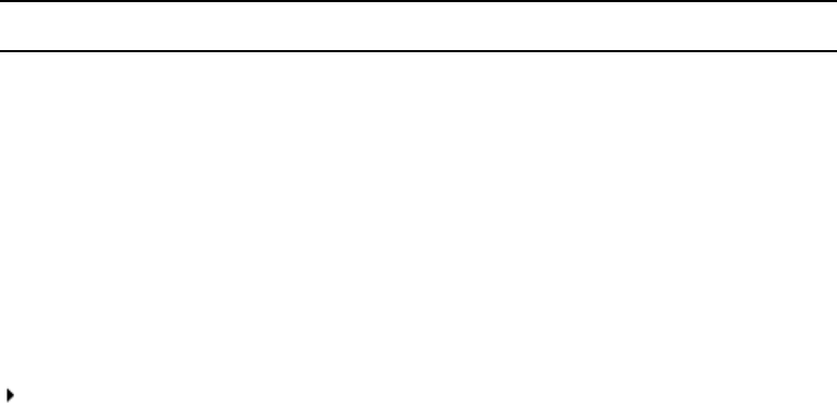
Basic Avid ISIS 7500 | 7000 Shared Storage Network Hardware
The following sections explain these components and some basic client configurations:
•System Director
•Engine
•Storage Configurations
•Automatic Redistribution on Disk Failure
•Client
•Network Zone Configurations
•Cabling
System Director front view
Rear view Front view
ISIS Integrated Switch (ISS)
ISIS Integrated Expansion Switch (IXS)
ISIS Storage Blade (ISB)
Power supply
Engine
ID
System Director
24
System Director
The System Director is 1U in size (see “System Director Front Panel” on page 24) and manages
the metadata by storing directory information and file attributes. The System Director does not
store the data used by share clients (for example media files), these data files are stored on the
ISBs within the engine.
nThe System Director password is preset to is-admin. Not to be confused with the System Director
Web Page Administrator user whose default password is blank.
You can have two System Directors configured in a redundant configuration, one Active the
other Standby. If the Active System Director goes down, the Standby System Director takes over.
You need at least one System Director to run the Avid ISIS system.
System Directors, workgroup servers, and clients must all be synchronized with a common
time-of-day. For information on setting the Network Time Protocol (NTP), see “Setting-Up
Network Addresses In the Stack” on page 69.
The System Director provides a location to coordinate file access modes (read/write), file
locking, range locking, performance data collection, logging, file lookup, and directory change
tracking for client systems. Examples of what the System Director is able to provide to a client or
storage element are:
• Identity of all storage elements connected to the system
• Information about the ISS and IXS modules in the configuration.
• List of workspaces to include name and their unique ID number
• List of users and groups within the system
• Identity of all System Directors in the system (if you have more than one System Director)
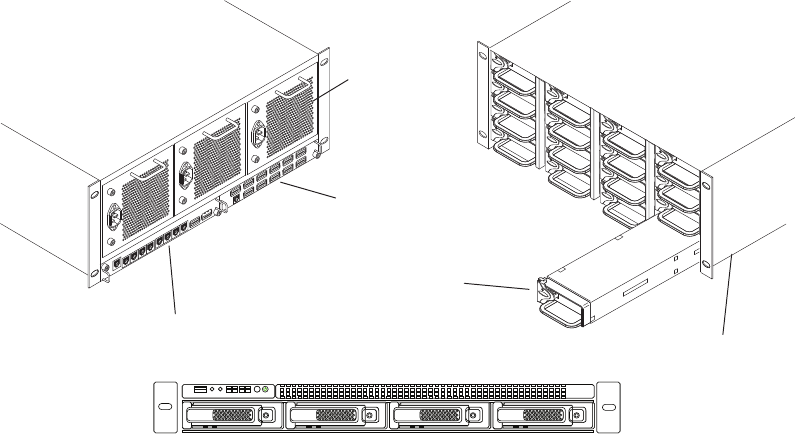
System Director Front Panel
The following figure shows the front view and control panel of the System Director.
System Director
25
System Director Front View
The following table describes the control panel shown in the previous figure.
System disk (ID 1)System disk (ID 0)
ID
ID
Control panel
BCAGHDFE
HALT RST
System Control Panel
Letter Component Description
A Universal Serial Bus (USB) port USB 2.0 device port on the front of the system supports one USB
device. Recommended for use when re-imaging the system drives or
loading software. Two more USB ports are located on the back of the
system.
B Halt or Non-maskable interrupt
(NMI) button
The halt or NMI signal halts the processor, which effectively halts
the server. A NMI is the highest priority interrupt and cannot be
masked by software.
cIf the Halt/NMI button is pressed, the NMI signal locks the
system and the system must be restarted to clear the
interrupt.
C System reset button Preforms a soft reset when pressed. Do not use this button unless the
system has had a fatal error and you need to restart. A soft reset
restarts the system; it clears all active program memory (you lose
unsaved work) and shuts down all active programs.
D Four green network activity
LEDs
Illuminates green when a good network connection is established and
blinks when there is network activity on the four built-in 1-GB
network ports.
The number beside the LED corresponds with the number beside the
network port on the rear of the enclosure. For example, Connector 1
is LED 1 on the front. See “System Director Rear Panel” on page 26.
E Red System error LED Illuminates red when an error is detected with the system (fan, power
supply, temperature, voltage).
System Director
26
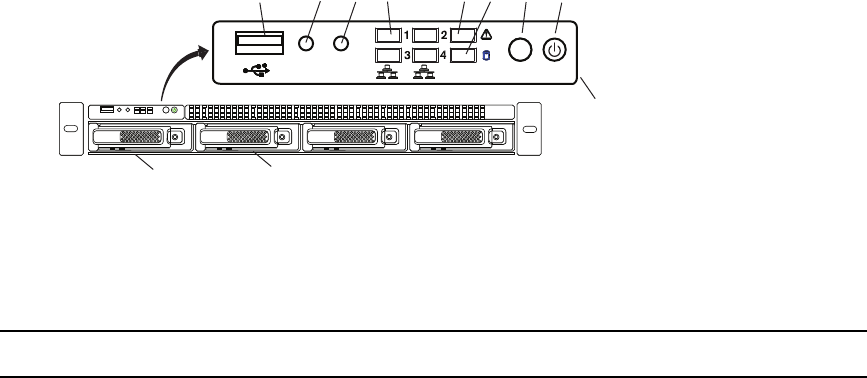
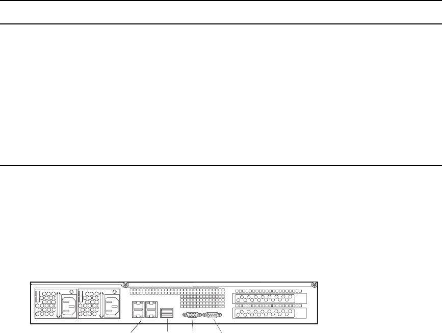
System Director Rear Panel
The following figure shows the rear panel of the System Director and the function of each
connection.
System Director Rear View
Second System Director
You can purchase a second System Director and configure it on the same subnets as the original
System Director. This provides a redundant System Director that is in constant contact with the
original System Director. The second System Director automatically takes over if the original
System Director fails (called failover).
nFor true redundancy it is recommended that you connect the second System Director to a
different engine than the first System Director. The Active and the Standby System Directors must
be the same model server, you cannot mix SR2500s, and AS3000 servers.
F System Drive activity LED Indicates drive activity from the onboard SATA controller and blinks
when either of the system drives is being accessed.
G System ID button When pressed it illuminates (blinks) blue and also illuminates an
LED on the rear of the enclosure. The rear LED is also blue and is
visible on the lower left-hand side of the Ethernet ports inside of the
enclosure. It is used to identify a system for servicing when it is
installed in a high-density rack/cabinet populated with several other
similar systems.
H Power button Press to power on the enclosure. Power button illuminates green
when the power is on.
System Control Panel
Letter Component Description
Power supplies Slots not used
Serial 1 Gb Ethernet VideoUSB
Engine
27
Engine
The engine contains the ISBs, ISSs, IXSs, power supplies, and an internal midplane. The engine
stores the data created and shared by the clients. The data is passed in and out of the engine
through the switches.
The engine contains:
• ISBs can support either 250 GB, 500 GB, 1 terabyte (TB), 2 terabyte, or 4 terabyte drives,
with two drives in each ISB. The size of the drives are identified by the label on the front of
the ISB (i500, i1000, i2000, i4000, i8000). As technology advances, the storage capacity of
the drives could increase, allowing the total storage per ISB/engine to increase.
• An ISS provides connections for clients via 1000BASE-T Ethernet ports. A 10-Gb Ethernet
port using SFP+ transceivers connects clients or serves as an uplink port. There is an engine
interconnect port and a management port for configuration. See “Integrated Ethernet
Switches” on page 29.
• An IXS used when you have more than two engines (need an IXS for each subnet), allowing
you to connect multiple engines providing up to 384 TB of storage, or 192 TB of mirrored
storage. See “Integrated Ethernet Switches” on page 29.
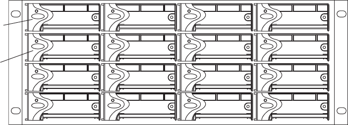
Engine Front View
The front of the engine allows access to the 16 ISBs. The first is in the upper left portion of the
front and the last ISB is in the lower right.
Each ISB can be removed and replaced separately with the power on.
nIf you replace an ISB with power on, the LEDs in all of the ISBs go off momentarily. This does
not represent a problem. All functions are still active and working properly.
Fifth ISB
First ISB
Engine
28
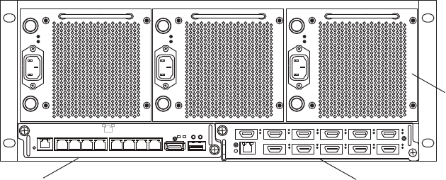
Engine Rear View
The following figure shows the rear of the engine in a configuration that contains the following:
• Three power supplies (with fans)
• Integrated Switch blade (ISS)
• Integrated Expansion Switch blade (IXS)
nIn a basic configuration containing two engines, each of the engines contains two ISS modules.
The IXS module is used with an ISS module in an engine only when the configuration goes
beyond two engines.
Power Supplies
The power supplies are powered on when the power cord is plugged in; they do not have power
switches. The power supplies not only provide power, but they also contain fans that cool the
system. The system only needs two of three power supplies to supply the needed power to
function properly. You can remove and replace a power supply temporarily while the system is
running if one fails.
cYou should leave the failing power supply in place until you replace the failing power
supply. Replace the power supply as soon as possible to maintain the proper airflow. Do not
remove the failing supply until immediately before you replace it.
wOnly trained Avid technicians should remove and replace the power supply while the
system is running. Since power to the system is still applied internally to the midplane you
must always keep your hands external to the engine when a power supply is missing from
the engine.
Power
supplies
IXS moduleISS module
1234 5678
12 34 5 6
7 8 9 10 11
Engine
29
Integrated Ethernet Switches
The two integrated Ethernet switches, ISS and IXS, serve different purposes and contain
different types of connections. You must have at least two switches in each engine for the system
to operate.
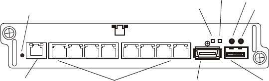
ISS Module
The connections on the ISS module are used for the following:
• Management connection — used to configure the Avid ISIS 7500 | 7000 engine hardware
during installation. This information is used by Avid representatives to originally configure
your system before turning it over to you.
• 1-Gb (RJ-45 cable) — direct connect for clients and the System Directors.
• High speed engine interconnect (CX-4 cable) — proprietary Avid bus that connects switch
blades between engines allowing subnets to connect between the engines.
• 10-Gb XFP or SFP+ MSA form factor transceiver (for Optical cable) — used for a 10-Gb
connection to a switch or 10-Gb Ethernet clients.
wOnly an Avid recommended SFP+ transceiver should be used in the 10-Gb XFP
connection, and only Avid trained representatives should remove and replace the XFP
transceiver. Currently supported XFP are the Picolight XFP and Foundry® XFP.
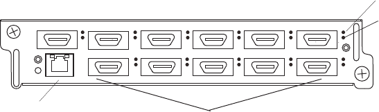
IXS Module
The IXS is needed only if you are connecting three or more engines. When connecting three or
more engines, two IXS modules are installed in one engine. The IXS offers the following
connections:
• Management connection — used to configure the switch during installation and monitor
switch functions.
• High speed engine interconnect (Hi-Gig) — proprietary Avid interconnection that stacks the
switches to create one large virtual switch.
High speed engine
interconnect (Hi-Gig)
Link
Activity
Management
connection
Link
Activity
10-Gb connection
1-Gb connections
Status
1 23 4 5678
ACT LINK 10 GIG
Storage Configurations
30
nIn a basic configuration containing one or two engines, each of the engines contains two ISS
modules. The IXS module is used with an ISS module in an engine only when the configuration
goes beyond two engines.
Storage Configurations
A maximum of twelve Avid ISIS Engines can be stacked and populated with either 250 GB,
500 GB, 1 terabyte (TB), 2 terabyte or 4 terabyte SATA drives. A fully populated Avid ISIS
system with 1 TB drives provides up to 384 terabytes (TB) of storage, or 192 TB of mirrored
storage.
You can have mixed ISB drive sizes in an engine (250 GB, 500 GB, 1 TB, 2 TB, and 4 TB
drives). You can even mix the different size ISBs in a Storage Group. Although, the larger ISBs
in the mixed Storage Group only use the amount of storage that is available in the smaller ISBs.
Storage Group Size
Storage elements are combined to create Storage Groups in the ISIS file system. These Storage
Groups can be configured to either operate using 512 KB (default) or 256 KB chunk sizes.
Earlier Avid ISIS releases used 256 KB chunk sizes. For more information about setting the
chunk size, see the Avid ISIS Administration Guide.
nAvid ISIS 7000 switch hardware shipped with v1.x (ISS1000 and IXS1000) does not support 512
KB chunk sizes. If you have Avid ISIS 7000 v2.x software running on v1.x switches, you must
select the 256KB chunk size when adding storage elements to the file system to create Storage
Groups.
You cannot change the chunk size of a Storage Group once the Storage Group has been created.
To change the chunk size of an existing Storage Group, you must delete the Storage Group and
create a new Storage Group with the desired chunk size. The chunk size selection is only
available when adding the storage elements.
cWhen you delete Storage Groups all data on that Storage Group is lost.
Engine interconnections
Link
Activity
Management
connection
1 2 3 4 5 6
7 8 9 10
10 1111
Storage Configurations
31
Chunk Size Support With ISB
All ISBs (i500, i1000, and i2000, i4000 and i8000) support the 512 KB chunk size. Although
you must have the new v2.x switch hardware (ISS2000 and IXS2000) to use the 512 KB chunk
size.
Adding an ISB to the File System
If you add an ISB (displays as an available storage element) to your file system, make sure you
match the chunk size of the new storage element to the chunk size of the existing storage group.
New storage elements are added with a default chunk size of 512 KB. You cannot mix chunk
sizes within a Storage Group. To change the chunk size of an ISB, you must remove the new
storage element from the file system and add the storage element again choosing the correct
chunk size.
Adding or Removing ISBs (Mirrored or RAID)
When permanently adding or removing ISBs from an ISIS Storage Group it is recommended to
do a full redistribution for all workspaces in the Storage Group. The full redistribution should be
done after the ISB add or remove is complete. Examples of permanent changes would be adding
or removing an engine to the storage stack.
The full redistribution makes sure all blocks in the Storage Group are optimally distributed based
on the new permanent configuration. Doing a full redistribution immediately after the permanent
adds or removes minimizes the chances of running into issues if a full redistribution is required
in the future. One potential issue would be the storage blades getting full during a full
redistribution and requiring the user to delete files to allow the redistribution to complete.
This recommendation does not apply to the case of removing and then replacing failed storage
blades. For other examples of symmetric and non-symmetric redistributions, see the Avid ISIS
Performance and Redistribution Guide on the Knowledge Base at www.avid.com/US/support.
Moving Workspaces Between Storage Groups
You can move workspaces between Storage Groups that use the same chunk sizes. Workspaces
cannot be moved between Storage Groups of different chunk sizes (256 KB and 512 KB chunk
sizes),
A Tech Alert has been written describing the process for moving data from a 256 KB chunk size
workspace to a 512 KB chunk size workspace. Search the Avid Knowledge Base at
www.avid.com/onlinesupport/ for Avid ISIS v2.x Moving Workspaces using RichCopy in the
Avid ISIS Tech Alerts.
Storage Configurations
32
nClients should not access workspaces that are in the process of being moved when it is a 256 KB
chunk size workspace being moved into a Storage Group with a 512 KB chunk size. Avid
recommends that clients unmount these workspaces until the move is complete to avoid an
unintentional access. Once the move begins, it cannot be cancelled.
Mirrored Storage Groups, Single ISB Failure
It is considered an “unprotected state” if you have a single ISB failure in a mirrored Storage
Group. In an unprotected state with no additional failures, read operations continue to function
normally.
However, in an unprotected state a subsequent or infrastructure failure will cause operational
issues which could result in failures when writing new data or prevent you from accessing data in
the Storage Group. An additional ISB failure creates a situation in which data accessibility has
been compromised. Networking issues, on the other hand, will not cause accessibility issues on
previously written data but might prevent the successful completion of the active write operation.
This issue only applies when the Storage Group is in an unprotected state and the remove
redistribution process on the failed ISBs has not been initiated. Therefore, it is highly
recommended that the remove redistribution process is initiated immediately upon confirmation
of any ISB failure. This ensures immediate protection (RAID or mirroring) of new data being
written, and full protection of all stored data at the earliest possible time.
RAID-6 Storage Groups
Avid ISIS supports a two types of data protection. Besides mirrored Storage Groups, you can
create redundant array of independent disks (RAID) Storage Groups. RAID storage offers more
value in that it provides more storage at a lower cost per GB. Using the Avid Interplay
Copy/Move service, data files can be moved from mirrored Storage Groups to and from RAID
Storage Groups. The following are two obvious advantages to using RAID Storage Groups:
• Migration from mirrored to RAID workspaces can become part of your normal workflow.
You can move the data that is no longer used in the mirrored workspaces to RAID
workspaces for longer term storage. This frees up faster storage elements (mirrored) for
higher performance work.
• RAID Storage Groups allow you to work on a lower resolution workflow at less cost.
• RAID Storage Groups increases available GB per physical engine from 50% in mirrored to
75% in RAID of installed capacity.
Storage Configurations
33
The following is a list of RAID workspace restrictions:
• Requires a Storage Group with a 512 KB chunk size (256 KB chunk sizes are not
supported).
• Requires ISIS v2.x generation switches (ISS2000/IXS2000) in the ISIS Engines (these
switches are also required for 512 KB chunk sizes).
• Avid recommends RAID Storage Groups have a minimum of 16 ISBs (one engine). The
Management Console allows you to create and use RAID Storage Groups with eight ISBs
but with in a RAID Storage Group of eight, you must add an ISB before you can remove an
ISB.
• Avid ISIS client software versions before v2.1.1 are not supported with RAID.
• RAID workflows require specific releases of Avid products that support the workflow
(AirSpeed Multi Stream, Avid editing applications, and Interplay), see the Avid ISIS
ReadMe.
• Supports only resolutions that draw 16 MB/s (50 Mb/s) or less.
nFor example, you can run two streams of DV 50 or DNxHD 36. Bandwidths are listed by
resolution and number of streams on the Avid Knowledge Base. Search the Avid Knowledge Base
for the Avid ISIS Performance and Redistribution Guide.
• If a RAID Storage Group experiences two disk failures, no writes to any of the workspaces
in that Storage Group are supported until the error condition is corrected.
• If you need to do a non-symmetrical full redistribution, you must first limit the bandwidth
used by your clients in that Storage Group. For more detailed guidance, see the Avid ISIS
Performance and Redistribution Guide on the Knowledge Base at
www.avid.com/US/support.
cAvid does not recommend a non-symmetric redistribution when your RAID Storage Group
capacity exceeds 80%.
RAID-6 Storage Groups, Single ISB Failure
When there is a single ISB failure in an ISIS Storage Group configured with RAID protection,
the Storage Group continues to function normally at a lower bandwidth. For mirrored Storage
Groups, see “Mirrored Storage Groups, Single ISB Failure” on page 32.
Automatic Redistribution on Disk Failure
34
After confirming the failure of an ISB, it is highly recommended that you initiate the remove
redistribution process of the failed ISB immediately. There are two benefits to doing this:
• First, immediately upon initiation of the remove redistribution, all new writes to the Storage
Group have the full benefit of RAID-6 protection (dual-parity protection).
• Second, upon completion of the remove redistribution process, existing data in the Storage
Group is once again fully protected. Prior to completion, if another ISB were to fail, the
Storage Group would be in an unprotected state (though no data would be lost).
RAID-6 Storage Groups, Dual ISB Failure
It is considered an “unprotected state” if you are with two failed ISBs in a RAID-6 Storage
Group. In an unprotected state with no additional failures, read operations continue to function
normally at a lower bandwidth.
However, in an unprotected state, due to the distributed architecture of the ISIS file system
(optimized for real-time performance), it is possible under certain circumstances that the system
would not be able to correctly update the parity information when writing new data. As a result
under these circumstances, the file system could return a failure status when writing. While the
failure rate percentage on the total number of write operations is low, heavy workloads on the
system would result in enough write failures to disrupt operations.
This issue only applies when the Storage Group is in an unprotected state and the remove
redistribution process on the failed ISBs has not been initiated. Therefore, it is highly
recommended that the remove redistribution process is initiated immediately upon confirmation
of any ISB failure. This ensures immediate protection (RAID or mirroring) of new data being
written, and full protection of all stored data at the earliest possible time.
Automatic Redistribution on Disk Failure
Avid ISIS performs an automatic redistribution on Disk Failure notification. Storage Elements
continuously monitors disk status and sends a “Disk Failed” notification to the System Director
upon determination that a disk is not usable. The System Director then removes the Storage
Element from its associated Storage Group. The removal of the Storage Element from the
Storage Group initiates redistributions on all workspaces associated with that Storage Group.
The System Director then prevents the Storage Element that reported the disk failure from being
added to a Storage Group.
Client
35
The Automatic Removal feature is controlled by a system preference that is configured using the
ISIS Management Console Preferences tool. The preference is called “Auto Remove
Redistribution on Disk Failure” The default setting is “enabled.” The Storage Element is only
removed from the Storage Group. It is not unbound from the ISIS Systems for the following
reasons:
• The Storage Element participates in the removal redistribution. This is required to prevent
data loss when there are un-protected workspaces or when full redundancy has not been
attained for all data blocks.
• The Storage Element continues to report status, such as physically replacing the blade.
Auto removal status is reported by way of the System Event Log. A sequence of event log entries
are generated for the initial report of the failure, the decision to remove the Storage Element, and
subsequent success or failure. Events are also logged for the start and stop of all the workspace
redistributions.
The following are important considerations when using Automatic Redistribution:
• When automatic redistribution is enabled, be sure to keep at least 7% of your Storage Group
unused at all times. Failure to do so can cause the system to run out of space after an
automatic redistribution has initiated and cause a client outage.
• If an automatic redistribution of a Storage Group is started during a critical time the overall
system performance can degrade significantly and be disruptive. For more information on
understanding the performance characteristics during remove redistribution, see the Avid
ISIS Performance and Redistribution Guide.
• An automatic redistribution removes the Storage Element from the Storage Group but not
from the file system. Once an automatic redistribution has occurred and completed, the
removed Storage Element should be removed from the file system. You must first removed
the Storage Element with the software and then physically replace it. A replacement ISB
must then be added to the file system and then the Storage Group, triggering another
redistribution.
• If unmirrored workspaces are in use, the data will be damaged on those workspaces in that
Storage Group.
Client
A client uses services provided by the Avid ISIS architecture. The client system, using a 1 Gb or
10 Gb Ethernet connection, communicates with the ISBs through the ISS to create, modify, and
read files stored in the actual ISB. Avid ISIS 7500 | 7000 supports 330 clients (150 active
clients), each using dual-stream video and up to 8 tracks of audio.
Network Zone Configurations
36
A client uses mechanisms specific to the operating system to display, create, and delete files
within the Avid ISIS shared storage network system. For example, when viewed from a
Windows operating system, the system sees a server containing many shares that are mapped to
drive letters.
Network Zone Configurations
All clients in the shared storage network are classified by zones, depending on how they connect
to the network. The following list defines the clients in each network layer by their zone
classification:
nA System Director must be attached to both subnets, but can only be attached once to each
subnet.
• Zone 1 Client — Connected to ISIS VLANs via an ISS 1 Gb or 10 Gb port (direct connect)
• Zone 2 Client — Connected to ISIS VLANs via a 1 Gb or 10 Gb port on an Avid qualified
layer-2 switch (non-routed)
• Zone 3 Client — Connected to an Avid qualified layer-3 switch (routed) with known Quality
of Service (QoS); traffic routed to ISIS (one hop) and load-balanced across ISIS VLANs
(approximately a 60/40 ratio)
• Zone 4 Client — Connected to the house network using an edge or a core switch with
unknown QoS; traffic routed to Avid ISIS (measured by the number of hops) and
load-balanced across ISIS VLANs (approximately a 60/40 ratio)
nClients which can connect to one zone can run in any lower-numbered zone — for example, a
Zone 3 client can also run as a Zone 2 or Zone 1 client.
Support for different client and device types vary by zone:
• Zone 1 — AirSpeed playout, Transfer Manager
• Zone 2 — AirSpeed ingest, editors, Interplay
• Zone 3 — Instinct, Assist, certain editors (for example, Avid NewsCutter); typical formats
include DV25, DV50/IMX-50, MPEG-2 proxy (2 Mb/s)
• Zone 4 — Instinct, Assist; typical formats include DV25, MPEG-2 proxy (2 Mb/s)
The following four examples show different types of Avid ISIS 7500 | 7000 configurations.
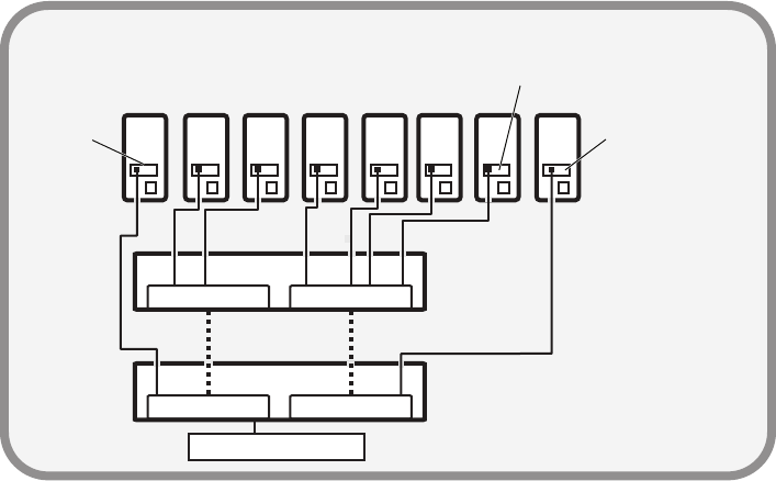
Network Zone Configurations
37
Zone 1 Clients (Direct Connected)
Any client that is connected directly to an ISIS is considered a Zone 1 or direct connected client.
Each Integrated Switch Blade has a total of eight, 1 Gb Ethernet ports and one 10 Gb Ethernet
port. A single engine has the capacity to support 18 clients or servers, subtracting any ports that
are to be used by the System Director(s). The following table defines the total number of 1 Gb
ports in Zone 1 based on what is available by the number of engines and System Directors in the
configuration. In addition, each ISS2000 provides a 10 Gb Ethernet port connection for one 10
Gb client.
nConnect TransferManagers and AirSpeed servers to Zone 1 or Zone 2.
A Zone 1 (direct connect) configuration consists of a group of clients connected directly to the
1-Gb and 10-Gb connections of the ISS in the engine. The System Director also connects to both
subnets via both ISS modules using a 1-Gb port.
Avid ISIS 7500 \ 7000 Zone 1 Network Configuration
Zone 1
Chassis
interconnect
10 GB ethernet
Engine
Engine
Intel Pro 1000
MT/PT board
Client systems
in Zone 1
1 GB ethernet
10 GB ethernet
10 GB board
10 GB board
System Director
ISS VLAN 10 ISS VLAN 20
ISS VLAN 20ISS VLAN 10

Network Zone Configurations
38
Zone 2 Clients (Indirect Connect) Configuration
There is support for external switches connected through the 10-Gb port on each ISS. Clients
that are connected to an external switch are referred to as Zone 2 clients. For a list of supported
switches, search the online Knowledge Base at www.avid.com/onlinesupport.
A Zone 2 (indirect connect) configuration consists of group of clients connected to an Ethernet
switch with a 10-Gb port connected to an ISS located in the engine. The System Director also
connects to both subnets via both ISS modules using a 1-Gb port. Depending upon the switch
configuration, each client shown connected to the external switch is connected to one of the two
subnets through one of the two 10-Gb connections.
1 Gb Ports in Zone 1
ISS1000 and IXS1000 Switches ISS2000 and IXS2000 Switches
Number
of ISIS
Engines
One System
Director
Two System
Directors
(failover)
One System
Director
Two System
Directors
(failover)
114121412
230283028
330
a
a. This is due to the use of IXS switches instead of an ISSs.
28a30a 28a
446444644
562606260
678767876
794929492
8 110 108 110 108
9 110b
b. This is due to the use of two more IXS1000 switches instead of an ISS.
108b 126 124
10 126 124 142 140
11 142 140 158 156
12 158 156 174 172
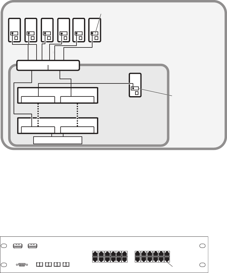
Network Zone Configurations
39
Avid ISIS 7500 | 7000 Zone 2 Network Configuration
As an example, you can configure a 24-port switch for three VLANs with Gigabit (Gb) Ethernet
ports 1 to 12 and 10-Gb Ethernet port 25 reserved for VLAN 10 (default ISIS VLAN
configuration). Gigabit Ethernet ports 13 to 23 and 10-Gb port 26 are reserved for VLAN 20
(default ISIS VLAN configuration) and Gb port 24 is reserved for the switch’s default VLAN.
The 10-Gb ports connected to the ISIS are also serving as uplinks to the ISIS for clients on either
VLAN. Each VLAN on the switch is connected to the appropriate VLAN in the shared storage
network using the 10-Gb port.
Zone 2 Switch
Chassis
interconnect
Engine
Engine
Zone 1 Zone 2
Intel Pro 1000
MT/PT board
Client system
in Zone 1
1 GB ethernet
System Director
Intel Pro 1000
MT/PT board
Client systems
in Zone 2
1 GB ethernet
ISS VLAN 10 ISS VLAN 20
ISS VLAN 20ISS VLAN 10
VLAN 10 VLAN 20
10 GB ethernet
Zone 2 switch with two 10-Gb Ports
Ports 1 - 12 Ports 13 - 24
Port 24
1-Gb ports
10-Gb ports
Port 25 Port 26

Network Zone Configurations
40
Each VLAN on the switch is allowed to support up to 12 connections but the size of the Storage
Groups and engine determine the overall client count. Changing the switch configuration to
increase the number of clients on a single VLAN is not supported and can result in unpredictable
system performance. Client count can be scaled according to the number of available switches.
The following table provides possibilities of Zone 2 client counts based on the number of ISIS
engine and switches. For each engine listed in the table, there is an associated 24-port switch.
The exception is with three engines, in which the IXS does not provide additional ports.
nThe previous table does not reflect the use of Zone 1 Clients (Direct Connect), which at a
minimum could consist of one System Director, AirSpeed devices, and TransferManagers. Mixing
Zone 1 and Zone 2 clients in an ISIS shared storage network is discussed in the next section.
There is no current support for an external switch to be connected with the use of a 1 Gb
connection as performance for multiple clients cannot be guaranteed over a single 1 Gb
connection.
Zone 1 and Zone 2 Clients Mixed Configuration
The number of ports available on the ISS (Zone 1) makes it necessary to add another layer of
clients through a qualified network switch to create a (Zone 2) in the ISIS shared storage
network.
A mixed configuration (Zone 1 and Zone 2) consists of clients connected directly and indirectly
through ports on the engine’s ISS. Also shown are two System Directors that connect to the
engine via two separate ISS 1-Gb ports for use as a redundant System Director in case of a
failure. Both System Directors also connect to each other through the onboard Ethernet
connections to monitor if one of the System Director fails.
Available Zone 2 Ports
Number of Engines 24-Port Switch Count External Switch Ports
11 23
22 46
32 46
a
a. This is due to the use of an IXS board instead of an ISS.
43 69
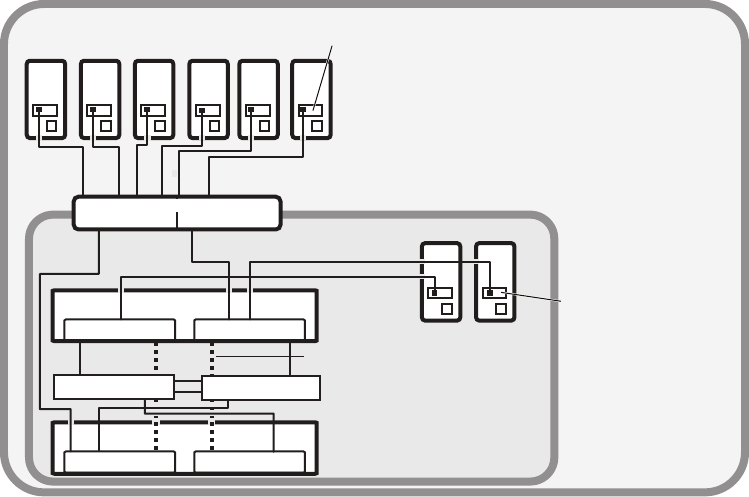
Network Zone Configurations
41
Avid ISIS 7500 | 7000 Zone 1 and Zone 2 Mixed Network Configuration
nAlthough it is not shown in the previous diagram, to ensure high availability, whenever possible,
the System Directors should be connected to two different subnets through two different engines.
Zone 3 and Zone 4 Client Configuration
A Zone 3 (indirect connect) configuration consist of a group of clients connected to an Avid
qualified layer-3 switch (routed) with known Quality of Service (QoS); traffic routed to ISIS
(one hop) and load-balanced across ISIS VLANs (approximately a 60/40 ratio)
A Zone 4 (indirect connect) configuration consists of group of clients using an edge or a house
Ethernet switch with unknown QoS; traffic routed to Avid ISIS (measured by the number of
hops) and load-balanced across ISIS VLANs (approximately a 60/40 ratio)
This switch is normally connected to a house switch that has uplinks to the Avid Production
Network through an Ethernet switch that contains a 10-Gb port connected to an ISS located in
the engine. The System Director connects to the both subnets via both ISS modules using a 1-Gb
port.
Zone 1 Zone 2
Intel Pro 1000
MT/PT board
Client systems
in Zone 2
VLAN 10 VLAN 20
10 GB ethernet
Intel Pro 1000
MT/PT board
Client systems
in Zone 1
1 GB ethernet
Chassis interconnect
ISS VLAN 10 ISS VLAN 20
Engine
Engine
System Director
ISS VLAN 20ISS VLAN 10
System Director System Director
connections
1 GB ethernet
1 GB ethernet
Zone 2 switch with two 10-Gb Ports
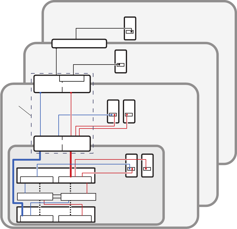
Network Zone Configurations
42
Avid ISIS 7500 | 7000 Zone 3 and Zone 4 Network Configuration
Link Aggregation Support
A link aggregation configuration supports Zone 2, Zone 3, and Zone 4 clients.
Zone 4
Zone 3
House switch
Zone 3 client
routed VLAN 30
Zone 4 clients
corporate network
Zone 1
Client systems
in Zone 1
Chassis
interconnect
ISS VLAN 10 ISS VLAN 20
Engine
Engine
System Director
ISS VLAN 20ISS VLAN 10
System Director
System Director
connections
1 GB ethernet
Zone 2
Avid Production Network (Zone 1, 2, and 3)
1 GB Ethernet
VLAN 10 VLAN 20
VLAN 30
Zone 3 layer 3 switch
VLAN 10 VLAN 20
Zone 2 Layer 2 switch
(Layer 3 routed/switched)
(Layer 2 switched)
Can be one
multilayer switch
(Layer 2 switched)
(Layer 3 routed/switched)
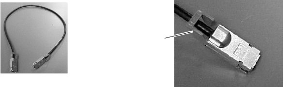
Cabling
43
Cabling
For a list of cables qualified with the Avid ISIS system, see “Supported Cabling” on page 199.
The following sections provide cabling information you should know when cabling your Avid
ISIS stack.
Connecting the Engine CX-4 Cable
The CX-4 cable is referred to as the Avid engine interconnect cable. It connects the engines
through the integrated Ethernet switches (ISS and IXS) to create the Avid ISIS stack.
To connect the cable:
tPlace it in the connector at the rear of the system.
You hear a snap, and the cable is connected.
cDamage can occur when disconnecting the Avid engine interconnect cable from the switch
board if not done properly.
nCare should be taken to reduce strain on the ISS switch blades by organizing and dressing the
ethernet cables and CX-4 cables. When dressing the cables do not block removable switch and
power components.
Removing the Avid Engine Interconnect Cable
The following explanation and illustration explain how to properly remove the engine
interconnect cable.
cIf you attempt disconnect the cable by pulling the blue cable release towards you and
pulling the cable out from the connector at the same time you can cause the cable and or
connector to be damaged.
Cable disconnect
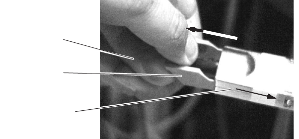
Cabling
44
To remove the Avid engine interconnect Cable from the Rear Connector:
1. While the cable is in the connector, use your bottom hand to grab the cable (or the metal
portion of the connector) and push the cable (or metal portion of the cable) towards the
connector at the rear of the engine.
2. While keeping the pressure towards the engine connector using the cable (or the metal
portion of the connector), use the top hand to pull the blue portion of the cable directly back.
This dislodges the connection of the cable from the connector.
3. Pull back with both hands to remove the cable.
10-Gb Link Aggregation Overview
The 10-Gb Link Aggregation functionality supported by the Avid ISIS 7500 | 7000 software is
described in the following sections. For a procedure on creating a Link Aggregation Group, see
“Configuring a 10-Gb Link Aggregation Group” on page 101. When configuring a Hi-Gb link
aggregation for ten- and twelve-engines, see “Hi-Gig Link Aggregation Group” on page 79.
Link aggregation is a method of combining physical network links into a single logical link for
increased bandwidth. With Link aggregation, your are able to increase the capacity and
availability of the communication channel between devices (both switches and clients) using
existing Ethernet technologies. Two or more 10-Gb Ethernet connections can be combined to
increase the bandwidth capability and to create resilient and redundant links. Link aggregation is
sometimes known as “Trunking.”
Link aggregation also provides load balancing across several links in a link aggregation so that
no single link is overwhelmed.
nYou must disable link aggregation before creating or modifying your Avid ISIS stack. After your
stack has been created, reconfigure your Link Aggregation Groups.
Pull back on blue
cable release
Push cable or metal
towards engine
Bottom hand
pushing cable
Cabling
45
Supported in Link Aggregation
Avid ISIS 7500 | 7000 supports 10-Gb link aggregation (between the ISS and the Avid
Production Network switch) and Hi-Gig link aggregation (between two IXS). Avid ISIS software
supports the link aggregation standard clause 43 of 802.3-2005 (also known as 802.3ad).
Number of Groups Supported
A link aggregation group refers to a number of links that combine together to form a single link
aggregation. The number of link aggregation groups supported in Avid ISIS 7500 | 7000 is five.
Number of Members Supported
A link aggregation group can have a maximum of eight members. This means no more than eight
10-Gb links can be combined into one link aggregation group per VLAN. The minimum number
of link aggregation members in a group is 2.
For performance reasons, Avid recommends that you maintain an even number of link
aggregation members. So for an eight engine stack, you can have a link aggregation group with
two, four, and six members. For a ten or twelve engine stack, there can be two, four, six, and
eight members in a link aggregation group.
nIf a member is already part of a link aggregation group, it cannot be part of another link
aggregation group. You also cannot create a link aggregation group with a single member.
Load Balancing
The software balances the load across multiple 10-Gb aggregated links based on source and
destination IP addresses.
Failover
If a 10-Gb trunk link fails, the software load balances the traffic among the remaining trunk
links. For example in a four-way 10-Gb trunk if a single 10-Gb link fails, the traffic is load
balanced among the remaining three links. This also means that the average traffic distribution
increases from 25% with the four links, to 33% in the three links. Therefore, it is strongly
advised that network planners setup the trunks to handle the additional load if a link or a set of
links should fail in a trunk configuration. The traffic automatically re-balances the load when a
trunk link returns.
Warning messages are sent to ISIS Management Console notifying you that a 10-Gb aggregation
link status has changed. Switch diagnostics also provides errors when you have a failed link in a
trunk.
Cabling
46
The engine menu within the ISIS Management Console flashes a yellow warning triangle
notifying you that a 10-Gb Link Aggregation link has changed. The specific engine displays a
yellow warning circle, and the Switch Blade Status displays “1 Error(s).” Details on the engine
switch displays a status of “Link Warning.” You can then open the Switch Agent page via the
“info” button on the engines details page, and look at the Port Status page to verify the 10-Gb
Link Status.
nThis failover feature functionality can be disable in switch agent page.
Recommended Topologies
For the best performance in stacks with two IXSs, the link aggregation members need to be
evenly distributed between the ISSs that are connected to each IXS. For example, with a four link
group; two are connected to ISSs that are connected to IXS A, and the other two links are
connected to ISSs that are connected to IXS B.
Supported Functionality
From the Link Aggregation menu in the switch agent, you can:
• View current settings — This displays the current link aggregation configurations, showing
all currently configured groups. The user may also modify a group or delete a group from
this page.
• Create a new link aggregation group — This allows you to define a new link aggregation
group.
• Enable or disable link aggregation configuration — This allows you to disable or enable the
current link aggregation configuration. The configuration is preserved.
• Restart the link aggregation configuration — This allows you to request that the stack restart
its link aggregation configuration. This removes and rebuilds the link aggregation groups as
defined in the current configuration.
• Delete the link aggregation configuration — This disables link aggregation and removes any
existing link aggregation configuration. The configuration is not recoverable. This can be
used to set link aggregation settings back to factory defaults.
Other Functionality
• Every time a switch is introduced to the stack (by connecting the stacking cable) or removed
from the stack (by disconnecting the stacking cable), the link aggregation software clears the
link aggregation information from the switches and re-programs them again.
• If the switches are being programmed with link aggregation information for the first time,
link aggregation needs to be enabled. This is done by clicking on “Enable or Disable link
aggregation configuration.”

2Connecting the ISIS Equipment
This chapter explains how to rackmount and connect the system hardware. To do this, a system
installation check list is provided to help you perform the installation in the correct order. The
installation check list continues past the information in this chapter and points you to the correct
area in this document or the ReadMe file to continue the installation.
This chapter contains the following information:
•Rack-Mounting the Equipment
•Installing Blades and Power Supplies
•Connecting Power to Equipment
•Connecting a Keyboard, Monitor, and Mouse
•Connecting the Optional Application Key
•Connecting Power to Equipment
•Connecting ISIS Hardware
nFor information on connecting and configuring two System Directors for failover, see
“Configuring the System for Failover” on page 122.
Rack-Mounting the Equipment
This chapter describes how to install and connect the System Director and other workgroup
hardware.
cBefore you start the procedures in this chapter, you should be familiar the previous
chapters in this document.
Rack-Mounting Examples
Avid supports more than one Avid ISIS rack configuration. You should have discussed the layout
for your system with an Avid representative prior to purchase.
The following examples show a few of the supported rack configurations.
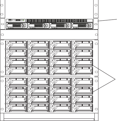
Rack-Mounting the Equipment
48
Single Rack - Two Engines - One System Director
Engines
System
Director
ID
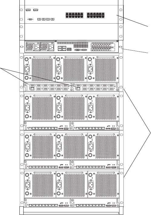
Rack-Mounting the Equipment
49
Single Rack - Four Engines - One System Director
21345678
MGMT
A
T
SS
UT
21345678
MGMT
SU
T
A
T
S
21345678
MGMT
A
TS S
U
T
21 345678
MGMT
A
TSSU
T
21345678
MGMT
ATSSU
T
21 345678
MGMT
S
U
T
A
T
S
Engines
System
Director
Switch
IXS
12 345 6
7 8 9 10 11
12 345 6
7 8 9 10 11
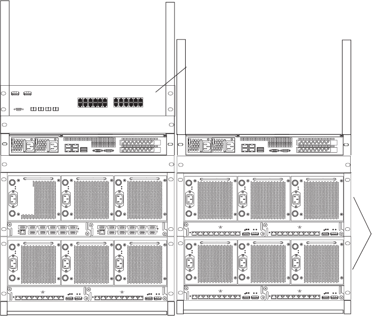
Rack-Mounting the Equipment
50
Dual Rack - Four Engines - Failover System
Installing Rack-Mount Rails and Brackets
The System Director is designed for 19-inch (483-mm) rack configurations and requires one EIA
rack units (1U), or 1.75 inches (44.45 mm) of rack space. The rail kit installs into rails that are
between 23-inches (584.2-mm) to 31-inches (787.4-mm) inches deep. An optional rail kit is
available for racks that are up to 37 inches deep.
The System Director includes rack mounting slide rails. If instructions are included with your
rail kit, use them instead of the instructions included in this section. The standard rail
configuration is for racks with square mounting holes. Optional brackets are included for racks
with round holes. The rack-mounting kit requires inner slide rails be mounted to the server and
the outer slide rails are mounted to the rack. Once both the inner and outer rails are in place, slide
the server with the inner rails attached into the outer rails. Secure the server in the front of the
rack using the supplied screws so it does not slide forward.
21345678
MGMT
A
TSSU
T
21345678
MGMT
SU
T
A
T
S
21345678
MGMT
A
TSSU
T
21345678
MGMT
A
T
SSU
T
21 345678
MGMT
A
T
SS
U
T
21345678
MGMT
S
UT
A
TS
Switch
Engines
System
Directors
Rack 1
Rack 2
12 345 6
7 8 9 10 11
12 345 6
7 8 9 10 11
Rack-Mounting the Equipment
51
cThe System Director is designed to be installed horizontally in a rack. Installing the System
Director on an angle or in a sloped console causes the internal drives to wear faster than
the intended life of the drive.
wTo ensure the stability of the rack enclosure, start with heaviest equipment installed at the
bottom of the rack enclosure. Lighter equipment goes towards the middle and top.
The following are recommendations you should take into account prior to rack-mounting Avid
ISIS equipment:
• Avid recommends that you leave a 1U or .5U space between each piece of equipment
mounted in the racks. This allows for better airflow and cable access, and helps stop
vibration in any equipment being transferred to spaces above and below.
nThe 1U System Director has vent holes on the top of the enclosure. Avid has performed thermal
testing with the top vent holes blocked, and the results indicated that even with the top vent holes
blocked, the 1U System Director still operates within the temperature tolerances.
• Avid recommends that you leave an 8 to 12 inch space at the bottom of the rack. This allows
for better airflow and lowers the possibility of dust or dirt being picked up by the devices.
• If you have a redundant configuration, you might place equipment in different racks. Place
the System Director and Failover System Director in different racks, separate the storage
elements between racks, place redundant Ethernet switches in different racks, and have the
power from each rack connected to different circuits.
• For normal operation, you’ll need to maintain approximately 2 feet (0.6 meters) of open
space in front of and behind the rack. This allows free access to the components in the rack
for operating changes or adjustments. For service, you need approximately 3 feet (1 meter)
of open space in front of the rack and 2 feet (0.6 meters) of open space behind the rack. This
allows for the removal of any component that needs to be replaced.
Rack-mount Requirements
• Elevated Operating Ambient — If installed in a closed or multi-unit rack assembly, the
operating ambient temperature of the rack environment might be greater than room ambient.
Therefore, consider installing the equipment in an environment compatible with the
maximum ambient temperature (Tma) specified by the manufacturer.
• Reduced Air Flow — Installation of the equipment in a rack should be such that the amount
of air flow required for safe operation of the equipment is not compromised.
Avid ISIS airflow is from the front of the enclosure to the rear. Make allowances for cooling
air to be available to the front panel surface and no restrictions at the rear.
• Mechanical Loading — Mounting of the equipment in the rack should be such that a
hazardous condition is not achieved due to uneven mechanical loading.
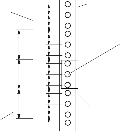
Rack-Mounting the Equipment
52
Make sure your rack enclosure is stable enough to prevent tipping over when one or more
Avid ISIS servers are extended on the sliding rails.
• Circuit Overloading — Consideration should be given to the connection of the equipment to
the supply circuit and the effect that overloading of the circuits might have on overcurrent
protection and supply wiring. Appropriate consideration of equipment nameplate ratings
should be used when addressing this concern.
• Reliable Grounding — Reliable grounding of rack-mounted equipment should be
maintained. Particular attention should be given to supply connections other than direct
connections to the branch circuit (for example, use of power strips).
• Inside Enclosure Access — If you want to extend the enclosure, and remove the top cover,
you must allow 0.5 in (1.3 cm) clearance on top of the enclosure for cover removal.
Positioning the server in the Rack
The following information helps you decide where to install the System Director in the rack.
To position the System Director in the rack enclosure:
tSelect a position in the rack where the System Director is at the proper baseline position.
Positioning the System Director
5/8 in
5/8 in
1/2 in
5/8 in
5/8 in
1/2 in
5/8 in
5/8 in
1/2 in
5/8 in
5/8 in
1/2 in
1U
2U
3U1 3/4 in
1 3/4 in
1 3/4 in
Baseline position is between
two 1/2inch holes.
Rack mounting rail
hole spacing
EIA rack unit
Rack mounting rail
System Director
front panel mounting hole
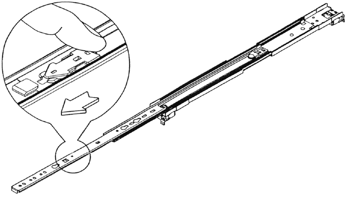
Rack-Mounting the Equipment
53
Separating the Slide Rails
You need to separate the slide rails and attach the inner “movable” section to the System Director
and the outer “fixed” section to the rack rails.
To separate the slide rails:
1. Slide the slide rail completely open.
2. Press the spring clip on the inner slide rail as shown in the illustration.
nThe blowup of the spring clip shown in the illustration is on the bottom side of the slide rail.
Separating the Slide Rails
3. Pull and separate the two halves.
4. Repeat these steps to separate the second slide rail.
Attaching Inner Slide Rails to the System Director
Attach the inner slide rails that were separated from the outer slide rails to the System Director.
To attach the inner slide rails:
1. Position the inner slide rail against the side of the server so that the screw holes are toward
the rear of the server, and front of the slide rail fits over the tab at the front of the server.
2. Secure the inner slide rail to the server with two of the small screws.
nYou might find more screws in the rail kit than is needed, and described in this procedure.
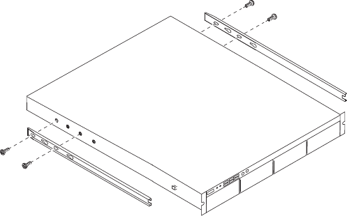
Rack-Mounting the Equipment
54
Attaching the Inner Slide Rails
3. Repeat this procedure to attach the other inner slide rail on the other side of the server.
Attaching the Outer Rails to a Square-Hole Rack
After separating the slide rails as previously described (see “Separating the Slide Rails” on
page 53), perform the following procedure. If your mounting rails have round holes, see
“Attaching the Outer Rails to a Round-Hole Rack” on page 56.
To attach the outer slide rails to the rack with square holes:
1. Align the outer slide rail bracket assembly with the front rack-mounding holes.
nYou should have someone helping you hold the slide rails level while you are positioning them in
the rack.
2. Slide the square tabs through the holes in the front, vertical rack-mounting rail.
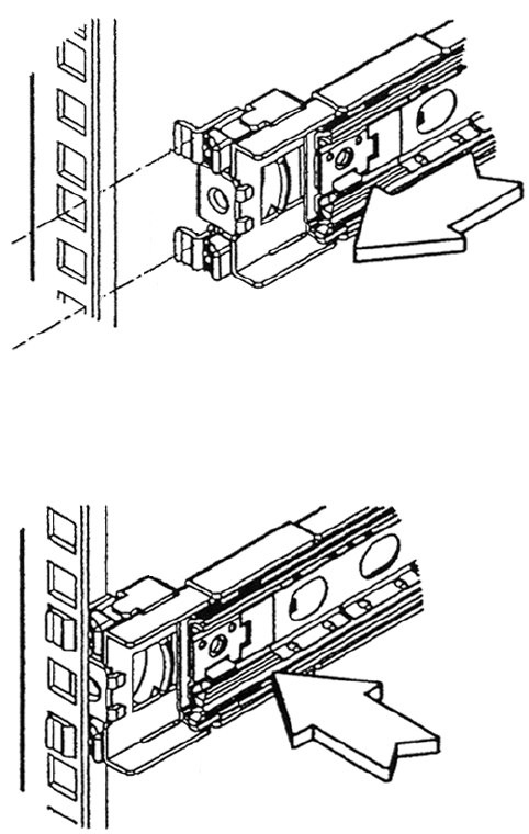
Rack-Mounting the Equipment
55
Positioning the Outer Slide Rail with the Front Rack-Mounting Rail
3. Push the outer rail towards the outside of the rack, to secure the outer rail in place
Insert the Outer Slide Rail to the Front Rack-Mounting Rail
4. Adjust the outer slide rail bracket assembly to the rear mounting rail.
5. Secure the rear outer slide rail bracket assembly to the rear mounting rail as you did for the
front rack-mounting rail.
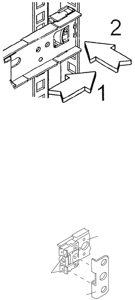
Rack-Mounting the Equipment
56
Securing the Outer Slide Rail to the Rear Rack-Mounting Rail
6. Repeat this procedure to attach the second outer slide rail on the other side of the rack.
Attaching the Outer Rails to a Round-Hole Rack
After separating the slide rails as previously described (see “Separating the Slide Rails” on
page 53), perform the following procedure. If your mounting rails have round holes, you first
need to clip on the round hole adapter.
To attach the outer slide rails to the rack with round holes:
1. Locate the four round hole adapters (which ship in the accessory kit's plastic bag, not in the
rack mount kit box) and position the adapter on the end of the outer slide rail bracket
assembly as shown in the following illustration.
Attaching the Round Hole Adapter to the Bracket Assembly
Round hole adapter
Outer slide rail bracket assembly
Bracket assembly tabs
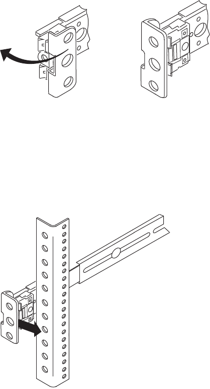
Rack-Mounting the Equipment
57
2. With the bracket assembly tabs aligning with the cut-out in the round hole adapter, swing the
adapter so that the holes face the front of the bracket assemble as shown in the following
illustration.
Positioning the Round Hole Adapter
3. Slide the outer slide rail bracket assembly onto the side rack-mounting rail so that the round
hole adapter is over the rack rail.
nYou should have someone helping you hold the slide rails level while you are positioning them in
the rack.
Insert the Outer Slide Rail to the Front Rack-Mounting Rail
4. Insert the small (10-32) Phillips-head screws through the round-hole adapter and mounting
rail, into the bracket. If the rack holes are different size, you need to supply your own screws
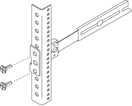
Rack-Mounting the Equipment
58
Securing the Outer Slide Rail to the Rack-Mounting Rail
5. Adjust the outer slide rail bracket assembly to the rear mounting rail.
6. Secure the rear outer slide rail bracket assembly to the rear mounting rail as you did for the
front rack-mounting rail.
7. Repeat this procedure to attach the second outer slide rail on the other side of the rack.
Securing the System Director in a Rack
cYou should have someone helping you lift the System Director while you are positioning it
into the slide rails.
To secure the server to the rack enclosure:
1. Lift and position the server so that the inner slide rails (secured to the System Director) are
aligned with the outer slide rails secured to the rack.
2. Push the front of the System Director server flush against the front mounting rail. The holes
in the server front panel align with the holes in the front mounting rail.
3. From the front of the rack enclosure, insert the large Phillips-head screw through the System
Director and front mounting rail.
- Square hole racks — the middle hole of the outer rail kit is where the screw anchors the
server front panel to the vertical rail. A M6x10 screw in the parts kit is included to
secure the front panel with square hole racks.
- Round hole racks — the server front panel attaches to the vertical rail of the rack. Use a
truss head screw or hardware that come with your rack to secure the front panel with
round hole racks.
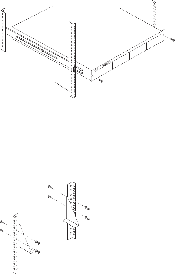
Rack-Mounting the Equipment
59
Front Panel Screws
Mounting the Engine
wLifting the engine with the blades and power supplies installed can cause an injury. The
engine must have the blades and power supplies removed prior to lifting. Avid recommends
that two people be used whenever lifting the empty engine.
To mount the engine into the rack:
1. Screw the brackets to the rear of the rack as shown in the following figure.
2. Make sure that the blades and power supplies are not in the engine.
3. Using two people, lift the engine and place the rear of the engine onto the brackets as shown
in the following figure.
Rack enclosure
front mounting rail
Rear
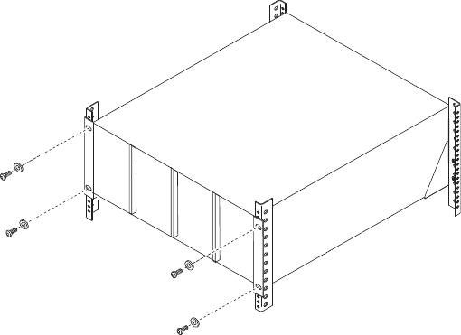
Installing Blades and Power Supplies
60
4. Screw the engine to the front of the rack through the ears of the engine as shown in the
preceding figure.
Installing Blades and Power Supplies
Once the engine has been mounted you can install the power supplies and blades.
wOnly trained Avid technicians should remove and replace the power supply when power is
applied to the system. Since power to the system is still on, you must always keep your
hands external to the engine when a power supply is missing from the engine.
To place the power supplies and blades into the engine:
1. Unpack each ISB and turn it so you can properly read the Avid name.
2. Pull open the plastic handle on the front of the ISB. (The plastic handle has the ISB model
for example, i2000, i4000, i8000, printed on the recessed grey plastic face.The older models
were reversed with the ISB model on the sticker on the handle and the Avid logo on the
recessed grey plastic face.)
3. Place the ISB into the slot and slowly push the ISB completely into the slot.
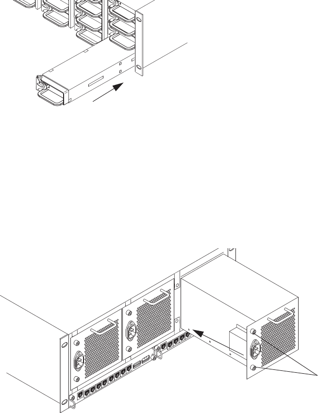
Installing Blades and Power Supplies
61
4. Push the plastic handle closed, to lock the ISB into the slot.
5. Repeat step 1 through step 4 until all blades are installed.
6. Carefully unpack each power supply.
wAvid recommends that two persons be used to install the power supplies. You could be
injured if you dropped a power supply on any part of your body.
7. Place the power supply into the engine as shown in the following figure and slowly push the
power supply into the slot.
8. Turn the screws until tight.
9. Repeat step 6 through step 8 until all power supplies are installed.
Screws
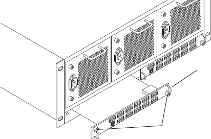
Connecting a Keyboard, Monitor, and Mouse
62
Installing IXS and ISS Switches
The location of the ISS and IXS switches in the stack are very important. If you have only one or
two engines you should only be installing ISS switches into the engines, see “Two-Engine
Stacking” on page 71.
If you have more than two engines, you need to install two IXSs in the first engine at the top of
the stack, depending on your the version of the hardware, the following is needed:
• You need two IXS2000s in three- to twelve-engine configurations with v2.x hardware, see
“Three- to Twelve-Engine Stacking Summary With v2.x Switches” on page 73.
• If you are installing a system with v1.x hardware, see the v2.1.1 (or earlier) Avid ISIS Setup
Guide for detailed procedures.
To install your IXS or ISS:
1. Unpack the switch and insert the switch edges into the internal engine slides.
2. Carefully push the switch into the midplane of the engine until the connection is made.
3. Tighten the thumbscrew on each side of the switch.
Connecting a Keyboard, Monitor, and Mouse
An industry standard USB keyboard, USB mouse and VGA monitor are use to access the System
Director. When installed in a rack with several servers an optional KVM switch can also be used.
The keyboard, monitor, and mouse connections use the same ports described in the following
procedure. Follow the instruction supplied with your KVM switch. You need to supply KVM
cables that are compatible with your KVM switch.
IXS
Thumbscrews
Connecting the Optional Application Key
63
nThere are only two USB ports on the rear of the System Director. One of the ports is typically
used for the application key. When you purchase your KVM switch make sure it includes a USB
splitter cable so that both your keyboard and mouse can plug into the splitter cable and use a
single USB port on the Engine.
To connect a keyboard, monitor, and mouse to the Avid ISIS:
1. Install your KVM switch in a suitable slot next to the System Director in the rack.
You can also place the monitor on a shelf, and the keyboard and mouse on a sliding tray in
the rack. These items are optional and can be purchased locally or from Avid.
cDo not place the monitor on top of the Avid ISIS.
2. Attach the VGA connector on the monitor cable to the 15-pin video port on the back of the
Avid ISIS. Secure the connector with the thumbscrews on the connector. For exact locations
see “System Director Rear Panel” on page 26.
3. Insert the connector on the keyboard and mouse cables into a USB splitter cable.
nIf you do not have a USB splitter cable, plug your keyboard and mouse cables directly into the
USB ports on the rear of the System Director.
4. Insert the other end of the USB splitter cable into a USB connector on the back of the
System Director.
Connecting the Optional Application Key
The default way of activating your ISIS software is through the Avid License Control tool (see
“Avid ISIS Software Licensing” on page 105), although you can purchase a USB application key
(also called a dongle). Before you start the System Director, you need to connect the Avid ISIS
system USB application key.
cDo not lose the USB application key. Your Avid ISIS system does not function without it. If
you lose the USB application key, you must purchase another one from Avid to use your
Avid ISIS system software.
Connecting Power to Equipment
64
To connect the application key to your Avid ISIS system:
1. Locate the USB application key in your Avid ISIS system kit.
2. Attach the USB application key to one of the rear USB ports of the System Director; see
“System Director Rear Panel” on page 26.
cDo not use the built-in USB connector on the front of the System Director.
Connecting Power to Equipment
The Avid ISIS 7500 | 7000 hardware includes three power supplies using an N+1 configuration
for redundancy. The three power supplies “load share” to allow the balanced distribution of V ac
power into each Avid ISIS 7500 | 7000 engine. Usually, a minimum of two of the three power
supplies must be operational at one time for the engine to function properly. The fans in each
power supply cool the supply and provides airflow for the engine. If a power supply fails, leave it
in place until you have a replacement.
Each power supply is rated at 5 amps of current capacity at 120 Vac. You can have up to one
power supply from each of the three engines on one 20-amp circuit. This allows the system to
continue running if one of the three power supplies fails, with the two remaining load-sharing
power supplies drawing slightly less than 10 amps.
nEach System Director has two power supplies rated at 5.8 amps each. Avid recommends each
power supplies be on a separated 20-amp circuit.
An engine can operate on two power supplies for a period of time to allow you to protect data.
The following illustration shows an example of how the power should be connected to protect
data.
nDo not connect the power cords to the engines until instructed to do so in “Setting-Up Network
Addresses In the Stack” on page 69.
cUse this section to determine how you should connect power to the engines. Place the power
cords into the engines when you place them into the rack as explained in “Rack-Mounting
the Equipment” on page 47, but do not plug them into the outlets until told to do so later in
the document.
See the following sections:
•Three 20-Amp V AC Circuits for Three Engines
•Three 20-Amp V AC Circuits for Two Engines
•Two 20-Amp V AC Circuits for Two Engines
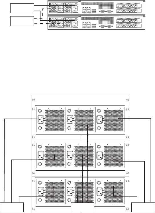
Connecting Power to Equipment
65
Connecting Power Cords
When using two System Directors, two 20-amp circuits should be supplied and configured as
follows:
To connect the power cords to the System Director:
tPlug two power cords into the back of the server and then plug the other ends into power
outlets on separate circuits.
Power Connections
Three 20-Amp V AC Circuits for Three Engines
When you are using three 20-amp circuits for three engines, they are configured as follows:
Basic Power Connection for Three ISIS Engines
Power supplies
System Director
20 Amp
20 Amp System Director
20 Amp20 Amp20 Amp
Engine
Engine
BCA
BCA
BCA
Engine
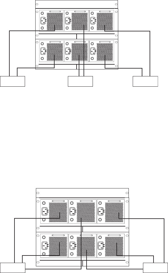
Connecting Power to Equipment
66
Three 20-Amp V AC Circuits for Two Engines
When using three 20-amp circuits for the engine, they are configured as follows:
First Example of Power Connection for Two ISIS Engines
nThe 20-amp circuits shown for the System Directors should remain the same for both the three
and two 20-amp circuit examples.
Two 20-Amp V AC Circuits for Two Engines
cThe following configuration is not recommended by Avid, but some locations might need to
connect in this manner.
When using two 20-amp circuits for the engine, they are configured as follows:
Second Example of Power Connection for Two ISIS Engines
20 Amp 20 Amp 20 Amp
Engine
BCA
Engine
BCA
20 Amp 20 Amp
Engine
BCA
Engine
BCA
Connecting ISIS Hardware
67
nThe 20-amp circuits shown for the System Directors should remain the same for both the three
and two 20-amp circuit examples.
Turning System On and Off
To turn the system on or off, use the following procedures. Do not turn off the Avid ISIS
components until they have completely powered on.
To turn your system on:
1. Turn on your engines one at a time by plugging at least two power cords into two power
supplies at the same time. Plug the third power cord into the third power supply soon after
the first two powers supplies have been given V ac power. Allow enough time for all lights
on the front panel to turn Green.
2. Turn on the System Directors and to start the Avid ISIS system.
3. Clients should restart there systems and use the Client Manager software to log on and
mount workspaces.
To turn your system off:
1. Exit the Client Manager on all clients.
2. Stop the secondary System Director using the System Director Control Panel if you are set
up for failover.
3. Stop the Active System Director using the System Director Control Panel.
4. Turn off the System Directors.
5. Turn off the engines one at a time by unplugging the three power cords for each engine.
Connecting ISIS Hardware
The process of connecting the engines to the Avid ISIS network is a two step process. First you
logically configure the addresses for the engine, then you physically make the connection to
complete the process. If you need to install software, see “Installing Software and Configuring
10-Gb Link Aggregation” on page 81.
cThe engines are powered on when two or three power supplies are plugged into an V ac
power source. When the engines are on, and the interconnect cables are attached, the
network tries to identify the new connection before it should. Do not connect the
interconnect cables until told to do so in the procedures.
Connecting ISIS Hardware
68
The 64-bit System Directors introduced in Avid ISIS 7500 | 7000 v2.0 can be used with v2.x and
v1.x generation switches in the engines. The two v2.x switches are branded with an IXS2000 and
ISS2000 silk-screen. The v2.x switches cannot be mixed in ISIS engines with earlier versions
(v1.x) of the switches (labeled IXS1000 and ISS1000). All the switches in the engines need to be
of the same generation.
cYou cannot mix new switches (labeled IXS2000 and ISS2000) with original switch
hardware (labeled IXS1000 and ISS1000). All switches in the engine, and engines in the
stack must be from the same generation of hardware.
The procedures provided in this guide describe the AS3000 System Directors and Avid ISIS 2.x
hardware. You will need the following:
• Windows computer (laptop or System Director)
• CAT5e or CAT6 Ethernet cable to run between the Windows computer and the Management
port of the ISS or IXS
• Two or more engine interconnect cables (when using more than one engine)
• System Director ISIS software kit
Engine Configuration v2.x Hardware Guidelines
Although there are a few ways to physically connect and enable the engines, Avid recommends
the process described in this section for consistency and dependability. In smaller configurations
different switch blades are used:
• ISS — Only the ISS blades are used when you are connecting two engines.
• IXS — When connecting three to twelve engines, two IXS2000 blades are used in the first
engine (one for each subnet) to connect the next eleven engines.
Engine configurations are described in the following sections:
•“Two-Engine Stacking” on page 71.
•“Three- to Twelve-Engine Stacking Summary With v2.x Switches” on page 73
nYou must disable link aggregation before creating or modifying your Avid ISIS stack. After your
stack has been created, reconfigure your link aggregation.
Connecting ISIS Hardware
69
Use the following list to help you when you connect the System Director, laptop for
configuration, and clients to the Avid ISIS 7500 | 7000 system.
• A laptop (or any computer running a Windows operating system) is used in the following
examples for configuring the engine at the beginning of the installation or for maintenance
by an Avid representative. You can use the 1-Gb connection on the System Director for
configuring the engine at the beginning if needed, but do not leave it connected or use it for a
maintenance connection.
• All clients connected to the switches on the left side of the engine are connected to one
subnet, while clients connected to the switches on right side of the box are connected to the
second subnet.
• When you are connecting the System Director to the ISS module using the dual port
Ethernet board, Avid recommends that you connect the left port to the left side of the engine
and the right port to the right side of the engine. Where the left side corresponds to the
VLAN 10 subnet and right side corresponds to the VLAN 20 subnet. However, it also
functions properly the other way.
You should rename the left side, to “Left Side, VLAN 10” and the right side, to “Right Side,
VLAN 20” in the Network Properties of your System Director.
Setting-Up Network Addresses In the Stack
Regardless of the number of engines you are planning in your Avid ISIS stack. The following
procedure describes how to configure the first engine.
To configure the engine:
1. Connect the power cords that are connected to the System Director to the V ac circuit and
turn on the System Director.
nThe System Director password is preset to is-admin. Not to be confused with the System Director
Web Page Administrator user whose default password is blank.
2. Connect the power cords from at least two of the engine’s power supplies to V ac circuit at
the same time. Then connect the third power supply.
It should take about 2 minutes for the engines to reach ready status. Wait for all the LEDS on
the engine to be green.
3. Power on all the engines in the stack.
nPower cords are plugged into the engines early in the process to speed up the installation time.
Engines can take a minute or two to become ready. If the engines are ready when it is time to add
them to the stack, the installation takes less time. Do not plug the interconnect cables into the
engines until instructed to do so.
Connecting ISIS Hardware
70
4. Using a laptop (or computer running a Windows operating system), assign a static IP address
of
192.168.0.100
to the network adapter (NIC) and attach it to the management port of
left switch.
5. Open a browser and navigate to the Switch Agent Web page via the following address:
https://192.168.0.10:5015
.
6. You are asked for the default password. Type
se-admin
.
The Avid ISIS 7500 | 7000 Integrated Switch Blade page appears.
7. Type the following into the Chassis Configuration window:
- Starting IP addresses. Enter the IP addresses for both subnets, see “IP Addressing
Overview” on page 81.
- Subnet mask
- Ending IP address should be the last address of the engine in the system. Remember that
each engine has 17 IP addresses on each side, for a total of 34. Set the ending address
high enough to cover the last engine and any possible near term future needs.
If you are going to be using a Zone 3 environment you must set the default gateway
addresses for both sides of the engine. These addresses must come from the site’s IS
department.
nMake sure there are no DHCP servers connected to the network segments that assign addresses
in the Avid ISIS range.
- Date, Time, and Time Zone or Enable network time protocol
If your network has a network time protocol (NTP) server, you can enter the IP address
of that server in the Chassis Configuration window. NTP Server 1 is for the primary
NTP server and if you have a secondary NTP server, enter the secondary IP address in
NTP Server 2.
nOnce the NTP is configured on a switch, the information propagates to all the other switches
automatically. The time is also automatically synchronized onto the storage blades after the NTP
is configured on the switch.
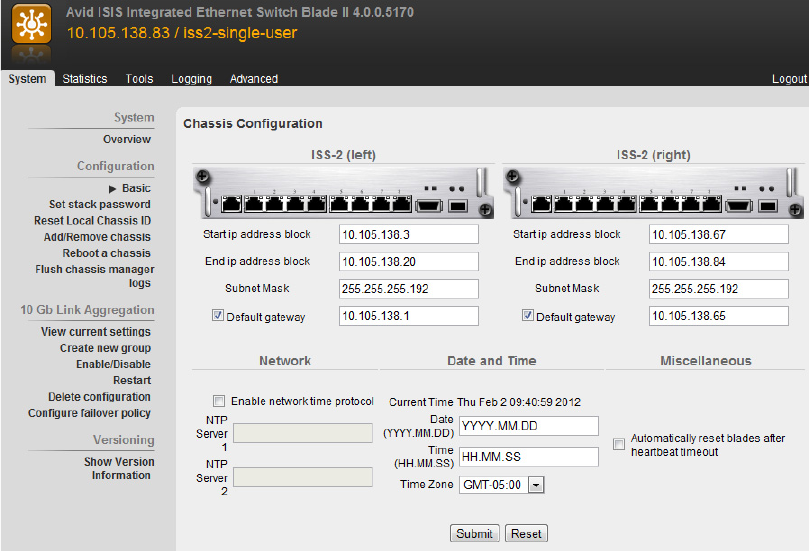
Connecting ISIS Hardware
71
8. Click Submit.
A Dialog box might appear with an informational warning and can be disregarded. The first
engine is now properly addressed.
Two-Engine Stacking
To stack two engines:
1. Complete the procedure “Setting-Up Network Addresses In the Stack” on page 69.
2. Open a left-side Switch Web page.
3. Go to System > Configuration > Add/Remove chassis.
4. Click Add and wait for the progress bar to complete.
5. Connect the interconnect cable from the left side of the stack to the new engine. The switch
then picks up the addresses and stacking information.
Wait 5 minutes and refresh the page.
6. Verify that the serial number of the second engine is now in the Add a chassis list.
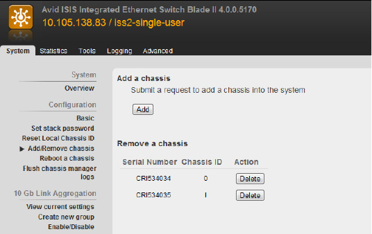
Connecting ISIS Hardware
72
7. Attach the right interconnect cable.
8. Assign appropriate static IP address to the left and right network ports of the System
Director.
9. Attach the System Director to the left and right switches and verify that all four switches can
be pinged on their client IP address.
The following example shows the physical connections between two engines, a System
Director, and clients. These are direct connections to the client system and not connected
through switches. For a procedure of this connection, see “Setting-Up Network Addresses In
the Stack” on page 69.
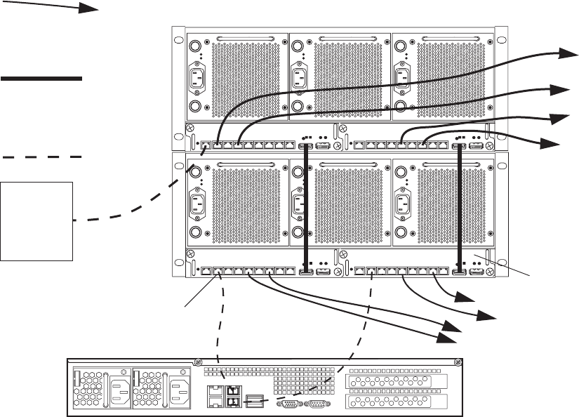
Connecting ISIS Hardware
73
Two-Engine Connections
Three- to Twelve-Engine Stacking Summary With v2.x Switches
When connecting three- to twelve-engines, connect and add the switches to the VLAN 10 subnet
(left side) first and then connect the engines to the VLAN 20 (right side) subnet. When accessing
the Agent Web pages for the engines, use your laptop through the Management port or the
Switch Agent Web through the Avid ISIS 7500 | 7000 software on your System Director.
Information on installing the software on the system Director is described in “Software
Installation” on page 85.
In three- to twelve-engine configurations with IXS2000 switches, two IXSs are installed in the
first engine, see “Three- to Twelve-Engine Connections With v2.x Switches” on page 74. The
IXS2000 ports 1 through 11 are referred to from left to right as shown in the following figure.
21345678
MGMT
STATUS
21345678
MGMT
STATUS
21345678
MGMT
STATUS
21345678
MGMT
STATUS
Connection 1
To client - RJ45 connector, CAT 5e or CAT 6
edis thgiRedis tfeL
System
Director or
laptop for
configuring
only
RJ 45 connector
CAT 5e or CAT 6
Inter-engine connection
CX-4 connector
Avid interconnect cable
ISS
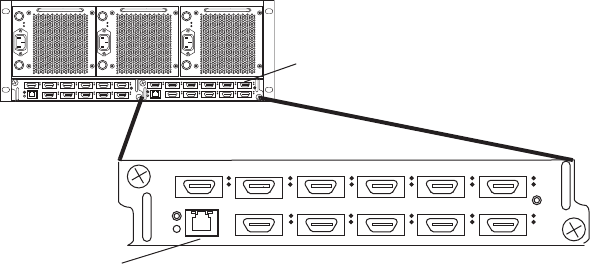
Connecting ISIS Hardware
74
IXS2000 Engine Port Numbering
Avid strongly recommends you keep your engines and IP addresses in order in conjunction with
the order of the ports used on the IXSs. When the IP address of the engines are in order with how
they are mounted in the rack, support personnel can better identify the connections and
components in the network. For an overview of the recommended IP addressing, see “IP
Addressing Overview” on page 81.
Three- to Twelve-Engine Connections With v2.x Switches
The following procedure describes cabling up to twelve engines and might not represent your
actual rack configuration. The cabling is the same when using IXSs regardless of the number of
engines in your configuration.
To connect the VLAN 10 subnet (left side):
1. Loosen the thumb screws on all the right side switches (IXS and ISS) and pull the right side
switches out about an inch of all the engines (so they are not electrically connected in the
engine).
2. Connect the power cords from at least two of the engine’s power supplies to V ac circuit at
the same time. Then connect the third power supply.
It should take about 2 minutes for the engines to reach ready status. Wait for all the LEDS on
the engine to be green.
3. Power on all the engines in the stack.
nPower cords are plugged into the engines early in the process to speed up the installation time.
Engines can take a minute or two to become ready. If the engines are ready when it is time to add
them to the stack, the installation takes less time. Do not plug the interconnect cables into the
engines until instructed to do so.
IXS module
11 Engine interconnections
Management
connection
12 34 5 6
7 891011
1 2 3 4 5 6
7 8 9 10
10 1111
12 34 5 6
7 8 9 10 11
Connecting ISIS Hardware
75
4. Using a laptop (or computer running a Windows operating system), assign a static IP address
of
192.168.0.100
to the network adapter (NIC) and attach it to the management port of left
IXS.
5. Open a browser and navigate to the Switch Agent Web page via the following address:
https://192.168.0.10:5015
.
6. You are asked for the default password. Type
se-admin
.
The Avid ISIS 7500 | 7000 Integrated Switch Blade Window appears.
7. Type the following into the Chassis Configuration window:
- Starting IP addresses. Enter the IP addresses for both subnets, see “IP Addressing
Overview” on page 81.
- Subnet mask
- Ending IP address should be the last address of the engine in the system. Remember that
each engine has 17 IP addresses on each side, for a total of 34. Set the ending address
high enough to cover the last engine and any possible near term future needs.
If you are going to be using a Zone 3 environment you must set the default gateway
addresses for both sides of the engine. These addresses must come from the site’s IS
department.
nMake sure there are no DHCP servers connected to the network segments that assign addresses
in the Avid ISIS range.
- Date, Time, and Time Zone or Enable network time protocol
If your network has a network time protocol (NTP) server, you can enter the IP address
of that server in the Chassis Configuration window. NTP Server 1 is for the primary
NTP server and if you have a secondary NTP server, enter the secondary IP address in
NTP Server 2.
nOnce the NTP is configured on a switch, the information propagates to all the other switches
automatically. The time is also automatically synchronized onto the storage blades after the NTP
is configured on the switch.

Connecting ISIS Hardware
76
8. Click Submit.
A Dialog box might appear with an informational warning and can be disregarded. The first
engine is now properly addressed.
9. Click Add/Remove chassis to go to the Add a Chassis page.
10. Click Add and wait for the progress bar to complete.
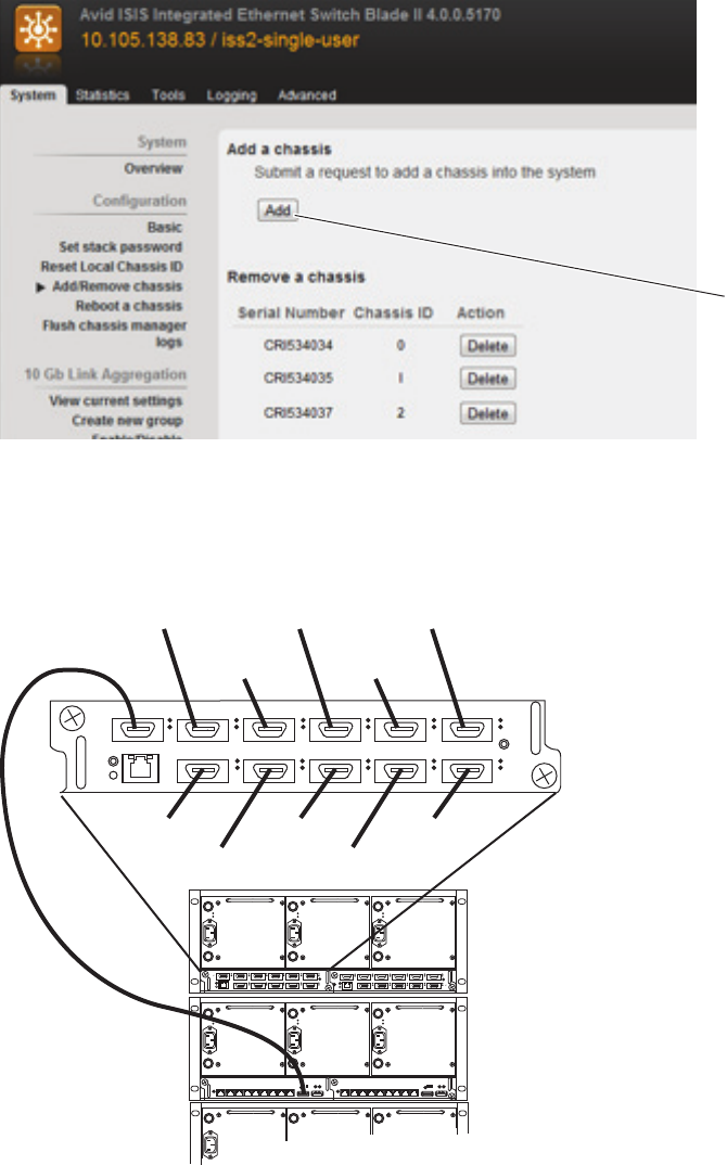
Connecting ISIS Hardware
77
11. Immediately attach an interconnect cable from port 1 of the left IXS to the left ISS
interconnect port of the second engine.
Left Subnet Twelve-Engine Connections
Add
1 2 3 4 5 6
7 8 9 10
10 1111
Third engine
Fourth engine
Fifth engine
Sixth engine
Seventh engine
Second engine
Eighth engine
Ninth engine
Tenth engine
Eleventh engine
Twelfth engine
12 34 5 6
7 8 9 10 11
12 34 5 6
7 8 9 10 11
21345678
MGMT
STATUS
21345678
MGMT
STATUS
Connecting ISIS Hardware
78
nIt is not mandatory that you connect each engine to the exact ports shown in the illustration. The
order of the ports and engines shown was suggested just to keep the stack logically organized.
12. Verify that the switch was added to the stack successfully.
The serial number of the new engine appears in the Add/Remove Chassis list after a few
moments when the switch is successfully added. If the new engine does not appear in the list
(times out), see “Engine Does Not Appear in Add Engine List” on page 94. You can also
navigate to the Tools tab and verify that IXS can ping the added switch via the expected
client IP address.
13. Repeat steps 9 through 11 until eleven engines are connected. Connect the third engine to
port 2, fourth engine to port 3, and so on, until all engines are connected to ports 1
through 11 on left subnet (VLAN 10).
14. Attach the System Director to client port and assign an appropriate IP address for the left
subnet. Verify that you can ping all the switches in the left stack at the expected
IP addresses.
15. Continue with the following procedure to connect VLAN 20 (right side).
To connect the VLAN 20 subnet (right side)
1. Insert right IXS (right-side switch in the top engine) and tighten the thumb screws.
The IXS switch starts when inserted, allow the switch 2 minutes to power on and enter a
ready state.
2. Insert the right side ISSs that you intend on connecting to right IXS subnet and tighten the
thumb screws.
Allow the switches 2 minutes to power on and enter a ready state.
3. Connect the second engine to port 1, third engine to port 2, and so on, until all engines are
connected to ports 1 through 11 on right subnet (VLAN 20).
Do not click “Add” from any IXS Agent Web page.
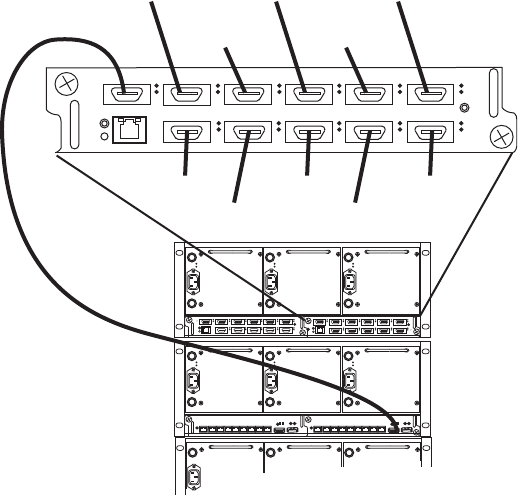
Connecting ISIS Hardware
79
Right Subnet Twelve-Engine Connections
4. Attach the System Director to client port and assign an appropriate IP address for the right
subnet. Verify that you can ping all the switches in the right stack at the expected
IP addresses.
All switches in the stack (left and right sides) should now be pingable from the System
Director.
Hi-Gig Link Aggregation Group
Two interconnect cables and Link Aggregation are used to increase the bandwidth between the
IXS’s. However, both interconnect cables must not be connected until Hi-Gig Link Aggregation
is Enabled. Link Aggregation must be enabled for both sides of the network in order for clients
on both sides to perform I/O operations.
cIf Hi-Gig Link Aggregation is not enabled, and two interconnect cables are used to connect
the IXS’s, then traffic loops and stacking problems occur.
1 2 3 4 5 6
7 8 9 10
10 1111
Third engine
Fourth engine
Fifth engine
Sixth engine
Seventh engine
Second engine
Eighth engine
Ninth engine
Tenth engine
Eleventh engine
Twelfth engine
12 34 5 6
7 8 9 10 11
12 34 5 6
7 891011
21345678
MGMT
STATUS
21345678
MGMT
STATUS
Connecting ISIS Hardware
80
To enable link aggregation:
1. Go to any left subnet Switch Agent Web page.
Notice on the left hand column of the System page there is an option Hi Gig Link
Aggregation with an Enable/Disable radio button.
2. Click Enable/Disable.
3. Click the radio button to Enable Hi Gig Link Aggregation.
4. Click submit, the IXS’s restart.
5. After the IXS has restarted, check that Hi Gig is “on” in the Hi Gig Link Aggregation
column of the System page > Switch Agent > Management Domain.
6. Connect a stacking cable from one IXS port to an IXS port on another Engine.
cCurrently only Port 6 and Port 7 on v1.x hardware can be used for Hi-Gig Link
Aggregation. Do not use any other stack ports to connect the IXS’s to each other.

3Installing Software and Configuring
10-Gb Link Aggregation
This chapter describes how to connect and configure the System Director and other Avid ISIS
hardware. Since the number of different configurations are endless, it uses a configuration with
four engines and one System Director as an example.
If you have questions, please call your Avid representative or your local ACSR.
cBefore you start the procedures in this chapter, you should be familiar with the information
in previous chapters and the Avid Products and Network Site Preparation Guide.
This chapter contains the following sections:
•IP Addressing Overview
•Configuration Overview
•Software Installation
•Product Recovery Needs to be Copied to the USB Flash Drive
•Avid Interplay Authentication
•Configuring a 10-Gb Link Aggregation Group
IP Addressing Overview
Before you attempt to define a total IP addressing scheme for your system and configure the
static internal IP addresses of the engine, you should have a solid understanding of how the
addresses are assigned within the engine and how the IP addresses increment between engines.
n192.168.10.10 and 192.168.20.10, subnet 10 and subnet 20, are used by Avid as examples
throughout this document, your site might require different addresses. Consult with your site’s
networking managers for site specific requirements. Unless specified, you can change the
addresses used in the following example to suit your needs. However, whichever static IP
addresses are assigned within the engine, they must not be assigned by a DHCP server to any
other device within the Network.
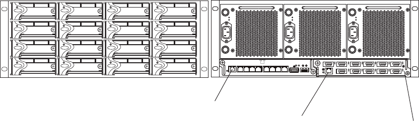
IP Addressing Overview
82
The following figure shows the front and rear view of a engine. Use the following two figures
and bulleted list to understand how static IP addresses are assigned to each engine.
Front and Rear of a Engine
The following list describes what needs to be accomplished to assign IP addresses to engines.
You should understand the assignment of IP addresses completely before you perform the actual
configuration.
nDo not attempt to assign addresses to the engine using this list. This provides an overview, not a
step-by-step procedure.
• Connect Port 1 of the System Director or a port on a laptop to the Management Port of the
ISS in the bottom engine of the rack using a CAT5 E, CAT6 cable or better. See the previous
figure.
• You are now talking to the Management Port on an isolated network interface on the ISS
using the default IP address of 192.168.0.10. This IP address is used on every Management
Port on the ISS and expansion switch blade. The address is not on the local 10 or 20 subnets
Ethernet bus and is never used to transfer actual data.
raeRtnorF
Upper left
Lower right Right side
(default subnet 20)
Left side
(default subnet 10)
Management Port
Management Port The IXS shown is only
used when three or more
engines are connected.
123 4 5678
12 34 5 6
7 891011

IP Addressing Overview
83
nWhen you assign subnet addresses internally and have more than one engine, all ISSs and IXSs
on the left side of the rear of the engine are on one subnet, while all ISSs and IXSs on the right
side of the rear of the engine are on the other subnet.
See the following tables provide an example of the address assignments described in the
following bullets.
• Then two static IP addresses are assigned to the upper left-most ISB slot in the engine when
looking at the engine from the front. The addresses are 192.168.10.10 on subnet 10 and
192.168.20.10 on subnet 20. You are assigning the address to the slot, not the blade. The ISB
can be physically moved, but the IP address remains with the slot.
• As the slots go sequentially from top left to right, over a row and starting at the left again,
each slot is assigned a static IP address that is incremented by one until you reach the
right-most bottom slot that contains addresses of 192.168.10.25 and 192.168.20.25.
• At this point, each ISS or IXS is assigned a base address. One ISS is assigned a subnet 10
address of 192.168.10.26 and the other a subnet 20 address of 192.168.20.26 (unless the you
want to change the IP scheme or subnet mask). Each side of the engine is assigned 17
addresses on each network for a total of 34 addresses per engine.
• You then increment the subnet 10 and subnet 20 addresses by one and assign them to the
switch blades in the next engine.
• The ISB slots and switches are again incremented.
First Engine Internal Static IP Address Assignments
ISB 0
192.168.10.10 (left side)
192.168.20.10 (right side)
ISB 1
192.168.10.11 (left side)
192.168.20.11 (right side)
ISB 2
192.168.10.12 (left side)
192.168.20.12 (right side)
ISB 3
192.168.10.13 (left side)
192.168.20.13 (right side)
ISB 4
192.168.10.14 (left side)
192.168.20.14 (right side)
ISB 5
192.168.10.15 (left side)
192.168.20.15 (right side)
ISB 6
192.168.10.16 (left side)
192.168.20.16 (right side)
ISB 7
192.168.10.17 (left side)
192.168.20.17 (right side)
ISB 8
192.168.10.18 (left side)
192.168.20.18 (right side)
ISB 9
192.168.10.19 (left side)
192.168.20.19 (right side)
ISB 10
192.168.10.20 (left side)
192.168.20.20 (right side)
ISB 11
192.168.10.21 (left side)
192.168.20.21 (right side)
ISB 12
192.168.10.22 (left side)
192.168.20.22 (right side)
ISB 13
192.168.10.23 (left side)
192.168.20.23 (right side)
ISB 14
192.168.10.24 (left side)
192.168.20.24 (right side)
ISB 15
192.168.10.25 (left side)
192.168.20.25 (right side)
Switch (ISS or IXS)
192.168.10.26
Switch (ISS or IXS)
192.168.20.26

Configuration Overview
84
Second Engine Internal Static IP Address Assignments
Configuration Overview
Your System Director and engines should be rack mounted with the interconnect cables
connected to the left side of your stack as previously described before continuing.
You now need to do the following:
1. Configure the engine by assigning IP addresses to the engine. This provides each ISS, IXS,
and ISB with the needed IP addresses to connect to the clients and System Director, see
“Setting-Up Network Addresses In the Stack” on page 69.
nThe ghost image on the System Directors does not set the IP addresses of the two onboard NICs
or the dual NICs card on the PCI bus; the system is set for DHCP.
2. Load the System Director software. This software is used to create a file system on the
System Director, bind the ISBs to the software on the System Director, create Storage
groups, and administer the Avid ISIS system. See “Loading Client Software” on page 96.
3. Perform administrative functions: bind ISBs (storage elements), create storage groups, and
do other administrative functions. See Creating an Active File System on the System
Director.
4. Load the client software; see Loading Client Software.
ISB 0
192.168.10.27 (left side)
192.168.20.27 (right side)
ISB 1
192.168.10.28 (left side)
192.168.20.28 (right side)
ISB 2
192.168.10.29 (left side)
192.168.20.29 (right side)
ISB 3
192.168.10.30 (left side)
192.168.20.30 (right side)
ISB 4
192.168.10.31 (left side)
192.168.20.31 (right side)
ISB 5
192.168.10.32 (left side)
192.168.20.32 (right side)
ISB 6
192.168.10.33 (left side)
192.168.20.33 (right side)
ISB 7
192.168.10.34 (left side)
192.168.20.34 (right side)
ISB 8
192.168.10.35 (left side)
192.168.20.35 (right side)
ISB 9
192.168.10.36 (left side)
192.168.20.36 (right side)
ISB 10
192.168.10.37 (left side)
192.168.20.37 (right side)
ISB 11
192.168.10.38 (left side)
192.168.20.38 (right side)
ISB 12
192.168.10.39 (left side)
192.168.20.39 (right side)
ISB 13
192.168.10.40 (left side)
192.168.20.40 (right side)
ISB 14
192.168.10.41 (left side)
192.168.20.41 (right side)
ISB 15
192.168.10.42 (left side)
192.168.20.42 (right side)
Switch (ISS or IXS)
192.168.10.43
Switch (ISS or IXS)
192.168.20.43
Software Installation
85
Software Installation
Your System Director and engines should be cabled and attached to both internal subnets similar
to the “Setting-Up Network Addresses In the Stack” on page 69.
Loading the Software
Avid ISIS Systems ship with one blank 8GB USB Drive that is intended to be used for storing
the ISIS Software Kit. You will need to download the ISIS software kit from download center
(www.avid.com/US/support/downloads) to your System Director using the software USB flash
drive included with your Avid ISIS.
The Avid ISIS 7500 | 7000 Setup Guide contains complete instructions for loading the software
onto the system. You can access the documentation in the top-level AvidISISDocumentation
folder on the Avid ISIS software installer kit. The following is a summarized version of the
procedure.
nIn the past Avid has instructed you stop the Standby System director, upgrade the Standby, and
restart the Standby. Once the Standby was running you were instructed to update the Active
System Director.
Avid has revised the upgrade process to stop the Standby System Director and upgrade the Active
System Director first, then upgrade the Standby System Director. This process avoids replicating
metadata between ISIS software versions.
To install your ISIS 7500 | 7000 software on new systems:
1. Log in to the Avid ISIS 7500 | 7000 System Director as Administrator (default password:
is-admin
).
2. Make a folder for the software kit on your root directory (C:\) of your Active System
Director.
3. Insert the software USB flash drive into any of USB ports on your Active System Director.
nYou can run the software installer from the USB flash drive. The advantage of copying the
software kit to the Avid ISIS 7500 | 7000 is that you have easy access to kit files if you should
ever them in the future.
If the USB flash drive does not automatically display:
a. Double-click the computer icon on the desktop.
b. Double-click the USB flash drive icon in the window and copy the software kit into the
new folder you created on the Avid ISIS 7500 | 7000 system.
4. Double-click the Autorun.exe file in the root directory of software kit.
Software Installation
86
The installer detects the existing version of the installed software (if any) and displays the
components that need to be upgraded in the splash screen.
nIf the Package Selection menu does not allow you to select the software, click Quit and run the
Autorun.exe again.
5. Select ISIS 7500 | 7000 System Director from the “Select Software Package” menu.
The File Gateway selection is used when loading the Avid File Gateway server. The File
Gateway software cannot be installed on the same server as the System Director software.
6. Click Apply.
7. Follow the screen prompts accepting the defaults and License agreement.
8. Once the installation is complete, click Finish.
9. Open the Avid License Control tool, click Start > Programs > Avid > Utilities > Avid
License Control and activate your Avid ISIS license. For detailed license activation
instructions, see the Avid ISIS 7500 | 7000 Setup Guide.
You will need the System ID and Activation ID card included with your new System
Director.
10. Run the Product Recovery tool to create a Product Recovery USB flash drive.
nFor information on creating the Product Recovery USB flash drive, see the Avid ISIS 7500 |
7000 Setup Guide, Avid ISIS 2000 Setup Guide or Avid ISIS 5500 | 5000 Setup Guide. To open
and use the ISIS Control Panel and Management Console see the Avid ISIS Administration
Guide.
11. Open the ISIS Control Panel.
12. Click Stop System Director.
13. Click Configure File System.
14. Select Create Active File System and click OK.
15. Open the Management Console.
Log in using the Administrator user name and the default password is blank.
16. Load the ISBs and ISS/IXSs firmware. Using the ISIS Management Console > Engines
page, select all the Engines and click Upgrade Blades and then select all your ISS/IXSs and
click Upgrade Switches. You do not need to wait for the blades (ISBs) to be finished, you
can upgrade ISBs and ISS/IXSs at the same time. For more information, see the Avid ISIS
7000 Setup Guide.
You can watch the upgrade progress in your Monitoring tool.
17. Bind the ISBs. Using the ISIS Management Console > Storage Managers page, select your
ISIS Storage Mangers in the list and click Bind.
Software Installation
87
18. Create a Storage Group, Workspaces, and add Users in the Management Console.
19. Install your Avid ISIS client software. For information, see “Loading Client Software” on
page 96 or the Avid ISIS Client Guide.
Product Recovery Needs to be Copied to the USB Flash Drive
The product recovery image is included on the D:\ or E:\ partition of the system drive. The
software installer splash screen provides a link to a tool that copies the image to the 16 GB USB
flash drive provided with your ISIS 7000. Avid highly recommends you copy this image during
the initial system setup. For instructions on how to create the product recovery USB flash drive,
see “Using the Product Recovery USB for 64-bit System Directors” on page 192.
Activating the License Key
You need to activate your Avid ISIS software before you can make an Active File System. After
installing your software, see “Avid ISIS Software Licensing” on page 105
nPrevious versions of Avid ISIS software use an application key plugged into the System Director
to allow clients to connected to the ISIS infrastructure. The USB application key is now available
as an option. New ISIS systems ship with software licensing that is activated online. If you are
already using an application key (dongle) in your ISIS infrastructure you can continue using it.
Software licensing is only required with new ISIS installations. Clients cannot access the Avid
ISIS software until the license key has been activated.
If configuring a Dual System Director for metadata redundancy, you will need a second
application key with the second System Director, For more information, see “Configuring the
System for Failover” on page 122.
Installing the Optional Application Key
You have purchased the optional Application Key, you do not need to use the Avid License
Control tool software.
To install the application key (dongle):
1. Locate the application key in the Avid ISIS kit.
2. Install the application key into one of the USB ports on the System Director. For an exact
locations, see Engine Front View or “Engine Rear View” on page 28.
Make sure the application key is seated completely in the port.
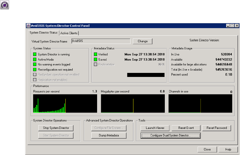
Software Installation
88
Creating an Active File System on the System Director
On new installations you must initialize your system by creating an Active File System on the
System Director.
To create an Active File System:
1. In the ISIS Launch Pad, click ISIS Control Panel icon or Start > Programs > Avid > ISIS
System Director and select Control Panel.
2. Click Stop System Director.
The Configure File System button becomes active.
3. Click Configure File System.
The File System Configuration dialog box opens.

Software Installation
89
cWhen you Create Active File System, this action results in the loss of all media assets on the
system. This is a non-recoverable action and extreme caution should be exercised when this
command is invoked.
4. (First System Director) Select Create Active File System and click OK.
The Avid ISIS System Director service automatically starts when complete. In the System
Director Control Panel, the “System Director is running” display turns green.
5. (Option) If creating a Standby System Director in an metadata redundancy configuration,
see “Configuring the System for Failover” on page 122.
Binding the Storage Managers
After you have created an Active File System you need to bind the Storage Managers using the
Management Console. If you have more than one Engine in your ISIS 7500 | 7000 configuration,
they appear listed in the Storage Manager page. One or multiple Storage Managers can be bound.
nThis procedure assumes you are creating an Active File System on a new unused Engine. If you
attempt to create a File System on an Engine that has been used before, your Storage Managers
might enter an Orphaned state. To remove an Orphaned state, search the Avid ISIS
Administration Guide for instructions on “Removing Orphaned Storage Managers.”
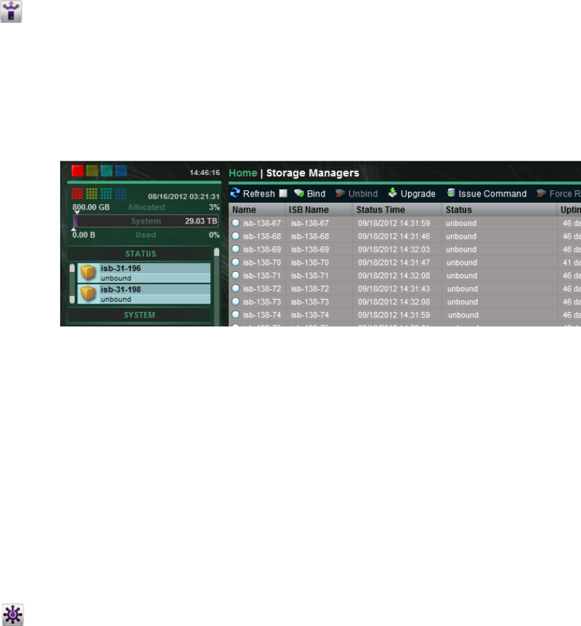
Software Installation
90
To bind the Storage Managers:
1. Type https://IP address of System Director:5015 in your browser.
If already logged into the System Director, click the Management Console icon in the
Launch Pad.
2. Log into the System Director and access the Management Console.
nThe default Management Console Administrator password is blank (no password).
3. Click the Storage Managers icon or double-click the unbound Status message in the System
Status console.
4. Select the ISBs listed in the Storage Managers list.
Multiple ISBs can be selected and bound.
5. Click Bind.
6. Click Yes to confirm the request.
7. Click Refresh to see the status circle next to the Name turn change to green when complete.
Checking the Status of the System Director
After you have installed the System Director software, an Avid ISIS Launch Pad is displayed on
the System Director Desktop.
To open and close the Launch Pad:
1. If the ISIS Launch Pad is not displayed on the Avid ISIS System Director Desktop, click the
ISIS Launch Pad icon in the Taskbar’s System Tray to display or hide the Launch Pad.
nYou can also open other ISIS tools by clicking the icons in the Launch Pad.
The ISIS Launch Pad is displayed.
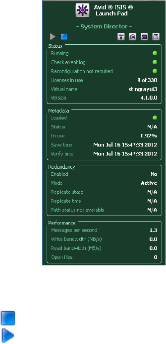
Software Installation
91
2. Start or stop the System Director by clicking one of the following icons in the ISIS Launch
Pad.
tClick the blue square icon to stop the System Director.
tClick the blue triangle icon to start the System Director.
Installing Software on the Engines
After you have loaded new software on the System Director you need to upgrade the software on
the engines. You can use Web Administrator from anywhere to perform the following functions,
but you usually do it from the System Director:
• Upgrade the ISS and IXS with the proper/latest software
• Upgrade the ISBs with the proper/latest software
• Create Workspaces
To upgrade the software:
1. Go to https://IP address of System Director (or virtual name):5015.
2. Log into the System Director.
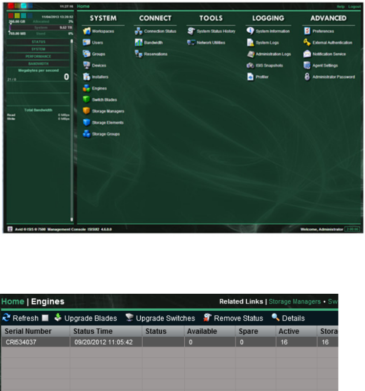
Software Installation
92
nThe default Administrator password is blank.
The ISIS Management Console opens.
3. Click Engine.
4. Select the all the Engines in the Engine list.
5. Click Upgrade Switches.
The Upgrade Switch Blades window opens.
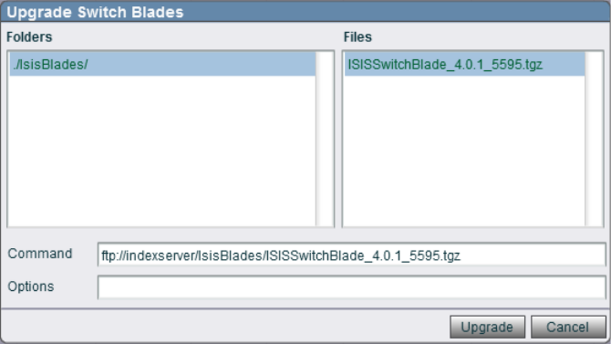
Software Installation
93
6. Select the upgrade .tgz file, and click Upgrade.
After all the Switch Blades are updated, upgrade the Storage Blades.
nUpgrading switches takes approximately 25 minutes for ISS1000 and IXS1000 switches, and
10 minutes for the v2.x switch hardware (ISS2000 and IXS2000). You should upgrade switches
on all your engines at the same time.
7. Click Upgrade Blades.
The Upgrade Storage Blades window opens.
8. Select the upgrade .tgz file, and click Upgrade.
Each Storage Blade takes approximately 10 minutes.
9. Select the Engine and click Details.
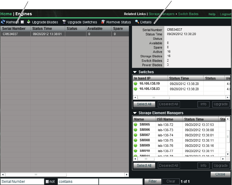
Software Installation
94
The Status for the upgrade is shown in the Details pain at the right of the window. Click the
Refresh button whenever you want the updated upgrade Status. When the Status is empty,
the upgrade is complete.
nOther ways to view the installation status is to use the Monitor Tool, the color indicator in the
System Overview Toolbar, and the Storage Blade Status column. Select the Engine Summary in
the left pane for each engine and click the Upgrade button to see the install status graphically
displayed.
Engine Does Not Appear in Add Engine List
If the engine did not appear in the Add/Remove chassis page (for more information, see “Three-
to Twelve-Engine Connections With v2.x Switches” on page 74), you must stop and
troubleshoot the problem. Once the engine appears in the list, continue adding any additional
engines. Perform the following steps one at a time and wait for the Add Engine process to
time-out before trying the next step.
Refresh Details
Software Installation
95
To troubleshoot why an engine did not appear in Add/Remove page:
1. Reseat the interconnect cables; both sides of the interconnect should have a green solid link
light when powered on. If not:
a. Remove the cable.
b. Click Add chassis.
c. Replace cable.
2. Reseat the ISS that is being added:
a. Remove the ISS.
b. Click Add chassis.
c. Reseat ISS.
3. Try a different IXS port:
a. Disconnect interconnect cable from IXS port.
b. Click Add chassis.
c. Attach interconnect to a new port on the IXS.
4. Try a different a new interconnect cable:
a. Disconnect interconnect cable.
b. Click Add chassis.
c. Replace interconnect cable.
Check Switch IP Address
Telnet to the newly added switch at the expected IP address.
If the switch cannot be reached, try the following:
1. On the IXS Switch Agent, view “System Overview.”
2. Click on the link for the newly added chassis. If Peth0-IP is not correct, Set switch back to
the default.
If the IP address is correct, proceed to the next step.
3. Check the State Machines in “System Overview” under “Stack Port Status.” The state for the
newly connect port should eventually become “SW_PORT_STACKED.” If it does not, try
the following:
a. Reseat the interconnect cable.
b. Restart the newly connected switch.
c. Restart the IXS.
Software Installation
96
Loading Client Software
You can load the Client software in several ways:
• You can take the software kit to each client separately and load it from the USB.
• You can store the client software somewhere on the corporate network and allow everyone
who needs the software to gain access to it and load it.
• You can use the a Browser to reach the ISIS Management Console and load it from the
System Director because it was loaded during the previous installation of the Client
Installers.
Keep in mind the following when connecting Avid ISIS clients.
• When installing Avid ISIS client software on Windows systems, make sure you are
up-to-date with your Windows critical updates.
• Zone 1 clients must use 1 Gb connections to the ISS. The ISS does not negotiate at any rate
below 1 Gb. If 100 BASE-T connections are needed, connect the clients or server to external
switches configured for Zone 2, 3, or 4.
To install the client software using a browser:
1. Start your browser application.
2. Run your Windows Update and accept all “High-priority Updates.”
3. Type https://IP address of System Director:5015 in your browser.
nIf your Avid ISIS network includes a Domain Name System (DNS), you can type the System
Director’s name in the browser (default Virtual name is AvidISIS).
The ISIS Management Console opens.
4. Type your ISIS user name and password.
5. Click the Installers icon.
An Installer Downloads screen opens.
Software Installation
97
6. Click the appropriate client installer.
The installer might ask if you want to save or run the installation software; either is
acceptable.
nIf you were able to access the Management Console it means that your client already has Flash
installed.
- For Windows clients, you need to uninstall the ISIS client using Windows Control
Panel, restart, install ISIS client, and restart.
The ISIS installer splash screen includes a Windows client software installer. Selecting
the “ISIS Windows Client” software package from the splash screen and clicking Apply,
uninstalls the earlier version of the software without having to use the Windows Control
Panel and installs the new software with a single click.
- For Macintosh clients, installing the new client software updates the previous version.
Preferences are saved and you do not need to restart the client.

Software Installation
98
cThe Macintosh client software installs an Avid_Uninstall folder. Use this folder only when
you want all of the Avid client files removed; including the preference files.
7. Install the client software following the on-screen prompts. Accept the defaults when
uncertain of any choices.
8. Restart the client when prompted.
The client software starts automatically when restarted.
Configuring Client Software
To mount workspaces on the client do the following:
1. Load the client software as explained in “Loading Client Software” on page 96.
2. Do one of the following:
t(Windows) If the Client Manager icon is not available in the Windows taskbar, select
Start > Programs > Avid > ISIS Client > ISISClientManager.
t(Windows) Click the Client Manager icon in the Windows taskbar.
t(Windows) Right-click the Client Manager icon and select Avid ISIS Client Manager.
t(Macintosh) If the Client Manager alias icon is not available, select Go > Applications,
and then double-click the AvidISIS folder. In this folder, double-click the
ISISClientManager.app file.
The ISIS Client Manager opens.
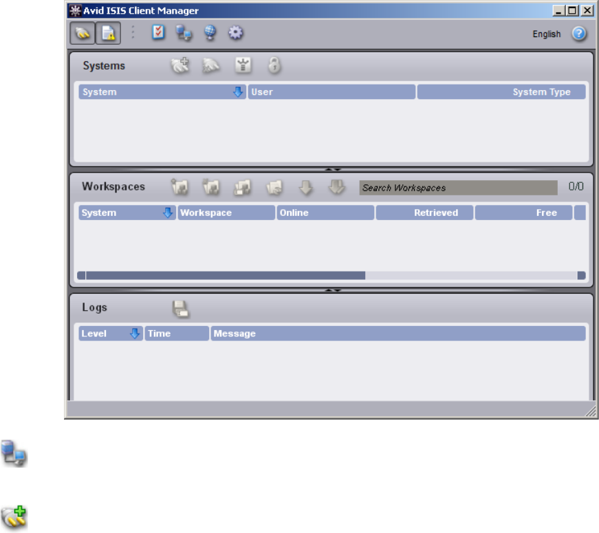
Software Installation
99
3. The first time you login, you might need to select a Remote Host (Avid ISIS system). For
information adding a remote host, see the Avid ISIS Client Manager Guide.
4. Select the ISIS system in the Systems panel.
5. Click the Connect button in the Systems panel.
6. Login using the Username and Password assigned to you by the Avid ISIS administrator. Do
one of the following:
t(Windows) Type your account name in the Username text box, and type your password
in the Password text box.
t(Windows) If your ISIS system is configured to use the Windows user name and
password for your local system, select OS Login. By default, the Username and
Password text boxes are inactive when you select this option.
(Optional — Windows only) If you used the OS Login option, and you want to connect
to the network automatically every time you start your system, select the Auto-Connect
checkbox.
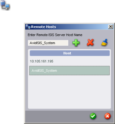
Adding a Remote Host for Zone 3 and 4 Clients
100
t(Macintosh) Type your Avid ISIS account name in the Username text box, and type your
password in the Password text box.
When the connection is successful:
- Workspaces you have been given access to are listed in the Workspaces list.
- The Client Manager buttons become active.
Adding a Remote Host for Zone 3 and 4 Clients
If your client is not on the same subnet as the ISIS shared storage network, you need to add the
name of your System Director in order for the Client Manager to connect to it. If your system
does not use a DNS server to configure your network connections, you can also type the IP
addresses of the remote host, but you cannot use the virtual server name or virtual IP addresses.
nClients on the same subnet as the ISIS System Director, automatically have the System Director
listed in the toolbar of the Client Manager window.
To add a remote host:
1. Open the Client Manager (see “Configuring Client Software” on page 98).
The Client Manager opens.
2. Click the Remote Host Settings button.
The Remote Hosts dialog box opens.

Avid Interplay Authentication
101
3. In the text box, type the actual server name or IP address of the Avid ISIS System Director to
which you want to connect.
You cannot use the virtual server name or the virtual IP address of the remote host.
4. Click the Add button.
The Input dialog box opens.
nThe Client Manager user interface could take up to 30 seconds to display changes made in the
Remote Host Settings.
5. Click the green check mark to apply the settings or the red X to close the dialog box without
any changes.
Avid Interplay Authentication
Avid Interplay Authentication requires the Avid ISIS System Director to use a virtual name. The
System Director’s virtual name must not match the actual host name and must be entered in the
General Configuration Options dialog box even if your Avid ISIS system configuration only has
one System Director. For instructions on adding the virtual name, search the Avid ISIS
Administration Guide for General Configuration Options.
Configuring a 10-Gb Link Aggregation Group
The 10-Gb link aggregation connection is done using the 10-Gb port on the ISS. You can make a
10-Gb link aggregation connection on the left, right or both subnets. The number of 10-Gb links
you can create, depends on the number of 10-Gb ports available on your zone switch (Avid
Production Network switch). The following procedure describes the process. For an overview of
10-Gb link aggregation, see “10-Gb Link Aggregation Overview” on page 44.
To create a 10-Gb link aggregation:
1. Configure your Avid Production Network switch for your 10-Gb link aggregation
connections.
This process is not described in Avid documentation, see the documentation that comes with
your switch. For additional information on configuring qualified switches, search the
Knowledge Base for the Avid ISIS Ethernet Switch Reference Guide.
nAvid Production Network switches need to be configured for Source Destination IP addresses in
terms of link aggregation load balancing. This is the default both in Avid ISIS switches and the
Avid Production Network switches that have been qualified, no other load balancing
configurations are supported.
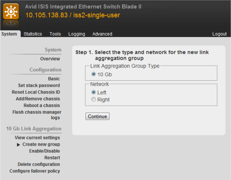
Configuring a 10-Gb Link Aggregation Group
102
cIf you connect the 10-Gb link cables before you have configure the link aggregation in the
ISIS Management Console, you will create network loops.
2. Open the Switch Blade Agent (see the Avid ISIS Administration Guide).
Click Switch Blade in the Management Console and double-click on the Switch Blade to
open the switch agent page. The default password is
se-admin
.
3. Click the System tab if it is not already selected.
The System window opens.
4. In the 10 Gb Link Aggregation area, click “Create new group.”
The agent displays information for the type of group and network. A maximum of eight
10-Gb links can be in a group.
5. Select either the Left (VLAN 10) or Right (VLAN 20) in the Network area of the window
and click Continue.
The ISSs on either the left or right side of the stack are listed.
Configuring a 10-Gb Link Aggregation Group
103
6. Select the serial number of the ISS you want to use for your new link aggregation group and
click Continue.
A minimum of two ports must be selected.
nIf you make a mistake on your link aggregation group, click “Delete configuration” and select
Left, Right, or Both to remove the link aggregation configuration.
cDo not click Restart in the 10 Gb Link Aggregation area unless instructed to do so by an
Avi d re pre se nt at ive .
7. Click Enable/Disable.
The top of the window displays the current 10-Gb link aggregation status.
8. Select Left, Right, or Both, and Enable, and then click Submit to enable the link aggregation
that you just created.
9. (Option) Repeat step 3 through step 8 to create a link aggregation for the other side.
Link aggregation groups are created on the left and right sides individually. You can have a
link aggregation just on one side if you want.
10. Connect the interconnect cable between the 10-Gb ports on the ISS switch you have
configured.
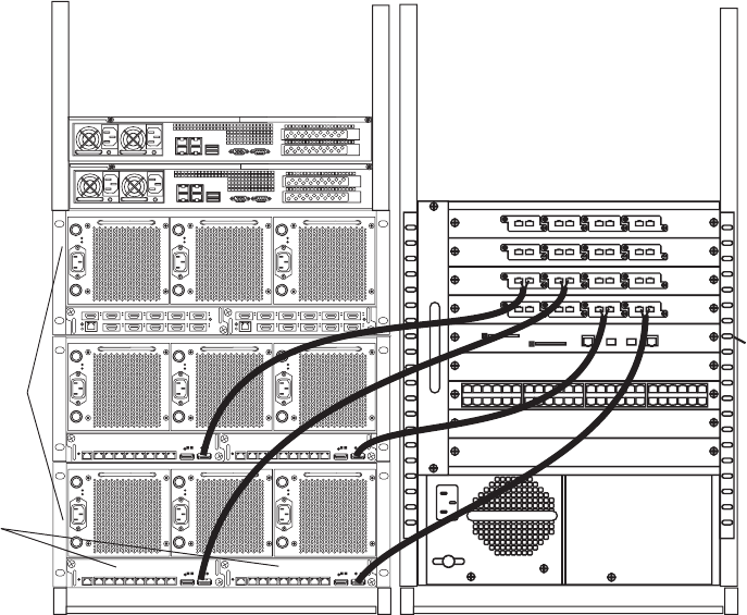
Configuring a 10-Gb Link Aggregation Group
104
Engines
ISS
10-Gb link
aggregation ports
21345678
MGMT
A
TSSUT
21345678
MGMT
S
U
T
A
T
S
21345678
MGMT
A
T
SSUT
21345678
MGMT
S
U
T
A
T
S
12 345 6
7 8 9 10 11
12 345 6
7 891011

4Avid ISIS Software Licensing
When installing a new Avid ISIS system, you need to activate the ISIS software with the Avid
License Control tool. If you have a dual System Director environment, you need to repeat the
procedure for each System Director.
nIf you are upgrading from an earlier version of Avid ISIS software which uses the USB
application key (dongle), you can continue to use that application key with your software
upgrade. New ISIS software continues to support existing USB application keys. USB application
keys are available as an option.
cIf you change your system configuration — for example, replacing a network adapter or
upgrading your operating system — you must first deactivate your Avid software. For
information on deactivation, see Deactivating the License.
• New installations — if you are a new user and have never installed the Avid software on
your system, use the following instructions.
nYour network administrator might need to open a few ports that are used during the licence
activation. The Avid License Control tool utilizes both port 3443 and port 443 for license request
and response communication. Port 3443 is the primary port, but if this port is blocked, the
Activation Service tries port 443 (which is more likely to be open for web communication).
• Existing installations — if you are upgrading from a previous version of the Avid ISIS
software, your Avid ISIS software license remains activated. You do not need to reactivate
your Avid ISIS software license as long as you've previously activated a licence or have a
valid ISIS application key (dongle) connected.
• Host name changes — if you change the host name of your system Director you must first
deactivate your license, delete the license binding file, and reactivate the license with the
new name, see “License Requirement with Host Name Change” on page 111.

What You Need to Activate the ISIS Software License
106
What You Need to Activate the ISIS Software License
License Activation Using an Internet Connection
To activate the ISIS software license from the System Director with an Internet connection:
1. Locate your System ID and Activation ID card included with your new System Director.
2. Open the Avid License Control tool, click Start > Programs > Avid > Utilities >
Avid License Control.
The Avid License Control tool opens.
Identification (ID) Numbers Where you can find them:
Activation ID The Activation ID is provided on an Activation ID and System ID card
shipped with your new ISIS system. The Activation ID is used to
activate the software license and has been linked to your System ID.
System ID The System ID is provided on an Activation ID and System ID card
shipped with your new ISIS system. The System ID is used for
expediting warranty verification and customer service.
Once activated, the License Profile tab of the Avid License Control
tool displays information about your system. Click “Copy to
Clipboard” to copy the information to your Clipboard. You can then
cut and paste from the clipboard to an e-mail or create a text file. This
is helpful if you need to save this information for your records or need
to send system information to Avid Customer Support.
Device ID The Device ID is only needed if you are activating your software on a
system that is not connected to the Internet. This is provided through
the Avid License Control tool during activation.
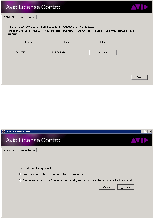
License Activation Using an Internet Connection
107
nAfter your Avid software is activated, the License Profile tab displays your System ID,
Activation ID, and Device ID.
3. Click Activate next to the Avid ISIS software.
4. Select “I am connected to the Internet and will use this computer” and then click Continue.
nIf you select “I am not connected to the Internet and will be using another computer that is
connected to the Internet” continue with “License Activation Without an Internet Connection”
on page 108.
5. Enter your system identification number in the System ID text box.
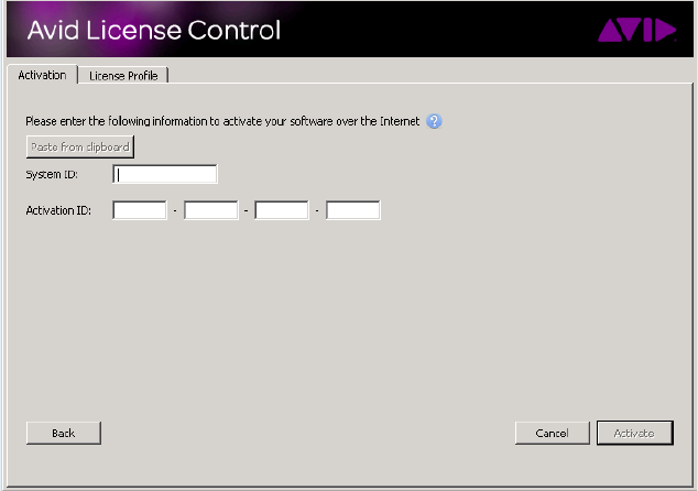
License Activation Without an Internet Connection
108
6. Enter your activation identification number in the Activation ID text box.
7. Click Activate.
The Activation tool confirms your system information. When the activation is complete, a
message informs you that your software has been successfully activated and the button
changes to Deactivate.
8. (Option) If you are planning a dual System Director configuration, you need to repeat this
procedure to Activate your software license on your second System Director.
nIf you have purchased a “failover” System Director for the ISIS 7500 | 7000, both System
Directors use the same System ID in a dual System Director configuration. You do need a
separate Activation ID for each System Director.
License Activation Without an Internet Connection
When you do an indirect activation, you are given a “.bin” activation file. This file is only good
for a single activation. If you have done an indirect activation, and deactivate your license for any
reason, you cannot use the same activation file to reactivate your license. You must repeat the
“License Activation Without an Internet Connection” procedure and obtain a new “.bin”
activation file.
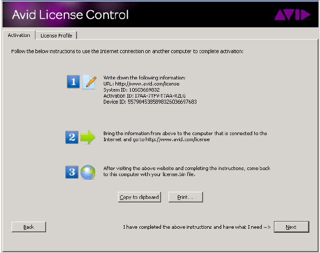
License Activation Without an Internet Connection
109
To activate the ISIS software license from a separate computer:
1. Locate your System ID and Activation ID card included with your new System Director.
2. Open the Avid License Control tool, click Start > Programs > Avid > Utilities > Avid
License Control.
The Avid License Control tool opens.
3. Click Activate next to the Avid ISIS software.
4. Select “I am not connected to the Internet and will be using another computer that is
connected to the Internet,” then click Continue.
5. Enter your system identification number in the System ID text box.
6. Enter your activation identification number in the Activation ID text box.
7. Click Next.
8. Follow the instructions in the Avid License Control tool, then click Next.
nYour System ID, Activation ID, and Device ID are displayed on the Activation tab, write these
numbers down to use later. These IDs are displayed in the License Profile tab after your Avid
software is activated.
9. On a computer with an Internet connection, open a Web browser and navigate to
http://avid.com/license.
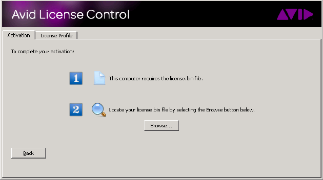
License Activation Without an Internet Connection
110
10. Follow the onscreen instructions on the web page.
The website creates a license.bin file. This file contains license information needed to
activate your Avid ISIS software.
11. Copy the license.bin file to the ISIS System Director you want to activate.
A USB flash drive is a good method of moving the license.bin file to the System Director.
12. Close the Web browser on the computer with the Internet connection.
13. Return to the ISIS System Director where you left off in the Avid License Control tool (see
the illustration in step 8) and click Next.
14. Click Browse and navigate to the license.bin file on your ISIS System Director, then click
Open.
The Activation tool confirms your system information. When the activation is complete, a
message informs you that your software has been successfully activated and the button
changes to Deactivate.
15. (Option) If you are planning a dual System Director configuration, you need to repeat this
procedure to Activate your software license on your second System Director.
nIf you have purchased a “failover” System Director for the ISIS 7500 | 7000, both System
Directors use the same System ID in a dual System Director configuration. You do need a
separate Activation ID for each System Director.
Deactivating the License
111
Deactivating the License
You must deactivate your ISIS software license when replacing the System Director so you can
use the license on your new System Director. If you need to deactivate the ISIS software you
must have an Internet connection to deactivate the software and its options.
Deactivating the ISIS System Director software:
1. Stop your Avid ISIS System Director.
2. Open the Avid License Control tool, click Start > Programs > Avid > Utilities > Avid
License Control.
The Avid License Control tool opens.
3. Next to the Avid ISIS software, click Deactivate.
4. Click Yes.
The system deactivates and the button changes to Activate.
5. Click Done to close the window.
License Requirement with Host Name Change
If you want to change the host name of your System Director, you must deactivate your ISIS
software license, delete the license binding file, and reactivate the license after changing the host
name.
When changing the System Director host name:
1. Deactivate the Avid License on your Avid ISIS System Director (see “Deactivating the
License” on page 111).
2. Browse to the following location on the System Director and delete the “binding.dat” file.
c:\ProgramData\Avid\Common\binding.dat
3. Change the System Director host name.
4. Restart the System Director.
5. Reactivate the Avid License on your Avid ISIS System Director (see “What You Need to
Activate the ISIS Software License” on page 106).

5Configuring Two Stacks of ISIS Engines
This chapter explains how to configure your ISIS engines into two Management Domains
(stacks); typically when setting up your ISIS environment with more than twelve engines. The
standard ISIS configuration supports up to twelve engines with one or two System Directors.
nISIS environments typically are configured with two System Directors for redundancy protection
against data loss. For information on connecting and configuring two System Directors, see
“Configuring the System for Failover” on page 122.
The following are the guidelines when planning two stacks of ISIS engines:
• Maximum number of engines in a stack is twelve engines; therefore all configurations larger
than twelve engines must be configured for two Management Domains (two stacks)
• Each stack, regardless of the number of engines, is configured into two subnets (in this
chapter, former VLAN 10 and VLAN 20 subnets are now VLAN 100 and VLAN 200 with a
Subnet Mask of 255.255.252.0 to accommodate the possible IP addresses needed for 24
engines)
• When adding more than twelve engines you increase the amount of shared storage, the file
and client counts are the same regardless of the number of engines and whether you have
one or two stacks
• An Avid ISIS configuration with two Management Domains can be managed by a single
Avid Interplay configuration
• Maximum Storage Group size is capped at twelve engines; you cannot increase the size of a
Storage Group that already has twelve engines by adding an engine in a different
Management Domain
nStorage Groups cannot expand across Management Domains.
• Multiple Storage Groups are supported in each Management Domain, a minimum of two
Storage Groups are required with more than twelve engines (or at least one Storage Group
per stack)
• Configurations with more than twelve engines or two stacks require generation 2 hardware
(ISS/IXS2000)
• Configurations with more than twelve engines or two stacks require the SR2500 or AS3000
System Directors. For information on updating your System Directors see “Replacing the
System Director” on page 187
ISIS Two Stack Configuration
113
• Two stacks are linked by 10 Gb Ethernet connections using external switches (EXS)
For a list of supported external Ethernet switches, see the Avid ISIS ReadMe
• Each VLAN must use the same number of 10 Gb connections on the external switches
between each stack
ISIS Two Stack Configuration
Each stack, regardless of the number of engines, is configured into two subnets (VLAN 100 and
VLAN 200). The following illustration shows the division, and the 10-Gb Link Aggregation
used to link the two Management Domains.
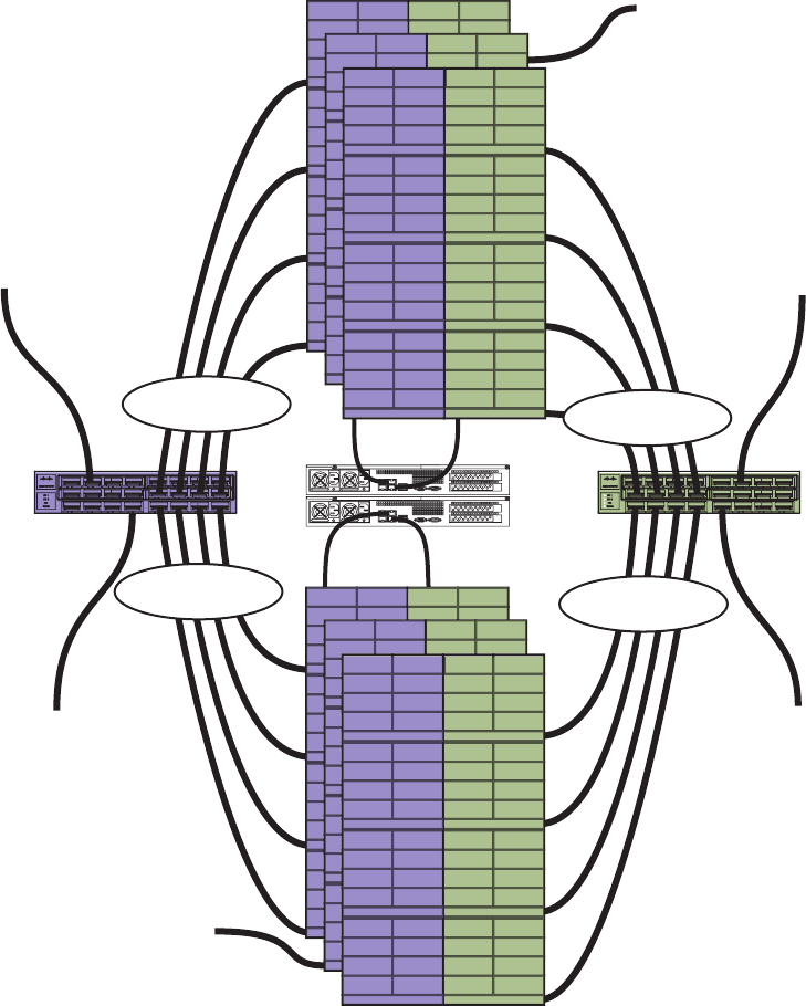
ISIS Two Stack Configuration
114
Two Stack Configuration
4 x 10 Gb
4 x 10 Gb 4 x 10 Gb
4 x 10 Gb
Right side
(default subnet 200)
Left side
(default subnet 100)
(Option 1) 10 Gb connection
to zone 2 switch
(Option 1) 10 Gb connection
to zone 2 switch
10 Gb connection
to house network
(Option 2) 10 Gb connection
to zone 2 switch
System Directors
External 10 Gb
Ethernet switch
External 10 Gb
Ethernet switch
(Option 2) 10 Gb connection
to zone 2 switch
10 Gb connection
to house network

ISIS Two Stack Configuration
115
External Switch Link Aggregation Connection Guidelines
The following table provides the recommended number of 10-Gb link aggregation connections
between ISIS Management Domains when configuring more than twelve engines. Typically, you
would not use more than one stack if your site has twelve engines or less. If planning on more
than twelve engines, it is recommended that you set up your initial ISIS environment with two
stacks. Then when you expand to more than twelve engines, the additional engines can be added
without reconfiguring your single stack environment and IP Address scheme. For information on
10-Gb link aggregation connections, see “Configuring a 10-Gb Link Aggregation Group” on
page 101.
For best performance each Management Domain should be balanced with the same number of
engines in both stacks. A 10-Gb link aggregation connection goes from VLAN 100 of the first
stack to the external switch and then another 10-Gb link aggregation connection goes from that
external switch to VLAN 100 on the second stack. VLAN 200 has a 10-Gb link aggregation
connection from the first stack to a second external switch and then another 10-Gb link
aggregation connection that goes from the second external switch to VLAN 200 on the second
stack. A diagram of these connections is shown in “Two Stack Configuration” on
page 114.These four connections are considered one 10-Gb link aggregation connection
described in the following table. You must have the same number of 10-Gb link aggregation
connections on both VLANs between the Management Domains. These connections are
bidirectional (full duplex) between the Management Domains.
Each 10-Gb link aggregation connection provides 600 MB/s bandwidth. To get the best full
bandwidth possible, you should make the 10-Gb link aggregation connections between the
Management Domains as listed in the following table. For more details on the bandwidth
between Management Domains, see the Avid ISIS Performance and Redistribution Guide.
Number of Engines
in First Stack
Number of Engines
in Second Stack
Number of 10-Gb Link Aggregation
Connections per Subnet
Up to 12 engines 1 engines One 10-Gb Link Aggregation
Up to 12 engines 2 or 3 engines Two 10-Gb Link Aggregations
Up to 12 engines 4 engines Three 10-Gb Link Aggregations
5 or more engines 5 or more engines Four 10-Gb Link Aggregations

ISIS Two Stack Configuration
116
IP Address Classes
You need a subnet with enough IP addresses to accommodate the number of engines, clients, and
devices you are connecting to your ISIS shared storage environment. A Class C network
typically provides 254 usable addresses. Your shared storage environment might need a larger
block of IP addresses than a Class C network provides. The pool of addresses in a Class B
network would be much larger than required.
A 24 engine ISIS configuration uses a minimum of 408 IP addresses. If you plan on over 170
clients you need to use a /22 or larger Network range (a /22 can accommodate 1024 addresses).
The subnet examples shown in this chapter use VLAN 100 and VLAN 200 with a Subnet Mask
of 255.255.252.0 to accommodate the possible IP addresses needed for 24 engines. The other
chapters in this guide use VLAN 10 and VLAN 20 with a Subnet Mask of 255.255.255.0 which
does not include enough IP addressed for all the ISIS blades and maximum client count.
IP Addressing With Two Stacks
The IP addressing scheme engines are described in “IP Addressing Overview” on page 81. This
section expands the system and configuration to include up to 24 engines. The first table
provides a review of the engine numbering scheme. The second table is an example on the
engines configured into two stacks.
Example of a Single Engine IP Address Assignments
ISB 0
192.168.100.10 (left side)
192.168.200.10 (right side)
ISB 1
192.168.100.11 (left side)
192.168.200.11 (right side)
ISB 2
192.168.100.12 (left side)
192.168.200.12 (right side)
ISB 3
192.168.100.13 (left side)
192.168.200.13 (right side)
ISB 4
192.168.100.14 (left side)
192.168.200.14 (right side)
ISB 5
192.168.100.15 (left side)
192.168.200.15 (right side)
ISB 6
192.168.100.16 (left side)
192.168.200.16 (right side)
ISB 7
192.168.100.17 (left side)
192.168.200.17 (right side)
ISB 8
192.168.100.18 (left side)
192.168.200.18 (right side)
ISB 9
192.168.100.19 (left side)
192.168.200.19 (right side)
ISB 10
192.168.100.20 (left side)
192.168.200.20 (right side)
ISB 11
192.168.100.21 (left side)
192.168.200.21 (right side)
ISB 12
192.168.100.22 (left side)
192.168.200.22 (right side)
ISB 13
192.168.100.23 (left side)
192.168.200.23 (right side)
ISB 14
192.168.100.24 (left side)
192.168.200.24 (right side)
ISB 15
192.168.100.25 (left side)
192.168.200.25 (right side)
Switch (ISS or IXS)
192.168.100.26
Switch (ISS or IXS)
192.168.200.26

ISIS Two Stack Configuration
117
Each engine uses 17 IP addresses on two subnets. The following table shows an example of the
starting and ending IP addresses for 24 engines on two VLANs.
Starting and Ending Engine IP Addresses for Two Stacks
VLAN 100 Subnet
Stack 1
VLAN 220 Subnet
Stack 1
VLAN 100 Subnet
Stack 2
VLAN 200 Subnet
Stack 2
Engine 1
192.168.100.10
192.168.100.26
Engine 1
192.168.200.10
192.168.200.26
Engine 1
192.168.101.10
192.168.101.26
Engine 1
192.168.201.10
192.168.201.26
Engine 2
192.168.100.27
192.168.100.43
Engine 2
192.168.200.27
192.168.200.43
Engine 2
192.168.101.27
192.168.101.43
Engine 2
192.168.201.27
192.168.201.43
Engine 3
192.168.100.44
192.168.100.60
Engine 3
192.168.200.44
192.168.200.60
Engine 3
192.168.101.44
192.168.101.60
Engine 3
192.168.201.44
192.168.201.60
Engine 4
192.168.100.61
192.168.100.77
Engine 4
192.168.200.61
192.168.200.77
Engine 4
192.168.101.61
192.168.101.77
Engine 4
192.168.201.61
192.168.201.77
Engine 5
192.168.100.78
192.168.100.94
Engine 5
192.168.200.78
192.168.200.94
Engine 5
192.168.101.78
192.168.101.94
Engine 5
192.168.201.78
192.168.201.94
Engine 6
192.168.100.95
192.168.100.111
Engine 6
192.168.200.95
192.168.200.111
Engine 6
192.168.101.95
192.168.101.111
Engine 6
192.168.201.95
192.168.201.111
Engine 7
192.168.100.112
192.168.100.128
Engine 7
192.168.200.112
192.168.200.128
Engine 7
192.168.101.112
192.168.101.128
Engine 7
192.168.201.112
192.168.201.128
Engine 8
192.168.100.129
192.168.100.145
Engine 8
192.168.200.129
192.168.200.145
Engine 8
192.168.101.129
192.168.101.145
Engine 8
192.168.201.129
192.168.201.145
Engine 9
192.168.100.146
192.168.100.162
Engine 9
192.168.200.146
192.168.200.162
Engine 9
192.168.101.146
192.168.101.162
Engine 9
192.168.201.146
192.168.201.162
Engine 10
192.168.100.163
192.168.100.179
Engine 10
192.168.200.163
192.168.200.179
Engine 10
192.168.101.163
192.168.101.179
Engine 10
192.168.201.163
192.168.201.179

Connecting Two Stacks of Engines
118
Static IP Addresses Available
There are some unused IP addresses between the two stacks that could be used for other servers
associated with the Avid ISIS environment. These IP addresses should be configured as static IP
addresses so not to interferer with the ISIS engines. The following table demonstrates where the
available IP addresses are located in the ISIS network. Your IP addresses depend on the address
scheme you use to configure the ISIS network.
Connecting Two Stacks of Engines
The process of connecting multiple stacks of Engines to the Avid ISIS network starts with
cabling and connecting single stacks as described in “Configuration Overview” on page 84. First
you logically configure the addresses for the engine, then you physically make the connection to
complete the process. If you need to install software, see “Installing Software and Configuring
10-Gb Link Aggregation” on page 81.
Engine 11
192.168.100.180
192.168.100.196
Engine 11
192.168.200.180
192.168.200.196
Engine 11
192.168.101.180
192.168.101.196
Engine 11
192.168.201.180
192.168.201.196
Engine 12
192.168.100.197
192.168.100.213
Engine 12
192.168.200.197
192.168.200.213
Engine 12
192.168.101.197
192.168.101.213
Engine 12
192.168.201.197
192.168.201.213
VLAN 100 Subnet
Stack 1
VLAN 220 Subnet
Stack 1
VLAN 100 Subnet
Stack 2
VLAN 200 Subnet
Stack 2
IP Addresses Used
VLAN 100
IP Addresses Used
VLAN 200
First stack of twelve engines Engine one 192.168.100.10 to
Engine twelve 192.168.100.213
Engine One 192.168.200.10 to
Engine twelve 192.168.200.213
Available static IP Address
block
192.168.100.214 to
192.168.100.254
192.168.200.214 to
192.168.200.254
Second stack of twelve
engines
Engine one 192.168.101.10 to
Engine twelve 192.168.101.213
Engine One 192.168.201.10 to
Engine twelve 192.168.201.213
Available static IP Address
block
192.168.101.214 to
192.168.101.254
192.168.201.214 to
192.168.201.254
Available DHCP IP Address
block
192.168.102.1 to
192.168.102.254
192.168.202.1 to
192.168.202.254
Connecting Two Stacks of Engines
119
Setting-Up Two Stacks
Regardless of the number of engines you are planning in your Avid ISIS stack. The following
procedure summarizes the tasks you need to do after you have decided on your IP address
scheme with your Network administrator, see “IP Addressing With Two Stacks” on page 116.
To setup two stacks of engines:
1. Setup and configure each stack separately as you would in a single stack configuration (see
“Connecting ISIS Hardware” on page 67.
Each for the two stacks connect to the same System Directors.
2. Once the two Management Domains are configured, set the appropriate 10-Gb Link
Aggregation between the stacks with external switches (see “Configuring a 10-Gb Link
Aggregation Group” on page 101).
3. Upgrade your software if you are currently on an earlier ISIS 7500 | 7000 software version
before setting up the Storage Groups in the separate Management Domains (see “Avid ISIS
7500 | 7000 Upgrade Guidelines” on page 141).
4. See the Avid ISIS Administration Guide for setting up your Storage Groups and Workspaces.
The two stacks of engines are identified using a Domain ID in the Storage Element page of
the Management Console.
nThe two stacks cannot be part of the same Storage Group. Each stack must have at least one
Storage Group.
Reconfiguring One Stack into Two Stacks
In many cases you do not have to delete your data if you are splitting your stack of engines into
two Management Domains. If you have one large Storage Group and there is enough available
space in your existing stack, you can remove engines, triggering a redistribution of the data to
other engines, see “Replacing an Engine” on page 184. This will make the chassis available to be
moved to the other Management Domain where they can be made into a new Storage Group, or
adding to an existing Storage Group in that Management Domain. If you added that engine to an
existing Storage Group in the new Management Domain, a Redistribution will be incurred.
If you have several Storage Groups in your current stack, you can select the complete Storage
Group by removing the engines with that Storage Group to start the new stack.
The following procedure summarizes the tasks you need to do if you have one stack
configuration and want to break it into two Management Domains. First establish your
IP address scheme with your Network administrator, see “IP Addressing With Two Stacks” on
page 116, then complete these tasks.
Connecting Two Stacks of Engines
120
To disassemble the existing stack:
1. Upgrade to the latest ISIS software on the existing stack.
2. Remove all 10-Gb Link Aggregation cables (if needed).
3. Disable all 10-Gb Link Aggregation groups (“Enable/Disable”) in the stack, see
“Configuring a 10-Gb Link Aggregation Group” on page 101.
4. Delete all 10-Gb Link Aggregation groups (“Delete configuration”) in the stack, see
“Configuring a 10-Gb Link Aggregation Group” on page 101.
5. Remove the engines from stack by unplugging the engine interconnect cables.
6. Use the “Reset Local Chassis ID” command in the ISIS Switch Blade Agent Page to
renumber the engines in the new Management Domain (see the Avid ISIS Administration
Guide).
7. Avid recommends running the Switch Diagnostics on stack 1 to make sure there are no
errors.
8. Create the 10-Gb Link Aggregation groups in the stack that will be used to connect to the
external switches (EXS).
9. Connect to the EXS to each VLAN EXS after it is configured.
cMake sure the ports on the EXS to which you are connecting these groups are configured
for link aggregation, otherwise you will end up with a loop.
To assemble the new stack:
1. Access the switch management port on one of the new engines that will be added to the new
stack (see “Setting-Up Network Addresses In the Stack” on page 69).
2. Go to System > Configuration > Basic page and update the IP configuration of the engines
that were removed from the old stack (see “Connecting ISIS Hardware” on page 67).
3. Reset the IP address scheme for each new or reconfigured engine (see “Setting-Up Network
Addresses In the Stack” on page 69).
4. Access the switch management port of one engines from the old stack.
5. Go to System > Configuration > Add/Remove chassis and update the IP configuration of the
old stack
6. Use the “Reset Local Chassis ID” command in the ISIS Switch Blade Agent Page to
renumber the engines that were removed from the old stack (see the Avid ISIS
Administration Guide).
7. Repeat step 4, 5, and 6 until all chassis have been reconfigured.
8. Cable the engines for stack 2 using the engine interconnect cables that were removed from
stack 1.
Connecting Two Stacks of Engines
121
9. Avid recommends running the Switch Diagnostics on stack 2 to make sure there are no
errors.
10. Create the 10-Gb Link Aggregation groups in the stack that will be used to connect to the
external switches (EXS).
11. Connect to the EXS to each VLAN EXS after it is configured.
cMake sure the ports on the EXS to which you are connecting these groups are configured
for link aggregation, otherwise you will end up with a loop.

6Configuring the System for Failover
This chapter explains how to enable the software for a failover using two System Directors.
nFor true redundancy it is recommended that you connect the second System Director to a
different engine than the first System Director. The Active and the Standby System Directors must
be the same model server, you cannot mix SR2500s and AS3000 servers.
nThis feature requires an Application Key or software licensing software be installed on both the
Active and Standby System Directors.
System Director Failover
When using two System Directors, one is referred to as Active System Director and the other one
is the Standby System Director. The File System on the Standby System Director is kept
up-to-date with the Active System Director. There might be a brief interruption in client
connectivity but all clients re-connect automatically when the Standby System Director becomes
active. In an attempt to keep the procedure easy to use, we use the following nomenclature:
• When adding a new System Director to an existing Avid ISIS system or creating a failover
system configuration, the original System Director is called the existing System Director and
the new System Director is called new.
• When installing two new System Directors to create a failover system configuration, one
System Director is called Active and the other Standby.
Each System Director must connect to right and left sides of the engine to allow both of the
System Directors to reach the two internal subnets. Connect the two System Directions under the
following conditions:
• After you have physically configured the system and loaded the Avid ISIS software on both
System Directors.
• When the System Director service is stopped on both systems.
• Connect the Ethernet port of the Active System Director to connection 1 on the left side of
the engine (from the rear). Connect the Ethernet port of the Standby System Director to
connection 1 on the right side of the engine (from the rear).
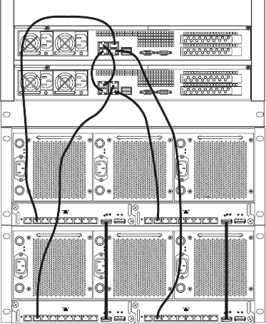
Setting IP Addresses for Crossover Link
123
Enabling a System Director
To enable a failover system for Avid ISIS:
1. Connect two System Directors (using straight or crossover cable) as shown in the following
figure.
2. Enable the software on both systems, see “Configuring the System for Failover” on
page 122.
nThe configuration information for the notification service (SMTP information, contacts, and
filters) is stored in the registry on the System Director. This information is not currently
replicated to the failover System Director and must be entered manually on both System
Directors. For information on setting up the notification service, see Setting up Error
Notification in the Avid ISIS Administration Guide.
Setting IP Addresses for Crossover Link
Avid recommends the System Director IP addresses for failover configurations that are listed
below. If you use different addresses, be sure to note them and have them available before
proceeding. You set the IP addresses in the Network Connections dialog box, which you access
from the Windows Control Panel. For information on setting Windows IP addresses, see the
documentation that came with your operating system.
21345678
MGMT
STATUS
21 345678
MGMT
STATUS
21 345678
MGMT
STATUS
21 345678
MGMT
STATUS

Configure a Failover Connection
124
To set IP addresses:
1. Go to Start > Control Panel > Network Connections for each System Director.
2. Set the Existing System Director to the following TCP/IP addresses for ports 1 and 2:
- Onboard Ethernet port 1 (ETH1) - 192.168.1.1 netmask 255.255.255.0
- Onboard Ethernet port 2 (ETH2) - 192.168.2.1 netmask 255.255.255.0
3. Set the New System Director to the following TCP/IP addresses for ports 1 and 2:
- Onboard Ethernet port 1 (ETH1) - 192.168.1.2 netmask 255.255.255.0
- Onboard Ethernet port 2 (ETH2) - 192.168.2.2 netmask 255.255.255.0
Configure a Failover Connection
Setting up the ISIS system for a System Director failover is done on two System Directors. The
first System Director is referred to as the Active System Director and the second System Director
is referred to as the Standby System Director.
nMake sure all clients are notified that you are stopping the System Director.
To set up a failover connection on the Active System Director:
1. Load the ISIS software on the Active System Director as described in “Loading the
Software” on page 85.
2. In the ISIS Launch Pad, click ISIS Control Panel icon or Start > Programs > Avid > ISIS
System Director and select Control Panel.
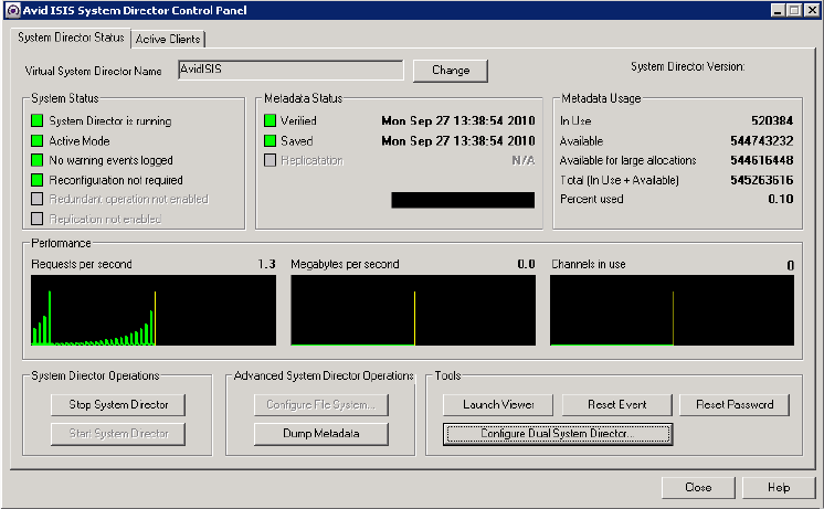
Configure a Failover Connection
125
3. Click Stop System Director.
The Configure File System button becomes active.
4. Click the Change button beside the Virtual System Director Name and type a name in the
Virtual System Director Name text box and click OK.
nThe same virtual name must be assigned to both System Directors.
5. Click Configure File System.
The File System Configuration dialog box opens.

Configure a Failover Connection
126
6. (First new System Director) Select Create Active File System and click OK.
cIf you already have a running System Director do not create a new file system and skip this
step. If you create a new file system on a System Director that already has a file system all
of your existing data will be lost.
The Avid ISIS System Director service automatically starts when complete. In the System
Director Control Panel, the “System Director is running” display turns green.
7. Click Stop System Director.
The Configure Dual System Director button becomes active.
8. Click Configure Dual System Director.
The Dual System Director Configuration dialog box opens.
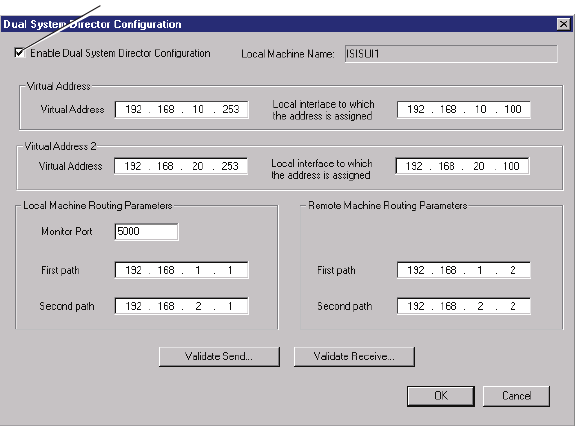
Configure a Failover Connection
127
9. Select “Enable Dual System Director Configuration.”
10. Configure the Virtual Addresses on both systems by doing the following:
a. Choose two unused static IP address that are used as the Virtual IP addresses for both
System Directors. This example uses 192.168.10.253 and 192.168.20.253.
b. Map the Virtual IP address to the corresponding real IP address for each of the System
Directors. This example uses 192.168.10.100 and 192.168.20.100.
c. Register both of the Virtual IPs in DNS with the Virtual System Director Name.
11. In the Local Machine area leave the Monitor port set to 5000. If you have another
application that uses port 5000, change the Monitor port to an available port number. This
port number must be the same on both the existing and the new System Directors.
12. Set the Local Machine First Path IP address to local IP 1: 192.168.1.1.
13. Set the Local Machine Second Path IP address to local IP 2: 192.168.2.1.
14. Set the Remote Machine First Path IP address to: 192.168.1.2.
15. Set the Remote Machine Second Path IP address to: 192.168.2.2.
The Active System Director has now been configured. Leave the Active System Director as
is; stopped and with the ISIS Control Panel and Dual System Director Configuration
window open.
16. Continue with “To set up the resiliency connection on the Standby System Director:” on
page 128.
Enable Dual System
Director Configuration
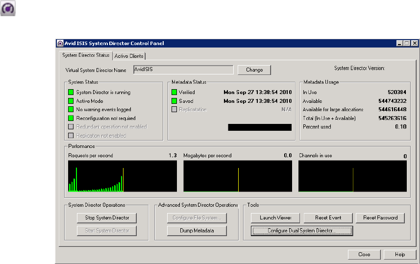
Configure a Failover Connection
128
To set up the resiliency connection on the Standby System Director:
1. Load the ISIS software on the Standby System Director as described in “Loading the
Software” on page 85.
2. Stop the Standby System Director, click System Director Control Panel from the ISIS
Launch Pad or Start > Programs > Avid > ISIS System Director and select Control Panel.
3. Click Stop System Director.
The Configure Dual System Director button becomes active.
4. Click the Change button beside the Virtual System Director Name and type a name in the
Virtual System Director Name text box and click OK.
nThe same virtual name must be assigned to both System Directors.
5. Click Configure Dual System Director.
The Dual System Director Configuration dialog box opens.
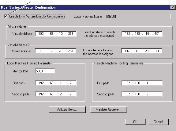
Configure a Failover Connection
129
6. Select “Enable Dual System Director Configuration.”
7. Configure the Virtual Addresses on both systems by doing the following:
a. Choose two unused static IP address that are used as the Virtual IP addresses for both
System Directors. This example uses 192.168.10.253 and 192.168.20.253.
b. Map the Virtual IP address to the corresponding real IP address for each of the System
Directors. This example uses 192.168.10.101 and 192.168.20.101.
c. Register both of the Virtual IPs in DNS with the Virtual System Director Name.
8. In the Local Machine area leave the Monitor port set to 5000. If you have another
application that uses port 5000, change the Monitor port to an available port number. This
port number must be the same on both the existing and the new System Directors.
9. Set the Local Machine First Path IP address to local IP 1: 192.168.1.2.
10. Set the Local Machine Second Path IP address to local IP 2: 192.168.2.2.
11. Set the Remote Machine First Path IP address to: 192.168.1.1.
12. Set the Remote Machine Second Path IP address to: 192.168.2.1.
The Standby System Director has now been configured. Leave the Standby System Director
as is; stopped and with the ISIS Control Panel open.
13. Continue with “To validate the connections:” on page 130.
Enable Dual System
Director Configuration
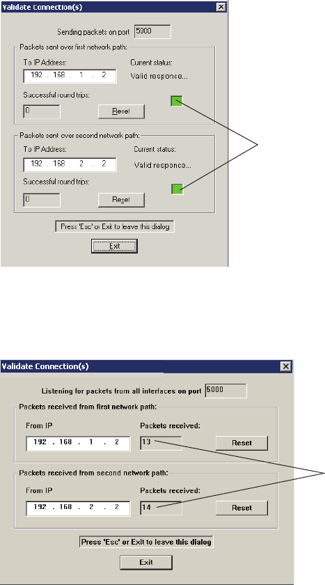
Configure a Failover Connection
130
To validate the connections:
1. Validate the crossover connections by clicking Validate Send on the Active System Director
and Validate Receive on the other System Director.
2. On the Sending System Director, you see the Red Box turn Green for each connection.
The numbers in the Packets Received boxes indicate the number of packets received from
the first System Director On the Receiving System Director you see the packets received
number incrementing for each connection.
3. On each system, click Exit.
Green
Packets received

Configure a Failover Connection
131
4. Repeat this validation procedure clicking Validate Send on the Standby System Director and
Validate Receive on the other System Director.
Verify you are getting the same results (green indicators and correct number of received
packets).
5. Click Configure File System on the Standby System Director.
The File System Configuration dialog box opens.
6. Select Create Standby System Director and click OK.
The Avid ISIS System Director service automatically starts when complete. In the System
Director Control Panel, the “System Director is running” display turns green.
7. Click Start System Director on both the Active and Standby System Directors and close the
ISIS Control Panels on each system.
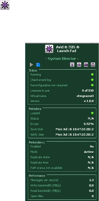
Stopping and Restarting the System Directors
132
Stopping and Restarting the System Directors
In a ISIS 7500 | 7000 failover configuration, you can stop the Active System Director and watch
the Standby System Director become the Active System Director. When you restart the System
Director that was previously Active, that System Director now becomes the Standby System
Director. If you stop and restart the Standby System Director it remains the Standby System
Director. The following procedures describes how you to stop and start the System Directors.
nIf you have a failed System Director, stop and restart that System Director. Very often a single
stop and start of the System Director corrects the problem.
To stop and start the System Director using the Launch Pad:
1. If the ISIS Launch Pad is not displayed on the Avid ISIS System Director Desktop, click the
ISIS Launch Pad icon in the Taskbar’s System Tray to display or hide the Launch Pad.
nYou can also open other ISIS tools by clicking the icons in the Launch Pad.
The ISIS Launch Pad is displayed.
2. Start or stop the System Director by clicking one of the following icons in the ISIS Launch
Pad.
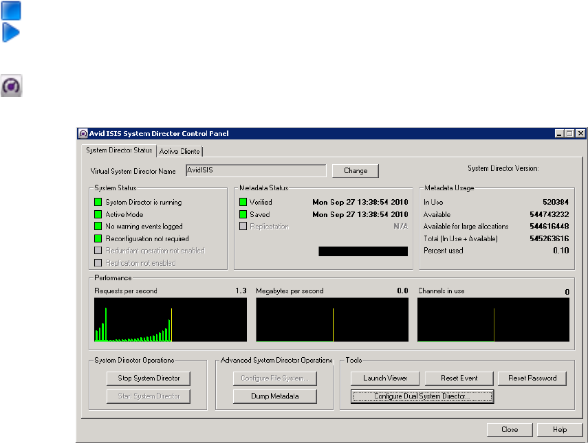
Binding Order for Health Monitoring
133
tClick the blue square icon to stop the System Director.
tClick the blue triangle icon to start the System Director.
To stop and start the System Director using the ISIS Control Panel:
1. Click Control Panel icon in the Launch Pad or Start > Programs > Avid > ISIS System
Director and select Control Panel.
2. Start or stop the System Director by clicking the appropriate buttons in the ISIS Control
Panel.
tClick Stop System Director to stop the System Director.
tClick Start System Director to start the System Director.
Binding Order for Health Monitoring
When you have your System Directors in a Failover configuration and use the Interplay Health
Monitor with the Interplay Framework, the VLAN 10 and VLAN 20 network interface cards
must be the first and second entries in the Network Interface Binding order to communicate
properly.
nIf a network crossover connection is the first entry, the System Director Health Monitor will not
display information regarding the System Director.
Binding Order for Health Monitoring
134
To set the network connection bindings order:
1. On the System Director, click Start > Settings > and double-click Network Connections.
2. Click the Advanced menu in the Network Connections window and select Advanced
Settings.
3. Click the Adapters and Bindings tab.
4. If the connections for the VLAN 10 and VLAN 20 network interface cards are not in the first
and second position, select them and press the Green Up arrow to move them to the top of
the list.
5. Make sure the two crossover connections are at the bottom of the list.

7Status LEDs and Stacking Problems
This chapter provides an explanation of the light-emitting diodes (LEDs) located on the different
sections of the Avid ISIS engines. It also provides a information on how to recover from a
stacking problem. The following sections are included:
•LED Locations and Colors
•LED Summaries
•Recovering from Stacking Problems
The ISS and IXS have activity and link LEDs for each port. The location of these LEDs are
shown in “Integrated Ethernet Switches” on page 29. These LEDs provide the following
functions:
• Activity — The activity LED indicates that the port is in use.
• Link — The link LED indicates that there is an active connection on the port.
LED Locations and Colors
The status LEDs are used to indicate errors and provide status on the different phases of the
software installation. The LED colors and blinking indicate the following functions:
• Green-blinking — System or section is getting ready or System is operation as expected
• Green-on solid — System or section is operation as expected and operational
• Amber-blinking — Minor failures occurring, but not fatal
• Amber-on solid — Fatal or almost fatal error has occurred, system or section is not
operational.
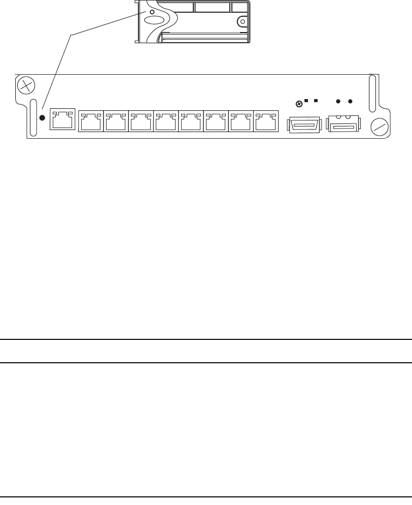
LED Summaries
136
LED Summaries
When determining errors, the status LED blinks at one of the following three rates or stays
On (on solid).
• Slow: 0.5 Hz
• Medium: 2.0 Hz
• Fast: 5.0 Hz
The following table provides a description of the ISS status LEDs.
The following table provides a description of the ISB status LEDs.
21345678
ISS
ISB as seen on front
(not to scale)
Status LEDs
ISS LED Summary
Color and Blink Speed Status
Green – slow Starting the Operating System
Green – on with 50 ms of black each second Master is operation as expected
Green – on with 50 ms of amber each second Backup is operation as expected
Amber – fast High temperature (> 60C)
Temperature critical (> 70C)
Waiting for temperature to drop
Amber – on solid Temperature OK/Not booting yet
Errora (followed by restart, but restart might not work)
a. Possible errors include: missing critical application, low level code problem, or temperature is critical.

LED Summaries
137
The following table provides a description of the Engine LEDs.
The following table provides a summary of the Engine LEDs during software installations.
ISB LED Summary
Color and Blink Speed Status
Green – slow Starting the operating system
Green – fast Degraded state
Green – on solid System is operation as expected
Amber – slow, all ISBs asynchronously No engine configuration
Amber – fast High temperature (> 60C)
Temperature critical (> 70C)
waiting for temperature to drop
Amber – on solid ISB has been taken offline in the user interface or
Temperature OK/Not booting yet Error (followed by restart,
if restart not working)
Possible errors include: missing critical application, low
level code boot problem, or temperature is critical.
Amber and Green – alternating fast flashing
(irregular)
ISB cannot boot because of a memory failure
The ISB needs to be replaced.
Engine LED Summary (Master ISS and All ISBs Synchronously)
Color and Blink Speed Status
Green – slow External request via ISS agent
Green – medium Stacking failure (error or collision)
Green – medium Engine error (anywhere)
Software Installation LED Reporting
Color and Blink Speed Status
Green – on solid No installation in progress

Recovering from Stacking Problems
138
Recovering from Stacking Problems
If your Avid ISIS shared storage network has a serious problems as a result of the setup, it might
necessary to recover the stack. Here are a few possible problems:
• Traffic loops were introduced
• Switch does not have the right IP address
• IP addresses seem to flipping; sometimes belonging to one switch, and then belonging to
another switch
Set One Switch Back to Default
The problem might only be with one particular switch or engine. If you think this is the case (for
example, a switch that was added does not have the right IP address), then perform the following.
To set a switch back to the default:
1. Disconnect the interconnect cables to both switches in the chassis of the problem switch. (If
the problem switch is an IXS, disconnect all stacking cables from each switch in the
chassis.)
2. In the Add/Remove Chassis page of the IXS, click Delete for the problem chassis.
3. Connect through the management port to the problem switch.
4. Use the management IP to go to the Switch Agent of the problem switch. For example
https://192.168.0.10:5015/.
5. Navigate to the “Advanced” page.
6. Under Switch Blade, click “Reset to factory defaults.”
7. Enter the password when prompted to reset the switch to defaults.
Amber – ½ second interval Installation starting, installing in phase 0
Amber – 1 second interval Installation in phase 1
Amber – 2 second interval Installation in phase 2
Amber – 3 second interval Installation in phase 3
Amber – fast Installation failed
Software Installation LED Reporting
Color and Blink Speed Status
Recovering from Stacking Problems
139
The switch and storage blade password is
se-admin
and the System Director password is
is-admin
.
8. The switch restarts.
When the switch starts up, it has IP address “192.168.10.26” and the password is reset to
default.
9. If the problem switch is an:
- IXS — Click Add from another IXS. If there is not another IXS, click Add from another
ISS.
- ISS — Click Add from the IXS to which this switch will connect.
10. Connect the interconnect cable from the problem switch to the IXS.
- If the problem switch is an IXS, connect an interconnect cable to another ISS.
- If the problem has been resolved, connect the interconnect cable from the switch on the
other VLAN subnet to the IXS on fixed subnet. If the problem switch was an IXS,
re-connect all other interconnect cables in the engine.
Rebuilding the Stack
The following procedure summarizes how to rebuild the entire stack of engines.
To rebuild the stack:
1. Disconnect all interconnect cables between all switches.
2. Pull each switch by removing them from the engine.
This clears any traffic loop problems.
3. Reseat the first IXS in the engine and connect through the management port of the first IXS.
4. Use the management IP address to access the switch’s Agent Page (for example
https://192.168.0.10:5015/).
5. Navigate to the Advanced Web page.
6. Under Switch Blade, click “Reset to factory defaults.”
nThe switch and storage blade password is se-admin and the System Director password is
is-admin. The System Director Web Page Administrator default password is blank.
7. Enter the password when prompted to reset the switch to defaults.
8. The switch restarts.
Recovering from Stacking Problems
140
When the switch starts, it has IP address “192.168.10.26” and the password is reset to the
default. Through the Switch Agent, configure the switch with the proper IP address range,
netmasks, time zone, passwords, see “Setting-Up Network Addresses In the Stack” on
page 69.
9. Perform the appropriate procedure for connecting your engines, see “Connecting ISIS
Hardware” on page 67.

8Avid ISIS 7500 | 7000 Upgrade Guidelines
This appendix provides a summarized list of what tasks need to be performed when upgrading
Avid ISIS 7500 | 7000. All Avid ISIS upgrades are to be performed by Avid ISIS Avid Certified
Support Representatives (ACSR).
The following list provides the order in which tasks need to be performed.
• If you have not already noted the host names, passwords, IP address, and other important
network details, see “Preupgrade Information” on page 158. Although this information
needs to be gathered before you start, the pages that include the blank tables are at the end of
this document.
• Do not perform an Avid ISIS system upgrade if your network is not in optimum working
order, see “Health Check” on page 141.
• If you have documented the preupgrade information and your Avid ISIS is healthy, you can
start the Avid ISIS system upgrade, see “Software Upgrade” on page 142.
• After you finish the upgrade, confirm everything is functioning properly, see “Post Upgrade
System Verification” on page 155.
Health Check
Before any changes are made to the system, perform the following quick checks to verify that the
system is in good working order. Do not perform an upgrade if there are any issues with the
system. Correct all problems before performing the upgrade.
Things to check before upgrading:
1. Log into the ISIS Management Console and click Storage Elements. All Storage Elements
should be green, investigate any error statuses. For details on troubleshooting Storage
Elements error statuses, search the Knowledge Base at www.avid.com/onlinesupport for
“ISB Error Status Glossary.”
2. Open a command window and ping all switches in both stacks. All switches should be
pingable and able to access the web pages for all switches. If running Avid ISIS v1.1B or
later, you could alternatively run switch diagnostics and only select the connectivity tests.
Access the switch diagnostics by clicking Advanced on the switch web page.
Software Upgrade
142
3. Ping each System Director on both subnets (left and right, not the crossover paths). Each
System Director should be accessible via both paths from any client or switch on the Avid
ISIS system.
4. Ping the default gateway on the left and right network from System Director and ISSs. This
should be accessible from any point in the network. You can ping directly from and ISS/IXS
from the Tools tab on the switch web page.
5. Log into each System Director and open the System Director’s Control Panel. Both paths
should be up, and standby should be receiving and replicating metadata. Check the Metadata
Status tab in the System Director’s Control Panel on the standby. The date stamp in the saved
and replicated fields should be current and updating frequently. Standby instructions only
apply if there is a failover machine present.
6. Check the system event logs on the System Directors for recent error events.
7. Perform a thorough physical inspection of the interconnection cables looking for:
- Missing retainers, strains, sharp bends, signs of physical abuse.
- Ensure that labels are visible, physically firmly in place, and legible.
- Confirm that all fans and ventilation areas are free of obstructions, dirt, lint, and debris.
- Ensure that there is clearance front and rear to allow components to be replaced without
obstructions for their full chassis travel length.
- Make sure cables are not zip tied to the power supplies or the switches.
8. Perform System Director Primary to Secondary Failover — Turn off one of the System
Directors and verify in the System Director Control Panel that the Active Mode indicator has
turned red. Turn the System Director back on and see that Active Mode displays Standby.
9. Check the system drive status on the System Director.
- On the AS3000, click Start > Programs > Intel -> Intel Rapid Storage Technology
right-click the Intel Rapid Storage Technology icon in the task bar. The icon should be a
green check mark when the drives are healthy.
- On the SR 2500, click Start > Programs > RAID Web Console 2 > Start UI and see that
the Server Heath is green. If not, search www.Intel.com and search for Intel® RAID
Software User’s Guide for corrective actions.
Software Upgrade
After noting the necessary network and system component information listed in “Preupgrade
Information” on page 158 you are ready to upgrade the Avid ISIS. The following is a generalized
procedure for upgrading an ISIS. Read the upgrade section in the ISIS ReadMe for specific
upgrade details in that release.
Software Upgrade
143
To upgrade Avid ISIS 7500 | 7000 v2.1.1 and later, you need to upgrade the clients before you
upgrade the infrastructure. This is necessary because ISIS client software before v2.1.1 is not
supported in the ISIS v2.1.1 and later infrastructure. Although, v2.1.x client software is
supported in v1.4 and later infrastructures. Once the clients have been upgraded, you can
upgrade Avid ISIS infrastructure.
The clients are defined as follows:
• Avid editing applications
• Interplay Assist and Instinct
• Interplay Access
• Avid Approved Applications Initiative such as Pro Tools and Final Cut Pro
The infrastructure is defined as follows:
• System Director — System Director software and upgrade Storage Blades (ISBs) and
Switch Blades (ISS/IXSs) in the Avid ISIS engines to the v2.1.1 firmware
• Interplay servers — Interplay Engine, Interplay Media Indexer, Interplay Transfer, and
CaptureManager
• Capture devices — AirSpeed, AirSpeed Multi Stream, and Avid Interplay Low-Res Encoder
nIf updating from an ISIS v1.x infrastructure you must do a full redistribution on your workspace
after you have updated the infrastructure to v2.x. A full redistribution is needed to take
advantage of the performance improvements. The redistribution is required even if the system
has zero (0) configuration changes listed.
nAvid ISIS v2.1.1 SR2500 64-bit System Directors ship with an
SD_X64_PIS21_MBS5000XALR_V05_DVD or later image on the internal RAID drives. The
image version number can be found in the
c:\IMAGE.TXT
file on the System Director root
directory. If upgrading your 64-bit System Director from Avid ISIS v2.0.1 or earlier Avid
recommends you reimage the System Directors to reduce the number if updates required in this
release. For instructions on how to reimage the System Director, see the “Reinstalling the
Windows Storage Server 2008 R2 Operating System” on page 194.
If you are upgrading from Avid ISIS v2.0.1 or earlier, Avid suggests you consider reimaging the
64-bit System Director (see “Reinstalling the Windows Storage Server 2008 R2 Operating
System” on page 194). Several configuration changes and driver versions have been updated in
the 64-bit System Director and you might find it easier than following the referenced procedures
listed in the following procedure. If you do decide to reimage, perform a failover, then reimage
the Standby System Director first.
Software Upgrade
144
Component Requirements From Previous ISIS 7500 | 7000 Releases
The following is a list of items outside the ISIS software that you might need to update
depending on the current version of your ISIS software. If you are on a version prior to 4.0, Avid
recommends that you update your System Director Storage Blades (ISB's) and switches (ISS's
and IXS's) to v4.2.x prior to updating to v4.6. If you are setting up a new ISIS system or updating
an ISIS environment that is already at v4.0, continue with ISIS 7500 | 7000 Upgrades.
• If updating from ISIS v2.4 – v4.0 — update the ISIS 7000 System Director software before
Installing this release of ISIS 7000 software, see Avid ISIS v4.0 ReadMe.
nRemember to copy your metadata to the new v4.x location, see ISIS 7500 | 7000 Upgrades.
• If updating from ISIS v2.0 – v2.0.6 to v2.4 — update the System Director Intel system BIOS
on the 64-bit System Director (SR2500), see Avid ISIS v2.2.2 ReadMe.
• If updating from ISIS v2.0 – v2.0.6 to v2.4 — update the Intel RAID controller driver and
registry key on the 64-bit System Director, see Avid ISIS v2.2.2 ReadMe.
• If updating from ISIS v2.0 – v2.0.3 to v2.4 — update the System Director to allow Windows
Updates, see Avid ISIS v2.2.2 ReadMe.
• If updating from ISIS v2.0 – v2.0.1 to v2.4 — update the System Director application key
(dongle), see Avid ISIS v2.2.2 ReadMe.
• If updating from ISIS v1.4 – v2.0.1 to v2.4 — you must first upgrade to Avid ISIS v2.1.1
before upgrading to v2.4, For instructions, see Avid ISIS v2.1.1 ReadMe.
ISIS 7500 | 7000 Upgrades
The following process summarizes the upgrade process to v4.6. Avid ISIS 7500 | 7000 v4.6
infrastructure software requires Avid ISIS v4.6 or later Client Manager software.
nIf you have a 32-bit System Director, you must upgrade to a 64-bit System Director before
loading your new ISIS v4.x software.
nIf you are upgrading from a version earlier than Avid ISIS v4.0, you must first perform the
updates documented in “Component Requirements From Previous ISIS 7500 | 7000 Releases”
on page 144 before upgrading to v4.6 and later.
Software Upgrade
145
Here are few general comments on upgrading System Directors and the ISIS file system
metadata:
• The preferred method of upgrading the file system metadata is using Partition0 and
Partition1. These are copies of the in-memory file system and the most accurate accounting
of the ISIS.
• The PartitionDump.bin file is a very different representation of what Avid believes to be the
important parts of the file system that should persist. Do not be tempted to just import
PartitionDump.bin, although this may be necessary if problems are seen with loading both
Partition0 and Partition1. Since only the active System Director writes out
PartitionDump.bin any PartitionDump.bin on the standby is out of date. Never use the
PartitionDump.bin from the standby System Director in an upgrade.
• Sometimes one of the Partition files fails to load but the other succeeds. This is considered a
successful upgrade and is still the preferred method of upgrading.
• There have been cases of loading old PartitionDump.bin files and losing data. Always
contact your support team before attempting to import PartitionDump.bin.
• There is a bug in ISIS versions 3.1 through 4.5 where the tie breakers are deleted when
importing PartitionDump.bin. When importing PartitionDump.bin it is important to
manually record the tie breakers before beginning the upgrade and restore them after the
upgrade completes.
Depending on what version you are upgrading from/to there are different steps required. This
guide contains common setup and finishing steps but different steps in the middle based on the
upgrade. Please read through once and identify your upgrade before beginning.
Common Setup Steps:
1. Download the ISIS v4.6 software kit from the Avid Download Center
(www.avid.com/US/support/downloads) to your System Director.
2. Create a new “test” workspace in a storage group. (This will be used later to verify that the
upgrade completed successfully.)
3. Log into Administrator account on the Standby System Director and open the System
Director Control Panel. Wait for the indication that metadata changes have been received
and saved. Allow this to happen twice. Stop the Standby System Director using the System
Director Control Panel.
4. Log into active System Director and do the following:
a. Open the System Director Log Viewer
b. Stop the System Director using the System Director Control Panel
cIf there are any errors please stop and contact your support team.
Software Upgrade
146
5. Check the modify date time of the files Partition0, Partition1 and PartitionDump.bin. The
Date Modified times should be identical or at most there can be a 1 minute difference. If the
times differ by more than a minute stop and contact your support team. These times
should also be very close to the current date/time. If they are more than a few minutes old
please stop and contact your support team.
To upgrade from v2.4 to v4.2.1 on the same hardware:
1. Follow the steps in “Common Setup Steps:” on page 145.
2. Load the ISIS v4.x software kit on the Active System Director.
3. Double-click the Autorun.exe.
nIf the Package Selection menu does not allow you to select the software, click Quit and run the
Autorun.exe again.
4. Once the install completes open the System Director Control Panel and stop the System
Director.
5. Copy (not move) the following files from the v2.x folder to the v4.x folder:
Partition0 and Partition1
Old v2.x metadata location
D:\Program Files\Avid Technology\AvidUnityISISSystemDirector
x64
New v4.x metadata location
D:\Program Files\Avid\ISIS System Director
6. Open the System Director Log viewer.
7. In the System Director Control Panel select “Start System Director.” If there are problems
with the upgrade of the Partition file stop and contact your support team.
8. Once the reconfigure completes the active System Director will be up and running. Proceed
to “Completing the Upgrade:” on page 148.
To upgrade from 2.4 to v4.X and from an SR2400/SR2500 to an AS3000:
1. First check to see if you are moving from a 32-bit System Director:
In this upgrade the file system metadata files need to be moved from the SR2400/SR2500 to
the AS3000. A network folder or memory stick can be used for this. The folder where the
System Director software resides was changed starting in v4.0. The Partition files need to be
copied manually. To do this correctly requires knowing whether the System Director is 32
bit or 64 bit. All SR2400 System Directors are 32 bit. There are some SR2500 System
Directors that were configured as 32 bit so this needs to be checked. The following are the
folder names and where they are located:
- From v2.X metadata location for a 32 bit System Director
- D:\Program Files\Avid Technology\AvidUnityISISSystemDirector
Software Upgrade
147
- From v2.X metadata location for a 64 bit System Director
- D:\Program Files\Avid Technology\AvidUnityISISSystemDirector64Bit
- To v4.X metadata location
- D:\Program Files\Avid\ISIS System Director (This folder is created on installation
of the 4.x kit)
2. Follow the steps in “Common Setup Steps:” on page 145.
3. Copy the following files from the v2.x folder to the network folder or memory stick.
a. Partition0
b. Partition1
c. PartitionDump.bin
4. Load the ISIS v4.x software kit on the new AS3000 Active System Director.
a. Double click the Autorun.exe.
5. Once the install completes open the System Director Control Panel and stop the System
Director.
6. Copy the following files from the network folder or memory stick to the v4.x folder:
a. Partition0
b. Partition1
7. Open the System Director Log viewer.
8. In the System Director, from the System Director Control Panel select Start System Director.
If there are problems with the upgrade of the Partition file please stop and contact your
support team.
9. Since the memory footprint for the System Director is larger on the AS3000 the System
Director Control Panel will have a status showing either “Reconfiguration possible” or
“Reconfiguration required.” To reconfigure use the following steps:
a. Stop the System Director
b. Select Configure File System.
c. In the File System Configuration dialog select Reconfigure File System. If there are
problems with the upgrade of the Partition file please stop and contact your support
team.
10. Once the reconfigure completes the active System Director will be up and running. Proceed
to “Completing the Upgrade:” on page 148.
Software Upgrade
148
To upgrade from a 4.x to a newer v4.X:
1. Create a new folder on the D: drive and copy the following files to the new folder prior to
installing the v4.x kit:
a. Partition0
b. Partition1
c. PartitionDump.bin (PartitionDump.bin is for use in case the normal Partition files fail to
load)
2. Load the ISIS v4.x software kit on the Active System Director.
a. Double click the Autorun.exe.
3. After the kit install completes, open the System Director Log Viewer. If there are problems
upgrading the metadata please stop and contact your support team.
Completing the Upgrade:
1. After the new Active System Director has started, log into the management console and
check if the “test” workspace exists on the Workspaces page. If it does not please stop the
System Director and contact your support team.
2. Upgrade the Standby System Director. Be sure that there are no Partition files in the v4.X
directory as they are not needed. If you are upgrading on the same system then move these
files to a temporary folder and do the following:
a. Load the ISIS v4.x software kit on Standby System Director.
b. Double-click the Autorun.exe file in the software kit.
c. Open the System Director Log Viewer.
d. Open the System Director Control Panel and stop the System Director.
e. Select Configure File System.
f. In the File System Configuration dialog select Create Standby System Director. If there
are problems creating the new Standby please contact your support team.
g. Once the new Standby System Director starts it will receive a complete copy of the
metadata from the Active Director.
3. The first replication between the active and standby System Directors copies the entire heap
over and can take several minutes. Because this first replication takes so long you will see a
message in the active System Director Log Viewer “Remote meta data save did not
complete.” This is normal and does not indicate a problem with the upgrade. The System
Director Control Panel on each system will indicate that the replication is in progress.
4. Once the initial replication between the System Directors is complete you can close the
System Director Log Viewer on both System Directors.
Software Upgrade
149
Copying the Metadata to the New Default Location On the System
Director
The ISIS v4.x software is installed in a different path and folders than in previous ISIS releases.
After upgrading your System Director to the ISIS v4.x software, you must copy your metadata to
the new location to get access to your existing data.
To copy the existing metadata to the new installation directory:
1. Install the ISIS 7000 v4.x software on your 64-bit System Director as previously described.
2. Stop the System Director Service.
3. Copy the files listed below from their old location and replace the files in the new location
on drive D:
- Partition0
- Partition1
- PartitionDump.bin
Old v2.x metadata location
D:\Program Files\Avid Technology\AvidUnityISISSystemDirector
x64
New v4.x metadata location
D:\Program Files\Avid\ISIS System Director
4. Start the System Director Service.
nIf there is an error upgrading the metadata, the System Director restarts and then fails again.
Import the metadata as described in the following procedure.
To import the existing metadata to the new installation directory:
1. Start the Avid ISIS and click System Director Control Panel from the Launch Pad or Start >
Programs > Avid > ISIS System Director and select Control Panel.
2. Click Stop System Director.
The Configure File System button becomes active.
3. Click Configure File System.
The File System Configuration dialog box opens.
4. Select Create Active File System From Import and click OK.
5. You are prompted to navigate to the
PartitionDump.bin
file.
Software Upgrade
150
cVerify that the time stamp on ALL metadata files is current. These files must be up-to-date
before importing them. Importing out-of-date metadata can result in media loss. Please
contact Customer Success immediately if encountering any issues with importing
metadata.
The old v2.x metadata location is:
D:\Program Files\Avid Technology\AvidUnityISISSystemDirector
x64
The file is copied to a location used by the Active System Director and its extension is
changed from bin to import.
D:\Program\Avid\ISIS System Director\PartitionDump.import
The Active System Director creates a new file system and imports the metadata from the file.
It may take a few minutes to import PartitionDump.bin depending on how much metadata
you have. Once it finishes, you will see “COMPLETING SAVE AND IMPORT
OPERATION (SUCCESS).”
6. Verify that the System Director is now running and Active. Start the Management Console
and verify that all workspaces are listed. If not, call customer support before continuing.
Avid ISIS Software Installation From the USB Flash Drive
Avid ISIS Systems ship with one blank 8GB USB Drive that is intended to be used for storing
the ISIS Software Kit. You need to download the ISIS software kit from download center
(http://www.avid.com/US/support/find-support/category/updates) and copy it to this USB drive
The second blank 16GB USB drive is used to create a bootable recovery drive. This will be used
when the server Operating System needs to be re-imaged.
If upgrading your software from an earlier release, download the software from the Avid
Download Center (www.avid.com/US/support/downloads) to your System Director.
nIn the past Avid has instructed you stop the Standby System director, upgrade the Standby, and
restart the Standby. Once the Standby was running you were instructed to update the Active
System Director.
Avid has revised the upgrade process to stop the Standby System Director and upgrade the Active
System Director first, then upgrade the Standby System Director. This process avoids replicating
metadata between ISIS software versions.
To install your Avid ISIS software on new installs:
1. Log in to the Avid ISIS 7000 as Administrator (default password:
is-admin
).
2. Make a folder for the software kit on your root directory (C:\) of your Active System
Director.
Software Upgrade
151
3. Insert the USB flash drive with software kit into any of USB ports on your Active System
Director.
nYou can run the software installer from the USB flash drive. The advantage of copying the
software kit to the Avid ISIS is that you have easy access to kit files if you should ever them in the
future.
If the USB flash drive does not automatically display:
a. Double-click the computer icon on the desktop.
b. Double-click the USB flash drive icon in the window and copy the software kit into the
new folder you created on the Avid ISIS system.
4. Double-click the Autorun.exe file in the software kit.
The installer detects the existing version of the installed software (if any) and displays the
components that need to be upgraded in the splash screen.
5. Select ISIS 7000 System Director from the “Select Software Package” menu.
The File Gateway selection is used when loading the Avid File Gateway server. The File
Gateway software cannot be installed on the same server as the System Director software.
6. Click Apply.
7. Follow the screen prompts accepting the defaults and License agreement.
8. Once the installation is complete, click Finish.
9. Install the Application Key or apply your software license.
10. Load the ISBs and ISS/IXSs firmware. Using the ISIS Management Console, select all the
ISBs and click Upgrade Storage Blades and then select all your ISS/IXSs and click Upgrade
Switch Blades. You do not need to wait for the ISBs to be finished, you can upgrade ISBs
and ISS/IXSs at the same time.
You can watch the upgrade progress in your Monitoring tool.
11. Open the ISIS Control Panel.
12. Click Stop System Director.
13. Click Configure File System.
14. Open the Management Console.
Log in using the Administrator user name and the default password is blank.
15. Select Create Active File System and click OK.
16. Click the Storage Managers icon.
17. Select your ISIS ISBs in the list and click Bind.
18. Create a Storage Group, Workspaces, and add Users in the Management Console.
Software Upgrade
152
19. Repeat these steps if you are setting up a Standby System Director.
20. Install your Avid ISIS client software. For more information, see the Avid ISIS 7000 Client
Guide.
Intel Network Driver and BIOS Update
Avid has qualified an Intel system BIOS upgrade on the 64-bit System Director (SR2500). This
BIOS and Intel Pro driver upgrade combination corrects a condition where the network
connection fails during a restart. The following sections describe the updates.
nIf you find it necessary to reimage the System Director, you need to updated the network driver
again. The BIOS is not affected when you reimage your server.
64-bit System Director BIOS Upgrade
Avid is recommending you update the BIOS on the 64-bit System Director and File Gateway. To
do that, you can visit the Intel web site and follow their instructions, or use the files and
instructions posted on the Avid Download Center (http://www.avid.com/US/support/downloads).
The procedure on the Avid Download Center requires you to create an Intel Deployment
Assistant DVD and use a USB flash drive to load the BIOS update package on the System
Director and File Gateway. Instructions for running the Intel BIOS Upgrade Utility and installing
the BIOS are included with the image for the utility and the BIOS package.
nCheck your current BIOS version before upgrading the BIOS. If your BIOS is at version 98, you
have the recommended BIOS version for this release. Enter BIOS Setup by pressing the F2 Key
during POST and the version is displayed as S5000.86B.12.00.0098 in the Main tab.
Intel RAID Controller Driver Update
This section describes the process for updating the Intel driver and registry key for the internal
RAID controller on the Intel SR2500 server using the SROMBSAS18E Intel hardware RAID
controller. This RAID controller is used in the Avid ISIS SR2500 System Director and the Avid
Interplay 64-bit Media Indexer. This driver does not apply to the other SR2500 configurations
using the embedded SATA RAID ESRTII.
nThe majority of the Intel SR2500 Avid ISIS System Directors use a 64-bit operating system. Avid
did ship some Intel SR2500 System Directors with a 32-bit operating system before the 64-bit
operating systems were released. All Avid ISIS System Directors using the Intel SR2500 server
require this RAID controller driver update.
The RAID controller update requires a driver update and a registry change. Access the update
package from one of the following locations. Create a new folder on the server that you are
updating and place the update files in it.
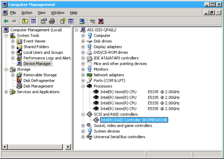
Software Upgrade
153
This RAID controller driver is available from two locations:
• Download the Intel hardware RAID controller SROMBSAS18E update package from
(http://www.avid.com/US/support/downloads).
• This version of the Intel driver has been added in the Avid ISIS software installer kit in
\Firmware\ISIS 7000\Intel\SR2500_Intel_Disk_Controller_Driver
\IntelSROMBSAS18E_Raid_Controller\Intel_Raid_v3.11.0.xx
folder.
To upgrade the SROMBSAS18E Intel driver:
1. Access the Standby System Director and stop the System Director service using the ISIS
Control Panel.
2. Right-click on My Computer and select Manage. The Computer Management Window
opens.
3. Select Device Manager. The Device Manager opens
4. Click the plus sign (+) next to SCSI and RAID Controllers.
5. Right-click on the Intel RAID Controller SROMBSAS18E and select Properties.
6. Click the Driver tab in the Properties window.
Software Upgrade
154
7. Click Update Driver in Driver tab.
8. In Hardware Update Wizard, do not let Windows select the driver:
a. Select “No, not at this time” and click Next.
b. Select “Install from a list of specific location (Advanced)” and click Next.
c. Select “Don’t search. I will choose the driver to install” and click Next.
d. Click “Have Disk.”
e. Click Browse and locate the
oemsetup.inf
file in the package you copied to the server.
- 64-bit System Director and Media Indexer — IntelSROMBSAS18E_Raid
_Controller
\Intel_Raid_v3.11.0.xx\W2K3X64
folder
f. Click Open, in the Locate File dialog box.
g. Click OK, in the Install From Disk dialog box.
h. Click Next in the Hardware Update Wizard.
9. Once you complete the driver install, click No when prompted to restart the server.
10. Close the Properties window.
11. Apply the registry key by browsing to the
RegKey_Updates
folder in the package you
copied to the server.
64-bit System Director — double-click the
w2k3.reg
file to apply the registry key change.
The following two entries are added to the 64-bit System Director registry location:
KEY_LOCAL_MACHINE\SYSTEM\CurrentControlSet\Services\msas2k3\
Parameters\Device
DriverParameters = flushrequest= 3
DriverParameter = flushrequest= 3
12. Restart the Standby System Director.
13. After the StandBy System Director has restarted, turn off the Active System Director to
failover to the updated Standby System director. Repeat this procedure on the second System
Director.
Record IP Addresses on the System Director
Before you update your Intel Pro network driver, Avid recommends you record the current IP
address used on the System Directors. This precaution allows you to restore the IP addresses to
the current settings if your network configuration is accidently lost.
Post Upgrade System Verification
155
To record the current IP addresses used by the System Director:
1. Open a command window on the System Director. Click Start > Programs > Accessories >
and select Command Prompt.
2. Type
ipconfig /all > c:\ip.txt
in the Command Prompt window.
This command saves a text file (named ip.txt) to the root directory on the System Director.
Open this text file if need to reconfigure the IP addresses to the addresses used before
performing this network configuration update.
Post Upgrade System Verification
After upgrading a system it is important to do a series of checks to verify that all upgraded
components are functioning optimally.
To verify the upgrade:
1. Verify network connectivity for all components:
a. Ping all ISSs and IXSs on left and right stack.
b. From any client, ping Active System Director and Standby System Director on left and
right sides.
c. Ping the virtual System Director on left and right side.
2. Verify both System Directors are functioning properly by checking the following:
a. Check if any new errors are getting generated in the event logs.
b. Both paths should be up and all green lights in System Director’s Control Panel on both
System Directors. If no failover, some lights will be blue.
c. Metadata should be replicating between the two System Directors. The Standby should
be toggling between receiving and replicated. Check the Metadata Status tab on the
standby. The date stamp in the saved and replicated fields should be current and
updating frequently.
d. Check the RAID status on the System Directory.
- On the AS3000, click Start > Programs > Intel -> Intel Rapid Storage Technology
right-click the Intel Rapid Storage Technology icon in the task bar. The icon should
be a green check mark when the drives are healthy.
- On the SR 2500, click Start > Programs > RAID Web Console 2 > Start UI and see
that the Server Heath is green. If not, search www.Intel.com and search for Intel®
RAID Software User’s Guide for corrective actions.
3. Perform System Director Primary to Secondary Failover — Turn off one of the System
Directors and verify in the System Director Control Panel that the Active Mode indicator has
turned red. Turn the System Director back on and see that Active Mode displays Standby.
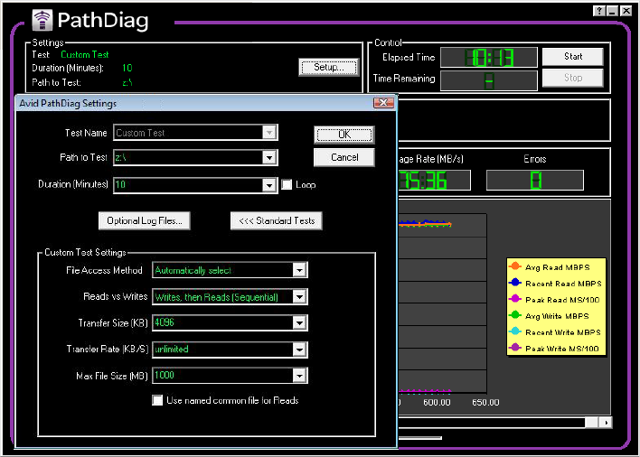
Post Upgrade System Verification
156
4. Check all clients for proper operation using Path Diag. Run path diag on a couple of clients
and verify consistent performance. To set PathDiag Tool:
a. Do one of the following.
- (Windows) Select Start > All Programs > Avid > ISIS Client > PathDiag.
- (Macintosh) Select Go > Applications > AvidISIS folder. In this folder, double-click
the PathDiag.app file.
b. Click Setup.
c. Set “Path to Test” to a mounted ISIS workspace letter. (Check in my computer if not
sure) Make sure its an ISIS workspace and not the internal C: drive.
d. Set the duration to 10 minutes.
e. Click Custom Test and set the following parameters:

Post Upgrade System Verification
157
f. Click Ok and Start.
- 1-Gb clients that are not bandwidth limited should expect at least 65 MB/sec in the
Path Diag tool.
- 10-Gb clients that are not bandwidth limited should expect at least 500 MB/sec for
reads and at least 200 MB/sec for writes in the Path Diag tool.
5. While Path Diag is running check the system to make sure that there are no Network
Degraded status indications. Check the following:
a. In the ISIS Management Console, click Storage Elements. All ISBs should be green and
not displaying any Network Degraded states.
b. Spot check a couple ISBs by browsing to the ISB web page and click Statistics. Select
the bottom network tab. None of the error columns should be incrementing. Press F5 to
update the page a few times.
For details on troubleshooting Storage Elements error statuses, search the Knowledge
Base at www.avid.com/onlinesupport for “Troubleshooting the Network Degraded
Status on ISIS 1.0-1.1” Tech Alert.
6. Run Switch Infrastructure Diagnostics:
a. Navigate to any switch agent web page (in the ISIS Management Console, click Chassis
from the list on the left, click Details tab and then double-click on a switch IP address).
b. In switch web page, click Advanced tab.
c. Click Switch Infrastructure Diagnostics from the list on the left.
d. Click Select All under System Tests.
e. Select Both in Select Network section.
f. Select All chassis in Select Chassis menu.
g. Click Run Diagnostics.
Custom Test
Settings
1 Gb client
(not bandwidth limited)
10 Gb Client
(not bandwidth limited)
File Access Method Automatically select Automatically select
Reads vs Writes Writes, then Reads (Sequential) Writes, then Reads (Sequential)
Transfer Size 4096 16384
Transfer Rate Unlimited Unlimited
Max File Size 1000 1000
Preupgrade Information
158
Let the diagnostics run, when the Switch Diagnostics - Reported Result/System
Overview displays, the results from all switches in both stacks should be available in the
summary page.
h. Click Switch Diagnostics Results Summary Page.
i. Any errors report as red and warning conditions are amber. Click headings to investigate
any error or warning statuses. There should be no red statuses present.
7. Check all other zones in use for proper operation. If there are Zone 2 and 3 clients, each of
these zones should be checked with clients running Path Diag:
a. Run a Path Diag client for left and right side for each Zone 2 switch in place.
b. Run a couple of Zone 3 path diag clients and verify consistent performance.
nA Zone 3 client might not have the bandwidth of a Zone 1 or 2 client.
Preupgrade Information
Gather the following information before the upgrade. This information is critical to
troubleshooting an Avid ISIS.
• Current Avid ISIS software version
• Avid ISIS Administrator password
• Switch agent password
• Number of Avid ISIS engines
• ISB Size: 500 GB ____ 1 TB____ 2 TB____ 4 TB____ 8 TB____
• Number of Storage Groups
• Number and type of editing clients: (Windows or Macintosh, and using what zones)
• Number of AirSpeeds
• Other workgroup server details (for example Interplay; host names, passwords, and
versions)
Zone 2 Switch Information
Note the following switch information:
•Type of switch (Cisco/Foundry)
• Number of switches
• Location of configuration files

Preupgrade Information
159
System Director Information
Note the following System Director information:
Virtual Network Name and IP Addresses
Virtual IP Left
Virtual IP Right
Virtual ISIS Name
System Director 1
Host name
Administrator Password
IP address
Left ISIS IP Address
Left Default Gateway
Right ISIS IP Address
Right Default Gateway
First failover IP address
Second failover IP address
System Director 2
Host name
Administrator Password
IP Address
Left ISIS IP Address
Left Default Gateway
Right ISIS IP Address
Right Default Gateway

Preupgrade Information
160
ISIS Engine/Switch Information
Fill out the following engine and switch information for the on site equipment.
Are any engines using Link Aggregation on the 10-Gb links? ______________
Note what engines that are using 10-Gb links and the configuration (a maximum of eight 10-Gb
links are supported):
First failover IP address
Second failover IP address
Engine #1, Serial Number
Left IXS/ISS IP: Right IXS/ISS IP:
First Left ISB IP: First Right ISB IP:
Left IXS IP: Right IXS IP:
Engine #2, Serial Number
Left IXS/ISS IP: Right IXS/ISS IP:
External Zone 2 switch
IP address (if attached):
External Zone 2 switch
IP address (if attached):
Engine #3, Serial Number
Left ISS IP: Right ISS IP:
External Zone 2 switch
IP address (if attached):
External Zone 2 switch
IP address (if attached):
Engine #4, Serial Number
Left ISS IP: Right ISS IP:
External Zone 2 switch
IP address (if attached):
External Zone 2 switch
IP address (if attached):

Preupgrade Information
161
Engine #5, Serial Number
Left ISS IP: Right ISS IP:
External Zone 2 switch
IP address (if attached):
External Zone 2 switch
IP address (if attached):
Engine #6, Serial Number
Left ISS IP: Right ISS IP:
External Zone 2 switch
IP address (if attached):
External Zone 2 switch
IP address (if attached):
Engine #7, Serial Number
Left ISS IP: Right ISS IP:
External Zone 2 switch
IP address (if attached):
External Zone 2 switch
IP address (if attached):
Engine #8, Serial Number
Left ISS IP: Right ISS IP:
External Zone 2 switch
IP address (if attached):
External Zone 2 switch
IP address (if attached):
Engine #9, Serial Number
Left ISS IP: Right ISS IP:
External Zone 2 switch
IP address (if attached):
External Zone 2 switch
IP address (if attached):
Engine #10, Serial Number
Left ISS IP: Right ISS IP:

Preupgrade Information
162
On Site Spares
List all Avid ISIS spare parts that are onsite:
External Zone 2 switch
IP address (if attached):
External Zone 2 switch
IP address (if attached):
Engine #11, Serial Number
Left ISS IP: Right ISS IP:
External Zone 2 switch
IP address (if attached):
External Zone 2 switch
IP address (if attached):
Engine #12, Serial Number
Left ISS IP: Right ISS IP:
External Zone 2 switch
IP address (if attached):
External Zone 2 switch
IP address (if attached):
Spare Components and Cables
Part Quantity Firmware Version (if known)
ISBs
ISSs v1.x or v2.x (ISS2000) hardware
IXSs v1.x or v2.x (IXS2000) hardware
XFP, X2, and SFP+
(used with external switches)
N/A
Intel® network boards
10-GB fiber cable N/A
CAT5e/6 cable N/A
Xenpack® (if Cisco)
3rd party switches
Additional Parts Available

Preupgrade Information
163
Spares Checklist
Use the following list to assure that you have the correct parts onsite when performing any Avid
ISIS upgrade. This can be a mix of customer spares and parts brought onsite by upgrade
technicians.
• 1 — IXS and IXS2000
• 1 — ISS and ISS2000
•2 — ISBs
• 1 — XFP and SFP+ (used with external switches)
Additional spares for a comprehensive spares parts list:
• If Cisco switches are in use: 1 Xenpack, 1 SC-LC cable
• If Foundry switches are in use: 1 additional XFP, 1 LC-LC cable
Spare Components and Cables (Continued)
Part Quantity Firmware Version (if known)

9Avid ISIS Upgrade Utility
This appendix describes the user interface of the Avid ISIS Upgrade Utility. The Avid ISIS
Upgrade Utility (AvidUnityISISTools.msi) can be found on the Avid ISIS 7000 software kit in
the
\AvidISISUtilities\ISIS 7000\
folder. This utility is an application for upgrading the
ISS and ISB firmware. It offers an alternative to the normal online upgrade utilities when the
switching infrastructure cannot be maintained during the upgrade.
nThe original documented procedure for upgrading the ISS and ISB firmware is located on the
Avid Web site under the name: Loading Firmware on Avid ISIS 7000 Switches. The original
procedure is now replace by this Avid ISIS Upgrade Utility.
Overview and Requirements
This stand-alone application allows field engineers to start and monitor the installation of switch
and ISB upgrades from a laptop connected to Avid ISIS through the management port. This
utility does not replace the current software upgrade process. Its primary function is for
upgrading a switch or a pair of switches that is incompatible with an existing stacked network.
Insertion of these switches into the network before the upgrade could disrupt or compromise the
network’s operation.
Functional Description
The Avid ISIS Upgrade Utility is a Windows based application that provides the following
functions:
• Provides a self-configuring FTP service.
• Picks up the install packages via a browse window.
• Discovers all the existing devices (switches and blades) on the network via broadcasting and
displays the information in a table.
• Displays the existing version, status, and package version already installed on each device.
• Provides the capability of issuing the firmware install command to one or more of the
displayed devices at the same time.
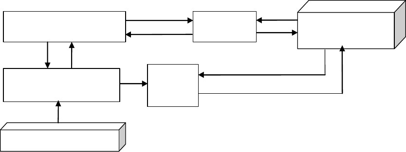
Overview and Requirements
165
• Provides the capability of monitoring the install status of every device currently in install
process.
• Provides the capability of viewing the install log information of each device individually.
Software Component Design
The Avid ISIS Upgrade Utility is composed of the following components:
• The GUI Component — provides the Graphical User Interface of the application
• The Avid ISIS Upgrade Utility application programming interface (API) handles the low
level functions such as:
- Configure and start the FTP server thread.
- Discover available Avid ISIS systems connected to the network.
- Manage and monitor the various Avid ISIS install threads.
- Manage the command requests and responses between the Avid ISIS Upgrade Utility
and the Avid ISIS agent.
• FTP Server — provides the file transfer service necessary for the devices to retrieve the
install package.
Avid ISIS Upgrade Utility Components
ISIS Upgrade Tool GUI
Laptop
ISIS Upgrade Tool API
ISIS
Device
ISIS Agent
FTP
Serve
r
Software Interface
166
Software Interface
The software interfaces with the storage devices through the switch agents with HTTP requests.
The application is provided with a graphical user interface which is described in the following
sections. The Avid ISIS Upgrade Utility main window displays when the application is started
and is divided into three sections:
• FTP Server section provides the function of managing the install packages and displaying
FTP related activities.
• Install Control section displays the storage device information table, performs a variety of
operations on the element table and of instantiating the install process.
• Monitoring section is the section where the Device Upgrade status is asynchronously
displayed every 2 seconds for monitoring the status for the installation.
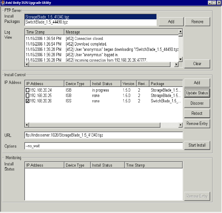
Software Interface
167
Avid ISIS Upgrade Utility Window
FTP Server Section
The FTP Server Section contains the following functions:
• Add installer package to the FTP root directory
• Remove installer from the FTP root directory
• Select installer to be sent to the storage device
• Display FTP Log information.
Software Interface
168
Install Control Section
The Install Control Section contains the following functions:
• The device information table:
-IP Address
-Device type
- Install Status
-Version
- Revision
- Current version of the firmware package running on the device
• Table operation buttons:
- Add button adds new entries to Device Information table.
- Update Status button reloads status, version, and packages information of the selected
device entries in the table.
- Discover button retrieves and displays information on all the devices that respond to the
application broadcast.
- Reboot button sends a restart command to the selected device entries in the table.
- Remove Entry button removes all the devices entries that are selected in the table.
- Start Install button issues the command that starts installing the selected package to the
selected devices.
This button is enabled when an install package is selected from the Install Packages list
and at least one device entry is selected from the device information table.
• Install Operation Command is composed of the following items:
- URL field displays the command text that is passed to the device.
- Option field displays the options associated with the command.
Monitoring Section
The Monitoring section contains the following functions:
• Install Status Monitoring table displays the upgrade status of the devices currently
upgrading.
• Remove Entry button removes the selected entries from the Install Status table.
Running the Avid ISIS Upgrade Utility
169
Running the Avid ISIS Upgrade Utility
The Avid ISIS software kit includes the Avid ISIS Upgrade Utility application and runs on the
Avid ISIS System Director.
To install an upgrade package:
1. Insert the USB with the Avid ISIS software into a laptop and double-click
AvidUtilityISISTool.msi located in the following location.
drive:
\AvidISISUtilities\ISIS 7000\
The installer file, installs the application on your laptop.
2. After the installation has completed, removed the USB and click Start > Programs >
AvidUnityISIS > Unity ISIS Upgrade Utility from your laptop.
The Avid ISIS Upgrade Utility Window opens.
3. Click Add in the FTP Server section of the window.
A browser dialog box opens.
4. Browse to the location where the new (or old) install package is located.
5. Select the package you want added and click Open.
The dialog box closes and the selected package is added to the Install Package list.
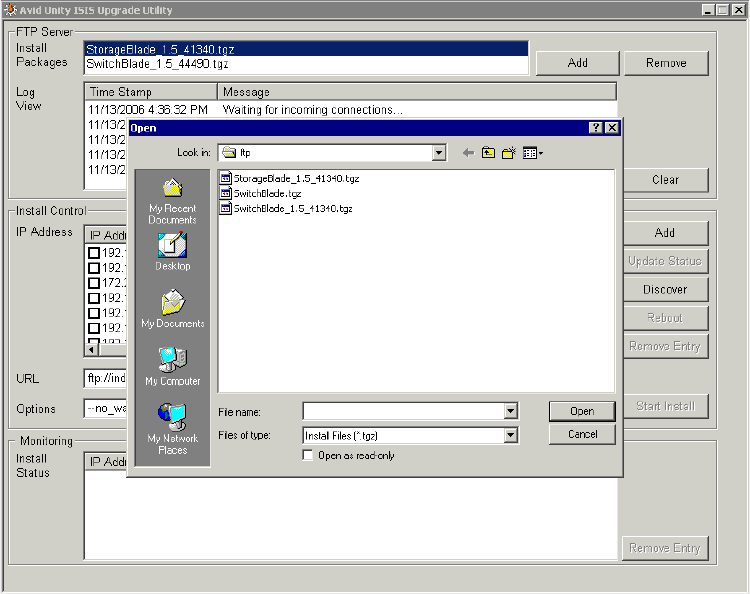
Running the Avid ISIS Upgrade Utility
170
6. Click Discover to retrieve information on all the available devices.
7. Select the devices you want to update. (Click the check-box beside the IP Address device
entries in the table.)
8. Click Start Install to begin installing the selected package to the selected devices.
nThe Start Install button is only enabled when an install package and at least one device entry are
selected.
The Install Status is displayed in the Monitoring section of the window. After the Install
Status shows complete, you can close the Avid ISIS Upgrade Utility.
To remove a package from the Install Package list:
1. Select the package you want to remove from the Install Package list.
2. Click Remove.

10 Avid ISIS Recommended Maintenance
The following maintenance recommendations are not meant to be a troubleshooting guide but
more of a care and monitoring checklist for Avid ISIS. Typically the Avid ISIS does not need to
be power cycled. All components of the ISIS stack can individually be replaced or restarted
without interfering with the operation of ISIS stack.
cPower cycling the entire stack (all the components at the same time) could risk the stability
of the ISIS stack.
For information on using the tools described in this section, see the Avid ISIS Administration
Guide.
Minimum Storage Space Requirement
The recommended amount space you must maintain for background functionality and failures is
7% of free space in each Storage Group. In other words, you should not fill Storage Group more
than 93% full. Exceeding 93% used space can produce severe performance issues in some
situations.
To calculate the right amount of free space, log into the ISIS management Console and navigate
to the Storage Group window. For each Storage Group, take the Effective number and multiply
by 0.07. This will be your recommended free space in GBs. To assure that you Storage Group
never exceeds the recommended space, create a new workspace in this Storage Group with the
same size and label it “Headroom” and do not give anyone access to this workspace.
Daily Maintenance
The following contains a list of items you should do on a daily basis. It is estimated to take 15
minutes to perform these functions.
• Check the Storage Elements status: Open the ISIS Management Console and click Storage
Elements.
- You should see a green circle beside the storage blade in the Name column
- Check the Status column for errors or Network Degraded
Daily Maintenance
172
The Status column in the Storage Elements report the status of the storage element
logged by the System Director. (The Status line in the Details area reports the same
information.) When the storage element maintains a working status, the Administrator
tool displays no entries in the Status field. If a problem arises, or when the status of the
storage element changes, the Administrator tool updates the Storage Elements dialog
box.
• Check the Storage Blade Status and Switch Blade Status: Open the ISIS Management
Console and click Chassis.
- You should see a green circle beside each chassis in the Serial Number column
- Check the both Status columns for errors
When the chassis, switches and storage elements maintain a working status, the ISIS
Management Console displays no entries in the status field. If a problem arises, or when
the status changes, the ISIS Management Console updates the status column and the
Details area.
• Start the Monitor Tool and check the front (ISBs) and back (ISSs, IXSs, and power supplies)
for errors.
You can hover your mouse pointer over a component and status details are displayed. Errors
display as red or yellow components, or as a warning icon on the component.
• Check System Director Control Panel on the Active System Director for errors. On the
System Director Status tab, make sure there are no red indicators in the status box.
- Check for green indicators beside the “System Director is running” and “Both paths are
up”
- Check that a blue or green indicator is displayed beside “Replicated” on the Active
System Directory
- If the event log indicator is not green, check the Windows Event logs on the Active
System Director
• Check System Director Control Panel on the Standby System Director for errors.
- Verify the Standby System Director is “Started” and in “Standby” Mode. Check for
green indicators beside the “System Director is running” and “Both paths are up”
- Check that a blue or green indicator is displayed beside “Receiving”
Weekly Maintenance
173
- If the event log indicator is not green, check the Windows Event logs on the Standby
System Director
• Check that the Avid ISIS Workspaces have “Free Space” available: Open the ISIS
Management Console and click Workspaces, see “Minimum Storage Space Requirement”
on page 171.
Weekly Maintenance
The following contains a list of items you should do on a weekly basis. It is estimated to take 30
minutes to perform these functions.
• Review Windows Event logs on the Active and Standby System Directors
• Check the ISB network connections between the ISBs using the ISB Connection Analyzer.
All Storage Elements should be green.
• In the Avid ISIS Switch Blade Agent, run the Switch Infrastructure Diagnostics located in
the Advanced tab. Select all tests, both the left and right networks, and all chassis.
nDo not run the switch diagnostics during heavy usage or critical network production times. Some
tests burden the system’s bandwidth and resources.
In the results page, save the diagnostic results by clicking the Download link and save the file
using the date as part of the file name.
• Check the RAID status on the System Director.
- On the AS3000, click Start > Programs > Intel -> Intel Rapid Storage Technology
right-click the Intel Rapid Storage Technology icon in the task bar. The icon should be a
green check mark when the drives are healthy.
- On the SR 2500, click Start > Programs > RAID Web Console 2 > Start UI and see that
the Server Heath is green. If not, search www.Intel.com and search for Intel® RAID
Software User’s Guide for corrective actions.
• Make sure you have at least one storage element worth of free space (depending on the size
of your storage blades) for each storage group, see “Minimum Storage Space Requirement”
on page 171. If a storage blade should fail, you need enough space to remove the failed
storage blade.
Monthly Maintenance
174
Monthly Maintenance
You should test a failover on a monthly basis. It is estimated to take 1 hour to perform this
function.
• Take a snapshot — The ISIS Snapshot tool collects information currently displayed by the
ISIS Management Console and the Avid ISIS System Director Control Panel. Open the ISIS
Management Console and click Logging > ISIS Snapshot in the Advanced section. Select
Create new snapshot.
• Perform System Director Primary to Secondary Failover — Turn off one of the System
Directors and verify in the System Director Control Panel that the Active Mode indicator has
turned red. Turn the System Director back on and see that Active Mode displays Standby.
Before you turn off either System Director, verify that the metadata date stamp in the
Metadata Status tab in the saved and replicated. Fields should be current and updating
frequently.
• Check the Redistribution status: Open the ISIS Management Console and click Workspaces.
- The Redistribution column for each workspace should be blank, and have less than 10
configuration changes (see Config Changes column)
- If you have 10 or more configuration changes, the status is highlighted in yellow and
displays “Requires Full Redistribution” in the Redistribution column
You should do a full redistribution at the next maintenance interval. Schedule a time
when the system is not heavily used, as this will allow the full redistribution to complete
in the shortest amount of time.
Redistribution Guidelines
Do not perform an ISB firmware upgrade while a Redistribution is in process. Make sure all
firmware upgrades are completed before any redistribution is started. The following events
trigger redistribution:
• Moving a Workspace
• Clicking “Full Redistribution” on a Workspace
• Adding a Storage Element to a Storage Group
• Removing a Storage Element from a Storage Group
• Changing the state of a Workspace to mirrored or unmirrored
Saving ISIS Metadata
175
If a firmware upgrade must be done and a redistribution in progress, do the following:
1. Suspend the active redistribution using the Advanced Commands in Workspace window.
2. Verify that the Workspace displays “redistribution suspended” in the Status column and all
other workspaces do not have “redistribution in progress” displayed.
3. Perform the firmware upgrade on the ISB(s) that must be upgraded.
4. Wait until the firmware upgrade is completed successfully.
5. Resume the redistribution using the Workspace window.
Saving ISIS Metadata
This procedure describes how to save the metadata stored on the system drives for the data
drives. You would typically only need to do this in a hardware replacement scenario, where both
System Director system drives are not going to stay with the data drives.
Regardless of how many Engines you have, all the metadata for all the data drives, in all of the
Engines, are saved on the System Director. The Engines do not store any metadata.
To save the System Director metadata:
1. Stop the System Director service using the ISIS Control Panel.
nThe System Director is constantly writing metadata. Metadata files are always open and locked,
so the best way to copy the metadata files is to stop the System Director service so the file are
closed.
2. Copy the Partition0 and Partition1 files from the following location on the System Director:
D:\Program Files\Avid\ISISSystemDirector
nThere is also a
PartitionDump.bin
file. This file is also helpful when identifying the data on
the data drives. If possible, include this files with the two Partition metadata files.
The following are a couple suggested ways of saving the Partition0 and Partition1
PartitionDump.bin files.
- Use a USB flash drive that has the capacity for the Partitionx files (4 GB recommended).
- Create a network share on a client system on the network and copy the Partitionx files to
that shared folder.
3. Verify that you have the current copy of the Metadata by comparing the date in the Metadata
tab of the ISIS control Panel.
4. Start the System Director service using the ISIS Control Panel.
Available Utilities
176
Available Utilities
The following is a list of headings in the Avid ISIS Administration Guide that describe other
utilities and tools for monitoring and troubleshooting.
• Avid ISIS System Director Control Panel
• ISIS Management Console
- Changing the Administration Password
- Setting up Error Notification
- Avid ISIS Snapshot Tool
- Using the Profile Tool
• System Statistics
• System Logging
- Accessing the Logging Window
- Viewing Event Logs
• Avid ISIS Log Aggregator Tool
• Avid ISIS Disk Tester Tool
• Avid ISIS ISB Connection Analyzer Tool
• Avid ISIS Switch Manager Tool
• Avid ISIS Agents
- Agent Tools
- Log Viewer Tool
- Switch Infrastructure Diagnostics
• Avid ISIS System Monitor Tool
• System Director event message meanings
Client Manager Maintenance
If you suspect a poor connection between your client system and a mounted workspace, you can
test the Avid ISIS shared storage network connection between each client system and the shared
storage network using the Avid PathDiag tool. This tool informs you if there is sufficient
Available Utilities
177
read/write throughput for read and write operations needed by the client system. For more
information on using the Avid PathDiag tool see, Avid ISIS 7000 Client Manger Guide. This
guide also describes the following Administrative tasks:
• Clearing Cached Data
• Using Logs and Messages
Status Indicators and Troubleshooting
If the LEDs on the ISSs or ISBs are indicating a problem, identify the problem using the
information under, “Status LEDs and Stacking Problems” on page 135.
Complete Server Room Shutdown
There is no requirement to power cycle the entire Avid infrastructure but, if the need arises to
turn off all the equipment (such as a relocating the server room), turn off the components in the
following order. When turning on the component, use the reverse order.
To shut down the entire Avid network (server room):
1. Shutdown all Avid editing system and attached media I/O equipment, for example Avid
Mojo and Avid Adrenalines.
2. Shutdown all capture and playout servers such as AirSpeeds.
3. Shutdown CaptureManager Server.
4. Shutdown Interplay Transfer Server.
5. Shutdown Avid Interplay Media Services and Providers.
6. Shutdown Interplay Engine and Avid Interplay Archive Engine.
7. Shutdown Media Indexers — Do not stop the Media Indexer while it is indexing storage.
8. Shutdown Systems running Interplay Framework Multicast Repeaters.
9. Shutdown Systems running the Interplay Framework Lookup Service.
10. Invoke Failover on Avid ISIS System Directors.
11. Shutdown Standby Avid ISIS System Director.
12. Shutdown Primary Avid ISIS System Director.
13. Shutdown Avid ISIS Engines.
14. Shutdown the network switches.
nPower up the entire rack of equipment in reverse order and verify all clients have mounted the
necessary ISIS Workspaces.
Available Utilities
178
False Link Aggregation Alerts
The following sections explain false link alerts caused by a slow Link Aggregation and provides
a procedure for correcting the issue.
Symptoms
If you experience problems with Link Aggregation during a power up, or if all the ISIS Engines
are restarting, the following could be happening.
• Slow Link Aggregation (Trunking) setup — When the Link Aggregation feature is taking a
longer than expected to complete. This setup process can viewed by opening to the Avid
ISIS Switch Blade Agent page > System tab, and click on the “View current settings” in the
left pane. When the process is complete, the status message “Enabled Fully Operational”
should be displayed for any VLAN that has a correctly defined and enabled Link
Aggregation (trunk) group.
While the Link Aggregation is setting up, the ISIS ports that are in the Link Aggregation
group form an open loop in the network that can cause problems with the connecting
Ethernet switches. When using the Cisco 4900. the longer the Link Aggregation feature
takes to come up, the longer the loop exists and is more likely to cause a problem.
• Fake Link Alert — A link alert is a message sent to the ISIS agent page and the Management
Console letting you know that the given 10 Gig port is not functioning as expected. A fake
link alert is when this link alert message is display when the port is working correctly. This
could also be thought of a false positive. This fake link alert can occur in ISIS 7000 v 2.4 and
earlier, this fix in the ISIS v4.0 release an later.
Displayed Link Alert Message
Use the following methods to determine if the displayed link alert message is a real problem or a
false positive.
To verify the link alert message:
1. Run diagnostics, and look at the “Details for test: (18) port link information.” The
information in this section of the diagnostic output comes directly from the hardware and
tells you the correct status on whether the switch port is up or down for all the ports in the
stack.
2. Check the stacking data for the Engine displaying the link alert message. The information in
the stacking display comes directly from the hardware and tells you the correct status on
whether the switch port is up or down for the port in question.
a. Go to the ISIS Switch Blade Agent page.
b. Click System tab.
c. Click Overview in the left pane.
Available Utilities
179
d. Click on the chassis (Engine) that is displaying the link alert message.
e. Scroll down to the stacking information. See the following example.
Example of the stacking data
Switch slot 0 is the left side of the Engine, and switch slot 1 is the right side of the Engine.
Look in the 10 Gb Port Map column:
- If “
0X1
” is displayed, the port is up.
- If “
0X0
” is displayed the port is down.
So if the right side of a Engine is reporting a link alert message, and “0X1” is displayed for
Switch slot 1. The port is up, and this is a fake link alert. If the right side of a Engine is
reporting a link alert message, and “0X0” is displayed for Switch slot 1. The port is down,
and this is a real link alert.
Restart All Procedure
The following procedure is a two part procedure used to correctly and safely restart all of the
Engines, as well as power cycling all of the Engines.
Part 1 gets the Engine correctly up and running, however it triggers the fake link alert problem.
You can to use the ISIS after you have completed part 1, however the link alerts you see are fake.
Part 2 corrects the fake link alert messages. When using part 2 of the procedure, wait until it is
complete before you use the ISIS.
Part 1 — Restart or power cycle all of the Engines:
1. Telnet into the connecting Ethernet switches (Cisco 4900’s) and use the “shut” command to
shut down all ports that connect to the ISIS stack (Currently there is no reason to shut down
the ports that connect one 4900 to the another 4900). The act of shutting down the ports
connected to the ISIS causes a link alert message to be displayed. This is a real alert message
because the ports have been shut down.
2. Restart all the Engines (or power cycle them). Allow all Engines to come up.
3. Go to the ISIS Switch Blade Agent page, and every few seconds select the Overview display.
This updates the Overview display with the latest information.
4. Watch the request busy entry, and wait for it to go to “No.”
5. Watch the Request state column, and wait for every state to go to “Done.”
Switch Slot State Master Collisions Failures 10 Gb port Map Hi Gb Port Map
0 Ready No None None 0X1 0X0
1 Ready No None None 0X1 0X0
Available Utilities
180
6. Go to the “view current setting” display and watch the information in the column labeled
“10 Gb Link Aggregation Current Configuration State.” This step takes several minutes.
Every few seconds select the “View current settings” to update the display with the latest
information. Continue watching until the “Enabled Fully operational” message is displayed
for the VLANs (left and right sides) that have a Link Aggregation group defined and
enabled. Once the “Enabled Fully operational” messages are displayed, continue to the next
step.
7. Again telnet into the connecting Ethernet switches and one by one, enter the command “no
shut” to each one of the ports that are connected to the ISIS.
Part 2 — To remove the fake link alert messages:
1. Each switch displaying the fake link alert must have the Chassis Manager restarted. This can
be done using one of the following methods:
tRestart the Engine – ISIS Switch Blade Agent page > System tab and click “Reboot a
chassis.”
tRestart the local host (switch) – ISIS Switch Blade Agent page > Advanced tab and
click “Reboot.”
tRestating the Chassis Manager – ISIS Switch Blade Agent page > Advanced tab and
click “Restart Chassis manager.”
tTelnet into the switch and enter the “reboot” command.
2. Each time you restart the Chassis Manager (step 1), you must watch for the stack (VLAN) to
come back up correctly. This can be done by following steps 3, 4, 5,and 6 of Part 1
procedure.
After you complete Part 1 and Part 2 the ISIS stack, including Link Aggregation should be
up and running.

11 Adding and Replacing Hardware
This appendix provides procedures for adding and replacing components in your Avid ISIS. Avid
ISIS hardware additions and replacements are to be performed by Avid ISIS Avid Certified
Support Representatives (ACSR).
Do not add any hardware if there are any issues with the system. Correct all problems before
adding new hardware and making changes to the system, perform a quick checks to be verify that
the system is in good working order, see “Health Check” on page 141.
Adding Hardware
Use the following guidelines if a switch replacement is required. Typically hardware
replacement be performed after the software upgrade to avoid unnecessary downgrade and
upgrades of the firmware.
Be aware that all switch firmware is not compatible. Incompatible firmware does not stack
together and therefore cannot be upgraded in the normal manner. As a general rule, v1.0x
firmware switches do not stack with v1.1, v1.2, v1.3 and later switches and vice versa. Older
v1.1x switches will usually stack with newer rev 1.1x switches.
Avid ISIS ships with a standalone firmware Avid ISIS Upgrade Utility which is suitable for
upgrading (or downgrading) any firmware version of switch. This utility should be on hand for
any upgrade if the normal upgrade procedure fails for any reason. This utility can be found in the
Avid ISIS software kit in a folder called
\AvidISISUtilities\ISIS 7000\
. For details on the
use of this utility, see “Running the Avid ISIS Upgrade Utility” on page 169.
For more details on compatibility between firmware versions, search the online Knowledge Base
at www.avid.com/US/support for “ISIS firmware matrix.”
If you are replacing an existing switch in the stack, you do not need to add/remove chassis or do
anything to the stack. Use the following procedure to swap a switch.
Adding an Engine
182
Adding an Engine
This section covers the simplest configuration on adding an engine to a system (1 engine, 2
switches and 16 ISBs). If you are expanding a system with v1.x hardware, see the v2.1.1 (or
earlier) Avid ISIS Setup Guide for detailed procedures.
cYou must disable link aggregation before creating or modifying your Avid ISIS stack. After
your stack has been created, reconfigure your Link Aggregation Groups.
To add an engine:
1. Rack engine in proper position.
2. Install power supplies, switches, and ISBs.
3. Apply power to the engine.
4. Allow chassis to boot fully, about 2 minutes.
5. Update the firmware on each switch if necessary (see “Replacing an Engine Switch” on
page 183).
6. Add the left switch to the stack:
a. Open the switch web page on any switch on the left stack.
b. Click add/remove chassis. You should see the existing stack with the same number of
chassis as are currently in the system.
c. Click add chassis and then click OK. Wait for the request to get to all switches (all bars
turn green). Then immediately attach the stacking cable from the left IXS to the switch.
This should be at the ready state before clicking OK.
d. Wait up to 5 minutes.
- If the stacking procedure is successful, the new chassis (verify by serial number) is
now listed in the chassis list.
- If you do not see it listed there after waiting and pressing F5 a few times, disconnect
the stacking cable and repeat steps c and d until chassis is successfully added to the
stack.
7. Once the left switch is added to the stack, verify that the new switch is at the expected
IP address by pinging the new switch from another switch (not management IP). You can get
the IP address from the ISIS Management Console and click Chassis from the list on the left
and then click the Details tab on the new chassis serial number.
8. Attach the stacking cable to right switch and verify that the new switch is at the expected IP
address by pinging the new switch from another switch (not management IP).
Replacing an Engine Switch
183
9. Once the switches are added and confirmed okay, update the ISB firmware and add the ISBs
to the filesystem.
a. Highlight new chassis in ISIS Management Console Chassis window and click Upgrade
Storage Blades,
b. Once upgraded, add the new ISBs to the filesystem. When added they become Storage
Elements listed as a Spare in the Type column.
c. Select all the new Storage Elements and add them to the Storage Group. Once in a
Storage Group they become Active in the Type column and a redistribution is initiated.
This can take several hours. The upgrade and client activity can continue during this
process.
nDo not go through the add chassis procedure a second time. The chassis has already been added
to the stack.
Replacing an Engine Switch
To replace an ISS or IXS switch:
1. Disconnect all network interconnect cables and remove old switch. (Power remains on at all
times.)
2. Insert new switch but do not attach the stacking cable yet.
3. Update switch to correct firmware (if necessary) using the Avid ISIS Upgrade Utility, see
“Avid ISIS Upgrade Utility” on page 164.
a. Install Avid ISIS Upgrade Utility on a spare computer or laptop.
b. Load the firmware package on your spare computer or laptop that matches the firmware
on your Avid ISIS.
c. Assign IP address on Laptop to 192.168.0.100.
d. Connect the Ethernet cable to the Management Port of the new switch.
e. Start the Avid ISIS Upgrade Utility. In the Install packages section select add and
browse to correct firmware package that you loaded on your spare computer or laptop.
f. The utility should detect the switch on 192.168.0.10 automatically. If not, you can put in
the IP address manually.
g. Check the switch and select Start Install.
h. Monitor the upgrade via the Avid ISIS Upgrade Utility until complete. This takes about
20 minutes.
4. Once the switch is at the correct firmware and restarted, the stacking cable can be attached.
Replacing an Engine
184
5. Verify that the switch is pingable via the correct stack IP address from another switch on the
same side of the stack (subnet).
Replacing an Engine
Use the following procedure when replacing an ISIS engine. For purposes of this procedure, the
engine to be replaced is referred to as “old chassis” and the replacement engine as “new chassis.”
To replace an ISIS engine:
1. Note the engine serial number on the front of the old chassis. Serial numbers are adhered on
the rack-mount ears of the Avid ISIS Engine (under the plastic screw covers, if installed).
nIf you have not already noted the host names, passwords, IP address, and other important
network details, see “Preupgrade Information” on page 158.
2. Log into the ISIS Management Console and get details on the old chassis (use the serial
number that you record on the front) and note the left and right IP addresses.
3. Disconnect the CX-4 interconnect cables from the old chassis.
4. Disconnect the 1-Gb connections and any 10-Gb (optical) connections from old chassis.
5. Open a Switch Agent Web page of any Zone 1 client on the left side.
nOpen the Switch Agent page via the Info button on the engines details page. For more details, see
the Avid ISIS Administration Guide.
a. Click Switch Blade in the Management Console.
b. Select the Switch Blade in the Switch Blade page and click Show Info.
c. Log into the Switch Agent page (se-admin is the default password).
6. Click the System tab > Add/Remove chassis.
7. Find the serial number of the old chassis in the Serial Number list and click the “Delete”
button for that chassis.
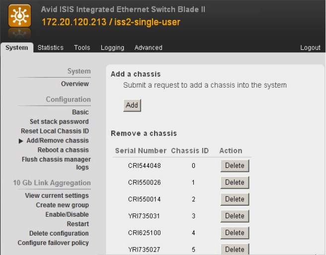
Replacing an Engine
185
8. Wait for the operation to be completed (all chassis in the list displays green and “The
configuration request completed successfully” is displayed).
The old chassis serial number should no longer be listed in the Serial Number list.
9. Power-off the old chassis by pulling a single power cord and then pulling the remaining two
power cords simultaneously.
10. Carefully remove all ISBs from the old chassis and put them in a safe place.
11. Carefully remove both switches from the old chassis, noting from which side of the chassis
each switch was removed. Put them in a safe place.
12. Carefully remove all three power supplies from the old chassis and put them in a safe place.
13. Remove the old chassis from the rack.
14. Install the new chassis into the rack (without the ISBs, switches, and power supplies).
15. Carefully reinsert all ISBs.
16. Carefully reinsert the three power supplies.
17. Carefully reinsert both switches into the original position in which they were in on the old
chassis. Do not reconnect any cables at this time.
All thumb screws should be secured and snug.
Replacing an Internal System Director Drive
186
18. Power-on the new chassis by simultaneously inserting two of the power cords and then the
third.
Give the new chassis at least 3 minutes to initialize and when all ISBs have solid green
LEDs.
nAfter 3 minutes if the ISBs are all blinking green in unison, call Avid Customer Support.
19. Reattach the CX-4 interconnect cables to the left and right switches
20. Go back to the Switch Agent Web page (use any left switch other than the one being added).
Select Configuration > Add/Remove chassis. The new chassis serial number should now be
listed in the Serial Number list.
21. Go to tools and select ping. Enter the left IP address noted in step 1. Both switches in the
new chassis should now be pingable.
22. Reconnect any 1-Gb and 10-Gb cables that were disconnected earlier.
23. Verify the proper operation of both stacks by running the Path Diag from a client in each of
the following locations: Zone 1 left, Zone 1 right, Zone 2 left, Zone 2 right, and Zone 3.
Replacing an Internal System Director Drive
There are two system drives installed in the Avid ISIS Engines. The two drives are mirrored and
accessible from the rear of the Engine. If you have a failure on either one of the two system
drives you can pull the failed drive out of the Engine and install a replacement without turning
off the Avid ISIS Engines. The Avid ISIS continues to run properly if one of the two system
drives are removed.
As soon as you install a replacement system drive into the vacant system drive slot, the system
begins the process of creating a mirror of the original drive on the new drive. All Avid ISIS
operations continue to run uninterrupted.
nThe drive carriers for the system drives are locked to avoid them from opening during shipment.
The plastic drive carrier key is mounted on the rear of the Engine beside the system drives.
To replace the System Director drive:
1. Remove the failed drive from the front of the System Director by releasing the drive latch on
the front of the drive and pulling the drive from the chassis.
2. Insert the new drive completely into the open drive slot and close the drive latch.
The new drive initiates and completes the repair with no other intervention.
Replacing the System Director
187
Replacing the System Director
Use the following procedure if you are replacing your System Director to a newer model server.
This includes updating from a 32-bit System Director to a 64-bit System Director, or updating
the Intel® SR2400 or SR2500 to the AS3000. Before you start the System Director replacement
procedure:
• Install the new System Director into the rack. If planning a Standby System Director, also
install the second System Director into the rack.
nThe new Standby System Director is configured after this new Active System Director is running,
see “Configure a Failover Connection” on page 124.
• Install the Avid ISIS v2.0 or later software on the new System Director, see “Software
Upgrade” on page 142.
• Make sure your existing Active and Standby System Directors are healthy, verify that the
system is in good working order. Do not upgrade to the new System Director if there are
issues with the old System Director, see “Health Check” on page 141.
• Update the software on existing Active and Standby System Directors to the same Avid ISIS
version as the new System Director, see “Software Upgrade” on page 142.
Avid has shipped the Intel SR2500 System Director with a 32-bit operating system and 9 MB of
memory. If you have this model System Director and want to upgrade to a 64-bit operating
system, you must purchase a Windows 64-bit operating system license and re-image the 32-bit
Intel SR2500 System Director.
• Save your current version of the metadata, see “On the old servers that are being removed:”
on page 187.
• Load the Windows operating system, see “Reinstalling the Windows Storage Server 2008
R2 Operating System” on page 194. This is not necessary if you have purchased a new
System Director.
• Import the current version of the metadata, see “On the new server that is to become the
active System Director:” on page 188.
On the old servers that are being removed:
1. Identify the existing Standby System Director and stop the System Director service via the
ISIS Control Panel.
2. Identify the existing Active System Director and stop the System Director service via the
ISIS Control Panel.
3. On the Active System Director, locate and preserve the “
PartitionDump.bin
” file.
This file is an exported version of the metadata.
Replacing the System Director
188
v2.x metadata location
D:\Program Files\Avid Technology\AvidUnityISISSystemDirector
x64
v4.x metadata location
D:\Program Files\Avid\ISIS System Director
4. Copy the
PartitionDump.bin
file into a temporary directory on the new System Director
that is to become the new Active System Director.
The Avid System Director software prevents you from creating a shared folder on the
System Directors. The following are a couple suggested ways of moving the
PartitionDump.bin file.
- Use a USB flash drive that has the capacity to move the
PartitionDump.bin
file.
- Create a network share on a client system on the network and copy the
PartitionDump.bin
file to that shared folder. From the new System Director copy the
PartitionDump.bin
file into the temporary folder.
On the new server that is to become the active System Director:
1. Verify that you have the current copy of the PartitionDump.bin file from the old Active
System Director.
2. Start the Avid ISIS and click System Director Control Panel from the Launch Pad or Start >
Programs > Avid > ISIS System Director and select Control Panel.
3. Configure the virtual name and IP address on the new Active System Director to match the
old Active System Director.
Configure the virtual name and IP address using the functions in the Configuration tab of the
ISIS System Director Control Panel.
4. If using the same IP addresses as the old System Director, make sure to shut down the old
System Director first to prevent an IP conflict.
nIt is acceptable to change the IP address scheme of the new System Director. It is not
recommended that you change the virtual ISIS name.
5. Click Stop System Director.
The Configure File System button becomes active.
6. Click Configure File System.
The File System Configuration dialog box opens.
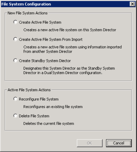
Replacing the System Director
189
7. Select Create Active File System From Import and click OK.
8. You are prompted to navigate to the
PartitionDump.bin
file you saved on the Active new
System Director.
The file is copied to a location used by the Active System Director and its extension is
changed from bin to import.
D:\Program\Avid\ISIS System Director\PartitionDump.import
The Active new System Director creates a new file system and imports the metadata from
the file.
9. Deactivate the Avid software license or move the Application Key (dongle) from the old
System Director to the new System Director.
10. Verify that the System Director is now running and Active. Start the Management Console
and verify that all workspaces are listed. If not, call customer support before continuing.
11. Configure the new Standby System Director, see “Configure a Failover Connection” on
page 124.
Replacing the Network Switch
190
Replacing the Network Switch
If replacing a switch in the ISIS environment, the following are a few suggestions you need to
consider before removing the switch.
• Have a backup copy of the switch configuration file.
• Disable any Link Aggregation that might be set in your ISIS 7000 environment. This
prevents odd network behavior and the inevitable trunking errors.
• Disable any trunking to other switches before removing the switch. Any trunking involved
with the switch would be part of the configuration file and would help when reconfiguring
the trunk on the new switch.
• You do not have to shutdown the System Director or Engines when replacing a switch,
particularly if you have a redundant switch configuration.
To replace a switch you will need a console connection to the switch and a tftp server. The
following are high level steps that assumes the failed switch is still capable of making a tftp
backup. If the switch is completely dead, the configuration will need to either be restored from a
previous backup or manually configured.
To capture the switch configuration file:
1. Copy the startup configuration of the failed switch to the tftp server.
2. Install the replacement switch.
3. Configure a temporary interface on the new switch to connect to the tftp server (best to use a
no switchport interface with IP address on same subnet as TFTP server).
4. Copy the backup copy of the old switch startup configuration to the new switch (copy tftp
startup-config).
5. Reload the switch configuration and old switch configuration should be restored on the new
switch.
The specific commands will be different between Cisco and Force10 but they all should be
in the switch configuration guide.
If a TFTP server is not available:
tUse a console/telnet client such as PUTTY to list the configuration and copy it to a text file,
which can then be pasted back into the new switch and save to NVRAM.
nThe PUTTY scroll back buffer needs to be increased from the default 200 to at least 2000. If you
increase it to 50000 and make the screen longer and wider you can capture “show tech-support”
output,
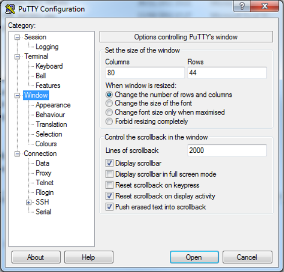
Replacing the Network Switch
191
To replace a switch:
1. Disconnect all network cables.
2. Pull out the power cables from the back of the switch.
3. Replace the failed switch with a new switch in the rack.
4. Replace the power cables in the back of the switch to power the switch on.
5. (Option) If you have transceivers in the failed switch, move the working transceivers into the
new switch.
6. (Option) If you have modified Avid’s default Force10 switch configuration, you need to
Telnet or HyperTerminal into switch.
Avid ships Force10 switches configured for ISIS 5000 configurations. Any changes you
have made to the default configuration would have to be reapplied.
Avid provides sample Cisco switch configurations in the ISIS software kit. Any changes you
have made need reapplied.
7. Reconnect all network cables in the front of the switch.

12 Using the Product Recovery USB for
64-bit System Directors
This section describes the procedures to recover your Avid ISIS system drive by reinstalling
Windows Storage Server 2008 and Avid specific additions and changes.
This procedure restores only the Windows operating system and the hardware drivers. It does not
restore the Avid ISIS software. The Avid ISIS software must be reinstalled separately, after the
operating system recovery is complete. The version number of the image can be found in the
C:\IMAGE.TXT
file on the root directory of the system drive.
cThe Avid ISIS ships with a backup product recovery image USB flash drive provided with
your Avid ISIS.
nAfter reimaging the server the Administrator password is set to is-admin.
You might need to reinstall the Windows Storage Server 2008 operating system on your Avid
ISIS System Director if you are directed to do so by Avid Customer Support. The reinstallation
offers you two options:
• Perform a Windows Storage Server 2008 R2 installation to the entire system. This replaces
all the data from all the available partitions on your system drive. You can perform this
operation if you are initializing your system drive.
cYou lose metadata if you restore all the partitions of the drive.
• Perform this operation to replace only the operating system on your system drive. Typically
this removes the first partition (C:); the other partitions are not changed.
Creating a Product Recovery USB Flash Drive
Avid highly recommends you copy the image to the 16 GB USB flash drive provided with your
Avid ISIS as part of your initial setup. The following procedure describes how to create the
product recovery USB flash drive. The product recovery image is included in the C:\Image folder
of the system drive.
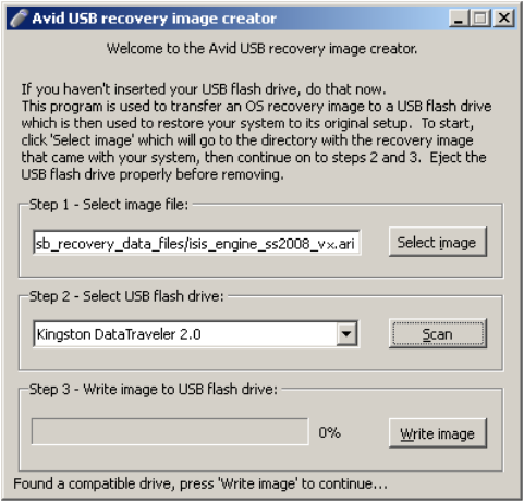
Creating a Product Recovery USB Flash Drive
193
Once you have created the bootable USB flash drive using the Product Recovery tool, use the
USB flash drive to reinstall the operating system image (and associated drivers) to the original
state as when it was shipped from Avid.
cWhen you perform a full product recovery of the Avid ISIS system drive using the product
recovery USB flash drive, you lose the product recovery image in the C:\Image folder of the
system drive.
To create a product recovery USB flash drive:
1. Locate the 16 GB USB flash drive Avid provided with the Avid ISIS and insert it into the
front USB port.
2. Click “Create Recovery USB Drive” from the installer splash screen or double-click the
AvidRecoveryImageTool.exe file included in the software installer kit from the following
location:
\AvidISISUtilities\
nA direct link to this file is included in the software install splash screen (Create Recovery USB
Drive).
The Avid USB recovery image creator window opens.
3. Click Select Image to locate the product recovery image from the C:\Image folder of the
Avid ISIS system drive (you need to browse to the location of the .ari file).
Reinstalling the Windows Storage Server 2008 R2 Operating System
194
4. Select the .ari file.
The Scan button becomes active when you select the image file. The “Select USB flash
drive” menu lists USB devices that are installed and capable of accepting the image file. If
the inserted USB flash drive does not appear in the drop down menu, verify the capacity of
the USB flash drive.
5. Click Scan.
6. Select the USB flash drive from the “Select USB flash drive” menu.
The Write image button becomes active when you select the USB flash drive.
7. Click Write image.
nCreating the product recovery image on the USB flash drive can take 18 to 45 minutes depending
on the capabilities of the USB flash drive.
8. Click OK to acknowledge the warning about losing all previous data on the USB flash drive.
The Write image button becomes a Cancel button when the image is being created. If you
cancel the write image process, the process starts over from the beginning on the next
undertaking.
9. Click Ok when process is completed.
10. The USB flash drive appears in the taskbar as an icon. Remove the USB flash drive as
follows:
a. Double-click the USB icon in the taskbar. A pop-up menu appears with a list of attached
USB devices.
a. Select the USB flash drive with the product recovery image.
b. Click Stop.
c. Click OK to remove the selected USB device.
d. Remove the USB flash drive from the Avid ISIS.
Reinstalling the Windows Storage Server 2008 R2
Operating System
To reinstall the Windows Storage Server 2008 R2 operating system from the Avid Product
Recovery flash drive:
1. Make sure all clients stop any activity and unmount their workspaces.
2. All clients need to exit Client Manager.
3. Locate the Product Recovery Image USB flash drive with the Avid ISIS image.
Reinstalling the Windows Storage Server 2008 R2 Operating System
195
4. Use the System Director Control Panel to stop the System Director.
5. Insert USB flash drive into the USB port in the system.
nYou must enter the BIOS with USB flash drive plugged-in to set correct drive boot order.
6. Select Start > Shut Down.
The Shut Down Windows dialog box opens.
7. Select Restart, and click OK.
The Windows Storage Server 2008 R2 operating system restarts.
8. Press the Delete key several times during startup until you see “Entering Setup.”
9. Set the USB Drive to boot first. Navigate to the Boot tab > Hard Disk Drives > 1st Drive and
select the default USB setting detected by the BIOS. The 2nd Drive setting changes to the
“RAID: Intel Volume.”
nDepending on the manufacturer of the USB flash drive, this USB selection in the BIOS changes.
10. Select the Advanced tab > CPU Configuration, make sure the hyper thread option “Intel HT
Technology” is [Disabled].
11. Select the Advanced tab > IPMI Configuration, make sure “Restore on Power Loss” is set to
[Last State].
12. Press F10 to Exit and Save your changes.
The system continues to start from the USB flash drive.
Wait until two windows appear, click on the blue window and select one of the available
options:
- Recover only the OS partition.
- Recover the entire system disk.
- Exit without doing a recovery.
13. At the prompt, type the number of the operation you want to perform:
tIf you type
1
or
2
, a warning screen opens, informing you that you are about to recover
the operating system. Continue with step 14.
tIf you type
3
, the recovery quits to the Main menu. You need to type
3
again to get to
command window. Press
Ctrl+Alt+Delete
to quit in any of these windows.
14. A yellow screen appears type Y.
15. A red screen appears type Y.
The reimaging takes 20 to 30 minutes.
Configuring the System Drive Using Windows 2008 Storage Server Setup
196
cDo not remove the USB flash drive while performing the product recovery. If you remove
the USB flash drive an error is displayed stating it cannot write the Ghosterr.txt file. If the
USB flash drive was removed, you cannot continue the process by re-installing the USB
flash drive. You would have to start the recovery process from the beginning.
16. A gray screen prompts you to reboot. Type R, and quickly remove the USB flash drive from
the system.
Configure the operating system as described in the following section. The Apply Computer
Setup message is displayed for 3 to 5 minutes.
Configuring the System Drive Using Windows 2008
Storage Server Setup
After you recover the Windows Storage Server 2008 R2 operating system, several system
parameters are set including a system Disk Check. The system restarts, and you are prompted to
enter the Windows activation key. This number is on the Windows Certificate located on the
right-side of the Engine top cover. You need this Windows number in the following procedure.
To set up the Windows operating system:
1. (If removed) Reconnect all the network Ethernet cables.
2. When the Product Key screen opens, type the Product Key from the Certificate of
Authenticity in the Product Key text box. The certificate is on the top of the Avid ISIS
Engine.
cThe Product Key Authenticity is verified with Microsoft through an Internet connection. If
you do not have the Avid ISIS connected to an in-house network, you need to phone in your
Product Key and get an Authenticity number back from Microsoft.
The Windows Storage Server 2008 R2 Setup utility starts, and the a dialog box opens
showing the License Agreement screen.
3. Select “I accept the agreement.”
4. Click Next.
The Avid ISIS Engine restarts (potentially more than once).
5. Log on as
Administrator
and
is-admin
as the password.
6. After your system restarts for the last time, customize the system and local settings. See the
Windows documentation for more information.
tIf you are outside the United States, customize the system and local settings.
tYou might want to create a new system administrator name and password.
Configuring the System Drive Using Windows 2008 Storage Server Setup
197
tCompany Name and Organization.
tDate and Time Settings.
tNetwork Workgroup and Computer Domain settings.
cWhen the operating system is restored in the Avid ISIS Engine, a unique computer host
name is created based on the MAC ID of the system board. Each time you re-image your
Avid ISIS Engine, the same name will be generated. Although if you have changed the
computer host name of your Avid ISIS Engine, you need to reapply your computer host
name again.
7. Start the system and install Avid ISIS software, see “Loading the Software” on page 85.

13 Specifications and Notices
This section provides information on the dimensions and weight, the environmental, the
electrical, and the power cord specifications for the Avid AS3000 when used as the ISIS 7000
System Director. It also recommends the use of an Uninterruptible Power Supply and supported
network cabling.
Dimensions and Weight
The following table lists the dimensions and weight.
Environment
The following table lists the environmental specifications.
Electrical
The following table lists the electrical specifications.
Component Dimensions and Weight
Component Height Width Depth Weight
AS3000 System Director 1.75 in (44.4 mm) 19 in (482.6 mm) 27 in (685.8 mm) 40.0 lb (18.1 kg)
with drives installed
Environmental Specifications
Component
Operating
Temperature
Operating
Humidity
Storage
Temperature
AS3000 System Director 32°F to 104°F
(0°C to 40°C)
5% to 95% (at 38°C)
non-condensing
–4°F to 140°F
(–20°C to 60°C)

Uninterruptible Power Supply (UPS)
199
Uninterruptible Power Supply (UPS)
Avid highly recommends you create a separate derived power system for your ISIS 7000 System
Director. This provides protection against sudden power surges or losses that could cause you to
lose files or experience data corruption.The power outlets need to be from the same distribution
panel. This helps prevent ground loops that can be caused by plugging equipment into power
sources with different ground potentials. Make sure there is adequate, dedicated power for the
UPSs.
wYou should have all the electrical work at your site done by a licensed electrician. The
electrical changes must meet country, state, and local electrical codes.
The ISIS 7000 System Director supports UPS devices that are connected using network
connections, USB connections, and serial connections. Install the software from the UPS
manufacturer for advanced shutdown behavior, calibrate the UPS device. These software
packages also allow for a connected Windows server to send alerts to other Windows servers to
perform actions.
If your ISIS 7000 System Director is connected to a network, network policy settings might also
prevent you from completing this procedure. Make sure there is adequate power and the correct
receptacle type for each hardware component, the rack power strips, and the UPSes. Do not use
extension cords to plug in any of the hardware components.
Supported Cabling
Avid supports the following cable types for connecting an ISIS 7000 System Director system.
nIf you need run your cable greater distances, call Avid Customer Support for supported cable
and accessory information.
Electrical Specifications
Component Voltage Frequency Watts (Max. U.S.)
AS3000 System Director 100 to 240 Vac
Two hot-swap
redundant AC power
supplies
50 to 60 Hz 650 W

Supported Cabling
200
Supported Cables
Cable Connection
Type Function
Connector Style and Maximum Cable
Length
Avid engine interconnect
CX-4 cable. Only available
from Avid.
Connect engines. See “Removing
the Avid Engine Interconnect
Cable” on page 43 for proper
removal.
CX-4 connector
There are three supported lengths at this time:
1, 3, and 5 meters
Ethernet network cable,
CAT5e, CAT6, or CAT6a
Connects:
Ethernet Avid ISIS clients
System Directors and clients to
1 Gb ports
Avid Interplay servers to shared
storage networks
Avid AirSpeed capture and
playback servers to shared storage
networks
RJ45 connector
100 Meters; If using CAT5e the cable must be rated
for 350 MHz for maximum length.
The minimum GigE cable length for Avid network
products is 6 feet or 2 meter.

Supported Cabling
201
Optical cables Connects:
10-Gb port of switch to optical
10-Gb port on the Avid ISIS
Engine.
10-Gb optical port to switch port
10-Gb optical port to 10-Gb
Ethernet Client
10-Gb Client to 10 Gb Switch
port
10-Gb Ethernet switch to 10-Gb
Ethernet Switch
The maximum length for 10 Gb Ethernet cable is
defined by the core diameter (measured in microns)
and modal bandwidth (in units of MHz*km).
Avid supports multi-mode fiber cable using 850 nm
transceivers (short distances). Specifications for
these cables can be found in the ISO 11801
structured cabling document.
MMF 62.5 micron cable Modal Bandwidth of:
(Overfilled Launch (OFL) Bandwidth, typical of
OM1 cable)
• 160 MHz*km at 26 meters
• 200 MHz*km at 33 meters
MMF 50 micron cable Modal Bandwidth of:
• 500 MHz*km at 82 meters (Overfilled Launch
Bandwidth, typical of OM2 cable)
• 2000 MHz*km at 300 meters (Effective Modal
Bandwidth, typical of OM3 cable)
Avid supports single-mode fiber cable using
1310 nm transceivers (long distances):
• SMF ITU G.652.A/B 9 micron cable up to
10 km
cWhen connecting to the 10 Gb port, it is important to follow two rules:
– Ensure that the cable has the required modal bandwidth for the distance of the run.
– Make sure that all multimode cables between an switch port and the other end of the cable run are of
the same diameter (for example, 50/125 um or 62.5/125 um).
wSingle mode transceivers are Class 1 laser product per IEC 60825-1 Amendment 2(2001) and IEC
60825-2 1997. Operating this product in a manner inconsistent with intended usage and specification
may result in hazardous radiation exposure.
Supported Cables
Cable Connection
Type Function
Connector Style and Maximum Cable
Length

Supported Cabling
202
Avid ISIS
X2 optical transceivers
Transceiver used in:
Cisco® 4948 and 4900M
SC connector
X2 = Cisco X2-10GB-SR for MMF
X2 = Cisco X2-10GB-LR for SMF
nThe minimum cable length for -LR and -SR
transceivers is 2 Meters.
Avid ISIS
XFP optical transceivers
Transceiver used in:
Force10 S60 switches
ISIS 7000 (ISS1000)
LC connector
XFP = 10G-XFP-SR for MMF
XFP = 10G-XFP-LR for SMF
XFP = 10G-XFP-SR
or Picolight XXL-SC-S45-21 for MMF
XFP = 10G-XFP-LR
or Bookham 10G-BASE-LR for SMF
nThe minimum cable length for -LR and -SR
transceivers is 2 Meters.
Avid ISIS
SFP+ optical transceivers
Transceiver used in:
ISIS 7000 (ISS2000)
ISIS 2000 (System Director)
Force10 S4810 switches
LC connector
• SFP+ multi-mode short range (SR) 850nm
JDS – PLRXPL-SC-S43-21-N
JDS – PLRXPL-SC-S43-22-N
Avago – AFBR-700SDZ
Avago – AFBR-703SDZ
• SFP+ long range (LR)
Finisar FTLX1471D3BCL for SMF
Avago AFCT-701SDZ for SMF
JDSU JSH-01LWAA1 for SMF
nThe minimum cable length for -LR and -SR
transceivers is 2 Meters.
Avid ISIS
SFP optical transceivers
Transceiver used in:
Force10 optical switch
LC connector
• SFP 1000BASE-SX short range (SR)
Force10 GP-SFP2-1S
nThe minimum cable length for -LR and -SR
transceivers is 2 Meters.
Supported Cables
Cable Connection
Type Function
Connector Style and Maximum Cable
Length

ASafety and Regulatory Information
This document contains safety and regulatory information for Avid hardware.
•Warnings and Cautions
•FCC Notice
•Canadian Notice (Avis Canadien)
•LED Safety Notices
•European Union Declaration of Conformity
•Disposal of Waste Equipment by Users in the European Union
•Argentina Conformity
•Australia and New Zealand EMC Regulations
•Japan EMC Regulations
•Korean EMC Regulations
•Taiwan EMC Regulations
Warnings and Cautions
cThis equipment is intended only for installation in a RESTRICTED ACCESS LOCATION.
cNever install equipment if it appears damaged.
cDisconnect the power cord before servicing unit.
cOnly perform the services explicitly described in this document. For services or procedures
not outlined in this document, speak with authorized Avid service personnel.
cFollow all warnings and cautions in the procedures.
cOperate the device within its marked electrical ratings and product usage instructions.
cIf you need to replace a battery in an Avid hardware unit, be sure to use the correct battery
type. There might be a risk of explosion if a battery is replaced by an incorrect type.
Dispose of used batteries according to the manufacturer's instructions.
FCC Notice
204
cFor products with a power switch the main power switch should remain accessible after
installation.
(Hebrew Warnings and Cautions)
FCC Notice
Part 15 of the Federal Communication Commission Rules and Regulations has established Radio
Frequency (RF) emission limits to provide an interference free radio frequency spectrum. Many
electronic devices produce RF energy incidental to their intended purpose.
Class A Equipment
This equipment has been tested and found to comply with the limits for a Class A digital device,
pursuant to Part 15 of the FCC rules. These limits are designed to provide reasonable protection
against harmful interference when the equipment is operated in a commercial environment. This
equipment generates, uses, and can radiate radio frequency energy and, if not installed and used
in accordance with the instructions, may cause harmful interference to radio communications.
Operation of this equipment in a residential area is likely to cause harmful interference, in which
case the user will be required to correct the interference at personal expense.
Canadian Notice (Avis Canadien)
205
Modifications
The FCC requires the user to be notified that any changes or modifications made to Avid
hardware that are not expressly approved by Avid Technology may void the user’s authority to
operate the equipment.
Cables
Connections to Avid hardware must be made with shielded cables with metallic RFI/EMI
connector hoods in order to maintain compliance with FCC Rules and Regulations.
Canadian Notice (Avis Canadien)
Class A Equipment
This Class A digital apparatus meets all requirements of the Canadian Interference-Causing
Equipment Regulations.
Cet appareil numérique de la classe A respecte toutes les exigences du Règlement sur le matériel
brouilleur du Canada.
LED Safety Notices
Avid hardware might contain LED or Laser devices for communication use. These devices are
compliant with the requirements for Class 1 LED and Laser Products and are safe in the intended
use. In normal operation the output of these laser devices does not exceed the exposure limit of
the eye and cannot cause harm.
Standard to which conformity is declared: (Class 1 LED Product per IEC 60825-1:2007)
European Union Declaration of Conformity
206
(Hebrew LED Safety Notices)
European Union Declaration of Conformity
Declaration of conformity
Konformitätserklärung
Déclaration de conformité
Declaración de Confomidad
Verklaring de overeenstemming
Dichiarazione di conformità
We/Wir/Nous/WIJ/Noi:
Avid Technology
75 Network Drive
Burlington, MA, 01803 USA
European Contact: Nearest Avid Sales and Service Office or
Avid Technology International B.V.
Sandyford Industrial Estate
Unit 38, Carmanhall Road
Dublin 18, Ireland
European Union Declaration of Conformity
207
declare under our sole responsibility that the product,
erklären, in alleniniger Verantwortung,daß dieses Produkt,
déclarons sous notre seule responsabilité que le produit,
declaramos, bajo nuestra sola responsabilidad, que el producto,
verklaren onder onze verantwoordelijkheid, dat het product,
dichiariamo sotto nostra unica responsabilità, che il prodotto,
Product Name(s): ISIS 7000
Model Number(s): 7020-30088-XX
Product Option(s): This declaration covers all options for the above product(s).
to which this declaration relates is in conformity with the following standard(s) or other
normative documents.
auf das sich diese Erklärung bezieht, mit der/den folgenden Norm(en) oder Richtlinie(n)
übereinstimmt.
auquel se réfère cette déclaration est conforme à la (aux) norme(s) ou au(x) document(s)
normatif(s).
al que se refiere esta declaración es conforme a la(s) norma(s) u otro(s) documento(s)
normativo(s).
waarnaar deze verklaring verwijst, aan de volende norm(en) of richtlijn(en) beantwoordt.
a cui si riferisce questa dichiarazione è conforme alla/e seguente/i norma/o documento/i
normativo/i.
The requirements of the European Council:
Safety: Directive 2006/95/EC
UL 60950-1, 2nd edition
CAN/CSA-C22.2 No. 60950-1-07; 2007
IEC 60950-1, 2nd edition
EN 60950-1:2006
EMC: Directive 2004/108/EC
EN55022:2006 /A1:2007
EN55024:1998 /A1:2001 /A2:2003
EN61000-3-2:2006
EN61000-3-3:2008
Gerrett Durling, VP of Engineering, Shared Services
Issued In Burlington MA, USA 2010
Disposal of Waste Equipment by Users in the European Union
208
Disposal of Waste Equipment by Users in the
European Union
This symbol on the product or its packaging indicates that this product must not be disposed of
with other waste. Instead, it is your responsibility to dispose of your waste equipment by handing
it over to a designated collection point for the recycling of waste electrical and electronic
equipment. The separate collection and recycling of your waste equipment at the time of disposal
will help conserve natural resources and ensure that it is recycled in a manner that protects
human health and the environment. For more information about where you can drop off your
waste equipment for recycling, please contact your local city recycling office or the dealer from
whom you purchased the product.
Argentina Conformity
Made in USA
Australia and New Zealand EMC Regulations
Ken Hopkins
Avid Technology (Aust) Pty Ltd
c/o – Elliot House
Suite 810, Level 8
140 Arther St
North Sydney
NSW – 2060
Japan EMC Regulations
209
Japan EMC Regulations
Class A Equipment
This is a Class A product. In a domestic environment this product may cause radio interference
in which case the user may be required to take corrective actions. VCCI-A
Korean EMC Regulations
Class A Equipment
Please note that this equipment has obtained EMC registration for commercial use. In the event
that it has been mistakenly sold or purchased, please exchange it for equipment certified for
home use.
Taiwan EMC Regulations
Taiwan EMC Regulations BSMI Class A EMC Warning
Taiwan EMC Regulations
210
Warning Statement
1. UV ray radiation
- Following statement or equivalent:
- Following marking or other equivalent marking:
2. Operator touchable area protection
Operation manual should have following statement and statement should be shown on
device, or put on similar sentence:
3. Heat-related hazards
Injury may result from high temperatures under normal operating conditions, causing:
- Burns due to contact with hot accessible parts
- Degradation of insulation and of safety-critical components
- Ignition of flammable liquids
Examples of measures to reduce risks include:
- Taking steps to avoid high temperature of accessible parts
- Avoiding temperatures above the ignition point of liquids
- Provision of marking to warn USERS where access to hot parts is unavoidable
High temperature warning marking — you may use the following high temperature warning
marking:

Taiwan EMC Regulations
211
4. Mechanical hazards
Injury may result from:
- Sharp edges and corners
- Moving parts which have the potential to cause injury
- Equipment instability
- Flying particles from imploding cathode ray tubes and exploding high pressure lamps
Examples of measures to reduce risks include:
- Rounding of sharp edges and corners
-Guarding
- Provision of SAFETY INTERLOCKS
- Providing sufficient stability to free-standing equipment
- Selecting cathode ray tubes and high pressure lamps that are resistant to implosion and
explosion respectively
- Provision of markings to warn USERS where access is unavoidable
5. Radiation
Injury to USERS and to SERVICE PERSONS may result from some forms of radiation
emitted by equipment.
Examples are sonic (acoustic), radio frequency, infra-red, ultraviolet and ionizing radiation,
and high intensity visible and coherent light (lasers).
Examples of measures to reduce risks include:
- Limiting the energy level of potential radiation sources
- Screening radiation sources
- Provision of SAFETY INTERLOCKS
- Provision of markings to warn USERS where exposure to the radiation hazard is
unavoidable
6. Chemical hazards
Injury may result from contact with some chemicals or from inhalation of their vapors and
fumes.
Taiwan EMC Regulations
212
Examples of measures to reduce risks include:
- Avoiding the use of constructional and consumable materials likely to cause injury by
contact or inhalation during intended and normal conditions of use
- Avoiding conditions likely to cause leakage or vaporization
- Provision of markings to warn USERS about the hazards
7. Safety warning statement for equipment that is under hazardous voltages
8. Equipment with touch current exceeding 3.5 mA
One of the following labels, or a label with similar wording, shall be affixed adjacent to the
equipment AC MAINS SUPPLY connection:
9. An EUT that provides TELECOMMUNICATIONS NETWORK connection ports for
connection of multiple items of other telecommunications equipment shall not create a
hazard for USERS and TELECOMMUNICATIONS NETWORK SERVICE
PERSONS due to summation of TOUCH CURRENT
Taiwan EMC Regulations
213
10. Replaceable batteries
If an equipment is provided with a replaceable battery, and if replacement by an incorrect
type could result in an explosion (for example, with some lithium batteries), the following
applies:
- If the battery is placed in an OPERATOR ACCESS AREA, there shall be a marking
close to the battery or a statement in both the operating and the servicing instructions
- If the battery is placed elsewhere in the equipment, there shall be a marking close to the
battery or a statement in the servicing instructions
The marking or statement shall include the following or similar text:
Taiwan EMC Regulations
214
11. Warning to service persons
Suitable markings shall be provided on the equipment or a statement shall be provided in the
servicing instructions to alert a SERVICE PERSON to a possible hazard, where both of the
following conditions exist:
- Where a fuse is used in the neutral of single-phase equipment either permanently
connected or provided with a non-reversible plug
- Where, after operation of the fuse, parts of the equipment that remain energized might
represent a hazard during servicing
The following or similar wording is regarded as suitable:
Numerics
10-Gb cable 29
1-Gb cable 29
A
Access to system 51
Activating software 106
without Internet connection 108
Activation ID 106
Adding an engine 182
Adding hardware 181
Adding remote host 100
Addresses
virtual 127, 129
Administrator
password 192
password (Management Console) 90
After 196
Application key
install 87
installed 87
see Licence key 87
Argentina Conformity 208
Australia EMC regulations 208
Auto-connect (Client Manager) 99
Autorun.exe file 85, 151
Avago, SFP+ 202
Avid
online support 13
training services 14
B
Bind Storage Elements 89
Binding order 133
Boards, space for changing 51
Button
NMI 25
power 26
system reset 25, 25
C
Cable
10-Gb 29
CX-4 200
interconnect 29
length 200
micron 201
multi-mode fiber 201
OM2, OM3 201
optical 201
remove interconnect 43
specifications 201
Cables
Category 5 or 6 200
connecting 43
described 43
space for connecting 51
supported 199
Canadian
interference causing equipment regulations 205,
209, 209
Category 5 or 6 cables 200
Chassis See Engine
Checklist
health of system 141, 181
new install 18
preupgrade 158
software 15
Chunk sizes 30
Cisco 202, 202, 202, 202
Index
Index
216
Clearance 51
Client
architecture 35
maximum 35
Client Manager
auto-connect 99
connecting from Zone clients 100
documentation 13
Preferences dialog box 100
Client Manager maintenance 176
Complete shutdown 177
Components, space for changing 51
Configure
System Director Control Panel 88, 124, 128, 133,
188
virtual name 88, 124, 128, 133, 188
Windows operating system 196
Configure the Virtual Addresses 127, 129
Connecting cables 43, 51
Connector
interconnect 29
USB 25
Control panel
System Director 88, 124, 128, 188
Control panel, System Director 25, 172
Create
New Active file system 89, 126, 131, 149, 189
Create New Active 88, 124, 128, 133, 188
Crossover connection validation 130
CX-4 cable 200
D
Daily maintenance 171
Deactivate License software 111
Device ID 106
Diagnostics
switch 173
switch infrastructure 157
Dimensions 198
Documentation
client software 13
Drive
activity 26
flash 192
Dump metadata 88, 124, 128, 133, 188
E
EIA rack units 50
Engine
adding 182
front view 27
interconnect 29
interconnect cable removal 43
power supplies 28
rear view 28
replacement 184
Environmental requirements 198
Ethernet switches 29
European Union notice 206
F
Failover
binding order 133
described 26
System Director 174
Fans 28
FCC notice 204
File system 19
Firmware
incompatible 181
utility 164
Flash drive
recovery 192
Flash software 97
Force10
connectors and cables 202
Foundry 29
Front panel controls, System Director 24
Full Redistribution 174, 174
G
Green LEDs 25
H
Hardware
adding components 181
Health check 141, 181
Health Monitor 133
Host 100
Index
217
Host name change, System Director 111
I
Image version file 143
Indirect license activation 108
Infrastructure diagnostics 157, 173
Installation, in a rack 50
Integrated switch 29
Interconnect
cable 29
connectors 29
Internal
space for changing drives 51
Interplay Framework 133
ISB (ISIS Storage Blade)
described 22
function 27, 27
password 70, 75
slot positions 27
ISS (ISIS Integrated Switch)
described 22
LED 29
location 28
IXS (ISIS Expansion Switch)
described 22, 29
function 27
LEDs 29
location 28
J
JDSU 202
JDSU, SFP+ 202, 202
K
KVM switch 62
L
Launch pad icon 90, 132
LED
IXS (ISIS Expansion Switch) 29
system drive 26
system ID 26
system status 25
Length, cable 200
License key
activation 87
License software
activation 106
deactivate 111
host name change 111
Log in 90, 90
M
Maintenance
check system health 141, 181
Client Manager 176
daily 171
monthly 174
weekly 173
Management connection 29
Management Console
bind 89
password 90
Maximum
number of clients 35
storage 30
Maximum length 200
Micron cable 201
Modal bandwidth 201
Monitor
VGA connector 62
Monthly maintenance 174
Multi-mode fiber cable 201
N
Naming convention 21
Network
activity LEDs 25
zones 36
Network connection
binding order 133
New install checklist 18
New Zealand EMC regulations 208
NMI (non-maskable interrupt) button 25
Nomenclature 21
Index
218
O
Online support 13
Operating system
configure 196
reinstall 194
Optical cable 29, 201
Optical transceivers 202, 202, 202
P
Packets received 130
Password
administrator 192
ISB 70, 75
Management Console 90
storage blade 139
switch 139
System Director 24, 69, 139
PathDiag Tool 156
Picolight 29
Port, management 29
Power
button 26
cord connection 65
specifications 198
Power supply
described 28
location 28
Preferences (Client Manager) 100
Preupgrade information 158
Product descriptions 21
Product recovery, flash drive 192
R
Rack
installation 58
mounting instructions 50
position 52
rack units 52
requirements 51
Rack-mount
installation 50
requirements 51
Rear panel, System Director 26
Received packets 130
Recommended maintenance 171
Recovery flash drive 192
Recreating file system 19
Red LED 25
Redistribution 174, 174
Regulatory information 204
Reinstall Windows 194
Remote Host 100
Replace
engine 184
switch 183, 191
Requirements for rack mounting 51
S
Safety information 204
Server room shutdown 177
Servicing, space for 51
SFP+ 29, 202, 202, 202, 202, 202, 202
Shutdown server room 177
Snapshot tool 174
Software
Flash 97
license 106
Software upgrade 15, 142
Space for changing components 51
Specifications
dimensions and weights 198
environmental 198
power 198
Status messages
storage elements 172
Stop System Director 88, 124, 128, 133, 188
Stop/Start server 88, 149, 188
Storage blade password 70, 75, 139
Storage elements 30
See also ISB
status 172
Storage Groups
adding ISBs 31
moving workspaces 31
size 30
Storage limit 30
Supported cables 199
Switch
adding 181
described 29
Index
219
diagnostics 157
firmware utility 164
infrastructure diagnostics 173
KVM 62
replacement 181, 183, 191
Switch Agent page 184
Switch blade password 139
System
drive LED 26
ID LED 26
reset button 25, 25
status LED 25
System Director
2U rack size 24
Control Panel 88, 124, 128, 133, 172, 188
Create New Active file system 89, 126, 131, 149,
189
failover 174
front control panel 25
front panel 24
host name change 111
image version 143
log in 90, 90
password 24, 69, 90, 90, 139
rear panel 26
recovery 192
second 26
stop/start service 88, 149, 188
System disk 24
System error 25
System ID 106
T
Taiwan EMC regulations 209
Task bar icon 90, 132
Training services 14
Transceivers 29, 201, 202, 202
Troubleshooting 13
check health 141, 181
recommended maintenance 171
U
Upgrade
checklist 15
firmware utility 164
post upgrade verification 155
preupgrade checklist 158
procedure 142
See also Upgrade Utility
software 15, 142
Upgrade utility
functional description 164
location 169
main window 166
overview 164
procedure for running 169
software interface 166
USB (universal serial bus)
connector 25
flash drive 192
keyboard and mouse 62
port described 25
Utility
list of available tools 176
upgrade firmware 164
V
Validate crossover connection 130
Verification of upgrade 155
Version of image 143
VGA monitor 62
Virtual Addresses, configure 127, 129
Virtual name 88, 124, 128, 133, 188
W
Weekly maintenance 173
Weight 198
Windows
event logs 173
reinstall 194
Windows Update 96
X
XFP 29
XFP transceivers 202
Z
Zone

Avid
75 Network Drive
Burlington, MA 01803-2756 USA
Technical Support (USA)
Visit the Online Support Center at
www.avid.com/support
Product Information
For company and product information,
visit us on the web at www.avid.com
