Avid ISIS Administration Guide 4.1 AG V4 1 EN
User Manual: avid ISIS - 4.1 - Administration Guide Free User Guide for Avid ISIS Software, Manual
Open the PDF directly: View PDF ![]() .
.
Page Count: 269 [warning: Documents this large are best viewed by clicking the View PDF Link!]
- Title Page
- Contents
- Using This Guide
- Working with the Avid ISIS Management Console
- Configuring the Management Console
- Managing Avid ISIS Hardware
- Managing Storage Managers
- Storage Manager Column List
- Viewing Storage Manager Details
- Storage Manager Status
- Adding (Binding) Storage Managers to the ISIS File System
- Removing (Unbinding) Storage Managers from the ISIS File System
- Clearing Network Degraded Status Messages
- Upgrading ISIS 7000 Storage Manager
- Adding Storage Elements to the File System
- Removing Storage Elements from the ISIS 7000 Shared Storage Network
- Removing Orphaned Storage Managers
- Managing Storage Elements
- Managing ISIS 7000 Switch Blades
- Managing the Engine (ISIS 7000 and ISIS 5000 Only)
- Managing Storage Managers
- Avid ISIS Control Panels
- ISIS Launch Pad
- Avid ISIS System Director Control Panel
- Opening the System Director Control Panel
- Starting and Stopping the System Director Service
- Changing System Director Virtual Name
- Monitoring System Director Status
- Using the ISIS System Director Memory Log Viewer
- Working with File System Operations
- Monitoring Metadata Status
- Resetting the Administrator Password
- Managing Active Clients
- Managing Storage Groups and Workspaces
- Managing Storage Groups
- Storage Groups List
- Viewing Storage Group Details
- Storage Groups on ISIS 7000
- Storage Groups on ISIS 5000 and ISIS 2000
- Adding Storage Elements to Storage Groups
- Adding New Storage Groups
- Removing ISIS Storage Elements from Storage Groups (ISIS 7000 and ISIS 5000 Only)
- Adding ISIS 7000 Storage Elements from Another Storage Group
- Adding ISIS 7000 Storage Managers Previously Used in Another Environment
- Deleting Storage Groups
- Minimum Free Storage Space Requirement
- Managing Workspaces
- Workspaces List
- Workspaces Considerations
- Using the Workspace Size Graph
- Viewing Workspace Details
- Adding New Workspaces
- Duplicating Workspaces
- Renaming Workspaces
- Protecting ISIS 7000 Workspaces
- Setting ISIS 7000 Workspace Protection
- Moving ISIS 7000 Workspaces
- Resizing Workspaces
- Setting Event Triggers
- Deleting Workspaces
- Managing Workspace Access Privileges
- Redistributing ISIS 7000 Data
- Redistributing ISIS 5000 Data
- Redistributing ISIS 2000 Data
- Managing Storage Groups
- Managing Clients
- Managing Connections
- System Monitoring and Diagnostics
- Hardware Monitoring Service (ISIS 5000 Only)
- System Information Page
- System and Administration Log Pages
- ISIS Snapshots Page
- Profiler Page
- System Status History Page
- ISIS Toolbox Page
- Network Utilities Page
- Monitor Tool (ISIS 7000 Only)
- Agent Settings Page
- Monitoring Avid ISIS with SNMP
- Avid ISIS Storage Manager Agent
- Avid ISIS 7000 Switch Blade Agent
- Avid ISIS SNMP MIB Reference
- Avid ISIS E-mail Notification List
- ISIS 5000 Media Drive LED Functions
- Index

Avid® ISIS®
Administration Guide
2
Legal Notices
Product specifications are subject to change without notice and do not represent a commitment on the part of Avid Technology, Inc.
This product is subject to the terms and conditions of a software license agreement provided with the software. The product may
only be used in accordance with the license agreement.
Avid ISIS products or portions thereof are protected by one or more of the following United States Patents: 6,374,336; 6,415,373;
7,660,947; 6,760,808; 7,111,115; 7,487,309; 7,660,947; 7,844,775; 7,917,696. Other patents are pending.
Avid products or portions thereof are protected by one or more of the following European Patents: 1040419; 1770508.
Other patents are pending.
Part of the software embedded in this product is gSOAP software.
Portions created by gSOAP are Copyright (C) 2001-2004 Robert A. van Engelen, Genivia inc. All Rights Reserved.
THE SOFTWARE IN THIS PRODUCT WAS IN PART PROVIDED BY GENIVIA INC AND ANY EXPRESS OR IMPLIED
WARRANTIES, INCLUDING, BUT NOT LIMITED TO, THE IMPLIED WARRANTIES OF MERCHANTABILITY AND FITNESS FOR
A PARTICULAR PURPOSE ARE DISCLAIMED. IN NO EVENT SHALL THE AUTHOR BE LIABLE FOR ANY DIRECT, INDIRECT,
INCIDENTAL, SPECIAL, EXEMPLARY, OR CONSEQUENTIAL DAMAGES (INCLUDING, BUT NOT LIMITED TO,
PROCUREMENT OF SUBSTITUTE GOODS OR SERVICES; LOSS OF USE, DATA, OR PROFITS; OR BUSINESS
INTERRUPTION) HOWEVER CAUSED AND ON ANY THEORY OF LIABILITY, WHETHER IN CONTRACT, STRICT LIABILITY,
OR TORT (INCLUDING NEGLIGENCE OR OTHERWISE) ARISING IN ANY WAY OUT OF THE USE OF THIS SOFTWARE, EVEN
IF ADVISED OF THE POSSIBILITY OF SUCH DAMAGE.
This document is protected under copyright law. An authorized licensee of Avid ISIS 7000 may reproduce this publication for the
licensee’s own use in learning how to use the software. This document may not be reproduced or distributed, in whole or in part, for
commercial purposes, such as selling copies of this document or providing support or educational services to others. This document
is supplied as a guide for Avid ISIS 7000. Reasonable care has been taken in preparing the information it contains. However, this
document may contain omissions, technical inaccuracies, or typographical errors. Avid Technology, Inc. does not accept
responsibility of any kind for customers’ losses due to the use of this document. Product specifications are subject to change without
notice.
Copyright © 2010 Avid Technology, Inc. and its licensors. All rights reserved.
The following disclaimer is required by Sam Leffler and Silicon Graphics, Inc. for the use of their TIFF library:
Copyright © 1988–1997 Sam Leffler
Copyright © 1991–1997 Silicon Graphics, Inc.
Permission to use, copy, modify, distribute, and sell this software [i.e., the TIFF library] and its documentation for any purpose is
hereby granted without fee, provided that (i) the above copyright notices and this permission notice appear in all copies of the
software and related documentation, and (ii) the names of Sam Leffler and Silicon Graphics may not be used in any advertising or
publicity relating to the software without the specific, prior written permission of Sam Leffler and Silicon Graphics.
THE SOFTWARE IS PROVIDED “AS-IS” AND WITHOUT WARRANTY OF ANY KIND, EXPRESS, IMPLIED OR OTHERWISE,
INCLUDING WITHOUT LIMITATION, ANY WARRANTY OF MERCHANTABILITY OR FITNESS FOR A PARTICULAR PURPOSE.
IN NO EVENT SHALL SAM LEFFLER OR SILICON GRAPHICS BE LIABLE FOR ANY SPECIAL, INCIDENTAL, INDIRECT OR
CONSEQUENTIAL DAMAGES OF ANY KIND, OR ANY DAMAGES WHATSOEVER RESULTING FROM LOSS OF USE, DATA OR
PROFITS, WHETHER OR NOT ADVISED OF THE POSSIBILITY OF DAMAGE, AND ON ANY THEORY OF LIABILITY, ARISING
OUT OF OR IN CONNECTION WITH THE USE OR PERFORMANCE OF THIS SOFTWARE.
The following disclaimer is required by the Independent JPEG Group:
This software is based in part on the work of the Independent JPEG Group.
This Software may contain components licensed under the following conditions:
Copyright (c) 1989 The Regents of the University of California. All rights reserved.
Redistribution and use in source and binary forms are permitted provided that the above copyright notice and this paragraph are
duplicated in all such forms and that any documentation, advertising materials, and other materials related to such distribution and
use acknowledge that the software was developed by the University of California, Berkeley. The name of the University may not be
used to endorse or promote products derived from this software without specific prior written permission. THIS SOFTWARE IS
PROVIDED ``AS IS'' AND WITHOUT ANY EXPRESS OR IMPLIED WARRANTIES, INCLUDING, WITHOUT LIMITATION, THE
IMPLIED WARRANTIES OF MERCHANTABILITY AND FITNESS FOR A PARTICULAR PURPOSE.
Copyright (C) 1989, 1991 by Jef Poskanzer.
3
Permission to use, copy, modify, and distribute this software and its documentation for any purpose and without fee is hereby
granted, provided that the above copyright notice appear in all copies and that both that copyright notice and this permission notice
appear in supporting documentation. This software is provided "as is" without express or implied warranty.
Copyright 1995, Trinity College Computing Center. Written by David Chappell.
Permission to use, copy, modify, and distribute this software and its documentation for any purpose and without fee is hereby
granted, provided that the above copyright notice appear in all copies and that both that copyright notice and this permission notice
appear in supporting documentation. This software is provided "as is" without express or implied warranty.
Copyright 1996 Daniel Dardailler.
Permission to use, copy, modify, distribute, and sell this software for any purpose is hereby granted without fee, provided that the
above copyright notice appear in all copies and that both that copyright notice and this permission notice appear in supporting
documentation, and that the name of Daniel Dardailler not be used in advertising or publicity pertaining to distribution of the software
without specific, written prior permission. Daniel Dardailler makes no representations about the suitability of this software for any
purpose. It is provided "as is" without express or implied warranty.
Modifications Copyright 1999 Matt Koss, under the same license as above.
Copyright (c) 1991 by AT&T.
Permission to use, copy, modify, and distribute this software for any purpose without fee is hereby granted, provided that this entire
notice is included in all copies of any software which is or includes a copy or modification of this software and in all copies of the
supporting documentation for such software.
THIS SOFTWARE IS BEING PROVIDED "AS IS", WITHOUT ANY EXPRESS OR IMPLIED WARRANTY. IN PARTICULAR,
NEITHER THE AUTHOR NOR AT&T MAKES ANY REPRESENTATION OR WARRANTY OF ANY KIND CONCERNING THE
MERCHANTABILITY OF THIS SOFTWARE OR ITS FITNESS FOR ANY PARTICULAR PURPOSE.
This product includes software developed by the University of California, Berkeley and its contributors.
The following disclaimer is required by Paradigm Matrix:
Portions of this software licensed from Paradigm Matrix.
The following disclaimer is required by Ray Sauers Associates, Inc.:
“Install-It” is licensed from Ray Sauers Associates, Inc. End-User is prohibited from taking any action to derive a source code
equivalent of “Install-It,” including by reverse assembly or reverse compilation, Ray Sauers Associates, Inc. shall in no event be liable
for any damages resulting from reseller’s failure to perform reseller’s obligation; or any damages arising from use or operation of
reseller’s products or the software; or any other damages, including but not limited to, incidental, direct, indirect, special or
consequential Damages including lost profits, or damages resulting from loss of use or inability to use reseller’s products or the
software for any reason including copyright or patent infringement, or lost data, even if Ray Sauers Associates has been advised,
knew or should have known of the possibility of such damages.
The following disclaimer is required by Videomedia, Inc.:
“Videomedia, Inc. makes no warranties whatsoever, either express or implied, regarding this product, including warranties with
respect to its merchantability or its fitness for any particular purpose.”
“This software contains V-LAN ver. 3.0 Command Protocols which communicate with V-LAN ver. 3.0 products developed by
Videomedia, Inc. and V-LAN ver. 3.0 compatible products developed by third parties under license from Videomedia, Inc. Use of this
software will allow “frame accurate” editing control of applicable videotape recorder decks, videodisc recorders/players and the like.”
The following disclaimer is required by Altura Software, Inc. for the use of its Mac2Win software and Sample Source
Code:
©1993–1998 Altura Software, Inc.
The following disclaimer is required by Interplay Entertainment Corp.:
The “Interplay” name is used with the permission of Interplay Entertainment Corp., which bears no responsibility for Avid products.
This product includes portions of the Alloy Look & Feel software from Incors GmbH.
This product includes software developed by the Apache Software Foundation (http://www.apache.org/).
© DevelopMentor
4
This product may include the JCifs library, for which the following notice applies:
JCifs © Copyright 2004, The JCIFS Project, is licensed under LGPL (http://jcifs.samba.org/). See the LGPL.txt file in the Third Party
Software directory on the installation CD.
Avid Interplay contains components licensed from LavanTech. These components may only be used as part of and in connection
with Avid Interplay.
Attn. Government User(s). Restricted Rights Legend
U.S. GOVERNMENT RESTRICTED RIGHTS. This Software and its documentation are “commercial computer software” or
“commercial computer software documentation.” In the event that such Software or documentation is acquired by or on behalf of a
unit or agency of the U.S. Government, all rights with respect to this Software and documentation are subject to the terms of the
License Agreement, pursuant to FAR §12.212(a) and/or DFARS §227.7202-1(a), as applicable.
Trademarks
003, 192 Digital I/O, 192 I/O, 96 I/O, 96i I/O, Adrenaline, AirSpeed, ALEX, Alienbrain, AME, AniMatte, Archive, Archive II, Assistant
Station, AudioPages, AudioStation, AutoLoop, AutoSync, Avid, Avid Active, Avid Advanced Response, Avid DNA, Avid DNxcel, Avid
DNxHD, Avid DS Assist Station, Avid Liquid, Avid Media Engine, Avid Media Processor, Avid MEDIArray, Avid Mojo, Avid Remote
Response, Avid Unity, Avid Unity ISIS, Avid VideoRAID, AvidRAID, AvidShare, AVIDstripe, AVX, Axiom, Beat Detective, Beauty
Without The Bandwidth, Beyond Reality, BF Essentials, Bomb Factory, Boom, Bruno, C|24, CaptureManager, ChromaCurve,
ChromaWheel, Cineractive Engine, Cineractive Player, Cineractive Viewer, Color Conductor, Command|24, Command|8, Conectiv,
Control|24, Cosmonaut Voice, CountDown, d2, d3, DAE, Dazzle, Dazzle Digital Video Creator, D-Command, D-Control, Deko,
DekoCast, D-Fi, D-fx, Digi 003, DigiBase, DigiDelivery, Digidesign, Digidesign Audio Engine, Digidesign Development Partners,
Digidesign Intelligent Noise Reduction, Digidesign TDM Bus, DigiLink, DigiMeter, DigiPanner, DigiProNet, DigiRack, DigiSerial,
DigiSnake, DigiSystem, Digital Choreography, Digital Nonlinear Accelerator, DigiTest, DigiTranslator, DigiWear, DINR, DNxchange,
DPP-1, D-Show, DSP Manager, DS-StorageCalc, DV Toolkit, DVD Complete, D-Verb, Eleven, EM, Euphonix, EUCON, EveryPhase,
Expander, ExpertRender, Fader Pack, Fairchild, FastBreak, Fast Track, Film Cutter, FilmScribe, Flexevent, FluidMotion, Frame
Chase, FXDeko, HD Core, HD Process, HDPack, Home-to-Hollywood, HYBRID, HyperControl, HyperSPACE, HyperSPACE
HDCAM, iKnowledge, Image Independence, Impact, Improv, iNEWS, iNEWS Assign, iNEWS ControlAir, Instantwrite, Instinct,
Intelligent Content Management, Intelligent Digital Actor Technology, IntelliRender, Intelli-Sat, Intelli-sat Broadcasting Recording
Manager, InterFX, Interplay, inTONE, Intraframe, iS Expander, ISIS, IsoSync, iS9, iS18, iS23, iS36, ISIS, IsoSync, KeyRig,
KeyStudio, LaunchPad, LeaderPlus, LFX, Lightning, Link & Sync, ListSync, LKT-200, Lo-Fi, Luna, MachineControl, Magic Mask,
Make Anything Hollywood, make manage move | media, Marquee, MassivePack, Massive Pack Pro, M-Audio, M-Audio Micro,
Maxim, Mbox, Media Composer, MediaFlow, MediaLog, MediaMatch, MediaMix, Media Reader, Media Recorder, MEDIArray,
MediaServer, MediaShare, MetaFuze, MetaSync, MicroTrack, MIDI I/O, Midiman, Mix Rack, MixLab, Moviebox, Moviestar,
MultiShell, NaturalMatch, NewsCutter, NewsView, Nitris, NL3D, NLP, Nova, NRV-10 interFX, NSDOS, NSWIN, Octane, OMF, OMF
Interchange, OMM, OnDVD, Open Media Framework, Open Media Management, Ozone, Ozonic, Painterly Effects, Palladium,
Personal Q, PET, Pinnacle, Pinnacle DistanTV, Pinnacle GenieBox, Pinnacle HomeMusic, Pinnacle MediaSuite, Pinnacle Mobile
Media, Pinnacle Scorefitter, Pinnacle Studio, Pinnacle Studio MovieBoard, Pinnacle Systems, Pinnacle VideoSpin, Podcast Factory,
PowerSwap, PRE, ProControl, ProEncode, Profiler, Pro Tools LE, Pro Tools M-Powered, Pro Transfer, Pro Tools, QuickPunch,
QuietDrive, Realtime Motion Synthesis, Recti-Fi, Reel Tape Delay, Reel Tape Flanger, Reel Tape Saturation, Reprise, Res Rocket
Surfer, Reso, RetroLoop, Reverb One, ReVibe, Revolution, rS9, rS18, RTAS, Salesview, Sci-Fi, Scorch, Scorefitter, ScriptSync,
SecureProductionEnvironment, Serv|LT, Serv|GT, Session, Shape-to-Shape, ShuttleCase, Sibelius, SIDON, SimulPlay,
SimulRecord, Slightly Rude Compressor, Smack!, Soft SampleCell, Soft-Clip Limiter, Solaris, SoundReplacer, SPACE, SPACEShift,
SpectraGraph, SpectraMatte, SteadyGlide, Streamfactory, Streamgenie, StreamRAID, Strike, Structure, Studiophile, SubCap,
Sundance Digital, Sundance, SurroundScope, Symphony, SYNC HD, Synchronic, SynchroScope, SYNC I/O, Syntax, TDM
FlexCable, TechFlix, Tel-Ray, Thunder, Titansync, Titan, TL Aggro, TL AutoPan, TL Drum Rehab, TL Everyphase, TL Fauxlder, TL In
Tune, TL MasterMeter, TL Metro, TL Space, TL Utilities, tools for storytellers, Torq, Torq Xponent, Transfuser, Transit, TransJammer,
Trigger Finger, Trillium Lane Labs, TruTouch, UnityRAID, Vari-Fi, Velvet, Video the Web Way, VideoRAID, VideoSPACE, VideoSpin,
VTEM, Work-N-Play, Xdeck, X-Form, Xmon, XPAND!, Xponent, X-Session, and X-Session Pro are either registered trademarks or
trademarks of Avid Technology, Inc. in the United States and/or other countries.
Apple, Macintosh, and Safari are either registered trademarks or trademarks of Apple Computer, Inc., registered in the U.S. and
other countries. HP is a registered trademark of Hewlett-Packard Company. Intel is a registered trademark of Intel Corporation. Java
is a trademark of Sun Microsystems in the United States and/or other countries. Kingston is a registered trademarks of Kingston
Technology Corporation. All other marks may be the property of their respective titleholders. Windows is either a registered
trademark or trademark of Microsoft Corporation in the United States and/or other countries. All other trademarks contained herein
are the property of their respective owners.
Avid ISIS Administration Guide • 0175-30980-00 Rev. B• August 2012 • Created 8/29/12
5
Contents
Using This Guide. . . . . . . . . . . . . . . . . . . . . . . . . . . . . . . . . . . . . . . . . . . . . . . 14
Who Should Use This Guide. . . . . . . . . . . . . . . . . . . . . . . . . . . . . . . . . . . . . . . . . . . . . . 14
Symbols and Conventions . . . . . . . . . . . . . . . . . . . . . . . . . . . . . . . . . . . . . . . . . . . . . . . 14
If You Need Help. . . . . . . . . . . . . . . . . . . . . . . . . . . . . . . . . . . . . . . . . . . . . . . . . . . . . . . 15
Accessing the Online Documentation . . . . . . . . . . . . . . . . . . . . . . . . . . . . . . . . . . . . . . . 16
Avid Training Services . . . . . . . . . . . . . . . . . . . . . . . . . . . . . . . . . . . . . . . . . . . . . . . . . . 16
Chapter 1 Working with the Avid ISIS Management Console. . . . . . . . . . . . . . . . . . . . 17
Before Performing Administrative Functions. . . . . . . . . . . . . . . . . . . . . . . . . . . . . . . . . . 18
Opening the Management Console . . . . . . . . . . . . . . . . . . . . . . . . . . . . . . . . . . . . . . . . 18
Using the Management Console Interface . . . . . . . . . . . . . . . . . . . . . . . . . . . . . . . . . . . 19
System Status Console . . . . . . . . . . . . . . . . . . . . . . . . . . . . . . . . . . . . . . . . . . . . . . 20
System Status Console Panels . . . . . . . . . . . . . . . . . . . . . . . . . . . . . . . . . . . . . . . . 22
Navigation Toolbar . . . . . . . . . . . . . . . . . . . . . . . . . . . . . . . . . . . . . . . . . . . . . . . . . . 24
Accessing Help. . . . . . . . . . . . . . . . . . . . . . . . . . . . . . . . . . . . . . . . . . . . . . . . . . . . . 24
Main Tools Panel . . . . . . . . . . . . . . . . . . . . . . . . . . . . . . . . . . . . . . . . . . . . . . . . . . . 25
Organizing Display Information . . . . . . . . . . . . . . . . . . . . . . . . . . . . . . . . . . . . . . . . . . . . 27
Moving Columns. . . . . . . . . . . . . . . . . . . . . . . . . . . . . . . . . . . . . . . . . . . . . . . . . . . . 27
Showing and Hiding Columns . . . . . . . . . . . . . . . . . . . . . . . . . . . . . . . . . . . . . . . . . 27
Sorting Information . . . . . . . . . . . . . . . . . . . . . . . . . . . . . . . . . . . . . . . . . . . . . . . . . . 28
Filtering the Display. . . . . . . . . . . . . . . . . . . . . . . . . . . . . . . . . . . . . . . . . . . . . . . . . . . . . 29
Updating Information. . . . . . . . . . . . . . . . . . . . . . . . . . . . . . . . . . . . . . . . . . . . . . . . . . . . 30
Selecting Items . . . . . . . . . . . . . . . . . . . . . . . . . . . . . . . . . . . . . . . . . . . . . . . . . . . . . . . . 30
Using Context Menus to Perform Actions . . . . . . . . . . . . . . . . . . . . . . . . . . . . . . . . . . . . 31
Entering Text. . . . . . . . . . . . . . . . . . . . . . . . . . . . . . . . . . . . . . . . . . . . . . . . . . . . . . . . . . 31
Chapter 2 Configuring the Management Console . . . . . . . . . . . . . . . . . . . . . . . . . . . . . 33
Configuring Management Console Preferences . . . . . . . . . . . . . . . . . . . . . . . . . . . . . . . 33
Creating a Log of the Deletes. . . . . . . . . . . . . . . . . . . . . . . . . . . . . . . . . . . . . . . . . . 35
6
Changing the Administrator Password . . . . . . . . . . . . . . . . . . . . . . . . . . . . . . . . . . . . . . 35
Configuring External Authentication . . . . . . . . . . . . . . . . . . . . . . . . . . . . . . . . . . . . . . . . 36
Configuring the Notification Service . . . . . . . . . . . . . . . . . . . . . . . . . . . . . . . . . . . . . . . . 37
Starting, Stopping, and Configuring the Notification Service . . . . . . . . . . . . . . . . . . 37
Configuring Error Notification Parameters . . . . . . . . . . . . . . . . . . . . . . . . . . . . . . . . 38
Configuring Contact Information. . . . . . . . . . . . . . . . . . . . . . . . . . . . . . . . . . . . . . . . 39
Chapter 3 Managing Avid ISIS Hardware . . . . . . . . . . . . . . . . . . . . . . . . . . . . . . . . . . . . 40
Managing Storage Managers . . . . . . . . . . . . . . . . . . . . . . . . . . . . . . . . . . . . . . . . . . . . . 40
Storage Manager Column List . . . . . . . . . . . . . . . . . . . . . . . . . . . . . . . . . . . . . . . . . 42
Viewing Storage Manager Details . . . . . . . . . . . . . . . . . . . . . . . . . . . . . . . . . . . . . . 44
Storage Manager Status . . . . . . . . . . . . . . . . . . . . . . . . . . . . . . . . . . . . . . . . . . . . . 45
Adding (Binding) Storage Managers to the ISIS File System. . . . . . . . . . . . . . . . . . 47
Removing (Unbinding) Storage Managers from the ISIS File System . . . . . . . . . . . 48
Clearing Network Degraded Status Messages . . . . . . . . . . . . . . . . . . . . . . . . . . . . 48
Upgrading ISIS 7000 Storage Manager . . . . . . . . . . . . . . . . . . . . . . . . . . . . . . . . . 48
Adding Storage Elements to the File System. . . . . . . . . . . . . . . . . . . . . . . . . . . . . . 49
Removing Storage Elements from the ISIS 7000 Shared Storage Network . . . . . . 50
Identifying the ISIS 7000 Storage Elements Prior to Removal . . . . . . . . . . . . . 52
Preparing to Removing Storage Elements from the Avid ISIS Engine . . . . . . . 53
Removing Orphaned Storage Managers . . . . . . . . . . . . . . . . . . . . . . . . . . . . . . . . . 54
Managing Storage Elements. . . . . . . . . . . . . . . . . . . . . . . . . . . . . . . . . . . . . . . . . . . . . . 54
Storage Element Column List. . . . . . . . . . . . . . . . . . . . . . . . . . . . . . . . . . . . . . . . . . 55
Storage Element Status . . . . . . . . . . . . . . . . . . . . . . . . . . . . . . . . . . . . . . . . . . . . . . 57
Storage Element Status Messages . . . . . . . . . . . . . . . . . . . . . . . . . . . . . . . . . . . . . 58
Storage Element Details. . . . . . . . . . . . . . . . . . . . . . . . . . . . . . . . . . . . . . . . . . . . . . 60
Initiate Block Rectify . . . . . . . . . . . . . . . . . . . . . . . . . . . . . . . . . . . . . . . . . . . . . . . . . 61
Managing ISIS 7000 Switch Blades . . . . . . . . . . . . . . . . . . . . . . . . . . . . . . . . . . . . . . . . 62
ISIS 7000 Switch Blades Column List . . . . . . . . . . . . . . . . . . . . . . . . . . . . . . . . . . . 62
Viewing ISIS 7000 Switch Blade Details . . . . . . . . . . . . . . . . . . . . . . . . . . . . . . . . . 62
Upgrading ISIS 7000 Switch Blades . . . . . . . . . . . . . . . . . . . . . . . . . . . . . . . . . . . . 63
Managing the Engine (ISIS 7000 and ISIS 5000 Only). . . . . . . . . . . . . . . . . . . . . . . . . . 64
Engine Column List . . . . . . . . . . . . . . . . . . . . . . . . . . . . . . . . . . . . . . . . . . . . . . . . . 64
Engine Details . . . . . . . . . . . . . . . . . . . . . . . . . . . . . . . . . . . . . . . . . . . . . . . . . . . . . 65
7
Removing Engines from the Engine List . . . . . . . . . . . . . . . . . . . . . . . . . . . . . . . . . 69
Upgrading ISIS 7000 Engine Components . . . . . . . . . . . . . . . . . . . . . . . . . . . . . . . 69
Upgrading Individual ISIS 7000 Engine Components . . . . . . . . . . . . . . . . . . . . . . . 70
Chapter 4 Avid ISIS Control Panels . . . . . . . . . . . . . . . . . . . . . . . . . . . . . . . . . . . . . . . . 71
ISIS Launch Pad . . . . . . . . . . . . . . . . . . . . . . . . . . . . . . . . . . . . . . . . . . . . . . . . . . . . . . . 71
Opening ISIS Launch Pad . . . . . . . . . . . . . . . . . . . . . . . . . . . . . . . . . . . . . . . . . . . . 74
Minimizing or Closing the ISIS Launch Pad . . . . . . . . . . . . . . . . . . . . . . . . . . . . . . . 74
ISIS Launch Pad Buttons . . . . . . . . . . . . . . . . . . . . . . . . . . . . . . . . . . . . . . . . . . . . . 75
Using Storage Manager Memory Log Viewer . . . . . . . . . . . . . . . . . . . . . . . . . . . . . 76
Avid ISIS System Director Control Panel . . . . . . . . . . . . . . . . . . . . . . . . . . . . . . . . . . . . 76
Opening the System Director Control Panel . . . . . . . . . . . . . . . . . . . . . . . . . . . . . . 77
Starting and Stopping the System Director Service . . . . . . . . . . . . . . . . . . . . . . . . . 79
Changing System Director Virtual Name . . . . . . . . . . . . . . . . . . . . . . . . . . . . . . . . . 80
Monitoring System Director Status. . . . . . . . . . . . . . . . . . . . . . . . . . . . . . . . . . . . . . 81
System Director Performance Indicators. . . . . . . . . . . . . . . . . . . . . . . . . . . . . . 81
System Director Status Indicators . . . . . . . . . . . . . . . . . . . . . . . . . . . . . . . . . . . 82
Resetting the System Director Event Log . . . . . . . . . . . . . . . . . . . . . . . . . . . . . 82
Using the ISIS System Director Memory Log Viewer. . . . . . . . . . . . . . . . . . . . . . . . 83
Working with File System Operations . . . . . . . . . . . . . . . . . . . . . . . . . . . . . . . . . . . 83
Reconfiguring the File System. . . . . . . . . . . . . . . . . . . . . . . . . . . . . . . . . . . . . . 83
Creating or Re-creating a New File System . . . . . . . . . . . . . . . . . . . . . . . . . . . 84
Monitoring Metadata Status . . . . . . . . . . . . . . . . . . . . . . . . . . . . . . . . . . . . . . . . . . . 84
Creating a Metadata Dump File. . . . . . . . . . . . . . . . . . . . . . . . . . . . . . . . . . . . . 86
Resetting the Administrator Password . . . . . . . . . . . . . . . . . . . . . . . . . . . . . . . . . . . 86
Managing Active Clients. . . . . . . . . . . . . . . . . . . . . . . . . . . . . . . . . . . . . . . . . . . . . . 87
Chapter 5 Managing Storage Groups and Workspaces . . . . . . . . . . . . . . . . . . . . . . . . 89
Managing Storage Groups . . . . . . . . . . . . . . . . . . . . . . . . . . . . . . . . . . . . . . . . . . . . . . . 89
Storage Groups List . . . . . . . . . . . . . . . . . . . . . . . . . . . . . . . . . . . . . . . . . . . . . . . . . 91
Viewing Storage Group Details . . . . . . . . . . . . . . . . . . . . . . . . . . . . . . . . . . . . . . . . 91
Storage Groups on ISIS 7000 . . . . . . . . . . . . . . . . . . . . . . . . . . . . . . . . . . . . . . . . . 93
Storage Group and Chunk Sizes. . . . . . . . . . . . . . . . . . . . . . . . . . . . . . . . . . . . 94
Storage Blades and Chunk Sizes . . . . . . . . . . . . . . . . . . . . . . . . . . . . . . . . . . . 94
RAID 6 Workspace, Single ISB Failure . . . . . . . . . . . . . . . . . . . . . . . . . . . . . . . 94
8
RAID 6 Workspace, Dual ISB Failure . . . . . . . . . . . . . . . . . . . . . . . . . . . . . . . . 94
Mirrored Workspace, Single ISB Failure . . . . . . . . . . . . . . . . . . . . . . . . . . . . . . 95
Adding or Removing ISBs (Mirrored or RAID 6) . . . . . . . . . . . . . . . . . . . . . . . . 95
Adding an ISB to the File System . . . . . . . . . . . . . . . . . . . . . . . . . . . . . . . . . . . 96
Zone 1 Switches . . . . . . . . . . . . . . . . . . . . . . . . . . . . . . . . . . . . . . . . . . . . . . . . 96
Storage Groups on ISIS 5000 and ISIS 2000 . . . . . . . . . . . . . . . . . . . . . . . . . . . . . 96
Adding Storage Elements to Storage Groups . . . . . . . . . . . . . . . . . . . . . . . . . . . . . 97
Adding New Storage Groups . . . . . . . . . . . . . . . . . . . . . . . . . . . . . . . . . . . . . . . . . . 98
Removing ISIS Storage Elements from Storage Groups
(ISIS 7000 and ISIS 5000 Only) . . . . . . . . . . . . . . . . . . . . . . . . . . . . . . . . . . . . . . 99
Adding ISIS 7000 Storage Elements from Another Storage Group . . . . . . . . . . . . 100
Adding ISIS 7000 Storage Managers Previously Used in Another Environment . . 101
Deleting Storage Groups . . . . . . . . . . . . . . . . . . . . . . . . . . . . . . . . . . . . . . . . . . . . 102
Minimum Free Storage Space Requirement. . . . . . . . . . . . . . . . . . . . . . . . . . . . . . . . . 103
Managing Workspaces . . . . . . . . . . . . . . . . . . . . . . . . . . . . . . . . . . . . . . . . . . . . . . . . . 103
Workspaces List . . . . . . . . . . . . . . . . . . . . . . . . . . . . . . . . . . . . . . . . . . . . . . . . . . . 105
Workspaces Considerations. . . . . . . . . . . . . . . . . . . . . . . . . . . . . . . . . . . . . . . . . . 106
Workspace Creation (ISIS 7000 Only) . . . . . . . . . . . . . . . . . . . . . . . . . . . . . . 106
Workspace Duplication (ISIS 7000 Only) . . . . . . . . . . . . . . . . . . . . . . . . . . . . 107
Workspace Move (ISIS 7000 Only) . . . . . . . . . . . . . . . . . . . . . . . . . . . . . . . . . 107
Using the Workspace Size Graph . . . . . . . . . . . . . . . . . . . . . . . . . . . . . . . . . . . . . 107
Viewing Workspace Details . . . . . . . . . . . . . . . . . . . . . . . . . . . . . . . . . . . . . . . . . . 108
Adding New Workspaces . . . . . . . . . . . . . . . . . . . . . . . . . . . . . . . . . . . . . . . . . . . . 110
Duplicating Workspaces. . . . . . . . . . . . . . . . . . . . . . . . . . . . . . . . . . . . . . . . . . . . . 111
Renaming Workspaces . . . . . . . . . . . . . . . . . . . . . . . . . . . . . . . . . . . . . . . . . . . . . 112
Protecting ISIS 7000 Workspaces . . . . . . . . . . . . . . . . . . . . . . . . . . . . . . . . . . . . . 113
Setting ISIS 7000 Workspace Protection . . . . . . . . . . . . . . . . . . . . . . . . . . . . . . . . 114
Moving ISIS 7000 Workspaces . . . . . . . . . . . . . . . . . . . . . . . . . . . . . . . . . . . . . . . 115
Resizing Workspaces. . . . . . . . . . . . . . . . . . . . . . . . . . . . . . . . . . . . . . . . . . . . . . . 116
Setting Event Triggers . . . . . . . . . . . . . . . . . . . . . . . . . . . . . . . . . . . . . . . . . . . . . . 116
Deleting Workspaces . . . . . . . . . . . . . . . . . . . . . . . . . . . . . . . . . . . . . . . . . . . . . . . 117
Managing Workspace Access Privileges . . . . . . . . . . . . . . . . . . . . . . . . . . . . . . . . . . . 118
Setting Workspace Access Privileges . . . . . . . . . . . . . . . . . . . . . . . . . . . . . . . . . . 120
9
Redistributing ISIS 7000 Data. . . . . . . . . . . . . . . . . . . . . . . . . . . . . . . . . . . . . . . . . . . . 120
Redistribution ISIS 7000 Guidelines. . . . . . . . . . . . . . . . . . . . . . . . . . . . . . . . . . . . 121
Symmetric Configuration Redistribution . . . . . . . . . . . . . . . . . . . . . . . . . . . . . . . . . 122
Automatic Redistribution on Disk Failure . . . . . . . . . . . . . . . . . . . . . . . . . . . . . . . . 123
Performing an ISIS 7000 Full Redistribution . . . . . . . . . . . . . . . . . . . . . . . . . . . . . 124
Using ISIS 7000 Advanced Redistribution Commands . . . . . . . . . . . . . . . . . . . . . 125
Redistributing ISIS 5000 Data. . . . . . . . . . . . . . . . . . . . . . . . . . . . . . . . . . . . . . . . . . . . 126
Redistribution ISIS 5000 Guidelines. . . . . . . . . . . . . . . . . . . . . . . . . . . . . . . . . . . . 127
Using ISIS 5000 Advanced Redistribution Commands . . . . . . . . . . . . . . . . . . . . . 127
Redistributing ISIS 2000 Data. . . . . . . . . . . . . . . . . . . . . . . . . . . . . . . . . . . . . . . . . . . . 129
Chapter 6 Managing Clients. . . . . . . . . . . . . . . . . . . . . . . . . . . . . . . . . . . . . . . . . . . . . . 130
Managing Users . . . . . . . . . . . . . . . . . . . . . . . . . . . . . . . . . . . . . . . . . . . . . . . . . . . . . . 131
User Column List . . . . . . . . . . . . . . . . . . . . . . . . . . . . . . . . . . . . . . . . . . . . . . . . . . 133
Viewing User Details . . . . . . . . . . . . . . . . . . . . . . . . . . . . . . . . . . . . . . . . . . . . . . . 133
Adding Users . . . . . . . . . . . . . . . . . . . . . . . . . . . . . . . . . . . . . . . . . . . . . . . . . . . . . 134
Duplicating Users . . . . . . . . . . . . . . . . . . . . . . . . . . . . . . . . . . . . . . . . . . . . . . . . . . 136
Modifying Users . . . . . . . . . . . . . . . . . . . . . . . . . . . . . . . . . . . . . . . . . . . . . . . . . . . 137
Deleting Users . . . . . . . . . . . . . . . . . . . . . . . . . . . . . . . . . . . . . . . . . . . . . . . . . . . . 138
Disabling Users . . . . . . . . . . . . . . . . . . . . . . . . . . . . . . . . . . . . . . . . . . . . . . . . . . . 138
Managing User Groups. . . . . . . . . . . . . . . . . . . . . . . . . . . . . . . . . . . . . . . . . . . . . . . . . 139
Viewing User Group Details . . . . . . . . . . . . . . . . . . . . . . . . . . . . . . . . . . . . . . . . . . 140
Adding User Groups. . . . . . . . . . . . . . . . . . . . . . . . . . . . . . . . . . . . . . . . . . . . . . . . 141
Modifying User Groups. . . . . . . . . . . . . . . . . . . . . . . . . . . . . . . . . . . . . . . . . . . . . . 142
Deleting User Groups. . . . . . . . . . . . . . . . . . . . . . . . . . . . . . . . . . . . . . . . . . . . . . . 143
Managing LDAP Accounts . . . . . . . . . . . . . . . . . . . . . . . . . . . . . . . . . . . . . . . . . . . . . . 144
Opening LDAP Sync Tool . . . . . . . . . . . . . . . . . . . . . . . . . . . . . . . . . . . . . . . . . . . 144
Using LDAP Sync Tool. . . . . . . . . . . . . . . . . . . . . . . . . . . . . . . . . . . . . . . . . . . . . . 146
Modifying the Account Synchronizer Display . . . . . . . . . . . . . . . . . . . . . . . . . 147
Synchronizing LDAP and ISIS Accounts. . . . . . . . . . . . . . . . . . . . . . . . . . . . . 147
Importing LDAP Users with Incorrectly Formatted LDAP UIDs . . . . . . . . . . . . 152
Connecting and Disconnecting from the ISIS and LDAP servers . . . . . . . . . . 152
Managing Devices. . . . . . . . . . . . . . . . . . . . . . . . . . . . . . . . . . . . . . . . . . . . . . . . . . . . . 153
Devices Column List. . . . . . . . . . . . . . . . . . . . . . . . . . . . . . . . . . . . . . . . . . . . . . . . 155
10
Viewing Device Details. . . . . . . . . . . . . . . . . . . . . . . . . . . . . . . . . . . . . . . . . . . . . . 155
Adding Devices . . . . . . . . . . . . . . . . . . . . . . . . . . . . . . . . . . . . . . . . . . . . . . . . . . . 156
Modifying Devices . . . . . . . . . . . . . . . . . . . . . . . . . . . . . . . . . . . . . . . . . . . . . . . . . 156
Deleting Devices . . . . . . . . . . . . . . . . . . . . . . . . . . . . . . . . . . . . . . . . . . . . . . . . . . 157
Chapter 7 Managing Connections. . . . . . . . . . . . . . . . . . . . . . . . . . . . . . . . . . . . . . . . . 158
Monitoring Client Bandwidth . . . . . . . . . . . . . . . . . . . . . . . . . . . . . . . . . . . . . . . . . . . . . 158
Opening the Bandwidth Page. . . . . . . . . . . . . . . . . . . . . . . . . . . . . . . . . . . . . . . . . 159
Bandwidth List . . . . . . . . . . . . . . . . . . . . . . . . . . . . . . . . . . . . . . . . . . . . . . . . . . . . 160
Scaling the Bandwidth List Graph Display . . . . . . . . . . . . . . . . . . . . . . . . . . . . . . . 160
Monitoring System Connection Status . . . . . . . . . . . . . . . . . . . . . . . . . . . . . . . . . . . . . 161
Opening the Connection Status Page . . . . . . . . . . . . . . . . . . . . . . . . . . . . . . . . . . 161
Connection Status Descriptions . . . . . . . . . . . . . . . . . . . . . . . . . . . . . . . . . . . . . . . 162
Disconnecting Clients from the Shared Storage Network . . . . . . . . . . . . . . . . . . . 162
Monitoring Reservations . . . . . . . . . . . . . . . . . . . . . . . . . . . . . . . . . . . . . . . . . . . . . . . . 163
Reservations Descriptions . . . . . . . . . . . . . . . . . . . . . . . . . . . . . . . . . . . . . . . . . . . 164
Revoking Reservations . . . . . . . . . . . . . . . . . . . . . . . . . . . . . . . . . . . . . . . . . . . . . 164
Chapter 8 System Monitoring and Diagnostics . . . . . . . . . . . . . . . . . . . . . . . . . . . . . . 165
Hardware Monitoring Service (ISIS 5000 Only) . . . . . . . . . . . . . . . . . . . . . . . . . . . . . . 165
System Information Page . . . . . . . . . . . . . . . . . . . . . . . . . . . . . . . . . . . . . . . . . . . . . . . 167
System and Administration Log Pages . . . . . . . . . . . . . . . . . . . . . . . . . . . . . . . . . . . . . 169
Using the Administration Logs . . . . . . . . . . . . . . . . . . . . . . . . . . . . . . . . . . . . . . . . 170
Using the System Logs Page . . . . . . . . . . . . . . . . . . . . . . . . . . . . . . . . . . . . . . . . . 171
Viewing System Logs . . . . . . . . . . . . . . . . . . . . . . . . . . . . . . . . . . . . . . . . . . . 171
Clearing System Logs . . . . . . . . . . . . . . . . . . . . . . . . . . . . . . . . . . . . . . . . . . . 171
ISIS Snapshots Page . . . . . . . . . . . . . . . . . . . . . . . . . . . . . . . . . . . . . . . . . . . . . . . . . . 172
Creating, Viewing, and Deleting Snapshots. . . . . . . . . . . . . . . . . . . . . . . . . . . . . . 173
Working with Snapshot Archives . . . . . . . . . . . . . . . . . . . . . . . . . . . . . . . . . . . . . . 174
Profiler Page . . . . . . . . . . . . . . . . . . . . . . . . . . . . . . . . . . . . . . . . . . . . . . . . . . . . . . . . . 175
System Status History Page . . . . . . . . . . . . . . . . . . . . . . . . . . . . . . . . . . . . . . . . . . . . . 176
ISIS Toolbox Page . . . . . . . . . . . . . . . . . . . . . . . . . . . . . . . . . . . . . . . . . . . . . . . . . . . . 176
Connection Analyzer Tool . . . . . . . . . . . . . . . . . . . . . . . . . . . . . . . . . . . . . . . . . . . 177
Log Aggregator Tool. . . . . . . . . . . . . . . . . . . . . . . . . . . . . . . . . . . . . . . . . . . . . . . . 178
Using the Log Aggregator Tool . . . . . . . . . . . . . . . . . . . . . . . . . . . . . . . . . . . . 179
11
Creating Aggregate Logs. . . . . . . . . . . . . . . . . . . . . . . . . . . . . . . . . . . . . . . . . 180
Viewing Aggregate Logs . . . . . . . . . . . . . . . . . . . . . . . . . . . . . . . . . . . . . . . . . 182
Disk Analyzer Tool . . . . . . . . . . . . . . . . . . . . . . . . . . . . . . . . . . . . . . . . . . . . . . . . . 182
Opening the Disk Analyzer Tool . . . . . . . . . . . . . . . . . . . . . . . . . . . . . . . . . . . 183
Updating the Disk Analyzer Tool Display . . . . . . . . . . . . . . . . . . . . . . . . . . . . 184
Running Disk Analyzer Tool Tests . . . . . . . . . . . . . . . . . . . . . . . . . . . . . . . . . 184
Saving Disk Analyzer Test Results . . . . . . . . . . . . . . . . . . . . . . . . . . . . . . . . . 185
Storage Manager Parameters Tool . . . . . . . . . . . . . . . . . . . . . . . . . . . . . . . . . . . . 186
Using the Storage Manager Parameters. . . . . . . . . . . . . . . . . . . . . . . . . . . . . 186
Retrieve Storage Manager Flag Parameters. . . . . . . . . . . . . . . . . . . . . . . . . . 187
Switch Manager Tool (ISIS 7000 Only) . . . . . . . . . . . . . . . . . . . . . . . . . . . . . . . . . 189
Network Utilities Page . . . . . . . . . . . . . . . . . . . . . . . . . . . . . . . . . . . . . . . . . . . . . . . . . . 191
Monitor Tool (ISIS 7000 Only). . . . . . . . . . . . . . . . . . . . . . . . . . . . . . . . . . . . . . . . . . . . 191
Accessing the Monitor Tool . . . . . . . . . . . . . . . . . . . . . . . . . . . . . . . . . . . . . . . . . . 192
Configuring the Monitor Tool . . . . . . . . . . . . . . . . . . . . . . . . . . . . . . . . . . . . . . . . . 193
Viewing Information in the Monitor Tool. . . . . . . . . . . . . . . . . . . . . . . . . . . . . . . . . 195
Displaying Rack Configurations in Separate Windows . . . . . . . . . . . . . . . . . . 196
Understanding the Monitor Tool Views . . . . . . . . . . . . . . . . . . . . . . . . . . . . . . . . . 197
Using System View . . . . . . . . . . . . . . . . . . . . . . . . . . . . . . . . . . . . . . . . . . . . . 197
Using Status Details View . . . . . . . . . . . . . . . . . . . . . . . . . . . . . . . . . . . . . . . . 198
Status Indicators . . . . . . . . . . . . . . . . . . . . . . . . . . . . . . . . . . . . . . . . . . . . . . . 198
Using Blade Identification View . . . . . . . . . . . . . . . . . . . . . . . . . . . . . . . . . . . . 199
Using Temperatures View . . . . . . . . . . . . . . . . . . . . . . . . . . . . . . . . . . . . . . . . 200
Using Upgrades View . . . . . . . . . . . . . . . . . . . . . . . . . . . . . . . . . . . . . . . . . . . 200
Agent Settings Page . . . . . . . . . . . . . . . . . . . . . . . . . . . . . . . . . . . . . . . . . . . . . . . . . . . 201
Monitoring Avid ISIS with SNMP. . . . . . . . . . . . . . . . . . . . . . . . . . . . . . . . . . . . . . . . . . 201
Appendix A Avid ISIS Storage Manager Agent . . . . . . . . . . . . . . . . . . . . . . . . . . . . . . . . 204
Opening the Avid ISIS Storage Manager Agent . . . . . . . . . . . . . . . . . . . . . . . . . . . . . . 204
Understanding the Agent Interface . . . . . . . . . . . . . . . . . . . . . . . . . . . . . . . . . . . . . . . . 205
System Tab . . . . . . . . . . . . . . . . . . . . . . . . . . . . . . . . . . . . . . . . . . . . . . . . . . . . . . 206
Managing Storage Manager Agent Profiles (ISIS 5000 Only) . . . . . . . . . . . . . . . . 209
Creating New Storage Manager Agent Profiles. . . . . . . . . . . . . . . . . . . . . . . . 209
Viewing Storage Manager Agent Profiles . . . . . . . . . . . . . . . . . . . . . . . . . . . . 209
12
Deleting Agent Profiles . . . . . . . . . . . . . . . . . . . . . . . . . . . . . . . . . . . . . . . . . . 210
Changing the Agent Administrator Password (ISIS 5000 and 2000 only) . . . . . . . 210
Statistics Tab . . . . . . . . . . . . . . . . . . . . . . . . . . . . . . . . . . . . . . . . . . . . . . . . . . . . . 211
Tools Tab . . . . . . . . . . . . . . . . . . . . . . . . . . . . . . . . . . . . . . . . . . . . . . . . . . . . . . . . 212
Logging Tab . . . . . . . . . . . . . . . . . . . . . . . . . . . . . . . . . . . . . . . . . . . . . . . . . . . . . . 213
Advanced Tab . . . . . . . . . . . . . . . . . . . . . . . . . . . . . . . . . . . . . . . . . . . . . . . . . . . . 214
Storage Manager Logging. . . . . . . . . . . . . . . . . . . . . . . . . . . . . . . . . . . . . . . . . . . . . . . 216
Using Storage Manager Agent Logging . . . . . . . . . . . . . . . . . . . . . . . . . . . . . . . . . 217
Viewing Agent Event Logs . . . . . . . . . . . . . . . . . . . . . . . . . . . . . . . . . . . . . . . . . . . 217
Clearing Agent Event Logs. . . . . . . . . . . . . . . . . . . . . . . . . . . . . . . . . . . . . . . . . . . 217
Enabling and Disabling Storage Manager Logging . . . . . . . . . . . . . . . . . . . . . . . . 218
Saving Logs . . . . . . . . . . . . . . . . . . . . . . . . . . . . . . . . . . . . . . . . . . . . . . . . . . . . . . 218
Viewing and Deleting Saved Logs . . . . . . . . . . . . . . . . . . . . . . . . . . . . . . . . . . . . . 219
Using the Log Viewer Tool . . . . . . . . . . . . . . . . . . . . . . . . . . . . . . . . . . . . . . . . . . . 219
Appendix B Avid ISIS 7000 Switch Blade Agent . . . . . . . . . . . . . . . . . . . . . . . . . . . . . . . 221
Understanding the Switch Agent Interface . . . . . . . . . . . . . . . . . . . . . . . . . . . . . . . . . . 221
System Tab . . . . . . . . . . . . . . . . . . . . . . . . . . . . . . . . . . . . . . . . . . . . . . . . . . . . . . 223
Statistics Tab . . . . . . . . . . . . . . . . . . . . . . . . . . . . . . . . . . . . . . . . . . . . . . . . . . . . . 226
Tools Tab . . . . . . . . . . . . . . . . . . . . . . . . . . . . . . . . . . . . . . . . . . . . . . . . . . . . . . . . 226
Logging Tab . . . . . . . . . . . . . . . . . . . . . . . . . . . . . . . . . . . . . . . . . . . . . . . . . . . . . . 227
Advanced Tab . . . . . . . . . . . . . . . . . . . . . . . . . . . . . . . . . . . . . . . . . . . . . . . . . . . . 227
Viewing System Information for Individual Chassis Switches . . . . . . . . . . . . . . . . . . . . 228
Setting Chassis Time . . . . . . . . . . . . . . . . . . . . . . . . . . . . . . . . . . . . . . . . . . . . . . . . . . 229
Resetting an Avid ISIS Engine to Factory Defaults. . . . . . . . . . . . . . . . . . . . . . . . . . . . 230
Switch Infrastructure Diagnostics . . . . . . . . . . . . . . . . . . . . . . . . . . . . . . . . . . . . . . . . . 231
Stacking . . . . . . . . . . . . . . . . . . . . . . . . . . . . . . . . . . . . . . . . . . . . . . . . . . . . . . . . . 231
Performance. . . . . . . . . . . . . . . . . . . . . . . . . . . . . . . . . . . . . . . . . . . . . . . . . . . . . . 233
Counters. . . . . . . . . . . . . . . . . . . . . . . . . . . . . . . . . . . . . . . . . . . . . . . . . . . . . . . . . 234
Connectivity . . . . . . . . . . . . . . . . . . . . . . . . . . . . . . . . . . . . . . . . . . . . . . . . . . . . . . 234
Hardware . . . . . . . . . . . . . . . . . . . . . . . . . . . . . . . . . . . . . . . . . . . . . . . . . . . . . . . . 235
Advanced . . . . . . . . . . . . . . . . . . . . . . . . . . . . . . . . . . . . . . . . . . . . . . . . . . . . . . . . 236
Environment . . . . . . . . . . . . . . . . . . . . . . . . . . . . . . . . . . . . . . . . . . . . . . . . . . . . . . 237
Running Switch Infrastructure Diagnostics. . . . . . . . . . . . . . . . . . . . . . . . . . . . . . . 237
13
Switch Diagnostics Results . . . . . . . . . . . . . . . . . . . . . . . . . . . . . . . . . . . . . . . . . . 238
Switch Blade Logging . . . . . . . . . . . . . . . . . . . . . . . . . . . . . . . . . . . . . . . . . . . . . . . . . . 239
Using Agent Logging . . . . . . . . . . . . . . . . . . . . . . . . . . . . . . . . . . . . . . . . . . . . . . . 239
Viewing Agent Event Logs . . . . . . . . . . . . . . . . . . . . . . . . . . . . . . . . . . . . . . . . . . . 239
Clearing Agent Event Logs. . . . . . . . . . . . . . . . . . . . . . . . . . . . . . . . . . . . . . . . . . . 240
Appendix C Avid ISIS SNMP MIB Reference . . . . . . . . . . . . . . . . . . . . . . . . . . . . . . . . . . 241
Appendix D Avid ISIS E-mail Notification List. . . . . . . . . . . . . . . . . . . . . . . . . . . . . . . . . 243
Appendix E ISIS 5000 Media Drive LED Functions . . . . . . . . . . . . . . . . . . . . . . . . . . . . . 252
Index . . . . . . . . . . . . . . . . . . . . . . . . . . . . . . . . . . . . . . . . . . . . . . . . . . . . . . . . 255

Using This Guide
The Avid® ISIS® media network provides a high-performance distributed file system that
contains high-capacity shared media storage for workgroups of connected Avid editing
workstations. This user’s guide describes how to connect your client system to the media
network, mount workspaces, and configure your system for best performance.
Unless noted otherwise, the material in this document applies to the Windows® and Mac OS® X
operating systems.The majority of screen shots in this document were captured on a Windows
system, but the information applies to both Windows and Mac OS X systems. Where differences
exist, both Windows and Mac OS X screen shots are shown.
nThe documentation describes the features and hardware of all models. Therefore, your system
might not contain certain features and hardware that are covered in the documentation.
Who Should Use This Guide
This user’s guide is intended for users who need to access workspaces on the Avid ISIS media
network. You should have a basic understanding of how to use and manage the Windows
operating system or the Mac OS X systems, and you should be familiar with basic workgroup
and network concepts.
Symbols and Conventions
Avid documentation uses the following symbols and conventions:
Symbol or Convention Meaning or Action
nA note provides important related information, reminders,
recommendations, and strong suggestions.
cA caution means that a specific action you take could cause harm to your
computer or cause you to lose data.
wA warning describes an action that could cause you physical harm. Follow
the guidelines in this document or on the unit itself when handling electrical
equipment.
If You Need Help
15
If You Need Help
If you are having trouble using your Avid product:
1. Retry the action, carefully following the instructions given for that task in this guide. It is
especially important to check each step of your workflow.
2. Check the latest information that might have become available after the documentation was
published.
New information would be found in the ReadMe file supplied on your Avid software kit
located on the installation USB. Documentation is available as a PDF in the software kit and
through the user interface.
You should always check online for the most up-to-date release notes or ReadMe
because the online version is updated whenever new information becomes available. To
view the online versions, visit the Knowledge Base at www.avid.com/US/support.
3. Check the documentation that came with your Avid application or your hardware for
maintenance or hardware-related issues.
4. Visit the online Knowledge Base at www.avid.com/US/support. Online services are
available 24 hours per day, 7 days per week. Search this online Knowledge Base to find
answers, to view error messages, to access troubleshooting tips, to download updates, and to
read or join online message-board discussions.
> This symbol indicates menu commands (and subcommands) in the order you
select them. For example, File > Import means to open the File menu and
then select the Import command.
This symbol indicates a single-step procedure. Multiple arrows in a list
indicate that you perform one of the actions listed.
(Windows) or (Macintosh) This text indicates that the information applies only to the specified
operating system, either Windows or Macintosh OS X.
Bold font Bold font is primarily used in task instructions to identify user interface
items and keyboard sequences.
Italic font Italic font is used to emphasize certain words and to indicate variables.
Courier Bold font
Courier Bold font identifies text that you type.
Ctrl+key or mouse action Press and hold the first key while you press the last key or perform the
mouse action. For example, Command+Option+C or Ctrl+drag.
Symbol or Convention Meaning or Action
Accessing the Online Documentation
16
Accessing the Online Documentation
The Avid ISIS online documentation contains all the product documentation in PDF format. You
can access the documentation in the top-level AvidISISDocumentation folder on the Avid ISIS
installer software kit.
nThe documentation describes the features and hardware of all models. Therefore, your system
might not contain certain features and hardware that are covered in the documentation.
To access the online documentation from the software installer kit:
1. Insert the Avid ISIS installer USB into the USB port.
2. Navigate to the [drive]:\.AvidISISDocumentation folder, and double-click the PDF file for
the document you want to view.
Avid Training Services
Avid makes lifelong learning, career advancement, and personal development easy and
convenient. Avid understands that the knowledge you need to differentiate yourself is always
changing, and Avid continually updates course content and offers new training delivery methods
that accommodate your pressured and competitive work environment.
For information on courses/schedules, training centers, certifications, courseware, and books,
please visit www.avid.com/support and follow the Training links, or call Avid Sales at
800-949-AVID (800-949-2843).

1Working with the Avid ISIS
Management Console
This section contains the following topics:
•Before Performing Administrative Functions
•Opening the Management Console
•Using the Management Console Interface
•Organizing Display Information
•Filtering the Display
•Updating Information
•Selecting Items
•Using Context Menus to Perform Actions
•Entering Text
The Avid ISIS Management Console allows you to access administration functions from any
system that has an Ethernet connection to the System Director, as well as from the
System Director itself.
cPerforming administrative functions on more than one Administration site at the same
time can cause unexpected results.
When you access the Avid ISIS Management Console, the Login page opens, and the site
prompts you to supply a user name and password to log in. If you type the wrong password, an
error message appears and the Login dialog box reappears.
nWhen you first install the Avid ISIS software, the login password is blank by default. To set a
password for the administrator, follow the procedure described in “Changing the Administrator
Password” on page 35.
Standard ISIS client users can log in to the Management Console, but they will have limited
access to the Management Console interface. They can also view certain information about the
network through the Client Manager. For more information about the Client Manager, see the
Avid ISIS Client Manager Help. The Avid ISIS Client Manager User’s Guide is also included in
the AvidISISDocumentation folder in the software kit.
Before Performing Administrative Functions
18
Before Performing Administrative Functions
It is critical that clients unmount Workspaces when you do the following:
• Stopping and restarting the System Director (unmount all Workspaces)
• Changing users’ or user groups’ access (unmount only the affected Workspaces)
• Renaming or deleting Workspaces (unmount only the affected Workspaces)
cIf a client is using a Workspace when the ISIS system is taken offline, the connection to the
Workspace is broken and data might be lost.
Opening the Management Console
The Avid ISIS Management Console runs within a web browser window. The following web
browsers have been qualified for use with the Management Console:
Microsoft Windows
• Microsoft Internet Explorer, v7.x and newer
• Mozilla Firefox®, v3.6 and newer
Apple Macintosh OS X
• Safari, v3.2 and newer
• Mozilla Firefox, v3.6 and newer
To open the Management Console as Administrator:
1. Open your web browser.
2. In the address bar of your browser, type one of the following:
Address of the active ISIS 7000 System Director
https://[
System Director host name
]
:5015
IP Address of the active ISIS 7000 System Director
https://[
System Director IP address
]
:5015
Address of the active ISIS 5000 System Director
http://[
System Director host name
]
IP Address of the active ISIS 5000 System Director
http://[
System Director IP address
]
Address of the active ISIS 2000 System Director
http://[
System Director host name
]
Using the Management Console Interface
19
IP Address of the active ISIS 2000 System Director
http://[
System Director IP address
]
The active System Director host name is one of the following:
- The System Director Windows host name.
- A host name which has been assigned to the active System Director on your network
DNS server(s).
Check with your network administrator if you are unsure of which System Director name to
use.
When you enter the ISIS 7000 System Director address, if any site certification warnings
open, click Yes to accept the certificate. If you are not sure about the security requirements
of your shared storage network, see your network administrator.
The Login dialog box for the ISIS Management Console opens. The “Username” field is
automatically populated with the Administrator username.
3. Type your password.
For information on changing the administrative password, see “Changing the Administrator
Password” on page 35.
4. Click the Login button (arrow icon), or press Enter.
The Avid ISIS Home page opens.
To log out of the ISIS Management Console:
tClick the Logout link, located in the upper right corner of the screen.
Using the Management Console Interface
This section contains the following topics:
•Navigation Toolbar
•System Status Console
•Accessing Help
•Main Tools Panel
The ISIS Management Console, which you can access on the System Director or on any
Ethernet-attached client, has a user interface where controls are grouped by function and are
displayed by clicking the appropriate icons.
To use the ISIS Management Console, you need to have Adobe® Flash® Player installed on your
system.
Using the Management Console Interface
20
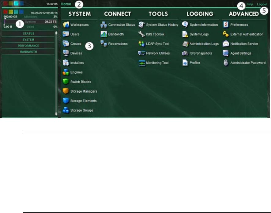
nThe following illustration is of the ISIS 7000 Management Console. It includes some features not
available in the ISIS 5000 and ISIS 2000. Non-Administrator users will see a subset of the tools
available to Administrators, depending on access privileges.
System Status Console
The System Status Console, located on the left side of the Avid ISIS Management Console,
contains several components that give you a snapshot view of the Avid ISIS system. These allow
you to access additional information about your system and to perform certain administrative
tasks, such as monitoring and logging.
nThe System Status Console is available from the Login window, even if you are not logged in to
the Management Console, but you have to log in to follow links from the tool bar screens, such as
the log files.
1 System Status panel — Provides a snap shot view of several aspects of the Avid ISIS system. See
“System Status Console” on page 20
2 Navigation toolbar — Access Management Console tools and bread crumb navigation. See
“Navigation Toolbar” on page 24
3 Main tools panel — Click to go to the respective tool pages. See “Main Tools Panel” on page 25
4 Help link — provides links to various ISIS online documents. See “Accessing Help” on page 24
5 Logout link — Ends the Management Console session and logs the user out of the system. See
“Opening the Management Console” on page 18
Using the Management Console Interface
21
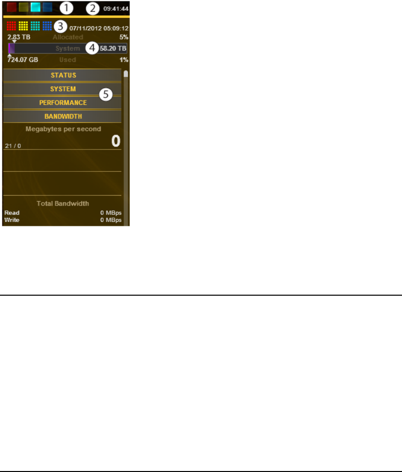
nDepending on your ISIS system and software version, the System Status Console is similar to one
of these images.
1 Current system status panel — error/warning/info/upgrade status LEDs will be lit to indicate the
presence of system events, along with a counter indicating the current number of each type of event
2 Status retrieval panel — The Management Console periodically retrieves system status information.
The panel displays the results and the time stamp of the retrieval operation.
3 Status event history panel — displays which type of system events have occurred since the
System Director was started, along with the date and time of the first logged event. Clicking this
panel opens the System Status History tool. For more information, see “System Status History Page”
on page 176
4 Storage capacity panel — displays the total capacity of all bound Storage Elements, capacity
allocated to Workspaces, and the amount of capacity used by data
5 System Status Console panels — click the panel headings to display the system information panel.
For more information, see “System Status Console Panels” on page 22
Using the Management Console Interface
22
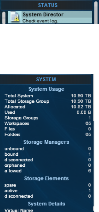
System Status Console Panels
The System Status Console contains several panels that provide information about different areas
of Avid ISIS operation. Each panel can be expanded and collapsed by clicking on the panel title.
The Status panel provides a quick summary of the System Director status. If an event in the
system log triggers a status to appear, a link is provided to the System Logs tool.
nFor more information about using the System Logs tool, see “Using the System Logs Page” on
page 171.
The System panel provides a summary of hardware, software, and networking information.
Using the Management Console Interface
23
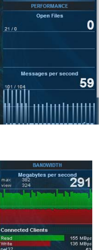
The Performance panel provides a summary of the following information:
• Messages Per Second
• Number of open files
The Bandwidth panel displays “Megabytes per second,” information on total and per-client
bandwidth.
Using the Management Console Interface
24
Navigation Toolbar
The navigation toolbar provides several items to help you navigate through the
Management Console interface.
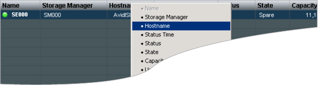
Accessing Help
The Help menu, located in the upper right-hand corner of the Management Console window,
provides links to the complete set of Avid ISIS online PDF documents.
nPDF documents can open in an external application or browser, depending on your
configuration. An Administration Guide HTML Help is only available from the System Director
Control Panel and requires Internet Explorer. The Help does not work properly in other
browsers.
To access the Help menu:
1. Move the mouse cursor over the Help menu text.
The Help pop-up menu opens.
2. (Option) Click the Help menu text to open the Avid ISIS online document.
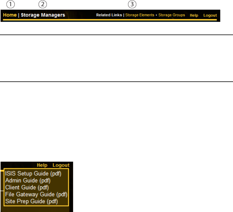
1 Home link—You can click this link from any page to return to the Management Console Home
screen
2 Current tool heading—Indicates the tool you are currently using and its associated icon
3 Related links section—Management Console tools that are related to the one you are currently using
are provided when relevant

Using the Management Console Interface
25
Main Tools Panel
The ISIS Management Console main panel is divided into the following sections:
• The System section, which contains the following tools:
• The Connectivity section, which contains the following tools:
Tool Description
Workspaces View details of, create, delete, duplicate, or change capacity of any
Workspace; see “Managing Workspaces” on page 103 for more information.
Users View details of, create, delete, duplicate, or modify Workspace access of any
User; see “Managing Users” on page 131 for more information.
Groups View details of, create, duplicate, modify Workspace access of, or assign
User access to any User Group; see “Managing User Groups” on page 139
for more information.
Devices View details of, create, delete, or modify descriptions of any device; see
“Managing Devices” on page 153 for more information.
Installers Download installers for Avid ISIS Client Manager, Flash, and other software.
Engines
(7000 and 5000 only)
View details of Engines, reported serial number, Status Time, Uptime; for
more information, see “Managing Storage Managers” on page 40.
Switch Blades
(7000 only)
View switch IP addresses, Upgrade Switches, or open the switch Agent
pages; for more information, see “Understanding the Switch Agent
Interface” on page 221.
Storage Managers View details of, bind, or unbind any Storage Manager; for more information,
see “Managing Storage Managers” on page 40.
Storage Elements View details and issue commands to any Storage Element; for more
information, see “Managing Storage Elements” on page 54.
Storage Groups View details of, create, delete, or modify Storage Elements of any Storage
Group; for more information, see “Managing Storage Groups” on page 89.
Tool Description
Connection Status View or disconnect any connected client; for more information, see
“Monitoring System Connection Status” on page 161.
Bandwidth View read and write bandwidth of any connected client; for more
information, see “Monitoring Client Bandwidth” on page 158.
Reservations View and revoke any current bandwidth reservation; for more information,
see “Monitoring Reservations” on page 163.

Using the Management Console Interface
26
• The Tools section, which contains the following tools:
• The Logging section, which contains the following tools:
Tool Description
System Status History View historical system status information; for more information, see “System
Status History Page” on page 176.
ISIS Toolbox Connection Analyzer, Log Aggregator, and Disk Analyzer, Storage Manager
Parameters, Switch Manager (ISIS 7000 only) and starts a Java tool; for more
information, see “ISIS Toolbox Page” on page 176.
LDAP Sync Tool Synchronize User information with your LDAP server; for more information,
see “Managing LDAP Accounts” on page 144.
Network Utilities Allows you to retrieve a detailed look at the connected network, or run a ping
or traceroute; for more information, see “Network Utilities Page” on
page 191.
Monitor Tool
(ISIS 7000 only)
Allows you to view information about the network hardware components in a
graphical display such as IP address, software version, and temperature; for
more information, see “Monitor Tool (ISIS 7000 Only)” on page 191.
Tool Description
System Information Get complete system information: Memory stats, host information, running
processes, and Agent statistics, all on one screen; for more information, see
“System Information Page” on page 167.
System Logs View all system messages, info, warnings, and errors at the application,
system, and security levels; for more information, see “Using the System
Logs Page” on page 171.
Administration Logs View current and archived Management Console logs; for more information,
see “Using the Administration Logs” on page 170.
ISIS Snapshots Create a snapshot of the ISIS system for viewing or downloading; for more
information, see “ISIS Snapshots Page” on page 172.
Profiler Create and view profiles of the System Director; for more information, see
“ISIS Snapshots Page” on page 172.

Organizing Display Information
27
• The Advanced section, which contains the following tools:
Organizing Display Information
This section contains the following topics:
•“Moving Columns” on page 27
•“Showing and Hiding Columns” on page 27
•“Sorting Information” on page 28
You can customize the Main display panel for any option by moving and hiding columns, and by
sorting and filtering information.
Moving Columns
To move a column in the Main display panel:
tClick and drag any column to the position you want, and release the mouse button.
The column appears in the new position, and columns to the right are moved to make room.
Showing and Hiding Columns
When you open a Management Console tool (for example, the Storage Elements tool), the Main
display panel lists items in default columns. Depending on the option selected, there might be
other headings available to view. You can select individual or multiple column headings to be
displayed or hidden.
Tool Description
Preferences Change and save bandwidth, LCT threshold, device creation, and disk errors
preferences; for more information, see “Configuring Management Console
Preferences” on page 33.
External
Authentication
Configure external authentication servers; for more information, see
“Configuring External Authentication” on page 36.
Notification Service Configure email notification on specific system events; for more information,
see “Configuring the Notification Service” on page 37.
Agent Settings Modify agent configuration options and trace settings; for more information,
see “Agent Settings Page” on page 201.
Administrator
Password
Change the Management Console Administrator password; for more
information, see “Changing the Administrator Password” on page 35.
Organizing Display Information
28
To show or hide columns:
tSelect one of the options, right-click in the column heading row and select a heading you
want to show or hide.
Displayed column headings are marked by a bullet symbol (•). You cannot hide the first
column on the left of the Main display panel (usually the Name column).
Sorting Information
The ISIS Management Console interface allows you to sort information listed in the Main
display panel, or in the Details panel. Sorting the information in columns arranges items in either
numerical or alphabetical order. You can also perform a multilevel sort of the displayed
information.
To sort information:
tClick the column heading for the column you want to sort.
The information is sorted in ascending order. To reverse the sort order, click the column
heading again.
To perform a multilevel sort:
1. Click the column heading for the first column you want to sort.
The items in the column are sorted in ascending order.
2. Click a second column.
The items in the second column are sorted in ascending order. The items in the first column
maintain their sort order, but with a lower priority than the second sort.
3. (Option) Click multiple columns to add levels to the sort. To cancel a multilevel sort, click a
column heading that has already been sorted.
Filtering the Display
29
Filtering the Display
You can limit the items listed in the Main display panel by setting Filter parameters at the bottom
of the Management Console window. Filtering the display allows you to focus on only those
items that you want to monitor. You can restore all items to the display by clearing the Filter
parameters.
nYou cannot filter the display for the Bandwidth, Connection Status, and Reservation options.
To filter the display:
1. Select a category from the Category menu.
The Category menu lists all of the column headings available for the selected Command
menu option.
2. (Option) Select “not” to exclude the items matching the filter rules from the search results.
3. Click the Condition menu and select the filter condition you want to use.
4. In the Filter text box, type the text or value you want to use to filter the display.
5. Click Filter.
The Main display panel updates to display the filtered results. The Filter panel displays the
number of filtered items displayed and the total number of items available for display.
To restore all items to the display:
tClick Clear.
The Main display panel updates to display all items.
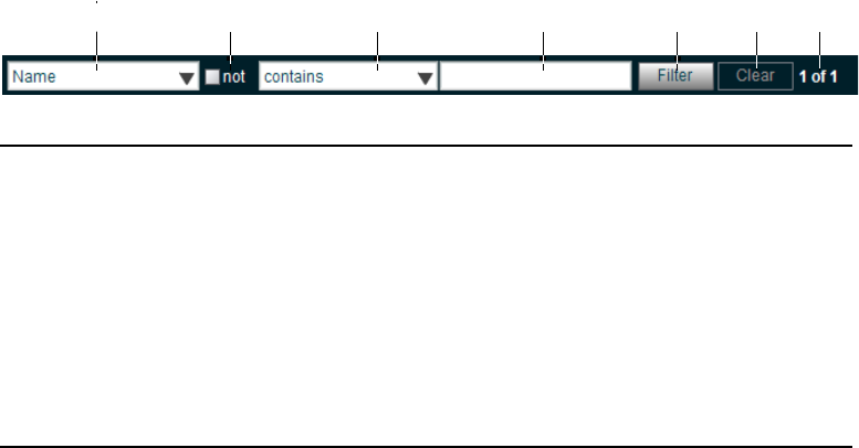
rewq t y u
1 Category menu—Select the category to filter
2 “not” operator—Select to exclude items matching the filter rules from the search results
3 Condition menu—Select the filter condition
4 Search term field—Type the text or value to filter
5 Filter button—Perform the filter operation
6 Clear button—Clear the filter settings
7 Filter results counter—Displays the number of filtered results on the page, and in total
Updating Information
30
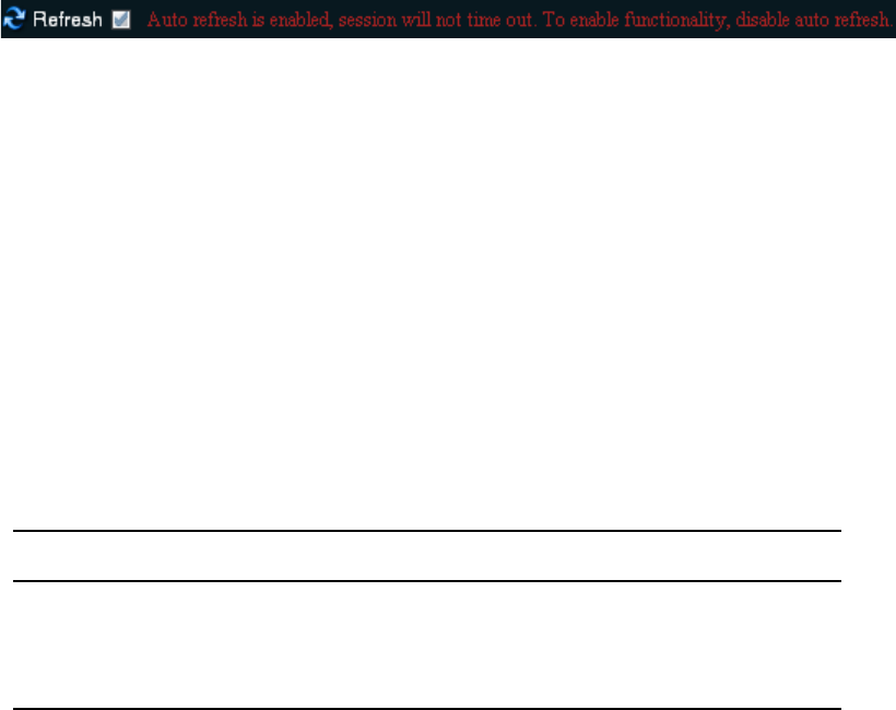
Updating Information
You can update onscreen information to reflect recent system changes by clicking the Refresh
button. You can also use Auto refresh to automatically refresh information at timed intervals, and
prevent your session from timing out.
nThis setting persists between Management Console sessions, but not browser sessions. If you
close the browser application, Auto refresh will revert to the default (disabled) setting.
To enable Auto refresh:
tSelect the check box next to the Refresh button.
Auto refresh mode is enabled, and a message is displayed.
nWhile Auto refresh mode is enabled, other functions such as add, delete, and details are not
available.
To disable Auto refresh:
tDeselect the check box next to the Refresh button.
Auto refresh mode is disabled, and the confirmation message closes.
Selecting Items
You can select multiple items in most Management Console tool windows. The methods for
selecting more than one item in a list are similar to those used in Windows Explorer or the
Macintosh Finder.
The following table summarizes the methods for selecting items and performing actions.
Actions Selection Method
To select an item Single click the item.
To select multiple, non-contiguous items Ctrl+click each item you want to select.
To select multiple, contiguous items Click the first item, then Shift+click on the last item.
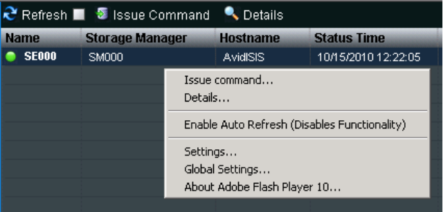
Using Context Menus to Perform Actions
31
Using Context Menus to Perform Actions
Most Management Console tool windows offer context menus you can use to perform
commands on selected items.
To access context menus within the Management Console:
tRight-click (Windows) or Ctrl+click (Macintosh) selected items.
Entering Text
The following are guidelines for entering text in Management Console tool text fields:
• Names can be a maximum of 31 characters in length.
• You should not include a space in the name fields.
• You should not use a period (.) as either the first or last character in the names you create.
• You should avoid using non-permitted characters in the name fields.

Entering Text
32
The following table summarizes characters that are not permitted in text fields in the
Management Console name text fields.
Character Name
^Circumflex accent
\Backslash
/Forward slash
:Colon
*Asterisk
?Question mark
"Double quotation mark
<Less-than sign
>Greater-than sign
|Vertical line
[Left square bracket
]Right square bracket
+Plus sign
=Equals sign
;Semicolon
,Comma
@Commercial At symbol

2Configuring the Management Console
This section contains the following topics:
•Configuring Management Console Preferences
•Changing the Administrator Password
•Configuring External Authentication
•Configuring the Notification Service
Avid ISIS provides a number of tools to customize the way the Management Console functions
and interacts with the network and other Avid products.
Configuring Management Console Preferences
The Preferences tool allows you to set parameters that apply to the basic functionality of the ISIS
Management Console.
To configure Management Console Preferences:
1. From the Management Console home page, click the Preferences icon, located in the
Advanced section.
The Preferences tool opens.
2. Configure ISIS preferences. The following table summarizes the ISIS Preferences items.
Option Type Description
Total System Bandwidth
(MB/sec)
text
(numeric)
Total reservation bandwidth allowed by the system, in MB/sec.
Default value is 1,000 MB/sec. When this value has been
reached, ISIS will no longer accept bandwidth reservations
from clients.
nThis value does not represent the actual bandwidth
capabilities of the ISIS system. For more information
about ISIS bandwidth capabilities, see the Avid ISIS
Performance Guide.

Configuring Management Console Preferences
34
3. (Option) To revert all options to the previously saved values, click the Refresh button.
4. Click the Save Preferences button to save your changes.
Default Bandwidth for Auto
Created Devices (MB/sec)
text
(numeric)
Reservation bandwidth allowed for devices that are
automatically created at connection time. Default value is 0
(zero). Using the default value results in auto-created devices
being granted unlimited bandwidth.
Force Manual Device
Creation
check box If enabled, clients which do not have an entry in the Devices
list will not be allowed to connect. The Administrator must
manually create a device account for every client computer that
is expected to connect to the ISIS system. Default value is
disabled.
cThe following options should only be altered under the direction of qualified Avid service or
support personnel.
Default LCT Threshold
(ms)
text
(numeric)
Defines the upper limit of the Long Command Time (LCT)
value, above which the Storage Element will report a Disk
Degraded condition to the System Director. Default value is 0
(zero). Using the value of zero sets the LCT threshold to the
internal system default of 750ms.
Default Hard Disk Error
Threshold
text
(numeric)
Defines the upper limit for number of hard disk errors before
the Storage Element reports a Disk Failure condition to the
System Director. Default value is 0 (zero). Using the value of
zero sets the LCT threshold to the internal system default of 25
errors).
Enable failover if standby
has more active NICS
(ISIS 7000 only)
check box Default value is enabled.
Auto Remove
Redistribution on Disk
Failure (ISIS 7000 only)
check box Default value is enabled. For more information about Auto
Remove Redistribution, see “Automatic Redistribution on Disk
Failure” on page 123.
Delete Logging
(ISIS 2000 only)
check box Logs all deletes performed in the Storage Groups. For more
information about delete logging, see “Creating a Log of the
Deletes” on page 35. Default value is disabled.
Option Type Description (Continued)
Changing the Administrator Password
35
Creating a Log of the Deletes
Delete logging is turned on and off in the Management Console Preferences. When enabled files
are created and saved in the following location.
D:\Program Files\Avid\ISIS System Director\DeleteLogs
Log file names include name contains the date and time, for example
“ISISdeleteLog-07_17_2012_17_59_30_322.csv.” Individual log files are limited to 4 MB in
size except where a new log file would have the same name as an existing one. Up to 100 log
files are kept then the oldest files are deleted.
Delete log files (.csv) can be viewed using Microsoft® Excel®. The first field does not display the
date until you select the cell and click the text entry box at the top of the spreadsheet.
Each entry in the log file consists of the following fields:
• Date and time of the file delete (19 characters)
• Name of the ISIS user initiating the delete (32 characters)
• Name of the client system the delete was issued from (32 characters)
• Full path of deleted file starting with the workspace name
Changing the Administrator Password
The Management Console Administrator password is blank by default; it is highly recommended
that you set an Administrator password when you use the Management Console for the first time.
To change the Administrator password:
1. From the Management Console home page, click the Administrator Password icon, located
in the Advanced section.
The Administrator Password tool opens.
2. Type the current Administrator password in the Current Password field (blank by default).
3. Type the new Administrator password in the New Password field.
4. Type the new Administrator password again in the Verify Password field.
5. Click Change.
- The Administrator Password is changed to the new value.
- A confirmation message appears in the Results area.
Configuring External Authentication
36
Configuring External Authentication
Users added to the system via the LDAP Sync Tool are automatically configured as remote users
in the ISIS system. When a remote user logs into the ISIS system, ISIS checks with an external
LDAP server to authenticate the user instead of the local ISIS user database. Before remote users
can access the ISIS system, you must configure ISIS to use an external LDAP server for
authentication.
For more information on working with LDAP users and groups, see “Managing LDAP
Accounts” on page 144.
To configure external Authentication:
1. From the Management Console home page, click the External Authentication icon, located
in the Advanced section.
The External Authentication tool opens.
2. Click the Enable check box to select it.
The Domain Name text box becomes active.
3. In the Domain Name text box, enter the domain name of the network which the LDAP
server(s) are members of, including subdomains, if applicable.
Use the format subdomain.domain.top-level-domain; for example:
dir.company.com
4. Click the “Server 0” check box to select it.
The Address text box becomes active.
5. In the Address text box, enter the fully-qualified domain name of the LDAP server.
Use the format servername.subdomain.domain.top-level-domain; for example:
server1.dir.company.com
6. (Option) Repeat steps 3 – 5 (using the “Server 1” and “Server 2” check boxes) to configure
additional backup LDAP servers, if applicable.
nAll of the LDAP servers must be mirrors, and reside on the same subdomain/domain.
7. When you have finished entering server information, click the Submit button.
The domain and LDAP server information is added to the ISIS database, and a confirmation
message is displayed in the Results area.
Configuring the Notification Service
37
Configuring the Notification Service
This section contains the following topics:
•Starting, Stopping, and Configuring the Notification Service
•Configuring Error Notification Parameters
•Configuring Contact Information
You can use the Notification Service tool to configure System Director to notify you when
problems occur. An error notification service regularly polls the Windows System Event log and,
if any errors are logged, sends a concise summary of those errors to one or more e-mail accounts.
The Notification Service tool window is divided into three main sections:
• Configuration – Start and stop the Notification Service, and configure the Notification
Service settings.
• Filters – Modify the parameters that define when email notifications are sent to email
recipients.
• Contact – Add and modify email recipients.
Starting, Stopping, and Configuring the Notification Service
The configuration information for the notification service (SMTP information, contacts, and
filters) is currently stored in the registry on the System Director. This information is not currently
replicated to the Dual System Director server, so you need to enter configuration information for
notification service on both System Directors.
To configure the Notification Service:
1. From the Management Console home page, click the Notification Service icon, located in
the Advanced section.
The Notification Service tool opens.
2. Click the Enable Service check box to toggle between checked and cleared.
tIf the check box is checked, the Notification Service is enabled.
tIf the check box is cleared, the Notification Service is disabled.

Configuring the Notification Service
38
3. (Option) configure the Notification service settings. The following table summarizes the
Notification Service settings.
4. (Option) To test the configuration settings, click Test.
The results of the service test are displayed in the Results area.
5. Click Save.
- A confirmation message is displayed in the Results area.
- If you started or stopped the Notification Service, the Service State will change to
reflect the new service state.
6. (Option) Click Reset.
The changes for the configuration will be lost.
Configuring Error Notification Parameters
The Filter area of the Notification Service tool window allows you to specify the type of error
message that triggers an e-mail notification and to set parameters for each type of error
message—Error, Warning, and Information messages.
You can configure the ISIS to send notification emails for one or more error types and what
severity level on which to be notified.
For a complete list of Avid ISIS email notifications, see “Avid ISIS E-mail Notification List” on
page 243.
To configure error notification parameters:
1. In the Filter section, select or deselect individual notifications by clicking the check boxes
corresponding to the error notification.
2. Click Save.
The settings are saved, and a confirmation message is displayed in the Results area.
Option Type Description
SMTP Server text The IP address or host name of your SMTP server.
SMTP Port text
(numeric)
The port number of your SMTP server. The default value (25) is
appropriate in most instances.
Poll Frequency
(seconds)
text
(numeric)
The frequency (in seconds) with which the error notification
service checks for problems.
Return Address text The e-mail address of the Avid ISIS administrator or other
primary contact for the error notification service.
Configuring the Notification Service
39
Configuring Contact Information
You must specify the contact information for all the people you want to receive ISIS notification
emails.
To add contacts:
1. In the Contact section, click New.
Empty User Name and Email fields open.
2. Type a user name into the first text box.
This can be any name you want to assign to the user.
3. Type a valid email address into the second text box.
4. Click Save.
5. Repeat steps 2 – 4 to add more email contacts, if needed.
To remove a contact:
1. Click the Delete button next to the email contact entry.
The contact is removed from the list.
2. Click Save.

3Managing Avid ISIS Hardware
This section contains the following topics:
•Managing Storage Managers
•Managing Storage Elements
•Managing ISIS 7000 Switch Blades
•Managing the Engine (ISIS 7000 and ISIS 5000 Only)
This section describes how to configure and manage your storage hardware. You perform all
storage management operations from the Avid ISIS Management Console, which allows you to
add, remove, configure, and manage your Storage Elements.
nFor an overview of the ISIS Management Console and information about how to start the tool,
see “Opening the Management Console” on page 18.
Managing Storage Managers
This section contains the following topics:
•Storage Manager Column List
•Viewing Storage Manager Details
•Storage Manager Status
•Adding (Binding) Storage Managers to the ISIS File System
•Removing (Unbinding) Storage Managers from the ISIS File System
•Clearing Network Degraded Status Messages
•Upgrading ISIS 7000 Storage Manager
•Adding Storage Elements to the File System
•Removing Storage Elements from the ISIS 7000 Shared Storage Network
•Removing Orphaned Storage Managers
The Storage Manager coordinates and controls the activity of Storage Elements. Before you start
building Storage Groups and Workspaces, you must bind each Storage Manager to the ISIS file
system to make Storage Elements available for use.
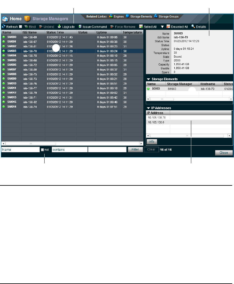
Managing Storage Managers
41
The Storage Manager tool allows you to bind/unbind Storage Managers and perform
maintenance operations.
t
r
e
wq
y
1 Action button toolbar — Perform actions on selected Storage Managers
2 Details panel—Detailed information on the selected Storage Managers; see “Viewing
Storage Manager Details” on page 44
3 Storage Managers list — Lists all configured Storage Managers and related information; see
“Storage Manager Column List” on page 42
4 Storage Elements panel — Lists the Storage Elements controlled by the selected
Storage Manager
5 Filter panel — Filter the Storage Managers list display based on conditions you configure; see
“Filtering the Display” on page 29
6 IP addresses list — Displays the IP addresses of the selected Storage Manager

Managing Storage Managers
42
Storage Manager Column List
The following table summarizes the basic information available when you first open the
Storage Manager list. Some columns are hidden by default (see “Showing and Hiding Columns”
on page 27 and “Storage Element Details” on page 60).
Heading Description
Name Displays the system-created name of each Storage Manager connected to the system
ISB Name
(ISIS 7000 only)
Displays the name of the ISB in the ISIS 7000 Engine
Hostname
(ISIS 5000 and
ISIS 2000 only)
Displays the host name of the Storage Element (System Director or Engine)
Status Time Lists the last time the System Director logged the Storage Element’s status
Status Displays any change in the working status logged by the System Director (for a
description of status messages, see “Storage Element Status Messages” on page 58)
Uptime Displays the amount of time Storage Manager service has been running
(days:hours:min:sec)
Temperature
(ISIS 7000 only)
Displays the temperature of each ISB in the ISIS 7000 Engine
State Displays the Storage Manager state (Bound/Unbound)
Type Displays the Storage Manager type (ISIS 7000 - ISB size, ISIS 5000 - ISIS Engine,
ISIS 2000 - Nearline Engine)
Capacity Displays the total capacity of all Storage Elements controlled by the selected
Storage Manager
Usable Displays the amount of storage space in gigabytes (GB) remaining
Spare Displays the number of spare Storage Elements for the Storage Manager
Active Displays the number of active Storage Elements for the Storage Manager
Other The following messages could be displayed:
• Displays “0” if none of the following apply
• Missing
• Out of Phase
• Unknown
• Wrong Server

Managing Storage Managers
43
nYou can organize the information in the Storage Elements Managers list by showing additional
columns or by sorting or filtering displayed items. For more information on modifying the
display, see “Organizing Display Information” on page 27.
A color-coded icon precedes the name of each Storage Manager, providing an indication of the
status of the component. The following table describes the color coding system used by the ISIS
Management Console.
Version Displays the software version number of each Storage Manager
Engine Serial Displays the serial number of the Engine
Slot Number
(ISIS 7000 only)
Displays the slot location of the ISB in the Engine, see “Identifying the ISIS 7000
Storage Elements Prior to Removal” on page 52
Domain ID
(ISIS 7000 only)
Displays the domain ID number of the Management Domain (stack) for each Engine
(chassis) in which the Storage Element is part of.
nDomain ID numbers are not displayed until the Storage Elements are bound.
Heading Description (Continued)
Icon Color Description
White Indicates the status of the Storage Manager is Unbound (the Storage Element is not
linked to the ISIS file system)
Green Indicates the Storage Manager is bound to the file system
Yellow Indicates one of the following:
• a problem with the Storage Manager
• the Storage Manager is experiencing degraded performance
Blue
(ISIS 7000 only)
Indicates that an installation or software upgrade is in progress
Red Indicates a Storage Manager problem, including any of the following:
• a hardware error
• a failed software installation or upgrade

Managing Storage Managers
44
Viewing Storage Manager Details
The Details panel displays all information for the currently selected Storage Manager. The
information displayed is the information as seen by the System Director. Some of the
information is embedded in the Storage Manager, and other information is assigned to the
Storage Manager by the Avid ISIS software.
To view detailed information about a Storage Manager:
1. In the Storage Manager list, select a Storage Manager.
2. Do one of the following:
tClick the Details button.
tDouble-click the Storage Manager name.
The Details panel displays all the information for the selected Storage Manager. For more
information, see “Viewing Storage Manager Details” on page 44.
To close the Details panel:
tClick the Details button.
The following table summarizes the information available in the Details panel.
Heading Description
Name Displays the system-created name of each Storage Manager connected to the system
ISB Name
(ISIS 7000 only)
Displays the name of the ISB in the ISIS 7000 Engine
Hostname
(ISIS 5000 and
ISIS 2000 only)
Displays the host name of the Storage Element (System Director or Engine)
Status Time Lists the last time the System Director logged the Storage Element’s status
Status Displays any change in the working status logged by the System Director (for a
description of status messages, see “Storage Element Status Messages” on page 58)
Uptime Displays the amount of time Storage Manager service has been running
(days:hours:min:sec)
Temperature
(ISIS 7000 only)
Displays the temperature of the selected ISB
State Displays the Storage Manager state (Bound/Unbound)
Type Displays the Storage Manager type

Managing Storage Managers
45
Storage Manager Status
The Status column in the Storage Managers list reports the status of the Storage Managers
logged by the System Director. (The Status line in the Details panel reports the same
information.) If the Storage Manager maintains a working status, the ISIS Management Console
lists no entries in the Status field. When a problem arises, or when the status of the
Storage Manager changes, the ISIS Management Console updates the Storage Managers display.
Capacity Displays the total capacity of all Storage Elements controlled by the selected
Storage Manager
Usable Displays the usable capacity of all Storage Elements controlled by the selected
Storage Manager
Spare Displays the number of spare Storage Elements
Active Displays the number of active Storage Elements
Other The following messages could be displayed:
• Available
• Mismatched
• Missing
• Orphaned
• Out of Phase
• Unknown
• Wrong Server
Version Displays the software version number of each Storage Manager
Engine Serial Displays the serial number of the Engine
Slot Number
(ISIS 7000 only)
Displays the slot location of the ISB in the Engine
Domain ID
(ISIS 7000 only)
Displays the domain ID number of the Management Domain (stack) for each Engine
(chassis) in which the Storage Manager is part of.
nDomain ID numbers are not displayed until the Storage Manager are bound.
Heading Description (Continued)

Managing Storage Managers
46
The following table summarizes the Storage Manager status messages.
Status Description
Memory Error The Storage Manager runs a memory test when it starts or restarts reports
any errors; this status is persistent.
Offline The Storage Manager has been taken offline.
Network degraded The IP interfaces on the Storage Manager have failed or the
Storage Manager experiences at least a 10% error rate (usually due to lost
packets), indicating a network communication problem.
Initializing
(ISIS 5000 and ISIS 2000
only)
The ISIS 5000 and ISIS 2000 RAID set getting initialized. This could take
several hours.
Install failed - Phase #
(ISIS 7000 and ISIS 2000
only)
A message displays if the ISIS 7000 ISB fails during the three phases of the
upgrade or during the two phases of the ISIS 2000 upgrade.
Install needed
(ISIS 7000 and ISIS 2000
only)
This message displays if the ISIS 7000 or ISIS 2000 Storage Manager
(Engine Controller in ISIS 2000) is not at the same version of the ISIS
System Director software. Select all the storage Managers and click
Upgrade.
Missing spare drive
(ISIS 5000 and ISIS 2000
only)
The spare drive is either missing or cannot be detected.
Invalid drive
(ISIS 5000 and ISIS 2000
only)
The drive detected is not an Avid qualified drive.
Invalid number of drives
(ISIS 7000 only)
The Storage Manager has determined it doesn't have enough drives to run in
the bound operating mode. In this mode the Storage Manager only
communicates with the System Director, no clients are allowed to connect,
and the Storage Manager is not functional in the Storage Group.
Once the Administrator has addressed the issue in the Storage Manager, the
Storage Manager must be restarted via the Storage Manager agent.
Drive controller error
(ISIS 5000 and ISIS 2000
only)
The drive controller has reported an error.
The following status messages are not specific to the Storage Manager. They will appear as
Storage Manager status when the corresponding Storage Element(s) status is set.
Rectifying Files The Storage Element is cleaning up deleted files and verifying existing files.

Managing Storage Managers
47
Adding (Binding) Storage Managers to the ISIS File System
Before you start building Storage Groups and Workspaces, you must bind each Storage Manager
to the ISIS file system to make Storage Elements available for use.
To add (bind) a Storage Manager to the ISIS file system:
1. Click to select the Storage Manager you want to bind.
2. Click the Bind button.
A confirmation dialog appears.
3. Click Yes to confirm.
- The selected Storage Manager is added to the ISIS file system.
- The selected Storage Manager state is changed to Bound.
Repairing Mirrors
(ISIS 7000 only)
The Storage Element is repairing mirrored blocks with a single point of
failure.
Disk Failure The Storage Element is unusable for data storage and must be replaced.
Test Mode The Storage Element is in disk test mode.
Redistributing Data is being redistributed to Storage Elements in the Storage Group.
Disk Performance
Degraded
The Storage Element’s performance is below the threshold for input/output
functions and might impact the performance of the system.
Disk full A Storage Element in a Storage Group has no more space available to write
data.
Metadata error The Storage Element experienced an error loading metadata from the disk or
writing new metadata to the disk (if mirrored in the ISIS 7000, the data on
the mirrored Storage Element is still available and no actual data loss
occurs); this indicates that the Storage Element should be replaced.
If you have a Storage Element with this status, reboot the Storage Element.
If “Metadata Error” status exists after a reboot, then the Storage Element
should be replaced. If the Metadata Error status clears after a reboot, then
the Storage Element is fine and no further action is required.
Status (Continued) Description
Managing Storage Managers
48
Removing (Unbinding) Storage Managers from the ISIS File System
Before you can unbind a Storage Manager from the ISIS file system, its Storage Element(s) must
be in the Spare state.
To remove (unbind) a Storage Manager from the ISIS file system:
1. Click to select the Storage Manager you want to unbind.
2. Click the Unbind button.
A confirmation dialog appears.
3. Click Yes to confirm.
- The selected Storage Manager is removed from the ISIS file system.
- The selected Storage Manager state is changed to Unbound.
Clearing Network Degraded Status Messages
You can use the Issue Command button to clear all Network Degraded status messages from the
Storage Managers list. Network Degraded status indicates a high number of errors detected by
the Storage Manager (see “Storage Element Status Messages” on page 58). Correcting the
problem might not clear the status messages, so you can use the Issue Command button to clear
the messages and reset the error count.
cYou should correct the cause of the Network Degraded status messages before you clear
them from the ISIS Management Console.
To clear all Network Degraded messages in the Storage Managers list:
1. Select one or more Storage Managers from the Storage Managers list.
You can use the Shift and Control keys to select multiple items. For more information, see
“Selecting Items” on page 30.
2. Click the Issue Command button.
The Issue Storage Manager(s) Command window opens.
3. Click Clear Network Degraded, and then click Send.
Upgrading ISIS 7000 Storage Manager
Use the Storage Manager tool to upgrade the Storage Manager software installed in an Engine
and connected to the shared storage network.
Managing Storage Managers
49
To upgrade a Storage software:
1. Select the Storage Manager(s) you want to upgrade.
2. Click the Upgrade button.
The Upgrade Storage Managers dialog box opens.
3. Select the upgrade installer from the list in the right column.
The Command text box displays the location of the upgrade installer.
cDo not enter any text in the Command or Options fields except under the supervision of
qualified Avid support personnel. Doing so can result in system degradation and data loss.
4. Click the Upgrade button.
The ISIS Management Console installs the necessary upgrade for the selected
Storage Manager. You can monitor the progress of the upgrade either in the Details panel of
the Storage Manager tool or in the ISIS 7000 System Monitor tool.
Adding Storage Elements to the File System
The Storage Group defines the Storage Elements that the network can use to store data. In order
to finish configuring your Avid ISIS shared storage network, you must add Storage Elements to
the ISIS file system, and then you must create a Storage Group from the available
Storage Elements.
To add a Storage Element to the ISIS file system:
1. From the Management Console home page, click the Storage Managers icon, located in the
System section.
The Storage Managers tool opens.
2. Select the Storage Manager(s) you want to add to the file system.
nYou can only add Storage Elements that are marked as Available.
3. Click the Bind button.
A confirmation dialog appears.
4. Click Yes.
- The Storage Manager is bound to the shared storage file system.
- The Storage Element status is changed to Spare and is made available to add to
Storage Groups.
nYou may have to click the Refresh button to see the changes.
Managing Storage Managers
50
5. (ISIS 7000 only) If you have i500 or i1000 ISBs you need to select the chunk size to be used
for the Storage Element(s).
nThe choices that appear in the Chunk Size list are dependent upon the capabilities of the
installed Storage Blades. Storage Elements can only be added to Storage Groups with the same
chunk size. For more information on protection types, see “Storage Groups on ISIS 7000” on
page 93.
6. Switch to the Storage Elements page by doing one of the following:
tClick “Storage Elements” in the Related Links section.
tClick System > Storage Elements in the pop-up navigation menu.
The Storage Elements tool opens.
7. Click Ok.
The “Add Storage Element Confirmation” dialog appears.
8. Click Yes.
- The selected Storage Elements are added to the ISIS file system.
- The selected Storage Element icons are changed to green.
- The selected Storage Element names are changed from isb-xx to SExx.
- The status of the selected Storage Elements is changed from Available to Spare.
nYou might have to click the Refresh button to see the changes you have made.
Removing Storage Elements from the ISIS 7000 Shared Storage Network
You can remove and replace Storage Elements without stopping the System Director or turning
off other components of the network. There are two principal reasons for removing
Storage Elements from the system:
• The element has a high number of unrecoverable errors
• The element has failed or has been removed from the system
Before you remove an Avid ISIS Storage Blade (Storage Element) from the network, you must
redistribute the data stored on the Storage Element to other Storage Elements in the system. The
redistribution occurs before you physically remove the Storage Element, and the process entails
moving data to the remaining drives within the Storage Group. Once you redistribute the data,
you add a new Storage Element to the system and then perform a redistribution again to place
data onto the new Storage Element.
cIf you physically remove a Storage Element from the shared storage network before
redistribution is complete, data loss can occur.
Managing Storage Managers
51
nYou should maintain an unused block of storage equivalent to one Storage Element within the
Storage Group to allow redistribution from a failing Storage Element to other Storage Elements
within the group.
If possible, you should redistribute data while the drive is experiencing problems but has not yet
been removed from the system. This allows the Storage Element having problems to participate
in the redistribution process by offering data that it has to both clients and to other
Storage Elements.
nOften the Storage Element is still functional, but its performance is slightly degraded — for
example, the Storage Element might have an unrecoverable error on one of its disks, or it might
have long I/O times.
If the Storage Element fails, or if it has been removed from the system, you can perform a
redistribution from the mirrored or RAID locations associated with the Storage Element.
However, if any other mirrored location experiences a failure while performing a redistribution,
the system can lose data.
cIf the failed Storage Element was part of an unprotected Workspace, data loss is likely.
Consider the following when planning a redistribution:
• A one-to-one replacement of Storage Elements might leave you with less storage space in
the Storage Group than you require. Instead, plan for using more Storage Elements than you
need for storage and bandwidth for each Storage Group. This way, you can keep an optimal
amount of available storage space allocated to the Storage Group. This allows you to quickly
perform redistribution, rather than attempting a redistribution with only one spare
Storage Element.
• In general, the removal of a Storage Element is quicker than an addition. This is because all
of the other Storage Elements in a Storage Group participate in redistribution by moving a
copy of any block held by the element to another location. The more Storage Elements in the
Storage Group, the more the workload is shared. A single Storage Element addition is
slower than a removal because the Storage Element receiving the data acts as a limiting
factor for the redistribution.
• When you add a new Storage Element to the Avid ISIS file system and then add it to a
Storage Group, the system redistributes data from the existing drives in the Storage Group to
the new element. This redistribution maintains all previously stored data, but the data might
not reside on the same Storage Elements.
nIf you do not have a replacement for a failed or failing Storage Element, Avid recommends that
you physically leave it in the Engine, even after it has been removed from the file system. Proper
airflow cannot be disturbed if a Storage Element slot is left open.

Managing Storage Managers
52
The following steps list the actions necessary for removing a Storage Element:
1. Identify the Storage Element you want to replace.
2. Remove the Storage Element from the Storage Group.
3. View the status of the redistribution and wait for redistribution to finish.
4. Unbind the Storage Manager from the Storage Group.
5. Physically remove and replace the Storage Element.
6. Add new Storage Element to the file system.
7. Add the new Storage Element to a Storage Group.
For more information on the process of redistributing data and how redistribution affects
system performance, see “Redistribution ISIS 7000 Guidelines” on page 121.
nRedistributing while adding a Storage Element takes longer than redistributing while removing
an ISB.
Identifying the ISIS 7000 Storage Elements Prior to Removal
To identify the Storage Element to be removed and replaced:
1. Locate the failing or failed Storage Element. For information on Storage Element status, see
“Storage Manager Column List” on page 42 and “Storage Manager Status” on page 45.
2. Select the Storage Manager, and do one of the following:
tClick the Details button.
tDouble-click the name of the Storage Manager.
The Details panel opens.
The Details panel lists the Engine Serial number and the Slot Number of the selected
Storage Element. The address identifies the Storage Element to be physically removed.
nThe slot numbers for Storage Elements begin at zero (0).
ISIS slot numbering
01 2 3
4567
89
10 11
12 13 14 15
Managing Storage Managers
53
Preparing to Removing Storage Elements from the Avid ISIS Engine
After you have identified the Storage Element you want to remove, you need to remove it from
the Storage Group before you physically remove the drive from the Engine.
cYou must finish the redistribution before you physically remove the Storage Element. If
you do not wait until the redistribution finishes, shared storage network clients might
receive multiple errors.
To physically remove a Storage Element from your shared storage network:
1. Remove the Storage Element from its Storage Group. For information on removing
Storage Elements, see “Removing ISIS Storage Elements from Storage Groups (ISIS 7000
and ISIS 5000 Only)” on page 99.
2. Open the Workspaces tool by clicking the Workspaces icon in the System section of the
following from the Management Console home page:
The Workspaces tool opens.
3. Select the Workspace for the appropriate Storage Group.
4. Monitor the Status column for the progress of the redistribution operation. Click the Refresh
button until the redistribution finishes.
The Status column displays no status message when the process is complete.
cDo not remove the Storage Element before the redistribution has completed.
5. Remove the Storage Element from the ISIS file system. For information on removing
Storage Elements, see “Removing (Unbinding) Storage Managers from the ISIS File
System” on page 48.
6. In the Storage Manager list, select the Storage Manager you want to remove and then click
the Issue Command button.
The Issue Storage Manager(s) Command dialog box opens.
7. Select Take Offline, and then click Send.
nIf you remove an active Storage Element by mistake, the System Director restores the
Storage Element to the Storage Element list the next time it polls the shared storage network
(usually within 20 seconds).
The system spins down the drives in the selected Storage Element and changes the status in
the Storage Elements list to Offline.
8. Disconnect the Storage Element from the network, as described in the Avid ISIS Setup
Guide.
Managing Storage Elements
54
Removing Orphaned Storage Managers
Orphaned Managers are Storage Managers connected to a file system which is not currently in
use. This can happen when a Storage Manager is moved from one ISIS environment to another,
or when you use the System Director Control Panel to create a new active partition on a system
that already includes bound Storage Managers. The “Force Remove” command will remove the
file system binding from the Storage Manager and make it available for use in the current file
system.
To remove orphaned Storage Managers, you must force-remove them from the system.
cRemoving Storage Managers causes all data stored on them to be erased. Do not remove
disconnected Storage Managers unless you are certain they contain no data you want to
save.
To remove orphaned Storage Managers:
1. From the Management Console home page, click the Storage Managers icon, located in the
System section.
The Storage Managers tool opens.
2. Select the orphaned Manager(s) you want to force-remove.
3. Click the Force Remove button.
A message warns you that removing Storage Managers erases all data on the component.
4. Click Yes.
The Force Removal Text Confirmation dialog box opens.
5. Type
Remove
in the text box, and then click Remove.
The orphaned Storage Manager is unbound from the ISIS file system and removed from the
Orphaned Managers list.
Managing Storage Elements
This section contains the following topics:
•Storage Element Column List
•Storage Element Status
•Storage Element Status Messages
•Storage Element Details
•Initiate Block Rectify
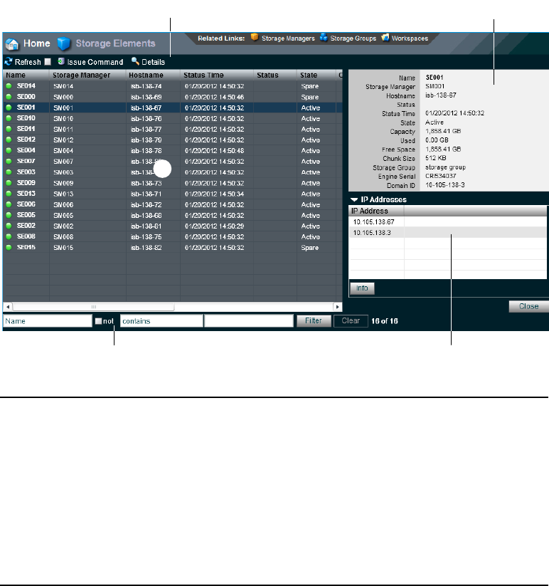
Managing Storage Elements
55
The Storage Elements tool allows you to monitor Storage Element operation.
Storage Element Column List
The following table summarizes the basic information available when you first open the
Storage Elements list. Some columns are hidden by default (see “Showing and Hiding Columns”
on page 27 and “Storage Element Details” on page 60).
tr
e
w
q
1 Action button toolbar—Perform actions on selected Storage Elements
2 Details panel—Detailed information on the selected Storage Elements; see “Storage Element
Details” on page 60
3 Storage Elements list—Lists all configured Storage Elements and related information; see
“Storage Element Column List” on page 55
4 Filter panel—Filter the Storage Elements list display based on conditions you configure; see
“Filtering the Display” on page 29
5 IP addresses list—Displays the IP addresses of the selected Storage Elements

Managing Storage Elements
56
nYou can organize the information in the Storage Elements list by showing additional columns or
by sorting or filtering displayed items. For more information on modifying the display, see
“Organizing Display Information” on page 27.
A color-coded icon precedes the name of each Storage Element, providing an indication of the
status of the component. The following table describes the color coding system used by the ISIS
Management Console.
Heading Description
Name Displays the system-created name of each Storage Element connected to the system
Storage Manager Displays the computer name of the Storage Manager
Hostname Displays the host name of the Storage Element (ISIS 5000 and ISIS 2000 System
Director or Engine) or the ISB (ISIS 7000)
Status Time Lists the last time the System Director logged the Storage Element’s status
Status Displays any change in the working status logged by the System Director (for a
description of status messages, see “Storage Element Status Messages” on page 58)
State Displays the Storage Element category of each Storage Element:
• Spare—Storage Element can be added to a Storage Group
• Active—Storage Element is currently assigned to a Storage Group
Capacity Displays the storage capacity in gigabytes (GB) of each Storage Element
Used Displays the amount of storage space in gigabytes (GB) in use by each
Storage Element
Chunk size The smallest unit of data that can be written to the shared storage network
Storage Group Displays the Storage Group, if any, to which the Storage Element is allocated
Engine Serial
(ISIS 7000 only)
Displays the serial number of the Engine
Domain ID
(ISIS 7000 only)
Displays the domain ID number of the Management Domain (stack) for each Engine
(chassis) in which the Storage Element is part of.
nDomain ID numbers are not displayed until the Storage Elements are bound.
Icon Color Description
White Indicates the status of the Storage Element is Available (the Storage Element is not
linked to the ISIS file system)

Managing Storage Elements
57
Storage Element Status
The Status column in the Storage Elements list reports the status of the Storage Element logged
by the System Director. (The Status line in the Details area reports the same information.) If the
Storage Element maintains a working status, the ISIS Management Console lists no entries in the
Status field. When a problem arises, or when the status of the Storage Element changes, the ISIS
Management Console updates the Storage Elements display.
The following table summarizes the Storage Element status messages.
Green Indicates the status of the Storage Element is either Spare (the Storage Element is not
allocated to a Storage Group) or Active (allocated to a Storage Group)
Yellow Indicates one of the following:
• Problem with the Storage Element
• The Storage Element experiences degraded performance due to a reboot during an
upgrade operation
Blue
(ISIS 7000 only)
Indicates that an installation or software upgrade is in progress
Red Indicates a Storage Element problem, including any of the following:
• Hardware error
• Failed software installation or upgrade
• Storage Element disconnected due to a reboot during an upgrade operation
Icon Color Description (Continued)
Category Status
Disk Status • Disk in test mode
• Metadata error
General Status • Rectifying files: the Storage Element is cleaning up deleted files and
verifying existing files
• No connection: the System Director cannot communicate with the
Storage Element; this could be due to a networking infrastructure issue or
Storage Element failure
• Repairing mirrors (ISIS 7000 only): the Storage Element is repairing
mirrored blocks with a single point of failure
• Disk failure: the Storage Element is unusable for data storage and must be
replaced

Managing Storage Elements
58
Storage Element Status Messages
The Status column in the Storage Elements list reports the status of the Storage Element logged
by the System Director. (The Status line in the Details panel reports the same information.) If the
Storage Element maintains a working status, the ISIS Management Console lists no entries in the
Status field. When a problem arises, or when the status of the Storage Element changes, the ISIS
Management Console updates the Storage Elements display.
• Redistributing: data is being redistributed to Storage Elements in the
Storage Group
• Disk performance degraded: the Storage Element’s performance is below
the threshold for input/output functions and might impact the performance
of the system
• Network degraded: the IP interfaces on the Storage Element has failed or
the Storage Element experiences at least a 10% error rate (usually due to
lost packets), indicating a network communication problem
• Memory error: the memory test that runs when the Storage Element starts
or restarts reports an error; this status is persistent and indicates that the
Storage Element has failed and should be replaced
• Metadata error: the Storage Element experienced an error loading
metadata from the disk or writing new metadata to the disk (if mirrored,
the data on the mirrored Storage Element is still available and no actual
data loss occurs); this indicates that the Storage Element should be
replaced.
If you have a Storage Element with this status, reboot the Storage Element.
If “Metadata Error” status exists after a reboot, then the Storage Element
should be replaced. If the Metadata Error status clears after a reboot, then
the Storage Element is fine and no further action is required.
• Disk in test: the Storage Element is in disk test mode
• Offline: the Storage Element has been taken offline, usually in preparation
for removal
Temperature status • Temperature above threshold: the temperature of the Storage Element
exceeds 60°C (140°F)
Connection Status • No Connection
Category Status (Continued)

Managing Storage Elements
59
The following table summarizes the Storage Element status messages.
Status Description
Rectifying Files The Storage Element is cleaning up deleted files and verifying existing files.
Repairing Mirrors
(ISIS 7000 only)
The Storage Element is repairing mirrored blocks with a single point of failure.
Disk Failure The Storage Element is unusable for data storage and must be replaced.
Test Mode The Storage Element is in disk test mode.
Redistributing Data is being redistributed to Storage Elements in the Storage Group.
Disk Performance
Degraded
The Storage Element’s performance is below the threshold for input/output
functions and might impact the performance of the system.
Disk full A Storage Element in a Storage Group has no more space available to write data.
Metadata error The Storage Element experienced an error loading metadata from the disk or
writing new metadata to the disk (if an ISIS 7000 mirror, the data on the mirrored
Storage Element is still available and no actual data loss occurs); this indicates that
the Storage Element should be replaced.
If you have a Storage Element with this status, reboot the Storage Element. If
“Metadata Error” status exists after a reboot, then the Storage Element should be
replaced. If the Metadata Error status clears after a reboot, then the
Storage Element is fine and no further action is required.
Disk offline The Storage Element has been taken offline, usually in preparation
for removal.
Identify Mode
(ISIS 7000 only)
A command was sent to blink the LED on the ISB to identify it. Typically this
command is sent when identifying a failed drive.
Drive missing
(ISIS 7000 only)
One or both of the drives in an ISB is not responding or missing.
Drive rebuilding
(ISIS 5000 and
ISIS 2000 only)
When an ISIS 5000 or ISIS 2000 drive is removed from the Engine, the spare drive
is automatically used to rebuild the RAID set.
Initializing raid set
(ISIS 5000 and
ISIS 2000 only)
When you initially install the Avid ISIS 5000 and ISIS 2000 software, the media
drives in a new ISIS 5000 and ISIS 2000 System Director or Engine are configured
into a RAID drive set. The RAID set is initialized automatically.
Checking raid set
(ISIS 5000 and
ISIS 2000 only)
Displays when the Avid ISIS 5000 or ISIS 2000 software is checking the RAID set
in an ISIS 5000 or ISIS 2000 system.

Managing Storage Elements
60
Storage Element Details
The Details panel displays all information for the currently selected Storage Element. The
information displayed is the information as seen by the System Director. Some of the
information is embedded in the Storage Element, and other information is assigned to the
Storage Element by the Avid ISIS software.
nYou can view more detailed information on Storage Elements by using the Avid ISIS Agent tool.
For more information, see “Avid ISIS Storage Manager Agent” on page 204.
To view information about a Storage Element:
1. In the Storage Elements list, select a Storage Element.
2. Do one of the following:
tClick the Details button.
tDouble-click the Storage Element name.
The Details panel displays all the information for the selected Storage Element. For more
information, see “Storage Element Details” on page 60.
To close the Details panel:
tClick the Details button.
The following table summarizes the information available in the Details panel.
Heading Description
Name Displays the system-created name of each Storage Element connected to the system
Storage
Manager
Displays the computer name of the Storage Manager
Hostname Displays the host name of the Storage Element (ISIS 5000 and ISIS 2000 System
Director or Engine) or the ISB (ISIS 7000)
Status Time Lists the last time the System Director logged the Storage Element’s status
Status Displays any change in the working status logged by the System Director (for a
description of status messages, see “Storage Element Status Messages” on page 58)
State Displays the Storage Element category of each Storage Element:
• Spare—Storage Element can be added to a Storage Group
• Active—Storage Element is currently assigned to a Storage Group
Capacity Displays the storage capacity in gigabytes (GB) of each Storage Element

Managing Storage Elements
61
Initiate Block Rectify
Once you have added Storage Elements to your network and configured them for storage, the
Storage Manager periodically checks the status of stored files, cleaning up deleted files and
verifying existing files. This process, called “rectifying files,” allows the Storage Manager(s) to
communicate with the System Director to monitor the state of its storage and clean up any files
that the Storage Elements no longer need to store. Rectifying files occurs randomly and
asynchronously during normal system operation to minimize any potential decrease in system
performance. The process is indicated for each affected Storage Manager in the Status column in
the Storage Manager list.
Storage Managers also rectify files when starting or restarting. When this happens, data stored
on the Storage Elements might not be in sync with the data in the file system itself. Also, if a
client, such as the asset manager, cannot communicate with the Storage Manager, there might
appear to be more data allocated to the Storage Elements than the file system has allocated. To
correct this, you can manually send the Storage Element a command to rectify its files.
To rectify files:
1. Select one or more Storage Elements from the Storage Elements list.
You can use the Shift and Control keys to select multiple items. For more information, see
“Selecting Items” on page 30.
2. Click the Issue Command button.
The Issue Storage Element(s) Command dialog box opens.
3. Select Initiate Block Rectify, and then click Send.
The system rectifies files on the selected Storage Elements and changes the status in the
Storage Elements list to Rectifying Files.
Used Displays the amount of storage space in gigabytes (GB) in use by
each Storage Element
Free Space Displays the amount of storage space in gigabytes (GB) remaining
Chunk size The smallest unit of data that can be written to the shared storage network
Storage Group Displays the Storage Group, if any, to which the Storage Element is allocated
Engine Serial
(ISIS 7000 only)
Displays the serial number of the Engine
Domain ID
(ISIS 7000 only)
Displays the domain ID number of the Management Domain (stack) for each Engine
(chassis) in which the Storage Element is part of.
nDomain ID numbers are not displayed until the Storage Elements are bound.
Heading Description (Continued)

Managing ISIS 7000 Switch Blades
62
Managing ISIS 7000 Switch Blades
The Switch Blades tool of the ISIS Management Console allows you to monitor and upgrade all
Switch Blades connected to the shared storage network. You can also launch the Agents for the
selected Switch Blades to view details and change configuration.
ISIS 7000 Switch Blades Column List
The following table summarizes the information available in the Switch Blades list.
Viewing ISIS 7000 Switch Blade Details
You can view detailed information on Switch Blades using Avid ISIS Switch Blade Agents,
which can be accessed through the Switch Blades tool. For more information about Avid ISIS
Switch Blade Agents, see “Avid ISIS 7000 Switch Blade Agent” on page 221.
Heading Description
In band IP Displays the internal IP addresses assigned to the CPU on the switch
Status Time The time at which the current status display was reported
Status Displays changes in the working status of the switch
Version Displays the software version number of each switch
Type Identifies the switch as one of the following:
• Integrated (ISS)
• Expansion (IXS)
Temp Lists the last logged temperature of the switch, in degrees Celsius
Chassis Master Indicates if an ISS or an IXS module is used as a master switch in the Engine
Base IP The base IP addresses of the switch, which are assigned during system configuration; for
more information, see the Avid ISIS Setup Guide
Out of band IP The IP address of the Switch Blade management port; for more information about the
management port, see the Avid ISIS Setup Guide
Engine Serial Displays the serial number of the Engine
Managing ISIS 7000 Switch Blades
63
To launch Avid ISIS Switch Blade Agents:
1. From the Switch Blades list, select the Switch Blade for which you want to launch the
Agent.
2. Click the Show Info button.
The Avid ISIS Switch Blade Agent opens.
nThe default switch Agent page password is se-admin.
Upgrading ISIS 7000 Switch Blades
You can use the Switch Blades tool to upgrade the software for Switch Blades installed in an
Engine and connected to the shared storage network.
nYou can also use the Engine page to upgrade Switch Blades. For more information, see
“Upgrading ISIS 7000 Engine Components” on page 69.
To upgrade Switch Blades:
1. From the Management Console home page, click the Switch Blades icon, located in the
System section.
The Switch Blades tool opens.
2. Select the Switch Blade you want to upgrade.
3. Click Upgrade Switches.
The Upgrade Switch Blades dialog box opens.
4. Select the upgrade installer from the list in the right column.
The Command text box displays the location of the upgrade installer.
cDo not enter any text in the Command or Options fields except under the supervision of
qualified Avid support personnel. Doing so can result in system degradation and data loss.
5. Click the Upgrade button.
The ISIS Management Console installs the necessary upgrade for the selected Switch Blade.
You can monitor the progress of the upgrade either in the Details panel of the Switch Blades
tool or in the Avid ISIS System Monitor tool.

Managing the Engine (ISIS 7000 and ISIS 5000 Only)
64
Managing the Engine (ISIS 7000 and ISIS 5000 Only)
The Engine page of the ISIS Management Console allows you to view details and to monitor the
status of all Engine connected to the shared storage network, as well as ISIS 7000
Storage Elements, ISIS 7000 Integrated switches (ISS), ISIS 7000 Expansion Integrated
switches (IXS), ISIS 7000 and ISIS 5000 power blades, and ISIS 7000 upgrades.
Engine Column List
The following table summarizes the information available in the Engine list.
nThe ISIS 2000 does not have an Engine icon in the Management Console.
Heading Description
Serial Number Lists the serial number of the Engine
Status Time Lists the last time the System Director logged the status of the Engine
Status Displays changes in the working status of Storage Element components due to
upgrade installation or failure
On the ISIS 7000 it also Displays changes in the working status of ISS and IXS
modules due to upgrade installation or failure
Uptime
(ISIS 5000 only)
Displays the length of time that the Storage Element has been running
continuously
Available Lists the number of available Storage Elements in each Engine
Spare Lists the number of spare Storage Elements in each Engine
Active Lists the number of active Storage Elements in each Engine
Storage Blades
(ISIS 7000 only)
Lists the number of Storage Element components installed in each Engine
Switch Blades
(ISIS 7000 only)
Lists the number of ISS and IXS modules for each Engine
Power Blades Lists the number of power supply units for each Engine
Free Memory
(ISIS 5000 only)
Displays the amount of memory not in use
Total Memory
(ISIS 5000 only)
Displays the total amount of available memory
Product Serial
(ISIS 5000 only)
Displays the Avid part number for the ISIS 5000 product. The ISIS 5000 has
more than one ISIS 5000 Engine configuration.

Managing the Engine (ISIS 7000 and ISIS 5000 Only)
65
Engine Details
The Details panel displays all information for the currently selected Engines. The panel is
divided into three sections:
• Engine Details — displays information also available in the Engine list
• Switches (ISIS 7000 only) — lists basic configuration and status information of all ISS and
IXS modules connected to the shared storage network
• Storage Elements — displays information also available in the Storage Elements list
nThe ISIS 2000 does not have an Engine icon in the Management Console.
The information displayed is the information as seen by the System Director. Some of the
information is embedded in the Engine, and other information is assigned to the Engine by the
Avid ISIS software.
You can sort the information in the Switches and Storage Elements sections of the Details panel
by clicking any column heading. For more information on sorting items in columns, see “Sorting
Information” on page 28.
nYou can view more detailed information on Engine components by using the Avid ISIS Agent
tool. For more information, see “Avid ISIS Storage Manager Agent” on page 204 and “Avid ISIS
7000 Switch Blade Agent” on page 221.
To view information about an Engine:
1. In the Engine list, select an Engine.
2. Do one of the following:
tClick the Details button.
tDouble-click the Engine name.
The Details panel displays all the information for the selected Engine.
To close the Details panel:
tClick the Details button.
The following table summarizes the information available in the Details panel.
Section Heading Description
Engine Details
(ISIS 7000 and
ISIS 5000 only)
Serial Number Lists the serial number of the Engine

Managing the Engine (ISIS 7000 and ISIS 5000 Only)
66
Status Time Lists the last time the System Director logged the status of the
Engine
Status Displays changes in the working status of Storage Element
components due to upgrade installation or failure
On the ISIS 7000 it also Displays changes in the working
status of ISS and IXS modules due to upgrade installation or
failure
Uptime
(ISIS 5000 only)
Displays the length of time that the Storage Element has been
running continuously
Available Lists the number of available Storage Elements in each
Engine
Spare Lists the number of spare Storage Elements in each Engine
Active Lists the number of active Storage Elements in each Engine
Storage Blades
(ISIS 7000 only)
Lists the number of Storage Element components installed in
each Engine
Switch Blades
(ISIS 7000 only)
Lists the number of ISS and IXS modules for each Engine
Power Blades Lists the number of power supply units for each Engine
Free Memory
(ISIS 5000 only)
Displays the amount of memory not in use
Total Memory
(ISIS 5000 only)
Displays the total amount of available memory
Product Serial
(ISIS 5000 only)
Displays the Avid part number for the ISIS 5000 product. The
ISIS 5000 has more than one ISIS 5000 Engine configuration.
Switches
(ISIS 7000 only)
In band IP Displays the internal IP addresses assigned to the CPU on the
switch
Status Time Displays the date and time in which status was retrieved from
the switch
Status Displays changes in the working status of the switch
Version Displays the software version number of each switch
Section Heading Description (Continued)

Managing the Engine (ISIS 7000 and ISIS 5000 Only)
67
Type Identifies the switch as one of the following:
• Integrated (ISS)
• Expansion (IXS)
Temp Lists the last logged temperature of the switch
Chassis Master Indicates if an ISS or an IXS module is used as a master
switch in the Engine
Base IP Displays the base IP addresses of the switch, which are
assigned during system configuration (for more information
on IP addresses, see the Avid ISIS Setup Guide)
Out of band IP Displays the IP addresses for the management port on the
switch
Storage Element
Managers
Name Displays the system-created name of each Storage Element
connected to the system
ISB Name
(ISIS 7000 only)
Displays the name of the ISB in the ISIS 7000 Engine
Hostname
(ISIS 5000 and
ISIS 2000 only)
Displays the host name of the Storage Element (System
Director or Engine)
Status Time Lists the last time the System Director logged the
Storage Element’s status
Status Displays any change in the working status logged by the
System Director (for a description of status messages, see
“Storage Element Status Messages” on page 58)
Uptime Displays the amount of time Storage Manager service has
been running (days:hours:min:sec)
Temperature
(ISIS 7000 only)
Displays the temperature of the selected ISB
State Displays the Storage Manager state (Bound/Unbound)
Section Heading Description (Continued)

Managing the Engine (ISIS 7000 and ISIS 5000 Only)
68
Type Displays the Storage Element category of each
Storage Element:
• Available
•Spare
•Active
Capacity Displays the total capacity of all Storage Elements controlled
by the selected Storage Manager
Usable Displays the usable capacity of all Storage Elements
controlled by the selected Storage Manager
Spare Displays the number of spare Storage Elements
Active Displays the number of active Storage Elements
Other The following messages could be displayed:
• Available
• Mismatched
•Missing
• Orphaned
• Out of Phase
• Unknown
• Wrong Server
Engine Serial Displays the serial number of the Engine
Version Displays the software version number of each
Storage Manager
Slot Number
(ISIS 7000 only)
Displays the slot location of the ISB in the Engine, see
“Identifying the ISIS 7000 Storage Elements Prior to
Removal” on page 52
Domain ID
(ISIS 7000 only)
Displays the domain ID number of the Management Domain
(stack) for each Engine (chassis) in which the Storage
Element is part of.
nDomain ID numbers are not displayed until the Storage
Elements are bound.
Section Heading Description (Continued)
Managing the Engine (ISIS 7000 and ISIS 5000 Only)
69
Removing Engines from the Engine List
If you need to replace an Engine, you can use the ISIS Management Console to remove the
connection history of the inactive or inoperative Engine from the Engine list in the Engine page.
Once the Engine is removed from the ISIS file system, you can physically remove it from the
network.
For information on removing Engines from the network, see the Avid ISIS Setup Guide.
To remove an Engine from the Engine list:
1. In the Engine list, select the Engine you want to remove.
2. Click the Remove Status button.
The Engine is removed from the Engine list.
nIf you remove an active Engine by mistake, the System Director restores the Engine to the Engine
list the next time it polls the shared storage network (usually within 20 seconds).
Upgrading ISIS 7000 Engine Components
You can use the Engine page to upgrade the software for all Storage Elements and all Switch
Blades installed in an Engine and connected to the shared storage network. You can also upgrade
individual Storage Elements and switches.
nYou might lose network connectivity temporarily when you upgrade Switch Blades while the
upgrade process reboots the switches.
To upgrade all Storage Elements and switches in an Engine:
1. In the Engine list, select the Engine you want to upgrade.
2. Do one of the following:
tClick the Upgrade Blades button.
tClick the Upgrade Switches button.
The Upgrade Storage Elements dialog box or the Upgrade Switch Blades dialog box opens.
3. Select the upgrade installer from the list in the right column.
The Command text box displays the location of the upgrade installer.
cDo not enter any text in the Command or Options fields except under the supervision of
qualified Avid support personnel. Doing so can result in system degradation and data loss.
4. Click the Upgrade button.
The ISIS Management Console installs the necessary upgrades for all Storage Elements or
for all Switch Blades for the selected Engine. You can monitor the progress of the upgrade
either in the Details panel of the Engine page or in the Avid ISIS System Monitor tool.
Managing the Engine (ISIS 7000 and ISIS 5000 Only)
70
Upgrading Individual ISIS 7000 Engine Components
You can upgrade individual Storage Elements and Switch Blades in the Engine tool. You can
also upgrade Storage Elements by using the Storage Elements tool, and Switch Blades by using
the Switch Blades tool. For more information on Storage Element upgrades, see “Upgrading
ISIS 7000 Storage Manager” on page 48. For more information on Switch Blade upgrades, see
“Upgrading ISIS 7000 Switch Blades” on page 63.
To upgrade individual Storage Elements and switches in an Engine:
1. In the Details panel of the Engine page, do one of the following:
tSelect the switch you want to upgrade.
tSelect the Storage Element you want to upgrade.
2. Click Upgrade.
The Upgrade Storage Blades dialog box or the Upgrade Switches dialog box opens.
3. Select the upgrade installer from the list in the right column.
The Command text box displays the location of the upgrade installer.
cDo not enter any text in the Command or Options fields except under the supervision of
qualified Avid support personnel. Doing so can result in system degradation and data loss.
4. Click the Upgrade button.
The ISIS Management Console installs the necessary upgrade for the selected
Storage Element or Switch Blade. You can monitor the progress of the upgrade either in the
Details panel of the Storage Elements tool or in the Avid ISIS System Monitor tool.

4Avid ISIS Control Panels
When you log into the Avid ISIS System Director desktop, there are several tools available to
help you access ISIS tools and perform diagnostic and maintenance tasks.
•ISIS Launch Pad provides buttons for quick access to various ISIS tools.
•Avid ISIS System Director Control Panel provides low-level, performance-monitoring
functions.
ISIS Launch Pad
This section contains the following topics:
•Opening ISIS Launch Pad
•Minimizing or Closing the ISIS Launch Pad
•ISIS Launch Pad Buttons
•Using Storage Manager Memory Log Viewer
ISIS Launch Pad provides buttons for quick access to various ISIS tools. The Launch Pad
window remains “docked” to the upper right corner of the System Director desktop, but may be
collapsed to a smaller size if needed (see “Minimizing or Closing the ISIS Launch Pad” on
page 74).
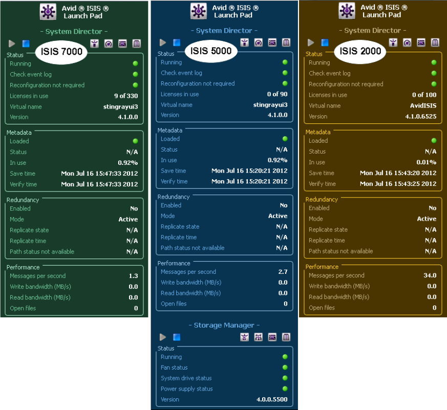
ISIS Launch Pad
72

ISIS Launch Pad
73
The following tools are available from the ISIS Launch Pad:
Category Description
System Director
Status
Running
No warning events logged
Reconfiguration not required
Licenses in use
Virtual name
Vers io n
Information from the System Status Console
Indicates if the System Director is running and healthy
Indicates if there are any warning events logged
If the Indicator is red, it will state Check events logged
Indicates if a reconfiguration is needed
Displays the number of client licenses in use
Displays the virtual name of the System Director
Displays the version number of the installed software on the System
Director
Metadata
Loaded
Status
In use
Save time
Verify time
Information from the System Director Control Panel
Indicates if the metadata successfully loaded by the System Director
Displays a status string for the metadata
Displays the percentage of allocated metadata memory that is in use
Displays the date and time the metadata was last saved
Displays the date and time the metadata was last verified
Redundancy
Enable
Mode
Replicate state
Replicate time
Path status not available
Information from the System Director Control Panel
Indicates if dual System Directors are configured
Displays if dual System Director redundancy is active or standby
Displays if dual System Director redundancy is replicating
Displays the date and time the metadata was last replicated
Displays the status of the failover network ports
Performance
Messages per second
Write bandwidth (MB/s)
Read bandwidth (MB/s)
Open files
Information from the System Status Console
Displays the number of messages per second
Displays the total Write bandwidth in megabytes per second
Displays the total Read bandwidth in megabytes per second
Displays the total number of open files in all the workspaces

ISIS Launch Pad
74
Opening ISIS Launch Pad
ISIS Launch Pad starts with Windows on the System Director and should remain on the desktop
at all times. In the event that it was shut down, you can restart the ISIS Launch Pad from the
System Director Windows Start Menu.
To open ISIS Launch Pad on the ISIS 7000 and ISIS 2000:
tClick Start > All Programs > Avid > ISIS System Director > ISIS Launch Pad.
To open ISIS Launch Pad on the ISIS 5000:
tClick Start > All Programs > Avid > ISIS Storage Manager > ISIS Launch Pad.
Minimizing or Closing the ISIS Launch Pad
The ISIS Launch Pad window remains “pinned” to the upper right corner of the System Director
desktop, but may be collapsed to a smaller size if needed.
To minimize the ISIS Launch Pad:
tRight-click the Avid ISIS Launch Pad icon on the right side of the Windows Taskbar and
select Minimize.
To restore the ISIS Launch Pad:
tRight-click the Avid ISIS Launch Pad icon on the right side of the Windows Taskbar and
select Restore.
To quit the ISIS Launch Pad:
tRight-click the Avid ISIS Launch Pad icon on the right side of the Windows Taskbar and
select Quit.
Storage Management (ISIS 5000 only)
Status
Running
Fan status
System drive status
Power supply status
Vers io n
Indicates if the Storage Manager is running and healthy
Indicates if the System Director fans are running and healthy
Indicates if the System Director system drives are running and healthy
Indicates if the power supplies are running and healthy
Displays the version of the System Director software
Category Description
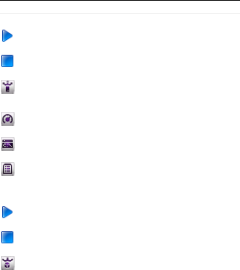
ISIS Launch Pad
75
ISIS Launch Pad Buttons
The following table describes the ISIS Launch Pad buttons. You can also hold the cursor over the
button and get a tool tip on the button function.
Button Location Function
System Director
Launch Pad —
System Director
Starts the System Director. The button is blue when the System
Director is stopped. The button is gray when the System Director is
running.
Launch Pad —
System Director
Stops the System Director. The button is blue when the System
Director is running. The button is gray when the System Director is
stopped.
Launch Pad —
System Director
Opens the Avid ISIS Management Console in a web browser window
(the default browser is Microsoft Internet Explorer). For more
information about using the Management Console, see “Opening the
Management Console” on page 18.
Launch Pad —
System Director
Opens the Avid ISIS System Director Control Panel. For more
information, see “Avid ISIS System Director Control Panel” on
page 76.
Launch Pad —
System Director
Opens the System Director Memory Log Viewer tool. For more
information, see “Using the ISIS System Director Memory Log
Viewer” on page 83.
Launch Pad —
System Director
Opens the Avid ISIS Profiler. Gathers system and version information
on the System Director, System Manager, or client. This tool detects
the system if is being run on and selects the components automatically.
For more information, see “Profiler Page” on page 175.
Storage Management (ISIS 5000 only)
Launch Pad —
Storage Manager
Starts the Storage Manager. The button is blue when the Storage
Manager is stopped. The button is gray when the Storage Manager is
running.
Launch Pad —
Storage Manager
Stops the Storage Manager. The button is blue when the Storage
Manager is running. The button is gray when the Storage Manager is
stopped.
Launch Pad —
Storage Manager
Opens the Storage Manager Agent page. For more information, see.
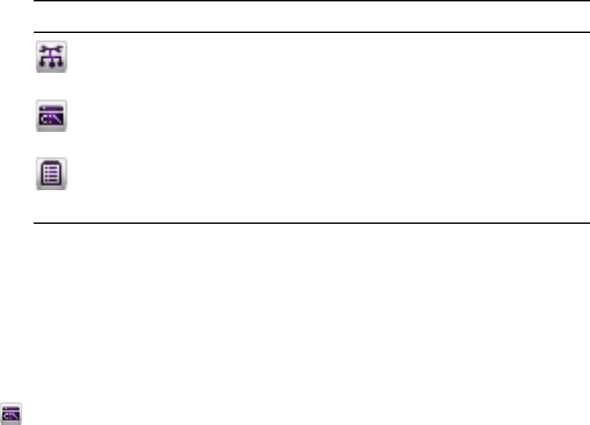
Avid ISIS System Director Control Panel
76
Using Storage Manager Memory Log Viewer
The Storage Manager Memory Log Viewer is a valuable tool that allows you to view the
Storage Manager log as it is buffered in memory. This log provides detailed status information
that is especially useful to Avid Customer Support personnel for monitoring Storage Manager
status during prolonged operations.
To open the Storage Manager Memory Log Viewer:
tDo one of the following:
- In the Storage Manager section of the ISIS Launch Pad, click Storage Manager Memory
Log Viewer icon.
- From the System Director desktop, click Start > Programs > Avid >
ISIS Storage Manager > Memory Log Viewer
- From the Storage Manager Agent page, click Console viewer in the Tools section (see
“Using the Log Viewer Tool” on page 219.
Avid ISIS System Director Control Panel
This section contains the following topics:
•Opening the System Director Control Panel
•Starting and Stopping the System Director Service
•Changing System Director Virtual Name
•Monitoring System Director Status
•Using the ISIS System Director Memory Log Viewer
•Working with File System Operations
Launch Pad —
Storage Manager
Opens the Network Configuration Tool. This tool is used to set the
IP addresses for the network ports on the ISIS 5000 System Director.
For more information, see the Avid ISIS 5000 Setup Guide.
Launch Pad —
Storage Manager
Opens the Storage Manager Memory Log Viewer. For more
information, see “Using Storage Manager Memory Log Viewer” on
page 76.
Launch Pad —
Storage Manager
Opens the Avid ISIS Profiler. Gathers system and version information
on the System Director, System Manager, or client. This tool detects
the system if is being run on and selects the components automatically.
For more information, see “Profiler Page” on page 175.
Button Location Function (Continued)
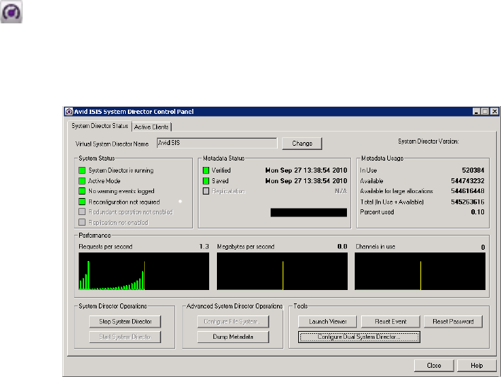
Avid ISIS System Director Control Panel
77
•Monitoring Metadata Status
•Resetting the Administrator Password
•Managing Active Clients
The Avid ISIS System Director Control Panel provides low-level performance monitoring
functions. Using the Control Panel, you can view the following:
• The current status of connected clients, including name, type, ID number, and active or
inactive status
• The status of communications between the System Director and the clients
• Information on the metadata maintained by the System Director
The System Director Control Panel is used to start, stop, and monitor the Avid ISIS
System Director, the application running on the System Director server that manages the overall
operation of the network. You can also use the Control Panel to configure general or Dual
System Director parameters, and to set some administrative options.
Opening the System Director Control Panel
The System Director Control Panel is a Windows application that can be accessed from the
Windows Start menu and from the ISIS Launch Pad.
To open the Control Panel, do one of the following:
tIn the ISIS Launch Pad, click ISIS Control Panel icon.
tFrom the System Director desktop, select Start > Programs > Avid > ISIS System Director >
Control Panel.
The System Director Control Panel opens.

Avid ISIS System Director Control Panel
78
The following table summarizes the functions available in the System Director control
panel.
Tab Buttons Description
System Director
Status
The System Director Status tab provides status
displays that provide a summary of your network and
controls that allow you to start and stop the
System Director, and reset the event log.
Change [Virtual System
Director Name]
Allows you to change the virtual server name for the
System Director.
Start/Stop
System Director
These buttons start and stop the System Director
windows service.
Configure File System This button is active only when the System Director
is stopped. When you click Configure File System
The File System Configuration dialog box appears
with the following options.
File System
Configuration
dialog box
Create Active File System Creates a new active file system on the
System Director.
File System
Configuration
dialog box
Create Active File System
from Import
Creates a new active file system using information
imported from another System Director.
File System
Configuration
dialog box
Create Standby System
Director
Designates the System Director as the Standby
System Director in a Dual System Director
configuration (ISIS 7000 and ISIS 5000 only).
File System
Configuration
dialog box
Reconfigure File System Reconfigures an existing file system.
File System
Configuration
dialog box
Delete File System Deletes the current file system.
Launch Memory Log
Viewer
Opens the System Director Memory Log Viewer.
Reset Event Resets the event log and the status displays after
errors are received from the client.
Reset Password Resets the System Director administrator's password.
Dump Metadata Writes all metadata information to a text file.

Avid ISIS System Director Control Panel
79
Starting and Stopping the System Director Service
The System Director software runs as a Windows service that starts automatically whenever the
System Director is online. However, various maintenance and administration functions require
that you shut down the System Director engine and then restart it.
Maintaining metadata integrity is very important to ensure you do not lose any data files. Avid
recommends you use the following procedure prior to System Director engine shutdown to avoid
problems with metadata integrity.
nMake sure that clients unmount all Workspaces before you stop the System Director. Otherwise,
when the clients attempt to access the Workspaces, they will receive errors.
To stop the System Director service:
1. Do one of the following:
tIn the ISIS Launch Pad, click ISIS Control Panel icon.
tFrom the ISIS Control Panel, click “Stop System Director” in the System Director
Status tab.
A dialog box opens, prompting you to confirm that you really want to stop the
System Director.
Configure Dual System
Director
When using two System Directors, one is referred to
as Active System Director and the other one is the
Standby System Director. The File System metadata
on the Standby System Director is kept up-to-date
with the Active System Director. If the Active System
Director fails, metadata functions switch to the
Standby System Director. For information on setting
up Dual System Directors, see the Avid ISIS Setup
Guide.
Active Clients The Active Clients tab is used to display the identity
of the Avid ISIS clients known to the
System Director.
The Active Clients tab displays all active
Storage Elements as well as connected client
accounts.
Refresh License Checks the license status of selected clients.
Disconnect Client Disconnects selected clients.
Tab Buttons Description (Continued)

Avid ISIS System Director Control Panel
80
2. Click OK.
The System Director Shutdown dialog box opens stating that it is saving multiple copies of
the metadata.
Wait for the process to finish and for the dialog box to close. When the System Director has
shut down, the System Director Status tab lists the System Director status as “Not running.”
3. (Option) If you are upgrading or modifying the system, make sure the System Director
software has successfully written a local copy of the metadata file:
- Open the partition where Avid ISIS System Director is installed (typically, “D:\Program
Files\Avid\ISIS System Director”).
- Find the PartitionDump.bin file with a modification date from when you stopped the
System Director (if upgrading or modifying the system in any way, copy the
PartitionDump.bin to another partition before you continue).
To start or restart the System Director service, do one of the following:
tIn the ISIS Launch Pad, click ISIS Control Panel icon.
tFrom the System Director control panel, click “Start System Director” in the
System Director Status tab.
Changing System Director Virtual Name
The System Director virtual name is the name that is used for the Shared Storage network and
will appear in the System Director list in the Avid ISIS Client Manager application. The System
Director virtual name is set to the Windows computer name by default, but you can change it to a
different value.
nThe System Director virtual name is used only within the Shared Storage network. It has no effect
on Windows networking.
To change the virtual System Director name:
1. In the top section of the System Director Status tab, click the Change button next to the
Virtual System Director Name field.
The Virtual System Director Name dialog box opens.
2. Type a name for the System Director in the Virtual System Director Name text box.
In a Dual System Director configuration, you must specify the same virtual System Director
name for both System Directors.
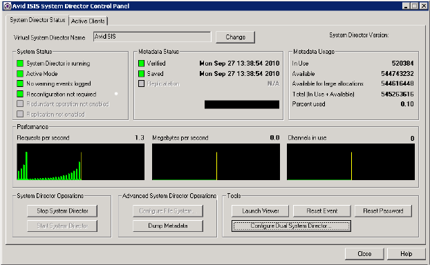
Avid ISIS System Director Control Panel
81
The naming conventions are the same for the System Director virtual name as they are for
Windows network computer names.
- No more than 31 characters in length
- Cannot use the following characters: " \ / [ ] : | < > + = ; , ?
- Cannot use ASCII control characters in range 0x00 through 0x1F
3. Click OK.
Monitoring System Director Status
The System Director Status tab provides status displays that provide a summary of your network
and controls that allow you to start and stop the System Director, and reset the event log.
System Director Performance Indicators
The System Director Status tab provides several indicators of system activity and performance.
These include the following:
• Requests per second—Current and recent System Director file system activity is indicated
by a small bar-style meter and a larger graph display, respectively
• Megabytes per second—Current and recent System Director file system throughput is
indicated by a small bar-style meter and a larger graph display, respectively
• Channels in use—Currently open files on the System Director file system are indicated by a
small bar-style meter
Avid ISIS System Director Control Panel
82
System Director Status Indicators
When no problems are detected in the shared storage network, a green indicator is displayed with
the following messages:
• System Director is running
•Active Mode
• No warning events logged
• Reconfiguration not required
• Single System Director — Redundant operation not Enabled; Dual System Directors —
Both paths are up
• Single System Director — Replication not Enabled; Dual System Directors — Replicated
nIf your network does not use a Dual System Director configuration, a gray indicator is displayed
next to the message, “Redundant operation is not enabled.”
If the indicator is yellow or red, the message changes. Use the following information to correct
the problem:
• System Director is not running — start the System Director by clicking the Start
System Director button.
• Check event log — logged significant events related to the System Director are also logged
in the Logging tab of the ISIS Management Console. For information on how to extract data
in the system logs, see “System and Administration Log Pages” on page 169.
• The following error messages indicate metadata replication status:
- Replication failed — Indicates that there was an error replicating the metadata to or
from a standby System Director.
- Replication unknown — Indicates that the current replication status has not been
determined.
- Replication status not available — Indicates that the status is unknown. Most likely, the
System Director is not running.
Resetting the System Director Event Log
To reset the event log and the status displays after errors are received from the client:
tPress the Reset Event button.
Avid ISIS System Director Control Panel
83
Using the ISIS System Director Memory Log Viewer
The System Director Memory Log Viewer is a valuable tool that allows you to view the
System Director log as it is buffered in memory. This log provides detailed status information
that is especially useful to Avid Customer Support personnel for monitoring system status during
prolonged operations.
To open the System Director Memory Log Viewer:
tDo one of the following:
- Click Memory Log Viewer icon under System Director on Launch Pad.
- In the Configuration tab of the System Director Control Panel, click Launch Memory
Log Viewer.
- From the System Director desktop, click Start > Programs > Avid >
ISIS System Director > Memory Log Viewer
Working with File System Operations
The File System Operations section of the Control Panel allows you to create Active and Standby
partitions, as well as to reconfigure existing file systems. You can also use the Control Panel to
delete file systems.
cDeleting the file system erases all data stored on the System Director.
For information on creating partitions, see the Avid ISIS Setup Guide.
Reconfiguring the File System
You can reconfigure the internal memory configuration of the System Director — for example, if
you want to adjust the memory usage to take advantage of expanded memory capabilities.
Reconfiguring the file system entails the following:
• Validating the export file
• Creating new metadata
• Importing the metadata
nReconfiguring an existing file system does not delete any data.
To reconfigure the file system:
1. From the System Director Status tab, click the Stop Server button.
A dialog box opens, prompting you to confirm that you want to stop the System Director.
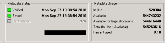
Avid ISIS System Director Control Panel
84
2. Click OK.
The System Director Shutdown dialog box opens stating that it is saving multiple copies of
the metadata.
3. Click Configure File System.
The File System Configuration window opens.
4. In the “Active File System Actions” section, click the “Reconfigure File System” radio
button.
A dialog box opens, prompting you to confirm that you want to reconfigure the existing file
system.
5. Click OK.
The system reconfigures its metadata and restarts the System Director.
Creating or Re-creating a New File System
You might need to create or re-create a file system under one of the following circumstances:
• You are setting up a System Director for the first time
• You are adding a second System Director
• You are upgrading your System Director hardware
• You are deleting and re-creating the System Director file system to recover from an error
For more information about creating, deleting and re-creating file systems on the
System Director, see the Avid ISIS Setup Guide.
Monitoring Metadata Status
The System Director Status tab displays information about the System Director’s internal
description of the file system. This metadata memory is used to record descriptions of
Workspaces, folders, and files.
nMost of this metadata information is also is displayed in the ISIS Launch Pad.

Avid ISIS System Director Control Panel
85
The metadata information includes:
• Total amount of memory in use
• Total amount of memory available
Metadata is saved to different drives in the Storage Element every 20 seconds. If the metadata
ever needs to be recovered, the last saved version is retrieved automatically by the
System Director. If that is the Storage Element that has failed, then the previous saved version is
retrieved from another Storage Element.
The Metadata Status box shows when the metadata was last verified and saved, and replicated. A
green indicator means no problem has been detected. A yellow indicator means the status is
uncertain. A red indicator means that a problem exists.
nMetadata memory is also saved automatically when you stop the System Director.
The following tables lists the status messages displayed in the Metadata Status box.
Status Category Messages Additional Notes
Veri fy •Not Active
• Verified
• Verify Failed
• State Unknown
When the System Director is in standby
mode, the Verify indicator is disabled.
Save •Saving
•Saved
• Unknown State
•Not Active
• Save Failed
Replicate
(ISIS 7000 and
ISIS 5000 only)
• Sending
• Receiving
• Unknown State
•Not Active
• Replication Failed
When the System Director is not in a Dual
System Director configuration, the
Replicate indicator is disabled.
Avid ISIS System Director Control Panel
86
Creating a Metadata Dump File
You can use the “Dump Metadata” function to write all metadata information to a text file.
nThis operation should be used only as a diagnostic aid. You cannot restore ISIS metadata from a
metadata dump file.
cWhen you write metadata to a file, the resulting file is extremely large and the time
required to create the file is significant. Do not use this option unless instructed to do so by
Avid Customer Support.
To write the contents of metadata to a text file in the System Director directory:
1. Click the System Director Status tab.
2. Click Dump Metadata.
A text file called PartitionDump.txt is created in the System Director’s data directory:
“D:\Program Files\Avid\ISIS System Director”
Resetting the Administrator Password
The Advanced Settings tab allows you to reset the System Director administrator's password in
the event that the administrator’s password is forgotten. This feature does not affect the Windows
operating system password. Windows administrator’s privileges are required to reset the
password.
nYou can change the administrator’s password in the ISIS Management Console. For information
on setting a new password, see “Changing the Administrator Password” on page 35.
To reset the administrator’s password:
1. From the System Director Status tab, click the “Reset Password” button.
A dialog box warns you that this action removes the administrator’s password from the
System Director’s account.
2. Click OK.
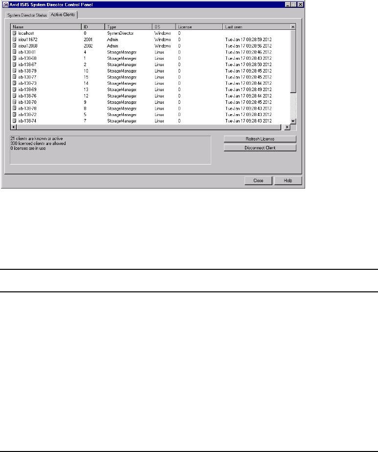
Avid ISIS System Director Control Panel
87
Managing Active Clients
The Active Clients tab is used to display the identity of the Avid ISIS clients known to the
System Director. The information listed in this tab can be used to determine if obsolete numeric
identifiers exist in the System Director.
The Active Clients tab displays all active Storage Elements as well as connected client accounts.
You can use the Bandwidth dialog box in the ISIS Management Console to view only the active
client accounts. For more information, see “Monitoring Client Bandwidth” on page 158.
The System Director reports the current client status as described in the following table.
Heading Description
Name Lists the name of the client
ID Lists an internal numeric identifier used by the System Director to represent each client
that has a Workspace mounted. These identifiers are assigned when a client first contacts
the System Director and remain valid until the client unmounts all Workspaces
Type Lists the client type (Admin, Client, Storage Manager or System Director)
OS Lists the operating system on the client
License Lists the number of licenses registered to the client
Last seen Lists the date and time when each client last sent its status to the System Director. The
System Director removes the entry when all Workspaces are unmounted from the client
desktop
Avid ISIS System Director Control Panel
88
The box below the active clients list provides the following information:
•n clients are known or active—Indicates the number of clients currently active or seen by the
System Director
•n licensed clients are allowed —Indicates the number of clients licensed by the software;
330 licensed ISIS 7000 clients, 90 licensed ISIS 5000 clients, and 100 licensed ISIS 2000
clients
•n licenses are in use—Indicates the number of licenses are being used by the clients
currently connected to the shared storage network
If a client fails without unmounting all Workspaces, the System Director maintains the numeric
identifiers. Typically, this is not a problem because the same identifier is reused when that client
mounts a Workspace the next time. However, it is possible for a client to leave a Workspace
mounted, shut down the client system, and never be seen by the System Director again. If that
client system is then physically removed or renamed, the numeric identifiers would not be
removed from the identification table. If enough obsolete entries were to accumulate, new clients
might not be able to obtain numeric identifiers.
To check the license status of an active or an inactive client:
tSelect the client in the active client list, and press the Refresh License button.
To disconnect an active or an inactive client:
tSelect the client in the active client list, and press the Disconnect Client button.
nYou should inform the client you are temporarily disconnecting them and the connection will
return after a few seconds.

5Managing Storage Groups and
Workspaces
This section contains the following topics:
•Managing Storage Groups
•Minimum Free Storage Space Requirement
•Managing Workspaces
•Managing Workspace Access Privileges
•Redistributing ISIS 7000 Data
•Redistributing ISIS 5000 Data
Storage Groups are collections of Storage Elements. Storage Groups give you flexibility in
allocating storage capacity among groups with different functional areas, workflow
requirements, or as a means of mitigating the risk of various drive failure scenarios. Workspaces
are virtual volumes that exist on Storage Groups and can be resized dynamically. Workspaces
allow you to segment your Storage Groups easily to accommodate projects and users.
Managing Storage Groups
This section contains the following topics:
•Storage Groups List
•Viewing Storage Group Details
•Adding New Storage Groups
•Adding Storage Elements to Storage Groups
•Removing ISIS Storage Elements from Storage Groups (ISIS 7000 and ISIS 5000 Only)
•Deleting Storage Groups
The Storage Groups page of the ISIS Management Console allows you to add and delete
Storage Groups, to rename Storage Groups, and to configure and manage Storage Groups. The
Storage Groups page contains three sections. On the left side, the Storage Groups list displays all
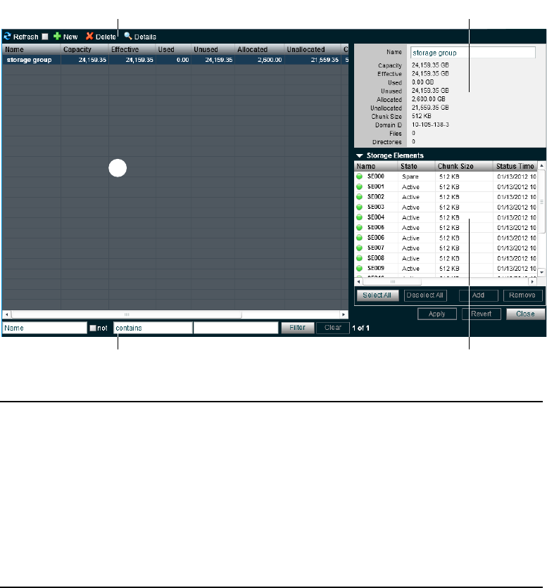
Managing Storage Groups
90
the Storage Groups available to the current user. On the right side, the Details panel displays
technical information about selected Storage Groups, and the Storage Elements panel displays
all Storage Elements available to the current user.
tr
e
wq
1 Action button toolbar—Perform actions on selected Storage Groups
2 Details panel—Detailed information on the selected Storage Groups; see “Viewing
Storage Group Details” on page 91
3 Storage Groups list—Lists all configured Storage Groups and related information; see
“Storage Groups List” on page 91
4 Filter panel—Filter the Storage Groups list display based on conditions you configure; see
“Filtering the Display” on page 29
5 Storage Elements list—Displays Storage Elements bound to the selected Storage Group

Managing Storage Groups
91
Storage Groups List
The following table summarizes the information available in the Storage Groups list.
You can sort the information in the Storage Groups page by clicking any column heading. For
more information on sorting items in columns, see “Sorting Information” on page 28.
Viewing Storage Group Details
The Details panel and the Storage Elements panel display all information for the currently
selected Storage Group and all information for the available Storage Elements. The information
displayed is the information as seen by the System Director. Some of the information is
embedded in the Storage Element, and other information is assigned to the Storage Element by
the Avid ISIS software.
nYou can sort the information in the Storage Elements panel by clicking any column heading. For
more information on sorting items in columns, see “Sorting Information” on page 28.
Heading Description
Name Displays the name of the currently selected Storage Group
Capacity Displays the storage capacity in gigabytes (GB) of the selected Storage Group
Effective Displays the effective (available) storage capacity in gigabytes (GB) of the
selected Storage Group
Used Displays the amount of storage space in gigabytes (GB) that currently has data
written on it in the selected Storage Group
Unused Displays the total amount of storage space in gigabytes (GB) that currently has
no data written on it in the Storage Element(s) assigned to the selected
Storage Group
Allocated Displays the amount of storage space in gigabytes (GB) reserved for use by
Workspaces in the selected Storage Group
Unallocated Displays the amount of storage space in gigabytes (GB) available on the
Storage Elements and not currently reserved for the selected Storage Group
Chunk Size Displays the size of segmented media files sent over the network
Files Displays the number of files in the selected Storage Group
Directories Displays the number of directories in the selected Storage Group

Managing Storage Groups
92
To view information about a Storage Group:
tIn the Storage Groups list, select a Storage Group.
The Storage Groups page displays all the information for the selected Storage Group. If the
Details panel is not visible, click the Details button.
To close the Details panel:
tClick the Details button.
The following table summarizes the information available in the details panels for
Storage Groups and Storage Elements.
The Storage Elements panel lists the Storage Elements allocated to the currently selected
Storage Group, as well as the Storage Elements available for allocation to the Storage Group.
The following table summarizes the information available in the Storage Elements panel. Some
columns are hidden by default (see “Showing and Hiding Columns” on page 27).
Heading Description
Name Displays the name of the currently selected Storage Group
Capacity Displays the storage capacity in gigabytes (GB) of the selected Storage Group
Effective Displays the effective (available) storage capacity in gigabytes (GB) of the selected
Storage Group
Used Displays the amount of storage space in gigabytes (GB) that currently has data written
on it in the selected Storage Group
Unused Displays the amount of storage space in gigabytes (GB) that currently has no data
written on it in the selected Storage Group
Allocated Displays the amount of storage space in gigabytes (GB) reserved for use by
Workspaces in the selected Storage Group
Unallocated Displays the amount of storage space in gigabytes (GB) available on the
Storage Elements and not currently reserved for the selected Storage Group
Chunk Size Displays the size of segmented media files sent over the network
Domain ID
(ISIS 7000 only)
Displays the domain ID number of the Management Domain (stack) for each Engine
(chassis) in which the Storage Element is part of.
nDomain ID numbers are not displayed until the Storage Elements are bound.
Files Displays the number of files in the selected Storage Group
Directories Displays the number of directories in the selected Storage Group

Managing Storage Groups
93
Storage Groups on ISIS 7000
Storage Groups are created by adding bound Storage Elements to the Storage Group. Start by
selecting the Storage Managers in the Storage Manager page and binding them. Open the
Storage Groups page and select New to the display the Spare Storage Elements. Select the
Storage Elements listed in the Storage Groups page and add them to a Storage Group. Once you
have a Storage Group you can create Workspaces. The Avid ISIS 7000 supports two types of
Workspace data protection: mirrored Workspaces and redundant array of independent disks
(RAID 6) Workspaces.
Heading Description
Name Displays the name of the selected Storage Element
State Displays the Storage Element category of the selected Storage Element:
• Spare—Indicates Storage Elements that have been added to the Avid ISIS file
system but are not allocated for a specific purpose; spare but inactive
Storage Elements cannot be used until allocated to a Storage Group
• Active—Indicates active Storage Elements added to a server and allocated to a
Storage Group
Chunk Size Displays the size of segmented media files sent over the network
Status Time Lists the last time the System Director logged the Storage Element’s status
Status Displays the working status logged by the System Director
Capacity Displays the storage capacity in gigabytes (GB) of the selected Storage Element
Used Displays the amount of storage space in gigabytes (GB) that currently has data
written on it in the selected Storage Element
Storage Group Displays the Storage Group, if any, to which the Storage Element is allocated
Engine Serial
(ISIS 7000 only)
Displays the serial number of the Engine
Domain ID
(ISIS 7000 only)
Displays the domain ID number of the Management Domain (stack) for each Engine
(chassis) in which the Storage Element is part of.
nDomain ID numbers are not displayed until the Storage Elements are bound.
Managing Storage Groups
94
Storage Group and Chunk Sizes
Storage Elements are combined to create Storage Groups in the ISIS file system. When you bind
a Storage Element you must select either 512 KB (default) or 256 KB chunk sizes. Earlier Avid
ISIS releases used 256 KB chunk sizes. These bound Storage Elements must all be of the same
chunk size when you configure your Storage Group.
nAvid ISIS switch hardware shipped with v1.x (ISS1000 and IXS1000) does not support 512 KB
chunk sizes. If you have Avid ISIS v2.x software running on v1.x switches, you must select the
256 KB chunk size when adding Storage Elements to the file system to create Storage Groups.
You cannot change the chunk size of a Storage Group once the Storage Group has been created.
To change the chunk size of an existing Storage Group, you must delete the Storage Group and
create a new Storage Group with the desired chunk size. The chunk size selection is only
available when adding the Storage Elements.
Storage Blades and Chunk Sizes
There are two drives in all Avid ISIS 7000 ISBs. ISBs are identified by the total amount of
storage in the ISB; for example, an ISB with the two 1 terabyte (TB) drives are referred to as
i2000s. All ISBs (i500, i1000, i2000, and i4000) support the 512 KB chunk size, but only the
i500 and i1000 support the 256k chunk size. The i2000 and i4000 ISBs require 512 KB chunk
size. In addition you must have v2.x switch hardware (ISS2000 and IXS2000) to use the 512 KB
chunk size.
RAID 6 Workspace, Single ISB Failure
When there is a single ISB failure in an ISIS Workspace configured with RAID 6 protection, the
Workspace continues to function normally at a lower bandwidth. For mirrored Workspace, see
“Mirrored Workspace, Single ISB Failure” on page 95.
After confirming the failure of an ISB, it is highly recommended that you initiate the remove
redistribution process of the failed ISB immediately. There are two benefits to doing this:
• First, immediately upon initiation of the remove redistribution, all new writes to the
Workspace have the full benefit of RAID-6 protection (dual-parity protection).
• Second, upon completion of the remove redistribution process, existing data in the
Workspace is once again fully protected. Prior to completion, if another ISB were to fail, the
Workspace would be in an unprotected state (though no data would be lost).
RAID 6 Workspace, Dual ISB Failure
It is considered an “unprotected state” if you are with two failed ISBs in a RAID 6 Workspace. In
an unprotected state with no additional failures, read operations continue to function normally at
a lower bandwidth.
Managing Storage Groups
95
However, in an unprotected state, due to the distributed architecture of the ISIS file system
(optimized for real-time performance), it is possible under certain circumstances that the system
would not be able to correctly update the parity information when writing new data. As a result
under these circumstances, the file system could return a failure status when writing. While the
failure rate percentage on the total number of write operations is low, heavy workloads on the
system would result in enough write failures to disrupt operations.
This issue only applies when the Workspace is in an unprotected state and the remove
redistribution process on the failed ISBs has not been initiated. Therefore, it is highly
recommended that the remove redistribution process is initiated immediately upon confirmation
of any ISB failure. This ensures immediate protection (RAID 6 or mirroring) of new data being
written, and full protection of all stored data at the earliest possible time.
Mirrored Workspace, Single ISB Failure
It is considered an “unprotected state” if you have a single ISB failure in a mirrored Workspace.
In an unprotected state with no additional failures, read operations continue to function normally.
However, in an unprotected state a subsequent or infrastructure failure will cause operational
issues which could result in failures when writing new data or prevent you from accessing data in
the Workspace. An additional ISB failure creates a situation in which data accessibility has been
compromised. Networking issues, on the other hand, will not cause accessibility issues on
previously written data but might prevent the successful completion of the active write operation.
This issue only applies when the Workspace is in an unprotected state and the remove
redistribution process on the failed ISBs has not been initiated. Therefore, it is highly
recommended that the remove redistribution process is initiated immediately upon confirmation
of any ISB failure. This ensures immediate protection (RAID 6 or mirroring) of new data being
written, and full protection of all stored data at the earliest possible time.
Adding or Removing ISBs (Mirrored or RAID 6)
When permanently adding or removing ISBs from an ISIS Workspace it is recommended to do a
full redistribution. The full redistribution should be done after the ISB add or remove is
complete. Examples of permanent changes would be adding or removing an engine to the
storage stack.
The full redistribution makes sure all blocks in the Workspace are optimally distributed based on
the new permanent configuration. Doing a full redistribution immediately after the permanent
adds or removes minimizes the chances of running into issues if a full redistribution is required
in the future. One potential issue would be the storage blades getting full during a full
redistribution and requiring the user to delete files to allow the redistribution to complete.
Managing Storage Groups
96
This recommendation does not apply to the case of removing and then replacing failed storage
blades. For other examples of symmetric and non-symmetric redistributions, see the Avid ISIS
Performance and Redistribution Guide on the Knowledge Base at www.avid.com/US/support.
Adding an ISB to the File System
If you add an ISB (displays as an available Storage Element) to your file system, make sure you
match the Chunk Size of the new Storage Element to the Chunk Size of the existing Storage
Group. New Storage Elements are added with a default chunk size of 512 KB on mirrored
Storage Groups (256 KB with i1000 ISBs). You cannot mix the chunk sizes within a Storage
Group. To change the chunk size of an ISB, you must remove the new Storage Element from the
file system and add the Storage Element again select the same protection and chunk size of the
existing Storage Group.
Zone 1 Switches
The ISIS v2.x generation IXS and ISS switches install in the same engines as earlier releases, the
chassis has not changed. However, all the switches in the engines need to be of the same
generation. The two new switches are labeled with IXS2000 and ISS2000. The new switches
cannot be mixed in ISIS Engines with earlier versions of the switches (labeled IXS1000 and
ISS1000). If your IXS and ISS switches are not labeled, consider them the earlier versions. The
ISS2000 switches are required for 10-Gb clients and 512 KB chunk size, see “Storage Group and
Chunk Sizes” on page 94.
The Avid ISIS documentation refers to IXS2000 and ISS2000 switches as v2.xhardware and
IXS1000 and ISS1000 switches as v1.xhardware.
Storage Groups on ISIS 5000 and ISIS 2000
For both ISIS 5000 and ISIS 2000, each Engine is a Storage Element. You can assign all of your
Engines to one large Storage Group, or each Engine can be a Storage Group. An Engine can be
assigned to only one Storage Group. Avid ISIS 5000 provides RAID 5 data protection with an
active hot spare and Avid ISIS 2000 provides RAID 6 data protection with an active hot spare in
each drawer.
Storage Groups are created by adding bound Storage Elements to the Storage Group. Start by
selecting the Storage Managers in the Storage Manager page and bind them. Open the Storage
Groups page and click New to the display the Spare Storage Elements. Select the Storage
Elements listed in the Storage Groups page and add them to a Storage Group. Once you have a
Storage Group you can create Workspaces.
Managing Storage Groups
97
Adding Storage Elements to Storage Groups
You can add unassigned Storage Elements to a Storage Group to increase its storage capacity.
This is typically done when adding a new Engine to your Avid ISIS system. This process
initiates a redistribution of the files in the existing Storage Group to include the new Storage
Element. For more information, see“Redistributing ISIS 7000 Data” on page 120 and
“Redistributing ISIS 5000 Data” on page 126.
To add Storage Elements to a Storage Group:
1. From the Management Console home page, click the Storage Groups icon, located in the
System section.
The Storage Groups page opens.
2. In the Storage Groups list, select the Storage Group where you want to add
Storage Elements, and then do one of the following:
tClick the Details button.
tDouble-click the Storage Group name.
The Details panel displays all the information on the selected Storage Group.
3. In the Storage Elements panel, select all the spare Storage Elements you want to add to the
Storage Group.
nIf you have two Management Domains in the ISIS 7000, you need to check the Domain ID
column and select Storage Elements from the same domain, you cannot add Storage Elements to
a Storage Group with a different Domain ID. Storage Groups cannot span across Management
Domains.
4. Click the Add button to add the selected spare Storage Elements to the Storage Group.
The Storage Elements panel refreshes to display the selected Storage Elements added to the
Storage Group.
5. (Option) Before you apply your changes, you can use the Revert button to undo any
modifications made to the Storage Group information.
6. Click Apply.
The Storage Elements are added to the Storage Group.
- The shared storage network performs a redistribution of any data on the
Storage Elements. The amount of time required for the redistribution depends on the
amount of data in the Storage Group.
- The configuration change counter for all affected Workspaces is incremented by one.
Managing Storage Groups
98
nAfter ten configuration changes, the system prompts you to perform a full redistribution. You can
suspend and resume the redistribution if needed. For more information, see “Using ISIS 7000
Advanced Redistribution Commands” on page 125 and “Using ISIS 5000 Advanced
Redistribution Commands” on page 127.
Adding New Storage Groups
A Storage Group is a set of physical Storage Elements that store a subset of the complete set of
media files accessible within a shared storage environment.
nYou need to add Storage Elements to the file system before you can create any Storage Groups.
For more information, see “Adding Storage Elements to the File System” on page 49.
nIf you have bound Storage Elements to the ISIS file system but you have not created any
Storage Groups, the Create Storage Groups dialog box opens by default when you select the
Storage Groups list.
To add a new Storage Group:
1. From the Management Console home page, click the Storage Groups icon, located in the
System section.
The Storage Groups page opens.
2. Click the New button.
The Create Storage Group dialog box opens.
3. In the Name text box, type a name for the Storage Group.
nDo not use non-permitted characters in Management Console text fields. For information on
Management Console text entry guidelines, see “Entering Text” on page 31.
If there is already a Storage Group with the name entered in the Name text box, an error
message tells you to type a new name.
4. In the Storage Elements panel, select the Storage Elements you want to assign to the new
Storage Group.
5. Click the Add button.
The Storage Elements are allocated to the Storage Group. You can use the Remove button to
remove Storage Elements from the Storage Group.
6. (Option) Before you create your Storage Group, you can use the Revert button to undo any
modifications made to the Storage Group information.
Managing Storage Groups
99
7. Click Apply to create a new Storage Group containing all the selected Storage Elements.
The new Storage Group appears in the Storage Groups list, and the Create Storage Group
dialog box refreshes to show the Storage Elements still available for additional
Storage Groups.
8. (Option) Repeat steps 3 through 8 to create new Storage Groups.
9. Click Close to close the Create Storage Group dialog box and to return to the
Storage Groups page.
Removing ISIS Storage Elements from Storage Groups (ISIS 7000 and
ISIS 5000 Only)
You can remove Storage Elements from your Storage Group, as long as the following conditions
are met after you have done so:
• The Storage Group contains a sufficient number of Storage Elements so that after the
remove operation, at least the minimum number of Storage Elements remain. For more
information, see “Adding New Storage Groups” on page 98.
• If the ISIS 7000 Storage Group includes RAID 6 Workspaces in the Storage Group, you
must have at least 8 Storage Elements in the Storage Group.
• The Storage Group contains enough Storage Elements to support the space allocated to your
Workspaces.
nThis is the total amount of storage allocated to the Workspaces, not the actual amount of data
stored on the Workspaces.
• There is no data present in any of the Workspaces.
Storage Elements removed from the Storage Group are returned to the system’s pool of spare
Storage Elements.
cWhen Storage Elements are removed, a redistribution is initiated. If you start the Storage
Element removal on an ISIS 7000 during high client usage, it might cause a negative
performance impact on your clients. This can include dropped frames, underruns, and
failed captures. Remove Storage Elements during periods of light client activity.
If you start the Storage Element removal on an ISIS 5000, all I/O to ISIS 5000 temporarily
stops. If you have important capture or playback operations in progress, click “Cancel”
and plan your Storage Element removal at a time when the ISIS 5000 is not in use.
Once a redistribution is started, you can suspend the redistribution if needed and restart it
at a more appropriate time.
Managing Storage Groups
100
To remove Storage Elements from a Storage Group:
1. From the Management Console home page, click the Storage Groups icon, located in the
System section.
The Storage Groups page opens.
2. In the Storage Groups list, select the Storage Group from which you want to remove
Storage Elements, and then do one of the following:
tClick the Details button.
tDouble-click the Storage Group name.
The Details panel displays all the information on the selected Storage Group.
3. In the Storage Elements panel, select all the Storage Elements you want to remove from the
Storage Group.
4. Click the Remove button.
The Storage Elements panel refreshes and displays the selected Storage Elements as Spare.
nYou cannot remove Storage Elements if it would cause the capacity of the Storage Group to fall
below either the used space or the allocated space. You must reduce the amount of space
allocated to the Workspace(s). For more information on modifying Workspaces, see “Resizing
Workspaces” on page 116.
5. (Option) Before you apply your changes, you can use the Revert button to undo any
modifications made to the Storage Group information.
6. Click Apply.
The Storage Elements are added to the Storage Group.
Adding ISIS 7000 Storage Elements from Another Storage Group
If you want to reassign Storage Elements from one Storage Group to another, you must remove
the Storage Elements before adding them to a new Storage Group.
To add Storage Elements previously used in another Storage Group to your current
Storage Group:
1. From the Management Console home page, click the Storage Groups icon, located in the
System section.
The Storage Groups page opens.
2. In the Storage Groups list, select the Storage Group which contains the Storage Elements
you want to reassign, and then do one of the following:
tClick the Details button.
tDouble-click the Storage Group name.
The Details panel displays all the information on the selected Storage Group.
Managing Storage Groups
101
3. In the Storage Elements panel, select all the Storage Elements you want to move to another
Storage Group.
4. Click the Remove button.
The Storage Elements panel refreshes to display the selected Storage Elements as Spare.
5. Click Apply.
The selected Storage Elements are removed from the Storage Group, and the shared storage
network performs a redistribution of any data on the Storage Elements.
6. In the Storage Groups list, click the Storage Group to which you want to add the
Storage Elements.
The Details panel displays all the information on the selected Storage Group.
7. In the Storage Elements panel, select all the spare Storage Elements you want to add to the
new Storage Group.
nIf you have two Management Domains you need to check the Domain ID column and select
Storage Elements from the same domain, you cannot add Storage Elements to a Storage Group
with a different Domain ID. Storage Groups cannot span across Management Domains.
8. Click the Add button to add the selected Storage Elements to the Storage Group.
The Storage Elements panel refreshes to display the selected Storage Elements added to the
new Storage Group.
9. (Option) Before you apply your changes, you can use the Revert button to undo any
modifications made to the Storage Group information.
10. Click Apply.
The selected Storage Elements are added to the Storage Group, and the shared storage
network performs a redistribution of any data on the Storage Elements. The amount of time
required for the redistribution depends on the amount of data in the Storage Group.
Adding ISIS 7000 Storage Managers Previously Used in Another
Environment
If adding Storage Managers that were previously used in another environment, first connect them
to your Avid ISIS shared storage network, and then add the unbound Storage Managers to the
ISIS using the Storage Manager page. Once you bind the Storage Managers, it will appear in the
Storage Managers page.
Managing Storage Groups
102
To add the Storage Elements to your current Storage Group:
1. Make sure the new Storage Managers are connected to the network. For information on
connecting Storage Managers, see the Avid ISIS Setup Guide.
2. Open the ISIS Management Console. (For information on opening the ISIS
Management Console, see “Opening the Management Console” on page 18.)
3. Click the Storage Manager icon from the System panel.
The Storage Manager page opens.
If the ISIS Management Console was open when you added the Storage Manager, click the
Refresh button to view the newly added Storage Manager.
If the Storage Manager are not listed, something might be wrong with their physical
connections, see the Avid ISIS Setup Guide.
4. Add the new Storage Elements to your Storage Group (see “Adding Storage Elements to
Storage Groups” on page 97).
5. Click Apply.
A dialog box opens asking you to confirm the action.
6. Click Yes.
The selected Storage Elements are added to the Storage Group.
Deleting Storage Groups
You can delete any Storage Group that does not have any Workspaces on it. As a result, all
Storage Elements previously assigned to the Storage Group return to the system’s pool of spare
Storage Elements.
To delete a Storage Group:
1. If any Workspaces exist on the Storage Group you want to delete, first delete the Workspace
(see “Deleting Workspaces” on page 117).
2. From the Management Console home page, click the Storage Groups icon, located in the
System section.
The Storage Groups page opens.
3. In the Storage Groups list, select the Storage Group you want to delete.
4. Click the Delete button.
A dialog box opens asking you to confirm the action.
5. Click Yes.
The Storage Group is deleted.
After the Storage Group is deleted, all of the Storage Elements previously in your Storage Group
will appear in the Storage Elements panel as Spare.
Minimum Free Storage Space Requirement
103
Minimum Free Storage Space Requirement
On the ISIS 7000 Avid recommends that you maintain 7% of free space in each Storage Group.
In other words, you should not fill Storage Group more than 93% full. Exceeding 93% used
space can produce severe performance issues in some situations. Avid recommends that you
maintain 5% of free space in each Storage Group on the ISIS 5000 and ISIS 2000.
To calculate the right amount of free space, log into the ISIS management Console and navigate
to the Storage Group window. For each Storage Group, take the Effective number and multiply
by 0.07 or 0.05 (depending on your ISIS system). This will be your recommended free space in
GBs. To assure that your Storage Group never exceeds the recommended space, create a new
workspace in this Storage Group with the same size and label it “Headroom” and do not give
anyone access to this workspace.
Managing Workspaces
This section contains the following topics:
•Workspaces Considerations
•Workspaces List
•Using the Workspace Size Graph
•Viewing Workspace Details
•Adding New Workspaces
•Duplicating Workspaces
•Renaming Workspaces
•Resizing Workspaces
•Setting Event Triggers
•Deleting Workspaces
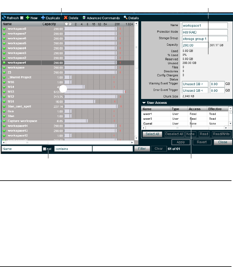
Managing Workspaces
104
This section describes how to create, rename, and delete Workspaces. and how to manipulate the
amount of storage allocated to each Workspace.
tr
e
wq
1 Action button toolbar—Perform actions on selected Workspaces
2 Details panel—Detailed information on the selected Workspaces; see “Viewing Workspace
Details” on page 108
3 Workspaces list—Lists all configured Workspaces and related information; see “Workspaces
List” on page 105
4 Filter panel—Filter the Workspaces list display based on conditions you configure; see
“Filtering the Display” on page 29
5 User access panel—Displays users who have access to the selected Workspace and details
about their access privileges; see “Managing Workspace Access Privileges” on page 118

Managing Workspaces
105
Workspaces List
The Workspaces list displays all Workspaces, the Storage Groups on which they reside, and
details about each Workspace.
The following table describes the information in the Workspaces list.
Heading Description
Name Lists the names of all Workspaces in the selected Storage Groups
Capacity Lists the total storage capacity of each Workspace in gigabytes (GB)
Resize slider Displays a graphical representation of the used and available space for each
Workspace (for information on using the Workspace Size graph, see “Using the
Workspace Size Graph” on page 107)
Maximum Lists the maximum amount of storage space in gigabytes (GB) available for the
Workspace on the network
Protection Mode Displays the type of protection applied.
Avid ISIS 7000 provides “mirrored” and “RAID 6” data protection modes, as
well as an “unprotected” mode.
Avid ISIS 5000 provides RAID 5 data protection with an active hot spare. This
will display as “HW RAID.”
Avid ISIS 2000 provides RAID 6 data protection with an active hot spare in each
drawer. This will display as “SW RAID.”
Used Displays the amount of storage space in gigabytes (GB) that currently has data
written on it in each Workspace
% Used Displays the percentage (%) of storage space currently storing data on the
Workspace
Reserved Displays the amount of storage space in gigabytes (GB) that has been reserved
by a client application
Unused Lists the amount of storage space in gigabytes (GB) that currently has no data
written on it in each Workspace
Status Displays the status of any current redistribution:
• In Progress
• Stalled
• Pending
• Requires Full Redistribution

Managing Workspaces
106
nYou can sort the information in the Workspaces list by clicking any column heading. For more
information on sorting items in columns, see “Sorting Information” on page 28.
Workspaces Considerations
Avid ISIS 7000 supports two types of data protection: mirrored Workspaces and redundant array
of independent disks (RAID 6) Workspaces. RAID 6 storage offers more value in that it provides
more storage at a lower cost per GB.
Before you create Workspaces, you should consider how you want to allocate them. For
example, do you want to allocate them to accommodate projects, groups, individual clients,
streaming bit rates, media types, media distributors, or a combination of these?
Once you create a plan to allocate Workspaces, you’ll need to determine how much storage each
Workspace requires and allocate space accordingly. This might be a function of project size or
the number of clients, or it might be a function of media duration or media resolution.
When sizing Workspaces in a multiple Workspace configuration, you should consider reserving
some space rather than assigning all of it immediately. Once space is allocated, it tends to be
filled quickly and you might need space later to accommodate a new project or client or to
extend or protect an existing Workspace. In these situations, it is easier to use space held in
reserve than to take it away from an existing Workspace.
When allocating and sizing Workspaces, you should also consider whether access restrictions are
required and whether protection for data integrity is necessary for each Workspace.
Workspace Creation (ISIS 7000 Only)
When creating Workspaces in Storage Groups that do not have any Workspaces, you have the
option of setting the protection as unprotected, mirrored, or RAID 6. The RAID 6 option is only
available if the Chunk Size is 512 KB. When creating Workspaces in a Storage Group that has a
Workspace in it. The available protection mode must be the same as the Workspace that is
already in that Storage Group. This means if the Storage Group has a mirrored or unprotected
Workspace in it, you can only create mirrored or unprotected Workspaces. If the Storage Group
contains a RAID 6 Workspace, you only are able to create RAID 6 Workspaces.
Config Changes Displays the number of changes to a Storage Group that involve moving data —
for example, the number of times a Storage Element has been added or removed
Storage Group For each Workspace, lists the Storage Group on which it is located
Files Lists the total number of files stored on the network for each Workspace
Heading Description (Continued)
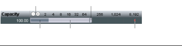
Managing Workspaces
107
Workspace Duplication (ISIS 7000 Only)
If duplicating a Workspace, you only have access to Storage Groups that support the protection
mode of that Workspace. If you had three Storage Groups, one with a RAID 6 Workspace, one
with a mirrored Workspace, and one with no Workspaces, and you duplicated a mirrored
Workspace, you would have access to the Storage Group with no Workspaces and the Storage
Group with the mirrored Workspace. If you select the Storage Group with no Workspaces, you
have access to the RAID 6 protection mode. If you change the protection type to RAID 6, you
would then have access to the RAID 6 Storage Group and not the Storage Group with the
mirrored Workspaces in it.
Workspace Move (ISIS 7000 Only)
When moving a Workspace, the Storage Group list contains Storage Groups with the same
protection mode as the Workspace you are moving. So if moving a RAID 6 Workspace, only
Storage Groups that support RAID 6 workspaces appear in the list. If the Workspace is mirrored,
only Storage Groups that support mirrored or unprotected Workspaces appear in the list.
Using the Workspace Size Graph
The Workspaces Size graph provides a quick way to view how much storage capacity is
currently allocated to each Workspace and how much of that storage space currently has data
written on it. The graph represents the following:
• Workspace size—total drive space in the Storage Group allocated to each Workspace
• Used space—used drive space in the Workspace
• Unused space—unused drive space in the Workspace
• Maximum Workspace size—total of Workspace size + drive space in the Storage Group still
available for allocation to each Workspace
e
wq
r t
1 Decrease/Increase buttons—Increases or decreases the scale of the graph
2 Resize handle—Click and drag to increase or decrease the Workspace size; see “Resizing
Workspaces” on page 116

Managing Workspaces
108
To resize the Workspaces Size graph, do one of the following:
tClick the Decrease Size button to reduce the size of the graph.
tClick the Increase Size button to expand the size of the graph.
Viewing Workspace Details
The Details panel and the User Access panels display all information for the currently selected
Workspace.
To view detailed information about a Workspace:
tIn the Workspaces list, select a Workspace.
The Workspaces page displays all the information for the selected Workspace. If the Details
panel is not visible, click the Details button.
To close the Details panel:
tClick the Details button.
The following table summarizes the information available in the Details panel.
3 Used Space
4 Unused space
5 Maximum Workspace size—total of Workspace size + drive space in the Storage Group still
available for allocation to each Workspace
Heading Description
Name Displays the name of the currently selected Workspace
Protection Mode Displays the type of protection applied.
Avid ISIS 7000 provides “mirrored” and “RAID 6” data protection
modes, as well as an “unprotected” mode.
Avid ISIS 5000 provides RAID 5 data protection with an active hot spare.
This will display as “HW RAID.”
Avid ISIS 2000 provides RAID 6 data protection with an active hot spares
in each drawer. This will display as “SW RAID.”
Storage Group Lists the Storage Group on which the selected Workspace was created
Capacity Displays the storage capacity in gigabytes (GB) of the selected
Workspace; the maximum limit for Workspace size is listed next to the
Size text box

Managing Workspaces
109
The User Access panel lists all users and user groups and their access privileges. (For
information on access privileges, see “Managing Workspace Access Privileges” on page 118.)
The following table summarizes the information available in the User Access panel.
Used Displays the amount of storage space in gigabytes (GB) that currently has
data written on it in the selected Workspace
% Used Displays the percentage (%) of storage space currently storing data on the
Workspace
Reserved Displays the amount of storage space in gigabytes (GB) that has been
reserved by a client application
Unused Displays the amount of storage space in gigabytes (GB) that currently has
no data written on it and is available to the selected Workspace
Files Displays the number of files used by the selected Workspace
Directories Displays the number of directories used by the selected Workspace
Config Changes Displays the number of changes to a Storage Group that involve moving
data — for example, the number of times a Storage Element has been
added or removed
Status Displays the status of any current redistribution:
• In Progress
• Stalled
• Pending
• Requires Full Redistribution
Warning Event Trigger Displays the value in used percentage (%) or unused gigabytes (GB) of
storage at which a warning event is written to the Event Log
Error Event Trigger Displays the value in used percentage (%) or unused gigabytes (GB) of
storage at which an error event is written to the Event Log
Chunk Size The smallest unit of data that can be written to the disk(s)
Heading Description (Continued)
Heading Description
Name Lists the names of the users and user groups on the network
Type Displays the client category (user or user group) for each client in the Name list
Access Lists the access privileges for each client in the Name list

Managing Workspaces
110
nYou can sort the information in the User Access panel by clicking any column heading. For more
information on sorting items in columns, see “Sorting Information” on page 28.
Adding New Workspaces
Workspaces are locations to store and segregate data. You can allow users to access some or all
of the Workspaces, and you can assign permissions for how each user can access the data in a
Workspace.
nIf you have created Storage Groups but you have not created any Workspaces, the Create
Workspace dialog box opens by default when you select the Workspaces list.
When creating Workspaces on an ISIS 7000, keep in mind the following:
• Mirror Workspaces must be at least 2 Storage Elements in the Storage Group;
• RAID 6 Workspaces must be at least 8 Storage Elements in the Storage Group;
To add a new Workspace:
1. From the Management Console home page, click the Workspaces icon, located in the
System section.
The Workspaces page opens.
2. Click the New button.
The Details panel opens.
3. In the Name text box, type a name for the Workspace.
nDo not use non-permitted characters in Management Console text fields. For information on
Management Console text entry guidelines, see “Entering Text” on page 31.
If there is already a Workspace with the name entered in the Name text box, an error
message tells you to type a new name.
4. (ISIS 7000 Option) Click the Protection menu and select the available Workspace protection
option.
Effective Lists the effective access privileges for each client in the Name list
Reason Lists the reason for any difference between the access privileges assigned to a user and
the effective access assigned to a user as a member of a user group
Heading Description (Continued)
Managing Workspaces
111
5. Click the Storage Group menu, and select the Storage Group in which you want to create the
Workspace.
The Storage Group name appears in the Storage Group text box.
6. Type a size for the Workspace in the Capacity text box. The default size (200 GB) is listed in
the Capacity text box, and the maximum size is listed next to the Capacity text box.
nThe minimum Workspace size is 1 GB.
If all storage in the Storage Group is allocated to existing Workspaces, you can make an
existing Workspace smaller. For information on resizing Workspaces, see “Resizing
Workspaces” on page 116.
7. (Option) In the Warning Event Trigger text box, do one of the following:
tTo set a Warning event trigger based on percentage of used storage, type in a percentage
value and select ‘%’.
tTo set a Warning event trigger based on gigabytes (GB) of unused storage, type in a
gigabyte value and select ‘GB’.
nFor more information about setting Event triggers, see “Setting Event Triggers” on page 116.
8. (Option) In the Error Event Trigger text box, do one of the following:
tTo set an Error event trigger based on percentage of used storage, type in a percentage
value and select ‘%’.
tTo set an Error event trigger based on gigabytes (GB) of unused storage, type in a
gigabyte value and select ‘GB’.
9. In the User Access panel, set the User and User Group access privileges.
10. Click Apply to create a new Workspace containing the selected Storage Group and users.
The new Workspace appears in the Workspace dialog box, and the Create Workspace dialog
box refreshes to allow you to create a new Workspace.
11. (Option) Repeat steps 3 through 10 to create new Workspaces.
12. Click Close to close the Create Workspace dialog box to return to the Workspaces page.
The new Workspace appears in the Workspaces list.
Duplicating Workspaces
When you duplicate Workspaces, they inherit the attributes of the Workspace from which they
were created.
nThe contents of the original Workspace are not duplicated.
Managing Workspaces
112
To duplicate a Workspace:
1. From the Management Console home page, click the Workspaces icon, located in the
System section.
The Workspaces page opens.
2. In the Workspace list, select the Workspace you want to duplicate.
3. Click the Duplicate button.
The Duplicate Workspace dialog box opens.
4. (Option) Modify any of the attributes of the new Workspace. For information on modifying
Workspaces, see the following topics:
-“Resizing Workspaces” on page 116
-“Renaming Workspaces” on page 112
-“Protecting ISIS 7000 Workspaces” on page 113
-“Managing Workspace Access Privileges” on page 118
5. Click Apply to create a new Workspace containing the attributes of the selected Workspace.
The duplicate Workspace appears in the Workspace list, and the Duplicate Workspace list
refreshes to allow you to duplicate a new Workspace. The new Workspace has a default
name — Workspace n, where n is an integer that is incremented each time you click Apply
to create another duplicate Workspace.
If there is no room for a Workspace of the same size as the original, the Capacity column
displays a red line and the Apply button remains inactive.
6. Click Close to close the Duplicate Workspace dialog box and to return to the Workspaces
page.
Renaming Workspaces
You can rename a Workspace at any time, even when it is being used by client workstations and
mapped to a local drive or by letterless mapping (to a Universal Naming Convention path) on the
client system. The only effect on users is that the Workspace name will be different the next time
they need to access it.
To rename a Workspace:
1. From the Management Console home page, click the Workspaces icon, located in the
System section.
The Workspaces page opens.
2. In the Workspaces list, click the Workspace name you want to change.

Managing Workspaces
113
3. If the Details panel is not visible, do one of the following:
tClick the Details button.
tDouble-click the Workspace name.
The Workspaces Details panel displays all the information on the selected Workspace.
4. Type a new name in the Name text box.
nDo not use non-permitted characters in Management Console text fields. For information on
Management Console text entry guidelines, see “Entering Text” on page 31.
5. (Option) Before you apply your changes, you can use the Revert button to undo any
modifications made to the Workspace information.
6. Click Apply.
Protecting ISIS 7000 Workspaces
Because of the potential impact of a drive failure, Avid recommends protecting all your
Workspaces whenever possible. When using the ISIS 7000, workspace protection is optional. If
you want to ensure protection of your files at all times, always choose a Protection option when
creating new Workspaces (before any files are stored on the Workspace).
If you are not sure that all files on a given Workspace are protected, select the Workspace and
enable the available Protection option for the Workspace. This protects all new files added to the
Workspace, and adds protection to any existing files in the Workspace that are not already
protected. The following are two advantages on using RAID 6 Workspaces:
• Migration from mirrored to RAID 6 Workspaces can become part of your normal workflow.
You can move the data that is no longer used in the mirrored Workspaces to RAID 6
Workspaces for long term storage. This frees up faster Storage Elements for higher
performance work.
• RAID 6 Workspaces allow you to use low bit-rate data, at less cost.
The following table summarizes the advantages and disadvantages of the different protection
types:
Type Advantages Disadvantages
Mirrored • Maximizes performance of protected
Workspaces
• Supports high-resolution workflows
• Mirrored Workspaces use twice as much
space as unprotected Workspaces
• Tolerates single Storage Element failure
RAID 6 • Maximizes protected storage capacity
• Tolerates two Storage Element
failures
• Supports low bit-rate (<=50 Mbs)
workflows
Managing Workspaces
114
nCertain restrictions and limitations apply when using RAID 6 Workspaces. For more
information, see the Avid ISIS ReadMe.
The following is a list of RAID 6 Workspace restrictions:
• Requires a Storage Group with a 512 KB chunk size (256 KB chunk sizes are not
supported).
• Requires ISIS v2.x generation switches (ISS2000/IXS2000) in the ISIS Engines (these
switches are also required for 512 KB chunk sizes).
• Supports only resolutions that draw 16 MB/s (50 Mb/s) or less.
nFor example, you can run two streams of DV 50 or DNxHD 36. Bandwidths are listed by
resolution and number of streams on the Avid Knowledge Base. Search the Avid Knowledge Base
for the Avid ISIS Performance Guide.
• If a RAID 6 Workspace experiences two disk failures, capturing (or writing) to the
Workspace is not supported until the error condition is corrected.
• If you need to do a non-symmetrical full redistribution, all clients must stop using that
Storage Group and unmount the Workspaces in that Storage Group.
Setting ISIS 7000 Workspace Protection
You can use the Workspaces page to enable or disable Workspace protection.
To enable protection for a Workspace:
1. From the Management Console home page, click Workspaces icon, located in the System
section.
The Workspaces page opens.
2. In the Workspaces list, click the Workspace you want to protect.
3. If the Details panel is not visible, do one of the following:
tClick the Details button.
tDouble-click the Workspace name.
The Workspaces Details panel displays all the information on the selected Workspace.
4. Click the Protection menu and select Mirrored.
nIn order to enable Workspace protection, there must be enough unallocated space in the
Storage Group to which the Workspace is assigned. Mirrored protection requires an amount of
unallocated space equal to the size of the Workspace.
5. (Option) Before you apply your changes, you can use the Revert button to undo any
modifications made to the Workspace information.
Managing Workspaces
115
6. Click Apply.
Protection is enabled for the Workspace, and the Protection heading changes from
unprotected to the type of protection you selected.
To disable protection for a Workspace:
1. In the Workspaces list, click the Workspace from which you want to remove protection.
2. In the Details panel, click the Protection menu and select unprotected from the list to remove
protection from the Workspace.
Protection is disabled for the Workspace, and the Protection field for the Workspace changes
to Unprotected.
3. Click Apply.
Moving ISIS 7000 Workspaces
You can move a Mirrored and Unprotected Workspace and all of its contents by assigning it to
another Storage Group in the Details panel of the Workspaces page. Moving a Workspace
requires that the source and destination Storage Groups contain Storage Elements of the same
chunk size or moving a smaller chunk size to a larger chunk size. You cannot move RAID 6
Workspaces between Storage Groups.
nIf you are moving between chunk sizes, you cannot do any I/O to the Workspace while the move is
in progress. The Management Console displays a warning when you start the move and if you
ignore the warning your, the I/O fails. You can do I/Os in other Workspaces in both the source
and destination Storage Groups during the move.
If moving a larger chunk size Workspace to a Storage Group with a smaller chunk size, you must
create a new Workspace in the destination Storage Group and manually transfer the files from
the source to the destination using an external copy method.
To move a Workspace and all of its contents to another Storage Group:
1. In the Workspaces list, select the Workspace you want to move.
2. If the Details panel is not visible, do one of the following:
tClick the Details button.
tDouble-click the Workspace name.
The Workspaces Details panel displays all the information on the selected Workspace.
3. Click the Storage Group menu, and select the Storage Group to which you want to move the
Workspace.
4. (Option) Before you apply your changes, you can use the Revert button to undo any
modifications made to the Workspace information.
Managing Workspaces
116
5. Click Apply.
The Workspace is moved, and the Details panel updates to show the new Storage Group
assignment. Existing files are moved, and new files written to the Workspace are written to
the destination Storage Group.
Resizing Workspaces
There are occasions when you must change the size of Workspaces. For example, you might
need to make a Workspace larger to create room for a capture procedure planned for later in the
day or for some new media files. Alternatively, you might need to make a Workspace smaller to
create space for other Workspaces or to reserve storage for another day.
To adjust the size of a Workspace:
1. From the Management Console home page, click the Workspaces icon, located in the
System section.
The Workspaces page opens.
2. In the Workspaces list, select a Workspace.
3. Do one of the following:
tClick the handle of the Workspaces Size graph, and drag it to resize the graphical
display. The Workspace size listed in the Capacity text box updates as you drag the
handle.
tClick the Details button, and type a new value for the Workspace size in the Capacity
text box in the Workspace Details panel.
4. Click Apply.
nYou cannot increase Workspace size above the storage space listed as the maximum size.
Setting Event Triggers
You can set event triggers that will write events to the Event log when Workspace capacity (in
gigabytes) is less than the specified value, or when used Workspace capacity exceeds the
specified percentage. You can create triggers for both Warning and Error events.
If you have email notifications enabled, you can select the ISIS General Error and Warning
subcodes to receive email notifications when Workspace capacity events are written to the
Windows Event Log. For more information on email notifications, see “Configuring the
Notification Service” on page 37.

Managing Workspaces
117
To set an event trigger:
1. In the Workspaces list, select the Workspace for which you want to set a trigger.
2. If the Details panel is not visible, do one of the following:
tClick the Details button.
tDouble-click the Workspace name.
The Workspaces Details panel displays all the information on the selected Workspace.
3. (Option) Select one of the following from the Warning Event Trigger “used” list:
4. Type a value in the text field for the used or unused capacity at which you want a warning
event to be written to the Event Log.
5. (Option) Select one of the following from the Error Event Trigger “used” list:
6. Type a value in the text field for the used or unused capacity at which you want an error
event to be written to the Event Log.
7. Click Apply to commit your changes.
8. Click Close to close the Details window.
Deleting Workspaces
You can delete Workspaces that are not currently accessed by any clients. You can also delete
Workspaces whether or not they have media files stored on them. You can delete multiple
Workspaces at one time.
Option Description
Unused GB < Trigger a warning when unused capacity falls below the
specified value, in gigabytes
Used % > Trigger a warning when used capacity exceeds the specified
percentage value
Option Description
Unused GB < Trigger an error when unused capacity falls below the
specified value, in gigabytes
Used % > Trigger an error when used capacity exceeds the specified
percentage value

Managing Workspace Access Privileges
118
If you need to delete a Workspace, make sure that its media is no longer needed, is moved, or is
backed up. You then can safely delete the Workspace.
If you delete a Workspace that has been mapped to a local drive by a client, the client cannot
access that Workspace. Clients should unmap the deleted Workspace by using the Avid ISIS
Client Manager. For information on using the Client Manager, see the Avid ISIS Client Guide or
the Client Manager Help.
cWhen a Workspace is deleted, a redistribution is initiated. If you start the delete on an
ISIS 7000 during high client usage, it might cause a negative performance impact on your
clients. This can include dropped frames, underruns, and failed captures. Delete
Workspaces during periods of light client activity.
If you start the delete on an ISIS 5000, all I/O to ISIS 5000 temporarily stops. If you have
important capture or playback operations in progress, click “Cancel” and plan your
workspace delete for a time when the ISIS 5000 is not in use.
Once a redistribution is started, you can suspend the redistribution if needed and restart it
at a more appropriate time.
To delete a Workspace:
1. From the Management Console home page, click the Workspaces icon, located in the
System section.
The Workspaces page opens.
2. In the Workspaces list, select the Workspace you want to delete.
3. Click the Delete button.
A dialog box opens, prompting you to confirm that you really want to delete the Workspace.
4. Click Yes.
The Workspace is deleted.
Managing Workspace Access Privileges
You can set privileges for user and user group access to Workspaces in the Workspaces page.
There are three levels of access available to clients of the network. The following table describes
the kinds of access privileges available to users and user groups.
Access Level Description
Read/Write Workspace can be read and written to.

Managing Workspace Access Privileges
119
By default, new client accounts do not have access privileges until an administrator assigns them
(see “Adding Users” on page 134). You can customize access for each client to every Workspace,
if necessary.
For example, you might need to increase the access privileges for a user who does not have write
access to the appropriate Workspace, or for a Workspace that does not provide the appropriate
access to one or more users. To do so, you can either modify an individual client’s access
privileges in the Users dialog box (see “Modifying Users” on page 137), or you can use the
Workspace dialog box (see “Setting Workspace Access Privileges” on page 120).
It is also possible to assign users access privileges different from those originally assigned to the
group. If a user group is given a more permissive level of access than some members of the
group, the group members then can have an effective access different from their assigned access.
This can be useful for projects that require users with a variety of permissions to be able to write
to certain Workspaces. You can also have users who have more permissive access than a user
group in which they are members. Using the Workspaces page, the administrator can assign the
necessary privileges.
Consider the following for access privileges:
• As access privileges are increased, the newly accessible Workspaces are immediately
available.
• If a client has Read privileges to a Workspace and is granted Read/Write privileges, the new
privileges apply immediately, without modifying the Workspace.
• If a client is already at the Workspace selection stage when the access privileges are
removed, then newly inaccessible Workspaces remain in the display. However, attempting to
actually access the Workspaces will be unsuccessful.
• If a client has Read/Write privileges to a Workspace and access privileges are reduced to
read, the new privileges apply immediately, without modifying the Workspace. If a file is
open for writing, the client retains write privilege to that file until it is closed.
• If a client has privileges to a Workspace and those privileges are reduced to None, then the
Workspace is unavailable the next time that Workspace is accessed.
Read Workspace can be read but not written to.
None Workspace cannot be read, written to, or mounted.
Access Level Description
Redistributing ISIS 7000 Data
120
Setting Workspace Access Privileges
You can set access privileges for users and user groups when the client accounts are first created
(see “Adding Users” on page 134 and “Adding User Groups” on page 141). You can also change
access in the Users dialog box (see “Modifying Users” on page 137). The Workspaces page,
however, allows you to set, modify, and monitor access privileges to Workspaces without having
to modify individual client accounts.
To set user or user group access to a Workspace:
1. From the Management Console home page, click the Workspaces icon, located in the
System section.
The Workspaces page opens.
2. In the Workspaces list, select a Workspace.
3. If the Details panel is not visible, do one of the following:
tClick the Details button.
tDouble-click the Workspace name.
The Workspaces Details panel displays all the information on the selected Workspace.
4. In the User Access panel, select a user or a user group. Ctrl+click (Windows) or Cmd+click
(Macintosh) to select multiple users and user groups. You can select all users and user
groups by using the Select All button.
5. Do one of the following:
tClick the Read/Write button to set both read and write Workspace access for the client.
tClick the Read button to set read-only Workspace access for the client.
tClick the None button to remove Workspace access privileges for the client.
6. (Option) Before you apply your changes, you can use the Revert button to undo any
modifications made to the user access information.
7. Click Apply.
Redistributing ISIS 7000 Data
Redistribution is an operation that ensures all files on a Workspace are balanced evenly across
the Storage Elements in the Storage Group to provide optimal file system performance. Data
chunks are distributed across multiple Storage Elements to ensure redundancy and protect
against data loss.
Redistributing ISIS 7000 Data
121
There are several operations that involve a redistribution of data:
• Adding or removing Storage Elements from a Storage Group
• Deleting or moving Workspaces
• Switching Workspaces between Mirrored protection and Unprotected
When you add or remove one or more Storage Elements from a Storage Group, the system
performs an incremental redistribution on the affected Workspace(s) in order to have minimal
impact on system performance. Each one of these incremental redistributions is counted as a
configuration change. You can view the number of configuration changes that have been applied
to a Workspace in the Details panel of the Workspaces page. For more information, see “Viewing
Workspace Details” on page 108.
After ten configuration changes, the system prompts you to perform a full redistribution. You can
manually initiate a Full Redistribution at any time using the Workspaces page in the
Management Console. If you do not do so, the system continues to function, but the affected
Workspaces, and System Status Panel general status will both remain at Warning until a full
redistribution is performed. For more information on performing a full redistribution, see
“Performing an ISIS 7000 Full Redistribution” on page 124.
cAfter 32 configuration changes without a full redistribution, the system will perform a full
redistribution automatically. This could significantly reduce system performance until the
redistribution operation has completed.
Redistribution ISIS 7000 Guidelines
You can start a redistribution when a Workspace is in a load or a no load condition:
• A load condition occurs when the Workspace has active clients (clients reading and writing
to the Workspace).
• A no load condition occurs when a Workspace has inactive clients (clients that have the
Workspace mounted but are not performing reads or writes).
cIf a redistribution is initiated on an ISIS 7000 during high client usage, it might cause a
negative performance impact on your clients. This can include dropped frames, underruns,
and failed captures. Perform redistributions during periods of light client activity. Once a
redistribution is started, you can suspend the redistribution if needed and restart it at a
more appropriate time.
Redistributing ISIS 7000 Data
122
Whenever you perform a redistribution, you should observe the following guidelines:
• When redistributing under load, allow the redistribution to complete before initiating a
second redistribution.
• System performance can degrade significantly during redistribution in a Storage Group with
maximum client count. Reducing the number of clients allows the active clients using the
Storage Group to function normally, with successful playback and captures. Reducing the
overall load might be needed in the event of client performance degradation. See the
Avid ISIS Performance Guide for more information.
• The amount of time a redistribution takes varies depending on whether the Workspace is in a
load or a no load condition, whether you add or remove a Storage Element, and how much
data in the Storage Group must be redistributed. For more information on redistribution
times, see the Avid ISIS Performance Guide.
• Do not physically remove a Storage Element until it has been removed from the
Storage Group, the redistribution is complete, and it has been removed from the file system.
cIf you physically remove a Storage Element from the shared storage network before
redistribution is complete, or if you physically remove more than one Storage Element
from a Storage Group before performing a redistribution, data loss can occur.
Limitations on expected client performance during redistribution include the following:
• Reducing audio tracks from 8 to 4 during playback might be required during redistribution.
(Normal operation supports 2 streams of video 8 tracks of audio.)
• Reducing the number of video streams from 2 to 1 might be required during redistribution.
(Normal operation supports 2 streams of video.)
Symmetric Configuration Redistribution
Faster full redistributions apply to workspaces that have had symmetric configuration changes.
This means that the same number of ISBs that were removed from a storage group need to then
be added in a single configuration change. For examples of symmetric configuration changes
search the Avid Knowledge Base for the Avid ISIS Performance and Redistribution Guide. As
with all full redistributions, all workspaces in the storage group should be selected for the full
redistribution.
A full redistribution is still recommended at 10 configuration changes. At 32 configuration
changes the Avid ISIS software automatically performs a full redistribution.
Redistributing ISIS 7000 Data
123
Automatic Redistribution on Disk Failure
Avid ISIS performs an automatic redistribution on Disk Failure notification. Storage Elements
continuously monitor disk status and sends a “Disk Failed” notification to the System Director
upon determination that a disk is not usable. The System Director then removes the Storage
Element from its associated Storage Group. The removal of the Storage Element from the
Storage Group initiates redistributions on all workspaces associated with that Storage Group.
The System Director then prevents the Storage Element that reported the disk failure from being
added to a Storage Group.
The Automatic Removal feature is controlled by a system preference that is configured using the
ISIS Management Console Preferences tool. The preference is called “Auto Remove
Redistribution on Disk Failure” The default setting is “enabled.” The Storage Element is only
removed from the Storage Group. It is not unbound from the ISIS Systems for the following
reasons:
• The Storage Element participates in the removal redistribution. This is required to prevent
data loss when full redundancy has not been attained for all data blocks.
• The Storage Element continues to report status, such as physically replacing the blade.
Auto removal status is reported by way of the System Event Log. A sequence of event log entries
are generated for the initial report of the failure, the decision to remove the Storage Element, and
subsequent success or failure. Events are also logged for the start and stop of all the workspace
redistributions.
The following are important considerations when using Automatic Redistribution:
• When automatic redistribution is enabled, be sure to keep at least 7% of your Storage Group
unused at all times. Failure to do so can cause the system to run out of space after an
automatic redistribution has initiated and cause a client outage. For more information on
keeping 7% of your Storage Group available, see “Minimum Free Storage Space
Requirement” on page 103.
• If an automatic redistribution of a Storage Group is started during a critical time the overall
system performance can degrade significantly and be disruptive. For more information on
understanding the performance characteristics during remove redistribution, see the Avid
ISIS Performance and Redistribution Guide.
Redistributing ISIS 7000 Data
124
• An automatic redistribution removes the Storage Element from the Storage Group but not
from the file system. Once an automatic redistribution has occurred and completed, the
removed Storage Element should be removed from the file system. You must first remove
the Storage Element with the software and then physically replace it. A replacement ISB
must then be added to the file system and then the Storage Group, triggering another
redistribution.
• If unmirrored workspaces are in use, the data will be damaged on those workspaces in that
Storage Group.
Performing an ISIS 7000 Full Redistribution
In addition to automatic redistribution operations (see “Redistributing ISIS 7000 Data” on
page 120), redistribution can also be invoked manually. The most common situation where you
need to perform a full redistribution is when the Config Changes count exceeds 10. (For
information about Config Changes, see “Viewing Workspace Details” on page 108.)
nWhen the Config Changes count reaches 10, a message warns you to perform a redistribution.
When redistributing files manually, you should apply the redistribution to all Workspaces in a
Storage Group. Avid does not recommend performing a full redistribution on some Workspaces
in a Storage Group and not on others.
To redistribute Workspaces manually:
1. From the Management Console home page, click Workspaces icon, located in the System
section.
The Workspaces page opens.
2. Select the Workspaces whose files you want to redistribute. When undertaking a full
redistribution, select all Workspaces.
3. Click the Full Redistribution button.
A confirmation message box opens.
4. Click OK.
Files are redistributed, and the count in the Config Changes column is reset to zero. The
amount of time required for the redistribution depends on the amount of data in the
Workspace.
5. If Storage Elements have rebooted following the completion of a full redistribution, do the
following:
a. Click the Advanced Commands button.
The Advanced Workspace Commands dialog box opens.
b. Select Verify Redistribution, and then click Send.
Redistributing ISIS 7000 Data
125
Using ISIS 7000 Advanced Redistribution Commands
Under some conditions, you might have to suspend or resume an in-progress redistribution. You
can do this with the Advanced Commands options available on the toolbar in the Workspaces
page.
cUse of the Resume Redistribution and the Suspend Redistribution options can result in
degraded system performance. Suspending redistributions can have serious consequences
for the file system if not monitored closely. These two Advanced Commands options should
be used by Avid Customer Support personnel or under Avid Customer Support direction.
You can also use the Advanced Commands to verify a redistribution. Verification checks that all
bad blocks on the appropriate Storage Element have been deleted and that the redistribution has
completed successfully. You should use the Verify Redistribution command whenever Storage
Elements are rebooted following a redistribution—for example, after you upgrade your system.
In this case, Storage Elements might report a “Repairing Mirrors” status on reboot; verifying the
redistribution replays the redistribution operation using the current configuration and restores the
status to normal.
nVerification causes minimal impact on performance and completes quickly.
To suspend a redistribution:
1. Open the ISIS Management Console. (For information on opening the ISIS Management
Console, see “Opening the Management Console” on page 18.)
2. Click the Workspaces icon from the System Area.
The Workspaces page opens.
3. Select the Workspace whose files are currently being redistributed.
4. Click the Advanced Commands button.
The Advanced Workspace Commands dialog box opens.
5. Select Suspend Redistribution.
6. Click Send.
cWhen you manually suspend a redistribution, you must also manually resume it.
Suspending redistributions should be considered temporary — Workspaces should not be
left in the suspended state for extended periods of time.
Redistributing ISIS 5000 Data
126
To resume a redistribution:
1. Open the ISIS Management Console. (For information on opening the ISIS Management
Console, see “Opening the Management Console” on page 18.)
2. Click the Workspaces icon from the System Area.
The Workspaces page opens.
3. Select the Workspace whose redistribution status is Stalled.
4. Click the Advanced Commands button.
The Advanced Workspace Commands dialog box opens.
5. Select Resume Redistribution.
6. Click Send.
To verify a redistribution:
1. Open the ISIS Management Console. (For information on opening the ISIS Management
Console, see “Opening the Management Console” on page 18.)
2. Click the Workspaces icon from the System Area.
The Workspaces page opens.
3. Select the Workspace where the redistribution has completed.
4. Click the Advanced Commands button.
The Advanced Workspace Commands dialog box opens.
5. Select Verify Redistribution.
6. Click Send.
Redistributing ISIS 5000 Data
Redistribution is an operation that ensures all files on a Workspace are balanced evenly across
the Storage Elements in the Storage Group to provide optimal file system performance. Data
chunks are distributed across multiple Storage Elements to ensure redundancy and protect
against data loss.
In the Avid ISIS, the redistribution of data is initiated when you add unassigned Storage
Elements to a Storage Group to increase its storage capacity of that Storage Group. For
information on adding Storage Elements to a Storage Group, see “Adding Storage Elements to
Storage Groups” on page 97.
When you add one or more Storage Elements from a Storage Group, the system performs an
redistribution on the affected Workspaces.
Redistributing ISIS 5000 Data
127
cIf a redistribution is initiated on an ISIS 5000, all I/O to ISIS 5000 temporarily stops. If you
have important capture or playback operations in progress, click “Cancel” and plan your
workspace delete for a time when the ISIS 5000 is not in use. Once a redistribution is
started, you can suspend the redistribution if needed and restart it at a more appropriate
time.
Redistribution ISIS 5000 Guidelines
You can add unassigned Storage Elements to a Storage Group to increase its storage capacity
and bandwidth. When adding a new Engine to the ISIS system, a redistribution is required if
adding the new Engine to an existing Storage Group. If adding a new Engine and creating a new
Storage Group, no redistribution is performed. Redistribution is an operation that ensures all files
on a Workspace are balanced evenly across the Storage Elements in the Storage Group to
provide optimal file system performance.
ISIS 5000 v4.0 and later also supports removing Storage Elements from a Storage Group.
cWhen redistributing files in an ISIS 5000 Storage Group, the redistribution applies to all
Workspaces in that Storage Group. If you start a redistribution while clients are reading or
writing to that Storage Group, client reads and writes to the Storage Group will fail until
the redistribution finishes.
When redistributing files in a Storage Group, the redistribution applies to all Workspaces in that
Storage Group. ISIS 5000 does not support client reading or writing to a Storage Group during
an “add” or “remove” redistribution of Engines to a Storage Group.
When redistributing files in a Storage Group, the redistribution applies to all Workspaces in that
Storage Group. Redistributions can be performed when the Workspaces in the Storage Group are
under no load:
• A load condition occurs when the Workspace has active clients (clients reading and writing
to the Workspace).
• A no load condition occurs when a Workspace has inactive clients (clients that have the
Workspace mounted but are not performing reads or writes).
cIf you power off any of the Engines before redistribution is complete, data loss can occur.
Using ISIS 5000 Advanced Redistribution Commands
Under some conditions, you might have to suspend or resume an in-progress redistribution. You
can do this with the Advanced Commands options available on the toolbar in the Workspaces
page.
Redistributing ISIS 5000 Data
128
You can also use the Advanced Commands to verify a redistribution. Verification checks that all
bad blocks on the appropriate Storage Element have been deleted and that the redistribution has
completed successfully. You should use the Verify Redistribution command whenever
Storage Elements are rebooted following a redistribution—for example, after you upgrade your
system. In this case, Storage Elements might report a “Repairing Mirrors” status on reboot;
verifying the redistribution replays the redistribution operation using the current configuration
and restores the status to normal.
Redistributions are performed on 20 Workspaces at a time. If your Storage Group exceeds
20 Workspaces, the Workspace Status shows “Redistribution In Process” for the first
20 Workspaces and the remainder of Workspaces in that Storage Group display the Status
“Redistribution Pending.” As Workspaces finish with the redistribution, the “Redistribution
Pending” Workspaces start to redistribute until all the Workspaces in that Storage Group have
finished the redistribution.
nIf you suspend the redistribution on a Storage Group that has more than 20 Workspaces you need
to suspend all the workspaces. Only workspaces that are in the status “Redistribution in
Progress” can be suspended. Once they are suspended then the next 20 workspaces will move to
the “Redistribution in Progress” state. You must repeat the suspend command until all the
Workspaces in the Storage Group are suspended.
To suspend a redistribution:
1. From the Management Console home page, click the Workspaces icon, located in the
System section.
The Workspaces page opens.
2. Select the Workspace whose files are currently being redistributed.
3. Click the Advanced Commands button.
The Advanced Workspace Commands dialog box opens.
4. Select Suspend Redistribution.
5. Click Send.
cWhen you manually suspend a redistribution, you must also manually resume it.
Suspending redistributions should be considered temporary — Workspaces should not be
left in the suspended state for extended periods of time.
A confirmation window opens.
6. Click Confirm.
The Redistribution operation is suspended.
Redistributing ISIS 2000 Data
129
To resume a redistribution:
1. Select the Workspace whose redistribution status is Stalled.
2. Click the Advanced Commands button.
The Advanced Workspace Commands dialog box opens.
3. Select Resume Redistribution.
4. Click Send.
A confirmation window opens.
5. Click Confirm.
The Redistribution operation is resumed.
To verify a redistribution:
1. Select the Workspace where the redistribution has completed.
2. Click the Advanced Commands button.
The Advanced Workspace Commands dialog box opens.
3. Select Verify Redistribution.
4. Click Send.
A confirmation window opens.
5. Click Confirm.
The Redistribution operation is verified.
Redistributing ISIS 2000 Data
Redistribution is not supported in the ISIS 2000.

6Managing Clients
This section contains the following topics:
•Managing Users
•Managing User Groups
•Managing LDAP Accounts
•Managing Devices
Client accounts limit access to the file system. This section describes how to assign client
accounts with associated passwords and access privileges for users, groups, and devices.
You must create a client account for any client that needs to access the Avid ISIS shared storage
network: users, groups, and devices. When you create client accounts, you set basic client
information, such as user names and passwords.
Each user and user group account has an associated privilege level that determines what access
the user logging in to that account has when working with files stored in the network.
The ISIS Management Console allows the administrator to create client accounts for each client
connected to the system, and it maintains a record of all attached clients. The client accounts are
listed in dialog boxes for each client type: users, groups, and devices.
The Avid ISIS 7000 system supports a maximum of 330 connected clients, Avid ISIS 5000
system supports a maximum of 90 connected clients, and Avid ISIS 2000 system supports a
maximum of 100 connected clients. ISIS systems support a maximum of 5,000 user accounts
(including the default Administrator and Guest user accounts). In addition, ISIS systems support
1,000 groups. A single user can be in a maximum of 15 groups.
nSome clients might not be able to connect to the shared storage network if the combined
bandwidth requirement of connected components equals the system limit for bandwidth use. For
information on monitoring bandwidth use, see “Monitoring Client Bandwidth” on page 158.
Managing Users
131
Managing Users
This section contains the following topics:
•User Column List
•Viewing User Details
•Adding Users
•Duplicating Users
•Modifying Users
•Deleting Users
•Disabling Users
The Users page of the ISIS Management Console allows you to perform the following actions:
• Create, modify, and delete user accounts
• Assign users to specific groups
• Manage access privileges for all users
The Users page contains two sections. On the left side of the dialog box, the Users list displays
all the current user accounts. On the right side of the dialog box, the Details panel displays
information about selected users, including user group membership and Workspace access.
nThe Details panel is visible only after you select a client in the Users list.
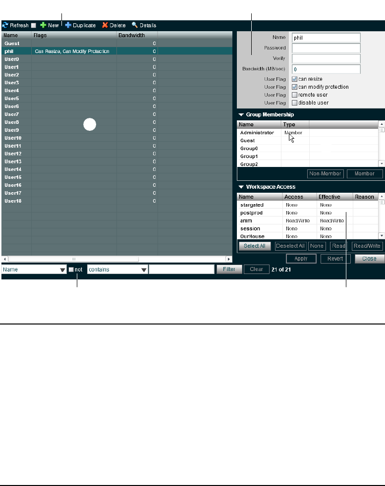
Managing Users
132
t
r
e
wq
y
1 Action button toolbar—Perform actions on selected users
2 Details panel—Detailed information on the selected users; see “Viewing User Details” on
page 133
3 User list—Lists all users and related information; see “User Column List” on page 133
4 Group membership—Displays information about the group membership for the selected user; see
“Adding Users” on page 134 and “Modifying Users” on page 137
5 Filter panel—Filter the user list display based on conditions you configure; see “Filtering the
Display” on page 29
6 Workspace access—Displays information about the Workspace access for the selected user; see
“Adding Users” on page 134 and “Modifying Users” on page 137

Managing Users
133
User Column List
The following table summarizes the information available in the Users list.
nYou can sort the information in the Users page by clicking any column heading. For more
information on sorting items in columns, see “Sorting Information” on page 28.
Viewing User Details
The Details panel displays all information for the currently selected user.
To view information about a user:
tIn the User list, click to select a user.
The Users page displays all the information for the selected user. If the Details panel is not
visible, click the Details button.
To hide the User Details panel:
tClick the arrow next to the Details title bar.
To close the User Details panel:
tClick Close.
The following table summarizes the information available in the Details panel.
Heading Description
Name Lists the client name
Flags Indicates the status of client privileges
Bandwidth Lists the client’s bandwidth allocation
Setting a bandwidth limit on editing clients, such as an Avid
NewsCutter®Adrenaline client, can adversely affect playback performance when
the Avid ISIS system is under load.
Panel Heading Description
Details
Name Lists the user name
Password Allows modification of the password used to log in to
the system

Managing Users
134
Adding Users
A user is anyone who accesses files stored on the network. User accounts include administrative
privilege levels, group membership types, and Workspace access. There can be more user
accounts than connected clients, with a maximum of 5,000 user accounts (including the default
Administrator and Guest accounts).
Verify Provides verification for the new password
Bandwidth Allows modification of maximum bandwidth
requirements
Setting a bandwidth limit on editing clients, such as an
Avid NewsCutter Adrenaline client, can adversely
affect playback performance when the Avid ISIS system
is under load.
User Flag
can resize Enables or disables user privilege for resizing
Workspaces
can modify
protection
Enables or disables user privilege for changing
protection status of Workspaces
remote user Enables or disables user LDAP authentication and
group privileges
disable user Disables the user
Group Membership
Name Lists the names of available groups
Type Lists the user’s membership status for each group
(Member or Non-Member)
Workspace Access
Name Lists the names of available Workspaces
Access Lists the access privileges for the selected user
Effective Lists the effective access privileges for the selected user
Reason Lists the reason for any difference between the access
privileges and the effective access assigned the selected
user
Panel Heading Description (Continued)

Managing Users
135
nUsers must have access to at least one Workspace before they can use the shared storage
network.
To create a user account:
1. From the Management Console home page, click the Users icon, located in the System
section.
The Users page opens.
2. Click the New button.
The Create User dialog box opens.
3. Set the user options. The following table summarizes these options.
4. (Option) In the Group Membership list, select a group, and click the Member button to make
the user a member in the group. Users can belong to 15 groups.
By default, new users are listed as “Non-Member” in the Type category for each group. As a
result, the Non-Member button is inactive until membership is set.
The Group Membership list updates to show the user as a member of the group.
Option Type Description
Name text If there is already a user with the name entered in the Name text
box, an error message tells you to type a new name
nDo not use non-permitted characters in Management
Console text fields. For information on Management Console
text entry guidelines, see “Entering Text” on page 31.
Password text User password (maximum of 15 characters)
Verify text Re-type the user password to verify
Bandwidth (MB/sec) text
(numeric)
Sets a bandwidth limit for the client. The default value of zero
denotes unlimited bandwidth
can resize check box Enables or disables user privilege for resizing Workspaces
can modify protection check box Enables or disables user privileges for changing protection status of
Workspaces.
remote user check box Enables or disables user LDAP authentication and group privileges
disable user check box Disables the user
Managing Users
136
5. (Option) In the Workspace Access list, select one or more Workspaces and do one of the
following:
tClick the Read button to set read-only Workspace access for the user.
By default, access privileges for new users are listed as “None” in the Access category
for each Workspace. As a result, the None button is inactive until access is set. (For
information on permissions for Workspace access in the network, see “Managing
Workspace Access Privileges” on page 118.)
tClick the Read/Write button to set both read and write Workspace access for the user.
The Workspace Access list updates to show the user access privileges for the selected
Workspace.
6. Click Apply.
7. (Option) Repeat steps 3 through 6 to create new users.
8. Click Close to close the Create User dialog box and to return to the Users page.
The new user appears in the Users list.
Duplicating Users
When you duplicate user accounts, they inherit the bandwidth allocation and access privileges of
the accounts from which they were created.
To duplicate a user account:
1. In the Users list, select the user account you want to duplicate.
2. Click the Duplicate button.
The Duplicate User dialog box opens.
3. (Option) Modify any of the attributes of the new user. For information on modifying user
accounts, see “Modifying Users” on page 137.
4. Click Apply to create a new user containing the attributes of the selected user.
The duplicate user appears in the Users page, and the Duplicate User dialog box refreshes to
allow you to duplicate a new user.
The new user account has a default name — user n, where n is an integer that is incremented
each time you click Apply to create another duplicate user account.
5. Click Close to close the Duplicate User dialog box and to return to the Users page.

Managing Users
137
Modifying Users
You can rename a User account, change the password, change the allocated bandwidth, edit
privileges, and change user membership in groups with the client dialog boxes. For example, you
can change user passwords to accommodate a new user, reestablish access for an existing user
who has forgotten the password, or disable access to an account.
You can modify a User account at any time, even when it is being actively used in your work
environment.
To modify a User account:
1. From the User list, do one of the following:
tSelect the User account you want to modify, and click the Details button.
tDouble-click the client name.
The Details panel displays information about the selected User account.
2. Modify the user options as required. The following table summarizes these options.
3. Modify Group membership for the user as required:
tClick the Member button to make the user a member in the user group.
tClick the Non-Member button to remove the user from the user group.
Option Type Description
Name text If there is already a user with the name entered in the Name text box,
an error message tells you to type a new name
nDo not use non-permitted characters in Management Console
text fields. For information on Management Console text
entry guidelines, see “Entering Text” on page 31.
Password text User password (maximum of 15 characters)
Verify text Re-type the user password to verify
Bandwidth (MB/sec) text
(numeric)
Sets a bandwidth limit for the client. The default value of zero
denotes unlimited bandwidth
can resize check box Enables or disables user privilege for resizing Workspaces
can modify protection check box Enables or disables user privileges for changing protection status of
Workspaces
remote user check box Enables or disables user LDAP authentication and group privileges
disable user check box Disables the user
Managing Users
138
4. Modify Workspace access for the user as required:
tClick the None button to remove Workspace access privileges for the client.
tClick the Read button to set read-only Workspace access for the client.
tClick the Read/Write button to set both read and write Workspace access for the client.
For information on permissions for Workspace access in the network, see “Managing
Workspace Access Privileges” on page 118 and “Setting Workspace Access Privileges” on
page 120.
5. (Option) Before you apply your changes, you can use the Revert button to undo any
modifications made to the client information.
6. Click Apply.
Deleting Users
You can use the ISIS Management Console to delete any User account. If you want to remove
the client from the shared storage network but still maintain the client account, see “Disabling
Users” on page 138.
cIf you delete the client account, its connection to the System Director is broken immediately
and any mounted Workspaces are unmounted as soon as they are accessed.
To delete a User account:
1. Ensure that the client account to be deleted is not currently active.
2. From the Users list, select the User account you want to delete.
3. Click the Delete button.
A dialog box opens, prompting you to confirm that you really want to delete the client.
4. Click OK.
Disabling Users
You can remove Users temporarily from the Avid ISIS shared storage network by using the
Disable User option. Disabling User accounts do not delete them from the list of Users in the
Users page. This preserves the client accounts and allows you to return the clients to the system
by enabling the User account at a later time.
To remove a user by disabling the user account:
1. Ensure that the client account to be removed is not currently active.
2. From the Users list, select the client account you want to disable.
Managing User Groups
139
3. Do one of the following:
tClick the Details button.
tDouble-click the client name.
The Details panel displays information about the selected client.
4. Select the “disable user” check box.
5. (Option) Before you apply your changes, you can use the Revert button to undo any
modifications made to the client information.
6. Click Apply.
7. Click Close to close the Details window.
Managing User Groups
This section contains the following topics:
•Viewing User Group Details
•Adding User Groups
•Modifying User Groups
•Deleting User Groups
Client accounts also allow groups of users to access media stored on your network. These
accounts allow users to mount or map Workspaces on their Avid workstations.
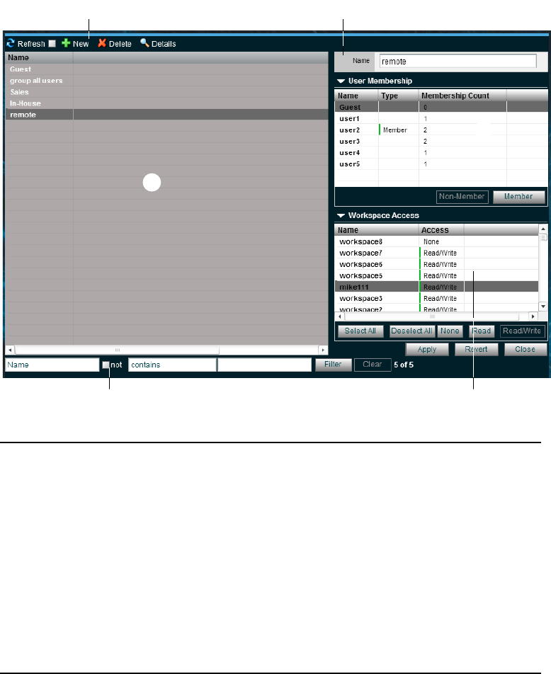
Managing User Groups
140
Viewing User Group Details
The Details panel displays all information for the currently selected user group.
t
r
e
wq
y
1 Action button toolbar—Perform actions on selected user groups
2 Details panel—Detailed information on the selected user group; see “Viewing User Group
Details” on page 140
3 User groups list—Lists all user groups and related information
4 User membership panel—Displays information about the membership for the selected user
group; see “Adding User Groups” on page 141 and “Modifying User Groups” on page 142
5 Filter panel—Filter the user list display based on conditions you configure; see “Filtering the
Display” on page 29
6 Workspace access panel—Displays information about the Workspace access for the selected
user group; see “Adding User Groups” on page 141 and “Modifying User Groups” on page 142

Managing User Groups
141
To view detailed information about a User group:
tIn the Group list, click to select a user group.
The Groups page displays all the information for the selected user group. If the Details panel
is not visible, click the Details button.
To hide the User Membership or Workspace Access panel:
tClick the arrow next to the Details title bar or the User Access title bar.
To close the Details panel:
tClick Close.
The following table summarizes the information available in the Details panel.
Adding User Groups
To add a group account:
1. From the Management Console home page, click the Groups icon, located in the System
section.
The Groups page opens.
2. Click the New button.
The Create Group dialog box opens.
Panel Heading Description
Group Details
Name Lists the user group name
User Membership
Name Lists the names of all users
Type Lists the user’s membership status for each user
group (Member or Non-Member)
Membership Count Lists the number of groups in which each user holds
membership (users can belong to no more than 15
user groups)
Workspace Access
Name Lists the names of available Workspaces
Access Lists the access privileges for the selected user group
Managing User Groups
142
3. Type a user group name in the Name text box.
If there is already a user group with the name entered in the Name text box, an error message
tells you to type a new name.
nDo not use non-permitted characters in Management Console text fields. For information on
Management Console text entry guidelines, see “Entering Text” on page 31.
4. (Option) In the User Membership list, select a user and click the Member button to make the
user a member in the user group. Users can belong to no more than 15 user groups.
By default, new users are listed as “Non-Member” in the Type category for each user group.
As a result, the Non-Member button is inactive until membership is set.
5. (Option) In the Workspace Access list, select a Workspace or click the Select All button to
select all Workspaces, and do one of the following:
tClick the Read button to set read-only Workspace access for the user group.
tClick the Read/Write button to set both read and write Workspace access for the user
group.
By default, access privileges for new user groups are listed as “None” in the Access category
for each Workspace. As a result, the None button is inactive until access is set. (For
information on permissions for Workspace access in the network, see “Setting Workspace
Access Privileges” on page 120.)
6. Click Apply.
7. (Option) Repeat steps 3 through 6 to create new user groups.
8. Click Close to close the Create Group dialog box and to return to the Groups dialog box.
The new user group appears in the Groups list.
Modifying User Groups
You can rename a user group account, change user membership, and modify Workspace access.
You can modify a client account at any time, even when it is being actively used in your work
environment.
To modify a user group account:
1. From the Groups list, do one of the following:
tSelect the user group account you want to modify, and click the Details button.
tDouble-click the user group name.
The Details panel displays information about the selected user group account.
Managing User Groups
143
2. Modify the user group name as required.
If there is already a user group with the name entered in the Name text box, an error message
tells you to type a new name.
nDo not use non-permitted characters in Management Console text fields. For information on
Management Console text entry guidelines, see “Entering Text” on page 31.
3. Modify user membership for the user group as required:
tClick the Member button to make the user a member in the user group.
tClick the Non-Member button to remove the user from the user group.
4. Modify Workspace access for the user group as required:
tClick the None button to remove Workspace access privileges for the user group.
tClick the Read button to set read-only Workspace access for the user group.
tClick the Read/Write button to set both read and write Workspace access for the user
group.
For information on permissions for Workspace access in the network, see “Managing
Workspace Access Privileges” on page 118 and “Setting Workspace Access Privileges” on
page 120.
5. (Option) Before you apply your changes, you can use the Revert button to undo any
modifications made to the client information.
6. Click Apply.
Deleting User Groups
You can use the ISIS Management Console to delete any user group account.
To delete a user group account:
1. Ensure that the user group account to be deleted is not currently active.
2. From the Groups list, select the user group account you want to delete.
3. Click the Delete button.
A dialog box opens, prompting you to confirm that you really want to delete the user group.
4. Click OK.
Managing LDAP Accounts
144
Managing LDAP Accounts
This section contains the following topics:
•Opening LDAP Sync Tool
•Using LDAP Sync Tool
LDAP (Lightweight Directory Access Protocol) is an Internet protocol that some applications
use to look up information — such as account information, user names, and groups — from a
server. The LDAP Sync page allows ISIS administrators to synchronize ISIS user accounts with
existing LDAP user accounts and to create and/or modify a large number of users and groups
within the Avid ISIS system. The LDAP Sync page provides you with the following
functionality:
• Display user accounts available within a given LDAP service but not in the ISIS system, and
vice versa
• Add new groups and users to the ISIS system
• Grant user memberships to groups
• Remove user membership from a group in ISIS if user no longer belongs to that group on the
LDAP server
• Users synchronized by the LDAP Sync page will automatically be added as “Remote” users
for authentication to the LDAP server
You can use the LDAP Sync Tool to search for groups and their users on an LDAP server,
synchronize users and groups accounts by adding or removing users and/or groups from ISIS,
generate a report of the account actions, and view a history of the synchronization activity. You
must first configure a connection by entering the LDAP server’s fully qualified name, port, and
user distinguished name and password for authentication.
nUsers imported by the LDAP Sync Tool cannot log into Avid ISIS server until it is configured for
external authentication. For more information about configuring external authentication, see
“Configuring External Authentication” on page 36.
nAt this time, Avid ISIS currently only supports Microsoft Active Directory. ISIS might not be
compatible with other LDAP implementations.
Opening LDAP Sync Tool
You can use the LDAP Sync Tool to configure LDAP connections. If you have not previously
configured a connection, you must enter the connection name and other information specific to
the particular LDAP server.
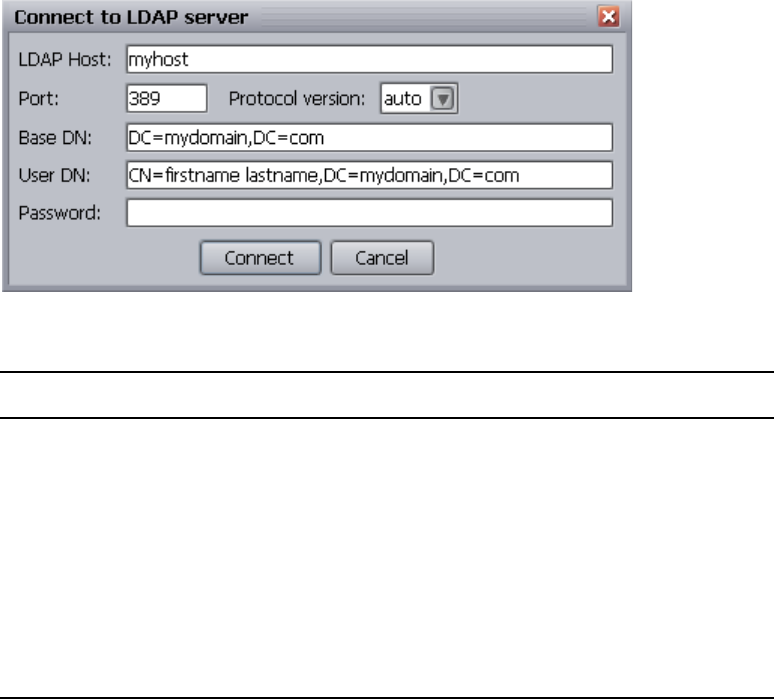
Managing LDAP Accounts
145
nAll connection information is stored locally for the connecting user’s account. If you try to
connect from a different workstation and/or as another user, you have to re-enter the ISIS and
LDAP login information.
To open LDAP Sync Tool:
1. From the Management Console home page, click the LDAP Sync Tool icon in the Tools
section.
nThe LDAP Sync Tool is a Java WebStart application that opens its own application window.
Management Console remains open.
The Connect to LDAP Server dialog box opens.
2. Type the following information in the appropriate text boxes:
cContact your IT administrator to obtain your LDAP login information. Three failed
connection attempts might result in your LDAP user account being disabled.
Field Value
LDAP Host Fully qualified name of the LDAP server to which you are connecting
Port Port number used by the LDAP server to which you are connecting
(default is 389, the default LDAP port)
Protocol Version LDAP version used on the server to which you are connecting (default is
“auto”)
Base DN Indicates where in the LDAP directory tree searches should begin
User DN Connecting user’s LDAP DN (Distinguished Name) information
Password Connecting user’s LDAP password.
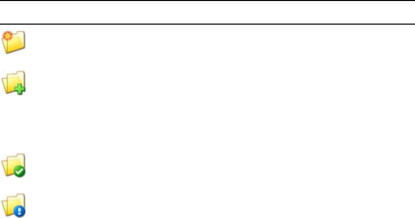
Managing LDAP Accounts
146
3. Click Connect.
- If this is the first time using this tool, the LDAP Group Selection window opens. For
more information about using the LDAP Group Selection window, see “Synchronizing
LDAP and ISIS Accounts” on page 147.
- If the tool has been used before on this workstation, the main window opens.
Using LDAP Sync Tool
The Account Synchronizer is the main window of the Avid ISIS LDAP Sync Tool. You use the
Account Synchronizer to search the LDAP user accounts, synchronize (reconcile) user accounts
by adding or removing users from the ISIS users list, generate a report of the account actions,
and view a history of the accounts. You can also modify the display of the Account Synchronizer
to filter out unneeded account information.
nAll LDAP reconciliation session data, such as reports and history, are stored in the local user’s
account. If you log into another workstation and/or as a different user, this information will not
be available.
When you first connect to the Avid ISIS and LDAP servers, the Account Synchronizer checks
the users in the selected LDAP groups against the Avid ISIS database and builds a set of actions
to reconcile the two. The main window displays the complete set of groups, using buttons with
colors and icons to indicate the reconciliation status of each group.
Icon Meaning
The group is in the LDAP database, but not ISIS. The default action is to add the group and all
users to ISIS.
The group is in both LDAP and ISIS, but the users are different between the two:
• If the user is in LDAP but not ISIS, the user will be added to ISIS.
• If the user is in ISIS, but not in LDAP, the user will be removed from the group in ISIS.
nThe user will no longer share privileges with the group. The user will still be able to
access ISIS, and membership in other local or LDAP groups is unaffected.
The group is in both LDAP and ISIS, and all users are reconciled. No action is taken by
default.
The user and/or group is in ISIS, but not LDAP.
cBy default, all users and groups in this entry will be permanently deleted. If you
do not want to remove these users from the ISIS database you must manually
override the default action before performing a Reconcile action.

Managing LDAP Accounts
147
You can click on these buttons to view detailed information about actions to be performed on
users in each group.
Modifying the Account Synchronizer Display
You can sort the columns in the display alphabetically, and add/remove one or more LDAP
groups from the Account Synchronizer display.
To sort columns:
tClick a column heading to sort the contents of the column alphabetically. Click the heading
again to reverse the sort.
To resize columns:
tClick and drag the divider between column headings.
Synchronizing LDAP and ISIS Accounts
The process of synchronizing the LDAP/Active Directory and ISIS user lists consists of the
following steps:
• Selecting LDAP groups
• Specifying user-specific synchronization actions
• Performing the synchronization process
nThe synchronization process is read-only with regard to the LDAP/Active Directory user list. The
Avid ISIS LDAP Sync Tool will never alter the LDAP/Active Directory user list.
The user is an ISIS only group.
cBy default, all users and groups in this entry will be permanently deleted. If you
do not want to remove these users from the ISIS database you must manually
override the default action before performing a Reconcile action.
Icon Meaning
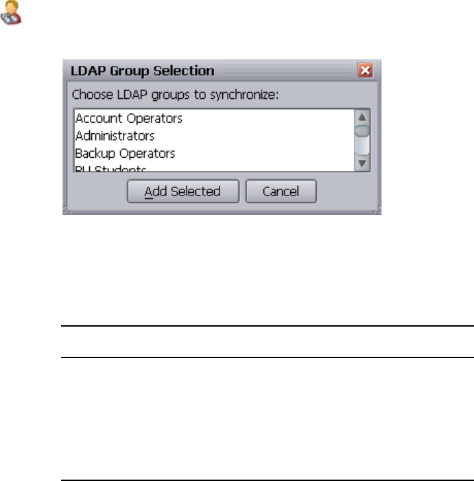
Managing LDAP Accounts
148
To add groups to the Account Synchronizer display:
1. Click the Select Groups button.
The LDAP Group Selection window opens.
nOn subsequent LDAP Sync Tool sessions, the main window will open after login and display the
selected groups from the last session.
2. Select the groups to be synchronized.
Selection Type Action
Single selection Click on the group name.
Multiple non-contiguous CTRL-click on each name to be selected.
Multiple contiguous Click on the first group name, then
SHIFT-click on the last group name.
All Press CTRL-A.
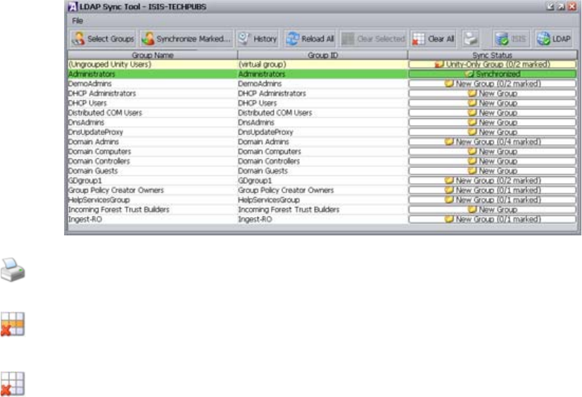
Managing LDAP Accounts
149
3. Click the “Add Selected” button.
The LDAP Sync Tool builds a list of sync actions for the selected groups, and displays the
selected groups in the main window.
4. (Option) To print a report of the account list and selections, click the Print button.
To remove groups from the Account Synchronizer display:
1. Select one or more rows and click the Clear Selected button to remove the row from the
Group list. Ctrl+click (Windows) or Cmd+click (Macintosh) or Shift+click to select multiple
rows.
2. Click the Clear All button to remove all rows from the Group list.
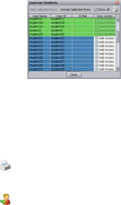
Managing LDAP Accounts
150
To modify the default reconciliation actions for individual users:
1. Click the row in the Sync Status column for the appropriate group (each row in the Sync
Status Column is a button).
The Descriptive name window opens and displays the user names of all members of the
group, as well as actions to be taken.
2. You can do the following:
tTo show all users, including those which are already reconciled, click the “Show All”
check box.
nThe “Show All” check box is disabled if all or no users in the group are already reconciled (all
users are shown by default).
tTo override the default action, click the check box in the “Reconciliation Action”
column to deselect it.
3. (Option) To print a report of the user list and selections, click the Print button.
4. Click Close to close the user selection window and return to the main window.
To synchronize LDAP/Active Directory and ISIS user databases:
tClick the Synchronized Marked button.
The LDAP Sync Tool performs the reconciliation actions, then displays the updated groups
status in the main window.
Managing LDAP Accounts
151
To refresh selected entries:
1. Select one or more groups from the main window.
2. Click the Reload All button.
Information about the selected groups is retrieved from the LDAP server, reassessed, and
displayed in the main window.
To view and/or print the History log:
1. Click the History button.
The History Log window opens.
2. (Option) To print the History Log, click the Print button.
The Print dialog opens.
3. (Option) To clear the History Log, click the Delete History button.
The History Log is cleared.
4. To close the History Log window, click the Close button.
To exit the LDAP Sync Tool
1. Do one of the following:
tClick File > Exit
tClick the Close Window button in the upper right corner of the window.
A confirmation window opens.
2. Click Yes.
The application closes.
Selection Type Action
Single selection Click on the group name.
Multiple non-contiguous CTRL-click on each name to be selected.
Multiple contiguous Click on the first group name, then
SHIFT-click on the last group name.
All Press CTRL-A.
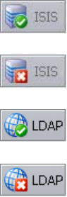
Managing LDAP Accounts
152
Importing LDAP Users with Incorrectly Formatted LDAP UIDs
When synchronizing users from the LDAP Synchronization Tool, the User ID (also known as the
UID) must contain characters that ISIS allows for valid Usernames. The entry in the User ID
column is used as the ISIS Username. If the User ID contains any character listed in the
procedure “Entering Text” on page 31, the user(s) will not be added to ISIS. Additionally, the
synchronization for that group will be aborted, and any subsequent user accounts in that group
will not be reconciled. In such cases, you must do one of the following:
• Create the user(s) in ISIS with a Username that does not contain these illegal characters, and
manually add them to groups.
• Update the user entry in the LDAP database with a UID that contains no illegal characters,
then run the LDAP Sync Tool again to reconcile the users.
Connecting and Disconnecting from the ISIS and LDAP servers
The connection status button icons indicate whether you are connected to the ISIS and/or LDAP
servers. You can use the connection status buttons to manually connect or disconnect from the
LDAP server, and to reconnect with the ISIS server if the connection is lost. The button icons
change depending on your current connection status.
nYou are disconnected from the ISIS or LDAP servers if their respective session time-out periods
are exceeded.
To disconnect from the LDAP server:
tClick the LDAP connection status button.
The LDAP Sync Tool disconnects from the LDAP server, and the LDAP connection status
button icon changes to Disconnected.
Connected to ISIS
Disconnected from ISIS
Connected to LDAP server
Disconnected from LDAP server
Managing Devices
153
To connect/reconnect to the LDAP server:
1. Click the LDAP connection status button.
The Connect to LDAP Server window appears.
nThe text fields will be filled in for you if you have previously logged into the LDAP server within
the same session.
2. Click Connect.
The following happens:
- The LDAP Sync Tool connects to the LDAP server.
- The Connection status icon changes to green (connected).
To reconnect to Avid ISIS:
1. Click the “Connect to server” button next to the ISIS server connection status icon.
The Connect to ISIS Server window opens.
2. Enter your password into the Password text box if needed, and click Connect.
The following happens:
- The LDAP Sync Tool connects to the ISIS server.
- The Connection status icon changes to green (connected).
Managing Devices
This section contains the following topics:
•Devices Column List
•Viewing Device Details
•Adding Devices
•Modifying Devices
•Deleting Devices
Devices, such as Avid AirSpeed® servers, can be assigned their own client accounts. Users of the
devices can then access Workspaces on the network.
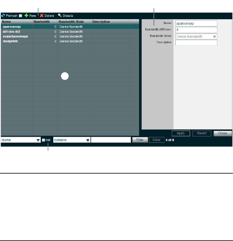
Managing Devices
154
nIf you select the Force Manual Device Creation option in the Preferences dialog box, clients who
do not have an entry in the Devices list are not allowed to connect. The administrator must
manually create a device account for every client computer that is expected to connect to the ISIS
system. If users deselect the Force Manual Device Creation, a client account is automatically
created for each new device when it is first connected to the shared storage network. For
information on preferences, see “Configuring Management Console Preferences” on page 33.
r
e
wq
1 Action button toolbar—Perform actions on selected client devices
2 Details panel—Detailed information on the selected client devices; see “Viewing Device
Details” on page 155
3 Devices list—Lists all client devices and related information; see “Devices Column List” on
page 155
4 Filter panel—Filter the user list display based on conditions you configure; see “Filtering the
Display” on page 29

Managing Devices
155
Devices Column List
The following table summarizes the information available in the Devices column list.
Viewing Device Details
The Details panel displays all information for the currently selected client device.
To view information about a client device:
tIn the Devices list, click to select a device.
The Devices page displays all the information for the selected client device. If the Details
panel is not visible, click the Details button.
The following table summarizes the information available in the Details panel.
Heading Description
Name Lists the client name
Bandwidth Allows modification of bandwidth requirements
nYou might need to set a bandwidth limit for a device such as an
Avid AirSpeed in the event the device is consuming more bandwidth
than expected.
Bandwidth Mode Lists the mode used to allocate bandwidth
Description Displays the user-supplied device description, if any
Heading Description
Name Lists the device name
Bandwidth
(MB/sec)
Allows modification of bandwidth requirements
nYou might need to set a bandwidth limit for a device such as an
Avid AirSpeed in the event the device is consuming more bandwidth than
expected.
Bandwidth Mode Lists the mode used to allocate bandwidth
Description Displays the user-supplied device description, if any
Managing Devices
156
Adding Devices
To create a device account:
1. From the Management Console home page, click the Devices icon, located in the System
section.
The Device page opens.
2. Click the New button.
The Create Device dialog box opens.
3. Type the system name of the device you want to add in the Name text box.
If there is already a device with the name entered in the Name text box, an error message
tells you to type a new name.
nDo not use non-permitted characters in Management Console text fields. For information on
Management Console text entry guidelines, see “Entering Text” on page 31.
4. Type a value in the Bandwidth text box to set the amount of read/write bandwidth (in MB/s)
you want to allocate to the device. A value of 0 (zero) indicates that bandwidth will not be
metered
5. (Option) Type a description of the device in the Description text box.
6. Click Apply.
7. (Option) Repeat steps 3 through 6 to create new devices.
8. Click Close to close the Create Device dialog box and to return to the Users page.
The new device appears in the Users list.
Modifying Devices
You can rename a Device account, change the allocated bandwidth, and Device description.
You can modify a Device account at any time, even when it is being actively used in your work
environment.
To modify a device:
1. From the Devices list, select the Device account you want to modify, and do one of the
following:
tClick the Details button.
tDouble-click the client name.
The Details panel displays information about the selected Device.

Managing Devices
157
2. Modify the Device options as required. The following table summarizes these options.
3. (Option) Before you apply your changes, you can use the Revert button to undo any
modifications made to the Device information.
4. Click Apply.
Deleting Devices
You can use the ISIS Management Console to delete any Device account.
cIf you delete the Device account, its connection to the System Director is broken
immediately and any mounted Workspaces are unmounted as soon as they are accessed.
To delete a Device account:
1. Ensure that the client account to be deleted is not currently active.
2. From the Devices list, select the Device account you want to delete.
3. Click the Delete button.
A dialog box opens, prompting you to confirm that you really want to delete the Device.
4. Click OK.
The Device account is deleted and the Device is removed from the Devices list.
Option Type Description
Name text If there is already a device with the name entered in the Name
text box, an error message tells you to type a new name
Bandwidth (MB/sec) text
(numeric)
Sets a bandwidth limit for the client. The default value of zero
denotes unlimited bandwidth
Description text Free-text description of the device, maximum of 63 characters

7Managing Connections
This section contains the following topics:
•Monitoring Client Bandwidth
•Monitoring System Connection Status
•Monitoring Reservations
This section describes how to use the Bandwidth page to monitor bandwidth usage in the
Avid ISIS shared storage network. You can also use the Bandwidth page to remove individual
components from the network.
Monitoring Client Bandwidth
This section contains the following topics:
•Opening the Bandwidth Page
•Bandwidth List
•Scaling the Bandwidth List Graph Display
The Bandwidth page allows you to monitor system usage, including total system bandwidth use
and bandwidth consumption of each connected system.
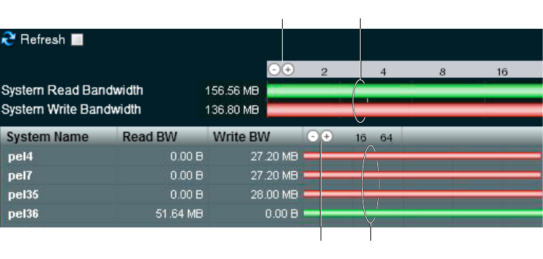
Monitoring Client Bandwidth
159
The System Read Bandwidth and System Write Bandwidth rows in the Bandwidth page show
total system read bandwidth (green bar) and total system write bandwidth (red bar) in megabytes
per second (MB/s).
Below the System Read Bandwidth and System Write Bandwidth rows is a list of all active
system components showing their current activity and their system identification.
Opening the Bandwidth Page
To open the Bandwidth page:
tFrom the Management Console home page, click the Bandwidth icon, located in the
Connectivity section.
The Bandwidth page opens.
re
wq
1 System bandwidth scale buttons—Increase or decrease the scale of the system bandwidth graph;
see “Scaling the Bandwidth List Graph Display” on page 160
2 System bandwidth read and write graphs—Graphic display of system read (green) and write
(red) bandwidth; see “Bandwidth List” on page 160
3 Device bandwidth scale buttons—Increase or decrease the scale of the device bandwidth graph;
see “Scaling the Bandwidth List Graph Display” on page 160
4 Device bandwidth read and write graphs—Graphic display of device read (green) and write
(red) bandwidth; see “Bandwidth List” on page 160

Monitoring Client Bandwidth
160
Bandwidth List
The following table describes the information displayed in the Bandwidth page.
nYou can sort the information in the Bandwidth Monitor list by clicking any column heading. For
more information on sorting items in columns, see “Sorting Information” on page 28.
Scaling the Bandwidth List Graph Display
The Bandwidth Monitor list represents bandwidth consumption for the network and for
individual system components in the form of horizontal bars in a graph display. Numeric
divisions are displayed in megabytes/second (MB/s). You can adjust the scale of the graph to
make it easier to monitor bandwidth information.
To decrease or increase the size of the graph view:
tClick the Decrease Size or Increase Size button.
Heading Description
System Read Bandwidth The value of the total system bandwidth currently in use for reading files (in
MB/s)
System Write Bandwidth The value of the total system bandwidth currently in use for writing to files (in
MB/s)
System Name The name of the system specified during the System Director configuration
Read BW For the listed system components, the value of the bandwidth currently in use
for reading files (in MB/s)
Write BW For the listed system components, the value of the bandwidth currently in use
for writing to files (in MB/s)
Bandwidth For the listed system components, graphical display of bandwidth usage:
• Read (green bar)
• Write (red bar)
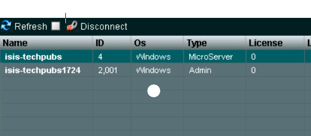
Monitoring System Connection Status
161
Monitoring System Connection Status
This section contains the following topics:
•Opening the Connection Status Page
•Connection Status Descriptions
•Disconnecting Clients from the Shared Storage Network
The Connection Status page allows you to view the status of all components connected to the
network. You can also use the Connection Status page to disconnect components from the
system.
nSome clients might not be able to connect to the shared storage network if the combined
bandwidth requirement of connected components equals the system limit for bandwidth use. For
information on monitoring bandwidth use, see “Monitoring Client Bandwidth” on page 158.
Opening the Connection Status Page
To open the Connection Status page:
tFrom the Management Console home page, click the Connection Status icon, located in the
Connectivity section.
The Connection Status page opens.
w
q
1 Action button toolbar—Perform actions on selected components
2 Connections list—List connected components and related information; see “Connection Status
Descriptions” on page 162

Monitoring System Connection Status
162
Connection Status Descriptions
The Connection Status dialog box lists information about all components — both active and
inactive — that comprise the shared storage network. The following table describes the
information displayed in the dialog box.
nYou can sort the information in the Connection Status dialog box by clicking any column
heading. For more information on sorting items in columns, see “Sorting Information” on
page 28.
Disconnecting Clients from the Shared Storage Network
You can use the Connection Status dialog box to momentarily disconnect clients from the shared
storage network. Disconnecting clients moves them from active to inactive status in the list of
active clients in the Connection Status dialog box. Inactive clients display the time of the last
logged contact between the System Director and the clients.
nBefore disconnecting a client from the network, you should determine the status of active clients
(for example, you should know if any clients currently have Workspaces mounted on the client
you want to disconnect). For information on using the Monitor tool to determine the status of
active clients, see “Managing Active Clients” on page 87.
Heading Description
Name Lists the name of the component
ID Lists an internal numeric identifier used by the System Director to represent the
component; these identifiers are assigned when a component first contacts the
System Director
OS Lists the operating system of the component
Type Lists the category or principal function of the component
License Displays the number of licenses allotted to the component
Last Seen For inactive components, displays the date and time when the component last sent its
status to the System Director; for active components, displays a zero (0) as the default
value
For active components, displays the date and time when the component last sent its
status to the System Director.
The System Director removes information about components that have not been seen
for a week, unless the component’s bandwidth limit is configured to custom values or
the Default Device Bandwidth option in the Preferences dialog box is selected
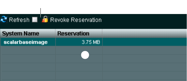
Monitoring Reservations
163
To disconnect a client from the shared storage network:
1. Select a client from the list.
2. Click the Disconnect button.
A dialog box opens asking you to confirm the action.
3. Click Yes.
The changes might not appear until the list is refreshed.
Monitoring Reservations
This section contains the following topics:
•Reservations Descriptions
•Revoking Reservations
Normally, bandwidth reservations are initiated and configured automatically by Avid
applications based on bandwidth requirements. In some cases however, you might want to limit
the bandwidth available to client systems. Client workstation users can use the Client Manager to
obtain a default bandwidth reservation on the ISIS system. The actual bandwidth available to the
client is the lowest of the following values:
• The default bandwidth requested by the Client Manager
• The maximum bandwidth assigned by the ISIS Administrator to the user
• The maximum bandwidth value assigned by the Management Console, either per-device or
by the default bandwidth allocation for auto-created devices
• The bandwidth limitation of the client device
You can use the Reservations page to monitor the status of client reservations, and to revoke
client reservations, if necessary.
w
q

Monitoring Reservations
164
Reservations Descriptions
The Reservations page lists information about all bandwidth reservations obtained by connected
clients. The following table describes the information displayed.
nYou can sort the information in the Reservations page by clicking any column heading. For more
information on sorting items in columns, see “Sorting Information” on page 28.
Revoking Reservations
You can revoke a client reservation using the Reservations page. Revoking a reservation will
only remove the bandwidth reservation; the client will still be connected to the Workspace.
To revoke a reservation:
1. From the Management Console home page, click the Reservations icon, located in the
Connectivity section.
The Reservations page opens.
2. Select one or more client systems for which you want to revoke the bandwidth reservation.
3. Click the Revoke Reservation button.
A confirmation dialog opens.
4. Click Yes.
The client reservation is revoked.
1 Action button toolbar—Perform actions on selected client reservations
2 Reservations list—List clients with reservations and related information; see “Reservations
Descriptions” on page 164
Heading Description
System Name The computer name of the client system
Reservation The value of the bandwidth reservation,
in MB/sec.

8System Monitoring and Diagnostics
This section contains the following topics:
•Hardware Monitoring Service (ISIS 5000 Only)
•System Information Page
•System and Administration Log Pages
•ISIS Snapshots Page
•Profiler Page
•System Status History Page
•ISIS Toolbox Page
•Network Utilities Page
•Monitor Tool (ISIS 7000 Only)
•Agent Settings Page
•Monitoring Avid ISIS with SNMP
Avid ISIS Management Console provides tools for logging, monitoring, and system diagnostics.
Hardware Monitoring Service (ISIS 5000 Only)
The Hardware Monitoring service runs on all ISIS 5000 Engines. It periodically polls certain
critical components on the Engine and reports status to the System Director. The System
Director then makes this status available to the Management Console. Errors and warnings are
indicated in the System Status Console. Expand the Status Console panel to view what
component that is causing the error or warning.
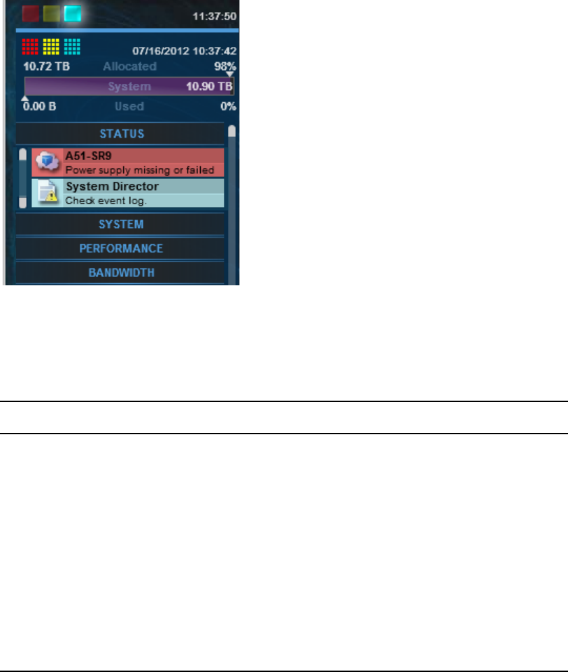
Hardware Monitoring Service (ISIS 5000 Only)
166
These status messages inform you of system issues that might not be obvious because in most
cases the ISIS system can continue to function. The issues should be corrected so that a more
serious failure does not occur. The components and messages that are displayed in the Status
Console panel are listed in the following table.
For a list of event logs generated by the Hardware Monitoring service, see “Avid ISIS E-mail
Notification List” on page 243.
Component Warning/Error Message Text Description
Power Supply Error Power supply missing or
failed
One or more power supplies have
failed, are failing, or do not have a
power cable plugged in.
System RAID
Volume
(ISIS 5000 only)
Error Storage volume missing or
failed
The system RAID volume is
degraded or failed (there is only
one system volume).
Fan
(ISIS 5000 only)
Error Fan missing or failed The Engine fan is missing or has
failed.
Approved
Network settings
Warning Incorrect network adapter
settings
One or more of the network
adapters used for ISIS
communication do not have the
correct settings applied.

System Information Page
167
System Information Page
You can use the System Information page of the Management Console to view basic information
about your system and your network. You cannot edit the information displayed in the System
Information window. Many of these items are also displayed in the Avid ISIS Launch Pad.
The following table describes the information available in the System Information window.
Category Heading
Server Status Server state
Active
Server Version
Event Log Status (7000 only)
Server Details Virtual Name
Local Host Name
Flock ID
Port number
Licensed clients allowed
Licensed clients connected
Interface 0 through x (depends on the number of Ethernet ports in your
System Director)
Metadata Loaded
Creation Time
In Use
Available
Available (Large Allocations)
Total
Percent Used
Verified Status
Verified D at e

System Information Page
168
Saved Status
Saved Date
Dual System Director
Configuration
Enabled
Host Information Username (7000/5000 only)
Host Name
OS Version
Processor Type
Number of Processors
System Uptime
Memory Information Total Physical Memory
Total Physical Memory Usage
Available Physical Memory
Total Page File
Available Page File
Running Processes List the processes running on the System Director
Agent Environment Server name
URL
GUID
Root directory
Work directory
WSDL directory
Cookie domain
Cookie path
Soap version
Soap accept timeout
Soap send timeout
Soap recv timeout
Soap max keep alive
Running interactively
Category (Continued) Heading

System and Administration Log Pages
169
To view System Information:
tFrom the Management Console home page, click the System Information icon, located in
the Logging section.
The System Information page opens.
System and Administration Log Pages
This section contains the following topics:
•Using the Administration Logs
•Using the System Logs Page
The Logging window provides a complete view of the Logs of a network, including active
Storage Elements, System Directors, and clients. You can filter the log reports to display
messages about the network, the Avid ISIS file system, or security information. This provides
Agent Statistics Ve rsion
Start Time
Requests
Failed soap accepts
Failed ssl accepts
Failed soap allocations
Failed thread allocations
Memory usage
Agent Configuration Server listen backlog
Server accept timeout
Server failed accept limit
Server send timeout
Server recv timeout
HTTP session timeout
HTTP expires time (secs)
SSL disabled
SSL certificate file
SSL verify client
SSL ca certificate file
SSL ca certificate path
Agent network tool timeout (secs)
Agent reboot reconnect time (secs)
Category (Continued) Heading
System and Administration Log Pages
170
you with a system snapshot that you can use to view error and status messages. The logs provide
detailed status information that is especially useful to Avid Customer Support personnel for
monitoring system status during prolonged operations.
Using the Administration Logs
You can view the log of the ISIS Management Console from the Administration Logs window in
the Logging section of the ISIS Management Console. The log lists the actions reported by the
ISIS Management Console, including informational messages (such as when upgrades occur),
errors, and warnings. You can sort the log entries by column or filtered. The log lists the
following data for each event:
• Type — The categories are the following: Info, Error, Warning
• Time — The time of the logged event
• IP — The recorded IP address depends on where the logged event happens. If the event
occurs on client, the IP address is client IP address. If the event occurs on System Director, it
is System Director IP address
• User — The ISIS user who initiated the event
• Message — Detailed information about the event
To view the Administration logs:
1. From the Management Console home page, click the Administration Logs icon, located in
the Logging section.
The Administration Logs page opens.
2. Do one of the following:
tClick View to view the Administration logs.
tClick Download to download the Administration logs in Comma Separated Values
(CSV) format.
3. (Option) To filter the log entries in the View Administration logs window, do the following:
a. Type the appropriate keyword in a Filter text box.
b. Press the Enter key. To view all log entries, clear the text box and press the Enter key.
4. (Option) If you want to refine your filtering, you can enter keywords into multiple Filter text
boxes.
5. If the log contains more entries than it displays, use the Navigation controls to move through
the log.
System and Administration Log Pages
171
Using the System Logs Page
System logging allows you to select the events to view by restricting the logs to the following
categories:
• System — Displays events associated with system configuration
• Application — Displays events associated with the functioning of the System Director
software
• Security — Displays events related to security in the network
Viewing System Logs
You can use the System Logs window to view event logs and to clear existing logs.
To access System Logging functions:
1. From the Management Console home page, click the System Logs icon, located in the
Logging section.
The System Logs page opens.
2. Click the Select Log to view menu, and select one of the following:
-System
- Application
- Security
3. Click View.
The selected log displays in the Logs panel.
Clearing System Logs
You can clear the logs in any of the logging categories. This empties the log of all event entries
and resets the logging process.
To clear logs:
1. Click the Clear button.
2. Click OK.
The event log for the selected category is cleared, and logging is reset to start recording new
events.

ISIS Snapshots Page
172
ISIS Snapshots Page
This section contains the following topics:
•Creating, Viewing, and Deleting Snapshots
•Working with Snapshot Archives
The ISIS Snapshots page collects information currently displayed by the ISIS
Management Console and the Avid ISIS System Director Control Panel and allows you to view
and archive the information. This snapshot of your ISIS system at a single point in time, coupled
with the system logs collected by the Log Aggregator tool (see “Log Aggregator Tool” on
page 178), can be used by Avid Customer Support personnel to diagnose and troubleshoot
problems.
The Snapshots page collects information from the following pages, dialog boxes, and tabs of the
ISIS Management Console and the Control Panel:
Category Description
General Info Includes the System Director computer name and virtual name, the snapshot
run date, and a link to the compressed snapshot file
ISIS Components Lists the ISIS components from the Command menu of the ISIS
Management Console, any warnings or errors logged, and a link to a comma
separated value (CSV) file for each component containing the information
displayed in the Details panel of each component page; you can open the
CSV file with an appropriate text editing application
Warnings and Errors Lists all warnings and errors currently logged for all components in the ISIS
system
System Director Status Summarizes the information on the System Director Status tab of the
System Director Control Panel (for more information, see “Monitoring
System Director Status” on page 81)
System Director Metadata Summarizes the information on the Metadata Status tab of the
System Director Control Panel (for more information, see “Monitoring
Metadata Status” on page 84)
Dual System Director
Settings
Summarizes the information on the Dual System Director Configuration
dialog box of the System Director Control Panel
Preferences Summarizes the information on the Preferences dialog box, accessed from
the ISIS Management Console (for more information, see “Configuring
Management Console Preferences” on page 33)
ISIS Snapshots Page
173
Creating, Viewing, and Deleting Snapshots
You use the ISIS Snapshots page to create a detailed view of your system at a particular time.
The snapshot is saved as a series of CSV files, one for each component in the system, and a
summary file in HTML format. Snapshot files are saved in folder named by the timestamp of the
snapshot and the System Director name — for example, 07-17-07 101321 AvidISIS — at the
following location within the application directory:
D:\Program Files\Avid\ISIS System Director\webroot\snapshot
You can also download the snapshot in compressed form as a ZIP file by clicking the Download
link.
To create a snapshot of the ISIS system:
1. From the Management Console home page, click the ISIS Snapshots icon, located in the
Logging section.
The ISIS Snapshots page opens.
2. Click New.
The Snapshot page creates a snapshot and displays the information in the ISIS Snapshot
window.
To delete a selected snapshot:
1. Select a snapshot from the list.
2. Click the Delete button.
A confirmation dialog window opens.
3. Click OK to confirm the deletion.
The Snapshot page deletes the selected snapshot.
To delete all snapshots:
1. Click the Delete All button.
A confirmation dialog window opens.
2. Click OK to confirm the deletion.
The Snapshot page deletes all snapshots listed in the System window.
ISIS Snapshots Page
174
Working with Snapshot Archives
When the Snapshot page creates a snapshot, it creates a folder which includes a compressed file
containing all information collected by the tool. You can combine snapshots into an archive to
keep track of the system status — for example, you could archive snapshots weekly or monthly.
The Snapshot tool compresses archives in a ZIP file (archivename.zip).
Archives are stored in folders named by the timestamp of the snapshot and the System Director
name — for example, 07-17-07 101321 AvidISIS. The compressed archive uses the same file
name format as the snapshot folder and is saved to the following location within the application
directory:
D:\Program Files\Avid\ISIS System Director\webroot\snapshot
You can also download the archive in compressed form as a ZIP file by clicking the Download
button.
To create a snapshot archive:
1. From the ISIS Snapshots page, click New next to Archives.
A confirmation dialog window opens.
2. Click OK to confirm building a new archive from all current snapshots.
The Snapshot page creates an archive and lists it in the Archives area.
To delete a snapshot archive:
1. Select a snapshot archive you want to delete from the list.
2. Click the Delete button.
A confirmation dialog appears.
3. Click OK to confirm the deletion.
The Snapshot page deletes the selected archive.
To delete all archives:
1. Click Delete All.
A confirmation dialog window opens.
2. Click OK to confirm the deletion.
The Snapshot page deletes all archives listed in the System window.
Profiler Page
175
Profiler Page
The Profiler page detects the current versions of required software, drivers, and hardware
components that are installed on a System Director. You can view, save, or delete profiles, but
you cannot use the Profile page to edit or modify the information.
Profiles are typically used by Avid Customer Support to help determine problems with installed
versions of the operating system, drivers, adapter boards, or firmware.
To create a new profile:
1. From the Management Console home page, click the Profiler icon, located in the Logging
section.
The Profiler page opens.
2. Click the Create New Profile button.
The new profile displays in the Profiles window.
To view profiles of the local system:
1. Select the Profile you want to view from the list.
2. Click the View button.
The profile displays in the Profiles window.
To delete a profile from the Profile window:
1. Select the Profile you want to delete from the list.
2. Click the Delete button.
A confirmation dialog window opens.
3. Click OK.
To delete all Profiles:
1. Click Delete All.
A confirmation dialog window opens.
2. Click OK.
System Status History Page
176
System Status History Page
You can use the System Status page to view the record of system status information collected
periodically by the System Status Console.
To open the Status History page:
tFrom the Management Console Home page, click the System Status History icon from the
Tools section.
The System Status History page opens to the day of the first logged system event.
To view information on a system event:
1. In the Hours column, click on the hour with the colored icon corresponding to the time and
type of system event you want to view.
The Seconds column opens.
2. In the Seconds column click on the second with the colored icon corresponding to the time
and type of system event you want to view.
A snapshot image of the System Status Console, taken at the time of the logged event, is
displayed.
To clear Status History Event flag:
tClick the “Clear status event history flag” button.
The status event history panel indicator is cleared.
nThis command only clears the status event history indicator from the System Status Console. It
does not remove any status event history entries.
ISIS Toolbox Page
This section contains the following topics:
•Connection Analyzer Tool
•Log Aggregator Tool
•Disk Analyzer Tool
•Storage Manager Parameters Tool
•Switch Manager Tool (ISIS 7000 Only)
Avid ISIS Toolbox is a collection of tools you can use to monitor and perform diagnostic
operations on all your ISIS hardware. Using the provided visual indicators, you can quickly
narrow your search to the intended system event.
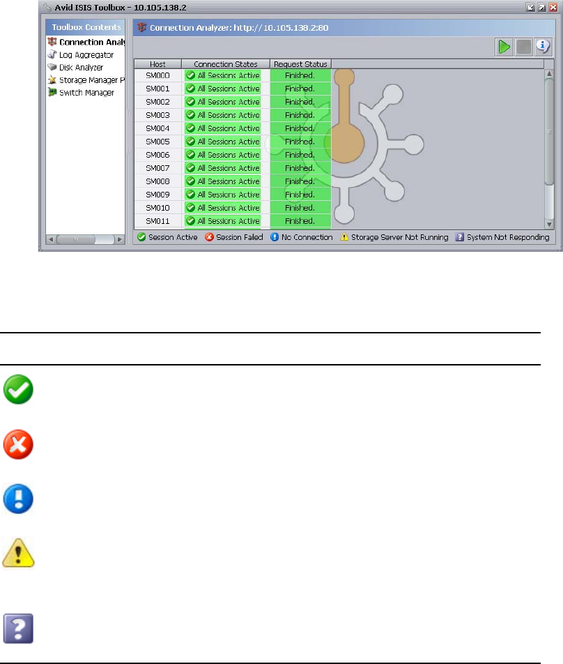
ISIS Toolbox Page
177
Connection Analyzer Tool
The Avid ISIS Connection Analyzer provides a quick look at the connection status of all
Storage Elements Managers in the shared storage network.
The Connection Analyzer displays connection status in a grid, using the following icons to
denote the status of each Storage Element:
Icon Label Status
Session Active Source Storage Manager has a session with the target Storage Manager
Session Failed Source Storage Manager does not have a session with the target
Storage Manager
No Connection Target Storage Manager is not communicating with the System Director
Storage Server
Not Running
Microserver failure—Failure in the request from the Agent to the
Storage Manager for session information—for example, a failed request
resulting from the Storage Manager not running or the Storage Manager
not servicing the request before it timed out
System Not
Responding
Communication failure—Unable to determine status—for example, the
Agent is not running or there is a network problem between the
Connection Analyzer tool and the Storage Manager

ISIS Toolbox Page
178
To open the Connection Analyzer and test the connection status of Storage Elements:
1. From the Management Console home page, click the ISIS Toolbox icon, located in the Tools
section.
If any site security warnings open, click Yes to accept the certificate. If you are not sure
about the security requirements of your shared storage network, see your system
administrator.
The Avid ISIS Toolbox opens.
2. Click Connection Analyzer from the left pane.
The Avid ISIS Connection Analyzer window opens and checks the connection status of all
Storage Managers in the network. The tool displays results in a color-coded grid.
If you place your pointer over a block in the grid, a tooltip indicates to which
Storage Elements the status applies. This is useful when you have more Storage Elements
than can be displayed in the dialog box and you need to use the scroll bars to view a specific
connection.
3. (Option) Click the Info button to display version information.
To update the status of Storage Elements:
1. Click the Start button to update the status of Storage Managers without reloading the entire
Storage Manager list from the System Director.
2. (Option) To stop the status update operation, do the following:
a. Click the Stop button.
A confirmation dialog appears.
b. Click the Yes button.
The update process stops and the main display returns to the previous result.
Log Aggregator Tool
The Avid ISIS Log Aggregator tool allows you to collect a full set of the event logs and system
statistics of a network, including active Storage Elements, Avid ISIS Switch Blades (ISIS 7000
only), and the System Director. You can select which information—from the network, the
System Director software, and Storage Elements — you want to collect in the log reports. This
provides you with a system record that you can use to view error and status messages. The logs
provide detailed status information that is especially useful to Avid Customer Support personnel
for monitoring system status during prolonged operations.
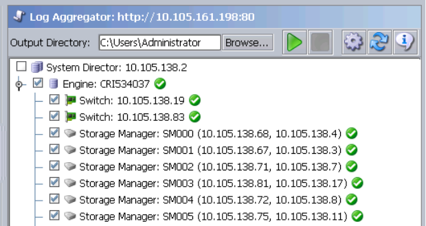
ISIS Toolbox Page
179
cDo not use the Avid ISIS Log Aggregator unless instructed to do so by Avid Customer
Support. Improper use could result in system downtime or degraded performance.
For more information on the Log Aggregator, see the following topics:
•“Using the Log Aggregator Tool” on page 179
•“Creating Aggregate Logs” on page 180
•“Viewing Aggregate Logs” on page 182
Using the Log Aggregator Tool
The Log Aggregator lists all components of the shared storage network in a tree view. You can
select events to log in two ways:
• You can view events for all components in the shared storage network by selecting all active
Avid ISIS systems in the Selection window (the highest level in the tree view).
• You can view events for any subset of components by selecting one or more entries in the
Selection window (at a level lower than the Avid ISIS Systems in the tree view).
nYou must run the Log Aggregator from a system with network access to the entire shared storage
network. Otherwise, the tool cannot collect logs for all systems connected to the network.
ISIS Toolbox Page
180
To open the Log Aggregator tool:
1. From the Management Console home page, Click the ISIS Toolbox icon, located in the
Tools section.
If any site security warnings open, click Yes to accept the certificate. If you are not sure
about the security requirements of your shared storage network, see your system
administrator.
The Avid ISIS Toolbox opens.
2. Click Log Aggregator in the left pane.
The Log Aggregator window opens.
To close the Log Aggregator:
1. Click the Close button.
A dialog box opens asking you to confirm that you want to quit the ISIS Toolbox.
2. Click Yes.
Creating Aggregate Logs
To use the Log Aggregator, you must have Administrative privileges and be logged into a system
with access to the shared storage network.
To create logs with the Log Aggregator tool:
1. Open the Log Aggregator tool. (For information on opening the Log Aggregator, see “Using
the Log Aggregator Tool” on page 179.)
2. In the Selection window, do one of the following:
tSelect all active Avid ISIS systems to view events from all components in the shared
storage network.
tSelect one or more components to view events from specific System Directors,
Storage Elements, and clients attached to the network.
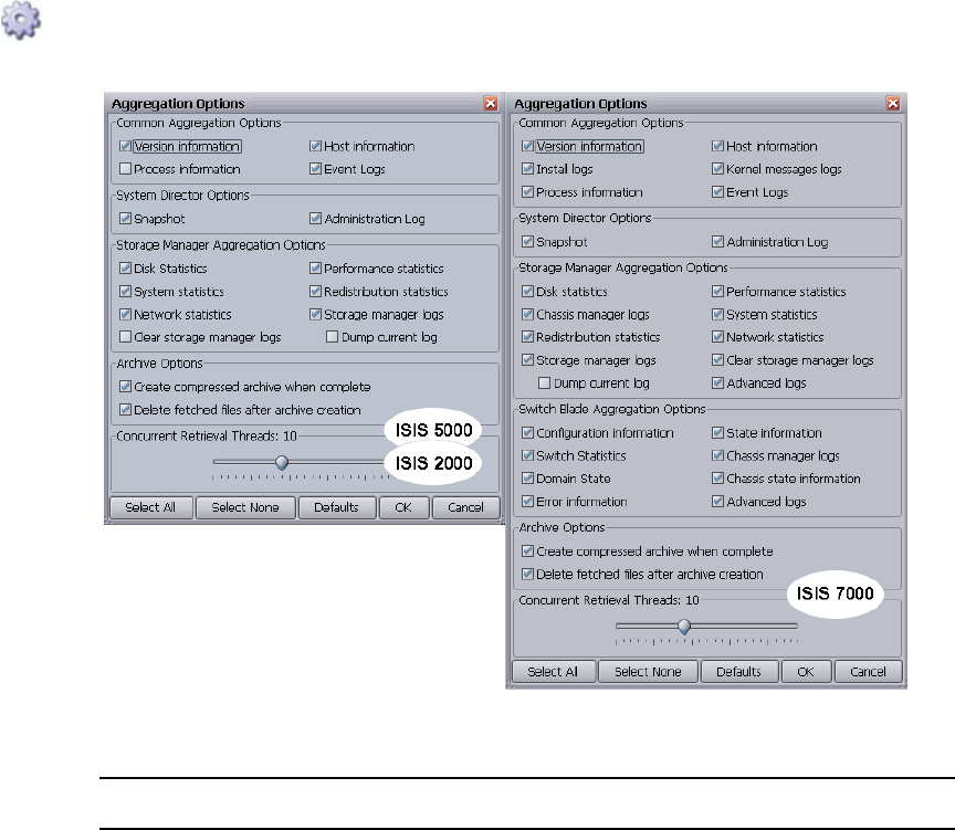
ISIS Toolbox Page
181
3. Click the Configure button.
The Aggregation Options dialog box opens.
4. Configure the following options to customize the data collected in the event logs:
Option Description
Common Aggregation
Options
Types of Windows logs or information
System Director Options Types of System Director logs or information
Storage Manager
Aggregation Options
Types of Storage Manager statistics or logs
Switch Blade Aggregation
Options (ISIS 7000 only)
Types of Storage Element statistics or logs
Archive Options Create a compressed archive file (Log Aggregator__date-time) and
whether to delete the fetched files after archive creation; the file is
saved to the directory specified in the Target Directory text field in the
Log Aggregator window

ISIS Toolbox Page
182
5. Click OK to close the Aggregator Options dialog box and return to the Log Aggregator.
6. (Option) In the Target Directory text section, click Browse to navigate to a directory for the
saved logs.
7. Click the Start button.
The progress bar indicates the status of the log aggregation. The Log Aggregator displays a
Success icon (green) or a Fail icon (red) for each system and component logged. You can
cancel the log aggregation process by clicking the Abort button.
Viewing Aggregate Logs
The Log Aggregator saves individual logs in a log directory called ISISLogs__date-time at the
location indicated in the Target Directory section in the Log Aggregator. Subdirectories include
separate logs for each component in the network for which you created logs. The Log
Aggregator also creates a compressed file containing all logs in the top-level folder
(aggregator_results.zip). You can forward this compressed file to your Avid representative if
requested by Avid Customer Support.
To view saved logs:
1. Navigate to the directory where the Log Aggregator saved the collected logs.
2. Double-click the file name of the log you want to view.
Disk Analyzer Tool
The Avid ISIS Disk Analyzer runs basic disk performance tests on your Storage Elements. The
tests include the following, which you can run in either Sequential or in Random access mode:
•Read test
• Write test
• Read/Write test
• Erase test
Concurrent Retrieval
Threads
Adjust the slider to maximize the use of resources in your system
when collecting logs. The default number of threads is 10. A lower
number uses fewer system resources but requires more time to
complete log aggregation; a higher number uses more resources but
completes the operation faster
Option (Continued) Description
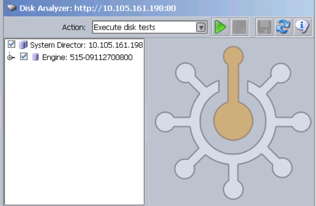
ISIS Toolbox Page
183
You can also use the Disk Analyzer to collect statistics on the status of Storage Elements and
network use, and redistribution actions, including statistics generated by Self-Monitoring,
Analysis, and by local Storage Element processes — for example, statistics on Long Command
Times (LCT).
You can run the Disk Analyzer on more than one Storage Element at a time; however, running
the tests might degrade performance on the shared storage network.
nYou should not run the Disk Analyzer unless instructed to do so by Avid Customer Support.
For information on running performance tests with the Disk Analyzer, see the following topics:
•“Opening the Disk Analyzer Tool” on page 183
•“Running Disk Analyzer Tool Tests” on page 184
Opening the Disk Analyzer Tool
To open the Disk Analyzer tool:
1. From the Management Console home page, click the ISIS Toolbox icon, located in the Tools
section.
If any site security warnings open, click Yes to accept the certificate. If you are not sure
about the security requirements of your shared storage network, see your system
administrator.
The Avid ISIS Toolbox opens.
2. Click Disk Analyzer from the left pane.
The Disk Analyzer window opens.
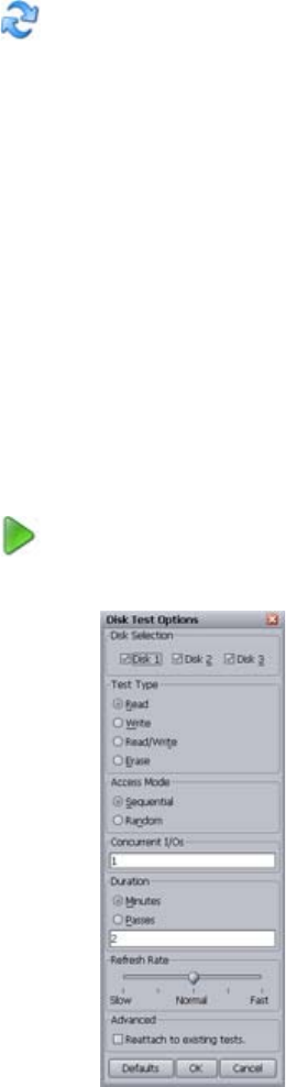
ISIS Toolbox Page
184
Updating the Disk Analyzer Tool Display
To update the display:
tClick the Refresh button.
Running Disk Analyzer Tool Tests
To run a test on the Disk Analyzer:
1. Open the Disk Analyzer.
2. Click the Disk Analyzer menu and select one of the following:
- Execute disk tests
- Collect disk statistics
- Collect network statistics
- Collect redistribution statistics
3. In the Selection window, do one of the following:
tSelect all active Avid ISIS systems to test all Storage Elements in the shared storage
network.
tSelect one or more Storage Elements to test specific components in the network.
4. Click the Start button.
If you selected Execute disk tests, the Disk Test Options dialog box opens.

ISIS Toolbox Page
185
5. Configure the appropriate options for the test you want to run.
6. Click OK to close the Disk Test Options dialog box and return to the Disk Analyzer.
Results of the test display in the Results area.
Saving Disk Analyzer Test Results
You can save the results of the Disk Analyzer tests to your local system. The test results are
saved in comma separated value (CSV) format.
To save the results of the Disk Analyzer tests:
1. Click the Save Results button.
The Save Results window opens.
2. Browse to the location on your local system where you want to save the test results and click
Save.
The test results are saved to the specified location.
Option Description
Disk Selection Which drive(s) in the selected Storage Elements to test
Test Type The type of test to be performed
Access Mode Perform sequential or random access test
Concurrent I/Os Number of input and output operations to run
concurrently
Duration Test duration in minutes or number of passes
Refresh Rate How often the test status is updated
Reattach to existing tests By default, starting a new test will abort any currently
running tests and clear any existing results. Select this
option to resume any currently running tests and retain
the results
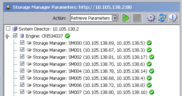
ISIS Toolbox Page
186
Storage Manager Parameters Tool
The Avid ISIS Storage Manager Parameters tool allows you to set and retrieve Storage Manager
logging and redistribution flags. This status information is useful to Avid Customer Support
personnel for monitoring system status during prolonged operations.
cDo not use the Avid ISIS Storage Manager unless instructed to do so by Avid Customer
Support. Improper use could result in system downtime or degraded performance.
For more information on the Storage Manager, see the following topics:
•“Using the Log Aggregator Tool” on page 179
•“Creating Aggregate Logs” on page 180
•“Viewing Aggregate Logs” on page 182
Using the Storage Manager Parameters
The Storage Manager lists all components of the shared storage network in a tree view. You can
select events to log in two ways:
• You can view events for all components in the shared storage network by selecting all active
Avid ISIS systems in the Selection window (the highest level in the tree view).
• You can view events for any subset of components by selecting one or more entries in the
Selection window (at a level lower than the Avid ISIS Systems in the tree view).
nYou must run the Storage Manager from a system with network access to the entire shared
storage network. Otherwise, the tool cannot collect logs for all systems connected to the network.
ISIS Toolbox Page
187
To open the Storage Manager Parameters:
1. From the Management Console home page, click the ISIS Toolbox icon, located in the Tools
section.
If any site security warnings open, click Yes to accept the certificate. If you are not sure
about the security requirements of your shared storage network, see your system
administrator.
The Avid ISIS Toolbox opens.
2. Click Storage Manager in the left pane.
The Storage Manager window opens.
To close the Storage Manager:
1. Click the Close button.
A dialog box opens asking you to confirm that you want to quit the ISIS Toolbox.
2. Click Yes.
Retrieve Storage Manager Flag Parameters
To use the Storage Manager, you must have Administrative privileges and be logged into a
system with access to the shared storage network.
To retrieve the Storage Manager Parameters:
1. Open the Storage Manager Parameters. (For information on opening the Storage Manager,
see “Using the Storage Manager Parameters” on page 186.)
2. In the Selection window, do one of the following:
tSelect all active Avid ISIS systems to view events from all components in the shared
storage network.
tSelect one or more Storage Manager to view events from specific System Director.
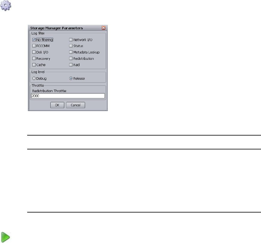
ISIS Toolbox Page
188
3. Click the Configure button.
The Storage Manager Parameters dialog box opens.
4. Configure the following options to retrieve data:
5. Click OK to close the Storage Manager Parameters dialog box.
6. Click the Start button.
The Storage Manager displays the retrieved information.
Option Description
No Filter Selects all of the parameters listed in the Storage Manager Parameters
window.
All other Storage Manager
Parameters
Allows you to select one or multiple parameters listed in the Storage
Manager Parameters window.
Log Level and Throttle Do not change the Log Level or Throttle setting unless instructed to do
so by Avid Customer Support. Improper use could result in system
downtime or degraded performance.
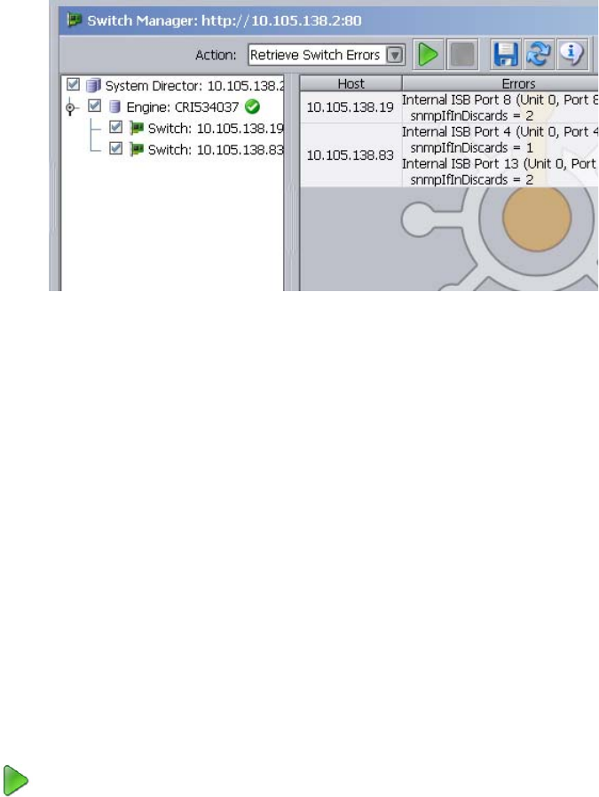
ISIS Toolbox Page
189
Switch Manager Tool (ISIS 7000 Only)
The Avid ISIS Switch Manager tool allows you to retrieve and save error messages and/or reset
the error count for any chassis switch (ISS or IXS).
To retrieve and save switch error messages:
1. Open the ISIS Management Console (see “Opening the Management Console” on page 18).
The Avid ISIS Home page opens.
2. Click the ISIS Toolbox icon from the Tools area.
If any Web site security warnings open, click Yes to accept the certificate. If you are not sure
about the security requirements of your media network, see your system administrator.
The Avid ISIS Toolbox opens.
3. Click Switch Manager in the left pane.
The Switch Manager window opens.
4. In the Switches area, do one of the following:
tSelect Avid ISIS Systems to retrieve error messages from all active switches in the
media network.
tSelect one or more switches to retrieve error messages from specific switches attached
to the network.
5. Choose Retrieve Switch Errors from the Action list.
6. Click the Start button.
The Status area displays the results of the retrieve operation.
7. (Option) To save retrieved error messages, do the following.

ISIS Toolbox Page
190
nThe results are saved in Comma Separated Values (.csv) format by default.
a. Click the Save Results button.
The Save Results dialog box opens.
b. Choose a location on your system where you want to save the results.
c. Type a file name into the File Name text field.
d. Click the Save button.
To reset the switch error count:
1. Open the ISIS Management Console (see “Opening the Management Console” on page 18).
The Avid ISIS Home page opens.
2. Click the ISIS Toolbox icon from the Tools area.
If any Web site security warnings open, click Yes to accept the certificate. If you are not sure
about the security requirements of your media network, see your system administrator.
The Avid ISIS Toolbox opens.
3. Click Switch Manager in the left pane.
The Switch Manager window opens.
4. In the Switches area, do one of the following:
tSelect Avid ISIS Systems to reset error counts from all active switches in the media
network.
tSelect one or more switches to reset error counts from specific switches attached to the
network.
5. Choose Retrieve Switch Errors from the Action list.
6. Click the Start button.
The Status area displays the results of the reset operation.
To close the Switch Manager:
1. Click the Close button.
A dialog box opens asking you to confirm that you want to quit the Switch Manager.
2. Click Yes.
Network Utilities Page
191
Network Utilities Page
The Network Utilities page provides you with the following standard utility tests:
• Ping—allows you to test the connection between a system in the shared storage network and
the System Director
• Traceroute—allows you to verify the path between a system in the shared storage network
and the System Director
• Network Statistics—displays network statistics
nYou must have Administrator privileges to run the utility tests.
To open the Network Utilities page:
1. From the Management Console home page, click the Network Utilities icon, located in the
Tools section.
The Network Utilities page opens.
2. Select Ping, Traceroute, or Network Statistics from the Command list.
3. Enter the network name or IP address of the target machine in the “Target name” field.
4. Click Submit to perform the command.
The results of the command are shown in the Results area.
Monitor Tool (ISIS 7000 Only)
The Monitor Tool provides detailed monitoring of all hardware components in the Avid ISIS
media network. The Monitor Tool displays overview information about the network hardware as
a graphical representation of the current configuration, so you can view the components remotely
to assess their functional status.
The Monitor Tool provides various views of the components in the media network and polls the
System Director at timed intervals to update network data. On the left is the Navigation panel,
which provides a tree view of the media network. On the right is the System panel, which
presents system hardware components in a graphical display. You can view the network
hardware at several levels: system, racks, chassis, or blades. At each level, the tool displays
indicators of the health of the component, usually as a graphical representation of the actual LED
state viewed on the component.
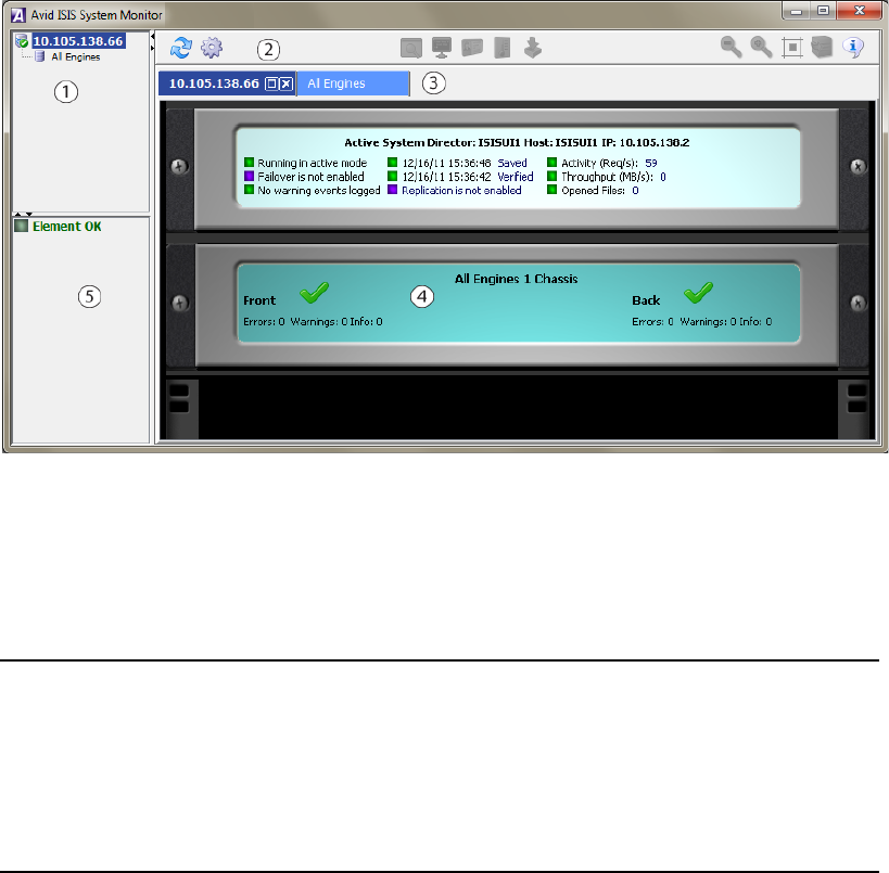
Monitor Tool (ISIS 7000 Only)
192
The Monitor Tool also provides information about the physical location of each component. For
example, the tool shows the chassis ID of each blade so that it can indicate the location of a
malfunctioning blade within a chassis. The Monitor Tool does not track how racks or chassis are
actually organized, but you can input site-specific data so that the tool can represent groupings of
components in a way that makes sense in relation to how a specific media network is organized.
Accessing the Monitor Tool
To open the Monitor Tool:
1. Open the ISIS Management Console (see “Opening the Management Console” on page 18).
2. Click the Monitoring Tool icon from the Tools area.
3. If any security warnings open, click Yes to accept the certificate. If you are not sure about
the security requirements of your media network, see your system administrator.
The Avid ISIS System Monitor tool opens.
1 Navigation panel—Provides a tree view of media network components
2 Tool bar—Perform various actions depending on the view
3 Tab bar—Manage system monitor windows
4 System panel—Presents system hardware components in a graphical display
5 Legend panel—displays summary of all status messages
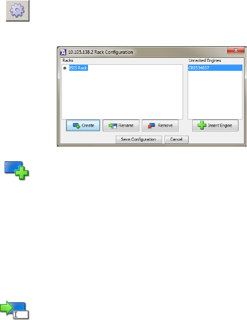
Monitor Tool (ISIS 7000 Only)
193
Configuring the Monitor Tool
By default the Monitor Tool shows all the Engines together in the same rack view regardless of
physical configuration. You can customize the view by creating “virtual” racks in the Monitor
Tool and populating them with Engines to reflect the layout of your physical rack system. You
can then save your customizations for use during subsequent sessions.
To create a rack or add a rack to the Racks list:
1. From the Avid ISIS System Monitor window, click the Configure button.
The Rack Configuration dialog box opens.
2. Click the Create New Rack button.
The New Rack dialog box opens.
3. Type a rack name, and click OK.
The new rack is added to your configuration and displays in the Racks list in the left pane of
the Rack Configuration dialog box.
4. (Option) Repeat this procedure to add additional racks.
To rename a rack:
1. Click to select the Rack you want to rename from the Racks list.
2. Click the Rename button.
The Rename Rack dialog box opens.
3. Type in the new Rack name and click OK.
The Rack name is changed.
To add one or more Engines to a rack:
1. Click to select the Rack to which you want to add Engines from the Racks list.
nWhen you create a new rack, it is selected by default.

Monitor Tool (ISIS 7000 Only)
194
2. Click to select one or more Engines from the Unracked Engines list on the right pane of the
Rack Configuration dialog box.
You can select multiple Engines using Shift-click and Ctrl-click. See “Filtering the Display”
on page 29 for more information on selecting multiple items.
3. Click the Insert Engine button.
The selected Engines are moved to the Racks list under the selected Rack.
To remove one or more Engines from a rack:
1. Click to select one or more Engines from the Racks list.
You can select multiple Engines using Shift-click and Ctrl-click. See “Filtering the Display”
on page 29 for more information on selecting multiple items.
2. Click the Remove button.
The selected Engine(s) are removed from the rack.
To remove a rack:
1. Click to select a Rack from the Racks list.
2. Click the Remove button.
The selected Rack is removed from the Racks list.
To save the configuration:
tClick the Save Configuration button.
To rearrange the placement of a chassis displayed in the Rack tab:
1. Click to select the chassis you want to move.
A yellow frame highlights the active chassis.
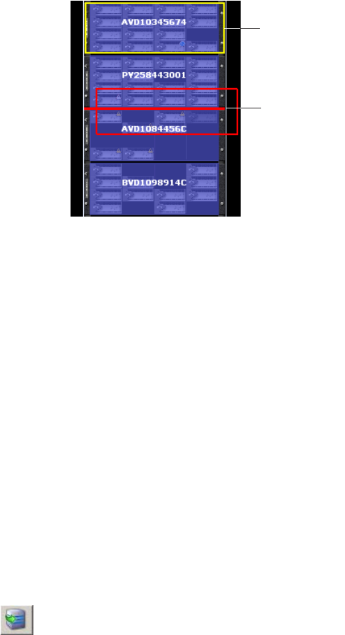
Monitor Tool (ISIS 7000 Only)
195
2. Drag and drop the chassis to a new location in the Avid ISIS System Monitor window. A red
insertion line appears when the chassis is moved to an appropriate position.
Viewing Information in the Monitor Tool
Once you have configured the Monitor Tool for your media network, you can use the tool’s
graphical interface to view the status of your hardware components and retrieve information
about its operation.
You can access the Avid ISIS Agents and view more information about Storage Elements and
chassis switches by right-clicking the component in the Monitor Tool and selecting the
appropriate IP address. For information on the Avid ISIS Agents, see “Understanding the Agent
Interface” on page 205 and “Understanding the Switch Agent Interface” on page 221.
To view information about the components of your media network:
1. Open the Monitor Tool (see “Accessing the Monitor Tool” on page 192).
2. Do one of the following to select the rack whose components you want to monitor:
tIn the Tree View pane, click the appropriate Rack element.
tClick the appropriate Rack element in the graphical Rack pane.
The Monitor Tool displays a graphical representation of the rack element.
3. (Option) To view the other panel of the rack (either front or back), do one of the following:
tClick the Rotate Rack View button to view the back panel of the rack.
tRight-click a component, and select Rotate Rack View.
The Monitor Tool displays the other panel of the selected rack. You can use the Rotate Rack
View button to switch between back and front views.
Active chassis
Red insertion
line
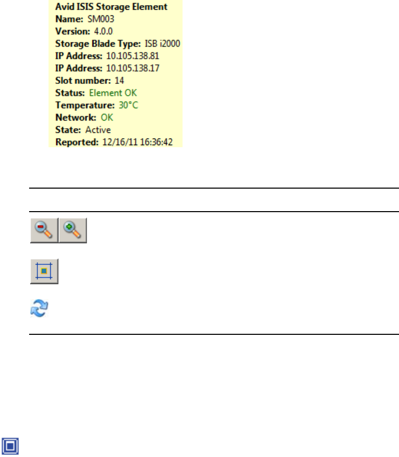
Monitor Tool (ISIS 7000 Only)
196
4. Move the mouse pointer over a component to view information about its status and
performance.
A tool tip window opens.
5. Use the following buttons to adjust your view of all components in the rack:
Displaying Rack Configurations in Separate Windows
You can detach any rack tab so you can view it in a separate window. This allows you to keep a
specific rack configuration visible while you configure other racks. You can also set the detached
display to keep it on top of any active window on your desktop.
To detach a rack tab:
tClick the Maximize button on the rack tab you want to display in a separate window.
Symbol Name Description
Zoom Out / Zoom In Zooms in or out on the rack components view.
Reset View Resets the zoom to the default for the window size.
Refresh Updates the rack component view.
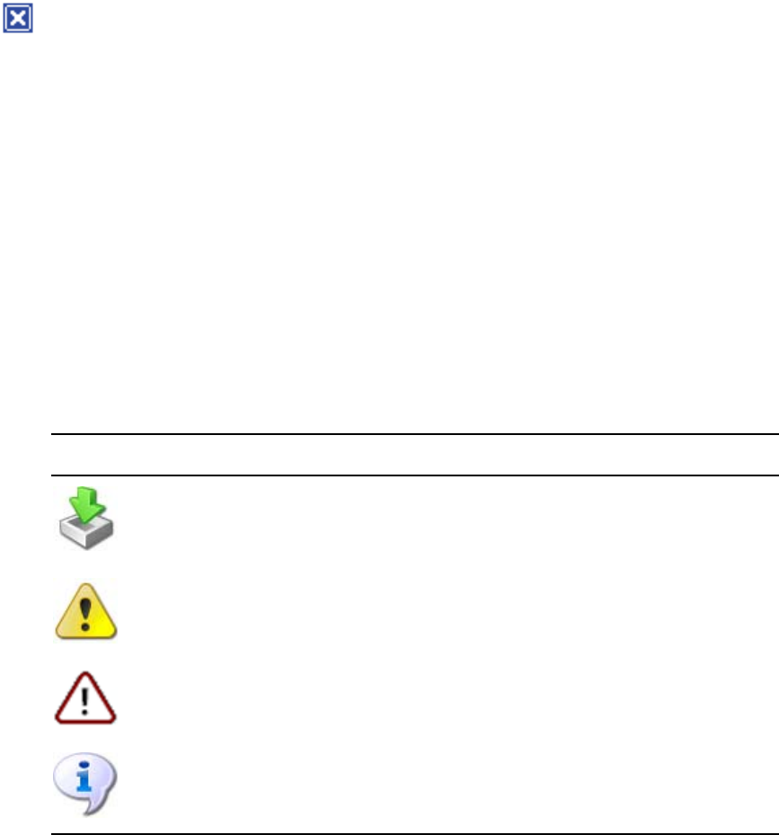
Monitor Tool (ISIS 7000 Only)
197
To return a detached rack tab to the Avid ISIS System Monitor window:
tClose the detached rack tab window. The tab will be restored to the Avid ISIS System
Monitor window.
To close a rack tab:
tClick the close button on the rack tab you want to close.
Understanding the Monitor Tool Views
The Monitor Tool allows you to select different views to see specific information about the
network or about an individual component.
Using System View
General View displays each of the Storage Elements, chassis switches, and power supplies in
your configuration. Elements flash gray if there is no communication between the System
Director and a rack — for instance, if an Avid ISIS Storage Blade (ISB) is rebooting. Elements
currently experiencing a failure appear grayed out. The Monitor Tool displays a Component
Missing icon for any empty Storage Element, chassis switch, or power supply slot that is empty.
In addition, the Monitor Tool displays the following symbols to indicate problems with the
Storage Elements.
Symbol Name Description
Upgrade Indicates the element is currently undergoing a software upgrade. For more
information on upgrade status, see “Using Upgrades View” on page 200.
Warning Indicates the element has returned a warning message — for example, the
Storage Element might be rectifying or redistributing files.
Error Indicates the element has experienced a failure — for example, a disk failure.
Info Indicates one or more information messages are available for the element.
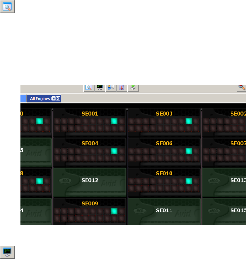
Monitor Tool (ISIS 7000 Only)
198
To see the System view:
1. Open the Monitor Tool (see “Accessing the Monitor Tool” on page 192).
2. Click the System View button.
Using Status Details View
In Status Details view, you can view comprehensive status details of each component in your
configuration. Status indicators appear if status information is currently associated with a
component. For a description of status indicators, see “Status Indicators” on page 198.
If no status information is associated with a component, the component appears green in Status
Details view.
To see the Status Details view:
tClick the Status Details View button.
Status Indicators
The Status Details view displays the following status information. You can toggle between front
and back views to see the status of Storage Elements, switches, and power supplies.
nNot all status indicators are available for each component.
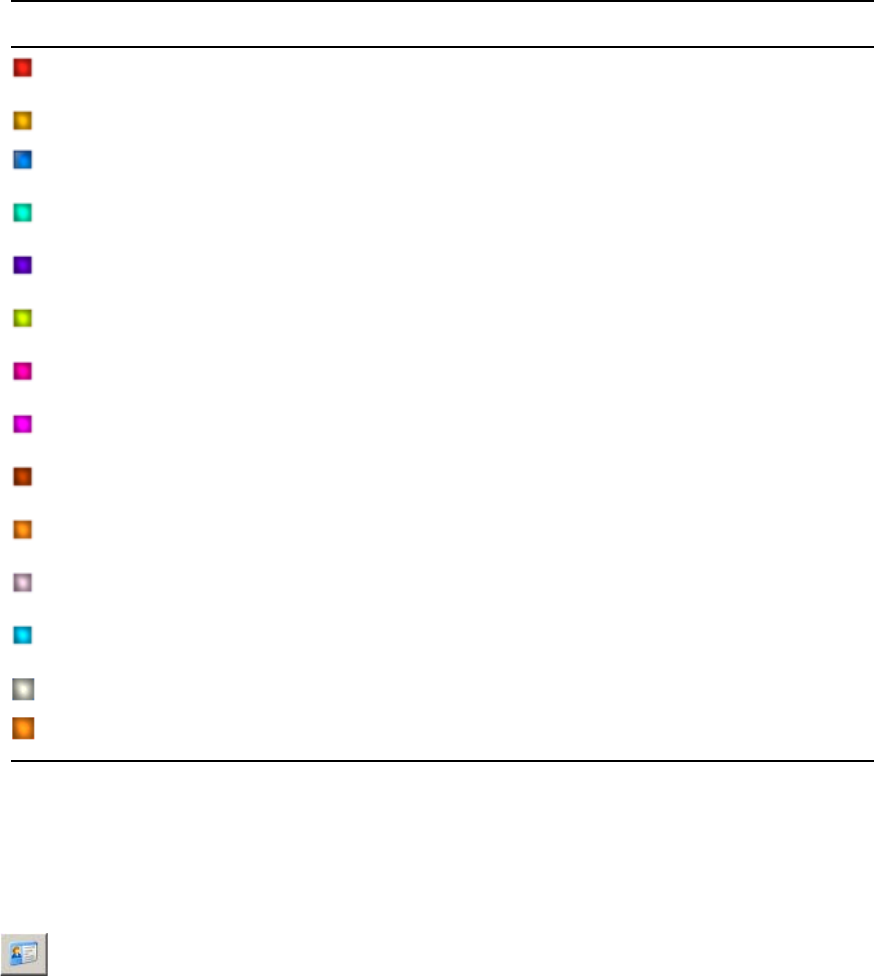
Monitor Tool (ISIS 7000 Only)
199
Using Blade Identification View
In Blade Identification view, you can view the names of each Storage Element in your
configuration.
To see the Blade Identification view:
tClick the Blades ID View button.
Status Details Information
Icon Description (Storage Elements) Description (switch) Description (power supply)
Connection error
Version mismatch Version mismatch
Installing in progress Installing in progress
Redistributing in progress
Rectifying files
Repairing mirrors
Disk failure Stack error
Diagnostic mode
Network degraded Trunking error
Disk degraded Chassis error
Memory error No power
Redistribution information available
Element offline
Link warning

Monitor Tool (ISIS 7000 Only)
200
Using Temperatures View
In Temperatures view, you can view the temperature status of each Storage Element in your
configuration. Temperatures view lists the temperature of each Storage Element, as well as a
color-coded marker to indicate its status:
• Green (Normal): the temperature of the Storage Element is under 60°C (140°F).
• Yellow (Warning): the temperature of the Storage Element is between 60° – 70°C
(140° – 158°F).
• Red (Critical): the temperature of the Storage Element exceeds 70°C (158°F).
To see Temperatures view:
tClick the Temperatures View button.
Using Upgrades View
In Upgrades view, you can view the upgrade status of each element in your configuration.
Upgrades view lists each Storage Element with a color-coded marker to indicate whether or not
it is being upgraded:
• Green: no upgrade is being installed.
• Blue: an upgrade is in progress.
• Orange: the upgrade installation failed.
• Yellow: the upgrade is waiting for components to complete installation before restarting
Upgrades view also highlights any mismatch between the version number of a component and
the rest of the components in the chassis. If a component was not upgraded when the rest of the
components in the chassis were upgraded, Upgrades view marks the component with a yellow
Version Mismatch indicator with red text.
To see Upgrades view:
tClick the Upgrades View button.

Agent Settings Page
201
Agent Settings Page
The Avid ISIS Management Console includes several tools for viewing the System Agent
statistics and configuration information, and for configuring advanced options.
nThese tools should not be used unless under the advice and supervision of Avid support
personnel.
• Agent Options is used to modify Agent configuration options.
• Agent Trace Setup is used to configure Agent trace settings for connections, HTTP requests,
SSL callbacks, and threads.
Monitoring Avid ISIS with SNMP
You can use your Network Management System (NMS) or Simple Network Management
Protocol (SNMP) management application to monitor ISIS-related system events on your
Avid ISIS System Director.
nAvid ISIS System Director supports unidirectional (read-only) SNMP communication only.
Bidirectional communication is currently not supported.
A MIB (Management Information Base) file is available in the following location on the System
Director:
D:\Program Files\Avid\ISIS System Director\ISIS.mib
You can import this MIB into your NMS so that you can monitor and manage Avid ISIS events.
For more information, see your NMS documentation. For a more detailed overview of the
Avid ISIS MIB, see “Avid ISIS SNMP MIB Reference” on page 241.
The following table lists the System Director events that can be monitored via SNMP:
Category Name Description
Product
ISIS_ProductName This variable shows the name of the ISIS
product line.
ISIS_Version This variable shows the version of the ISIS
install.
Status

Monitoring Avid ISIS with SNMP
202
ISIS_SystemDirectorState This variable shows the state of the System
Director.
• 0=Online
• 1=Offline
• 2=Standby
• 3=Unknown
ISIS_SystemDirectorStateString This variable shows the state of the System
Director in string format.
ISIS_CheckEventLog This variable shows whether the check event log
flag is set.
ISIS_WorkspaceRedistributingCount This variable shows the current number of
workspaces currently performing a
redistribution.
Performance
ISIS_MegabytesPerSecond This variable shows total megabytes per second
for all connected clients.
ISIS_ReadMegabytesPerSecond This variable shows total read megabytes per
second for all connected clients.
ISIS_WriteMegabytesPerSecond This variable shows total write megabytes per
second for all connected clients.
ISIS_MessagesPerSecond This variable shows the number of messages per
second the System Director is processing.
ISIS_OpenFiles This variable shows how many files are currently
open.
ISIS_ActiveClientCount This variable shows the active client count.
ISIS_MaximumClientCount This variable shows the maximum active client
count.
Usage
ISIS_HighestDiskUsedPercentage This variable shows the highest percent used
across all disks.
ISIS_TotalSystemMB This variable shows the total system megabytes.
Category Name Description (Continued)

Monitoring Avid ISIS with SNMP
203
ISIS_TotalAllocatedMB This variable shows the total allocated
megabytes. Allocated size is the sum of all the
workspace sizes.
ISIS_TotalUsedMB This variable shows the total system usage
across all workspaces.
ISIS_FileCount This variable shows the total number of files
across all workspaces.
ISIS_FolderCount This variable shows the number of folders across
all workspaces.
ISIS_WorkspaceCount This variable shows the total number of
workspaces.
Category Name Description (Continued)

AAvid ISIS Storage Manager Agent
This chapter contains the following topics:
•Opening the Avid ISIS Storage Manager Agent
•Understanding the Agent Interface
•Storage Manager Logging
You can view detailed information about all Storage Elements connected to the shared storage
network by using Avid ISIS Agents. The Agents run as a Web service on the Storage Elements,
and can be accessed during normal system operations from the ISIS Management Console.
nYou must have Administrator privileges to access the Agents.
Opening the Avid ISIS Storage Manager Agent
The Avid ISIS Storage Manager Agent runs within a web browser window. You can open the
Agent pages from either the Management Console or the ISIS Launch Pad.
The following are the default Agent passwords. For more information about changing the Agent
Administrator password, see “Changing the Agent Administrator Password (ISIS 5000 and 2000
only)” on page 210.
• ISIS 5000 Agent page password is: — is-admin
• ISIS 7000 and ISIS 2000 Agent page password is: — se-admin
nOn either ISIS system, you can also use the ISIS Administrator password to access the Agent
pages.
To open the Storage Manager Agent:
1. Do one of the following:
tFrom the Storage Managers tool, select an IP address from the IP Addresses panel of the
Details panel, and click the Info button. For more information, see “Viewing
Storage Manager Details” on page 44.
tFrom the Storage Elements tool, select an IP address from the IP Addresses panel of the
Details panel, and click the Info button. For more information, see “Storage Element
Details” on page 60.

Understanding the Agent Interface
205
tFrom the System Director desktop, click the “Launches the Agent Management Page”
button on the ISIS Launch Pad.” For more information, see “ISIS Launch Pad” on
page 71.
The Storage Manager Agent page opens.
2. Type the Administrator password into the password field and do one of the following:
tClick the arrow icon.
tPress the Enter key.
The Agent page opens.
Understanding the Agent Interface
This section contains the following topics:
•System Tab
•Managing Storage Manager Agent Profiles (ISIS 5000 Only)
•Changing the Agent Administrator Password (ISIS 5000 and 2000 only)
•Statistics Tab
•Tools Tab
•Logging Tab
•Advanced Tab
The Avid ISIS Agent, which you can run on the System Director or any Ethernet-attached client,
has a user interface where controls are grouped by function and are displayed by clicking the
appropriate buttons.
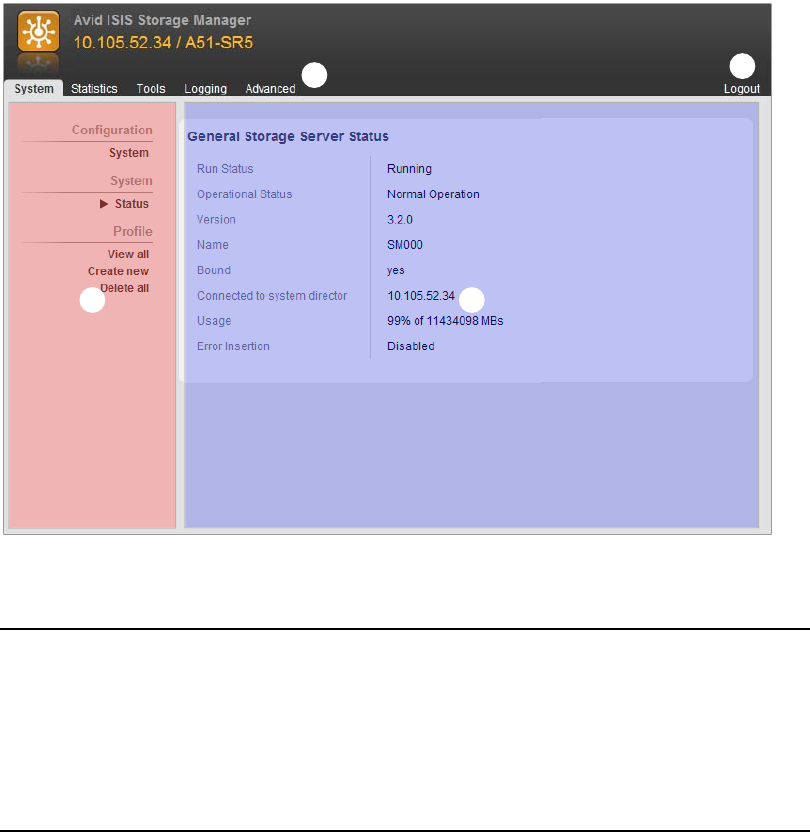
Understanding the Agent Interface
206
The following figure illustrates the Avid ISIS Storage Manager Agent with the System tab
selected. Depending on the ISIS product you have the options in each tab can vary.
The Agent is divided into the following areas:
System Tab
The System tab allows you to view configuration information for Storage Elements. The System
tab lists general information about component status, version, and usage. You can also change
the Management Console Administrator password and manage Storage Manager Agent profiles.
r
e
w
q
1 Command menu—Contains the options used for basic management functions.
2 Tabs—You can access different Command functions by clicking the tabs at the top of the Agent tool.
The System tab is selected by default.
3 Logout link
4 Main display area—Displays information about your network and allows you to configure
components.

Understanding the Agent Interface
207
The following table summarizes the information available in the System tab.
Menu Heading
ISIS
Infrastructure Description
Configuration System 5000 only Displays the following information:
• Host Name
• Nameservers
You can also change the Storage Manager Agent Administrator
password in this area; for more information, see “Changing the
Agent Administrator Password (ISIS 5000 and 2000 only)” on
page 210
Administration 2000 only You can also change the Storage Manager Agent Administrator
password in this area; for more information, see “Changing the
Agent Administrator Password (ISIS 5000 and 2000 only)” on
page 210
cNever use the Command Line to change the
Administrator’s password, doing so would prevent all
future log-ins.
System Status 7000/5000/2000 Displays the following information:
• Run Status
• Operational Status
•Version
•Name
• Bound
• Connected to System Director
•Usage
• Error Insertion

Understanding the Agent Interface
208
System
Information 2000 only
2000 only
2000 only
2000 only
2000 only
2000 only
2000 only
7000 only
7000 only
7000/5000
7000/5000
Displays the following information:
• Product
• Engine Controller Slot
• Storage Engine Serial Number
• Engine Controller Serial Number
• Storage Engine Part Number
• Engine Controller Part Number
• Storage Engine ID
•Slot
•Domain ID
•Board Serial Number
• Chassis Serial Number
Hardware
Status
5000 only Displays the following information:
• Status
• Product Part Number
•BMC
• System Temp (2)
•CPU Temp (2)
•Fan (5)
• System Drive
• Power Supply (2)
Profile View all 5000 Displays Agent profiles that have been created
Create new 5000 Clicking this link creates a new Agent profile, displays it on
screen, and adds the profile to the profiles list; for more
information, see “Creating New Storage Manager Agent
Profiles” on page 209
Delete this 5000 Clicking this link deletes the currently displayed Agent profile;
for more information, see “Deleting Agent Profiles” on page 210
nThis link appears only when an Agent profile is being
displayed
Menu Heading
ISIS
Infrastructure Description (Continued)

Understanding the Agent Interface
209
Managing Storage Manager Agent Profiles (ISIS 5000 Only)
Storage Manager Agent profiles contain information about the current versions of required
software, drivers, and hardware components that are installed on a Storage Server. You can view,
save, or delete profiles, but you cannot use the Profile tool to edit or modify the information.
Profiles are typically used by Avid Customer Support to help determine problems with installed
versions of the operating system, drivers, adapter boards, or firmware.
Creating New Storage Manager Agent Profiles
To create a new Storage Manager profile:
tFrom the Element Agent System tab, click “Create new” in the Profile section.
A new Element Agent profile is created and displayed on screen.
nThe profile is automatically saved, and can be viewed at a later time using the View all link. For
more information, see “Viewing Storage Manager Agent Profiles” on page 209.
Viewing Storage Manager Agent Profiles
Once you have created at least one profile, you can use the “View all” link to retrieve them at any
time.
To view profiles:
1. From the Element Agent System tab, click “View all” in the Profile section.
The profile viewer page opens.
2. Click Open for the profile that you want to view.
The selected profile opens.
Delete all 5000 Clicking this link deletes all Agent profiles; for more
information, see “Deleting Agent Profiles” on page 210
Versioning Show Version
Information
7000/2000 Displays current software version of the Storage Blade.
Menu Heading
ISIS
Infrastructure Description (Continued)
Understanding the Agent Interface
210
Deleting Agent Profiles
You can delete the currently displayed profile, any, or all saved profiles.
To delete the currently displayed profile:
1. Click “Delete this” from the left side menu.
A confirmation dialog opens.
2. Click Yes.
The currently displayed profile is deleted, and the “View all” page opens.
To delete any profile:
1. From the “View all” page, click Delete for the profile you want to delete.
A confirmation dialog opens.
2. Click Yes.
The selected profile is deleted.
To delete all profiles:
1. Click “Delete all” from the left menu.
A confirmation dialog opens.
2. Click OK.
All profiles are deleted.
Changing the Agent Administrator Password (ISIS 5000 and 2000 only)
By default the Agent Administrator password is set to “is-admin.” or “se-admin.” You should
change this password the first time you use the Agent page.
cNever use the Command Line to change the Administrator’s password, doing so would
prevent all future log-ins.
To change the Agent Administrator password:
1. Click System, under Configuration in the System tab.
2. In the Administrative Password section, do the following:
a. Type the current password in the “Current Password” field.
b. Type the new password in the “New Password” field.
c. Type the new password again in the “Confirm Password” field.
d. Click Submit.
The Agent Administrator password is changed to the new value.

Understanding the Agent Interface
211
Statistics Tab
You can use the Statistics tab to view basic information about your network or network
components. The Statistics tab provides you with statistics for the local system and for the
Storage Element.
The following table describes the information available in the Statistics tab.
Menu Heading
ISIS
Infrastructure Description
Local System General 7000/5000 Displays the basic properties of the Storage Element:
System Information:
• User Name (7000/5000 only)
• Computer Name
•OS Version
• Processor Type
• Number of Processors
• System Uptime
• Serial number (7000/2000 only)
Memory Information:
• Total Physical Memory Usage
• Total Physical Memory
• Available Physical Memory
• Total Page File
• Available Page File
Agent 7000/5000/2000 Displays detailed information Storage Elements:
• Agent Environment
• Agent Statistics
• Agent Configuration
• Browser Details
Storage
Manager
General 7000/5000/2000 Displays the basic properties of the Storage Manager
Displays Parity RAID Specific Statistics (ISIS 7000
only)
Disk 7000/5000/2000 Displays detailed information about disk or array
properties and disk use

Understanding the Agent Interface
212
Tools Tab
The Tools tab provides you with network tools and component utilities that generate basic
information on network functioning and low-level information on Storage Elements and
switches. These tools are used primarily by Avid Customer Support to diagnose problems with
components of the shared storage network.
The Tools tab for Storage Elements provides access to the Console Viewer. For information on
the Console Viewer, see “Using the Log Viewer Tool” on page 219.
The following table describes the tools available on the Tools tab.
Disk S.M.A.R.T. 7000 only Retrieves S.M.A.R.T. statistics for the Storage Manager
S.M.A.R.T. is an industry-standard reporting method.
Redistribution 7000/5000/2000 Displays information about the Storage Manager’s
status during current redistribution pass, and lists
Storage Managers that are having problems with the
current redistribution pass
Performance 7000/5000/2000 Displays information about the Storage Manager’s
performance
Network 7000/5000/2000 Displays information about the current network status
and connectivity between the Storage Manager and the
System Director
Menu Heading
ISIS
Infrastructure Description (Continued)
Tool Heading
ISIS
Infrastructure Description
General Tools •ping
• traceroute
• df (disk free)
or Disk Space
Usage
7000/5000/2000 Allow you to test the connections between components in
the shared storage network, to verify the path between
components, and to run the Linux df command
Blade Tools •i2cio
•istate
•ivers
• route show
7000 — all
headings
2000 — istate and
ivers headings
Allow you to run low-level tests to generate data to
identify problems with components in the shared storage
network

Understanding the Agent Interface
213
Logging Tab
The Logging tab provides a complete view of the logs of active Storage Elements and ISIS 7000
switches. The logs provide you with a system snapshot that you can use to view error and status
messages. The logs provide detailed status information that is especially useful to Avid
Customer Support personnel for monitoring system status during prolonged operations.
The following table describes the tools available on the Logging tab.
Storage Manager
Tools
Console viewer 7000/5000/2000 From the Storage Manager Agent, allows you to access
the Log Viewer tool (for information on the Log Viewer
tool, see “Using the Log Viewer Tool” on page 219)
Tool Heading
ISIS
Infrastructure Description (Continued)
Tool Heading
ISIS
Infrastructure Description
System Entries to view 7000/5000/2000 Specifies the number of entries to view. Specify 0 to
view all entries
Log to view 7000/5000/2000 Selects the log to view
Log to clear 7000/5000/2000 Selects the log to clear
Kernel Ring
Buffer
7000/2000 The Kernel Ring Buffer displays logs maintained by the
Linux kernel. These logs are used by Avid Customer
Support
Storage Manager Disable/Enable
logging
7000/5000/2000 Enables and disables the logging function for the
individual Storage Manager
Dump current log 7000/5000/2000 Saves the current log to a file and makes it available for
download
Log filter 7000/5000/2000 This option appears only when you disable logging.
Select the logs you want to capture. Select No filtering if
you want all the logs.
View available
logs
7000/5000/2000 Displays the logs that have been previously saved
Delete all logs 7000/5000/2000 Deletes all log files on the current Storage Element
Dump all peer
logs
7000/5000/2000 Saves the logs of all Storage Elements in the current
chassis to files

Understanding the Agent Interface
214
Advanced Tab
The Advanced tab contains configuration utilities, installation logs, and diagnostic tools used by
Avid Customer Support personnel used to troubleshoot problems with the shared storage
network. You can also use the Advanced tab in the ISIS 7000 to set the integrated switches back
to the factory defaults. This might be necessary to reset the IP addresses of system components if
your Avid ISIS system experiences network communication problems.
cUse of the tools in the Advanced tab can result in degraded system performance or loss of
data. The tools should be used by Avid Customer Support personnel or under Avid
Customer Support direction.
The following table describes the tools available on the Advanced tab.
Log fccomm
messages
7000/5000/2000 This option appears only when you Enable logging.
Select this option if you want to continue logging
fccomm messages while Storage Manager logging is
disabled.
Fccomm is a low-level network communication
protocol used by devices on the Shared Storage
network.
Storage Engine Dump engine log 2000 Saves the current Engine log to a file and makes it
available for download
Tool Heading
ISIS
Infrastructure Description (Continued)
Tool Heading
ISIS
Infrastructure Description
Local Host Reboot 7000/2000 Restarts the Storage Element. This function requires the
Administrator password.
ShutDown 2000 Sends a shutdown command the ISIS 2000 Engine. This
function requires the Administrator password. Allow
1 minute for the buffers to clear, then you can turn off the
power to the Engine.
Once this command has been sent, the Engine needs to be
power cycled before the Engine can turn back on (turn
both Engine power switches off and on).
Issue Shell
Command
7000/2000 Provides a text field to issue shell commands directly to
the Storage Element.

Understanding the Agent Interface
215
Agent Settings Configuration 7000/5000/2000 Add or change Storage Element configuration option
values.
Installation Logs *.log 7000/2000 Provides read-only access to Storage Element installation
logs.
Storage Manager Unbind 7000/5000/2000 Unbind a bound Storage Element. This function requires
the Administrator password.
Error Insertion 7000/5000/2000 Simulate various errors to diagnose Storage Manager.
Format Foreign
Disks
5000 If the System Status panel in the Management Console
reports a foreign disk or no spare. Use this function to
clear the foreign configuration and create a spare disk.
This function requires the Administrator password.
cResetting a disk is a destructive operation
which will permanently delete all data currently
stored on the disk.
Refresh RAID
Status
5000 The System Status panel in the Management Console
updates automatically but if you suspect that it is not
correct, you and click the Refresh RAID Status to force
an update of the status.
Log Disk
Configuration
5000 Click the Log Disk Configuration to create a detailed log
of the configuration of each LUN. On the ISIS 5000 this
is the makeup of each of the three RAID 5 LUNs. These
logs are written automatically on startup and whenever
the RAID LUN configuration is changed.
Files are located in the System Director — D:\Program
Files\Avid\ISIS Storage Manager\logs
Redistribution
Near Full
Threshold
7000/5000/2000 Displays the remaining free block count before the ISBs
start prioritizing moving blocks off of it over accepting
new data so that it doesn't get filled up and wedged before
it has enough time to delete older blocks. This typically
happens during full redistributions when the system is
greater than ~80% full. The default of 2000 blocks is
typically good for most situations.
This option gives Avid Customer Support the ability to
change the field when needed. This function requires the
Administrator password.
Tool Heading
ISIS
Infrastructure Description (Continued)

Storage Manager Logging
216
Storage Manager Logging
This section contains the following topics:
•Using Storage Manager Agent Logging
•Viewing Agent Event Logs
•Clearing Agent Event Logs
•Enabling and Disabling Storage Manager Logging
•Saving Logs
•Viewing and Deleting Saved Logs
•Using the Log Viewer Tool
Disk Tools Log Physical
Configuration
5000/2000 Logs the current configuration of the disks
Clear Foreign
Configuration
5000/2000 Clears the configuration on the disks and permanently
deletes all data from those disks. This function requires
the Administrator password.
RAID Diagnostics Verify RAID
Configuration
2000 Verifies the current configuration of the RAID set
(number of arrays and spares)
Show RAID
Configuration
2000 Displays the current configuration of the RAID set
(number of arrays and spares) with details of each disk
and slot
Show RAID
Status
2000 Displays details about the low level RAID status
RAID Tools Storage Manager
Rescan
2000 Refreshes the status of the RAID set in the Engine to the
System Director. The Status in the agent page System tab
is one of many places that is updated.
Repair
Configuration
2000 Attempts to do a non-destructive repair (currently restart)
of the RAID configuration (not to be confused with a
drive repair/rebuild).
Destructive RAID
Tools
Delete and
Recreate
2000 Recreates the RAID configuration on the disks and
permanently deletes all data from those disks. This
function requires the Administrator password.
Tool Heading
ISIS
Infrastructure Description (Continued)
Storage Manager Logging
217
The Logging tab provides a complete view of the logs of active Storage Managers. The logs
provide you with a system snapshot that you can use to view error and status messages. The logs
provide detailed status information that is especially useful to Avid Customer Support personnel
for monitoring system status during prolonged operations.
Using Storage Manager Agent Logging
You can use the Logging tab to view event logs and to clear existing logs. The Logging tab
contains two main sections:
• Options section—The left section allows you to select specific logging options to display
and to perform administrative tasks relating to the Agent logs.
• Logs section—The right section displays different types of events and information from the
network components.
To access Agent Logging functions:
1. Open the Agent. (For information on opening the Agent, see “Opening the Avid ISIS
Storage Manager Agent” on page 204.)
2. Click the Logging tab.
The Logging window opens.
Viewing Agent Event Logs
To view event logs:
1. Open the Agent. (For information on opening the Agent, see “Opening the Avid ISIS
Storage Manager Agent” on page 204.)
2. Click the Logging tab.
The Logging window opens.
3. In the Entries to view text box, type the number of events to display. The default is 100. If
you want to view all events, type “0” (zero) in the Entries to view text box.
4. Select a log from the “Log to view” list.
5. Click View.
The event log displays in the Logs area.
Clearing Agent Event Logs
You can clear the logs in any of the logging categories. This empties the log of all event entries
and resets the logging process.
Storage Manager Logging
218
To clear logs:
1. Open the Agent. (For information on opening the Agent, see “Opening the Avid ISIS
Storage Manager Agent” on page 204.)
2. Click the Logging tab.
The Logging window opens.
3. Select a log from the “Log to clear” list.
4. Click the Clear button.
5. Click OK.
The event log is cleared, and logging is reset to start recording new events.
Enabling and Disabling Storage Manager Logging
You can use the Logging window to start and stop the logging function of any Storage Manager.
Disabling logging for a Storage Manager does not affect system logging functions.
To stop the logging function:
tSelect “Disable logging” from the Storage Manager area.
- A confirmation message appears in the logging window.
- The “Disable logging” link changes to “Enable logging.”
To start the logging function:
tSelect “Enable logging” from the Storage Manager area.
- A confirmation message appears in the logging window.
- The “Enable logging” link changes to “Disable logging.”
Saving Logs
To save the log displayed in the Logs area, do one of the following:
tSelect “Dump current log” from the Storage Manager area.
tSelect “Dump all peer logs” from the Storage Manager area.
The current log or all peer logs are saved, and the Logging window displays a list of saved
logs.
Storage Manager Logging
219
Viewing and Deleting Saved Logs
To view a saved log:
1. Select “View available logs” from the Storage Manager area.
The Logs area displays a list of all available logs.
2. Locate the log you want to view, and click Download.
The Agent tool downloads the log to the specified directory on your local system.
nDepending on your browser configuration, the log file might display in the browser window
automatically.
3. Open the log file in a text editor.
To delete a saved log:
1. Select Storage Manager > View available logs.
The Logs area displays a list of all available logs.
2. Locate the log you want to delete, and click Delete.
A confirmation dialog box appears.
3. Click OK.
The log is deleted from the Agent system.
Using the Log Viewer Tool
The Log Viewer tool displays event information about Storage Managers. You cannot save the
information displayed in the Log Viewer tool, but you can copy it to a word processing
application, such as Notepad. You can also save event logs displayed in the Logging tab (see
“Saving Logs” on page 218). The information is used primarily by Avid Customer Support
personnel to help analyze problems with Storage Managers.
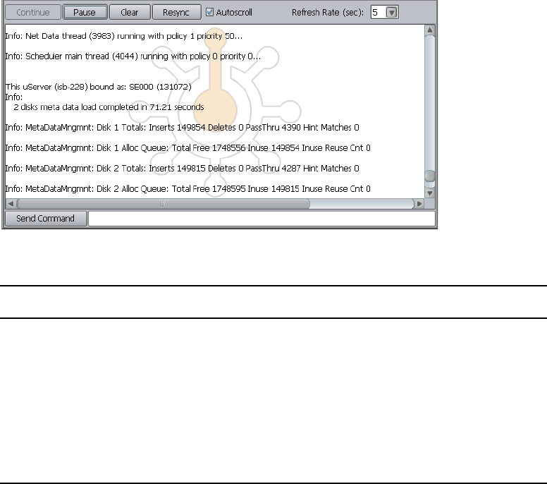
Storage Manager Logging
220
To monitor event information about Storage Managers:
1. Click the Tools tab, and then click Console viewer in the Storage Manager Tools section.
If any site security warnings open, click Yes to accept the certificate. If you are not sure
about the security requirements of your shared storage network, see your system
administrator.
The Log Viewer tool opens.
2. Select an option as described in the following table.
Option Description
Continue Resumes monitoring Storage Element events
Pause Stops monitoring Storage Element events
Clear Clears all event data from the Console View tool
Resync Restores previously-cleared event data to the Console View tool
Autoscroll Scrolls the display to the bottom of the page
Refresh Rate (sec) Sets the rate at which the Console View tool refreshes event data

BAvid ISIS 7000 Switch Blade Agent
You can view detailed information about all ISIS 7000 chassis switches connected to the media
network by using the Avid ISIS Switch Blade Agents. The Agents run as a Web service on the on
the chassis switches — Integrated Switch Blades (ISS) and ISIS Expansion Switch Blades (IXS).
You can access the Agents during installation and configuration procedures by attaching a laptop
to the Management port on the ISS or IXS, or you can access them during normal system
operations from the ISIS Management Console.
You can also access the Agents from the System Monitor tool. For more information, see
“Hardware Monitoring Service (ISIS 5000 Only)” on page 165.
nYou must have Administrator privileges to access the Agents.
Understanding the Switch Agent Interface
The Avid ISIS Agent, which you can run on the System Director or any Ethernet-attached client,
has a user interface where controls are grouped by function and are displayed by clicking the
appropriate buttons.
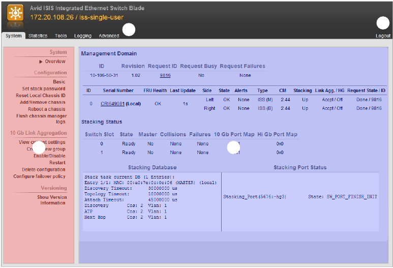
Understanding the Switch Agent Interface
222
The following figure illustrates the Avid ISIS Switch Blade Agent with the System tab selected.
The Agent is divided into the following areas:
r
e
w
q
1 Command menu—Contains the options used for basic management functions.
2 Tabs—You can access different Command functions by clicking the tabs at the top of the Agent
tool. The System tab is selected by default.
3 Logout link
4 Main display area—Displays information about your network and allows you to configure
components.
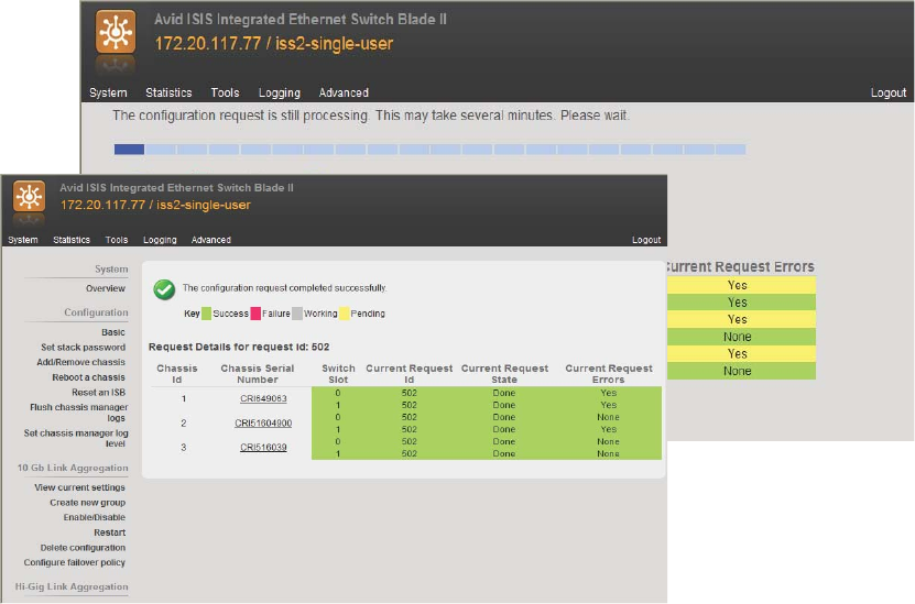
Understanding the Switch Agent Interface
223
When you access Switch Blade Agents and submit a request for an action — for example, when
you change the level of detail for chassis logs — a message tells you that the request was
successfully or unsuccessfully submitted, and the progress of the request is reported to the Main
display area.
System Tab
The System tab allows you to view configuration information for chassis switches. The System
tab lists general information about component status, version, and usage. You can use the System
tab to access information on any chassis switch (see “Viewing System Information for Individual
Chassis Switches” on page 228). You can also add or remove chassis. For information on adding
and removing network components, see the Avid ISIS 7000 Setup Guide.
You can also create, modify, and delete link aggregation configurations. Link aggregation,
sometimes called trunking, allows you to combine physical network links into a single logical
link for increased bandwidth. Link aggregation can increase the capacity and availability of the
communication channel between devices (both switches and clients) using existing Ethernet
technologies in such a way that two or more Ethernet connections can be combined to increase

Understanding the Switch Agent Interface
224
the bandwidth capability and to create resilient and redundant links. Link aggregation also
provides load-balancing where the processing and communications activity is distributed across
several links so that no single link is overwhelmed.
cLink aggregation is configured during setup and installation of your Avid ISIS media
network. Changing the configuration can disrupt all link aggregation for your network and
degrade system performance. Do not modify configuration values unless instructed to do so
by Avid Customer Support.
Configuration values are set during installation and are displayed in the System tab. By default,
the System tab displays general status information about the Storage Element.
The following table summarizes the information available in the System tab:
Menu Option Description
System Overview Displays a snapshot view of the status of switches and
information about the stacking state and Management Domain ID
number of the network chassis.
Configuration Basic Displays basic setup and configuration information about a
chassis switch.
Changing configuration IP addresses can affect network
connectivity.
The Basic option also allows you to set the date and time on a
chassis switch. This resets the date and time for all Storage
Elements in the chassis as well. For more information, see
“Setting Chassis Time” on page 229.
Set stack password Allows you to change the password for a chassis stack (maximum
of 8 characters). Changing the stack password affects all
connected Storage Elements and chassis in the stack.
Add/Remove
chassis
Allows you to add a chassis to or remove a chassis from the
network. For more information on adding and removing chassis,
see the Avid ISIS 7000 Setup Guide.
Reboot a chassis Allows you to reboot all Storage Elements and switches in a
chassis at one time.
Flush chassis
manager logs
Allows you to dump all current chassis logs to the \var\log
directory on the Storage Blades.

Understanding the Switch Agent Interface
225
Set chassis
manager log level
Allows you to set the level of detail collected in chassis logs:
•Off
• Normal
• Verbose
The Chassis Manager — the application running on the switch —
maintains logs and periodically collects them in a compressed
file.
10 Gb Link
Aggregation
View current
settings
Displays the current configuration used for link aggregation,
including the link type and the chassis port map
Create new group Allows you to define a new link aggregation group.
Link aggregation is configured during setup and installation of
your Avid ISIS 7000 media network. Changing the configuration
can disrupt all link aggregation for your network and degrade
system performance. Do not modify configuration values unless
instructed to do so by Avid Customer Support.
Enable/Disable Lists the network link aggregation configurations for the chassis
and allows you to enable or disable them.
Enabling or disabling link aggregation affects all configurations
in the network.
Restart Lists the network link aggregation configurations for the chassis
and allows you to restart them.
Restarting link aggregation stops all configurations in the network
and restarts them.
Delete
configuration
Allows you to delete all of the current link aggregation
configurations for your network.
Configure failover
policy
Allows you to enable or disable failover for all current link
aggregation configurations for your network.
Versioning Show Version
Information
Displays current software version of the component.
Menu Option Description (Continued)

Understanding the Switch Agent Interface
226
Statistics Tab
You can use the Statistics tab to view basic information about your network or network
components. The Statistics tab provides you with statistics for the local system and for the
switch.
The following table describes the information available in the Statistics tab:
Tools Tab
The Tools tab provides you with network tools and component utilities that generate basic
information on network functioning and low-level information on switches. These tools are used
primarily by Avid Customer Support to diagnose problems with components of the media
network.
The following table describes the tools available on the Tools tab:
Type Description
Local System • General
•Network
• Agent
Displays detailed information about the chassis, including
its components, the status of each part of the switch, and
stacking information
Port Status • View by chip
• View by function
Displays information about port status grouped either by
chip (matching the physical location of the port on the
switch) or by function (for example, stacking ports or
external client ports)
Port Errors: • View by chip
• View by function
• Reset all error counts
Lists port errors grouped either by chip (matching the
physical location of the port on the switch) or by function
(for example, stacking ports or external client ports); also
allows you to clear all error counts
Tool Description
General Tools • ping
• traceroute
• df (disk free)
Allow you to test the connections between components in the
media network, to verify the path between components, and
to run the Linux df command
Blade Tools • i2cio
•istate
•ivers
• route show
Allow you to run low-level tests to generate data to identify
problems with components in the media network

Understanding the Switch Agent Interface
227
Logging Tab
The Logging tab provides a complete view of the logs of active switches. The logs provide you
with a system snapshot that you can use to view error and status messages. The logs provide
detailed status information that is especially useful to Avid Customer Support personnel for
monitoring system status during prolonged operations.
The following table describes the tools available on the Logging tab for switches:
Advanced Tab
The Advanced tab contains configuration utilities, installation logs, and diagnostic tools used by
Avid Customer Support personnel used to troubleshoot problems with the media network. You
can also use the Advanced tab to set the integrated switches back to the factory defaults. This
might be necessary to reset the IP addresses of system components if your Avid ISIS system
experiences network communication problems.
cUse of the tools in the Advanced tab can result in degraded system performance or loss of
data. The tools should be used by Avid Customer Support personnel or under Avid
Customer Support direction.
The following table describes the tools available on the Advanced tab for switches:
Tool Description
System Entries to view Specifies the number of entries to view. Specify 0 to view all
entries.
Log to view Selects the log to view.
Log to clear Selects the log to clear.
Kernel Ring Buffer The Kernel Ring Buffer displays logs maintained by the
Linux kernel. These logs are used by Avid Customer
Support.
Tool Description
Local Host Reboot Reboots the switch.
Issue shell command Provides a text field to issue shell commands directly to the
switch.
Agent Settings Configuration Add or change switch configuration option values.
Installation Logs Provides read-only access to switch installation logs.

Viewing System Information for Individual Chassis Switches
228
Viewing System Information for Individual Chassis
Switches
When you log in to a selected ISS or IXS, you can use the System tab of the Switch Blade Agent
to access information about any switch, not just the selected one.
To view system information for a chassis switch:
1. Open the Switch Blade Agent (see “Avid ISIS 7000 Switch Blade Agent” on page 221).
2. Click the System tab if it is not already selected.
The System window opens.
3. In the Management Domain area, click a switch listed in the Serial Number column.
The Agent displays information for the switch in the Main display area.
Switch Blade Reboot an ISB Restart the selected Storage Element (ISB).
Reset to factory
defaults
Reset the chassis to factory default settings; for more
information, see “Resetting an Avid ISIS Engine to Factory
Defaults” on page 230.
Management port
configuration
Change the network settings for the Switch Blade
management port.
Access configuration Set local or remote access to the switch.
Local Driver
Diagnostics
Runs local switch driver diagnostic tests and display the
results.
Switch Infrastructure
Diagnostics
Run system level diagnostic tests; for more information, see
“Switch Infrastructure Diagnostics” on page 231.
Restart Chassis
Manager
Restart the chassis manager software.
Set chassis manager
log level
Allows you to set the level of detail collected in chassis logs:
•Off
• Normal
• Verbose
The Chassis Manager — the application running on the
switch — maintains logs and periodically collects them in a
compressed file.
Normal is selected by default.
Tool Description (Continued)
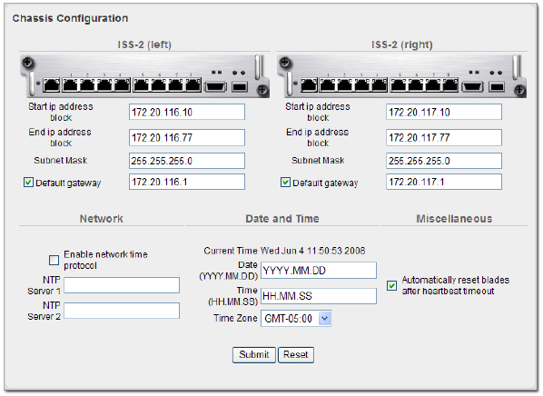
Setting Chassis Time
229
Setting Chassis Time
You can set the time for all Storage Elements connected to your chassis switch by using the
Switch Blade Agent. You can also use a Network Time Protocol (NTP) server to establish the
time for your system. Setting chassis time synchronizes the time for all Storage Elements and, in
systems with multiple chassis, on all switches.
nOnly make changes to the settings listed in this procedure. Do not make changes to any other
settings unless instructed to do so by qualified Avid support personnel.
To set the time for a chassis:
1. Open the Switch Blade Agent (see “Avid ISIS 7000 Switch Blade Agent” on page 221).
2. Click the System tab if it is not already selected.
The System window opens.
3. Click Basic in the Configuration area.
The Chassis Configuration dialog box opens.
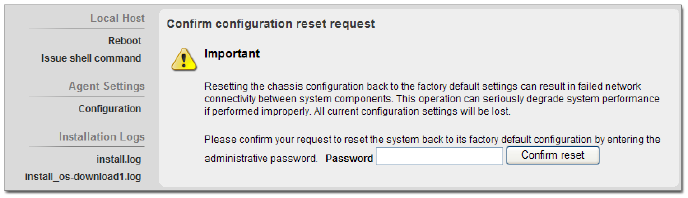
Resetting an Avid ISIS Engine to Factory Defaults
230
4. Do one of the following:
tTo configure your system to use NTP to synchronize Storage Elements with a network
reference, select Enable network time protocol, and then type the IP address of a
primary NTP server. You can also type the IP address of a secondary NTP server.
tTo set the time for a chassis manually, type the date and time in the Date and Time text
boxes, and then select a time zone from the Time Zone menu.
5. Click the Submit button.
Resetting an Avid ISIS Engine to Factory Defaults
You can set the integrated switches back to the factory defaults. Resetting your configuration,
including resetting the IP addresses of system components if your Avid ISIS system, can help
correct some network communication problems.
cResetting switch configuration can lead to failed connectivity in your ISIS system and
degrade performance. You should only reset your system if directed to by Avid Customer
Support personnel or under Avid Customer Support direction.
To reset an Avid ISIS Engine to its factory defaults:
1. Open the Switch Blade Agent for the Engine you want to reset. (For information on opening
the Agent, see “Avid ISIS 7000 Switch Blade Agent” on page 221.)
The Avid ISIS Integrated Ethernet Switch Blade Agent opens.
2. Click the Advanced tab.
The Advanced window opens.
3. Select “Reset to factory defaults” from the Switch Blade area.
A confirmation dialog box opens.
4. Type the Administrator password for your Avid ISIS system, and click Confirm reset.
The chassis switch configuration is reset to its factory defaults.
Switch Infrastructure Diagnostics
231
Switch Infrastructure Diagnostics
Avid ISIS supports system level diagnostics for every Avid ISIS switch from one location. The
diagnostics organize results and provides a report of problems with the switch.
The Switch Diagnostics test does not fix diagnosed problems; instead, it looks for problems and
provides clues as to the root cause. There are circumstances where the diagnostics can point to
what the problem might be, where the problem is located, or how to address the problem. There
are also error cases where the diagnostics cannot determine the cause of the problem, and the test
only reports relevant data for further analysis.
The diagnostic tests are organized into separate groupings. Each group investigates the switch in
different ways to look for possible problems. If you are unsure if you have a problem or where a
problem is, select all the test groups to get a more complete picture of the system's health. Each
test exists in only one group. The following sections describe how the tests are arranged within
the groups.
Stacking
The Stacking test group looks for symptoms that might indicate a problem with switch stack
health. Run this group of tests if you think a switch is not properly stacked, or if you are having
trouble with traffic flow on a particular switch.
Stack MAC Addresses
This is a report of MAC addresses for all Layer 2 visible switches in the stack from the reporting
switch’s perspective.
When the number of switches reported here are less than the number of switches reported by the
Stack Serial Numbers Test, this indicates that there could be problems reaching a switch that is
supposed to be part of the stack. Sometimes this information can be verified by a failure in the
Ping Stack Test. Or, if there is an extra switch listed in Stack Mac Addresses, it could mean that
a switch is visible that is not yet part of the stack and may need to be added.
State Machine
When switches connect to each other to form a stack, they go through a state machine process. If
the two switches have successfully completed their state machine process, they both reconcile to
state STACKED. Switch Diagnostics will report any switches that have not reconciled to this
state.
Switch Infrastructure Diagnostics
232
nIf Diagnostics is run immediately after connecting two switches together, then those switches
might still be going through the normal state machine process and might not yet be reconciled.
So, if Diagnostics is reporting an error in the State Machine Test, and the two switches were just
connected, try waiting about 5 minutes and run Diagnostics again.
If there are problems reported in the State Machine Test, there could be a few reasons for this.
• A Stack Collision would prevent the State Machines from reconciling successfully. Check
the results of the Collision Test to check for this.
• Otherwise, if another error has occurred during the State Machine Test, the process can be
restarted by disconnecting the stacking cable, and then re-connecting it. If the error does not
clear up after re-connecting the cable, then reboot the switch. If the error still does not clear
up, reboot both switches on either side of the stacking cable. Finally, try to reboot all
switches on that side of the stack.
Stack Serial Numbers
This is a report of the serial numbers of switches that are expected to be part of the stack from the
reporting switch’s perspective.
When the switches reported here are not the same as the switches reported by the Stack MAC
Addresses Test, this indicates that there could be problems reaching a switch that is supposed to
be part of the stack. Sometimes this information can be verified by a failure in the Ping Stack
Test.
The test will also report two chassis serial numbers with the same chassis id (think of this as an
index). This could indicate a collision.
Module Assignment
This test makes sure that all switches have been assigned Module ids correctly. This information
is necessary for proper switch communication. If a problem is reported, a reboot is the only
action that might clear it up. If the problem persists, contact Avid Personnel for additional help.
Collision
One common problem is a collision. This means that there are two switches with some
configuration information that is conflicting. This can happen when connecting a new switch to a
stack that has an IP address or chassis id that conflicts with a switch that is already in the stack.
Performing an “Add” from a switch that is already a part of the stack will remedy this collision,
and configure the new switch with non-conflicting information.
Switch Infrastructure Diagnostics
233
Performance
Link Aggregation Configuration
This test checks that Link Aggregation Configuration information is consistent among different
processes in the switch. If there is a problem reported here, try configuring link aggregation
again through the switch Agent web page.
Each port that is a member of a link aggregation group will also be checked to make sure that the
link is up.
Link Aggregation Load Balancing
This test is marked informational. Therefore, no determination of PASS/WARN or FAILED will
be made regarding the test result. In order to provide complete Link Aggregation Load Balancing
results for the entire system, it is necessary that every switch that is a member of a link
aggregation group reports information that is consistent with other switches in the system. If data
is not consistent, or a result from a switch is missing, then the total data transmitted and received
for all link aggregation groups cannot be determined. Review the data displayed carefully, and
make sure that:
• The data transmitted and received should be balanced between all port members of the link
aggregation group. If system results are complete, then each port will report its percentage of
data transmitted and received with regard to the total amount of data transmitted and
received for that link aggregation group.
• If system results are not complete, then make sure other issues reported by Switch
Diagnostics are remedied, and run Switch Diagnostics again.
Keep in mind how long link aggregation has been configured and how much load the system has
been under. If link aggregation was just configured very recently, and there has not been much
data load on the system, then the data reported may not provide you with applicable information.
Make sure the system has been under load, and then run Diagnostics again to capture a new load
balancing report.
Also, if one of the link aggregated port members has been down previously, then keep in mind
that the data transmitted and received on this port will always be less than other group members
(depending on how long this link was down). The data reported is a total of all packets sent and
received on this port since the last time Switch Diagnostics was run.
The next time Diagnostics is run, the load balancing values will be cleared, so Download the
Diagnostics results before running Diagnostics again in order for Avid Personnel to better
analyze the situation.
Switch Infrastructure Diagnostics
234
Counters
Counters and Registers
When reviewing this data, it is important to keep in mind the last time these values were reset.
Counters and incrementing Register values get reset every time the switch reboots or Diagnostics
is run.
nSome Register values under the “Registers” column cannot be cleared by Switch Diagnostics.
These values can only be reset by performing a reboot of the switch.
So, if the switch has been running for several months without running Diagnostics, then some of
these values may get quite high, and still mean the system is healthy. Or, a spike of packet drops
may have occurred several weeks in the past – so the values reported are high, but the network
may have since cleared up. If values reported by Diagnostics seem suspect, and the system is still
under data load, then try waiting a few minutes***, and run Diagnostics again. If the test still
flags WARN or FAILED for values reported, then contact Avid Personnel for additional help on
what these values may indicate.
nThe time to wait depends on how much system load is traveling through the switches, network
configuration, how many clients are connected, etc.
Remember that the next time Diagnostics is run, the counter and register values will be cleared,
so download the Diagnostics results before running Diagnostics again in order for Avid
Personnel to better analyze the situation.
Connectivity
Default Gateway
If the gateway cannot be reached by ping, then there could be several reasons for this. Be sure to
check the following:
• Is the gateway up and running?
• If there are switches between the storage system and the gateway, verify that every switch is
running successfully and properly configured to allow communication to the gateway from
the storage system.
• Also, if there are switches between the storage system and the gateway, verify that the 10G
link between the storage system and the switch has link (Port Link Information test) and is
not dropping packets (Counters and Registers).
Switch Infrastructure Diagnostics
235
Ping Storage Blades
If a Storage Blade is not reachable by ping, make sure that the Storage Blade is not pulled out of
its slot. If the Storage Blade looks to be seated, try reseating it. If the Storage Blade is still
unreachable, try moving it to a different slot. If the LED lights up on the Storage Blade, then also
check the Intermittent Link test for a possible intermittent link, and Counters and Registers for
error statistics.
Ping Stack
If a member of the stack is not reachable, check first to make sure the stacking cable to the
problem switch is plugged in and has link at both ends. Check Hardware tests to be sure that the
stacking link is not running at the wrong speed or suspected of having an intermittent link. Also,
check test results in the Stacking test group in case there was a stacking error. Lastly, make sure
Counters and Registers do not indicate errors have occurred on this stack port.
Hardware
Intermittent Link
An intermittent link is reported if the number of link ups or link downs on a port exceeds a
predefined threshold. Keep the following in mind when viewing this report for the port that is
reporting a possible intermittent link:
• Have you unplugged and plugged in a cable to this port several times since the last time
Switch Diagnostics was run?
• If the port is for a Storage Blade, have you reseated this Storage Blade several times since
the last time Switch Diagnostics was run? Has the Storage Blade rebooted several times
since the last time Switch Diagnostics was run?
• If the port is for a client, have you rebooted this client several times since the last time
Switch Diagnostics was run?
If you answered yes to any of the above, then these results do not necessarily indicate a hardware
problem with the reported port or link. If there does not seem to be an explanation for the
numerous link ups and link downs reported, then there could possibly be a hardware problem
with the switch port, the cable, or the port on the other end (not the switch).
Intermittent Link statistics are cleared each time Diagnostics is run. So, if you want to keep these
results, remember to Download the Diagnostics results before running Diagnostics again.
Switch Infrastructure Diagnostics
236
Link Status
Whenever possible, Switch Diagnostics will try to alert the user to ports that are down if it is
expected that these ports are in use. All Storage Blades and all ports that are members of Link
Aggregation groups are expected to have link. If they do not, they will be flagged within Switch
Diagnostics as suspect. See Port Link Information for status on other ports.
Port Speeds
By default, client ports will not negotiate to any speed except 1000Mbps. Therefore, by default,
if any client port was configured to run at a speed other than 1000Mbps, then link would not be
established. If any client port is reporting a speed that is not 1000Mbps, then it is possible that
the default behavior was explicitly overridden. It is then necessary to execute 2 steps:
• Set the Right Speed: Configure the Client to run at 1000Mbps
• Return to Default: To clear this override, and return to the default behavior, reboot the switch
Port Link Information
This test is marked informational. Therefore, no determination of PASS/WARN or FAILED will
be made regarding the test result. This information is best used to compare a known topology
(i.e. what stacking, 10G and client ports should be connected and working) to the displayed
system link status for each reporting switch.
• Client Ports—Switch Diagnostics cannot determine whether a client port should have link or
not – as this is specific to each user’s setup. Therefore, use this information to make sure that
the client ports in use are reporting link UP status as expected. Also, be aware that the switch
will not negotiate to any speed except 1000Mbps on client ports. So, if a client is configured
to run at a different speed, then the link will not be successfully established and will be
reported as DOWN.
• Stacking Ports—Switch Diagnostics cannot determine in all cases whether a stack port
should have link or not. Use this information to make sure that the stack ports in use are
reporting link UP status as expected.
• 10G Ports—Unless a 10G Port is part of a Link Aggregation Group, Switch Diagnostics
cannot determine if this port should have link or not. Use this information to make sure that
the 10G ports in use are reporting link UP status as expected.
Advanced
Unicast Bitmaps
This information can indicate if there are errors with the way traffic is mapped to stack ports.
Avid Personnel will review this information.
Switch Infrastructure Diagnostics
237
Environment
Installation Errors
Switch Diagnostics will indicate if there were any installation failures reported on the switches.
If an installation failure is reported, then navigate to the Agent page on the switch reporting the
failure and investigate the installation logs.
Processes
There are several important processes that need to run in order to achieve and maintain both
switch and stack health. Switch Diagnostics will report any processes in a suspect state.
Running Switch Infrastructure Diagnostics
The diagnostics should not be used during a critical time in your production. Some tests burden
system bandwidth and resources.
To access Switch Infrastructure Diagnostics:
1. In the Avid ISIS Switch Blade Agent, click the Advanced tab, and then click Switch
Infrastructure Diagnostics in the Switch Blade section of the command menu.
The Run Switch Diagnostics dialog box opens.
2. Select the tests you want to perform.
3. In the Select network section, select the VLAN subnets you want to test:
-Left
-Right
- Both
4. Click the Select chassis menu, and do one of the following:
tSelect a chassis on which to run the diagnostics.
tSelect All to run the diagnostics on all chassis.
5. Click Run diagnostics.
A progress bar appears as the diagnostics run. When the results are available, they are
displayed in results window in table format. Each component is displayed in a separate row.
6. Click “View the Switch Diagnostics Results Summary Page.”
The Switch Diagnostics Results Summary window opens.

Switch Infrastructure Diagnostics
238
7. When the Results Summary page is displayed, you can do one or more of the following:
- Click a column header to display detailed results for the selected group on all switches.
- Click a switch to display detailed results for all groups on the selected switch.
- Return to the Reported Results/System Overview Page.
- View the Raw diagnostic output.
- Download the result files to the local system.
Detailed results provide other display options. Each window includes instructions on
how to view your results. For additional information, see the Switch Diagnostic Help
link in the upper right corner of the window.
Switch Diagnostics Results
You should keep in mind the following when using the Switch Infrastructure Diagnostics:
• Once the diagnostics have run on the selected tests, you can use the Switch Diagnostic Help
link located in the upper right corner of the Reported Result window to read what each test
performs and what possible solutions might be appropriate to any failed tests (see “Running
Switch Infrastructure Diagnostics” on page 237).
• Brief instructions are displayed at the bottom of each display. Other statistic information is
usually listed in table format after the results are available.
• After selecting the type of test to perform, you can then select a column in the display to
select a particular test on a group of components or select a row to run all tests on just one
component.
The results are displayed in these colors:
Green Passed
Yellow Warning. There is not enough information to confirm that the switch is in an error
state; however, the test diagnostics has flagged a situation that might need
attention. Double-click the warning text to display a list of possible reasons for the
warning.
For example, if a Storage Blade is pulled out, the ping test provides a warning
result to inform you that the ping test failed. But the Storage Blade might have
been intentionally pulled out, so it is an unknown condition and not a failure
condition.
Red Failed. Double-click the failed text to display a list of possible reasons for the
failure.
Gray This test was not selected to be performed.
Switch Blade Logging
239
Switch Blade Logging
The Logging tab provides a complete view of the logs of active switches. The logs provide you
with a system snapshot that you can use to view error and status messages. The logs provide
detailed status information that is especially useful to Avid Customer Support personnel for
monitoring system status during prolonged operations.
For more information on the Logging tab, see the following topics:
•Using Agent Logging
•Viewing Agent Event Logs
•Clearing Agent Event Logs
Using Agent Logging
You can use the Logging tab to view event logs and to clear existing logs.The Logging tab
contains two sections:
• Options area: the left area allows you to select specific logging options to display and to
perform administrative tasks relating to the Agent logs.
nThe Kernel Ring Buffer displays logs maintained by the Linux kernel. These logs are used by
Avid Customer Support.
• Logs area: the right area displays different types of events and information from the network
component.
To access Agent Logging functions:
1. Open the Agent. (For information on opening the Agent, see “Avid ISIS 7000 Switch Blade
Agent” on page 221.)
2. Click the Logging tab.
The Logging window opens.
Viewing Agent Event Logs
To view event logs:
1. Open the Agent. (For information on opening the Agent, see “Avid ISIS 7000 Switch Blade
Agent” on page 221.)
2. Click the Logging tab.
The Logging window opens.
Switch Blade Logging
240
3. In the Entries to view text box, type the number of events to display. The default is 100. If
you want to view all events, type “0” (zero) in the Entries to view text box.
4. Select a log from the “Log to view” list.
5. Click View.
The event log displays in the Logs area.
Clearing Agent Event Logs
You can clear the logs in any of the logging categories. This empties the log of all event entries
and resets the logging process.
To clear logs:
1. Open the Agent. (For information on opening the Agent, see “Avid ISIS 7000 Switch Blade
Agent” on page 221.)
2. Click the Logging tab.
The Logging window opens.
3. Select a log from the “Log to clear” list.
4. Click the Clear button.
5. Click OK.
The event log is cleared, and logging is reset to start recording new events.

CAvid ISIS SNMP MIB Reference
A MIB (Management Information Base) is a virtual database that describes the objects available
from the managed device. Using this information with your NMS (Network Management
System), you can send queries, receive SNMP trap broadcasts, and configure notifications and
alarms based on Avid ISIS System Director events.
Most NMS applications provide the ability to import MIB files. You can find the Avid ISIS
System Director MIB at the following location:
D:\Program Files\Avid\ISIS System Director\ISIS.mib
The following table lists the values found within the Avid ISIS SNMP MIB.
Object OID Description
product
ISIS_ProductName .1.3.6.1.4.1.526.20.1.1 This variable shows the name of the ISIS product line.
ISIS_Version .1.3.6.1.4.1.526.20.1.2 This variable shows the version of the ISIS install.
status
ISIS_SystemDirectorState .1.3.6.1.4.1.526.20.2.1 This variable shows the state of the System Director.
• 0=Online
• 1=Offline
• 2=Standby
• 3=Unknown
ISIS_SystemDirectorStateString .1.3.6.1.4.1.526.20.2.2 This variable shows the state of the System Director
in string format.
ISIS_CheckEventLog .1.3.6.1.4.1.526.20.2.3 This variable shows whether the check event log flag
is set.
ISIS_WorkspaceRedistributingCount .1.3.6.1.4.1.526.20.2.4 This variable shows the current number of
workspaces currently performing a redistribution.

242
performance
ISIS_MegabytesPerSecond .1.3.6.1.4.1.526.20.3.1 This variable shows total megabytes per second for all
connected clients.
ISIS_ReadMegabytesPerSecond .1.3.6.1.4.1.526.20.3.2 This variable shows total read megabytes per second
for all connected clients.
ISIS_WriteMegabytesPerSecond .1.3.6.1.4.1.526.20.3.3 This variable shows total write megabytes per second
for all connected clients.
ISIS_MessagesPerSecond .1.3.6.1.4.1.526.20.3.4 This variable shows the number of messages per
second the System Director is processing.
ISIS_OpenFiles .1.3.6.1.4.1.526.20.3.5 This variable shows how many open files are
currently open.
ISIS_ActiveClientCount .1.3.6.1.4.1.526.20.3.6 This variable shows the active client count.
ISIS_MaximumClientCount .1.3.6.1.4.1.526.20.3.7 This variable shows the maximum active client count.
usage
ISIS_HighestDiskUsedPercentage .1.3.6.1.4.1.526.20.4.1 This variable shows the highest percent used across
all disks.
ISIS_TotalSystemMB .1.3.6.1.4.1.526.20.4.2 This variable shows how total system megabytes.
ISIS_TotalAllocatedMB .1.3.6.1.4.1.526.20.4.3 This variable shows how total allocated megabytes.
Allocated size is the sum of all the workspace sizes.
ISIS_TotalUsedMB .1.3.6.1.4.1.526.20.4.4 This variable shows the total system usage across all
workspaces.
ISIS_FileCount .1.3.6.1.4.1.526.20.4.5 This variable shows the total number of files across
all workspaces.
ISIS_FolderCount .1.3.6.1.4.1.526.20.4.6 This variable shows the number of folders across all
workspaces.
ISIS_WorkspaceCount .1.3.6.1.4.1.526.20.4.7 This variable shows the total number of workspaces.
Object (Continued) OID Description

DAvid ISIS E-mail Notification List
The following table lists the events logged by the System Director Service and related
components. A brief description of what the error means is also provided. This list does not
include the administrator server service.
Subcode Severity
ISIS
Infrastructure Message
ISIS General Information 7000/5000/2000 Administrator password reset was requested by
administrative command
ISIS General Information 7000 ISIS chassis SN %s : Power supply < %d > present
ISIS General Information 7000 ISIS chassis SN %s : Power supply < %d > DC OKAY
ISIS General Information 7000/5000/2000 Storage Element remove scheduled
ISIS General Information 7000/5000/2000 %s completed for < %s >
ISIS General Information 7000/5000/2000 %s started for < %s >
ISIS General Warning 7000/5000/2000 Workspace < %s > free space at or below warning
threshold
ISIS General Warning 7000/5000/2000 Client %s is being forced to disconnect by an
administrative command
ISIS General Warning 7000/5000/2000 Deleting Workspace < %s >
ISIS General Warning 7000/5000/2000 Canceling delete Workspace < %s >
ISIS General Warning 7000/5000/2000 < %s > has reached the config depth warning threshold
ISIS General Warning 7000/5000/2000 %s suspended for < %s >
ISIS General Error 7000/5000/2000 Workspace < %s > is full\n
ISIS General Error 7000/5000/2000 Workspace < %s > free space at or below critical
threshold\n
ISIS General Error 7000/5000/2000 Avid ISIS dongle was not found. Clients may not be
allowed to connect.

244
ISIS General Error 7000/5000/2000 Avid ISIS dongle version is incorrect. Clients may not be
allowed to connect.
ISIS General Error 7000 ISIS chassis SN %s : Power supply < %d > not present
ISIS General Error 7000 ISIS chassis SN %s : Power supply < %d > DC not OKAY
ISIS General Error 7000/5000/2000 < %s > has reached the config depth critical threshold
ISIS General Error 7000/5000/2000 < %s > scheduled for full rebuild. Depth is %d
ISIS General Error 7000/5000/2000 “Removing failed Storage Element %s, unit < %d, %d >,
sn %s chassis %s, slot %d”
ISIS General Error 7000/5000/2000 Storage Element remove not scheduled, status %d
ISIS General Error 7000/5000/2000 %s completed in error for < %s >
ISIS General Error 7000/5000/2000 SE%03d failed to complete %s
ISIS General Success 7000/5000/2000 Install File System Successful, Meta Data is %d MB
ISIS General Error 5000 ISIS Storage Engine <hostname>: CMOS battery fault
detected
ISIS General Information 5000 ISIS Storage Engine <hostname>: CMOS battery fault
cleared
ISIS General Error 5000 ISIS Storage Engine <hostname>: Processor Over
Temperature fault detected
ISIS General Information 5000 ISIS Storage Engine <hostname>: Processor Over
Temperature fault cleared
ISIS General Error 5000 ISIS Storage Engine <hostname>: Power-supply fault
detected
ISIS General Information 5000 ISIS Storage Engine <hostname>: Power-supply fault
cleared
ISIS General Error 5000 ISIS Storage Engine <hostname>: Engine Over
Temperature fault detected
ISIS General Information 5000 ISIS Storage Engine <hostname>: Engine Over
Temperature fault cleared
ISIS General Error 5000 ISIS Storage Engine <hostname>: Fan fault detected
ISIS General Information 5000 ISIS Storage Engine <hostname>: Fan fault cleared
Subcode Severity
ISIS
Infrastructure Message (Continued)

245
ISIS General Error 5000 ISIS Storage Engine <hostname>: System drive fault
detected
ISIS General Information 5000 ISIS Storage Engine <hostname>: System drive fault
cleared
ISIS General Error 7000/5000 ISIS Storage Engine <hostname>: Software fault detected
ISIS General Error 7000/5000 ISIS Storage Engine <hostname>: Network adapter
settings error detected
Server Control Information 7000/5000/2000 Avid ISIS System Director service stopped.
Server Control Information 7000/5000/2000 System Director service can not be started (err = %ld)
Server Control Information 7000/5000/2000 Interactive Start of System Director
Server Control Information 7000/5000/2000 Avid System Director (Version %s) has successfully
started
Server Control Error 7000/5000/2000 System Director service can not be started (err = %ld)
Server Control Error 7000/5000/2000 Server will not start with an incorrect time setting.
Server Control Error 7000/5000/2000 There is a problem saving metadata. Shutting down.
Storage Blade General Information 7000/5000 Storage Element %s, unit <%d,%d>, SN %s, chassis %s,
slot %d: Repairing mirrors completed
Storage Blade General Information 7000/5000 Storage Element %s, unit <%d,%d>, SN %s, chassis %s,
slot %d: Disk performance no longer degraded
Storage Blade General Information 7000/5000 Storage Element %s, unit <%d,%d>, SN %s, chassis %s,
slot %d: Disk no longer full
Storage Blade General Information 7000/5000 Storage Element %s, unit <%d,%d>, SN %s, chassis %s,
slot %d: Network no longer degraded
Storage Blade General Information 7000/5000 Storage Element %s, unit <%d,%d>, SN %s, chassis %s,
slot %d: Temp normal
Storage Blade General Information 7000/5000 Storage Element %s, unit <%d,%d>, SN %s, chassis %s,
slot %d: Reconnected
Storage Blade General Warning 7000/5000 Storage Element %s, unit <%d,%d>, SN %s, chassis %s,
slot %d: Disks under test
Storage Blade General Warning 7000/5000 Server %s, SN %s, chassis %s, slot %d: Send unbind
because not current member
Subcode Severity
ISIS
Infrastructure Message (Continued)

246
Storage Blade General Warning 7000/5000 Storage Element %s, unit <%d,%d>, SN %s, chassis %s,
slot %d: No connection
Storage Blade General Warning 7000/5000 Can not add < %s > : microserver has incompatible version
Storage Blade General Error 7000 Storage Element %s, unit <%d,%d>, SN %s, chassis %s,
slot %d: Repairing mirrors
Storage Blade General Error 7000/5000 Storage Element %s, unit <%d,%d>, SN %s, chassis %s,
slot %d: Disks failed
Storage Blade General Error 7000/5000 Storage Element %s, unit <%d,%d>, SN %s, chassis %s,
slot %d: Disk performance degraded
Storage Blade General Error 7000/5000 Storage Element %s, unit <%d,%d>, SN %s, chassis %s,
slot %d: Memory error
Storage Blade General Error 7000/5000 Storage Element %s, unit <%d,%d>, SN %s, chassis %s,
slot %d: Disk full
Storage Blade General Error 7000/5000 Storage Element %s, unit <%d,%d>, SN %s, chassis %s,
slot %d: Metadata errors
Storage Blade General Error 7000/5000 Storage Element %s, unit <%d,%d>, SN %s, chassis %s,
slot %d: Network degraded
Storage Blade General Error 7000/5000 Storage Element %s, unit <%d,%d>, SN %s, chassis %s,
slot %d: Temp critical
Storage Blade General Error 7000/5000 Storage Element %s, unit <%d,%d>, SN %s, chassis %s,
slot %d: Temp warning
Storage Blade General Error 7000/5000/2000 Remove failed because: Workspace reservations exceed
capacity
Storage Blade General Error 7000/5000/2000 Remove failed because: Would be too few
Storage Elements
Storage Blade General Error 7000/5000/2000 Remove failed because: Already removed
Storage Blade General Error 7000/5000/2000 Storage Element remove not scheduled - too many errors
Storage Blade General Error 7000/5000/2000 Storage Element remove not scheduled - servers not
connected
Switch Blade General Information 7000 ISIS chassis SN %s : Status reported from switch in slot
%d
Subcode Severity
ISIS
Infrastructure Message (Continued)

247
Switch Blade General Information 7000 ISIS chassis SN %s, Switch slot %d : Temp normal
Switch Blade General Error 7000 ISIS chassis SN %s, Switch slot %d : No status reported
Switch Blade General Error 7000 ISIS chassis SN %s, Switch slot %d : Temp critical
Switch Blade General Error 7000 ISIS chassis SN %s, Switch slot %d : Temp warning
Switch Blade General Error 7000 ISIS chassis SN %s, Switch slot %d : Stacking alert
Switch Blade General Error 7000 ISIS chassis SN %s, Switch slot %d : Trunking alert
Switch Blade General Error 7000 ISIS chassis SN %s, Switch slot %d : Chassis alert
Switch Blade General Error 7000 "SIS chassis SN %s, Switch slot %d : Unspecified alert
Switch Blade General Error 7000 ISIS chassis SN %s, Switch slot %d : Link alert, HiG or
10Gig
Switch Blade General Error 7000 ISIS chassis SN %s, Switch slot %d : Memory (ECC) alert
Switch Blade General Error 7000 ISIS chassis SN %s, Switch slot %d : Driver compatibility
alert
Switch Blade General Error 7000 ISIS chassis SN %s, Switch slot %d : Security disabled
alert
System Director Information 7000/5000/2000 Can not locate valid metadata to load
System Director Information 7000/5000/2000 Loading metadata from %s
System Director Information 7000/5000/2000 Metadata converter generated new export file
System Director Information 7000/5000/2000 Memory size changed. File system can be reconfigured
System Director Information 7000/5000/2000 Partition does not fit into server configured memory.
Available memory is too small.
System Director Information 7000/5000/2000 Export started
System Director Information 7000/5000/2000 Export complete
System Director Information 7000/5000/2000 Export did not complete
System Director Information 7000/5000/2000 Unmount Partition
System Director Information 7000/5000/2000 Reconfiguring because of install file system request
System Director Information 7000/5000/2000 Updated tiebreaker IP address (%d): %s
Subcode Severity
ISIS
Infrastructure Message (Continued)

248
System Director Information 7000/5000/2000 System Director was requested to force clients to log out
System Director Information 7000/5000/2000 Offline Canceled
System Director Information 7000/5000/2000 MetaUpgrade: Validated PartitionDump.bin file
System Director Information 7000/5000/2000 MetaUpgrade: Starting %s metadata converter
System Director Information 7000/5000/2000 Server start is scheduled in non-redundant configuration
System Director Information 7000/5000 This server became the primary System Director due to a
Dual System Director event.
System Director Information 7000/5000 This server is ready to become the primary
System Director because it was the last active server.
System Director Information 7000/5000 Remote System Director is already active - enabling
synchronization
System Director Information 7000/5000 This server became the primary System Director because
other system is new standby.
System Director Information 7000/5000 This server became the primary System Director because it
was the most recent metadata.
System Director Information 7000/5000 This server became the active System Director because it
had the same version as the other server.
System Director Information 7000/5000 The other server has more recent metadata - enabling
synchronization
System Director Information 7000/5000 The metadata server is not in agreement - disregarding
System Director Information 7000/5000 This server now the active System Director.
System Director Information 7000/5000/2000 Started IP address %s on interface %s
System Director Information 7000/5000/2000 Could not find an interface with IP address %s
System Director Information 7000/5000 Unable to start Dual System Director IP address %s
System Director Information 7000/5000/2000 Unable to start IP address %s :
System Director Information 7000/5000 Dual System Director IP address %d is not configured or
enabled
System Director Information 7000/5000 Saved %s to %s
Subcode Severity
ISIS
Infrastructure Message (Continued)

249
System Director Information 7000/5000/2000 Metadata conversion earlier than BASE_VERSION_V28
not supported
System Director Information 7000/5000/2000 Metadata conversion from metadata version %d not
supported
System Director Information 7000/5000/2000 Metadata upgrade completed.
System Director Information 7000/5000/2000 validateFS(): warning, fix made to allocated byte counts
System Director Information 7000/5000/2000 validateFS(): warning, fix made to byte counts
System Director Warning 7000/5000/2000 Failed to setup a Metadata save operation for %s
System Director Warning 7000/5000/2000 Unable to clear previous tiebreaker IP address: fstatus %d
System Director Warning 7000/5000/2000 Unable to update tiebreaker IP address: fstatus %d
System Director Warning 7000/5000/2000 No export file to save. Metadata upgrade will continue.
System Director Warning 7000/5000/2000 Start metadata create failed status = %d
System Director Warning 7000/5000/2000 Metadata create wait failed, status = %d, state = %d
System Director Warning 7000/5000/2000 Metadata create failed
System Director Warning 7000/5000/2000 Start metadata load failed
System Director Warning 7000/5000/2000 Metadata load wait failed, status = %d, state = %d
System Director Warning 7000/5000/2000 Metadata load failed
System Director Warning 7000/5000/2000 Metadata load wait failed, status = %d, state = %d
System Director Warning 7000/5000/2000 Metadata is being deleted by user instruction
System Director Error 7000/5000/2000 FSrespond failed. Status is: %d
System Director Error 7000/5000/2000 Unable to validate PartitionDump.bin that was just created
System Director Error 7000/5000/2000 Import pass 2: could not reconstruct from the import file
System Director Error 7000/5000/2000 THE IMPORT FAILED PLEASE CALL AVID SERVICE
BEFORE DOING ANYTHING ELSE
System Director Error 7000/5000/2000 Failed to allocate memory error = %d
System Director Error 7000/5000/2000 Metadata converter failed to generate export file
Subcode Severity
ISIS
Infrastructure Message (Continued)

250
System Director Error 7000/5000/2000 Metadata import failed - file mgr exiting - call AVID
support
System Director Error 7000/5000/2000 Dismount failed. Partition did not validate
System Director Error 7000/5000/2000 Unable to save metadata to %s sequence number
""INT64_FORMAT""
System Director Error 7000/5000/2000 Going to fail Install File System, Memory Needed %d,
Avail %d
System Director Error 7000/5000/2000 Failed to create a unique id
System Director Error 7000/5000/2000 Failed to create root Storage Element set
System Director Error 7000/5000/2000 Local drive does not contain enough free space for meta
data files
System Director Error 7000/5000/2000 *******THE INSTALL FILESYSTEM FAILED *******
fs error %d
System Director Error 7000/5000 Synchronization metadata did not verify
System Director Error 7000/5000/2000 Meta data is corrupted
System Director Error 7000/5000 checkForMetaDataSave() sending to standby server is
taking too long to complete
System Director Error 7000/5000 checkForMetaDataSave() saving to a file is taking too long
complete
System Director Error 7000/5000/2000 Failed to update metadata on %s
System Director Error 7000/5000/2000 Severe disk errors, must shut down now
System Director Error 7000/5000 CSMetaDataSendDone - the checksum engine may be
stuck
System Director Error 7000/5000 sendMetaSyncToStandby() An async request is taking too
long to complete
System Director Error 7000/5000 sendMetaSyncToStandby() replication is taking too long to
complete
System Director Error 7000/5000/2000 Local drive does not contain enough free space for meta
data file
System Director Error 7000/5000/2000 Unable to open a local metadata file
Subcode Severity
ISIS
Infrastructure Message (Continued)

251
System Director Error 7000/5000/2000 The low priority scheduler seems hung. Shutting down.
System Director Error 7000/5000/2000 Assert Error from %s line %d, %s
System Director Error 7000/5000/2000 Server shutdown
System Director Error 7000/5000/2000 MetaUpgrade: Metadata converter (%s) was not present
System Director Error 7000/5000/2000 MetaUpgrade: Error starting for metadata converter - err
%d
System Director Error 7000/5000/2000 MetaUpgrade: Error waiting for metadata converter - err
%d
System Director Error 7000/5000/2000 MetaUpgrade: Error obtaining metadata converter exit
status - err %d
System Director Error 7000/5000/2000 Metadata copy seems out of date so this system will not
become active.
System Director Error 7000/5000/2000 System Director shutting down because standby server
may have better connectivity
System Director Error 7000/5000/2000 Failed to save %s to %s
System Director Error 7000/5000/2000 Export file not saved. Metadata upgrade will not continue.
System Director Error 7000/5000/2000 Metadata upgrade starting.
System Director Success 7000/5000/2000 MetaUpgrade: Metadata conversion completed by %s
System Director Success 7000/5000/2000 MetaUpgrade: Metadata conversion was not completed by
%s
Subcode Severity
ISIS
Infrastructure Message (Continued)

EISIS 5000 Media Drive LED Functions
This section describes the ISIS 5000 media drive LED functions. Each media drive has a blue
and red LED on the bottom front of the drive. The left LED (blue) is on when a drive has power
and flashes when the drive is in use. The right LED (red) is lit when an error is detected with the
drive and the drive needs to be replaced. Details on the media drive LED indicators are in the
following table.
cThe following media drive LED functions have changed for systems with the 6 Gb SAS
expander board. These changes have been incorporated into Engine shipments starting in
September 2011.
6 Gb SAS Expander — Media Drive LED Functions
Drive State Blue LED Red LED
Management Console
Messaging Comments
Online Inactive On solid Off No Special Status Healthy online drive,
no disk I/O
On-line Active Activity Off No Special Status Healthy online drive,
with disk I/O
Healthy Spare On solid Off No Special Status Health Global Hot Spare disk
Online Disk in a
Degraded Set
On solid/
Activity
Fast flashing Error – Disk Performance
Degraded
Nothing needs to be done to
these online drives, but failed
drive should be replaced
Spare Rebuilding Activity Slow flashing Error – Disk Performance
Degraded – Rebuilding x%
Rebuild automatically occurs
on drive failure by using Hot
Spare disk
Data Rebuilding Activity Fast flashing Error – Disk Performance
Degraded – Rebuilding x%
Rebuild automatically occurs
on drive failure by using Hot
Spare disk
Consistency Check Activity Off Checking Raid Set – x% No user intervention required
Initializing Activity Off Initializing Raid Set – x% Happens on initial array
creation

253
Failed Data Disk On solid On solid Error – Disk Performance
Degraded
Should replace disk
Failed Spare Disk On solid On solid Missing Spare Should replace disk
Unused Disk On solid Off No Special Status No user intervention required
Non-Branded On solid Slow flashing Warning – Unapproved
spare disk attempting to be
added as a hot spare
Should replace disk
3 Gb SAS Expander — Media Drive LED Functions
Drive State Blue LED Red LED
Management Console
Messaging Comments
On-line Inactive On solid Off No Special Status Healthy online drive,
no disk I/O
On-line Active Activity Off No Special Status Healthy online drive,
with disk I/O
Healthy Spare On solid Slow flashing No Special Status
Online Disk in a
Failed Set
On
solid/Activity
Double flashing Error – Disk Performance
Degraded
Nothing needs to be done to
these online drives, but failed
drive should be replaced
Spare Rebuilding Activity Activity Error – Disk Performance
Degraded – Rebuilding x%
Automatically occurs on drive
failure
Data Rebuilding Activity Double flashing Error – Disk Performance
Degraded – Rebuilding x%
Automatically occurs on drive
failure
Consistency Check Activity Fast flashing Checking Raid Set – x% No user intervention required
Initializing Activity Fast flashing Initializing Raid Set – x% Happens on initial array
creation
Failed Data Disk On solid On solid Error – Disk Performance
Degraded
Should replace disk
Failed Spare Disk On solid On solid Missing Spare Should replace disk
6 Gb SAS Expander — Media Drive LED Functions (Continued)
Drive State Blue LED Red LED
Management Console
Messaging Comments

254
Unused Disk On solid Off
Non-Branded Medium
Flashing
Off Warning – Unapproved
spare disk attempting to be
added as a hot spare
Should replace disk
3 Gb SAS Expander — Media Drive LED Functions (Continued)
Drive State Blue LED Red LED
Management Console
Messaging Comments
A
access privileges
effective 119
Workspace, setting 120
Account Synchronizer (LDAP Sync tool) 146
accounts
See User accounts, User group accounts, Device
accounts
active clients
See also Bandwidth tool
checking license status 88
disconnecting client 88
managing 87
obsolete entries 88
Active Clients tab (System Director Control Panel) 79
checking license status 88
described 87
disconnecting client 88
obsolete entries 88
Activity LED 252
adding
Device accounts 156
LDAP/Active Directory groups 148
Storage Elements 49, 51
Storage Elements (to Storage Groups) 97
Storage Groups 98
Storage Managers 47
User accounts 134
User groups 141
Workspaces 110
Administration Logs
downloading 170
filtering 170
viewing 170
Administration Logs tool 26
described 26, 170
Administration tool
See Management Console
Administrator password (Management Console)
resetting (System Director Control Panel) 86
setting/changing 35
Administrator password (Storage Manager Agent)
default 210
setting/changing 210
Administrator Password tool (Management Console)
described 27
Advanced Settings tab (System Director Control Panel)
metadata dump text file (PartitionDump.txt) 86
Advanced Settings tab (System Director Control Panel)
resetting ISIS Administrator password 86
Advanced tab (Avid ISIS Agents) 227
Advanced Workspaces Commands 125, 127
Agent logging 239
Agent Logging window
described 239
opening 239
Agent Options tool
described 201
Agent Trace Setup tool
described 27, 201
aggregate logs 178, 179, 186
options 181
allocating
Workspaces 106, 113
Auto Refresh
enabling/disabling 30
Avid
online support 15
training services 16
Avid ISIS
connected clients limit 130
logging 169
monitoring and diagnostics 165
Index
Index
256
User accounts limit 130
User group accounts limit 130
Avid ISIS 5000 Agents
See also Storage Manager Agent
Avid ISIS 7000 Agents
See Switch Blade Agent
Avid ISIS Agents
clearing logs 240
configuration values 224
described 221
diagnostic tools 231
link aggregation 223
Logging tab 227, 239
Statistics tab 226
System tab 223
Tools tab 226
user interface overview 221
viewing logs 239
Avid ISIS Engine
resetting to factory defaults 227, 230
Avid ISIS Help
See Help
Avid ISIS Launch Pad
See ISIS Launch Pad
Avid ISIS Management Console
See Management Console
Avid ISIS Switch Manager
See Switch Manager tool
Avid ISIS System Director
See System Director
Avid ISIS System Director Control Panel
See System Director Control Panel
B
bandwidth
aggregate 159
monitoring 158
system 159
bandwidth reservations
described 163
monitoring 163
revoking 164
Bandwidth tool
See also active clients
described 25, 158, 160, 164
opening 159
revoking bandwidth reservations 164
scaling bandwidth graph display 160
Blade Identification view (System Monitor tool) 199
Buttons
Data Migration Utility 75
C
changing
System Director virtual name 80
Chassis
descriptions 65
Details panel 65
checking
active client license status 88
Clear foreign disk configuration 215
clearing
LDAP Sync tool History log 151
Network Degraded status messages 48
status event history 176
Storage Manager Agent logs 217
system logs 171
accounts
See also User accounts
client accounts
See also User accounts, User group accounts, Device
accounts
described 130
Client Manager
documentation 16
closing
Groups tool Details panel 141
LDAP Sync tool 151
Log Aggregator tool 180
Retrieve Storage Manager Parameters 187
Storage Elements tool Details panel 60
Storage Groups tool Details panel 92
Storage Managers tool Details panel 44
Users tool User Details panel 133
Workspaces tool Details panel 108
collapsing
ISIS 5000 Control Panel 74
columns (LDAP Sync tool)
resizing 147
sorting 147
columns (Management Console)
moving 27
Index
257
showing and hiding 27
sorting 28
sorting (multi-level) 28
Concurrent Retrieval Threads 182
Configuration
Avid ISIS Agents 224
Configuration tab (System Director Control Panel) 80
changing System Director virtual name 80
creating file system 84
opening Memory Log Viewer 76, 83
reconfiguring file system 83
System Director Memory Log Viewer 83
configuring
contact information (Notification service) 39
general settings (System Director) 80
Management Console 33
connecting
to ISIS and LDAP servers (LDAP Sync tool) 152
Connection Analyzer tool
See also ISIS Toolbox
checking connection status 178
described 177
opening 178
status icons 177
Connection Status tool
described 25, 161, 162
disconnecting clients 162
opening 161
connections
managing 158
contact information (Notification service) 39
context menus (Management Console) 31
Control Panel
See System Director Control Panel
Create spare disk
Advanced tab
Create spare disk 215
creating
aggregate logs 180
ISIS snapshot 173
ISIS snapshot archives 174
metadata dump text file (System Director Control
Panel) 86
profiles (Management Console) 175
profiles (Storage Manager Agent) 209
System Director file system 84
D
Data Migration Utility
buttons 75
icons 75
Date, changing on chassis switch 224
Default Bandwidth for Auto Created Devices
(Management Console preferences) 34
default value 34
Default Hard Disk Error Threshold (Management
Console preferences) 34
default value 34
Default LCT Threshold (Management Console
preferences) 34
default value 34
default password
Management Console 17
Storage Manager Agent 210
Delete log
saved 35
Delete RAID sets 216, 216
deleting
all ISIS snapshots 173
all profiles (Management Console) 175
Device accounts 157
ISIS snapshot 173
ISIS snapshot archives 174
profiles (Management Console) 175
Storage Groups 102
Storage Manager Agent profiles 210
Storage Manager Agent saved logs 219
User accounts 138
User group accounts 143
Workspaces 117
Details
chassis 65
Device accounts
See also client accounts
adding 156
deleting 157
managing 153
modifying 156
Devices tool
adding Device accounts 156
deleting Device accounts 157
described 25, 153
Details panel 155
Index
258
Device accounts list 155
modifying Device accounts 156
viewing Device account details 155
Diagnostic tests
results 238
running Switch Infrastructure Diagnostics 237
test groups 231
Diagnostic tools
Avid ISIS Agents 227
Switch Manager tool 189
disabling
Storage Manager logging 218
User accounts 138
Disabling protection
for workspaces 114
disconnecting
client (System Director Control Panel) 88
clients 162
from LDAP server (LDAP Sync tool) 152
Disk Analyzer tool
described 182
disk test options 184
opening 183
running disk tests 184
saving results 185
Storage Element statistics 183
updating display 184
Disk S.M.A.R.T. (Self-Monitoring, Analysis, And
Reporting Technology)
See Disk Analyzer tool
Documentation
client software 16
Domain ID 224
downloading
Administration Logs 170
ISIS snapshot archives 174
Drive
carrier latch 252
LED 252
Drive sets
See Storage Elements
duplicating
User accounts 136
Workspaces 111
E
email notifications
See Notification service
Enable Protection option 114
enabling
Storage Manager logging 218
Enabling protection
for workspaces 114
Engine page
described 64
entering text (Management Console) 31
error notification
Notification service 37
error notification parameters (Notification service)
configuring 38
event triggers
described 116
setting 116
expanding
ISIS 5000 Control Panel 74
External Authentication
configuring 36
described 36
See also Avid LDAP Account Synchronizer
External Authentication tool 36
described 27
F
Factory defaults, resetting 227, 230
file system operations (System Director)
described 83
filtering
Administration logs 170
limitations (Management Console) 29
resetting (Management Console) 29
filtering information (Management Console) 29
Force Manual Device Creation (Management Console
preferences) 34
default value 34
Format Foreign Disk 216
Format foreign disks 215
G
General Configuration Options dialog box 80
Index
259
General settings (System Director)
configuring 80
General view (System Monitor tool) 197
Groups tool
closing Details panel 141
described 25, 139
hiding User Membership panel 141
hiding Workspace Access panel 141
modifying User group accounts 142
User Membership panel 140
viewing User group details 140
Workspace Access panel 140
H
Hard drive
See Drive
hardware
storage, managing 40
Help
accessing 24
menu 24
hiding
Groups tool User Membership panel 141
Groups tool Workspace Access panel 141
Users tool Details panel 133
I
Icons
Data Migration Utility 75
importing
LDAP/Active Directory users with incorrectly
formatted UIDs 152
Installers tool
described 25
ISIS 5000 Control Panel
collapsing/expanding 74
opening 74
ISIS Control Panel
opening Storage Manager Agent 204
ISIS Launch Pad
described 71
opening Management Console 73, 74, 75
Storage Manager Viewer 76
ISIS Management Console
Avid ISIS Agents 221
See Management Console
ISIS Management Console Tools
Engine 64
Switch Blades 62
ISIS Notification service
See Notification service
ISIS Snapshots tool
collected information 172
creating ISIS snapshot archives 174
creating snapshot 173
deleting all ISIS snapshots 173
deleting ISIS snapshot 173
deleting ISIS snapshot archives 174
described 26, 172
downloading archives 174
file name format 173
ISIS snapshot archives 174
Log Aggregator tool 172
output format 173
snapshot archive file location 174
snapshot archive file name format 174
snapshot archives described 174
snapshot file location 173
using 172
ISIS SNMP
described 201
ISIS 5000 MIB reference 241
ISIS events 201
MIB file location 201, 241
monitoring 201
ISIS SubCodes
See error notification parameters (Notification
service)
ISIS System Director
opening Memory Log Viewer 76, 83
virtual name conventions 81
ISIS Toolbox
See also Connection Analyzer tool
See also Disk Analyzer tool
See also Log Aggregator tool
described 26, 176
opening 178, 180, 183
Storage Manager Parameters 186
ISS modules
upgrading 63, 69, 70
IXS modules
upgrading 63, 69, 70
Index
260
J
Java WebStart tools
ISIS Toolbox 26, 176
LDAP Sync tool 26, 144
Log Viewer tool (Storage Manager Agent) 219
L
LDAP (Lightweight Directory Access Protocol)
external authentication 36
remote users 36
See also LDAP Sync tool
LDAP Sync tool
See also External Authentication
account list and selections report 149
Account Synchronizer 146
adding LDAP/Active Directory groups 148
clearing History log 151
closing 151
compatibility 144
connecting and disconnecting from ISIS and LDAP
servers 152
described 26, 144
importing users with incorrectly formatted UIDs 152
Java WebStart 145
login information storage 145
modifying
group reconciliation actions 150
modifying display 147
opening 144
printing History log 151
removing LDAP/Active Directory groups 149
resizing columns 147
sorting columns 147
synchronization status icons 146
synchronizing accounts 147
synchronizing LDAP/Active Directory groups 150
user list and selections report 150
using 146
viewing History log 151
LED
drive activity 252
drive power 252
function 252
Link aggregation
described 223
Log Aggregator tool
Administrative privileges 180
aggregate log options 181
closing 180, 189
Concurrent Retrieval Threads (setting) 182
creating aggregate logs 180
described 178, 179, 186
event logs 179, 186
opening 180
output format 182
using 179
viewing aggregate logs 182
logging
enabling/disabling (Storage Manager Agent) 218
Logging tab (Avid ISIS Agents) 227, 239
Logs
Agent logging 227, 239
clearing Agent logs 240
viewing Agent logs 239
logs
administration 170
aggregate logs 178, 179, 186
application 171
security 171
Storage Manager 76, 216, 219
system (Management Console) 171
System Director 82, 83
M
Management Console
See also Management Console tools
Adobe® Flash® player 19
Auto Refresh 30
before performing administrative functions 18
configuring 33
configuring preferences 33
context menus 31
Default Bandwidth for Auto Created Devices
(preferences) 34
Default Hard Disk Error Threshold (preferences) 34
Default LCT Threshold (preferences) 34
default password 17
delete log 35
described 19
entering text 31, 31
filtering information 29, 29
Index
261
Force Manual Device Creation (preferences) 34
Help menu 24
Home page 17
logging 169
logging out 19
moving columns 27
navigation toolbar 24
non-administrative login 17
opening (as Administrator) 18
organizing display information 27
resetting Administrator password 86
selecting items 30
setting Administrator password 35
showing and hiding columns 27
sorting information 28
Storage Manager Agent 204
supported web browsers 18
Switch Blade Agent 221
System Status Console 20
tools overview 25
Total System Bandwidth (preferences) 33
updating information (refresh) 30
using 19
Management Console tools
Administration Logs tool 26, 170
Administrator Password tool 27, 35
Agent Options tool 201
Agent Trace Setup tool 27, 201
Bandwidth tool 25, 158
Connection Status tool 25, 161
Devices tool 25, 153
External Authentication tool 27, 36
Groups tool 25
Hardware Monitor tool 165
Installers tool 25
ISIS Snapshots tool 26, 172
ISIS Toolbox 26, 176
LDAP Sync tool 26, 144
Network Utilities tool 26, 26, 191
Notification Service tool 27, 37
Preferences tool 27, 33
Profiler tool 26, 175
Reservations tool 25, 163
Storage Elements tool 25, 54
Storage Groups tool 25, 89
Storage Managers tool 25, 40
System Information tool 26, 167
System Logs tool 26, 171
System Status History tool 176
System Status tool 26
User groups tool 139
Users tool 25, 131
Workspaces tool 25, 103
Management Domain 224
managing
active clients (System Director Control Panel) 87
client accounts 130
connections 158
Device accounts 153
Storage Elements 54
Storage Groups 89, 89
Storage Manager Agent 204
Storage Manager Agent profiles 209
Storage Managers 40
Switch Blade Agent 221
User groups 139
Users 131
Workspace access privileges 118
Workspaces 103
Media drive
LED function 252
Media network
viewing components 195
metadata
described 84
monitoring status 84
partition dump file (PartitionDump.bin) 80
partition dump text file (PartitionDump.txt) 86
redundancy 80, 85
Metadata Status tab (System Director Control Panel)
described 84
Metadata Status box 85
MIB (Management Information Base)
See ISIS SNMP
modifying
Device accounts 156
group reconciliation actions (LDAP Sync tool) 150
LDAP Sync tool display 147
User accounts 137
User group accounts 142
Monitor tool
(Management Console) described 165
monitoring
bandwidth 158
Index
262
bandwidth reservations 163
metadata status 84
system connection status 161
Moving
workspaces 115
moving columns (Management Console) 27
multi-level sorting (columns) 28
N
navigation toolbar
current tool heading 24
described 24
Home link 24
related links section 24
Network Degraded status
clearing 48
network statistics
See Network Utilities tool
Network Time Protocol (NTP) 229
Network Utilities tool 26, 26
Administrative privileges 191
described 26, 26
opening 191
using 191
NMS (Network Management System)
See ISIS SNMP
No spare, import disk 215
non-permitted characters (Management Console) 31
Notification service
configuring 37, 37
error notification parameters 38
event messages 243, 252
Poll Frequency setting 38
Return Address setting 38
SMTP Port setting 38
SMTP Server setting 38
starting and stopping 37
testing settings 38
Notification Service tool 37
described 27
NTP (Network Time Protocol) 229
O
Online support 15
Opening
Management Console (as Administrator) 18
opening
Bandwidth tool 159
Connection Status tool 161
Disk Analyzer tool 183
ISIS 5000 Control Panel 74
ISIS Toolbox 178, 180, 183
LDAP Sync tool 144
Log Aggregator tool 180
Memory Log Viewer (System Director Control
Panel) 76, 83
Network Utilities tool 191
Storage Manager Agent 204
Storage Manager Agent profiles 209
Storage Manager Parameters 186
System Logs tool 171
System Status History tool 176
organizing display information (Management Console)
27
Orphaned Managers
removing 54
Orphaned Managers tool
removing Orphaned Managers 54
P
passwords
See Administrator password (Agent)
See Administrator password (Management
Console)
See User passwords
ping tool
See Network Utilities tool
Poll Frequency (Notification service setting) 38
Power
LEDs 252
Preferences
See Settings
delete log 35
See settings
Preferences tool
described 27
printing
account list and selections (LDAP Sync tool) 149
LDAP Sync tool History log 151
user list and selections (LDAP Sync tool) 150
Profiler tool
Index
263
creating profiles 175
deleting all profiles 175
deleting profiles 175
described 26, 175
viewing profiles 175
profiles (Management Console) 175
creating 175
deleting 175
deleting all 175
described 175
viewing 175
profiles (Storage Manager Agent)
See also Storage Manager Agent
creating 209
deleting 210
described 209
managing 209
viewing 209
Protection
disabling, for workspaces 114
enabling, for workspaces 114
recommendations 113
R
Racks
viewing back panels 195
viewing in System Monitor tool 195
RAID (Redundant Array of Inexpensive Disks)
See
See Storage Groups
RAID
reconfiguring
System Director file system 83
Recreate RAID sets 216, 216
Rectifying files 57, 61
Redistribution
described 50, 120, 126
guidelines 121, 127
ISIS 2000 129
manual 120, 124, 126
removing Storage Elements 50
replacing Storage Elements 51
resuming 125, 127
suspending 125, 127
verifying 125, 127
remote users
described 36
Removing
Storage Elements 50, 53
removing
LDAP/Active Directory groups (LDAP Sync tool)
149
Orphaned Managers 54
Storage Elements (from Storage Groups) 99
Storage Managers 48
renaming
Device accounts 156
System Director (virtual name) 80
User accounts 137
User Group accounts 142
Workspaces 112
reports
account list and selections (LDAP Sync tool) 149
user list and selections (LDAP Sync tool) 150
reservations
See bandwidth reservations
Reservations tool
described 25, 163
revoking reservations 164
resetting
filters (Management Console) 29
ISIS Administrator password 86
System Director event log 82
Resetting switch error count 189
Resetting to factory defaults 227, 230
resizing Workspaces 116
restarting
System Director engine 79
Retrieve Storage Manager Parameters
closing 187
Return Address (Notification service setting) 38
revoking
bandwidth reservations 164
right-click menus
See context menus (Management Console)
Rotate Rack View button (System Monitor tool) 195
running
Disk Analyzer tool disk tests 184
S
saving
Disk Analyzer tool results 185
Index
264
Storage Manager logs 218
scaling
Bandwidth tool graph display 160
Selecting multiple items 30
setting
Administrator password (Management Console) 35
Administrator password (Storage Manager Agent)
210
event triggers 116
Workspace access privileges 120
Settings
Notification service 38
settings
External Authentication 36
Management Console 33
showing and hiding columns (Management Console) 27
shutting down
System Director engine 79
SMTP Port (Notification service setting) 38
SMTP Server (Notification service setting) 38
Snapshots
See ISIS Snapshots tool
SNMP (Simple Network Management Protocol)
See ISIS SNMP
sorting
LDAP Sync tool columns 147
sorting information (Management Console) 28
starting
Notification service 37
System Director Control Panel 77
System Director service 79, 80
Statistics
Avid ISIS Agents 226
storage Element 226
Statistics tab (Avid ISIS Agents) 226
Status Details view (System Monitor tool) 198
status icons
Connection Analyzer tool 177
LDAP Sync tool 146
Metadata Status box 85
Storage Managers tool 43
System Director status 82
status messages
Metadata Status box 85
Storage Elements 58
Storage Managers 45, 57
System Director (System Director Control Panel) 82
stopping
Notification service (Management Console) 37
System Director service 79
Storage Elements
adding 49, 51
adding (to Storage Groups) 97
changing date and time 229
managing 54
rectifying files 57, 61
removing 50, 53
removing (from Storage Groups) 99
status 58
upgrading 48, 69, 70
viewing statistics 183
Storage elements
statistics 226
Storage Elements tool
adding Storage Elements 49
closing Details panel 60
described 25, 54
opening Storage Manager Agent 204
Storage Element list 55
Storage Elements status messages 58
viewing Storage Element details 60
Storage Groups
adding 98
deleting 102
described 89
managing 89, 89
RAID 93, 96
removing Storage Elements 99
Storage Groups tool
adding Storage Elements 97
adding Storage Groups 98
closing Details panel 92
described 25, 89
Details panel 91
Storage Elements panel 91
Storage Groups list 91
viewing Storage Group details 91
Storage Manager
logging 216
Storage Manager Agent
See also profiles (Storage Manager Agent)
Advanced tab 214
Agent Settings menu (Advanced tab) 215
Blade Tools menu (Tools tab) 212
Index
265
clearing logs 217
Configuration menu (System tab) 207
default password 204
deleting saved logs 219
described 204, 205
enabling and disabling logging 218
General Tools menu (Tools tab) 212
Local System menu (Statistics tab) 211
Log Viewer tool 219
Logging tab 213, 216
managing 204
opening 204
Profile menu (System tab) 208, 209
saving logs 218
Statistics tab 211
Storage Element menu (Statistics tab) 211
Storage Element Tools menu (Tools tab) 213
Storage Manager menu (Advanced tab) 215, 216
Storage Manager menu (Logging tab) 213, 214
System menu (Logging tab) 213
System menu (System tab) 207
System tab 206
Tools tab 212
viewing logs 217
viewing saved logs 219
Storage Manager Parameters
opening 186
retrieve 187
Storage Manager Viewer
described 76
Storage Managers
adding (binding) 47
clearing Network Degraded messages 48
described 40
managing 40
removing (unbinding) 48
status 45, 57
viewing logs (Storage Manager Viewer) 76
Storage Managers tool
adding (binding) 47
clearing Network Degraded status 48
closing Details panel 44
described 25, 25, 25
Details panel 44
opening Storage Manager Agent 204
removing (unbinding) Storage Managers 48
Storage Manager details 44
Storage Manager icon colors 43
Storage Manager list 42
Storage Manager status messages 45, 57
viewing Storage Manager details 44
Suspending redistribution 125, 127
Switch Blade Agent
See also profiles (Switch Blade Agent)
described 221
managing 221
Switch blades
changing date and time 224, 229
resetting to factory defaults 227, 230
upgrading 63, 69, 70
Switch Blades tool
described 62
Switch error count 189
Switch Infrastructure Diagnostics 231, 237, 238
Switch Manager tool
described 189
opening 189
synchronizing
LDAP/Active Directory and ISIS accounts 147
LDAP/Active Directory groups 150
System Director
changing virtual name 80
chassis information 65
creating file system 84
file system operations 83
reconfiguring file system 83
resetting event log 82
restarting (System Director engine) 79
shutting down (System Director engine) 79
starting System Director service 79, 80
status messages (System Director Control Panel) 82
stopping System Director service 79
System Director service 79
virtual name 80
System Director Control Panel
Active Clients tab 79, 87
creating file system 84
described 76
dumping metadata (text file) 86
file system operations 83
Metadata Status box 85
Metadata Status tab 84
performance indicators 81
reconfiguring file system 83
Index
266
resetting ISIS Administrator password 86
starting 77
status messages (System Director Status tab) 82
System Director status indicators 82
System Director Status tab 78, 81
System Director Memory Log Viewer
described 83
System Director Status tab (System Director Control
Panel) 78, 81
stopping/starting System Director service 79
System Director performance indicators 81
System Director status indicators 82
System Director Viewer
See System Director Memory Log Viewer
system information
viewing (System Information tool) 169
System Information tool
described 26, 167
viewing system information 169
System Logging tool
opening 171
system logs
clearing 171
viewing 171
System Logs tool
accessing from Status panel 22
clearing logs 171
described 26, 171
viewing logs 171
System Monitor tool
Blade Identification view 199
described 191
display 197
General view 197
opening 192
Rotate Rack View button 195
Status Details view 198
Temperatures view 200
Upgrades view 200
viewing racks 195
viewing system information 195
System Status Console 20
accessing 20
Bandwidth panel 23
console panels 22
current system status panel 21
described 20, 20
expanding/collapsing panels 22
Performance panel 23
status event history panel 21
Status panel 22
status retrieval panel 21
storage capacity panel 21
System panel 22
System Status History tool
clearing status event 176
described 26, 176
opening 176
viewing system events 176
System tab (Avid ISIS Agents) 223
T
Temperatures view (System Monitor tool) 200
Text fields
guidelines 31
non-permitted characters 31
Time, changing on chassis switch 224, 229
toolbars
navigation (Management Console) 24
tools
client management 130
connection management 158
diagnostic 177, 182
hardware management 40
ISIS System Director management 71
logging 169, 178, 186, 216, 219
Management Console configuration 33
Storage Element Agent 226
Storage Group management 89
Switch Manager tool 189
system monitoring and diagnostics 165
Workspace management 103
Tools tab (Avid ISIS Agents) 226
Total System Bandwidth (Management Console
preferences)
default values 33
ISIS bandwidth capabilities 33
traceroute tool
See Network Utilities tool
Training services 16
Troubleshooting 15
Trunking 223
Index
267
U
updating
Disk Analyzer tool display 184
Upgrades view (System Monitor tool) 200
Upgrading
ISS modules 63, 69, 70
IXS modules 63, 69, 70
Storage Elements 48, 69, 70
switch blades 63, 69, 70
User Access panel 109
User accounts
See also client accounts
adding 134
deleting 138
disabling 138
duplicating 136
modifying 137
setting Workspace access privileges 120
synchronizing (LDAP Sync tool) 144, 147
User group membership limit 130
Workspace access privileges described 118
User group accounts
See also client accounts
adding 141
deleting 143
managing 139
modifying 142
setting Workspace access privileges 120
synchronizing (LDAP Sync tool) 144, 147
Workspace access privileges 118
User interface
Avid ISIS Agents 221
User passwords
changing 137
Users
effective access privileges 119
managing 131
Users list 133
Users tool
closing User Details panel 133
deleting User accounts 138
described 25, 131
hiding User Details panel 133
User Details panel 133
User list 133
using
ISIS Snapshots tool 172
LDAP Sync tool 146
Log Aggregator tool 179
Log Viewer tool 219
Management Console 19
Network Utilities tool 191
Storage Manager Agent logging 217
Storage Manager Parameters 186
Storage Manager Viewer 76
System Director Memory Log Viewer 83
V
Verifying redistribution 125, 127
viewing
Administration logs 170
aggregate logs 182
connection status 178
Device details 155
LDAP Sync tool History log 151
profiles (Management Console) 175
saved Storage Manager logs 219
Storage Element details 60
Storage Element statistics 183
Storage Group details 91
Storage Manager Agent logs 217
Storage Manager Agent profiles 209
Storage Manager details 44, 44
Storage Manager log (Storage Manager Viewer) 76
Storage Manager logs (Storage Manager Viewer) 76
System Director log (System Director Memory Log
Viewer) 83
system information (System Information tool) 169
system logs 171
system status history events 176
User details 133
User group details 140
Workspace details 108
Workspace User access details 108
virtual name
See ISIS System Director
W
working
with ISIS snapshot archives 174
Workspaces
Index
268
adding 110
allocating 106, 106, 113
deleting 117
described 89
duplicating 111
event triggers 116
graphical display 107
managing 103
minimum Workspace size 111
moving 115
redistribution of data 120, 124, 126
renaming 112
resizing 116
User access privileges 118
User group access privileges 118
Workspaces Size graph 107
Workspaces tool
adding Workspaces 110
closing Details panel 108
default Workspace size 111
deleting Workspaces 117
described 25
Details panel 108
duplicating Workspaces 111
managing User access privileges 118
managing User group access privileges 118
renaming Workspaces 112
resizing Workspaces 116
setting effective User access 119
setting event triggers 116
setting Workspace access privileges 120
size graph 107
User Access panel 108
Workspaces list 105

Avid
75 Network Drive
Burlington, MA 01803-2756 USA
Technical Support (USA)
Visit the Online Support Center at
www.avid.com/support
Product Information
For company and product information,
visit us on the web at www.avid.com
