Avid MediaCentral Platform Services Installation & Configuration Guide Media Central 2.3 And MCS V2 3 ICG EN
User Manual: avid MediaCentral Platform Services - 2.3 - Installation and Configuration Guide Free User Guide for Avid MediaCentral Software, Manual
Open the PDF directly: View PDF ![]() .
.
Page Count: 223 [warning: Documents this large are best viewed by clicking the View PDF Link!]
- Important Information
- Revision History
- Part I: Installation Prerequisites
- Chapter Overview
- Before You Begin
- Network Interface Cards and Network Connections
- Accessing the MCS Server(s)
- Obtaining the Software
- Updating MediaCentral UX Licenses
- Creating User Accounts
- Adjusting Interplay Production Settings
- Adding the MediaCentral UX Version to Avid iNEWS
- Installing the MediaCentral Distribution Service
- Creating the MCS Installation USB Drive
- Part II: BIOS & RAID Configuration
- Chapter Overview
- Changing BIOS Settings
- Configuring the Onboard RAID
- Part III: Software Installation and Preparation
- Chapter Overview
- Installing RHEL and the MCS Software
- Special Instructions for Dell Servers
- MCS Software Deployment
- Booting RHEL for the First Time
- Network Configuration
- Verify DNS
- Identifying NIC Interfaces and Connecting the Network Cable
- (HP Only) Verifying the NIC Interface Name
- (HP Only) Swapping NIC Interface Names
- (HP Only) Removing the MAC Address Hardware References
- Configuring the Hostname and Static Network Route
- Verifying the hosts File Contents
- Verifying the Contents of resolv.conf and nsswitch.conf
- Ensuring the NIC Interface Comes Up at System Startup
- Verifying Hostname, Network and DNS Connectivity
- Configure Date and Time Settings
- Creating the File Cache on the RAID
- Enable / Disable 3G and Edge Streams
- Copying Software to the MCS Server
- Security Updates
- Install Software Patches
- Part IV: Configuring MCS
- Chapter Overview
- Configuring MCS for MediaCentral UX and Media Composer Cloud
- Updating the MediaCentral UX Configuration
- Logging into MediaCentral UX
- Changing the Administrator Password
- Creating a Second Administrator User
- Configuring System Settings
- Verifying the System Settings
- Configuring Send To Playback Settings
- Importing Domain Users
- Creating Local Users and Assigning Roles
- Continuing the Installation
- Configuring MCS for Interplay MAM
- Continuing the Installation
- Part V: Clustering
- Chapter Overview
- Cluster Overview
- Configuring the Player System Setting
- Configuring DRBD
- Starting the Cluster Services on the Master Node
- Adding Nodes to the Cluster
- Replicating the File Caches using GlusterFS
- Part VI: Verifying the Installation
- Chapter Overview
- Testing the Basics
- Testing the Cluster Email Service
- Testing Cluster Failover
- Verifying ACS Bus Functionality
- Verifying the Status of RabbitMQ
- Validating the FQDN for External Access
- Backing up the MCS System Settings and the MCS Database
- Part VII: Installing the Closed Captioning Service
- Chapter Overview
- Preparing the Software Package
- Installing the Closed Captioning Service on a Single Server
- Installing the Closed Captioning Service in a Cluster
- Uninstalling the Closed Captioning Service
- Part VIII: Installing the MAM Connector
- Chapter Overview
- Preparing the Software Package
- Installing the MAM Connector on a Single Server
- Installing the MAM Connector in a Cluster
- Uninstalling the MAM Connector
- Configuring the MAM Connector
- Part IX: Multi-Zone Configuration
- Chapter Overview
- Multi-Zone Overview
- Creating and Installing the RSA Keys
- Creating the Master Zone and Initiating Multi-Zone
- Adding Slave Zone(s) to the Multi-Zone Environment
- Validating Multi-Zone Functionality
- Troubleshooting the Multi-Zone Setup
- Dismantling a Multi-Zone Environment
- Appendices
- Appendix A: Overview
- Enabling the Player Demonstration Web Page
- Copying Software to the MCS Server
- Installing MCS on Non-HP / Dell Hardware for Interplay MAM
- Working with the Dell RAID Controller
- HP DL360p Gen8 Card Placement
- Contents of the MCS Installation Package
- Enabling Trusted Certificates
- Determining the Installed MCS Version
- Using SNMP Monitoring on the MCPS Server
- Log Cycling
- Retrieving MCS Logs
- Verifying Cache Directory Permissions
- Monitoring the AAF Generator Service
- Monitoring Services and Resources
- Backing up and Restoring the MCS Database
- Verifying the ISIS Mount
- Reconfiguring the ISIS Connection(s)
- Unicast Support in Clustering
- Reconfiguring MediaCentral Settings in a Cluster
- Shutting Down or Rebooting a MediaCentral Cluster
- Identifying the Master, Slave and Load-Balancing Nodes
- Monitoring MCS High-Availability
- Monitoring Load Balancing
- Changing the Cluster Administrator Email Address
- Taking a Cluster Node Off-Line Temporarily
- Permanently Removing a Node from a Cluster
- Adding a New Node to a Cluster
- Port Requirements
- Appendix B: Configuring Port Bonding for Interplay MAM
- Appendix C: Enabling MOS Active-X Plug-Ins
- Appendix D: Configuring iNEWS for Integration with MediaCentral
- Appendix E: The Avid MediaCentral UX Mobile Application
- iNEWS Configuration for Mobile Integration
- Installing Avid Central on an iOS Device
- Installing Avid Central on an Android Device
- Copyright and Disclaimer

MediaCentral® Platform Services
Installation and Configuration Guide Version 2.3
Important Information
This document provides instructions to install and configure Avid MediaCentral Platform
Services (MCS) v2.3. For a complete list of qualified products, see the Avid MediaCentral
Platform Services ReadMe.
For the latest information on the MediaCentral Platform Services, see the documentation
available from the MediaCentral Platform Services page of the Avid Knowledge Base. Updates
are occasionally issued after initial release.
For information on upgrading to MCS 2.3 from an earlier release, see the Avid MediaCentral
Platform Services Upgrading Guide, available on the MediaCentral Platform Services page of the
Avid Knowledge Base.
For information on configuring Media | Index, see the Avid Media | Index Configuration Guide,
which is currently available internally only.
For information on installing Media | Distribute, see the Media |Distribute Installation and
Configuration Guide available on the MediaCentral Platform Services page of the Avid
Knowledge Base.
Note: Throughout this document, “Avid MediaCentral Platform Services” will be referred to as
“MCS”. “Red Hat Enterprise Linux” will be referred to as “RHEL”.
Note: The RHEL deployment used in an MCS environment is a command-line based operating
system. The installation process will require the editing of various system files. Although
multiple text editors exist, the tool used throughout this document is “vi”. If needed, a short
introduction to vi is included in the MediaCentral Platform Services Concepts and Clustering Guide.
Note: When working in Linux, this guide assumes the user is logged in as the “root” user.
Perform all commands and server configuration as the “root” user.

MCS 2.3 Installation and Configuration Guide
2
Revision History
Date Revised
Changes Made
November 20, 2015
• Added restart of “avid-acs-ctrl-core” to Multi-Zone
configuration process.
• Minor update to Configuring Unicast Cluster
Communication.
September 25, 2015
•
Updated Closed Captioning Service installation
instructions.
August 27, 2015
•
Added support for GlusterFS v3.6.4.
• Updated MediaCentral Distribution Service support.
August 14, 2015
Added note regarding prerequisite package for Gluster v3.4.4.
July 30, 2015
•
Added support for GlusterFS v3.4.4 and updated the
process for installing GlusterFS.
• Updated process for configuring a cluster for unicast.
• New uninstall process for the Closed Captioning service.
• Removed Avid Collect Suite Client from Part VI of this
guide.
June, 25 2015
First publication.
Updates from the 2.2 Installation Guide include:
• The Installation Guide has been updated to present a
more streamlined installation process.
• Pay particular attention to the creation of the “MCS
Installation USB Drive” as processes have changed.
• Sections of the guide that contained general concepts
regarding RHEL and clustering have been moved to the
MediaCentral Platform Services Concepts and Clustering
Guide.
• Information regarding the Pre-Flight checklist has been
consolidated and relocated directly to the Pre Flight
document itself.
• Installation process for the new Closed Captioning
Service.
MCS 2.3 Installation and Configuration Guide
3
Contents
Important Information ....................................................................................................................... 1
Revision History .................................................................................................................................. 2
PART I: INSTALLATION PREREQUISITES .......................................................................................................... 10
Chapter Overview .................................................................................................................................... 11
Before You Begin ...................................................................................................................................... 12
Network Interface Cards and Network Connections ............................................................................... 13
Accessing the MCS Server(s) .................................................................................................................... 14
Copying Software to the MCS Server ................................................................................................... 14
Obtaining the Software ............................................................................................................................ 15
Red Hat Enterprise Linux (RHEL) .......................................................................................................... 15
RHEL Security Updates ......................................................................................................................... 15
MCS Installation Packages .................................................................................................................... 16
Storage Controller Driver for the HP ProLiant Gen9 Server ................................................................. 17
GlusterFS .............................................................................................................................................. 18
Updating MediaCentral UX Licenses ........................................................................................................ 19
Interplay Production Licensing ............................................................................................................. 19
iNEWS Licensing ................................................................................................................................... 20
Creating User Accounts ............................................................................................................................ 20
Interplay Production User .................................................................................................................... 20
Avid ISIS User ........................................................................................................................................ 21
Avid iNEWS User ................................................................................................................................... 22
Interplay MAM User ............................................................................................................................. 22
Media Composer Cloud User ............................................................................................................... 22
Adjusting Interplay Production Settings .................................................................................................. 23
Adding the MediaCentral UX Version to Avid iNEWS .............................................................................. 24
Installing the MediaCentral Distribution Service ..................................................................................... 25
Creating the MCS Installation USB Drive ................................................................................................. 26
Preparing the Installation Drive for the HP ProLiant Gen9 .................................................................. 26
Preparing the Installation Drive for HP Gen8 and Dell Servers ............................................................ 29
PART II: BIOS & RAID CONFIGURATION ....................................................................................................... 31
Chapter Overview .................................................................................................................................... 32
Changing BIOS Settings ............................................................................................................................ 33
MCS 2.3 Installation and Configuration Guide
4
Configuring the BIOS on the HP ProLiant DL360 Gen9 ........................................................................ 33
Configuring the BIOS on the HP ProLiant DL360p Gen8 ...................................................................... 38
Configuring the BIOS on the Dell PowerEdge R620 / R630 .................................................................. 39
Configuring the Onboard RAID ................................................................................................................ 41
HP ProLiant DL360 Gen9 RAID Configuration ...................................................................................... 41
Configuring the HP ProLiant DL360 Gen9 RAID 1 ............................................................................. 42
Configuring the HP ProLiant DL360 Gen9 RAID 5 ............................................................................. 44
HP ProLiant DL360p Gen8 RAID Configuration .................................................................................... 45
Configuring the HP ProLiant DL360p Gen8 RAID 1 ........................................................................... 45
Configuring the HP ProLiant DL360p Gen8 RAID 5 ........................................................................... 48
Dell PowerEdge R620 / R630 RAID Configuration ................................................................................ 50
Verifying the PowerEdge Dell R620 / 630 RAID Configuration:........................................................ 50
PART III: SOFTWARE INSTALLATION AND PREPARATION .................................................................................. 53
Chapter Overview .................................................................................................................................... 54
Installing RHEL and the MCS Software ..................................................................................................... 55
Special Instructions for Dell Servers ........................................................................................................ 56
MCS Software Deployment ...................................................................................................................... 60
Booting RHEL for the First Time ............................................................................................................... 63
Booting from the System Drive ............................................................................................................ 63
Changing the root Password ................................................................................................................ 64
Network Configuration ............................................................................................................................ 65
Verify DNS ............................................................................................................................................ 65
Identifying NIC Interfaces and Connecting the Network Cable ........................................................... 66
(HP Only) Verifying the NIC Interface Name ........................................................................................ 67
(HP Only) Swapping NIC Interface Names ............................................................................................ 67
(HP Only) Removing the MAC Address Hardware References ............................................................. 69
Configuring the Hostname and Static Network Route ......................................................................... 70
Verifying the hosts File Contents .......................................................................................................... 72
Verifying the Contents of resolv.conf and nsswitch.conf .................................................................... 73
Ensuring the NIC Interface Comes Up at System Startup .................................................................... 74
Verifying Hostname, Network and DNS Connectivity .......................................................................... 75
Configure Date and Time Settings ........................................................................................................... 76
Setting the Time Zone .......................................................................................................................... 76
MCS 2.3 Installation and Configuration Guide
5
Synching the System Clock ................................................................................................................... 77
Creating the File Cache on the RAID ........................................................................................................ 79
Partitioning the RAID ............................................................................................................................ 79
Creating the Logical Volume, Filesystem and Mounting the Cache ..................................................... 80
Enable / Disable 3G and Edge Streams .................................................................................................... 84
Copying Software to the MCS Server ....................................................................................................... 84
Security Updates ...................................................................................................................................... 84
Install Software Patches ........................................................................................................................... 84
PART IV: CONFIGURING MCS ...................................................................................................................... 85
Chapter Overview .................................................................................................................................... 86
Configuring MCS for MediaCentral UX and Media Composer Cloud....................................................... 88
Updating the MediaCentral UX Configuration ......................................................................................... 88
Logging into MediaCentral UX ................................................................................................................. 89
Changing the Administrator Password .................................................................................................... 92
Creating a Second Administrator User .................................................................................................... 93
Configuring System Settings .................................................................................................................... 93
General Settings ................................................................................................................................... 94
iNEWS Settings ..................................................................................................................................... 94
Interplay Production Settings ............................................................................................................... 95
Messages & Sharing ............................................................................................................................. 96
Playback Service Settings ..................................................................................................................... 96
Player Settings ...................................................................................................................................... 99
Verifying the System Settings ................................................................................................................ 100
Verifying the iNEWS Connection ........................................................................................................ 100
Verifying the Interplay Production and ISIS Connections .................................................................. 100
Configuring Send To Playback Settings .................................................................................................. 101
Importing Domain Users ........................................................................................................................ 103
Creating Local Users and Assigning Roles .............................................................................................. 105
Continuing the Installation .................................................................................................................... 106
Configuring MCS for Interplay MAM ..................................................................................................... 107
Configuring the MediaCentral UI ....................................................................................................... 107
Creating the MAM System User ......................................................................................................... 108
Configuring the MCS Player ................................................................................................................ 109
MCS 2.3 Installation and Configuration Guide
6
Continuing the Installation .................................................................................................................... 109
PART V: CLUSTERING ................................................................................................................................. 110
Chapter Overview .................................................................................................................................. 111
Cluster Overview .................................................................................................................................... 112
Configuring the Player System Setting ................................................................................................... 113
Configuring DRBD ................................................................................................................................... 114
Starting the Cluster Services on the Master Node ................................................................................. 117
Adding Nodes to the Cluster .................................................................................................................. 120
Replicating the File Caches using GlusterFS ........................................................................................... 121
Installing GlusterFS ............................................................................................................................. 121
Creating the Trusted Storage Pool ..................................................................................................... 122
Configuring the GlusterFS Volumes ................................................................................................... 123
Setting Gluster Volume Ownership .................................................................................................... 125
Making the RHEL Cache Directories ................................................................................................... 127
Changing Ownership and Mounting the GlusterFS Volumes ............................................................. 128
Testing the Cache ............................................................................................................................... 130
Ensuring Gluster is On at Boot ........................................................................................................... 130
PART VI: VERIFYING THE INSTALLATION ....................................................................................................... 131
Chapter Overview .................................................................................................................................. 132
Testing the Basics ................................................................................................................................... 133
Testing the Cluster Email Service ........................................................................................................... 134
Testing Cluster Failover .......................................................................................................................... 135
Verifying ACS Bus Functionality ............................................................................................................. 138
Verifying the Status of RabbitMQ .......................................................................................................... 138
Validating the FQDN for External Access ............................................................................................... 139
Backing up the MCS System Settings and the MCS Database ............................................................... 141
PART VII: INSTALLING THE CLOSED CAPTIONING SERVICE.............................................................................. 145
Chapter Overview .................................................................................................................................. 146
Preparing the Software Package ............................................................................................................ 147
Installing the Closed Captioning Service on a Single Server .................................................................. 147
Installing the Closed Captioning Service in a Cluster ............................................................................. 148
Verifying Prerequisites ....................................................................................................................... 148
Identifying the Master, Slave and Load-Balancing Nodes .................................................................. 148
MCS 2.3 Installation and Configuration Guide
7
Taking the Cluster Offline ................................................................................................................... 149
Installing the Closed Captioning Service Software ............................................................................. 149
Bringing the Cluster Online ................................................................................................................ 150
Checking on the Cluster Status ........................................................................................................... 150
Uninstalling the Closed Captioning Service ........................................................................................... 151
PART VIII: INSTALLING THE MAM CONNECTOR ........................................................................................... 153
Chapter Overview .................................................................................................................................. 154
Preparing the Software Package ............................................................................................................ 155
Installing the MAM Connector on a Single Server ................................................................................. 155
Installing the MAM Connector in a Cluster ............................................................................................ 156
Before You Begin ................................................................................................................................ 156
Take the Cluster Offline ...................................................................................................................... 156
Install the MAM Connector Software ................................................................................................ 156
Bring the Cluster Back Online ............................................................................................................. 157
Uninstalling the MAM Connector .......................................................................................................... 158
Configuring the MAM Connector ........................................................................................................... 159
PART IX: MULTI-ZONE CONFIGURATION ..................................................................................................... 160
Chapter Overview .................................................................................................................................. 161
Multi-Zone Overview ............................................................................................................................. 162
Making Changes to a Multi-Zone Configuration ................................................................................ 162
Creating and Installing the RSA Keys ..................................................................................................... 163
Creating the Master Zone and Initiating Multi-Zone ............................................................................. 164
Adding Slave Zone(s) to the Multi-Zone Environment .......................................................................... 166
Validating Multi-Zone Functionality ...................................................................................................... 168
Troubleshooting the Multi-Zone Setup ................................................................................................. 169
Failed to Resolve Zone URL ............................................................................................................ 169
Bus Error ......................................................................................................................................... 170
Errors in Zone Configuration .......................................................................................................... 170
Errors During Setup ........................................................................................................................ 170
Dismantling a Multi-Zone Environment ................................................................................................. 171
APPENDICES ............................................................................................................................................. 173
Appendix A: Overview ............................................................................................................................ 174
Enabling the Player Demonstration Web Page ...................................................................................... 175
MCS 2.3 Installation and Configuration Guide
8
Copying Software to the MCS Server ..................................................................................................... 176
Copying Software Using WinSCP ........................................................................................................ 176
Copying Software Using a USB Drive .................................................................................................. 177
Installing MCS on Non-HP / Dell Hardware for Interplay MAM ............................................................ 179
Non-HP / Dell Installation Notes ........................................................................................................ 180
Working with the Dell RAID Controller .................................................................................................. 182
Creating the RAIDs ............................................................................................................................. 182
Deleting the RAIDs .............................................................................................................................. 183
HP DL360p Gen8 Card Placement .......................................................................................................... 183
Connecting to non-ISIS Proxy Storage ................................................................................................ 183
Connecting to ISIS Proxy Storage ....................................................................................................... 184
Contents of the MCS Installation Package ............................................................................................. 185
Enabling Trusted Certificates ................................................................................................................. 186
Determining the Installed MCS Version ................................................................................................. 186
Using SNMP Monitoring on the MCPS Server........................................................................................ 186
Log Cycling ............................................................................................................................................. 187
Retrieving MCS Logs ............................................................................................................................... 187
Verifying Cache Directory Permissions .................................................................................................. 188
Monitoring the AAF Generator Service ................................................................................................. 189
Monitoring Services and Resources ....................................................................................................... 190
Backing up and Restoring the MCS Database ........................................................................................ 191
Verifying the ISIS Mount ........................................................................................................................ 193
Reconfiguring the ISIS Connection(s) ..................................................................................................... 194
Unicast Support in Clustering ................................................................................................................ 195
Configuring Unicast Cluster Communication.................................................................................. 196
Reconfiguring MediaCentral Settings in a Cluster ................................................................................. 197
Shutting Down or Rebooting a MediaCentral Cluster ........................................................................... 197
Identifying the Master, Slave and Load-Balancing Nodes ..................................................................... 198
Monitoring MCS High-Availability .......................................................................................................... 199
Monitoring Load Balancing .................................................................................................................... 200
Changing the Cluster Administrator Email Address ............................................................................... 202
Taking a Cluster Node Off-Line Temporarily .......................................................................................... 203
Permanently Removing a Node from a Cluster ..................................................................................... 203
MCS 2.3 Installation and Configuration Guide
9
Adding a New Node to a Cluster ............................................................................................................ 204
Port Requirements ................................................................................................................................. 206
Appendix B: Configuring Port Bonding for Interplay MAM ................................................................... 207
Verifying the Ethernet Ports ............................................................................................................... 207
Configuring the Ports ......................................................................................................................... 207
Appendix C: Enabling MOS Active-X Plug-Ins ......................................................................................... 210
Enabling MediaCentral MOS Plug-Ins in Chrome ............................................................................... 210
Setting Up Your Browser ................................................................................................................ 210
Enabling MOS.................................................................................................................................. 210
Installing Plug-Ins ............................................................................................................................ 211
Uninstalling the Chrome Extension ................................................................................................ 211
Enabling MediaCentral MOS Plug-Ins in Internet Explorer ................................................................ 211
Sample ActiveX Object in the Preferences File ............................................................................... 213
Appendix D: Configuring iNEWS for Integration with MediaCentral ..................................................... 214
Verifying MediaCentral Licenses on iNEWS ....................................................................................... 214
Editing SYSTEM.CLIENT.VERSIONS ..................................................................................................... 215
Editing SYSTEM.CLIENT.WINDOWS .................................................................................................... 216
Appendix E: The Avid MediaCentral UX Mobile Application ................................................................. 218
Before You Begin ................................................................................................................................ 218
iNEWS Configuration for Mobile Integration ......................................................................................... 219
Editing SYSTEM.CLIENT.VERSIONS ..................................................................................................... 219
Editing the iNEWS Configuration File ................................................................................................. 220
Installing Avid Central on an iOS Device ................................................................................................ 222
Installing Avid Central on an Android Device ......................................................................................... 222
Copyright and Disclaimer ....................................................................................................................... 223
MCS 2.3 Installation and Configuration Guide
10
PART I: INSTALLATION PREREQUISITES
MCS 2.3 Installation and Configuration Guide
11
Chapter Overview
The purpose of this chapter is to guide the preparation of all materials needed for the MCS
installation and to pre-configure all connected systems for integration with MCS.
The following table describes the topics covered in this chapter.
Step Task Time Est.
1
Before You Begin
varies
A quick check to make sure you have everything in place for an efficient and
successful installation.
2
Network Interface Cards and Network Connections
15 min
Network connection information for various deployment options.
3
Accessing the MCS Server(s)
1 min
Understanding how to connect to the MCS server(s).
4
Obtaining the Software
varies
Where to find all the software necessary for the installation.
5
Updating MediaCentral UX Licenses
15 min
Licensing requirements for Interplay Production and iNEWS.
6
Creating User Accounts
10 min
Convers the creation of user accounts required by MCS.
7
Adjusting Interplay Production Settings
5 min
Information on adjusting settings required by MCS.
8
Adding the MediaCentral UX Version to Avid iNEWS
5 min
Enables MediaCentral UX user to connect to iNEWS.
9
Installing the MediaCentral Distribution Service
10 min
Required for certain Interplay Production workflows.
10
Creating the MCS Installation USB Drive
45 min
In this procedure, you create the USB drive you will use to install the MCS
software.

MCS 2.3 Installation and Configuration Guide
12
Before You Begin
A successful MCS installation begins with careful planning. Ensuring that you have identified all
prerequisites to the installation is very important. Examples:
Networking: IP addresses, hostnames, domain name, DNS, NTP, SNMP, etc.
Cluster-specific information: Additional IP addresses, e-mail address
Users: Identifying users, user groups, and passwords (both local and domain users)
Host Solutions: Identify what systems will connect to MCS. Once identified, it is also
important to verify that these systems are available and operating normally. Examples:
o Avid | ISIS
o Avid | iNEWS
o Interplay | Production
o Interplay | MAM
o Media Composer | Cloud
For Interplay | Production deployments, the following systems could also be required:
o Interplay | Production Services Automation and Interplay | Consolidate (Required for
certain Interplay | Delivery workflows. Media | Index is required for this functionality.)
o Interplay | Transcode (Required for Send To Playback workflows)
o Interplay | STP Encode (Required for Send To Playback of Long GOP media formats)
o Interplay | Transfer (Required for Send To Playback to 3rd party playback solutions)
To assist in ensuring you have all the information you need prior to beginning the installation,
Avid provides a “Pre-Flight Checklist” available on the MediaCentral Services page of the Avid
Knowledge Base. Completing the Pre-Flight information will avoid delays during the installation
process.
While the installation procedures for MediaCentral UX, Media Composer Cloud and Interplay
MAM are very similar, the configuration steps are different. Any configuration differences
between MediaCentral UX and Media Composer Cloud will be identified in this document. For
differences in the Interplay MAM configuration process, refer to the Interplay | MAM
Installation Manual.
MCS is available in single server and cluster configurations. A cluster is a group of MCS servers
that provide redundancy, load balancing, and scale. Each server in a cluster is called a “node”.
During the cluster configuration, one server is identified as the Master node. If you have
multiple MCS servers in a rack, the Master node is usually the top-most server in the rack.
If you are configuring a cluster, configure Part I through Part III concurrently on all cluster nodes.
Part IV of this installation document must be completed on the Master node only, unless
otherwise instructed.

MCS 2.3 Installation and Configuration Guide
13
Network Interface Cards and Network Connections
Avid supports the onboard 1 Gb NIC for each of the HP DL360 Gen8 / Gen9 and Dell R620/R630
servers. However, certain workflows require the increased bandwidth of an add-in 10 Gb card.
For example, a 10 Gb connection is required for any MCS deployment that will use 100+ Mbps
video formats (e.g., AVC-I 100, DVCPro 100, DNxHD 145). 10 Gb connections may be desired for
additional bandwidth / playback streams.
The HP DL360p Gen8 supports additional 1 Gb network adapters. See HP DL360p Gen8 Card
Placement in Appendix A for more information.
For more information on determining 1 Gb or 10 Gb connections as well as information on
supported adapters, see the MediaCentral Platform Services Hardware Guide located on the
MediaCentral Services page of the Avid Knowledge Base.
The Zone in which the network connection is made must also be considered.
Zone 1: Connected to ISIS VLAN(s) through an ISS 1 Gb or 10 Gb port (direct connect)
Zone 2: Connected to ISIS VLAN(s) through a 1 Gb or 10 Gb port on an Avid qualified
layer-2 switch (non-routed)
Zone 3: Connected to an Avid qualified layer-3 switch (routed) with known Quality of
Service (QoS); traffic routed to ISIS (one hop) and (if applicable) load-balanced across
ISIS VLANs (approximately a 60/40 ratio)
For more information on networking in an Avid environment, see “Network Requirements for
ISIS and Interplay PAM and MAM” located at:
http://avid.force.com/pkb/articles/en_US/compatibility/en244197
MediaCentral UX and Media Composer Cloud
In this workflow MCS decodes the source media format on ISIS and streams images and sound
to the c
li
ents
. This workflow requires MCS to
connect to an Avid ISIS system.
Zone 1, Zone 2 or Zone 3 (recommended) connections are supported.
Interplay MAM
In this workflow MCS provides playback of video assets registered as browse proxies by
Interplay MAM. The connection required depends on where the browse proxies are stored.
For non-ISIS storage, the network connection is at the user’s discretion as long as it is a 1 Gb
connection or better.
For ISIS storage, Zone 1, Zone 2 or Zone 3 (recommended) connections are supported.
Avid iNEWS
iNEWS-only deployments do not require an ISIS connection. The network connection is at the
user’s discretion as long as it is a 1 Gb connection or better.

MCS 2.3 Installation and Configuration Guide
14
Accessing the MCS Server(s)
The initial configuration of the MCS server(s) must be completed using a directly connected
monitor and keyboard to the server, or through a KVM (keyboard, video and mouse) device.
Note: Some KVMs present virtual USB devices to the operating system. These devices might
be assigned a device name (sda, sdb) by RHEL during the installation, which results in a failed
installation. Disable this option on your KVM if applicable.
Once the initial configuration is complete, Avid recommends connecting to MCS indirectly
through SSH (Secure Shell). SSH is preferable for the following reasons:
Allows for an expandable view of the RHEL interface (adjustable window size)
Allows for multiple sessions to the host server or to multiple servers
Allows for simplified copy/paste of commands between SSH windows
Allows for logging of all session output
On Windows, PuTTY.exe is an example of a SSH client:
http://www.chiark.greenend.org.uk/~sgtatham/putty/download.html
At the appropriate point in the installation procedure, you will be given the option to switch
from a direct connection to an indirect connection.
Copying Software to the MCS Server
At various times during the upgrade, you will need to copy software to the MCS server. This task
can be performed using one of two methods:
Using a Windows system and a SFTP tool such as WinSCP
Connecting a USB drive directly to the server
While the SFTP method may be preferred for ease of access, the USB method may be required
for some operations such as backing up MCS files during a system upgrade.
See Copying Software to the MCS Server in Appendix A for details on each of these methods.

MCS 2.3 Installation and Configuration Guide
15
Obtaining the Software
Multiple software packages are required to properly install and configure MCS. These include:
Red Hat Enterprise Linux (RHEL)
RHEL Security Updates
MCS Installation Packages
MediaCentral Platform Services
(if applicable) MediaCentral Platform Services Updates
(if applicable) MediaCentral UX Closed Captioning Service
(if applicable) MediaCentral Distribution Service (MCDS)
(if applicable) Interplay MAM Connector
(If applicable) Media Composer Cloud plugin
(If applicable) Media Distribute
(if applicable) Storage Controller Driver ISO for the HP ProLiant Gen9 Server
(If applicable) GlusterFS
Red Hat Enterprise Linux (RHEL)
Due to licensing restrictions, Avid is unable to redistribute the RHEL installation media. The RHEL
installation image (.iso) file can be located at: http://www.redhat.com/en
Log in to your Red Hat Network account and download the DVD image (.iso) file.
Note: At the time of this document’s publication, the RHEL 6.5 ISOs were available by
choosing Red Hat Enterprise Linux Server from the Red Hat Product Downloads page.
Specify Red Hat Enterprise Linux Server (product variant), 6.5 (version) and x86_64
(architecture). Download the Binary DVD (rhel-server-6.5-x86_64-dvd.iso).
Important: MCS requires RHEL 6.5. Do not install any OS updates or patches unless
specifically directed to do so by Avid.
RHEL Security Updates
Red Hat has issued various security advisories for RHEL 6.5. Avid has tested and supports the
installation of specific patches for RHEL. For instructions and software download links, see the
“Security Updates” section in the Avid MediaCentral Platform Services ReadMe located on the
MediaCentral Services page of the Avid Knowledge Base.

MCS 2.3 Installation and Configuration Guide
16
MCS Installation Packages
The MCS software packages are available from the Avid Download Center.
Note: If you have not already created an Avid.com user account, you will need to do so now.
This Master Account enables you to sync your Avid Video Download and Avid Video
Community accounts as well as gain access to the Avid Support Center.
After you have logged into the Download Center, download the following:
Avid MediaCentral Platform Services
This is the primary MCS installer package. All MCS installations will require this
software.
(if applicable) Avid MediaCentral Platform Services Updates
Avid will often release updates to MCS providing fixes and new features. Consult the
ReadMe for your version of software for patch availability and specific installation
instructions.
(if applicable) Avid MediaCentral UX Closed Captioning Service
Introduced with MCS v2.3, this service adds functionality to MediaCentral UX that
enables new closed captioning workflows.
(if applicable) MediaCentral Distribution Service (MCDS)
MCDS is a service that resides on a Windows system that coordinates jobs with Avid
Production Services for send-to-playback operations. If your installation will include a
STP workflow, download this software.
(if applicable) Interplay MAM Connector
The MAM Connector enables Interplay MAM workflows within MediaCentral UX. If
your installation includes MAM integration, download this software.
(If applicable) Media Composer Cloud plugin
The Media Composer Cloud software is a plugin for the Media Composer editor that
enables remote editing capabilities. If your installation includes a Cloud workflow,
download this software.
(If applicable) Media Distribute
Media Distribute links production with distribution to web, mobile, and social media
outlets by orchestrating workflow and automating file preparation and transcoding.
Media Distribute is not publicly available on the Avid Download Center at this time. If
your installation includes a Distribute workflow, contact your Avid representative for
this software.
Note: If any of these packages are not available through the Download Center, contact your
Avid representative to obtain the necessary software.

MCS 2.3 Installation and Configuration Guide
17
Storage Controller Driver for the HP ProLiant Gen9 Server
By default the HP ProLiant Gen9 server storage controller does not support RHEL 6.5. Manually
download the following RHEL driver update disk (.iso) to enable RHEL 6.5 support:
dd-hpsa-18216-x86_64.iso
The driver update disk is available directly from Red Hat, but driver details and a link to the
correct page can be found at the “HP Servers Support & Certification Matrices” “technical
exceptions” web page:
http://h17007.www1.hp.com/us/en/enterprise/servers/supportmatrix/exceptions/rhel_excepti
ons.aspx
Note: This procedure applies to the HP ProLiant Gen9 server only.
To download the driver disk:
1. Open a web browser and navigate to the “HP Servers Support & Certification Matrices”
“technical exceptions” web page:
http://h17007.www1.hp.com/us/en/enterprise/servers/supportmatrix/exceptions/rhel_exc
eptions.aspx
2. Locate the link to Red Hat by searching for the words “DL360 Gen9” using the browser’s
“find on this page” feature.
3. Click on the RHEL6.5 x86_64 link.
You are redirected to the Red Hat web site.
4. Log in to your Red Hat Network account.
5. On the “Download Red Hat Enterprise Linux” page, locate the driver update disk (.iso):
dd-hpsa-18216-x86_64.iso
6. Click the “Download Now” button and save the ISO file to your computer.
You will use this driver update disk ISO file later when you create the MCS Installation USB
drive.

MCS 2.3 Installation and Configuration Guide
18
GlusterFS
GlusterFS is an open source software package that MCS uses to automate replication of the
dedicated media cache volumes (e.g. RAID 5) across all MCS servers in the cluster. Doing so
increases the speed at which clients can access the media on multiple cluster nodes. If you will
be installing a clustered MCS system, you should obtain this software.
MediaCentral Platform Services v2.3.2 introduced support for GlusterFS v3.6.4. This is the
minimum version required for MCS v2.3.2 and higher
MediaCentral Platform Services v2.3.1 introduced support for GlusterFS v3.4.4. MediaCentral
Platform Services v2.0 introduced support for GlusterFS v3.4.0. GlusterFS v3.4.0 is the minimum
version required for MCS v2.0 – v2.3.1.
Note: If you are installing GlusterFS v3.4.4 with MCS v2.3.1, a perquisite package called “xfsprogs” is
required. This software is not automatically installed during the RHEL and MCS install process. See
the MCS 2.3.1 ReadMe for details on how to obtain and install this software
Navigate to the download directory at gluster.org containing the GlusterFS version supported by
MCS: http://download.gluster.org/pub/gluster/glusterfs/3.6/3.6.4/RHEL/epel-6Server/x86_64
Download following packages:
glusterfs-3.6.4-1.el6.x86_64.rpm
glusterfs-api-3.6.4-1.el6.x86_64.rpm (new in GlusterFS v3.6.4)
glusterfs-cli-3.6.4-1.el6.x86_64.rpm
glusterfs-fuse-3.6.4-1.el6.x86_64.rpm
glusterfs-geo-replication-3.6.4-1.el6.x86_64.rpm
glusterfs-libs-3.6.4-1.el6.x86_64.rpm
glusterfs-server-3.6.4-1.el6.x86_64.rpm
Note: If the specified version of GlusterFS is no longer available, contact your Avid
representative.
MCS 2.3 Installation and Configuration Guide
19
Updating MediaCentral UX Licenses
Depending upon your deployment, one or more connected systems may need licenses installed
or updated to allow for integration with MCS.
If connecting to Interplay Production, MediaCentral UX users will consume Interplay Client
licenses.
If connecting to iNEWS, MediaCentral UX users will consume iNEWS Client licenses.
If connecting to Interplay Production and iNEWS, MediaCentral UX users will consume both
Interplay and iNEWS Client licenses.
Interplay Production Licensing
If you will be connecting to an Interplay Production system, MediaCentral UX will validate client
licenses against the Interplay Engine. Additional client licenses might have been included with
the purchase of MCS. These licenses will need to be added to the Interplay Engine.
Note: Interplay Production v3.3 introduced a software licensing option (no dongle). The
following process is correct for the original dongle licensing process. For software licensing
procedures, see the Interplay | Production Software Installation and Configuration Guide.
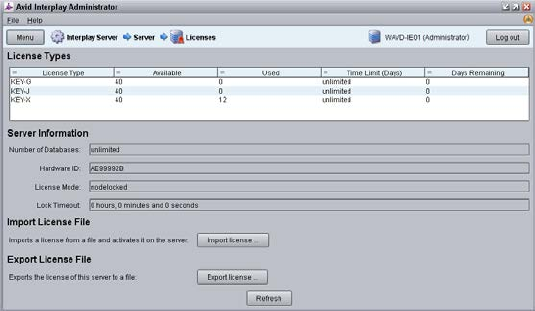
1. Launch the Interplay Administrator on the Interplay Engine. This can be found at:
Start>Avid>Avid Interplay Access Utilities>Avid Interplay Administrator.
2. Log in using Interplay Production’s Administrator credentials.
3. From the main menu, select Server>Licenses.
4. Click the Import License button.
5. Navigate to the location of the license file (often provided on a USB drive).
6. Select the license file and click Open.
You should receive a message indicating that the license was successfully activated.
7. Log out and close the Interplay Administrator application.
For additional information on the Interplay Administrator, see the Interplay | Engine and
Interplay | Archive Engine Administration Guide.

MCS 2.3 Installation and Configuration Guide
20
iNEWS Licensing
If you will be connecting to an iNEWS system, MediaCentral UX will validate client licenses
against the iNEWS server(s). Additional client licenses might have been included with the
purchase of MCS. These licenses will need to be added to iNEWS.
See Appendix D: Configuring iNEWS for Integration with MediaCentral for more information.
Creating User Accounts
This section will cover the creation of user accounts for use with:
Interplay Production
Avid ISIS
iNEWS
Interplay MAM
Media Composer Cloud
Create any user accounts applicable to your installation.
Interplay Production User
When integrating with Interplay Production, MediaCentral UX requires credentials to access the
Interplay Production database. This user should have Read/Write privileges to the entire
database (at minimum). For consistency purposes, this user and password should be the same
as the user you create on the Avid ISIS system.
Decide upon the name and password for this user now. Suggested user name: MCSAdmin
1. Launch the Interplay Administrator on the Interplay Engine. This can be found at:
Start>Avid>Avid Interplay Access Utilities>Avid Interplay Administrator.
2. Log in using Interplay Production’s Administrator credentials.
3. From the main menu, select User Management>User Management.
4. If multiple User Groups are created, highlight the User Group on the left under which you
want to create your new user. Example: Administrators
5. Click the Create User button at the top of the window.
6. Enter a name and password.
7. Verify that the MediaCentral UX Admin user has at least Read/Write access to the entire
database. Administrator-level access is not required, but recommended.
8. Click Apply.
9. Close the Interplay Administrator.
For additional information on users creation in Interplay Production, see the Interplay | Engine
and Interplay | Archive Engine Administration Guide.
MCS 2.3 Installation and Configuration Guide
21
Avid ISIS User
When integrating with Interplay Production, MediaCentral UX requires credentials to access the
media on the ISIS system to enable playback and allow for the creation of voice-over media. For
consistency purposes, this user and password should be the same as the user you create on the
Interplay Production system.
Decide upon the name and password for this user now. Suggested user name: MCSAdmin
1. Launch the ISIS Management Console page by opening a web browser and navigating to one
of the following:
ISIS 5500: http://System Director hostname
ISIS 7500: https://System Director hostname:5015
Note: In a failover configuration, use the virtual System Director hostname.
Alternatively, the IP address of the System Director (or virtual System Director) can also
be used.
2. Log in using the ISIS Administrator credentials.
3. From the main menu, select System>Users.
4. Click the New button to create a new user.
5. Give the user a name and password.
6. Under Workspace Access, assign privileges to all indexed workspaces. At minimum, the user
needs Read access to all workspaces indexed by the Interplay Media Indexer and
Read/Write access to the workspace where voice-overs will be recorded (workspace defined
in the Interplay Administrator> Interplay Application Settings).
7. Click Apply to create the user account.
8. Close the ISIS Management Console.
Note: If you are connecting to multiple ISIS systems, ensure the same user/password is
created on each ISIS.
For additional information on users creation in Interplay Production, see the Avid | ISIS
Administration Guide.

MCS 2.3 Installation and Configuration Guide
22
Avid iNEWS User
When integrating with iNEWS, the MCS Administrator requires access to the iNEWS database.
This can be accomplished by creating a custom user account (superuser rights not required) or
by associating the Administrator with an existing iNEWS account.
Decide upon the name and password for this user now. Suggested user name: MCSAdmin
For instructions on creating a custom iNEWS user account for MediaCentral UX, see the Avid
iNEWS Setup and Configuration Guide.
Interplay MAM User
If you are integrating with MCS as a player for an Interplay MAM system, a specialized user must
be created within the MCS user database.
Decide upon the name of this custom user now. Suggested user name: MAMuser
For details on creating this user, see Configuring MCS for Interplay MAM on page 107.
When installing Interplay MAM, a special user account is created on the MAM system. This user
is identified as: “Service-Ics” with password “Avid123”. If you will be installing the MAM
Connector software for MediaCentral UX, this “Service-Ics” is used in the System Settings.
For details on configuring the MAM Connector System Settings, see Configuring the MAM
Connector on page 159.
For more information on this user and setting, see the Avid MediaCentral | UX Administration
Guide.
Media Composer Cloud User
When integrating with Media Composer Cloud, a custom, matching user account needs to be
added to the Interplay Administrator (Application Database Settings) and to the MediaCentral
UX System Settings (ICPS>Player tab).
When added to the MediaCentral UX System Settings, this account is automatically added as an
MCS user and assigned a special “Playback-Only Client” user role. This will appear in the Users
Layout under Users>Unassigned>Playback-Only.
Rules regarding the specialized user account:
This must be a unique user created solely for this purpose. Do not use the same user
you created to log into Interplay Production and Avid ISIS.
Do not use an account that already exists as a Central User. It must be a new user.
This user should not be created as an Interplay Production or an ISIS user.
Remember that MCS runs on Linux. Both passwords and user accounts are case
sensitive.
Decide upon the name of this custom user now. Suggested user name: cloud
For more information on this user, see the Media Composer | Cloud Installation and
Configuration Guide.
MCS 2.3 Installation and Configuration Guide
23
Adjusting Interplay Production Settings
When integrating with Interplay Production, MCS will check with the Interplay Engine for various
settings. This section is particularly important for sites requiring STP workflows or integrations
with Media Composer Cloud.
1. Launch the Interplay Administrator on the Interplay Engine. This can be found at:
Start>Avid>Avid Interplay Access Utilities>Avid Interplay Administrator
2. Log in using Interplay Production’s Administrator credentials.
3. From the main menu, select Application Settings>Application Database Settings. Adjust the
following:
a. Audio – General Settings: Ensure a Media Creation Workspace is selected.
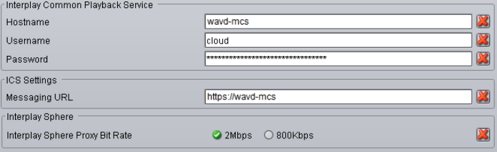
b. Interplay Common Playback Service (Cloud workflow only):
i. Hostname: Enter the hostname of the MCS server. In the case of a cluster,
enter the virtual MCS hostname.
ii. Username / Password: Specify a custom user and password that can be used
to communicate with MediaCentral UX. This same user / password will be
entered in the MediaCentral UX System Settings under the ICPS>Player tab.
This must be a unique user created solely for this purpose.
c. ICS Settings – Messaging URL: This setting enables a messaging workflow between
MCS and Media Composer. Enter the hostname of the MCS server in the form of a
URL. In the case of a cluster, enter the virtual MCS hostname.
d. Interplay Sphere (Cloud workflow only): The proxy setting used with Media
Composer Cloud is shown here for legacy purposes only. The proxy settings were
moved to “Application Settings>Media Composer | Cloud Settings” in Interplay
Production v3.1.
4. Click Apply.
5. If you are integrating with Media Composer Cloud, you should also configure the Application
Settings>Media Composer | Cloud Settings. See the Media Composer | Cloud Installation
and Configuration Guide for additional details.
MCS 2.3 Installation and Configuration Guide
24
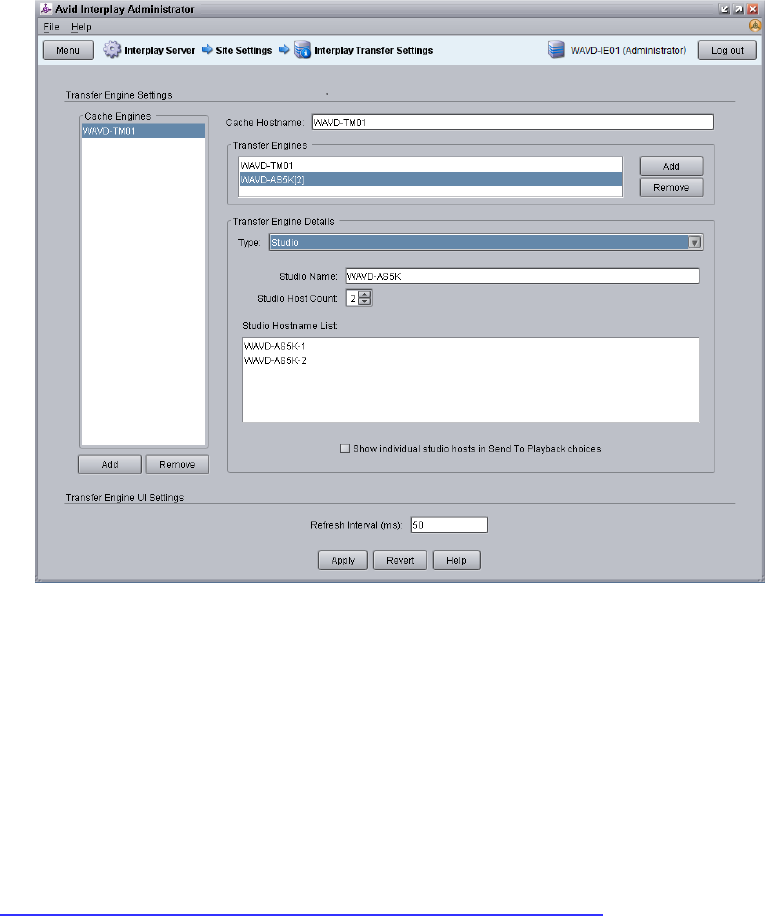
6. From the main menu, select Site Settings>Interplay Transfer Settings. MediaCentral will poll
this setting for configured Transfer Engines and AirSpeed servers when creating STP profiles.
7. Click Apply.
Adding the MediaCentral UX Version to Avid iNEWS
Before connecting MediaCentral UX to iNEWS, the MediaCentral UX Client version must be
added to the iNEWS SYSTEM.CLIENT.VERSIONS file.
Refer to the Avid MediaCentral Platform Services ReadMe for the correct version number for
your installation.
See Appendix D: Configuring iNEWS for Integration with MediaCentral for instructions on
adding the version number to iNEWS.

MCS 2.3 Installation and Configuration Guide
25
Installing the MediaCentral Distribution Service
The MediaCentral Distribution Service (MCDS) is a lightweight required for Send to Playback
(STP) operations. It analyzes the STP request and determines if additional actions are required
before sending the media to the playback device (AirSpeed, Transfer Engine, other). An
Interplay Transcode provider is required for STP operations requiring audio mixdowns (stereo
audio tracks) or video mixdowns (sequences with dissolves). An Interplay STP Encode provider
is required when using Long GOP media.
MCDS is not used if you are sending an asset directly to Transcode or Delivery. MCDS is not
used in iNEWS-only configurations.
The following guidelines apply to installing MCDS:
Supported on Windows 7 64-bit and Windows Server 2012.
o If you are running Windows Server 2012, you must install the Windows Desktop
Experience feature. For more information and installation procedures, see the Interplay
| Production Dell and HP Server Support guide at:
http://avid.force.com/pkb/articles/en_US/readme/Avid-Interplay-Production-V3-3-x-
Documentation
o If you are running Windows 7 N, Windows Media Player must be manually installed. For
more information on “N” versions of Windows, see:
http://windows.microsoft.com/en-us/windows7/products/what-is-windows-7-n-edition
Requires a minimum of 512MB of RAM and approximately 380MB of hard drive space on the
host server.
Ensure that all enabled network adapters on both the system hosting the MCDS and the Interplay
Production Services Engine are fully routable to each other.
Can be installed on a server hosting other services or applications, such as the Interplay
Production Services Engine or an Interplay Archive Provider.
Must be installed on a system that has the ISIS Client software installed.
Must not be installed on a system running Interplay Transcode or STP Encode. These systems
share libraries with MCDS and a co-install risks introducing incompatibilities.
Must not be installed on an Interplay Production Engine or Interplay Archive Engine.
As of Interplay Production 3.2, MCDS should not be installed on a Media Indexer server as the
two systems risk sharing network port 8443.
In MediaCentral UX 1.x, the MCDS service used port 8080 for normal http communication. In
MediaCentral UX v2.0 / MCDS v3.1, the port changed to 8890. This change allows MCDS to be
installed on the same server as the Production Services Engine (if desired). Port 8443 is used for
http security protocol.
Versions of MCDS prior to v3.3 required the Interplay Service Framework (32 or 64bit) software
to be installed on the system hosting MCDS. As of v3.3, this is no longer a requirement.
For redundancy purposes, MCDS can be installed on two systems. Installing a second instance
of MCDS does not provide load-balancing functionality. You will configure MediaCentral UX to
find the installed instance(s) of MCDS later in this document.
Installing the MediaCentral Distribution Service:
1. Launch the MCDS installer on your desired system(s).
MCS 2.3 Installation and Configuration Guide
26
2. Proceed through the installation and accept the defaults.
You may be asked to install prerequisite requirements such as Microsoft Visual C++.
3. Once installed, use Windows Computer Management to verify that the service is “Started”
and the Startup Type is configured as “Automatic”.
Creating the MCS Installation USB Drive
The MCS installation is initiated from a bootable USB drive that contains the OS (Red Hat
Enterprise Linux) and the MCS software. For this procedure you require the following items:
A Windows-based computer
The MCS installation package
RHEL installation image (.iso) file
A 16GB or larger USB drive
Note: Avid has been informed of problems using USB drives from some vendors. If the
server does not boot from the USB drive, or fails to complete the boot, try using a drive
from another vendor or a drive with a larger capacity (32GB).
This procedure uses an application called “ISO to USB” to create a bootable USB drive containing
the required RHEL operating system and MCS files. Do not simply drag and drop installation files
onto the USB drive as this will not create the correct file structure needed to successfully install
MCS.
Note: Since “ISO to USB” creates a bootable drive, Avid recommends only connecting the
USB drive you plan to use to the Windows system. If you have more than one USB drive
inserted, make sure you choose the right one when performing this procedure.
Preparing the Installation Drive for the HP ProLiant Gen9
The procedure for creating the MCS installation drive on a ProLiant Gen9 server differs from that
of other installations. Make sure you follow the customized instructions for your server type.
This section contains three procedures:
Preparing the MCS Installation USB Drive
Copying the Storage Controller Driver to the USB Drive
Preparing the MCS Installation USB Drive:
1. Log into a Windows system.
2. Connect the USB drive to the Windows system and give it a few moments to be
recognized.
3. Use Windows Disk Management to format the USB drive as a FAT32 volume.
MCS 2.3 Installation and Configuration Guide
27
4. Extract the contents of the MediaCentral_Services_<version>_Linux.zip file to the
desktop (or your preferred destination directory).
5. Open the newly created MediaCentral_Services_<version>_Linux folder.
6. Double-click iso2usb.exe to launch the application.
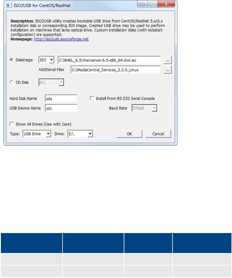
7. Choose the Diskimage radio button then navigate to the RHEL image (.iso) file (named
rhel-server-6.5-x86_64-dvd.iso or similar).
Note: Make sure the RHEL image (.iso) file is accessible locally (preferable) or over the
network from your computer.
8. In the “Additional Files” field, navigate to the MediaCentral_Services_<version>_Linux
folder and click the “Select Folder” button.
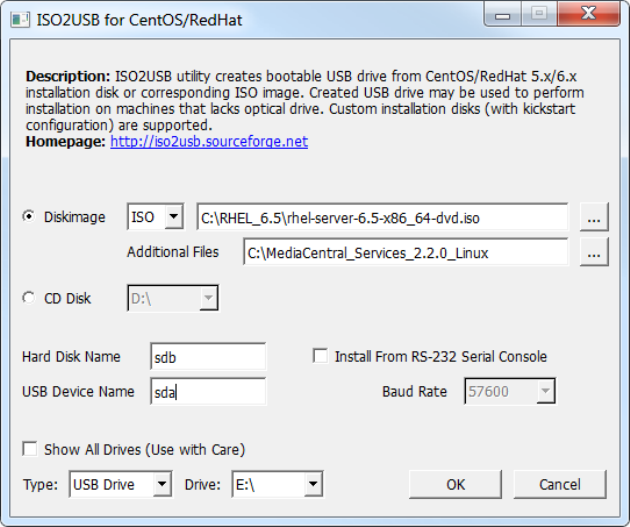
9. Use the table below to verify that the Hard Disk Name and USB Device Name fields are
correct for your deployment.
RAID Configuration RAID 1
(“Hard Disk Name”)
RAID 5 USB
(“USB Device Name”)
RAID 1 and RAID 5
sda
sdb
sdc
RAID 1 only
sda
--
sdb
For example, for a system deploying both RAID 1 and RAID 5 volumes, enter the
following values in the dialog:
• Hard Disk Name: sda
• USB Device Name: sdc
Important: For those familiar with earlier HP servers, the HP ProLiant Gen9 server
identifies the RAID 1, RAID 5, and the USB drive with different device names.

MCS 2.3 Installation and Configuration Guide
28
10. Verify the USB Drive letter or use the pull-down menu to select a new drive letter.
11. Click OK in the main dialog.
12. A process begins to copy the RHEL image (.iso) file and the MCS installation files to the
USB drive.
This process takes 10-20 minutes. Once complete, the USB drive has everything it needs
to complete the RHEL and MCS installation.
Note: Copying the RHEL image (.iso) file to the USB drive is a one-time process. To install
MCS on more than one server, or to re-install MCS, you do not need to repeat these
steps.
13. Click Exit to close the application.
Copying the Storage Controller Driver to the USB Drive:
1. With the Installation USB drive still plugged in to the Windows laptop or desktop, copy
the RAID controller driver ISO to the root directory on the drive:
dd-hpsa-18216-x86_64.iso
2. Rename the ISO:
• Old Name: dd-hpsa-18216-x86_64.iso
• New Name: z_dd-hpsa-18216-x86_64.iso
Renaming the driver ISO is essential, since the installation script attempts to mount the
first ISO it finds as the RHEL ISO. If you do not rename it, the installation will fail.
MCS 2.3 Installation and Configuration Guide
29
Preparing the Installation Drive for HP Gen8 and Dell Servers
Follow this procedure only if you are installing MCS software components on supported HP
Gen8 or Dell servers.
Preparing the MCS Installation USB Drive:
1. Log into a Windows system.
2. Connect the USB drive to the Windows system and give it a few moments to be
recognized.
3. Use Windows Disk Management to format the USB drive as a FAT32 volume.
4. Extract the contents of the MediaCentral_Services_<version>_Linux.zip file to the
desktop (or your preferred destination directory).
5. Open the newly created MediaCentral_Services_<version>_Linux folder.
6. Double-click iso2usb.exe to launch the application.
7. Choose the Diskimage radio button then navigate to the RHEL image (.iso) file (named
rhel-server-6.5-x86_64-dvd.iso or similar).
Note: Make sure the RHEL image (.iso) file is accessible locally (preferable) or over the
network from your computer.
8. In the “Additional Files” field navigate to the MediaCentral_Services_<version>_Linux
folder and click the “Select Folder” button.
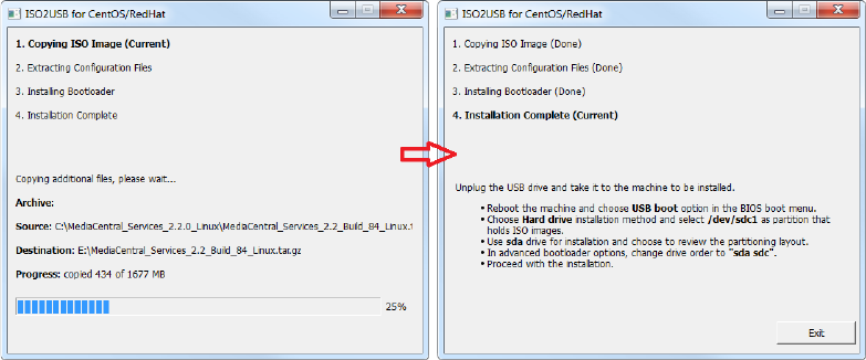
MCS 2.3 Installation and Configuration Guide
30
9. Verify the Hard Disk Name and USB Device Name fields are as follows:
• Hard Disk Name: sdb
• USB Device Name: sda
Note: If the drive names are not configured properly in the kickstart file, you could
encounter errors in the deployment process. Example: “Error Partitioning: Could not
allocate requested partitions: not enough free space on disks.”
10. Verify the USB Drive letter or use the pull-down menu to select a new drive letter
11. Click OK in the main dialog.
12. A process begins to copy the RHEL image (.iso) file and the MCS installation files to the
USB drive.
This process takes 10-20 minutes. Once complete, the USB drive has everything it needs
to complete the RHEL and MCS installation.
Note: Copying the RHEL image (.iso) file to the USB drive is a one-time process. To install
MCS on more than one server, or to re-install MCS, you do not need to repeat these
steps.
MCS 2.3 Installation and Configuration Guide
31
PART II: BIOS & RAID CONFIGURATION
MCS 2.3 Installation and Configuration Guide
32
Chapter Overview
The purpose of this chapter is to prepare the server hardware for the installation of RHEL and
MCS.
The following table describes the topics covered in this chapter.
Step Task Time Est.
1
Changing BIOS Settings
15 min
Each of the supported server types require adjustments to the system BIOS.
This section covers:
• HP ProLiant DL360 Gen9
• HP ProLiant DL360p Gen8
• Dell PowerEdge R620 / R630
2
Configuring the Onboard RAID
varies
Each of the supported server types features different methods for creating
and working with the onboard RAID controllers. This section covers:
• HP ProLiant DL360 Gen9
• HP ProLiant DL360p Gen8
• Dell PowerEdge R620 / R630
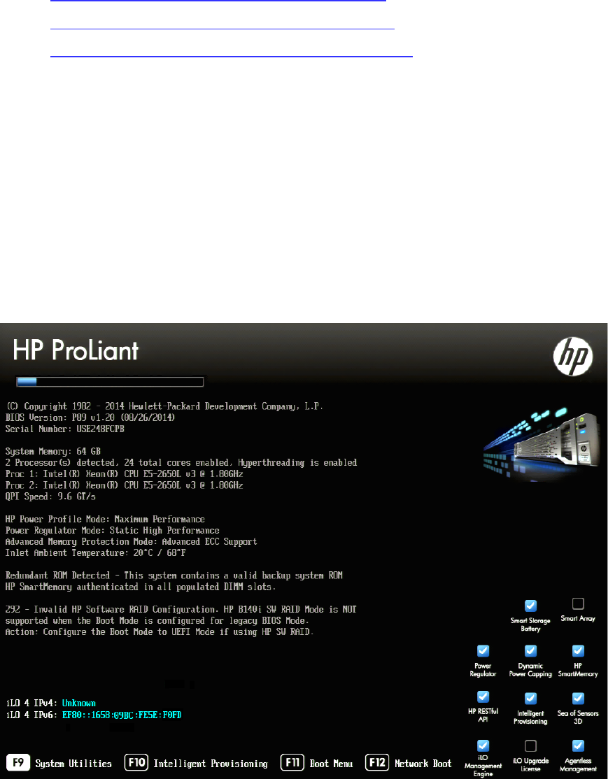
MCS 2.3 Installation and Configuration Guide
33
Changing BIOS Settings
This section provides information on the BIOS settings for the following Avid qualified servers:
• Configuring the BIOS on the HP ProLiant DL360 Gen9
• Configuring the BIOS on the HP ProLiant DL360p Gen8
• Configuring the BIOS on the Dell PowerEdge R620 / R630
Servers are frequently shipped with BIOS settings configured for a power-saving mode. MCS
makes intensive use of the server’s CPUs and memory, especially when under heavy load.
Configuring the server to operate at maximum performance will ensure operational efficiency.
To ensure the smooth installation of RHEL and MCS, the system clock must be set within the
BIOS. When configuring an MCS cluster, setting the system clocks accurately is particularly
important.
Configuring the BIOS on the HP ProLiant DL360 Gen9
1. Power up the server.
2. When the console displays the option to enter the “System Utilities” menu, press F9. The
BIOS responds by highlighting the F9 button at the bottom of the screen.
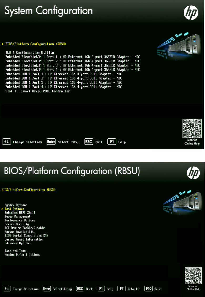
MCS 2.3 Installation and Configuration Guide
34
3. Select System Configuration and press Enter.
4. Select BIOS/Platform Configuration (RBSU) and press Enter.
5. Select Boot Options and press Enter.
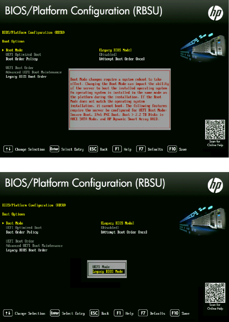
MCS 2.3 Installation and Configuration Guide
35
6. Select Boot Mode and press Enter.
You may see a warning message (shown below) indicating that Boot Mode changes will
require a reboot. Press Enter to accept this warning.
7. A smaller selection box will appear. Select Legacy BIOS Mode and press Enter.
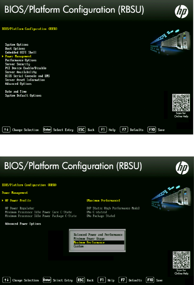
MCS 2.3 Installation and Configuration Guide
36
8. Press ESC to navigate back to the BIOS/Platform Configuration (RBSU) screen.
9. Select Power Management and press Enter.
10. Press Enter to select HP Power Profile.
11. A smaller selection box will appear. Select Maximum Performance and press Enter.
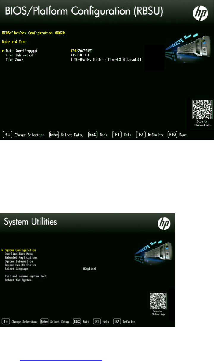
MCS 2.3 Installation and Configuration Guide
37
12. Press ESC to navigate back to the BIOS/Platform Configuration (RBSU) screen.
13. Select Date and Time and press Enter.
14. Set the date (mm-dd-yyyy) and time (hh:mm:ss).
15. Press ESC to navigate back to the BIOS/Platform Configuration (RBSU) screen.
16. Press F10 to save.
17. Press ESC to navigate back to the System Configuration screen.
If prompted, select “Y” to save changes and exit.
18. Press ESC to navigate back to the System Utilities screen.
19. Select Reboot the System and press Enter.
The server reboots with new options.
Proceed to Configuring the Onboard RAID on page 41.
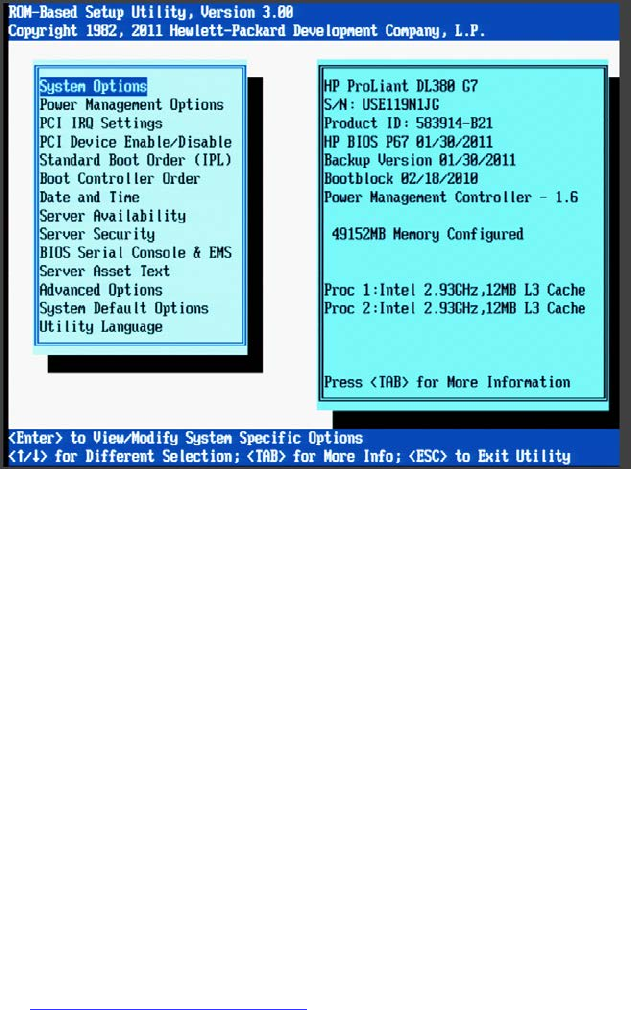
MCS 2.3 Installation and Configuration Guide
38
Configuring the BIOS on the HP ProLiant DL360p Gen8
1. Power up the server.
2. When the console displays the option to enter the “System Utilities” menu, press F9. The
BIOS responds by highlighting the F9 button at the bottom of the screen.
The ROM-Based Setup Utility appears after a few moments.
3. Select Power Management Options and press Enter.
Power Management options are displayed.
4. Choose HP Power Profile.
Power Profile options are displayed.
5. Choose Maximum Performance.
You are returned to the Power Management options menu.
6. Press Esc to return to main menu.
7. Select Date and Time and press Enter.
Date and Time options are displayed.
Set the date (mm-dd-yyyy) and time (hh:mm:ss).
8. Press Enter to save the changes and return to the Setup Utility menu.
9. Exit the Setup utility. Press Esc and F10 to save.
The server reboots with new options.
Proceed to Configuring the Onboard RAID on page 41.
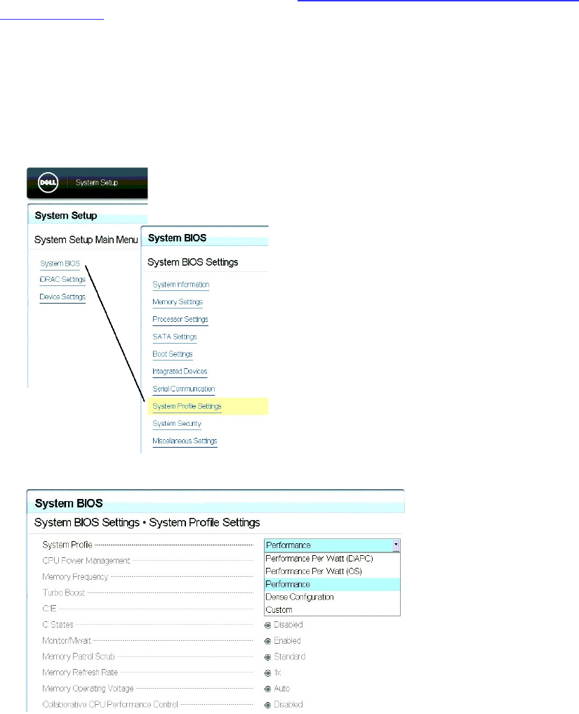
MCS 2.3 Installation and Configuration Guide
39
Configuring the BIOS on the Dell PowerEdge R620 / R630
This process includes steps to ensure your MCS Installation USB drive is first in the boot order.
Prior to beginning this process, ensure your MCS Installation drive is available.
For instructions on creating the boot drive, see Preparing the Installation Drive for HP Gen8
and Dell Servers on page 29.
1. Connect your MCS Installation USB drive to one of the Dell’s USB ports.
2. Power up the server.
3. Press F2 to enter the BIOS.
4. Select System BIOS
5. Select System Profile Settings.
6. Select the Performance profile from the pull-down menu and click Back.
Note: There are three “Performance” profiles. Once of them specifically says “Performance”
and not “Performance Per Watt.”
7. Select System BIOS Settings
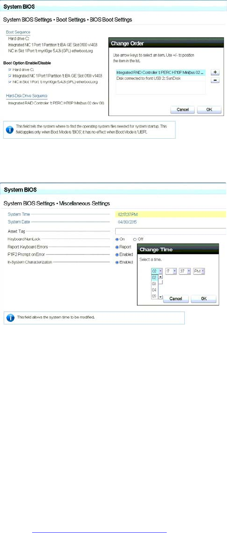
MCS 2.3 Installation and Configuration Guide
40
8. Select Boot Settings
9. Select BIOS Boot Settings
10. Select Hard-Disk Drive Sequence
11. In the Change Order window, use the + or – keys to move the USB boot drive to the top of
the list and click OK.
12. Click Back to exit the page and to exit the System BIOS Settings page.
13. Select Miscellaneous Settings
14. Change the System Time and System Date by highlighting the appropriate field and pressing
Enter.
15. A window will appear with pull-down menu options. Click OK when done.
16. You are asked to confirm the changes.
A “Success” dialog indicates the settings were saved.
17. Click Back and Finish to return to the main System Setup screen.
Note: When ordering a Dell server, an ”Internal SD Card Port” is an optional component. This
device will appear to Linux as a media device and it will automatically be assigned a device
name. This can interfere with the RHEL / MCS deployment. If you have an ”Internal SD Card
Port”, temporarily disable it in the BIOS: System BIOS > Integrated Devices > Internal SD Card
Port > Off. The device can be re-enabled once you have completed the MCS installation.
Proceed to Configuring the Onboard RAID on page 41.

MCS 2.3 Installation and Configuration Guide
41
Configuring the Onboard RAID
This section provides information on the RAID configuration for the following Avid qualified
servers:
• HP ProLiant DL360 Gen9 RAID Configuration
• HP ProLiant DL360p Gen8 RAID Configuration
• Dell PowerEdge R620 / R630 RAID Configuration
RAID 1: All MCS implementations require a RAID 1 (mirror) for the system (OS) drive. This RAID
provides redundancy in the event of HD failure.
RAID 5: Certain deployments also require additional disks configured as a RAID 5 (data striping
with parity blocks) for caching file data. This RAID provides redundancy and increased
performance.
See the MediaCentral Platform Services Concepts and Clustering Guide for more information on
RAID configurations.
HP ProLiant DL360 Gen9 RAID Configuration
In this step you configure two of the HD drives in the server enclosure as a RAID Level 1 – a
mirrored RAID – where the RHEL and MCS software will be installed. This is done using the
Option ROM Configuration for Arrays utility, in the HP server’s BIOS.
If applicable, configure the remaining HD drives in the server enclosure as a RAID Level 5. In a
RAID 5 data is automatically distributed across all the disks in the RAID for increased
performance and redundancy. This is done using the Option ROM Configuration for Arrays
utility, in the HP server’s BIOS.
Note: If the list of available disks does not appear as expected, it may be that a RAID has
already been created. Deleting a RAID destroys all the data it contains, so verify it is safe
to do so first.
Note: This document provides instructions for creating a media cache volume as a
RAID 5 using multiple disks in the server enclosure. However, other configurations are
possible, including two drives in a RAID 1 configuration, or a single drive. For details, see
the MediaCentral Platform Services Hardware Guide.
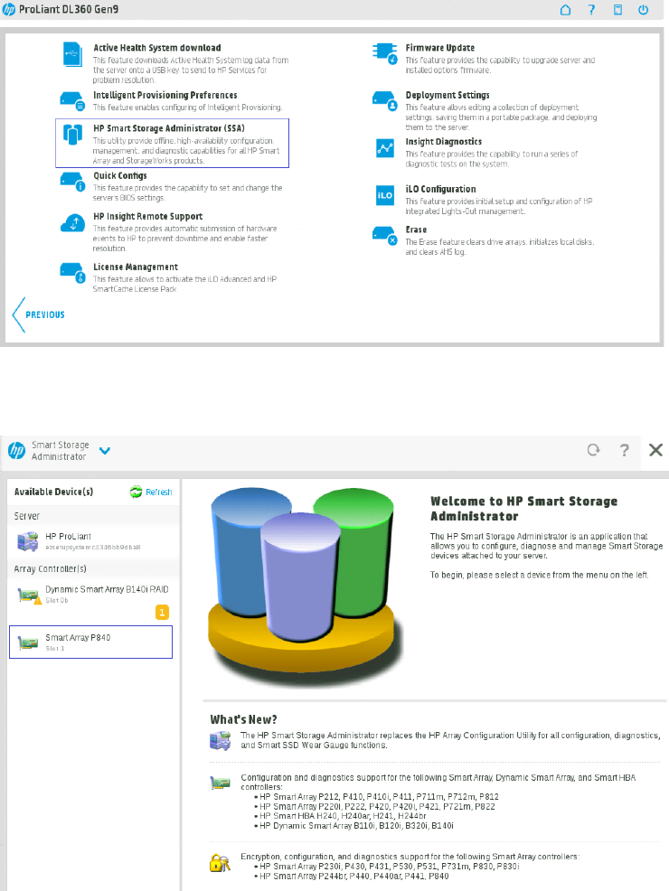
MCS 2.3 Installation and Configuration Guide
42
Configuring the HP ProLiant DL360 Gen9 RAID 1
Note: The RAID configuration process will immediately transition into the Red Hat / MCS
installation. It is recommended that you connect your MCS Installation USB drive to the server at
this time.
1. Reboot the server and press F10 to select Intelligent Provisioning.
2. Select Perform Maintenance.
3. Select HP Smart Storage Administrator (SSA)
4. At the “Welcome to HP Smart Storage Administrator” screen, select Smart Array P840
from left side menu.
5. Select Create Array under “Actions”.
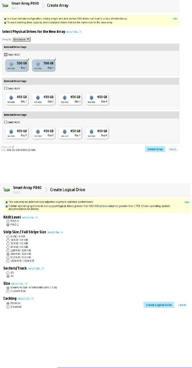
MCS 2.3 Installation and Configuration Guide
43
6. Select both 500GB Drives then select Create Array.
7. Verify the following are selected: RAID 1, 256 KiB / 256 KiB Stripe Size, 32 Sectors,
Maximum Size, Caching Enabled.
8. Click Create Logical Drive.
9. You will receive a message indicating the “Logical Drive was successfully created.” Click
Finish to complete the RAID 1 creation process.
Note: Do not press the Escape key to exit, since this reboots the server.
If applicable, proceed to Configuring the HP ProLiant DL360 Gen9 RAID 5 on page 44.
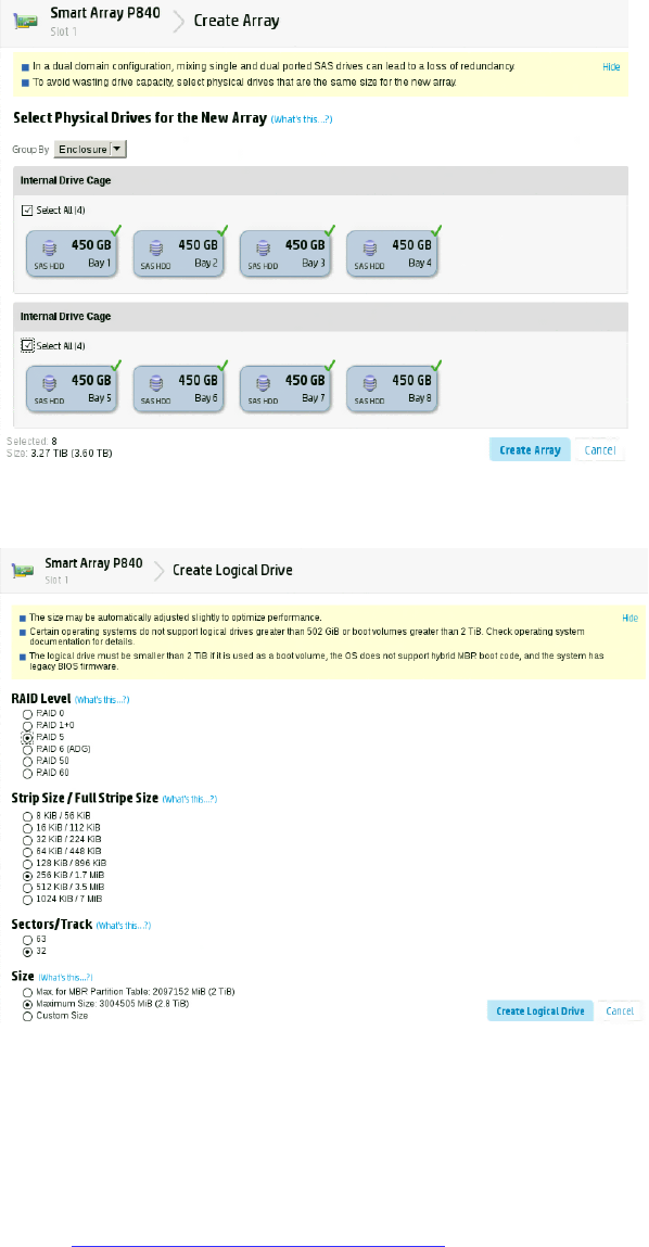
MCS 2.3 Installation and Configuration Guide
44
Configuring the HP ProLiant DL360 Gen9 RAID 5
This process assumes you are continuing from the RAID 1 creation process.
1. Select Create Array under “Actions”.
2. Select all eight 450GB Drives then select Create Array.
3. Verify the following are selected: RAID 5, 256 KiB / 1.7 MiB Stripe Size, 32 Sectors,
Maximum Size, Caching Enabled.
4. Click Create Logical Drive.
5. You will receive a message indicating the “Logical Drive was successfully created.” Click
Finish to complete the RAID 5 creation process.
6. Click the “X” (top right) to exit. Confirm the exit by clicking “OK” when prompted.
7. Click the “Power” button (top right) to exit. Select “Reboot” when prompted.
Proceed to Installing RHEL and the MCS Software on page 55.
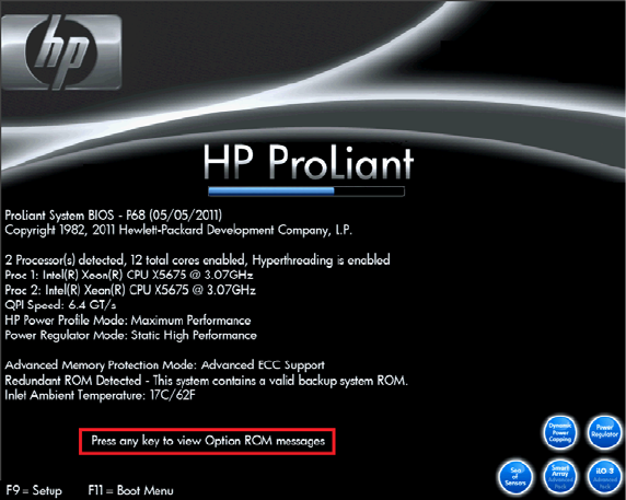
MCS 2.3 Installation and Configuration Guide
45
HP ProLiant DL360p Gen8 RAID Configuration
In this step you configure two of the HD drives in the server enclosure as a RAID Level 1 – a
mirrored RAID – where the RHEL and MCS software will be installed. This is done using the
Option ROM Configuration for Arrays utility, in the HP server’s BIOS.
If applicable, configure the remaining HD drives in the server enclosure as a RAID Level 5. In a
RAID 5, data is automatically distributed across all the disks in the RAID for increased
performance and redundancy. This is done using the Option ROM Configuration for Arrays
utility, in the HP server’s BIOS.
Note: If the list of available disks does not appear as expected, it may be that a RAID has
already been created. Deleting a RAID destroys all the data it contains, so verify it is safe
to do so first.
Note: This document provides instructions for creating a media cache volume as a
RAID 5 using multiple disks in the server enclosure. However, other configurations are
possible, including two drives in a RAID 1 configuration, or a single drive. For details, see
the “MediaCentral Platform Services Hardware Guide”.
Configuring the HP ProLiant DL360p Gen8 RAID 1
Note: The RAID configuration process will immediately transition into the Red Hat / MCS
installation. It is recommended that you connect your MCS Installation USB drive to the server at
this time.
1. Reboot the server and press any key (spacebar recommended) when prompted to
display the HP ProLiant “Option ROM” messages.
Note: Do not press F9 or F11. Press any key other than F9 or F11 (spacebar
recommended).
Detailed messages now appear as the server boots up.
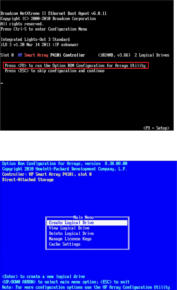
MCS 2.3 Installation and Configuration Guide
46
2. As soon as you see the prompt to “Press <F8> to run the Option ROM Configuration for
Arrays Utility”, press F8.
Note: The prompt to press F8 can flash by quite quickly. If you miss it, reboot and try
again.
3. From the Main Menu, select Create Logical Drive.
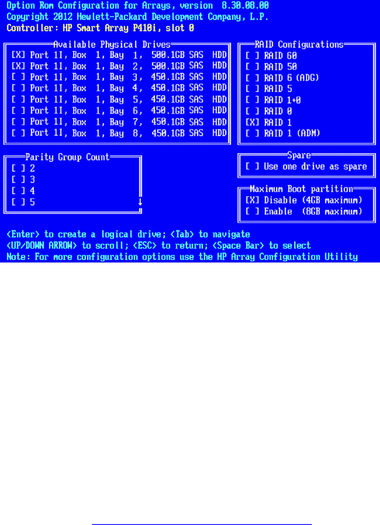
MCS 2.3 Installation and Configuration Guide
47
4. Select the following two HD drives in “Available Physical Drives”:
• Box 1, Bay 1
• Box 1, Bay 2
5. Deselect all the other available HD drives (if any).
6. Ensure RAID 1 is selected in the “RAID Configurations” section.
Note: In older firmware versions, the choice presented may be RAID 1+0. Since you
are only using two HD drives, this is identical to a RAID 1.
7. Ensure Disable (4GB maximum) is selected in the “Maximum Boot partition” section.
8. Ensure nothing is selected in the “Parity Group Count” section.
9. Ensure nothing is selected in the “Spare” section.
10. Press Enter to create the logical drive.
A message appears summarizing the RAID 1 setup.
11. Press F8 to save the configuration.
A message appears confirming the configuration has been saved.
12. Press Enter to finalize the RAID 1 setup.
Note: Do not press the Escape key to exit, since this reboots the server.
If applicable, proceed to Configuring the HP ProLiant DL360p Gen8 RAID 5 on page 48.
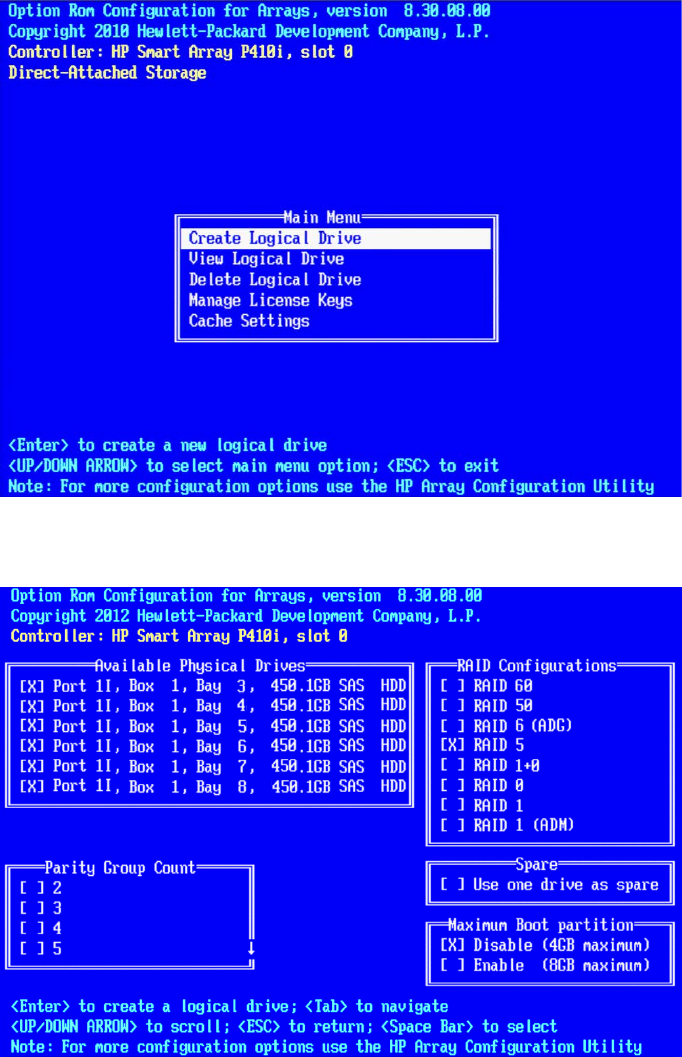
MCS 2.3 Installation and Configuration Guide
48
Configuring the HP ProLiant DL360p Gen8 RAID 5
This process assumes you are continuing from the RAID 1 creation process.
1. From the Main Menu, select Create Logical Drive.
2. Select the drives to be included in the RAID 5 in the “Available Physical Drives” section.
• Box 1 Bays 3-8 (typical configuration)
3. Ensure RAID 5 is selected in the “RAID Configurations” section.
4. Ensure Disable (4GB maximum) is selected in the “Maximum Boot partition” section.
5. Ensure nothing is selected in the “Parity Group Count” section.

MCS 2.3 Installation and Configuration Guide
49
6. Ensure nothing is selected in the “Spare” section.
7. Press Enter to create the logical drive.
A message appears summarizing the RAID 5 setup.
8. Press F8 to save the configuration.
A message appears confirming the configuration has been saved.
9. Press Enter to finalize the RAID 5.
10. Press ESC to reboot the system.
Proceed to Installing RHEL and the MCS Software on page 55.
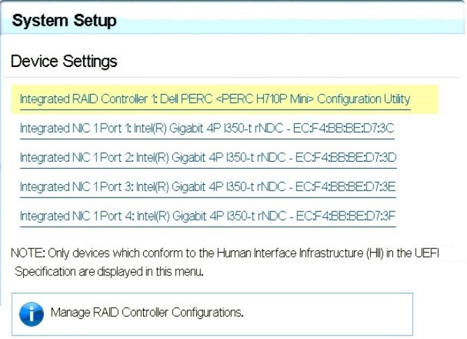
MCS 2.3 Installation and Configuration Guide
50
Dell PowerEdge R620 / R630 RAID Configuration
The Dell R620 / R630 servers ship with preconfigured RAID 1 and RAID 5 arrays. In this step you
verify the RAID configuration through the BIOS. Later you will use RHEL to ensure the RAID
arrays are cleared of existing data.
Two of the HD drives in the server are configured as a RAID Level 1 – a mirrored RAID – where
the RHEL and MCS software will be installed.
If applicable, the remaining drives in the server enclosure will be configured as a RAID Level 5. In
a RAID 5 data is automatically distributed across all the disks in the RAID for increased
performance and redundancy.
Note: This document provides instructions for creating a media cache volume as a
RAID 5 using multiple disks in the server enclosure. However, other configurations are
possible, including two drives in a RAID 1 configuration, or a single drive. For details, see
the “MediaCentral Platform Services Hardware Guide”.
Verifying the PowerEdge Dell R620 / 630 RAID Configuration:
Note: The RAID configuration process will immediately transition into the Red Hat / MCS
installation. If you do not already have the MCS Installation USB drive connected, connect it to
the server at this time.
1. (if necessary) Reboot the server and press F2 to enter the BIOS.
2. From the main System Setup screen, select Device Settings.
3. From the Device Settings menu, select Integrated RAID Controller Configuration Utility.
4. From the Configuration Options menu, select Virtual Disk Management.
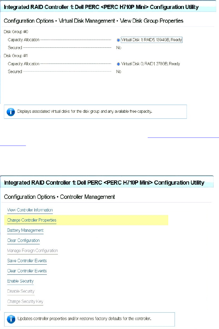
MCS 2.3 Installation and Configuration Guide
51
5. From the Virtual Disk Management menu, select View Disk Properties.
This window lists the configured RAID Groups on the server. You should see both a RAID
1 set and a RAID 5 set.
Note: If the preconfigured RAID arrays do not exist, see Working with the Dell RAID
Controller in Appendix A for information on creating the RAID.
6. From the Configuration Options menu, select Controller Management.
7. From the Controller Management menu, select Change Controller Properties.
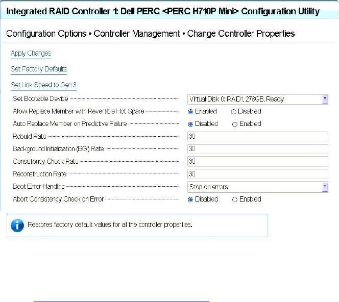
MCS 2.3 Installation and Configuration Guide
53
PART III: SOFTWARE INSTA LLATION AND PREPARATION
MCS 2.3 Installation and Configuration Guide
54
Chapter Overview
The purpose of this chapter is to assist you with the installation and configuration of the system
software.
The following table describes the topics covered in this chapter.
Step Task Time Est.
1
Installing RHEL and the MCS Software
5 min
Provides some introductory information on the installation process.
2
Special Instructions for Dell Servers
10 min
Covers the deletion of any existing partitions on the Dell RAID arrays prior to
the installation of RHEL and MCS.
3
MCS Software Deployment
30 min
Covers the actual installation of RHEL and MCS.
4
Booting RHEL for the First Time
5 min
Covers keyboard layout configuration and a process for changing the default
‘root’ user password.
5
Network Configuration
30 min
Guides you through the configuration of all network-related settings.
6
Configure Date and Time Settings
15 min
Configuration of Date, Time, Time Zone and NTP settings.
7
Creating the File Cache on the RAID
15 min
If a RAID 5 array is used, this step finalizes the creation of the RAID 5.
8
Enable / Disable 3G and Edge Streams
2 min
Instructions for enabling / disabling 3G and Edge streams.
9
Copying Software to the MCS Server
varies
While RHEL and MCS software is installed by the MCS Installation USB drive,
additional software might be required.
10
Security Updates
15 min
Information regarding Security Updates for RHEL.
11
Install Software Patches
15 min
A reminder to install available software patches.

MCS 2.3 Installation and Configuration Guide
55
Installing RHEL and the MCS Software
This process will step you through the installation and configuration of an MCS server.
Caution: If you are in the process of upgrading from an earlier version of MCS — called ICS in
earlier releases — it is a fresh install, and will overwrite your current ICS settings and databases.
Before proceeding with the upgrade, back up your current settings:
Database: The ICS settings and database using the backup script (system-backup.sh)
provided. See Backing up the MCS System Settings on page 141.
SSL Private Key(s): If you deployment makes use of CA-signed certificates, back up
private(s), regardless of the upgrade path.
Corosync Configuration File: If you configured ICS 1.4.x for unicast, you made changes to
the corosync configuration (corosync.conf) file. The installation script overwrites this file.
To preserve your changes, back up the file before beginning the upgrade, and restore it
after.
Note: For workflow details on upgrading to MCS 2.3 from an earlier release, see the MCS 2.3
Upgrading Guide, available from the Avid Knowledge Base MCS 2.3 web page.
How to proceed:
If you are installing MCS on a Dell server, additional steps are required during the server
imaging process. Proceed to Special Instructions for Dell Servers on page 56 (the next
page).
If you are installing MCS on an HP server, proceed directly to MCS Software
Deployment on page 60.
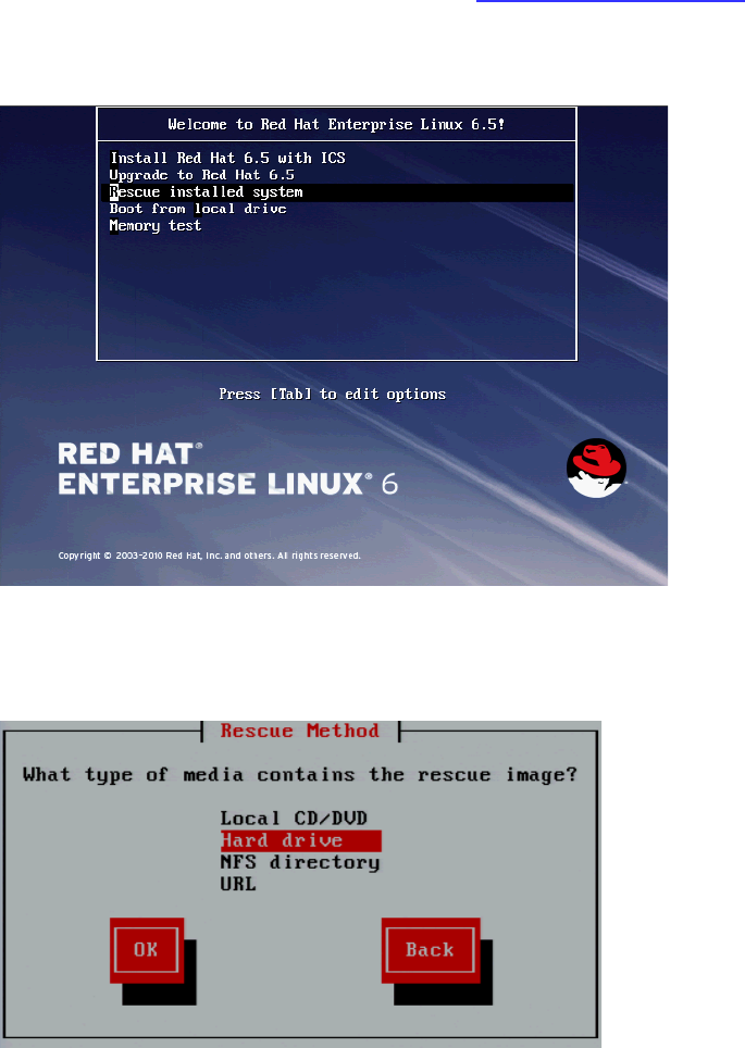
MCS 2.3 Installation and Configuration Guide
56
Special Instructions for Dell Servers
Dell servers are generally shipped with preconfigured RAID 1 and RAID 5 arrays. These RAID sets
include partitions that can interfere with the kickstart assisted software deployment. The
partitions must be deleted prior to starting the installation.
Deleting and recreating the RAID sets using the DELL BIOS utility does not erase data, nor does it
delete existing partitions. That is, deleting a RAID does not delete the partition table — unless
you initialize the disk at the same time. However, initializing the disk is a slow process.
In this procedure, you boot from the MCS Installation USB Drive and launch a RHEL “rescue”
session in order to examine the current system partitions and delete them.
If you are installing MCS on an HP server, proceed to MCS Software Deployment on page 60.
1. Boot from the MCS Installation USB drive.
2. At the RHEL Welcome screen, select “Rescue Installed System”.
3. When prompted choose the language and keyboard.
4. Choose “Hard drive” as the rescue method. For the purposes of booting from a RHEL image,
the USB drive is considered a hard drive.
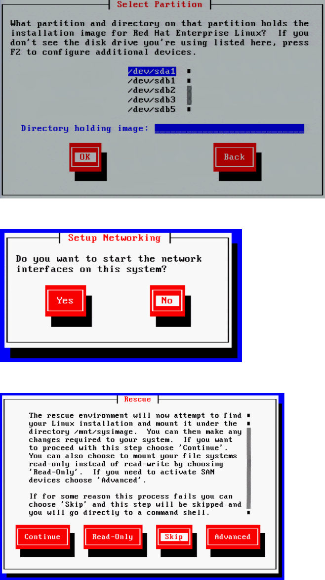
MCS 2.3 Installation and Configuration Guide
57
5. Select the “/dev/sda1” partition (the USB drive). Leave the “Directory holding image” field
blank.
6. Select No in the Setup Networking window; as networking is not needed at this time.
7. Select “Skip” in the Rescue window.
MCS 2.3 Installation and Configuration Guide
58
8. At the next screen, choose “shell Start shell” and select Ok.
9. At the system prompt, use the RHEL fdisk utility to examine the current partitions:
fdisk -cul
This command will display the available disks and partitions on the system. Use Shift-Pg Up
and Shift-Pg Down to view the entire output, since scroll bars will not be present in the
rescue shell.
In this case “sda” should be the USB boot drive, “sdb” should be the RAID 1 volume and
“sdc” should be the RAID 5 volume.
The following example shows information for “sdb” with three partitions (sdb1, sdb2, sdb3):
Disk /dev/sdb: 500.1 GB, 500074307584 bytes
255 heads, 63 sectors/track, 60797 cylinders, total 97670732 sectors
Units = sectors of 1 * 512 = 512 bytes
Sector size (logical/physical): 512 bytes / 512 bytes
I/O size (minimum/optimal): 512 bytes / 512 bytes
Disk identifier: 0xc755f5b0
Device Boot Start End Blocks Id System
/dev/sdb1 * 2048 1026047 512000 83 Linux
/dev/sdb2 1026048 42051583 20512768 8e Linux LVM
/dev/sdb3 42051584 976707583 467328000 8e Linux LVM
Additional entries for the filesystem (sdb4, sdb5) could be possible. Example:
Disk /dev/sdb: 598.9 GB, 598879502336 bytes
255 heads, 63 sectors/track, 72809 cylinders, total 11696828 sectors
Units = sectors of 1 * 512 = 512 bytes
Sector size (logical/physical): 512 bytes / 512 bytes
I/O size (minimum/optimal): 512 bytes / 512 bytes
Disk identifier: 0x930a8a0e
Device Boot Start End Blocks Id System
/dev/sdb1 * 2048 1026047 512000 83 Linux
/dev/sdb2 1026048 2050047 512000 83 Linux
/dev/sdb3 2050048 43075583 20512768 8e Linux LVM
/dev/sdb4 43075584 1169686527 563305472 5 Extended
/dev/sdb5 43077632 1169686527 563304448 8e Linux LVM

MCS 2.3 Installation and Configuration Guide
59
You will need to delete the any partitions on the RAID 1 volume and the RAID 5 volume (if
applicable). This process will assume “sdb” is the RAID 1 and “sdc” is the RAID 5.
10. Use the RHEL fdisk utility to select the sdb volume:
fdisk /dev/sdb
11. Type: p to print the current filesystem partition table. This will show you a similar output
as the fdisk –cul command you used earlier.
12. Type: d to begin deleting the partitions.
13. You will be prompted to specify the partition to delete. Example: 1
Partition number (1-4): 1
14. Repeat the above two steps to delete the remaining “sdb” partitions.
15. Once complete, type p to print the partition table again. An empty partition table should
look like the following:
Device Boot Start End Blocks Id System
16. Type: w to write the changes to the partition table and exit the utility.
17. If you have a RAID 5 volume, repeat this process by specifying the RAID 5 “sdc” partition:
fdisk /dev/sdc
18. Repeat the above steps and type w to write the changes to the partition table and exit the
utility.
19. Verify that the partitions on sdb and sdc (if applicable) were successfully removed using the
RHEL fdisk utility:
fdisk -cul
20. Reboot the server by selecting CTRL-ALT-DEL. You will again boot from the USB Installation
drive. The correct partitions and filesystems will be created automatically during the
installation.
Proceed to MCS Software Deployment on page 60.
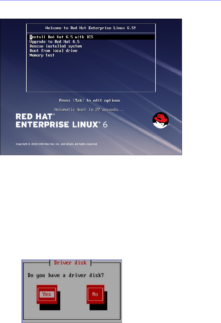
MCS 2.3 Installation and Configuration Guide
60
MCS Software Deployment
This process will install both RHEL and MCS from the MCS Installation USB drive.
1. Ensure the MCS Installation USB drive is connected to the server and reboot if necessary
Note: For HP installs, an error message may appear: "[Firmware Bug]: the BIOS has
corrupted hw-PMU resources". This error can be ignored. For more information, see:
http://h20000.www2.hp.com/bizsupport/TechSupport/Document.jsp?objectID=c03265132.
2. Wait for the RHEL Welcome screen to appear.
Note: It has been reported that under some circumstances the installation bypasses the
RHEL Welcome screen. This will not affect the install process. The correct installation
choice is always selected by default.
3. If you are installing on an HP ProLiant Gen9 server, install the RHEL driver to enable
RHEL support for the storage controller before proceeding:
a. Press the Esc key to open the RHEL boot shell.
b. At the boot shell, type the following:
linux dd
c. In the dialog that appears, confirm that you have a driver disk.
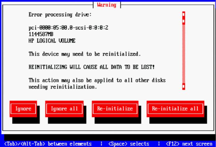
MCS 2.3 Installation and Configuration Guide
61
d. The installer may prompt you to specify the location of the update. Select the
device name indicating the MCS Installation USB drive (e.g sda). Similarly specify
the partition on the device (e.g. sda1).
e. Select the driver and select OK:
z_dd-hpsa-18216-x86_64.iso
f. When prompted for more drivers, select No.
The driver is updated, and the installation process continues as described
below.
4. Select “Install Red Hat with ICS” to install a new MCS and press Enter.
Note: If you are upgrading your system, do not use the “Upgrade” option. For upgrading
instructions, see the ”MCS 2.3 Upgrading Guide”.
The RHEL and MCS packages are installed—this takes about 20 minutes.
Note: Regarding the following error message:
Unable to download kickstart file
If you see this message, it could indicate that the partition where the installation
program expects to find the kickstart file (sda) is already in use. The most likely cause is a
KVM with “virtual media” capability reserving the sda partition to facilitate the mapping
of removable drives to the attached server.
To resolve the issue, disable the virtual media capability. Alternately, unplug the KVM
and connect to the server directly using an external monitor and USB keyboard.
5. If you just created the RAIDs a warning screen appears indicating a device (i.e. the
RAIDs) needs to be reinitialized. This is normal. Select Re-Initialize All.
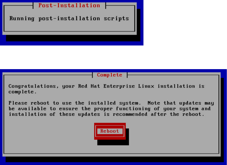
MCS 2.3 Installation and Configuration Guide
62
6. The RHEL installation proceeds.
When you see the “Post-Installation” message, it indicates the MCS installation scripts
are being executed.
7. When the installation process is complete, you are prompted to reboot. DO NOT
REBOOT before removing the MCS Installation USB drive.
If you reboot without removing the USB drive the server will reboot from the USB drive
again and re-launch the installer.
Note: If you pressed Enter by mistake, remove the USB drive as quickly as possible
(before the system boots up again). If this is not possible, you need to perform the
installation again.
8. Once the MCS Installation USB drive is removed, press Enter to reboot the server.
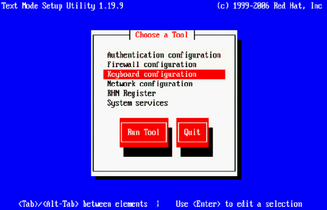
MCS 2.3 Installation and Configuration Guide
63
Booting RHEL for the First Time
Like many operating systems, when you boot RHEL for the first time, you will be asked to
provide some basic information. A RHEL “first boot” causes the RHEL Configuration screen to
appear, providing access to system set-up menus.
Note: The first boot set-up menu can be accessed at any time by typing “setup” (without
quotes) at the Linux command prompt.
Note: Some MCS software components depend on the language for RHEL being set to
English. This is done automatically by the MCS installation scripts. Do not change the
input language afterwards.
Booting from the System Drive
1. From the Choose a Tool menu, arrow down to select “Keyboard Configuration” and
press Enter.
2. In the Keyboard Selection menu, use the arrows to select the appropriate language for
your keyboard.
Note: Selecting a language for the keyboard is different from the language selected for
RHEL. While selecting a different language for the keyboard is supported, the RHEL
language must remain as English.
3. Press the Tab key to focus on the OK button and press Enter.
4. Press the Tab key to focus on the Quit button and press Enter.
The first boot set-up menu can be accessed at any time by typing “setup” (without quotes) at
the Linux command prompt.

MCS 2.3 Installation and Configuration Guide
64
Changing the
root
Password
The RHEL installation script configures a default password for the root user (the Linux user with
administrator privileges). For security reasons, it is strongly suggested that you change the
password for the root user at the earliest opportunity.
To change the root password:
1. Log in a the Linux prompt
Default user name: root
Default password: _
Note: Please contact your Avid representative for the default root password.
2. While logged in as the root user type the Linux change password command:
passwd
3. Follow the prompts to change the password.
If you do not enter a strong password, RedHat will warn you that the password is bad.
This could be because you have entered a password based on a word in the dictionary.
While this warning can be ignored, Avid suggests using strong passwords.

MCS 2.3 Installation and Configuration Guide
65
Network Configuration
MCS servers support both static and dynamic (DHCP) IP addressing. Static addressing is the Avid
recommended method for any MCS server and is a requirement for any MCS cluster
deployment.
Normally, on a server with multiple network interfaces (i.e. Ethernet connectors), each interface
has its own IP address. However, MCS servers in Interplay MAM can benefit from port bonding
(a.k.a. teaming), in which several network interfaces appear as a single IP address. Port bonding
is supported in MCS for MAM deployments only. For more information, see Appendix B:
Configuring Port Bonding for Interplay MAM.
Under the Linux operating system, every physical network connector, called an interface in
Linux, has a name. By default, when installing RHEL, the installer scans the NIC cards in the
machine and labels the interfaces it finds, in the order it finds them.
HP Servers: Each interface in an HP server is labeled “ethx”, where ‘x’ is an incremental
number starting with zero. Example: eth0, eth1, eth2 and so on. This naming convention is
true for both onboard and add-in (PCIe) network adapters.
Dell Onboard: The Dell onboard interfaces are similar to the HP in that each interface is
labeled as “emx”, where ‘x’ is an incremental number starting with one. Example: em1,
em2, em3 and so on. This naming convention only applies to the onboard 1 Gb interfaces.
Dell PCIe Slots: The PCIe slots in a Dell are labeled as “p1p1” (slot 1) and “p2p1” (slot 2). If
you are using a 10 Gb network adapter in the Dell, it will be assigned one of these labels;
depending upon where you added the card (either slot is acceptable).
Note: This installation guide will use “eth0 as the default example for many commands. If
you are using a Dell server, make sure to substitute “eth0”with the correct interface name
for your deployment. In general on a Dell, these should be “em1” or “p1p1”.
Note: To obtain a list of the NICs installed in your system, enter the following in a Linux
command prompt: lspci | grep net
Verify DNS
The Avid MCS implementation on RHEL is not configured to automatically register in DNS. Work
with your onsite IT Department to manually enter each MCS server in both Forward and Reverse
DNS.
If you will be configuring an MCS cluster, the cluster’s virtual IP and hostname should also be
entered in DNS.
From a Windows system, the “nslookup” command can be used in a command prompt to check
the DNS records directly.

MCS 2.3 Installation and Configuration Guide
66
Identifying NIC Interfaces and Connecting the Network Cable
RHEL provides a simple means for visually identifying the NIC ports on a server, whether they
are active or not. The ethtool command can be used to cause ports to blink for a pre-determined
amount of time.
To visually identify a NIC Interface:
1. Use the Linux ethtool command, identify your primary network interface by causing it to
blink for 60 seconds:
ethtool --identify <interface name> 60
Where <interface name> is the name of the interface you want to identify.
• For HP servers, this is: eth0
• For Dell servers using a 1 Gb connection, this is: em1
• For Dell servers using a 10 Gb connection, this is: p1p1 or p2p1
Example: ethtool -–identify eth0 60
Note the use of the double-dash in the identify command. In Linux, a single- or double-
dash distinguishes options from arguments. A double-dash often precedes a word (i.e.
human readable) option.
2. Connect your network cable at this time.
a. If you are on a Dell server, connect your network cable to the interface that
flashed for “em1”, “p1p1” or “p2p1”.
Skip to Ensuring the NIC Interface Comes Up at System Startup on page 74.
b. If you are on an HP server and will be connecting through a 1 Gb connection to a
supported onboard NIC, connect your network cable to the interface that
flashed for “eth0”.
Skip to Ensuring the NIC Interface Comes Up at System Startup on page 74.
c. If you are on an HP server and will be connecting through 10 Gb connection,
connect the fibre cable to the PCIe card.
Proceed to (HP Only) Verifying the NIC Interface Name on page 67.
d. If you are on an HP server and will be connecting through a 1 Gb connection to
an add-in 1 Gb NIC, “eth0” may or may not have flashed on that card. If the
above command made “eth0” flash on the add-in card, connect your cable to
the port that flashed. If the above command made “eth0” flash on the onboard
adapter, connect the network cable to the first port (far left) of the add-in card
and repeat the identify command to determine the name of the port you are
connected to (you will need this information in the following step).
Proceed to (HP Only) Verifying the NIC Interface Name on page 67.
3. If needed, repeat the above to identify additional ports.
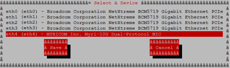
MCS 2.3 Installation and Configuration Guide
67
(HP Only) Verifying the NIC Interface Name
In an HP server, Avid assumes that interface “eth0” will be used. Since all interfaces in an HP
server are named “ethx”, additional steps need to be taken to ensure “eth0” is used.
To verify the NIC interface name:
1. Enter the RHEL Configuration screens by typing the following at the command prompt:
setup
2. From the Choose a Tool menu, select Network Configuration. Press Enter.
3. From the Network Configuration menu, select Device Configuration. Press Enter.
A list of NIC cards contained in the server enclosure appears.
4. Make note of the name associated with your interface. If necessary, use the arrow keys
to move up and down the list.
In the above example, a 10 Gb card has been placed in the server. It is currently
assigned “eth4”, but we will want to change that to “eth0”.
5. Note the name assigned to the interface of interest (e.g. eth0, eth1, ethn).
6. Perform the actions required at each menu (Cancel, Quit, Exit, etc.) to return to the
Linux prompt.
(HP Only) Swapping NIC Interface Names
If your interface of interest was not already named “eth0”, you will need to rename it. You will
also rename the NIC interface currently using the name “eth0”.
1. Edit the network script where persistent names are assigned to network interfaces:
vi /etc/udev/rules.d/70-persistent-net.rules
Note: A server with just one installed NIC card does not have a 70-persistent-net.rules file by
default. If the file is missing for any reason, it can be created using the following command:
udevadm trigger --subsystem-match=net
The output may look similar to the following. Note that in the example below, the 10Gb
Myricom card has been assigned “eth4”. In this scenario, you will want to swap the
names for “eth0” and “eth4” so that the desired Myricom board is renamed “eth0”.
MCS 2.3 Installation and Configuration Guide
68
# PCI device 0x14e4:0x1657 (tg3)
SUBSYSTEM=="net", ACTION=="add", DRIVERS=="?*",
ATTR{address}=="ac:16:2d:74:1b:58", ATTR{type}=="1", KERNEL=="eth*",
NAME="eth0"
# PCI device 0x14e4:0x1657 (tg3)
SUBSYSTEM=="net", ACTION=="add", DRIVERS=="?*",
ATTR{address}=="ac:16:2d:74:1b:59", ATTR{type}=="1", KERNEL=="eth*",
NAME="eth1"
# PCI device 0x14e4:0x1657 (tg3)
SUBSYSTEM=="net", ACTION=="add", DRIVERS=="?*",
ATTR{address}=="ac:16:2d:74:1b:5a", ATTR{type}=="1", KERNEL=="eth*",
NAME="eth2"
# PCI device 0x14e4:0x1657 (tg3)
SUBSYSTEM=="net", ACTION=="add", DRIVERS=="?*",
ATTR{address}=="ac:16:2d:74:1b:5b", ATTR{type}=="1", KERNEL=="eth*",
NAME="eth3"
# PCI device 0x14c1:0x0008 (myri10ge)
SUBSYSTEM=="net", ACTION=="add", DRIVERS=="?*",
ATTR{address}=="00:60:dd:45:14:50", ATTR{type}=="1", KERNEL=="eth*",
NAME="eth4"
2. Locate the lines corresponding to the NIC card you want to name eth0 and the one
already using the name.
Use the arrow keys on the keyboard to navigate the file.
3. Press the A key to append to the end of the line:
NAME="eth0"
4. Change NAME="ethX" (e.g. eth1, eth2, etc.) to the following:
NAME="eth0"
5. Locate the line corresponding to the NIC card that was already using the name eth0 and
rename it:
NAME="ethX"
where “X” is the number you removed in step 5 (e.g. eth1, eth2, etc.); that is, swap the
names.
6. Save and exit the vi session. Press <ESC> and type: :wq
MCS 2.3 Installation and Configuration Guide
69
(HP Only) Removing the MAC Address Hardware References
In addition to renaming the NIC interface, you will also need to remove the hardware references
– generally known as MAC addresses – from the affected NIC interface configuration files.
For each card where you renamed a NIC interface, edit the corresponding interface
configuration file and remove the hardware identifier. Otherwise, Linux will override the
changes you made earlier and reassign the old interface names the next time it boots (or you
restart the Linux network services).
1. Using the Linux text editor, vi, open the interface configuration file for one of the
renamed interfaces (e.g. ifcfg-eth0):
vi /etc/sysconfig/network-scripts/ifcfg-eth0
In Linux, each NIC interface has its own configuration file.
2. Locate the line containing the hardware identifier. It has the following form:
HWADDR = 00:00:00:00:00:00
3. Position the cursor on the HWADDR line and press “dd” to remove it. That is tap the
lower case letter D twice.
4. Save and exit the vi session. Press <ESC> and type: :wq
5. Repeat the above steps for the other NIC interface you renamed (e.g. ethX).
6. Once you have finished removing the hardware references for both the renamed NIC
interfaces, reboot the server to restart the network services and make the effects
permanent:
reboot
The MAC addresses will refresh automatically after the reboot.
7. Once the system has rebooted, log back into RHEL.
Note: Changing the contents of the /etc/udev/rules.d file requires a reboot rather than
simply restarting network service.
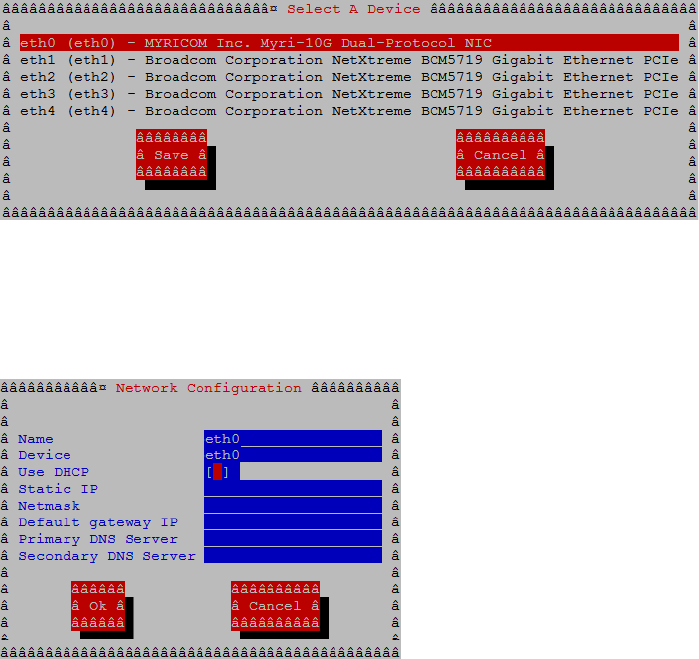
MCS 2.3 Installation and Configuration Guide
70
Configuring the Hostname and Static Network Route
This process will assume the configuration of a static IP address is desired.
1. Enter the RHEL Configuration screens by typing the following at the command prompt:
setup
2. From the Choose a Tool menu, select Network Configuration. Press Enter.
3. From the Network Configuration menu, select Device Configuration. Press Enter.
A list of NIC cards contained in the server enclosure appears.
4. Use the arrow keys to locate the primary interface (eth0, em1 or p1p1). Press Enter to
view its details.
Note: If you configured port bonding for an Interplay MAM integration, your primary
interface may be called “bond0”. For more information on port bonding, see Appendix B.
5. Dynamic Host Configuration Protocol (DHCP) is the default option. Arrow down to the
“Use DHCP” line and press the spacebar to deselect it.
6. Enter the following information:
Static IP address
Netmask (Subnet)
Note: All MCS servers in a cluster must be in the same subnet.
Default gateway IP
Primary DNS server
Secondary DNS server (if applicable)
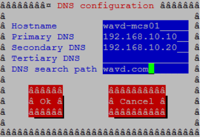
MCS 2.3 Installation and Configuration Guide
71
7. Arrow or Tab down to the OK button and press Enter.
You are returned to the list of NIC cards in the enclosure.
8. Select Save and press Enter.
9. From the Choose a Tool menu, select DNS Configuration. Press Enter.
10. Enter the following information for the DNS Configuration:
Enter the hostname
This should be entered as the short hostname only (e.g. wavd-mcs01) and not the
fully qualified domain name (FQDN) (e.g. wavd-mcs01-wavd.com).
Note: Hostnames should comply with “RFC 952” standards. Hostnames can be up to
24 characters, but Avid recommends keeping it under 15 characters. Hostnames
can contain numbers, but never begin a hostname with a number. The only “special
character” allowed in a hostname is a dash “ - “. Underscores are not allowed.
Primary DNS server
Secondary DNS server (if applicable)
Tertiary DNS server (if applicable)
DNS search path
11. Select Save & Quit. Press Enter.
12. Select Quit. Press Enter.

MCS 2.3 Installation and Configuration Guide
72
Verifying the
hosts
File Contents
The hosts file is used by the operating system to map hostnames to IP addresses. It allows
network transactions on the computer to resolve the right targets on the network when the
instructions carry a “people-friendly” hostname (e.g. wavd-mcs01) rather than an IP address
(e.g. 192.XXX.XXX.XXX). Querying and waiting for a response from a DNS server can be slow due
to network latency. The hosts file assists in quickly resolving hostnames to IPs which is
particularly important for clustered configurations.
By default the hosts file on a computer resolves the machine’s own IP address to localhost. In
this step, you verify the content of the hosts file, and remove any extra entries, if present. In
addition, since the active hosts file can be reset to its default configuration when a server fails or
is rebooted you also verify the system default hosts file.
1. Using the following command, open the active hosts (/etc/hosts) file for editing:
vi /etc/hosts
It should look similar to the following:
127.0.0.1 localhost localhost.localdomain localhost4 localhost4.localdomain4
::1 localhost localhost.localdomain localhost6 localhost6.localdomain6
In this example, the default IP address of 127.0.0.1 is mapped to various forms of
localhost, for both ipv4 and ipv6 systems.
In some cases, the entries include an explicit call-out of the computer’s own host name
(e.g. wavd-mcs01):
127.0.0.1 localhost localhost.localdomain localhost4 localhost4.localdomain4 wavd-mcs01
::1 localhost localhost.localdomain localhost6 localhost6.localdomain6 wavd-mcs01
Note: In a cluster the explicit call-out of the computer’s own host name is particularly
problematic. If this entry remains unaltered, another node querying "wavd-mcs01" for its IP
address would receive "127.0.0.1" in response. The node that did the querying would send
messages to itself instead of to the real "wavd-mcs01", and clustering would not function
normally.
2. If the computer’s own host name is present (e.g. wavd-mcs01), remove it:
127.0.0.1 localhost localhost.localdomain localhost4 localhost4.localdomain4
::1 localhost localhost.localdomain localhost6 localhost6.localdomain6
3. If you will be configuring an MCS cluster, you will want to add the IP addresses, FQDN
and hostnames of each of the cluster nodes.
For a four node cluster, for example, you would add four lines similar to the following:
127.0.0.1 localhost localhost.localdomain localhost4 localhost4.localdomain4
::1 localhost localhost.localdomain localhost6 localhost6.localdomain6
192.168.10.51 wavd-mcs01.wavd.com wavd-mcs01
192.168.10.52 wavd-mcs02.wavd.com wavd-mcs02
192.168.10.53 wavd-mcs03.wavd.com wavd-mcs03
192.168.10.54 wavd-mcs04.wavd.com wavd-mcs04
MCS 2.3 Installation and Configuration Guide
73
Note: It is a good idea to declare the nodes in the hosts file in order of latency, ascending.
Run a ping command to each node and add the lines to the file in order of the ping return.
For example, if node-2 returns a ping after 30ms and node-3 after 20ms, put in the line for
node-3 before node-2.
4. Save and exit the vi session. Press <ESC> and type: :wq
5. If you made changes, verify that the system default hosts file reflects the changes.
cat /etc/sysconfig/networking/profiles/default/hosts
If necessary, “vi” can be used to edit the file to match the changes you made to toe
master hosts file.
Verifying the Contents of resolv.conf and nsswitch.conf
Verifying the resolv.conf file:
The resolv.conf file contains your DNS and domain information.
1. Verify the DNS Server information has been stored in the RHEL resolver configuration
(resolv.conf) file:
cat /etc/resolv.conf
The DNS servers and DNS search path should be present in the file.
Using the vi editor, one or more additional search domains can be entered if necessary.
The search list is limited to six domains with a total of 256 characters. The file should
look something like:
nameserver <IP address of server1> (Primary DNS server)
nameserver <IP address of server2> (Secondary DNS server)
search domain1.com domain2.com (multiple domain names separated by a
single space or tab can be entered)
2. Delete any backup resolver configuration (resolv.conf.save) file that might have been
automatically created by the OS:
rm /etc/resolv.conf.save
Note: Due to a caveat in Linux, if you do not delete the resolv.conf.save file, when you
reboot, Linux overwrites the changes you just made.
Verifying the nsswitch.conf file:
Avid adjusts the nsswitch.conf file to instruct RHEL to prefer the local hosts file over DNS. In
cluster configurations, this ensures that there is no latency when attempting to discover the
cluster nodes.
1. Type: cat /etc/nsswitch.conf | grep hosts
MCS 2.3 Installation and Configuration Guide
74
The system outputs the lines containing the string “hosts”, similar to the following:
#hosts: db files nisplus nis dns
hosts: files dns
In the second line, ensure the word “files” comes before the word “dns”.
2. If “files” does not appear before “dns”, use the vi editor to reverse the priority order.
Ensuring the NIC Interface Comes Up at System Startup
In this step you verify that the primary network interface is set to come up when the system
boots.
1. Using the Linux text editor, vi, open the interface configuration file for eth0 for editing:
vi /etc/sysconfig/network-scripts/ifcfg-eth0
Note: If you are on a Dell server, remember to substitute “em1”, “p1p1” for “eth0”.
2. When you open the file for editing, it should look something like this:
DEVICE=eth0
HWADDR=00:60:dd:45:15:11
TYPE=Ethernet
UUID=
ONBOOT=yes
NM_CONTROLLED=no
DHCP_HOSTNAME=’$HOSTNAME’
BOOTPROTO=none
IPADDR=192.169.10.51
NETMASK=255.255.255.0
DNS1=192.169.10.10
DNS2=192.169.10.20
GATEWAY=192.168.10.1
USERCTL=no
IPV6INIT=no
3. Ensure that the ONBOOT entry is set to “yes”. If it is not, the interface will not be active
after rebooting the server.
4. Save and exit the vi session. Press <ESC> and type: :wq
5. Reboot the MCS server:
reboot
Note: You are asked to reboot at this time to ensure that all networking changes are
active and the system comes up as expected. If you do not reboot, some of the steps in
the next procedure will fail.
6. Once the system has rebooted, log back into RHEL.

MCS 2.3 Installation and Configuration Guide
75
Verifying Hostname, Network and DNS Connectivity
Before continuing, take a moment to verify that the server’s hostname responds as expected
and that network connectivity is now established.
To verify the hostname:
1. Verify the short hostname. In the RHEL command prompt, type:
hostname
The short hostname (e.g. wavd-mcs01) should be print to the screen.
2. Verify the fully qualified domain name (FQDN). In the RHEL command prompt, type:
hostname -f
The fully qualified hostname (e.g. wavd-mcs01.wavd.com) should be print to the screen.
If you do not receive the expected output, verify your hosts file and the resolv.conf file.
To verify network connectivity:
1. Use the ping command to verify connectivity to your network gateway address.
ping –c 4 <Gateway IP address>
“ping” is the command. “-c 4” is the count of how many times the ping command is
issued. If you do not specify a count, ping will continue forever. In that event, press
CTRL-C to stop the ping. Example:
[root@wavd-mcs01 ~]# ping -c 4 192.168.10.1
PING 192.168.10.1 (192.168.10.1) 56(84) bytes of data.
64 bytes from 192.168.10.1: icmp_seq=1 ttl=255 time=0.362 ms
64 bytes from 192.168.10.1: icmp_seq=2 ttl=255 time=0.330 ms
64 bytes from 192.168.10.1: icmp_seq=3 ttl=255 time=0.302 ms
64 bytes from 192.168.10.1: icmp_seq=4 ttl=255 time=0.804 ms
2. Now use the ping command to test the connection to host servers in your network.
Examples of host servers could be: Interplay Production Engines, ISIS servers, iNEWS
servers, etc. This will not only test connection to the host server, but also verifies DNS.
ping –c 4 <hostname>
3. Verify the same test, this time by pinging the host servers by IP address.
Note: Now that you have configured and verified the connection to the network, you can now
switch to using an indirect method for configuring the server. For more information refer back to
Accessing the MCS Server(s) on page 14.
MCS 2.3 Installation and Configuration Guide
76
Configure Date and Time Settings
Ensuring that the date, time and time zone are correct on each MCS server is critical to a
successful implementation. This process will walk you through configuring the above values as
well as setting a Network Time Protocol (NTP) source for continued time synchronization.
If you do not have an NTP server already configured, see your local IT Department about
creating one prior to continuing with this process. Maintaining time synchronization between
MCS servers and host systems (ISIS, Interplay Production, etc) is critical. Maintaining time
synchronization between nodes in an MCS cluster configuration is particularly critical.
Setting the Time Zone
1. The installation script sets the default location to “America/New_York”. Verify this by
viewing the contents of the Linux “clock” file.
cat /etc/sysconfig/clock
If the US/Eastern time zone is appropriate for your installation, skip this process.
Otherwise, continue…
2. List the contents of the directory containing RHEL time zone information:
ls /usr/share/zoneinfo
A list of time zone regions is presented. For example:
US time zones are located in: /usr/share/zoneinfo/US (standard US time zones)
European time zones are located in: /usr/share/zoneinfo/Europe
And so on...
3. List the contents of the directory that are specific to your location. Example:
ls /usr/share/zoneinfo/US
4. Make note of the time zone name that relates to your installation.
5. Edit the clock file to reflect the correct time zone for your installation.
vi /etc/sysconfig/clock
Example: Replace zone="America/New_York" with zone="US/Pacific"
6. Save and exit the vi session. Press <ESC> and type: :wq
7. Create the symbolic link RHEL needs to make use of the new time zone information:
ln –sf /usr/share/zoneinfo/<yourzone> /etc/localtime
In the above command, <yourzone> is the path you entered in the clock file (e.g.
US/Pacific).
MCS 2.3 Installation and Configuration Guide
77
Note: Creating a symbolic link is more robust than copying. For example, the files in
/usr/share/zoneinfo contain daylight saving time (DST) information. A symbolic link allows
your system to automatically accommodate changes to DST practices that might arise in the
future. Such changes would be propagated through RHEL updates to the /usr/share/zoneinfo
files.
8. Verify the settings using the date command:
date
The local time and time zone should now be shown.
Synching the System Clock
In this step you set the Network Time Protocol (NTP) daemon to automatically synchronize the
system clock with an NTP time server every 30 minutes. This is done by creating a job for the
Linux cron utility. The cron job runs the NTP daemon, ntpd.
Note: Setting up ntpd to run as a service at startup is also a possibility. However, some
consider it a security risk to run ntpd in “continuous” mode. The technique shown here
keeps the system clock synchronized while minimizing exposure to risk by causing ntpd
to exit after it fetches the correct time.
Note: The use of the iburst option within the cron job is not recommended. It produces
very rapid time shifts and can lead to synchronization problems.
1. Verify the current date and time with the date command. Type: date
2. This process will verify connectivity to the NTP server. Change the date and time so that the
clock is 10 minutes behind the correct time of day.
date MMDDHHmmYYYY
Note: If you set the clock more than 1000ms (~17min) off from your NTP server, the time
may not update.
3. Check the status of the ntpd service. Type: service ntpd status
If the service is running, stop the service. Type: service ntpd stop
4. Verify that the NTP server of interest is reachable by querying it:
ntpdate -q <ntp_server_address>
Example output:
server 192.168.10.25, stratum 3, offset 468.746036, delay 0.02585
1 Jan 13:05:00 ntpdate[7554]: step time server 192.168.10.25 offset
468.746036 sec
5. Edit the NTP configuration (ntp.conf) file:
vi /etc/ntp.conf
MCS 2.3 Installation and Configuration Guide
78
6. Scroll down to the section of the file that details the NTP servers and place a ‘#’ symbol in
front of any existing NTP servers to comment them out. For example:
# server 0.rhel.pool.ntp.org
# server 1.rhel.pool.ntp.org
# server 2.rhel.pool.ntp.org
7. Update the file with the NTP information for your configuration. Updated example:
# server 0.rhel.pool.ntp.org
# server 1.rhel.pool.ntp.org
# server 2.rhel.pool.ntp.org
server 192.168.10.25
server 192.168.10.26
8. Save and exit the vi session. Press <ESC> and type: :wq
9. Set up a cron job by creating a new file containing instructions for cron:
vi /etc/cron.d/ntpd
10. Add a line with the instructions for cron:
0,30 * * * * root /usr/sbin/ntpd -q -u ntp:ntp
The command above instructs cron to:
• Run the cron job every 30 minutes as root.
“0,30” is a comma-separated list (i.e. run at 0 minutes and 30 minutes). “*” is a
special list indicating every value in the list (i.e. every hour, every day of the month,
every month, every day of week).
• The job is /usr/sbin/ntpd
• The -q switch tells ntpd to exit after it sets the system clock
• The -u switch tells Linux to run the job as user ntp, in user group ntp
The general form of the cron command is the following:
# Minute Hour Day of Month Month Day of Week
# (0-59) (0-23) (1-31) (1-12 or Jan-Dec) (0-6 or Sun-Sat)
11. Save and exit the vi session. Press <ESC> and type: :wq
12. Once again, verify the current date and time. It should be 10 minutes behind the correct
clock.
date
13. Update the system clock now by querying the NTP server with the NTP daemon:
/usr/sbin/ntpd -q -u ntp:ntp
The system responds with a message similar to the following:
ntpd: time set +570.677029s
14. Verify the updated date and time:
date

MCS 2.3 Installation and Configuration Guide
79
Creating the File Cache on the RAID
If your configuration does not include a RAID 5, continue to one of the following (as appropriate
for your installation):
• Configuring MCS for MediaCentral UX and Media Composer Cloud
• Configuring MCS for Interplay MAM
In an earlier step you might have created a RAID 5 for the cache using the “arrays” utility built-in
to the server’s BIOS. In this step you will partition the RAID, create a logical volume for the RAID
and mount the MCS cache on it.
Partitioning the RAID
In this procedure you partition the RAID and write the new partition table entry to disk using the
GNU parted disk partitioning utility.
The enclosure contains two devices of interest, the system disk (/dev/sda) and the RAID
(/dev/sdb). Partitioning the system disk was performed automatically by the RHEL installer. You
only need to partition the RAID, as indicated in this section.
Note: Starting with RHEL 6.3, Red Hat creates a GPT volume when the MCS installation
scripts initialize the cache volume during OS installation. GPT volumes must be handled
using the GNU parted utility (rather than the Linux fdisk utility).
To partition the RAID:
1. Use the GNU parted utility to ensure the RAID 5 HD device exists:
parted –l
Note: Note the command take a lower-case “L” (not a numerical “one”).
Note: The Linux “fdisk -l” command can also be used to list the devices. However, it
returns the following warning:
WARNING: GPT (GUID Partition Table) detected on '/dev/sdb'! The
util fdisk doesn't support GPT. Use GNU Parted.
2. Find the free space on the /dev/sdb device:
parted /dev/sdb p free
Information similar to the following is displayed:
Model: HP LOGICAL VOLUME (scsi)
Disk /dev/sdb: 2500GB
Sector size (logical/physical): 512B/512B
Partition Table: gpt
Number Start End Size File system Name Flags
17.4kB 2500GB 2500GB Free Space
MCS 2.3 Installation and Configuration Guide
80
3. Create a primary partition on the RAID 5 using all the available space (2500 GB in the
sample output provided above):
parted -a optimal /dev/sdb mkpart primary ext2 0% 2500GB
The system might respond with the following message:
Information: You may need to update /etc/fstab
The message can be ignored. You will update fstab when you create the logical volume
and mount the cache for the new partition.
4. Set sdb partition one to type logical volume, and its state to on.
parted /dev/sdb set 1 lvm on
5. Run the parted utility again to list your changes:
parted -l
Model: HP LOGICAL VOLUME (scsi)
Disk /dev/sdb: 2500GB
Sector size (logical/physical): 512B/512B
Partition Table: gpt
Number Start End Size File system Name Flags
1 17.4kB 2500GB 2500GB primary lvm
Notice in the above output the partition now has a partition number, is the primary
partition, and has a logical volume flag. You create the filesystem in the next step.
Creating the Logical Volume, Filesystem and Mounting the
Cache
In this procedure you work with the newly partitioned RAID 5 using the Linux Logical Volume
Manager (LVM). The hierarchy of volumes in Linux is as follows: physical volume, volume group
and logical volume.
To create the logical volume and mount the cache:
1. Create the physical volume:
pvcreate --metadatasize=64k /dev/sdb1
Note the name of the physical volume (/dev/sdb1) takes a 1 (one).
LVM feedback indicates the successful creation of the physical volume.
2. Create a volume group, vg_ics_cache, containing the physical volume /dev/sdb1:
vgcreate -s 256k -M 2 vg_ics_cache /dev/sdb1
LVM feedback indicates the successful creation of the volume group.
MCS 2.3 Installation and Configuration Guide
81
3. Before creating the logical volume, obtain a value for the volume group’s physical
extents:
vgdisplay vg_ics_cache
A list of properties for the volume groups appear, including the physical extents (Free
PE). Physical extents are the chunks of disk space that make up a logical volume.
Sample output is shown below:
--- Volume group ---
VG Name vg_ics_cache
System ID
Format lvm2
Metadata Areas 1
Metadata Sequence No 2
VG Access read/write
VG Status resizable
MAX LV 0
Cur LV 1
Open LV 1
Max PV 0
Cur PV 1
Act PV 1
VG Size 1.09 TiB
PE Size 256.00 KiB
Total PE 4578332
Alloc PE / Size 0 / 0
Free PE / Size 4578332 / 1.09 TiB
VG UUID cyWpGZ-s3PG-8UqH-4TBl-rvBA-33oJ-3uZt0u
Use the “Free PE” value to create a logical volume occupying the entire volume group
(below).
4. Create the logical volume, lv_ics_cache, containing the volume group vg_ics_cache:
lvcreate -l <Free_PEs> -r 1024 -n lv_ics_cache vg_ics_cache
In the above command, replace <Free_PEs> with the value obtained in the previous
step. This is the number before the slash in the “Free PE” line. No unit is needed.
For example:
lvcreate -l 4578332 -r 1024 -n lv_ics_cache vg_ics_cache
Note the first switch in lvcreate is lower case “L”.
LVM feedback indicates the successful creation of the logical volume. Note that Linux
may override the sector size you specified. That is OK.
MCS 2.3 Installation and Configuration Guide
82
5. Create a filesystem on the logical volume (i.e. format it):
mkfs.ext4 /dev/vg_ics_cache/lv_ics_cache
Note in the above command you specify logical volume by its Linux block device name
(/dev/<volume_group>/<logical_volume>).
As in other operating systems, formatting in RHEL is a slow operation. Please be patient.
Feedback similar to the following indicates success:
This filesystem will be automatically checked every 38 mounts or
180 days, whichever comes first. Use tune2fs -c or -i to override.
6. Edit the filesystem table:
vi /etc/fstab
7. Add an entry at the end of the file:
/dev/mapper/vg_ics_cache-lv_ics_cache /cache ext4 rw 0 0
This automates the mapping of the logical volume to a filesystem directory (/cache in
this case).
8. Save and exit the vi session. Press <ESC> and type: :wq
9. Mount the volume:
mount /dev/mapper/vg_ics_cache-lv_ics_cache /cache
Alternately, since you added an entry to fstab, you ought to be able to mount the cache
as follows:
mount /cache
Note: If you receive an error indicating the mount point /cache does not exist, create the
cache manually and issue the mount command again:
mkdir /cache
mount /dev/mapper/vg_ics_cache-lv_ics_cache /cache
10. Verify that /cache has been mounted correctly:
df –h
The following information is displayed about the cache: size, used, available, user % and
mount point (mounted on), similar to the following:
Filesystem Size Used Avail Use% Mounted on
/dev/mapper/vg_ics_cache-lv_ics_cache
29G 585M 27G 3% /cache
MCS 2.3 Installation and Configuration Guide
83
11. Verify that /cache has the correct ownership and read-write-exec settings:
ls -la /cache
Information is displayed about the cache ownership, similar to the following:
drwxr-xr-x 5 maxmin maxmin 4096 Oct 16 10:02 .
12. If the ownership is of /cache is not set to user maxmin, change its ownership:
chown maxmin:maxmin /cache
13. If the /cache directory does not have its read-write-exec settings are not rwx for owner,
group, other, change the permissions:
chmod 0777 /cache
14. Create the following two cache directories:
mkdir /cache/download
mkdir /cache/fl_cache
15. Change their ownership to user maxmin:
chown maxmin:maxmin /cache/download
chown maxmin:maxmin /cache/fl_cache
16. Change their permissions:
chmod -R 02777 /cache/download
chmod -R 02777 /cache/fl_cache
17. Verify that /cache and its subdirectories now have the correct ownership, read-write-
exec settings, and setgid special permission:
ls -la /cache
Updated information is displayed, which ought to be similar to the following:
drwxrwxrwx 5 maxmin maxmin 4096 Mar 22 10:04 .
Note: User maxmin owns the MCS process that writes to the cache. Avid processes will
create subdirectories in /cache, on an as-needed basis. If you are deploying a cluster, you will
revisit caching later in the installation to replicate the cluster contents using GlusterFS.

MCS 2.3 Installation and Configuration Guide
84
Enable / Disable 3G and Edge Streams
By default, MCS servers encode three different media streams for MediaCentral UX applications
detected on mobile devices -- for Wi-Fi, 3G, and Edge connections. For Wi-Fi only facilities, it is
recommended that you disable the 3G and Edge streams, to improve the encoding capacity of
the MCS server.
To Disable 3G and or Edge Streams:
1. Log in as root and edit the following file using a text editor (such as vi):
/usr/maxt/maxedit/share/MPEGPresets/MPEG2TS.mpegpreset
2. In each of the [Edge] and [3G] areas, set the active parameter to active=0.
3. Save and close the file.
To re-enable 3G or Edge, edit the file and reset the “active” value to 1.
Copying Software to the MCS Server
Now that the basic RHEL installation is complete, you might need to copy additional software to
the MCS server. Common software includes:
RHEL Security Patches
MCS Software Updates
Gluster file replication software (used in cluster configurations)
Closed Captioning Service installer
MAM Connector
For information on how to copy software to an MCS server, see Copying Software to the MCS
Server on page 176.
Security Updates
Once you have installed the operating system, please take a moment to resolve any outstanding
RHEL security vulnerabilities. For information and links to KB articles with instructions, see the
“Security Updates” section in the Avid MediaCentral Platform Services ReadMe.
Install Software Patches
Avid releases patches for MCS on a regular basis to assist in addressing customer issues and
feature requests. Refer to the Avid MediaCentral Platform Services ReadMe for information on
current patches and install any available patches at this time.
MCS 2.3 Installation and Configuration Guide
85
PART IV: CONFIGURING MCS

MCS 2.3 Installation and Configuration Guide
86
Chapter Overview
This chapter is divided into two main sections. Proceed to the section appropriate for your
installation:
- Configuring MCS for MediaCentral UX and Media Composer Cloud
o This section includes information on multiple workflows such as iNEWS, Interplay
Production, Media Composer Could, Send To Playback, etc. Read and apply the
sections appropriate for your installation.
- Configuring MCS for Interplay MAM
The following table describes the topics covered in this chapter.
Step Task Time Est.
Configuring MCS for MediaCentral UX and Media Composer Cloud
1
Updating the MediaCentral UX Configuration
2 min
Covers use of the Configurator Tool.
2
Logging into MediaCentral UX
5 min
Log in to MediaCentral for the first time.
3
Changing the Administrator Password
2 min
For security it is recommended you change the administrator password.
4
Creating a Second Administrator User
5 min
Helps to ensure you do not get locked out of the interface.
5
Configuring System Settings
varies
Covers the configuration of the MediaCentral System Settings.
6
Verifying the System Settings
varies
A process for testing the configured settings.
7
Configuring Send To Playback Settings
5 min
Configure settings for STP workflows.
8
Importing Domain Users
5 min
Covers the process of importing Windows Domain Users.
9
Creating Local Users and Assigning Roles
varies
Information on creating local users and role assignments.
10
Continuing the Installation
1 min
Suggestions for additional steps to continue your installation.

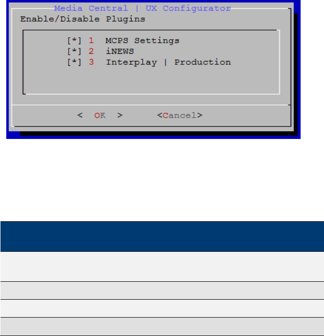
MCS 2.3 Installation and Configuration Guide
88
Configuring MCS for MediaCentral UX and Media Composer
Cloud
Now that you have installed and configured the operating system, you are ready to configure
the software and settings specific to MediaCentral.
As a reminder, if you are running a cluster, complete this section on the master node only.
Settings will be replicated to the other nodes during the cluster configuration process.
Updating the MediaCentral UX Configuration
By default, the MediaCentral UX user interface contains functionality for all the MCS solutions it
supports. Functions that are not required for your installation should be removed. If you are
configuring a cluster, this step only needs to be completed on the master and slave nodes, but it
is good practice to run the configurator on all nodes. This step can be completed on all nodes
concurrently.
1. Start the configurator by typing the following at the Linux prompt:
/opt/avid/avid-interplay-central/configurator
The configuration UI appears.
Note: Media Distribute (not shown) appears in the configurator UI only if it has been
installed on the system (through a separate installer).
2. Select the appropriate application profile settings.
The following table outlines typical settings by deployment type:
MCPS
Settings
iNEWS
Interplay
Production
Media
Distribute
MediaCentral & Media
Distribute ON ON ON ON
Standard MediaCentral
ON
ON
ON
OFF
Interplay Production Only
ON
OFF
ON
OFF
Media Composer Cloud
ON
OFF
ON
OFF

MCS 2.3 Installation and Configuration Guide
89
MCPS
Settings
iNEWS
Interplay
Production
Media
Distribute
Interplay MAM
ON
OFF
OFF
OFF
iNEWS Only
OFF
ON
OFF
OFF
For example, for an iNEWS-only deployment without video playback, you would enable
iNEWS and disable MCPS Settings and Interplay Production.
Note what each selection controls:
• MCPS Settings: Toggles the MCPS group in the System Settings layout. This
group provides access to the Load Balancer, Playback Services and Player
settings details pages.
• Interplay Production: Toggles the Interplay Production settings group.
• iNEWS: Toggles the iNEWS settings group.
• Media Distribute: Toggles the Interplay Media Distribute layout.
3. Use the Up and Down arrow keys to move between the options, Left and Right arrow
keys to move between OK and Cancel, SPACEBAR to toggle the asterisks, and press
Enter to confirm.
• Asterisk = enabled
• No Asterisk = disabled
Now when you launch MediaCentral, the UI will be correctly configured for your
deployment.
Logging into MediaCentral UX
MCS servers are configured using the MediaCentral UX System Settings. This configuration is
completed through the use of a web browser such as Google Chrome.
Note: If you are configuring a cluster, you configure the MediaCentral UX System
Settings once on the master node only. Do not configure these settings on slave nodes.
The slave nodes obtain settings from the master node through the clustering
mechanisms. Complete all remaining sections of this chapter on the Master node only.
When you sign in to MediaCentral for the first time (in this procedure) you are prompted to sign
in to an iNEWS server, an Interplay Production system, or both.
1. Launch a web browser supported by MediaCentral.
Supported browsers include: Google Chrome or Safari (on Mac OS).
2. Enter the URL of the MCS server In the address bar:
• https://<hostname> where <hostname> is the host name of the MCS server
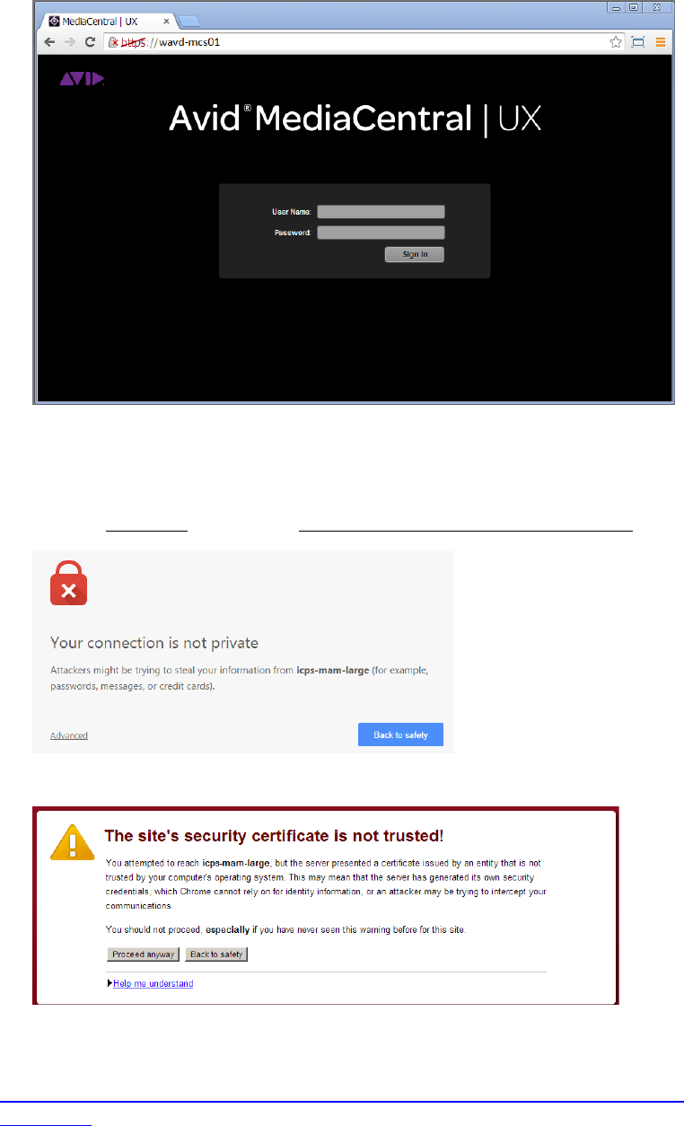
MCS 2.3 Installation and Configuration Guide
90
The Interplay Central sign-in screen appears.
In place of the sign-in screen, you might see a warning indicating the connection is not
private. The warning relates to SSL certificates.
For the purposes of installing and configuring, ignore the warning:
- Click Advanced and then the Proceed to <MediaCentral URL> (unsafe) link.
In older versions of Chrome (previous to release 37), the following warning is shown instead:
In the above case, click Proceed Anyway.
Note: For information on configuring a trusted certificate, see the Avid KB:
http://avid.force.com/pkb/articles/en_US/how_to/SSL-Certificates-for-server-to-browser-
connections.
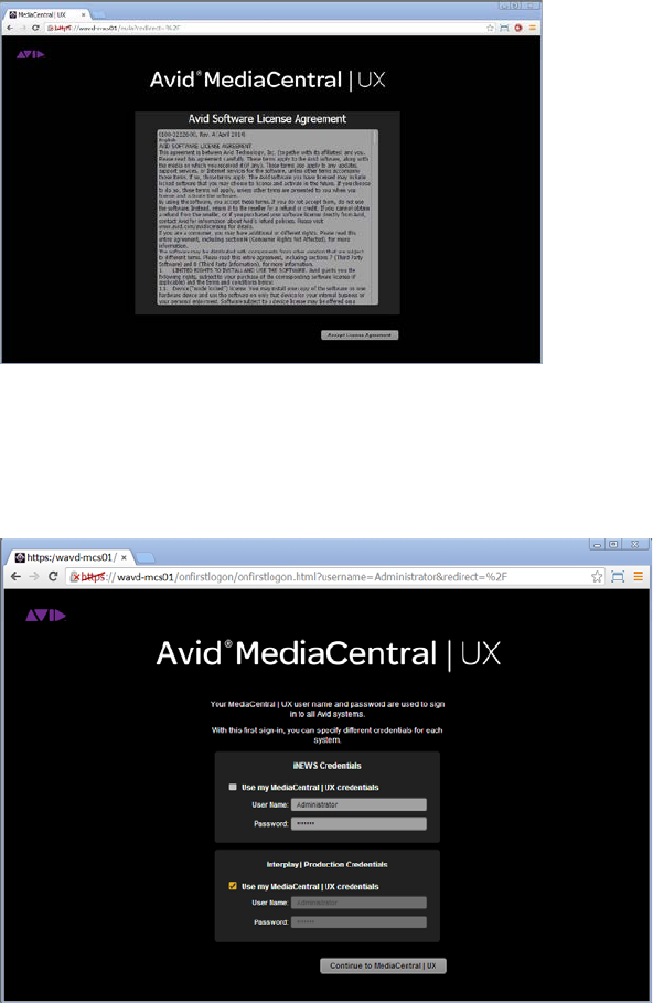
MCS 2.3 Installation and Configuration Guide
91
3. The first time any user signs in, the Avid Software License Agreement is presented. Click
the Accept License Agreement button to proceed.
4. You are asked for login credentials. Depending upon what options were selected in the
Interplay Configurator, you may be asked for Interplay and / or iNEWS login information.
• User name: Administrator
• Default Password: Avid123
If you created iNEWS and Interplay Production users called Administrator with the
default MediaCentral Administrator password, select the “Use my MediaCentral
Credentials” checkboxes.
Otherwise, enter the user names and passwords for the iNEWS system, and the
Interplay Production system.
Note: If the security settings for one of these systems is inaccurate, you will see a warning
message that states that the application is unable to authorize the sign-in name or
password. This will be the case for any iNEWS credentials entered, since you have not yet
specified the iNEWS server to be used. If you receive a warning, click the link provided and
verify your security settings.
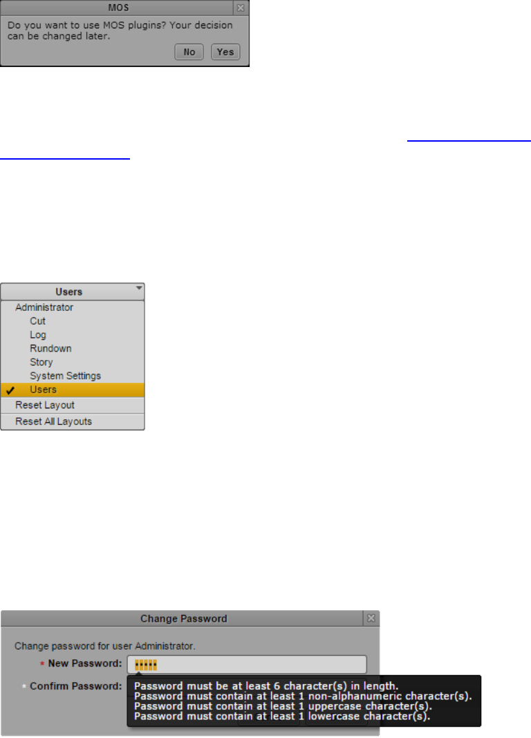
MCS 2.3 Installation and Configuration Guide
92
5. If you are using a Chrome browser, the first time you sign in to MediaCentral a dialog
box asks if you want to use MOS plug-ins.
MOS plug-ins are used in certain iNEWS workflows.
Note: Selecting “yes” installs only the container needed for Active X controls. To make use of
MOS plug-ins you need to install additional software as described in “Appendix C: Enabling
MOS Active-X Plug-Ins” on page 210.
Changing the Administrator Password
For security reasons, it is strongly suggested that you change the password for the Administrator
1. While logged in as the Administrator, select Users from the Layout selector.
2. Expand the list of Administrators in the User Tree and locate the Administrator user.
3. Double-click the Administrator. Details for the user account will appear on the right.
4. Click the Change Password button in the Details pane, and enter a new password for the
Administrator user.
Note: MediaCentral v2.1 introduced strong password enforcement. This feature was made
optional in v2.2; however the default is to have strong passwords enabled. See the Avid
MediaCentral | UX Administration Guide for more information on this feature.
5. Click OK update the password information.
A message appears indicating that the password was successfully changed.
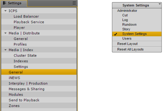
MCS 2.3 Installation and Configuration Guide
93
Creating a Second Administrator User
In the event that you are locked out of MediaCentral for any reason, it is wise to create a second
Administrator-level user.
1. While in the Users Layout, highlight the Administrators group in the User Tree.
2. Click the Create User button under the User Tree tab.
3. In the Details pane, assign a User Name.
4. Enter a Password and confirm the password.
5. Deselect the checkbox for “User must change password at next sign-in.”
6. Click the Save button in the bottom-right corner of the window.
The user account is created.
Configuring System Settings
Much of the configuration of MediaCentral is completed through the System Settings. Proceed
through this section and configure settings applicable to your configuration.
Note: If you are configuring a cluster, you configure the MediaCentral UX System Settings
once on the master node only. Do not configure these settings on slave nodes. The slave
nodes obtain settings from the master node through clustering mechanisms.
To access the System Settings, select “System Settings” from the Layout selector in the top-right
corner of the interface. This layout will only appear if you are logged in as a user with
Administrator rights.
This section will guide you through the configuration of some of these system settings. For
more information, see the Avid MediaCentral | UX Administration Guide.
Media Distribute settings are shown in the above example, however these settings will only
appear if Media Distribute has been installed on the system. For more information see the
Media Distribute Installation and Configuration Guide.
MCS 2.3 Installation and Configuration Guide
94
General Settings
This section configures general settings related to the overall operation of MediaCentral.
1. In the Settings pane, select General.
2. System ID: Every MCS system can be identified with a System ID provided by Avid at
point of sale. This ID can be used to access Avid Customer Care for systems with valid
support contracts.
Once entered, the System ID is stored in the ACS bus. The System ID is displayed when
you invoke the ics_version command from Linux or when you select Home>About within
the MediaCentral UI.
Note: If you cannot locate your System ID, contact your Avid representative.
3. Search Pane: Specify the maximum number of assets to be displayed in a search. The default
value of this field is 50.
4. Session Timeout: Specify the number of minutes of inactivity before the user’s session
is disconnected. The range of this value is between 10 minutes and 1440 minutes (24
hours). The default value of this field is 30 minutes. As of MediaCentral v2.1.0, this
feature can be enabled or disabled.
5. Time Zone: Use the pull-down menu to select a default time zone for the local
MediaCentral system. This information is used to properly display assets when doing
searches outside of the local system. Examples:
- US/Eastern
- Europe/London
- Asia/Hong_Kong
6. Date Format: Use the pull-down menu to select a default date format for the local
MediaCentral system. This information is used to properly display assets when doing
searches outside of the local system. Options:
- DD.MM.YYYY hh:mm:ss
- DD/MM/YYYY hh:mm:ss
- YYYY-MM-DD hh:mm:ss
- MM/DD/YYYY hh:mm:ss
7. Click Apply to save your changes.
iNEWS Settings
This section configures settings related to Avid iNEWS. ICS 1.0 – 1.4 supported connection to
only one iNEWS system. iNEWS Community support was added in ICS 1.5 with up to 24
members. ICS 1.8 increased possible community members to 50.
1. In the Settings pane, select iNEWS.
MCS 2.3 Installation and Configuration Guide
95
2. System ID: Enter the System ID for your iNEWS system. This information can be found
on the iNEWS server(s) in the /site/system file. If your iNEWS system consists of
multiple servers for load balancing and failover, using the System ID ensures that
MediaCentral connects to iNEWS properly. iNEWS servers will often include a –a or –b
suffix in their hostname. Do not include these suffixes. Ensure that all MediaCentral
servers can resolve the hostnames and IP addresses of all iNEWS servers through DNS.
3. Timing: This value specifies how the iNEWS timing field is updated when you associate a
sequence with a story.
4. Tape ID: When you associate a sequence with a story, this iNEWS field name is
associated with the sequence’s Tape-ID field.
Example iNEWS field: video-id
5. Pagination: The maximum number of items listed in the Queue/Story pane or the
Project/Story pane. To view more items beyond the number displayed, click the Show
More Results button. The range is 5 to 255 items. The default value of this field is 50.
6. Click Apply to save your changes.
Interplay Production Settings
This section configures settings related to Interplay Production. Avid supports connecting
MediaCentral to only one Interplay Production system per MCS installation.
1. In the Settings pane, select Interplay | Production.
2. Interplay | Production Server: Enter the (short) hostname or virtual hostname of the
Interplay Production Engine. An IP address is also acceptable here. Do not use a Fully
Qualified Domain Name (FQDN) in this field.
3. MCDS Service URL: Enter the URL of the server or servers hosting the MediaCentral
Distribution Service. You can enter a hostname or IP address for the server. The
standard port number used by this service is 8443. If you have installed multiple copies
of MCDS, list each URL separated by a comma and a space. Multiple instances of MCDS
provide failover capability, but not load balancing.
Example: https://wavd-tc01:8443
4. Location for Script Sequence:
a. In the Path field, specify a folder in the Interplay Production database where
script sequences will be stored. The correct path format does not include a
leading slash.
Example: Projects/iNEWS or iNEWS/Scripts
b. Select whether you want sub-folders in the parent folder to be created by
Queue name, Date, or Story name.
5. Assets Pane: Sets the max number of Interplay assets to display at one time. This value
can range between 5 and 1000. The default value for this field is 50.
6. Click Apply to save your changes.
MCS 2.3 Installation and Configuration Guide
96
Messages & Sharing
These settings enable messages delivered through the messaging service to be forwarded to
user’s individual email accounts. These settings have nothing to do with emails sent from the
MCS cluster or other Linux processes. Only messages created in the Messaging Pane are
forwarded.
1. In the Settings pane, select Messages & Sharing.
2. Message Archiving: Configure the number of days to retain active messages. Messages
older than this will be archived. The default value of this field is 7.
Note: For instructions on retrieving archived messages, see the Avid MediaCentral | UX
Administration Guide.
3. Email forwarding: If email forwarding is desired, enable the checkbox for this option.
Consult with your in-house IT Department for this information.
a. SMTP server hostname: Enter an SMTP server hostname.
Example: webmail.wavd.com
b. Port: Enter a communication port. The default port is 25.
c. User name: Enter a username in the form of an e-mail address.
Example: admin@wavd.com
d. Password: Enter the password for the associated user account.
e. Use SSL (Secure Sockets Layer): Select this checkbox if required by IT.
f. Ignore TLS (Transport Layer Security): Select this checkbox if required by IT.
4. Once you have configured the email forwarding fields, verify functionality by entering a
recipient email and clicking Validate.
Note: If the e-mail is not received, verify with your IT Department that ICMP traffic is
allowed through appropriate firewalls and network switches.
5. Click Apply to save your changes.
Playback Service Settings
This section configures settings related to MediaCentral Playback Services (MCPS). MCPS is one
of the software services that run on the MCS server. MCPS is responsible for the compression
and playback of video and audio media on Internet-connected clients.
1. In the Settings pane, select ICPS> Playback Service.
2. Player Settings: The “Save Failed AAF” feature automatically saves AAF files that do not
parse properly to a dedicated folder (/cache/aaf_to_investigate) on the MCS server.
This feature can assist in troubleshooting efforts and should only be enabled upon
request from Avid Customer Care.

MCS 2.3 Installation and Configuration Guide
97
3. Interplay Workgroup Properties
a. User / Password: MediaCentral requires a dedicated user to access the
Interplay Production database. Enter that user and password.
Suggested User Name: MCSAdmin
b. Connect to HAG: Check this box to connect to an Interplay Production Media
Indexer High Availability Group (HAG). The HAG must already be configured in
Interplay Production.
Note: Interplay Central connects to the primary node of the HAG only. It does not
participate in HAG redundancy.
c. MI Host: If you did not select the Connect to HAG checkbox, enter the (short)
hostname of the Interplay Media Indexer to connect to a specific Media Indexer.
An IP address can also be used in this field. Do not use a Fully Qualified Domain
Name (FQDN) in this field.
Note: Checking the Connect to HAG box grays-out the MI Host field.
d. Workgroup Name: Enter the name of the Interplay Production Workgroup
(Framework). The Workgroup Name is case sensitive.
e. Lookup Servers: Enter the (short) hostname of the server hosting the Interplay
Production Framework Lookup Service. If there are multiple Lookup Servers,
enter each hostname separated by a comma. Do not use a Fully Qualified
Domain Name (FQDN) in this field.
f. Enable Dynamic Relink: If working in a multi-res environment, environments
with Interplay Capture or environments with Interplay Archive using partial
restore workflows, enable this checkbox.
4. General ISIS Settings
a. Enable Remote Host: If you are connected to Avid ISIS through a Zone1 or
Zone2 network connection, leave this box unchecked. If you are connecting
through Zone3 (preferred configuration for ISIS 7500), enable this checkbox.
Note: For a refresher on ISIS Zone definitions, see Network Interface Cards and
Network Connections on page 13.
b. Use Network Device: If you have multiple network interfaces configured and
enabled on the MCS server, enter the name of the interface used to connect to
Avid ISIS. Multiple interfaces can be entered, separated by a comma. This field
can be left blank if the MCS server has only one active network connection.
Examples: eth0 or em1
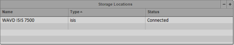
MCS 2.3 Installation and Configuration Guide
98
c. Ignore Network Device: If you have multiple network interfaces configured and
enabled on the MCS server, enter the name of the interface that will not be
used to connect to Avid ISIS. Multiple interfaces can be entered, separated by a
comma. This field can be left blank if the MCS server has only one active
network connection.
Examples: eth1 or em2
d. Connection Mode: Select the type of connection used to connect to Avid ISIS.
Options: 1GB Connection or 10GB Connection
5. Storage Locations. This section provides settings enabling MCA to connect to Avid ISIS
shared storage.
a. Click the plus ‘+’ button to add a Storage Location.
b. A “New File System” box will appear. Give the Storage Location a nickname and
click OK.
Examples: “WAVD ISIS 7500” or “Production ISIS”
c. Click OK. Additional fields will appear below the Storage Location.
d. Virtual Host Name: Enter the virtual hostname of the ISIS. Every ISIS system has
a virtual hostname, regardless of it being a single or failover configuration. The
Virtual Host Name should be entered in all lower-case.
e. User / Password: MediaCentral requires a dedicated user to access the ISIS
storage system. Enter that user and password.
Suggested User Name: MCSAdmin
Note: If you are connecting to multiple ISIS systems, ensure the same
user/password is created on each ISIS.
f. System Directors: If you are connecting through Zone3 to ISIS, enter the IP
addresses of the System Directors. Do not add the virtual IP’s. Each IP address
should be separated by a semicolon (no spaces).
g. Repeat these steps if configuring more than one ISIS connection.
6. Click Apply to save your changes. As the settings apply, MediaCentral will attempt to
connect to the ISIS system(s) you have specified.
If the connection is made successfully, the Status field should change from
“Disconnected” to “Connected”.
MCS 2.3 Installation and Configuration Guide
99
Player Settings
This section configures settings related to MediaCentral Player. The MCPS Player communicates
directly with the MCS server to obtain media for playback, using the credentials of the logged-in
user for validation
1. In the Settings pane, select ICPS> Player.
2. Server: Enter the (short) hostname, IP address or Fully Qualified Domain Name (FQDN)
of the MCS server. The FQDN is the preferred value and is required for workflows
involving the MediaCentral mobile app.
Example: wavd-mcs01.wavd.com
Note: If you are in the process of setting up the first server in a cluster, enter the FQDN of
the server you are working on (node1 of the cluster). Later in the process, you will update
this field with the virtual cluster hostname.
3. Media Composer | Cloud User: If your configuration consists of a Media Composer
Cloud workflow, enter the user name and password for the Cloud user.
Suggested User name: cloud
If your workflow does not include Media Composer Cloud, these fields can be left blank.
As a reminder, the Cloud user is a custom account that is added here and in the
Interplay (Production) Administrator. This must be a unique user created solely for this
purpose. This user should not be created as an Interplay Production or an ISIS user.
Note: If the credentials do not match, the Media Composer Cloud console will present a
“Sphere XKAsset Error: 6” indicating an invalid username and password.
If you need to delete the Cloud user, you are advised to delete the user from the System
Settings>Player layout, rather than in the Users Pane.
4. Variable Speed Playback: If desired, adjust the values used when JKL shuttling. For
more information on this feature, see the MediaCentral UX Administration Guide.
5. Image Quality Settings: If desired, the playback image quality can be adjusted to provide
higher image quality to the user. For more information on this feature, see the
MediaCentral UX Administration Guide.
This section also controls the ability for users to export .mp4 files from the Media pane.
This option is not enabled for all users by default to allow system administrators the
ability to control who can export potentially sensitive data.
Note: Adjusting the Image Quality Settings affects overall performance of the
MediaCentral system. This could result in additional hardware requirements such as
expanding from a single node server to a cluster or adding additional nodes to an
existing cluster.
6. Click Apply to save your changes.
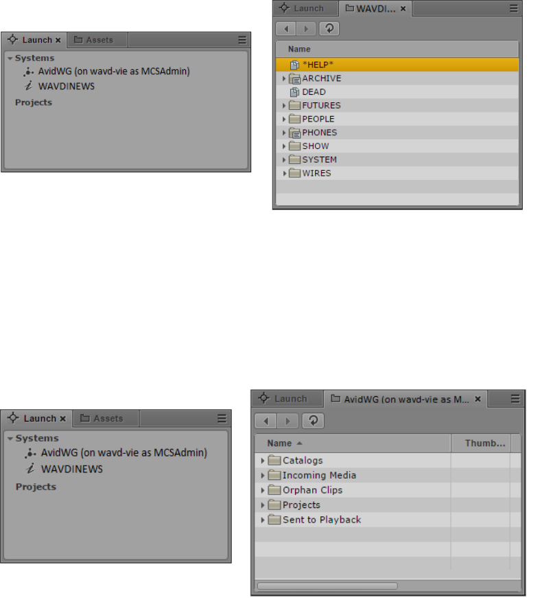
MCS 2.3 Installation and Configuration Guide
100
Verifying the System Settings
Now that you have configured the base system settings for connecting to iNEWS, Interplay
Production and Avid ISIS (as applicable); perform some initial testing.
Verifying the iNEWS Connection
1. Select Log from the Layout selector.
Note: If you receive an error message indicating “This version if Interplay Central is not
authorized to connect to the configured iNEWS Server.”, verify that the correct iNEWS
Client version has been entered into the iNEWS “SYSTEM.CLIENT.VERSIONS” story.
The Log layout will appear which consists of multiple default Panes. The Launch Pane
(shown on left) lists available iNEWS and Interplay Production workgroups.
2. Double-click one of the iNEWS systems to verify the connection. If the connection is
successful, a list of iNEWS assets should appear in the Assets Pane (shown on right).
Verifying the Interplay Production and ISIS Connections
1. Select Log from the Layout selector.
The Log layout will appear which consists of multiple default Panes. The Launch Pane
(shown on left) lists available Interplay Production and iNEWS workgroups.
MCS 2.3 Installation and Configuration Guide
101
2. Double-click on AvidWG to verify the connection. If the connection is successful, a list of
Interplay Production assets should appear in the Assets Pane (shown on right).
3. Navigate through the assets tree to find a piece of media to play. Alternatively, the
Search function can be used to find an asset.
4. Once you have found an asset, double-click on it to load it into the Media Pane.
5. Click the Play button in the Media Pane to verify playback.
Configuring Send To Playback Settings
If your workflow includes a Send To Playback (STP) component, configure and test those settings
now. Depending on your workflow, one or more of the following are required:
Interplay Transcode Provider - Required for STP Profiles using stereo audio tracks
(audio mixdown) or for sequences with dissolves (video mixdown).
Interplay STP Encode Provider – Required for workflows that include Long GOP
media.
Interplay Transfer Engine – Required for workflows that use non-Avid servers in
their STP workflow such as Harmonic Omneon or Grass Valley K2. Interplay
Transcode and STP Encode could also be required in this workflow.
1. In the Settings pane, select Send to Playback.
When you open the STP settings, MediaCentral checks the configuration of the Interplay
Administrator>Site Settings>Interplay Transfer Settings. If the Transfer Settings are
populated with AirSpeed or Transfer Servers that are unavailable, the MediaCentral
Send To Playback is window will appear to be hung for a period of time. After a timeout
period, the STP settings will become available. If you get a “Loading of Playback Device
failed” (or similar) error, check the Transfer Settings configuration and verify all
AirSpeed and Transfer Servers are available.
2. Click the plus sign ‘+’ in the upper-right corner of this window to create a new profile.
3. Configure the profile settings:
a. Name: Give the profile a name. Special characters and spaces are allowed if
desired.
Example: To AirSpeed
b. Individual Device or Studio: Select the appropriate radio button.
A “Studio” is a specialized group of AirSpeed servers.
c. Servers: This pull-down list is populated by the servers entered in the Interplay
Administrator. Select a server from this list.
MCS 2.3 Installation and Configuration Guide
102
d. Playback Device:
i. When selecting an AirSpeed, you will see AirSpeed and AirSpeed-HD
options. The –HD options are valid if working with LongGOP media.
ii. When selecting a Transfer Engine, you will see the profiles configured
on that server.
e. Video Options:
i. Long GOP: Select Long GOP if this profile will be used to transfer Long
GOP media (XDCAM HD).
ii. Accelerated STP: If you select both Long GOP and AirSpeed, the
Accelerated STP option is activated. This option enables Play While
Transfer (PWT).
iii. AirSpeed: Select this option if transferring to an AirSpeed, AMS,
AirSpeed 5000.
iv. Dalet: Select this option if transferring to a Dalet system.
f. Video Target Resolution: Select a target resolution from the pull-down menu.
The target device must match this setting. Make sure to match the settings
specified on the target device.
g. Video Frame Rate: Select a frame rate from the pull-down menu. Make sure to
match the settings specified on the target device.
Example: If using XDCAM-HD 50 mbps 1080i 60, select 59.94. If using 1080i
59.94 material, use 29.97.
h. Audio Target Sample Rate: This is always configured for 48k.
i. Audio Target Bit Depth: Select the bit depth (16 or 24) for your target device.
Make sure to match the settings specified on the target device.
j. Audio Target Mixdown Mode: Select the type of audio output you want.
Options are: Stereo or Direct Out.
k. Interplay | Production ISIS Workspace: Select a workspace for storing media
that results from an audio mixdown or an STP Encode operation.
4. Click Apply.
5. If desired, create additional STP profiles.
6. Once you have configured all required STP profiles, test your work by completing a Send
To Playback test. See the Avid MediaCentral | UX User’s Guide for information on
creating a sequence within MediaCentral and sending media to playback.
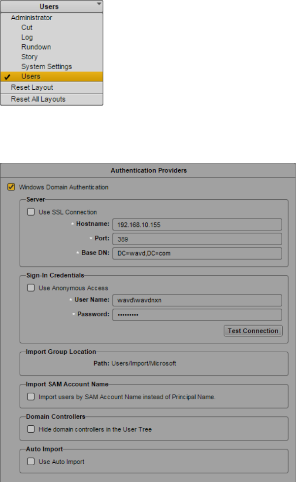
MCS 2.3 Installation and Configuration Guide
103
Importing Domain Users
If your workflow includes signing into MediaCentral as a domain user, review the information
below to configure settings and import domain users into MediaCentral.
See the Avid MediaCentral | UX Administration Guide for more information about any of these
settings.
1. While logged in as the Administrator, select Users from the Layout selector.
2. Double-click the top-level “Users” folder in the user tree on the left. The Authentication
Provider settings will appear on the right.
3. Enable the checkbox for “Windows Domain Authentication”.
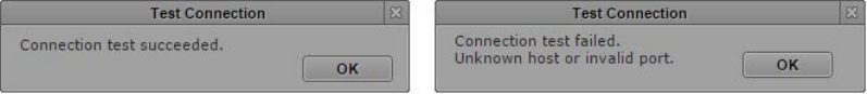
MCS 2.3 Installation and Configuration Guide
104
4. Configure the following settings:
a. Use SSL Connection: If your site uses Secure Sockets Layer (SSL) technology,
select this option.
b. Hostname: Enter the hostname or IP address of a Domain Controller (DC)
containing the user database. Currently, only one DC can be specified.
c. Port: Enter the port used to communicate to the DC. The standard default port
is 389. The SSL default port is 636.
d. Base DN: The Base DN is the “root location” where the import of the user tree
should be started.
How you type the Base DN depends on how your Active Directory is configured
and which domains you want to authenticate from. If you want to authenticate
from multiple sub-domains, set the common root of the sub-domains instead of
the Base DN of a specific domain. Examples:
DC=company,DC=com
DC=company,DC=division,DC=com
CN=Domain Users,OU=Organizational Unit, DC=company,DC=com
e. Sign-In Credentials:
i. If applicable, select “Use Anonymous Access”. Selecting this will disable
the user/password fields.
ii. Alternatively, enter a user and password for a domain user that has
appropriate access to the Active Directory user database. The user
should be in the form of: domain\user
Example: wavd\wavdnxn
f. Import Group location: This is the location in the MediaCentral user tree where
imported domain users will be located.
g. Import SAM Account Name: (Optional) If your facility uses SAM Account Names
instead of the newer Active Directory Principal Names, select “Import users by
SAM Account Name instead of Principal Name.” This configuration is specifically
for those users who are used to logging into Interplay Production with the older
Windows Domain style login.
h. Domain Controllers: Select this checkbox to hide Domain Controllers in the
import window.
i. Auto Import: Select this option if you want to automatically import new users
from this Windows domain.
5. Click the “Test Connection” button. This will verify if the settings you have entered are
valid. A pop-up window will indicate success or failure.
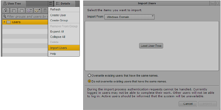
MCS 2.3 Installation and Configuration Guide
105
6. If your settings are valid, click Apply to save the information
7. Click the User Tree Pane Menu button and select Import Users.
The Import Users dialog box opens.
8. Select whether you want to overwrite existing users that have the same user names.
In most cases, especially when reimporting, select “Do not overwrite existing users that
have the same names.” This option preserves any existing user settings.
9. Click the Load User Tree button.
A bar displays the progress while the user tree is loading. When the loading is complete,
the root of the user tree appears.
10. Select the users or groups you wish to import and click the Import button. The users are
imported into MediaCentral.
Note: When users are imported into MCS, the user data is stored in the local user database.
The fields in this database have a maximum limit of 255 characters. LDAP allows for some
fields such as the “Distinguished Name” (DN) to be longer than 255 characters. If you find
that some users are not imported into MCS, verify none of the fields associated with the
domain user are longer than 255 characters.
Creating Local Users and Assigning Roles
If desired, create additional non-domain user accounts within MediaCentral UX. This could be
useful if you have a guest user or contractor that may only need access to MediaCentral for a
short time.
You will also want to assign roles to the users you have created either manually or through
domain import.
See the Avid MediaCentral | UX Administration Guide for more information about user creation
and role assignment.

MCS 2.3 Installation and Configuration Guide
106
Continuing the Installation
Depending upon your workflow, your installation could be complete. Proceed to one of the
following sections as applicable:
• PART V: CLUSTERING
• PART VI: VERIFYING THE INSTALLATION
• PART VII: INSTALLING THE CLOSED CAPTIONING SERVICE
• PART VIII: INSTALLING THE MAM CONNECTOR
• PART IX: MULTI-ZONE CONFIGURATION
• Media Distribute
Refer to the Media | Distribute Installation and Configuration Guide for detailed
installation instructions.
• Media Index
Refer to the Media | Index Installation and Configuration Guide for detailed installation
instructions.
Review the Avid MediaCentral | UX Administration Guide and the Avid MediaCentral | UX User’s
Guide for additional information on customizing your base installation.

MCS 2.3 Installation and Configuration Guide
107
Configuring MCS for Interplay MAM
For MCS to play Interplay MAM media, the filesystem containing the MAM proxies must be
mounted on the MCS servers. The mounting is done at the operating system level using
standard Linux commands for mounting volumes (e.g. mount). To automate the mounting of the
MAM filesystem, create an entry in /etc/fstab.
Note: Some proprietary storage solutions may require that you install and configure
proprietary filesystem drivers or client software. Consult the documentation for the
storage solution to be used by the Interplay MAM system.
To determine the correct path to be mounted, examine the path associated with the MAM
essence pool to which MCS is being given access. This is found in the Interplay MAM
Administrator interface under the Essence Management Configuration tab. Look for the
“MORPHEUS” entry and tease out the path information. It is likely that MCS has been given
access to more than one MAM essence pool. Be sure to mount all the associated filesystems.
Note: Configuration must also take place on the Interplay MAM side, to set up
permissions for MCS to access MAM storage, to point Interplay MAM to the MCS server
or server cluster, etc. For instructions on this aspect of setup and configuration, please
refer to the Interplay MAM documentation.
Note: This step can be performed at any time during the installation.
Configuring the MediaCentral UI
By default, the MediaCentral UI contains functionality for all the MCS solutions it supports.
Functions that are not required for your installation should be removed. If you are configuring a
cluster, this step can be completed on all nodes concurrently.
See Updating the MediaCentral UX Configuration on page 88 for details on this process.
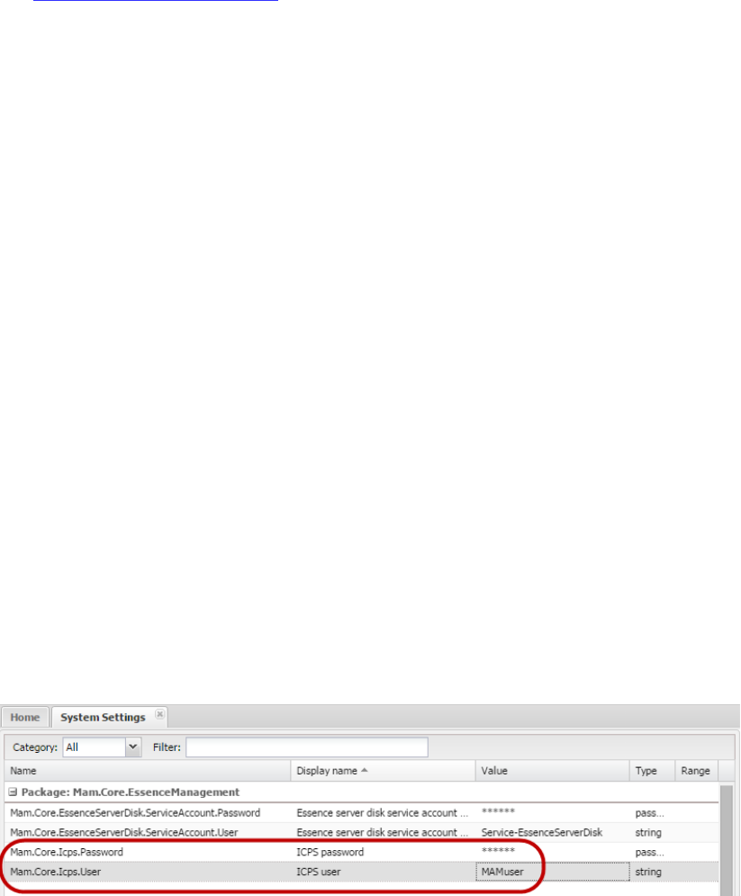
MCS 2.3 Installation and Configuration Guide
108
Creating the MAM System User
When integrating with Interplay MAM, a specialized user needs to be created within
MediaCentral.
Note: If you are configuring an MCS cluster, complete this step on the Master Node only.
1. With the MCS server up and running, log in to MediaCentral as the Administrator user.
See Logging into MediaCentral UX on page 89 for details on this process.
2. Select Users from the Layout selector.
3. Create a special role for the MAM user by clicking on the Create Role button in the Roles
pane.
4. Click the Create Role button.
5. In the Details pane, type the properties for the new role:
• Role name (e.g. MAM)
• Advance License
• Do not assign the MAM role any layouts
6. Click Apply to save your changes.
The new MAM role is added to the Roles pane.
7. Create the MAM system user by clicking the Create User button.
8. In the Details pane, type the properties for the new user:
• User name (e.g. MAMuser)
• Password
• Uncheck “User must change password at next sign-in”
• Check “User cannot change password
9. Drag the MAM role from Roles pane to the Role section of the Details pane for the new
user.
10. Click Save to save your changes.
The new MAM user is added to the User Tree, as a top-level user.
11. Ensure the System Settings on the Interplay MAM system are configured to make use of
the assigned user name and password. Example:
See the Avid MediaCentral | UX Administration Guide for more information about user
creation and role assignment.
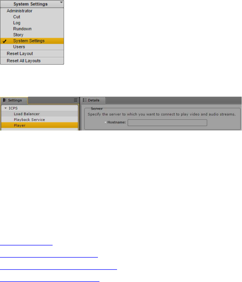
MCS 2.3 Installation and Configuration Guide
109
Configuring the MCS Player
Configuring the MCS Player setting allows you to monitor connections to the player through the
MediaCentral System Settings>ICPS>Load Balancer page.
Note: If you are configuring an MCS cluster, complete this step on the Master Node only.
1. While logged in as the Administrator, select System Settings from the Layout selector.
2. In the Settings pane, select ICPS> Player.
3. In the Server>Hostname field, enter the Fully Qualified Domain Name (FQDN) of the
MCS server. The FQDN is the preferred value of this field, however the short hostname
or IP address are also acceptable values.
Example: wavd-mcs01.wavd.com
Note: If you are in the process of setting up the first server in a cluster, enter the FQDN of
the server you are working on (node1 of the cluster). Later in the process, you will update
this field with the virtual cluster hostname.
4. Click Apply to save your changes.
Continuing the Installation
Depending upon your workflow, your installation could be complete. Proceed to one of the
following sections as applicable:
• PART V: CLUSTERING
• PART VI: VERIFYING THE INSTALLATION
• PART VIII: INSTALLING THE MAM CONNECTOR
• PART IX: MULTI-ZONE CONFIGURATION
MCS 2.3 Installation and Configuration Guide
110
PART V: CLUSTERING
MCS 2.3 Installation and Configuration Guide
111
Chapter Overview
The purpose of this chapter is to guide you through the creation and configuration of a multi-
server MCS cluster.
The following table describes the topics covered in this chapter.
Step Task Time Est.
1
Cluster Overview
varies
Overview information and prerequisite check for building the cluster.
2
Configuring the Player System Setting
5 min
Process for updating the MediaCentral Player System Setting.
3
Configuring DRBD
10 min
Initiate replication of the MCS PostgreSQL database.
4
Starting the Cluster Services on the Master Node
15 min
Begin the cluster configuration on the Master node.
5
Adding Nodes to the Cluster
15min
Connect all additional nodes to the cluster.
6
Replicating the File Caches using GlusterFS
1 hr
Set up Gluster to mirror the caches, so each server in the cluster can
easily use material transcoded by the others.

MCS 2.3 Installation and Configuration Guide
112
Cluster Overview
A cluster is a group of two or more MCS servers that work together to provide high-availability,
load balancing and scale. Each server in a cluster is called a “node”. During the cluster
configuration one server is identified as the Master node. If you have multiple MCS servers in a
rack, the Master node is usually the top-most server in the rack. The second MCS server in the
cluster is called the Slave node. In addition to load balancing and scale, it provides high-
availability of some specialized MCS services. In the event of a failover, the Slave node becomes
the new Master and owner of the MCS database. Additional nodes do not participate in high-
availability; they provide load balancing and system scaling only.
Throughout this process the nodes will be identified by the following:
Master Node (node1): wavd-mcs01 / 192.168.10.51
Slave Node (node 2): wavd-mcs02 / 192.168.10.52
Load Balancing Nodes (node3, node4): wavd-mcs03 / 192.168.10.53, wavd-mcs04 /
192.168.10.54
The cluster is identified by the clients through a virtual cluster hostname and IP address. This
allows the clients to connect to the cluster no matter which server is the current Master.
Throughout this process the virtual cluster will be identified by the following:
Virtual Cluster Name / IP: wavd-mcs / 192.168.10.50
Prior to proceeding with the cluster process, confirm the following:
You have fully configured and tested the Master node. All other nodes should be
configured through, but not including, Part IV of this document.
Hostnames and IP’s of each cluster node (static IP’s are required for cluster
configurations)
The primary network interface on each node must have the same name (e.g. eth0, em1,
etc).
Virtual cluster hostname and a unicast IP address (used for communication between
cluster and external systems – such as a MediaCentral client).
A multicast IP address (used for internal communication between the cluster nodes). If
necessary, a unicast IP can be used. However, specifying a unicast IP requires additional
configuration.
All hostnames and IP addresses, including the cluster’s virtual name and IP, are resolved
normally through DNS.
Consult the Pre-Flight Checklist for a complete list if installation prerequisites.
http://avid.force.com/pkb/articles/en_US/readme/Avid-MediaCentral-Version-2-3-x-Documentation
For detailed information on MCS Clusters, see the MediaCentral Platform Services Concepts and
Clustering Guide on the Avid Knowledge Base.
MCS 2.3 Installation and Configuration Guide
113
Configuring the Player System Setting
When configuring and testing the Master Node, you entered the Fully Qualified Domain Name
(FQDN) of the server in the MediaCentral System Settings. Prior to configuring the cluster, you
need to alter this setting to reflect the cluster FQDN.
1. Using Chrome or another qualified browser, log into MediaCentral as the Administrator
user.
2. Select System Settings from the Layout pull-down menu.
3. In the Settings pane, select ICPS> Player.
4. Server: Enter the Fully Qualified Domain Name (FQDN) of the virtual MCS server.
Example: wavd-mcs.wavd.com
5. Click Apply to save the setting.
6. Logout and exit the browser.

MCS 2.3 Installation and Configuration Guide
114
Configuring DRBD
In a clustered configuration, MCS uses the open source Distributed Replicated Block Device
(DRBD) storage system software to replicate its PostgreSQL database between the Master and
Slave nodes. Even in a cluster with more than two nodes, DRBD runs on the Master and Slave
nodes only.
Note: This procedure assumes a 20 GB partition exists on the RAID 1 mirrored system drive
(/dev/sda). If you are installing MCS on supported HP or Dell hardware using the MCS
Installation USB Drive, the required partition (/dev/sda2) was automatically created for you.
If you are installing MCS on a server from another vendor, see Installing MCS on Non-HP /
Dell Hardware for Interplay MAM.
Explanation (do not type this example)
This procedure uses the drbd_setup command:
drbd_setup
[primary_host="<hostname>"] [secondary_host="<hostname>"]
{[primary_ip="<ip>"] [secondary_ip="<ip>"]}
{[primary_disk="<device>"] [secondary_disk="<device>"]}
where:
primary_host: Host name (e.g. wavd-mcs01) of the machine to serve as Master node for DRBD.
secondary_host: Host name (e.g. wavd-mcs02) of the Slave node (the machine to serve as fail-over for
DRBD).
primary_ip: Optional. IP address (e.g. 192.XXX.XXX.XXX) of the Master node. Helpful when host
primary_host specified does not resolve.
secondary_ip: Optional. IP address (e.g. 192.XXX.XXX.XXX) of the Slave node. Helpful when
secondary_host does not resolve.
primary_disk: Optional. Name of the disk device reserved for DRBD on the Master node (/dev/sda2 by
default).
secondary_disk: Optional. Name of the disk device reserved for DRBD on the Slave node (/dev/sda2 by
default).
Note: The primary_disk and secondary_disk parameters are provided for special cases in which the
partitions reserved for DRBD are in a non-standard location. In most cases, the /dev/sda2 values
supplied by default will be sufficient.
Note: The DRBD setup script is case-sensitive. The host names you enter must exactly match those defined
for the master and non-master.
MCS 2.3 Installation and Configuration Guide
115
1. On the Master node, change to the directory containing the drbd_setup script:
cd /opt/avid/cluster/bin
2. Run the drbd_setup script:
./drbd_setup primary_host="master hostname" secondary_host="slave
hostname"
The quotes are required in this command. The hostnames in this command are case
sensitive. DRBD requires you to enter the short hostname and not the FQDN.
The period-slash “./” in this command tells Linux to look for the script in the current
directory.
Note: If an error message appears indicating that the IP addresses cannot be identified using
the host names, add the “primary_ip” and “secondary_ip” switches to the command:
./drbd_setup primary_host="master hostname" secondary_host="slave
hostname" primary_ip="ip of master node" secondary_ip="ip of slave
node"
You might receive an error message indicating the bus is not running and/or a path does not
exist, similar to the following:
- error: bus is not running
- error: Given --path is not exist:
These errors can be ignored.
3. You might receive the following message:
Found some data
==> This might destroy existing data! <==
Do you want to proceed?
[need to type 'yes' to confirm]
This indicates the DRBD setup script has found the 20GB partition set aside for it and is
about to take ownership of it.
4. Type yes (the whole word) at the prompt to continue with the setup.
The system responds, and waits for the other DRBD node, with output similar to the
following:
Writing meta data...
initializing activity log
NOT initializing bitmap
New drbd meta data block successfully created.
success
Waiting for secondary node ...
5. On the Slave node, change to the directory containing the drbd_setup script:
cd /opt/avid/cluster/bin
MCS 2.3 Installation and Configuration Guide
116
6. On the Slave node, run the same drbd_setup command that you ran on the Master node.
The Master node responds with output similar to the following:
Secondary node found
Node initialized with role: Primary
Stopping postgresql-9.1 service: [ OK ]
mke2fs 1.41.12 (17-May-2010)
Filesystem label=
OS type: Linux
Block size=4096 (log=2)
Fragment size=4096 (log=2)
Stride=0 blocks, Stripe width=0 blocks
128000 inodes, 511975 blocks
25598 blocks (5.00%) reserved for the super user
First data block=0
Maximum filesystem blocks=524288000
16 block groups
32768 blocks per group, 32768 fragments per group
8000 inodes per group
Superblock backups stored on blocks:
32768, 98304, 163840, 229376, 294912
Writing inode tables: 0/16 1/16 2/16 3/16 4/16 5/16 6/16 7/16 8/16
9/1610/1611/1612/1613/1614/1615/16 done
Creating journal (8192 blocks): done
Writing superblocks and filesystem accounting information: done
This filesystem will be automatically checked every 23 mounts or
180 days, whichever comes first. Use tune2fs -c or -i to override.
partition mounted at /mnt/drbd
Starting postgresql-9.1 service: [ OK ]
Note: A fail message might appear when the drbd_setup script tries to start PostgreSQL. This
is normal.
Finally, information indicating synchronization is underway appears in the output, similar to
the following (on the master node only). The synchronization process can take some time,
since DRBD replicates at the block level.
Node synchronization started
5% synchronized
…
55% synchronized
97% synchronized
Node synchronization finished
7. Wait until node synchronization is completed before proceeding to the next step.

MCS 2.3 Installation and Configuration Guide
117
Starting the Cluster Services on the Master Node
MCS supports both multicast and unicast for intra-cluster communication. This body of this
guide provides instructions for configuring a cluster in a multicast environment (standard
configuration). However, multicast requires multicast enabled routers. If your network does not
support multicasting, see Unicast Support in Clustering for details on altering the configuration.
1. On the Master node only, assign the cluster multicast IP address. This is the IP that the
cluster will use for communication between the nodes.
a. If your network has no other multicast activity, the default multicast address of
239.192.1.1 is assumed in the following command:
/opt/avid/cluster/bin/cluster setup-corosync --corosync-
bind-iface=interface --rabbitmq_master="master hostname"
b. If your network includes multicast activity (perhaps a second MCS system),
specify a custom multicast address with the following command:
/opt/avid/cluster/bin/cluster setup-corosync --corosync-
bind-iface=interface --corosync-mcast-addr="multicast
address" --rabbitmq_master="master hostname"
Note: As of MCS v2.0, this command will not accept a multicast address outside
of the 239.0.0.0/8 range. If specifying a non-239.x.x.x, you will see an error:
“Multicast IP is not in subnetwork 239.0.0.0/8”.
Explanation (do not type this example)
This procedure uses the cluster setup-corosync command:
cluster setup-corosync
[corosync-bind-iface =<interface>]
{[--corosync-mcast-addr="<ip>"]}
{[--rabbitmq_master="<device>"]}
where:
--corosync-bind-iface: Identifies the name of the primary network interface. In an
HP server, this is generally “eth0”. In a Dell server, this is generally “em1” for 1 Gb
connections or “p1p1” / “p2p1” for 10 Gb connections (depending on which slot the
card 10 Gb card has been installed). For Interplay MAM configurations with port
bonding, this is generally “bond0”. Quotes are not required in this command.
--corosync-mcast-addr: In configurations that do not use the default multicast
address of 239.192.1.1, this command can be used to specify a custom multicast
address. Quotes are required in this command.
--rabbitmq_master: This specifies the (short) hostname of the Master node in the
cluster (e.g. wavd-mcs01). This should be the same as the DRBD Master node
specified in the drbd_setup process. Quotes are required in this command.

MCS 2.3 Installation and Configuration Guide
118
Messages appear echoing the Corosync network binding process; followed by messages
indicating that services are being stopped. At the end of the process, you are informed
that the Corosync cluster engine has successfully started [OK].
The following is sample output:
bind_iface=eth0 bind_network=192.168.10.51 mcast_addr=239.192.1.1
Avid Service: edit fl_xmd: no process killed
.
..
...
Starting Corosync Cluster Engine (corosync): [ OK ]
Starting Pacemaker Cluster Manager: [ OK ]
You may notice the following text appear during this process:
Clustering node rabbit@nodename with rabbit@nodename...
Error: cannot_cluster_node_with_itself
Starting node rabbit@nodename....
…done
Failed to join cluster, exiting!!.
This message can be ignored as it simply indicates that this is the first node in the rabbit
cluster.
2. On the Master node only, assign the cluster’s virtual unicast IP address. This is the IP
that the cluster will use for communication with clients and external systems.
/opt/avid/cluster/bin/cluster setup-cluster --cluster_ip="cluster
IP address" --pingable_ip="router IP address" --
cluster_ip_iface="eth0" --admin_email="comma separated e-mail
list" --drbd_exclude="comma separated list of non-DRBD nodes"
Explanation (do not type this example)
This procedure uses the cluster setup-cluster command:
cluster setup-cluster
{[--cluster_ip="<cluster IP address>"]}
{[--pingable_ip="<router IP address>"]}
{[--cluster_ip_iface="<interface_name>"]}
{[--admin_email="<comma separated e-mail list>"}]
{[--drbd_exclude="<comma separated list of non-DRBD nodes>"}]
where:
--cluster_ip: Identifies the unicast virtual IP address assigned to the cluster.
--pingable_ip: This is an IP address that will always be available on the network
- for example, the IP address of your default gateway (e.g. 192.168.10.1).
-- cluster_ip_iface: Identifies the name of the primary network interface. In an
HP server, this is generally “eth0”. In a Dell server, this is generally “em1” for 1 Gb
connections or “p1p1” / “p2p1” for 10 Gb connections (depending on which slot
the card 10 Gb card has been installed). For Interplay MAM configurations with
port bonding, this is generally “bond0”.

MCS 2.3 Installation and Configuration Guide
119
--admin_email: This is a comma separated list of e-mail addresses to which cluster
status notifications are automatically sent. This command is not optional. If you
do not want to receive e-mail notifications, enter a bogus email address.
Note: At least one cluster administrator email address is mandatory (though not
validated by the system). To change the email address later, see “Changing the
Cluster Administrator Email Address” on page 202.
--drbd_exclude: This is a comma separated list of the non-DRBD nodes in the
cluster (e.g. wavd-mcs03, wavd-mcs04). This parameter prevents the non-DRBD
nodes from running PostgreSQL. The comma-separated list of non-DRBD nodes
must not contain any spaces between each entry, only a comma.
Note: Quotes are required in each of the above commands.
Error messages appear indicating missing resources and attributes.
For example:
ERROR: resource <resource name> does not exist
Error: performing operation: The object/attribute does not exist
These can be ignored.
Additional warning, error and info messages may also appear, similar to the following:
WARNING: 125: AvidConnectivityMon: specified timeout 20s for
start is smaller than the advised 60
ERROR: 125: rsc-options: attribute admin-email does not exist
INFO: 125: commit forced
These can be ignored.
3. Restart the following services so they register correctly on the newly created instance of
the message bus:
service avid-acs-messenger restart
service avid-aaf-gen restart
4. Now that the clustering services are up and running on the master node, start the
cluster monitoring tool:
crm_mon
This utility provides a “live view” of the cluster which can be useful as you add additional
nodes to the cluster. Typing “crm_mon –f” will give you additional information about
fail counts. Press CTRL-C to exit crm_mon.
Note: If you are using a SSH tool such as PuTTY, open a second session to the Master
cluster node and run the “crm_mon” monitoring tool in a dedicated window.

MCS 2.3 Installation and Configuration Guide
120
Adding Nodes to the Cluster
With the clustering services up and running on the Master node – the fully configured MCS
server – add the other servers to the cluster.
If your network does not support multicast activity, see Unicast Support in Clustering for details
on altering the configuration.
1. On each of the non-master nodes in the cluster, complete one of the following:
Note: See the previous section for more information on each of the following commands.
a. If your network has no other multicast activity, the default multicast address of
239.192.1.1 is assumed in the following command:
/opt/avid/cluster/bin/cluster setup-corosync --corosync-
bind-iface=interface --rabbitmq_master="master hostname"
b. If your network includes multicast activity (perhaps a second MCS system),
specify a custom multicast address with the following command:
/opt/avid/cluster/bin/cluster setup-corosync --corosync-
bind-iface=interface --corosync-mcast-addr="multicast
address" --rabbitmq_master="master hostname"
As before, messages appear echoing the Corosync network binding process. The Avid
UMS service is temporarily shut down. A message appears indicating the Corosync
cluster engine has successfully started.
The following is sample output:
bind_iface=eth0 bind_network=192.168.10.51 mcast_addr=239.192.1.1
Shutting down UMS [ OK ]
2012-11-19 15:48:57.891 -0500 - info: Done. System is up-to-date.
generic – stop [ OK ]
boot – stop [ OK ]
Starting Corosync Cluster Engine (corosync): [ OK ]
2. Restart the following services so they register correctly on the newly created instance of
the message bus:
service avid-acs-messenger restart
service avid-aaf-gen restart
Note: After this point, if you reconfigure any System Settings through the MediaCentral UI, the
new settings are retained by the Master node only. Non-master nodes must be updated
manually. On each non-master node, log in as root and run the following command:
service avid-all reconfigure.

MCS 2.3 Installation and Configuration Guide
121
Replicating the File Caches using GlusterFS
When a playback request is sent to an MCS server, the media is obtained from the ISIS (or
Standard FS storage) and is quickly transcoded into an alternate delivery format. The transcoded
media is stored in the system’s “/cache” folder. In the case of a cluster, the transcoding is
performed on the cluster node that received the playback request. To expedite playback of the
same media for future playback requests (where the request may be handled by a different
node), the contents of the “/cache” folder is automatically replicated to all cluster nodes. This is
completed using Gluster, an open source software solution for creating shared filesystems.
Note: Cluster and Gluster are independent from each other. Multiple MCS servers require a Cluster
but may not require Gluster. See the MediaCentral Platform Services Concepts and Clustering Guide
for more information on Gluster configurations.
Installing GlusterFS
In this step, you install the GlusterFS RPMs and create the folders where the caches will be
located. This section is completed on all cluster nodes.
1. Ensure that you have obtained and copied the Gluster software. If you have not already
completed this task, see Obtaining the Software for instructions.
2. Create a “gluster364” folder within the “installers” folder:
mkdir /media/installers/gluster364
3. Copy the GlusterFS software packages to the “gluster364” folder. Ensure that the GlusterFS
packages are the only items in this folder. If needed, see Copying Software to the MCS
Server for more information.
4. Navigate to the directory containing the GlusterFS packages:
cd /media/installers/gluster364
5. Install the Gluster packages using the Linux rpm command.
rpm -Uvh *
Note: Earlier versions of this guide required you to install all packages individually and in a
certain order. This streamlined process installs all packages with a single command while
maintaining the correct installation order. Ensure that only the GlusterFS .rpm files are contained
in this folder.
6. Start the Gluster daemon, glusterd:
service glusterd start
7. Create the RHEL physical directories that Gluster will use to build its GlusterFS filesystem:
mkdir -p /cache/gluster/gluster_data_download
mkdir -p /cache/gluster/gluster_data_fl_cache
mkdir –p /cache/gluster/gluster_data_multicam
MCS 2.3 Installation and Configuration Guide
122
Creating the Trusted Storage Pool
With Gluster installed and running on each MCS server in the cluster, you will create the trusted
storage pool. This section is completed on the Master node only.
1. Verify that you can ping the other servers in the cluster by their hostname:
ping –c 4 <hostname>
“ping” is the command. “-c 4” is the count of how many times the ping command is issued.
If you do not specify a count, ping will continue forever. In that event, press CTRL-C to stop
the ping.
2. Repeat the above command to ping each cluster node.
3. Add the Slave node to the trusted storage pool:
gluster peer probe <hostname>
This command adds <hostname> to the trusted storage pool. For each successful “join”,
the system responds as follows:
peer probe: success <hostname>
Note: Only probe the other servers in the cluster. You do not need to “self-probe” the
server you are issuing commands from.
4. Repeat the above command to add any additional cluster nodes.
5. Once you have probed each cluster node, verify peer status.
gluster peer status
The system responds by indicating the number of peers, their host names and connection
status, plus other information. Example:
Number of Peers: 1
Hostname: wavd-mcs02
Uuid: 220976c3-dc58-4cdc-bda3-7b2213d659fc
State: Peer in Cluster (Connected)

MCS 2.3 Installation and Configuration Guide
123
Configuring the GlusterFS Volumes
Gluster uses its own filesystem, GlusterFS, which includes its own notion of volumes. GlusterFS
volumes consist of underlying directories from the trusted storage pools. When you create a
GlusterFS volume, you also configure its behavior. In MCS we make use of Gluster’s ability to
automatically distribute and replicate data (mirror) across the trusted storage.
Explanation (do not type this example)
In this procedure, you create GlusterFS volumes for the physical cache folders already created. You
created the following directories when you installed gluster.
/cache/gluster/gluster_data_download
/cache/gluster/gluster_data_fl_cache
/cache/gluster/gluster_data_multicam
This is done using the gluster volume create command, specifying the name of the GlusterFS volume and
the underlying directory assets it consists of:
gluster volume create gluster-cache replica <N> transport tcp
<hostname1>:/gluster_mirror_data/
<hostname2>:/gluster_mirror_data/
continuing, in the same line, for each host name, up to:
<hostnameN>:/gluster_mirror_data/
Where <N> is the total number of nodes used.
And <hostname1> through <hostnameN> are the machine names (host names) of the nodes in the
cluster.
Example (do not type this example)
To illustrate the command, consider an MCS server cluster consisting of four servers, wavd-mcs01,
wavd-mcs02, wavd-mcs03 and wavd-mcs04. Further, suppose you want to replicate a directory called
/cache.
To create a GlusterFS volume called gluster-cache consisting of the /cache directories from each server
in the cluster, you would issue the following command:
gluster volume create gluster-cache replica 4 transport tcp
wavd-mcs01:/cache
wavd-mcs02:/cache
wavd-mcs03:/cache
wavd-mcs04:/cache
In this step, you will create GlusterFS volumes associated with those physical cache folders. This
section is completed on the Master node only.
MCS 2.3 Installation and Configuration Guide
124
1. Create a GlusterFS volume called gl-cache-dl consisting of the
/cache/gluster/gluster_data_download folders:
gluster volume create gl-cache-dl replica N transport tcp
hostname1:/cache/gluster/gluster_data_download
hostname2:/cache/gluster/gluster_data_download
…continuing, in the same line, for each host name, up to:
<hostnameN>:/cache/gluster/gluster_data_download
Where N is the total number of nodes used.
And <hostname1> through <hostnameN> are the machine names (host names) of the nodes
in the cluster.
2. Create a GlusterFS volume called gl-cache-fl consisting of the
/cache/gluster/gluster_data_fl_cache folders:
gluster volume create gl-cache-fl replica N transport tcp
hostname1:/cache/gluster/gluster_data_fl_cache
hostname2:/cache/gluster/gluster_data_fl_cache
…continuing, in the same line, for each host name, up to:
<hostnameN>:/cache/gluster/gluster_data_fl_cache
Where N is the total number of nodes used.
And <hostname1> through <hostnameN> are the machine names (host names) of the nodes
in the cluster.
3. Create a GlusterFS volume called gl-cache-mcam consisting of the
/cache/gluster/gluster_data_multicam folders:
gluster volume create gl-cache-mcam replica N transport tcp
hostname1:/cache/gluster/gluster_data_multicam
hostname2:/cache/gluster/gluster_data_multicam
…continuing, in the same line, for each host name, up to:
<hostnameN>:/cache/gluster/gluster_data_multicam
Where N is the total number of nodes used.
And <hostname1> through <hostnameN> are the machine names (host names) of the nodes
in the cluster.
4. Start the GlusterFS volumes.
gluster volume start gl-cache-dl
gluster volume start gl-cache-fl
gluster volume start gl-cache-mcam
MCS 2.3 Installation and Configuration Guide
125
Setting Gluster Volume Ownership
The following two directories must be owned by user maxmin and have group id set to maxmin:
cache/gluster/gluster_data_download
cache/gluster/gluster_data_fl_cache
The directories above are associated with RHEL directories (/cache/fl_cache and
/cache/download) used to store files for http-based streaming, such as media converted to FLV
for file-based playback. They are also used to store media converted to Mpeg2TS for playback
on iOS devices. The download directory contains links to simplify iOS playback.
Restarting the Gluster daemon (glusterd) results in user ID and group ownership of the Gluster
volumes being changed from maxmin to root, which breaks playback on iOS devices. Thus if a
cluster node is rebooted, playback issues can arise.
To prevent issues for an existing cluster, configure the two Gluster cache volumes to use the
same UID and GID as the maxmin user, as described in the following procedure.
This section is completed on all cluster nodes (slave first, master second, load balancing at any
time):
1. Stop Pacemaker:
service pacemaker stop
2. Stop Corosync:
service corosync stop
3. Obtain the user ID of the user maxmin (this might be different on each machine):
id -u maxmin
4. Change the user ownership of the gluster volume to maxmin using the user ID:
gluster volume set gl-cache-dl storage.owner-uid <uid>
gluster volume set gl-cache-fl storage.owner-uid <uid>
In the above commands, do not type the angle brackets. Enter the number obtained in
the previous step.
Note: Do not alter the gl-cache-mcam (multicam) volume. It uses the default root ownership.
5. Obtain the group ID of the user maxmin (this might be different on each machine):
id -g maxmin
6. Change the group ownership of the gluster volume to maxmin using the group ID:
gluster volume set gl-cache-dl storage.owner-gid <gid>
gluster volume set gl-cache-fl storage.owner-gid <gid>
Note: Do not alter the gl-cache-mcam (multicam) volume. It uses the default root ownership.
MCS 2.3 Installation and Configuration Guide
126
7. Verify the success of the ownership changes:
ls –la /cache/gluster
Should return:
drwxrwsrwx 3 maxmin maxmin 4096 Jan 12 09:51 gluster_data_download
drwxrwsrwx 5 maxmin maxmin 4096 Jan 12 09:51 gluster_data_fl_cache
drwxr-xr-x 3 root root 4096 Feb 5 08:33 gluster_data_multicam
8. Restart the GlusterFS service:
service glusterd restart
9. Verify the ownership changes are sticky:
ls –la /cache/gluster
Should return same as before:
drwxrwsrwx 3 maxmin maxmin 4096 Jan 12 09:51 gluster_data_download
drwxrwsrwx 5 maxmin maxmin 4096 Jan 12 09:51 gluster_data_fl_cache
drwxr-xr-x 3 root root 4096 Feb 5 08:33 gluster_data_multicam
10. Change ownership of any files residing in gluster_data_download and
gluster_data_fl_cache:
chown –R maxmin:maxmin /cache/gluster/gluster_data_download
chown –R maxmin:maxmin /cache/gluster/gluster_data_fl_cache
This is only absolutely necessary on systems that have already been running, where the
Gluster daemon reset ownership to root. It should not be necessary on a fresh install.
11. Start Corosync:
service corosync start
12. Start Pacemaker:
service pacemaker start

MCS 2.3 Installation and Configuration Guide
127
Making the RHEL Cache Directories
With the GlusterFS volumes now created and Gluster service running, configure the local cache
on each server in the cluster. This section is completed on all cluster nodes.
1. Create the following cache folders:
mkdir /cache/download
mkdir /cache/fl_cache
mkdir /cache/mob-fetch
mkdir /cache/render
mkdir /cache/spooler
Note: You created /cache/download and /cache/fl_cache earlier when setting up the RAID
(see Partitioning the RAID on page 79).
Moreover, if you are creating a cluster for a system that has already been set up and run, the
above folders already exist.
For example, if you are currently operating on the fully functional master node where you
played back a media asset, some folders were created automatically.
Ignore any “cannot create directory: file exists” warnings.
2. Change permissions on the following directories:
chmod 0777 /cache/spooler
chmod 0777 /cache/mob-fetch
3. Verify the success of all the changes:
ls -la /cache
Output similar to the following ought to be presented:
drwxrwxrwx 9 maxmin maxmin 4096 Nov 4 10:13 .
drwxr-xr-x 33 root root 4096 Nov 4 13:34 ..
drwxrwxrwx 2 root root 4096 Nov 4 20:04 download
drwxrwxrwx 5 root root 4096 Nov 4 20:03 fl_cache
drwxrwxrwx 55 root root 4096 Nov 4 13:50 mob-fetch
drwxrwxrwx 2 root root 4096 Nov 4 10:04 render
drwxrwxrwx 9 root root 4096 Nov 4 14:05 spooler
Note that in the output above the dot (“.”) directory represents the current directory, that
is, /cache.
4. Navigate to the directory used by Linux to organize scripts run by the RHEL init program:
cd /etc/rc.d
MCS 2.3 Installation and Configuration Guide
128
5. Open the local run command (rc.local) file for editing:
vi rc.local
The rc.local file contains commands to be run at the end of the boot cycle, but before Linux
displays the command prompt.
6. Add the following lines:
/bin/mount /cache/download
/bin/mount /cache/fl_cache
/bin/mount /cache/render
/sbin/service avid-all restart
The above lines mount the cache at the end of the boot cycle, when the network services
are up. Restarting the avid-all service ensures the backend services have access to the newly
mounted caches.
7. Save and exit the vi session. Press <ESC> and type: :wq
Changing Ownership and Mounting the GlusterFS Volumes
With the GlusterFS volumes now created and Gluster service running, configure the local cache
on each server in the cluster. It is important to change the ownership of two cache directories so
that files written to them inherit the group affiliation. This section is completed on all cluster
nodes.
1. Give the maxmin:maxmin user access to the following two folders (original data folders, not
the cache folders created in the procedure above):
chown maxmin:maxmin /cache/gluster/gluster_data_download
chown maxmin:maxmin /cache/gluster/gluster_data_fl_cache
Note: If you are creating a cluster for a system that has already been set up and run, the
ownership has already been changed.
2. Set the group ID bit for the following two directories. This ensures new files written to the
directories are owned by the group of the parent directory — maxmin, in this case — rather
than by the process writing the files:
chmod 2777 /cache/gluster/gluster_data_download
chmod 2777 /cache/gluster/gluster_data_fl_cache
Note: Setting the setgid special permission bit ensures files (and subdirectories) newly created in
the directory inherit the group affiliation of the directory (maxmin), rather than inheriting it from
the user/shell doing the writing. The setgid special permission — the “2” in the above chmod
command — is especially important for deployments where the iOS application is used.
MCS 2.3 Installation and Configuration Guide
129
3. Verify the success of the operations:
ls -la /cache/gluster
Updated information is displayed, which ought to be similar to the following:
drwxrwsrwx 2 maxmin maxmin 4096 Nov 4 10:15 gluster_data_download
drwxrwsrwx 2 maxmin maxmin 4096 Nov 4 10:15 gluster_data_fl_cache
The “s” in the group position indicates a special permission has been applied.
4. Mount the folders using the Linux mount command, specifying the type as glusterfs:
mount -t glusterfs <hostname>:/gl-cache-dl /cache/download
mount -t glusterfs <hostname>:/gl-cache-fl /cache/fl_cache
mount -t glusterfs <hostname>:/gl-cache-mcam /cache/render
Where <hostname> is the name of the server you are working on (e.g. wavd-mcs01).
5. Verify that caches have been mounted correctly:
df –h
The following information is displayed about the caches: size, used, available, user % and
mount point (mounted on).
In the following sample output, only the relevant lines are shown.
Filesystem Size Used Avail Use% Mounted on
wavd-mcs01:/gl-cache-dl 2.1T 947M 2.0T 1% /cache/download
wavd-mcs01:/gl-cache-fl 2.1T 947M 2.0T 1% /cache/fl_cache
wavd-mcs01:/gl-cache-mcam 2.1T 947M 2.0T 1% /cache/render
6. Navigate to the directory containing the filesystem table:
cd /etc
7. Open the filesystem table file, fstab, for editing:
vi fstab
8. Navigate to the end of the file and add the following lines (A to append):
<hostname>:/gl-cache-dl /cache/download glusterfs defaults,noauto 0 0
<hostname>:/gl-cache-fl /cache/fl_cache glusterfs defaults,noauto 0 0
<hostname>:/gl-cache-mcam /cache/render glusterfs defaults,noauto 0 0
Where <hostname> is the name of the server you are working on (e.g. wavd-mcs01).
These lines automate the mounting of the GlusterFS volumes to the folders used by MCS for
caching (/cache/download, /cache/fl_cache and /cache/render).
9. Save and exit the vi session. Press <ESC> and type: :wq
MCS 2.3 Installation and Configuration Guide
130
Testing the Cache
It is a good idea to test that Gluster is replicating the caches correctly.
Test the cache setup by writing a file to one of the GlusterFS cache folders
(e.g. /cache/download) on one server and verify it appears on the other servers.
For example, the following Linux commands create two files: 1) toto.txt in /cache/download and
2) sample.txt in /cache/render:
touch /cache/download/toto.txt
touch /cache/render/sample.txt
Ensuring Gluster is On at Boot
Verify that the Gluster service starts on boot. This section is completed on all cluster nodes.
1. Check the Gluster service configuration:
chkconfig --list glusterd
This command returns the current Gluster service configuration. It likely looks like this:
glusterd 0:off 1:off 2:off 3:off 4:off 5:off 6:off
But it should look like this:
glusterd 0:off 1:off 2:on 3:on 4:on 5:on 6:off
2. If all 6 run levels are off, type the following
chkconfig glusterd on
Verify that run levels 2-5 are now on by repeating the command in the previous step.
MCS 2.3 Installation and Configuration Guide
131
PART VI: VERIFYING THE INSTALLATION
MCS 2.3 Installation and Configuration Guide
132
Chapter Overview
This chapter focuses on testing and verification of the completed installation.
The following table describes the topics covered in this chapter:
Step Task Time Est.
1
Testing the Basics
varies
Covers a range of tests to verify your completed installation.
2
Testing the Cluster Email Service
5 min
Verifies that e-mails sent by the cluster will be delivered.
3
Testing Cluster Failover
varies
For configurations with a cluster, verifying failover is a crucial aspect of
the installation and testing process.
4
Verifying ACS Bus Functionality
5 min
Verifies that the ACS bus and dependent services are communicating
normally.
5
Verifying the Status of RabbitMQ
5 min
Verifies the status of the RabbitMQ messaging bus.
6
Validating the FQDN for External Access
5 min
Verifies that the MCS server(s) are accessible over the network.
7
Backing up the MCS System Settings and the MCS Database
10 min
Provides a process to backup and restore the MCS settings.
MCS 2.3 Installation and Configuration Guide
133
Testing the Basics
Because MCS provides workflows for many types of environments, testing steps may vary. Test
the items that are applicable to your situation:
Testing MCS for MediaCentral and Media Composer Cloud:
• Can web-based clients log into MediaCentral? Can they play media?
• Can mobile clients log into MediaCentral? Can they play media?
• Can Media Composer Cloud clients log into MediaCentral. Can they play media?
• Can you access and search the Interplay Production database?
• Can you access and search the iNEWS database?
• Can you create a sequence and Send To Playback?
Note: Send To Playback is an excellent test as it simultaneously verifies connection to
ISIS, Interplay Production, MediaCentral Distribution Service, Interplay Production
Services Engine, Interplay Transcode and potentially Interplay STP Encode and Interplay
Transfer Engine.
• Can you Delivery media to a remote workgroup? Can you “Deliver To Me”?
• Can Media Composer Cloud clients upload/download media?
• Does the Messaging Pane delivery messages between MediaCentral Users? Does it
deliver messages between MediaCentral and Media Composer?
• Do Media Index searches return expected results?
• For Multi-Zone configurations, can you log in to MediaCentral from a Slave zone? This
tests the accessibility of the user database on the Master Zone.
Testing MCS for Interplay MAM:
• Proxy playback in the MAM Desktop
• Proxy playback in the MAM Cataloger Application
• MAM VideoAnalysis (video analysis of Proxy / Low-res material)
• MAM Connector: Proxy playback of MAM assets in MediaCentral UX
MCS 2.3 Installation and Configuration Guide
134
Testing the Cluster Email Service
The cluster automatically sends email notifications to the administrator email address. This
requires that the Linux postfix email service is running on the master node (and slave node, for
failovers). In this section you verify that the postfix service is operating as expected.
To test the cluster email service:
1. Verify the email service is running:
service postfix status
2. The system should respond with the following:
master (pid XXXX) is running...
3. If it is not running:
a. Check the postfix service run-level configuration:
chkconfig –-list postfix
The configuration returned should look like this (run levels 2–5 on):
postfix 0:off 1:off 2:on 3:on 4:on 5:on 6:off
b. To enable run levels 2–5, type the following:
chkconfig postfix on
c. Start the service:
service postfix start
4. Compose and send Linux mail command:
mail –v <email address>
The system responds by opening an email shell and prompting you for a subject line:
Subject:
5. Enter a subject line and press Return:
The system responds by moving the cursor into the body of the email.
Type a line or two of text, as desired.
Note: If the Backspace key types “^H” rather than deleting, exit the email shell by typing
Ctrl-C (twice). Next, type the following at the Linux command line, and try again (do not type
the quotation marks: “stty erase ^H”.
6. Type Ctrl-D to exit the email shell and send the email.
The system responds with the following:
Mail Delivery Status Report will be mailed to <root>.
7. Check the in-box of the addressee for the email.
MCS 2.3 Installation and Configuration Guide
135
Testing Cluster Failover
If your configuration consists of a cluster, verifying the system’s ability to failover from the
Master node to the Slave node (and back again) is very important.
The cluster monitoring tool, “crm_mon”, provides a “live” view of the cluster and its associated
resources. The tool can be launched in one of two ways:
- crm_mon
- crm_mon -f
Specifying the “-f” asks the tool to display the status of the cluster with fail counts. Each time
that a service fails, a node failure count is retained by the system. Except for the AvidAll service,
the default threshold for failures of each service is two (2). Before testing the cluster, you will
want to clear the fail counts. If you do not, the cluster will failover automatically, and perhaps
unexpectedly, when the threshold is reached.
To test cluster failover:
1. From a Windows machine, use an SSH utility such as PuTTY to open a remote session to
any node in the cluster. Log in as the root user.
2. Launch the cluster monitoring tool, specifying the fail-count option:
crm_mon -f
This returns the status of all cluster-related services on all nodes, with output similar to
the following example using two nodes (e.g. wavd-mcs01 & wavd-mcs02).
Last updated: Wed Jun 25 13:11:10 2014
Last change: Thu Jun 19 11:42:05 2014 via crmd on wavd-mcs01
Current DC: wavd-mcs01 - partition with quorum
2 Nodes configured
18 Resources configured
Online: [ wavd-mcs01 wavd-mcs02 ]
Clone Set: AvidConnectivityMonEverywhere [AvidConnectivityMon]
Started: [ wavd-mcs01 wavd-mcs02 ]
AvidClusterMon (lsb:avid-monitor): Started wavd-mcs01
MongoDB (lsb:mongod): Started wavd-mcs01
Redis (lsb:redis): Started wavd-mcs01
Resource Group: postgres
postgres_fs (ocf::heartbeat:Filesystem): Started wavd-mcs01
AvidClusterIP (ocf::heartbeat:IPaddr2): Started wavd-mcs01
pgsqlDB (ocf::avid:pgsql_Avid): Started wavd-mcs01
Master/Slave Set: ms_drbd_postgres [drbd_postgres]
Masters: [ wavd-mcs01 ]
Slaves: [ wavd-mcs02 ]
Clone Set: AvidAllEverywhere [AvidAll]
Started: [ wavd-mcs01 wavd-mcs02 ]
AvidIPC (lsb:avid-interplay-central): Started wavd-mcs01
AvidUMS (lsb:avid-ums): Started wavd-mcs01
AvidUSS (lsb:avid-uss): Started wavd-mcs01
AvidACS (lsb:avid-acs-ctrl-core): Started wavd-mcs01
Clone Set: AvidICPSEverywhere [AvidICPS]
Started: [ wavd-mcs01 wavd-mcs02 ]
MCS 2.3 Installation and Configuration Guide
136
Migration summary:
* Node wavd-mcs01:
* Node wavd-mcs02:
Note the line identifying the Master node:
• AvidClusterIP
Note that the Master node always runs the following services:
• AvidIPC (avid-interplay-central)
• AvidUMS (avid-ums)
• AvidUSS (avid-uss)
• AvidACS (avid-acs-ctrl-core)
In the above list, the actual service name, as it would appear at the Linux command line,
is shown in parentheses. Additional services may appear in the monitoring utility
depending upon your installation.
Note: The prefix lsb shown in the cluster resource monitor indicates the named service
conforms to the Linux Standard Base project, meaning these services support standard
Linux commands for scripts (e.g. start, stop, restart).
3. Check the tool for failure counts. If failures exist, they will be displayed per node in the
“Migration summary” area at the bottom of the window. Example:
Migration summary:
* Node wavd-mcs01:
AvidIPC: migration-threshold=2 fail-count=1
AvidAll:0: migration-threshold=1000000 fail-count=58
* Node wavd-mcs02:
AvidAll:2: migration-threshold=1000000 fail-count=77
Failed actions: AvidAll_monitor_25000 on wavd-mcs01 'not
running' (7): call=574, status=complete, last-rc-change='Wed Jun
25 13:13:15 2014, queued=0ms, exec=0ms
Note: Make sure your SSH window is large enough (vertically) to see the failure counts.
4. If failures exist, they need to be cleared before testing the failover:
crm resource cleanup <rsc> [<node>]
• <rsc> is the resource name of interest: AvidIPC, AvidUMS, AvidACS, etc.
• <node> (optional) is the node of interest. Omitting the node cleans up the resource
on all nodes.
Note: If you receive an “object/attribute does not exist” error message, it indicates the
resource is active on more than one node. Repeat the command using the group name
for the resource (the “everywhere” form). For example, for the AvidAll resource, use
AvidAllEverywhere. For AvidConnectivityMon, use AvidConnectivityMonEverywhere.
MCS 2.3 Installation and Configuration Guide
137
Note: You can address the services contained in the postgres resource group
(postgres_fs, AvidClusterIP and pgsqlDB) individually, or as a group.
For example, to reset the fail count for AvidALL resource, issue the following command:
crm resource cleanup AvidAllEverywhere
Once all failures have been cleared, the Migration summary should look like the
following:
Migration summary:
* Node wavd-mcs01:
* Node wavd-mcs02:
5. Once the tool is free of failures, identify and make note of the Master node.
6. From a Windows machine, use an SSH utility such as PuTTY to open a second remote
session to another node in the cluster. Make sure to specify a different node than the
one opened in the previous SSH session. Log in as the root user.
7. Put the Master node into standby:
crm node standby <hostname>
Replace <hostname> with the hostname of the Master node (e.g. wavd-mcs01).
8. Observe the failover in the crm_mon utility within the other terminal session. The
former Master node will be put into standby. The former Slave node will become the
new master and services will begin to come online under that new Master node.
Note: During the failover process, any active MediaCentral clients will receive a message
indicating the need to log back in. Playback might be briefly affected.
9. If failure counts were added to the monitoring tool, clear them with the crm resource
cleanup command.
10. Perform some basic testing of the system such as logging into MediaCentral, verifying
access to the associated databases (Interplay, iNEWS), verify playback, etc.
11. Bring the standby node back online:
crm node online <hostname>
Replace <hostname> with the hostname of the offline node (e.g. wavd-mcs01).
Observe in the crm_mon window as the offline node is brought back up and rejoins the
cluster. This node will now take on the role of the Slave node.
12. If failure counts were added to the monitoring tool, clear them with the crm resource
cleanup command.
13. Repeat the process to test failover in the opposite direction. Remember to clear any
failure counts at the end of the process and verify basic functionality.

MCS 2.3 Installation and Configuration Guide
138
Verifying ACS Bus Functionality
The Avid Common Services bus (“the bus”) provides essential bus services needed for the overall
platform to work. Numerous services depend upon it, and will not start — or will throw serious
errors — if the bus is not running. You can easily verify ACS bus functionality using the acs-query
command. On a master node, this tests the ACS bus directly. Although the ACS bus operates on
the master and slave nodes only, by running acs-query on a non-master node you can validate
network and node-to-node bus connectivity.
To verify the ACS bus is functioning correctly:
Query the ACS bus database using the acs-query command with using the --path option:
acs-query --path=serviceType
Output similar to the following ought to be presented:
"avid.acs.registy"
The above output indicates RabbitMQ, MongoDB and PostgreSQL are all running and
reachable by the ACS bus (since no errors are present). It also indicates the
“avid.acs.registry” bus service is available.
Verifying the Status of RabbitMQ
RabbitMQ is a messaging bus used by the top-level MCS services on each node to communicate
with each other. It maintains its own cluster functionality independent of the Corosync cluster,
but is often co-located on the same Master and Slave nodes.
To verify that RabbitMQ is functioning properly:
Request the status of the messaging bus using the rabbitmqctl command:
rabbitmqctl cluster_status
Example output for a two node cluster:
[root@wavd-mcs01 ~]# rabbitmqctl cluster_status
Cluster status of node 'rabbit@wavd-mcs01' ...
[{nodes,[{disc,['rabbit@wavd-mcs01','rabbit@wavd-mcs02']}]},
{running_nodes,['rabbit@wavd-mcs01','rabbit@wavd-mcs02']},
{cluster_name,<<"rabbit@wavd-mcs01.wavd.com">>},
{partitions,[]}]
...done.
If you do not see similar results or need additional information on RabbitMQ, including
troubleshooting assistance, see:
http://avid.force.com/pkb/articles/en_US/troubleshooting/RabbitMQ-cluster-troubleshooting
More information on Corosync and RabbitMQ clustering can be found in the MediaCentral
Platform Services Concepts and Clustering Guide.

MCS 2.3 Installation and Configuration Guide
139
Validating the FQDN for External Access
It is vital that the fully qualified domain name (FQDN) for the MCS server(s) is resolvable by the
domain name server (DNS) tasked with doing so. This is particularly important when
MediaCentral will be accessed from the MediaCentral mobile application (iPad, iPhone or
Android device) or when connecting from outside the corporate firewall through Network
Address Translation (NAT). In such cases, review the FQDN returned by the XLB load balancer.
Ensure that the network administrator has assigned the FQDN a unique public IP address.
Note: Currently, connecting to MediaCentral through NAT is supported only for single-server
configurations, not clusters.
To validate the FQDN of the MCS Servers:
1. Launch a web browser on your client(s) of interest. This could be:
- iPad, iPhone or Android device
- On a client outside of the corporate firewall through a VPN or NAT connection
- On a client within the corporate firewall
2. Enter the following URL into the address bar:
http://<FQDN>/api/xlb/nodes/less/?service=xmd
Where <FQDN> is the fully qualified domain name of the MCS server. In a cluster
configuration, enter the FQDN of the first node in the cluster. For example:
http://wavd-mcs01.wavd.com/api/xlb/nodes/less/?service=xmd
The system returns a string similar to the following (line breaks added for clarity):
{"status":"ok","data":
{"xlb_service_ip":"10.XXX.XXX.XX",
"xlb_service_port":5000,
"xlb_node_ip":"10.XXX.XXX.XX/32",
"xlb_node_name":"wavd-mcs",
"xlb_node_full_name":"wavd-mcs01.subdomain.domain.net"}}
Note: An example of a failed connection from an iOS device appears as follows: “Safari
cannot open the page because the server cannot be found.”
Note the following data of interest:
Item Description
xlb_node_ip
The IP address of the node assigned to you for the current session.
xlb_node_name
The host name of the assigned node.
xlb_node_full_name
The FQDN of the assigned node. If connecting to MediaCentral from
outside the corporate firewall through NAT, this domain name must
resolve to an external (public) IP address.
MCS 2.3 Installation and Configuration Guide
140
3. Verify the output of the command:
- In a single server configuration, the “xlb_node_full_name” should match the
FQDN name entered in the Server field of the MediaCentral System Setting (System
Settings>ICPS>Player>Server).
- In a cluster configuration, the domain extension (e.g. wavd.com) displayed in
“xlb_node_full_name” should match the domain extension used in the Server
field of the MediaCentral System Setting (System Settings>ICPS>Player>Server).
Note: In this case you are only matchingt he domain extension because the Server field
in the MediaCentral System Settings specified the cluster name and not an individual
node.
If the output does not match, you may be able to log into MediaCentral on a remote
client, but playback may not function.
If MediaCentral will be accessed from outside the corporate firewall through NAT,
ensure that this server is accessible. In particular, ensure the FQDN returned by the
query is associated with a public address.
4. If you have a cluster, repeat the process to verify each individual cluster node.
5. If you have a cluster, repeat this command using the cluster’s FQDN (e.g. wavd-
mcs.wavd.com). The “xlb_node_full_name” will not return the cluster FQDN, but will
instead return one of the cluster’s individual node names. The returned node name is
based on whichever node is most available to respond at that time.
Note: Refreshing the webpage may return a different node name. This is normal.
Troubleshooting:
If you are not getting the results you expect, work with your onsite IT Department to verify that
your DNS includes forward and reverse entries for each MCS server and an entry for the virtual
cluster hostname and IP. Make sure there are no duplicate entries that contain incorrect
information (e.g. an invalid IP address).
If you are still unsuccessful and you are not using NAT, an alternative option exists. MCS v2.0.2
added a feature for altering the “application.properties” file to instruct the MCS servers to
return an IP address during the load-balancing handshake instead of a hostname.
Note: This process is not supported for single-server systems using NAT.
1. Log in to the master node as the ‘root’ user.
2. Navigate to the following directory:
cd /opt/avid/etc/avid/avid-interplay-central/config
3. This directory contains an “application.properties.example” file. Use the following
command to rename this file to exclude the “.example” extension:
mv application.properties.example application.properties
4. Edit the file using a text editor (such as vi):
vi application.properties
MCS 2.3 Installation and Configuration Guide
141
5. Add the following text to the end of the file:
system.com.avid.central.services.morpheus.media.UseIpForPreferredHost=true
6. Save and exit the vi session. Press <ESC> and type: :wq
7. Repeat steps 1 – 6 on the slave node.
8. Once complete, the AvidIPC resource must be restarted. Issue the following command
on any node in the cluster:
crm resource restart AvidIPC
Note: Restarting the AvidIPC resource will disconnect any users currently working on the
system.
9. Once this process is complete, repeat the process for validating the FQDN of the MCS
Servers.
Backing up the MCS System Settings and the MCS Database
With the MediaCentral or Interplay MAM server or server cluster set up and running, consider
this an excellent moment to back up the system settings. In the event you need to re-image the
server, or upgrade MCS, having a backup of the settings is invaluable.
The system-backup script provided on the MCS Installation USB Drive backs up important files
and directories, including NIC card settings, DNS settings, and so on. In addition, the script calls
the avid-db command, which dumps and backs up the contents of the MCS database. The MCS
database contains ACS (Avid Common Services, “the bus”), UMS (User Management Services)
and MCPS (MediaCentral Playback Services) data. It collects all this information and backs it up
to the USB drive itself.
Note: In a cluster, the MCS database is replicated across the master and slave node, but it is
only mounted on the master. Thus, the MCS database is only available for dumping and
backup on the master node.
If you are backing up multiple nodes in a cluster, rename the backup file for each node before
proceeding to the next node. If you do not rename the backup file obtained from the master
node, it will be overwritten by the backup from a non-master node and the contents of the
MCS database will be lost (including user information).

MCS 2.3 Installation and Configuration Guide
142
The following table lists the files and directories backed up and restored by the system-backup
script.
Directory/File Description
/etc/sysconfig/*
Network settings
/etc/fstab (restored in /root)
Filesystem settings
/etc/resolv.conf
DNS config file
/etc/ntp.conf
Network Time Protocol config file
/etc/cron.d/ntpd
Instructions for the Linux cron utility.
/etc/snmp/snmpd.conf
Simple Network Management Protocol
(network monitor)
/usr/maxt/maxedit/etc/*
Maxedit settings (used by MCPS)
/etc/udev/rules.d/70-persistent-net.rules
NIC card settings
/usr/maxt/maxedit/share/MPEGPresets/MPEG2TS.
mpegpreset
Defines encoding for iOS playback
/etc/localtime
Time zone info
/etc/sudoers
List of users with sudo privileges
/opt/avid/etc/avid/avid-interplay-
central/ssl/jetty.keystore
/opt/avid/etc/avid/avid-interplay-
central/config/application.properties
Jetty keystore and SSL certificates and
usage passwords.
Pacemaker configuration
(restored as /root/pcmk.conf)
Pacemaker configuration
/etc/corosync/corosync.conf
Corosync config file
/etc/drbd.d/r0.res
DRBD config file
MCS database
MCS database, including user
information.
RHEL user names and passwords.
Not backed up.
Note: RHEL user names and passwords (such as the root user) are not backed up or
restored by the system-backup script. After an upgrade, for example, logging in as “root”
requires the default password. For the default root user password, contact your Avid
representative.

MCS 2.3 Installation and Configuration Guide
143
To back up the system settings and MCS database:
1. Mount the original MCS Installation USB drive that contains the system-backup script.
For detailed instructions, see Copying Software Using a USB Drive on page 177.
2. Change to the mount point. For example:
cd /media/usb
3. Back up the MCS settings and database using the backup script.
./system-backup.sh –b
A backup file is written to the USB drive:
/media/usb/sys-backup/ics_setup_files.tar.gz
Since the system-backup script also calls the avid-db command, a backup of the MCS
database is also written to the following directory (on the MCS server):
/var/lib/avid/db/dumps
The backup file on the server has a name has the following form:
ALL-YYYYMMDD_HHMMSSZ.sql.gz.cr
Note: Note the time stamp appended to the file name uses the Universal Time Code
(UTC), not the local time.
The following message indicates success:
Backup setup successful!
4. Rename the backup file on the USB drive using the Linux mv command. For example:
mv sys-backup sys-backup-<nodename>
The above command renames the directory containing the backup file just created. The
backup file itself (ics_setup_files.tar.gz) remains unchanged inside the directory.
Note: Renaming the backup file is particularly important if you are backing up multiple
nodes in a cluster. Only the master node backup contains a complete set of backup
information. If you do not rename the master node backup file, it will be overwritten by the
backup from a non-master node.
5. Unmount the USB drive.
For detailed instructions, see Copying Software Using a USB Drive on page 177.
6. If you have a cluster, repeat the process on each node.

MCS 2.3 Installation and Configuration Guide
144
To restore the system settings and MCS database:
In the event that you need to restore system settings to the MCS servers, the following process
is provided. This step does not need to be completed when testing the system.
1. Mount the original MCS Installation USB drive that contains the system-backup script.
For detailed instructions, see Copying Software Using a USB Drive on page 177.
1. Change to the mount point. For example:
cd /media/usb
2. If you renamed the backup file, restore it to the original name.
mv sys-backup-<nodename> sys-backup
3. Restore the MCS settings and database using the backup script.
./system-backup.sh –r
You are asked to confirm the restoration of the MCS database:
Would you like to restore the database now? (y/n)
4. Type “y” (without the quotes) to confirm the action.
You are asked to confirm the shutting down of the Avid services:
All Avid services will be shut down before performing a database
restore operation.
Would you like to continue? [yes/no]
5. Type “yes” (spelled out in full, without the quotes) to confirm the action.
Note: Be careful when typing your response to this question. Typing anything other
than “yes” results in the script exiting without restoring the MCS database. Other
items are restored, but not the MCS database.
Services are shut down, the MCS database is restored, and services are restarted.
The MCS database service is stopped, and you are prompted to restore the
database.
The following message indicates success:
Restoration done!
Your old fstab settings were saved in /root/fstab
Please remove the USB key and reboot the server.
Note: The filesystem table (fstab) file contains information to automate mounting
volumes at boot time. It is not restored automatically.
6. Once the settings are restored, unmount and remove the USB drive.
For detailed instructions, see Copying Software Using a USB Drive on page 177.
7. If you have a cluster, repeat the process on each node.
MCS 2.3 Installation and Configuration Guide
145
PART VII: INSTALLING THE CLOSED CAPTIONING SERVICE
MCS 2.3 Installation and Configuration Guide
146
Chapter Overview
The purpose of this chapter is to guide you through the installation of the Closed Captioning (CC)
Service introduced with MCS v2.3.
The following table describes the topics covered in this chapter.
Step Task Time Est.
1
Preparing the Software Package
5 min
Process for copying and unzipping the CC installer.
2
Installing the Closed Captioning Service on a Single Server
5 min
Process for installing the CC Service on a single MCS server.
3
Installing the Closed Captioning Service in a Cluster
15 min
Process for installing the CC Service on an MCS cluster.
The Closed Captioning Service adds new functionality to MediaCentral UX in the form of a
Closed Captioning pane. Broadcasters in the United States and Canada face increased pressure
to include closed captioning information in their content due to government regulations.
Through this pane, editors can review, edit, and repackage closed captioning data contained in
Sequences. Closed captioning data can also be imported from file and exported to file from
within MediaCentral UX.
Note: If the Closed Captioning service is not installed, the Closed Captioning pane will still be visible
to users on all MCS 2.3 and higher systems. If the pane is selected without the installation of the
service, the user will be informed the CC service needs to be installed.
The process for upgrading an existing installation and performing a new installation of the
Closed Captioning Service are the same. The upgrade process simply overwrites the appropriate
files.
Note: The Closed Captioning Service installation process disconnects any user currently logged in to
MediaCentral UX. Ensure that all users save their sessions and log off during the installation or
upgrade procedures.

MCS 2.3 Installation and Configuration Guide
147
Preparing the Software Package
If you have a cluster configuration, complete steps below on all cluster nodes.
1. Ensure that you have obtained and copied the Closed Captioning Service software to the
MCS server(s). If you have not completed these tasks, see Obtaining the Software and
Copying Software to the MCS Server for instructions.
2. Navigate to the directory where the CC Service installer has been copied. Example:
cd /media/installers
3. If necessary, unzip the CC Service installer:
unzip MediaCentral_ClosedCaptioning_Service_<x.x.x>_Linux.zip
4. If necessary, unpack the package containing the CC Service installations files:
tar -xzvf MediaCentral_ClosedCaptioning_Service_<x.x.x>.tar.gz
5. Navigate to the newly created directory.
cd MediaCentral_ClosedCaptioning_Service_<x.x.x>_<build>_Linux
Installing the Closed Captioning Service on a Single Server
1. If you have not already done so, navigate to the directory containing the CC Service
installation script “install.sh.”
cd /<path>
2. Run the CC Service installation script:
./install.sh
The period-slash “./” in this command tells Linux to look for the script in the current
directory.
The end of the CCS installation process should indicate a successful installation:
Complete!
Restarting avid-interplay-central on standalone node
avid-ccc is not running [ OK ]
avid-ccc [1] starting... [ OK ]
avid-ccc [2] starting... [ OK ]
avid-ccc [3] starting... [ OK ]
avid-ccc [4] starting... [ OK ]
avid-ccc [5] starting... [ OK ]
Avid Interplay Central process has been started.
Wait for Interplay Central web interface...
Avid Interplay Central has been started successfully (31 seconds)
3. Verify the installation using rpm command:
rpm -qa | grep avid-ccc
The output should include the following lines:
avid-ccc-anc-<version>.x86_64
avid-ccc-cluster-config-<version>.x86_64
avid-ccc-<version>.x86_64

MCS 2.3 Installation and Configuration Guide
148
Installing the Closed Captioning Service in a Cluster
In a cluster deployment, the Closed Captioning Service is installed on all cluster nodes. A new
AvidCCC resource is added to the cluster during installation. This resource is active on the
master node and migrates to the slave node during a failover.
The cluster upgrade involves the following steps:
Preparing the Software Package
Verifying Prerequisites
Identifying the Master, Slave and Load-Balancing Nodes
Taking the Cluster Offline
Installing the Closed Captioning Service Software
Bringing the Cluster Online
Checking on the Cluster Status
Verifying Prerequisites
Prior to installing the Closed Captioning Service, verify the following:
MCS is installed and configured on all servers in the cluster.
All cluster resources should be online and free of errors.
Use “crm_mon –f” to verify the cluster status.
Identifying the Master, Slave and Load-Balancing Nodes
There are three types of nodes in a cluster: master, slave, and load-balancing. The master
“owns” multiple resources such as the cluster IP address. The slave assumes the role of master
in the event of a failover. Additional nodes play a load-balancing role, but can never take on the
role of master.
To identify the master, slave, and load-balancing nodes:
1. Verify the current role of each node by logging in to any machine in the cluster as the
root user and typing:
crm_mon
2. To identify the master and slave nodes, look for the line containing “Master/Slave Set”.
For example:
Master/Slave Set: ms_drbd_postgres [drbd_postgres]
Masters: [ wavd-mcs01 ]
Slaves: [ wavd-mcs02 ]
In this example, the master node is wavd-mcs01 and the slave node is wavd-mcs02.
MCS 2.3 Installation and Configuration Guide
149
3. To identify the load-balancing nodes, look for the line containing “Clone Set”:
Clone Set: AvidAllEverywhere [AvidAll]
Started: [ wavd-mcs01 wavd-mcs02 wavd-mcs03]
In this example, the load-balancing node is wavd-mcs03.
4. Exit crm_mon by pressing CTRL-C on the keyboard.
Taking the Cluster Offline
Prior to installing the Closed Captioning Service, all nodes must be taken offline. To avoid
accidental cluster failover, make sure to follow the order represented below.
To take the cluster offline:
1. Begin taking the cluster off-line by putting the load-balancing nodes into standby mode:
crm node standby <node name>
2. Next, put the slave node into standby mode:
crm node standby <node name>
3. Finally, put the master node into standby mode:
crm node standby <node name>
Installing the Closed Captioning Service Software
Complete the following process on all nodes in any order. However, be sure to bring the nodes
back online in the correct order, as indicated in the instructions below.
1. If you have not already done so, navigate to the directory containing the CC Service
installation script “install.sh”.
cd /<path>
2. Run the CC Service installation script:
./install.sh
The period-slash “./” in this command tells Linux to look for the script in the current
directory.
The end of the CCS installation process should indicate a successful installation:
Complete!
Cluster detected
avid-ccc is not running [ OK ]
avid-ccc is not running [ OK ]
[INFO] chkconfig avid-ccc off
Cleaning up AvidCCC on wavd-mcs01
Cleaning up AvidCCC on wavd-mcs02
Cleaning up AvidCCC on wavd-mcs03
Waiting for 3 replies from the CRMd.. OK
Note: When installing the service on additional nodes, you will see one additional
informational message:
[INFO] Already configured, service has been stopped and disabled
MCS 2.3 Installation and Configuration Guide
150
3. Verify the success of the installation using rpm command:
rpm -qa | grep avid-ccc
The output should include the following lines:
avid-ccc-anc-<version>.x86_64
avid-ccc-cluster-config-<version>.x86_64
avid-ccc-<version>.x86_64
Bringing the Cluster Online
With the Closed Captioning Service installed on all nodes, bring the cluster back online. Make
sure to follow the order represented below.
To bring the cluster online:
1. Frist, bring the master node back online.
crm node online <node name>
2. Next, bring the slave node online:
crm node online <node name>
3. Finally, bring any load-balancing nodes online:
crm node online <node name>
Checking on the Cluster Status
1. Verify the cluster status and cluster failover status
crm_mon -f
• Verify the master, slave, and load-balancing nodes are online.
• Verify that the new AvidCCC resource is started on the master node.
• Verify the fail counts for the following resources (at a minimum): AvidCCC, AvidIPC,
AvidUMS, AvidACS, pgsqlDB.
• Verify the cluster status.
2. If there are fail counts listed, run the cluster resource manager cleanup command to
reset them:
crm resource cleanup <rsc> [<node>]
<rsc> is the resource name of interest: AvidCCC, AvidIPC, pgsqlDB (or another)
<node> (optional) is the node of interest.
Note: If you receive an “object/attribute does not exist” error message, it indicates the
resource is active on more than one node. Repeat the command using the group name for
the resource (the “everywhere” form). For example, for the AvidAll resource, use
AvidAllEverywhere. For AvidConnectivityMon, use AvidConnectivityMonEverywhere.
Note: You can address the services contained in the postgres resource group (postgres_fs,
AvidClusterIP and pgsqlDB) individually, or as a group.

MCS 2.3 Installation and Configuration Guide
151
For example, to reset the fail count for AvidALL resource, issue the following command:
crm resource cleanup AvidAllEverywhere
Uninstalling the Closed Captioning Service
In the event that you need to disable the Closed Captioning functionality, use the following
process to uninstall the CC Service. This process will disconnect any users currently working on
the system. Make sure all users save their work prior to completing this process.
Uninstalling the CC Service on a Single Server
1. Navigate to the directory containing the CC Service installation files:
cd /<path>
2. Run the CC Service uninstall script:
./uninstall.sh
The period-slash “./” in this command tells Linux to look for the script in the current
directory.
The CC Service is uninstalled and the avid-interplay-central service is restarted.
Uninstalling the CC Service on a Cluster
1. Verify the current Master, Slave and load balancing nodes.
For details, see Identifying the Master, Slave and Load-Balancing Nodes on page 148.
2. Take the cluster offline.
For details, see Taking the Cluster Offline on page 149.
3. On each node, navigate to the directory containing the CC Service installation files:
cd /<path>
4. Run the CC Service uninstall script:
./uninstall.sh
The period-slash “./” in this command tells Linux to look for the script in the current
directory.
5. Repeat steps 3 and 4 on all cluster nodes.
6. Bring the cluster back online.
For details, see Bringing the Cluster Online on page 150.
7. Verify the status of the cluster:
crm_mon -f
• Verify the master, slave, and load-balancing nodes are online.
• Verify that the AvidCCC resource has been removed.
• Verify that the AvidIPC resource is online on the master node.
MCS 2.3 Installation and Configuration Guide
152
• Verify the fail counts for the following resources (at a minimum): AvidIPC, AvidUMS,
AvidACS, pgsqlDB.
• Verify the cluster status.
8. If there are fail counts listed, run the cluster resource manager cleanup command to
reset them:
crm resource cleanup <rsc> [<node>]
<rsc> is the resource name of interest: AvidIPC, pgsqlDB (or another)
<node> (optional) is the node of interest.
Note: If you receive an “object/attribute does not exist” error message, it indicates the
resource is active on more than one node. Repeat the command using the group name for
the resource (the “everywhere” form). For example, for the AvidAll resource, use
AvidAllEverywhere. For AvidConnectivityMon, use AvidConnectivityMonEverywhere.
Note: You can address the services contained in the postgres resource group (postgres_fs,
AvidClusterIP and pgsqlDB) individually, or as a group.
For example, to reset the fail count for AvidALL resource, issue the following command:
crm resource cleanup AvidAllEverywhere
MCS 2.3 Installation and Configuration Guide
153
PART VIII: INSTALLING THE MAM CONNECTOR
MCS 2.3 Installation and Configuration Guide
154
Chapter Overview
The purpose of this chapter is to guide you through the installation of the MAM Connector
software.
The following table describes the topics covered in this chapter.
Step Task Time Est.
1
Preparing the Software Package
5 min
Process for copying and unzipping the MAM Connector software.
2
Installing the MAM Connector on a Single Server
5 min
Process for installing the MAM Connector on a single MCS server.
3
Installing the MAM Connector in a Cluster
15 min
Process for installing the MAM Connector on an MCS cluster.
4
Uninstalling the MAM Connector
varies
In the event that you no longer require Interplay MAM workflows, the
MAM Connector software can be easily removed.
5
Configuring the MAM Connector
5 min
Once the MAM Connector has been installed, the MediaCentral System
Settings must be configured.
The MAM Connector enables Interplay MAM workflows in MediaCentral UX. The supported
configuration for the MAM Connector requires you to install the connector on the MCS server,
which is part of your MediaCentral configuration. The MCS server must be fully installed and
configured prior to installing the MAM Connector.
For MAM Connector compatibility with MCS please refer to the Avid MediaCentral Platform
Services ReadMe.
Note: The MAM connector installation process disconnects any user currently logged in to
MediaCentral UX. Ensure that all users save their sessions and log off during the installation or
upgrade procedures.

MCS 2.3 Installation and Configuration Guide
155
Preparing the Software Package
If you have a cluster configuration, complete steps below on the Master and Slave nodes only.
1. Ensure that you have obtained and copied the MAM Connector software to the MCS
server(s). If you have not completed these tasks, see Obtaining the Software and Copying
Software to the MCS Server for instructions.
For the precise installation package name, see the Avid MediaCentral Platform Services
ReadMe. The package is available from your Avid representative.
2. Navigate to the directory where the MAM Connector installer has been copied. Example:
cd /media/installers
3. If necessary, unzip the MAM Connector:
unzip MediaCentral_MAM_Connector_<version>_Linux.zip
4. If necessary, unpack the package containing the MAM Connector installations files:
tar -xzvf MediaCentral_MAM_Connector_<version>_<build>.tar.gz
5. Navigate to the newly created directory.
cd MediaCentral_MAM_Connector_<version>_<build>_Linux/
Installing the MAM Connector on a Single Server
1. If you have not already done so, navigate to the directory containing the MAM Connector
installation script “install.sh”.
cd /<path>
2. Run the MAM Connector installation script:
./install.sh
The period-slash “./” in this command tells Linux to look for the script in the current
directory.
3. Verify the success of the installation using rpm command:
rpm -qa | grep mam
The output should include the following line:
avid-interplay-central-mam-<version>.<build>.noarch.rpm
4. Restart the avid-interplay-central service:
service avid-interplay-central restart

MCS 2.3 Installation and Configuration Guide
156
Installing the MAM Connector in a Cluster
In a cluster deployment, the MAM connector is installed on the Master and Slave nodes. It is not
installed on load-balancing nodes.
Before You Begin
Verify the following:
MCS is installed and configured on all servers in the cluster
All servers are set up and configured correctly for the cluster
Failover processes work correctly
Take the Cluster Offline
Pacemaker tracks failure counts for various services in a cluster, and a failover from master to
slave will automatically take place when a service’s threshold is reached. To prevent unintended
failovers during installation of the MAM connector, bring the cluster offline first.
1. Verify the current Master, Slave and load balancing nodes. For details, see Identifying the
Master, Slave and Load-Balancing Nodes on page 198.
2. Begin bringing the cluster off-line by putting the load-balancing nodes into standby mode:
crm node standby <node name>
3. Next, put the Slave node into standby mode:
crm node standby <node name>
4. Finally, put the Master node into standby mode:
crm node standby <node name>
Install the MAM Connector Software
With all the cluster nodes offline, you are ready to install the MAM Connector software.
Complete the following process on the Master node first. Once complete; repeat the process on
the Slave node.
1. If you have not already done so, navigate to the directory containing the MAM Connector
installation script “install.sh”.
cd /<path>
2. Run the MAM Connector installation script:
./install.sh
The period-slash “./” in this command tells Linux to look for the script in the current
directory.
MCS 2.3 Installation and Configuration Guide
157
3. Verify the success of the installation using rpm command:
rpm -qa | grep mam
The output should include the following line:
avid-interplay-central-mam-<version>.<build>.noarch.rpm
4. Restart the MediaCentral service:
crm resource restart AvidIPC
Bring the Cluster Back Online
With the installation of the MAM Connector complete on both the Master and Slave nodes,
bring the cluster back online.
1. First, bring the Master node online:
crm node online <node name>
Bringing the master node back online starts the Avid Interplay Central service (which was
stopped when you put the node into standby).
2. Next, bring the Slave node back online:
crm node online <node name>
3. Finally, bring the load-balancing nodes back online:
crm node online <node name>
4. Verify the cluster status and cluster failover status
crm_mon -f
• Verify the Master, Slave, and load-balancing nodes have rejoined the cluster, as
expected.
• Verify the fail counts for the following resources (at a minimum): AvidIPC, AvidUMS,
AvidACS, pgsqlDB.
• Verify the cluster status.
5. If there are fail counts listed, run the cluster resource manager cleanup command to reset
them:
crm resource cleanup <rsc> [<node>]
<rsc> is the resource name of interest: AvidIPC, AvidUMS, AvidACS, pgsqlDB (or another)
<node> (optional) is the node of interest.
Note: If you receive an “object/attribute does not exist” error message, it indicates the resource
is active on more than one node. Repeat the command using the group name for the resource
(the “everywhere” form). For example, for the AvidAll resource, use AvidAllEverywhere. For
AvidConnectivityMon, use AvidConnectivityMonEverywhere.
MCS 2.3 Installation and Configuration Guide
158
Note: You can address the services contained in the postgres resource group (postgres_fs,
AvidClusterIP and pgsqlDB) individually, or as a group.
For example, to reset the fail count for AvidALL resource, issue the following command:
crm resource cleanup AvidAllEverywhere
Uninstalling the MAM Connector
In the event that you need to disable MAM functionality, use the following process to uninstall
the MAM Connector.
1. If you are in a cluster configuration, see the process above for taking the cluster offline.
2. Navigate to the directory containing the MAM Connector installation script “install.sh”.
cd /<path>
3. Run the MAM Connector installation script:
./uninstall.sh
The period-slash “./” in this command tells Linux to look for the script in the current
directory.
4. Restart the MediaCentral service.
For a single MCS server:
service avid-interplay-central restart
For a cluster configuration, run the following command on the Master node first. Once
the service has been restarted, repeat on the Slave node.
crm resource restart AvidIPC
5. If you are in a cluster configuration, see the process above for bringing the cluster back
online.
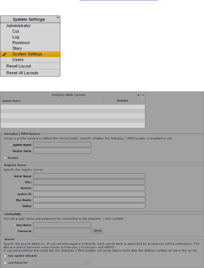
MCS 2.3 Installation and Configuration Guide
159
Configuring the MAM Connector
Once the MAM Connector has been installed, additional System Settings must be configured
within MediaCentral.
1. Log into MediaCentral.
For details on this process, see Logging into MediaCentral UX on page 89.
2. While logged in as the Administrator, select System Settings from the Layout selector.
3. In the Settings pane, select Interplay | MAM.
4. Configure the settings to connect to your Interplay MAM system. For detailed
information on the configuration of these settings, see the Avid MediaCentral | UX
Administration Guide.
MCS 2.3 Installation and Configuration Guide
160
PART IX: MULTI-ZONE CONFIGURATION
MCS 2.3 Installation and Configuration Guide
161
Chapter Overview
The purpose of this chapter is to provide instructions on setting up a multi-zone environment.
Configuration of a multi-zone workflow can be completed during the initial system installation
or added to systems in an established environment. The procedures in this section cover single
MCS nodes and MCS clusters that are already established.
The following table describes the topics covered in this chapter:
Step Task Time Est.
1
Multi-Zone Overview
5 min
Provides an introduction to the Multi-Zone concept.
2
Creating and Installing the RSA Keys
5 min
The multi-zone services must have access to remote servers directly,
without the need to log in. Installing RSA keys creates a network of trust
within the zone.
3
Creating the Master Zone and Initiating Multi-Zone
10 min
Once the MCS nodes in the master zone and slave zone(s) are up and
running, the multi-zone environment can be initialized.
4
Adding Slave Zone(s) to the Multi-Zone Environment
5 min
With the master zone established, slave zone(s) can be added to the
configuration.
5
Validating Multi-Zone Functionality
5 min
Creating a user with a different role in each zone verifies that the multi-
zone environment is working as expected.
6
Troubleshooting the Multi-Zone Setup
varies
This section offers solutions to typical problems encountered during
setup.
7
Dismantling a Multi-Zone Environment
5 min
Instructions for de-registering the multi-zone environment.
MCS 2.3 Installation and Configuration Guide
162
Multi-Zone Overview
By default, each MediaCentral system operates independently, within a single “zone”, with the
following configuration:
• One MediaCentral server or MediaCentral cluster
• One Interplay Production engine and/or iNEWS database
• ISIS storage system(s)
A multi-zone environment comprises two or more single-zone systems joined together. The
master zone maintains a read/write copy of the User Management System (UMS) database.
Each slave zone has a read-only copy. All log-in activity in the slave zones is channeled through
the master zone. In the event of a network disruption, the slave zones continue to operate in
read-only mode until connectivity to the master zone is re-established.
The benefits of a multi-zone environment include:
• Multi-zone user management: Centralized user management across all zones.
• Multi-zone central index search: Search across multiple databases in different zones
• Multi-zone media asset delivery: Transfer material you found on a remote zone to your
local zone.
For example, in a single zone environment a user can search for assets in their own zone. In a
multi-zone environment, a user in one zone can find media assets in remote zones, transfer
them to their local zone, for use in their local work.
Similarly, in a single zone environment, users log in to the locally configured MediaCentral
system. If they log in to another MediaCentral system, they must have login credentials on that
system too. In a multi-zone environment, one master server runs the user management service
(UMS). All users, whatever their zone, log in through that system. Thus, each user requires only
one set of login credentials.
Making Changes to a Multi-Zone Configuration
If changes are made to the multi-zone configuration after the initial setup, the MCS messenger
service must be restarted on all nodes. Examples of such changes include: altering information
contained in the initial multi-zone configuration process; adding or removing a zone.
To restart the messenger service, do the following:
Log in to each node of the cluster and type the following command:
service avid-acs-messenger restart
MCS 2.3 Installation and Configuration Guide
163
Creating and Installing the RSA Keys
The multi-zone services must gain access to remote servers directly and without the need to
provide log-in information. This is accomplished by generating RSA key(s) on the Master Zone
and installing the key(s) on the Slave Zone(s).
Generate the RSA keys in the master zone on the following nodes:
Master node
Slave node
Install the generated RSA keys in the slave zone on the following nodes:
Master node
Slave zone
To Generate and Install RSA Keys:
1. Log in (at the Linux prompt) to the master node in the master zone as the root user.
2. Generate the public/private RSA key pair using the RHEL ssh-keygen utility:
ssh-keygen
• Accept the default file and location
• Leave the passphrase blank
The system responds by outputting information similar to the following:
Your identification has been saved in /root/.ssh/id_rsa.
Your public key has been saved in /root/.ssh/id_rsa.pub.
The key fingerprint is:
55:66:25:00:f7:15:d5:cd:30:89:6f:0d:e2:c3:d4:4f root@wavd-mcs01.wavd.com
The key's randomart image is:
+---[ RSA 2048]---+
| o.B=+++Bo|
| . o = .o.+.E|
| o + + |
| . . + .|
| S . |
| o . |
| o o |
| .o |
+-----------------+
3. Use the RHEL ssh-copy-id utility to add the public key to the list of authorized keys on
the master node in the slave zone.
ssh-copy-id root@<hostname>
The system may respond with message similar to the following:
The authenticity of host '<hostname> (XXX.XX.XX.XXX)' can't be
established.
Now multi-zone processes can gain access to the remote server automatically (without
the need to provide root user credentials).
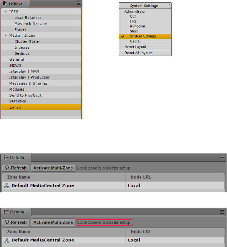
MCS 2.3 Installation and Configuration Guide
164
4. Copy the public key from the master node in the master zone to the slave node in the
slave zone.
5. Repeat the procedure for the slave node in the master zone.
Creating the Master Zone and Initiating Multi-Zone
1. Log in as the Administrator user to the MediaCentral UX instance located in the master
zone, and select System Settings from the Layout selector.
2. In the Settings pane, click Zones.
The Details pane appears on the right side of the screen. This pane displays the
currently active zone(s). For now, only the “default” zone exists.
Note that if the local zone is a cluster this is indicated in the UI:
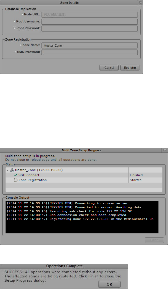
MCS 2.3 Installation and Configuration Guide
165
3. Click the Activate Multi-Zone button. In the confirmation dialog that appears, click
Proceed.
A Zone Details dialog appears.
4. In the Zone Details dialog that appears, enter the following information:
• Root Username and Root Password: The root user credentials for the master zone
MCS server.
• Zone Name: Name of the master zone (e.g. Master_Zone).
• UMS Password: Administrator password for the master zone UMS database (e.g.
Avid123).
5. Click Register.
A dialog appears showing progress of the operations related to zone creation.
Once registration of the master zone is complete, a dialog appears indicating success of
the operations.

MCS 2.3 Installation and Configuration Guide
166
6. Click OK to close the dialog and complete the process.
MediaCentral is automatically restarted.
7. Once restarted, log back in to MediaCentral UX.
The Zones Details area now shows the newly created zone (e.g. Master_Zone):
Adding Slave Zone(s) to the Multi-Zone Environment
1. Log in to MediaCentral UX in the master zone as the Administrator user.
2. Select System Settings from the Layout selector and Zones in the Settings pane.
3. Click the Add Slave Zone button. In the confirmation dialog that appears, click Proceed.
The Zone Details dialog appears.
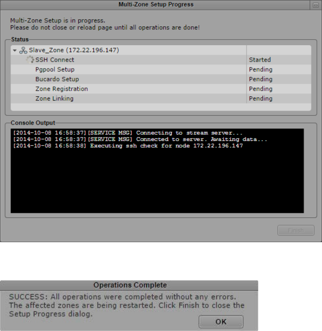
MCS 2.3 Installation and Configuration Guide
167
4. In the Zone Details dialog, enter the following information.
Database Replication:
• Master Zone Network: Specify the IP range for this network (e.g. 23, 24, 25)
• Slave Zone Address: Specify the IP address of the slave zone. This is either the IP
address of a single server or the IP address of a multi-server cluster.
• Root Username and Root Password: Specify the username (root) and password
for the slave zone.
Zone Registration:
• Zone Name: Name of the slave zone (e.g. Slave_Zone). This name will appear in
the “Node URL” column in System Settings>Zones.
• UMS Password: Administrator password for the slave zone UMS database (e.g.
Avid123).
5. Click Register.
A dialog appears showing progress of the operations related to slave zone registration.
Once the slave zone registration is complete, a dialog appears indicating success of the
operations.
6. Click OK to close the dialog and complete the process.
Note: Any users logged into the slave zone will be disconnected at this time as services are
restarted on the slave zone.
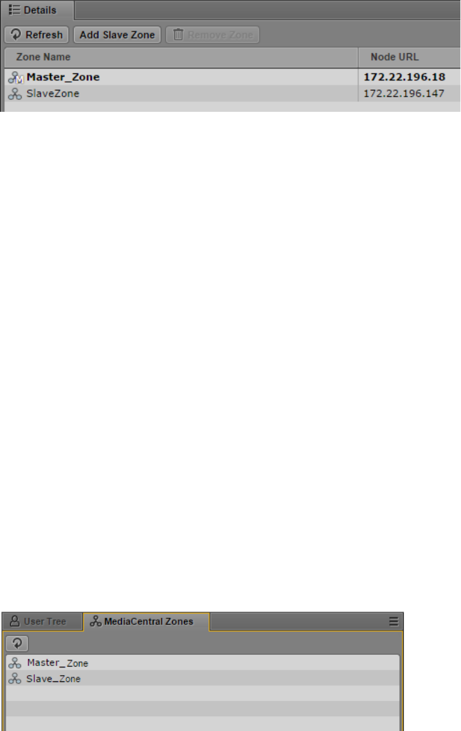
MCS 2.3 Installation and Configuration Guide
168
7. The Zones Details page is refreshed with the new slave zone.
Note that the master zone is now identified with the letter “M” and the current zone is
bolded. The “current zone” is the zone for the machine where you are currently logged
in.
8. Repeat the process to add other slave zones, as desired.
9. Once all slave zones have been added, the avid-acs-ctrl-core service must be restarted
on all zones, in any order.
a. If your zone consists of a single server, restart the service:
service avid-acs-ctrl-core restart
b. If your zone consists of a cluster configuration, restart the cluster resource:
crm resource restart AvidACS
Validating Multi-Zone Functionality
In this step you verify multi-zone UMS functionality by adding creating a user with different
roles in each zone.
To validate the multi-zone functionality:
1. Log in to MediaCentral UX as an administrator-level user in either the master zone or one of
the slave zones.
2. Select Users from the Layout selector.
3. Observe that the Users layout now has an additional tab named MediaCentral Zones, where
all the linked zones are displayed.
4. To validate that a user added to one zone can log in from another, begin by clicking the
Create User button.
In the Details pane, type the properties for the new user, at the very least:
• User name (e.g. multzone_test)
• Password
• To simplify the test, uncheck “User must change password at next sign-in”
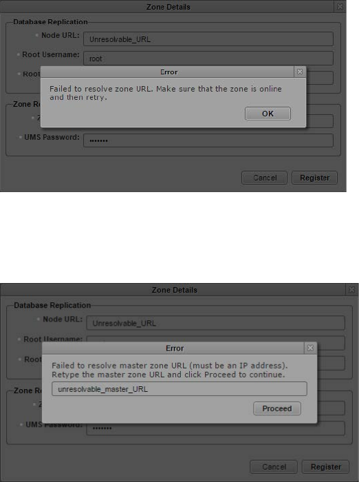
MCS 2.3 Installation and Configuration Guide
169
5. Drag a role for the user from the Roles pane to the Role section of the Details pane for the
new user.
Notice that you can assign the multi-zone user a different role in each zone. For example,
the user can be an administrator in one zone, and a media logger in another.
6. Click Save to save your changes.
The new user is added to the User Tree, and the Details pane is populated with the layouts
available to the user in each zone.
7. Finally, log in to MediaCentral UX in the other zone using the newly created multi-zone user.
• If you log in to a slave zone, note the user credentials are being validated in the master
zone.
• Notice the available layouts are those you assigned for the user upon creation.
Troubleshooting the Multi-Zone Setup
This section contains troubleshooting tips.
Failed to Resolve Zone URL
When registering the slave zone the following message indicates the zone is unreachable. Verify
that the zone is online and the URL you entered is correct.
The master zone URL is passed into the zone configuration processes automatically, based on
the current URL as shown in the browser. If you receive the following error, it may indicate the
browser is using a form that is unreachable to the backend services (e.g. a hostname). Re-enter
the address as an IP address and try again.
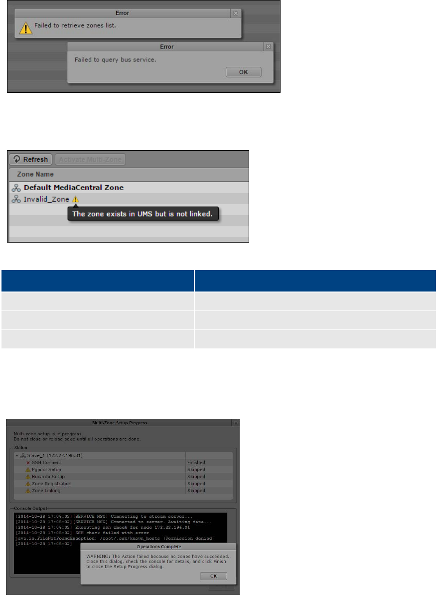
MCS 2.3 Installation and Configuration Guide
170
Bus Error
If a “failed to query bus service” error appears, check that the ACS bus is running in a command
shell.
Errors in Zone Configuration
An exclamation point next to a zone indicates incorrect configuration.
The following table presents typical configuration error messages:
Message Explanation
The zone does not exist in the UMS.
Zone is present in the BUS, but not in the UMS.
The zone exists in UMS but is not linked.
Zone is present in the UMS, but not in the BUS.
Some links are missing
The zone is missing one or more links to other zones.
Errors During Setup
If any stage of the setup fails, all the subsequent steps are skipped. In this case, the problem
most likely cannot be fixed through the UI, and must be resolved at the command-line.
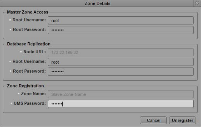
MCS 2.3 Installation and Configuration Guide
171
Dismantling a Multi-Zone Environment
When a multi-zone environment is no longer required, it can be dismantled. Dismantling a multi-
zone environment removes all roles for multi-zone users (login credentials remain). If you later
use the same user names on independent systems, you need to manually re-assign the roles on
each system.
To dismantle the multi-zone:
1. Log in to MediaCentral UX in the master zone as the Administrator user.
2. Select System Settings from the Layout selector and Zones in the Settings pane.
3. For each slave zone, select the zone and click the Remove Zone button.
The Zone Details dialog appears for the slave zone.
4. In the Zone Details dialog, enter the following information:
Master Zone Access:
• Root Username and Root Password: The root user credentials for the master
zone MCS server.
Database Replication:
• Node URL: This field is completed for you. This is the IP address of the
MediaCentral instance/cluster in the slave zone.
• Root Username and Root Password: This is the root user of the slave zone.
Zone Registration:
• Zone Name: This field is completed for you. This is the name of the slave zone
(e.g. Slave_Zone).
• UMS Password: Administrator password for the slave zone UMS database (e.g.
Avid123).
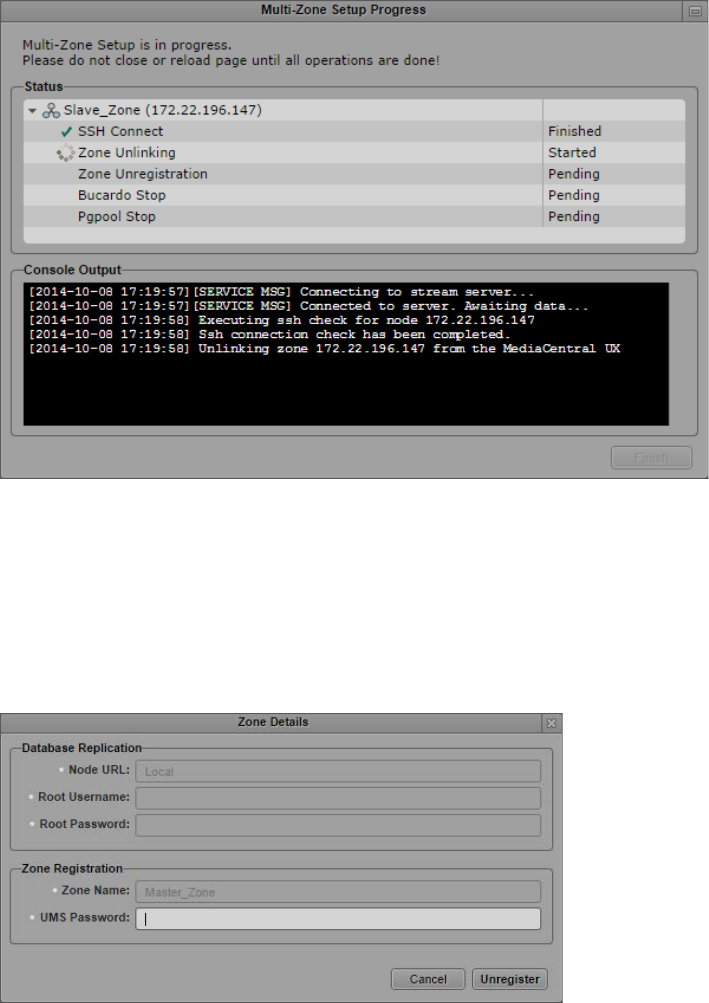
MCS 2.3 Installation and Configuration Guide
172
5. Click the Unregister button.
A dialog appears showing progress of the operations related to slave zone
deregistration.
6. Repeat for any other slave zones you wish to add.
Note: Any users logged into the slave zone will be disconnected at this time as services are
restarted on the slave zone.
7. Once deregistration of the slave zone(s) is complete, select the master zone and click
the Remove Zone button.
The Zone Details dialog appears for the master zone.
8. Enter the master zone UMS administrator password (e.g. Avid123), then click the
Unregister button.
A dialog appears showing progress of the operations related to the de-registration.
Note: Any users logged into the master zone will be disconnected at this time as services are
restarted on the master zone.
MCS 2.3 Installation and Configuration Guide
173
APPENDICES

MCS 2.3 Installation and Configuration Guide
174
Appendix A: Overview
The purpose of this Appendix is to provide additional information and detail on topics included
in the main body of the Installation Guide.
The following table describes the topics covered in this Appendix.
Topic
Enabling the Player Demonstration Web Page
Copying Software to the MCS Server
Installing MCS on Non-HP / Dell Hardware for Interplay MAM
Working with the Dell RAID Controller
HP DL360p Gen8 Card Placement
Contents of the MCS Installation Package
Enabling Trusted Certificates
Determining the Installed MCS Version
Using SNMP Monitoring on the MCPS Server
Log Cycling
Retrieving MCS Logs
Verifying Cache Directory Permissions
Monitoring the AAF Generator Service
Monitoring Services and Resources
Backing up and Restoring the MCS Database
Verifying the ISIS Mount
Reconfiguring the ISIS Connection(s)
Unicast Support in Clustering
Reconfiguring MediaCentral Settings in a Cluster
Shutting Down or Rebooting a MediaCentral Cluster
Identifying the Master, Slave and Load-Balancing Nodes
Monitoring MCS High-Availability
Monitoring Load Balancing
Changing the Cluster Administrator Email Address
Taking a Cluster Node Off-Line Temporarily
Permanently Removing a Node from a Cluster
Adding a New Node to a Cluster
Port Requirements

MCS 2.3 Installation and Configuration Guide
175
Enabling the Player Demonstration Web Page
The player demonstration web page (http://<host-domain>/player/index.html) is a powerful tool
for verification and troubleshooting. However, since it is accessible by way of an unrestricted
URL, it is not installed by default (as of ICS 1.6).
Note: The player demonstration web page is accessible by way of an unrestricted URL.
This may be considered a security concern at customer sites. Moving or renaming its
index.html file will prevent loading of the page. When not in use, move the player
demonstration index.html file to a folder not accessible through http, such as the root
user home directory (/root). The root user home directory is visible only to the root user.
This is not to be confused with the root directory (/), which is visible to all users.
To install/uninstall the player demonstration web page:
1. Log in to the master node as root.
For help identifying the master node, see Identifying the Master, Slave and Load-Balancing
Nodes on page 198.
2. Determine the name of the maxcut-devel RPM file containing the player demonstration web
page:
ls /opt/avid/Packages/
3. Manually install the maxcut-devel RPM:
rpm -ivh /opt/avid/Packages/maxcut-devel-<version>-
<build>.x86_64.rpm
Recall that tapping the tab key invokes the Linux autocomplete functionality and ensures
accuracy when typing long file names.
Some feedback appears indicating the success of the installation.
4. To verify the package has been installed:
rpm -qa | grep max
5. Log in to the slave node as root and repeat the process.
6. To launch the player demo web page by opening a browser and navigating to the following
URL:
http://<host-domain>/player/index.html
Where <host-domain> is the host name or FQDN of the node where you installed the player
demonstration page. For a cluster, enter the virtual host name of the cluster instead.
7. To erase/remove the package (should you wish to uninstall):
rpm –e maxcut-devel
To move the player demonstration web page to a secure location:
mv /var/www/html/player/index.html /root
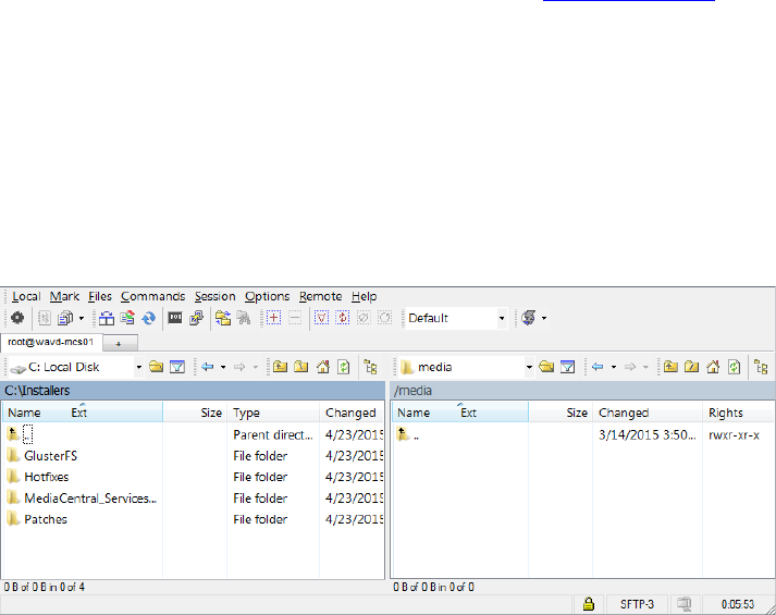
MCS 2.3 Installation and Configuration Guide
176
Copying Software to the MCS Server
At various times during the upgrade, you will need to copy software to the MCS server. This task
can be performed using one of two methods:
Using a Windows system and a SFTP tool such as WinSCP
Connecting a USB drive directly to the server
While the SFTP method may be preferred for ease of access, the USB method may be required
for some operations such as backing-up MCS files during a system upgrade.
Copying Software Using WinSCP
1. Download and install the WinSCP software on a Windows system that has network access to
the MCS server. The WinSCP software can be found at: http://winscp.net.
2. Launch WinSCP.
3. Enter the Host name (or IP address) of your server, User name (root), and Password.
4. Click Login.
5. The following warning message is displayed: “Continue connecting and add host key to the
cache?” Click Yes.
The WinSCP interface is displayed. The left pane represents your source Windows system.
The right pane represents your MCS server.
6. Navigate to the location of the downloaded MCS installation files in the left pane.
7. Navigate to the /media folder on the MCS server in the right pane.
8. Right-click in the right pane and select New>Directory.
9. In the “New folder name” field, type installers and click OK.
10. Double-click on the new installers folder in the right pane.
11. Drag and drop the files or folders you wish to copy from the left pane to the right.
Depending on your WinSCP settings, you might see a dialog box asking if you want to copy
the files to the remote directory. Click Copy.
12. After all desired files or folders have been copied, close WinSCP.
MCS 2.3 Installation and Configuration Guide
177
Copying Software Using a USB Drive
For simply mounting and unmounting a USB drive, follow the process below and eliminate steps
7 and 8.
1. Insert the USB drive into the MCS server.
2. Verify the name of the device:
dmesg
Information for the USB drive will appear near the end of the output, near the list of SCSI
devices. The name of the USB drive is found inside square brackets (for example, sdc). This is
the name you use to mount the drive.
3. If needed, create a mount point for the USB drive:
mkdir /media/usb
4. Mount the USB drive at the mount point you just created:
mount /dev/sdc1 /media/usb
Note the name of the USB drive, sdc (in this case) takes a 1 (one) in the mount command.
This simply indicates a partition exists on the drive. When the USB drive was formatted, the
partition was created.
The USB drive is now mounted and available for use.
5. Verify the USB drive has been mounted:
df -h
Information is displayed about all mounted filesystems and devices, and should include
information about the USB drive, similar to the following (other output has been omitted,
for clarity):
Filesystem Size Used Avail Use% Mounted on
/dev/sdc1 7.5G 5.3G 2.2G 71% /media/usb
6. To change to the mount point:
cd media/usb
7. If needed, create a directory for the installer packages:
mkdir /media/installers
8. Copy files to the MCS server:
For a single file: cp filename /media/installers
For a folder: cp -R foldername /media/installers
9. Once you have finished copying all necessary files, unmount the USB drive.
cd
Note: In Linux the “cd” command without any arguments takes you directly to the user’s
home directory. If you are logged in as root, it takes you to the /root directory. RHEL will not
unmount the USB drive if it is the current active directory.
MCS 2.3 Installation and Configuration Guide
178
umount /media/usb
If you receive an error message that the USB device is busy, it typically indicates the Linux
ISO on the USB drive was auto-mounted. Verify what is mounted using the df -h command
or the mount command, or both. Then dismount the Linux ISO first, followed by the USB
device:
umount /sysinstall
umount /media/usb
Remove the USB drive from the server.
Caution: Once you have copied the necessary software, make sure you unmount and remove
the USB drive from the server. If you re-boot with the server with the USB drive still in place,
RHEL will be re-installed and all your work will be lost.
MCS 2.3 Installation and Configuration Guide
179
Installing MCS on Non-HP / Dell Hardware for Interplay MAM
MCS supports MediaCentral and MediaCentral Cloud on HP and Dell hardware only. Therefore,
this section does not pertain to those deployments. Installing MCS on non-HP or Dell hardware
is only supported for Interplay MAM deployments.
For the most part the steps provided in the main body of this guide for installing and configuring
MCS on HP and Dell servers are easily generalized to other hardware. The primary difference is
the use of a RHEL “kickstart” file. A kickstart file (ks.cfg) is a Linux convenience that speeds up
installation by automatically answering some questions for hardware that is known in advance.
The express installation of RHEL and MCS using a USB drive should not be followed on
installations not using HP or Dell hardware. RHEL and MCS are installed in separate steps
because there is no guarantee that the supplied kickstart file will work on other hardware.
However, you can examine its contents and mimic them during a manual installation, or create a
kickstart file for your own hardware. As previously stated, the kickstart file is a convenience and
the creation of a kickstart file is not required.
As of the ICS 1.4 release, three partitions are created on the (mirrored) system drive:
The first is the boot partition (/boot).
The second is the DRBD (Distributed Replicated Block Device) storage system
partition. In a clustered configuration, MCS uses DRBD to replicate its PostgreSQL
database.
The third is the system partition (/).
On HP and Dell hardware, the kickstart file on the MCS Installation USB Drive creates the second
partition on the OS drive automatically. On other servers this partition would need to be created
manually. After the second partition has been created the steps for setting up DRBD are the
same as the HP / Dell process.
Note: The DRBD partition on the system drive is required only for cluster deployments.
However, it is recommended you create it even for a single MCS server deployment, to keep
open the possibility of clustering.
This process will require a RHEL DVD or dvd.iso. Log in to your Red Hat Network account and
download the DVD image (.iso) file or purchase a DVD. Either format can be used for the MCS
installation.
Note: At the time of this document’s publication, the RHEL 6.5 ISOs were available by
choosing Red Hat Enterprise Linux Server from the Red Hat Product Downloads page.
Specify Red Hat Enterprise Linux Server (product variant), 6.5 (version) and x86_64
(architecture). Download the Binary DVD (rhel-server-6.5-x86_64-dvd.iso).

MCS 2.3 Installation and Configuration Guide
180
Non-HP / Dell Installation Notes
The following notes pertain to the main installation steps for non-HP hardware:
1. Set Up the Server Hardware
a. Create a RAID 1 (mirror) for the system disk using the hardware BIOS utilities.
b. If possible, set the system clock before installing RHEL. Otherwise, set the clock at
the appropriate stage in the RHEL installation process.
2. Install RHEL manually.
a. Select BASIC SERVER during the RHEL installation process.
b. When prompted to create storage, create two partitions on the OS drive. One
partition is for RHEL. The other one is used by DRBD. The DRBD partition should be
20GB in size.
Note: Some MCS software components depend on the language for RHEL being set to
English. Please select English as the language of installation. Do not change the input
language afterwards.
3. Mount the RHEL Installer
You will need to mount the physical DVD or DVD.iso to the /sysinstall directory. This is
where the MCS install script looks for it.
If you have physical RHEL DVD media:
mount /dev/sdx /sysinstall
In the above command, substitute the optical drive device name for sdx (e.g. sr0)
Note: RHEL will automatically create an alias for the optical drive on /CDROM. Thus the
following mount command can also be used:
mount /CDROM /sysinstall
If you have a RHEL .iso file:
a. Create a directory on the server where you can copy the .iso. Example:
mkdir /media/installers
Note: If needed, see Copying Software to the MCS Server for instructions for
mounting a USB drive.
b. Copy the .iso to the newly created folder.
cp /path/rhel-server-6.5-x86_64-dvd.iso /media/installers
c. Mount the .iso
mount –t iso9660 –o loop /media/installers/rhel-server-
6.5-x86_64-dvd.iso /sysinstall
In the above command, “/media/installers” is used as an example. Substitute
“/media/installers” with the directory you created for the .iso.
MCS 2.3 Installation and Configuration Guide
181
4. Install MCS.
a. Unpack the MCS installer file:
tar –zxovf MediCentral_Services_<version>.tar.gz
b. Change directories to the MediaCentral_Services_<version> folder and run the
installation script:
./install.sh
5. Once the installation is complete, follow the instructions in the body of this guide to Set up
the cluster (optional), configure MCS for MAM (if applicable), etc., as instructed in the main
body of this guide.
MCS 2.3 Installation and Configuration Guide
182
Working with the Dell RAID Controller
This section provides information on working with the Dell R620 / R630 RAID controller. The
installation process assumes that the server shipped with preconfigured RAID 1 and RAID 5
arrays. If that is not the case, this information can be used to create the RAID sets.
Creating the RAIDs
1. From the Virtual Disk Management menu, select Create Virtual Disk.
If you just deleted the disk, this item is grayed-out. Go up one level in the menu system, and
then return to the Virtual Disk Management page.
2. From the Create Virtual Disk page select Select Physical Disks.
3. Put check marks in the appropriate Physical Disk boxes.
a. For the RAID 1 (system disk) this should be 00:01:00 and 00:01:01
b. For the RAID 5 (optional cache disk) this should be 00:01:02 through 00:01:07.
4. Select Apply Changes.
A confirmation screen indicates success.
5. From the Create Virtual Disk Page, select Create Virtual Disk.
You may need to scroll down the page to see the link.
6. From the Warning page, confirm you selection and select Yes.
A confirmation screen indicates success.
7. Return to the Virtual Disk Management page and select View Disk Group Properties to
view your changes.
a. You should see a Virtual Disk 0 (the RAID 1) and a Virtual Disk 1 (the RAID 5).
8. Return to the Integrated RAID Controller Configuration Utility page.
9. From the Integrated RAID Controller Configuration Utility menu choose Controller
Management.
10. From the Controller Management menu choose Change Controller Properties.
11. Verify that the Virtual Disk 0 (the RAID 1) is selected in Set Bootable Device.
If not, select it and apply your changes. Once you install RHEL and MCS, you want the server
to boot from the RAID 1.
12. Exit the RAID configuration utility and return to the System Setup menu.
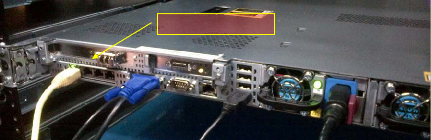
MCS 2.3 Installation and Configuration Guide
183
Deleting the RAIDs
If necessary, it is possible to delete the RAID sets from within the RAID controller.
1. From the Virtual Disk Management menu select Select Virtual Disk Operations.
2. Select the virtual disk of interest (the RAID 1 or RAID 5) from the drop-down menu
3. Select Delete Virtual Disk.
4. Confirm your action.
The menu indicates the success of the operation.
HP DL360p Gen8 Card Placement
Connecting to non-ISIS Proxy Storage
Interplay MAM deployments where browse proxies reside on non-ISIS storage do not require
additional NIC cards. They make use of the Ethernet ports built in to the HP server. Visually
verify that one of the built-in ports is connected to the network. For a 10GigE connection to
non-ISIS storage, use a 10GigE NIC of your choosing.
Note: If MAM browse proxies reside on an ISIS, the connection to the ISIS must be over a
Zone 1, Zone 2, or Zone 3 (recommended) connection, using a GigE or 10GigE network
interface.
HP DL360 Gen8 backplane (showing built-in Ethernet ports):
Note: This applies to Interplay MAM deployments only.
Built-in Ethernet Ports
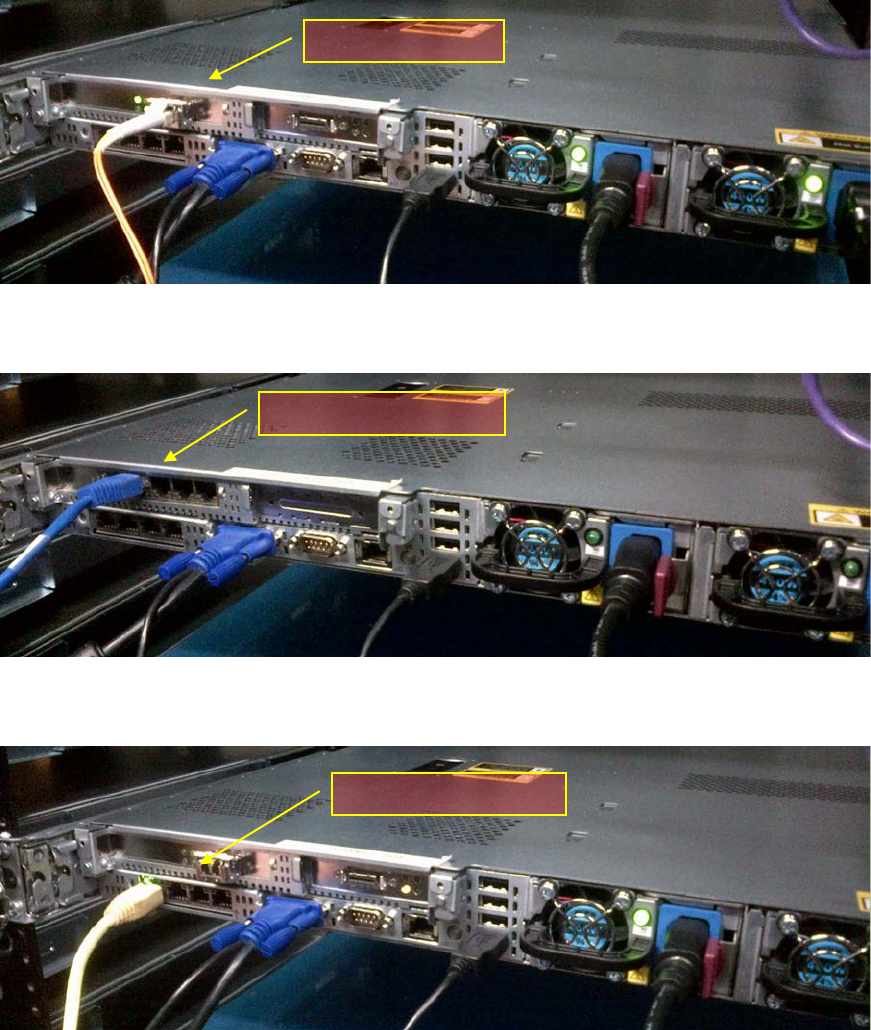
MCS 2.3 Installation and Configuration Guide
184
Connecting to ISIS Proxy Storage
The HP DL360 G8 has a full height PCI slot in the upper left corner. Use this slot for either the
Myricom 10GigE or the HP NC365T 4-port GigE NIC. The “built-in” Ethernet ports can also be
used, if the server is provisioned with the HP 366FLR 4-port GigE NIC.
HP DL360 Gen8 backplane (indicating Myricom 10GigE):
HP DL360 Gen8 backplane (indicating HP NC365T 4-Port GigE):
HP DL360 Gen8 backplane (indicating HP 366FLR 4-port GigE):
Myricom 10GigE
HP NC365T 4-Port GigE
HP 366FLR 4-port GigE

MCS 2.3 Installation and Configuration Guide
185
Contents of the MCS Installation Package
The MCS installation package is a ZIP file with a name of the form:
MediaCentral_Services_<version>_Linux.zip
For the precise installation package name, see the Avid MediaCentral Platform Services ReadMe.
The ZIP file contains the following:
Item Description
MediaCentral_Services
_<version>_Linux.tar.gz
The MCS Server Installation package.
This compressed tar file contains numerous files, including the following
useful shell script:
ics_version.sh
It outputs version/build information for the following processes:
• UMS - User Management Service
• ICPS - MediaCentral Playback Services
• ICPS Manager - MediaCentral Playback Services Manager (player-
to-server connection manager)
• ACS - Avid Common Services bus (“the bus”)
• System ID: An 11-digit number used in support calls that you
enter when configuring MediaCentral
• ICS Installer - MediaCentral installer
The MediaCentral version information is also available in the user
interface in the Home -> About box.
Once MCS is installed, a symlink is created and you can simply type the
following to execute the script:
ics_version
install.sh
The installation script, for upgrades and installations.
iso2usb.exe
iso2usb.patch
iso2usb_LICENSE.html
iso2usb_README.rtf
Used in creating the MCS installation MCS Installation USB Drive.
ks.cfg
ks_upgrade.cfg
The Avid-supplied kickstart files for fresh installations and for upgrade
installations.
system-backup.sh
Prepares for an upgrade by backing up important data, including system
settings, network settings, the Jetty keystore and application.properties
file, and the UMS database.

MCS 2.3 Installation and Configuration Guide
186
Enabling Trusted Certificates
For security, MediaCentral uses the Secure Sockets Layer (SSL) for its server-to-browser
connections. This is indicated by https:// in the browser address bar, rather than the usual
http://. (Some browsers also show a locked padlock icon for an SSL connection.) SSL enables the
secure transmission of information between web servers and web browsers.
For more information on configuring SSL certificates, see the Avid Knowledge Base:
http://avid.force.com/pkb/articles/en_US/how_to/SSL-Certificates-for-server-to-browser-connections
Determining the Installed MCS Version
The version and build numbers of the MCS installation can be verified with the following
command:
ics_version
Service version numbers are returned as follows:
UMS Version: 2.3.x.x
ICPS Version: 2.3.x.x
ICPS manager Version: 2.3.x.x
ACS Version: 2.3.x.x
System ID: "xxxxxxxxxxx"
ICS installer: 2.3 (Build xx)
Created on <installer creation date>
Note: The System ID is an 11-digit number you entered when configuring MediaCentral.
Note: For precise version numbers for this release, see the Avid MediaCentral Platform Services
ReadMe.
Using SNMP Monitoring on the MCPS Server
The Avid System Monitor application and MCS server can be configured to collect information
from the MCS server. This allows you to monitor the status of mandatory MCS services and
display graphs for activities such as CPU usage, network usage, and system memory usage. The
following items are graphed over time in the Avid System Monitor web page interface:
• Average CPU load
• Number of CPU interrupts per second
• System uptime
• Swap space (disk space reserved for memory when RAM is fully loaded)
• System memory usage
• CPU usage
Contact your Avid representative for information about Avid System Monitor. A qualified Avid
support representative can upgrade an Avid System Monitor system to work with MCS.
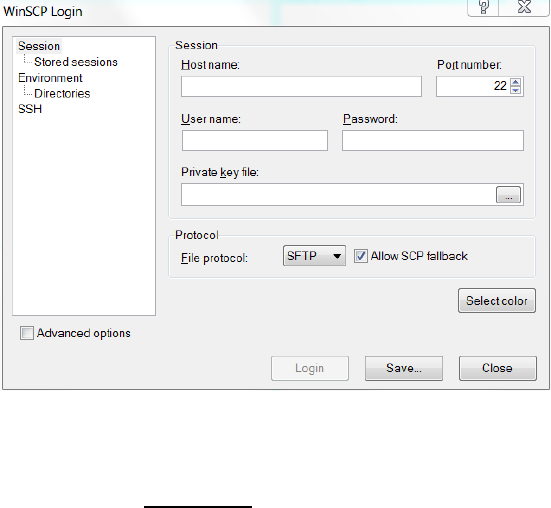
MCS 2.3 Installation and Configuration Guide
187
Log Cycling
Like other Linux logs, the MCS server logs are stored under the /var/log directory, in
/var/log/avid. Logs are automatically rotated on a daily basis as specified in /etc/logrotate.conf.
Retrieving MCS Logs
As you use MediaCentral you may encounter issues for which you wish to gather additional
information. The simplest way to retrieve logs residing on a Linux machine is using an
application that supports SCP/SFTP such as WinSCP (Windows) or muCommander (MacOS).
To retrieve MCS logs using an SCP/SFTP client:
1. Launch the SCP/SFTP client (WinSCP shown) and enter the session information.
• Hostname: The host name of the MCS server you want to gather logs from.
• User name: root
• Password: _
Note: Please contact your Avid representative for the default root password.
2. Once connected, navigate to the directory where the logs are stored:
/var/log/avid
3. Use the SCP/SFTP client’s built-in functionality to retrieve the logs.
Some logs can be quite large and may take longer to transfer.
If you encounter any issues on your MCS system, contact Avid Customer Care for assistance.
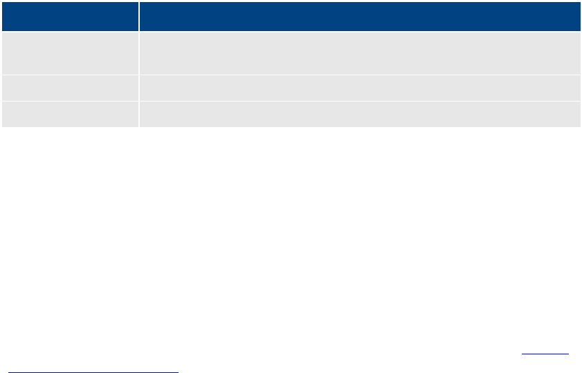
MCS 2.3 Installation and Configuration Guide
188
Verifying Cache Directory Permissions
As part of the installation (or upgrading) process, you created a number of cache directories,
changing ownership and setting their permissions. In this section, you verify the permissions are
set correctly.
Note: This procedure is only necessary for a cluster deployment. Do not use this procedure
for a single node deployment. Some directories may not be present, as they are created
automatically in a running system. Adjust the steps accordingly.
To verify cache directory permissions:
1. Verify the ownership and permissions for of all cache directories:
ls -la /cache
Output similar to the following ought to be presented:
drwxrwxrwx 9 maxmin maxmin 4096 Nov 4 10:13 .
drwxr-xr-x 33 root root 4096 Nov 4 13:34 ..
drwxrwsrwx 2 maxmin maxmin 4096 Nov 4 20:04 download
drwxrwsrwx 5 maxmin maxmin 4096 Nov 4 20:03 fl_cache
drwxrwxrwx 55 root root 4096 Nov 4 13:50 mob-fetch
drwxrwxrwx 2 root root 4096 Nov 4 10:04 render
drwxrwxrwx 9 root root 4096 Nov 4 14:05 spooler
Note that in the output above the dot (“.”) directory represents the current directory, that
is, /cache.
Note that some directories might not exist yet, as explained in the following table:
Directory Description
/cache/fl_cache
Automatically created and assigned maxmin ownership by MCS processes
only after specific media types have been accessed.
/cache/download
As above.
/cache/render
Automatically created by MCS processes with first multicam playback.
For a complete description of all cache directories, see the MediaCentral Platform Services
Concepts and Clustering Guide.
2. The following directories must be owned by user maxmin:
/cache
/cache/download
/cache/fl_cache
3. The following directories must have the SGID special bit set:
/cache/download
/cache/fl_cache
4. If the ownership and permissions are not set correctly, refer to the instructions in “Making
the RHEL Cache Directories” on page 127.
MCS 2.3 Installation and Configuration Guide
189
Monitoring the AAF Generator Service
The AAF Generator service (avid-aaf-gen) is responsible for saving sequences. To reduce the
possibility of bottlenecks when many users attempt to save sequences at the same time,
multiple instances of the service run simultaneously (by default, five). As a result, MediaCentral
has the ability to save multiple sequences concurrently, significantly reducing overall wait-times
under heavy load.
In a cluster deployment, this service is installed and running on all nodes. However, it is only
involved in saving sequences on the node where the IPC core service (avid-interplay-central) is
currently running.
The service is not managed by Pacemaker. It is therefore important to regularly verify its status.
If one or more instances of it have failed, restart the service. An instance can fail, for example, if
an invalid AAF is used within a sequence. If all instances fail, responsibility for saving transfers to
the MediaCentral core service (avid-interplay-central), and bottlenecks can arise.
Logs are stored in /var/log/avid/avid-aaf-gen/log_xxx.
To verify the status and/or stop the AAF Generator service:
1. Log in to both the master and slave nodes as root.
Though the AAF Generator service is active in saving sequences only on the master node,
you should verify its status on the slave node too, to prepare for any failover.
2. Verify the status of the AAF Generator service:
service avid-aaf-gen status
The system outputs the status of each instance, similar to the following:
avid-aaf-gen_1 process is running [ OK ]
avid-aaf-gen_2 process is running [ OK ]
avid-aaf-gen_3 process is running [ OK ]
avid-aaf-gen_4 process is running [ OK ]
avid-aaf-gen_5 process is running [ OK ]
An error would look like this:
avid-aaf-gen_1 process is not running [WARNING]
3. In the event of an error, restart the service as follows:
service avid-aaf-gen restart
Output similar to the following indicates the service has restarted correctly:
Starting process avid-aaf-gen_1 - Stat: 0 [ OK ]
Starting process avid-aaf-gen_2 - Stat: 0 [ OK ]
Starting process avid-aaf-gen_3 - Stat: 0 [ OK ]
Starting process avid-aaf-gen_4 - Stat: 0 [ OK ]
Starting process avid-aaf-gen_5 - Stat: 0 [ OK ]
MCS 2.3 Installation and Configuration Guide
190
4. If you need to stop the service this must be done in two steps. First, configure 0 instances of
the service (there are 5 by default):
echo 0 > /opt/avid/avid-aaf-gen/DEFAULT_NUM_PROCESSES
5. With zero instances configured, stop the service:
service avid-aaf-gen-stop
To restart the service, reset the number of instances to the default (5) then restart it in the
usual way.
Monitoring Services and Resources
Resources are collections of services grouped together for oversight by Pacemaker. Pacemaker
sees and manages resources, not individual services.
The state of services can be verified by typing the following command at the command line:
service <servicename> status
If the service is not active, it can be restarted by using the following command:
service <servicename> restart
The state of a cluster resource can be verified by typing the following command:
crm resource <resource> status

MCS 2.3 Installation and Configuration Guide
191
Backing up and Restoring the MCS Database
You may recall that the system-backup script, discussed in the Backing up the MCS System
Settings and the MCS Database section of this document, calls the avid-db command as part of
its system setting backup process.
The MCS database is automatically backed up by the same avid-db utiliy on a daily basis. If
desired the utility can run manually to back up and restore the database (plus perform other
operations) at any time.
The avid-db command has the following format:
/opt/avid/bin/avid-db <parameter-list> <command> [ <args>... ]
For example, to back up the contents of the MCS database to /opt/avid/share/avid/db/dumps:
/opt/avid/bin/avid-db -–dump-base=/opt/avid/share/avid/db/dumps dumpall
For a list of all the parameters and arguments, issue the following:
/opt/avid/bin/avid-db help
Note: Restoring the MCS database in cluster has special requirements. Due to the automatic
restarting of halted services in a cluster, do not use the avid-db restore command by itself.
Follow the procedure as outlined below.
To restore the MCS database in a cluster:
1. Log in to the master and slave nodes as root.
For help identifying the node, see Identifying the Master, Slave and Load-Balancing
Nodes on page 198.
2. Stop pacemaker on both nodes:
service pacemaker stop
3. Start DRBD on both nodes:
service drbd start
4. Make the master node the DRBD primary (on the master node):
drbdadm primary r0
5. Mount the DRBD drive on the master node:
mount /dev/drbd1 /mnt/drbd
6. Start the PostgreSQL database on the master node:
service postgresql-9.1 start
7. Restore the MCS database on the master node:
/opt/avid/bin/avid-db --drop-db="no" restoreall
Once the MCS database has been restored, begin handing control back to pacemaker in
the steps below.
MCS 2.3 Installation and Configuration Guide
192
8. Stop PostgreSQL on the master node:
service postgresql-9.1 stop
9. Unmount the DRBD drive on the master node:
umount /mnt/drbd
10. Stop DRBD on both nodes:
service drbd stop
11. Restart Pacemaker (which restarts all needed services) on both nodes, master node first,
slave node second:
service pacemaker start
MCS 2.3 Installation and Configuration Guide
193
Verifying the ISIS Mount
The validity of the ISIS mount is initially authenticated during the configuration procedure. In
that procedure, the Status of the ISIS connection changes from “Disconnected” to “Connected”.
However, it is possible to verify the ISIS mounts using various command line tools which can be
useful for troubleshooting. Examples of such commands are:
• service avid-isis status
• mount -t fuse.avidfos
• df -h
To verify the ISIS mount(s):
1. Verify the status of the avid-isis service:
service avid-isis status
The system responds with output similar to the following:
AVID Service: isis fuse_avidfos (pid 2302) is running...[ OK ]
2. Use the Linux mount command to display all mounted filesystems of type fuse.avidfos
(the ISIS filesystem):
mount -t fuse.avidfos
The system responds with output showing the ISIS mounts, similar to the following:
wavd-isis on /mnt/ICS_Avid_Isis/wavd-isis type fuse.avidfos
(rw,nosuid,nodev,allow_other,default_permissions)
The output above indicates an ISIS called wavd-isis mounted at /isis/wavd-isis. “Fuse” is
the RHEL filesystem type reserved for third-party filesystems.
3. The Linux df command displays disk usage information for all the mounted filesystems:
df -h
The system responds with output similar to the following:
Filesystem Size Used Avail Use% Mounted on
/dev/mapper/vg_icps-lv_cache
527G 6.3G 494G 2% /
tmpfs 24G 0 24G 0% /dev/shm
/dev/sda1 485M 33M 428M 8% /boot
wavd-isis 15T 5.7T 8.9T 40% /mnt/ICS_Avid_Isis/wavd-isis
/dev/sdb1 7.3G 5.5G 1.9G 75% /media/usb
4. Finally, explore the mounted ISIS and its workspaces by navigating it as you would any
Linux filesystem.
For example, for the sample output shown above, to view the workspaces available to
the MCPS player, list the contents of the mounted ISIS:
ls /mnt/ICS_Avid_Isis/wavd-isis

MCS 2.3 Installation and Configuration Guide
194
Reconfiguring the ISIS Connection(s)
When you set up MCS for the first time you configure a network interface to be used for
playback of video assets. For a MediaCentral UX and/or Media Composer UX deployment, for
example, you configure a GigE or 10GigE connection to the ISIS. If at a later date you decide to
change the network interface, this section provides the instructions.
To reconfigure the ISIS Connection(s):
1. Install the new card.
See Network Interface Cards and Network Connections on page 13.
2. Verify the NIC interface names using the RHEL Network Configuration tool.
See Identifying NIC Interfaces and Connecting the Network Cable on page 66.
3. If running an HP server, swap the NIC interface names so the new card owns port eth0
by editing the 70-persistent-net.rules file.
See (HP Only) Swapping NIC Interface Names on page 67.
4. If running an HP server, remove the MAC address hardware references for the swapped
ports from the corresponding ifcfg-ethX files and reboot.
See (HP Only) Removing the MAC Address Hardware References on page 69.
5. Log in to MediaCentral UX with administrator privileges and update the ISIS connection
in the Playback Service System Settings to match the new connection speed.
For example, change it from “1 Gb Connection” to “10 Gb Connection”.
See Playback Service Settings on page 96.
MCS 2.3 Installation and Configuration Guide
195
Unicast Support in Clustering
MCS clustering supports both unicast and multicast communication protocols. The default
configuration, as set up by the cluster installation script (and covered in the body of this guide)
uses multicast. In facilities where the routers do not support multicast (i.e. are not multicast
enabled), configuring the cluster for unicast communication is an alternative.
This process can also be used for new installations and for systems that already have a
functional cluster configured for multicast and wish to convert to unicast communication.
Note: If you are converting an existing multicast cluster to unicast communication, skip Step
1 of the following process.
Configuring a cluster for unicast requires altering the contents of the corosync configuration
(corosync.conf) file.
The following is an example of the default corosync configuration file using multicast:
totem {
version: 2
secauth: off
threads: 0
interface {
ringnumber: 0
bindnetaddr: 192.168.10.0
mcastaddr: 239.192.1.1
mcastport: 5405
}
}
The following is an example of an altered corosync configuration file using unicast:
totem {
version: 2
secauth: off
threads: 0
interface {
member {
memberaddr: 192.168.10.51
}
member {
memberaddr: 192.168.10.52
}
ringnumber: 0
bindnetaddr: 192.168.10.0
mcastport: 5405
}
transport: udpu
}
Note the following changes in the altered file:
• A “member{}” section for each node in the cluster has been added.
• “mcastaddr: 239.192.1.1” has been removed.
• A “transport: udpu” line has been added.

MCS 2.3 Installation and Configuration Guide
196
Configuring Unicast Cluster Communication
This process assumes that the following steps from the PART V: CLUSTERING section of this guide
have already been completed:
• Cluster Overview
• Configuring the Player System Setting
• Configuring DRBD
1. Run the following command on each node in the cluster:
/opt/avid/cluster/bin/cluster setup-corosync --corosync-bind-
iface=interface --rabbitmq_master="master hostname"
When using this command, reference the following:
• interface: Identifies the name of the primary network interface. In an HP
server, this is generally “eth0”. In a Dell server, this is generally “em1” for 1 Gb
connections or “p1p1” / “p2p1” for 10 Gb connections (depending on which slot
the card 10 Gb card has been installed). For Interplay MAM configurations with
port bonding, this is generally “bond0”. Quotes are not required in this
command.
• master hostname: Specifies the (short) hostname of the Master node in the
cluster (e.g. wavd-mcs01). This should be the same as the DRBD Master node
specified in the drbd_setup process. Quotes are required in this command
Note: The body of this guide instructs you to run this command on the master node only. In
this process, you will run the command on all nodes.
2. Stop the cluster services on all load-balancing nodes:
service pacemaker stop && service corosync stop
3. Stop the cluster services on the slave node:
service pacemaker stop && service corosync stop
4. Once the cluster services have been stopped on the slave node, stop the services on the
master node:
Note: You can confirm the status of the slave and load-balancing nodes through the Cluster
Resource Monitor, crm_mon. All non-master nodes should report as “OFFLINE”.
service pacemaker stop && service corosync stop
5. Using the example above as a guide, edit the corosync configuration file:
vi /etc/corosync/corosync.conf
• Remove mcastaddr from the file (leave mcastport).
• Add the new transport (that indicates unicast): udpu.
• Create a member{} section for each node in the cluster, following the example, but
replacing the values for memberaddr with the IP addresses of your own cluster nodes.

MCS 2.3 Installation and Configuration Guide
197
6. Restart the cluster services on the nodes in the reverse order that you stopped them
(master node first, then slave, then load-balancing nodes):
service corosync start && service pacemaker start
Prior to starting the services on the slave and load-balancing nodes, use the Cluster
Resource Monitor, crm_mon, to verify that all resources have started on the master node.
7. Once you have completed the above instructions on each node in the cluster, run the setup-
cluster command on the DRBD master node only, following the instructions in the body of
this guide. The most commonly used form of the setup-cluster command is provided below
(for reference):
/opt/avid/cluster/bin/cluster setup-cluster
--cluster_ip="<cluster IP address>"
--pingable_ip="<router IP address>"
--cluster_ip_iface="<interface_name>”
--admin_email="<comma separated e-mail list>"
--drbd_exclude="<comma separated list of non-DRBD nodes>"
See “Starting the Cluster Services on the Master Node” for details (and the appropriate
form of the setup-cluster command).
8. Restart the following services on each node so that they register correctly on the newly
created instance of the message bus:
service avid-acs-messenger restart
service avid-aaf-gen restart
9. Launch the Cluster Resource Manager to verify that the cluster is aware of all nodes and
that all services are running normally.
crm_mon -f
Reconfiguring MediaCentral Settings in a Cluster
If you reconfigure any MediaCentral System Settings (e.g. adding/removing an ISIS system), the
new settings are retained by the master node only. Non-master nodes must be updated
manually.
On each non-master node, log in as root and run the following command:
service avid-all reconfigure
Shutting Down or Rebooting a MediaCentral Cluster
For a detailed process, see the Avid Knowledge Base:
http://avid.force.com/pkb/articles/en_US/how_to/Shutdown-or-reboot-procedure-for-a-
MediaCentral-cluster
MCS 2.3 Installation and Configuration Guide
198
Identifying the Master, Slave and Load-Balancing Nodes
Recall that there are three types of nodes in a cluster: master, slave, and load-balancing. The
master “owns” the cluster’s virtual IP address. The slave assumes the role of master in the event
of a failover. Any extra nodes play a load-balancing role, but can never take on the role of
master.
To identify the master, slave, and load-balancing nodes:
5. Identify the master node of the cluster. Log into any machine in the cluster as root and
type:
crm_mon
6. In the output of that command, look for the line containing “AvidClusterIP”—this service
runs on the master server.
For example, if the crm_mon command output contains the line:
AvidClusterIP (ocf::heartbeat:IPaddr2): Started wavd-mcs01
…the master server is wavd-mcs01.
7. To identify the slave, look for the line containing “Master/Slave Set”.
For example, if the crm_mon command output contains the lines:
Master/Slave Set: ms_drbd_postgres [drbd_postgres]
Masters: [ wavd-mcs01 ]
Slaves: [ wavd-mcs02 ]
…the slave server is wavd-mcs02.
8. To identify the load-balancing nodes, look for the line containing “Clone Set”.
For example, if the crm_mon command output contains the lines:
Clone Set: AvidAllEverywhere [AvidAll]
Started: [ wavd-mcs01 wavd-mcs02 wavd-mcs03 ]
…the extra server in this case is wavd-mcs03.
MCS 2.3 Installation and Configuration Guide
199
Monitoring MCS High-Availability
If you have configured a highly-available and load-balanced MCS cluster, see the following
commands to monitor the cluster for problems and if necessary, resolve them.
If the following procedure does not resolve problems with the MCS cluster, please contact an
Avid representative.
To monitor the status of the cluster:
Enter the following command as root.
crm_mon -f
This returns the status of services on all nodes. Error messages may appear. A properly running
cluster of 2 nodes named wavd-mcs01 and wavd-m02 will return something like the following:
Last updated: Wed Jun 25 13:11:10 2014
Last change: Thu Jun 19 11:42:05 2014 via crmd on wavd-mcs01
Current DC: wavd-mcs01 - partition with quorum
2 Nodes configured
18 Resources configured
Online: [ wavd-mcs01 wavd-mcs02 ]
Clone Set: AvidConnectivityMonEverywhere [AvidConnectivityMon]
Started: [ wavd-mcs01 wavd-mcs02 ]
AvidClusterMon (lsb:avid-monitor): Started wavd-mcs01
MongoDB (lsb:mongod): Started wavd-mcs01
Redis (lsb:redis): Started wavd-mcs01
Resource Group: postgres
postgres_fs (ocf::heartbeat:Filesystem): Started wavd-mcs01
AvidClusterIP (ocf::heartbeat:IPaddr2): Started wavd-mcs01
pgsqlDB (ocf::avid:pgsql_Avid): Started wavd-mcs01
Master/Slave Set: ms_drbd_postgres [drbd_postgres]
Masters: [ wavd-mcs01 ]
Slaves: [ wavd-mcs02 ]
Clone Set: AvidAllEverywhere [AvidAll]
Started: [ wavd-mcs01 wavd-mcs02 ]
AvidIPC (lsb:avid-interplay-central): Started wavd-mcs01
AvidUMS (lsb:avid-ums): Started wavd-mcs01
AvidUSS (lsb:avid-uss): Started wavd-mcs01
AvidACS (lsb:avid-acs-ctrl-core): Started wavd-mcs01
Clone Set: AvidICPSEverywhere [AvidICPS]
Started: [ wavd-mcs01 wavd-mcs02 ]
Migration summary:
* Node wavd-mcs01:
* Node wavd-mcs02:
Note the line identifying the master node:
• AvidClusterIP
This is the node you will put into standby mode to observe failover (wavd-mcs01 in the
above example).

MCS 2.3 Installation and Configuration Guide
200
Note that the master node always runs the following services:
• AvidIPC (avid-interplay-central)
• AvidUMS (avid-ums)
• AvidUSS (avid-uss)
• AvidACS (avid-acs-ctrl-core)
In the bullet list above, the actual service name, as it would appear at the Linux
command line, is shown in parentheses.
Note: The prefix lsb shown in the cluster resource monitor indicates the named service
conforms to the Linux Standard Base project, meaning these services support standard
Linux commands for scripts (e.g. start, stop, restart).
• If you see errors in the crm_mon report about services not running, enter the
following (as root):
/opt/avid/cluster/bin/cluster rsc-start
• If you see fail counts listed (in the Migration Summary area), reset them following
the instructions found in the Testing Cluster Failover process.
Monitoring Load Balancing
Incoming playback requests are routed to the cluster’s virtual IP address, and then distributed
evenly throughout the cluster. Load balancing is automatic, and supports many concurrent
clients simultaneously. The load balancing daemon/service, xmd, runs multiple instances on
each node in the cluster.
Note: To monitor load balancing in an Interplay MAM deployment, a server hostname
must be entered in the Player section of the MCPS settings. See Configuring MCS for
Interplay MAM on page 107.
To monitor load-balancing:
1. Sign in to MediaCentral using the default Administrator credentials (case-sensitive):
• User name: Administrator
2. Select System Settings from the Layout selector.
3. In the Settings pane, click Load Balancer.
The nodes involved in load balancing appear in the details pane.

MCS 2.3 Installation and Configuration Guide
201
The following table explains the information:
Service Description
Node Name
Host name of the load-balancing node.
Click the plus (+) button to reveal details about a particular node,
as explained below.
Service
The xmd service is the playback service responsible for delivering
video from the MCS server to the player embedded in the web
browser.
User
Reserved for future use.
Host
The IP address of the client machine (and end-user) to which
video is being served.
Session ID
The session ID associated with the playback session.
Session Start
The time (MM.DD.YYYY HH:SS) at which the player embedded in
the browser connected to the MCS server.
Session End
The time at which the session was terminated.
IP
The node’s IP address (e.g. XXX.XX.XX.XXX/32)
Note that a /32 netmask indicates that point-to-point
communication is used by the load balancing service. It does not
reflect the facility netmask in use across the facility network.
Added
The time (MM.DD.YYYY HH) at which the node was added to the
load-balancer.
4. The following table explains the possible actions you can take.
Action Description
Update
Updates information (e.g. host, session ID, etc.) for all nodes
registered for load balancing.
Reset
Flushes the database where nodes register for load balancing.
Helpful if you have removed a node from the cluster, but it
continues to appear in the list.
Nodes capable of load balancing will self-register in a short time.
delete
Explicitly removes the named node from the load balancing
database. This does not remove the node from the cluster.
MCS 2.3 Installation and Configuration Guide
202
Changing the Cluster Administrator Email Address
When you set up the cluster, you provided an administrator email address where the system
sends emails related to cluster performance. You can change the email address (or add others)
at any time using the Corosync-Pacemaker command-line interface for configuration and
management, crm.
For more information on the crm tool, type the following at the Linux prompt:
man crm
To change the cluster administrator email address:
Note: Please be careful when editing the cluster configuration settings. Incorrect settings will
break the cluster.
1. Load the crm configuration file into the Linux vi editor:
crm configure edit
Note: Due to a bug in the Cluster Resource Manager, “crm configure edit” must be entered
on one line. Do not enter the Cluster Resource Manager in steps (that is crm -> configure ->
edit). If you do, the changes are not saved.
2. Scroll to the bottom of the file, or jump to it directly (Shift-g).
3. Locate the line indicating the cluster administrator email address, for example:
admin-email="email_A@temp.net"
4. Edit the admin-email string as desired, for example.
admin-email="email_A@temp.net,email_B@temp.net"
5. Save and exit the vi session. Press <ESC> and type: :wq
The system responds by writing the updated configuration file to a temporary location
and outputting an error message similar to the following:
"/tmp/tmpjve4D9" 72L, 3258C written
ERROR: rsc-options: attribute admin-email does not exist
Do you still want to commit?
6. Type yes to commit your changes.
7. Verify the changes have been made by displaying the Cluster Resource Manager
configuration information:
crm configure show
Look for the “admin-email” entry, near the bottom of the file.
8. Press Q to exit.
9. The new email address(es) are now active.
MCS 2.3 Installation and Configuration Guide
203
Taking a Cluster Node Off-Line Temporarily
If you need to take a node offline make sure to let your users know that playback may stop. In
the best case, the client will automatically re-connect to one of the remaining available nodes,
though it may take several seconds. In the worst case, the end-user be required to log in to
MediaCentral again, in which case playback will be stopped.
To take a cluster node off-line temporarily, log in as root on any node and issue the following
command:
crm node standby <hostname>
In the above command, replace <hostname> with the name of the node to be brought off-line.
Permanently Removing a Node from a Cluster
Permanently removing a node from a cluster takes the following main steps:
1. Bring the cluster into maintenance mode
2. Unmount the GlusterFS volumes
3. Recreate the GlusterFS volumes, without the eliminated node
4. Reconfigure the cluster, and bring the cluster back up.
Note: Even after performing the above steps, a “node offline” message may remain in the
cluster monitoring tool (crm_mon). To eliminate the “ghost” node, delete node from the
cluster using the following command:
crm node delete <node>
MCS 2.3 Installation and Configuration Guide
204
Adding a New Node to a Cluster
To add a node to an existing cluster, the cluster must be dismantled and rebuilt. The process
consists of the following main steps:
1. Preparing the new node
2. Bringing the cluster into maintenance mode
3. Unmounting the GlusterFS volumes
4. Recreating the GlusterFS volumes, including the new node
5. Reconfiguring the cluster, including the new node and bring the cluster back up
To prepare the new node:
To prepare the new node, complete Parts I – III of this document.
To bring the cluster into maintenance node:
Put each node in the cluster into standby mode (maintenance mode) using the crm utility:
crm node standby <node name>
In the above command, replace < node name> with the name of each node, in turn.
To unmount the GlusterFS volumes:
In this step you dismantle GlusterFS (the Gluster filesystem). This must be done so Gluster will
recognize the new node, later. If you leave traces of the old GlusterFS behind, gluster will refuse
to integrate the new node.
1. On each server in the cluster, unmount the GlusterFS volumes from the Linux filesystem:
umount /cache/download
umount /cache/fl_cache
2. One any server in the cluster, stop the GlusterFS volumes:
gluster volume stop gl-cache-dl
gluster volume stop gl-cache-fl
3. One any server in the cluster, delete the GlusterFS volumes:
gluster volume delete gl-cache-dl
gluster volume delete gl-cache-fl
4. On each server in the cluster, remove the Linux extended attributes for the /cache
directories:
setfattr -x trusted.glusterfs.volume-id /cache/gluster/gluster_data_download
setfattr -x trusted.glusterfs.volume-id /cache/gluster/gluster_data_fl_cache
setfattr -x trusted.gfid /cache/gluster/gluster_data_download
setfattr -x trusted.gfid /cache/gluster/gluster_data_fl_cache
5. Remove the hidden files used by Gluster:
rm -rf /cache/gluster/gluster_data_download/.glusterfs
rm -rf /cache/gluster/gluster_data_fl_cache/.glusterfs

MCS 2.3 Installation and Configuration Guide
205
To re-create the GlusterFS filesystem and include the new node:
In this step you set up Gluster from scratch, this time including the new node. For the most part,
you can follow the instructions in Replicating the File Caches using GlusterFS on page 121 as
they are written.
Note the following points:
1. Install Gluster and create cache directories as instructed on the new server only.
The other nodes already have Gluster and the cache directories.
2. Create the trusted storage pool as instructed.
3. Configure and start the GlusterFS volumes as instructed.
4. Mount the GlusterFS volumes in Linux as instructed.
You will receive appropriate error messages for some steps, where the work has already
been done on all but the new node (such as creating /cache subdirectories).
Similarly, the filesystem table (/etc/fstab) does not need to be altered for the old nodes,
just the new one.
5. Test the cache as instructed.
6. Ensure Gluster is on at boot for the new node.
It is already set to be on at boot on the old nodes.
To bring the cluster back up with the new node:
In this step, you run the setup-cluster script on an existing master or slave node, as you did when
originally setting up the cluster, excluding the new node from DRBD. Next, you join the new
node to the cluster.
1. On either the master or slave node, run the setup-cluster script.
Be sure to exclude the new node (and all other load-balancing-only nodes) from DRBD.
2. On the new node, run the setup-corosync script.
Observe as the new node joins the cluster.
3. Bring the other nodes out of maintenance (standby) mode:
crm node online <node name>
Note the following points:
• Do not set up DRBD again.
It is already set up on the master-slave pair, and does not run on any other nodes.
• The node where you run the setup-cluster script becomes the master, but it must be run
on either the master or slave node from the old cluster.
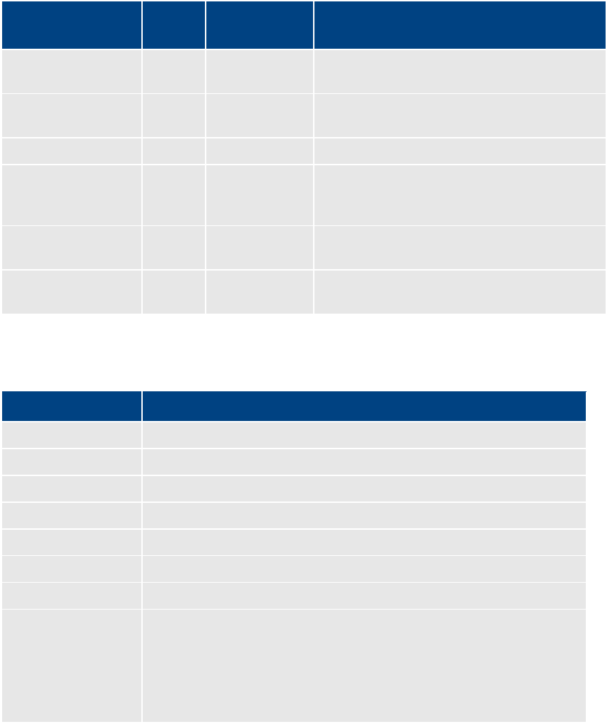
MCS 2.3 Installation and Configuration Guide
206
Port Requirements
The following table lists the MCS port requirements for the client-side applications (the browser-
based MediaCentral application and mobile applications). Ports 80 and 443 are required for the
HTTP(S) traffic. In addition, the Adobe Flash Player (running inside the browser) requires ports
843 and 5000.
For more information see the MCS Security Architecture and Analysis document.
Component Port Protocol and
Direction
Usage
MediaCentral
Web application
80
TCP inbound
MediaCentral Playback Services (MCPS) HTTP
calls (file streaming from MCPS)
443
Secure TCP
Inbound
MediaCentral HTTPS calls (communication with
MediaCentral server)
843
TCP Inbound
Serving Flash Player socket policy files
5000
TCP Inbound
Playback service (loading assets, serving JPEG
images, and audio, etc.). Output flow to client
serving inbound request.
MediaCentral
mobile applications
80
TCP Inbound
MediaCentral Playback Services (MCPS) HTTP
calls (file streaming from MCPS)
443
Secure TCP
Inbound
MediaCentral HTTPS calls (communication with
MediaCentral server)
The following table lists the server-side port requirements. For more information see the MCS
Security Architecture and Analysis document.
Service Name Port
MediaCentral
80, 443
MCPS
843 (Flash), 80, 5000, 26000
MCS
8000 (optional Admin UI), 8183 (bus cluster info)
ISIS
5000 – 5399 (UPD and TCP)
RabbitMQ
5672 (AMQP), 15672 (Management UI/API)
MongoDB
27017
PostgreSQL
5432
System
22, ICMP, 111, 24007, 24008, 24009-(24009 + number of bricks across all
volumes for Gluster). If you will be using NFS, open additional ports 38465-
(38465 + number of Gluster servers). Some MAM configuration might
require additional NFS ports (111, 2049 tcp & udp) or CIFS (137,138 udp
and 137,139 tcp). Other filesystems will have to be checked individually
(Isilon, Harmonic Omneon, etc.).
MCS 2.3 Installation and Configuration Guide
207
Appendix B: Configuring Port Bonding for Interplay MAM
In MAM deployments of MCS, port bonding improves playback performance when multiple
clients are making requests of the MCS server simultaneously. With port bonding, more
concurrent playback requests can be sustained by a single server, especially for file-based
playback.
Port bonding is only possible for Interplay MAM deployments. It does not apply to MediaCentral
and/or Media Composer Cloud deployments.
Verifying the Ethernet Ports
In a port bonding configuration, two or more ports are grouped together. Before bonding the
ports, identify the ports you wish to allocate using the RHEL set-up menus.
To verify the Ethernet ports for port bonding:
1. Enter the RHEL set-up menus by typing setup at the command prompt:
setup
The setup screen appears.
2. From the Choose a Tool menu, select the Network Configuration option. Press Enter.
3. Choose the Device Configuration option. Press Enter.
A list of network interface ports appears.
4. Identify the names of the ports you plan to bond together.
Example: eth0 & eth1
5. Exit the set-up menus without making any changes by pressing Cancel and Quit.
Configuring the Ports
Port bonding requires that you modify the contents of the interface configuration files for each
bonded ports and the creation of a new configuration file for the bonded interface.
To configure port bonding for Interplay MAM:
1. Navigate to the directory containing the interface configuration files.
cd /etc/sysconfig/network-scripts
2. List the directory contents to view the files.
ls
3. Using the vi editor, open the interface configuration file for the first interface to be
included in the port bond. Depending upon your server type, this could be ifcfg-eth0,
ifcfg-em1, or other. In this process an HP “eth0” interface will be used as an example.
vi ifcfg-eth0
MCS 2.3 Installation and Configuration Guide
208
4. When you open it for editing, the file should look something like this:
DEVICE=eth0
NM_CONTROLLED=yes
ONBOOT=yes
DHCP_HOSTNAME=$HOSTNAME
BOOTPROTO=static
TYPE=Ethernet
USERCTL=no
PEERDNS=yes
IPV6INIT=no
• DEVICE=eth0 specifies the name of the physical Ethernet interface device. This
line will be different for each device. It must correspond to the name of the file itself
(e.g. ifcfg-eth0).
• ONBOOT=yes must be set to “yes” so Linux brings up the port at boot time.
5. Add port bonding configuration information for the device by inserting the following line
(shown in bold):
DEVICE=eth0
NM_CONTROLLED=yes
ONBOOT=yes
MASTER=bond0
DHCP_HOSTNAME=$HOSTNAME
BOOTPROTO=static
TYPE=Ethernet
USERCTL=no
PEERDNS=yes
IPV6INIT=no
• MASTER=bond0 specifies the name of the port bonding interface. This must be
the same in each network script file in the port bonded group.
6. Save and exit the vi session. Press <ESC> and type: :wq
7. Perform the above steps for each interface to be included in the port bond (e.g. eth0,
eth1, eth2, etc.)
8. Create a new port bonding network script file in the same directory. Use vi to create the
file:
vi ifcfg-bond0
Where “ifcfg-bond0” is the name of the port-bonding group.
MCS 2.3 Installation and Configuration Guide
209
9. Add the following lines to the newly created file:
DEVICE=bond0
ONBOOT=yes
BOOTPROTO=static
USERCTL=no
BONDING_OPTS="mode=0"
IPADDR=
NETMASK=
GATEWAY=
• DEVICE=bond0 specifies the name of the port bonding group interface. It must
correspond to the name of the file itself.
• BOOTPROTO=static lets you assign IP address of the device explicitly
(recommended), or allow a local DHCP server to assign of the IP address device
dynamically. Can be static (recommended) or dhcp (system assigned).
• BONDING_OPTS="mode=0" specifies the type of port bonding (mode=0
specifies round-robin).
• IPADDR and NETMASK entries are required if you are assigning a static IP address.
• GATEWAY is required if you are routing outside of your primary subnet.
10. Save and exit the vi session. Press <ESC> and type: :wq
11. Restart the network service (as root):
/etc/init.d/network restart
MCS 2.3 Installation and Configuration Guide
210
Appendix C: Enabling MOS Active-X Plug-Ins
This section includes steps to enable MOS Active-X Plug-Ins for:
Chrome
Internet Explorer (legacy)
Note: As of MediaCentral v2.3, Internet Explorer is no longer a supported browser. This applies to all
versions of Internet Explorer.
Note: Active X plug-ins are not supported in the Safari browser.
Enabling MediaCentral MOS Plug-Ins in Chrome
MediaCentral provides support for MOS Active-X plug-ins. For example, Deko Select is a plug-in
for a newsroom computer system’s interface that allows a user, such as a reporter, to drag and
drop graphic templates directly into the story, as well as alter replaceable text or graphics in the
selected template. You can also use the Avid Deko Select plug-in to add graphics to the video for
a story sequence. Other plug-ins are available through third-party manufacturers.
These plug-ins are specific to iNEWS workflows, and they are available only in Rundown and
Story layouts.
Note: The MCS installation program installs only the container needed for Active X controls.
You need to install additional software as described in the following sections.
Setting Up Your Browser
The Chrome browser requires an extension that lets you use MOS plug-ins. The first time you
sign in to MediaCentral, a dialog box asks if you want to use MOS plug-ins.
• If you click yes, an installer is downloaded from the MediaCentral Services server. Allow
pop-ups from the MediaCentral Services server if you are informed that a pop-up was
blocked, and then refresh the page. Double-click the .exe file to install the program.
After installation is complete, close Chrome and then reopen it for the extension to be
accessible by MediaCentral. Recent Chrome versions disable third-party plug-ins. Make
sure that Chrome Tools > Extensions displays Enabled next to the Avid ActiveX
extension.
• If you click no, and later want to use plug-ins, enable MOS as described below. The next
time you sign in or refresh the application, a blank window opens and the installer is
downloaded. Click the .exe file to install the extension.
Note: See the Avid MediaCentral Platform Services v2.3 ReadMe for additional information
regarding support of Active-X plugins in Chrome.
Enabling MOS
To use the plug-ins for a user you need to enable MOS in MediaCentral. Select Home > User
Settings > MOS and then select “MOS enabled.”

MCS 2.3 Installation and Configuration Guide
211
Installing Plug-Ins
For procedures on how to install plug-ins, see the documentation for the plug-in.
After installation and configuration, plug-ins are listed at the bottom of the Panes menu.
If you do not see the plugin, review the following information on the Avid Knowledge Base:
http://avid.force.com/pkb/articles/en_US/troubleshooting/Avid-Interplay-Central-Avid-MOS-
Plugin-is-disabled-by-Chrome
Uninstalling the Chrome Extension
If you need to uninstall the Chrome Extension, use the Windows Control Panel. Do not use the
Chrome Extensions page.
1. Click Start and select Control Panel.
2. Click Programs and Features.
3. Right-click Avid MediaCentral MOS plugin and select Uninstall. Click Yes and follow the
prompts.
For more information about MOS plug-ins, see the Avid MediaCentral User’s Guide or the Avid
MediaCentral Help.
Enabling MediaCentral MOS Plug-Ins in Internet Explorer
The instructions in this appendix were produced for Internet Explorer 9.0.8112.16421 using
Google Chrome Frame 65.169.107 on Windows 7 x86_64 SP1. Updates to any of these
applications may change the steps below, including the order in which you perform them.
Once you complete the procedure, the Avid ActiveX container is available in IE9. When a MOS-
enabled user logs in, a list of their installed ActiveX plug-ins appears at the bottom of the Panes
menu. Opening a plug-in will create a new tab. (Press F5 if the tab is empty when loaded.) The
tab can be dragged out of Internet Explorer, permitting drag and drop into the IPC page.
To enable MediaCentral MOS plug-ins in IE:
1. Launch Internet Explorer and enter the URL of the MCS server (or cluster) in the address
bar (e.g. https://<hostname>).
Bypass the certificate warning, if one is present.
The MediaCentral sign-in page informs you that the Google Chrome Frame is required.
MCS 2.3 Installation and Configuration Guide
212
2. Install Google Chrome Frame using the link on the sign in page.
Note: Google Chrome Frame must be installed as user with Administrator rights. The Avid
ActiveX container also requires administrator elevation.
3. A dialog should appear indicating the ChromeFrame BHO add-on from Google Inc is
ready for use. Select Enable in that dialog.
4. Navigate once again to MCS server or cluster (e.g. https://<hostname>) and log in as a
user for whom MOS plug-ins are enabled.
Note: To enable MOS for the logged in user, in MediaCentral, select Home -> User Settings ->
MOS and then select “MOS enabled”
5. Download and run setup.exe as prompted.
If your receive a "This webpage is not available" message, refresh with F5, and then say
Yes to proceed.
Follow the instructions appearing in the Avid MediaCentral MOS plugin installation
wizard, and accept the defaults to install the extension.
6. Close and re-open Internet Explorer. Navigate to MediaCentral and log in as the same
user. Do not download setup.exe again. Sign out of MediaCentral and close IE.
This step forces Chrome Frame to register the Avid extension.
7. In Windows Explorer, navigate to the following directory:
C:\Users\<username>\AppData\Local\Google\Chrome Frame\User Data\iexplorer\Default
8. Open the “Preferences” file in Notepad.
9. Locate the “known_disabled” key and delete the line.
"known_disabled": [ "lmcebpepkojaapaoliodbjagahkpedph" ],
10. Search for the term "ActiveX" to find the "Avid MOS ActiveX Chrome Extension" object,
and modify the “state” value from 0 to 1.
"state": 1,
11. Save and close the Preferences file.
12. Once again, Launch IE, navigate to the MCS server or cluster (e.g. https://<hostname>),
and log in as the user for whom MOS plug-ins are enabled.
Installed ActiveX plug-ins are now visible in MediaCentral, on the Panes menu.
MCS 2.3 Installation and Configuration Guide
213
Sample ActiveX Object in the Preferences File
For reference, the full ActiveX object after completion of the procedure is included below. Some
values may be different for your particular installation.
"lmcebpepkojaapaoliodbjagahkpedph": {
"ack_prompt_count": 1,
"active_permissions": {
"api": [ "plugin" ]
},
"creation_flags": 1,
"from_bookmark": false,
"from_webstore": false,
"initial_keybindings_set": true,
"install_time": "13029963342661257",
"location": 3,
"manifest": {
"description": "Avid MOS ActiveX Chrome Extension",
"key":
"MIGfMA0GCSqGSIb3DQEBAQUAA4GNADCBiQKBgQCa6DtGBLy26p0nWU7mfBTutgDZpGZw0t
a30LRo1Av6J1LUgL3AxJu5BP4TJxlXXbIKd0H2X6oLgKU3GIw5+r1YKK8BKVfgjpSanEWzg
vWsbjXcnH4XVF8thXYvutkTj5telkhFmOba1UG0zauqMqpnWus9ADGyMGBUIPsTlLhXDwID
AQAB",
"manifest_version": 2,
"name": "Avid MOS ActiveX hosting plugin",
"plugins": [ {
"path": "npchmos.dll",
"public": true
} ],
"version": "1.0.1.10"
},
"path": "lmcebpepkojaapaoliodbjagahkpedph\\1.0.1.10_0",
"state": 1,
"was_installed_by_default": false
},

MCS 2.3 Installation and Configuration Guide
214
Appendix D: Configuring iNEWS for Integration with
MediaCentral
Before connecting to an iNEWS newsroom computer system from a MediaCentral workstation,
two iNEWS system files must be edited so that MediaCentral is recognized as a licensed device.
The files to edit are:
• SYSTEM.CLIENT.VERSIONS
• SYSTEM.CLIENT.WINDOWS
Note: Additional files must be edited to ensure proper licensing for iNEWS integration with the
MediaCentral mobile application. For more information, see Appendix E: The Avid MediaCentral
UX Mobile Application on page 218.
Verifying MediaCentral Licenses on iNEWS
Before MediaCentral connects to iNEWS, verify that iNEWS is configured with the proper
number of MediaCentral devices authorized to connect to the system based on the purchased
licenses. iNEWS licensing limits can be identified from the iNEWS console using the following
command:
t NRCS-A$ status license
A message similar to the following will appear on your screen:
A is ONLINE and has been CONFIGURED. ID is INWS.
System is AB. Master is A.
Disk status is OK. The database is OPEN.
Site Key............. : 009999
CPUs................. : 3
Workstation addresses : 3000
Workstation resources : 1000
COM resources........ : 5
Web Access resources. : 2
Web Client resources. : 10
Web API resources.... : 5
Wire Server resources : 8
Instinct resources... : 10
Mobile devices allowed: 2000
Community Sessions... : allowed.
MCS 2.3 Installation and Configuration Guide
215
The three lines to pay attention to are:
• Workstation addresses—indicates how many IP and/or MAC addresses can be specified
in the SYSTEM.CLIENT.WINDOWS story. This story may be deleted from the iNEWS
database if Workstation addresses shows a “site” license and IP-specific restriction is not
wanted.
• Workstation resources—the number of clients that can simultaneously connect to
iNEWS, including iNEWS workstations, MediaCentral workstations, Apple iPad tablets,
and Apple iPhone devices.
• Mobile devices allowed—the number of mobile devices that can simultaneously connect
to iNEWS.
Note: Any time the iNEWS newsroom computer system is configured, your licensing information is
checked. An error message appears in iNEWS if the configuration file defines more devices than are
licensed.
Editing SYSTEM.CLIENT.VERSIONS
Some steps in the following procedure are conducted at the iNEWS console in superuser mode.
For more information, see “The iNEWS Console” chapter in the “iNEWS Setup and Configuration
Guide”.
Note: For the correct iNEWS client version, see the Avid MediaCentral Platform Services ReadMe.
To edit the SYSTEM.CLIENT.VERSIONS story in iNEWS:
1. Sign in to an iNEWS workstation as a system administrator, or any user account with
write access to the System directory.
2. Navigate to SYSTEM.CLIENT.VERSIONS and open the first story in that queue.
3. On a new line, add the version of the iNEWS Client module that will run on the
MediaCentral server.
Note: To obtain the correct version of the iNEWS Client module, see the Avid
MediaCentral Platform Services ReadMe.
4. Save the story.
5. Reconfigure the system. From the iNEWS console:
a. Select the master computer, which is typically server A.
b. Enter superuser mode, using the correct password.
The dollar sign ($) at the end of the console’s server prompt will change to a
pound sign (#).
c. Take the system offline by typing:
NRCS-A# offline

MCS 2.3 Installation and Configuration Guide
216
d. Reconfigure the system by typing:
NRCS-A# configure -n
The above command must be run on the master computer.
e. When the prompt reappears, bring the system back online by typing:
NRCS-A# online
f. Press Ctrl+D to leave superuser mode.
The pound sign (#) at the end of the console’s server prompt will change back to
a dollar sign ($).
Editing SYSTEM.CLIENT.WINDOWS
The following procedure only applies to sites that are not using a “site” license as Workstation
addresses in iNEWS. You can review your site license information from the iNEWS console. For
more information, see Verifying MediaCentral Licenses on iNEWS above.
Some steps in the following procedure are conducted at the iNEWS console in superuser mode.
For more information, see “The iNEWS Console” chapter in the “iNEWS Setup and Configuration
Guide”.
To edit the SYSTEM.CLIENT.WINDOWS story in iNEWS:
1. Sign in to an iNEWS workstation as a system administrator, or any user account with
write access to the System directory.
2. Navigate to SYSTEM.CLIENT.WINDOWS and open the first story in that queue.
3. Add the IP address of the MediaCentral middleware server to a new line. Use a
semicolon to add helpful commentary for future reference to the end of the line.
For instance, type:
125.1.100.5 ;MediaCentral middleware server
If there are multiple middleware (Web application) servers, you will need to add the IP
address for each one on individual lines in the story.
Note: You do not need to add to SYSTEM.CLIENT.WINDOWS the IP addresses of any
MediaCentral client computers or devices.
4. Save the story.
5. Reconfigure the system. From the iNEWS console:
a. Select the master computer, which is typically server A.
MCS 2.3 Installation and Configuration Guide
217
b. Enter superuser mode, using the correct password.
The dollar sign ($) at the end of the console’s server prompt will change to a
pound sign (#).
c. Take the system offline by typing:
NRCS-A# offline
d. Reconfigure the system by typing:
NRCS-A# configure -n
The above command must be run on the master computer.
e. When the prompt reappears, bring the system back online by typing:
NRCS-A# online
f. Press Ctrl+D to leave superuser mode.
The pound sign (#) at the end of the console’s server prompt will change back to
a dollar sign ($).

MCS 2.3 Installation and Configuration Guide
218
Appendix E: The Avid MediaCentral UX Mobile Application
The Avid MediaCentral UX mobile application is a native user interface designed to run on the
Apple iPad, iPhone and various Android-based devices. It enables direct, secure access to your
station’s iNEWS newsroom computer system.
You can use the Avid Central mobile application to view and approve news stories, navigate the
news directory, play video sequences associated with stories and view a show’s scripts in
presenter mode (iPad only) while signed in to your station’s iNEWS newsroom computer system.
The MediaCentral mobile application can connect to your environment in one of two ways:
• Wi-Fi
• Carrier-specific cellular service— for example, 3G or 4G
Note: The application automatically selects the first available connection from the list of options
according to the priority shown in the list.
Before You Begin
Before connecting the MediaCentral mobile application to an iNEWS newsroom computer
system, verify the following tasks have been completed:
If you have a cluster configuration and intend to playback media on the mobile device, ensure
that Gluster has been installed. This is a requirement for streaming to mobile devices.
See: Replicating the File Caches using GlusterFS on page 121.
Verify that the Hostname in the MediaCentral “ICPS> Player” System Settings has been
configured with the system’s Fully Qualified Domain Name (FQDN).
See Player Settings on page 99.
Confirm that the mobile device can access MediaCentral via its Fully Qualified Domain Name
(FQDN).
See: Validating the FQDN for External Access on page 139.
If this process does not return expected results, contact your local IT team to assist.
Confirm that iNEWS is properly configured for licensed integration with the Avid Central mobile
application.
See: Appendix D: Configuring iNEWS for Integration with MediaCentral on page 214.
Verify that Wi-Fi and/or or 3G/4G streams have been enabled on your MCS system.
See: Enable / Disable 3G and Edge Streams on page 84.

MCS 2.3 Installation and Configuration Guide
219
iNEWS Configuration for Mobile Integration
Before connecting to an iNEWS system from a device running the Avid Central mobile
application, some iNEWS system files might require adjustment. Editing the files enables the
iNEWS servers to recognize the Avid Central mobile application as a licensed device.
Complete the following two procedures to verify iNEWS configuration:
• Editing SYSTEM.CLIENT.VERSIONS
• Editing the iNEWS Configuration File
Editing SYSTEM.CLIENT.VERSIONS
You use the iNEWS console in superuser mode, for some steps in the following procedure. For
more information, see the “iNEWS Setup and Configuration Guide”.
1. Sign in to an iNEWS workstation as a system administrator, or any user account with
write access to the System directory.
2. Navigate to SYSTEM.CLIENT.VERSIONS and open the first story in that queue.
3. Confirm that the iNEWS Client module version appears as a line in the story.
Note: To obtain the correct version of the iNEWS Client module, see the Avid
MediaCentral Platform Services ReadMe.
4. If the version is correct, then close the story. You do not need to complete the rest of
the steps in this procedure.
5. If the version is not correct or does not appear, on a new line, add the version of the
iNEWS client module that will run on the MediaCentral server.
6. Save the story.
7. Reconfigure the system. From the iNEWS console:
a. Select the master computer, which is typically server “A”.
b. Enter superuser mode, using the correct password.
The dollar sign ($) at the end of the console’s server prompt will change to a
pound sign (#).
c. Take the system offline by typing: NRCS-A# offline
d. Reconfigure the system by typing: NRCS-A# configure
e. When the prompt reappears, bring the system back online by typing:
NRCS-A# online
f. Press Ctrl+D to leave superuser mode.
The pound sign (#) at the end of the console’s server prompt will change back to
a dollar sign ($).
MCS 2.3 Installation and Configuration Guide
220
Editing the iNEWS Configuration File
The configuration file (/site/config) lists all devices, servers, and resources configured to run on
your iNEWS newsroom computer system and how they are connected. If a mobile device does
not appear in the configuration file, you cannot use it with the iNEWS newsroom computer
system.
The Avid Central mobile application uses the same G (inws) sessions in the configuration file as
other MediaCentral Web clients or as iNEWS workstations. You need to confirm that there are
enough sessions configured to handle simultaneous connections from these types of devices
available to users at your site.
Note: You need to edit the configuration file only if there are not enough sessions.
If you need to edit the configuration file, see “The iNEWS Console” and “System Configuration”
chapters in the “iNEWS Setup and Configuration Guide”. Also, some steps require use of ed, the
line editor. If you do not know how to use the line editor to modify lines in the file, see “The Line
Editor, ed” in the “iNEWS Setup and Configuration Guide”.
To edit /site/config for the Avid Central mobile application:
1. Select all servers.
Caution: Whenever you make changes to any iNEWS site file, such as the configuration
file, you must select all servers in your system at the console. Unlike database stories,
site files are not automatically mirrored from one computer’s disk to another.
2. Type the following and press Enter:
ed /site/config
The editor displays a numerical value indicating the file size expressed as the number of
characters, including spaces and returns.
The configuration file has two major sections: the host section and the device section.
For the Avid Central mobile integration, both must be edited.
3. In the host section, add a resource list entry, using the following format.
reslist <device # or range> ; <comments>
For example:
reslist 2001:2005 ;iNEWS and IPC sessions
Note: For dual or triple server systems, the configuration file has multiple host sections
to define which server handles which devices under various circumstances. You should
add resource list entries to each host section.
MCS 2.3 Installation and Configuration Guide
221
4. In the INWS sessions section, add a resource line for the devices, using the following
format:
inws <device # or range> - gnews <device name> ;<comment>
For example:
inws 2001:2005 - gnews –
5. Type w to write (save) your changes to disk.
Caution: Do not use an uppercase W in this step. Uppercase W appends the file you edit to
the existing file. The resulting file might be unreadable and lead to problems with running
your iNEWS system.
6. Type q to quit the line editor.
7. (Optional) Use the configure command to test your configuration changes, using the
following syntax:
configure /site/config <system> <computer>
For example:
configure /site/config ab a
When the prompt reappears, the configuration file has been checked. If the system
detects any errors, it displays appropriate “bad configuration” messages.
8. Reconfigure the system. From the iNEWS console:
a. Select the master computer, which is typically server A.
b. Enter superuser mode, using the correct password.
The dollar sign ($) at the end of the console’s server prompt changes to a pound
sign (#).
c. Take the system offline by typing: NRCS-A# offline
d. Reconfigure the system by typing: NRCS-A# configure
e. When the prompt reappears, bring the system back online by typing: NRCS-A#
online
f. Press Ctrl+D to leave superuser mode.
The pound sign (#) at the end of the console’s server prompt changes back to a
dollar sign ($).

MCS 2.3 Installation and Configuration Guide
222
Installing Avid Central on an iOS Device
The following procedure assumes licensing, setup, and configuration of the MediaCentral and
iNEWS servers have already been completed.
To install Avid Central on an iPad or iPhone:
1. Open iTunes (the Apple market).
2. Locate the Avid Central mobile application.
3. Tap Download.
When the Avid Central mobile application is installed on your touch-screen device, an
icon representing the application appears on the home screen. You can move it
elsewhere like the icons for other applications.
A direct link to the Avid MediaCentral application on the Apple iTunes Store provided here (link
current at time of publication):
https://itunes.apple.com/us/app/avid-mediacentral-ux/id517760700?mt=8
For additional information on the configuration and usage of the MediaCentral mobile
application, see the Avid MediaCentral User’s Guide.
Installing Avid Central on an Android Device
The following procedure assumes licensing, setup, and configuration of the MediaCentral and
iNEWS servers have already been completed.
To install Avid Central on an Android device:
1. Open the Google Play Store
2. Search for “Avid MediaCentral”.
3. Select the application and click Install.
A direct link to the Avid MediaCentral application on the Google Play Store provided here (link
current at time of publication):
https://play.google.com/store/apps/details?id=com.avid.avidcentral
For additional information on the configuration and usage of the MediaCentral mobile
application, see the Avid MediaCentral User’s Guide.

MCS 2.3 Installation and Configuration Guide
223
Copyright and Disclaimer
Product specifications are subject to change without notice and do not represent a commitment on the part of Avid Technology, Inc.
The software described in this document is furnished under a license agreement. You can obtain a copy of that license by visiting the Avid Web
site at www.avid.com. The terms of that license are also available in the product in the same directory as the software. The software may not
be reverse assembled and may be used or copied only in accordance with the terms of the license agreement. It is against the law to copy the
software on any medium except as specifically allowed in the license agreement.
No part of this document may be reproduced or transmitted in any form or by any means, electronic or mechanical, including photocopying
and recording, for any purpose without the express written permission of Avid Technology, Inc.
Copyright © 2013 Avid Technology, Inc. and its licensors. All rights reserved.
Attn. Government User(s). Restricted Rights Legend
U.S. GOVERNMENT RESTRICTED RIGHTS. This Software and its documentation are “commercial computer software” or “commercial computer
software documentation.” In the event that such Software or documentation is acquired by or on behalf of a unit or agency of the U.S.
Government, all rights with respect to this Software and documentation are subject to the terms of the License Agreement, pursuant to FAR
§12.212(a) and/or DFARS §227.7202-1(a), as applicable.
This product may be protected by one or more U.S. and non-U.S patents. Details are available at www.avid.com/patents.
Trademarks
Adrenaline, AirSpeed, ALEX, Alienbrain, Archive, Archive II, Assistant Avid, Avid Unity, Avid Unity ISIS, Avid VideoRAID, CaptureManager,
CountDown, Deko, DekoCast, FastBreak, Flexevent, FXDeko, iNEWS, iNEWS Assign, iNEWSControlAir, Instinct, IntelliRender, Intelli-Sat, Intelli-
sat Broadcasting Recording Manager, Interplay, ISIS, IsoSync, LaunchPad, LeaderPlus, ListSync, MachineControl, make manage move | media,
Media Composer, NewsCutter, NewsView, OMF, OMF Interchange, Open Media Framework, Open Media Management, SIDON, SimulPlay,
SimulRecord, SPACE, SPACEShift, Sundance Digital, Sundance, Symphony, Thunder, Titansync, Titan, UnityRAID, Video the Web Way,
VideoRAID, VideoSPACE, VideoSpin, and Xdeck are either registered trademarks or trademarks of Avid Technology, Inc. in the United States
and/or other countries.
All other trademarks contained herein are the property of their respective owners.
MCS 2.3 Installation and Configuration Guide • 20 November 2015
• This document is distributed by Avid in online (electronic) form only, and is not available for purchase in printed form.
