Avid MediaStream Server 8000NS 0130 07711 01 Rev_A Media Stream 3.3 Site Preparation, Installation, And Reference Guide MSS V3 3x
User Manual: avid Avid MediaStream Server 8000NS - 3.3 - Site Preparation, Installation, and Reference Guide Free User Guide for Avid MediaStream Software, Manual
Open the PDF directly: View PDF ![]() .
.
Page Count: 384 [warning: Documents this large are best viewed by clicking the View PDF Link!]
- Title Page
- Contents
- Official Notices and Warranties
- Using This Guide
- Introduction
- System Components
- VLAN Topology
- Preparation and Installation
- Connecting System Components
- MediaStream Interface (MSi)
- Introduction to System Administration
- Palladium Store 1000 Administration
- Hardware Removal and Replacement (Server Nodes and Storage System)
- Field Replaceable Units (FRUs)
- Palladium Store 1000
- File System Controller
- MediaStream Server
- Replacing or Adding Decoder/Encoder Boards
- Lantronix Module Replacement
- Verifying CPU I/O Connections
- Adding a Server Node
- System Controller Board
- Palladium Store 1000
- File System Controller
- CLI and Server Node Calibration
- Software Recovery and Upgrade
- VLAN and Fibre Channel Switch Configuration
- Troubleshooting Resources
- MSS 8000 Bandwidth Tables
- Cables and Connectors
- Network Block Diagrams
- Legacy FSC and MSi Front & Back Panels
- Specifications
- Regulatory and Safety Notices
- Index

make manage move | media™
Avid ®
Avid® MediaStream™ Server 8000NS
Site Preparation, Installation, and
Reference Guide
for MediaStream Network Storage System
2
Copyright and Disclaimer
Product specifications are subject to change without notice and do not represent a commitment on the part of
Avid Technology, Inc.
The software described in this document is furnished under a license agreement. You can obtain a copy of that license by
visiting Avid's Web site at www.avid.com. The terms of that license are also available in the product in the same directory as
the software. The software may not be reverse assembled and may be used or copied only in accordance with the terms of the
license agreement. It is against the law to copy the software on any medium except as specifically allowed in the license
agreement.
This document is protected under copyright law. An authorized licensee of Avid MediaStream may reproduce this publication
for the licensee’s own use in learning how to use the software. This document may not be reproduced or distributed, in whole
or in part, for commercial purposes, such as selling copies of this document or providing support or educational services to
others. This document is supplied as a guide for Avid MediaStream . Reasonable care has been taken in preparing the
information it contains. However, this document may contain omissions, technical inaccuracies, or typographical errors. Avid
Technology, Inc. does not accept responsibility of any kind for customers’ losses due to the use of this document. Product
specifications are subject to change without notice.
Copyright © 2006 Avid Technology, Inc. and its licensors. All rights reserved. Printed in USA.
The following disclaimer is required by Sam Leffler and Silicon Graphics, Inc. for the use of their TIFF library:
Copyright © 1988–1997 Sam Leffler
Copyright © 1991–1997 Silicon Graphics, Inc.
Permission to use, copy, modify, distribute, and sell this software [i.e., the TIFF library] and its documentation for any purpose
is hereby granted without fee, provided that (i) the above copyright notices and this permission notice appear in all copies of
the software and related documentation, and (ii) the names of Sam Leffler and Silicon Graphics may not be used in any
advertising or publicity relating to the software without the specific, prior written permission of Sam Leffler and Silicon
Graphics.
THE SOFTWARE IS PROVIDED “AS-IS” AND WITHOUT WARRANTY OF ANY KIND, EXPRESS, IMPLIED OR
OTHERWISE, INCLUDING WITHOUT LIMITATION, ANY WARRANTY OF MERCHANTABILITY OR FITNESS FOR A
PARTICULAR PURPOSE.
IN NO EVENT SHALL SAM LEFFLER OR SILICON GRAPHICS BE LIABLE FOR ANY SPECIAL, INCIDENTAL, INDIRECT
OR CONSEQUENTIAL DAMAGES OF ANY KIND, OR ANY DAMAGES WHATSOEVER RESULTING FROM LOSS OF USE,
DATA OR PROFITS, WHETHER OR NOT ADVISED OF THE POSSIBILITY OF DAMAGE, AND ON ANY THEORY OF
LIABILITY, ARISING OUT OF OR IN CONNECTION WITH THE USE OR PERFORMANCE OF THIS SOFTWARE.
The following disclaimer is required by the Independent JPEG Group:
Portions of this software are based on the work of the Independent JPEG Group.
This Software may contain components licensed under the following conditions:
Copyright © 1989 The Regents of the University of California. All rights reserved.
Redistribution and use in source and binary forms are permitted provided that the above copyright notice and this paragraph
are duplicated in all such forms and that any documentation, advertising materials, and other materials related to such
distribution and use acknowledge that the software was developed by the University of California, Berkeley. The name of the
University may not be used to endorse or promote products derived from this software without specific prior written
permission. THIS SOFTWARE IS PROVIDED ``AS IS'' AND WITHOUT ANY EXPRESS OR IMPLIED WARRANTIES,
INCLUDING, WITHOUT LIMITATION, THE IMPLIED WARRANTIES OF MERCHANTABILITY AND FITNESS FOR A
PARTICULAR PURPOSE.
Copyright © 1989, 1991 by Jef Poskanzer.
Permission to use, copy, modify, and distribute this software and its documentation for any purpose and without fee is hereby
granted, provided that the above copyright notice appear in all copies and that both that copyright notice and this permission
notice appear in supporting documentation. This software is provided "as is" without express or implied warranty.
Copyright 1995, Trinity College Computing Center. Written by David Chappell.
Permission to use, copy, modify, and distribute this software and its documentation for any purpose and without fee is hereby
granted, provided that the above copyright notice appear in all copies and that both that copyright notice and this permission
notice appear in supporting documentation. This software is provided "as is" without express or implied warranty.
Copyright 1996 Daniel Dardailler.

3
Permission to use, copy, modify, distribute, and sell this software for any purpose is hereby granted without fee, provided that
the above copyright notice appear in all copies and that both that copyright notice and this permission notice appear in
supporting documentation, and that the name of Daniel Dardailler not be used in advertising or publicity pertaining to
distribution of the software without specific, written prior permission. Daniel Dardailler makes no representations about the
suitability of this software for any purpose. It is provided "as is" without express or implied warranty.
Modifications Copyright 1999 Matt Koss, under the same license as above.
Copyright © 1991 by AT&T.
Permission to use, copy, modify, and distribute this software for any purpose without fee is hereby granted, provided that this
entire notice is included in all copies of any software which is or includes a copy or modification of this software and in all
copies of the supporting documentation for such software.
THIS SOFTWARE IS BEING PROVIDED "AS IS", WITHOUT ANY EXPRESS OR IMPLIED WARRANTY. IN PARTICULAR,
NEITHER THE AUTHOR NOR AT&T MAKES ANY REPRESENTATION OR WARRANTY OF ANY KIND CONCERNING THE
MERCHANTABILITY OF THIS SOFTWARE OR ITS FITNESS FOR ANY PARTICULAR PURPOSE.
This product includes software developed by the University of California, Berkeley and its contributors.
The following disclaimer is required by Paradigm Matrix:
Portions of this software licensed from Paradigm Matrix.
The following disclaimer is required by Ray Sauers Associates, Inc.:
“Install-It” is licensed from Ray Sauers Associates, Inc. End-User is prohibited from taking any action to derive a source code
equivalent of “Install-It,” including by reverse assembly or reverse compilation, Ray Sauers Associates, Inc. shall in no event be
liable for any damages resulting from reseller’s failure to perform reseller’s obligation; or any damages arising from use or
operation of reseller’s products or the software; or any other damages, including but not limited to, incidental, direct, indirect,
special or consequential Damages including lost profits, or damages resulting from loss of use or inability to use reseller’s
products or the software for any reason including copyright or patent infringement, or lost data, even if Ray Sauers Associates
has been advised, knew or should have known of the possibility of such damages.
The following disclaimer is required by Videomedia, Inc.:
“Videomedia, Inc. makes no warranties whatsoever, either express or implied, regarding this product, including warranties with
respect to its merchantability or its fitness for any particular purpose.”
“This software contains V-LAN ver. 3.0 Command Protocols which communicate with V-LAN ver. 3.0 products developed by
Videomedia, Inc. and V-LAN ver. 3.0 compatible products developed by third parties under license from Videomedia, Inc. Use
of this software will allow “frame accurate” editing control of applicable videotape recorder decks, videodisc recorders/players
and the like.”
The following disclaimer is required by Altura Software, Inc. for the use of its Mac2Win software and Sample
Source Code:
©1993–1998 Altura Software, Inc.
The following disclaimer is required by 3Prong.com Inc.:
Certain waveform and vector monitoring capabilities are provided under a license from 3Prong.com Inc.
The following disclaimer is required by Interplay Entertainment Corp.:
The “Interplay” name is used with the permission of Interplay Entertainment Corp., which bears no responsibility for Avid
products.
This product includes portions of the Alloy Look & Feel software from Incors GmbH.
This product includes software developed by the Apache Software Foundation (http://www.apache.org/).
© DevelopMentor
This product may include the JCifs library, for which the following notice applies:
JCifs © Copyright 2004, The JCIFS Project, is licensed under LGPL (http://jcifs.samba.org/). See the LGPL.txt file in the Third
Party Software directory on the installation CD.
Avid Interplay contains components licensed from LavanTech. These components may only be used as part of and in
connection with Avid Interplay.
Attn. Government User(s). Restricted Rights Legend
4
U.S. GOVERNMENT RESTRICTED RIGHTS. This Software and its documentation are “commercial computer software” or
“commercial computer software documentation.” In the event that such Software or documentation is acquired by or on behalf
of a unit or agency of the U.S. Government, all rights with respect to this Software and documentation are subject to the terms
of the License Agreement, pursuant to FAR §12.212(a) and/or DFARS §227.7202-1(a), as applicable.
Trademarks
888 I/O, Adrenaline, AirPlay, AirSPACE, AirSPACE HD, AirSpeed, AniMatte, AudioSuite, AudioVision, AutoSync, Avid,
Avid DNA, Avid DNxcel, Avid DNxHD, AVIDdrive, AVIDdrive Towers, Avid DS Assist Station, Avid ISIS,
Avid Learning Excellerator, Avid Liquid, Avid Mojo, AvidNet, AvidNetwork, Avid Remote Response, AVIDstripe, Avid Unity,
Avid Unity ISIS, Avid Xpress, AVoption, AVX, CamCutter, ChromaCurve, ChromaWheel, DAE, Dazzle, Deko, DekoCast, D-Fi,
D-fx, DigiDelivery, Digidesign, Digidesign Audio Engine, Digidesign Intelligent Noise Reduction, DigiDrive,
Digital Nonlinear Accelerator, DigiTranslator, DINR, DNxchange, do more, D-Verb, Equinox, ExpertRender, Face Robot,
FieldPak, Film Composer, FilmScribe, FluidMotion, HIIP, HyperSPACE, HyperSPACE HDCAM, IllusionFX,
Image Independence, iNEWS, iNEWS ControlAir, Instinct, Interplay, Intraframe, iS9, iS18, iS23, iS36, LaunchPad, Lightning,
Lo-Fi, Magic Mask, make manage move | media, Marquee, Matador, Maxim, MCXpress, Media Browse, Media Composer,
MediaDock, MediaDock Shuttle, Media Fusion, Media Illusion, MediaLog, Media Reader, Media Recorder, MEDIArray,
MediaShare, MediaStream, Meridien, MetaSync, MissionControl, NaturalMatch, Nearchive, NetReview, NewsCutter, Nitris,
OMF, OMF Interchange, OMM, Open Media Framework, Open Media Management, PCTV, Pinnacle MediaSuite,
Pinnacle Studio, Pinnacle Systems, ProEncode, Pro Tools, QuietDrive, Recti-Fi, RetroLoop, rS9, rS18, Sci-Fi, ScriptSync,
SecureProductionEnvironment, Show Center, Softimage, Sound Designer II, SPACE, SPACEShift, SpectraGraph,
SpectraMatte, SteadyGlide, Symphony, TARGA, Thunder, Trilligent, UnityRAID, Vari-Fi, Video RAID, Video Slave Driver,
VideoSPACE, and Xdeck are either registered trademarks or trademarks of Avid Technology, Inc. in the United States and/or
other countries.
Windows is either a registered trademark or trademark of Microsoft Corporation in the United States and/or other coutnries. All
other trademarks contained herein are the property of their respective owners.
Avid MediaStream 8000NS Site Preparation, Installation, and Reference Guide • 0130-07711-01 Rev A• October 2006
5
Contents
Official Notices and Warranties . . . . . . . . . . . . . . . . . . . . . . . . . . . . . . . . 19
Software License Agreement . . . . . . . . . . . . . . . . . . . . . . . . . . . . . . . . . . . . . . . . . . 19
Limitation of Liability . . . . . . . . . . . . . . . . . . . . . . . . . . . . . . . . . . . . . . . . . . . . . . . . . 20
Using This Guide . . . . . . . . . . . . . . . . . . . . . . . . . . . . . . . . . . . . . . . . . . . . 21
Symbols and Conventions . . . . . . . . . . . . . . . . . . . . . . . . . . . . . . . . . . . . . . . . . . . . 21
If You Need Help. . . . . . . . . . . . . . . . . . . . . . . . . . . . . . . . . . . . . . . . . . . . . . . . . . . . 22
Accessing the Online Library . . . . . . . . . . . . . . . . . . . . . . . . . . . . . . . . . . . . . . . . . . 22
How to Order Documentation . . . . . . . . . . . . . . . . . . . . . . . . . . . . . . . . . . . . . . . . . . 23
Avid Training Services . . . . . . . . . . . . . . . . . . . . . . . . . . . . . . . . . . . . . . . . . . . . . . . 23
Chapter 1 Introduction . . . . . . . . . . . . . . . . . . . . . . . . . . . . . . . . . . . . . . . . . . . . . . . . 25
Overview . . . . . . . . . . . . . . . . . . . . . . . . . . . . . . . . . . . . . . . . . . . . . . . . . . . . . . . . . . 25
Major Components . . . . . . . . . . . . . . . . . . . . . . . . . . . . . . . . . . . . . . . . . . . . . . . . . . 26
Networked Storage File System. . . . . . . . . . . . . . . . . . . . . . . . . . . . . . . . . . . . . 26
MSS 8000 Server Nodes . . . . . . . . . . . . . . . . . . . . . . . . . . . . . . . . . . . . . . . . . . 27
VME Bus . . . . . . . . . . . . . . . . . . . . . . . . . . . . . . . . . . . . . . . . . . . . . . . . . . . . . . 28
LynxOS™ Operating System . . . . . . . . . . . . . . . . . . . . . . . . . . . . . . . . . . . . . . . 28
AMS . . . . . . . . . . . . . . . . . . . . . . . . . . . . . . . . . . . . . . . . . . . . . . . . . . . . . . . . . . 28
Palladium Store 1000. . . . . . . . . . . . . . . . . . . . . . . . . . . . . . . . . . . . . . . . . . . . . 29
MSS Networked Storage System Features . . . . . . . . . . . . . . . . . . . . . . . . . . . . . . . 29
File System Redundancy . . . . . . . . . . . . . . . . . . . . . . . . . . . . . . . . . . . . . . . . . . 29
Video Data Path Redundancy . . . . . . . . . . . . . . . . . . . . . . . . . . . . . . . . . . . 30
MSS Networked Storage System Configuration . . . . . . . . . . . . . . . . . . . . . . . . . . . . 31
Adding Video Server Nodes and Channels. . . . . . . . . . . . . . . . . . . . . . . . . 31
Adding Arrays to the System. . . . . . . . . . . . . . . . . . . . . . . . . . . . . . . . . . . . 32
The MSi Host PC . . . . . . . . . . . . . . . . . . . . . . . . . . . . . . . . . . . . . . . . . . . . . . . . 32
MediaStream Interface (MSi) . . . . . . . . . . . . . . . . . . . . . . . . . . . . . . . . . . . . . . . 33
Simple Network Management Protocol (SNMP) . . . . . . . . . . . . . . . . . . . . . . . . 34
Chapter 2 System Components . . . . . . . . . . . . . . . . . . . . . . . . . . . . . . . . . . . . . . . . . 35
MSS 8000 Server Nodes . . . . . . . . . . . . . . . . . . . . . . . . . . . . . . . . . . . . . . . . . . . . . 35
6
System Controller. . . . . . . . . . . . . . . . . . . . . . . . . . . . . . . . . . . . . . . . . . . . . . . . . . . 37
Encoders . . . . . . . . . . . . . . . . . . . . . . . . . . . . . . . . . . . . . . . . . . . . . . . . . . . . . . 38
File System Controller . . . . . . . . . . . . . . . . . . . . . . . . . . . . . . . . . . . . . . . . . . . . . . . 41
Palladium Store 1000. . . . . . . . . . . . . . . . . . . . . . . . . . . . . . . . . . . . . . . . . . . . . . . . 42
VLAN Switches. . . . . . . . . . . . . . . . . . . . . . . . . . . . . . . . . . . . . . . . . . . . . . . . . . . . . 44
Fibre Channel Switches . . . . . . . . . . . . . . . . . . . . . . . . . . . . . . . . . . . . . . . . . . . . . . 45
MSi PC . . . . . . . . . . . . . . . . . . . . . . . . . . . . . . . . . . . . . . . . . . . . . . . . . . . . . . . . . . . 46
Simple Network Management Protocol (SNMP) . . . . . . . . . . . . . . . . . . . . . . . . . . . 48
ConnectPlus 1000 NS Gateway PC. . . . . . . . . . . . . . . . . . . . . . . . . . . . . . . . . . . . . 49
Chapter 3 VLAN Topology . . . . . . . . . . . . . . . . . . . . . . . . . . . . . . . . . . . . . . . . . . . . . 51
VLAN Topology . . . . . . . . . . . . . . . . . . . . . . . . . . . . . . . . . . . . . . . . . . . . . . . . . . . . 51
Hosts File . . . . . . . . . . . . . . . . . . . . . . . . . . . . . . . . . . . . . . . . . . . . . . . . . . . . . . . . . 52
Aliases. . . . . . . . . . . . . . . . . . . . . . . . . . . . . . . . . . . . . . . . . . . . . . . . . . . . . . . . 52
VLAN Topology Diagram. . . . . . . . . . . . . . . . . . . . . . . . . . . . . . . . . . . . . . . . . . 54
Networked Storage System I/P Addressing Scheme. . . . . . . . . . . . . . . . . . . . . . . . 56
Subnet Mask . . . . . . . . . . . . . . . . . . . . . . . . . . . . . . . . . . . . . . . . . . . . . . . . . . . 57
Hosts Table and Addressing . . . . . . . . . . . . . . . . . . . . . . . . . . . . . . . . . . . . . . . 57
File System Controllers (FSCs) . . . . . . . . . . . . . . . . . . . . . . . . . . . . . . . . . 58
MSi PCs . . . . . . . . . . . . . . . . . . . . . . . . . . . . . . . . . . . . . . . . . . . . . . . . . . . 59
Gateways . . . . . . . . . . . . . . . . . . . . . . . . . . . . . . . . . . . . . . . . . . . . . . . . . . 60
Fibre Channel Switches . . . . . . . . . . . . . . . . . . . . . . . . . . . . . . . . . . . . . . . 61
Routers . . . . . . . . . . . . . . . . . . . . . . . . . . . . . . . . . . . . . . . . . . . . . . . . . . . . 61
Chapter 4 Preparation and Installation . . . . . . . . . . . . . . . . . . . . . . . . . . . . . . . . . . . 63
Floor Load Limit . . . . . . . . . . . . . . . . . . . . . . . . . . . . . . . . . . . . . . . . . . . . . 64
Vibration . . . . . . . . . . . . . . . . . . . . . . . . . . . . . . . . . . . . . . . . . . . . . . . . . . . 65
Heat Dissipation . . . . . . . . . . . . . . . . . . . . . . . . . . . . . . . . . . . . . . . . . . . . . 65
Environmental Considerations . . . . . . . . . . . . . . . . . . . . . . . . . . . . . . . . . . . . . . . . . 65
Temperature and Humidity . . . . . . . . . . . . . . . . . . . . . . . . . . . . . . . . . . . . . . . . 65
Electromagnetic Interference . . . . . . . . . . . . . . . . . . . . . . . . . . . . . . . . . . . . . . 66
Electrostatic Discharge . . . . . . . . . . . . . . . . . . . . . . . . . . . . . . . . . . . . . . . . . . . 66
Receiving Server Components. . . . . . . . . . . . . . . . . . . . . . . . . . . . . . . . . . . . . . . . . 67
Inspecting the Contents of the Shipment . . . . . . . . . . . . . . . . . . . . . . . . . . 69
Claims Procedure Guidelines. . . . . . . . . . . . . . . . . . . . . . . . . . . . . . . . . . . 69
7
Server Repacking Guidelines . . . . . . . . . . . . . . . . . . . . . . . . . . . . . . . . . . . 70
Technical Assistance. . . . . . . . . . . . . . . . . . . . . . . . . . . . . . . . . . . . . . . . . . 70
Installing the MSS Networked Storage System . . . . . . . . . . . . . . . . . . . . . . . . . . . . 70
EIA Racks . . . . . . . . . . . . . . . . . . . . . . . . . . . . . . . . . . . . . . . . . . . . . . . . . . 74
Placing Supports . . . . . . . . . . . . . . . . . . . . . . . . . . . . . . . . . . . . . . . . . . . . . 74
Adjusting Supports . . . . . . . . . . . . . . . . . . . . . . . . . . . . . . . . . . . . . . . . . . . 76
Racking the Storage Array . . . . . . . . . . . . . . . . . . . . . . . . . . . . . . . . . . . . . . . . . 77
Racking the Server. . . . . . . . . . . . . . . . . . . . . . . . . . . . . . . . . . . . . . . . . . . . . . . 77
Mounting the Audio Interface Panel . . . . . . . . . . . . . . . . . . . . . . . . . . . . . . . . . . 79
Install the Monitor . . . . . . . . . . . . . . . . . . . . . . . . . . . . . . . . . . . . . . . . . . . . 80
Racking the FSCs and VLAN Switches . . . . . . . . . . . . . . . . . . . . . . . . . . . . . . . 81
Chapter 5 Connecting System Components. . . . . . . . . . . . . . . . . . . . . . . . . . . . . . . 83
Connecting Video . . . . . . . . . . . . . . . . . . . . . . . . . . . . . . . . . . . . . . . . . . . . . . . . . . . 84
Video Input . . . . . . . . . . . . . . . . . . . . . . . . . . . . . . . . . . . . . . . . . . . . . . . . . . . . . 85
Video Output . . . . . . . . . . . . . . . . . . . . . . . . . . . . . . . . . . . . . . . . . . . . . . . . . . . 86
Serial Digital Output. . . . . . . . . . . . . . . . . . . . . . . . . . . . . . . . . . . . . . . . . . . 86
Analog Output . . . . . . . . . . . . . . . . . . . . . . . . . . . . . . . . . . . . . . . . . . . . . . . . . . 86
Connecting Genlock (Black Burst) . . . . . . . . . . . . . . . . . . . . . . . . . . . . . . . . . . . 87
Connecting Audio . . . . . . . . . . . . . . . . . . . . . . . . . . . . . . . . . . . . . . . . . . . . . . . . . . . 87
Audio Interface Panel Options . . . . . . . . . . . . . . . . . . . . . . . . . . . . . . . . . . . . . . 88
BNC Input Audio Module . . . . . . . . . . . . . . . . . . . . . . . . . . . . . . . . . . . . . . . . . . 90
XLR Output Audio Module. . . . . . . . . . . . . . . . . . . . . . . . . . . . . . . . . . . . . . 90
BNC Output Audio Module . . . . . . . . . . . . . . . . . . . . . . . . . . . . . . . . . . . . . 91
BNC Output Audio Module . . . . . . . . . . . . . . . . . . . . . . . . . . . . . . . . . . . . . 92
Six-channel and 8-Channel Audio Module . . . . . . . . . . . . . . . . . . . . . . . . . 93
System Connections . . . . . . . . . . . . . . . . . . . . . . . . . . . . . . . . . . . . . . . . . . . . . . . . . 94
Connect the FSCs to VLAN Switches . . . . . . . . . . . . . . . . . . . . . . . . . . . . . . . . 96
FSC 40 . . . . . . . . . . . . . . . . . . . . . . . . . . . . . . . . . . . . . . . . . . . . . . . . . . . . 96
FSC 100 . . . . . . . . . . . . . . . . . . . . . . . . . . . . . . . . . . . . . . . . . . . . . . . . . . . 97
Connect the MSi PC to the VLAN Switches. . . . . . . . . . . . . . . . . . . . . . . . . . . . 99
Connect the ConnectPlus 1000 Gateway PC to the VLAN Switches. . . . . . . . 100
Keyboard, Video and Mouse Connections. . . . . . . . . . . . . . . . . . . . . . . . . . . . 100
KVM Switch Connections . . . . . . . . . . . . . . . . . . . . . . . . . . . . . . . . . . . . . 101
8
Up-Conversion Connection . . . . . . . . . . . . . . . . . . . . . . . . . . . . . . . . . . . . . . . 103
Down-Conversion Connection. . . . . . . . . . . . . . . . . . . . . . . . . . . . . . . . . . . . . 104
Other MSi PC Connections . . . . . . . . . . . . . . . . . . . . . . . . . . . . . . . . . . . . . . . 105
Connecting Power . . . . . . . . . . . . . . . . . . . . . . . . . . . . . . . . . . . . . . . . . . 110
UPS Power Requirements . . . . . . . . . . . . . . . . . . . . . . . . . . . . . . . . . . . . 111
Frequency. . . . . . . . . . . . . . . . . . . . . . . . . . . . . . . . . . . . . . . . . . . . . . . . . 111
Power Line Transients . . . . . . . . . . . . . . . . . . . . . . . . . . . . . . . . . . . . . . . 112
Circuit Wiring . . . . . . . . . . . . . . . . . . . . . . . . . . . . . . . . . . . . . . . . . . . . . . 112
Lightening Protection . . . . . . . . . . . . . . . . . . . . . . . . . . . . . . . . . . . . . . . . 112
Chapter 6 MediaStream Interface (MSi) . . . . . . . . . . . . . . . . . . . . . . . . . . . . . . . . . . 113
MSi Control Panel . . . . . . . . . . . . . . . . . . . . . . . . . . . . . . . . . . . . . . . . . . . . . . . . . 114
Configuring the Control Panel . . . . . . . . . . . . . . . . . . . . . . . . . . . . . . . . . . . . . 114
Adding a New Group . . . . . . . . . . . . . . . . . . . . . . . . . . . . . . . . . . . . . . . . 115
Adding a New Server Node. . . . . . . . . . . . . . . . . . . . . . . . . . . . . . . . . . . . . . . 115
Changing the Control Panel View. . . . . . . . . . . . . . . . . . . . . . . . . . . . . . . 116
Starting the MSi Application . . . . . . . . . . . . . . . . . . . . . . . . . . . . . . . . . . . . . . . . . . 116
Msi PC and Server Node Communication . . . . . . . . . . . . . . . . . . . . . . . . 117
MPEG Input Card Configuration. . . . . . . . . . . . . . . . . . . . . . . . . . . . . . . . 123
Recording . . . . . . . . . . . . . . . . . . . . . . . . . . . . . . . . . . . . . . . . . . . . . . . . . 125
Playing Clips. . . . . . . . . . . . . . . . . . . . . . . . . . . . . . . . . . . . . . . . . . . . . . . 127
The Disk Management Window . . . . . . . . . . . . . . . . . . . . . . . . . . . . . . . . 131
System Status Window . . . . . . . . . . . . . . . . . . . . . . . . . . . . . . . . . . . . . . . . . . . . . 133
FSC Enclosure . . . . . . . . . . . . . . . . . . . . . . . . . . . . . . . . . . . . . . . . . . . . . . . . 135
System Administration . . . . . . . . . . . . . . . . . . . . . . . . . . . . . . . . . . . . . . . . . . . . . . 136
Telnet from the Console Port . . . . . . . . . . . . . . . . . . . . . . . . . . . . . . . . . . . . . 136
Opening Additional Telnet Sessions . . . . . . . . . . . . . . . . . . . . . . . . . . . . . . . . 137
Shutting Down and Restarting Individual Server Nodes. . . . . . . . . . . . . . 137
Server Shutdown . . . . . . . . . . . . . . . . . . . . . . . . . . . . . . . . . . . . . . . . . . . 138
Server Startup . . . . . . . . . . . . . . . . . . . . . . . . . . . . . . . . . . . . . . . . . . . . . 138
Server Reboot . . . . . . . . . . . . . . . . . . . . . . . . . . . . . . . . . . . . . . . . . . . . . 138
Telnet to File System Controller . . . . . . . . . . . . . . . . . . . . . . . . . . . . . . . . . . . 139
Powering Up a MSS Networked Storage System . . . . . . . . . . . . . . . . . . . . . . . . . 140
Controlled System Shudown . . . . . . . . . . . . . . . . . . . . . . . . . . . . . . . . . . . . . . 142
9
Chapter 7 Introduction to System Administration . . . . . . . . . . . . . . . . . . . . . . . . . 143
Logging On to the Server . . . . . . . . . . . . . . . . . . . . . . . . . . . . . . . . . . . . . . . . . . . . 143
UNIX Commands . . . . . . . . . . . . . . . . . . . . . . . . . . . . . . . . . . . . . . . . . . . . . . . . . . 144
Command Syntax. . . . . . . . . . . . . . . . . . . . . . . . . . . . . . . . . . . . . . . . . . . . . . . 144
Basic UNIX Commands . . . . . . . . . . . . . . . . . . . . . . . . . . . . . . . . . . . . . . . . . . 144
Change Directories . . . . . . . . . . . . . . . . . . . . . . . . . . . . . . . . . . . . . . . . . . 145
Where Am I? Command . . . . . . . . . . . . . . . . . . . . . . . . . . . . . . . . . . . . . . 145
List Command . . . . . . . . . . . . . . . . . . . . . . . . . . . . . . . . . . . . . . . . . . . . . . 145
Make a Directory . . . . . . . . . . . . . . . . . . . . . . . . . . . . . . . . . . . . . . . . . . . . 146
Remove a Directory. . . . . . . . . . . . . . . . . . . . . . . . . . . . . . . . . . . . . . . . . . 146
Copy Command. . . . . . . . . . . . . . . . . . . . . . . . . . . . . . . . . . . . . . . . . . . . . 146
Move File. . . . . . . . . . . . . . . . . . . . . . . . . . . . . . . . . . . . . . . . . . . . . . . . . . 146
Remove Files. . . . . . . . . . . . . . . . . . . . . . . . . . . . . . . . . . . . . . . . . . . . . . . 147
More Command. . . . . . . . . . . . . . . . . . . . . . . . . . . . . . . . . . . . . . . . . . . . . 147
The vi Editor . . . . . . . . . . . . . . . . . . . . . . . . . . . . . . . . . . . . . . . . . . . . . . . 147
Command Mode vs. Text Entry Mode. . . . . . . . . . . . . . . . . . . . . . . . . . . . 148
Saving a File and Quitting . . . . . . . . . . . . . . . . . . . . . . . . . . . . . . . . . . . . . 148
Introduction to FSC Administration . . . . . . . . . . . . . . . . . . . . . . . . . . . . . . . . . . . . . 149
fsc_start . . . . . . . . . . . . . . . . . . . . . . . . . . . . . . . . . . . . . . . . . . . . . . . . . . . . . . 149
Running fsc_start . . . . . . . . . . . . . . . . . . . . . . . . . . . . . . . . . . . . . . . . . . . . . . . 149
fsc_status . . . . . . . . . . . . . . . . . . . . . . . . . . . . . . . . . . . . . . . . . . . . . . . . . . . . . 151
FSC Status Report Details . . . . . . . . . . . . . . . . . . . . . . . . . . . . . . . . . . . . . . . . 153
Hostname . . . . . . . . . . . . . . . . . . . . . . . . . . . . . . . . . . . . . . . . . . . . . . . . . 153
IP Address. . . . . . . . . . . . . . . . . . . . . . . . . . . . . . . . . . . . . . . . . . . . . . . . . 153
Applications . . . . . . . . . . . . . . . . . . . . . . . . . . . . . . . . . . . . . . . . . . . . . . . . 153
Database . . . . . . . . . . . . . . . . . . . . . . . . . . . . . . . . . . . . . . . . . . . . . . . . . . 153
SanService . . . . . . . . . . . . . . . . . . . . . . . . . . . . . . . . . . . . . . . . . . . . . . . . 154
Watchdog . . . . . . . . . . . . . . . . . . . . . . . . . . . . . . . . . . . . . . . . . . . . . . . . . 154
fsc_stop . . . . . . . . . . . . . . . . . . . . . . . . . . . . . . . . . . . . . . . . . . . . . . . . . . . 154
Introduction to Server Node Configuration . . . . . . . . . . . . . . . . . . . . . . . . . . . . . . . 155
/bvs Directory. . . . . . . . . . . . . . . . . . . . . . . . . . . . . . . . . . . . . . . . . . . . . . . 155
/etc Directory . . . . . . . . . . . . . . . . . . . . . . . . . . . . . . . . . . . . . . . . . . . . . . . . . . 155
Configuration Checks. . . . . . . . . . . . . . . . . . . . . . . . . . . . . . . . . . . . . . . . . . . . 156
10
Startup Server Node. . . . . . . . . . . . . . . . . . . . . . . . . . . . . . . . . . . . . . . . . 156
Verify Hosts File . . . . . . . . . . . . . . . . . . . . . . . . . . . . . . . . . . . . . . . . . . . . 156
Verify Configuration of Site Files . . . . . . . . . . . . . . . . . . . . . . . . . . . . . . . 157
Verify bvsrc File . . . . . . . . . . . . . . . . . . . . . . . . . . . . . . . . . . . . . . . . . . . . 158
Running edit_bvsrc. . . . . . . . . . . . . . . . . . . . . . . . . . . . . . . . . . . . . . . . . . 160
Saving Site Files . . . . . . . . . . . . . . . . . . . . . . . . . . . . . . . . . . . . . . . . . . . . . . . 164
Saving Sitefiles to CD Disc. . . . . . . . . . . . . . . . . . . . . . . . . . . . . . . . . . . . 166
Chapter 8 Palladium Store 1000 Administration. . . . . . . . . . . . . . . . . . . . . . . . . . . 167
Palladium Store 1000 Storage System . . . . . . . . . . . . . . . . . . . . . . . . . . . . . . . . . 167
Using MSi to Monitor the Storage Arrays. . . . . . . . . . . . . . . . . . . . . . . . . . . . . . . . 168
Disk Array Dialog Box . . . . . . . . . . . . . . . . . . . . . . . . . . . . . . . . . . . . . . . . . . . 169
Disk Dialog Box . . . . . . . . . . . . . . . . . . . . . . . . . . . . . . . . . . . . . . . . . . . . . . . . 171
Rebuilding Failed Disks. . . . . . . . . . . . . . . . . . . . . . . . . . . . . . . . . . . . . . . . . . 172
Formatting an Array . . . . . . . . . . . . . . . . . . . . . . . . . . . . . . . . . . . . . . . . . 172
Creating a File System . . . . . . . . . . . . . . . . . . . . . . . . . . . . . . . . . . . . . . . 172
Adding Arrays . . . . . . . . . . . . . . . . . . . . . . . . . . . . . . . . . . . . . . . . . . . . . . 172
SNMP Configuration. . . . . . . . . . . . . . . . . . . . . . . . . . . . . . . . . . . . . . . . . . . . . . . . 173
Running snmp_config . . . . . . . . . . . . . . . . . . . . . . . . . . . . . . . . . . . . . . . . . . . 173
Array Services Utility . . . . . . . . . . . . . . . . . . . . . . . . . . . . . . . . . . . . . . . . . . . . . . . 183
Disk Errors and Drive Failures. . . . . . . . . . . . . . . . . . . . . . . . . . . . . . . . . . . . . 186
Current Firmware Revision . . . . . . . . . . . . . . . . . . . . . . . . . . . . . . . . . . . . . . . 187
Array Capacity . . . . . . . . . . . . . . . . . . . . . . . . . . . . . . . . . . . . . . . . . . . . . 188
Configuration . . . . . . . . . . . . . . . . . . . . . . . . . . . . . . . . . . . . . . . . . . . . . . 190
Setting Configuration on a Networked Storage System . . . . . . . . . . . . . . 190
Chapter 9 Hardware Removal and Replacement (Server Nodes and Storage System)
193
Field Replaceable Units (FRUs). . . . . . . . . . . . . . . . . . . . . . . . . . . . . . . . . . . . . . . 193
MSS 8000 Server (8000). . . . . . . . . . . . . . . . . . . . . . . . . . . . . . . . . . . . . . . . . 193
Palladium Store 1000. . . . . . . . . . . . . . . . . . . . . . . . . . . . . . . . . . . . . . . . . . . . . . . 194
File System Controller . . . . . . . . . . . . . . . . . . . . . . . . . . . . . . . . . . . . . . . . . . . . . . 194
MediaStream Server . . . . . . . . . . . . . . . . . . . . . . . . . . . . . . . . . . . . . . . . . . . . . . . 194
Boot Disk Replacement. . . . . . . . . . . . . . . . . . . . . . . . . . . . . . . . . . . . . . . . . . 194
Restore the Site Files . . . . . . . . . . . . . . . . . . . . . . . . . . . . . . . . . . . . . . . . . . . 198
11
Replacing the Boot Disk and the System Controller . . . . . . . . . . . . . . . . . . . . 198
TFTP Startup. . . . . . . . . . . . . . . . . . . . . . . . . . . . . . . . . . . . . . . . . . . . . . . 199
PMON Upgrade . . . . . . . . . . . . . . . . . . . . . . . . . . . . . . . . . . . . . . . . . . . . . . . . 201
Replacing or Adding Decoder/Encoder Boards . . . . . . . . . . . . . . . . . . . . . . . . . . . 204
Identifying a Faulty Decoder. . . . . . . . . . . . . . . . . . . . . . . . . . . . . . . . . . . . . . . 205
Removing a Decoder . . . . . . . . . . . . . . . . . . . . . . . . . . . . . . . . . . . . . . . . . . . . 205
Adding a New Decoder . . . . . . . . . . . . . . . . . . . . . . . . . . . . . . . . . . . . . . . . . . 206
Setting the Address . . . . . . . . . . . . . . . . . . . . . . . . . . . . . . . . . . . . . . . . . . 206
Dip Switch Settings . . . . . . . . . . . . . . . . . . . . . . . . . . . . . . . . . . . . . . . . . . 206
Setting the Hardware Address. . . . . . . . . . . . . . . . . . . . . . . . . . . . . . . . . . 207
Installing a Decoder Board . . . . . . . . . . . . . . . . . . . . . . . . . . . . . . . . . . . . 208
Configure MSi to Include New Channels . . . . . . . . . . . . . . . . . . . . . . . . . . . . . 213
Identifying a Faulty Encoder. . . . . . . . . . . . . . . . . . . . . . . . . . . . . . . . . . . . . . . 214
Removing and Replacing an Encoder . . . . . . . . . . . . . . . . . . . . . . . . . . . . . . . 214
Encoder Address Dip Switch Settings. . . . . . . . . . . . . . . . . . . . . . . . . . . . 215
Adding Encoder Boards . . . . . . . . . . . . . . . . . . . . . . . . . . . . . . . . . . . . . . . . . . 216
Encoder Installation. . . . . . . . . . . . . . . . . . . . . . . . . . . . . . . . . . . . . . . . . . 216
Software Configuration . . . . . . . . . . . . . . . . . . . . . . . . . . . . . . . . . . . . . . . 217
Server Fan Tray Replacement . . . . . . . . . . . . . . . . . . . . . . . . . . . . . . . . . . . . . 219
Lantronix Module Replacement . . . . . . . . . . . . . . . . . . . . . . . . . . . . . . . . . . . . . . . 220
Lantronix Setup . . . . . . . . . . . . . . . . . . . . . . . . . . . . . . . . . . . . . . . . . . . . . . . . 222
Lantronix Troubleshooting . . . . . . . . . . . . . . . . . . . . . . . . . . . . . . . . . . . . . . . . 223
Telnet Logon . . . . . . . . . . . . . . . . . . . . . . . . . . . . . . . . . . . . . . . . . . . . . . . 223
HyperTerminal Logon . . . . . . . . . . . . . . . . . . . . . . . . . . . . . . . . . . . . . . . . 225
Manual Configuration of the Lantronix . . . . . . . . . . . . . . . . . . . . . . . . . . . . . . . 228
Verifying CPU I/O Connections. . . . . . . . . . . . . . . . . . . . . . . . . . . . . . . . . . . . . . . . 229
Server Power Supply Replacement . . . . . . . . . . . . . . . . . . . . . . . . . . . . . . . . . 231
Adding a Server Node. . . . . . . . . . . . . . . . . . . . . . . . . . . . . . . . . . . . . . . . . . . . . . . 232
Install the Server Node. . . . . . . . . . . . . . . . . . . . . . . . . . . . . . . . . . . . . . . . . . . 233
Connect RS-232 Cable to Server Node and MSi PC . . . . . . . . . . . . . . . . 233
Disconnect VLAN Network Connections . . . . . . . . . . . . . . . . . . . . . . . . . . 234
Start a HyperTerminal Session on the Server Node . . . . . . . . . . . . . . . . . . . . 235
System Controller Board . . . . . . . . . . . . . . . . . . . . . . . . . . . . . . . . . . . . . . . . . . . . . 235
12
Palladium Store 1000. . . . . . . . . . . . . . . . . . . . . . . . . . . . . . . . . . . . . . . . . . . . . . . 239
Control Panel. . . . . . . . . . . . . . . . . . . . . . . . . . . . . . . . . . . . . . . . . . . . . . . . . . 239
Hot Swappable Components. . . . . . . . . . . . . . . . . . . . . . . . . . . . . . . . . . . . . . 240
Replacing a Drive . . . . . . . . . . . . . . . . . . . . . . . . . . . . . . . . . . . . . . . . . . . . . . 241
Replacing the Fan Module . . . . . . . . . . . . . . . . . . . . . . . . . . . . . . . . . . . . . . . 243
Replacing the Power Supply . . . . . . . . . . . . . . . . . . . . . . . . . . . . . . . . . . . . . . 244
Replacing a Bridge Module . . . . . . . . . . . . . . . . . . . . . . . . . . . . . . . . . . . . . . . 245
Removing a Controller. . . . . . . . . . . . . . . . . . . . . . . . . . . . . . . . . . . . . . . . . . . 246
Adding Disk Sets . . . . . . . . . . . . . . . . . . . . . . . . . . . . . . . . . . . . . . . . . . . . . . . 247
File System Controller . . . . . . . . . . . . . . . . . . . . . . . . . . . . . . . . . . . . . . . . . . . . . . 247
Power Supplies . . . . . . . . . . . . . . . . . . . . . . . . . . . . . . . . . . . . . . . . . . . . . . . . 247
Chapter 10 CLI and Server Node Calibration . . . . . . . . . . . . . . . . . . . . . . . . . . . . . . 249
Port Selection . . . . . . . . . . . . . . . . . . . . . . . . . . . . . . . . . . . . . . . . . . . . . . . . . 250
Encoder Ports . . . . . . . . . . . . . . . . . . . . . . . . . . . . . . . . . . . . . . . . . . . . . . . . . 250
Decoder Ports. . . . . . . . . . . . . . . . . . . . . . . . . . . . . . . . . . . . . . . . . . . . . . 250
Open Port . . . . . . . . . . . . . . . . . . . . . . . . . . . . . . . . . . . . . . . . . . . . . . . . . . . . 250
Select Port. . . . . . . . . . . . . . . . . . . . . . . . . . . . . . . . . . . . . . . . . . . . . . . . . . . . 251
Record. . . . . . . . . . . . . . . . . . . . . . . . . . . . . . . . . . . . . . . . . . . . . . . . . . . . . . . 251
Auto Stop. . . . . . . . . . . . . . . . . . . . . . . . . . . . . . . . . . . . . . . . . . . . . . . . . . . . . 251
Recording a File . . . . . . . . . . . . . . . . . . . . . . . . . . . . . . . . . . . . . . . . . . . . . . . 251
Playing a File. . . . . . . . . . . . . . . . . . . . . . . . . . . . . . . . . . . . . . . . . . . . . . . . . . 252
CLI Command Summary . . . . . . . . . . . . . . . . . . . . . . . . . . . . . . . . . . . . . . . . . . . . 253
Basic Commands . . . . . . . . . . . . . . . . . . . . . . . . . . . . . . . . . . . . . . . . . . . . . . 253
Server Calibration. . . . . . . . . . . . . . . . . . . . . . . . . . . . . . . . . . . . . . . . . . . . . . . . . . 254
Audio Level Indicator. . . . . . . . . . . . . . . . . . . . . . . . . . . . . . . . . . . . . . . . . . . . 255
Recording Test Video . . . . . . . . . . . . . . . . . . . . . . . . . . . . . . . . . . . . . . . . . . . 255
4:2:2 Decoder Adjustments . . . . . . . . . . . . . . . . . . . . . . . . . . . . . . . . . . . . . . . 256
Adjusting Video Output. . . . . . . . . . . . . . . . . . . . . . . . . . . . . . . . . . . . . . . 256
Adjusting Audio Output. . . . . . . . . . . . . . . . . . . . . . . . . . . . . . . . . . . . . . . 257
Horizontal Line Timing. . . . . . . . . . . . . . . . . . . . . . . . . . . . . . . . . . . . . . . . . . . 258
Calibration Setup . . . . . . . . . . . . . . . . . . . . . . . . . . . . . . . . . . . . . . . . . . . 258
Subcarrier Phase (Colorburst Phase) . . . . . . . . . . . . . . . . . . . . . . . . . . . . . . . 262
13
Chapter 11 Software Recovery and Upgrade . . . . . . . . . . . . . . . . . . . . . . . . . . . . . . 267
Software Version Numbers . . . . . . . . . . . . . . . . . . . . . . . . . . . . . . . . . . . . . . . . . . . 268
Software Release Version . . . . . . . . . . . . . . . . . . . . . . . . . . . . . . . . . . . . . . . . 268
MSi Software Backup and Recovery. . . . . . . . . . . . . . . . . . . . . . . . . . . . . . . . . . . . 269
Backing Up MSi Files . . . . . . . . . . . . . . . . . . . . . . . . . . . . . . . . . . . . . . . . . . . . 269
Restoring the MSi Files . . . . . . . . . . . . . . . . . . . . . . . . . . . . . . . . . . . . . . . . . . 270
MSi System Recovery . . . . . . . . . . . . . . . . . . . . . . . . . . . . . . . . . . . . . . . . . . . 271
MSi Software Upgrade . . . . . . . . . . . . . . . . . . . . . . . . . . . . . . . . . . . . . . . . . . . 273
Run Configuration Utility for MSi . . . . . . . . . . . . . . . . . . . . . . . . . . . . . . . . 274
Configuring Network Settings for MSi . . . . . . . . . . . . . . . . . . . . . . . . . . . . 276
Set the Virus Protection Program to Run Automatically . . . . . . . . . . . . . . 278
FSC System Recovery . . . . . . . . . . . . . . . . . . . . . . . . . . . . . . . . . . . . . . . . . . . . . . 280
FSC Software Upgrade . . . . . . . . . . . . . . . . . . . . . . . . . . . . . . . . . . . . . . . . . . 283
Preparation for FSC Upgrade . . . . . . . . . . . . . . . . . . . . . . . . . . . . . . . . . . 283
FSC Status Checks . . . . . . . . . . . . . . . . . . . . . . . . . . . . . . . . . . . . . . . . . . 284
Video Files Status Check . . . . . . . . . . . . . . . . . . . . . . . . . . . . . . . . . . . . . . . . . 284
FSC Status Check . . . . . . . . . . . . . . . . . . . . . . . . . . . . . . . . . . . . . . . . . . . . . . 285
Installing or Upgrading the FSC Software . . . . . . . . . . . . . . . . . . . . . . . . . . . . 285
Installing or Upgrading MSS 8000 Server Software . . . . . . . . . . . . . . . . . . . . . . . . 286
Open Telnet Session . . . . . . . . . . . . . . . . . . . . . . . . . . . . . . . . . . . . . . . . . . . . 286
Setting Up Logging of Telnet Session . . . . . . . . . . . . . . . . . . . . . . . . . . . . . . . 286
Backing Up Site Files . . . . . . . . . . . . . . . . . . . . . . . . . . . . . . . . . . . . . . . . . . . . 287
Upgrading the Server Software . . . . . . . . . . . . . . . . . . . . . . . . . . . . . . . . . . . . 288
Restore the Site Files. . . . . . . . . . . . . . . . . . . . . . . . . . . . . . . . . . . . . . . . . . . . 288
Chapter 12 VLAN and Fibre Channel Switch Configuration . . . . . . . . . . . . . . . . . . 289
Before You Begin . . . . . . . . . . . . . . . . . . . . . . . . . . . . . . . . . . . . . . . . . . . 289
HP Procurve Switch Configuration. . . . . . . . . . . . . . . . . . . . . . . . . . . . . . . . . . 290
Check Switch Status . . . . . . . . . . . . . . . . . . . . . . . . . . . . . . . . . . . . . . . . . 290
Copy the Files to C:\Temp. . . . . . . . . . . . . . . . . . . . . . . . . . . . . . . . . . . . . 290
Set Up a HyperTerminal Session on the PC . . . . . . . . . . . . . . . . . . . . . . . 291
HP Procurve Firmware Download . . . . . . . . . . . . . . . . . . . . . . . . . . . . . . . 293
Downloading the Configuration Files. . . . . . . . . . . . . . . . . . . . . . . . . . . . . 297
Check the LAN Settings Configuration . . . . . . . . . . . . . . . . . . . . . . . . . . . 298
14
VLAN IP Configuration Table . . . . . . . . . . . . . . . . . . . . . . . . . . . . . . . . . . 300
Gadzoox Capellix Switch Configuration . . . . . . . . . . . . . . . . . . . . . . . . . . . . . 301
Verify Fibre Channel Switch Status . . . . . . . . . . . . . . . . . . . . . . . . . . . . . 301
Prepare System for Download . . . . . . . . . . . . . . . . . . . . . . . . . . . . . . . . . 302
Setup HyperTerminal Session on the PC. . . . . . . . . . . . . . . . . . . . . . . . . 303
Set Up the TFTP Program . . . . . . . . . . . . . . . . . . . . . . . . . . . . . . . . . . . . 305
Set Up Ethernet Connection. . . . . . . . . . . . . . . . . . . . . . . . . . . . . . . . . . . 306
Set Up the Capellix for Download. . . . . . . . . . . . . . . . . . . . . . . . . . . . . . . 306
Download Firmware . . . . . . . . . . . . . . . . . . . . . . . . . . . . . . . . . . . . . . . . . 308
Downloading the Configuration Files . . . . . . . . . . . . . . . . . . . . . . . . . . . . 309
Brocade SilkWorm Switch Configuration. . . . . . . . . . . . . . . . . . . . . . . . . . . . . 311
IP Address . . . . . . . . . . . . . . . . . . . . . . . . . . . . . . . . . . . . . . . . . . . . . . . . 312
Firmware Revision . . . . . . . . . . . . . . . . . . . . . . . . . . . . . . . . . . . . . . . . . . 312
Configuration . . . . . . . . . . . . . . . . . . . . . . . . . . . . . . . . . . . . . . . . . . . . . . 312
Chapter 13 Troubleshooting Resources . . . . . . . . . . . . . . . . . . . . . . . . . . . . . . . . . . 315
Support Resources. . . . . . . . . . . . . . . . . . . . . . . . . . . . . . . . . . . . . . . . . . . . . . . . . 316
Using FTP . . . . . . . . . . . . . . . . . . . . . . . . . . . . . . . . . . . . . . . . . . . . . . . . . . . . 316
Copying Files with FTP. . . . . . . . . . . . . . . . . . . . . . . . . . . . . . . . . . . . . . . 317
Logging Telnet Sessions . . . . . . . . . . . . . . . . . . . . . . . . . . . . . . . . . . . . . . . . . 319
File Redirection . . . . . . . . . . . . . . . . . . . . . . . . . . . . . . . . . . . . . . . . . . . . . . . . 320
Error Log Files. . . . . . . . . . . . . . . . . . . . . . . . . . . . . . . . . . . . . . . . . . . . . . . . . 320
syslog.txt. . . . . . . . . . . . . . . . . . . . . . . . . . . . . . . . . . . . . . . . . . . . . . . . . . 320
solmsg.out . . . . . . . . . . . . . . . . . . . . . . . . . . . . . . . . . . . . . . . . . . . . . . . . 321
Sending Logs to Avid MediaStream Support. . . . . . . . . . . . . . . . . . . . . . . . . . 321
Useful Troubleshooting Commands . . . . . . . . . . . . . . . . . . . . . . . . . . . . . . . . 321
fsc_status . . . . . . . . . . . . . . . . . . . . . . . . . . . . . . . . . . . . . . . . . . . . . . . . . 321
fsc_copy . . . . . . . . . . . . . . . . . . . . . . . . . . . . . . . . . . . . . . . . . . . . . . . . . . 323
fs_ls . . . . . . . . . . . . . . . . . . . . . . . . . . . . . . . . . . . . . . . . . . . . . . . . . . . . . 323
fs_util . . . . . . . . . . . . . . . . . . . . . . . . . . . . . . . . . . . . . . . . . . . . . . . . . . . . 324
fs_dump_meta . . . . . . . . . . . . . . . . . . . . . . . . . . . . . . . . . . . . . . . . . . . . . 325
fsc_revisions. . . . . . . . . . . . . . . . . . . . . . . . . . . . . . . . . . . . . . . . . . . . . . . 325
checkLan . . . . . . . . . . . . . . . . . . . . . . . . . . . . . . . . . . . . . . . . . . . . . . . . . 325
Troubleshooting Database Problems . . . . . . . . . . . . . . . . . . . . . . . . . . . . . . . 327
15
Log Files. . . . . . . . . . . . . . . . . . . . . . . . . . . . . . . . . . . . . . . . . . . . . . . . . . . . . . 328
syslog File . . . . . . . . . . . . . . . . . . . . . . . . . . . . . . . . . . . . . . . . . . . . . . . . . 328
eLog File . . . . . . . . . . . . . . . . . . . . . . . . . . . . . . . . . . . . . . . . . . . . . . . . . . 329
Clearing the eLog File . . . . . . . . . . . . . . . . . . . . . . . . . . . . . . . . . . . . . . . . 329
UNIX Commands . . . . . . . . . . . . . . . . . . . . . . . . . . . . . . . . . . . . . . . . . . . . . . . 329
revisions . . . . . . . . . . . . . . . . . . . . . . . . . . . . . . . . . . . . . . . . . . . . . . . . . . 329
mdsutil . . . . . . . . . . . . . . . . . . . . . . . . . . . . . . . . . . . . . . . . . . . . . . . . . . . . 330
vmescan . . . . . . . . . . . . . . . . . . . . . . . . . . . . . . . . . . . . . . . . . . . . . . . . . . 331
hostname. . . . . . . . . . . . . . . . . . . . . . . . . . . . . . . . . . . . . . . . . . . . . . . . . . 332
sand_state –s . . . . . . . . . . . . . . . . . . . . . . . . . . . . . . . . . . . . . . . . . . . . . . 332
san_checkLan . . . . . . . . . . . . . . . . . . . . . . . . . . . . . . . . . . . . . . . . . . . . . . 334
Tools for ConnectPlus NS Gateway PC Administration . . . . . . . . . . . . . . . . . . . . . 335
FSC.log . . . . . . . . . . . . . . . . . . . . . . . . . . . . . . . . . . . . . . . . . . . . . . . . . . . 335
Server.log . . . . . . . . . . . . . . . . . . . . . . . . . . . . . . . . . . . . . . . . . . . . . . . . . 336
Appendix A MSS 8000 Bandwidth Tables. . . . . . . . . . . . . . . . . . . . . . . . . . . . . . . . . . 337
System Channel Bandwidth . . . . . . . . . . . . . . . . . . . . . . . . . . . . . . . . . . . . . . . . . . 338
Disk System Bandwidth . . . . . . . . . . . . . . . . . . . . . . . . . . . . . . . . . . . . . . . . . . . . . 340
Appendix B Cables and Connectors. . . . . . . . . . . . . . . . . . . . . . . . . . . . . . . . . . . . . . 343
RS-422 Connectors and Cables . . . . . . . . . . . . . . . . . . . . . . . . . . . . . . . . . . . . . . . 343
RJ45 to DB9 Cable Diagram. . . . . . . . . . . . . . . . . . . . . . . . . . . . . . . . . . . . . . . . . . 344
Serial Y-Cable to Automation Remote Control and Converter . . . . . . . . . . . . . 345
AAES/EBU Audio Connectors and Cables . . . . . . . . . . . . . . . . . . . . . . . . . . . . . . . 346
Where to Obtain the Connector . . . . . . . . . . . . . . . . . . . . . . . . . . . . . . . . . . . . 347
Where to Obtain the Cable. . . . . . . . . . . . . . . . . . . . . . . . . . . . . . . . . . . . . . . . 347
Where to Obtain the Connectors . . . . . . . . . . . . . . . . . . . . . . . . . . . . . . . . . . . 351
Where to Obtain the Cable. . . . . . . . . . . . . . . . . . . . . . . . . . . . . . . . . . . . . . . . 351
Fibre Channel over Copper Cables . . . . . . . . . . . . . . . . . . . . . . . . . . . . . . . . . 351
Where to Obtain the Cable . . . . . . . . . . . . . . . . . . . . . . . . . . . . . . . . . . . . 351
Appendix C Network Block Diagrams. . . . . . . . . . . . . . . . . . . . . . . . . . . . . . . . . . . . . 353
Appendix D Legacy FSC and MSi Front & Back Panels . . . . . . . . . . . . . . . . . . . . . . 359
File System Controllers . . . . . . . . . . . . . . . . . . . . . . . . . . . . . . . . . . . . . . . . . . 359
Appendix E Specifications. . . . . . . . . . . . . . . . . . . . . . . . . . . . . . . . . . . . . . . . . . . . . . 363
MS Server 8000NS . . . . . . . . . . . . . . . . . . . . . . . . . . . . . . . . . . . . . . . . . . . . . . . . . 363
16
Video . . . . . . . . . . . . . . . . . . . . . . . . . . . . . . . . . . . . . . . . . . . . . . . . . . . . . . . . 363
Audio . . . . . . . . . . . . . . . . . . . . . . . . . . . . . . . . . . . . . . . . . . . . . . . . . . . . . . . . 363
Control. . . . . . . . . . . . . . . . . . . . . . . . . . . . . . . . . . . . . . . . . . . . . . . . . . . . . . . 364
Vertical Blanking Interval. . . . . . . . . . . . . . . . . . . . . . . . . . . . . . . . . . . . . . . . . 364
Preserved Video Signal Lines . . . . . . . . . . . . . . . . . . . . . . . . . . . . . . . . . . . . . 364
Environmental . . . . . . . . . . . . . . . . . . . . . . . . . . . . . . . . . . . . . . . . . . . . . . . . . 364
Temperature . . . . . . . . . . . . . . . . . . . . . . . . . . . . . . . . . . . . . . . . . . . . . . . 364
Humidity . . . . . . . . . . . . . . . . . . . . . . . . . . . . . . . . . . . . . . . . . . . . . . . . . . 365
Altitude . . . . . . . . . . . . . . . . . . . . . . . . . . . . . . . . . . . . . . . . . . . . . . . . . . . 365
EMC . . . . . . . . . . . . . . . . . . . . . . . . . . . . . . . . . . . . . . . . . . . . . . . . . . . . . 365
Safety . . . . . . . . . . . . . . . . . . . . . . . . . . . . . . . . . . . . . . . . . . . . . . . . . . . . . . . . . . . 365
Component Specifications . . . . . . . . . . . . . . . . . . . . . . . . . . . . . . . . . . . . . . . . . . . 365
Appendix F Regulatory and Safety Notices . . . . . . . . . . . . . . . . . . . . . . . . . . . . . . . . 369
Warnings and Cautions . . . . . . . . . . . . . . . . . . . . . . . . . . . . . . . . . . . . . . . . . . . . . 369
FCC Notice. . . . . . . . . . . . . . . . . . . . . . . . . . . . . . . . . . . . . . . . . . . . . . . . . . . . . . . 369
Canadian ICES-003 . . . . . . . . . . . . . . . . . . . . . . . . . . . . . . . . . . . . . . . . . . . . . . . . 370
Canadian EMC Notice of Compliance. . . . . . . . . . . . . . . . . . . . . . . . . . . . . . . 370
European Union Notice . . . . . . . . . . . . . . . . . . . . . . . . . . . . . . . . . . . . . . . . . . . . . 370
Disposal of Waste Equipment by Users in the European Union . . . . . . . . . . . . . . 372
Australia and New Zealand EMC Regulations . . . . . . . . . . . . . . . . . . . . . . . . . . . . 372
Taiwan EMC Regulations. . . . . . . . . . . . . . . . . . . . . . . . . . . . . . . . . . . . . . . . . . . . 373
Power Supply Cord Notice . . . . . . . . . . . . . . . . . . . . . . . . . . . . . . . . . . . . . . . 373
English . . . . . . . . . . . . . . . . . . . . . . . . . . . . . . . . . . . . . . . . . . . . . . . . . . . 373
German. . . . . . . . . . . . . . . . . . . . . . . . . . . . . . . . . . . . . . . . . . . . . . . . . . . 373
French . . . . . . . . . . . . . . . . . . . . . . . . . . . . . . . . . . . . . . . . . . . . . . . . . . . 373
Lithium Battery Notice . . . . . . . . . . . . . . . . . . . . . . . . . . . . . . . . . . . . . . . . . . . . . . 373
English . . . . . . . . . . . . . . . . . . . . . . . . . . . . . . . . . . . . . . . . . . . . . . . . . . . 373
German. . . . . . . . . . . . . . . . . . . . . . . . . . . . . . . . . . . . . . . . . . . . . . . . . . . 374
French . . . . . . . . . . . . . . . . . . . . . . . . . . . . . . . . . . . . . . . . . . . . . . . . . . . 374
English . . . . . . . . . . . . . . . . . . . . . . . . . . . . . . . . . . . . . . . . . . . . . . . . . . . 374
French . . . . . . . . . . . . . . . . . . . . . . . . . . . . . . . . . . . . . . . . . . . . . . . . . . . 374
German. . . . . . . . . . . . . . . . . . . . . . . . . . . . . . . . . . . . . . . . . . . . . . . . . . . 374
English . . . . . . . . . . . . . . . . . . . . . . . . . . . . . . . . . . . . . . . . . . . . . . . . . . . 374
17
French . . . . . . . . . . . . . . . . . . . . . . . . . . . . . . . . . . . . . . . . . . . . . . . . . . . . 374
German . . . . . . . . . . . . . . . . . . . . . . . . . . . . . . . . . . . . . . . . . . . . . . . . . . . 375
English. . . . . . . . . . . . . . . . . . . . . . . . . . . . . . . . . . . . . . . . . . . . . . . . . . . . 375
French: . . . . . . . . . . . . . . . . . . . . . . . . . . . . . . . . . . . . . . . . . . . . . . . . . . . 375
German:. . . . . . . . . . . . . . . . . . . . . . . . . . . . . . . . . . . . . . . . . . . . . . . . . . . 376
Index . . . . . . . . . . . . . . . . . . . . . . . . . . . . . . . . . . . . . . . . . . . . . . . . . . . . . 377
18
Official Notices and Warranties
Software License Agreement
IMPORTANT-READ CAREFULLY: This Software License Agreement is a legal agreement
between You and Avid (or its suppliers). This System contains certain Avid MediaStream
computer software (“Software”), associated media, printed materials, and electronic
documentation. By using the Software, You agree to be bound by the terms of this Software
License Agreement. If You do not agree to the terms of this Software License Agreement,
Avid is unwilling to license the Software to You. In such case, You may not use or copy the
Software. This system also contains certain third party software, which is provided to You
upon the condition that You agree to the terms outlined in the third party software licenses
included with the materials shipped with the System.
License: Avid grants to You a nonexclusive, personal, perpetual, nontransferable, limited
license to use the installed Software exclusively on hardware on which Avid has loaded the
Software, or other hardware on which Avid has authorized it to be loaded, but solely in
connection with the operation of Your internal business, and not for the benefit of any third
party. If the contract, purchase order or invoice specifies the number of licenses granted or
seats or channels authorized, You may only use the specified number of copies of the
Software or specified number of channels or seats and must obtain additional licenses from
Avid for use of any additional copies, seats or channels. Such Software may only be enabled
by Avid or its authorized agent. Avid and its licensors retain all right, title and interest in and
to all Software, but title to the media on which the Software is delivered is transferred to
You.
Restrictions: The Software is copyrighted and may contain material that is protected by
patent, trade secret or other laws pertaining to proprietary rights. You may not copy the
Software, except that it may make a single copy for archival purposes. You may not modify
the Software or permit or assist any third party in doing so. You may not decompile, reverse
engineer, disassemble, or otherwise reduce the Software to source code or other human-

Official Notices and Warranties
20
readable form, or attempt or permit any third party to do so. Any violation of this Software
license shall be a material breach and shall immediately entitle Avid MediaStream Supportto
exercise any remedy that may exist at law or in equity.
Copyright: All title and copyrights in the Software (and any copies thereof) and the
accompanying printed materials are owned by Pinnacle. All rights not specifically granted
under this Software License Agreement are reserved by Pinnacle.
Limited Warranty: Avid MediaStream warrants that (a) the Software will perform
substantially in accordance with the published specifications for a period of one year from
the date of receipt and (b) any Avid MediaStream hardware will be free from defects in
materials and workmanship under normal use and service for a period of one year from the
date of receipt. This warranty will not apply to repair or replacement necessitated by
accident, disaster, improper or inadequate maintenance, customer or customer-supplied
interfacing or machines, unauthorized modifications or repairs, improper electrical current,
misuse, abuse or improper installation. This warranty is personal to You and may not be
assigned or transferred. Avid MediaStream does not warrant that the Software will operate
error-free.
THE LIMITED WARRANTY SET FORTH HEREIN IS THE ONLY WARRANTY,
EXPRESS, IMPLIED OR STATUTORY THAT Avid MediaStream MAKES WITH
RESPECT TO THE PRODUCTS. ALL IMPLIED WARRANTIES, INCLUDING, BUT
NOT LIMITED TO, THE IMPLIED WARRANTIES OF MERCHANTABILITY, FITNESS
FOR A PARTICULAR PURPOSE AND NONINFRINGEMENT, ARE DISCLAIMED.
Limitation of Liability
Avid MediaStream SHALL NOT BE LIABLE FOR INDIRECT, SPECIAL, INCIDENTAL,
OR CONSEQUENTIAL DAMAGES; FOR DAMAGES THAT DIRECTLY OR
INDIRECTLY ARISE FROM YOUR USE OF, OR INABILITY TO USE, THE SYSTEM;
FOR COMMERCIAL LOSS OF ANY KIND; FOR THE PROCUREMENT OF
SUBSTITUTE GOODS--WHETHER ARISING IN TORT, CONTRACT OR ANY OTHER
LEGAL THEORY, EVEN IF AVID MEDIASTREAM HAS BEEN ADVISED OF THE
POSSIBILITY OF SUCH DAMAGES. IN ANY EVENT, PINNACLE'S LIABILITY
SHALL BE LIMITED TO THE AMOUNT ACTUALLY PAID BY YOU FOR THE
SYSTEM GIVING RISE TO ANY SUCH DAMAGE. THIS LIMITATION IS INTENDED
TO LIMIT PINNACLE'S LIABILITY AND SHALL APPLY NOTWITHSTANDING ANY
FAILURE OF ESSENTIAL PURPOSE OF ANY LIMITED REMEDY.

Using This Guide
Congratulations on your purchase of an Avid MediaStream products. This guide contains
site preparation, installation tasks as well as reference information.
Unless noted otherwise, the material in this document applies to the Windows XP.
nThe documentation describes the features and hardware of all models. Therefore, your
system might not contain certain features and hardware that are covered in the
documentation.
Symbols and Conventions
Avid documentation uses the following symbols and conventions:
Symbol or Convention Meaning or Action
nA note provides important related information, reminders,
recommendations, and strong suggestions.
cA caution means that a specific action you take could cause harm to
your computer or cause you to lose data.
wA warning describes an action that could cause you physical harm.
Follow the guidelines in this document or on the unit itself when
handling electrical equipment.
> This symbol indicates menu commands (and subcommands) in the
order you select them. For example, File > Import means to open the
File menu and then select the Import command.
tThis symbol indicates a single-step procedure. Multiple arrows in a
list indicate that you perform one of the actions listed.
(Windows), (Windows only),
(Macintosh), or (Macintosh
only)
This text indicates that the information applies only to the specified
operating system, either Windows XP or Macintosh OS X.
Italic font Italic font is used to emphasize certain words and to indicate variables.
Courier Bold font
Courier Bold font identifies text that you type.

Using This Guide
22
If You Need Help
If you are having trouble using your MediaStream products:
1. Retry the action, carefully following the instructions given for that task in this guide. It
is especially important to check each step of your workflow.
2. Check for the latest information that might have become available after the
documentation was published:
- If the latest information for your Avid product is provided as printed release notes,
they ship with your application and are also available online.
-You should always check online for the most up-to-date release notes or
ReadMe because the online version is updated whenever new information
becomes available. To view these online versions, select ReadMe from the Help
menu. or visit the Knowledge Base at www.avid.com/readme.
3. Check the documentation that came with your Avid application or your hardware for
maintenance or hardware-related issues.
4. Visit the online Knowledge Base at www.avid.com/onlinesupport. Online services are
available 24 hours per day, 7 days per week. Search this online Knowledge Base to find
answers, to view error messages, to access troubleshooting tips, to download updates,
and to read or join online message-board discussions.
Accessing the Online Library
The Online Library for your Avid editing application contains all the product documentation
in PDF format, including a Master Glossary of all specialized terminology used in the
documentation for Avid products.
Most Avid online libraries also include multimedia content such as tutorials and feature
presentations. This multimedia content is an excellent first resource for learning how to use
your application or for helping you understand a particular feature or workflow.
The Online Library for your Avid editing application is installed along with the application
itself.
Ctrl+key or mouse action Press and hold the first key while you press the last key or perform the
mouse action. For example, Ctrl+drag.
Symbol or Convention Meaning or Action
How to Order Documentation
23
nYou will need Adobe® Reader® to view the PDF documentation online. You can download
the latest version from the Adobe web site.
To access the Online Library, do one of the following:
tFrom your Avid editing application, select Help > Online Library.
tFrom the Windows desktop, select Start > Programs > Avid > [Avid editing application]
Online Library.
tBrowse to the Online Library folder, and then double-click the MainMenu file.
The Online Library folder is in the same location as the application itself, for example:
C:\Program Files\Avid\[Avid editing application]\Online Library
How to Order Documentation
To order additional copies of this documentation from within the United States, call Avid
Sales at 800-949-AVID (800-949-2843). If you are placing an order from outside the United
States, contact your local Avid representative.
Avid Training Services
Avid makes lifelong learning, career advancement, and personal development easy and
convenient. Avid understands that the knowledge you need to differentiate yourself is always
changing, and Avid continually updates course content and offers new training delivery
methods that accommodate your pressured and competitive work environment.
To learn about Avid's new online learning environment, Avid Learning Excellerator
(ALEX), visit http://learn.avid.com.
For information on courses/schedules, training centers, certifications, courseware, and
books, please visit www.avid.com/training or call Avid Sales at 800-949-AVID
(800-949-2843).
Using This Guide
24
Chapter 1
Introduction
This chapter provides an overview of the MediaStream (MSS) Networked Storage System
covering the following topics:
• MediaStream Overview
• Major System Components
• System Features
• Basic System Layout
• MSi Host PC
nYou may be able to obtain more recent versions of this and other related manuals in Adobe
Acrobat PDF format. Go to the Avid MediaStream Support website:
www.avid.com/onlinesupport/.
Overview
The MediaStream Networked Storage System is the latest generation of Avid MediaStream
Servers (MSS). The Avid MediaStream family of servers was first introduced in 1992 as part
of Hewlett Packard’s Video Communications Division that pioneered MPEG2-based
broadcast-quality video servers. Avid MediaStream acquired the Video Communication
Division in 1999, and has continued innovative developments. The Avid MediaStream
Networked Storage System builds on the legacy MediaStream and supports all current and
future video I/O hardware.
Chapter 1 Introduction
26
The Avid MediaStream Server Networked Storage System is based on the existing
MSS Servers with the addition of the following key features and benefits:
• Centralized storage—All MSS Networked Storage server nodes belonging to a
networked storage cluster have access to a common pool of storage. In this model, one
server node can be used for ingesting video material while other nodes play the ingested
material back within seconds of the start of the record process.
• Simplified automation—Since the need to copy video material is eliminated within a
storage cluster, media management is dramatically simplified. An entire Networked
Storage Cluster is viewed by automation as a single server, eliminating the need for
complicated schedule driven heuristics and algorithms to ensure that playout material is
available at the right server.
• Fully backwards compatible—The MSS Networked Storage System is fully compatible
with standalone MSS servers, and files can be shared between existing MSS servers and
the MSS Networked Storage server nodes.
• No single point of failure—All common storage and common file system components
are fully redundant and transparently fail-over in real-time.
• Hot swap of redundant components—All redundant components can be exchanged in
case of failure while the system is operational.
• Hot expandable—You can expand storage capacity and channel count while the system
is on-air.
Major Components
Three major components make up the MSS Network Storage System:
• MSS Networked Storage File System
• MSS Networked Storage System server nodes
• Palladium 1000 storage system
Networked Storage File System
The Networked Storage File System maintains a database of the location of clips on the
Palladium Store 1000 storage system. It runs on two fully redundant Windows 2000
computers called File System Controllers (FSC) as shown in the following figure. The
Networked File System software automatically mirrors File System changes on one FSC
onto the redundant FSC in real-time. In case of a FSC failure, or any connection failure
between a video server node and the FSC (including an Ethernet switch failure), the server
nodes can continue to access the Networked Storage File System without interruption via the
redundant Ethernet control path.
Major Components
27
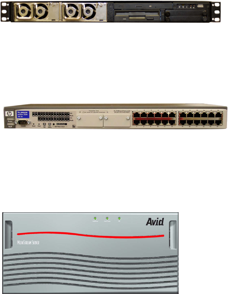
File System Controller
Each FSC is linked via a VLAN (Virtual Local Area Network) Ethernet topology through its
own VLAN switch to the MSS Networked Storage System server nodes. This further
enhances network isolation and prevents network loops from causing potential additional
latencies in the network if a failure occurs in the Ethernet topology itself. The MSS
Networked Storage System requires two FSCs regardless of the size of the system. This
important feature contributes to the system’s ability to handle real-time fail-over scenarios.
VLAN Switch
MSS 8000 Server Nodes
The video input/output (I/O) portion of the MSS Networked Storage System is the
MediaStream 8000 server nodes. Server nodes provide the video engine of the system. The
MediaStream 8000 chassis incorporates nine video I/O slots in a 5 rack unit (RU) package.
The MSS 8000 is based on proven MediaStream 700/1600 platform technology.
MS Server 8000
Chapter 1 Introduction
28
Each server node has redundant connections to both FSCs through redundant VLAN
switches. In addition, communication to the storage system is via Fibre Channel connections
to redundant controllers in the storage system. This design provides for dual data paths and
fast fail-over should key components or connection paths fail (see “MSS Networked Storage
System Configuration” on page 31).
As with existing MSS systems, each server node contains its own System Controller board,
redundant power supplies, fans, and a combination of encoder and decoder boards. In
general, decoder boards play content out to broadcast, while encoder boards convert
601 Serial Digital to MPEG-2 for storage on the system.
An individual server node can provide up to 16 channels. One MSS Networked Storage
System can accommodate up to 16 server nodes. This system is referred to as a cluster. An
expanded system can support up to 16 clusters that can share data through an FTP gateway
server node.
The server node interfaces with the station’s automation system via RS-422 protocol and
Ethernet .dll and sends the video content in specified formats to the station’s routing system.
VME Bus
The System Controller board and other control boards plug directly into a VME backplane
(bus). The System Controller board controls traffic on the backplane, while direct processing
power is distributed among encoders, decoders, and the other boards plugged into the VME
bus. Data flow between the array controller and input/output cards travels down the back
plane of the bus.
LynxOS™ Operating System
The server nodes run under the LynxOS, a real-time variant of the industry-standard UNIX
operating system. LynxOS provides a stable platform for reliable real-time playout and
record of video with a low risk of system interruption.
AMS
AMS is the primary server node application that provides interface and control with
automation.

MSS Networked Storage System Features
29
Palladium Store 1000
The Palladium Store 1000 storage system consists of one or more storage units. Each
Palladium Store 1000 chassis contains dual RAID controllers and 10 disks in two redundant
4+1 sets.
In case of a single disk failure in either or both of the disk sets, the system continues to
operate normally at full performance. After replacing the faulty disk, the system can
reconstruct the data from parity while operating at full performance.
Palladium Store 1000 - Front Bezel
Each controller provides a separate data path to the server nodes. In case of a component
failure, the system will continue to operate normally. Hardware replacement of the failed
component can occur without service interruption.
MSS Networked Storage System Features
File System Redundancy
The MSS Networked Storage System is able to sustain a failure in any file system control
component without performance degradation, video loss, or jitter. The redundant
MediaStream Networked Storage File System control path consists of the following three
components:
• Two redundant FSCs that are independent from each other in software and hardware,
and which mirror the FSC File System in real-time.
Chapter 1 Introduction
30
• Two redundant VLAN Ethernet switches, which are independent of each other in
functionality. These switches provide isolated connections between the video server
nodes and the two FSCs. The VLAN topology design prevents network loop conditions
that could lead to unacceptably long network time-out scenarios during an Ethernet
LAN connection failure.
• Two redundant Ethernet control connections on the server node connected to the two
VLAN switches.
During normal operation, one of the FSCs acts as the Primary Controller, while the other
acts as the Hot-Standby Secondary Controller. The Primary Controller controls the content
mirroring process of the Hot-Standby Secondary Controller; however, all MediaStream 8000
server nodes communicate directly with both the Primary and Secondary Controllers even
during normal operation and treat both FSCs equally. All File System requests issue twice,
one request per FSC, allowing for a transparent fail-over if one of the Controllers does not
respond.
Multiple Watchdog software modules distributed in the FSCs and the server nodes
constantly monitor the File System components and Ethernet connectivity. These software
modules ultimately make the decision if and when to switch the Secondary Controller to
become the Primary Controller. At that point the original Primary Controller is off-line and
can be serviced. Once the old Primary Controller comes back on line, it will automatically
become the Secondary Controller and will slave itself to the Primary Controller for content
mirroring and other housekeeping tasks.
Video Data Path Redundancy
The system is able to sustain a failure in one of the Fibre Channel data paths without
performance degradation, video loss, or jitter. The redundant data paths consist of the
following components:
• Dual Fibre Channel ports on the Fibre Channel card of the server node. These ports are
independent of each other in hardware and software.
• Dual RAID controllers per array. Both controllers are independent of each other in
hardware and software. Both FSCs have access to all of the storage at full bandwidth.
• Required Fibre Channel switches are always installed in redundant pairs.
• During normal operation, only one data path is used to read/write the data from/to the
storage system. If a failure in the data path occurs, the server node software detects this
failure in real-time and switches transparently to the other redundant data path. Since all
components are designed to deliver data at or above full bandwidth, there is no
performance degradation. The real-time fail-over design prevents video outages at the
decoder, as well as data overflow scenarios on the encoder system.
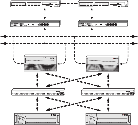
MSS Networked Storage System Configuration
31
MSS Networked Storage System Configuration
All MediaStream Networked Storage Systems require redundant FSCs roller and redundant
VLAN switches for data control and redundant Fibre Channel switches for connection to the
array(s).
MediaStream Redundant System
Adding Video Server Nodes and Channels
In most cases, adding additional video server nodes and channels to a system means that the
bandwidth requirement increases. Operators need to properly calculate if sufficient
bandwidth exists to support the increased channel count. This calculation can vary
significantly because it depends on how the system is used and operated in a given facility.
See for Appendix A for bandwidth calculation tables.
Adding additional channels to a server node is a straightforward process. Only the server
node that receives the channel upgrade needs to be shut down for the hardware and
configuration upgrade. Everything else will continue to operate normally.
File System
Controllers
VLAN
Switches
MSS 8000
Server Node
Fibre Channel
Switches
Storage
Subsystem
Isolated
Ethernet
Network
Temperature Power Supply Fan
M
EDIA
S
TREAM
S
ERVER
Temperature Power Supply Fan
M
EDIA
S
TREAM
S
ERVER
P
ALLADIUM
TM
S
TORE
1000P
ALLADIUM
TM
S
TORE
1000
Chapter 1 Introduction
32
Adding a server node involves hot-plugging the unit into the Ethernet VLAN topology to
provide file system connectivity and to connect the dual Fibre Channel interface into the
Palladium Store 1000 storage system. The Ethernet and Fibre Channel topology is factory
pre-configured to accommodate run-time configuration changes.
Adding Arrays to the System
Once the additional storage has been physically added, the operator needs to run File System
utilities to add the additional storage to the File System. For more information contact Avid
MediaStream Support.
The MSi Host PC
The system is administered via a host PC. The PC runs an application called MediaStream
Interface (MSi) that allows support personnel to playout, record, and run diagnostics on the
system components. Communication between the Host PC and the system components is via
redundant Ethernet connections to the dual VLAN switches. Depending on the
configuration, a storage cluster may have either one or two MSi PCs. Where there are two
MSi PCs, both have full access to all server nodes and both FSCs. Serial communication to
server nodes is provided by a Lantronix Ethernet-to-serial interface that integrated into each
server node chassis. This connection allows full access to the boot-up sequence of each
server node.
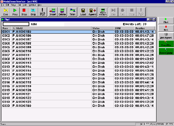
MSS Networked Storage System Configuration
33
MediaStream Interface (MSi)
MSI Screen Display
y
The MediaStream Interface (MSi) is a Graphical User Interface (GUI) application used for
administering the MediaStream Server. The MSi provides support personnel a means of
playing, recording, rebooting, installing new software, and performing other maintenance
activities on the server node. While the MSi is capable of performing many activities
associated with playing and recording media clips, it is meant to be used as a support and
diagnostic tool.
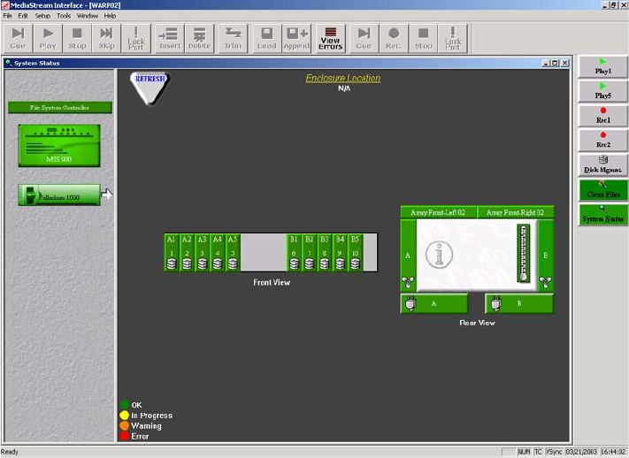
Chapter 1 Introduction
34
Simple Network Management Protocol (SNMP)
The MSS Networked Storage System includes status monitoring with Simple Network
Management Protocol (SNMP). The MSi’s System Status window presents SNMP data in
an easy to monitor graphic interface.
MediaStream System Status Window
The data is updated automatically at regular intervals (about two minutes). A trouble
condition, reported in any of the server node’s key operating modules (disk drives, array,
power supply, or cooling fans), updates the System Status display and changes the button
alert color to red. Click the System Status button to see a graphic representation of the server
node, FSCs, and arrays. A failed component is highlighted in red in the System Components
pane.
Chapter 2
System Components
Although a MSS Networked Storage System may vary in scale and size, all systems share
certain components. This chapter examines the components that comprise a MSS Networked
Storage System:
• MediaStream 8000 server nodes
• File System Controllers
• Palladium Store 1000 Storage systems
• VLAN switches
• Fibre Channel switches
•MSi PC
• ConnectPlus 1000 NS Gateway PC
MSS 8000 Server Nodes
The MSS 8000 server node dseign uses VME 64-bit bus architecture (bus) and provides
high-speed communication between boards with a throughput of 400 Mbps. Direct
processing power is distributed among the cards plugged into the back plane.
The server interfaces with the station’s automation system using the RS-422 port with Video
Disk Control Protocol (VDCP) as defined in the Avid MediaStream VDCP documentation
and Ethernet LAN controls. Video content is sent in specified formats to the station’s routing
system.
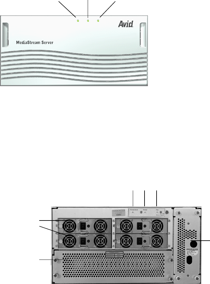
Chapter 2 System Components
36
Avid MediaStream Server 8000
After removing the server’s front panel, you can access the redundant hot-swappable power
supplies and view the three LED indicators for temperature, power supply, and fan status.
You can remove the cover that encloses the CPU I/O board (provides LAN, SCSI and
RS-232 connections to the CPU) and the Boot Drive. Mounted on the right side of the unit in
a pullout tray is the Lantronix Ethernet-to-Serial Interface that provides Console port access
via Telnet.
Avid MediaStream Server 8000 - Front with Bezel Removed
LEDs
Temperature Power Fans
LEDs
Temp. Power Fan
supply
CPU-IO board
and boot drive
Redundant
power supplies
Lantronix
module
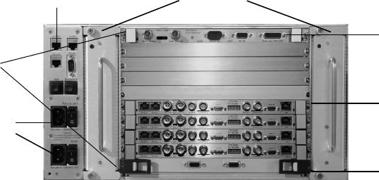
System Controller
37
Avid MediaStream Server 8000 - Rear
In the rear panel, VME slot 1 (bottom rear slot) contains the System Controller (CPU)/Fibre
Channel board that provides system control and data transfer to the Palladium Store 1000.
Slots 2 through 10 (numbering from bottom to top) contain decoder and encoder boards. Up
to 16 input/output channels can be supported using a combination of single- and
dual-channel boards. The left side of the unit contains LAN connections and power
switches.
System Controller
The System Controller board regulates backplane traffic. It performs only a fraction of the
actual computing on the Server; other boards perform activities such as MPEG
compression/decompression. The System Controller Board regulates traffic by maintaining
the bit rates of real-time processes (play and record) at the expense of non-real-time
processes, such as administrative tasks. No encoder or decoder traffic actually passes
through the System Controller Board. Video Input/Output traffic passes directly across the
VME Bus to its destination.
Power
Fan trays
Encoder
System
controller/CPU/
Fiber Channel
(VME slot 1)
Dual decoders
LAN
connections
Slots 1
through 10
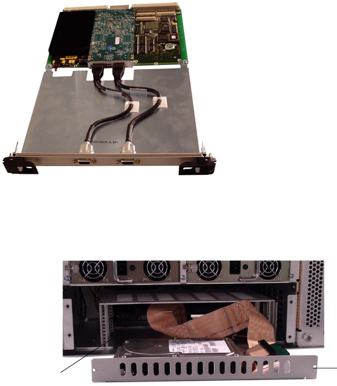
Chapter 2 System Components
38
System Controller Board (CPU)
The MSS 8000 Boot Disk Drive mounts above the CPU-IO board and connects to it via a
SCSI connection.
MSS 8000 Boot Disk Drive
Encoders
System encoders are responsible for coding video for storage on disk. Base band ITU 601
video enters the System via a Serial Digital Interface (SDI) port on the encoder board. A
601 signal has a bandwidth of 270 Mbps, far too high for storage on a storage array. The
encoder applies MPEG video compression to the signal, which reduces the signal to between
6 Mbps and 50 Mbps.
Boot disk
tray
CPU I/O board
connects to
VME backplane

System Controller
39
After the signal is compressed it is passed through the encoder to the VME back plane and
through Fibre Channel Adapter (FCA) to the external storage array. Encoders do not have
circuitry for playing out video signals. Signals must first be recorded to disk. Playback and
preview is accomplished by playing disk-based segments through a decoder card.
Encoder cards cannot accept analog signals. These signals must be converted to ITU 601 via
an analog to digital converter. The Revision 3 Encoder supports encoding for up to 8
channels of embedded audio.
AES-EBU audio is connected through an audio input module, which is bridged to the
encoder with a custom cable. Encoders are controlled by automation systems via RS-422,
which guarantees frame accuracy in recording.
Encoder Board
Decoder boards are required to playback signals from the array to air. Decoders output
embedded AES/EBU audio with SDI, separate AES-EBU and analog audio (via adapter
panel) and Composite NTSC or PAL analog video. Software must be configured for
embedded audio on or off. Video connections are via BNC while audio connections are
ported via a special cable to a breakout panel. A loop-through Genlock port and an RS-422
control port are included as well.
The board designs employ new audio connections and new automation connections.
Connecting cables ship with each board. There are different cable connections for the four,
six, and eight channel audio versions of the boards.
The Audio cable part numbers are as follows:
• PN: 51010004 Cable audio 4 channel
• PN: 51010005 Cable audio 6 channel “Y” (Decoder)
• PN: 51013529 Cable audio 8 channel “Y” (Decoder)
The SD (Standard Definition) board comes in Dual and Single configuration. The Dual
Decoder board provides two channels of playout on a single card. Each channel has a
composite video output and an SDI SMPTE 259M output. The connections for Dual and
Single Decoder boards are the same, but the video, audio and control connections for the B
ports are not active and are not labeled on the Single boards. The board has support for four,
six, or eight channels of 16- and 20-bit audio which can be used for Dolby E or Dolby
Serial ASerial B Audio B Audio ASDI In B SDI IN A
Note: Unlabled items are not used.
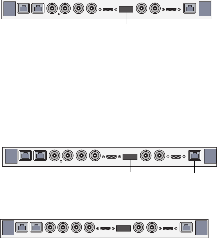
Chapter 2 System Components
40
Digital pass through. The board also features jog, shuttle, and Pinnacle’s patented CleanCut
MPEG decoding at bit rates up to 50 Mbps per channel. The following figure shows the
connections for the Dual SD Decoder board. The single version of the board has the same
connections, but the B Port connections are not active.
Dual Channel SD Decoder
nThe latest Avid I/O board is an all-in-one board with 8-channel audio that can be converted
into either a dual channel SD/HD Decoder, HD Input, or MPEG Input/Output board.
The HD (High Definition) decoder board provides SMPTE 292M output with a down-
converted SD SMPTE 259M output channel. The board comes in dual- or single-channel
configuration and supports four or six channels of audio, using the same audio standard as
for the SD board. The board also supports jog, shuttle, and Avid MediaStream Systems’
patented CleanCut MPEG decoding at bit rates up to 50 Mbps for each channel.
nAttach a 75-Ω terminator to the HD outputs when not in use.
Dual Channel HD Decoder
MPEG I/O Board
Dec 1
GenlockSerial B Serial A Loop SDI B SDI AAnalog B Analog AAudio B Audio A
Genlock LED
Green: Genlock Available
Orange: Genlock Unavailable
Display alternates
between port addresses
DO NOT USE
Dec 1
GenlockSerial B Serial A Loop HD B SDI B HD A SDI A
Audio B Audio A
Genlock LED
Green: Genlock Available
Orange: Genlock Unavailable
Display alternates
between port addresses
DO NOT USE
Serial ASerial B SD OUT A ASI I/O ASD OUT B ASI I/O B
Genlock Loop
Note: Unlabeld items are note used. Display shows port
addresses
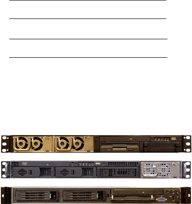
File System Controller
41
One of the factors in configuring an HD system is the bandwidth limitation. At 50Mbps, a
dual channel HD Decoder board and an HD Input board will occupy up to 200 Mbps of
bandwidth at maximum load (worse case).
nThe MediaStream HD Solution requires an external HD Encoder that can provide an ASI
signal to the MPEG Input card.
File System Controller
nThe following figure shows the FSC 80 and FSC 200 models. If you have the Super Micro or
the IBM 335 models, see Appendix D.
File System Controller — Front
HD Dual Channel Decoder
Channel 1 (Port A) 50 Mb + 25 Mb (Cueing) = 75 Mb
Channel 2 (Port B) 50 Mb + 25 Mb (Cueing) = 75 Mb
HD Input Board
Single Input 50 Mb = 50 Mb
Total = 200 Mb
FSC 40
FSC 100
FSC 80
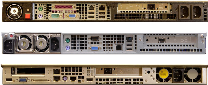
Chapter 2 System Components
42
The MSS Networked Storage System design employs redundant Windows 2000 PCs to
operate as external File System Controllers (FSCs). Regardless of the size of a server cluster,
the system will always use only two FSCs. These controllers manage the content database
that is accessed by all server nodes for content playout. FSCs occupy one rack unit each.
The Power button enables you to safely shut down the Windows OS component of the unit
for servicing without requiring access to a Windows 2000 interface.
wPowering down a FSC without verifying current system status could bring the system
off-air.
The rear of the unit provides monitor/keyboard/mouse connections and Ethernet
and VLAN connections.
File System Controller — Rear
Palladium Store 1000
Each MSS Networked Storage System cluster contains one or more arrays. Each array
storage unit consists of dual redundant Controllers. The array chassis contains 10 drives in
two banks of 4 plus 1 configured disks.
FSC 40
FSC 100
FSC 80
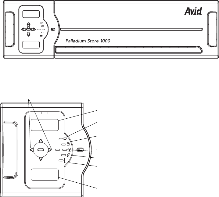
Palladium Store 1000
43
Avid Palladium Store 1000
PS 1000 Controller Status Display
The array storage chassis provides a display panel allowing monitoring of the chassis and
individual drives
The LED indicators on the front panel are as follows:
• Address indicator for Channel A and Channel B controllers
• Temperature indicator
• Disk status indicator
• Fan status indicator
• Power indicator
• Controller status indicator
silence
enter
ChA address
ChB address
Controller status
Power supplies
Fans status
Drive status
Temperature
Controller B display
Panel navigation
buttons
Controller A display
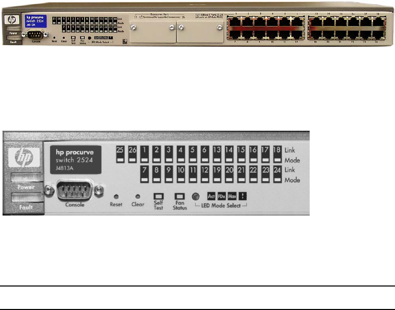
Chapter 2 System Components
44
VLAN Switches
Each MSS Networked Storage System cluster employs two Hewlett-Packard Pro Curve
VLAN 24 port switches.
Hewlett-Packard Pro Curve 2524 Switch
The left side of the switch contains an RS-232 console port for setup and
configuration of the switch, and indicators for switch status and activity.
HP Pro Cure 2524 Switch Indicators
The following table describes the VLAN switch control panel display.
VLAN Switch Indicators
LED Meaning Significance
Power (green) On. The VLAN is powered up OK
Off. No power Fix power supply
Fault (orange) Off. Normal OK
Blinking. Fault detected Look for component LED
blinking in unison
On. Goes out after self-test. If it remains on,
self test failed
Fatal hardware failure. Call tech
support
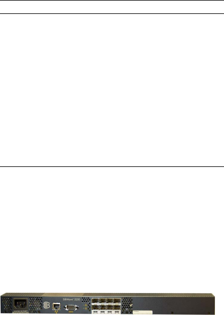
Fibre Channel Switches
45
Fibre Channel Switches
Your system will include two independent and redundant Fibre Channel switches.
Depending on the size of the cluster, different Fibre Channel switches will be used. The
Fibre Channel switches provide the link between the server nodes and the Palladium Store
1000 storage arrays. Each switch provides an independent path to each server node and to
each array. Up to 16 server nodes and one-to-eight storage arrays are connected to the
switches. Should any path fail on one switch, communication will continue via the
redundant path on the second switch.
Avid supports an 8-port and a 16-port fibre channel switch.
Avid supports an 8-port and a 16-port fibre channel switch.
FCS - Brocade SilkWorm 3250
Self Test (green) Off. Normal during operation OK
On. Self-test in progress OK
Blinking. Component failure Look for component LED
blinking in unison
Mode Select
(three green LEDs)
Act. Port LEDs set to display network
activity
A display option
FDx. LEDs lit for ports in full duplex mode A display option
Max. LEDs lit for ports operating at full link
speed
A display option
!. Port LEDs display network events that
could require operator attention, such as
CRC errors and network collisions
A display option
Fan Status (green) On. Normal Fans work
Blinking. Failure Fan needs replacement
Port Activity LAN port with matching number is sending
or receiving
LAN port works
VLAN Switch Indicators (Continued)
LED Meaning Significance

Chapter 2 System Components
46
FCS - Brocade SilkWorm 3850
Status indicators vary between models.
Gadzoox 2000
Gadzoox 3000 HA
Status indicators vary between models.
MSi PC
Each MSS Networked Storage System cluster has either one or two MSi PCs, depending on
the option purchased. Although a system cluster can function without an operational MSi
PC, the MSi PC is valuable in that it enables you to monitor all system components. Systems
with a second MSi PC have redundant system-monitoring capability.
MSi 2000 - Front Panel
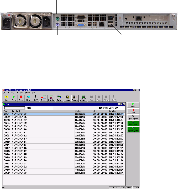
MSi PC
47
The rear of the unit provides two LAN ports for system communications. There is also a
connector for the internal modem and one for an optional analog phone, which you can use
when the modem is not in use. Other connectors include a serial, VGA, and USB port. If
your MSi PC has the optional Fibre Channel card installed, there is a Fibre Channel port.
MSi 2000 - Rear Panel
The Avid MediaStream Interface (MSi) application provides a means of playing, recording,
rebooting, installing new software, and performing other maintenance activities on the
server.
Main MSi Window
USB
modem
RS-232
connector
LAN 1
LAN 2
Mouse
Keyboard
Unused
VGA port

Chapter 2 System Components
48
The Host PC communicates with the server components through a LAN connection.
A Lantronix Ethernet-to-serial interface, which is integrated into each server node, provides
serial communication to servers, allowing full access to the boot sequence.
Simple Network Management Protocol (SNMP)
The Simple Network Management Protocol is a set of networking protocols designed to
provide diagnostic data over networks. The MediaStream 8000 Server employs SNMP to
provide a user with easily accessible and regularly updated diagnostic data. Data is fed to the
MSi and is displayed graphically in the System Status window of the MSi application.
System Status Window
The data is updated automatically at regular intervals (about two minutes) and sent to the
MSi. If a trouble condition is reported in any of the server’s key operating modules (array,
power supply, or cooling fan, the System Status button changes color from green (good) to
red (bad). Clicking the System Status button shows a graphic representation of the system
components. The MSS 8000 and the Palladium Store 1000 are shown to the left of the main
window. System components that fail are highlighted in the main window.
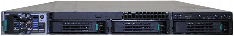
ConnectPlus 1000 NS Gateway PC
49
ConnectPlus 1000 NS Gateway PC
ConnectPlus 1000 Networked Storage (option) is a gateway that provides access to archive
storage and to content distribution with other MediaStream Servers. Data transfer is
accomplished via Pinnacle’s implementation of standard FTP (File Transfer Protocol),
providing for easy integration with automation and archive systems.
nWhen configuring one or more Gateway PCs into a networked storage system, special
consideration must be given to bandwidth load of the entire system. Each configured
gateway must be considered a server node with adequate bandwidth allocated for its use.
Failure to consider gateway impact on system bandwidth can have serious system-wide
performance implications. See Appendix A for more information on bandwidth calculations.
Connect Plus 1000 - Front Panel
Chapter 2 System Components
50
Chapter 3
VLAN Topology
This chapter introduces the VLAN topology used in the MSS Networked Storage System.
Topics covered include:
• Hosts table
• Ethernet topology diagrams
• IP addressing scheme
VLAN Topology
The Networked Storage System uses redundant VLAN Ethernet switches to provide fast and
safe fail-over in the event of a break in network connectivity. Each switch provides isolated
connections between the server nodes and the two FSCs. The VLAN topology design
prevents network loop conditions that could lead to unacceptably long network time-out
scenarios during a LAN failure.
To ensure system redundancy, installation must conform explicitly to system design
parameters. Each switch must have the current firmware and the correct switch-
configuration files installed. With VLAN, a different network is assigned for each server
node providing isolated connection paths between the server nodes and the FSCs.

Chapter 3 VLAN Topology
52
Hosts File
The hosts file provides name resolution for all devices within the cluster. The complete hosts
file on the FSCs and MSi PC is quite large and contains all names and addresses for all 16
possible clusters. Each server node contains a hosts file for a given cluster. An abbreviated
version of this file (with headings separating devices) follows. Sequential addresses have
been skipped, and any entry ending with xx… shows a continued sequence to the next entry.
Aliases
Some device hostnames have been provided with aliases to simplify the connection of
devices via Telnet. Connections can be established by using the hostname, LAN address, or
any provided alias.
Host Table for Cluster 1
Host Name LAN Address Aliases
MSS 8000 (LAN)
mss0101 10.64.1.3
mss0102 10.64.2.3
mss01xx … 10.64.xx.3 …
mss0116 10.64.16.3
MSS 8000 (Console)
con0101 10.64.1.4
con0102 10.64.2.4
con01xx … 10.64.xx.4 …
con0116 10.64.16.4
FSC1
fsc0101-1 10.64.1.1 fsc0101A fsc0101
fsc0101B 10.64.21.1

Hosts File
53
fsc0101-2 10.64.2.1
fsc0101-xx … 10.64.xx.1 …
fsc0101-16 10.64.16.1
fsc0101-22 10.64.22.1
FSC 2
fsc0102A 10.64.21.2 fsc0102
fsc0102-1 10.64.1.2 fsc0102B
fsc0102-2 10.64.2.2
fsc0102-xx … 10.64.xx.2 .
fsc0102-16 10.64.16.2
fsc0102-22 10.64.22.2
MSI 1
msi0101-1 10.64.1.5 msi0101A
msi0101-17 10.64.17.5 msi0101B
msi0101-2 10.64.2.5
msi0101-xx … 10.64.xx.5 …
msi0101-16 10.64.16.5
MSI 2
msi0102-1 10.64.1.6 msi0102A
msi0102-17 10.64.17.6 msi0102B
msi0102-2 10.64.2.6
msi0102-xx … 10.64.xx.6 …
Host Table for Cluster 1 (Continued)
Host Name LAN Address Aliases

Chapter 3 VLAN Topology
54
VLAN Topology Diagram
The following diagram shows a logical Ethernet connections for the 24-port switch. Your
installed system ships with color-coded labels and cables to make both wiring and tracing
connections easier. This diagram will help you isolate network paths when servicing or
troubleshooting the system.
All tagged connections are VLAN logical connections while untagged connections are fixed
LAN addresses. For tagged VLAN connections, the sequence of addresses has been
abbreviated to simplify the diagram. In addition, only the last two octet groups of the address
are provided. The complete address includes the 10.xx prefix that designates the cluster.
nThe port layout of the 24-port switch is not physically the same as shown here. Make your
connections based on the port numbers, not their apparent positions in this diagram.
msi0102-16 10.64.16.6
Gateway
gwy0101-1 10.64.1.11
gwy0101-2 10.64.2.11
gwy0101-3 10.64.3.11...
gwy0101-16 10.64.16.11
gwy0101-21 10.64.21.11
gwy0102-1 10.64.1.12
gwy0102-2 10.64.2.12...
FC Switch
fcw0101 10.64.21.36
fcw0102 10.65.17.37
Host Table for Cluster 1 (Continued)
Host Name LAN Address Aliases
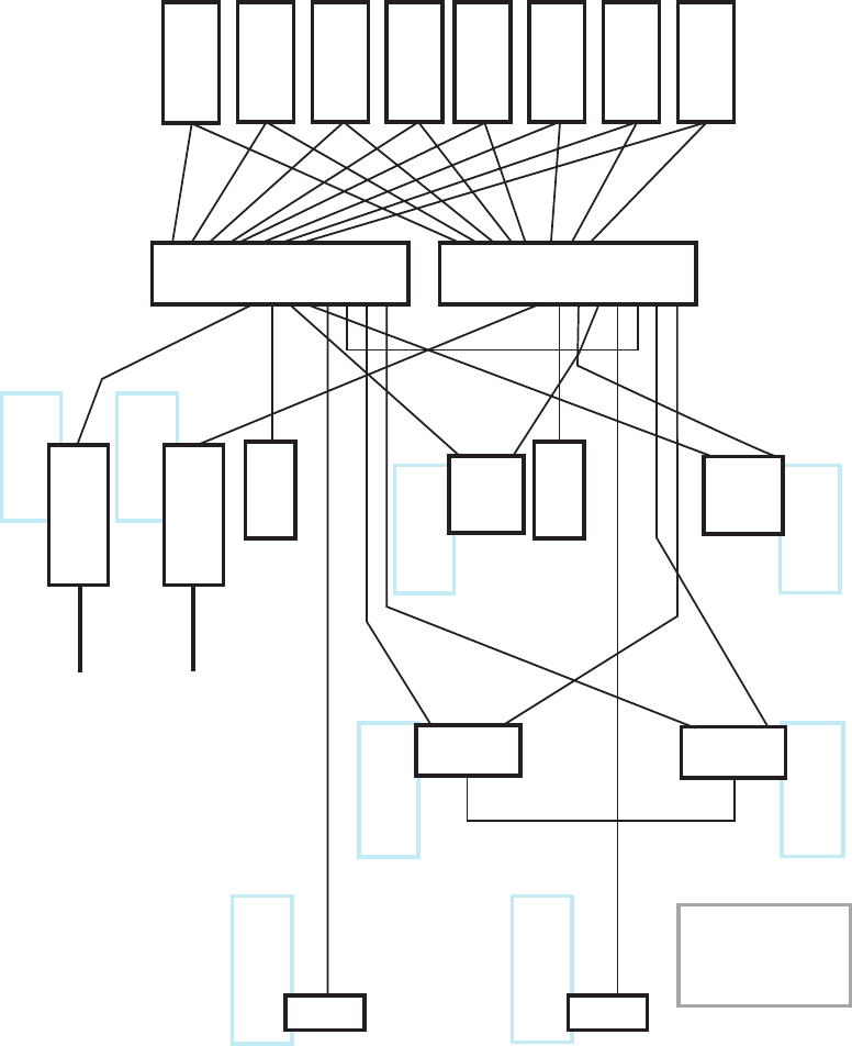
Hosts File
55
VLAN Topology
MSI 1
(tagged)
.1.5
.2.5
.3.5
. .....
.16.5
.21.5
GWY 2
(tagged)
.1.12
.2.12
.3.12
. .....
.16.12
.21.12
GWY 1
(tagged)
.1.11
.2.11
.3.11
. .....
.16.11
.21.11
MSI 2
(tagged)
.1.6
.2.6
.3.6
. .....
.16.6
.21.6
FSC 1
(tagged)
.1.1
.2.1
.3.1
. .....
.16.1
.17.1
FSC 2
(tagged)
.1.2
.2.2
.3.2
. .....
.16.2
.17.2
HP2524 A 21.34 HP2524 A 17.35
1010
S
SM
N
A
L 3.1
)deggatnu(
losnoC 4.1
)deggatnu
(
2010
S
SM
N
A
L 3.2
)deggatnu(
losnoC 4.2
)degg
a
tnu
(
30
10SSM
NA
L
3.3
)d
eggatnu(
losno
C
4.3
)de
gg
at
nu
(
4
010SSM
NA
L
3.4
)
d
eggatnu(
losno
C
4.4
)deg
g
atn
u
(
50
10SSM
NA
L
3.5
)d
eggatnu(
losno
C
4.5
)
degg
a
tnu
(
601
0SSM
NA
L
3
.
6
)d
egg
a
tnu(
losno
C
4
.
6
)d
egg
a
tnu
(
70
10
S
SM
N
A
L
3.7
)d
eggatnu(
losn
o
C
4.7
)de
gg
a
tnu
(
80
10
S
SM
N
A
L
3
.8
)d
e
gga
t
nu(
losn
o
C
4
.8
)deg
g
a
t
nu
(
hct
iwS
CFA
)d
eggatnu(
63
.1
2
B
hct
i
w
S CF
)d
eggatnu(
73
.7
1
)yawetaG( 1010
Y
WG
)ya
we
taG(
2010YWG
1010ISM
LAN 2 LAN 1
Router A
(tagged)
.1.32
.2.32
.3.32
. .....
.16.32
.17.32
.21.32
Router A
Router B
(tagged)
.1.33
.2.33
.3.33
. .....
.16.33
.17.33
.21.33
Router B
)deggatnu( 7.821
)d
eg
ga
t
nu
(
8
.
92
1
FSC0101
LAN 1
LAN 3 LAN 2
21.1
(untagged)
21.0
5
.
71
)
d
eg
g
atn
u
(
6.
71
)
deggat
n
u(
22.1
(untagged)
FSC0102
LAN 2 LAN 3
21.2
(untagged)
22.2
(untagged)
Ethernet topology of a Single MSS
Networked Storage Cluster
24 Port Switch
2010
IS
M
LAN 2LAN 1
Note:
Ports 9-16 available for
additional MSS-8000
Server Nodes
LAN 1
123456789101112
13 14 15 16 17 18 19 20 21 22 23 24
123456789101112
13 14 15 16 17 18 19 20 21 22 23 24

Chapter 3 VLAN Topology
56
Networked Storage System I/P Addressing
Scheme
IP Address Scheme Example
The addressing scheme takes a 32-bit TCP/IP address and breaks it into logical units that can
be used to identify cluster, network IDs, and device IDs. The four-octet network address is
logically allocated to distinguish between clusters, VLAN networks, and device IDs. All
clusters are addressed as follows:
The first octet is always 10. The second octet designates cluster ID. Cluster 1 (the most
common) is 10.64.xxx.xxx. Addresses 64 to 79 are allocated for the first 16 clusters, with
clusters 17 through 32 using addresses 81 to 96. Clusters 33 to 48 use 64 through 79, but the
third octet (the network ID, described below) for VLANs in these clusters starts with 65
rather than 1.
10.xxx.yyy.zzz
Cluster
ID
Network
ID Device
ID
Cluster Addressing
Initial Cluster Addresses
Cluster 1 10.64.1 Cluster 17 10.81.1 Cluster 33 10.64.65
Cluster 2 10.65.1 Cluster 18 10.82.1 Cluster 34 10.65.65
Cluster 3 10.66.1 Cluster 19 10.83.1 Cluster 35 10.66.65
Cluster 4 10.67.1 Cluster 20 10.84.1 Cluster 36 10.67.65
Cluster 5 10.68.1 Cluster 21 10.85.1 Cluster 37 10.68.65
Cluster 6 10.69.1 Cluster 22 10.86.1 Cluster 38 10.69.65
Cluster 7 10.70.1 Cluster 23 10.87.1 Cluster 39 10.70.65
Cluster 8 10.71.1 Cluster 24 10.88.1 Cluster 40 10.71.65
Cluster 9 10.72.1 Cluster 25 10.89.1 Cluster 41 10.72.65
Cluster 10 10.73.1 Cluster 26 10.90.1 Cluster 42 10.73.65

Networked Storage System I/P Addressing Scheme
57
The third octet grouping acts as a network ID, dividing a cluster into separate VLAN
networks, providing isolated communication paths for each server node. Sixteen separate
networks are allocated for server node communication with additional network paths
available for gateway, MSi PC, switch, and router traffic.
The fourth and final octet grouping acts as a device ID specifying the device type and/or
number in a storage cluster. The hosts file contains all addresses in all clusters with name
resolution for each device in a cluster.
The FSCs, MSi PCs, gateways, and routers employ VLAN Ethernet cards in addition to
standard Ethernet NICs to allow communication with devices across multiple networks
within a cluster.
Subnet Mask
The network uses the Class C subnet mask of 255.255.255.0, providing up to 256 individual
addresses per designated network ID.
Hosts Table and Addressing
Given the above parameters, the following devices are named and addressed in the hosts file
on systems components and integrated into the VLAN Switch:
• MSS 8000 server nodes and console ports
• File System Controller 1 and 2
•MSi PC 1 and 2
Cluster 11 10.74.1 Cluster 27 10.91.1 Cluster 43 10.74.65
Cluster 12 10.75.1 Cluster 28 10.92.1 Cluster 44 10.75.65
Cluster 13 10.76.1 Cluster 29 10.93.1 Cluster 45 10.76.65
Cluster 14 10.77.1 Cluster 30 10.94.1 Cluster 46 10.77.65
Cluster 15 10.78.1 Cluster 31 10.95.1 Cluster 47 10.78.65
Cluster 16 10.79.1 Cluster 32 10.96.1 Cluster 48 10.79.65
Cluster Addressing (Continued)
Initial Cluster Addresses
Chapter 3 VLAN Topology
58
• Gateways 1 through 8
• Fibre Channel (FC) Switch A and B
•Router A and B
LAN Port Name And Address
Hostname = mss<xx><yy> where xx equals cluster number and yy equals server node
ID
e.g., mss0101 is Network 1 Server Node 1 of Cluster 1
LAN address = 10.<xx>.<yy>.3 where xx equals cluster ID and yy equals server node
ID
e.g., 10.64.1.3 for Network 1 Server Node 1 of Cluster 1
nThe device ID (the last octet group) is always 3 for server nodes.
Console Address
Hostname = con<xx><yy> where xx equals cluster number and yy equals server node
ID
e.g., con0101 is Network 1 Console Port 1 of Cluster 1
LAN address = 10.<xx>.<yy>.4 where xx equals cluster ID and yy equals console port
ID
e.g., 10.64.1.4 for Network 1 Console Port 1 of Cluster 1
nThe device ID is always 4 for console ports.
File System Controllers (FSCs)
There are two FSCs in each MSS Networked Storage System cluster. Each FSC has three
Network Interface Cards (NICs). The first is a VLAN connection to its primary switch. The
VLAN card is logically addressed (tagged) for communication with all configured networks
on the VLAN switch. This connection allows direct communication between the FSC and
each of the server nodes as well as the second FSC, MSi PCs, gateways and Fibre Channel
switches. The second is a direct connection to the redundant VLAN Switch. The third is a
direct crossover connection to the second FSC.
The convention for naming and addressing the three NICs is as follows:
Hostname
Hostname = fsc<xx><yy>-<z> where xx equals cluster number, yy equals FSC ID
(FSC A is “01” while FSC B is FSC “02”) and z is Network ID.
e.g., fsc0101-3 is FSC A of Cluster 1 on Network ID 3
Networked Storage System I/P Addressing Scheme
59
LAN 1 Connection
LAN address = 10.<xx>.<22>.<z> where xx equals cluster ID and z is either “1” for
FSC A or “2” for FSC B.
e.g., 10.64.22.1 for FSC A on Cluster 1
nThis is the crossover connection between the two FSCs.
LAN 2 Connection
LAN address = 10.<xx>.<21>.<z> where xx equals cluster ID, and z is either “1” for
FSC A or “2” for FSC B.
e.g., 10.64.21.2 for FSC B on Cluster 1
LAN 3 Connection
LAN address = 10.<xx>.<yy>.<z> where xx equals cluster ID, yy equals Network ID
and z is either “1” for FSC A or “2” for FSC B.
e.g., 10.64.3.1 is FSC A of Cluster 1 on Network ID 3
nThe VLAN card is configured for 17 logical addresses (from Network ID 1 to 17). It in effect
creates a “Virtual” Network Interface Card for each address. The hosts file for the VLAN
port on the FSC will include a hostname and LAN address for each of these.
MSi PCs
A MSS Networked Storage System cluster will always have at least one MSi PC configured
but may have a second unit installed for redundant monitoring of the system. Each MSi PC
has one tagged VLAN NIC and one conventional Ethernet card installed. The VLAN
connection is for direct connection to the PCs primary VLAN switch while the Ethernet port
is for redundant connection to the secondary VLAN switch. The convention for naming and
addressing the two NICs is as follows:
Tagged VLAN Connection
Hostname = msi<xx><yy>-<z> where xx equals cluster number, yy equals MSi ID
(MSi 1 is designated “01” while MSi 2 is designated “02”) and z is network ID.
e.g., msi0101-1 is MSi 1 of Cluster 1 on Network ID 1
LAN address = 10.<xx>.<yy>.<z> where xx equals cluster ID and yy equals network
ID; and z is either “5” for MSi 1 or “6” for MSi 2.
e.g., 10.64.3.5 for Primary MSi on Network ID 3
nThe VLAN card is configured for 17 logical addresses (from Network ID 1 to 16 plus
Network ID 21).
Chapter 3 VLAN Topology
60
Redundant Connection
Hostname = msi<xx><yy>-17 where xx equals cluster number, yy equals MSi ID (MSi
1 is designated “01” while MSi 2 is designated “02”)
e.g., msi0101-17 is MSi 1 of Cluster 1 Network ID 17
LAN address = 10.<xx>.17.<y> where xx equals cluster ID and y is either “5” for MSi
1, or “6” for MSi 2.
nIn all cases the device address is always 5 for MSi 1 or 6 for MSi 2.
Gateways
A MSS Networked Storage System cluster may have optional gateways installed. The
gateways allow for content sharing between clusters and/or legacy MediaStream Servers. Up
to eight gateways may be configured into a system although a system is usually configured
for one or two. Each gateway has a VLAN NIC with three tagged addresses as well as an
untagged Ethernet port. The untagged port is available for connection to external networks,
not to the system’s switches. Since the gateways are not mission-critical on-air components,
redundant connections are not needed, and each gateway is connected to only one of the
VLAN switches:
Tagged VLAN Connection
Hostname = gwy<xx><yy> where xx equals cluster number and yy equals gateway
number; gateways are numbered from 1 to 8.
e.g., GWY0101 = Gateway 1 in Cluster 1
LAN address = 10.<xx>.<yy>.<zz> where xx equals cluster ID, yy equals Network ID,
and zz equals device ID. Gateways are ID’d from 11 to 18.
e.g., 10.64.16.11 for Gateway 1 ID 11 on network ID 16
nEach gateway has tagged VLAN addresses for network IDs 1 through 16 and 21. Gateway
device IDs will always be between 11 and 18 (11 for Gateway 1 and 18 for Gateway 8).
Gigabit Ethernet Connection
Hostname = gwy<xx><yy> where xx equals cluster number, yy equals gateway
number; gateways are numbered from 1 to 8.
e.g, GWY0101 = Gateway 1 in Cluster 1
LAN address = 10.<xx>.<yy>.<zz> where xx equals cluster ID, yy equals network ID,
and zz equals device ID
e.g., 10.64.128.11 for Gateway 1 in Cluster 1 on Network ID 128
Networked Storage System I/P Addressing Scheme
61
Fibre Channel Switches
A LAN connection is provided for each Fibre Channel switch to the VLAN switches to
provide access by the MSi PC for maintenance purposes. Each FC Switch is connected to
one of the VLAN switches. It is important to note that redundant connections are not
available, and monitoring will only be possible from MSi 1. These connections have been
provided as a convenience when servicing the switch.
Hostname = fc<xx><yy> where xx equals cluster number, yy equals FC switch
number. Switches are designated A or B.
e.g., FC0101 = FC Switch A in Cluster 1
LAN address = 10.<xx>.<yy>.<zz> where xx equals cluster ID yy equals network ID
and zz equals Device ID. Device ID is 36 for FC Switch A and 37 for FC Switch B.
e.g., 10.64.21.36 for FC Switch A in Cluster 1 on Network ID 6. and 10.65.17.37 for FC
Switch B on Cluster 1 Network ID 17
nFC Switch A can communicate with MSi PC 1 on Network ID 21 while FC Switch B is set to
Network ID 17 to allow communication with MSi PC 1 through its direct connection on
Network ID 17 with VLAN Switch 2.
Routers
A MSS Network Storage System cluster may be configured with optional routers to allow
communication to occur between the cluster devices and an internal LAN in the facility.
Each router is configured with a VLAN NIC to allow communication between configured
Network IDs and external devices. With redundant routers connected to each switch,
redundant communication paths are available to external networks The VLAN addresses are
configured as follows:
LAN address = 10.<xx>.<yy>.<z> where xx equals cluster ID, yy equals network ID
and z equals router device ID. This is 32 for Router A and 33 for Router B.
Chapter 3 VLAN Topology
62

Chapter 4
Preparation and Installation
This chapter describes the site preparation and installation process which includes the
following tasks:
• Site preparation checklist
• Receiving the Networked Storage System
• Installing system components into racks
About 8 weeks prior to installation, assign a site coordinator. The following table offers
guidelines for the site coordinator. For specific information, refer to the appropriate sections
in this chapter.
Site Preparation Time Table
Time
Frame Activity
8 weeks
prior to
installation
Based on the components you have ordered, determine the type of racks and
rack-mounting screws you will need and order them.
Determine what kind of racks you will need.
Select the location for the MSS 8000. Consider existing electrical outlets and
lighting, immovable objects, floor vents, etc.

Chapter 4 Preparation and Installation
64
Follow these guidelines when preparing your site for the installation
• Allow enough space at the site to accommodate additional servers and arrays should
your requirements increase.
• Locate cables away from traffic paths to prevent accidents and equipment failures.
• Allow space for a monitor to connect to the analog output of each decoder.
• Consider space for your MSi PC (racked or adjacent).
• Consider space for other equipment, such as the automation station.
• For proper ventilation of the MSS 8000 component racks, and to ensure enough room to
perform periodic maintenance and servicing, install the MSS 8000 components a
minimum of 40 inches (1 m) (front and back) from walls or other items that might
obstruct airflow or the removal of modules.
Avid MediaStream Support recommends that the equipment racks be anchored at the ceiling
or floor or bolted to the wall. Ensure that the racks will be stable when all equipment is
loaded into the racks. The center of gravity in a fully loaded rack must be low enough to
keep the rack from being top heavy.
This section addresses floor load limits, vibration, and heat dissipation.
Floor Load Limit
The room that will house the MSS 8000 must be able to support the total weight of the
various components, as well as the localized weight at each level of your rack or cabinet.
To estimate floor strength requirements, consider the following items:
1. Total weight of the MSS 8000 components and any associated equipment.
2. Total weight of furniture such as desks, chairs, tables, racks, etc.
6 weeks
prior to
installation
Create a site layout plan.
Schedule with appropriate trades persons to ensure that the site is in compliance
with structural, power, interface, and environmental specifications.
Obtain external cables as necessary. Avid MediaStream provides cables to
connect Avid MediaStream server components. (Check with your Avid
MediaStream Sales Representative if you plan to attach multiple arrays.) You
need to provide external connections to station automation, video, and audio
devices. See Appendix B.
Site Preparation Time Table (Continued)
Time
Frame Activity
Environmental Considerations
65
3. Total approximate weight of the operating personnel.
4. Weight of the moving equipment (such as forklifts and transport dollies).
Ensure that all floors, stairs, and elevators to be used when the server is moved to its
destination can support the weight of the server and moving equipment.
Refer any questions regarding the adequacy of floor construction to a qualified structural
engineer for evaluation.
Vibration
Vibration, when severe, can cause a slow degradation of mechanical parts and connections
and data errors in disk drives. If you suspect that vibration might be a problem, contact Avid
MediaStream Technical Support for advice and recommendations.
Heat Dissipation
Consider the heat dissipation by the MSS 8000 components as well as other equipment at
the site, individuals working at the site, and lighting to determine whether the existing air
conditioning system is adequate, or if an upgrade is necessary.
When estimating heat dissipation, consider the addition of Networked Storage components,
should your requirements increase.
nThe cooling air for the server flows in the front and out the left side of the unit. Make sure
that there is enough space between the left side of the server and other equipment in
neighboring racks so warm air can escape.
Environmental Considerations
This section covers ideal operating temperature, electromagnetic interference, and
electrostatic discharge.
Temperature and Humidity
To ensure that airflow is not impeded, and to ensure adequate space to perform periodic
maintenance and servicing, do not place racks closer than one meter to walls or obstructions
in the front and back.
For reliable operation, maintain room temperature between 20 and 25 degrees Celsius (68
and 77 degrees Fahrenheit), and relative humidity between 30 and 50

Chapter 4 Preparation and Installation
66
Electromagnetic Interference
The MSS Networked Storage System is designed to reduce susceptibility to radiated and
conducted interference. The MSS Networked Storage System conforms to the
electromagnetic susceptibility (EMC) standards. Excessive electromagnetic interference can
cause a variety of problems. Avid MediaStream Support can advise you about the most
common causes of electromagnetic interference.
Electrostatic Discharge
Static electricity at the MSS Networked Storage System location should be within the
normal range (lower than 15 KVs). Carpeting or low humidity will facilitate the generation
of static electricity, especially in dry and cold climates.
To reduce static electricity, install grounded mats in front of the MSS Networked Storage
System. Avid MediaStream Support recommends using a heat evaporating humidifier (and
strongly recommends against using a cold water atomizer humidifier).
Anti-static spray is not recommended because it can enter the intake filters and coat the
circuitry. If you must use a spray, apply it while the MSS Networked Storage System
components are turned off.
Use the following checklist to schedule activities and to monitor the progress of the site
preparation process.
Site Preparation Checklis t
Activity
Date
Completed
Have phone lines and modem (data) lines been installed? A direct analog line (not
a PBX connection) is required to receive Avid MediaStream Support.
Has the possible need for lifting/moving equipment been addressed?
Will the flooring and the installation site itself support the weight of the racks,
moving equipment, and personnel? Are doorways and pathways wide enough to
accommodate the shipping crate and boxes?
Has the site layout plan been completed?
Does the layout show the location for all proposed equipment?

Receiving Server Components
67
Receiving Server Components
The server, MSi PC and its monitor, File System Controllers, switches, the array(s) and
other components are packaged in separate containers. If your shipment includes the
optional Rack Mounting Kit for the MSi PC, you will receive additional boxes that contain
the rack-mounting accessories.
When the shipment arrives, check each container against the carrier’s shipping documents.
Inspect the exterior of each container immediately for mishandling or damage during transit.
If any of the containers are damaged, request the carrier’s agent be present when the
container is opened.
Have the equipment racks been installed? Are they anchored to the floor and
ceiling or bolted to the wall? Have you ensured that the racks will be stable
enough to support all installed equipment?
Is sufficient space provided in front of and behind the racks for operation and
service?
Is space provided for manuals and supplies?
Is proper and adequate power available at the site for the systems components?
Are all appropriate uninterruptible power supply (UPS) units on line?
Have tests been conducted to determine the voltage fluctuations throughout the
day?
Do you have enough power receptacles for any supplemental equipment, such as
a tape backup?
Has interface cabling been properly routed to the installation site?
Has the installation site been checked for minimum and maximum temperature
and relative humidity range?
Has any problem with excessive vibration, electromagnetic interference, and
electrostatic discharge been resolved?
Site Preparation Checklis (Continued)t
Activity
Date
Completed

Chapter 4 Preparation and Installation
68
nDo not throw anything away until you have found and unpacked all of the components.
To protect the components, leave them in their packaging until you are ready to install them.
Keep the shipping materials. If you have to repackage any of the components, you will need
the original shipping materials.
The MSS Networked Storage System components are fragile. Some components can be
damaged even when carefully handled. Move components in their original packaging.
wThe components are packed in containers that can weigh more than 120 pounds (55
kg). Exercise care when moving them to avoid injury.
nThe server ships in a wooden crate. Ensure that doorways and pathways are wide enough to
allow passage. The following table shows the dimensions of the boxes and crates.
nUse an elevator to move containers. Stairs may result in excess vibration. Leave components
in the packaging until you are ready to install them.
wNever touch any exposed electrical connectors on the components as they can be
damaged by electrostatic discharge (ESD). Never drop or sharply bump the array(s).
This can cause immediate or delayed failure of the disk drives, permanent data loss, or
intermittent operation.
A server ships in one crate and several boxes. Carefully check all compartments of each box.
Chassis Shipping Box Dimension
Component Length Width Height
File System Controller: 23.5 in (59.7 cm) 34.0 in (86.4 cm) 8.0 in (20.3 cm)
MSi Monitor 19.5 in (49.5 cm) 20.5 in (52.1 cm) 7.25 in (18.4 cm)
MSi Computer 16.75 in (42.5 cm) 19.25 in (48.9 cm) 18.5 in (47 cm)
MSS8000si Serve 35.0 in (88.9 cm) 36.0 in (91.4 cm) 19.0 in (68.6 cm)
Fibre Channel Switch 20.0 in (50.8 cm) 21.75 in (55.2 cm) 9.5 in (24.1 cm)
Palladium Store 1000 Chassis 27.5 in (69.9 cm) 24.75 in (62.9 cm) 14.5 in (36.8 cm)
Palladium Store 1000 Drives (2 boxes) 20.5 in (52.1 cm) 14.5 in (36.8 cm) 11.5 in (29.2 cm)
Receiving Server Components
69
To unpack the crate:
1. Remove the wire clips that surround the top of the crate and remove the lid.
2. Remove the front panel, rack ears, cords, and accessories from the pockets around the
inside of the crate. Some small items may be in packaging material.
3. On the outside of the crate, unfasten the latches that secure the sides of the crate to its
bottom. To unfasten the latches, flip the lever of the latch up, and then turn the lever
counter-clockwise.
4. Lift the crate up and over the main server chassis, placing the crate out of the way.
5. Remove all packing foam surrounding the server.
Inspecting the Contents of the Shipment
As you unpack the shipment, account for and inspect all the components:
• Check each container against the packing list to ensure all shipping containers were
received.
• Check all packing materials and containers for the missing components. Small
components, such as adapters and short cables, can remain undetected in the packing
materials.
• Check the packing foam for damage that indicates rough handling during transit.
• Look for broken controls and connectors, dented corners, scratches, bent panels, and
loose components.
• Check the exterior of the components for the following signs of shipping damage:
- Look at the top and sides for dents, warping, or scratches.
- Check the connector panels for signs of damage (bent or broken connectors,
scratches, and so forth).
If you have any problems with the shipment, refer to the claims procedure guidelines.
Claims Procedure Guidelines
If you found any damage, follow these claims procedures.
nSome damage may be repaired by replacing the part. In the case of extensive damage, you
need to return all of the components to Avid MediaStream Support. Contact your Avid
MediaStream representative immediately.
Notify your Avid MediaStream representative if the shipment is incomplete or if any
shipment contents are damaged. If damage occurred in transit, also notify the carrier.
Chapter 4 Preparation and Installation
70
nAvid will arrange for repair or replacement without waiting for settlement of claims against
the carrier. If damage occurred during shipping, retain the packing container and packaging
materials for inspection.
Server Repacking Guidelines
To repackage any of the server components for shipment, reverse the appropriate
unpacking procedures.
Use the original packing material to repackage the components for shipment. If the packing
material is not available, contact your local Avid MediaStream Support Sales and Support
Office in the U.S., or contact your Avid MediaStream Support authorized dealer outside the
U.S. regarding shipment.
Technical Assistance
If your server is still under warranty:
• Before you call Avid MediaStream Support, record the model and serial numbers of
your server. You need to remove the front panel to locate these numbers.
• If you opt to have a replacement part shipped to you, retain the packaging materials for
the return shipment of the failed assembly, and follow the instructions on the Return
Authorization Form that will be included with the part.
• Customers outside the USA should contact their local dealer or Avid MediaStream
Systems representative for assistance in diagnosing a problem and identifying a possible
failed assembly.
After the warranty expires, you can purchase a Avid MediaStream Support service contract.
Please contact your Avid MediaStream Support Sales Representative for more information.
Visit the Avid MediaStream Support Web site for more information about Avid
MediaStream Support: www.avid.com.
Installing the MSS Networked Storage System
A rack unit (RU) is the measurement rack manufacturers use to measure the height of
equipment mounted in the rack. A rack unit is 4.45 centimeters (1.75 inches). Some rack
manufacturers provide an additional hole or other symbol to mark the rack unit, as shown in
the following figure.
wBecause of the weight of the some of the units, installing the MediaStream server and
Palladium Store 1000 requires at least two people. A third person may be needed to
stabilize and guide the chassis while two others lift and slide the module onto the rack
rails
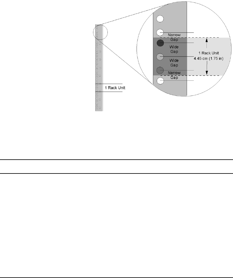
Installing the MSS Networked Storage System
71
nRack mounting screws vary. Avid MediaStream does not provide hardware such as mounting
screws. See your rack manufacturer for these items.
Rack Unit
Use the information in the following table to determine the rack space required for the MSS
Networked Storage System.
Rack Space Requirements for MS Products
Component Rack Units Height Depth
File System Controller 1 1.75 in (4.4 cm) 28.25 in (71.8 cm)
MSi/Gateway Computer
Monitor
Keyboard
1
10
1
1.75 in (4.4 cm)
18 in (45.8 cm)
1.75 in (4.4 cm)
17.2in (43.7 cm)
17.0 in (43.2 cm)
6.75 in (17.2 cm)
MSS 8000 Server 5 8.75in (22.2 cm) 25.6 in (65.0 cm)
Fibre Channel Switch
8-Port
32-Port 1
2
1.66 in (4.2 cm)
3.4 in (8.6 cm)
16.3in (41.4 cm)
18.5in (47.0 cm)
Palladium Store 1000 3 5.25 in (13.3 cm) 22 in (55.9 cm)
ConnectPlus 1000 1 1.75 in (4.4 cm) 26 in (66 cm)
Chapter 4 Preparation and Installation
72
For example, a basic MSS Networked Storage System requires a six-foot or two-meter rack.
Additional server nodes or storage arrays will require additional racks.
nBefore installing any components, be sure your rack is stable. Avid MediaStream Support
recommends anchoring your rack at the ceiling and the floor. All persons building racks or
installing components into racks should have the physical strength, training, and equipment
to manipulate heavy objects without causing personal injury.
Each MSS Networked Storage component is labeled. There are always two File System
Controllers (FSC A and FSC B), two VLAN Switches (VLAN A and VLAN B), two Fibre
Channel Switches (FC A and FC B), and at least one server node (MSS 1) and storage array
(Array 1). Additional server nodes and storage arrays have sequential numbers.
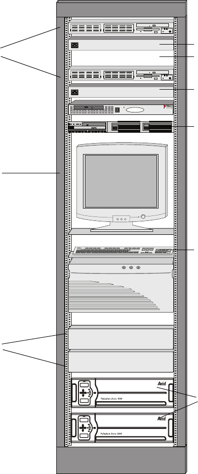
Installing the MSS Networked Storage System
73
Suggested Basic System Rack Installation
MSI
POWER
POWER
VLAN switch A
1 RU
ConnectPlus 1000
Keyboard
Palladium Store 1000
Fibre Channel switch
Monitor
File system controller 1 RU empty space
VLAN switch B
1 RU

Chapter 4 Preparation and Installation
74
EIA Racks
Make sure that your rack hardware, including protruding screw heads, leaves at least
44.2 cm (17.4 inches) of clearance.
Rack Dimensions
Placing Supports
Avid MediaStream ships two supports and two mounting ears that form a shelf in the
equipment rack for the server. The ears are brackets that attach to the front of a server and
allow the chassis to be secured to the equipment rack.
The supports will mount anywhere because the holes are spaced one rack unit apart. The
center hole (the hole between wide gaps) in a rack unit is generally used to mount the
module supports. See the following figure.
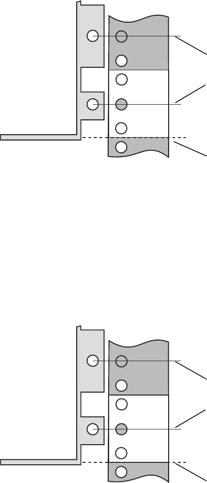
Installing the MSS Networked Storage System
75
Mounting Supports
The support hole pattern is designed to fit vertical rack rails, and not interfere with chassis
placement.
The MSS 8000 components are secured to the equipment rack by attaching the mounting
ears to the vertical rails of the rack. If you install the module supports correctly, the ear holes
on the chassis mounting will have clear access to the rack-mounting holes. See the following
figure.
Support Placement
Support Most supports and components
align with the bottom of a rack unit.
The hole at the center of a rack unit is
generally used for mounting
supports.
Rack
Support Most supports and components
align with the bottom of a rack unit.
The hole at the center of a rack unit is
generally used for mounting
supports.
Rack
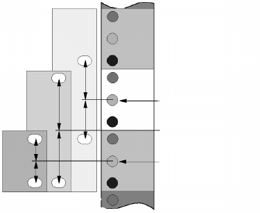
Chapter 4 Preparation and Installation
76
Even-height components add another level of complexity. The following figure shows an
example of two odd-height modules (IR and 3R units), and an even-height module (2R
units). The odd-height support’s rack ear holes should align with holes that are an equal
distance from a rack unit center hole. Even-height component mounting holes may align
with holes that are an equal distance from the narrow gap between rack units. If you mount
the module supports correctly, you should avoid a mounting hole versus rack hole conflict.
Mounting Even and Odd Supports
Adjusting Supports
Measure the required space from the top of the rack. Install supports from the bottom of the
rack.
The recommended rack depth is from 66.6 to 91.6 cm (26 to 37.4 in.). After reviewing the
previous figures for the support vertical placement, adjust the support to fit your rack depth.
Use M5 panhead screws to adjust supports. Install the supports to the inside surface of the
rack rails as shown in the following figure.
Rack unit center hole
Gap
Rack unit center hole
1 RU 2 RU 3 RU

Installing the MSS Networked Storage System
77
Installing Supports
3.157"
The support mounting hole has an attached threaded per nut to receive the M5 screw. The
support depth is adjustable to fit racks as shown above. To adjust the supports, loosen the
four M5 screws, adjust the depth, and then tighten the screws.
Racking the Storage Array
The storage array comes with its own mounting hardware and instructions.
nAvid MediaStream recommends that you have two persons lift the storage array and that you
install it as low on the rack as possible.
Racking the Server
wThe server weighs as much as 25 kg (55 pounds). Installing the server is a two-person
job. Occasionally, a third person may be needed to stabilize and guide the chassis while
two others lift and slide it into position.
To install the server into the rack:
1. Ensure that you are using either an anti-static wrist strap or mat.
2. Remove the server from the shipping crate.
3. Lift the server and slide it onto the rack rails. Do not insert the chassis all the way into
the rack. Instead, insert the chassis about 3/4 of the way onto the rails so that you can
access the front of the unit.
4. Detach the shipping cover from the front of the server by removing the screws that
secure the cover to the chassis.
Fixed nut
M5 screw

Chapter 4 Preparation and Installation
78
nBe careful not to bump or damage any of the components on the LED panel at the top front
of the chassis. The front panel, which you install last, protects the components. Save the
screws that you removed. You will use these screws to attach the ears onto the server. (The
ears will allow the chassis to be secured to the vertical rail of the equipment rack.)
5. Attach the ears to the sides of the server chassis using the screws that you removed from
the shipping cover.
The ears are packed in the shipping crate with the server.
6. Slide the server chassis all the way into the equipment rack.
Securing Server to Rack
7. Secure the ears of the server chassis to the vertical rack posts as show.
8. Install the front panel onto the front of the chassis. Care must be taken when attaching
the front panel to avoid breaking the light pipes for the LED indicators.

Installing the MSS Networked Storage System
79
Mounting the Audio Interface Panel
Position the audio interface panel on the rear of the rack unit within 91 centimeters (3 feet)
of the VME card cage.
Mounting the Audio Interface Panel
The MSS 8000 server node’s 1 RU MSi PC comes with its own mounting hardware and
instructions.
nAvid recommends that you install a cable management system.Use the 1 RU space between
the MSi and the VLANs for cable management.
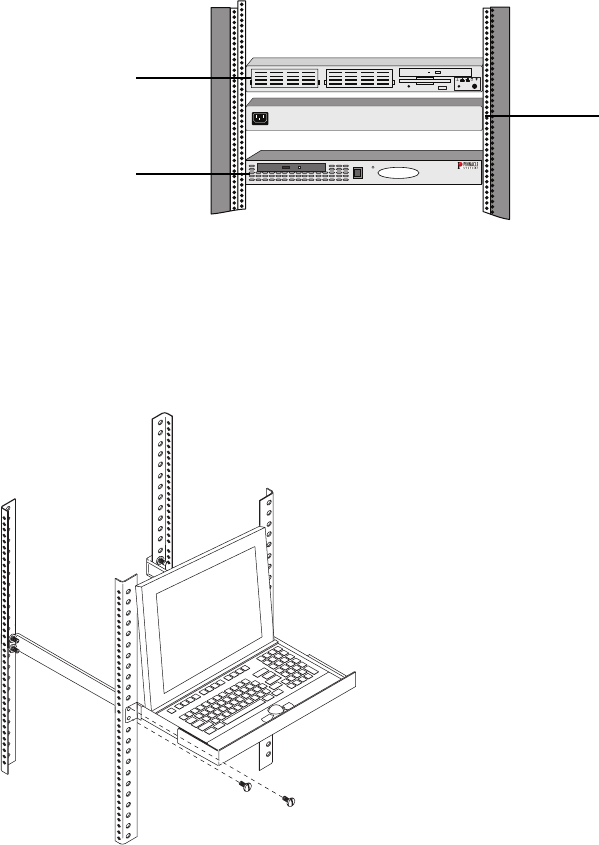
Chapter 4 Preparation and Installation
80
Rack Mounted MSi PC
Install the Monitor
Install the MSi PC’s flip-up monitor at eye level in the equipment rack.
Position Monitor Platform
MSI
POWER
POWER
VLAN switch
File System
Controller (FSC)
MSi PC (1 RU)
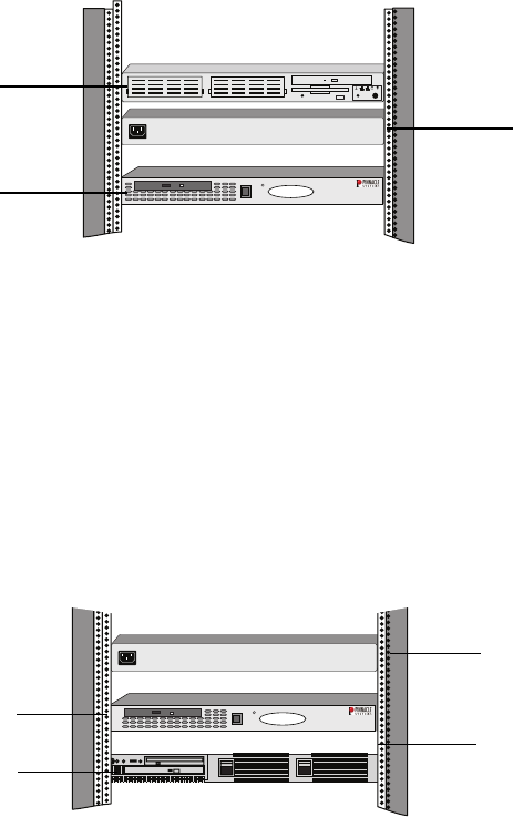
Installing the MSS Networked Storage System
81
To rack mount the flip-up monitor:
1. Attach the monitor platform to the rack at eye level.
2. Set the monitor on the platform and position the top strip as shown in the following
figure. If the strip does not fit your monitor, or you prefer not to use it, you may discard
the strip.
Racking the FSCs and VLAN Switches
The FSCs and VLAN Switches come with their own mounting hardware and instructions.
FSC and VLAN Switches
nBecause all of the VLAN Switch connections are on the front of the chassis, install these
components facing backwards in the rack. For easier connections and better cooling, install
a File System Controller on top, a VLAN Switch below it, leave a 1 RU space, and then
install the other FSC with the remaining VLAN Switch below it.
The 1 RU gateway comes with its own mounting hardware and instructions. Your system
will have one or more Connect Plus 1000 Gateways. Depending on how many are installed
in your system, they may fit in the rack near the FSCs, MSi PC and VLAN switches.
Mounting the Gateway PC
MSI
POWER
POWER
VLAN switch
File System
Controller (FSC)
MSi PC (1 RU)
MSI
POWER
POWER
MSi PC (1 RU)
Gateway PC (1 RU)
VLAN switch
VLAN B (1 RU)
1 RU space
Chapter 4 Preparation and Installation
82
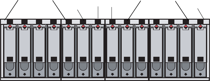
Chapter 5
Connecting System Components
This chapter describes the following system connections
• Connecting storage arrays
• Video connections
• Audio connections
• System and network connections
• Connecting power
Each MSS Networked Storage System ships with a storage system consisting of one or more
Palladium Store 1000 arrays.
Palladium Storage 1000 Array (Front View with Bezel Removed)
A1 A2 A3 A4 A5 C C B1 B2 B3 B4 B5
B1 B2 B3 B4 B5
A1 A2 A3 A4 A5 C C
Bridge controllers
A and B
A drives 1 - 5 B drives 1 - 5
Empty Empty

Chapter 5 Connecting System Components
84
Palladium Storage 1000 Array (Rear View)
wCorrect connections are essential to proper system operation and to maintain full
redundancy. It is possible to make the wrong connections and obtain some degree of
functionality but lose redundancy.
Connecting Video
Avid MediaStream products ship with all of the cables for connecting the MSS 8000 server
components. You provide external connections to station automation, video, and audio
devices. To prepare inputs and outputs for your MediaStream server, you need to know how
many encoder and decoder assemblies you will receive with your server. You need to
prepare one set of input cables for each encoder assembly and one set of output cables for
each decoder assembly. See Appendix B for connector and cable information.
The following figure shows the video input and output connections on the encoders and
decoders, respectively.
DC
AC
DC
AC
Power Supply 1
Power Supply 2
StatusStatus
Service Service
Switch Contoller
Switch Contoller
Port
4
Port
2
Port
1
Port
3
Port
4
Port
2
Port
1
Port
3
A
B
Controller (Blue) Controller (Green)
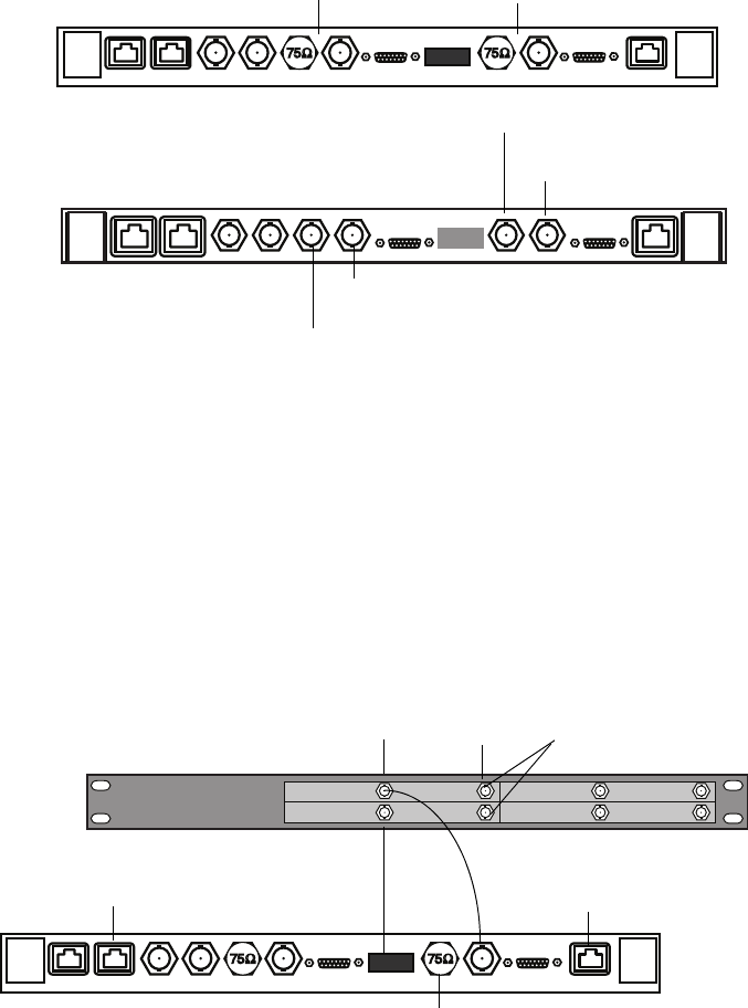
Connecting Video
85
Video Connections
Video Input
Video input to the encoder must be in serial digital form, as specified by the IRU-R BT.601-
2 standard. Analog video must be converted into serial digital form to be input to the
encoder. This can be accomplished with a third-party analog-to-digital converter module.
A typical video input with a third-party analog-to-digital solution resembles that shown in
the following diagram.
Video Convertor to Encoder Connections
Serial digital input (Ch. B) Serial digital input (Ch A)
Serial digital output (Ch A)
Analog output (Ch A)
Analog output (Ch. B)
Serial digital output (Ch. B)
Encoder
Dual Decoder
RS-422 (A) Audio Input Audio Input Serial DigitalSerial Digital
Digital
output
Analog
Source
Analog to serial
digitat converters
75 Ohm
load
Encoder
Station automation
(video input control) Digital audio input (A)

Chapter 5 Connecting System Components
86
Video Output
Video output from the decoder can be in both serial digital and analog format.
Serial Digital Output
Decoders provide a standard ITU-R BT.601.2 serial digital signal, as well as a composite
analog output that is suitable for station monitoring. Audio is embedded with the video track
and is also available in AES/EBU and analog via optional XLR or BNC audio output
modules. Serial digital may be converted to broadcast-compliant analog composite or
component video via an external serial digital-to-analog converter.
The following figure shows serial output from four decoders on a server to a digital-to-
analog converter.
Decoder to Video Converter Connections
Analog Output
The following figure shows analog output from the server node to broadcast transmission.
Decoder to Analog Broadcast Connections
AES/EBU OutAES/EBU Out
Serial Digital Analog Serial Digital AnalogInput Loopthru
Video output Genlock
Dual
Decoder
CH1 CH2
CH3 CH4
Serial digital to analog converters Analog outputs to broadcast
AES/EBU OutAES/EBU Out
Serial Digital Analog Serial Digital AnalogInput Loopthru
Video output Genlock
Dual
Decoder
Analog output for broadcast

Connecting Audio
87
Connecting Genlock (Black Burst)
The Genlock connector on the decoder assemblies allows video output to be synchronized
with a station reference signal, also known as black burst. Once the station reference signal
is made available to the first decoder in the server, additional decoders are connected via
loop-through ports.
The last loop-through output should be terminated with a 75-ohm load. With the dual
decoder board, termination is internal and automatic. Therefore, if the last board in the loop
is a dual decoder board, or your server has only dual decoder boards, you do not need the 75-
ohm terminator.
The following figure shows the connections for station reference and loop-through outputs:
Genlock Connections
Connecting Audio
To prepare inputs and outputs for your server, you need to know how many encoder and
decoder assemblies you will receive with your server. You need to prepare one set of input
cables for each encoder assembly and one set of output cables for each decoder assembly.
See Appendix B.
nEncoders may accept either separate AES-EBU audio or embedded audio.
The following figure shows the audio input and output connections on the
encoders and decoders, respectively.
AES/EBU OutAES/EBU Out
Serial Digital Analog Input Loopthru
Video output Genlock
AES/EBU OutAES/EBU Out
Serial Digital Analog Serial Digital Analog
Serial Digital Analog
Serial Digital Analog
Input Loopthru
Video output Genlock
AES/EBU OutAES/EBU Out
Serial Digital Analog Input Loopthru
Video output Genlock
Dual
Decoder
Dual
Decoder
Dual
Decoder
Genlock from station
75 ohm terminator load
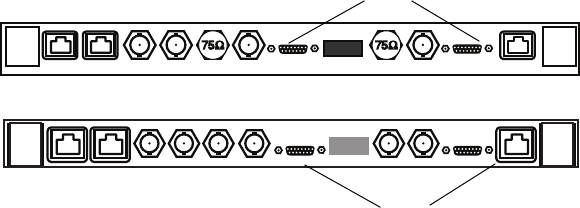
Chapter 5 Connecting System Components
88
Audio Connections
The server node accepts audio input that complies with AES/EBU (digital) standards. The
server‘s encoders receive AES/EBU audio signals through an HD-26 pin connector. Analog
audio input may be made compatible with the AES/EBU standard with a third party analog-
to-digital solution.
Audio connections vary from station to station. Your station may have digital audio, analog
audio, or both. You may use either 75-ohm BNC or XLR, or both.
Audio Interface Panel Options
Avid MediaStream provides optional interface modules for audio input and output. Up to six
modules are inserted into a panel, which is mounted on the rear of the equipment rack.
The following figure shows the audio modules in the panel. Each of the modules is described
below
Dual
Decoder
Encoder
AES-EBU input
AES-EBU or
Analog output
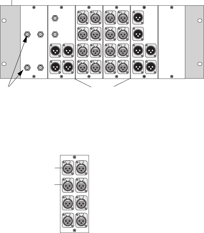
Connecting Audio
89
Audio Panel
.
The XLR input audio module is for digital audio input. It provides a 4-channel XLR
interface with loopback capability to an encoder (digital audio).
Audio/Input Module
When the server comes from the factory, the audio interface panel is marked for analog
input. For digital audio input, apply the stickers supplied with the MSS 8000 to indicate
digital audio input connections. If you have properly connected the audio interface panel as
described above, it will accept digital audio input.
Unused
Unused
CH 1/2
CH 3/4
Audio
interface panel
frame BNC output XLR output
BNC input XLR input Blank panel
CH1/CH2
CH3/CH4
Digital Audio Input
Unused Unused
Unused Unused
Unused
Unused
Left/Right channels
Left/Right channels
Digital input
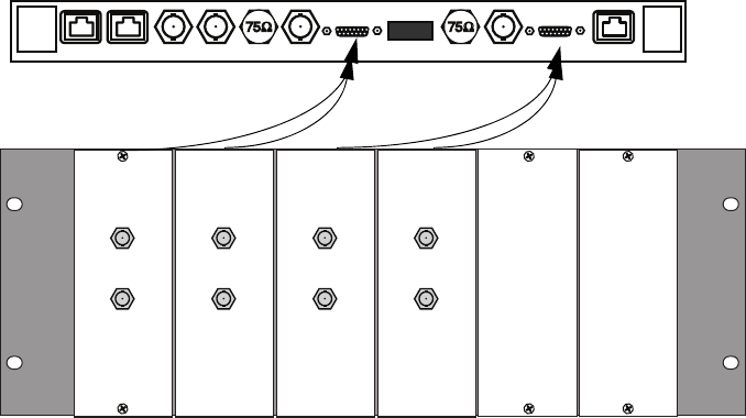
Chapter 5 Connecting System Components
90
BNC Input Audio Module
This module is for digital audio input to the encoder. It provides a 4- or 6-channel BNC
interface. Connect the audio module to the encoder’s Audio Input connector as shown in the
following figure.
BNC Input Panel Connected to Encoder
XLR Output Audio Module
This module is for digital and analog audio output from the decoder. It provides two pairs of
AES-EBU digital audio output via XLR connectors and two pairs of XLR analog audio
output channels. Expansion is provided for one more pair of digital and one more pair of
analog audio output channels.
Connect the audio module to the decoder’s Audio Output connector. See the following figure
for an example of this connection.
Audio Input AES/EBU
Audio Input AES/EBU
CH1 / CH2
Input
CH3 / CH4
Input
Digital Audio
CH5 / CH6
Input
CH7 / CH8
Input
Digital Audio
CH1 / CH2
Input
CH3 / CH4
Input
Digital Audio
CH5 / CH6
Input
CH7 / CH8
Input
Digital Audio
BNC input BNC input BNC inputBNC input
Encoder
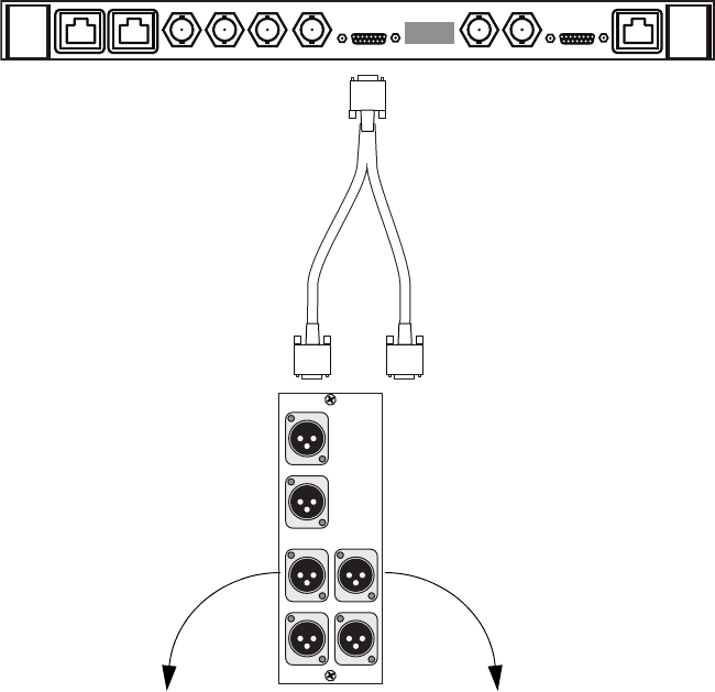
Connecting Audio
91
XLR Output Panel Connected to Decoder
BNC Output Audio Module
This module is for analog or digital audio output from the decoder. It provides two pairs of
BNC digital audio output and four channels of XLR analog audio output. Expansion is
provided for two additional channels of XLR analog audio output.
CH1 CH2
Unused Unused
Analog Audio Output
CH1/CH2
CH3/CH4
Digital Audio Output
Dual
decoder
CH 1 analog audio
output to broadcast
(Left)
CH 2 analog audio
output to broadcast
(Right)
XLR output
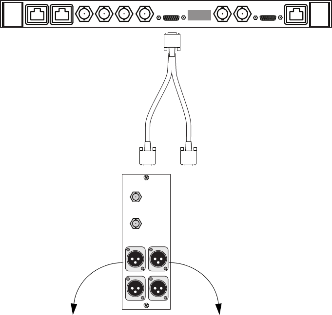
Chapter 5 Connecting System Components
92
Connect the audio module to the decoder’s Audio Output connector. An example of this
connection is shown in the following figure.
BNC Output Panel Connected to Decoder
BNC Output Audio Module
This module is for analog or digital audio output from the decoder. It provides two pairs of
BNC digital audio output and four channels of XLR analog audio output. Expansion is
provided for two additional channels of XLR analog audio output.
Connect the audio module to the decoder’s Audio Output connector. An example of this
connection is shown in the following figure.
CH1 CH2
Unused Unused
Analog Audio Output
CH1/CH2
CH3/CH4
Digital Audio Output
Dual
decoder
CH 1 analog audio
output to broadcast
(Left)
CH 2 analog audio
output to broadcast
(Right)
XLR output
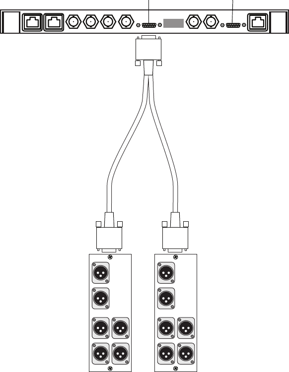
Connecting Audio
93
Six-channel and 8-Channel Audio Module
Some encoder and decoder boards and all dual decoder boards can support six-
and eight-channel audio. Connections with the audio XLR input/output are made
via a Y-cable. An example of this connection is shown in the following figure.
BNC Output Panel Connected to Decoder
CH5 CH6
Unused Unused
Analog Audio Output
CH5/CH6
Unused
Digital Audio Output
CH1 CH2
Analog Audio Output
CH1/CH2
CH3/CH4
Digital Audio Output
Unused Unused
Second panel First panel
Channel B audio Channel A audio
Dual decoder
Chapter 5 Connecting System Components
94
System Connections
At this point, all of the hardware should be mounted in the equipment rack. This section
describes connections among the components of a MSS Networked Storage System.
nEvery cable and connector in the MSS Networked Storage System is marked, which
facilitates installation, expansion, and troubleshooting.
wTo achieve full redundancy, wire your system according to the following instructions.
Failure to do so may result in a loss of system redundancy and may cause an
unexpected failure.
The following figure illustrates the basic connection arrangements. More detailed
instructions for system connections follow.
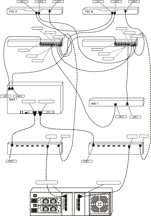
System Connections
95
Connection with FC Switches
FC A (Blue) FCB (Green)
13 14 15 16 17 18
19 20 21 22 23 24
123456
789101112
VLAN A 13 14 15 16 17 18
19 20 21 22 23 24
123456
789101112
VLAN B
PORT 22
PORT 24
PORT 23
PORT 20
PORT 18
PORT 1
PORT 22
PORT 23
PORT 24
PORT 19
PORT 18
PORT 1
LAN
LAN
CONTROLLER (Green)
CONTROLLER (Blue)
PORT 8 PORT 8
DC
AC
DC
AC
Palladium Store 1000
FC A (Blue) FC B (Green)
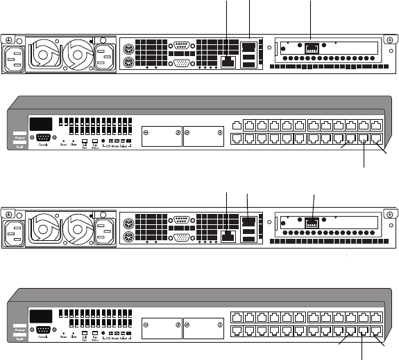
Chapter 5 Connecting System Components
96
Connect the FSCs to VLAN Switches
There are two FSCs and two VLAN switches in MSS Networked Storage System, regardless
of its size or storage capacity. Current systems ship with two different FSC PCs depending
on configuration.
nIf you have one of the older models (SuperMicro or the IBM 335), see Appendix D.
FSC 40
The following figure represents the FSC 40 and VLAN switches as installed in an equipment
rack in their recommended positions. Note the location of the LAN and PORT connections.
FSC 40 to VLAN Connections
Connect the FSCs and VLAN switches as follows. Use the instructions below as a checklist
to verify each cable connection.
1. Locate cables 1, 2, 3, 4, 5, and 10.
2. Connect cable 1 (CBL 1).
789101112 192021222324
123456 131415161718
123456
789101112
13 14 15 16 17 18
19 20 21 22 23 24
25 26 Link
Mode
Link
Mode
hp procurve
switch 2524
J4813A
789101112 192021222324
123456 131415161718
123456
789101112
13 14 15 16 17 18
19 20 21 22 23 24
25 26 Link
Mode
Link
Mode
hp procurve
switch 2524
J4813A
LAN 1
FSC A
LAN 3
LAN 2
VLAN A
VLAN B
FSC B
LAN 3LAN 2
Port 22 Port 23 Port 24
LAN 1
Port 22
Port 23 Port 24
System Connections
97
The FSC A end goes to LAN 1 on FSC A.
The FSC B end goes to LAN 1 on FSC B.
3. Connect cable 2 (CBL 2).
The FSC A end goes to LAN 2 on FSC A.
The VLAN B end goes to PORT 24 on VLAN B.
4. Connect cable 3 (CBL 3).
The FSC A end goes to LAN 3 on FSC A.
The VLAN A end goes to PORT 23 on VLAN A.
5. Connect cable 4 (CBL 4).
The FSC B end goes to LAN 2 on FSC B.
The VLAN A end goes to PORT 24 on VLAN A.
6. Connect cable 5 (CBL 5).
The FSC B end goes to LAN 3 on FSC B.
The VLAN B end goes to PORT 23 on VLAN B.
7. Connect cable 10 (CBL 10).
The VLAN A end goes to PORT 22 on VLAN A.
The VLAN B end goes to PORT 22 on VLAN B.
FSC 100
The following figure represents the FSC 100 and VLAN switches as installed in an
equipment rack in their recommended positions.
Note the location of the LAN and PORT connections.
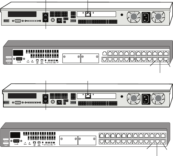
Chapter 5 Connecting System Components
98
FSC 100 to VLAN Connections
Connect the FSCs and VLAN switches as follows. Use the instructions below as a checklist
to verify each cable connection.
1. Locate cables 1, 2, 3, 4, 5, and 10.
2. Connect cable 1 (CBL 1).
The FSC A end goes to LAN 1 on FSC A.
The FSC B end goes to LAN 1 on FSC B.
3. Connect cable 2 (CBL 2).
The FSC A end goes to LAN 2 on FSC A.
The VLAN B end goes to PORT 24 on VLAN B.
4. Connect cable 3 (CBL 3).
The FSC A end goes to LAN 3 on FSC A.
The VLAN A end goes to PORT 23 on VLAN A.
5. Connect cable 4 (CBL 4).
7 8 9 1011 12 192021222324
1 2 3 4 5 6 13 14 15 16 17 18
123456
789101112
13 14 15 16 17 18
19 20 21 22 23 24
25 26 Link
Mode
Link
Mode
hp procurve
switch 2524
J4813A
789101112 192021222324
1 2 3 4 5 6 131415161718
123456
789101112
13 14 15 16 17 18
19 20 21 22 23 24
25 26 Link
Mode
Link
Mode
hp procurve
switch 2524
J4813A
LAN 1
FSC A
VLAN A
VLAN B
FSC B
Port 22
Port 23 Port 24
Port 22
Port 23 Port 24
LAN 2 LAN 3LAN 2
LAN 1
LAN 3
LAN 2
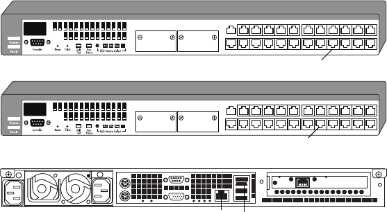
System Connections
99
The FSC B end goes to LAN 2 on FSC B.
The VLAN A end goes to PORT 24 on VLAN A.
6. Connect cable 5 (CBL 5).
The FSC B end goes to LAN 3 on FSC B.
The VLAN B end goes to PORT 23 on VLAN B.
7. Connect cable 10 (CBL 10).
The VLAN A end goes to PORT 22 on VLAN A.
The VLAN B end goes to PORT 22 on VLAN B.
Connect the MSi PC to the VLAN Switches
There are always two VLAN switches but there may be one or two MSi PCs on your MSS
Networked Storage System. The following figure represents your VLAN switches and one
MSi PC as installed in an equipment rack in their recommended positions. Note the location
if the LAN and port connections.
VLAN to MSi PC Connections
Connect the MSi PC and VLAN switches as follows. Use the instructions below as a
checklist to verify each cable connection.
1. Locate cables 6 and 7.
2. Connect cable 6 (CBL 6).
The MSI 1 end goes to LAN 1 on MSI 1.
The VLAN B end goes to PORT 20 on VLAN B.
789101112 19 20 21 22 23 24
123456 13 14 15 16 17 18
123456
789101112
13 14 15 16 17 18
19 20 21 22 23 24
25 26
Link
Mode
Link
Mode
hp procurve
switch 2524
J4813A
7 8 9 1011 12 192021222324
1 2 3 4 5 6 13 14 15 16 17 18
123456
789101112
13 14 15 16 17 18
19 20 21 22 23 24
25 26
Link
Mode
Link
Mode
hp procurve
switch 2524
J4813A
VLAN A
MSi PC
Port 19
LAN 1
Port 20
LAN 2
VLAN B
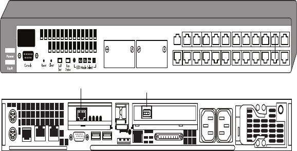
Chapter 5 Connecting System Components
100
3. Connect cable 7 (CBL 7).
The MSI 1 end goes to LAN 2 on MSI 1.
The VLAN A end goes to PORT 19 on VLAN A.
Connect the ConnectPlus 1000 Gateway PC to the VLAN Switches
While the ConnectPlus 1000 Gateway PC is optional, virtually all Networked Storage
Systems will have at least one Gateway PC installed. Detailed connection and configuration
information are provided in the ConnectPlus 1000 Networked Storage Installation and
Operations Guide. The Gateway PC has four RJ-45 connectors on the rear panel. The top left
is the VLAN port for system connection (see the following figure). As the Gateway PC is
not an on-air mission-critical component, redundant connections are not provided. Connect
Gateway PC 1 to VLAN A, Port 17. Connect Gateway PC 2 to VLAN B, Port 17.
A Gigabit Ethernet PCI card is available to the right of these connections. Use this port for
connection to your WAN/LAN infrastructure (see Appendix C for information on system
interconnection).
VLAN to Gateway Connections
Keyboard, Video and Mouse Connections
The MSS Networked Storage System ships with a four-port Keyboard Video Mouse (KVM)
switch. This switch allows you to use a single keyboard, VGA monitor, and mouse to
monitor the startup and operation of the MSS Networked Storage System.
789101112 19 20 21 22 23 24
123456 13 14 15 16 17 18
123456
789101112
13 14 15 16 17 18
19 20 21 22 23 24
25 26 Link
Mode
Link
Mode
hp procurve
switch 2524
J4813A
Connect
Plus 1000
Gigabit Ethernet
Port 17
VLAN A
VLAN
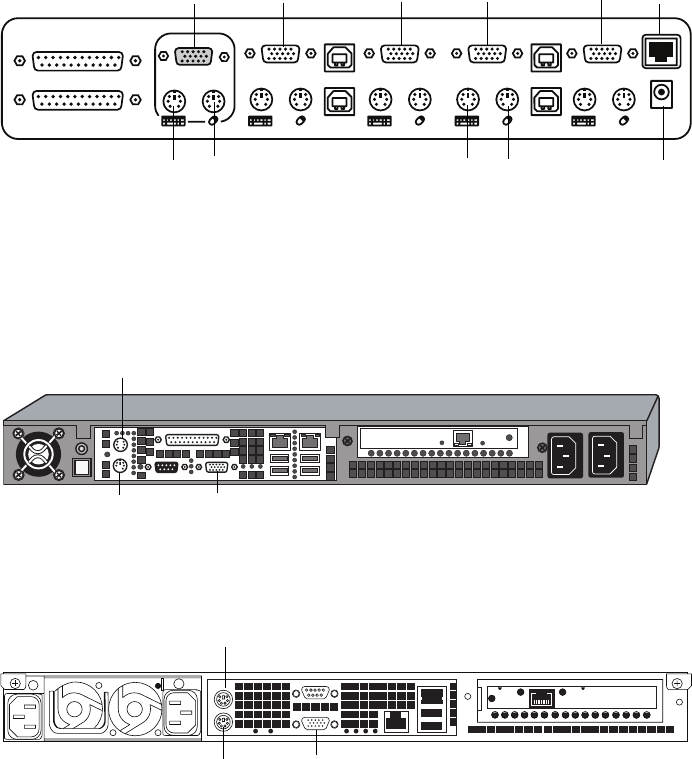
System Connections
101
KVM Switch Connections
On the back of the KVM switch there are four sets of connectors as shown in the following
figure. These connect to the keyboard, monitor (VGA), and mouse ports on the two File
System Controllers and the MSi PC as shown below. Cables are supplied to connect the
ports on the FSCs and MSi PC to the KVM switch.
KVM Switch Connections
Connect FSC A to the right-most set of connectors. Connect FSC B next to it.
FSC 40 Keyboard, Video and Mouse Connections
FSC 80 Keyboard, Video and Mouse Connections
Console VGA
Slave Input
Master Input / Slave Output VGA 4
04
USB 04
USB 03
VGA 2
02
VGA 3
03
VGA 1
01
USB 02
USB 01
FLASH
DC 12V, 1A
To monitor
Port 4
GWY PC
Port 3
FSC B
Port 2
FSC A
Port 1
MSi PC
From
VGA port
To keyboard To monitor From
keyboard port
From mouse
port
To powe r
supply
Keyboard
port VGA port
Mouse
port
Mouse
Keyboard VGA port
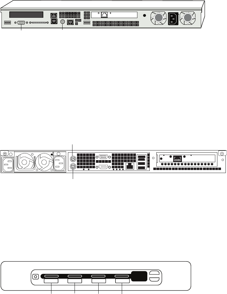
Chapter 5 Connecting System Components
102
FSC 100 Keyboard, Video and Mouse Connections
nThe IBM 335 PC comes with an optional C2T Output Cable adapter. One end connects from
the C2T Out connector on the Back Panel. The cable provides breakout for VGA, and PS-2
Mouse and Keyboard connections.
Connect the MSi PC to the third set of connectors. The left set can be used for the Gateway
PC.
nThe MSi PC comes with a Mouse Keyboard Y adapter that breaks out into separate PS-2
keyboard and mouse connections.
MSi PC Keyboard, Video and Mouse Connections
Connect your VGA monitor to the left connector on the back of the KVM Switch. Connect
the KVM switch’s power supply to its port. Connect your keyboard and mouse to their
respective connectors on the front of the KVM Switch.
When your system is running, press the selector switch to toggle among the FSCs and MSi
PC. See the following figure.
KVM Switch Operation
VGA port Mouse/keyboard port
M
ouse
Keyboard
8.8.
01 02 03 04
bank
+
-
BELKIN
Port 1
MSi PC
Port 2
FSC A
Port 3
FSC B
Port 4
available
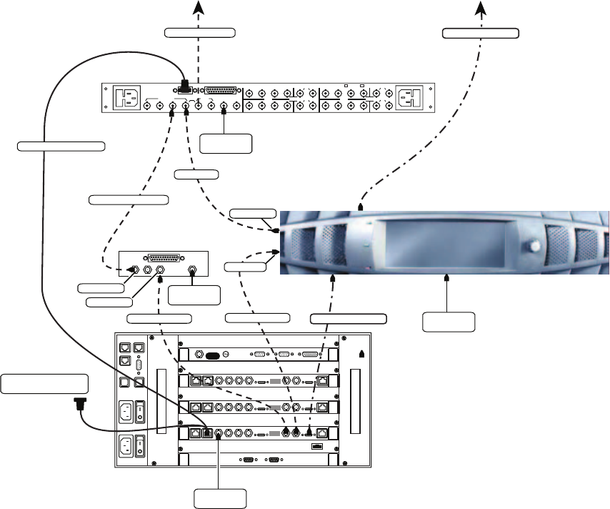
System Connections
103
When you have FSC A selected, you will see that component on your VGA monitor and can
control it with the keyboard and mouse.
Up-Conversion Connection
For more information regarding the pin-outs on the serial Y-cable to the automation see
“Serial Y-Cable to Automation Remote Control and Converter” on page 311.
The following figure illustrates the connections for an up-conversion (SD to HD
conversion).
Up-conversion Diagram
MSS 8000si
RS-232 switch control
REMOTE CTL
HDVIDEO INPUTS OPT VIDEO REF
VIDEO 1
OUT
BYPASS OPT
BYPASS
REF LOOP
AES OUTPUTS
AES
INPUTS AES
INPUTS
2A
1A
AES OUTPUTS
2A
1A
4BYPASS SS
1
2
3
41
2
3
41
2
3
41
2
34 1
2
3
OPT
BYPASS
AES (up to 4 pairs)
HD video output
Delayed HD output
HD video
HD video output
HD Delay
Video router
SD to HD Up-converter
SD video output AES (up to 4 pairs)
RS-422 Y-cable to
automation controller
Genlock to
house Sync
Genlock to
house Sync
HD output
HD input
Genlock to
house Sync
SD input
HD output
Genlock to
house Sync
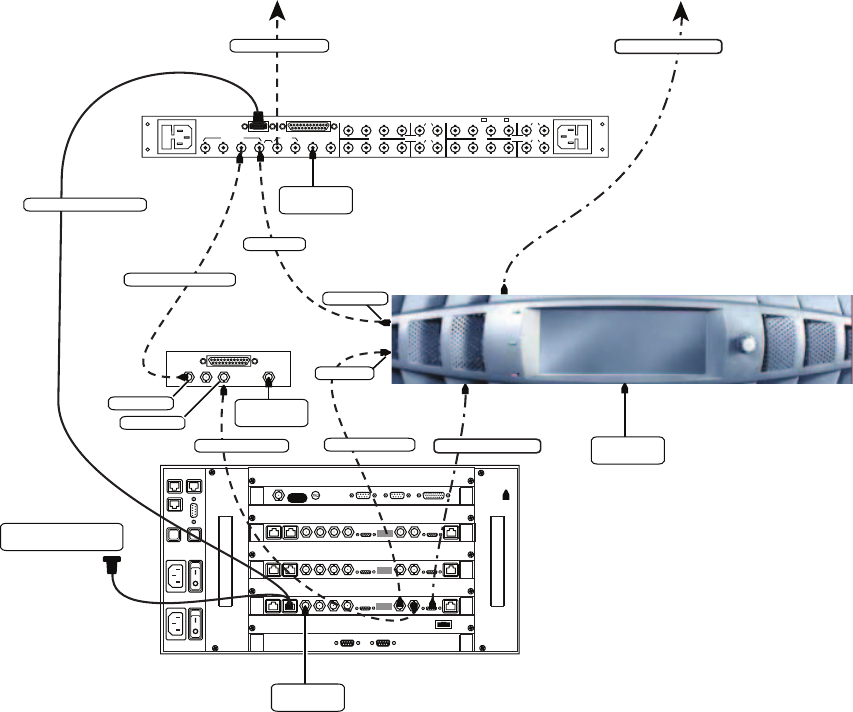
Chapter 5 Connecting System Components
104
Down-Conversion Connection
The following figure illustrates the connections for an down-conversion (HD to SD
conversion).
Down-conversion Diagram
MSS 8000si
RS-232 switch control
REMOTE CTL
HDVIDEO INPUTS OPT VIDEO REF
VIDEO 1
OUT
BYPASS OPT
BYPASS
REF LOOP
AES OUTPUTS
AES
INPUTS AES
INPUTS
2A
1A
AES OUTPUTS
2A
1A
4BYPASS SS
1
2
3
41
2
3
41
2
3
41
2
34 1
2
3
OPT
BYPASS
SD video output
Delayed SD output
SD video
SD video output
SD Delay
Video router
SD to HD Up-converter
HD video output AES (up to 4 pairs)
RS-422 Y-cable to
automation controller
Genlock to
house Sync
Genlock to
house Sync
SD output
SD input
Genlock to
house Sync
HD input
SD output
Genlock to
house Sync
AES (up to 4 pairs)
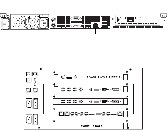
System Connections
105
Other MSi PC Connections
The non-network-related connections on the MSi PC are industry standard. Make the
following connections:
1. Connect your analog phone line to the modem connector indicated (right).
2. To access a server node while the VLAN is down (and for no other purpose), connect
the RS-232 cable from the MSi PC to the corresponding connector on the server node.
MSi PC Connections
MSi PC
MSS 8000
RS-232
connector
Modem
RS-232
connector
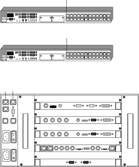
Chapter 5 Connecting System Components
106
VLAN to Server Node Connections
There are always two VLAN switches, but there may be from one-to-sixteen server nodes on
your MSS Networked Storage System. The following figure represents your VLAN
switches and one server node as installed in their recommended positions. Note the location
of the PORT and LAN connections involved in connecting these three components.
Connect the VLAN switches to the server node (in a system with only one server node) as
follows. Use the instructions below as a checklist to verify each cable connection.
1. Locate cables 20 and 21.
2. Connect cable 20 (CBL 20).
The VLAN A end goes to PORT 1 on VLAN A.
The MSS 1 end goes to LAN A on MSS 1.
3. Connect cable 21 (CBL 21).
The VLAN B end goes to PORT 1 on VLAN B.
The MSS 1 end goes to LAN B on MSS 1.
7 8 9 10 11 12 192021222324
1 2 3 4 5 6 13 14 15 16 17 18
123456
789101112
13 14 15 16 17 18
19 20 21 22 23 24
25 2 6
Link
Mode
Link
Mode
hp p rocu rve
switch 2524
J4813A
7 8 9 10 11 12 192021222324
1 2 3 4 5 6 13 14 15 16 17 18
123456
789101112
13 14 15 16 17 18
19 20 21 22 23 24
25 2 6
Link
Mode
Link
Mode
hp p rocu rve
switch 2524
J4813A
VLAN A
VLAN B
MSS 8000
Port 1
Port 1
LAN 1 LAN 2
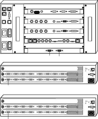
System Connections
107
There may be from one-to-sixteen server nodes on your MSS Networked Storage System.
Two Fibre Channel switches are require for connection to the array(s). The following figure
represents your server node and Fibre Channel switches as installed in their recommended
positions. Note the location of the LAN and port connections involved in connecting these
three components, and make sure all SFP modules are firmly seated in the fibre channel
ports.
nThe Gadzoox 3000 HA switch is shown in this and the following examples, but the same
guidelines apply to all Fibre Channel switches used with the MSS.
Server Node to Fibre Channel Switch Connections
Connect the server node to the Fibre Channel switches. Use the instructions below as a
checklist to verify each cable connection.
1. Locate cables 22 and 23.
Connect cable 22 (CBL 22).
The MSS end goes to FC A on MSS 1.
The FC end goes to PORT 1 on FC A (Gadzoox switch).
2. Connect cable 23 (CBL 23).
The MSS end goes to FC B on MSS 1.
MSS 8000
FC A
(Blue)
FC B
(Green)
FC A FC B
Port 1
Port 1
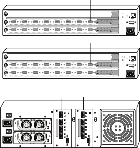
Chapter 5 Connecting System Components
108
The FC end goes to PORT 1 on FC B (Gadzoox switch).
nFor Brocade Silkworm FC switches, use only ports 0-3 on the 3250 or ports 0-7 on the 3850
for connections to an MSS.
Fibre Channel switches always come in a redundant pair. The following figure
represents your Fibre Channel switches and one storage array as installed in their
recommended positions. Note the location of the port and array connections
involved in connecting these three components.
Fibre Channel to Storage Array Connections
Connect the Fibre Channel switches the storage array (in a system with only one server
node) as follows. Use the instructions below as a checklist to verify each cable connection.
1. Locate cables 80 and 81.
2. Connect cable 80 (CBL 80).
The FC A end goes to PORT 16 on FC A (Gadzoox switch).
The ARRAY 1 end goes to RAID A1 on ARRAY 1 (Controller Blue, Port 4 on PS-
1000).
3. Connect cable 81 (CBL 81).
DC
AC
DC
AC
Power Supply 1
Power Supply 2
StatusStatus
Service Service
rell
o
tnoC hct
i
w
S
rellotnoC h
c
t
i
wS
Port
4
Port
2
Port
1
Port
3
Port
4
Port
2
Port
1
Port
3
A
B
PS 1000
FC A
(Blue)
FC B
(Green)
Port 8 Blade 2
Port 8 Blade 2
Controller (Blue) Controller (Green)
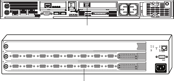
System Connections
109
The FC B end goes to PORT 16 on FC B (Gadzoox switch).
The ARRAY 1 end goes to RAID B1 on ARRAY 1 (Controller Green, Port 4 on
PS-1000).
nFor Brocade Silkworm FC switches, use only ports 4-7 on the 3250 or ports 8-15 on the
3850 for connections to storage arrays.
The Gateway PC connects to the Fibre Channel Switches after all MSS 8000 server node
connections have been made. Since the Gateway PC is not a mission-critical device,
redundant connections are not provided. The Gateway PC connection is an HSSDC port on
right-most PCI card. Connect Gateway PC 1 to FC Switch A and Gateway PC 2 to FC
Switch B. Use the first available port to the right of the last MSS 8000 server node
connection. The connection to the Switch will be DB-9 or HSSDC depending on the model
used in your system.
nComplete Gateway PC connection and configuration information is available in the
ConnectPlus 1000 Networked Storage Installation and Operations Guide.
Fibre Channel to Gateway Connections
nFor Brocade Silkworm FC switches, use only ports 0-3 on the 3250 or ports 0-7 on the 3850
for connections to a Gateway.
FC A
ConnectPlus
10001
Fibre channel
Fibre channel

Chapter 5 Connecting System Components
110
Connecting Power
This section shows how to connect power to the MediaStream Networked Storage System
components.
The MediaStream Networked Storage System is designed for full redundancy of all
components and functions, however, no system can function without a continuous supply of
clean power. Thus much of the advantage of system redundancy is lost unless there are two
separate circuits feeding the MediaStream Networked Storage System. Preferably one of
those circuits is connected to an Uninterruptible Power Supply (UPS). See UPS Power
Requirements later in this chapter.
Two components of the MediaStream Networked Storage System have redundant power
supplies: the server node(s) and the storage array(s). If one set of power supplies or fans
fails, the other set takes over. The other system components, the File System Controller,
VLAN switch, MSi PC, and most models of Fibre Channel switch have only a single power
supply. However, all of these, except for the MSi PC, work in pairs to achieve redundancy.
To connect the power cables on each component:
1. Make sure that all power switches are set to the off position.
2. Plug in the power cable on the connector. All components use the same industry-
standard power connector as shown in the following figure.
Power Connector
3. Connect the power cables to the power sources. For redundant power operation, provide
two separate circuits to which to connect the main and redundant power supplies. Do not
connect the main and redundant power supplies to the same circuit.
The following table lists AC line voltage specifications for the MediaStream Networked
Storage System.
AC Line Voltage Requirements
Maximum
Power
120V
Maximum
Power
240V
Power
in Watts
File System Controller 3A 1.5A –
VLAN switch 2.4A1.2A–

System Connections
111
The line voltage (AC) at the wall power outlet is a function of the local power utility
company and the building power distribution network. Voltage outside the operating range
of the system can cause intermittent server errors, or a complete shutdown. If required, Avid
MediaStream Support, along with your electrician, can determine the current line voltage
and make recommendations. Do not use a line voltage conditioner.
UPS Power Requirements
wTo avoid the loss of critical data, the loss or corruption of video files, and a system
reboot due to loss of power, use an Uninterruptible Power System (UPS). Make sure
that there are enough outlets of the correct type and at the correct voltage to support
all components of the MediaStream Networked Storage System.
Avid MediaStream Support recommends that each installed UPS be of the On Line
UPS or Line-Interactive UPS type.
nEach UPS must be capable of switching to full load in less than 10 milliseconds after main
power is interrupted or data could be lost.
Frequency
Frequency is normally a function of the local power utility company. In rare cases, electrical
power is supplied from a motorized generator located within the building. Frequency shifts
can cause intermittent system errors or terminal display jitter. If required, Avid MediaStream
Support, along with your electrician, can determine the power line frequency and make
recommendations.
MSi PC 5.0A 3.0A –
8000 server node 10.0A 5.0A 595W
Fibre Channel switch, 8 port 1.5A .75A 100W
Fibre Channel switch, 32 port 3.0A 1.5A 200W
Palladium Store 1000 3.0A 1.5A 250W
Gateway 3.5A 1.75A –
AC Line Voltage Requirements (Continued)
Maximum
Power
120V
Maximum
Power
240V
Power
in Watts
Chapter 5 Connecting System Components
112
Power Line Transients
Heavy electrical loads from nearby machinery or equipment (such as elevators or electric
welders) can cause intermittent system errors even if that equipment is on a separate circuit
breaker. When faced with these conditions, you should provide a separate, completely
independent power panel with an isolated ground and circuit breaker coming directly from
the main building power source or secondary power source.
Circuit Wiring
The system requires dedicated or individual branch circuits (using separate 20 Amp circuit
breakers). There are two reasons for requiring branch circuits. The first reason is to ensure
that no other electrical devices are connected to the circuit, thus preventing induced
electrical noise or unnecessary tripping of the circuit breaker. The second reason is to ensure
that there is enough power to run the server. The lack of a dedicated circuit can cause low
voltages and intermittent problems.
You can connect components of the MediaStream Networked Storage System to the branch
circuit via plug and receptacle.
nAlways complete each installation with a compliance check for local electrical codes.
wTo reduce the possibility of personal injury, receptacles must include a dedicated
ground connection that is insulated from the receptacle box. It is important that the
receptacle box be grounded with an additional ground connection that is not dedicated
(the additional ground can be hard conduit). When installing receptacles, ensure that
each receptacle has its own neutral (if required) and ground. Using the same
neutral/ground for more than one circuit will cause voltage loss, heat problems, and
can result in a fire hazard. A shared neutral conductor that fails open-circuit will result
in possible over-voltage damage to equipment. A safety earth ground is required by the
National Electrical Code (USA) and most other local, regional, and national codes. In
addition to the safety ground, Avid MediaStream Support requires that a dedicated
(earth reference) ground be installed as a common reference point for all System
components.
nPower cords and plugs that cannot be ordered must be fabricated by an electrician to meet
local requirements.
Lightening Protection
In some geographic areas, it might be advisable to install lightning protection. In the U.S.,
the installation of lightning and surge arrestors on power lines is described in the National
Electrical Code, Article 280.
Chapter 6
MediaStream Interface (MSi)
This chapter introduces the MediaStream Interface (MSi), a graphical-user interface
application that resides on a computer running Windows 2000. Avid MediaStream Support
uses the MSi to troubleshoot the MSS Networked Storage System and to install new
software and perform other maintenance activities. Although the MSi application is capable
of playing and recording video files (also called clips), it is intended as a support and
diagnostic tool. Avid MediaStream Support uses these features for testing the system.
This chapter describes the following elements and functions:
•MSi Control Panel
• MSi function and appearance
• Recording files to disk
• Playing back files
• Saving and loading playlists
• Trimming file outputs
• Using the Disk Management window
• The Configuration dialog
• The System Status window
• Conducting a telnet session for server node and FSC administration
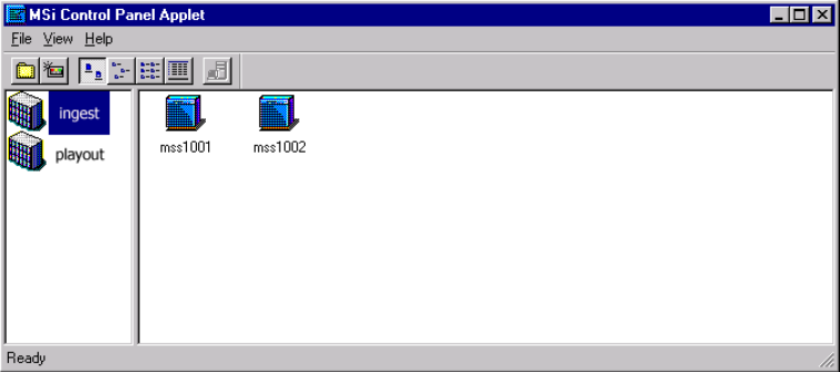
Chapter 6 MediaStream Interface (MSi)
114
MSi Control Panel
The MSi provides control for individual Networked Storage System server nodes. A server
cluster can have two or more server nodes. Each node provides up to 16 input or output
channels and full access to all content stored on the array(s). To access a given server node
for control, you must use the MSi Control Panel.
To launch the MSi Control Panel, select MSiControlPanelApplet from the Start menu. The
MSi Control Panel is displayed.
MSi Control Panel Window
The MSi Control Panel will allow you access to all server nodes in all server clusters
available on your network. To access a server node, click the appropriate cluster in the left
pane of the application window. The server nodes available for that cluster will appear in the
right pane. Double-click the icon for the server node you wish to work on to start the MSi
application.
nThe MSi can only monitor one server node at a time. If the application is already started for
another node, you must quit the application first before starting a new session.
Configuring the Control Panel
With the Control Panel, you can monitor clusters in a network and all server nodes on a
cluster. The two steps to configuration are:
• Adding a new cluster to the Control Panel
• Adding to a cluster
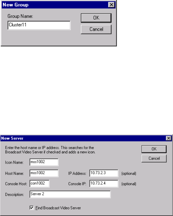
MSi Control Panel
115
Adding a New Group
The MSi Control Panel provides access to all server nodes in a cluster. These nodes can be
subdivided into cluster Groups, such as ingest and playout server nodes.
To create a new cluster group,
1. Go to File > New Group or press Ctrl+N. The New Group dialog appears as shown in
the following figure.
2. Type in the name of the group and click OK.
New Cluster Group Dialog
Adding a New Server Node
New server nodes must be added to the Control Panel in order to gain access to
them.
To add a new server node:
1. Select File > New Server. The New Server dialog appears.
New Server Dialog
Chapter 6 MediaStream Interface (MSi)
116
2. Obtain the following information for the node and enter it in the New Server dialog box
•Icon Name — The name of the server node icon that appears in the Control Panel
should be the same as your Host Name. The Host Name will start with mss followed by
two digits corresponding to cluster number and two digits corresponding to server node
number. The example above is mss1002 for node 2 of cluster 10
•Host Name — Enter the server node’s Host Name.
•IP Address — Check your host table to find the appropriate host address
(see VLAN Topology).
•Console Host — The Console Host is the address of the Lantronix module. This port
address allows you to view the boot sequence of the MSi. Enter con followed by cluster
number and server node number. The example above shows Console Port of Server
Node 2 on Cluster 10.
•Console IP address — (see VLAN Topology).
•Description — An optional descriptive ID for identifying the server.
nThe host address is listed in the /etc/hosts file.
Deselect the option Find Broadcast Video Server. Unless the server is running because
having this option selected causes a time-out when you exit the New Server dialog box.
After you define your server, click OK in the dialog box. The server icon appears in the
Control Panel.
Changing the Control Panel View
The Control Panel View menu allows you to change the view of the display. You can choose
to display the Toolbar and Status bar and change the view of the display to show large or
small icons as well as a list or details.
Starting the MSi Application
To start the MSi application, from the Control Panel select File > Launch MSi. The
MediaStream Interface window displays. To navigate among the windows in the MSi
application, click the appropriate button in the column of buttons to the right of the active
window. The tools in the toolbar that do not apply to an active window are grayed out.
To display the System Status window for your server, click the System Status button.
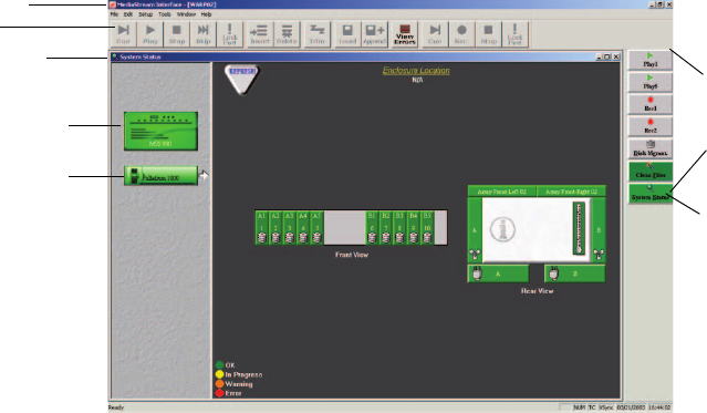
Starting the MSi Application
117
System Status Window
Msi PC and Server Node Communication
The MSi PC communicates to the Networked Storage System through redundant VLAN
Ethernet connections.
The MSS 8000 Lantronix module connects to an internal Ethernet LAN hub providing
connections to the System Controller board’s LAN port and RS-232 Console Port for server
administration. The Console Port provides the MSi PC access to system boot and monitoring
via telnet.
The System Controller LAN port provides access to multiple telnet sessions for server nodes
as well as the link for the MSi application.
You will use the Configuration dialog box to define server parameters to the MSi. To open
this dialog box, select Setup > Configuration from the MSi main menu. This dialog box
consists of four panes: Global Configuration, Play Window, Record Window, and Console
(System Administration window).
System
status
button
Window
selection
buttons
Main Menu
Toolbar
Name of
active window
MSS 8000 icon
PS 1000 icon
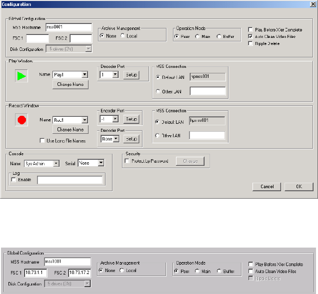
Chapter 6 MediaStream Interface (MSi)
118
MediaStream MSi Configuration Dialog Box
Global Configuration
Global configuration sets up the communication link between the MSi, the server node and
both FSCs.
• MSS Hostname is the <hostname> as specified in the hosts file of the MSS 8000 server
node. If this field is not filled in properly, the MSi cannot properly communicate with
the server node. Name syntax is as follows:
mss
<YYXX>
where
<YY>
is the cluster number and
<XX>
is the Server Node
• FSC 1 and FSC 2 – set the FSC name or IP address in this section.
The format is as follows:
For FSC 1 – 10.XX.1.1 where
<XX>
equals Cluster Subnet
For FSC 2 – 10.XX.17.2 where
<XX>
equals Cluster Subnet

Starting the MSi Application
119
• Archive Management – Set to None.
• Operation Mode – Set to Peer.
• Play Before Xfer Complete – When checked, files can be played back from disk as soon
as enough material has been transferred to feed the playback buffers. When left
unchecked, video files can only be played back when a file transfer is complete.
• Auto Clean Video Files – Leave unchecked.
Cluster Addressing
Initial Cluster Addresses
Cluster 1 10.64.1 Cluster 17 10.81.1 Cluster 33 10.64.65
Cluster 2 10.65.1 Cluster 18 10.82.1 Cluster 34 10.65.65
Cluster 3 10.66.1 Cluster 19 10.83.1 Cluster 35 10.66.65
Cluster 4 10.67.1 Cluster 20 10.84.1 Cluster 36 10.67.65
Cluster 5 10.68.1 Cluster 21 10.85.1 Cluster 37 10.68.65
Cluster 6 10.69.1 Cluster 22 10.86.1 Cluster 38 10.69.65
Cluster 7 10.70.1 Cluster 23 10.87.1 Cluster 39 10.70.65
Cluster 8 10.71.1 Cluster 24 10.88.1 Cluster 40 10.71.65
Cluster 9 10.72.1 Cluster 25 10.89.1 Cluster 41 10.72.65
Cluster 10 10.73.1 Cluster 26 10.90.1 Cluster 42 10.73.65
Cluster 11 10.74.1 Cluster 27 10.91.1 Cluster 43 10.74.65
Cluster 12 10.75.1 Cluster 28 10.92.1 Cluster 44 10.75.65
Cluster 13 10.76.1 Cluster 29 10.93.1 Cluster 45 10.76.65
Cluster 14 10.77.1 Cluster 30 10.94.1 Cluster 46 10.77.65
Cluster 15 10.78.1 Cluster 31 10.95.1 Cluster 47 10.78.65
Cluster 16 10.79.1 Cluster 32 10.96.1 Cluster 48 10.79.65
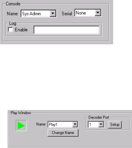
Chapter 6 MediaStream Interface (MSi)
120
Console
The Console section is not normally used with the Networked Storage System. Leave this set
to None.
Console Configuration
Play Window
The Play window pane contains the tools to configure decoder channels. When a channel is
assigned, a decoder Play button for that channel is added as a Play button in the MSi
window.
Play Window Configuration Area
To configure decoder channels:
1. Select Play 1 as the Name.
2. Select 1 as the Decoder Port.
3. Click the Setup button, which opens the Decoder Configuration dialog box to configure
Decoder channels:
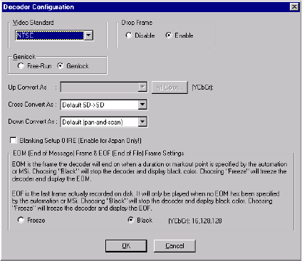
Starting the MSi Application
121
Decoder Configuration Dialog Box
4. Set the following parameters:
- Video Standard: Select NTSC or PAL.
- Drop Frame: Select whether to enable or disable the drop frame time code.
- Genlock: Select Genlock.
- Display Mode (HD decoder board only): Sets up conversion display when
converting Standard Definition (SD) signals to High Definition (HD) signals.
- Blanking Setup: Leave unselected except for Japanese NTSC.
- EOM: End of Message playback, select Black or Freeze. This determines how a file
playback will end at the end of the playback message (time code out)
- EOF: End of File playback, select Black or Freeze. This determines the output
should a file play to the end of the recorded video.
5. Click OK to confirm your settings
You must repeat this procedure for each physical decoder channel.
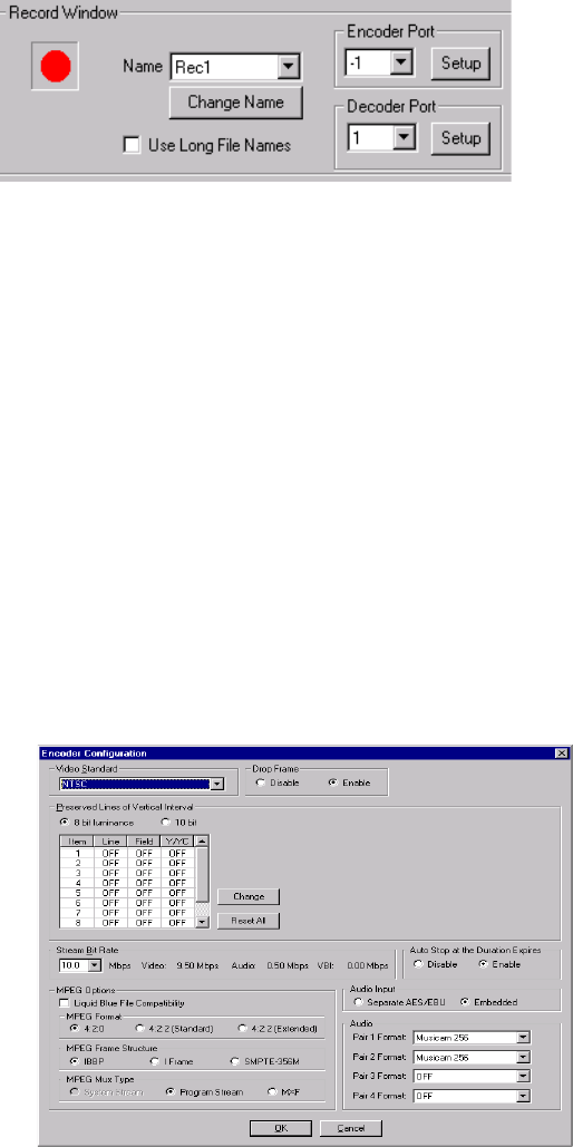
Chapter 6 MediaStream Interface (MSi)
122
Record Window
The Record Window pane allows you to configure the encoders installed in the server.
Adjust settings in this pane to gain access from the MSi to each encoder and to specify
encoder configurations.
To configure Record channels:
1. In the Record window panel, select Rec1 as the Name.
2. Select -1 as the Encoder Port.
3. To provide a preview channel to view record results, select 1 as the Decoder Port.
nIf automation also accesses the Preview port, use caution when assigning a decoder port as
the Preview port. If a Preview port is associated with the encoder port on the MSi, using the
MSi to record could potentially interrupt on-air operation through the Preview port.
4. Click the Setup button associated with each Encoder port to display the Encoder
Configuration dialog box.
Encoder Setup Configuration
Starting the MSi Application
123
5. Set the following parameters:
• Video Standard: NTSC or PAL.
nThis video standard must match the decoder standard. Although MSi supports multiple video
standards selections, all Play and Record windows must be set to the same video standard
(either PAL or NTSC). Mixed mode is not allowed and if used, the MSi returns an error
message. Support of multiple video standards needs to be set on the server.
• Drop Frame: Choose the time code parameter, Enable or Disable.
• Preserved Lines of Vertical Interval: Up to ten lines of Vertical Interval signals can be
preserved before compression, using either 8-bit luminance or 10-bit YC. You may
select one line to be preserved from each menu (for a total of ten). For NTSC choose any
ten lines between line 10-21. For PAL choose any ten lines between 7-22 and/or 320-
335.
• Stream Bit Rate: Select the desired compression rate for the encoder channel. The rates
range between 6 and 50 Mbps for MPEG 4:2:2. Dual decoder boards support a
maximum rate of 50 Mbps.
• Auto Stop at the Duration Expires: Specifies that recording will stop at the entered
duration in the Record window. Select Enable or Disable.
• Liquid Blue File Compatibility: Check this box to maintain file compatibility with the
Liquid Blue editor.
• MPEG Format: Select the desired MPEG recording format.
• MPEG Frame Structure: Select the desired MPEG frame structure.
• MPEG Mux Type: MSi automatically enables/disables Program Stream or System
Stream selection, depending on the hardware. For HD, select Program Stream only. For
SD, either MUX type may be selected. Select MXF to use Material eXchange Format.
• Audio Input: Select the desired audio input method.
• Audio: Select the desired Audio format for encoding. Choose settings for up to four
Audio pairs (eight channels).
• Click OK to verify the changes.
6. Repeat this process for each encoder channel.
MPEG Input Card Configuration
If you have an MPEG Input Card configured the process is similar as with record channels
for encoders.
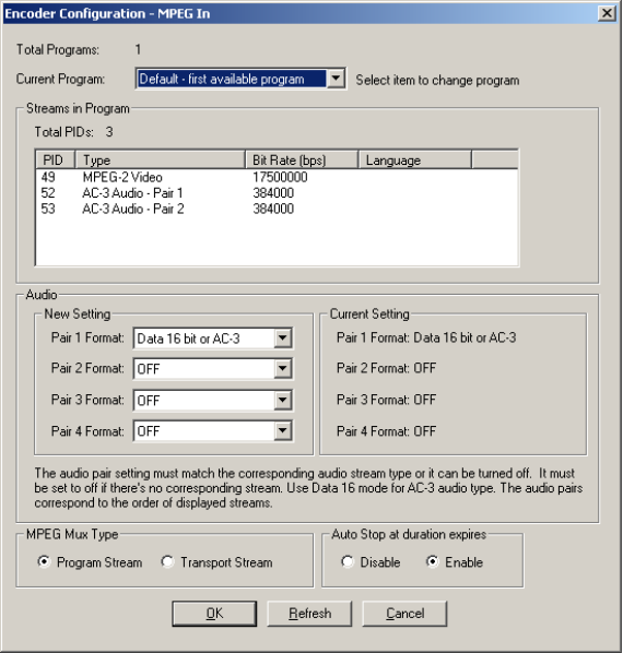
Chapter 6 MediaStream Interface (MSi)
124
1. Select Menu > Configure. The configuration dialog appears.
2. In the Record window panel, select Rec<x> where x is the record channel with the
MPEG input channel.
3. Select -<x> where x is the Encoder Port to assign.
4. Click the setup button for that channel. The MPEG Input dialog appears.
nThe system automatically detects the MPEG Input configuration and displays the right
dialog.
Encoder Configuration MPEG In
5. Choose the desired program stream. All available streams will be visible in the Stream
List Box.
6. If audio is available, Choose audio pairs you wish to capture.

Starting the MSi Application
125
nIf audio format is Musicam, you must the correct format (either Musicam 256 or Musicam
384). The system is incapable of distinguishing which format is encoded. If you are unsure
which Musicam format is used, consult with the program originator.
7. Click OK.
Recording
To record video, click the Rec1 button on the right side of the MSi window. A Record
window similar to the one shown in the following figure displays. There is a button for each
encoder installed in the server. Choose the Rec (n) button for the encoder to be used for
recording.
MSi Record Window with Port Unlocked
Record Port Status
When the Record window is open, an Idle status for the encoder record port may appear at
the top right of the Record window. Idle means that the port is free for use. Generally it will
be in use by automation.
Status of the play port.
Idle means the port is
free for use
Status of the record port.
Idle means the port is free
for use
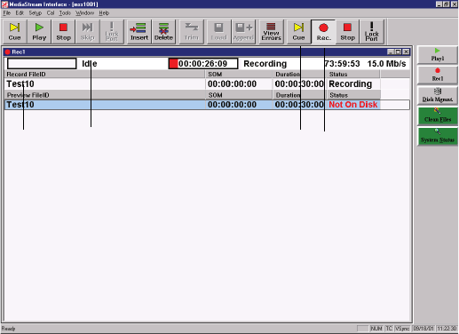
Chapter 6 MediaStream Interface (MSi)
126
Play Port Status
If the Record window is configured to play video (or preview it), then a second Port Status
indicator should display at the top left of the Record window. This port status reflects the
condition of the decoder Play port. The status should read Idle, assuming that the Play port is
not already in use by a Play window or by automation.
Recording Video Files
Follow these steps to record video files (see the following figure):
1. Enter the Record File ID in the data entry cell under the field (see Step 1 in the
following figure). The length of the file name can be up to 32 characters.
2. Change the Duration field to the desired time. Enter the duration in hours, minutes,
seconds, and frames.
3. Click the Cue button in the toolbar, which causes the Record port to cue. After three
seconds, the status should read Cued.
Recording Steps within MSi Window
4. Select the Record button in the toolbar, which causes the Record port to record. The
status should read Recording. After a few seconds of recording, the status for the
recorded video file (clip) should change to On Disk.
Previewing the Video File
Preview means to play a video file, or clip, in a Record window. As soon as the status for a
clip is On Disk, it can be played.
12 43
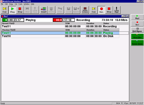
Starting the MSi Application
127
To preview the clip:
1. Select the clip (if there is more than one, otherwise go to Step 2).
2. Click the Cue button in the toolbar to cue the clip for playing.
3. Click the Play button to play the clip.
Previewing a Clip with MSi Window
nYou can click Play without clicking Cue. The clip will cue automatically and then begin to
play.
Playing Clips
The Play window is similar to the Record window, but shows only the Play port’s status.
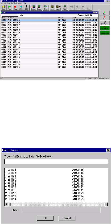
Chapter 6 MediaStream Interface (MSi)
128
MSi Play Window
To play video files:
1. Click the Play1 button to open the Play window.
nPlay and Record buttons are located in the button column at the right side of the MSi
window.
2. Click the Insert button in the toolbar to open the File ID Insert dialog box
File Insert Window for Playing Files
3. Enter the File ID in the text field if you know it, or select one or more files from the list.
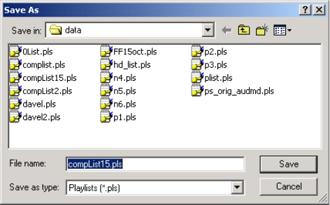
Starting the MSi Application
129
nTo select multiple files, you can click and drag (that is, select the first file and hold down the
mouse button while selecting additional files). You can also use the standard Windows
multiple selection features: Press the Shift key while selecting to select contiguous files in the
list, or press the Ctrl key while selecting separate files.
4. Click OK to accept the selection. The file name(s) should now display in the Play
window.
5. Click the Cue button in the toolbar.
6. Click the Play button in the toolbar to play the clip.
You can create a playlist, which is a text file from which you can select files for playing:
1. Select the files to be included from the list in the Play window.
2. From the MSi main menu, select File > Save As.
3. Enter a file name for the list, and click Save, which creates a playlist file.
Window for Creating and Saving Playlists
To load a playlist:
1. Click the Load button in the toolbar.
2. Select your playlist file from the Open dialog box, and click Open.
3. The playlist appears in your Play window.
Trimming
Trimming allows you to edit a video file, play it in slow motion, freeze a frame, or play it
backwards. You use the Trimming window to set trimming parameters and view the results
in a Play window.
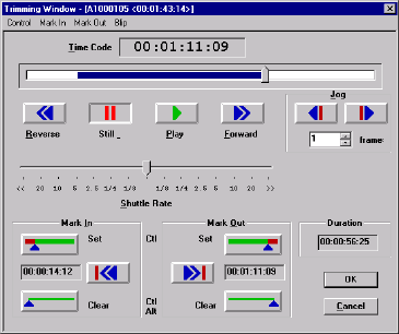
Chapter 6 MediaStream Interface (MSi)
130
MSi Trimming Window
To apply the Trimming features to a clip:
1. Select a clip from the list in the Play window.
2. Click the Trim button in the MSi toolbar.
3. Click the Play button in the top half of the Trimming window to play the file normally.
nThe amount of time that the clip has played is shown in the Duration field (lower right of
Trimming window).
You can perform these tasks using the Trimming window:
• Play backwards and forwards
You can set the direction of the clip using the Reverse and Forward buttons in the top
half of the window. The Shuttle Rate setting determines the rate that the clip plays or
rewinds. Drag the indicator to the left to decrease the rate, or to the right to increase it.
• Jump to another part of the video
Use the scroll bar at the top of the window to jump to another part of the video by
selecting the indicator and dragging it in either direction.
• Freeze a frame
Click the Still button to freeze the file on the current frame.
• Advance/rewind a frame at a time
The forward and backward Jog buttons cause the clip to advance or rewind one or more
frames at a time. Set the frame increment in the Frame field.
• Set start and end points for viewing a segment of the click
Starting the MSi Application
131
The Mark In and Mark Out buttons add reference points to the clip, which are saved
with the file in the playlist. If you delete the playlist or clear your Play window, the
settings are lost. To edit a clip:
-Click Mark In to mark a start point for an edit.
- Click Mark Out to mark a finish point for an edit.
- Click OK to save your edits.
- Click Play in the Play window to play the edited clip.
The Disk Management Window
The Disk Management window provides utilities to manage video files. You can delete a
file, rename it, or protect it from being deleted. The window lists all of the stored Clip IDs in
alphabetical order.
To open the Disk Management window, click the Disk Management button to the right of the
active MSi window. At the top of the window, you can see the number of clips stored on the
server and the percentage of storage used.
The disk management utilities are located below the list:
• To delete a clip from the storage system, select it from the list, and click the Delete from
Disk button.
• To rename a selected file, enter the new name/ID in the Rename as text box, and click
Rename.
• To prevent a selected file from being deleted, select Delete Protected.
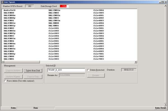
Chapter 6 MediaStream Interface (MSi)
132
MSi Disk Management Window
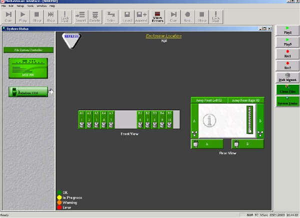
System Status Window
133
System Status Window
The System Status window allows you to monitor the status of the MSS 8000 and the
Palladium Store 1000. Click the System Status button in the MSi button column to open this
window.
MSi System Status Window
To monitor components of either the server or Palladium Store 1000, select its icon from the
left side of window. Icons for each subcomponent that you can monitor display in the
window. Double-clicking any subcomponent opens a dialog box that indicates its status.

Chapter 6 MediaStream Interface (MSi)
134
MSi System Status Dialog Boxes
Disks Array
Power supplies
Fans
Chassis
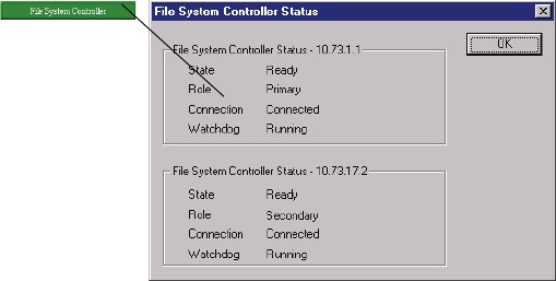
System Status Window
135
The following items are monitored:
• Power supplies for both the server and the array(s). If a supply fails, this button turns
red.
• Fans (redundant) for both server/storage array. If a fan module fails, its button changes
from green to red.
• Enclosure Information. (8000 chassis) Double-click the gray area of the Chassis icon in
the window to display information about the enclosure. The temperature sensor turns to
orange if a component begins to overheat.
• Disks. Double-click any disk to display disk status, error counter hardware firmware
information and Disable button. For the Palladium Store 1000 chassis, Disable is not
necessary and does not function. Do not attempt to disable a drive before changing
disks. To replace a malfunctioning disk, simply remove it and replace it with a
replacement disk.
• Disk Array. Click either button to reveal information about a given array controller. The
Disk Array dialog box provides information about the controller. You also use this
dialog box to rebuild arrays.
FSC Enclosure
Double-click the File System Controller icon in the left pane of the System Status window to
reveal the File System Controller window (see the following figure) that provides
information on the status and health of the system’s two FSCs.
MSi FSC Status Dialog
nIf the Drive Status for the FSC reads “Failed,” run the Adaptec Storage Manager
application on the FSC. If that succeeds in fixing the error, reboot the FSC to clear the
“Failed” message.
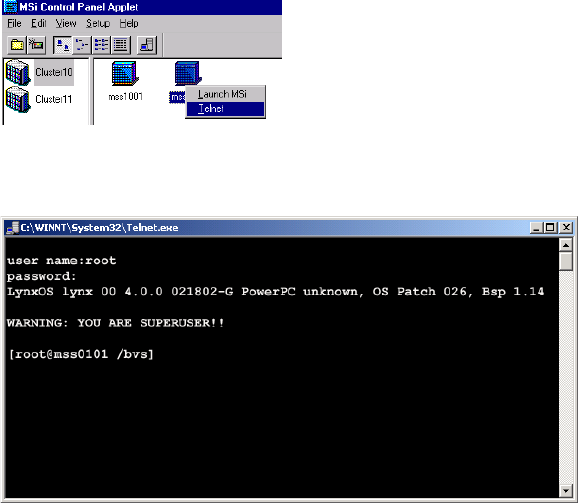
Chapter 6 MediaStream Interface (MSi)
136
System Administration
Many tasks can be performed directly through the MSi. However, some configuration and
maintenance must be performed through a command line interface. This is especially
important when starting up and shutting down server nodes for maintenance. To perform
these tasks, you need to communicate directly with the server node through the MSi PCs
Telnet application. You will use also use Telnet to monitor and maintain the System’s two
FSCs.
Telnet from the Console Port
The Console Port is the preferred method of access to the server node for system
maintenance, because the port can be active whether the server has completed boot-up or
not. To launch a telnet session to the Console Port, right-click the server node icon in the
MSi Control Panel and select Telnet from the menu. A telnet window displays.
MSi Control Panel
MSi Telnet Window
If the server node is running, a prompt similar to this should display: [root@0101]. If
necessary, press the Enter key once or twice to display the prompt.
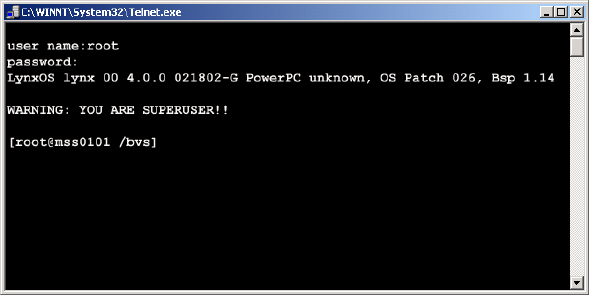
System Administration
137
Opening Additional Telnet Sessions
The Console Port can only support one telnet session at a time. It is sometimes necessary to
open more than one telnet session for some maintenance functions. If you need to open
another telnet session on a server node, click Start > Run and enter:
telnet <Server Node Hostname>
A new telnet session opens (see the following figure). Enter
root
at the user name prompt
and press Enter at the password prompt. The system returns the following:
LynxOS lynx00 4.0.0 021802-G PowerPC unknown, OS Patch 026, Bsp 1.14
WARNING: YOU ARE SUPERUSER!!
[root@mss0101 /bvs]
New Telnet Session Window
You may have multiple telnet sessions open.
Shutting Down and Restarting Individual Server Nodes
The MSS Networked Storage System can continue to operate normally while individual
server nodes are shut down for servicing. During server node software upgrades, the node
may be required to be restarted for the upgrade to be complete. Although power supplies and
cooling fans may be replaced while the node is operating, the node must be powered down
for servicing other components.
Chapter 6 MediaStream Interface (MSi)
138
Server Shutdown
To safely shut down a server node:
1. Open a telnet session to the Console Port
2. If you have not done so already, login as root (password is
.root
).
3. Type
stopams –H
and press Enter
4. Wait for the words:
Halting (in tight loop) – OK to Hit Reset button
5. Turn off the two power switches on the back of the machine.
Server Startup
To start a server node up after shutdown:
1. Power up the server node. Wait for a few seconds.
2. Open a Console Port telnet session. If you have one opened from your shutdown, you
will need to reconnect it. From the MSi Control Panel, right-click the server node icon
you wish to open and select Console from the menu.
3. The boot sequence should begin to appear. Wait several minutes for the entire boot
sequence to complete.
4. When the message
HP:37N85A000
running appears, press Enter.
5. At the user prompt: enter
root
.
6. At the password prompt, type
.root
to complete the logon.
Server Reboot
To restart a server node after configuration change or software upgrade:
1. From a Console Port telnet session, type
stopams
.
2. Wait for the server node to reboot. The complete reboot may take five minutes or more
depending on how many input output channels are configured.
3. When the message
HP:37N85A000
running
displays, press Enter.
4. At the user prompt, type
root
.
5. At the password prompt, type
.root
to complete the logon.
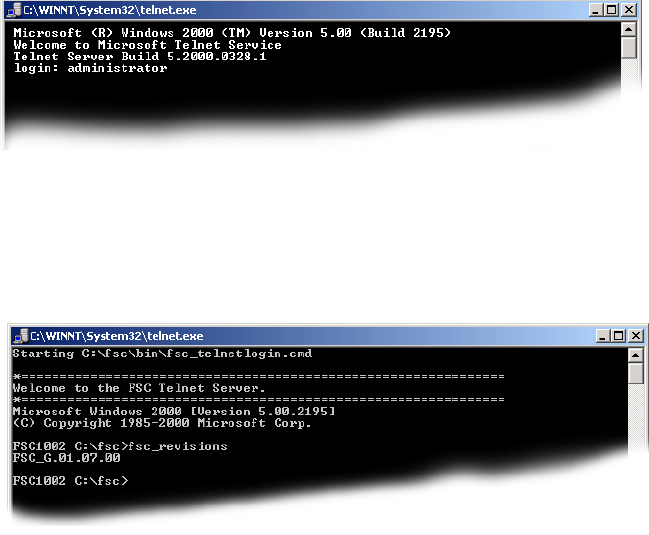
System Administration
139
Telnet to File System Controller
Communication with and administration of the FSCs occurs from the MSi PC via Telnet.
The FSCs operate on a Windows 2000 operating system.
To open a telnet session on an FSC:
1. Click Start > Run.
2. When the Run window opens, enter
telnet fscxx0y
where
<xx>
is the cluster number and
<y>
is the FSC 01 for primary and 02 for
secondary, e.g., fsc0101 for primary FSC in cluster 1.
3. A telnet session opens.
Opening a Telnet Session
4. At the logon prompt, enter
Administrator
.
5. Press Enter at the password prompt:
Telnet Log onto FSC
A message displays saying that you are now logged on to the FSC.
nChapter 7 covers administration of the FSCs in more detail.
Chapter 6 MediaStream Interface (MSi)
140
Powering Up a MSS Networked Storage System
In a normal operating environment, the MSS Networked Storage System remains powered
up. Individual components may be powered down for servicing without interruption to
system operations. Should the entire system need to be shut down for more extensive
maintenance, the power on (and off) sequencing of components is important. The following
startup procedure should be followed to bring the system back to an operational status:
1. Start the MSi PC.
2. Start the storage array(s).
3. If not already powered up, plug in the Fibre Channel switch power cords to power up the
switches.
4. Start a server node.
5. If not already powered up, plug in the VLAN switches to power them up.
- Start FCS 1.
- Start FSC 2.
6. When both FSCs have booted successfully, run the
fsc_status
command on each.
Wait for the script to run completely. The result of the script should resemble that shown
here.
7. Start any remaining server nodes.

Powering Up a MSS Networked Storage System
141
nOnce the System is running, you will rarely have a need to restart it. Most service procedures
are performed on running components or they require individual components to be shut
down.
FSC Status
Fri 08/10/2001 8:39:02.11
Local Host Remote Host
Hostname FSC0101.pcle.com fsc0102-22
IP 127.0.0.1 10.64.22.2
APPLICATIONS
Database running running
SanService running running
Watchdog running running
DATABASE
TCP Port 1315 1325
Role PRIMARY SECONDARY
Connection CONNECTED CONNECTED
Remote DB tcp 10.64.22.2 1325 tcp 10.64.22.1 1315
Operations 1584610 989983
Date 08/10/2001 08/10/2001
Time 08:33a 08:33a
Size 18,055,168 18,055,168
SANSERVICE
Status Ready Ready
WATCHDOG
Status ok ok
HSB STATUS REPORT 127.0.0.1
This is a Hot Standby primary server.
Connected to secondary 'tcp 10.64.22.2 1325'
HotStandby log size 0 bytes
Replicated 1584630 operations, 188775 transactions
HSB STATUS REPORT 10.64.22.2
This is a Hot Standby secondary server.
Replicated 989993 operations, 188775 transactions
Chapter 6 MediaStream Interface (MSi)
142
Controlled System Shudown
Use the following procedure to shut down the entire system from the MSi PC.
1. Telnet to each server node.
2. Type the command
stopams –H
to stop the server nodes. Wait for the LynxOS is down
message to display before turning off the power on each server node.
3. Telnet to each FSC and enter the command
fsc_stop
for each. Follow the on-screen
instructions.
nYou should stop the FSC 2 first and FSC 1 next. When you restart, start FSC 1 first followed
by FSC 2. This sequence ensures that FSC 1 remains the Primary FSC.
4. Wait for the database to update. Then quickly depress the power button on the front
panel of each FSC. This will execute a graceful shutdown of each FSC.
5. Turn off the other system components.
nThe last FSC you shut down must be the first FSC you restart.
The MSi application may be closed at any time the system is idle using the normal Windows
2000 application exit function (click the “x” located at the far right end of the application
title bar). You can power down the MSi PC at any time without adverse effect on the server
node’s external applications.
Before you shut down the MSi application, be sure you are not playing or recording using
the MSi Play or Record windows.

Chapter 7
Introduction to System Administration
This chapter explores some concepts and tools you will need to use when you are
administering the MSS Networked Storage System. Many administration tasks are
performed in several different command-line interfaces. The MSS 8000 server nodes operate
in an LynxOS environment that is very similar to UNIX. The FSCs are administered through
telnet sessions using a command-line interface. This chapter covers these topics:
• Useful UNIX commands
• Introduction to the vi editor
• Introduction to FSC administration
• Introduction to server node configuration
Logging On to the Server
When prompted to enter your username, type
root
and press Enter. The password is
“
.root
” (no quotes). The server responds as follows:
By logging on as
root
, you have the privileges required for server administration.
user name:root
LynxOS lynx00 4.0.0 021802-G PowerPC unknown, OS Patch 026, Bsp 1.14
WARNING: YOU ARE SUPERUSER!!
[root@0101 /bvs]
Chapter 7 Introduction to System Administration
144
UNIX Commands
UNIX commands are abbreviations of actions; for example:
• ls
lists the contents of a directory.
• rm
removes a file.
• cd
changes your directory path in the file hierarchy.
nUNIX is case sensitive. Your entries on a command line must be exact, including case and
punctuation.
Command Syntax
UNIX command syntax consists of the commands (similar to verbs) and arguments (similar
to direct objects) that modify commands. You can add flags to further modify a command.
A command by itself describes an action. For example:
•pwd displays the current directory location.
•date displays the current date and time.
An argument added to the command redirects the command’s action. For example,
cd /bvs
changes your current directory to the directory bvs. Flags, which begin with a minus (-) sign,
modify the command. For example, when you add the -l flag to the ls (list) command (ls -l)
the output is a detailed list of a file directory (either the current or specified directory).
You can combine commands, arguments, and flags according to UNIX syntax. For example.
entering
ls –l bvs*
means that you want a detailed list of all the files in the directory that
begin with bvs. The asterisk
(*)
is used as a wildcard that represents any subsequent
characters. The command line returns all files in the directory that start with the characters
bvs.
Basic UNIX Commands
Daily operation of the server requires a basic knowledge of UNIX. The following table lists
the commands most useful for normal server operation. A more detailed description of each
command follows

UNIX Commands
145
Change Directories
Use the cd command to move between directories. UNIX directories begin in the root
directory, which is specified by a forward slash (/). Entering cd/ moves you to the root
directory. Entering
cd /<dir>/<dir>
allows you to move within directories several layers
deep.
For example, entering
cd /bvs
moves you to the /bvs directory.
Two important server directories are /bvs and /etc. The /bvs directory is the Broadcast Video
Server directory, which contains configuration information, including the bvsrc file—the
primary server configuration document. The /etc directory contains the hosts file.
Where Am I? Command
Entering the pwd command returns the pathname of your current directory. When logged
onto a server, this command is unnecessary because the System has been set up to return the
active directory at all times. This command is useful when you run FTP (File Transfer
Protocol) from a command-line interface.
List Command
The ls command allows you to view the contents of a directory. To list the contents of a
directory, use the cd command to move to the directory (
cd /<dir>
), and then enter
ls
on
the following command line.
Basic UNIX Commands
UNIX Command Action
cd Change directory
pwd – “Where am I?” Returns current working directory location
ls List files
mkdir Make directory
rmdir Remove directory
cp Copy files
mv Move files; use to move or rename files
rm Remove file; a dangerous command because there is no undo
more Read the contents of a file
Chapter 7 Introduction to System Administration
146
Examples of ls command syntax:
• ls -l
provides a detailed list of the contents of the selected directory.
• ls -l *hosts*
provides a detailed list of all files in the directory that contain hosts.
Make a Directory
The mkdir command allows you to create a new directory in which to store files. The syntax
is
mkdir <dir name>
Remove a Directory
The rmdir command allows you to remove a directory. The syntax is
rmdir <dir
name>
nOnly empty directories can be removed with rmdir.
Copy Command
The cp command allows you to make backup copies of files or create copies of
files in other directories. The syntax is
cp <filename> <new filename>
or
cp <filename><newdirectory>
. For example:
•
cp bvsrc bvsrc.b
k
creates a copy of the file bvsrc named bvsrc.bk and stores it within the same directory
•
cp bvsrc /newdir
creates a copy of the file bvsrc and places it in /newdir
•
cp *hosts* /newdi
r
copies all files that contain hosts in their names to /newdir
• cp hosts fchost /newdir
copies the two files to /newdir
To copy multiple files to a new location, either use the wildcard (*), or list each file
individually.
Move File
The mv command allows you to move files to new directories and to rename files within a
directory. The syntax is mv
<filename> <newdirectory>
or mv
<filename>
<newname>
. For example:
UNIX Commands
147
•
mv bvsrc.bk /etc
moves the file bvsrc.bk to the /etc directory
•
mv bvsrc.bk bvsrc.new
renames the file bvsrc.bk to bvsrc.new. The file named bvsrc.bk no longer
exists.
You can move multiple files to a new directory.
Remove Files
The rm command allows you to remove files. A removed file is permanently
deleted and cannot be restored.
The syntax is
rm <filename>
For example:
rm bvsrc.bak
removes the file bvsrc.bak.
As a precaution, add the
-i
(interactive) flag when you issue the remove
command. Entering
rm bvsrc.bak -i
asks you to confirm file deletion:
rm: remove bvsrc.bak?
Press y to delete the file, or n to cancel the command.
More Command
Use the more command to view the contents of a file. Entering
more <filename>
displays
the contents of the file, one screen at a time. Press the space bar to display the next screen.
To quit the file, type
q
.
The vi Editor
The vi editor is a text editor for UNIX systems. To create a new file and open the editor, type
vi <newfilename>
. When the editor starts, a cursor for data entry appears at the top of the
screen and tilde (~) characters appear down the side of the screen.

Chapter 7 Introduction to System Administration
148
Command Mode vs. Text Entry Mode
When you edit with vi, you work in one of two modes—command or text entry. To toggle
between modes, press the Esc key. In command mode, you press a key such as i, which is the
command to insert text after the cursor. To insert text, press Esc to enter text entry mode.
Then type the characters you want to insert. You remain in text entry mode until you press
Esc to return to command mode from which you can issue another command, such as x,
which deletes one character. See Table for a description of vi commands.
Saving a File and Quitting
To save and quit your file, enter the command :wq! which combines the write (w) and quit
(q) commands. The explanation point (!) means you really want to issue this command. To
quit without saving, type
q!
which means quit without saving my work.
Quick Reference
Function Key Action
Add text a Append or add text after cursor
Insert text i Insert text after cursor position.
Navigation h Moves cursor left one space
l Moves cursor right one space
j Moves cursor down one line
k Moves cursor up one line
0 Moves to beginning of line
$ Moves to end of line
G Moves to last line
<n>G Moves to nth line
<Ctrl> b Moves back 1 page
<Ctrl> f Moves forward 1 page
Deleting x Delete 1 character
d Delete through the end of the line
dw Delete word
dd Delete line

Introduction to FSC Administration
149
Introduction to FSC Administration
When you boot up an FSC, it starts an auto logon process that allows system boot without
requiring a user logon.
fsc_start
The fsc_start script is used to startup the individual components of the FSC and makes sure
that all programs have been started properly.
Three critical module that must start successfully are:
• Database – the data structure that actually manages the video file system
• SanService – the FSC operating module which manages network traffic
• Watchdog – an application designed to constantly monitor the health of critical FSC
components.
Running fsc_start
Normally, the FSCs starts automatically. When you enter the command fsc_start, a
successful script will look something like this:
Replacing r Replace 1 character
R Replace until you press Esc
cw Change word
Undo u Undo last change to file
U Undo current line if changed
Open new line o Open new line below cursor
O open new line above cursor
Searching /<pattern> Search for specified pattern
n Press n to look for next instance
Quitting <esc> :wq! Save and quit (write and quit)
<esc> :q! Quit without saving
Quick Reference (Continued)
Function Key Action

Chapter 7 Introduction to System Administration
150
If the system detects that one or more applications are running, you are alerted as follows:
INFO Check for old Database process
INFO Check for old SanService process
INFO Check for old Watchdog process
INFO Starting Elogger
INFO Database EXE present
INFO Elogger EXE present
INFO SanService EXE present
INFO Watchdog EXE present
INFO All EXEs present
INFO Database file present
INFO Start Database
INFO Check Database
SUCCESS Database running
INFO Number of DiskProxies defined in fsc.ini file = 2
INFO Found DiskProxy mss1001
INFO Start SanService - may take up to 20 seconds
INFO Checking SanService status.
INFO FSC returned Ready
SUCCESS SanService running
INFO Start SanWatchdog
SUCCESS SanWatchdog running
INFO Start log trail
SUCCESS Server started successfully
INFO fsc_start script finished
[C:/fsc]
INFO Check for old Database process
WARNING Database already running
INFO Check for old SanService process
WARNING SanService already running
INFO Check for old Watchdog process
WARNING SanWatchdog is already running
INFO fsc_start detected old instances of application processes running.
INFO The script can only be executed when these are shut down, which may
INFO take you off air.
INFO Are you sure [y/n]? n
Introduction to FSC Administration
151
If you are unsure of the state of the system, press n and then press Enter. The script will exit
without affecting current operation. Run fsc_status (see below) to determine the status of
both FSCs before proceeding.
If you are sure you are able to shut down the FSC, press y and then press Enter.
The script will stop currently running applications and execute the start script
normally.
fsc_status
The FSC status utility detects and reports the status of both FSCs in the network. This utility
should be run before performing any maintenance on FSCs. Because the system is designed
to be serviced while on-air, it is critical that both FSCs are in good working condition when
you are performing routine maintenance.
wIf you try to shut down an FSC while the other unit is in a Shutdown or Not Ready
state, you will bring the entire system off-air.
When you run fsc_status, a healthy system with two operational FSCs responds as follows:

Chapter 7 Introduction to System Administration
152
FSC Status
Tue 10/02/2001 15:07:21.76
Local Host Remote Host
Hostname FSC1001.pcle.com fsc1002-22
IP 127.0.0.1 10.73.22.2
APPLICATIONS
Database running running
SanService running running
Watchdog running running
DATABASE
TCP Port 1315 1325
Role PRIMARY SECONDARY
Connection CONNECTED CONNECTED
Remote DB tcp 10.73.22.2 1325 tcp 10.73.22.1 1315
Operations 3271 9534
Date 10/02/2001 10/02/2001
Time 02:52p 02:54p
Size 39,354,368 39,354,368
SANSERVICE
Connection CONNECTED CONNECTED
Remote DB tcp 10.73.22.2 1325 tcp 10.73.22.1 1315
Operations 3271 9534
Date 10/02/2001 10/02/2001
Time 02:52p 02:54p
Size 39,354,368 39,354,368
SANSERVICE
Status Ready Ready
WATCHDOG
Status ok ok
HSB STATUS REPORT 127.0.0.1
This is a Hot Standby primary server.
Replicated 3271 operations, 481 transactions
HSB STATUS REPORT 10.73.22.2
This is a Hot Standby secondary server.
Connected to primary 'tcp 10.73.22.1 1315'
HotStandby log size 0 bytes
Replicated 9534 operations, 936 transactions
Introduction to FSC Administration
153
FSC Status Report Details
Hostname
Local Host is the FSC to which you made the telnet connection. Remote Host is the other
FSC. If you had connected to fsc0102 and run this command, fsc0102 would be listed as the
Local Host.
IP Address
The network address of each FSC is an IP address. These addresses are set at the factory. Do
not attempt to change them.
Applications
Status of the three operating applications Database, SanService and Watchdog are checked.
If the FSC is operating normally, all three should be listed as running.
Database
Each FSC maintains a separate database of all clips on the RAID storage system. The
fsc_status utility can be used to determine if the two databases are in sync. When run from
either FSC, the output will contain a column for the local machine and another for the
remote machine.
Make a note of any deviations for diagnostic purposes.
•Role
One FSC should show the role “PRIMARY” while the other should show
“SECONDARY”. The other FSC will only become primary if the first one fails.
•Connection
Both FSCs should show “CONNECTED”, meaning they are connected to the database.
If one is not, there may be a network problem, or the Database may be out of sync.
• Remote DB
This refers to the copy of the database that resides on each FSC. Each FSC should show
the TCP port number and IP address of the other.
•Size
Two synchronized databases will not always be the same size. The Solid RDBMS
system replicates data on the secondary database by issuing Data Base Transactions. It
does not make a binary copy of the Primary database. Database size will become
different over time depending upon usage, load and file system characteristics of the two
systems.

Chapter 7 Introduction to System Administration
154
SanService
SanService handles network management. Both FSCs should show “Ready”. If you see “Not
Ready”, “No Response”, or “Connection Broken”, make a note for diagnostic purposes and
refer to “Troubleshooting Database Problems” on page 327 for possible corrective action.
Watchdog
Watchdog monitors the FSC operation. Both FSCs should show OK. If you see an Error,
make a note for diagnostic purposes.
If the FSC Status report indicates a problem with the other FSC, telnet to that FSC and run a
report. The results of the two reports will narrow your search for the problem.
fsc_stop
The FSC Stop script allows an FSC to be shutdown in a safe manner that ensures database
integrity. Always run fsc_stop before shutting down the FSC PC.
wMake sure that the other FSC’s status is Ready, OK before shutting down a given FSC.
Otherwise, you may take the system off-air.
To safely stop an FSC, type
fsc_stop
. The following warning displays:
SANSERVICE
Status Ready Ready
Role SECONDARY PRIMARY
Connection CONNECTED CONNECTED
Remote DB tcp 10.73.22.2 1325 tcp 10.73.22.1 1315
Operations 133852 138163
Date 10/02/2001 10/02/2001
Time 09:37a 09:37a
Size 39,354,368 39,354,368
SANSERVICE
Status Ready Ready
WATCHDOG
Status ok ok

Introduction to Server Node Configuration
155
Press y, then press Enter. The following output indicates that the application has stopped:
Introduction to Server Node Configuration
Server node administration via Telnet is introduced in Chapter 6. Most configurations and
monitoring of individual server nodes are performed through telnet. administration and
upgrades of the server node requiring reboot should be handled through a console port login
(see “Telnet from the Console Port” on page 136). For many administration tasks, more than
one telnet session may be advantageous. Multiple LAN telnet sessions for one or more
server nodes may be opened at the same time on the MSi PC. For information on opening
LAN telnet sessions, see “Opening Additional Telnet Sessions” on page 137.
/bvs Directory
When you log on to the server node, it should open with the prompt, [root@0101 /bvs]. This
tells you that the node opens at the /bvs directory, a subdirectory of / (root directory).
/bvs contains the bvsrc file (broadcast video server run command). This is the primary
configuration file for the server node. The /bvs directory also contains many important
configuration files as well as the /bvs/bin directory, which holds many executable files used
for operation and maintenance.
/etc Directory
Another important directory is the /etc directory which holds the hosts file, critical to LAN
communication. This file must be configured for each new server node added in the system.
INFO WARNING!
INFO You are about to stop the FSC.
INFO Use 'fsc_status' to ensure that the other FSC is running proper
l
INFO Having no running FSC will take you off air!
INFO Are you sure to continue (y/n)? INFO Stop Server
I
NFO Stop SanService
I
NFO Checking remote database status, this may take few seconds..
I
NFO Waiting for remote side to switch to PRIMARY
I
NFO Creating a checkpoint before database shutdown
I
NFO Shutdown Database....
I
NFO Stop Watchdog
I
NFO Stop Elogger
I
NFO Script finished.

Chapter 7 Introduction to System Administration
156
Configuration Checks
Configuration files are pre-set at factory. Check these files if you have trouble starting the
server node on bootup, or after you have changed configuration settings or performed
upgrades or installed software that may have changed initial configuration.
Startup Server Node
1. Turn on the server node.
2. On the MSi PC, open a telnet session. Go to Start > Run.
3. Enter
telnet con0101
(for Cluster 1). The Telnet window opens.
4. Watch the booting sequence over the telnet session. When you see the following prompt:
Press the ESC key. The prompt should return [root@01 /bvs].
nAfter you log on, the prompt will always return as [root@XX /bvs] with XX representing the
server node ID number. A [root@01 /bvs] prompt represents MSS server node 1.
Verify Hosts File
1. Change the directory to /etc (at the prompt type
cd /etc)
.
The prompt will return [root@01 /etc].
2. Enter
vi hosts
. The hosts file will open in the vi editor (see the following figure). In
the example below, the hosts file for a Server Node 1 configured in Cluster 1 is shown.
Your hosts file should look something like this. If it looks substantially different, the
server node’s hosts file has not been set up (see step 3). The hosts file is rather large, and
this sample only represents part of the first screen display. The important values to
check are all on the first page. They are:
Cluster Number – should match the designated cluster number of the system. Cluster 1
is the most common.
Cluster LAN Address – will be 10.xx.yy.3 – where
<xx>
equals cluster subnet and
<yy>
equals server node number.
Server Node Hostnames – will be of the value mssxxyy where
<xx>
equals cluster
number and
<yy>
equals server node.
Waiting 00:40 to start the MSS storage controller:
- Press <return> to start the MSS Server immediately.
- Press ESCAPE to end the timeout and bypass the MSS server startup.
{ 0:40} Waiting to start MSS Server. (<Enter>=StartNow or <ESC>=DoNotSt
a

Introduction to Server Node Configuration
157
Server Node Hosts File
3. Verify the cluster number for the hosts file. The /etc directory has 16 prebuilt hosts files.
If the cluster number of the hosts file you opened under vi hosts is incorrect, you will
need to copy one of the prebuilt files to the name hosts. At the prompt, enter:
[root@01 /etc] cp hostsxx hosts
where
xx
is cluster number.
The prebuilt hosts file will overwrite the existing file.
nIf the cluster ID number is correct, both the LAN address and host name settings for the file
will also be correct.
Verify Configuration of Site Files
From the /etc directory, enter this command line:
more sitefiles.cfg
The following values should be set.
# $Header: /warp7/san/cfg_files/hosts01 1.4 2001/08/09 20:45:25 dlow Exp $
#
# Cluster 1
#
# MSS Nodes (Cluster 1)
#----------- --------- ----------------- ----------------------------
# Lan Addr HostName Aliases #Comments
#----------- --------- ----------------- ----------------------------
10.64.1.3 mss0101 #Cluster01
10.64.2.3 mss0102 #Cluster01
10.64.3.3 mss0103 #Cluster01
10.64.4.3 mss0104 #Cluster01
10.64.5.3 mss0105 #Cluster01
10.64.6.3 mss0106 #Cluster01
10.64.7.3 mss0107 #Cluster01
10.64.8.3 mss0108 #Cluster01
Cluster number
Server node
hostnames
Cluster LAN
address

Chapter 7 Introduction to System Administration
158
If these values are not present, call Avid MediaStream Support.
nDEFROUTE will change depending on the server node and cluster ID in question.
HOSTNAME is the name of the server represented. The NUMLOGS setting may or may not
be present and may vary. The NUMLOGS setting determines the number of logs saved on the
server.
Verify bvsrc File
Change directories to
/bvs
and in vi open the bvsrc file (an example follows).
BVSRC File Details
[root@1002 /etc] more sitefiles.cfg
ENABLE_NFS:true
SAMBA_SERVER:false
NUMLOGS:250
NTP_SERVER:fsc1001-2
HOSTNAME:mss1002
NETMASK:255.255.255.0
DEFROUTE:10.73.2.32
FILEID: BVSCFGFILE # HP Video Broadcast Server
REV: 2.4 # cfg file fmt rev num
MODEL: "HP:37T85A000" # Generic model number for all configs
FCHOST_NAME: /etc/fchosts # DO NOT change this line.
# VideoServer
# Cpu Name
BVS_CPU: mss1001
#BVS_CPU: hpmss000 # Uncomment if this is a peer cpu
#BVS_CPU: hpmss001 # Uncomment if this is a peer cpu
#BVS_CPU: hpmss002 # Uncomment if this is a peer cpu
# Uncomment the following line only if Louth RS422 Copy command is used
#BVS_CPU: aardvark
SAN Model
Number
Local Host
Name.

Introduction to Server Node Configuration
159
FILEID: BVSCFGFILE # HP Video Broadcast Server
# BVScpu Encoder Encoder Video Encoder Hardware Video
# Type name HW Addr Model+Rev Firmware File Cfg File P.Num
VIDEO_IN: mss1001 0 "422 encoder" "enc_code" "enc_fpga_m422" -1
VIDEO_IN: mss1001 1 "422 encoder" "enc_code" "enc_fpga_m422" -2
#VIDEO_IN: mss1001 2 "Unassigned" "enc_code" "enc_fpga_m422" -3
#VIDEO_IN: mss1001 3 "Unassigned" "enc_code" "enc_fpga_m422" -4
# BVScpu Decoder Decoder Video Decoder Hardware Video
# Type name HW Addr Model+Rev Firmware File Cfg File P.Num
VIDEO_OUT: mss1001 0 "422 decoder" "dec_code" "dec_fpga_emb" 1
VIDEO_OUT: mss1001 1 "422 decoder" "dec_code" "dec_fpga_emb" 2
VIDEO_OUT: mss1001 2 "Unassigned" "dec_code" "dec_fpga_emb" 3
#VIDEO_OUT: mss1001 3 "Unassigned" "dec_code" "dec_fpga_emb" 4
# Type BVScpu name HW Addr HW PLD File Utility BoardNum
#COMP2D1: mss1001 0 "comp2D1_pld" 1
# Host SCSI Device Driver Library Library
# BvsCpu File Name RevName ArchCtlr RevName
#ARCHIVE: mss1001 /etc/aamadm_config "SGT:2.0" stkacs0 "x01"
# Video File System Environment file.
VFS_ENV: "cfg_files/vfs_san.env"
# Shared Video File System Configuration Parameters
SAN_CONNECT: "local" # VidFileSys Connection method
SAN_SVR1: "fsc1001-1" # First VidFileSys hostname.
SAN_SVR2: "fsc1002-1" # Second VidFileSys hostname.
# Port Num BVS
# Number Connects CPU Name
LANPORT: 6000 42 mss1001
# Baud NumberOf Parity Parity NumberOf
# Rate DataBits (1=Enab) Even/Odd StopBits
COMPORT_CFG: 38400 8 1 O 2
Configured
Encoders.
Configured
Decoders.
SAN
Configuration

Chapter 7 Introduction to System Administration
160
nIn the complete bvsrc file there are listings for all possible encoders and decoders (16
entries each for encoders and decoders). This file has been abridged to fit on the page.
Check for the following entries (see the previous figure).
• Model: HP:37N85A000.
• BVSCPU: First entry should read mssxxyy – where <xx> equals Cluster Number and
<yy> equals Server Node Number for the local file.
• VIDEO_IN: Remove the comment (#) sign that precedes the entry for each configured
encoder installed in the System. Count the installed encoders on the server node and
compare this number to uncommented entries in the file.
• VIDEO_OUT: Remove the comment sign that precedes the entry for each configured
decoder installed in the System. Count the installed decoders on the server node and
compare this number to uncommented entries in the file.
nDual decoders contain two decoders for each card. In the case of dual decoder boards, two
entries need to be uncommented for each installed card. In the case of a fully configured
system, only 12 channels are supported. You may encounter a case where one of the dual
decoder cards is only using one available channel and the other is left uncommented. This is
the correct setting.
• SAN configuration settings: The following settings must be correct for the node to
operate properly in for a SAN (Storage Area Network) configuration:
If these entries are not correct, the bvsrc file must be edited to include them.
Running edit_bvsrc
If any entries are incorrect, you can edit them in vi. In the case of adding or removing
encoder or decoder cards, this is the easiest way to update the file. Add a comment (#) sign
for each card removed from a server node, or remove the sign for each card added. If
extensive edits are required and you wish to avoid making mistakes in the file entries the,
safest way to correct the file is to run edit_bvsrc.
VFS_ENV: "cfg_files/vfs_san.env"
# Shared Video File System Configuration Parameters
SAN_CONNECT: "local" # VidFileSys Connection method
SAN_SVR1: "fsc1001-1" # First VidFileSys hostname.
SAN_SVR2: "fsc1002-1" # Second VidFileSys hostname.

Introduction to Server Node Configuration
161
To run edit_bvsrc:
1. If you have not already done so, change directories to /bvs. The command prompt for
this directory is [root@0101 /bvs].
2. At the prompt, type
edit_bvsrc
to start the bvsrc file-edit program.
3. Press Enter to continue.
4. Enter 1.
- - - F A C T O R Y B V S R C F I L E E D I T - - -
You will now interactively edit the Broadcast Video Server Runtime
Configuration file (/bvs/bvsrc). This file is used to describe the
VME cardcage and video server to the System Controller.
Please read all directions on this list before pressing [Enter].
(1) After reading these directions, begin by pressing the [Enter] key.
(2) Enter an "h" after any question and you will see more information.
(3) When all entries have been completed, a preview of the file
will be displayed. If you choose to accept this file, it will
be stored as (/bvs/bvsrc). If you do not accept the file, you
will return to the first question, and may make changes to your
previous entries, or quit.
Press [Enter] to resume, or "n" & [Enter] to leave file unchanged:
====================================================================
=
MODEL NUMBER SELECTION
Enter the index of the Model Number for this system:
1 37T85A000 (MSS 8000 Shared Transwarp 9-slot mainframe)
2 37T9xx00x (MSS All models of 8000SI)
MENU COMMANDS:
[Enter] Accept the default choice. h Print a help message
.
q Quit now and change nothing.
Enter 1 through 2, or Menu Cmd (def = 1):
====================================================================
=

Chapter 7 Introduction to System Administration
162
5. Enter 1.
6. Press Enter.
==================================================================
CONFIGURATION FILE GENERATION METHODS
Do you want to manually enter the system configuration information
such as the number of Encoders and the number of Decoders, or
enable automatic detection of the system configuration?
You still have a chance to override any of the values before the
configuration file is generated.
1. Enable automatic detection
2. Manually enter the values
q. Quit without generating the file
Enter your choice: ( 1 )
==================================================================
SCANNING VME BACKPLANE FOR BOARDS
Scanning for Video Input ports: .................
Type: 422 (1 of them)
Scanning for Video Output ports: .................
Type: 422 (1 of them)
Scanning for the Fibre Channel board: ...
fibreNum 1
Scanning for the Archive SCSI board: ....
archiveNum 0
Scanning for the Analog boards: ...
analogNum 0
Scan is complete. Shared Video Storage will need to be manually

Introduction to Server Node Configuration
163
7. Verify that the hostname is correct and press Enter to select the default choice.
8. Verify that the FSC hostnames are correct and press Enter.
=========================================================================
S8000 LOCAL HOSTNAME SELECTION
Enter the hostname for this server. The hostname must be of the form
mss{CC}{NN}. {CC} is the two-digit Cluster number which may range
between 1 and 99 inclusive. {NN} is the two-digit node number, which
may range between zero and 16 inclusive. A leading zero is required
for {CC} or {NN} if the respective numeric is less than ten. In the
following sample hostnames, the first five are for Cluster one and the
last is for Cluster five.
HOSTNAMES:
mss0100 mss0102 mss0501
mss0101 mss0103
MENU COMMANDS:
[Enter] Accept the default choice. h Print a help message.
q Quit now and change nothing.
Enter the S900 hostname, or Menu Cmd (def = mss10017.Press “a” to acce
p
=========================================================================
S900 FILE SYSTEM CONTROLLER (FSC) HOSTNAMES
Enter the hostname of one FSC controllers, or enter the hostname of two FSC
controllers separated by a space. The format of these hostnames are very
specific for the S900. Please use the help (h and ENTER) for further
details.
MENU COMMANDS:
[Enter] Accept the default choice. h Print a help message.
q Quit now and change nothing.
Enter names or Menu Cmd (def = fsc1001-1 fsc1002-1):

Chapter 7 Introduction to System Administration
164
9. Press a to select the Current Value.
10. The script generates a copy of the new bvsrc file that you can review. Press the space bar
to advance through the file screen by screen. Verify that the file connects are correct.
11. If the file appears to be correct, press y to accept any changes.
Saving Site Files
When you have verified that these files are set up correctly, enter
startams
to complete the
boot sequence of the server node. The node will use the bvsrc script to execute the sequences
required to initialize hardware and start the AMS operating program. When you see the
following output, AMS has started successfully:
====================================================
SYSTEM CONFIGURATION SETTINGS
Current Value AutoDetected Existing bvsrc
------------- ------------- --------------
Model number ............... 37N85A000 (n/a) 37N85A000
Host name .................. mss1001 mss1001 mss1001
Num Enc/Dec/Analog Bds ..... 1 / 1 / 0 1 / 1 / 0 1 / 1 / 0
System Type In/Out ......... 422/422 422/422 422/422
Shared Video File System ... true (na) true
Shared FSC1 Hostname ....... fsc1001-1 (n/a) 0
Shared FSC2 Hostname ....... fsc1002-1 (n/a) 0
Choices:
a. Accept the Current Values h. Help on this menu
m. Modify the Current Values q. Quit
Choice: ( a m h or q; default = a )
Generating configuration file:
------------------------------------------------------------
The following lines show what the bvsrc file would look like:
------------------------------------------------------------
FILEID: BVSCFGFILE # HP Video Broadcast Server
WARNING: Answering "yes" to the following question
will write over the existing file /bvs/bvsrc.
Do you wish to save this bvsrc file? (y/n/q; def=n):

Introduction to Server Node Configuration
165
1. At the prompt, type
sitefiles2file
.
2. If site files have been saved before, this operation will overwrite them. Since you have
checked configuration, and may have changed one or more settings, press y.
A list of the site files saved will display in the window followed by notification the
process has been completed.
The site files have now been saved as a .cpio file on the node. To protect these site files, store
them on the MSi PC or copy them to a CD.
3. With the MSi Control Panel, open the MSi for the server node.
LAN Comport Init...
[0] [1] [2] [3] [4] [5] [6] [7] [8] [9]
[10] [11] [12] [13] [14] [15] [16] [17] [18] [19]
[20] [21] [22] [23] [24] [25] [26] [27] [28] [29]
[30] [31] [32] [33] [34] [35] [36] [37] [38] [39]
[40] [41]
Initialization Complete.
"HP:37N85A000 running"
[root@0101 /bvs]
root@02 /bvs] sitefiles2file
This sitefiles save operation would overwrite the file /tmp/sfiles.cpio.
Is it ok to overwrite this file with the latest sitefiles? (y/n) (def=y)
etc/group
etc/hosts
etc/fchosts
etc/sitefiles.cfg
etc/srconf/agt/snmpd.cnf
88 Blocks
--->> sitefiles copied to '/tmp/sfiles.cpio':
[root@0101 /bvs]
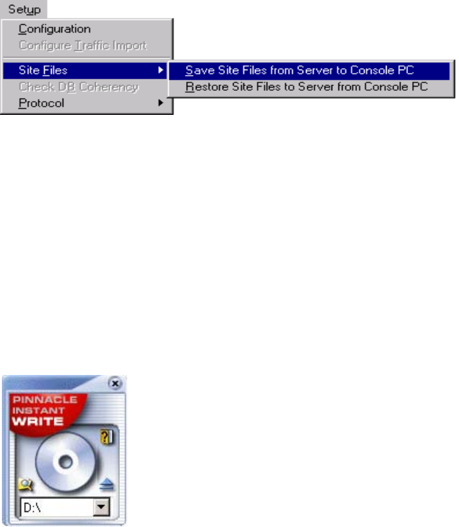
Chapter 7 Introduction to System Administration
166
Site File Protection Backup
4. From the MSi menu, select Setup > Sitefiles > Save Sitefiles from Server to Console PC.
In the resulting dialog box, enter the location to which you want to save the sitefiles.
This command copies the .cpio file to the MSi PC and renames it <hostname>.cpio; for
example, mss0101.cpio.
Saving Sitefiles to CD Disc
To save a copy of these site files on a rewritable CD disc:
1. Insert a formatted CD-recordable disc in your MSi PC and open the MSi application.
2. Drag and drop the *.cpio files onto the Instant Write window to back them up to the CD.
Avid Instant Write
3. Remove the disc and Label it Site Files <hostname>. Date it and place it in a safe place.
nThe new MSi PC provides a USB port on the back of the unit. An alternate method to save
files is to insert a USB drive in the available port and save files to the drive.
Chapter 8
Palladium Store 1000 Administration
This chapter covers the following topics related to Palladium Store 1000 administration:
• Array controller functions
• Communicating with the storage array
• Monitoring the storage array with the MSi
• Disk dialog
• Array dialog
• Rebuilding disks
• SNMP configuration
• Using the array_services utility
Palladium Store 1000 Storage System
Each MSS Networked Storage System has one or more Palladium Store 1000 storage arrays.
Each array consists a chassis with a Controller and 10 disks (in two disk sets). A disk set
consists of five disks (four data disks and one parity disk). Figure shows the Palladium Store
1000.
Controller hardware manages the disk controller functions, which include:
• Creating and writing data
• Checking parity data
• Monitoring disks array status and reporting errors
• Rebuilding disks
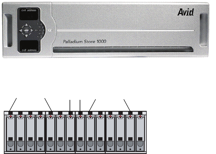
Chapter 8 Palladium Store 1000 Administration
168
PS 1000 Array - Front Bezel
PS 1000 Array - Front Bezel Removed
You can communicate with the storage array(s) via the MSi’s System Status window or the
array_services utility. Use the MSi’s System Status window for normal monitoring. The
array services utility provides additional tools for disk storage administration via a
command-line interface (see “Array Services Utility” on page 183
Using MSi to Monitor the Storage Arrays
In the event of a malfunction, the System Status button on the MSi turns red. Clicking this
button displays the System Status window in which the affected array enclosure is indicated
by a change in color. If you click the enclosure, the failed component appears in
A1 A2 A3 A4 A5 C C B1 B2 B3 B4 B5
B1 B2 B3 B4 B5
A1 A2 A3 A4 A5 C C
Bridge controllers
A and B
A drives 1 - 5 B drives 1 - 5
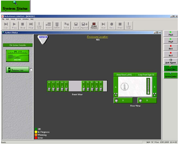
Using MSi to Monitor the Storage Arrays
169
System Status Window
The left panel of the window displays icons of the enclosures being monitored. A system
with multiple arrays will have a separate indicator for each array. Click an enclosure icon to
display the enclosure in the system status window.
Icons that function as buttons represent the power supplies, disks, array controllers, fans, and
system enclosure. Clicking any one of these buttons displays the status for that item.
Clicking the Refresh button updates the display.
Clicking in the center section of the Rear View icon opens the Enclosure Information dialog
box. This window displays the temperature status of the enclosure and other enclosure
information.
Disk Array Dialog Box
Clicking the Array button opens the Disk Array dialog box, which has four panes:
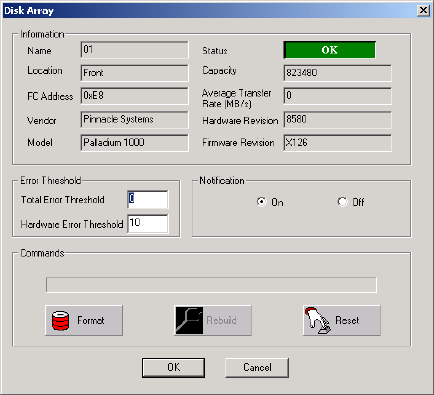
Chapter 8 Palladium Store 1000 Administration
170
Disk Array Dialog
• Information
The Information pane lists the name of the array, the user-defined location, FC address
(in hexadecimal), status of the array, disk capacity, average transfer rate, and the
hardware and firmware revision number.
•Error Threshold
Total Error Threshold determines when the array LED changes to orange (indicating a
warning, which is an intermediate error). The default setting is 0, which means no
reporting occurs. You can set a number to determine when the orange warning state
triggers (start with 25).
The Hardware Error Threshold determines how many hardware errors are required to
trigger a warning state. The default setting is 10.
• Notification
Notification is normally set to off. If you set it to on, SNMP updating occurs within 50
seconds rather than every two minutes.
• Commands (the buttons in this pane are not used).
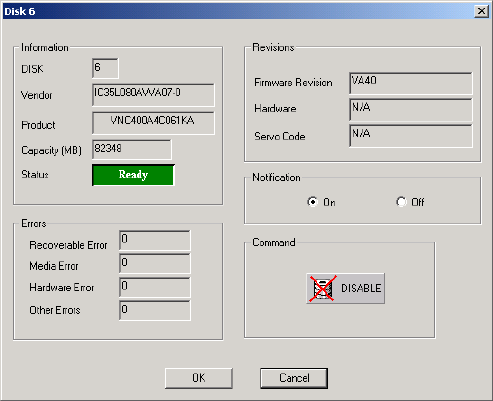
Using MSi to Monitor the Storage Arrays
171
Disk Dialog Box
There are ten labeled disk buttons representing each of the ten disks in the array. Clicking a
button opens the Disk Dialog box for that disk.
Sample Disk Dialog
There are five panes in this dialog box:
• Information
• This section lists the following: Disk number, Vendor, Capacity, and Status. Status can
be Ready, Rebuild or Failed.
•Errors
The Errors section displays four types of errors. Large numbers of Recoverable Errors
and Media Errors (100 or more) should be cause for concern and may require disabling
and a disk to prevent potential failure. In the event of Hardware Errors, contact Avid
MediaStream Support. Other Errors can be ignored.
•Revision
Shows the firmware revision number.
• Notification
The Notification field is turned off by default. In this state status is reported on the disks
every two minutes. Turning notification on, changes reporting status to every 50
seconds.
Chapter 8 Palladium Store 1000 Administration
172
• Command
Do not attempt to disable a drive before changing disks. To replace a malfunctioning
disk, simply remove it and replace it with a replacement disk. A new disk inserted in its
place automatically begins to rebuild, which can take several hours. Make sure the
Array is running in an uninterrupted manner to accomplish this task.
nIf two or more disks in an array fail, the entire array stops functioning and all data on the
array will be lost.
Rebuilding Failed Disks
nBecause the array is formatted at the factory, no reformatting is required. Should the disk
ever need reformatting, contact Avid MediaStream Support for assistance.
Failed disks are indicated by a Red LED above the Drive. When you replace a failed disk,
disk rebuild commences automatically. A rebuild calculates the lost data from the parity disk
and remaining data disks and adds it to the new disk. For information on replacing drives see
“Replacing a Drive” on page 241.
wDo not attempt firmware updates on any system that has a failed drive in one or more
arrays. No software or firmware upgrades should be performed on any malfunctioning
system.
Formatting an Array
Because the array is formatted at the factory, no reformatting is required. Should the disk
ever need reformatting, contact Avid MediaStream Support for assistance.
Creating a File System
The formatted array contains its own file system. Creating a new file system destroys all
content. If you need to create a new file system, contact Avid MediaStream Support for
assistance.
Adding Arrays
A MSS 8000 can support up to eight array chassis. Array chassis can be added in volume
sets. The initial disk set will determine how additional storage can be added to your system.
For example, if the original unit consists of two arrays, additional storage can be added in
volume sets of two to a maximum of eight array chassis, or four volume sets of two array
chassis each.
For information about adding arrays, contact Avid MediaStream Support.

SNMP Configuration
173
SNMP Configuration
Simple Network Management Protocol (SNMP) enables the monitoring of fans, power
supplies, chassis, disks, the Controller, and the Video File System. Monitoring relies on two
processes: polling, in which SNMP periodically reports its status to the MSi PC or other
monitoring computer (default polling is every two minutes), and trap notification, in which
SNMP sends an alarm within 50 seconds of a failure.
To enable SNMP monitoring, a program called snmp_config is run. The snmp_config
program configures the server to report status information via the array_services command
and the MSi System Status window. If you have multiple servers, SNMP needs to be
configured on each so that the MSi PC can monitor system components.
SNMP is first run at the factory. When you add a new server or array chassis, you need to run
this application to report the new hardware to the MSi. Also run SNMP after upgrading the
server software. Although the SNMP script is long, most information requests require that
you press Enter. The procedure is described in detail on the following pages.
Running snmp_config
1. From the /bvs directory, enter the command:
snmp_config.
2. Press Enter to run the entire script.
- - - S N M P C O N F I G U R A T I O N - - -
This interactive utility will allow the user to configure either or
both of the two SNMP configuration files, the Master Agent configuration
file /etc/srconf/agt/snmpd.cnf, and the Disk Subagent configuration file
/bvs/cfg_files/hpMsvs.cnf. Note that the program will replace the
content in the existing files.
We will begin with the Master Agent configuration file.
Press [Enter] to continue, or "s" & [Enter] skip this segment
a
nd begin with the Disk Agent's configuration file:
========================================================================
=

Chapter 8 Palladium Store 1000 Administration
174
3. If no default location has been noted, enter the location of the system.
4. The system host name request should return the value of the host name for this server.
Press Enter to accept this value.
SYSTEM LOCATION
At the prompt, enter a single line description of the location for
this MediaStream Server. This description will be returned in
response to an SNMP get request for the variable sysLocation.0 Note, a
server may be composed of multiple enclosures each with a different
location. You will be prompted for enclosure locations at a later
time. Here you may wish to enter a more general description of the
system's location than that of its enclosures, or you may wish to
enter the location of the main enclosure -- the one containing the
system processor. If you press [Enter] without typing any characters,
a default location of:
""
will be used.
Type a one line description of location on the following line
Support Lab
SYSTEM HOST NAME
At the prompt, enter the host name for the processor board inside this
MediaStream Server. If you do not know the host name, quit this
application and type "hostname" on the command line of the System
Administration window. You will likely see something like: hpmss001.
This will be the name returned in response to an SNMP get request for
sysName.0. If you press [Enter] without typing any characters, a
default IP name of:
"mss0101"
will be used.
Type the system host name and press [Enter]:

SNMP Configuration
175
5. Trap Notification allows external PCs to receive reports of system status (normal
notification occurs every 2 minutes). Enter the IP address of the MSi PC (or other
computer receiving trap notification). The Primary MSi PCs IP address is 10.xx.yy.5
with <xx> for cluster ID and <yy> for the network ID of the server in question. An
address of 10.64.1.5 would be correct as the address from Server Node 1 to the MSi PC.
6. Press Enter to review the data you entered, or press the s key to skip this step.
TRAP NOTIFICATION
At the prompt, enter the IP address, in dotted decimal format, for
each manager station configured to receive SNMP Trap Notifications.
Typically, this would be the IP address of the PC running your MSI
application. Enter as many addresses as you like, but only one per
prompt. If a default IP address is offered, you may press the [Enter]
key to accept this address, or type a new address. Type "s" and
[Enter] to skip to the next segment.
Type an IP address (def=10.64.1.3):
Type an IP address (no default):
REVIEW SNMP.CNF
A temporary version of the Master Agent configuration file has been
written to /tmp/snmpd.tmp. If you would like to review the file, selec
t
[Enter] at the prompt and the file will be displayed on the screen.
Press [Enter] to continue, or "s" & [Enter] skip the review:

Chapter 8 Palladium Store 1000 Administration
176
# Entry type: sysDescr
# Entry format: octetString
sysDescr "MediaStream Server"
# Entry type: sysObjectID
# Entry format: OID
sysObjectID enterprises.11.2.34.5
# Entry type: sysLocation
# Entry format: octetString
sysLocation "/Support Lab"
# Entry type: sysContact
# Entry format: octetString
sysContact ""
# Entry type: sysName
--More--# Entry format: octetString
sysName mss0101
# Entry type: snmpEnableAuthenTraps
# Entry format: integer
snmpEnableAuthenTraps 1
# Entry type: MAX_THREADS
# Entry format: integer
MAX_THREADS 10
# Entry type: MAX_PDU_TIME
# Entry format: integer
MAX_PDU_TIME 2500
# Entry type: MAX_OUTPUT_WAITING
# Entry format: integer
MAX_OUTPUT_WAITING 65536
# Entry type: MAX_SUBAGENTS
# Entry format: integer
MAX_SUBAGENTS 10
# Entry type: subagent
# Entry format: octetString
# Entry type: community
# Entry format: octetString
# integer
# integer
# integer
Display of contents of file
you’re just confgured.
Press space bar to scroll
to the next page.

SNMP Configuration
177
7. The server reports the data you entered and the hardware data detected by SNMP.
Several screens of data are displayed. Press the Space bar to advance to the next screen
of data.
8. Press Enter to save the changes.
9. Press Enter to continue.
10. Press Enter to restart the Master Agent.
=
========================================================================
WRITE FINAL VERSION
If you would like to accept the new Master Agent configuration file,
select [Enter] at the prompt, and the temporary file /tmp/snmpd.tmp
will replace the existing file /etc/srconf/agt/snmpd.cnf.
NOTE: The current contents of /etc/srconf/agt/snmpd.cnf will be lost.
If you choose to skip this step, both /tmp/snmpd.tmp,
and /etc/srconf/agt/snmpd.cnf will remain unchanged.
Press [Enter] to replace file, or "s" & [Enter] to skip:
File has been replaced. Press [Enter] to continue.
======================================================================
=
========================================================================
RESTART MASTER AGENT
The changes you have made to the Master Agent configuration file will not
be recognized until the agent restarts. Would you like to restart the
Master Agent now? Note: stopping the Master Agent now will cause the
Disk Subagent (hpMsvsagt) and the VFS Subagent (hpMsvsVfsagt) to be
stopped if they are running. They will have to be restarted manually.
Press [Enter] to restart Master Agent, or "s" & [Enter] to skip:
SNMP Research SNMP Agent Resident Module Version 15.1.1.8
Copyright 1989, 1990, 1991, 1992, 1993, 1994, 1995, 1996, 1997, 199
8
Research, Inc.
Agent has been restarted. Press [Enter] to continue.

Chapter 8 Palladium Store 1000 Administration
178
11. Press Enter to begin configuration of the Disk Subagent.
12. Array IDs for each configured array display. Array IDs are numbered consecutively
from 2, which indicates the first array. Verify that all arrays are listed, and press Enter.
13. To enable trap notifications, enter
y
.
=========================================================================
DISK SUBAGENT CONFIGURATION
You will now be asked several questions which will be used to set up
the Disk Subagent's configuration file /bvs/cfg_files/hpMsvs.cnf.
Press [Enter] to continue, or "s" & [Enter] skip this segment
and quit the program:
========================================================================
LIST OF ARRAY INDEXES
This network storage Cluster consists of several array enclosures.
The following array IDs have been read from the current configuration
file:
2
[Enter] to accept this list, or type a new list:
=
========================================================================
TRAP NOTIFICATION
The MediaStream Server may be configured to issue SNMP Trap Notifications
in the event of certain fault conditions. Do you wish to enable Trap
Notifications?
Type "y" or "n" then press [Enter] (def=n):

SNMP Configuration
179
14. A report of the status of the MSS 8000 enclosure is displayed. Review it to make sure
that it accurately reflects the specified enclosure, and then press Enter.
15. Enter the location of the MSS 8000 for identification purposes.
======================================================================
=
ENCLOSURE #1 CONSISTS OF THE FOLLOWING:
PRODUCT_ID: "MediaStream Server -- Series 900 -- SAN Configuration"
Component: 37N85A000
Redundant Fan Configuration
RDLocationStatus
M1Bottom-RightOK
R1Bottom-LeftOK
Redundant Power Supply Configuration
RDLocationStatus
R2Top-LeftOK
R1Bottom-LeftOK
M2Top-RightOK
M1Bottom-RightOK
Press [Enter] to accept and continue, or "q" to quit:
LOCATION OF ENCLOSURE #1
At the prompt, enter a single line description of the location for
this enclosure. This description will be returned in response to an
SNMP get request for the variable hpMsvsBoxLocation.1 If you press
[Enter] without typing any characters, a default location of:
""
will be used.
Type a one line description of location on the following line.
Support Lab
ENCLOSURE #2 CONSISTS OF THE FOLLOWING:
PRODUCT_ID: "Palladium 1000"
Component:
Redundant fans and Power Supplies
Press [Enter] to accept and continue, or "q" to quit:

Chapter 8 Palladium Store 1000 Administration
180
16. The location of the array chassis and Controllers is displayed. Review this and press
Enter.
nIf you have more than one configured array chassis, information is displayed for each.
17. Enter the location of the array chassis.
18. You have the option of reviewing the SNMP configuration data. In most cases, this is
unnecessary and you can press the
s
key to skip this step. If you do view the data, press
the space bar to view the next screen of data.
LOCATION OF ENCLOSURE #2
At the prompt, enter a single line description of the location for
this enclosure. This description will be returned in response to an
SNMP get request for the variable hpMsvsBoxLocation.2 If you press
[Enter] without typing any characters, a default location of:
"Lab"
will be used.
Type a one line description of location on the following line.
lab
REVIEW HPMSVS.CNF
A temporary version of the Disk Subagent configuration file has been
written to /tmp/hpMsvs.tmp. If you would like to review the file, select
[Enter] at the prompt and the file will be displayed on the screen.
Press [Enter] to continue, or "s" & [Enter] skip the review:

SNMP Configuration
181
FILEID:HPMSVSCNFFILE# MediaStream Server
REV:3.0# config. file format
# rev. num.
# The objects managed by the hpMsvsagt subagent, are defined in the
# hpMsvs.my, hpMsvsBox.my, hpMsvsDa.my, hpMsvsPs.my, and hpMsvsFan.my
# MIB files. They are located under the private.enterprises subtree as
# shown below:
# # iso(1).org(3).dod(6).internet(1)
# |
# private(4)
# |
# enterprises(1)
# |
# hp(11)
# |
# nm(2)
# |
# hpMediaStream(34)
# |
# ._______________________________________________.
--More--# | | |
# hpMsvs(5) msi(6) automation(7)
# |
# ._______________________________________.
# | | |
# cfg(1) hardware(2) software(3)
# |
# hpMsvsBox(1)
# |
# ._______________________________________.
# | | |
# hpMsvsBoxObjs(1) hpMsvsBoxEvents(2) hpMsvsBoxConf(3)
# |
# ._______________________________________________________________.
# | | | | | |
# hpMsvsDiskArray(1) hpMsvsPs(2) hpMsvsFan(3) hpMsvsEnc(4) hpMsvsDec(5) |
# | | | |
# hpMsvsDaObjects(1) | hpMsvsFanObjects(1) |
# | hpMsvsPsObjects(1)| hpMsvsDisk(7)
# .________. | hpMsvsFanTable(1) |
# | | hpMsvsPsTable(1) |
# hpMsvsDaTable(1)| |
--More--# | .__________________________________________.
# hpMsvsDaDiskTable(2) | | |
# hpMsvsDiskObjects(1) hpMsvsDiskEvents(2) hpMsvsDiskConf(3)
# |
# hpMsvsDiskTable(1)

Chapter 8 Palladium Store 1000 Administration
182
# This MIB defines several tables within tables. The following configuration file specifies
the values of several of the leaf-nodes or table variables managed by the subagent hpMsvsagt.
# Entry type: hpMsvsVendorID
# Entry format: octetString
VENDOR_ID: "Avid MediaStream SupportSystems"
# Entry type: hpMsvsProductID
# Entry format: octetString
PRODUCT_ID: "MediaStream Server -- Series 900 -- SAN Configuration"
# Entry type: hpMsvsOptionsList
--More--# Entry format: octetString
OPTION_LIST: "N/A"
# hpMsvsBoxTable-- Represents each seperate box in the hpMsvs system.
# BoxIndex BoxTypeId BoxTempAlarm BoxLocation
# integer integer integer octetString
BOX_TABLE: 1 5 -1 "Lab"
BOX_TABLE: 2 7 -1 "lab"
# hpMsvsDaTable-- Represents the disk arrays within each box.
# BoxIndex DaIndex DaCompId DaUserNo DaLoc DaErrT DaHwErrT DaStAlrm
# integer integer octetStr integer octetStr integer integer integer
DA_TABLE: 1 1 "N/A" 1 "Front" 0 10 -1
# hpMsvsPsTable-- Represents each seperate power supply within a box.
# BoxIndex PsIndex PsName PsLocation PsStatusAlarm
# integer integer octetStr octetStr integer
PS_TABLE: 1 1 "A" "Rear-Top" -1
PS_TABLE: 1 2 "B" "Rear-Bottom" -1
--More--
# hpMsvsFanTable-- Represents each seperate fan within a box.
# BoxIndex FanIndex FanName FanLocation FanStatusAlarm
# integer integer octetStr octetStr integer
FAN_TABLE: 1 1 "A" "Rear-Top" -1
FAN_TABLE: 1 2 "B" "Rear-Bottom" -1
# hpMsvsDaDiskTable-- Represents each seperate disk within a disk array.
# BoxIndex DaIndex DiskIndex DiskStatusAlarm
# integer integer integer integer
DA_DISK_TABLE: 1 1 1 -1
DA_DISK_TABLE: 1 1 2 -1
DA_DISK_TABLE: 1 1 3 -1
DA_DISK_TABLE: 1 1 4 -1
DA_DISK_TABLE: 1 1 5 -1
DA_DISK_TABLE: 1 1 6 -1
DA_DISK_TABLE: 1 1 7 -1
DA_DISK_TABLE: 1 1 8 -1
DA_DISK_TABLE: 1 1 9 -1
DA_DISK_TABLE: 1 1 10 -1
Press [Enter] to continue:

Array Services Utility
183
19. Press Enter to accept the changes and write the final version to the disk. Reboot the
server to initialize the changes.
Array Services Utility
The array_services utility allows you to monitor and administer the storage system from a
command-line interface. This utility translates graphical information available in the MSi
System Status window into text format. You will use this utility to upgrade the disk array
firmware, rebuild disks, and format arrays.
To display status information for a storage array, including rebuild status, online status for
each drive, and power supply and fan status, enter:
array_services array<n>
where n is the number of the array.
nThe first array is always Array 02.
WRITE FINAL VERSION
If you would like to accept the new Disk Subagent configuration file,
select [Enter] at the prompt, and the temporary file /tmp/hpMsvs.tmp
will replace the existing file /bvs/cfg_files/hpMsvs.cnf.
NOTE: The current contents of /bvs/cfg_files/hpMsvs.cnf will be lost.
If you choose to skip this step, both /tmp/hpMsvs.tmp,
and /bvs/cfg_files/hpMsvs.cnf will remain unchanged.
Press [Enter] to replace file, or "s" & [Enter] to skip:

Chapter 8 Palladium Store 1000 Administration
184
To view additional tools available from array services enter
array_services -h
.
[root@0101 /bvs] array_services array02
DEVICE STATUS:
Chassis Type: Palladium 1000
conroller..1
Controller Box Temp (celcius): 31
ARRAY STATUS:
Rebuild Bank A: Not Active
Rebuild Bank B: Not Active
Bank A
Drive 1: ONLINE
Drive 2: ONLINE
Drive 3: ONLINE
Drive 4: ONLINE
Drive 5: ONLINE
Drive 6: ONLINE
State: Redundant
Bank B
Drive 1: ONLINE
Drive 2: ONLINE
Drive 3: ONLINE
Drive 4: ONLINE
Drive 5: ONLINE
Drive 6: ONLINE
State: Redundant
Redundant Power Supply - Fan Status:
Power Supply 1: OK Power Supply 2: OK
Fan A: OK Fan B: OK

Array Services Utility
185
[root@0101 /bvs] array_services -h
array_services [option -- only one per call] device
Options for Ciprico and Palladium 1000:
device May be of the form "array01, array02..." or
"/dev/fcdss0101, /dev/fcdss0102..."
[no options] Prints array and disk status, board temperatures,
and % completion for formats and rebuilds
[-l page] Prints log page in human readable form. The
following are legal values for page:
Ciprico Pages:
0x1 -Command counters
0x2 -Block size counters
0x3 -Disk error counters
0x4 -Last 40 drive errors
0x5 -Last 15 drive failures
0x6 -Fibre channel diagnostic status
(not supported by FibreStore)
0x7 -Throughput
0x8 -FC Loop Event Count (FS - only)
0x9 -CDB stats (FS - only)
0x34 -Extended drive errors (last 40)
0x3E -Log page status (on/off)
Palladium 1000 pages:
1 - Version information and Drive Capacity
2 - Configuration information
3 - Controller information, power supply and
fan status, and rebuild status
4 - Drive status
5 - Format status
9 - Drive details
10 - Bad Block information
[-d drive] Disable a drive. Legal values for drive are
1 - 9 (Ciprico) or 1-10 (Palladium 1000)
[-e drive] Enable a drive. Legal values for drive are
1 - 9 (Ciprico) or 1-10 (Palladium 1000)
[-s] Restart array software. This is equivalent to
a power-on reset. Do not use while server running.
[-b file] Download firmware to bootrom.
If FibreStore array, must specify -I.
[-I id] Id of controller target ( 1 | 2 | A | B ).
[-t] Read main-frame temperature and fan status.
[-h] Prints this menu. Use -H for factory-only features.
Ciprico Only Options:
[-c page] Clears log page. Legal values for page are the
same as above. Also turns logging on for page.
[-T] Clears drive error thresholds.
[-r] Rebuild a drive. Fmt 1st; mode pages unchanged.
[-f] Format the array. Do not use while server running.
[-q] Quick format all disks (does not substitute for
a full format). Do not use while server running.

Chapter 8 Palladium Store 1000 Administration
186
Disk Errors and Drive Failures
array_services -l 4 array<n>
where n is the number of the array in question.
[root@1102 /users.ws/atenold/san.1] array_services -l4 array02
PAGE 0x04
----------------------------------------------------------------------
Page Code: 0x04
Page Length: 93
Reserved0: 0x0
Reserved1: 0x0
Reserved2: 0x0
Reserved3: 0x0
Drive Status:
BankA - Drive1: NOT ONLINE
BankA - Drive2: ONLINE
BankA - Drive3: ONLINE
BankA - Drive4: ONLINE
BankA - Drive5: ONLINE
BankA State: Non-Redundant
BankB - Drive1: ONLINE
BankB - Drive2: ONLINE
BankB - Drive3: ONLINE
BankB - Drive4: NOT ONLINE
BankB - Drive5: ONLINE
BankB State: Non-Redundant
Reserved4: 0x0
BankA Drive1
State: Spun Down
Message: Drive spun down from GUI
Number of read dropout errors: 0
Number of bank dropouts: 0
Number of read timeout errors: 0
Number of write timeout errors: 0
BankB Drive2
State: Online
Message: No message to report
Number of read dropout errors: 0
Number of bank dropouts: 0
Number of read timeout errors: 0
Number of write timeout errors: 0

Array Services Utility
187
Current Firmware Revision
scsi_inquiry array<n>
where
<n>
is the number of a given array.
wDo not run this command when your system is on-air. It may impact on-air operation.
Current firmware revision is published with the software release installation guides. If you
are unsure what current revision to use, check with Avid MediaStream Support.
BankA Drive3
State: Online
Message: No message to report
Number of read dropout errors: 0
Number of bank dropouts: 0
Number of read timeout errors: 0
Number of write timeout errors: 0
BankA Drive4
State: Online
Message: No message to report
Number of read dropout errors: 0
Number of bank dropouts: 0
Number of read timeout errors: 0
Number of write timeout errors: 0
BankA Drive5
State: Online
Message: No message to report
Number of read dropout errors: 0
Number of bank dropouts: 0
Number of read timeout errors: 0
Number of write timeout errors: 0
Device 'array02' converted to device name '/dev/fcdss0102'.
Drive type string = Medea SR12 FC X125SN: 00000000x024 .
Product ID:Medea SR12 FC X125SN: 00000000x024
dev_type = Palladium 1000
----------------------------------------------------------------------

Chapter 8 Palladium Store 1000 Administration
188
Array Capacity
array_services -l 1 array<n>
where <n> is the number of a given array.
PAGE 0x01
----------------------------------------------------------------------
Page Code: 0x01
Page Length: 73
Reserved0: 0x0
Controller Firmware Checksum: 50947
FPGA Checksum: 60904
Reserved1: 0x0
Reserved2: 0x0
CPU Version: 47
SWX Version: 5
Buffer Version: 32
Host Version: 2
Reserved3: 0x0
Reserved4: 0x0
Reserved5: 0x0
Reserved6: 0x0
Bridge 0 FRAID or FPGAPGA version: 86
Bridge 0 IDE01 FPGA version: 48
Bridge 0 IDE23 FPGA version: 48
Bridge 0 IDE45 FPGA version: 48
Bridge 1 FRAID or FPGAPGA version: 86
Bridge 1 IDE01 FPGA version: 48
Bridge 1 IDE23 FPGA version: 48
Bridge 1 IDE45 FPGA version: 48
Reserved7: 0x0
DiskCap :0 0 0 0
Disk Capacity BankA Drive1 (MB): 123522
Disk Capacity BankA Drive2 (MB): 123522
Disk Capacity BankA Drive3 (MB): 123522
Disk Capacity BankA Drive4 (MB): 123522
Disk Capacity BankA Drive5 (MB): 123522
Disk Capacity BankB Drive1 (MB): 123522
Disk Capacity BankB Drive2 (MB): 123522
Disk Capacity BankB Drive3 (MB): 123522
Disk Capacity BankB Drive4 (MB): 123522
Disk Capacity BankB Drive5 (MB): 123522
Reserved8: 0x0

Array Services Utility
189
Drive Information (cap, status, manufacture/f/w rev)
array_services -l 4 array<n>
where <n> is the number of a given array (see “Disk Errors and Drive Failures” on
page 186).
array_services -l 9 array<n>
where <n> is the number of a given array. As with the previous command, this page displays
information for all drives in the array. For display purposes, only the first two drives are
shown.
PAGE 0x09 DRIVE INFORMATION: Bank A Drive 1
----------------------------------------------------------------------
Page Code: 0x9
Page Length: 77
Reserved0: 0x0
Reserved1: 0x0
Num of drives: 10
Bank A, Drive 1:
Drive model number: IC35L120AVV207-0
Reserved2: 0x0
Drive serial number: VNC403C4C4ZJ2B
Reserved3: 0x0
Drive firmware revision: V240A63A
Reserved4: 0x0
Reserved5: 0x0
Reserved6: 0x0
PAGE 0x09 DRIVE INFORMATION: Bank A Drive 2
----------------------------------------------------------------------
Page Code: 0x9
Page Length: 77
Reserved0: 0x0
Reserved1: 0x0
Num of drives: 10
Bank A, Drive 2:
Drive model number: IC35L120AVV207-0
Reserved2: 0x0
Drive serial number: VNC402A4C8ZH3A
Reserved3: 0x0
Drive firmware revision: V240A63A
Reserved4: 0x0
Reserved5: 0x0
Reserved6: 0x0

Chapter 8 Palladium Store 1000 Administration
190
Configuration
scsi_set_mode array<n> –s
where n is the number of a given array. Displays current configuration.
wDo not run this command without the direction of Avid MediaStream Support. It may
impact on-air operation.
Setting Configuration on a Networked Storage System
For Controller 1:
scsi_set_mode array<n> -I 1 -d
where n is the number of a given array
wDo not run this command without the direction of Avid MediaStream Support. It can
impact on-air operation.
For Controller 2:
scsi_set_mode array<n> -I 2 -d
where <n> is the number of a given array.
scsi_set_mode array02 -s
Device 'array02' converted to device name '/dev/fcdss0102'.
PAGE 0x02
------------------------------------------------------------
Array stripe size (Bytes): 983040 (0xf0000)
Fibre channel loop ID (alpa index): 2
IDE Read Timeout (msec): 400
IDE Write Timeout (msec): 400
Non-Redun Check Condition State: 0x1
Gross timeout value: 1400 ms
Device 'array02' converted to device name '/dev/fcdss0102'.
You have chosen to set the read timeout to 400
You have chosen to set the write timeout to 400
You have chosen to set the gross timeout to 1400
You have chosen to set the stripe size to 983040
Are you sure(y or n)?y
Executing

Array Services Utility
191
Device 'array02' converted to device name '/dev/fcdss0102'.
You have chosen to set the read timeout to 400
You have chosen to set the write timeout to 400
You have chosen to set the gross timeout to 1400
You have chosen to set the stripe size to 983040
Are you sure(y or n)?y
Executing
Chapter 8 Palladium Store 1000 Administration
192
Chapter 9
Hardware Removal and Replacement
(Server Nodes and Storage System)
This chapter describes how to replace hot-swappable components in the MediaStream
products. As with any replacement procedure, it is important to understand exactly what
each procedure involves and adhere to all precautions and warnings for each specific
procedure.
wAll hardware components and boards are static sensitive. Anti-static precautions must
be used when handling these devices. This includes the use of an anti-static mat and the
use of anti-static wrist straps.
Never touch any exposed electrical connectors on the components as they can be
damaged by electrostatic discharge (ESD). Do not handle components unless you are
using the appropriate antistatic wrist or heel strap.
Field Replaceable Units (FRUs)
Each product in the MS System has a specific set of hot-swappable FRUs. The following is a
list of MS products and their respective FRUs.
MSS 8000 Server (8000)
•Boot disk
• Decoders and encoders
•Fan tray
• Fibre Channel Adapter (FCA)
• Lantronix module
•Power supply
• Server nodes
• System controller board
Chapter 9 Hardware Removal and Replacement (Server Nodes and Storage System)
194
Palladium Store 1000
• Controller
•Disk drive
•Power supply
File System Controller
•Disk drive
•Power supply
MediaStream Server
This section covers the replacement of MSS 8000 components. With the exception of the fan
tray and power supply modules, all boards and components must be removed after the server
has been shut down and turned off. Be sure to observe safe practices to avoid injury or
damage to equipment.
Boot Disk Replacement
The MS server contains a boot disk drive, accessible from the front of the server. If a boot
disk drive fails, remove and replace the boot disk drive. This procedure also requires the
reinstallation of server software.
nBecause you cannot back up site files after a Boot Drive failure, back up site files on a
regular basis. See “MSS 8000 Server (8000)” on page 193.
To remove and replace the Boot Disk:
1. Ensure you are using an anti-static wrist strap or an anti-static mat
2. Stop and halt the server by issuing the stopams command (stopams –H), and then
power the server down.
3. Firmly grasp the server bezel and remove the front bezel cover.
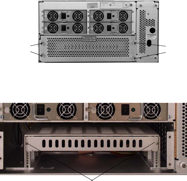
MediaStream Server
195
MS Server Front Plate (with bezel removed)
4. Loosen the four retaining screws of the front cover plate and remove cover.
Boot Disk
5. Loosen the two retaining screws holding the boot disk tray in the unit.
Retaining screws Retaining screws
Retaining screws

Chapter 9 Hardware Removal and Replacement (Server Nodes and Storage System)
196
6. Carefully slide the boot disk tray out.
7. Remove SCSI cable and unscrew drive from tray.
8. Replace with new drive reversing instructions above for installation.
Boot Drive Removal
9. Connect the Serial cable to the Server Node and the MSI PC. See Connect RS-232
Cable to Server Node and MSi PC on page 233.
10. Power on the server node, and press ESC when the following prompt appears:
11. Verify that the four bootrom monitor variables are set as shown below:
Enter
set bootaddr
The boot address is the IP address for the TFTP server. This server runs on the MSi
PC. The correct address is the VLAN address for connection between the Server
Node and the MSi PC. This command returns the following:
PMON> bootaddr = 10.xx.y.5
(where xx equals cluster ID and y equals server
ID).
If the value is incorrect, enter
set bootaddr 10.xx.y.5
(where xx equals cluster ID and y equals server ID).
Enter
set ipaddr
The IP address is the LAN address for the server node. This command returns the
following:
PMON> ipaddr = 10.xx.y.3
(where xx equals cluster ID and y equals server ID).
Autoboot command: "diskboot -x -d /dev/sd0 -o100 -l5000 -a100000 -- a;g -e 1000"
Press <Enter> to execute or any other key to abort.
MediaStream Server
197
If the value is incorrect, enter the correct value i.e.
set ipaddr 10.xx.y.3
•Enter
set gateway
The Gateway is the IP address for the external router connection. This command returns
the following:
PMON> gateway = 10.xx.y.32
(where xx equals cluster ID and y equals
server ID).
If the value is incorrect, enter the correct value.
• Enter
set netmask
The netmask for MSS Networked storage systems should always be set as follows:
PMON> netmask = 255.255.255.0
nSee Networked Storage System I/P Addressing Scheme on page 56 for information on
determining cluster ID.
12. If any of the return variables are incorrect, enter the set command followed the correct
variable.
13. Verify the flash boot string is present in the ‘flashboot’ PMON variable by entering:
set flashboot
The following should return:
PMON> flashboot = "copy 78000000 100000 900000;g -e 100020"
If this value is not present enter:
set flashboot "copy 78000000 100000 900000;g -e 100020
"
14. When finished, enter
$flashboot
This will execute the flashboot routine and flash the drive from the CPU RAM kernel.
This will take a minute or so.
15. Wait for the following prompt to appear:
Install upgrade now ('no' => exit)? (y/n; def=y):
16. At this point, insert the current server software CD in the MSI PC CDROM drive.
Follow the dialog on the MSI PC to execute the FTP transfer of data to the Server Node.
nRefer to the Software installation instructions for your upgrade for specific instructions.
17. When complete, enter
y
to begin the upgrade process.
Install upgrade now ('no' => exit)? (y/n; def=y):y
The upgrade begins. This may take a few minutes.

Chapter 9 Hardware Removal and Replacement (Server Nodes and Storage System)
198
18. When prompted with the following, enter y:
Is it ok to reboot the OS off the new disk kernel?
(y/n; def=y):
The system completes a reboot off the disk drive.
19. When the system has completed reboot press ESC at the following prompt:
20. Logon as
root
.
21. Restore Sitefiles as described below.
Restore the Site Files
To restore the site files:
1. Insert the CD with the site files into the MSi PC’s drive.
2. Open the MSi application for the server.
3. From the MSi menu, select Setup > Restore Sitefiles to Server from Console PC >
Local Disk. This command copies the site files (using ftp) from the MSi PC to the
server.
4. From your telnet session, run the command file2sitefiles.
This command will unzip the site files into its many configuration files and install the
files in their proper place.
5. The server upgrade procedure modifies the site files. Save the site files.
Replacing the Boot Disk and the System Controller
To replace the Boot Disk hardware see steps 1-6 of “Boot Disk Replacement” on page 194.
To replace the system controller see steps 1-6 of “System Controller Board” on page 235.
nConsult with Avid MediaStream Support to determine if both the System Controller and the
Boot Disk need replacement.
Waiting 00:40 to start the MSS storage controller:
- Press <return> to start the MSS Server immediately.
- Press ESCAPE to end the timeout and bypass the MSS server startup.
{ 0:40} Waiting to start MSS Server. (<Enter>=StartNow or <ESC>=DoNotS
t

MediaStream Server
199
TFTP Startup
If both the boot disk and the system controller must be replaced, the system controller must
be booted off a RAM kernel located on a TFTP server (on the MSI PC). The TFTP startup
application expects the MSI PC and the server node to be part of the same cluster.
1. On the MSI, start the Avid MediaStream SupportTFTP application by double clicking
the TFTP Server icon (on the MSi desktop). The Avid MediaStream SupportTFTP
Server application will display the MSI PC name and prompt you to enter the node
name or IP address of the server node being upgraded.
2. Enter the IP address or the hostname of the server node.
3. In the PumpKIN program window, verify that the TFTP server is set up correctly. The
program window displays PumpKIN started in the message area of the window.
nPumpKIN is a program designed to send and receive files over the net while having a
Wintalk session running using TFTP (RFC1350) protocol. It includes a full-functional TFTP
server/client so it may be useful for maintaining Cisco routers, Versanet ISP accelerators,
and other network devices.
This software is free for use and distribution as long as developers' credits are explicitly
mentioned.
Developed by: Klever Group, Inc. (http://www.klever.net/)
Author: Michael Krelin (hacker@klever.net)
Copyright 1997,1998 Klever Group, Inc.
Fan mail send to gefilte@klever.net
Options Dialog Box

Chapter 9 Hardware Removal and Replacement (Server Nodes and Storage System)
200
4. Click the Options button. The Options dialog box opens.
Change settings to the following values if not already correct:
- Select Give all files.
- Select Take all files
- Set TFTP filesystem root (download path) to C:\Program Files\Pinnacle\Tftp
- Click OK to accept changes
5. Leave PumpKIN open on the desktop so that it can accept your TFTP download
process.
6. Power on the server node. The following text appears:
7. At the prompt, set the four bootrom monitor variables are set as shown below:
Enter
set bootaddr 10.xx.y.5
(where xx equals cluster ID and y equals server
ID).
Enter
set ipaddr 10.xx.y.3
(where xx equals cluster ID and y equals server ID).
Enter
set gateway 10.xx.y.32
(where xx equals cluster ID and y equals server
ID).
Enter
set netmask 255.255.255.0
nSee Networked Storage System I/P Addressing Scheme on page 56 for information on
determining cluster ID.
8. When you have entered each variable, verify they are correct,
e.g. enter set boot addr. The prompt should return:
PMON>
bootaddr = 10.xx.y.5
9. Reboot the Server.
10. At the PMON> prompt, enter the following:
netboot -o 100000 10.xx.y.5:vg4install.kdi;g -e 104020.
* PMON/2000 Professional *
Configuration [SBS VG4,EB,NET,SCSI]
Version: C03 (Avid MediaStream SupportCustom) 1.0 Build 1.21.5.
Nov 5 2003 11:07:47
This software may be redistributed under the BSD copyright.
ih hli
MediaStream Server
201
For example, if the server node was node 1 in cluster 1, the address would be 10.64.1.5
(this is the address the server will use to reach the TFTP server on the MSi PC).
Entering this command will execute the Kernel download from the TFTP server. If the
following error appears, recheck your TFTP settings (step 4. on page 200).
"Cannot get kdi file from the host IP ###.###.###.###"
Wait for the prompt:
Install upgrade now ('no' => exit)? (y/n; def=y):
11. At this point, insert the current server software CD in the MSI PC CDROM drive.
Follow the dialog on the MSi PC to execute the FTP transfer of data to the Server Node.
If you encounter difficulties, contact Avid MediaStream SupportSystems MediaStream
Support.
12. Enter y.
Install upgrade now ('no' => exit)? (y/n; def=y):y
The upgrade begins. This may take a few minutes.
13. When prompted with the following, enter y:
Is it ok to reboot the OS off the new disk kernel? (y/n; def=y):
The system completes a reboot off the disk drive.
14. When the system has completed reboot, logon as
root
.
15. Restore Sitefiles (see Restore the Site Files on page 198).
16. When Sitefiles have been restored run
startams
to complete the reboot of the server
node.
PMON Upgrade
The PMON bootrom monitor of the system controller board may require field upgrade. If
this procedure is called out in the software install guide for a particular release, then you will
use the MSi TFTP server to accomplish this. To perform the PMON upgrade:
1. On the MSI, start the Avid MediaStream Support TFTP application by double clicking
the Avid MediaStream Support TFTP Server icon (on the MSi desktop). The Avid
MediaStream Support. TFTP Server application will display the MSI PC name and
prompt you to enter the node name or IP address of the server node in question.
2. Enter the IP address or the hostname of the server node.
3. Power on the server node, and press ESC when the following prompt appears:

Chapter 9 Hardware Removal and Replacement (Server Nodes and Storage System)
202
4. Verify that the four bootrom monitor variables are set as shown below:
Enter
set bootaddr
The boot address is the IP address for the TFTP server. This server runs on the MSi
PC. The correct address is the VLAN address for connection between the Server
Node and the MSi PC. This command should return the following:
PMON> bootaddr = 10.xx.y.5
(where xx equals cluster ID and y equals server
ID).
If the value is incorrect, enter
set bootaddr 10.xx.y.5
(where xx equals cluster ID and y equals server ID).
Enter
set ipaddr
The IP address is the LAN address for the server node. This command returns the
following:
PMON> ipaddr = 10.xx.y.3
(where xx equals cluster ID and y equals server ID).
If the value is incorrect, enter the correct value i.e. s
et ipaddr 10.xx.y.3
Enter
set gateway
The Gateway is the IP address for the external router connection. This command
returns the following:
PMON> gateway = 10.xx.y.32
(where xx equals cluster ID and y equals server
ID).
If the value is incorrect, enter the correct value.
Enter
set netmask
The netmask for MSS Networked storage systems should always be set as follows:
PMON> netmask = 255.255.255.0
nSee Networked Storage System I/P Addressing Scheme on page 56 for information on
determining cluster ID.
5. If any of the return variables are incorrect, enter the command followed the correct
variable.
Autoboot command: "diskboot -x -d /dev/sd0 -o100 -l5000 -a100000 -- a;g
1000"
Press <Enter> to execute or any other key to abort.Restore the server’s
as described below.

MediaStream Server
203
6. If variables have been changed, enter
reboot
, and press ESC when the following
prompt appears:
7. On the MSi, verify that the TFTP server (PumpKIN) is setup correctly (see TFTP
Startup on page 199).
8. Set TFTP filesystem root (download path) to D:\kdi directory. This is the directory in
which the needed PMON file is located on the installation CD.
nIf you haven’t already done so, insert the installation CD in the MSi PC, and exit the
installation prompt when it appears.
9. At the PMON> prompt, enter
set sbsexpert 1
.
10. Enter
netboot -f fff00000 -o 10000 pmon122vg4.elf
This will begin the TFTP transfer and flash of the PMON. When complete you will see
the following:
11. At the prompt, enter unset
sbsexpert
.
12. Enter
reboot
. This activates the newly loaded changes.
13. Start up the server and allow it to start normally.
14. If the server doesn’t autoboot, at the PMON> prompt, enter:
diskboot -x -d/dev/sd0 -o100 -l5000 -a100000 --a;g -e 100020
15. When the system has completed reboot press ESC at the following prompt:
Autoboot command: "diskboot -x -d /dev/sd0 -o100 -l5000 -a100000 -- a;g -e
1
Press <Enter> to execute or any other key to abort.
[DISKROOT] Install the ram kdi into flash memory.
cd /
Flash program /usr/local/bin/flash exists, let's go on.
Evaluating flash kdi revision info:
9400320 = Size of /vg4install.bin, in decimal bytes
1.5 = New /vg4install.bin revision
1.5 = Current Flashed /vg4install.bin revision
New kdi (1.5) and flash kdi (1.5) are the same, no reflash required
Waiting 00:40 to start the MSS storage controller:
- Press <return> to start the MSS Server immediately.
- Press ESCAPE to end the timeout and bypass the MSS server startup.
{ 0:40} Waiting to start MSS Server. (<Enter>=StartNow or <ESC>=DoNot
S

Chapter 9 Hardware Removal and Replacement (Server Nodes and Storage System)
204
16. Logon as root and enter the following command:
installbvs -c
17. When the prompt returns, the process is complete. Restart the server by
entering
stopams
.
Replacing or Adding Decoder/Encoder Boards
You may add decoder and/or encoder channels in any server to a maximum of 12 channels.
Multiple types of decoders can be configured in individual servers.
The following table shows the part numbers and the MediaStream Server (MSS) system
software version associated with the Rev 3 decoder/encoder boards.
nIf you exchanged a board, your part number becomes the Exchange Part Number for the
original board as shown in the table.
n* The Exchange Part No. is the replacement board part number. Use this number if you have
replaced the original board.
nIf you upgrade your board, you may need to upgrade your MediaStream Server (MSS)
software to the supported software version.
As of the 37N914XXX series, the boards do not have an internal termination for Genlock, so
an external terminator is required.
Avid MediaStream Avid MediaStream SupportI/O Board Part Numbers and
Software Version
Board Part No. Description
Exchange Part
No.
MSS
Version
Network
Storage
System Version
37N21A000 Dual Decoder 37N200321 B.09.30 C.15.72
37N21B000 Dual Decoder
w/SMPTE-356M 37N200353 B.09.40 C.16.00
37N20D001 Single Channel SD Encoder 37N200138 B.09.40 C.16.00
37N20E001 Dual Channel SD Encoder 37N200139 B.09.40 C.16.00
37N20E100 SD Encoder/SD Decoder 37N2000354 B.09.40 C.16.00
Replacing or Adding Decoder/Encoder Boards
205
nIf you install a loop-through cable that is not connected at the other end, the Genlock will
not be terminated.
Identifying a Faulty Decoder
Determining whether a decoder has failed can be a difficult task. You will need to
troubleshoot error log files, run diagnostic programs, and check hardware and software
configurations. Making the determination may require Avid MediaStream Support
assistance.
After a faulty decoder has isolated, you need to identify the decoder. Enter vmescan -d
to display a list of the decoders and their hardware addresses. At the back of the board, an
LED displays the board’s port address, for example, DEC 1. Decoder 1 occupies port ID 0
on the VME bus. For dual decoder boards, the display alternates between the two decoder
port addresses.
Removing a Decoder
Before removing a decoder board, shut down the server and turn off the power.
To remove the board:
1. Disconnect any audio and video cables that are attached to the board and any other
cables that may prevent removal of the board from the card cage.
2. Loosen the two captive screws (one at each end of the board) that secure the board in the
cage.
3. If a blanking panel is installed below or above the decoder board, remove it. If another
board is installed in this position, loosen its retaining screws. Use the ejection levers to
pull the board about 1 inch out of the card cage.
4. Use the ejection levers to pull the board loose from its connectors, then gently remove
the board from the server.
5. Set the dip switches on the replacement decoder to the appropriate port number. Dual
decoders have two sets of dip switches (see Figures 9-13 and 9-14 for correct decoder
settings).
6. Insert the new decoder in the VME chassis. Make sure the board is firmly seated in the
chassis before screwing it down.
7. Once the new board has been installed, and all of the cables reconnected, turn on the
server and ensure that the software loads properly.
8. If there are problems with the software, or the decoder does not operate correctly:

Chapter 9 Hardware Removal and Replacement (Server Nodes and Storage System)
206
Enter
vmescan -d
to display a list of the decoders in the server. If the new decoder is
not displayed in the list, shut down and turn off the server and remove the board. Check
the address switches to verify the correct settings. Reseat the board and restart the
server. If there still are problems, call Avid MediaStream Support.
Adding a New Decoder
Setting the Address
There are two sets of dip switches (one for each channel) on each board. With dual decoder
boards, both the primary and secondary address switches must be set. On single channel
boards, only the primary switch must be set. The switches are mounted towards the back of
the board as shown in .
Decoder Dip Switches
Dip Switch Settings
shows the dip switch settings for the decoder board. Each dip switch has eight micro
switches that need to be set for board configuration. To set the board correctly, view it with
bit 8 on the left and bit 1 on the right as shown. The bits are numbered from 8 to 1 (1 is the
Least Significant Bit).
• Set bits 7-5 to the correct Device ID .
• Bits 4-1 are set in binary.
• Set channel 1 to address 0000, and number sequentially from there for each channel to a
maximum of 1111.
Secondary switch
Primary switch
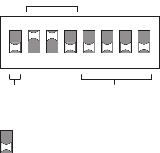
Replacing or Adding Decoder/Encoder Boards
207
• For dual boards, the hardware address for the primary and secondary switches must be
unique.
Dip Switch Settings
Setting the Hardware Address
Before you can install a new decoder board in the server, you must set its hardware address.
The MediaStream software relies on a unique address for each channel.
The dual decoder boards represent two channels and require two addresses. The
MediaStream software will recognize one board as two separate decoders.
To determine the right address:
1. Start a telnet session for the server in which you plan to install the board.
2. Enter
vmescan -d
to view a list of all the installed decoders and their addresses. Select
two unused addresses for the new Card.
In the example below, the positions 0 and 1 (Decoder 1 and Decoder 2) are taken.
Subsequent addresses up to Decoder 16 are available.
ON
12345678
1
0
Hardware
Address
Debug
Leave At "0"
Device ID
Note: White is switch position
in this case white is down or 0
Device ID
110 = SD
100 = HD
001 = HD & MPEG IN
010 = MPEG OUT
LSB

Chapter 9 Hardware Removal and Replacement (Server Nodes and Storage System)
208
Installing a Decoder Board
Always shut down the server before installing a decoder board.
To shut down the server:
1. Start the MSi application. From the System Administration window, open a telnet
session and enter the command
stopams -H
.
2. When this message is displayed, turn off the power switches on the back of the server:
Halting (in tight loop) –OK to Hit Reset Button
To install the board:
1. Move or disconnect any cables that might interfere.
2. Select an unused slot in the server, and remove the screws and cover plate.
3. Carefully, slide the new decoder board into the slot.
4. Press the board firmly to seat it into the connectors at the rear of the frame. The front
panel should be flush with the other boards in the server.
5. Tighten the attached retaining screws.
6. Attach your video output cables.
7. Attach your audio output cables.
8. Attach your Genlock cables, if required.
nIf the Genlock signal terminates at a dual decoder board, you do not need to attach a
terminator as the board is internally terminated. However, it there are more boards
connected to the Genlock Loop, install a terminator on the last one.
nThe HD Input board requires no Genlock.
[root@08 /bvs/tmp] vmescan -d
Indx Type <-- Address Range --> <Queried> <Conclusion>
32 Decoder 0x80000000 0x83FFFFFFF 0x00000000 4:2:2 EA decoder
FOUND at -d 0
33 Decoder 0x84000000 0x87FFFFFFF 0x00000000 4:2:2 EA decoder
FOUND at -d 1
34 Decoder 0x88000000 0x8BFFFFFFF 0x00000000 No board found.
35 Decoder 0x8C000000 0x8FFFFFFFF 0x00000000 No board found.
36 Decoder 0x90000000 0x93FFFFFFF 0x00000000 No board found.
45 Decoder 0xB4000000 0XB7FFFFFFF 0xffffffff No board found.
46 Decoder 0xB8000000 0xBBFFFFFFF 0xffffffff No board found.
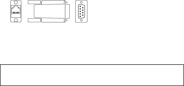
Replacing or Adding Decoder/Encoder Boards
209
9. Use two RJ-45 to RS-422 adapters and the RS-422 control cable to provide connections
from the station’s automation to the RJ-45 connectors on the board. Use one connector
on Port A for connection to a single port. For dual ports, use both Port A and Port B
connectors
LAN-to-RS-422 Adapter
.
10. Reconnect any cables you removed during dual decoder board installation.
11. Turn the power switches back on.
12. Monitor the server’s boot process from the MSi’s System Administration window.
When this message appears, press the Esc before the AMS application starts:
Software Configuration
In order for the new boards to boot up correctly and be available for use, you
need to configure the bvsrc file on the server using the edit_bvsrc command.
Run vmescan
Before configuring the decoder boards, verify that the new boards are available
to the system and that the dip switches are set correctly. To do this, run the
vmescan command with the decoder flag (
vmescan -d
), which reports all
available decoders on the VME bus.
An example of the output from the command follows. The output addresses start
at 0. The system found six dual decoder boards configured at hardware ID’s 0-
11.
Waiting 00:40 to start the MSS storage controller:
- Press <return> to start the MSS Server immediately.

Chapter 9 Hardware Removal and Replacement (Server Nodes and Storage System)
210
Check that the board you inserted shows up correctly addressed. If the board
does not appear in the list, run vmescan without a command flag to find out if the
board shows up as an “unknown” board.
If the board shows up as unknown or without the correct ID, shut down and turn
off the server. Remove the board and reset the dip switches to the correct ID. If
the board does not appear in the list, shut down the server and reseat the board. In
all cases, restart the server and re-run vmescan. Call Avid MediaStream Support
if you still cannot detect the board with the correct ID.
Run edit_bvsrc
When the boards have been correctly identified with vmescan, run edit_bvsrc
from /bvs. This command begins an interactive script that will result in a
correctly configured bvsrc file. Follow the instructions on the screen to complete
this procedure. The bvsrc file is required to correctly initialize the new boards so
they will be available to the system.
When the script has finished, verify the output. To do this, navigate to /bvs and
enter vi bvsrc. If the files are incorrect, manually edit them in vi. Consult Avid
MediaStream Support if you have questions regarding the proper input for the
bvsrc file.
[root@08 /bvs/tmp] vmescan -d
Indx Type <-- Address Range --> <Queried> <Conclusion>
32 Decoder 0x80000000 0x83FFFFFF 0x00000000 dual SD decoder r1 (P) FOUND at -
d
33 Decoder 0x84000000 0x87FFFFFF 0x00000000 dual SD decoder r1 (S) FOUND at -
d
34 Decoder 0x88000000 0x8BFFFFFF 0x00000000 dual SD decoder r1 (P) FOUND at -
d
35 Decoder 0x8C000000 0x8FFFFFFF 0x00000000 dual SD decoder r1 (S) FOUND at -
d
36 Decoder 0x90000000 0x93FFFFFF 0x00000000 dual SD decoder r1 (P) FOUND at -
d
37 Decoder 0x94000000 0x97FFFFFF 0x00000000 dual SD decoder r1 (S) FOUND at -
d
38 Decoder 0x98000000 0x9BFFFFFF 0x00000000 dual SD decoder r2 (P) FOUND at -
d
39 Decoder 0x9C000000 0x9FFFFFFF 0x00000000 dual SD decoder r2 (S) FOUND at -
d
40 Decoder 0xA0000000 0xA3FFFFFF 0x00000000 dual SD decoder r2 (P) FOUND at -
d

Replacing or Adding Decoder/Encoder Boards
211
Example Lines in the bvsrc File
The following are examples of the output you should see in the bvsrc file for dual
SD Decoders, dual HD Decoders, and HD Input Cards. The data fields that
change can be seen under the headings of Decoder/Encoder Model+Rev and
Video Decoder/Encoder Firmware File.
Note: The HD Input board will appear in the Encoder section of the file, while
all decoders will appear in the section reserved for decoders.
Hardware address (set with the dip switch) appear under the heading
Decoder/Encoder HW Addr. The first address is 0, there can be a maximum of 12
total input/output (encoder/decoder) ports per MSS 8000.
Dual SD Decoder
Decoder HD Decoder
# BVScpu Decoder Decoder Video Decoder Hardware Vide
o
# Type name HW Addr Model+Rev Firmware File Cfg File P.Nu
m
VIDEO_OUT: hpmss001 0 "dual SD decoder" "hd_code" "/dev/null" 1
VIDEO_OUT: hpmss001 1 "dual SD decoder" "hd_code" "/dev/null" 2
# BVScpu Decoder Decoder Video Decoder Hardware Vide
# Type name HW Addr Model+Rev Firmware File Cfg File P.Nu
m
VIDEO_OUT: hpmss001 0 "HD decoder" "hd_code" "/dev/null" 1

Chapter 9 Hardware Removal and Replacement (Server Nodes and Storage System)
212
MPEG Output
HD or MPEG Input Card
When the bvsrc file has been appropriately edited, run
startams
to start the server. When
the server has successfully booted, the card installation is complete.
# BVScpu Decoder Decoder Video Decoder Hardware Vide
o
# Type name HW Addr Model+Rev Firmware File Cfg File P.Nu
m
VIDEO_IN: hpmss001 0 "MPEG out" "mpi_code" "/dev/null" 1
VIDEO_IN: hpmss001 0 "MPEG out" "mpi_code" "/dev/null" 2
# BVScpu Encoder Encoder Video Encoder Hardware Vide
o
# Type name HW Addr Model+Rev Firmware File Cfg File P.Nu
m
VIDEO_IN: hpmss001 0 "MPEG in" "mpi_code" "/dev/null" -1
VIDEO_IN: hpmss002 1 "MPEG in" "mpi_code" "/dev/null" -2

Replacing or Adding Decoder/Encoder Boards
213
Configure MSi to Include New Channels
When the server has successfully started, open the MSi application.
Configuration Dialog
1. Select Setup > Configuration. The Configuration dialog box appears.
2.In the Play Window pane of the Configuration dialog box, select a Play
button from the Name menu.
3.Select a Decoder Port for each channel you have added and click the
Setup button to define the settings for the port.
4.Click OK. When you exit the Configuration dialog box, there should
be new Play buttons on the MSi window for each channel you added.
5.Click one of the new Play buttons and play a clip to confirm the board
operates correctly.

Chapter 9 Hardware Removal and Replacement (Server Nodes and Storage System)
214
Identifying a Faulty Encoder
The MSS 8000 has encoder boards installed from the top slot down in the chassis with
Encoder number 1 usually as the top encoder board, although encoder boards can be
installed in any order. The only way to confirm that the correct board is being replaced is to
check the dip switches on the board.
Removing and Replacing an Encoder
Prior to removing an encoder board, the server must be shutdown and turned off. To remove
the board:
1. Disconnect any audio and video cables attached to the board and any other cables that
may prevent removal of the board from the card cage.
2. Loosen the captive screws that secure the board in the cage.
3. If a blanking panel is installed below or to the right of the encoder board, remove it.If
another board is installed in this position, loosen its retaining screws. Use the ejection
levers to pull the board about 1 inch out of the card cage.
4. Use the ejection levers to pull the board loose from its connectors then gently remove
the board from the server.
5. Encoder replacement is the reverse of the removal process. Insert the board firmly into
the card cage.
6. Once the new board has been installed and all of the cables have been reconnected, turn
on the server and ensure that the software startup process completes without errors.
7. If the startup process has errors or the encoder does not operate correctly:
8. Enter vmescan -e to display a list of the encoders in the server. If the new encoder is
not displayed in the list, remove the board and check the address switches. Re-fit the
board and try the boot up process again. If there still are problems, call Avid
MediaStream Support.
[root@01 /bvs] vmescan -e
Indx Type <-- Address Range --> <Queried> <Conclusion>
48 Encoder 0xC0000000 0xC3FFFFFF 0x00000000 dual SD enc r3* FOUND at -e 0
Encoder 0xC4000000 0xC7FFFFFF 0xffffffff No board found.

Replacing or Adding Decoder/Encoder Boards
215
Encoder Address Dip Switch Settings
The following figure shows the dip switch settings for the encoder board. Each dip switch
has eight micro switches that need to be set for board configuration. To set the board
correctly, view it with bit 8 on the left and bit 1 0n the right, as shown in the diagram. The
bits are numbered from 8 to 1(1 is the Least Significant Bit).
1. Set bits 8-5 to 1001 for the Device ID setting.
2. Set Bits 4-1 according to the binary address for each encoder, ranging from hardware
address 0000 for “port 0” Encoder 1 up to address 1111 for “port 15” Encoder 16.
Encoder Dip Switch Settings
nAlthough hardware address 15 is “legal,” no more than 12 total input/output channels are
allowed on a single MSS 8000. Typically, encoders are sequenced in order from port 0 to the
last configured encoder on the server.
Encoder Dip Switch Location
The following figure shows the location of the encoder dip switches.
ON
12345678
1
0
Hardware
Address
Device ID
Note: White is switch position
in this case white is down or 0
Device ID
0110 = SD Decoder
0100 = HD Decoder
0001 = HD & MPEG IN
0010 = MPEG OUT
1001 = SD Encoder
LSB
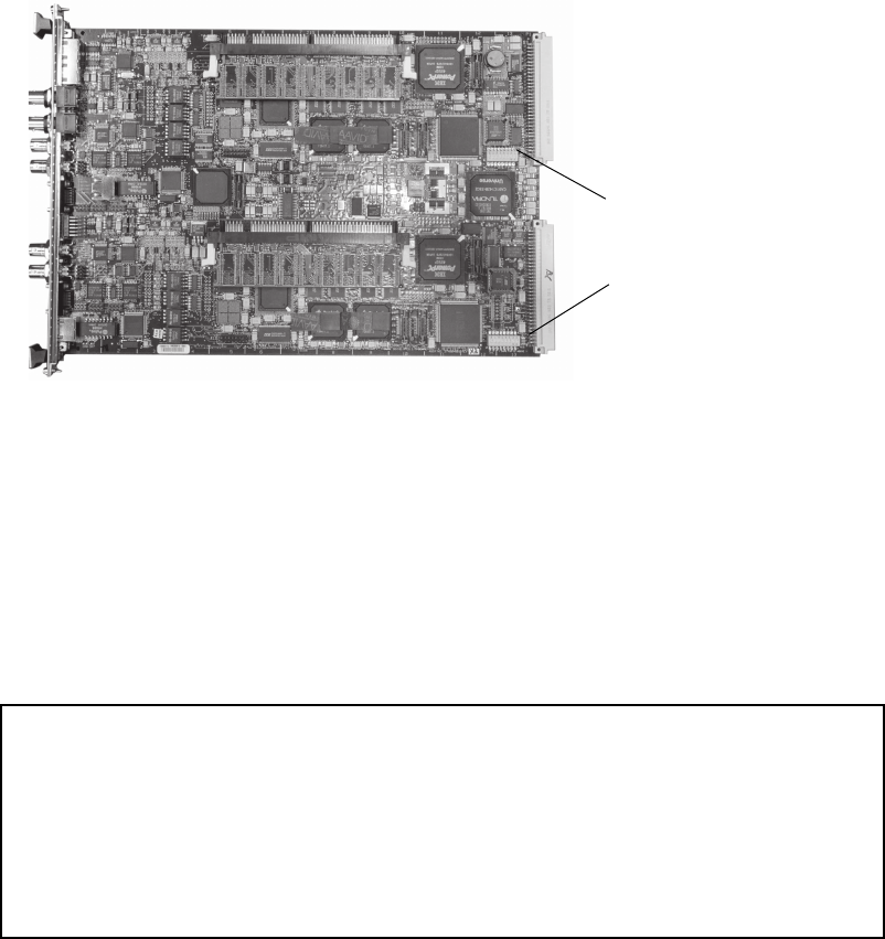
Chapter 9 Hardware Removal and Replacement (Server Nodes and Storage System)
216
Encoder Dip Switch Location
Adding Encoder Boards
Before you can install a new encoder board, you must set its hardware address.
To determine the right address:
1. Start a telnet session for the server in which you plan to install the board.
2. Enter vmescan -e to display a list of all the installed encoders and their addresses.
Select two unused addresses for the new board.
In this example, position 0 (Encoder 1) is taken. All addresses after that, to Encoder 16, are
available.
Encoder Installation
You must shut down the server before installing an encoder board.
Secondary switch
Primary switch
[root@1401 /bvs] vmescan -e
Indx Type <-- Address Range --> <Queried> <Conclusion>
48 Encoder 0xC0000000 0xC3FFFFFF 0x00000000 dual SD enc r3* FOUND at -e 1
49 Encoder 0xC4000000 0xC7FFFFFF 0xffffffff No board found.
50 Encoder 0xC8000000 0xCBFFFFFF 0xffffffff No board found.
51 Encoder 0xCC000000 0xCFFFFFFF 0xffffffff No board found.
52 Encoder 0xD0000000 0xD3FFFFFF 0xffffffff No board found.
53 Encoder 0xD4000000 0xD7FFFFFF 0xffffffff No board found.
54 Encoder 0xD8000000 0xDBFFFFFF 0xffffffff No board found.

Replacing or Adding Decoder/Encoder Boards
217
1. Start the MSi application. From the System Administration window, open a telnet
session and enter the command
stopams -H.
2. When this message is displayed, turn off the power switches on the back of the server:
3.
Halting (in tight loop) –OK to Hit Reset Button
.
4. Move or disconnect any cables that might interfere.
5. Select an unused slot in the server and remove its screws and cover plate.
6. Carefully, slide the new encoder board into the slot.
7. Press the board firmly to seat it into the connectors in the rear of the frame. The front
panel should be flush with the other boards in the server.
8. Tighten the attached retaining screws.
9. Attach your video Input cable.
10. Attach your audio Input cable.
11. Attach RS-422 cables for Automation.
12. Reconnect any cables you removed during encoder board installation.
13. Turn on the power switches on.
14. Monitor the system startup from the MSi’s System Administration window. When this
message appears, press the Esc button before the AMS application starts:
Software Configuration
For the new boards to boot up correctly and be available for use, configure the bvsrc file on
the server (using edit_bvsrc). For the server to recognize the latest releases of these boards,
the server needs to be running the latest MSS software.
Run vmescan
Before configuring the encoder board(s), verify that the new board(s) are available to the
system and that the dip switches are set correctly. To do this, run the command vmescan
-e. This command reports all available encoders on the VME bus.
An example of the output from the command follows. The output addresses start at 0. The
system found two encoder boards configured at the hardware IDs 0-1.
Waiting 00:40 to start the MSS storage controller:
- Press <return> to start the MSS Server immediately.
- Press ESCAPE to end the timeout and bypass the MSS server startup.
{ 0:40} Waiting to start MSS Server. (<Enter>=StartNow or <ESC>=DoNotStart)

Chapter 9 Hardware Removal and Replacement (Server Nodes and Storage System)
218
Check that the board you inserted in the system shows up correctly addressed. If the board is
not listed, run vmescan without the command flag to determine if the board is incorrectly
addressed, or listed as an “unknown” board.
If the board shows up as unknown or without the correct ID, shut down and turn off the
server. Then, remove the board and reset the dip switches to the correct ID. If the board does
not appear in the list, shut down the server and reseat it. In all cases, restart the server and re-
run vmescan to see if the board is listed with the correct ID. If there is still a problem, call
Avid MediaStream Support.
Run edit_bvsrc
When the boards have been correctly identified with vmescan, run edit_bvsrc from the /bvs
directory. This command begins an interactive script that will result in a correctly configured
bvsrc file. Follow the instructions on the screen to complete this procedure. The bvsrc file is
required to correctly initialize the new boards so they will be available to the system.
When the script has finished, open the bvsrc file in vi to verify the output. To do this, go to
the directory /bvs and enter vi bvsrc. If the files are incorrect, manually edit them in vi.
Consult Avid MediaStream Support if you have questions regarding the bvsrc file.
Example Lines in the bvsrc File
The following is an example of the output you should see in the bvsrc file for the 4:2:2
Encoder Board. The data fields that will change are under the headings of Encoder
Model+Rev, and Video Encoder Firmware File.
nThe HD Input board will appear in the Encoder section of the file, while all decoders will
appear in the section reserved for decoders.
Hardware address (set with dip switch) will appear under the heading Encoder HW Addr.
The first address is 0 up to 12 maximum total input/output (Encoder/Decoder) boards per
MSS 8000.
Indx Type <-- Address Range --> <Queried> <Conclusion>
48 Encoder 0xC0000000 0xC3FFFFFF 0x00000000 4:2:2 Encoder FOUND at -e 0
Encoder 0xC0000000 0xC3FFFFFF 0x00000000 4:2:2 Encoder FOUND at -e 1
50 Encoder 0xC8000000 0xCBFFFFFF 0xffffffff No board found.
51 Encoder 0xCC000000 0xCFFFFFFF 0xffffffff No board found.
52 Encoder 0xD0000000 0xD3FFFFFF 0xffffffff No board found.
53 Encoder 0xD4000000 0xD7FFFFFF 0xffffffff No board found.
54 Encoder 0xD8000000 0xDBFFFFFF 0xffffffff No board found.
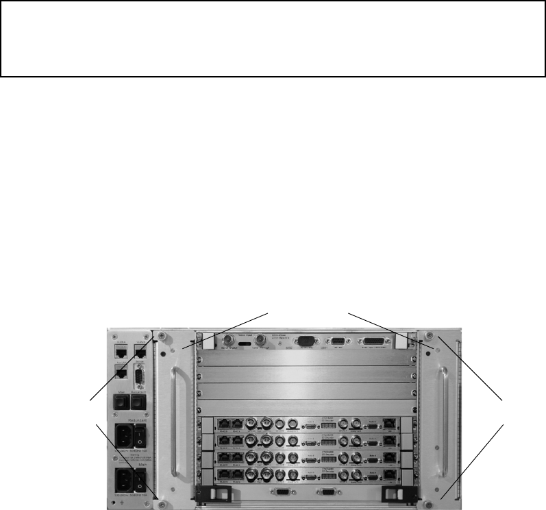
Replacing or Adding Decoder/Encoder Boards
219
When the bvsrc file has been appropriately edited, run startams to start the server. When
the server has successfully booted, the board installation is complete.
Server Fan Tray Replacement
The MSS 8000 server node contains two rear-mounted, hot-swappable fan tray modules. If a
fan tray fails, the right LED on the front panel will turn red. The server can run safely with
one functional fan tray.
MS Server Fan Tray
To replace a fan tray:
1. Ensure you are using an anti-static wrist strap or an anti-static mat.
2. Loosen the two retaining screws securing the fan tray to the chassis.
3. Use the tray handle to slide the tray out of the assembly a few inches.
cWait at least minutes for fans to stop spinning after being disengaged from unit.
4. Avoid touching any spinning fan blades.
5. Replace the fan tray with the replacement unit and secure the mounting screws.
Indx Type <-- Address Range --> <Queried> <Conclusion>
48 Encoder 0xC0000000 0xC3FFFFFF 0x00000000 4:2:2 Encoder FOUND at -e 0
Encoder 0xC0000000 0xC3FFFFFF 0x00000000 4:2:2 Encoder FOUND at -e 1
50 Encoder 0xC8000000 0xCBFFFFFF 0xffffffff No board found.
Fan trays (2)
Retaining
screws
Retaining
screws

Chapter 9 Hardware Removal and Replacement (Server Nodes and Storage System)
220
MS Server Fan Tray Module
Lantronix Module Replacement
The MS server contains a Lantronix module and an internal Ethernet LAN hub mounted on
a removable tray on the front right side of the MS server chassis. Lantronix module failure
interrupts communications through the server’s console port.
To remove for service or replacement:
1. Ensure you are using an anti-static wrist strap or an anti-static mat.
2. Safely shut down and power down the MS server.
3. Firmly grasp the server bezel and remove the front bezel cover.
4. Loosen the four captive screws of the front cover plate.
MS Server Front Plate (with bezel removed)
5. Carefully, slid the Lantronix module partially out of the server chassis.
Retaining screws
of front panel
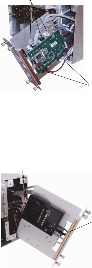
Lantronix Module Replacement
221
6. Support the Lantronix module and unscrew the three RS-232 cables from the board
assembly.
Lantronix Module (Right Side)
7. Disconnect the two circuit board connectors on the bottom of the board assembly.
8. Disconnect the 5-volt DC power connector from the LAN hub mounted on the opposite
side of the Lantronix module (see the following figure).
9. Disconnect the three RJ-45 cable connectors from () the LAN hub (see the following
figure).
Lantronix Module (Left Side)
RS-232 connectors
Circuit board connectors
RJ-45 connectors
5V OC Power
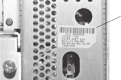
Chapter 9 Hardware Removal and Replacement (Server Nodes and Storage System)
222
10. Slide the Lantronix module out.
11. Install the replacement module and reconnect the cables in the order you removed them.
Lantronix Setup
After installing the new Lantronix module, it must be configured to allow telnet
communication through the console port. The module has a tag on its faceplate containing
the Lantronix MAC address a 12-digit Hexidecimal number (see the following figure). You
need to use this number for the unit’s configuration.
MAC Address Location
To configure the module:
1. Power up the MS server and let it boot up.
2. On the MSi PC, double-click the MediaStream Console Setup icon. The Console Setup
dialog box opens.
3. Enter the 12-digit MAC address number into the MAC Address data field. Separate each
two-digit number with a hyphen (-).
Lantronix module
MAC address
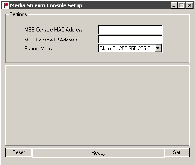
Lantronix Module Replacement
223
Console Setup Tool Dialog
4. Enter the correct LAN address in the IP Address field. The address should be as follows:
10.XX.YY.4 where <XX> equals cluster subnet and <YY> equals server node.
For example, 10.64.1.4 is the console address for server node 1 in cluster 1 (see VLAN
Topology on page 51).
5. The subnet mask should be Class C – 255.255.255.0. If all entries are correct, press Set.
6. The dialog box shows the progress of the setup. If successful, Setup successfully
finished displays at the bottom of the window.
7. Close the dialog box. Setup is complete.
Lantronix Troubleshooting
If the Console Tool fails to set up the Lantronix module correctly, you may have to perform
a manual setup. Manual configuration requires There are two options to manually configure
the Lantronix module, one is to log on to the unit via Telnet or connect the unit with a 9-pin
null-modem cable and the other is to log on via Hyperterminal.
Telnet Logon
Logon procedures are slightly different for system operating on Windows 2000 and
Windows NT. If you are using a third-party program, follow its instructions. Open a telnet
session without specifying the hostname or IP address. Specify the port as 9999. This will
log on to the Lantronix transceiver rather than the MSS 8000 console port.
nNote: Telnet logon cannot be used when installing a new Lantronix module.
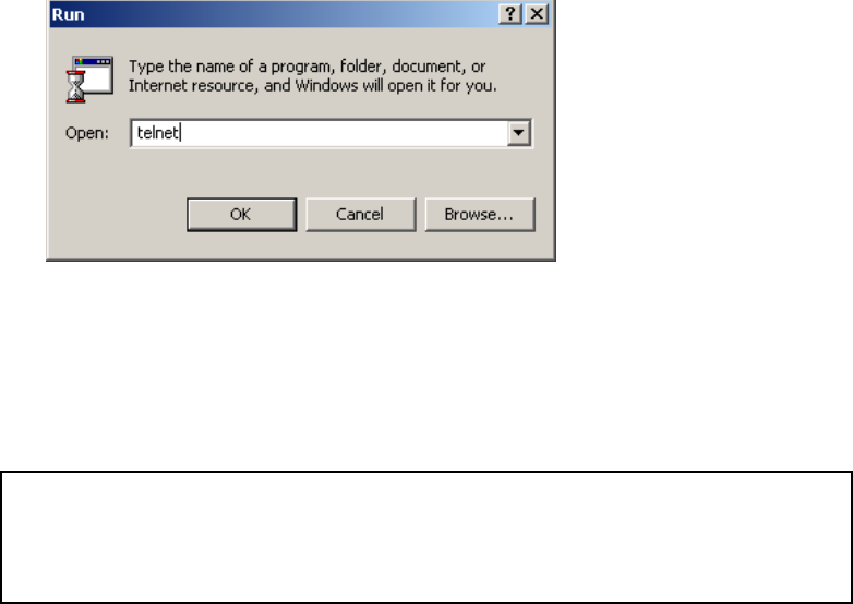
Chapter 9 Hardware Removal and Replacement (Server Nodes and Storage System)
224
To open a telnet session from systems using Windows 2000:
1. From the Start menu, select Run and enter telnet in the dialog. Press OK.
Run Telnet Dialog
2. At the prompt enter the following:
open <hostname> or <IP address> <port ID>
For example, con0101 or 10.64.1.4 followed by 9999 for port ID
The Lantronix session opens with the following display:
*** Lantronix Universal Device Server ***
Serial Number 5223866 MAC address 00:20:4A:52:5D:3A
Software Version V04.2 (000908)
Press Enter to go into Setup Mode

Lantronix Module Replacement
225
3. Press Enter. The following text displays:
4. Press 0 to enter Server Configuration.
HyperTerminal Logon
If you do not know the IP address of the Lantronix unit (this may be the case if the unit is a
replacement), you can also log on via Hyperterminal to obtain the IP address. Attach a cable
between the Lantronix module and the MSi PC using a male to female 9-pin null-modem
cable or a female-to-female cable with a male pass-through gender changer.
To connect the Lantronix module and the MSi PC:
1. Ensure you are using an anti-static wrist strap or an anti-static mat.
2. With the MSS 8000 running, unscrew the four retaining screws on the Lantronix module
and carefully slide the unit out, taking care not to crimp or unplug attached cables.
3. Carefully remove the center RS-232 cable on the right side of the Lantronix module
interface board (see the following figure).
*** basic parameters
Hardware: Ethernet Autodetect
IP addr 010.073.001.004, no gateway set,netmask 255.255.255.000
***************** Channel 1 *****************
Baudrate 9600, I/F Mode 4C, Flow 00
Port 00023
Remote IP Adr: --- none ---, Port 00000
Connect Mode: C0 Disconn Mode: 40 Disconn Time: 30:00
Flush Mode: 00
Terminal name:
***************** Channel 2 *****************
Baudrate 9600, I/F Mode 4C, Flow 00
Port 10002
Remote IP Adr: --- none ---, Port 00000
Connect Mode: C0 Disconn Mode: 00
Flush Mode: 00
Change Setup : 0 Server configuration
1 Channel 1 configuration
2 Channel 2 configuration
7 Factory defaults
8 Exit without save
9 Save and exit Your choice ? 0
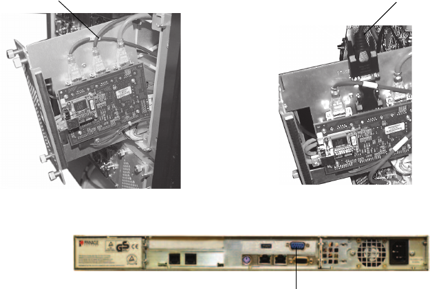
Chapter 9 Hardware Removal and Replacement (Server Nodes and Storage System)
226
4. Attach the male side of the cable or the male gender changer to the center connector on
the interface board.
5. Attach the female side of the cable to the COM 1 port of the MSi PC.
Serial Connection to Lantronix Unit
To start Hyperterminal:
1. On the PC, open the Hyperterminal program. Go to Start > Programs Accessories >
Communication > Hyperterminal.
2. The Connection Description dialog box displays. Enter a value for the Name, and click
OK.
3. Select COM1 in the Connect To dialog box.
4. Enter the values in the COM1 Properties dialog box and click OK.
Attach cable to the moduleRemove the center RS-232 connector
Attach RS-232 cable to serial port on MSi PC
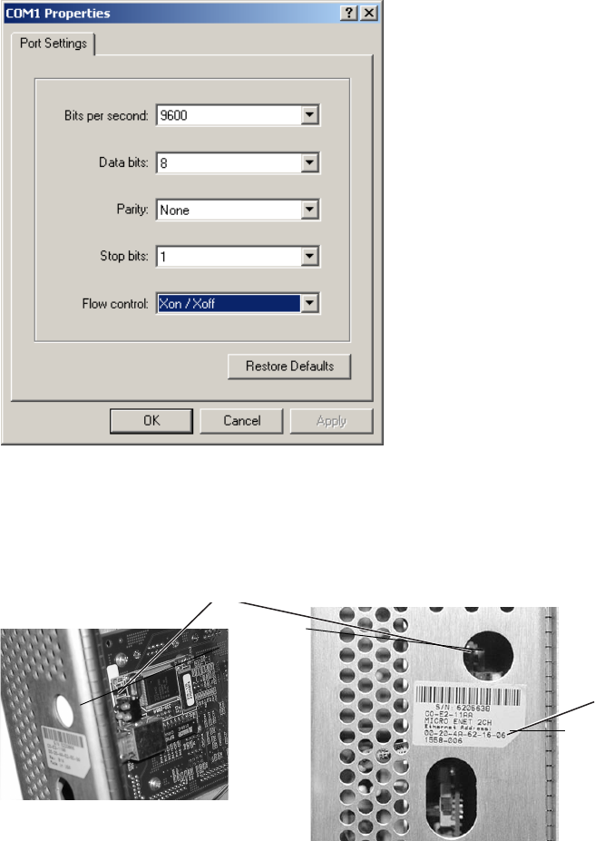
Lantronix Module Replacement
227
COM1 Properties
5. To log on to the Lantronix unit, press the reset button on the interface board. You will
next use the keyboard. Count to three by one thousands (1001, 1002, 1003) and then
press three lower-case x characters (xxx) followed by pressing Enter.
Lantronix Reset Switch
nYou may have to repeat this procedure. The timing needs to be right in order to access the
Lantronix command-line interface.
MAC Ad
d
Reset switch
MAC address

Chapter 9 Hardware Removal and Replacement (Server Nodes and Storage System)
228
When you have successfully logged on, the Hyperterminal session will display the
Lantronix interface:
6. Select 0 to enter the Lantronix configuration.
nYou must enter 0 quickly or else the session will lock up and you will have to repeat Step 4.
Manual Configuration of the Lantronix
If the Lantronix failed to setup successfully with the Serial tool, the most likely problem is
that the configuration tool encountered another IP address in a different subnet. The easiest
way to correct this is to zero out the Lantronix LAN address in Setup and then run the tool
again.This procedure is the same whether you are running it from Telnet or with
Hyperterminal. When resetting with a Hyperterminal, you need to reconnect the cables
before proceeding with the Serial Tool.
*** Lantronix Universal Device Server ***
Serial Number 5223866 MAC address 00:20:4A:52:5D:3A
Software Version V04.2 (000908)
Press Enter to go into Setup Mode
*** basic parameters
Hardware: Ethernet Autodetect
IP addr 010.073.001.004, no gateway set,netmask 255.255.255.000
***************** Channel 1 *****************
Baudrate 9600, I/F Mode 4C, Flow 00
Port 00023
Remote IP Adr: --- none ---, Port 00000
Connect Mode: C0 Disconn Mode: 40 Disconn Time: 30:00
Flush Mode: 00
Terminal name:
***************** Channel 2 *****************
Baudrate 9600, I/F Mode 4C, Flow 00
Port 10002
Remote IP Adr: --- none ---, Port 00000
Connect Mode: C0 Disconn Mode: 00
Flush Mode: 00
Change Setup : 0 Server configuration

Verifying CPU I/O Connections
229
To zero out the LAN address:
1. Go into Lantronix (Server) Setup by selecting 0 at the prompt following logon.
2. The first Byte group will appear on the display in parenthesis. Enter 000 after each
LAN Byte group appears. Then press Enter after each default entry choice.
3. When the display menu choices appear again, enter 9 to save the changes and exit.
4. If performing via Hyperterminal, reconnect the MSS - Lantronix connections. Then, run
the Console Tool again.
nIf you still have trouble setting up the Lantronix unit, contact Avid MediaStream Support.
Verifying CPU I/O Connections
SCSI, Ethernet and RS-232 connections to the System Controller card are made via a CPU
I/O connection card that is attached to the VME bus under the Boot Drive tray. Loose
connections to this card will interrupt RS-232 Console connections to the System Controller
and/or Ethernet connections. If the SCSI connection is loose, the server will fail to boot.
If you are having interconnection problems, and you have verified Lantronix and/or Boot
drive connections, remove the card, verify connections and re-connect the card.
The card is mounted on the VME backplane under the Boot Drive Tray.
nYou may have to remove a card securing plate to access the card. There are no active
components on this card so card failure is unlikely.
Change Setup : 0 Server configuration
1 Channel 1 configuration
2 Channel 2 configuration
7 Factory defaults
8 Exit without save
9 Save and exit Your choice ? 0
IP Address : (010) 000.(000) 000.(000) 000.(000) 000
Set Gateway IP Address (N) N
Netmask: Number of Bits for Host Part (0=default) (08)
Change telnet config password (N) N
Change Setup : 0 Server configuration
1 Channel 1 configuration
2 Channel 2 configuration
df l
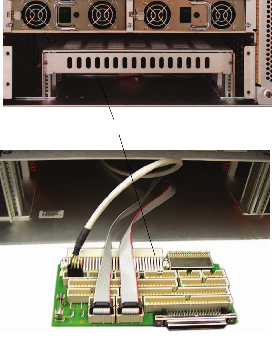
Chapter 9 Hardware Removal and Replacement (Server Nodes and Storage System)
230
CPU I/O Connections
CPU I/O Card
Ethernet
RS-232 1
(marked) RS-232 1 SCSI

Verifying CPU I/O Connections
231
CPU I/O SCSI Connection
nThe 22 inch SCSI cable is mounted on the SCSI connector. The cable faces downward.
Server Power Supply Replacement
The MSS 8000 server node contains four front-mounted, hot-swappable power supply
modules. With the front bezel removed, power modules are easily accessible. If a power
supply fails, an audible alarm triggers and the center LED on the front panel turns red.
Pressing the Alarm Reset button turns off the alarm. The following figure outlines a single
MS power supply. The MSS 8000 can run safely with any two power supplies running.
MS Single Power Supply
SCSI connection
LEDs
Temperature Power Fan
Alarm reset
button
Captive
retaining screw
(1)
Power switch
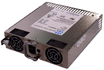
Chapter 9 Hardware Removal and Replacement (Server Nodes and Storage System)
232
To replace a power supply:
1. Ensure you are using an anti-static wrist strap or an anti-static mat.
2. Loosen the retaining screw securing the power supply to the chassis.
3. Grasp the front handle and pull the power supply from the chassis.
4. Install the replacement supply and secure it to the chassis.
MSS Server Power Supply Module
Adding a Server Node
The MS Networked Storage System allows for system upgrades without interrupting on-air
operations. This includes adding additional MSS 8000 server nodes to the system. This
section documents the procedures you must follow to add one or more additional server
nodes to your system.
nIncreasing channel playout capacity with additional server nodes will impact overall system
bandwidth. Consult the bandwidth tables in Appendix A or contact Avid MediaStream
Support to make sure you have adequate bandwidth for additional channel playout.
nSystems configured with the HP2512 12 port VLAN switch are limited to four server nodes.
The Capellix 2000C switch will limit total server node and/or array expansion as well. If
your switch configuration limits server node expansion, consult your Avid MediaStream
Systems sales representative to discuss a switch upgrade for system expansion.
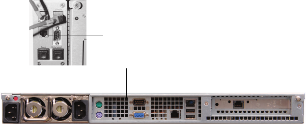
Adding a Server Node
233
Install the Server Node
Mount your server node and attach all video, audio and system connections. See Preparation
and Installation for information on rack mounting and installing the server node. See
Connecting System Components for system connection instructions.
Your new server node will come pre-configured from the factory as mss0101 (Server 1 in
Cluster 1). Your system will already have a Server 1, which may or may not be in Cluster 1.
The new node will need to be configured with the correct server and cluster ID for its
position within the system before it is brought up as a member of the Networked Storage
System.
Connect RS-232 Cable to Server Node and MSi PC
MSi to MSS 8000 Connection
To accomplish initial server node configuration, you will need to physically connect
the node to the MSi PC via RS-232. To do this:
1. Attach an RS-232 cable to the 9-pin connector on the upper left rear corner of the MSS
8000.
2. Attach the other end of the cable to the COM2 port on the MSi PC.
3. Flip the bypass switch to the “up” position on the Lantronix module. You can feel the
switch by placing your finger in the oval shaped hole on the Lantronix cover plate (see
the following figure).
MSS 8000 RS-232 port
MSi serial port
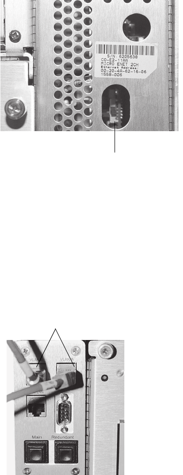
Chapter 9 Hardware Removal and Replacement (Server Nodes and Storage System)
234
Lantronix Bypass
Disconnect VLAN Network Connections
The MSS 8000 shipped from the factory will have a hostname ID of mss0101. If
your system is already configured for Cluster 1, you will already have a server
designated as mss0101. To avoid a network conflict, disconnect the two LAN
cables from the back of the server, and leave them disconnected until you have
configured your server. You can then reconnect the LAN cables and bring the
server into the system.
MSS 8000 LAN Connections
Lantronix bypass switch
MSS 8000 LAN connections
System Controller Board
235
Start a HyperTerminal Session on the Server Node
1. From the Start menu, go to Start > Programs > Accessories > Hyperterminal >
HyperTerminal.
2. The HyperTerminal program will open with a new connection and the Connection
Description dialog box. Enter a name for the session, such as Server. Then, click OK.
3. In the Connect using: field, select COM2, and click OK.
4. From the COM2 Properties dialog box select the following and click OK:
- Bits per second: 9600
- Data bits: 8
-Parity: None
- Stop bits: 1
- Flow control: XONXOFF
5. Click the Properties button, and select the Settings tab on the Server Properties dialog.
Select Emulation: VT100, then, click OK
System Controller Board
The MS server contains a system controller board, accessible from the rear of the MS server.
If a system controller board fails, remove and replace the system controller board.
wWith the exception of fan trays and power supplies, all boards and components must
be removed after the server has been shut down and turned off. Be sure to observe safe
practices to avoid damage to sensitive circuits.
To remove and replace the System Controller board:
1. Ensure you are using an anti-static wrist strap or an anti-static mat
2. Safely turn off the server.
3. Remove fibre channel connections from the system controller board.
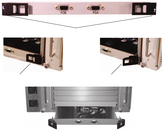
Chapter 9 Hardware Removal and Replacement (Server Nodes and Storage System)
236
System Controller Board Removal
4. Loosen the two retaining screws on the system controller board tray.
5. Press both latch release buttons simultaneously and pull latches open.
wLift the board slightly as you remove it, to ensure that none of the components on the
underside of the board run into the metal strip across the bottom of the MSS 8000
server chassis.
6. Carefully slide the system controller board out of the server chassis.
7. Insert the new board, keeping it clear of the bottom strip as cautioned above.
8. Close latches, and tighten retaining screws and reconnect fibre channel cables.
If the system controller board fails, but the boot drive is still functional, continue with the
next step.
nContact Avid MediaStream Support if you need help in determining the status of the boot
disk and/or the system controller.
Retaining screws
Latch release button Latch in open position

System Controller Board
237
1. Start up the server. The server displays the following text.
2. At the prompt, set the four bootrom monitor variables are set as shown below.
Enter
set bootaddr 10.xx.y.5
(where xx equals cluster ID and y equals server
ID).
Enter
set ipaddr 10.xx.y.3
(where xx equals cluster ID and y equals server ID).
Enter
set gateway 10.xx.y.32
(where xx equals cluster ID and y equals server
ID).
Enter
set netmask 255.255.255.0
3. When you have entered each variable, verify they are correct
e.g. enter set bootaddr. The prompt should return:
PMON>
bootaddr = 10.xx.y.5
4. At the PMON> prompt, enter the following command to boot the system off the
functioning boot drive:
diskboot -x -d /dev/sd0 -o100 -l5000 -a100000 -- a;g -e 100020
5. When the system starts, press ESC at the following prompt:
6. Log in as root. Then run the following command:
installbvs -c
The following text, or similar, should appear:
* PMON/2000 Professional *
Configuration [SBS VG4,EB,NET,SCSI]
Version: C03 (Avid MediaStream SupportCustom) 1.0 Build 1.21.5.
Nov 5 2003 11:07:47
This software may be redistributed under the BSD copyright.
BSP Copyright 2000-2003, SBS Technologies, Inc.
CPU PowerPC 7410 @ 500 MHz/100 MHz.
{ /--------------------------------------------------------------------
Waiting 00:40 to start the MSS storage controller:
- Press <return> to start the MSS server immediately.
- Press ESCAPE to end the timeout and bypass the MSS server startup.
[ 0:40] Waiting to start MSS Server. (<ENTER>=StartNow or <ESC>=DoNotS
t
} \--------------------------------------------------------------------

Chapter 9 Hardware Removal and Replacement (Server Nodes and Storage System)
238
7. When the prompt returns, the process is complete. Restart the server by entering
stopams
.
[DISKROOT] Setting up pmon --
pmon_var bootaddr 10.1.5.182
pmon startup IP is correct, at 10.73.3.3
pmon route gateway is correct, at 10.73.3.32
pmon netmask variable is correct, at 255.255.255.0
Sizes for /sys/lynx.os/vg4_boot/vg4.disk disk kernel:
2167813 = disk kernel size, bytes
4234 = (2167813 / 512) = disk kernel size, in 512-byte BLOCKS
5000 = boot string kernel size, in 512-byte blocks
Disk Kernel: want 4234 + 1 ?_<_? 5000 .. OK
pmon 'diskboot' variable is already correct, at:
"diskboot -x -d /dev/sd0 -o100 -l5000 -a100000 -- a;g -e
100020"
pmon bootdelay variable is correct, at 15
pmon 'autoboot' variable is correct, at:
"diskboot -x -d /dev/sd0 -o100 -l5000 -a100000 -- a;g -e
100020"
Sizes for /sys/lynx.os/vg4_boot/vg4.disk disk recovery kernel:
(are same as above)
2167813 = disk kernel size, bytes
4234 = (2167813 / 512) = disk kernel size, in 512-byte BLOCKS
5000 = recovery boot string kernel size, in 512-byte blocks
Disk Recovery Kernel: want 4234 + 1 ?_<_? 5000 .. OK
pmon 'recovery' variable is correct, at:
"diskboot -x -d /dev/sd0 -o100100 -l5000 -a100000 -- a;g -e
100020"
Sizes for /vg4install.bin flash kernel:
9400320 = flash kernel size, bytes
0x08F7000 = flash kernel size, in bytes (hex)
0x0900000 = flash boot string kernel size, in bytes (hex)
Flash rambased kernel: want 0x08F7000 ?_<_? 0x900000 .. OK
pmon 'flashboot' variable is correct, at:
"copy 78000000 100000 900000;g -e 100020"
pmon spyker variable (num hex bytes for post-mortem buf) is
correct, at:
"200000"
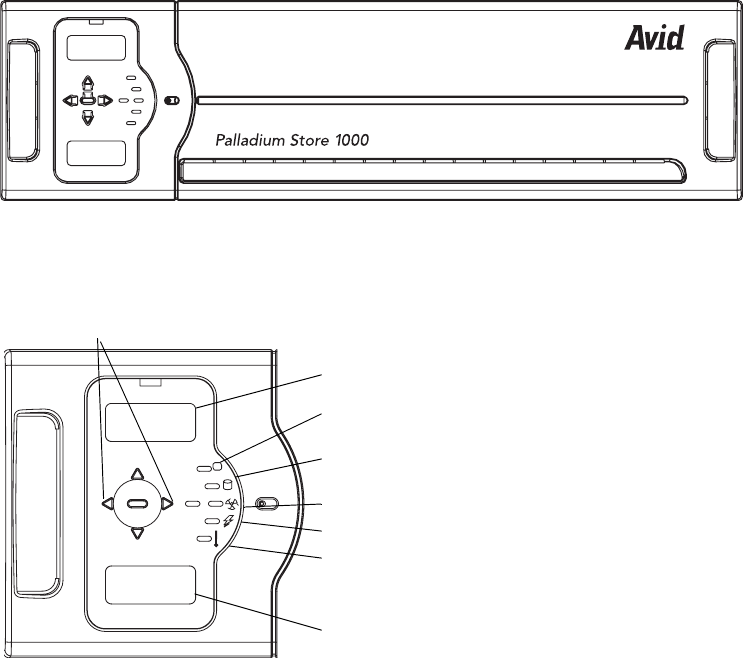
Palladium Store 1000
239
Palladium Store 1000
The Palladium Store 1000 is housed in a array chassis. It consists of field-replaceable
modules that can be hot swapped at your site.
Control Panel
The Palladium Store 1000 Control Panel is attached to the array front cover. You must
remove the indicator panel to access the drives.
Paladium Store 1000 (Front cover)
Control Panel
silence
enter
ChA address
ChB address
Controller status
Power supplies
Fans status
Drive status
Temperature
Controller B display
Panel navigation
buttons
Controller A display

Chapter 9 Hardware Removal and Replacement (Server Nodes and Storage System)
240
The indicator panel displays the following:
• Controller Address display
• Temperature Status Light – turns red to indicate a cooling failure
• Drive status – indicates drive activity and drive failure
• Fan status – turns red in the event of a fan failure
• Controller Status – turns red in the event of a controller failure
The navigation buttons are used to set addresses for the two controllers. The center button is
used to enter values and to silence the alarm.
Hot Swappable Components
The following components can be replaced while the unit is operational:
•Disk drives
•Fans
• Power supplies (dual redundant supplies)
wThere are two fans in a fan module. Failure of one of them will trigger an alarm and
the Fan indicator light. A notification will also be sent via SNMP to the System Status
window of the MSi. The unit can run safely with one fan in operation. Do not remove
the fan module on an operating unit without having a replacement fan ready for
installation. Running the Palladium Store 1000 unit without a cooling module for more
than a few minutes could result in damage to the unit, and will result in shutdown if
temperature thresholds are exceeded.
Palladium Store 1000: Front without Bezel Cover
A1 A2 A3 A4 A5 C C B1 B2 B3 B4 B5
B1 B2 B3 B4 B5
A1 A2 A3 A4 A5 C C
Bridge controllers
A and B
A drives 1 - 5 B drives 1 - 5
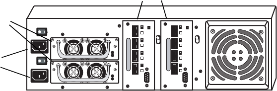
Palladium Store 1000
241
Disks and the 2 bridge modules are accessible from the front of the array after removal of the
front panel. Disk drive labels indicate the Drive number A 1-5 (bank A) or B 1-5 (bank B).
The bridge modules are labeled C.
The Palladium Store 1000’s rear panel, shown in the following figure, provides access to the
hot-swappable units: the dual redundant power supplies, the Controllers, and a fan module
enclosure containing two fans.
Palladium Store 1000 - Rear Panel
Replacing a Drive
A failed disk drive is indicated by a red LED on the drive indicates in the unit. In addition, a
warning is sent to the MSi’s System Status window via SNMP. Replace failed drives as soon
as possible to avoid loss of content.
Drives are numbered A1 to A 5 in the left bank (bank A) and B1 to B5 in the right bank
(bank B). The numbering of drives is the same in the MSi System Status window where any
failed drive appears in red.
wMake sure you remove the failed drive from the chassis. Removing the wrong drive will
result in loss of content.
To replace a drive:
1. Remove the front panel cover to access the drive bay.
2. Press your forefinger into the indentation at the lower part of the drive (see the following
figure). The drive pops out slightly.
3. Gently grasp the cover flap and pull the drive a few inches out. Wait 30 seconds for the
drive to spin down and then remove it completely from the chassis.
4. Affix the correct drive label on the replacement drive (labels are shipped with the unit).
DC
AC
DC
AC
Power Supply 1
Power Supply 2
StatusStatus
Service Service
Switch Contoller
Switch Contoller
Port
4
Port
2
Port
1
Port
3
Port
4
Port
2
Port
1
Port
3
A
B
Switch controllers
A and B
Power
connections
Power supplies
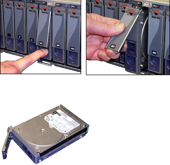
Chapter 9 Hardware Removal and Replacement (Server Nodes and Storage System)
242
5. Carefully slide the replacement drive into the drive bay. Open the front flap to guide the
disk to the rear of the drive bay until it snaps into rear connection.
6. Press the cover flap down until it clicks in place, locking the drive.
7. Check the drive indicator and the MSi’s System Status window to see if the new drive is
in place. Drive reconstruction begins automatically “Setting Configuration on a
Networked Storage System” on page 190.
Replacing a Disk
Disk Drive
Step 2Step 1
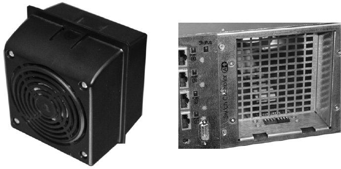
Palladium Store 1000
243
Replacing the Fan Module
The fan module is housed in the fan slot in the rear of the Palladium Store 1000. A failed fan
triggers an audible alarm, and the SNMP indicator in the MSi window turns red, indicating a
component failure. There are two fans in the Fan Module, so air should be circulating unless
both fans have failed.
nWarning: Do not remove the module unless you have a replacement module available.
Operating the unit for more than a few minutes without a cooling unit could result in
damage to the unit and will cause the unit to shut down once temperature thresholds are
exceeded.
Fan Unit and Fan Slot
To replace the fan:
1. Grasp the side of the fan unit with your thumb on the top. See Step A in the following
figure.
2. Pull the fan unit slightly downward and then pull it towards you to remove it (Step B in
the following figure).
3. Position the new fan as shown in Step B. Insert it into the slot as shown in the following
figure, Step A until the fan unit snaps into place.
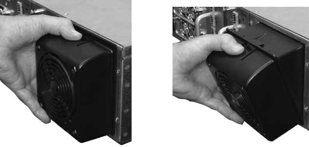
Chapter 9 Hardware Removal and Replacement (Server Nodes and Storage System)
244
Removing the Fan
Replacing the Power Supply
The following figure shows the Palladium Store 1000 power supply. A failed power supply
triggers an audible alarm. The LED indicator on the failed unit turns red, and the SNMP
indicator in the MSi window turns red, which signifies a component failure.
To replace a power supply:
4. Note the failed power supply’s position and check the LED indicator to make sure you
are removing the correct power supply. Remove the power connector from the failed
unit.
5. Facing the rear of the unit, loosen the two retaining screws (see the following figure).
6. Firmly pull on the retaining handle and carefully slide the unit out of the chassis,
making sure to clear any cables in the way.
7. Reverse the process to insert the replacement unit.
Step 2Step 1
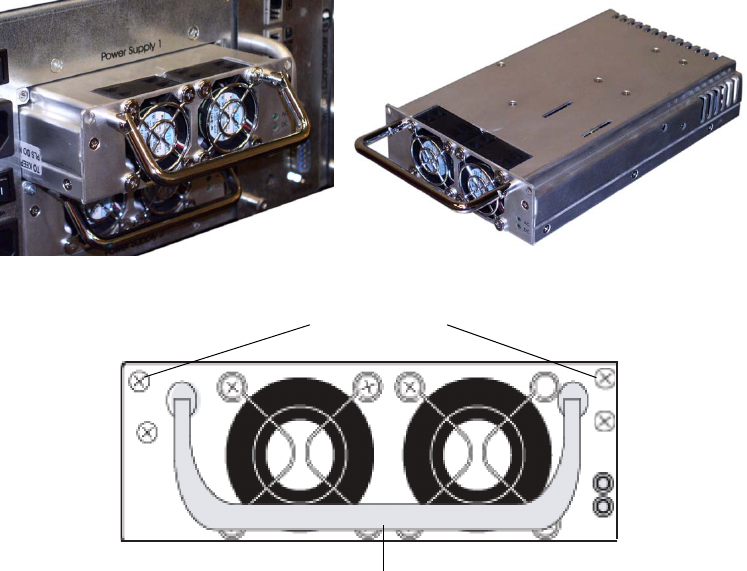
Palladium Store 1000
245
Palladium Store 1000 Power Supply
Replacing a Bridge Module
A controller or a bridge failure may indicated by the LED on the front panel and the System
Status window on the MSi. The Drive Bay has two Bridge modules.
wIf this is a replacement during an on-air operation, you must contact Avid
MediaStream Support before replacing the unit for any special instructions.
Make sure you have correctly identified the failed unit. The LED above the Bridge
module indicates fault.
When a failure is indicated the Bridge and/or it’s associated Controller may be
involved.If you are unsure which unit is involved and do not wish to replace both,
contact Avid MediaStream Support support before proceeding.
Screws to remove
Pull Handle
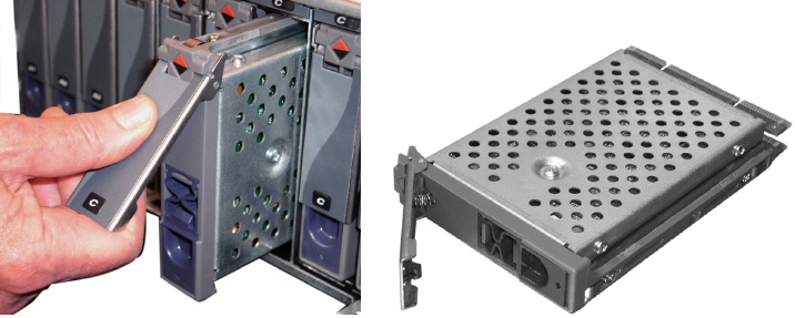
Chapter 9 Hardware Removal and Replacement (Server Nodes and Storage System)
246
To replace a Bridge module:
1. Remove the front panel cover to access the disk drive bay.
2. Press your forefinger into the indentation at the lower part of the Bridge (see the
following figure). The Bridge pops out slightly.
3. Gently grasp the cover flap and pull the Bridge completely out of the bay.
4. Carefully slide the replacement Bridge into the bay. Open the front flap to guide the
Bridge to the rear of the drive bay until it snaps into rear connection.
5. Press the cover flap down until it clicks in place locking the unit.
6. Place a thumb on the upper and lower portions of the Bridge and provide even pressure
to ensure the module is fully inserted.
Bridge Removal
Removing a Controller
To remove the Controller:
1. Loosen the two large retaining screws (on either side of the handle).
2. Remove the cables plugged into the board noting their connection position.
3. Carefully pull the handle out towards you, being careful to clear any cables.
4. Reverse this procedure when inserting a new Controller.
5. Verify the new controller has the correct firmware version and is configured properly.
nSee Current Firmware Revision on page 21 for information on checking firmware revision.
To upgrade configuration, see See “Setting Configuration on a Networked Storage System”
on page 24..
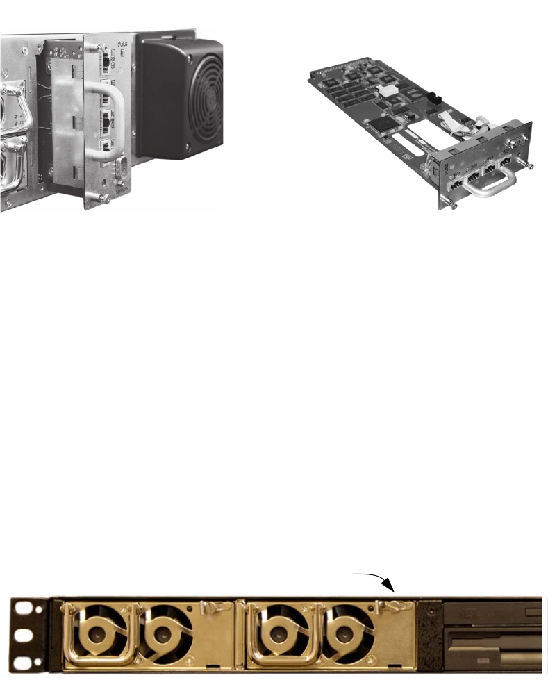
File System Controller
247
Controller Removal
Adding Disk Sets
Additional storage may be added to your unit. For more information on adding storage
capacity to your system, consult Avid MediaStream Support.
File System Controller
The power supplies on the FSC are modular replaceable units. This section describes the
replacement procedures for these components.
Power Supplies
Follow this procedure to replace a failed FSC power supply.
1. Loosen the captive screw on the front of the power supply unit.
Power Supply Retaining Screw
Retaining screw
Retaining screw
Captive screw
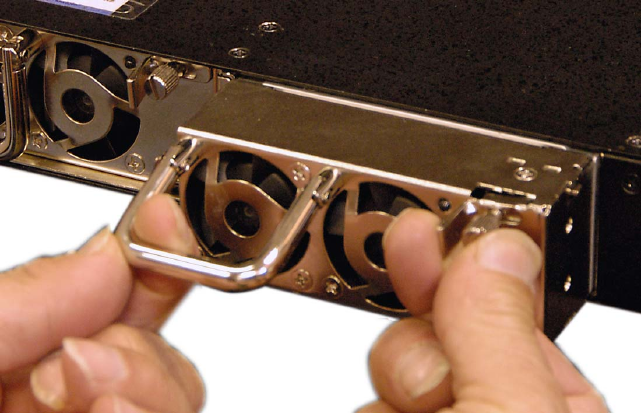
Chapter 9 Hardware Removal and Replacement (Server Nodes and Storage System)
248
2. With one hand, push the lever next to the captive screw to the right, and pull out the
power supply by the handle using the other hand, until the latch holding the power
supply in the chassis is cleared.
Remove Power Supply
3. Continue pulling the power supply unit out by the handle, supporting it with your other
hand as it comes out.
4. Insert the new power supply into the bay, pushing it straight in until it locks into place.
5. Tighten the captive screw on the front of the new power supply.
Chapter 10
CLI and Server Node Calibration
CLI (Command Line Interface) is the interface to AMS software. CLI provides access to the
same command set used by automation to control playout record and other system functions.
You open a telnet session within the MSi application from which to enter CLI commands
that perform routine maintenance checks and system adjustments.
This chapter introduces some basic concepts in CLI, including how to record and playback
files. The following topics are covered:
• Recording and playing files
• CLI command summary
• Server calibration
• Decoder adjustments
• System timing
CLI is accessed from a telnet session. When you log on to a server node, you are in the
LynxOS operating system, which has the prompt [root@ 0101 /bvs].
Enter:
cli
.
The following prompt displays:
Now connected to Broadcast Video Server. Enter ‘end’ to exit.
bvs:
Whenever you are in CLI, the return cursor prompt is prefaced by bvs.
Chapter 10 CLI and Server Node Calibration
250
Port Selection
Input/Output ports represent the encoders and decoders on the system. These channels are
referred to as video ports. Video ports can be input or output ports. An input port is an
encoder. The system logic treats an encoder as a virtual record-only VCR. An output port is
a decoder, which is similar to a virtual play-only VCR. Each port has a dedicated RS-422
port that can be directly controlled by an external automation system.
Encoder Ports
An Encoder port records new content into the system. Encoder ports are specified by
negative numbers. Encoder port 1 is designated -1. The number in sequence ( -2, -3, -4, and
so forth) provides access to each additional installed encoder.
Decoder Ports
A Decoder port provides the server with a channel for playing back material. Decoder ports
are specified by positive numbers; for example 1, 2, 3, 4 refers to Decoder ports 1, 2, 3 4.
Any action on an Input or Output port requires two steps. First, the port must be opened.
This only needs to be done once. A port once opened will remain open until it is closed or
grabbed by another device. Second, a port must be selected. Several ports may be opened at
once. You must select each port before you begin to execute a command on that port.
Open Port
The open command is used to establish communications between the controlling device and
the port. Communications could be coming from an automation system or from the MSi PC.
The command syntax is
open? <port>,<lock mode
>
The <port> is the one-digit value of the encoder or decoder port. Encoder ports must be
prefaced with a “-” (minus sign). The <lock mode> specifies how the port is opened. A 1
will open the port in the locked mode, which will lock access to the port from other devices
such as automation. A 0 value will place the port in the unlock mode, which will allow the
port to be grabbed by other communication channels that request it.
For example:
open? -2,0
opens Encoder 2 in the unlock mode
–open? 1,1
opens
Decoder 1 in the locked mode.
nIf you open a port in the lock mode, make sure you close it when you are finished with it. If it
remains open and locked, an automation system will not have access when it needs it. To
close a port, enter the command clos <port>.
251
Select Port
Once a port has been opened, you must select it to perform a task with it. The command for
selection is
psel <port>
.
For example,
psel -1
selects Encoder 1;
psel 2
selects Decoder 2.
Record
Once an Encoder port has been selected, there are three commands used in recording: cue,
record and stop. The cue command is:
rcue “<filename>”,<frames>,<seconds>,<minutes>,<hours>
Where “filename” (in quotes) is followed by duration in frames, seconds, minutes and hours.
The minimum record duration for a spot is 3 seconds.
Once cued, the command for record is
recd
.To stop a file recording in progress, enter
stop.
Auto Stop
Record cue requires a specified duration. This duration will act on a clip only if the auto stop
mode has been activated. The enable auto stop command activates this feature.
To activate auto stop on a selected channel, enter
enas 1
.
Auto stop will remain activated for this port until you deactivate it by entering
enas 0.
To check the status of a port, enter
enas?
.
A return value of 1 or 0 shows the status of the port.
Recording a File
To record a video file:
1. Enter
open? -1,0
to open Encoder 1 in the unlock mode.
2. Enter
psel -1
.
This selects Encoder 1 for activity.
3. Enter
enas 1
.
4. Enter
enas?
.
Chapter 10 CLI and Server Node Calibration
252
You should receive a return value of +1. This verifies you have activated the auto stop
mode.
5. Enter rcue
“filename”,0,30,0,0.
This cues the Encoder port to prepare recording of a file named testspot for a duration of
30 seconds.
nFile names can have up to 32 characters.
6. Enter
recd
to start the recording.
The recording stops after 30 seconds. If you disable auto stop, the recording continues
until enter the stop command.
7. When you are finished enter
clos -1
.
This closes the port for Encoder 1.
Playing a File
To play a video file requires two commands, cue and play.
The cue command syntax is
pcue “filename”
.
Filenames of up to 32 characters must be enclosed in quotes.
The play command is play.
Follow these steps:
1. Enter
open? 1,0
.
This opens Decoder port 1 in the unlock mode.
2. Enter
psel 1
.
This selects Decoder port 1.
3. Enter
pcue “testspot”
.
This cues the file testspot for playback.
4. Enter
play
to start playing the file.
5. Enter
clos 1
to close Decoder port 1.

CLI Command Summary
253
CLI Command Summary
Basic Commands
Basic Commands
open? <port>, <lock mode>
Opens a port for use. Lock mode is either a 0 (unlocked) or
1 (locked) psel <port>
psel <port>
Selects a port for an action or adjustment
clos <port>
Closes selected port
pcue “id name
Play cues selected ID name (names must in “quotes”)
rcue “id name”
Record cues ID with specified file name
stop
Stops play/record action on active por
idel “id name”
Deletes specified ID name
idpr “id name”
Delete protects specified ID name
idup “id name”
Delete “unprotects” specified ID name
end
Exits CLI and displays the system prompt
Edit Play Commands
paus
Pauses play on current channe
cont
Continues playing
step
Jogs forward 1 frame
jog <frames>
Moves forward specified frames
shtl <rate>
Shuttles at specified rate according to the Harris manual

Chapter 10 CLI and Server Node Calibration
254
Server Calibration
Board-level calibration is performed in a telnet session using CLI commands or through the
MSi. The following board calibrations can be performed and are outlined in this section:
• 4:2:2 Decoder analog output adjustments – CLI video and audio gain adjustments
• Horizontal line timing – Adjusted in the MSi application
• Subcarrier phase – Adjusted in the MSi application
You will need a waveform monitor and vectorscope to perform the horizontal line timing and
subcarrier phase calibrations on the 4:2:2 Decoder.
Miscellaneous Commands
drst <port ID>
Resets decoder for specified port (not decoder number
vstd <standard>
Sets video standard NTSC = 0, PAL = 1
vstd?
Returns value of current video standard setting
cbar <value>
Turns decoder color bar on (1) or off (0)
sadj <burst, hue>
Adjusts subcarrier value –1800 to +1800 for both values.
Initial value is set to 0,0
sadj?
Current subcarrier value
hsyn <value>
Sets Horizontal Sync timing within range of 0-8181. Initial
value 3072
hsyn?
Returns current setting
dagn <chan, increment>
Sets audio gain of channel (1, 2, 3 or 4)
dagn? <chan>
Returns current setting
dvgn <increment>
Sets video gain of the channel
dvgn?
Returns current value
stat? <bitmap>
Returns port status bits for active channel stat? 15 returns all
bits
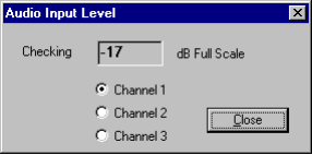
Server Calibration
255
Audio Level Indicator
Input audio headroom adjustments measure the audio level going into the server node’s
encoder. Use the MSi application to verify the audio level of the digitized audio input signal.
1. In the MSi application, click the Rec1 button.
2. In the Record window, go to Cal > Audio Input Level. This Audio Input Level dialog
box is displayed:
Audio Input Level
3. Make your adjustments on an external box, soundboard, and so forth.
nOn this dialog box, Channel 1 refers to AES 1 channels 1 and 2. Channel 2 refers to AES 2
channels 3 and 4. When reading values for each Channel pair, the values in each channel
are not additive. Thus the higher value of the two channels displays in the window. For
example, if AES 1 channel 1 has an input level of –10 dB and channel 2 has an input level of
–20, the dialog box displays the value of –10. To adjust the levels correctly, disconnect the
channel you are not monitoring.
nThe input audio signal to the encoder is always digital audio. 0 dB is a hard clip. This means
that as you approach 0 dB full scale, the audio signal will become severely distorted.
Recording Test Video
This section describes how to record test content to the server’s storage system. You will use
this test content to calibrate the decoder output.
In the MSi application, you need to have a Record window configured for each encoder in
the server. Verify that you have a Record window configured for each encoder.
The following steps describe how to record a five-minute tone and color bars video for each
encoder:
1. Connect the tone and color bar video source to the encoder.
2. In the MSi application, click the Rec1 button.
3. Enter test1 in the Record File ID field.
Chapter 10 CLI and Server Node Calibration
256
4. In the Duration field, enter a duration of five minutes (00:05:00:00).
5. Click the Rec button at the top of the Record window and wait five minutes for the color
bars to record.
6. If you have a second encoder installed in the server, open its Record window; for
example, click the Rec2 button. Enter test2 in the Record File ID field, and click the
Rec button.
4:2:2 Decoder Adjustments
You will start a telnet session and log on as root to enter CLI mode, or use the MSi
application to make decoder video and audio adjustments. Adjustments include:
• Video Output—CLI
• Audio Output—CLI
• Horizontal Line Timing—MSi
• Subcarrier Phase—CLI
There is no adjustment for digital output.
Adjusting Video Output
To adjust video output:
1. Via Telnet, log on as root to the server.
2. At the command line prompt, enter
cli
.
3. At the prompt, enter
grab? <port>,1
where port is the number of the decoder card (1 to 16) that you want to adjust.
For example,
grab? 1,1
specifies Decoder card 1.
wThe
grab
command takes control of the port from the automation software.
4. Select the Decoder port by entering:
psel <port>
where port is the Decoder port number.
5. Cue the test file by entering:
pcue “test1”
.
nThe name of the test file must be enclosed in quotation marks.
Wait three seconds for the file to cue.
6. Play the test file by entering:
play.
Server Calibration
257
7. Enter the command
dvgn?
to return the current video gain setting. The setting is
reported in units of 1/10 IRE.
8. To adjust the video setting, enter
dvgn gain
where gain is the channel gain in units of 1/10 IRE. Valid values range from –375 to
+375
(–37.5 to 37.5 IRE).
The following example sets the video gain to 10 IRE:
dvgn 100
.
nIf you cannot complete your adjustments before the test file finishes playing, repeat the pcue
and play commands.
9. When the video setting is correct, enter
close port
.
This command enables the automation station to take control of the port.
1. Repeat the above steps for each decoder.
1. To exit the CLI interface, enter
end
.
Adjusting Audio Output
To adjust audio output:
1. Using telnet, log on as root to the server.
2. At the command line prompt, enter
cli
.
3. At the prompt, enter
grab? <port>,1
where port is the number of the decoder (1 to 16) that you want to adjust. For example,
grab? 1,1
specifies Decoder card 1.
wThe above command takes control of the port from the automation software.
1. Select the Decoder port by entering:
psel <port>
where port is the Decoder port number.
2. Cue the test file by entering:
pcue “test1”
.
Wait 3 seconds for the file to cue.
3. Play the test file by entering:
play
.
4. To see the current audio setting, enter
dagn? <channel>
.
where channel is the audio channel number (1 to 8). The command returns the current
audio level, in units of 1/10 dB, for the specified channel.
5. To adjust the audio setting, enter dagn
<channel>,<gain>
where channel is the audio channel number 1, 2, 3, 4, 5, 6, 7, or 8.
Chapter 10 CLI and Server Node Calibration
258
The following example sets the gain for audio channel 2 to 5 dB: dagn 2, 50
nGain is the channel gain in units of 1/10 dB. The value specified must be in increments of 0.5
dB. Valid values range from –102.5 to +250 (-10.25 to 25.0) dB.
nIf you cannot complete your adjustments before the test file finishes playing, repeat the pcue
and play commands.
6. When the audio setting is correct, enter close <port>.
The above command enables the automation station to take control of the port.
7. Repeat the above steps for each decoder.
8. To exit the CLI interface, enter
end.
Horizontal Line Timing
The purpose of this adjustment is to compensate for line delays from the server to the
broadcast router. This adjustment will synchronize the server to the station reference (black
burst) signal. You will need a waveform monitor for this adjustment.
Your setup should be similar to the example shown. If you use serial digital output, perform
this adjustment using your digital-to-analog converter and all other devices that could cause
delays to the station router (see dotted line in the illustration).
nIf you use a frame sequencer on your digital video output, this adjustment is irrelevant.
nHorizontal-line timing adjustments you make affect both analog and digital output. If you
require separate timing for one of them, use an external delay line.
Calibration Setup
The following figure shows an example of the calibration setup for a server with two
encoders and two decoders. If you are using analog output only, ignore the dotted line and
the D/A Converter on the output. See Connecting System Components for information on
connector types. If you have a second encoder, connect the loopthrough as shown here.
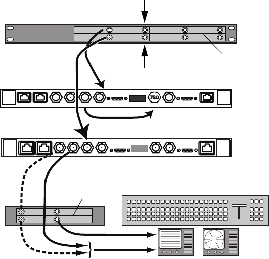
Server Calibration
259
Calibration Setup for Node with Two Decoders
The signal is output from the server’s decoder to the digital-to-analog converter, then to a
vectorscope/waveform monitor at the production switcher. The black portion of the color bar
signal is then synchronized to the station reference at the station router.
The following adjustments should be made to your A/D and D/A Signal Converters:
• Video level
• Audio headroom
• Audio output level
See the documentation provided by the manufacturer of these devices for information on
how to perform the adjustments.
Instructions for using MSi to play the color bars test video through a decoder and for making
adjustments to the signal via your waveform monitor follow.
Loopthru
RS-422 (A) Audio Input Serial Digital
Serial Digital
AES/EBU OutAES/EBU Out
Serial Digital Analog Serial Digital AnalogInput Loopthru
Video output Genlock
Input A
Dual decoder
Analog to digital
converter
Station color bar generator
Station
Reference
(Black Burst)
Digital to analog
converter Video production switches
Waveform
monitor
Vectorscope
Dual decoder
Input B
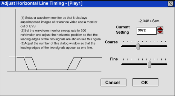
Chapter 10 CLI and Server Node Calibration
260
1. In the MSi application, open the Play window configured for Decoder 1. For example,
click the Play1 button.
2. Do one of the following:
- Click the Insert button at the top of the window.
- Press the Insert key on the keyboard.
- Go to Edit > Insert ID.
A new item line appears in the Play window.
3. Move the mouse pointer to the blank File ID field and right-click. The Field ID Search
window allows you to select a file to add to the Play window. In the Field ID Search
window, double-click the file that contains the color bars test video that you previously
recorded. Information about the file then appears in the fields in the Play window and
the file is selected (highlighted).
4. With the test video file selected, click the Play button at the top of the Play window. The
file is first cued, and then playout begins.
5. Go to Cal > Horizontal Line Timing to display the window shown in
Horizontal Line Timing Window
6. Look at the waveform monitor. Settings are listed in the illustration shown in the
following figure. Adjust your waveform monitor until you see a similar display.

Server Calibration
261
Waveform Monitor Settings
Most waveform monitors display the falling or rising edge of the signal. This procedure will
synchronize on the falling edge of the signal. When the two edges are superimposed (looks
like one line), this adjustment is complete.
7. In the Adjust Horizontal Line Timing window, move the adjustment bars for coarse and
fine until the two edges are superimposed to appear as one line.
8. Change your waveform monitor setting to SCH phase to fine tune horizontal line timing.
-1.0 0.0 1.0 2.0 3.0 4.0 5.0 6.0
0.5
0.0
Volts
Microseconds
Superimpose leading edges. At MSSI type:
hsyn? queries horizontal sync setting
3072 factory setting
hsyn n n is 0 to 8191
Waveform Monitor / Vectorscope
Mode Waveform Monitor
Input A/B
Sweep 200 ns / division
Reference Internal
Vertical Gain Calibrated position
Horizontal Gain Calibrated postion
Line Sample 15 lines

Chapter 10 CLI and Server Node Calibration
262
Example SCH Phase Adjustment
9. In the Adjust Horizontal Line Timing window, move the slider for the Fine setting to
bring the SCH phase as close to zero as possible.
This completes the horizontal line timing for Decoder 1. Without changing the cabling
setup for Decoder 1, proceed to the subcarrier phase adjustment described in the next
section.
Subcarrier Phase (Colorburst Phase)
Your vectorscope should display the subcarrier phase of the server’s analog video output
superimposed on the subcarrier phase signal of the reference video output.
Use CLI commands to play the test video you previously recorded:
1. In the telnet window, log on as
root
2. At the command line prompt, enter
cli
.
3. At the prompt, enter
grab? <port>,1
where port is the number of the Decoder card (1 to 6) that you want to adjust. For
example,
grab? 1,1
specifies Decoder card 1.
90
180
-90
0
90
180
-90
0
This figure shows the Server SC
H
is about -30 degrees out of phas
e
Waveform Monitor / Vectorscope
Mode SCH phase
Input B
Server Calibration
263
wThe above command takes control of the port from the automation software.
4. Select the Decoder port by entering
psel <port>
where port is the Decoder port number.
5. Cue the test file by entering pcue
“test1”
.
Wait 3 seconds for the file to cue.
6. Play the test file by entering
play
.
7. While the color bar signals are playing out, change the setting on your waveform
monitor to vectorscope mode. On the vectors cope, set both input A and input B to be
displayed.
The following figure shows the video output out of phase with the targeted reference
signal.
Adjustment of Server Node’s Video Output

Chapter 10 CLI and Server Node Calibration
264
The point of this adjustment is to align the signal from the server as closely as possible with
the reference signal on the R, Mg, B, Cy, G and Y1 targets (that is, each of the dots of the
connected vectors should fall into the corresponding rectangle of the targeted reference
signal).
To make a clockwise adjustment of 4 to 5 degrees should align the server’s video output with
the reference signal.
8. Use the CLI
sadj
command to adjust the signal:
To see the current setting, enter
sadj?
.
To rotate the vector, enter
sadj <value>,0
where value is the rotation in units of 1/10 degrees. Negative values rotate clockwise,
while positive values rotate counter-clockwise. Valid values range from –1800 to +1800
(–180 to +180 degrees).
For example, the command
sadj -40,0
rotates the vector clockwise 4 degrees.
Continue to change the values of the subcarrier phase until the display on your vectorscope
looks similar to what is shown in the following figure.
Correctly Adjusted Server Node’s Video Output
Server Calibration
265
The tips of the connected vectors all fall within the boxes. This completes the serial
digital video adjustments for Decoder 1. Enter close1 to close the port.
9. Repeat the above steps to adjust the other decoders you may have in your server.
10. To exit CLI, enter
end.
Chapter 10 CLI and Server Node Calibration
266
Chapter 11
Software Recovery and Upgrade
This chapter describes the procedures for system recovery and upgrading major system
components of a MediaStream NSS to the current software release.
System recovery and software upgrade are distinct and separate procedures. The recovery
process brings failed systems back online and then reinstalls the software. Software
upgrades install new releases of software on existing products. Following the recovery
procedure, software upgrade is required for all components.
nRefer to the current software upgrade instructions (posted on the Avid MediaStream Support
web site @ www.pinnaclesys.com/support), or contact Avid MediaStream Support.
wPerform upgrades in the following order to ensure system operating integrity:
1. MSi PCs
2. FSC PCs
- FSC 1 – First
- FSC 2 – Second
3. MSS 8000 Server Nodes
4. Disk Array Firmware
wUpgrade all components (the complete System). Your System’s integrity may be
compromised if any component is more than one revision back from the current
software upgrade release.
Do not proceed with any upgrades if your System is not fully functional due to some
type of malfunction until you have consulted with Avid MediaStream Technical
Support.
Chapter 11 Software Recovery and Upgrade
268
This chapter covers the following topics:
• MSi system recovery
• MSi backup and restore
• MSi software upgrade
• FSC system recovery
• MSS 8000 boot drive removal and replacement
Software Version Numbers
Software Releases for the MSS Networked Storage System are shipped on two discs:
• Disk one contains the MSi PC and MSS 8000 software
• Disk two contains FSC PC software
To track overall system releases, a System Version number will be given to the overall
release.
Software Release Version
System software revision numbering: 0X.YZ
•X is the current major release number
•Y is the minor release number
•Z indicates a patch number
MSi software revision numbering: A.X.YZ
•A indicates MSi software
•X is the current major release number
•Y is the minor release number
•Z indicates the patch number
A complete upgrade on the device is necessary for any change in the revision number.
FSC software revision numbering: G.0X.0Y.ZZ
•G indicates FSC software
•X is the current major release number
•Y is the minor release number
•Z indicates the patch number
MSi Software Backup and Recovery
269
A complete upgrade on the device is necessary for any change in the revision
number.
MSS 8000 software revision numbering: C.XX.YZ
•C indicates that this software is for use with a Avid MediaStream Networked Storage
System.
•XX is the major revision of software. If you are installing software that has a different
major number than the software you are currently running, you must check with your
automation vendor before installing this software.
•Y is the minor revision number. A change in the minor number indicates minor feature
changes and bug fixes. A change of minor release does not include any changes that will
affect control of the servers via automation.
•Z is a patch level; the Z number indicates the number of patches installed on top of the
minor release. Installing additional patches does not require a complete re-install of the
software.
nVersions C.15.XX provides for the use of longer (32-character) file names. The “Long File
Names” feature should only be enabled with approval of your automation vendor as their
software may not support its use, or may need configuration changes to accommodate it. If
desired, the MSi application can be then enabled to allow it to create and reference these
longer file names. You can do so by selecting Setup/Configuration menu from the
application’s title bar and clicking the Long File Names option in the resulting dialog box.
MSi Software Backup and Recovery
This section describes how to:
• back up and restore MSi files
• restore the MSi PC to its original configuration using the Recovery CD
• upgrade the MSi software
Backing Up MSi Files
The MSi application includes a backup function to back up MSi playlists and configuration
files. After making any changes to the MSi configuration, back up the MSi data files. The
files that are backed up include all files in the C:\Program Files\Hewlett-Packard/data
directory and the msi*.ini files and applet registry information (located in the Windows 2000
directory on the C drive).
nYou can back up data while the MSi application is running, but not while playing out from a
playlist.
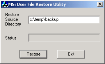
Chapter 11 Software Recovery and Upgrade
270
To back up MSi data and configuration files:
1. From the MSi main menu, select File > Backup User Files. Enter the drive and directory
path in the text box.
2. If the directory chosen already has data on it, you are warned that existing MSi files in
the backup directory will be deleted. Click OK to continue, or click Cancel and choose a
different backup directory.
Your files are copied to the specified directory.
Restoring the MSi Files
If your original MSi data and configuration files have been corrupted, they can be restored
using the MSi Restore program. In order to run the program, you must quit the MSi
application. To restore configuration files:
1. Start restore.exe.
• Locate the restore program icon in C:\Program Files\Pinnacle\MSi directory and
double-click it, or
• Select Run from the Start menu. Click Browse and locate the restore.exe file in the MSi
directory. Click OK.
MSi User File Restore Utility
If MSi does not find a configuration file, you are prompted to enter the information.
2. Enter the directory path of the back up files, such as C:\Temp\backup or your CD
backup disc.
3. Click Restore.
4. Click Exit and restart MSi. Your configuration files should have been successfully
restored.
5. Restore the network settings on the MSi PC. Refer to the MediaStream Video Server
Installation Guide and consult with your network administrator.
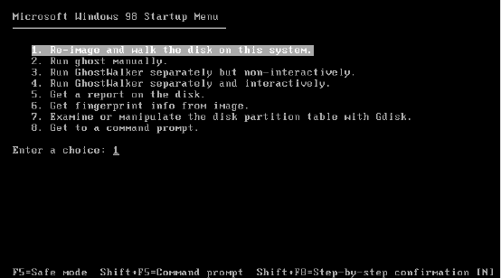
MSi Software Backup and Recovery
271
MSi System Recovery
The MSi Recovery CDs are provided to restore a malfunctioning MSi PC to its original
configuration. The discs may be required if the original hardware needs to be replaced, or if
the Windows 2000 operating software has been corrupted.
wThe MSi Recovery process destroys all data and settings. Use this procedure only if
other problem-solving efforts have failed.
To perform an MSi system recovery:
1. Insert the first MSi Recovery CD and turn on the MSi PC.
2. The MSi boots up in the Symantec Ghost program. Choose “Re-image and Walk Disk”
from the menu. Note that there is no warning step in this procedure, so be sure that a full
re-image is what you want to do.
Ghost Startup Menu
The main Ghost window appears, and the program runs automatically.
3. After 5 to 10 minutes, the Ghost program asks for the second recovery CD. Insert this
CD and click OK
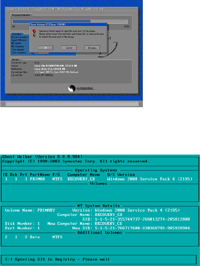
Chapter 11 Software Recovery and Upgrade
272
Insert Second CD
After all files have been copied off the second CD, the Ghost Walker program starts
automatically. This program verifies disk and file information
Ghost Walker
4. .When Ghost Walker completes, you will see a DOS prompt. Remove the second
recovery CD and press CTRL+ALT+DEL to restart the MSi PC.
MSi Software Backup and Recovery
273
nOn the first boot following a system recovery, the automatic Windows file system check will
display many error messages. This is normal, and should not have any further effect on the
operation of the MSi PC.
5. Following the file system check, the PC will display a message indicating that system
settings have changed, and asking if you want to restart. Click Yes to restart the PC now.
The PC should start up normally.
You can now reinstall the MSi and optional gateway software (and any upgrades required to
bring the software to the current version) and restore the MSi data and configuration files.
MSi Software Upgrade
MSi software updates take about three minutes to perform. Follow these steps:
1. Close all applications and turn off the MSi.
2. Insert the MSi upgrade CD into the drive. The setup program starts automatically.
MSS Server and MSi Setup Dialog Box
3. Click MSi System Console Software. The MSi Setup program runs.
4. When prompted to select a model, select the MSS 8000 series and click Next.
5. Click Yes to display the Release Notes, otherwise click No.
6. Click Next to start the installation, which takes less than a minute to complete.
7. Click Yes, I want to restart my computer now.
8. Click Finish.
Chapter 11 Software Recovery and Upgrade
274
Run Configuration Utility for MSi
After installing the upgrade software, the next step is to run the MSi configure application.
This application configures all machine-specific settings for networking, communication,
and application initialization.
The Configure application automatically performs the settings required to make each MSi
unique within the overall system architecture. It is recommended that you run this
application after any system upgrades.
Configure provides tools to change varying degrees of settings on the MSi PC. The choices
are:
• Complete Configuration – configures all required settings
• MAC Address update – resets the MAC address for the PC
• MSI .ini – changes the .ini and hosts files only
The complete configuration automatically makes over 300 changes including:
• Updates all VLAN settings in the registry
• Updates the TCP port for the Solid database in the registry
• Changes the name of the MSi in the registry to the desired Cluster ID
• Updates the MAC address for the VLAN card as well as the LAN cards
• Sets the NTP server to the Primary (01) FSC.
To run the application:
1. At the command prompt, enter
cd: C:\
to return to the C directory.
The prompt should be
C:\>
.
2. Enter
config
.

MSi Software Backup and Recovery
275
3. Press C to select a complete configuration.
4. Enter the number for the MSi you are upgrading – 1 for Primary or 2 for Secondary.
5. When prompted, enter the cluster number:
Please enter the Cluster number [1..16]: 10
6. When prompted, enter the MSi number:
Please enter the MSi number [1 or 2]: 2
7. Enter the cluster number for the system. This setting is crucial to make sure the LAN
and configuration settings are correctly configured. MSi will not be able to
communicate over the network without the correct setting.
nAllow the Config tool to complete it’s operation before continuing. This may take some time.
Attempting to exit the tool before completion may generate errors, and may require
reimaging of the PC.
C:\> config
----------------------------------------------------------------------
----------------------------------------------------------------------
CONFIG Version 2.00
----------------------------------------------------------------------
----------------------------------------------------------------------
Press: 'C' Complete Configuration.
'M' only MAC-Address update.
'H' only create hosts and lmhosts.
'X' for exit!
Please enter one of the Items:

Chapter 11 Software Recovery and Upgrade
276
Upon completion, the following output displays:
8. When the script has completed, make sure that the total of all errors is 0.
- If the total of all errors is 0, reboot the MSi. The system should boot normally and
the MSi Control Panel should start automatically.
- If the total of all errors is not 0, run the script a second time. If errors still appear,
call Avid MediaStream Support.
9. Open a command prompt, and then run the checkLan utility, which pings all relevant
LAN connections from the selected FSC. See “checkLan” on page 325.
Configuring Network Settings for MSi
After running the MSi configuration utility, set the Link Speed & Duplex value for LAN 2 to
Auto-Detect. Follow these steps:
1. Right-click My Network Places on the Windows desktop and select Properties from the
menu.
2. In the Network and Dial-up Connections dialog box, right-click Vlan adapter and select
Properties from the menu.
----------------------------------------------------------------------
Total of all changes: 267
Total of all errors: 0
MSI_Name-Update is done.
----------------------------------------------------------------------
Creating hosts and lmhosts and saving the old ones.
Total of all changes: 269
Total of all errors: 0
Creating the hosts and lmhosts is done.
----------------------------------------------------------------------
Updating the registry done.
PLEASE REBOOT
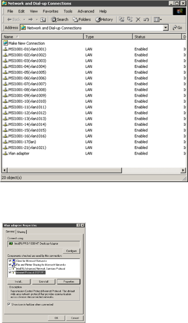
MSi Software Backup and Recovery
277
Network and Dial-up Connections
3. In the LAN 2 Properties dialog box, click the Configure button.
LAN 2 Properties
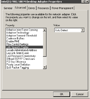
Chapter 11 Software Recovery and Upgrade
278
4. The Desktop Adapter Properties dialog box displays. Select the Advanced tab.
5. In the Advanced tab, select Link Speed & Duplex from the Property list. For this value,
select Auto Detect. Click OK.
Desktop Adapter Properties
The last step for the MSi setup is to set the virus protection program to run automatically.
Set the Virus Protection Program to Run Automatically
To set up the virus protection program:
1. Right-click My Computer and select Manage from the menu.
2. In the Computer Management dialog box, expand the Services and Applications
directory in the left pane.
3. Select the Services subdirectory. A list of the Services is displayed in the right pane
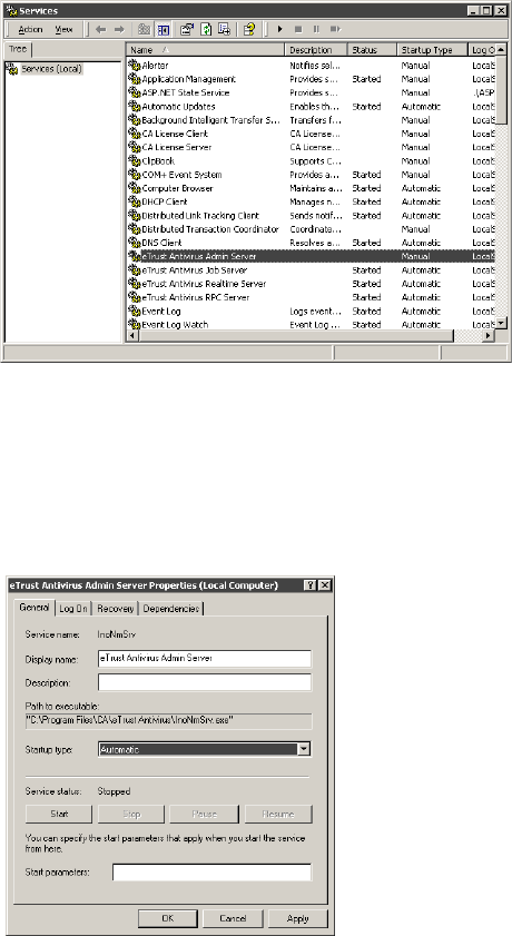
MSi Software Backup and Recovery
279
Services List
4. Locate eTrust Virus Admin Services in the list and double-click it.
5. In the General tab of the eTrust Properties dialog box, select Automatic as the startup
type. Click OK
eTrust Properties
The virus-protection program should start automatically whenever you start the MSi
computer.
Chapter 11 Software Recovery and Upgrade
280
FSC System Recovery
The FSC Recovery CD is provided to restore a malfunctioning FSC to original
configuration. This disc may be required if the original hardware has been replaced or the
operating software has been corrupted, causing the unit to malfunction. The FSC recovery
procedure will destroy all previous data and settings and should be used only if other
problem-solving efforts have failed.
wBefore attempting to perform this operation, make sure the other FSC is operating
reliably. Should both FSCs fail, the System will be brought off-air.
Do not run the recovery CD on both FSCs at the same time or all database content will
be destroyed and access to any recorded content on the array(s) will be lost. Only begin
the recovery procedure on the second FSC after recovery, upgrade, configuration and
startup have been performed on the first. If you encounter problems starting the FSC
after recovery, review the troubleshooting tips in “Troubleshooting Database
Problems” on page 327, or call Avid MediaStream Support.
To perform a FSC recovery:
1. Make sure you have selected the correct FSC for recovery.
nIf you will be running recovery on both FSCs, first start the procedure on FSC 1, if possible.
This will leave FSC 1 as Primary when the procedure is completed on both units. If you are
doing this, make sure that FSC 2 is in the Ready state before beginning.
2. Insert the first recovery CD (number one of two Recovery CDs) in the FSC’s CD-ROM
drive and then restart the computer.
3. In the Microsoft Windows Startup Menu, press 1 (re-image and walk the disk on this
system) to begin the recovery process.
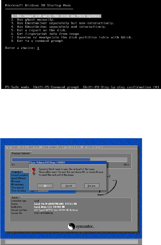
FSC System Recovery
281
Startup Menu
4. The recovery continues automatically. When prompted to insert the second CD, insert it
and click OK
Insert Second Recovery CD
5. You can monitor the installation’s progress via the Progress Indicator.
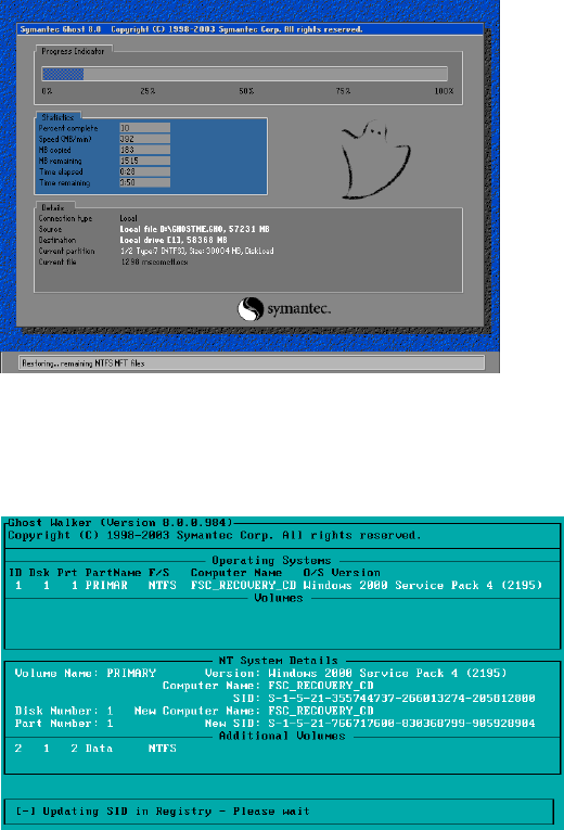
Chapter 11 Software Recovery and Upgrade
282
Installation Progress Indicator
1. After the installation is complete, the system is verified.
System Verification
2. After verification, restart the computer. The first time the FSC starts up after the
recovery, allow the disk check to proceed.
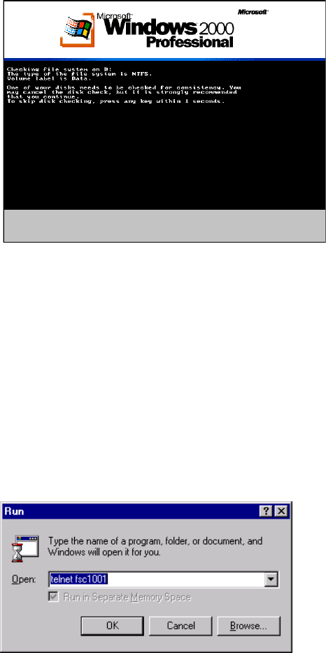
FSC System Recovery
283
Disk Check
FSC Software Upgrade
FSC software updates involve checking the status of both FSCs, and then inserting a CD-
ROM into the FSC 1 and starting the upgrade. You should complete the upgrade of FSC 1
before upgrading FSC 2.
Preparation for FSC Upgrade
nThis procedure assumes that you have already upgraded to the current MSi version. If you
have not already done so, perform the MSi upgrade first.
Opening FSC Telnet Session

Chapter 11 Software Recovery and Upgrade
284
FSC Status Checks
1. From the MSi PC, open a telnet session for each FSC. To start a telnet session, go to
Start > Run and enter telnet fscXX0Y where <XX> equals the cluster number of the
system and <0Y> equals 01 for Primary FSC or 02 for Secondary FSC.
2. From either FSC, check FSC Status by entering
fsc_status
.
nMake sure both FSCs are running in a Ready state before beginning upgrade procedure.
.
3. Check the current software revision on each FSC by running the command
fsc_revisions
.
Video Files Status Check
From the MSi, click the Clean Files button. When the Check Video Files window appears,
click Start Checking Video Files followed by OK. If this procedure finds any defective video
files, delete them now and re-run Clean Video Files until no defective files appear. You can
then re-dub these files after the upgrade procedure is complete.
After the check procedure is complete, click the Close button.
SANSERVICE
Status Ready Ready
Role SECONDARY PRIMARY
Connection CONNECTED CONNECTED
Remote DB tcp 10.73.22.2 1325 tcp 10.73.22.1 1315
Operations 133852 138163
Date 10/02/2001 10/02/2001
Time 09:37a 09:37a S
Size 39,354,368 39,354,368
SANSERVICE
Status Ready Ready
WATCHDOG
FSC revisions in the FSC upgrade CD:
FSC_G.01.06.00

FSC System Recovery
285
FSC Status Check
Normal upgrades of the FSCs can be run via Telnet.
nYou should begin your upgrade on FSC 1 unless otherwise directed by Avid MediaStream
Support.
wDo not attempt to upgrade FSC 2 until the upgrade of FSC 1 has successfully
completed and both FSCs are running. Not observing this sequence will bring your
system off-air.
At the telnet prompt, enter
fsc_status
to verify the two FSCs are in a Ready state. See the
following figure.
FSC Status Report
Installing or Upgrading the FSC Software
nRefer to the current software upgrade instructions (posted on the Avid MediaStream website
in the support area at http://www.avid.com/onlinesupport/), or contact Avid MediaStream
SupportSystems MediaStream Support.
SANSERVICE
Status Ready Ready
Role SECONDARY PRIMARY
Connection CONNECTED CONNECTED
Remote DB tcp 10.73.22.2 1325 tcp 10.73.22.1 1315
Operations 133852 138163
Date 10/02/2001 10/02/2001
Time 09:37a 09:37a
Size 39,354,368 39,354,368
SANSERVICE
Status Ready Ready
WATCHDOG
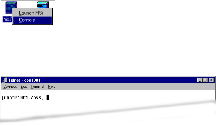
Chapter 11 Software Recovery and Upgrade
286
Installing or Upgrading MSS 8000 Server Software
This section covers the installation and upgrading of your server node’s AMS operating
system.
Open Telnet Session
Open a Console port telnet session on the MSi PC and login as root. To start a telnet
session:
1. From the MSi Control Panel, right-click the server node icon and select Console.
Console Port Option
2. A telnet session will open. If there is nothing in the window, press Enter. If a login
prompt is displayed, login as root. Otherwise, you should see the current directory’s
prompt, such as [root@<xxyy> /bvs].
Open Console Port Telnet Session
Setting Up Logging of Telnet Session
If you encounter difficulties or have questions about the process or procedures during
upgrade, a telnet session log can provide information to Avid MediaStream Support that can
be used to assist you. The Telnet client supplied with Windows 2000 does not support telnet
session logging. To log telnet sessions, you will need to install a telnet client supplied by
another vendor.
Installing or Upgrading MSS 8000 Server Software
287
Several shareware telnet clients are available. Tera Term (Pro) is a free terminal and telnet
client fully capable of logging telnet sessions. You can download it from this Web site:
http:/hp.vector.co.jp/authors/VA002416/teraterm.html
Backing Up Site Files
Site files specify a server node’s configuration. These files include the bvsrc, hosts, rhosts,
passwd, group and a number of audio and video configuration files. Backing up the site files
ensures that in the event of a problem such as a Boot Disk failure, you can quickly restore a
server to its configured operating mode.
To back up a server node’s site files:
1. Open a MSS or console telnet session and login as root.
2. From the prompt, enter the command
sitefiles2file
.
3. If requested to enter your name, enter your name or initials.
4. When prompted if it is OK to overwrite the file /tmp/sfiles.cpio, press Enter.
Wait for the process to complete (several minutes). When it is complete, the prompt
displays:
--->> sitefiles copied to '/tmp/sfiles.cpio':
followed by the root prompt.
5. From the MSi main menu, select Setup > Site Files > Save Sitefiles from BVS to
Console PC > Local Hard Disk.
6. When the following message appears, click OK:
root@01 /bvs] sitefiles2file
Operator Name:
No operator name has been specified in the last 24 hours.
Please enter your name at the prompt below. Your name is used to
keep track of who is doing system administration on you
Broadcast Video Server. It will appear in the /bvs/syslog log file.
Please enter your name: ekl
This sitefiles save operation would overwrite the file /tmp/sfiles.cpio.
Is it ok to overwrite this file with the latest sitefiles? (y/n)(def=y):
Chapter 11 Software Recovery and Upgrade
288
Save Sitefiles to C:\Program Files\Hewlett-
Packard\Msi\data\servername.cpio?
where servername is your server node’s name.
<Help Search Keywords>A message stating Is ‘sitefiles2file’ done? is displayed. Click Yes.
<Help Search Keywords>After the site files are saved successfully to the PC, a message is
displayed. Click OK.
7. Insert a formatted CD-recordable disc into your MSi PC CDRW drive.
8. Drag and drop the *.cpio files in the directory C:\Program Files\Hewlett
Packard\MSi\data onto the CD-recordable disc.
9. Remove the disc and label it Site Files <Server Hostname>. Date it and store it in a safe
place.
Upgrading the Server Software
nRefer to the current software upgrade instructions (posted on the Avid MediaStream
SupportWeb site in the support area at www.pinnaclesys.com/support), or contact Avid
MediaStream SupportSystems MediaStream Support.
Restore the Site Files
To restore the site files:
1. Insert the CD with the site files into the MSi PC’s drive.
2. Open the MSi application for the server.
3. From the MSi menu, select Setup > Restore Sitefiles to Server from Console PC >
Local Disk. This command copies the site files (using ftp) from the MSi PC to the
server.
4. From your telnet session, run the command file2sitefiles.
This command will unzip the site files into its many configuration files and install the
files in their proper place.
5. When the process is complete, upgrade the server software. (see note above).
6. The server upgrade procedure modifies the site files. Save the site files as described in
“Backing Up Site Files” on page 287.
Chapter 12
VLAN and Fibre Channel Switch
Configuration
The redundant Fibre Channel and VLAN switches in the System have been configured at the
factory. If a switch fails and needs replacement, or if the configuration of a switch changes,
you may need to reset the configuration settings for the switch. Both VLAN and Fibre
Channel switches are configured via a command line interface that is accessed through a
HyperTerminal session. To minimize the need for making numerous manual settings on the
switches, Avid MediaStream Support provides pre-configured setup files for your switch.
This chapter describes the procedures for configuring both VLAN and Fibre Channel
switches for clusters in the MSS Networked Storage System. The following topics are
covered:
• HP Procurve VLAN switch configuration
• Capellix 2000 and 3000 switch configuration
Before You Begin
Before you begin, you will need the following:
• A Windows configured PC (use the MSi PC)
• A 9-Pin null-modem cable for connection of the PC and the serial port on the VLAN
and Fibre Channel switches
nOne of these cables ships with each VLAN switch.
• A tftp application
(we recommend PumpKin tftp available on the web at
http://www.klever.net/kin/pumpkin.html)
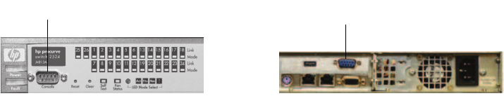
Chapter 12 VLAN and Fibre Channel Switch Configuration
290
• The latest version of the MSS 8000 software for MSS Networked Storage System
HP Procurve Switch Configuration
Check Switch Status
Open a telnet session to each FSC. Run the command checkLan. This runs a a utility
designed to check the connections from the specified device. Enter the required information
after each prompt. The CheckLan utility will then ping all required devices on both VLAN
switch and will report any communication errors encountered.
nIf errors are encountered, correct the fault before proceeding and verify correction by
running the checkLan utility a second time.
wDo not perform a switch upgrade or configuration until you have verified that both
switches are performing normally. Failure to follow this precaution before switch
configuration could cause components within your system to go off-air.
Prepare System for Download
Use the 9-pin null-modem cable to connect the PC to the HP Procurve switch.
Null-modem Cable Connections
Copy the Files to C:\Temp
The configuration files are on the MSS 8000 Software Release CD in the swt_cfg directory.
To simplify the download procedure, copy the files you need for the procedure from the CD
to the C:\temp directory on the MSi PC
9-pin serial port MSi serial port
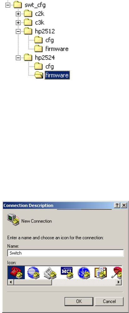
291
Configuration Files Directory
1. Open the directory for your switch (the 24-port VLAN switch is hp2524) to the two
subfolders: cfg (configuration files) and firmware.
nThe cfg folder contains 32 configuration files, two for each of 16 clusters. The files should be
labeled hp2524<#> followed by <a> or <b> e.g. hp2524_01a (switch 1 in cluster 1).
2. Copy the configuration file(s) and the firmware file to C:\Temp.
Set Up a HyperTerminal Session on the PC
1. Go to Start Menu > Program > Accessories > Hyperterminal and Choose Hyperterminal
from the menu. The Hyperterminal application will launch a session.
Connection Description Dialog Box
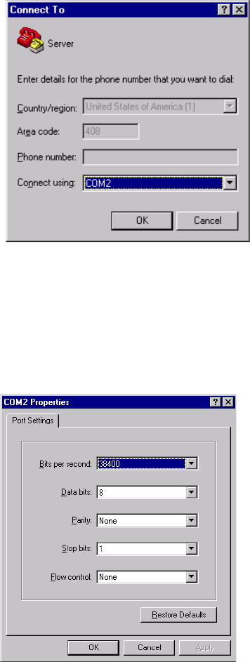
Chapter 12 VLAN and Fibre Channel Switch Configuration
292
2. Enter a name in the connection description to save the connection for future use. Click
OK.
Connection to Dialog Box
3. The Connect To dialog box is displayed. In the Connect using text entry box, click the
arrow and select COM 2 from the pull-down list, and then click OK.
4. The COM2 Properties dialog box displays. Set the values to 38400 bps, 8 Data bits,
Parity None, Stop bits 1, Flow control None. Click OK. The session will open.
COM2 Properties Dialog Box
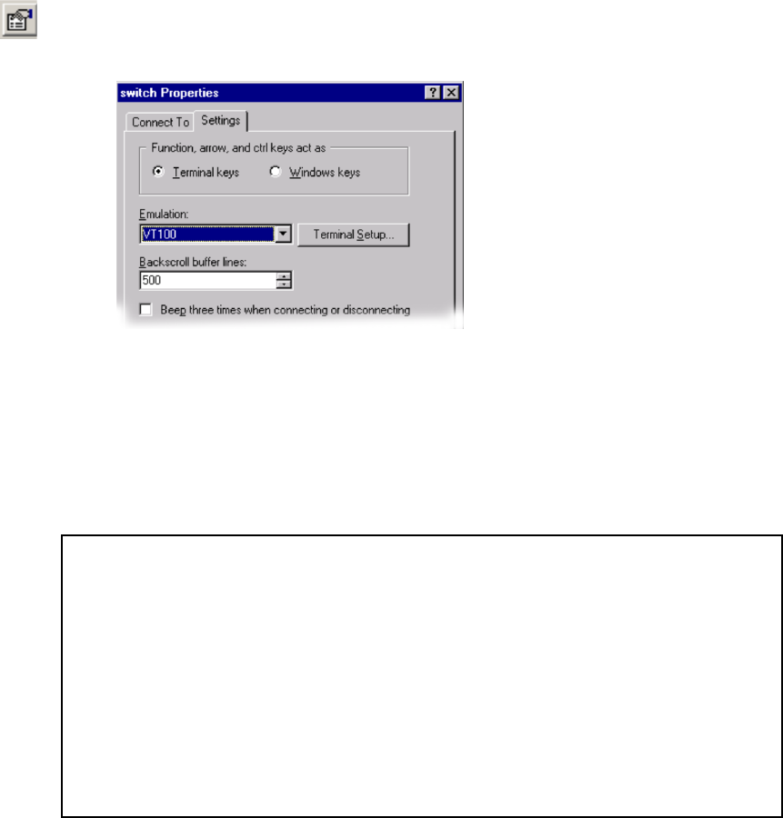
293
5. Click the Properties button on the tool bar. The switch Properties dialog box appears.
Switch Properties Dialog Box
6. Click the Settings Tab, and set Emulation to VT100. Then click OK. The session now is
ready to receive data from the switch.
HP Procurve Firmware Download
1. Power up the switch. Press Enter twice. You should see the boot sequence progress.
2. The switch will take about 30 seconds to initialize. See below
.
3. Press the space bar. The prompt HP2524# will appear.
4. Enter menu. The Console Manager Mode’s main menu will appear.
5.
HP J4813A ProCurve Switch 2524
Firmware revision F.02.11
Copyright (C) 1991-1998 Hewlett-Packard Co. All Rights Reserved.
RESTRICTED RIGHTS LEGEND
Use, duplication, or disclosure by the Government is subject to restricti
set forth in subdivision (b) (3) (ii) of the Rights in Technical Data and
Computer Software clause at 52.227-7013.
HEWLETT-PACKARD COMPANY, 3000 Hanover St., Palo Alto, CA 94303

Chapter 12 VLAN and Fibre Channel Switch Configuration
294
6. Press 1 to view the Status and Counters.
VLAN Switch Status and Counters Menu
7. Press 1 to view General Information.
==========================- CONSOLE - MANAGER MODE -==================
=
Main Menu
1. Status and Counters...
2. Switch Configuration...
3. Console Passwords...
4. Event Log
5. Command Line (CLI)
6. Reboot Switch
7. Download OS
8. Run Setup
9. Stacking...
10. Logout
Provides the menu to display configuration, status, and counters.
==========================- CONSOLE - MANAGER MODE -===================
=
Status and Counters Menu
1. General System Information
2. Switch Management Address Information
3. Port Status
4. Port Counters
5. Address Table
6. Port Address Table
7. Spanning Tree Information

295
If the firmware version is not F.02.11, you need to download more recent firmware.
8. Press Enter to go to previous menu. Press 0 to return to the main menu. If the correct
firmware is installed, go to the “Downloading the Configuration Files” on page 297.
9. Press 7 to begin Download OS.
10. TFTP is the displayed method. Press the space bar to select XMODEM.
11. Press Enter. A C should display on the screen. Press Enter until the C displays.
==========================- CONSOLE - MANAGER MODE -===================
=
Status and Counters - General System Information
System Contact :
System Location :
Firmware revision : F.02.11 Base MAC Addr : 0001e7-701d80
ROM Version : F.01.01 Serial Number : tw05300761
Up Time : 9 mins Memory- Total : 11,337,704
CPU Util (%) : 12 Free : 9,663,348
IP Mgmt - Pkts Rx : 427 Packet - Total : 512
Pkts Tx : 0 Buffers Free : 510
Lowest : 329
Currrent firmware
==========================- CONSOLE - MANAGER MODE -
=======================
Download OS
Current Firmware revision : F.02.11
Method [XMODEM] : TFTP.
TFTP Server
Remote File Name :
Actions-> Cancel Edit eXecute Help
Select the file transfer method (TFTP and XMODEM are currently supported).
Download method
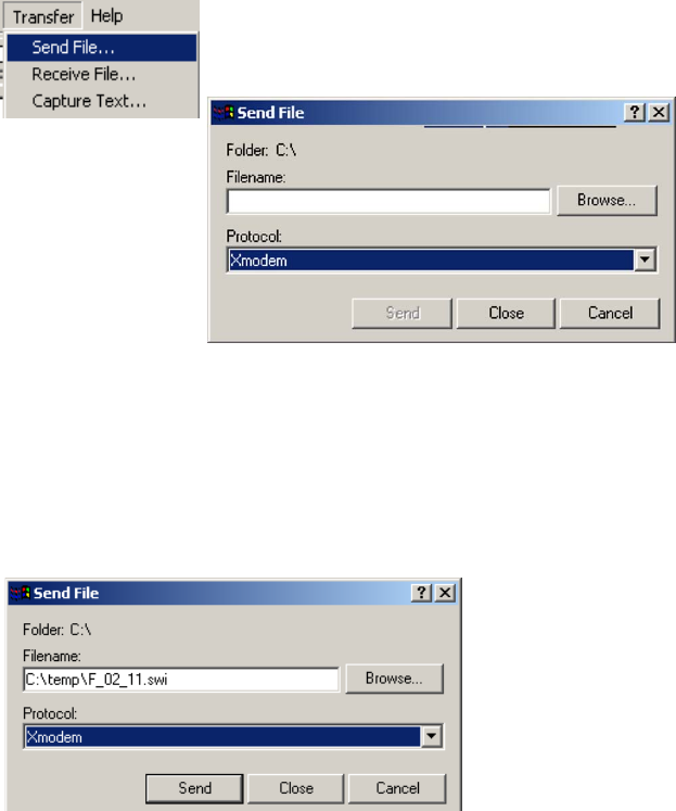
Chapter 12 VLAN and Fibre Channel Switch Configuration
296
Select Send File
12. On the HyperTerminal menu bar, select Transfer > Send File. The Send File dialog box
displays. Select Xmodem from the Protocol list.
13. Click Browse and go to the directory where the files are located (C:\temp). Select
F_02_11.SWI. (See Figure 12-9.) Double-clicking the file selects it for sending.
Send File
14. Click the Send Button. The Xmodem file send for switch dialog box displays. After a few
seconds, the progress indicator should show activity. The download process takes about
20 minutes. When the download is finished, the switch automatically reboots.
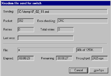
297
XModem File Send for Switch
15. To verify the download has completed, wait for the switch to reboot. Enter menu at the
prompt.
16. Press 1 for Status and Counters. Then press 1 for General System Information. The
software version should be Firmware revision F.02.11.
17. Press Enter to return to the previous menu, and press 0 to return to the main menu.
Downloading the Configuration Files
To download the configuration files for the switch:
1. From the main menu, press 5 to enter the Command Line (CLI) mode.
2. At the prompt enter:
copy xmodem startup-config pc
3. Press
y
when asked if you want to continue.
4. Press Enter again to begin the XMODEM transfer.
5. When a capital C is displayed, go to the HyperTerminal menu bar and select
Transfer > Send File.
6. The Send File dialog box is displayed. Click the Browse button and navigate to the
correct directory and select the correct file for your switch. The files should be labeled
with the number corresponding to the cluster of your system and an <a> or <b> (for
example, hp2512_01a or hp2512_01b).
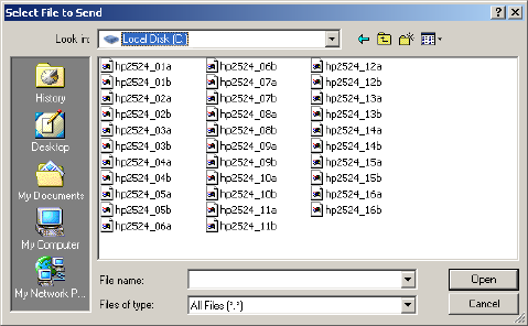
Chapter 12 VLAN and Fibre Channel Switch Configuration
298
Select File To Send Dialog Box
7. Double-click the file to select it for sending. The Xmodem file to send dialog box is
displayed.
nThere are two groups of configuration files (each with 32 configuration files):
hp2524 is for the 24-port switch, and hp2512 is for the 12-port switch.
8. Press the Send button. The transfer should complete in seconds. When the transfer is
complete, the switch reboots automatically. When it comes back up, press Enter twice.
The return prompt will change from HP2524# to switch<id>#.
Check the LAN Settings Configuration
nThis step is necessary only if you are having trouble with switch communication.
1. Verify that the prompt indication reflects the correct switch number i.e. switch01a for
switch 1 Cluster 1.
2. At the prompt, enter
menu.
3. From the main menu, press
2 –
Switch Configuration.
4. Press
5 –
IP Configuration.
5. Confirm that the Default Gateway is set to 10.xx.21.32 (switch A) or 10.xx.17.33
(switch B).
nSee Table on page 300 for the correct VLAN address.

299
Press E for edit. Then press the down cursor arrow until vlan <xx>16 is displayed.
(<xx> corresponds to Cluster ID number). Check the settings. The settings should be:
Switch Configuration - Internet (IP) Service
Default Gateway : 10.64.21.32
Default TTL : 64
VLAN IP Config IP Address Subnet Mask
------------ + ---------- --------------- ---------------
vlan1013 | Disabled
vlan1014 | Disable
vlan1015 | Disabled
vlan1016 | Manual 10.64.16.34 255.255.255.0
vlan1017 | Disabled
Actions-> Cancel Edit Save Help
Enter the IP address of the default gateway.
Switch Configuration - Internet (IP) Service
Default Gateway : 10.64.21.32
Default TTL : 64
VLAN IP Config IP Address Subnet Mask
------------ + ---------- --------------- ---------------
vlan1013 | Disabled
vlan1014 | Disabled
vlan1015 | Disabled
vlan1016 | Manual 10.64.16.34 255.255.255.0
vlan1017 | Disabled
Actions-> Cancel Edit Save Help
Enter the IP address of the default gateway.
Subnet mask is 255.255.255.0
Switch 1 VLAN IP address is
10.xx.16.33 on VLAN<xx> 16
Switch 2 VLAN IP address is
10.xx.1735 on VLAN<xx>17
Note: <xx> = cluster ID
Default Gateway address will be
10.xx.16.3(x).<yy> corresponds
to cluster addressing
Default Gateway address 10.xx.16.3<x><yy>
corresponds to cluster address

Chapter 12 VLAN and Fibre Channel Switch Configuration
300
6. When you have confirmed these settings, press Enter to leave the edit mode and press C
to leave the configuration. Press 0 to return to the main menu.
7. Press “5” to return to the Command Line Interface.
VLAN IP Configuration Table
VLAN IP Address Settings
Switch VLAN IP Config IP Address Subnet Mask
A (Primary) vlan <xx>16 Manual 10.xx.16.34 255.255.255.0
B (Secondary) vlan <xx>17 Manual 10.xx.17.35 255.255.255.0
VLAN Configuration Table
Cluster
Number
Switch
Name
VLAN
Name
Switch IP
Address Subnet Mask
Default
Gateway
Cluster 1 switch01a vlan116 10.64.21.34 255.255.255.0 10.64.21.32
switch01b vlan116 10.64.17.35 255.255.255.0 10.64.17.33
Cluster 2 switch02a vlan216 10.65.21.34 255.255.255.0 10.65.21.32
switch02b vlan216 10.65.17.35 255.255.255.0 10.65.17.33
Cluster 3 switch03a vlan316 10.66.21.34 255.255.255.0 10.66.21.32
switch03b vlan316 10.66.17.35 255.255.255.0 10.66.17.33
Cluster 4 switch04a vlan416 10.67.21.34 255.255.255.0 10.67.21.32
switch04b vlan416 10.67.17.35 255.255.255.0 10.67.17.33
Cluster 5 switch05a vlan516 10.68.21.34 255.255.255.0 10.68.21.32
switch05b vlan516 10.68.17.35 255.255.255.0 10.68.17.33
Cluster 6 switch06a vlan616 10.69.21.34 255.255.255.0 10.69.21.32
switch06b vlan616 10.69.17.35 255.255.255.0 10.69.17.33
Cluster 7 switch07a vlan716 10.70.21.34 255.255.255.0 10.70.21.32
switch07b vlan716 10.70.17.35 255.255.255.0 10.70.17.33
Cluster 8 switch08a vlan816 10.71.21.34 255.255.255.0 10.71.21.32

301
nIf your site has more than 16 clusters, contact Avid MediaStream Support for configuration
assistance.
VLAN name is the name of the VLAN port that is configured under the switch configuration
menu.
Gadzoox Capellix Switch Configuration
Verify Fibre Channel Switch Status
From the MSi System Status window, verify that both Fibre Channel paths are operational.
switch08b vlan816 10.71.17.35 255.255.255.0 10.71.17.33
Cluster 9 switch09a vlan916 10.72.21.34 255.255.255.0 10.72.21.32
switch09b vlan916 10.72.17.35 255.255.255.0 10.72.17.33
Cluster 10 switch10a vlan1016 10.73.21.34 255.255.255.0 10.73.21.32
switch10b vlan1016 10.73.17.35 255.255.255.0 10.73.17.33
Cluster 11 switch11a vlan1116 10.74.21.34 255.255.255.0 10.74.21.32
switch11b vlan1116 10.74.17.35 255.255.255.0 10.74.17.33
Cluster 12 switch12a vlan1216 10.75.21.34 255.255.255.0 10.75.21.32
switch12b vlan1216 10.75.17.35 255.255.255.0 10.75.17.33
Cluster 13 switch13a vlan1316 10.76.21.34 255.255.255.0 10.76.21.32
switch13b vlan1316 10.76.17.35 255.255.255.0 10.76.17.33
Cluster 14 switch14a vlan1416 10.77.21.34 255.255.255.0 10.77.21.32
switch14b vlan1416 10.77.17.35 255.255.255.0 10.77.17.33
Cluster 15 switch15a vlan1516 10.78.21.34 255.255.255.0 10.78.21.32
switch15b vlan1516 10.78.17.35 255.255.255.0 10.78.17.33
Cluster 16 switch16a vlan1616 10.79.21.34 255.255.255.0 10.79.21.32
switch16b vlan1616 10.79.17.35 255.255.255.0 10.79.17.33
VLAN Configuration Table
Cluster
Number
Switch
Name
VLAN
Name
Switch IP
Address Subnet Mask
Default
Gateway
Chapter 12 VLAN and Fibre Channel Switch Configuration
302
1. Check the System Status button. If it is green, then the Fibre Channel Paths are
functioning.
2. If the System Status button is red, verify which component failed. Both controllers on
each array should be green (that is, it is OK) to proceed. If any controllers are not
operational from any server node, locate the problem and correct it before proceeding.
nStatus must be checked from the MSi PC for each server node. To do this, quit each MSi
session and start the next one. Performed sequentially from each server node in the system.
wDo not perform a switch upgrade or configuration until you have verified that both
Fibre Channel switches are performing normally. Not following this precaution before
proceeding with upgrade could cause components within your system to go off-air.
Prepare System for Download
PumpKin Files
Loading the configuration files on the Capellix Fibre Channel Switches requires that your
PC has a TFTP server available. This procedure uses PumpKin TFTP. If you need a copy of
this application, it can be downloaded at no charge from:
http://www.klever.net/kin/pumpkin.html
nPumpKin is a program designed to send and receive files over the net while having Wintalk
session running using TFTP (RFC1350) protocol. It includes full-functional TFTP
server/client so it may be useful for maintaining Cisco routers, Versanet ISP accelerators
and probably some other network devices.
This software is free for use and distribution as long as developers' credits are explicitly
mentioned.
nDeveloped by: Klever Group, Inc. (http://www.klever.net/)
Author: Michael Krelin (hacker@klever.net)
Copyright 1997,1998 Klever Group, Inc.
Fan mail send to gefilte@klever.net
If you have any questions about configuration using PumpKin TFTP, contact Avid
MediaStream Support.
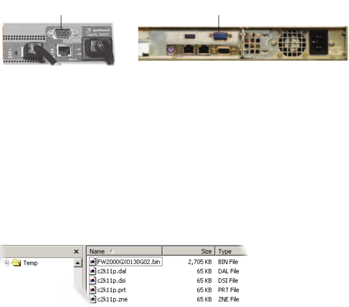
303
To prepare the switch for download:
1. Install the PumpKin TFTP on your PC. Place the three files
in a directory on the C drive and label the directory PumpKin.
2. Use the 9-pin null-modem cable to connect the PC to the Capellix switch.
Null-Modem Cable Connections
Copy the Firmware and Configuration Files
The firmware and configuration files are on the MSS8000 software release CD in the
swt_cfg directory.
1. From this directory go to the folder labeled c2k for the Capellix 2000 switch,
or c3k for the Capellix 3000 with 12-port blades. (For the Capellix 3000 with 8-port
blades, go to the folder labeled 8portBlade within c3k.)
2. Within this directory are two sub-directories – fw and config. Copy the contents of both
directories into C:\Temp on the MSi PC.
Sample of Files to be Copied
Setup HyperTerminal Session on the PC
1. Go to Start Menu > Program > Accessories > HyperTerminal > HyperTerminal.
The HyperTerminal application will launch a session.
2. Type a name in the connection description, then click OK.
9-pin serial port MSi serial port
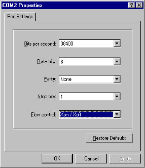
Chapter 12 VLAN and Fibre Channel Switch Configuration
304
3. The Connect To dialog box is displayed. For the Connect using option, select COM2,
and click OK.
4. The COM2 Properties dialog box displays. Set to 38400 bps, 8 Data bits, Parity None,
Stop bits 1, Flow control None. Click OK. The session opens.
COM 2 Properties Dialog Box
5. Click the Properties button on the tool bar. The Switch Settings dialog box will appear.
Click the Settings Tab, and set Emulation to VT100. Then click OK.
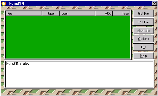
305
Set Up the TFTP Program
1. Start PumpKIN.exe on the MSi PC. The program window will open and display
PumpKIN started in the message area of the window.
PumpKIN Window
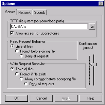
Chapter 12 VLAN and Fibre Channel Switch Configuration
306
2. Click the Options button. The Options dialog box opens. Do the following:
- Select Give all files
- Select Take all files
- Set TFTP filesystem root (download path) to C:\Temp.
- Click OK to accept changes.
Options Dialog Box
3. Leave PumpKIN open on the desktop so that it can accept your TFTP download
process.
Set Up Ethernet Connection
The Capellix switches are connected to the VLAN switches. The Primary FC Switch is
connected to VLAN A. The Secondary FS Switch is connected to VLAN B. The switch
addresses are 10.xx.21.36 for Primary and 10.xx.17.37 for Secondary. See “VLAN
Topology” on page 51. No additional connections need to be made for downloading files to
the switches.
Set Up the Capellix for Download
1. From your HyperTerminal session reset the switch (remove and reinsert the power
cable). Reboot takes about one minute.
2. When the boot up is completed, logon as user and enter ADMIN (all caps) for the
password.
3. Enter 2 to check Networking parameters.

307
nIf you are already in the Command Interface at this point, enter exit.
4. Verify the IP and subnetwork mask settings. The IP address should be 10.xx.21.36 for
the primary switch and 10.<xx>.17.37 for the Secondary switch where <xx> is the
cluster ID. See Chapter 3: VLAN Topology for information on VLAN Addresses.
5. If the IP address is correct, enter 2 to return to the main menu. Then enter the Command
Line interface and download the firmware (next section).
6. If the IP address is not correct, enter 2. Then enter the new IP address at the prompt and
enter 2 to return to the previous menu.
7. Change the Switch subnet mask by pressing 3.
8. Enter 255.255.255.0. Press 1 to return to the previous menu.
9. Press 5 to save your changes. When settings have been saved, press 1 to return to the
main menu:
10. Press 6 to reset the switch. Press y to reboot with the new parameters.
11. When the switch boots up, logon as user and enter ADMIN for password.
12. Press 4 to open the command-line interface. The prompt changes to cmd>.
Capellix 2000C Stackable SAN Switch
Model Number: Model 2000C
Ventana SANtools GX: 01.30-G02
Selftest Status: passed
2. Networking parameters
3. Management options
4. Command line interface
5. Logout
6. Reset switch
1. Return to main menu
2. Set IP address [current: 127.0.0.1]
3. Set subnetwork mask [current: 0.0.0.0]
4. Set gateway address [current: 0.0.0.0]
5. Save modifications and reset switch to activate
> 2

Chapter 12 VLAN and Fibre Channel Switch Configuration
308
Download Firmware
1. At the command prompt enter
tftpdl
.
The return value will provide the TFTP download file name, the TFTP boot file name, and
the TFTP IP address. The following values should be present:
:
2. Edit the values as required to conform to the table above.
- To change the download file name, enter:
tftpdl dfile = <filename
>
- To change the boot file name, enter:
tftpdl bfile = <filename>
- To change the TFTP IP address, enter:
tftpdl ip = <10.xx.21.5>
(Primary) or:
tftpdl ip = <10.xx.17.5>
(Secondary)
-Enter
tftpdl
start to begin the download process. PumpKIN TFTP will also
show the progress of the download process.
Download will continue until complete. The progress of the download will display in the
green display window of PumpKIN, with the ACK column showing the progress of the
download. As long as this continues to advance, the download is proceeding normally.
Firmware takes a minute or two to completely download.
When the transfer is completed, the progress indicator no longer appears in the top
green window, and a message indicating a successful completion displays.
cmd> tftpdl
TFTP download file name: FW2000GX0130G02.bin
TFTP boot file name: FA2000GX0130G02.bin
TFTP IP address: 10.64.21.5
Request time out: 5000 ms
Request number of retries: 24
Data time out: 500 ms
Data number of retries: 90
Name Capellix 2000 Capellix 3000
TFTP download file name FW2000GX0130G02.bin FW3000GX0140G08.bin
TFTP boot file name FA2000GX0130G02.bin FA3000GX0140G08.bin
TFTP IP address (Primary) 10. xx.21.5 10.xx.21.5
TFTP IP address (Secondary) 10. xx.17.5 10.xx.17.5

309
PumpKIN Download Complete
3. On the HyperTerminal window, the boot sequence will continue with the loading of the
newly transferred firmware and finish with a boot to the login prompt.
4. Enter
user
(lower case) at the Login prompt.
5. Enter
ADMIN
(upper case) at the Password prompt. (If the screen shown below does not
appear, then enter
exit
to quit the Command Line Interface.)
nIf for any reason your download file was corrupted, and the switch is temporarily non-
operational, repeat the download process.
Troubleshooting
If after attempting to download firmware, you receive the following message:
Download failed. Ret=2 Failed to read package header from tftp server
Perform the following troubleshooting steps:
1. The TFTP server window indicates a GET request; check the spelling of the file name
and the path on the tftp server.
2. The TFTP server window has no contact indications; check your network settings and
connections.
If you are still unable to upgrade your switch, contact Gadzooks Networks
Customer Service Organization:
Telephone: 888 423-3222 or 408 360-4990
Fax: 408 360-4951
E-mail: tech.support@gadzoox.com
Downloading the Configuration Files
The switch should have successfully booted up with the new firmware. After logon, the
prompt displays the five options for further settings. Press 4 to enter the command-line
interface from which you can download the configuration files.
1. At the cmd> prompt enter one of the following:
[Primary]
config ip = 10.xx.21.5
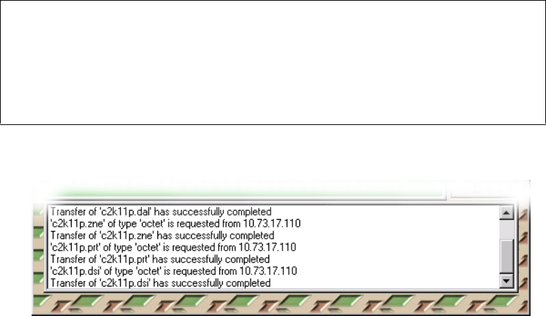
Chapter 12 VLAN and Fibre Channel Switch Configuration
310
[Secondary
] config ip = 10.xx.17.5
nThese are the correct addresses for the FC switches to your MSi PC. See “VLAN Topology”
on page 51 to find the correct MSi VLAN address for your cluster.
2. Enter
config file = c2k11p
.
nThis is the prefix for the four configuration files in C:\Temp.
3. Enter
config restore
.
4. Press
y
to start the download. The file transfer’s progress displays.
File Transfer Successful
The tftp server should note the transfer in the lower window.
5. Enter
exit
to leave the command-line interface.
6. Press
6
to reset the switch. The switch will boot with the updated switch settings.
7. Quit HyperTerminal and the TFTP application.
8. Remove the 9-pin connection and replace VLAN connections as necessary. The switch
is ready for operation and should boot correctly with the new settings when turned on.
Restoring DAL configuration file
Restoring ZONE configuration file
Restoring ZONE PORT configuration file
Restoring DSI configuration file
Activating restored zoning & zone port configuration
Configuration files were restored properly
cmd

311
Brocade SilkWorm Switch Configuration
These switches should already have the proper firmware and configuration information on
them when they are installed. To log in to the switch for verification or troubleshooting, do
the following:
1. Connect an RS-232 cable with a DB9-to-RJ45 adaptor to the 9-pin DIN connector on
the Brocade switch. Connect the other end of the cable to the COM1 port on the MSi PC
(or other PC used for setup or testing purposes).
2. On that PC, start the Hyperterminal application (usually via Start > Programs >
Accessories > Communications > Hyperterminal), with the following options: 9600
baud, 8 bits, no parity, one stop bit, no flow control. Make sure that Scroll Lock is
disabled on the PC keyboard.
3. If necessary, power up the Brocade switch and wait for it to boot to the login screen.
(This may take 4-6 minutes.)
4. Make sure the switch displays “Script PASSED” during the boot process, as shown here.
If it does not, contact Avid MediaStream Support. Otherwise, press Enter to continue
the login.
5. Log in as user “admin” with password “password”.
You can now verify configuration information for the switch.
POST2: Test #1 - Running camtest
POST2: Test #2 - Running txdpath
POST2: Test #3 - Running spinsilk (SERDES)
POST2: Test #4 - Running backplanetest
POST2: Running diagshow
POST2: Script PASSED with exit status of 0 Mon Dec 20 18:28:28 UTC 2004
1:27)
Initializing Ports ....
Port Initialization Completed
Enabling switch...
0x25b (fabos): Switch: 0, Info FABRIC-SWITCH_ROLE, 4, Principal switch
0x25b (fabos): Switch: 0, Info FABRIC-DOMAIN_INFO, 4, Domain 1
Fabric OS (swd77)
swd77 console login:

Chapter 12 VLAN and Fibre Channel Switch Configuration
312
IP Address
Type ipAddrShow at the prompt to see the switch IP address information.
The Ethernet IP address should be 10.xx.21.36 for FC switch A and 10.xx.17.37 for FC B,
where xx maps to the cluster number, starting at 64 for cluster 1.
The subnet masks and Fibre Channel IP address should be as shown here for both FC
switches.
The Gateway IP address should be 10.xx.21.32 for FC switch A and 10.xx.17.32 for FC B,
where xx maps to the cluster number, starting at 64 for cluster 1.
Firmware Revision
Type firmwareShow at the prompt to see the switch firmware information.
Configuration
Type
switchShow
at the prompt to see the switch port configuration information.
Here is the expected output for the Brocade 3850 (16-port) switch used with the Medea
1GB drive array:
swd77:admin> ipAddrShow
Ethernet IP Address [10.64.21.36]:
Ethernet Subnetmask [255.255.255.0]:
Fibre Channel IP Address [0.0.0.0]:
Fibre Channel Subnetmask [0.0.0.0]:
Gateway IP Address [10.64.21.32]:
swd77:admin> firmwareShow
Primary partition: v4.2.2a
Secondary Partition: v4.2.2a

313
Here is the expected output for the Brocade 3250 (8-port) switch used with the Medea 1 GB
drive array:
If any of this output does not match what is expected, contact Avid MediaStream Support.
For Brocade switch cabling information, see Chapter 5.
Ports of Slot 0 0 1 2 3 4 5 6 7 8 9 10 11 12 13 14 15
-----------------+--+--+--+--+----+--+--+--+----+--+--+--+----+--+--+--
Speed 1G 1G 1G 1G 1G 1G 1G 1G 1G 1G 1G 1G 1G 1G 1G 1G
Trunk Port ON ON ON ON ON ON ON ON ON ON ON ON ON ON ON ON
Long Distance .. .. .. .. .. .. .. .. .. .. .. .. .. .. .. ..
VC Link Init .. .. .. .. .. .. .. .. .. .. .. .. .. .. .. ..
Locked L_Port .. .. .. .. .. .. .. .. ON ON ON ON ON ON ON ON
Locked G_Port .. .. .. .. .. .. .. .. .. .. .. .. .. .. .. ..
Disabled E_Port .. .. .. .. .. .. .. .. .. .. .. .. .. .. .. ..
ISL R_RDY Mode .. .. .. .. .. .. .. .. .. .. .. .. .. .. .. ..
Persistent Disable.. .. .. .. .. .. .. .. .. .. .. .. .. .. .. ..
Locked Loop HD .. .. .. .. .. .. .. .. .. .. .. .. .. .. .. ..
Ports of Slot 0 0 1 2 3 4 5 6 7
-----------------+--+--+--+--+----+--+--+--
Speed 1G 1G 1G 1G 1G 1G 1G 1G
Trunk Port ON ON ON ON ON ON ON ON
Long Distance .. .. .. .. .. .. .. ..
VC Link Init .. .. .. .. .. .. .. ..
Locked L_Port .. .. .. .. ON ON ON ON
Locked G_Port .. .. .. .. .. .. .. ..
Disabled E_Port .. .. .. .. .. .. .. ..
ISL R_RDY Mode .. .. .. .. .. .. .. ..
Persistent Disable.. .. .. .. .. .. .. ..
Locked Loop HD .. .. .. .. .. .. .. ..
Chapter 12 VLAN and Fibre Channel Switch Configuration
314
Chapter 13
Troubleshooting Resources
The chapter presents resources for maintaining and troubleshooting the MediaStream
System. The following topics are covered:
Support Resources
• Online Manuals
• Telnet Logs
•FTP
• Redirecting Output To File
Tools for FSC Administration
• Error Logs
-fsc.log
-syslog
- solmsg.out log
- FSC Utilities
-fsc_status
- fsc_copy
-fs_ls
-fs_util
-fs_dump_meta
• Troubleshooting Database Problems

Chapter 13 Troubleshooting Resources
316
Tools for Server Node Administration
• Error Logs
-elog
-Syslog
• Server Node Utilities
-revisions
-mdsutil
-vmescan
- sand_state –s
- san_checkLan
Tools for ConnectPlus 1000 Networked Storage Gateway PC Administration
• Error Logs
Support Resources
In addition to Avid MediaStream SupportSystems Broadcast Support, this manual is a
primary support resource. It is periodically updated and is available online at
www.pinnaclesys.com/support/. Other support resources are available on the MSS 8000
server node and can be accessed via FTP. The server logs and the output of telnet sessions
will prove to aid you as well. To help you troubleshoot your system, this section covers the
following support tools:
•Using FTP
• Logging telnet sessions
• File redirection to save output to text
Using FTP
You can transfer files between components via FTP (File Transfer Protocol). For example,
you can use FTP to copy log file data from the server to the MSi PC to be printed or e-mailed
to Avid MediaStream Support for analysis.
To open an FTP session:
1. From the Start menu, select Run, and enter cmd.
2. At the DOS prompt, enter
ftp <hostname>
of the server. The system responds:

Support Resources
317
3. At the user prompt, enter ftp.
4. For the password, enter ftp and press Enter. The system responds:
FTP Logon Window
Copying Files with FTP
FTP allows you to copy files between servers and from the server to the MSi PC. Save the
files to a destination folder on the MSi PC’s local disk and then copy the files to a writable
CD (see “Saving Site Files” on page 164).
Open an ftp session
1. Open an ftp session and logon (see the logon instructions above).
To see which options are available in ftp, enter a question mark (?) at the ftp prompt.
This returns a list of command options you can in your ftp session. The most common
command is get. The get command followed by a filename executes a file transfer.
The put command allows you to move a file from your local directory to the
destination directory. The mget command allows you to copy multiple files at once
without having to request each file individually.
Connected to <hostname>.
220 <hostname> FTP server (Version 6.00) ready.
User (<hostname>: (none)):
230 Guest login ok, access restrictions apply.
ftp>
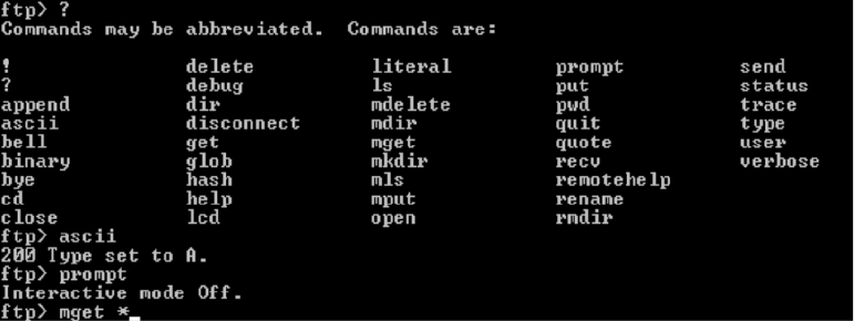
Chapter 13 Troubleshooting Resources
318
FTP Session with Help Screen
To copy files:
1. In the command prompt window, change to the directory from which you will copy files
by entering cd <directory path>. To confirm your current directory, enter
pwd.
2. Enter
ascii
to set the mode to ASCII (A) mode, which is used to copy ASCII text
documents.
3. Set local directory on the MSi PC. At the prompt, enter
lcd c:\<directory path>
4. Enter
prompt
to turn off interactive mode. If you enter prompt again, interactive mode
is turned on. Interactive mode requests a keyboard y or n response for each file transfer.
Perform this transfer with interactive mode off.
5. The verbose command lists files as the transfer occurs. (This is a toggle command
similar as is the prompt command.) Verbose is set to on by default.
6. Enter
mget *
.
The wildcard * (asterisk) symbol returns all files in the directory.
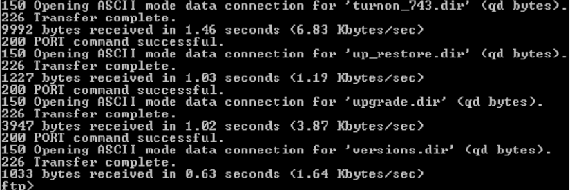
Support Resources
319
FTP File Transfer with Verbose Mode Set On
When all transfers are complete, the ftp> prompt displays. PDF files are binary so they
should not be copied in ASCII mode. Enter binary. The response is:
Enter set to
I
.
1. Enter
mget *.pdf
.
The asterisk (*) is a wildcard that searches for all files that include a .pdf extension.
Entering this command will begin file transfer of the files within the .pdf extension files.
There are two PDF files in the /bvs/doc directory.
7. When complete, enter ascii to return to ASCII mode.
Logging Telnet Sessions
It is often useful to preserve the screen output for future examination or to send to Avid
MediaStream Support for review. telnet sessions can be saved for later review with the Start
Logging function.
nWindows 2000 Telnet client does not support logging. To log telnet sessions, you must use a
third party telnet client. Several are available as shareware on the Web Tera Term Pro
version 2.3 for Windows 95/NT, which is available at:
http://hp.vector.co.jp/authors/VA002416/teraterm.html
To view a log file:
1. From My Computer or Explorer, navigate to the log file directory.
2. Double-click the file to open it. The file will open in Notepad.
Chapter 13 Troubleshooting Resources
320
File Redirection
In UNIX, output can be redirected to a file that you can print out. You can use the redirect
file command when you want to save the output of a command.
To redirect output, enter the command followed by the greater than (>) symbol and the
directory path and file name. For example:
fs_ls -l > /fsc/doc/fs_ls.txt
The output is written to the designated text file.
This section reviews the FSC log files and key commands used to monitor and maintain
system storage from the FSCs.
Error Log Files
The File System Controllers produce three log files for troubleshooting:
• syslog.txt
•fsc.log
• solmsg.out
syslog.txt
The syslog.txt file records major events during bootup or shutdown of the FSC.
Information contained in the file might be linked to other log files to provide key
information to a system problem. Syslog.txt is stored in the /fsc/logs directory.
To view recent entries in the syslog, open a telnet session on the FSC you wish to
monitor. Then enter:
tail -20 /fsc/logs/syslog.txt
This will open the last 20 lines of the syslog file.
fsc.log File
The fsc.log file resides in /fsc/logs directory. The file name is fsc.log.0x where <x> is the
last character of the FSCs hostname (1 for Primary or 2 for Secondary)
fsc0101 = fsc.log.01
fsc0102 = fsc.log.02
The fsc.log can also be read using tail, vi or the more command. Locate the file in /bvs/tmp,
and enter ls to verify the files name and location. To see the last 20 lines in the file, enter:

Support Resources
321
tail –20 fsc.log.0x
The fsc.log file can be dynamically accessed by enter the command tlog. In this mode, the
log updates automatically as new error states are introduced. Begin a telnet session and log
into the FSC as root or administrator. Then enter
tlog.
Press Ctrl+C to exit. When asked if
you want to terminate the batch job, press Y.
wUsing tlog with an on-air System can potentially bring the System off-air.
If the eLog file is too large, or if you want to start monitoring the System with a clean log,
enter
clearlog
. This command will move the contents of the
fsc.log.xx
to
fsc.log.xx.old
. The new
fsc.log.xx
will start out empty, and will fill as the System
records new errors.
solmsg.out
The solmsg.out file records major events during bootup or shutdown of the Solid Database.
Information contained in the file might be linked to other log files to provide key
information to a system problem. solmsg.out is stored in the /solidDB directory. To view
recent entries in solmsg.out, open a telnet session on the FSC you wish to monitor. Then
enter:
tail -20 /solidDB/solmsg.out
This will open the last 20 lines of solmsg.out.
Sending Logs to Avid MediaStream Support
A copy of any log file can be recovered from the FSC via ftp. Copy the file to a floppy
diskette. The file can then be attached to an e-mail and sent to
mss_support@pinnaclesys.com.
Useful Troubleshooting Commands
fsc_status
The fsc_status utility is the most important utility for administering the File System
Controller. Use this command to ascertain the status and health of both FSCs. Both FSCs
should be in the Ready, ok state. Make sure, Database, SanService, and Watchdog are
running on both FSCs.

Chapter 13 Troubleshooting Resources
322
FSC Status
Tue 10/30/2001 10:56:43.70
Local Host Remote Host
Hostname FSC1001.pcle.com fsc1002-22
IP 127.0.0.1 10.73.22.2
APPLICATIONS
Database running running
SanService running running
Watchdog running running
DATABASE
TCP Port 1315 1325
Role PRIMARY SECONDARY
Connection CONNECTED CONNECTED
Remote DB tcp 10.73.22.02 1325 tcp 10.73.22.01 1315
Operations 14526 14526
Date 10/30/2001 10/30/2001
Time 10:56a 10:48a
Size 16,007,168 16,007,168
SANSERVICE
Status Ready Ready
WATCHDOG
Status ok ok
HSB STATUS REPORT 127.0.0.1
This is a Hot Standby primary server.
Connected to secondary 'tcp 10.73.22.02 1325'
HotStandby log size 0 bytes
Replicated 6996 transactions
HSB STATUS REPORT 10.73.22.2
This is a Hot Standby secondary server.
Replicated 6996 transactions

Support Resources
323
fsc_copy
This command overwrites the remote database with the local database. This command can
be dangerous, as it will force the overwrite of a database and could replace a functioning
database with one that is less accurate. To protect against this happening, the command can
be run only when the local database is in the Primary Alone mode.
wExtreme care should be exercised when using fsc_copy. If you are unsure about
whether to use this command and under what conditions, contact Avid MediaStream
Support for advice.
fs_ls
The fs_ls command will provide a list of content stored and available on the storage system.
The report will begin with a list of total files as well as total disk space, free space and
available space. The command fs_ls provides a simple listing of file names, while adding the
command flag -l will provide a more detailed report of the content. For example, fs_ls -l
provides the following data:
An example of output from the fs_ls -l command follows:
nYou should limit your listing of files with a name including the wildcard symbol (*) to
prevent a long listing of the Video File System. This is especially important on systems that
may have several thousand clips stored.
File
Name File Size
Bitr
ate
MPEG
Codin
g
GOP
Structu
re
Video
Standa
rd
Disk
Set #
Delete
Protec
t
File
Clean
Status
File
Create
Date/Time
File Size Mbs Prf Gop Std S D ok Create Time
A10000
01.std
75497472 20 422 IBP NTSC 0 0 Y Oct 30
10:29:03
2001
FSC Server: fsc1001 [FSC READY,Primary,HSB Connected]
Total Files: 126
TotalDiskSpace = 544.53 GBFreeSpace = 539.26 GBAvailSpace = 539.25
GBDiskSet: 0 Total = 544.53 GB Free = 539.26 GB Avail = 539.25 GB
File Size Mbs Prf Gop Std S D ok Create Time
A1000001.std 75497472 20 422 IBP NTSC 0 0 Y Oct 30 10:29:03 2001
A1000002.std 75497472 20 422 IBP NTSC 0 0 Y Oct 30 10:30:13 2001
A1000003.std 75890688 20 422 IBP NTSC 0 0 Y Oct 010:31:22 2001
A1000004.std 75497472 20 422 IBP NTSC 0 0 Y Oct 30 10:32:32 2001

Chapter 13 Troubleshooting Resources
324
fs_util
The fs_util utility provides a number of tools to observe and manage playout of content on
the system. Running fs_util without command flags will provide information about disk
content as well as an update on playback (Read) and record (Write) streams occurring on
system server nodes.
The fs_util command flags:
• -a – Show all streams
• -k – Kill stream
• -d – Kill non-active streams for specified node
• -r – Kill all streams for specified node
• -m – Forcefully make more current (latest) FSC READY(IN_SYNC)
• -p – Ping the disk proxy to check if it is online
• -R – Request proxy to re-discover disks on or offline
• -D – Get disk list from proxy (-o 1 will refresh proxy)
• -o – Option bits (specific to command type)
• -L – Show disk label information
• -h – Show help
FSC Server: fsc1001 [FSC READY,Primary,HSB Connected]
TotalDiskSpace = 544.53 GB FreeSpace = 540.31 GB AvailSpace =
540.28 GB
DiskSet: 0 Total = 544.53 GB Free = 540.31 GB Avail =
540.28 GB
Stream Handle NODE L-Block Media Name M Type ST Date
------------------------------------------------------------------------
8010203 40002590 2.3 32 A1000036.std W RECD OK 10-30-01
11:09:58
48010203 40002591 2.3 32 A1000036.ft W RECD OK 10-30-01
11:09:58
Total Streams: 2 Displayed: 2
M (MODE) R = Read, W = Write
ST (STATE) OK, NF:Not found, NA:Not active, CP:Close Pending

Support Resources
325
fs_dump_meta
The fs_dump_meta utility provides important information about video file content on the
Storage Subsystem. Enter fs_dump_meta –c <filename> to get the following report on
individual video clips.
fsc_revisions
The fsc_revisions command returns the current software revision running on the FSC.
checkLan
The checkLan command pings all relevant LAN connections from the selected FSC. This
tool is valuable when troubleshooting potential VLAN issues. The tool is available for the
MSi and the Gateway.
C:\fsc>fs_dump_meta -c A1000038
FSC Server: fsc1001 [FSC READY,Primary,HSB Connected]
Item: A1000038.std
Version = 1 setNum = 0 tracks = 2 suspect = n delProt = No
created on Oct 30 11:12:16 2001 modified on Oct 30 11:12:16 2001
expiration date: Feb 07 16:59:44 2037
startTimeCode: 00:0
0:00:00 mediaDuration: 00:00:30:02
Track: std
stripeDepth = 96 blks numAus = 39 maxStripes = 192
lastStripeSize = 393216 track size = 75497472 firstAu = 0
Video std = NTSC Format = 422; IBP Stream = MPEG-1 S Bitrate=20000000
Audio Formats: (Off,Off) (Off,Off) (Off,Off) (Off,Off)
User Info Track: No
Item: A1000038.ft
Version = 1 setNum = 0 suspect = n delProt = No
created on Oct 30 11:12:16 2001 modified on Oct 30 11:12:16 2001
expiration date: no expiration date
Track: ft
stripeDepth = 96 blks numAus = 1 maxStripes = 1
lastStripeSize = 393216 track size = 393216 firstAu = 0
User Info Track: No
C:\fsc>fsc_revisions
FSC_G.01.02.00

Chapter 13 Troubleshooting Resources
326
nIf an external router is connected to the system, the router should be disconnected before
running this command to prevent false reports of successful completion.
Open an FSC telnet session and enter checkLan at the prompt:
The utility will run a script to scan the VLAN addresses. Three prompts will ask you for the
number of MSS server nodes, the number of MSi PCs, and the number of Gateways in the
system. Enter the appropriate values. The utility will scan all critical IP paths. If it
encounters errors, it will pause initially and then report the errors. If there are no errors, the
utility takes no more than a second or two to run.
C:\fsc>checkLan
----------------------------------------------------------
----------------------------------------------------------
checkLan Version 1.00
----------------------------------------------------------
----------------------------------------------------------
Please enter the total of:
Mss Nodes for this Cluster [0..16]: 2
Msi Nodes for this Cluster [0..2]: 1
Gateways for this Cluster [0..8]: 0

Support Resources
327
Troubleshooting Database Problems
If a FSC reports back from fsc_status as NOT_READY, this means that the database is out of
sync with the media disks and the MSS 8000 server node cannot establish communication
with it. The following describes two problem scenarios and recovery procedures from them.
Problem 1
After an ungraceful shutdown, due to a power failure or other event, both FSCs come up as
Secondary, Broken and NOT_READY.
0.73.22.2 ok
MSI01
-----------------------
10.73.1.5 ok
10.73.2.5 ok
10.73.3.5 ok
10.73.4.5 ok
10.73.5.5 ok
10.73.6.5 ok
10.73.7.5 ok
10.73.8.5 ok
10.73.9.5 ok
10.73.10.5 ok
10.73.11.5 ok
10.73.12.5 ok
10.73.13.5 ok
10.73.14.5 ok
10.73.15.5 ok
10.73.16.5 ok
MSS01
-----------------------
10.73.1.3 ok
MSS02
-----------------------
10.73.2.3 ok
CON01
-----------------------
10.73.1.4 ok
CON02
-----------------------
10.73.2.4 ok
C:\fsc>
Chapter 13 Troubleshooting Resources
328
Recovery
1. Keeping both FSCs running in the Secondary Broken NOT READY state. Open a telnet
session on one of them.
2. Enter fs_util -m.
The utility will check both FSCs to determine which one is more current and then
switch it to READY. Watchdog will then switch it to FSC Primary Alone, and then
automatically perform an fsc_copy to update the second FSC. The second FSC is
restarted and should have the status of Ready, OK.
Symptom 2
One FSC comes up as Secondary Broken NOT READY and the other FSC fails to start and
errors out when running fsc_start.
Recovery
1. Try to run
fsc_start
a second time on the unit that failed to start successfully.
2. If this fails, run
fsc_stop
on the unit that came up as Secondary Broken NOT READY.
3. Try to run
fsc_start
a third time on the unit that initially failed to start successfully.
If it starts successfully restart the FSC that initially came up as Secondary Broken NOT
READY. Both units should come up and running in a READY state.
If it doesn’t start successfully, call Avid MediaStream Support.
This section discusses server node log files and basic troubleshooting commands.
Log Files
The following section describes the server node’s two log files: syslog and eLog.
syslog File
The syslog file records major events during serer startup or shutdown. The syslog file is
stored in the /bvs directory. To view recent entries in the syslog, open a telnet session. Then
enter
tail –20 /bvs/syslog to open the last 20 lines of the syslog file.
Support Resources
329
eLog File
The eLog resides in /bvs/tmp directory. The file name is bvs.log.xx (where xx are the last
two characters of the server node’s hostname).
mss0101 = bvs.log.01
mss0102 = bvs.log.02
The eLog can also be read using the commands tail, vi, or more. Locate the file in /bvs/tmp
and enter ls to verify the files name and location. To display the last 20 lines in the file
enter:
tail –20 bvs.log.xx
The eLog file can be dynamically accessed by entering
tlog
In this mode, the log updates
automatically as new error states are introduced. Start a telnet session as root. Then enter
tlog
. Press Ctrl+C to exit tlog.
nBe careful when using the tlog command with an on-air server node; it could take the node
off-air.
Clearing the eLog File
If the eLog file is too large, or if you want to start monitoring the system with a clean log,
enter clearlog. This command will move the contents of the bvs.log.xx to
bvs.log.xx.old.The new bvs.log.xx will start out empty, and will begin to fill as the system
records new errors.
UNIX Commands
UNIX commands that aid Avid MediaStream Support in maintaining servers are
described below.
revisions
The revisions command displays the status of the server node software and firmware.
revisions -a will safely list the complete software revision
revisions -c describes the installed CPU
wDo not run the revisions command without modifiers on an on-air system as it could
lock the server up requiring a reboot bringing the server off the air.
This information is useful to provide for Avid MediaStream Support when diagnosing
potential problems. Entering the revisions command returns the following:

Chapter 13 Troubleshooting Resources
330
mdsutil
The mdsutil command allows you to review the storage capacity as well as read/write
activity on the arrays. This command is useful in diagnosing whether disk activity is actually
taking place and if data is being written or read at any given moment. To invoke this
command, enter mdsutil. Output similar to the following is displayed.
--------------------------------------.
| SNAPSHOT REVISION OF BVS SOFTWARE |
| This is for Avid MediaStream SupportSystems internal |
| use only. No support is guaranteed! |
| |
| Snapshot revision ====>> C.15.10.snap0927 |
| Directory: /users/steam/SAN.snap0917 |
| Date: 28Sep01 // 12:30pm |
`-----------------------------------------------'
Media Stream Server (MSS) Software:
BVS System Controller code.................... C.15.00
Decoder Firmware, and FPGA ( 4:2:0 / 4:2:2 ).. 2.45, ( 1.23 / 1.7 )
HD Decoder Firmware .......................... 3.4
Encoder Firmware, and FPGA ( 4:2:0 / 4:2:2 ).. 2.38, ( 2.23 / 1.7 )
HD Input Board Firmware ...................... 3.3
Maximum bitrate (bits/s) (from bvsrc)......... 30000000 (default)
Composite2D1 PLD, FW ( NTSC / NTSCJ/ PAL ) ... 1.4, ( 1.4 / 1.3 /
1.4 )
LynxOS:
CPU type and frequency ....................... 743 (100 MHz)
LynxOS Operating System Rev and Patch Leve... A.03.01 PL000022
Fibre Channel Lan Driver ..................... N/A
Fibre Channel Disk Driver .................... ?
SAN Disk Driver .............................. 1.7 1.7
System Controller Disk ModelNum and Firmware.. [QUANTUM:SCA] - 0909
Video File System: N/A

Support Resources
331
vmescan
The vmescan command shows which boards are “addressed” by the server node. Run this
command if an error occurs while running startams because of an undetected board. If an
installed board is not addressed or present in the listing, shut the server down and turn it off,
and reseat the suspected board. If the board still fails, install it in another VME slot to isolate
whether the board or the chassis is problematic.
When diagnosing specific boards, enter flags to return output for the specific board:
• vmescan -d scans decoders only
• vmescan -e scans encoders only
• vmescan -u scans utility boards such as the A/D converter board
[root@1002 /] mdsutil
AvailStrm = 36 MaxBit/Strm = 45000000 I/O BlkBytes = 393216
AvailBits = 300000000 MaxServerBW = 320000000 AllocedBW = 20000000
Streams = 2 Buses:Disk/Bus = 1:1 DiskType = 2
AvgDiskTime = 66 msec Max = 1140 msec Min = 49 msec
Avg Wait Qlen = 0 Avg Active Qlen = 0
Total averaged disk(s) server bitrate = 7.0 MegBit/sec
Characteristics of each active stream:
Stream Tag Pid Mb/s Last Block Media Name Svc Type
Mode
------ --- --- ---- ---------- ---------- -------- -
---
15 DEC1B 104 20 65 A1000001 VIDEO READ
16 ENC1 130 20 0 A1000002 VIDEO WRITE
[root@01 /bvs] vmescan -d
Indx Type <-- Address Range --> <Queried> <Conclusion>
32 Decoder 0x80000000 0x83FFFFFF 0x00000000 4:2:2 EA Decoder FOUND at -d 0
33 Decoder 0x84000000 0x87FFFFFF 0x00000000 4:2:2 EA Decoder FOUND at -d 1
34 Decoder 0x88000000 0x8BFFFFFF 0xffffffff No board found.
35 Decoder 0x8C000000 0x8FFFFFFF 0xffffffff No board found.

Chapter 13 Troubleshooting Resources
332
hostname
Use the hostname command to verify that your server hostname is correct.
sand_state –s
The sand_state command with a –s flag will provide the current status of the Fibre
Channel Driver. The display provides about two screens of data. What you are looking for is
the [FCSA_READY] state after Fibre Channel Driver State. This status will appear twice in
the display. Both must be set to [FCSA_READY]. If the display is
FCSA_AWAITING_LINKUP] or another value, the Fibre Channel Driver did not initialize.
This is a good command to run when first bringing up the System to make sure the server
[root@01 /bvs] hostname
mss0101

Support Resources
333
node can communicate with the storage system. Start the server node by entering startams
with the –f flag. This will save having to go through the entire boot sequence before you
verify the state of the Fibre Channel Drivers.
[root@1001 /bvs] sand_state -s
items 0x1e fcsa_rmgr.numBlocks 0xa fcsa_rmgr.blockSize 0x180000
---------------------------------------------------------------------
Driver Build Information:
---------------------------------------------------------------------
Driver Revision: 1.7
Build Date: Fri Oct 19 14:35:25 PDT 2001
Built By: dlow@vidux066
Build Directory: /users/steam/SANrelease
---------------------------------------------------------------------
Driver State Information:
---------------------------------------------------------------------
Fibre Channel Driver State: 0x0000000F [FCSA_READY]
Tachyon Configuration Register: 0x40000A00
Tachyon Status Register: 0x00001016
Tachyon ee_cr_0_tmr: 0x00000000
Tachyon bb_cr_0_tmr: 0x000001E7
Frame Manager Config Register: 0x72000200
Frame Manager Status Register: 0x98000000
Frame Manager TOV Register: 0x00000000
Frame Manager Link Err Stat 1: 0x00000000
Frame Manager Link Err Stat 2: 0x00000000
Frame Manager WWNHI: 0x00010800
Frame Manager WWNLO: 0x09D40E40
items 0x1e fcsa_rmgr.numBlocks 0xa fcsa_rmgr.blockSize 0x180000
Driver Build Information:
--------------------------------------------------------------------

Chapter 13 Troubleshooting Resources
334
san_checkLan
This utility pings the connections of all devices connected to the VLAN switches. This
utility should be run if you suspect network communication problems between devices.
Running san_checkLan –h provides the following options.
• -m <msi units> – Number of MSI units (0, 1, or 2) default 1
• -v <ports> – Ports on VLAN switches (12 or 24) default 12
• -s – Only show IP addresses, no pings. THIS OPTION MUST BE LAST.
• -h – Show this help menu
Any failure to ping a device is reported in the display and recorded in log directory:
/bvs/tmp/san_checkLan.log
Driver Revision: 1.7
Build Date: Fri Oct 19 14:35:25 PDT 2001
Built By: dlow@vidux066
Build Directory: /users/steam/SANrelease
---------------------------------------------------------------------
Driver State Information:
---------------------------------------------------------------------
Fibre Channel Driver State: 0x0000000F [FCSA_READY]
Tachyon Configuration Register: 0x40000A00
Tachyon Status Register: 0x00001016
Tachyon ee_cr_0_tmr: 0x00000000
Tachyon bb_cr_0_tmr: 0x0000003E
Frame Manager Config Register: 0x71000200
Frame Manager Status Register: 0x98000000
Frame Manager TOV Register: 0x00000000
Frame Manager Link Err Stat 1: 0x00000000
Frame Manager Link Err Stat 2: 0x00000000
Frame Manager WWNHI: 0x00010800
Frame Manager WWNLO: 0x09D4E41

Tools for ConnectPlus NS Gateway PC Administration
335
Tools for ConnectPlus NS Gateway PC
Administration
The following log files can be helpful in troubleshooting the Gateway PC:
FSC.log
The fsc.log.<xx> file provides the primary login function for the Gateway PC. The
log file, found in C:\fsc\logs is named fsc.log.<xx> (xx being the last two
characters in the gateway name. The file contains one backup copy of this file named
fsc.log.<xx>.old. Should you wish to preserve log files beyond this, you can copy
the log file to a new directory and/or rename it. Use the clearlog command to clear the log
[root@1001 /bvs/tmp] san_checkLan
Test LAN Network Connections to the FSC controllers
This node 'mss1001' (IP addr 10.73.1.3) is in Cluster '10' and VLAN '1'
Options set for 1 MSi units and VLAN switches with 12 ports.
FSC A using switch A uses IP = 10.73.1.1 (using VLAN switch B IP = 10.73.21.1)
FSC
B using switch B uses IP = 10.73.1.2 (using VLAN switch A IP = 10.73.21.2)
MSI A using switch A uses IP = 10.73.1.5 (using VLAN switch B IP = 10.73.8.5)
Attempt to ping all 4 IP addresses for FSC units.
Ping FSC A using VLAN Switch A and IP address '10.73.1.1'
Ping FSC A using cross-switch IP address '10.73.21.1'
Ping FSC B using VLAN Switch B and IP address '10.73.1.2'
Ping FSC B using cross-switch IP address '10.73.21.2'
Ping MSI A using VLAN Switch A and IP address '10.73.1.5'
Ping MSI A using cross-switch IP address '10.73.8.5'
3 packets transmitted, 0 packets received, 100% packet loss
WARNING: Cannot find MSI A using cross-switch IP '10.73.1.5'.
Any errors that occured would show in above text and also the log.
A detailed log can be found in '/bvs/tmp/san_checkLan.log'
Chapter 13 Troubleshooting Resources
336
file and start new. When the log file is cleared, the existing log file replaces
fsc.log.<xx>.old and an empty log file is available for recording messages.
Periodically check the log to make sure it isn’t too large.
Server.log
The server.log file captures ftp data and ftp transmission errors. Find it in
c:\pinnacle
nMore information on Gateway PC installation, configuration and troubleshooting is
available in the ConnectPlus 1000 Networked Storage Installation and Operations Guide.

Appendix A
MSS 8000 Bandwidth Tables
This appendix provides tables that allow you to determine bit-rate channel bandwidth for the
MediaStream Networked Storage System, working with Standard Definition video. Input
and output channels and system channel bandwidth are covered.
nTo determine bandwidth figures for High Definition video, consult Avid MediaStream
Support.
The following table represents the maximum allowable bit rates based on various
combinations of encoder and decoder channel usage. The maximum bit rate for an
individual HD- and SD- stream on the server is 60Mb/sec. The MSS 8000NS server allows
for encoder and decoder usage for up to 16 channels per Server.
nThe maximum allowable bit rate per server node is 300-Mbps for the Networked Storage
System.
MSS 8000si Channel Bandwidth (in Mbps)
Outputs
Inputs 0 1 2 3 4 5 6 7 8 9 10 11 12 13 14 15 16
060 60 60 50 40 33 28 25 22 20 18 16 10 10 10 10
160 60 60 54 42 35 30 26 23 20 18 17 10 10 10 10
260 60 60 46 37 31 27 24 21 19 17 10 10 10 10
360 60 50 40 33 28 25 22 20 18 10 10 10 10
460 54 42 35 30 26 23 20 18 10 10 10 10
560 46 37 31 27 24 21 19 10 10 10 10
650 40 33 28 25 22 20 10 10 10 10
742 35 30 26 23 20 10 10 10 10

Appendix A MSS 8000 Bandwidth Tables
338
nThis chart represents a server node receiving the maximum allowable bit rate of 300 Mbps.
Depending on the number of nodes and total channels supported by the storage system, the
total bit rate allocated for your server node may be less.
Use the matrix to match your desired channel bit rate to the combination of
encoder and decoder channels. For example, with 8 decoder channels and
2 encoder channels you can have a maximum channel bit rate of 17 Mbps.
System Channel Bandwidth
The following table provides a matrix of maximum supported bit rates for variously
configured MSS Networked Storage Systems. The columns are in groups of three
representing MSS 8000 server nodes configured with either 5, 8, or 10 channels each. Each
row represents a system configured with from one-to-eight array storage units.
nAs matrix values max out, additional arrays can add storage capacity but not improve output
bandwidth. This is because each server node has a maximum bandwidth of 300 Mbs.
837 31 27 24 21 10 10 10 10
MSS 8000si Channel Bandwidth (in Mbps) (Continued)
Outputs
Inputs 012345678910111213141516
MSS 8000 System Channel Output Bandwidth (in Mbps)
5 8 10 Channels per Node
Number of
Nodes234567
Total
System
Channels 10 16 20 15 24 30 20 36 40 25 40 50 30 48 60 35 56 70
Arrays
130 20 16 21 13 10 16 10 8 12 8 6 10 6 9
230 20 16 30 20 16 26 16 13 21 13 10 17 11 8 15 9 7

System Channel Bandwidth
339
330 20 16 30 20 16 30 20 16 28 18 14 24 15 16 20 12 10
430 20 16 30 20 16 30 20 16 30 20 16 30 20 16 27 17 13
530 20 16 30 20 16 30 20 16 30 20 16 30 20 16 30 19 15
630 20 16 30 20 16 30 20 16 30 20 16 30 20 16 30 20 16
730 20 16 30 20 16 30 20 16 30 20 16 30 20 16 30 20 16
830 20 16 30 20 16 30 20 16 30 20 16 30 20 16 30 20 16
Number
of Nodes 8 9 10 11 12 16
Total
System
Channel
s 4064804572905080
10
0 5588 6096 96
Arrays
18
213 8 6 11 7 10 6 9 6 8
318 11 9 16 10 8 14 9 7 13 8 12 7 9
418 18 12 21 13 10 19 12 9 17 10 16 10 12
521 16 13 23 14 11 21 16 10 19 12 17 11 13
630 20 16 28 17 14 25 16 12 23 14 21 13 16
730 20 16 30 20 16 29 18 14 27 16 24 15 18
830 20 16 30 20 16 30 20 16 30 19 28 17 21
MSS 8000 System Channel Output Bandwidth (in Mbps)
5 8 10 Channels per Node
Number of
Nodes234567
Total
System
Channels 10 16 20 15 24 30 20 36 40 25 40 50 30 48 60 35 56 70

Appendix A MSS 8000 Bandwidth Tables
340
Total Bandwidth = 480 Mbps for 1 array, 400 Mbps for 2 arrays, 360 Mbps for 3-4 arrays and 320 Mbps
for 5-8 arrays
Channel Output Load = 1.5 x Encoder Bit Rate (i.e., Input Load)
To use the matrix in the previous tables, determine the optimum bit rate you wish to operate
at and the number of channels you wish to output. Find the closest value on the matrix to
determine the number of MSS 8000 server nodes, arrays, and total channels required to
support that bit rate. For example, you want your system to output 50 channels at 20 Mbps.
The table shows that a system with seven server nodes with eight channels per node and six
arrays will support 20 Mbps for up to 55 channels.
nThese tables represents maximum channel bandwidth for nodes configured with SD
Decoders only. Systems with a mix of encoders and decoders may have slightly different
limits.
nHD input channels and HD decoders allow for bandwidths of up to 50 Mbs per channel. As
with SD decoders, allow a 1.5x factor for cue channels. Input channels can be calculated
directly.
nEach Gateway in the system must be treated as a separate server node. depending on the
bandwidth throttle setting, each Gateway can use up to 300 Mbps of bandwidth. You must
plan for Gateway bandwidth when designing your overall system. See Connect Plus 1000
Networked Storage Installation and Operations Guide for more information on Gateway
bandwidth throttle settings.
Disk System Bandwidth
The following table lists the maximum disk system bandwidth (in Mbps) for an MSS 8000,
based on the number of arrays on the system and the FSC type in use. Note the italicized
maximum effective bandwidth for each FSC type.
FSC
SuperMicro
FSC40
IBM
FSC100
WinterPark
FSC40
Westville2
FSC100
# Arrays
1480 480 480 480
2800 800 800 800
31080 1080 1080 1080
41200 1440 1280 1440
5" 1600 " 1600

Disk System Bandwidth
341
6" 1920 " 1920
7" " " 2240
8" " " 2300
FSC
SuperMicro
FSC40
IBM
FSC100
WinterPark
FSC40
Westville2
FSC100
Appendix A MSS 8000 Bandwidth Tables
342
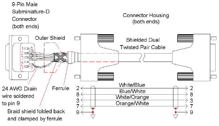
Appendix B
Cables and Connectors
This appendix provides information about these cables and connectors for the MSS 8000:
• RS-422 cable and connectors
• AES/EBU input and output
• Fibre Channel Cables: Fibre-Over-Copper cables
RS-422 Connectors and Cables
Use only industry approved connectors and cables when planning for your installation.
Some RS-422 cables provided by other manufacturers may not meet the radiated emissions
standards specified for the Server Node. It this is a problem for your station, the following
figure illustrates how to make your own.
RS-422 Cable
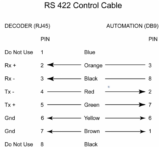
Appendix B Cables and Connectors
344
nRS-422 cables and connectors should be commonly available from most electronic supply
outlets.
RJ45 to DB9 Cable Diagram
RJ-45 Connector
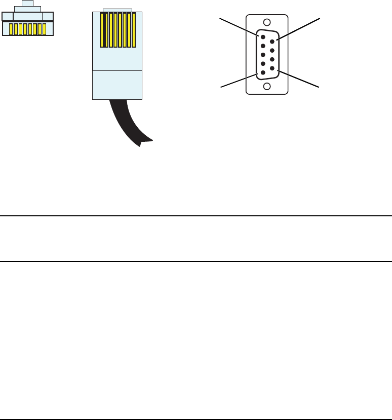
RJ45 to DB9 Cable Diagram
345
RJ45 to DB9
Serial Y-Cable to Automation Remote Control and Converter
Y-Cable From RJ45 Decoder Connector
Decoder RJ45
Pin Number
Automation DB9
Pin Number
External
Converter DB9
Pin Number Signal
1 Not used 3 (RX)
2 3 Not used Receive +
3 8 Not used Receive –
4 2 Not used Transmit –
5 7 Not used Transmit +
6 6 Not used Ground
7 1 1 Ground
8 Not used 2 (TX)
DB-9 FemaleRJ-45 Male
Pin 6Pin 1
Pin 5 Pin 9
18
18
TopFront
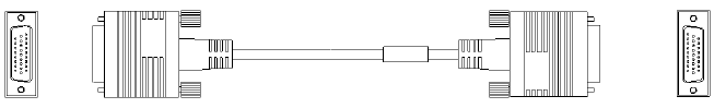
Appendix B Cables and Connectors
346
AAES/EBU Audio Connectors and Cables
This cable is designed to connect to the MSS 8000si AES/EBU audio connector.
AES/EBU Cable
If you have any of the audio interface panels, you will not need to make your own connector.
The appropriate cables are provided with your order.

AAES/EBU Audio Connectors and Cables
347
Where to Obtain the Connector
Contact Amp, Incorporated and ask for the AMPLIMITE® HDP-22 (26 pin) plug,
drawing # 748474-1 or equivalent.
AMP, Inc.
Harrisburg, PA
Toll free: 800-522-6752
Phone: 717-564-0100
Fax: 717-986-7575
Web site: www.amp.com
Where to Obtain the Cable
Use an overall shielded 28 AWG copper drains cable that contains 9 twisted pairs. The outer
shield should make a 360-degree connection to the connector shell. Use Belden™ 9809
cable or equivalent.
Belden Wire & Cable Company
2200 US Highway 25 S
Richmond, IN 47375
Toll free: 800-235-3361
Phone: 765-983-5200
Fax: 765-983-5294
Web site: www.belden.com
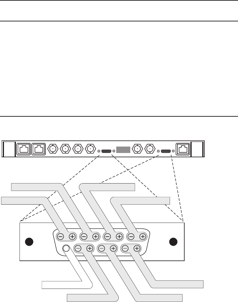
Appendix B Cables and Connectors
348
Dual Decoder AES/EBU 6-Channel Audio Output
Micro D-sub 15 Decoder (Output Audio 6 Channel) Connection
Pin
No. Description
Pin
No. Description
1 Analog Output Ch 1 – (Left) 9 NC
2 Analog Output Ch 1 + (Left) 10 Output Analog Ch 4 – (Right)
3 Ch 5/6 – 11 Output Analog Ch 4 + (Right)
4 Ch 5/6 + 12 Output Analog Ch 3 – (Left)
5 Ch 3/4 – 13 Output Analog Ch 3 + (Left)
6 Ch 3/4 + 14 Output Analog Ch 2 – (Right)
7 Ch 1/2 – 15 Output Analog Ch 2 + (Right)
8 Ch 1/2 +
Dual
Decoder
Audio Output
Connector
1
915
8
CH1/CH2 AES/EBU
CH1 Analog Left
CH5/CH6 AES/EBU
Reserved
CH3/CH4 AES/EBU
CH3 Analog Left
CH2 Analog Right
CH4 Analog Right
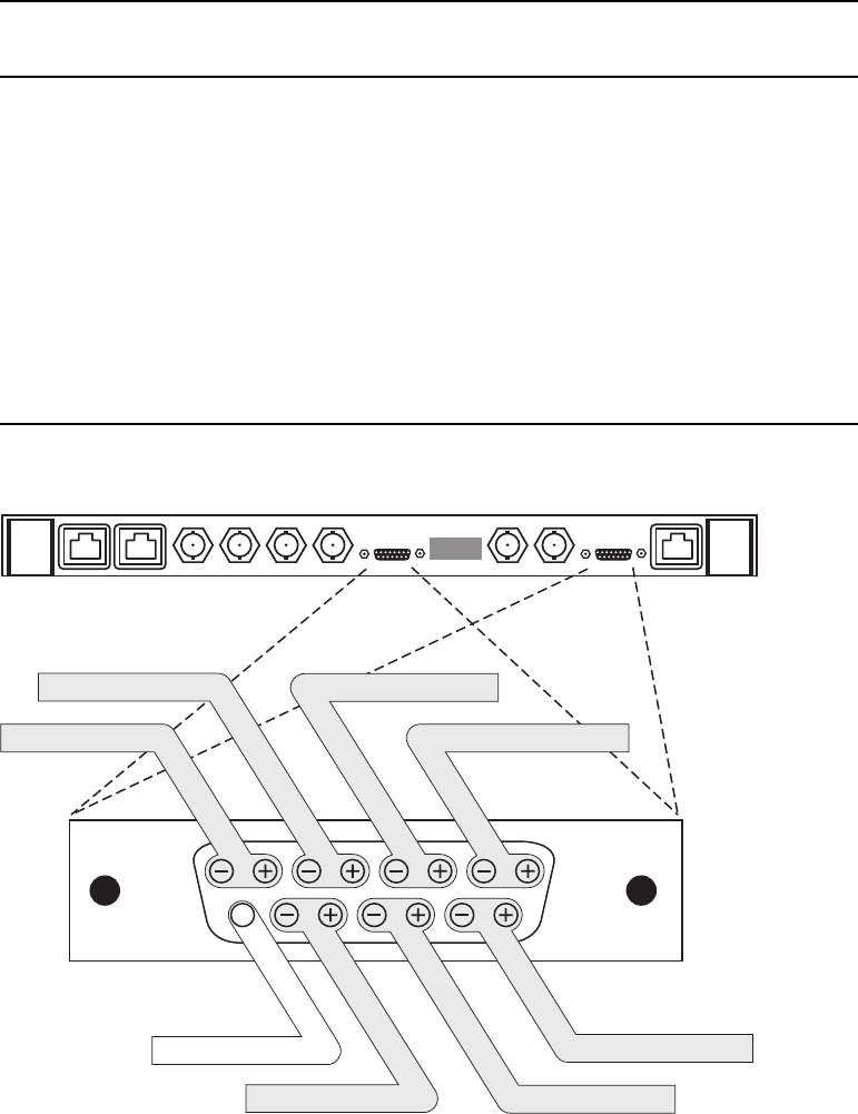
AAES/EBU Audio Connectors and Cables
349
Dual Decoder AES/EBU 8-Channel Audio Output
Micro D-sub 15 Decoder (Output Audio 8 Channel) Connection
Pin
No. Description
Pin
No. Description
1 Analog Output Ch 1 – (Left) 9 NC
2 Analog Output Ch 1 + (Left) 10 Ch 7/8 –
3 Ch 5/6 – 11 Ch 7/8 +
4 Ch 5/6 + 12 Do Not Use
5 Ch 3/4 – 13 Do Not Use
6 Ch 3/4 + 14 Output Analog Ch 2 – (Right)
7 Ch 1/2 – 15 Output Analog Ch 2 + (Right)
8 Ch 1/2 +
Dual
Decoder
Audio Output
Connector
1
915
8
CH1/CH2 AES/EBU
CH1 Analog Left
CH5/CH6 AES/EBU
Reserved
CH3/CH4 AES/EBU
CH2 Analog Right
Do Not Use
CH7/CH8 AES/EBU
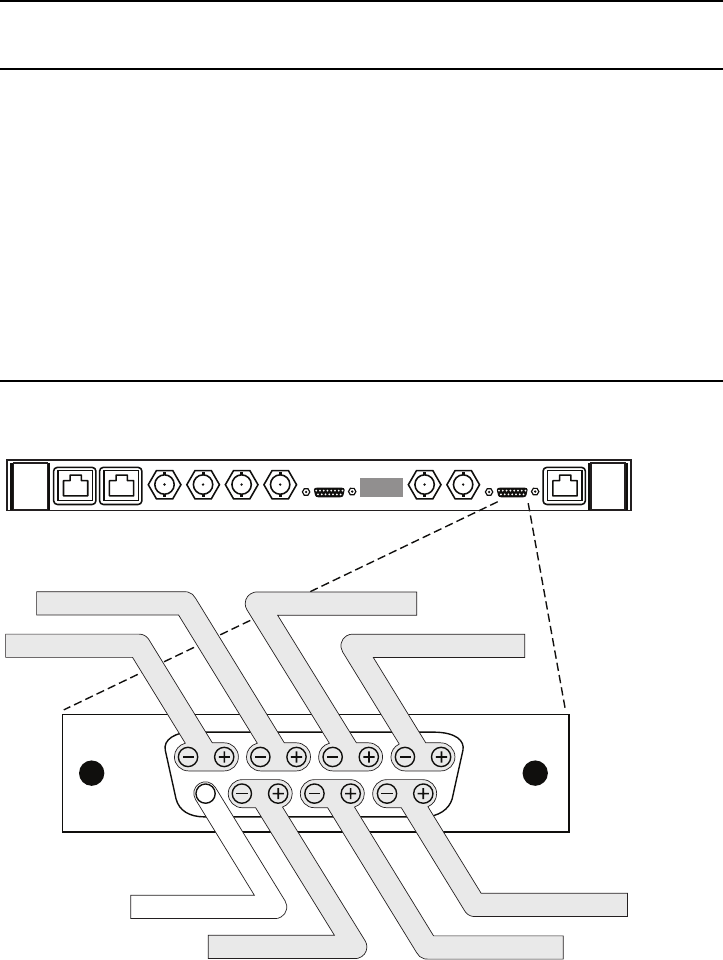
Appendix B Cables and Connectors
350
Single Encoder 8-Channel Audio Input
Single SD Encoder (Input Audio 8 Channel) Connections
Pin
No. Description
Pin
No. Description
1 Do Not Use 9Do Not Use
2 Do Not Use 10 Ch 7/8 –
3 Ch 5/6 – 11 Ch 7/8 +
4 Ch 5/6 + 12 Do Not Use
5 Ch 3/4 – 13 Do Not Use
6 Ch 3/4 + 14 Do Not Use
7 Ch 1/2 – 15 Do Not Use
8 Ch 1/2 +
Dual
Decoder
Audio Output
Connector
1
915
8
CH1/CH2 AES/EBU
CH5/CH6 AES/EBU
Reserved
CH3/CH4 AES/EBU
Do Not Use
CH7/CH8 AES/EBU
Do Not Use
Do Not Use

AAES/EBU Audio Connectors and Cables
351
Where to Obtain the Connectors
Contact Amp, Incorporated and ask for the AMPLIMITE® HDP-22 (26-pin) plug, drawing #
748474-1 or equivalent.
AMP, Inc.
Harrisburg, PA
Toll free: 800-522-6752
Phone: 717-564-0100
Fax: 717-986-7575
Web site: www.amp.com
Where to Obtain the Cable
Use an overall shielded 28 AWG copper drains cable that contains 9 twisted pairs. The outer
shield should make a 360-degree connection to the connector shell. Use Belden™ 9809
cable or equivalent.
Belden Wire & Cable Company
2200 US Highway 25 S
Richmond, IN 47375
Toll free: 800-235-3361
Phone: 765-983-5200
Fax: 765-983-5294
Web site: www.belden.com
Fibre Channel over Copper Cables
MSS Networked Storage uses Fibre Channel over Copper cables to connect the Fibre
Channel switches with the storage array. These cables use a standard HSSDC connector at
the Switch end and a DB-9 connector at the array end. Use care when handling the cables.
Where to Obtain the Cable
CS Electronics
17500 Gillette Ave
Irvine, CA 92614
Phone: 949-475-9100
Fax: 949-475-9119
Web site: www.cselex.com
Appendix B Cables and Connectors
352
Appendix C
Network Block Diagrams
The following four block diagrams are intended to provide you with various visual schemes
of how networks might interface with the Avid MediaStream SupportSystems MSS
Networked Storage System solutions.
nThe Network System Block Diagrams are visual representations only, and may or may not
reflect the way your MSS Networked Storage System is set up.
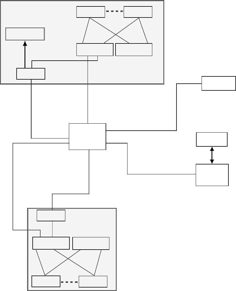
Appendix C Network Block Diagrams
354
1. Two Networked Storage Clusters (Non-Redundant Automation and Gateway)
Automation
GWY0101
10.80.128.1 \24
Gig-Ethernet
(copper)
Gig-Ethernet
(copper)
Gig-Ethernet
(copper)
FTP Data and Control
10.80.128.7 \24
VLAN-A
HPJ4812A Switch
HP 5300
10/100/
Gig-Ethernet
Layer 3 Switch
10.80.128.250\16
VLAN-B
HPJ4812A Switch
MSS0101 MSS0116
GWY0201
VLAN-A
HPJ4812A Switch
VLAN-B
HPJ4812A Switch
MSS0201 MSS0216
Archive
Control
Tape
Library
10.80.128.3 \24
Fibre
Channel
FC to Storage
10.80.128.11
Note: Highlighted items are
supplied by Pinnacle Systems.
All others are customer supplied.
21 17
21 17
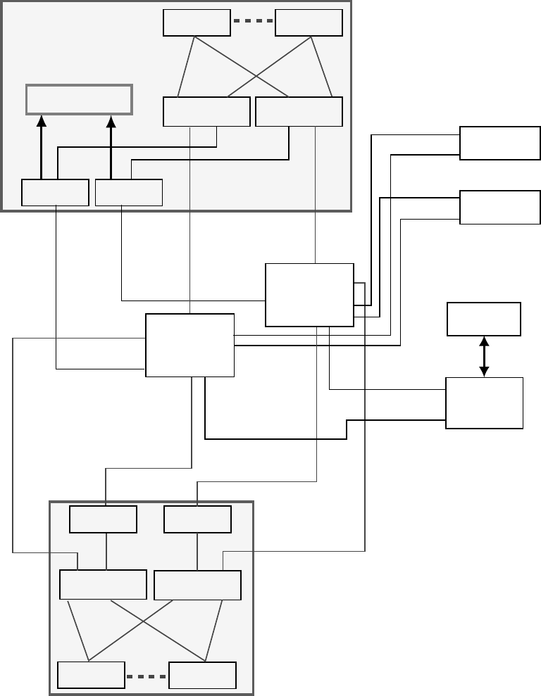
355
2. Two Networked Storage Clusters (Fully-Redundant Automation and Gateway)
Automation
Automation
Backup
GWY0101 GWY0102
10.80.129.1 \24
10.80.129.2 \24
10.80.128.2 \24
10.80.128.1 \24
Gig-Ethernet
(copper)
Gig-Ethernet
(copper)
Gig-Ethernet
(copper) Gig-Ethernet
(copper)
Gig-Ethernet
(copper)
10.80.128.7 \24
FTP Data and Control
FTP Data and Control
FTP Data and Control
FTP Data and Control
10.80.129.7 \24
VLAN-A
HPJ4812A Switch
VLAN-B
HPJ4812A Switch
MSS0101 MSS0116
GWY0201 GWY0202
VLAN-A
HPJ4812A Switch
VLAN-B
HPJ4812A Switch
MSS0201 MSS0216
Archive
Control
Tape
Library
10.80.129.3 \24
10.80.128.3 \24
Fibre
Channel
FC to Storage
10.80.128.11
10.80.129.11
Note: Highlighted items are
supplied by Pinnacle Syste
m
All others are customer su
p
21
2121
21
17 17
17 17
HP 5300
10/100/
Gig-Ethernet
Layer 3 Switch
10.80.129.250\16
HP 5300
10/100/
Gig-Ethernet
Layer 3 Switch
10.80.128.250\16
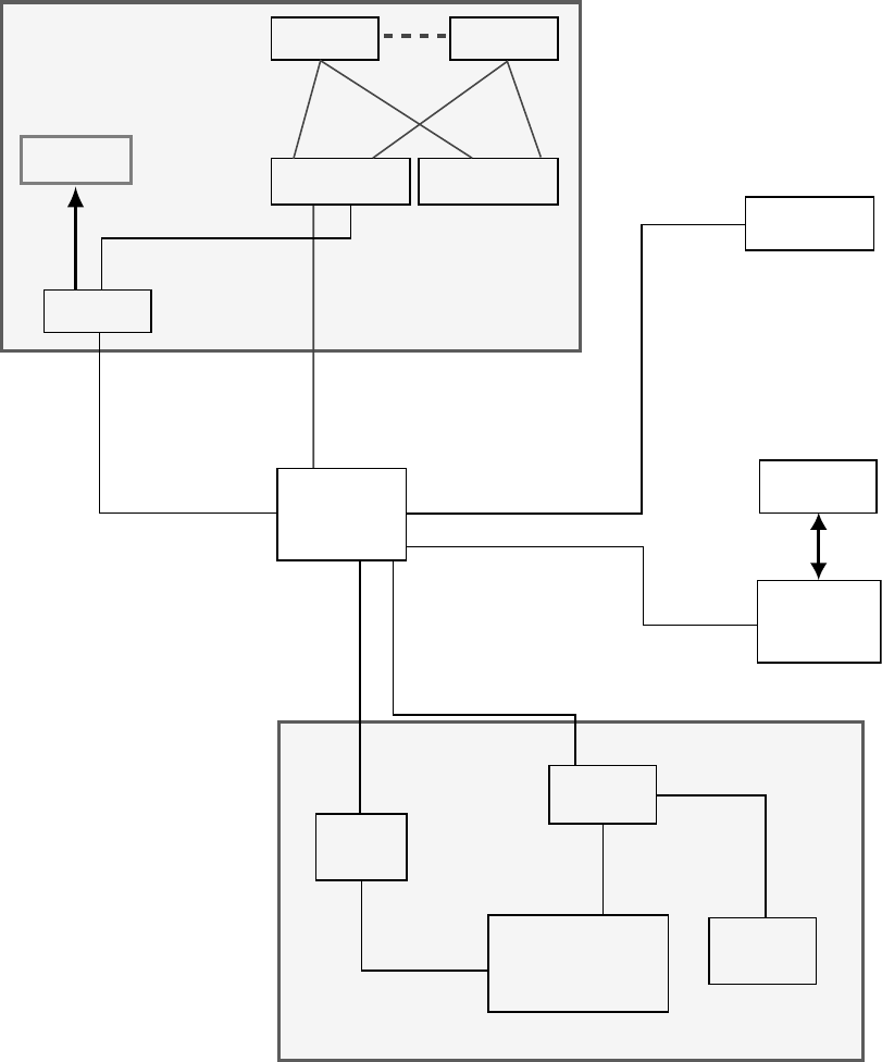
Appendix C Network Block Diagrams
356
3. Networked Storage System to Legacy MediaStream (Non-Redundant
Automation and Gateway)
Automation
GWY0101
Archive
Control
MSS 1600
Tape
Library
GWY
MSS 1600
Ethernet
Hub for
MSS 1600
MSi for
MSS 1600
10.80.128.1 \24
Gig-Ethernet
(copper)
Gig-Ethernet
(copper)
10.80.128.3 \24
FTP Data and Control
10.80.128.7 \24
10.80.128.4 \16
10.80.128.6 \16
10.80.128.5 \16
Fibre
Channel
(optical)
Fibre
Channel
MediaStream 1600 Legacy System
VLAN-A
HPJ4812A Switch
VLAN-B
HPJ4812A Switch
MSS0101 MSS0116
FC to Storage
21 17
Note: Highlighted items are
supplied by Pinnacle Systems.
All others are customer supplied.
Gig-Ethernet
(fiber)
HP 5300
10/100/
Gig-Ethernet
Layer 3 Switch
10.80.128.250\16
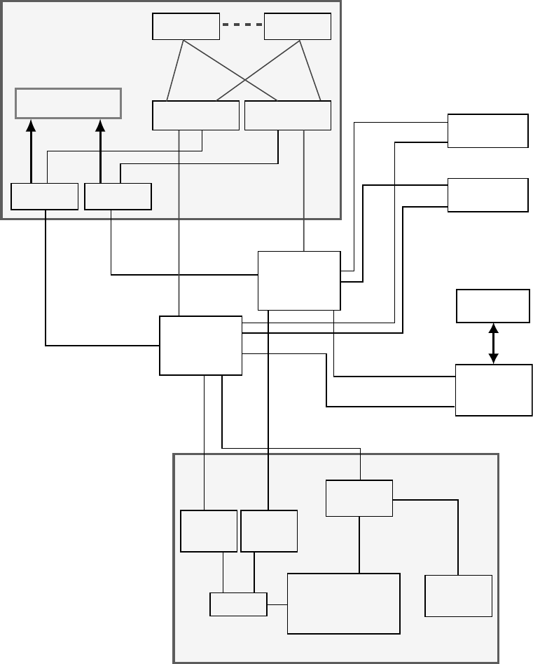
357
4. Networked Storage System to Legacy MediaStream (Fully-Redundant
Automation and Gateway)
Automation
Automation
Backup
GWY0101 GWY0102
Archive
Control
MSS 1600
Tape
Library
GWY
MSS 1600
GWY
MSS 1600
FC-Switch
Ethernet
Hub for
MSS 160
0
MSi for
MSS 1600
10.80.129.1 \24
10.80.129.2 \24
10.80.128.2 \24
10.80.128.1 \24
Gig-Ethernet
(copper)
Gig-Ethernet
(copper)
Gig-Ethernet
(fiber)
Gig-Ethernet
(fiber)
Gig-Ethernet
(copper)
Gig-Ethernet
(copper)
10.80.129.3 \24
10.80.128.3 \24
FTP Data and Control
FTP Data and Control
10.80.129.7 \24
10.80.128.7 \24
10.80.129.4 \16
10.80.128.4 \16
10.80.128.6 \16
10.80.128.5 \16
Fibre
Channel
(optical)
Fibre
Channel
MediaStream 1600 Legacy System
VLAN-A
HPJ4812A Switch
VLAN-B
HPJ4812A Switch
MSS0101 MSS0116
FC to Storage
Note: Highlighted items are
supplied by Pinnacle Systems.
A
ll others are customer supplied.
Important: If more than one 1600/700
server is used, all servers must plug
into the same Ethernet hub.
21 (9) 21 (9)
17 (5) 17 (5)
HP 5300
10/100/
Gig-Ethernet
Layer 3 Switch
10.80.128.250\16
HP 5300
10/100/
Gig-Ethernet
Layer 3 Switch
10.80.129.250\16
Appendix C Network Block Diagrams
358
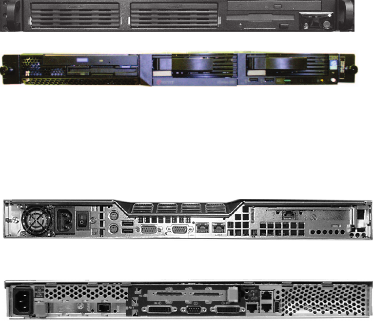
Appendix D
Legacy FSC and MSi Front & Back
Panels
File System Controllers: Front Panels
File System Controllers
File System Controllers: Rear Panels
Super Micro PC
IBM 355
Super Micro
IBM 355

Appendix D Legacy FSC and MSi Front & Back Panels
360
FSC 40
VLAN to MSi PC Connections
SuperMicro Keyboard, Video and Mouse Connections
789101112 19 20 21 22 23 24
123456 13 14 15 16 17 18
123456
789101112
13 14 15 16 17 18
19 20 21 22 23 24
25 26
Link
Mode
Link
Mode
hp procurve
switch 2524
J4813A
7 8 9 101112 192021222324
1 2 3 4 5 6 13 14 15 16 17 18
123456
789101112
13 14 15 16 17 18
19 20 21 22 23 24
25 26
Link
Mode
Link
Mode
hp procurve
switch 2524
J4813A
VLAN A
VLAN B
Port 19
Port 20
LAN 1 LAN 2
VGA port
keyboard port
Mouse port
VGA port
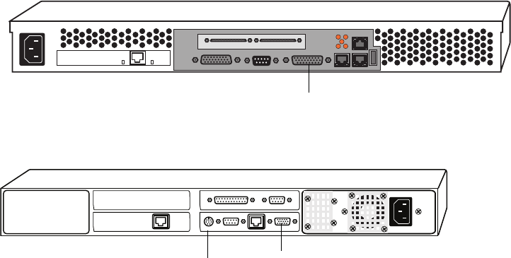
361
IBM 355 Keyboard Video and Mouse Connections
MSi PC Keyboard, Video, and Mouse Connectors
C2T Out Connector
Mouse/keyboard
port VGA port
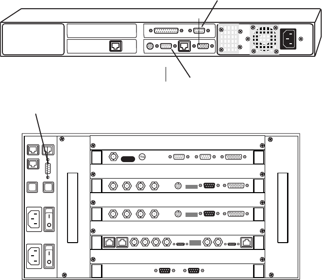
Appendix D Legacy FSC and MSi Front & Back Panels
362
MSi PC Connections
Modem (COM 1)
MSi PC
MSS-8000
RS-232 Connector
RS-232 connector (COM 2)
Modem (COM 1)
MSi PC
MSS 8000
RS-232 connector
Appendix E
Specifications
MS Server 8000NS
Video
ITU-R BT.601-2 resolution MPEG 2
6 to 50 Mb/s, user selected (10 Mb/s quality comparable to 30 Mb/s MJPEG)
Serial digital component input/output
75 ohm BNC
NTSC/PAL analog output
Audio
4 or 8 channels (2 or 4 stereo pairs) per video channel.
AES/EBU 48 kHz, 16 bit
Musicam compliant
XLR and 75 ohm BNC connections available with optional interface.
E Specifications
364
Control
RS-422 control for each channel
Back-to-back frame-accurate play
Genlock video reference required for frame-accurate system operation.
Supplied system console provides a Windows 2000™ based interface separate from the
automation for server set-up, diagnostics, and emergency play-to-air and dub.
Modem provides access for remote system diagnostics
Vertical Blanking Interval
Preserves any 6 of the following user-selected lines, luminance only:
525: lines 10-22 and 273-285
625: lines 7-22 and 320-335
nComposite Video Output: the first half of NTSC Line 20, Field 2 is blanked as per NTSC
standard.
Preserved Video Signal Lines
The following two lines are preserves in the video signal:
Teletext — line 9
Wide Screen Signaling — line 23 on SD PAL (specifically DVB-VBI ETSI-EN301775)
Environmental
Temperature
Non-operating/Storage Temperature Range: (w/o disks): –40° to 160°F (–40° to 70°C)
Operating Temperature Range: 50° to 95°F (10° to 35°C)
Recommended Operating Temperature Range: 68° to 78°F (20° to 25°C)
Temperature Shock Immunity: Maximum rate of Change: 0.59°F per minute or 36°F per
hour (0.33°C/min or 20°C/hr)

Safety
365
Humidity
Non-operating/Storage Humidity Range: 15 to 90% RH
Operating Humidity Range @ 72°F (22°C): 20 to 80% RH
Recommended Operating Humidity Range @ 72°F (22°C): 30 to 50% RH
Altitude
Non-operating: 15,000 ft (4600 m) Operating: 10,000 ft (3100 m)
Temperature rating above 8,000 ft (2500 m): 95F (35C) over full range
EMC
Meets the requirements of:
• FCC Part 15 (Class A for Digital Equipment)
• EMC Directive 89/336/EEC (EN55103-1, EN50082-1, IEC801-2,3,4)
• CISPR 22/EN55022 Class A (1998/A1/A2)
Safety
UL approved for the U.S. (U.L. 1950) and Canada (C22.2 No. 950).
TUV approved for the U.S. (U.L. 60950-1:2003) and Canada (C22.2 No. 60950-1: 2003)
TUV approved for European Union: EN60950-1 + A11:2004
Fax Modem: Meets EN41003 and CSA C22.2 No. 225 (Telecom)
Component Specifications
The following tables provide the physical specifications for each MediaStream component.
Chassis Shipping Box Dimension
Component Length Width Height
File System Controller: 23.5 in (59.7 cm) 34.0 in (86.4 cm) 8.0 in (20.3 cm)
MSi Monitor 19.5 in (49.5 cm) 20.5 in (52.1 cm) 7.25 in (18.4 cm)
MSi Computer 16.75 in (42.5 cm) 19.25 in (48.9 cm) 18.5 in (47 cm)

E Specifications
366
MSS 8000 Serve 35.0 in (88.9 cm) 36.0 in (91.4 cm) 19.0 in (68.6 cm)
Fibre Channel Switch 20.0 in (50.8 cm) 21.75 in (55.2 cm) 9.5 in (24.1 cm)
Palladium Store 1000 Chassis 27.5 in (69.9 cm) 24.75 in (62.9 cm) 14.5 in (36.8 cm)
Palladium Store 1000 Drives (2 boxes) 20.5 in (52.1 cm) 14.5 in (36.8 cm) 11.5 in (29.2 cm)
ConnectPlus 1000 NS Gateway 39 in (99 cm) 24 in (61 cm) 8 in (20.3 cm)
Rack Space Requirements for MS Products
Component Rack Units Height Depth
File System Controller 1 1.75 in (4.4 cm) 28.25 in (71.8 cm)
MSi/Gateway Computer
Monitor
Keyboard
1
10
1
1.75 in (4.4 cm)
18 in (45.8 cm)
1.75 in (4.4 cm)
17.2in (43.7 cm)
17.0 in (43.2 cm)
6.75 in (17.2 cm)
MSS 8000 Server 5 8.75in (22.2 cm) 25.6 in (65.0 cm)
Fibre Channel Switch
8-Port
32-Port
1
2
1.66 in (4.2 cm)
3.4 in (8.6 cm)
16.3in (41.4 cm)
18.5in (47.0 cm)
Palladium Store 1000 3 5.25 in (13.3 cm) 22 in (55.9 cm)
ConnectPlus 1000 1 1.75 in (4.4 cm) 26 in (66 cm)
Components Weights for MS Products
Component Weight
File System Controller 27.8 lb (12.6 kg)
MSi PC
Monitor
Keyboard
20 lb (9 kg)
34.0 lb (15.5 kg)
2.5 lb (1.1 kg)
MSS 8000 Server 55.0 lb (25.0 kg)
Chassis Shipping Box Dimension (Continued)
Component Length Width Height

Component Specifications
367
Fibre Channel Switch
8-Port
32-Port
10.7 lb (4.9 kg)
18.5 lb (8.4 kg)
Palladium Store 1000 70 lb (32 kg)
ConnectPlus 1000 NS Gateway 30 lb (13.5 kg)
Line Voltage Requirements
Component Current 120 V Current 240 V Watts
File System Controller 3A 1.5 A —
MSi/Gateway Computer 5.0 A 3.0 A —
MSi Monitor 1.5 A 0.75 A —
MSS 8000 Server 10.0 A 5.0 A 595 W
Fibre Channel Switch
8 port
32 port
1.5 A
3.0 A
0.75 A
1.5 A
100 W
200 W
Palladium Store 1000 3.0 A 1.5 A 250 W
ConnectPlus 1000 3.5A 1.75A
Components Weights for MS Products (Continued)
Component Weight
E Specifications
368
Appendix F
Regulatory and Safety Notices
Warnings and Cautions
wNever install equipment if it appears damaged.
wDisconnect the power cord before servicing unit.
wOnly perform the services explicitly described in this document. For services or
procedures not outlined in this document, speak with authorized Avid service
personnel.
cFollow all warnings and cautions in the procedures.
cOperate the device within its marked electrical ratings and product usage instructions.
FCC Notice
This device complies with Part 15 of the FCC Rules. Operation is subject to the following
two conditions:
1. This device may not cause harmful interference.
2. This device must accept any interference received, including interference that may cause
undesired operation.
This equipment has been tested and found to comply with the limits for a Class A digital
device, pursuant to Part 15 of the FCC Rules. These limits are designed to provide
reasonable protection against harmful interference when the equipment is operated in a
commercial environment. This equipment generates, uses, and can radiate radio frequency
energy and, if not installed in accordance with the instruction manual, may cause harmful
interference to radio communications. Operation of this equipment in a residential area is
likely to cause harmful interference in which case the user will be required to correct the
interference at his own expense. Shielded cables must be used to ensure compliance with the
FCC Class A limits.

Appendix F Regulatory and Safety Notices
370
Canadian ICES-003
This Class A digital apparatus meets all requirements of the Canadian Interference Causing
Equipment Regulations.
Cet appareil numérique de la classe A respecte toutes les exigences du Règlement sur le
matériel brouilleur du Canada.
Canadian EMC Notice of Compliance
This digital apparatus does not exceed the Class A limits for the radio noise emissions from
digital apparatus set out in the Radio Interference Regulations of the Canadian Department
of Communications. Le present appariel numerique n'emet pas de bruits radioelectriques
depassant les limites applicables aux appareils numerique de la classe A prescrites dans le
Reglement sur le brouillage radioelectrique edicte par le ministere des Communications du
Canada.
European Union Notice
Declaration of Conformity
(According to ISO/IEC Guide 22 and EN 45014)
Application of Council
Directives:
73/23/EEC, 89/336/EEC.
Standards to which
Conformity is Declared:
EN60950:1999 Third Edition
CISPR 22:1997 / EN55022:1994 + A1:1998 + A2:1998 Class A
EN55024:1998/EN61000 — 3-2, 4-2, 4-3, 4-4, 4-5, 4-6, 4-11
Manufacturer’s Name: Avid Technology, Inc.
1925 Andover Street
Tewksbury, MA 01876, USA
European Contact: Nearest Avid Sales and Service Office or
Avid Technology International B.V.
Sandyford Business Center
Unit 3,
Dublin 18, Ireland
European Union Notice
371
(1) Products for the Windows NT, Windows 2000, or Windows XP Operating System: products were
tested in a typical Avid Adrenaline DNA, Avid DS Nitris DNA, Avid Equinox Break-Out-Box,
Avid|DS, Avid Xpress, Avid Xpress DV, Film Composer, Media Composer, MediaDock, MediaDock
2+, MediaDrive, MediaRAID, MEDIArray, MEDIArray Drive, MEDIArray II, MEDIArray II Drive,
Meridien I/O box, NewsCutter, NewsCutter DV, NewsCutter XP, Pro Tools AVoption|V10, or
Symphony configuration.
(2) Products for the Mac OS X Operating System: products were tested in a typical Avid Adrenaline
DNA, Avid Xpress, Avid Xpress DV, Film Composer, Media Composer, MediaDock, MediaDock 2+,
MediaDrive, MediaRAID, MEDIArray, MEDIArray Drive, MEDIArray II, MEDIArray II Drive,
Meridien I/O box, Pro Tools AVoption|V10, Symphony, or VideoRAID configuration.
(3) Products for the UNIX Operating System: products were tested in an AirPlay, AirSpeed,
DNxchange, or VideoSPACE configuration.
Type of Equipment: Information Technology Equipment
Product Name: Products for the Windows NT, Windows 2000, or Windows XP Operating
System: Avid Adrenaline DNA, Avid DS Nitris DNA, Avid Equinox
Break-Out-Box, Avid|DS, Avid Xpress, Avid Xpress DV, Film Composer,
Media Composer, MediaDock, MediaDock 2+, MediaDrive, MediaRAID,
MEDIArray, MEDIArray Drive, MEDIArray II, MEDIArray II Drive,
Meridien I/O box, NewsCutter, NewsCutter DV, NewsCutter XP,
Pro Tools AVoption|V10, Symphony
Products for the Mac OS X Operating System: Avid Adrenaline DNA,
Avid Xpress, Avid Xpress DV, Film Composer, Media Composer,
MediaDock, MediaDock 2+, MediaDrive, MediaRAID, MEDIArray,
MEDIArray Drive, MEDIArray II, MEDIArray II Drive, Meridien I/O
box, Pro Tools AVoption|V10, Symphony, VideoRAID
Products for the UNIX Operating System: AirPlay, AirSPACE, AirSpeed,
DNxchange, VideoSPACE
Products for MediaNetwork and Workgroups: Avid ProEncode,
Avid Unity ISIS, Avid Unity MediaManager, Avid Unity MediaNetwork
(includes File Manager), Avid Unity TransferManager, LANserver,
LANserver EX, MEDIArray, MEDIArray Drive, MEDIArray II,
MEDIArray II Drive, MEDIArray ZX, MEDIArray ZX Drive, Nearchive,
PortServer, Vixel switches (8100, 7100, 7200, 9100, 9200), Xdeck
Base Model Numbers: None
Product Options: All
Year of Manufacture: 2006

Appendix F Regulatory and Safety Notices
372
(4) Products for MediaNetwork and Workgroups: products were tested in a typical Avid ProEncode,
Avid Unity ISIS, Avid Unity MediaManager, Avid Unity MediaNetwork (includes File Manager),
Avid Unity TransferManager, LANserver, LANserver EX, MEDIArray, MEDIArray Drive,
MEDIArray II, MEDIArray II Drive, MEDIArray ZX, MEDIArray ZX Drive, Nearchive, PortServer,
or Xdeck configuration.
I, the undersigned, hereby declare that the equipment specified above conforms to the above
Directives and Standards.
George R. Smith, Director of Hardware Engineering
Disposal of Waste Equipment by Users in the
European Union
This symbol on the product or its packaging indicates that this product must not be disposed
of with other waste. Instead, it is your responsibility to dispose of your waste equipment by
handing it over to a designated collection point for the recycling of waste electrical and
electronic equipment. The separate collection and recycling of your waste equipment at the
time of disposal will help conserve natural resources and ensure that it is recycled in a
manner that protects human health and the environment. For more information about where
you can drop off your waste equipment for recycling, please contact your local city recycling
office or the dealer from whom you purchased the product.
Australia and New Zealand EMC Regulations
John Kells, Australian Operations Manager
Avid Technology (Australia)
Unit B
5 Skyline Place
French Forest NSW 2086
Australia
Phone: 61-2-8977-4800

Taiwan EMC Regulations
373
Taiwan EMC Regulations
Taiwan EMC Regulations BSMI Class A EMC Warning
Power Supply Cord Notice
English
cCAUTION - The power supply cord is used as the main disconnect device, ensure that
the socket outlet is located/installed near the equipment and is easily accessible.
German
cACHTUNG - Zur sicheren Trennung des Gerätes vom Netz ist der Netzstecker zu
ziehen. Vergewissern Sie sich, daß die Steckdose leicht zugänglich ist.
French
cATTENTION - Le cordon d'alimentation est utilisé comme interrupteur général. La
prise de
courant doit être située ou installée à proximité du materiél et être facile d'accés.
Lithium Battery Notice
English
cCAUTION - Danger of explosion if battery is replaced with incorrect type. Replace
only with the same type recommended by the manufacturer. Dispose of used batteries
according to the manufacturer's instructions.
Appendix F Regulatory and Safety Notices
374
German
cACHTUNG - Explosionsgefahr wenn die Battery in umgekehrter Polarität eingesetzt
wird. Nur mit einem gleichen oder ähnlichen, vom Hersteller empfohlenen Typ,
ersetzen. Verbrauchte Batterien müssen per den Instructionen des Herstellers
verwertet werden.
French
cATTENTION - Il y a danger d'explosion s'il a remplacement incorrect de la batterie.
Remplacer uniquement avec une batterie du meme type ou d'un type equivalent
recommande par le constructeur. Mettre au rebut les batteries usagees conformement
aux instructions du fabricant.
English
cCAUTION: This unit has more than one power supply connection; all connections
must be removed to remove all power from the unit.
French
cATTENTION: Cette unité est équipée de plusieurs raccordements d'alimentation.
Pour supprimer tout courant électrique de l'unité, tous les cordons d'alimentation
doivent être débranchés
German
wWARNUNG: Diese Einheit verfügt über mehr als einen Stromanschluß; um Strom
gänzlich von der Einheit fernzuhalten, müssen alle Stromzufuhren abgetrennt sein.
English
wThis product relies on the building's installation for short-circuit (overcurrent)
protection. Ensure that a fuse or circuit breaker no larger than 120 VAC, 15A U.S. (240
VAC, 10A international) is used on the phase conductors (all current-carrying
conductors).
French
cAttention: Pour ce qui est de la protection contre les courts-circuits (surtension), ce
produit dépend de l'installation électrique du local. Vérifier qu'un fusible ou qu'un
disjoncteur de 120 V alt., 15 A U.S. maximum (240 V alt., 10 A international) est utilisé
sur les conducteurs de phase (conducteurs de charge).
Lithium Battery Notice
375
German
wWarnung: Dieses Produkt ist darauf angewiesen, daß im Gebäude ein Kurzschluß-
bzw. Überstromschutz installiert ist. Stellen Sie sicher, daß eine Sicherung oder ein
Unterbrecher von nicht mehr als 240 V Wechselstrom, 10 A (bzw. in den USA 120 V
Wechselstrom, 15 A) an den Phasenleitern (allen stromführenden Leitern) verwendet
wird.
wWarning:
Operating the unit in an equipment Rack, take the following precautions:
- Make sure the ambient temperature around the unit (which may be higher than the
room temperature) is within the limit specified for the unit.
- Make sure there is sufficient airflow around the unit.
- Make sure electrical circuits are not overloaded - consider the nameplate rating of
all the connected equipment, and make sure you have over current protection.
- Make sure the equipment is properly grounded.
- Make sure no objects place on top of unit.
English
wTo prevent bodily injury when mounting or servicing this unit in a rack, you must take
special precautions to ensure that the system remains stable. The following guidelines
are provided to ensure your safety:
- This unit should be mounted at the bottom of the rack if it is the only unit in the
rack.
- When mounting this unit in a partially filled rack, load the rack from the bottom to
the top with the heaviest component at the bottom of the rack.
- If the rack is provided with stabilizing devices, install the stabilizers before
mounting or servicing the unit in the rack.
French:
Attention: Pour éviter toute blessure corporelle pendant les opérations de montage ou de
réparation de cette unité en casier, il convient de prendre des précautions spéciales afin de
maintenir la stabilité du système. Les directives ci-dessous sont destinées à assurer la
protection du personnel:
- Si cette unité constitue la seule unité montée en casier, elle doit être placée dans le
bas.
Appendix F Regulatory and Safety Notices
376
- Si cette unité est montée dans un casier partiellement rempli, charger le casier de
bas en haut en plaçant l'élément le plus lourd dans le bas.
- Si le casier est équipé de dispositifs stabilisateurs, installer les stabilisateurs avant
de monter ou de réparer l'unité en casier.
German:
wWarnung: Zur Vermeidung von Körperverletzung beim Anbringen oder Warten
dieser Einheit in einem Gestell müssen Sie besondere Vorkehrungen treffen, um
sicherzustellen, daß das System stabil bleibt. Die folgenden Richtlinien sollen zur
Gewährleistung Ihrer Sicherheit dienen:
- Wenn diese Einheit die einzige im Gestell ist, sollte sie unten im Gestell angebracht
werden.
- Bei Anbringung dieser Einheit in einem zum Teil gefüllten Gestell ist das Gestell
von unten nach oben zu laden, wobei das schwerste Bauteil unten im Gestell
anzubringen ist.
- Wird das Gestell mit Stabilisierungszubehör geliefert, sind zuerst die Stabilisatoren
zu installieren, bevor Sie die Einheit im Gestell anbringen oder sie warten.

A B C D E F G H I J K L M N O P Q R S T U V W X Y Z
A
AC line voltage specifications 110
AES/EBU 86, 88
Audio connectors 346
AMS application 28
AMS operating system
installing/upgrading 286
Analog-to-digital converters 85
array_services utility 168, 183
Audio adjustments 257
Audio connectors
pinnouts 346
Audio devices
user-supplied connections 84
Audio input/ output connections 87
Audio interface
modules 88
panels 79
Australia EMC regulations 372
Automation, user-supplied connections 84
B
Black burst 87
Blanking Setup 121
BNC
audio output modules 86
output audio module 92, 92
Boot Disk Drive
replacement 194
bvsrc file 158, 209, 210, 217
C
Cables 64
Canadian
interference causing equipment regulations 370
Capellix 307
Model 2000, 3000 FFC switches 289
cd command 145
Chassis, monitoring 135
checkLan utility 325
Claims procedures 69
CleanCut MPEG decoding 40
CLI 249
commands 253
sadj command 264
Clips, editing 131
Colorburst phase 262
ConnectPlus 1000
description 49
FTP 49
gateway PC 35
Conversion
down 104
up 103
cp command 146
D
Decoder ports 250
Decoders 64
adding 207
audio connections 87
BNC connection 92, 92
calibration with server 258
configuring channels 120
dip switch settings 206, 206
Genlock connection 87
HD (High Definition) board 40
identifying faulty 205
installing 208
output cables for 84
Index

Index A B C D E F G H I J K L M N O P Q R S T U V W X Y Z
378
removing 205
replacing/adding 204
video output 86
video/audio adjustments 256
Digital-to-analog converters 259
Disk Management window 131
Down-conversion 104
Drop Frame 121, 123
Dual Decoders
adding 207
setting address 206
E
edit_bvsrc 218
EIA racks 74
eLog file 329
clearing 329
Encoder ports 250
Encoders 38
adding 216
audio connections 87
calibration with server 258
configuring channels 122
dip switch location 215
dip switch settings 215
identifying faulty 214
input cables for 84
installing 216
replacing/adding 204
video input format 85
EOF 121
EOM 121
Equipment rack requirements 64
Error threshold, RAID storage arrays 170
European Union notice 370
F
Fan modules
monitoring 135
replacing 219
FCC notice 369
Fibre Channel
cables 351
redundancy 30
Fibre Channel Adapter
description 37
signal path 39
Fibre Channel switches 351
configuration 299, 301, 309
connection to Palladium Store 1000 108
Ethernet setup 306
status indicators 46, 46
TFTP communication setup 305
File System
redundancy 29
File System Controller 27, 41, 42
administration 149
software upgrade 283
status monitoring 151
troubleshooting database problems 327
Firmware
current revision number 187
Floor, load requirements 64
Frames, freezing 130
fs_dump_meta command 325
fs_util command 324
FSC
see File System Controller
fsc_revisions command 325
fsc_status command 151
FTP
copying files 317
opening a session 316
G
Genlock
connections 87
decoder configuration 121
loop-through port 39
H
Horizontal line timing 258
Host name 116
hostname command 332
Hosts file
aliases 52
HP Procurve
VLAN switch 289
HP-RT Operating System 28
HSSDC connector 351

A B C D E F G H I J K L M N O P Q R S T U V W X Y Z Index
379
Humidity, recommended 65
HyperTerminal
Fibre Channel communications 303
sending files 296, 297
session setup 291
I
Input audio, headroom adjustments 255
Installation guidelines 63
K
KVM switch
connection to File System Controllers 101
connection to MSi PC 101
L
Lantronix Module
removal and replacement 220
setup 222
Log files 328
ls command 145
M
mdsutil command 330
MediaStream 8000
adding a server node 232
adding nodes 31
configuration 155
connection to Fibre Channel switches 107
fan tray replacement 219
features 27
MSi monitoring 48
server shutdown 138
System Controller 28
MediaStream Interface
see MSi
MediaStream Networked Storage System 25
block diagrams 353
cables 64
cluster subnets 118
hosts file for system cluster 52
I/P addressing scheme 56
installation guidelines 63
placing supports 74
rack space requirements 71, 71
mkdir command 146
Monitor
installing 80
more command 147
Mounting ears 74
MPEG Mux Type 123
MSi 32
as diagnostic tool 113
backing up files 269
configuration utility 274
configuring application 117–??
configuring new channels 213
data and configuration files 270
launching 116
RAID storage array monitoring 169
Restore program 270
software installation 273
software revision number 268
software updates 273
system recovery procedure 271
System Status window 48, 116, 168
MSi Control Panel Applet
creating a Cluster Group 115
MSi PC
communication with System 117
connection to KVM switch 100
connection to VLAN switches 99
rack mounting 79
MSi Recovery CD 271
MSS 8000
air flow/cooling 65
airflow considerations 65
calibration 254, 258
configuration 190
contents of shipment 69
enclosure status 179
floor load requirements 64
front panel 78
front/back panels 36
host name 116
log files 328
logging on 143
racking 64, 64, 77
repacking guidelines 70
vibration concern 65

Index A B C D E F G H I J K L M N O P Q R S T U V W X Y Z
380
mv command 146
N
New Zealand EMC regulations 372
P
Palladium Store 1000 29
adding arrays 32
chassis components 167
Control Panel 239
RAID configuration 42
replacing power supplies 244
SNMP 34
Play window 120, 127
Playlists
creating 129
loading 129
Power requirements 110
Power supplies
failure 231
monitoring 135
replacing 232
replacing Palladium Store 1000 244
Preserved Lines of Vertical Interval 123
Previewing video files 126
Program Stream 123
PumpKIN TFTP 289, 302
pwd command 145
R
Racks
dimensions 74
mounting ears 74
mounting kit 67
rack unit measurement 70
specifications 76
supports for 74–76
RAID Controller 29
errors, types of 171
redundant configuration 42
RAID storage arrays
current configuration 190
deleting a clip from 131
drive data 189
error threshold 170
file systems 172
firmware revision number 170
formatting 172, 172
IDs 178
monitoring 135
replacing disks 241
status information 169
RAID Storage System
see Palladium Store 1000
Record window 122
Regulatory information 369
restore.exe 270
Return packing guidelines 70
revisions command 329
rm command 147
rmdir command 146
RS-422
connectors and cables 343
S
Safety information 369
Serial digital output 86
Shipping containers 68
Simple Network Management Protocal
see SNMP
Site files
backing up 287
restoring 198, 288
SNMP
enabling monitoring 173
MSi interface 34
snmp_config 173
Software
AMS 28
releases for the Networked Storage System 268
system release numbering scheme 268
Static electricity 66
Station reference signal 87
Stream Bit Rate 123
Subcarrier phase 262
syslog file 328
System Controller
board replacement 235
System Status window 116, 133, 168
System Stream 123

A B C D E F G H I J K L M N O P Q R S T U V W X Y Z Index
381
T
Taiwan EMC regulations 373
Telnet 136
logging sessions 319
opening a session 137
Temperature, recommended operating 65
Trap notification 175
U
UNIX 143
UNIX commands 329
syntax 144
Up-conversion 103
UPS 110
V
VDCP (Video Disk Control Protocol) 35
vi editor 147
vi quick reference 148
Vibration considerations 65
Video
playing files in MSi 128–129
recording files in MSi 125–126
user-supplied connections 84
Video files
playing 252
recording 251
recording test content 255
Video ports 250
VLAN 299
configuration file download 297
LAN configuration settings 298
switch configuration 290, 298
topology diagram 54
topology of Networked Storage System 51
VLAN switches
connection to MSi PC 99
connection to the FSC 96
VLAN Topology
Fibre Channel Switches 61
File System Controllers 58
Gateways 60
MSi PCs 59
MSS 8000 Server Nodes 57
Routers 61
subnet mask 57
VME
card cage 28, 79
vmescan command 209, 217, 331
W
wq command 148
X
XLR
input audio module 89
input/output 93
output audio module 86


