Avid Unity ISIS Administration Guide 1.4 AG V1 4 EN
User Manual: avid Unity ISIS - 1.4 - Administration Guide Free User Guide for Avid ISIS Software, Manual
Open the PDF directly: View PDF ![]() .
.
Page Count: 268 [warning: Documents this large are best viewed by clicking the View PDF Link!]
- Title Page
- Contents
- Using This Guide
- Installing Your Avid Unity ISIS Software
- Configuring Your Avid Unity ISIS Software
- Managing the Storage Hardware
- Configuring and Managing Storage
- Managing Workspaces
- Managing Client Accounts and Access Privileges
- Monitoring Bandwidth Usage and System Status
- Configuring Failover Parameters
- Adding a System Director to an Existing File System
- IP Addresses for Existing and New System Directors
- Setting Up the Failover Connection on the Existing System Director
- Setting Up the Failover Connection on the New System Director
- Validating the Connections Between Existing and New System Directors
- Configuring the Virtual Addresses for Existing and New System Directors
- Creating a New Standby File System
- Starting the Existing and New System Directors
- Creating Failover with Two New Systems
- IP Addresses for First and Second System Directors
- Setting Up the Failover Connection on the First System Director
- Setting Up the Failover Connection on the Second System Director
- Validating the Connections Between First and Second System Directors
- Configuring the Virtual Addresses for First and Second System Directors
- Creating a New File System on the System Directors
- Starting the First and Second System Directors
- Stopping and Starting System Directors During Failover
- Adding a System Director to an Existing File System
- Avid Unity ISIS System Director Control Panel
- Advanced Support Tools
- System Administration Tools
- System Statistics
- System Logging
- Avid Unity ISIS Log Aggregator Tool
- Avid Unity ISIS Disk Tester Tool
- Avid Unity ISB Connection Analyzer Tool
- Avid Unity ISIS Switch Manager Tool
- General Tools
- Installers
- Avid Unity ISIS Agents
- Avid Unity ISIS System Monitor Tool
- Avid Unity ISIS E-mail Notification List
- Index

make manage move | media™
Avid ®
Avid Unity ISIS™
Administration Guide
2
Copyright and Disclaimer
Product specifications are subject to change without notice and do not represent a commitment on the part of Avid Technology,
Inc.
The software described in this document is furnished under a license agreement. You can obtain a copy of that license by
visiting Avid's Web site at www.avid.com. The terms of that license are also available in the product in the same directory as
the software. The software may not be reverse assembled and may be used or copied only in accordance with the terms of the
license agreement. It is against the law to copy the software on any medium except as specifically allowed in the license
agreement.
Avid products or portions thereof are protected by one or more of the following United States Patents: 4,746,994; 4,970,663;
5,045,940; 5,267,351; 5,309,528; 5,355,450; 5,396,594; 5,440,348; 5,452,378; 5,467,288; 5,513,375; 5,528,310; 5,557,423;
5,577,190; 5,584,006; 5,640,601; 5,644,364; 5,654,737; 5,715,018; 5,724,605; 5,726,717; 5,729,673; 5,745,637; 5,752,029;
5,754,851; 5,799,150; 5,812,216; 5,828,678; 5,842,014; 5,852,435; 5,987,501; 6,061,758; 6,223,211; 6,301,105; 6,532,043;
6,546,190; 6,636,869; 6,747,705, 6,763,523; 6,813,622. Other patents are pending.
This document is protected under copyright law. An authorized licensee of Avid Unity ISIS may reproduce this publication for
the licensee’s own use in learning how to use the software. This document may not be reproduced or distributed, in whole or in
part, for commercial purposes, such as selling copies of this document or providing support or educational services to others.
This document is supplied as a guide for Avid Unity ISIS. Reasonable care has been taken in preparing the information it
contains. However, this document may contain omissions, technical inaccuracies, or typographical errors. Avid Technology,
Inc. does not accept responsibility of any kind for customers’ losses due to the use of this document. Product specifications
are subject to change without notice.
Copyright © 2007 Avid Technology, Inc. and its licensors. All rights reserved.
APPLE COMPUTER, INC. MAKES NO WARRANTIES WHATSOEVER, EITHER EXPRESS OR IMPLIED, REGARDING
THIS PRODUCT, INCLUDING WARRANTIES WITH RESPECT TO ITS MERCHANTABILITY OR ITS FITNESS FOR ANY
PARTICULAR PURPOSE. THE EXCLUSION OF IMPLIED WARRANTIES IS NOT PERMITTED BY SOME STATES. THE
ABOVE EXCLUSION MAY NOT APPLY TO YOU. THIS WARRANTY PROVIDES YOU WITH SPECIFIC LEGAL RIGHTS.
THERE MAY BE OTHER RIGHTS THAT YOU MAY HAVE WHICH VARY FROM STATE TO STATE.
The following disclaimer is required by Sam Leffler and Silicon Graphics, Inc. for the use of their TIFF library:
Copyright © 1988–1997 Sam Leffler
Copyright © 1991–1997 Silicon Graphics, Inc.
Permission to use, copy, modify, distribute, and sell this software [i.e., the TIFF library] and its documentation for any purpose
is hereby granted without fee, provided that (i) the above copyright notices and this permission notice appear in all copies of
the software and related documentation, and (ii) the names of Sam Leffler and Silicon Graphics may not be used in any
advertising or publicity relating to the software without the specific, prior written permission of Sam Leffler and Silicon
Graphics.
THE SOFTWARE IS PROVIDED “AS-IS” AND WITHOUT WARRANTY OF ANY KIND, EXPRESS, IMPLIED OR
OTHERWISE, INCLUDING WITHOUT LIMITATION, ANY WARRANTY OF MERCHANTABILITY OR FITNESS FOR A
PARTICULAR PURPOSE.
IN NO EVENT SHALL SAM LEFFLER OR SILICON GRAPHICS BE LIABLE FOR ANY SPECIAL, INCIDENTAL, INDIRECT
OR CONSEQUENTIAL DAMAGES OF ANY KIND, OR ANY DAMAGES WHATSOEVER RESULTING FROM LOSS OF USE,
DATA OR PROFITS, WHETHER OR NOT ADVISED OF THE POSSIBILITY OF DAMAGE, AND ON ANY THEORY OF
LIABILITY, ARISING OUT OF OR IN CONNECTION WITH THE USE OR PERFORMANCE OF THIS SOFTWARE.
The following disclaimer is required by the Independent JPEG Group:
This software is based in part on the work of the Independent JPEG Group.
This Software may contain components licensed under the following conditions:
Copyright (c) 1989 The Regents of the University of California. All rights reserved.
Redistribution and use in source and binary forms are permitted provided that the above copyright notice and this paragraph
are duplicated in all such forms and that any documentation, advertising materials, and other materials related to such
distribution and use acknowledge that the software was developed by the University of California, Berkeley. The name of the
University may not be used to endorse or promote products derived from this software without specific prior written
permission. THIS SOFTWARE IS PROVIDED ``AS IS'' AND WITHOUT ANY EXPRESS OR IMPLIED WARRANTIES,
INCLUDING, WITHOUT LIMITATION, THE IMPLIED WARRANTIES OF MERCHANTABILITY AND FITNESS FOR A
PARTICULAR PURPOSE.
Copyright (C) 1989, 1991 by Jef Poskanzer.
3
Permission to use, copy, modify, and distribute this software and its documentation for any purpose and without fee is hereby
granted, provided that the above copyright notice appear in all copies and that both that copyright notice and this permission
notice appear in supporting documentation. This software is provided "as is" without express or implied warranty.
Copyright 1995, Trinity College Computing Center. Written by David Chappell.
Permission to use, copy, modify, and distribute this software and its documentation for any purpose and without fee is hereby
granted, provided that the above copyright notice appear in all copies and that both that copyright notice and this permission
notice appear in supporting documentation. This software is provided "as is" without express or implied warranty.
Copyright 1996 Daniel Dardailler.
Permission to use, copy, modify, distribute, and sell this software for any purpose is hereby granted without fee, provided that
the above copyright notice appear in all copies and that both that copyright notice and this permission notice appear in
supporting documentation, and that the name of Daniel Dardailler not be used in advertising or publicity pertaining to
distribution of the software without specific, written prior permission. Daniel Dardailler makes no representations about the
suitability of this software for any purpose. It is provided "as is" without express or implied warranty.
Modifications Copyright 1999 Matt Koss, under the same license as above.
Copyright (c) 1991 by AT&T.
Permission to use, copy, modify, and distribute this software for any purpose without fee is hereby granted, provided that this
entire notice is included in all copies of any software which is or includes a copy or modification of this software and in all
copies of the supporting documentation for such software.
THIS SOFTWARE IS BEING PROVIDED "AS IS", WITHOUT ANY EXPRESS OR IMPLIED WARRANTY. IN PARTICULAR,
NEITHER THE AUTHOR NOR AT&T MAKES ANY REPRESENTATION OR WARRANTY OF ANY KIND CONCERNING THE
MERCHANTABILITY OF THIS SOFTWARE OR ITS FITNESS FOR ANY PARTICULAR PURPOSE.
This product includes software developed by the University of California, Berkeley and its contributors.
The following disclaimer is required by Paradigm Matrix:
Portions of this software licensed from Paradigm Matrix.
The following disclaimer is required by Ray Sauers Associates, Inc.:
“Install-It” is licensed from Ray Sauers Associates, Inc. End-User is prohibited from taking any action to derive a source code
equivalent of “Install-It,” including by reverse assembly or reverse compilation, Ray Sauers Associates, Inc. shall in no event be
liable for any damages resulting from reseller’s failure to perform reseller’s obligation; or any damages arising from use or
operation of reseller’s products or the software; or any other damages, including but not limited to, incidental, direct, indirect,
special or consequential Damages including lost profits, or damages resulting from loss of use or inability to use reseller’s
products or the software for any reason including copyright or patent infringement, or lost data, even if Ray Sauers Associates
has been advised, knew or should have known of the possibility of such damages.
The following disclaimer is required by Videomedia, Inc.:
“Videomedia, Inc. makes no warranties whatsoever, either express or implied, regarding this product, including warranties with
respect to its merchantability or its fitness for any particular purpose.”
“This software contains V-LAN ver. 3.0 Command Protocols which communicate with V-LAN ver. 3.0 products developed by
Videomedia, Inc. and V-LAN ver. 3.0 compatible products developed by third parties under license from Videomedia, Inc. Use
of this software will allow “frame accurate” editing control of applicable videotape recorder decks, videodisc recorders/players
and the like.”
The following disclaimer is required by Altura Software, Inc. for the use of its Mac2Win software and Sample
Source Code:
©1993–1998 Altura Software, Inc.
The following disclaimer is required by Interplay Entertainment Corp.:
The “Interplay” name is used with the permission of Interplay Entertainment Corp., which bears no responsibility for Avid
products.
This product includes portions of the Alloy Look & Feel software from Incors GmbH.
This product includes software developed by the Apache Software Foundation (http://www.apache.org/).
© DevelopMentor
4
This product may include the JCifs library, for which the following notice applies:
JCifs © Copyright 2004, The JCIFS Project, is licensed under LGPL (http://jcifs.samba.org/). See the LGPL.txt file in the Third
Party Software directory on the installation CD.
Avid Interplay contains components licensed from LavanTech. These components may only be used as part of and in
connection with Avid Interplay.
Attn. Government User(s). Restricted Rights Legend
U.S. GOVERNMENT RESTRICTED RIGHTS. This Software and its documentation are “commercial computer software” or
“commercial computer software documentation.” In the event that such Software or documentation is acquired by or on behalf
of a unit or agency of the U.S. Government, all rights with respect to this Software and documentation are subject to the terms
of the License Agreement, pursuant to FAR §12.212(a) and/or DFARS §227.7202-1(a), as applicable.
Trademarks
888 I/O, Adrenaline, AirPlay, AirSPACE, AirSPACE HD, AirSpeed, AniMatte, AudioSuite, AudioVision, AutoSync, Avid,
Avid DNA, Avid DNxcel, Avid DNxHD, AVIDdrive, AVIDdrive Towers, Avid DS Assist Station, Avid ISIS,
Avid Learning Excellerator, Avid Liquid, Avid Mojo, AvidNet, AvidNetwork, Avid Remote Response, AVIDstripe, Avid Unity,
Avid Unity ISIS, Avid Xpress, AVoption, AVX, CamCutter, ChromaCurve, ChromaWheel, DAE, Dazzle, Deko, DekoCast, D-Fi,
D-fx, DigiDelivery, Digidesign, Digidesign Audio Engine, Digidesign Intelligent Noise Reduction, DigiDrive,
Digital Nonlinear Accelerator, DigiTranslator, DINR, DNxchange, do more, D-Verb, Equinox, ExpertRender, Face Robot,
FACE ROBOT, FieldPak, Film Composer, FilmScribe, FluidMotion, FXDeko, HIIP, HyperSPACE, HyperSPACE HDCAM,
IllusionFX, Image Independence, iNEWS, iNEWS ControlAir, Instinct, Interplay, Intraframe, iS9, iS18, iS23, iS36, IsoSync,
LaunchPad, Lightning, Lo-Fi, Magic Mask, make manage move | media, Marquee, Matador, Maxim, MCXpress,
Media Browse, Media Composer, MediaDock, MediaDock Shuttle, Media Fusion, Media Illusion, MediaLog, Media Reader,
Media Recorder, MEDIArray, MediaShare, MediaStream, Meridien, MetaSync, MissionControl, NaturalMatch, Nearchive,
NetReview, NewsCutter, Nitris, OMF, OMF Interchange, OMM, Open Media Framework, Open Media Management, PCTV,
Pinnacle MediaSuite, Pinnacle Studio, Pinnacle Systems, ProEncode, Pro Tools, QuietDrive, Recti-Fi, RetroLoop, rS9, rS18,
Sci-Fi, ScriptSync, SecureProductionEnvironment, Show Center, Softimage, Sound Designer II, SPACE, SPACEShift,
SpectraGraph, SpectraMatte, SteadyGlide, Symphony, TARGA, Thunder, Thunder station, Trilligent, UnityRAID, Vari-Fi,
Video RAID, Video Slave Driver, VideoSPACE, and Xdeck are either registered trademarks or trademarks of Avid Technology,
Inc. in the United States and/or other countries.
Adobe and Photoshop are either registered trademarks or trademarks of Adobe Systems Incorporated in the United States
and/or other countries. Apple and Macintosh are trademarks of Apple Computer, Inc., registered in the U.S. and other
countries. Windows is either a registered trademark or trademark of Microsoft Corporation in the United States and/or other
countries. All other trademarks contained herein are the property of their respective owners.
GOT FOOTAGE?
Editors — Filmmakers — Special Effects Artists — Game Developers — Animators — Educators — Broadcasters — Content
creators of every genre — Just finished an incredible project and want to share it with the world?
Send us your reels and we may use your footage in our show reel or demo!*
For a copy of our release and Avid’s mailing address, go to www.avid.com/footage.
*Note: Avid cannot guarantee the use of materials submitted.
Avid Unity ISIS Administration Guide • 0130-07874-01 • September 2007
Contents
Using This Guide . . . . . . . . . . . . . . . . . . . . . . . . . . . . . . . . . . . . . . . . . . . . 13
Who Should Use This Guide. . . . . . . . . . . . . . . . . . . . . . . . . . . . . . . . . . . . . . . . . . . 13
Symbols and Conventions . . . . . . . . . . . . . . . . . . . . . . . . . . . . . . . . . . . . . . . . . . . . 13
If You Need Help. . . . . . . . . . . . . . . . . . . . . . . . . . . . . . . . . . . . . . . . . . . . . . . . . . . . 14
Accessing the Online Documentation . . . . . . . . . . . . . . . . . . . . . . . . . . . . . . . . . . . . 15
How to Order Documentation . . . . . . . . . . . . . . . . . . . . . . . . . . . . . . . . . . . . . . . . . . 15
Avid Training Services . . . . . . . . . . . . . . . . . . . . . . . . . . . . . . . . . . . . . . . . . . . . . . . 15
Chapter 1 Installing Your Avid Unity ISIS Software . . . . . . . . . . . . . . . . . . . . . . . . . 17
Installing the Avid Unity ISIS System Director Software . . . . . . . . . . . . . . . . . . . . . . 17
Initializing the Avid Unity ISIS System Director. . . . . . . . . . . . . . . . . . . . . . . . . . . . . 17
Configuring the Avid Unity ISIS Software . . . . . . . . . . . . . . . . . . . . . . . . . . . . . . . . . 19
Chapter 2 Configuring Your Avid Unity ISIS Software. . . . . . . . . . . . . . . . . . . . . . . 21
Management Tasks and General Considerations. . . . . . . . . . . . . . . . . . . . . . . . . . . 21
System Capacity . . . . . . . . . . . . . . . . . . . . . . . . . . . . . . . . . . . . . . . . . . . . . . . . . . . . 22
Using the Administration Tool . . . . . . . . . . . . . . . . . . . . . . . . . . . . . . . . . . . . . . . . . . 23
Before Performing Administrative Functions . . . . . . . . . . . . . . . . . . . . . . . . . . . 24
Opening the Administration Tool . . . . . . . . . . . . . . . . . . . . . . . . . . . . . . . . . . . . 24
Logging Out of the Administration Tool . . . . . . . . . . . . . . . . . . . . . . . . . . . . . . . 26
Accessing the Help System . . . . . . . . . . . . . . . . . . . . . . . . . . . . . . . . . . . . . . . . 26
Understanding the Administration Tool Interface . . . . . . . . . . . . . . . . . . . . . . . . . . . 26
Command Menu. . . . . . . . . . . . . . . . . . . . . . . . . . . . . . . . . . . . . . . . . . . . . . . . . 27
Storage Elements Option . . . . . . . . . . . . . . . . . . . . . . . . . . . . . . . . . . . . . . 28
Chassis Option . . . . . . . . . . . . . . . . . . . . . . . . . . . . . . . . . . . . . . . . . . . . . . 28
Storage Groups Option . . . . . . . . . . . . . . . . . . . . . . . . . . . . . . . . . . . . . . . . 29
Workspaces Option . . . . . . . . . . . . . . . . . . . . . . . . . . . . . . . . . . . . . . . . . . . 29
Users Option . . . . . . . . . . . . . . . . . . . . . . . . . . . . . . . . . . . . . . . . . . . . . . . . 30
User Groups Option. . . . . . . . . . . . . . . . . . . . . . . . . . . . . . . . . . . . . . . . . . . 30
6
Devices Option . . . . . . . . . . . . . . . . . . . . . . . . . . . . . . . . . . . . . . . . . . . . . . 30
Bandwidth Option . . . . . . . . . . . . . . . . . . . . . . . . . . . . . . . . . . . . . . . . . . . . 31
Connection Status Option. . . . . . . . . . . . . . . . . . . . . . . . . . . . . . . . . . . . . . 31
Preferences Option. . . . . . . . . . . . . . . . . . . . . . . . . . . . . . . . . . . . . . . . . . . 31
Orphaned Elements Option . . . . . . . . . . . . . . . . . . . . . . . . . . . . . . . . . . . . 31
System Options . . . . . . . . . . . . . . . . . . . . . . . . . . . . . . . . . . . . . . . . . . . . . . . . . 32
Organizing Display Information . . . . . . . . . . . . . . . . . . . . . . . . . . . . . . . . . . . . . 32
Moving and Rearranging Columns. . . . . . . . . . . . . . . . . . . . . . . . . . . . . . . 32
Showing and Hiding Columns . . . . . . . . . . . . . . . . . . . . . . . . . . . . . . . . . . 32
Sorting Information . . . . . . . . . . . . . . . . . . . . . . . . . . . . . . . . . . . . . . . . . . . 33
Filtering the Display . . . . . . . . . . . . . . . . . . . . . . . . . . . . . . . . . . . . . . . . . . 34
Chapter 3 Managing the Storage Hardware . . . . . . . . . . . . . . . . . . . . . . . . . . . . . . . 35
Accessing the Storage Elements Dialog Box. . . . . . . . . . . . . . . . . . . . . . . . . . . . . . 36
Storage Element List . . . . . . . . . . . . . . . . . . . . . . . . . . . . . . . . . . . . . . . . . . . . . 37
Viewing Storage Elements Descriptions . . . . . . . . . . . . . . . . . . . . . . . . . . . . . . 38
Storage Element Details . . . . . . . . . . . . . . . . . . . . . . . . . . . . . . . . . . . . . . . . . . 39
Storage Element Status . . . . . . . . . . . . . . . . . . . . . . . . . . . . . . . . . . . . . . . . . . 41
Adding Storage to the Media Network . . . . . . . . . . . . . . . . . . . . . . . . . . . . . . . . . . . 43
Adding Storage Elements. . . . . . . . . . . . . . . . . . . . . . . . . . . . . . . . . . . . . . . . . . . . . 44
Rectifying Files. . . . . . . . . . . . . . . . . . . . . . . . . . . . . . . . . . . . . . . . . . . . . . . . . . . . . 46
Removing Storage Elements from the File System . . . . . . . . . . . . . . . . . . . . . . . . . 48
Removing Storage Elements from the Media Network . . . . . . . . . . . . . . . . . . . . . . 49
Identifying Storage Elements Prior to Removal. . . . . . . . . . . . . . . . . . . . . . . . . 51
Removing Storage Elements. . . . . . . . . . . . . . . . . . . . . . . . . . . . . . . . . . . . . . . 52
Removing Orphaned Storage Elements . . . . . . . . . . . . . . . . . . . . . . . . . . . . . . 53
Accessing the Orphaned Elements Dialog Box. . . . . . . . . . . . . . . . . . . . . . . . . 54
Orphaned Elements List . . . . . . . . . . . . . . . . . . . . . . . . . . . . . . . . . . . . . . . . . . 55
Removing Orphaned Storage Elements . . . . . . . . . . . . . . . . . . . . . . . . . . . . . . 55
Upgrading Storage Elements . . . . . . . . . . . . . . . . . . . . . . . . . . . . . . . . . . . . . . . . . . 57
Managing the Avid Unity ISIS Chassis. . . . . . . . . . . . . . . . . . . . . . . . . . . . . . . . . . . 58
Accessing the Chassis Dialog Box . . . . . . . . . . . . . . . . . . . . . . . . . . . . . . . . . . 59
Chassis List . . . . . . . . . . . . . . . . . . . . . . . . . . . . . . . . . . . . . . . . . . . . . . . . . . . . 59
Viewing Chassis Descriptions . . . . . . . . . . . . . . . . . . . . . . . . . . . . . . . . . . . . . . 60
7
Chassis Details. . . . . . . . . . . . . . . . . . . . . . . . . . . . . . . . . . . . . . . . . . . . . . . . . . 61
Upgrading Chassis Components . . . . . . . . . . . . . . . . . . . . . . . . . . . . . . . . . . . . 63
Upgrading Individual Chassis Components . . . . . . . . . . . . . . . . . . . . . . . . . . . . 64
Removing Chassis from the Chassis List. . . . . . . . . . . . . . . . . . . . . . . . . . . . . . 66
Adding and Removing Storage Elements in the Chassis List . . . . . . . . . . . . . . 66
Chapter 4 Configuring and Managing Storage . . . . . . . . . . . . . . . . . . . . . . . . . . . . . 67
Accessing the Storage Groups Dialog Box. . . . . . . . . . . . . . . . . . . . . . . . . . . . . . . . 68
Storage Group List . . . . . . . . . . . . . . . . . . . . . . . . . . . . . . . . . . . . . . . . . . . . . . . 69
Viewing Storage Group Details . . . . . . . . . . . . . . . . . . . . . . . . . . . . . . . . . . . . . 69
Storage Group Details . . . . . . . . . . . . . . . . . . . . . . . . . . . . . . . . . . . . . . . . . . . . 70
Managing Storage Groups . . . . . . . . . . . . . . . . . . . . . . . . . . . . . . . . . . . . . . . . . . . . 72
Storage Group Usage Guidelines . . . . . . . . . . . . . . . . . . . . . . . . . . . . . . . . . . . 72
Creating Storage Groups . . . . . . . . . . . . . . . . . . . . . . . . . . . . . . . . . . . . . . . . . . 73
Adding Storage Elements to Storage Groups . . . . . . . . . . . . . . . . . . . . . . . . . . 75
Removing Storage Elements from Storage Groups. . . . . . . . . . . . . . . . . . . . . . 76
Adding Storage Elements from Another Storage Group . . . . . . . . . . . . . . . . . . 78
Adding Storage Elements Previously Used with Another Network . . . . . . . . . . 79
Deleting Storage Groups . . . . . . . . . . . . . . . . . . . . . . . . . . . . . . . . . . . . . . . . . . 80
Chapter 5 Managing Workspaces . . . . . . . . . . . . . . . . . . . . . . . . . . . . . . . . . . . . . . . 81
Allocating Workspaces . . . . . . . . . . . . . . . . . . . . . . . . . . . . . . . . . . . . . . . . . . . . . . . 81
Accessing the Workspaces Dialog Box. . . . . . . . . . . . . . . . . . . . . . . . . . . . . . . . . . . 82
The Workspaces List . . . . . . . . . . . . . . . . . . . . . . . . . . . . . . . . . . . . . . . . . . . . . 83
Using the Graphical Display. . . . . . . . . . . . . . . . . . . . . . . . . . . . . . . . . . . . . . . . 85
Viewing Workspace Details . . . . . . . . . . . . . . . . . . . . . . . . . . . . . . . . . . . . . . . . 86
Workspaces Descriptions. . . . . . . . . . . . . . . . . . . . . . . . . . . . . . . . . . . . . . . . . . 86
Creating New Workspaces . . . . . . . . . . . . . . . . . . . . . . . . . . . . . . . . . . . . . . . . . . . . 88
Duplicating Workspaces . . . . . . . . . . . . . . . . . . . . . . . . . . . . . . . . . . . . . . . . . . . . . . 90
Adjusting Workspace Size . . . . . . . . . . . . . . . . . . . . . . . . . . . . . . . . . . . . . . . . . . . . 91
Renaming Workspaces. . . . . . . . . . . . . . . . . . . . . . . . . . . . . . . . . . . . . . . . . . . . . . . 92
Protecting Workspaces . . . . . . . . . . . . . . . . . . . . . . . . . . . . . . . . . . . . . . . . . . . . . . . 94
Workspace Protection Recommendations . . . . . . . . . . . . . . . . . . . . . . . . . . . . . 94
Setting Workspace Protection . . . . . . . . . . . . . . . . . . . . . . . . . . . . . . . . . . . . . . 95
8
Redistributing Data. . . . . . . . . . . . . . . . . . . . . . . . . . . . . . . . . . . . . . . . . . . . . . . . . . 96
Redistribution Guidelines . . . . . . . . . . . . . . . . . . . . . . . . . . . . . . . . . . . . . . . . . 96
Performing a Full Redistribution . . . . . . . . . . . . . . . . . . . . . . . . . . . . . . . . . . . . 97
Using Advanced Redistribution Commands . . . . . . . . . . . . . . . . . . . . . . . . . . . 99
Moving Workspaces. . . . . . . . . . . . . . . . . . . . . . . . . . . . . . . . . . . . . . . . . . . . . . . . 101
Managing Workspace Access Privileges . . . . . . . . . . . . . . . . . . . . . . . . . . . . . . . . 103
Setting Workspace Access Privileges . . . . . . . . . . . . . . . . . . . . . . . . . . . . . . . 104
Deleting Workspaces . . . . . . . . . . . . . . . . . . . . . . . . . . . . . . . . . . . . . . . . . . . . . . . 106
Chapter 6 Managing Client Accounts and Access Privileges . . . . . . . . . . . . . . . . 107
Creating Client Accounts for Users . . . . . . . . . . . . . . . . . . . . . . . . . . . . . . . . . . . . 108
Accessing the Users Dialog Box . . . . . . . . . . . . . . . . . . . . . . . . . . . . . . . . . . . 109
User Descriptions . . . . . . . . . . . . . . . . . . . . . . . . . . . . . . . . . . . . . . . . . . . . . . 110
Creating User Accounts . . . . . . . . . . . . . . . . . . . . . . . . . . . . . . . . . . . . . . . . . 112
Duplicating Client Accounts. . . . . . . . . . . . . . . . . . . . . . . . . . . . . . . . . . . . . . . 114
Creating Client Accounts for Groups . . . . . . . . . . . . . . . . . . . . . . . . . . . . . . . . . . . 115
Accessing the Groups Dialog Box. . . . . . . . . . . . . . . . . . . . . . . . . . . . . . . . . . 115
Viewing Group Descriptions . . . . . . . . . . . . . . . . . . . . . . . . . . . . . . . . . . . . . . 116
User Group Descriptions . . . . . . . . . . . . . . . . . . . . . . . . . . . . . . . . . . . . . . . . . 117
Creating User Group Accounts . . . . . . . . . . . . . . . . . . . . . . . . . . . . . . . . . . . . 117
Creating Client Accounts for Devices. . . . . . . . . . . . . . . . . . . . . . . . . . . . . . . . . . . 119
Accessing the Device Dialog Box . . . . . . . . . . . . . . . . . . . . . . . . . . . . . . . . . . 119
Device List. . . . . . . . . . . . . . . . . . . . . . . . . . . . . . . . . . . . . . . . . . . . . . . . . . . . 121
Device Descriptions. . . . . . . . . . . . . . . . . . . . . . . . . . . . . . . . . . . . . . . . . . . . . 122
Creating Device Accounts . . . . . . . . . . . . . . . . . . . . . . . . . . . . . . . . . . . . . . . . 122
Modifying Client Accounts . . . . . . . . . . . . . . . . . . . . . . . . . . . . . . . . . . . . . . . . . . . 124
Deleting Client Accounts . . . . . . . . . . . . . . . . . . . . . . . . . . . . . . . . . . . . . . . . . 126
Removing Clients from the Avid Unity ISIS Media Network . . . . . . . . . . . . . . 127
Changing Access Privileges. . . . . . . . . . . . . . . . . . . . . . . . . . . . . . . . . . . . . . . . . . 128
Setting System Preferences. . . . . . . . . . . . . . . . . . . . . . . . . . . . . . . . . . . . . . . . . . 129
9
Chapter 7 Monitoring Bandwidth Usage and System Status . . . . . . . . . . . . . . . . 131
Monitoring Client Bandwidth . . . . . . . . . . . . . . . . . . . . . . . . . . . . . . . . . . . . . . . . . . 131
Accessing the Bandwidth Monitor Dialog Box . . . . . . . . . . . . . . . . . . . . . . . . . 132
Bandwidth List . . . . . . . . . . . . . . . . . . . . . . . . . . . . . . . . . . . . . . . . . . . . . . . . . 132
Scaling the Bandwidth List Graph Display . . . . . . . . . . . . . . . . . . . . . . . . . . . . 133
Removing Components. . . . . . . . . . . . . . . . . . . . . . . . . . . . . . . . . . . . . . . . . . . . . . 133
Monitoring System Connection Status . . . . . . . . . . . . . . . . . . . . . . . . . . . . . . . . . . 134
Accessing the Connection Status Dialog Box . . . . . . . . . . . . . . . . . . . . . . . . . 135
Connection Status Information. . . . . . . . . . . . . . . . . . . . . . . . . . . . . . . . . . . . . 135
Disconnecting Components from the System . . . . . . . . . . . . . . . . . . . . . . . . . 136
Chapter 8 Configuring Failover Parameters . . . . . . . . . . . . . . . . . . . . . . . . . . . . . . 139
Adding a System Director to an Existing File System. . . . . . . . . . . . . . . . . . . . . . . 139
IP Addresses for Existing and New System Directors . . . . . . . . . . . . . . . . . . . 140
Setting Up the Failover Connection on the Existing System Director . . . . . . . 141
Setting Up the Failover Connection on the New System Director . . . . . . . . . . 144
Validating the Connections Between Existing and New System Directors . . . 146
Configuring the Virtual Addresses for Existing and New System Directors . . . 148
Creating a New Standby File System. . . . . . . . . . . . . . . . . . . . . . . . . . . . . . . . 149
Starting the Existing and New System Directors . . . . . . . . . . . . . . . . . . . . . . . 149
Creating Failover with Two New Systems. . . . . . . . . . . . . . . . . . . . . . . . . . . . . . . . 150
IP Addresses for First and Second System Directors . . . . . . . . . . . . . . . . . . . 150
Setting Up the Failover Connection on the First System Director . . . . . . . . . . 151
Setting Up the Failover Connection on the Second System Director. . . . . . . . 153
Validating the Connections Between First and Second System Directors. . . . 155
Configuring the Virtual Addresses for First and Second System Directors . . . 157
Creating a New File System on the System Directors . . . . . . . . . . . . . . . . . . . 158
Starting the First and Second System Directors . . . . . . . . . . . . . . . . . . . . . . . 158
Stopping and Starting System Directors During Failover . . . . . . . . . . . . . . . . . . . . 159
Appendix A Avid Unity ISIS System Director Control Panel. . . . . . . . . . . . . . . . . . . 161
Starting the System Director Control Panel . . . . . . . . . . . . . . . . . . . . . . . . . . . . . . 161
System Director Status Tab . . . . . . . . . . . . . . . . . . . . . . . . . . . . . . . . . . . . . . . . . . 163
Performance Indicators . . . . . . . . . . . . . . . . . . . . . . . . . . . . . . . . . . . . . . . . . . 163
Status Indicators. . . . . . . . . . . . . . . . . . . . . . . . . . . . . . . . . . . . . . . . . . . . . . . . 164
10
Starting and Stopping the System Director . . . . . . . . . . . . . . . . . . . . . . . . . . . 164
Resetting the Event Log . . . . . . . . . . . . . . . . . . . . . . . . . . . . . . . . . . . . . . . . . 165
Configuration Tab. . . . . . . . . . . . . . . . . . . . . . . . . . . . . . . . . . . . . . . . . . . . . . . . . . 165
Starting and Stopping the System Director . . . . . . . . . . . . . . . . . . . . . . . . . . . 166
Configuring General Settings . . . . . . . . . . . . . . . . . . . . . . . . . . . . . . . . . . . . . 167
Working with File System Operations . . . . . . . . . . . . . . . . . . . . . . . . . . . . . . . 168
Opening the System Director Viewer . . . . . . . . . . . . . . . . . . . . . . . . . . . . . . . 169
Active Clients Tab . . . . . . . . . . . . . . . . . . . . . . . . . . . . . . . . . . . . . . . . . . . . . . . . . 169
MetaData Status Tab . . . . . . . . . . . . . . . . . . . . . . . . . . . . . . . . . . . . . . . . . . . . . . . 171
Advanced Settings Tab . . . . . . . . . . . . . . . . . . . . . . . . . . . . . . . . . . . . . . . . . . . . . 172
Appendix B Advanced Support Tools. . . . . . . . . . . . . . . . . . . . . . . . . . . . . . . . . . . . . 175
System Administration Tools . . . . . . . . . . . . . . . . . . . . . . . . . . . . . . . . . . . . . . . . . 175
Changing the Administration Password. . . . . . . . . . . . . . . . . . . . . . . . . . . . . . 176
Setting up Error Notification . . . . . . . . . . . . . . . . . . . . . . . . . . . . . . . . . . . . . . 177
Configuring the E-mail Error Notification Service . . . . . . . . . . . . . . . . . . . 177
Setting Up E-mail Error Notification Contacts. . . . . . . . . . . . . . . . . . . . . . 179
Configuring the Error Notification Parameters . . . . . . . . . . . . . . . . . . . . . 181
Starting and Stopping the ISIS Interplay Health Monitoring Service . . . . . . . . 181
Viewing the Administration Tool Log . . . . . . . . . . . . . . . . . . . . . . . . . . . . . . . . 183
The Avid Unity ISIS Snapshot Tool . . . . . . . . . . . . . . . . . . . . . . . . . . . . . . . . . 184
Creating, Viewing, and Deleting Snapshots . . . . . . . . . . . . . . . . . . . . . . . 185
Working with Snapshot Archives . . . . . . . . . . . . . . . . . . . . . . . . . . . . . . . 187
Using the Profile Tool . . . . . . . . . . . . . . . . . . . . . . . . . . . . . . . . . . . . . . . . . . . 188
System Statistics . . . . . . . . . . . . . . . . . . . . . . . . . . . . . . . . . . . . . . . . . . . . . . . . . . 191
System Logging . . . . . . . . . . . . . . . . . . . . . . . . . . . . . . . . . . . . . . . . . . . . . . . . . . . 192
Using System Logging . . . . . . . . . . . . . . . . . . . . . . . . . . . . . . . . . . . . . . . . . . 193
Accessing the Logging Window . . . . . . . . . . . . . . . . . . . . . . . . . . . . . . . . . . . 194
Viewing Event Logs. . . . . . . . . . . . . . . . . . . . . . . . . . . . . . . . . . . . . . . . . . . . . 194
Clearing Event Logs . . . . . . . . . . . . . . . . . . . . . . . . . . . . . . . . . . . . . . . . . . . . 195
Avid Unity ISIS Log Aggregator Tool . . . . . . . . . . . . . . . . . . . . . . . . . . . . . . . . . . . 196
Using the Avid Unity ISIS Log Aggregator Tool. . . . . . . . . . . . . . . . . . . . . . . . 196
Creating Aggregate Logs . . . . . . . . . . . . . . . . . . . . . . . . . . . . . . . . . . . . . . . . 198
Viewing Aggregate Logs . . . . . . . . . . . . . . . . . . . . . . . . . . . . . . . . . . . . . . . . . 200
11
Avid Unity ISIS Disk Tester Tool. . . . . . . . . . . . . . . . . . . . . . . . . . . . . . . . . . . . . . . 200
Opening the Disk Tester Tool. . . . . . . . . . . . . . . . . . . . . . . . . . . . . . . . . . . . . . 201
Using the Disk Tester Tool. . . . . . . . . . . . . . . . . . . . . . . . . . . . . . . . . . . . . . . . 202
Avid Unity ISB Connection Analyzer Tool. . . . . . . . . . . . . . . . . . . . . . . . . . . . . . . . 204
Avid Unity ISIS Switch Manager Tool . . . . . . . . . . . . . . . . . . . . . . . . . . . . . . . . . . . 206
General Tools . . . . . . . . . . . . . . . . . . . . . . . . . . . . . . . . . . . . . . . . . . . . . . . . . . . . . 208
Installers . . . . . . . . . . . . . . . . . . . . . . . . . . . . . . . . . . . . . . . . . . . . . . . . . . . . . . . . . 208
Avid Unity ISIS Agents . . . . . . . . . . . . . . . . . . . . . . . . . . . . . . . . . . . . . . . . . . . . . . 208
Understanding the Agent Interface. . . . . . . . . . . . . . . . . . . . . . . . . . . . . . . . . . 210
System Tab . . . . . . . . . . . . . . . . . . . . . . . . . . . . . . . . . . . . . . . . . . . . . . . . . . . 213
System Information . . . . . . . . . . . . . . . . . . . . . . . . . . . . . . . . . . . . . . . . . . 214
Stopping and Starting Storage Elements . . . . . . . . . . . . . . . . . . . . . . . . . 216
Viewing System Information for Individual Chassis Switches . . . . . . . . . . 217
Setting Chassis Time. . . . . . . . . . . . . . . . . . . . . . . . . . . . . . . . . . . . . . . . . 217
Statistics Tab . . . . . . . . . . . . . . . . . . . . . . . . . . . . . . . . . . . . . . . . . . . . . . . . . . 218
Using the Statistics Window . . . . . . . . . . . . . . . . . . . . . . . . . . . . . . . . . . . 219
Statistics Tab Information . . . . . . . . . . . . . . . . . . . . . . . . . . . . . . . . . . . . . 219
Tools Tab . . . . . . . . . . . . . . . . . . . . . . . . . . . . . . . . . . . . . . . . . . . . . . . . . . . . . 221
Agent Tools . . . . . . . . . . . . . . . . . . . . . . . . . . . . . . . . . . . . . . . . . . . . . . . . 222
Using the Log Viewer Tool . . . . . . . . . . . . . . . . . . . . . . . . . . . . . . . . . . . . 222
Logging Tab . . . . . . . . . . . . . . . . . . . . . . . . . . . . . . . . . . . . . . . . . . . . . . . . . . . 223
Using Agent Logging . . . . . . . . . . . . . . . . . . . . . . . . . . . . . . . . . . . . . . . . . 224
Viewing Agent Event Logs. . . . . . . . . . . . . . . . . . . . . . . . . . . . . . . . . . . . . 225
Clearing Agent Event Logs . . . . . . . . . . . . . . . . . . . . . . . . . . . . . . . . . . . . 225
Disabling Logging . . . . . . . . . . . . . . . . . . . . . . . . . . . . . . . . . . . . . . . . . . . 226
Saving Logs. . . . . . . . . . . . . . . . . . . . . . . . . . . . . . . . . . . . . . . . . . . . . . . . 226
Viewing and Deleting Saved Logs. . . . . . . . . . . . . . . . . . . . . . . . . . . . . . . 227
Advanced Tab . . . . . . . . . . . . . . . . . . . . . . . . . . . . . . . . . . . . . . . . . . . . . . . . . 227
Switch Infrastructure Diagnostics . . . . . . . . . . . . . . . . . . . . . . . . . . . . . . . 228
Switch Diagnostics Results . . . . . . . . . . . . . . . . . . . . . . . . . . . . . . . . . . . . 229
Running Switch Infrastructure Diagnostics . . . . . . . . . . . . . . . . . . . . . . . . 230
Resetting an Avid ISIS Engine to Factory Defaults . . . . . . . . . . . . . . . . . . 232
12
Appendix C Avid Unity ISIS System Monitor Tool . . . . . . . . . . . . . . . . . . . . . . . . . . . 235
Using the Avid Unity ISIS System Monitor Tool . . . . . . . . . . . . . . . . . . . . . . . . . . . 235
Accessing the Avid Unity ISIS System Monitor Tool . . . . . . . . . . . . . . . . . . . . 236
Configuring the System Monitor Tool . . . . . . . . . . . . . . . . . . . . . . . . . . . . . . . 237
Viewing Information in the System Monitor Tool . . . . . . . . . . . . . . . . . . . . . . . . . . 239
Displaying Rack Configurations in Separate Windows . . . . . . . . . . . . . . . . . . 241
Understanding the System Monitor Display . . . . . . . . . . . . . . . . . . . . . . . . . . 241
Using General View . . . . . . . . . . . . . . . . . . . . . . . . . . . . . . . . . . . . . . . . . 242
Using Status Details View . . . . . . . . . . . . . . . . . . . . . . . . . . . . . . . . . . . . 243
Status Indicators . . . . . . . . . . . . . . . . . . . . . . . . . . . . . . . . . . . . . . . . . . . 244
Using the Status Details Legend . . . . . . . . . . . . . . . . . . . . . . . . . . . . . . . 245
Using Chassis Identification View. . . . . . . . . . . . . . . . . . . . . . . . . . . . . . . 245
Using Blade Identification View . . . . . . . . . . . . . . . . . . . . . . . . . . . . . . . . 245
Using IP Addresses View . . . . . . . . . . . . . . . . . . . . . . . . . . . . . . . . . . . . . 245
Using Temperatures View . . . . . . . . . . . . . . . . . . . . . . . . . . . . . . . . . . . . 246
Using Upgrades View . . . . . . . . . . . . . . . . . . . . . . . . . . . . . . . . . . . . . . . . 246
Modifying the System Monitor Configuration. . . . . . . . . . . . . . . . . . . . . . . . . . 247
Appendix D Avid Unity ISIS E-mail Notification List . . . . . . . . . . . . . . . . . . . . . . . . . 251
Index . . . . . . . . . . . . . . . . . . . . . . . . . . . . . . . . . . . . . . . . . . . . . . . . . . . . . 259

Using This Guide
The Avid Unity ISIS™ (Infinitely Scalable Intelligent Storage) media network provides a
high-performance distributed file system that contains high-capacity shared media storage
for workgroups of connected Avid® editing workstations.
nThis document describes the features for all Avid Unity ISIS media networks. Therefore,
your system might not contain certain features that are covered in the documentation.
Who Should Use This Guide
This administration guide is intended for system administrators responsible for the setup and
day-to-day management of an Avid Unity ISIS media network, as well as for users who need
to access workspaces on the network. You should have a basic understanding of how to use
and manage the Windows® operating system and Mac OS® X systems, and you should be
familiar with basic workgroup and network concepts.
Symbols and Conventions
Avid documentation uses the following symbols and conventions:
Symbol or Convention Meaning or Action
nA note provides important related information, reminders,
recommendations, and strong suggestions.
cA caution means that a specific action you take could cause harm to
your computer or cause you to lose data.
wA warning describes an action that could cause you physical harm.
Follow the guidelines in this document or on the unit itself when
handling electrical equipment.
> This symbol indicates menu commands (and subcommands) in the
order you select them. For example, File > Import means to open the
File menu and then select the Import command.

14
If You Need Help
If you are having trouble using your Avid product:
1. Retry the action, carefully following the instructions given for that task in this guide. It
is especially important to check each step of your workflow.
2. Check the latest information that might have become available after the documentation
was published:
- If the latest information for your Avid product is provided as printed release notes,
they ship with your application and are also available online.
- If the latest information for your Avid product is provided as a ReadMe file, it is
supplied on your Avid installation CD or DVD as a PDF document
(README_product.pdf) and is also available online.
You should always check online for the most up-to-date release notes or ReadMe
because the online version is updated whenever new information becomes
available. To view these online versions, select ReadMe from the Help menu, or visit
the Knowledge Base at www.avid.com/readme.
3. Check the documentation that came with your Avid application or your hardware for
maintenance or hardware-related issues.
4. Visit the online Knowledge Base at www.avid.com/onlinesupport. Online services are
available 24 hours per day, 7 days per week. Search this online Knowledge Base to find
answers, to view error messages, to access troubleshooting tips, to download updates,
and to read or join online message-board discussions.
tThis symbol indicates a single-step procedure. Multiple arrows in a list
indicate that you perform one of the actions listed.
(Windows), (Windows
only), (Macintosh), or
(Macintosh only)
This text indicates that the information applies only to the specified
operating system, either Windows XP or Macintosh OS X.
Bold font Bold font is primarily used in task instructions to identify user interface
items and keyboard sequences.
Italic font Italic font is used to emphasize certain words and to indicate variables.
Courier Bold font
Courier Bold font identifies text that you type.
Ctrl+key or mouse action Press and hold the first key while you press the last key or perform the
mouse action. For example, Command+Option+C or Ctrl+drag.
Symbol or Convention Meaning or Action
Accessing the Online Documentation
15
Accessing the Online Documentation
The Avid Unity ISIS online documentation contains all the product documentation in PDF
format. You can access the documentation in the top-level AvidUnityISISDocumentation
folder on the Avid Unity ISIS installer DVD.
nThe documentation describes the features and hardware of all models. Therefore, your
system might not contain certain features and hardware that are covered in the
documentation.
To access the online documentation from the installer DVD-ROM:
1. Insert the Avid Unity ISIS installer DVD-ROM into the drive.
2. Navigate to the [DVD drive]:\.AvidUnityISISDocumentation folder, and double-click
the PDF file for the document you want to view.
How to Order Documentation
To order additional copies of this documentation from within the United States, call Avid
Sales at 800-949-AVID (800-949-2843). If you are placing an order from outside the United
States, contact your local Avid representative.
Avid Training Services
Avid makes lifelong learning, career advancement, and personal development easy and
convenient. Avid understands that the knowledge you need to differentiate yourself is always
changing, and Avid continually updates course content and offers new training delivery
methods that accommodate your pressured and competitive work environment.
To learn about Avid's new online learning environment, Avid Learning Excellerator(ALEX),
visit http://learn.avid.com.
For information on courses/schedules, training centers, certifications, courseware, and
books, please visit www.avid.com/training or call Avid Sales at 800-949-AVID
(800-949-2843).
16

1Installing Your Avid Unity ISIS Software
This section describes what you need to do to install and initialize the Avid Unity ISIS
software for the System Director file system, the software that sets up and manages the
storage groups and workspaces on your Avid Unity ISIS media network. This software is
supplied on a DVD-ROM in the Avid Unity ISIS installation kit.
For more information, see the following topics:
•Installing the Avid Unity ISIS System Director Software
•Initializing the Avid Unity ISIS System Director
•Configuring the Avid Unity ISIS Software
Installing the Avid Unity ISIS System Director
Software
You must install Avid Unity ISIS software on the System Director that manages your media
storage system. You can also install the client software on any client attached to the
Avid Unity ISIS media network.
The Avid Unity ISIS installation software is included on the Avid Unity ISIS DVD-ROM.
For specific instructions on installing the software, see the Avid Unity ISIS Setup Guide. For
any updates in the information about installation, see the Avid Unity ISIS ReadMe that
comes with your system.
Initializing the Avid Unity ISIS System Director
Before you log on to the Avid Unity ISIS System Administrator, you need to initialize your
system by creating an active partition on the System Director’s main drive. This step is
necessary in order to build an Avid Unity ISIS file system that maintains the data on
attached storage elements and system metadata.
1 Installing Your Avid Unity ISIS Software
18
To create an active partition:
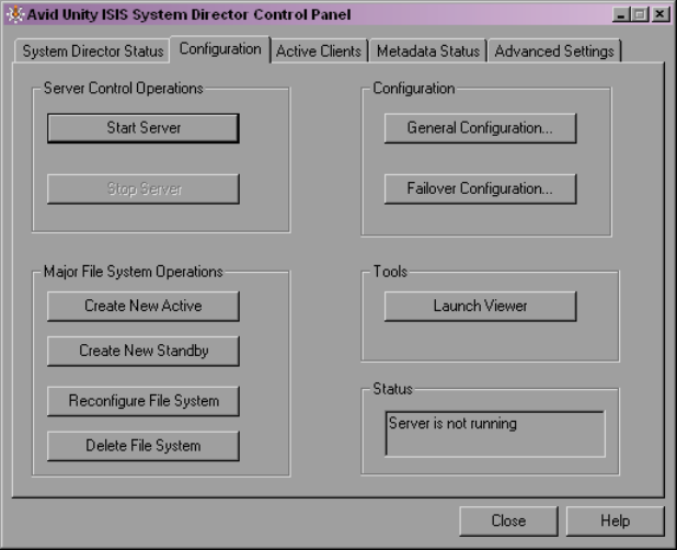
1. Select Start > Programs > Avid Unity ISIS System Director > System Director Control
Panel.
The Avid Unity ISIS System Director Control Panel opens.
2. Click the Configuration tab.
3. In the Server Control Operations area, click Stop Server.
A confirmation message box opens.
4. Click OK.
The System Director stops.
5. In the Major File System Operations area, click Create New Active.
A confirmation message box opens.
6. Click OK.
An active partition is created, and the System Director starts.
7. In the Configuration area, click General Configuration.
The General Configuration Options dialog box opens.
Configuring the Avid Unity ISIS Software
19
8. (Optional) Type a name for the Virtual System Director. In a failover configuration, this
name should be different from the network node name for the System Director.
9. Click OK.
10. Click Close.
Configuring the Avid Unity ISIS Software
You need to configure the Avid Unity ISIS software to establish a functioning media
network. This configuration requires that you do the following:
• Add the storage elements to the media network (see “Managing the Storage Hardware”
on page 35).
• Create a storage group (see “Configuring and Managing Storage” on page 67).
• Create a workspace (see “Managing Workspaces” on page 81).
• Create user accounts (see “Managing Client Accounts and Access Privileges” on page
107).
For more information about the Avid Unity ISIS software and the Avid Unity ISIS System
Administration tool, see “Configuring Your Avid Unity ISIS Software” on page 21.
1 Installing Your Avid Unity ISIS Software
20

2Configuring Your Avid Unity ISIS
Software
Avid Unity ISIS allows you to manage very large amounts of storage that multiple clients
can access to share video, audio, and effects media in an intuitive, collaborative
environment.
This section provides an overview of the configuration factors you need to consider, the
tasks you need to perform, and the tool you use to manage storage groups, clients, and
workspaces.
For more information, see the following topics:
•Management Tasks and General Considerations
•System Capacity
•Using the Administration Tool
•Understanding the Administration Tool Interface
Management Tasks and General Considerations
The responsibilities of an administrator include the following:
• Initial setup and configuration of the workgroup: You must configure the storage
elements, as well as one or more storage groups, workspaces, and user accounts.
• Day-to-day administration: You probably need to reconfigure your network to
accommodate new users and evolving projects.
Avid Unity ISIS also provides monitoring functionality that allows you to check total
system activity as well as that of each connected client.
• Troubleshooting: When problems occur with the storage hardware, the System Director,
or a client, you need to diagnose the problem and, if possible, fix it. Avid Unity ISIS
provides easy-to-understand error, warning, and informational messages that inform you
of problems, as well as tools that help you diagnose and fix problems.
2 Configuring Your Avid Unity ISIS Software
22
How you answer the following strategic questions determines your priorities when making
configuration decisions and trade-offs (possibly affecting several aspects of your
configuration).
• What is your site type?
Broadcast and post-production editing suites, for instance, require very different
administration requirements, particularly in terms of workspace-access restrictions and
how often you need to reconfigure workspaces and users. For more information on
managing workspaces, see “Managing Workspaces” on page 81.
• Does your workgroup include uncompressed clients, multiple-stream clients, or high
definition clients?
If so, you will need to set up special hardware and storage group configurations. For
more information on managing storage groups, see “Configuring and Managing
Storage” on page 67.
• Will your client users be working on individual projects with their own media or will
they be collaborating on team projects that use the same source media?
These factors affect how you should allocate workspaces and user accounts. For more
information on managing users and user groups, see “Managing Client Accounts and
Access Privileges” on page 107.
• Which is more important at your site: the integrity and speed at which your media can
be recovered in the event of hardware failure or maximizing available storage space?
Avid recommends that you always use protection to avoid data loss. However, these
factors determine whether you will want to protect your workspaces.
• Is security more important than ease of access at your site?
Individual password user accounts combined with tightly controlled workspace access
privileges provide the most security at the cost of restricting user flexibility. For more
information on managing user accounts and access privileges, see “Managing Client
Accounts and Access Privileges” on page 107.
System Capacity
An Avid Unity ISIS media network provides up to 192 terabytes (TB) of storage, or 96 TB
of mirrored storage, distributed across storage elements — such as Avid Unity ISIS storage
blades (ISB). The Avid Unity ISIS Engine — the chassis holding the ISBs, the ISIS
Integrated Switch (ISS), the ISIS Integrated Expansion switch (IXS), power supplies, and an
internal midplane — can use either 250 GB drives or 500 GB drives.
Using the Administration Tool
23
The System Director handles file management for the system, which supports a
configuration including the following:
• 2,500,000 to 3,000,000 files; however, the maximum number of files depends on the
number of directories, the number of files in directories, the number of System
Directors, and the length of file names
• Up to 10,000 files in a directory and 10,000 directories, although individual client
accounts might require restrictions on files and directories based on performance issues
• Up to 1000 user accounts
• Up to 550 Windows and Macintosh clients with mounted workspaces; the total amount
of clients is controlled by your Avid Unity ISIS license and System Director application
key
Using the Administration Tool
You use the Avid Unity ISIS System Administration tool for the configuration and
day-to-day administration of workspaces, clients, and storage groups. The tool also allows
you to monitor your system’s activity.
nTo use the Administration tool, you need to have Macromedia® Flash® Player installed on
your system
You open the Administration tool from the Avid Unity ISIS Home page, which also allows
you to access the following support tools:
• System Monitor tool (see “Avid Unity ISIS System Monitor Tool” on page 235)
• Log Aggregator tool (see “Avid Unity ISIS Log Aggregator Tool” on page 196)
• Switch Manager tool (see “Avid Unity ISIS Switch Manager Tool” on page 206)
• Disk Tester tool (see “Avid Unity ISIS Disk Tester Tool” on page 200)
• ISB Connection Analyzer tool (see “Avid Unity ISB Connection Analyzer Tool” on
page 204)
This section provides an overview of the Administration tool. For more information, see the
following topics:
•Before Performing Administrative Functions
•Opening the Administration Tool
•Logging Out of the Administration Tool
•Accessing the Help System
2 Configuring Your Avid Unity ISIS Software
24
Before Performing Administrative Functions
It is critical that clients unmount workspaces when you do the following:
• Stopping and restarting the System Director (unmount all workspaces)
• Rebooting the System Director (unmount all workspaces)
• Changing users’ or user groups’ access (unmount only the affected workspaces)
cIf a client is using a workspace when it is taken offline, the connection to the workspace
is broken and data might be lost.
Opening the Administration Tool
The Administration tool runs as a Web service on the System Director. This allows you to
open the Administration tool from any system that has an Ethernet connection to the System
Director, as well as from the System Director itself.
cPerforming administrative functions on more than one Administration tool at the same
time can cause unexpected results. For example, if two administrators are deleting the
same user account at the same time, a second user account might also be accidentally
deleted.
When you start the Administration tool, the Login dialog box opens. If you have specified an
administration password (see “Modifying Client Accounts” on page 124), the
Administration tool prompts you to supply that password to log in. If you type the wrong
password, an error message appears and the Login dialog box reappears.
nWhen you first install the Avid Unity ISIS software, the login password is blank by default.
To set a password for the administrator, follow the procedure described in “Changing the
Administration Password” on page 176.
Regular users cannot log in to the Administration tool. However, they can view certain
information about the network through the Client Manager. For more information about the
Client Manager, see the Avid Unity ISIS Client Manager Help or the Avid Unity ISIS Quick
Start Card. The Avid Unity ISIS Client Manager User’s Guide is also included in the
Avid Unity ISIS Online Library as a separate document.

Using the Administration Tool
25
To open the Administration tool:
1. Open your Web browser.
2. In the address bar of your browser, do one of the following:
tType
https://[
System Director IP address
]:5015
— for example,
https://172.20.22.122:5015
.
tType
https://[
System Director network pathname
]:5015
— for example,
https://AvidSysDir01:5015.
If any Web site certification warnings open, click Yes to accept the certificate. If you are
not sure about the security requirements of your media network, see your administrator.
The Login dialog box for the Administration tool opens.
3. Type your password.
For information on changing the administrative password, see “Changing the
Administration Password” on page 176.
4. Click the Login button.
The Avid Unity ISIS Home page opens.
5. Do one of the following:
tClick Administration. You can also click the Administration icon.
tClick the Quick Launch menu and select Administration.
The Administration tool opens.
2 Configuring Your Avid Unity ISIS Software
26
Logging Out of the Administration Tool
You can log out of the Administration tool at any time by using the Logout button in the
Tabs area.
To log out of the Administration tool:
tClick the Logout [user] button.
Accessing the Help System
You can get comprehensive task-oriented, background, and reference information through
the Administration tool Help.
To open the Help:
tClick the Help button.
The Help displays in a separate browser window.
Understanding the Administration Tool Interface
The Administration tool, which you can run on the System Director or on any
Ethernet-attached client, has a user interface where controls are grouped by function and are
displayed by clicking the appropriate buttons.
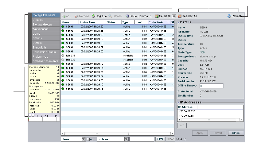
Command
menu
Main display area Details area
System
Details
area
Toolbar
Understanding the Administration Tool Interface
27
The Administration tool is divided into the following areas:
• The Command menu, which contains the options used for basic management functions.
You can access different Command functions by clicking the tabs at the top of the
Administration tool.
• The System Details area, which summarizes information about the status of your
Avid Unity ISIS media network.
• The Main display area, which displays information about your network and allows you
to configure its components
• The Details area, which displays information about the system and allows you to modify
its components
nYou can hide the Details area by clicking the Close button.
Buttons accessible from the toolbar change depending on the active dialog box. For more
information on the Administration tool interface, see the following topics:
•“Command Menu” on page 27
•“System Options” on page 32
•“Sorting Information” on page 33
Command Menu
The Command menu opens dialog boxes in the Main display area that allow you to
configure your network and to perform a full range of administrative tasks from the
Administration tool, including the following:
• Creating workspaces and storage groups
• Adding, deleting, and modifying client accounts
• Setting access privileges
• Setting and monitoring bandwidth usage
• Displaying information about clients and system usage
• Performing other administrative tasks, such as logging or monitoring
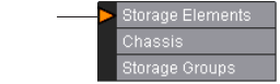
In addition, some Command menu selections display action markers that flash to indicate
issues that require administrative attention, such as a change in storage element
performance.
Action
marker

2 Configuring Your Avid Unity ISIS Software
28
The following table summarizes the color coding used by the action markers:
At the top of the Command menu are tabs for the support functions. These tabs list menu
options that allow you to access additional information about your system and to perform
certain administrative tasks, such as monitoring and logging. For more information on the
Support tabs, see “Avid Unity ISIS System Director Control Panel” on page 161 and
“Advanced Support Tools” on page 175.
The Command menu selections are described in the following sections.
Storage Elements Option
Selecting the Storage Elements option opens the Storage Elements dialog box. This allows
you to manage the storage elements connected to your media network. You use the Storage
Elements dialog box to perform the following functions:
• Add storage elements to the media network
• Remove storage elements from the media network
For more information on the Storage Elements dialog box, see “Managing the Storage
Hardware” on page 35.
Chassis Option
Selecting the Chassis option opens the Chassis dialog box, which allows you to view basic
information about your storage element and switch blade hardware and to perform the
following functions:
• Display a list of all chassis connected to the media network
• Display information on the storage elements and switch blades in the chassis
• Upgrade all storage elements and switch blades in the chassis
Marker Color Description
White Indicates that no storage element has been bound to the Avid Unity ISIS file
system, or that there are no storage groups or workspaces created yet
Blue Indicates that an installation or software upgrade is in progress
Orange Indicates a failed software installation or upgrade, or a hardware error
Yellow Indicates a potential problem with an Avid Unity ISIS component. It also
indicates a redistribution is in progress. For more information, see the sections on
the appropriate Administration tool functions
Understanding the Administration Tool Interface
29
• Upgrade individual storage elements and switch blades in the chassis
• Remove inactive chassis from the Chassis list
For more information on the Chassis dialog box, see “Managing the Storage Hardware” on
page 35.
Storage Groups Option
Selecting the Storage Groups option opens the Storage Groups dialog box. This allows you
to set up and administer storage groups. You use the Storage Groups dialog box to perform
the following functions:
• Display a list of storage groups
• Create, rename, and delete storage groups
• Add storage elements to storage groups
• Remove storage elements from storage groups
For more information on the Storage Groups dialog box, see “Configuring and Managing
Storage” on page 67.
Workspaces Option
Selecting the Workspaces option opens the Workspaces dialog box, which allows you to
view information about each workspace and to perform the following functions:
• Create a workspace
• Delete a workspace
• Rename a workspace
• Set the protection state for a workspace
• Set user access for a workspace
• Move a workspace to another storage group
• Resize a workspace
For more information on the Workspaces dialog box, see “Managing Workspaces” on page
81.
2 Configuring Your Avid Unity ISIS Software
30
Users Option
Selecting the Users option opens the Users dialog box, which allows you to view
information about all user accounts and to administer use of the network. User management
tasks include the following:
• Display a list of users
• Create new user accounts and user passwords
• Assign user privileges and access
• Assign user bandwidth limits
• Delete user accounts
• Modify user accounts
For more information on the Users dialog box, see “Managing Client Accounts and Access
Privileges” on page 107.
User Groups Option
Selecting the User Groups option opens the User Groups dialog box, which allows you to
view information about all user group accounts and to administer use of the network. User
group management tasks include the following:
• Display a list of user groups
• Add and delete user groups
• Modify user group accounts
For more information on the User Groups dialog box, see “Managing Client Accounts and
Access Privileges” on page 107.
Devices Option
Selecting the Devices option opens the Devices dialog box, which allows you to view
information about all device accounts and to administer use of the network. Device
management tasks include the following:
• Display a list of devices
• Add and delete device accounts
• Modify device accounts
• Assign device bandwidth limits
For more information on the Devices dialog box, see “Managing Client Accounts and
Access Privileges” on page 107.
Understanding the Administration Tool Interface
31
Bandwidth Option
Selecting the Bandwidth option opens the Bandwidth Monitor dialog box and provides
low-level, performance-monitoring functions. The Bandwidth option allows you to view the
following information:
• A list of the individual system components connected to the media network
• A description of the current Read and Write bandwidth usage for each component
• The system bandwidth reservation for both Read and Write operations
You can also use the Bandwidth Monitor dialog box to remove individual system
components from the network by revoking bandwidth reservation.
For more information on the Bandwidth Monitor dialog box, see “Monitoring Bandwidth
Usage and System Status” on page 131.
Connection Status Option
Selecting the Connection Status option opens the Connection Status dialog box and allows
you to view basic information about the components connected to the network. You can also
use the Connection Status dialog box to disconnect components from the network.
For more information on the Connection Status dialog box, see “Monitoring System
Connection Status” on page 134.
Preferences Option
Selecting the Preferences option opens the Preferences dialog box and allows you to set
bandwidth requirements and to enable the automatic creation of device accounts when
components are added to the media network.
For more information on the Preferences dialog box, see “Setting System Preferences” on
page 129.
Orphaned Elements Option
Selecting the Orphaned Elements option opens the Orphaned Elements dialog box and
allows you to remove storage elements that are bound to the ISIS file system but no longer
connected.
For more information on the Orphaned Elements dialog box, see “Removing Orphaned
Storage Elements” on page 53.
2 Configuring Your Avid Unity ISIS Software
32
System Options
The System options are two buttons located in the Tabs area that allow you to do the
following:
• Logout: Clicking this button logs out the current user and closes the Administration
tool.
• Help: Clicking this button opens the Help, which provides procedures and reference
information for all features of the Administration tool.
Organizing Display Information
You can customize the Main display area for any Command menu option by moving and
hiding columns, and by sorting and filtering information.
For detailed descriptions of these procedures, see the following topics:
•“Moving and Rearranging Columns” on page 32
•“Showing and Hiding Columns” on page 32
•“Sorting Information” on page 33
•“Filtering the Display” on page 34
Moving and Rearranging Columns
To move a column in the Main display area:
1. With one of the options in the Command menu selected, click the heading of the column
that you want to move.
2. Drag the column to the position you want, and release the mouse button.
The column appears in the new position, and columns to the right are moved to make
room.
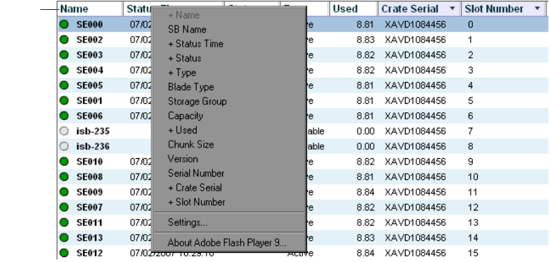
Showing and Hiding Columns
When you open a Command menu option (for example, the Storage Elements dialog box),
the Main display area lists items in default columns. Depending on the option selected, there
might be other headings available to view. You can select individual or multiple column
headings to be displayed or hidden.
Understanding the Administration Tool Interface
33
To show or hide column headings:
tWith one of the options in the Command menu selected, right-click in the column
heading row and select a heading you want to show or hide.
Displayed column headings are marked by a plus sign (+). You cannot hide the first
column on the left of the Main display area (usually the Name column).
Sorting Information
The Administration tool interface allows you to sort information listed in the Main display
area, both in the default panels (for example, the Storage Elements dialog box) or in the
Details area. Sorting the information in columns arranges items in either numerical or
alphabetical order. You can also perform a multilevel sort of the displayed information.
To sort information:
tWith one of the options in the Command menu selected, click the column heading for
the category of information you want to sort.
The information is sorted in ascending order. To reverse the sort order, click the column
heading again.
To perform a multilevel sort:
1. With one of the options in the Command menu selected, click the column heading for
the first category of information you want to sort.
The items in the column are sorted in ascending order.
Column
Heading
row
2 Configuring Your Avid Unity ISIS Software
34
2. Click a second column.
The items in the second column are sorted in ascending order. The items in the first
column maintain their sort order, but with a lower priority than the second sort.
3. (Option) Click multiple columns to add levels to the sort. To cancel a multilevel sort,
click a column heading that has already been sorted.
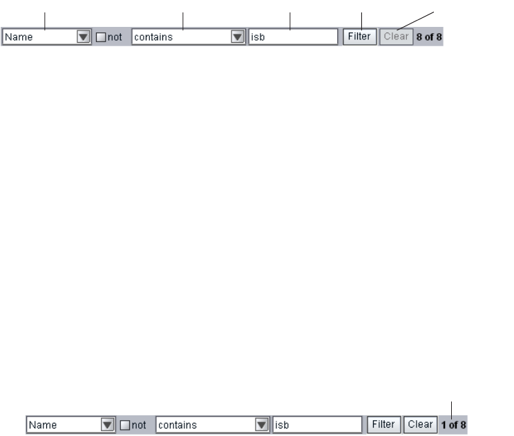
Filtering the Display
You can limit the items listed in the Main display area by setting Filter parameters. Filtering
the display allows you to focus on only those items that you want to monitor. You can restore
all items to the display by clearing the Filter parameters.
nYou cannot filter the display for the Bandwidth, Connection Status, and Preferences menu
options.
To filter the display:
1. Select one of the options in the Command menu.
2. In the Filter area, click the Category menu and select a category.
The Category menu lists all of the column headings available for the selected Command
menu option.
3. (Option) Select “not” to exclude the Filter parameters from the display.
4. Click the Parameter menu and select the constraining parameter you want to use.
5. In the Filter text box, type the characters you want to use to filter the display.
6. Click Filter.
The Main display area updates to display the filtered results. The Filter area displays the
number of filtered items displayed and the total number of items available for display.
To restore all items to the display:
tClick Clear.
The Main display area updates to display all items.
Category menu Parameter menu Filter text box Filter button Clear button
Number of filtered items
3Managing the Storage Hardware
This chapter describes how to configure and manage your storage hardware. You perform all
storage management operations from the Avid Unity ISIS System Administration tool,
which allows you to add, remove, configure, and manage your storage elements.
nFor an overview of the Administration tool and information about how to start the tool, see
“Using the Administration Tool” on page 23.
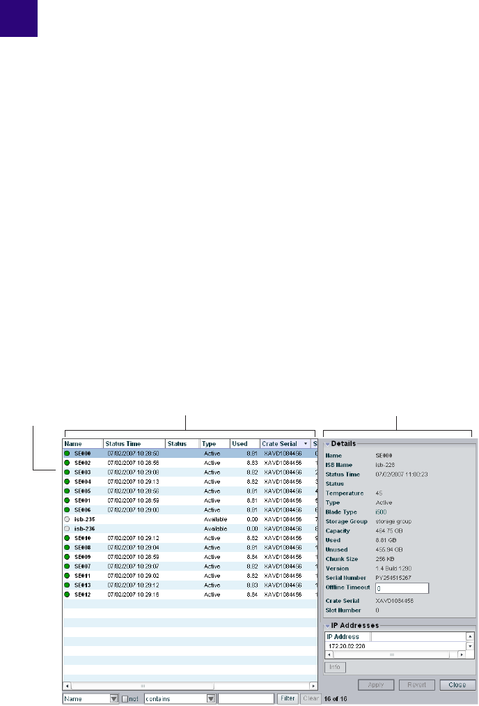
The Storage Elements dialog box of the Administration tool allows you to add and remove
storage elements, upgrade the storage element software, and monitor storage element
operation.
The Storage Elements dialog box contains two sections. On the left side of the dialog box
the Storage Elements list displays all the storage elements available to the current user. On
the right side of the dialog box, the Details area displays technical information about
selected storage elements.
nThe Details area is visible only after you select a storage element in the Storage Elements
list.
Details area
Storage Elements list
Storage element
icon
3 Managing the Storage Hardware
36
For more information, see the following topics:
•Accessing the Storage Elements Dialog Box
•Adding Storage to the Media Network
•Adding Storage Elements
•Rectifying Files
•Removing Storage Elements from the File System
•Removing Storage Elements from the Media Network
•Removing Orphaned Storage Elements
•Upgrading Storage Elements
•Managing the Avid Unity ISIS Chassis
Accessing the Storage Elements Dialog Box
To access the Storage Elements dialog box:
1. Open the Administration tool. (For information on opening the Administration tool, see
“Opening the Administration Tool” on page 24.)
2. Select Storage Elements from the list on the left.
The Storage Elements dialog box opens and displays the Storage Elements list.
Storage element icon

Accessing the Storage Elements Dialog Box
37
If you do not have any storage elements bound to the Avid Unity ISIS file system, a
yellow action marker flashes next to the Storage Elements list. For more information
about the Storage element list, see “Storage Element List” on page 37 and “Viewing
Storage Elements Descriptions” on page 38.
Storage Element List
The following table summarizes the basic information available when you first open the
Storage Elements list. Some columns are hidden by default (see “Showing and Hiding
Columns” on page 32 and “Storage Element Details” on page 39).
nYou can organize the information in the Storage Elements list by showing additional
columns or by sorting or filtering displayed items. For more information on modifying the
display, see “Organizing Display Information” on page 32.
Heading Description
Name Displays the system-created name of each storage element connected to the system
SB Name Displays the computer name of each storage element connected to the system
Status Time Lists the last time the System Director logged the storage element’s status
Status Displays any change in the working status logged by the System Director (for a
description of status messages, see “Storage Element Status” on page 41)
Type Displays the storage element category of each storage element (see “Storage
Element Details” on page 39):
• Available
•Spare
•Active
Used Displays the amount of storage space in gigabytes (GB) in use by each storage
element
Crate Serial Displays the identification number of the unit that holds each storage element
Slot Number Displays the slot number of each storage element

3 Managing the Storage Hardware
38
A color-coded icon precedes the name of each storage element, providing an indication of
the status of the component. The following table describes the color coding system used by
the Administration tool.
Viewing Storage Elements Descriptions
The Details area displays all information for the currently selected storage element. The
information displayed is the information as seen by the System Director. Some of the
information is embedded in the storage element, and other information is assigned to the
storage element by the Avid Unity ISIS software.
nYou can view more detailed information on storage elements by using the Avid Unity ISIS
Agent tool. For more information, see “Avid Unity ISIS Agents” on page 208.
To view information about a storage element:
1. In the Storage Elements list, select a storage element.
2. Do one of the following:
tClick the Details button.
tDouble-click the storage element name.
Icon Color Description
White Indicates the status of the storage element is Available (the storage element is not
linked to the ISIS file system)
Green Indicates the status of the storage element is either Spare (the storage element is not
allocated to a storage group) or Active (allocated to a storage group)
Yellow Indicates one of the following:
• a problem with the storage element
• the storage element experiences degraded performance due to a reboot during an
upgrade operation
Blue Indicates that an installation or software upgrade is in progress
Orange Indicates a storage element problem, including any of the following:
• a hardware error
• a failed software installation or upgrade
• a storage element disconnected due to a reboot during an upgrade operation
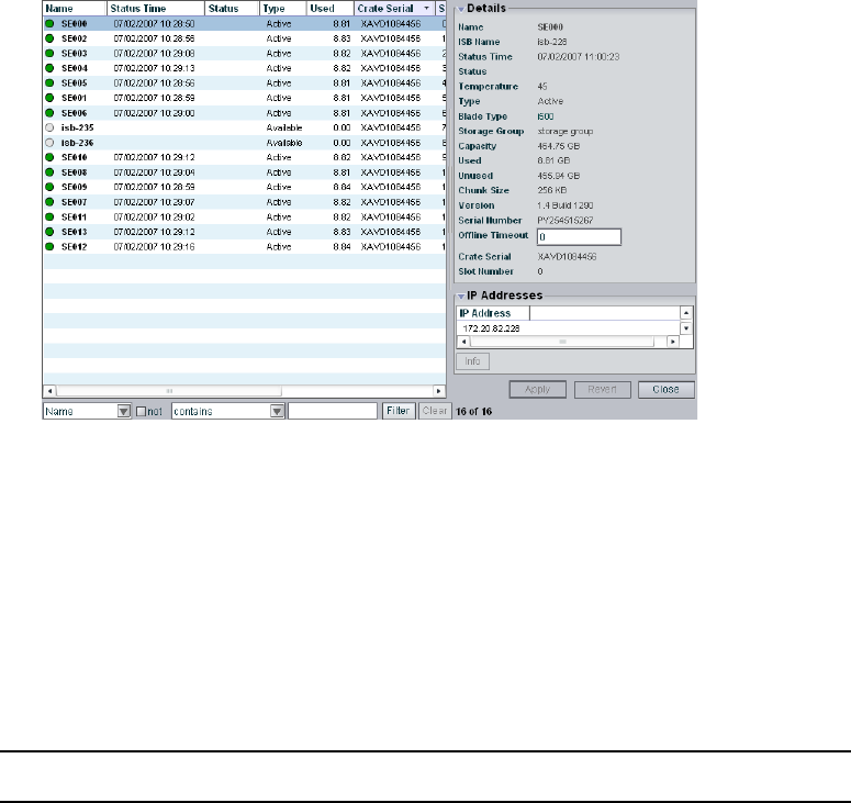
Accessing the Storage Elements Dialog Box
39
The Details area displays all the information for the selected storage element. For more
information, see “Storage Element Details” on page 39.
To hide the Details area:
tClick the arrow next to the storage element Details title bar.
To close the Details area:
tClick the Close button.
Storage Element Details
The following table summarizes the information available in the Details area.
Heading Status Description
Name Displays the system-created name of the selected
storage element
ISB Name Displays the computer name of the selected storage
element
Status Time Lists the last time the System Director logged the
storage element’s status
Status For a description of status
messages, see “Storage
Element Status” on page 41.
Displays any change in the working status logged
by the System Director.

3 Managing the Storage Hardware
40
Temperature Displays the last logged temperature of the storage
element
Type Displays the storage element category of the
selected storage element
Available Indicates storage elements that are not
appropriately initialized for use in a storage group;
these storage elements can be used for other
purposes in your environment
Spare Indicates storage elements that have been added to
the ISIS file system but are not allocated for a
specific purpose; spare but inactive storage
elements cannot be used until allocated to a storage
group
Active Indicates active storage elements added to a file
system and allocated to a storage group
Blade Type Lists the storage element model:
• i500
• i1000
Storage Group Displays the storage group, if any, to which the
storage element is allocated
Capacity Displays the storage capacity in gigabytes (GB) of
the selected storage element
Used Displays the amount of storage space in gigabytes
(GB) that currently has data written on it in the
selected storage element
Unused Displays the amount of storage space in gigabytes
(GB) available for use in the selected storage
element
Chunk Size Displays the size of segmented media files sent
over the network
Heading Status Description (Continued)

Accessing the Storage Elements Dialog Box
41
Storage Element Status
The Status column in the Storage Elements list reports the status of the storage element
logged by the System Director. (The Status line in the Details area reports the same
information.) If the storage element maintains a working status, the Administration tool lists
no entries in the Status field. When a problem arises, or when the status of the storage
element changes, the Administration tool updates the Storage Elements dialog box.
Version Displays the software version number of each
storage element
Serial Number Displays the identification number of each storage
element
Offline Timeout nIndicates the amount of time (in seconds) a storage
element is offline before the System Director logs
an error message
Crate Serial Displays the identification number of the unit that
holds each storage element
Slot Number Displays the slot number of each storage element
IP Addresses Displays the IP addresses of the selected storage
element in a separate area. To hide this area, click
the arrow in the IP Addresses title bar.
Heading Status Description (Continued)

3 Managing the Storage Hardware
42
The following table summarizes the storage element status messages.
Category Status
Disk Status • Disk in test mode
• Metadata error
General Status • Rectifying files: the storage element is cleaning up deleted files and
verifying existing files
• No connection: the System Director cannot communicate with the
storage element; this could be due to a networking infrastructure issue
or storage element failure
• Repairing mirrors: the storage element is repairing mirrored blocks
with a single point of failure
• Disk failure: the storage element is unusable for data storage and must
be replaced
• Redistributing: data is being redistributed to storage elements in the
storage group
• Disk performance degraded: the storage element’s performance is
below the threshold for input/output functions and might impact the
performance of the system
• Network degraded: the IP interfaces on the storage element has failed
or the storage element experiences at least a 10% error rate (usually
due to lost packets), indicating a network communication problem
• Memory error: the memory test that runs when the storage element
starts or restarts reports an error; this status is persistent and indicates
that the storage element has failed and should be replaced
• Metadata error: the storage element experienced an error loading
metadata from the disk or writing new metadata to the disk (if
mirrored, the data on the mirrored storage element is still available
and no actual data loss occurs); this indicates that the storage element
should be replaced
• Disk in test: the storage element is in disk test mode
• Offline: the storage element has been taken offline, usually in
preparation for removal
Temperature status • Temperature above threshold: the temperature of the storage element
exceeds 60°C (140°F)

Adding Storage to the Media Network
43
Adding Storage to the Media Network
The Administration tool checks the metadata integrity and updates all data related to the
storage elements connected to the network. Anytime you add or remove a storage element
from your system, you can update the information in the Storage Elements dialog box.
You do not need to turn off the System Director to add or remove storage elements.
cWhen adding storage elements to the Avid Unity ISIS engine (the chassis that holds the
physical components of your Avid Unity ISIS network), be sure to insert them
carefully. Do not force them into place, as damage to the disk drives might occur if they
sustain any physical shock. For information on adding storage elements to your
network, see the Avid Unity ISIS Setup Guide and the Avid Unity ISIS ReadMe.
To physically add new storage elements to your media network:
1. Add the new storage elements, installing new units as described in the Avid Unity ISIS
Setup Guide.
2. Start the System Director if it is not already running.
3. Open the Administration tool. (For information on opening the Administration tool, see
“Opening the Administration Tool” on page 24.)
Upgrade Status • Install failed
• Installing Phase 0
• Installing Phase 1
• Installing Phase 2
• Installing Phase 3
• Install Waiting
Connection Status • No Connection
Category Status (Continued)
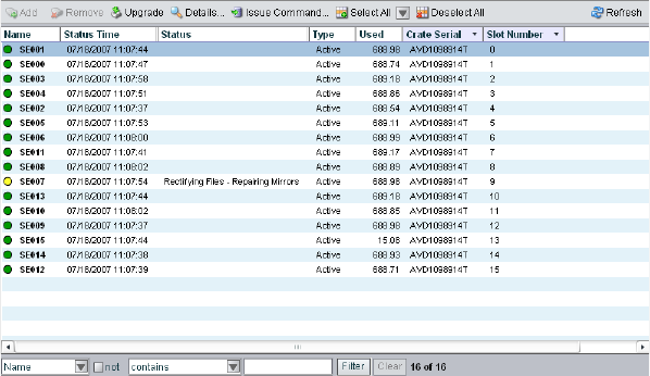
3 Managing the Storage Hardware
44
4. Select Storage Elements from the list on the left.
The Storage Elements dialog box opens.
If the Administration tool is open when you add the storage elements, click the Refresh
button to view the newly added storage elements in the Storage Elements dialog box.
If the storage elements are not listed, something might be wrong with their physical
connections. Do not proceed any further, and see the Avid Unity ISIS Setup Guide.
5. Add the new storage elements to a server (see “Adding Storage Elements” on page 44).
6. Add the new storage elements to a storage group (see “Adding Storage Elements to
Storage Groups” on page 75).
Adding Storage Elements
The storage group defines the storage elements that the network can use to store data. In
order to finish configuring your Avid Unity ISIS media network, you must add storage
elements to the ISIS file system (sometimes called “linking” or “binding” storage elements),
and then you must create a storage group from the available storage elements.
To add a storage element to the ISIS file system:
1. Open the Administration tool. (For information on opening the Administration tool, see
“Opening the Administration Tool” on page 24.)
2. Select Storage Elements from the list on the left.
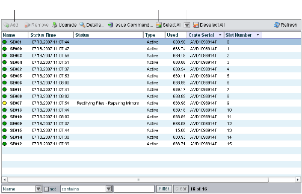
Adding Storage Elements
45
The Storage Elements dialog box opens.
3. Do one of the following:
tSelect the available storage element you want to add to a server. Ctrl+click to select
multiple available storage elements.
tClick the Select All button to select all storage elements.
tClick the Select All menu, and select one of the following options:
- Select All Available
- Select All Spare
- Select All Active
- [Select all in] chassis
4. Click the Add button.
The Storage Elements list refreshes and displays the storage element type as “Spare.”
For more information about storage groups, see “Managing the Storage Hardware” on
page 35.
Select All menuSelect All buttonAdd button
3 Managing the Storage Hardware
46
Rectifying Files
Once you have added storage elements to your network and configured them for storage, the
storage elements — Avid Unity ISIS storage blades (ISB) — periodically check the status of
stored files, cleaning up deleted files and verifying existing files. This process, called
“rectifying files,” allows the ISBs to communicate with the System Director to monitor the
state of its storage and clean up any files that the ISB no longer needs to store. Rectifying
files occurs randomly and asynchronously during normal system operation to minimize any
potential decrease in system performance. The process is indicated for each affected ISB in
the Status column in the Storage Elements list.
Storage elements also rectify files when the ISB starts or restarts. When this happens — for
example, when an ISB loses connectivity to the network — data stored on the ISB might not
be in sync with the data in the file system itself. Also, if a client, such as the asset manager,
cannot communicate with the ISB, there might appear to be more data allocated to the ISB
than the file system has allocated. To correct this, you can manually send the storage element
a command to rectify its files.
You can also use the Issue Command button to clear all Network Degraded status messages
from the Storage Elements list. Network Degraded status indicates a high number of errors
detected by the ISB (see “Storage Element Status” on page 41). Correcting the problem
might not clear the status messages, so you can use the Issue Command button to clear the
messages and reset the error count.
cYou should correct the cause of the Network Degraded status messages before you
clear them from the Administration tool.
To rectify files:
1. Open the Administration tool. (For information on opening the Administration tool, see
“Opening the Administration Tool” on page 24.)
2. Select Storage Elements from the list on the left.
The Storage Elements dialog box opens.
3. Do one of the following:
tSelect a storage element. Ctrl+click to select multiple storage elements.
tClick the Select All button to select all storage elements.
tClick the Select All menu, and select one of the following options:
- Select All Available
- Select All Spare

Rectifying Files
47
- Select All Active
- [Select all in] chassis
4. Click the Issue Command button.
The Issue Storage Element(s) Command dialog box opens.
5. Select Initiate Block Rectify, and then click Send.
The system rectifies files on the selected storage elements and changes the status in the
Storage elements list to Rectifying Files.
To clear all Network Degraded messages in the Storage Elements list:
tSelect Clear Network Degraded, and then click Send.
3 Managing the Storage Hardware
48
Removing Storage Elements from the File System
When you remove storage elements from the Avid Unity ISIS file system, or when you
move storage elements from one system to another, you need to unlink the storage elements
from the file system.
nYou cannot remove a storage element that is part of a storage group. You must remove the
storage element from its storage group first so the system can redistribute data before
unlinking the storage element from the file system.
Avid strongly recommends that you wait until any redistribution process completes before
removing storage elements.
To remove a storage element from the ISIS file system:
1. Open the Administration tool. (For information on opening the Administration tool, see
“Opening the Administration Tool” on page 24.)
2. Select Storage Groups from the list on the left.
The Storage Groups dialog box opens.
3. Select the storage group for the storage element you want to remove, and do one of the
following:
tClick the Details button.
tDouble-click the storage group name.
The Details area opens.
4. In the Storage Elements list, select the storage element you want to remove. If the
storage element status shows a redistribution in progress, you should wait until the
redistribution completes before removing the storage element from the file system.
5. Click the Remove button.
The storage element type changes from Active to Spare.
6. Click the Apply button.
The Storage Elements list refreshes and displays the storage element as Spare. The
media network performs a redistribution of any data on the storage element.
7. Select Storage Elements from the list on the left.
The Storage Elements dialog box opens.
Removing Storage Elements from the Media Network
49
8. Do one of the following:
tSelect the storage element you want to remove. Ctrl+click to select multiple storage
elements.
tClick the Select All button to select all storage elements.
tClick the Select All menu, and select one of the following options:
- Select All Available
- Select All Spare
- Select All Active
- [Select all in] chassis
9. Click the Remove button.
If you are using storage elements with mixed blade types, a dialog box opens and warns
you that using mixed blade types might not provide optimal performance for your
Avid Unity ISIS system.
10. Click Apply.
Removing Storage Elements from the Media
Network
You can remove and replace storage elements without stopping the System Director or
turning off other components of the network. There are two principal reasons for removing
storage elements from the system:
• The element has a high number of unrecoverable errors
• The element has failed or has been removed from the system
Before you remove an Avid Unity ISIS Storage Blade (ISB) from the network, you must
redistribute the data stored on the ISB to other ISBs in the system. The redistribution occurs
before you physically remove the ISB, and the process entails moving data to the remaining
drives within the storage group. Once you redistribute the data, you add a new ISB to the
system and then perform a redistribution again to place data onto the new ISB.
cIf you physically remove an ISB from the media network before redistribution is
complete, data loss can occur.
nYou should maintain an unused block of storage equivalent to one ISB within the storage
group to allow redistribution from a failing ISB to other ISBs within the group.
3 Managing the Storage Hardware
50
If possible, you should redistribute data while the drive is experiencing problems but has not
yet been removed from the system. This allows the ISB having problems to participate in the
redistribution process by offering data that it has to both clients and to other ISBs.
nOften the ISB is still functional, but its performance is slightly degraded — for example, the
ISB might have an unrecoverable error on one of its disks, or it might have long I/O times.
If the ISB fails, or if it has been removed from the system, you can perform a redistribution
from the mirrored locations associated with the ISB. However, if any other mirrored location
experiences a failure while performing a redistribution, the system can lose data.
Consider the following when planning a redistribution:
• A one-to-one replacement of ISBs might leave you with less storage space in the storage
group than you require. Instead, plan for using more ISBs than you need for storage and
bandwidth for each storage group. This way, you can keep an optimal amount of
available storage space allocated to the storage group. This allows you to quickly
perform redistribution, rather than attempting a redistribution with only one spare ISB.
• In general, the removal of an ISB is quicker than an addition. This is because all of the
other ISBs in a storage group participate in redistribution by moving a copy of any block
held by the element to another location. The more ISBs in the storage group, the more
the workload is shared. A single ISB addition is slower than a removal because the ISB
receiving the data acts as a limiting factor for the redistribution.
• When you add a new ISB to the Avid Unity ISIS file system and then add it to a storage
group, the system redistributes data from the existing drives in the storage group to the
new element. This redistribution maintains all previously stored data, but the data might
not reside on the same storage elements.
nIf you do not have a replacement for a failed or failing ISB, Avid recommends that you leave
it in the system. Proper airflow can be disturbed if an ISB slot is left open.
The following steps list the actions necessary for removing a storage element:
1. Identify the storage element you want to replace.
2. Remove the storage element from the storage group.
3. View the status of the redistribution and wait for redistribution to finish.
4. Remove the storage element from the file system.
5. Physically remove and replace the storage element.
6. Add new storage element to the file system.
7. Add the new storage element to a storage group.
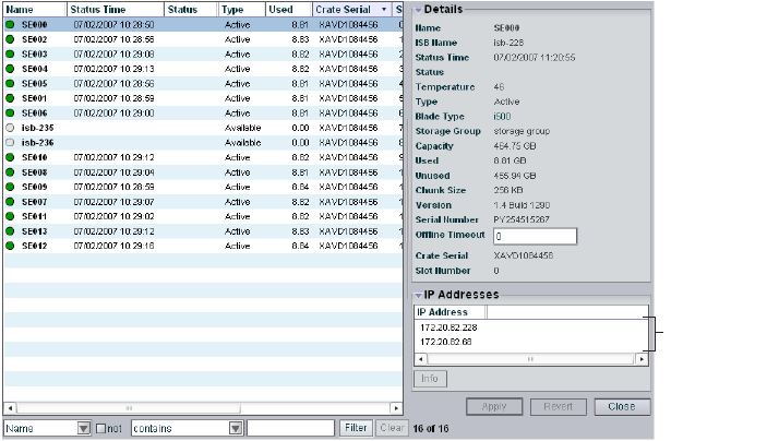
Removing Storage Elements from the Media Network
51
For more information on the process of redistributing data and how redistribution affects
system performance, see “Redistribution Guidelines” on page 96.
nRedistributing while adding an ISB takes longer than redistributing while removing an ISB.
Identifying Storage Elements Prior to Removal
To identify the storage element to be removed and replaced:
1. Open the Administration tool (see “Opening the Administration Tool” on page 24).
2. Select Storage Elements from the list on the left.
The Storage Elements dialog box opens.
3. Locate the failing or failed storage element. For information on storage element status,
see “Viewing Storage Elements Descriptions” on page 38 and “Storage Element Status”
on page 41.
4. Select the storage element, and do one of the following:
tClick the Details button.
tDouble-click the name of the storage element.
The Details area opens.
The Details area lists the Crate Serial number and the Slot Number of the selected
storage element. This address identifies the ISB to be physically removed.
nThe slot numbers for storage element begin at zero (0).
IP addresses
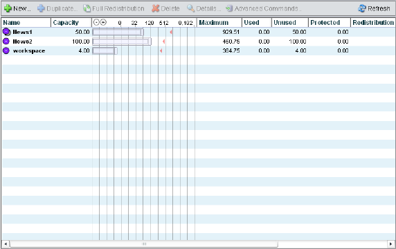
3 Managing the Storage Hardware
52
Removing Storage Elements
After you have identified the storage element you want to remove, you need to remove the
element from the storage group and monitor the redistribution of data.
cYou must finish the redistribution before you physically remove the storage element. If
you do not wait until the redistribution finishes, media network clients might receive
multiple errors.
To physically remove a storage element from your media network:
1. Remove the storage element from its storage group. For information on removing
storage elements, see “Removing Storage Elements from Storage Groups” on page 76.
2. Select Workspaces from the list on the left.
The Workspaces dialog box opens.
3. Select the Workspace for the appropriate storage group.
4. Monitor the status listed in the Redistribution column. Click the Refresh button until the
redistribution finishes.
The Redistribution column displays no status message when the process is complete.
cDo not remove the storage element before the redistribution has completed.
5. Remove the storage element from the ISIS file system. For information on removing
storage elements, see “Removing Storage Elements from the File System” on page 48.
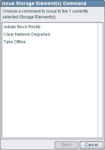
Removing Storage Elements from the Media Network
53
6. In the Storage Element list, select the storage element you want to remove and then click
the Issue Command button.
The Issue Storage Element(s) Command dialog box opens.
7. Select Take Offline, and then click Send.
The system spins down the drives in the selected storage element and changes the status
in the Storage Elements list to Offline.
8. Disconnect the storage element from the network, as described in the Avid Unity ISIS
Setup Guide.
Removing Orphaned Storage Elements
The Storage Element list might display storage elements associated with a media network
but with which the System Director cannot communicate. This can occur when you use the
System Director Control Panel to create a new active partition on a system that already
includes bound storage elements. In this case, the storage elements are “orphaned” — the
storage elements remain bound to the network, but they cannot communicate with it. To
correct the problem, you need to first remove all storage elements previously linked to the
ISIS file system, and then add them again to the new system.
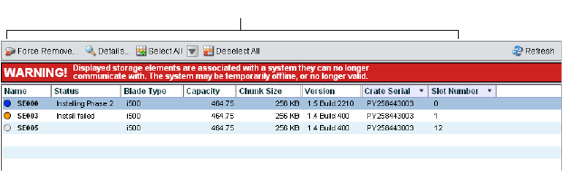
3 Managing the Storage Hardware
54
The System Director also might not be able to communicate with storage elements that are
bound to the ISIS file system if the System Director is offline. In this case, do not remove the
orphaned storage elements; instead, you should restart the System Director.
cRemoving storage elements causes all data stored on them to be erased. Do not remove
disconnected storage elements unless you are certain they contain no data you want to
save.
For information on removing orphaned storage elements, see the following topics:
•“Accessing the Orphaned Elements Dialog Box” on page 54
•“Removing Orphaned Storage Elements” on page 55
Accessing the Orphaned Elements Dialog Box
The Orphaned Elements dialog box of the Administration tool allows you to add and remove
storage elements, upgrade the storage element software, and monitor storage element
operation.
To open the Orphaned Elements dialog box:
1. Open the Administration tool (see “Opening the Administration Tool” on page 24).
2. Select Orphaned Elements from the list on the left.
The Orphaned Elements dialog box opens. For more information on the Orphaned
Elements dialog box, see “Orphaned Elements List” on page 55.
Orphaned Elements list

Removing Storage Elements from the Media Network
55
Orphaned Elements List
The following table summarizes the basic information available in the Orphaned Elements
list.
Removing Orphaned Storage Elements
To remove orphaned storage elements, you must force-remove them from the system.
cRemoving storage elements causes all data stored on them to be erased. Do not remove
disconnected storage elements unless you are certain they contain no data you want to
save.
To remove orphaned storage elements:
1. Open the Administration tool (see “Opening the Administration Tool” on page 24).
2. Select Orphaned Elements from the list on the left.
Heading Description
Name Displays the name of each storage element connected to the system
Status Displays any change in the working status logged by the System Director (for a
description of status messages, see “Storage Element Status” on page 41)
Type Displays the storage element category of each storage element:
• Available
•Spare
•Active
Capacity Displays the storage capacity in gigabytes (GB) of each storage element
Chunk size Displays the size of segmented media files sent over the network
Version Displays the software version number of each storage element
Crate Serial Displays the identification number of the unit that holds each storage element
Slot Number Displays the slot number of each storage element
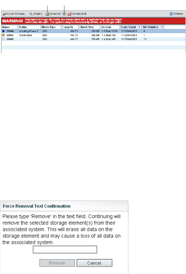
3 Managing the Storage Hardware
56
The Orphaned Elements dialog box opens.
3. Do one of the following:
tSelect the storage element you want to remove. Ctrl+click to select multiple storage
elements.
tClick the Select All button to select all storage elements.
tClick the Select All menu, and select one of the following options:
- Select All Available
- Select All Spare
- Select All Active
- [Select all in] chassis
4. Click the Force Remove button.
A message warns you that removing storage elements erases all data on the component.
5. Click Yes.
The Force Removal Text Confirmation dialog box opens.
6. Type
Remove
in the text box, and then click Remove.
The storage element is unbound from the ISIS file system and removed from the
Orphaned Elements list.
Select All menuSelect All button
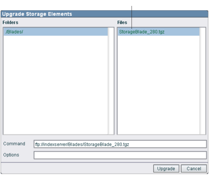
Upgrading Storage Elements
57
Upgrading Storage Elements
You can use the Storage Elements dialog box to upgrade the software for storage elements
installed in a chassis and connected to the media network.
nYou can also use the Chassis dialog box to upgrade storage elements. For more information,
see “Upgrading Chassis Components” on page 63.
To upgrade a storage element:
1. Open the Administration tool (see “Opening the Administration Tool” on page 24).
2. Select Storage Elements from the list on the left.
The Storage Elements dialog box opens.
3. Select the storage element you want to upgrade.
4. Click the Upgrade button.
The Upgrade Storage Elements dialog box opens.
Upgrade installer
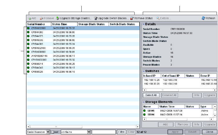
3 Managing the Storage Hardware
58
5. Select the upgrade installer from the list in the right column.
The Command text box displays the location of the upgrade installer.
6. Click the Upgrade button.
The Administration tool installs the necessary upgrade for the selected storage element.
You can monitor the progress of the upgrade either in the Details area of the Storage
Elements dialog box or in the Avid Unity ISIS System Monitor tool.
Managing the Avid Unity ISIS Chassis
The Chassis dialog box of the Administration tool allows you to view details and to monitor
the status of all chassis connected to the media network, as well as upgrade any Avid Unity
ISIS storage blade (ISB), any Avid Unity ISIS Integrated switch (ISS), or any Avid Unity
ISIS Expansion Integrated switch (IXS).
The Chassis dialog box contains two sections. On the left side of the dialog box, the Chassis
list displays all the chassis connected to the media network. On the right side of the dialog
box, the Details area displays technical information about selected chassis, including details
on the chassis switch and storage element (ISB) components.
nThe Details area is visible only after you select a chassis in the Chassis list.
Chassis Details areaChassis area
Chassis
list
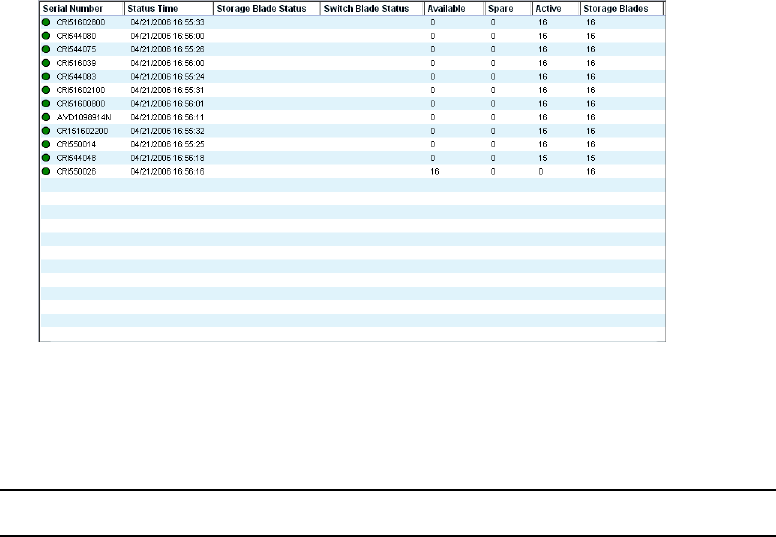
Managing the Avid Unity ISIS Chassis
59
Accessing the Chassis Dialog Box
You can organize the information in the Chassis list by showing additional columns or by
sorting or filtering displayed items. For more information on modifying the display, see
“Organizing Display Information” on page 32.
To access the Chassis dialog box:
1. Open the Administration tool. (For information on opening the Administration tool, see
“Opening the Administration Tool” on page 24.)
2. Select Chassis from the list on the left.
The Chassis dialog box opens.
Chassis List
The following table summarizes the basic information available in the Chassis list.
Heading Description
Serial Number Lists the serial number of the chassis
Status Time Lists the last time the System Director logged the status of the chassis
Storage Blade Status Displays changes in the working status of ISB components due to upgrade
installation or failure
Switch Blade Status Displays changes in the working status of ISS and IXS modules due to
upgrade installation or failure

3 Managing the Storage Hardware
60
Viewing Chassis Descriptions
The Details area displays all information for the currently selected chassis. The area is
divided into three sections:
• Chassis Details — displays information also available in the Chassis list
• Switches — lists basic configuration and status information of all ISS and IXS modules
connected to the media network
• Storage Elements — displays information also available in the Storage Elements list
The information displayed is the information as seen by the System Director. Some of the
information is embedded in the chassis, and other information is assigned to the chassis by
the Avid Unity ISIS software.
You can sort the information in the Switches and Storage Elements sections of the Details
area by clicking any column heading. For more information on sorting items in columns, see
“Sorting Information” on page 33.
nYou can view more detailed information on chassis components by using the Avid Unity ISIS
Agent tool. For more information, see “Avid Unity ISIS Agents” on page 208.
To view information about a chassis:
1. In the Chassis list, select a chassis.
2. Do one of the following:
tClick the Details button.
tDouble-click the chassis name.
Available Lists the number of available storage elements in each chassis
Spare Lists the number of spare storage elements in each chassis
Active Lists the number of active storage elements in each chassis
Storage Blades Lists the number of ISB components installed in each chassis
Switch Blades Lists the number of ISS and IXS modules for each chassis
Power Blades Lists the number of power supply units for each chassis
Heading Description (Continued)
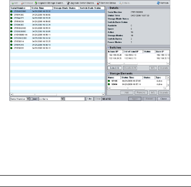
Managing the Avid Unity ISIS Chassis
61
The Details area displays all the information for the selected chassis. For information on
the Details area, see “Chassis Details” on page 61
To hide the Details area:
tClick the arrow next to the Details title bar.
To close the Details area:
tClick the Close button.
Chassis Details
The following table summarizes the information available in the Details area.
Section Heading Description
Chassis Details
Serial Number Lists the serial number of the chassis
Status Time Lists the last time the System Director logged the status
of the chassis
Storage Blade Status Displays changes in the working status of ISB
components due to upgrade installation or failure

3 Managing the Storage Hardware
62
Switch Blade Status Displays changes in the working status of switches due
to upgrade installation or failure
Storage Blades Lists the number of ISB components installed in each
chassis
Available Lists the number of available storage elements in each
chassis
Spare Lists the number of spare storage elements in each
chassis
Active Lists the number of active storage elements in each
chassis
Switch Blades Lists the number of switches for each chassis
Power Blades Lists the number of power blades for each chassis
Switches
In band IP Displays the internal IP addresses assigned to the CPU
on the switch
Status Displays changes in the working status of the switch
Version Displays the software version number of each switch
Type Identifies the switch as one of the following:
• Integrated (ISS)
• Expansion (IXS)
Temp Lists the last logged temperature of the switch
Stack Master Indicates if an ISS or an IXS module is used as a master
switch in the stack
Stack Master IP Displays the IP addresses of the stack master, if
applicable
Base IP Displays the base IP addresses of the switch, which are
assigned during system configuration (for more
information on IP addresses, see the Avid Unity ISIS
Setup Guide)
Out of band IP Displays the IP addresses for the management port on the
switch
Section Heading Description (Continued)

Managing the Avid Unity ISIS Chassis
63
Upgrading Chassis Components
You can use the Chassis dialog box to upgrade the software for all storage elements and all
switch blades installed in a chassis and connected to the media network. You can also
upgrade individual storage elements and switches.
nYou might lose network connectivity temporarily when you upgrade switch blades while the
upgrade process reboots the switches.
To upgrade all storage elements and switches in a chassis:
1. In the Chassis list, select the chassis you want to upgrade.
2. Do one of the following:
tClick the Upgrade Storage Blades button.
tClick the Upgrade Switch Blades button.
Storage Elements
Name Displays the name of each storage element connected to
the system
Status Time Lists the last time the System Director logged the storage
element’s status
Status Displays any change in the working status logged by the
System Director (for a description of status messages,
see “Storage Element Status” on page 41)
Type Displays the storage element category of each storage
element:
• Available
•Spare
•Active
Version Displays the software version number of each storage
element
Slot Number Displays the slot number of each storage element
Section Heading Description (Continued)
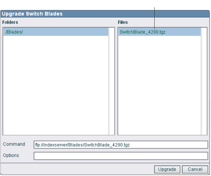
3 Managing the Storage Hardware
64
The Upgrade Storage Blades dialog box or the Upgrade Switch Blades dialog box
opens.
3. Select the upgrade installer from the list in the right column.
The Command text box displays the location of the upgrade installer.
4. Click the Upgrade button.
The Administration tool installs the necessary upgrades for all storage elements or for
all switch blades for the selected chassis. You can monitor the progress of the upgrade
either in the Details area of the Chassis dialog box or in the Avid Unity ISIS System
Monitor tool.
Upgrading Individual Chassis Components
You can upgrade individual storage elements and switch blades in the Chassis dialog box.
You can also upgrade storage elements by using the Storage Elements dialog box. For more
information on storage element upgrades, see “Upgrading Storage Elements” on page 57.
Upgrade installer
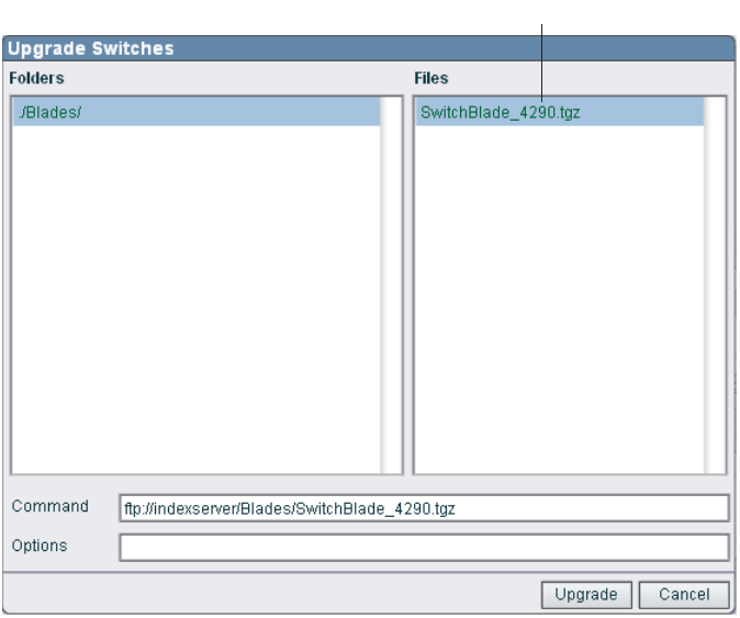
Managing the Avid Unity ISIS Chassis
65
To upgrade individual storage elements and switches in a chassis:
1. In the Details area of the Chassis dialog box, do one of the following:
tSelect the switch you want to upgrade.
tSelect the storage element you want to upgrade.
2. Click Upgrade.
The Upgrade Storage Blades dialog box or the Upgrade Switches dialog box opens.
3. Select the upgrade installer from the list in the right column.
The Command text box displays the location of the upgrade installer.
4. Click the Upgrade button.
The Administration tool installs the necessary upgrade for the selected storage element
or switch blade. You can monitor the progress of the upgrade either in the Details area of
the Storage Elements dialog box or in the Avid Unity ISIS System Monitor tool.
Upgrade installer
3 Managing the Storage Hardware
66
Removing Chassis from the Chassis List
If you need to replace a chassis, you can use the Administration tool to remove the
connection history of the inactive or inoperative chassis from the Chassis list in the Chassis
dialog box. Once the chassis is removed from the ISIS file system, you can physically
remove it from the network.
For information on removing chassis from the network, see the Avid Unity ISIS Setup Guide.
To remove a chassis from the Chassis list:
1. In the Chassis list, select the chassis you want to remove.
2. Click the Remove Status button.
The chassis is removed from the Chassis list.
nIf you remove an active chassis by mistake, the System Director restores the chassis to the
Chassis list the next time it polls the media network (usually within 20 seconds).
Adding and Removing Storage Elements in the Chassis List
You can add and remove (bind and unbind) available or spare storage elements from the ISIS
file system by using Chassis list in the Chassis dialog box. Adding and removing storage
elements in the Chassis list functions the same way as selecting the “Select All Available”
and “Select All Spare” options when adding or removing storage elements in the Storage
Element list. For more information on adding and removing storage elements, see “Adding
Storage Elements” on page 44 and “Removing Storage Elements from the File System” on
page 48.
For information on removing chassis from the network, see the Avid Unity ISIS Setup Guide.
To add or remove storage elements by using the Chassis list:
1. In the Chassis list, select the chassis with the storage elements you want to add or
remove. You can only add or remove storage elements listed in the Available or Spare
columns in the Chassis list.
2. Do one of the following:
tClick the Add button to bind storage elements to the file system.
tClick the Remove button to unbind storage elements from the file system
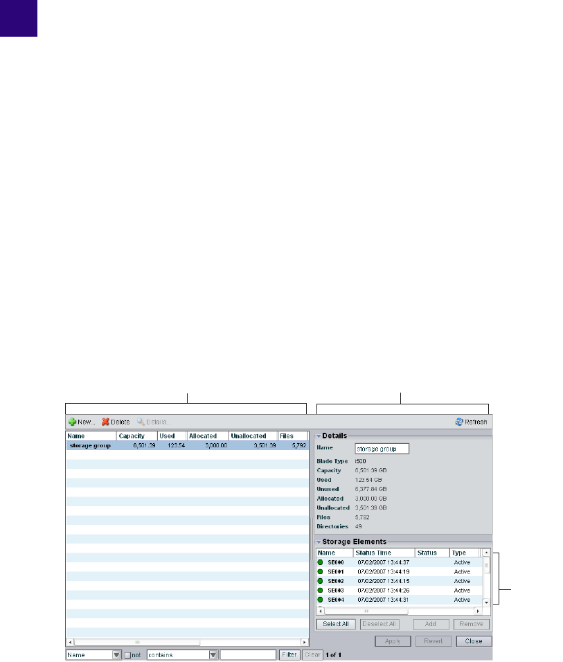
4Configuring and Managing Storage
This chapter describes the Storage Groups dialog box of the Administration tool and the
basic administrative operations you can perform from the dialog box.
nFor detailed descriptions of how to use the Administration tool to manage your drive
hardware, see “Managing the Storage Hardware” on page 35.
You use the Storage Groups dialog box of the Administration tool to add and delete storage
groups, to rename storage groups, and to configure and manage storage groups.
The Storage Groups dialog box contains three sections. On the left side of the dialog box,
the Storage Groups list displays all the storage groups available to the current user. On the
right side of the dialog box, the Details area displays technical information about selected
storage groups, and the Storage Elements area displays all storage elements available to the
current user.
nThe Details area and the Storage Elements area are visible only after you select a storage
group in the Storage Groups list.
Details area
Storage
Elements
area
Storage Groups list
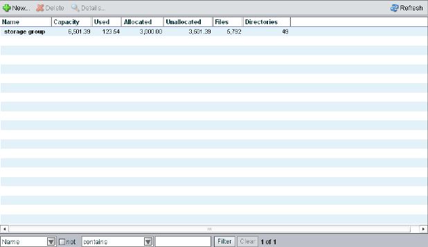
4 Configuring and Managing Storage
68
When you add storage groups, a separate window opens in the Storage Group dialog box.
For information on adding storage groups, see “Creating Storage Groups” on page 73.
For more information on using the Storage Groups dialog box, see the following topic:
•Accessing the Storage Groups Dialog Box
•Storage Group List
•Storage Group Details
Accessing the Storage Groups Dialog Box
To access the Storage Groups dialog box:
1. Open the Administration tool. (For information on opening the Administration tool, see
“Opening the Administration Tool” on page 24.)
2. Select Storage Groups from the list on the left.
The Storage Groups dialog box opens.
If you have not yet created any storage groups, a white action marker flashes next to the
Storage Groups list.

Accessing the Storage Groups Dialog Box
69
Storage Group List
The following table summarizes the information available in the Storage Groups list.
You can sort the information in the Storage Groups dialog box by clicking any column
heading. For more information on sorting items in columns, see “Sorting Information” on
page 33.
Viewing Storage Group Details
The Details area and the Storage Elements area display all information for the currently
selected storage group and all information for the available storage elements. The
information displayed is the information as seen by the System Director. Some of the
information is embedded in the storage element, and other information is assigned to the
storage element by the Avid Unity ISIS software.
nYou can sort the information in the Storage Elements area by clicking any column heading.
For more information on sorting items in columns, see “Sorting Information” on page 33.
Heading Description
Name Displays the name of the currently selected storage group
Capacity Displays the storage capacity in gigabytes (GB) of the selected storage group
Used Displays the amount of storage space in gigabytes (GB) that currently has data
written on it in the selected storage group
Allocated Displays the amount of storage space in gigabytes (GB) reserved for use by
workspaces in the selected storage group
Unallocated Displays the amount of storage space in gigabytes (GB) available on the storage
elements and not currently reserved for the selected storage group
Files Displays the number of files in the selected storage group
Directories Displays the number of directories in the selected storage group
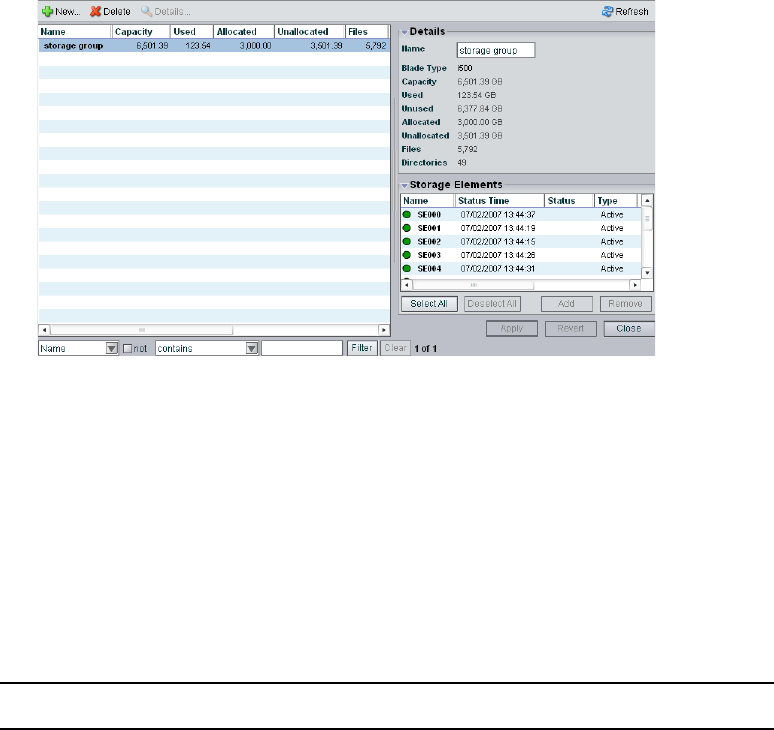
4 Configuring and Managing Storage
70
To view information about a storage group:
tIn the Storage Groups list, select a storage group.
The Storage Groups dialog box displays all the information for the selected storage
group. If the Details area is not visible, click the Details button.
To hide the Details area or the Storage Elements area:
tClick the arrow next to the Details title bar or the Storage Elements title bar.
To close the Details area:
tClick the Close button.
Storage Group Details
The following table summarizes the information available in the details panels for storage
groups and storage elements.
Heading Description
Name Displays the name of the currently selected storage group
Blade Type Lists the storage element model for the storage group:
•i500
• i1000
• [blank if mixed blade type]
Capacity Displays the storage capacity in gigabytes (GB) of the selected storage group

Accessing the Storage Groups Dialog Box
71
The Storage Elements area lists the storage elements allocated to the currently selected
storage group, as well as the storage elements available for allocation to the storage group.
The following table summarizes the information available in the Storage Elements area.
Some columns are hidden by default (see “Showing and Hiding Columns” on page 32).
Used Displays the amount of storage space in gigabytes (GB) that currently has data
written on it in the selected storage group
Unused Displays the amount of storage space in gigabytes (GB) that currently has no data
written on it in the selected storage group
Allocated Displays the amount of storage space in gigabytes (GB) reserved for use by
workspaces in the selected storage group
Unallocated Displays the amount of storage space in gigabytes (GB) available on the storage
elements and not currently reserved fo2r the selected storage group
Files Displays the number of files in the selected storage group
Directories Displays the number of directories in the selected storage group
Heading Description (Continued)
Heading Status Description
Name Displays the name of the selected storage element
Status Time Lists the last time the System Director logged the storage element’s
status
Status Displays the working status logged by the System Director
Type Displays the storage element category of the selected storage element
Available Indicates storage elements that are not appropriately initialized for use
in a storage group; these storage elements can be used for other
purposes in your environment
Spare Indicates storage elements that have been added to the Avid Unity
ISIS file system but are not allocated for a specific purpose; spare but
inactive storage elements cannot be used until allocated to a storage
group
Active Indicates active storage elements added to a server and allocated to a
storage group

4 Configuring and Managing Storage
72
Managing Storage Groups
Storage groups are partitions, each containing multiple assigned storage elements. This
section describes how to create and manage storage groups in your network.
For more information on managing storage groups, see the following topics:
•“Storage Group Usage Guidelines” on page 72
•“Creating Storage Groups” on page 73
•“Adding Storage Elements to Storage Groups” on page 75
•“Removing Storage Elements from Storage Groups” on page 76
•“Adding Storage Elements from Another Storage Group” on page 78
•“Adding Storage Elements Previously Used with Another Network” on page 79
•“Deleting Storage Groups” on page 80
Storage Group Usage Guidelines
You can assign all of your storage elements to one large storage group, or you can divide
your storage elements among multiple storage groups. (Storage elements can be assigned to
only one storage group.) To optimize performance, you can use storage groups to configure
your Avid Unity ISIS file system.
Used Displays the amount of storage space in gigabytes (GB) that currently
has data written on it in the selected storage element
Crate Serial Displays the identification number of the unit that holds each storage
element
Slot Number Displays the slot number of each storage element
Heading Status Description (Continued)
Managing Storage Groups
73
Avid recommends that you use all storage elements in an Avid ISIS Engine when creating a
storage group, and you size larger storage groups in increments of whole ISIS engines.
While storage groups can be created with a partial ISIS engine, performance and sizing
scalability cannot be guaranteed.
nYou can divide very large storage groups (over 60 storage elements) into several storage
groups to minimize the risk of two storage elements used in a protected workspace failing at
the same time. When you assign storage elements to different storage groups, however, you
must be careful how you allocate bandwidth reservations for the different groups as the
available bandwidth allocations for individual storage groups might differ from the total
system bandwidth, depending on the number of storage elements assigned to each group.
If your environment supports clients with very high bandwidth requirements, you need to set
up specific hardware and storage group configurations to support them. For more
information, see the Avid Unity ISIS Setup Guide.
In such an environment, you can use storage groups to isolate clients that need very high
bandwidth and thus eliminate the competition from other clients trying to access the same
storage elements. For example, when high-definition (HD) media is in its own storage group
and a single client is using the HD media, that client is serviced independently from any
other clients in the workgroup. This logic can also be applied to separating audio and video
media.
In other situations, storage groups are more flexible, allowing you to assign storage elements
in your file system configuration to storage groups with few limitations.
nYou must use a minimum of one storage element per storage group.
Creating Storage Groups
A storage group is a set of physical storage elements that store a subset of the complete set
of media files accessible within a shared storage environment and which can accommodate
different storage element types, as well as clients with different privileges and media
requirements (for instance, clients that use low-resolution media and ones that use
high-resolution media).
nIf you have bound storage elements to the ISIS file system but you have not created any
storage groups, the Create Storage Groups dialog box opens by default when you select the
Storage Groups list.
To create a new storage group:
1. Open the Administration tool. (For information on opening the Administration tool, see
“Opening the Administration Tool” on page 24.)
2. Select Storage Groups from the list on the left.
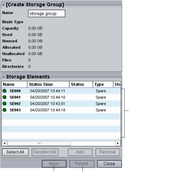
4 Configuring and Managing Storage
74
3. Click the New button.
The Create Storage Group dialog box opens.
4. In the Name text box, type a name for the storage group (a maximum of 32 characters).
The following characters are illegal in storage group names: \, /, :, *, ?, ", +, <, >, and |.
If there is already a storage group with the name entered in the Name text box, an error
message tells you to type a new name.
5. In the Storage Elements area, select the storage element you want to assign to the new
storage group. Ctrl+click to select multiple storage elements.
6. Click the Add button.
The storage elements are allocated to the storage group. You can use the Remove button
to remove storage elements from the storage group.
7. (Option) Before you create your storage group, you can use the Revert button to undo
any modifications made to the storage group information.
Storage Elements area
Apply button Revert button

Managing Storage Groups
75
8. Click the Apply button to create a new storage group containing all the selected storage
elements.
The new storage group appears in the Storage Groups list, and the Create Storage Group
dialog box refreshes to show the storage elements still available for additional storage
groups.
9. (Option) Repeat steps 5 through 9 to create new storage groups.
10. Click the Close button to close the Create Storage Group dialog box and to return to the
Storage Groups dialog box.
Adding Storage Elements to Storage Groups
You can add unassigned storage elements to a storage group at any time to increase its
storage capacity.
To add storage elements to a storage group:
1. Open the Administration tool. (For information on opening the Administration tool, see
“Opening the Administration Tool” on page 24.)
2. Select Storage Groups from the list on the left.
The Storage Groups dialog box opens.
3. In the Storage Groups list, select the storage group where you want to add storage
elements, and then do one of the following:
tClick the Details button.
tDouble-click the storage group name.
The Details area displays all the information on the selected storage group.
4 Configuring and Managing Storage
76
4. In the Storage Elements area, select all the spare storage elements you want to add to the
storage group.
5. Click the Add button to add the selected spare storage elements to the storage group.
The Storage Elements area refreshes to display the selected storage elements added to
the storage group.
6. (Option) Before you apply your changes, you can use the Revert button to undo any
modifications made to the storage group information.
7. Click the Apply button.
The storage elements are added to the storage group, and the media network performs a
redistribution of any data on the storage elements. The amount of time required for the
redistribution depends on the amount of data in the storage group.
Removing Storage Elements from Storage Groups
You can remove storage elements from your storage group, as long as the following
conditions are met after you have done so:
• The storage group contains at least four storage elements.
• The storage group contains enough storage elements to support the space allocated to
your workspaces.
nThis is the total amount of storage allocated to the workspaces, not the actual amount of
data stored on the workspaces.
• The storage group contains at least the number of storage elements currently required to
store the file system’s data.
Storage elements removed from the storage group are returned to the system’s pool of spare
storage elements.
To remove storage elements from a storage group:
1. Open the Administration tool. (For information on opening the Administration tool, see
“Opening the Administration Tool” on page 24.)
2. Select Storage Groups from the list on the left.
The Storage Groups dialog box opens.
3. In the Storage Groups list, select the storage group from which you want to remove
storage elements, and then do one of the following:
tClick the Details button.
tDouble-click the storage group name.

Managing Storage Groups
77
The Details area displays all the information on the selected storage group.
4. In the Storage Elements area, select all the grouped storage elements you want to
remove from the storage group.
5. Click the Remove button.
The Storage Elements area refreshes and displays the selected storage elements as
Spare. If you try to remove too many storage elements so that the capacity of the storage
group falls below either the used space or the allocated space, a dialog box opens asking
you to confirm the action.
6. (Option) Before you apply your changes, you can use the Revert button to undo any
modifications made to the storage group information.
7. Click the Apply button.
The selected storage elements are removed from the storage group, and the media
network performs a redistribution of any data on the storage elements. The amount of
time required for the redistribution depends on the amount of data in the storage group.
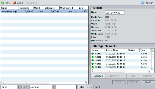
4 Configuring and Managing Storage
78
Adding Storage Elements from Another Storage Group
If you want to reassign storage elements from one storage group to another, you must
remove the storage elements before adding them to a new storage group.
To add storage elements previously used in another storage group to your current
storage group:
1. Open the Administration tool. (For information on opening the Administration tool, see
“Opening the Administration Tool” on page 24.)
2. Select Storage Groups from the list on the left.
The Storage Groups dialog box opens.
3. In the Storage Groups list, select the storage group which contains the storage elements
you want to reassign, and then do one of the following:
tClick the Details button.
tDouble-click the storage group name.
The Details area displays all the information on the selected storage group.
4. In the Storage Elements area, select all the storage elements you want to move to
another storage group.
5. Click the Remove button.
The Storage Elements area refreshes to display the selected storage elements as Spare.
6. Click the Apply button.
The selected storage elements are removed from the storage group, and the media
network performs a redistribution of any data on the storage elements.
Managing Storage Groups
79
7. In the Storage Groups list, click the storage group to which you want to add the storage
elements.
The Details area displays all the information on the selected storage group.
8. In the Storage Elements area, select all the spare storage elements you want to add to the
new storage group.
9. Click the Add button to add the selected storage elements to the storage group.
The Storage Elements area refreshes to display the selected storage elements added to
the new storage group.
10. (Option) Before you apply your changes, you can use the Revert button to undo any
modifications made to the storage group information.
11. Click the Apply button.
The selected storage elements are added to the storage group, and the media network
performs a redistribution of any data on the storage elements. The amount of time
required for the redistribution depends on the amount of data in the storage group.
Adding Storage Elements Previously Used with Another Network
If the storage elements you want to add to your storage group were used previously in
another environment, you must first connect them to your Avid Unity ISIS media network,
and then you must add them to the ISIS file system. For information on adding storage
elements to the network, see “Adding Storage to the Media Network” on page 43.
To add the storage elements to your current storage group:
1. Make sure the new storage elements are connected to the network. For information on
connecting storage elements, see the Avid Unity ISIS Setup Guide.
2. Open the Administration tool. (For information on opening the Administration tool, see
“Opening the Administration Tool” on page 24.)
3. Select Storage Elements from the list on the left.
The Storage Elements dialog box opens.
If the Administration tool is open when you add the storage elements, click the Refresh
button to view the newly added storage elements in the Storage Elements dialog box.
If the storage elements are not listed, something might be wrong with their physical
connections. Do not proceed any further, and see the Avid Unity ISIS Setup Guide.
4. Add the new storage elements to the ISIS file system (see “Adding Storage Elements”
on page 44).
5. Add the new storage elements to your storage group (see “Adding Storage Elements to
Storage Groups” on page 75).
4 Configuring and Managing Storage
80
6. Click the Apply button.
A dialog box opens asking you to confirm the action.
7. Click Yes.
The selected storage elements are added to the storage group.
Deleting Storage Groups
You can delete any storage group that does not have any workspaces on it. As a result, all
storage elements previously assigned to the storage group return to the system’s pool of
spare storage elements.
To delete a storage group:
1. Open the Administration tool. (For information on opening the Administration tool, see
“Opening the Administration Tool” on page 24.)
2. If any workspaces exist on the storage group you want to delete, first delete the
workspace (see “Deleting Workspaces” on page 106).
3. Select Storage Groups from the list on the left.
The Storage Groups dialog box opens.
4. In the Storage Groups list, select the storage group you want to delete.
5. Click the Delete button.
A dialog box opens asking you to confirm the action.
6. Click Yes.
The storage group is deleted.
After the storage group is deleted, all of the storage elements previously in your storage
group will appear in the Storage Elements area as Spare.

5Managing Workspaces
Workspaces are virtual volumes that exist on storage groups and can be resized dynamically.
Workspaces allow you to segment your storage elements easily to accommodate projects and
users.
This section describes how to create, rename, and delete workspaces. It also tells you how to
manipulate the amount of storage allocated to each workspace, how to move a workspace
and its contents to another storage group, and how to protect a workspace against drive
failure.
For more information, see the following topics:
•Allocating Workspaces
•Accessing the Workspaces Dialog Box
•Creating New Workspaces
•Duplicating Workspaces
•Adjusting Workspace Size
•Renaming Workspaces
•Protecting Workspaces
•Redistributing Data
•Moving Workspaces
•Managing Workspace Access Privileges
•Deleting Workspaces
Allocating Workspaces
Before you create workspaces, you should consider how you want to allocate them. For
example, do you want to allocate them to accommodate projects, groups, individual clients,
streaming bit rates, media types, media distributors, or a combination of these?
Once you create a plan to allocate workspaces, you’ll need to determine how much storage
each workspace requires and allocate space accordingly. This might be a function of project
size or the number of clients, or it might be a function of media duration or media resolution.
5 Managing Workspaces
82
For instance, if you plan to capture high-definition (HD) media to a workspace, you need to
create a workspace with more than two storage elements. (Assigning a full chassis of storage
elements to an HD workspace would perform better in this example.)
When sizing workspaces in a multiple workspace configuration, you should consider
reserving some space rather than assigning all of it immediately. Once space is allocated, it
tends to be filled quickly and you might need space later to accommodate a new project or
client or to extend or protect an existing workspace. In these situations, it is easier to use
space held in reserve than to take it away from an existing workspace.
When allocating and sizing workspaces, you should also consider whether access
restrictions are required and whether protection for data integrity is necessary for each
workspace.
Accessing the Workspaces Dialog Box
You perform workspace functions in the Workspaces dialog box of the Administration tool,
which allows you to do the following:
• Create, delete, and rename workspaces
• Manipulate the amount of storage allocated to each workspace
• Protect a workspace against drive failure by duplicating files on more than one drive (a
form of mirroring)
• Monitor how much free space exists on each workspace, and how much unallocated
space exists in each storage group
• Move a workspace and its contents to another storage group
To open the Workspaces dialog box:
1. Open the Administration tool. (For information on opening the Administration tool, see
“Opening the Administration Tool” on page 24.)
2. Select Workspaces from the list on the left.
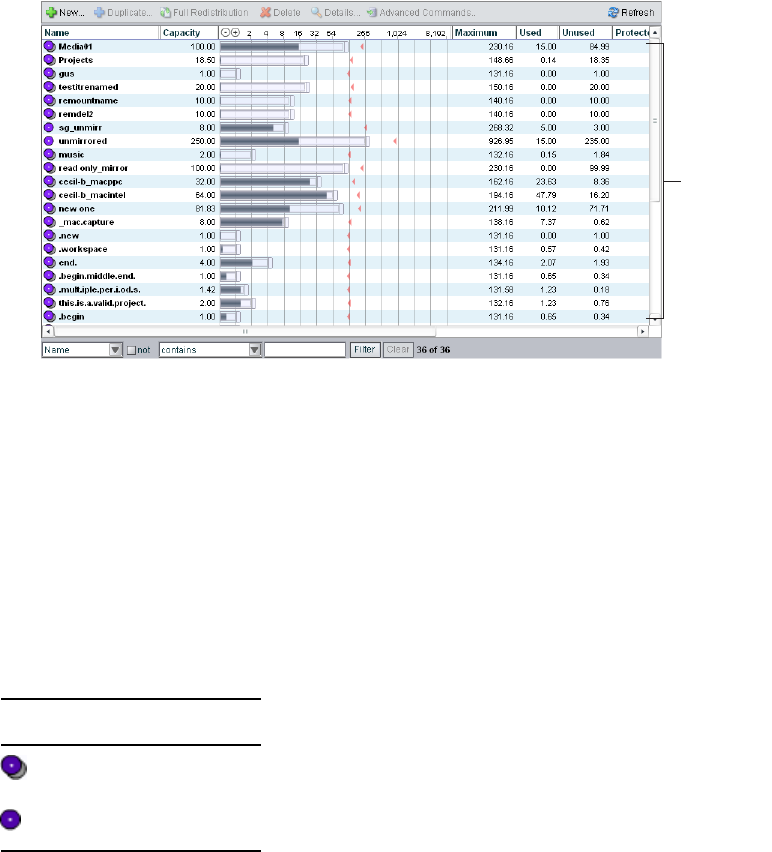
Accessing the Workspaces Dialog Box
83
The Workspaces dialog box opens. If you have not yet created any workspaces, a white
action marker flashes next to the Workspaces list.
For more information on the Workspaces list, see the following topics:
-The Workspaces List
-Using the Graphical Display
-Workspaces Descriptions
The Workspaces List
The Workspaces list displays all workspaces, the storage groups on which they reside, and
details about each workspace. Workspace names are preceded by an icon identifying
protected and unprotected workspaces.
Workspace
list
Icon Description
Protected workspace
Unprotected workspace

5 Managing Workspaces
84
The following table describes the information in the Workspaces list.
nYou can sort the information in the Workspaces list by clicking any column heading. For
more information on sorting items in columns, see “Sorting Information” on page 33.
Heading Description
Name Lists the names of all workspaces in the selected storage groups
Capacity Lists the total storage capacity of each workspace in gigabytes (GB)
Workspace Size
graph
Displays a graphical representation of the used and available space for each
workspace (for information on using the Workspace Size graph, see “Using the
Graphical Display” on page 85)
Maximum Lists the maximum amount of storage space in gigabytes (GB) available for the
workspace on the network
Used Lists the amount of storage space in gigabytes (GB) that currently has data
written on it in each workspace
Unused Lists the amount of storage space in gigabytes (GB) that currently has no data
written on it in each workspace
Protected Lists the amount of storage space assigned to each workspace for mirrored files
Redistribution Displays the status of any current redistribution:
• In Progress
• Stalled
• Pending
• Requires Full Redistribution
Config Changes Displays the number of changes to a storage group that involve moving data —
for example, the number of times an ISB has been added or removed
Storage Group For each workspace, lists the storage group on which it is located
Files Lists the total number of files stored on the network for each workspace
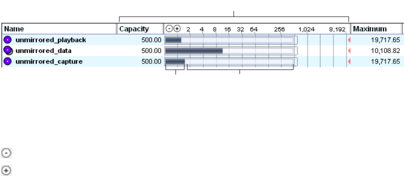
Accessing the Workspaces Dialog Box
85
Using the Graphical Display
The Workspaces Size graph provides a quick way to view how much storage capacity is
currently allocated to each workspace and how much of that storage space currently has data
written on it. The graph represents the following:
• Used space: total drive space in the storage group allocated to each workspace
• Unused space: total drive space in the storage group still available for allocation to each
workspace
You can resize the graph to expand or reduce the size of the graph.
To resize the Workspaces Size graph, do one of the following:
tClick the Decrease Size button to reduce the size of the graph.
tClick the Increase Size button to expand the size of the graph.
You can also use the Workspaces Size graph to adjust the size of the workspaces by
dragging the resize handles. For information on resizing workspaces, see ‘“Adjusting
Workspace Size” on page 91.
Used space Unused space
Workspace Size graph
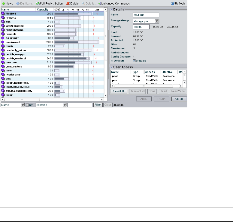
5 Managing Workspaces
86
Viewing Workspace Details
The Workspaces dialog box displays all the information for the selected workspace.
To view information about a workspace:
tIn the Workspaces list, select a workspace.
The Workspaces dialog box displays all the information for the selected workspace. If
the Details area is not visible, click the Details button.
Workspaces Descriptions
The Details area and the User Access panels display all information for the currently
selected workspace. The following table summarizes the information available in the Details
area.
Heading Description
Name Displays the name of the currently selected workspace
Storage Group Lists the storage group on which the selected workspace was created
Capacity Displays the storage capacity in gigabytes (GB) of the selected
workspace; the minimum and maximum limits for workspace size is
listed next to the Size text box
Used Displays the amount of storage space in gigabytes (GB) that currently has
data written on it in the selected workspace

Accessing the Workspaces Dialog Box
87
The User Access area lists all users and user groups and their access privileges. (For
information on access privileges, see “Managing Workspace Access Privileges” on page
103.) The following table summarizes the information available in the User Access area.
nYou can sort the information in the User Access area by clicking any column heading. For
more information on sorting items in columns, see “Sorting Information” on page 33.
Unused Displays the amount of storage space in gigabytes (GB) that currently has
no data written on it and is available to the selected workspace
Protected Lists the amount of storage space in gigabytes (GB) that is protected for
the selected workspace
Files Displays the number of files used by the selected workspace
Directories Displays the number of directories used by the selected workspace
Redistribution Displays the status of any current redistribution:
• In Progress
• Stalled
• Pending
• Requires Full Redistribution
Config Changes Displays the number of changes to a storage group that involve moving
data — for example, the number of times an ISB has been added or
removed
Protection Indicates if protection for the workspace is enabled (selected) or disabled
(not selected)
Heading Description (Continued)
Heading Description
Name Lists the names of the users and user groups on the network
Type Displays the client category (user or user group) for each client in the Name list
Access Lists the access privileges for each client in the Name list
Effective Lists the effective access privileges for each client in the Name list
Reason Lists the reason for any difference between the access privileges assigned to a user and
the effective access assigned to a user as a member of a user group
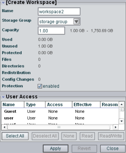
5 Managing Workspaces
88
Creating New Workspaces
Workspaces are locations to store and segregate data. You can allow users to access some or
all of the workspaces, and you can assign permissions for how each user can access the data
in a workspace.
nIf you have created storage groups but you have not created any workspaces, the Create
Workspace dialog box opens by default when you select the Workspaces list.
To create a new workspace:
1. Open the Administration tool. (For information on opening the Administration tool, see
“Opening the Administration Tool” on page 24.)
2. Select Workspaces from the list on the left.
3. Click the New button.
The Create Workspace dialog box opens.
4. In the Name text box, type a name for the workspace (a maximum of 31 characters). The
following characters are illegal in workspace names: \, /, :, *, ?, ", +, <, >, and |. Also,
you cannot use a period (.) as either the first or the last character in a workspace name.
Creating New Workspaces
89
If there is already a workspace with the name entered in the Name text box, an error
message tells you to type a new name.
5. Click the Storage Group menu, and select the storage group on which you want to create
the workspace.
The storage group name appears in the Storage Group text box.
6. Click the Sub Group menu, and select the substorage group on which you want to create
the workspace.
The substorage group name appears in the Sub Group text box.
7. Type a size for the workspace in the Capacity text box. The minimum size and the
maximum size allowed are listed next to the Capacity text box.
If all storage in the storage group is allocated to existing workspaces, you can make an
existing workspace smaller. For information on resizing workspaces, see “Adjusting
Workspace Size” on page 91.
8. (Option) Select Protection: enabled to protect the workspace. (For more information on
workspace protection, see “Protecting Workspaces” on page 94.)
9. In the User Access area, set the User and User Group access privileges. (For information
on setting access privileges, see “Changing Access Privileges” on page 128.)
10. Click the Apply button to create a new workspace containing the selected storage group
and users.
The new workspace appears in the Workspace dialog box, and the Create Workspace
dialog box refreshes to allow you to create a new workspace.
11. (Option) Repeat steps 5 through 10 to create new workspaces.
12. Click the Close button to close the Create Workspace dialog box and to return to the
Workspaces dialog box.
The new workspace appears in the Workspaces list.
n(Macintosh only) If you access the Administration tool from a Macintosh system and create
a workspace, the Macintosh operating system creates hidden files in the
/volume/[workspace name] directory of your system. If you want to delete the workspace,
you must first manually delete these files.
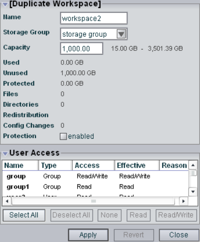
5 Managing Workspaces
90
Duplicating Workspaces
When you duplicate workspaces, they inherit the attributes (storage group, capacity, and
protection status) of the workspace from which they were created.
nThe contents of the original workspace are not duplicated.
To duplicate a workspace:
1. Open the Administration tool. (For information on opening the Administration tool, see
“Opening the Administration Tool” on page 24.)
2. Select Workspaces from the list on the left.
3. In the Workspace list, select the workspace you want to duplicate.
4. Click the Duplicate button.
The Duplicate Workspace dialog box opens.
Adjusting Workspace Size
91
5. (Option) Modify any of the attributes of the new workspace. For information on
modifying workspaces, see the following topics:
-“Adjusting Workspace Size” on page 91
-“Renaming Workspaces” on page 92
-“Protecting Workspaces” on page 94
-“Managing Workspace Access Privileges” on page 103
6. Click the Apply button to create a new workspace containing the attributes of the
selected workspace.
The duplicate workspace appears in the Workspace dialog box, and the Duplicate
Workspace dialog box refreshes to allow you to duplicate a new workspace. The new
workspace has a default name — workspace n, where n is an integer that is incremented
each time you click the Apply button to create another duplicate workspace.
If there is no room for a workspace of the same size as the original, the operation fails
and displays a “Not enough unallocated space on the partition” error message.
7. Click the Close button to close the Duplicate Workspace dialog box and to return to the
Workspaces dialog box.
Adjusting Workspace Size
There are occasions when you must change the size of workspaces. For example, you might
need to make a workspace larger to create room for a capture procedure planned for later in
the day or for some new media files. Alternatively, you might need to make a workspace
smaller to create space for other workspaces or to reserve storage for another day.
nDo not adjust workspaces while clients are writing files to them.
To adjust the size of a workspace:
1. Open the Administration tool. (For information on opening the Administration tool, see
“Opening the Administration Tool” on page 24.)
2. Select Workspaces from the list on the left.
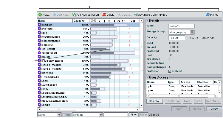
5 Managing Workspaces
92
The Workspaces dialog box opens.
3. In the Workspaces list, select a workspace.
4. Do one of the following:
tClick the handle of the Workspaces Size graph, and drag it to resize the graphical
display. The workspace size listed in the Capacity text box updates as you drag the
handle.
tClick the Details button, and type a new value for the workspace size in the
Capacity text box in the Workspace Details area.
5. Click the Apply button.
nYou cannot reduce workspace size below the storage space listed next to the Capacity text
box as the minimum size, which indicates the amount already allocated to files. (For empty
workspaces, the minimum workspace size is 1 GB.) You also cannot increase workspace size
above the storage space listed as the maximum size.
Renaming Workspaces
You can rename a workspace at any time, even when it is being used by client workstations
and mapped to a local drive or by letterless mapping (to a Universal Naming Convention
path) on the client system. The only effect on users is that the workspace name will be
different the next time they need to access it.
Details areaWorkspaces list
Workspaces
Size graph
handle

Renaming Workspaces
93
To rename a workspace:
1. Open the Administration tool. (For information on opening the Administration tool, see
“Opening the Administration Tool” on page 24.)
2. Select Workspaces from the list on the left.
The Workspaces dialog box opens.
3. In the Workspaces list, click the workspace name you want to change.
4. If the Details area is not visible, do one of the following:
tClick the Details button.
tDouble-click the workspace name.
The Workspaces Details area displays all the information on the selected workspace.
5. Type a new name in the Name text box. The following characters are illegal in
workgroup names: \, /, :, *, ?, ", +, <, >, and |. Also, you cannot use a period (.) as either
the first or the last character in a workspace name.
6. (Option) Before you apply your changes, you can use the Revert button to undo any
modifications made to the workspace information.
7. Click the Apply button.
5 Managing Workspaces
94
Protecting Workspaces
The Protection option offers high levels of data integrity by ensuring that two copies of
media data are written onto different physical drives to avoid data loss in the event of drive
failure. This allows workspaces that are protected to be repaired very quickly with no data
loss upon drive failure.
The disadvantage is that protected workspaces use twice as much space as unprotected
workspaces. However, because of the data protection and recovery speed that protection
offers, Avid recommends that you always protect your workspaces.
Workspace Protection Recommendations
Because of the potential impact of a drive failure, Avid recommends protecting all your
workspaces whenever possible. If you want to ensure protection of your files at all times,
always enable the Protection option when creating new workspaces (before any files are
stored on the workspace).
If you are not sure that all files on a given workspace are protected, select the workspace and
enable the Protection option for the workspace. This protects all new files added to the
workspace, and adds protection to any existing files in the workspace that are not already
protected.
Avid Unity ISIS allows clients to access protected workspaces that have more than one
storage element missing from the workspace’s storage group. However, protected storage
groups with more than one storage element missing are unstable. Some or all of the files the
storage groups contain might not be available for use. The administrator should repair these
workspaces at the earliest opportunity.
When you are deciding to use protection, Avid recommends you consider the following:
• Storage groups with an even number of storage elements provide the best performance
and the best data distribution for all video resolutions.
• Storage groups with an odd number of storage elements might not provide adequate
performance for some video resolutions, such as 1:1 or 2:1.
• If you are not going to protect a workspace, the storage group can contain any number
of storage elements.
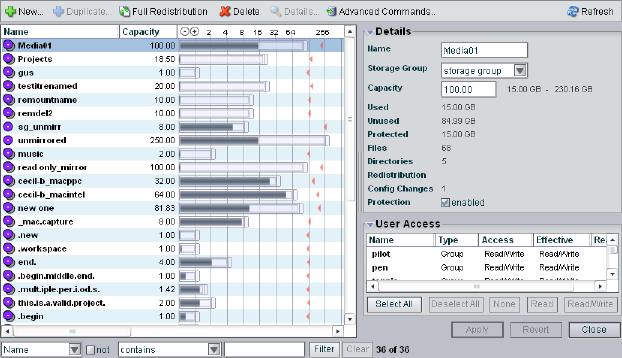
Protecting Workspaces
95
Setting Workspace Protection
You can use the Workspaces dialog box to enable or disable workspace protection.
To enable protection for a workspace:
1. Open the Administration tool. (For information on opening the Administration tool, see
“Opening the Administration Tool” on page 24.)
2. Select Workspaces from the list on the left.
The Workspaces dialog box opens.
3. In the Workspaces list, click the workspace you want to protect.
4. If the Details area is not visible, do one of the following:
tClick the Details button.
tDouble-click the workspace name.
The Workspaces Details area displays all the information on the selected workspace.
5. Select Protection: enabled to protect the workspace.
Protection is enabled for the workspace, and the icon next to the workspace name
changes from Unprotected to Protected.
6. (Option) Before you apply your changes, you can use the Revert button to undo any
modifications made to the workspace information.
7. Click the Apply button.
5 Managing Workspaces
96
To disable protection for a workspace:
1. In the Workspaces list, click the workspace from which you want to remove protection.
2. In the Details area, deselect Protection: enabled to remove protection from the
workspace.
Protection is disabled for the workspace, and the icon next to the workspace name
changes from Protected to Unprotected.
3. Click the Apply button.
Redistributing Data
Redistribution is an operation that ensures all files on a workspace are balanced evenly
across the storage elements in the storage group to provide optimal file system performance.
Data chunks are distributed across multiple storage elements to ensure redundancy and
protect against data loss. Redistribution occurs automatically in the following
circumstances:
• Adding a storage element to a storage group
• Removing a storage element from a storage group
• Moving a workspace from one storage group to another
• Removing protection from a protected workspace
• Protecting an unprotected workspace
You can also initiate a manual redistribution of data.
Redistribution Guidelines
You can start a redistribution when a workspace is in a load or a no load condition:
• A load condition occurs when the workspace has active clients (clients reading and
writing to the workspace).
• A no load condition occurs when a workspace has inactive clients (clients that have the
workspace mounted but are not performing reads or writes).
Whenever you perform a redistribution, you should observe the following guidelines:
• When redistributing under load, allow the redistribution to complete before initiating a
second redistribution.
Redistributing Data
97
• System performance can degrade up to 20% during redistribution in a workspace with
maximum client count. Reducing the number of clients by 20% allows the active clients
using the workspace to function normally, with successful playback and captures.
Reducing the overall load by 20% of the maximum capacity might be needed in the
event of client performance degradation.
• The amount of time a redistribution takes varies depending on whether the workspace is
in a load or a no load condition, whether you add or remove an ISB, and how much data
in the storage group must be redistributed. For more information on redistribution times,
see the Avid Unity ISIS ReadMe.
• Do not physically remove an storage element until it has been removed from the storage
group, the redistribution is complete, and it has been removed from the file system.
cIf you physically remove an storage element from the media network before
redistribution is complete, or if you physically remove more that one storage element
from a storage group before performing a redistribution, data loss can occur.
Limitations on expected client performance during redistribution include the following:
• Reducing audio tracks from 8 to 4 during playback might be required during
redistribution. (Normal operation supports 2 streams of video 8 tracks of audio.)
• Reducing the number of video streams from 2 to 1 might be required during
redistribution. (Normal operation supports 2 streams of video.)
Performing a Full Redistribution
In addition to automatic redistribution operations (see “Redistributing Data” on page 96),
redistribution can also be invoked manually. The most common situation where you need to
perform a full redistribution is when the Config Changes count exceeds 10. (For information
about Config Changes, see “Workspaces Descriptions” on page 86.)
nWhen the Config Changes count reaches 10, a message warns you to perform a
redistribution.
When redistributing files manually, you should apply the redistribution to all workspaces.
Avid does not recommend performing a full redistribution on some workspaces and not on
others.
To redistribute workspaces manually:
1. Open the Administration tool. (For information on opening the Administration tool, see
“Opening the Administration Tool” on page 24.)
2. Select Workspaces from the list on the left.
The Workspaces dialog box opens.
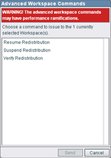
5 Managing Workspaces
98
3. Select the workspaces whose files you want to redistribute. When undertaking a full
redistribution, select all workspaces.
4. Click the Full Redistribution button.
A confirmation message box opens.
5. Click OK.
Files are redistributed, and the count in the Config Changes column is reset to zero. The
amount of time required for the redistribution depends on the amount of data in the
workspace.
6. If storage elements have rebooted following the completion of a full redistribution, do
the following:
a. Click the Advanced Commands button.
The Advanced Workspace Commands dialog box opens.
b. Select Verify Redistribution, and then click Send.
Redistributing Data
99
Using Advanced Redistribution Commands
Under some conditions, you might have to suspend or resume an in-progress redistribution.
You can do this with the Advanced Commands options available on the toolbar in the
Workspaces dialog box.
cUse of the Resume Redistribution and the Suspend Redistribution options can result in
degraded system performance. Suspending redistributions can have serious
consequences for the file system if not monitored closely. These two Advanced
Commands options should be used by Avid Customer Support personnel or under Avid
Customer Support direction.
You can also use the Advanced Commands to verify a redistribution. Verification checks that
all bad blocks on the appropriate storage element have been deleted and that the
redistribution has completed successfully. You should use the Verify Redistribution
command whenever storage elements are rebooted following a redistribution — for
example, after you upgrade your system. In this case, storage elements might report a
“Repairing Mirrors” status on reboot; verifying the redistribution replays the redistribution
operation using the current configuration and restores the status to normal.
nVerification causes minimal impact on performance and completes quickly.
To suspend a redistribution:
1. Open the Administration tool. (For information on opening the Administration tool, see
“Opening the Administration Tool” on page 24.)
2. Select Workspaces from the list on the left.
The Workspaces dialog box opens.
3. Select the workspace whose files are currently being redistributed.
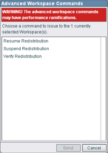
5 Managing Workspaces
100
4. Click the Advanced Commands button.
The Advanced Workspace Commands dialog box opens.
5. Select Suspend Redistribution.
6. Click Send.
cWhen you manually suspend a redistribution, you must also manually resume it.
Suspending redistributions should be considered temporary — workspaces should not
be left in the suspended state for extended periods of time.
To resume a redistribution:
1. Open the Administration tool. (For information on opening the Administration tool, see
“Opening the Administration Tool” on page 24.)
2. Select Workspaces from the list on the left.
The Workspaces dialog box opens.
3. Select the workspace whose redistribution status is Stalled.
4. Click the Advanced Commands button.
The Advanced Workspace Commands dialog box opens.
Moving Workspaces
101
5. Select Resume Redistribution.
6. Click Send.
To verify a redistribution:
1. Open the Administration tool. (For information on opening the Administration tool, see
“Opening the Administration Tool” on page 24.)
2. Select Workspaces from the list on the left.
The Workspaces dialog box opens.
3. Select the workspace where the redistribution has completed.
4. Click the Advanced Commands button.
The Advanced Workspace Commands dialog box opens.
5. Select Verify Redistribution.
6. Click Send.
Moving Workspaces
To move a workspace and all of its contents to another storage group:
1. Open the Administration tool. (For information on opening the Administration tool, see
“Opening the Administration Tool” on page 24.)
2. Select Workspaces from the list on the left.
The Workspaces dialog box opens.
3. In the Workspaces list, select the workspace you want to move.
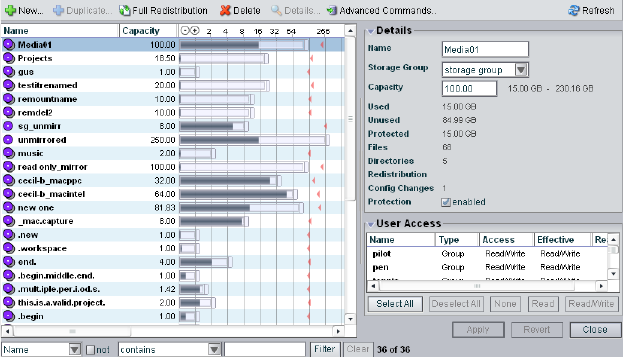
5 Managing Workspaces
102
4. If the Details area is not visible, do one of the following:
tClick the Details button.
tDouble-click the workspace name.
The Workspaces Details area displays all the information on the selected workspace.
5. Click the Storage Group menu, and select the storage group to which you want to move
the workspace.
6. (Option) Before you apply your changes, you can use the Revert button to undo any
modifications made to the workspace information.
7. Click the Apply button.
The workspace is moved, and the Details area updates to show the new storage group
assignment. Existing files are moved, and new files written to the workspace are written
to the destination storage group.

Managing Workspace Access Privileges
103
Managing Workspace Access Privileges
You can set privileges for user and user group access to workspaces in the Workspaces
dialog box. There are three levels of access available to clients of the network. The following
table describes the kinds of access privileges available to users and user groups.
By default, new client accounts do not have access privileges until an administrator assigns
them (see “Creating User Accounts” on page 112). You can customize access for each client
to every workspace, if necessary.
For example, you might need to increase the access privileges for a user who does not have
write access to the appropriate workspace, or for a workspace that does not provide the
appropriate access to one or more users. To do so, you can either modify an individual
client’s access privileges in the Users dialog box (see “Modifying Client Accounts” on page
124), or you can use the Workspace dialog box (see “Setting Workspace Access Privileges”
on page 104).
It is also possible to assign users access privileges different from those originally assigned to
the group. If a user group is given a more permissive level of access than some members of
the group, the group members then can have an effective access different from their assigned
access. This can be useful for projects that require users with a variety of permissions to be
able to write to certain workspaces. You can also have users who have more permissive
access than a user group in which they are members. Using the Workspaces dialog box, the
administrator can assign the necessary privileges.
Consider the following for access privileges:
• As access privileges are increased, the newly accessible workspaces are immediately
available.
• If a client has Read privileges to a workspace and is granted Read/Write privileges, the
new privileges apply immediately, without modifying the workspace.
• If a client is already at the workspace selection stage when the access privileges are
removed, then newly inaccessible workspaces remain in the display. However,
attempting to actually access the workspaces will be unsuccessful.
Access Level Description
Read/Write Workspace can be read and written to.
Read Workspace can be read but not written to.
None Workspace cannot be read, written to, or mounted.
5 Managing Workspaces
104
• If a client has Read/Write privileges to a workspace and access privileges are reduced to
read, the new privileges apply immediately, without modifying the workspace. If a file is
open for writing, the client retains write privilege to that file until it is closed.
• If a client has privileges to a workspace and those privileges are reduced to None, then
the workspace is unavailable the next time that workspace is accessed.
For more information on access privileges, see “Changing Access Privileges” on page 128.
Setting Workspace Access Privileges
You can set access privileges for users and user groups when the client accounts are first
created (see “Creating User Accounts” on page 112 and “Creating Client Accounts for
Groups” on page 115). You can also change access in the Users dialog box (see “Modifying
Client Accounts” on page 124). The Workspaces dialog box, however, allows you to set,
modify, and monitor access privileges to workspaces without having to modify individual
client accounts.
To set user or user group access to a workspace:
1. Open the Administration tool. (For information on opening the Administration tool, see
“Opening the Administration Tool” on page 24.)
2. Select Workspaces from the list on the left.
The Workspaces dialog box opens.
3. In the Workspaces list, select a workspace.
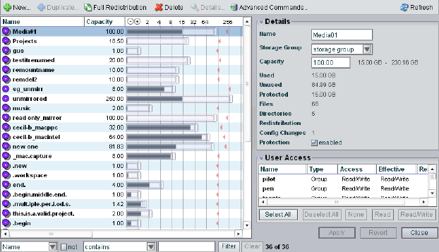
Managing Workspace Access Privileges
105
4. If the Details area is not visible, do one of the following:
tClick the Details button.
tDouble-click the workspace name.
The Workspaces Details area displays all the information on the selected workspace.
5. In the User Access area, select a user or a user group. Ctrl+click to select multiple users
and user groups. You can select all users and user groups by using the Select All button.
6. Do one of the following:
tClick the Read/Write button to set both read and write workspace access for the
client.
tClick the Read button to set read-only workspace access for the client.
tClick the None button to remove workspace access privileges for the client.
7. (Option) Before you apply your changes, you can use the Revert button to undo any
modifications made to the user access information.
8. Click the Apply button.
5 Managing Workspaces
106
Deleting Workspaces
You can delete workspaces that are not currently accessed by any clients and that have no
media files stored on them. You can delete multiple empty workspaces at one time.
If you need to delete a workspace, make sure that its media is no longer needed, is moved, or
is backed up. You then can safely delete the files in the workspace. After the workspace is
empty, you can remove it.
If you delete a workspace has been mapped to a local drive by a client, the client cannot
access that workspace. Clients should unmap the deleted workspace by using the
Avid Unity ISIS Client Manager. For information on using the Client Manager, see the
Avid Unity ISIS Client Manager User’s Guide or the Client Manager Help.
nTo see if a workspace can be deleted, check the Details area. If the Used entry is zero, no
files are stored in the workspace and you can delete it.
If you mount a workspace from a Macintosh system, the Macintosh operating system creates
hidden files in the /volume/[workspace name] directory of your system. If you want to delete
the workspace, you must first manually delete these files.
To delete a workspace:
1. Open the Administration tool. (For information on opening the Administration tool, see
“Opening the Administration Tool” on page 24.)
2. Select Workspaces from the list on the left.
The Workspaces dialog box opens.
3. In the Workspaces list, select the workspace you want to delete.
4. Click the Delete button.
A dialog box opens, prompting you to confirm that you really want to delete the
workspace.
5. Click Yes.
The workspace is deleted.

6Managing Client Accounts and Access
Privileges
Client accounts limit access to the file system. This section describes how to assign client
accounts with associated passwords and access privileges for users, groups, and devices.
You must create a client account for any client that needs to access the Avid Unity ISIS
media network: users, groups, and devices. When you create client accounts, you set basic
client information, such as names and passwords.
Each user and user group account has an associated privilege level that determines what
access the user logging in to that account has when working with files stored in the network.
The Administration tool allows the administrator to create client accounts for each client
connected to the system, and it maintains a record of all attached clients. The client accounts
are listed in dialog boxes for each client type: users, groups, and devices.
The Avid Unity ISIS system supports a maximum of 300 clients, consisting of up to 150
active clients and 150 disconnected or inactive clients. (Disconnected clients are those that
have not mounted any workspaces; inactive clients are those that have mounted workspaces
but are not performing read/write operations on the Avid Unity ISIS file system.) The
system also supports a maximum of 1000 user accounts (including the default Administrator
and Guest user accounts).
nSome clients might not be able to connect to the media network if the combined bandwidth
requirement of connected components equals the system limit for bandwidth use. For
information on monitoring bandwidth use, see “Monitoring Client Bandwidth” on page 131.
For more information, see the following topics:
•Creating Client Accounts for Users
•Creating Client Accounts for Groups
•Creating Client Accounts for Devices
•Modifying Client Accounts
•Changing Access Privileges
•Setting System Preferences

6 Managing Client Accounts and Access Privileges
108
Creating Client Accounts for Users
The Users dialog box of the Administration tool allows you to perform the following
actions:
• Create, modify, and delete user accounts
• Assign users to specific groups
• Manage access privileges for all users
The Users dialog box contains two sections. On the left side of the dialog box, the Users list
displays all the current user accounts. On the right side of the dialog box, the Details area
displays information about selected users, including user group membership and workspace
access.
nThe Details area is visible only after you select a client in the Users list.
When you add user accounts, a separate window opens in the Users dialog box. For
information on adding users, see “Creating User Accounts” on page 112.
Details area
Users list
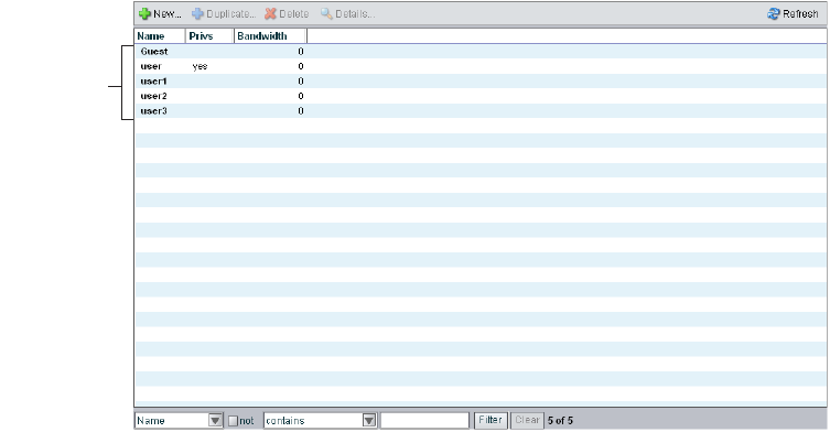
Creating Client Accounts for Users
109
Accessing the Users Dialog Box
To open the Users dialog box:
1. Open the Administration tool. (For information on opening the Administration tool, see
“Opening the Administration Tool” on page 24.)
2. Select Users from the list on the left.
The Users dialog box opens and displays the Users list. The Users list displays the name
and basic information for each user connected to the network.
Several panels display all information for the currently selected user.
To view information about a user:
1. In the Users list, select a user.
2. Do one of the following:
tClick the Details button.
tDouble-click the user name.
Users list
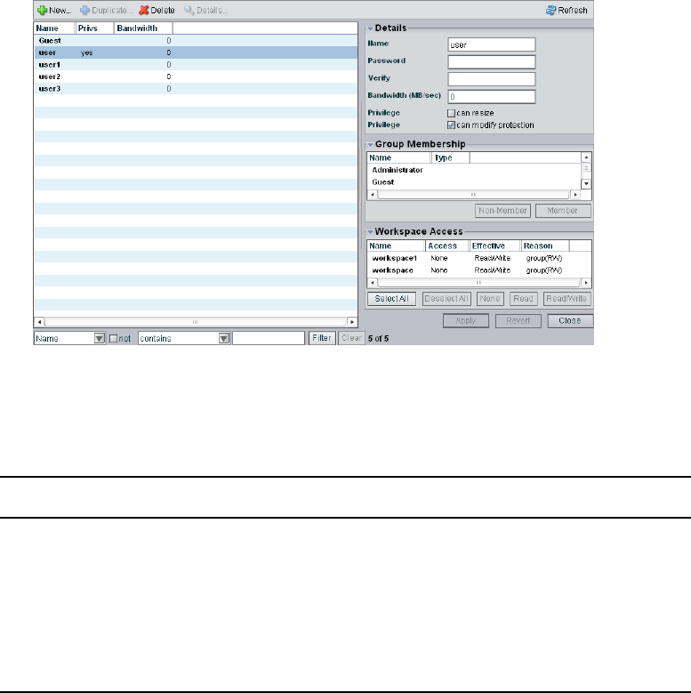
6 Managing Client Accounts and Access Privileges
110
The Details area displays all the information for the selected user.
User Descriptions
The following table summarizes the information available in the Users list.
nYou can sort the information in the Users dialog box by clicking any column heading. For
more information on sorting items in columns, see “Sorting Information” on page 33.
Heading Description
Name Lists the client name
Privs Indicates the status of client privileges
Bandwidth Lists the client’s bandwidth allocation
Setting a bandwidth limit on editing clients, such as an Avid
NewsCutter Adrenaline client, can adversely affect playback performance
when the Avid Unity ISIS system is under load.

Creating Client Accounts for Users
111
The following table summarizes the information available in panels in the Details area.
Panel Heading Description
Details
Name Lists the user name
Password Allows modification of the password used to log in
to the system
Verify Provides verification for the new password
Bandwidth Allows modification of maximum bandwidth
requirements
Setting a bandwidth limit on editing clients, such
as an Avid NewsCutter Adrenaline client, can
adversely affect playback performance when the
Avid Unity ISIS system is under load.
Privilege
can resize Enables or disables user privilege for resizing
workspaces
can modify
protection
Enables or disables user privilege for changing
protection status of workspaces
Group Membership
Name Lists the names of available groups
Type Lists the user’s membership status for each group
(member or nonmember)
Workspace Access
Name Lists the names of available workspaces
Access Lists the access privileges for the selected user
Effective Lists the effective access privileges for the selected
user
Reason Lists the reason for any difference between the
access privileges and the effective access assigned
the selected user
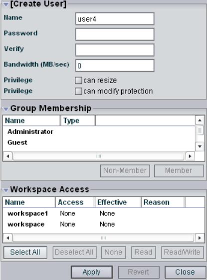
6 Managing Client Accounts and Access Privileges
112
Creating User Accounts
A user is anyone who accesses files stored on the network. User accounts include
administrative privilege levels, group membership types, and workspace access. there can be
more user accounts than connected clients, with a maximum of 1000 user accounts
(including the default Administrator and Guest accounts).
nUsers must have access to at least one workspace before they can use the media network.
To create a user account:
1. Open the Administration tool. (For information on opening the Administration tool, see
“Opening the Administration Tool” on page 24.)
2. Select Users from the list on the left.
3. Click the New button.
The Create User dialog box opens.
Creating Client Accounts for Users
113
4. Type a user name in the Name text box. The following characters are illegal in user
names: \, /, :, *, ?, ", +, <, >, and |.
If there is already a user with the name entered in the Name text box, an error message
tells you to type a new name.
5. Type a password in the Password text box (a maximum of 15 characters).
6. For confirmation, type the password again in the Verify text box.
7. Type a value in the Bandwidth text box to set the amount of read/write bandwidth (in
MB/s) you want to allocate to the user.
8. (Option) Select User Flag options to set user account privileges and status:
- Can resize [workspaces]
- Can modify protection
9. (Option) In the Group Membership list, select a group, and click the Member button to
make the user a member in the group. Users can belong to no more than three groups.
By default, new users are listed as “Nonmember” in the Type category for each group.
As a result, the Nonmember button is inactive until membership is set.
The Group Membership list updates to show the user as a member of the group.
10. (Option) In the Workspace Access list, select a workspace or click the Select All button
to select all workspaces, and do one of the following:
tClick the Read button to set read-only workspace access for the user.
By default, access privileges for new users are listed as “None” in the Access
category for each workspace. As a result, the None button is inactive until access is
set. (For information on permissions for workspace access in the network, see
“Managing Workspace Access Privileges” on page 103.)
tClick the Read/Write button to set both read and write workspace access for the
user.
The Workspace Access list updates to show the user access privileges for the
selected workspace.
11. Click the Apply button.
12. (Option) Repeat steps 5 through 13 to create new users.
13. Click the Close button to close the Create User dialog box and to return to the Users
dialog box.
The new user appears in the Users list.
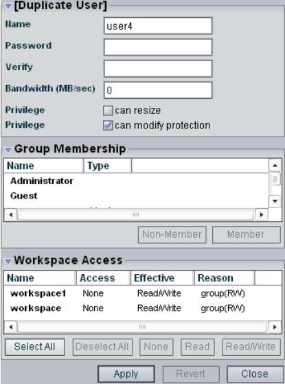
6 Managing Client Accounts and Access Privileges
114
Duplicating Client Accounts
When you duplicate user accounts, they inherit the bandwidth allocation and access
privileges of the accounts from which they were created.
To duplicate a user account:
1. Open the Administration tool. (For information on opening the Administration tool, see
“Opening the Administration Tool” on page 24.)
2. Select Users from the list on the left.
3. In the Users list, select the user account you want to duplicate.
4. Click the Duplicate button.
The Duplicate User dialog box opens.
5. (Option) Modify any of the attributes of the new user. For information on modifying
user accounts, see “Modifying Client Accounts” on page 124.
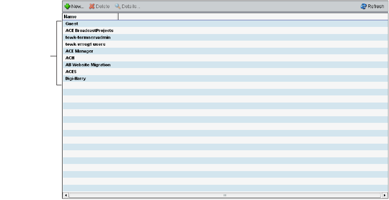
Creating Client Accounts for Groups
115
6. Click the Apply button to create a new user containing the attributes of the selected user.
The duplicate user appears in the Users dialog box, and the Duplicate User dialog box
refreshes to allow you to duplicate a new user.
The new user account has a default name — user n, where n is an integer that is
incremented each time you click the Apply button to create another duplicate user
account.
7. Click the Close button to close the Duplicate User dialog box and to return to the Users
dialog box.
Creating Client Accounts for Groups
Client accounts also allow groups of users to access media stored on your network. These
accounts allow users to mount or map workspaces on their Avid workstations.
Accessing the Groups Dialog Box
To open the Groups dialog box:
1. Open the Administration tool. (For information on opening the Administration tool, see
“Opening the Administration Tool” on page 24.)
2. Select Groups from the list on the left.
The Groups dialog box opens. The Group list displays the name of each group
connected to the network.
Group
list
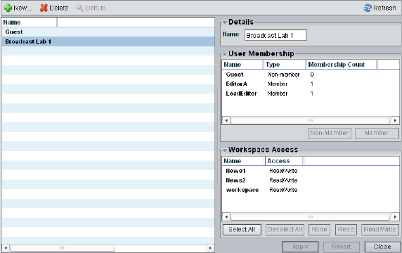
6 Managing Client Accounts and Access Privileges
116
For information on the functions you can perform in the Groups dialog box, see the
following topics:
•Creating User Group Accounts
•Modifying Client Accounts
•Deleting Client Accounts
Viewing Group Descriptions
The Details panels display all information for the currently selected group. You can sort the
information in the User Membership and Workspace Access areas by clicking any column
heading. For more information on sorting items in columns, see “Sorting Information” on
page 33.
To view information about a group:
1. Open the Administration tool. (For information on opening the Administration tool, see
“Opening the Administration Tool” on page 24.)
2. Select Groups from the list on the left.
3. Do one of the following:
tClick the Details button.
tDouble-click the group name.
The Details area displays all the information for the selected user group.

Creating Client Accounts for Groups
117
User Group Descriptions
The following table summarizes the information available in the Details area.
Creating User Group Accounts
To create a group account:
1. Open the Administration tool. (For information on opening the Administration tool, see
“Opening the Administration Tool” on page 24.)
2. Select Groups from the list on the left.
Area Heading Description
Group Details
Name Lists the user group name
User Membership
Name Lists the names of all users
Type Lists the user’s membership status for each user group
(member or nonmember)
Membership Count Lists the number of groups in which each user holds
membership (users can belong to no more than three
groups)
Workspace Access
Name Lists the names of available workspaces
Access Lists the access privileges for the selected user group
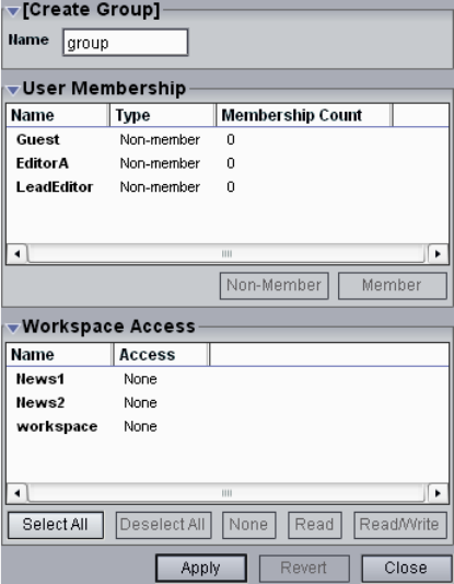
6 Managing Client Accounts and Access Privileges
118
3. Click the New button.
The Create Group dialog box opens.
4. Type a group name in the Name text box. The following characters are illegal in group
names: \, /, :, *, ?, ", +, <, >, and |.
If there is already a group with the name entered in the Name text box, an error message
tells you to type a new name.
5. (Option) In the User Membership list, select a user and click the Member button to make
the user a member in the group. Users can belong to no more than three groups.
By default, new users are listed as “Nonmember” in the Type category for each group.
As a result, the Nonmember button is inactive until membership is set.
Creating Client Accounts for Devices
119
6. (Option) In the Workspace Access list, select a workspace or click the Select All button
to select all workspaces, and do one of the following:
tClick the Read button to set read-only workspace access for the group.
tClick the Read/Write button to set both read and write workspace access for the
group.
By default, access privileges for new groups are listed as “None” in the Access category
for each workspace. As a result, the None button is inactive until access is set. (For
information on permissions for workspace access in the network, see “Changing Access
Privileges” on page 128.)
7. Click the Apply button.
8. (Option) Repeat steps 5 through 8 to create new groups.
9. Click the Close button to close the Create Group dialog box and to return to the Groups
dialog box.
The new group appears in the Groups list.
Creating Client Accounts for Devices
Devices, such as Avid AirSpeed™ recorders, can be assigned their own client accounts.
Users of the devices can then access workspaces on the network.
nIf you deselect the Force Manual Device Creation option in the Preferences dialog box, a
client account is automatically created for each new device when it is first connected to the
media network. For information on preferences, see “Setting System Preferences” on page
129.
Accessing the Device Dialog Box
You can sort the information in the Devices dialog box by clicking any column heading. For
more information on sorting items in columns, see “Sorting Information” on page 33.
To open the Device dialog box:
1. Open the Administration tool. (For information on opening the Administration tool, see
“Opening the Administration Tool” on page 24.)
2. Select Devices from the list on the left.
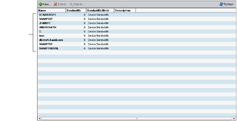
6 Managing Client Accounts and Access Privileges
120
The Devices dialog box opens. The Device list displays basic information about each
device connected to the network.
To view information about a device:
1. Open the Administration tool. (For information on opening the Administration tool, see
“Opening the Administration Tool” on page 24.)
2. Select Devices from the list on the left.
3. Do one of the following:
tClick the Details button.
tDouble-click the device name.
Device
list

Creating Client Accounts for Devices
121
The Details area displays all information for the currently selected device.
For information on the functions you can perform in the Devices dialog box, see the
following topics:
Device List
The following table summarizes the information available in the Device list.
Heading Description
Name Lists the client name
Bandwidth Lists the client’s bandwidth allocation
.You might need to set a bandwidth limit for a device such as an
Avid AirSpeed in the event the device is consuming more bandwidth than
expected.
Bandwidth Mode Lists the mode used to allocate bandwidth
Description Displays the user-supplied device description, if any

6 Managing Client Accounts and Access Privileges
122
Device Descriptions
The following table summarizes the information available in the Details area.
Creating Device Accounts
To create a device account:
1. Open the Administration tool. (For information on opening the Administration tool, see
“Opening the Administration Tool” on page 24.)
2. Select Devices from the list on the left.
Heading Description
Name Lists the device name
Bandwidth Allows modification of bandwidth requirements
nYou might need to set a bandwidth limit for a device such as an
Avid AirSpeed in the event the device is consuming more bandwidth than
expected.
Bandwidth Mode Lists the mode used to allocate bandwidth
Description Displays the user-supplied device description, if any
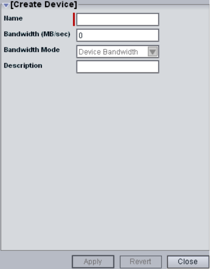
Creating Client Accounts for Devices
123
3. Click the New button.
The Create Device dialog box opens.
4. Type the system name of the device you want to add in the Name text box. The
following characters are illegal in device names: \, /, :, *, ?, ", +, <, >, and |.
If there is already a device with the name entered in the Name text box, an error message
tells you to type a new name.
5. Type a value in the Bandwidth text box to set the amount of read/write bandwidth (in
MB/s) you want to allocate to the device.
6. Click the Bandwidth Mode menu and select a mode for bandwidth allocation, if
available.
7. (Option) Type a description of the device in the Description text box.
8. Click the Apply button.
9. (Option) Repeat steps 5 through 9 to create new devices.
10. Click the Close button to close the Create Device dialog box and to return to the Users
dialog box.
The new device appears in the Users list.
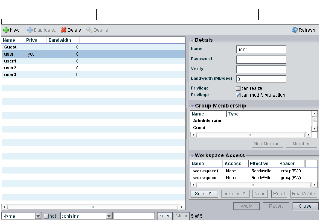
6 Managing Client Accounts and Access Privileges
124
Modifying Client Accounts
You can rename an account, change the password, change the allocated bandwidth, edit
privileges, and change user membership in groups with the client dialog boxes. For example,
you can change user passwords to accommodate a new user, reestablish access for an
existing user who has forgotten the password, or disable access to an account.
You can modify a client account at any time, even when it is being actively used in your
work environment.
To modify a client account:
1. Open the Administration tool. (For information on opening the Administration tool, see
“Opening the Administration Tool” on page 24.)
2. From the list on the left, select one of the following client types:
-Users
- Groups
- Devices
3. Do one of the following:
tClick the Details button.
tDouble-click the client name.
The Details area displays information about the selected client.
Details area
Users list
Modifying Client Accounts
125
4. Click the client account that you want to change.
The client name is highlighted, and the Details area displays the information for the
client.
5. (Option) In the Name text box, type a new client name. The following characters are
illegal in user names: \, /, :, *, ?, ", +, <, >, and |.
If there is already a client with the name entered in the Name text box, an error message
tells you to type a new name.
6. (Option — user accounts only) In the Password text box, type a new password (a
maximum of 15 characters), and then type it again in the Verify text box.
If the password is a duplicate of an existing password, an error message tells you to type
a new password.
7. (Option — user and device accounts only) Type a new value in the Bandwidth text box
to set the amount of read/write bandwidth (in MB/s) you want to allocate to the user.
(System bandwidth limits are listed in the System Details area.)
8. (Option — user accounts only) Select or deselect User Flag options to set user account
privileges and status:
- Can resize [workspaces]
- Can modify protection
9. (Option — device accounts only) In the Description area, edit the description for the
device.
10. (Option — user accounts only) In the Group Membership panel, select a group and do
one of the following (users can belong to no more than three groups):
tClick the Member button to make the user a member in the user group.
tClick the Nonmember button to remove the user from the user group.
11. (Option — user and group accounts only) In the Workspace Access panel, select a
workspace or click the Select All button to select all workspaces, and do one of the
following:
tClick the None button to remove workspace access privileges for the client.
tClick the Read button to set read-only workspace access for the client.
tClick the Read/Write button to set both read and write workspace access for the
client.
For information on permissions for workspace access in the network, see “Managing
Workspace Access Privileges” on page 103 and “Changing Access Privileges” on page
128.
12. (Option) Before you apply your changes, you can use the Revert button to undo any
modifications made to the client information.
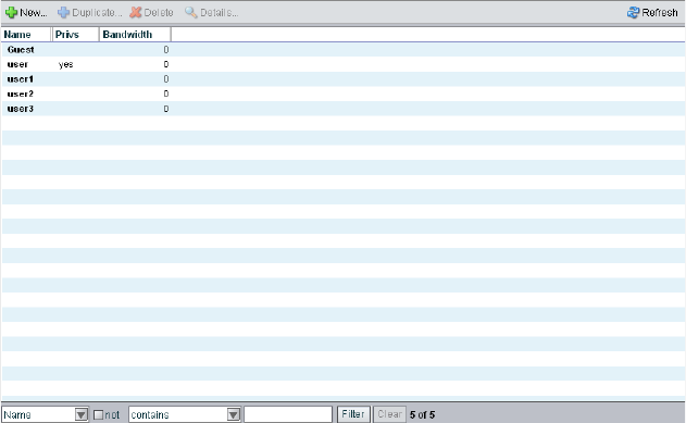
6 Managing Client Accounts and Access Privileges
126
13. Click the Apply button.
A dialog box opens asking you to confirm the action.
Deleting Client Accounts
You can use the Administration tool to delete any client account. If you want to remove the
client from the media network but still maintain the client account, see “Removing Clients
from the Avid Unity ISIS Media Network” on page 127.
cIf you delete the client account, its connection to the System Director is broken
immediately and any mounted workspaces are unmounted as soon as they are
accessed.
To delete a client account:
1. Ensure that the client account to be deleted is not currently active.
2. Open the Administration tool. (For information on opening the Administration tool, see
“Opening the Administration Tool” on page 24.)
3. From the list on the left, select one of the following client types:
-Users
- Groups
- Devices
The client dialog box opens.
4. Select the client account you want to delete.
Modifying Client Accounts
127
5. Click the Delete button.
A dialog box opens, prompting you to confirm that you really want to delete the client.
6. Click OK.
The client dialog box updates to show the client account deleted from the client list.
Removing Clients from the Avid Unity ISIS Media Network
You can remove users and devices temporarily from the network by revoking their
bandwidth allocation. Removing clients does not delete them from the list of clients in the
Users dialog box or the Devices dialog box. This preserves the client accounts and allows
you to return the clients to the system by reallocating bandwidth at a later time.
To remove a client by revoking the assigned bandwidth:
1. Ensure that the client account to be removed is not currently active.
2. Open the Administration tool. (For information on opening the Administration tool, see
“Opening the Administration Tool” on page 24.)
3. From the list on the left, select one of the following client types:
-Users
-Devices
The client dialog box opens.
4. Select the client account you want to remove from the system.
5. Do one of the following:
tClick the Details button.
tDouble-click the client name.
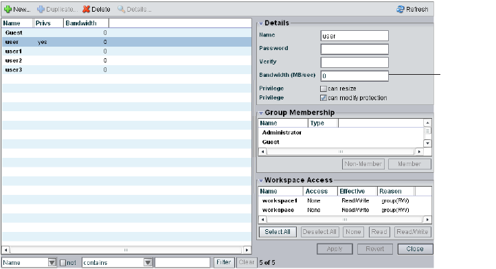
6 Managing Client Accounts and Access Privileges
128
The Details area displays information about the selected client.
6. Set a new value of zero (0) in the Bandwidth text box.
7. (Option) Before you apply your changes, you can use the Revert button to undo any
modifications made to the client information.
8. Click the Apply button.
Changing Access Privileges
You can change access privileges for more than one client at a time. You can also set access
privileges for a group at a more permissive level than originally assigned to an individual
user who is a member of the group. This creates an effective access that differs from the
user’s assigned access. For example, if a user has read access but is a member of a user
group whose access is changed to read/write, the user’s effective access is listed as
read/write.
nMake sure that no client account whose access privileges you intend to downgrade is being
used by a client who currently has workspaces mounted.
You use the Workspaces dialog box to change the workspaces privileges for multiple users
or groups. For information on changing user access in the Workspace dialog box, see
“Setting Workspace Access Privileges” on page 104.
Bandwidth
text box
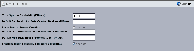
Setting System Preferences
129
Setting System Preferences
The Preferences dialog box allows you to set basic parameters that apply to components
added to the media network. You can also set the total system bandwidth. For more
information on bandwidth functions, see “Managing Client Accounts and Access Privileges”
on page 107.
When you add a component to the media network, you must create an account and set the
bandwidth for the component prior to using it in the network. You can use the Preferences
option to create a device account automatically for all new clients, and you can set the
default bandwidth allocated to the new devices. This provides a quick way to connect new
clients and components to the media network.
To set preferences for new components in the media network:
1. Open the Administration tool. (For information on opening the Administration tool, see
“Opening the Administration Tool” on page 24.)
2. From the list on the left, select Preferences
The Preferences dialog box opens.
3. (Option) Type a number in the Total System Bandwidth text box.
4. (Option) Type a number in the Default Device Bandwidth text box.
5. (Option) Select Enabled to create device options manually for each new device.
6. (Option) Type a number (in milliseconds) in the Default LCT (Long Command Times)
Threshold text box.
7. (Option) Type a number in the Default Hard Disk Error Threshold text box.
8. (Option) Select Enabled to allow failover to a second System Director if the failover
server has more active Network Interface Cards (NICs) than the active System Director.
9. Click the Save Preferences button.
6 Managing Client Accounts and Access Privileges
130
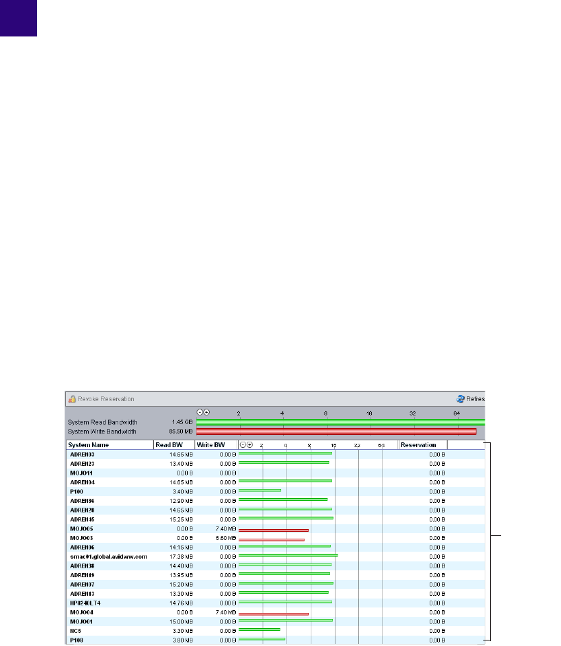
7Monitoring Bandwidth Usage and
System Status
This section describes how to use the Bandwidth Monitor dialog box to monitor bandwidth
usage in the Avid Unity ISIS media network. You can also use the Bandwidth Monitor
dialog box to remove individual components from the network.
For more information, see the following topics:
•Monitoring Client Bandwidth
•Removing Components
•Monitoring System Connection Status
Monitoring Client Bandwidth
The Bandwidth Monitor dialog box allows you to monitor system usage, including total
system bandwidth use and bandwidth consumption of each connected system.
Bandwidth
Monitor list

7 Monitoring Bandwidth Usage and System Status
132
The System Read Bandwidth and System Write Bandwidth rows in the Bandwidth Monitor
dialog box show total system read bandwidth (green bar) and total system write bandwidth
(red bar) in megabytes per second (MB/s).
Below the System Read Bandwidth and System Write Bandwidth rows is a list of all active
system components showing their current activity, their system identification, and the total
bandwidth reserved for all components.
Accessing the Bandwidth Monitor Dialog Box
To access the Bandwidth Monitor dialog box:
1. Open the Administration tool. (For information on opening the Administration tool, see
“Opening the Administration Tool” on page 24.)
2. Select Bandwidth from the list on the left.
The Bandwidth Monitor dialog box opens.
Bandwidth List
The following table describes the information displayed in the Bandwidth Monitor dialog
box.
Heading Description
System Read Bandwidth The value of the total system bandwidth currently in use
for reading files (in MB/s)
System Write Bandwidth The value of the total system bandwidth currently in use
for writing to files (in MB/s)
System Name The name of the system specified during the System
Director configuration
Read BW For the listed system components, the value of the
bandwidth currently in use for reading files (in MB/s)
Write BW For the listed system components, the value of the
bandwidth currently in use for writing to files (in MB/s)

Removing Components
133
nYou can sort the information in the Bandwidth Monitor list by clicking any column heading.
For more information on sorting items in columns, see “Sorting Information” on page 33.
Scaling the Bandwidth List Graph Display
The Bandwidth Monitor list represents bandwidth consumption for the network and for
individual system components in the form of horizontal bars in a graph display. Numeric
divisions are displayed in megabytes/second (MB/s). You can adjust the scale of the graph to
make it easier to monitor bandwidth information.
To decrease or increase the size of the graph view:
tClick the Decrease Size or Increase Size button.
Removing Components
You can use the Bandwidth Monitor dialog box to remove system components from the
network by revoking their bandwidth reservations. Removing components moves them from
active status to inactive status in the list of components in the Connection Status dialog box,
but it does not disconnect them from the network and they remain in the list of components
in the Bandwidth Monitor dialog box. Before the clients of the removed component can
access the network, you must reserve bandwidth for them (see the Avid Unity ISIS Setup
Guide).
To remove a component from the active system list in the media network:
1. Open the Administration tool. (For information on opening the Administration tool, see
“Opening the Administration Tool” on page 24.)
2. Select Bandwidth from the list on the left.
Bandwidth For the listed system components, graphical display of
bandwidth usage:
• Read (green bar)
• Write (red bar)
Reservation For the listed system components, the value of the total
bandwidth reserved for read/write operations (in MB/s)
Heading Description (Continued)
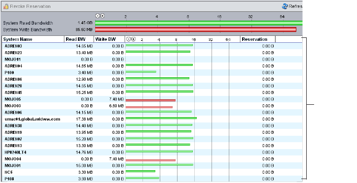
7 Monitoring Bandwidth Usage and System Status
134
The Bandwidth Monitor dialog box opens.
3. Select a component from the Bandwidth Monitor list.
4. Click the Revoke Reservation button.
A confirmation message box opens.
5. Click OK.
The Bandwidth Monitor dialog box updates to show the component removed from the
network.
Monitoring System Connection Status
The Connection Status dialog box allows you to view the status of all components connected
to the network. You can also use the Connection Status dialog box to disconnect components
from the system.
nSome clients might not be able to connect to the media network if the combined bandwidth
requirement of connected components equals the system limit for bandwidth use. For
information on monitoring bandwidth use, see “Monitoring Client Bandwidth” on page 131.
Bandwidth
Monitor list

Monitoring System Connection Status
135
Accessing the Connection Status Dialog Box
To access the Connection Status dialog box:
1. Open the Administration tool. (For information on opening the Administration tool, see
“Opening the Administration Tool” on page 24.)
2. Select Connection Status from the list on the left.
The Connection Status dialog box opens.
Connection Status Information
The Connection Status dialog box lists information about all components — both active and
inactive — that comprise the media network. The following table describes the information
displayed in the dialog box.
Component
list
Heading Description
Name Lists the name of the component
ID Lists an internal numeric identifier used by the System Director to represent the
component; these identifiers are assigned when a component first contacts the System
Director
OS Lists the operating system of the component
Type Lists the category or principal function of the component
License Displays the number of licenses allotted to the component

7 Monitoring Bandwidth Usage and System Status
136
nYou can sort the information in the Connection Status dialog box by clicking any column
heading. For more information on sorting items in columns, see “Sorting Information” on
page 33.
Disconnecting Components from the System
You can use the Connection Status dialog box to disconnect components from the network.
Disconnecting components moves them from active to inactive status in the list of active
components in the Connection Status dialog box. Inactive components display the time of
the last logged contact between the System Director and the components.
nBefore disconnecting a component from the network, you should determine the status of
active clients (for example, you should know if any clients currently have workspaces
mounted on the component you want to disconnect). For information on using the Monitor
tool to determine the status of active clients, see “Avid Unity ISIS System Director Control
Panel” on page 161.
To remove a component from the media network:
1. Open the Administration tool. (For information on opening the Administration tool, see
“Opening the Administration Tool” on page 24.)
2. Select Connection Status from the list on the left.
Last Seen For inactive components, lists the date and time when the component last sent its status
to the System Director; for active components, displays a zero (0) as the default value
The System Director removes information about components that have not been seen
for a week, unless the component’s bandwidth limit is configured to custom values or
the Default Device Bandwidth option in the Preferences dialog box is selected.
Heading Description (Continued)
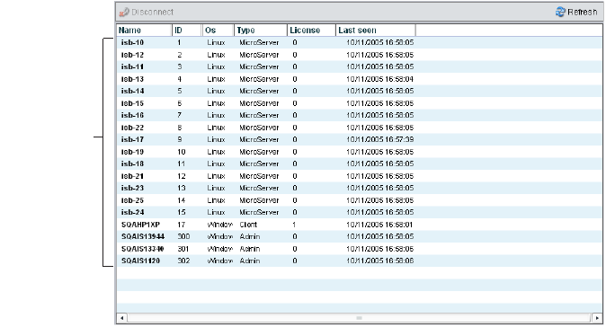
Monitoring System Connection Status
137
The Connection Status dialog box opens.
3. Select a component from the Component list.
4. Click the Disconnect button.
A dialog box opens asking you to confirm the action.
5. Click Yes.
The Connection Status dialog box updates to show the component disconnected from
the network.
Component
list
7 Monitoring Bandwidth Usage and System Status
138

8Configuring Failover Parameters
If properly configured with a redundant System Director, Avid Unity ISIS supports
automatic failover to a standby System Director when the active System Director fails.
Because there is polling over the Ethernet, any lack of response from the active System
Director indicates that it is offline and is not due to a failed connection between the two
System Directors.
nIn a failover configuration, one System Director is assigned to an active role and the other is
assigned to a standby role.
For information on connecting a second System Director to your media network, see the
Avid Unity ISIS Setup Guide.
You can create a failover configuration for the following conditions:
• When you add a System Director to an existing system — see “Adding a System
Director to an Existing File System” on page 139.
• When you set up two new System Directors — see “Creating Failover with Two New
Systems” on page 150.
Adding a System Director to an Existing File
System
Configuring System Director failover when you add a second System Director to your media
network requires the steps outlined in the following sections:
•IP Addresses for Existing and New System Directors
•Setting Up the Failover Connection on the Existing System Director
•Setting Up the Failover Connection on the New System Director
•Validating the Connections Between Existing and New System Directors
•Configuring the Virtual Addresses for Existing and New System Directors
•Creating a New Standby File System
•Starting the Existing and New System Directors

8 Configuring Failover Parameters
140
IP Addresses for Existing and New System Directors
Avid recommends the System Director IP addresses for failover configurations that are listed
in the table below. If you use different addresses, be sure to note them and have them
available before proceeding. You set the IP addresses in the Network Connections dialog
box, which you access from the Windows Control Panel. For information on setting
Windows IP addresses, see the documentation that came with your operating system.
Recommended Failover IP Addresses
Connector Port IP Address Subnet Mask
Existing System Director
Ethernet Connector 1
Onboard Ethernet Port 1 (ETH1) 192.168.1.1 255.255.255.0
Existing System Director
Ethernet Connector 2
Onboard Ethernet Port 2 (ETH2) 192.168.2.1 255.255.255.0
New System Director
Ethernet Connector 1
Onboard Ethernet Port 1 (ETH1) 192.168.1.2 255.255.255.0
New System Director
Ethernet Connector 2
Onboard Ethernet Port 2 (ETH2) 192.168.2.2 255.255.255.0

Adding a System Director to an Existing File System
141
Setting Up the Failover Connection on the Existing System Director
Once you set the IP addresses, you need to configure the failover settings in the
Avid Unity ISIS System Director Control Panel.
To set up the failover connection on the existing System Director:
1. Select Start > Programs > Avid Unity ISIS System Director > System Director Control
Panel.
The Avid Unity ISIS System Director Control Panel opens.
2. Click the System Director Status tab.
3. Click Stop System Director.
The System Director stops.
Stop System Director button
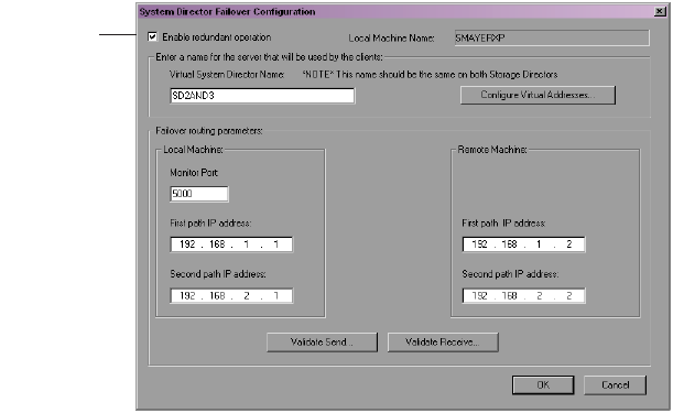
8 Configuring Failover Parameters
142
4. Click the Configuration tab.
The System Director Failover Configuration dialog box opens.
5. In the Configuration area, click Failover Configuration.
The System Director Failover Configuration dialog box opens.
6. Select “Enable redundant operation.”
7. Type a virtual server name in the Virtual System Director Name text box. This name
must be the same for both the existing and the new System Directors.
If you have an Avid Unity MediaManager system attached to the media network and
you add a new System Director to create a failover system, it is important that you
maintain the same server name and virtual name as used previously to maintain database
integrity. For example, if, prior to installation of a new System Director as a failover
server, you set the actual and virtual server name of the existing System Director to
SD2, you should set the virtual server name for the new System Director to SD2 as well.
However, you should use a unique machine name for the new System Director — for
example, SD2SERVER.
Enable
redundant
operations

Adding a System Director to an Existing File System
143
8. In the Local Machine area, leave the Monitor port set to 5000. If you have another
application that uses port 5000, change the Monitor port to an available port number.
This port number must be the same on both the new and the existing System Directors.
9. In the Failover routing parameters area, type IP addresses as described in the following
table:
10. Leave the System Director Control Panel and the System Director Failover
Configuration dialog box open, and continue to the procedure described in “Setting Up
the Failover Connection on the New System Director” on page 144.
Path IP Address
Local Machine — First path IP address 192.168.1.1
Local Machine — Second path IP address 192.168.2.1
Remote Machine — First path IP address 192.168.1.2
Remote Machine — Second path IP address 192.168.2.2

8 Configuring Failover Parameters
144
Setting Up the Failover Connection on the New System Director
To set up the failover connection on the new System Director:
1. Select Start > Programs > Avid Unity ISIS System Director > System Director Control
Panel.
The Avid Unity ISIS System Director Control Panel opens.
2. Click the System Director Status tab.
3. Click Stop System Director.
The System Director stops.
4. Click the Configuration tab.
The System Director Failover Configuration dialog box opens.
Stop System Director button
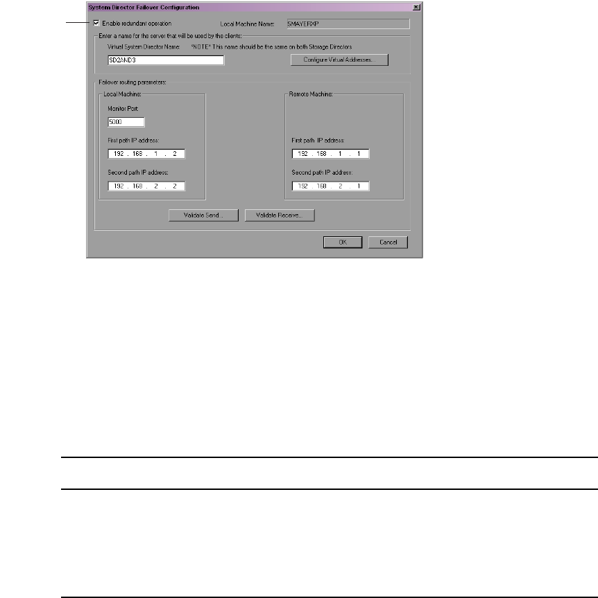
Adding a System Director to an Existing File System
145
5. In the Configuration area, click Failover Configuration.
The System Director Failover Configuration dialog box opens.
6. Select “Enable redundant operation.”
7. Type a virtual server name in the Virtual System Director Name text box. This name
must be the same for both the new and the existing System Directors.
8. In the Local Machine area leave the Monitor port set to 5000. If you have another
application that uses port 5000, change the Monitor port to an available port number.
This port number must be the same on both the existing and the new System Directors.
9. In the Failover routing parameters area, type IP addresses as described in the following
table:
10. Leave the System Director Control Panel and the System Director Failover
Configuration dialog box open, and continue to the procedure described in “Validating
the Connections Between Existing and New System Directors” on page 146.
Enable
redundant
operations
Path IP Address
Local Machine — First path IP address 192.168.1.2
Local Machine — Second path IP address 192.168.2.2
Remote Machine — First path IP address 192.168.1.1
Remote Machine — Second path IP address 192.168.2.1
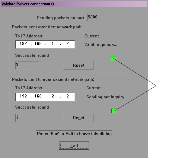
8 Configuring Failover Parameters
146
Validating the Connections Between Existing and New System
Directors
To validate the connections for System Director failover:
1. In the System Director Failover Configuration dialog box on the existing System
Director, click Validate Send.
The Validate failover connection(s) dialog box opens. The indicator boxes turn green for
each connection.
Indicator
boxes

Adding a System Director to an Existing File System
147
2. In the System Director Failover Configuration dialog box on the new System Director,
click Validate Receive.
The Validate failover connection(s) dialog box opens. The numbers in the Packets
Received boxes indicate the number of packets received from the existing System
Director.
If you are receiving packets on only one of the failover network paths, you probably
have a network configuration problem. Recheck your configuration.
3. On each system, click Exit.
4. On each system, leave the System Director Control Panel and the System Director
Failover Configuration dialog box open, and continue to the procedure described in
“Configuring the Virtual Addresses for Existing and New System Directors” on page
148.
Packets
received
boxes

8 Configuring Failover Parameters
148
Configuring the Virtual Addresses for Existing and New System
Directors
You need to configure virtual addresses for both System Directors.
To configure virtual addresses:
1. On both System Directors, click Configure Virtual Addresses.
The Virtual Server Address Configuration dialog box opens.
2. Choose an unused static IP address on the subnets for both systems to be used as the
virtual IP addresses for both System Directors.
3. Map the virtual IP address to the corresponding real IP address on each subnet for each
of the System Directors.
The example below uses the virtual IP addresses of 192.168.10.253 and 192.
168.20.253, and the mapped IP addresses of 192.168.10.100 and 192.168.20.100.
4. Click OK to close the Virtual Server Address Configuration dialog box.
5. Click OK to close the System Director Failover Configuration dialog box.
6. On each system, leave the System Director Control Panel open, and continue to the
procedure described in “Creating a New Standby File System” on page 149.
Adding a System Director to an Existing File System
149
Creating a New Standby File System
Before you start the new System Director, you need to initialize the system by creating a
standby partition on the new System Director’s main drive. This step is necessary in order to
build an Avid Unity ISIS file system that maintains the data on attached storage elements
and system metadata.
To create a standby file system:
tOn the new System Director, click Create New Standby.
A standby partition is created.
Starting the Existing and New System Directors
For more information on stopping and starting System Directors in a failover configuration,
see “Stopping and Starting System Directors During Failover” on page 159.
To start the existing and new System Directors:
1. On the existing System Director, click the Configuration tab.
2. Click Start Server.
3. On the new System Director, click the Configuration tab.
4. Click Start Server.
5. On both systems, click Close to close the System Director Control Panel.

8 Configuring Failover Parameters
150
Creating Failover with Two New Systems
Configuring System Director failover for two new System Directors requires the steps
outlined by the following sections:
•IP Addresses for First and Second System Directors
•Setting Up the Failover Connection on the First System Director
•Setting Up the Failover Connection on the Second System Director
•Validating the Connections Between First and Second System Directors
•Configuring the Virtual Addresses for First and Second System Directors
•Creating a New File System on the System Directors
•Starting the First and Second System Directors
IP Addresses for First and Second System Directors
Avid recommends the System Director IP addresses for failover configurations that are listed
in the table below. If you use different addresses, be sure to note them and have them
available before proceeding. You set the IP addresses in the Network Connections dialog
box, which you access from the Windows Control Panel. For information on setting
Windows IP addresses, see the documentation that came with your operating system.
Recommended Failover IP Addresses
Connector Port IP Address Subnet Mask
First System Director Ethernet
Connector 1
Onboard Ethernet Port 1 (ETH1) 192.168.1.1 255.255.255.0
First System Director Ethernet
Connector 2
Onboard Ethernet Port 2 (ETH2) 192.168.2.1 255.255.255.0
Second System Director
Ethernet Connector 1
Onboard Ethernet Port 1 (ETH1) 192.168.1.2 255.255.255.0
Second System Director
Ethernet Connector 2
Onboard Ethernet Port 2 (ETH2) 192.168.2.2 255.255.255.0

Creating Failover with Two New Systems
151
Setting Up the Failover Connection on the First System Director
Once you set the IP addresses, you need to configure the failover settings in the
Avid Unity ISIS System Director Control Panel.
To set up the failover connection on the existing System Director:
1. Select Start > Programs > Avid Unity ISIS System Director > System Director Control
Panel.
The Avid Unity ISIS System Director Control Panel opens.
2. Click the Configuration tab.
The System Director Failover Configuration dialog box opens.
Stop System Director button

8 Configuring Failover Parameters
152
3. In the Configuration area, click Failover Configuration.
The System Director Failover Configuration dialog box opens.
4. Select “Enable redundant operation.”
5. Type a virtual server name in the Virtual System Director Name text box. This name
must be the same for both the existing and the new System Directors.
6. In the Local Machine area, leave the Monitor port set to 5000. If you have another
application that uses port 5000, change the Monitor port to an available port number.
This port number must be the same on both the first and the second System Directors.
7. In the Failover routing parameters area, type IP addresses as described in the following
table:
8. Leave the System Director Control Panel and the System Director Failover
Configuration dialog box open, and continue to the procedure described in “Setting Up
the Failover Connection on the New System Director” on page 144.
Enable
redundant
operations
Path IP Address
Local Machine — First path IP address 192.168.1.1
Local Machine — Second path IP address 192.168.2.1
Remote Machine — First path IP address 192.168.1.2
Remote Machine — Second path IP address 192.168.2.2
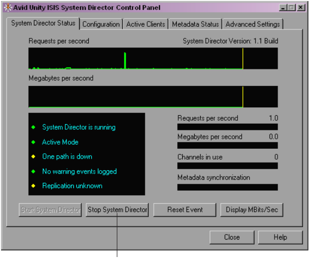
Creating Failover with Two New Systems
153
Setting Up the Failover Connection on the Second System Director
To set up the failover connection on the second System Director:
1. Select Start > Programs > Avid Unity ISIS System Director > System Director Control
Panel.
The Avid Unity ISIS System Director Control Panel opens.
2. Click the Configuration tab.
The System Director Failover Configuration dialog box opens.
Stop System Director button

8 Configuring Failover Parameters
154
3. In the Configuration area, click Failover Configuration.
The System Director Failover Configuration dialog box opens.
4. Select “Enable redundant operation.”
5. Type a virtual server name in the Virtual System Director Name text box. This name
must be the same for both the first and the second System Directors.
6. In the Local Machine area leave the Monitor port set to 5000. If you have another
application that uses port 5000, change the Monitor port to an available port number.
This port number must be the same on both the first and the second System Directors.
7. In the Failover routing parameters area, type IP addresses as described in the following
table:
8. Leave the System Director Control Panel and the System Director Failover
Configuration dialog box open, and continue to the procedure described in “Validating
the Connections Between Existing and New System Directors” on page 146.
Enable
redundant
operations
Path IP Address
Local Machine — First path IP address 192.168.1.2
Local Machine — Second path IP address 192.168.2.2
Remote Machine — First path IP address 192.168.1.1
Remote Machine — Second path IP address 192.168.2.1
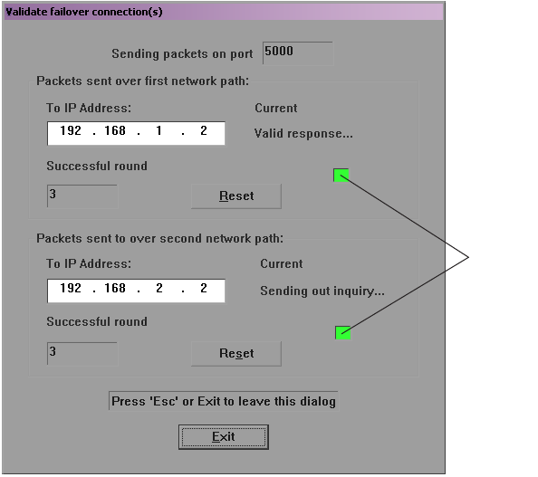
Creating Failover with Two New Systems
155
Validating the Connections Between First and Second System
Directors
To validate the connections for System Director failover:
1. In the System Director Failover Configuration dialog box on the first System Director,
click Validate Send.
The Validate failover connection(s) dialog box opens. The indicator boxes turn green for
each connection.
Indicator
boxes
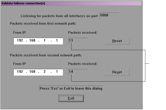
8 Configuring Failover Parameters
156
2. In the System Director Failover Configuration dialog box on the second System
Director, click Validate Receive.
The Validate failover connection(s) dialog box opens. The numbers in the Packets
Received boxes indicate the number of packets received from the first System Director
If you are receiving packets on only one of the failover network paths, you probably
have a network configuration problem. Recheck your configuration.
3. On each system, click Exit.
4. On each system, leave the System Director Control Panel and the System Director
Failover Configuration dialog box open, and continue to the procedure described in
“Configuring the Virtual Addresses for Existing and New System Directors” on page
148.
Packets
received
boxes
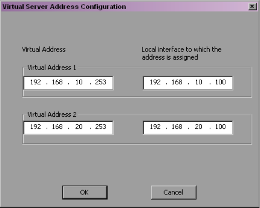
Creating Failover with Two New Systems
157
Configuring the Virtual Addresses for First and Second System
Directors
You need to configure virtual addresses for both System Directors.
To configure virtual addresses:
1. On both System Directors, click Configure Virtual Addresses.
The Virtual Server Address Configuration dialog box opens.
2. Choose an unused static IP address on the subnets for both systems to be used as the
virtual IP addresses for both System Directors.
3. Map the virtual IP address to the corresponding real IP address on each subnet for each
of the System Directors.
The example below uses the virtual IP addresses of 192.168.10.253 and 192.168.20.253,
and the mapped IP addresses of 192.168.10.100 and 192.168.20.100.
4. Click OK to close the Virtual Server Address Configuration dialog box.
5. Click OK to close the System Director Failover Configuration dialog box.
6. On each system, leave the System Director Control Panel open, and continue to the
procedure described in “Creating a New Standby File System” on page 149.
8 Configuring Failover Parameters
158
Creating a New File System on the System Directors
Before you start the System Directors, you need to initialize both systems by creating an
active partition on the first System Director’s main drive and a standby partition on the
second System Director. This step is necessary in order to build an Avid Unity ISIS file
system that maintains the data on attached storage elements and system metadata.
To create an active file system:
tOn the first System Director, click Create New Active.
An active partition is created.
To create a standby file system:
tOn the second System Director, click Create New Standby.
A standby partition is created.
Starting the First and Second System Directors
For more information on stopping and starting System Directors in a failover configuration,
see “Stopping and Starting System Directors During Failover” on page 159.
To start the first and second System Directors:
1. On the first System Director, click the Configuration tab.
2. Click Start Server.
3. On the second System Director, click the Configuration tab.
4. Click Start Server.
5. On both systems, click Close to close the System Director Control Panel.
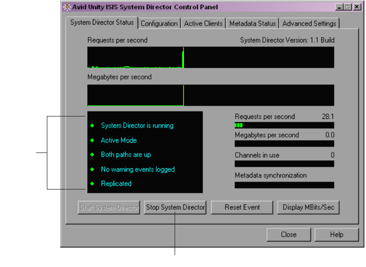
Stopping and Starting System Directors During Failover
159
Stopping and Starting System Directors During
Failover
You might need to stop and start the System Directors during failover at various times. Avid
recommends you stop the standby System Director before stopping the active System
Director.
To determine the active and the standby System Directors:
1. On each system, select Start > Programs > Avid Unity ISIS System Director > System
Director Control Panel.
The Avid Unity ISIS System Director Control Panel opens.
2. Click the System Director Status Tab.
In the status box, the second line indicates either the Active mode or the Standby mode.
Status
box
Stop System Director button
8 Configuring Failover Parameters
160
To stop the System Directors:
1. On the standby System Director, select Start > Programs >
Avid Unity ISIS System Director > System Director Control Panel.
The Avid Unity ISIS System Director Control Panel opens.
2. Click the System Director Status Tab.
3. Click Stop System Director.
4. On the active System Director, select Start > Programs >
Avid Unity ISIS System Director > System Director Control Panel.
The Avid Unity ISIS System Director Control Panel opens.
5. Click the System Director Status Tab.
6. Click Stop System Director.
To start the System Directors:
1. On the active System Director, select Start > Programs >
Avid Unity ISIS System Director > System Director Control Panel.
The Avid Unity ISIS System Director Control Panel opens.
2. Click the System Director Status Tab.
3. Click Start System Director.
4. On the standby System Director, select Start > Programs >
Avid Unity ISIS System Director > System Director Control Panel.
The Avid Unity ISIS System Director Control Panel opens.
5. Click the System Director Status Tab.
6. Click Start System Director.

AAvid Unity ISIS System Director Control
Panel
The Avid Unity ISIS System Director Control Panel is used to start, stop, and monitor the
Avid Unity ISIS System Director, the application running on the System Director server that
manages the overall operation of the network. The Control Panel’s tabs, buttons, and
displays provide information that help debug the media network.
For information on the System Director Control Panel, see the following topics:
•Starting the System Director Control Panel
•System Director Status Tab
•Configuration Tab
•Active Clients Tab
•MetaData Status Tab
•Advanced Settings Tab
Starting the System Director Control Panel
The System Director Control Panel provides low-level, performance-monitoring functions.
Using the Control Panel, you can view the following:
• The current status of connected clients, including name, type, ID number, and active or
inactive status
• The status of communications between the System Director and the clients
• Information on the metadata maintained by the System Director
You can also use the Control Panel to start and stop the System Director service, to configure
general or failover parameters, and to set some administrative options.
You can access the Control Panel only from the System Director.
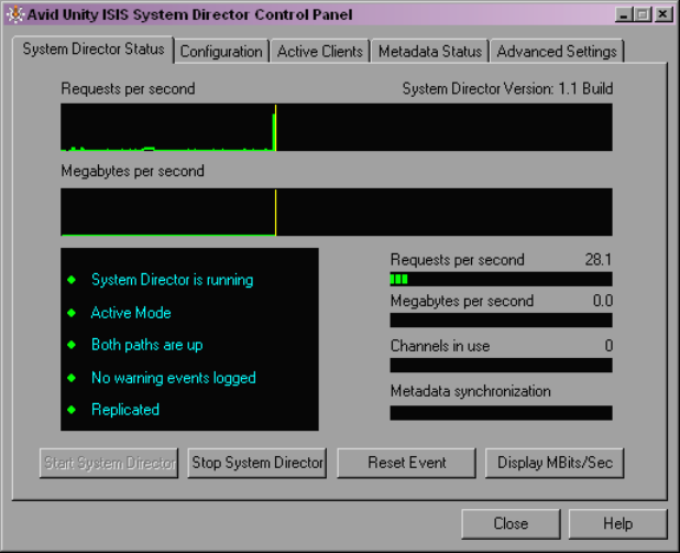
162
To start the Control Panel:
tFrom the System Director desktop, select Start > Programs > Avid Unity ISIS System
Director > System Director Control Panel.
The System Director Control Panel opens.
The Control Panel displays information about the System Director and about the network,
organized by the following tabs:
•System Director Status Tab
•Configuration Tab
•Active Clients Tab
•MetaData Status Tab
•Advanced Settings Tab
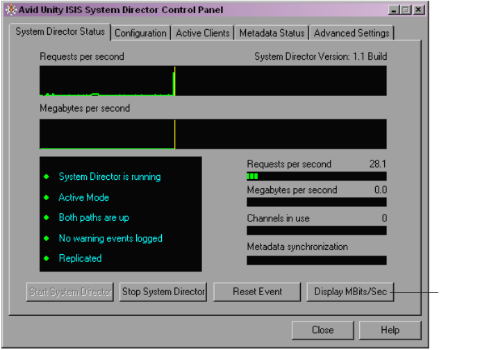
System Director Status Tab
163
System Director Status Tab
The System Director Status tab provides status displays that provide a summary of your
network and controls that allow you to start and stop the System Director, reset the event log,
and change the bandwidth display scale.
Performance Indicators
The System Director Status tab provides several indicators of system activity and
performance. These include:
• Requests per second — current and recent System Director file system activity is
indicated by a small bar-style meter and a larger graph display, respectively.
• Megabytes/Megabits per second — current and recent System Director file system
throughput is indicated by a small bar-style meter and a larger graph display,
respectively.
• Channels in use — currently open files on the System Director file system are indicated
by a small bar-style meter.
Display
MBits/Sec
button
164
To switch the throughput indicators between Mbytes/Sec and Mbits/Sec:
tClick the Display M[Bits][Bytes]/Sec button.
Status Indicators
When no problems are detected in the media network, a green indicator is displayed with the
following messages:
• System Director is running
•Active Mode
• Both paths are up
nIf your network does not use a failover configuration, a blue indicator is displayed next to
the message, “Redundant operation is not enabled.”
• No warning events logged
• Replicated
If the indicator is yellow or red, the message changes. Use the following information to
correct the problem:
• System Director is not running — start the System Director by clicking the Start System
Director button.
• Warning events — logged significant events related to the System Director are also
logged in the Logging tab of the Administration tool. For information on how to extract
data in the system logs, see “System Logging” on page 192.
• The following error messages indicate metadata replication status:
- Replication failed — Indicates that there was an error replicating the metadata to or
from a standby System Director.
- Replication unknown — Indicates that the current replication status has not been
determined.
- Replication status not available — Indicates that the status is unknown. Most likely,
the System Director is not running.
Starting and Stopping the System Director
Make sure that clients unmount all workspaces before you stop the System Director.
Otherwise, when the clients attempt to access the workspaces, they will receive errors.
nBefore the System Director stops, multiple copies of the metadata memory are written to
various locations.

Configuration Tab
165
The Start the System Director:
tPress the Start System Director button.
To Stop the System Director:
tPress the Stop System Director button.
Resetting the Event Log
If the event log was set because of a protection error, the Reset Event button will reset the
event log only after the protected files have been repaired by the System Director.
To reset the event log and the status displays after errors are received from the client:
tPress the Reset Event button.
Configuration Tab
You use the Configuration tab of the System Director Control Panel to start and stop the
System Director, to set general and failover parameters, and to open the System Director
Viewer.
166
For more information, see the following topics:
•“Starting and Stopping the System Director” on page 164
•“Configuring General Settings” on page 167
•“Working with File System Operations” on page 168
•“Opening the System Director Viewer” on page 169
For information on configuring your media network for failover, see “Configuring Failover
Parameters” on page 139.
Starting and Stopping the System Director
The System Director software runs as a Windows service that starts automatically whenever
the System Director is online. However, various maintenance and administration functions
require that you shut down the System Director and then restart it.
Maintaining metadata integrity is very important to ensure you do not lose any data files.
Avid recommends you use the following shutdown procedure to avoid problems with
metadata integrity.
cIn a failover configuration, you must shut down the standby System Director before
shutting down the active System Director whenever you perform operations that
require you to shut down the System Director. Otherwise, the active System Director
fails over to the standby System Director as the active System Director shuts down.
To shut down the System Director:
1. Click the Stop Server button.
A dialog box opens, prompting you to confirm that you really want to stop the System
Director.
2. Click OK.
The System Director Shutdown dialog box opens stating that it is saving multiple copies
of the metadata.
Wait for the process to finish and for the dialog box to close. When the System Director
has shut down, the System Director Status tab lists the System Director status as “Not
running.”
3. Close the System Director Control Panel.
4. Make sure the System Director software has successfully written a local copy of the
metadata file:
- Open the partition where Avid Unity ISIS System Director is installed (typically,
C:\Program Files\ Avid Technology\AvidUnityISISSystemDirector\).
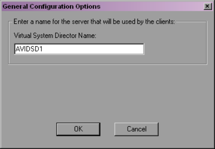
Configuration Tab
167
-Find the PartitionDump.bin file with a modification date from when you stopped
the System Director (if upgrading or modifying the system in any way, copy the
PartitionDump.bin to another partition before you continue).
5. If the PartitionDump.bin file exists with the correct time and date, continue to the next
step.
6. Select Start > Shut Down.
The Shut Down Windows dialog box opens.
7. Select “Shut down.”
8. Click Yes.
9. When the computer has shut down, turn off the power to the System Director.
To restart the System Director after it has been manually shut down or has failed for
any reason:
tClick the Start Server button.
Configuring General Settings
General configuration settings allow you to change the name of the virtual System Director.
cInappropriate configuration of the settings described in this section could result in
degraded system performance. Contact Avid Customer Support before attempting to
change General Configuration Options.
To change the virtual System Director name:
1. Click the General Configuration button.
The General Configuration Options dialog box opens.
168
2. Type a name for the System Director in the Virtual System Director Name text box.
Give the System Director a name that is different from the Computer Name defined in
the system’s network properties.
In a failover configuration, you must specify the same virtual System Director name for
both System Directors.
3. Click OK.
Working with File System Operations
The Major File System Operations area of the Control Panel allows you to create active and
standby partitions, as well as to reconfigure existing file systems. You can also use the
Control Panel to delete file systems.
cDeleting the file system erases all data stored on the System Director.
For information on creating an active partition, see “Initializing the Avid Unity ISIS System
Director” on page 17. For information on creating a standby partition, see “Creating a New
Standby File System” on page 149.
You can reconfigure the internal memory configuration of the System Director — for
example, if you want to adjust the memory usage to take advantage of expanded memory
capabilities. Reconfiguring the file system entails the following:
• Validating the export file
• Creating new metadata
• Importing the metadata
To reconfigure the file system:
1. Click the Stop Server button.
A dialog box opens, prompting you to confirm that you want to stop the System
Director.
2. Click OK.
The System Director Shutdown dialog box opens stating that it is saving multiple copies
of the metadata.
3. Click the Reconfigure File System button.
A dialog box opens, prompting you to confirm that you want to reconfigure the existing
file system.
4. Click OK.
The system reconfigures its metadata and restarts the System Director.
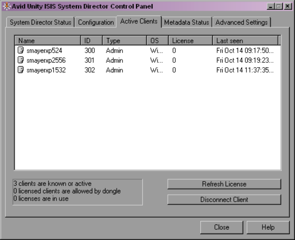
Active Clients Tab
169
Opening the System Director Viewer
Installed on the System Director, the System Director Viewer is a valuable tool that allows
you to view the System Director log as it is buffered in memory. This log provides detailed
status information that is especially useful to Avid Customer Support personnel for
monitoring system status during prolonged operations.
nYou can also open the System Director Viewer by clicking
Start > Programs > Avid Unity ISIS System Director > System Director Viewer.
To open the System Director Viewer:
tIn the Tools area of the Configuration tab, click Launch Viewer.
Active Clients Tab
The Active Clients tab is used to display the identity of the Avid Unity ISIS clients known to
the System Director. The information listed in this tab can be used to determine if obsolete
numeric identifiers exist in the System Director.
The Active Clients tab displays all active storage elements as well as connected client
accounts. You can use the Bandwidth dialog box in the Administration tool to view only the
active client accounts (see “Monitoring Bandwidth Usage and System Status” on page 131.

170
The System Director reports the current client status as described in the following table.
The box below the active clients list provides the following information:
•n clients are known or active — indicates the number of clients currently active or seen
by the System Director
•n licensed clients are allowed by dongle— indicates the number of clients licensed by
the application key (dongle)
•n licenses are in use — indicates the number of licenses are being used by the clients
currently connected to the media network
If a client fails without unmounting all workspaces, the System Director maintains the
numeric identifiers. Typically, this is not a problem because the same identifier is reused
when that client mounts a workspace the next time. However, it is possible for a client to
leave a workspace mounted, shut down the client system, and never be seen by the System
Director again. If that client system is then physically removed or renamed, the numeric
identifiers would not be removed from the identification table. If enough obsolete entries
were to accumulate, new clients might not be able to obtain numeric identifiers.
To check the license status of an active or an inactive client:
tSelect the client in the active client list, and press the Refresh License button.
To disconnect an active or an inactive client:
tSelect the client in the active client list, and press the Disconnect Client button.
Heading Description
Name Lists the name of the client.
ID Lists an internal numeric identifier used by the System Director to represent each client
that has a workspace mounted. These identifiers are assigned when a client first contacts
the System Director and remain valid until the client unmounts all workspaces.
Type Lists the client type (Macintosh or Windows).
OS Lists the operating system on the client.
License Lists the number of licenses registered to the client.
Last seen Lists the date and time when each client last sent its status to the System Director. The
System Director removes the entry when all workspaces are unmounted from the client
desktop.
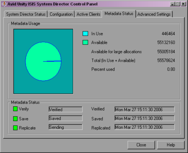
MetaData Status Tab
171
MetaData Status Tab
The MetaData Status tab displays information about the System Director’s internal
description of the file system. This metadata memory is used to record descriptions of
workspaces, folders, and files.
The metadata information includes:
• Total amount of memory in use
• Total amount of memory available
MetaData is saved to different drives in the storage element every 20 seconds. If the
metadata ever needs to be recovered, the last saved version is retrieved automatically by the
System Director. If that is the storage element that has failed, then the previous saved version
is retrieved from another storage element.
The Metadata Status box shows when the metadata was last verified, saved, and replicated.
A green indicator means no problem has been detected. A yellow indicator means the status
is uncertain. A red indicator means that a problem exists.
nMetadata memory is also saved automatically when you stop the System Director.

172
The following tables lists the status messages displayed in the Metadata Status box.
Advanced Settings Tab
The Advanced Settings tab allows you to reset the System Director administrator's password
in the event that the administrator’s password is forgotten. This feature does not affect the
Windows operating system password. Windows administrator’s privileges are required to
reset the password.
You can also use the Advanced Settings tab to write all metadata information to a text file.
Status Category Messages
Verify
When the System Director is in standby mode, the Verify indicator is
disabled.
Not Active
Verified
Verify Failed
State Unknown
Save Saving
Saved
Unknown State
Not Active
Save Failed
Replicate
When the System Director is not in a failover configuration, the Replicate
indicator is disabled.
Sending
Receiving
Unknown State
Not Active
Replication Failed
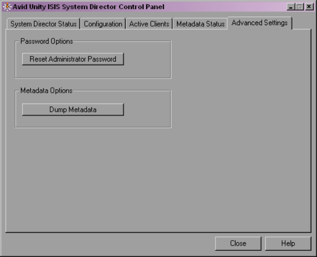
Advanced Settings Tab
173
cWhen you write metadata to a file, the resulting file is extremely large and the time
required to create the file is significant. Do not use this option unless instructed to do so
by Avid Customer Support.
nYou can change the administrator’s password in the Administration tool. For information on
setting a new password, see “Modifying Client Accounts” on page 124.
To reset the administrator’s password:
1. Click Reset Administrator Password.
A dialog box warns you that this action removes the administrator’s password from the
System Director’s account.
2. Click OK.
To write the contents of metadata to a text file in the System Director directory:
tClick Dump Metadata. This should be used only as a diagnostic aid. The resulting file is
extremely large, and the time required to create the file is significant.
174

BAdvanced Support Tools
This appendix lists the advanced support tools available for troubleshooting your network.
cDo not use these tools unless instructed to do so by Avid Customer Support. Improper
use could result in system downtime or data loss.
For more information about the Administration support tools, see the following topics:
•System Administration Tools
•System Statistics
•System Logging
•Avid Unity ISIS Log Aggregator Tool
•Avid Unity ISIS Disk Tester Tool
•Avid Unity ISB Connection Analyzer Tool
•Avid Unity ISIS Switch Manager Tool
•General Tools
•Installers
•Avid Unity ISIS Agents
System Administration Tools
The System tab in the Administration tool opens the System window, which allows you to
set some administrative defaults and view event information for your network. You can
perform the following functions in the System window:
• Change the administration password
• Set up e-mail notification of system events
• Start or stop the Interplay Health Monitoring service
• View the log of the Administration tool
• Use The ISIS Snapshot tool to collect information currently displayed by the
Administration tool and the Avid Unity ISIS System Director Control Panel
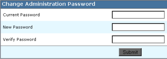
176
• Create and view profiles of the local system and any client attached to the System
Director
To access the system administration functions:
1. Open the Administration tool (see “Opening the Administration Tool” on page 24).
2. Click the System tab.
The System window opens, displaying general information on the status of the System
Director.
Changing the Administration Password
The System window allows you to change the password used by the administrator to access
the Administration tool (see “Opening the Administration Tool” on page 24). The
administrator password allows you to log in to the Administration tool and Avid Unity ISIS
Agents for bound storage elements. You use a chassis stack password to access Avid Unity
ISIS Agents for unbound storage elements and chassis switches. For information on the
Agents, see “Avid Unity ISIS Agents” on page 208.
cTo protect your configuration, Avid recommends that you specify a password the first
time you use the Administration tool. If you do not set a password, anyone can access
the tool from your system.
To change the administration password:
1. Open the Administration tool. (For information on opening the Administration tool, see
“Opening the Administration Tool” on page 24.)
2. Click the System tab.
The System window opens.
3. Select System Director > Change Password.
The Change Administration Password dialog box opens.
4. In the Current Password text box, type the old password.
System Administration Tools
177
5. In the New Password text box, type the new password (a maximum of 15 characters),
and then type it again in the Verify Password text box.
6. Click Change to save the new password.
Setting up Error Notification
You can configure the System Director software to notify you when problems occur. An
error notification service regularly polls the client log file and, if any errors are logged, sends
a concise summary of those errors to one or more e-mail accounts.
The Notification Service Control Panel displays the current status of the notification service,
and allows you to start and stop the service. You can also test the e-mail notification service
(see “Setting Up E-mail Error Notification Contacts” on page 179).
For a full list of error messages, see “Avid Unity ISIS E-mail Notification List” on page 251.
To stop or start the notification service:
tClick the Stop or the Start button.
The Status line indicates the service is either stopped or running.
For more information on e-mail error notification, see the following topics:
•Configuring the E-mail Error Notification Service
•Setting Up E-mail Error Notification Contacts
Configuring the E-mail Error Notification Service
The configuration information for the notification service (SMTP information, contacts, and
filters) is currently stored in the registry on the System Director. This information is not
currently replicated to the failover server, so you need to enter configuration information for
notification service on both System Directors.
To configure the e-mail error notification service:
1. Open the Administration tool. (For information on opening the Administration tool, see
“Opening the Administration Tool” on page 24.)
2. Click the System tab.
The System window opens.
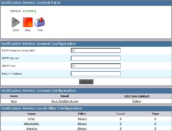
178
3. Select System Director > Notification Service.
The Notification Service Control Panel opens.
4. In the Notification Service General Configuration area, configure the parameters as
follows:
- Poll Frequency (seconds) — Specify the frequency (by setting an interval in
seconds) with which the error notification service checks for problems.
- SMTP Server — Specify the IP address or host name of your SMTP server. If you
are unsure of this address, contact your network administrator.
- SMTP Port — Specify the port number of your SMTP server. If you are unsure of
the port number, contact your network administrator. The default value (25) is
appropriate in most instances.
- Return Address — Type the e-mail address of your Avid Unity ISIS administrator
or other primary contact for the error notification service.
5. Click Update.
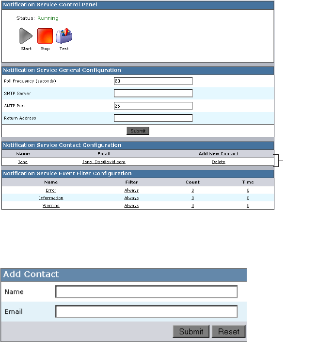
System Administration Tools
179
Setting Up E-mail Error Notification Contacts
You can add to, edit, and delete your Administration tool e-mail notification list.
To add an e-mail account to the Contact list:
1. Open the Administration tool (see “Opening the Administration Tool” on page 24).
2. Click the System tab.
The System window opens.
3. Select System Director > Notification Service.
The Notification Service Control Panel opens.
4. In the Notification Service Contact Configuration area, click Add New Contact.
The Add Contact dialog box opens.
5. In the Name text box, type a name for the contact account.
Contacts list
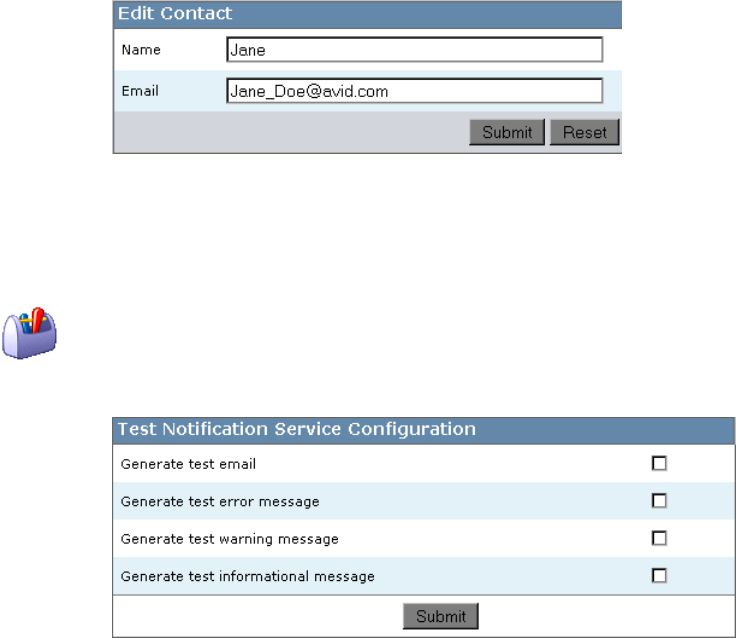
180
6. In the E-mail text box, type the e-mail address (in the standard person@domain.com
format) to which the message should be sent. You can use the Reset button to clear the
text fields and return to the Notification Service Control Panel.
7. Click the Submit button.
The Add Contact dialog box closes and the contact information is added to the Contacts
list.
8. (Option) Repeat steps 4 to 7 to add more contacts.
To edit an existing contact:
1. Click any of the fields in the Contact list for the contact you want to edit.
The Edit Contact dialog box opens.
2. Change the Name and E-mail address information.
3. Click Submit.
The changes are applied.
To test the contact configuration:
1. Click the Test button.
The Test Notification Service Configuration text box opens.
System Administration Tools
181
2. Select the following options, as needed:
- Generate test e-mail
- Generate test error message
- Generate test warning message
- Generate test informational message
3. Click Submit.
The SMTP Session Transcript window opens and displays the results of the test.
To remove a contact:
1. Click Delete next to the contact you want to remove from the Contact list.
A dialog box opens, prompting you to confirm that you really want to delete the contact.
2. Click OK.
The contact is removed from the list.
Configuring the Error Notification Parameters
The Events area of the Event Notification Configuration dialog box allows you to specify the
type of error message that triggers an e-mail notification and to set parameters for each type
of error message — Error, Information, and Warning messages.
You can set the Filter category to one of the following:
•Always — always filters messages, so contacts listed in the Contacts area are not
notified when the Event Notification Service logs an error
•Threshold — notifies the contacts listed in the Contacts area when errors exceed the
threshold limits set in the Count and Time columns
•Never — never filters messages, so contacts listed in the Contacts area are notified when
the Event Notification Service logs any Error, Information, or Warning message
Starting and Stopping the ISIS Interplay Health Monitoring Service
The ISIS Interplay Health Monitoring Service allows you to view the health of the Avid
workgroup network at a glance using the Avid Interplay Health Monitor.
The Avid Interplay workgroup environment uses asset management applications to access
and organize media assets stored in the Avid Unity ISIS system. Interplay utilizes the media
assets within the Avid Unity ISIS media network.
182
The Health Monitor displays a variety of information provided by each of the registered
Avid components on your media network and notifies you with a warning or critical
indication if a component goes beyond its normal operating range. Different Avid services
can supply custom health information to the monitor tailored to their specific functionality.
If your media network has a failover configuration, you must enable the Health Monitoring
Service on both the active System Director and the standby System Director.
For more information on the Avid Interplay Health Monitor, see the Avid Interplay
Framework User’s Guide.
To start or to stop the Health Monitoring Service:
1. Open the Administration tool (see “Opening the Administration Tool” on page 24).
2. Click the System tab.
The System window opens.
3. Select System Director > Interplay Health Monitoring.
The Interplay Health Monitoring Status dialog box opens.
4. Select or deselect Enable the ISIS Interplay Health Monitoring Service.
5. Type the name of the workgroup your system is configured to monitor in the Interplay
Workgroup Name text box.
6. Click Submit.
The service starts or stops, depending on the current status.
To start the Health Monitoring Service in a failover configuration:
1. On the active System Director, open the Administration tool, and click the System tab.
The System window opens.
2. Select System Director > Interplay Health Monitoring.
The Interplay Health Monitoring Status dialog box opens.
3. Select Enable the ISIS Interplay Health Monitoring Service.
4. Type the name of the workgroup your system is configured to monitor in the Interplay
Workgroup Name text box.
5. Click Submit.
The service starts on the active System Director.
6. From the active System Director desktop, select Start > Programs > Avid Unity ISIS
System Director > System Director Control Panel.
The System Director Control Panel opens.
System Administration Tools
183
7. Click the System Director Status tab, and press the Stop System Director button.
The active System Director stops, and the standby System Director becomes active.
8. On the newly-active System Director desktop, repeat steps 1 through 5.
9. (Option) If you want to return the failover configuration to its original state, repeat steps
6 and 7 to return the System Directors to their original status.
Viewing the Administration Tool Log
You can view the log of the Administration tool from the System tab of the tool. The log lists
the actions reported by the Administration tool, including informational messages (such as
when upgrades occur), errors, and warnings. You can sort the log entries by column or
filtered. The log lists the following data for each event:
•Type — The categories are the following: Info, Error, Warning
•Time — The time of the logged event
•IP — The IP address of the System Director
•User — The ISIS user who initiated the event
•Message — Detailed information about the event
To view the Administration tool log:
1. Open the Administration tool (see “Opening the Administration Tool” on page 24).
2. Click the System tab.
The System window opens.
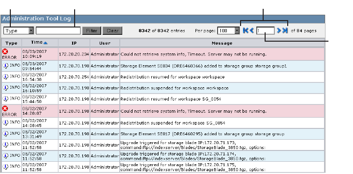
184
3. Select System Director > View Administration Log.
The Administration Tool log dialog box opens.
4. (Option) To filter the log entries, do the following:
a. Click the Filter menu and select the category you want to filter — Type, Time, IP,
User, or Message.
b. In the Filter text box, type the appropriate keyword(s).
c. Click Filter. To view all log entries, click Show All.
5. (Option) If you want to view a smaller or larger number of log entries, type a number in
the View text box and click Enter. The default number of log entries displayed is 500.
6. If the log contains more entries than it displays, use the Navigation controls to move
through the log.
The Avid Unity ISIS Snapshot Tool
The ISIS Snapshot tool collects information currently displayed by the Administration tool
and the Avid Unity ISIS System Director Control Panel and allows you to view and archive
the information. This snapshot of your ISIS system at a single point in time, coupled with
the system logs collected by the Log Aggregator tool (see “Avid Unity ISIS Log Aggregator
Tool” on page 196), can be used by Avid Customer Support personnel to diagnose and
troubleshoot problems.
Filter menu Filter text box
View
text
box
Navigation controls

System Administration Tools
185
The Snapshot tool collects information from the following pages, dialog boxes, and tabs of
the Administration tool and the Control Panel:
Creating, Viewing, and Deleting Snapshots
You use the Avid Unity ISIS Snapshot tool to create a detailed view of your system at a
particular time. The snapshot is saved as a series of CSV files, one for each component in the
system, and a summary file in HTML format. Snapshot files are saved in folder named by
the timestamp of the snapshot and the System Director name — for example,
07-17-07 101321 SD1 — at the following location within the application directory:
AvidUnityISIS\webroot\mm-dd-yy hhmmss SystemDirectorName
You can also download the snapshot in compressed form as a ZIP file by clicking the
Download link.
Category Description
General Info Includes the System Director computer name and virtual name, the
snapshot run date, and a link to the compressed snapshot file
ISIS Components Lists the ISIS components from the Command menu of the
Administration tool, any warnings or errors logged, and a link to a
comma separated value (CSV) file for each component containing the
information displayed in the Details area of each component page; you
can open the CSV file with an appropriate text editing application
Warnings and Errors Lists all warnings and errors currently logged for all components in the
ISIS system (warnings and errors are indicated by action markers in the
Administration tool (for more information, see “Command Menu” on
page 27)
System Director Status Summarizes the information on the System Director Status tab of the
System Director Control Panel (for more information, see “System
Director Status Tab” on page 163)
System Director Metadata Summarizes the information on the Metadata Status tab of the System
Director Control Panel (for more information, see “MetaData Status
Tab” on page 171)
Failover Settings Summarizes the information on the System Director Failover
Configuration dialog box of the System Director Control Panel (for
more information, see “Configuring Failover Parameters” on page 139)
Preferences Summarizes the information on the Preferences dialog box, accessed
from the Administration tool (for more information, see “Setting
System Preferences” on page 129)
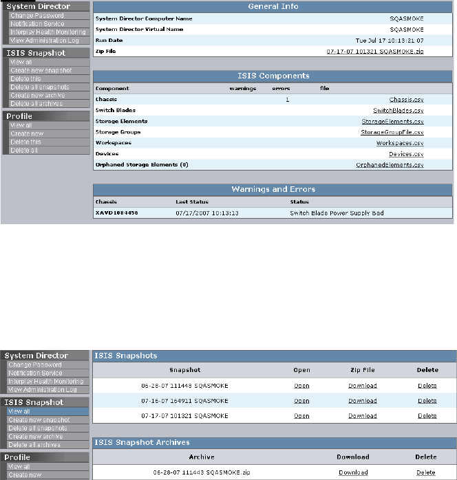
186
To create a snapshot of the ISIS system:
1. Open the Administration tool (see “Opening the Administration Tool” on page 24).
2. Click the System tab.
The System window opens.
3. Select ISIS Snapshot > Create new snapshot.
The Snapshot tool creates a snapshot and displays the information in the System
window.
To view a list of all current and archived snapshots, do the following:
tSelect ISIS Snapshot > View All. There must be at least one current snapshot for this
option to display in the Command menu.
The Snapshot tool displays a list of all of the saved and archived snapshots.
System Administration Tools
187
To delete the current snapshot:
1. Do one of the following:
tIf the snapshot you want to delete is displayed in the System window, select ISIS
Snapshot >Delete this.
tIf the snapshot you want to delete is not displayed, select ISIS Snapshot > View all,
locate the snapshot you want to delete, and then click Delete.
2. Click OK to confirm the deletion.
The Snapshot tool deletes the selected snapshot.
To delete all snapshots:
1. Select ISIS Snapshot > Delete all snapshots.
2. Click OK to confirm the deletion.
The Snapshot tool deletes all snapshots listed in the System window.
Working with Snapshot Archives
When the Snapshot tool creates a snapshot, it creates a folder which includes a compressed
file containing all information collected by the tool. You can combine snapshots into an
archive to keep track of the system status — for example, you could archive snapshots
weekly or monthly. The Snapshot tool compresses archives in a ZIP file (archivename.zip).
Archives are stored in folders named by the timestamp of the snapshot and the System
Director name — for example, 07-17-07 101321 SD1. The compressed archive uses the
same file name format as the snapshot folder and is saved to the following location within
the application directory:
AvidUnityISIS\webroot\mm-dd-yy hhmmss SystemDirectorName
You can also download the archive in compressed form as a ZIP file by clicking the
Download link.
To create a snapshot archive:
1. Open the Administration tool (see “Opening the Administration Tool” on page 24).
2. Click the System tab.
The System window opens.
3. Select ISIS Snapshot > Create new archive.
4. Click OK to confirm building a new archive from all current snapshots.
The Snapshot tool creates an archive and lists it in the System window.
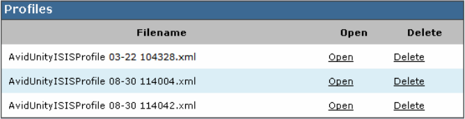
188
To delete a snapshot archive:
1. Select ISIS Snapshot > View all.
2. Locate the archive you want to delete, and then click Delete.
3. Click OK to confirm the deletion.
The Snapshot tool deletes the selected archive.
To delete all archive:
1. Select ISIS Snapshot > Delete all archives.
2. Click OK to confirm the deletion.
The Snapshot tool deletes all archives listed in the System window.
Using the Profile Tool
The Profile tool detects the current versions of required software, drivers, and hardware
components that are installed on a System Director. You can view, save, or delete profiles,
but you cannot use the Profile tool to edit or modify the information.
Profiles are typically used by Avid Customer Support to help determine problems with
installed versions of the operating system, drivers, adapter boards, or firmware.
To view profiles of the local system:
1. Open the Administration tool (see “Opening the Administration Tool” on page 24).
2. Click the System tab.
The System window opens.
3. Select Profile > View all.
The Profiles dialog box opens.
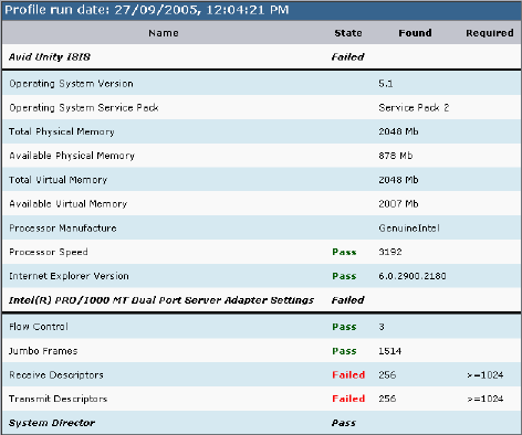
System Administration Tools
189
4. Click Open in the row containing the profile you want to view.
The profile displays in the Profiles window.
To create a new profile:
1. Open the Administration tool. (For information on opening the Administration tool, see
“Opening the Administration Tool” on page 24.)
2. Click the System tab.
The System window opens.
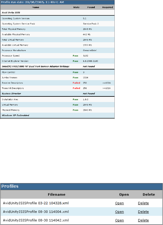
190
3. Select Profile > Create new.
The new profile displays in the Profiles window.
To delete a profile from the Profile window:
1. Open the Administration tool (see “Opening the Administration Tool” on page 24).
2. Click the System tab.
The System window opens.
3. Select Profile > View all.
The Profiles dialog box opens.

System Statistics
191
4. Click Delete in the row containing the profile you want to view. You can also delete the
current profile displayed in the Profile window by selecting Delete All from the Profile
list on the left.
A dialog box opens, prompting you to confirm that you really want to delete the profile.
5. Click OK.
System Statistics
You can use the Statistics window to view basic information about your system and your
network. You cannot edit the information displayed in the Statistics window.
The following table describes the information available in the Statistics window:
Type Heading Description
General System Information Lists the basic properties of the system running the System
Director software.
Memory Information Lists statistics about system memory.
Running Processes Lists the processes currently running on the local system.
Network Lists detailed information about network communication.
Agent Agent Environment Lists information about the connection between the agent and
the System Director.
Agent Statistics Lists information about the communication between the
agent and the System Director.
Agent Configuration Lists the parameter values for agent/server communication.
Browser Details Lists details about the connected browser
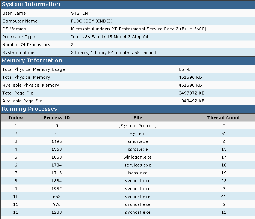
192
To access statistical information about your system:
1. Open the Administration tool (see “Opening the Administration Tool” on page 24).
2. Click the Statistics tab.
The Statistics window opens.
3. Select one of the following from the Local System menu:
- General
-Network
- Agent
System Logging
The Logging tab provides a complete view of the logs of a network, including active storage
elements, System Directors, and clients. You can filter the log reports to display messages
about the network, the Avid Unity ISIS file system, or security information. This provides
you with system snapshot that you can use to view error and status messages. The logs
provide detailed status information that is especially useful to Avid Customer Support
personnel for monitoring system status during prolonged operations.

System Logging
193
For more information on the Logging tab, see the following topics:
•“Using System Logging” on page 193
•“Accessing the Logging Window” on page 194
•“Viewing Event Logs” on page 194
•“Clearing Event Logs” on page 195
Using System Logging
The Logging window contains two sections:
• System area — the left area allows you to select specific logging options to display.
• Logs area — the right area displays different types of events and information from the
Avid Unity ISIS components.
System logging allows you to select the events to view by restricting the logs to the
following categories:
•System — Displays events associated with system configuration
•Application — Displays events associated with the functioning of the System Director
software
•Security — Displays events related to security in the network
Logs area
System area
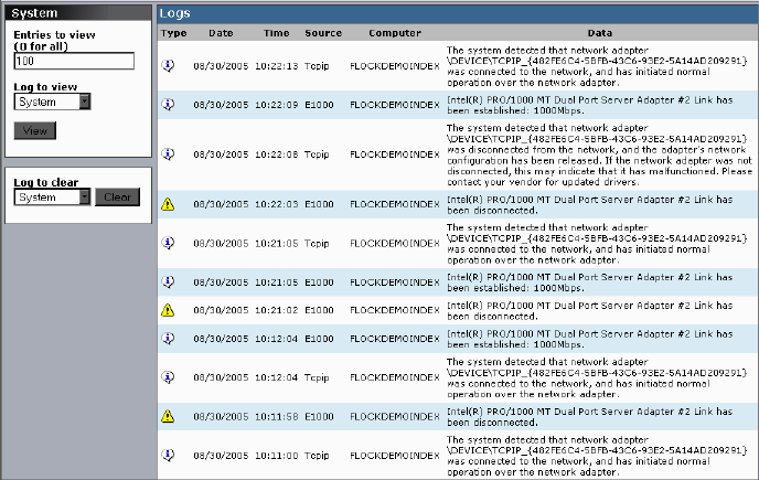
194
Accessing the Logging Window
You can use the Logging window to view event logs and to clear existing logs.
To access System Logging functions:
1. Open the Administration tool (see “Opening the Administration Tool” on page 24).
2. Click the Logging tab.
The Logging window opens.
Viewing Event Logs
To view event logs:
1. Open the Administration tool (see “Opening the Administration Tool” on page 24).
2. Click the Logging tab.
The Logging window opens.
3. In the Entries to view text box, type the number of events to display. The default is 100.
If you want to view all events, type “0” (zero) in the Entries to view text box.
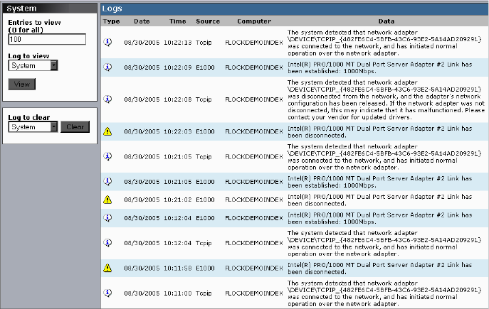
System Logging
195
4. Click the Log to view menu, and select one of the following:
-System
- Application
-Security
5. Click View.
The event log displays in the Logs area.
Clearing Event Logs
You can clear the logs in any of the logging categories. This empties the log of all event
entries and resets the logging process.
To clear logs:
1. Open the Administration tool (see “Opening the Administration Tool” on page 24).
2. Click the Logging tab.
The Logging window opens.
196
3. Click the Log to clear menu, and select one of the following:
-System
- Application
-Security
4. Click the Clear button.
5. Click OK.
The event log for the selected category is cleared, and logging is reset to start recording
new events.
Avid Unity ISIS Log Aggregator Tool
The Avid Unity ISIS Log Aggregator tool allows you to collect a full set of the event logs
and system statistics of a network, including active storage elements, Avid Unity ISIS switch
blades, and the System Director. You can select which information — from the network, the
System Director software, storage elements, and switches — you want to collect in the log
reports. This provides you with a system record that you can use to view error and status
messages. The logs provide detailed status information that is especially useful to Avid
Customer Support personnel for monitoring system status during prolonged operations.
cDo not use the Avid Unity ISIS Log Aggregator unless instructed to do so by Avid
Customer Support. Improper use could result in system downtime or degraded
performance.
For more information on the Log Aggregator, see the following topics:
•“Using the Avid Unity ISIS Log Aggregator Tool” on page 196
•“Creating Aggregate Logs” on page 198
•“Viewing Aggregate Logs” on page 200
Using the Avid Unity ISIS Log Aggregator Tool
The Log Aggregator lists all components of the media network in a tree view. You can select
events to log in two ways:
• You can view events for all components in the media network by selecting all active
Avid Unity ISIS systems in the Selection area (the highest level in the tree view).
• You can view events for any subset of components by selecting one or more entries in
the Selection area (at a level lower than the Avid Unity ISIS Systems in the tree view).
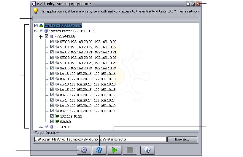
Avid Unity ISIS Log Aggregator Tool
197
nYou must run the Log Aggregator from a system with network access to the entire media
network. Otherwise, the tool cannot collect logs for all systems connected to the network.
To open the Log Aggregator tool:
1. Open the Administration tool (see “Opening the Administration Tool” on page 24).
The Avid Unity ISIS Home page opens.
2. Do one of the following:
tClick Log Aggregation.
tClick the Quick Launch menu, and select Log Aggregation.
If any Web site security warnings open, click Yes to accept the certificate. If you are not
sure about the security requirements of your media network, see your system
administrator.
The Login dialog box opens.
3. In the text box, type your Avid Unity ISIS password, and click OK.
The Avid Unity ISIS Log Aggregator dialog box opens. You can click the Refresh
button to update the tree view at any time.
Selection
area
Progress
bar
Configure
button
Collect button
Close button
Refresh
button
Target directory
for compressed
logs
198
To close the Log Aggregator:
1. Click the Close button.
A dialog box opens asking you to confirm that you want to quit the Log Aggregator.
2. Click Yes.
Creating Aggregate Logs
To use the Log Aggregator, you must have administration privileges and be logged into a
system with access to the media network.
To create logs with the Log Aggregator tool:
1. Open the Log Aggregator tool. (For information on opening the Log Aggregator, see
“Using the Avid Unity ISIS Log Aggregator Tool” on page 196.)
2. In the Selection area, do one of the following:
tSelect all active Avid Unity ISIS systems to view events from all components in the
media network.
tSelect one or more components to view events from specific System Directors,
storage elements, and clients attached to the network.
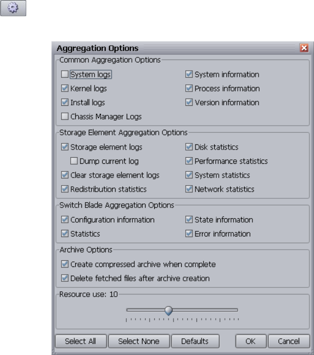
Avid Unity ISIS Log Aggregator Tool
199
3. Click the Configure button.
The Aggregation Options dialog box opens.
4. Do the following to customize the data collected in the event logs:
- In the Common Aggregation Options area, select the types of logs or information
you want to collect.
- In the Storage Element Aggregation Options area, select the types of statistics or
logs you want to collect.
- In the Switch Blade Aggregation Options area, select the types of information you
want to collect.
- In the Archive Options area, select the option if you want to create a compressed
file (aggregation_results.zip). The Target Directory box in the Log Aggregator lists
the directory where the log is saved.

200
- In the Resource use area, adjust the slider to maximize the use of resources in your
system when collecting logs. The default number of threads is 10. A lower number
uses fewer system resources but requires more time to complete log aggregation; a
higher number uses more resources but completes the operation faster.
5. Click OK to close the Aggregator Options dialog box and return to the Log Aggregator.
6. (Option) In the Target Directory area, click Browse to navigate to a directory for the
saved logs.
7. Click the Collect button.
The progress bar indicates the status of the log aggregation. The Log Aggregator
displays a Success icon (green) or a Fail icon (red) for each system and component
logged. (You can cancel the log aggregation process by clicking the Abort button.)
Viewing Aggregate Logs
The Log Aggregator saves individual logs in a log directory called
UnityISISLogs__date-time at the location indicated in the Target Directory area in the Log
Aggregator. Subdirectories include separate logs for each component in the network for
which you created logs. The Log Aggregator also creates a compressed file containing all
logs in the top-level folder (aggregator_results.zip). You can forward this compressed file to
your Avid representative if requested by Avid Customer Support.
To view saved logs:
1. Navigate to the directory where the Log Aggregator saved the collected logs.
2. Double-click the file name of the log you want to view.
Avid Unity ISIS Disk Tester Tool
The Avid Unity ISIS Disk Tester runs basic disk performance tests on your storage elements.
The tests include the following, which you can run in either Sequential or in Random access
mode:
• Read test
• Write test
• Read/Write test
• Erase test
You can also use the Disk Tester to collect statistics on the status of storage elements,
network use, and redistribution actions, including statistics generated by Self-Monitoring,
Analysis, and Reporting Technology (S.M.A.R.T.) and by local storage element
processes — for example, statistics on Long Command Times (LCT).
Avid Unity ISIS Disk Tester Tool
201
You can run the Disk Tester on more than one storage element at a time; however, running
the tests might degrade performance on the media network. You should not run the Disk
Tester unless instructed to do so by Avid Customer Support.
For information on running performance tests with the Disk Tester, see the following topics:
•“Opening the Disk Tester Tool” on page 201
•“Using the Disk Tester Tool” on page 202
Opening the Disk Tester Tool
To open the Disk Tester:
1. Open the Administration tool (see “Opening the Administration Tool” on page 24).
The Avid Unity ISIS Home page opens.
2. Do one of the following:
tClick ISB Disk Verification.
tClick the Quick Launch menu, and select ISB Disk Verification.
If any Web site security warnings open, click Yes to accept the certificate. If you are not
sure about the security requirements of your media network, see your system
administrator.
The Login dialog box opens.
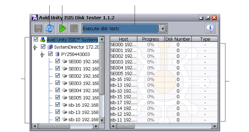
202
3. In the text box, type your Avid Unity ISIS password, and click OK.
The Avid Unity ISIS Disk Tester dialog box opens. You can click the Refresh button to
update the tree view at any time.
Using the Disk Tester Tool
To run a test on the Disk Tester:
1. Open the Disk Tester.
2. Click the Disk Tester menu and select one of the following:
- Execute disk tests
- Collect disk statistics
- Collect network statistics
- Collect redistribution statistics
3. In the Selection area, do one of the following:
tSelect all active Avid Unity ISIS systems to test all storage elements in the media
network.
tSelect one or more storage elements to test specific components in the network.
Selection
area
Refresh button Run button
Results
area
Disk Tester menu
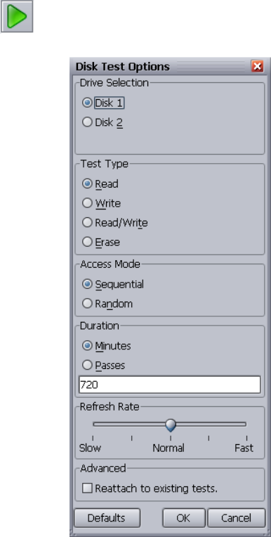
Avid Unity ISIS Disk Tester Tool
203
4. Click the Run button.
If you selected Execute disk tests, the Disk Test Options dialog box opens.
5. (Option) Select the appropriate options for the test you want to run.
6. Click OK to close the Disk Test Options dialog box and return to the Disk Tester.
Results of the test display in the Results area.

204
Avid Unity ISB Connection Analyzer Tool
The Avid Unity ISB Connection Analyzer provides a quick look at the connection status of
all storage elements in the media network. The Connection Analyzer displays connection
status in a grid, using the following color coding to denote the status of each storage
element:
To open the Connection Analyzer and test the connection status of storage elements:
1. Open the Administration tool (see “Opening the Administration Tool” on page 24).
The Avid Unity ISIS Home page opens.
2. Do one of the following:
tClick ISB Connection Analysis.
tClick the Quick Launch menu, and select ISB Connection Analysis.
If any Web site security warnings open, click Yes to accept the certificate. If you are not
sure about the security requirements of your media network, see your system
administrator.
The Login dialog box opens.
Color Status
Green Has Session — Connected.
Red No Session — Not connected.
White Session Not Needed — An ISB returning a “not needed” status for another ISB. In
day-to-day operation, it is unlikely to see this state; however, it might appear as a transient
state during the ISB initialization phase following a restart.
Gray Communication failure — Unable to determine status — for example, the agent is not
running or there is a network problem between the Connection Analyzer tool and the ISB
Yellow Microserver failure — Failure in the request from the agent to the ISB for session
information — for example, a failed resulting from the ISB not running or the ISB not
servicing the request before it timed out. Do not replace the ISB without additional
analysis.
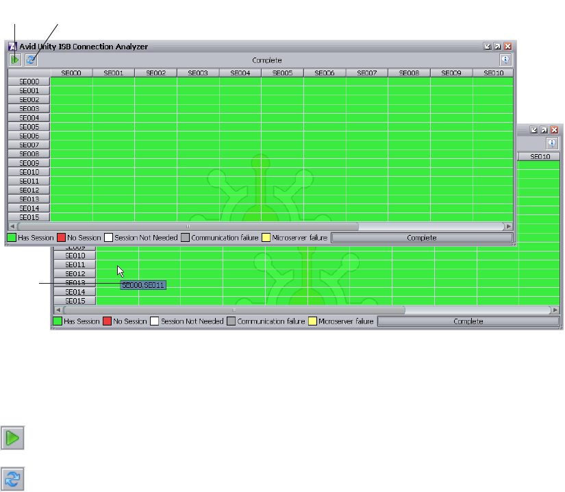
Avid Unity ISB Connection Analyzer Tool
205
3. In the text box, type your Avid Unity ISIS password, and click OK.
The Avid Unity ISB Connection Analyzer dialog box opens and checks the connection
status of all storage elements in the network. The tool displays results in a color-coded
grid.
If you place your pointer over a block in the grid, a tooltip indicates to which storage
elements the status applies. This is useful when you have a more storage elements than
can be displayed in the dialog box and you need to use the scroll bars to view a specific
connection.
4. (Option) Click the Analyze button to update the status of ISBs without reloading the
entire storage element list from the System Director.
5. (Option) Click the Refresh button to reload the storage element list from the System
Director prior to updating the status of ISBs.
Analyze
button
Refresh
button
Tooltip
206
Avid Unity ISIS Switch Manager Tool
The Avid Unity ISIS Switch Manager tool allows you to reset the error count for any chassis
switch (ISS or IXS).
To reset the switch error count:
1. Open the Administration tool (see “Opening the Administration Tool” on page 24).
The Avid Unity ISIS Home page opens.
2. Do one of the following:
tClick Switch Management.
tClick the Quick Launch menu, and select Switch Management.
If any Web site security warnings open, click Yes to accept the certificate. If you are not
sure about the security requirements of your media network, see your system
administrator.
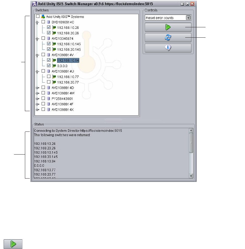
Avid Unity ISIS Switch Manager Tool
207
The Avid Unity ISIS Switch Manager dialog box opens. You can click the Refresh
button to update the tree view at any time.
3. In the Switches area, do one of the following:
tSelect Avid Unity ISIS Systems to reset error counts from all active switches in the
media network.
tSelect one or more switches to reset error counts from specific switches attached to
the network.
4. Click the Run button.
The Status area displays the results of the reset operation.
To close the Switch Manager:
1. Click the Close button.
A dialog box opens asking you to confirm that you want to quit the Switch Manager.
2. Click Yes.
Selection
area
Status
area
Reset button
Refresh button
208
General Tools
The Tools tab in the System Administration tool also provides you with the following
standard utility tests:
•Ping — allows you to test the connection between a system in the media network and
the System Director
• Traceroute — allows you to verify the path between a system in the media network and
the System Director
nYou must have Administrator privileges to run either of these utility tests.
Installers
The Installers tab of the Administration tool lists which installers have been downloaded to
the System Director, including the version number and the qualified operating system. You
can use these installers to update the Avid Unity ISIS software on clients and hardware
within the network.
You can also install client software and third-party software from the Installers tab.
nIf you encounter problems with the Administration tool display, you might have an outdated
version of Macromedia Flash Player installed on your system, or you might have multiple
versions installed. To uninstall any previous versions of Flash Player before installing the
current version, select the uninstall_flash_player.exe option.
For more information on installing upgrades, see the Avid Unity ISIS Setup Guide.
Avid Unity ISIS Agents
You can view detailed information about all storage elements and all chassis switches
connected to the media network by using the Avid Unity ISIS Agents. The Agents run as a
Web service on the storage elements — Avid Unity ISIS Storage Blades (ISB) — and on the
chassis switches — Avid Unity ISIS Integrated Switch Blades (ISS) and Avid Unity ISIS
Expansion Switch Blades (IXS). You can access the Agents during installation and
configuration procedures by attaching a laptop to the Management port on the ISS or IXS, or
you can access them during normal system operations from the Administration tool.
You can also access the Agents from the Avid Unity ISIS System Monitor tool. For more
information, see “Viewing Information in the System Monitor Tool” on page 239.
nYou must have Administrator privileges to access the Agents.
Avid Unity ISIS Agents
209
To open an Avid Unity ISIS Agent:
1. Open the Administration tool (see “Opening the Administration Tool” on page 24).
2. Select one of the following from the list on the left:
- Storage Elements
- Chassis
The Storage Elements dialog box or the Chassis dialog box opens.
3. Select a storage element or a chassis, and do one of the following:
tClick the Details button.
tDouble-click the storage element name or the chassis name.
The Details area opens.
4. Select a storage element or a chassis switch, and do one of the following:
tClick the Info button.
tDouble-click the storage element name or the chassis switch name.
If any Web site certification warnings open, accept the certificate. If you are not sure
about the security requirements of your media network, see your system administrator.
The Login dialog box opens in a separate browser.
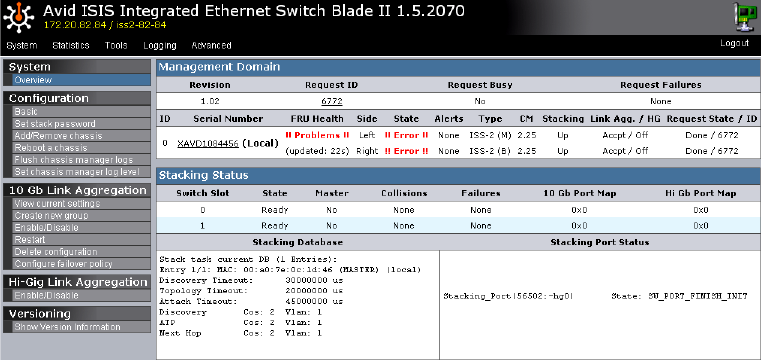
210
5. Type your password in the Administrator password text box, and click the Login button.
If you log in to a a storage blade agent for an unbound storage element or to a switch
blade agent, you must use the chassis stack password and not the Avid Unity ISIS
system password.
The Agent opens, with the System tab selected by default. (The following figure
illustrates the Avid ISIS Switch Blade Agent.)
For more information on the Avid Unity ISIS agent, see the following topics:
•Understanding the Agent Interface
•Using the Log Viewer Tool
•System Tab
•Statistics Tab
•Logging Tab
•Advanced Tab
Understanding the Agent Interface
The Avid Unity ISIS Agent, which you can run on the System Director or any
Ethernet-attached client, has a user interface where controls are grouped by function and are
displayed by clicking the appropriate buttons.
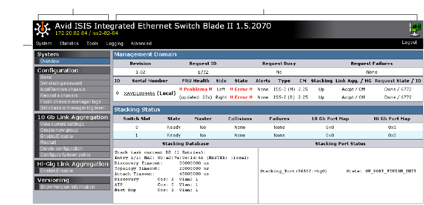
Avid Unity ISIS Agents
211
The following figure illustrates the Avid ISIS Switch Blade Agent with the System tab
selected.
The Agent is divided into the following areas:
• The Command menu, which contains the options used for basic management functions.
You can access different Command functions by clicking the tabs at the top of the Agent
tool. The System tab is selected by default.
• The Main display area, which displays information about your network and allows you
to configure components.
Main display areaCommand menu
Tabs
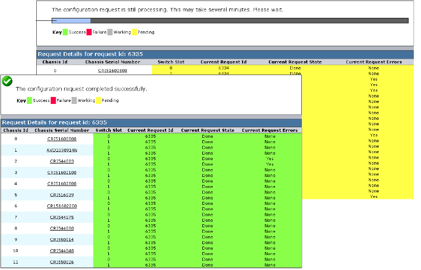
212
When you access switch blade agents and submit a request for an action — for example,
when you change the level of detail for chassis logs — a message tells you that the request
was successfully or unsuccessfully submitted, and the progress of the request is reported to
the Main display area.
For more information on the Agent interface, see the following topics:
•System Tab
•Statistics Tab
•Tools Tab
•Logging Tab
•Advanced Tab
Request pending message
Request completed message
Progress
bar
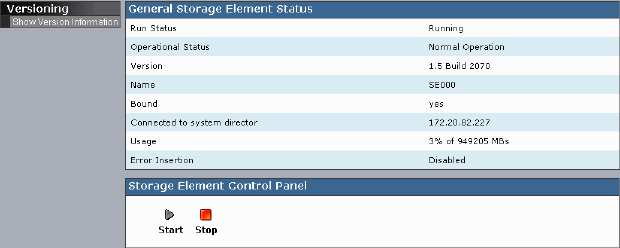
Avid Unity ISIS Agents
213
System Tab
The System tab allows you to view configuration information for storage elements and
chassis switches. The System tab lists general information about component status, version,
and usage. You can also start and stop storage elements and add or remove chassis. For
information on adding and removing network components, see the Avid Unity ISIS Setup
Guide.
You can also create, modify, and delete link aggregation configurations. Link aggregation,
sometimes called trunking, allows you to combine physical network links into a single
logical link for increased bandwidth. Link aggregation can increase the capacity and
availability of the communication channel between devices (both switches and clients) using
existing Ethernet technologies in such a way that two or more Ethernet connections can be
combined to increase the bandwidth capability and to create resilient and redundant links.
Link aggregation also provides load-balancing where the processing and communications
activity is distributed across several links so that no single link is overwhelmed.
Your Avid Unity ISIS system supports two kinds of link aggregation:
• 10-Gb Link Aggregation — combines two or more 10-Gb Ethernet connections
• Hi-Gig Link Aggregation — combines two integrated switches (IXS)
cLink aggregation is configured during setup and installation of your Avid Unity ISIS
media network. Changing the configuration can disrupt all link aggregation for your
network and degrade system performance. Do not modify configuration values unless
instructed to do so by Avid Customer Support.
Configuration values are set during installation and are displayed in the System tab. By
default, the System tab displays general status information about the storage element and
allows you to stop or to start the storage element with the Storage Element Control Panel
(see “Stopping and Starting Storage Elements” on page 216).
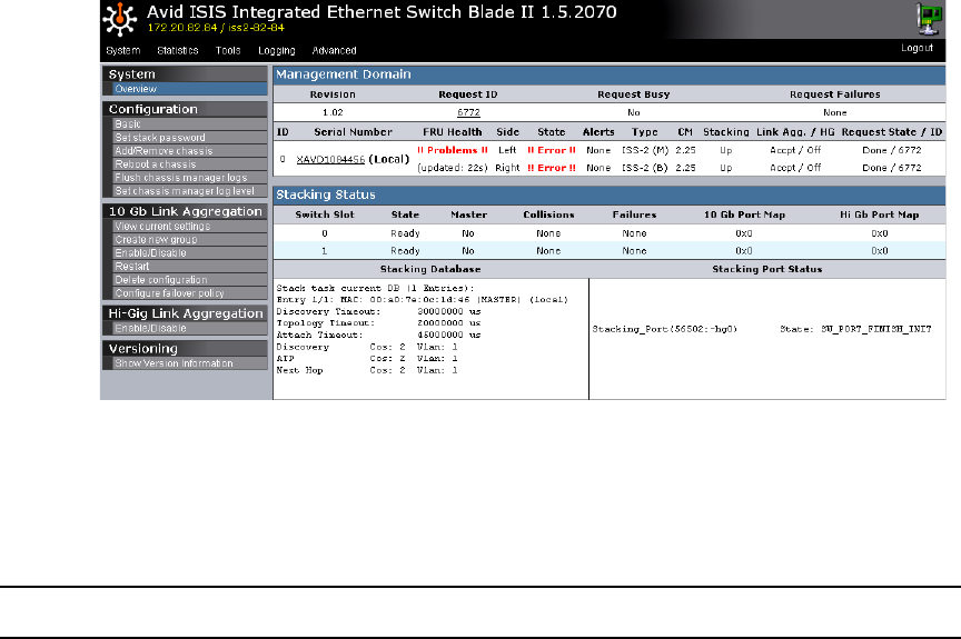
214
The Show Version Information option Displays current software version of the component.
The System tab for chassis switches allows you to view configuration, link aggregation, and
versioning information. You can use the System tab to access information on any chassis
switch (see “Viewing System Information for Individual Chassis Switches” on page 217).
System Information
The following table summarizes the information available in the System tab for chassis
switches.
Menu Option Description
System Overview Displays a snapshot view of the status of switches and
information about the stacking state of the network chassis.
Configuration Basic Displays basic setup and configuration information about a
chassis switch.
Changing configuration IP addresses can affect network
connectivity.
The Basic option also allows you to set the date and time on a
chassis switch. This resets the date and time for all storage
elements in the chassis as well. For more information, see
“Setting Chassis Time” on page 217.
Set stack password Allows you to change the password for a chassis stack
(maximum of 8 characters). Changing the stack password
affects all connected storage elements and chassis in the stack.

Avid Unity ISIS Agents
215
Add/Remove
chassis
Allows you to add a chassis to or remove a chassis from the
network. For more information on adding and removing
chassis, see the Avid Unity ISIS Setup Guide.
Reboot chassis Allows you to reboot all storage elements and switches in a
chassis at one time.
Flush chassis
manager logs
Allows you to dump all current chassis logs to the \var\log
directory on the storage blades.
Set chassis manager
log level
Allows you to set the level of detail collected in chassis logs:
• Normal
• More Verbose
• Extra Verbose
The Chassis Manager — the application running on the
switch — maintains logs and periodically collects them in a
compressed file.
Normal is selected by default.
10 Gb Link Aggregation View current
settings
Displays the current configuration used for link aggregation,
including the link type and the chassis port map
Create new group Allows you to define a new link aggregation group.
Link aggregation is configured during setup and installation of
your Avid Unity ISIS media network. Changing the
configuration can disrupt all link aggregation for your network
and degrade system performance. Do not modify configuration
values unless instructed to do so by Avid Customer Support.
Enable/disable Lists the network link aggregation configurations for the
chassis and allows you to enable or disable them.
Enabling or disabling link aggregation affects all
configurations in the network.
Restart Lists the network link aggregation configurations for the
chassis and allows you to restart them.
Restarting link aggregation stops all configurations in the
network and restarts them.
Delete configuration Allows you to delete all of the current link aggregation
configurations for your network.
Configure Failover
Policy
Allows you to enable or disable failover for all current link
aggregation configurations for your network.
Menu Option Description (Continued)
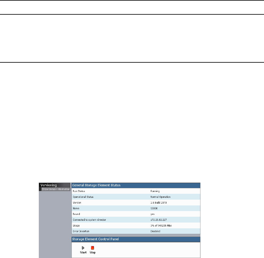
216
Stopping and Starting Storage Elements
You can use the Storage Element Control Panel to start and stop storage blade processes.
This can be useful if you need to restart a storage element for the purposes of
troubleshooting a problem.
cStopping a storage element while a client is writing to it can disrupt network
performance.
To stop or to start a storage element:
1. Open the Storage Blade Agent (see “Avid Unity ISIS Agents” on page 208).
2. Click the System tab if it is not already selected.
The System window opens.
3. In the Storage Element Control Panel, click the Stop or the Start button.
Hi-Gig Link Aggregation Enable/Disable Allows you to enable or disable Hi-Gig link aggregation.
Enabling Hi-Gig link aggregation stops all switches in the
chassis and restarts them.
Versioning Show Version
Information
Displays current software version of the component.
Menu Option Description (Continued)
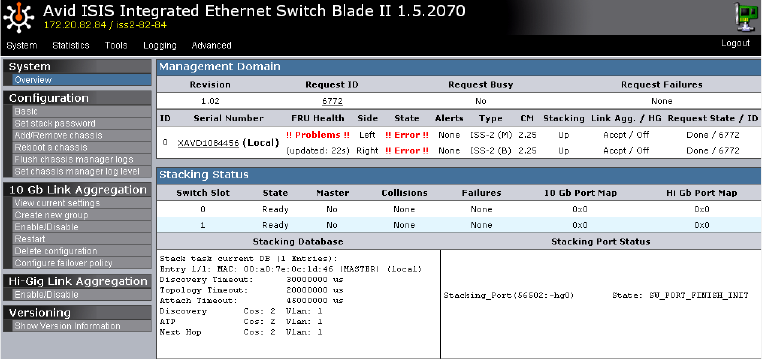
Avid Unity ISIS Agents
217
Viewing System Information for Individual Chassis Switches
When you log in to a selected ISS or IXS, you can use the System tab of the Switch Blade
Agent to access information about any switch, not just the selected one.
To view system information for a chassis switch:
1. Open the Switch Blade Agent (see “Avid Unity ISIS Agents” on page 208).
2. Click the System tab if it is not already selected.
The System window opens.
3. In the Management Domain area, click a switch listed in the Serial Number column.
The agent displays information for the switch in the Main display area.
Setting Chassis Time
You can set the time for all storage elements connected to your chassis switch by using the
Switch Blade Agent. You can also use a Network Time Protocol (NTP) server to establish
the time for your system. Setting chassis time synchronizes the time for all storage elements
and, in systems with multiple chassis, on all switches.
To set the time for a chassis:
1. Open the Switch Blade Agent (see “Avid Unity ISIS Agents” on page 208).
2. Click the System tab if it is not already selected.
The System window opens.
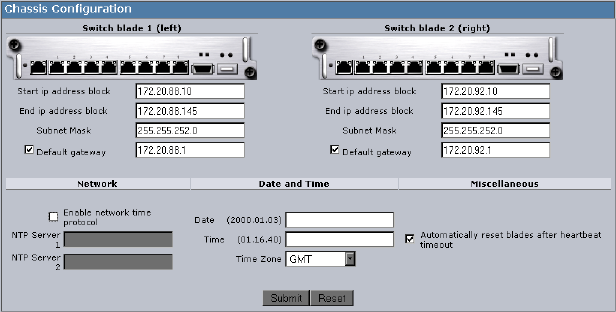
218
3. Select Configuration > Basic.
The Chassis Configuration dialog box opens.
4. Do one of the following:
tTo configure your system to use NTP to synchronize storage elements with a
network reference, select Enable network time protocol, and then type the
IP address of a primary NTP server. You can also type the IP address of a secondary
NTP server.
tTo set the time for a chassis manually, type the date and time in the Date and Time
text boxes, and then select a time zone from the Time Zone menu.
5. (Option) Select “Automatically reset blades after heartbeat timeout.”
6. Click the Submit button.
Statistics Tab
You can use the Statistics tab to view basic information about your network or network
components. The Statistics tab provides you with statistics for the local system and for the
storage element or switch.
For information on using the Statistics tab, see the following topics:
•Using the Statistics Window
•Statistics Tab Information
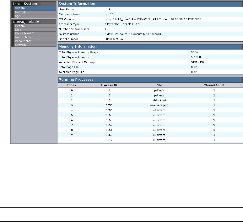
Avid Unity ISIS Agents
219
Using the Statistics Window
To access statistical information about the local component:
1. Open the Agent (see “Avid Unity ISIS Agents” on page 208).
2. Click the Statistics tab.
The Statistics window opens.
3. Select an option from the Command menu.
Statistics Tab Information
The following table describes the information available in the Statistics tab for the local
system:
Type Heading Description
General System Information Lists the basic properties of the system running the
System Director software
Memory Information Lists statistics about system memory
Running Processes Lists the processes currently running on the local system

220
The following table describes the information available in the Statistics tab for storage
elements:
Network Lists detailed information about network
communication
Agent Agent Environment Lists settings specific to the agent service
Agent Statistics Lists start time and statistics applicable to agent
connections
Agent Configuration Lists agent service configuration parameter values
Browser Details Lists details about the connected browser
Agent <-> Chassis Manager
Interface (switch blade
agent only)
Lists basic version information about the
agent-to-chassis interface
Type Heading Description (Continued)
Type Description
General Displays the basic properties of the storage element
Disk Displays detailed information about disk properties and disk use
Disk S.M.A.R.T. Retrieves S.M.A.R.T. statistics for the storage element
S.M.A.R.T. is an industry-standard reporting method.
Redistribution Displays information about the storage element’s status during current
redistribution pass
Performance Displays information about the storage element’s performance
Network Displays information about the current network status and connectivity between
the storage element and the System Director

Avid Unity ISIS Agents
221
The following table describes the information available in the Statistics tab for switches:
Tools Tab
The Tools tab provides you with network tools and component utilities that generate basic
information on network functioning and low-level information on storage elements and
switches. These tools are used primarily by Avid Customer Support to diagnose problems
with components of the media network.
The Tools tab for storage elements provides access to the Console Viewer. For information
on the Console Viewer, see “Using the Log Viewer Tool” on page 222.
For more information, see the following topics:
•“Agent Tools” on page 222
•“Using the Log Viewer Tool” on page 222
Type Description
Port Status:
• View by chip
• View by function
Displays information about port status grouped either by chip (matching
the physical location of the port on the switch) or by function (for
example, stacking ports or external client ports)
Port Errors:
• View by chip
• View by function
• Reset all error counts
Lists port errors grouped either by chip (matching the physical location of
the port on the switch) or by function (for example, stacking ports or
external client ports); also allows you to clear all error counts
Chassis:
• Status
Displays detailed information about the chassis, including its components,
the status of each part of the switch, and stacking information

222
Agent Tools
The following table describes the tools available on the Tools tab for both storage elements
and switches:
Using the Log Viewer Tool
This tab allows you to access the storage blade Log Viewer tool. The Log Viewer tool
displays event information about storage elements. You cannot save the information
displayed in the Log Viewer tool, but you can copy it to a word processing application, such
as Notepad. You can also save event logs displayed in the Logging tab (see “Saving Logs”
on page 226). The information is used primarily by Avid Customer Support personnel to
help analyze problems with storage elements.
nThe Log Viewer tool is available on the storage element Agent only.
To monitor event information about storage elements:
1. Open the Avid Unity ISIS Storage Blade Agent (see “Avid Unity ISIS Agents” on page
208).
2. Click the Tools tab, and then select Storage Element Tools > Console viewer.
If any Web site security warnings open, click Yes to accept the certificate. If you are not
sure about the security requirements of your media network, see your system
administrator.
Tool Description
General Tools:
•ping
• traceroute
•df
Allow you to test the connections between components in the
media network, to verify the path between components, and to run
the Linux df command
Blade Tools
•i2cio
•istate
•ivers
• route show
Allow you to run low-level tests to generate data to identify
problems with components in the media network
Storage Element Tools
• Console viewer
From the storage element Agent, allows you to access the Log
Viewer tool (for information on the Log Viewer tool, see “Using the
Log Viewer Tool” on page 222)
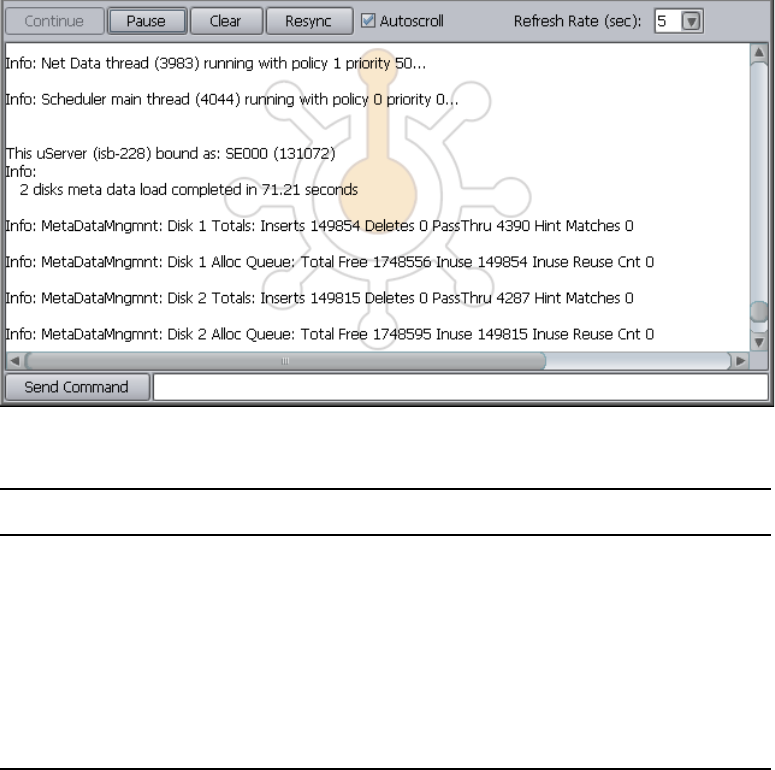
Avid Unity ISIS Agents
223
The Log Viewer tool opens.
3. Select an option as described in the following table:
Logging Tab
The Logging tab provides a complete view of the logs of active storage elements and
switches. The logs provide you with a system snapshot that you can use to view error and
status messages. The logs provide detailed status information that is especially useful to
Avid Customer Support personnel for monitoring system status during prolonged
operations.
Option Description
Continue Resumes monitoring storage element events
Pause Stops monitoring storage element events
Clear Clears all event data from the Console View tool
Resync Restores previously-cleared event data to the Console View tool
Autoscroll Scrolls the display to the bottom of the page
Refresh Rate (sec) Sets the rate at which the Console View tool refreshes event data
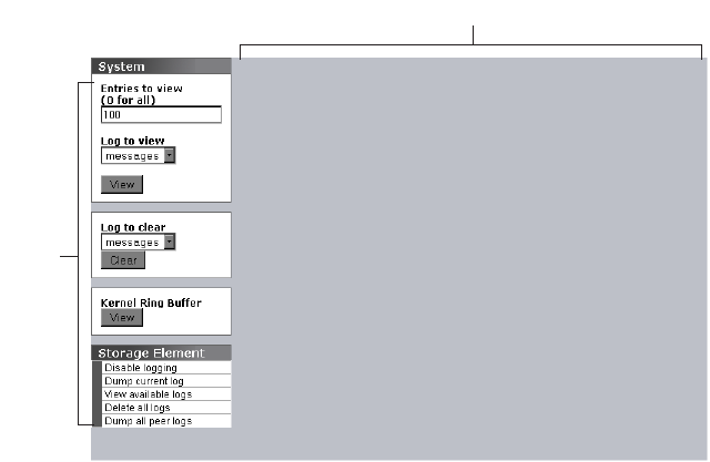
224
For more information on the Logging tab, see the following topics:
•Using Agent Logging
•Viewing Agent Event Logs
•Clearing Agent Event Logs
Using Agent Logging
You can use the Logging tab to view event logs and to clear existing logs.The Logging tab
contains two sections:
• Options area: the left area allows you to select specific logging options to display and to
perform administrative tasks relating to the agent logs.
nThe Kernel Ring Buffer displays logs maintained by the Linux kernel. These logs are used by
Avid Customer Support.
• Logs area: the right area displays different types of events and information from the
network component.
To access Agent Logging functions:
1. Open the Agent. (For information on opening the Agent, see “Avid Unity ISIS Agents”
on page 208.)
2. Click the Logging tab.
The Logging window opens.
Logs panel
Options
panel
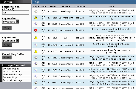
Avid Unity ISIS Agents
225
Viewing Agent Event Logs
To view event logs:
1. Open the Agent. (For information on opening the Agent, see “Avid Unity ISIS Agents”
on page 208.)
2. Click the Logging tab.
The Logging window opens.
3. In the Entries to view text box, type the number of events to display. The default is 100.
If you want to view all events, type “0” (zero) in the Entries to view text box.
4. Click View.
The event log displays in the Logs area.
Clearing Agent Event Logs
You can clear the logs in any of the logging categories. This empties the log of all event
entries and resets the logging process.
To clear logs:
1. Open the Agent. (For information on opening the Agent, see “Avid Unity ISIS Agents”
on page 208.)
2. Click the Logging tab.
The Logging window opens.
3. Click the Clear button.
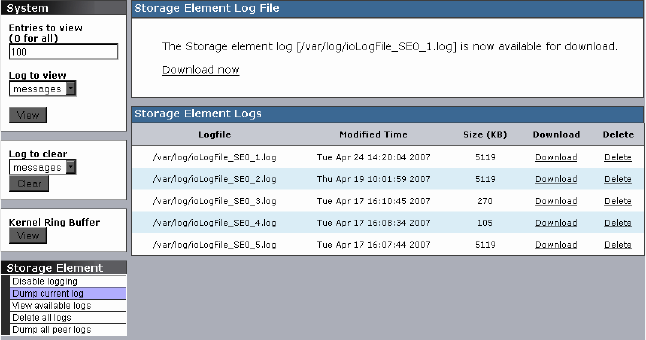
226
4. Click OK.
The event log is cleared, and logging is reset to start recording new events.
Disabling Logging
You can use the Logging window to start and stop the logging function of any storage
element. Disabling logging for a storage element does not affect system logging functions.
To stop the logging function:
tSelect Storage Element > Disable logging.
To start the logging function:
tSelect Storage Element > Enable logging.
Saving Logs
To save the log displayed in the Logs area, do one of the following:
tSelect Storage Element > Dump current log.
tSelect Storage Element > Dump all peer logs.
The current log or all peer logs are saved, and the Logging window displays a list of
saved logs.
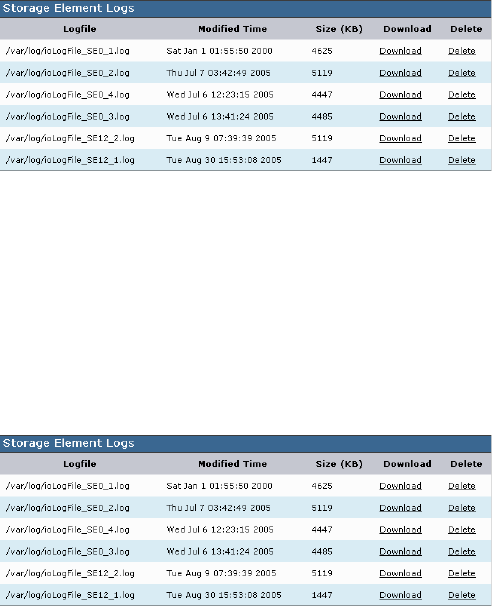
Avid Unity ISIS Agents
227
Viewing and Deleting Saved Logs
To view a saved log:
1. Select Storage Element > View available logs.
The Logs area displays a list of all available logs.
2. Locate the log you want to view, and click Download.
The Agent tool downloads the log to the root directory on your local system.
3. Open the log file in a text editor (for example, in Notepad).
To delete a saved log:
1. Select Storage Element > View available logs.
The Logs area displays a list of all available logs.
2. Locate the log you want to delete, and click Delete.
The log is deleted from the agent system.
Advanced Tab
The Advanced tab contains configuration utilities, installation logs, and diagnostic tools
used by Avid Customer Support personnel used to troubleshoot problems with the media
network. You can also use the Advanced tab to set the integrated switches back to the factory
defaults. This might be necessary to reset the IP addresses of system components if your
Avid Unity ISIS system experiences network communication problems.

228
cUse of the tools in the Advanced tab can result in degraded system performance or loss
of data. The tools should be used by Avid Customer Support personnel or under Avid
Customer Support direction.
For more information on using some of the tools in the Advanced tab, see the following
topics:
•“Switch Infrastructure Diagnostics” on page 228
•“Resetting an Avid ISIS Engine to Factory Defaults” on page 232
Switch Infrastructure Diagnostics
Avid Unity ISIS supports system level diagnostics for every Avid Unity ISIS switch from
one location. The diagnostics organize results and provides a report of problems with the
switch.
The Switch Diagnostics test does not fix diagnosed problems; instead, it looks for problems
and provides clues as to the root cause. There are circumstances where the diagnostics can
point to what the problem might be, where the problem is located, or how to address the
problem. There are also error cases where the diagnostics cannot determine the cause of the
problem, and the test only reports relevant data for further analysis.
The diagnostic tests are organized into separate groupings. Each group investigates the
switch in different ways to look for possible problems. If you are unsure if you have a
problem or where a problem is, select all the test groups to get a more complete picture of
the system's health. Each test exists in only one group. The following list describes how the
tests are arranged within the groups.
Test Group Tests Description
Stacking • Stack MAC Addresses
• State Machine
• Stack Serial Numbers
• Module Assignment
• Collision
The Stacking test group looks for symptoms that might
indicate a problem with switch stack health. Run this
group of tests if you think a switch is not properly
stacked, or if you are having trouble with traffic flow on
a particular switch.
Performance • Link Aggregation
Configuration
• Link Aggregation Load
Balancing
This group of tests verifies that link aggregation is
configured and operating correctly. Performance on
ISIS may suffer if link aggregation is not behaving as
expected.

Avid Unity ISIS Agents
229
Switch Diagnostics Results
You should keep in mind the following when using the Switch Infrastructure Diagnostics:
• Once the diagnostics have run on the selected tests, you can use the Switch Diagnostic
Help link located in the upper right corner of the Reported Result window to read what
each test performs and what possible solutions might be appropriate to any failed tests
(see “Running Switch Infrastructure Diagnostics” on page 230).
• Brief instructions are displayed at the bottom of each display. Other statistic information
is usually listed in table format after the results are available.
• After selecting the type of test to perform, you can then select a column in the display to
select a particular test on a group of components or select a row to run all tests on just
one component.
Counters • Counters and Registers The Counters test group checks various statistical
counters and register information on the switch. You
can find statistical information here for issues such as
dropped, discarded, blocked or corrupted packets. Also,
registers can indicate various types of error status.
Connectivity • Default Gateway
• Ping ISBs
• Ping Stack
The Connectivity test group performs tests to pinpoint
any vital nodes that might be unreachable.
Hardware • Intermittent Link
• Link Status
• Port Speeds
• Port Link Information
The Hardware test group looks for symptoms of
hardware problems on ISIS switch links such as
incorrect port speed, intermittent link, and link status.
Advanced • Unicast Bitmaps These tests provide supplemental information for
review by Avid personnel.
Environment • Installation Errors
•Processes
This group of tests check that the switch has all the
necessary processes running, and that the previous
install completed successfully
Test Group Tests Description (Continued)
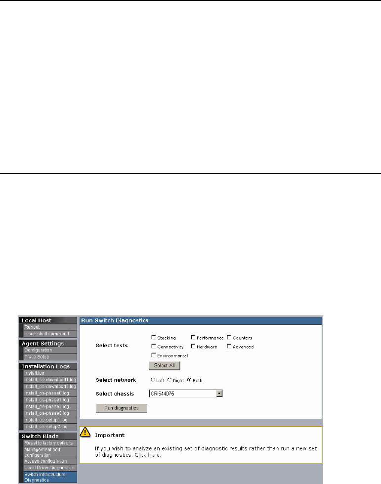
230
• The results are displayed in these colors:
Running Switch Infrastructure Diagnostics
The diagnostics should not be used during a critical time in your production. Some tests
burden system bandwidth and resources.
To access Switch Infrastructure Diagnostics:
1. In the Avid ISIS Switch Blade Agent, click the Advanced tab, and then select Switch
Infrastructure Diagnostics from the Command menu.
The Run Switch Diagnostics dialog box opens.
Green Passed
Yellow Warning. There is not enough information to confirm that the switch is in
an error state; however, the test diagnostics has flagged a situation that
might need attention. Double-click the warning text to display a list of
possible reasons for the warning.
For example, if a storage blade is pulled out, the ping test provides a
warning result to inform you that the ping test failed. But the storage
blade might have been intentionally pulled out, so it is an unknown
condition and not a failure condition.
Red Failed. Double-click the failed text to display a list of possible reasons for
the failure.
Black (Not Run) This test was not selected to be performed.
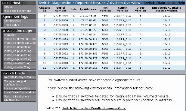
Avid Unity ISIS Agents
231
2. Select the tests you want to perform.
3. In the Select network section, select the VLAN subnet(s) you want to test:
-Left
-Right
-Both
4. Click the Select chassis menu, and do one of the following:
tSelect a chassis on which to run the diagnostics.
tSelect All to run the diagnostics on all chassis.
5. Click Run diagnostics.
A progress bar appears as the diagnostics run. When the results are available, they are
displayed in results window in table format. Each component is displayed in a separate
row.
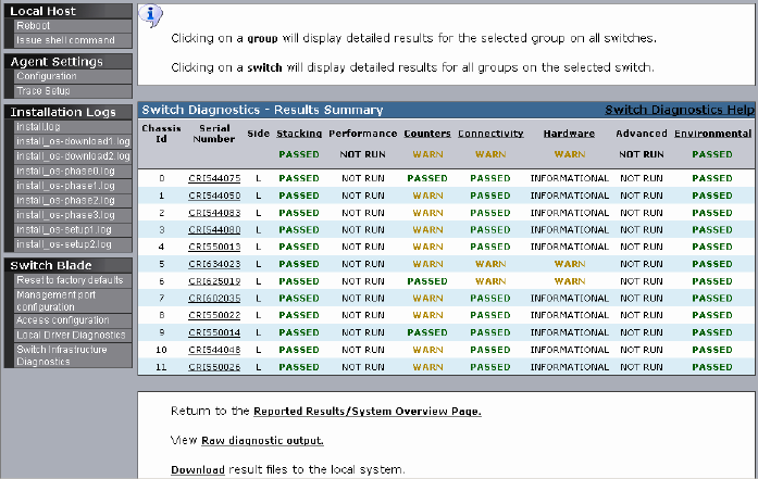
232
6. Click Switch Diagnostics Results Summary Page.
The Switch Diagnostics Results Summary window opens.
7. When the Results Summary page is displayed, do one or more of the following:
- Click a column header to display detailed results for the selected group on all
switches.
- Click a switch to display detailed results for all groups on the selected switch.
- Return to the Reported Results/System Overview Page.
- View the Raw diagnostic output.
- Download the result files to the local system.
Detailed results provide other display options. Each window includes instructions
on how to view your results. For additional information, see the Switch Diagnostic
Help link in the upper right corner of the window.
Resetting an Avid ISIS Engine to Factory Defaults
You can set the integrated switches back to the factory defaults. Resetting your
configuration, including resetting the IP addresses of system components if your Avid Unity
ISIS system, can help correct some network communication problems.

Avid Unity ISIS Agents
233
cResetting switch configuration can lead to failed connectivity in your ISIS system and
degrade performance. You should only reset your system if directed to by Avid
Customer Support personnel or under Avid Customer Support direction.
To reset an Avid Unity ISIS engine to its factory defaults:
1. Open the Switch Blade Agent for the engine you want to reset. (For information on
opening the Agent, see “Avid Unity ISIS Agents” on page 208.)
The Avid ISIS Integrated Ethernet Switch Blade Agent opens.
2. Click the Advanced tab.
The Advanced window opens.
3. Select Switch Blade > Reset to factory defaults.
A confirmation dialog box opens.
4. Type the Administrator password for your Avid Unity ISIS system, and click Confirm
reset.
The chassis switch configuration is reset to its factory defaults.
234

CAvid Unity ISIS System Monitor Tool
This appendix describes the data available in the Avid Unity ISIS System Monitor tool. For
detailed information about the tool, see the following topics:
•Using the Avid Unity ISIS System Monitor Tool
•Viewing Information in the System Monitor Tool
Using the Avid Unity ISIS System Monitor Tool
The Avid Unity ISIS System Monitor tool provides detailed monitoring of all hardware
components in the Avid Unity ISIS media network. The System Monitor tool displays
overview information about the network hardware as a graphical representation of the
current configuration, so you can view the components remotely to assess their functional
status.
The System Monitor tool provides various views of the components in the media network
and polls the System Director at timed intervals to update network data. On the left is the
Navigation panel, which provides a tree view of the media network. On the right is the
System panel, which presents system hardware components in a graphical display. You can
view the network hardware at several levels: system, racks, chassis, or blades. At each level,
the tool displays indicators of the health of the component, usually as a graphical
representation of the actual LED state viewed on the component.
The System Monitor tool also provides information about the physical location of each
component. For example, the tool shows the chassis ID of each blade so that it can indicate
the location of a malfunctioning blade within a chassis. The System Monitor tool does not
track how racks or chassis are actually organized, but you can input site-specific data so that
the tool can represent groupings of components in a way that makes sense in relation to how
a specific media network is organized.
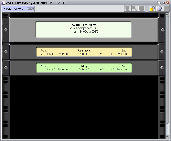
236
Accessing the Avid Unity ISIS System Monitor Tool
To open the System Monitor tool:
1. Open the Administration tool (see “Opening the Administration Tool” on page 24).
2. Do one of the following:
tClick Monitoring.
tClick the Quick Launch menu, and select Monitoring.
3. If any security warnings open, click Yes to accept the certificate. If you are not sure
about the security requirements of your media network, see your system administrator.
The Avid Unity ISIS System Monitor tool opens.
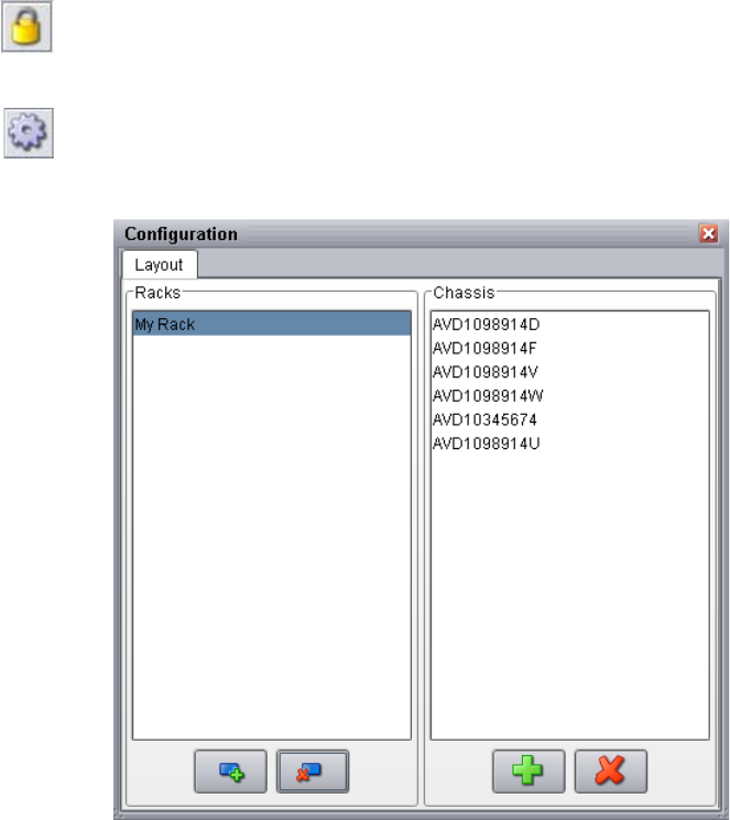
Using the Avid Unity ISIS System Monitor Tool
237
Configuring the System Monitor Tool
You can set up the System Monitor tool to reflect the configuration of your media network.
You can add information on racks, chassis, servers, or any other components in your
network.
To configure the System Monitor tool:
1. Open the System Monitor tool. (For information on opening the System Monitor tool,
see “Accessing the Avid Unity ISIS System Monitor Tool” on page 236.)
2. Click the Unlock Editing button.
The Unlock Editing button changes to the Lock Editing button to indicate the
configuration is unlocked and can be edited.
3. Click the Configure button.
The Configuration dialog box opens.
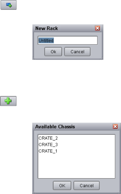
238
4. Click the Create New Rack button.
The New Rack dialog box opens.
5. Type a rack name, and click OK.
The new rack is added to your configuration and displays in the Racks list in the
Configuration dialog box.
6. Click the Add Chassis button.
The Available Chassis dialog box opens.
7. Click the chassis you want to add to the rack. Ctrl+click to select multiple chassis.
8. Click OK.
The chassis is added to your configuration and displays in the Chassis list in the
Configuration dialog box.
9. (Option) Repeat steps 3 through 8 to add additional racks.
10. Click the Close button in the title bar to return to the System Monitor.
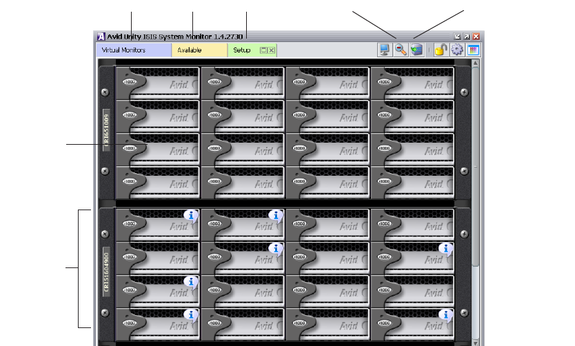
Viewing Information in the System Monitor Tool
239
Viewing Information in the System Monitor Tool
Once you have configured the System Monitor tool for your media network, you can use the
tool’s graphical interface to view the status of your hardware components and retrieve
information about its operation.
You can access the Avid Unity ISIS Agents and view more information about storage
elements and chassis switches by right-clicking the component in the System Monitor tool
and selecting the appropriate IP address. For information on the Avid Unity ISIS Agents, see
“Avid Unity ISIS Agents” on page 208.
To view information about the components of your media network:
1. Open the System Monitor tool (see “Accessing the Avid Unity ISIS System Monitor
Tool” on page 236).
2. Do one of the following to select the rack whose components you want to monitor:
tIn the Virtual Monitors tab, click either Front or Back in the appropriate Rack
element.
tClick the appropriate Rack tab.
The System Monitor tool displays a graphical representation of the rack.
Virtual Monitors tab Available tab Rack tab
Chassis
Storage
element
Rotate Rack View button
Zoom In/Out button
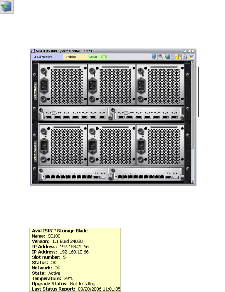
240
3. (Option) To view the other panel of the rack (either front or back), do one of the
following:
tClick the Rotate Rack View button to view the back panel of the rack.
tRight-click a component, and select Rotate Rack View.
The System Monitor tool displays the other panel of the selected rack. You can use the
Rotate Rack View button to switch between back and front views.
4. Move the mouse pointer over a component to view information about its status and
performance.
A status box opens.
Chassis
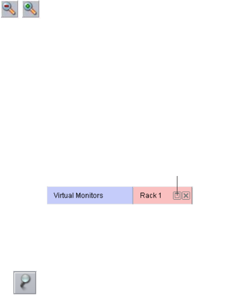
Viewing Information in the System Monitor Tool
241
5. (Option) Click the Zoom Out or Zoom In button to adjust your view of all components
in the rack.
For more information on the System Monitor, see the following topics:
•Understanding the System Monitor Display
•Modifying the System Monitor Configuration
Displaying Rack Configurations in Separate Windows
You can detach any rack tab so you can view it in a separate window. This allows you to
keep a specific rack configuration visible while you configure other racks. You can also set
the detached display to keep it on top of any active window on your desktop.
To detach a rack tab:
tClick the Maximize button on the rack tab you want to display in a separate window.
To keep the detached rack tab on top of any active window:
tIn the detached rack display, click the Always On Top button.
nThe Always On Top button appears only on detached rack displays.
Understanding the System Monitor Display
The System Monitor tool allows you to select different views to see specific information
about the network or about an individual component. For information on System Monitor
views, see the following topics:
•Using General View
•Using Status Details View
•Using Blade Identification View
•Using Status Details View
•Using IP Addresses View
•Using Temperatures View
•Using Upgrades View
Maximize button
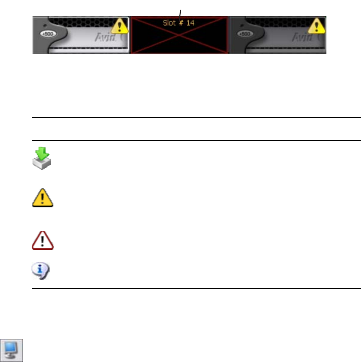
242
Using General View
General View displays each of the storage elements, chassis switches, and power supplies in
your configuration. Elements flash gray if there is no communication between the System
Director and a rack — for instance, if an Avid Unity ISIS storage blade (ISB) is rebooting.
Elements currently experiencing a failure appear grayed out. The System Monitor tool
displays a Component Missing icon for any empty storage element, chassis switch, or power
supply slot that is empty.
In addition, the System Monitor displays the following symbols to indicate problems with
the storage elements.
To see the System view:
1. Open the System Monitor tool (see “Accessing the Avid Unity ISIS System Monitor
Tool” on page 236).
2. Click the View Mode button, and select System.
Component Missing icon
Symbol Name Description
Upgrade Indicates the element is currently undergoing a software
upgrade. For more information on upgrade status, see
“Using Upgrades View” on page 246.
Warning Indicates the element has returned a warning message —
for example, the storage element might be rectifying or
redistributing files.
Error Indicates the element has experienced a failure — for
example, a disk failure.
Info Indicates one or more information messages are available
for the element.
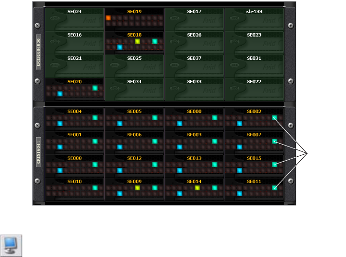
Viewing Information in the System Monitor Tool
243
Using Status Details View
In Status Details view, you can view comprehensive status details of each component in your
configuration. Status indicators appear if status information is currently associated with a
component. For a description of status indicators, see “Status Indicators” on page 244.
If no status information is associated with a component, the component appears green in
Status Details view.
To see the Status Details view:
tClick the View Mode button, and select Status Details.
Status
indicators
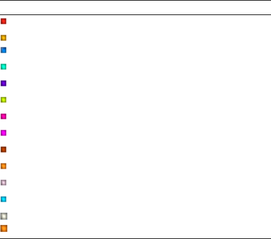
244
Status Indicators
The Status Details view displays the following status information. You can toggle between
front and back views to see the status of storage elements, switches, and power supplies.
nNot all status indicators are available for each component.
Status Details Information
Icon Description (storage elements) Description (switch) Description (power supply)
Connection error
Version mismatch Version mismatch
Installing in progress Installing in progress
Redistributing in progress
Rectifying files
Repairing mirrors
Disk failure Stack error
Diagnostic mode
Network degraded Trunking error
Disk degraded Chassis error
Memory error No power
Redistribution information available
Element offline
Link warning
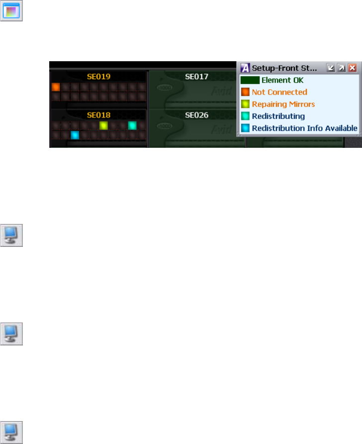
Viewing Information in the System Monitor Tool
245
Using the Status Details Legend
You can access a summary of the status indicators displayed in Status Details view by using
the Legend button. The Status Details legend lists all status indicators currently associated
with the components in your system. If no status information is available, the Legend button
is not active.
To access the Status Details legend, do the following:
tClick the Legend button.
The Status Details legend displays a summary of the status indicators associated with
your system.
Using Chassis Identification View
In Chassis Identification view, you can view the names of each chassis in your configuration.
To see the Chassis Identification view:
tClick the View Mode button, and select Chassis Identification.
Using Blade Identification View
In Blade Identification view, you can view the names of each storage element in your
configuration.
To see the Blade Identification view:
tClick the View Mode button, and select Blade Identification.
Using IP Addresses View
In IP Addresses view, you can view the IP addresses of each storage element in your
configuration.
To see the IP Addresses view:
tClick the View Mode button, and select IP Addresses.
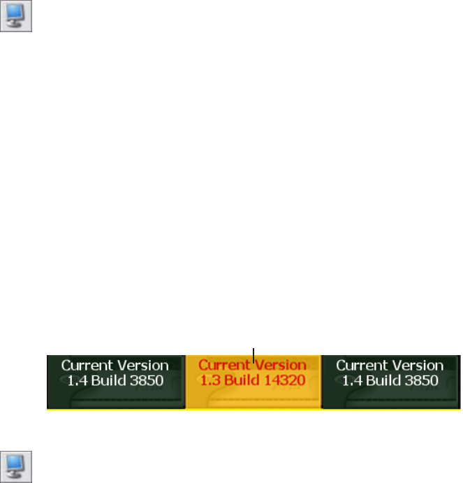
246
Using Temperatures View
In Temperatures view, you can view the temperature status of each storage element in your
configuration. Temperatures view lists the temperature of each storage element, as well as a
color-coded marker to indicate its status:
• Green (Normal): the temperature of the storage element is under 60°C (140°F).
• Yellow (Warning): the temperature of the storage element is between 60° – 70°C
(140° – 158°F).
• Red (Critical): the temperature of the storage element exceeds 70°C (158°F).
To see Temperatures view:
tClick the View Mode button, and select Temperatures.
Using Upgrades View
In Upgrades view, you can view the upgrade status of each element in your configuration.
Upgrades view lists each storage element with a color-coded marker to indicate whether or
not it is being upgraded:
• Green: no upgrade is being installed.
• Blue: an upgrade is in progress.
• Orange: the upgrade installation failed.
• Yellow: the upgrade is waiting for components to complete installation before restarting
Upgrades view also highlights any mismatch between the version number of a component
and the rest of the components in the chassis. If a component was not upgraded when the rest
of the components in the chassis were upgraded, Upgrades view marks the component with
a yellow Version Mismatch indicator with red text.
To see Upgrades view:
tClick the View Mode button.
Version Mismatch Indicator
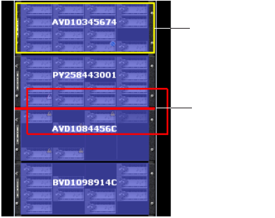
Viewing Information in the System Monitor Tool
247
Modifying the System Monitor Configuration
You can change the information displayed in the System Monitor by modifying or
rearranging the storage elements.
To rearrange the placement of a chassis displayed in the Rack tab:
1. Click to select the chassis you want to move.
A yellow frame highlights the active chassis.
2. Drag and drop the chassis to a new location in the System Monitor window. A red
insertion line appears when the chassis is moved to an appropriate position.
Active chassis
Red insertion
line
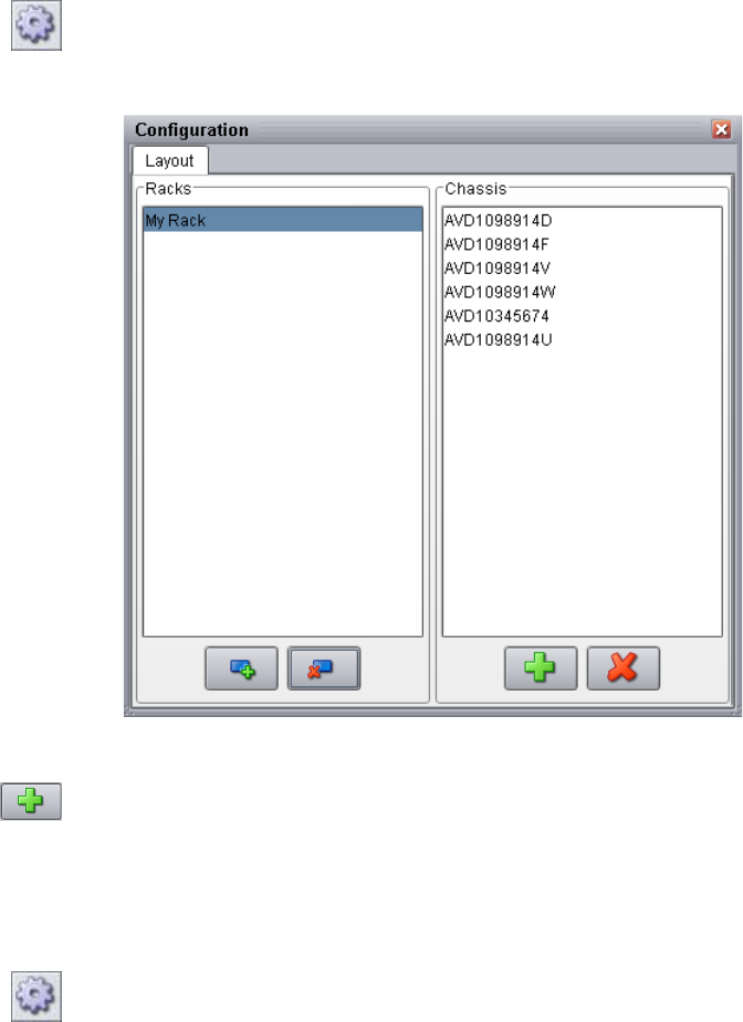
248
To add a chassis to a rack:
1. Click the Configure button.
The Configuration dialog box opens.
2. In the Racks column, select the rack you want to modify.
3. Click the Add Chassis button.
The Available Chassis dialog box opens.
4. Select a chassis, and click OK.
5. Click the Close button in the title bar.
To remove a chassis from a rack:
1. Click the Configure button.
The Configuration dialog box opens.
2. In the Racks column, select the rack you want to modify.
3. In the Chassis column, select the chassis you want to remove.

Viewing Information in the System Monitor Tool
249
4. Click the Remove Chassis button.
The chassis is removed from the Chassis list.
5. Click the Close button in the title bar.
To delete a rack:
1. Click the Configure button.
The Configuration dialog box opens.
2. In the Racks column, click the rack you want to delete.
3. Click the Delete button.
The rack is deleted from the Racks list.
4. Click the Close button in the title bar.
250

DAvid Unity ISIS E-mail Notification List
The following table lists the events logged by the System Director Service and related
components. A brief description of what the error means is also provided. This list does not
include the administrator server service.
Message Meaning Severity
uServera number, unit <location, location>,
SNb number, chassis number, slot location:
Disks operational
The disk on this ISB is operational. Informational
uServer number, unit <location, location>,
SN number, chassis number, slot location:
Disks failed
The disk on this ISB has failed. Error
uServer number, unit <location, location>,
SN number, chassis number, slot location:
Disks under test
The disk on this ISB is under test. Warning
uServer number, unit <location, location>,
SN number, chassis number, slot location:
Metadata errors
This ISB is reporting metadata errors. Error
uServer number, unit <location, location>,
SN number, chassis number, slot location:
Disk performance degraded
The disk on this ISB has degraded performance. Error
uServer number, unit <location, location>,
SN number, chassis number, slot location:
Unknown status
The disk on this ISB has an unknown status. Warning
uServer number, unit <location, location>,
SN number, chassis number, slot location:
Temp normal
The disk on this ISB is operating a normal
temperature.
Informational
uServer number, unit <location, location>,
SN number, chassis number, slot location:
Over temp
The disk on this ISB is hotter than the normal
temperature.
Error

252
Removing failed microserver number, unit
< location, location >, chassis number, slot
location
Removing the failed ISB disk from the specified
location.
Error
Microserver remove did not complete,
status location
The ISB did not completely get removed from
the specified location.
Error
Administrator password reset was
requested by administrative command
An administrative command was sent to reset
the administrator password.
Informational
Avid Unity ISIS dongle was not found. No
clients are allowed to connect.
The Avid Unity ISIS dongle was not found.
Clients are not allowed to connect.
Informational
Avid Unity ISIS dongle version is incorrect.
No clients are allowed to connect.
The Avid Unity ISIS dongle version is incorrect.
No clients are allowed to connect.
Informational
System Director shutdown because of
missing dongle
System Director is shutting down because of a
missing dongle.
Warning
Unable to validate PartitionDump.bin that
was just created
Unable to validate PartitionDump.bin that was
just created.
Error
Import pass 2: could not reconstruct from
the import file
The second attempt to import a file failed and
could not be reconstructed.
Error
THE IMPORT FAILED PLEASE CALL
AVID SERVICE BEFORE DOING
ANYTHING ELSE
The attempt to import a file has failed. Contact
Avid customer support.
Error
Can not locate valid metadata to load The System Director could not find a valid
metadata file to load.
Informational
Metadata converter failed to generate
export file
The metadata converter could not generate an
export file.
Error
Metadata converter generated new export
file
The metadata converter generated a new export
file.
Informational
Memory size changed. File system can be
reconfigured
The amount of memory has changed in the file
system. You can reconfigure the file system to
match the change.
Informational
Metadata import failed - file mgr exiting -
call AVID support
The attempt to import metadata has failed and
the file manager shutting down. Contact Avid
customer support.
Error
Partition does not fit into server configured
memory. There is not enough available
memory.
The drive partition is larger than the available
memory configured in the server.
Informational
Message (Continued) Meaning Severity

253
Dismount failed. Partition did not validate The workspace dismount failed. The system
could not validate the partition.
Error
Export started The system started the export. Informational
Export complete The system completed the export. Informational
Unmount Partition The system unmounted partition successfully. Informational
Export did not complete The system could not complete the export. Informational
Failed to create a unique id The system could not create a unique ID. Error
Local drive does not contain enough free
space for meta data files
The local drive in the System Director does not
contain enough free space for metadata files.
Error
System Director shutting down because
standby server may have better connectivity
A failover was triggered by a connectivity
change on the primary System Director.
Error
Synchronization metadata did not verify The system could not verify that the metadata is
synchronized.
Error
Meta data is corrupted The system has detected that the metadata is
corrupt.
Error
Reconfiguring because of install file system
request
The file system is reconfiguring because of an
install request.
Informational
Local drive does not contain enough free
space for meta data file
The local drive on the System Director does not
contain enough free space for metadata file.
Error
Unable to open a local metadata file The system was unable to open a metadata file
on the local drive.
Error
Avid Unity ISIS System Director service
stopped.
The service on the System Director has stopped. Informational
validateFS(): warning, fix made to allocated
byte counts
A fix was made to validate the byte counts that
were allocated to the file system.
Informational
validateFS(): warning, fix made to byte
counts
A fix was made to validate the byte counts on
the file system.
Informational
Sever disk errors, must shut down now Disk errors on the System Director are forcing
the server to shut down.
Error
System Director was requested to force
clients to log out
A process was initiated that requests the System
Director to log out the clients.
Informational
Message (Continued) Meaning Severity

254
Offline Canceled The condition taking the system offline was
corrected.
Informational
Interactive Start of System Director And Interactive Start of System Director has
been initiated.
Informational
Server will not start with an incorrect time
setting.
The System Director requires a valid time
setting.
Error
Server shutdown An event has occurred causing the System
Director to shut down.
Error
MetaUpgrade: Validated PartitionDump.bin
file
The metadata has been updated and a
PartitionDump.bin file has been created.
Informational
System Director shutting down because
standby server might have better
connectivity
One System Director is shutting down because
the failover System Director has better network
performance.
Error
Start metadata load failed The load failed when the System Director
attempted to load the metadata.
Warning
Metadata load failed The System Director was not able to completely
load the metadata.
Warning
Metadata is being deleted by user
instruction
The metadata is being deleted by the user. Warning
Remote access is enabled for the
management communication channel
Remote access in the communication channel
has been enabled.
Informational
FSrespond failed. Status is: location The File System at the specified location has
failed to respond.
Error
Client number is being forced to disconnect
by an administrative command
The specified client is being logged out by an
administrative command.
Warning
Failed to allocate memory error = location The System Director could not allocate memory
at the specified location.
Error
Loading metadata from number Metadata is being loaded from the specified
location.
Informational
Unable to save metadata to number
sequence number INT64_FORMAT
The System Director is unable to save the
metadata for the specified sequence and format.
Error
Going to fail Install File System, Memory
Needed location, Avail location
The File System install has failed because of
insufficient memory at the specified location.
Error
Message (Continued) Meaning Severity

255
Failed to create root microserver set The System Director could not create a root
microserver set.
Error
*******THE INSTALL FILESYSTEM
FAILED ******* fs error location
The File System has an error at the specified
location.
Error
Install File System Successful, Meta Data is
size MB
The File System has successful installed and
loaded the metadata. The size of the metadata
file is specified.
Informational
checkForMetaDataSave() sending to
standby server is taking too long to
complete
It is taking too long to check the metadata on the
standby File System.
Error
checkForMetaDataSave() saving to a file is
taking too long complete
It is taking too long to save the metadata on the
File System.
Error
Failed to setup a MetaData save operation
for number
The Files System could not set up a metadata
save operation on the specified File System.
Warning
Failed to update metadata on number Failed to update metadata on the specified File
System.
Error
CSMetaDataSendDone - the checksum
engine may be stuck
The engine metadata could not create a
checksum.
Error
sendMetaSyncToStandby() An async
request is taking too long to complete
It is taking too long to return an async request to
the File System.
Error
sendMetaSyncToStandby() replication is
taking too long to complete
It is taking too long to replicate an async to the
File System.
Error
Failed to allocate memory error = location The Files System could not allocate memory in
the specified location.
Error
Unable to clear previous tiebreaker IP
address: fstatus location
Unable to clear the IP address previously
assigned to the ISB.
Warning
Unable to update tiebreaker IP address:
fstatus location
Unable to update the IP address previously
assigned to the ISB.
Warning
System Director service can not be started
(err = location)
The specified System Director service cannot be
started.
Error
The low priority scheduler seems hung.
Shutting down.
There is no response from the low priority
scheduler and the System Director is shutting
down.
Error
Message (Continued) Meaning Severity

256
There is a problem saving metadata.
Shutting down.
There is a problem saving metadata to the
System Director and the System Director is
shutting down.
Error
Assert Error from number line location,
number
Assert error detected on line number in the
specified location.
Error
MetaUpgrade: Metadata converter
(number) was not present
When attempting to update the metadata, the
system Director could not locate the converter.
Error
MetaUpgrade: Error starting for metadata
converter - err location
When attempting to update the metadata, the
System Director detected an error in the
specified location.
Error
MetaUpgrade: Error waiting for metadata
converter - err location
When attempting to update the metadata, the
System Director detected an error while waiting
for a response from the specified location.
Error
MetaUpgrade: Error obtaining metadata
converter exit status - err location
When updating the metadata, the System
Director detected an error in the specified
location when finishing the update.
Error
Avid System Director (Version number) has
successfully started
The System Director (Version number) has
successfully started.
Informational
Updated tiebreaker IP address (number):
number
The System Director has updated the tiebreaker
IP address on the ISB to: number.
Informational
This server became the primary System
Director due to a failover event.
This server became the primary System Director
due to a failover event.
Informational
This server is ready to become the primary
System Director because it was the last
active server.
This server is ready to become the primary
System Director because it was the last active
server.
Informational
MetaUpgrade: Starting number metadata
converter
The System Director has started updating the
metadata on the specified converter.
Informational
Remote System Director is already active -
enabling synchronization
The synchronization on the remote System
Director is already active.
Informational
This server became the primary System
Director because other system is new
standby.
This server became the primary System Director
and the other server is the new standby.
Informational
This server became the primary System
Director because it was the most recent
metadata.
This server became the primary System Director
because it has the most recent metadata.
Informational
Message (Continued) Meaning Severity

257
This server became the active System
Director because it had the same version as
the other server.
This server became the active System Director
and has the same version as the other server.
Informational
The other server has more recent metadata -
enabling synchronization
The other server has more recent metadata and
this server is starting a metadata
synchronization.
Informational
System director start server failed, status =
location,
System Director service failed to start with the
specified error.
Warning
System director startup wait failed, status =
location, server state = location
System Director startup failed in a wait state at
the specified error.
Warning
Start metadata create failed status =
location
A failed status was reported when starting to
create the metadata at the specified location.
Warning
Metadata create wait failed, status =
location, state = location
A failed wait state was reported when creating
the metadata at the specified location.
Warning
Metadata load wait failed, status = location,
state = location
A load wait state was reported when creating the
metadata at the specified location.
Warning
Metadata create failed The System Director could not create the
metadata.
Warning
The metadata server is not in agreement -
disregarding
The metadata on the System Director is not in
agreement and is being removed.
Informational
Server start is scheduled in non-redundant
configuration
During the System Director start-up, it was
detected that the System Director is in a
non-redundant configuration.
Informational
This server now the active System Director This server now the active System Director. Informational
Started IP address number on interface
number
The ISB with the specified IP address is started
on the specified interface.
Informational
Could not find an interface with IP address
number
The System Director could not find an interface
with the specified IP address.
Informational
Unable to start failover IP address number Unable to start failover IP address number. Informational
Unable to start IP address number Unable to start the device at the specified
IP address.
Informational
Failover IP address number is not
configured or enabled
The failover device at the specified IP address is
not configured or enabled.
Informational
Message (Continued) Meaning Severity

258
MetaUpgrade: Metadata conversion
completed by number
The System Director completed the metadata
upgrade for the specified location.
Informational
MetaUpgrade: Metadata conversion was
not completed by number
The System Director could not complete the
metadata upgrade for the specified location.
Informational
a. uServer means the ISIS Storage Blade (ISB) microserver.
b. SN means serial number.
Message (Continued) Meaning Severity
A B C D E F G H I J K L M N O P Q R S T U V W X Y Z
Numerics
10-Gb Link Aggregation 213
A
Access privileges
changing 128
effective access 103, 128
managing 103, 107
setting 104
user accounts 107, 111, 113, 128
user group accounts 117, 119
Accounts
devices 119, 129
user groups 115
user, duplicating 114
users 112
Active Clients tab (System Director Control Panel)
169
Active mode
determining on System Director 159
Active partition 17
Active, storage element type 40
Adding
device accounts 122
group accounts 117
storage elements 44, 50, 66
storage elements to storage groups 75
storage groups 73
storage to the media network 43
user accounts 112
workspaces 88
Administration password
changing 176
Administration tool
Avid Unity ISIS Agents 208
described 23
Home page 24
Installers tab 208
logging 196
Logging tab 192
logs 183
Monitoring tab 236
opening 24
sorting information 33
Statistics tab 191
System tab 175
user interface overview 26
Administrator tasks 21
Advanced Settings tab (System Director Control
Panel) 172
Advanced support tools 175, 235
Advanced test group (Switch Infrastructure
Diagnostics) 229
Advanced Workspaces Commands 99
Agent logging 225, 227
Agent Logging window
described 224
opening 224
Aggregate bandwidth 132
Aggregate logs 196
Aggregator Options dialog box 199
Available, storage element type 40
Avid ISIS Interplay Health Monitoring Service 181
Avid Unity ISB Connection Analyzer tool 204
Avid Unity ISIS Agents
clearing logs 225
configuration values 213
Console View tool 222
deleting saved logs 227
described 208
Index
Index A B C D E F G H I J K L M N O P Q R S T U V W X Y Z
260
diagnostic tools 228
disabling logging 226
enabling logging 226
link aggregation 213
Logging tab 223, 224
opening 208
saving logs 226
Statistics tab 218, 219, 220, 221
System tab 213, 214
Tools tab 221, 222
user interface overview 210
viewing logs 225
viewing saved logs 227
Avid Unity ISIS Disk Tester tool 200
Avid Unity ISIS Engine
defined 22
resetting to factory defaults 227, 232
Avid Unity ISIS Home page 24
Avid Unity ISIS Integrated Expansion Switch (IXS)
See Switch blades
Avid Unity ISIS Integrated Switch (ISS)
See Switch blades
Avid Unity ISIS Log Aggregator
See Log Aggregator tool
Avid Unity ISIS storage blade (ISB)
See Storage elements
Avid Unity ISIS Switch Manager
See Switch Manager tool
Avid Unity ISIS System Administration tool See
Administration tool
Avid Unity ISIS System Director Control Panel
See System Director Control Panel
B
Bandwidth
aggregate 132
monitoring 131
removing components 133
revoking 133
setting system bandwidth 129
system 132
Bandwidth list
scaling the graph display 133
Bandwidth Monitor dialog box
described 131, 132
opening 132
Bandwidth option 31
Binding storage elements 44, 66
Blade Identification view (System Monitor tool) 245
Bound storage elements 44, 66
C
Characters
illegal, in storage group names 74
illegal, in user names 113
illegal, in workspace names 88
Chassis
descriptions 60
Details area 58, 60
Chassis dialog box
described 58
opening 59
Chassis Identification view (System Monitor tool)
245
Chassis list 58
Chassis option 28
Client accounts
See also User accounts, User group accounts,
Device accounts
deleting 126
described 107
device 121
group 116
modifying 124
removing 127
Client Manager
documentation 15
Columns
hiding 32
moving 32
performing multilevel sorts 33
sorting 33
Command menu 27
Components
disconnecting 136
removing 133
revoking bandwidth 133
Configuration
Avid Unity ISIS Agents 213
Configuration considerations
data protection 22
security 22
A B C D E F G H I J K L M N O P Q R S T U V W X Y Z Index
261
site type 22
uncompressed clients 22
Configuration tab (System Director Control Panel)
165
Configure button (System Monitor tool) 237
Configuring
e-mail error notification service 177
error notification parameters 181
general settings 167
System Director failover 139
Connection Analyzer tool
checking connection status 204
described 204
Connection Status dialog box
disconnecting components 136
opening 135
Connection Status option 31
Connectivity (Switch Infrastructure Diagnostics) 229
Console View tool 222
Control Panel
See System Director Control Panel
Counters (Switch Infrastructure Diagnostics) 229
Create Device dialog box 123
Create Group dialog box 118
Create Storage Group dialog box 74
Create User dialog box 112
Create Workspace dialog box 88
Creating
device accounts 122
group accounts 117
storage groups 73
user accounts 112
workspaces 88
D
Date, changing on chassis switch 214
Deleting
storage groups 80
user accounts 126
workspaces 106
Details
chassis 58, 60
storage elements 38
Details area
devices 122
groups 117
storage elements 35
storage groups 67, 69
users 108, 111
workspace 86
Device accounts
adding 122
creating 122
deleting 126
described 121
modifying 124
setting automatically 129
Device list 121
Devices dialog box
Details area 122
opening 119
Devices option 30
Diagnostic tests
Advanced group 229
Connectivity group 229
Counters group 229
Environment group 229
Hardware group 229
Performance group 228
results 229
running Switch Infrastructure Diagnostics 230
Stacking group 228
test groups 228
Diagnostic tools
Avid Unity ISIS Agents 227
Connection Analyzer tool 204
Disk Tester tool 200
Switch Manager tool 206
Dialog boxes
Bandwidth Monitor 131, 132
Chassis 58
Create Device 123
Create Group 118
Create Storage Group 74
Create User 112
Create Workspace 88
Duplicate User 114
Duplicate Workspace 90
Orphaned Elements 54
Preferences 129
Storage Elements 35
Storage Groups 67, 68
Index A B C D E F G H I J K L M N O P Q R S T U V W X Y Z
262
Users 108
Workspaces 82
Disabling protection
for workspaces 95
Disconnecting
components 136
Disk Test Options dialog box 203
Disk Tester tool
described 200
options 203
Documentation
client software 15
Drive sets
See Storage elements
Drives
See Storage elements
Duplicate User dialog box 114
Duplicate Workspace dialog box 90
Duplicating
user accounts 114
users 114
workspaces 90
E
Effective access 103, 128
E-mail notification 177, 177, 181, 251
Enable Protection option 95
Enabling protection
for workspaces 95
Environment test group (Switch Infrastructure
Diagnostics) 229
Error messages 251
Error notification 177, 181
Event Viewer
select events 193
F
Factory defaults, resetting 227, 232
Failover
configuring the System Director 139
starting and stopping System Director 159
File limit 23
File Systems Operations 168
G
General Configuration Options dialog box 167
General settings
configuring 167
General view (System Monitor tool) 242
Group accounts
adding 117
creating 117
deleting 126
described 116
modifying 124
Group Details area 117
Groups dialog box
opening 115
Guidelines
storage group usage 72
H
Hardware
storage, managing 35
Hardware group tests (Switch Infrastructure
Diagnostics) 229
Help
Administration tool 32
Help button 32
Hiding columns 32
Hi-Gig Link Aggregation 213
Home page
opening the Administration tool 24
Quick Launch menu 25
I
Identifying storage elements 51
Illegal characters
in storage group names 74
in user names 113
in workspace names 88
Initializing
active partition 17
standby partition 149, 158
System Director 17, 149, 158
Installers tab 208
Installing updates 208
IP Addresses view (System Monitor tool) 245
A B C D E F G H I J K L M N O P Q R S T U V W X Y Z Index
263
ISB (Avid Unity ISIS storage blade)
See Storage elements
ISIS Interplay Health Provider 181
ISIS Snapshot 184
ISS (Avid Unity ISIS Integrated Switch)
See Switch blades
ISS modules
upgrading 63, 64
IXS (Avid Unity ISIS Integrated Expansion Switch)
See Switch blades
IXS modules
upgrading 63, 64
L
Limits, files 23
Link aggregation
10-Gb Link Aggregation 213
described 213
Hi-Gig Link Aggregation 213
Log Aggregator tool
Archive Options 199
closing 196, 206
creating logs 198
described 196
event logs 196
opening 196
options 199
resource use 200
storage elements 199
switch blades 199
viewing logs 200
Logging tab 192, 223
Logout button 32
Logs
Administration tool 183
Agent logging 223
aggregate logs 196
archiving 199
clearing Agent logs 225
creating 198
deleting saved Agent logs 227
event log 165
filters 199
options 199
saving Agent logs 226
storage elements 199
switch blades 199
System Director Viewer 169
System Logging 192, 196
viewing 200
viewing Agent logs 225
viewing saved Agent logs 227
M
Management tasks 21
Managing
access privileges 107
drive hardware 35, 54, 67
storage groups 72
user accounts 107
workspaces 82
Media network
viewing components 239
Messages
System Director is not running 164
warning events 164
MetaData Status tab (System Director Control Panel)
171
Modifying
user accounts 124
Monitoring system usage 131
Monitoring tab 236
Moving
workspaces 101
Moving columns 32
Multilevel sorting 33
N
Network Time Protocol (NTP) 217
Notifications
configuring 177, 181
e-mail 177, 251
errors 251
NTP (Network Time Protocol) 217
Index A B C D E F G H I J K L M N O P Q R S T U V W X Y Z
264
O
Online Help
See Help
Options (Command menu)
Bandwidth 31
Chassis 28
Connection Status 31
Devices 30
Orphaned Elements 31
Preferences 31
Storage Elements 28
Storage Groups 29
User Groups 30
Users 30
Workspaces 29
Orphaned elements
removing 55
Orphaned Elements dialog box
described 54
Orphaned Elements option (Command menu) 31
Orphaned storage elements
described 53
removing 53
P
Partitions
creating active 17
creating standby 149
Passwords
administration 176
administrator 24
changing 124, 176
client 107
user 111, 113
Performance (Switch Infrastructure Diagnostics) 228
Preferences
option (Command menu) 31
setting 129
Privileges
access levels 103
changing user access privilege 128
setting user access privilege 104
user access privilege 103, 107, 111, 113
user group access privilege 117, 119
Profile tool 188
Protection
disabling, for workspaces 95
enabling, for workspaces 95
recommendations 94
Q
Quick Launch menu 25
R
Racks
viewing back panels 240
viewing in System Monitor tool 239
Reconfiguring the file system 168
Rectifying files 42, 46
Redistribution
described 49, 96
guidelines 96
manual 96, 97
monitoring 52
removing storage elements 49
replacing storage elements 50
resuming 99
suspending 99
verifying 99
Redundancy for System Director 141, 151
Removing
orphaned storage elements 55
storage elements 48, 49, 52, 66
storage elements from storage groups 76
Renaming
workspaces 92
Reset Event button 165
Resetting switch error count 206
Resetting to factory defaults 227, 232
Resizing workspaces 91
Rotate Rack View button (System Monitor tool) 240
S
Security considerations 22
Sorting information 33
Spare, storage element type 40
Stacking (Switch Infrastructure Diagnostics) 228
Standby mode
determining on System Director 159
A B C D E F G H I J K L M N O P Q R S T U V W X Y Z Index
265
Standby partition 149, 158
Start System Director button 164
Starting
System Director 166
System Director Control Panel 161
Statistics
Avid Unity ISIS Agents 218
storage element 218
Statistics tab 191, 219
Statistics window
opening 191, 219
Status Details view (System Monitor tool) 243
Status messages
storage elements 41, 46
Stop System Director button 164
Stopping
shutting down the System Director 166
Storage
adding, to the media network 43
capacity 22
Storage blade
statistics 220
Storage elements
active 40
adding 43, 44, 50, 66
adding to storage groups 75
available 40
binding or adding 44, 66
changing date and time 217
Console View tool 222
descriptions 38
Details area 35, 38
disconnected 53, 55
identifying prior to removal 51
orphaned 53
rectifying files 42, 46
removing 48, 49, 52, 66
removing from storage groups 76
spare 40
starting 216
statistics 218, 220
status 41, 46
stopping 216
upgrading 57, 63, 64
Storage Elements area 69
Storage Elements dialog box
described 35
opening 36
Storage Elements list 35
Storage Elements option 28
Storage groups
adding 73
adding storage elements 75
deleting 80
described 67, 72
Details area 67, 69
managing 72
removing storage elements 76
usage guidelines 72
Storage Groups dialog box
described 67
opening 68
Storage Groups list 67
Storage Groups option 29
Storage hardware
managing 35
Support tools 161, 175, 235
Suspending redistribution 99
Switch blades
changing date and time 214, 217
resetting to factory defaults 227, 232
statistics 221
upgrading 63, 64
Switch error count 206
Switch Infrastructure Diagnostics 228, 229, 230
Switch Manager tool
described 206
opening 206
Switches
statistics 221
System administration functions 175
System Director
chassis information 60
determining active or standby mode 159
initializing 17
initializing failover system 149, 158
shutting down 166
starting 164, 166
starting and stopping during failover 159
stopping 164
storage elements information 38
storage group information 69
Index A B C D E F G H I J K L M N O P Q R S T U V W X Y Z
266
System Director Control Panel
Active Client tab 169
Advanced Settings tab 172
Configuration tab 165
creating active partition 18
described 161
initializing System Director 18
MetaData Status tab 171
reconfiguring the file system 168
starting 161
System Director Status tab 163
System Director failover
configuring the first System Director 141, 151
configuring the second System Director 144, 153
configuring virtual addresses 148, 157
setting IP addresses 140, 150
validating connections 146, 155
System Director is not running message 164
System Director Status tab (System Director Control
Panel) 163
System Director Viewer 169
System logging 192
System Logging window
described 192
opening 194
System Monitor tool
Blade Identification view 245
changing information 247
Chassis Identification view 245
Configure button 237
configuring 237
described 235
display 241
General view 242
IP Addresses view 245
modifying information 247
opening 236
Rotate Rack View button 240
Status Details view 243
Temperatures view 246
Upgrades view 246
viewing racks 239
viewing system information 239
Zoom button 241
System Preferences
setting 129
System Read Bandwidth 132
System tab 175
System usage
monitoring 131
System Write Bandwidth 132
Systems buttons 32
T
Temperatures view (System Monitor tool) 246
Time, changing on chassis switch 214, 217
Tools
Administration, overview 23
advanced support 175
Avid Unity ISIS System Administration tool 23
Connection Analyzer tool 204
Disk Tester tool 200
ISIS Snapshot 184
Log Aggregator tool 196
Profile tool 188
storage element Agent 221
Switch Manager tool 206
System Director Control Panel 161
System Monitor tool 235
Tools tab 221
Trunking 213
U
Unbound storage elements 44, 66
Updating software 208
Upgrades view (System Monitor tool) 246
Upgrading
ISS modules 63, 64
IXS modules 63, 64
storage elements 57, 63, 64
switch blades 63, 64
User Access area 86, 87
User accounts
access privilege 103, 107, 111, 113
adding 112
changing access privilege 128
changing privileges 128
creating 112
deleting 126
described 109
duplicating 114
levels of access privilege 103
A B C D E F G H I J K L M N O P Q R S T U V W X Y Z Index
267
managing 107
modifying 124
passwords 124
privileges 103, 107, 111, 113
setting access privilege 104
User Details area 111
User group accounts
access privilege 117, 119
privileges 117, 119
User Groups option 30
User interface
Administration tool 26
Avid Unity ISIS Agents 210
Users
duplicating 114
Users dialog box
described 108
Details area 108
opening 109
Users list 108, 110
Users option 30
V
Verifying redistribution 99
W
Warning events messages 164
Workspace Details area 86, 86
Workspaces
access privileges 103
adding 88
allocating 81
creating 88
deleting 106
deleting from a Macintosh system 106
described 86
duplicating 90
graphical display 85
managing 81
moving 101
protecting 94
redistribution of data 96, 97
renaming 92
resizing 91
Workspaces dialog box
described 82
opening 82
Workspaces list 83
Workspaces option 29
Workspaces Size graph 85
Z
Zoom button (System Monitor tool) 241
