Avid INEWS ControlAir Installation And Operations Manual I News Control Air 1.0.5 & CA V1.0.5
User Manual: avid iNews ControlAir - 1.0.5 - Installation & Operations Manual Free User Guide for Avid iNews Software, Manual
Open the PDF directly: View PDF ![]() .
.
Page Count: 212 [warning: Documents this large are best viewed by clicking the View PDF Link!]
- Contents
- Preface
- Chapter 1
- Introduction to the iNEWS ControlAir™ System
- Chapter 2
- Preparing for Installation
- Chapter 3
- Installing and Configuring iNEWS ControlAir
- Chapter 4
- Setting up the Monitor Server on iNEWS Servers
- Overview
- Configuring Monitor Servers
- Configuration Summary
- Configuration Details
- Step 1: Creating a Monitor Server for Each Show
- Reconfigure the System
- Assigning the Mailbox to the Rundown Queue
- Using the list Command to View Assigned Mailboxes
- Step 2: Creating Composite and Event List Queues
- Step 3: Set Up Queue and Story Forms
- Step 4: Assigning Forms to Queues
- Step 5: Create an Entry in the SYSTEM.MAP Story
- Step 6: Updating the iNEWS System Dictionaries (Optional)
- Editing the /site/dict/mcs Dictionary File
- Styles
- Using the Monitor Server
- Chapter 5
- Working with Devices
- Chapter 6
- Control Air Operations
- Chapter 7
- Troubleshooting
- Appendix A
- Appendix B
- Appendix C
- Glossary
- Index

iNEWS ControlAir™
Installation & Operations Manual
Version 1.0.5

Copyright and Disclaimer
© 2001, Avid Technology, Inc. All rights reserved. All Avid products are covered by U.S. and foreign
patents, issued and pending. Information in this publication supersedes that in all previo1usly pub-
lished material. Specifications and price change privileges reserved.
The software described in this document is furnished under a license agreement and is protected
under the copyright laws of the United States and other countries.
U.S. GOVERNMENT USERS RESTRICTED RIGHTS: Use, duplication, or disclosure by the U.S. Gov-
ernment is subject to restriction as set forth in subparagraph (b)(2) of the Technical Data and Com-
puter Software-Commercial items clause at DFARS 252.211-7015, or in subparagraph (c)(2) of the
Commercial Computer Software-Restricted Rights clause at FAR 52.227-19, as applicable.
Avid is a registered trademark of Avid Technology, Inc. Media Browse, ControlAir, iNEWS ControlAir
and iNEWS are trademarks of iNews, LLC. Microsoft, the Microsoft logo, MS, MS-DOS, Win 32, Win-
dows, Windows NT, Windows 2000, Windows NT Server, and the Windows operating system logo
are registered trademarks of Microsoft Corporation in the United States of America and other coun-
tries. UNIX is a registered trademark of X/Open Company, Ltd. All other trademarks and registered
trademarks used herein are the property of their respective owners.
Avid
6400 Enterprise Lane
Madison, Wisconsin 53719 USA
Tel: +1-608-274-8686 Fax: +1-608-273-5876
Avid
Intec 1
Wade Road
Basingstoke Hants RG24 8NE UK
Tel: +44 1256 814300 Fax: +44 1256 814700
Avid
315 Alexandra Road
#03-01 Performance Centre
159944 Singapore
Tel: +65 3789 534 Fax: +65 475 7666
Avid
Tegel Forum
Breitenbachstraße 10
Berlin 13509 GERMANY
Tel: +49 30 5900993 0 Fax: +49 30 5900993 24
iNEWS ControlAir™ Installation & Operations Manual Version 1.0.5
Document # 0130-00874 Rev. C (bbl)
September 23, 2002
Printed in the United States of America

i
Contents
Preface
Who Should Use This Guide . . . . . . . . . . . . . . . . . . . . . . . . . . . . . . . . . . . v
About This Manual . . . . . . . . . . . . . . . . . . . . . . . . . . . . . . . . . . . . . . . . . . . v
Symbols and Conventions . . . . . . . . . . . . . . . . . . . . . . . . . . . . . . . . . . . . vi
Cross References . . . . . . . . . . . . . . . . . . . . . . . . . . . . . . . . . . . . vii
Keyboard Conventions . . . . . . . . . . . . . . . . . . . . . . . . . . . . . . . . . . viii
If You Need Help. . . . . . . . . . . . . . . . . . . . . . . . . . . . . . . . . . . . . . . . . . . viii
Related Information. . . . . . . . . . . . . . . . . . . . . . . . . . . . . . . . . . . . . . . . . . ix
If You Have Documentation Comments . . . . . . . . . . . . . . . . . . . . . . . . ix
How To Order Documentation . . . . . . . . . . . . . . . . . . . . . . . . . . . . . . . . . x
Chapter 1 Introduction to the iNEWS ControlAir™ System
Overview. . . . . . . . . . . . . . . . . . . . . . . . . . . . . . . . . . . . . . . . . . . . . . . . . . 1-2
Links to Other Newsroom Products . . . . . . . . . . . . . . . . . . . . . . . 1-2
System Architecture . . . . . . . . . . . . . . . . . . . . . . . . . . . . . . . . . . . . . . . . 1-3
ControlAir Components . . . . . . . . . . . . . . . . . . . . . . . . . . . . . . . . . 1-4
ControlAir Server . . . . . . . . . . . . . . . . . . . . . . . . . . . . . . . . . . . 1-4
casvr.exe . . . . . . . . . . . . . . . . . . . . . . . . . . . . . . . . . . . . . . . 1-4
AMCPapp.exe. . . . . . . . . . . . . . . . . . . . . . . . . . . . . . . . . . . 1-5
camgr.exe. . . . . . . . . . . . . . . . . . . . . . . . . . . . . . . . . . . . . . . 1-5
Device Managers. . . . . . . . . . . . . . . . . . . . . . . . . . . . . . . . . . . . 1-5
ControlAir Workstation . . . . . . . . . . . . . . . . . . . . . . . . . . . . . . 1-6
Monitor Server. . . . . . . . . . . . . . . . . . . . . . . . . . . . . . . . . . . . . . 1-6
ControlAir Work Flow . . . . . . . . . . . . . . . . . . . . . . . . . . . . . . . . . . . . . . 1-9
Monitor Mode - On. . . . . . . . . . . . . . . . . . . . . . . . . . . . . . . . . 1-10
Monitor Mode - Load . . . . . . . . . . . . . . . . . . . . . . . . . . . . . . . 1-12
Monitor Mode - Unload . . . . . . . . . . . . . . . . . . . . . . . . . . . . . 1-14

ii
Chapter 2 Preparing for Installation
Before You Begin the Installation Procedure . . . . . . . . . . . . . . . . . . . 2-2
Site Requirements. . . . . . . . . . . . . . . . . . . . . . . . . . . . . . . . . . . . . . . . . . 2-2
Power Requirements. . . . . . . . . . . . . . . . . . . . . . . . . . . . . . . . . . . . 2-3
Environmental Requirements . . . . . . . . . . . . . . . . . . . . . . . . . . . . 2-4
Hardware Requirements . . . . . . . . . . . . . . . . . . . . . . . . . . . . . . . . 2-4
ControlAir Server . . . . . . . . . . . . . . . . . . . . . . . . . . . . . . . . . . . 2-5
ControlAir Workstation. . . . . . . . . . . . . . . . . . . . . . . . . . . . . . 2-6
Machine Control PC (MCS-PC) . . . . . . . . . . . . . . . . . . . . . . . 2-7
Ports . . . . . . . . . . . . . . . . . . . . . . . . . . . . . . . . . . . . . . . . . . . . . . 2-7
Additional Serial Ports . . . . . . . . . . . . . . . . . . . . . . . . . . . 2-7
COM Ports—Digi and Equinox. . . . . . . . . . . . . . . . . . . . 2-8
Configuring & Installing the Host Adapter Card . . . . . . . . . . . . . . 2-10
Installing the Digi Software Driver . . . . . . . . . . . . . . . . . . . 2-13
On Windows 2000-based PC . . . . . . . . . . . . . . . . . . . . . 2-13
On Windows NT-based PC . . . . . . . . . . . . . . . . . . . . . . 2-14
Installing the Equinox Software Driver. . . . . . . . . . . . . . . . 2-15
Chapter 3 Installing and Configuring iNEWS ControlAir
Overview of the Setup . . . . . . . . . . . . . . . . . . . . . . . . . . . . . . . . . . . . . . 3-2
Adding IP Addresses on ControlAir Server . . . . . . . . . . . . . . . . 3-2
Adding IP Addresses on iNEWS Servers. . . . . . . . . . . . . . . . . . . 3-3
Installing ControlAir Software . . . . . . . . . . . . . . . . . . . . . . . . . . . 3-5
Configuring ControlAir Software . . . . . . . . . . . . . . . . . . . . . . . . 3-25
Setup ControlAir Manager . . . . . . . . . . . . . . . . . . . . . . . . . . 3-25
Chapter 4 Setting up the Monitor Server on iNEWS Servers
Overview . . . . . . . . . . . . . . . . . . . . . . . . . . . . . . . . . . . . . . . . . . . . . . . . . 4-2
Configuring Monitor Servers . . . . . . . . . . . . . . . . . . . . . . . . . . . . . . . . 4-3
Configuration Summary. . . . . . . . . . . . . . . . . . . . . . . . . . . . . . . . . 4-4
Configuration Details . . . . . . . . . . . . . . . . . . . . . . . . . . . . . . . . . . . 4-4
Reconfigure the System . . . . . . . . . . . . . . . . . . . . . . . . . . . . . . 4-9
Assigning the Mailbox to the Rundown Queue . . . . . . . . 4-10

iii
Using the list Command to View Assigned Mailboxes. . . 4-11
Editing the /site/dict/mcs Dictionary File. . . . . . . . . . . . . 4-29
Styles . . . . . . . . . . . . . . . . . . . . . . . . . . . . . . . . . . . . . . . . . . . . . . . . . . . . 4-33
Creating Styles . . . . . . . . . . . . . . . . . . . . . . . . . . . . . . . . . . . . . . . . 4-35
Using the Monitor Server . . . . . . . . . . . . . . . . . . . . . . . . . . . . . . . . . . . 4-41
Chapter 5 Working with Devices
Overview. . . . . . . . . . . . . . . . . . . . . . . . . . . . . . . . . . . . . . . . . . . . . . . . . . 5-2
Native Device Managers . . . . . . . . . . . . . . . . . . . . . . . . . . . . . . . . . 5-4
MCS-PC Device Manager . . . . . . . . . . . . . . . . . . . . . . . . . . . . . . . . 5-5
Adding Devices . . . . . . . . . . . . . . . . . . . . . . . . . . . . . . . . . . . . . . . . . . . . 5-6
DMP Configuration Files . . . . . . . . . . . . . . . . . . . . . . . . . . . . . . . . . . . . 5-6
What Does a DMP File Do?. . . . . . . . . . . . . . . . . . . . . . . . . . . . . . . 5-8
Character Mapping . . . . . . . . . . . . . . . . . . . . . . . . . . . . . . . . . . . . . 5-9
For Native DMs . . . . . . . . . . . . . . . . . . . . . . . . . . . . . . . . . . . . 5-10
For MCS-PC DM . . . . . . . . . . . . . . . . . . . . . . . . . . . . . . . . . . . 5-10
Chapter 6 Control Air Operations
Overview. . . . . . . . . . . . . . . . . . . . . . . . . . . . . . . . . . . . . . . . . . . . . . . . . . 6-2
The ControlAir Server Program . . . . . . . . . . . . . . . . . . . . . . . . . . . . . . 6-3
Printing ControlAir Server Diagnostics. . . . . . . . . . . . . . . . . 6-3
Setting Diagnostic Filters . . . . . . . . . . . . . . . . . . . . . . . . . . . . . 6-4
Stopping and Starting the ControlAir Server. . . . . . . . . . . . . . . . 6-6
Setting the Override Password. . . . . . . . . . . . . . . . . . . . . . . . . . . . 6-7
The AMCP Application Program . . . . . . . . . . . . . . . . . . . . . . . . . . . . . 6-9
Device Manager Windows. . . . . . . . . . . . . . . . . . . . . . . . . . . . . . . . . . 6-12
Device Status at the ControlAir Workstation . . . . . . . . . . . . . . . . . . 6-13
Chapter 7 Troubleshooting
ControlAir Components. . . . . . . . . . . . . . . . . . . . . . . . . . . . . . . . . . . . . 7-2
Where to Look for Errors . . . . . . . . . . . . . . . . . . . . . . . . . . . . . . . . . . . . 7-2
Visual Indicators. . . . . . . . . . . . . . . . . . . . . . . . . . . . . . . . . . . . . . . . 7-3
Error Messages . . . . . . . . . . . . . . . . . . . . . . . . . . . . . . . . . . . . . . . . . 7-4

iv
Other Problem-Solving Tips . . . . . . . . . . . . . . . . . . . . . . . . . . . . . . . . . 7-5
ControlAir Manager . . . . . . . . . . . . . . . . . . . . . . . . . . . . . . . . . . . . 7-5
Gathering Diagnostic Data. . . . . . . . . . . . . . . . . . . . . . . . . . . . . . . 7-5
Capturing Server Data Logs . . . . . . . . . . . . . . . . . . . . . . . . . . 7-5
Saving Rundown Data. . . . . . . . . . . . . . . . . . . . . . . . . . . . . . . 7-6
Appendix A Error Messages
Errors . . . . . . . . . . . . . . . . . . . . . . . . . . . . . . . . . . . . . . . . . . . . . . . . . . . . A-2
Error Message Tokens. . . . . . . . . . . . . . . . . . . . . . . . . . . . . . . . . . A-29
Appendix B System Reference Files
The autostart.ini File. . . . . . . . . . . . . . . . . . . . . . . . . . . . . . . . . . . . . . . . B-2
The /etc/hosts File. . . . . . . . . . . . . . . . . . . . . . . . . . . . . . . . . . . . . . . . . B-3
Sample Configuration File on iNEWS Servers . . . . . . . . . . . . . . . . . . B-4
Sample SYSTEM.MAP Story. . . . . . . . . . . . . . . . . . . . . . . . . . . . . . . . . B-5
Appendix C Upgrading Information
Upgrading to iNEWS . . . . . . . . . . . . . . . . . . . . . . . . . . . . . . . . . . . . . . . C-2
Glossary
Index
Preface
This publication provides information on how to install and manage
the iNEWS ControlAir system.
Who Should Use This Guide
This manual is written for journalists, producers, directors, writers,
and various technical personnel responsible for using the iNEWS Con-
trolAir system in a broadcast newsroom. Portions of the manual pro-
vide installation data for technicians. Other chapters provide
configuration and maintenance information for system administrators
who are managing the system.
nIt is strongly recommended that system administrators have prior experience
in or classroom knowledge of the Windows 2000 or NT® operating system.
About This Manual
This guide will lead you through even the most complex procedures
with task-oriented instructions, illustrated for a more realistic presen-
tation of the actual icons and images you will encounter. The informa-
tion provided here builds on basic user procedures, while adding a

vi
complete explanation of all the tools and techniques required to create,
apply, and adjust various settings, including useful tips, shortcuts, and
custom options.
The Table of Contents that precedes this preface lists all topics
included in the book. They are presented with the following overall
structure:
•The Introduction helps you get oriented with beginning concepts
and general work flow and provides valuable pointers to keep in
the back of your mind as you proceed.
• The main body of the guide follows the natural flow of your work,
with clear and comprehensive step-by-step procedures.
• At the back of the book is a comprehensive Glossary, providing
cross-industry terms and definitions.
• Finally, a detailed Index helps you quickly locate specific topics.
This manual provides requirements and specifications for your system
in the following areas:
• Environmental and electrical
• Minimum hardware and software components
• Installation procedures
• System configuration and maintenance
Use this manual to prepare for and set up your system on the network,
after you have purchased ControlAir components according to
requirements and specifications. Before installing any equipment, the
site must already have a configured network.
Symbols and Conventions
The ControlAir documentation uses the following special symbols and
conventions:

vii
Symbols and Conventions
1. Numbered lists, when the order of the primary items is important.
a. Alphabetical lists, when the order of secondary items is
important or in the case of optional procedures.
• Bulleted lists, when the order of primary items is unimportant.
- Indented dashed lists, when the order of secondary items is
unimportant.
Look here in the margin
for tips and environ-
ment-specific informa-
tion.
In the margin you will find tips that help you perform tasks more eas-
ily and efficiently. You will also find information specific to a particu-
lar operating environment.
nA note provides important related information, reminders, recommendations,
and strong suggestions.
cA caution means that a specific action you take could harm your
computer or cause you to lose data.
Cross References
Cross references are provided throughout this manual to give readers
locations where additional—sometimes more detailed—information
on a certain topic can be found. In some cases, the chapter name and
number is provided. In most cases, a two-part page number is given
along with the name of a section header. The first number in the page
number is actually the chapter number.
For instance: See “ControlAir Work Flow” on page 1-9.
See “About This Man-
ual” on page v for more
information on what
chapters are in which
sections of this manual.
In this example, information on work flows through a ControlAir sys-
tem can be found on page 1-3 in Chapter 1 of this manual. Chapters
are numbered consecutively; page numbers restart at one in each
chapter. Section numerals are not provided in cross references. So, a
cross reference that shows page 9-57, for instance, indicates that the
information is in Chapter 9.

viii
Keyboard Conventions
•CTRL-x means to press and hold down the Control key and then
press another key on the keyboard, represented here by x. This is
also used for other key-combinations such as ALT-x or Shift-x.
•“Type” in a command procedure means to type the command on
the command line and then “press” the Enter key.
•“Select” means to choose an operation on a drop-down or pop-up
menu.
•“Click” means to click the left mouse button, usually in response
to a dialog box. “Right-click” means to click the right mouse but-
ton.
If You Need Help
If you are having trouble using ControlAir, you should:
1. Repeat the procedure, carefully following the instructions pro-
vided for the task in this guide.
2. Refer to the documentation included with your hardware to
review the maintenance procedures or the hardware-related
issues.
3. Check the Support section of Avid’s Web site at
http://www.avid.com/support/ for online technical publications
and additional telephone support phone numbers.
4. Maintenance Agreement contract customers can contact Avid
Broadcast Customer Support personnel at any of these 24-hour
global telephone numbers:
•1 800 639 7364 in the Americas (All Broadcast products, except
Newsview)
•44 1256 814222 in Europe, Africa, and Mid-East
•61 2 8877 6880 in Asia/Pacific

ix
Related Information
Or online:
•e-mail support@inewsroom.com
•http://www.avid.com/support/contact.html
For general information, call your local Avid reseller or in North
America call the Avid Broadcast Customer Relations desk at
1-800-869-7009.
Related Information
Contact your Avid Sales representative for documentation and infor-
mation on other Avid® products, such as the iNEWS™ newsroom com-
puter system, Media Browse™, EditStar™, LeaderPlus™, MOS
Gateway, and so forth.
If You Have Documentation Comments
The Avid Broadcast Technical Publications department continually
seeks to improve its documentation. We value your comments about
this manual or other Avid-supplied documentation.
Send your documentation comments by e-mail to:
techpubs@inewsroom.com
Include the title of the document, its part number, revision, and the
specific section that you are commenting on in all correspondence.

x
How To Order Documentation
To order additional copies of this documentation from within the
United States, call the Avid Sales department at 1-608-274-8686. If you
are placing an order from outside the United States, contact your local
Avid Sales representative.

1-2
Introduction to the iNEWS ControlAir™ System
Overview
The iNEWS ControlAir system is a machine control system for on-air
operations, which can be integrated into the iNEWS newsroom com-
puter system. It can also operate in a standalone environment if the
iNEWS connection is lost.
A ControlAir system normally consists of one or more servers, one or
more workstations, and several Device Managers (DMs).
Also, ControlAir:
•Directly controls production devices
•Receives information from the iNEWS Workstation as control
events are entered into production cues in scripts
•Handles several shows simultaneously, while enabling shows to
be produced back-to-back, with only a few seconds between them
Windows-based workstations, with Graphical User Interfaces (GUIs),
allow production personnel to control events on the ControlAir
Server.
Links to Other Newsroom Products
The iNEWS ControlAir system also provides efficient links to other
Avid products for additional scripting and video capabilities, such as
Digital News Gathering (DNG), a disk-based production system,
which stores digital video, audio, and graphics data in a single central
library. That data is then accessible by workstations for recording, edit-
ing, and playback. Another feature is the iNEWS CG Title Entry, which
enables newsroom personnel to simulate character-generated graphics
on the iNEWS Workstation.
The iNEWS product set is constructed on a modular, open architec-
ture, enabling its components to work efficiently not only with other
Avid products, but also with third-party hardware and software. The
iNEWS newsroom computer system operates on industry-standard

1-3
System Architecture
technologies, including Windows®-based operating systems,
Intel®-based PCs, Intel and Silicon Graphics®-based servers, and TCP/
IP Internet networking protocols.
Avid publishes open Applications Programming Interfaces (APIs) for
ControlAir that enables integration with third-party software and
hardware.
System Architecture
There are three groups of software in the iNEWS ControlAir system.
•The ControlAir Server (which includes the casvr.exe and
AMCPapp.exe executable programs)
•Device Managers (DMs)
•ControlAir Workstation
Typically, ControlAir Server software and DMs are installed on the
ControlAir Server, while the ControlAir Workstation is installed on
computers in each of the control rooms where ControlAir will be oper-
ated. So, the ControlAir architecture consists of:
•ControlAir Server
•Avid Machine Control Protocol application (AMCPapp.exe)
•ControlAir Server application (casvr.exe)
•ControlAir Manager application (camgr.exe)
•Device Managers
•ControlAir Workstation(s)
•The monitor server utility program - running on the iNEWS
Server.

1-4
Introduction to the iNEWS ControlAir™ System
nControlAir software can be installed on either the Mirror Net or the House
Net of the iNEWS hosts. If ControlAir components need access to other sta-
tion networking services than just iNEWS Servers, then they should be
placed on the House network. In either case, static IP addresses and local
hosts files should be used for all ControlAir components.
ControlAir Components
There are several ControlAir components, including the ControlAir
Server program (casvr.exe),AMCP application ( AMCPapp.exe),
ControlAir Manager program (camgr.exe), device managers, and
ControlAir Workstation, which are explained in this section.
ControlAir Server
The ControlAir Server is a computer that will minimally run the
casvr.exe, AMCPapp.exe, and camgr.exe programs. Device
managers should also reside on the same server as the ControlAir
Server program (casvr.exe). You can run ControlAir Workstation
software on this computer, if desired, but it is not required. For more
information on hardware requirements for the ControlAir Server, see
“Hardware Requirements” on page 2-4.
casvr.exe
The executable program called casvr.exe is the central program that
runs on the ControlAir Server.
The ControlAir Server program:
•Routes status and messages between AMCPapp.exe, device man-
agers, and ControlAir Workstations
•Creates and manages playlists and downloads them to their
respective devices
•Tracks which components have playlists and devices reserved

1-5
System Architecture
•Directs control commands from ControlAir Workstation to the
appropriate device manager.
AMCPapp.exe
The executable program called AMCPapp.exe is the interface between
Avid’s iNEWS newsroom computer system and the ControlAir Server
running casvr.exe. It translates Avid Machine Control Protocol
(AMCP) data coming in from iNEWSor other newsroom computer
systemsinto data that the ControlAir system can manage.
camgr.exe
The executable program named camgr.exe is known as the
ControlAir Manager and it monitors ControlAir components, includ-
ing device managers, on the ControlAir Server. If one stops running,
the ControlAir Manager will restart it automatically.
nControlAir Manager can also monitor third-party device managers.
For information on configuring this program, see “Setup ControlAir
Manager” on page 3-25.
cIf casvr.exe fails, components must be reconnected to the server.
If the ControlAir Manager program is set up, it will monitor device
managers and reconnect them to the ControlAir Server should they
stop running. If ControlAir Manager is not used, the DMs cannot
automatically reconnect and must be restarted manually. Any play-
lists loaded at the time must be reloaded if the ControlAir Server
program (casvr.exe) is stopped.
Device Managers
A Device Manager (DM) is the program that handles communication
between ControlAir and specific production devices. When the con-
nection is made to casvr.exe, the DM will accept playlists from
iNEWS and commands from ControlAir Workstation. Device manag-

1-6
Introduction to the iNEWS ControlAir™ System
ers should be installed on the ControlAir Server—the same computer
running the casvr.exe program.
Each DM is designed to control a specific machine. For instance,
LouthDM.exe is a DM designed to control any video server that cor-
rectly supports the Louth video device control protocol (VDCP)—such
as Avid’s AirSPACE series of video servers.
There are existing DMs that allow the ControlAir operator to control
the following machine types used for broadcast production:
•Character generators
•Still stores
•Video playback devices
ControlAir Workstation
From the ControlAir Workstation, the ControlAir operator can view
playlists that have been downloaded from iNEWS, get device and
event status, and control the broadcast production devices.
The ControlAir client software can run on the same computer as the
casvr.exe program, or on a separate computer.
Monitor Server
The monitor server is not an actual part of the ControlAir system soft-
ware, but is a utility program on the iNEWS Server. For ControlAir, it
is used to scan stories in the rundown, searching for production cues
to build lists of machine control events (playlists) for the production
devices. It continues monitoring the rundown for changes to produc-
tion cues and sends them to the ControlAir system until the show goes
off the air.
Figure 1-1 depicts how connections are made from iNEWS, through
the Avid Machine Control Protocol Application (AMCPapp.exe), to
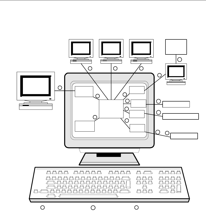
1-7
System Architecture
the ControlAir Server program (casvr.exe), then to the ControlAir
Workstation, device managers, and devices.
Figure 1-1 Association of Components in ControlAir
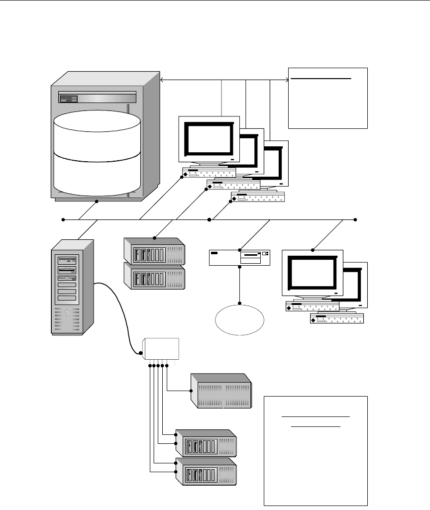
Figure 1-2 shows network (TCP-IP) and serial connections between
equipment related to the ControlAir system.
ControlAir
Server
Application
(casvr.exe)
Device
Manager
Device
Manager
Device
Manager
Device
Manager
iNEWS
newsroom computer system
ControlAir
Workstation
AMCP
Application
ControlAir
Workstation
MCS-PC
ControlAir
Workstation ControlAir
Workstation
N
N NN
C
C
C
C
C
C
Still Store
Character Generator
Video
S
S
S
N
S
Still Store,
CG, Cart, &
other Video
Devices
SCN Network Serial Communication between
programs in computer
N
or
1-8
Introduction to the iNEWS ControlAir™ System
Figure 1-2 Typical ControlAir Network Layout
iNEWS Server:
Leitch
ASC 300's
Any MCS Legacy
Playback device
ControlAir Server
Connections
Typically, most ControlAir components
(casvr.exe, AMCPapp.exe, & DMs) will
run on the ControlAir Server.
Some DMs (Louth) will attach to their
production devices via Equinox or other
multi-port serial board (RS-422 and/or
RS-232). Other DMs, such as the Leitch
ASC 300 DM, and our DM for legacy
MCS-PC's, will connect via Ethernet.
RS-422
or RS-232
iNEWS
Workstations
MCS-PC
ControlAir
Workstations
Equinox
16 Port
RS-422
(or RS-232)
Chyron
Database
Rundown & Event List queues
System Map & Resource queues
Software
monitor server; /site/config file;
MCSPC Legacy drivers
AirSPACE
(AirSPACE DM)
100Base-T Ethernet or Faster
ControlAir
Server
iNEWS stations
Writers, etc. create scripts with
production cues. Producer
tracks progress of show, and
can make changes to
production cues even while
the show is on-air.

1-9
ControlAir Work Flow
nControlAir software can be installed on either the Mirror Net or the House
Net of the iNEWS hosts. If ControlAir components need access to other sta-
tion networking services than just iNEWS Servers, then they should be
placed on the House network. In either case, static IP addresses and local
hosts files should be used for all ControlAir components.
ControlAir Work Flow
After the news staff has entered machine control events in scripts, the
producer can download rundowns to ControlAir using the monitor
server in iNEWS.
nFor more information on creating monitor servers, see “Setting up the Moni-
tor Server on iNEWS Servers” on page 4-1.
From the ControlAir Workstation, production personnel, such as the
ControlAir operator, can access playlists for downloaded rundowns
and control associated production devices to cue, play, and stop the
production events requested.
When your newsroom staff builds a show, they insert special key-
words into scripts, known as production cues. These items include a
word to identify the specific production machine or a machine type,
such as CG or SS, and some information to indicate what they want
that machine to display.
The following example shows a production cue that instructs the char-
acter generator to display two lines of text using a saved template
named LOC2:
*CG LOC2
Bob Willhouser
Washington DC

1-10
Introduction to the iNEWS ControlAir™ System
Monitor Mode - On
When the monitor server is turned on—usually by the producer, from
the iNEWS Workstation’s Tools drop-down menu—it will read all
production cues in the rundown and build playlists, also known as
event lists, for each device.
After the monitor server is turned on, it continues to monitor the run-
down, examining every saved story for deleted, new, or updated
events in the playlist.
The monitor server performs as much error checking as it can without
communicating with any broadcast equipment.
The iNEWS ControlAir system is not yet involved. Event lists can be
printed and distributed to the equipment operators, who can control
devices, such as the CG, using traditional methods.
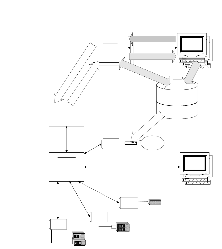
Figure 1-3 depicts communication paths after the monitor server is
turned on from the iNEWS Workstation.
nFor more information about iNEWS utility programs known as monitor serv-
ers, see “Setting up the Monitor Server on iNEWS Servers” on page 4-1.
Also, see “Monitor Server’s Error Checking Workflow” on page 4-34 and
“Using the Monitor Server” on page 4-41.
1-11
ControlAir Work Flow
Figure 1-3 Communication Paths after Monitor Mode - On
iNEWS Monitor
Servers
ON: Watch for added,
deleted, or Modified
Machine Control Events
LOAD: Send playlists and
updates to ControlAir
AMCPapp
Protocol converter
Maintains link to each
loaded monitor server
iNEWS Software
Monitor Server
MCSPC Legacy Drivers
iNEWS DB
Rundown & Event List queues
System Map & Resource queues
Messages
(progress, errors, warnings)
ON:Getsysteminfo,ParseRundown,
BuildPlaylist,WriteEventListqueues
ASC 300's
Any MCS Legacy
Playback device
Monitor Commands
(ON, LOAD, UNLOAD, OFF)
casvr.exe
Retains all loaded playlists,
playlist & event status,
status of attached DM and
ControlAir workstations.
Distributes Commands,
updated status, event
changes & messages.
MCSDM
iNEWS
Workstations
MCSPC
ControlAir
Workstations
Video Servers
RS-422
Leitch DM
10base-T
Chyron
Chyron DM
CreateRundowns,
EnterEvents
RestartfromiNEWSto
downloaddrivers
Louth DM
Download/UpdatePlaylists,Stories,Events
EventStatus,ErrorMessages

1-12
Introduction to the iNEWS ControlAir™ System
Monitor Mode - Load
As air time nears and the newsroom staff completes the rundown,
someone—usually the producer or equipment (ControlAir) opera-
tor—will instruct the monitor server to load the playlist into the
ControlAir system (via the AMCP application program). See “Using
the Monitor Server” on page 4-41 and Figure 4-7 on page 4-42 for more
information about the various modes of the monitor server.
As the rundown is downloaded to the ControlAir Server, the
casvr.exe program loads it to the ControlAir Workstation, and
loads individual playlists to the appropriate device manager (DM).
That DM establishes a connection to the device (if it has not already
done so) and begins its assigned task, such as inserting CG text, check-
ing for availability of video clips, and so forth.
Each DM sends to the ControlAir Server program (casvr.exe) the
status of devices and individual playlists, such as whether video is
available, and so forth. The ControlAir Server then forwards the data
to the ControlAir Workstation and iNEWS monitor server. Error mes-
sages are returned to the iNEWS user who loaded the rundown and
the ControlAir operator. The monitor server also displays status for
video clips, such as whether the clip is available, into stories in the
rundown and event lists located in the iNEWS database.
The ControlAir operator can now take control of the playback devices
and take the show to air.
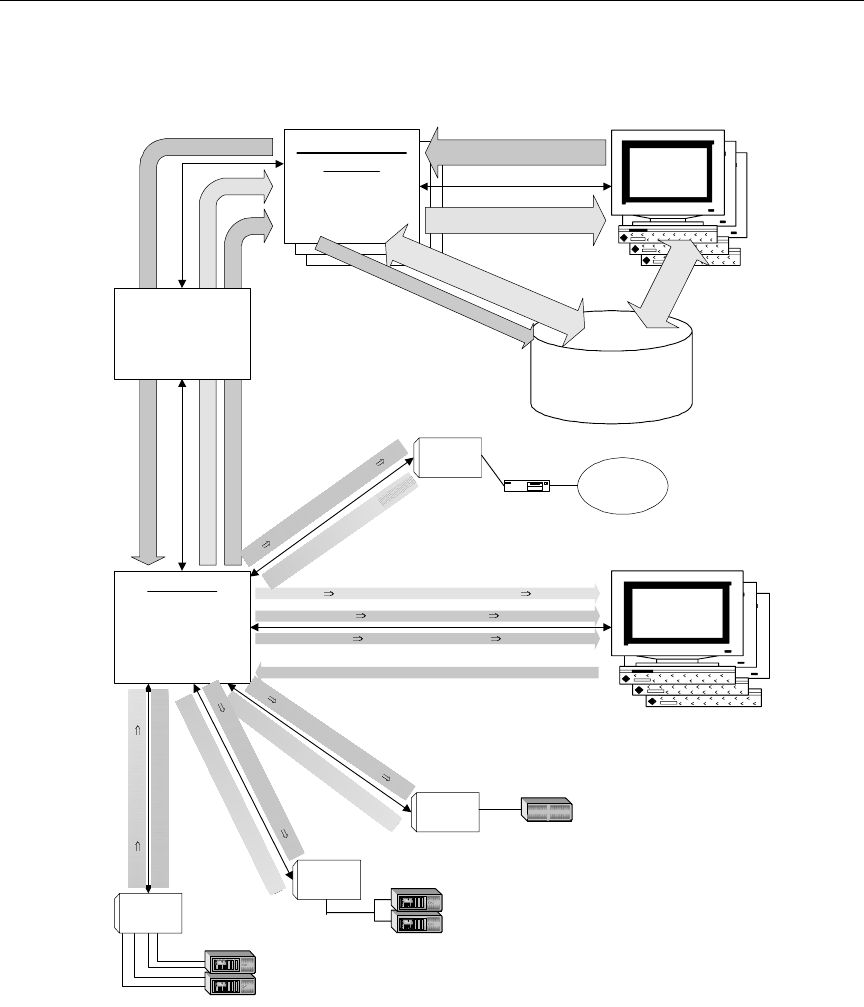
Figure 1-4 depicts communication paths after the monitor server is
instructed to load playlists, commands, status, and user messages
between ControlAir components; note the direction of flow for the
four different kinds of data.
1-13
ControlAir Work Flow
Figure 1-4 Communication Paths after Monitor Load
iNEWS Monitor
Servers
ON: Watch for added,
deleted, or Modified
Machine Control Events
LOAD: Send playlists and
updates to ControlAIr
Playlist, Event Updates
Messages (progress, errors, warnings)
Event Status, Messages
AMCPapp
Protocol converter
Maintains link to each
loaded monitor server iNEWS DB
Rundown & Event List queues
System Map & Resource queues
Messages
(progress, errors, warnings)
ON: Getsysteminfo,ParseRundown,
BuildPlaylist,WriteEventListqueues
ASC 300's
Any MCS Legacy
Playback device
Monitor Commands
(ON, LOAD, UNLOAD, OFF)
Device & Event Status
casvr.exe
Retains all loaded playlists,
playlist & event status,
status of attached DM and
ControlAir workstations.
Distributes Commands,
updated status, event
changes & messages.
MCSDM
(client)
iNEWS
Workstations
Video Servers
RS-422
Leitch DM
10base-T
Messages Progress, errors, warnings
AfterLOAD:EventStatus(Available,Cued,etc.)
⇐
⇐⇐
⇐Playback Commands (Channel, Play, Stop, etc.) ⇐
⇐⇐
⇐
Playlist, Event Updates
Chyron
ChyronDM
⇐Status|Messages⇐
Playlists|ControlAirCmds
⇐Status|Messages⇐
Playlists|ControlAirCmds
⇐Status|Messages⇐
Playlists|ControlAirCmds
CreateRundowns,
EnterEvents
Status | Messages
⇐Playlists | ControlAir Cmds ⇐
ControlAir
Workstations
MCS-PC
Louth DM

1-14
Introduction to the iNEWS ControlAir™ System
Monitor Mode - Unload
After the show airs, someone—typically the producer or equipment
(ControlAir) operator—will instruct the monitor server to unload the
playlist from the ControlAir system. The unload mode allows the user
to disconnect from the ControlAir Server without turning off the mon-
itor server.
See “Using the Monitor Server” on page 4-41 and Figure 4-7 on
page 4-42 for more information about the various modes of the moni-
tor server.

2-2
Preparing for Installation
Before You Begin the Installation Procedure
Setting up ControlAir involves doing tasks in the following places:
•ControlAir Server
•iNEWS Servers (at the console)
•ControlAir Workstations
nDevice Manager configuration is done at the ControlAir Server. You should
consult the iNews Newsroom Computer System Operations Manual for
specific information on iNEWS Servers, the console, or various related sys-
tem operations.
Before you begin installing the ControlAir software, do the following:
•Read the iNEWS ControlAir Release Notes for the most up-to-date
product and installation information.
•Familiarize yourself with the entire installation procedure
described in this manual.
•Ensure the installation CD is available.
•Ensure the site meets all requirements, provided in this chapter.
Site Requirements
The following sections describe customer-supplied components that
make up the iNEWS ControlAir system. Most are hardware compo-
nents typically purchased from a third party vendor. However, some
items can be obtained through Avid. For more information, contact
your Avid Broadcast Sales representative.
nIt is recommended you install a hand-held, wall-mounted Halon fire extin-
guisher, or alternative environmentally acceptable extinguisher, in the
vicinity of all computer equipment.
2-3
Site Requirements
Power Requirements
Surge protection and an uninterruptible power supply (UPS) are
essential for all system servers. If the computers lose power even for a
moment, the entire system will stop functioning properly.
wMost systems are designed to work with single-phase (three-wire)
power cord with a grounded neutral conductor. To reduce the risk of
electric shock, always plug the cord into a grounded power outlet.
For best performance, keep all system power connections on the same
power feed distribution panel. Do not connect fans, lamps, coffee pots,
or other equipment to the same outlet that is powering the iNEWS
ControlAir equipment.
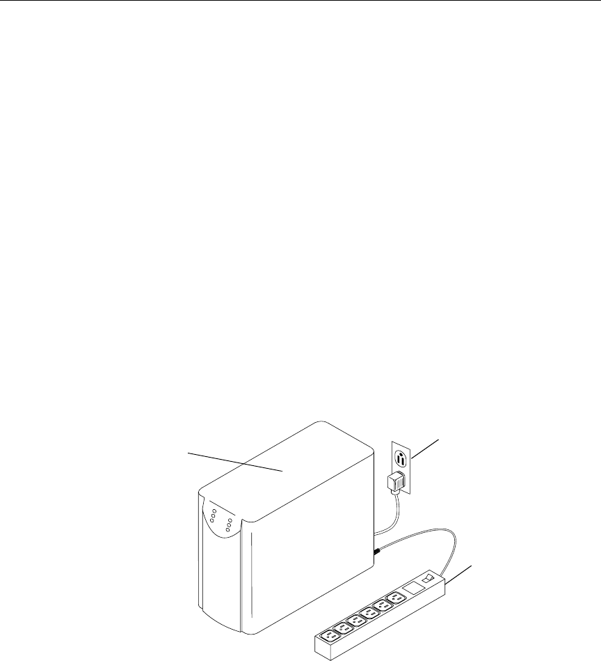
Ensure the UPS has surge protection and a high enough rating to han-
dle all systems connected to it. The rating plate on each system will
help calculate the required rating for the UPS. Figure 2-1 shows how to
connect multiple systems to a UPS using a power strip.
Figure 2-1 UPS Connections
UPS Grounded AC wall outlet
Power strip

2-4
Preparing for Installation
Environmental Requirements
The air conditioning must maintain the operating temperature shown
in Table 2-1. The Avid iNEWS newsroom computer system produces
an estimated heat load of 15,000 BTUs per hour. Table 2-1 shows the
environmental specifications for a standard iNEWS environment.
cAvid reserves the right to stop the installation and shut off the
iNEWS equipment if the temperature exceeds 75°F (24°C). Installa-
tion will be completed after the air conditioning has been corrected.
Hardware Requirements
To install and run ControlAir, use the following tables as a guide for
basic equipment needs. Because development is on-going, require-
ments are subject to change without notice. For specifications pertain-
ing to ControlAir, visit Avid’s Web site at:
www.avid.com/products/controlair/specs.shtml
Review the latest minimum hardware requirements for all
iNEWS-related product lines on the Web at:
www.avid.com/products/.
Table 2-1 Environmental Specifications
Condition Range
Operating temperature 50°F to 75°F (10°C to 24°C)
Storage temperature –4°F to 140°F (–20°C to 60°C)
Relative humidity 20% to 80%
Altitude 0 to 6000 ft (0 to 1829 m)

2-5
Site Requirements
For a list of qualified PCs, contact Avid Broadcast Customer Support
at: +1-800-869-7009 in the USA
+44-1256-814222 in Europe
+61 2 8877 6888 in Asia/Pacific
ControlAir Server
Table 2-2 describes the base hardware required to install and operate a
ControlAir Server and associated device managers.
cEnsure the time is set correctly on all machines (including date and
AM/PM). In general, this makes it easier to interpret messages from
the system. However, some equipment may cause critical errors if
the time is set differently between systems. For instance, Grass Val-
ley Group’s Profile currently will not correctly report the completion
of video clip transfers, so the clips will remain "unavailable" for
playback on ControlAir.
Table 2-2 ControlAir Server Requirements
Device Minimum Requirement
CPU 450-MHz Pentium® II
Memory 256 MB of RAM
Keyboard 104 keyboard
Mouse Windows-compatible mouse
Hard drive 4-GB drive (NTFS format recommended)
Floppy drive 3.5-inch diskette drive; reads and writes to
1.44-MB diskettes
CD-ROM drive 4X CD-ROM drive

2-6
Preparing for Installation
nA site may also need a serial host adapter card installed on the ControlAir
Server. See “Ports” on page 2-7 and “Configuring & Installing the Host
Adapter Card” on page 2-10 for more information.
ControlAir Workstation
To install and run ControlAir Workstation, you will need the base
equipment detailed in Table 2-3.
Operating system Windows 2000 with Service Pack 2 or Windows
NT Server 4.0 with Service Pack 6a (minimum)
Monitor 15-inch screen
Video card SVGA-compatible video card with 2MB of
VRAM. Must support:
•1024 x 768 resolution
•256 colors
Network card Windows-compatible 10/100 NIC
Table 2-2 ControlAir Server Requirements
Device Minimum Requirement
Table 2-3 ControlAir Workstation Requirements
Device Minimum Requirement
CPU 450-MHz Pentium II
Memory 256 MB of RAM
Keyboard 104 keyboard
Mouse Windows-compatible mouse
Hard Drive 4-GB drive

2-7
Site Requirements
Machine Control PC (MCS-PC)
If your site uses an MCS-PC, for more information, refer to the latest
minimum hardware requirements on the Web at:
www.avid.com/products/controlair
Ports
Additional Serial Ports
Most CG and SS devices use a serial port (either RS-232 or RS-422) to
communicate with the ControlAir device manager. Many video
devices require an RS-422-only serial port for each channel. The device
managers use any serial ports that can be addressed through Win-
dows as a standard COM port, such as COM1, COM4, COM9, or
COM32.
Floppy Drive 3.5-inch diskette drive; reads and writes to
1.44-MB diskettes
CD-ROM Drive 4X CD-ROM drive
Operating System Windows 2000 with Service Pack 2 or
Windows NT Workstation 4.0 with Service Pack
6a (minimum)
Monitor SVGA color monitor (17-inch recommended)
Video Card SVGA-compatible video card with 2MB of
VRAM. Must support:
•1024 x 768 resolution
•256 colors
Network Card Windows-compatible 10/100 NIC
Table 2-3 ControlAir Workstation Requirements (Continued)
Device Minimum Requirement
2-8
Preparing for Installation
nA less expensive alternative is the optional use of the built-in RS-232 COM1
and 2, and add a Sea-Level two-port RS-422 board for COM3 and 4. Refer to
the appropriate third-party manufacturer’s documentation for the host
adapter card.
COM Ports—Digi and Equinox
See “Configuring &
Installing the Host
Adapter Card” on
page 2-10 for more
information on install-
ing a host adapter card.
For scalability, Avid recommends using the Digi AccelePort
8r-(PCI)EIA-422 serial host adapter card in the ControlAir Server, as
shown below.
Flat telco, cat-3, or cat-5
are all more than ade-
quate.
The 8r-(PCI)EAI-422 host adapter cable assemblies should have eight
DB-25 (male) connectors to which a DB-25 (female) to RJ-45 adapter is
connected. From there, an 8-wire RJ-45 terminated straight cable goes
from the ControlAir Server to the video server, character generator, or
other peripheral device. A custom RJ-45 modular adapter connects to
the device of your choice.
Pinouts for this custom adapter will vary, depending on the device
you are attaching.
To peripherals
2-9
Site Requirements
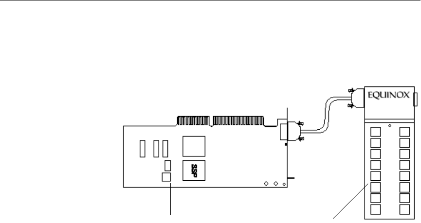
Some sites may choose to use other cards, such as the Equinox™
SST-64 PCI serial host adapter card, with the PM16-RJ/422 port mod-
ule, as shown below.
The PM16-RJ/422 is an external box which connects to the SuperSe-
rial™ Technology (SST) card and has 16 RS-422 ports using RJ-45 sock-
ets. After the SST card is installed, up to 4 port modules can be
attached to each other, in series, for a total of 64 ports (128 ports with
the SST-128). There is no need to install additional boards or change
any software, drivers, or settings. Any combination of external port
modules RS-232 or RS-422 with either DB-25 or RJ-45 connectors will
work. So, a site could have an RS-232 port module for CGs and still
stores, and RS-422 for video devices, on the same SST-64 card. (As of
this publication, DB-9s for the SST do not exist).
Flat telco, cat-3, or cat-5
are all more than ade-
quate.
An 8-wire RJ-45 terminated straight cable goes from the Equinox port
module on the ControlAir Server to the peripheral devices. A custom
RJ-45 modular adapter connects the cable to the device of your choice.
nA pin-out diagram is located on the back of the Equinox RJ/422 port module.
Some manufacturers, including Digi International and Equinox, use "A" to
represent "+" and "B" for "-” while others, such as Sony, reverse "A" and
"B," respectively. Refer to the manufacturer’s documentation for more infor-
mation.
Serial Host Adapter Card Port Module
2-10
Preparing for Installation
Configuring & Installing the Host Adapter Card
Before installing the host adapter card on the ControlAir Server, set
any configuration switches according to the manufacturer’s documen-
tation. Digi and Equinox documentation provided with the cards have
more detailed installation instructions, configuration settings, and
cabling diagrams.
To install the host adapter card, do the following:
1. Unplug the PC.
2. Remove the computer’s cover.
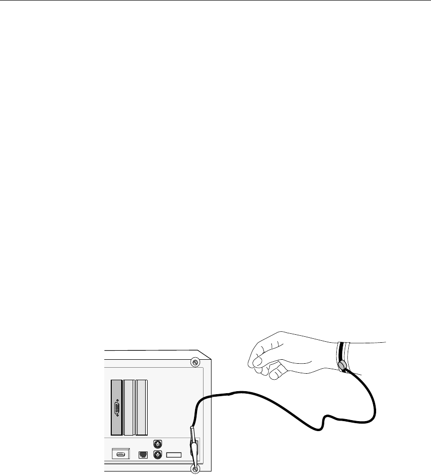
3. Put on a wrist strap and attach the ground clip to the computer’s
chassis as shown in Figure 2-2.
cSemiconductor devices are vulnerable to damage by electrostatic
discharge (ESD). Always use an ESD wrist strap or other grounding
device when opening the computer or removing any circuit boards
from its packing.
Figure 2-2 ESD wrist strap
2-11
Configuring & Installing the Host Adapter Card
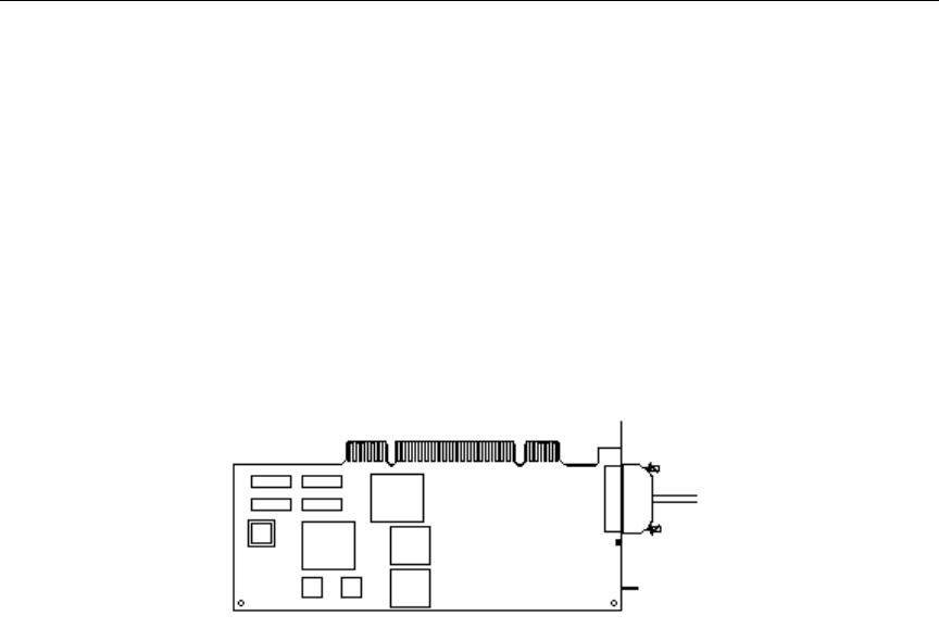
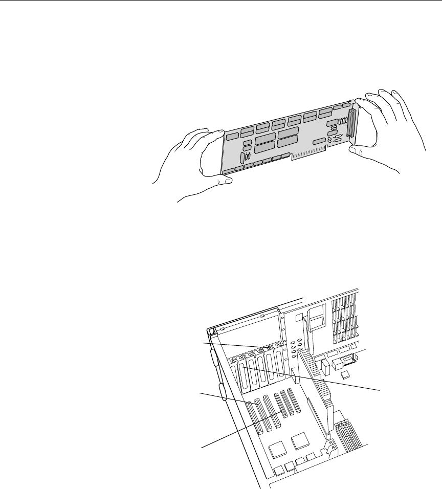
4. Remove the host adapter card from its static-proof bag. Hold the
card by its outer edges to avoid touching the components and con-
nector on the card.
Figure 2-3 Host Adapter Card
5. Record the card’s serial number so the manufacturer can provide
better service, should the need arise.
6. Remove the expansion slot cover from within the computer.
7. Locate a free expansion slot (ISA, EISA or PCI) of the proper type
for your card. Match the bottom of the host adapter card with the
structure of the expansion slot.
ISA connectors Slot cover
(larger)
Slot cover screw
PCI connectors
(smaller)
2-12
Preparing for Installation
The correct slot is selected if all the gold pins will fit into the slot
and all spaces in the slot will be occupied.
Align the connector on the adapter card with the system board
connector.
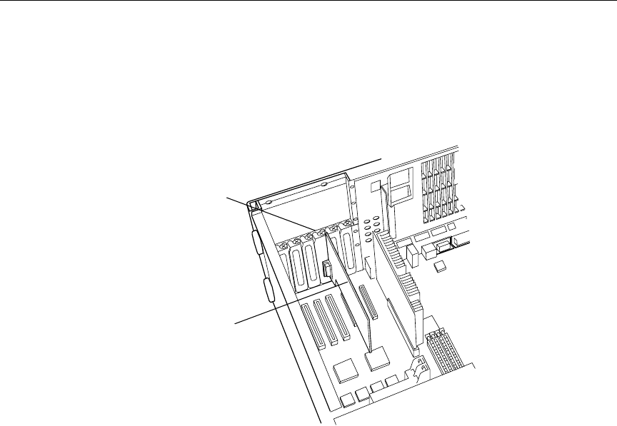
8. Press the adapter card firmly until the connector is seated. Do not
force the card. If you meet with a lot of resistance, pull it out,
inspect the connector, and try again.
9. Reinstall the screw used for the slot cover to secure the host
adapter.
10. Reconnect any cables that you disconnected.
11. Replace the computer cover.
12. Connect a host cable between the host adapter card and a 16-port
expansion module, such as the PMT6-RJ45/RS-422.
nA 16-port expansion module is not required; some sites may use a 4 or 8-port
expansion module.
13. Turn on the computer.
Screw
Card

2-13
Configuring & Installing the Host Adapter Card
Installing the Digi Software Driver
On Windows 2000-based PC
The Access Resource CD that accompanies the Digi host adapter card,
if inserted and run on a PC with the Windows 2000 operating system,
will provide the following prompt:
The driver for the product (AccelePort 8r-PCI 422)
is included in the Microsoft Windows 2000
installation CD-ROM and is not included with the
Access Resource CD-ROM. However, documentation can
be browsed.
In that documentation, the following installation procedures are pro-
vided—and included for your information here:
Use this procedure to install Microsoft Windows 2000 device drivers
for Digi PCI adapters.
1. Ensure the adapter is installed according to instructions as pro-
vided earlier in this section or on the hardware installation card
for that adapter.
nWhen you install multiple PCI adapters of the same type on a Windows sys-
tem, it is sometimes difficult to determine which adapter you are configuring.
To avoid confusion, you may want to install and configure adapters one at a
time.
2. Turn on the computer and start Windows 2000.
3. Windows will auto-detect the adapter and search for the correct
device driver.
4. If Windows cannot find a driver for the adapter, you will be asked
for the location of the driver. If the driver is on a Digi-supplied
CD, check the CD-ROM box. If you have downloaded the driver,
enter the path to the folder into which you downloaded the driver.

2-14
Preparing for Installation
5. Depending on your adapter type, you may be asked to complete
various configuration wizards or dialogs. These wizards and dia-
logs are fully documented in context-sensitive help screens.
6. When the installation is complete, the device is ready to use. There
is no need to restart Windows.
On Windows NT-based PC
The following instruc-
tions are for installing
on a PC with the Win-
dows NT operating sys-
tem. Procedures may
vary for other operating
systems.
To install the software driver, do the following:
1. Insert the Digi CD into your CD-ROM drive.
2. Click the Start on the Windows taskbar.
3. Select Settings.
4. Select Control Panel. The Control Panel window opens.
5. Double-click on the Network icon.
The Network dialog box opens.
6. Click the Adapters tab.
7. Click the Add button.
8. When the Select Network Adapter dialog box appears, click the
Have Disk button.
9. Type the following driver path, with d: indicating your CD-ROM
drive letter.
D:/drivers/windows/nt/acceleport/i386
10. When the Select OEM Option dialog box appears, select Digi
Acceleport 8r-(PCI)EAI-422 Adapter.
11. Click OK. The driver files are installed.
12. Make any configuration modifications as needed, if prompted.
2-15
Configuring & Installing the Host Adapter Card
Installing the Equinox Software Driver
These sample instruc-
tions are for installing
on a PC with the Win-
dows NT operating sys-
tem. Procedures may
vary for other operating
systems.
To install the software driver, do the following:
1. Insert the Equinox CD into your CD-ROM drive.
2. Click the Start on the Windows taskbar.
3. Select Settings.
4. Select Control Panel. The Control Panel window opens.
5. Double-click on the Network icon.
The Network dialog box opens.
6. Click the Adapters tab.
7. Do one of the following, depending on whether an Equinox driver
exists and is displayed in the Network Adapters list.
a. Select it from the list and click Update. Go to step 10.
-OR-
b. If an Equinox driver does not exist in the list, choose Add and
continue to Step 8.
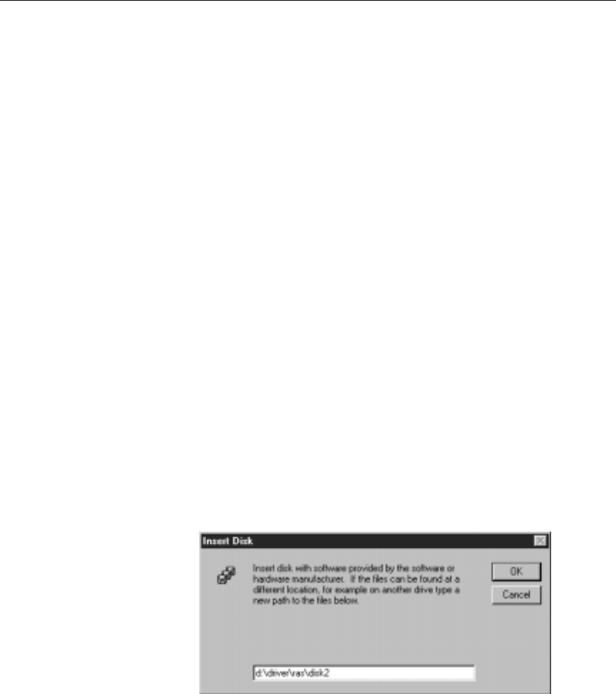
8. When the adapter list is displayed, click the Have Disk button.
9. The Insert Disk dialog box appears.
10. Type the following driver path, with d: indicating your CD-ROM
drive letter.
d:\drivers\ras\disk2
2-16
Preparing for Installation
11. Do one of the following:
a. If you are Updating, click Continue and go to step 19.
-OR-
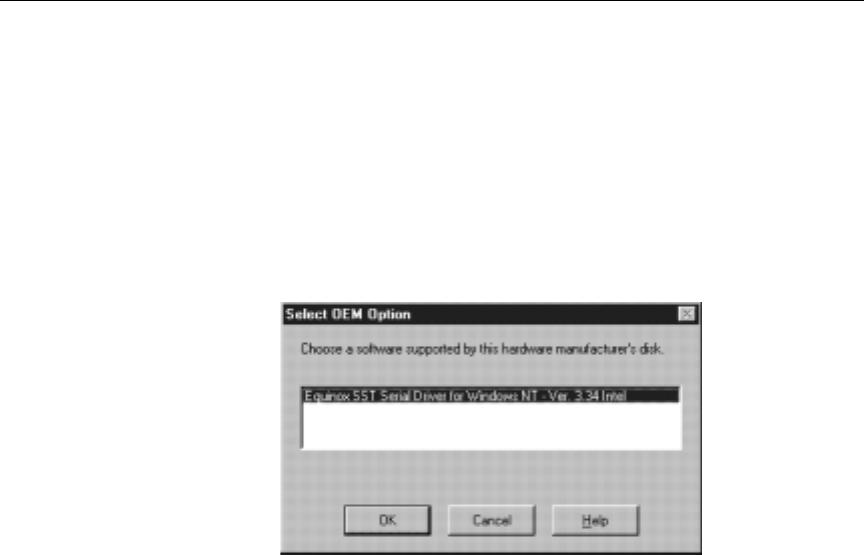
b. If you are adding the driver, click the OK button.
The Select OEM Option dialog box opens. Go to step 12.
12. Select Equinox SST.
13. Click the OK button.
The driver files are installed and a message box appears, telling
you the Equinox driver has been installed.
14. Click the OK button.
The Equinox SST Configuration dialog box appears.
15. Make any necessary changes to the COM port number or the
memory block for the ISA adapter cards.
16. Click the Next button.
17. If the path for the data scope trace files is acceptable, click Finish.
18. A notice indicating that /PC1LOCK was added to the boot.ini
file may appear. Click OK.
19. Click the Equinox Logger icon on the Windows taskbar (at the bot-
tom of your screen).
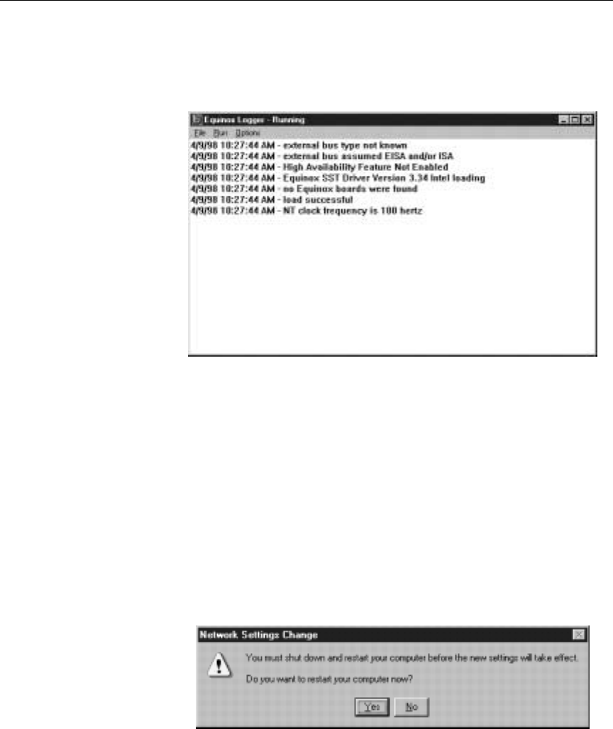
2-17
Configuring & Installing the Host Adapter Card
The Equinox Logger - Running window opens, displaying status
messages generated during the driver loading operations.
The following information is displayed:
•Number of adapter cards (boards) found
•Memory range(s) and I/O addresses used
•Names of ports available
•Any failure reasons
•Driver version
20. Click Close in the Network dialog box to continue with the
installation procedure.
21. The system prompts you to reboot the system. Click Restart and
then click Yes.

2-18
Preparing for Installation

3-2
Installing and Configuring iNEWS ControlAir
Overview of the Setup
The following tasks must be performed on the ControlAir Server.
•Add IP addresses for ControlAir and iNEWS Servers
•Install the ControlAir software
•Configure the ControlAir software
These tasks are described in this chapter.
Ideally, all ControlAir Servers, iNEWS Servers, and ControlAir Work-
stations would have each other’s IP addresses and computer names,
so IP addresses should be added on the ControlAir Server as well as
on iNEWS Servers. It is not necessary to include IP addresses for Avid
Broadcast workstations or other equipment. See “Adding IP
Addresses on iNEWS Servers” on page 3-3 for more information.
nThe monitor server communicates with the ControlAir software only if the
ControlAir Server’s IP address is added to all of the iNEWS Servers’
/etc/hosts files. Procedures for configuring monitor servers are located in
Chapter 4.
Adding IP Addresses on ControlAir Server
This section provides steps for adding IP addresses to the ControlAir
Server.
To add IP addresses to the ControlAir Server, do the following:
1. Use My Computer or the Windows Explorer to open the
\WINNT\system32\drivers\etc folder.
2. Double-click on the hosts file.
3. A dialog box may appear with a list of programs to use for open-
ing the file. Scroll down the list and select Notepad. Ensure that
you uncheck the box to “Always use this program.”

3-3
Overview of the Setup
4. Click OK. The hosts file opens in a Notepad window.
IP Addresses for LAN
connected devices
should also be listed.
See “Native Device
Managers” on page 5-4
for more information.
5. At the bottom of the file, add lines listing the IP addresses and
computer names for iNEWS Servers, ControlAir Servers,
ControlAir Workstations, and MCS-PC machines (if any). For
example:
192.198.1.1 NRCS-A nrcs-a nrcs-a.yourdomain.com
192.198.1.2 NRCS-B nrcs-b nrcs-b.yourdomain.com
192.198.1.11 CA1 ca1
192.198.1.12 CA2 ca2
192.198.1.21 CAWKSTN1 cawkstn1
192.198.1.22 CAWKSTN2 cawkstn2
192.198.1.31 MCSPC1 mcspc1
192.198.1.32 MCSPC2 mcspc2
6. Save the file and close the Notepad window.
cWhen saving, ensure the newly edited file does not have a .txt
extension. The default options in Windows Explorer will not display
this crucial information. To change this setting, open Windows
Explorer and select Options from the View drop-down menu. In the
dialog box, check Show All Files and uncheck Hide file extension
for known file types, then click OK.
7. Repeat this procedure for each computer on which ControlAir
Server, device manager, or ControlAir Workstation software is
installed.
Adding IP Addresses on iNEWS Servers
For more information
about monitor servers,
see Chapter 4.
To enable monitor server to communicate with ControlAir, the IP
address of the ControlAir Server must be added to all iNEWS Servers’
/etc/hosts files.
The following procedures explain how to add the ControlAir IP
addresses to iNEWS Servers.

3-4
Installing and Configuring iNEWS ControlAir
nControlAir software can be installed on either the Mirror Net or the House
Net of the iNEWS hosts. If ControlAir components need access to other sta-
tion networking services than just iNEWS Servers, then they should be
placed on the House network. In either case, static IP addresses and local
hosts files should be used for all ControlAir components.
cAlways back up the /etc/hosts file before editing.
At the console, perform the steps below:
1. Select all servers. Instructions for how to do this is provided in
Chapter 2 of the iNEWS Newsroom Computer System Operations
Manual.
2. Type su to log in as superuser and type the superuser password.
These steps require the
use of ed, the UNIX line
editor. For more infor-
mation, see Chapter 10
of the iNEWS Newsroom
Computer System Opera-
tions Manual.
3. Type ed /etc/hosts
This command launches the UNIX line editor, and positions the
cursor at the end of the /etc/hosts file, which contains a list of
IP addresses, computer names, and comments, such as:
125.1.0.1 NRCS-A nrcs-a nrcs-a.yourdomain.com
125.1.0.2 NRCS-B nrcs-b nrcs-b.yourdomain.com
nA sample /etc/hosts file is provided in Appendix B.
4. Add addresses to the file by doing the following:
a. Type a and press Enter to append information to the file.
b. Enter IP addresses, computer names, and comments, such as:
192.198.1.11 CA1 ca1 #ControlAir Server1
c. Type a period (.) to stop appending information to the file.
d. (Optional) Type p to print the appended file and verify your
changes.
Do not use an uppercase
W
.
e. Save the file by typing w.
f. Quit ed by typing q.

3-5
Overview of the Setup
The following example shows the UNIX line editing commands
used in step 4 along with explanations (appearing in parentheses
after the command):
Installing ControlAir Software
It is possible to install all ControlAir components on a single computer
or to install them separately. Typically, ControlAir Server software and
device managers (DMs) are installed together on ControlAir Servers
and the ControlAir client software is installed on ControlAir Worksta-
tions—computers in each control room where ControlAir will be used.
See “ControlAir Components” on page 1-4 for more information.
cIf you are planning to install either the AirSPACE or Grass Valley
Group Device Manager, there is other software that must be
installed prior to the ControlAir software. For the AirSPACE DM,
install Avid AirSPACE NT Applications. For the GVG DM, install
the Profile software for non-Profile PCs. If the GVG DM is to be
used with EditStar, you must also install the EditStar Server Inter-
face for ControlAir. For more information, refer to the specific
Device Manager Guides available for these DMs, located in the
Docs folder on the ControlAir Install CD.
The procedure in this
manual provides steps
for a typical installation.
To install the ControlAir software, do the following:
a(begins append mode)
192.198.1.11 CA1 ca1 # ControlAir Server1
192.198.1.12 CA2 ca2 # ControlAir Server2
192.198.1.21 CAWKSTN1 cawkstn1 # Wkstn1(ControlRm1)
192.198.1.22 CAWKSTN2 cawkstn2 # Wkstn2(ControlRm2)
.(ends append mode)
p(prints appended file)
w(saves changes by writing the file to the disk)
362 (ed responds by displaying file size)
q(quits the edit session)
3-6
Installing and Configuring iNEWS ControlAir
1. Insert the ControlAir Installation CD into the computer’s
CD-ROM drive.
2. Navigate to the CD drive. For instance, on a computer running the
Windows NT operating system, use Windows NT Explorer and
select the CD-ROM drive from the tree-style directory listing.
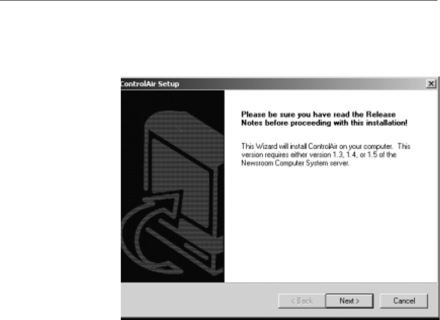
3. Double-click the Setup.exe file to launch the Setup program.
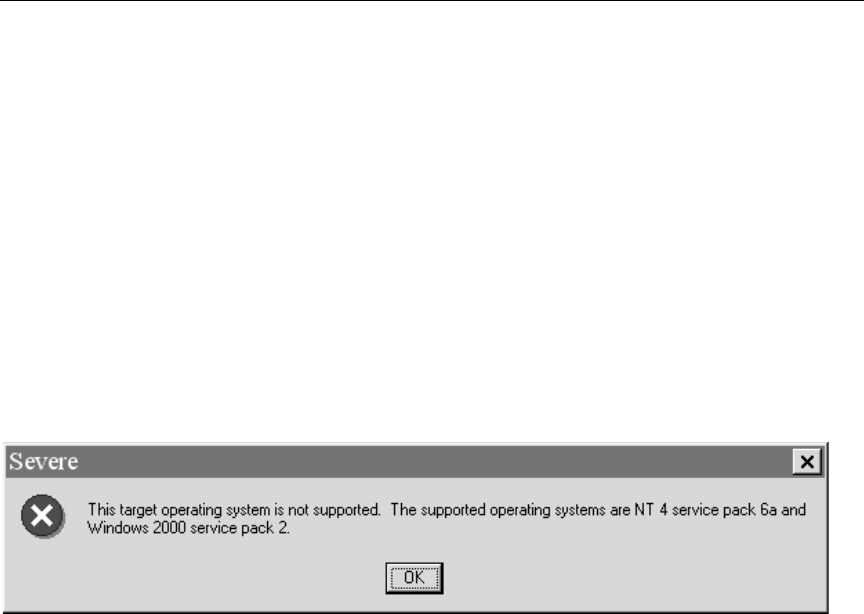
nDuring installation, the Setup program will check for a valid operating sys-
tem (OS). Exactly when this check is done varies, depending on selections you
make during the installation procedure. If a valid operating system is not
found, a message indicating an unsupported OS will appear.
Your only option will be to exit the Setup program.
3-7
Overview of the Setup
When the Setup program launches, the ControlAir Setup dialog
box opens.
4. Click Next.
nA dialog box will appear with a notice stating the Setup program will change
the main directory name from old name(s), if any—such as iNEWS—to Avid.
If you have a device manager not provided by iNews, LLC or Avid Technol-
ogy, Inc., you may need to reinstall it. When this dialog box appears, continue
the setup process by clicking Next.
3-9
Overview of the Setup
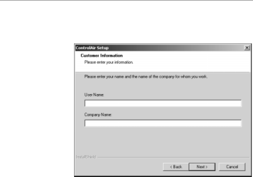
6. When the Customer Information dialog box appears, enter a user
name and company name in the appropriate fields.
3-10
Installing and Configuring iNEWS ControlAir
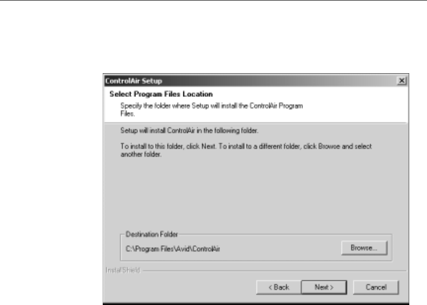
7. Click Next to continue. The Select Program Files Location dialog
box appears.
8. Do one of the following:
a. If the default Destination Folder is acceptable, click Next. Go
to step 9.
-OR-
b. If the default Destination Folder is not acceptable, click
Browse and choose another location, then click Next. Go to
step 9.
3-11
Overview of the Setup
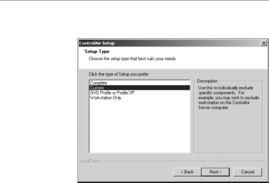
9. The Setup Type dialog box appears.
Highlight each type—with a single click—to see a description of
that Setup type, provided in the Description section on the left
side of the dialog box.
nWhen you click Next in the Setup Type dialog box, the Setup program will
verify whether the selected destination has enough space for the type chosen. If
it does, the Setup program continues. If not, a warning message will appear
and the Setup program will return to the Select Program Files Location dialog
box. See step 7 on page 3-10.
Do one of the following:
Step 9a is recom-
mended for the
ControlAir Server.
a. Select Complete if installing all ControlAir components—
server, device manager, and client software—on a single com-
puter. Go to step 11 on page 3-13.
-OR-
3-12
Installing and Configuring iNEWS ControlAir
b. Select Custom if you want to select individual components to
install, such as installing only ControlAir Server and device
manager software on a computer. The Select Components dia-
log box appears. Go to step 10.
-OR-
c. Select GVG Profile or Profile XP if installing software related
to the Grass Valley Group’s Profiles, high resolution video
servers. Go to step 13 on page 3-17.
-OR-
d. Select Workstation Only if installing the client software only
on a ControlAir Workstation. Go to step 13 on page 3-17.
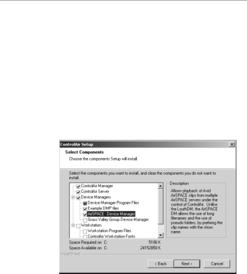
10. When a Custom Setup is chosen (as in step 9b), the Select Compo-
nents dialog box appears.
As each component is highlighted, a description is provided on
the right.

3-13
Overview of the Setup
nIndividual Device Manager subcomponents are explained in Device Manager
Guides for each device, which are provided on the ControlAir Install CD. For
more information, refer to the guide for your devices.
To install components for the ControlAir Server and device man-
agers on a single computer, ensure that the following primary
components are checked:
•ControlAir Manager
•ControlAir Server– if selected, go to step12 on page 3-16.
•Device Managers, and any of its secondary components, as
listed below:
- Device Manager Program Files – select this option to install
program files for the Louth, MCS, and Chyron device man-
agers.
- Example DMP files – select this option to install sample
DMP files.
-AirSPACE Device Manager – select this option to install
program files for the AirSPACE DM. Doing so will result in
additional dialog boxes appearing as part of the setup pro-
cess. Go to step 11 on page 3-13.
- Grass Valley Group Device Manager – select this option to
install program files for the GVG DM. Doing so will result
in additional dialog boxes appearing as part of the setup
process. Go to step 11 on page 3-13.
nThe other primary component available in the Select Components dialog box
is for ControlAir Workstations. Selecting all components in the list would be
the same as selecting a Complete setup as shown in step 9a on page 3-11.
11. This step only applies to Complete Setups or Custom Setups when
the Device Managers component is chosen.
If the Complete Setup type is not chosen or if the AirSPACE DM
and Grass Valley Group DM components are not chosen for a Cus-
tom Setup, you may skip this step and go to step 12.
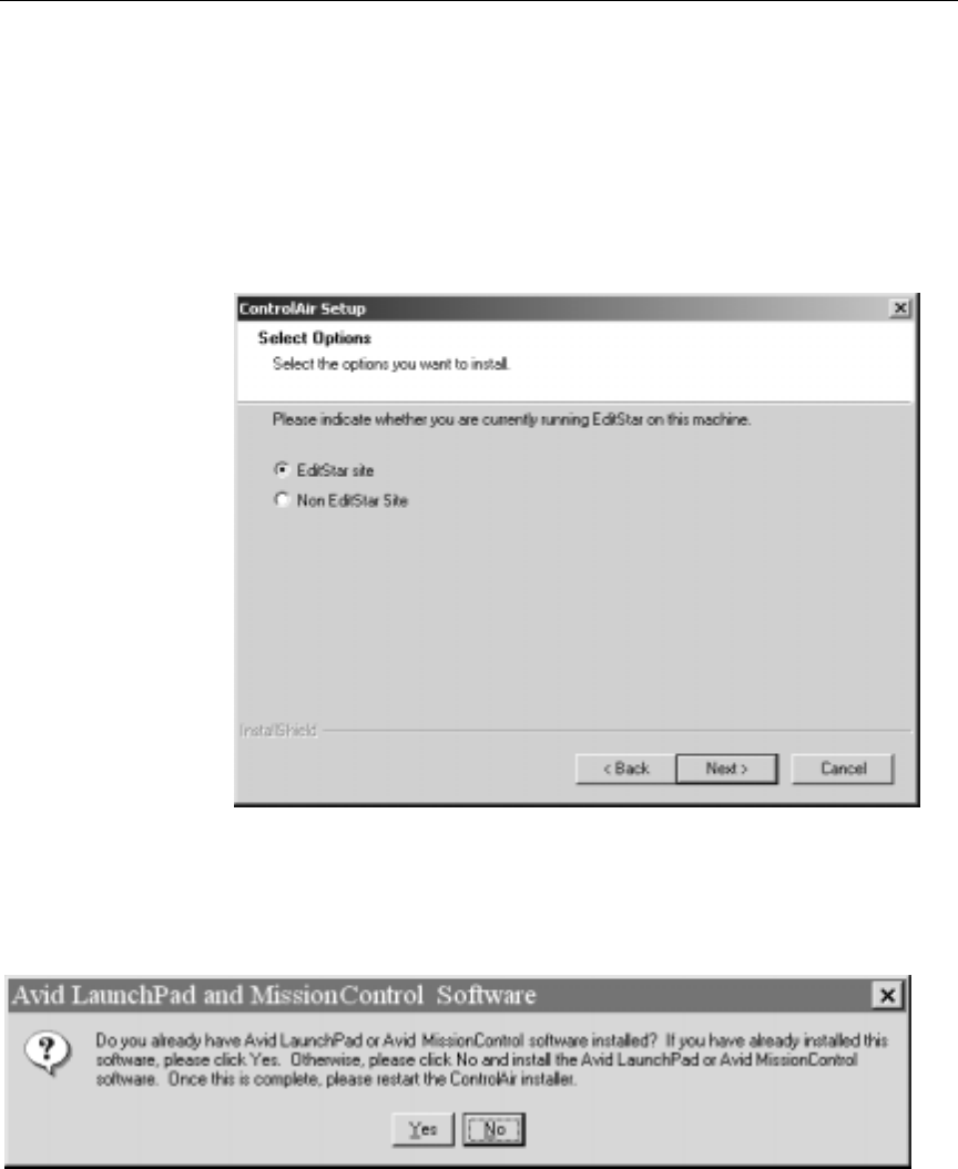
3-14
Installing and Configuring iNEWS ControlAir
If the AirSPACE and GVG DM components are chosen, additional
dialog boxes will appear as part of the setup process—four of
which are described in this step:
•For Complete Setups or for a Custom Setup in which the GVG DM
is selected, a dialog box will appear asking if the site also has Edit-
Star.
Select the appropriate radio button and click Next.
•For Complete Setups or for a Custom Setup in which the Air-
SPACE DM is selected, a dialog box will appear asking if software
pertaining to Avid’s LaunchPad or MissionControl is installed.
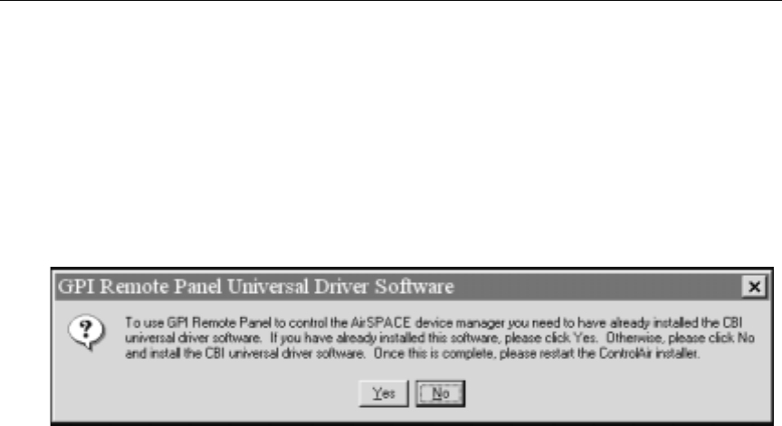
3-15
Overview of the Setup
a. Choose Yes if the requested software is already installed.
-OR-
b. Choose No and the Setup program will exit automatically.
•For Complete Setups and or for Custom Setups in which the Air-
SPACE DM and/or GVG DM are selected, a dialog box similar to
following will appear:
It pertains to GPI Remote Panel support for either the AirSPACE
DM, the GVG DM, or both.
a. Click Yes, if the driver software is already installed.
-OR-
b. If not, click No. The Setup program will exit automatically.
3-16
Installing and Configuring iNEWS ControlAir
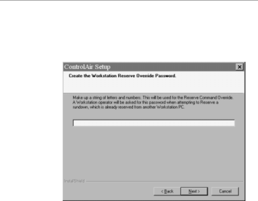
12. This step only applies to Complete Setups or Custom Setups when
the ControlAir Server component is chosen. The Create the Con-
trolAir Workstation Reserve Override Password dialog box
appears.
To set a password, type an Override password in the text box. The
password is case-sensitive and can be a combination of letters and
numbers.
nThe Override password must be set during installation; it can be changed
through the ControlAir Server program. See “Setting the Override Pass-
word” on page 6-7 for more information. The purpose of the password is to
prevent a show from being reserved by a second ControlAir Workstation
while under the control of a first workstation. Setting this password ensures
that only authorized personnel may take control of the show from another
workstation, which is useful should a workstation computer fail after it was
used to reserve a rundown.
3-17
Overview of the Setup
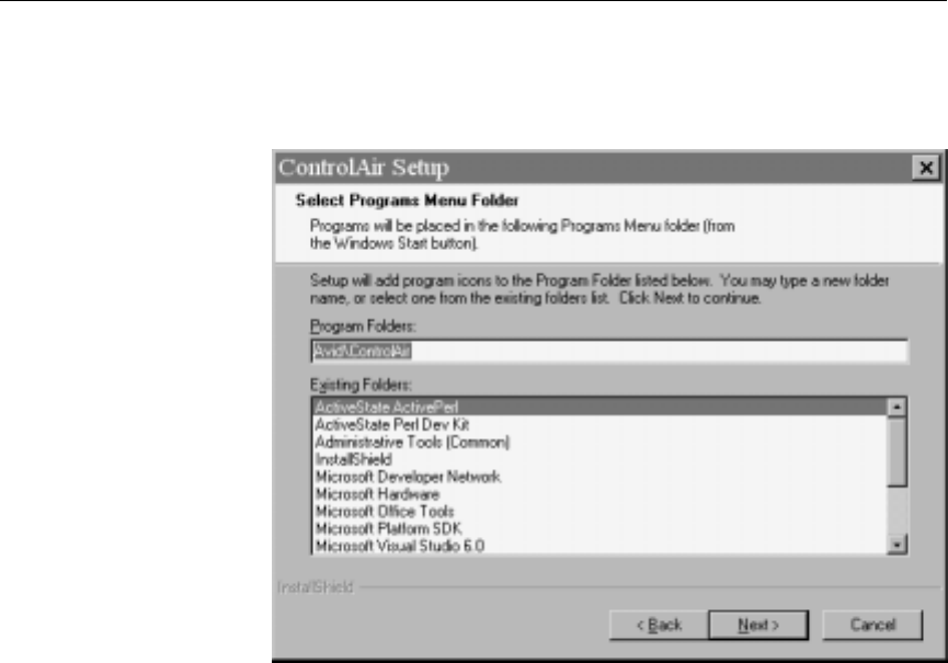
13. Click Next. The Select Programs Menu Folder dialog box opens.
nProgram icons are used to launch software programs. For instance, a user
clicks the Start button, selects Programs from the menu, then chooses the pro-
gram icon for the software the user wants to run. By default, most program
icons are placed in the Start menu under the Programs option. But , the Select
Programs Menu Folder dialog box (shown above) allows an installer to choose
an alternative location in the Start menu, during the setup process.
14. Do one of the following:
a. Click Next if the default Program Folder setting for the pro-
gram icons is acceptible.
-OR-
b. Type another folder pathname in the Program Folder text box,
if the default setting is unacceptable, then click Next.
3-18
Installing and Configuring iNEWS ControlAir
Settings will vary
according to selections
made in previous steps.
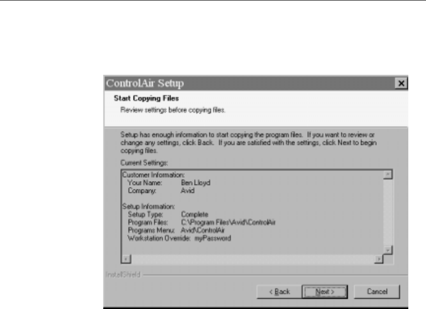
15. Click Next. The Start Copying Files dialog box appears, displaying
the current settings for installation.
16. Do one of the following:
a. To review or change any setting, click the Back button.
-OR-
b. To continue the setup and start copying files, click Next. Go to
step 17.
3-19
Overview of the Setup
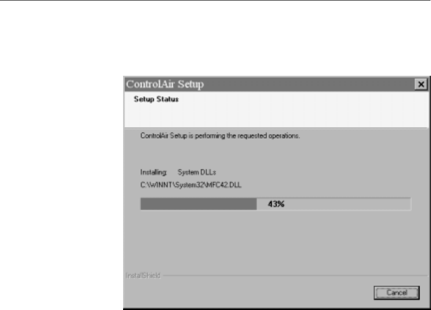
17. The Setup Status dialog box appears, displaying a progress bar
that indicates the percentage of installation completed.
When the progress bar reaches 100%, another dialog box appears;
which one depends on what type of installation you chose in step
9 on page 3-11:
•If you chose a Complete or Custom installation that included
ControlAir Server software, go to step 18.
•If you chose a Custom installation that did not include the
ControlAir Server software, a Workstation Only installation,
or GVG Profile or Profile XP installation, go to step 23 on
page 3-22.
3-20
Installing and Configuring iNEWS ControlAir
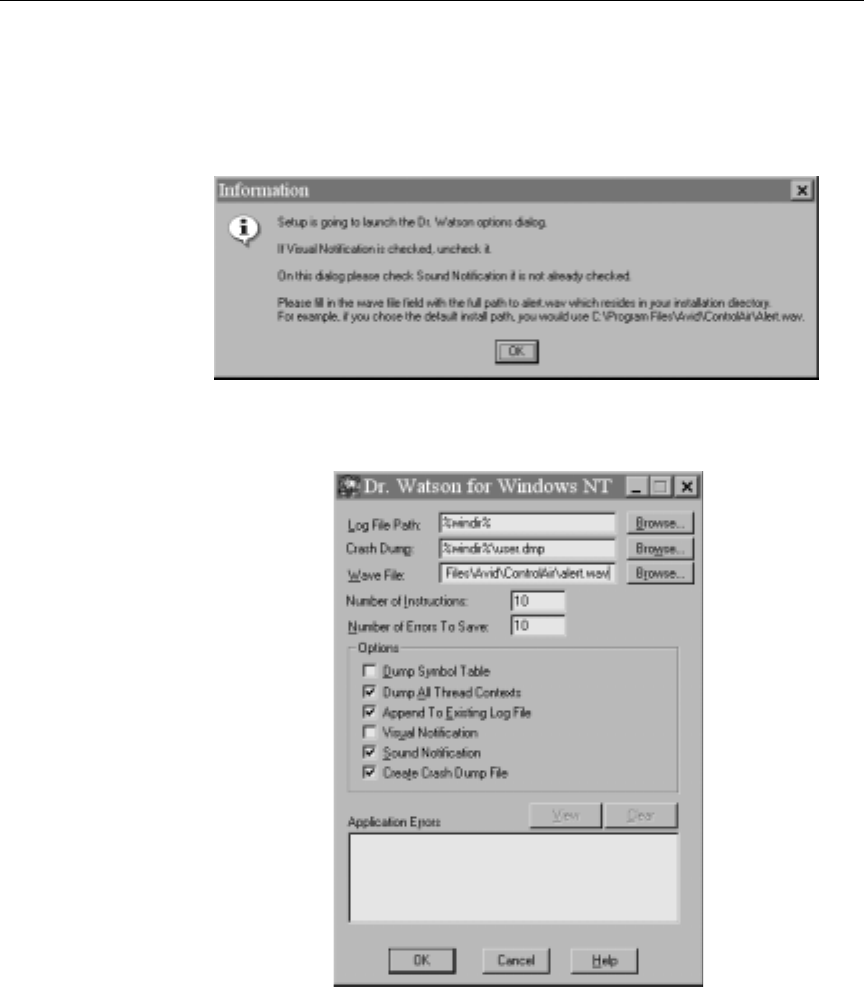
18. If you are installing ControlAir Server components, an Informa-
tion dialog box will appear with instructions on how to set up Dr.
Watson notifications on the server.
19. Click OK.
20. The Dr. Watson for Windows NT dialog box appears.
Since most ControlAir Servers are left to run unobserved, visual
notification of Dr. Watson issues is not needed. Instead an audible
alert is provided. The default audio file is a WAV file called

3-21
Overview of the Setup
alert.wav. However, this setup dialog box allows the installer to
select an alternative audio file, so do each of the following:
a. Ensure the correct pathname to the WAV file is provided. The
default location is in the Program Files directory, as shown in
the above graphic.
b. Ensure that Visual Notification is unchecked and Sound Noti-
fication is checked.
c. Click OK.
nThe audible alert will only work if the ControlAir Server has a sound card and
speakers.
21. A Question dialog box will appear, confirming whether you want
the ControlAir Server to automatically logon after reboot? Do one
of the following:
a. Click No if you do not want to enable automatic logon. Go to
step 23 on page 3-22.
-OR-
b. Click Yes if you want the ControlAir Server to automatically
log on after rebooting. Go to step 22 on page 3-22.
cIf automatic log on is enabled, the password is stored in the server’s
registry, which means anyone with access to the computer has access
to the password. You can bypass the auto logon function after it is
enabled by holding down the Shift key during the boot or logoff
process.
3-22
Installing and Configuring iNEWS ControlAir
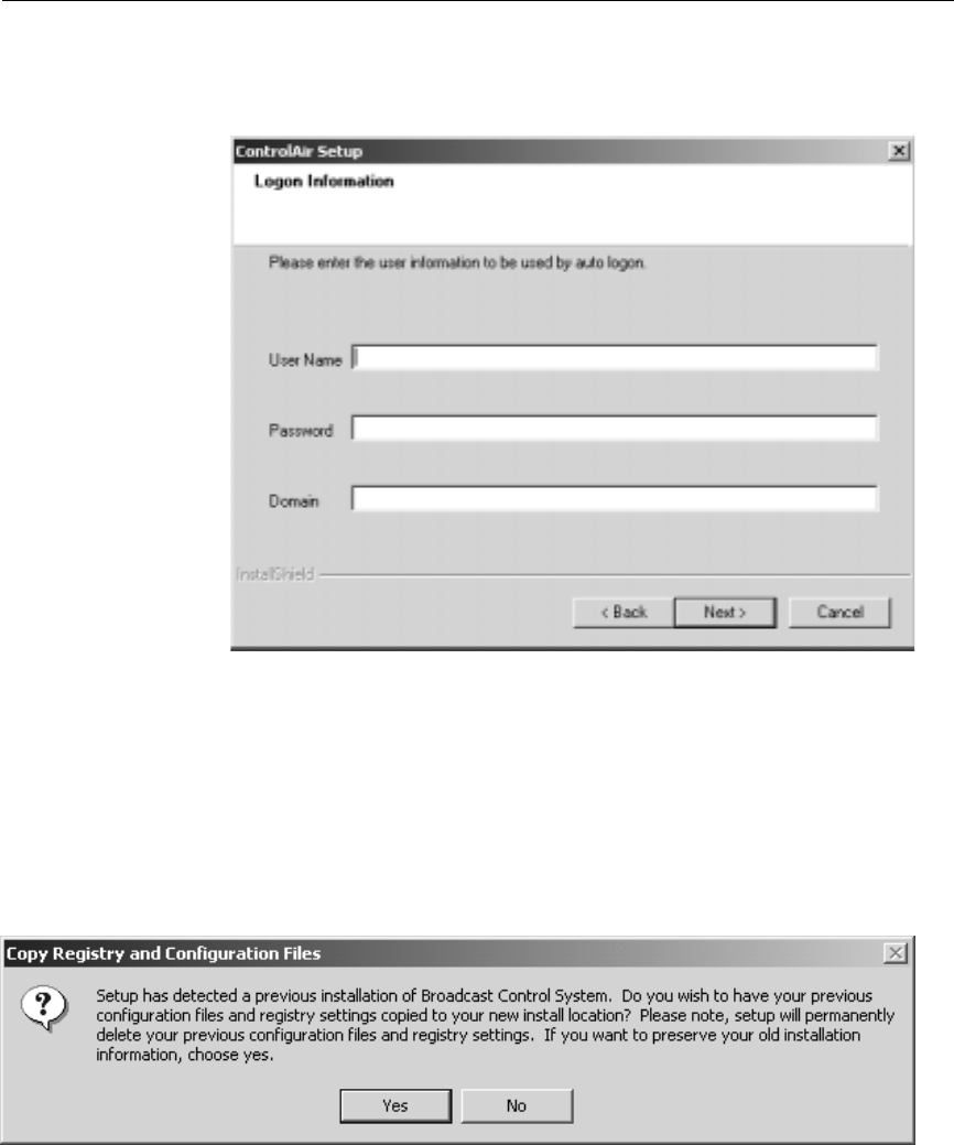
22. The Logon Information dialog box will appear.
Enter your User Name, Password, and Domain, then click Next.
23. The Setup program will determine whether any previous version
of the ControlAir(formerly known as BCS) software is installed.
a. If not, go to step 27 on page 3-25.
-OR-
b. If there is previous software installed, a dialog box will appear
as shown:
Click Yes, then go to step 24 on page 3-23.
3-23
Overview of the Setup
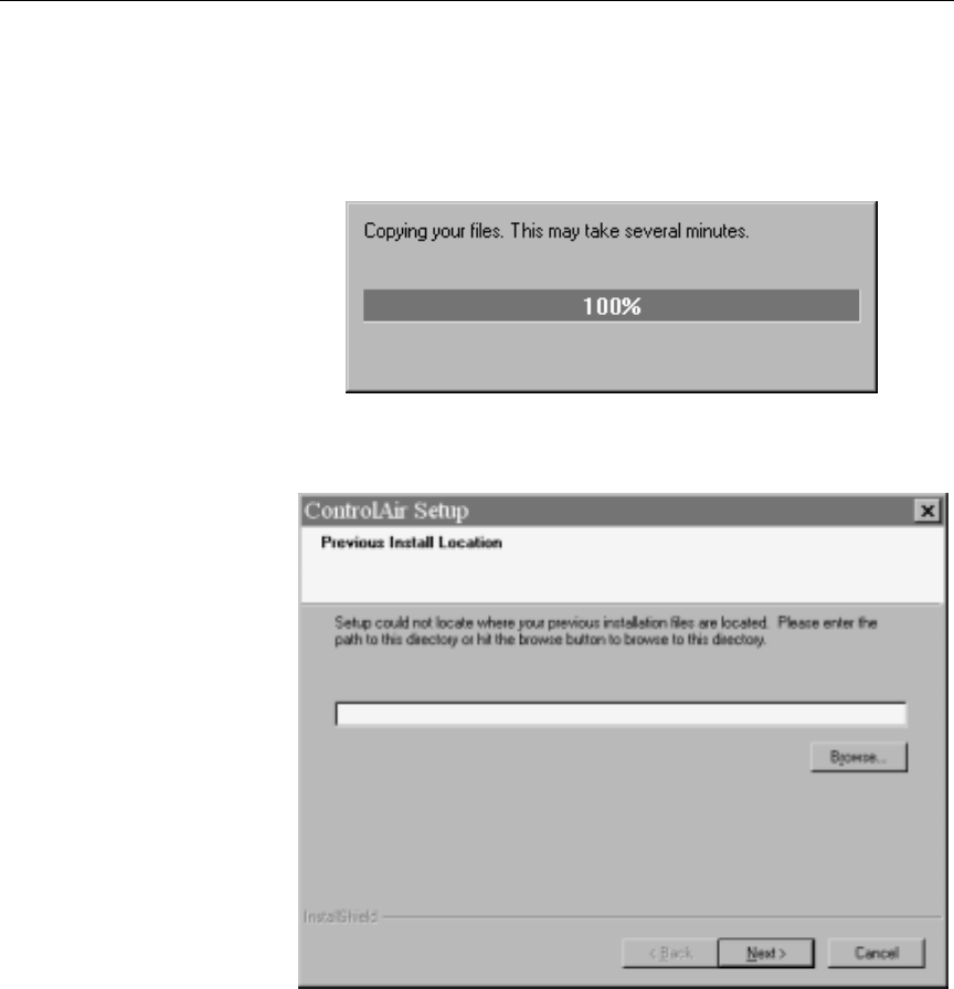
24. The Setup program will search for previous configuration files
and registry settings. If it finds them, the copying will proceed as
shown:
If it does not find them, then a prompt will appear allowing you to
provide the path to their location.
Fill in the path and click Next. The copying will then proceed.
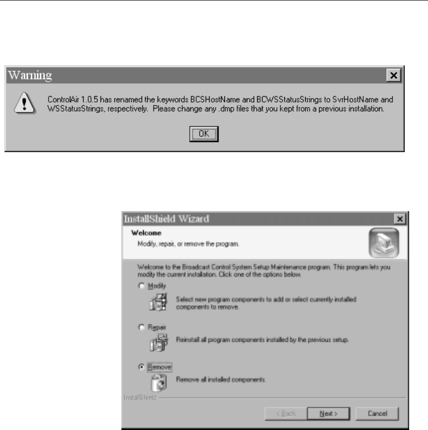
25. After the configuration files and registry settings are copied, if a
previous version of ControlAir (formerly known as BCS) exists,
3-24
Installing and Configuring iNEWS ControlAir
the following notification is displayed: Click OK.
The Setup program will then inform you that it will launch the
previous version’s uninstall program. Click OK.
26. The InstallShield Wizard displays its Welcome screen.
a. Ensure that Remove is selected.
b. Click Next.
c. Respond to any prompts as needed.
d. When the uninstallation is complete, click OK.

3-25
Overview of the Setup
27. The InstallShield Wizard Complete dialog box will appear and
prompt you to restart the computer. Do one of the following:
a. Select Yes to restart the computer, remove the Install CD, and
click Finish.
-OR-
b. Select No to close the Setup program without restarting the
computer.
nWhen installing the software, the computer must be restarted after setup is
complete. If the server and device manager software was installed, the
ControlAir Server and device manager programs will launch automatically
following the reboot. See “Overview” on page 6-2 for more information.
Configuring ControlAir Software
Because ControlAir can interface with a variety of devices, such as
character generators, still store machines, and video playback devices,
the specific steps for configuring the system will vary. However, the
major steps to configuring ControlAir are:
•Setup the ControlAir Manager program by editing the
autostart.ini file.
•Edit the Device Manager Profile (DMP) file for each device.
The first step is explained in this section. See “DMP Configuration
Files” on page 5-6 for more on editing DMP files.
Setup ControlAir Manager
The ControlAir Manager program monitors ControlAir components,
including device managers, on the ControlAir Server. If one stops run-
ning, the ControlAir Manager will restart it automatically.
nControlAir Manager can also monitor third-party device managers.

3-26
Installing and Configuring iNEWS ControlAir
To determine which programs to monitor, the ControlAir Manager
looks for the Start Sequence list in the autostart.ini file. A default
version of this file—shown in Appendix B—is installed with the
ControlAir Server software in the Avid/ControlAir directory. A
sample copy is also provided in the Examples folder, which is located
in the Avid/ControlAir directory too.
cDo not use ControlAir Manager for video device managers, such as
DMAirPlay, that do not protect playing clips when it starts up. For
more information, refer to the Device Manager Guide for each spe-
cific device—located on the ControlAir Install CD.
The autostart.ini file contains two lists:
•The Start Sequence list appears first in the file and contains a line
for each program monitored by the ControlAir Manager, in the
order in which they are to be started.
•The Samples list appears second in the file and contains standard
sample lines for other devices commonly used.

3-27
Overview of the Setup
The following is an example of the two lists as they appear in the
default version of the autostart.ini file:
[Start Sequence]
casvr.exe
AMCPapp.exe
MCSDM.exe dmp\mcsdmss.dmp
MCSDM.exe dmp\mcsdmcg.dmp
LouthDM.exe dmp\Louth.dmp
[Samples]
;This section is ignored by the ControlAir Manager
ChyronDM.exe dmp\ChyronDM.dmp
LouthDM.exe dmp\pdr1.dmp
MCSDM.exe dmp\clipbox.dmp
LouthDM.exe “c:\My Device Profiles\AirSPACE-2.dmp”
The Start Sequence list must begin with the name of the ControlAir
Server program, casvr.exe. Next comes the Avid Machine Control
Protocol Application filename, AMCPapp.exe. The remaining lines
contain two columns of information pertaining to various device man-
agers—one device per line. The first column has the name of the
device manager program and the second provides the pathname for
the DMP configuration file. If no DMP file is specified, the device man-
ager will start, but an Open File dialog box will appear, requesting the
user to specify a DMP file. See the Device Manager Guides on the Con-
trolAir Install CD for more information on creating and editing DMP
files for each device.
cIf no DMP file is specified, the ControlAir Manager cannot automat-
ically restart the DM.
nIt is highly recommended that a copy be made first as a backup before editing
the autostart.ini file.

3-28
Installing and Configuring iNEWS ControlAir
To edit the autostart.ini file, use the Windows Notepad program.
cWhen saving the newly edited INI file, ensure that it does not have a
.txt extension. The default options in Windows Explorer will not
display this crucial information. To change this setting, open Win-
dows Explorer and select Options from the View drop-down menu.
In the dialog box, check Show All Files and uncheck Hide file exten-
sion for known file types, then click OK.
To prevent ControlAir Manager from automatically restarting a device
program, the line for that device must be removed from the Start
Sequence list in the autostart.ini file. It can be deleted from the
list completely or moved to the Samples list.
In the following example, the default line for a character genera-
tor—MCSDM.exe—is and replaced with the standard Chyron device
manager line—ChyronDM.exe—originally provided in the Samples
list. Compare the list below with the standard default listings shown
on page 3-27 to spot the edit.
[Start Sequence]
casvr.exe
AMCPapp.exe
MCSDM.exe dmp\mcsdmss.dmp
ChyronDM.exe dmp\ChyronDM.dmp
LouthDM.exe dmp\Louth.dmp
[Samples]
;This section is ignored by the ControlAir Manager
MCSDM.exe dmp\mcsdmcg.dmp
LouthDM.exe dmp\pdr1.dmp
MCSDM.exe dmp\clipbox.dmp
LouthDM.exe “c:\My Device Profiles\AirSPACE-2.dmp”
CHAPTER 4
Setting up the Monitor
Server on iNEWS Servers
After the iNEWS ControlAir software is installed, you must set up
monitor servers on iNEWS Servers to use ControlAir.
Do not confuse the monitor server in this chapter with server hard-
ware or file servers, which are computers with the iNEWS database
and running the iNEWS Server software. If referenced in this chapter,
those computers are called iNEWS Servers, NRCS-A, NRCS-B, and so
forth. This chapter explains setup and use of the utility program
known as the monitor server. There are various types of these utility
programs, called servers, which perform a multitude of tasks. See the
“Servers” chapter of the iNEWS Newsroom Computer System Operations
Manual for more information.
This chapter contains the following major sections:
•Overview
•Configuring Monitor Servers
- Configuration Summary
- Configuration Details
•Using Monitor Server

4-2
Setting up the Monitor Server on iNEWS Servers
Overview
A monitor server is a utility program—running on the iNEWS news-
room computer system—that checks a show’s event requests for
errors, creates composite and event lists, and sends playlists to
ControlAir.
A monitor server must be assigned device and mailbox num-
bers—typically, these numbers are the same, which makes the configu-
ration easier to remember. A device number is chosen for monitor
server so iNEWS recognizes the server (utility program) as a valid
device. The device number must be entered in the system’s configura-
tion file. The mailbox number must be assigned to both the show’s
monitor server and its rundown queue.
nA mailbox is an activation mechanism for a server (utility) program, so if a
queue has a mailbox number matching a server program, then that server is
the one activated or “awakened” whenever something happens to the queue.
See Chapter 14 in the iNEWS Newsroom Computer System Operations
Manual for more information on mailboxes and other server programs.
The mailbox enables iNEWS to notify the monitor server of changes
made to a rundown queue—the one sharing the same mailbox num-
ber—while that show is monitored. The monitor server then updates
composite and event lists, if necessary.
The monitor server is turned on when a user at an iNEWS Workstation
turns it on. When on, monitor server checks its assigned rundown for
production cues, and builds playlists.
It continues to monitor the rundown for changes and performs as
much error checking as it can—by comparing production cues with
styles located in the SYSTEM.RESOURCE queue—without communi-
cating with any broadcast equipment, including ControlAir. See
“Monitor Mode - On” on page 1-10 and Figure 1-3 on page 1-11 for
more information. Also, to learn more about styles and how monitor
checks for errors, see “Styles” on page 4-33.

4-3
Configuring Monitor Servers
The monitor server loads data to the ControlAir system when a user
instructs it to do so from an iNEWS Workstation. The communication
paths between monitor server and ControlAir, at this point, is
explained in more detail in “Monitor Mode - Load” on page 1-12. See
also Figure 1-4 on page 1-13 and “Using the Monitor Server” on
page 4-41.
nIt is recommended that producers turn the monitor server on early so it can
check the rundown queue throughout much of the show’s development.
Instructing the monitor server to load data should be done later, such as just
before taking the show to air.
Some sites use the monitor server alone—without any direct connec-
tion to devices or ControlAir—to check machine control events within
scripts for errors and produce playlists that personnel can print out or
refer to during broadcasts.
Configuring Monitor Servers
When configuring monitor servers, there are certain tasks that must be
performed on the iNEWS Servers at the console, and at an iNEWS
workstation. If your site already has the Machine Control System
(MCS), much of this work may already be done. These tasks must be
completed to download playlists and updates to the ControlAir sys-
tem.
This chapter assumes:
•Your site has a fully functioning network.
•Your newsroom computer system servers are operational and run-
ning the iNEWS Server software.
•All iNEWS Servers are connected to a console multiplexor, to
which Avid Broadcast Customer Support technicians have dial-in
access.

4-4
Setting up the Monitor Server on iNEWS Servers
•The person performing the installation has attended an iNEWS,
AvidNews, or NetStation system administration course or has
equivalent experience. This includes having a working knowledge
of ed, the UNIX line editor and selecting servers at the console.
nIt is highly recommended that you have an iNEWS Newsroom Computer
System Operations Manual available while conducting procedures found in
this chapter. Selecting servers is explained in Chapter 2 of the operations
manual and the UNIX line editor is explained in Chapter 10.
Configuration Summary
The set-up procedure has the following steps: Each step is explained
further in “Configuration Details” on page 4-4.
1. Creating a Monitor Server for Each Show (page 4-5)
2. Creating Composite and Event List Queues (page 4-12)
3. Set Up Queue and Story Forms (page 4-15)
4. Assigning Forms to Queues (page 4-17)
5. Create an Entry in the SYSTEM.MAP Story (page 4-19)
6. Updating the iNEWS System Dictionaries (Optional) (page 4-28)
7. Some configurations require updating styles in the
SYSTEM.RESOURCE story. For more information on how to do
that, see “Styles” on page 4-33.
Configuration Details
The following steps do not include setting up external devices, such as
character generators and still stores, which play broadcast events.
Refer to the manufacturer’s documentation, provided with the device,
and to the Device Manager Guides, provided on the ControlAir Installa-
tion CD, for more configuration details.

4-5
Configuring Monitor Servers
The configuration procedure comprises the following steps:
Step 1: Creating a Monitor Server for Each Show
This section assumes
rundown queues for the
shows being monitored
already exist. If not, cre-
ate them before con-
tinuing. Refer to the
iNEWS Newsroom Com-
puter System Operations
Manual for more infor-
mation.
To create and configure a monitor server, do the following:
1. Check the configuration file (/site/config) and choose the next
available device number for the monitor server, from the range of
3-digit numbers reserved for use by your system’s server pro-
grams, such as 201 to 300.
Valid standard mailbox
numbers are 1 through
4096. For more on mail-
boxes, see “Using Mail-
boxes” in Chapter 14 of
the iNEWS Newsroom
Computer System Opera-
tions Manual.
2. Choose an available mailbox number. For simplicity, this can be
the same 3-digit device number. Do the following:
a. Use the list console command to ensure no other device is
using the mailbox number you have chosen.
For instance, to check mailbox 266, type:
list mailbox=266 c
Information similar to the following appears:
nFor other
list
command options for determining mailbox assignments of
queues and servers, see “Using the list Command to View Assigned Mail-
boxes” on page 4-11.
b. If you see the device configuration header (as shown in step
2a) with no information below it, then no device has that mail-
box and you can use that number. However, if configuration
information for a device appears below the header, that device
has the same mailbox as the one you chose. Therefore, choose
another mailbox number and repeat step 2a.
DEV DEVICE_TYPE COMPUTER CCU PRINTER SPEED OPTIONS DEVNAME

4-6
Setting up the Monitor Server on iNEWS Servers
nIf the mailbox number is already being used, and you must choose another,
you may want to try another device number for the monitor server as well.
Typically, mailbox numbers match server program device numbers, although
this is not required. However, the mailbox number you select must be
assigned to the queue monitored by the server program. Multiple queues can
share the same mailbox number, but care must be take to avoid conflicts. See
“Assigning the Mailbox to the Rundown Queue” on page 4-10 for more
information.
3. Add the monitor server to the /site/config file on each iNEWS
Server—such as server A and server B in a dual server system—
by doing the following:
cAlways back up the /site/config file before making any
changes. See “Changing the Configuration File” in Chapter 11 of the
iNEWS Newsroom Computer System Operations Manual for more
information.
Changing the configu-
ration file requires the
use of ed, the UNIX line
editor. See Chapter 10 of
the iNEWS Newsroom
Computer System Opera-
tions Manual for more
information.
a. At the console, select all iNEWS Servers. Instructions for how
to do this is provided in Chapter 2 of the iNEWS Newsroom
Computer System Operations Manual.
b. Use the ed command to open and edit the configuration file,
by typing:
ed /site/config
1259
After you press Enter, the editor responds by displaying a
number, as shown, indicating the file size expressed as the
number of characters, including spaces and returns.
c. Add the monitor server’s device number to the servers line
in the host definition for the iNEWS Server that will run the
monitor server program. For instance:
servers 261 263 265 267
The device number 267 is added to the servers line in this
example.

4-7
Configuring Monitor Servers
nDivide your server programs evenly among your iNEWS Servers to distrib-
ute the load they put on your system. For instance, put odd numbered pro-
grams on server A and even numbered ones on server B. Additionally, ensure
that you also add the configuration line for the monitor server to alternate
host definitions for your iNEWS Servers. This ensures it can run on the sur-
viving computer should one of your iNEWS Servers stop functioning. A sam-
ple configuration file is provided in Appendix B; it includes pointers
indicating where in the file information is added, as described in this proce-
dure.
Do not confuse the con-
figuration line, which
starts with server, and
the servers line men-
tioned in 3c (page 4-6),
which lists device num-
bers.
d. Add a configuration line for the monitor server in the host
definition belonging to the iNEWS Server that will run the
server program. This line begins with the word server and
contains the mailbox number assigned to the monitor server.
The format for server programs’ configuration lines are:
server <device#> <type> <mailbox> <device name>
Parameter Description
device # The device number assigned to the server pro-
gram. This 3-digit number must also be listed
in the servers line in a host definition.
type The type of server program is monitor.
mailbox The mailbox the server program uses. Valid
standard mailbox numbers are 1 through 4096.
This number typically matches the server pro-
gram’s device number.
device name Monitor servers do not use a device name;
enter a hyphen (-).

4-8
Setting up the Monitor Server on iNEWS Servers
Comments appearing
after the semicolons (;)
are optional.
The following are sample configuration lines for various server
programs:
Do not use an uppercase
(W) in step 3e. See Chap-
ter 10 in the iNEWS
Newsroom Computer Sys-
tem Operations Manual
for more information.
e. When you finish making changes to the configuration file,
save your changes by typing:
w
f. When you press enter, a number will appear, such as 1279,
indicating the file size. You can then exit the UNIX line editor
by typing:
q
4. (Optional) Test your configuration changes. See “Testing the Site
Configuration File After Changing” in Chapter 11 of the iNEWS
Newsroom Computer System Operations Manual for more informa-
tion.
nAfter editing the configuration file (/site/config), it should be backed up
to tape. For more information about backing up site files, see the iNEWS
Newsroom Computer System Operations Manual.
Before the monitor server can be used, two more tasks must be com-
pleted:
server 256 action 256 actphon ;action svr
server 257 distribution 257 devname1 ;dist server
server 258 parallel 258 devname2
server 259 keyword 259 key1 ;keyword server
server 260 seek 260 seek ;seek server
server 261 ftsseek 261 - ;fts searches
server 262 ftsindex 262 - ;fts indexing
server 263 print 263 - ;print server
server 264 monitor 264 - ;monitor server
server 265 monitor 265 - ;monitor server
server 266 monitor 266 - ;monitor server
server 267 monitor 267 - ;monitor server

4-9
Configuring Monitor Servers
•Reconfiguring the system to incorporate the new device (monitor
server) into your system’s operation.
•Adding the monitor server’s mailbox to the rundown queue it will
be monitoring.
These tasks are covered in the next two sections.
Reconfigure the System
You do not need to stop
anything to reconfigure
the system.
To reconfigure the system, do the following:
1. At the console, select the master computer (typically server A).
2. Type su to log in as superuser and type the superuser password.
3. Type:
NRCS-A# offline
4. Type:
NRCS-A# configure
5. When the prompt returns, bring the system online again by typ-
ing:
NRCS-A# online
A message similar to the following will appear:
6. After you see the System being configured message, exit
from superuser mode. (CTRL-D)
Unlike other utility programs, it is not necessary to start a monitor
server when you add it to the configuration file. It starts when some-
one uses the monitor on or monitor load command for the run-
down queue to which you have assigned the monitor server. See
“Using the Monitor Server” on page 4-41 for more information.
A Wed Oct 3 00:18:58 2001 msg System being configured
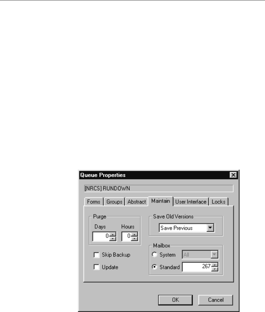
4-10
Setting up the Monitor Server on iNEWS Servers
Assigning the Mailbox to the Rundown Queue
Mailboxes are assigned
to queues in the same
way other database
traits are—using the
Queue Properties dia-
log box. See Chapter 5
in the iNEWS Newsroom
Computer System Opera-
tions Manual for more
information.
After you choose the monitor server’s mailbox number and verify that
it is not used by another device, you must also assign it to the show’s
rundown queue, being monitored by the monitor server.
For instance, the rundown queue in the following procedure is
SHOWS.6P.RUNDOWN, and the mailbox being assigned is number 267.
To assign a mailbox to the rundown queue, do the following:
1. Log in as a system administrator—that is, with a superuser
account—to an iNEWS workstation.
2. Navigate to the rundown queue, such as the queue named Run-
down located in the SHOWS.6P directory.
3. Right-click on the queue and select Properties from the pop-up
menu. The Queue Properties dialog box will appear.
4. Click on the Maintain tab.

4-11
Configuring Monitor Servers
5. Select the Standard radio button located in the Mailbox section.
6. Type in the mailbox number, such as 267.
7. Click OK to save changes.
Using the list Command to View Assigned Mailboxes
Variations of the list command can be used at the console to deter-
mine mailbox assignments for specific devices, queues, and so forth.
Since multiple queues can share the same mailbox, you can list all
queues and directories in the database that are using a certain mailbox,
such as 267. To do this, type:
list mailbox=267 d
To find out which monitor server mailboxes are assigned, type:
list c monitor
The system displays configuration information for your system’s mon-
itor servers, similar to the following:
The mailbox number assigned to each monitor server appears in the
PRINTER column and begins with the letter, N.
To see if any servers are assigned a certain mailbox number, use the
following format: list mailbox=<mailbox number> c
DEV DEVICE_TYPE COMPUTER CCU PRINTER SPEED OPTIONS DEVNAME
S264 monitor A N264
S265 monitor B N265
S266 monitor A N266
S267 monitor B N267
NRCS-A:

4-12
Setting up the Monitor Server on iNEWS Servers
cTwo rundown queues can share the same mailbox, but they should
never be monitored simultaneously. If two rundowns share the same
mailbox number, ensure that both their monitor servers do not run
simultaneously; otherwise, results could be unpredictable.
To check whether mailbox 267 is assigned to a server program, type:
list mailbox=267 c
Step 2: Creating Composite and Event List Queues
The monitor server scans stories for production cues and builds lists of
machine control events, which can be referenced or used to transmit
data to production devices, such as character generators (CGs), video
servers, and still store machines. These lists, known as composite and
event lists, are optional, yet valuable, resources for a show’s director
and production device operators. An event list contains details for a
specific device, while a composite list contains status information for
all devices connected through ControlAir.
You may want to create only composite and/or event lists for certain
production devices. If you do not create list queues for some devices,
the monitor server will not create lists.
For these lists to exist, queues for them must be created—if they do not
already exist—and they must be “mapped” to the monitor server so it
knows where to put composite information and event lists.
The following procedure explains how to create queues. For more on
mapping them, see “Create an Entry in the SYSTEM.MAP Story” on
page 4-19.
To create and configure the composite and event list queues, do the
following:
1. At an iNEWS workstation, log in as a system administrator—or
user with authority to create queues in the iNEWS database.
2. Navigate to and select the directory (folder) created to hold the
queue you want to create.
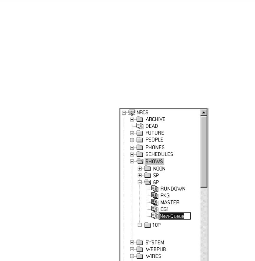
4-13
Configuring Monitor Servers
3. Do one of the following:
a. Click on the Tools drop-down menu, then select New Queue.
-OR-
b. Right-click on the folder in the Directory panel, and choose
New Queue from the pop-up menu.
A new queue appears under the folder you selected. The
New-Queue appears at the end of the list of existing queues.
The title, New-Queue, is highlighted, so you can rename it.
4. Type the name of the new queue, such as COMPOSITE or CG1.
nThe pathname of each device’s event list queue is a combination of the event
list directory and the device manager’s name. For instance, if you want an
event list for the 6PM show that has a character generator called CG1, you

4-14
Setting up the Monitor Server on iNEWS Servers
may select to place the event list queue in the SHOWS.6P directory. The path-
name would be SHOWS.6P.CG1. Using the same example, the pathname for
the composite list queue would be SHOWS.6P.COMPOSITE.
5. Press Enter to save the new queue name.
The newly created queue will inherit database traits of its parent
directory initially. You can open the new queue by double-clicking
on it. For more information about queues and their database traits,
see Chapter 5 in the iNEWS Newsroom Computer System Operations
Manual.
6. To have monitor server display information in these lists properly,
each queue must be assigned the proper queue and story form.
Assigning these forms is covered in “Assigning Forms to Queues”
on page 4-17.
7. To ensure that you can use the queues effectively, remove the
inverted database trait and apply the refresh database trait to
them. This can be done by removing the check mark from the
Inverted checkbox and selecting the Refresh checkbox on the User
Interface tab of the Queue Properties dialog box at any iNEWS
workstation.
For more information about assigning database traits to queues,
see Chapter 5 of the iNEWS Newsroom Computer System Operations
Manual.
8. Assign a write security group to your event and composite list
queues to ensure that only the monitor server makes changes to
the composite and event lists. It is recommended that you restrict
writing access of these queues to superusers.
For more information on how to assign write groups to queues,
see “Group Traits for the Database” in Chapter 6 of the iNEWS
Newsroom Computer System Operations Manual.
After the composite and event list queues are created, the monitor
server must be created—as described in step 1 on page 4-5—and
mapped to them. This will enable the monitor server to determine the
queue where the composite list should be placed and the directory

4-15
Configuring Monitor Servers
where the event list queues are located. The procedures for mapping
the monitor server to composite and event list queues are explained in
“Create an Entry in the SYSTEM.MAP Story” on page 4-19.
Step 3: Set Up Queue and Story Forms
All three queues—rundown, composite, and event list—use forms
with fields that may be filled in by monitor server programs.
Add fields to existing rundown queue and story forms in iNEWS, as
well as forms used by the composite and event list queues, using the
following guidelines:
•Two form field types that are often used in forms for all three
queues—except for CG and Still Store event lists: VIDEO-ID and
EVENT-STATUS.
•The following form field types are used in forms for composite
and event list queues: CG-ADDR, CG-TEMPLATE, CG-TEXT,
STILL-ID, STILL-PRESET, STYLE, and EFFECT.
All of these fields, associated with the ControlAir system, are
explained in more detail in Table 4-1.
Table 4-1 iNEWS Form Fields for ControlAir
Field Type Description
CG-ADDR This field holds the ID’s or recorded page addresses from the character gener-
ator on which a CG (or super) is written by the character generator interface.
CG-TEMPLATE This field contains template information for the character generator, namely
the address on the character generator of the template or tab description mes-
sage to be used for the requested super.
CG-TEXT This field contains text of the CG (or super) from the machine control event
requested by a user in the script. It is written into specified template fields on
the character generator that is interfaced with the iNEWS newsroom com-
puter system.

4-16
Setting up the Monitor Server on iNEWS Servers
EFFECT This field holds the effect name requested in association with a machine con-
trol event that will be applied to the character generator or still store machine
when it is taken to air. For instance: a wipe or a dissolve.
EVENT-STATUS This field displays availability and play status of a machine control event, as
reported by the production device involved. For instance, a video event could
be reported as N/L (not loaded) or OFFLINE, CUED,PLAYING, or
STOPPED, among other things. In forms for rundown and event list queues,
only the status of a video event can be displayed. In Machine Control Termi-
nal (MCT) and ControlAir Workstation forms, this field can also contain the
status of CG and still store events.
STYLE This field contains the style name specified when a user requests a CG or Still
Store machine control event in the production cue. It is typically an alpha or
alphanumeric sequence that is a maximum of eight characters long. For
instance, iNEWS translates a CG style into an address on the character gener-
ator at which a template is stored. That template is then used to build the
requested CG. Styles are defined in stories in the SYSTEM.RESOURCE queue.
They define the details, such as CG template, number of fields, still preset or
playback effect, that define an event.
STATUS This field is used in a rundown queue. It will display “OK” or “ERROR,”
depending on the status of production cues in the story. The iNEWS system’s
monitoring program sets this field to indicate whether there are any errors in
the production cues in stories of the rundown.
STILL-ID In a composite or event list queue, this field displays the alphanumeric iden-
tifier for a still store graphic.
STILL-PRESET This field contains the number or letter designation of a predefined still store
format. It is typically used in the form for the still store device event list, and
is recognized by the ControlAir Workstation.
VIDEO-ID This field is used in the rundown queue to display the tape number or clip ID
for video. It is also found in forms for the composite and video event lists.
This field is primarily used in association with machine control and
ControlAir systems.
Table 4-1 iNEWS Form Fields for ControlAir
Field Type Description (Continued)

4-17
Configuring Monitor Servers
nSee the “MCS/BCS Fields and Forms” section in Chapter 8 of the iNEWS
Newsroom Computer System Operations Manual for further information on
when and how these fields are used, as well as other fields that maybe used.
For instance, TAPE-TIME, RUNS-TIME, and MOS-DURATION.
For a field to be used in a queue form, it must also exist in a story form. Refer
to Chapter 8 in the iNEWS Newsroom Computer System Operations Manual
for details on creating or modifying forms and other form field types. More
form and field information pertaining to upgrading to iNEWS as it relates to
ControlAir is provided in Appendix C of this manual.
Step 4: Assigning Forms to Queues
After you create queues to hold the composite and event lists, you
must assign forms containing ControlAir fields to each queue. For
instance:
•Assign a form designed to display composite list information to
SHOWS.6P.COMPOSITE
•Assign a form designed to display the information in a character
generator’s event list to SHOWS.6P.CG1
nYour system includes default forms—located in the SYSTEM.FORMS direc-
tory—for composite, still store, character generator, and video event list
queues. If upgrading to iNEWS from a previous product version, such as Net-
Station, you must update forms for composite and event list queues, includ-
ing rundown forms.
To assign a form to a queue, do the following at an iNEWS worksta-
tion:
1. Navigate to the queue you want in the Directory panel.
2. Right-click on it. A pop-up menu will appear.
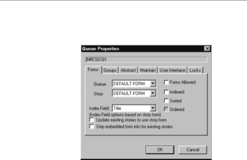
4-18
Setting up the Monitor Server on iNEWS Servers
3. Select Properties from the pop-up menu. The Directory/Queue
Properties dialog box will appear.
nAccess to the Directory/Queue Properties dialog box and its appearance vary,
depending on certain circumstances. See Chapter 5 of the iNEWS Newsroom
Computer System Operations Manual for more information.
4. Do either or both of the following:
a. Use the Queue drop-down list on the Forms tab to select the
form you want to apply to the directory as queue form data-
base trait.
b. Use the Story drop-down list on the Forms tab to select the
form you want to apply to the directory as story form data-
base trait.
You must assign a queue form and a story form. The queue form
determines the look of the queue. The story form determines the
look of each individual story.
For instance, to assign the standard composite list queue form to
the SHOWS.6P.COMPOSITE queue, select the appropriate form
from the Queue drop-down list in the Queue Properties dialog

4-19
Configuring Monitor Servers
box. To assign a story form to this composite list, select the appro-
priate form from the Story drop-down list in the Queue Properties
dialog box.
nThe forms will only appear in the drop-down lists if they exist in the database.
For information about how to create your own forms or modify existing
forms, and about database traits, see the iNEWS Newsroom Computer Sys-
tem Operations Manual.
5. If you made changes to an existing form, you must select the
Update existing stories to use story form. When this check box is
selected, iNEWS changes the story form assignment for previously
existing stories within the queue.
6. Click OK to save changes and apply the new queue/story form
settings.
nUsers should log off and sign back on to view the new queue/story form set-
tings.
Step 5: Create an Entry in the SYSTEM.MAP Story
The map story is a standard iNEWS database story and is always the
first story in the SYSTEM.MAP queue. It can be opened and edited like
any other iNEWS database story; however, access to it is typically lim-
ited to system administrators who already have access to the System
directory.
When you create a show’s map story entry, you will usually specify
that monitor server create and maintain event and composite lists
when someone monitors the show.
After creating the show’s monitor server, add an entry for the show to
your system’s map story. This entry specifies to the show’s monitor
server the location of the show’s rundown queue, and composite and
event lists. Without this information, the monitor server will not create
lists. The map story entry also specifies the list of groups that can mon-
itor a queue, and when the monitor server turns itself off.

4-20
Setting up the Monitor Server on iNEWS Servers
To add an entry for the show in the map story, do the following:
MOS Gateway is
another Avid product
that works with the
iNEWS newsroom com-
puter system to control
production devices.
1. Open the SYSTEM.MAP story, which contains a separate entry for
each show that will be produced using ControlAir or MOS Gate-
way.
Figure 4-1 shows three sample entries, with four devices each, in a
SYSTEM.MAP story.
Figure 4-1 Sample Map Story
2. Create an entry header.
As shown in Figure 4-2, the entry header specifies the following
information for each show:
•The show’s rundown queue
•The directory that holds the event list queue(s)
•The composite list queue
;RUNDOWN EVENT DIR COMP QUEUE GROUP (OFF TIME)
;DEVICE DEVNAME UPDATE PLAYBACK FORM (MSG DIR)
;
SHOW.10P.RUNDOWN SHOW.10P SHOW.10P.COMPOSITE - 130
ss ss@casvr-1,casvr-2 UPDATE bcs-bcw
cg cg@casvr-1,casvr-2 UPDATE bcs-bcw C:NEWS:300 499
cart pdr@casvr-1,casvr-2 UPDATE bcs-bcw 3
mos sony@mosgwy UPDATE bcs-bcw -
;
;
SHOW.6P.RUNDOWN SHOW.6P SHOW.6P.COMPOSITE - 2100
ss ss@casvr-1,casvr-2 UPDATE bcs-bcw
cg cg@casvr-1,casvr-2 UPDATE bcs-bcw C:NEWS:500 699
cart pdr@casvr-1,casvr-2 UPDATE bcs-bcw 3
mos sony@mosgwy UPDATE bcs-bcw -
;
;
SHOW.SPECIALS.RUNDOWN SHOW.SPECIALS SHOW.SPECIALS.COMPOSITE - D130
ss ss2@casvr-1,casvr-2 UPDATE bcs-bcw
cg cg2@casvr-1,casvr-2 UPDATE bcs-bcw C:NEWS:300 499
cart pdr2@casvr-1,casvr-2 UPDATE bcs-bcw 3
mos sony@mosgwy UPDATE bcs-bcw -
Each show’s map story entry must begin with a line called an entry header.
The entry header must be followed by a device list.

4-21
Configuring Monitor Servers
•Group of users who can monitor the show
•The time you want the monitor to turn itself off—when you
want the system to stop monitoring the show.
nThe time may be entered as a specific time, such as 130 (1:30 AM) or 2100
(9:00 PM). It may also be entered as a duration, such as D130; the monitor
server will turn itself off 1 hour and 30 minutes after it was turned on.
Figure 4-2 Sample Entry Header
;RUNDOWN EVENT DIR COMP QUEUE GROUP (OFF TIME)
;DEVICE DEVNAME UPDATE PLAYBACK FORM (MSG DIR)
;
SHOW.10P.RUNDOWN SHOW.10P SHOW.10P.COMPOSITE - 130
ss ss@casvr-1,casvr-2 UPDATE bcs-bcw
cg cg@casvr-1,casvr-2 UPDATE bcs-bcw C:NEWS:300 499
cart pdr@casvr-1,casvr-2 UPDATE bcs-bcw 3
mos sony@mosgwy UPDATE bcs-bcw -
;
;
SHOW.6P.RUNDOWN SHOW.6P SHOW.6P.COMPOSITE - 2100
ss ss@casvr-1,casvr-2 UPDATE bcs-bcw
cg cg@casvr-1,casvr-2 UPDATE bcs-bcw C:NEWS:500 699
cart pdr@casvr-1,casvr-2 UPDATE bcs-bcw 3
mos sony@mosgwy UPDATE bcs-bcw -
;
;
SHOW.SPECIALS.RUNDOWN SHOW.SPECIALS SHOW.SPECIALS.COMPOSITE - D130
ss ss2@casvr-1,casvr-2 UPDATE bcs-bcw
cg cg2@casvr-1,casvr-2 UPDATE bcs-bcw C:NEWS:300 499
cart pdr2@casvr-1,casvr-2 UPDATE bcs-bcw 3
mos sony@mosgwy UPDATE bcs-bcw -
The show’s
rundown queue
The directory that
holds the event list
queues
The time you want the
monitor to turn itself off
The composite list queue Groups

4-22
Setting up the Monitor Server on iNEWS Servers
You must specify the parameters in the entry header in the order indi-
cated in Table 4-2.
Table 4-2 Entry Header Parameters
Parameter Definition
Rundown Queue The full pathname of the show’s rundown queue.
Event List Directory (Optional) The directory in which event lists are
stored. The monitor server combines information
you put here with the device name. For instance, if
you specify SHOWS.6P here and you have a still
store machine called “ss1,” the monitor server
puts the still store’s event list in SHOWS.6P.SS1. It is
a good idea to use the same directory that holds the
show’s rundown. If you do not use this field, put a
dash here.
Composite List Queue (Optional) The full pathname of the queue in
which the show’s composite list is stored. It is a
good idea to put the composite list in the same
directory as the show’s rundown queue. If you do
not use this feature, put a dash here.
Group of Users (Optional) Put a security group in this field so that
only superusers and people assigned to that group
can monitor the show.
Put a dash here if you do not want to restrict who
can monitor the show.
Consider using different security groups for each
show in a series of back-to-back shows to prevent
one show’s producer from starting or stopping
another show’s monitor server.
Off Time The time you want the show’s monitor server to
turn itself off. You can enter this time as either a
time of day or a duration. Enter the time of day in
24-hour format. For instance, type 1915 to have the
monitor server turn itself off at 7:15 PM. Enter a
duration by typing D before the value. For instance,
enter a duration of one hour and 30 minutes as
D130. (These values are not case-sensitive.)

4-23
Configuring Monitor Servers
3. List the devices used by the show; production devices for which
you want the show’s monitor server to process event requests.
Figure 4-3 Sample Device List in a SYSTEM.MAP story
The monitor server can only process event requests for devices
specified in the device list; event requests for other devices gener-
ate errors. The parameters contained in the device list are
explained in Table 4-3 and Table 4-4.
;RUNDOWN EVENT DIR COMP QUEUE GROUP (OFF TIME)
;DEVICE DEVNAME UPDATE PLAYBACK FORM (MSG DIR)
;
SHOW.10P.RUNDOWN SHOW.10P SHOW.10P.COMPOSITE - 130
ss ss@casvr-1,casvr-2 UPDATE bcs-bcw
cg cg@casvr-1,casvr-2 UPDATE bcs-bcw C:NEWS:300 499
cart pdr@casvr-1,casvr-2 UPDATE bcs-bcw 3
mos sony@mosgwy UPDATE bcs-bcw -
;
;
SHOW.6P.RUNDOWN SHOW.6P SHOW.6P.COMPOSITE - 2100
ss ss@casvr-1 UPDATE bcs-bcw
cg cg@casvr-1 UPDATE bcs-bcw C:NEWS:500 699
cart pdr@casvr-1 UPDATE bcs-bcw 3
mos sony@mosgwy UPDATE bcs-bcw -
;
;
SHOW.SPECIALS.RUNDOWN SHOW.SPECIALS SHOW.SPECIALS.COMPOSITE - D130
ss ss2@casvr-1,casvr-2 UPDATE bcs-bcw
cg cg2@casvr-1,casvr-2 UPDATE bcs-bcw C:NEWS:300 499
cart pdr2@casvr-1,casvr-2 UPDATE bcs-bcw 3
mos sony@mosgwy UPDATE bcs-bcw -
The type of
production
device
The name of
the production
device
The address range
you want to use (CGs
and still stores only)
Whether the monitor
server updates the
device’s playlist
The ControlAir Worksta-
tion form for that show, or
the MCT form for that
device
Name of backup server

4-24
Setting up the Monitor Server on iNEWS Servers
Table 4-3 Device List Parameters
Parameter Definition
Device Type Specify the type of production device in this
parameter.
In some cases, iNEWS users may create machine
control events that specify devices by type
rather than name. When the monitor server
encounters such an event, it sends it to the first
device of that type defined in the show’s
SYSTEM.MAP story entry. If you have a show
that uses two devices of the same type, decide
which device you want as the monitor server’s
default, and define it first in the show’s
SYSTEM.MAP story entry.

4-25
Configuring Monitor Servers
Device Name Specify the name of the production device in this
parameter. If the device is connected to the system
through an MCS-PC or PC-PCU, only the device
name is needed in this parameter, such as CG1, SS,
VID-A.
The device name is assigned to the production device
in the iNEWS configuration file (/site/config). If
you are unsure of the device name, check its entry in
this configuration file.
For devices interfaced through a ControlAir Server
the format is:
<device name>@<ControlAir Server name>
In addition, a backup server may be specified. The
backup server can be loaded in place of the primary
server; however, both may not be loaded at the same
time.
For server pairs, the format is:
<device name>@<primary>,<backup>
Examples are provided in Figure 4-3.
Device names for ControlAir Server devices, must
match the device name specified in a DMP file for one
of the DMs configured on that ControlAir Server.
Update Specify whether you want the monitor server to
update the device’s playlist when someone modifies
the rundown in this parameter. By default, these
updates are performed. Type noupdate in this
parameter if you do not want the monitor server to
perform these updates.
Playback Form Specify the form used to display each device’s
machine control events. You can use standard forms
provided with your system, such as the bcs-bcw
form, or build your own. If you use a Machine Con-
trol Terminal (MCT), the standard forms are MCT-CG,
MCT-SS, and MCT-CART.
Table 4-3 Device List Parameters (Continued)
Parameter Definition

4-26
Setting up the Monitor Server on iNEWS Servers
nThe iNEWS newsroom computer system stores a Machine Control System
(MCS) dictionary file—named mcs—in the /site/dict directory. The
/site/dict/mcs file usually defines production device types as CG for
character generator, SS for still store machines, and CART for video devices,
such as video servers or cart machines. You must specify in the device list a
valid production device as defined in the dictionary file; otherwise, the moni-
tor server ignores that line and any that follow it, so it cannot properly pro-
cess event requests.
The last parameter of a device list line—Drive, Directory/User#, and
so forth—is defined in Table 4-4.
Table 4-4 CG and Still Store Specific Device List Parameters
Parameter Definition
Parameters for Character Generators:
Drive Select the disk drive you want the character generator
to use. If you leave this field empty, the CG uses its
default drive.
Directory/User# Select the directory you want the character generator
to use.

4-27
Configuring Monitor Servers
Address Range
n
Specify a range of addresses in this field. The monitor
server uses this range to store the forms it builds. To
specify a range of addresses, enter the starting
address, followed by a space and the ending address.
For instance, to reserve addresses 1 through 199, type
1 199 in this field.
The range of numbers must be large enough to hold
all character-generated graphics—also known as
supers—that monitor server is likely to build for the
show. Also, ensure you do not select a range that con-
flicts with the addresses the character generator uses
to store its permanent supers or templates.
Because the monitor server may skip an address to
keep them contiguous within a story, this range
should be larger than the largest number of possible
addresses used.
Parameters for Still Stores:
Drive Select the disk drive you want the still store to use. If
you leave this field empty, the still store uses its
default drive.
Directory/User# If your still store has user numbers, use this field to
specify the user number you want to use for that
show.
Stack Specify the stack or playlist identifier you want the
still store to use in this field.
Table 4-4 CG and Still Store Specific Device List Parameters
Parameter Definition

4-28
Setting up the Monitor Server on iNEWS Servers
4. Save the map story.
5. Test monitor the show to ensure map story entries are functioning
correctly.
The monitor server only examines the show’s map story entry when a
user turns it on, so any changes to the show’s map story entry will not
take effect until then. Changes made to the show’s map story entry
after the show is monitored do not take effect until the next time the
show is monitored.
For this reason, you should monitor the show after creating or modify-
ing the show’s SYSTEM.MAP story entry to test the changes you make.
Monitoring the show allows the monitor server to check your work
and ensures smooth operation when you produce the show.
Step 6: Updating the iNEWS System Dictionaries (Optional)
Machine Control System (MCS) dictionary files in iNEWS can be mod-
ified to customize the text of any dictionary entry. These include the
names given to device types, the text of any error or warning messages
sent to the iNEWS Workstation, certain keywords, and the text of
status indicators from various devices. There are many reasons a site
Parameters for Video Machines:
Channel Assignment This parameter specifies whether the iNEWS system,
the ControlAir Workstation, the device manager, or
the video (cart) device assigns channels. Use these
codes:
0 to have channels assigned by device
1 to have channels assigned by iNEWS
2 to have channels assigned by device manager
3 to have channels assigned by ControlAir Worksta-
tion
Table 4-4 CG and Still Store Specific Device List Parameters
Parameter Definition

4-29
Configuring Monitor Servers
may want to change a dictionary entry. For instance, an AirSPACE,
connected to iNEWS, shows a video play-back status of “OnAir,” but
the status field in the show rundown on iNEWS shows “Play” instead.
If the system administrator wants the two status indicators to match,
the MCS dictionary file in iNEWS must be modified. This will “trans-
late” the iNEWS status wording so that it corresponds to what appears
on the actual device.
nThe monitor server uses the MCS dictionary to show status for all devices, so
ensure that words you choose apply to all devices. For instance, there is no
way for the play status to be “OnAir” for character generators and “Playing”
for video servers simultaneously.
Dictionary files are located in the /site/dict directory. This section
covers changes made only to the /site/dict/mcs file; if changes are
made to other dictionaries in the /site/dict directory, the proce-
dure may require more steps. Refer to the iNEWS Newsroom Computer
System Operations Manual for more information about editing iNEWS
system dictionaries.
Editing the /site/dict/mcs Dictionary File
In the following procedure, as an example, the term “Play” is changed
to “OnAir” in the dictionary.
To edit the dictionary file, do the following:
1. Select all servers at the console, so changes you make are made to
each server’s copy of the file. See “Selecting One or More Servers”
in Chapter 2 of the iNEWS Newsroom Computer System Operations
Manual for more information.
This procedure uses the
UNIX line editor. For
more information, see
Chapter 10 of the
iNEWS Newsroom Com-
puter System Operations
Manual.
2. Open /site/dict/mcs for editing by typing:
ed /site/dict/mcs
3. Navigate to the line with the word you want changed, such as
“PLAY” by typing:
/PLAY

4-30
Setting up the Monitor Server on iNEWS Servers
The console will respond with a display similar to the following:
A_CAPLAY /PLAY
In the above example, PLAY appears twice in the line.
nWhen navigating in the file, remember the UNIX line editor is case-sensitive.
So, typing either /Play or /play will not locate a line with “PLAY.”
4. Substitute the new word, such as “OnAir,” for the second occur-
rence of the existing word, PLAY, by typing:
s?/PLAY?/OnAir
The console will respond with a display similar to the following:
A_CAPLAY /OnAir
nThe question marks are necessary to prevent the editor from substituting
“OnAir” in place of the first occurrence of the word, “PLAY.” For instance,
typing s/PLAY/OnAir would result in the edited line appearing as
/A_CAOnAir /PLAY.
Do not use an uppercase
(W) in step 5. See Chap-
ter 10 in the iNEWS
Newsroom Computer Sys-
tem Operations Manual
for more information.
5. When you finish making changes to the dictionary file, save your
changes by typing:
w
6. When you press enter, a number will appear, such as 1279, indi-
cating the file size. You can then exit the UNIX line editor by typ-
ing:
q
nSee Appendix C in the iNEWS Newsroom Computer System Operations
Manual for more information about Dictionary files.
If you change your existing MCS dictionary files, you must apply
those changes by running the makemctab command at the iNEWS
console; however, if any monitor servers are running at the time the
command is entered, the changes will not apply. All monitor servers
must be stopped prior to running the makemctab command.

4-31
Configuring Monitor Servers
cA system administrator who knows the device numbers for monitor
servers can choose to stop just those programs; however, it should be
done only when the monitor servers are not being used to monitor
on-air shows or during preparation prior to going on-air.
To update your iNEWS dictionaries, do the following:
The prompt endings
change from a colon
(:)—indicating a system
operator login—to a
pound sign (#)—indi-
cating a superuser
login.
1. Select all servers.
2. At the console, type su to become a superuser and type the supe-
ruser password. The prompts will appear as follows:
NRCS-A: su
Password:
NRCS-A#
For security reasons, the console does not display the password
you type.
3. At the specified time, select one server and type the command
list s to check who is still logged in and which server pro-
grams are still running.
A message similar to the following appears:
The list s command displays the device controlling the session,
the user account used for the session, and the server servicing the
session. In the example, the first line starts with an S, indicating a
server (utility) program, such as a monitor server. The 3-digit
number after the S is the device number.
If you are unsure whether the device number is that of a monitor
server, check the iNEWS configuration file (/site/config) for
monitor servers and their assigned device numbers. You can do this
S264 2Af4 B
T11 miller A
T82 allen B
T101 stevens A
R801 stevens A

4-32
Setting up the Monitor Server on iNEWS Servers
by using the list c command at the console, in the following format:
list c <device number>.
cServer programs are only listed as a result of the list s command
if they are actually running, so they may be in use. Do not stop them
without first check with production staff to ensure you are not stop-
ping a monitor server that is monitoring a show that is on-air.
4. After checking with production staff, type list s again to con-
firm whether all monitor servers are off.
5. Use the stop command followed by the device number(s) of
monitor servers. This further ensures they are stopped. For
instance, type:
stop 264
6. Type makemctab -i to translate dictionaries used by monitor
servers.
nIn versions prior to iNEWS 1.5, the command was makemctab -b. This
command is still valid in version 1.5, but makemctab -i is recommended.
7. Log off the iNEWS console.
Unlike other utility programs, monitor servers do not have to be
restarted from the iNEWS console. They are turned on and off from
the iNEWS Workstation.

4-33
Styles
Styles
Whether the monitor server in iNEWS is used alone or with the
iNEWS ControlAir, it must have a defined set of styles with which to
compare machine control events to work properly.
nStyles apply to machine control events for character generators (CGs) and
still store (SS) machines. Video machines do not use styles.
Styles are defined in stories located in the SYSTEM.RESOURCE queue
of the iNEWS database. Each style represents elements necessary for
the device (CG or SS) to produce a particular playback event.
nEach device must have its own list of styles. If there are two production
devices of the same type, such as two CGs, users may assume that a style that
works on one device also works on the other. Consider creating a new story for
each device, defining the same styles for both devices to avoid confusion.
Because SYSTEM.RESOURCE stories for several devices can be lengthy,
users can find information they need more efficiently if there is one story per
device. See “Creating Styles” on page 4-35 for more information.
Styles make it easier to create event requests because they simplify the
information users must put into the request. Styles are also important
for providing information required for the monitor server to check
production cues for errors. Any errors are then reported to iNEWS
users through instant messages or by changing the color of the pro-
duction cue when displayed in the Story panel at an iNEWS Worksta-
tion. The information contained in styles will also be forwarded to the
ControlAir system.
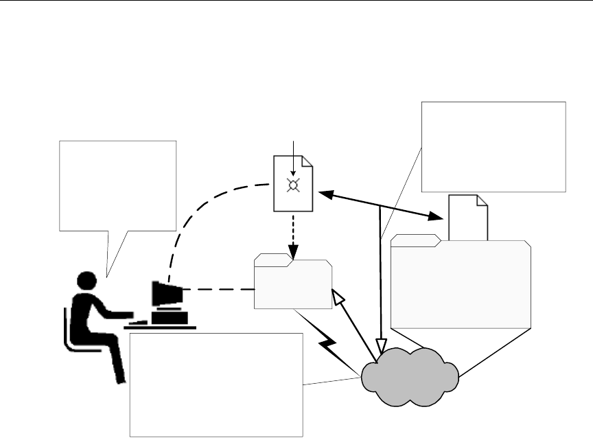
4-34
Setting up the Monitor Server on iNEWS Servers
The following diagram shows where styles appear in the workflow.
Figure 4-4 Monitor Server’s Error Checking Workflow
If you use effects in your character generator and still store styles, you
should develop a strategy for using them. How you use effects
depends on whether or not you use the ControlAir system:
•If you have a ControlAir Workstation and want to include an
effect in a style, you must first define the style effect in the DMP
file for the device manager that controls the production device.
•If you do not have a ControlAir Workstation, the effects you
include in your styles serve as instructions to your production
device operators. Develop a standard set of effect names that your
production device operators can easily understand.
Rundown
Queue SYSTEM.RESOURCE
Queue
Monitor Server
1. An iNEWS User
writes a script with
machine control
events and saves it
to a show's rundown
queue.
2. If the monitor server is on and
checking its Rundown Queue, it
notices the newly saved script
and immediately compares the
data in machine control events
with styles provided in the
SYSTEM.RESOURCE queue.
3. When the monitor
server finds errors during
the comparison, it reports
them to iNEWS users
through the Rundown
Queue, among other ways.
Styles
Machine control events are anchored
to scripts at locations indicated by
production cue markers, shown below:
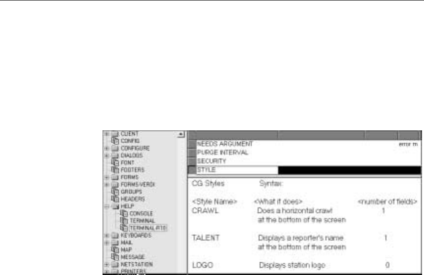
4-35
Styles
To help users remember the styles and their names when they assign
event requests, you should publish a list of styles as shown in
Figure 4-5.
Publish the list both in printed format and in a read-only queue to
allow users to reference the list from an iNEWS Workstation.
Figure 4-5 Example Style List
Creating Styles
Styles are stored in stories, which are saved to the SYSTEM.RESOURCE
queue. These stories are created and edited like any other story in the
iNEWS newsroom computer system. However, if the queue has a
write security group assigned to it, you must belong to that group or
be logged on as a superuser to edit stories in the SYSTEM.RESOURCE
queue.
cIf your SYSTEM.RESOURCE queue does not have a write security
group, one should be assigned. Because its stories define styles that
people will use to request playback events, assigning a write secu-
rity group helps ensure that only authorized personnel can edit
these stories. Instructions for doing this is in the iNEWS Newsroom
Computer System Operations Manual.
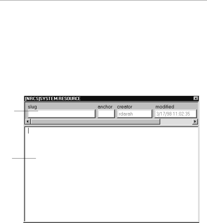
4-36
Setting up the Monitor Server on iNEWS Servers
To create a style, do the following:
1. At an iNEWS Workstation, navigate to the SYSTEM.RESOURCE
queue.
2. Do one of the following:
a. Open an existing story to edit.
-OR-
b. Click the File drop-down menu and select New Story. The
new story is created, and will appear with blank Story Form
and Story Text panels.
Story
Form
Panel
Story
Text
Panel

4-37
Styles
Lines beginning with a
semicolon (;) are com-
ments and ignored by
the system. Comments
may also be added to
the end of lines.
3. The story should begin with a commented header and parameter
line similar to the following:
4. Do one of the following:
a. If editing styles in an existing story, move to the appropriate
line(s) in the story.
-OR-
b. If creating a new story, type the header as shown in step 3.
5. Enter a style entry line for the device, ensuring all parameters are
addressed, as explained in Table 4-5. The information you provide
will vary slightly between styles for character generators and still
store machines.
;Resource File
;Dev Style Template Effect # of Fields ;Comments
Table 4-5 Style Parameters for CGs and Still Store Machines
Parameter Definition
Device The device name of the character generator or still
store machine to which the style applies. This
name must match one of the device names
assigned to a rundown in the SYSTEM.MAP story.
For instance, CG, CG1, CG2, SS, and SS1.
Style The name of the style. Specify a name, eight char-
acters or less, containing at least one alpha charac-
ter. For instance, 1LINE , 2-LINE , and LLBOX are
valid style names, but 412 is not.

4-38
Setting up the Monitor Server on iNEWS Servers
Template/Preset
n
This information differs depending on the device:
For CGs: Enter the character generator address
where the pre-recorded super or tem-
plate that you want to use is located.
Many CGs allow alphanumeric addresses. Template
addresses for these machines can also be alpha-only
addresses, which are very useful to CG operators.
Pre-recorded super addresses must be numeric
only—at an address outside the address ranges listed
in the SYSTEM.MAP story. See Figure 4-3 on
page 4-23 for more information.
For Still Stores: Enter the preset you want to
include in the style. If the style does not
use a preset, type a dash ( - ) for this
parameter. If you specify an invalid pre-
set, when the playlist is downloaded the
still store generates an error for event
requests that use this style.
Effect The name of a special effect you want to include
in the style. If you do not want to include a special
effect, such as FADE or WIPE, type a dash for this
parameter.
If you have a ControlAir Workstation and want to
include an effect in a style, you must first define
the style effect in the DMP file for the device
manager that controls the production device.
If the operator plays the event requests from the
console, you can use any name up to eight charac-
ters long to represent the effect you want. How-
ever, ensure the operator is familiar with the
name. When an event request uses this style, the
monitor server puts the effect name you specify
here in the event list entry for that event request.
The operator uses the effect name to identify what
effect should be used when the event is played.
Table 4-5 Style Parameters for CGs and Still Store Machines
Parameter Definition

4-39
Styles
6. When finished editing the styles in the story, save it by clicking the
Save button or selecting Save from the File drop-down menu.
7. Test new or edited styles by monitoring a rundown. Changes to
SYSTEM.RESOURCE stories do not take effect until a show con-
taining scripts with machine control events using the styles is
monitored. Also, if a monitor server is running when changes are
made, they will not take effect until it is restarted.
# of Fields This information differs depending on the device:
For CGs: If the style uses a template, use this
parameter to specify the number of
fields (or lines) in that template. Typing
a number of fields here specifies to
ControlAir that the address refers to a
template. The number here also ensures
that this style cannot be used to add
more text than there are fields in the
template.
If the style uses a pre-recorded super
address, type a zero here to specify to
ControlAir that the Template parameter
refers to the CG address of that
pre-recorded super. When you type a
zero for this parameter, ControlAir
ensures that this style cannot be used to
add text to the CG.
For Still Stores: If the style uses a fixed still num-
ber, put that number here. Otherwise,
type a dash for this parameter.
If you use this field, no address can be
entered into the machine control event.
If you enter a dash for this parameter,
you must enter the still number with the
machine control event before the event
can be loaded onto the still store’s event
list, also known as a still store stack.
Table 4-5 Style Parameters for CGs and Still Store Machines
Parameter Definition

4-40
Setting up the Monitor Server on iNEWS Servers
Some examples of styles for a character generator are shown in the
sample SYSTEM.RESOURCE story in Figure 4-6.
;Dev Style Template Effect # lines Comment
cg bnews 62 - 0 ;breaking news
cg mm 75 - 1 ;money matters
cg lottopb 9993 - 12 ;lotto/powerball
cg world 50 - 1 ;the world
cg nation 50 - 1 ;the nation
cg south 50 - 1 ;the south
cg recap 52 - 1 ;recap
cg nitetz 53 LOGO 1 ;11 tonight
cg tvex 67 WIPE 0 ;tv exclusive
cg intv1 1 - 1 ;1 line interview
cg intv 2 - 2 ;2 line interview
cg loc 4 - 1 ;1 line locator
cg locdate 5 - 2 ;locator with date
cg date 6 - 1 ;date
cg file 7 - 0 ;file tape
cg ctsy 8 - 1 ;courtesy
cg sktch 10 - 1 ;sketches by
cg locskylv 24 - 1 ;live skycam locator
cg repsky 18 - 1 ;reporter skycam
cg loclv 19 - 1 ;live locator
cg intvlv 20 - 2 ;live interview 2 line
cg live 21 - 0 ;live
cg replv 22 - 1 ;live generic reporter
cg lvsky 23 LOGO 0 ;live skycam
cg rep 27 - 1 ;reporter not live
;
;special for NoonDay
cg locn 1002 - 1 ;1-line locator/noonday
cg innd 1001 - 2 ;2 line interview noon
cg lond 1008 - 1 ;live locator noon
;
;SPORTS
cg nl 950 - 10 ;national league
cg al 951 - 10 ;american league
cg nfl 952 - 10 ;nfl
cg cf 953 - 10 ;college football
cg nba 954 - 10 ;nba
cg cbb 955 - 10 ;college basketball
cg nhl 956 - 10 ;nhl
cg prep 957 - 16 ;high school
cg scr 960 - 4 ;score lower third
;
; Anchors/Reporters
cg sa 104 - 0 ; steve aveson
cg salv 105 - 0 ; steve aveson live
cg sasky 107 - 0 ; steve aveson skycam
Figure 4-6 Sample Styles for CG in SYSTEM.RESOURCE Story

4-41
Using the Monitor Server
Here is an example of styles for a still store machine as shown in a
sample SYSTEM.RESOURCE story:
Using the Monitor Server
This section provides some basic user information, which can be used
to test when the monitor server is set up and working properly. Proce-
dures include how to turn the monitor server on and off, as well as
how to instruct it to load or unload machine control event data.
To use the monitor server, log in to an iNEWS Workstation, and do the
following:
1. Open the appropriate rundown queue.
2. Click the Tools drop-down menu.
3. Select Monitor.
;picture box style
;Device Style Preset Effect Address
pb rtbox 1 a1 -
pb ltbox 1 a2 -
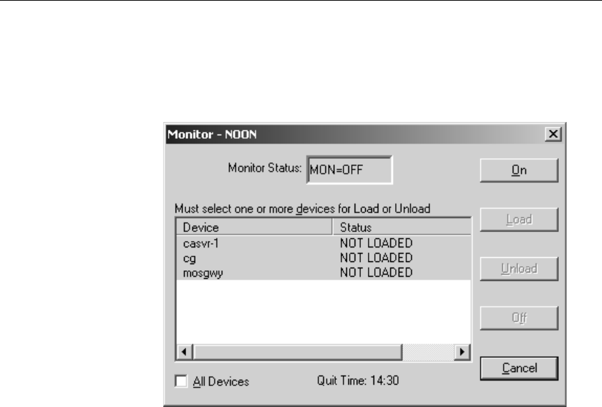
4-42
Setting up the Monitor Server on iNEWS Servers
Quit Time indicates the
time that machine con-
trol is automatically
turned off. Quit Time is
based on the run time of
the queue.
The Monitor Queue dialog box appears. The Quit Time or auto-
matic shut-off time appears at the bottom left corner of the dialog
box.
Figure 4-7 Monitor Queue Dialog Box
4. Select a monitor mode based on the following options:
•On - turns the monitor server on and creates an event
list for each device in the rundown queue.
•Load - instructs the monitor server to load event lists to
devices you select.
•Unload - disconnects from the selected device or server with-
out turning the monitor server off. (If all devices/
servers are unloaded, the monitor server returns to
the On mode.
•Off - turns the monitor server off, overriding the Quit
Time setting.
The Devices section of the Monitor Queue dialog box displays a
list of devices based on those defined for the queue in the
SYSTEM.MAP story.
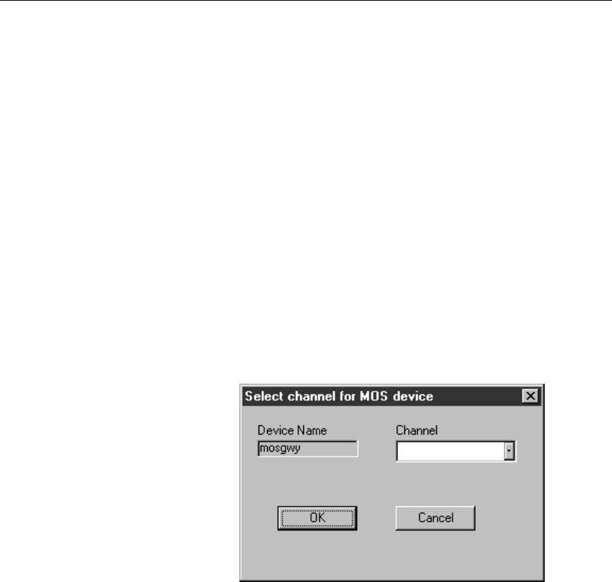
4-43
Using the Monitor Server
The list could include:
- Specific devices, such as those connected through an
MCS-PC or PC-PCU
- Servers, such as the ControlAir Server and/or MOS Gate-
way Server
If you select Load, specify the device or server to load from the
Devices list, or select the All Devices checkbox to load all devices
associated with the rundown queue. To select up to three devices
from the list, without selecting all, press the CTRL key while you
click on each item. If you select a server, the data will be loaded to
all devices associated with that server.
If you select the MOS Gateway Server that is interfacing with a
device that has multiple channels, such as an OmniBus automa-
tion system, a second dialog box will appear, allowing you to
select the channel from a drop-down list.
Click OK to return to the previous dialog box.
5. Click OK.
nFor more information on using the monitor server, please refer to the
ControlAir Training Guide.

4-44
Setting up the Monitor Server on iNEWS Servers
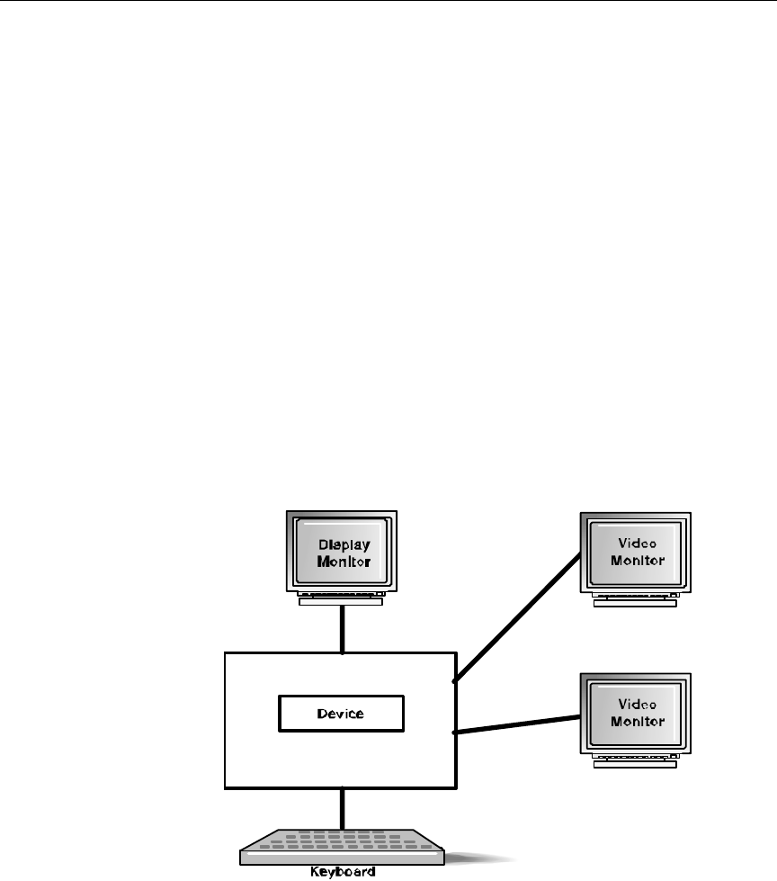
5-2
Working with Devices
Overview
To get a show to air, you must control several devices simultaneously.
These devices include:
•Character generators
•Still store machines
•Video playback devices (such as the Louth VDCP or cart
machines)
The ControlAir system enables you to control several types of devices
from one workstation, using device managers—also known as DMs.
Without ControlAir, each device has a separate standalone worksta-
tion through which it is controlled. Not all production devices use
computer interfaces; some older ones have special panels, custom key-
boards, and so forth. Figure 5-1 depicts a one type of standalone
device configuration.
Figure 5-1 Sample Standalone Device Configuration

5-3
Overview
When ControlAir software is installed, one option includes installing
default DMs and configuration files for various devices. This is usu-
ally done on the ControlAir Server. See “Installing ControlAir Soft-
ware” on page 3-5 for more information.
Devices are connected to the ControlAir Server through DMs, which
control the devices and report their status in DM windows. See
“Device Manager Windows” on page 6-12 for more information.
DMs are executable program files that usually have DM in the name
and end with the extension .exe, such as LouthDM.exe.
The ControlAir system supports two types of DMs:
•Native DMs, such as ChyronDM and Louth VDCP DM, written
specifically for ControlAir
•MCS-PC DM, which makes ControlAir compatible with devices
that run on Avid’s iNEWS newsroom computer system. See
“MCS-PC Device Manager” on page 5-5 for more information.
nSome Native DMs are supplied by Avid, while other Native DMs are pro-
vided by third-party suppliers, such as production device vendors.
Figure 5-2 illustrates a sample device setup in ControlAir.
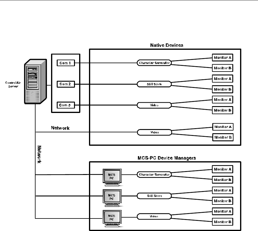
5-4
Working with Devices
Figure 5-2 Sample Device Setup in ControlAir
Native Device Managers
Some devices connect directly to the ControlAir Server through a
native device manager. These devices include:
•Louth VDCP-compatible devices
•Chyron Intelligent Interface-compatible devices

5-5
Overview
•Avid AirSPACE™
•Grass Valley Group Profile™
Third-party DMs will
connect in a manner
most appropriate for
the device. See the
third-party manufac-
turer’s documentation
for more information.
With ControlAir, the current native DMs for Louth and Chyron-com-
patible devices are connected to devices over a serial interface, but a
Local Area Network (LAN) is used for connecting the AirSPACE and
GVG DMs to their respective devices: the Avid AirSPACE and GVG
Profile. For those using LAN connections, ControlAir Server must
have their IP addresses in its etc/host file. See “Adding IP
Addresses on ControlAir Server” on page 3-2 for more information.
Each native DM has a Device Manager Profile—also known as the
DMP file—in which configuration data for the device is specified.
MCS-PC Device Manager
Some devices connect to an MCS-PC first, which in turn connects to
the ControlAir Server through the MCS-PC device manager. These
devices include:
•Character generators
•Still Stores
•Cart machines
With ControlAir, device managers are connected to MCS-PCs through
a network connection, and from MCS-PCs to devices over a serial
interface. The ControlAir Server must have IP addresses for MCS-PCs
in its etc/host file. See “Adding IP Addresses on ControlAir Server”
on page 3-2 for more information.
Unlike native DMs, configuration data for devices controlled by the
MCS-PC DM is specified in two locations:
•An MCSDM.dmp file, located in the Avid/ControlAir/DMP
directory on the ControlAir Server. These files are typically named

5-6
Working with Devices
for the device or for the ControlAir device name if there is more
than one of the same type.
•The device’s MCS-PC driver profile—a file with the device’s num-
ber as its name and located on the iNEWS Servers in the
/site/mcs directory
For instance, the MCS-PC DM controlling a character generator called
CG1 with the device number of 407 would rely on configuration data
located in the CG1.dmp MCSDM profile and the /site/mcs/407
MCS-PC driver profile.
Adding Devices
While the ControlAir Install program sets up the standard DMs for
typical devices, different devices can be added at a later date.
To add a device, ensure the following items are done:
•The executable program for the device is installed in the
iNEWS/ControlAir directory. See “Installing ControlAir Soft-
ware” on page 3-5 for more information.
If the device is con-
trolled by the MCS-PC
device manager, addi-
tional configuration
data may be required in
a driver profile. See the
specific device’s Device
Manager Guide for more
information.
•The device’s DMP configuration file is edited and saved into the
Avid/ControlAir/DMP folder. See the Device Manager Guide for
the device, which is located in the Docs folder on the
ControlAir Install CD, for more information.
•The device is added to the autostart.ini file, if necessary. See
“Setup ControlAir Manager” on page 3-25 for more information.
DMP Configuration Files
Each DM has a Device Manager Profile (DMP) file that enables you to
specify the device’s configuration. For each device and DM (except

5-7
DMP Configuration Files
AirPlay devices), there must be a separate DMP file, which is a text file
with the extension .dmp. Multiple instances of any device and its DM
can be run on ControlAir by starting each with its own DMP file.
nIn the case of the MCS-PC DM, configuration data is in two locations; some
settings are defined in its DMP file, while others are configured in specific
MCS-PC driver profiles on the iNEWS Server in the /site/mcs directory.
See “MCS-PC Device Manager” on page 5-5 for more information.
Each DM will open its corresponding DMP file—as defined in the
autostart.ini file—at start-up. See “Setup ControlAir Manager”
on page 3-25 for more information.
By default, DMs are installed in the Avid/ControlAir directory.
Sample DMP configuration files are installed together in a folder
called Examples, which is put in the same Avid/ControlAir direc-
tory. DMP files can be edited using the Windows Notepad program.
nIt is highly recommended that a copy be made as a backup first before editing
any DMP file. Most text is not case-sensitive in DMP files. For the excep-
tions to this rule, see the Device Manager Guide for your specific device,
located in the Docs folder on the ControlAir Install CD.
The active DMP files, after edited, should be placed in the DMP folder,
which—by default—is also located in the same Avid/ControlAir
directory. A device manager will find its DMP file by searching rela-
tive to the directory it is in.
The device manager can be running while its DMP configuration file is
edited; however, the changes will not take effect until the DM is
restarted. To do this, do the following:
1. Leave the DM running while you edit and save its DMP file.
2. Stop the device manager by closing its DM window located on the
ControlAir Server.

5-8
Working with Devices
When the DM stops, this triggers the ControlAir Manager, which
will automatically restart the DM with its new configuration set-
tings as found in the DMP file.
nOne exception to this procedure is the AirPlay DM, which is not monitored
by the ControlAir Manager. For further editing instructions, see the Device
Manager Guide for your specific device, located on the ControlAir Install CD
in the Docs folder.
What Does a DMP File Do?
Device parameters that can be defined in DMP files include:
•The ControlAir Server’s Host name
•The Device’s name
•Number of Channels
•Dictionary (for error messages)
•Serial port configuration (and/or network settings)
•Character mapping
•Playback effects
nThe ControlAir Server’s Host name and device manager name are required in
all DMP files. Also, all DMP files will have connection (serial or network)
configuration information. All CG-related DMP files will have character
mapping and most files for CGs and still stores will include effects.
Depending on the device, other parameters not listed here may be defined. See
the device’s specific Device Manager Guide for more information.
Just as production devices differ from each other, so do their profiles.
For instance, some still store machines can display graphics using spe-
cial effects, such as fade or dissolve. Normally, if the still store operator
wants to use an effect, he or she would select that effect from the still
store machine’s console when the graphic is displayed. However,

5-9
DMP Configuration Files
ControlAir can select the effect for you when the graphic is aired if it is
provided with the information to do so. This information is defined in
the still store machine’s DMP file. This same concept applies to charac-
ter generators, which can also implement special effects, such as
crawls.
Character Mapping
Character generators can usually produce characters that do not
appear on standard keyboards . For instance, your character generator
can probably produce the character “¥” for yen, the Japanese currency
or “£” for pound, the British currency, but these characters do not
appear on standard keyboards. To enable users to select these charac-
ters from their workstations—that is, entering text in the CG machine
control event—they must be mapped to characters located on the key-
board.
For users to create machine control events with these kinds of charac-
ters in CG template fields, they must be mapped to characters that do
appear on the keyboard but are not likely to appear in actual character
generated graphics—also known as supers. An example of such a
character is the carrot symbol ( ^ ).
You can map a single character to a string of one or more characters in
a profile, but not vice versa. In fact, this is the only way that you can
pass eight-bit (or extended) characters through certain serial inter-
faces; the eight-bit characters would be mapped in the profile to the
escape codes that would generate them on the device.
Except in the case of the MCS-PC DM, character mapping is done in
the device’s DMP file. For MCS-PC DM, character mapping is done in
the MCS PC driver profile located in /site/mcs.

5-10
Working with Devices
For Native DMs
This section provides a brief introduction of character mapping in
DMP files for natively-controlled character generators. For more
detailed information, see the device’s Device Manager Guide, located on
the ControlAir Install CD.
In each CG DMP configuration file, a section dealing with character
mapping is included. It is easily recognizable; locate the line that looks
like this:
[Mapping]
The syntax for character mapping in a DMP file is:
<Character-to-Map>=<Mapped String>
A single character on a keyboard can be mapped to another single
character or string of characters.
To correctly map characters for a device, refer to the manufacturer’s
documentation accompanying the device to determine the acceptable
codes. The standard Windows ASCII codes, such as 0163 for the Brit-
ish pound (£), may not be used to define a mapped character or string.
For MCS-PC DM
This section applies to mapping characters for character generators
controlled by the MCS-PC device manager.
In the following example, a character generator’s profile is edited to
map that CG’s code for the Yen (¥) to the asterisk character (*) on the
keyboard. The character generator, in this example, recognizes 234 as
the code for the Yen character and its device number is 407, so its pro-
file is stored in /site/mcs/407.
1. List the profile by using the cat command:
NRCS-A: cat /site/mcs/407

5-11
DMP Configuration Files
A message similar to the following appears:
This part should be
done with all iNEWS
Servers selected. See the
iNEWS Newsroom Com-
puter System Operations
Manual for more infor-
mation on selecting
servers and how to use
the UNIX line editor.
2. To add a new line to the profile, use the UNIX line editor by typ-
ing the ed command.
NRCS-A: ed /site/mcs/407
editing /site/mcs/407
145
3. Since the character mapping information is at the end of this pro-
file, type $ to move to the end of the file and append the new line
there.
$
map <209> <78>
4. Type a and press Enter. This will start appending information you
type to the file:
a
5. The format you must use to map a character the CG can produce
to one available on the keyboard is shown below:
map <terminal character> <CG character>
Enter the <terminal character> and <CG character>
parameter values either by typing the actual character—if, of
;Configuration
setup com1 9600-8nh
setup id 2
setup mixpreset 0
;setup debug 81
;character mapping
;map <fromchar> <tochar>
map <209> <78>
NRCS-A:

5-12
Working with Devices
course, it is one that can be generated from the keyboard—or by
using the ASCII code for that character. If you use an ASCII value,
you must enclose it in angle brackets—<67> for instance. If you
type the character itself; however, do not enclose it in angle brack-
ets. In the following example, the asterisk (*) key is mapped to the
code the character generator uses to represent yen symbol repre-
sented by the code 234, so the command line appears as follows:
map * <234>
Do not use an upper-
case (W). For more infor-
mation, on the UNIX
line editor, see Chapter
10 in the iNEWS News-
room Computer System
Operations Manual.
6. Type a period to stop appending, the save and exit the UNIX line
editor by typing the write and quit commands, as shown:
.
w
167 chars
q
NRCS-A:
After editing the file, restart the device so the changes to the profile
can take effect.

6-2
Control Air Operations
Overview
After the ControlAir Server software is installed and when the com-
puter is rebooted, several programs associated with the ControlAir
system are launched automatically. These programs include:
•The ControlAir Manager program
•The ControlAir Server program (casvr.exe)
•The AMCP application (AMCPapp.exe)
•Any device managers configured in the ControlAir Manager
The ControlAir Server program and AMCP application are explained
in this chapter. Information about the ControlAir Manager is available
in “Setup ControlAir Manager” on page 3-25. For more information
pertaining to device managers, see Chapter 5 and the appropriate
Device Manager Guides on the ControlAir Installation CD.
Windows for each of these programs will open on the desktop. They
may be minimized, but do not close a window since this will close the
actual program.
Shortcuts—indicated by icons like those shown at left—may also be
placed on the desktop for quick access to one or more of these pro-
grams.
For instance, there is typically a shortcut to the ControlAir Manager.
Double-clicking on the icon will manually launch the
ControlAir Manager program, which in turn launches other
ControlAir programs the manager monitors. Using the shortcut is not
necessary after the computer is rebooted, since the programs launch
automatically upon a reboot.
nIf the ControlAir Manager is configured and running, should a user close a
window associated with the system, such as the ControlAir Server program,
ControlAir Manager will automatically relaunch the program, which will
reopen the window.

6-3
The ControlAir Server Program
Because the ControlAir Manager relaunches device managers, short-
cuts for them are not usually needed.
The ControlAir Server Program
The ControlAir Server’s window—as shown in Figure 6-1 on
page 6-4—displays a list of diagnostics while the program is running.
As changes occur, information about errors, new clients or playlists, or
other status changes is displayed along with the date and time of the
change. The types of messages that appear in the list vary, depending
on what diagnostic filters are set. See “Setting Diagnostic Filters” on
page 6-4 for more information.
Printing ControlAir Server Diagnostics
To obtain a printout of the readings on the screen—that is, the list of
messages in the ControlAir Server window, do the following:
1. Click the File drop-down menu.
2. Select Print Screen. The Print dialog box will appear, from which
you can select a printer, number of copies, and so forth.
3. Click OK to print.
nThere are two other options in the File drop-down menu that pertain to print-
ing. Choose the Print Setup option to alter printer settings. Choose the Print
Preview option to view on screen a sample of what will be sent to the printer.
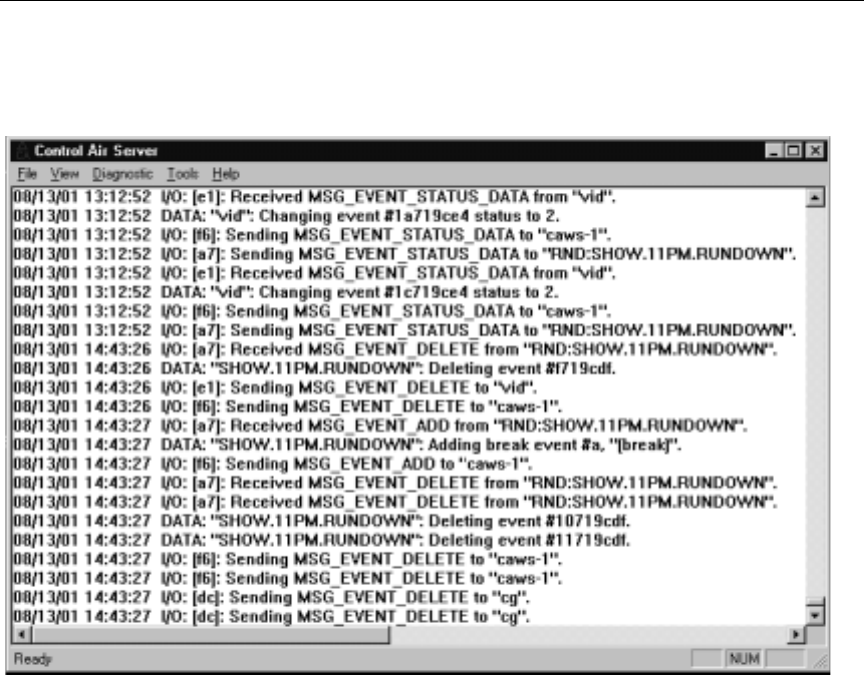
6-4
Control Air Operations
Figure 6-1 The ControlAir Server Window
Setting Diagnostic Filters
Diagnostic information is grouped into four separate categories:
•Errors and Warnings
•Status changes
•Data information
•Input/Output information
Any or all of this information could be displayed in the ControlAir
Server window, as determined by diagnostic filters. The data could
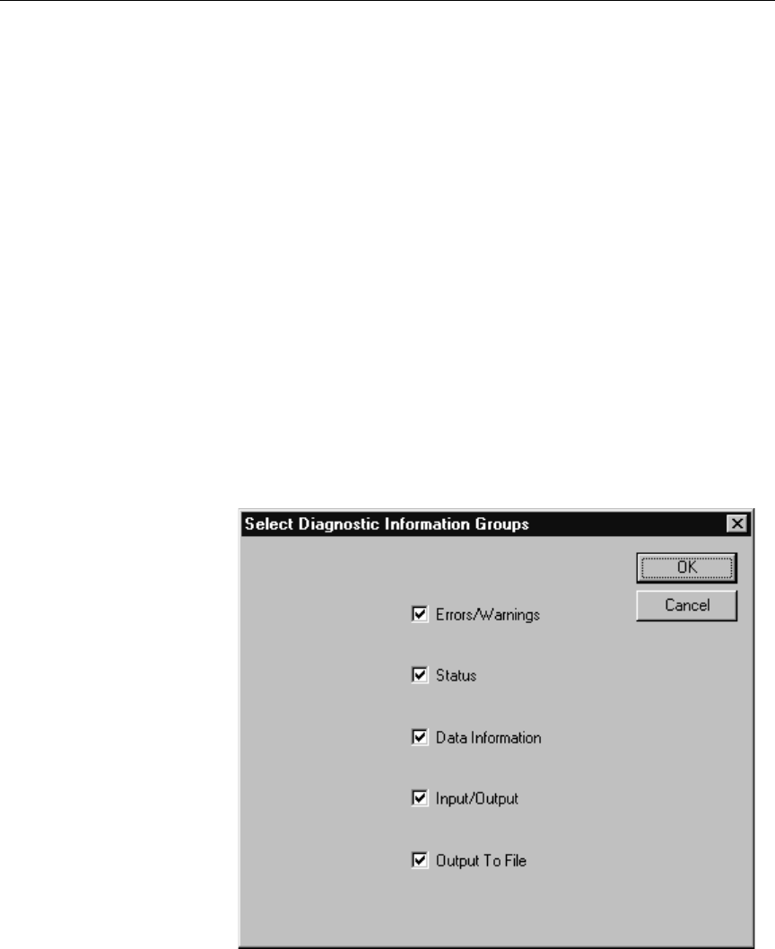
6-5
The ControlAir Server Program
also be saved as text files, known as Log files, on the ControlAir
Server, if the Output to File check box is selected, as shown below in
the Select Diagnostic Information Groups dialog box.
nSamples of Data and Input/Output information are shown in Figure 6-1.
To set diagnostic filters, do the following: from the ControlAir Server
window:
1. Restore the ControlAir Server window if it is not already.
2. Do one of the following:
a. Click the Diagnostic drop-down menu and select Choose Fil-
ter.
-OR-
b. Type ALT-DC.
The Select Diagnostic Information Group dialog box appears.

6-6
Control Air Operations
3. Check each box, depending on whether you want that type of
information displayed in the ControlAir Server window.
nThe ControlAir Server stores diagnostic information, status changes, and all
error/warning messages. Checking those corresponding boxes only controls
whether such information is displayed on screen in the ControlAir Server
program window. Data and Input/Output information is only stored when
the appropriate check box is selected.
4. Check the Output to File box if you want the data saved to text
files—thus generating Log files—on the ControlAir Server.
5. Click OK to save settings.
Stopping and Starting the ControlAir Server
The ControlAir Manager program automatically launches the
ControlAir Server program when the computer boots up. However, a
system administrator can manually stop and restart the ControlAir
Server program without having to completely reboot the computer.
To stop and restart the ControlAir Server program, do the following:
1. Close the ControlAir Server window.
2. Close the AMCP Applications window.
The device managers will close their own windows automatically
after the ControlAir Server program stops.
The ControlAir Manager program will automatically relaunch the
ControlAir Server program, the AMCP application, and the device
managers.
nAn exception is the device manager for AirPlay, which must be manually
stopped and restarted. If the ControlAir Manager does not restart a program
or device, see Chapter 7 for more information on troubleshooting.

6-7
The ControlAir Server Program
To stop the ControlAir Server program without restarting it, do the
following:
1. Close the ControlAir Manager window.
2. Close the ControlAir Server window.
3. Close the AMCP Applications window.
The device managers will close their own windows automatically
after the ControlAir Server program stops.
4. Verify that all device manager windows closed; if not, close them.
nIf the programs are not stopped in the proper sequence, the system could be
caught in a loop. This can happen if a device manager is left running after the
ControlAir Manager is stopped and restarted; the ControlAir Manager
attempts to restart the DM, which is already running, thus causing the Con-
trolAir Manager to issue an error message stating that it cannot restart the
DM. Should this happened, see Chapter 7 for troubleshooting information.
5. Close the ControlAir Workstation program if it is running on the
same computer.
This procedure is useful for maintenance purposes, such as if you
should need to cut the power to the computer for some reason.
To restart the ControlAir Server, do one of the following:
a. Reboot the computer.
-OR-
b. Restart the ControlAir Manager program. It will automatically
launch the ControlAir Server program, the AMCP application,
and device managers (except the DM for AirPlay).
Setting the Override Password
The purpose of the Override password is to prevent a show from
being reserved by a second ControlAir Workstation while under the
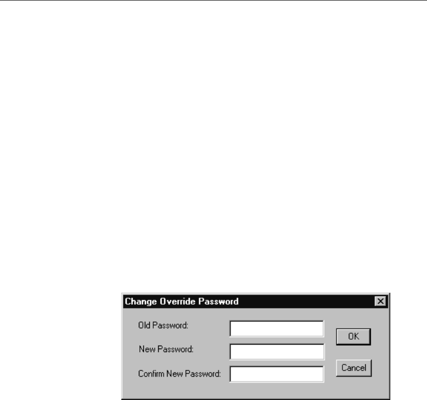
6-8
Control Air Operations
control of a first workstation. Setting this password ensures that only
authorized personnel may take control of the show from another
workstation, which is useful should a workstation computer fail after
it was used to reserve a rundown. The password must be set during
installation of the ControlAir Server software; however, from the Con-
trolAir Server window, it may be changed at any time. The password
cannot be set from a ControlAir Workstation.
To change the password, do the following:
1. Maximize the ControlAir Server window if it is not already.
2. Do one of the following:
a. Click the Tools drop-down menu and select Options, then
Password.
-OR-
b. Type ALT-TOP.
The Change Override Password dialog box appears.
3. In the fields provided, do the following:
a. Type the old password.
b. Type the new password. The password is case-sensitive and
can be a combination of letters and numbers.
c. Confirm the new password, by typing it a second time.
4. Click OK to save the new settings. (Click Cancel only if you want
to exit without altering the existing password.)

6-9
The AMCP Application Program
The AMCP Application Program
The Avid Machine Control Protocol (AMCP) application is one of the
programs typically monitored by the ControlAir Manager, so if it is
stopped, the ControlAir Manager will automatically relaunch it. This
also happens after the ControlAir Server is rebooted.
The AMCP application is an executable program used primarily as a
translator between the iNEWS monitor server and the ControlAir
Server; without it running, there is no communication between
iNEWS and ControlAir. It is also used by software programmers and
third-party developers for obtaining diagnostic information so they
can build device managers that interface well with the ControlAir sys-
tem. It is seldom used by system administrators on site, but it must be
running on the ControlAir Server. Closing the application’s window
will stop the program; minimize the window instead to regain access
to the desktop.
In the main window, smaller windows—known as views—will open
containing machine control data for each show when the monitor
server loads machine control event data from a rundown to the
ControlAir system. That is done when a user issues the monitor
load command in iNEWS, using the drop-down menu option pro-
vided in the rundown.
Each view disappears when the monitor unload or monitor off
command is issued, the last of which turns off that show’s monitor
server.
nSee Chapter 4, particularly the section called “Overview” on page 4-2, for
more information on monitor servers.
The AMCP application also provides a verbose mode feature that
records communication between monitor servers and ControlAir. This
is particularly helpful for troubleshooting. See “Saving Rundown
Data” on page 7-6 for more information.
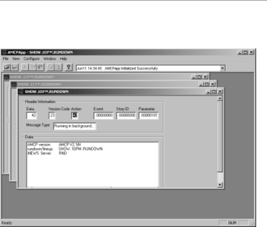
6-10
Control Air Operations
Figure 6-2 shows the AMCP Application window, displaying three
cascaded workspaces for the Noon, 10 PM, and 11 PM shows:
Figure 6-2 The AMCPAPP Window
The display can be changed from cascade to tile so views do not over-
lap within the AMCP Application window, as shown in Figure 6-3.
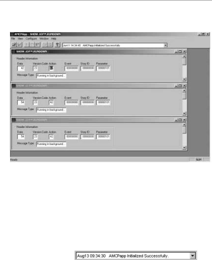
6-11
The AMCP Application Program
To do this, click the Window drop-down menu, and select Tile.
Figure 6-3 The AMCPApp Window with Tiled Workspaces
cEach view represents a connection between an iNEWS rundown and
the ControlAir Server. Users must not close the view within the
AMCP Application window; doing so closes that connection
between rundown and server. The proper method to close the con-
nection is to use the monitor unload and monitor off
options at an iNEWS Workstation.
The main toolbar has a drop-down list—shown below—that provides
a historical list of the past several system messages, such as initializa-
tion and disconnect notices, with the most recent appearing on screen.
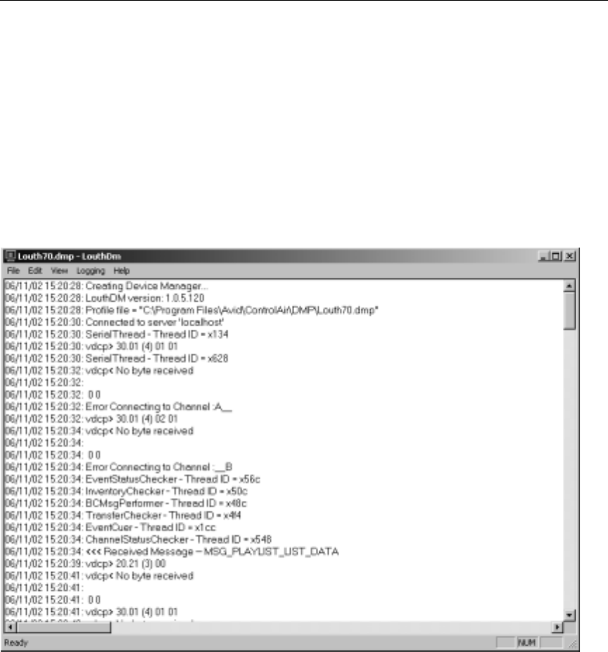
6-12
Control Air Operations
Device Manager Windows
Typically, device managers are installed on the ControlAir Server, so
when it boots, DM programs are launched and their windows opened
over the desktop. The look and information provided in each DM win-
dow varies, depending on the device; however, one example is shown
in Figure 6-4.
Figure 6-4 Device Manager Window for LouthDM
The specific details of each DM window are explained in each device’s
Device Manager Guide, provided on the ControlAir Install CD.
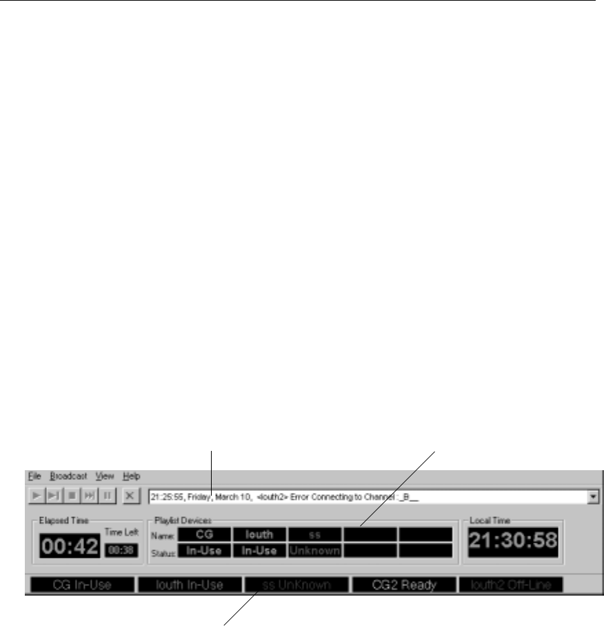
6-13
Device Status at the ControlAir Workstation
DM windows can be minimized to the Windows taskbar, without
jeopardizing control of devices. However, do not close a DM window
because doing so will terminate control of the device.
nWhen ControlAir Manager is set up and running, it will monitor
DMs—with the exception of the AirPlay DM—and should a DM window be
closed, it will relaunch the DM program, reopening the DM window.
See Chapter 5, “Working with Devices,” for more information.
Device Status at the ControlAir Workstation
This section provides some basic information about the ControlAir
Workstation window, as it pertains to connectivity between devices
and the ControlAir Server. At the top of the window is a drop-down
list providing a history of messages about system status. Below the
drop-down list is a section called Playlist Devices and below that is the
Device bar, containing five black fields.
Figure 6-5 Partial View of the ControlAir Workstation Screen
Device Bar, with five devices shown
Playlist Devices Section
Message History List

6-14
Control Air Operations
Below the Device bar is a spreadsheet-style panel displaying informa-
tion loaded from an iNEWS rundown. The top row of that spreadsheet
is identified by an icon—shown at left—and displays the name of the
rundown, whether it is reserved, and by which ControlAir Worksta-
tion.
When the ControlAir Workstation program is launched, and the win-
dow opens for the first time, devices will not necessarily appear auto-
matically on the Device bar in the window. They will appear when the
ControlAir Workstation connects to the ControlAir Server if the DMs
have already been connected as well. Should another DM be started
after the ControlAir Workstation is launched and monitor server is
loaded, it will automatically appear on the Device bar.
Devices on the Device bar will remain displayed even after the run-
down is unloaded, as long as the ControlAir Workstation remains con-
nected to the ControlAir Server.
The DMs listed on the bar are not necessarily used by the current run-
down queue; that is, the rundown may or may not have a playlist for
the device associated with the DM. Those actually used by the loaded
rundown are shown in the Playlist Devices section when the rundown
is reserved from the ControlAir Workstation. If a device appears,
whether on the Device bar or in the Playlist Devices section, both the
device name and its status will be shown.
There are five status possibilities that are color-coded for easy visual
recognition.
Table 6-1 Status of Devices
Status Color Explanation
On-Line Green Indicates the DM for the named device is run-
ning, connected to the ControlAir Server, and
communicating with the device. However,
control of the device has not yet been reserved
by a ControlAir Workstation.

6-15
Device Status at the ControlAir Workstation
See “Visual Indicators” on page 7-3 in Chapter 7, “Troubleshooting,” for more
information on how to handle these status issues.
In-Use Green Indicates the DM for the named device is run-
ning, connected to the ControlAir Server, com-
municating with the device, and control of the
device is reserved by this ControlAir Worksta-
tion.
Busy Green Indicates the same things as In-Use, except
that control of the device is reserved by
another ControlAir Workstation.
Ready Yellow Indicates a DM for a certain device is running
on the ControlAir Server and ready to commu-
nicate with the device, but no communication
between DM and device has happened.
nReady does not indicate an actual connection between the
device and ControlAir Server. For more information, see
“Visual Indicators” on page 7-3.
Off-Line Purple Indicates ControlAir can communicate with
the DM for this device, but the device is not
available to be controlled by ControlAir; can
indicate problems with the serial connection.
Unknown Red Indicates a DM for this device is not running
or is no longer connected to the ControlAir
Server. It can also indicate a mismatched
device name; ensure that the device names in
the SYSTEM.MAP file and device manager’s
DMP file are correct.
Table 6-1 Status of Devices
Status Color Explanation

6-16
Control Air Operations
CHAPTER 7
Troubleshooting
This chapter contains information to help you respond to various error
messages and recover from various types of system failures. This
chapter contains the following major sections:
•ControlAir Components
•Where to Look for Errors
•Visual Indicators
•Error Messages
•Other Problem-Solving Tips
•ControlAir Manager
•Gathering Diagnostic Data

7-2
Troubleshooting
ControlAir Components
The iNEWS ControlAir system consists of several components that
interface to provide machine control for on-air operations. Problems
can arise when communication between components is interrupted for
various reasons, such as the cable to a device being inadvertently dis-
connected.
Primary components include:
•The ControlAir Server program (casvr.exe)
For information on how
the AMCP application
or ControlAir Server
can be used in trouble-
shooting, see “Gather-
ing Diagnostic Data” on
page 7-5.
•The AMCP application (AMCPapp.exe)
•ControlAir Workstation(s) running the client software
•iNEWS Workstation(s)
•Device manager programs (DMs)
•Devices, such as character generators
This chapter, combined with Appendix A, provides information to
help troubleshoot common problems. It is recommended that system
administrators and operators familiarize themselves with this infor-
mation.
Where to Look for Errors
Problems are often identified when a ControlAir component issues an
error message. Because the iNEWS ControlAir system interfaces with
Avid’s iNEWS newsroom computer system, errors may appear in a
variety of locations.
The most common locations include:
•The iNEWS Console Multiplexor

7-3
Where to Look for Errors
•The iNEWS Workstation’s Message bar
•The ControlAir Workstation (Figure 6-5 on page 6-13)
Visual Indicators
The ControlAir Workstation also provides some indicators concerning
devices and their DMs in the Device bar and Playlist Devices section,
as shown in Figure 6-5 on page 6-13 and in Table 6-1 on page 6-14. For
instance, some status categories may indicate potential problems, such
as Off-line and Unknown.
Unknown indicates no DM is running for a requested device. When
Unknown appears, check the following:
•Ensure the actual device manager for the requested device is run-
ning on or connected to the ControlAir Server.
•Ensure the device manager’s DMP configuration file is correct.
•Ensure the settings on iNEWS in the SYSTEM.MAP file are correct.
If alldevices show an Unknown status, it may indicate a more serious
problem:
•Ensure the ControlAir Server program (casvr.exe) is running.
Off-line indicates that ControlAir can communicate with a device
manager for the requested device, but that device is not available to be
controlled by ControlAir. When a show containing machine control
events for that device is loaded, the device status should change to
Online. If the device status remains Off-line or if the machine control
events for that device still have event status Unknown in the playlist,
check the following:
•Ensure the device is connected to its device manager and they are
configured correctly.

7-4
Troubleshooting
nA device with multiple channels will appear Off-line when all of its channels
become disconnected. When this happens, an error message is issued to the
ControlAir Workstation and displayed in its Message History drop-down list.
An example of this is shown in Figure 6-5 on page 6-13; see the louth2
device.
Another potential problem may exist even when the device status is
Ready. The Ready status indicates a DM for a certain device is running
on the ControlAir Server and ready to communicate with the device,
but no communication between DM and device has happened. This
does not indicate an actual connection between the ControlAir Server
and the device.
Error Messages
Many ControlAir errors can be divided into the following categories:
•Startup errors, which are generated when any component associ-
ated with ControlAir cannot start.
•System configuration errors, which are reported when ControlAir
encounters a situation where its configuration is incomplete or
incorrect.
•Communication errors, which are reported when ControlAir
encounters a problem communicating with any component, such
as a device or program.
•Monitor errors, which are reported by the monitor server utility
program on the iNEWS newsroom computer system.
An alphabetical listing of errors are provided in Appendix A along
with the category, the source—the ControlAir component generating
the error—and actions required to alleviate any problems as noted by
each error message.

7-5
Other Problem-Solving Tips
Other Problem-Solving Tips
The following sections provide other troubleshooting tips.
ControlAir Manager
If programs on the server are not stopped in the proper sequence, the
system could be caught in a loop. This can happen if a device manager
(DM) or other program, such as the AMCP application, monitored by
the ControlAir Manager, is left running after the ControlAir Manager
is stopped and restarted. The ControlAir Manager attempts to restart
the program, which is already running, thus causing the program to
issue an error message—appearing in a dialog box—stating that it can-
not restart.
nTwo identical DMs can coexist only if each uses a different DMP configura-
tion file. Only one copy of the AMCP application or ControlAir Server pro-
gram can be running at a time.
Gathering Diagnostic Data
Not all problems can be resolved through user action. Such problems
should be reported to Avid Broadcast Customer Support. The
ControlAir system provides the means to gather diagnostic data that
can assist Avid personnel in locating and correcting these problems.
Capturing Server Data Logs
The ControlAir Server produces some diagnostic information that
may be helpful in troubleshooting problems. That information can be
viewed in two ways:
•The ControlAir Server window (Figure 6-1 on page 6-4)
•The ControlAir Server’s Log files, if configured to output the data.

7-6
Troubleshooting
Log files are text files, which can be opened with Notepad. To view
these files, open Windows Explorer and navigate to the installation
directory where these files are stored, usually on the ControlAir
Server. The default pathname is:
C:\Program Files\Avid\ControlAir
See “Setting Diagnostic Filters” on page 6-4 for more information on
setting up the system to output data to Log files.
Saving Rundown Data
A feature of the AMCP application may be used to help troubleshoot
problems related to communication between ControlAir and the
monitor server in iNEWS. When the AMCP application is configured
to save rundown data, it will record all messages known as rundown
data—which may be saved and used later—that are sent to ControlAir
by the monitor server.
To save the rundown data, do the following:
1. At the ControlAir Server, in the AMCP application window, click
the Configure menu.
2. Select iNEWS.
3. Select Save to File.
nAfter Save to File is set, verbose mode is on and all messages from the next
monitor server to connect to ControlAir will be recorded until the rundown is
unloaded or the monitor server is stopped. This option also turns on verbose
mode, which displays each of the data messages in the rundown view window
as they arrive.
4. Start the monitor server and load the show.
5. When the monitor unload command is issued from an iNEWS
Workstation, the AMCP application will prompt for the informa-
tion recorded to that point to be saved in a data file. The dialog

7-7
Other Problem-Solving Tips
box—shown below—will appear onscreen at the ControlAir
Server where the AMCP application is running.
6. Choose ... to save the file. By default these files are in the following
format:
<show name>.rdn
For instance, if the monitor server was monitoring the 10PM run-
down, located in the Show directory, the name of the file may be
similar to the following:
show.10pm.rundown.rdn
These RDN files may be kept and provided to Avid Broadcast Cus-
tomer Support—instead of the actual rundowns—to help identify and
troubleshoot monitor server communications issues with ControlAir.
RDN files are not text files; they contain rundown data. These files
must be viewed using the AMCP application.

7-8
Troubleshooting
APPENDIX A
Error Messages
This appendix contains ControlAir error messages in alphabetical
order. Each message appears in a paragraph with the following for-
mat:
Error: Error message text.
Location: Where message is found. Source: Which program.
Category: Which type of error. Token: Standard name
Action: What to do about the problem.
Error shows the error message itself, although some words are itali-
cized and shown inside parentheses, indicating their purpose rather
than the actual words that may appear as part of the error message.
For instance, if an actual error message appears at the iNEWS Work-
station as "Bad map line: Duplicate device: louth1," the corresponding
error message in this appendix will be "Bad map line: Duplicate
device: (invalid entry)."
Token shows the standard name for the message as defined in the sys-
tem’s dictionaries. The system looks up these tokens as needed and
translates them into error messages, which are then sent to worksta-
tions under special circumstances. Table A-1 on page A-29 provides
an alphabetical listing of these tokens—pertaining to the monitor
server—that is cross-referenced with their corresponding error mes-
sages in the “Errors” section of this appendix.

A-2
Error Messages
Location specifies where the error is found. For errors generated by the
monitor server and located on an iNEWS Workstation, they only
appear on the workstation used to start the monitor server, not all
iNEWS Workstations on the network.
Source specifies which ControlAir component generated the error.
Category specifies in which category the error falls. Categories are
defined in the “Error Messages” on page 7-4 in Chapter 7, “Trouble-
shooting.” Action describes steps to take to resolve the error.
nSome error messages are warnings only; the ControlAir system will continue
to run with a default behavior. Warnings are marked below with the opening
statement "This is a warning only," and a description of the default behavior.
Errors
Error: Bad map line: CG Map entry requires range
Location: iNEWS Workstation & console Source: monitor server
Category: Monitor Token: A_BADCG
Action: The show’s SYSTEM.MAP story entry contains a character gen-
erator (CG) device line that does not specify a range of addresses. (You
can leave out the drive and directory information, but you must spec-
ify a range.) Examine the show’s SYSTEM.MAP story entry and add the
range of addresses that you want the CG to use for that show. The
monitor server failed when it encountered the problem map entry, so
restart monitor server by turning it on from an iNEWS Workstation.

A-3
Errors
Error: Bad map line: device-server type mismatch: (device name)
Location: iNEWS Workstation & console Source: monitor server
Category: Monitor Token: A_BADMAPBADSVR
Action: The show’s SYSTEM.MAP story entry contains a line where a
MOS device is assigned to a ControlAir Server or ControlAir device is
assigned to a MOS Gateway. Examine the show’s SYSTEM.MAP story
entry and check that each device type is correct. Also check that MOS
devices are only assigned to a MOS Gateway and that video (cart), CG
and SS devices are only assigned to ControlAir Servers. The monitor
server failed to startup when it encountered the problem map entry, so
restart monitor server by turning it on from an iNEWS Workstation.
Error: Bad map line: Duplicate device (invalid entry)
Location: iNEWS Workstation & console Source: monitor server
Category: Monitor Token: A_BADMAPDUPE
Action: The same device name appears twice in the show’s
SYSTEM.MAP story entry. The second entry was ignored. If the second
entry is the duplicate remove it. If one of the entries references the
wrong device name, correct that entry. Resave the SYSTEM.MAP story,
then, to incorporate the repaired entry, turn the monitor server off and
back on from an iNEWS Workstation.

A-4
Error Messages
Error: Bad map line: Invalid arg count: (line number)
Location: iNEWS Workstation Source: monitor server
Category: Monitor Token: A_BADMAPARG
Action: There are only one or two parameters in one of the lines in the
show’s SYSTEM.MAP story entry. Check that show’s entry and fix the
erroneous line. Resave the SYSTEM.MAP story, then, to incorporate the
repaired entry, turn the monitor server off and back on from an iNEWS
Workstation.
Error: Bad map line: Invalid drive specification
Location: iNEWS Workstation & console Source: monitor server
Category: Monitor Token: A_BADMAPDRV
Action: The show’s SYSTEM.MAP story entry contains a character gen-
erator (CG) or still store device line that does not specify the drive and
directory information. The drive and directory information can be
empty, but you must enter two delimiters—namely, colons (:)—to sep-
arate the fields. Examine the show’s SYSTEM.MAP story entry and add
the two delimiters. The monitor server failed to startup when it
encountered the problem map entry, so restart monitor server by turn-
ing it on from an iNEWS Workstation.

A-5
Errors
Error: Bad map line: Invalid MCT form: (invalid entry)
Location: iNEWS Workstation & console Source: monitor server
Category: Monitor Token: A_BADMCT
Action: The monitor server was unable to open the form named in the
<MCT/CAWS form> parameter in the show’s SYSTEM.MAP story
entry. Check this parameter and ensure the name of the form appears.
A hyphen (-) in this field indicates that the story form for the Event
List queue is to be used. Resave the SYSTEM.MAP story, then, to incor-
porate the repaired entry, turn the monitor server off and back on
from an iNEWS Workstation.
Error: Bad map line: Invalid time value: (invalid entry)
Location: iNEWS Workstation Source: monitor server
Category: Monitor Token: A_BADMAPQTME
Action: An improper monitor shutdown time was entered in the
show’s SYSTEM.MAP story entry. Ensure the shutdown time is in the
proper format, and that it is preceded by a “D” if it is a duration. The
monitor server failed when it encountered the problem map entry, so
restart monitor server by turning it on from an iNEWS Workstation.
Error: Bad map line: Invalid update arg: (invalid entry)
Location: iNEWS Workstation & console Source: monitor server
Category: Monitor Token: A_BADMAPUPDT
Action: Something other than update, noupdate, or a hyphen (-),
which is equivalent to update, was placed in the <update> parame-

A-6
Error Messages
ter in the show’s SYSTEM.MAP story entry. Check this parameter and
ensure the proper value appears, depending on whether you want the
monitor server to update the device’s playlist. Resave the
SYSTEM.MAP story, then, to incorporate the repaired entry, turn the
monitor server off and back on from an iNEWS Workstation.
Error: Bad map line: Invalid video channel assignment policy
Location: iNEWS Workstation & console Source: monitor server
Category: Monitor Token: A_BADMAPINVCHAN
Action: The show’s SYSTEM.MAP story entry contains a video device
line that does not specify the ControlAir channel assignment policy
information. This field determines which ControlAir component
assigns video channels. The options are zero (0) for the video device,
one (1) for the iNEWS Workstation, two (2) for the video device man-
ager, and three (3) or a hyphen (-) for the ControlAir Workstation.
Examine the show’s SYSTEM.MAP story entry and add the appropriate
channel assignment indicator. The monitor server failed to startup
when it encountered the problem map entry, so restart monitor server
by turning it on from an iNEWS Workstation.
Error: Bad resource line: Duplicate style entry: (style name)
Location: iNEWS Workstation Source: monitor server
Category: Monitor Token: A_BADDUPENTRY
Action: The previously identified SYSTEM.RESOURCE story contains
two styles with the same name. Examine the SYSTEM.RESOURCE
story and choose a new name for one of the styles. Resave the
SYSTEM.RESOURCE story, then, to incorporate the changes, turn the
monitor server off and back on from an iNEWS Workstation.

A-7
Errors
Error: Bad resource line: Invalid #CG fields: (line number)
Location: iNEWS Workstation Source: monitor server
Category: Monitor Token: A_BADCGLINES
Action: The CG fields entry at line (line number) in the previously iden-
tified SYSTEM.RESOURCE story is missing or is not a valid number.
The entry in the SYSTEM.RESOURCE story should match the number
of fields in the CG template. Find and correct the value in the
SYSTEM.RESOURCE story and resave it. Then, to incorporate the
changes, turn the monitor server off and back on from an iNEWS
Workstation.
Error: Bad resource line: Invalid arg count: (line number)
Location: iNEWS Workstation Source: monitor server
Category: Monitor Token: A_BADRESARG
Action: The entry on line (line number) in the previously identified
SYSTEM.RESOURCE story contains only one or two parameters. Exam-
ine the SYSTEM.RESOURCE story, looking for that erroneous line and
add the necessary parameters. Resave the SYSTEM.RESOURCE story,
then, to incorporate the changes, turn the monitor server off and back
on from an iNEWS Workstation.

A-8
Error Messages
Error: Bad resource line: Invalid CG template: (line number)
Location: iNEWS Workstation Source: monitor server
Category: Monitor Token: A_BADCGTMPL
Action: A style defined for the character generator does not have a CG
template or CG address in the third parameter. Locate this line in the
previously identified SYSTEM.RESOURCE story and add the necessary
parameter values—specifically, the template or address you want that
style to use. Resave the SYSTEM.RESOURCE story, then, to incorporate
the changes, turn the monitor server off and back on from an iNEWS
Workstation.
Error: Bad resource line: Invalid SS address: (line number)
Location: iNEWS Workstation Source: monitor server
Category: Monitor Token: A_BADSSADDR
Action: A style defined for the still store machine has an invalid num-
ber in the fifth parameter. Locate this line in the previously identified
SYSTEM.RESOURCE story and add the correct parameter values. If the
style uses a fixed still number, put that number here; otherwise, type a
dash for this parameter. If you enter a dash for this parameter, the still
number must be entered in the production cue. Resave the
SYSTEM.RESOURCE story, then, to incorporate the changes, turn the
monitor server off and back on from an iNEWS Workstation.

A-9
Errors
Error: Cannot access form: (form name)
Location: iNEWS Workstation Source: monitor server
Category: Monitor Token: A_NOFORM
Action: The monitor server was unable to locate the specified form in
the SYSTEM.FORMS directory. The form may be the story form for an
event list or composite queue or the MCT/CAWS form for a device
specified in the SYSTEM.MAP story. If the form is used by an event list
or composite queue, check the story form assigned to the queue and
ensure that the name of a valid form has been entered. If not, enter the
correct name and turn the monitor server off and back on from an
iNEWS Workstation. If the specified form is the MCT/CAWS form for
a device, check the device entry in the SYSTEM.MAP story for this run-
down and ensure that a valid form name appears in the MCS/CAWS
form field. Resave the SYSTEM.MAP story, then, to incorporate the
repaired entry, turn the monitor server off and back on from an
iNEWS Workstation.
Error: Cannot delete from: (queue name)
Location: iNEWS Workstation & console Source: monitor server
Category: Monitor Token: A_DELERR
Action: The monitor server was unable to delete a story in a composite
or event list queue, with the result that the information in that queue
will be unreliable. This error may be caused by editing or removing
stories in that queue. Composite and event list queues are maintained
by the monitor server program. They should be read-only and not
altered by users. This error may also indicate database corruption or
even hardware failures. The system administrator should investigate
to isolate the cause. If the cause cannot be determined, report the
problem directly to Avid Broadcast Customer Support.

A-10
Error Messages
Error: ControlAir Server Aborted: (CAServer host name) disconnecting.
Location: iNEWS Workstation Source: AMCPapp.exe
Category:
Action: See the action for the error: “ControlAir Server Aborted: dis-
connecting (CAServer host name).”
Error: ControlAir Server Aborted: disconnecting (CAServer host name).
Location: iNEWS console Source: AMCPapp.exe
Category:
Action: The ControlAir Server program (casvr.exe) is not running;
restart it. Matching workstation messages may say “ControlAir Server
Aborted: (CAServer host name) disconnecting”. This is the same error.
nWhen the ControlAir Server program (casvr.exe) exits, device managers con-
nected to it will also exit. Restart them if necessary and reload the rundown.
Error: Device not in Map: (device name)
Location: iNEWS Workstation Source: monitor server
Category: Monitor Token: A_DRVNOTINMAP
Action: The user attempted to load the monitor server for a device not
listed in the show’s SYSTEM.MAP story entry. Try again, and ensure
the correct device name is selected when loading the monitor server. If
a valid device name was used, then examine the SYSTEM.MAP story,
and ensure the show’s entry specifies the correct device name for each
of the show’s devices. If the device name does not appear in the

A-11
Errors
show’s SYSTEM.MAP story entry, users cannot download playlists
from that show to that device. Resave the SYSTEM.MAP story to incor-
porate the changes to the show’s entry, then turn the monitor server
off and back on from an iNEWS Workstation, and reload the show.
Error: Directory open error
Location: iNEWS Workstation & console Source: monitor server
Category: Monitor Token: A_DIRERR
Action: The monitor server was unable to open a necessary system
directory; the directory name will be reported on the iNEWS console.
This is a very serious problem that should never occur. The system
administrator should immediately investigate and correct the prob-
lem. If the cause cannot be determined, report the problem directly to
Avid Broadcast Customer Support.
Error: Download failed: device not configured: (device name)
Location: iNEWS Workstation Source: monitor server
Category: Monitor/System Configuration Token: A_DRVNCONFIG
Action: The user attempted to load the monitor server for a device that
is not assigned to a ControlAir Server or a MOS Gateway or defined in
the configuration file. This can also happen if a monitor LOAD all
command is used and one or more of the devices in the show’s
SYSTEM.MAP story entry are not defined in the configuration file.
Examine the SYSTEM.MAP story, correcting the erroneous entries.
Ensure the show’s entry specifies the correct device name for each of
the show’s devices. Then, to incorporate the changes, turn the monitor
server off and back on from an iNEWS Workstation.

A-12
Error Messages
Error: Driver communication failed: (device name)
Location: iNEWS console Source: monitor server
Category: Monitor/Communication Token: A_DRVNOCOMM
Action: See the action for the error: “Network communication failed:
(device name)”
Error: Error sorting queue
Location: iNEWS Workstation & console Source: monitor server
Category: Monitor Token: A_SRTERR
Action: The monitor server was unable to re-arrange the stories in a
composite or event list queue to match the order of the rundown, with
the result that the information in that queue will be unreliable. This
error may be caused by editing or removing stories in that queue.
Composite and event list queues are maintained by the monitor server
program. They should be read-only and not altered by users. This
error may also indicate database corruption or even hardware failures.
The system administrator should investigate to isolate the cause (the
queue name will be reported on the iNEWS console). If the cause can-
not be determined, report the problem directly to Avid Broadcast
Customer Support.
Error: Exceeded address range
Location: iNEWS Workstation Source: monitor server
Category: Monitor Token: A_XMAXADD

A-13
Errors
Action: The monitor server has used all of the available addresses
assigned to the specified character generator (CG) device in the
SYSTEM.MAP story. When this happens, no new CG events can be pro-
cessed. The immediate solution is to turn the monitor server off and
then on again. Then, reload the show. The address range in the map
story will be larger than the total number of CG events because the
monitor server reassigns new addresses when the number of CG
events in a story increases. This keeps addresses contiguous within a
story, making their recall more efficient. If this error occurs frequently,
the address range for the device should be increased in the SYS-
TEM.MAP story.
Error: Exceeded max # events: (device name)
Location: iNEWS Workstation & console Source: monitor server
Category: Monitor Token: A_XMAX
Action: Some older device managers limit the number of events they
can support to 250. The monitor server program will stop processing
events for those devices when the limit is reached. To create room for
new events, float or remove stories that have already aired. In some
cases, the limit was removed for newer versions of the device man-
ager. Contact Avid Broadcast Customer Support for specific details.
Error: Following errors found in resource story [(story name)]
Location: iNEWS Workstation Source: monitor server
Category: Monitor Token: A_RESERRORS
Action: One or more errors were found in the SYSTEM.RESOURCE
story. Remember the name of the story in the SYSTEM.RESOURCE
queue so that you can locate and correct errors that will follow.

A-14
Error Messages
Error: iNEWS DISCONNECTED DURING LOAD: Items Lost, No
Updates: (rundown name)
Location: ControlAir Workstation & iNEWS Source: casvr.exe
Category: Runtime
Action: The connection to the iNEWS monitor server was lost while a
rundown was loading. Some data was lost as a consequence. Will need
to reload to receive needed playlist items; do so when safe.
Error: iNEWS DISCONNECTED: No Updates: (rundown name)
Location: ControlAir Workstation & iNEWS Source: casvr.exe
Category: Runtime
Action: The connection to the iNEWS monitor server was lost either
intentionally or unintentionally, for the named rundown while that
playlist is reserved. The playlist will be preserved while it remains
reserve red, but no further updates will occur. May need to reload to
receive needed playlist items; do so when safe.
Error: Invalid address: (video ID)
Location: iNEWS Workstation Source: monitor server
Category: Monitor Token: A_INVLADD
Action: A video machine control event in a script is missing the clip
ID. This can also indicate that an incorrect channel is appended to the

A-15
Errors
clip ID. Examine the script’s production cue containing the machine
control event and ensure the correct clip ID (or channel) is entered.
Error: Invalid Device Specification
Location: iNEWS Workstation Source: monitor server
Category: Monitor Token: A_INVLDEV
Action: A machine control event in a script contains a device name
that the monitor server does not recognize. The script’s author either
mistyped the device name or selected a device that is not used by the
show. Examine the script’s production cue containing the machine
control event and ensure the correct device name is used. If the device
name appears to be correct, check the show’s SYSTEM.MAP story entry
to see if that device is listed as one used by that show. If it is not but
should be, add it. Resave the SYSTEM.MAP story to incorporate any
changes made to the show’s entry, then turn the monitor server off and
back on from an iNEWS Workstation, and reload the show.
Error: Invalid Msg Data: Order : Story Count Mismatch:
iNEWS=(number), ControlAir=(number)
Location: iNEWS Workstation & console Source: AMCPapp.exe
Category: Runtime
Action: A serious data error has occurred. As a first step, unload and
reload the rundown. It may be necessary to restart ControlAir compo-
nents. Report this error directly to Avid Broadcast Customer Support.

A-16
Error Messages
Error: Invalid Msg Data: Story Add: Exceeded Max Stories?
Location: iNEWS Workstation & console Source: AMCPapp.exe
Category: Runtime
Action: A serious data error has occurred. As a first step, unload and
reload the rundown. It may be necessary to restart ControlAir compo-
nents. Report this error directly to Avid Broadcast Customer Support.
Error: Invalid Msg Data: Story Add: Found duplicate ID (hex number)
Location: iNEWS Workstation & console Source: AMCPapp.exe
Category: Runtime
Action: A serious data error has occurred. As a first step, unload and
reload the rundown. It may be necessary to restart ControlAir compo-
nents. Report this error directly to Avid Broadcast Customer Support.
Error: Invalid Msg Data: Story Delete: Could not find ID (hex number)
Location: iNEWS Workstation & console Source: AMCPapp.exe
Category: Runtime
Action: A serious data error has occurred. As a first step, unload and
reload the rundown. It may be necessary to restart ControlAir compo-
nents. Report this error directly to Avid Broadcast Customer Support.

A-17
Errors
Error: Invalid Parameter Value: Missing iNEWS Server Name
Location: iNEWS Workstation & console Source: AMCPapp.exe
Category: System Configuration
Action: The iNEWS system is not matched to the ControlAir system.
The two cannot communicate properly. Report this error directly to
Avid Broadcast Customer Support.
Error: Invalid Parameter Value: Missing Playlist Name
Location: iNEWS Workstation & console Source: AMCPapp.exe
Category: System Configuration
Action: The iNEWS system is not matched to the ControlAir system.
The two cannot communicate properly. Report this error directly to
Avid Broadcast Customer Support.
Error: Invalid Parameter Value: Unsupported String Type 0x(string
type code)
Location: iNEWS Workstation & console Source: AMCPapp.exe
Category: System Configuration
Action: The iNEWS system is not matched to the ControlAir system.
The two cannot communicate properly. Report this error directly to
Avid Broadcast Customer Support.

A-18
Error Messages
Error: (style name): Invalid Style
Location: iNEWS Workstation Source: monitor server
Category: Monitor Token: A_INVLSTYLE
Action: The monitor server found a machine control event that uses an
unknown style. Common causes of this error are mistyping a valid
style (especially using the letter “l” for the number “1”) or using a
style that has not been defined for the device specified in the event
request. Alternately, an error in the SYSTEM.RESOURCE story may
result in a style listed there being considered undefined. Check the
machine control event to see if the style was entered correctly. Also,
ensure the style is one that has been defined for the device specified in
the machine control event. Finally, check the SYSTEM.RESOURCE
story for other errors that might cause the style to be skipped.
Error: Lost Connection to (CAServer host name) Press OK to clear dis-
play.
Location: ControlAir Workstation Source: ControlAir
Workstation
Category: Runtime
Action: See the action for the error: “Received ControlAir Server
CONNECTION END!”

A-19
Errors
Error: Map story open error
Location: iNEWS Workstation & console Source: monitor server
Category: Monitor Token: A_MAPOPENERR
Action: The monitor was unable to find or open the first story in the
SYSTEM.MAP queue. Ensure that the correct map story is in the queue
and that the user starting the monitor server has the correct permis-
sions to read that story. The monitor server failed to startup when it
could not open the map story, so restart monitor server by turning it
on from an iNEWS Workstation.
Error: Missing argument
Location: iNEWS Workstation Source: monitor server
Category: Monitor Token: A_INVLARG
Action: A non-video machine control event in a script is missing nec-
essary information. The script’s author forgot to enter a style name or
address (or both). Examine the script’s production cue containing the
machine control event and ensure the correct information is entered.
Error: Monitor exiting: Exceeded max # stories (rundown queue name)
Location: iNEWS Workstation & console Source: monitor server
Category: Monitor Token: A_XMAXSTORY
A_MONEXIT
Action: The monitor server limits the number of stories that it can pro-
cess in a rundown queue. The limit is 500 total stories. Reduce the
number of stories in the rundown, either by floating, moving, or delet-

A-20
Error Messages
ing stories until the number is below the limit. The monitor server
exited when it exceeded the story limit, so restart monitor server by
turning it on from an iNEWS Workstation.
This message is only a
warning. Error: Monitor exiting: Quit Time reached: (rundown queue name)
Location: iNEWS Workstation & console Source: monitor server
Category: Monitor Token: A_QUITTIME
A_MONEXIT
Action: This message is sent to inform the user that monitor server has
reached the time specified in the SYSTEM.MAP story for it to exit. No
action is required unless the show has run past its scheduled time. In
that case, if further updates for the show are required, it is necessary to
restart the monitor server and reload the show to the ControlAir
Server.
Error: Monitor exiting: Memory allocation failure: (rundown queue
name)
Location: iNEWS Workstation & console Source: monitor server
Category: Monitor Token: A_NOMEM
A_MONEXIT
Action: The monitor server was unable to allocate more memory for
data processing; it cannot continue and has exited. This is a very seri-
ous problem that should never occur; it means that all of the systems
available physical and virtual memory are in-use by running pro-
cesses. The system administrator should immediately investigate and
correct the problem.

A-21
Errors
Error: Multiple SS addresses specified
Location: iNEWS Workstation Source: monitor server
Category: Monitor Token: A_MULSSADDR
Action: Both a still store machine control event and the style it is using
contain a still address. If the style is correct, then no address is needed
in the production cue; remove it. If the wrong style is being used,
change it to the correct style.
This message is only a
warning. Error: Must first unload: (server name)
Location: iNEWS Workstation & console Source: monitor server
Category: Monitor Token: A_MUSTUNLOAD
Action: A pair of ControlAir Servers have been configured for this
rundown, with one designated as a backup for the other. Both are con-
figured with the same devices. Only one server may be loaded at any
given time. This message alerts the user to the fact that one of the pair
is already loaded. To load this server, first unload the other.

A-22
Error Messages
Error: Network communication failed: (device name)
Location: iNEWS Workstation Source: monitor server
Category: Monitor/Communication Token: A_DRVNOCOMM
Action: The monitor server is unable to communicate with the
ControlAir Server or a stand-along device manager (DM) running on
an MCS-PC or in a PCU. This may be because of one of the following:
•The network is down
•The AMCP application on the ControlAir Server is not running
•The ControlAir Server is down
•The stand-alone DM on the MCS-PC or PCU is not running
•The computer to which the device is connected, either the
MCS-PC or PCU, is down.
Check the network and connections to the ControlAir Server,
MCS-PC, or PCU. Ensure that the AMCP application or stand-alone
DM is running; restart it if it not. Download the playlist to the device
again by reloading the monitor server from an iNEWS Workstation.
Older versions of this message may say “Driver communication failed:
(device name)”. This is the same error.
Error: No SS address specified
Location: iNEWS Workstation Source: monitor server
Category: Monitor Token: A_NOSSADDR
Action: There is no address specified for a still store machine control
event, either in the machine control event (production cue) or in the
style used. If the style is correct, then add the correct address in the
production cue. If the wrong style is being used, change it to the cor-
rect style.

A-23
Errors
Error: Queue append error: (queue name)
Location: iNEWS Workstation & console Source: monitor server
Category: Monitor Token: A_QUEAPPERR
Action: The monitor server was unable to insert a story in a composite
or event list queue, with the result that the information in that queue
will be unreliable. This error may be caused by editing or removing
stories in that queue. Composite and event list queues are maintained
by the monitor server program. They should be read-only and not
altered by users. This error may also indicate database corruption or
even hardware failures. The system administrator should investigate
to isolate the cause. If the cause cannot be determined, report the
problem directly to Avid Broadcast Customer Support.
Error: Queue open error: (queue name)
Location: iNEWS Workstation & console Source: monitor server
Category: Monitor Token: A_QUEERR
Action: The monitor server was unable to open the rundown or a com-
posite or event list queue. Ensure that the named queue exists and has
the correct properties for its purpose. The monitor server failed to star-
tup when it encountered this problem, so restart monitor server by
turning it on from an iNEWS Workstation.

A-24
Error Messages
Errors: Received ControlAir Server CONNECTION END!
Location: ControlAir Workstation Source: ControlAir
Workstation
Category: Runtime
Action: When the message appears, a dialog box will also appear with
the following text:
“Lost Connection to (CAServer host name) Press OK to clear display.”
The message—”Disconnected: (CAServer host name)” will appear on
the status bar. All three identify the same problem—an unexpected
disconnect from the ControlAir Server program. Close the dialog box.
Check status of ControlAir Server program (casvr.exe); restart, if
necessary. Reconnect ControlAir Workstation to ControlAir Server.
nWhen the ControlAir Server program (casvr.exe) exits, device managers
connected to it will also exit. Restart them if necessary and reload any run-
downs.
Error: Refused connection request
Location: iNEWS Workstation & console Source: monitor server
Category: Monitor Token: A_DEVBUSY
Action: The ControlAir system has denied a connection request from
this monitor server program. The most common reason for this error
is that the AMCP application was unable to connect to the ControlAir
Server program (casvr.exe). Ensure the casvr.exe program is
running; restart it if necessary. This message may also follow an error
message from the AMCP application indicating an incompatibility
between the iNEWS and ControlAir systems. In that case, refer to the
preceding error message for the correct action.

A-25
Errors
Error: Resource story open error
Location: iNEWS Workstation & console Source: monitor server
Category: Monitor Token: A_RESOPENERR
Action: The monitor server was unable to find or open at least one
story in the SYSTEM.RESOURCE queue. Ensure that the correct
resource story is in the queue and that the user starting the monitor
server has the correct permissions to read that story. The monitor
server failed to startup when it could not open the resource story, so
restart monitor server by turning it on from an iNEWS Workstation.
nA resource story is only required for character generator (CG) devices, is
optional for still store devices, and is not used by video devices.
Error: Server cannot execute
Location: iNEWS Workstation & console Source: monitor server
Category: Monitor Token: A_NOSERVER
Action: The monitor server was unable to find or start its companion
program (/exc/monserver). Ensure that the monserver program is
in the /exc directory and has the correct permissions. The monitor
server failed to startup when it could not launch the monserver
program, so restart monitor server by turning it on from an iNEWS
Workstation.

A-26
Error Messages
Error: Story create error
Location: iNEWS Workstation & console Source: monitor server
Category: Monitor Token: A_STRYCRT
Action: The monitor server was unable to create a new story in a com-
posite or event list queue, with the result that the information in that
queue will be unreliable. This error may be caused by changing the
properties in that queue. Composite and event list queues are main-
tained by the monitor server program. They should be read-only and
not altered by users. This error may also indicate database corruption
or even hardware failures. The system administrator should investi-
gate to isolate the cause. If the cause cannot be determined, report the
problem directly to Avid Broadcast Customer Support.
Error: (story name): Story open error
Location: iNEWS Workstation & console Source: monitor server
Category: Monitor Token: A_STRYERR
Action: The monitor server was unable to open a story in the run-
down, with the result that the information in that queue will be unreli-
able. This error may be caused by rapidly editing or removing stories
in that queue. This error may also indicate database corruption or even
hardware failures. The system administrator should investigate to iso-
late the cause. If the cause cannot be determined, report the problem
directly to Avid Broadcast Customer Support.

A-27
Errors
Error: (story name): Story write error
Location: iNEWS Workstation & console Source: monitor server
Category: Monitor Token: A_STRYWRT
Action: The monitor server was unable to write text into a story in an
event list queue, with the result that the information in that queue will
be unreliable. This error may be caused by editing or removing stories
in that queue. Event list queues are maintained by the monitor server
program. They should be read-only and not altered by users. This
error may also indicate database corruption or even hardware failures.
The system administrator should investigate to isolate the cause. If the
cause cannot be determined, report the problem directly to Avid
Broadcast Customer Support.
Error: Unable to create playlist; disconnecting.
Location: iNEWS Workstation & console Source: AMCPapp.exe
Category: Runtime
Action: Ensure that the ControlAir Server program (casvr.exe) is
running; restart it if necessary and reload any rundowns.
Error: Unsupported AMCP Version: (version string)
Location: iNEWS Workstation & console Source: AMCPapp.exe
Category: System Configuration
Action: This indicates component mismatch between iNEWS and
ControlAir systems. Contact Avid Broadcast Customer Support for
upgrade.

A-28
Error Messages
Error: Unsupported NRCS Type: (type string) - Currently iNEWS is the
only supported NRCS.
Location: iNEWS Workstation & console Source: AMCPapp.exe
Category: System Configuration
Action: This indicates component mismatch between iNEWS and
ControlAir systems. Contact Avid Broadcast Customer Support for
upgrade.
Error: Warning: (video id): Channel out of range; reset to (first channel
ID).
Location: ControlAir Workstation Source: ControlAir
Workstation
Category: Runtime
Action: An invalid video channel was entered in iNEWS. The
ControlAir Workstation has changed it to the A channel. If this is not
correct, correct it in the iNEWS Workstation. It may also be set locally
on the ControlAir Workstation, but that change will not be reflected in
iNEWS.

A-29
Errors
Error Message Tokens
The following table provides an alphabetical listing of tokens, which
may be cross-referenced to error messages (translations) in the previ-
ous section of this Appendix.
Table A-1 Error Message Tokens
Standard Name Translation See Page:
A_BADCG Bad map line: CG device requires
range Page A-2
A_BADCGLINES Bad resource line: Invalid # CG
fields Page A-7
A_BADCGTMPL Bad resource line: Invalid CG tem-
plate Page A-8
A_BADDUPENTRY Bad resource line: Duplicate style
entry Page A-6
A_BADMAPARG Bad map line: Invalid arg count Page A-4
A_BADMAPBADSVR Bad map line: device-server type
mismatch Page A-3
A_BADMAPDRV Bad map line: Invalid drive
specification Page A-4
A_BADMAPDUPE Bad map line: Duplicate device Page A-3
A_BADMAPINVCHAN Bad map line: Invalid video chan-
nel assignment policy Page A-6
A_BADMAPQTME Bad map line: Invalid time value Page A-5
A_BADMAPUPDT Bad map line: Invalid update arg Page A-5

A-30
Error Messages
A_BADMCT Bad map line: Invalid MCT
form Page A-5
A_BADRESARG Bad resource line: Invalid arg
count Page A-7
A_BADSSADDR Bad resource line: Invalid SS
address Page A-8
A_DELERR Cannot delete from Page A-9
A_DEVBUSY Refused connection request Page A-24
A_DIRERR Directory open error Page A-11
A_DRVNCONFIG Download failed: device not con-
figured Page A-11
A_DRVNOCOMM Network connection failed Page A-12 and
Page A-12
A_DRVNOTINMAP Device not in Map Page A-10
A_INVLADD Invalid address Page A-14
A_INVLARG Missing argument Page A-19
A_INVLDEV Invalid device specification Page A-15
A_INVLSTYLE Invalid style Page A-18
A_MAPOPENERR Map story open error Page A-19
A_MONEXIT Monitor exiting Page A-20
A_MULSSADDR Multiple SS addresses specified Page A-21
A_MUSTUNLOAD Must first unload Page A-21
Table A-1 Error Message Tokens
Standard Name Translation See Page:

A-31
Errors
A_NOFORM Cannot access form Page A-9
A_NOMEM Memory allocation failure Page A-20
A_NOSERVER Server cannot execute Page A-25
A_NOSSADDR No ss address specified Page A-22
A_QUEAPPERR Queue append error Page A-23
A_QUEERR Queue open error Page A-23
A_QUITTIME Quite Time reached Page A-20
A_RESERRORS Following errors found in resource
story Page A-13
A_RESOPENERR Resource story open error Page A-25
A_SRTERR Error sorting queue Page A-12
A_STRYCRT Story create error Page A-26
A_STRYERR Story open error Page A-26
A_STRYWRT Story write error Page A-27
A_XMAX Exceeded max # events Page A-13
A_XMAXADD Exceeded address range Page A-12
A_XMAXSTORY Exceeded max # stories Page A-19
Table A-1 Error Message Tokens
Standard Name Translation See Page:

A-32
Error Messages

B-2
System Reference Files
The autostart.ini File
See “Setup ControlAir
Manager” on page 3-25
for more information.
This section provides the default autostart.ini file installed on
ControlAir Servers, which is used by the ControlAir Manager pro-
gram. Text preceded by semicolons (;) is a comment and will be
ignored by ControlAir.
; The ControlAir executables that are to be auto-started
; are listed below in their desired start sequence. The
; ControlAir Server program must be started first. Any
; needed parameters are included on the same line. Note:
; do not include comments or programs that are not to be
; auto-started.
[Start Sequence]
casvr.exe
AMCPapp.exe
MCSDM.exe dmp\mcsdmss.dmp
MCSDM.exe dmp\mcsdmcg.dmp
LouthDM.exe dmp\Louth.dmp
[Samples]
; This section is ignored by ControlAir Manager. You may
; copy lines from here into the Start Sequnce section.
; Ensure that ControlAir Server is listed first.
; For device managers, specify a valid rooted or
; non-rooted path to the DMP file.
; If no DMP file is specified for a device manager, the DM
; will be invoked, which will present an "Open File"
; dialog box, and wait for the operator to specify a DMP
; file.
ChyronDM.exe dmp\ChyronDM.dmp
LouthDM.exe dmp\pdr1.dmp
MCSDM.exe dmp\clipbox.dmp
LouthDM.exe "c:\My Device Profiles\AirSPACE-2.dmp"
; WARNING: Do not use ControlAir Manager for video device
; managers that do not protect playing clips when it
; starts up (such as DMAirplay).
; Refer to the documentation for you device manager. If

B-3
The /etc/hosts File
; you are not sure, test it by playing a clip, then kill
; the DM while the clip is still playing (using NT's Task
; Manager, click Processes tab, select the Device Manager
; program, and click the End Task button).
;
; Video DMs from iNEWS (except DMAirplay) and most CG or
; SS DMs are safe to use with ControlAir Manager's
; Autostart.
The /etc/hosts File
# IP address-hostname database
#MIRROR NETWORK
10.1.0.1 NRCS-A nrcs-a A a nrcs-a.local NRCS-A.local
10.1.0.2 NRCS-B nrcs-b B b nrcs-b.local NRCS-B.local
10.1.0.8 WEBARCHIVE webarchive
10.1.0.10 PCU10 pcu10
10.1.0.20 PCU20 pcu20
10.1.0.30 pcu30 PCU30
10.1.0.19 MCSPC1 mcspc1 MCSPC19 MCSPC19
10.1.0.29 MCSPC2 mcspc2 MCSPC29 mcspc29
#CLIENT NETWORK
172.101.6.2 NRCS-A1 nrcs-a1 A1 a1 #iNEWS Workstation
172.101.6.3 NRCS-B1 nrcs-b1 B1 b1 #iNEWS Workstation
172.101.6.4 ftsserver FTSSERVER
172.101.6.5 casvr1 CASVR1 #CA Server Studio A
172.101.6.6 casvr2 CASVR2 #CA Server Studio B
172.101.6.8 CAWS-a CAWS-A #CA Workstation
172.101.6.9 CAWS-b CAWS-B #CA Workstation
172.101.6.10 CAWS-video CAWS-VIDEO
172.101.6.11 inews-web INEWS-WEB
172.101.6.12 MOSGWY mosgwy # MOS Gateway machine
172.101.6.13 MG1 mg1 # MOS Gateway Server 1
172.101.6.14 MG2 mg2 # MOS Gateway Server 2

B-4
System Reference Files
Sample Configuration File on iNEWS Servers
After you choose a mailbox and a device number for your monitor
server, you must add certain information to your system configuration
file—/site/config on the iNEWS Servers. The procedures for this
are found in Chapter 4 of this manual. However, Figure B-1 shows a
sample configuration file with pointers indicating where in the file
information is entered. In this example, the monitor server being
added is assigned 204 as its device number and mailbox number.
Figure B-1 Adding a Monitor Server to the Configuration File
host ab a
net- 10
servers 200 201 256
;
host ab b
net- 20
servers 202 203 204 257
;
host a a
net- 10 20
servers 200 201 202 203 204 257
;
host b b
net- 10 20
servers 200 201 202 203 204 257
;
ccu 10 ccu10 at 1112131415- - -
terminal 11 19200-7 2 news - - ;[1-01]
terminal 12 9200-7 1 news - - ;[2-01]
terminal 13 9200-7 3 news - - ;[3-03]
terminal 14 9200-7 1 news - - ;[1-07]
printer 15 1200-7e 1 ;[4-04]
;
ccu 20 ccu20 at 2122232425- - -
terminal 21 9200-7 2 news - - ;[1-02]
terminal 22 9200-7 1 news - - ;[5-01]
terminal 23 9200-7 1 news - - ;[2-03]
terminal 24 9200-7 1 news - - ;[1-03]
printer 25 9600-7e 2 ;[5-03]
;
server 256 action 128 - ;action server
server 257 action 129 - ;action server
server 200 monitor 200 ;monitor server
server 201 monitor 201 - ;monitor server
server 202 monitor 202 - ;monitor server
server 203 monitor 203 - ;monitor server
server 204 monitor 204 - ;monitor server
Add the monitor server to the
servers line for the computer
on which you want the server
utility program to run.
Also, add the monitor server
to each server’s alternate host
definition.
Finally, add the
monitor server
configuration line.

B-5
Sample SYSTEM.MAP Story
Sample SYSTEM.MAP Story
;<rundown queue> <event dir> <composite> <grp> <mon off time>
;<name> <dev name> <update> <mct temp> <drv>:<dir>:<range>
;--------------------------------------------------------
;
show.10pm.rundown show.10pm - 2300
cg cg@casvr update MCT-CG C:NEWS:2000 2498
cart video@casvr update MCT-CART 1
ss ss@casvr update MCT-SS
;
;
show.5pm.rundown show.5pm - monitor 1615
cg cg@casvr update MCT-CG C:NEWS:2000 2498
cart video@casvr update MCT-CART 1
ss ss@casvr update MCT-SS
;

B-6
System Reference Files
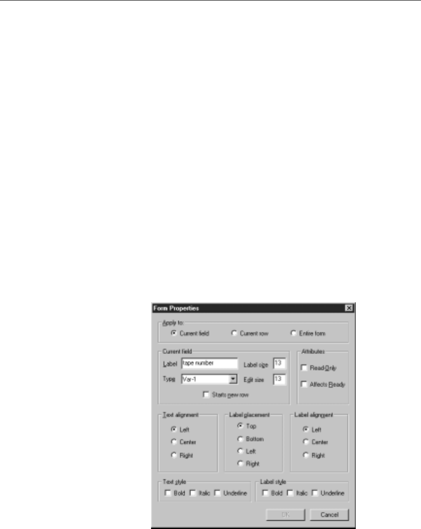
C-2
Upgrading Information
Upgrading to iNEWS
When upgrading to the Avid iNEWS newsroom computer system
from a previous product version, such as NetStation, you must update
specific field types in all your forms. See Table 3-1 for information
about which field types to update.
nYou must update these forms after you run the standard upgrade conversions
on your system.
To update field types on forms:
1. At the iNEWS Workstation, open a specific form.
For example, you may open the CG event list form under
SYSTEM.FORMS.C.CG.
2. Place the cursor in the field you need to update, and right-click.
3. Click Field Properties on the menu that appears.
The Form Properties dialog box opens.

C-3
Upgrading to iNEWS
4. In the Form Properties dialog box, ensure that Current field is
selected.
5. In the Type field, enter the new type or select it from the
drop-down list.
6. Click the OK button.
nIf you are upgrading from NetStation software, you must change the tape ID
assignment for cart devices. On NetStation, this information was entered in
the
APP1
form field. In iNEWS, this information must be entered in the
VIDEO-ID
form field. For more information about fields and forms, see
Chapter 8 in the iNEWS Newsroom Computer System Operations Manual.
Table 3-1 Form Properties Window Parameters
In this form: Change this field
type: To this field type:
Rundown APP1-1
AFF-READY-1 VIDEO-ID
EVENT-STATUS
Video Event List APP1-1
AFF-READY-1 VIDEO-ID
EVENT-STATUS
CG Event List APP2-1
APP1-1
APP3-1
MODIFY-DEV
VAR-1
CG-ADDR
STYLE
CG-TEMPLATE
EFFECT
CG-TEXT
SS Event List APP2-1
APP3-1
APP1-1
MODIFY-DEV
STILL-ID
STILL-PRESET
STYLE
EFFECT
Composite List APP1-1
APP2-1
CUME-TIME
AFF-READY-1
CG-ADDR
STILL-ID
VIDEO-ID
EVENT-STATUS

C-4
Upgrading Information
Glossary
10Base-T Low-cost point-to-point 10Mb/sec Ethernet using four unshielded
twisted pairs (UTP) of wire (only two pairs are actually used) with
RJ-45 connectors.
100Base-T Low-cost point-to-point 100Mb/sec Ethernet using four UTP (only
two pairs are actually used) with RJ-45 connectors.
absolute time The time assigned to a clip when it was encoded.
account A level of authorization assigned to individuals using iNEWS news-
room computer system. This determines the types of information
users can access and the actions they can perform. Account types
include user, user manager, superuser, and system administrator.
alias A code of up to 12 alphanumeric characters. It substitutes individual
user names and automates the distribution of a mail story to a group
of people.
anchor 1. The person presenting a newscast on-air to a television audience.
Also called a presenter.
2. The indicator in a Story Text panel that links a script to production
information, such as machine control events. Also called: grommet or
production cue marker.

-6
ASCII American Standard Code for Information Interchange. The standard
that governs the recording of characters by a sequence of binary digits,
as in a computerized timecode or video editing system.
auto-backup A function in iNEWS newsroom computer system that writes a
backup copy of an open story to a user’s local disk at specified time
intervals.
auto-refresh A queue attribute that automatically redisplays the queue screen
whenever changes are made to the queue.
autoscript A mode in which the production cue area of a story is automatically
displayed if production cues are in the story. If there are no production
cues added to a story, the story is displayed unscripted.
backtime The exact time when a story in a newscast must start in order for the
show to remain on schedule. Television newscasts typically use back-
time to ensure that the newscast ends precisely as scheduled.
baud Unit for measuring the rate of the digital data transmission. Usually
one baud equals one bit per second.
bulletin An incoming wire story coded as high-priority by a wire service; it is
fed directly into the iNEWS “priority” queue. Users are informed of its
arrival with both an audio signal and lightning bolt icon in the status
portion of the iNEWS Workspace.
clip A segment of digitized source material.
connect To call a service that is either local (such as an archive system) or
remote (such as Nexis). In iNEWS, users connect to services to access
data.
context menu See pop-up menu.

-7
ControlAir A product, formerly known as Broadcast Control System or BCS, that
works with the iNEWS newsroom computer system to run a show’s
production devices, such as character generators, still-stores, and
videotape devices.
cue See production cue.
cume (cumulative)
time The amount of airtime required from the beginning of the show up to
a certain point in the show in order for the show to remain on-sched-
ule. It is displayed with each entry in a rundown queue. Cumetime is
used by producers when building, ordering, or airing a newscast.
DAT A digital audio recording format that uses 3.8mm-wide magnetic tape
in a plastic cassette. (Digital Audio Tape)
Dead queue A queue containing stories that have been either deleted by users or
purged automatically by the system. These stories are recycled auto-
matically as new space is required.
device Any computer peripheral of hardware component (such as printer,
mouse, monitor, or hard disk) capable of receiving or sending data.
dialog box A secondary window that gathers additional information from a user.
It usually contains only a close (X) button in the top right corner, and
can be removed from the screen by pressing the Escape (ESC) key. See
also window.
directory Like a file drawer in a file cabinet, a directory is a storage space. Direc-
tories, also known as folders, can contain other directories (known as
sub-directories) or queues. Directories do not contain stories.
Directory panel An area in the iNEWS Workspace that displays the hierarchy of direc-
tories (folders) and queues in the iNEWS database. Users can use the
Directory panel to navigate through the system.

-8
drop-down menu A menu that is displayed from a menu bar—the bar of words, such as
File or Edit, located at the top of a window. The menu can appear as a
result of a mouse click on the menu bar or a keystroke combination of
ALT plus the underlined letter of a word in the menu bar. For instance,
ALT-F will open the File drop-down menu. See also pop-up menu.
duration The length of a show or story. It is calculated by using the elapsed time
in a broadcast when a story begins.
easy lock A feature that allows a user to open a queue or story while preventing
others from doing the same. It is similar to a key lock, but is created
without a key. Therefore, others cannot be granted access. See also lock,
key lock.
Edit Decision List
(EDL) A list of edits made during offline editing and used to direct the online
editing of the master.
edit lock A feature that prevents two people from working in a story simulta-
neously. The iNEWS system automatically places a story in edit-lock
mode when a user is working in a story, and a user can also manually
edit lock a story.
encode The process of converting analog video to a digital form.
Ethernet A standard for connecting computers in a local area network (LAN).
The actual technicalities are based on a Collision Sense Multiple
Access protocol (CSMA).
export 1. To create an EDL from a sequence.
2. To conform a sequence.
extract To remove a selected area from an edited sequence and close the
resulting gap in the sequence.
float To temporarily suspend a story. The story’s time is removed from the
show timing. Float time is also ignored by the teleprompter and

-9
machine control. Floating is used when you are not sure whether or
where to put a story in a rundown.
folder See directory.
form A preformatted layout (template) containing the fields and the field
positions (such as presenter and writer) required for a story. The form
serves as a copy master when creating a new story.
gigabyte (GB) Approximately one billion bytes (1,073,741,824 bytes) of information.
grommet The indicator in a Story Text panel that links a script to production
information. Also called: anchor or marker.
hard out A story in a newscast that has a fixed start time, usually at the end of a
segment or show. It is manually entered into the system.
headframe A single frame that can be used to help visually identify a clip or a
sequence.
high-resolution Digital video of a resolution suitable for broadcast.
In point Starting point of an edit. Also known as a Mark IN.
insert The process of including a clip into a sequence.
Instruction panel The area of the Story panel that contains production cues or machine
control data. This area can be removed (hidden) from the display
within the Story panel, so it may not appear on screen. See also Story
panel, Story Form panel, Story Text panel.
IP address An Internet Protocol address is a 32-bit numeric identifier usually
expressed as four groups of 8-bit decimal numbers (0 to 256) separated
by dots, as in 192.168.0.1.

-10
ISA Industry Standard Architecture. A bus standard used in personal com-
puters.
key A special alphanumeric code that a user assigns to a queue or story to
lock it. To open, or unlock, a queue or story, a user must have the key.
See also lock, easy lock, key lock.
key lock A feature that allows a user to lock a queue. To open the key-locked
queue, all users (including the individual who put the key lock on the
queue) must know the ”key” if they want to open, move, duplicate,
print, or delete the queue. See also lock, easy lock.
kill To delete a story and place it in the Dead queue.
lineup See rundown.
load The process of opening a clip into the editor in preparation for viewing
or editing.
Local Area Network
(LAN) This is a network of computers located in a common environment,
such as in a building or building complex.
lock To protect a queue or story from access by unauthorized users. A
queue or story can be locked and unlocked with a key or by a
user-name specific lock. See also key, easy lock, key lock.
low-resolution Digital video of a resolution suitable for edits.
machine control
event The event typically appears in Production Cue Text boxes in the
Instruction panel of iNEWS, and includes commands for machines,
such as still stores, character generators, digital playback devices, cart
machines, and so forth. Each one begins with an asterisk, followed by
a code for the type of machine the instruction is for, such as CG for
character generator or SS for still store machine, and so forth. Then,
information specific to the machine and particular item or template is

-11
provided. Also known as machine control commands or machine con-
trol instructions.
marker 1. The indicator in a Story Text panel that links a script to production
information. Also called: grommet or anchor.
2. A mark added to a selected frame to qualify a particular location
within a video sequence.
Media Browse A system that works with iNEWS and high-resolution editing applica-
tions to create broadcast-quality video output.
media object An on-air object managed by a MOS device. See also MOS.
menu See drop-down menu, pop-up menu.
Messages of the
Day window A window that displays one or more messages for iNEWS system
users when they log in to the system.
mirroring A fault tolerance method that keeps identical copies of data on disk
partitions located on different physical hard disks and servers.
monitor server Autility program on the iNEWS Server. For ControlAir, it is used to
scan stories in the rundown, searching for machine control events to
build event lists (playlists) for the production devices
MOS Acronym for Media Object Server. See also MOS device.
MOS device A vendor product that stores media objects and supports the MOS
protocol.
MOS protocol XML-based protocol for communication between a newsroom com-
puter system and a MOS device. For more information, visit
http://www.mosprotocol.com on the Internet.
multimedia In computing, multimedia refers to the presentation of information on
a computer using sound, graphics, animation, and text.

-12
network A group of computers and other devices connected together so they
can communicate with each other.
network address A network number that uniquely identifies a network cable segment.
It is also referred to as the IPX external network number.
NRCS An acronym for Newsroom Computer System.
order lock A temporary lock that the iNEWS system places on a queue when a
user changes a sequence of stories in that queue. Order locking does
not prevent other users from accessing the queue, but does prevent
them from ordering the queues simultaneously.
Out point End point of an edit, or a mark on a clip indicating a transition point.
Also known as a Mark OUT.
out time The total length of time for a show (shown in hours, minutes, and sec-
onds) or the actual time by which the show must end (shown in
12-hour-clock time). See also backtime.
panel A part of an iNEWS Workspace. In iNEWS, the three panels are the
Directory panel, Queue panel, and Story panel. The Story panel is split
further into the Story Form panel, Story Text panel, and Instruction
panel (used for production cues).
partition A method of assigning disk space, creating two or more virtual disks
from a single physical disk. Similar to creating a directory.
password A word users enter when logging in to the iNEWS system. Passwords
are alphanumeric and must be between 5- and 12-characters long.
pathname The hierarchical name of the directory and queue in which a story is
located. For instance, the pathname for the Yankees queue is
WIRES.SPORTS.STORIES.YANKEES.

-13
PCI Peripheral Component Interconnect. A bus standard used in newer
computers.
player controls The electronic equivalent of a tape-deck controls.
pop-up menu A menu that appears at the mouse pointer location when a user exe-
cutes a right-click on a selected object. It contains commands contextu-
ally relevant to the selection. Also known as context menu. See also
drop-down menu.
presenter The person presenting a newscast on-air to a television audience. Also
called an anchor.
preview To rehearse an sequence without actually performing (exporting) it.
priority queue 1. An area where iNEWS places copies of wire stories (usually in
WIRES.ADVISORY.PRIORITY).
2. A queue designated to be read first by a server program for new
stories.
production cue A prompt to start a story element, such as a video playback. In
iNEWS, it is typically anchored to the script by a marker with text
appearing to the left of a scripted story, and it provides information for
production staff, such as VO—an indication to the presenter that video
is on-air. Production cues may also contain instructions for machine
control events that involve other devices being controlled in the run-
down. These machine control instructions are usually prefaced by an
asterisk (*). See also marker and machine control event.
purge To remove stories from queues (based on age) and place them in the
Dead queue. Purged stories are recycled as needed as new space is
required. See also purge interval.
purge interval A queue trait that indicates the time after which a story is considered
“old.” At hourly intervals, iNEWS will scan the entire database and
purge old stories from a queue.

-14
queue An area of the database that contains stories related to a general topic.
Like a folder in a file drawer, queues are storage places within a sys-
tem’s file structure that allow you to organize information in detailed
categories. See also directory, Directory panel, Queue panel.
queue form The area used to display the contents, size, and labels of a Queue
panel.
Queue panel An area in the iNEWS Workspace that contains a list of the stories in a
queue. Users can add, delete, and sequence stories in the Queue panel.
queue property A trait that controls the characteristics of a queue in the iNEWS data-
base. Queue properties include the refresh trait, read-only purge inter-
val, sorting, and so forth.
read access Authority granted to users that allows them to read and duplicate the
contents of a directory, queue, or story.
read rate The number of words per minute at which a talent can read a news
story. The system determines the total running time of a newscast
based on the read rate of the assigned presenter.
refresh A queue property or trait that automatically updates your screen’s dis-
play of the queue when changes are made to that queue by another
user or by the system.
relative-to-mark
time Time is displayed as though the start of the clip is at the locator mark.
relative-to-start
time Time is displayed as though the start of the clip is at 00;00;00;00.
remote service An archival system, bulletin board, or any information service that
allows you to establish a connection to another service.
results queue An area in iNEWS in which results from a Find All search are placed.

-15
roll To play a video. The digital equivalent of starting the tape deck.
RS-232 The Electronic Industries Association standard for short-range serial
control.
RS-422 The Electronic Industries Association standard for medium-range
serial control.
rundown A lineup or timed-out list of stories indicating the order in which they
will be aired during a news program. A rundown is viewed in the
Queue panel of the iNEWS Workspace. The rundown queue typically
uses a form with BACK-TIME or CUME-TIME fields to display the
timing of the newscast.
SCO Santa Cruz Operation UNIX® operating system.
scratch pad A buffer in which text or notes are stored until the appropriate recov-
ery procedures is performed. Deleted text and notes are stored in the
scratch pad. It is separate from the Windows Clipboard and allows
clippings to be accumulated.
script A story that is read on the air. Typically, a script also contains produc-
tion cues and references to the related media annotations.
SCSI Small Computer System Interface is an industry standard with guide-
lines for connecting peripheral devices (such as hard drives and tape
backup systems) and their controllers to a microprocessor. The SCSI,
commonly pronounced “scuzzy,” interface defines standards for hard-
ware and software to communicate between a host computer and a
peripheral device. Computers and peripheral devices designed to
meet SCSI Specifications are normally compatible.
selection bar The box at the left edge of a Queue panel that, when clicked, selects a
story and all of that story’s details.
sequence An edited composition that includes one or more clips.

-16
server 1. A special utility program the system uses to handle the distribu-
tion of stories internally. Some of these servers are known as:
action, distribution, parallel, and so forth.
2. Computer hardware (or file servers) with the iNEWS database and
running the iNEWS application software. These computers also
run other operating systems, such as UNIX or Windows NT®. For
instance, the FTS server and the iNEWS Servers (also called server
A, server B, or NRCS-A, NRCS-B, and so forth).
session The way in which an iNEWS Workspace is customized. Toolbars,
workspace layout, and preferences can be customized and saved with
a session.
slave printer A printer attached to the workstation.
sorted queue A queue in which stories are sorted according to criteria specified by
the system administrator.
source queue A queue from which stories are copied or moved.
story Uniquely identified file containing text; stories are grouped in queues
and are displayed in the Story panel of the iNEWS Workspace.
Story Form panel An area at the top of a Story panel that contains information about a
story, such as its title, length, or status. This information is provided in
fields that may correspond to data displayed in the Queue panel. This
area can be removed (hidden) from the display within the Story panel,
so it may not appear on screen.
Story panel An area in the iNEWS Workspace that displays the story form, text,
and production cues of a story.
Story Text panel An area in the Story panel that contains the text or script of a story. It is
the only area that is always displayed as part of the Story panel. See
also Story panel, Story Form panel, Instruction panel.

-17
superuser A user account that is given access to restricted functions in the
iNEWS system. Only a system administrator can assign superuser sta-
tus.
system
administrator A person responsible for maintaining the iNEWS system and keeping
all functions operating properly.
TCP/IP Transmission Control Protocol/Internet Protocol is a platform-inde-
pendent protocol for intercomputer communication.
time bar A graphical representation of the duration of a clip, including an indi-
cation of the current position and the In and Out marks.
user Individual who has a valid user account in the iNEWS system.
user ID A special alphanumeric code that identifies a user account in the
iNEWS system. A user ID can be up to 20-characters long.
user manager User ID given the authority to add, modify, delete, and search for
information about user accounts. User manager status can be assigned
by a system administrator only.
user name A word established to identify the individual user. Enter your user
name and your password to log in. User names are alphanumeric and
are up to 20-characters long.
video clip See clip.
window An area in which the main interaction takes place. It is typically rectan-
gular, with a title bar (that appears blue when active and gray when
inactive), and three buttons in the top right corner (used to resize the
window or close it). Unlike a dialog box, a standard window cannot be
closed by pressing the Escape key.
Windows®Graphical shell operating environment that runs on top of DOS. It con-
tains many accessories and features that access DOS functions such as

-18
file, program, and printer management. Windows is referred to as a
GUI (Graphical User Interface).
Windows NT®Microsoft Windows New Technology operating system that imple-
ments protected process multitasking, security, and other features of
traditional operating systems, while maintaining a high level of com-
patibility with other Windows operating systems.
wire bulletin See bulletin.
workstation A personal computer (PC) that, when running the iNEWS client soft-
ware, is called an iNEWS Workstation. This the PC that is operated by
end-users to write scripts or email, create rundowns (lineups), and so
forth.
workspace The area within the iNEWS main window consisting of the Directory
panel, Queue panel, and Story panel. The iNEWS Workspace is where
users can view, add, edit, and delete information.
write access The ability to add new stories, edit existing stories in a particular
queue, add a queue, or add a directory.

Index-1
Index
Symbols
/etc/hosts 3-2, 3-3
editing 3-4
sample B-3
/site/config 4-5
sample B-4
/site/dict 4-29
/site/dict/mcs, editing 4-29
/site/mcs 5-6
A
AMCP Application, defined 1-5
architecture, ControlAir 1-3
assign forms 4-17
autostart.ini file 3-26
default B-2
B
become a superuser 4-31
busy device status 6-15
C
camgr.exe 1-5
casvr.exe 1-4
CG-ADDR form field 4-15
CG-TEMPLATE form field 4-15
CG-TEXT form field 4-15
character generators, parameters 4-26
COM ports 2-8
Digi AccelePort 2-8
Equinox 2-9
components, grounding 2-3
composite list 4-12
security 4-14
configuration file
adding a monitor server to B-4
configuration lines
example 4-8
console command
list s 4-31
stop all 4-32
ControlAir
architecture 1-3
components 1-4
network layout 1-8
overview 1-2
setup overview 3-2
workflow 1-3
ControlAir Manager
defined 1-5
setup 3-25
ControlAir Server
defined 1-4
printing diagnostics 6-3
program 6-3
requirements 2-5
window 6-4
ControlAir Workstation
defined 1-6
requirements 2-6
D
default forms 4-17
device managers
defined 1-5
MCS-PC 5-5
restarting 5-7
device numbers 4-5
device status 6-14
busy 6-15
in-use 6-15
off-line 6-15, 7-3

Index-2
Index
on-line 6-14
ready 6-15
unknown 6-15, 7-3
diagnostic filters, setting 6-4
dialog boxes
Change Override Password 6-8
Form Properties C-2
Monitor Queue 4-42
Queue Properties 4-10
Select Diagnostic Info Groups 6-5
dictionaries
incorporating changes 4-29
updating 4-31
DMP files 5-6
listed in autostart.ini 3-27
E
ed command 4-6
EFFECT form field 4-16
effects, using in styles 4-34
entry header variables 4-22
error categories 7-4
error checking 4-34
event list 4-12
security 4-14
EVENT-STATUS form field 4-16
F
Form Fields 4-15
CG-ADDR 4-15
CG-TEMPLATE 4-15
CG-TEXT 4-15
EFFECT 4-16
EVENT-STATUS 4-16
STATUS 4-16
STILL-ID 4-16
STILL-PRESET 4-16
STYLE 4-16
VIDEO-ID 4-16
forms
assigning to queues 4-17
default 4-17
G
grounding components 2-3
I
iNEWS Servers
configuration details 4-4
configuration file 4-5
configuration summary 4-4
prerequisites for configuring 4-3
iNEWS, upgrading to C-2
installing
ControlAir software 3-5
serial ports 2-7
in-use device status 6-15
IP addresses
adding to ControlAir Server 3-2
adding to iNEWS Servers 3-4
example 3-3
L
list console command 4-5
variations of 4-11
list s command 4-31
loading playlists 1-12
loading shows 1-12
Log files 6-5, 7-6
LouthDM.exe 1-6
M
mailbox
assigning to rundown queue 4-10
defined 4-2
valid numbers 4-5
makemctab -b 4-32

Index-3
makemctab command 4-30
map story, defined 4-19
MCS dictionary files 4-28
updating 4-30
MCS-PC
configuration 5-5
device driver profile 5-6
device managers 5-5
requirements 2-7
Monitor Load 1-12
command 4-9
monitor modes 1-10–1-14
dialog box 4-42
Monitor On 1-10
command 4-9
monitor server
adding to configuration file B-4
communicating 3-2
configuring 4-3
creating 4-2–4-11
defined 1-6
display 4-14
error checking 4-34
listing assigned mailboxes 4-11
uses 4-33
Monitor Unload 1-14
monitoring shows 1-10
O
off-line device status 6-15, 7-3
on-linedevicestatus6-14
Override password 3-16, 6-7
P
parameters
character generator 4-26
device list line 4-24, 4-26
entry header 4-22
still stores 4-27
video machines 4-28
password, Override 3-16
playlists, loading 1-12
playlists, unloading 1-14
procedures
adding IP addresses 3-2, 3-4
assign form to queue 4-17
assign mailbox to queue 4-10
creating composite list queues 4-12
creating event list queues 4-12
edit the dictionary file 4-29
setting Override password 6-8
update field types C-2
updating dictionaries 4-31
Q
queue forms 4-15
explained 4-18
Queue Properties dialog box 4-10
queues
composite list 4-12
eventlist4-12
R
ready device status 6-15
reconfigure the system 4-9
reserve Override password 3-16
S
serial ports, installing 2-7
specifications
environmental 2-4
hardware 2-4
workstation 2-6
STATUS form field 4-16
still stores, parameters 4-27
STILL-ID form field 4-16
STILL-PRESET form field 4-16

Index-4
Index
stop all command 4-32
Story Form panel 4-36
story forms 4-15
explained 4-18
Story Text panel 4-36
STYLE form field 4-16
Style Parameters 4-37
Device 4-37
Effect 4-38
Number of Fields 4-39
Preset 4-38
Style 4-37
Template 4-38
Styles
create and edit 4-36
using effects 4-34
where stored 4-35
why use 4-33
symbols and conventions
keyboard i-viii
SYSTEM.FORMS directory 4-17
SYSTEM.MAP story 4-19
sample device list 4-23
sample entries 4-20
sample entry header 4-21
sample story B-5
SYSTEM.RESOURCE queue 4-35
SYSTEM.RESOURCE story
sample 4-40
testing 4-39
T
Troubleshooting
ControlAir Manager 7-5
ControlAir Workstation 7-3
error categories 7-4
looping problem 7-5
missing machine control events 7-3
off-line status 7-3
unknown status 7-3
U
UNIX line editor 3-4, 4-6
unknown device status 6-15, 7-3
unloading playlists 1-14
unloading shows 1-14
upgrading from NetStation C-3
UPS (uninterruptible power supply) 2-3
V
VIDEO-ID form field 4-16
W
work flow 1-3
write security group 4-14
