Avid INEWS Command Installation And Configuration Guide V3.1 I News 3.1 ICG EN
User Manual: avid iNews Command - 3.1 - Installation and Configuration Guide Free User Guide for Avid iNews Software, Manual
Open the PDF directly: View PDF ![]() .
.
Page Count: 328 [warning: Documents this large are best viewed by clicking the View PDF Link!]
- Avid® iNEWS® Command
- Title Page
- Contents
- Using This Guide
- Installing and Configuring the Command Server
- System Architecture
- Checklist: Before you Begin
- Checklist: Command Server Installation
- Copying Install CD to Local Directory
- Installing Avid Service Framework
- Installing the License Service
- Installing Avid iNEWS Command on the Server
- Configuring the iNEWS Command Server
- Configuring the System Administration Password
- Configuring the Time Synchronization Service
- Configuring Avid Video Device Services (VDS)
- Configuring VDS for Omneon
- Configuring Video Setup for GVG K2 Servers using AMP Protocol
- Configuring VDS for Harris
- Wiring Serial Connections for Avid Video Device Services (for VDCP)
- Configuring VDS for VDCP
- Configuring VDS for Slugs and Thumbnails in Non-Interplay Systems
- Configuring Redundancy for VDCP
- Transfer Status Icon
- Configuring Avid Interplay Agent Services
- Configuring the Avid UMD Device Service
- Configuring the Lookup Tab
- Configuring AirSpeed Device Services
- Configuring a Second Command System
- Installing and Configuring the AirSpeed Video Servers
- Checklist: Installing the AirSpeed Video Server
- Installing Avid Service Framework
- Installing AirSpeed Multi Stream Device Services
- Checklist: Configuring the AirSpeed Video Server
- Configuring Properties for Interplay Workgroup
- Configuring the AirSpeed Multi Stream Device Service
- Configuring Properties for Command Workgroup
- Working with Play While Record
- AirSpeed Multi Stream Los-Res Proxy Viewer
- Installing and Configuring Avid Motion Graphics
- What You Need to Activate the Software License
- Avid Motion Graphics Journalist Server Installation and Configuration
- Installing AMG Journalist Client Software
- Installing the AMG Preview Renderer
- Starting the AMG Journalist Server Applications
- Installing the AMG Advanced Device Manager
- Installing the Avid Service Framework
- Installing Avid Motion Graphics Device Service
- Configuring the Avid Motion Graphics Device Service
- Installing and Configuring the Graphic Device Service
- Installing Avid Service Framework
- Installing Avid Graphic Device Service
- Installing Third-Party Plug-ins for the Graphic Device Service
- CII Integration
- Installing and Configuring the Deko
- System Architecture
- Checklist: Installing the Deko
- Installing Avid Service Framework
- Installing Avid Deko Device Service
- Installing the DekoMOS Gateway
- Installing the DekoMOS Macro Server
- Checklist: Configuring the Deko
- Configuring the DekoMOS Gateway
- Configuring the DekoMOS Macro Server
- Configuring Avid Workgroup Properties
- Configuring the Deko Device Service
- Configuring the Avid Deko Renderer Service
- Creating Graphic Styles in Command
- Installing and Configuring the Thunder
- Installing the Command Workstation
- Installing and Configuring the Tablet Application
- Configuring Playout Control
- Controling Playout via the Keyboard
- Disabling a Command Workstation’s Keyboard
- Checklist: Setting up an X-keys USB Keypad
- Installing an X-keys USB Keypad
- Mapping Indices to Channel Names
- Programming the X-keys
- Setting up the Playout Panel for Touch Screens
- Checklist: Setting up the GPI Panel
- Configuring the GPI Card
- Restarting the GPI Device Service
- Confirming Successful Setup of a GPI Panel
- Mapping Events to Actions for a GPI Panel
- Enabling the GPI Panel
- Configuring GPI Out
- Integrating with Avid iNEWS
- Editing the SYSTEM.MAP Story
- Editing the SYSTEM.MOS-MAP Story
- Setting up the Plug-ins in iNEWS
- Monitor Servers
- Queue Properties
- Integrating with ENPS
- Configuring the Perle IOLAN Server
- Confirming Functionality

Avid® iNEWS® Command
Installation and Configuration Guide
2
Legal Notices
Product specifications are subject to change without notice and do not represent a commitment on the part of Avid
Technology, Inc.
This product is subject to the terms and conditions of a software license agreement provided with the software. The product
may only be used in accordance with the license agreement.
This product may be protected by one or more U.S. and non-U.S patents. Details are available at www.avid.com/patents.
This document is protected under copyright law. An authorized licensee of Avid iNEWS Command may reproduce this
publication for the licensee’s own use in learning how to use the software. This document may not be reproduced or
distributed, in whole or in part, for commercial purposes, such as selling copies of this document or providing support or
educational services to others. This document is supplied as a guide for Avid iNEWS Command. Reasonable care has been
taken in preparing the information it contains. However, this document may contain omissions, technical inaccuracies, or
typographical errors. Avid Technology, Inc. does not accept responsibility of any kind for customers’ losses due to the use of
this document. Product specifications are subject to change without notice.
Copyright © 2013 Avid Technology, Inc. and its licensors. All rights reserved.
The following disclaimer is required by Apple Computer, Inc.:
APPLE COMPUTER, INC. MAKES NO WARRANTIES WHATSOEVER, EITHER EXPRESS OR IMPLIED, REGARDING
THIS PRODUCT, INCLUDING WARRANTIES WITH RESPECT TO ITS MERCHANTABILITY OR ITS FITNESS FOR ANY
PARTICULAR PURPOSE. THE EXCLUSION OF IMPLIED WARRANTIES IS NOT PERMITTED BY SOME STATES. THE
ABOVE EXCLUSION MAY NOT APPLY TO YOU. THIS WARRANTY PROVIDES YOU WITH SPECIFIC LEGAL RIGHTS.
THERE MAY BE OTHER RIGHTS THAT YOU MAY HAVE WHICH VARY FROM STATE TO STATE.
The following disclaimer is required by Sam Leffler and Silicon Graphics, Inc. for the use of their TIFF library:
Copyright © 1988–1997 Sam Leffler
Copyright © 1991–1997 Silicon Graphics, Inc.
Permission to use, copy, modify, distribute, and sell this software [i.e., the TIFF library] and its documentation for any purpose
is hereby granted without fee, provided that (i) the above copyright notices and this permission notice appear in all copies of
the software and related documentation, and (ii) the names of Sam Leffler and Silicon Graphics may not be used in any
advertising or publicity relating to the software without the specific, prior written permission of Sam Leffler and Silicon
Graphics.
THE SOFTWARE IS PROVIDED “AS-IS” AND WITHOUT WARRANTY OF ANY KIND, EXPRESS, IMPLIED OR
OTHERWISE, INCLUDING WITHOUT LIMITATION, ANY WARRANTY OF MERCHANTABILITY OR FITNESS FOR A
PARTICULAR PURPOSE.
IN NO EVENT SHALL SAM LEFFLER OR SILICON GRAPHICS BE LIABLE FOR ANY SPECIAL, INCIDENTAL, INDIRECT
OR CONSEQUENTIAL DAMAGES OF ANY KIND, OR ANY DAMAGES WHATSOEVER RESULTING FROM LOSS OF USE,
DATA OR PROFITS, WHETHER OR NOT ADVISED OF THE POSSIBILITY OF DAMAGE, AND ON ANY THEORY OF
LIABILITY, ARISING OUT OF OR IN CONNECTION WITH THE USE OR PERFORMANCE OF THIS SOFTWARE.
The following disclaimer is required by the Independent JPEG Group:
This software is based in part on the work of the Independent JPEG Group.
This Software may contain components licensed under the following conditions:
Copyright (c) 1989 The Regents of the University of California. All rights reserved.
Redistribution and use in source and binary forms are permitted provided that the above copyright notice and this paragraph
are duplicated in all such forms and that any documentation, advertising materials, and other materials related to such
distribution and use acknowledge that the software was developed by the University of California, Berkeley. The name of the
University may not be used to endorse or promote products derived from this software without specific prior written
permission. THIS SOFTWARE IS PROVIDED ``AS IS'' AND WITHOUT ANY EXPRESS OR IMPLIED WARRANTIES,
INCLUDING, WITHOUT LIMITATION, THE IMPLIED WARRANTIES OF MERCHANTABILITY AND FITNESS FOR A
PARTICULAR PURPOSE.
Copyright (C) 1989, 1991 by Jef Poskanzer.
Permission to use, copy, modify, and distribute this software and its documentation for any purpose and without fee is hereby
granted, provided that the above copyright notice appear in all copies and that both that copyright notice and this permission
notice appear in supporting documentation. This software is provided "as is" without express or implied warranty.
3
Copyright 1995, Trinity College Computing Center. Written by David Chappell.
Permission to use, copy, modify, and distribute this software and its documentation for any purpose and without fee is hereby
granted, provided that the above copyright notice appear in all copies and that both that copyright notice and this permission
notice appear in supporting documentation. This software is provided "as is" without express or implied warranty.
Copyright 1996 Daniel Dardailler.
Permission to use, copy, modify, distribute, and sell this software for any purpose is hereby granted without fee, provided that
the above copyright notice appear in all copies and that both that copyright notice and this permission notice appear in
supporting documentation, and that the name of Daniel Dardailler not be used in advertising or publicity pertaining to
distribution of the software without specific, written prior permission. Daniel Dardailler makes no representations about the
suitability of this software for any purpose. It is provided "as is" without express or implied warranty.
Modifications Copyright 1999 Matt Koss, under the same license as above.
Copyright (c) 1991 by AT&T.
Permission to use, copy, modify, and distribute this software for any purpose without fee is hereby granted, provided that this
entire notice is included in all copies of any software which is or includes a copy or modification of this software and in all
copies of the supporting documentation for such software.
THIS SOFTWARE IS BEING PROVIDED "AS IS", WITHOUT ANY EXPRESS OR IMPLIED WARRANTY. IN PARTICULAR,
NEITHER THE AUTHOR NOR AT&T MAKES ANY REPRESENTATION OR WARRANTY OF ANY KIND CONCERNING THE
MERCHANTABILITY OF THIS SOFTWARE OR ITS FITNESS FOR ANY PARTICULAR PURPOSE.
This product includes software developed by the University of California, Berkeley and its contributors.
The following disclaimer is required by Nexidia Inc.:
© 2010 Nexidia Inc. All rights reserved, worldwide. Nexidia and the Nexidia logo are trademarks of Nexidia Inc. All other
trademarks are the property of their respective owners. All Nexidia materials regardless of form, including without limitation,
software applications, documentation and any other information relating to Nexidia Inc., and its products and services are the
exclusive property of Nexidia Inc. or its licensors. The Nexidia products and services described in these materials may be
covered by Nexidia's United States patents: 7,231,351; 7,263,484; 7,313,521; 7,324,939; 7,406,415, 7,475,065; 7,487,086
and/or other patents pending and may be manufactured under license from the Georgia Tech Research Corporation USA.
The following disclaimer is required by Paradigm Matrix:
Portions of this software licensed from Paradigm Matrix.
The following disclaimer is required by Ray Sauers Associates, Inc.:
“Install-It” is licensed from Ray Sauers Associates, Inc. End-User is prohibited from taking any action to derive a source code
equivalent of “Install-It,” including by reverse assembly or reverse compilation, Ray Sauers Associates, Inc. shall in no event be
liable for any damages resulting from reseller’s failure to perform reseller’s obligation; or any damages arising from use or
operation of reseller’s products or the software; or any other damages, including but not limited to, incidental, direct, indirect,
special or consequential Damages including lost profits, or damages resulting from loss of use or inability to use reseller’s
products or the software for any reason including copyright or patent infringement, or lost data, even if Ray Sauers Associates
has been advised, knew or should have known of the possibility of such damages.
The following disclaimer is required by Videomedia, Inc.:
“Videomedia, Inc. makes no warranties whatsoever, either express or implied, regarding this product, including warranties with
respect to its merchantability or its fitness for any particular purpose.”
“This software contains V-LAN ver. 3.0 Command Protocols which communicate with V-LAN ver. 3.0 products developed by
Videomedia, Inc. and V-LAN ver. 3.0 compatible products developed by third parties under license from Videomedia, Inc. Use
of this software will allow “frame accurate” editing control of applicable videotape recorder decks, videodisc recorders/players
and the like.”
The following disclaimer is required by Altura Software, Inc. for the use of its Mac2Win software and Sample
Source Code:
©1993–1998 Altura Software, Inc.
The following disclaimer is required by Ultimatte Corporation:
Certain real-time compositing capabilities are provided under a license of such technology from Ultimatte Corporation and are
subject to copyright protection.
4
The following disclaimer is required by 3Prong.com Inc.:
Certain waveform and vector monitoring capabilities are provided under a license from 3Prong.com Inc.
The following disclaimer is required by Interplay Entertainment Corp.:
The “Interplay” name is used with the permission of Interplay Entertainment Corp., which bears no responsibility for Avid
products.
This product includes portions of the Alloy Look & Feel software from Incors GmbH.
This product includes software developed by the Apache Software Foundation (http://www.apache.org/).
© DevelopMentor
This product may include the JCifs library, for which the following notice applies:
JCifs © Copyright 2004, The JCIFS Project, is licensed under LGPL (http://jcifs.samba.org/). See the LGPL.txt file in the Third
Party Software directory on the installation CD.
Avid Interplay contains components licensed from LavanTech. These components may only be used as part of and in
connection with Avid Interplay.
Attn. Government User(s). Restricted Rights Legend
U.S. GOVERNMENT RESTRICTED RIGHTS. This Software and its documentation are “commercial computer software” or
“commercial computer software documentation.” In the event that such Software or documentation is acquired by or on behalf
of a unit or agency of the U.S. Government, all rights with respect to this Software and documentation are subject to the terms
of the License Agreement, pursuant to FAR §12.212(a) and/or DFARS §227.7202-1(a), as applicable.
Trademarks
003, 192 Digital I/O, 192 I/O, 96 I/O, 96i I/O, Adrenaline, AirSpeed, ALEX, Alienbrain, AME, AniMatte, Archive, Archive II,
Assistant Station, AudioPages, AudioStation, AutoLoop, AutoSync, Avid, Avid Active, Avid Advanced Response, Avid DNA,
Avid DNxcel, Avid DNxHD, Avid DS Assist Station, Avid Ignite, Avid Liquid, Avid Media Engine, Avid Media Processor, Avid
MEDIArray, Avid Mojo, Avid Remote Response, Avid Unity, Avid Unity ISIS, Avid VideoRAID, AvidRAID, AvidShare, AVIDstripe,
AVX, Beat Detective, Beauty Without The Bandwidth, Beyond Reality, BF Essentials, Bomb Factory, Bruno, C|24,
CaptureManager, ChromaCurve, ChromaWheel, Cineractive Engine, Cineractive Player, Cineractive Viewer, Color Conductor,
Command|24, Command|8, Control|24, Cosmonaut Voice, CountDown, d2, d3, DAE, D-Command, D-Control, Deko,
DekoCast, D-Fi, D-fx, Digi 002, Digi 003, DigiBase, Digidesign, Digidesign Audio Engine, Digidesign Development Partners,
Digidesign Intelligent Noise Reduction, Digidesign TDM Bus, DigiLink, DigiMeter, DigiPanner, DigiProNet, DigiRack,
DigiSerial, DigiSnake, DigiSystem, Digital Choreography, Digital Nonlinear Accelerator, DigiTest, DigiTranslator, DigiWear,
DINR, DNxchange, Do More, DPP-1, D-Show, DSP Manager, DS-StorageCalc, DV Toolkit, DVD Complete, D-Verb, Eleven,
EM, Euphonix, EUCON, EveryPhase, Expander, ExpertRender, Fader Pack, Fairchild, FastBreak, Fast Track, Film Cutter,
FilmScribe, Flexevent, FluidMotion, Frame Chase, FXDeko, HD Core, HD Process, HDpack, Home-to-Hollywood, HYBRID,
HyperSPACE, HyperSPACE HDCAM, iKnowledge, Image Independence, Impact, Improv, iNEWS, iNEWS Assign, iNEWS
ControlAir, InGame, Instantwrite, Instinct, Intelligent Content Management, Intelligent Digital Actor Technology, IntelliRender,
Intelli-Sat, Intelli-sat Broadcasting Recording Manager, InterFX, Interplay, inTONE, Intraframe, iS Expander, iS9, iS18, iS23,
iS36, ISIS, IsoSync, LaunchPad, LeaderPlus, LFX, Lightning, Link & Sync, ListSync, LKT-200, Lo-Fi, MachineControl, Magic
Mask, Make Anything Hollywood, make manage move | media, Marquee, MassivePack, Massive Pack Pro, Maxim, Mbox,
Media Composer, MediaFlow, MediaLog, MediaMix, Media Reader, Media Recorder, MEDIArray, MediaServer, MediaShare,
MetaFuze, MetaSync, MIDI I/O, Mix Rack, Moviestar, MultiShell, NaturalMatch, NewsCutter, NewsView, NewsVision, Nitris,
NL3D, NLP, NSDOS, NSWIN, OMF, OMF Interchange, OMM, OnDVD, Open Media Framework, Open Media Management,
Painterly Effects, Palladium, Personal Q, PET, Podcast Factory, PowerSwap, PRE, ProControl, ProEncode, Profiler, Pro Tools,
Pro Tools|HD, Pro Tools LE, Pro Tools M-Powered, Pro Transfer, QuickPunch, QuietDrive, Realtime Motion Synthesis, Recti-Fi,
Reel Tape Delay, Reel Tape Flanger, Reel Tape Saturation, Reprise, Res Rocket Surfer, Reso, RetroLoop, Reverb One,
ReVibe, Revolution, rS9, rS18, RTAS, Salesview, Sci-Fi, Scorch, ScriptSync, SecureProductionEnvironment, Serv|GT,
Serv|LT, Shape-to-Shape, ShuttleCase, Sibelius, SimulPlay, SimulRecord, Slightly Rude Compressor, Smack!, Soft
SampleCell, Soft-Clip Limiter, SoundReplacer, SPACE, SPACEShift, SpectraGraph, SpectraMatte, SteadyGlide,
Streamfactory, Streamgenie, StreamRAID, SubCap, Sundance, Sundance Digital, SurroundScope, Symphony, SYNC HD,
SYNC I/O, Synchronic, SynchroScope, Syntax, TDM FlexCable, TechFlix, Tel-Ray, Thunder, TimeLiner, Titansync, Titan, TL
Aggro, TL AutoPan, TL Drum Rehab, TL Everyphase, TL Fauxlder, TL In Tune, TL MasterMeter, TL Metro, TL Space, TL
Utilities, tools for storytellers, Transit, TransJammer, Trillium Lane Labs, TruTouch, UnityRAID, Vari-Fi, Video the Web Way,
VideoRAID, VideoSPACE, VTEM, Work-N-Play, Xdeck, X-Form, Xmon and XPAND! are either registered trademarks or
trademarks of Avid Technology, Inc. in the United States and/or other countries.
5
Footage
Arri — Courtesy of Arri/Fauer — John Fauer, Inc.
Bell South “Anticipation” — Courtesy of Two Headed Monster — Tucker/Wayne Atlanta/GMS.
Canyonlands — Courtesy of the National Park Service/Department of the Interior.
Eco Challenge British Columbia — Courtesy of Eco Challenge Lifestyles, Inc., All Rights Reserved.
Eco Challenge Morocco — Courtesy of Discovery Communications, Inc.
It’s Shuttletime — Courtesy of BCP & Canadian Airlines.
Nestlé Coffee Crisp — Courtesy of MacLaren McCann Canada.
Saturn “Calvin Egg” — Courtesy of Cossette Communications.
“Tigers: Tracking a Legend” — Courtesy of www.wildlifeworlds.com, Carol Amore, Executive Producer.
"The Big Swell" — Courtesy of Swell Pictures, Inc.
Windhorse — Courtesy of Paul Wagner Productions.
Arizona Images — KNTV Production — Courtesy of Granite Broadcasting, Inc.,
Editor/Producer Bryan Foote.
Canyonlands — Courtesy of the National Park Service/Department of the Interior.
Ice Island — Courtesy of Kurtis Productions, Ltd.
Tornados + Belle Isle footage — Courtesy of KWTV News 9.
WCAU Fire Story — Courtesy of NBC-10, Philadelphia, PA.
Women in Sports – Paragliding — Courtesy of Legendary Entertainment, Inc.
News material provided by WFTV Television Inc.
GOT FOOTAGE?
Editors — Filmmakers — Special Effects Artists — Game Developers — Animators — Educators — Broadcasters — Content
creators of every genre — Just finished an incredible project and want to share it with the world?
Send us your reels and we may use your footage in our show reel or demo!*
For a copy of our release and Avid’s mailing address, go to www.avid.com/footage.
*Note: Avid cannot guarantee the use of materials submitted.
Avid iNEWS Command v3.1 Installation and Configuration Guide • 9329-65262-00 Rev B • October 1, 2013
6
7
Contents
Using This Guide. . . . . . . . . . . . . . . . . . . . . . . . . . . . . . . . . . . . . . . . . . . . . . . 13
Symbols and Conventions . . . . . . . . . . . . . . . . . . . . . . . . . . . . . . . . . . . . . . . . . . . . . . . 13
If You Need Help. . . . . . . . . . . . . . . . . . . . . . . . . . . . . . . . . . . . . . . . . . . . . . . . . . . . . . . 14
Avid Training Services . . . . . . . . . . . . . . . . . . . . . . . . . . . . . . . . . . . . . . . . . . . . . . . . . . 15
Chapter 1 Installing and Configuring the Command Server. . . . . . . . . . . . . . . . . . . . . 17
System Architecture . . . . . . . . . . . . . . . . . . . . . . . . . . . . . . . . . . . . . . . . . . . . . . . . . . . . 18
Checklist: Before you Begin . . . . . . . . . . . . . . . . . . . . . . . . . . . . . . . . . . . . . . . . . . . . . . 19
Checklist: Command Server Installation . . . . . . . . . . . . . . . . . . . . . . . . . . . . . . . . . . . . . 20
Copying Install CD to Local Directory . . . . . . . . . . . . . . . . . . . . . . . . . . . . . . . . . . . . . . . 22
Installing Avid Service Framework . . . . . . . . . . . . . . . . . . . . . . . . . . . . . . . . . . . . . . . . . 24
Installing the License Service . . . . . . . . . . . . . . . . . . . . . . . . . . . . . . . . . . . . . . . . . . . . . 31
Configuring the License Service. . . . . . . . . . . . . . . . . . . . . . . . . . . . . . . . . . . . . . . . 35
Adding the Temporary Command License . . . . . . . . . . . . . . . . . . . . . . . . . . . . 35
Generate an Activation File for a Full Command License . . . . . . . . . . . . . . . . . 37
Add the Permanent Command License. . . . . . . . . . . . . . . . . . . . . . . . . . . . . . . 39
Installing Avid iNEWS Command on the Server . . . . . . . . . . . . . . . . . . . . . . . . . . . . . . . 41
Configuring the iNEWS Command Server . . . . . . . . . . . . . . . . . . . . . . . . . . . . . . . . . . . 47
Configuring the System Administration Password . . . . . . . . . . . . . . . . . . . . . . . . . . 47
Configuring the Time Synchronization Service . . . . . . . . . . . . . . . . . . . . . . . . . . . . 49
Configuring Avid Video Device Services (VDS) . . . . . . . . . . . . . . . . . . . . . . . . . . . . 50
Configuring VDS for Omneon . . . . . . . . . . . . . . . . . . . . . . . . . . . . . . . . . . . . . . 50
Configuring Video Setup for GVG K2 Servers using AMP Protocol . . . . . . . . . 55
Configuring VDS for Harris . . . . . . . . . . . . . . . . . . . . . . . . . . . . . . . . . . . . . . . . 56
Wiring Serial Connections for Avid Video Device Services (for VDCP) . . . . . . 57
Configuring VDS for VDCP . . . . . . . . . . . . . . . . . . . . . . . . . . . . . . . . . . . . . . . . 58
Configuring VDS for Slugs and Thumbnails in Non-Interplay Systems. . . . . . . 60
Configuring Redundancy for VDCP. . . . . . . . . . . . . . . . . . . . . . . . . . . . . . . . . . 61
Transfer Status Icon . . . . . . . . . . . . . . . . . . . . . . . . . . . . . . . . . . . . . . . . . . . . . 62
Configuring Avid Interplay Agent Services . . . . . . . . . . . . . . . . . . . . . . . . . . . . . . . . 62
8
Configuring the Avid UMD Device Service. . . . . . . . . . . . . . . . . . . . . . . . . . . . . . . . 65
Configuring UMD for Redundancy. . . . . . . . . . . . . . . . . . . . . . . . . . . . . . . . . . . 68
Configuring the Lookup Tab. . . . . . . . . . . . . . . . . . . . . . . . . . . . . . . . . . . . . . . . . . . 69
Configuring AirSpeed Device Services . . . . . . . . . . . . . . . . . . . . . . . . . . . . . . . . . . 70
Configuring a Second Command System . . . . . . . . . . . . . . . . . . . . . . . . . . . . . . . . . . . . 72
Chapter 2 Installing and Configuring the AirSpeed Video Servers . . . . . . . . . . . . . . . 74
Checklist: Installing the AirSpeed Video Server . . . . . . . . . . . . . . . . . . . . . . . . . . . . . . . 75
Installing Avid Service Framework . . . . . . . . . . . . . . . . . . . . . . . . . . . . . . . . . . . . . . . . . 76
Installing AirSpeed Multi Stream Device Services . . . . . . . . . . . . . . . . . . . . . . . . . . . . . 79
Checklist: Configuring the AirSpeed Video Server . . . . . . . . . . . . . . . . . . . . . . . . . . . . . 81
Configuring Properties for Interplay Workgroup . . . . . . . . . . . . . . . . . . . . . . . . . . . . . . . 81
Configuring the AirSpeed Multi Stream Device Service . . . . . . . . . . . . . . . . . . . . . . . . . 83
Configuring Properties for Command Workgroup . . . . . . . . . . . . . . . . . . . . . . . . . . . . . . 85
Working with Play While Record . . . . . . . . . . . . . . . . . . . . . . . . . . . . . . . . . . . . . . . . . . . 87
AirSpeed Multi Stream Los-Res Proxy Viewer . . . . . . . . . . . . . . . . . . . . . . . . . . . . . . . . 88
Configuring AirSpeed Video Servers for the Low-Res Proxy Viewer . . . . . . . . . . . . 89
Configuring Command for Low-Res Proxy Viewing . . . . . . . . . . . . . . . . . . . . . . . . . 90
Chapter 3 Installing and Configuring Avid Motion Graphics . . . . . . . . . . . . . . . . . . . . 91
What You Need to Activate the Software License . . . . . . . . . . . . . . . . . . . . . . . . . . . . . 92
License Activation Using an Internet Connection. . . . . . . . . . . . . . . . . . . . . . . . . . . 93
License Activation Without an Internet Connection . . . . . . . . . . . . . . . . . . . . . . . . . 95
Deactivating the License . . . . . . . . . . . . . . . . . . . . . . . . . . . . . . . . . . . . . . . . . . . . . 97
Avid Motion Graphics Journalist Server Installation and Configuration . . . . . . . . . . . . . 98
Installing Avid Motion Graphics Journalist Server . . . . . . . . . . . . . . . . . . . . . . . . . . 99
Licensing Avid Motion Graphics Journalist Server . . . . . . . . . . . . . . . . . . . . . . . . . 100
Configuring the Avid Motion Graphics Journalist Server . . . . . . . . . . . . . . . . . . . . 101
Installing AMG Journalist Client Software . . . . . . . . . . . . . . . . . . . . . . . . . . . . . . . . . . . 103
Installing the AMG Preview Renderer . . . . . . . . . . . . . . . . . . . . . . . . . . . . . . . . . . . . . . 104
Starting the AMG Journalist Server Applications . . . . . . . . . . . . . . . . . . . . . . . . . . . . . 105
Installing the AMG Advanced Device Manager. . . . . . . . . . . . . . . . . . . . . . . . . . . . . . . 105
Configuring the Advanced Device Manager. . . . . . . . . . . . . . . . . . . . . . . . . . . . . . 106
Installing the Avid Service Framework . . . . . . . . . . . . . . . . . . . . . . . . . . . . . . . . . . . . . 109
Installing Avid Motion Graphics Device Service . . . . . . . . . . . . . . . . . . . . . . . . . . . . . . 113
9
Configuring the Avid Motion Graphics Device Service . . . . . . . . . . . . . . . . . . . . . . . . . 117
Chapter 4 Installing and Configuring the Graphic Device Service . . . . . . . . . . . . . . 119
Installing Avid Service Framework . . . . . . . . . . . . . . . . . . . . . . . . . . . . . . . . . . . . . . . . 120
Installing Avid Graphic Device Service . . . . . . . . . . . . . . . . . . . . . . . . . . . . . . . . . . . . . 124
Installing Third-Party Plug-ins for the Graphic Device Service . . . . . . . . . . . . . . . . . . 130
Checklist: Installing and Configuring for Third-Party Plug-ins . . . . . . . . . . . . . . . . 130
Configuring the Avid Graphic Device Service . . . . . . . . . . . . . . . . . . . . . . . . . . . . 131
CII Integration . . . . . . . . . . . . . . . . . . . . . . . . . . . . . . . . . . . . . . . . . . . . . . . . . . . . . . . . 132
Checklist: Setting up Command for CII Integration . . . . . . . . . . . . . . . . . . . . . . . . 132
Installing the Avid Graphic Inventory Editor . . . . . . . . . . . . . . . . . . . . . . . . . . . . . . 133
Configuring the Avid Graphic Device Service for CII . . . . . . . . . . . . . . . . . . . . . . . 133
Configuring Graphic Device Service Macros. . . . . . . . . . . . . . . . . . . . . . . . . . 136
Configuring the Graphic Inventory Editor . . . . . . . . . . . . . . . . . . . . . . . . . . . . . . . . 137
Importing Inventory . . . . . . . . . . . . . . . . . . . . . . . . . . . . . . . . . . . . . . . . . . . . . 138
Working with Templates . . . . . . . . . . . . . . . . . . . . . . . . . . . . . . . . . . . . . . . . . 141
Working with Styles . . . . . . . . . . . . . . . . . . . . . . . . . . . . . . . . . . . . . . . . . . . . . 143
Configuring iNEWS Command Device Channels and Channel Groups . . . . . . . . 145
Configuring 3rd Party Software . . . . . . . . . . . . . . . . . . . . . . . . . . . . . . . . . . . . . . . 148
Configuring the Chyron Lyric Software . . . . . . . . . . . . . . . . . . . . . . . . . . . . . . 148
Configuring the GDS for Chyron LUCI iNEWS ActiveX Support . . . . . . . . . . . 148
Chapter 5 Installing and Configuring the Deko . . . . . . . . . . . . . . . . . . . . . . . . . . . . . . 150
System Architecture . . . . . . . . . . . . . . . . . . . . . . . . . . . . . . . . . . . . . . . . . . . . . . . . . . . 151
Command with Avid Deko Overview . . . . . . . . . . . . . . . . . . . . . . . . . . . . . . . . . . . 152
Checklist: Installing the Deko . . . . . . . . . . . . . . . . . . . . . . . . . . . . . . . . . . . . . . . . . . . . 153
Installing Avid Service Framework . . . . . . . . . . . . . . . . . . . . . . . . . . . . . . . . . . . . . . . . 154
Installing Avid Deko Device Service . . . . . . . . . . . . . . . . . . . . . . . . . . . . . . . . . . . . . . . 158
Installing the DekoMOS Gateway . . . . . . . . . . . . . . . . . . . . . . . . . . . . . . . . . . . . . . . . . 164
Connecting the Net HASP Dongle . . . . . . . . . . . . . . . . . . . . . . . . . . . . . . . . . . . . . 164
Installing the DekoMOS Gateway and Net HASP Software. . . . . . . . . . . . . . . . . . 164
Confirming the NetHASP License Manager Configuration. . . . . . . . . . . . . . . . . . . 165
Installing the DekoMOS Macro Server . . . . . . . . . . . . . . . . . . . . . . . . . . . . . . . . . . . . . 165
Checklist: Configuring the Deko . . . . . . . . . . . . . . . . . . . . . . . . . . . . . . . . . . . . . . . . . . 166
Configuring the DekoMOS Gateway . . . . . . . . . . . . . . . . . . . . . . . . . . . . . . . . . . . . . . . 167
10
Deko and Deko Select Subfolders . . . . . . . . . . . . . . . . . . . . . . . . . . . . . . . . . . . . . 175
Configuring the DekoMOS Macro Server . . . . . . . . . . . . . . . . . . . . . . . . . . . . . . . . . . . 175
Configuring Styles on the DekoMOS Macro Server . . . . . . . . . . . . . . . . . . . . . . . . 177
Configuring Avid Workgroup Properties . . . . . . . . . . . . . . . . . . . . . . . . . . . . . . . . . . . . 179
Configuring the Deko Device Service . . . . . . . . . . . . . . . . . . . . . . . . . . . . . . . . . . . . . . 181
Configuring the Avid Deko Renderer Service . . . . . . . . . . . . . . . . . . . . . . . . . . . . . . . . 182
Creating Graphic Styles in Command. . . . . . . . . . . . . . . . . . . . . . . . . . . . . . . . . . . . . . 183
Chapter 6 Installing and Configuring the Thunder . . . . . . . . . . . . . . . . . . . . . . . . . . . 186
Checklist: Installing and Configuring the Thunder. . . . . . . . . . . . . . . . . . . . . . . . . . . . . 187
Installing Avid Service Framework . . . . . . . . . . . . . . . . . . . . . . . . . . . . . . . . . . . . . . . . 188
Installing Avid Thunder Device Service. . . . . . . . . . . . . . . . . . . . . . . . . . . . . . . . . . . . . 192
Configuring Avid Workgroup Properties . . . . . . . . . . . . . . . . . . . . . . . . . . . . . . . . . . . . 198
Configuring the Thunder Device Service . . . . . . . . . . . . . . . . . . . . . . . . . . . . . . . . . . . 199
Configuring the Thunder . . . . . . . . . . . . . . . . . . . . . . . . . . . . . . . . . . . . . . . . . . . . . . . . 201
Creating the ThunderMOS.cfg File . . . . . . . . . . . . . . . . . . . . . . . . . . . . . . . . . . . . . . . . 203
Creating the ThunderMOS.ini File. . . . . . . . . . . . . . . . . . . . . . . . . . . . . . . . . . . . . . . . . 204
Chapter 7 Installing the Command Workstation . . . . . . . . . . . . . . . . . . . . . . . . . . . . . 206
Checklist: Installing the Command Workstation . . . . . . . . . . . . . . . . . . . . . . . . . . . . . . 207
Installing Avid Service Framework . . . . . . . . . . . . . . . . . . . . . . . . . . . . . . . . . . . . . . . . 208
Installing Avid iNEWS Command on the Workstation. . . . . . . . . . . . . . . . . . . . . . . . . . 213
Configuring Avid Workgroup Properties . . . . . . . . . . . . . . . . . . . . . . . . . . . . . . . . . . . . 218
Setting up Device Channels . . . . . . . . . . . . . . . . . . . . . . . . . . . . . . . . . . . . . . . . . . . . . 220
Setting up Channel Groups. . . . . . . . . . . . . . . . . . . . . . . . . . . . . . . . . . . . . . . . . . . . . . 223
Chapter 8 Installing and Configuring the Tablet Application . . . . . . . . . . . . . . . . . . . 233
Checklist: Setup Tablet Application Integration. . . . . . . . . . . . . . . . . . . . . . . . . . . . . . . 234
Install the Avid Remote Communication Service . . . . . . . . . . . . . . . . . . . . . . . . . . . . . 234
Configure the Avid Remote Communication Service . . . . . . . . . . . . . . . . . . . . . . . . . . 237
Download the iNEWS Command Tablet Application . . . . . . . . . . . . . . . . . . . . . . . . . . 237
Configure the Tablet Application Connection . . . . . . . . . . . . . . . . . . . . . . . . . . . . . . . . 237
Chapter 9 Configuring Playout Control . . . . . . . . . . . . . . . . . . . . . . . . . . . . . . . . . . . . 240
Controling Playout via the Keyboard. . . . . . . . . . . . . . . . . . . . . . . . . . . . . . . . . . . . . . . 241
Disabling a Command Workstation’s Keyboard . . . . . . . . . . . . . . . . . . . . . . . . . . . . . . 243
Checklist: Setting up an X-keys USB Keypad. . . . . . . . . . . . . . . . . . . . . . . . . . . . . . . . 244
11
Installing an X-keys USB Keypad . . . . . . . . . . . . . . . . . . . . . . . . . . . . . . . . . . . . . . . . . 245
Mapping Indices to Channel Names . . . . . . . . . . . . . . . . . . . . . . . . . . . . . . . . . . . . . . . 245
Programming the X-keys. . . . . . . . . . . . . . . . . . . . . . . . . . . . . . . . . . . . . . . . . . . . . . . . 246
Setting up the Playout Panel for Touch Screens . . . . . . . . . . . . . . . . . . . . . . . . . . . . . 249
Checklist: Setting up the GPI Panel . . . . . . . . . . . . . . . . . . . . . . . . . . . . . . . . . . . . . . . 252
Configuring the GPI Card . . . . . . . . . . . . . . . . . . . . . . . . . . . . . . . . . . . . . . . . . . . . . . . 253
Restarting the GPI Device Service . . . . . . . . . . . . . . . . . . . . . . . . . . . . . . . . . . . . . . . . 256
Confirming Successful Setup of a GPI Panel . . . . . . . . . . . . . . . . . . . . . . . . . . . . . . . . 257
Mapping Events to Actions for a GPI Panel . . . . . . . . . . . . . . . . . . . . . . . . . . . . . . . . . 258
Enabling the GPI Panel. . . . . . . . . . . . . . . . . . . . . . . . . . . . . . . . . . . . . . . . . . . . . . . . . 263
Configuring GPI Out . . . . . . . . . . . . . . . . . . . . . . . . . . . . . . . . . . . . . . . . . . . . . . . . . . . 264
Chapter 10 Integrating with Avid iNEWS . . . . . . . . . . . . . . . . . . . . . . . . . . . . . . . . . . . . 266
Editing the SYSTEM.MAP Story . . . . . . . . . . . . . . . . . . . . . . . . . . . . . . . . . . . . . . . . . . 267
iNEWS Style Validation . . . . . . . . . . . . . . . . . . . . . . . . . . . . . . . . . . . . . . . . . . . . . 269
Editing the SYSTEM.MOS-MAP Story . . . . . . . . . . . . . . . . . . . . . . . . . . . . . . . . . . . . . 269
Setting up the Plug-ins in iNEWS . . . . . . . . . . . . . . . . . . . . . . . . . . . . . . . . . . . . . . . . . 271
AMG Journalist Client Installation . . . . . . . . . . . . . . . . . . . . . . . . . . . . . . . . . . . . . 271
Installing AMG Journalist Client Software . . . . . . . . . . . . . . . . . . . . . . . . . . . . 272
Testing the AMG Journalist Client. . . . . . . . . . . . . . . . . . . . . . . . . . . . . . . . . . 272
Installing and Configuring Avid Deko Select . . . . . . . . . . . . . . . . . . . . . . . . . . . . . 273
Configuring Gateway Settings from an ini File . . . . . . . . . . . . . . . . . . . . . . . . 275
Installing and Configuring Avid Thunder Select . . . . . . . . . . . . . . . . . . . . . . . . . . . 275
Configuring a MOS Alias in iNEWS . . . . . . . . . . . . . . . . . . . . . . . . . . . . . . . . . . . . 278
Configuring Command with iNEWS . . . . . . . . . . . . . . . . . . . . . . . . . . . . . . . . . . . . 279
Monitor Servers. . . . . . . . . . . . . . . . . . . . . . . . . . . . . . . . . . . . . . . . . . . . . . . . . . . . . . . 279
Creating a Monitor Server for Each Show . . . . . . . . . . . . . . . . . . . . . . . . . . . . . . . 280
Using the list Command to View Assigned Mailboxes . . . . . . . . . . . . . . . . . . . . . . 283
Queue Properties . . . . . . . . . . . . . . . . . . . . . . . . . . . . . . . . . . . . . . . . . . . . . . . . . . . . . 284
Chapter 11 Integrating with ENPS. . . . . . . . . . . . . . . . . . . . . . . . . . . . . . . . . . . . . . . . . . 288
Configuring ENPS . . . . . . . . . . . . . . . . . . . . . . . . . . . . . . . . . . . . . . . . . . . . . . . . . . . . . 289
Configuring ENPS to Host AMG Journalist Client. . . . . . . . . . . . . . . . . . . . . . . . . . . . . 292
Installing Avid Motion Graphics Journalist Client . . . . . . . . . . . . . . . . . . . . . . . . . . 293
Confirming Avid Motion Graphics Journalist Functionality . . . . . . . . . . . . . . . . . . . 294
12
Configuring MOS Settings in Command . . . . . . . . . . . . . . . . . . . . . . . . . . . . . . . . . . . . 294
Creating Multiple Channel Groups with a Single MOS ID. . . . . . . . . . . . . . . . . . . . . . . 301
ENPS roChannel Guidelines. . . . . . . . . . . . . . . . . . . . . . . . . . . . . . . . . . . . . . . . . . . . . 301
Configuring Command for MOS Redirection. . . . . . . . . . . . . . . . . . . . . . . . . . . . . . . . . 302
Enabling Object Placeholders . . . . . . . . . . . . . . . . . . . . . . . . . . . . . . . . . . . . . . . . . . . . 304
Configuring ENPS for Deko Select . . . . . . . . . . . . . . . . . . . . . . . . . . . . . . . . . . . . . . . . 304
Chapter 12 Configuring the Perle IOLAN Server . . . . . . . . . . . . . . . . . . . . . . . . . . . . . . 306
Configuring the IOLAN Server . . . . . . . . . . . . . . . . . . . . . . . . . . . . . . . . . . . . . . . . . . . 307
Configuring the TruePort Clients. . . . . . . . . . . . . . . . . . . . . . . . . . . . . . . . . . . . . . . . . . 308
Wiring for IOLAN to Video Server . . . . . . . . . . . . . . . . . . . . . . . . . . . . . . . . . . . . . . . . . 309
Chapter 13 Confirming Functionality . . . . . . . . . . . . . . . . . . . . . . . . . . . . . . . . . . . . . . . 311
Monitoring System Status . . . . . . . . . . . . . . . . . . . . . . . . . . . . . . . . . . . . . . . . . . . . . . . 312
Viewing Status of Services . . . . . . . . . . . . . . . . . . . . . . . . . . . . . . . . . . . . . . . . . . . . . . 313
Confirming Command Inventory . . . . . . . . . . . . . . . . . . . . . . . . . . . . . . . . . . . . . . . . . . 314
Confirming Functionality with Avid Motion Graphics . . . . . . . . . . . . . . . . . . . . . . . . . . . 315
Starting the Avid Motion Graphics Journalist Server . . . . . . . . . . . . . . . . . . . . . . . 316
Starting Avid Motion Graphics . . . . . . . . . . . . . . . . . . . . . . . . . . . . . . . . . . . . . . . . 316
Starting the Avid Motion Graphics Preview Renderers . . . . . . . . . . . . . . . . . . . . . 316
Testing the Journalist Client . . . . . . . . . . . . . . . . . . . . . . . . . . . . . . . . . . . . . . . . . . 317
Testing Command Inventory, Playout, and Editing . . . . . . . . . . . . . . . . . . . . . . . . 317
Testing Workflow. . . . . . . . . . . . . . . . . . . . . . . . . . . . . . . . . . . . . . . . . . . . . . . . . . . . . . 318

Using This Guide
Congratulations on your purchase of your Avid iNEWS Command system.
Avid iNEWS Command offers a considerable amount of functionality for the state-of-the-art
newsroom, including newsroom system integration and playout control. With Command,
newsroom personnel can easily create and manage playlists.
This publication provides information on how to install and configure the Command system.
nThe documentation describes the standard features of a basic system configuration.
Therefore, your system might contain certain features and hardware that are not covered in
the documentation.
Symbols and Conventions
Avid documentation uses the following symbols and conventions:
Symbol or Convention Meaning or Action
nA note provides important related information, reminders,
recommendations, and strong suggestions.
cA caution means that a specific action you take could cause harm to
your computer or cause you to lose data.
wA warning describes an action that could cause you physical harm.
Follow the guidelines in this document or on the unit itself when
handling electrical equipment.
> This symbol indicates menu commands (and subcommands) in the
order you select them. For example, File > Import means to open the
File menu and then select the Import command.
This symbol indicates a single-step procedure. Multiple arrows in a list
indicate that you perform one of the actions listed.
(Windows), (Windows
only), (Macintosh), or
(Macintosh only)
This text indicates that the information applies only to the specified
operating system, either Windows or Macintosh OS X.

14
If You Need Help
If you are having trouble using your Avid product:
1. Retry the action, carefully following the instructions given for that task in this guide. It
is especially important to check each step of your workflow.
2. Check the latest information that might have become available after the documentation
was published:
- If the latest information for your Avid product is provided as printed release notes,
they ship with your application and are also available online.
If the latest information for your Avid product is provided as a ReadMe file, it is
supplied on your Avid installation CD or DVD as a PDF document
(README_product.pdf) and is also available online.
You should always check online for the most up-to-date release notes or ReadMe
because the online version is updated whenever new information becomes
available. To view these online versions, select ReadMe from the Help menu, or visit
the Knowledge Base at www.avid.com/readme.
3. Check the documentation that came with your Avid application or your hardware for
maintenance or hardware-related issues.
4. Visit the online Knowledge Base at www.avid.com/onlinesupport. Online services are
available 24 hours per day, 7 days per week. Search this online Knowledge Base to find
answers, to view error messages, to access troubleshooting tips, to download updates,
and to read or join online message-board discussions.
Bold font Bold font is primarily used in task instructions to identify user interface
items and keyboard sequences.
Italic font Italic font is used to emphasize certain words and to indicate variables.
Courier Bold font
Courier Bold font identifies text that you type.
Ctrl+key or mouse action Press and hold the first key while you press the last key or perform the
mouse action. For example, Command+Option+C or Ctrl+drag.
Symbol or Convention Meaning or Action
Avid Training Services
15
Avid Training Services
Avid makes lifelong learning, career advancement, and personal development easy and
convenient. Avid understands that the knowledge you need to differentiate yourself is always
changing, and Avid continually updates course content and offers new training delivery
methods that accommodate your pressured and competitive work environment.
To learn about Avid's new online learning environment, Avid Learning Excellerator™
(ALEX), visit http://learn.avid.com.
For information on courses/schedules, training centers, certifications, courseware, and
books, please visit www.avid.com/training or call Avid Sales at 800-949-AVID
(800-949-2843).
16

1Installing and Configuring the Command
Server
Avid iNEWS Command is a device automation system that integrates with any iNEWS or
MOS-enabled newsroom computer system (NRCS) and provides broadcasters precise control
over a range of playout devices, including video servers, still stores, and character generators in a
broadcast news environment. Backup services and mirrored playout make this system reliable
while the user interface allows you to control multiple production devices. Avid iNEWS
Command also works with Avid Service Framework applications and services to ensure you
always have the best system performance.
•System Architecture
•Checklist: Before you Begin
•Checklist: Command Server Installation
•Copying Install CD to Local Directory
•Installing Avid Service Framework
•Installing the License Service
•Installing Avid iNEWS Command on the Server
•Configuring the iNEWS Command Server
•Configuring a Second Command System
System Architecture
18
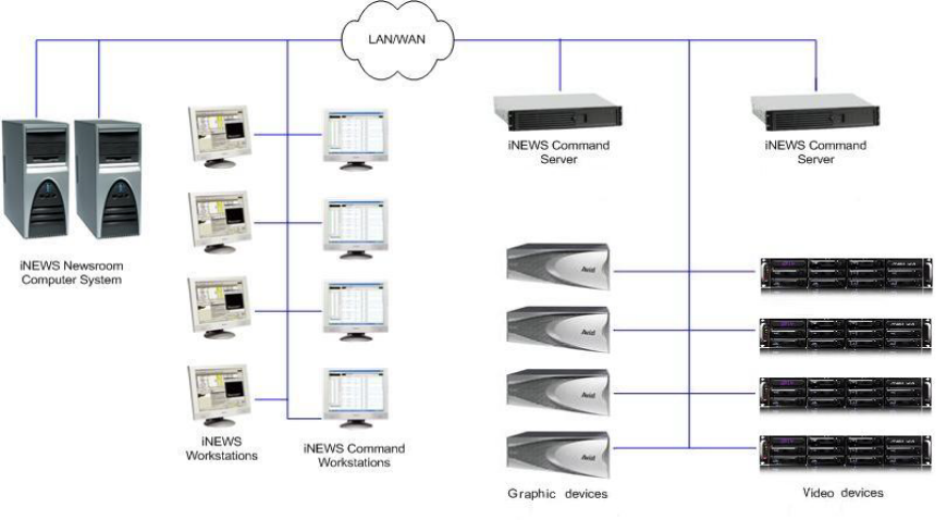
System Architecture
The basic iNEWS Command system is comprised of servers that run a variety of Command
services, workstations that run the client software, and devices, such as Avid AirSpeed video
servers, Thunder production servers, and Deko graphics systems.
Avid iNEWS Command is scalable and can adapt to work in traditional newsroom-based playlist
creation to production-centric workflows where running orders are created inside the iNEWS
Command playback application. All of the services can run on a single computer, or they can be
spread out across multiple computers with redundant services configured as backups to take
control if any or all of the primary services should become unavailable.
An example of a basic Command system architecture is shown in the following illustration:
Avid recommends having all primary Command services on one designated primary server with
the backup services running on other backup servers. Command determines primary and backup
roles based on the length of time the service has been running. The server that has been running
longer is the primary. Therefore, to get all primary services on one server, it is necessary to start
the primary server first; when all services have started, start the backup servers. This is the only
way to ensure all services on the primary server take on the primary role, which allows for more
consistent behavior during times when redundancy is needed, and it helps simplify any necessary
troubleshooting efforts.

Checklist: Before you Begin
19
Checklist: Before you Begin
Before you start to install software and configure the Command Server(s), ensure the following
tasks are completed.
Some Avid Interplay products, such as Instinct, Assist, and Access use Service Framework. Avid
iNEWS Command also uses Service Framework; however, the two versions might not be
compatible. Consult with Avid Customer Support to determine Service Framework compatibility
when Avid Interplay products are installed in the same workgroup. It might be necessary to:
Tasks
Assign a static IP address to each server.
If the server has dual network cards, you must disable the unused connection.
The Avid Service Framework relies heavily on DNS name resolution to discover and communicate
with Avid Service Framework and Command services.
Establish the DNS server and ensure all computers with Command services or applications
are entered in the DNS table with reverse lookup enabled.
Make sure that your TCP/IP settings have the correct primary and alternate DNS addresses.
Also, ensure the Advanced TCP/IP settings (on the DNS tab) are set to the following:
• The Append these DNS suffixes option is selected and the domain is listed, preferably
first.
• The Register this connection’s addresses in DNS check box is selected.
• (Optional) The Use this connection’s DNS suffix in DNS registration check box is
selected.
If Command will be used to control a third-party video device via VDCP, ensure that a serial card or
serial port server are used.
nFor version compatibility information, see the latest ReadMe available for your version of
Avid iNEWS Command.
Tasks
Use a separate workgroup for the Command system.
Install Command on separate machines that run Service Framework compatible with Command.

Checklist: Command Server Installation
20
Checklist: Command Server Installation
Determine which computer or computers will serve as iNEWS Command Servers and, if
installing on a redundant system, decide which one will run the primary services; you should
install on the primary server first, then the backup server(s).
nIf you want to copy the installation CD to a specified location on your network to alleviate or
reduce having to manually insert the CD into actual computers on site, see “Copying Install CD
to Local Directory” on page 22.
On the Command Server, complete the following tasks in the order that they are listed. If you are
viewing this checklist online, you can easily link to a topic that provides procedural details for
the task. Return to this main checklist after you have completed each task.
Tasks Refer to...
Install Avid Service Framework. “Installing Avid Service Framework” on page 24
Install the License service. “Installing the License Service” on page 31
Configure the License service. “Configuring the License Service” on page 35
Add temporary license. “Adding the Temporary Command License” on
page 35
Generate an activation file for a full license. “Generate an Activation File for a Full
Command License” on page 37
Add the permanent license. “Add the Permanent Command License” on
page 39
Install Avid iNEWS Command. For redundancy,
repeat this procedure on the second server.
“Installing Avid iNEWS Command on the
Server” on page 41
Configure the Command Server. “Configuring the iNEWS Command Server” on
page 47
nAll settings in Command and Service Framework are case sensitive. Ensure that case matches in all
configuration settings.
Set the system administrator password. “Configuring the System Administration
Password” on page 47
(Optional) Configure the Time
Synchronization service.
“Configuring the Time Synchronization
Service” on page 49
nInstallation and configuration of the Time Synchronization service only applies to sites that do not
already have a method for synchronizing PC clocks on the network.

Checklist: Command Server Installation
21
(Optional) Configure the Lookup tab in
Workgroup Properties.
“Configuring the Lookup Tab” on page 69
(Optional) Configure the system name. “Configuring a Second Command System” on
page 72
Configure the AirSpeed device services. “Configuring AirSpeed Device Services” on
page 70
Configure the Avid Video device services. “Configuring VDS for Omneon” on page 50
“Configuring VDS for VDCP” on page 58
nFor information on how to configure the Avid Video device service for the Harris NEXIO plug-in, see
the third-party documentation provided by the Harris Corporation.
(Optional) Configure the Interplay Agent
services.
“Configuring Avid Interplay Agent Services” on
page 62
(Optional) Configure the UMD device service
for Under Monitor Display or In Monitor
Display devices.
“Configuring the Avid UMD Device Service” on
page 65
Tasks Refer to...

Copying Install CD to Local Directory
22
Copying Install CD to Local Directory
The autorun feature on the Avid iNEWS Command installation CD enables you to copy all
necessary files to a local directory on your network. From that location, you can then access
product documentation and run the installer applications on computers across your local area
network.
To copy the CD to a local directory:
1. Insert the Command installation CD. The autorun installation program starts and displays
the following screen.
Copying Install CD to Local Directory
23
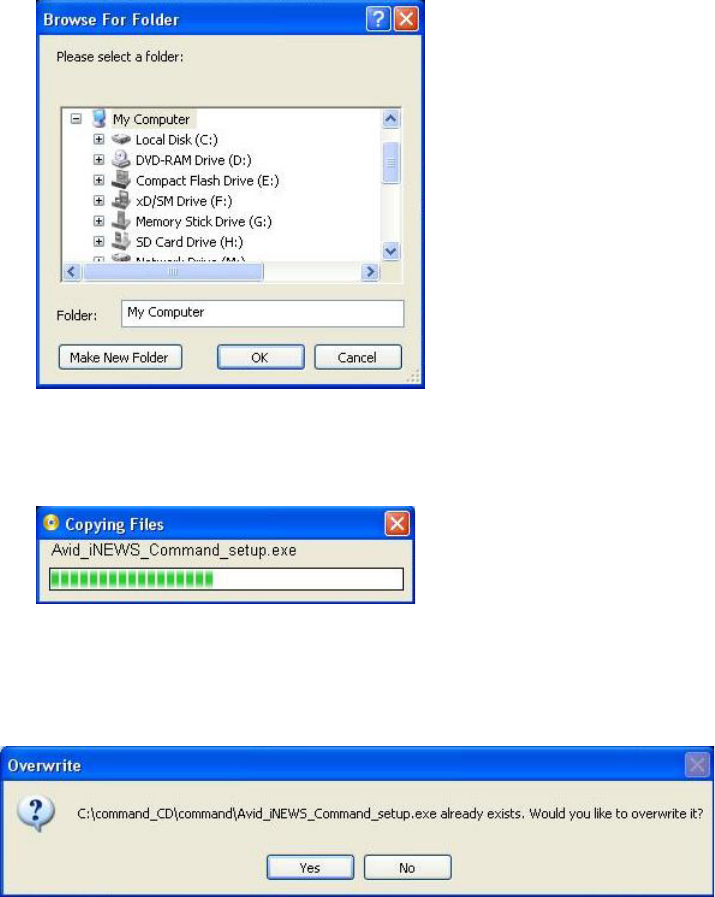
2. Click the Copy This CD To A Local Directory button.
The Browse For Folder dialog box appears.
3. Select a local directory. If one does not exist, you can make a new folder.
4. Click OK. A progress bar will appear as the files are copied.
nFor upgrades, some files might already exist on your computer. If so, a dialog box (like the one
shown below) will notify you of this and ask for your overwrite approval of existing files with
those on the CD.
5. When the Copy Complete dialog box appears indicating a successful copy, click OK.

Installing Avid Service Framework
24
Installing Avid Service Framework
Avid Service Framework consists of applications and services which provide dynamic discovery
and lookup mechanisms, a scalable notification system, a centralized configuration tool,
diagnostic logging for workgroup-enabled applications and services, system health monitoring,
and so on. Some of the services are known collectively as Support services. The Support services
are viewed, monitored, and configured using the Service Framework applications.
nAvid strongly recommends the installation of the Avid Service Framework applications, which
take up almost no space or overhead on the hard drive and can prove vital in troubleshooting
integration issues, etc.
Those most vital to iNEWS Command are:
Each computer (server and workstation) running Avid iNEWS Command software requires at
least the core components of Service Framework and must be able to connect to a computer
running the Avid Lookup service.
nAvid Service Framework and Avid iNEWS Command must be installed individually on each
computer; do not use drive image software as a substitute for installation. Avid does recommend
making a image of the hard drive after installation, but not before.
Major Services Description Server Workstation
Avid Lookup Service This service enables communication between all
Command and Framework services running in
the workgroup. Without it, there is no
communication between services. Only two
should be installed in a workgroup.
System Configuration This service sets the configuration settings for all
configurable services. The Avid Service
Configuration application is used to enter
configuration information that the System
Configuration service will carry out and set in
the registry. Without it, the workgroup cannot
function. Only two should be installed in a
workgroup.

Installing Avid Service Framework
25
To install the Avid Service Framework software:
1. Insert the Command installation CD (or access the install program from the network).
nWhen installing Service Framework on Command Servers, use only the installer provided on the
Command installation CD and not any other software DVD that might be supplied with other
Avid products, such as AirSpeed Multi Stream.
The autorun installation program starts and displays the following screen.
nThe Command Documentation button will open a window displaying the contents of the Doc
folder on the Command installation CD in which product documentation is provided in PDF
format.
If the autorun does not begin, manually navigate to and run the
ServiceFrameworkSetup.exe
install program.

Installing Avid Service Framework
26
2. Click the Avid Service Framework button.
nOther dialog boxes could appear depending on whether older versions of Service Framework,
the License service, or Command are found on the server, particularly if upgrading existing
software. If one appears, read it carefully and reply accordingly with regard to upgrades, etc.
A splash graphic will appear briefly as the installer prepares the InstallShield Wizard. Then
the Welcome dialog box appears.
Installing Avid Service Framework
27
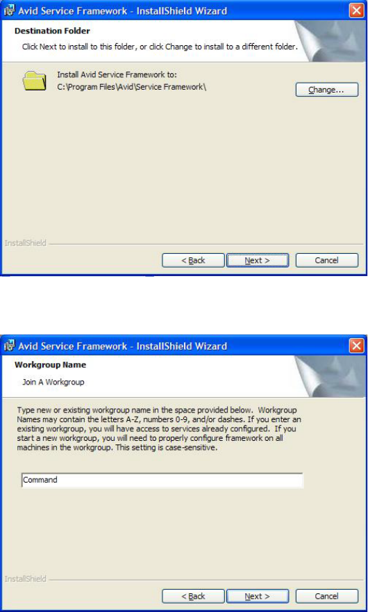
3. Click Next.
The Workgroup Name dialog box opens.
4. Set the location to which Avid Service Framework will be installed and click Next.
Installing Avid Service Framework
28
5. Type a new or existing workgroup name in the field.
n Do not install iNEWS Command in an Avid Interplay workgroup.
Because iNEWS Command is mission critical, Avid recommends you make it a separate
workgroup from any existing Interplay workgroups. Make a note regarding the workgroup
name so that it can be entered during other Avid Service Framework installations. You must
use the same workgroup name on all computers and devices that are connected in your
Command architecture. The workgroup name is case sensitive.
cIf you are updating the Service Framework software, the installer remembers the last
installed value. If the workgroup name was changed after the install, the installer will not
be aware of the change.
6. Click Next.
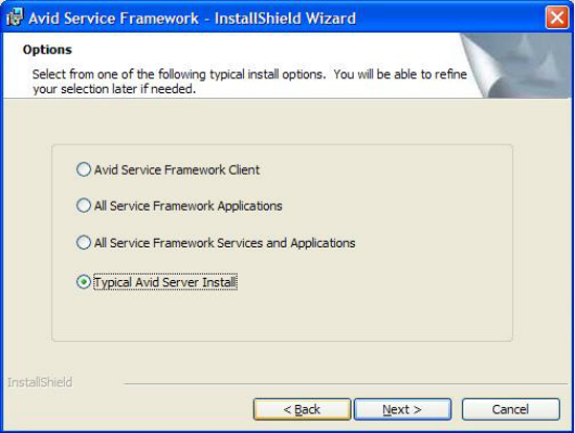
The Options dialog box opens.
Installing Avid Service Framework
29
7. Select the option: Typical Avid Server Install and click Next.
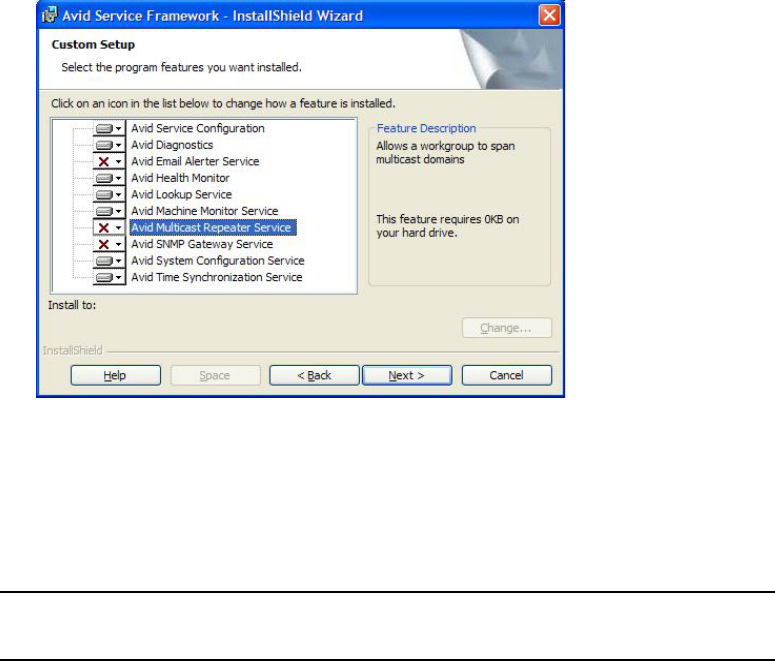
The Custom Setup dialog box opens.
On the Command Server, you must ensure the Lookup Service and System Configuration
are selected. For more information about them, see the table on page 24.
The following table includes additional applications and services that Avid strongly
recommends be installed on the server—since they do not take up any overhead and are
useful in troubleshooting situations.
Applications and
Services Description Server Workstation
Service Configuration This application is used to configure settings and
host names for Framework and Command
services in the workgroup. For instance,
configuring the Command system to work with a
GPI panel requires defining certain parameters
through the Avid Service Configuration
application. Avid recommends installing this
application on the Command Server.
Health Monitor This application allows you to see the status of
Command and Framework services health
statistics throughout the workgroup. Avid
recommends installing this application on the
Command Server.

Installing Avid Service Framework
30
The following table describes some minor services that are generally considered optional or
are not recommended at sites under certain circumstances. If concerned about overhead, you
should not install these services.
8. Click Next and follow the installation instructions to complete the installation.
nYou might be required to restart your system to complete the installation.
After installation, verify that the services are running on each computer where Service
Framework services were installed.
Diagnostics This application is used to view Avid log files
(
.alf
) when troubleshooting. Avid recommends
installing this application on the Command
Server.
Machine Monitor This service reports machine information to the
Health Monitor, including disk, memory, and
network status. You can also monitor specific
services on that local machine. Avid
recommends installing this service on the
Command Server.
Applications and
Services Description (Continued) Server Workstation
Minor Services Description
Email Alerter This service sends a notification email if one of the services in the
workgroup has a warning or critical status. It is seldom installed on the
Command Server.
SNMP Gateway This service provides an interface to send health monitoring information to
industry standard SNMP manager applications. It is seldom installed on
the Command Server.
Time Synchronization This service should only be installed if you do not already use something
to synchronize your PC clocks on the network. If you use NTP or some
other method for time synchronization, do not install this service.
cSerious problems can occur if more than one service for time
synchronization is installed.
Multicast Repeater This service is required only when a workgroup must span subnets or
domains. It is seldom installed on the Command Server.

Installing the License Service
31
Installing the License Service
The Avid License service manages the site licenses for Command Workstations as well as CG
and video devices that interface with the Command system.
This service must be installed on the computer running the Command Server software, but is not
necessary on any other computer; however, two instances of this service can be installed for
redundancy. Some configuration is required after installation.
To install the License service:
1. Insert the Command installation CD (or access the install program from the network).
The autorun installation program starts and displays the following screen.
nThe Command Documentation button will open a window displaying the contents of the Doc
folder on the Command installation CD in which product documentation is provided in PDF
format.
If the autorun does not begin, manually navigate to and run the
Avid_License_Setup.exe
install program.
Installing the License Service
32
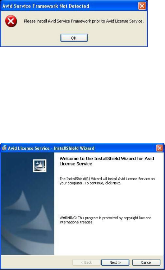
2. Click the Avid License Service button. If Avid Service Framework is not already installed, a
warning dialog box will appear.
If it does, click OK and install Avid Service Framework before restarting this installation.
See “Installing Avid Service Framework” on page 24 for more information.
nOther dialog boxes could appear depending on whether older versions of Service Framework,
the License service, or Command are found on the server, particularly if upgrading existing
software. If one appears, read it carefully and reply accordingly with regard to upgrades, etc.
If all prerequisite installations are in order, and the installation can proceed, a splash graphic
will appear briefly as the installer prepares the InstallShield Wizard.
Then the Welcome dialog box appears.
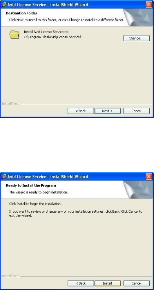
Installing the License Service
33
3. Click Next.
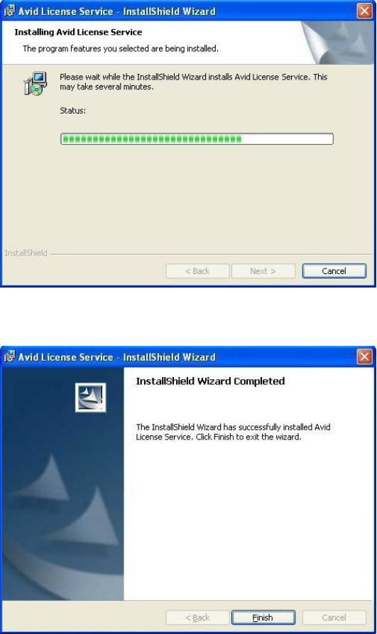
The Destination Folder dialog box appears.
4. Do one of the following:
tAccept the default location for the destination folder by clicking Next.
tClick the Change button to select a different location, then click Next.
The Ready to Install the Program dialog box appears.
Installing the License Service
34
5. Click Install.
A new dialog box will appear indicating the progress of the install.
6. When the InstallShield Wizard Completed dialog box appears, click Finish.
Installing the License Service
35
Configuring the License Service
After installing the service, some configuration is required, using the Avid Service Configuration
application. This application should already be installed on a PC on the same network, but might
not necessarily be installed on the same computer as the Command Server software or the
License service.
Configuring the Avid License service involves three tasks:
•Adding the Temporary Command License
•Generate an Activation File for a Full Command License
•Add the Permanent Command License
Adding the Temporary Command License
To get you started with Avid iNEWS Command, Avid provides you with a Command temporary
(TEMP) license to use until your get your full Command license.
To add the temporary license:
1. Save the license file to My Documents on the Command Server.
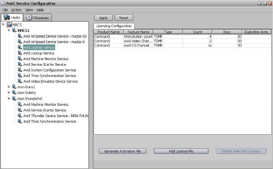
2. Open the the Avid Service Configuration application.
3. On the Hosts tab, navigate to and select the Avid License Service.
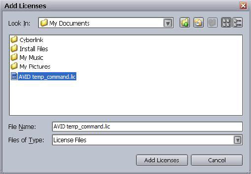
4. Click the Add License File button.
5. In the Add Licenses dialog box, select the license file and click Add Licenses.
Installing the License Service
36
Your license file information will appear.
6. Click Apply.
nThe temporary license Avid provides gives full Command functionality for thirty (30) days.

Installing the License Service
37
Generate an Activation File for a Full Command License
On systems with redundant configurations, the activation file for a full license must be generated
on the primary server.
To generate an activation file:
1. Open the Service Configuration application.
2. On the Hosts tab, navigate to and select the Avid License Service.
3. When prompted, enter the system administrator password and click OK. If you have not yet
created one, leave the space blank and click OK.
4. On the Allow Unrestricted Security dialog, click Yes.
Installing the License Service
38
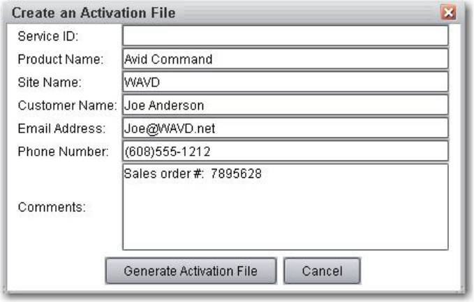
5. Click the Generate Activation File button.
6. Review and edit the required information, as well as contact information, if necessary. You
can also add comments.
nDo not remove any information that is already supplied in the fields.
7. Click the Generate Activation File button to create the
.act
file and select where you want
to save it on your PC.
8. Zip the file and then e-mail that
.zip
file to your respective Avid manufacturing site. Ensure
the subject line of the e-mail contains your site name and Command Activation File.

Installing the License Service
39
Add the Permanent Command License
To activate the full license:
1. When you receive your permanent
.lic
file from Avid, save it to My Documents on the
same Command Server where the activation file was created.
2. Open the Avid Service Configuration application.
3. On the Hosts tab, navigate to and select the Avid License Service.
4. When prompted, enter the system administrator password and click OK. If you have not yet
created one, leave the space blank and click OK.
5. On the Allow Unrestricted Security dialog, click Yes.
6. Select an existing TEMP license and click Delete Selected Licenses. Repeat until all of the
TEMP licenses are gone.
7. Click the Add License File button.
The Add Licenses dialog box appears.
Installing the License Service
40
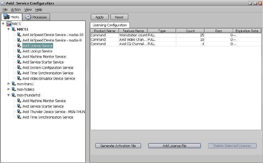
8. Select the full Command license file, and click Add Licenses.
Your licensing configuration details will appear.
9. Click Apply.
nTo verify that an installed service is running, you must use the Avid Workgroup Properties
application.

Installing Avid iNEWS Command on the Server
41
Installing Avid iNEWS Command on the Server
This section contains the procedure for installing the Command Server software, along with
some device services that must run on the server, if used with specific devices, such as Avid
AirSpeed video servers or third-party video devices controlled via VDCP.
nIf you are upgrading, open Avid Workgroup Properties and stop all services first and then close
the application when you’re done.
To install the software on a Command Server:
1. Insert the Command installation CD (or access the install program from the network).
The autorun installation program starts and displays the following screen.
nThe Command Documentation button will open a window displaying the contents of the Doc
folder on the Command installation CD in which product documentation is provided in PDF
format.
Installing Avid iNEWS Command on the Server
42
2. Click the Avid iNEWS Command button. If Avid Service Framework is not already
installed, a warning dialog box will appear.
If it does, click OK and install Avid Service Framework before restarting this installation.
See “Installing Avid Service Framework” on page 24 for more information.
nOther dialog boxes could appear depending on whether older versions of Service Framework,
the License service, or Command are found on the server, particularly if upgrading the
Command Server software. If one appears, read it carefully and reply accordingly with regard to
upgrades, etc.
If all prerequisite installations are in order, and the Command Server installation can
proceed, a splash graphic will appear briefly as the installer prepares the InstallShield
Wizard. Then the Welcome dialog box appears.
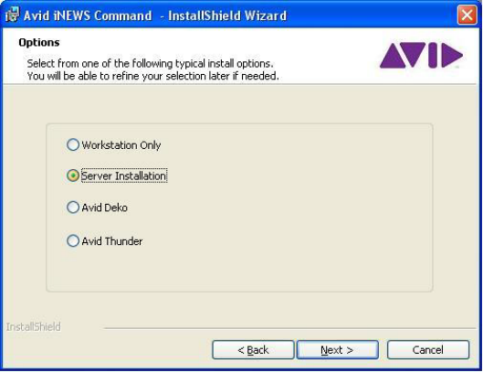
3. Click Next. The License Agreement appears.

Installing Avid iNEWS Command on the Server
43
4. Read the License Agreement, accept the terms, and click Next.
nYou can print the terms if you want to read them later or keep a copy for your records. If you do
not accept the terms, the installation program will not continue.
The Destination Folder dialog box opens.
5. Do one of the following:
tClick Change to designate an install directory, and then click Next.
tAccept the default location by clicking Next.
Installing Avid iNEWS Command on the Server
44
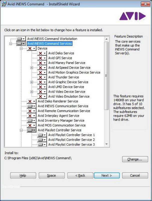
The Options dialog box opens.
6. Select Server Installation and click Next.
Installing Avid iNEWS Command on the Server
45
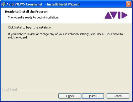
7. The Custom Setup dialog box appears with the default services selected for a server
installation. However, you can modify the selections to customize your installation. To learn
more about a service, click any service listed and view a Feature Description provided along
the right side of the dialog box.
nAvid recommends installing the Avid iNEWS Command Workstation software on the server as
well, because it can be useful in some troubleshooting situations.
Installing Avid iNEWS Command on the Server
46
If installing Avid iNEWS Command to interface with a MOS-based newsroom computer
system, such as ENPS, you must select Avid MOS Communication Service and deselect
Avid iNEWS Communication Service.
If your site intends to use Avid iNEWS Command tablet application on the iPad, ensure the
Avid Remote Communication Service is selected for installation. For more information, see
“Installing and Configuring the Tablet Application” on page 233.
If your site intends to control third-party video device(s) via VDCP, ensure that the Avid
Video device service is selected for installation. Add one for each device—up to ten possible
per server—by clicking the plus [+] next to that service and selecting more. By default, this
device service is not installed with the Perle IOLAN TCP/serial port server. Command
supports full redundancy with VDCP.
If your site intends to view thumbnails of media items, such as graphics from an Avid Deko
or video from Avid AirSpeed video servers, ensure that either or both of the following
services are installed:
- For thumbnail integration with an Avid AirSpeed and thumbnail/metadata integration
with third-party video servers, install the Avid Interplay Agent service. This service will
require some configuration after installation on each Command Server. For more
information, see “Configuring Avid Interplay Agent Services” on page 62.
- For thumbnail integration with an Avid Deko, install the Avid Deko Renderer service.
By default, this service is pre-configured to automatically locate the DekoMOS
Gateway on the network. You can verify the setting via the Avid Service Configuration
application. For more information, see the Avid iNEWS Command Administration
Guide.
By default, these two services are not installed.
nThe Deko Renderer service does not take up a HASP license seat.
Configuring the iNEWS Command Server
47
8. Click Next.
9. When the Ready to Install the Program dialog box appears, click Install.
10. When the installation is complete, click Finish.
To verify that installed services are running, you must use the Avid Service Framework
Workgroup Properties application.
Configuring the iNEWS Command Server
After installation, some configuration is required on each iNEWS Command Server. This section
covers defining the password for system administrators, configuring the system name, and some
services—such as the Time Synchronization and AirSpeed device services.
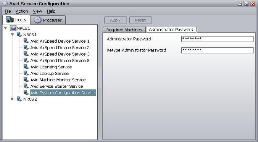
Configuring the System Administration Password
Modifying system settings in Avid iNEWS Command requires an administrator password (if
set), which is configured through the Service Configuration application of Avid Service
Framework.
Configuring the iNEWS Command Server
48
To change or set up the system administration password:
1. Click the Start button, and then select All Programs > Avid > Service Framework > Avid
Service Configuration.
2. On the Hosts tab, navigate to and select the Avid System Configuration Service.
3. Select the Administrator Password tab.
4. Type in an alphanumeric password and retype it.
5. Click Apply.
nClick the Reset button to restore to password to the default “blank” password.
Configuring the iNEWS Command Server
49
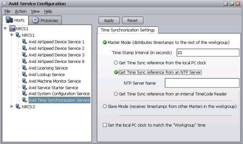
Configuring the Time Synchronization Service
This service should only be installed and configured if you do not already use something to
synchronize your PC clocks.
To configure the Time Synchronization service:
1. Click the Start button, and then select All Programs > Avid > Service Framework > Avid
Service Configuration.
2. On the Hosts tab, navigate to and select the Avid Time Synchronization Service.
3. When prompted, enter the system administrator password and click OK. If you have not yet
created one, leave the space blank and click OK.
4. Select the Master Mode check box.
5. Select the Get Time Sync reference from an NTP Server check box and enter the name of
that server on your system.
6. Click Apply.
nAfter you configure the Time Synchronization service on the primary Command Server, you will
need to install the service on all other Command Servers, workstations and devices, which will
be in Slave Mode by default.
Configuring the iNEWS Command Server
50
Configuring Avid Video Device Services (VDS)
The Avid iNEWS Command user interface lets you integrate with some third-party video devices
via the network or via Video Disk Control Protocol (VDCP). For this integration to work,
however, some configuration of the device service is required, which varies depending on the
type of integration. The following sections contain information related to Command integration
with Omneon or Harris devices, as well as others that use VDCP.
Because VDCP does not support metadata, all of the information (item slug, date, etc.) is stored
within the iNEWS Command system.
• Command sets the Last Modified date to the date that the item first appears in Command.
• Command lets users edit the item’s slug.
• If the item’s slug is blank, Command copies the item’s ID to the Slug field.
Configuring VDS for Omneon
The Avid Video device service has a plug-in that allows for network-based control of Omneon
Spectrum and Media Deck. Selecting the Omneon plug-in also means that the Video device
service is fully redundant, like other Command services.
For the plug-in to work, however, some configuration is required, using the Avid Service
Configuration application of Avid Service Framework. For more information about this
application, see the Avid Service Framework User’s Guide.
To configure the Avid Video device service for Omneon network control:
1. Click the Start button, and then select All Programs > Avid > Service Framework > Avid
Service Configuration.
2. On the Hosts tab, navigate to and select the Avid Video Device Service.
3. When prompted, enter the system administrator password and click OK. If you have not yet
created one, leave the space blank and click OK.
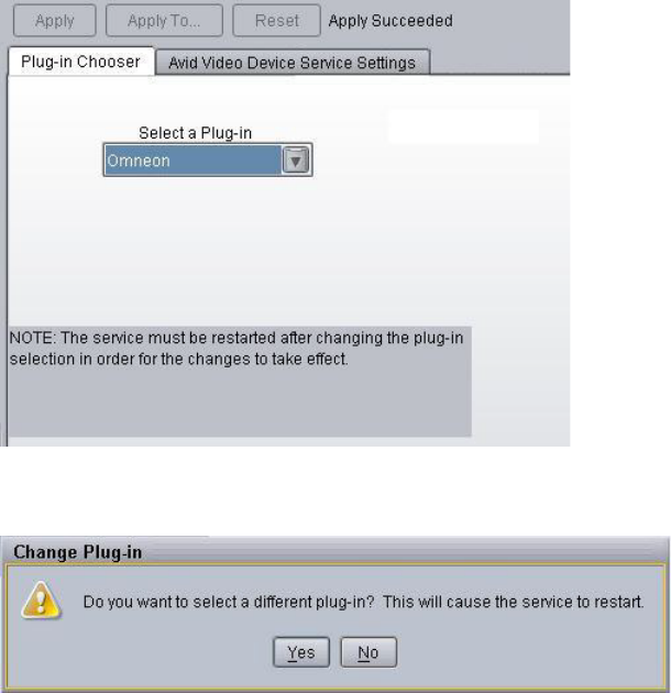
Configuring the iNEWS Command Server
51
4. On the Plug-in Chooser tab, select the Omneon plug-in and click Apply. By default this
selection is set to none.
5. Click Apply. The Change Plug-in dialog box will appear.
6. Click Yes. This will restart the device service.
cAfter you select a plug-in, you must click Apply and let the service restart before
proceeding.
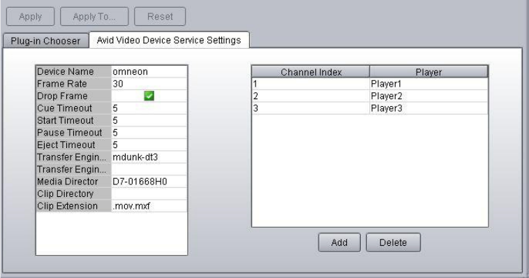
Configuring the iNEWS Command Server
52
7. On the Avid Video Device Service Settings tab, enter the name of the device, which must
match the name used for the device channel in the Command system settings.
8. Set the Frame Rate accordingly, and leave the Drop Frame check box selected.
nThe Frame Rate setting is a default; it is displayed whether the Video device service (VDS) is
using the default VDCP mode or using a plug-in. It will be displayed in the Omneon VDS plug-in
configuration, but is not used because VDS gets the frame rate from the player to which it is
connected.
9. Set timeout in seconds for cue, start (play), pause, and eject.
10. Transfer Status is a feature that only works with Interplay. It connects to the Interplay
Transfer Manager to monitor status. Select the check box only if this is the case with your
system. For more information, see “Transfer Status Icon” on page 62.
11. Enter the machine name or IP address of the Omneon’s Media Director. This information is
obtainable via the Omneon System Manager software.
12. Leave the Clip Directory field blank to accept the default or enter another pathname for the
directory that will hold all of the media clips. An example of the clip directory is:
/OMN/clip.dir
.
13. Omneon usually stores clip information in MOV or MXF formats. The extension for the
default format is
.mov.mxf
so that either format is recognized.
Configuring the iNEWS Command Server
53
14. Edit and add channel indices accordingly:
- The first channel index will appear automatically with the player information filled in,
but it can be modified as needed. The channel index values must match the channel
index value when you add the device channel in Command. Command is case sensitive,
so the case must match exactly.
- Enter the name for each player. This information is also obtainable via the Omneon
System Manager software.
- Use the Add button to add more. To change a setting, click on it and select the proper
index being used from the list that appears.
15. Click Apply and then click Yes when asked to restart the device service. You can then close
the Avid Service Configuration application.
nFor a redundant configuration, you can apply these settings to the second device service by
clicking the Apply To... button. If the Apply To... button is dimmmed, make a bogus change, such
as adding a splace to a setting and deleting it, and then moving to a different field. Then click the
Apply To... button and navigate to the second device service.
16. Confirm configuration by viewing the service in Health Monitor. The service will appear
connected with a green checked icon displayed when it is working properly.
nIf using the Avid Video device service to control an Omneon, and if you want to use Command’s
system setting, Hold Last Frame—the default for which is five seconds—you must configure the
setting, Advance-to-Cued, to zero on the Omneon device. Avid also recommends setting Last
Frame Freeze to zero because Command sets that time period.
After the Video device service has been configured, you must add device channels and
channel groups in Command. This can be done from a Command Workstation.
To add device channels and channel groups for Omneon integration:
1. At a Command Workstation, click Tools > System Settings. The System Settings dialog box
appears.
2. Expand Channel.
3. Select Device Channels.
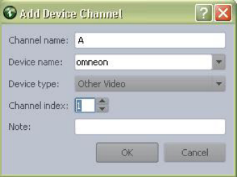
Configuring the iNEWS Command Server
54
4. Click Add.
5. Enter the channel’s name.
6. Enter the device’s name. This name must match the device name that was entered during
configuration of the Video device service.
7. For Device type, select Other Video.
8. Set the Channel Index to 1, 2, or 3, depending on which player you are controlling.
9. (Optional) Add notes.
10. Click OK. The Add Device Channel dialog box closes. Repeat these steps to add more
device channels.
11. On the System Settings dialog box, click Apply so that you can add the new device channels
to a channel group.
12. On the left side of the System Settings dialog box, select Group.
13. Click Add to create the channel group.
14. Enter the name of the channel group.
15. Click Add and select the appropriate channel. Repeat as necessary.
16. Click OK, and then OK again to save the settings.
17. Create a standalone playlist, add items, and test playout to confirm functionality.
With Omneon network control, Command users can make subclips. The subclip feature will
create a new media item on the Omneon video server. It is not a master clip with specific
pointers.
Configuring the iNEWS Command Server
55
To create a subclip:
1. At a Command Workstation, open an item in the Media Viewer.
2. Click the Subclip button.
3. Give the subclip a name and click OK. It should appear in the Inventory panel shortly.
nThe Subclip button will appear when controlling other devices via the Video device service, but
only functions when creating subclips on an Omneon device.
Configuring Video Setup for GVG K2 Servers using AMP Protocol
Command supports the GVG AMP protocol for controlling playout of Grass Valley video
servers.
nThe AMP protocol does not support the Delete Protect feature. The right-click menu will reflect
this in 3.1, but not in 3.0.1.
To configure video setup for GVG K2 servers using AMP protocol:
1. Open Avid Service Configuration.
2. On the left side, select the respective Video Device Service.
3. On the Plug-in Chooser tab, select the GVG AMP plug-in in the selection box, and then
click Apply.
4. When the restart dialog appears, click Yes. After the service restarts, you need to configure
the plug-in.
5. Select the service again, and then select the Avid Video Device Service Settings tab.
6. Enter the Device Name, which must match the device name used in the Command System
Settings.
7. Enter the host name or IP.
8. If the folder is different from the default, change the Folder to the correct path.
9. Click the Add button to add channels. The (left) Channel Index is automatically populated.
10. In the Channel column, enter the K2 channel number.
nThe value in the Channel column can only be 1-4, corresponding to the respective Player on the
K2.
nThe Channel Index and Channel columns do not need to be equal. For example, if Command is
only controlling the 3rd and 4th channels of the K2, you only need to add 2 channels – and enter
3 and 4 for the Channel values, corresponding to Channel Index 1 and 2.
11. (Optional) when connecting to a transfer engine, add the machine name.
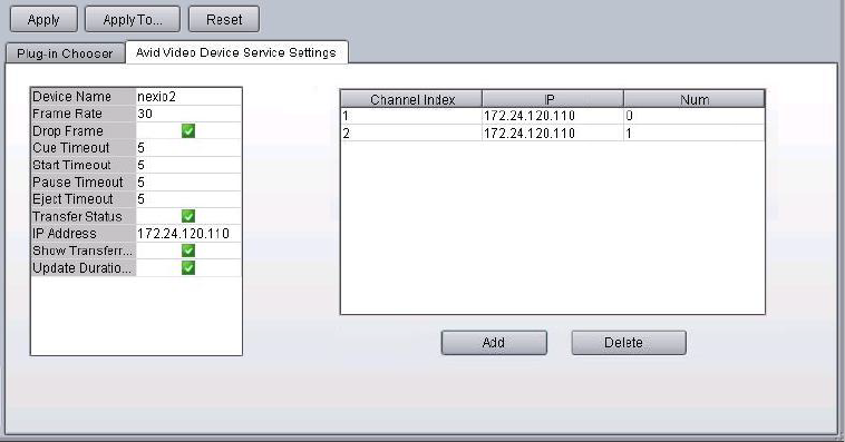
Configuring the iNEWS Command Server
56
12. The remaining settings should be left as they are
13. Click Apply, and click Yes on the restart dialog message.
14. Configure the Device Channels and Channel Groups in the Command System Settings.
nShutting down the K2 user interface ejects any cued or playing clips, but the items will not show
correct transport status in Command. Command will not report CHANNEL DOWN. The K2 has
a service called the AppService that will continue to facilitate communication between
Command and the K2, but items will need to be recued before then can be played. After the
connection is down, such as when the device is restarted, Command checks for the connection
every minute.
Configuring VDS for Harris
Like Omneon, there is a third-party plug-in that can be used for Command integration with a
Harris Nexio device. The Harris plug-in is distributed by the Harris Corporation; users should
contact the Harris Corporation for more information.
nAs with all third-party devices, users need to purchase a 3P device channel for each channel that
is going to be controlled by Command.
For the plug-in to work, some configuration is required, using the Avid Service Configuration
application of Avid Service Framework. The following graphic shows sample settings for the
Avid Video device service with the Harris plug-in chosen.
nFor detailed information on how to configure the Avid Video device service for the Harris NEXIO
plug-in, see the third-party documentation provided by the Harris Corporation.
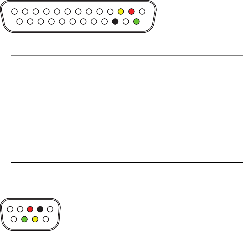
Configuring the iNEWS Command Server
57
Wiring Serial Connections for Avid Video Device Services (for VDCP)
Before configuring Command for VDCP control, ensure the serial cables are correct, according
to the specifications provided in this section. The external connector and cable are customer
supplied. A shielded cable must be used on the connector to maintain RFI compliance. The
shield of the cable should be connected to the connector’s shield or shell.
This table is for cabling with a 25-pin, female-ended connector (shown) to the Digi Acceleport
RS422 card on the Command Server via the “octopus” cable:
This table is for cabling with a Sony-standard, 9-pin, male-ended connector (shown) to the video
server:
113
1425
Pins # Wire Color Signal
1 Not used —
2RedTxD+
3 Yellow RxD+
4 - 13 Not used —
14 Green TxD-
15 Not used —
16 Black RxD-
17 - 25 Not used —
15
69

Configuring the iNEWS Command Server
58
nVideo pinouts are manufacturer specific, but in all tested devices, they used the Sony standard
wiring provided in this section.
For serial connections not specifically covered in this section, the follow table applies:
Configuring VDS for VDCP
For integration with third-party video devices that use VDCP, it’s important to confirm that the
device is set to VDCP control.
To configure the Avid Video device services:
1. Click the Start button, and then select All Programs > Avid > Service Framework > Avid
Service Configuration.
2. On the Hosts tab, navigate to and select the Avid Video Device Service.
3. When prompted, enter the system administrator password and click OK. If you have not yet
created one, leave the space blank and click OK.
Pins # Wire Color Signal
1 Not used —
2BlackRxD-
3RedTxD+
4 - 6 Not used —
7 Yellow RxD+
8 Green TxD-
9 Not used —
DB-25 Video Server
Rx+ Tx+
Rx- Tx-
Tx+ Rx+
Tx- Rx-
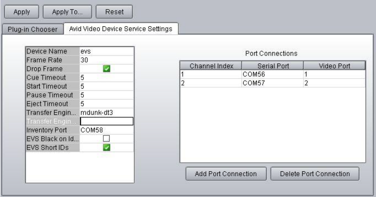
Configuring the iNEWS Command Server
59
4. On the Avid Video Device Service Settings tab, enter the name of the device, which must
match the name used for the device channel in the Command system settings.
5. Set the Frame rate accordingly, and leave the Drop Frame check box selected.
6. Set timeout in seconds for cue, start (play), pause, and eject.
7. Transfer Status is a feature that only works with Interplay. It connects to the Interplay
Transfer Manager to monitor status. Select the check box only if this is the case with your
system. For more information, see “Transfer Status Icon” on page 62.
8. An inventory port is mainly used to create standalone playlists, or to view items in the
Inventory panel at a Command Workstation. Enter a COM port if you want to use one port
for inventory. Leave it blank if you want to use all available channels for playback.
nIf the Avid Video device service is configured with playback channels only (no inventory port),
you will not see the device’s playback inventory in the Inventory panel at a Command
Workstation. Despite this, the playlist in Command will still reflect inventory status, and an
unavailable item promptly changes to available once it is transferred to the device.
9. Edit and add port connections accordingly:
- The first channel index will appear automatically with the port information filled in, but
it can be modified as needed. The channel index values must match the channel index
value when you add the device channel in Command.
- Use the Add Port Connection button to add more port connections. To change a serial
port setting, click on it and select the proper port being used for serial control from the
list that appears.
Configuring the iNEWS Command Server
60
For instance, if the serial cables are connected to the first three ports (P1,P2, and P3),
these would correspond to COM 3, COM 4, and COM 5. The Windows operating
system uses COM 1 and COM 2 by default.
- To change a video port setting, click on it and type a new value. Typically, video ports
are set to 1, 2, 3, and 4.
10. Click Apply. You can then close the Avid Service Configuration application.
11. Click the Start button, and then select All Programs > Avid > Service Framework > Avid
Workgroup Properties.
12. Click the Advanced button.
13. After the Avid Services dialog box opens, select the device, then stop and restart it.
14. Confirm configuration by viewing the service in Health Monitor. The service will appear
connected with a green checked icon displayed when it is working properly.
Configuring VDS for Slugs and Thumbnails in Non-Interplay Systems
Command supports slug and thumbnail handling for non-Interplay systems. Command has
adopted the Adobe XMP standard, which allows the editor to put the slug and thumbnail into an
.xml file. The following applies:
• The .xml file must have the same file name as the video file. For example, if the video ID is
012912TR5, the xml file needs to be 012912TR5.xml.
• Command parses the <dc:title> field as the slug.
• Although the XMP format can contain more than 1 thumbnail, Command only supports 1
embedded thumbnail. The thumbnails are contained in the <xmp:Thumbnails> element,
which has an <rdf:Alt> child element, which in turn has one or more <rdf:li> child elements,
which in turn has several child elements that specify the size, format, and binary data of the
thumbnail. The format must be JPEG.
• Command ignores the <dc:identifier> field. Command uses the file name to determine the
item ID.
nThe Command Video Device Service has a new field in the configuration that allows you to enter
a UNC FTP, or drive letter path, which it will then monitor for changes.
To configure the Avid Video device services for slugs and thumbnails:
1. Click the Start button, and then select All Programs > Avid > Service Framework > Avid
Service Configuration.
2. On the Hosts tab, navigate to and select the Avid Video Device Service.
Configuring the iNEWS Command Server
61
3. In the XMP Path field, add the UNC path to the location where the .xml files are stored.
A UNC path must start with a double backslash. For FTP, use the normal syntax -
ftp://username:password@hostname:port/path.
4. Click in a different field, and then click Apply.
nThe Video Device Service only needs read access to the directory.
5. When the restart dialog appears, click Yes to restart.
Once this is complete, editors should create the .xml file and save it in the specified location.
It is not necessary to create the video file first – files can be added or edited in any order.
Command will monitor the location for changes to any files, and update its slug and
thumbnail as necessary.
Configuring Redundancy for VDCP
Command supports full redundancy with VDCP control via the Perle IOLAN TCP/serial port
server. Avid recommends this method for VDCP redundancy. See “Configuring the Perle
IOLAN Server” on page 306 for more information.
For sites still using serial cards, you can use mirrored playback to achieve redundant
functionality for devices with VDCP control.
To configure VDCP devices for redundant mirrored playback:
1. Install and configure the VDS that controls the primary device channels of the primary
Command Server.
2. Install and configure the VDS that controls the mirrored device channels on the backup
server.
nThe mirror VDS should use a different device name, such as device2, from the primary VDS. The
mirror VDS will run as an active primary service, even though it’s running on the backup server.
3. In the event of a primary server failure, users should switch to mirror-only playback.
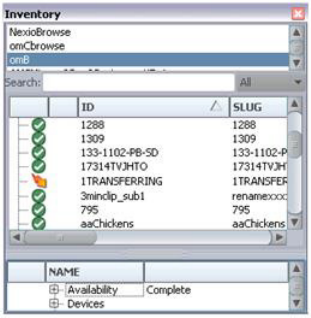
Configuring the iNEWS Command Server
62
Transfer Status Icon
Command can show the transfer status of items that are sent to playback from Interplay.
Command displays the transfer status icon—an orange arrow—in the Inventory panel to denote
that the item is transferring.
This integration requires the following:
• Interplay Transfer Manager, using the Send to Playback feature.
• The Transfer Manager be entered in the configuration of the Avid Video device service.
To see the transfer status icon, the user needs to have the Inventory panel open and the correct
channel group selected at a Command Workstation.
nThe Harris plug-in also has a Transfer Status checkbox, but it works differently. The Harris
NXOS manages transfer status without involvement from Interplay.
Configuring Avid Interplay Agent Services
The Avid Interplay Agent service is installed at sites that want to utilize thumbnail images in
Command from video on AirSpeed or third-party video servers. It connects and logs in to the
Interplay engine to retrieve thumbnail images and also collects slugs (title) and format
information in the Command playlist.
After the service is installed on the Command Server, some additional configuration is required,
using the Avid Service Configuration application of Avid Service Framework. For more
information, see the Avid Service Framework User’s Guide.
nOn systems with multiple Command Servers, you must configure the Avid Interplay Agent service
on each of them.
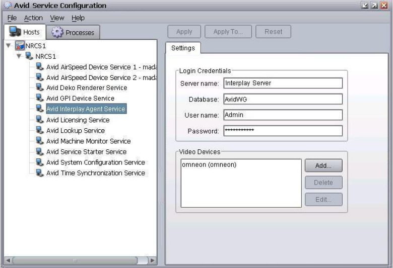
Configuring the iNEWS Command Server
63
To configure the Interplay Agent services:
1. Click the Start button, and then select All Programs > Avid > Service Framework > Avid
Service Configuration.
2. On the Hosts tab, navigate to and select the Avid Interplay Agent Service.
3. When prompted, enter the system administrator password and click OK. If you have not yet
created one, leave the space blank and click OK.
4. If the Allow Unrestricted Security dialog box appears, click Yes.
5. On the Settings tab in the Login Credentials section, enter the following information:
a. Server Name - This is the name of the asset manager server also known as the Interplay
Server running the Interplay Administration application.
b. Database - By default, this is AvidWG. It is the asset manager project. You can obtain
the name of the project database via the Interplay Administration application on the
Interplay Server.
c. User Name - This should be the Avid Interplay administrator’s user name, not the
Command administrator’s user name.
d. Password - This should be the Avid Interplay administrator’s password, not the
Command administrator’s password.
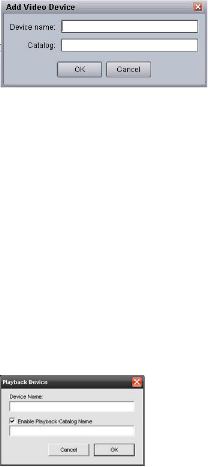
Configuring the iNEWS Command Server
64
6. In the Video Devices section, click Add. The Add Video Device dialog box appears.
nAdding a video device is not necessary when integrating with an AirSpeed video server.
7. Enter the device’s name exactly as it appears in the Avid Video device service.
8. In the Catalog field, enter the name of the folder (inside the Catalogs folder) where items are
being transferred to in Interplay. This should match the playback catalog in the Avid
Transfer Engine. If the destination folder is more than one layer deep, use a forward slash (/)
as the directory separator, such as omneoncat/1A. You do not need to specify the Catalogs
folder itself.
nIf the playback catalog is not already configured, it must be set up correctly via the Tranfer
Engine Configuration application, which runs on the Transfer Engine Server. The procedure for
this is provided next.
9. Click OK.
10. Click Apply. You can then close the Avid Service Configuration application.
To configure the playback catalog on the Transfer Engine Server:
1. Start the Transfer Engine Configuration application.
2. In the Playback section, click Add. The Playback Device dialog box appears.
Configuring the iNEWS Command Server
65
3. Select the Enable Playback Catalog Name check box and, in the text field below that, enter
the same destination folder used to configure the Interplay Agent device service, such as
omneoncat/1A.
nThe device name in the Playback Device dialog box is not the same as the Interplay Agent device
name. This one is specific to Transfer Manager.
4. Click OK.
Configuring the Avid UMD Device Service
The Avid iNEWS Command user interface lets you control Under Monitor Display (UMD) or In
Monitor Display (IMD) devices via the TSL UMD protocol, developed by Television Systems
Limited, so that the clip’s title, the countdown timecode—the one showing the remaining
duration—and the tally light for playing video can be displayed on or near the video monitor in
the control room. Without the Avid UMD device service and Avid’s TSL plug-in, the timecodes
for playing video appear only on the Command Workstation.
In general, the device service communicates through a third-party intermediate device, such as
TallyMan manufactured by Television Systems Limited. With the TallyMan, one cable is run to
the TallyMan and other cables run from it to each UMD.
The Avid UMD device service, along with Avid’s TSL plug-in, is installed from the Command
installation CD on the iNEWS Command Server. For more information, see “Installing Avid
iNEWS Command on the Server” on page 41. After installation, additional configuration of the
device service is required, using the Avid Service Configuration application of Avid Service
Framework. For more information about this application, see the Avid Service Framework User’s
Guide. Configuration of the device service is covered in the following procedure.
To configure the Avid UMD device service(s):
1. Click the Start button, and then select All Programs > Avid > Service Framework > Avid
Service Configuration.
2. On the Hosts tab, navigate to and select the Avid UMD Device Service.
3. When prompted, enter the system administrator password and click OK. If you have not yet
created one, leave the space blank and click OK.
nAvid’s TSL plug-in is preselected for you on the Plug-in Chooser tab.
4. On the Avid UMD Device Service Settings tab, the Service Name should be set to a unique
name that represents the current instance of the device service. By default, it first appears as
Service Name.
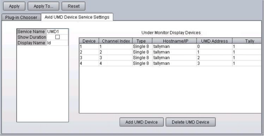
Configuring the iNEWS Command Server
66
5. The Show Duration check box determines if the duration of a clip is displayed when a clip is
cued. For 8-character displays, if Show Duration is left unchecked, the clip’s title or ID is
displayed as determined in the step 6. If Show Duration is selected, then instead of the clip’s
title or ID, the total clip duration is shown in an abbreviated timecode format (hh:mm:ss with
no frames) when a clip is cued.
For 16-character displays, the clip’s title or ID are always shown. So, if Show Duration is
left unchecked, the full 16 characters are used to display the clip’s title or ID. If Show
Duration is selected, then an abbreviated timecode in the format mm:ss is shown (or
hh:mm:ss if needed for clips longer than an hour) along with a shortened version of the clip’s
title or ID. The two are separated by one space.
Configuring the iNEWS Command Server
67
6. Select the Display Name. Options are: Title or ID. If Title is chosen, and Show Duration is
not selected, then the clip’s title will be displayed when a clip is cued. If ID is chosen, and
Show Duration is not selected, then the clip’s video ID will be displayed when a clip is cued.
nWhen a clip title is displayed, only the rightmost eight characters show up in an 8-character
display, so if the clip’s title is longer than 8 characters it will be truncated. Generally the
rightmost characters will be more unique, making it easier to identify the clip. There is no
indication when a clip’s title is truncated.
For 16-character displays, the number of characters is determined by whether the duration is
shown and the length of that duration. For instance, you could see 10 characters of either the
clip’s title or video ID followed by a space and the duration in an mm:ss format, as shown in the
following example: p-politics 01:32
If the clip’s duration is longer than an hour, the duration will appear as hh:mm:ss, and the clip’s
title or ID will be truncated to eight characters.
7. For every under monitor display you want to operate, click Add UMD Device to add a new
row to the table from which you can then edit the information in each column. Each device is
assigned its own device number; that is, the Device column is filled out automatically,
starting with one (1), and is not used in the service’s configuration.
8. The Channel Index lets you associate a device with a device channel index in Command.
Options in this drop-down list include numerical values of one (1) through 16. The channel
index, which corresponds to a playout channel, is set in Command’s System Setting dialog
box under the Channel > Indices category. You can access that dialog box by clicking Tools
> System Settings.
nFour columns shown in the previous graphic (Type, Hostname/IP, UMD Address, and Tally)
relate to the TSL plug-in. If an alternative third-party plug-in is used, what you see might vary.
9. Set the Type according to what kind of UMD device you are using. The Type column can be
set to one of three options:
tSingle 8 for 8-character display
tDual 8 Left for 16-character display, access leftmost 8 characters
tDual 8 Right for 16-character display, access rightmost 8 characters
tSingle 16 for 16-character display
10. The Hostname/IP column is most commonly set to tallyman, but can be an IP address
instead of the device’s hostname. The device service uses port 8900 by default; however, if a
different port needs to be specified, you can add it to the end of the hostname, such as
tallyman:1001.
Configuring the iNEWS Command Server
68
11. The UMD address can be set to numerical values of zero (0) through 126. When using
TallyMan, except for Dual 8 Left and Dual 8 Right types, which share an address, each
UMD device should have a unique address.
nIf you do not know the UMD address for your device, unplug and reconnect the Ethernet
connection. Watch the device’s display; it will show its UMD address as Addr plus a numerical
value, such as: Addr 001.
12. The Tally column is a drop-down list that relates to tally indicator control for Command. Its
options are: one (1) through two (2). UMD devices often have two tally indicator lights. If
set to one, Command will use the left light. If set to two, the right tally light is used. For
TallyMan, however, you will have to choose which light to use when you set up the
TallyMan.
13. Click Apply. You can then close the Avid Service Configuration application.
nYou can reconfigure UMD devices without having to restart the device service.
Configuring UMD for Redundancy
The Avid UMD device service supports redundancy, but some configuration is required.
To configure for redundancy:
1. Configure both device services to have the same service name, such as UMD1.
2. Restart the services. After the service name is set, it should not be necessary to restart
services for the remaining changes to occur; clicking Apply is all that is necessary.
3. Configure the remaining fields on the primary service and click Apply.
4. Make a bogus change, such as adding a space after the host name and then removing it.
5. Click the Apply To button and check the backup device service.
nFor Ethernet control and redundancy to work, you must upgrade the Tallyman TM1 device’s
software to version 1.7.4 and then configure it for Ethernet control. Please see Tallyman
documentation for more information. Avid also recommends the Tallyman device be in the same
subnet as the Command Server, to minimize the possibility of lost packets.

Configuring the iNEWS Command Server
69
Configuring the Lookup Tab
If setting up redundant systems that are in different subnets, you must add both server names to
the Lookup tab in Avid Workgroup Properties. The following procedure should be completed on
both the primary and backup Command Servers.
To configure the Lookup tab:
1. Click the Start button, and then select All Programs > Avid > Service Framework > Avid
Workgroup Properties.
2. On the Lookup tab, click the Add button under the Workgroup section.
The Add Workgroup dialog box will open on top of the Avid Workgroup Properties window,
as shown:
3. Enter the name of the workgroup and click OK. It will appear in the Workgroup section of
the Avid Workgroup Properties window.

Configuring the iNEWS Command Server
70
4. Click the Add button under the Lookup services section (above the Apply button).
The Add Lookup Service dialog box will open.
5. Enter the full domain name of the current server, such as:
cmdsvr1.avidbroadcast.com
.
6. Leave the port setting as is.
7. Select the Expected check box.
8. Click OK.
9. Repeat steps 4 - 8 to add any other Command Server that is running the Lookup service.
10. Click OK on the Avid Workgroup Properties window.
11. Click Yes, when prompted to restart all services.
Configuring AirSpeed Device Services
After any device service is installed for Avid AirSpeed video servers, some additional
configuration is required, using the Avid Service Configuration and Avid Workgroup Properties
applications of Avid Service Framework. For more information, see the Avid Service Framework
User’s Guide.
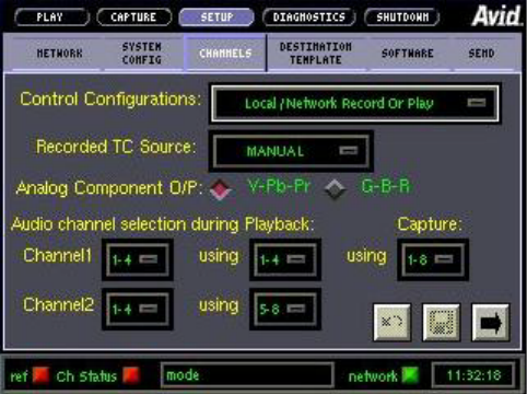
Configuring the iNEWS Command Server
71
To configure the AirSpeed device services:
1. Click the Start button, and then select All Programs > Avid > Service Framework > Avid
Service Configuration.
2. On the Hosts tab, navigate to and select the AirSpeed Device Service.
3. When prompted, enter the system administrator password and click OK. If you have not yet
created one, leave the space blank and click OK.
4. On the Device Settings tab, enter the device name for the respective device.
5. Click Apply. You can then close the Avid Service Configuration application.
6. Click the Start button, and then select All Programs > Avid > Service Framework > Avid
Workgroup Properties.
7. Click the Advanced button.
8. After the Avid Services dialog box opens, select the device, then stop and restart it.
nFor Command upgrades, the AirSpeed device server hostname might revert back to the local
server host name and must be reset, using the Avid Service Configuration application.
To configure the AirSpeed Control Configurations:
1. On the AirSpeed, select Setup > Channels.
2. Set Control Configurations to Local/Network Record or Play. It is the only configuration
supported with Command.
nAvid recommends that you do not use VDCP to control AirSpeed video servers.Unrestricted
VDCP is not supported for on-air broadcasting.
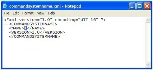
Configuring a Second Command System
72
Configuring a Second Command System
A second Command system is for controlling an independent system, like a second studio, in the
same workgroup. It is not the same as a redundant system, in which the backup server uses the
same system name as the primary server. In Command, the system name is numeric, such as 1, 2,
3, and so forth.
nFor a more meaningful name, a system alias can be configured, which appears in the status bar
of the Command user interface. For more information on system aliases, see the Avid iNEWS
Command Administration Guide.
Multiple Avid iNEWS Command systems usually belong to the same workgroup. If two or more
systems are in the same workgroup, each of the Command systems must have a unique, numeric
name, which is assigned by Avid manufacturing.
After installing Command on a computer that will be part of a second system, you will need to
change the system name by editing the
commandsystemname.xml
file, which by default is
installed in the following location:
C:\Program Files\Avid\iNEWS Command
To change the system name:
1. Navigate to:
C:\Program Files\Avid\iNEWS Command
.
2. Right click the
commandsystemname.xml
file and choose Properties.
3. Deselect the Read-only check box and click OK.
4. Open the
commandsystemname.xml
file in Notepad.
The text in the file will appear as shown:
5. Using numerals only, change the number (shown highlighted in the graphic) located between
the tags:
<NAME> </NAME>
. When setting up a second system, the number must be 2 to
match the license. Subsequent systems must be 3, 4, and so forth.
Configuring a Second Command System
73
6. Select File > Save.
7. Close all workstation sessions and restart all Command and Avid Service Framework
services on that computer.
nThe
commandsystemname.xml
file must be changed on all computers that are part of the second
Command system.

2Installing and Configuring the AirSpeed
Video Servers
AirSpeed 5000 and AirSpeed Multi Stream are digital recorders or playback devices designed to
work seamlessly in Interplay environments. These video servers let you capture incoming media
directly into Avid shared storage or play out media to air.
Both AirSpeed video servers can join three Avid Service Framework workgroups, the Interplay
workgroup and the Command workgroup. The primary workgroup must be the Interplay
workgroup so ingests are transferred to Unity and media sent to playback are transferred to video
server.
Both AirSpeed 5000 and AirSpeed Multi Stream use the AirSpeed Multi Stream or AMS device
service, which can be configured to join multiple workgroups. The main reason for joining a
second workgroup will be to join the Command workgroup. Because the video servers are
communicating with multiple workgroups, they need to be added to the Lookup tab in the
Workgroup Properties application.
•Checklist: Installing the AirSpeed Video Server
•Installing Avid Service Framework
•Installing AirSpeed Multi Stream Device Services
•Checklist: Configuring the AirSpeed Video Server
•Configuring Properties for Interplay Workgroup
•Configuring the AirSpeed Multi Stream Device Service
•Configuring Properties for Command Workgroup
•Working with Play While Record

Checklist: Installing the AirSpeed Video Server
75
Checklist: Installing the AirSpeed Video Server
Ensuring integration with video devices, such as the AirSpeed 5000 or AirSpeed Multi Stream,
requires installation of various components and services, as well as some configuration. The
following is a checklist of activities an installer should verify to ensure a successful installation.
Complete the following tasks in the order that they are listed. If you are viewing this checklist
online, you can easily access a linked topic that provides procedural details for the task. Return
to this main checklist after you have completed each task.
After installation, some configuration is required. For more information, see “Checklist:
Configuring the AirSpeed Video Server” on page 81.
nRegardless of whether the AirSpeed video server is a capture and/or playback server, ensure it is
in the Interplay workgroup. If it is a playback server that will be controlled by iNEWS Command,
it must be configured to join a second workgroup—the same workgroup as the Command
servers.
Tasks Refer to...
Rack, cable, and connect the AirSpeed video
server to the network.
The documentation that came with your Avid
AirSpeed video server for more information.
Install the core components of Avid Service
Framework on the video server.
“Installing Avid Service Framework” on page 76
Install the AirSpeed software. The documentation that came with your Avid
AirSpeed Multi Stream or AirSpeed 5000 for
more information.
Install the AirSpeed Multi Stream device service
from the Avid iNEWS Command software
installation CD. Both AirSpeed video servers, the
5000 and Multi Stream, use the AMS device
service.
“Installing AirSpeed Multi Stream Device
Services” on page 79
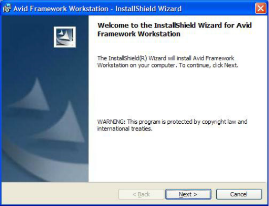
Installing Avid Service Framework
76
Installing Avid Service Framework
Each computer and device running Avid iNEWS Command software requires at least the core
components of Service Framework and must be able to connect to a computer running the Avid
Lookup service. This includes the AirSpeed Multi Stream, which will be running the AirSpeed
Multi Stream device service for Command.
To install the Service Framework Software:
1. Insert the AirSpeed Multi Stream installation DVD.
nDo not install Service Framework on the video server from the Command installation CD. Use
the installer bundled with the AirSpeed software. Also, when Service Framework is upgraded, be
sure to upgrade only the components for which the update is designed.
2. Navigate to the directory called Avid_Framework_Workstation.
3. Double-click the program:
Setup.exe
.
The Introduction window opens.
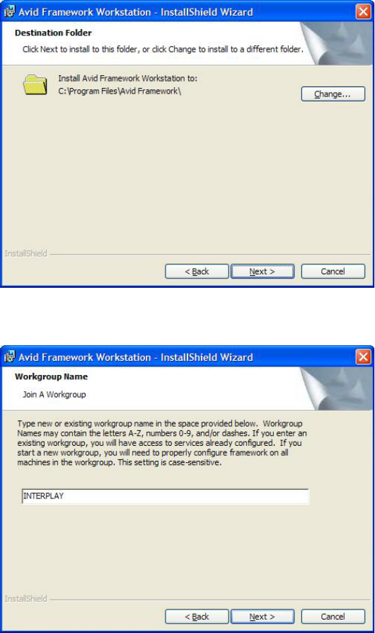
Installing Avid Service Framework
77
4. Click Next.
The Workgroup Name dialog box opens.
5. Set the location to which Avid Service Frameworkwill be installed and click Next.
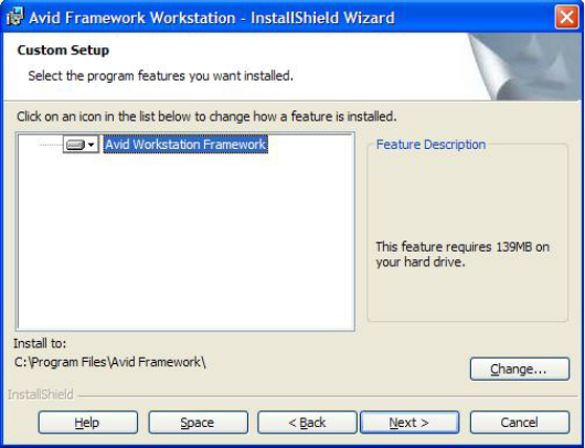
Installing Avid Service Framework
78
6. Type a new or existing workgroup name in the field.
This is the video server’s primary workgroup, which should be the Avid Interplay
workgroup. You must use the same workgroup name on all Interplay clients that are
connected in your Command architecture. The workgroup name is case sensitive. You can
either create a new workgroup or join an existing one. If you are creating a new workgroup,
make a note regarding the workgroup name so that it can be entered during other Avid
Service Framework installations. Later, you’ll configure a secondary workgroup for the
AirSpeed Multi Stream device service, which will be the Command workgroup.
cIf you are updating the Service Framework software, the installer remembers the last
installed value. If the workgroup name was changed after the install, the installer will not
be aware of the change.
7. Click Next.
The Custom Setup dialog box opens.
8. Click Next.
9. Click Install to complete the installation.
After installation, verify that the services are running as expected on each computer in the
workgroup. For more information, see “Viewing Status of Services” on page 313.
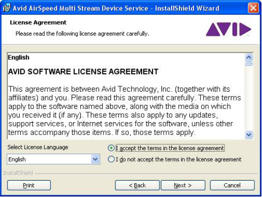
Installing AirSpeed Multi Stream Device Services
79
Installing AirSpeed Multi Stream Device Services
The Command installation CD provides for installation of services associated with various
production devices, such as the AirSpeed 5000 or AirSpeed Multi Stream. Both of these video
servers use the AMS device service.There is no separate AirSpeed 5000 device service.
nUnlike other device services, the AirSpeed Multi Stream device service is not part of the
Command installation program. It’s a separate install program, located on the CD.
To install the AirSpeed Multi Stream device service on the video server:
1. Insert the Command installation CD (or access the install program from the network).
2. Navigate to and double-click on
AvidAirSpeedMultiStreamDeviceService.exe
.
3. After the Welcome dialog box appears, click Next. The License Agreement appears.
4. Read the License Agreement, accept the terms, and click Next.
If you do not accept the terms, the installation program will not continue.
nYou can print the terms if you want to read them later or keep a copy for your records.
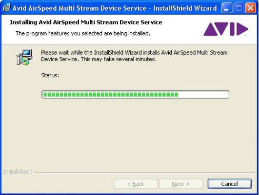
Installing AirSpeed Multi Stream Device Services
80
5. When the Ready to Install the Program dialog box appears, click Install.
A progress bar is provided to show the current status of the installation.
6. When the installation is complete, click Finish.
To verify that installed services are running, you must use the Avid Workgroup Properties
application.

Checklist: Configuring the AirSpeed Video Server
81
Checklist: Configuring the AirSpeed Video Server
For integration between Command and AirSpeed video servers to succeed, some configuration is
required. Complete the following tasks in the order that they are listed. If you are viewing this
checklist online, you can easily access a linked topic that provides procedural details for the task.
Return to this main checklist after you have completed each task.
nWith Command controlling the AirSpeed 5000, the Show first of next option must be turned off.
To turn off this option, navigate to the AirSpeed 5000 Web configuration at
http://<Airspeedhostname>, log in, select Playback/Output, and uncheck the Show first of next
box for all channels.
nAll settings in Command and Framework are case sensitive. Ensure that case matches in all
configuration settings.
Configuring Properties for Interplay Workgroup
The AirSpeed video server must be installed in an Avid Interplay workgroup. If it will be
controlled by Command, then the AirSpeed Multi Stream device service should be configured to
join a second workgroup—the same workgroup as the Command Servers. See “Configuring
Properties for Command Workgroup” on page 85 for more information.
To configure the properties for the Interplay Workgroup on the video server:
1. Click the Start button, and then select All Programs > Avid > Service Framework > Avid
Workgroup Properties.
2. On the Lookup tab, select the Interplay workgroup listed in the Workgroup section.
Tasks Refer to...
Configure the properties for the Interplay
workgroup in which the video server resides.
“Configuring Properties for Interplay
Workgroup” on page 81
Configure the AirSpeed Multi Stream device
service.
“Configuring the AirSpeed Multi Stream Device
Service” on page 83
Configure the properties for the Command
workgroup if Command will be used to control
the AirSpeed for playback.
“Configuring Properties for Command
Workgroup” on page 85
Add the AirSpeed to the list of devices and
channels in Command. Also, add the channels to
a channel group in Command.
The Avid iNEWS Command Administration
Guide
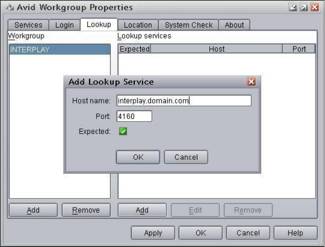
Configuring Properties for Interplay Workgroup
82
nThe Interplay workgroup is the same workgroup named during the installation process of Avid
Service Framework on the AirSpeed video server. See “Installing Avid Service Framework” on
page 76 for more on that procedure.
3. On the Lookup tab, click the Add button under the Lookup services section (located above
the Apply button, and not the one to the far left).
The Add Lookup Service dialog box will open on top of the Avid Workgroup Properties
window, as shown:
4. Enter the fully qualified domain name of the server running the Lookup service for the
workgroup.
5. Leave the port setting as is.
6. Select the Expected check box.
7. Click OK.
8. (Optional) If running multiple Lookup services, repeat steps 2 - 7 to add another server that
is running the Lookup service for the workgroup.
9. Click OK on the Avid Workgroup Properties window.
10. Click Yes, when prompted to restart all services.
Configuring the AirSpeed Multi Stream Device Service
83
Configuring the AirSpeed Multi Stream Device
Service
After any device service is installed for Avid AirSpeed video servers, some additional
configuration is required, using the Avid Service Configuration and Avid Workgroup Properties
applications of Avid Service Framework.
To configure the AirSpeed Multi Stream device services:
1. Click the Start button, and then select All Programs > Avid > Service Framework > Avid
Service Configuration.
2. On the Hosts tab, navigate to and select the AirSpeed Multi Stream Device Service.
3. When prompted, enter the system administrator password and click OK. If you have not yet
created one, leave the space blank and click OK.
4. On the Device Settings tab, enable the second workgroup and enter the name of the
Command workgroup. If you are joining more than one Command workgroup, enter a
workgroup name in the third workgroup box.
5. (Optional) If the AirSpeed video server will be controlled by two Command systems, enable
the second system and enter the numerical value of that system, such as 2. Options include
1-10. The default Command system number is 1.
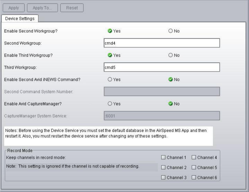
Configuring the AirSpeed Multi Stream Device Service
84
6. (Optional) If using CaptureManager for ingest control, enable it and enter the hostname of
the CaptureManager server.
An example of these settings is shown in the following graphic.
7. Click Apply.
nUpon applying the new settings, and if the CaptureManager is enabled, the system will append a
port number to the end of the hostname you entered for the CaptureManager Server.
8. You can then close the Avid Service Configuration application.
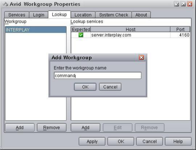
Configuring Properties for Command Workgroup
85
Configuring Properties for Command Workgroup
AirSpeed video servers must be installed in an Avid Interplay workgroup; however, if they will
be controlled by Command, then the AirSpeed Multi Stream device service should be configured
to join a second workgroup—the same workgroup as the Command Servers.
If the Avid AirSpeed video server device is in a different subnet than the Command Servers, you
must add the server names to the Lookup tab in Avid Workgroup Properties on the video server.
nAvid recommends, for servers and workstations joining multiple workgroups, you configure the
Lookup tab to specify the FQDN of the Lookup services in both workgroups regardless of
whether the server or workstation is in the same subnet as the Lookup service.
To configure the properties for the Command Workgroup on the video server:
1. Click the Start button, and then select All Programs > Avid > Service Framework > Avid
Workgroup Properties.
2. On the Lookup tab, click the Add button under the Workgroup section—the far left button at
the bottom.
The Add Workgroup dialog box will open on top of the Avid Workgroup Properties window,
as shown:
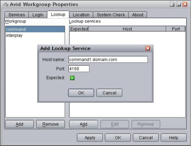
Configuring Properties for Command Workgroup
86
3. Enter the name of the Command workgroup. It is case sensitive.
4. Click OK. The name you entered will appear in the Workgroup section of the Avid
Workgroup Properties window.
5. Click the Add button under the Lookup services section (located above the Apply button,
and not the one to the far left).
The Add Lookup Service dialog box will open on top of the Avid Workgroup Properties
window, as shown:
6. Enter the fully qualified domain name of the server running the Lookup service for the
Command workgroup.
7. Leave the port setting as is.
8. Select the Expected check box.
9. Click OK.
10. (Optional) If running multiple Lookup services, repeat steps 2 - 7 to add another server that
is running the Lookup service for the Command workgroup.
11. Click OK on the Avid Workgroup Properties window.
12. Click Yes, when prompted to restart all services.
Working with Play While Record
87
nFor AMS up/down cross convert integration, autocue must be turned off when transitioning
between XDCAM 720p and 1080i clips. For Auto Switch Output Format, users also need to turn
off autocue if they plan to switch formats. This is because the AMS channel needs to be in an idle
state—not playing for instance—for it to switch formats.
Avid recommends having dedicated channels for specific resolutions.
Working with Play While Record
This section provides additional information to help clarify the existing Play While Record
feature when used with an AirSpeed video server, such as AirSpeed 5000 or AirSpeed Multi
Stream.
After an item starts recording on the video server, it appears within the Command Inventory
Panel within approximately 10 seconds. When it appears in Command, users can open the item
in the Media Viewer to adjust the Mark In point, and then play the item.
nThis requires an available playback channel on the video server that is recording the item. A
Mark Out point is not required, only a Mark In timecode.
To set the Mark In point for an item that is recording, it needs to be added to a Command playlist
(via ENPS, iNEWS, or a Standalone playlist). Once there and available, you can double-click the
item and type the Mark In point.
If you want to open the item in the Media Viewer and use the Jog to set the Mark In point, you
have to configure a Browse channel as part of the Command playlist. It can either be a Browse
channel that is part of the Playback channel group—such as, Channels AB for playback and C
for browse—or with Command v2.6, you can configure a Playback channel group (AB) and a
separate Browse-only group (C). The Browse-only channel group also needs to be added to the
playlist.
To play while record on an AirSpeed video server:
1. Configure an AirSpeed video server so that it has a record and playback channel. This means
that the AMS Device Service needs to be part of the Command workgroup, and the playback
channel needs to be in a Command channel group.
2. After the item starts recording, it should appear in Command's inventory within
approximately 10 seconds.
3. After the item is available, it can be played at any time. The countdown clock time will be
erratic, because the duration is being updated while the item is playing.
4. When the recording is stopped, the total time code gets updated one last time, Command
then stops at the recording's stopping point, and then follows the Command hold last frame
setting.
AirSpeed Multi Stream Los-Res Proxy Viewer
88
To play while record with Avid iNEWS:
1. Add the item’s ID to the Video ID column of the iNEWS playlist and load the show.
2. Start recording the item on the video server, using the Video ID that you entered in the
iNEWS playlist.
3. After the item becomes available, you can play it, and optionally double-click the item to
enter the Mark In point.
To play while record with ENPS:
1. Do an object autocreate to create a Video ID.
2. Start recording, using the autocreated Video ID.
3. After the item becomes available, you can play it, and optionally double-click the item to
enter the Mark In point.
To play while record with a standalone playlist:
1. Add the item to a standalone playlist (Alt+Ins).
2. Start recording, using the Video ID that you used in the standalone playlist.
3. After the item becomes available, you can play it, and optionally double-click the item to
enter the Mark In point.
AirSpeed Multi Stream Los-Res Proxy Viewer
Both the AirSpeed 5000 and AirSpeed Multi Stream video servers support a low-res proxy
viewer, which lets users view video (with audio) at their Command Workstations rather than use
an output channel to browse clips. However, there are certain limitations with each type of
server.
For AirSpeed 5000:
• Ten viewers can be opened at once.
• The low-res proxy viewer is only supported on workstations running the Windows 7
operating system.
nThe AirSpeed 5000 supports playout for all clips.
AirSpeed Multi Stream Los-Res Proxy Viewer
89
For AirSpeed Multi Stream:
• The low-res proxy viewer is only supported for items that are recorded on the AirSpeed
Multi Stream and is not supported for items that are transferred.
• Only two viewers can be opened at once.
• An H.264 card must be installed on the Multi Stream server that runs AMS v1.7 or later
software.
• An H.264 decoder is required on the Command Workstation. Workstations running
Windows 2008 or Windows 7 operating systems already have this decoder installed.
nIf your workstation has an earlier operating system, Avid recommends installing the DivX H.264
codec pack from the following Web site:
http://www.divx.com/en/software/divx-plus/codec-pack/h264
Setting up this feature, also requires some configuration of AirSpeed Multi Stream as well as
Avid iNEWS Command.
Configuring AirSpeed Video Servers for the Low-Res Proxy Viewer
Both the AirSpeed 5000 and Multi Stream servers must be configured to create proxies.
To configure the AirSpeed 5000 for proxy creation:
1. Open the AirSpeed 5000 Management Console.
2. In the Record Template section, select the Proxy enabled checkbox.
3. In the Inventory section, select Generate proxy on Send to Playback.
4. Click Apply.
To configure the AirSpeed Multi Stream for proxy creation:
1. In the AMS application, click File > Preferences > Generate proxy after record.
The proxies are kept on
E:\madamsdb\proxies
(where madamsdb is the default database).
2. Ensure the E drive is a shared drive.
nThe AirSpeed 5000 shares the E drive automatically.
For either video server, it is necessary to connect to the AirSpeed E drive before opening the
proxy viewer. There are three ways to connect:
• Manually connect to the share via Windows Explorer.
• Add a user account to AirSpeed and have users log into the client with this account.
• Create a net use script that opens the connection automatically.
AirSpeed Multi Stream Los-Res Proxy Viewer
90
Configuring Command for Low-Res Proxy Viewing
The low-res proxy viewer opens as a separate application from Command; however,
functionality is similar to the Media Viewer. Command users can play an item, jog or shuttle,
create subclips, and set “soft” mark in or out points—“soft” meaning they only apply to the item
in Command and are not set in the AMS application. So, for items opened from the Inventory
panel in Command, they must be dragged into a playlist to play the item with its mark in/out
points. If users open items from the Inventory panel, there will be a second Media Viewer
window that only displays the headframe, which lets users drag and drop the item into the
Command playlist.
nCommand specific keystrokes, such as Alt+Right Arrow (forward 15 frames), are not functional
in the low-res proxy viewer, but users can scroll with the Right or Left Arrow keys.
Configuration within Command is required for this feature to work.
To configure Command for low-res proxy viewing:
1. At a Command Workstation, select Tools > Options > Media Viewer.
2. Select the Use AMS low-resolution proxy viewer checkbox if available.

3Installing and Configuring Avid Motion
Graphics
The following provides instructions for installing and configuring Avid Motion Graphics
Journalist software and related applications.
The following main topics describe:
•What You Need to Activate the Software License
•Avid Motion Graphics Journalist Server Installation and Configuration
•Installing AMG Journalist Client Software
•Installing the AMG Preview Renderer
•Installing the AMG Advanced Device Manager
•Installing the Avid Service Framework
•Configuring the Avid Motion Graphics Device Service

What You Need to Activate the Software License
92
What You Need to Activate the Software License
This section contain general steps for using Avid License Control to license AMG, AMG
Journalist, and AMG Preview Renderer. To activate the software using the Avid License Control
tool you need the items listed in the following table:
cIf you change your system configuration — for instance, by replacing your hard drive, a
network adapter, or by upgrading your operating system — you must first deactivate your
Avid software.
nYour network administrator might need to open a few ports that are used during the license
activation. The Avid License Control tool utilizes both port 3443 and port 443 for license request
and response communication. Port 3443 is the primary port, but if this port is blocked, the
Activation Service tries port 443, which is more likely to be open for Web communication.
Identification Number Type Where you can find it:
Activation ID The Activation ID is provided on an Activation ID and System ID
card shipped with your new Avid Motion Graphics system. The
Activation ID is used to activate the software license and has been
linked to your System ID.
System ID The System ID is provided on an Activation ID and System ID card
shipped with your new Avid Motion Graphics system. The System
ID is used for expediting warranty verification and customer service.
After activation, the License Profile tab of the Avid License Control
tool displays information about your system. Click “Copy to
Clipboard” to copy the information to your clipboard. You can then
paste from the clipboard to an e-mail or create a text file. This is
helpful if you need to save this information for your records or need
to send system information to Avid Customer Support.
Device ID The Device ID is only needed if you are activating your software on a
system that is not connected to the Internet. This is provided through
the Avid License Control tool during activation.
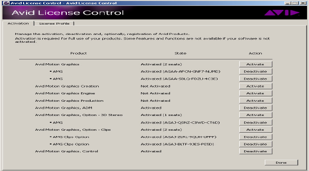
What You Need to Activate the Software License
93
License Activation Using an Internet Connection
To activate the software license using an Internet connection:
1. Locate your System ID and Activation ID card included with your new hardware.
2. Open the Avid License Control tool, click Start > Programs > Avid > Utilities > Avid
License Control.
The Avid License Control tool opens.
nAfter your Avid software is activated, the License Profile tab displays your System ID, Activation
ID, and Device ID.
3. Click the Activate button located next to the Avid Motion Graphics software product name.
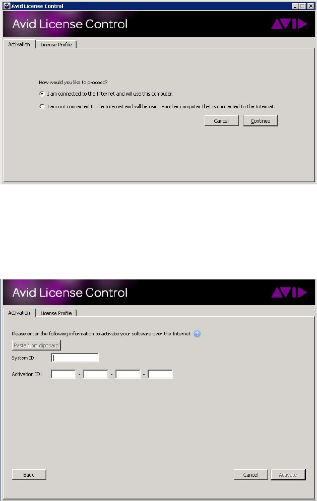
What You Need to Activate the Software License
94
4. Select “I am connected to the Internet and will use this computer” and then click Continue.
nIf you select “I am not connected to the Internet and will be using another computer that is
connected to the Internet” continue with “License Activation Without an Internet Connection”
on page “License Activation Without an Internet Connection” on page 95.
5. Enter your system identification number in the System ID text box.
What You Need to Activate the Software License
95
6. Enter your activation identification number in the Activation ID text box.
7. Click the Activate button.
The Activation tool confirms your system information. When the activation is complete, a
message informs you that your software has been successfully activated and the Activate
button changes to a Deactivate button.
License Activation Without an Internet Connection
License Activation Without an Internet Connection
When you do an indirect activation, you are given a “.bin” activation file. This file is only works
for a single activation. If you have done an indirect activation, and deactivate your license for any
reason, you may not use the same activation file to reactivate your license. You must repeat the
“License Activation Without an Internet Connection” procedure and obtain a new “.bin”
activation file.
To activate the software license from a separate computer
1. Locate your System ID and Activation ID card included with your new hardware.
2. Open the Avid License Control tool, click Start > Programs > Avid > Utilities > Avid
License Control.
The Avid License Control tool opens.
3. Click the Activate button located next to the Avid product software name.
4. Select “I am not connected to the Internet and will be using another computer that is
connected to the Internet,” then click the Continue button.
5. Enter your system identification number in the System ID text box.
6. Enter your activation identification number in the Activation ID text box.
7. Click the Next button.
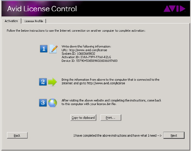
What You Need to Activate the Software License
96
8. Follow the instructions in the Avid License Control tool, then click the Next button.
nYour System ID, Activation ID, and Device ID are displayed on the Activation tab, write these
numbers down to use later. These IDs are displayed in the License Profile tab after your Avid
software is activated.
9. On a computer with an Internet connection, open a Web browser and navigate to
http://avid.com/license
.
10. Follow the on screen instructions on the web page.
The Website creates a license.bin file. This file contains license information needed to
activate your Avid Motion Graphics software.
11. Copy the
license.bin
file to the computer you want to activate.
A USB flash drive is a good method of moving the
license.bin
file.
12. Close the Web browser on the computer with the Internet connection.
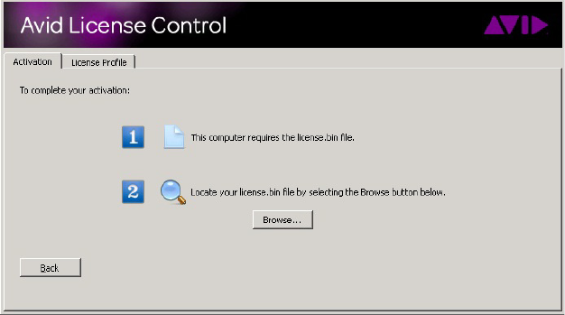
What You Need to Activate the Software License
97
13. Return to the computer where you left off in the Avid License Control tool and click the
Next button.
14. Click the Browse button and navigate to the license.bin file on your computer, then click
Open.
The Activation tool confirms your system information. When the activation is complete, a
message informs you that your software has been successfully activated and the Activate
button changes to a Deactivate button.
Deactivating the License
You must deactivate your Avid Motion Graphics software license when replacing the computer
so you can use the license on your new computer.
nTo be able to deactivate the software and it’s options, you must have an Internet connection.
To deactivate the software license:
1. Close any Avid Motion Graphics applications that are running.
2. Open the Avid License Control tool, click Start > Programs > Avid > Utilities > Avid
License Control.
The Avid License Control tool opens.
3. Next to the Avid Motion Graphics software, click the Deactivate button.
4. Click Yes.
5. Click Done to close the Avid License Control tool.

Avid Motion Graphics Journalist Server Installation and Configuration
98
Avid Motion Graphics Journalist Server Installation
and Configuration
After setting up and configuring settings of the operating system for your Avid Motion Graphics
system, you can install and configure the Avid Motion Graphics Journalist software and related
applications.
For installing Avid Motion Graphics Creation, Journalist, or News Control there will be one
USB flash drive containing the software.
nThe Avid Motion Graphics software is also available on the Avid Download Center
(www.avid.com/support/downloadcenter).
To Install This Software See The Following Section
Avid Motion Graphics
Journalist Server
See “Installing Avid Motion Graphics Journalist Server” on page 99.
Once installed, you need to license the software as described in
“Licensing Avid Motion Graphics Journalist Server” on page 100.
Then, you must start the AMG Journalist Server software, as described in
“Starting the AMG Journalist Server Applications” on page 105
Then you must configure the software as described in “Configuring the
Avid Motion Graphics Journalist Server” on page 101
Avid Motion Graphics
Journalist Client
See “Installing AMG Journalist Client Software” on page 103.
AMG Preview Renderer See “Installing the AMG Preview Renderer” on page 104.
AMG Advanced Device
Manager
See “Installing the AMG Advanced Device Manager” on page 105. Once
installed, you must configure the AMG Advanced Device Manager, as
described in “Configuring the Advanced Device Manager” on page 106.
Once you are installing these applications, you must start the AMG
Journalist server software as described in “Starting the AMG Journalist
Server Applications” on page 105.
Avid Service Framework See “Installing the Avid Service Framework” on page 109. Once
installed, you can configure the Avid Motion Graphics Device Service, as
described in “Configuring the Avid Motion Graphics Device Service” on
page 117.
Avid Motion Graphics News
Control
See the Avid Motion Graphics Setup Guide.
Avid Motion Graphics Journalist Server Installation and Configuration
99
Installing Avid Motion Graphics Journalist Server
The following steps describe how to install the Avid Motion Graphics Journalist Server (AMG
Journalist Server) for integration with Avid iNEWS Command and Avid iNEWS newsroom
computer system or ENPS. They assume that the Avid Motion Graphics servers have already
been installed and licensed.
Prior to starting the Journalist installation, confirm the Win2008 R2 64 bit installation.
To confirm the Win2008 R2 64 bit installation:
1. Open a command prompt Start > Run.
2. Type cmd.
3. Press Enter.
4. Type ver
5. Press Enter.
The version of server should be 6.1.7601.
Install both the vcredist_x64 and vcredist_86 installers before continuing with the Journalist
installation.
To install both veredist_x64 and vcredist_86 installers
tOpen the AMG Journalist Folder and locate the folder labeled VS2008, Open this folder and
install both the vcredist_x64 and vcredist_86 installers before starting the
AMG_Journalist_Server_setup.exe
.
tWindows Media player must be enabled before proceeding, this is part of the Desktop
Experience feature for Windows Server 2008.
To Install the Avid Motion Graphics Journalist Server:
1. Navigate to and double-click
AMG_Journalist_Server_setup.exe
.
2. Click the option to install Microsoft Visual C++ Redistributable.
3. Install Avid Motion Graphics Journalist Server.
This will share the AMGNews folder and configure the X: drive. It also installs the AMG
Drive Monitor.
4. Install Avid License Control.
5. Install PostgreSQL 8.4.4.
6. Install AMG ODBC.
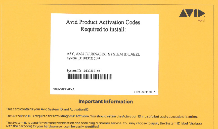
Avid Motion Graphics Journalist Server Installation and Configuration
100
Licensing Avid Motion Graphics Journalist Server
The Avid Motion Graphics NRCS License is the only License required for the Avid Motion
Graphics Journalist server. The server does not have a license.
The Avid Motion Graphics Journalist System ID label, as shown in the following illustration, is
used as the System ID number to Activate the Avid Motion Graphics NRCS Clients, Preview
Renderers, and Preview Renderer Clips.
The AMG Preview Renderer also requires licenses to activate it.
If you do not have an NRCS license, contact your sales representative to obtain an NRCS license.
The Avid Motion Graphics NRCS Client activation is performed on the Journalist Server.
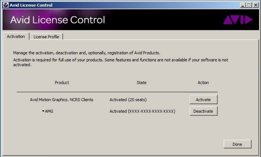
Avid Motion Graphics Journalist Server Installation and Configuration
101
To activate the license for Avid Motion Graphics NRCS Clients:
1. Open Avid License Control tool.
2. Activate the Avid Motion Graphics NRCS license.
nThe license is most easily added with an internet connection, so that the computer can connect to
the Avid license server and verify the license. For more information, see “Software Licensing”
on page 73.
Configuring the Avid Motion Graphics Journalist Server
After installing the server software, you must configure the Avid Motion Graphics Journalist
Server.
To configure the Avid Motion Graphics Journalist Server:
1. On the Avid Motion Graphics Journalist Server, navigate to:
C:\AMGNews\bins\conf\AMGConf.ini
.
2. In the General section:
tSet VIDEO FRAMES to NTSC or PAL.
tSet the SLUG FORMAT to <tpl>.
Avid Motion Graphics Journalist Server Installation and Configuration
102
nAll values in the AMG.ini files must be surrounded by quotes. When editing values, remember to
keep the quotes in tact.
3. In the Preview Snaps section:
tSet the IP to the specific address for the local AMG Journalist Server (do not use
127.0.0.1, or a host name).
nThis IP is for the AMG News Preview Server application, which runs on the AMG Journalist
Server. The IP does not point to the AMG Preview Renderer itself - that IP is set in a different .ini
file, and explained in Step 11.
4. In the Gateway section:
tSet the IP to the specific address for the local AMG Journalist Server (do not use
127.0.0.1, or a host name).
tFor iNEWS, leave the NCS and MOS ports at their current values.
tFor ENPS, change the NCS UPPER PORT to 10541, and the NCS LOWER PORT to
10540.
5. In the MOS Device section:
tConfirm the NAME is set to AMGNews.
tIn the CHANNELS field, enter the channels names that you intend to use in the system.
Each name must be separated by a comma and space.
nCommand will need to use the same channel names, so it's a good idea to write down or
remember the channel names used here.
6. In the Control section (where NAME = CTRL1):
tFor Command, comment out this entire section with a
;
at the beginning of each line.
7. In the Control section (where NAME = COMMAND1):
tSet the IP to the specific address for the Avid Motion Graphics computer.
tA new section will need to be added, with the name COMMAND2, for a second device.
8. In the Render Sections (There are two.):
tFor Command, comment out this entire section with
a ;
at the beginning of each line.
9. In the Manager section:
tSet the IP to the specific address for the local AMG Server (do not use 127.0.0.1, or a
host name).
tFor iNEWS, confirm that IS NCS is set to YES.
tFor ENPS, change IS NCS to NO.
Installing AMG Journalist Client Software
103
10. In the NCS section:
tIn the NAME field, enter the NRCS server name.
tFor iNEWS, leave the IP as is at 127.0.0.1.
tFor ENPS, enter the IP for the ENPS server. For the buddy server, add the following:
"BACKUP NAME" = "ENPS BUDDY SERVER NAME"
"BACKUP IP" = "ENPS BUDDY SERVER IP"
tIf you want to see more than the first 2 replaceable fields in the Command playlist,
change the ABSTRACT FMT field from <2values> to the desired number.
tFor ENPS, confirm that the <ch> variable has been added to the beginning of the
ABSTRACT FMT line.
For example: “ABSTRACT FORMAT” = “<ch>:<tpl>:<2values>”
11. On the AMG Journalist Server, go to
C:\AMGNews\bins\conf\Previewunits.ini
.
tIn both IP fields, enter the IP address for where the AMG Preview Renderer will be
running.
Installing AMG Journalist Client Software
The following steps describe how to install the Avid Motion Graphics Journalist Client for
integration with Command, and iNEWS or ENPS.
If you configure AMG Journalist for iNEWS, you can use it as a plug-in to Interplay Central, but
you must first enable your browser to accept MOS plugins.
To install the AMG Journalist client:
1. Navigate to the Avid Motion Graphics Journalist Server (via UNC path -
\\servername)
.
2. Open the install folder.
3. Double-click the Avid_Motion_Graphics_Journalist_setup.exe to run the executable.
4. In the AMG Journalist Applications window, click the AMG NRCS Client to install it.
5. Select Microsoft Visual C++ Redistributable to install it.
6. Select AMG Drive Monitor to install it. Make sure the IP address for the AMG Journalist
server is populated. Follow the prompts (Install, Next, Finish) to complete the installation.
7. Select AMG ODBC to install it.
nA database password is not necessary, and should not be entered.
8. Select AMG NRCS to install, and click Finish to complete the installation.
Installing the AMG Preview Renderer
104
9. Select Exit to close the installer.
You can now test the AMG Journalist Client.
10. (Optional) If you are using AMG Journalist Client (a MOS plugin) with iNEWS and
Interplay Central, you need to configure your web browser to accept MOS plugins.
tIf you are using Chrome as your browser, you must install the Chrome Extension for
Interplay Central MOS plug-in. For more information, see Appendix F of the Interplay
Central Services Installation and Configuration Guide.
tIf you are using Internet Explorer as your browser, you must enable Interplay Central
MOS plug-ins in Internet Explorer. For more information, see Appendix G of the
Interplay Central Services Installation and Configuration Guide.
Installing the AMG Preview Renderer
The following describes installing the Avid Motion Graphics Preview Renderer on a dedicated
computer.
To install the Avid Motion Graphics Preview Renderer:
1. Navigate to the Avid Motion Graphics Journalist Server (via UNC path -
\\servername)
.
2. Open the install folder.
3. Double-click the
Avid_Motion_Graphics_Journalist_setup.exe.
4. In the AMG Journalist Applications window, click Avid Motion Graphics News Preview
Renderer.
5. Click Avid Motion Graphics Drive Monitor to install. You will need to enter the IP address
for the Avid Motion Graphics Journalist server Microsoft Visual C++ 2008 Re-distributable
to install.
6. Click the Avid Motion Graphics Drive Monitor to install. You will need to enter the IP
address for the Avid Motion Graphics Journalist Server.
7. Click Avid Motion Graphics ODBC to install. You will need to enter the IP address for the
Avid Motion Graphics Journalist server. A database password is not necessary, and should
not be entered.
8. Click Avid License Control to install.
9. Click Avid Motion Graphics News Preview Renderer to install.
10. Click Exit to close the installer licensing.
11. Open the Avid License Control tool.
12. Add the Preview Renderer licenses (Preview and Clips). If you do not have a Preview
Renderer license, contact your sales representative to obtain a license.
Installing the AMG Preview Renderer
105
nThe license is most easily added with an internet connection, so that the computer can connect to
the Avid license server and verify the license.
Starting the AMG Journalist Server Applications
106
Starting the AMG Journalist Server Applications
After the server configuration is complete, you can start the AMG Journalist Server application..
To start the AMG Journalist Server applications:
tDouble-click the AMG Application Monitor shortcut.
This starts the Avid Motion Graphics Journalist Server applications, AMG News Licenser,
AMG Gateway, and AMG Preview Renderer.
- AMG News Licenser: gives out Avid Motion Graphics Journalist client license seats.
- AMG Gateway: manages communication between NRCS, database, and Command.
- AMG Preview Renderer: manages Avid Motion Graphics Preview Renderer requests
Installing the AMG Advanced Device Manager
This topic contains information on how to install and configure Avid Motion Graphics Device
service on each Avid Motion Graphics playout chassis.
To install the AMG Advanced Device Manager:
1. Navigate to the Avid Motion Graphics Journalist Server (via UNC path -
\\servername)
.
2. Open the Install folder.
3. Double-click the Avid_Motion_Graphics_Journalist_setup.exe.
4. In the AMG Journalist Applications window, click AMG Playout.
5. Click Microsoft Visual C++ Redistributable to install.
6. Click Avid Motion Graphics Drive Monitor to install. You will need to enter the IP
address for the Avid Motion Graphics Journalist server
7. Click Avid Motion Graphics ODBC to install. You will need to enter the IP address for the
Avid Motion Graphics Journalist server. A database password is not necessary, and should
not be entered.
Installing the AMG Advanced Device Manager
107
8. Click the AMG Advanced Device Manager option to install the AMG Advanced Device
Manager onto the AMG Playout server.
nWait for all of the components to install before continuing. After each component successfully
installs, a green circle, containing a white check mark, replaces all of the red circles, containing
white Xs. If a component is already installed, it is detected and the green circle with the check
mark appears immediately.
When all components have been installed, the Installshield Wizard for the Avid Motion
Graphics application opens.
nAvid License Control should already be installed, and have a green check mark next to it.
9. Open the Av id Lic ense Cont ro l tool and confirm that you have the respective AMG licenses
added. If not done, add the AMG ADM license.
nThe license is most easily added with an internet connection, so that the computer can connect to
the Avid license server and verify the license.
Configuring the Advanced Device Manager
Once you have installed the Advanced Device Manager on your AMG Playout chassis, you must
configure it.
Configuring the Advanced Device Manager:
1. From the Start menu select All Programs > Avid > Advanced Device Manager
Configuration Tool. The Advanced Device Manager Configuration dialog box opens.
There are two protocol selection tabs available. The Primary Protocol Selection is used to
configure AMG Channel A with Avid Command.
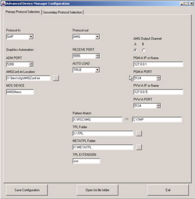
Installing the AMG Advanced Device Manager
108
nIf the AMG Playout chassis is optioned for Dual Channel and you want to control the second
channel using a different protocol, this can be accomplished by selecting the Secondary Protocol
Selection tab. Select AMG News Output Channel B.
2. /in the Protocol In field (for use with Command), select GAP (Graphics Automation
Protocol).
3. In the ADM PORT field, set the value to 5200.
4. In the AMG Config.ini Location field, make sure it points to X:\bins\cfg\AMGConf.ini.
5. In the MOS DEVICE field, type AMGNews.
6. In the Protocol out field, select AMG.
7. In the Receive PORT field, select 5555.
8. In the AUTO LOAD field, select True.
9. In the Pattern Match field, type X:\RSC\IMG. Then, in the >> field, type C:\TMP.
Installing the AMG Advanced Device Manager
109
10. In the TPL Folder field, make sure it points to X:\TPL.
11. In the METATPL Folder field, make sure it points to X:\METATPL.
12. In the TPL EXTENSION field, scn.
13. , To set up the first output channel (A), do the following:
a. In the AMG Output Channel section, select A to set up the first output channel.
b. In the PGM-A IP or Name field, type the IP address of the local AMG chassis. You can
use the local host name, as well.
c. In the PGM-A PORT field, select 5124.
d. In the PVW-A IP or Name field, type the IP address of the local AMG chassis. You can
use the local host name, as well.
e. In the PVW-A PORT field, select 5124.
14. (Option) If the chassis is a single channel AMG Playout chassis, do the following.
Otherwise, go to the next step:
a. Select the Save Configuration button to save your configuration.
b. Select the Open Ini file folder, and double-click the AMG_AdvancedDM_Primary.ini
file.
c. Disable the Program B, Preview B channels by adding a semi-colon (;) in front of the
following strings to prevent false errors in the ADM logs. as shown:
- ;"PGM-B IP"= "127.0.0.1"
- ;"PGM-B PORT"= "6124"
- ;"PVW-B IP"= "127.0.0.1"
- ;"PVW-B PORT"= "6124"
15. , To set up the second Output channel (B), do the following:
a. In the AMG Output Channel section, select B to set up the second output channel.
b. In the PGM-B IP or Name field, type the IP address of the local AMG chassis. You can
use the local host name, as well.
c. In the PGM-B PORT field, select 6124.
d. In the PVW-B IP or Name field, type the IP address of the local AMG chassis. You can
use the local host name, as well.
e. In the PVW-B PORT field, select 6124.
16. Click the Save Configuration button and close the Advanced Device Manager
Configuration Tool.

Installing the Avid Service Framework
110
Installing the Avid Service Framework
Each computer and device running Avid iNEWS Command software requires at least the core
components of Service Framework and must be able to connect to a computer running the Avid
Lookup service.
To install the Avid Service Framework:
1. Insert the Command installation CD (or access the install program from the network).
The autorun installation program starts and displays the following screen.
nThe Command Documentation button will open a window displaying the contents of the Doc
folder on the Command installation CD in which product documentation is provided in PDF
format.
If the autorun does not begin, manually navigate to and run the
ServiceFrameworkSetup.exe
install program.
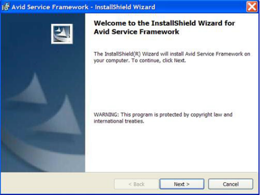
Installing the Avid Service Framework
111
2. Click the Avid Service Framework button.
nOther dialog boxes could appear depending on whether older versions of Service Framework are
found, particularly if upgrading existing software. If one appears, read it carefully and reply
accordingly with regard to upgrades, etc.
A splash graphic will appear briefly as the installer prepares the InstallShield Wizard. Then
the Welcome dialog box appears.
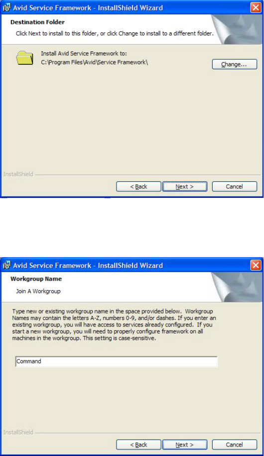
Installing the Avid Service Framework
112
3. Click Next.
The Destination Folder dialog box opens.
4. Set the location to which Avid Service Framework will be installed and click Next.
The Workgroup Name dialog box opens.

Installing the Avid Service Framework
113
5. Type the name of the Command workgroup in the field.
cIf you are updating the Service Framework software, the installer remembers the last
installed value. If the workgroup name was changed after the install, the installer will not
be aware of the change.
6. Click Next.
The Options dialog box opens.
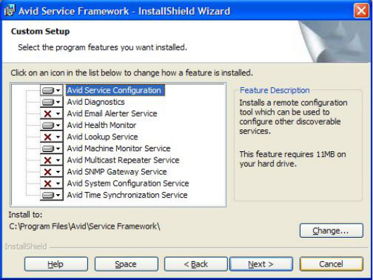
Installing Avid Motion Graphics Device Service
114
7. Select the option: Avid Service Framework Client and click Next.
The Custom Setup dialog box opens.
By default, the Time Synchronization service is selected to be installed; however, this
service should only be installed if you do not already use something to synchronize your PC
clocks. If you use NTP or some other method for time synchronization, do not install this
service. For more information about the services in this dialog box, see the tables in
“Installing Avid Service Framework” on page 24.
8. Click Next and follow the installation instructions to complete the installation.
nYou might be required to restart your system to complete the installation.
After installation, verify that the services are running on each computer where Service
Framework services were installed.
Installing Avid Motion Graphics Device Service
This section provides the standard procedure for installing the device service.
To install the Avid Motion Graphics Device Service on the device:
1. Install iNEWS Command and select the AMG Device Service from the install menu.
When the autorun program starts, select the Avid iNEWS Command button. The
InstallShield Wizard starts and displays the Welcome screen.
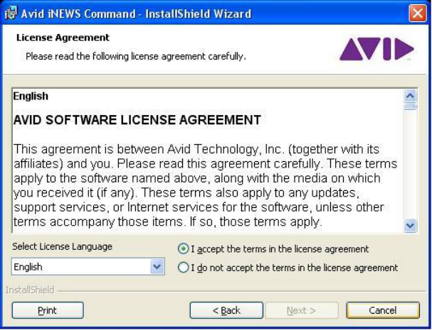
Installing Avid Motion Graphics Device Service
115
2. Click Next.
The License Agreement appears.

Installing Avid Motion Graphics Device Service
116
3. Read the License Agreement, accept the terms, and click Next.
If you do not accept the terms, the installation program will not continue.
nYou can print the terms if you want to read them later or keep a copy for your records.
The Destination Folder dialog box opens.
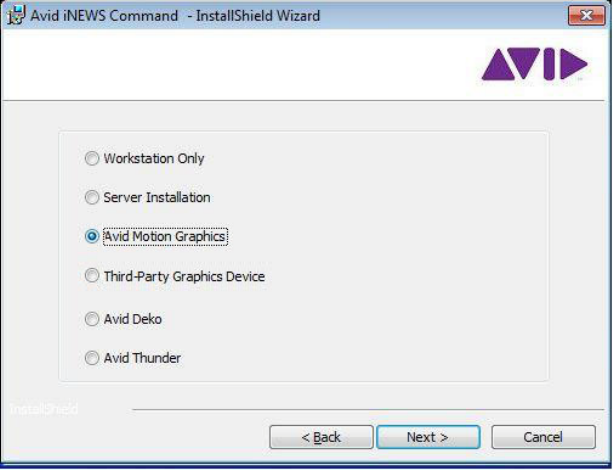
Installing Avid Motion Graphics Device Service
117
4. Do one of the following:
tClick Change to designate an install directory, and then click Next.
tAccept the default location by clicking Next.
The Options dialog box opens.
5. Select Avid Motion Graphics and click Next.
The Custom Setup dialog box appears with the default services selected for installation of
client software. However, for CII integration, you must modify the selections to customize
your installation.

Configuring the Avid Motion Graphics Device Service
118
6. Click Next to continue.
7. When the Ready to Install the Program dialog box appears, click Install.
8. When the installation is complete, click Finish.
You are now ready to install the appropriate plug-in or the Graphic Inventory Editor (GIE), if
necessary.
Configuring the Avid Motion Graphics Device
Service
Once you have installed the Avid Motion Graphics Device Service on each Avid Motion
Graphics playout chassis, you must next configure it.
To configure the Avid Motion Graphics Device Service:
1. Select Start > All Programs > Avid Service Framework.
2. Open the Avid Service Configuration application.
3. Navigate to the local machine, open the drop down menu, and select the Avid Moti on
Graphics Device Service.
Configuring the Avid Motion Graphics Device Service
119
4. Enter a Device name (in lowercase), such as “amg1”, and set the channel count to 1 for
single-channel, or 2 for dual-channel playout chassis.
5. Click the AMG Device Service Settings tab.
6. In the ADM IP field, type the local machine’s specific IP address.
7. In the NET CONNECT AS, type the computer name\user name for the AMG Journalist
Server, so that the device service connects to the AMG Journalist Server with the right
credentials.
nIf the Journalist Server uses a local log in, enter the local computer name and user name, such
as AMGJourn\Admin. A domain login also works here.
8. In the NET PASSWORD field, type the password for that user name (if there is one).
Otherwise, leave it blank.
9. In the NET SHARED RESOURCE field, type the AMG Journalist computer name and
share name. For instance,
\\AMGJourn\AMGNews.
nMake sure the case matches.
10. Confirm that the SYSTEM MOS ID is correct. It should be the same (including the case) as
was configured in the AMGConf.ini and the ADM Configuration.
nAfter changing any value, select a different field before clicking Apply, so that the last change is
kept. Or press Enter.
11. After the configuration is complete, click the Apply button.
The service restarts automatically.
12. Close the window.

4Installing and Configuring the Graphic
Device Service
Avid iNEWS Command lets you control third-party graphics devices via the Graphic device
service (GDS).
This chapter provides instructions for installing the device service as well as configuration
information needed when integrating Command with third-party plug-ins or CII-based devices.
nIn almost all cases, Avid Service Framework and the device service should be installed on the
graphics device, not the Command Server. The only exception is if you are controlling the
graphics device via a serial connection.
•Installing Avid Service Framework
•Installing Avid Graphic Device Service
•Installing Third-Party Plug-ins for the Graphic Device Service
-Checklist: Installing and Configuring for Third-Party Plug-ins
-Configuring the Avid Graphic Device Service
•CII Integration
-Checklist: Setting up Command for CII Integration
-Installing the Avid Graphic Inventory Editor
-Configuring the Avid Graphic Device Service for CII
-Configuring the Graphic Inventory Editor
-Configuring iNEWS Command Device Channels and Channel Groups
•Configuring 3rd Party Software

Installing Avid Service Framework
120
Installing Avid Service Framework
Each computer and device running Avid iNEWS Command software requires at least the core
components of Service Framework and must be able to connect to a computer running the Avid
Lookup service.
To install the Service Framework software:
1. Insert the Command installation CD (or access the install program from the network).
The autorun installation program starts and displays the following screen.
nThe Command Documentation button will open a window displaying the contents of the Doc
folder on the Command installation CD in which product documentation is provided in PDF
format.
If the autorun does not begin, manually navigate to and run the
ServiceFrameworkSetup.exe
install program.
2. Click the Avid Service Framework button.
nOther dialog boxes could appear depending on whether older versions of Service Framework are
found, particularly if upgrading existing software. If one appears, read it carefully and reply
accordingly with regard to upgrades, etc.

Installing Avid Service Framework
121
A splash graphic will appear briefly as the installer prepares the InstallShield Wizard. Then
the Welcome dialog box appears.
3. Click Next.
The Destination Folder dialog box opens.

Installing Avid Service Framework
122
4. Set the location to which Avid Service Framework will be installed and click Next.
The Workgroup Name dialog box opens.
5. Type the name of the Command workgroup in the field.
cIf you are updating the Service Framework software, the installer remembers the last
installed value. If the workgroup name was changed after the install, the installer will not
be aware of the change.
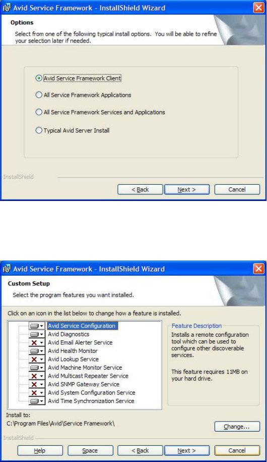
Installing Avid Service Framework
123
6. Click Next.
The Options dialog box opens.
7. Select the option: Avid Service Framework Client and click Next.
The Custom Setup dialog box opens.
Installing Avid Graphic Device Service
124
By default, the Time Synchronization service is selected to be installed; however, this
service should only be installed if you do not already use something to synchronize your PC
clocks. If you use NTP or some other method for time synchronization, do not install this
service. For more information about the services in this dialog box, see the tables in
“Installing Avid Service Framework” on page 24.
8. Click Next and follow the installation instructions to complete the installation.
nYou might be required to restart your system to complete the installation.
After installation, verify that the services are running on each computer where Service
Framework services were installed.
Installing Avid Graphic Device Service
This section provides the standard procedure for installing the device service.
To install the Avid Graphic device service on the device:
1. Insert the Command installation CD (or access the install program from the network).
When the autorun program starts, select the Avid iNEWS Command button. The
InstallShield Wizard starts and displays the Welcome screen.

Installing Avid Graphic Device Service
125
2. Click Next.
The License Agreement appears.

Installing Avid Graphic Device Service
126
3. Read the License Agreement, accept the terms, and click Next.
If you do not accept the terms, the installation program will not continue.
nYou can print the terms if you want to read them later or keep a copy for your records.
The Destination Folder dialog box opens.
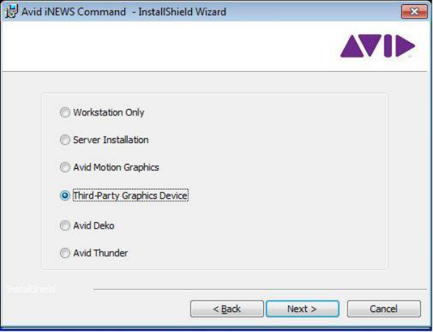
Installing Avid Graphic Device Service
127
4. Do one of the following:
tClick Change to designate an install directory, and then click Next.
tAccept the default location by clicking Next.
The Options dialog box opens.
5. Select Third-party Graphic Device and click Next.
The Custom Setup dialog box appears with the default services selected for installation of
client software. However, for CII integration, you must modify the selections to customize
your installation.
6. Deselect Avid iNEWS Command Workstation so that it is not installed.
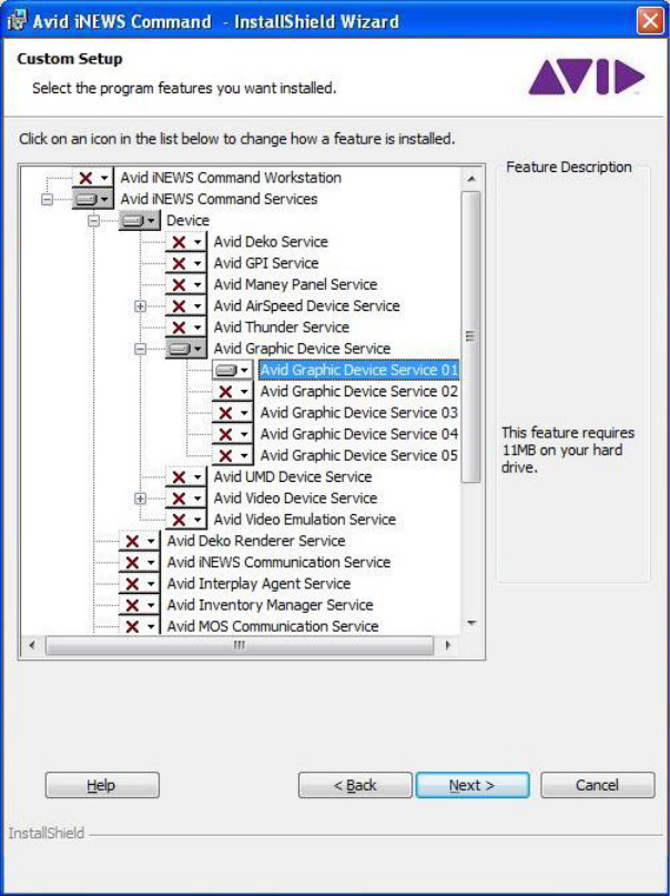
Installing Avid Graphic Device Service
128
7. Expand Avid Graphic Device Service and select Avid Graphic Device Service 01.
nThe Help button opens a dialog box that provides descriptions of the various install states
available for a custom installation as indicated by the icons. The Space button opens a dialog
box that provides information on whether the computer’s destination drive has enough disk
space available to install the current selection of features.

Installing Avid Graphic Device Service
129
8. Click Next to continue.
nThe Avid Graphic Device Service 01 should be the only service selected.
9. When the Ready to Install the Program dialog box appears, click Install.
10. When the installation is complete, click Finish.
You are now ready to install the appropriate plug-in or the Graphic Inventory Editor (GIE), if
necessary.

Installing Third-Party Plug-ins for the Graphic Device Service
130
Installing Third-Party Plug-ins for the Graphic Device
Service
The Avid Graphics device service can be used with several third-party plug-ins, which provide
API-based control to graphics devices. These plug-ins must be purchased directly from the
vendor; they are not part of the Command installation kit. Specific installation and configuration
information is provided by those third party suppliers; however, for your convenience, this
section contains general setup information for various graphics plug-ins you may use with
Command.
Checklist: Installing and Configuring for Third-Party Plug-ins
Complete the following tasks in the order that they are listed. If you are viewing this checklist
online, you can easily access a linked topic that provides procedural details for the task. Return
to this main checklist after you have completed each task.
nBefore installing, be sure to confirm that your plug-in is compatible with Command. See the
Compatibility Matrix for GDS plug-ins in the Avid iNEWS Command ReadMe for the latest
information.
Tasks Refer to...
Install the core components of Avid Service
Framework on the device. Select the Client
Install.
“Installing Avid Service Framework” on page 120
Install the Graphic device service on the device. “Installing Avid Graphic Device Service” on
page 124
Install the plug-in. The vendor’s installation instructions that came
with your third-party plug-in. After the plug-in is
installed, restart the Graphic device service.
nAll settings in Command and Framework are case sensitive. Ensure that case matches in all
configuration settings.
Configure the Graphic device service. “Configuring the Avid Graphic Device Service”
on page 131
Configure the plug-in. The vendor’s configuration instructions that came
with your third-party plug-in. After the
configuration is complete, restart the Graphic
device service.
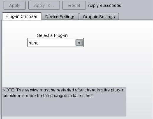
Installing Third-Party Plug-ins for the Graphic Device Service
131
Configuring the Avid Graphic Device Service
After the installations are complete, for the integration to succeed, some additional configuration
is required, using the Avid Service Configuration application of Avid Service Framework. For
more information about the ASF application, see the Avid Service Framework User’s Guide.
To configure the Graphic device service:
1. Click the Start button, and then select All Programs > Avid > Service Framework > Avid
Service Configuration.
2. On the Hosts tab, navigate to and select the Avid Graphic Device Service.
3. When prompted, enter the system administrator password and click OK. If you have not yet
created one, leave the space blank and click OK.
4. On the Plug-in Chooser tab, select the plug-in you intend to use, provided by a third-party
vender. By default this selection is set to none.
5. Click Apply and let the service restart before proceeding.
6. On the Device Settings tab, enter a name for the device. This name will be used later when
configuring the system’s settings in Command.
7. Set the Channel count to the number of channels your device will use.
8. Click Apply and let the service restart before proceeding.

CII Integration
132
CII Integration
In addition to the Graphic device service (GDS), the Graphic Inventory Editor (GIE) application
is also provided with Avid iNEWS Command and may be used to manage the inventory that
Command needs to control any third-party graphics device that uses the Chryon Intelligent
Interface (CII).
Checklist: Setting up Command for CII Integration
Complete the following tasks in the order that they are listed. If you are viewing this checklist
online, you can easily access a linked topic that provides procedural details for the task. Return
to this main checklist after you have completed each task.
nAvid strongly recommends installing Avid Service Framework (ASF), the Graphic device service,
and the Graphic Inventory Editor (GIE) on the device itself. If controlling more than one device,
then ASF, the device service, and GIE should be installed on each device.
Tasks Refer to...
Install the core components of Avid Service
Framework on the device.
“Installing Avid Service Framework” on page 120
Install the Graphic device service on the device. “Installing Avid Graphic Device Service” on
page 124
Install the Graphic Inventory Editor on the
device.
“Installing the Avid Graphic Inventory Editor” on
page 133
nAll settings in Command and Framework are case sensitive. Ensure that case matches in all
configuration settings.
Configure the Graphic device service. “Configuring the Avid Graphic Device Service
for CII” on page 133
Configure the Graphic Inventory Editor. “Configuring the Graphic Inventory Editor” on
page 137
Configure the system’s setting in Command and
the device, using the Lyric software, for CII
Integration.
“Configuring iNEWS Command Device
Channels and Channel Groups” on page 145
CII Integration
133
Installing the Avid Graphic Inventory Editor
After installing the Avid Graphic device service on the graphics device, you need to install and
configure the GIE application.
nThe GIE application is not needed for Command integration with Avid Deko products or
third-party graphics plug-ins. For users upgrading from ControlAir, the GIE application
replaces data in the SYSTEM.RESOURCE queue in the Avid iNEWS newsroom computer system.
To install the Avid Graphic Inventory Editor:
1. Insert the Command installation CD (or access the install program from the network).
The autorun installation program starts.
nIf the autorun does not begin, manually navigate to and run the
AvidGraphicInventoryEditorSetup.exe
install program from the CD.
2. Click the Avid Graphic Inventory Editor button.
3. When the Welcome dialog box appears, click Next.
4. Read and accept the license agreement, and then click Next.
5. The default Destination folder is:
C:\Program Files\Avid\Graphic Inventory Editor\
You can change the location first or accept the default by clicking Next.
6. When the Ready to Install the Program dialog box appears, click Install.
7. When the installation is complete, click Finish. When installed, a separated icon for the GIE
is made available on the desktop or in the Start menu.
Configuring the Avid Graphic Device Service for CII
After the installations are complete, for the integration to succeed, some additional configuration
is required, using the Avid Service Configuration application of Avid Service Framework. For
more information about the ASF application, see the Avid Service Framework User’s Guide.
To configure the Graphic device service:
1. Click the Start button, and then select All Programs > Avid > Service Framework > Avid
Service Configuration.
2. On the Hosts tab, navigate to and select the Avid Graphic Device Service.
3. When prompted, enter the system administrator password and click OK. If you have not yet
created one, leave the space blank and click OK.
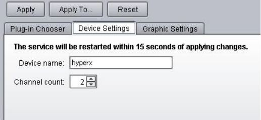
CII Integration
134
4. On the Device Settings tab, enter a name for the device. This name will be used later when
configuring the system’s settings in Command.
5. Set the Channel count to the number of channels your device will use, which is usually 1 or
2.
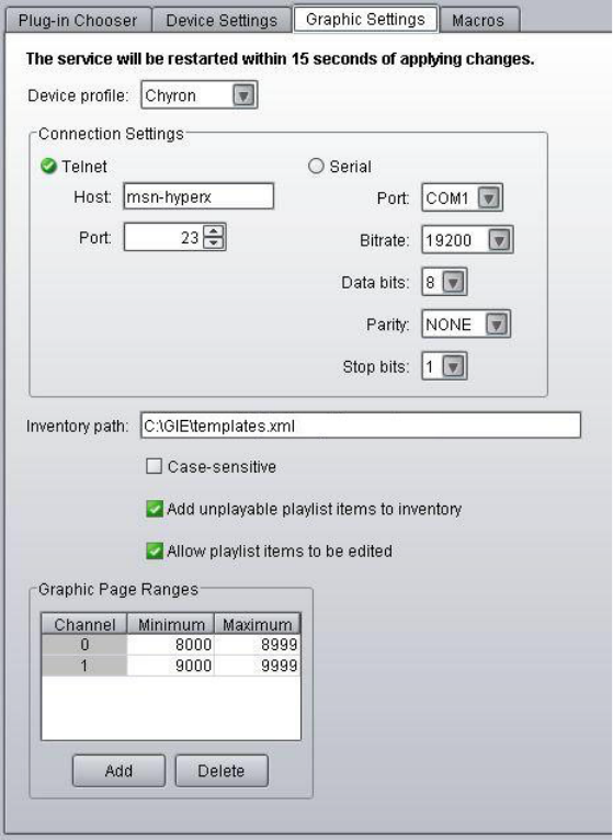
CII Integration
135
6. On the Graphic Settings tab, for Device profile, select the appropriate profile.
nDevice profiles are vendor specific because some of the CII commands used for playout vary
from vendor to vendor. The profiles also allow for customization of the transport commands.
7. In the Connection Settings section, do one of the following:
tSelect Telnet and enter the machine’s name for Host. Ensure the graphic device is also
set for a telnet connection.
tSelect Serial and fill in the appropriate information for port, bitrate, parity, and so forth.
CII Integration
136
8. The Graphic device service with CII protocol uses an XML file to keep inventory
information. The easiest way to create it is to make a new text file and then rename it,
changing the
.txt
tag to an
.xml
tag.
nAvid recommends keeping your inventory XML file in a dedicated folder, such as
C:\GIE\templates.xml
.
9. Set the Inventory path to the XML file that you just created.
10. Leave the Case-sensitive check box unselected, so that inventory items are not case sensitive.
11. If you do not need to use the Graphic Inventory Editor to manage inventory or if you use an
iNEWS Active-X plug-in, such as Chyron LUCI or Orad Maestro, select the check box
called Add unplayable playlist items to inventory.
12. Enter the page range(s).
This needs to be a range of graphics that will be used solely for Command. Ensure that page
ranges do not overlap between channel groups.
A show’s graphics will be loaded sequentially from the start of this page range when the
channel group is locked. If graphics are added or updated, they will be loaded to the page at
the end of the sequentially loaded pages.
cAlthough the Minimum field permits zero (0), it should be set to a number greater than the
largest page number used by your original graphics on the device; this is to ensure that
your original graphics are not overwritten by the temporary graphics that contain
fulfillment data for a show. The maximum value available is 99999998.
After a show with graphics is loaded to Command, the page numbers assigned to graphics
may be viewed in the playlist so long as the Graphic Page column is displayed.
Configuring Graphic Device Service Macros
Avid iNEWS Command supports sending a macro through the Avid Graphic device service, but
some additional configuration is necessary.
To configure Command for sending macros through the Avid Graphic device service:
1. Create a macro in the Chyron Lyric software.
cMacros should not be used to change the transport status of the item in the program
channel. Command relies on the transport status to be consistent when sending transport
commands; having a macro change that status could severely impact playout.
CII Integration
137
2. Go to the Avid Service Configuration application, locate the Graphic device service, and
define the macro on the Macros tab. Command supports up to 10 macros.
3. At a Command Workstation, select Tools > System Settings > Channel > Indices and add
your graphic channel to the index.
4. To trigger the macro, it needs to be added to an X-keys or GPI device.
tFor X-keys, select Tools > Options > Actions > K-keys. Click the button and in the
Choose Action dialog box, select the macros from Control > Macros.
tFor GPI, select Tools > System Settings > GPI and select the appropriate GPI. Then
select Control > Macros and the appropriate index.
nCommand sends the macro through its index, but unless the macro also specifies the frame buffer,
Chryon Lyric will apply the macro to the active frame buffer. So, even though Command is
channel specific, the macro is not channel specific unless the frame buffer is defined in the
macro.
Configuring the Graphic Inventory Editor
The configuration of the Graphic Inventory Editor (GIE) involves multiple procedures that are
covered in this section in a standard workflow. Configuration is done on the device, using the
GIE application. The GIE application provides a multi-tabbed user interface for managing
graphic inventory. Those tabs are: Templates and Styles. For more information about each tab in
the GIE application, see the following sections: “Working with Templates” on page 141 and
“Working with Styles” on page 143.
The first step in the configuration process is to identify a path to your graphic inventory.
To specify the inventory path:
1. Click the Start button and select Programs > Avid > Avid Graphic Inventory Editor.
2. Click the Browse button.
3. In the Browse dialog box, navigate to the XML file specified earlier in the Avid Service
Configuration application.
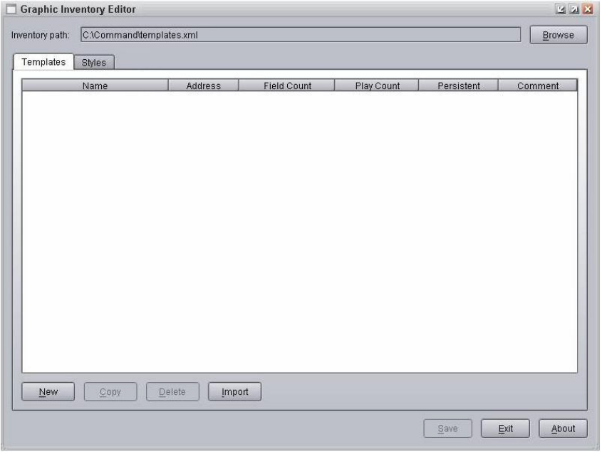
CII Integration
138
4. Click Open.
After an inventory path is set, the New and Import buttons are enabled.
Importing Inventory
The following procedure only applies to sites converting from ControlAir to Command.
To import graphic inventory from SYSTEM.RESOURCE:
1. At an iNEWS Workstation, check for errors by turning on the monitor server on any iNEWS
rundown and reading the messages sent back from that utility program; look for any
problems with SYSTEM.RESOURCE.
2. Fix the problems before proceeding.
3. Export all stories in SYSTEM.RESOURCE as plain text files (all files). This can be done in
a single operation by selecting all of them in the queue and selecting File > Export.
4. Open the Graphic Inventory Editor.
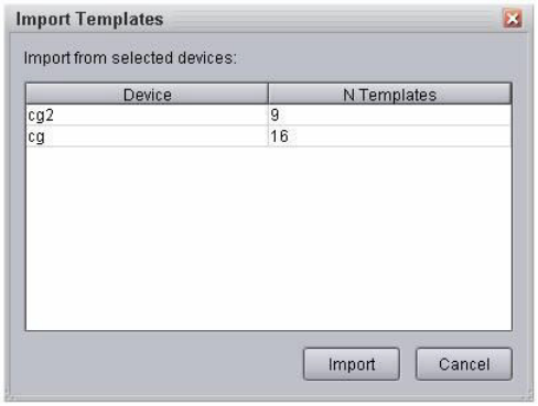
CII Integration
139
5. Click the Templates tab.
6. Click the Import button.
7. Select the file you just saved.
8. Click Open. An Import Templates dialog box appears.
9. Choose from among the devices provided; these are devices known to iNEWS. You can
select multiple devices by pressing the Shift or Control keys down while making your
selections. With Command, these individual devices will be converted to styles—lower
thirds and stills, for example.
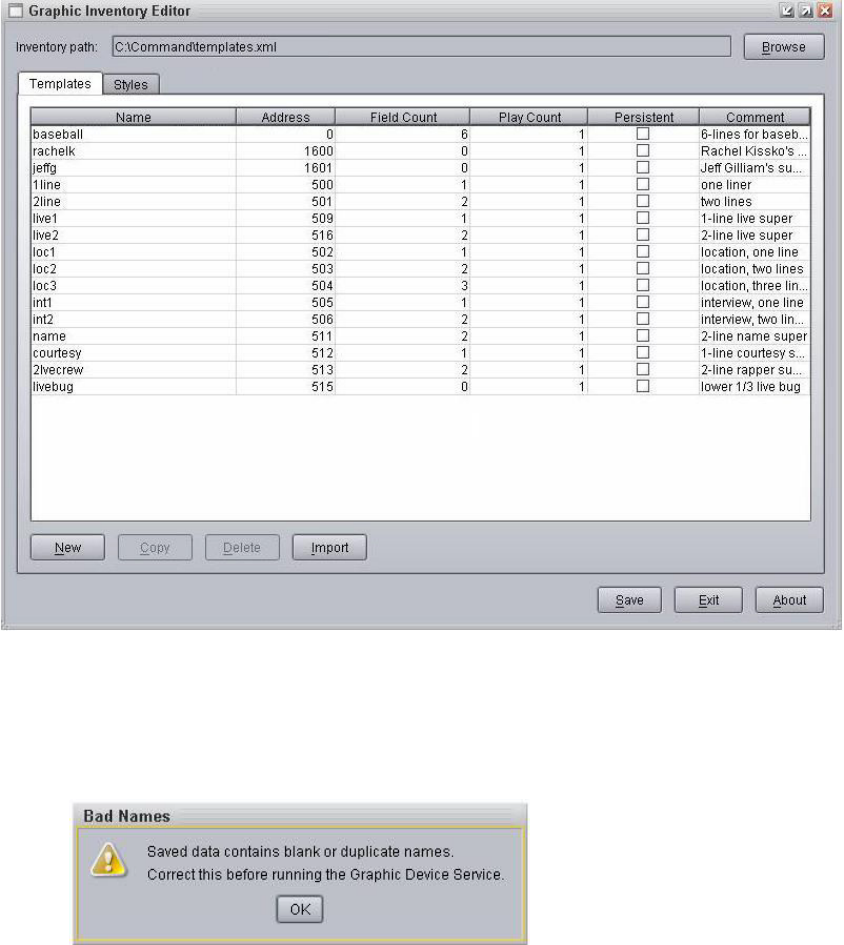
CII Integration
140
10. Click Import. The inventory of templates will appear on the Templates tab in the Graphic
Inventory Editor window.
nThe GIE application will allow the importation of templates that might share the same name of
existing templates. If duplicates result from the importation or creation of templates, a Bad
Names dialog box will appear to warn you that this issue must be resolved before the Graphics
device service will work.
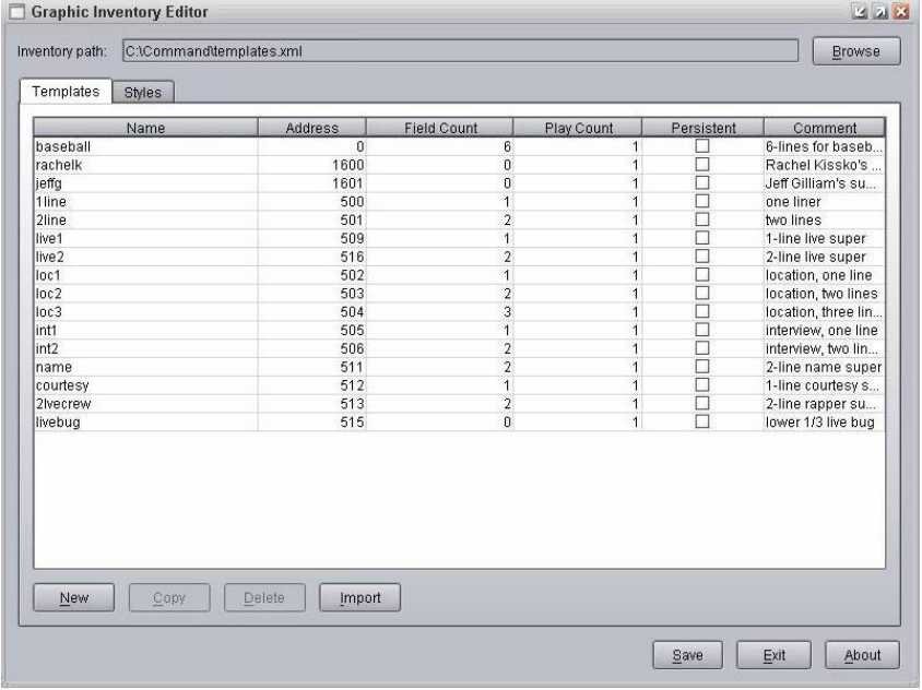
CII Integration
141
Working with Templates
A template is a graphic with a pre-set look and fields (or layers) for replaceable data, such as text
or video clips. Templates can be grouped together to form a style, such as a set of graphics
designed for a specific show.
This section provides additional details on the Templates tab in the Graphic Inventory Editor and
how to manage templates in the Command inventory. You can create a new template, copy an
existing template, or delete templates from the inventory. Although you can also add or remove
templates from a style, you must do that on the Styles tab.
nYou can also import a list of templates from a pre-existing inventory in an Avid iNEWS newsroom
computer system. Although previous versions of Command allowed for more than one, there can
be only one template name per address. For more information, see “Importing Inventory” on
page 138.
CII Integration
142
To create a new template:
1. Click the New button at the bottom of the Templates tab. A new blank row will appear in the
list of templates.
2. Type the name of the new template in the Name column.
3. Fill in the address information for the template. For CII integration, the address in Command
must match the address of the template on the device.
4. Set the field count to a numerical value. This number must match the number of replaceable
fields in the graphic.
5. Set the Play count to a numerical value. This number must match the number of triggers in
the item—that is the number of times an operator must press Play to get through all of the
effects in the template.
6. Select the check box in the Persistent column if the template is one that will remain onscreen
while other graphics are played and ejected. An example of a persistent template is a LIVE
graphic that remains onscreen during a live broadcast while other location or name graphics
are also aired as lower-thirds.
7. (Optional) Type a meaningful description of what the template is used for, such as:
Lower-third Location with two fields.
8. Click Save.
To copy a template:
1. Select a template from the list of templates on the Templates tab.
2. Click Copy.
3. Click in the Name and Address fields to rename the copy.
4. (Optional) Modify the other fields associated with the copied template as needed.
5. Click Save.
To delete a template:
1. Select a template from the list of templates on the Templates tab.
2. Click Delete
nIf deleting a template that has already been assigned to a style, a warning will appear to notify
you of the assignment and confirm the deletion. If confirmed, the template is deleted from the
inventory as well as the style. However, to clarify, deleting a template in the GIE application
does not remove the corresponding file from the Chyron graphics device.
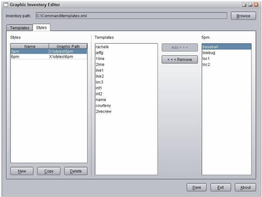
CII Integration
143
Working with Styles
A style sets the path to the actual graphics files on the device; therefore, all templates need to be
added to a style before they can be played. The style also needs to be set in iNEWS in
SYSTEM.MAP.
This section provides additional details on the Styles tab in the Graphic Inventory
Editor—shown below—and how to manage styles in the Command inventory. You can create a
new style, copy or edit an existing style, and delete styles from the inventory.
To create a style:
1. Click the New button at the bottom of the Styles tab. A new blank row appears in the list of
styles.
2. Type the name of the new style in the Name column.
3. Fill in the path information for the style. The path is the location on the actual graphics
device where the styles are stored.
CII Integration
144
4. From the Templates list, select the template or templates you want to add to the new style.
nYou can use Ctrl+A, Shift+click, or Ctrl+click to make your selection.
5. Click Add.
6. (Optional) To remove a template from the style, select it from the New list and click
Remove.
7. Click Save.
To copy a style:
1. Select a style from the list of styles on the Styles tab.
2. Click Copy.
3. Click in the Name field to rename the copy.
4. (Optional) Add or remove templates from the copied style as needed.
5. Click Save.
To delete a style:
1. Select a style from the list of styles on the Styles tab.
2. Click Delete.
nDeleting a style in the GIE does not remove anything from the actual graphics device. It deletes
the style from the inventory (located in the root directory on the PC) than Command uses to
control the device.
After you have created all of the styles, you need to define them in Command.
To add styles to a Command Workstation:
1. Select Tools > System Settings.
2. Select Playlist.
3. In the Graphics Style section, click the Add button to add styles to the list.
nThe default style must also be defined in SYSTEM.MAP in iNEWS. For instance:
video ABCD - A ;
cg 1 - hyperx WAVD;
cg 2 - microx STILLS;
CII Integration
145
To assign a style for a standalone playlist:
1. Right-click on the playlist’s channel group icon.
2. Select Edit properties for this channel group. The Playlist Channel Group Properties dialog
box appears.
3. Enter the style.
4. Click OK.
The following list contains further guidelines related to playback.
• Numeric only items do not need to be added to the GIE.
• Numeric only items will show up originally as unavailable in the Command playlist, even if
the item exists on the graphics device. Lock the channel group; this will make Command
check for availability and correct the status.
• In Command, page numbers are written when the playlist is locked. This is by design and is
different from ControlAir, where the page numbers were written when the show was loaded.
• If a new graphic is created in the GIE, the new graphic will not show up until after the
monitor server for the show is turned off and back on in iNEWS.
Configuring iNEWS Command Device Channels and Channel Groups
Some additional configuration is required to enable Command via the Graphic device
service—part of which is done at a Command Workstation, and part of which must be done on
the device itself.
To configure device channels and channel groups in Command:
1. Start the Avid iNEWS Command Workstation application. The Choose Command
Workgroup dialog box opens.
2. Select your Command workgroup and click OK. The iNEWS Command application
launches.
3. Select Tools > System Settings. The System Settings dialog box appears.
4. Expand Channel.
5. Select Device Channels.
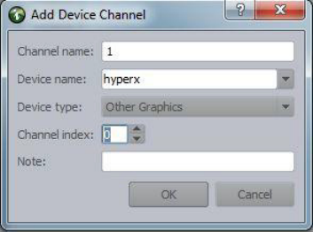
CII Integration
146
6. Click Add. The Add Device Channel dialog box appears.
7. Do the following:
a. In the Channel name field, type a channel name. The channel name must match what
was entered in the AMGconf.ini file. Avid recommends using numbers for the name of
the channel.
b. In the Device name field, type a device name. The device name must match the device
name set for the Graphic device service on the Device Settings tab in the Avid Service
Configuration application.
c. In the Device type field, set the device type to Avid Motion Graphics.
d. Set the channel index to zero (0) for channel 1.
e. Click OK. The Add Device Channel dialog box closes.
f. Repeat these steps for each device channel as needed. For instance, if using two
channels, add a second device channel and set the channel index to 1 for channel 2.
8. Click Apply.
9. Type a password, if necessary, and click OK.
10. In The System Settings dialog box, select Groups.
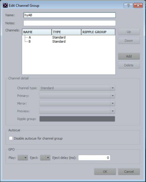
CII Integration
147
11. Click Add. The Create New Channel Group dialog box appears.
a. In the Name field, set the name of the group to something eight characters or less with
no spaces.
b. Click Add for each channel in the group.
c. Select the appropriate device channel from the Primary menu.
12. Select Playlist, and then the Add button in the Graphics Style section.
13. Change the newly added style from its default name of Style to Style-1.
14. Click Apply and then set it as the default style if you are no longer using Deko, or any other
device.
CII Integration
148
15. Click OK to save the changes.
Configuring 3rd Party Software
Additional configuration in the 3rd party device's software is also needed. Please see below for
the specific device.
Configuring the Chyron Lyric Software
This section contains information on how to configure the Chyron Lyric software.
To configure the Lyric software:
1. In the Lyric application, select Config > Intelligent Interface.
2. Select the Enable Telnet check box.
nWhen switching from ControlAir to Command (from serial to telnet communications), be sure to
change all macros on the device so that the Chyron Intelligent Interface configuration setting
does not get altered inadvertently.
Use the Clone Canvas feature to send preview output to a VGA monitor in the control room.
See the Lyric Help system for further instructions.
Configuring the GDS for Chyron LUCI iNEWS ActiveX Support
Avid iNEWS Command supports both hand-entered items and newsroom playlist items added to
an iNEWS rundown via the Chyron LUCI plug-in.
For the plug-in to work, however, some minor configuration of the Graphic device service is
necessary. Sites that use the Chyron LUCI plug-in also need to change the MOS configuration on
the CAMIO server. Procedures for both configurations are provided in this section.
To configure the Graphic device service to support the LUCI plug-in:
1. Click the Start button, and then select All Programs > Avid > Service Framework > Avid
Service Configuration.
2. On the Hosts tab, navigate to and select the Avid Graphic Device Service.
3. When prompted, enter the system administrator password and click OK. If you have not yet
created one, leave the space blank and click OK.

CII Integration
149
4. On the Graphic Settings tab, at the bottom, select Add unplayable playlist to inventory.
nUsers need to select the Command profile in CAMIO so that Command correctly parses the
plug-in data.
The following limitations apply:
- Items can be numeric only, such as 10256.
- Items cannot be multi-triggered. This is set in the Graphic Inventory Editor application.
- Items cannot be persistent. This is set in the Graphic Inventory Editor application.
To modify MOS configuration settings on the CAMIO server:
1. Open the CAMIO Admin Tool Web page and go to MOS Configuration.
2. Click Show Advanced, and then More Advanced.
3. Change the Slug field from %s to %m.
4. Click the Submit button.
This will change the XML data so that the item slug has the message number.

5Installing and Configuring the Deko
The Avid iNEWS Command user interface allows you to control multiple production devices,
such as Deko character generators. For the interface to work, however, some software installation
and configuration is required.
•System Architecture
•Checklist: Installing the Deko
•Installing Avid Service Framework
•Installing Avid Deko Device Service
•Installing the DekoMOS Gateway
•Installing the DekoMOS Macro Server
•Checklist: Configuring the Deko
•Configuring the DekoMOS Gateway
•Configuring the DekoMOS Macro Server
•Configuring Avid Workgroup Properties
•Configuring the Deko Device Service
•Configuring the Avid Deko Renderer Service
•Creating Graphic Styles in Command
System Architecture
151
System Architecture
Understanding the relationship of Avid iNEWS Command to other aspects of the newsroom
environment, such as Avid Deko systems, is helpful.
Your newsroom computer system such as Avid iNEWS (or ENPS) organizes the newsroom.
There is two-way communication between the iNEWS Server and other workstations running
the iNEWS and iNEWS Command client software in regard to production and management of
playlists. Each iNEWS Workstation can have the Deko Select plug-in, functioning as part of the
user interface that enables a journalist to drag and drop any Deko graphics template into a news
story and alter replaceable text or graphics in the selected template. The Deko Select plug-in
communicates with the DekoMOS Gateway.
The DekoMOS Gateway is the essential interface for integration of the newsroom computer
system and Command with various Deko components in regard to the creation, modification, and
playout of graphic elements in newsroom playlists. The DekoMOS Gateway manages
configuration information and presents logs of DekoMOS activity and connections. The
DekoMOS Macro Server, installed on all Deko devices used for playout, allows Command to
communicate with the Dekos. The DekoMOS Macro Server receives and processes macro
commands. It also acts as a client to the DekoMOS Gateway to retrieve a list of defined styles.
Through this integration, Command can control playback of graphics on Deko systems and drive
up to nine channels of Deko across multiple systems from a single user interface.
nIn this explanation, the term Deko refers to any one of these products: Deko 3000, Deko 3000
Hybrid, Deko 3000 HD, FXDeko II, Deko 2200, Deko 1000, Deko 1000 Hybrid, Deko 1000 HD,
and Deko 550.

System Architecture
152
Command with Avid Deko Overview
This section contains an overview of each component involved in a Command/Deko workflow
and the main purpose each serves.
Component Description
DekoMOS Gateway • Defines Deko styles
• Equates channel number (1-9) with a MOS ID
• Provides inventory to the Avid Deko Select plugin in iNEWS
Avid iNEWS •
SYSTEM.MOS-MAP
equates the MOS ID with the channel group in
Command
•
SYSTEM.MAP
associates the newsroom rundown with the channel group
and assigns a style
Avid Deko Select Used to choose the channel number and style for an item that is dragged into
the newsroom rundown.
Avid iNEWS Command • Creates channel groups
• Creates graphic environments (also known as styles in Deko) for
standalone playlists
• Sends playout control commands to the Avid Deko device
Avid Deko • Inventory is copied from this device to the DekoMOS Gateway.
• Deko software provides graphics for on-air playout.
DekoMOS Macro Server • Gets style list from DekoMOS Gateway
• Sets style paths for replaceable, static graphics, motions, and so forth
• Sends inventory to the Inventory Manager in Command

Checklist: Installing the Deko
153
Checklist: Installing the Deko
Ensuring integration with devices, such as the Avid Deko, requires installation of various
components and services, as well as some configuration. Using the Avid Deko as the example of
a device, the following is a checklist of activities an installer should verify to ensure a successful
installation.
Complete the following tasks in the order that they are listed. If you are viewing this checklist
online, you can easily access a linked topic that provides procedural details for the task. Return
to this main checklist after you have completed each task.
After installation, some configuration is required. For more information, see “Checklist:
Configuring the Deko” on page 166.
For more information on installation of the Avid Deko Select plug-in, see “Setting up the
Plug-ins in iNEWS” on page 271.
Tasks Refer to...
Connect the Deko to the network. The documentation that came with your Avid
Deko for more information..
Install the Deko software.
Install the core components of Avid Service
Framework on the Deko.
“Installing Avid Service Framework” on page 154
Install Deko device service from the Avid iNEWS
Command software installation CD.
“Installing Avid Deko Device Service” on
page 158
Install the DekoMOS Gateway. This requires a
dongle.
“Installing the DekoMOS Gateway” on page 164
Install DekoMOS Macro Server on the Deko. “Installing the DekoMOS Macro Server” on
page 165

Installing Avid Service Framework
154
Installing Avid Service Framework
Each computer and device running Avid iNEWS Command software requires at least the core
components of Service Framework and must be able to connect to a computer running the Avid
Lookup service.
To install the Service Framework software:
1. Insert the Command installation CD (or access the install program from the network).
The autorun installation program starts and displays the following screen.
nThe Command Documentation button will open a window displaying the contents of the Doc
folder on the Command installation CD in which product documentation is provided in PDF
format.
If the autorun does not begin, manually navigate to and run the
ServiceFrameworkSetup.exe
install program.
2. Click the Avid Service Framework button.
nOther dialog boxes could appear depending on whether older versions of Service Framework are
found, particularly if upgrading existing software. If one appears, read it carefully and reply
accordingly with regard to upgrades, etc.
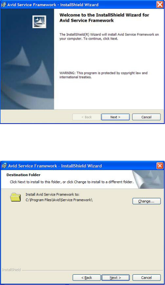
Installing Avid Service Framework
155
A splash graphic will appear briefly as the installer prepares the InstallShield Wizard. Then
the Welcome dialog box appears.
3. Click Next.
The Destination Folder dialog box opens.
nIf space is a concern on the C drive, install in the
D:\Avid\Service Framework\
directory.
You will need to create these directories.
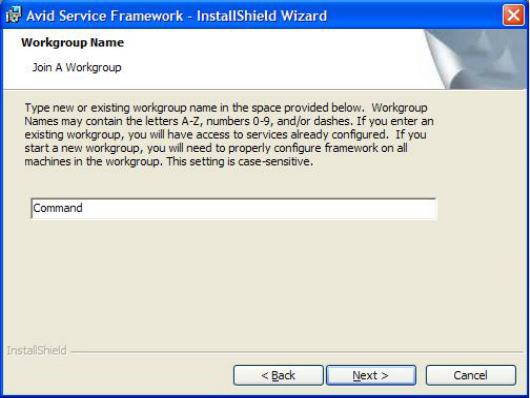
Installing Avid Service Framework
156
4. Set the location to which Avid Service Frameworkwill be installed and click Next.
The Workgroup Name dialog box opens.
5. Type the name of the Command workgroup in the field.
cIf you are updating the Service Framework software, the installer remembers the last
installed value. If the workgroup name was changed after the install, the installer will not
be aware of the change.
6. Click Next.
The Options dialog box opens.

Installing Avid Service Framework
157
7. Select the option: Avid Service Framework Client and click Next.
The Custom Setup dialog box opens.
By default, the Time Synchronization service is selected to be installed; however, this
service should only be installed if you do not already use something to synchronize your PC
clocks. If you use NTP or some other method for time synchronization, do not install this
service. For more information about the services in this dialog box, see the tables in page 24.
8. Click Next and follow the installation instructions to complete the installation.

Installing Avid Deko Device Service
158
nYou might be required to restart your system to complete the installation.
After installation, verify that the services are running on each computer where Service
Framework services were installed.
Installing Avid Deko Device Service
The Command installation CD provides for installation of services associated with various
production devices, such as the Avid Deko.
To install the Deko device service on the Deko:
1. Insert the Command installation CD (or access the install program from the network).
The autorun installation program starts and displays the following screen.
nThe Command Documentation button will open a window displaying the contents of the Doc
folder on the Command installation CD in which product documentation is provided in PDF
format.

Installing Avid Deko Device Service
159
2. Click the Avid iNEWS Command button. If Avid Service Framework is not already
installed, a warning dialog box will appear.
If it does, click OK and install Avid Service Framework before restarting this installation.
See “Installing Avid Service Framework” on page 154 for more information.
nOther dialog boxes could appear depending on whether older versions of Service Framework,
the License service, or Command are found on the server, particularly if upgrading the
Command Server software. If one appears, read it carefully and reply accordingly with regard to
upgrades, etc.
If all prerequisite installations are in order, and the Command Server installation can
proceed, a splash graphic will appear briefly as the installer prepares the InstallShield
Wizard. Then the Welcome dialog box appears.
3. Click Next. The License Agreement appears.
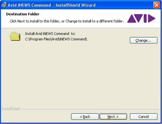
Installing Avid Deko Device Service
160
4. Read the License Agreement, accept the terms, and click Next.
If you do not accept the terms, the installation program will not continue.
nYou can print the terms if you want to read them later or keep a copy for your records.
The Destination Folder dialog box opens.
nIf space is a concern on the C drive, install in the
D:\Avid\iNEWS Command\
directory. You will
need to create these directories.
5. Do one of the following:
tClick Change to designate an install directory, and then click Next.
tAccept the default location by clicking Next.

Installing Avid Deko Device Service
161
6. When the Options dialog box opens, select Avid Deko.
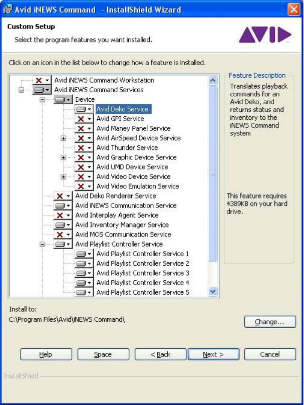
Installing Avid Deko Device Service
162
The Custom Setup dialog box will appear.
nThe Help button opens a dialog box that provides descriptions of the various install states
available for a custom installation as indicated by the icons. The Space button opens a dialog
box that provides information on whether the computer’s destination drive has enough disk
space available to install the current selection of features.

Installing Avid Deko Device Service
163
7. Click Next.
8. When the Ready to Install the Program dialog box appears, click Install.
9. When the installation is complete, click Finish.
To verify that installed services are running, you must use the Avid Service Framework
Workgroup Properties application.
Installing the DekoMOS Gateway
164
Installing the DekoMOS Gateway
The Net HASP dongle, supplied by Avid, as well as the HASP License software and driver are
part of the DekoMOS Gateway installation. Therefore, installing the DekoMOS Gateway is
three-fold:
•Connecting the Net HASP Dongle
•Installing the DekoMOS Gateway and Net HASP Software
•Confirming the NetHASP License Manager Configuration
nFor thumbnails of Deko graphics to appear in Command, the DekoMOS Gateway must be in the
same domain as the Command Server(s).
The DekoMOS Gateway cannot be installed on the iNEWS Gateway or ENPS Server. Avid
recommends installing the DekoMOS Gateway on the Command Server. However, if it’s
installed on another computer, the selected computer must have a network connection to the
Deko and should be running Windows 2003 Server operating system, not Windows XP.
Otherwise, because of Windows limitations, the number of clients allowed to connect
simultaneously is limited to ten.
Connecting the Net HASP Dongle
The Net HASP dongle included with your Deko system should be connected to the computer
where you will install the DekoMOS Gateway software.
To connect the Net HASP Dongle:
tConnect the dongle to either the parallel port or one of the USB ports on the back of
the machine. The Net HASP dongle enables the Deko Select option for the newsroom
workstations.
The Net HASP License Manager, the driver for the Net HASP, installs automatically with the
DekoMOS Gateway software.
Installing the DekoMOS Gateway and Net HASP Software
To install the DekoMOS Gateway on a dedicated computer:
1. Insert the Deko Select installation CD in the computer’s CD-ROM drive (or access the
program from the network).
2. Navigate to and run the
DekoMOSGateway.exe
install program.
3. Click OK and follow the instructions on the screen to install the software.
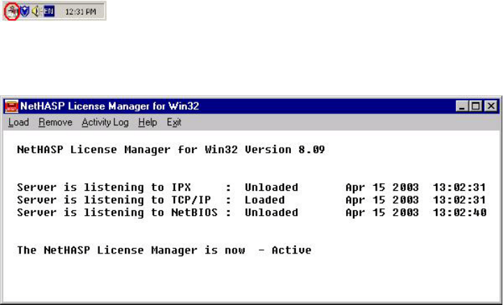
Installing the DekoMOS Macro Server
165
nAvid recommends selecting Service as the installation option for the Net HASP License Manager.
After installing, you should confirm that the Net HASP License Manager is running and that it is
configured to use TCP/IP.
Confirming the NetHASP License Manager Configuration
You will need to confirm that the NetHASP License Manager is both running and configured
properly.
To confirm activation and configuration of the NetHASP License Manager:
tRight-click the NetHASP License Manager icon (circled in red below) in the system tray at
the bottom of your screen and select Show.
The Net HASP License Manager window opens. You should see the words Server is
listening to TCP/IP: Loaded and Net HASP License Manager is now - Active.
Installing the DekoMOS Macro Server
The DekoMOS Macro Server should be installed on each Deko used for playout to air.
To install the DekoMOS Macro Server on the Deko:
1. Insert the Deko Select installation CD in the Deko device’s CD-ROM drive.
2. Navigate to and run the
DekoMOSMacroServer.exe
program.
3. Click OK or press Enter.
4. Follow the on-screen prompts to complete the installation.

Checklist: Configuring the Deko
166
Checklist: Configuring the Deko
For integration between Command and Deko to succeed, some configuration is required.
Complete the following tasks in the order that they are listed. If you are viewing this checklist
online, you can easily access a linked topic that provides procedural details for the task. Return
to this main checklist after you have completed each task.
nAll settings in Command and Framework are case sensitive. Ensure that case matches in all
configuration settings.
Tasks Refer to...
Configure the DekoMOS Gateway. “Configuring the DekoMOS Gateway” on
page 167
Configure the DekoMOS Macro Server. “Configuring the DekoMOS Macro Server” on
page 175
Configure the styles in the DekoMOS Macro
Server.
“Configuring Styles on the DekoMOS Macro
Server” on page 177
Configure Avid Workgroup Properties for the
Deko.
“Configuring Avid Workgroup Properties” on
page 179
Configure the Deko device service. “Configuring the Deko Device Service” on
page 181
Add the MOS-IDs for Command channel
group(s) to the
SYSTEM.MOS-MAP
story in Avid
iNEWS.
“Editing the SYSTEM.MOS-MAP Story” on
page 269
(Optional) If you intend to use standalone
playlists in Command or use the Avid Deko
Select plug-in with ENPS and Avid iNEWS
Command, create the same styles—configured in
the DekoMOS Macro Server—as graphic styles
in Command.
“Creating Graphic Styles in Command” on
page 183

Configuring the DekoMOS Gateway
167
Configuring the DekoMOS Gateway
Templates exist on both the DekoMOS Gateway and the Deko device. The DekoMOS Gateway
is then used to supply thumbnail graphics and handle file requests from plug-ins at multiple
workstations, thus relieving such burden from the actual device that might be busy during
playout. Duplication of assets on the gateway and device is not automatic; therefore, it must be
maintained manually.
After the DekoMOS Gateway is installed, you need to configure various settings in the software.
This section covers only those settings that directly impact integration with Command.
nFor more information on how to configure the DekoMOS Gateway and for further explanation of
the settings available for configuration that are not covered in this book, see the Avid Deko
Select Installation and User’s Guide.
To configure the DekoMOS Gateway:
1. Determine if the DekoMOS Gateway is running.
- If the DekoMOS Gateway is not running, click the Start button and select
Programs > Avid Systems > DekoMOS > DekoMOS Gateway.
- If the DekoMOS Gateway is running, maximize the window by right-clicking on the
icon (shown below next to the clock) in the taskbar’s system tray.
2. If you have not previously configured DekoMOS Gateway, or if it is missing any required
information, the DekoMOS Gateway Configuration dialog box will automatically open
when the application starts.
If it does not open, do one of the following:
tClick the Configure button.
tPress Alt+C.
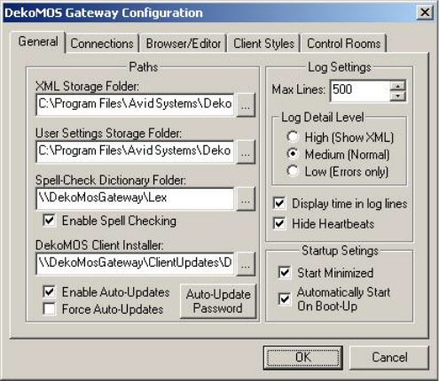
Configuring the DekoMOS Gateway
168
3. Select the General tab.
4. In the Paths area, enter settings as follows:
tIn the XML Storage Folder text box, enter or browse to the pathname of the folder for
storing active rundowns. If you enter a folder name that does not exist, when you click
OK, the system will prompt you with a question asking if you would like the system to
create this folder. This path should be local to the DekoMOS Gateway computer and
therefore begin with a drive letter, such as
C:
.
tIn the User Settings Storage Folder text box, enter or browse to the pathname of the
folder for storing individual user client settings. If you enter a folder name that does not
exist, when you click OK, the system will prompt you with a question asking if you
would like the system to create this folder. This path should be local to the DekoMOS
Gateway computer and therefore begin with a drive letter, such as
C:
.
nIn most cases, these are left at the default settings. The remaining settings on the General tab can
also be left at the defaults.
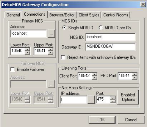
Configuring the DekoMOS Gateway
169
5. Select the Connections tab.
6. In the Primary NCS area, enter
localhost
for the address.
7. Avid recommends leaving the port settings in the Primary NCS and Listening Ports areas set
to the defaults.
8. In the Net HASP Settings area:
tThe IP address text box automatically defaults to the address of the current computer.
Ensure that the address is correct and belongs to the DekoMOS Gateway computer with
the Net HASP License Manager software installed. If not, enter it.
tKeep the default setting of 475 in the Port field to indicate the port number where the
Net HASP checks for connections. This can be changed if you receive an error message.
9. In the MOS IDs area, enter the Gateway ID and set the NCS ID to
localhost
.
This setting enables every template that is dragged and dropped into a story to use the
specified ID.
nThe Gateway ID must match the MOS ID specified in the
SYSTEM.MOS-MAP
story in the iNEWS
newsroom computer system.
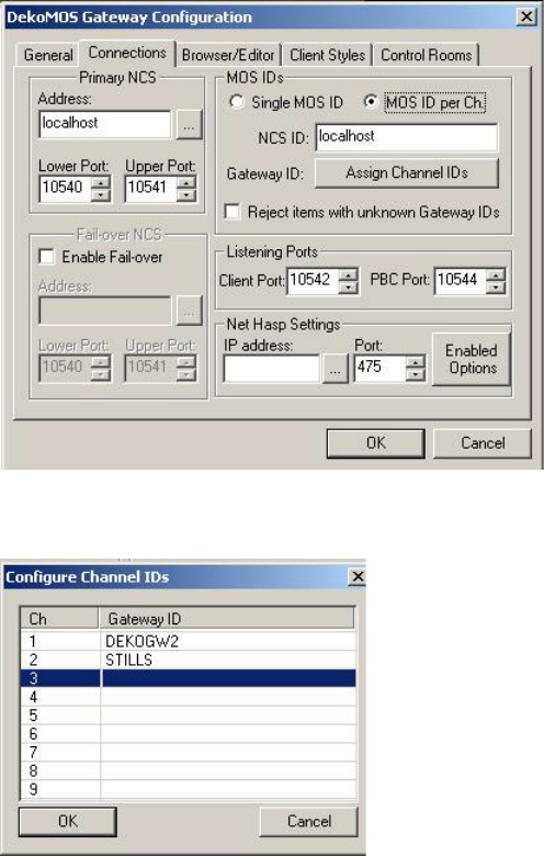
Configuring the DekoMOS Gateway
170
10. Select the MOS ID per Ch radio button to enable users the ability to drag and drop templates
into specific channels. Once you select this radio button, the dialog box changes to reveal the
Assign Channel IDs button.
11. Click the Assign Channel IDs button. The Configure Channel IDs dialog box opens.
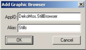
Configuring the DekoMOS Gateway
171
12. For each channel listed in the Ch column (that is, 1, 2, 3, 4...), in the Gateway ID column,
enter a corresponding MOS ID for the channels you want to use.
With MOS ID per Ch selected and channel IDs configured, the MOS ID of the templates that
are dragged and dropped into a story will vary depending on the channel with which the
template was dropped.
nThe channel IDs configured in the DekoMOS Gateway must be added to the
SYSTEM.MOS-MAP
story in the iNEWS newsroom computer system. For more information, see “Editing the
SYSTEM.MOS-MAP Story” on page 269.
13. Click OK to return to the DekoMOS Gateway Configuration dialog box.
14. Select the Reject items with unknown Gateway IDs check box unless you are using Avid
Deko Select with an ENPS system and MOS Redirection.
15. Click the Browser/Editor tab.
16. In the Graphic Browsers area, click the Add button.
The Add Graphic Browser dialog box opens.
17. Type
<manual>
in the Alias field.
18. Type
<manual>
in the AppID field.
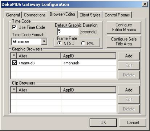
Configuring the DekoMOS Gateway
172
19. Click OK.
The settings you entered will appear in the corresponding columns in the Graphic Browsers
area.
nSetting Graphic Browsers to
<manual>
enables the Deko Select plug-in for manual entry of
replaceable graphic names or numbers.
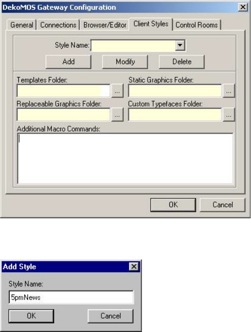
Configuring the DekoMOS Gateway
173
20. Click the Client Styles tab.
21. Click the Add button. The Add Style dialog box opens.
22. Enter a style name in the Style Name text box (with no spaces) and click OK.
This is the name that will appear in the Deko Select plug-in on the newsroom computer
system workstations and in the Avid iNEWS Command Inventory.
nThe Deko style is also referenced by the DekoMOS Macro Server and must be in the iNEWS
SYSTEM.MAP
story for each rundown using the Deko with Command. For more information, see
“Configuring Styles on the DekoMOS Macro Server” on page 177.
23. If the style name you just added is not displayed in the Style Name text box on the Client
Styles tab, click the Down arrow beside the text box to select it from a list of style names.
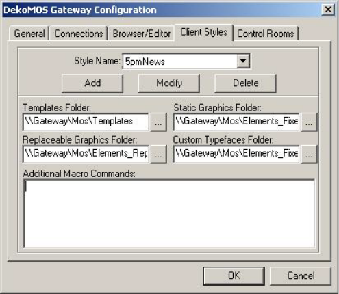
Configuring the DekoMOS Gateway
174
24. In each of the four Folder text boxes, enter the path that the style should reference or press
the button to the right of each text box to navigate to the appropriate folder.
All newsroom computer system workstations will locate the elements for display in these
folders.
nAvid recommends that they reside on the computer where the DekoMOS Gateway is installed. All
folders should be shared for Read Only access. This ensures that the graphics remain as they
were created while allowing access to those graphics. For best performance, files for playout are
stored on the Deko. Duplicate files stored on the DekoMOS Gateway are accessed by the Deko
Select plug-in.
The path you enter must be a UNC path and not a drive letter path. The format for a UNC
path is
\\server\volume\directory
and is not case-sensitive. For example:
\\Shared1_svr\Shared1\WGroups
25. On the Control Room tab, enter a name for a control room.
26. Click OK.

Configuring the DekoMOS Macro Server
175
Deko and Deko Select Subfolders
Users can organize their templates into subfolders, both on the DekoMOS Gateway and the Deko
device itself. Command supports the use of subfolders with the Deko for both hand-entered
(*CG) and Deko Select items.
nThe Deko and DekoMOS Gateway must have a uniform subfolder structure so, for instance, an
item in the Sports\Score subfolder on the Deko must also be in the Sports\Score subfolder on the
DekoMOS Gateway.
For hand-entered items, the subfolder must be added prior to the template in the iNEWS
production cue. For example, the SPORTS folder is a subfolder of the base template directory,
and the SCORE folder is in the SPORTS folder. F_SCORE1 is the name of the template, which
contains four fields.
*cg SPORTS\SCORE\F_SCORE1
FIELD1
FIELD2
FIELD3
FIELD4
Configuring the DekoMOS Macro Server
To configure the DekoMOS Macro Server:
1. Do one of the following:
tIf the DekoMOS Macro Server is not running, access the configuration window by
clicking the Start button and select Programs > Avid > DekoMOS > DekoMOS Macro
Server.
tDouble-click the desktop icon.
tIf the DekoMOS Macro Server is running and is visible in the system tray, click the
DekoMOS symbol in the system tray to maximize the application.
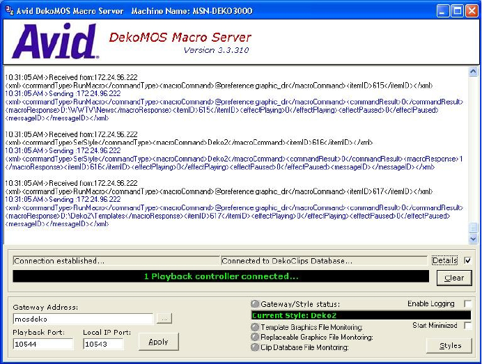
Configuring the DekoMOS Macro Server
176
The DekoMOS Macro Server window appears. The top portion of the window displays a log
of DekoMOS Macro Server activity. The XML commands that the DekoMOS Macro Server
is executing are shown in the white text area. Blue text indicates that things are OK. Red text
indicates that there is a problem. The Gateway/Style status icon appears green on
connection; it does not stay green.
2. To specify that this log shows data communication in full xml view, select Details, near the
bottom right of the window. Or, deselect Details to show a simple one line view. To clear the
information displayed here, click the Clear button.
3. In the Gateway Address text box, type the IP address or host hame of the machine running
the DekoMOS Gateway.
4. The Playback Port text box and the Local IP Port text box are 10544 and 10543, respectively,
by default. Do not change these port numbers unless you receive an error message. The
Playback Port number must be the same number you typed during DekoMOS Gateway
configuration as the Playback Port.
5. Click the Apply button below the Gateway Address text box.
6. Click Enable Logging if you want all logged information about DekoMOS Macro Server
activity to be automatically sent to the folder
Avid\DekoMOS\Logs
.

Configuring the DekoMOS Macro Server
177
7. Click Start Minimized to specify that upon starting the DekoMOS Macro Server will not
display this window, but will appear in the system tray.
You can verify that the DekoMOS Macro Server is communicating with the Gateway. When the
Macro Server is first started and correctly communicating with the DekoMOS Gateway, the
Gateway/Styles status icon turns green for a few seconds, then appears grayed out. If there is no
communication, it will appear red, indicating that there is a problem talking to the Gateway.
You can verify that the DekoMOS Macro Server can confirm the existence of scheduled
graphics, graphic assets, and clips. The status icons next to Template Graphics File Monitoring,
and Replacement Graphic File Monitoring should be green. The DekoMOS Macro Server must
be able to monitor these files to communicate information to Avid iNEWS Command.
Configuring Styles on the DekoMOS Macro Server
The same style names, but with local paths, must be configured on the Macro Server as they
were configured on the DekoMOS Gateway. For best performance, files for playout are stored on
the Deko; duplicate files, stored on the Gateway, are accessed by the Deko Select plug-in.
To configure styles and corresponding local paths:
1. Do one of the following:
tIf the DekoMOS Macro Server is not running, access the configuration window by
clicking the Start button and select Programs > Avid > DekoMOS > DekoMOS Macro
Server.
tDouble-click the desktop icon.
tIf the DekoMOS Macro Server is running and is visible in the system tray, click the
DekoMOS symbol in the system tray to maximize the application.
The DekoMOS Macro Server window appears.
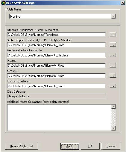
Configuring the DekoMOS Macro Server
178
2. Click the Styles button.
The Deko Style Settings dialog box opens.
3. To configure styles defined in the DekoMOS Gateway, select the Style Name from the list
and then set the appropriate paths that this style will use.
Although you should use the same paths as set in the DekoMOS Gateway for that style,
paths should be local to this computer for best performance.
4. In the Additional Macro Commands text box, type additional commands to send to Deko
when the style is selected. This is useful for opening any show-specific presets or other files.
5. Click Apply to apply settings for a style.
6. Click OK when you have finished configuring styles.
To retrieve styles recently configured in DekoMOS Gateway and add them to the list of
styles in the Deko Style Settings window:
tClick the Refresh Styles List button in the Deko Style Settings window.

Configuring Avid Workgroup Properties
179
Configuring Avid Workgroup Properties
If the Deko device is in a different subnet than the Command Servers, you must add the server
names to the Lookup tab in Avid Workgroup Properties on the Deko.
To configure Avid Workgroup Properties on the Deko:
1. Click the Start button, and then select All Programs > Avid > Service Framework > Avid
Workgroup Properties.
2. On the Lookup tab, click the Add button under the Workgroup section.
The Add Workgroup dialog box will open on top of the Avid Workgroup Properties window,
as shown:
3. Enter the name of the workgroup. It is case sensitive.
4. Click OK. The name you entered will appear in the Workgroup section of the Avid
Workgroup Properties window.
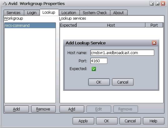
Configuring Avid Workgroup Properties
180
5. Click the Add button under the Lookup services section (above the Apply button).
The Add Lookup Service dialog box will open on top of the Avid Workgroup Properties
window, as shown:
6. Enter the full domain name of the server running the Lookup service for the workgroup,
such as:
cmdsvr1.avidbroadcast.com
.
7. Leave the port setting as is.
8. Select the Expected check box.
9. Click OK.
10. Repeat steps 5 - 9 to add another server running the Lookup service for the workgroup.
11. Click OK on the Avid Workgroup Properties window.
12. Click Yes, when prompted to restart all services.
Configuring the Deko Device Service
181
Configuring the Deko Device Service
After any device service is installed for Deko character generators, some additional
configuration is required, using the Service Configuration application of Avid Service
Framework. For more information, see the Avid Service Framework User’s Guide.
To configure the device service:
1. Click the Start button, and then select All Programs > Avid > Service Framework > Avid
Service Configuration.
2. Navigate to and select the Avid Deko device service.
3. When prompted for the administrator password, enter it.
4. Enter the host name for the respective device.
5. Enter the name of the DekoMOS Gateway computer.
6. Select the appropriate device mode.
nIn single channel mode, items with motions and/or clips are rendered when cued and then
paused at the first frame. In dual channel mode, items are not rendered until they are played.
7. Click Apply. You can then close the Avid Service Configuration application.
8. Click the Start button, and then select All Programs > Avid > Service Framework >
Avid Workgroup Properties.
9. Click the Advanced button.
10. After the Avid Services dialog box opens, select the device, then stop and restart it.
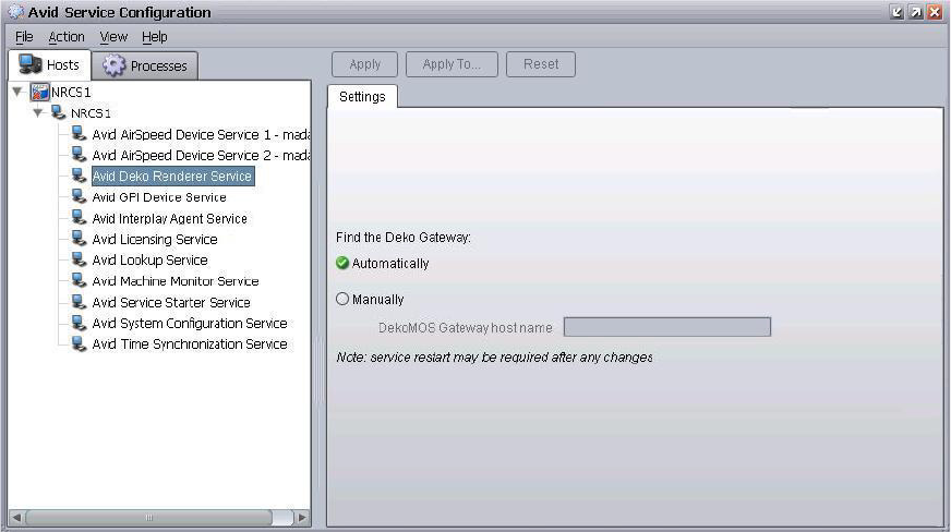
Configuring the Avid Deko Renderer Service
182
Configuring the Avid Deko Renderer Service
The Avid Deko Renderer service is installed at sites that want to integrate with an Avid Deko and
utilize thumbnail images. After the service is installed on the Command Server, additional
configuration should not be necessary. By default, this service is pre-configured to automatically
locate the DekoMOS Gateway on the network. However, if the service was installed and cannot
locate the DekoMOS Gateway, you can manually configure it to do so via the Avid Service
Configuration application.
nThe Deko Renderer service does not take up a HASP license seat.
To configure Deko Renderer services:
1. Click the Start button, and then select All Programs > Avid > Service Framework > Avid
Service Configuration.
2. On the Hosts tab, navigate to and select the Avid Deko Renderer Service.
3. When prompted, enter the system administrator password and click OK. If you have not yet
created one, leave the space blank and click OK.
4. If the Allow Unrestricted Security dialog box appears, click Yes.
On the Settings tab, you’ll see the service set to Automatically.

Creating Graphic Styles in Command
183
5. Select Manually.
6. Enter the host name or IP address for the DekoMOS Gateway computer.
7. Click Apply. You can then close the Avid Service Configuration application.
nYou might need to restart the service after applying any changes. For redundant systems, ensure
that all Deko Renderer services on every Command Server are set the same.
Creating Graphic Styles in Command
If you plan to create and use standalone playlists at a Command Workstation or use a Avid Deko
Select plug-in with ENPS integration, you must create graphic styles in Command that match the
styles configured on the DekoMOS Macro Server.
To add a graphic style:
1. Select Tools > System Settings.
2. Select Playlist.
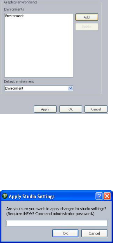
Creating Graphic Styles in Command
184
3. Click the Add button. A style will appear in the Styles list as shown:
4. By default, the name of any added style is
Style
, but that can be changed. To do so,
double-click on the name in the list and retype the new name.
5. After multiple styles are added, use the Default style drop-down list to select which one the
system should use as a default.
6. Click Apply (if you want the System Settings dialog box to remain open after settings are
applied) or OK.
The system will prompt you for the administrator password.
Creating Graphic Styles in Command
185
7. Enter the administrator password and click OK. If you did not configure a password, leave it
blank.
For more information on styles, see the Avid Deko Select User’s Guide.
nThe set of graphics styles specified in the system settings in the Playlist category will appear as
options in various parts of the Command user interface, such as: the Default style list (shown in
the previous graphic), the Default graphics style list in the the MOS > General category of the
System Settings dialog box (shown in the graphic in “Configuring MOS Settings in Command”
on page 294), and in the Playlist Properties dialog box.

6Installing and Configuring the Thunder
The Avid iNEWS Command user interface allows you to control multiple production devices,
such as Thunder production servers. For the interface to work, however, some software
installation and configuration is required.
•Checklist: Installing and Configuring the Thunder
•Installing Avid Service Framework
•Installing Avid Thunder Device Service
•Configuring Avid Workgroup Properties
•Configuring the Thunder Device Service
•Configuring the Thunder
•Creating the ThunderMOS.cfg File
•Creating the ThunderMOS.ini File

Checklist: Installing and Configuring the Thunder
187
Checklist: Installing and Configuring the Thunder
Ensuring integration with devices, such as the Avid Thunder, requires installation of various
components and services, as well as some configuration. The following is a checklist of activities
an installer should verify to ensure a successful installation and configuration.
Complete the following tasks in the order that they are listed. If you are viewing this checklist
online, you can easily access a linked topic that provides procedural details for the task. Return
to this main checklist after you have completed each task.
Tasks Refer to...
Connect the Thunder to the network. The documentation that came with your Avid
Thunder for more information.
Install the Thunder software.
nThunder integration with Command and iNEWS requires an SQL server and ODBC connection. For
information on SQL server and ODBC configuration, see the Avid Thunder Products User’s Guide,
and the Avid On-Air Graphics Setup and Configuration Guide.
Install the core components of Avid Service
Framework on the Thunder.
“Installing Avid Service Framework” on page 188
Install Thunder device service from the Avid
iNEWS Command software installation CD.
“Installing Avid Thunder Device Service” on
page 192
Configure Avid Workgroup Properties for the
Thunder.
“Configuring Avid Workgroup Properties” on
page 198
nAll settings in Command and Framework are case sensitive. Ensure that case matches in all
configuration settings.
Configure the Thunder device service. “Configuring the Thunder Device Service” on
page 199
Configure the Thunder. “Configuring the Thunder” on page 201
Create the ThunderMOS configuration file. “Creating the ThunderMOS.cfg File” on
page 203
Create the
Thunder
MOS.ini
file. “Creating the ThunderMOS.ini File” on page 204

Installing Avid Service Framework
188
Installing Avid Service Framework
Each computer and device running Avid iNEWS Command software requires at least the core
components of Service Framework and must be able to connect to a computer running the Avid
Lookup service.
To install the Service Framework software:
1. Insert the Command installation CD (or access the install program from the network).
The autorun installation program starts and displays the following screen.
nThe Command Documentation button will open a window displaying the contents of the Doc
folder on the Command installation CD in which product documentation is provided in PDF
format.
If the autorun does not begin, manually navigate to and run the
ServiceFrameworkSetup.exe
install program.
2. Click the Avid Service Framework button.
nOther dialog boxes could appear depending on whether older versions of Service Framework are
found, particularly if upgrading existing software. If one appears, read it carefully and reply
accordingly with regard to upgrades, etc.

Installing Avid Service Framework
189
A splash graphic will appear briefly as the installer prepares the InstallShield Wizard. Then
the Welcome dialog box appears.
3. Click Next.
The Destination Folder dialog box opens.
nIf space is a concern on the C drive, install in the
D:\Avid\Service Framework\
directory.
You will need to create these directories.

Installing Avid Service Framework
190
4. Set the location to which Avid Service Frameworkwill be installed and click Next.
The Workgroup Name dialog box opens.
5. Type the name of the Command workgroup in the field.
cIf you are updating the Service Framework software, the installer remembers the last
installed value. If the workgroup name was changed after the install, the installer will not
be aware of the change.
6. Click Next.
The Options dialog box opens.

Installing Avid Service Framework
191
7. Select the option: Avid Service Framework Client and click Next.
The Custom Setup dialog box opens.
By default, the Time Synchronization service is selected to be installed; however, this
service should only be installed if you do not already use something to synchronize your PC
clocks. If you use NTP or some other method for time synchronization, do not install this
service. For more information about the services in this dialog box, see the tables in page 24.
8. Click Next and follow the installation instructions to complete the installation.

Installing Avid Thunder Device Service
192
nYou might be required to restart your system to complete the installation.
After installation, verify that the services are running on each computer where Service
Framework services were installed.
Installing Avid Thunder Device Service
The Command installation CD provides for installation of services associated with various
production devices, such as the Avid Thunder.
To install the Thunder device service on the Thunder:
1. Insert the Command installation CD (or access the install program from the network).
The autorun installation program starts and displays the following screen.
nThe Command Documentation button will open a window displaying the contents of the Doc
folder on the Command installation CD in which product documentation is provided in PDF
format.
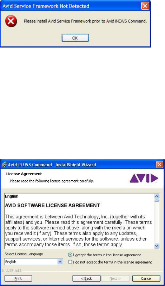
Installing Avid Thunder Device Service
193
2. Click the Avid iNEWS Command button. If Avid Service Framework is not already
installed, a warning dialog box will appear.
If it does, click OK and install Avid Service Framework before restarting this installation.
See “Installing Avid Service Framework” on page 188 for more information.
nOther dialog boxes could appear depending on whether older versions of Service Framework,
the License service, or Command are found on the server, particularly if upgrading the
Command Server software. If one appears, read it carefully and reply accordingly with regard to
upgrades, etc.
If all prerequisite installations are in order, and the Command Server installation can
proceed, a splash graphic will appear briefly as the installer prepares the InstallShield
Wizard. Then the Welcome dialog box appears.
3. Click Next. The License Agreement appears.

Installing Avid Thunder Device Service
194
4. Read the License Agreement, accept the terms, and click Next.
If you do not accept the terms, the installation program will not continue.
nYou can print the terms if you want to read them later or keep a copy for your records.
The Destination Folder dialog box opens.
5. Do one of the following:
tClick Change to designate an install directory, and then click Next.
tAccept the default location by clicking Next.

Installing Avid Thunder Device Service
195
6. When the Options dialog box opens, select Avid Thunder.
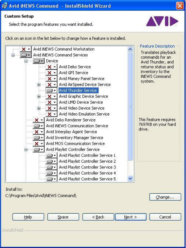
Installing Avid Thunder Device Service
196
The Custom Setup dialog box will appear.
nThe Help button opens a dialog box that provides descriptions of the various install states
available for a custom installation as indicated by the icons. The Space button opens a dialog
box that provides information on whether the computer’s destination drive has enough disk
space available to install the current selection of features.

Installing Avid Thunder Device Service
197
7. Click Next.
8. When the Ready to Install the Program dialog box appears, click Install.
9. When the installation is complete, click Finish.
To verify that installed services are running, you must use the Avid Workgroup Properties
application.
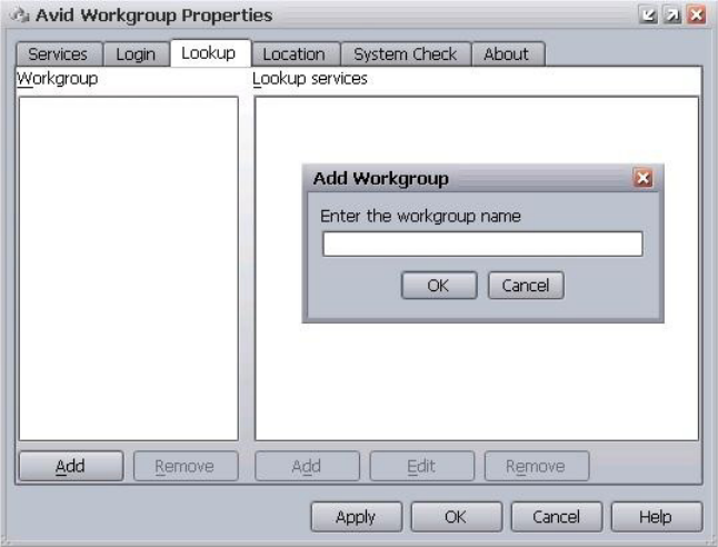
Configuring Avid Workgroup Properties
198
Configuring Avid Workgroup Properties
If the Thunder device is in a different subnet than the Command Servers, you must add the server
names to the Lookup tab in Avid Workgroup Properties on the Thunder.
To configure Avid Workgroup Properties:
1. Click the Start button, and then select All Programs > Avid > Service Framework > Avid
Workgroup Properties.
2. On the Lookup tab, click the Add button under the Workgroup section.
The Add Workgroup dialog box will open on top of the Avid Workgroup Properties window,
as shown:
3. Enter the name of the workgroup.
4. Click OK. The name you entered will appear in the Workgroup section of the Avid
Workgroup Properties window.
5. Click the Add button under the Lookup services section (above the Apply button).
The Add Lookup Service dialog box will open on top of the Avid Workgroup Properties
window, as shown:

Configuring the Thunder Device Service
199
6. Enter the full domain name of the server, such as:
cmdsvr1.avidbroadcast.com
.
7. Leave the port setting as is.
8. Select the Expected check box.
9. Click OK.
10. Repeat steps 5 - 9 to add another Command Server if necessary.
11. Click OK on the Avid Workgroup Properties window.
12. Click Yes, when prompted to restart all services.
Configuring the Thunder Device Service
After any device service is installed for Thunder production servers, some additional
configuration is required, using the Service Configuration of Avid Service Framework. For more
information, see the Avid Service Framework User’s Guide.
To configure the device service:
1. Click the Start button, and then select All Programs > Avid > Service Framework > Avid
Service Configuration.
2. Navigate to and select the Avid Thunder device service.
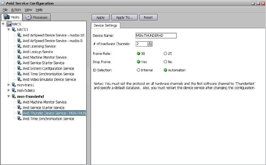
Configuring the Thunder Device Service
200
3. When prompted for the administrator password, enter it.
4. On the Device Settings tab, enter the host name for the respective device.
5. Specify the number of hardware channels. Do not include the software channel when
counting the number of hardware channels.
6. Select the frame rate: either 30 or 25.
7. Specify whether you want to enable drop frames: Yes or No.
8. Set ID selection to Automation.
9. Click Apply. You can then close the Avid Service Configuration application.
10. Click the Start button, and then select All Programs > Avid > Service Framework > Avid
Workgroup Properties.
11. Click the Advanced button.
12. After the Avid Services dialog box opens, select the Avid Thunder device service, then stop
and restart it.
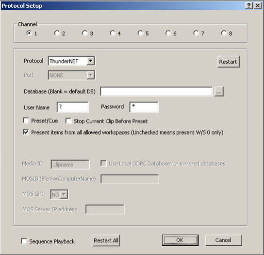
Configuring the Thunder
201
Configuring the Thunder
Configuring a MOS connection for the Thunder is accomplished at the device, using the Thunder
software application.
To configure the Thunder:
1. Open the Thunder software application.
2. Select File > Preferences > Protocol Setup to configure a MOS connection.
The Protocol Setup dialog box opens.
3. In the Protocol Setup dialog box, do the following:
- Select a channel (1-8) in the Channel area.
- Set Protocol to ThunderNET.
- If you intend to use a different database for the channel, enter it in the Database (Blank
= default DB) field.
4. Leave the rest of the settings as is.
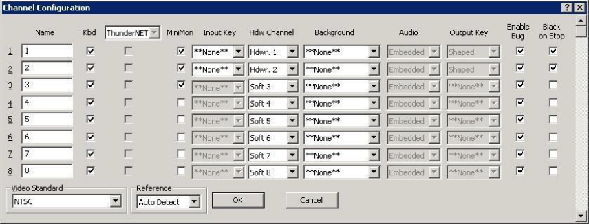
Configuring the Thunder
202
5. Repeat step 3 for all physical channels, plus an extra channel that is used by Command to
send inventory and transport commands. Normally, there are two hardware channels and one
software channel.
6. Click OK.
7. Select File > Preferences > Channel Configuration.
The Channel Configuration dialog box opens.
8. Set the Hdw Channel to correspond to the channels you set protocols for in step 3. The
physical channels should be set to Hdwr; the extra channel should be set to Soft.
9. Uncheck the channels in the MiniMon column that you will not be using.
10. Click OK.
11. In the Thunder directory, right-click on the database that you intend to use and set it as the
default database.
Creating the ThunderMOS.cfg File
203
Creating the ThunderMOS.cfg File
If you intend to use the Thunder Select plug-in at your newsroom workstations, you must create
the
ThunderMOS.cfg
file and configure it for each Thunder server. The
ThunderMOS.cfg
file
contains information that allows workstations with Thunder Select plug-ins to find your various
Thunder servers and browse their respective MOS databases. This information is set up in one
line per Thunder server.
To configure the ThunderMOS.cfg file:
1. On the Thunder’s C drive create a folder called ThunderCFG, if one doesn’t already exist,
and ensure it is shared across the network for read access.
Only one cfg file is necessary per iNEWS newsroom computer system.
nThe cfg file can reside in any shared network folder, as long as every workstation with the
Thunder Select plug-in can access that folder. However, Avid recommends that it reside on the
Thunder for easy maintenance reasons.
2. Ensure that the E drive is also shared across the network. This is because the cfg file will
point the Thunder Select plug-in to the E drive for access to clips and the clip database.
3. Create a file called:
ThunderMOS.cfg
in the
C:\ThunderCFG
folder.
4. Open it with Notepad.
5. Add a line in the
ThunderMOS.cfg
with the following information:
- An arbitrary name for the Thunder that the journalists will easily recognize. This part is
seen in the drop-down list of the Thunder Select plug-in on the iNEWS Workstation
(shown below). It can be any name, such as: 5PM, Control Room A, Sports, and so
forth.
- The MOS ID, such as
MOSIDTHDR_A
. This must be added to the MOS-Map story in the
SYSTEM.MOS-MAP
directory in iNEWS.
- The full UNC path to the Thunder database specified when you set up the MOS
protocol. This part appears next to the drop-down list in the plug-in (shown below).
Make sure it corresponds to the Thunder specified by the MOS ID.
Each of these values must be separated by a semi-colon and appear all on one line. For
example:
5PM;MOSIDTHDR_A;\\ThxlxxA\E\5PM\5PM.pff
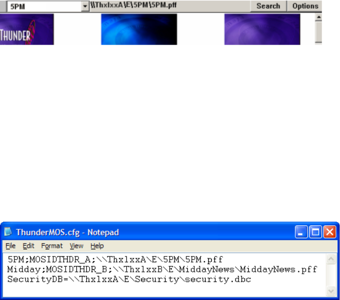
Creating the ThunderMOS.ini File
204
The following graphic shows the Thunder’s arbitrary name and the full UNC path to the
Thunder database as they might appear in the Thunder Select plug-in:
nDue to the nature of the MOS configuration, you can only have one database per Thunder server.
Although you can add multiple databases in the cfg file and the workstations will browse the
databases correctly, the MOS metadata will not be properly transmitted between the iNEWS and
Thunder servers.
6. If you:
- have a security database, type the correct path on a separate line below the
Thunder lines.
- do not have a security database, delete the whole line starting with “SecurityDB=”
Your finished
ThunderMOS.cfg
file might look like this:
7. Save the
ThunderMOS.cfg
file.
Creating the ThunderMOS.ini File
If you intend to use the Thunder Select plug-in at your newsroom workstations, you must create
the
ThunderMOS.ini
file on each Thunder device. The
ThunderMOS.ini
file identifies the
location of the default database by pointing to the
ThunderMOS.cfg
file.
To create the ThunderMOS.ini file:
1. On the Thunder’s C drive, in the Thunder directory (
C:\Thunder
), create a file called
ThunderMOS.ini
.
2. Open it with Notepad.
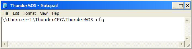
Creating the ThunderMOS.ini File
205
3. Add a single line with the full UNC path to the
ThunderMOS.cfg
file, using the following
format:
\\<machine name>\<directory>\<file name>
Your finished
ThunderMOS.ini
file might look like this:
4. Save the
ThunderMOS.ini
file.

7Installing the Command Workstation
The Avid iNEWS Command user interface allows you to control multiple production devices
from a single workstation running the client software.
•Checklist: Installing the Command Workstation
•Installing Avid Service Framework
•Installing Avid iNEWS Command on the Workstation
•Configuring Avid Workgroup Properties
•Setting up Device Channels
•Setting up Channel Groups

Checklist: Installing the Command Workstation
207
Checklist: Installing the Command Workstation
Complete the following tasks in the order that they are listed. If you are viewing this checklist
online, you can easily access a linked topic that provides procedural details for the task. Return
to this main checklist after you have completed each task.
Tasks Refer to...
Install the core components of Avid Service
Framework.
“Installing Avid Service Framework” on page 208
Install Avid iNEWS Command. “Installing Avid iNEWS Command on the
Workstation” on page 213
Configure Avid Workgroup Properties. “Configuring Avid Workgroup Properties” on
page 218
nAll settings in Command and Framework are case sensitive. Ensure that case matches in all
configuration settings.
Map the actual channels for the various
production devices, such as Deko character
generators or AirSpeed video servers, to names.
“Setting up Device Channels” on page 220
Create channel groups. “Setting up Channel Groups” on page 223
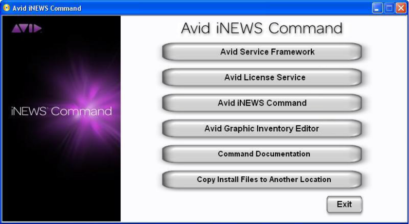
Installing Avid Service Framework
208
Installing Avid Service Framework
Each computer and device running Avid iNEWS Command software requires at least the core
components of Service Framework and must be able to connect to a computer running the Avid
Lookup service.
To install the Service Framework software:
1. Insert the Command installation CD (or access the install program from the network).
The autorun installation program starts and displays the following screen.
nThe Command Documentation button will open a window displaying the contents of the Doc
folder on the Command installation CD in which product documentation is provided in PDF
format.
If the autorun does not begin, manually navigate to and run the
ServiceFrameworkSetup.exe
install program.

Installing Avid Service Framework
209
2. Click the Avid Service Framework button.
nOther dialog boxes could appear depending on whether older versions of Service Framework are
found, particularly if upgrading existing software. If one appears, read it carefully and reply
accordingly with regard to upgrades, etc.
A splash graphic will appear briefly as the installer prepares the InstallShield Wizard. Then
the Welcome dialog box appears.
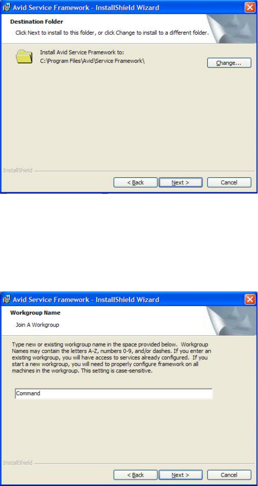
Installing Avid Service Framework
210
3. Click Next.
The Destination Folder dialog box opens.
nIf space is a concern on the C drive, install in the
D:\Avid\Service Framework\
directory.
You will need to create these directories.
4. Set the location to which Avid Service Frameworkwill be installed and click Next.
The Workgroup Name dialog box opens.
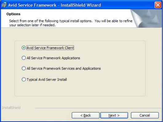
Installing Avid Service Framework
211
5. Type the name of the Command workgroup in the field.
cIf you are updating the Service Framework software, the installer remembers the last
installed value. If the workgroup name was changed after the install, the installer will not
be aware of the change.
6. Click Next.
The Options dialog box opens.

Installing Avid Service Framework
212
7. Select the option: Avid Service Framework Client and click Next.
The Custom Setup dialog box opens.
By default, the Time Synchronization service is selected to be installed; however, this
service should only be installed if you do not already use something to synchronize your PC
clocks. If you use NTP or some other method for time synchronization, do not install this
service. For more information about the services in this dialog box, see the tables in page 24.
8. Click Next and follow the installation instructions to complete the installation.
nYou might be required to restart your system to complete the installation.
After installation, verify that the services are running on each computer where Service
Framework services were installed.

Installing Avid iNEWS Command on the Workstation
213
Installing Avid iNEWS Command on the Workstation
This section provides the standard procedure for installing the Command software on a
Windows-based computer—Windows XP SP2, Windows Vista, or Windows Server
2003—designated as a Command Workstation.
To install the software on a Command Workstation:
1. Insert the Command installation CD (or access the install program from the network).
The InstallShield Wizard starts and displays the Welcome screen.
2. Click Next.
The License Agreement appears.

Installing Avid iNEWS Command on the Workstation
214
3. Read the License Agreement, accept the terms, and click Next.
If you do not accept the terms, the installation program will not continue.
nYou can print the terms if you want to read them later or keep a copy for your records.
The Destination Folder dialog box opens.

Installing Avid iNEWS Command on the Workstation
215
4. Do one of the following:
tClick Change to designate an install directory, and then click Next.
tAccept the default location by clicking Next.
The Options dialog box opens.
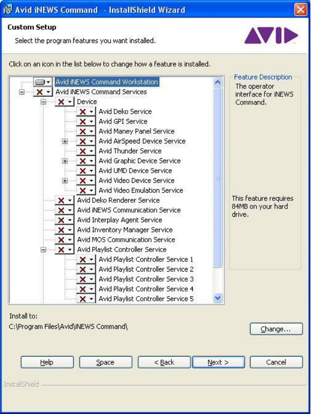
Installing Avid iNEWS Command on the Workstation
216
5. Select Workstation Only and click Next.
The Custom Setup dialog box appears with the default services selected for installation of
client software. However, you can modify the selections to customize your installation.
To learn more about a service, click any service listed and view a Feature Description
provided along the right side of the dialog box.

Installing Avid iNEWS Command on the Workstation
217
nThe Help button opens a dialog box that provides descriptions of the various install states
available for a custom installation as indicated by the icons. The Space button opens a dialog
box that provides information on whether the computer’s destination drive has enough disk
space available to install the current selection of features.
6. Click Next.
7. When the Ready to Install the Program dialog box appears, click Install.
8. When the installation is complete, click Finish.
After the installation, if you need to alter the system name from the default, which is
command
,
see the procedure provided in “Configuring a Second Command System” on page 72.
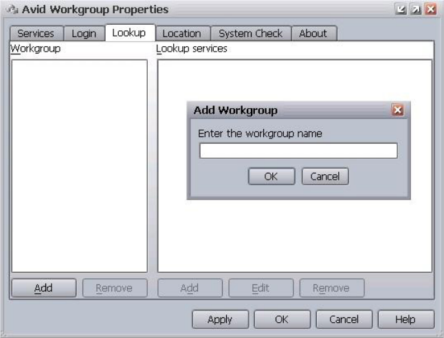
Configuring Avid Workgroup Properties
218
Configuring Avid Workgroup Properties
If the Command Workstation is in a different subnet than the Command Servers, you must add
the server names to the Lookup tab in Avid Workgroup Properties on the workstation.
To configure Avid Workgroup Properties:
1. Click the Start button, and then select All Programs > Avid > Service Framework > Avid
Workgroup Properties.
2. On the Lookup tab, click the Add button under the Workgroup section.
The Add Workgroup dialog box will open on top of the Avid Workgroup Properties window,
as shown:
3. Enter the name of the workgroup.
4. Click OK. The name you entered will appear in the Workgroup section of the Avid
Workgroup Properties window.

Configuring Avid Workgroup Properties
219
5. Click the Add button under the Lookup services section (above the Apply button).
The Add Lookup Service dialog box will open on top of the Avid Workgroup Properties
window, as shown:
6. Enter the full domain name of the server running the Lookup service, such as:
cmdsvr1.avidbroadcast.com
.
7. Leave the port setting as is.
8. Select the Expected check box.
9. Click OK.
10. Repeat steps 5 - 9 to add another server running the Lookup service.
11. Click OK on the Avid Workgroup Properties window.
12. Click Yes, when prompted to restart all services.
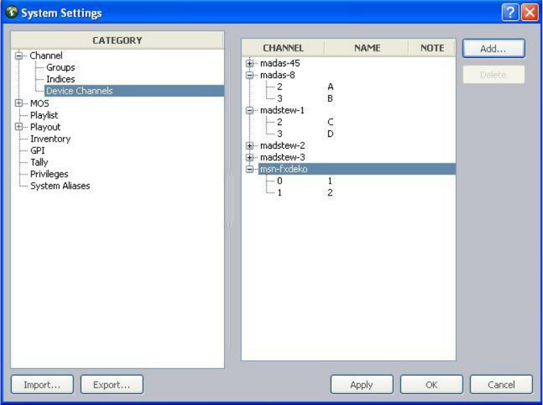
Setting up Device Channels
220
Setting up Device Channels
Avid iNEWS Command enables system administrators to map actual channels from a device,
such as an Avid Deko or AirSpeed video server to a name of your choosing. This name can then
be used to create channel groups or assign channel-specific actions to keys on a USB keypad at
the Command Workstation.
For more information on channel groups, see “Setting up Channel Groups” on page 223. Also,
see “Mapping Indices to Channel Names” on page 245 and “Programming the X-keys” on
page 246 for more information on assigning channel-specific actions to keypad keys.
To map device channels to names:
1. Open the Command Workstation application.
2. Select Tools > System Settings. The System Settings dialog box appears.
3. Expand Channel.
4. Select Device Channels.
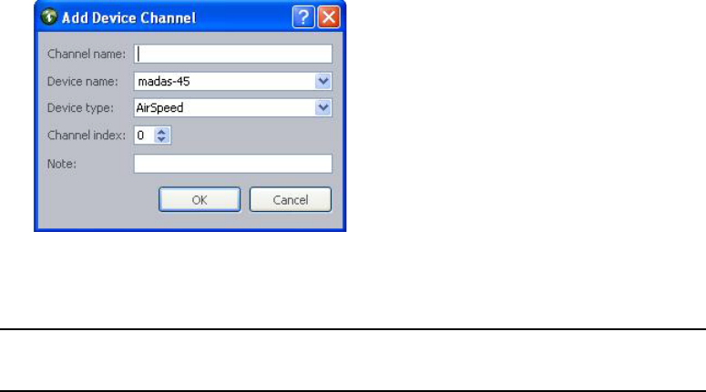
Setting up Device Channels
221
5. Click Add.
6. Enter the channel’s name, which can be any alpha-numeric character(s), based on the
following guidelines:
Device Type
Channel
Index
Channel
Name Description
nAll channel names within a single device type must be unique.
Multi Stream 1 A AirSpeed Multi Stream video servers begin channel
designations at one (1). The channel names can be
anything, but a typical example is alphabetic names
from A through F.
An AirSpeed 5000 can be configured in the same way
as the Multi Stream video server.
Multi Stream 2 B
Multi Stream 3 C
AirSpeed 2 A AirSpeed (classic) video servers begin channel
designations at one (1); however, the first channel is
reserved for video ingest. So the first available channel
for playout or browse purposes would be channel 2.
AirSpeed 3 B
Video device
service
1 A All supported third-party video devices begin channel
designations at one (1). The channel index values here
must match the channel index values set for the Avid
Video device service in Avid Service Configuration.
Video device
service
2B
Graphic device
service
0 1 All devices using the Avid Graphic device service
begin channel designations at zero (0).
Graphic device
service
12
Setting up Device Channels
222
7. Select the name and type of the device from the lists. The device name is the host name for
the device, such as deko3000. If it does not appear in the list, you must enter it.
nFor third-party video devices controled via VDCP, the device name must match the device name
set for the Avid Video device service in Avid Service Configuration.
8. Select the channel index, using the Channel index spinbox.
9. Enter any notes you want, which can help identify the device should future alterations be
necessary.
10. Click OK.
11. Repeat steps 5 through 10 for each device channel, as needed.
12. Click Apply (if you want the System Settings dialog box to remain open after settings are
applied) or OK.
The system will prompt you for the administrator password.
13. Enter the administrator password and click OK.
Until this procedure is completed, device channels cannot be added to a channel group.
Deko 0 1 Avid Deko devices begin channel designations at zero
(0); however, the name of the first channel can be one.
Deko 1 2
nBoth channel names for a Deko must be numeric to match the channel selection available
through the Deko Select plug-in inside of the iNEWS newsroom computer system.
Thunder 1 aPlay Avid Thunder begins channel designations at one (1).
The channel names must be in the following format:
aPlay, bPlay, cPlay, 1, 2...8, or pgm (for program).
Thunder 2 bPlay
nAvid recommends against using numeric names for the Thunder to avoid confusion with
channel names for any Avid Deko device.
Device Type
Channel
Index
Channel
Name Description

Setting up Channel Groups
223
nBefore you can delete a device channel, you must first delete that channel from that channel from
any channel groups or delete the channel group(s) that use the channel.
Setting up Channel Groups
A channel group is a cluster configured with one or more device channels composed from
compatible video servers or character generators. Many channel groups can be created from the
same pool of resources, and different groups can use the same resources to serve different
operational needs.
nEach channel group must contain a single “type” of device. For instance, a channel group called
AS is a grouping of channels from two or more AirSpeed video servers, while a different channel
group named CG is a grouping of channels on a Deko character generator.
AirSpeed channels provide one of the best examples of the way in which channel groups provide
control configurations; they do not guarantee media availability, which is the role of the
AirSpeed studio configuration. For example, a station has two AirSpeed video servers, each with
two channels that are numbered 2 and 3. (With AirSpeed video servers, the first channel is
reserved for ingest.) Let’s call the first AirSpeed AS1 and the second AS2. With channel groups
on Command, the station’s system administrator can set up numerous different channel groups
and call them anything, such as:
Channel Group
Channel
Names Actual Device Channels Channel Type
AS-Noon A
B
C
AS1 - channel 2
AS1 - channel 3
AS2 - channel 2
Playout
Playout
Browse
AS-5PM A
B
C
D
AS1 - channel 2
AS1 - channel 3
AS2 - channel 2
AS2 - channel 3
Playout
Playout
Playout
Playout
AS-10PM A
C
B
D
AS1 - channel 2
AS2 - channel 2
AS1 - channel 3
AS2 - channel 3
Playout
Mirrored
Playout
Mirrored
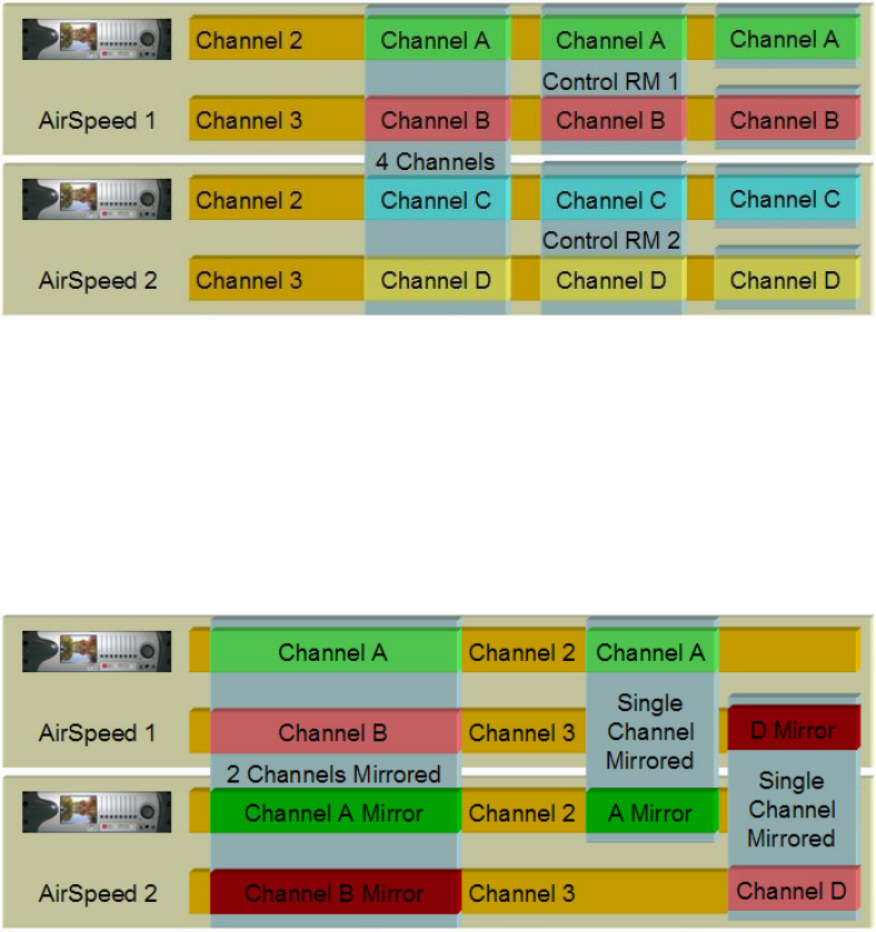
Setting up Channel Groups
224
The following graphic shows a more visual example of how multiple channel groups can be
created from the same four AirSpeed video server channels.
The first group shows a single channel group configured to create four playback channels called
A, B, C, and D. The next set shows two groups, representing control rooms, with two playback
channels each. Alternatively, the groups can be created from any combination of channels and
used to support simultaneous two-channel playout from two control rooms sharing the same
resources. The last set shows four channel groups, each controlling a single channel.
The following graphic shows a more visual example of how channel groups are used to mirror
playout for redundancy.
The first group creates a two channel playout solution with both channels mirrored on a
secondary video server for maximum reliability. Whenever a video clip is cued and played on
either of the primary channels, the same clip is also cued and played on the corresponding mirror
channels. The other two groups depict single channel solutions with redundancy.

Setting up Channel Groups
225
All of these channel groups can exist at the same time, although they cannot necessarily all be on
air simultaneously.
Channels must be created before they can be assigned to channel groups. For more information
on how to create channels, see “Setting up Device Channels” on page 220.
nThe first eight (8) characters of a channel group’s name must be unique to match the
eight-character device name in the iNEWS newsroom computer system. For instance, a channel
group name in Command that is ASNoonMirrored will appear as ASNoonMi in iNEWS.
System administrators can create channel groups via the System Settings dialog box.
To create channel groups:
1. Select Tools > System Settings. The System Settings dialog box appears.
2. Expand Channel.
3. Select Groups.
4. Click Add.
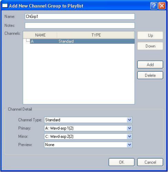
Setting up Channel Groups
226
The Add New Channel Group to Playlist dialog box opens.
5. Enter the name of the new channel group and any notes you want. Names of channel groups
can be upper or lowercase and contain any alpha-numeric character. Avoid using spaces in,
before, or after the name. If interfacing with the Avid iNEWS newsroom computer system, it
is best to make the channel group’s name less than eight characters.
6. Click Add to add a channel to the group.
nIf channels have not been created, they cannot be assigned to channel groups; therefore, the Add
button will be disabled if no channels exist in the system. For more information on how to create
channels, see “Setting up Device Channels” on page 220.
Setting up Channel Groups
227
7. In the Channel Detail section, select the following:
8. Repeat steps 6 and 7 as needed. You can use the Up and Down buttons to rearrange the order
of channels in the group.
9. Click OK. This will close the Add New Channel Group to Playlist dialog box. The new
channel group will appear in the System Settings dialog box.
10. Click Apply (if you want the System Settings dialog box to remain open after settings are
applied) or OK.
The system will prompt you for the administrator password.
11. Enter the administrator password and click OK.
cUntil the Apply or OK button is clicked and administrator password supplied, the channel
group(s) are not created.
Channel Detail Description
Channel Type Select the appropriate channel type, based on:
Standard - This is the channel type selected for playout.
Browse - This is the channel type selected for changing In and Out points
of pre-existing clips for preview or editing purposes only. This does not
apply to playout operations.
Hotswap - This is the channel type selected for emergency backup
channel assignment.
Primary Select the channel designated as the primary playout channel for the
device.
Mirrored (Optional) If mirrored playout is to be used, select the device’s channel
designated for mirrored playout.
Preview (Optional) Select which device channel to use for displaying the
headframe of the next media event in the playlist.

Setting up Channel Groups
228
To edit a channel group:
1. Select Tools > System Settings. The System Settings dialog box appears.
2. Expand Channel.
3. Select Groups.
4. Select the channel group from the list on the right.
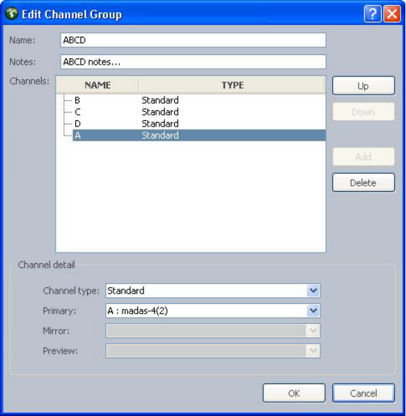
Setting up Channel Groups
229
5. Click Edit.
The Edit Channel Group dialog box appears.
6. You can rename the channel group, add notes, rearrange the order of channels by using the
Up and Down buttons, add or delete channels, or alter the channel details for each channel in
the group.
7. After editing the channel group, click OK.
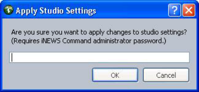
Setting up Channel Groups
230
8. Click Apply (if you want the System Settings dialog box to remain open after settings are
applied) or OK.
The system will prompt you for the administrator password.
9. Enter the administrator password and click OK.
cUntil the Apply or OK button is clicked and administrator password supplied, the changes
in the system settings are not saved.
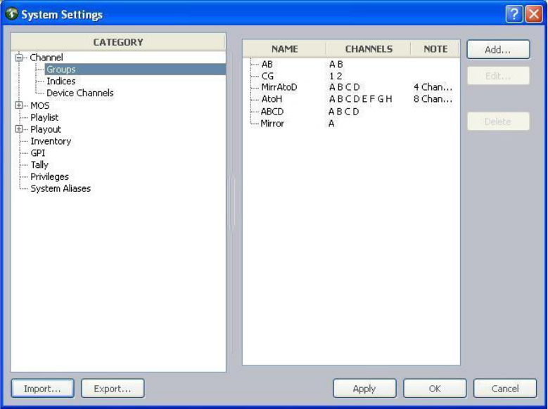
Setting up Channel Groups
231
To delete a channel group:
1. Select Tools > System Settings. The System Settings dialog box appears.
2. Expand Channel.
3. Select Groups.
4. Select the channel group from the list on the right.
5. Click Delete.

Setting up Channel Groups
232
6. Click Apply (if you want the System Settings dialog box to remain open after settings are
applied) or OK.
The system will prompt you for the administrator password.
7. Enter the administrator password and click OK.
cUntil the Apply or OK button is clicked and administrator password supplied, the channel
group(s) are not deleted from the system settings.

8Installing and Configuring the Tablet
Application
Avid iNEWS Command supports playout control from an iPad® touch-screen device running the
Command tablet application. However, to control playout from the mobile device, some addition
installation and configuration of services and applications are required.
•Checklist: Setup Tablet Application Integration
•Install the Avid Remote Communication Service
•Configure the Avid Remote Communication Service
•Download the iNEWS Command Tablet Application
•Configure the Tablet Application Connection

Checklist: Setup Tablet Application Integration
234
Checklist: Setup Tablet Application Integration
To enable a connection between an iPad touch-screen device to the Command workgroup, you
must complete the following tasks. If you are viewing this checklist online, you can easily link to
a topic that provides procedural details for the task. Return to this main checklist after you have
completed each task.
Install the Avid Remote Communication Service
The Command tablet application requires a WiFi connection and must be able to connect to the
computer running the Avid Remote Communication Service.
Although the Avid Remote Communication Service can be installed on any computer in the
Command workgroup, Avid recommends it be installed on the Command Server. It should be
selected as one of the services installed during the Command Server installation procedure. See
the step about selecting services from the Custom Setup dialog box in “Installing Avid iNEWS
Command on the Server” on page 41 for more information.
If you did not install this service when originally setting up the Command Server, or if you want
to install it on a different computer, such as a Command Workstation, you can still do so.
Possible scenarios for install locations are:
• Install the service on the Command Server.
• Install the service on a Command Workstation.
• Install the service on a computer in the studio and route connection between studio computer
and the Command Server.
Tasks Refer to...
Install the Avid Remote Communication Service. “Install the Avid Remote Communication Service”
on page 234
Configure the Avid Remote Communication
Service.
“Configure the Avid Remote Communication
Service” on page 237
Download onto the iPad the iNEWS Command
tablet application from the iTunes store.
“Download the iNEWS Command Tablet
Application” on page 237
Configure and authorize connection between the
tablet device and the Command workgroup.
“Configure the Tablet Application Connection” on
page 237
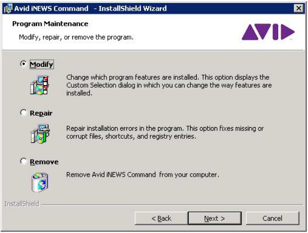
Install the Avid Remote Communication Service
235
The following procedure is based on installing the service on a computer that already has
Command software installed on it. Steps might vary if installing on a new computer without
Command software already on it.
To install the Avid Remote Communication Service:
1. Insert the Command installation CD (or access the install program from the network).
2. When the Welcome dialog box appears, click Next.
The Program Maintenance dialog box appears.
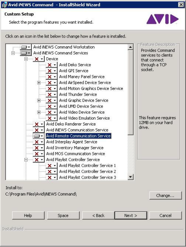
Install the Avid Remote Communication Service
236
3. Select Modify and click Next.
The Custom Setup dialog box appears.
4. Select to install the Avid Remote Communication Service.
5. Click Next.
6. When the Ready to Modify the Program dialog box appears, click Install.
7. When the installation is complete, click Finish.
Configure the Avid Remote Communication Service
237
Configure the Avid Remote Communication Service
After the service is installed, some configuration is still required.
To configure the Avid Remote Communication Service:
1. Open the Avid Service Configuration application.
2. Navigate to the Avid Remote Communication Service.
3. Set the TCP port that you would like to use for the connection.
4. Click Apply.
You can now have the user download the tablet application to the device and configure the
connection.
Download the iNEWS Command Tablet Application
To use an iPad touch-screen tablet to control playout, you must download the iNEWS Command
tablet application from the iTunes store to the device.
To download the tablet application:
1. Open the iTunes store.
2. Locate the iNEWS Command tablet application.
3. Tap Free, then the Install button.
Configure the Tablet Application Connection
Before a user can connect to your Command workgroup with the tablet application, some
additional configuration is necessary.
After downloading the tablet application, you will need to open the Command application,
configure the connection, and get authorized to connect to the system.
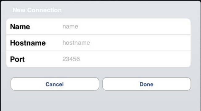
Configure the Tablet Application Connection
238
To configure the tablet application connection:
1. Open the Command tablet application on the device.
2. Tap Create New.
The New Connection information will appear.
3. In the Name field, enter an alias for the connection. This should be an easy-to-recognize
name, such as Studio A.
4. In the Hostname field, enter the name of the computer running the Avid Remote
Communication Service.
5. Enter the correct port and tap Done.
6. Tap the Connect button.
You should see a message indicating that you are not authorized. Your site’s system
administrator must now authorize your device.
To authorize a tablet to connect to the system:
1. Open the Avid Service Configuration application.
2. Select the Avid Remote Communication Service.
nYou should see in the list the name of the device that just attempted to connect.
3. In the Authorized column, select the check box next to the device you want to authorize.
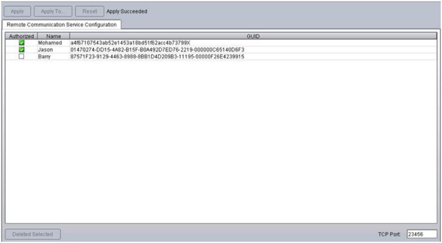
Configure the Tablet Application Connection
239
4. Click Apply.
5. Have the user attempt to connect again. If successful, the user should see the main window.
nIt would be a good idea to create a shotbox at a Command Workstation before connecting so that
it is easier to confirm connection to the Command workgroup.

9Configuring Playout Control
Playout control through Avid iNEWS Command varies from site to site depending on workflow.
Television stations can choose to control playout from the control room via keyboards, USB
keypads, touch screens, or GPI.
•Controling Playout via the Keyboard
•Disabling a Command Workstation’s Keyboard
•Checklist: Setting up an X-keys USB Keypad
•Installing an X-keys USB Keypad
•Mapping Indices to Channel Names
•Programming the X-keys
•Setting up the Playout Panel for Touch Screens
•Checklist: Setting up the GPI Panel
•Configuring the GPI Card
•Restarting the GPI Device Service
•Confirming Successful Setup of a GPI Panel
•Mapping Events to Actions for a GPI Panel
•Enabling the GPI Panel
•Configuring GPI Out
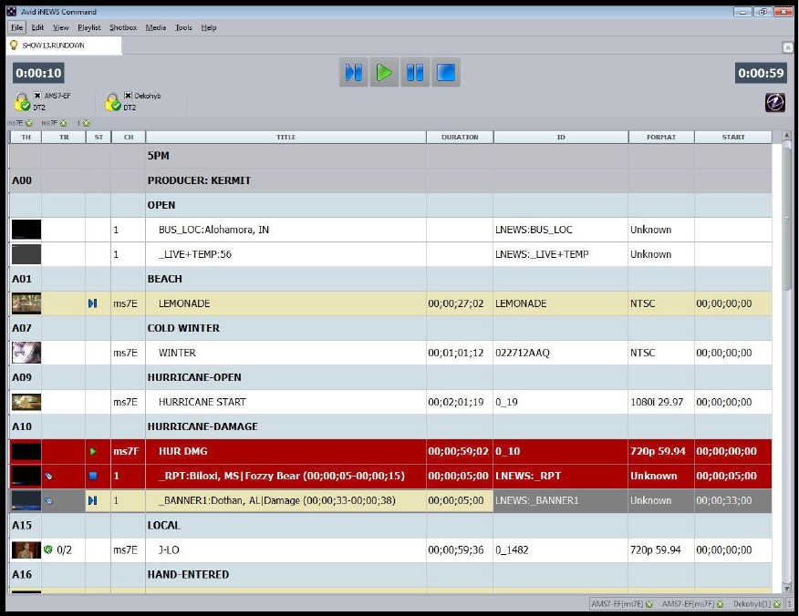
Controling Playout via the Keyboard
241
Controling Playout via the Keyboard
Playout control from a Command Workstation is accomplished through the use of the tabbed
workspace known as the Playlist Viewer. While some functionality is described in this section,
additional information such as customization options is available in Chapter 4 of the Avid iNEWS
Command User’s Guide.

Controling Playout via the Keyboard
242
Command uses various icons, as well as color, to indicate the status of machine control events
(items) in the playlist. Some of which are shown in the following closeup graphic:
There is no special installation or configuration needed to use the software’s graphic user
interface to control playout of media from a Command Workstation with a standard keyboard
and mouse.
Users can cue, play, pause or stop the playout of media from a Command Workstation, using the
mouse to click control buttons on the Playlist toolbar or by using keys on the numeric keypad.
To control playout, using the numeric keypad on a keyboard:
1. Select the event in the playlist.
2. Do one of the following:
tPress the Decimal key (.) to cue the media.
tPress Enter to play the media.
tPress the Plus key (+) to pause the media.
tPress zero (0) to stop playing the media.
nPlayout options are also available by right-clicking on the event and selecting the options from
the Playout submenu.
Users can also set playout of an item in a playlist to automatically occur immediately following
the completion of the previous item. This functionality is called follow-on playout and is
indicated by an icon in the playlist that looks like a bent blue arrow. For more information, see
the Avid iNEWS Command User’s Guide.
Icon representing a
“Follow-On Playout” event.
Playout of this event is done.
This event is playing now.
This event is cued.
This event is unavailable.
Cursor location can appear solid
or as an outline; varies by field.
This event will loop twice.
Icon representing a
Looped event.
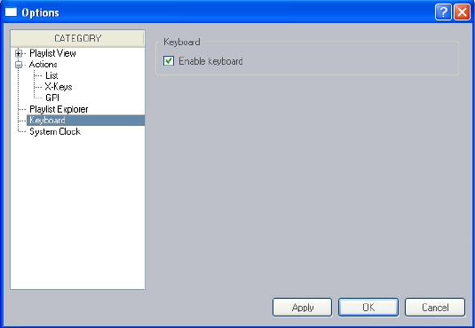
Disabling a Command Workstation’s Keyboard
243
Disabling a Command Workstation’s Keyboard
Some sites use alternative devices to control playout from Command, such as a GPI device or an
X-keys USB keypad, and therefore do not want the computer keyboard at the workstation
enabled.
To enable or disable the keyboard:
1. Select Tools > Options.
2. In Category, select Keyboard.
3. Do one of the following:
tSelect Enable keyboard.
tDeselect Enable keyboard.
4. Click Apply.
5. Click OK.
nIf the keyboard is disabled, the numeric keypad cannot be used to control playout from the
Command Workstation. Disabling the keyboard does not affect the use of the keyboard for
software on the workstation PC unrelated to the Command client software.

Checklist: Setting up an X-keys USB Keypad
244
Checklist: Setting up an X-keys USB Keypad
Avid iNEWS Command interfaces with the X-keys® USB keypad for playout control. The
X-keys USB keypads connect to the USB port the Command Workstation and offer up to
fifty-eight user-reprogrammable keys for one-button access to playout functionality.
nX-keys is third-party hardware. Command natively supports a variety of X-keys devices, which
are configured through the Command Workstation application. Native support gives users an
added level of functionality that is not available through the X-keys Macro Works software. See
the Avid iNEWS Command ReadMe for the specific X-keys devices that are supported.
You can also use the Macro Works software, a keyboard emulator, with any X-keys device. For
more information on X-keys USB keypads, see that manufacturer’s documentation on
www.xkeys.com.
Setting up the keypad to control playout through Command requires the completion of the
following tasks:
Tasks Refer to...
(Optional) Disable the keyboard at the Command
Workstation.
“Disabling a Command Workstation’s Keyboard”
on page 243
Install the keypad on the Command Workstation. “Installing an X-keys USB Keypad” on page 245
Map Indices to Channel Names. “Mapping Indices to Channel Names” on
page 245
Program the keypad. “Programming the X-keys” on page 246
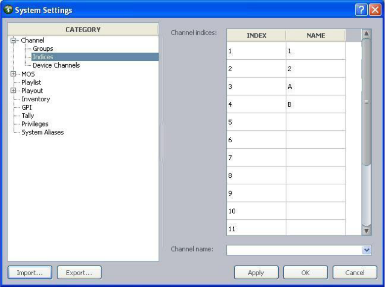
Installing an X-keys USB Keypad
245
Installing an X-keys USB Keypad
To install an X-keys USB keypad:
tPlug in the keypad to a USB port on your Command Workstation.
Mapping Indices to Channel Names
Channel indices are a configuration feature used to map an index integer (1-16) to a channel
name, which can be alpha or numeric, to enable assignment of channel-specific actions to certain
keys on a keypad. This pre-configuration should be done before assigning the channel-specific
actions to any keys.
To map an index to a channel name:
1. Log in to a Command Workstation.
2. Select Tools > System Settings. The System Settings dialog box appears.

Programming the X-keys
246
3. Expand Channel.
4. Select Indices.
5. Enter the channel’s name in the Name column next to the appropriate index.
nAvid recommends that if a channel name must be numeric, such as is the case whenever the
ActiveX plug-in Avid Deko Select is used, assign it to the same Index number to avoid confusion.
6. Click Apply (if you want the System Settings dialog box to remain open after settings are
applied) or OK. The system will prompt you for the administrator password.
7. Enter the administrator password and click OK.
Programming the X-keys
The following procedure should be conducted at the Command Workstation to which the
X-keys USB keypad is installed.
To program the X-keys from the Command Workstation:
1. Select Tools > Options.
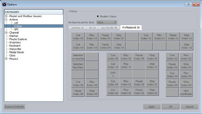
Programming the X-keys
247
2. In Category, expand Actions and select X-keys.
3. Select Enable X-keys.
4. Set the de-bounce period. Designed to avoid inadvertent repetition, this is the span of time
(in milliseconds) during which the system should ignore duplicated signals.
nIf you find that you are having problems with “double-hits” when you press a key, increase the
de-bounce period.
5. Select the tab corresponding to the type of keypad you have.
6. Click on a gray box that represents (or corresponds to) the key on the keypad.
nSome sites might use key caps that cover 2 or 4 buttons on the keypad, turning a set of buttons
into a single key. If that is the case, select the left box to set the “2-button” key. For 4-button keys,
select the upper left box.
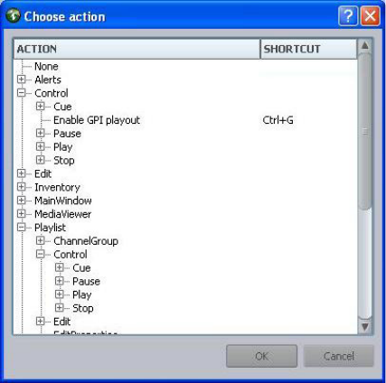
Programming the X-keys
248
7. Assign an action to the key by selecting it from the list of those available in the Choose
Action dialog box. The most commonly used actions will appear open for your selection
already.
- The Playlist > Channel Group actions refer to channel group commands, such as lock,
unlock, and assign channel.
- The Playlist > Selection actions refer to selected items on the playlist, such as play
selection, cue selection, stop selection, and move up/down.
- The Control actions refer to channel-specific actions that correspond to a particular
index as configured when mapping indices to channel names. An example of this would
be for a key to initiate a play command on a single channel. Assigning the
channel-specific actions affects only the keypad attached to the workstation at which the
assignments are programmed.
8. Click OK.
9. Repeat steps 5-7 as needed.
10. Click Apply.
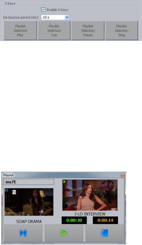
Setting up the Playout Panel for Touch Screens
249
11. Click OK.
The following graphic shows a closeup of the first row of keys after they were assigned to the
four playout control options of play, cue, pause, and stop.
Setting up the Playout Panel for Touch Screens
The Playout panel displays transport controls, thumbnails, duration information and IDs or slugs
for media items.
The panel has two main uses:
• Lets users access channel specific transport commands from within the Command user
interface. This is most useful for sites with touch screen monitors.
• Lets users monitor the currently playing item from a workstation that does not have the
channel group locked.
The Playout panel can display either video or graphics. The following illustration shows a
Playout panel with a sample video item.
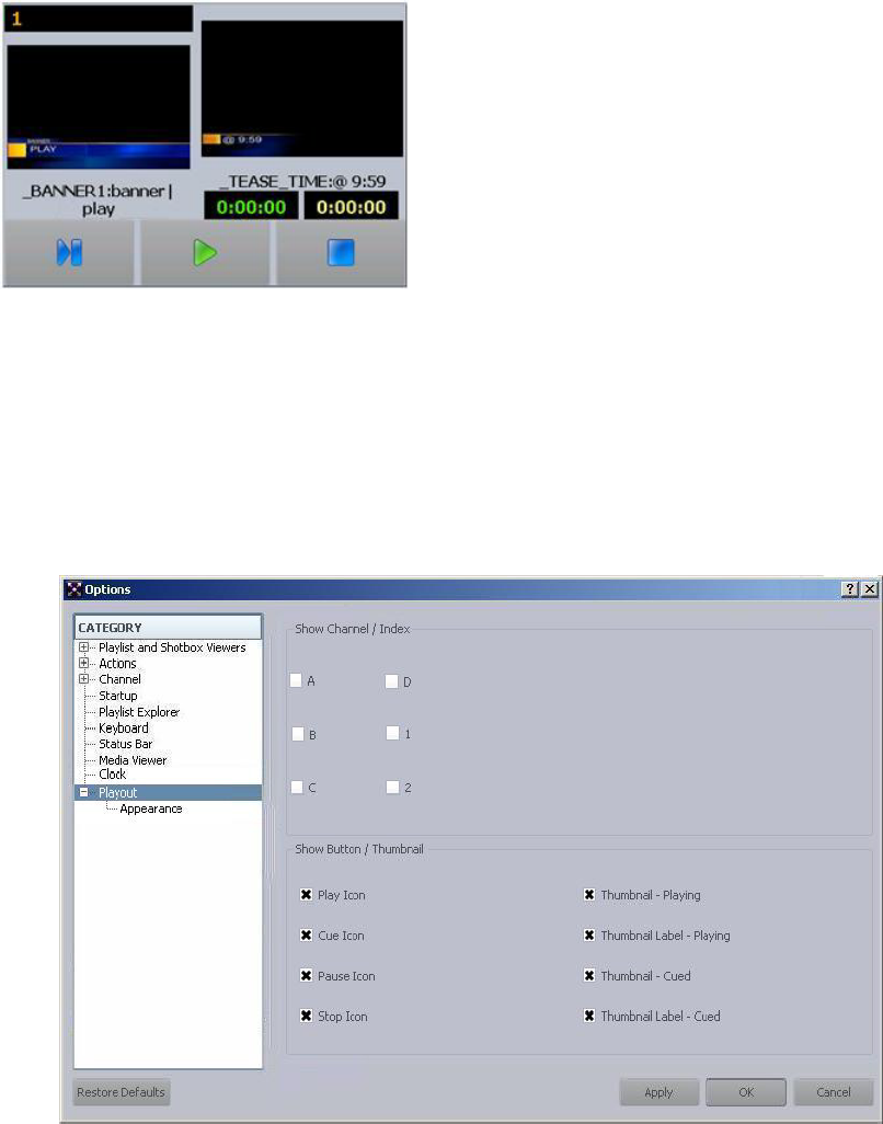
Setting up the Playout Panel for Touch Screens
250
The following illustration shows a Playout panel with a sample graphic.
To view the Playout panel:
tSelect View > Playout.
To configure the Playout panel:
1. Select Tools > Options. If prompted for a password, you must provide it or contact your
system administrator.
he Options dialog box opens.
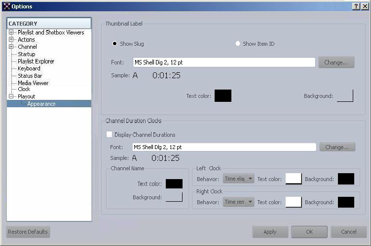
Setting up the Playout Panel for Touch Screens
251
2. In Category, select Playout.
3. In the Show Channel / Index section, select the channels you want displayed in the panel.
4. In the Show Button / Thumbnail section, select the icons representing which control buttons
you want displayed. You can also select whether you want thumbnails and labels shown in
the panel while an item is playing or cued.
5. In Category, select Playout > Appearance.
6. In the Thumbnail Label section, select whether you want the item’s slug or ID to be shown.
7. Click the Change button to set the font for thumbnail labels. A sample of your settings is
provided as a preview. You can also alter the colors of text and background for the labels.
8. In the Channel Duration Clocks section, select the Display Channel Durations check box if
you want to display duration clocks in the Playout panel. Command offers two duration
clocks in the Playout panel—also known as count up/down clocks—and users can customize
the size and color of the clocks for that panel in this section of the Options dialog box.
9. Click the Change button to set the font for the duration clocks. A sample of your settings is
provided as a preview.
10. When done, click Apply, then OK.

Checklist: Setting up the GPI Panel
252
nThe Playout panel does not support selection-based playout. For the Playout panel to work,
indices for the channels being controlled must be set up.
Checklist: Setting up the GPI Panel
A GPI panel is alternative playback control device that can be used to control playout through
Command. GPI panels connect to a GPI card installed in the Command Server.
A GPI panel allows a user to select up to four channels, with each channel having its own set of
Control buttons for play, cue, pause, and stop functionality. Configuring the system to work with
a GPI panel requires defining certain parameters through the Avid Service Configuration
application, the Avid Workgroup Properties application, and the system settings in Command
itself.
Before configuration can begin, you should verify installation of all necessary applications and
components. To ensure a successful setup, complete the following tasks in the order that they are
listed. If you are viewing this checklist online, you can easily link to a topic that provides
procedural details for the task. Return to this main checklist after you have completed each task.
Tasks Refer to...
Verify installation of Avid Service Framework,
which includes the Avid Service Configuration
and Workgroup Properties applications.
“Installing Avid Service Framework” on page 24
Verify installation of the GPI device service on
the Command Server.
“Installing Avid iNEWS Command on the
Server” on page 41
nInstallation of the device service occurs during the installation of the Command Server software.
Installing the GPI card on the Command Server. The installation instructions that came with your
GPI card. See the latest Command ReadMe
documentation for more information on which
cards are supported.
Configure the GPI card. “Configuring the GPI Card” on page 253
Restart the GPI device service. “Restarting the GPI Device Service” on page 256
Confirm proper setup of the GPI. “Confirming Successful Setup of a GPI Panel” on
page 257
Map Indices to Channel Names. “Mapping Indices to Channel Names” on
page 245
Map GPI events to actions. “Mapping Events to Actions for a GPI Panel” on
page 258
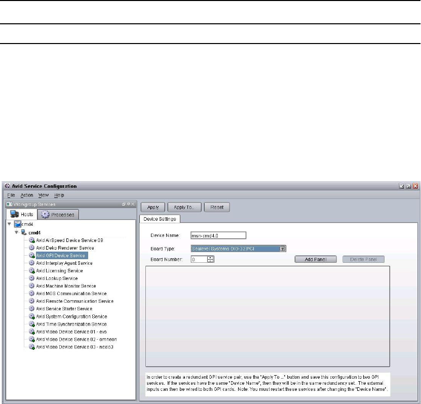
Configuring the GPI Card
253
Configuring the GPI Card
Configuring the GPI card is done using the Avid Service Configuration application. The
procedure is covered in this section.
To define the GPI card’s board settings:
1. Start Avid Service Configuration by clicking the Start button and selecting
All Programs > Avid > Service Framework > Avid Service Configuration.
2. Navigate to and select the Avid GPI Device Service.
Enable the GPI panel for playlist control. “Enabling the GPI Panel” on page 263
Tasks Refer to...
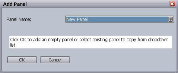
Configuring the GPI Card
254
3. By default the Device Name is set to the host name of the computer on which the GPI device
service is installed plus a period and the numeral zero. So, for example, the default device
name for the system in the previous graphic would be NRCS1.0. The default name can be
changed, if necessary.
nFor redundant systems, the name of the device must match on all computers running the GPI
device service. For instance, if you have two servers with the GPI device service installed, with
one named NRCS1 and the second named NRCS2, by default, the device names would be
NRCS1.0 and NRCS2.0. You would have to alter the device names to match to ensure
redundancy.
4. Select the Board Type—the GPI card installed on the PC running the Avid GPI Device
Service.
5. Set the Board Number to the number of GPI cards installed. Options include 0-4, with the
zero (0) representing the first card and four (4) representing the fifth card, which is the
maximum. Command supports only one board per server.
6. Click Apply.
7. Click Add Panel.
The Add Panel dialog box appears.
8. Click OK. The new panel will appear as a tab.
9. (Optional) Rename the panel in the Panel Name textbox.
10. Accept the default Debounce Time. This input threshold setting in milliseconds is 200 by
default, which means the system will ignore any signal shorter than 200 milliseconds.
11. Click Apply.
12. Set First Input Pin. Options include 0-15, with the zero (0) representing the first pin and
fifteen (15) representing the sixteenth pin, which is the maximum. This numerical value is
card dependent.
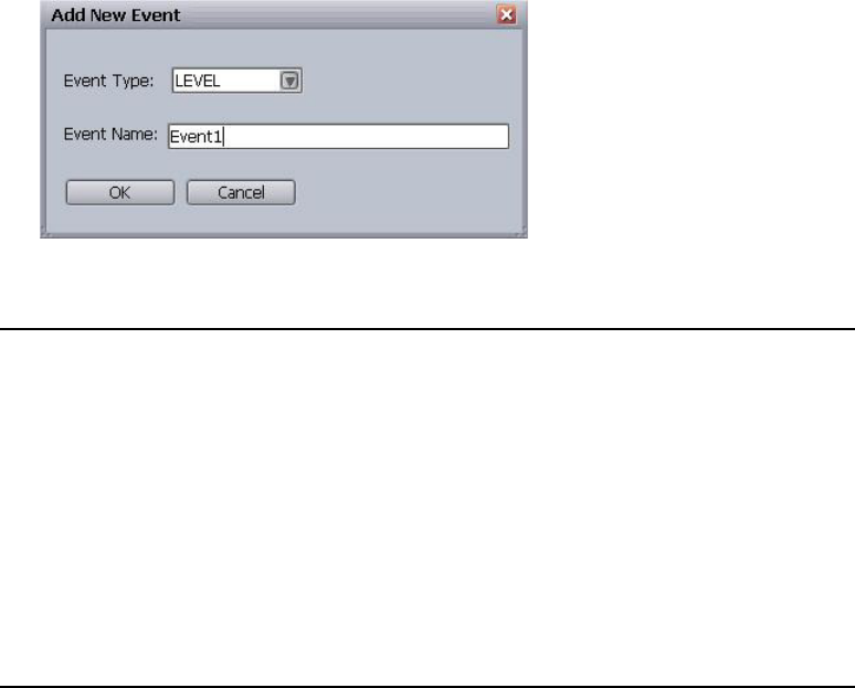
Configuring the GPI Card
255
13. Click Add Event. The Add New Event dialog box appears.
14. Select the type of event. Options include:
15. Enter a name for the event.
16. Click OK.
17. Repeat steps 14 through 17 to continue pin assignment.
nFor redundant systems, to ensure identical functionality, make certain that the device
settings—all input pins and event names and types—are the same for every GPI device service
installed.
Trigger GPI input. Used for normal, GPI button type; push the GPI button for it to
trigger play, pause, cue, and so forth. The GPI signal occurs only while
the button is held down, usually no more than a fraction of a second.
Level GPI input. Extended on/off. While on, the voltage (usually around 5
volts) will remain high. This is useful for channel-specific actions like
play (active) and stop (inactive), and can also be used for tally tally
restriction/reflection. The signal will stay active as long as the switch
allows the voltage signal to continue.
Toggle GPI output. Quick on/off. Seldom used with Command, this is designed
more for a toggle switch-type of workflow and not a button-type of
workflow. It will trigger an action each time the switch changes
position—up to down or down to up.
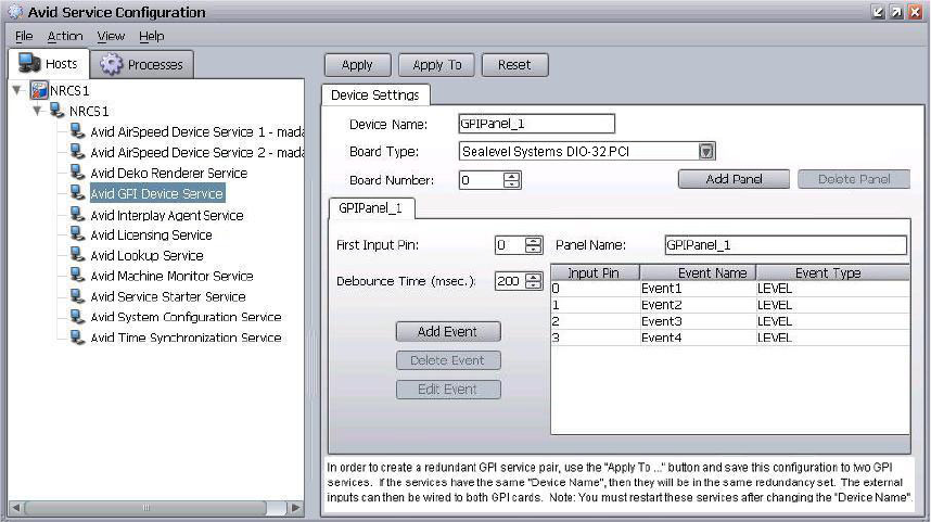
Restarting the GPI Device Service
256
18. Click Apply.
19. After modifying the GPI device service system settings, restart the service.
Restarting the GPI Device Service
After configuring the GPI card, you must restart the device service.
To restart the Avid GPI Device Service:
1. Click Start and select All Programs > Avid > Service Framework > Avid Workgroup
Properties.
2. On the Services tab, click Advanced.
3. Select Avid GPI Device Service.
4. Click Restart.
nAvid also recommends restarting the client software at the Command Workstation.
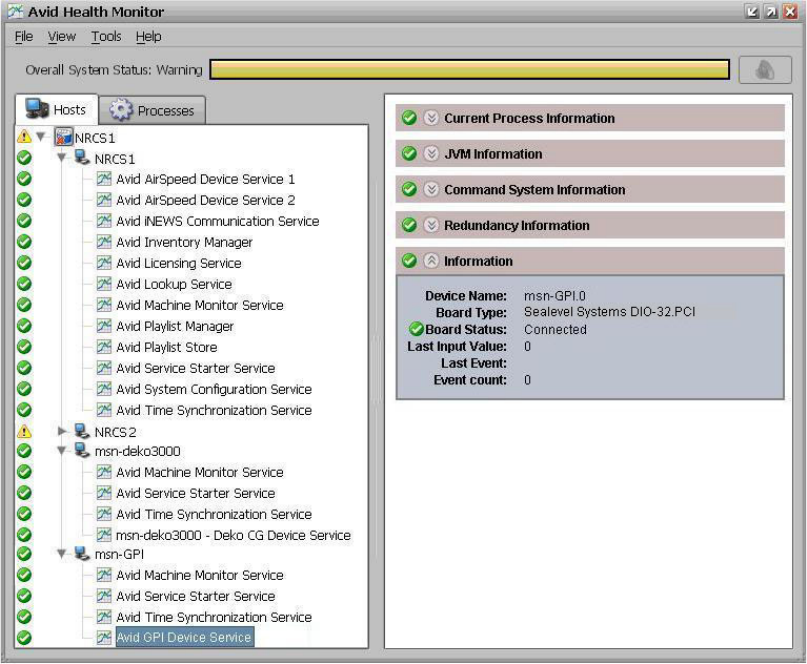
Confirming Successful Setup of a GPI Panel
257
Confirming Successful Setup of a GPI Panel
This section provides a way to verify that the installation and configuration of a GPI panel was
successful.
To verify successful setup of a GPI panel:
1. At the Command Workstation to which a GPI panel is connected, click the Start button and
select Programs > Avid > Service Framework > Avid Health Monitor.
On the Hosts tab, services are listed by computer and device. The Processes tab lists by
services.
2. Navigate to the Avid GPI Device Service and select it.

Mapping Events to Actions for a GPI Panel
258
3. Expand the Information section. The Device Name shows the hostname.board number. If the
Board Status is connected, the service is installed in the right location and the board number
was set correctly. The Last Input Value will typically show zero (0) if there’s no button
pressed on the panel. The Last Event should be empty, and Event count should be zero (0).
4. Press any of the GPI panel buttons. Health Monitor will refresh after a short delay.
nThe time it takes Health Monitor to report a GPI event is slower than the response of Command
to that GPI input.
The Information section will appear similar to the following example:
5. Press a number of buttons to make sure they all work.
nIf the switcher is wired to the GPI panel, test that, too.
Mapping Events to Actions for a GPI Panel
Mapping events to playout actions is done at a Command Workstation in the System Settings
dialog box. In most cases, GPI events are mapped directly to channel-specific actions because
these actions are communicated directly to the Playlist Controller, bypassing the user interface;
the procedure for this type of mapping is provided below.
nFor more information on mapping GPI events for selection-based playout, see page 261.
To map GPI events to channel-specific actions:
1. Log in to a Command Workstation.
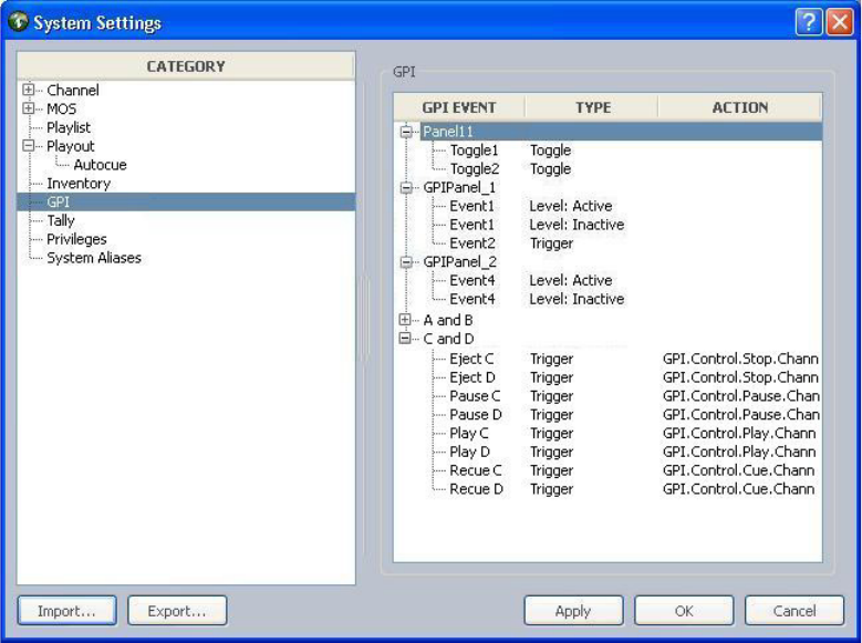
Mapping Events to Actions for a GPI Panel
259
2. Select Tools > System Settings.
The System Settings dialog box appears.
3. Select GPI.
4. Expand the panels to view each panel’s events.

Mapping Events to Actions for a GPI Panel
260
5. Double-click on an event to map it to an action.
The Choose Action dialog box appears with the GPI > Control options expanded by default.
6. Expand the action, such as Play, and select the index value that corresponds to the
appropriate channel.
nChannel 01 actually refers to Index value 01.
Here are some of the most commonly used commands for channel-specific playout:
- Play a specific channel - Choose GPI > Control > Play > index value
- Stop a specific channel - Choose GPI > Control > Stop > index value
nIf doing level-based playback, set the Level:Active to Play a specific channel and the
Level:Inactive to stop that same channel.
- Cue a specific channel - Choose GPI > Control > Cue > index value
nThe Cue channel action only recues the item that is playing. Cueing a different item in the
playlist must be done manually—via mouse, keyboard, or X-keys—or a GPI button must be
mapped and enabled for selection-based playout.
7. Click OK.

Mapping Events to Actions for a GPI Panel
261
8. Repeat steps 5 through 7 as needed.
9. Click Apply (if you want the System Settings dialog box to remain open after settings are
applied) or OK.
The system will prompt you for the administrator password.
10. Enter the administrator password and click OK. If there is no administrator password, leave
the field blank and click OK.
11. Confirm functionality by playing items in a playlist.
To map GPI events for selection-based playout:
1. Log in to a Command Workstation.
2. Select Tools > System Settings.
3. Select GPI.
4. Expand the panels to view each panel’s events.
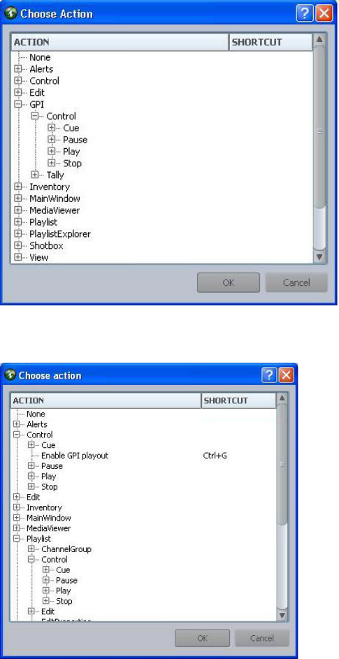
Mapping Events to Actions for a GPI Panel
262
5. Double-click on an event to map it to an action.
The Choose Action dialog box appears with the GPI > Control options expanded by default.
6. Navigate to the Playlist action and expand it.

Enabling the GPI Panel
263
Here are some of the most commonly used commands for selection-based playout:
- Play selection - Choose Playlist > Control > Play > Selection
- Stop selection - Choose Playlist > Control > Stop > Selection
- Cue selection - Choose Playlist > Control > Cue > Selection
nIf you program the GPI panel for these selection-based actions, you must enable the GPI panel
at the workstation.
7. Click OK.
8. Repeat steps 5 through 7 as needed.
9. Click Apply (if you want the System Settings dialog box to remain open after settings are
applied) or OK.
The system will prompt you for the administrator password.
10. Enter the administrator password and click OK. If there is no administrator password, leave
the field blank and click OK.
11. Confirm functionality by playing items in a playlist.
Enabling the GPI Panel
The GPI panel must be enabled to control a playlist if used for non-channel-specific,
selection-based actions that go through the Command user interface.
nThis procedure does not apply to GPI panels (or Maney panels) with events mapped only to
actions chosen in GPI > Control—such as Cue, Pause, Play, or Stop—because those are sent
directly to the Playlist Controller and do not go through the user interface.
A user can enable a panel at any Command Workstation.

Configuring GPI Out
264
To enable a GPI panel to control a playlist:
1. At the Command Workstation, select Tools > Options.
2. In Category, expand Actions and select GPI.
3. Select a GPI panel from the list.
4. Click Apply.
5. Click OK.
System administrators must configure system settings to provide a list of GPI panels in the
Options dialog box. You can confirm mapping by playing items from the GPI panel; test all of
the commands.
Configuring GPI Out
Command supports GPI Out, meaning a GPI pulse can be sent from the system. This feature
does require additional configuration, but after the GPI device service is configured, GPI events
can be selected in a new GPI Out column of a playlist, or the user can enter them in the story title
(slug) or an iNEWS or ENPS rundown.
Configuring GPI Out
265
To configure the GPI device service for GPI Out:
1. Click the Start button, and then select All Programs>Service Framework>Avid Service
Configuration.
2. On the Hosts tab, navigate to and select GPI Device Service.
3. Click Add Panel. The Add Panel dialog box appears.
4. Select Output Panel and click OK.
5. In the Panel Name field, enter a name for the panel.
6. On the new panel’s tab, enter the Pulse Width and Output Early values. You will need to test
this with your automation system to determine the Output Early value that will ensure a
smooth transition. Lab testing revealed a maximum two-frame variation between when the
pulse was sent and the Done status received from an AirSpeed (classic) device.
7. Set the first output pin.
8. Click Add Event. The Add Event dialog box appears.
9. Enter the event’s name and click OK. This is the name that will appear in the Command
playlist (and needs to be entered by iNEWS or ENPS users), so it should be something that
is easy to understand and type.
10. After you finish modifying the configuration, click Apply.

10 Integrating with Avid iNEWS
To ensure proper integration between Avid iNEWS Command and the iNEWS newsroom
computer system, some configuration must be done at the iNEWS Workstation. Those
configuring iNEWS must have system administrator access and a working knowledge of the
newsroom computer system’s administrative features.
•Editing the SYSTEM.MAP Story
•Editing the SYSTEM.MOS-MAP Story
•Setting up the Plug-ins in iNEWS
•Monitor Servers
•Queue Properties

Editing the SYSTEM.MAP Story
267
Editing the SYSTEM.MAP Story
In Avid iNEWS the Map story, which is the first one in the
SYSTEM.MAP
queue, contains monitor
server settings for each newsroom rundown. For more information on monitor servers, see
“Monitor Servers” on page 279.
Here is an example of settings for Command as they might appear in the Map story:
The first line is a comment—as indicated by the semicolon—that helps system administrators
locate the appropriate settings within the Map story.
The second line contains the following rundown information:
• Name of the rundown, such as
nrcs.shows.rundown
• Directory that contains the rundown queue where event lists are created, such as
nrcs.shows
.
• Name of the Composite List queue. In none are configured, a hyphen is used, as shown.
• Name of the user group with access to monitor the rundown, such as
monitors
. Superusers
are also permitted to start monitor servers.
• Monitor duration or quit time. A duration will automatically switch off the monitor server
after the allotted time is achieved. For instance, D200 signifies the duration set to two hours,
and no minutes. (This setting is not case sensitive.) A quit time, such as
2100
, will
automatically switch off the monitor server at the specified time, ensuring the integrity of the
system. The quit time can be three to four digits, specifying an exact time on the 24-hour
clock. When configured, this information appears in the iNEWS user interface at the bottom
of the Monitor dialog box. See “iNEWS Integration” in the Avid iNEWS Command User’s
Guide.
nBecause monitor servers use large amounts of system resources, Avid recommends this setting be
configured but, for best results, manually turn off monitor servers at the end of each show.
The third line contains the following server information:
• Server type -
wnasvr
specifies a Command Server.
;NRCS.SHOWS.RUNDOWN USES MONITOR 292
nrcs.shows.rundown nrcs.shows - monitor D200
wnasvr cmdsvr1 cmdsvr2 ca-composite
CG Deko1 - 1 6pm;Deko Device Channels
video AB - A;AirSpeed Device Channels
Editing the SYSTEM.MAP Story
268
• Primary server’s name, such as
nrcs1
, which is the computer running the Avid iNEWS
Communication service.
• Backup server’s name, such as
nrcs2
.
• Form name for the monitor server, such as
ca-composite
. A hyphen can be used as a
placeholder.
Below the third line are device settings for channel groups in iNEWS Command.
Each line associated with a device begins with:
• Type of device, such as
CG
or
video
.
• Name of device’s channel group, such as
Deko1
or
AB
. Channel group names are case
sensitive.
• Alias for channel group. If none are used, hyphens can act as placeholders.
• For character generators, the next information in the line is the default channel, such as
1
,
which is assigned to an event when the user does not enter a channel in the story, followed
by the style, such as
6pm
. For Deko devices, this style must match the one configured on the
Deko.
• For video devices, the next information in the line is the default channel, such as
A
, which is
assigned to a clip when a user does not enter a channel in the story.
Any comments can be added to the end of the lines following a semicolon.
The Map story can be edited like any other story in the newsroom computer system; however,
access to it is typically limited to system administrators who already have access to
SYSTEM.MAP
directory in iNEWS.
To edit the Map story in iNEWS:
1. Log in to an iNEWS Workstation as a system administrator.
2. Navigate to the
SYSTEM.MAP
queue.
3. Double-click on the first story in the queue.
4. Modify the story as needed.
5. Click Save.

Editing the SYSTEM.MOS-MAP Story
269
iNEWS Style Validation
Command users can turn off style validation in iNEWS. This is most useful for graphics systems
that create new items and need to have them sent to Command, even though they do not exist in
the Command inventory. For this feature to work, modification to the
SYSTEM.MAP
story is
required in iNEWS.
To turn off style validation:
1. From an iNEWS Workstation, open the first story in the
SYSTEM.MAP
queue.
2. Add a sixth column to the story with the word NO in it.
For example:
3. Click Save.
Editing the SYSTEM.MOS-MAP Story
The MOS-Map story, which is the first story in the
SYSTEM.MOS-MAP
queue, contains
information vital to the integration of the plug-ins. Here is an example of settings for Command
as they might appear in the Map story:
The first line is the header. The second and third lines are comments—as indicated by the
semicolons—that provides additional information or structure to the file to help system
administrators.
The fourth line contains the following device information, which is case sensitive:
• The MOS ID of a Deko character generator, such as
DEKO1
. The channel names in this
channel group must match the Gateway ID configured on the DekoMOS Gateway. See
“Configuring the DekoMOS Gateway” on page 167.
• The channel group for the Deko, such as
CG1
. This, too, must match the channels IDs
assigned and configured on the DekoMOS Gateway.
wnasvr cmdsvr1 cmdsvr2 -
CG Deko1 - 1 6pm NO;style validation turned off
TABLE-START DeviceTable
;MOSID AMCPDeviceName
;==============================
DEKO1 CG1
MOSIDTHDR_A Thunder
Editing the SYSTEM.MOS-MAP Story
270
nYou must enter a new line with MOS ID and channel group for each Deko channel group you
configured in Avid iNEWS Command.
The fifth line contains the following device information:
• The MOS ID of an Avid Thunder production server, such as
MOSIDTHDR_A
. This must match
the MOS ID configured in the
ThunderMOS.cfg
file. See “Creating the ThunderMOS.cfg
File” on page 203.
• The channel group for the Thunder, such as
Thunder
.
To ensure that the Avid Deko Select and Avid Thunder Select plug-ins use the correct device
designation, you must set the MOS ID and channel groups in the MOS-Map story.
The MOS-Map story can be edited like any other story in the newsroom computer system;
however, access to it is typically limited to system administrators who already have access to
SYSTEM.MOS-MAP
directory in iNEWS.
To edit the
SYSTEM.MOS-MAP
story:
1. Log in to an iNEWS Workstation as a system administrator.
2. Navigate to the
SYSTEM.MOS-MAP
queue.
3. Double-click on the first story in the queue.
4. Modify the story as needed.
5. Click Save.
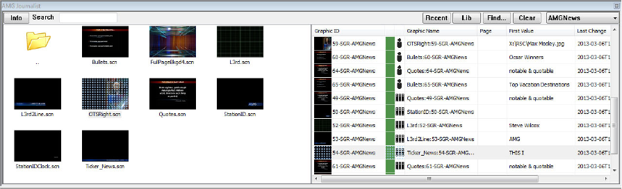
Setting up the Plug-ins in iNEWS
271
Setting up the Plug-ins in iNEWS
Using plug-ins, such as AMG Journalist Client, Deko Select or Thunder Select, with Avid
iNEWS and iNEWS Command is optional. The plug-ins are installed on iNEWS Workstations
and are accessed through the iNEWS client software. The appearance of the plug-in(s) in Avid
iNEWS depends on whether one or more were installed. For instance, when both Deko Select
and Thunder Select are installed, the title of the workspace—shown on the title bar—is Avid
Graphics Select, and the plug-in workspace will appear in the iNEWS window with each plug-in
on its own tab, as shown:
If only one plug-in is installed, the Tools menu option will be the name of that plug-in: Avid
Deko Select or Avid Thunder Select. Also, only one tab will appear in the plug-in workspace.
nIf both Thunder and Deko plug-ins are being installed on an iNEWS Workstation, Avid
recommends the Thunder service be installed first.
AMG Journalist Client Installation
This section contains the following topics:
•“Installing AMG Journalist Client Software” on page 272
•“Testing the AMG Journalist Client” on page 272
Setting up the Plug-ins in iNEWS
272
Installing AMG Journalist Client Software
The following steps describe how to install the Avid Motion Graphics Journalist Client for
integration with Command, and iNEWS or ENPS.
To install the AMG Journalist client:
1. Navigate to the Avid Motion Graphics Journalist Server (via UNC path -
\\servername)
.
2. Open the install folder.
3. Double-click the Avid_Motion_Graphics_Journalist_setup.exe to run the executable.
4. In the AMG Journalist Applications window, click the AMG NRCS Client to install it.
5. Select Microsoft Visual C++ Redistributable to install it.
6. Select AMG Drive Monitor to install it. Make sure the IP address for the AMG Journalist
server is populated. Follow the prompts (Install, Next, Finish) to complete the installation.
7. Select AMG ODBC to install it.
nA database password is not necessary, and should not be entered.
8. Select AMG NRCS to install, and click Finish to complete the installation.
9. Select Exit to close the installer.
You can now test the AMG Journalist Client.
Testing the AMG Journalist Client
After starting the AMG Journalist Client, you can test the functionality of it.
To test the AMG Journalist Client:
1. Open the AMG Journalist Client.
2. Double-click an item to open it in the template editor.
3. Add replacement data and click Save.
The new item should appear in the Graphic Database area list with a unique ID for the item.
4. Open the new item and edit the first replaceable field.
5. Click Save and confirm that the data has updated.
6. Open the created item and click the Preview button.
7. Confirm that the correct replacement data appears.
8. Open the created item and click the Movie button.
9. Confirm that the item appears with motions and correct replacement data.
Setting up the Plug-ins in iNEWS
273
10. Create several more items and drag them into the rundown.
11. Create a hand-entered item.
12. Designate one of the items as a library graphic and drag into a playlist.
13. MON Load the show, and confirm that all graphics appear in the Command playlist.
Installing and Configuring Avid Deko Select
The Deko Select plug-in allows iNEWS users to create CG items directly at the iNEWS
Workstation, including changing background graphics, editing replaceable text, and setting In
and Out points.
To install and configure Avid Deko Select:
1. Ensure that the iNEWS client software is not running.
2. At the iNEWS Workstation, run the Deko Select installation program called
DekoSelectClient.exe
.
3. Log in to iNEWS.
4. Select Tools > Plugins > Avid Deko Select.
If Thunder Select is also installed on the workstation, the menu option will be Tools >
Plugins > Avid Graphics Select.
The first time you open Avid Deko Select, an error message appears stating that Deko Select
is not configured.
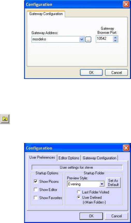
Setting up the Plug-ins in iNEWS
274
5. Click OK.
The Configuration dialog box opens.
6. In the Configuration dialog box, on the Gateway Configuration tab, enter the host name or IP
address for the computer that is running the DekoMOS Gateway software.
7. Click OK. The initial Configuration dialog box will close.
8. Click the Configure button on the toolbar of Deko Select.
The Configuration dialog box opens with three tabs.
9. Click the User Preferences tab, if it’s not already selected.
10. Select options to indicate what you want Deko Select to display.
11. Select the Preview Style you want to use as your default, then click the Set As Default
button.
12. Click OK.
Setting up the Plug-ins in iNEWS
275
Configuring Gateway Settings from an ini File
After you have configured the Gateway Settings on the first workstation, you can install them on
additional workstations from an ini file.
Gateway settings, as configured via the plug-in’s Configuration dialog box, are stored in a file
called
DekoMOS.ini
in
C:\WinNT\System32
or
C\WINDOWS\system32
. After installing and
configuring Gateway settings on one workstation, you can copy this
DekoMos.ini
file onto
other computers rather than actually repeating the configuration procedure.
Installing and Configuring Avid Thunder Select
The Thunder Select plug-in allows iNEWS users to view thumbnails of video items on the
Thunder and to drag-and-drop those items directly into an iNEWS story.
To install and configure Avid Thunder Select:
1. Ensure that the iNEWS client software is not running.
2. At the iNEWS Workstation, run the Avid Thunder Select installation program called
ThunderSelectClient.exe
.
3. Copy the
ThunderMOS.ini
file from the
C:\Thunder
directory on your Thunder device to
your local
C:\Thunder
directory.
If you do not have a
ThunderMOS.ini
file, create it in the
C:\Thunder
directory, open it,
and enter the full UNC path to the the
ThunderMOS.cfg
file. For more information, see
“Creating the ThunderMOS.ini File” on page 204.
4. Log in to iNEWS.
5. Select Tools > Plugins > Avid Thunder Select.
If Avid Deko Select is also installed on the workstation, the menu option will be Tools >
Plugins > Avid Graphics Select.
The first time you open Avid Thunder Select, three errors will appear.
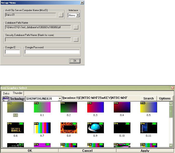
Setting up the Plug-ins in iNEWS
276
6. Click OK.
The Setup Menu dialog box opens.
7. If it doesn’t, click the Options button in the top right corner of the plug-in.
8. In the Setup Menu dialog box, select the interface, either iNEWS or ENPS, depending upon
the newsroom computer system with which you are interfacing.
If you are integrating with an iNEWS system, the fields will be grayed out and populated
according to the information you supplied in the
ThunderMOS.cfg
file.
If you are installing into an ENPS system, you must do the following:
- Type the Thunder name in the Avid Clip Server Computer Name (MosID) field, or
browse to the Thunder by clicking on the ellipsis (“…”) button.
- Select File > Preferences > Protocol Setup, and browse to or enter the database that was
set up on the Thunder.
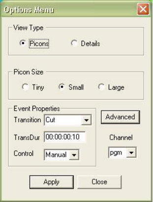
Setting up the Plug-ins in iNEWS
277
9. Enter the Dongle ID and Dongle Password. If your Thunder system is a:
- ThunderXL or LT system, use the dongle ID and password of the dongle on the Thunder
server.
- ThunderMX, HD, or HY system, use the dongle ID and password that was printed on
the options letter which shipped with your ThunderMX/HD/HY software CD.
nThe number of Thunder Select client licenses is controlled by the dongle on the server, and is
determined by the number of client licenses that you purchased.
10. Click OK.
The plug-in connects to the Thunder database, and you will see thumbnails of clips and
stills. You can now drag and drop this media into an iNEWS or ENPS story or preview them
by double-clicking.
nOnce this setup information has been entered, it should not need to be reconfigured. However, if
the dongle is removed, or for any other reason the data has changed, a warning dialog appears
and the setup information will need to be reconfigured. Enter the network path to the Thunder
database and the Thunder license key.
11. Click the Options button again.
The Options dialog box opens.
Setting up the Plug-ins in iNEWS
278
12. Set the options, including View Type, Event Properties, and Channel.
The channel value selected here must match the channel name entered when the device
channels were set up for the Thunder. For more information, see “Setting up Device
Channels” on page 220.
13. Click Apply.
For more information on Avid Thunder Select, see the Avid Thunder Select Installation and
Configuration Guide.
Configuring a MOS Alias in iNEWS
Command and iNEWS support the ability to use multiple Command channel groups with a
single MOS ID. This configuration allows a site to use a single graphics system (with a single
MOS ID), and create graphics that can be used in multiple studios. iNEWS ActiveX users (e.g.
AMG Journalist, Viz Template Filler, Chyron LUCI, etc.) will be able to view all of the graphics
in the system in their respective iNEWS ActiveX control, and configure the items to be assigned
to the desired devices on a per rundown basis. This is accomplished using iNEWS MOS alias.
nThere can be only one Command channel group per rundown.
To configure a MOS Alias in iNEWS:
1. In the SYSTEM.MOS-MAP, enter the MOS ID and alias (rather than a specific Command
channel group).
For example, MOSID MOSalias.
2. In the system.map, configure the rundown to use the desired Command channel group, and
add the alias to the 3rd position.
For example: cg AMG12 MOSalias 1 Style-1
When you drop an item from the ActiveX control, it will get the MOS Alias as the device
designation (*MOSalias in the example above).
nThis item can be moved to any rundown, and the channel group will be assigned as it is
configured in the system.map (i.e. per rundown). Items can be moved be from story to story, and
can be used in different rundowns as needed.
Monitor Servers
279
Configuring Command with iNEWS
Command device channels, channel groups, and iNEWS rundowns must also be configured.
To configure Command iNEWS rundowns:
1. In the SYSTEM.MOS-MAP, add an entry for the new MOS ID, AMGNews, and then add
the channel group name, as defined in the iNEWS Command configuration.
2. In the SYSTEM.MAP, add a new line for the AMG channel group. For instance, the device
designation <cg>, channel group name <AMG6>, dash <->, default channel <mg1>, and
style <Style-1>.
Monitor Servers
Monitor server is a utility program—running on the iNEWS newsroom computer system—that
checks a show’s event requests for errors, creates composite and event lists, and sends newsroom
playlists to Avid iNEWS Command.
A monitor server must be assigned device and mailbox numbers—typically, these numbers are
the same, which makes the configuration easier to remember. A device number is chosen for
monitor server so iNEWS recognizes the server (utility) program as a valid device. The device
number must be entered in the newsroom computer system’s configuration file. The mailbox
number must be assigned to both the show’s monitor server and its rundown queue.
nA mailbox is an activation mechanism for a server (utility) program, so if a queue has a mailbox
number matching a server program, then that server is the one activated whenever something
happens to the queue.
The mailbox enables iNEWS to notify the monitor server of changes made to a rundown
queue—the one sharing the same mailbox number—while that show is monitored.When on,
monitor server checks its assigned rundown for machine control events, and builds playlists. The
monitor server then sends updates to that rundown’s newsroom playlist in Command, and will
continue to do so as long as the monitor is running and the newsroom computer system retains
the lock on the playlist. It also updates composite and event lists, if necessary.The monitor server
is turned on when a user at an iNEWS Workstation turns it on. The monitor server loads data to
the iNEWS Command system or the MOS Gateway system when a user instructs it to do so from
an iNEWS Workstation.

Monitor Servers
280
Creating a Monitor Server for Each Show
The procedures in this section assumes the user has a working knowledge of administration tasks
associated with an Avid iNEWS system and that rundown queues for the shows being monitored
already exist in iNEWS. If not, create them before continuing. For more information on how to
create queues or further details regarding steps in this section, see the administration
documentation that accompanied your iNEWS system.
To create and configure a monitor server:
1. Check the configuration file (
/site/config
) and choose the next available device number
for the monitor server, from the range of 3-digit numbers reserved for use by your system’s
server programs, such as 201 to 300.
Valid standard mailbox numbers are 1 through 4096.
2. Choose an available mailbox number. For simplicity, this should be the same 3-digit device
number. Do the following:
a. Use the
list
console command to ensure no other device is using the mailbox number
you have chosen. For instance, to check mailbox 266, type:
list mailbox=266 c
Information similar to the following appears:
nFor other list command options for determining mailbox assignments of queues and servers, see
“Using the list Command to View Assigned Mailboxes” on page 283.
b. If you see the device configuration header (as shown in step 2a) with no information
below it, then no device has that mailbox and you can use that number.
However, if configuration information for a device appears below the header, that device
has the same mailbox as the one you chose. Therefore, choose another mailbox number
and repeat step 2a.
nIf the mailbox number is already being used, and you must choose another, you may want to try
another device number for the monitor server as well. Typically, mailbox numbers match server
program device numbers, although this is not required. However, the mailbox number you select
must be assigned to the queue monitored by the server program. Multiple queues can share the
same mailbox number, but care must be take to avoid conflicts. For more information, see
“Using the list Command to View Assigned Mailboxes” on page 283.
DEV DEVICE_TYPE COMPUTER CCU PRINTER SPEED OPTIONS DEVNAME
Monitor Servers
281
3. Changing the configuration file requires the use of
ed
, the line editor.
Add the monitor server to the
/site/config
file on each iNEWS Server—such as server A
and server B in a dual server system— by doing the following:
cAlways back up the /site/config file before making any changes.
a. At the console, select all iNEWS Servers.
b. Use the ed command to open and edit the configuration file, by typing:
ed /site/config
1259
After you press Enter, the editor responds by displaying a number, as shown, indicating
the file size expressed as the number of characters, including spaces and returns. For
more information on the line editor and Avid iNEWS configuration files, see the Avid
iNEWS Setup and Configuration Manual.
c. Add the monitor server’s device number to the servers line in the host definition for the
iNEWS Server that will run the monitor server program. For instance:
servers 261 263 265 267
The device number 267 is added to the servers line in this example.
nDivide your server programs evenly among your iNEWS Servers to distribute the load they put
on your system. For instance, put odd numbered programs on server A and even numbered ones
on server B. Additionally, ensure that you also add the configuration line for the monitor server
to alternate host definitions for your iNEWS Servers. This ensures it can run on the surviving
computer should one of your iNEWS Servers stop functioning.
Do not confuse the configuration line, which starts with server, and the servers line mentioned in
3c on page 281, which lists device numbers.

Monitor Servers
282
d. Add a configuration line for the monitor server in the host definition belonging to the
iNEWS Server that will run the server program. This line begins with the word server
and contains the mailbox number assigned to the monitor server.
The format for server programs’ configuration lines are:
server <device#> <type> <mailbox> <device name>
Comments appearing after the semicolons (;) are optional.
The following are sample configuration lines for monitor server programs:
e. When you finish making changes to the configuration file, save your changes by typing:
w
cDo not use an uppercase (W) in step 3e.
f. When you press enter, a number will appear, such as
1279
, indicating the file size. You
can then exit the line editor by typing:
q
4. (Optional) Test your configuration changes. After editing the configuration file
(
/site/config
), it should be backed up.
Parameter Description
device #
The device number assigned to the server program. This 3-digit
number must also be listed in the servers line in a host definition.
type
The type of server program is monitor.
mailbox
The mailbox the server program uses. Valid standard mailbox
numbers are 1 through 4096. This number typically matches the
server program’s device number.
device name
Monitor servers do not use a device name; enter a hyphen (-).
server 264 monitor 264 - ;monitor server
server 265 monitor 265 - ;monitor server
server 266 monitor 266 - ;monitor server
server 267 monitor 267 - ;monitor server

Monitor Servers
283
5. Reconfigure the system.
When adding monitor server programs, you do not need to stop anything to reconfigure the
system.
nUnlike other utility programs, it is not necessary to start a monitor server when you add it to the
configuration file. It starts when someone uses the monitor on or monitor load command for the
rundown queue to which you have assigned the monitor server. See the Command User’s Guide
for more information on using monitor servers.
Mailboxes are assigned to queues in the same way other database traits are—using the Queue
Properties dialog box. For more information, see “Queue Properties” on page 284.
6. After you choose the monitor server’s mailbox number and verify that it is not used by
another device, you must also assign it to the show’s rundown queue, being monitored by the
monitor server.
For instance, if the monitor server’s mailbox number is 267 and it will monitor the
SHOWS.6PM.RUNDOWN queue, then that number must be assigned to that queue.
For more information on assigning mailboxes to queues, see the Avid iNEWS Setup and
Configuration Manual.
Using the list Command to View Assigned Mailboxes
Variations of the list command can be used at the console to determine mailbox assignments for
specific devices, queues, and so forth.
Since multiple queues can share the same mailbox, you can list all queues and directories in the
database that are using a certain mailbox, such as 267, by typing:
list mailbox=267 d
To find out which monitor server mailboxes are assigned:
tType:
list c monitor
The system displays configuration information for your system’s monitor servers, similar to
the following:
DEV DEVICE_TYPE COMPUTER CCU PRINTER SPEED OPTIONS DEVNAME
S264 monitor A N264
S265 monitor B N265
S266 monitor A N266
S267 monitor B N267
NRCS-A
$
Queue Properties
284
The mailbox number assigned to each monitor server appears in the PRINTER column and
begins with the letter, N.
To see if any servers are assigned a certain mailbox number:
tUse the following format:
list mailbox=<mailbox number> c
To check whether mailbox 267 is assigned to a server program:
tType:
list mailbox=267 c
Two rundowns queues can share the same mailbox, but they should never be monitored
simultaneously.
cIf two rundowns share the same mailbox number, ensure that both their monitor servers do
not run simultaneously; otherwise, results could be unpredictable.
Queue Properties
To ensure seamless interaction between Avid iNEWS and iNEWS Command, the queue
properties for newsroom rundowns must be configured properly. This section provides a few
things to verify in the Queue Properties dialog box of Avid iNEWS. For more information on the
Queue Properties dialog box, see Chapter 5 in the Avid iNEWS Setup and Configuration Manual.
To view the Queue Properties dialog box:
1. Log in to an iNEWS Workstation.
2. Navigate to a rundown associated with iNEWS Command.
3. Right-click on that rundown in Directory panel.
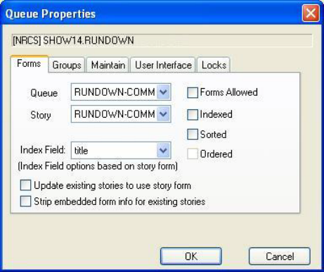
Queue Properties
285
4. Select Properties.
The Queue Properties dialog box has multiple tabs; however, the ones of greater importance in
regard to interaction with Command are: Forms, Maintain, and User Interface.
On the Forms tab, ensure that the appropriate story form is chosen. The selected form must
contain fields for all necessary media events. The queue form determines the look of the queue.
The story form chosen must contain an item-channel field. The story form determines how an
event request is displayed when you double-click it. The forms will only appear in the
drop-down lists if they exist in the database. For information about how to create your own forms
or modify existing forms, and about database traits, see Chapters 5 and 8 of the Avid iNEWS
Setup and Configuration Manual. Users should log off and sign back on to view the new
queue/story form settings.
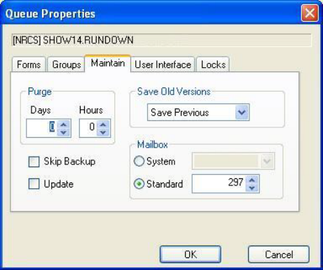
Queue Properties
286
On the Maintain tab, ensure the standard mailbox number is set correctly. Rundowns that load
playlists to Command through monitor servers must be set to use a standard mailbox number.
The Mailbox section does not apply to the e-mail feature of the iNEWS newsroom computer
system. These mailboxes are “signal carriers” by which utility programs, called servers, are
notified to perform a pre-defined task. The mailbox number assigned to the queue must match
the device number of the server monitoring it, as defined in the iNEWS Configuration file
(
/site/config
). Valid mailbox numbers are one through 4096.
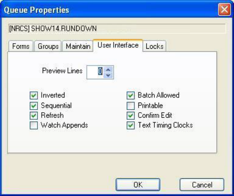
Queue Properties
287
On the User Interface tab, ensure that the Refresh option is selected to enable automatic updates
from Command.

11 Integrating with ENPS
To ensure proper integration between Avid iNEWS Command and the ENPS newsroom
computer system, certain configuration must be completed within ENPS. Those configuring
ENPS must have system administrator access and a working knowledge of the newsroom
computer system’s administrative features.
nENPS is third-party software. Refer to the manufacturer’s documentation for more detailed
information regarding the newsroom computer system.
•Configuring ENPS
•Configuring ENPS to Host AMG Journalist Client
•Configuring MOS Settings in Command
•Creating Multiple Channel Groups with a Single MOS ID
•ENPS roChannel Guidelines
•Configuring Command for MOS Redirection
•Enabling Object Placeholders
•Configuring ENPS for Deko Select
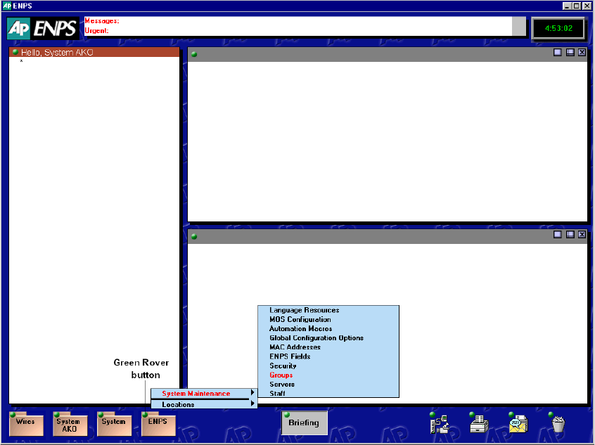
Configuring ENPS
289
Configuring ENPS
You must configure the ENPS MOS settings on an ENPS newsroom computer system to enable
integration with Avid iNEWS Command.
To configure the ENPS MOS settings:
1. Open the ENPS client interface.
2. Click the green Rover button on the Corporate folder at the bottom of your screen.
This folder—fourth from the left—is typically labeled with your station call letters or
corporate name. By default, it is labeled ENPS.
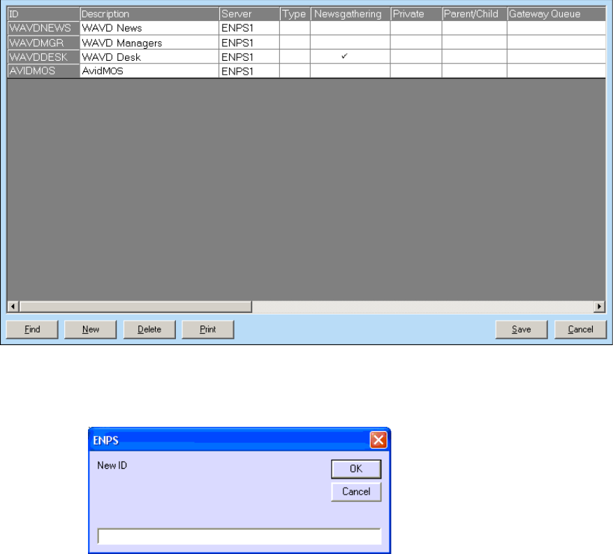
Configuring ENPS
290
3. Select System Maintenance > Groups.
A dialog box with a list of configured groups opens.
4. Click the New button.
The ENPS dialog box opens.
5. Enter the name of the group and click OK. A new row appears in the list.
6. On that row, do the following:
a. Enter a description.
b. Select the server. This should be the primary ENPS server.
7. Click Save.
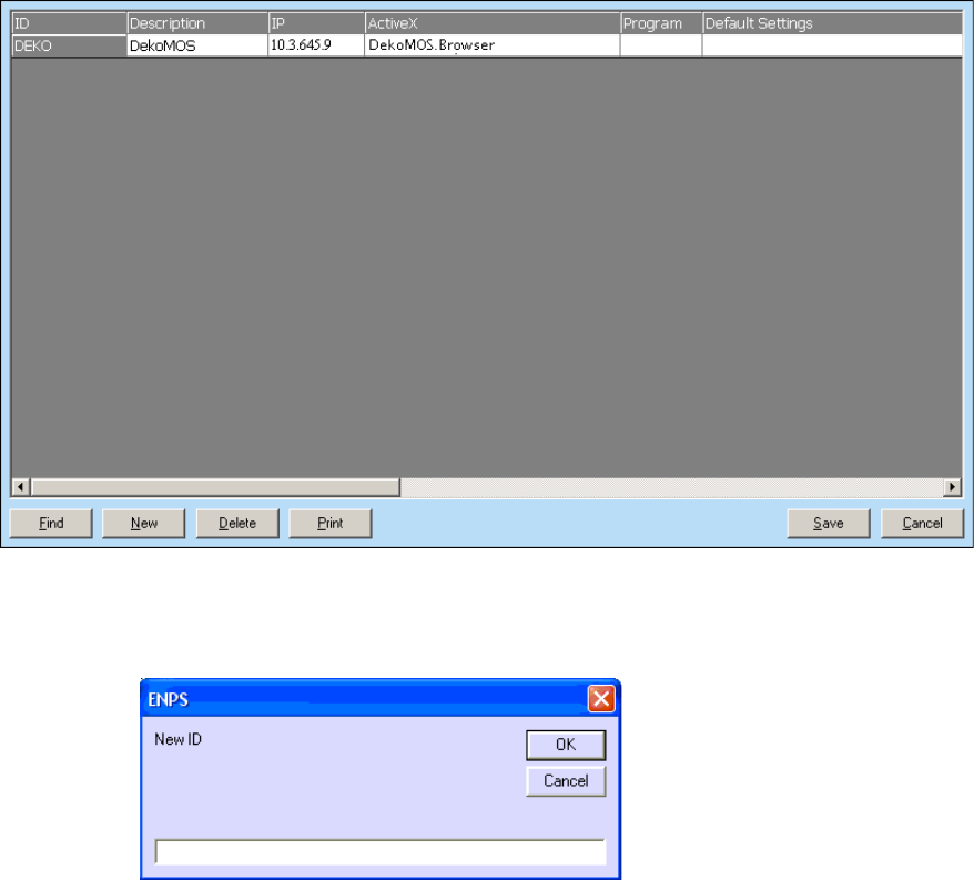
Configuring ENPS
291
8. Click the green Rover button on the Corporate folder again.
9. Select System Maintenance > MOS Configuration.
A dialog box with a list of configured MOS plug-ins opens.
10. Click the New button.
The ENPS dialog box opens.
11. Enter the MOS ID. The information you enter here must match the iNEWS Command MOS
ID in the Command system settings. For more information, see “Configuring MOS Settings
in Command” on page 294.
12. Click OK. A new row appears in the list.

Configuring ENPS to Host AMG Journalist Client
292
13. On that row, fill in the fields as shown in the following table:
nYou might need to scroll to the right to view all fields that require modification.
14. Repeat the previous steps to create a second MOS ID for the backup Command Server.
15. Click Save.
16. Restart all ENPS client applications so that the new MOS ID information will appear as an
option.
17. Restart the ENPS News Object Manager (NOM) to allow the new MOS ID to take effect and
appear throughout the ENPS newsroom computer system.
Configuring ENPS to Host AMG Journalist Client
If you are using AMG Journalist with ENPS, then you must configure ENPS to host the AMG
Journalist client.
nThis can be done from any ENPS client machine.
Once configured, the AMG Journalist client will need to be installed (from the X: drive) on all
ENPS client machines that need access to it.
To configure ENPS to host AMG Journalist client:
1. Open the ENPS client.
2. Select the green 'rover' on the 4th folder in the client, point to System Maintenance, and then
MOS Configuration.
Text Box Name Description
Description Enter the name that identifies this plug-in for users.
IP Enter the IP address of the Command Server running the MOS
Communication service.
Program Select the group you created in step 5.
MOS Version Enter the version used by your Avid iNEWS Command system. Although
both versions 2.6 and 2.8 are supported, Avid strongly recommends using
MOS 2.8.
Auto Create Ensure the auto create field is enabled.
Object Type Set the object type to VIDEO.
Configuring ENPS to Host AMG Journalist Client
293
3. If you already have a MOS ID configured for the Command system, add the following
information to the respective fields:
a. In the Description field, if a description is already entered, it should be changed to
AMG Journalist, so users can easily identify it.
b. In the IP field, type the IP address of the Command server, if not already done.
c. In the ActiveX field, type RCGPLUGIN.RCGpluginCtrl.1, which identifies the AMG
Journalist client plugin.
d. In the Program field, select the group that was created specifically for Command.
e. In the MOS Version field, 2.8 is the recommended version.
nMake sure that the AMGConf.ini is also set to use MOS 2.8.
f. In the Local DragDrop field, make sure it is set to Off.
g. In the Story Send field, make sure this option is selected.
nUsing the same MOS ID as the Command system allows the journalist to open graphics that
have already been created.
nIf you are using more than one ActiveX plugin (such as AMG Journalist and Deko Select), only
one ActiveX plugin can be configured to use the same MOS ID as Command. The second ActiveX
plugin will need to be set up with a separate MOS ID.
Installing Avid Motion Graphics Journalist Client
The following steps describe how to install the Avid Motion Graphics Journalist client for
integration with Avid Motion Graphics Journalist. They assume that the Avid Motion Graphics
servers have already been installed and licensed.
To install the Avid Motion Graphics Journalist client:
1. Navigate to the Avid Motion Graphics Journalist Server (via UNC path -
\\servername)
.
2. Open the install folder.
3. Click AMGDriveMonitor to install. This configures the x: Drive and configures the system
tray icon.
4. Click AMGODBC to install. This configures the database connection.
5. Click the AMGNRCS to install. This configures the AMG Journalist Client.
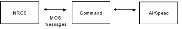
Configuring MOS Settings in Command
294
Confirming Avid Motion Graphics Journalist Functionality
After installing and configuring the Journalist and Command components, confirm the
functionality.
To confirm Journalist functionality:
1. Open the AMG Journalist client.
2. Double-click an item to open it in the template editor.
3. Add replacement data, and click Save.
4. Open the new item and edit the first replaceable field.
5. Click Save and confirm that the data has updated.
6. Open the created item, and click the Preview button.
7. Confirm that the correct replacement data appears.
8. Open the created item, and click the Movie button.
9. Confirm that the item appears with motions and correct replacement data.
10. Create several more items and drag them into a rundown.
11. Create a hand-entered item. Confirm that it appears in Command.
12. Designate one of the items as a library graphic and drag into a playlist.
13. MON Load the show, and confirm that all graphics appear in the Avid Motion Graphics
Command Workstation.
Configuring MOS Settings in Command
The MOS category in the System Settings dialog box allows system administrators to configure
the Command system to integrate with a MOS-enabled newsroom computer system, such as
ENPS. A MOS-enabled newsroom computer system can send playlists to Command.
MOS (Media Object Server) is an industry-standard, XML-based protocol that is primarily used
by a newsroom computer system (NRCS) to maintain running orders on a video server. MOS
also enables servers to update the newsroom computer system with changes to the server’s media
inventory. Command’s MOS support enables communication between the newsroom computer
system and AirSpeed video servers, as shown in the following illustration.
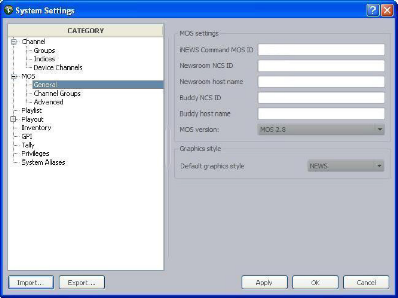
Configuring MOS Settings in Command
295
MOS does not provide a means of controlling playout from a video server. Command supplies
this function.
Under the MOS category are three subcategories:
• General - used to configure MOS and graphics style settings.
• Channel Groups - used to identify channel groups for integration with MOS-based
newsroom computer systems.
• Advanced - used for advanced MOS feature configuration.
To configure Command’s system settings to work with a MOS-based newsroom computer
system:
1. At a Command Workstation, select Tools > System Settings.
2. Expand the MOS category.
3. Select General.

Configuring MOS Settings in Command
296
4. Edit the MOS settings accordingly:
5. Set the default graphics style for playlists loaded from a MOS-based newsroom computer
system, if necessary.
Graphics styles are added at the Command Workstation via the Playlist category in the
System Settings dialog box. If none are added, then the list in the MOS > General category
will appear blank.
6. Select Channel Groups.
MOS Setting Description
iNEWS Command MOS
ID
The ID that enables enables bidirectional communications between a
MOS-based newsroom computer system and Command. For instance:
avid.command1.mos
or
avid.command2.mos
Newsroom NCS ID Usually, this is set to the host name of the newsroom computer system’s
server.
Newsroom Host Name Host name of the newsroom computer system’s server. The name entered
in this field must be resolvable via the Domain Name Service (DNS);
otherwise, an IP address can be used instead.
Buddy NCS ID Usually, this is set to host name of the newsroom computer system’s
“buddy” or backup server. The name entered in this field must be
resolvable via the Domain Name Service (DNS); otherwise, an IP address
can be used instead.
Buddy Host Name Host name of the newsroom computer system’s “buddy” or backup
server.
MOS version Determines which version of MOS protocol Command will use.
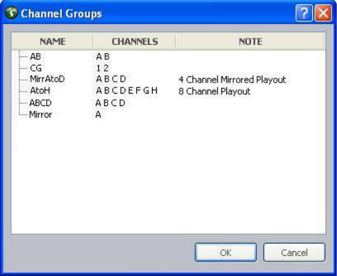
Configuring MOS Settings in Command
297
7. Click Add.
The Channel Groups dialog box appears.
8. Select a channel group.
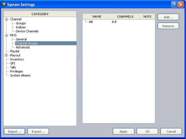
Configuring MOS Settings in Command
298
9. Click OK.
The chosen channel group will appear in the list on the right side of the System Settings
dialog box.
nIf entering multiple channel groups, the device channels in those groups must not conflict. When
entering multiple channel groups of the same type, such as AirSpeed, Command will auto-assign
MOS items to the first channel of the first channel group listed. For more information, see
“Creating Multiple Channel Groups with a Single MOS ID” on page 301.
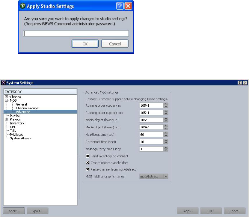
Configuring MOS Settings in Command
299
10. Click Apply (if you want the System Settings dialog box to remain open after settings are
applied) or OK. The system will prompt you for the administrator password.
11. Enter the administrator password and click OK.
While a newsroom computer system can use non-standard ports for the incoming and
outgoing sockets and the advanced settings can be customized, Avid recommends that the
default settings be used.
nAvid strongly recommends contacting Customer Support before altering any of the advanced
settings.
The first four settings specify the port numbers for the sockets used to communicate with the
MOS-based newsroom computer system. The defaults, as defined in the MOS protocol
specifications, are: 10541 (upper) and 10540 (lower).
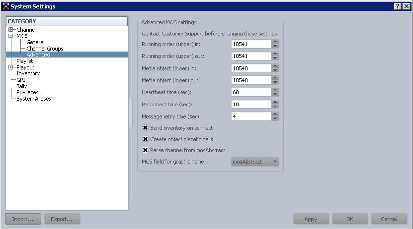
Configuring MOS Settings in Command
300
To view advanced MOS settings:
1. Select Tools > System Settings.
2. Expand the MOS category.
3. Select Advanced.
While a newsroom computer system can use non-standard ports for the incoming and
outgoing sockets and the advanced settings can be customized, Avid recommends that the
default settings be used.
The first four settings specify the port numbers for the sockets used to communicate with the
MOS-based newsroom computer system. The defaults, as defined in the MOS protocol
specifications, are: 10541 (upper) and 10540 (lower).
4. Send Inventory on connect should be selected.
5. If you intend to use Object Placeholders, select Create object placeholders.
6. For graphics systems, such as AMG Journalist, you should select Parse channel from MOS
Abstract.
7. Select the desired MOS field for graphic name. This setting affects how the graphic items
appear in the Title column of the Command playlist

Creating Multiple Channel Groups with a Single MOS ID
301
Creating Multiple Channel Groups with a Single MOS
ID
Command support the ability to create multiple channel groups with a single MOS ID for the
graphics system. This requires that the ActiveX plugin supports the ability to populate the MOS
Abstract with the specific item channel for the device.
For ENPS or other MOS based systems, the single MOS ID problem is resolved by placing the
item channel in the MOS Abstract. Command parses the item channel, and assigns the respective
channel group accordingly.
For example, an item created and assigned to channel "1", should have
1:<itemID>:<replaceabledata> in the MOS Abstract. Command will parse the 1 and colon, and
assign the item to the channel group that contains channel 1.
ENPS roChannel Guidelines
For ENPS systems, Command supports roChannel with roCreate and roMetadataReplace in the
MOS Communication service.
Here are guidelines for using roChannel:
• Users can set the MOS Channel in the ENPS properties, and when the rundown is loaded,
video items will be assigned to that channel group. Only one entry is allowed, and users
should not set the MOS Channel to a graphic channel group; it is not necessary.
• Users should add all channel groups that might be used to the system settings in Command.
Those settings are located in the System Settings dialog box under the MOS category in the
Channel Groups sub-category.
• The channel group assigned in the MOS Channel will be the first one displayed in the
Command playlist. Other channel groups will be to the right of it.
In this example, omAB is defined in the ENPS MOS Channel, and therefore displayed first.
Both omAB and omC are defined in the system settings in Command.
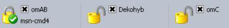
Configuring Command for MOS Redirection
302
• If there are graphic channel groups, they will be displayed after the channel group set in the
MOS Channel.
In this example, the channel group omAB is set in the ENPS MOS Channel, Dekohyb is a
graphic channel group. All three are defined in the system settings in Command.
• Users can assign an individual item to a different channel group by changing the MOS
Channel in the rundown rather than the rundown properties.
If the rundown MOS Channel is set when the rundown is MOS activated, the item will keep
its channel designation. The rundown MOS Channel will not override the rundown’s MOS
Channel.
• Users can easily switch to a different channel group for a MOS Active/Ready to Air
rundown by opening the rundown properties and entering the new MOS Channel. Before the
change is made in ENPS, the operator must unlock the current channel group in Command,
and then lock the updated channel group after the change is made.
nIf you plan to use MOS Channel to change the channel group for any MOS Active rundown, you
need to define channel group in the MOS Channel field for all rundowns. If the MOS Channel is
not defined when the rundown is MOS activated, the MOS Channel needs to be set twice to make
the change happen.
Configuring Command for MOS Redirection
Command sites that interface with the ENPS newsroom computer system can run two MOS
Communication services and set the second one to have a different MOSID so that MOS
redirection can be used to send playlists to the backup server. The purpose of MOS redirection to
allow users to load the ENPS rundown to the backup Command Server in the event of a primary
server failure. It is the equivalent of loading an iNEWS rundown to the backup server, but this
workflow requires a little more configuration.
To configure Command for MOS redirection:
1. In ENPS, configure the primary and backup Command MOS IDs.
2. Click the Start button and select Programs > Avid > Service Framework > Avid Service
Configuration.
3. On the Hosts tab, navigate to and select the Avid MOS Communication Service running on
the backup server.
4. Enter the MOSID for the backup server.
Configuring Command for MOS Redirection
303
5. Click Apply.
6. Restart the service by going to the backup Command Server.
a. Click the Start button and select Programs > Avid > Service Framework > Avid
Workgroup Properties.
b. Click the Advanced button and select the MOS Communication service.
c. Click Restart.
After your configuration is complete, you can confirm MOS redirection functionality.
nYou can test MOS redirection at any time; it does not require the primary server to be down.
To confirm MOS redirection functionality:
1. Make a rundown MOS Active and Ready to Air, confirming that it appears in the Command
Workstation.
2. Open the rundown’s Properties dialog box.
3. Deselect the MOS Control Active checkbox.
4. Click Apply.
5. In the MOS Redirection text box, enter the group name followed by an equal sign (=) and
the MOS ID for the backup server. The syntax is:
<group name>=<backup MOS ID>
6. Select the MOS Control Active checkbox.
7. Click Apply and then Go.
8. Confirm that the rundown appears in the Command Workstation.
When you need to direct MOS traffic to the backup server, disconnect from the primary
server and connect to the backup server via MOS redirection in ENPS.
For instance, enter
avid=enps.command2.mos
in the MOS Redirection field, then check
MOS Control Active, and click Go. The sample equation tells ENPS that any device in the
rundown starting with “avid” should get redirected to the MOS backup system with the
MOS ID of “enps.command2.mos”.
nAvid recommends the MOS Redirection steps be posted in the control room so that users can
reference them quickly. It’s also recommended you do a MOS redirection periodically to practice
the steps.
For more information, see documentation that came with your third-party ENPS system.

Enabling Object Placeholders
304
Enabling Object Placeholders
Avid iNEWS Command supports the ENPS object placeholder workflow, which lets users enter
video IDs for placeholders rather than have them automatically generated.
To enable object placeholder creation for ENPS:
1. In Command, click Tools > System Settings.
2. Expand the MOS category.
3. Select Advanced.
4. Select the Create object placeholders check box.
To add an object placeholder in ENPS:
1. Select the correct object placeholder story cell in the ENPS rundown.
2. In the placeholder menu, select the correct MOS ID.
3. Enter the name you would like to use for the placeholder.
4. Click OK.
You should see the placeholder in the ENPS rundown, and also in Command when the
rundown is MOS Active and Ready to Air.
Configuring ENPS for Deko Select
When using the Avid Deko Select plug-in with Command and ENPS, some configuration is
needed.
To configure integration for Deko Select with ENPS:
1. In ENPS, configure the Deko Select plug-in based on the following table.
Text Box Name Description
Description Enter the name that identifies this plug-in for users, such as DekoMOS.
IP Enter the IP address of the Command Server running the DekoMOS
Gateway.
ActiveX Enter the ActiveX Application ID. This is usually
DekoMOS.Browser
.
(Don’t forget the period between DekoMOS and Browser.)
Program Select the group you created in step 5.
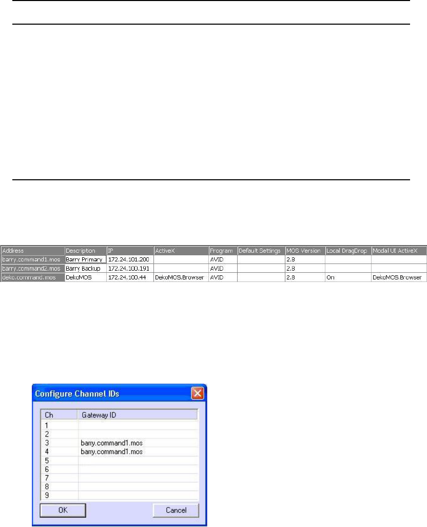
Configuring ENPS for Deko Select
305
An example of this configuration is shown as the bottom row of the following graphic. The
IP address is the DekoMOS Gateway. The first two rows are the primary and backup
Command Servers.
nFor more information, see documentation provided by ENPS.
2. Configure the Deko channel group in Command.
3. In the DekoMOS Gateway, add the primary ENPS Server’s MOS ID field, shown here with
MOS ID per channel:
MOS Version Enter the version used by DekoMOS. Although both versions 2.6 and 2.8
are supported, Avid strongly recommends using MOS 2.8.
Local DragDrop Set to Off.
Modal UI ActiveX Enter the ActiveX Application ID. This is usually
DekoMOS.Browser
.
(Don’t forget the period between DekoMOS and Browser.)
Auto Create Confirm that this box is not checked.
Object Type Set the object type to STILL.
Use Detached If users want the Deko Select plug-in to be detached from the ENPS
client, check this box.
Text Box Name Description

12 Configuring the Perle IOLAN Server
Avid iNEWS Command supports 422 serial connection via the Perle IOLAN TCP/Serial port
server, which must be purchased separately from Command.
nThis is the only supported means of 422 communication with Windows 2008 and Windows 7. See
the Avid iNEWS Command ReadMe for latest supported versions of IOLAN software.
Additionally, the IOLAN server supports full VDCP redundancy. In earlier versions of
Command, mirrored channel configuration was required as a means for achieving VDCP
redundancy.
Like the setup for the AirSpeed (classic) device service, the Video device service is installed on
the primary and backup Command Servers, and when the primary server fails, the VDS on the
backup server assumes control of the VDCP channels as part of the Command failover process.
•Configuring the IOLAN Server
•Configuring the TruePort Clients
•Wiring for IOLAN to Video Server
Configuring the IOLAN Server
307
Configuring the IOLAN Server
To configure the IOLAN server:
1. Turn on the IOLAN server and connect it to the network. Make sure it is in the same subnet
as the Command Server.
2. On the Command Server, install the Perle TruePort software, which includes the Perle
Device Manager and the TruePort Management Tool.
3. Start the Perle Device Manager.
It will enable the Assign IP button when it automatically detect the IOLAN server.
4. Click the Assign ID button and configure for a static IP.
5. After the IP is configured, click OK to open the configuration utility.
6. If prompted for a password, enter superuser.
7. Click Tools > Import Configuration from a File.
8. Navigate to the Avid Command IOLAN configuration file (IOLAN.dme) and click OK.
nThe configuration file (IOLAN.dme) is in the Command install directory.
9. Confirm the following settings in the Configuration section:
a. Network, IP Settings, IPv4 Settings: Confirm that the IP address, subnet mask, and
default gateway are correct.
b. Serial, Serial Ports: Confirm that the serial ports are all enabled and that the listening
ports are 10001 through 10008. Click the Edit button to continue.
c. In the Serial Port 1 Settings dialog box, confirm that Listen for connection is selected
and that the TCP port is 10001.
d. On the Advanced tab, confirm that the Enable TCP Keep Alive box is selected.
e. On the Hardware tab, confirm that Enable line termination is selected.
f. On the Packet Forwarding tab, confirm that Prevent Message Fragmentation is selected,
and the delay is set to 10 milliseconds.
g. Serial, Advanced: Confirm that the Monitor Connections section has the following set:
- Status Interval: 5
- Retry Interval: 2
-Retry: 3
Configuring the TruePort Clients
308
h. If any changes were needed, click OK and then click Copy to set all of the other ports to
the same settings.
10. If any changes were needed, click Download All Changes.
11. If any changes were needed, click Tools > Reset > Reboot IOLAN.
Configuring the TruePort Clients
After you complete configuration on the IOLAN server, you need to configure the TruePort
clients.
To configure TruePort clients:
1. Run the TruePort Management Tool.
2. Click the Add button.
3. In the Add TruePort Adapter Wizard dialog box, enter the IP address for the IOLAN server
and click Next.
4. Add the number of serial ports corresponding to your server (such as 2, 4, 8, or 16), and
choose a starting COM port.
nAvid recommends you choose 50 as the starting COM port, so that it is clear that you are using
the serial-to-IP ports.
5. Click Next and then Finish to save changes.
6. From the TruePort Management Tool’s main window, click Properties to configure the ports.
7. On the Configuration tab, click Settings.
8. In the Perle TruePort Adapter Setting dialog box, confirm that the listening ports match the
ones configured on the server: 10001 - 10008.
9. On the Connection tab, set Connection Mode to Full Mode.
10. Select Initiate connection to device server, and then confirm that the TCP port is 10001.
11. Click the Settings button to change the Client-Initiated Connection settings accordingly:
a. Confirm that Connect at system startup is not selected.
b. Select Close TCP connection when COM port is closed.
c. Select Delay close of TCP connection, and set it to two (2) seconds.
d. In the Connection Options section, select Number of retries and set it to one (1).
e. Set the Time between connection retries to three (3) seconds.
f. Deselect Restore a dropped connection.
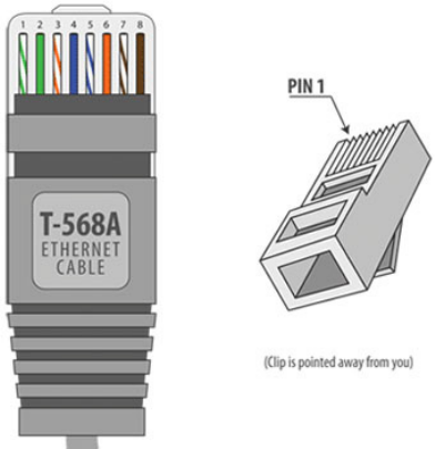
Wiring for IOLAN to Video Server
309
g. Click OK.
12. Click the Advanced tab and confirm the following options are set accordingly:
- Return when connection is fully establish should be selected.
- The maximum wait time should be set to five (5) seconds.
- Send keep alive packets should not be selected.
13. Click the Packet Forwarding tab, select Enable Packet Forwarding, and set the Idle Time to
10 milliseconds.
14. Click the Copy Settings To button and copy the settings to the remaining COM ports.
15. Click OK to save and exit. You might be asked to restart the computer.
After you have completed these steps, you can proceed with wiring serial cables between the
video device and the IOLAN server, and configure the Avid Video device service for serial
connection.
Wiring for IOLAN to Video Server
The following illustration shows the wiring diagram for the RJ45 cable.
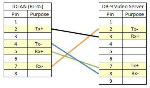
Wiring for IOLAN to Video Server
310
The following illustration is the wiring diagram for the IOLAN server to video device.
The lines in the diagram are colored only to show the connections; they do not correspond to any
wire colors on an RJ45 cable. If you are using DB9 connectors, the inside of the RJ45 side of the
connector’s wires are counted from 8 to 1, with the connecting tab on top. The connector’s wire
colors are never consistent either, so Avid strongly recommends that you use a volt meter to
confirm the correct color wire for the 2, 4, 5, and 7 pins of the RJ45 cable, and then plug them
into their appropriate place on the DB9 connector.
If you are diagnosing connection problems using Avid Diagnostics, and the Command Video
device service shows the warning message, “Unable to create a VDCP channel on port COM58”,
and the details show that the port is in use, it means that the wire is not correct.

13 Confirming Functionality
After software installation and system configuration is complete, you should verify proper
functionality of components and ensure the success of the installation and integration.
•Monitoring System Status
•Viewing Status of Services
•Confirming Command Inventory
•Confirming Functionality with Avid Motion Graphics
•Testing Workflow
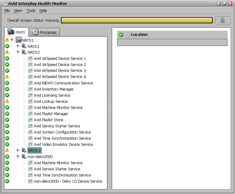
Monitoring System Status
312
Monitoring System Status
After installation and configuration of the Command system is complete, you can check the
status by using the Avid Health Monitor
To check the current status of the system:
1. Click the Start button and select Programs > Avid > Service Framework > Avid Health
Monitor.
On the Hosts tab, services are listed by computer and device. The Processes tab lists by
services.
2. Confirm that no problems are reported. Any problems on the system will appear with a red
X.
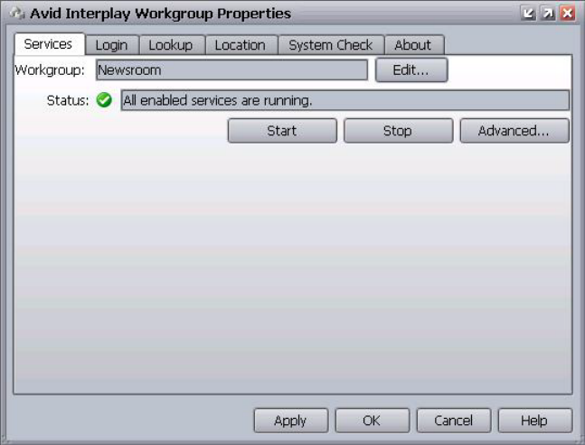
Viewing Status of Services
313
Viewing Status of Services
Avid Command uses Avid Service Framework as its structure for discovering and
communicating with services.
To start Workgroup Properties:
tClick the Start button and select > All Programs > Avid > Service Framework > Avid
Workgroup Properties.
The Avid Workgroup Properties window opens.
When you start the Workgroup Properties application, the Services tab appears by default
displaying the name of the workgroup, to which this computer belongs, in the Workgroup
text box. Also shown, in the Status text box, is the status of all Avid services running on the
local computer.
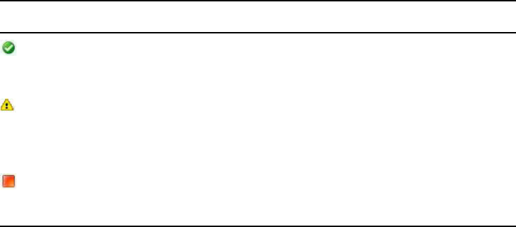
Confirming Command Inventory
314
The Workgroup Properties application uses colored icons—in combination with text—on
the Services tab to show the status (started and/or enabled) of all Avid services. A user can
click the Advanced button to see more information about individual services. The icons
displayed provide fast, easy identification of the current status of an Avid service.
For more information on viewing Avid services using the Workgroup Properties application,
see the Avid Service Framework User’s Guide.
Confirming Command Inventory
You should confirm that the inventory of media available to Command is appearing properly at a
Command Workstation.
To confirm that the Avid iNEWS Command system is seeing inventory correctly:
1. Start the Command client application.
2. If the Inventory panel is not already open, select View > Inventory.
3. Click the down arrow (indicated in the graphic) and select a channel group from the list.
The Inventory panel shows the inventory (media) for a selected channel group in a table or
spreadsheet-style format. You can see the media’s availability, clip ID, name (slug),
duration, and the time when it was last modified. A user can select a different channel group
using the drop-down arrow in the top right corner of the panel. When a user selects an item
in the inventory, further details become available for viewing at the bottom of the panel. The
size of the list and details area can be adjusted with the Resize bar that separates the two
areas.
For more information on the Inventory panel, see the Avid iNEWS Command User’s Guide.
Icon Description
When all of the enabled Avid components are running on the local machine a green
circle with a check mark in the center is shown next to the Status text box and the
sentence—All enabled services are running—is displayed.
When some of the enabled Avid components are running on the local machine a caution
symbol (yellow triangle with an exclamation mark in the center) is shown next to the
Status text box and the sentence—Some services are enabled but not
running—is displayed.
When none of the enabled Avid components are running on the local machine a red
square is shown next to the Status text box and the sentence—No services are
running—is displayed.
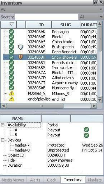
Confirming Functionality with Avid Motion Graphics
315
cIf you are using VDCP and do not have an inventory port configured, you cannot confirm
inventory via the Inventory panel in Command.
nThere can be a delay of approximately 2 minutes for the inventory to appear after creating a
channel group. Also, ensure that you check both video and graphic (character generator) assets.
Confirming Functionality with Avid Motion Graphics
Once you have created a project to test with, you can confirm functionality by doing the
following:
•Starting the Avid Motion Graphics Journalist Server
•Starting Avid Motion Graphics
•Starting the Avid Motion Graphics Preview Renderers
•Testing the Journalist Client
Confirming Functionality with Avid Motion Graphics
316
•Testing Command Inventory, Playout, and Editing
Starting the Avid Motion Graphics Journalist Server
Starting the Avid Motion Graphics Journalist Server is the second task in confirming
functionality.
To start the Avid Motion Graphics Journalist Server:
1. Turn on the Avid Motion Graphics Journalist Server.
2. Click the Avid Motion Graphics Monitor shortcut to start the server applications.
Starting Avid Motion Graphics
Starting the Avid Motion Graphics server is the first task in confirming functionality.
To start Avid Motion Graphics:
1. Turn on the Avid Motion Graphics computer.
2. Start the Avid Motion Graphics application.
3. Click File, > Project > Open and navigate to the
X:\TPL
folder to open the project.
4. Click the Playout button. This step is required for any playout operation.
5. Open the Advanced Device Manager. This initiates the Open All command. You are now
ready to play items in Command.If you have to close and open the UI for any reason, do the
following:
- Open the Avid Motion Graphics application from your shortcut.
- In the Avid Motion Graphics user interface, switch to Playout mode.
- In the open Advanced Device Manager, click the Connect button, which initiates the
Open All.
Starting the Avid Motion Graphics Preview Renderers
After starting Avid Motion Graphics and the Avid Motion Graphics Journalist Server, you must
start the Avid Motion Graphics Preview Renderers.
To start the Avid Motion Graphics Preview Renderers A & B”
1. On the Avid Motion Graphics preview Renderer computer, click Start > AMGNews Preview
Renderer A.
2. Select File > Project > Open All, and navigate to the X:\TPL folder to open the project.
3. On the Avid Motion Graphics preview Renderer computer, click Start > AMGNews Preview
Renderer B.
Confirming Functionality with Avid Motion Graphics
317
4. Select File > Project > Open All, and navigate to the X:\TPL folder to open the project.
Testing the Journalist Client
After starting the Avid Motion Graphics Preview Renderers, you can test the functionality of the
Avid Motion Graphics client.
To test the Journalist client:
1. Open the AMG Journalist client.
2. Double-click an item to open it in the template editor.
3. Add replacement data and click Save.
The new item should appear in the Graphic Database area list with a unique ID for the item.
4. Open the new item and edit the first replaceable field.
5. Click Save and confirm that the data has updated.
6. Open the created item and click the Preview button.
7. Confirm that the correct replacement data appears.
8. Open the created item and click the Movie button.
9. Confirm that the item appears with motions and correct replacement data.
10. Create several more items and drag them into the rundown.
11. Create a hand-entered item.
12. Designate one of the items as a library graphic and drag into a playlist.
13. MON Load the show, and confirm that all graphics appear in the Command playlist.
Testing Command Inventory, Playout, and Editing
After confirming functionality of the Avid Motion Graphics Journalist Client, you must test the
Command inventory, playout, and editing functionality.
To test Command inventory, playout, and editing:
1. In the Inventory Panel, confirm that you can see the templates from the your project, and the
library graphic you created.
2. Confirm that thumbnails appear in the playlist.
3. Lock channel group:
tConfirm that the replacement fields update (if not already updated).
tCue and play items – confirm on output.
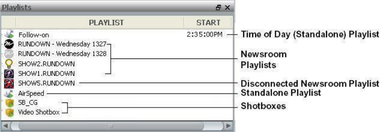
Testing Workflow
318
4. Open item in media viewer and change replacement data:
tConfirm that data is updated in the playlist.
tConfirm that the thumbnail updates.
tOpen the item in the Avid Motion Graphics Journalist client, and confirm that the
replacement data has also changed here.
5. Play the cued item. Confirm that it appears on the output, and that the next item cues as
expected. Eject the item from the program channel.
Testing Workflow
The person testing the system’s workflow should have a basic working knowledge of the various
systems that interact with Command, such as the newsroom computer system as well as the
Command client application.
nFor basic user information on Avid iNEWS, iNEWS Command, or other integrated Avid
products, see the User’s Guides and help systems that accompany each product.
To test workflow:
1. Create an iNEWS rundown with stories that contain graphic and video events.
a. If you use hand-entered machine control events, test that by entering some into new and
existing stories.
b. If you are using a plug-in, such as Avid Deko Select or Avid Thunder Select, open the
plug-in and test it as well by using it to insert events into stories.
2. Load the rundown. (For Avid iNEWS, this means to turn on and load the monitor server.)
3. At a Command Workstation, start the Command client application.
4. Confirm that the newsroom playlist associated with that rundown appears in the Playlist
Explorer.
Testing Workflow
319
5. Open the playlist.
6. Lock all channel groups.
7. Play video and graphic events. Ensure that they appear as expected on the video monitors,
and check to make certain that available and unavailable items are correctly reported.
8. Rearrange stories in the newsroom rundown and ensure that the items in the newsroom
playlist at the Command Workstation adjust accordingly.
Index
320
Symbols
/site/config 280
A
Add Lookup Service dialog box 82
Add New Event dialog box 255
Add Panel dialog box 254
Add Workgroup dialog box 198
AirSpeed
channel groups 223
configuring device services 70, 83
configuring services for thumbnails 62
AirSpeed Multi Stream
channel designations 221
configuration checklist 81
configuring Command workgroup 85
configuring Interplay workgroup 81
configuring the device service 83
device integration checklist 75
install Service Framework 76
installing the device service 79
overview 74
play while record 87
Apply Studio Settings dialog box 227
Avid
online support 14
Avid Deko
channel designations 222
configure the device service 181
device integration checklist 153
installing device services 158
styles aka environments 183
Avid Deko Renderer service 46
Avid Diagnostics 30
Avid Graphics Select 271
Avid Health Monitor 29, 312
Avid iNEWS
configuring 266
mailboxes 286
Map story 267
plug-ins 271
queue properties 284
Avid iNEWS Communication Service 46
Avid Interplay Agent Service 46
Avid MOS Communication Service 46
Avid Service Configuration application 24, 29
Avid Service Framework
Diagnostic Log Viewer 30
Email Alerter 30
Lookup Service 24
Machine Monitor 30
Multicast Repeater 30
Service Configuration 29, 35, 181, 199
starting 253
SNMP Gateway 30
System Configuration 24
Time Synchronization 30
Workgroup Properties 313
Avid Thunder
configure the device service 199
device integration checklist 187
installing device services 192
Avid Unity 74
Avid Video device service 46
Avid Workgroup Properties 60, 71, 181, 252, 256
Avid_License_Setup.exe 31
B
Backup server 296
C
Channel groups
creating 225
defined 223
Index
Index
321
deleting 231
editing 228
examples of 223
redundancy 224
Channel indices 245
Channel-specific actions
assigning 248
mapping 245
Checklists
Command client installation 132, 207
Command pre-installation 19
Command Server installation 20
Deko configuration 166
Deko installation 153
Multi Stream configuration 81
Multi Stream installation 75
setting up the GPI panel 252
setting up X-keys USB keypad 244
Thunder integration 187
Choose Action dialog box 260, 262
Chyron
configuring 145
configuring LUCI plug-in for ActiveX 148
configuring Lyric 148
installing the Graphic device service 113, 124
installing the Graphic Inventory Editor 133
Command
configuring second system 72
import graphic inventory from iNEWS 138
monitoring system status 312
pre-installation checklist 19
system architecture 18
viewing documentation 41
Command Server
installation checklist 20
installing software 41
Command workgroup, configure for Multi Stream 85
Command Workstation
alternative keypad device 252
disabling keyboard 243
installation checklist 132, 207
installing software 213
using X-keys 244
configuration lines, example of 282
Connections tab 169
Console commands
iNEWS 281
list 280
variations of list 283
D
Debounce Time 254
Deko 150
configuration checklist 166
configuring device services 181
installation checklist 153
integration checklist 153
MOS ID 269
subfolders 175
system architecture 151
thumbnails 164
user settings 168
XML storage 168
Deko Renderer, configuring the service 182
Deko Select 271
configure for ENPS 304
installing 273
subfolders 175
DekoMOS Gateway
configuring 167
installing 164
Net HASP dongle 164
DekoMOS Gateway Configuration dialog box 167
DekoMOS Macro Server
configuring 175
configuring styles 177
installing 165
DekoMos.ini file 275
Destination Folder dialog box 115, 126, 214
Device numbers 280
Device services
Avid Video 46
configuring 70, 83, 181
configuring Deko Renderer service 182
configuring for Thunder 199
configuring Interplay Agent service 62
Diagnostic log viewer 30
Dialog boxes
Add Lookup Service 82
Add New Event 255
Add Panel 254
Add Workgroup 198
Apply Studio Settings 227
Index
322
Choose Action 248, 260, 262, 262
DekoMOS Gateway Configuration 167
Destination Folder 115, 126, 214
Options 250
Queue Properties 284
System Settings 225, 258
Digital recorder 74
Documentation for Command 41
dongle 164
Duration 267
E
Email Alerter service 30
ENPS
configure Deko Select 304
configure MOS redirection 302
integration 288
MOS settings 289
News Object Manager 292
play while record 87
Event types 255
F
First Input Pin 254
Functionality, confirming 233, 311
G
Gateway settings 275
General tab 168
GIE
configuring 137
importing from iNEWS 138
installing 133
working with styles 143
working with templates 141
GPI card 252
GPI device
enabling the panel 263
restart the device service 256
GPI events
mapping for GPI panel 258
GPI Out 264
GPI panel
checklist 252
enabling the panel 263
Graphic device service
Chyron integration 145
configuring 133
configuring for LUCI plug-in 148
installing 113, 124
Graphic Inventory Editor
configuring 137
importing from iNEWS 138
installing 133
working with styles 143
working with templates 141
Graphic styles 143
Graphic templates 141
Graphics environments 183
setting default 296
H
Harris Nexio 56
Health Monitor 30
I
Icons
DekoMOS Gateway 167
in Command playlists 242
Macro Server 175
NetHasp License Manager 165
transfer status 62
iNEWS
/site/config 280
configuring 266
ed command line editor 281
list command 280
mailboxes 279
Map story 267
play while record 87
SYSTEM.MAP for styles 143
SYSTEM.MOS-MAP 269
SYSTEM.RESOURCE 138
iNEWS Command
install on workstation 213
licensing 31
MOS ID 296
MOS support 294
iNEWS Servers
Index
323
configuration file 280
host definition 282
Installation
Avid Deko Select 273
Avid Thunder Select 275
Command on a server 41
Command on a workstation 113, 124, 213
determining disk space 162, 196
Service Framework software on Multi Stream 76
USB keypads 245
Interplay Agent service 62
Interplay workgroup, configuring for Multi Stream 81
Inventory panel 314
confirming media availability 314
K
Keyboard
alternative keypad device 252
disabling 243
L
Level 255
License manager 164
License service 31
configuring 35
Licenses
activation file 37
permanent 39
temporary 35
list command, variations of 283
Lookup service 24
Lookup tab, configuring 69
LUCI plug-in 148
M
Machine Monitor service 30
Macro server 165
Mailboxes 286
assigning to rundown queue 283
defined 279
valid numbers 280
viewing assignments 283
Map story 267
Mapping GPI events to actions 258
MiniMon column 202
Mirrored playout 227
channel groups 224
Monitor LOAD command 283
Monitor ON command 283
Monitor servers 279
configuration lines 282
form name 268
listing assigned mailboxes 283
MOS ID 269
MOS protocol
defaults 299, 300
described 294
version 296
MOS settings 300
editing 296
MOS, defined 294
MOS-based newsroom configuration 288
MOS-Map story 269
Multi Stream
channel designations 221
installation checklist 75
play while record 87
Multicast Repeater service 30
N
Net HASP Connection Settings 169
Net HASP dongle 164
Net HASP License Manager 164
Newsroom buddy host name 296
Newsroom buddyID 296
Newsroom host name 296
Newsroom NCS ID 296
O
Omneon 53
configuring the video device service 50
Online support 14
P
Paths 168
Play while record 87
Playlist icons 242
Playlist Viewer 241
Index
324
Playout control 241
configuring 240, 306
Plug-ins 271
Procedures
add a style 144
add an environment 183
add the permanent license 39
add the temporary license 35
assign a style to standalone playlist 145
change system name 72
checking system status 312
configure a second Command system 72
configure Avid Video device service (Omneon) 50
configure Avid Video device service (VDCP) 58, 60
configure Chyron integration 145
configure Command for MOS-based NRCS 295
configure Command workgroup properties 85
configure Deko Renderer service 182
configure Deko Select for ENPS 304
configure DekoMOS Macro Server 175
configure for GPI Out 264
configure for VDCP redundancy 61
configure Interplay workgroup properties 81
configure Lookup tab 69
configure MOS redirection for ENPS 302
configure the Avid Thunder device service 199
configure the Deko device service 181
configure the DekoMOS Gateway 167
configure the ENPS MOS settings 289
configure the GPI card’s board settings 253
configure the Graphic device service 133
configure the License service 35
configure the Multi Stream device service 83
configure the Thunder 201
configure workgroup properties for Thunder 198
configuring LUCI plug-in 148
configuring Lyric 148
configuring the Graphic Inventory Editor 137
confirm GPI panel setup 257
confirm running of NetHASP License Manager 165
confirming inventory 314
connect the New HASP Dongle 164
control playout with numeric keypad 242
copy a style 144
copy a template 142
copy install CD to local directory 22
create & configure monitor server 280
create a style 143
create a template 142
create channel groups 225
create the ThunderMOS.cfg file 203
create the ThunderMOS.ini file 204
delete a channel group 231
delete a style 144
delete a template 142
edit a channel group 228
edit the Map story in iNEWS 268
edit the SYSTEM.MOS-MAP story 270
enable a GPI panel to control a playlist 263
enable or disable the keyboard 243
generate an activation file 37
import graphic inventory from iNEWS 138
install an X-keys USB keypad 245
install Avid Deko Select 273
install Avid Service Framework on a workstation
109, 120, 188, 208
install Avid Thunder Select 275
install Service Framework on a server 24
install Service Framework on a workstation 154
install Service Framework on Multi Stream 76
install software on a Command Server 41
install software on a Command Workstation 113,
124, 213
install the Deko device software 158
install the DekoMOS Gateway 164
install the DekoMOS Macro Server 165
install the Graphic device service 113, 124
install the Graphic Inventory Editor 133
install the License service 31
install the Multi Stream device service 79
install the Thunder device software 192
map an index to a channel name 245
map GPI events to actions 258
play while record on AMS 87
play while record with ENPS 88
play while record with iNEWS 88
play while record with standalone playlist 88
programming X-keys 246
restart the GPI device service 256
specify inventory path in GIE 137
start Workgroup Properties 313
test workflow 318
view advanced MOS settings 300
view the Queue Properties dialog box 284
Index
325
Q
Queue form, explained 285
Queue Properties dialog box 284
Quit time 267
R
Redundancy
channel groups 224
configuring the Lookup tab 69
VDCP 61
Rover button 289
S
Secondary Command systems 72
Serial connections 57
Server type 267
Service Configuration 35
Services
Avid Deko Renderer 46
Service Framework 24, 29
viewing status 313
Site licenses 31
SNMP Gateway 30
Starting
Workgroup Properties 313
Story forms, explained 285
system architecture 18
System settings
GPI 258
indices 245
MOS 296
MOS advanced 300
MOS channel groups 298
Playlist 183
System Settings dialog box 225, 258
System status, monitoring 312
SYSTEM.MAP 267
SYSTEM.MOS-MAP 269
T
Temporary Command license 35
Thumbnails, installing services for 46
Thunder
configuring device services 199
integration checklist 187
MOS ID 270
Thunder Select 271
ThunderMOS.cfg file 270
creating the file 203
ThunderMOS.ini file 204
Time Synchronization service 30
Toggle 255
Transfer status icon 62
Trigger 255
Troubleshooting 14
U
USB keypad 244
Utility programs 279
V
VDCP
configuring for mirrored playback 61
configuring the device service 58, 60
installing the device service 46
wiring serial connections 57
Video server
channel designations 221
channel groups 223
W
Wiring serial connections 57
Workflow, testing 318
Workgroup Properties 313
restarting GPI device service 256
X
X-keys
channel-specific actions 248
checklist 244
XML-based protocol 294

Avid
75 Network Drive
Burlington, MA 01803-2756 USA
Technical Support (USA)
Visit the Online Support Center at
www.avid.com/support
Product Information
For company and product information,
visit us on the web at www.avid.com
