Avid Unity MediaNet File Manager Setup Guide Media Net 3.1 FMSetup
User Manual: avid Unity MediaNet - 3.1 - File Manager Setup Guide Free User Guide for Avid Unity Software, Manual
Open the PDF directly: View PDF ![]() .
.
Page Count: 104 [warning: Documents this large are best viewed by clicking the View PDF Link!]
- Avid Unity™ MediaNet File Manager Setup Guide
- Who Should Use This Guide
- About This Guide
- Symbols and Conventions
- If You Need Help
- If You Have Documentation Comments
- How to Order Documentation
- Related Information
- Before You Begin
- MediaNet and Trilligent Cluster Components
- File Manager Failover Configurations
- Component Layout Recommendations
- Installing Rack-Mount Rails and Brackets
- Installing File Managers and Storage Subsystem Components
- Uninterruptible Power Supply
- Installing the MEDIArray II Drive Enclosures
- Installing a Standard Keyboard, Monitor, and Mouse
- Installing the Keyboard, Monitor, and Mouse (KMM) Assembly(Optional)
- Installing a MEDIASwitch
- Installing the KVM Switch (Optional)
- Installing File Managers
- Installing a Second File Manager For Failover
- Installing the Ethernet Hub (Optional)
- Connecting the File Manager and Storage
- Connecting a Standard Keyboard, Monitor, and Mouse to the File Manager
- Connecting a Standard Keyboard, Monitor, and Mouse to the KVM
- Connecting the KMM to the KVM (Optional)
- Connecting the File Manager to the KVM (Optional)
- Connecting a Failover File Manager to the KVM (Optional)
- Connecting the File Manager to the MEDIASwitch
- Connecting a Failover File Manager to the MEDIASwitch
- Connecting the MEDIASwitch Serial Port to the File Manager for Initial Switch Configuration
- Connecting the MEDIArray II Drive Enclosure to the MEDIASwitch
- Connecting the File Manager to the Ethernet Hub
- Connecting a Failover File Manager to the Ethernet Hub
- Connecting the MEDIASwitch to the Ethernet Hub
- Cross-Connecting the File Managers in Failover Configurations
- Changing the MEDIASwitch IP Address
- Installing SAN InSite Professional
- Configuring the MEDIASwitch
- SAN InSite Server
- Using the SAN InSite Client
- Setting Up the File Manager
- Configuring a Second File Manager For Failover
- MediaNet File Manager Software Installation
- UPS Monitoring Software
- Configuring the MediaNet Software
- Trilligent Cluster File Manager Software Installation
- UPS Monitoring Software
- Configuring the MediaNet Software
- Dimensions and Weight
- Environment
- Electrical
- Power Cords
- UPS Power Cord
- Installing the Serial Cable
- Installing the CheckUPS II Software
- Configuring the CheckUPS II Software
- FCC Notice
- Canadian ICES-003
- European Union Notice
- Australia and New Zealand EMC Regulations
- Taiwan EMC Regulations

Avid Unity™ MediaNet
File Manager Setup Guide
0521501B.book Page i Wednesday, September 25, 2002 10:08 AM

Copyright and Disclaimer
Product specifications are subject to change without notice and do not represent a commitment on
the part of Avid Technology, Inc. The software described in this document is furnished under a
license agreement. You can obtain a copy of that license by visiting Avid's Web site at
www.avid.com. The terms of that license are also available in the product in the same directory as
the software. The software may not be reverse assembled and may be used or copied only in
accordance with the terms of the license agreement. It is against the law to copy the software on any
medium except as specifically allowed in the license agreement. Avid products or portions thereof
are protected by one or more of the following United States patents: 4,746,994; 4,970,663;
5,045,940; 5,063,448; 5,077,604; 5,245,432; 5,267,351; 5,309,528; 5,325,200; 5,355,450;
5,396,594; 5,440,348; 5,452,378; 5,467,288; 5,513,375; 5,528,310; 5,557,423; 5,568,275;
5,577,190; 5,583,496; 5,584,006; 5,627,765; 5,634,020; 5,640,601; 5,644,364; 5,654,737;
5,701,404; 5,715,018; 5,719,570; 5,724,605; 5,726,717; 5,729,673; 5,731,819; 5,745,637;
5,752,029; 5,754,180; 5,754,851; 5,781,188; 5,799,150; 5,812,216; 5,828,678; 5,842,014;
5,852,435; 5,883,670; 5,889,532; 5,892,507; 5,905,841; 5,912,675; 5,929,836; 5,929,942;
5,930,445; 5,930,797; 5,946,445; 5,966,134; 5,977,982; 5,986,584; 5,987,501; 5,995,079;
5,995,115; 5,999,190; 5,999,406; 6,009,507; 6,011,562; 6,014,150; 6,016,152; 6,016,380;
6,018,337; 6,023,531; 6,023,703; 6,031,529; 6,035,367; 6,038,573; 6,052,508; 6,058,236;
6,061,758; 6,072,796; 6,084,569; 6,091,422; 6,091,778; 6,105,083; 6,118,444; 6,128,001;
6,128,681; 6,130,676; 6,134,379; 6,134,607; 6,137,919; 6,141,007; 6,141,691; 6,154,221;
6,157,929; 6,160,548; 6,161,115; 6,167,404; 6,174,206; 6,192,388; 6,198,477; 6,208,357;
6,211,869; 6,212,197; 6,215,485; 6,223,211; 6,226,005; 6,226,038; 6,229,576; 6,239,815;
6,249,280; 6,269,195; 6,271,829; 6,301,105; 6,310,621; 6,314,403; 6,317,142; 6,317,153;
6,317,515; D352,278; D372,478; D373,778; D392,267; D392,268; D392,269; D395,291;
D396,853; D398,912. Additional U.S. and foreign patents pending. No part of this document may
be reproduced or transmitted in any form or by any means, electronic or mechanical, including
photocopying and recording, for any purpose without the express written permission of Avid
Technology, Inc.
Copyright © 2002 Avid Technology, Inc. and its licensors. All rights reserved. Printed in USA.
The following disclaimer is required by Apple Computer, Inc.
APPLE COMPUTER, INC. MAKES NO WARRANTIES WHATSOEVER, EITHER EXPRESS OR
IMPLIED, REGARDING THIS PRODUCT, INCLUDING WARRANTIES WITH RESPECT TO ITS
MERCHANTABILITY OR ITS FITNESS FOR ANY PARTICULAR PURPOSE. THE EXCLUSION OF
IMPLIED WARRANTIES IS NOT PERMITTED BY SOME STATES. THE ABOVE EXCLUSION MAY NOT
APPLY TO YOU. THIS WARRANTY PROVIDES YOU WITH SPECIFIC LEGAL RIGHTS. THERE MAY
BE OTHER RIGHTS THAT YOU MAY HAVE WHICH VARY FROM STATE TO STATE.
The following disclaimer is required by Sam Leffler and Silicon Graphics, Inc. for the
use of their TIFF library:
Copyright © 1988–1997 Sam Leffler
Copyright © 1991–1997 Silicon Graphics, Inc.
Permission to use, copy, modify, distribute, and sell this software [i.e., the TIFF library] and its
documentation for any purpose is hereby granted without fee, provided that (i) the above copyright
notices and this permission notice appear in all copies of the software and related documentation,
and (ii) the names of Sam Leffler and Silicon Graphics may not be used in any advertising or
publicity relating to the software without the specific, prior written permission of Sam Leffler and
Silicon Graphics.
THE SOFTWARE IS PROVIDED “AS-IS” AND WITHOUT WARRANTY OF ANY KIND, EXPRESS,
IMPLIED OR OTHERWISE, INCLUDING WITHOUT LIMITATION, ANY WARRANTY OF
MERCHANTABILITY OR FITNESS FOR A PARTICULAR PURPOSE.
IN NO EVENT SHALL SAM LEFFLER OR SILICON GRAPHICS BE LIABLE FOR ANY SPECIAL,
INCIDENTAL, INDIRECT OR CONSEQUENTIAL DAMAGES OF ANY KIND, OR ANY DAMAGES
WHATSOEVER RESULTING FROM LOSS OF USE, DATA OR PROFITS, WHETHER OR NOT
ADVISED OF THE POSSIBILITY OF DAMAGE, AND ON ANY THEORY OF LIABILITY, ARISING OUT
OF OR IN CONNECTION WITH THE USE OR PERFORMANCE OF THIS SOFTWARE.
0521501B.book Page ii Wednesday, September 25, 2002 10:08 AM

The following disclaimer is required by the Independent JPEG Group:
Portions of this software are based on work of the Independent JPEG Group.
The following disclaimer is required by Paradigm Matrix:
Portions of this software licensed from Paradigm Matrix.
The following disclaimer is required by Ray Sauers Associates, Inc.:
“Install-It” is licensed from Ray Sauers Associates, Inc. End-User is prohibited from taking any
action to derive a source code equivalent of “Install-It,” including by reverse assembly or reverse
compilation, Ray Sauers Associates, Inc. shall in no event be liable for any damages resulting from
reseller’s failure to perform reseller’s obligation; or any damages arising from use or operation of
reseller’s products or the software; or any other damages, including but not limited to, incidental,
direct, indirect, special or consequential Damages including lost profits, or damages resulting from
loss of use or inability to use reseller’s products or the software for any reason including copyright or
patent infringement, or lost data, even if Ray Sauers Associates has been advised, knew or should
have known of the possibility of such damages.
The following disclaimer is required by Videomedia, Inc.:
“Videomedia, Inc. makes no warranties whatsoever, either express or implied, regarding this
product, including warranties with respect to its merchantability or its fitness for any particular
purpose.”
“This software contains V-LAN ver. 3.0 Command Protocols which communicate with V-LAN ver. 3.0
products developed by Videomedia, Inc. and V-LAN ver. 3.0 compatible products developed by
third parties under license from Videomedia, Inc. Use of this software will allow “frame accurate”
editing control of applicable videotape recorder decks, videodisc recorders/players and the like.”
The following notice is required by Altura Software, Inc. for the use of its Mac2Win soft-
ware and Sample Source Code:
©1993–1998 Altura Software, Inc.
The following notice is required by Ultimatte Corporation:
Certain real-time compositing capabilities are provided under a license of such technology from
Ultimatte Corporation and are subject to copyright protection.
Attn. Government User(s). Restricted Rights Legend
U.S. GOVERNMENT RESTRICTED RIGHTS. This Software and its documentation are “commercial
computer software” or “commercial computer software documentation.” In the event that such
Software or documentation is acquired by or on behalf of a unit or agency of the U.S. Government,
all rights with respect to this Software and documentation are subject to the terms of the License
Agreement, pursuant to FAR §12.212(a) and/or DFARS §227.7202-1(a), as applicable.
Trademarks
AirPlay, AudioVision, Avid, Avid Xpress, CamCutter, Digidesign, FieldPak, Film Composer, HIIP,
Image Independence, Marquee, Media Composer, Media Recorder, NewsCutter, OMF,
OMF Interchange, Open Media Framework, Pro Tools, and Softimage are registered trademarks and
888 I/O, AirSPACE, AirSPACE HD, AniMatte, AudioSuite, AutoSync, AVIDdrive, AVIDdrive Towers,
AvidNet, Avid Production Network, AvidProNet, AvidProNet.com, AVIDstripe, Avid Unity,
AVX, DAE, D-Fi, D-fx, Digidesign Audio Engine, DINR, D-Verb, ExpertRender, FilmScribe,
HyperSPACE, HyperSPACE HDCAM, Intraframe, iS9, iS18, iS23, iS36, Lo-Fi, Magic Mask,
make manage move | media, Matador, Maxim, MCXpress, MEDIArray, MediaDock,
MediaDock Shuttle, Media Fusion, Media Illusion, MediaLog, Media Reader, MediaShare, Meridien,
NaturalMatch, NetReview, OMM, Open Media Management, ProEncode, QuietDrive, R&A, Recti-Fi,
Review & Approval, rS9, rS18, Sci-Fi, Sound Designer II, SPACE, SPACEShift, Symphony, Trilligent,
UnityRAID, Vari-Fi, Video Slave Driver, and VideoSPACE are trademarks of Avid Technology, Inc.
0521501B.book Page iii Wednesday, September 25, 2002 10:08 AM

iNEWS and Media Browse are trademarks of iNews, LLC.
Avid Unity MediaNet File Manager Setup Guide• Part 0130-05215-01 Rev. B •
September 2002
0521501B.book Page iv Wednesday, September 25, 2002 10:08 AM

v
Contents
Using This Guide
Who Should Use This Guide . . . . . . . . . . . . . . . . . . . . . . . . . . . . . . . . . .xiv
About This Guide . . . . . . . . . . . . . . . . . . . . . . . . . . . . . . . . . . . . . . . . . . .xiv
Symbols and Conventions . . . . . . . . . . . . . . . . . . . . . . . . . . . . . . . . . . . . xv
If You Need Help . . . . . . . . . . . . . . . . . . . . . . . . . . . . . . . . . . . . . . . . . . . .xvi
If You Have Documentation Comments . . . . . . . . . . . . . . . . . . . . . . . xvii
How to Order Documentation. . . . . . . . . . . . . . . . . . . . . . . . . . . . . . . . xvii
Related Information. . . . . . . . . . . . . . . . . . . . . . . . . . . . . . . . . . . . . . . . . xvii
Chapter 1 Preinstallation Overview
Before You Begin . . . . . . . . . . . . . . . . . . . . . . . . . . . . . . . . . . . . . . . . . . . 1-1
MediaNet and Trilligent Cluster Components . . . . . . . . . . . . . . . . . . 1-2
The Storage Subsystem . . . . . . . . . . . . . . . . . . . . . . . . . . . . . . . . . . 1-3
The Media Server Subsystem for a Trilligent Cluster . . . . . . . . . 1-3
File Manager Failover Configurations . . . . . . . . . . . . . . . . . . . . . . . . . 1-4
Component Layout Recommendations . . . . . . . . . . . . . . . . . . . . . . . . 1-5
Single-Rack Layout. . . . . . . . . . . . . . . . . . . . . . . . . . . . . . . . . . . . . . 1-5
Multiple-Rack Layout . . . . . . . . . . . . . . . . . . . . . . . . . . . . . . . . . . . 1-6
Chapter 2 Installing the MediaNet Storage Subsystem Hardware
Installing Rack-Mount Rails and Brackets. . . . . . . . . . . . . . . . . . . . . . 2-1
Installing File Managers and Storage Subsystem Components . . . . 2-2
Uninterruptible Power Supply. . . . . . . . . . . . . . . . . . . . . . . . . . . . 2-2
Installing the MEDIArray II Drive Enclosures. . . . . . . . . . . . . . . 2-3
Installing the MEDIArray II Drive Enclosure
Rack-Mount Rails. . . . . . . . . . . . . . . . . . . . . . . . . . . . . . . . . . 2-3
Mounting the MEDIArray II Drive Enclosure . . . . . . . . . . . 2-4
0521501B.book Page v Wednesday, September 25, 2002 10:08 AM

vi
Connecting the MEDIArray II Drive Enclosure
Power Cords . . . . . . . . . . . . . . . . . . . . . . . . . . . . . . . . . . . . . 2-6
Installing the MEDIArray II Drives . . . . . . . . . . . . . . . . . . . . 2-6
Setting the MEDIArray II Drive Enclosure IDs . . . . . . . . . . 2-9
Installing a Standard Keyboard, Monitor, and Mouse. . . . . . . 2-10
Installing the Shelf . . . . . . . . . . . . . . . . . . . . . . . . . . . . . . . . . 2-10
Installing the Monitor . . . . . . . . . . . . . . . . . . . . . . . . . . . . . . 2-10
Connecting the Monitor Power Cord . . . . . . . . . . . . . . . . . 2-10
Installing the Keyboard, Monitor, and Mouse (KMM)
Assembly (Optional) . . . . . . . . . . . . . . . . . . . . . . . . . . . . . . . . . 2-11
Installing the KMM Rack-Mount Rails . . . . . . . . . . . . . . . . 2-11
Mounting the KMM on the Rack-Mount Rails. . . . . . . . . . 2-11
Connecting the KMM Power Cord . . . . . . . . . . . . . . . . . . . 2-12
Installing a MEDIASwitch . . . . . . . . . . . . . . . . . . . . . . . . . . . . . . 2-12
Installing the MEDIASwitch Rack-Mount Rails . . . . . . . . 2-12
Mounting the MEDIASwitch . . . . . . . . . . . . . . . . . . . . . . . . 2-13
MEDIASwitch Port Requirements. . . . . . . . . . . . . . . . . . . . 2-13
Installing SFPs. . . . . . . . . . . . . . . . . . . . . . . . . . . . . . . . . . . . . 2-14
Connecting the MEDIASwitch Power Cord. . . . . . . . . . . . 2-15
Installing the KVM Switch (Optional) . . . . . . . . . . . . . . . . . . . . 2-16
Installing the KVM Switch Rack-Mount Bracket. . . . . . . . 2-16
Mounting the KVM Switch . . . . . . . . . . . . . . . . . . . . . . . . . . 2-16
Connecting the KVM Power Cord. . . . . . . . . . . . . . . . . . . . 2-17
Installing File Managers . . . . . . . . . . . . . . . . . . . . . . . . . . . . . . . . 2-17
Installing File Manager Rack-Mount Rails . . . . . . . . . . . . . 2-18
Mounting a File Manager . . . . . . . . . . . . . . . . . . . . . . . . . . . 2-18
Connecting File Manager Power Cords . . . . . . . . . . . . . . . 2-19
Installing a Second File Manager For Failover . . . . . . . . . . . . . 2-19
Installing the Ethernet Hub (Optional). . . . . . . . . . . . . . . . . . . . 2-19
Installing the Rack-Mount Bracket. . . . . . . . . . . . . . . . . . . . 2-19
Mounting the Ethernet Hub . . . . . . . . . . . . . . . . . . . . . . . . . 2-20
Connecting the Ethernet Hub Power Cord. . . . . . . . . . . . . 2-20
0521501B.book Page vi Wednesday, September 25, 2002 10:08 AM

vii
Connecting the File Manager and Storage. . . . . . . . . . . . . . . . . . . . . 2-20
Connecting a Standard Keyboard, Monitor, and
Mouse to the File Manager . . . . . . . . . . . . . . . . . . . . . . . . . . . . 2-21
Connecting a Standard Keyboard, Monitor, and Mouse
to the KVM. . . . . . . . . . . . . . . . . . . . . . . . . . . . . . . . . . . . . . . . . . 2-21
Connecting the KMM to the KVM (Optional) . . . . . . . . . . . . . . 2-22
Connecting the File Manager to the KVM (Optional). . . . . . . . 2-22
Connecting a Failover File Manager to the KVM (Optional). . 2-23
Connecting the File Manager to the MEDIASwitch . . . . . . . . . 2-24
Connecting a Failover File Manager to the MEDIASwitch . . . 2-25
Connecting the MEDIASwitch Serial Port to the File
Manager for Initial Switch Configuration. . . . . . . . . . . . . . . . 2-25
Connecting the MEDIArray II Drive Enclosure to the
MEDIASwitch . . . . . . . . . . . . . . . . . . . . . . . . . . . . . . . . . . . . . . . 2-26
Connecting One MEDIArray II Drive Enclosure . . . . . . . . 2-27
Connecting a Daisy Chain of Two MEDIArray II Drive
Enclosures. . . . . . . . . . . . . . . . . . . . . . . . . . . . . . . . . . . . . . . 2-32
Connecting to Two MEDIASwitches . . . . . . . . . . . . . . . . . . 2-33
Connecting the File Manager to the Ethernet Hub . . . . . . . . . . 2-34
Connecting a Failover File Manager to the Ethernet Hub . . . . 2-35
Connecting the MEDIASwitch to the Ethernet Hub . . . . . . . . . 2-35
Cross-Connecting the File Managers in Failover
Configurations. . . . . . . . . . . . . . . . . . . . . . . . . . . . . . . . . . . . . . . 2-36
Chapter 3 Installing the MediaNet Software
MediaNet File Manager Software Installation . . . . . . . . . . . . . . . . . . 3-1
UPS Monitoring Software. . . . . . . . . . . . . . . . . . . . . . . . . . . . . . . . . . . . 3-3
Chapter 4 Installing the Trilligent File Manager Software
Trilligent Cluster File Manager Software Installation . . . . . . . . . . . . 4-1
UPS Monitoring Software. . . . . . . . . . . . . . . . . . . . . . . . . . . . . . . . . . . . 4-3
0521501B.book Page vii Wednesday, September 25, 2002 10:08 AM

viii
Chapter 5 Configuring the File Manager
Setting Up the File Manager . . . . . . . . . . . . . . . . . . . . . . . . . . . . . . . . . 5-2
Checking the Operating System Installation. . . . . . . . . . . . . . . . 5-2
Setting the Date, Time, and Time Zone . . . . . . . . . . . . . . . . . . . . 5-3
Setting the File Manager Paging File Size . . . . . . . . . . . . . . . . . . 5-4
Configuring Network Properties . . . . . . . . . . . . . . . . . . . . . . . . . 5-5
Configuring System Properties . . . . . . . . . . . . . . . . . . . . . . . . . . . 5-6
Configuring a Second File Manager For Failover . . . . . . . . . . . . . . . 5-7
Configuring Network Properties for File Managers in a Failover
Configuration . . . . . . . . . . . . . . . . . . . . . . . . . . . . . . . . . . . . . . . . 5-7
Configuring the MediaNet Software . . . . . . . . . . . . . . . . . . . . . . . . . 5-11
Chapter 6 Configuring the MEDIASwitches
SAN InSite Professional. . . . . . . . . . . . . . . . . . . . . . . . . . . . . . . . . . . . . 6-2
Installing SAN InSite Professional . . . . . . . . . . . . . . . . . . . . . . . . 6-2
SAN InSite Server. . . . . . . . . . . . . . . . . . . . . . . . . . . . . . . . . . . 6-4
Using the SAN InSite Client . . . . . . . . . . . . . . . . . . . . . . . . . . 6-5
Setting Up the MEDIASwitch . . . . . . . . . . . . . . . . . . . . . . . . . . . . . . . . 6-5
Copying the MEDIASwitch Files into the SAN InSite Folder. . 6-6
Connecting to the MEDIASwitch . . . . . . . . . . . . . . . . . . . . . . . . . 6-6
Changing the MEDIASwitch IP Address. . . . . . . . . . . . . . . . . . . 6-7
Establishing an IP Connection to the MEDIASwitch . . . . . . . . . 6-9
Setting the MEDIASwitch Configuration. . . . . . . . . . . . . . . . . . . 6-9
Appendix A File Manager and Storage Specifications
Dimensions and Weight. . . . . . . . . . . . . . . . . . . . . . . . . . . . . . . . . . . . . A-2
Environment . . . . . . . . . . . . . . . . . . . . . . . . . . . . . . . . . . . . . . . . . . . . . . A-3
Electrical . . . . . . . . . . . . . . . . . . . . . . . . . . . . . . . . . . . . . . . . . . . . . . . . . . A-4
Power Cords . . . . . . . . . . . . . . . . . . . . . . . . . . . . . . . . . . . . . . . . . . . . . . A-4
UPS Power Cord . . . . . . . . . . . . . . . . . . . . . . . . . . . . . . . . . . . . . . . . . . . A-6
0521501B.book Page viii Wednesday, September 25, 2002 10:08 AM

ix
Appendix B Installing UPS Monitoring Software
Installing the Serial Cable. . . . . . . . . . . . . . . . . . . . . . . . . . . . . . . . . . . . B-2
Installing the CheckUPS II Software. . . . . . . . . . . . . . . . . . . . . . . . . . . B-2
Configuring the CheckUPS II Software . . . . . . . . . . . . . . . . . . . . . . . . B-4
Appendix C Regulatory and Safety Notices
FCC Notice . . . . . . . . . . . . . . . . . . . . . . . . . . . . . . . . . . . . . . . . . . . . . . . . C-1
Canadian ICES-003 . . . . . . . . . . . . . . . . . . . . . . . . . . . . . . . . . . . . . . . . . C-2
European Union Notice . . . . . . . . . . . . . . . . . . . . . . . . . . . . . . . . . . . . . C-2
Australia and New Zealand EMC Regulations. . . . . . . . . . . . . . . . . . C-4
Taiwan EMC Regulations. . . . . . . . . . . . . . . . . . . . . . . . . . . . . . . . . . . . C-4
0521501B.book Page ix Wednesday, September 25, 2002 10:08 AM

x
0521501B.book Page x Wednesday, September 25, 2002 10:08 AM

Using This Guide
Congratulations on your purchase of an Avid Unity™ MediaNet
workgroup or Trilligent™ Cluster. You can use your MediaNet
workgroup to share media files and other project data among up to 24
Fibre Channel attached clients and up to 60 Ethernet clients across four
PortServer Pro systems.
nConsult Avid Technology Product Marketing for other possible Ethernet
client configurations.
For Macintosh-based products—Media Composer®, Film Composer®,
Media Station XL, Avid Xpress®, and Pro Tools® for Macintosh®
systems.
For Windows-based products—Avid Symphony™, Media Composer,
Film Composer, Avid Xpress for Windows NT® or Windows® 2000
systems, NewsCutter, and NewsCutter XP.
Creating a Trilligent Cluster allows you to connect up to 20 Trilligent
MediaServers to deliver streaming media and other high-bandwidth
content over the Internet.
Your MediaNet workgroup or Trilligent Cluster might not contain all of the
components or features described in the documentation. Avid’s
documentation describes all components and features of the configuration you
purchased.
0521501B.book Page xi Wednesday, September 25, 2002 10:08 AM

xii
Using This Guide
Who Should Use This Guide
This guide is intended for those responsible for installing, configuring,
or maintaining a MediaNet workgroup or Trilligent Cluster. It
provides installation and configuration information specific to the
MediaNet and Trilligent hardware and software.
About This Guide
This guide provides complete task-oriented procedural instructions
for setting up a MediaNet workgroup with a Trilligent Cluster.
The Contents provide a complete listing of all the topics in this book:
• Chapter 1, “Preinstallation Overview,” provides information on
the components, unpacking, rack layout, network connection
necessary to complete the installation, and configuration of the
MediaNet environment.
• Chapter 2, “Installing the MediaNet Storage Subsystem
Hardware,” provides step-by-step instructions for connecting the
File Manager and storage subsystem hardware.
• Chapter 3, “Configuring the MEDIASwitches,” provides
step-by-step instructions for configuring and installing the
necessary software for the MEDIASwitches.
• Chapter 4, “Configuring the File Manager,” provides step-by-step
instructions for configuring and installing the necessary software
for the File Managers.
• Chapter 5, “Installing the MediaNet Software,” provides
step-by-step instructions for installing the various software
components that are part of the File Manager and MEDIASwitch.
• Chapter 6, “Installing the Trilligent File Manager Software,”
provides step-by-step instructions for installing the various
software components that are part of the File Manager, and the
MEDIASwitch.
0521501B.book Page xii Wednesday, September 25, 2002 10:08 AM

xiii
Symbols and Conventions
• Appendix A, “File Manager and Storage Specifications,” lists the
dimensions and weight, and the environmental, power, and
power cord specifications for the components that are part of a
MediaNet/Trilligent Cluster environment.
• Appendix B, “Installing UPS Monitoring Software,” provides
information for installing and configuring the UPS monitoring
software on the File Manager.
• Appendix C, “Regulatory and Safety Notices,” lists regulatory and
safety notices for the MediaNet and Trilligent hardware.
nYou’ll also need the Avid Unity MediaNet Management Guide to create a
file system, to create allocation groups and workspaces for media files, and to
create a system user account.
Symbols and Conventions
Unless noted otherwise, the material in this document applies to the
Windows NT operating system, the operating software for the File
Manager.
This guide uses the following special symbols and conventions:
1. Numbered lists, when the order of the items is important.
a. Alphabetical lists, when the order of secondary items is
important.
• Bulleted lists, when the order of the items is unimportant.
- Indented dashed lists, when the order of secondary items is
unimportant.
tOne arrow indicates a single-step procedure. Multiple arrows in a
list indicate that you perform one of the actions listed.
Courier Bold font identifies text that you type.
0521501B.book Page xiii Wednesday, September 25, 2002 10:08 AM

xiv
Using This Guide
Look here in the margin
for tips. In the margin, you will find tips that help you perform tasks more
easily and efficiently.
nA note provides important related information, reminders, recommendations,
and strong suggestions.
cA caution means that a specific action you take could cause harm to
your computer or cause you to lose data.
If You Need Help
If you are having trouble using your MediaNet or Trilligent
environment, you should:
1. Retry the action, carefully following the instructions given for that
task in this guide.
2. Check the documentation that came with your hardware for
maintenance or hardware-related issues.
3. Check the release notes supplied with your Avid application for
information on accessing the Avid Web site and the Avid
Knowledge Center.
4. For support services, call Avid Customer Support:
- Broadcast products — call 800-NEWS-DNG (639-7364).
- Post-production products — call 800-800-AVID (2843).
- Trilligent products — call 800-800-AVID.
0521501B.book Page xiv Wednesday, September 25, 2002 10:08 AM

xv
If You Have Documentation Comments
If You Have Documentation Comments
Avid Technology continuously seeks to improve its documentation.
We value your comments about this guide and other Avid-supplied
documentation.
Simply e-mail your documentation comments to Avid Technology at:
TechPubs@avid.com
Please include the title of the document, its part number, revision, and
the specific section you are commenting on in all correspondence.
How to Order Documentation
To order additional copies of this documentation from within the
United States, call Avid Telesales at 800-949-AVID (2843). If you are
placing an order from outside the United States, contact your local
Avid representative.
Related Information
The following documents provide more information about the
MediaNet workgroup, the MediaNet client, and other storage options:
•Avid Unity MediaNet Site Preparation Guide
•Avid Unity MediaNet File Manager Setup Guide
•Avid Unity MediaNet Upgrade Notes
•Avid Unity MediaNet System Overview
•Avid Unity MediaNet Management Guide
•Avid Unity MediaNet Troubleshooting Guide
•Avid Unity MediaNet Macintosh Fibre Channel Client Setup Guide
0521501B.book Page xv Wednesday, September 25, 2002 10:08 AM

xvi
Using This Guide
•Avid Unity MediaNet Macintosh Fibre Channel Client Quick Start Card
•Avid Unity MediaNet Windows Fibre Channel Client Setup Guide
•Avid Unity MediaNet Windows Fibre Channel Client Quick Start Card
•Avid Unity MediaNet Macintosh Ethernet Client Setup Guide
•Avid Unity MediaNet Macintosh Ethernet Client Quick Start Card
•Avid Unity MediaNet Windows Ethernet Client Setup Guide
•Avid Unity MediaNet Windows Ethernet Client Quick Start Card
•Avid Unity MediaNet Release Notes
The most recent update of the Avid Products Collaboration Guide is
available in the Documentation section of the Avid Customer Service
Knowledge Center. To access the Avid Customer Service Knowledge
Center, click the Avid Customer Service link at www.avid.com and
select Knowledge Center.
0521501B.book Page xvi Wednesday, September 25, 2002 10:08 AM

CHAPTER 1
Preinstallation Overview
This guide provides instructions for installing and configuring
MediaNet Storage workgroup and Trilligent Cluster components.
Before You Begin
Keep the shipping
boxes that come with
your MediaNet
environment. You
might need to
repackage and ship the
components in the
future.
Before you begin to install the File Manager and storage, do the
following:
• Unpack all the components.
• Check the contents of each kit against the list shipped with the
order to confirm you have received all the components.
• Examine all of the components for damage and contact Avid
Customer Support if you notice any problems.
• Ensure that you have obtained a dedicated (static) IP address and
host name for each of the following components in your
MediaNet/Trilligent environment:
- The File Manager
- The backup File Manager, if you have a failover configuration
- Each MEDIASwitch (2 maximum)
- Each MediaNet Fibre attached client (24 maximum)
0521501B.book Page 1 Wednesday, September 25, 2002 10:08 AM

1-2
Preinstallation Overview
- Each Port Server
- Each MediaNet Ethernet client (maximum 60)
- Each Media Server (20 maximum) (Trilligent Cluster)
- The routing network switch (Trilligent Cluster)
- The load-balancing network switch (Trilligent Cluster)
- If you have a load-balancing network switch, a virtual IP
address for the cluster (Trilligent Cluster)
Alternately, you can use the nonrouting IP addresses presented
throughout this manual to configure the network for the File
Manager and MEDIASwitches.
nThe IP addresses should be supplied to you (based on your input) by Trilligent
Customer Support on a Configuration Sheet.
MediaNet and Trilligent Cluster Components
A MediaNet workgroup allows you to connect the latest in shared
storage environments to your Avid workstations. The shared storage
lets you set up a collaborative user environment where several editors
can work on a project at the same time using the same video and audio
files.
The Trilligent Cluster is a streaming media environment that consists
of the Trilligent Storage subsystem and the Trilligent Media Server
subsystem. The following sections describe the components that make
up each of these subsystems.
The MediaNet and Trilligent components are supplied ready to mount
in any standard 19-inch NEMA or EIA rack. The racks are used to
mount the File Manager, the storage, the MEDIASwitch, the Media
Servers, network switches, the uninterruptible power supplies (UPSs),
and other components.
0521501B.book Page 2 Wednesday, September 25, 2002 10:08 AM

1-3
MediaNet and Trilligent Cluster Components
The Storage Subsystem
The storage subsystem provides high-capacity, expandable Fibre
Channel shared storage and consists of:
• One to eight rack-mount MEDIArray™ II drive enclosures
nAvid supports a maximum of 100 drives in a data drive set. Using eight
MEDIArray II drive enclosures allows for the maximum number of data
drives. Raw state drives can fill any unpopulated drive slots in the drive
enclosure.
•Computer rack (optional)
•One or more UPSs (optional)
• One or two rack-mount MEDIASwitches (8-port or 16-port)
• One or two rack-mount File Managers. (For more information
about failover configurations with two File Managers, see “File
Manager Failover Configurations” on page 1-4.)
• One standard keyboard, monitor, and mouse, or one optional
pull-out keyboard, monitor, and mouse (KMM) assembly
• One rack-mount keyboard, video, and mouse (KVM) switch
(optional)
• One 10BASE-T/100BASE-T Ethernet hub (Trilligent)
The Media Server Subsystem for a Trilligent Cluster
The Trilligent Cluster Media Server subsystem provides
high-throughput media streaming capabilities and consists of:
• One to twenty Media Servers
• One 100BASE-T or gigabit Ethernet load-balancing network
switch
• One 100BASE-T or gigabit Ethernet routing network switch
0521501B.book Page 3 Wednesday, September 25, 2002 10:08 AM

1-4
Preinstallation Overview
nNot all Media Server subsystem components in your installation are
necessarily supplied by Avid. In your installation, you might be providing
one or more components yourself.
When you are expanding an existing MediaNet workgroup or
Trilligent Cluster, you can order MEDIArray II drive enclosures and
Media Servers separately. You can add them to the existing
environment, providing you do not exceed the environmental limits.
For more information on environmental limits see, “Component
Layout Recommendations” on page 1-5.
File Manager Failover Configurations
If properly configured with a redundant File Manager, the MediaNet
workgroup or Trilligent Cluster supports automatic failover to a
second (Failover) File Manager in the event that the active (Primary)
File Manager fails. This ensures that the File Manager is not a single
point of failure in your environment.
Communication through the first three drives in the drive set, as well
as polling over two cross-connected Ethernet paths, ensures that any
lack of response from the initially active File Manager is because it has
gone offline, and is not due to a failure of the network connections
between the two File Managers.
nIn a failover configuration, neither File Manager is assigned to a primary or
backup role — the first system to come online becomes the Primary File
Manager and the second to come online becomes the Failover File Manager. If
both systems come online at the same time, the active role is negotiated
arbitrarily between the two File Managers. For this reason, Avid recommends
that you physically label and refer to your first and second File Managers as
FM1 and FM2 (or use a similar convention).
0521501B.book Page 4 Wednesday, September 25, 2002 10:08 AM

1-5
Component Layout Recommendations
Component Layout Recommendations
You might be installing MediaNet workgroup or Trilligent Cluster
components into either a single rack or into multiple racks (two or
three racks depending on the configuration). The network switches
might need to be placed in their own rack. Plan the rack layout using
the general guidelines in the following sections.
Single-Rack Layout
Use the following guidelines to help you determine your single-rack
layout.
• Install the pull-out keyboard, monitor, and mouse (KMM)
assembly approximately 40 inches from the floor.
• Install the heaviest components at the bottom of the rack (UPSs
and drive enclosures):
- Five to six drive enclosures with no UPSs
- Three to four drive enclosures with one UPS
• Install the MEDIASwitches above the KMM.
• Install the keyboard, video, and mouse (KVM) switch above the
MEDIASwitches.
• Install the Media Servers (Trilligent only) above the KVM.
• Install the File Manager and backup File Manager above the
Media Servers.
• Install the servers for other Avid integrated applications above the
File Manager.
• Install the load-balancing network switch (Trilligent only) at the
top of the rack.
0521501B.book Page 5 Wednesday, September 25, 2002 10:08 AM

1-6
Preinstallation Overview
Multiple-Rack Layout
Use the following guidelines to help you determine your rack layout.
• Install up to eight drive enclosures in one rack.
• Install the pull-out keyboard, video, and mouse approximately 40
inches from the floor in the second rack.
• Install the Media Servers (Trilligent only) in the lower portion of
the next rack, a maximum of 20 2U Media Servers.
• Install the MEDIASwitches above the KMM.
• Install the KVM switch above the KMM.
• Install the File Manager and backup File Manager at the bottom of
the second rack.
• Install the servers for other Avid integrated applications above the
File Manager.
• Install the load-balancing network switch (Trilligent only) at the
top of the rack.
• If included, install the network switch (layer 2) below the
load-balancing network switch.
0521501B.book Page 6 Wednesday, September 25, 2002 10:08 AM

CHAPTER 2
Installing the MediaNet
Storage Subsystem
Hardware
This chapter describes how to install and connect the File Manager
and other MediaNet workgroup hardware.
cBefore you start the procedures in this chapter, you should already
be familiar with the preinstallation information in Chapter 1.
Installing Rack-Mount Rails and Brackets
All MediaNet rack-mount components are supplied with either
mounting rails or brackets. You should follow the manufacturer’s
installation instructions supplied with each component to correctly
attach the rails or brackets to the rack rails.
nWhere necessary, this guide supplies specific rack-mount rail or bracket
installation instructions. These instructions supersede the manufacturer’s
instructions.
0521501B.book Page 1 Wednesday, September 25, 2002 10:08 AM

2-2
Installing the MediaNet Storage Subsystem Hardware
Installing File Managers and Storage Subsystem
Components
The File Manager and storage are placed into a rack for easy access to
the cables, connectors, and drives. The following installation process
places the various components into the rack from bottom to top.
Uninterruptible Power Supply
Avid recommends that you use an uninterruptible power source to
help protect the data in your MediaNet workgroup. You should have
an adequate uninterruptible power source to support these items:
• The File Manager
• The failover File Manager
• All of the MEDIArray II drive enclosures
• The MEDIASwitches
• The keyboard, monitor, and mouse assembly
• The keyboard, video, and mouse switch
You can supply the uninterruptible power source as conditioned
power for your computer room or as several uninterruptible power
supplies (UPSs). If you choose uninterruptible power supplies, you
can acquire them or purchase them from Avid. Avid supplies the Best
Power™ Fortress 2250 UPS with the CheckUPS® II software.
You should also use power monitoring software to control the UPSs
and shut down the File Manager properly in the event of an extended
power outage. This helps to protect the integrity of your data.
If your environment does not use UPSs, continue with “Installing the
MEDIArray II Drive Enclosures” on page 2-3.
0521501B.book Page 2 Wednesday, September 25, 2002 10:08 AM

2-3
Installing File Managers and Storage Subsystem Components
Installing the MEDIArray II Drive Enclosures
The MEDIArray II drive enclosures hold the MEDIArray II drives.
Install the drive enclosures starting at the bottom of the rack.
Installing the MEDIArray II Drive Enclosure Rack-Mount Rails
The rack-mount MEDIArray II drive enclosure can be installed in
either a NEMA or an EIA rack. Follow the instructions supplied with
the drive enclosure to install the rack-mount rails, while ensuring that:
• You select the lowest full U-alignment position in the rack where
you can mount the drive enclosure. The drive enclosure uses 3 U,
or 5.25 inches of rack space. Position the drive enclosure support
rails so the bottom of each rail is at the baseline of a U-alignment
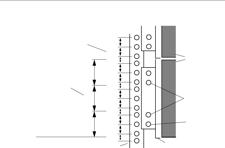
position (see Figure 2-1).
• The rails do not interfere with the power strips, power cords, or
other cables at the back of the rack.
• The rails allow the drive enclosure to slide completely into the
rack.
• The bottom of the drive enclosure is at the bottom of a
U-alignment position.
0521501B.book Page 3 Wednesday, September 25, 2002 10:08 AM
2-4
Installing the MediaNet Storage Subsystem Hardware
Figure 2-1 Locating the MEDIArray II Drive Enclosure Rails
nIf you are installing the rails in a rack that does not have threaded holes, you
will also need to locate four clip nuts in the rail kit. Slip the clip nuts over the
holes in the rack front and back channels where you will be installing the
screws for the drive enclosure rails.
Mounting the MEDIArray II Drive Enclosure
To place a rack-mount drive enclosure into the rack:
1. Make sure you have installed the rack-mount drive enclosure
support rails (see “Installing the MEDIArray II Drive Enclosure
Rack-Mount Rails” on page 2-3). If you are installing several drive
enclosures, install all the support rails before you begin to install
the drive enclosures.
5/8 in
5/8 in
1/2 in
5/8 in
5/8 in
1/2 in
5/8 in
5/8 in
1/2 in
5/8 in
5/8 in
1/2 in
1 U
2 U
3 U
Drive
Rack front channel
Rack channel hole spacing
1 3/4 in
1 3/4 in
1 3/4 in
Support rail
Baseline of drive
enclosure is at
U-alignment position
between two 1/2-inch
spaced holes.
EIA rack unit
enclosure
Support rail
mounting holes
MEDIArray II
mounting hole
0521501B.book Page 4 Wednesday, September 25, 2002 10:08 AM
2-5
Installing File Managers and Storage Subsystem Components
nFor installing multiple MEDIArray II Drive Enclosures, make sure you
position the next set of support rails approximately 3 U above the bottom of
the previous set of support rails. The holes in the rails should align so you can
use the top or bottom holes.
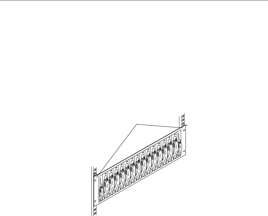
2. From the front of the rack, slide a drive enclosure onto the bottom
set of support rails. Push the drive enclosure in until the mounting
brackets on the side of the drive enclosure touch the rack front rail
(see Figure 2-2).
Figure 2-2 Installing a Drive Enclosure
3. Locate mounting screws in the rail kit.
4. Attach the drive enclosure to the rack front rail using one
mounting screw on each side of the drive enclosure. The mounting
screw can go into either the top or the bottom hole in the
mounting bracket.
5. If you are installing several rack-mount drive enclosures, repeat
steps 2 to 4 for each additional drive enclosure.
Mounting Brackets
0521501B.book Page 5 Wednesday, September 25, 2002 10:08 AM

2-6
Installing the MediaNet Storage Subsystem Hardware
Connecting the MEDIArray II Drive Enclosure Power Cords
Each MEDIArray II drive enclosure has two power cords, one for each
power supply. The power cord connectors are located on the back
panel below the Advanced Cooling Modules (ACMs).
To connect the power cords to the power supplies in a drive
enclosure:
1. Locate two power cords in the MEDIArray II kit.
2. Attach one power cord to the power connector in the right power
supply.
3. Attach the other power cord to the power connector in the left
power supply.
4. Check that the drive enclosure power switches are on.
nBy default, each drive enclosure ships with the power switch in the on
position. Check the power switches to make sure they are on.
5. Plug the power cords from the right side of each drive enclosure
into a power strip on the right side of the rack.
6. Plug the power cords from the left side of each drive enclosure
into a power strip on the left side of the rack.
7. Repeat steps 1 to 6 for each drive enclosure.
Installing the MEDIArray II Drives
The MEDIArray II ships with the power supplies and ACMs installed.
However, you must install the MEDIArray II drives before you connect
the cables between the Fibre Channel controller, the MEDIArray II and
the power cords. The drive slots are filled with dummy drives. You
will need to remove some or all of the dummy drives and replace them
with MEDIArray II drives. The MEDIArray II drives are shipped
separately from the drive enclosure and must be installed in the drive
enclosure.
0521501B.book Page 6 Wednesday, September 25, 2002 10:08 AM
2-7
Installing File Managers and Storage Subsystem Components
cMake sure you are wearing a grounding wrist strap and that it is
attached to the rack assembly before you remove or add any drives
in the drive enclosure.
nAvid recommends that you not mix different capacity MEDIArray II drives
in the same drive enclosure. Mount different drive sizes in separate drive
enclosures.
To install the drives:
1. Starting with the first unpopulated slot, remove as many dummy
drives as you have drives in the MEDIArray II drive kit. Using
your finger, release the locking tab by pressing down, and pull the
cam lever towards you until the cam lever is fully open (see
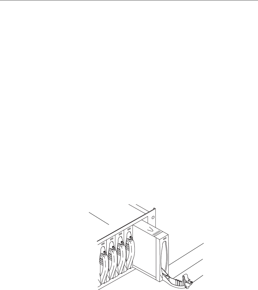
Figure 2-3).
nSave the dummy drives. You might need to reinstall some of them at a later
time if you rearrange the drives in your drive enclosures.
cIf you are not filling the drive enclosure with 14 drives, leave the
dummy drives in any unused slots to provide proper airflow within
the drive enclosure.
Figure 2-3 Removing a Dummy Drive from the Drive Enclosure
2. Gently pull the dummy drive out of the enclosure.
Dummy drive
Drive enclosure
Cam Lever
Locking Tab
0521501B.book Page 7 Wednesday, September 25, 2002 10:08 AM
2-8
Installing the MediaNet Storage Subsystem Hardware
3. Locate a drive in the MEDIArray II drive kit.
4. Remove the drive from the antistatic bag.
cUse caution when you are handling the drives. They contain
components that can be damaged if you hit or drop the drive.
5. Grasp the drive assembly, and fully open the cam lever.
6. Align the drive assembly with the guides in the drive enclosure,
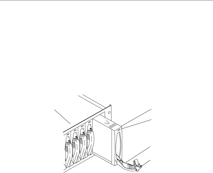
making sure the LEDs are on the top (see Figure 2-4).
Figure 2-4 Inserting a Drive into the Drive Enclosure
7. With the cam lever fully open, gently slide the drive into the drive
enclosure. To lock the drive assembly in place, lift the cam lever
from the lowered position upward. You should hear the locking
tab “click” when it engages.
cUse caution when inserting the drives into the drive enclosure. The
protective strip mounted to one side of the drive can be damaged if
not inserted properly.
8. Repeat steps 1 to 7 for each drive you are installing into the drive
enclosure.
Drive assembly
Drive enclosure
Cam Lever
Locking Tab
LEDs
0521501B.book Page 8 Wednesday, September 25, 2002 10:08 AM
2-9
Installing File Managers and Storage Subsystem Components
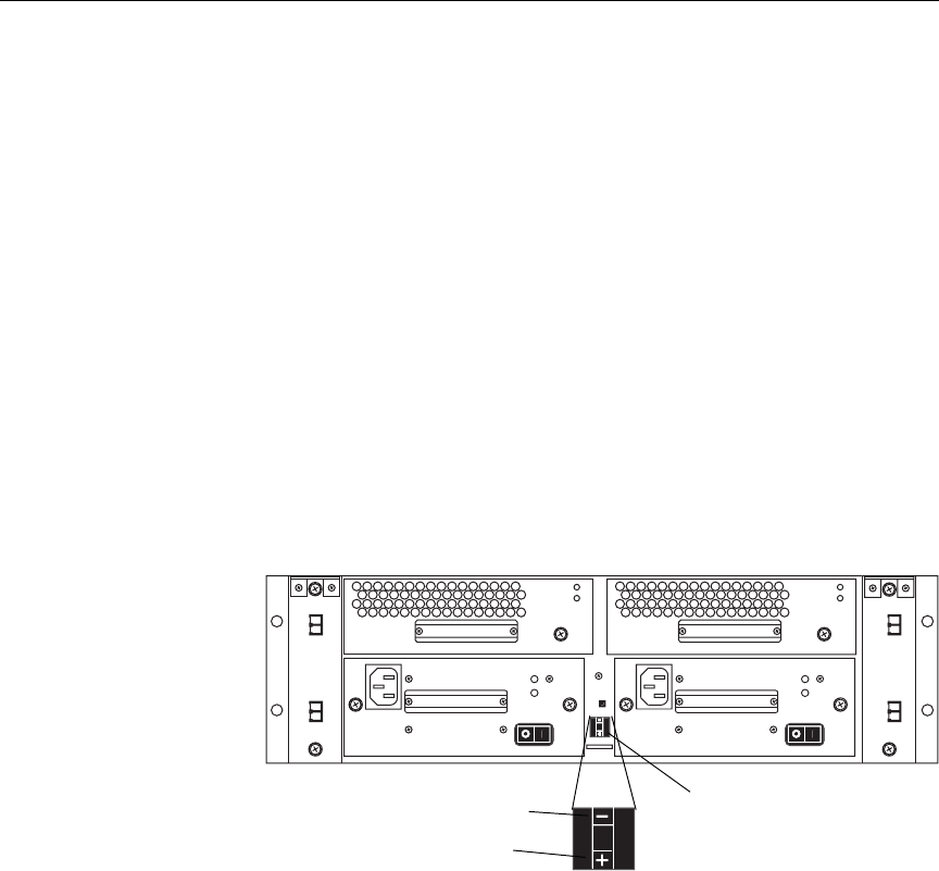
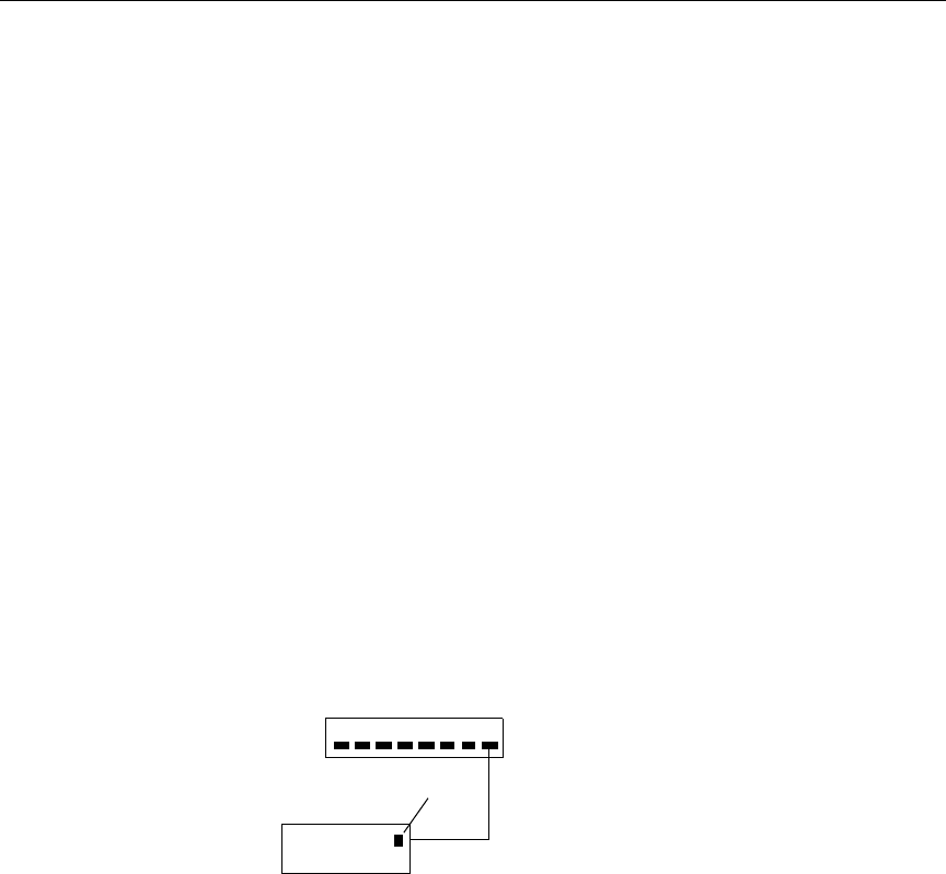
Setting the MEDIArray II Drive Enclosure IDs
Each MEDIArray II drive enclosure needs a unique enclosure ID
number to identify the drive enclosure and determine its drive
addresses. The enclosure IDs must be between zero and seven (0 and
7), and the IDs must be in sequential order.
To set the drive enclosure IDs:
1. Locate the enclosure ID switch on the drive enclosure rear panel.
2. Use the + (plus) button to increment the drive enclosure ID or the
– (minus) button to decrement the drive enclosure ID (see
Figure 2-5).
3. Starting with the drive enclosure that is physically lowest in the
rack, set the ID to 0.
You might need to use a
pen or a paper clip to
push the + and –
buttons to change the
drive enclosure ID.
Figure 2-5 Setting the Drive Enclosure ID
4. Move up to the next drive enclosure and set the ID to 1.
5. Continue setting the drive enclosure IDs by moving up to the next
drive enclosure and incrementing the ID number by one from the
previous enclosure’s ID number.
6. Repeat step 5 until all of the drive enclosure IDs are set. The last ID
number should be no higher than 7.
l
l
0
0
Enclosure ID switch
Decrement - (minus) button
Increment + (plus) button
0521501B.book Page 9 Wednesday, September 25, 2002 10:08 AM

2-10
Installing the MediaNet Storage Subsystem Hardware
Installing a Standard Keyboard, Monitor, and Mouse
The File Manager ships with a keyboard and mouse. You need to
supply a monitor and a monitor shelf before you can connect the
monitor to the File Manager. You can provide your own monitor and
shelf, or purchase them from Avid.
If you purchased a keyboard, monitor, and mouse assembly, skip the
following instructions and continue with “Installing the Keyboard,
Monitor, and Mouse (KMM) Assembly(Optional)” on page 2-11.
Installing the Shelf
Follow the instructions supplied with the shelf to install it while
ensuring that:
• The shelf does not interfere with the power strips, power cords, or
other cables at the back of the rack.
• The shelf allows the monitor to slide completely into the rack.
• You install the rails at the nearest U-alignment position.
• The bottom of the shelf is at the bottom of a U-alignment position.
Installing the Monitor
To install the monitor, set the monitor on the shelf. Route the power
cord and cable to the back of the shelf.
Connecting the Monitor Power Cord
To connect the monitor power cord:
1. Plug the power cord into the back of the monitor.
2. Plug the power cord into the right power strip in the back of the
rack.
0521501B.book Page 10 Wednesday, September 25, 2002 10:08 AM

2-11
Installing File Managers and Storage Subsystem Components
Installing the Keyboard, Monitor, and Mouse (KMM)
Assembly(Optional)
The keyboard, monitor, and mouse is a rack-mount assembly that
includes a standard keyboard, liquid crystal monitor, and trackball. It
requires 1 U of rack space. The monitor pivots and folds flat so that the
KMM can slide into the rack for storage when not in use.
The KMM is an option for the MediaNet workgroup. If your
workgroup does not include the KMM, you will need to use a
standard PC keyboard, PS/2 mouse, and monitor. Follow the
instructions in “Installing a Standard Keyboard, Monitor, and Mouse”
on page 2-10 to install your keyboard, monitor, and mouse.
Installing the KMM Rack-Mount Rails
Follow the instructions supplied with the KMM to install the
rack-mount rails while ensuring that:
• The rails do not interfere with the power strips, power cords, or
other cables at the back of the rack.
• The rails allow the KMM to slide completely into the rack.
• The rails are installed at the nearest U-alignment position that is
approximately 40-inches from the floor.
• The bottom of the KMM is at the bottom of a U-alignment
position.
Mounting the KMM on the Rack-Mount Rails
To mount the KMM on the rack-mount rails:
1. Align the fixed rails attached to the sides of the KMM with the
sliding rails attached to the rack.
2. Push the KMM onto the sliding rails and into the rack. You will
hear the rails click as they lock in place.
0521501B.book Page 11 Wednesday, September 25, 2002 10:08 AM

2-12
Installing the MediaNet Storage Subsystem Hardware
3. Carefully pull the KMM out of the rack. Make sure that the KMM
stops and does not come out of the rack. Support the KMM in case
the rails do not lock in place and the KMM slides off the rails.
4. If the KMM does not stop, make any necessary adjustments to
make sure it is locked to the sliding rails.
Connecting the KMM Power Cord
To connect the KMM power cord:
1. Plug the power cord into the back of the KMM unit.
2. Plug the power cord into the left power strip in the back of the
rack.
Installing a MEDIASwitch
The MEDIASwitch connects the storage and clients to the File
Manager. It allows several clients to use the storage simultaneously,
and prevents interruptions by allowing other clients in the workgroup
to continue working if one or more clients goes offline. The switch is
available in either 8-port or 16-port versions.
The switch mounts in the rack above the drive enclosures. If you have
two switches, mount them with no space between the switches.
Installing the MEDIASwitch Rack-Mount Rails
Follow the instructions supplied with the switch to install the
rack-mount rails while ensuring that:
• The rails do not interfere with the power strips, power cords, or
other cables at the back of the rack.
• The rails allow the switch to slide completely into the rack.
• The bottom of the switch is at the bottom of a U-alignment
position.
0521501B.book Page 12 Wednesday, September 25, 2002 10:08 AM

2-13
Installing File Managers and Storage Subsystem Components
Mounting the MEDIASwitch
To mount the switch on the rack-mount rails:
1. Align the fixed rails attached to the sides of the switch with the
sliding rails attached to the rack.
2. Push the switch onto the sliding rails and into the rack. You will
hear the rails click as they lock in place.
3. Carefully pull the switch out of the rack. Make sure that the switch
stops and does not come out of the rack. Support the switch in
case the rails did not lock in place and the switch slides off the
rails.
4. If the switch does not stop, make any necessary adjustments to
make sure it is locked to the sliding rails.
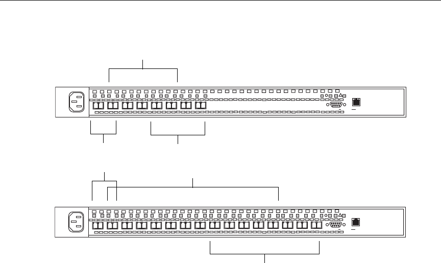
MEDIASwitch Port Requirements
The MediaNet workgroup has specific requirements for placing SFP
(Small Form-factor Protocol) modules into the MEDIASwitch ports.
In the MediaNet workgroup, the MEDIASwitch can be configured for
up to two File Manager ports (ports 1 and 2), up to four storage ports
on an 8-port switch (ports 5 to 8), or up to eight storage ports on a
16-port switch (ports 9 to 16), with the remaining host ports available
for MediaNet Fibre attached clients.
You can connect one File Manager to each File Manager port. You can
connect one MediaNet client to each host port. You can connect up to
four drive enclosures to each storage port.
0521501B.book Page 13 Wednesday, September 25, 2002 10:08 AM
2-14
Installing the MediaNet Storage Subsystem Hardware
Figure 2-6 MEDIASwitch Port Layout
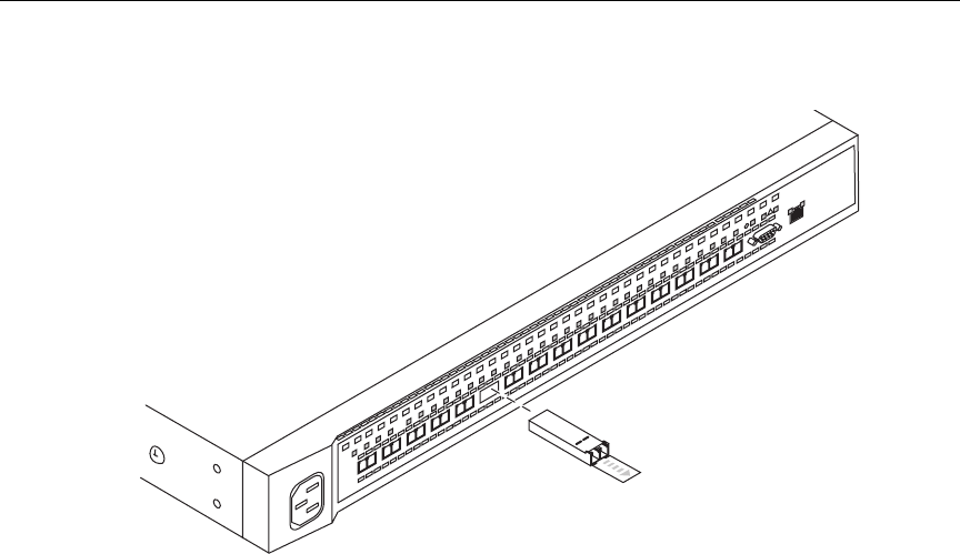
Installing SFPs
The MEDIASwitch can use up to eight or sixteen SFPs, depending on
the switch that is part of your MediaNet workgroup. The SFPs allow
you to attach cables from the File Manager, the MediaNet clients, and
the drive enclosures to the switch. SFPs are supplied separately.
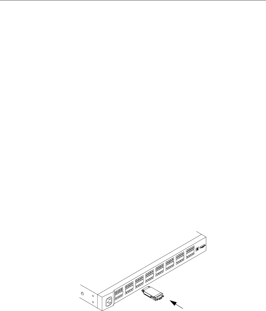
To install the SFPs into a switch:
1. Locate an SFP in the switch kit.
2. Position an SFP in front of a switch port. Make sure the optical
connector is facing away from the switch and the pull tab is on the
bottom.
Storage ports
File Manager ports Storage ports
File Manager ports
9100
9200
100Act/Col
MGMT ENET
l0l0l
3
2
145678
100Act/Col
MGMT ENET
l0l0l
3
2
145678910 11 12 13 14 15 16
MediaNet client ports
MediaNet client ports
0521501B.book Page 14 Wednesday, September 25, 2002 10:08 AM
2-15
Installing File Managers and Storage Subsystem Components
Figure 2-7 Installing an SFP
3. Slide the SFP into the MEDIASwitch port. You should hear the
retainer clips click when they engage the port.
4. Repeat steps 1 to 3 for each SFP in your workgroup.
nRemove any SFPs that are not populated. This will eliminate the risk of
invalid error messages being logged by your SAN Insite software.
Connecting the MEDIASwitch Power Cord
To connect the switch power cord:
1. Plug the power cord into the back of the switch.
2. Plug the power cord into the right power strip in the back of the
rack.
3. If you have two switches, plug the second switch power cord into
the left power strip in the back of the rack.
3
2
14567891011 12 13 14 15 16
100
Act/Col
MGMTENET
0521501B.book Page 15 Wednesday, September 25, 2002 10:08 AM

2-16
Installing the MediaNet Storage Subsystem Hardware
Installing the KVM Switch (Optional)
The keyboard, video, and mouse switch allows you to connect the File
Manager and multiple MediaNet clients (such as TransferManager or
MediaManager) to a single keyboard, monitor, and mouse. The
keyboard, monitor, and mouse can be standalone devices or a KMM
assembly (see “Installing the Keyboard, Monitor, and Mouse (KMM)
Assembly(Optional)” on page 2-11).
Installing the KVM Switch Rack-Mount Bracket
Follow the instructions supplied with the KVM switch to install the
rack-mount bracket while ensuring that:
• The bracket does not interfere with the power strips, power cords,
or other cables at the back of the rack.
• The bracket allows the KVM to slide completely into the rack.
• The bottom of the KVM is at the bottom of a U-alignment position.
Mounting the KVM Switch
To mount the KVM on the rack-mount bracket:
1. Align the KVM with the opening in the bracket.
2. Push the KVM into the bracket until the front of the KVM touches
the front of the rack. The indents in the bottom of the KVM should
align with the support rails on the bracket.
3. Screw the bracket and the KVM together using the screws
supplied with the KVM.
0521501B.book Page 16 Wednesday, September 25, 2002 10:08 AM

2-17
Installing File Managers and Storage Subsystem Components
Connecting the KVM Power Cord
To connect the KVM power cord:
1. Plug the power cord into the back of the KVM.
2. Plug the power cord into the right power strip in the back of the
rack.
Installing File Managers
The File Manager controls the files on the storage and also controls
MediaNet client access to the files. The File Manager is
rack-mountable and requires 2 U of rack space.
Your MediaNet workgroup might include a Failover File Manager to
limit downtime when there is a problem with the Primary File
Manager.
Before you place the File Manager, you need to add the MediaNet
application key (also called a dongle). The application key determines
how many MediaNet clients can simultaneously use your MediaNet
workgroup.
cBe careful not to lose the application key. Your MediaNet
workgroup does not function without it. If you lose the application
key, you must purchase another one from Avid to use your
MediaNet software.
To connect the application key to your MediaNet workgroup:
1. Locate the application key in your MediaNet kit.
2. Attach the application key to the parallel/printer port on the
MediaNet Server. Secure the application key with the
thumbscrews that are part of the key.
0521501B.book Page 17 Wednesday, September 25, 2002 10:08 AM

2-18
Installing the MediaNet Storage Subsystem Hardware
nThe File Manager ships with a parallel port or USB adapter board and a Fibre
Channel adapter board (two Fibre Channel adapter boards when configured
for two switches). When configured for automatic failover, a 10/100 Ethernet
adapter board is also installed.
cDo not use the built-in USB connectors on the front or back of the
SR2200. These USB connectors can support only a keyboard and
mouse, and not devices such as CD-ROM drives.
Installing File Manager Rack-Mount Rails
Follow the instructions supplied with the File Manager to install the
rack-mount rear brackets while ensuring that:
• The brackets do not interfere with the power strips, power cords,
or other cables at the back of the rack.
• The brackets allow the File Manager to slide completely into the
rack.
• The bottom of the File Manager is at the bottom of a U-alignment
position.
Mounting a File Manager
To mount a File Manager on the rack-mount brackets:
1. Attach the left and right front brackets to the File Manager.
2. Attach the rear support washers to the last mounting location on
each side of the File Manager.
3. Slide the File Manager into the rack. If you have other equipment
installed close to the brackets, you might need help supporting the
rear of the File Manager,.
4. Set the support washers onto the brackets.
5. Attach the front bracket to the rack rails.
0521501B.book Page 18 Wednesday, September 25, 2002 10:08 AM

2-19
Installing File Managers and Storage Subsystem Components
Connecting File Manager Power Cords
To connect the File Manager power cord:
1. Plug the power cord into the top power outlet on the back of the
File Manager.
2. Plug the power cord into the left power strip in the back of the
rack.
Installing a Second File Manager For Failover
The Primary File Manager and Failover File Manager are identical
hardware components. If your MediaNet workgroup has a Failover
File Manager, install it following the instructions in “Installing File
Managers” on page 2-17.
Installing the Ethernet Hub (Optional)
You use an Ethernet hub to connect the Primary File Manager, the
Failover File Manager, and the MEDIASwitches together. This allows
you to manage the switches from either File Manager.
Installing the Rack-Mount Bracket
Follow the instructions supplied with the Ethernet hub to install the
rack-mount bracket while ensuring that:
• The bracket does not interfere with the power strips, power cords,
or other cables at the back of the rack.
• The bracket allows the hub to slide completely into the rack.
• The bottom of the hub is at the bottom of a U-alignment position.
0521501B.book Page 19 Wednesday, September 25, 2002 10:08 AM

2-20
Installing the MediaNet Storage Subsystem Hardware
Mounting the Ethernet Hub
To mount the Ethernet hub on the rack-mount bracket:
1. Align the Ethernet hub with the opening in the bracket.
2. Push the Ethernet hub into the bracket until the front of the
Ethernet hub touches the front of the rack. The indents in the
bottom of the Ethernet hub should align with the support rails on
the bracket.
3. Screw the bracket and the Ethernet hub together using the screws
supplied with the Ethernet hub.
Connecting the Ethernet Hub Power Cord
To connect the Ethernet hub power cord:
1. Plug the power cord into the back of the hub.
2. Plug the power cord into the right power strip in the back of the
rack.
Connecting the File Manager and Storage
The following sections describe how to connect the components in
your MediaNet workgroup. If you are using:
• A standard keyboard, monitor, and mouse, begin with
“Connecting a Standard Keyboard, Monitor, and Mouse to the File
Manager” on page 2-21.
• A standard keyboard, monitor, and mouse, and a KVM, begin
with “Connecting a Standard Keyboard, Monitor, and Mouse to
the KVM” on page 2-21.
• A KMM and a KVM, begin with “Connecting the KMM to the
KVM (Optional)” on page 2-22.
0521501B.book Page 20 Wednesday, September 25, 2002 10:08 AM

2-21
Connecting the File Manager and Storage
Connecting a Standard Keyboard, Monitor, and Mouse to the
File Manager
To connect a standard keyboard, monitor, and mouse:
1. Locate the keyboard and mouse in the File Manager kit.
2. Locate the keyboard/mouse Y-cable in the File Manager kit.
3. Attach the right branch of the connector on the Y- cable to the
keyboard.
4. Attach the left branch of the connector on the Y-cable to the
mouse.
nWhen connecting the Y-cable, left and right is determined by looking at the
back of the File Manager. Be sure to connect all Y-cables with the mouse on
the left and keyboard on the right.
5. Attach the 15-pin monitor connector to the monitor port on the
back of the File Manager.
Continue with “Connecting the File Manager to the MEDIASwitch” on
page 2-24.
Connecting a Standard Keyboard, Monitor, and Mouse to the
KVM
To connect a KVM:
1. Locate the keyboard and mouse in the File Manager kit.
2. Attach the connector on the keyboard cable to the keyboard port
on the back of the KVM.
0521501B.book Page 21 Wednesday, September 25, 2002 10:08 AM

2-22
Installing the MediaNet Storage Subsystem Hardware
3. Attach the connector on the mouse cable to the mouse port on the
back of the KVM.
4. Attach the 15-pin connector on the monitor cable to the monitor
port on the back of the KVM.
Continue with “Connecting the File Manager to the KVM (Optional)”
on page 2-22.
Connecting the KMM to the KVM (Optional)
To connect the KMM to the KVM:
1. Locate the 15-pin video connector on the KMM.
2. Attach the connector to the Monitor connector on the back of the
KVM. Secure the connector with the thumbscrews in the
connector.
3. Locate the cable with the keyboard and mouse connectors.
4. Push the keyboard cable connector into the keyboard connector on
the back of the KVM.
5. Push the mouse cable connector into the mouse connector on the
back of the KVM.
Connecting the File Manager to the KVM (Optional)
To connect the first File Manager to the KVM:
1. Locate a KVM cable in the File Manager kit. It has a 25-pin
connector on one end, and a 15-pin connector, a keyboard
connector, and a mouse connector on the other end.
2. Attach the 25-pin connector to port 1 on the back of the KVM.
Secure the connector with the thumbscrews in the connector.
0521501B.book Page 22 Wednesday, September 25, 2002 10:08 AM

2-23
Connecting the File Manager and Storage
3. Attach the 15-pin connector to the video port on the back of the
File Manager. Secure the connector with the thumbscrews in the
connector.
4. Locate the keyboard/mouse Y-cable in the File Manager kit.
5. Attach the single cable end of the Y-cable to the keyboard/mouse
port on the back of the File Manager.
6. Attach the right-hand section of the Y- cable to the keyboard cable
coming from the KVM.
7. Attach the left-hand section of the Y-cable to the mouse cable
coming from the KVM.
nWhen connecting the Y-cable, left or right is determined by looking at the back
of the File Manager. Be sure to connect all left-hand sections of Y-cables to the
mouse and right-hand sections of Y-cables to the keyboard. The KVM cable
ends are marked with symbols for mouse and keyboard.
Connecting a Failover File Manager to the KVM (Optional)
To connect a second File Manager to the KVM in a failover
configuration:
1. Locate a KVM cable in the File Manager kit. It has a 25-pin
connector on one end, and a 15-pin connector, a keyboard
connector, and a mouse connector on the other end.
2. Attach the 25-pin connector to port 2 on the back of the KVM.
Secure the connector with the thumbscrews in the connector.
3. Attach the 15-pin connector to the video port on the back of the
Failover File Manager. Secure the connector with the thumbscrews
in the connector.
4. Locate the keyboard/mouse Y-cable in the File Manager kit.
5. Attach the single cable end of the Y-cable to the keyboard/mouse
port on the back of the File Manager.
0521501B.book Page 23 Wednesday, September 25, 2002 10:08 AM

2-24
Installing the MediaNet Storage Subsystem Hardware
6. Attach the right-hand section of the Y- cable to the keyboard cable
coming from the KVM.
7. Attach the left-hand section of the Y-cable to the mouse cable
coming from the KVM.
nWhen connecting the Y-cable, left or right is determined by looking at the back
of the File Manager. Be sure to connect all left-hand sections of Y-cables to the
mouse and right-hand sections of Y-cables to the keyboard. The KVM cable
ends are marked with symbols for mouse and keyboard.
Connecting the File Manager to the MEDIASwitch
To connect the File Manager to the MEDIASwitch:
1. Locate a 10-foot (3-meter) optical cable in the File Manager kit.
nIf the File Manager is set up for dual switches there are two Fibre Channel
adapter boards installed. Attach the first cable to the top board in the File
Manager PCI card bracket first.
2. Attach one end of the cable to the Fibre Channel adapter board
populating the top slot. Secure the optical cable by firmly inserting
the connector into the optical port.
3. Attach the other end of the cable to port 1 on the first switch.
4. If you have a second switch, locate another 10-foot (3-meter)
optical cable in the File Manager kit.
5. Attach one end of the cable to the Fibre Channel adapter board
populating the middle slot in the File Manager PCI card bracket.
6. Attach the other end of the cable to port 1 on the second switch.
0521501B.book Page 24 Wednesday, September 25, 2002 10:08 AM

2-25
Connecting the File Manager and Storage
Connecting a Failover File Manager to the MEDIASwitch
To connect a Failover File Manager to the MEDIASwitch:
1. Locate a 10-foot (3-meter) optical cable in the File Manager kit.
nIf the File Manager has two Fibre Channel adapter boards, attach the cable to
the top board in the File Manager PCI card bracket. For more information on
the File Manager PCI card brackets.
2. Attach one end of the cable to the Fibre Channel adapter board.
Secure the optical cable by firmly inserting the connector into the
optical port.
3. Attach the other end of the cable to port 2 on the first switch.
4. If you have a second switch, locate another 10-foot (3-meter)
optical cable in the File Manager kit.
5. Attach one end of the cable to the Fibre Channel adapter board
populating the middle slot in the Failover File Manager PCI card
bracket. For more information on the File Manager PCI card
brackets, see Avid SR2200 Platform Introduction.
6. Attach the other end of the cable to port 2 on the second switch.
Connecting the MEDIASwitch Serial Port to the File Manager
for Initial Switch Configuration
You should connect the MEDIASwitch serial port to the File Manager
to accommodate changing the switch IP address in your initial switch
configuration.
To connect the switch to the File Manager:
1. Locate the RJ-45-to-9-pin serial adapter in the File Manager kit.
2. Locate the serial cable supplied with the MediaSwitch.
0521501B.book Page 25 Wednesday, September 25, 2002 10:08 AM
2-26
Installing the MediaNet Storage Subsystem Hardware
3. Connect the RJ-45-to-9-pin serial adapter to the RJ-45 Serial port
on the back panel of the File Manager.
4. Connect the serial cable from the MediaSwitch to the 9-Pin
connector of the serial adapter.
5. Connect the serial cable from the MediaSwitch to the 9-Pin
connector on the MediaSwitch.
nIf you have two switches, you can move the serial cable from one switch to the
other when you need to change the other switch’s IP address. See “Adding the
MEDIASwitch to the Hosts File” on page 3-6.
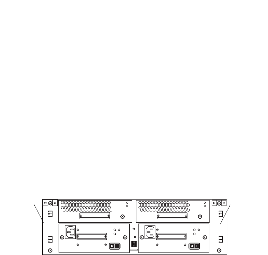
Connecting the MEDIArray II Drive Enclosure to the
MEDIASwitch
Each drive enclosure is supplied with two I/O Modules. The I/O
Modules connect the storage to the MEDIASwitches. Figure 2-8 shows
the locations of the I/O Modules on the rear of the drive enclosure.
Figure 2-8 Drive Enclosure Connection Locations
Each I/O Module has two connectors: the primary (INPUT) connector
and the expansion (OUTPUT) connector (see Figure 2-8). The INPUT
port on the I/O Module accepts data from a host or another I/O
Module when two drive enclosures are daisy-chained together. The
OUTPUT port on the I/O Module is used to pass data to the INPUT
port on the next I/O Module when two drive enclosures are
daisy-chained together.
l
l
0
INPUTOUTPUT
INPUTOUTPUT
I/O Module I/O Module
AB
0521501B.book Page 26 Wednesday, September 25, 2002 10:08 AM
2-27
Connecting the File Manager and Storage
You connect the drive enclosures to the MEDIASwitch either
individually or in groups of two. The number of drive enclosures and
MediaNet clients that you have in your workgroup, and the type of
work that the clients will do, determine how you need to connect the
drive enclosures to the switch. You typically connect several groups of
drive enclosures, up to the maximum of 8 enclosures, to the switch.
If you need to connect:
• One drive enclosure, see “Connecting One MEDIArray II Drive
Enclosure” on page 2-27 for cabling instructions.
• A daisy chain of two drive enclosures, see “Connecting a Daisy
Chain of Two MEDIArray II Drive Enclosures” on page 2-32 for
cabling instructions.
Connecting One MEDIArray II Drive Enclosure
When you have one drive enclosure in your MediaNet workgroup or
Trilligent Cluster, you connect it directly to the MEDIASwitch (see
Figure 2-9).
Figure 2-9 Cabling for One MEDIArray II Drive Enclosure
Connecting the Cable to the MEDIArray II Drive Enclosure
To connect the MEDIArray II drive enclosure:
1. Locate a 10-foot (3-meter) optical cable in the MEDIArray II kit.
tIf you are connecting to a 1-Gb MEDIASwitch, the cable has
an SC (large) optical connector on one end and an LC (small)
connector on the other end.
Drive
Cables
enclosure
#1
Switch
Input
0521501B.book Page 27 Wednesday, September 25, 2002 10:08 AM
2-28
Installing the MediaNet Storage Subsystem Hardware
tIf you are connecting to a 2-Gb MEDIASwitch, the cable has
an LC (small) optical connector on both ends.
2. Attach the connector on one end of the cable to the INPUT
connector on I/O Module A on the back of drive enclosure 1 (see
Figure 2-9). Secure the optical cable by firmly inserting the
connector into the optical port.
3. Do one of the following:
tIf you are connecting to a 1-Gb MEDIASwitch, continue with
“Connecting to a 1-Gb MEDIASwitch” on page 2-28.
tIf you are connecting to a 2-Gb MEDIASwitch, continue with
“Connecting to a 2-Gb MEDIASwitch” on page 2-30.
Connecting to a 1-Gb MEDIASwitch
To connect an optical cable to the 1-Gb MEDIASwitch:
1. Locate the GBIC in the MEDIArray II kit.
2. Route the cable from the MEDIArray II to the MEDIASwitch, if it
has not already been installed.
3. Position the GBIC in front of a MEDIASwitch port
(see Figure 2-10). Make sure the optical connector is facing away
from the MEDIASwitch.
Figure 2-10 Installing a GBIC
0521501B.book Page 28 Wednesday, September 25, 2002 10:08 AM
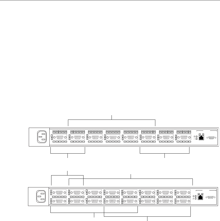
2-29
Connecting the File Manager and Storage
nYou can install the GBIC while the MEDIASwitch is turned on.
4. Slide the GBIC into the MEDIASwitch port. You should hear the
retainer clips “click” when the GBIC is seated in the port.
5. Remove the protective covers from the optical connector on the
optical cable.
6. Remove the protective cover from the GBIC in the MEDIASwitch.
7. Attach the connector on the cable into the GBIC for the client (see
Figure 2-11). Firmly push the plug on the cable into the connectors
on the optical GBIC.
Figure 2-11 MEDIASwitch Port Layout
8. Label the cable with the name or location of the MEDIArray II to
which it connects.
Storage ports
File Manager ports Storage ports
100 RS232Act/Col
1234567 8
MGMT
100 RS232Act/Col
1234567 8
910 11 12 13 14 15 16
MGMT
MediaNet client ports
MediaNet client ports
File Manager ports
MediaNet client ports
7100
7200
0521501B.book Page 29 Wednesday, September 25, 2002 10:08 AM
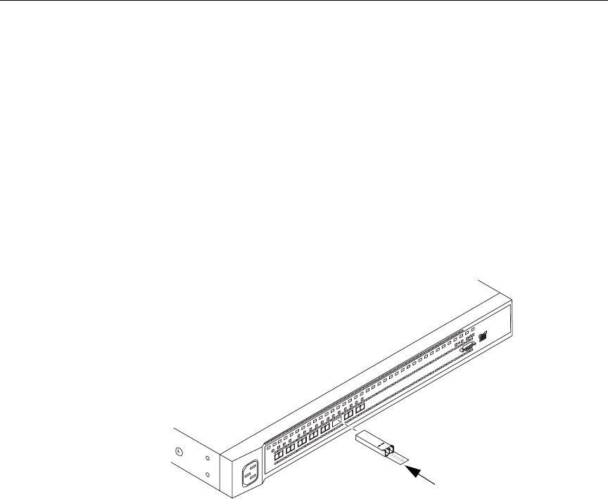
2-30
Installing the MediaNet Storage Subsystem Hardware
Connecting to a 2-Gb MEDIASwitch
To connect an optical cable to the 2-Gb MEDIASwitch:
1. Locate an SFP in the MEDIArray II kit.
2. Route the cable from the MEDIArray II to the MEDIASwitch, if it
has not already been installed.
3. Position the SFP in front of a MEDIASwitch port. Make sure the
optical connector is facing away from the MEDIASwitch
(see Figure 2-12).
Figure 2-12 Installing an SFP
nYou can install the SFP while the MEDIASwitch is turned on.
4. Slide the SFP into the MEDIASwitch port. You should hear a
“click” when the SFP is seated in the port.
5. Remove the protective covers from the optical connector on the
optical cable.
6. Remove the protective cover from the SFP in the MEDIASwitch.
3
2
145678
100
Act/Col
MGMT ENET
0521501B.book Page 30 Wednesday, September 25, 2002 10:08 AM
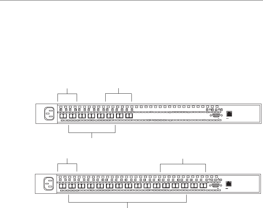
2-31
Connecting the File Manager and Storage
7. Attach the connector on the cable to the SFP for the client (see
Figure 2-13). Firmly push the plug on the cable into the connectors
on the optical SFP.
8. Label the cable with the name or location of the MEDIArray II to
which it connects.
Figure 2-13 MEDIASwitch Port Layout
Storage ports
MediaNet client ports
File Manager ports
9100
9200
100Act/Col
MGMT ENET
l0l0l
3
2
145678
100Act/Col
MGMT ENET
l0l0l
3
2
145678910 11 12 13 14 15 16
File Manager ports
MediaNet client ports
Storage ports
0521501B.book Page 31 Wednesday, September 25, 2002 10:08 AM
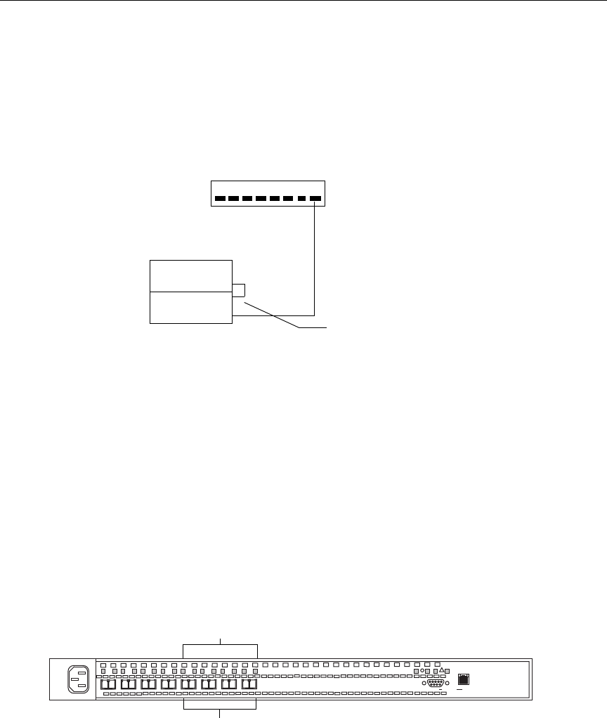
2-32
Installing the MediaNet Storage Subsystem Hardware
Connecting a Daisy Chain of Two MEDIArray II Drive Enclosures
When you have multiple drive enclosures in your MediaNet
workgroup or Trilligent Cluster, you can create daisy chains of two
drive enclosures to connect to the MEDIASwitch (see Figure 2-14).
Figure 2-14 Cabling for Two MEDIArray II Drive Enclosures
To connect the drive enclosures:
1. Locate a 10-foot (3-meter) optical cable in the MEDIArray II kit.
2. Attach the optical connector on one end of the optical cable to the
INPUT optical connector on I/O Module A on the back of drive
enclosure 1 (see Figure 2-14). Secure the optical cable by firmly
inserting the connector into the optical port.
3. Attach the optical connector on the other end of the cable to any of
the unpopulated switch ports 5 through 8 on an 8-port switch or
ports 9 to 16 on a 16-port switch (see Figure 2-15). Secure the
optical cable by firmly inserting the connector into the SFP.
Figure 2-15 Cabling to a MEDIASwitch Port
Cables
Daisy-chain cable
Drive
enclosures
#1
#2
Switch
To drive enclosures
Switch ports 5 to 8
100Act/Col
MGMT ENET
l0l0l
3
2
145678
0521501B.book Page 32 Wednesday, September 25, 2002 10:08 AM
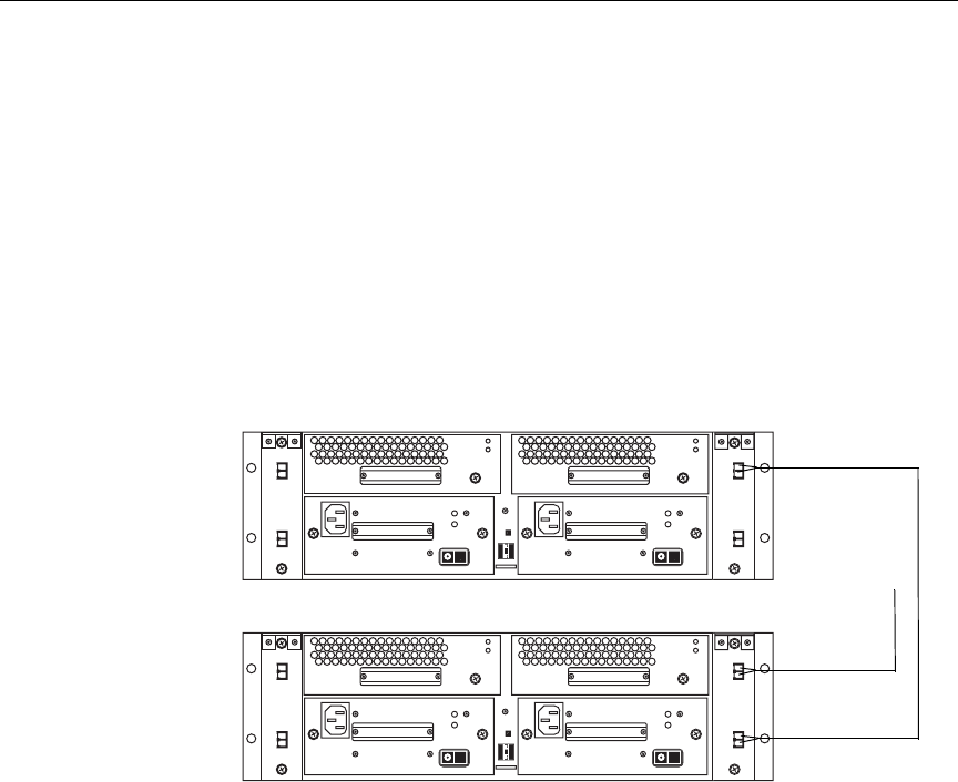
2-33
Connecting the File Manager and Storage
4. Locate a 1-foot (0.3-meter) optical cable in the kit.
5. Attach the optical connector on one end of the cable to the
OUTPUT optical connector on I/O Module A on the back of drive
enclosure 1 (see Figure 2-16). Secure the optical cable by firmly
inserting the connector into the optical port.
6. Attach the optical connector on the other end of the cable to the
INPUT optical connector on I/O Module A on the back of drive
enclosure 2 (see Figure 2-16). Secure the optical cable by firmly
inserting the connector into the optical port.
Figure 2-16 Daisy Chaining Drive Enclosures
Connecting to Two MEDIASwitches
When you have two MEDIASwitches in your MediaNet workgroup,
you need to connect cables from I/O Module A on the drive
enclosures to the first switch and from I/O Module B on the drive
enclosures to the second switch (see Figure 2-17). After you have
connected the cables between I/O Module A on the drive enclosures
and the first switch, repeat the cabling for the same drive enclosures,
this time using I/O Module B and connect them to the second switch.
l
l
0
l
l
0
INPUTOUTPUTINPUTOUTPUT
INPUT
OUTPUT
INPUT
OUTPUT
Drive Enclosure 1
Drive Enclosure 2
Optical Cable
to Switch
Daisy Chain
Cable OUT
Daisy Chain
Cable IN
0521501B.book Page 33 Wednesday, September 25, 2002 10:08 AM
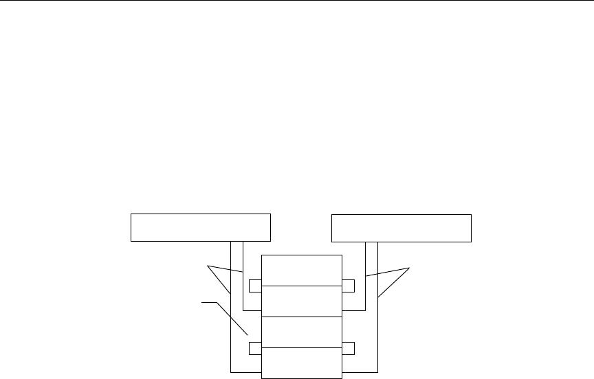
2-34
Installing the MediaNet Storage Subsystem Hardware
nMake sure that you connect cables from I/O Module A and I/O Module B to
the same ports on both switches.
On an 8-port switch you can use ports 5 to 8 to connect drive
enclosures. On a 16-port switch you can use ports 9 to 16 to connect
drive enclosures.
Figure 2-17 Cabling for Two MEDIASwitches
Connecting the File Manager to the Ethernet Hub
To connect the File Manager to the Ethernet hub:
1. Locate an Ethernet cable in the MEDIASwitch kit.
2. Attach one end of the cable to port 1 on the hub.
3. Attach the other end of the cable to the File Manager Ethernet
adapter card in the PCI card bracket.
cConnecting your File Manager to an Ethernet hub is optional in a
MediaNet workgroup, but mandatory when running a Trilligent
Cluster.
Drive
Daisy-chain cable
enclosures
MEDIASwitch 1
I/O Module A cables I/O Module B cables
Ports 7 and 8 (or 15 and 16) MEDIASwitch 2
Ports 7 and 8 (or 15 and 16)
0521501B.book Page 34 Wednesday, September 25, 2002 10:08 AM

2-35
Connecting the File Manager and Storage
Connecting a Failover File Manager to the Ethernet Hub
To connect a Failover File Manager to the hub in a failover
configuration:
1. Locate an Ethernet cable in the File Manager kit.
2. Attach one end of the cable to port 2 on the hub.
3. Attach the other end of the cable to the File Manager built-in
Ethernet port 1.
Connecting the MEDIASwitch to the Ethernet Hub
To connect the MEDIASwitch to the Ethernet hub:
1. Locate an Ethernet cable in the MEDIASwitch kit.
2. Attach one end of the cable to port 3 on the hub.
3. Attach the other end of the cable to the MGMT ENET connector on
the back of the switch.
4. If you have a second switch, repeat steps 1 to 3 this time using port
4 on the hub.
nThe MEDIASwitches have the same IP address by default. For more
information on IP address configuration, see Table 2-1 on page 2-37.
0521501B.book Page 35 Wednesday, September 25, 2002 10:08 AM
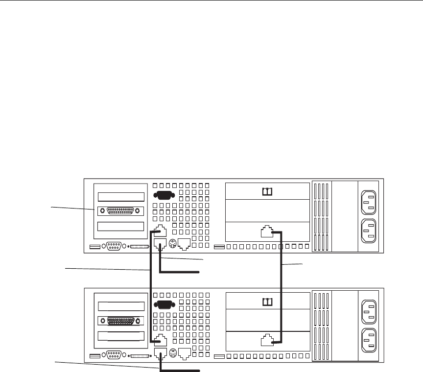
2-36
Installing the MediaNet Storage Subsystem Hardware
Cross-Connecting the File Managers in Failover
Configurations
To connect the Primary File Manager and Failover File Manager:
Use the following diagram, table, and instructions for connecting and
configuring the File Managers for failover operation.
Figure 2-18 File Managers in Failover Configuration
1. Connect the RJ-45 Ethernet connector 2 of the Primary File
Manager to the RJ-45 Ethernet connector 2 of the Failover File
Manager using the supplied crossover cable.
2. Connect the Primary File Manager RJ-45 10/100 Ethernet port on
the full-height PCI interface card to the Failover File Manager
RJ-45 10/100 Ethernet port of the full-height PCI interface card.
3. Connect the RJ-45 Ethernet connector 1 on the Primary File
Manager to your LAN/WAN or optional Ethernet hub.
Crossover Cable from
PCI 10/100 interface cards
from RJ-45 Ethernet
Connectors 2
Primary Ethernet
Failover Ethernet
Connector 1 to
LAN/WAN/Hub
Crossover Cable
Primary SR2200 File Manager
Parallel Port
Failover SR2200 File Manager
Connector 1 to
LAN/WAN/HUB
0521501B.book Page 36 Wednesday, September 25, 2002 10:08 AM

2-37
Connecting the File Manager and Storage
4. Connect the RJ-45 Ethernet connector 1 of the Failover File
Manager to your LAN/WAN or optional Ethernet hub.
5. Configure the IP addresses for the File Managers as shown in
Table 2-1.
nWhen viewing the IP addresses in a Windows NT environment, the File
Manager Ethernet Connector numbering is reversed;
Connector 1 will show as connector 2
Connector 2 will show as connector 1
Connector 3, the RJ-45 10/100 Ethernet PCI full height interface card (when
installed) maintains its numeric position. See “File Managers in Failover
Configuration” on page 2-36.
Table 2-1 File Manager IP Addresses
IP Address Description
192.168.1.1aPrimary File Manager RJ-45 Ethernet Connector 1
192.168.2.1 Primary File Manager RJ-45 Ethernet Connector 2
192.168.3.1 Primary File Manager PCI 10/100 NIC
192.168.1.2 Failover File Manager RJ-45 Ethernet Connector 1
192.168.2.2 Failover File Manager RJ-45 Ethernet Connector 2
192.168.3.2 Failover File Manager PCI 10/100 NIC
a. This is the default IP address to use for configuring the Fibre
Channel switch initially. Change this IP address to comply with
your specific IP addressing conventions when configuring the
Fibre Channel switch for use in your network.
0521501B.book Page 37 Wednesday, September 25, 2002 10:08 AM

2-38
Installing the MediaNet Storage Subsystem Hardware
0521501B.book Page 38 Wednesday, September 25, 2002 10:08 AM

CHAPTER 3
Configuring the
MEDIASwitches
This chapter describes how to install the appropriate software and
how to configure the MEDIASwitches in your MediaNet workgroup
or Trilligent Cluster. Installing all the necessary software is a multistep
process. Make sure you complete the sections in sequential order.
nThe IP addresses used in the following sections are recommendations. They
are non-routing IP addresses and can be used if your site does or does not
currently have an Ethernet network. If your site has an Ethernet network,
you can select unused IP addresses from your network environment for the
MEDIASwitches.
Changing the MEDIASwitch IP Address
You initially connect to the MEDIASwitch from the File Manager
using the serial cable that you installed earlier (see “Connecting the
MEDIASwitch Serial Port to the File Manager for Initial Switch
Configuration” on page 2-25). Make sure the serial cable is connected
to both the File Manager and the MediaSwitch you want to configure.
The MEDIASwitch ships with a default IP address of 192.168.1.129. If
you are not changing the IP address of the switch to an address on
0521501B.book Page 1 Wednesday, September 25, 2002 10:08 AM

3-2
Configuring the MEDIASwitches
your internal network, continue with “Establishing a Connection to
the MEDIASwitch” on page 3-7.
nIf you have more than one MEDIASwitch, and your File Manager and
switches are connected to an Ethernet network, you should turn one switch
off before running SAN InSite for the first time to configure the switch IP
addresses. This prevents SAN InSite from seeing duplicate IP addresses that
can cause SAN InSite not to recognize either switch.
nIf you have two switches, you need to change the IP address of the second
switch so that it does not conflict with the first switch. If you are not
changing the IP address to an address on your internal network, use the IP
address 192.168.1.130.
To change the switch IP address:
1. Open a terminal session through a terminal emulation program,
such as HyperTerminal, with the serial port set to COM 1 and the
following serial port parameters:
• Bits per second: 19200
• Data bits: 8
• Parity: None
•Stop bits: 1
• Flow control: Xon/Xoff
2. Press Enter and a password dialog box appears in the
HyperTerminal window.
3. Type the password manage to start the Command Line Interface
(CLI).
4. At the Root menu prompt type 1 (Config) and press Enter. The
Config window appears.
5. At the Config prompt, type 8 (Com) and press Enter. The
Config/Com window appears.
6. At the Config/Com prompt, type 4 (Ethernet) and press Enter.
The Ethernet menu appears.
0521501B.book Page 2 Wednesday, September 25, 2002 10:08 AM

3-3
Installing SAN InSite Professional
7. To change the MEDIASwitch Ethernet IP address type 3 (Set
Ethernet Address) and press Enter.
8. At the IP Address prompt, type in the new IP address and press
Enter.
9. At the Ethernet menu and type 4 (Netmask) and press Enter.
10. At the Netmask prompt, type in the Netmask and press Enter.
11. At the Ethernet menu and type 5 (Gateway IP address) and press
Enter.
12. At the Gateway IP Address prompt, type in the new Gateway IP
address and press Enter.
13. Reset the MEDIASwitch by unplugging it, then plugging it back in
to make the changes take affect.
14. Log out of the CLI type logout at the prompt.
15. Close the HyperTerminal window.
Installing SAN InSite Professional
MediaNet Release 3.0 uses an updated release of SAN InSite
Professional software to configure the MEDIASwitches.
To install SAN InSite Professional:
1. Locate the SAN InSite Professional CD-ROM.
2. Insert the CD-ROM into the File Manager CD-ROM drive. The
CD-ROM is set to auto-start and the SAN InSite Professional
installation starts. This takes approximately 1 minute. The Verify
Account Privileges dialog box appears.
If the CD-ROM does not auto-start, start the installation manually
as follows:
a. Double-click the My Computer icon on the desktop. The My
Computer window opens.
0521501B.book Page 3 Wednesday, September 25, 2002 10:08 AM

3-4
Configuring the MEDIASwitches
b. Right-click the CD-ROM icon and choose AutoPlay from the
pop-up menu. The SAN InSite Professional installation starts.
The Verify Account Privileges dialog box appears.
3. Click Yes. The SAN InSite Professional window opens to the
Introduction screen.
4. Click Next. The License Agreement screen appears. Read the
agreement and click Yes.
5. Click Next. The Choose One Item To Install screen appears.
6. Click SAN InSite Professional.
7. Click Next. The Choose A Directory screen appears. Make no
changes.
8. Click Next. The Enter Server Address screen appears. It shows the
host name for the File Manager. If it is correct, click Yes. Write the
host name down; you will need it later.
9. Click Next. The Enter License screen appears.
10. Type the license number in the text box. The license number is on
the CD-ROM case.
11. Click Next. The License Status screen appears showing the status
of the license. It should indicate the number of agents available
and the license expiration date.
12. Click Next. The Installation screen appears showing the software
installation progress.
13. When the software installation is complete, the SAN InSite
Professional Server Configuration window opens.
14. Click the Log tab.
15. Select each check box to turn on all of the event logging
capabilities.
16. In the “Site log entry priority levels” menu, choose
“info,config,warning,fail.”
17. Click the Discover tab.
0521501B.book Page 4 Wednesday, September 25, 2002 10:08 AM

3-5
Configuring the MEDIASwitch
18. Select the “Discover agents listed below” check box. The Add
button becomes available.
19. Click the Add button. The Add Agent IP Address/DNS Host
Name dialog box appears.
20. Type the IP address for your MEDIASwitch in the text box and
click OK. The IP address appears in the list on the Discover tab.
21. If you have two MEDIASwitches, repeat step 20 for the second
switch.
22. Click OK. A Message dialog box appears stating that the
configuration was successful.
23. Click OK. The SAN InSite Professional Install Complete screen
appears.
24. Click OK. The SAN InSite Professional window closes.
25. Click the Start button, and then select Shut Down. The Shut Down
dialog box appears.
26. Choose Restart from the menu and click OK. The File Manager
reboots.
27. When the reboot is complete, log in as Administrator.
Configuring the MEDIASwitch
You need to configure the MEDIASwitch to have a valid IP address
and to have appropriate port configurations for the File Manager,
MediaNet clients, and drive enclosures in your MediaNet workgroup
or Trilligent Cluster.
Copying the MEDIASwitch Files into the SAN InSite Folder
The MEDIASwitch has configuration files that you need to copy into
the SAN InSite Pro folder.
0521501B.book Page 5 Wednesday, September 25, 2002 10:08 AM

3-6
Configuring the MEDIASwitches
To copy the configuration files:
1. Make sure that the MediaNet CD-ROM is in the File Manager
CD-ROM drive.
2. Click Start, point to Programs, and then click Windows NT
Explorer. The Windows NT Explorer window opens.
3. Expand the CD-ROM to show the
\Drivers_Firmware\FibreChannelSwitches\Vixel folder.
4. Expand the C: drive to show the
\SANInSitePro\SIFileSystemRoot\deviceconfig\vixel folder.
5. Drag the \Drivers_Firmware\FibreChannelSwitches\Vixel folder
to the \SANInSitePro\SIFileSystemRoot\deviceconfig\vixel
folder.
6. Click Copy Here in the pop-up menu. The files are copied to the
new location.
Adding the MEDIASwitch to the Hosts File
You need to add the MEDIASwitch IP address to the Hosts file to be
able to download switch firmware and make other updates.
To add the switch IP address to the Hosts file:
1. Locate the Hosts file. It is found at
%systemroot%\system32\drivers\etc, where %systemroot% is
typically C:\Winnt.
2. Open the Hosts file with a text editor, such as WordPad.
3. Scroll to the end of the file.
4. On a new line, type 192.168.1.129 #9x00 switch. Use the correct IP
address and switch name for your switch.
5. If you have two switches, repeat step 4 for the second switch,
using its IP address.
6. Close and save the Hosts file.
0521501B.book Page 6 Wednesday, September 25, 2002 10:08 AM

3-7
Configuring the MEDIASwitch
Establishing a Connection to the MEDIASwitch
To establish the connection:
1. Click the Start button, point to Programs, point to SAN InSite
Professional, and then click Run SAN Insite Client. The SAN
InSite Professional Server Specification dialog box appears,
showing the server IP address or server DNS name.
2. Click Connect. The SAN InSite Professional User Authorization
dialog box appears.
3. Click Monitor & Manage.
4. Type manage into the Password text box.
5. Click OK. The SAN Insite Professional window opens. You should
see the switch IP address in green.
Setting the MEDIASwitch Configuration
This section describes how to configure the MEDIASwitch.
To load switch firmware and configuration files:
1. Connect a crossover Ethernet cable between the File Manager
Ethernet port and the switch MGMT port.
2. Click Start, point to Programs, point to SAN InSite Professional,
and then click Run SAN Insite Client. The SAN InSite Professional
Server Specification dialog box appears showing the server host
name.
3. Click Connect. The SAN InSite Professional User Authorization
dialog box appears.
4. Click Monitor & Manage.
5. Type manage into the Password text box.
6. Click OK. The SAN InSite Professional Server window opens.
0521501B.book Page 7 Wednesday, September 25, 2002 10:08 AM

3-8
Configuring the MEDIASwitches
7. Double-click the switch that you want to update. The Switch
window opens.
8. In the Switch window, click the Tools menu, then click Configure
firmware image. The Firmware Image Configuration window
opens.
9. Click Browse. The Select File dialog box appears.
10. Navigate to Vixel\Firmware\YGb \Vixel_xxxx, where xxxx is the
model number of your switch. Y is the switch speed (1 or 2.)
11. Click the .dwn file in the switch folder.
12. Click OK. The firmware file name appears in the File Name text
box in the Firmware Image Configuration window.
13. Click Download. The firmware downloads to the Active Image in
the switch. When the download completes, a dialog box appears
asking if you want to set both images to the new firmware.
cAvid recommends that you download the new firmware to both the
Active Image and the Alternate Image. This prevents problems if the
switch should change from the Active Image to the Alternate Image
for any reason.
14. Click Yes to choose a configuration file to download with the
firmware. The Select File dialog box appears.
15. Navigate to Vixel\Config Files\YGb \Vixel_xxxx, where xxxx is
the model number of your switch. Y is the switch speed (1 or 2.)
16. Click the configuration file in the switch folder. The files have the
following naming convention.
9100_tm_1fm_3h_4j
Number of MEDIArray enclosure connections
Number of clients
Number of File Managers
Target Mode enabled
MEDIASwitch model
0521501B.book Page 8 Wednesday, September 25, 2002 10:08 AM

3-9
SAN InSite Server
17. Click OK. The firmware and switch configuration file download to
the Active Image and Alternate Image, and the switch resets. This
takes approximately 4 minutes.
18. When the download and reset are complete, close the Switch
window.
nOnce this process is complete the name of the switch in the SAN Insite main
window should match the configuration you loaded.
SAN InSite Server
cAvid has discovered performance issues when running the SAN
InSite Server in most MediaNet configurations. You can avoid these
issues by stopping the SAN InSite Server and changing the SAN
InSite Service to start manually.
To stop the SAN InSite Server:
1. Click the Start button, point to Programs, point to SAN InSite
Professional, point to SAN InSite Server, and then select Stop
Server.
2. Click the Start button, point to Settings, and then select Control
Panel. The Control Panel window opens.
3. Double-click the Services icon. The Services dialog box appears.
4. Locate and select the SAN InSite Professional v3.5 service in the
list of services.
5. Click Startup. The Service dialog box appears.
6. In the Startup Type area, click Manual.
7. Click OK. The dialog box closes and the service is reset.
8. Click Close.
0521501B.book Page 9 Wednesday, September 25, 2002 10:08 AM

3-10
Configuring the MEDIASwitches
Using the SAN InSite Client
nAvid recommends that you do not run the SAN InSite client and the File
Manager software at the same time. Stop the File Manager from the Monitor
Tool before running the SAN InSite Client.
To use the SAN InSite client to change your MEDIASwitch settings:
1. Stop the File Manager using the Monitor Tool.
2. Click the Start button, point to Programs, point to SAN InSite
Professional, point to SAN InSite Server, and then select Start
Server. It takes the server software about 20 seconds to start, so
you should wait before continuing with step 3.
3. Click the Start button, point to Programs, point to SAN InSite
Professional, and then select Run SAN InSite Client.
4. Log in to SAN InSite as usual and make the necessary changes.
5. Quit the SAN InSite client.
6. Click the Start button, point to Programs, point to SAN InSite
Professional, point to SAN InSite Server, and then select Stop
Server.
7. Start the File Manager using the Monitor Tool.
0521501B.book Page 10 Wednesday, September 25, 2002 10:08 AM

CHAPTER 4
Configuring the File
Manager
This chapter describes how to configure and install the appropriate
software on the File Managers in your MediaNet workgroup or
Trilligent Cluster. Installing all the necessary software is a multistep
process. Make sure you complete the sections in sequential order.
Before you start the procedures in this chapter, you should have the
File Managers and other MediaNet workgroup or Trilligent Cluster
hardware installed.
nThe IP addresses used in the following sections are recommendations. They
are non-routing IP addresses and can be used if your site does or does not
currently have an Ethernet network. If your site has an Ethernet network,
you can select unused IP addresses from your network environment for the
File Manager.
0521501B.book Page 1 Wednesday, September 25, 2002 10:08 AM

4-2
Configuring the File Manager
Setting Up the File Manager
Set up the File Manager and, in failover configurations, the second File
Manager as described in the following sections.
Quick Summary
If you are already
familiar with
configuring Windows
NT systems, you may
choose to skip the
detailed directions in
the rest of this chapter
and perform the steps
outlined here.
• Check that the File Manager is running Windows NT Workstation
with Service Pack 5 and the ScsiPort.sys hotfix.
• Accurately set the date, time, and time zone.
• Configure IP addresses and, if necessary, gateway IP addresses for
the network adapter.
• Configure paging file size to be two times the installed RAM size
on the D: drive. See “Setting the File Manager Paging File Size” on
page 4-4.
Checking the Operating System Installation
The File Manager runs the Windows NT Workstation 4.0 operating
system, and Service Pack 5 and the ScsiPort.sys hotfix.
nAvid ships the File Manager with Windows NT Workstation, Service Pack 5,
and the ScsiPort.sys hotfix preinstalled. If you are concerned that the
operating system may not be appropriately installed, you can check by
following the procedures in this section.
To determine that the appropriate Windows NT Workstation
operating system, service pack, and hotfix versions are installed on
the File Manager:
1. Click the Start button, point to Programs, point to Administrative
Tools, and then select Windows NT Diagnostics. The Windows NT
Diagnostics window opens.
0521501B.book Page 2 Wednesday, September 25, 2002 10:08 AM

4-3
Setting Up the File Manager
2. Click the Version tab. The version of the Windows NT
Workstation operating system and Service Pack installed on the
File Manager appears below the Windows icon.
3. Open the Add/Remove Programs control panel and check to see
if the ScsiPort.sys hotfix is installed.
If your File Manager does not have the Windows NT Workstation 4.0
operating system, Service Pack 5, or the ScsiPort.sys hotfix properly
installed, you should install the Windows NT Workstation operating
system, the service pack, the hotfix, or all three.
nWindow NT Service Pack 5 and the ScsiPort.sys hotfix are provided in the
Extras folder on the MediaNet CD-ROM.
When you reinstall the Windows NT operating system for any reason,
make sure you perform a default installation (accept all the standard
installation recommendations) of the Windows NT Workstation 4.0
operating system. Follow the Windows NT installation instructions
that came with your Windows NT software.
Setting the Date, Time, and Time Zone
You need to correctly set the date, time, time zone, and daylight saving
time option on the File Manager. This allows the “Synchronize time
with File Manager” function on the MediaNet clients to work
correctly.
To set the date, time, time zone, and daylight saving time option on
the File Manager:
1. Double-click the time in the taskbar. The Date/Time Properties
dialog box appears.
2. Set the date and time by using the Date & Time tab.
3. Click the Time Zone tab.
0521501B.book Page 3 Wednesday, September 25, 2002 10:08 AM

4-4
Configuring the File Manager
4. Set the time zone correctly for the location of the File Manager. By
default, Windows NT 4.0 sets the time zone to “(GMT - 8:00)
Pacific Time (US & Canada), Tijuana.”
5. Make sure that “Automatically adjust clock for daylight saving
changes” is selected.
6. Click OK to close the Date/Time Properties dialog box and save
the settings.
Setting the File Manager Paging File Size
The paging file extends the physical memory (RAM) in your File
Manager by using a portion of the hard drive as a location to move
unused data from physical memory. Windows NT uses the paging file
(pagefile.sys) to track the size and location of the reserved hard drive
space, and to move data to the hard drive from RAM.
nAvid ships all File Managers with the paging file configured to 2048 MB.
The File Manager allocates 2048 MB of memory on the D: drive of the
internal (system) hard drive. This provides adequate space for normal
File Manager operation.
To set the paging file size:
1. Right-click the My Computer icon on the desktop and select
Properties. The System Properties dialog box appears.
2. Click the Performance tab. The performance settings appear.
3. Click the Performance Options button. The Performance Options
dialog box appears.
4. Click the Change button. The Virtual Memory dialog box appears.
5. Select D: in the Drive [Volume Label] list.
nMake sure you select a drive or partition with sufficient free space for the page
file.
0521501B.book Page 4 Wednesday, September 25, 2002 10:08 AM

4-5
Setting Up the File Manager
6. Double-click the text box next to Initial Size (MB) and type 1536.
7. Double-click the text box next to Maximum Size (MB) and type
3072.
8. Click the Set button.
9. Click OK to close the Virtual Memory dialog box.
10. Click OK to close the Performance Options dialog box
11. Close the System Properties dialog box.
12. Click the Start button and select Shut Down. The Shut Down
Windows dialog box appears.
13. Choose Restart from the menu and click OK. The new paging file
size takes effect after the restart is complete.
Configuring Network Properties
You need to configure the File Manager’s network properties so that it
can communicate with the MEDIASwitch.
nThis section describes how to set network properties for a workgroup with a
single File Manager. If you have a failover configuration with two File
Managers, continue with “Configuring Network Properties for File
Managers in a Failover Configuration” on page 4-7.
To configure the network properties:
1. Right-click Network Neighborhood on the desktop and select
Properties. The Network dialog box appears.
2. Click the Protocols tab. The TCP/IP Protocol should be the only
protocol installed on the File Manager.
3. Select TCP/IP Protocol and click the Properties button. The
Microsoft TCP/IP Properties dialog box appears.
4. Choose the Ethernet connector 2 adapter.
5. Click Specify an IP address.
0521501B.book Page 5 Wednesday, September 25, 2002 10:08 AM

4-6
Configuring the File Manager
6. Type 192.168.1.1 into the IP Address text box and press the
Tab key. The File Manager should fill in the subnet mask with
255.255.255.0. If not, type the subnet mask in the Subnet Mask text
box.
7. Click OK to set the changes.
8. Click the Services tab.
9. In the Network Services list, click Server.
10. Click Properties and set Minimize Memory to make more memory
available to the File Manager.
11. Click OK to return to the Services tab.
12. Close the Network dialog box.
Configuring System Properties
To configure the File Manager system properties:
1. Click the Start button, point to Settings, and then click Control
Panel. The Control Panel window opens.
2. Double-click System. The System Properties dialog box opens.
3. Click the Performance tab.
4. Set the Boost slider to None.
5. Click the Startup/Shutdown tab.
6. Click “Write debugging information to” and use the default
location and file name.
7. Click Automatically reboot.
8. Close the System Properties dialog box to save the changes.
9. Reboot the File Manager.
0521501B.book Page 6 Wednesday, September 25, 2002 10:08 AM

4-7
Configuring a Second File Manager For Failover
Configuring a Second File Manager For Failover
If your MediaNet workgroup is a failover configuration with
redundant File Managers, you should configure the Failover File
Manager now. To configure the Failover File Manager, repeat all the
steps in “Setting Up the File Manager” on page 4-2.
When you are done configuring the Failover File Manager, stop the
File Manager service using the Monitor Tool, but do not shut it down.
Configuring Network Properties for File Managers in a Failover
Configuration
To configure a failover environment, you need six dedicated
non-routeable Internet IP addresses: three for the Primary File
Manager and three for the Failover File Manager. The IP addresses are
for the built-in Ethernet ports and the Ethernet adapter board. The IP
addresses for these ports must be on different subnets and require a
subnet mask of 255.255.255.0.
cAvid recommends that you use the non-routeable IP addresses
shown in Table 4-1 when you are configuring File Managers for
failover operation.
Table 4-1 Failover IP Addresses
IP Address Description
192.168.1.1aPrimary File Manager RJ-45 Ethernet Connector 1
192.168.2.1 Primary File Manager RJ-45 Ethernet Connector 2
192.168.3.1 Primary File Manager PCI 10/100 NIC
192.168.1.2 Failover File Manager RJ-45 Ethernet Connector 1
0521501B.book Page 7 Wednesday, September 25, 2002 10:08 AM

4-8
Configuring the File Manager
Setting Up the IP Addresses
cBefore you continue, select one File Manager to act as the Primary
File Manager and one to act as the Failover File Manager. It is
important that you make this determination, as the next several sets
of instructions are structured to perform specific configuration
operations on either the Primary or Failover File Manager.
To set the IP addresses on the File Managers:
1. Right-click the Network Neighborhood icon on the desktop and
then click Properties. The Network dialog box appears.
2. Make sure that there is a name entered in the Computer Name text
box.
• If it is blank, you need to enter a name.
• If the name is set to Avid, you need to change it.
nMake sure that you enter a unique computer name for each File Manager.
3. Make sure that there is a name in the Domain text box and that it is
correct if you are connecting to an in-house network.
4. Click the Protocols tab.
5. Click TCP/IP Protocol.
192.168.2.2 Failover File Manager RJ-45 Ethernet Connector 2
192.168.3.2 Failover File Manager PCI 10/100 NIC
a. This is the default IP address to use for configuring the
MEDIASwitch initially. Change this IP address to comply with
your specific IP addressing conventions when configuring the
MEDIASwitch for use in your network.
Table 4-1 Failover IP Addresses
IP Address Description
0521501B.book Page 8 Wednesday, September 25, 2002 10:08 AM

4-9
Configuring a Second File Manager For Failover
6. Click the Properties button. The Microsoft TCP/IP Properties
dialog box appears.
7. Choose the RJ-45 Ethernet Connector 2 from the Adapter pull-down
list.
8. Click Specify an IP address and type the first IP address from the
list of six addresses that you obtained for this configuration. (This
port is used to connect to the Ethernet hub and therefore requires
an appropriate IP address.)
9. Press Enter. The Subnet Mask field should fill with the subnet
mask for the IP address. Make sure the subnet mask is
255.255.255.0. If any other subnet mask appears, change it to the
correct mask value.
10. If you plan to connect the File Manager to a subnet on your
network, click the DNS tab and type a DNS server IP address into
the DNS Service Search Order text box.
11. If you plan to connect the File Manager to a subnet on your
network, click the WINS Address tab and type the IP addresses for
a primary and secondary WINS server into the appropriate text
box.
12. Click the Apply button.
13. Choose the RJ-45 Ethernet Connector 1 in the Adapter pull-down list.
14. Click Specify an IP address and type the second IP address from
the list of addresses that you obtained for this configuration.
15. Press Enter. The Subnet Mask field should fill with the subnet
mask for the IP address. Make sure the subnet mask is
255.255.255.0. If any other subnet mask appears, change it to the
correct mask value.
16. If you plan to connect the File Manager to a subnet on your
network, click the DNS tab and type a DNS server IP address into
the DNS Service Search Order text box.
0521501B.book Page 9 Wednesday, September 25, 2002 10:08 AM

4-10
Configuring the File Manager
17. If you plan to connect the File Manager to a subnet on your
network, click the WINS Address tab and type the IP addresses for
a primary and secondary WINS server into the appropriate text
box.
18. Choose the Primary File Manager PCI 10/100 NIC in the Adapter
pull-down list.
19. Click Specify an IP address and type the third IP address from the
list of addresses that you obtained for this configuration.
20. Press Enter. The Subnet Mask field should fill with the subnet
mask for the IP address. Make sure the subnet mask is
255.255.255.0. If any other subnet mask appears, change it to the
correct mask value.
21. If you plan to connect the File Manager to a subnet on your
network, click the DNS tab and type a DNS server IP address into
the DNS Service Search Order text box.
22. If you plan to connect the File Manager to a subnet on your
network, click the WINS Address tab and type the IP addresses for
a primary and secondary WINS server into the appropriate text
box.
23. Click the Apply button.
24. Reboot the File Manager.
25. Repeat steps 1 to 24 for the second File Manager, using the fourth
through sixth IP addresses from the list of addresses. See Table 4-1
on page 4-7.
0521501B.book Page 10 Wednesday, September 25, 2002 10:08 AM

CHAPTER 5
Installing the MediaNet File
Manager Software
The File Manager software sets up and manages the files that are
stored on the MediaNet workgroup. This software is supplied on a
CD-ROM in the MediaNet installation kit.
MediaNet File Manager Software Installation
Use the following procedure to install the MediaNet File Manager
software needed to operate your MediaNet workgroup.
cYou must install the MediaNet File Manager software to the D:
partition — there might not be sufficient free space on the C:
partition to completely save a local copy of the MediaNet file system
metadata.
To install the MediaNet software on the File Manager:
1. Locate the MediaNet CD-ROM.
2. Locate and attach the application key to the File Manager.
0521501B.book Page 1 Wednesday, September 25, 2002 10:08 AM

5-2
Installing the MediaNet File Manager Software
3. Insert the CD-ROM into the File Manager CD-ROM drive. The
CD-ROM is set to automatically start and opens the MediaNet
Installation window. This will take approximately 30 seconds.
If the CD-ROM does not automatically start, start the installation
manually as follows:
a. Double-click My Computer on the desktop. The My
Computer window opens.
b. Right-click the CD-ROM icon and choose AutoPlay. The
MediaNet Installation window opens.
4. Click Product Installers. The screen changes to show the available
products you can install.
5. Click MediaNet Components. The screen changes to show the
available MediaNet component installers.
6. Click Install File Manager. The InstallShield Wizard dialog box
appears showing the Welcome screen.
7. Accept the default values presented by the InstallShield Wizard
until the Setup Status screen appears. It shows the installation
progress.
nThe destination location for the software installation should default to the
location where the previous release was installed.
8. On the InstallShield Wizard Complete screen, click “Yes, I want to
restart my computer now.”
9. Click Finish to complete the installation of the File Manager
software and reboot the File Manager.
0521501B.book Page 2 Wednesday, September 25, 2002 10:08 AM

5-3
UPS Monitoring Software
UPS Monitoring Software
If you have Avid-supplied UPSs, you can have the File Manager
monitor the UPS to determine when a power interruption occurs.
Appendix B provides complete instructions for installing and
configuring the UPS monitoring software.
Configuring the MediaNet Software
You need to configure the MediaNet software to establish a
functioning MediaNet workgroup or Trilligent Cluster. This
configuration requires that you:
• Create a drive set
• Create an allocation group
• Create a workspace
• Create user accounts
While you are performing the configuration, you will need to refer to
the Avid Unity MediaNet Management Guide for information about the
MediaNet configuration tools. You should also read the first two
chapters of the guide. They describe the MediaNet software and the
tools.
0521501B.book Page 3 Wednesday, September 25, 2002 10:08 AM

5-4
Installing the MediaNet File Manager Software
0521501B.book Page 4 Wednesday, September 25, 2002 10:08 AM

CHAPTER 6
Installing the Trilligent File
Manager Software
The Trilligent File Manager software sets up and manages the files that
are stored on the Trilligent Storage subsystem. This software is
supplied on a CD-ROM in the MediaNet installation kit.
Trilligent Cluster File Manager Software Installation
Use the following procedure to install the MediaNet File Manager
software needed to operate your Trilligent Cluster.
cYou must install the Trilligent File Manager software to the D:
partition — there might not be sufficient free space on the C:
partition to completely save a local copy of the Trilligent file system
metadata.
To install the Trilligent software on the File Manager:
1. Locate the MediaNet CD-ROM.
2. Locate and attach the application key to the File Manager.
0521501B.book Page 1 Wednesday, September 25, 2002 10:08 AM

6-2
Installing the Trilligent File Manager Software
3. Insert the CD-ROM into the File Manager CD-ROM drive. The
CD-ROM is set to automatically start and opens the MediaNet
Installation window. This will take approximately 30 seconds.
If the CD-ROM does not automatically start, start the installation
manually as follows:
a. Double-click My Computer on the desktop. The My
Computer window opens.
b. Right-click the CD-ROM icon and choose AutoPlay. The
MediaNet Installation window opens.
4. Click Product Installers. The screen changes to show the available
products you can install.
5. Click Trilligent Components. The screen changes to show the
available Trilligent component installers.
6. Click Install File Manager. The InstallShield Wizard dialog box
appears showing the Welcome screen.
7. Accept the default values presented by the InstallShield Wizard
until the Setup Status screen appears. It shows the installation
progress.
nThe destination location for the software installation should default to the
location where the previous release was installed.
8. On the InstallShield Wizard Complete screen, click “Yes, I want to
restart my computer now.”
9. Click Finish to complete the installation of the File Manager
software and reboot the File Manager.
0521501B.book Page 2 Wednesday, September 25, 2002 10:08 AM

6-3
UPS Monitoring Software
UPS Monitoring Software
If you have Avid-supplied UPSs, you can have the File Manager
monitor the UPS to determine when a power interruption occurs.
Appendix B provides complete instructions for installing and
configuring the UPS monitoring software.
Configuring the MediaNet Software
You need to configure the MediaNet software to establish a
functioning MediaNet workgroup or Trilligent Cluster. This
configuration requires that you:
• Create a drive set
• Create an allocation group
• Create a workspace
• Create user accounts
While you are performing the configuration, you will need to refer to
the Avid Unity MediaNet Management Guide for information about the
MediaNet configuration tools. You should also read the first two
chapters of the guide. They describe the MediaNet software and the
tools.
0521501B.book Page 3 Wednesday, September 25, 2002 10:08 AM

6-4
Installing the Trilligent File Manager Software
0521501B.book Page 4 Wednesday, September 25, 2002 10:08 AM

APPENDIX A
File Manager and Storage
Specifications
The following sections provide the dimensions and weight, the
environmental, the electrical, and the power cord specifications for the
components in the MediaNet environment.
0521501B.book Page 1 Wednesday, September 25, 2002 10:08 AM

A-2
File Manager and Storage Specifications
Dimensions and Weight
Table A-1 shows the dimensions and weight for the File Manager, the
KMM, the KVM, the MEDIArray II drive enclosure, the
MEDIASwitch, and the Ethernet hub.
Table A-1 Component Dimensions and Weight
Component Height Width Depth Weight
File Manager 3.46 in (88 mm) 16.75 in (426 mm) 28 in (711 mm) 51 lb (23.1 kg)
KMM 1.75 in (44 mm) 17 in (430 mm) 21 in (533 mm) 30 lb (13.6 kg)
KVM 8-port 1.75 in (44 mm) 15.40 in (391 mm) 9 in (229 mm) 6 lb (2.8 kg)
KVM 16-port 3.50 in (89 mm) 15.40 in (391 mm) 9 in (229 mm) 8 lb (3.8 kg)
Drive enclosure 5.22 in (132.5 mm) 17.50 in (444 mm) 20 in (508 mm) 60 lb (27 kg) empty
127 lb (58 kg) fulla
1.75 in (44 mm) 17.50 in (444 mm) 21.25 in (540 mm) 17 lb (7.7 kg)
Ethernet hub 1.7 in (44 mm) 17.3 in (440 mm) 6.8 in (173 mm) 5 lb (2.27 kg)
a. Fully configured with two power supplies, two I/O modules, and fourteen MEDIArray II
drives.
0521501B.book Page 2 Wednesday, September 25, 2002 10:08 AM

A-3
Environment
Environment
Table A-2 shows the environmental specifications for the File
Manager, the KMM, the KVM, the MEDIArray drive enclosure, the
MEDIASwitch, and the Ethernet hub.
Table A-2 Environmental Specifications
Component
Operating
Temperature
Operating
Humidity
Storage
Temperature
Storage
Humidity
File Manager 50°F to 95°F
(10°C to 35°C)
10% to 80%
noncondensing
-40°F to 158°F
(-40°C to 70°C)
5% to 95%
noncondensing
KMM 50°F to 104°F
(10°C to 40°C)
20% to 80%
noncondensing
9°F to 158°F
(-25°C to 70°C)
10% to 90%
noncondensing
KVM 32°F to 122°F
(0°C to 50°C)
10% to 80%
noncondensing
0°F to 158°F
(-17°C to 70°C)
5% to 90%
noncondensing
Drive enclosure
and drives
50°F to 104°F
(10°C to 40°C)
20% to 80%
noncondensing
–40°F to 149°F
(–40°C to 65°C)
10% to 90%
noncondensing
32°F to 104°F
(0°C to 40°C)
5% to 95%
noncondensing
–40°F to 176°F
(–40°C to 80°C)
5% to 95%
noncondensing
Ethernet hub 32°F to 122°F
(0°C to 50°C)
0% to 95%
noncondensing
0°F to 149°F
(-17°C to 65°C)
0% to 95%
noncondensing
0521501B.book Page 3 Wednesday, September 25, 2002 10:08 AM

A-4
File Manager and Storage Specifications
Electrical
Table A-3 shows the electrical specifications for the File Manager, the
KMM, the KVM, the MEDIArray II drive enclosure, the
MEDIASwitch, and the Ethernet hub.
Power Cords
Select the power cords for the MediaNet environment hardware
according to the country destination; it must comply with local safety
requirements.
Use the following guidelines to replace the original cord set:
•CEE-22 requirements: The female receptacle of the cord set,
shown in Figure A-1, must comply with CEE-22 requirements.
Table A-3 Electrical Specifications
Component Voltage Frequency
Watts
(Max. U.S.)
File Manager 115 or 230 V ac 50 to 60 Hz 300 W
KMM 100 or 240 V ac 50 to 60 Hz 10 W
KVM 115 or 230 V ac 50 to 60 Hz 20 W
Drive enclosure 100 to 240 V ac 47 to 63 Hz 400 Wa
100 to 250 V ac 50 to 60 Hz 47 W
Ethernet hub 100 to 240 V ac 50 to 60 Hz 10 W
a. Fully configured with two power supplies, two I/O cards, and 14 MEDIArray II drives.
0521501B.book Page 4 Wednesday, September 25, 2002 10:08 AM
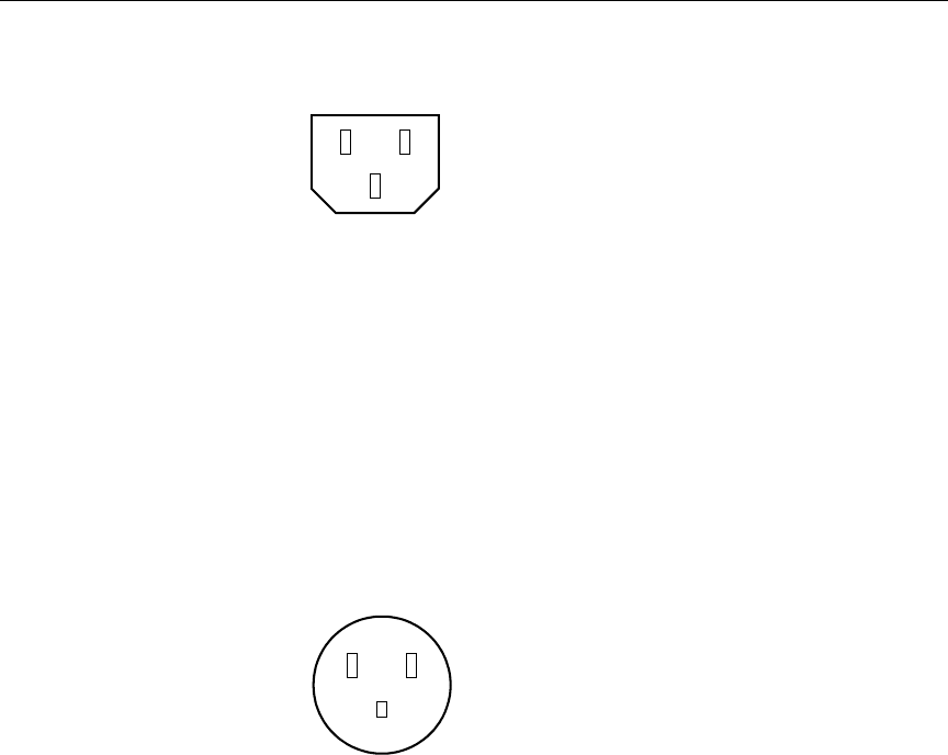
A-5
Power Cords
Figure A-1 Receptacle (CEE-22)
•United States and Canada requirements: In the United States and
Canada, the male plug is a NEMA 5-15P style and is UL listed and
CSA certified. Figure A-2 shows the plug. SVT cordage can be
used with desktop, countertop, or rack-mounted units; all other
equipment requires SJT cordage. Only SJT-type cord sets can be
used for units that sit on the floor.
Select the cord set according to the current rating of your unit. See
Table A-4 for the selection criteria for power cords in the United
States and Canada.
Figure A-2 NEMA 5-15P Style Plug
•European countries requirements: In Europe, use only an
H05VV-F, <HAR>, VDE, PVC, 3 x 1.00 mm2 power cord. Für den
Gebrauch in Deutschland muß ein Netzkabel des Typs H05VV-F,
<HAR>, PVC, Größe, 3 x 1.00 mm2 verwendet werden.
0521501B.book Page 5 Wednesday, September 25, 2002 10:08 AM

A-6
File Manager and Storage Specifications
UPS Power Cord
The Avid-supplied UPS has special power cord requirements. Use the
following guidelines to replace the original cord set on the UPS:
•United States and Canada requirements: In the United States and
Canada, the male plug is a NEMA L5-30P style and is UL listed
and CSA certified.
•Worldwide requirements: The UPS ships with a replaceable
power cord and the male plug is an IEC C-20 style. The power
cord and plug are UL listed and CSA certified. Figure A-3 shows
the plug.
Figure A-3 IEC C-20 Style Plug and Receptacle
Table A-4 Power Cord Requirements
Size of Conductors in Cord Maximum Current Rating of Unit
Cord Type U.S./Canada Europe U.S./Canada Europe
SJT 16 AWG 3 x 1.00 mm212 A 10 A
SVT 18 AWG NAa10 A NA
SVT 17 AWG NA 12 A NA
a. NA – Not applicable.
Receptacle Plug
0521501B.book Page 6 Wednesday, September 25, 2002 10:08 AM

APPENDIX B
Installing UPS Monitoring
Software
Each Best Power™ Fortress® Model 2250 uninterruptible power supply
(UPS) ships with the following items:
•Fortress Safety Information (multiple languages)
•Fortress User Guide (multiple languages)
• A CheckUPS II CD-ROM
• A 9-pin RS-232 serial communication cable
These notes describe how to install the communication cable, and how
to install and configure the Best Power CheckUPS II® monitoring
software.
The communication cable allows the CheckUPS software, running on
the File Manager, to monitor the Fortress 2250 UPS. The cable and the
monitoring software ensure that the File Manager is shut down at a
specified time after a power outage.
0521501B.book Page 1 Wednesday, September 25, 2002 10:08 AM

B-2
Installing UPS Monitoring Software
Installing the Serial Cable
To install the serial cable:
1. Locate the serial cable that came with the UPS. This is a special
cable. You cannot substitute another serial cable.
2. Attach the male end of the cable to the Communications connector
on the back of the UPS. Secure the cable with the thumbscrews
that are part of the connector.
3. Attach the female end of the cable to the COM1 serial port on the
back of the File Manager. Secure the cable with the thumbscrews
that are part of the connector.
Installing the CheckUPS II Software
To install the CheckUPS II software:
1. Locate the CheckUPS II CD-ROM in the Best Power kit.
2. Load the CD-ROM into the File Manager CD-ROM drive. The
CD-ROM autostarts Internet Explorer and the Welcome to
CheckUPS II Software Suite screen appears.
3. Click the Click Here to Get Started link. The Table of Contents
screen appears.
4. Click the CheckUPS II Software link. The CheckUPS II Software
screen appears.
5. Click the Windows button. The CheckUPS II Suite for Windows
screen appears.
6. Click the NT/2000 button. The CheckUPS II Suite for
Windows NT/2000 screen appears.
7. Scroll down to the NT/2000 Suite Advanced button.
8. Click the Advanced button. The File Download dialog box
appears.
0521501B.book Page 2 Wednesday, September 25, 2002 10:08 AM

B-3
Installing the CheckUPS II Software
9. Click Save this program to disk.
10. Click OK. The Save As dialog box appears.
11. Click Save to accept the default name and save the file to the
desktop.
12. Click Close.
13. Exit Internet Explorer.
14. Double-click ChkAdvNT on the desktop. The CheckUPS II Suite
for NT/2000 Setup dialog box appears at the Welcome screen.
15. Click Next. The Information screen appears with the copyright
and software description information.
16. Click Next to accept the terms of the copyright. The Choose
Destination Location screen appears.
17. Click Next to accept the default installation location. The Setup
Type Selection screen appears.
18. Click CheckUPS II Advanced and Data Server in the list.
19. Click Next. The Start Copying Files screen appears.
20. Click Next. The Setup Status progress bar shows the files being
copied to the destination location. When complete, the
InstallShield Wizard Complete screen appears.
21. Make sure the checkbox for Yes I want to view the CheckUPS Help
files now is not checked.
22. Click Finish to complete the software installation.
23. Reboot the File Manager.
0521501B.book Page 3 Wednesday, September 25, 2002 10:08 AM

B-4
Installing UPS Monitoring Software
Configuring the CheckUPS II Software
To configure the CheckUPS II software:
1. Click Start, point to Settings, and then click Control Panel.
2. Double-click the Check UPS II Advanced control panel. The
CheckUPS II Advanced control panel opens.
3. Click the UPS Monitoring tab.
4. In UPS Connection, set Type to serial and set Name to COM1.
5. Make sure that a check appears in the following checkboxes:
• Enable Event Logging
•Enable User Messaging
6. Click the Event Action tab.
7. Make sure that a check appears in the Enable Operating System
Shutdown checkbox.
8. Set the shutdown time to 1 minute after the power failure.
9. Make sure that a check appears in the Enable UPS Shutdown Time
check box.
10. Set the shutdown time to 3 minutes.
11. Make sure that a check appears in the Restart UPS checkbox. This
restarts the UPS when power returns.
12. Click Apply and then click OK.
13. In the Control Panel window, double-click Services. The Services
window opens.
14. Locate and click the CheckUPS II Advanced service.
15. Click the Startup button. The Service dialog box appears.
16. In Startup Type, click Automatic.
17. Click OK to close the dialog box and save the change.
18. In the Services dialog box, click the Close button.
0521501B.book Page 4 Wednesday, September 25, 2002 10:08 AM

B-5
Configuring the CheckUPS II Software
19. Reboot the File Manager.
20. After the File Manager reboots, a message appears, stating
Connection Established With Fortress.
21. Click OK.
22. A second message appears, stating UPS Monitoring Started.
23. Click OK. The CheckUPS II Advanced configuration and startup is
complete.
While the Check UPS II Advanced service is set to Automatic, the UPS
monitoring restarts each time that you reboot the File Manager. You’ll
need to dismiss the two startup messages after each reboot.
You can test that the CheckUPS II Advanced software is working by
unplugging the UPS from its power source. The File Manager shuts
down after five minutes.
cOnly test the UPS and File Manager shut down when others are not
using the MediaNet environment. Shutting down the File Manager
keeps MediaNet clients from using the media files on the MediaNet
storage.
0521501B.book Page 5 Wednesday, September 25, 2002 10:08 AM

B-6
Installing UPS Monitoring Software
0521501B.book Page 6 Wednesday, September 25, 2002 10:08 AM

APPENDIX C
Regulatory and Safety
Notices
FCC Notice
The devices listed in this documentation comply with Part 15 of the
FCC Rules. Operation is subject to the following two conditions:
1. This device may not cause harmful interference.
2. This device must accept any interference received, including
interference that may cause undesired operation.
This equipment has been tested and found to comply with the limits
for a Class A digital device, pursuant to Part 15 of the FCC Rules.
These limits are designed to provide reasonable protection against
harmful interference when the equipment is operated in a commercial
environment. This equipment generates, uses, and can radiate radio
frequency energy and, if not installed in accordance with the
instruction manual, may cause harmful interference to radio
communications. Operation of this equipment in a residential area is
likely to cause harmful interference in which case the user will be
required to correct the interference at his own expense.
0521501B.book Page 1 Wednesday, September 25, 2002 10:08 AM

C-2
Regulatory and Safety Notices
Canadian ICES-003
This Class A digital apparatus meets all requirements of the Canadian
Interference Causing Equipment Regulations.
Cet appareil numérique de la classe A respecte toutes les exigences du
Règlement sur le matériel brouilleur du Canada.
European Union Notice
Declaration of Conformity
(According to ISO/IEC Guide 22 and EN 45014)
Application of Council
Directives:
73/23/EEC, 89/336/EEC.
Standards to which
Conformity is Declared:
EN60950:1992 + A1 + A2 + A3 + A4 + A11
CISPR 22:1985 / EN55022:1988 Class A
EN55024:1998 + A1
Manufacturer’s Name: Avid Technology, Inc.
1925 Andover Street
Tewksbury, MA 01876, USA
European Contact: Nearest Avid Sales and Service Office or
Avid Technology International B.V.
Sandyford Business Center
Unit 3,
Dublin 18, Ireland
Type of Equipment: Information Technology Equipment
0521501B.book Page 2 Wednesday, September 25, 2002 10:08 AM

C-3
European Union Notice
(1) Products for the Windows NT Operating System: products were
tested in a typical Media Composer, Film Composer, Avid Xpress,
Avid Xpress DV, Avid Unity, Avid|DS, NewsCutter, NewsCutter XP,
NewsCutter DV, or Symphony configuration.
(2) Products for the Macintosh Operating System: products were
tested in a typical Media Composer, Film Composer, Avid Xpress, or
Avid Unity configuration.
(3) Products for the UNIX Operating System: products were tested in
an AirPlay or VideoSPACE configuration.
I, the undersigned, hereby declare that the equipment specified above
conforms to the above Directives and Standards.
George R. Smith, Director of Hardware Engineering.
Product Name: Products for the Windows NT Operating System:
Media Composer, Film Composer, Avid Xpress,
Avid Xpress DV, Avid Unity, Avid|DS, NewsCutter,
NewsCutter XP, NewsCutter DV, Symphony
Products for the Macintosh Operating System:
Media Composer, Film Composer, Avid Xpress,
Avid Unity
Products for the UNIX Operating System: AirPlay,
VideoSPACE
Base Model Numbers: None
Product Options: All
Year of Manufacture: 2002
0521501B.book Page 3 Wednesday, September 25, 2002 10:08 AM
C-4
Regulatory and Safety Notices
Australia and New Zealand EMC Regulations
John Kells, Australian Operations Manager
Avid Technology (Australia)
Unit B
5 Skyline Place
French Forest NSW 2086
Australia
Phone: 61-2-8977-4800
Taiwan EMC Regulations
Taiwan EMC Regulations BSMI Class A EMC Warning
N1709
0521501B.book Page 4 Wednesday, September 25, 2002 10:08 AM
